6 bearings cylindrical roller - bearing spec online - cylindrical... · cylindrical roller bearings...
TRANSCRIPT
Cylindrical roller bearings6
Cylindrical roller bearings
Other cylindrical roller bearings
Bearings with Solid Oil 1023
INSOCOAT bearings 1029
Hybrid bearings 1043
NoWear coated bearings . . . . . . . . . . . . . . . . . . . . . . . . . . 1059
Super-precision bearings † skf com/super-precision
Double and four-row cylindrical roller bearings † skf com/bearings
Split cylindrical roller bearings † skf com/bearings
Backing bearings † skf com/bearings
Indexing roller units † skf com/bearings
Cylindrical roller bearings and bearing units
for railway applications → contact SKF
Designs and variants 496
Single row cylindrical roller bearings 496
Common designs 496
Other designs 497
Other variants 497
High-capacity cylindrical roller bearings 498
Bearings with an inner ring centred cage 499
Bearings with an outer ring centred cage 499
Separable bearings with an inner ring raceway centred
cage 499
Double row bearings 499
Single row full complement cylindrical roller bearings 500
NCF design bearings 500
NJG design bearings 500
Double row full complement cylindrical roller bearings 500
NNCL design bearings 501
NNCF design bearings 501
NNC design bearings 501
NNF design sealed bearings 501
SKF Explorer bearings 502
Matched bearings 502
Cages 502
Bearing data 504
(Dimension standards, tolerances, radial internal
clearance, axial clearance, permissible misalignment,
permissible axial displacement)
Loads 509
(Minimum load, equivalent dynamic bearing load,
equivalent static bearing load)
Dynamic axial load carrying capacity 510
Permissible axial loads 510
Temperature limits 511
Permissible speed 511
Design considerations 512
Flange support 512
Mounting 512
Designation system 514
Product tables
6.1 Single row cylindrical roller bearings 516
6.2 High-capacity cylindrical roller bearings 550
6.3 Single row full complement cylindrical roller
bearings 554
6.4 Double row full complement cylindrical roller
bearings 564
6.5 Sealed double row full complement cylindrical
roller bearings 576
493
6
6 Cylindrical roller bearings
Cylindrical roller bearings
More information
Bearing life and load ratings 63
Design considerations 59
Bearing systems 160
Recommended its 169
Abutment and illet dimensions 208
Lubrication 239
Mounting, dismounting and
bearing care 271
Mounting instructions for
individual bearings † skf com/mount
SKF bearing maintenance
handbook (ISBN 978-91-978966-4-1)
SKF cylindrical roller bearings are available
in many designs, series and sizes The major
design differences between the cylindrical
roller bearings presented in this catalogue
are in:
• the number of roller rows (one or two)
• the type of cage (with, without or special
designs)
– Bearings with a cage can accommodate
heavy radial loads and peak loads, rapid
accelerations and high speeds
– Full complement bearings (without
cage) incorporate a maximum number
of rollers and are therefore suitable for
very heavy radial loads at moderate
speeds
– SKF high-capacity cylindrical roller
bearings combine the high load carrying
capacity of a full complement bearing
with the high speed capability of a bear-
ing with cage
• the coniguration of the inner and outer
ring langes (position and number of guide
langes, ig. 1)
Bearing features
• High load carrying capacity
• High stiffness
• Accommodate axial displacement (ig. 2)
Except for bearings with langes on both
the inner and outer rings
• Low friction
The open lange design (ig. 3), together
with the roller end design and surface in-
ish, promote lubricant ilm formation
resulting in lower friction and higher axial
load carrying capacity
• Long service life
The logarithmic roller proile reduces edge
stresses at the roller/raceway contact
(ig. 4) and sensitivity to misalignment and
shaft delection
More information
General bearing knowledge 17
Bearing selection process 59
Lubrication 109
Bearing interfaces 139
Seat tolerances for standard
conditions 148
Selecting internal clearance 182
Sealing, mounting and
dismounting 193
Mounting instructions for
individual bearings † skf com/mount
SKF bearing maintenance
handbook ISBN 978-91-978966-4-1
Fig. 1
Coniguration examples guide langes
494
6
6 Cylindrical roller bearings
Fig. 2
Axial displacement
Fig. 3
Open lange design
Fig. 4
Load distribution for the logarithmic roller proile
Fig. 5
Interchangeable components
• Enhanced operational reliability
The surface inish on the contact surfaces
of the rollers and raceways supports the
formation of a hydrodynamic lubricant
ilm
• Separable and interchangeable
The separable components of SKF cylin-
drical roller bearings are interchangeable
(ig. 5) This facilitates mounting and
dismounting, as well as maintenance
inspections
In addition to the cylindrical roller bearings
presented in this catalogue, SKF supplies
cylindrical roller bearings for special applica-
tion requirements This assortment includes:
• Double row cylindrical roller bearings
† skf com/bearings
• Four-row cylindrical roller bearings
† skf com/bearings
• Split cylindrical roller bearings
† skf com/bearings
• Super-precision bearings
† skf com/super-precision
• Backing bearings † skf com/bearings
• Indexing roller units † skf com/bearings
• Cylindrical roller bearings and bearing
units for railway applications → contact SKF
495
6
6 Cylindrical roller bearings
Designs and variants
Single row cylindrical roller bearings
The major design differences between the
single row cylindrical roller bearings pre-
sented in this catalogue are in:
• the cage design and material
• the coniguration of the inner and outer
ring langes
SKF inch bearings (CRL and CRM series,
skf com/go/17000-6-1), which are not pre-
sented in this catalogue, conform to the
metric N design (ig. 6) They are mainly
used in the aftermarket and, therefore, SKF
recommends not to use these bearings for
new bearing arrangement designs
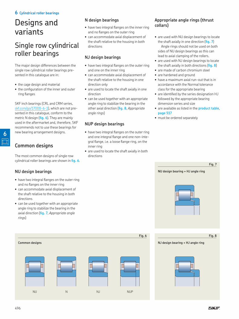
Common designs
The most common designs of single row
cylindrical roller bearings are shown in ig. 6
NU design bearings
• have two integral langes on the outer ring
and no langes on the inner ring
• can accommodate axial displacement of
the shaft relative to the housing in both
directions
• can be used together with an appropriate
angle ring to stabilize the bearing in the
axial direction (ig. 7, Appropriate angle
rings)
N design bearings
• have two integral langes on the inner ring
and no langes on the outer ring
• can accommodate axial displacement of
the shaft relative to the housing in both
directions
NJ design bearings
• have two integral langes on the outer ring
and one on the inner ring
• can accommodate axial displacement of
the shaft relative to the housing in one
direction only
• are used to locate the shaft axially in one
direction
• can be used together with an appropriate
angle ring to stabilize the bearing in the
other axial direction (ig. 8, Appropriate
angle rings)
NUP design bearings
• have two integral langes on the outer ring
and one integral lange and one non-inte-
gral lange, i e a loose lange ring, on the
inner ring
• are used to locate the shaft axially in both
directions
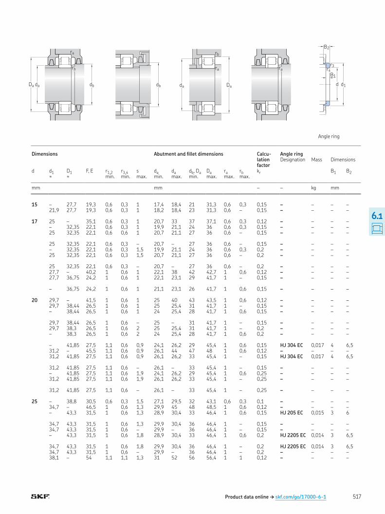
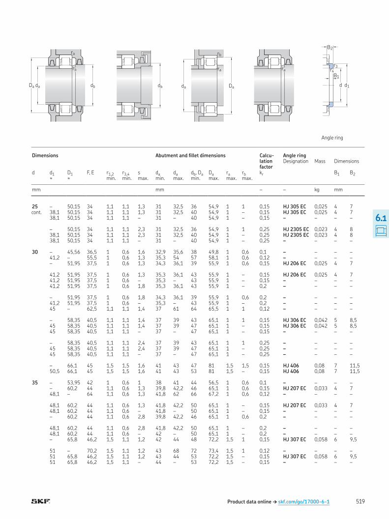
Appropriate angle rings (thrust collars)
• are used with NU design bearings to locate
the shaft axially in one direction (ig. 7)
Angle rings should not be used on both
sides of NU design bearings as this can
lead to axial clamping of the rollers
• are used with NJ design bearings to locate
the shaft axially in both directions (ig. 8)
• are made of carbon chromium steel
• are hardened and ground
• have a maximum axial run-out that is in
accordance with the Normal tolerance
class for the appropriate bearing
• are identiied by the series designation HJ
followed by the appropriate bearing
dimension series and size
• are available as listed in the product table,
page 517
• must be ordered separately
Fig. 7
NU design bearing + HJ angle ring
Fig. 8
NJ design bearing + HJ angle ring
Fig. 6
Common designs
NU N NJ NUP
496
6
Designs and variants
Fig. 10
Bearing without inner ring, RNU
Fig. 11
Bearing without outer ring, RN
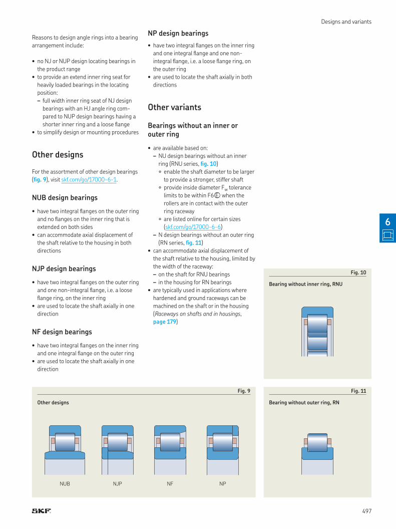
Fig. 9
Other designs
NUB NJP NF NP
Reasons to design angle rings into a bearing
arrangement include:
• no NJ or NUP design locating bearings in
the product range
• to provide an extend inner ring seat for
heavily loaded bearings in the locating
position:
– full width inner ring seat of NJ design
bearings with an HJ angle ring com-
pared to NUP design bearings having a
shorter inner ring and a loose lange
• to simplify design or mounting procedures
Other designs
For the assortment of other design bearings
(ig. 9), visit skf com/go/17000-6-1
NUB design bearings
• have two integral langes on the outer ring
and no langes on the inner ring that is
extended on both sides
• can accommodate axial displacement of
the shaft relative to the housing in both
directions
NJP design bearings
• have two integral langes on the outer ring
and one non-integral lange, i e a loose
lange ring, on the inner ring
• are used to locate the shaft axially in one
direction
NF design bearings
• have two integral langes on the inner ring
and one integral lange on the outer ring
• are used to locate the shaft axially in one
direction
NP design bearings
• have two integral langes on the inner ring
and one integral lange and one non-
integral lange, i e a loose lange ring, on
the outer ring
• are used to locate the shaft axially in both
directions
Other variants
Bearings without an inner or outer ring
• are available based on:
– NU design bearings without an inner
ring (RNU series, ig. 10)
○ enable the shaft diameter to be larger
to provide a stronger, stiffer shaft
○ provide inside diameter Fw tolerance
limits to be within F6� when the
rollers are in contact with the outer
ring raceway
○ are listed online for certain sizes
(skf com/go/17000-6-6)
– N design bearings without an outer ring
(RN series, ig. 11)
• can accommodate axial displacement of
the shaft relative to the housing, limited by
the width of the raceway:
– on the shaft for RNU bearings
– in the housing for RN bearings
• are typically used in applications where
hardened and ground raceways can be
machined on the shaft or in the housing
(Raceways on shafts and in housings,
page 179)
497
6
6 Cylindrical roller bearings
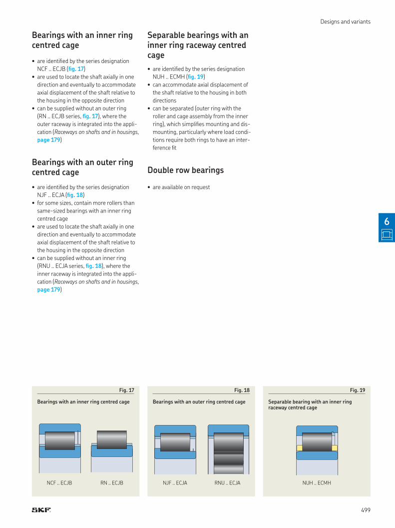
High-capacity cylindrical roller bearingsSKF high-capacity cylindrical roller bearings
(ig. 15) are designed for applications such
as industrial gearboxes, wind turbine gear-
boxes and mining equipment
The cage bars are displaced relative to the
roller pitch diameter to enable the rollers to
be placed closer to each other, creating room
for additional rollers (ig. 16) and thereby
increasing load carrying capacity and radial
stiffness
The black oxide coating of rings and roll-
ers (designation sufix L4B) contributes to
extended service life by improving:
• smearing damage resistance
• running-in properties and reducing
friction
• performance under poor lubrication
conditions
• chemical resistance (from agressive oil
additives)
• corrosion resistance
SKF high-capacity cylindrical roller bearings
are available in three different main designs
and some variants
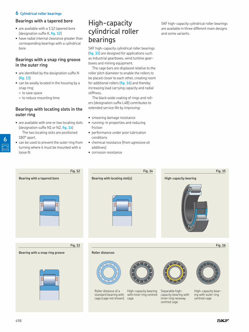
Bearings with a tapered bore
• are available with a 1:12 tapered bore
(designation sufix K, ig. 12)
• have radial internal clearance greater than
corresponding bearings with a cylindrical
bore
Bearings with a snap ring groove in the outer ring
• are identiied by the designation sufix N
(ig. 13)
• can be axially located in the housing by a
snap ring:
– to save space
– to reduce mounting time
Bearings with locating slots in the outer ring
• are available with one or two locating slots
(designation sufix N1 or N2, ig. 14)
The two locating slots are positioned
180° apart
• can be used to prevent the outer ring from
turning where it must be mounted with a
loose it
Fig. 16
Roller distances
Roller distance of a standard bearing with cage (cage not shown)
High-capacity bearing with inner ring centred cage
Separable high- capacity bearing with inner ring raceway centred cage
High-capacity bear-ing with outer ring centred cage
Fig. 13
Bearing with a snap ring groove
Fig. 14
Bearing with locating slot(s)
Fig. 12
Bearing with a tapered bore
Fig. 15
High-capacity bearing
498
6
Designs and variants
Bearings with an inner ring centred cage
• are identiied by the series designation
NCF ECJB (ig. 17)
• are used to locate the shaft axially in one
direction and eventually to accommodate
axial displacement of the shaft relative to
the housing in the opposite direction
• can be supplied without an outer ring
(RN ECJB series, ig. 17), where the
outer raceway is integrated into the appli-
cation (Raceways on shafts and in housings,
page 179)
Bearings with an outer ring centred cage
• are identiied by the series designation
NJF ECJA (ig. 18)
• for some sizes, contain more rollers than
same-sized bearings with an inner ring
centred cage
• are used to locate the shaft axially in one
direction and eventually to accommodate
axial displacement of the shaft relative to
the housing in the opposite direction
• can be supplied without an inner ring
(RNU ECJA series, ig. 18), where the
inner raceway is integrated into the appli-
cation (Raceways on shafts and in housings,
page 179)
Separable bearings with an inner ring raceway centred cage
• are identiied by the series designation
NUH ECMH (ig. 19)
• can accommodate axial displacement of
the shaft relative to the housing in both
directions
• can be separated (outer ring with the
roller and cage assembly from the inner
ring), which simpliies mounting and dis-
mounting, particularly where load condi-
tions require both rings to have an inter-
ference it
Double row bearings
• are available on request
Fig. 17
Bearings with an inner ring centred cage
NCF ECJB RN ECJB
Fig. 18
Bearings with an outer ring centred cage
NJF ECJA RNU ECJA
Fig. 19
Separable bearing with an inner ring raceway centred cage
NUH ECMH
499
6
6 Cylindrical roller bearings
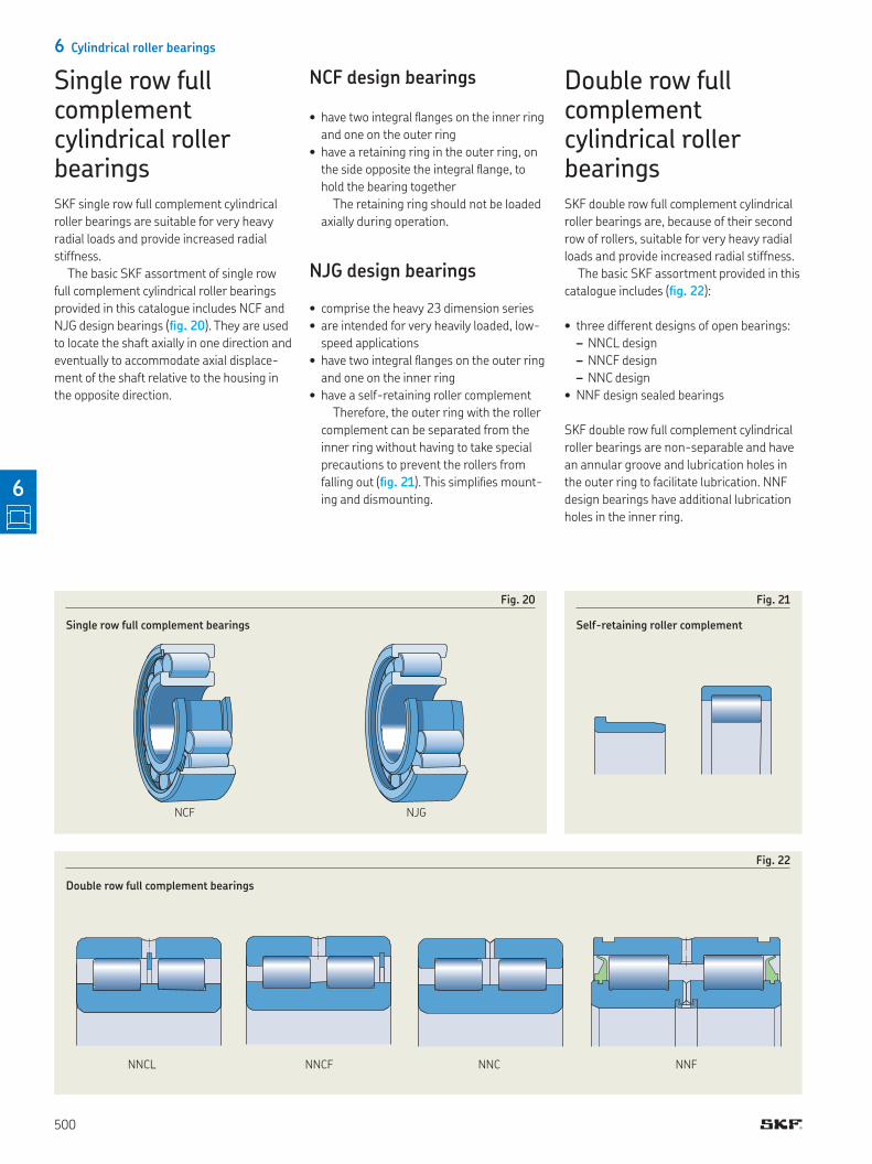
Single row full complement cylindrical roller bearingsSKF single row full complement cylindrical
roller bearings are suitable for very heavy
radial loads and provide increased radial
stiffness
The basic SKF assortment of single row
full complement cylindrical roller bearings
provided in this catalogue includes NCF and
NJG design bearings (ig. 20) They are used
to locate the shaft axially in one direction and
eventually to accommodate axial displace-
ment of the shaft relative to the housing in
the opposite direction
NCF design bearings
• have two integral langes on the inner ring
and one on the outer ring
• have a retaining ring in the outer ring, on
the side opposite the integral lange, to
hold the bearing together
The retaining ring should not be loaded
axially during operation
NJG design bearings
• comprise the heavy 23 dimension series
• are intended for very heavily loaded, low-
speed applications
• have two integral langes on the outer ring
and one on the inner ring
• have a self-retaining roller complement
Therefore, the outer ring with the roller
complement can be separated from the
inner ring without having to take special
precautions to prevent the rollers from
falling out (ig. 21) This simpliies mount-
ing and dismounting
Fig. 20
Single row full complement bearings
NCF NJG
Fig. 21
Self-retaining roller complement
Fig. 22
Double row full complement bearings
NNCL NNCF NNC NNF
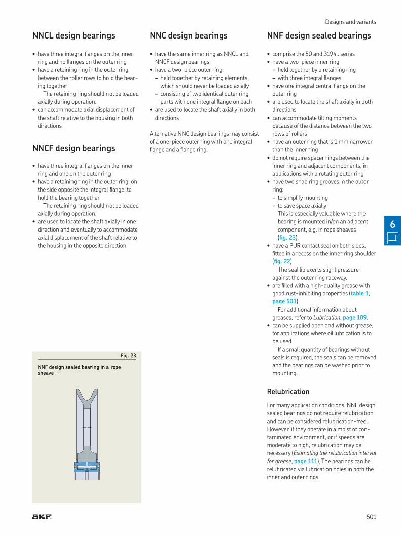
Double row full complement cylindrical roller bearingsSKF double row full complement cylindrical
roller bearings are, because of their second
row of rollers, suitable for very heavy radial
loads and provide increased radial stiffness
The basic SKF assortment provided in this
catalogue includes (ig. 22):
• three different designs of open bearings:
– NNCL design
– NNCF design
– NNC design
• NNF design sealed bearings
SKF double row full complement cylindrical
roller bearings are non-separable and have
an annular groove and lubrication holes in
the outer ring to facilitate lubrication NNF
design bearings have additional lubrication
holes in the inner ring
500
6
Designs and variants
NNCL design bearings
• have three integral langes on the inner
ring and no langes on the outer ring
• have a retaining ring in the outer ring
between the roller rows to hold the bear-
ing together
The retaining ring should not be loaded
axially during operation
• can accommodate axial displacement of
the shaft relative to the housing in both
directions
NNCF design bearings
• have three integral langes on the inner
ring and one on the outer ring
• have a retaining ring in the outer ring, on
the side opposite the integral lange, to
hold the bearing together
The retaining ring should not be loaded
axially during operation
• are used to locate the shaft axially in one
direction and eventually to accommodate
axial displacement of the shaft relative to
the housing in the opposite direction
NNC design bearings
• have the same inner ring as NNCL and
NNCF design bearings
• have a two-piece outer ring:
– held together by retaining elements,
which should never be loaded axially
– consisting of two identical outer ring
parts with one integral lange on each
• are used to locate the shaft axially in both
directions
Alternative NNC design bearings may consist
of a one-piece outer ring with one integral
lange and a lange ring
NNF design sealed bearings
• comprise the 50 and 3194‥ series
• have a two-piece inner ring:
– held together by a retaining ring
– with three integral langes
• have one integral central lange on the
outer ring
• are used to locate the shaft axially in both
directions
• can accommodate tilting moments
because of the distance between the two
rows of rollers
• have an outer ring that is 1 mm narrower
than the inner ring
• do not require spacer rings between the
inner ring and adjacent components, in
applications with a rotating outer ring
• have two snap ring grooves in the outer
ring:
– to simplify mounting
– to save space axially
This is especially valuable where the
bearing is mounted in/on an adjacent
component, e g in rope sheaves
(ig. 23)
• have a PUR contact seal on both sides,
itted in a recess on the inner ring shoulder
(ig. 22)
The seal lip exerts slight pressure
against the outer ring raceway
• are illed with a high-quality grease with
good rust-inhibiting properties (table 1,
page 503)
For additional information about
greases, refer to Lubrication, page 109
• can be supplied open and without grease,
for applications where oil lubrication is to
be used
If a small quantity of bearings without
seals is required, the seals can be removed
and the bearings can be washed prior to
mounting
Relubrication
For many application conditions, NNF design
sealed bearings do not require relubrication
and can be considered relubrication-free
However, if they operate in a moist or con-
taminated environment, or if speeds are
moderate to high, relubrication may be
necessary (Estimating the relubrication interval
for grease, page 111) The bearings can be
relubricated via lubrication holes in both the
inner and outer rings
Fig. 23
NNF design sealed bearing in a rope sheave
501
6
6 Cylindrical roller bearings
Matched bearings• are combined so that any difference in
cross-sectional height of the bearings
used in a matched set lies within a very
small tolerance range
This tighter tolerance is a precondition
for equal load sharing between the
bearings
• can be supplied as:
– sets of two bearings (designation sufix
DR)
– sets of three bearings (designation sufix
TR)
– sets of four bearings (designation sufix
QR)
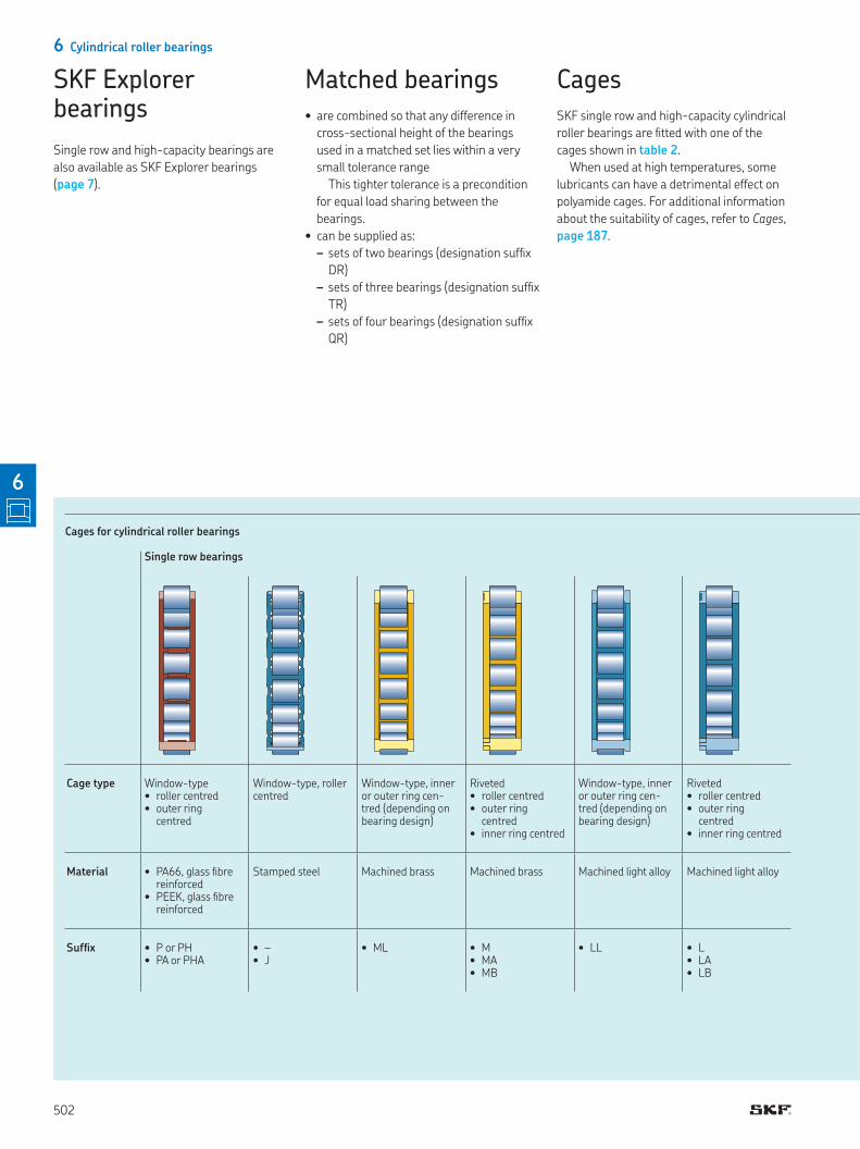
CagesSKF single row and high-capacity cylindrical
roller bearings are itted with one of the
cages shown in table 2
When used at high temperatures, some
lubricants can have a detrimental effect on
polyamide cages For additional information
about the suitability of cages, refer to Cages,
page 187
Cages for cylindrical roller bearings
Single row bearings
Cage type Window-type
• roller centred • outer ring
centred
Window-type, roller centred
Window-type, inner or outer ring cen-tred (depending on bearing design)
Riveted • roller centred • outer ring
centred• inner ring centred
Window-type, inner or outer ring cen-tred (depending on bearing design)
Riveted • roller centred• outer ring
centred• inner ring centred
Material • PA66, glass ibre reinforced
• PEEK, glass ibre reinforced
Stamped steel Machined brass Machined brass Machined light alloy Machined light alloy
Sufix • P or PH• PA or PHA
• – • J
• ML • M• MA• MB
• LL • L• LA• LB
SKF Explorer bearings
Single row and high-capacity bearings are
also available as SKF Explorer bearings
(page 7)
502
6
Designs and variants
Table 2
High-capacity bearings
Window-type, inner ring centred
Window-type, outer ring centred
Window-type, inner ring raceway centred
Sheet steel, manganese phosphated
Sheet steel, manganese phosphated
Machined brass
JB JA MH
Table 1
Technical speciications of SKF standard grease for sealed double row full complement cylindrical roller bearings
Grease Temperature range1) Thickener Base oil type NLGI grade Base oil viscosity[mm2/s]at 40 °C at 100 °C(105 °F) (210 °F)
–50 0 50 100 150 200 250 °C
GHU Lithium complex soap
Mineral 2 150 15
–60 30 120 210 300 390 480 °F
1) Refer to the SKF trafic light concept (page 117)
503
6

Bearing data
6 Cylindrical roller bearings
Bearing dataSingle row bearings High-capacity bearings
Dimension
standards
Boundary dimensions: ISO 15 Boundary dimensions: ISO 15
Except for:
• HJ angle rings: ISO 246
• Snap rings and grooves: ISO 464
• Locating slots: ISO 20515
Tolerances
For additional infor-
mation † page 35
Normal dimensional tolerance
P6 geometrical tolerance
Check availability of P5 or P6 tolerance class for bear-
ings in the 10 series
Normal dimensional tolerance
P6 geometrical tolerance
Values: ISO 492 (table 2, page 38, to table 4, page 40)
Radial internal
clearance
For additional infor-
mation † page 182
Normal, C3
Check availability of other clearance classes
Values: ISO 5753-1 (table 3, page 506)
Values are valid for unmounted bearings under zero measuring load
Axial internal
clearance
Guideline values:
• NUP design (table 4, page 507)
• NJ design with an HJ angle ring (table 5, page 508)
When measuring the axial internal clearance, the roll-
ers may tilt, causing an enlargement of the measured
axial clearance:
• 10, 18, 19, 2, 3 and 4 series: ≈ the radial internal
clearance
• 22, 23, 29 and 39 series: ≈ 2/3 the radial internal
clearance
–
Permissible
misalignment
• 10, 12, 18, 19, 2, 3 and 4 series: ≈ 4 minutes of arc
• 20, 22, 23, 29 and 39 series: ≈ 3 minutes of arc
The values are not valid for bearings of the NUP design
or the NJ design with an HJ angle ring
≈ 3 minutes of arc
Permissible axial
displacement (ig. 2,
page 495)
smax † product tables,
page 516 page 550
Bearings having no lange, or only one integral lange on either the inner or
outer ring, can accommodate axial displacement Displacement of the shaft …
Misalignment increases bearing noise and reduces bearing service life, and …
504
6
Bearing data
Single row full complement bearings Double row full complement bearings
Boundary dimensions: ISO 15 Boundary dimensions: ISO 15
Except for:
• outer ring width of NNF 50 series
bearings:
C = 1 mm smaller than ISO standard
• bearings in the 3194‥ series:
dimensions not standardized
Normal
• 18 series: ≈ 4 minutes of arc
• 22, 23, 28, 29 and 30 series:
≈ 3 minutes of arc
For information, contact the SKF applica-
tion engineering service
page 554 page 564
… relative to the housing occurs within these bearings As a result, there is virtually no
increase in friction
… when it exceeds the guideline values these effects become particularly noticeable
505
6
6 Cylindrical roller bearings
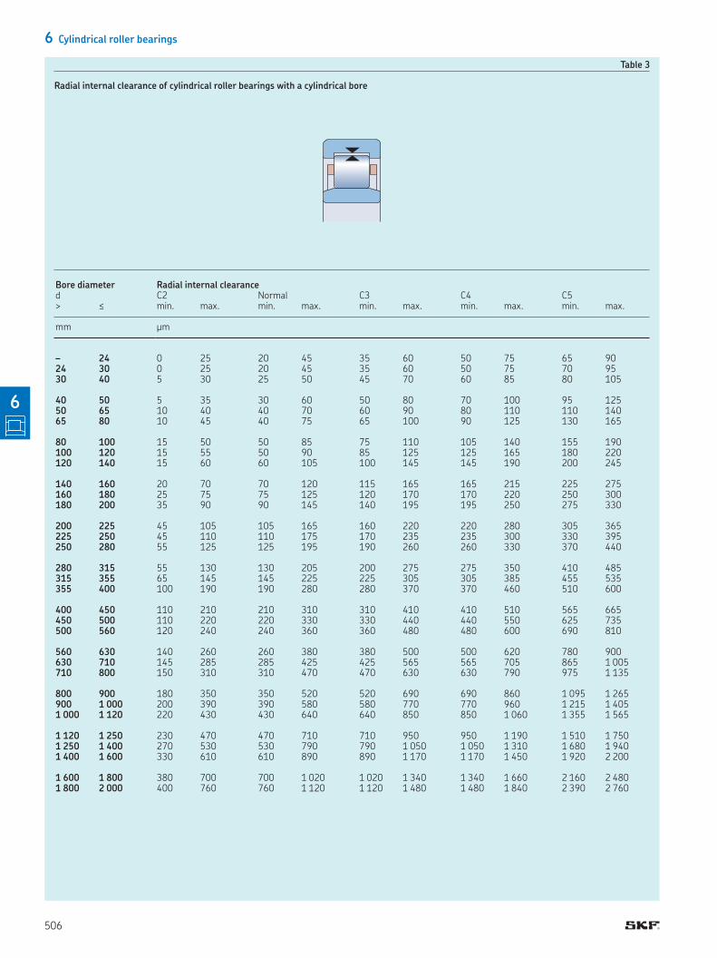
Table 3
Radial internal clearance of cylindrical roller bearings with a cylindrical bore
Bore diameter Radial internal clearanced C2 Normal C3 C4 C5> ≤ min max min max min max min max min max
mm µm
– 24 0 25 20 45 35 60 50 75 65 9024 30 0 25 20 45 35 60 50 75 70 9530 40 5 30 25 50 45 70 60 85 80 105
40 50 5 35 30 60 50 80 70 100 95 12550 65 10 40 40 70 60 90 80 110 110 14065 80 10 45 40 75 65 100 90 125 130 165
80 100 15 50 50 85 75 110 105 140 155 190100 120 15 55 50 90 85 125 125 165 180 220120 140 15 60 60 105 100 145 145 190 200 245
140 160 20 70 70 120 115 165 165 215 225 275160 180 25 75 75 125 120 170 170 220 250 300180 200 35 90 90 145 140 195 195 250 275 330
200 225 45 105 105 165 160 220 220 280 305 365225 250 45 110 110 175 170 235 235 300 330 395250 280 55 125 125 195 190 260 260 330 370 440
280 315 55 130 130 205 200 275 275 350 410 485315 355 65 145 145 225 225 305 305 385 455 535355 400 100 190 190 280 280 370 370 460 510 600
400 450 110 210 210 310 310 410 410 510 565 665450 500 110 220 220 330 330 440 440 550 625 735500 560 120 240 240 360 360 480 480 600 690 810
560 630 140 260 260 380 380 500 500 620 780 900630 710 145 285 285 425 425 565 565 705 865 1 005710 800 150 310 310 470 470 630 630 790 975 1 135
800 900 180 350 350 520 520 690 690 860 1 095 1 265900 1 000 200 390 390 580 580 770 770 960 1 215 1 4051 000 1 120 220 430 430 640 640 850 850 1 060 1 355 1 565
1 120 1 250 230 470 470 710 710 950 950 1 190 1 510 1 7501 250 1 400 270 530 530 790 790 1 050 1 050 1 310 1 680 1 9401 400 1 600 330 610 610 890 890 1 170 1 170 1 450 1 920 2 200
1 600 1 800 380 700 700 1 020 1 020 1 340 1 340 1 660 2 160 2 4801 800 2 000 400 760 760 1 120 1 120 1 480 1 480 1 840 2 390 2 760
506
6
Bearing data
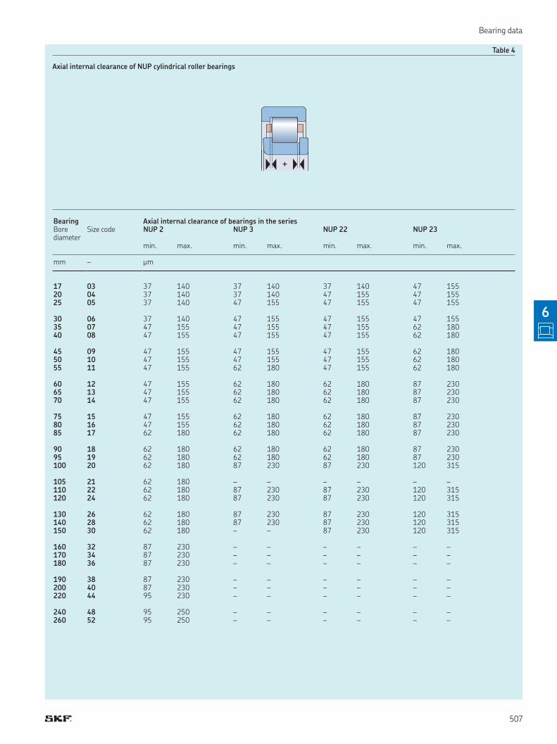
Table 4
Axial internal clearance of NUP cylindrical roller bearings
+
Bearing Axial internal clearance of bearings in the series Bore diameter
Size code NUP 2 NUP 3 NUP 22 NUP 23
min max min max min max min max
mm – µm
17 03 37 140 37 140 37 140 47 15520 04 37 140 37 140 47 155 47 15525 05 37 140 47 155 47 155 47 155
30 06 37 140 47 155 47 155 47 15535 07 47 155 47 155 47 155 62 18040 08 47 155 47 155 47 155 62 180
45 09 47 155 47 155 47 155 62 18050 10 47 155 47 155 47 155 62 18055 11 47 155 62 180 47 155 62 180
60 12 47 155 62 180 62 180 87 23065 13 47 155 62 180 62 180 87 23070 14 47 155 62 180 62 180 87 230
75 15 47 155 62 180 62 180 87 23080 16 47 155 62 180 62 180 87 23085 17 62 180 62 180 62 180 87 230
90 18 62 180 62 180 62 180 87 23095 19 62 180 62 180 62 180 87 230100 20 62 180 87 230 87 230 120 315
105 21 62 180 – – – – – –110 22 62 180 87 230 87 230 120 315120 24 62 180 87 230 87 230 120 315
130 26 62 180 87 230 87 230 120 315140 28 62 180 87 230 87 230 120 315150 30 62 180 – – 87 230 120 315
160 32 87 230 – – – – – –170 34 87 230 – – – – – –180 36 87 230 – – – – – –
190 38 87 230 – – – – – –200 40 87 230 – – – – – –220 44 95 230 – – – – – –
240 48 95 250 – – – – – –260 52 95 250 – – – – – –
507
6
6 Cylindrical roller bearings
Table 5
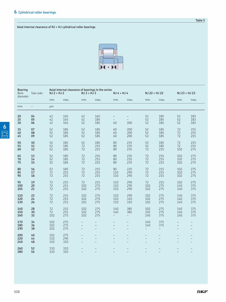
Axial internal clearance of NJ + HJ cylindrical roller bearings
+
Bearing Axial internal clearance of bearings in the seriesBore diameter
Size code NJ 2 + HJ 2 NJ 3 + HJ 3 NJ 4 + HJ 4 NJ 22 + HJ 22 NJ 23 + HJ 23
min max min max min max min max min max
mm – µm
20 04 42 165 42 165 – – 52 185 52 18325 05 42 165 52 185 – – 52 185 52 18330 06 42 165 52 185 60 200 52 185 52 183
35 07 52 185 52 185 60 200 52 185 72 21540 08 52 185 52 185 60 200 52 185 72 21545 09 52 185 52 185 60 200 52 185 72 215
50 10 52 185 52 185 80 235 52 185 72 21555 11 52 185 72 215 80 235 52 185 72 21560 12 52 185 72 215 80 235 72 215 102 275
65 13 52 185 72 215 80 235 72 215 102 27570 14 52 185 72 215 80 235 72 215 102 27575 15 52 185 72 215 80 235 72 215 102 275
80 16 52 185 72 215 80 235 72 215 102 27585 17 72 215 72 215 110 290 72 215 102 27590 18 72 215 72 215 110 290 72 215 102 275
95 19 72 215 72 215 110 290 72 215 102 275100 20 72 215 102 275 110 290 102 275 140 375105 21 72 215 102 275 110 290 102 275 140 375
110 22 72 215 102 275 110 290 102 275 140 375120 24 72 215 102 275 110 310 102 275 140 375130 26 72 215 102 275 110 310 102 275 140 375
140 28 72 215 102 275 140 385 102 275 140 375150 30 72 215 102 275 140 385 102 275 140 375160 32 102 275 102 275 – – 140 375 140 375
170 34 102 275 – – – – 140 375 – –180 36 102 275 – – – – 140 375 – –190 38 102 275 – – – – – – – –
200 40 102 275 – – – – – – – –220 44 110 290 – – – – – – – –240 48 110 310 – – – – – – – –
260 52 110 310 – – – – – – – –280 56 110 310 – – – – – – – –
508
6
Loads
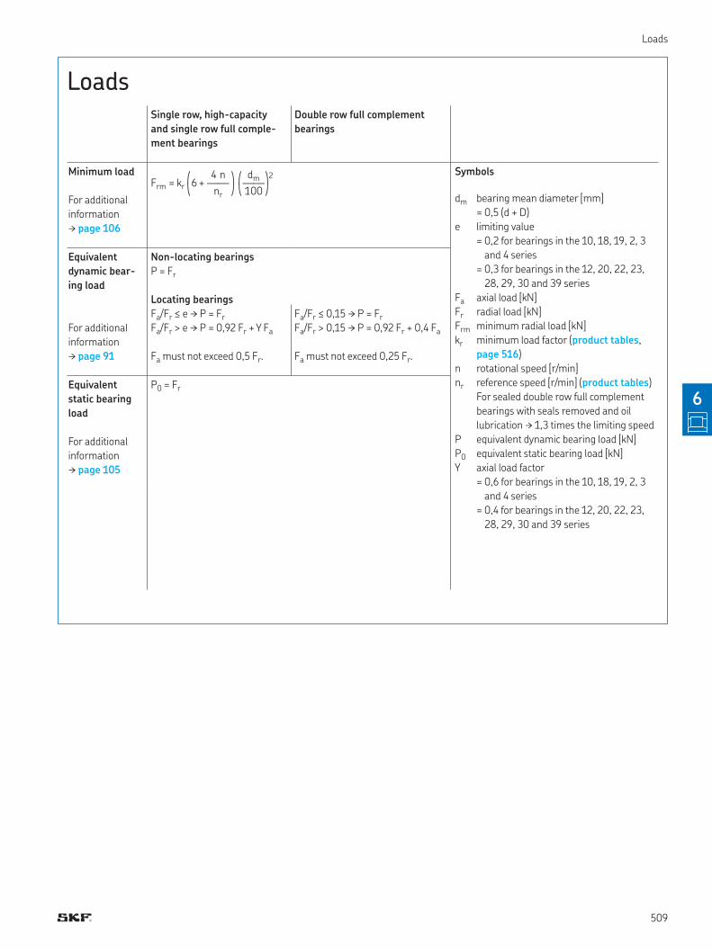
LoadsSingle row, high-capacity
and single row full comple-
ment bearings
Double row full complement
bearings
Minimum load
For additional
information
† page 106
Equivalent
dynamic bear-
ing load
For additional
information
† page 91
Non-locating bearings
P = Fr
Locating bearings
Fa/Fr ≤ e † P = Fr
Fa/Fr > e † P = 0,92 Fr + Y Fa
Fa must not exceed 0,5 Fr
Fa/Fr ≤ 0,15 † P = Fr
Fa/Fr > 0,15 † P = 0,92 Fr + 0,4 Fa
Fa must not exceed 0,25 Fr
Equivalent
static bearing
load
For additional
information
† page 105
P0 = Fr
q 4 n w q dm w 2Frm = kr 6 + —— —— < nr z < 100 z
Symbols
dm bearing mean diameter [mm]
= 0,5 (d + D)
e limiting value
= 0,2 for bearings in the 10, 18, 19, 2, 3
and 4 series
= 0,3 for bearings in the 12, 20, 22, 23,
28, 29, 30 and 39 series
Fa axial load [kN]
Fr radial load [kN]
Frm minimum radial load [kN]
kr minimum load factor (product tables,
page 516)
n rotational speed [r/min]
nr reference speed [r/min] (product tables)
For sealed double row full complement
bearings with seals removed and oil
lubrication † 1,3 times the limiting speed
P equivalent dynamic bearing load [kN]
P0 equivalent static bearing load [kN]
Y axial load factor
= 0,6 for bearings in the 10, 18, 19, 2, 3
and 4 series
= 0,4 for bearings in the 12, 20, 22, 23,
28, 29, 30 and 39 series
509
6
6 Cylindrical roller bearings
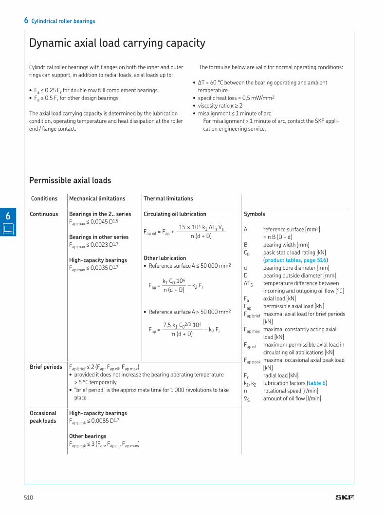
Dynamic axial load carrying capacity
Permissible axial loads
Conditions Mechanical limitations Thermal limitations
Continuous Bearings in the 2‥ series
Fap max ≤ 0,0045 D1,5
Bearings in other series
Fap max ≤ 0,0023 D1,7
High-capacity bearings
Fap max ≤ 0,0035 D1,7
Circulating oil lubrication
Other lubrication
• Reference surface A ≤ 50 000 mm2
• Reference surface A > 50 000 mm2
Brief periods Fap brief ≤ 2 (Fap, Fap oil, Fap max)
• provided it does not increase the bearing operating temperature
> 5 °C temporarily
• “brief period” is the approximate time for 1 000 revolutions to take
place
Occasional
peak loads
High-capacity bearings
Fap peak ≤ 0,0085 D1,7
Other bearings
Fap peak ≤ 3 (Fap, Fap oil, Fap max)
15 × 104 k1 ∆Ts V̇sFap oil = Fap + ————————– n (d + D)
k1 C0 104Fap = ———— – k2 Fr n (d + D)
7,5 k1 C02/3 104Fap = ——————— – k2 Fr n (d + D)
Symbols
A reference surface [mm2]
= π B (D + d)
B bearing width [mm]
C0 basic static load rating [kN]
(product tables, page 516)
d bearing bore diameter [mm]
D bearing outside diameter [mm]
ΔTS temperature difference between
incoming and outgoing oil low [°C]
Fa axial load [kN]
Fap permissible axial load [kN]
Fap brief maximal axial load for brief periods
[kN]
Fap max maximal constantly acting axial
load [kN]
Fap oil maximum permissible axial load in
circulating oil applications [kN]
Fap peak maximal occasional axial peak load
[kN]
Fr radial load [kN]
k1, k2 lubrication factors (table 6)
n rotational speed [r/min]
V̇S amount of oil low [l/min]
Cylindrical roller bearings with langes on both the inner and outer
rings can support, in addition to radial loads, axial loads up to:
• Fa ≤ 0,25 Fr for double row full complement bearings
• Fa ≤ 0,5 Fr for other design bearings
The axial load carrying capacity is determined by the lubrication
condition, operating temperature and heat dissipation at the roller
end / lange contact
The formulae below are valid for normal operating conditions:
• ΔT ≈ 60 °C between the bearing operating and ambient
temperature
• speciic heat loss ≈ 0,5 mW/mm2
• viscosity ratio κ ≥ 2
• misalignment ≤ 1 minute of arc
For misalignment > 1 minute of arc, contact the SKF appli-
cation engineering service
510
6
Page 511 footnot
Permissible speed
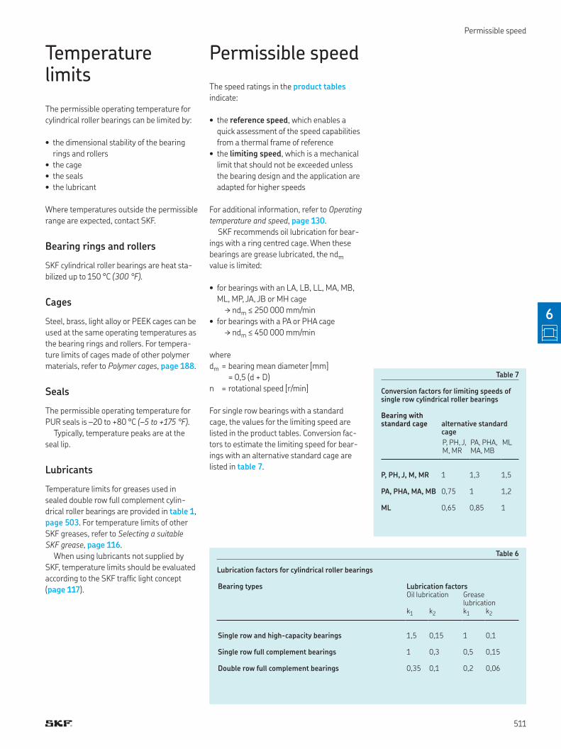
Table 6
Lubrication factors for cylindrical roller bearings
Bearing types Lubrication factorsOil lubrication Grease
lubrication k1 k2 k1 k2
Single row and high-capacity bearings 1,5 0,15 1 0,1
Single row full complement bearings 1 0,3 0,5 0,15
Double row full complement bearings 0,35 0,1 0,2 0,06
Temperature limits
The permissible operating temperature for
cylindrical roller bearings can be limited by:
• the dimensional stability of the bearing
rings and rollers
• the cage
• the seals
• the lubricant
Where temperatures outside the permissible
range are expected, contact SKF.
Bearing rings and rollers
SKF cylindrical roller bearings are heat sta-
bilized up to 150 °C (300 °F)
Cages
Steel, brass, light alloy or PEEK cages can be
used at the same operating temperatures as
the bearing rings and rollers For tempera-
ture limits of cages made of other polymer
materials, refer to Polymer cages, page 188
Seals
The permissible operating temperature for
PUR seals is –20 to +80 °C (–5 to +175 °F)
Typically, temperature peaks are at the
seal lip
Lubricants
Temperature limits for greases used in
sealed double row full complement cylin-
drical roller bearings are provided in table 1,
page 503 For temperature limits of other
SKF greases, refer to Selecting a suitable
SKF grease, page 116
When using lubricants not supplied by
SKF, temperature limits should be evaluated
according to the SKF trafic light concept
(page 117)
Permissible speed
The speed ratings in the product tables
indicate:
• the reference speed, which enables a
quick assessment of the speed capabilities
from a thermal frame of reference
• the limiting speed, which is a mechanical
limit that should not be exceeded unless
the bearing design and the application are
adapted for higher speeds
For additional information, refer to Operating
temperature and speed, page 130
SKF recommends oil lubrication for bear-
ings with a ring centred cage When these
bearings are grease lubricated, the ndm
value is limited:
• for bearings with an LA, LB, LL, MA, MB,
ML, MP, JA, JB or MH cage
† ndm ≤ 250 000 mm/min
• for bearings with a PA or PHA cage
† ndm ≤ 450 000 mm/min
where
dm = bearing mean diameter [mm]
= 0,5 (d + D)
n = rotational speed [r/min]
For single row bearings with a standard
cage, the values for the limiting speed are
listed in the product tables Conversion fac-
tors to estimate the limiting speed for bear-
ings with an alternative standard cage are
listed in table 7
Table 7
Conversion factors for limiting speeds of single row cylindrical roller bearings
Bearing with standard cage alternative standard
cage
P, PH, J, M, MR
PA, PHA, MA, MB
ML
P, PH, J, M, MR 1 1,3 1,5
PA, PHA, MA, MB 0,75 1 1,2
ML 0,65 0,85 1
511
6
page 512 footnot
6 Cylindrical roller bearings
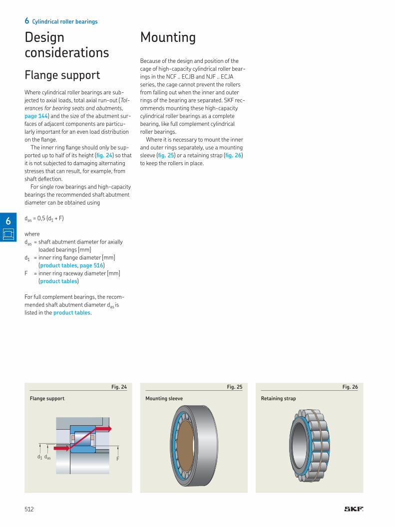
Fig. 25
Mounting sleeve
Fig. 26
Retaining strap
d1 Fdas
Fig. 24
Flange support
Design considerations
Flange support
Where cylindrical roller bearings are sub-
jected to axial loads, total axial run-out (Tol-
erances for bearing seats and abutments,
page 144) and the size of the abutment sur-
faces of adjacent components are particu-
larly important for an even load distribution
on the lange
The inner ring lange should only be sup-
ported up to half of its height (ig. 24) so that
it is not subjected to damaging alternating
stresses that can result, for example, from
shaft delection
For single row bearings and high-capacity
bearings the recommended shaft abutment
diameter can be obtained using
das = 0,5 (d1 + F)
where
das = shaft abutment diameter for axially
loaded bearings [mm]
d1 = inner ring lange diameter [mm]
(product tables, page 516)
F = inner ring raceway diameter [mm]
(product tables)
For full complement bearings, the recom-
mended shaft abutment diameter das is
listed in the product tables
Mounting
Because of the design and position of the
cage of high-capacity cylindrical roller bear-
ings in the NCF ECJB and NJF ECJA
series, the cage cannot prevent the rollers
from falling out when the inner and outer
rings of the bearing are separated SKF rec-
ommends mounting these high-capacity
cylindrical roller bearings as a complete
bearing, like full complement cylindrical
roller bearings
Where it is necessary to mount the inner
and outer rings separately, use a mounting
sleeve (ig. 25) or a retaining strap (ig. 26)
to keep the rollers in place
512
6
Mounting
513
6
Designation system
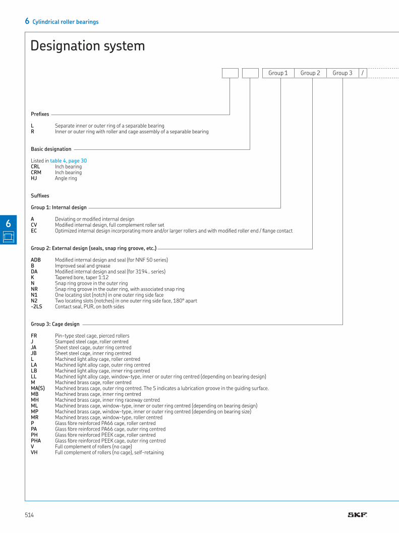
6 Cylindrical roller bearings
Designation system
Group 1 Group 2 Group 3 /
Preixes
L Separate inner or outer ring of a separable bearingR Inner or outer ring with roller and cage assembly of a separable bearing
Basic designation
Listed in table 4, page 30CRL Inch bearingCRM Inch bearingHJ Angle ring
Sufixes
Group 1: Internal design
A Deviating or modiied internal designCV Modiied internal design, full complement roller setEC Optimized internal design incorporating more and/or larger rollers and with modiied roller end / lange contact
Group 2: External design (seals, snap ring groove, etc.)
ADB Modiied internal design and seal (for NNF 50 series)B Improved seal and greaseDA Modiied internal design and seal (for 3194‥ series)K Tapered bore, taper 1:12 N Snap ring groove in the outer ringNR Snap ring groove in the outer ring, with associated snap ringN1 One locating slot (notch) in one outer ring side faceN2 Two locating slots (notches) in one outer ring side face, 180° apart-2LS Contact seal, PUR, on both sides
Group 3: Cage design
FR Pin-type steel cage, pierced rollers J Stamped steel cage, roller centredJA Sheet steel cage, outer ring centredJB Sheet steel cage, inner ring centredL Machined light alloy cage, roller centredLA Machined light alloy cage, outer ring centredLB Machined light alloy cage, inner ring centredLL Machined light alloy cage, window-type, inner or outer ring centred (depending on bearing design)M Machined brass cage, roller centred MA(S) Machined brass cage, outer ring centred. The S indicates a lubrication groove in the guiding surface.MB Machined brass cage, inner ring centred MH Machined brass cage, inner ring raceway centredML Machined brass cage, window-type, inner or outer ring centred (depending on bearing design) MP Machined brass cage, window-type, inner or outer ring centred (depending on bearing size) MR Machined brass cage, window-type, roller centred P Glass ibre reinforced PA66 cage, roller centredPA Glass ibre reinforced PA66 cage, outer ring centredPH Glass ibre reinforced PEEK cage, roller centredPHA Glass ibre reinforced PEEK cage, outer ring centredV Full complement of rollers (no cage)VH Full complement of rollers (no cage), self-retaining
514
6
Designation system
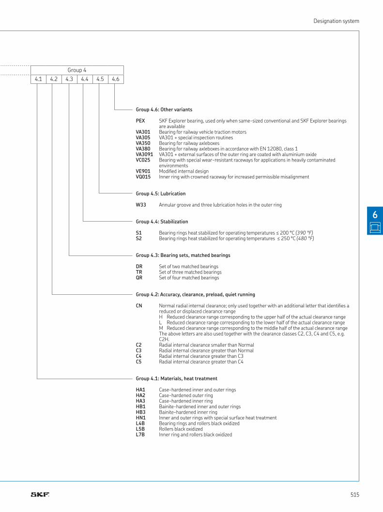
Group 4
4 1 4 2 4 3 4 4 4 5 4 6
Group 4.6: Other variants
PEX SKF Explorer bearing, used only when same-sized conventional and SKF Explorer bearings are available
VA301 Bearing for railway vehicle traction motors VA305 VA301 + special inspection routines VA350 Bearing for railway axleboxes VA380 Bearing for railway axleboxes in accordance with EN 12080, class 1 VA3091 VA301 + external surfaces of the outer ring are coated with aluminium oxide VC025 Bearing with special wear-resistant raceways for applications in heavily contaminated
environments VE901 Modiied internal designVQ015 Inner ring with crowned raceway for increased permissible misalignment
Group 4.5: Lubrication
W33 Annular groove and three lubrication holes in the outer ring
Group 4.4: Stabilization
S1 Bearing rings heat stabilized for operating temperatures ≤ 200 °C (390 °F)S2 Bearing rings heat stabilized for operating temperatures ≤ 250 °C (480 °F)
Group 4.3: Bearing sets, matched bearings
DR Set of two matched bearingsTR Set of three matched bearings QR Set of four matched bearings
Group 4.2: Accuracy, clearance, preload, quiet running
CN Normal radial internal clearance; only used together with an additional letter that identiies a reduced or displaced clearance rangeH Reduced clearance range corresponding to the upper half of the actual clearance rangeL Reduced clearance range corresponding to the lower half of the actual clearance rangeM Reduced clearance range corresponding to the middle half of the actual clearance rangeThe above letters are also used together with the clearance classes C2, C3, C4 and C5, e g C2H
C2 Radial internal clearance smaller than NormalC3 Radial internal clearance greater than NormalC4 Radial internal clearance greater than C3C5 Radial internal clearance greater than C4
Group 4.1: Materials, heat treatment
HA1 Case-hardened inner and outer ringsHA2 Case-hardened outer ringHA3 Case-hardened inner ring HB1 Bainite-hardened inner and outer rings HB3 Bainite-hardened inner ringHN1 Inner and outer rings with special surface heat treatment L4B Bearing rings and rollers black oxidizedL5B Rollers black oxidizedL7B Inner ring and rollers black oxidized
515
6
Product tablesproduct tables
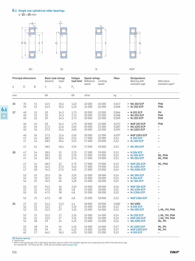
6.1 Single row cylindrical roller bearings
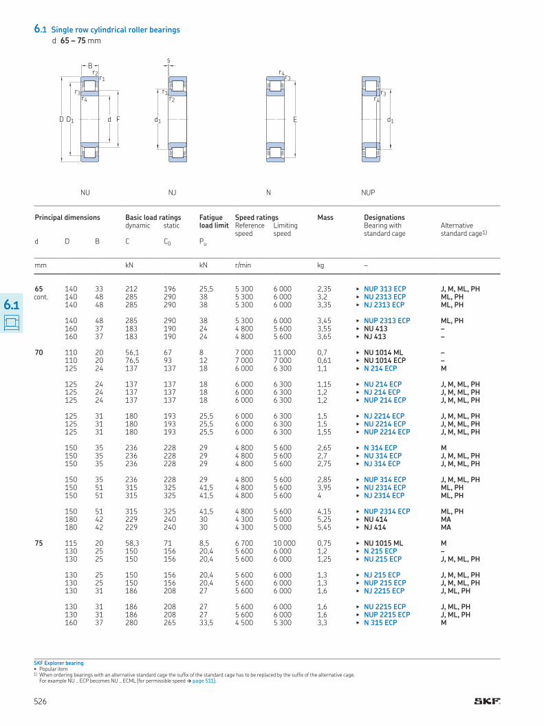
d 15 – 25 mm
NU NJ N NUP
SKF Explorer bearing▶ Popular item1) When ordering bearings with an alternative standard cage the sufix of the standard cage has to be replaced by the sufix of the alternative cage
For example NU ECP becomes NU ECML (for permissible speed † page 511)
Principal dimensions Basic load ratings Fatigue load limit
Speed ratings Mass Designations dynamic static Reference
speedLimiting speed
Bearing with standard cage
Alternative standard cage1)
d D B C C0 Pu
mm kN kN r/min kg –
15 35 11 12,5 10,2 1,22 22 000 26 000 0,047 ▶ NU 202 ECP PHA 35 11 12,5 10,2 1,22 22 000 26 000 0,048 ▶ NJ 202 ECP PHA 17 40 12 20 14,3 1,73 20 000 22 000 0,066 ▶ N 203 ECP PH 40 12 20 14,3 1,73 20 000 22 000 0,068 ▶ NU 203 ECP PHA 40 12 20 14,3 1,73 20 000 22 000 0,069 ▶ NJ 203 ECP PHA 40 12 20 14,3 1,73 20 000 22 000 0,072 ▶ NUP 203 ECP PHA 40 16 27,5 21,6 2,65 20 000 22 000 0,087 ▶ NU 2203 ECP – 40 16 27,5 21,6 2,65 20 000 22 000 0,093 ▶ NJ 2203 ECP – 40 16 27,5 21,6 2,65 20 000 22 000 0,097 ▶ NUP 2203 ECP – 47 14 28,5 20,4 2,55 17 000 20 000 0,12 N 303 ECP – 47 14 28,5 20,4 2,55 17 000 20 000 0,12 ▶ NJ 303 ECP – 47 14 28,5 20,4 2,55 17 000 20 000 0,12 ▶ NU 303 ECP – 20 47 14 28,5 22 2,75 17 000 19 000 0,11 ▶ N 204 ECP – 47 14 28,5 22 2,75 17 000 19 000 0,11 ▶ NJ 204 ECP ML, PHA 47 14 28,5 22 2,75 17 000 19 000 0,11 ▶ NU 204 ECP ML, PHA 47 14 28,5 22 2,75 17 000 19 000 0,12 ▶ NUP 204 ECP ML, PHA 47 18 34,5 27,5 3,45 17 000 19 000 0,14 ▶ NJ 2204 ECP – 47 18 34,5 27,5 3,45 17 000 19 000 0,14 ▶ NU 2204 ECP – 52 15 35,5 26 3,25 15 000 18 000 0,14 ▶ NU 304 ECP – 52 15 35,5 26 3,25 15 000 18 000 0,15 ▶ N 304 ECP – 52 15 35,5 26 3,25 15 000 18 000 0,15 ▶ NJ 304 ECP – 52 15 35,5 26 3,25 15 000 18 000 0,16 ▶ NUP 304 ECP – 52 21 47,5 38 4,8 15 000 18 000 0,21 ▶ NU 2304 ECP – 52 21 47,5 38 4,8 15 000 18 000 0,22 ▶ NJ 2304 ECP – 52 21 47,5 38 4,8 15 000 18 000 0,22 ▶ NUP 2304 ECP – 25 47 12 14,2 13,2 1,4 18 000 18 000 0,082 ▶ NU 1005 – 52 15 32,5 27 3,35 15 000 16 000 0,13 ▶ N 205 ECP – 52 15 32,5 27 3,35 15 000 16 000 0,13 ▶ NU 205 ECP J, ML, PH, PHA 52 15 32,5 27 3,35 15 000 16 000 0,14 ▶ NJ 205 ECP J, ML, PH, PHA 52 15 32,5 27 3,35 15 000 16 000 0,14 ▶ NUP 205 ECP J, ML, PH, PHA 52 18 39 34 4,25 15 000 16 000 0,16 ▶ NU 2205 ECP ML, PH 52 18 39 34 4,25 15 000 16 000 0,17 ▶ NJ 2205 ECP ML, PH 52 18 39 34 4,25 15 000 16 000 0,17 ▶ NUP 2205 ECP ML, PH 62 17 46,5 36,5 4,55 12 000 15 000 0,23 ▶ N 305 ECP –
D1D
B
d F
r1r2
r3r4
r3r4
E
r3r4
d1
s
r1r2
d1
516
6.1
product table
Dimensions Abutment and illet dimensions Calcu-lation factor
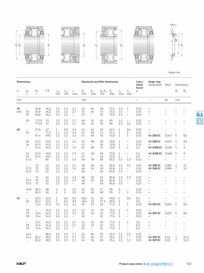
Angle ring Designation Mass Dimensions
d d1 D1 F, E r1,2 r3,4 s da da db, Da Da ra rb kr B1 B2≈ ≈ min min max min max min max max max
mm mm – – kg mm
15 – 27,7 19,3 0,6 0,3 1 17,4 18,4 21 31,3 0,6 0,3 0,15 – – – – 21,9 27,7 19,3 0,6 0,3 1 18,2 18,4 23 31,3 0,6 – 0,15 – – – – 17 25 – 35,1 0,6 0,3 1 20,7 33 37 37,1 0,6 0,3 0,12 – – – – – 32,35 22,1 0,6 0,3 1 19,9 21,1 24 36 0,6 0,3 0,15 – – – – 25 32,35 22,1 0,6 0,6 1 20,7 21,1 27 36 0,6 – 0,15 – – – – 25 32,35 22,1 0,6 0,3 – 20,7 – 27 36 0,6 – 0,15 – – – – – 32,35 22,1 0,6 0,3 1,5 19,9 21,1 24 36 0,6 0,3 0,2 – – – – 25 32,35 22,1 0,6 0,3 1,5 20,7 21,1 27 36 0,6 – 0,2 – – – – 25 32,35 22,1 0,6 0,3 – 20,7 – 27 36 0,6 – 0,2 – – – – 27,7 – 40,2 1 0,6 1 22,1 38 42 42,7 1 0,6 0,12 – – – – 27,7 36,75 24,2 1 0,6 1 22,1 23,1 29 41,7 1 – 0,15 – – – – – 36,75 24,2 1 0,6 1 21,1 23,1 26 41,7 1 0,6 0,15 – – – – 20 29,7 – 41,5 1 0,6 1 25 40 43 43,5 1 0,6 0,12 – – – – 29,7 38,44 26,5 1 0,6 1 25 25,4 31 41,7 1 – 0,15 – – – – – 38,44 26,5 1 0,6 1 24 25,4 28 41,7 1 0,6 0,15 – – – – 29,7 38,44 26,5 1 0,6 – 25 – 31 41,7 1 – 0,15 – – – – 29,7 38,3 26,5 1 0,6 2 25 25,4 31 41,7 1 – 0,2 – – – – – 38,3 26,5 1 0,6 2 24 25,4 28 41,7 1 0,6 0,2 – – – – – 41,85 27,5 1,1 0,6 0,9 24,1 26,2 29 45,4 1 0,6 0,15 HJ 304 EC 0,017 4 6,5 31,2 – 45,5 1,1 0,6 0,9 26,1 44 47 48 1 0,6 0,12 – – – – 31,2 41,85 27,5 1,1 0,6 0,9 26,1 26,2 33 45,4 1 – 0,15 HJ 304 EC 0,017 4 6,5 31,2 41,85 27,5 1,1 0,6 – 26,1 – 33 45,4 1 – 0,15 – – – – – 41,85 27,5 1,1 0,6 1,9 24,1 26,2 29 45,4 1 0,6 0,25 – – – – 31,2 41,85 27,5 1,1 0,6 1,9 26,1 26,2 33 45,4 1 – 0,25 – – – – 31,2 41,85 27,5 1,1 0,6 – 26,1 – 33 45,4 1 – 0,25 – – – – 25 – 38,8 30,5 0,6 0,3 1,5 27,1 29,5 32 43,1 0,6 0,3 0,1 – – – – 34,7 – 46,5 1 0,6 1,3 29,9 45 48 48,5 1 0,6 0,12 – – – – – 43,3 31,5 1 0,6 1,3 28,9 30,4 33 46,4 1 0,6 0,15 HJ 205 EC 0,015 3 6 34,7 43,3 31,5 1 0,6 1,3 29,9 30,4 36 46,4 1 – 0,15 – – – – 34,7 43,3 31,5 1 0,6 – 29,9 – 36 46,4 1 – 0,15 – – – – – 43,3 31,5 1 0,6 1,8 28,9 30,4 33 46,4 1 0,6 0,2 HJ 2205 EC 0,014 3 6,5 34,7 43,3 31,5 1 0,6 1,8 29,9 30,4 36 46,4 1 – 0,2 HJ 2205 EC 0,014 3 6,5 34,7 43,3 31,5 1 0,6 – 29,9 – 36 46,4 1 – 0,2 – – – – 38,1 – 54 1,1 1,1 1,3 31 52 56 56,4 1 1 0,12 – – – –
Product data online † skf.com/go/17000-6-1
Angle ring
Da da db
rb
ra
db
ra
Da
rb
da
ra
d d1
B1
B2
r4r3
517
6.1
6.1 Single row cylindrical roller bearings
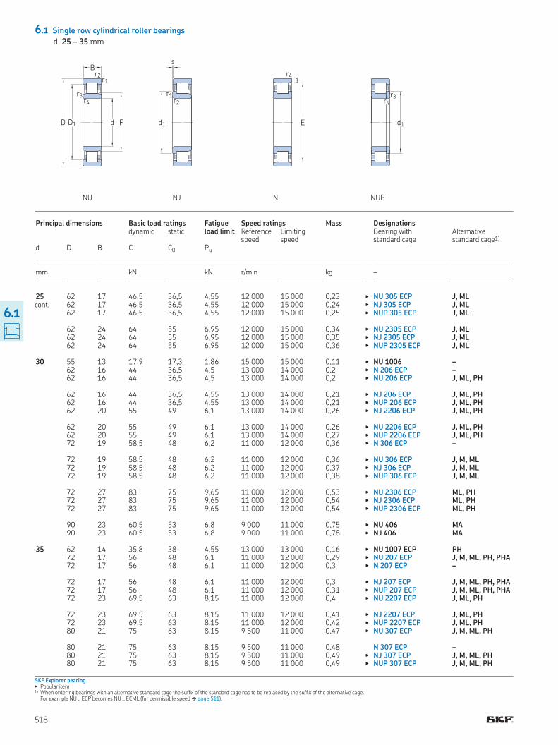
d 25 – 35 mm
cont
SKF Explorer bearing▶ Popular item1) When ordering bearings with an alternative standard cage the sufix of the standard cage has to be replaced by the sufix of the alternative cage
For example NU ECP becomes NU ECML (for permissible speed † page 511)
NU NJ N NUP
D1D
B
d F
r1r2
r3r4
s
r1r2
d1
r3r4
E
r3r4
d1
Principal dimensions Basic load ratings Fatigue load limit
Speed ratings Mass Designations dynamic static Reference
speedLimiting speed
Bearing with standard cage
Alternative standard cage1)
d D B C C0 Pu
mm kN kN r/min kg –
25 62 17 46,5 36,5 4,55 12 000 15 000 0,23 ▶ NU 305 ECP J, ML 62 17 46,5 36,5 4,55 12 000 15 000 0,24 ▶ NJ 305 ECP J, ML 62 17 46,5 36,5 4,55 12 000 15 000 0,25 ▶ NUP 305 ECP J, ML 62 24 64 55 6,95 12 000 15 000 0,34 ▶ NU 2305 ECP J, ML 62 24 64 55 6,95 12 000 15 000 0,35 ▶ NJ 2305 ECP J, ML 62 24 64 55 6,95 12 000 15 000 0,36 ▶ NUP 2305 ECP J, ML 30 55 13 17,9 17,3 1,86 15 000 15 000 0,11 ▶ NU 1006 – 62 16 44 36,5 4,5 13 000 14 000 0,2 ▶ N 206 ECP – 62 16 44 36,5 4,5 13 000 14 000 0,2 ▶ NU 206 ECP J, ML, PH 62 16 44 36,5 4,55 13 000 14 000 0,21 ▶ NJ 206 ECP J, ML, PH 62 16 44 36,5 4,55 13 000 14 000 0,21 ▶ NUP 206 ECP J, ML, PH 62 20 55 49 6,1 13 000 14 000 0,26 ▶ NJ 2206 ECP J, ML, PH 62 20 55 49 6,1 13 000 14 000 0,26 ▶ NU 2206 ECP J, ML, PH 62 20 55 49 6,1 13 000 14 000 0,27 ▶ NUP 2206 ECP J, ML, PH 72 19 58,5 48 6,2 11 000 12 000 0,36 ▶ N 306 ECP – 72 19 58,5 48 6,2 11 000 12 000 0,36 ▶ NU 306 ECP J, M, ML 72 19 58,5 48 6,2 11 000 12 000 0,37 ▶ NJ 306 ECP J, M, ML 72 19 58,5 48 6,2 11 000 12 000 0,38 ▶ NUP 306 ECP J, M, ML 72 27 83 75 9,65 11 000 12 000 0,53 ▶ NU 2306 ECP ML, PH 72 27 83 75 9,65 11 000 12 000 0,54 ▶ NJ 2306 ECP ML, PH 72 27 83 75 9,65 11 000 12 000 0,54 ▶ NUP 2306 ECP ML, PH 90 23 60,5 53 6,8 9 000 11 000 0,75 ▶ NU 406 MA 90 23 60,5 53 6,8 9 000 11 000 0,78 ▶ NJ 406 MA 35 62 14 35,8 38 4,55 13 000 13 000 0,16 ▶ NU 1007 ECP PH 72 17 56 48 6,1 11 000 12 000 0,29 ▶ NU 207 ECP J, M, ML, PH, PHA 72 17 56 48 6,1 11 000 12 000 0,3 ▶ N 207 ECP – 72 17 56 48 6,1 11 000 12 000 0,3 ▶ NJ 207 ECP J, M, ML, PH, PHA 72 17 56 48 6,1 11 000 12 000 0,31 ▶ NUP 207 ECP J, M, ML, PH, PHA 72 23 69,5 63 8,15 11 000 12 000 0,4 ▶ NU 2207 ECP J, ML, PH 72 23 69,5 63 8,15 11 000 12 000 0,41 ▶ NJ 2207 ECP J, ML, PH 72 23 69,5 63 8,15 11 000 12 000 0,42 ▶ NUP 2207 ECP J, ML, PH 80 21 75 63 8,15 9 500 11 000 0,47 ▶ NU 307 ECP J, M, ML, PH 80 21 75 63 8,15 9 500 11 000 0,48 N 307 ECP – 80 21 75 63 8,15 9 500 11 000 0,49 ▶ NJ 307 ECP J, M, ML, PH 80 21 75 63 8,15 9 500 11 000 0,49 ▶ NUP 307 ECP J, M, ML, PH
518
6.1
Product data online † skf.com/go/17000-6-1
cont
Angle ring
Da da db
rb
ra
db
ra
Da
rb
da
ra
d d1
B1
B2
r4r3
Dimensions Abutment and illet dimensions Calcu-lation factor
Angle ring Designation Mass Dimensions
d d1 D1 F, E r1,2 r3,4 s da da db, Da Da ra rb kr B1 B2≈ ≈ min min max min max min max max max
mm mm – – kg mm
25 – 50,15 34 1,1 1,1 1,3 31 32,5 36 54,9 1 1 0,15 HJ 305 EC 0,025 4 7 38,1 50,15 34 1,1 1,1 1,3 31 32,5 40 54,9 1 – 0,15 HJ 305 EC 0,025 4 7 38,1 50,15 34 1,1 1,1 – 31 – 40 54,9 1 – 0,15 – – – – – 50,15 34 1,1 1,1 2,3 31 32,5 36 54,9 1 1 0,25 HJ 2305 EC 0,023 4 8 38,1 50,15 34 1,1 1,1 2,3 31 32,5 40 54,9 1 – 0,25 HJ 2305 EC 0,023 4 8 38,1 50,15 34 1,1 1,1 – 31 – 40 54,9 1 – 0,25 – – – – 30 – 45,56 36,5 1 0,6 1,6 32,9 35,6 38 49,8 1 0,6 0,1 – – – – 41,2 – 55,5 1 0,6 1,3 35,3 54 57 58,1 1 0,6 0,12 – – – – – 51,95 37,5 1 0,6 1,3 34,3 36,1 39 55,9 1 0,6 0,15 HJ 206 EC 0,025 4 7 41,2 51,95 37,5 1 0,6 1,3 35,3 36,1 43 55,9 1 – 0,15 HJ 206 EC 0,025 4 7 41,2 51,95 37,5 1 0,6 – 35,3 – 43 55,9 1 – 0,15 – – – – 41,2 51,95 37,5 1 0,6 1,8 35,3 36,1 43 55,9 1 – 0,2 – – – – – 51,95 37,5 1 0,6 1,8 34,3 36,1 39 55,9 1 0,6 0,2 – – – – 41,2 51,95 37,5 1 0,6 – 35,3 – 43 55,9 1 – 0,2 – – – – 45 – 62,5 1,1 1,1 1,4 37 61 64 65,5 1 1 0,12 – – – – – 58,35 40,5 1,1 1,1 1,4 37 39 43 65,1 1 1 0,15 HJ 306 EC 0,042 5 8,5 45 58,35 40,5 1,1 1,1 1,4 37 39 47 65,1 1 – 0,15 HJ 306 EC 0,042 5 8,5 45 58,35 40,5 1,1 1,1 – 37 – 47 65,1 1 – 0,15 – – – – – 58,35 40,5 1,1 1,1 2,4 37 39 43 65,1 1 1 0,25 – – – – 45 58,35 40,5 1,1 1,1 2,4 37 39 47 65,1 1 – 0,25 – – – – 45 58,35 40,5 1,1 1,1 – 37 – 47 65,1 1 – 0,25 – – – – – 66,1 45 1,5 1,5 1,6 41 43 47 81 1,5 1,5 0,15 HJ 406 0,08 7 11,5 50,5 66,1 45 1,5 1,5 1,6 41 43 53 81 1,5 – 0,15 HJ 406 0,08 7 11,5 35 – 53,95 42 1 0,6 1 38 41 44 56,5 1 0,6 0,1 – – – – – 60,2 44 1,1 0,6 1,3 39,8 42,2 46 65,1 1 0,6 0,15 HJ 207 EC 0,033 4 7 48,1 – 64 1,1 0,6 1,3 41,8 62 66 67,2 1 0,6 0,12 – – – – 48,1 60,2 44 1,1 0,6 1,3 41,8 42,2 50 65,1 1 – 0,15 HJ 207 EC 0,033 4 7 48,1 60,2 44 1,1 0,6 – 41,8 – 50 65,1 1 – 0,15 – – – – – 60,2 44 1,1 0,6 2,8 39,8 42,2 46 65,1 1 0,6 0,2 – – – – 48,1 60,2 44 1,1 0,6 2,8 41,8 42,2 50 65,1 1 – 0,2 – – – – 48,1 60,2 44 1,1 0,6 – 42 – 50 65,1 1 – 0,2 – – – – – 65,8 46,2 1,5 1,1 1,2 42 44 48 72,2 1,5 1 0,15 HJ 307 EC 0,058 6 9,5 51 – 70,2 1,5 1,1 1,2 43 68 72 73,4 1,5 1 0,12 – – – – 51 65,8 46,2 1,5 1,1 1,2 43 44 53 72,2 1,5 – 0,15 HJ 307 EC 0,058 6 9,5 51 65,8 46,2 1,5 1,1 – 44 – 53 72,2 1,5 – 0,15 – – – –
519
6.1
6.1 Single row cylindrical roller bearings
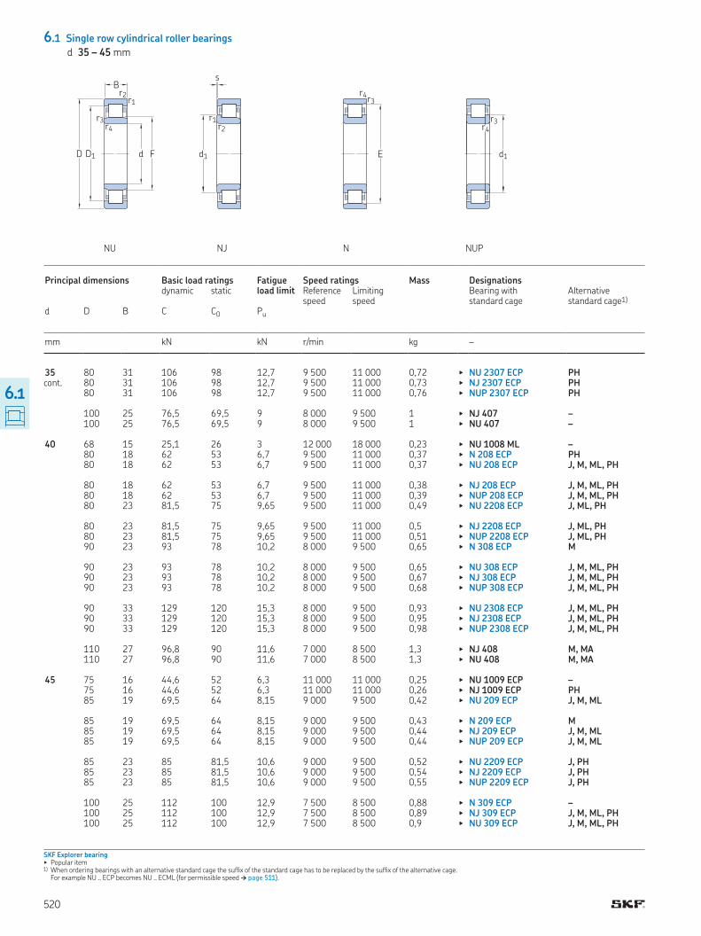
d 35 – 45 mm
cont
SKF Explorer bearing▶ Popular item1) When ordering bearings with an alternative standard cage the sufix of the standard cage has to be replaced by the sufix of the alternative cage
For example NU ECP becomes NU ECML (for permissible speed † page 511)
NU NJ N NUP
D1D
B
d F
r1r2
r3r4
s
r1r2
d1
r3r4
E
r3r4
d1
Principal dimensions Basic load ratings Fatigue load limit
Speed ratings Mass Designations dynamic static Reference
speedLimiting speed
Bearing with standard cage
Alternative standard cage1)
d D B C C0 Pu
mm kN kN r/min kg –
35 80 31 106 98 12,7 9 500 11 000 0,72 ▶ NU 2307 ECP PH 80 31 106 98 12,7 9 500 11 000 0,73 ▶ NJ 2307 ECP PH 80 31 106 98 12,7 9 500 11 000 0,76 ▶ NUP 2307 ECP PH 100 25 76,5 69,5 9 8 000 9 500 1 ▶ NJ 407 – 100 25 76,5 69,5 9 8 000 9 500 1 ▶ NU 407 – 40 68 15 25,1 26 3 12 000 18 000 0,23 ▶ NU 1008 ML – 80 18 62 53 6,7 9 500 11 000 0,37 ▶ N 208 ECP PH 80 18 62 53 6,7 9 500 11 000 0,37 ▶ NU 208 ECP J, M, ML, PH 80 18 62 53 6,7 9 500 11 000 0,38 ▶ NJ 208 ECP J, M, ML, PH 80 18 62 53 6,7 9 500 11 000 0,39 ▶ NUP 208 ECP J, M, ML, PH 80 23 81,5 75 9,65 9 500 11 000 0,49 ▶ NU 2208 ECP J, ML, PH 80 23 81,5 75 9,65 9 500 11 000 0,5 ▶ NJ 2208 ECP J, ML, PH 80 23 81,5 75 9,65 9 500 11 000 0,51 ▶ NUP 2208 ECP J, ML, PH 90 23 93 78 10,2 8 000 9 500 0,65 ▶ N 308 ECP M 90 23 93 78 10,2 8 000 9 500 0,65 ▶ NU 308 ECP J, M, ML, PH 90 23 93 78 10,2 8 000 9 500 0,67 ▶ NJ 308 ECP J, M, ML, PH 90 23 93 78 10,2 8 000 9 500 0,68 ▶ NUP 308 ECP J, M, ML, PH 90 33 129 120 15,3 8 000 9 500 0,93 ▶ NU 2308 ECP J, M, ML, PH 90 33 129 120 15,3 8 000 9 500 0,95 ▶ NJ 2308 ECP J, M, ML, PH 90 33 129 120 15,3 8 000 9 500 0,98 ▶ NUP 2308 ECP J, M, ML, PH 110 27 96,8 90 11,6 7 000 8 500 1,3 ▶ NJ 408 M, MA 110 27 96,8 90 11,6 7 000 8 500 1,3 ▶ NU 408 M, MA 45 75 16 44,6 52 6,3 11 000 11 000 0,25 ▶ NU 1009 ECP – 75 16 44,6 52 6,3 11 000 11 000 0,26 ▶ NJ 1009 ECP PH 85 19 69,5 64 8,15 9 000 9 500 0,42 ▶ NU 209 ECP J, M, ML 85 19 69,5 64 8,15 9 000 9 500 0,43 ▶ N 209 ECP M 85 19 69,5 64 8,15 9 000 9 500 0,44 ▶ NJ 209 ECP J, M, ML 85 19 69,5 64 8,15 9 000 9 500 0,44 ▶ NUP 209 ECP J, M, ML 85 23 85 81,5 10,6 9 000 9 500 0,52 ▶ NU 2209 ECP J, PH 85 23 85 81,5 10,6 9 000 9 500 0,54 ▶ NJ 2209 ECP J, PH 85 23 85 81,5 10,6 9 000 9 500 0,55 ▶ NUP 2209 ECP J, PH 100 25 112 100 12,9 7 500 8 500 0,88 ▶ N 309 ECP – 100 25 112 100 12,9 7 500 8 500 0,89 ▶ NJ 309 ECP J, M, ML, PH 100 25 112 100 12,9 7 500 8 500 0,9 ▶ NU 309 ECP J, M, ML, PH
520
6.1
Product data online † skf.com/go/17000-6-1
cont
Angle ring
Da da db
rb
ra
db
ra
Da
rb
da
ra
d d1
B1
B2
r4r3
Dimensions Abutment and illet dimensions Calcu-lation factor
Angle ring Designation Mass Dimensions
d d1 D1 F, E r1,2 r3,4 s da da db, Da Da ra rb kr B1 B2≈ ≈ min min max min max min max max max
mm mm – – kg mm
35 – 65,8 46,2 1,5 1,1 2,7 42 44 48 72,2 1,5 1 0,25 – – – – 51 65,8 46,2 1,5 1,1 2,7 43 44 53 72,2 1,5 – 0,25 – – – – 51 65,8 46,2 1,5 1,1 – 43 – 53 72,2 1,5 – 0,25 – – – – 59 77,15 53 1,5 1,5 1,7 48 51 61 90 1,5 – 0,15 – – – – – 77,15 53 1,5 1,5 1,7 48 51 55 90 1,5 1,5 0,15 – – – – 40 – 57,6 47 1 0,6 2,4 43 46 49 62,3 1 0,6 0,15 – – – – 54 – 71,5 1,1 1,1 1,4 47 69 73 74,1 1 1 0,12 – – – – – 67,4 49,5 1,1 1,1 1,4 47 48 51 72,8 1 1 0,15 HJ 208 EC 0,047 5 8,5 54 67,4 49,5 1,1 1,1 1,4 47 48 56 72,8 1 – 0,15 HJ 208 EC 0,047 5 8,5 54 67,4 49,5 1,1 1,1 – 47 – 56 72,8 1 – 0,15 – – – – – 67,4 49,5 1,1 1,1 1,9 47 48 51 72,8 1 1 0,2 HJ 2208 EC 0,048 5 9 54 67,4 49,5 1,1 1,1 1,9 47 48 56 72,8 1 – 0,2 HJ 2208 EC 0,048 5 9 54 67,4 49,5 1,1 1,1 – 47 – 56 72,8 1 – 0,2 – – – – 57,5 – 80 1,5 1,5 1,4 48 78 82 83,2 1,5 1,5 0,12 – – – – – 75 52 1,5 1,5 1,4 48 50 54 81,8 1,5 1,5 0,15 HJ 308 EC 0,084 7 11 57,5 75 52 1,5 1,5 1,4 48 50 60 81,8 1,5 – 0,15 HJ 308 EC 0,084 7 11 57,5 75 52 1,5 1,5 – 48 – 60 81,8 1,5 – 0,15 – – – – – 75 52 1,5 1,5 2,9 48 50 54 81,8 1,5 1,5 0,25 – – – – 57,5 75 52 1,5 1,5 2,9 48 50 60 81,8 1,5 – 0,25 – – – – 57,5 75 52 1,5 1,5 – 48 – 60 81,8 1,5 – 0,25 – – – – 64,8 85,3 58 2 2 2,5 52 56 67 99 2 – 0,15 – – – – – 85,3 58 2 2 2,5 52 56 60 99 2 2 0,15 – – – – 45 – 65,3 52,5 1 0,6 0,9 48,4 51 54 69,8 1 0,6 0,1 – – – – 56 65,3 52,5 1 0,6 0,9 48,4 51 57,5 69,8 1 – 0,1 – – – – – 72,4 54,5 1,1 1,1 1,2 52 53 56 77,6 1 1 0,15 HJ 209 EC 0,052 5 8,5 59 – 76,5 1,1 1,1 1,2 52 74 78 79,1 1 1 0,12 – – – – 59 72,4 54,5 1,1 1,1 1,2 52 53 61 77,6 1 – 0,15 HJ 209 EC 0,052 5 8,5 59 72,4 54,5 1,1 1,1 – 52 – 61 77,6 1 – 0,15 – – – – – 72,4 54,5 1,1 1,1 1,7 52 53 56 77,6 1 1 0,2 – – – – 59 72,4 54,5 1,1 1,1 1,7 52 53 61 77,6 1 – 0,2 – – – – 59 72,4 54,5 1,1 1,1 – 52 – 61 77,6 1 – 0,2 – – – – 64,4 – 88,5 1,5 1,5 1,7 54 86 91 92,3 1,5 1,5 0,12 – – – – 64,4 83,2 58,5 1,5 1,5 1,7 54 56 67 91,4 1,5 – 0,15 HJ 309 EC 0,11 7 11,5 – 83,2 58,5 1,5 1,5 1,7 54 56 60 91,4 1,5 1,5 0,15 HJ 309 EC 0,11 7 11,5
521
6.1
product table p522
Single row cylindrical roller
bearings
6.1 Single row cylindrical roller bearings
d 45 – 55 mm
cont.
SKF Explorer bearing▶ Popular item1) When ordering bearings with an alternative standard cage the sufix of the standard cage has to be replaced by the sufix of the alternative cage
For example NU ECP becomes NU ECML (for permissible speed † page 511)
NU NJ N NUP
6.1
D1D
B
d F
r1r2
r3r4
s
r1r2
d1
r3r4
E
r3r4
d1
Principal dimensions Basic load ratings Fatigue load limit
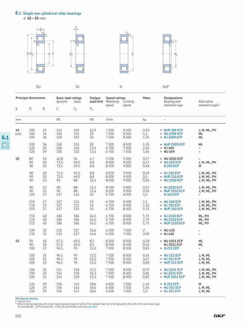
Speed ratings Mass Designations dynamic static Reference
speedLimiting speed
Bearing with standard cage
Alternative standard cage1)
d D B C C0 Pu
mm kN kN r/min kg –
45 100 25 112 100 12,9 7 500 8 500 0,93 ▶ NUP 309 ECP J, M, ML, PH 100 36 160 153 20 7 500 8 500 1,3 ▶ NU 2309 ECP ML 100 36 160 153 20 7 500 8 500 1,35 ▶ NJ 2309 ECP ML 100 36 160 153 20 7 500 8 500 1,35 ▶ NUP 2309 ECP ML 120 29 106 102 13,4 6 700 7 500 1,65 ▶ NJ 409 – 120 29 106 102 13,4 6 700 7 500 1,65 ▶ NU 409 – 50 80 16 46,8 56 6,7 9 500 9 500 0,27 ▶ NU 1010 ECP – 90 20 73,5 69,5 8,8 8 500 9 000 0,47 ▶ NU 210 ECP J, M, ML, PH 90 20 73,5 69,5 8,8 8 500 9 000 0,48 N 210 ECP M 90 20 73,5 69,5 8,8 8 500 9 000 0,49 ▶ NJ 210 ECP J, M, ML, PH 90 20 73,5 69,5 8,8 8 500 9 000 0,5 ▶ NUP 210 ECP J, M, ML, PH 90 23 90 88 11,4 8 500 9 000 0,56 ▶ NU 2210 ECP J, M, ML, PH 90 23 90 88 11,4 8 500 9 000 0,57 ▶ NJ 2210 ECP J, M, ML, PH 90 23 90 88 11,4 8 500 9 000 0,59 ▶ NUP 2210 ECP J, M, ML, PH 110 27 127 112 15 6 700 8 000 1,1 N 310 ECP – 110 27 127 112 15 6 700 8 000 1,1 ▶ NU 310 ECP J, M, ML, PH 110 27 127 112 15 6 700 8 000 1,15 ▶ NJ 310 ECP J, M, ML, PH 110 27 127 112 15 6 700 8 000 1,15 ▶ NUP 310 ECP J, M, ML, PH 110 40 186 186 24,5 6 700 8 000 1,75 ▶ NJ 2310 ECP ML, PH 110 40 186 186 24,5 6 700 8 000 1,75 ▶ NU 2310 ECP ML, PH 110 40 186 186 24,5 6 700 8 000 1,75 ▶ NUP 2310 ECP ML, PH 130 31 130 127 16,6 6 000 7 000 2 ▶ NU 410 – 130 31 130 127 16,6 6 000 7 000 2,05 ▶ NJ 410 – 55 90 18 57,2 69,5 8,3 8 500 8 500 0,39 ▶ NU 1011 ECP ML 90 18 57,2 69,5 8,3 8 500 8 500 0,42 NJ 1011 ECP ML 100 21 96,5 95 12,2 7 500 8 000 0,65 ▶ N 211 ECP – 100 21 96,5 95 12,2 7 500 8 000 0,66 ▶ NU 211 ECP J, M, ML 100 21 96,5 95 12,2 7 500 8 000 0,67 ▶ NJ 211 ECP J, M, ML 100 21 96,5 95 12,2 7 500 8 000 0,68 ▶ NUP 211 ECP J, M, ML 100 25 114 118 15,3 7 500 8 000 0,79 ▶ NU 2211 ECP J, M, ML, PH 100 25 114 118 15,3 7 500 8 000 0,81 ▶ NJ 2211 ECP J, M, ML, PH 100 25 114 118 15,3 7 500 8 000 0,82 ▶ NUP 2211 ECP J, M, ML, PH 120 29 156 143 18,6 6 000 7 000 1,45 ▶ N 311 ECP M 120 29 156 143 18,6 6 000 7 000 1,45 ▶ NU 311 ECP J, M, ML 120 29 156 143 18,6 6 000 7 000 1,5 ▶ NJ 311 ECP J, M, ML
522
Product data online † skf.com/go/17000-6-1
6.1cont
Angle ring
Da da db
rb
ra
db
ra
Da
rb
da
ra
d d1
B1
B2
r4r3
Dimensions Abutment and illet dimensions Calcu-lation factor
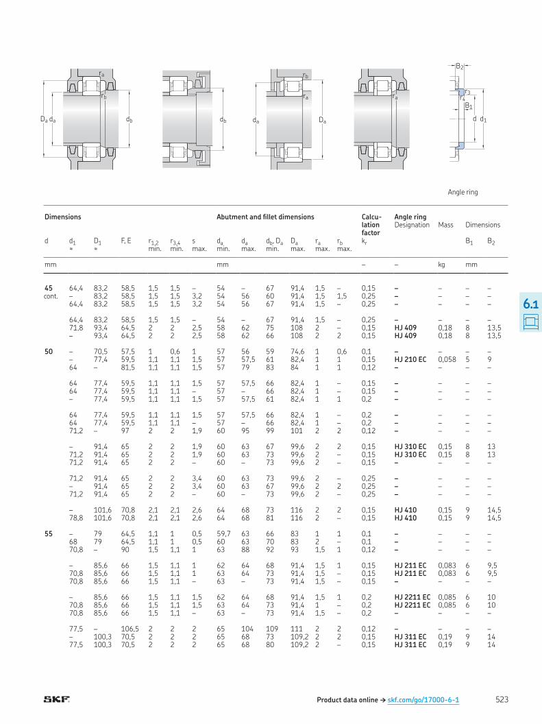
Angle ring Designation Mass Dimensions
d d1 D1 F, E r1,2 r3,4 s da da db, Da Da ra rb kr B1 B2≈ ≈ min min max min max min max max max
mm mm – – kg mm
45 64,4 83,2 58,5 1,5 1,5 – 54 – 67 91,4 1,5 – 0,15 – – – – – 83,2 58,5 1,5 1,5 3,2 54 56 60 91,4 1,5 1,5 0,25 – – – – 64,4 83,2 58,5 1,5 1,5 3,2 54 56 67 91,4 1,5 – 0,25 – – – – 64,4 83,2 58,5 1,5 1,5 – 54 – 67 91,4 1,5 – 0,25 – – – – 71,8 93,4 64,5 2 2 2,5 58 62 75 108 2 – 0,15 HJ 409 0,18 8 13,5 – 93,4 64,5 2 2 2,5 58 62 66 108 2 2 0,15 HJ 409 0,18 8 13,5 50 – 70,5 57,5 1 0,6 1 57 56 59 74,6 1 0,6 0,1 – – – – – 77,4 59,5 1,1 1,1 1,5 57 57,5 61 82,4 1 1 0,15 HJ 210 EC 0,058 5 9 64 – 81,5 1,1 1,1 1,5 57 79 83 84 1 1 0,12 – – – – 64 77,4 59,5 1,1 1,1 1,5 57 57,5 66 82,4 1 – 0,15 – – – – 64 77,4 59,5 1,1 1,1 – 57 – 66 82,4 1 – 0,15 – – – – – 77,4 59,5 1,1 1,1 1,5 57 57,5 61 82,4 1 1 0,2 – – – – 64 77,4 59,5 1,1 1,1 1,5 57 57,5 66 82,4 1 – 0,2 – – – – 64 77,4 59,5 1,1 1,1 – 57 – 66 82,4 1 – 0,2 – – – – 71,2 – 97 2 2 1,9 60 95 99 101 2 2 0,12 – – – – – 91,4 65 2 2 1,9 60 63 67 99,6 2 2 0,15 HJ 310 EC 0,15 8 13 71,2 91,4 65 2 2 1,9 60 63 73 99,6 2 – 0,15 HJ 310 EC 0,15 8 13 71,2 91,4 65 2 2 – 60 – 73 99,6 2 – 0,15 – – – – 71,2 91,4 65 2 2 3,4 60 63 73 99,6 2 – 0,25 – – – – – 91,4 65 2 2 3,4 60 63 67 99,6 2 2 0,25 – – – – 71,2 91,4 65 2 2 – 60 – 73 99,6 2 – 0,25 – – – – – 101,6 70,8 2,1 2,1 2,6 64 68 73 116 2 2 0,15 HJ 410 0,15 9 14,5 78,8 101,6 70,8 2,1 2,1 2,6 64 68 81 116 2 – 0,15 HJ 410 0,15 9 14,5 55 – 79 64,5 1,1 1 0,5 59,7 63 66 83 1 1 0,1 – – – – 68 79 64,5 1,1 1 0,5 60 63 70 83 2 – 0,1 – – – – 70,8 – 90 1,5 1,1 1 63 88 92 93 1,5 1 0,12 – – – – – 85,6 66 1,5 1,1 1 62 64 68 91,4 1,5 1 0,15 HJ 211 EC 0,083 6 9,5 70,8 85,6 66 1,5 1,1 1 63 64 73 91,4 1,5 – 0,15 HJ 211 EC 0,083 6 9,5 70,8 85,6 66 1,5 1,1 – 63 – 73 91,4 1,5 – 0,15 – – – – – 85,6 66 1,5 1,1 1,5 62 64 68 91,4 1,5 1 0,2 HJ 2211 EC 0,085 6 10 70,8 85,6 66 1,5 1,1 1,5 63 64 73 91,4 1 – 0,2 HJ 2211 EC 0,085 6 10 70,8 85,6 66 1,5 1,1 – 63 – 73 91,4 1,5 – 0,2 – – – – 77,5 – 106,5 2 2 2 65 104 109 111 2 2 0,12 – – – – – 100,3 70,5 2 2 2 65 68 73 109,2 2 2 0,15 HJ 311 EC 0,19 9 14 77,5 100,3 70,5 2 2 2 65 68 80 109,2 2 – 0,15 HJ 311 EC 0,19 9 14
523

6.1 Single row cylindrical roller bearings
d 55 – 65 mm
cont
SKF Explorer bearing▶ Popular item1) When ordering bearings with an alternative standard cage the sufix of the standard cage has to be replaced by the sufix of the alternative cage
For example NU ECP becomes NU ECML (for permissible speed † page 511)
NU NJ N NUP
D1D
B
d F
r1r2
r3r4
s
r1r2
d1
r3r4
E
r3r4
d1
Principal dimensions Basic load ratings Fatigue load limit
Speed ratings Mass Designations dynamic static Reference
speedLimiting speed
Bearing with standard cage
Alternative standard cage1)
d D B C C0 Pu
mm kN kN r/min kg –
55 120 29 156 143 18,6 6 000 7 000 1,5 ▶ NUP 311 ECP J, M, ML 120 43 232 232 30,5 6 000 7 000 2,25 ▶ NJ 2311 ECP ML, PH 120 43 232 232 30,5 6 000 7 000 2,25 ▶ NU 2311 ECP ML, PH 120 43 232 232 30,5 6 000 7 000 2,3 ▶ NUP 2311 ECP ML, PH 140 33 142 140 18,6 5 600 6 300 2,5 ▶ NU 411 – 140 33 142 140 18,6 5 600 6 300 2,55 NJ 411 – 60 95 18 37,4 44 5,3 8 000 13 000 0,5 ▶ NU 1012 ML – 110 22 108 102 13,4 6 700 7 500 0,79 ▶ N 212 ECP M 110 22 108 102 13,4 6 700 7 500 0,8 ▶ NU 212 ECP J, M, ML 110 22 108 102 13,4 6 700 7 500 0,82 ▶ NJ 212 ECP J, M, ML 110 22 108 102 13,4 6 700 7 500 0,86 ▶ NUP 212 ECP J, M, ML 110 28 146 153 20 6 700 7 500 1,05 ▶ NU 2212 ECP J, M, ML, PH 110 28 146 153 20 6 700 7 500 1,1 ▶ NJ 2212 ECP J, M, ML, PH 110 28 146 153 20 6 700 7 500 1,1 ▶ NUP 2212 ECP J, M, ML, PH 130 31 173 160 21,2 5 600 6 700 1,75 ▶ N 312 ECP J, M 130 31 173 160 21,2 5 600 6 700 1,75 ▶ NU 312 ECP J, M, ML, PH 130 31 173 160 21,2 5 600 6 700 1,85 ▶ NJ 312 ECP J, M, ML, PH 130 31 173 160 21,2 5 600 6 700 1,9 ▶ NUP 312 ECP J, M, ML, PH 130 46 260 265 34,5 5 600 6 700 2,75 ▶ NU 2312 ECP M, ML, PH 130 46 260 265 34,5 5 600 6 700 2,8 ▶ NJ 2312 ECP M, ML, PH 130 46 260 265 34,5 5 600 6 700 2,85 ▶ NUP 2312 ECP M, ML, PH 150 35 168 173 22 5 000 6 000 3 ▶ NU 412 – 150 35 168 173 22 5 000 6 000 3,05 ▶ NJ 412 – 65 100 18 38 46,5 5,5 7 500 12 000 0,51 ▶ NU 1013 ML – 100 18 62,7 81,5 9,8 7 500 7 500 0,45 ▶ NU 1013 ECP PH 120 23 122 118 15,6 6 300 6 700 1 ▶ NU 213 ECP J, M, ML, PH 120 23 122 118 15,6 6 300 6 700 1,05 ▶ N 213 ECP – 120 23 122 118 15,6 6 300 6 700 1,05 ▶ NJ 213 ECP J, M, ML, PH 120 23 122 118 15,6 6 300 6 700 1,05 ▶ NUP 213 ECP J, M, ML, PH 120 31 170 180 24 6 300 6 700 1,4 ▶ NU 2213 ECP J, ML, PH 120 31 170 180 24 6 300 6 700 1,45 ▶ NJ 2213 ECP J, ML, PH 120 31 170 180 24 6 300 6 700 1,45 ▶ NUP 2213 ECP J, ML, PH 140 33 212 196 25,5 5 300 6 000 2,2 ▶ N 313 ECP M 140 33 212 196 25,5 5 300 6 000 2,2 ▶ NU 313 ECP J, M, ML, PH 140 33 212 196 25,5 5 300 6 000 2,3 ▶ NJ 313 ECP J, M, ML, PH
524
6.1
Product data online † skf.com/go/17000-6-1Product data online † skf.com/go/17000-6-1
cont
Angle ring
Da da db
rb
ra
db
ra
Da
rb
da
ra
d d1
B1
B2
r4r3
Dimensions Abutment and illet dimensions Calcu-lation factor
Angle ring Designation Mass Dimensions
d d1 D1 F, E r1,2 r3,4 s da da db, Da Da ra rb kr B1 B2≈ ≈ min min max min max min max max max
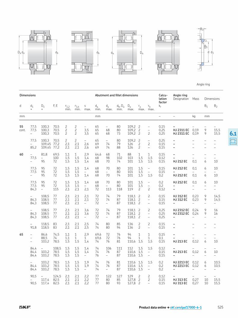
mm mm – – kg mm
55 77,5 100,3 70,5 2 2 – 65 – 80 109,2 2 – 0,15 – – – – 77,5 100,3 70,5 2 2 3,5 65 68 80 109,2 2 – 0,25 HJ 2311 EC 0,19 9 15,5 – 100,3 70,5 2 2 3,5 65 68 73 109,2 2 2 0,25 HJ 2311 EC 0,19 9 15,5 77,5 100,3 70,5 2 2 – 65 – 80 109,2 2 – 0,25 – – – – – 109,45 77,2 2,1 2,1 2,6 69 74 79 126 2 2 0,15 – – – – 85,2 109,45 77,2 2,1 2,1 2,6 69 74 88 126 2 – 0,15 – – – – 60 – 81,8 69,5 1,1 1 2,9 64,6 68 71 88 1 1 0,15 – – – – 77,5 – 100 1,5 1,5 1,4 68 98 102 103 1,5 1,5 0,12 – – – – – 95 72 1,5 1,5 1,4 68 70 74 101 1,5 1,5 0,15 HJ 212 EC 0,1 6 10 77,5 95 72 1,5 1,5 1,4 68 70 80 101 1,5 – 0,15 HJ 212 EC 0,1 6 10 77,5 95 72 1,5 1,5 – 68 – 80 101 1,5 – 0,15 – – – – – 95 72 1,5 1,5 1,4 68 70 74 101 1,5 1,5 0,2 HJ 212 EC 0,1 6 10 77,5 95 72 1,5 1,5 1,4 68 70 80 101 1,5 – 0,2 HJ 212 EC 0,1 6 10 77,5 95 72 1,5 1,5 – 68 – 80 101 1,5 – 0,2 – – – – 84,3 – 115 2,1 2,1 2,1 72 113 118 119 2 2 0,12 – – – – – 108,5 77 2,1 2,1 2,1 72 74 79 118,1 2 2 0,15 HJ 312 EC 0,23 9 14,5 84,3 108,5 77 2,1 2,1 2,1 72 74 87 118,1 2 – 0,15 HJ 312 EC 0,23 9 14,5 84,3 108,5 77 2,1 2,1 – 72 – 87 118,1 2 – 0,15 – – – – – 108,5 77 2,1 2,1 3,6 72 74 79 118,1 2 2 0,25 HJ 2312 EC 0,24 9 16 84,3 108,5 77 2,1 2,1 3,6 72 74 87 118,1 2 – 0,25 HJ 2312 EC 0,24 9 16 84,3 108,5 77 2,1 2,1 – 72 – 87 118,1 2 – 0,25 – – – – – 118,5 83 2,1 2,1 2,5 74 80 85 136 2 2 0,15 – – – – 91,8 118,5 83 2,1 2,1 2,5 74 80 94 136 2 – 0,15 – – – – 65 – 86,6 74,5 1,1 1 2,9 69,6 72 76 94 1 1 0,15 – – – – – 88,5 74 1,1 1 1 69,6 72 76 94 1 1 0,1 – – – – – 103,2 78,5 1,5 1,5 1,4 74 76 81 110,6 1,5 1,5 0,15 HJ 213 EC 0,12 6 10 84,4 – 108,5 1,5 1,5 1,4 74 106 111 112 1,5 1,5 0,12 – – – – 84,4 103,2 78,5 1,5 1,5 1,4 74 76 87 110,6 1,5 – 0,15 HJ 213 EC 0,12 6 10 84,4 103,2 78,5 1,5 1,5 – 76 – 87 110,6 1,5 – 0,15 – – – – – 103,2 78,5 1,5 1,5 1,9 74 76 81 110,6 1,5 1,5 0,2 HJ 2213 EC 0,12 6 10,5 84,4 103,2 78,5 1,5 1,5 1,9 74 76 87 110,6 1,5 – 0,2 HJ 2213 EC 0,12 6 10,5 84,4 103,2 78,5 1,5 1,5 – 74 – 87 110,6 1,5 – 0,2 – – – – 90,5 – 124,5 2,1 2,1 2,2 77 122 127 129 2 2 0,12 – – – – – 117,4 82,5 2,1 2,1 2,2 77 80 85 127,8 2 2 0,15 HJ 313 EC 0,27 10 15,5 90,5 117,4 82,5 2,1 2,1 2,2 77 80 93 127,8 2 – 0,15 HJ 313 EC 0,27 10 15,5
525
6.1
6.1 Single row cylindrical roller bearings
d 65 – 75 mm
cont
SKF Explorer bearing▶ Popular item1) When ordering bearings with an alternative standard cage the sufix of the standard cage has to be replaced by the sufix of the alternative cage
For example NU ECP becomes NU ECML (for permissible speed † page 511)
NU NJ N NUP
D1D
B
d F
r1r2
r3r4
s
r1r2
d1
r3r4
E
r3r4
d1
Principal dimensions Basic load ratings Fatigue load limit
Speed ratings Mass Designations dynamic static Reference
speedLimiting speed
Bearing with standard cage
Alternative standard cage1)
d D B C C0 Pu
mm kN kN r/min kg –
65 140 33 212 196 25,5 5 300 6 000 2,35 ▶ NUP 313 ECP J, M, ML, PH 140 48 285 290 38 5 300 6 000 3,2 ▶ NU 2313 ECP ML, PH 140 48 285 290 38 5 300 6 000 3,35 ▶ NJ 2313 ECP ML, PH 140 48 285 290 38 5 300 6 000 3,45 ▶ NUP 2313 ECP ML, PH 160 37 183 190 24 4 800 5 600 3,55 ▶ NU 413 – 160 37 183 190 24 4 800 5 600 3,65 ▶ NJ 413 – 70 110 20 56,1 67 8 7 000 11 000 0,7 ▶ NU 1014 ML – 110 20 76,5 93 12 7 000 7 000 0,61 ▶ NU 1014 ECP – 125 24 137 137 18 6 000 6 300 1,1 ▶ N 214 ECP M 125 24 137 137 18 6 000 6 300 1,15 ▶ NU 214 ECP J, M, ML, PH 125 24 137 137 18 6 000 6 300 1,2 ▶ NJ 214 ECP J, M, ML, PH 125 24 137 137 18 6 000 6 300 1,2 ▶ NUP 214 ECP J, M, ML, PH 125 31 180 193 25,5 6 000 6 300 1,5 ▶ NJ 2214 ECP J, M, ML, PH 125 31 180 193 25,5 6 000 6 300 1,5 ▶ NU 2214 ECP J, M, ML, PH 125 31 180 193 25,5 6 000 6 300 1,55 ▶ NUP 2214 ECP J, M, ML, PH 150 35 236 228 29 4 800 5 600 2,65 ▶ N 314 ECP M 150 35 236 228 29 4 800 5 600 2,7 ▶ NU 314 ECP J, M, ML, PH 150 35 236 228 29 4 800 5 600 2,75 ▶ NJ 314 ECP J, M, ML, PH 150 35 236 228 29 4 800 5 600 2,85 ▶ NUP 314 ECP J, M, ML, PH 150 51 315 325 41,5 4 800 5 600 3,95 ▶ NU 2314 ECP ML, PH 150 51 315 325 41,5 4 800 5 600 4 ▶ NJ 2314 ECP ML, PH 150 51 315 325 41,5 4 800 5 600 4,15 ▶ NUP 2314 ECP ML, PH 180 42 229 240 30 4 300 5 000 5,25 ▶ NU 414 MA 180 42 229 240 30 4 300 5 000 5,45 ▶ NJ 414 MA 75 115 20 58,3 71 8,5 6 700 10 000 0,75 ▶ NU 1015 ML M 130 25 150 156 20,4 5 600 6 000 1,2 ▶ N 215 ECP – 130 25 150 156 20,4 5 600 6 000 1,25 ▶ NU 215 ECP J, M, ML, PH 130 25 150 156 20,4 5 600 6 000 1,3 ▶ NJ 215 ECP J, M, ML, PH 130 25 150 156 20,4 5 600 6 000 1,3 ▶ NUP 215 ECP J, M, ML, PH 130 31 186 208 27 5 600 6 000 1,6 ▶ NJ 2215 ECP J, ML, PH 130 31 186 208 27 5 600 6 000 1,6 ▶ NU 2215 ECP J, ML, PH 130 31 186 208 27 5 600 6 000 1,6 ▶ NUP 2215 ECP J, ML, PH 160 37 280 265 33,5 4 500 5 300 3,3 ▶ N 315 ECP M
526
6.1
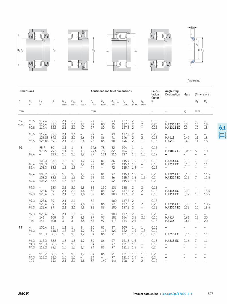
Product data online † skf.com/go/17000-6-1
cont
Angle ring
Da da db
rb
ra
db
ra
Da
rb
da
ra
d d1
B1
B2
r4r3
Dimensions Abutment and illet dimensions Calcu-lation factor
Angle ring Designation Mass Dimensions
d d1 D1 F, E r1,2 r3,4 s da da db, Da Da ra rb kr B1 B2≈ ≈ min min max min max min max max max
mm mm – – kg mm
65 90,5 117,4 82,5 2,1 2,1 – 77 – 93 127,8 2 – 0,15 – – – – – 117,4 82,5 2,1 2,1 4,7 77 80 85 127,8 2 2 0,25 HJ 2313 EC 0,3 10 18 90,5 117,4 82,5 2,1 2,1 4,7 77 80 93 127,8 2 – 0,25 HJ 2313 EC 0,3 10 18 90,5 117,4 82,5 2,1 2,1 – 77 – 93 127,8 2 – 0,25 – – – – – 126,85 89,3 2,1 2,1 2,6 78 86 91 146 2 2 0,15 HJ 413 0,42 11 18 98,5 126,85 89,3 2,1 2,1 2,6 78 86 101 146 2 – 0,15 HJ 413 0,42 11 18 70 – 95,7 80 1,1 1 3 74,6 78 82 104 1 1 0,15 – – – – – 97,55 79,5 1,1 1 1,3 74,6 78 82 104 1 1 0,1 HJ 1014 EC 0,082 5 10 89,4 – 113,5 1,5 1,5 1,2 79 111 116 117 1,5 1,5 0,12 – – – – – 108,3 83,5 1,5 1,5 1,2 79 81 86 115,4 1,5 1,5 0,15 HJ 214 EC 0,15 7 11 89,4 108,3 83,5 1,5 1,5 1,2 79 81 92 115,4 1,5 – 0,15 HJ 214 EC 0,15 7 11 89,4 108,3 83,5 1,5 1,5 – 79 – 92 115,4 1,5 – 0,15 – – – – 89,4 108,2 83,5 1,5 1,5 1,7 79 81 92 115,4 1,5 – 0,2 HJ 2214 EC 0,15 7 11,5 – 108,2 83,5 1,5 1,5 1,7 79 81 86 115,4 1,5 1,5 0,2 HJ 2214 EC 0,15 7 11,5 89,4 108,2 83,5 1,5 1,5 – 79 – 92 115,4 1,5 – 0,2 – – – – 97,3 – 133 2,1 2,1 1,8 82 130 136 138 2 2 0,12 – – – – – 125,6 89 2,1 2,1 1,8 82 86 92 137,5 2 2 0,15 HJ 314 EC 0,32 10 15,5 97,3 125,6 89 2,1 2,1 1,8 82 86 100 137,5 2 – 0,15 HJ 314 EC 0,32 10 15,5 97,3 125,6 89 2,1 2,1 – 82 – 100 137,5 2 – 0,15 – – – – – 125,6 89 2,1 2,1 4,8 82 86 92 137,5 2 2 0,25 HJ 2314 EC 0,35 10 18,5 97,3 125,6 89 2,1 2,1 4,8 82 86 100 137,5 2 – 0,25 HJ 2314 EC 0,35 10 18,5 97,3 125,6 89 2,1 2,1 – 82 – 100 137,5 2 – 0,25 – – – – – 141 100 3 3 3,5 87 97 102 164 2,5 2,5 0,15 HJ 414 0,61 12 20 110 141 100 3 3 3,5 87 97 113 164 2,5 – 0,15 HJ 414 0,61 12 20 75 – 100,4 85 1,1 1 3 80 83 87 109 1 1 0,15 – – – – 94,3 – 118,5 1,5 1,5 1,2 84 116 121 122 1,5 1,5 0,12 – – – – – 113,3 88,5 1,5 1,5 1,2 84 86 91 121,5 1,5 1,5 0,15 HJ 215 EC 0,16 7 11 94,3 113,3 88,5 1,5 1,5 1,2 84 86 97 121,5 1,5 – 0,15 HJ 215 EC 0,16 7 11 94,3 113,3 88,5 1,5 1,5 – 84 – 97 121,5 1,5 – 0,15 – – – – 94,3 113,2 88,5 1,5 1,5 1,7 84 86 97 121,5 1,5 – 0,2 – – – – – 113,2 88,5 1,5 1,5 1,7 84 86 91 121,5 1,5 1,5 0,2 – – – – 94,3 113,2 88,5 1,5 1,5 – 84 – 97 121,5 1,5 – 0,2 – – – – 104 – 143 2,1 2,1 1,8 87 140 146 148 2 2 0,12 – – – –
527
6.1
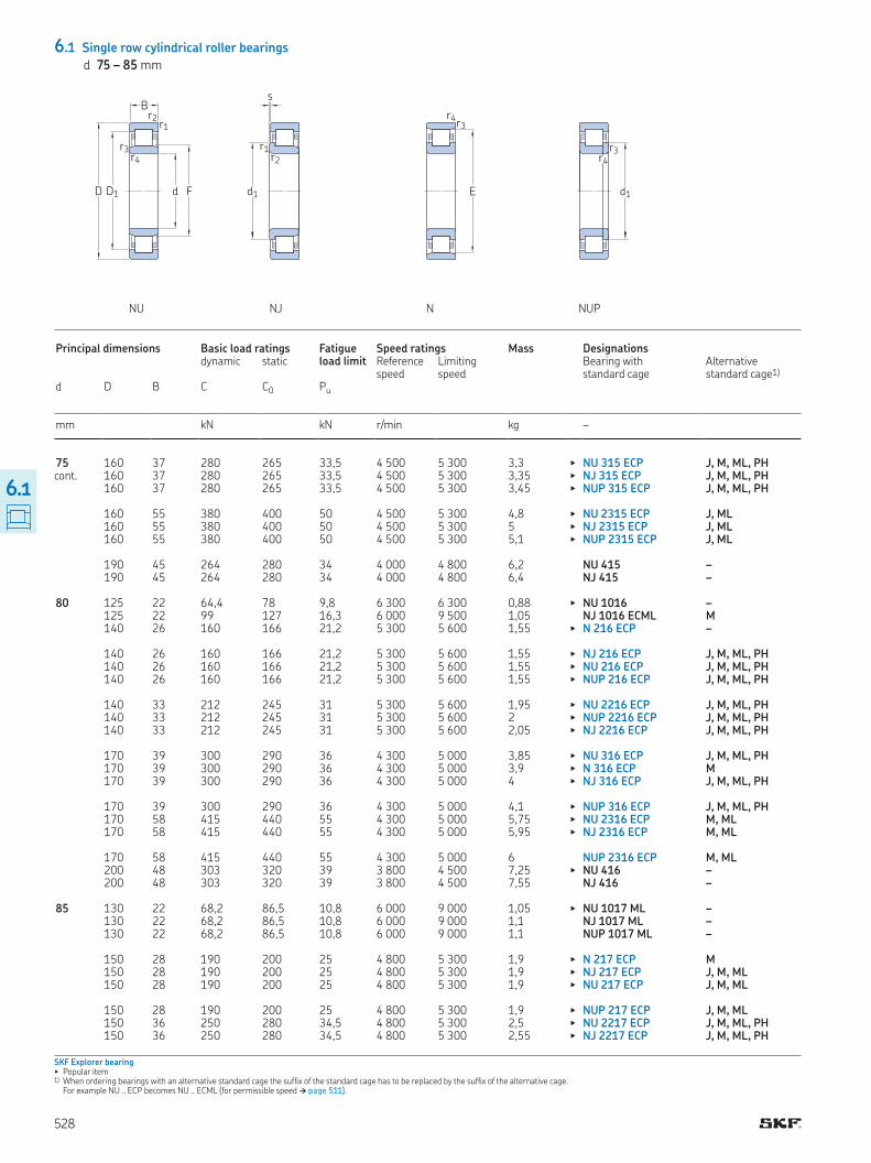
6.1 Single row cylindrical roller bearings
d 75 – 85 mm
cont
SKF Explorer bearing▶ Popular item1) When ordering bearings with an alternative standard cage the sufix of the standard cage has to be replaced by the sufix of the alternative cage
For example NU ECP becomes NU ECML (for permissible speed † page 511)
NU NJ N NUP
D1D
B
d F
r1r2
r3r4
s
r1r2
d1
r3r4
E
r3r4
d1
Principal dimensions Basic load ratings Fatigue load limit
Speed ratings Mass Designations dynamic static Reference
speedLimiting speed
Bearing with standard cage
Alternative standard cage1)
d D B C C0 Pu
mm kN kN r/min kg –
75 160 37 280 265 33,5 4 500 5 300 3,3 ▶ NU 315 ECP J, M, ML, PH 160 37 280 265 33,5 4 500 5 300 3,35 ▶ NJ 315 ECP J, M, ML, PH 160 37 280 265 33,5 4 500 5 300 3,45 ▶ NUP 315 ECP J, M, ML, PH 160 55 380 400 50 4 500 5 300 4,8 ▶ NU 2315 ECP J, ML 160 55 380 400 50 4 500 5 300 5 ▶ NJ 2315 ECP J, ML 160 55 380 400 50 4 500 5 300 5,1 ▶ NUP 2315 ECP J, ML 190 45 264 280 34 4 000 4 800 6,2 NU 415 – 190 45 264 280 34 4 000 4 800 6,4 NJ 415 – 80 125 22 64,4 78 9,8 6 300 6 300 0,88 ▶ NU 1016 – 125 22 99 127 16,3 6 000 9 500 1,05 NJ 1016 ECML M 140 26 160 166 21,2 5 300 5 600 1,55 ▶ N 216 ECP – 140 26 160 166 21,2 5 300 5 600 1,55 ▶ NJ 216 ECP J, M, ML, PH 140 26 160 166 21,2 5 300 5 600 1,55 ▶ NU 216 ECP J, M, ML, PH 140 26 160 166 21,2 5 300 5 600 1,55 ▶ NUP 216 ECP J, M, ML, PH 140 33 212 245 31 5 300 5 600 1,95 ▶ NU 2216 ECP J, M, ML, PH 140 33 212 245 31 5 300 5 600 2 ▶ NUP 2216 ECP J, M, ML, PH 140 33 212 245 31 5 300 5 600 2,05 ▶ NJ 2216 ECP J, M, ML, PH 170 39 300 290 36 4 300 5 000 3,85 ▶ NU 316 ECP J, M, ML, PH 170 39 300 290 36 4 300 5 000 3,9 ▶ N 316 ECP M 170 39 300 290 36 4 300 5 000 4 ▶ NJ 316 ECP J, M, ML, PH 170 39 300 290 36 4 300 5 000 4,1 ▶ NUP 316 ECP J, M, ML, PH 170 58 415 440 55 4 300 5 000 5,75 ▶ NU 2316 ECP M, ML 170 58 415 440 55 4 300 5 000 5,95 ▶ NJ 2316 ECP M, ML 170 58 415 440 55 4 300 5 000 6 NUP 2316 ECP M, ML 200 48 303 320 39 3 800 4 500 7,25 ▶ NU 416 – 200 48 303 320 39 3 800 4 500 7,55 NJ 416 – 85 130 22 68,2 86,5 10,8 6 000 9 000 1,05 ▶ NU 1017 ML – 130 22 68,2 86,5 10,8 6 000 9 000 1,1 NJ 1017 ML – 130 22 68,2 86,5 10,8 6 000 9 000 1,1 NUP 1017 ML – 150 28 190 200 25 4 800 5 300 1,9 ▶ N 217 ECP M 150 28 190 200 25 4 800 5 300 1,9 ▶ NJ 217 ECP J, M, ML 150 28 190 200 25 4 800 5 300 1,9 ▶ NU 217 ECP J, M, ML 150 28 190 200 25 4 800 5 300 1,9 ▶ NUP 217 ECP J, M, ML 150 36 250 280 34,5 4 800 5 300 2,5 ▶ NU 2217 ECP J, M, ML, PH 150 36 250 280 34,5 4 800 5 300 2,55 ▶ NJ 2217 ECP J, M, ML, PH
528
6.1
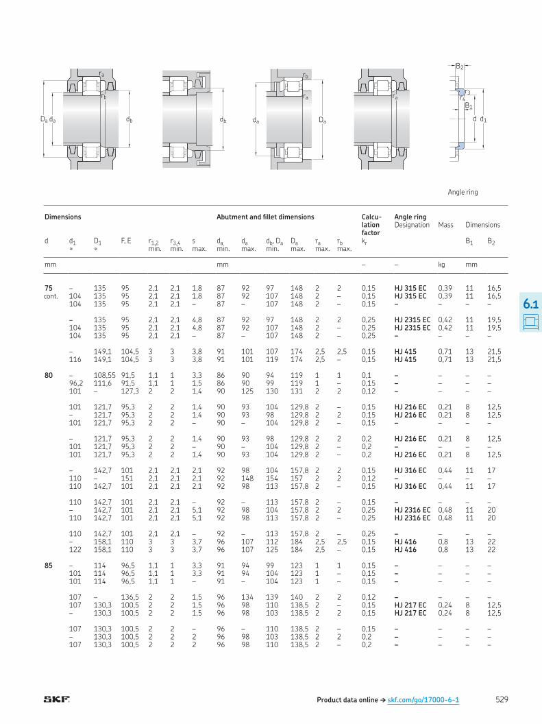
Product data online † skf.com/go/17000-6-1
cont
Angle ring
Da da db
rb
ra
db
ra
Da
rb
da
ra
d d1
B1
B2
r4r3
Dimensions Abutment and illet dimensions Calcu-lation factor
Angle ring Designation Mass Dimensions
d d1 D1 F, E r1,2 r3,4 s da da db, Da Da ra rb kr B1 B2≈ ≈ min min max min max min max max max
mm mm – – kg mm
75 – 135 95 2,1 2,1 1,8 87 92 97 148 2 2 0,15 HJ 315 EC 0,39 11 16,5 104 135 95 2,1 2,1 1,8 87 92 107 148 2 – 0,15 HJ 315 EC 0,39 11 16,5 104 135 95 2,1 2,1 – 87 – 107 148 2 – 0,15 – – – – – 135 95 2,1 2,1 4,8 87 92 97 148 2 2 0,25 HJ 2315 EC 0,42 11 19,5 104 135 95 2,1 2,1 4,8 87 92 107 148 2 – 0,25 HJ 2315 EC 0,42 11 19,5 104 135 95 2,1 2,1 – 87 – 107 148 2 – 0,25 – – – – – 149,1 104,5 3 3 3,8 91 101 107 174 2,5 2,5 0,15 HJ 415 0,71 13 21,5 116 149,1 104,5 3 3 3,8 91 101 119 174 2,5 – 0,15 HJ 415 0,71 13 21,5 80 – 108,55 91,5 1,1 1 3,3 86 90 94 119 1 1 0,1 – – – – 96,2 111,6 91,5 1,1 1 1,5 86 90 99 119 1 – 0,15 – – – – 101 – 127,3 2 2 1,4 90 125 130 131 2 2 0,12 – – – – 101 121,7 95,3 2 2 1,4 90 93 104 129,8 2 – 0,15 HJ 216 EC 0,21 8 12,5 – 121,7 95,3 2 2 1,4 90 93 98 129,8 2 2 0,15 HJ 216 EC 0,21 8 12,5 101 121,7 95,3 2 2 – 90 – 104 129,8 2 – 0,15 – – – – – 121,7 95,3 2 2 1,4 90 93 98 129,8 2 2 0,2 HJ 216 EC 0,21 8 12,5 101 121,7 95,3 2 2 – 90 – 104 129,8 2 – 0,2 – – – – 101 121,7 95,3 2 2 1,4 90 93 104 129,8 2 – 0,2 HJ 216 EC 0,21 8 12,5 – 142,7 101 2,1 2,1 2,1 92 98 104 157,8 2 2 0,15 HJ 316 EC 0,44 11 17 110 – 151 2,1 2,1 2,1 92 148 154 157 2 2 0,12 – – – – 110 142,7 101 2,1 2,1 2,1 92 98 113 157,8 2 – 0,15 HJ 316 EC 0,44 11 17 110 142,7 101 2,1 2,1 – 92 – 113 157,8 2 – 0,15 – – – – – 142,7 101 2,1 2,1 5,1 92 98 104 157,8 2 2 0,25 HJ 2316 EC 0,48 11 20 110 142,7 101 2,1 2,1 5,1 92 98 113 157,8 2 – 0,25 HJ 2316 EC 0,48 11 20 110 142,7 101 2,1 2,1 – 92 – 113 157,8 2 – 0,25 – – – – – 158,1 110 3 3 3,7 96 107 112 184 2,5 2,5 0,15 HJ 416 0,8 13 22 122 158,1 110 3 3 3,7 96 107 125 184 2,5 – 0,15 HJ 416 0,8 13 22 85 – 114 96,5 1,1 1 3,3 91 94 99 123 1 1 0,15 – – – – 101 114 96,5 1,1 1 3,3 91 94 104 123 1 – 0,15 – – – – 101 114 96,5 1,1 1 – 91 – 104 123 1 – 0,15 – – – – 107 – 136,5 2 2 1,5 96 134 139 140 2 2 0,12 – – – – 107 130,3 100,5 2 2 1,5 96 98 110 138,5 2 – 0,15 HJ 217 EC 0,24 8 12,5 – 130,3 100,5 2 2 1,5 96 98 103 138,5 2 2 0,15 HJ 217 EC 0,24 8 12,5 107 130,3 100,5 2 2 – 96 – 110 138,5 2 – 0,15 – – – – – 130,3 100,5 2 2 2 96 98 103 138,5 2 2 0,2 – – – – 107 130,3 100,5 2 2 2 96 98 110 138,5 2 – 0,2 – – – –
529
6.1
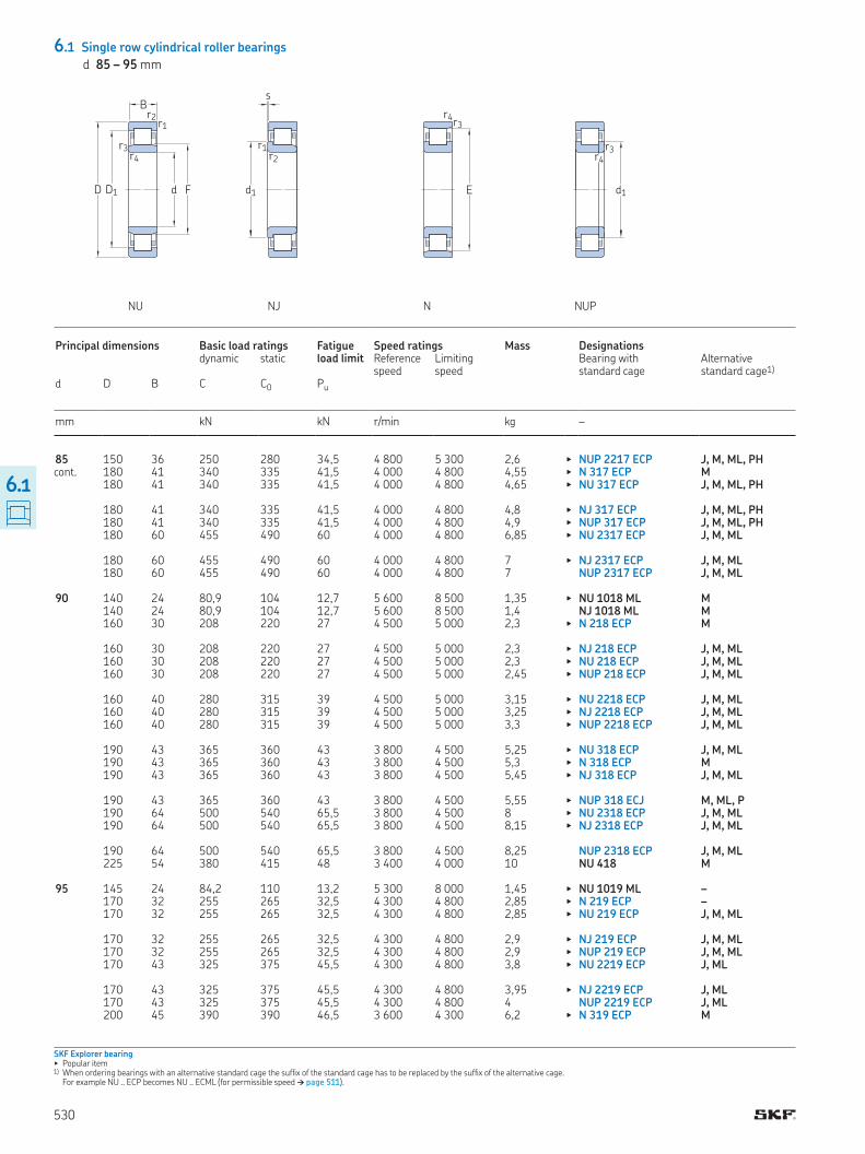
6.1 Single row cylindrical roller bearings
d 85 – 95 mm
cont
SKF Explorer bearing▶ Popular item1) When ordering bearings with an alternative standard cage the sufix of the standard cage has to be replaced by the sufix of the alternative cage
For example NU ECP becomes NU ECML (for permissible speed † page 511)
NU NJ N NUP
D1D
B
d F
r1r2
r3r4
s
r1r2
d1
r3r4
E
r3r4
d1
Principal dimensions Basic load ratings Fatigue load limit
Speed ratings Mass Designations dynamic static Reference
speedLimiting speed
Bearing with standard cage
Alternative standard cage1)
d D B C C0 Pu
mm kN kN r/min kg –
85 150 36 250 280 34,5 4 800 5 300 2,6 ▶ NUP 2217 ECP J, M, ML, PH 180 41 340 335 41,5 4 000 4 800 4,55 ▶ N 317 ECP M 180 41 340 335 41,5 4 000 4 800 4,65 ▶ NU 317 ECP J, M, ML, PH 180 41 340 335 41,5 4 000 4 800 4,8 ▶ NJ 317 ECP J, M, ML, PH 180 41 340 335 41,5 4 000 4 800 4,9 ▶ NUP 317 ECP J, M, ML, PH 180 60 455 490 60 4 000 4 800 6,85 ▶ NU 2317 ECP J, M, ML 180 60 455 490 60 4 000 4 800 7 ▶ NJ 2317 ECP J, M, ML 180 60 455 490 60 4 000 4 800 7 NUP 2317 ECP J, M, ML 90 140 24 80,9 104 12,7 5 600 8 500 1,35 ▶ NU 1018 ML M 140 24 80,9 104 12,7 5 600 8 500 1,4 NJ 1018 ML M 160 30 208 220 27 4 500 5 000 2,3 ▶ N 218 ECP M 160 30 208 220 27 4 500 5 000 2,3 ▶ NJ 218 ECP J, M, ML 160 30 208 220 27 4 500 5 000 2,3 ▶ NU 218 ECP J, M, ML 160 30 208 220 27 4 500 5 000 2,45 ▶ NUP 218 ECP J, M, ML 160 40 280 315 39 4 500 5 000 3,15 ▶ NU 2218 ECP J, M, ML 160 40 280 315 39 4 500 5 000 3,25 ▶ NJ 2218 ECP J, M, ML 160 40 280 315 39 4 500 5 000 3,3 ▶ NUP 2218 ECP J, M, ML 190 43 365 360 43 3 800 4 500 5,25 ▶ NU 318 ECP J, M, ML 190 43 365 360 43 3 800 4 500 5,3 ▶ N 318 ECP M 190 43 365 360 43 3 800 4 500 5,45 ▶ NJ 318 ECP J, M, ML 190 43 365 360 43 3 800 4 500 5,55 ▶ NUP 318 ECJ M, ML, P 190 64 500 540 65,5 3 800 4 500 8 ▶ NU 2318 ECP J, M, ML 190 64 500 540 65,5 3 800 4 500 8,15 ▶ NJ 2318 ECP J, M, ML 190 64 500 540 65,5 3 800 4 500 8,25 NUP 2318 ECP J, M, ML 225 54 380 415 48 3 400 4 000 10 NU 418 M 95 145 24 84,2 110 13,2 5 300 8 000 1,45 ▶ NU 1019 ML – 170 32 255 265 32,5 4 300 4 800 2,85 ▶ N 219 ECP – 170 32 255 265 32,5 4 300 4 800 2,85 ▶ NU 219 ECP J, M, ML 170 32 255 265 32,5 4 300 4 800 2,9 ▶ NJ 219 ECP J, M, ML 170 32 255 265 32,5 4 300 4 800 2,9 ▶ NUP 219 ECP J, M, ML 170 43 325 375 45,5 4 300 4 800 3,8 ▶ NU 2219 ECP J, ML 170 43 325 375 45,5 4 300 4 800 3,95 ▶ NJ 2219 ECP J, ML 170 43 325 375 45,5 4 300 4 800 4 NUP 2219 ECP J, ML 200 45 390 390 46,5 3 600 4 300 6,2 ▶ N 319 ECP M
530
6.1
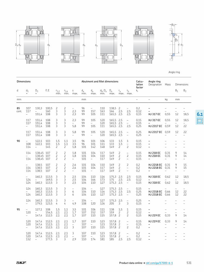
Product data online † skf.com/go/17000-6-1
cont
Angle ring
Da da db
rb
ra
db
ra
Da
rb
da
ra
d d1
B1
B2
r4r3
Dimensions Abutment and illet dimensions Calcu-lation factor
Angle ring Designation Mass Dimensions
d d1 D1 F, E r1,2 r3,4 s da da db, Da Da ra rb kr B1 B2≈ ≈ min min max min max min max max max
mm mm – – kg mm
85 107 130,3 100,5 2 2 – 96 – 110 138,5 2 – 0,2 – – – – 117 – 160 3 3 2,3 99 157 163 166 2,5 2,5 0,12 – – – – – 151,4 108 3 3 2,3 99 105 111 165,5 2,5 2,5 0,15 HJ 317 EC 0,55 12 18,5 117 151,4 108 3 3 2,3 99 105 120 165,5 2,5 – 0,15 HJ 317 EC 0,55 12 18,5 117 151,4 108 3 3 – 99 – 120 165,5 2,5 – 0,15 – – – – – 151,4 108 3 3 5,8 99 105 111 165,5 2,5 2,5 0,25 HJ 2317 EC 0,59 12 22 117 151,4 108 3 3 5,8 99 105 120 165,5 2,5 – 0,25 HJ 2317 EC 0,59 12 22 117 151,4 108 3 3 – 99 – 120 165,5 2,5 – 0,25 – – – – 90 – 122,1 103 1,5 1,1 3,5 96 101 106 133 1,5 1 0,15 – – – – 108 122,1 103 1,5 1,1 3,5 96 101 111 133 1,5 – 0,15 – – – – 114 – 145 2 2 1,8 101 142 148 149 2 2 0,12 – – – – 114 138,45 107 2 2 1,8 101 104 117 149 2 – 0,15 HJ 218 EC 0,31 9 14 – 138,45 107 2 2 1,8 101 104 110 149 2 2 0,15 HJ 218 EC 0,31 9 14 114 138,45 107 2 2 – 101 – 117 149 2 – 0,15 – – – – – 138,5 107 2 2 2,6 101 104 110 149 2 2 0,2 HJ 2218 EC 0,31 9 15 114 138,5 107 2 2 2,6 101 104 117 149 2 – 0,2 HJ 2218 EC 0,31 9 15 114 138,5 107 2 2 – 101 – 117 149 2 – 0,2 – – – – – 160,3 113,5 3 3 2,5 104 110 116 175,3 2,5 2,5 0,15 HJ 318 EC 0,62 12 18,5 124 – 169,5 3 3 2,5 104 166 173 175 2,5 2,5 0,12 – – – – 124 160,3 113,5 3 3 2,5 104 110 127 175,3 2,5 – 0,15 HJ 318 EC 0,62 12 18,5 124 160,3 113,5 3 3 – 104 – 127 175,3 2,5 – 0,15 – – – – – 160,3 113,5 3 3 6 104 110 116 175,3 2,5 2,5 0,25 HJ 2318 EC 0,66 12 22 124 160,3 113,5 3 3 6 104 110 127 175,3 2,5 – 0,25 HJ 2318 EC 0,66 12 22 124 160,3 113,5 3 3 – 104 – 127 175,3 2,5 – 0,25 – – – – – 179,5 123,5 4 4 4,9 108 120 126 205 3 3 0,15 – – – – 95 – 127,1 108 1,5 1,1 3,5 101 106 111 138 1,5 1 0,15 – – – – 120 – 154,5 2,1 2,1 1,7 107 152 157 159 2 2 0,12 – – – – – 147,4 112,5 2,1 2,1 1,7 107 110 115 157,8 2 2 0,15 HJ 219 EC 0,33 9 14 120 147,4 112,5 2,1 2,1 1,7 107 110 123 157,8 2 – 0,15 HJ 219 EC 0,33 9 14 120 147,4 112,5 2,1 2,1 – 107 – 123 157,8 2 – 0,15 – – – – – 147,4 112,5 2,1 2,1 3 107 110 115 157,8 2 2 0,2 – – – – 120 147,4 112,5 2,1 2,1 3 107 110 123 157,8 2 – 0,2 – – – – 120 147,4 112,5 2,1 2,1 – 107 – 123 157,8 2 – 0,2 – – – – 132 – 177,5 3 3 2,9 110 174 181 185 2,5 2,5 0,12 – – – –
531
6.1
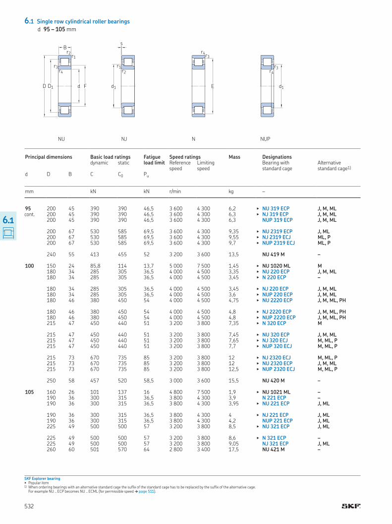
6.1 Single row cylindrical roller bearings
d 95 – 105 mm
cont
SKF Explorer bearing▶ Popular item1) When ordering bearings with an alternative standard cage the sufix of the standard cage has to be replaced by the sufix of the alternative cage
For example NU ECP becomes NU ECML (for permissible speed † page 511)
NU NJ N NUP
D1D
B
d F
r1r2
r3r4
s
r1r2
d1
r3r4
E
r3r4
d1
Principal dimensions Basic load ratings Fatigue load limit
Speed ratings Mass Designations dynamic static Reference
speedLimiting speed
Bearing with standard cage
Alternative standard cage1)
d D B C C0 Pu
mm kN kN r/min kg –
95 200 45 390 390 46,5 3 600 4 300 6,2 ▶ NU 319 ECP J, M, ML 200 45 390 390 46,5 3 600 4 300 6,3 ▶ NJ 319 ECP J, M, ML 200 45 390 390 46,5 3 600 4 300 6,3 NUP 319 ECP J, M, ML 200 67 530 585 69,5 3 600 4 300 9,35 ▶ NU 2319 ECP J, ML 200 67 530 585 69,5 3 600 4 300 9,55 ▶ NJ 2319 ECJ ML, P 200 67 530 585 69,5 3 600 4 300 9,7 ▶ NUP 2319 ECJ ML, P 240 55 413 455 52 3 200 3 600 13,5 NU 419 M – 100 150 24 85,8 114 13,7 5 000 7 500 1,45 ▶ NU 1020 ML M 180 34 285 305 36,5 4 000 4 500 3,35 ▶ NU 220 ECP J, M, ML 180 34 285 305 36,5 4 000 4 500 3,45 ▶ N 220 ECP – 180 34 285 305 36,5 4 000 4 500 3,45 ▶ NJ 220 ECP J, M, ML 180 34 285 305 36,5 4 000 4 500 3,6 ▶ NUP 220 ECP J, M, ML 180 46 380 450 54 4 000 4 500 4,75 ▶ NU 2220 ECP J, M, ML, PH 180 46 380 450 54 4 000 4 500 4,8 ▶ NJ 2220 ECP J, M, ML, PH 180 46 380 450 54 4 000 4 500 4,8 ▶ NUP 2220 ECP J, M, ML, PH 215 47 450 440 51 3 200 3 800 7,35 ▶ N 320 ECP M 215 47 450 440 51 3 200 3 800 7,45 ▶ NU 320 ECP J, M, ML 215 47 450 440 51 3 200 3 800 7,65 ▶ NJ 320 ECJ M, ML, P 215 47 450 440 51 3 200 3 800 7,7 ▶ NUP 320 ECJ M, ML, P 215 73 670 735 85 3 200 3 800 12 ▶ NJ 2320 ECJ M, ML, P 215 73 670 735 85 3 200 3 800 12 ▶ NU 2320 ECP J, M, ML 215 73 670 735 85 3 200 3 800 12,5 ▶ NUP 2320 ECJ M, ML, P 250 58 457 520 58,5 3 000 3 600 15,5 NU 420 M – 105 160 26 101 137 16 4 800 7 500 1,9 ▶ NU 1021 ML – 190 36 300 315 36,5 3 800 4 300 3,9 N 221 ECP – 190 36 300 315 36,5 3 800 4 300 3,95 ▶ NU 221 ECP J, ML 190 36 300 315 36,5 3 800 4 300 4 ▶ NJ 221 ECP J, ML 190 36 300 315 36,5 3 800 4 300 4,2 NUP 221 ECP J, ML 225 49 500 500 57 3 200 3 800 8,5 ▶ NU 321 ECP J, ML 225 49 500 500 57 3 200 3 800 8,6 ▶ N 321 ECP – 225 49 500 500 57 3 200 3 800 9,05 NJ 321 ECP J, ML 260 60 501 570 64 2 800 3 400 17,5 NU 421 M –
532
6.1
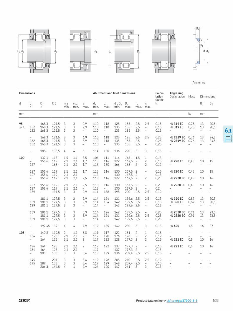
Product data online † skf.com/go/17000-6-1
cont
Angle ring
Da da db
rb
ra
db
ra
Da
rb
da
ra
d d1
B1
B2
r4r3
Dimensions Abutment and illet dimensions Calcu-lation factor
Angle ring Designation Mass Dimensions
d d1 D1 F, E r1,2 r3,4 s da da db, Da Da ra rb kr B1 B2≈ ≈ min min max min max min max max max
mm mm – – kg mm
95 – 168,3 121,5 3 3 2,9 110 118 125 185 2,5 2,5 0,15 HJ 319 EC 0,78 13 20,5 132 168,3 121,5 3 3 2,9 110 118 135 185 2,5 – 0,15 HJ 319 EC 0,78 13 20,5 132 168,3 121,5 3 3 – 110 – 135 185 2,5 – 0,15 – – – – – 168,3 121,5 3 3 6,9 110 118 125 185 2,5 2,5 0,25 HJ 2319 EC 0,76 13 24,5 132 168,3 121,5 3 3 6,9 110 118 135 185 2,5 – 0,25 HJ 2319 EC 0,76 13 24,5 132 168,3 121,5 3 3 – 110 – 135 185 2,5 – 0,25 – – – – – 188 133,5 4 4 5 114 130 136 220 3 3 0,15 – – – – 100 – 132,1 113 1,5 1,1 3,5 106 111 116 143 1,5 1 0,15 – – – – – 155,6 119 2,1 2,1 1,7 113 116 122 167,5 2 2 0,15 HJ 220 EC 0,43 10 15 127 – 163 2,1 2,1 1,7 113 160 166 168 2 2 0,12 – – – – 127 155,6 119 2,1 2,1 1,7 113 116 130 167,5 2 – 0,15 HJ 220 EC 0,43 10 15 127 155,6 119 2,1 2,1 – 113 – 130 167,5 2 – 0,15 – – – – – 155,6 119 2,1 2,1 2,5 113 116 122 167,5 2 2 0,2 HJ 2220 EC 0,43 10 16 127 155,6 119 2,1 2,1 2,5 113 116 130 167,5 2 – 0,2 HJ 2220 EC 0,43 10 16 127 155,6 119 2,1 2,1 – 113 – 130 167,5 2 – 0,2 – – – – 139 – 191,5 3 3 2,9 114 188 195 200 2,5 2,5 0,12 – – – – – 181,1 127,5 3 3 2,9 114 124 131 199,6 2,5 2,5 0,15 HJ 320 EC 0,87 13 20,5 139 181,1 127,5 3 3 2,9 114 124 142 199,6 2,5 – 0,15 HJ 320 EC 0,87 13 20,5 139 181,1 127,5 3 3 – 114 – 142 199,6 2,5 – 0,15 – – – – 139 181,1 127,5 3 3 5,9 114 124 142 199,6 2,5 – 0,25 HJ 2320 EC 0,91 13 23,5 – 181,1 127,5 3 3 5,9 114 124 131 199,6 2,5 2,5 0,25 HJ 2320 EC 0,91 13 23,5 139 181,1 127,5 3 3 – 114 – 142 199,6 2,5 – 0,25 – – – – – 197,45 139 4 4 4,9 119 135 142 230 3 3 0,15 HJ 420 1,5 16 27 105 – 140,8 119,5 2 1,1 3,8 111 117 122 151 2 1 0,15 – – – – 134 – 173 2,1 2,1 2 117 170 176 178 2 2 0,12 – – – – – 164 125 2,1 2,1 2 117 122 128 177,3 2 2 0,15 HJ 221 EC 0,5 10 16 134 164 125 2,1 2,1 2 117 122 137 177,3 2 – 0,15 HJ 221 EC 0,5 10 16 134 164 125 2,1 2,1 – 117 – 137 177,3 2 – 0,15 – – – – – 189 133 3 3 3,4 119 129 136 209,4 2,5 2,5 0,15 – – – – 145 – 201 3 3 3,4 119 198 205 210 2,5 2,5 0,12 – – – – 145 189 133 3 3 3,4 119 129 148 209,4 2,5 – 0,15 – – – – – 206,3 144,5 4 4 4,9 124 140 147 241 3 3 0,15 – – – –
533
6.1

6.1 Single row cylindrical roller bearings
d 110 – 120 mm
SKF Explorer bearing▶ Popular item1) When ordering bearings with an alternative standard cage the sufix of the standard cage has to be replaced by the sufix of the alternative cage
For example NU ECP becomes NU ECML (for permissible speed † page 511)
NU NJ N NUP
D1D
B
d F
r1r2
r3r4
s
r1r2
d1
r3r4
E
r3r4
d1
Principal dimensions Basic load ratings Fatigue load limit
Speed ratings Mass Designations dynamic static Reference
speedLimiting speed
Bearing with standard cage
Alternative standard cage1)
d D B C C0 Pu
mm kN kN r/min kg –
110 170 28 128 166 19,3 4 500 7 000 2,3 ▶ NU 1022 ML M 200 38 335 365 42,5 3 600 4 000 4,7 ▶ NU 222 ECP J, M, ML 200 38 335 365 42,5 3 600 4 000 4,8 ▶ N 222 ECP M 200 38 335 365 42,5 3 600 4 000 4,8 ▶ NJ 222 ECP J, M, ML 200 38 335 365 42,5 3 600 4 000 5 ▶ NUP 222 ECP J, M, ML 200 53 440 520 61 3 600 4 000 6,7 ▶ NJ 2222 ECP J, ML 200 53 440 520 61 3 600 4 000 6,7 ▶ NU 2222 ECP J, ML 200 53 440 520 61 3 600 4 000 7 ▶ NUP 2222 ECP J, ML 240 50 530 540 61 3 000 3 400 10 ▶ N 322 ECP M 240 50 530 540 61 3 000 3 400 10,5 ▶ NJ 322 ECJ M, ML, P 240 50 530 540 61 3 000 3 400 10,5 ▶ NU 322 ECP J, M, ML 240 50 530 540 61 3 000 3 400 10,5 NUP 322 ECP J, M, ML 240 80 780 900 102 3 000 3 400 17 NJ 2322 ECP ML 240 80 780 900 102 3 000 3 400 17 ▶ NU 2322 ECP ML 240 80 780 900 102 3 000 3 400 17,5 NUP 2322 ECP ML 280 65 550 630 69,5 2 600 3 200 22,5 NJ 422 M – 120 180 28 134 183 20,8 4 000 6 300 2,55 ▶ NU 1024 ML M 215 40 390 430 49 3 400 3 600 5,75 ▶ N 224 ECP M 215 40 390 430 49 3 400 3 600 5,75 ▶ NU 224 ECP J, M, ML 215 40 390 430 49 3 400 3 600 5,85 ▶ NJ 224 ECP J, M, ML 215 40 390 430 49 3 400 3 600 5,95 ▶ NUP 224 ECJ M, ML, P 215 58 520 630 72 3 400 3 600 8,2 ▶ NU 2224 ECP J, M, ML 215 58 520 630 72 3 400 3 600 8,65 ▶ NJ 2224 ECJ M, ML, P 215 58 520 630 72 3 400 3 600 8,65 NUP 2224 ECP J, M, ML 260 55 610 620 69,5 2 800 3 200 13 ▶ N 324 ECP M 260 55 610 620 69,5 2 800 3 200 13 ▶ NU 324 ECP J, M, ML 260 55 610 620 69,5 2 800 3 200 13,5 ▶ NJ 324 ECJ M, ML, P 260 55 610 620 69,5 2 800 3 200 14 NUP 324 ECP J, M, ML 260 86 915 1 040 116 2 800 5 000 22,5 ▶ NU 2324 ECML M 260 86 915 1 040 116 2 800 5 000 23 ▶ NJ 2324 ECML M 260 86 915 1 040 116 2 800 5 000 23,5 NUP 2324 ECML M 310 72 644 735 78 2 400 2 800 27,5 NU 424 M
534
6.1
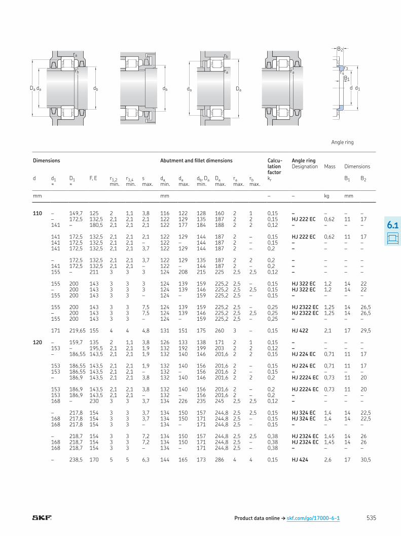
Product data online † skf.com/go/17000-6-1
Angle ring
Da da db
rb
ra
db
ra
Da
rb
da
ra
d d1
B1
B2
r4r3
Dimensions Abutment and illet dimensions Calcu-lation factor
Angle ring Designation Mass Dimensions
d d1 D1 F, E r1,2 r3,4 s da da db, Da Da ra rb kr B1 B2≈ ≈ min min max min max min max max max
mm mm – – kg mm
110 – 149,7 125 2 1,1 3,8 116 122 128 160 2 1 0,15 – – – – – 172,5 132,5 2,1 2,1 2,1 122 129 135 187 2 2 0,15 HJ 222 EC 0,62 11 17 141 – 180,5 2,1 2,1 2,1 122 177 184 188 2 2 0,12 – – – – 141 172,5 132,5 2,1 2,1 2,1 122 129 144 187 2 – 0,15 HJ 222 EC 0,62 11 17 141 172,5 132,5 2,1 2,1 – 122 – 144 187 2 – 0,15 – – – – 141 172,5 132,5 2,1 2,1 3,7 122 129 144 187 2 – 0,2 – – – – – 172,5 132,5 2,1 2,1 3,7 122 129 135 187 2 2 0,2 – – – – 141 172,5 132,5 2,1 2,1 – 122 – 144 187 2 – 0,2 – – – – 155 – 211 3 3 3 124 208 215 225 2,5 2,5 0,12 – – – – 155 200 143 3 3 3 124 139 159 225,2 2,5 – 0,15 HJ 322 EC 1,2 14 22 – 200 143 3 3 3 124 139 146 225,2 2,5 2,5 0,15 HJ 322 EC 1,2 14 22 155 200 143 3 3 – 124 – 159 225,2 2,5 – 0,15 – – – – 155 200 143 3 3 7,5 124 139 159 225,2 2,5 – 0,25 HJ 2322 EC 1,25 14 26,5 – 200 143 3 3 7,5 124 139 146 225,2 2,5 2,5 0,25 HJ 2322 EC 1,25 14 26,5 155 200 143 3 3 – 124 – 159 225,2 2,5 – 0,25 – – – – 171 219,65 155 4 4 4,8 131 151 175 260 3 – 0,15 HJ 422 2,1 17 29,5 120 – 159,7 135 2 1,1 3,8 126 133 138 171 2 1 0,15 – – – – 153 – 195,5 2,1 2,1 1,9 132 192 199 203 2 2 0,12 – – – – – 186,55 143,5 2,1 2,1 1,9 132 140 146 201,6 2 2 0,15 HJ 224 EC 0,71 11 17 153 186,55 143,5 2,1 2,1 1,9 132 140 156 201,6 2 – 0,15 HJ 224 EC 0,71 11 17 153 186,55 143,5 2,1 2,1 – 132 – 156 201,6 2 – 0,15 – – – – – 186,9 143,5 2,1 2,1 3,8 132 140 146 201,6 2 2 0,2 HJ 2224 EC 0,73 11 20 153 186,9 143,5 2,1 2,1 3,8 132 140 156 201,6 2 – 0,2 HJ 2224 EC 0,73 11 20 153 186,9 143,5 2,1 2,1 – 132 – 156 201,6 2 – 0,2 – – – – 168 – 230 3 3 3,7 134 226 235 245 2,5 2,5 0,12 – – – – – 217,8 154 3 3 3,7 134 150 157 244,8 2,5 2,5 0,15 HJ 324 EC 1,4 14 22,5 168 217,8 154 3 3 3,7 134 150 171 244,8 2,5 – 0,15 HJ 324 EC 1,4 14 22,5 168 217,8 154 3 3 – 134 – 171 244,8 2,5 – 0,15 – – – – – 218,7 154 3 3 7,2 134 150 157 244,8 2,5 2,5 0,38 HJ 2324 EC 1,45 14 26 168 218,7 154 3 3 7,2 134 150 171 244,8 2,5 – 0,38 HJ 2324 EC 1,45 14 26 168 218,7 154 3 3 – 134 – 171 244,8 2,5 – 0,38 – – – – – 238,5 170 5 5 6,3 144 165 173 286 4 4 0,15 HJ 424 2,6 17 30,5
535
6.1
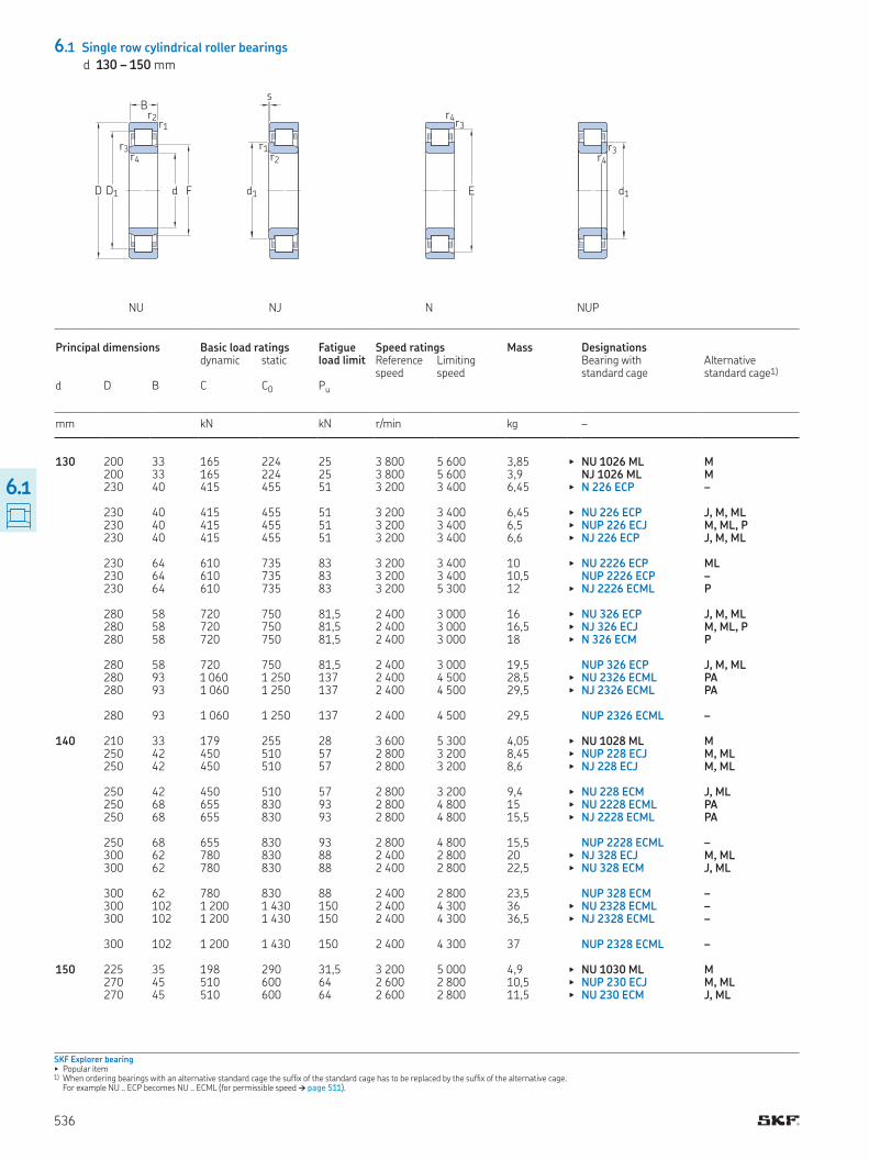
6.1 Single row cylindrical roller bearings
d 130 – 150 mm
SKF Explorer bearing▶ Popular item1) When ordering bearings with an alternative standard cage the sufix of the standard cage has to be replaced by the sufix of the alternative cage
For example NU ECP becomes NU ECML (for permissible speed † page 511)
NU NJ N NUP
D1D
B
d F
r1r2
r3r4
s
r1r2
d1
r3r4
E
r3r4
d1
Principal dimensions Basic load ratings Fatigue load limit
Speed ratings Mass Designations dynamic static Reference
speedLimiting speed
Bearing with standard cage
Alternative standard cage1)
d D B C C0 Pu
mm kN kN r/min kg –
130 200 33 165 224 25 3 800 5 600 3,85 ▶ NU 1026 ML M 200 33 165 224 25 3 800 5 600 3,9 NJ 1026 ML M 230 40 415 455 51 3 200 3 400 6,45 ▶ N 226 ECP – 230 40 415 455 51 3 200 3 400 6,45 ▶ NU 226 ECP J, M, ML 230 40 415 455 51 3 200 3 400 6,5 ▶ NUP 226 ECJ M, ML, P 230 40 415 455 51 3 200 3 400 6,6 ▶ NJ 226 ECP J, M, ML 230 64 610 735 83 3 200 3 400 10 ▶ NU 2226 ECP ML 230 64 610 735 83 3 200 3 400 10,5 NUP 2226 ECP – 230 64 610 735 83 3 200 5 300 12 ▶ NJ 2226 ECML P 280 58 720 750 81,5 2 400 3 000 16 ▶ NU 326 ECP J, M, ML 280 58 720 750 81,5 2 400 3 000 16,5 ▶ NJ 326 ECJ M, ML, P 280 58 720 750 81,5 2 400 3 000 18 ▶ N 326 ECM P 280 58 720 750 81,5 2 400 3 000 19,5 NUP 326 ECP J, M, ML 280 93 1 060 1 250 137 2 400 4 500 28,5 ▶ NU 2326 ECML PA 280 93 1 060 1 250 137 2 400 4 500 29,5 ▶ NJ 2326 ECML PA 280 93 1 060 1 250 137 2 400 4 500 29,5 NUP 2326 ECML – 140 210 33 179 255 28 3 600 5 300 4,05 ▶ NU 1028 ML M 250 42 450 510 57 2 800 3 200 8,45 ▶ NUP 228 ECJ M, ML 250 42 450 510 57 2 800 3 200 8,6 ▶ NJ 228 ECJ M, ML 250 42 450 510 57 2 800 3 200 9,4 ▶ NU 228 ECM J, ML 250 68 655 830 93 2 800 4 800 15 ▶ NU 2228 ECML PA 250 68 655 830 93 2 800 4 800 15,5 ▶ NJ 2228 ECML PA 250 68 655 830 93 2 800 4 800 15,5 NUP 2228 ECML – 300 62 780 830 88 2 400 2 800 20 ▶ NJ 328 ECJ M, ML 300 62 780 830 88 2 400 2 800 22,5 ▶ NU 328 ECM J, ML 300 62 780 830 88 2 400 2 800 23,5 NUP 328 ECM – 300 102 1 200 1 430 150 2 400 4 300 36 ▶ NU 2328 ECML – 300 102 1 200 1 430 150 2 400 4 300 36,5 ▶ NJ 2328 ECML – 300 102 1 200 1 430 150 2 400 4 300 37 NUP 2328 ECML – 150 225 35 198 290 31,5 3 200 5 000 4,9 ▶ NU 1030 ML M 270 45 510 600 64 2 600 2 800 10,5 ▶ NUP 230 ECJ M, ML 270 45 510 600 64 2 600 2 800 11,5 ▶ NU 230 ECM J, ML
536
6.1
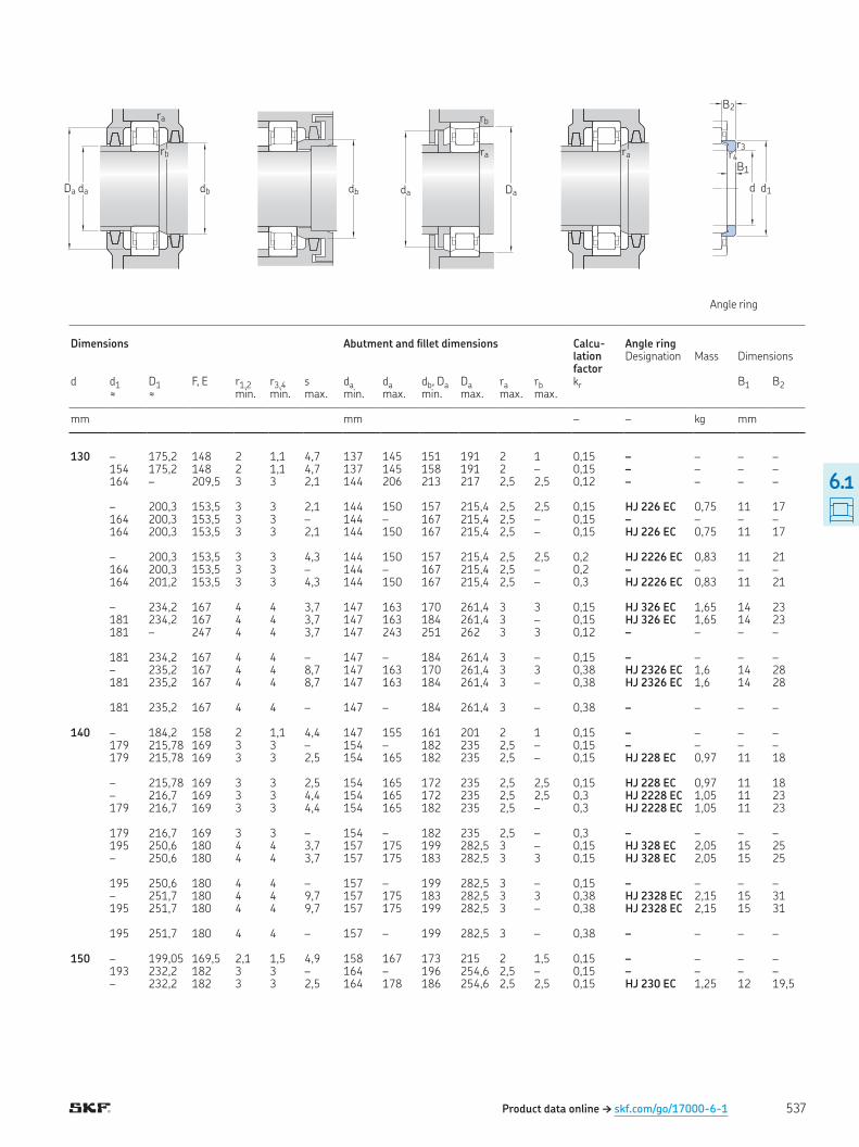
Product data online † skf.com/go/17000-6-1
Angle ring
Da da db
rb
ra
db
ra
Da
rb
da
ra
d d1
B1
B2
r4r3
Dimensions Abutment and illet dimensions Calcu-lation factor
Angle ring Designation Mass Dimensions
d d1 D1 F, E r1,2 r3,4 s da da db, Da Da ra rb kr B1 B2≈ ≈ min min max min max min max max max
mm mm – – kg mm
130 – 175,2 148 2 1,1 4,7 137 145 151 191 2 1 0,15 – – – – 154 175,2 148 2 1,1 4,7 137 145 158 191 2 – 0,15 – – – – 164 – 209,5 3 3 2,1 144 206 213 217 2,5 2,5 0,12 – – – – – 200,3 153,5 3 3 2,1 144 150 157 215,4 2,5 2,5 0,15 HJ 226 EC 0,75 11 17 164 200,3 153,5 3 3 – 144 – 167 215,4 2,5 – 0,15 – – – – 164 200,3 153,5 3 3 2,1 144 150 167 215,4 2,5 – 0,15 HJ 226 EC 0,75 11 17 – 200,3 153,5 3 3 4,3 144 150 157 215,4 2,5 2,5 0,2 HJ 2226 EC 0,83 11 21 164 200,3 153,5 3 3 – 144 – 167 215,4 2,5 – 0,2 – – – – 164 201,2 153,5 3 3 4,3 144 150 167 215,4 2,5 – 0,3 HJ 2226 EC 0,83 11 21 – 234,2 167 4 4 3,7 147 163 170 261,4 3 3 0,15 HJ 326 EC 1,65 14 23 181 234,2 167 4 4 3,7 147 163 184 261,4 3 – 0,15 HJ 326 EC 1,65 14 23 181 – 247 4 4 3,7 147 243 251 262 3 3 0,12 – – – – 181 234,2 167 4 4 – 147 – 184 261,4 3 – 0,15 – – – – – 235,2 167 4 4 8,7 147 163 170 261,4 3 3 0,38 HJ 2326 EC 1,6 14 28 181 235,2 167 4 4 8,7 147 163 184 261,4 3 – 0,38 HJ 2326 EC 1,6 14 28 181 235,2 167 4 4 – 147 – 184 261,4 3 – 0,38 – – – – 140 – 184,2 158 2 1,1 4,4 147 155 161 201 2 1 0,15 – – – – 179 215,78 169 3 3 – 154 – 182 235 2,5 – 0,15 – – – – 179 215,78 169 3 3 2,5 154 165 182 235 2,5 – 0,15 HJ 228 EC 0,97 11 18 – 215,78 169 3 3 2,5 154 165 172 235 2,5 2,5 0,15 HJ 228 EC 0,97 11 18 – 216,7 169 3 3 4,4 154 165 172 235 2,5 2,5 0,3 HJ 2228 EC 1,05 11 23 179 216,7 169 3 3 4,4 154 165 182 235 2,5 – 0,3 HJ 2228 EC 1,05 11 23 179 216,7 169 3 3 – 154 – 182 235 2,5 – 0,3 – – – – 195 250,6 180 4 4 3,7 157 175 199 282,5 3 – 0,15 HJ 328 EC 2,05 15 25 – 250,6 180 4 4 3,7 157 175 183 282,5 3 3 0,15 HJ 328 EC 2,05 15 25 195 250,6 180 4 4 – 157 – 199 282,5 3 – 0,15 – – – – – 251,7 180 4 4 9,7 157 175 183 282,5 3 3 0,38 HJ 2328 EC 2,15 15 31 195 251,7 180 4 4 9,7 157 175 199 282,5 3 – 0,38 HJ 2328 EC 2,15 15 31 195 251,7 180 4 4 – 157 – 199 282,5 3 – 0,38 – – – – 150 – 199,05 169,5 2,1 1,5 4,9 158 167 173 215 2 1,5 0,15 – – – – 193 232,2 182 3 3 – 164 – 196 254,6 2,5 – 0,15 – – – – – 232,2 182 3 3 2,5 164 178 186 254,6 2,5 2,5 0,15 HJ 230 EC 1,25 12 19,5
537
6.1
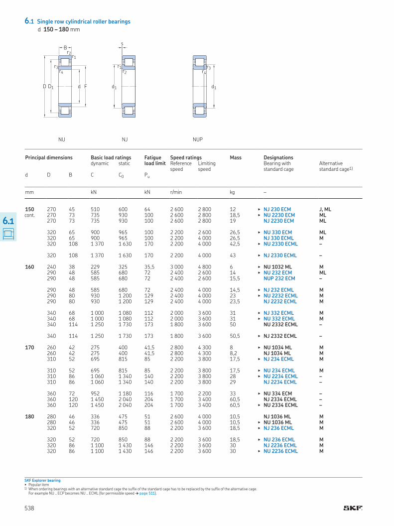
6.1 Single row cylindrical roller bearings
d 150 – 180 mm
SKF Explorer bearing▶ Popular item1) When ordering bearings with an alternative standard cage the sufix of the standard cage has to be replaced by the sufix of the alternative cage
For example NU ECP becomes NU ECML (for permissible speed † page 511)
r3r4
d1D1D
B
d F
r1r2
r3r4
s
r1r2
d1
NU NJ NUP
Principal dimensions Basic load ratings Fatigue load limit
Speed ratings Mass Designations dynamic static Reference
speedLimiting speed
Bearing with standard cage
Alternative standard cage1)
d D B C C0 Pu
mm kN kN r/min kg –
150 270 45 510 600 64 2 600 2 800 12 ▶ NJ 230 ECM J, ML 270 73 735 930 100 2 600 2 800 18,5 ▶ NU 2230 ECM ML 270 73 735 930 100 2 600 2 800 19 NJ 2230 ECM ML
320 65 900 965 100 2 200 2 600 26,5 ▶ NU 330 ECM ML 320 65 900 965 100 2 200 4 000 26,5 NJ 330 ECML M 320 108 1 370 1 630 170 2 200 4 000 42,5 ▶ NU 2330 ECML – 320 108 1 370 1 630 170 2 200 4 000 43 ▶ NJ 2330 ECML – 160 240 38 229 325 35,5 3 000 4 800 6 ▶ NU 1032 ML M 290 48 585 680 72 2 400 2 600 14 ▶ NU 232 ECM ML 290 48 585 680 72 2 400 2 600 15,5 NUP 232 ECM – 290 48 585 680 72 2 400 4 000 14,5 ▶ NJ 232 ECML M 290 80 930 1 200 129 2 400 4 000 23 ▶ NU 2232 ECML M 290 80 930 1 200 129 2 400 4 000 23,5 NJ 2232 ECML M 340 68 1 000 1 080 112 2 000 3 600 31 ▶ NJ 332 ECML M 340 68 1 000 1 080 112 2 000 3 600 31 ▶ NU 332 ECML M 340 114 1 250 1 730 173 1 800 3 600 50 NU 2332 ECML – 340 114 1 250 1 730 173 1 800 3 600 50,5 ▶ NJ 2332 ECML – 170 260 42 275 400 41,5 2 800 4 300 8 ▶ NU 1034 ML M 260 42 275 400 41,5 2 800 4 300 8,2 NJ 1034 ML M 310 52 695 815 85 2 200 3 800 17,5 ▶ NJ 234 ECML M 310 52 695 815 85 2 200 3 800 17,5 ▶ NU 234 ECML M 310 86 1 060 1 340 140 2 200 3 800 28 ▶ NU 2234 ECML – 310 86 1 060 1 340 140 2 200 3 800 29 NJ 2234 ECML – 360 72 952 1 180 116 1 700 2 200 33 ▶ NU 334 ECM – 360 120 1 450 2 040 204 1 700 3 400 60,5 NJ 2334 ECML – 360 120 1 450 2 040 204 1 700 3 400 60,5 ▶ NU 2334 ECML – 180 280 46 336 475 51 2 600 4 000 10,5 NJ 1036 ML M 280 46 336 475 51 2 600 4 000 10,5 ▶ NU 1036 ML M 320 52 720 850 88 2 200 3 600 18,5 ▶ NJ 236 ECML M 320 52 720 850 88 2 200 3 600 18,5 ▶ NU 236 ECML M 320 86 1 100 1 430 146 2 200 3 600 30 NJ 2236 ECML M 320 86 1 100 1 430 146 2 200 3 600 30 ▶ NU 2236 ECML M
cont
538
6.1
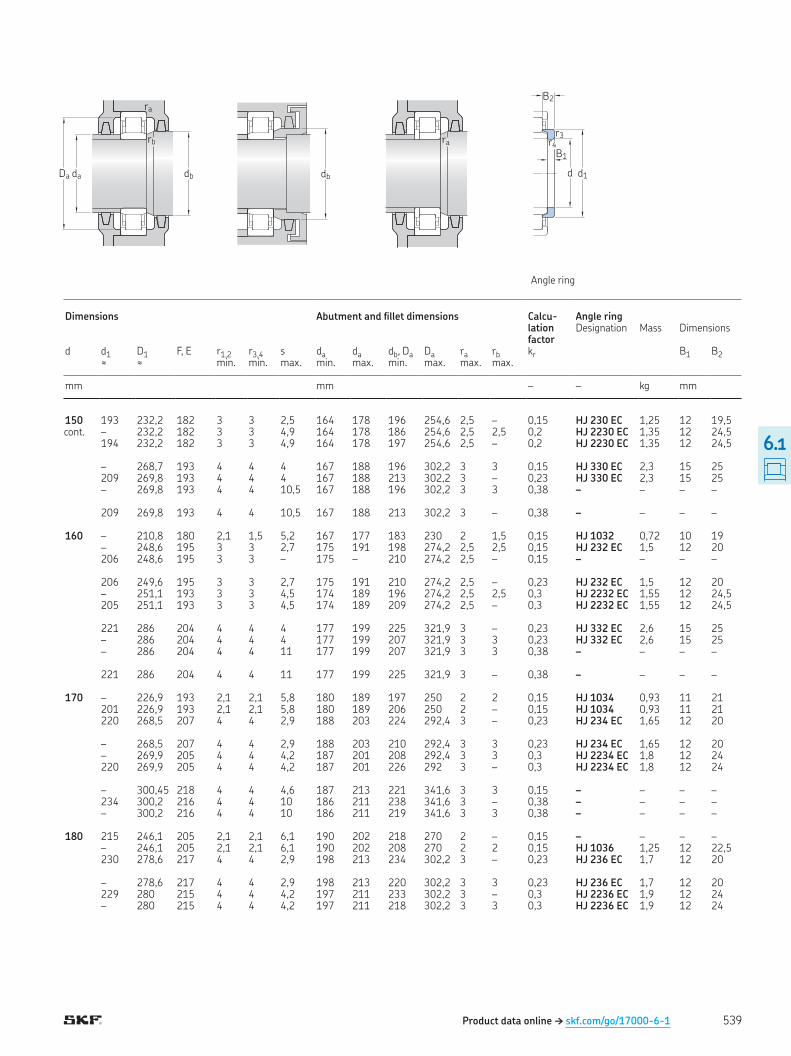
Da da db
rb
ra
db
ra
d d1
B1
B2
r4r3
Angle ring
Product data online † skf.com/go/17000-6-1
cont
Dimensions Abutment and illet dimensions Calcu-lation factor
Angle ring Designation Mass Dimensions
d d1 D1 F, E r1,2 r3,4 s da da db, Da Da ra rb kr B1 B2≈ ≈ min min max min max min max max max
mm mm – – kg mm
150 193 232,2 182 3 3 2,5 164 178 196 254,6 2,5 – 0,15 HJ 230 EC 1,25 12 19,5 – 232,2 182 3 3 4,9 164 178 186 254,6 2,5 2,5 0,2 HJ 2230 EC 1,35 12 24,5 194 232,2 182 3 3 4,9 164 178 197 254,6 2,5 – 0,2 HJ 2230 EC 1,35 12 24,5 – 268,7 193 4 4 4 167 188 196 302,2 3 3 0,15 HJ 330 EC 2,3 15 25 209 269,8 193 4 4 4 167 188 213 302,2 3 – 0,23 HJ 330 EC 2,3 15 25 – 269,8 193 4 4 10,5 167 188 196 302,2 3 3 0,38 – – – – 209 269,8 193 4 4 10,5 167 188 213 302,2 3 – 0,38 – – – – 160 – 210,8 180 2,1 1,5 5,2 167 177 183 230 2 1,5 0,15 HJ 1032 0,72 10 19 – 248,6 195 3 3 2,7 175 191 198 274,2 2,5 2,5 0,15 HJ 232 EC 1,5 12 20 206 248,6 195 3 3 – 175 – 210 274,2 2,5 – 0,15 – – – – 206 249,6 195 3 3 2,7 175 191 210 274,2 2,5 – 0,23 HJ 232 EC 1,5 12 20 – 251,1 193 3 3 4,5 174 189 196 274,2 2,5 2,5 0,3 HJ 2232 EC 1,55 12 24,5 205 251,1 193 3 3 4,5 174 189 209 274,2 2,5 – 0,3 HJ 2232 EC 1,55 12 24,5 221 286 204 4 4 4 177 199 225 321,9 3 – 0,23 HJ 332 EC 2,6 15 25 – 286 204 4 4 4 177 199 207 321,9 3 3 0,23 HJ 332 EC 2,6 15 25 – 286 204 4 4 11 177 199 207 321,9 3 3 0,38 – – – – 221 286 204 4 4 11 177 199 225 321,9 3 – 0,38 – – – – 170 – 226,9 193 2,1 2,1 5,8 180 189 197 250 2 2 0,15 HJ 1034 0,93 11 21 201 226,9 193 2,1 2,1 5,8 180 189 206 250 2 – 0,15 HJ 1034 0,93 11 21 220 268,5 207 4 4 2,9 188 203 224 292,4 3 – 0,23 HJ 234 EC 1,65 12 20 – 268,5 207 4 4 2,9 188 203 210 292,4 3 3 0,23 HJ 234 EC 1,65 12 20 – 269,9 205 4 4 4,2 187 201 208 292,4 3 3 0,3 HJ 2234 EC 1,8 12 24 220 269,9 205 4 4 4,2 187 201 226 292 3 – 0,3 HJ 2234 EC 1,8 12 24 – 300,45 218 4 4 4,6 187 213 221 341,6 3 3 0,15 – – – – 234 300,2 216 4 4 10 186 211 238 341,6 3 – 0,38 – – – – – 300,2 216 4 4 10 186 211 219 341,6 3 3 0,38 – – – – 180 215 246,1 205 2,1 2,1 6,1 190 202 218 270 2 – 0,15 – – – – – 246,1 205 2,1 2,1 6,1 190 202 208 270 2 2 0,15 HJ 1036 1,25 12 22,5 230 278,6 217 4 4 2,9 198 213 234 302,2 3 – 0,23 HJ 236 EC 1,7 12 20 – 278,6 217 4 4 2,9 198 213 220 302,2 3 3 0,23 HJ 236 EC 1,7 12 20 229 280 215 4 4 4,2 197 211 233 302,2 3 – 0,3 HJ 2236 EC 1,9 12 24 – 280 215 4 4 4,2 197 211 218 302,2 3 3 0,3 HJ 2236 EC 1,9 12 24
539
6.1
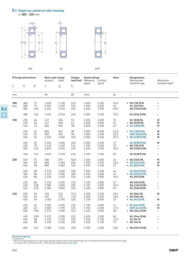
6.1 Single row cylindrical roller bearings
d 180 – 220 mm
SKF Explorer bearing▶ Popular item1) When ordering bearings with an alternative standard cage the sufix of the standard cage has to be replaced by the sufix of the alternative cage
For example NU ECP becomes NU ECML (for permissible speed † page 511)
cont
D1D
B
d F
r1r2
r3r4
s
r1r2
d1
NU NJ NUP
r3r4
d1
Principal dimensions Basic load ratings Fatigue load limit
Speed ratings Mass Designations dynamic static Reference
speedLimiting speed
Bearing with standard cage
Alternative standard cage1)
d D B C C0 Pu
mm kN kN r/min kg –
180 380 75 1 020 1 290 125 1 600 2 200 42,5 ▶ NU 336 ECM – 380 75 1 020 1 290 125 1 600 2 200 44 NJ 336 ECM – 380 126 1 610 2 240 216 1 600 3 200 69,5 NU 2336 ECML – 380 126 1 610 2 240 216 1 600 3 200 70,5 NJ 2336 ECML – 190 290 46 347 500 53 2 600 3 800 11 NJ 1038 ML M 290 46 347 500 53 2 600 3 800 11 ▶ NU 1038 ML M 340 55 800 965 98 2 000 3 400 22 ▶ NJ 238 ECML M 340 55 800 965 98 2 000 3 400 22,5 ▶ NU 238 ECML M 340 55 800 965 98 2 000 3 400 22,5 NUP 238 ECML M 340 92 1 220 1 600 160 2 000 3 400 35,5 ▶ NU 2238 ECML M 340 92 1 220 1 600 160 2 000 3 400 37 NJ 2238 ECML M 400 78 1 140 1 500 143 1 500 2 000 50 ▶ NU 338 ECM – 400 132 1 830 2 550 236 1 500 3 000 80,5 NU 2338 ECML – 400 132 1 830 2 550 236 1 500 3 000 82 NJ 2338 ECML – 200 310 51 380 570 58,5 2 400 3 600 14 ▶ NU 1040 ML M 360 58 880 1 060 106 1 900 3 200 26,5 ▶ NU 240 ECML M 360 58 880 1 060 106 1 900 3 200 27 ▶ NJ 240 ECML M 360 98 1 370 1 800 180 1 900 3 200 44 NJ 2240 ECML – 360 98 1 370 1 800 180 1 900 3 200 44 ▶ NU 2240 ECML – 420 80 1 230 1 630 150 1 400 2 800 56,5 NJ 340 ECML – 420 80 1 230 1 630 150 1 400 2 800 57 NU 340 ECML – 420 138 1 980 2 800 255 1 400 2 800 92,5 NU 2340 ECML – 420 138 1 980 2 800 255 1 400 2 800 94 NJ 2340 ECML – 220 340 56 495 735 73,5 2 200 3 200 18,5 NJ 1044 ML M 340 56 495 735 73,5 2 200 3 200 18,5 ▶ NU 1044 ML - 400 65 1 060 1 290 125 1 700 3 000 37 ▶ NJ 244 ECML M 400 65 1 060 1 290 125 1 700 3 000 37 ▶ NU 244 ECML M 400 65 1 060 1 290 125 1 700 3 000 37,5 NUP 244 ECML M 400 108 1 570 2 280 212 1 600 3 000 58 ▶ NU 2244 ECML – 400 108 1 570 2 280 212 1 600 3 000 60 NJ 2244 ECML – 460 88 1 210 1 630 150 1 500 1 700 73,5 NJ 344 M – 460 88 1 210 1 630 150 1 500 1 700 75 ▶ NU 344 M – 460 145 2 380 3 450 310 1 300 2 600 118 ▶ NU 2344 ECML –
540
6.1
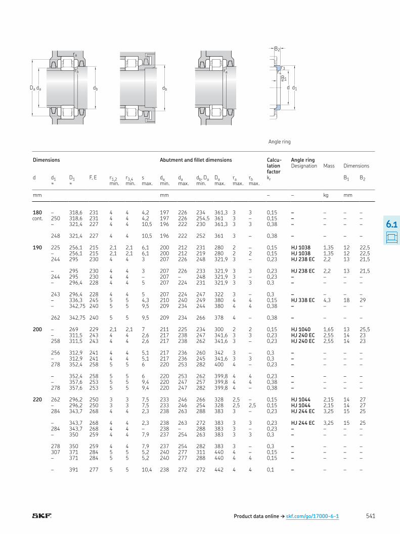
Product data online † skf.com/go/17000-6-1
cont
Da da db
rb
ra
db
ra
d d1
B1
B2
r4r3
Angle ring
Dimensions Abutment and illet dimensions Calcu-lation factor
Angle ring Designation Mass Dimensions
d d1 D1 F, E r1,2 r3,4 s da da db, Da Da ra rb kr B1 B2≈ ≈ min min max min max min max max max
mm mm – – kg mm
180 – 318,6 231 4 4 4,2 197 226 234 361,3 3 3 0,15 – – – – 250 318,6 231 4 4 4,2 197 226 254,5 361 3 – 0,15 – – – – – 321,4 227 4 4 10,5 196 222 230 361,3 3 3 0,38 – – – – 248 321,4 227 4 4 10,5 196 222 252 361 3 – 0,38 – – – – 190 225 256,1 215 2,1 2,1 6,1 200 212 231 280 2 – 0,15 HJ 1038 1,35 12 22,5 – 256,1 215 2,1 2,1 6,1 200 212 219 280 2 2 0,15 HJ 1038 1,35 12 22,5 244 295 230 4 4 3 207 226 248 321,9 3 – 0,23 HJ 238 EC 2,2 13 21,5 – 295 230 4 4 3 207 226 233 321,9 3 3 0,23 HJ 238 EC 2,2 13 21,5 244 295 230 4 4 – 207 – 248 321,9 3 – 0,23 – – – – – 296,4 228 4 4 5 207 224 231 321,9 3 3 0,3 – – – – 243 296,4 228 4 4 5 207 224 247 322 3 – 0,3 – – – – – 336,3 245 5 5 4,3 210 240 249 380 4 4 0,15 HJ 338 EC 4,3 18 29 – 342,75 240 5 5 9,5 209 234 244 380 4 4 0,38 – – – – 262 342,75 240 5 5 9,5 209 234 266 378 4 – 0,38 – – – – 200 – 269 229 2,1 2,1 7 211 225 234 300 2 2 0,15 HJ 1040 1,65 13 25,5 – 311,5 243 4 4 2,6 217 238 247 341,6 3 3 0,23 HJ 240 EC 2,55 14 23 258 311,5 243 4 4 2,6 217 238 262 341,6 3 – 0,23 HJ 240 EC 2,55 14 23 256 312,9 241 4 4 5,1 217 236 260 342 3 – 0,3 – – – – – 312,9 241 4 4 5,1 217 236 245 341,6 3 3 0,3 – – – – 278 352,4 258 5 5 6 220 253 282 400 4 – 0,23 – – – – – 352,4 258 5 5 6 220 253 262 399,8 4 4 0,23 – – – – – 357,6 253 5 5 9,4 220 247 257 399,8 4 4 0,38 – – – – 278 357,6 253 5 5 9,4 220 247 282 399,8 4 – 0,38 – – – – 220 262 296,2 250 3 3 7,5 233 246 266 328 2,5 – 0,15 HJ 1044 2,15 14 27 – 296,2 250 3 3 7,5 233 246 254 328 2,5 2,5 0,15 HJ 1044 2,15 14 27 284 343,7 268 4 4 2,3 238 263 288 383 3 – 0,23 HJ 244 EC 3,25 15 25 – 343,7 268 4 4 2,3 238 263 272 383 3 3 0,23 HJ 244 EC 3,25 15 25 284 343,7 268 4 4 – 238 – 288 383 3 – 0,23 – – – – – 350 259 4 4 7,9 237 254 263 383 3 3 0,3 – – – – 278 350 259 4 4 7,9 237 254 282 383 3 – 0,3 – – – – 307 371 284 5 5 5,2 240 277 311 440 4 – 0,15 – – – – – 371 284 5 5 5,2 240 277 288 440 4 4 0,15 – – – – – 391 277 5 5 10,4 238 272 272 442 4 4 0,1 – – – –
541
6.1
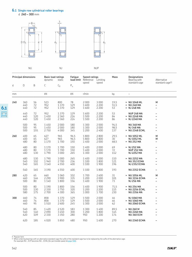
6.1 Single row cylindrical roller bearings
d 240 – 300 mm
▶ Popular item1) When ordering bearings with an alternative standard cage the sufix of the standard cage has to be replaced by the sufix of the alternative cage
For example NU ECP becomes NU ECML (for permissible speed † page 511)
D1D
B
d F
r1r2
r3r4
s
r1r2
d1
NU NJ NUP
r3r4
d1
Principal dimensions Basic load ratings Fatigue load limit
Speed ratings Mass Designations dynamic static Reference
speedLimiting speed
Bearing with standard cage
Alternative standard cage1)
d D B C C0 Pu
mm kN kN r/min kg –
240 360 56 523 800 78 2 000 3 000 19,5 ▶ NU 1048 ML M 440 72 952 1 370 129 1 600 2 200 51,5 ▶ NU 248 MA – 440 72 952 1 370 129 1 600 2 200 53 ▶ NJ 248 MA – 440 72 952 1 370 129 1 600 2 200 53 NUP 248 MA – 440 120 1 450 2 360 216 1 500 2 200 84 ▶ NU 2248 MA – 440 120 1 450 2 360 224 1 500 2 200 86 ▶ NJ 2248 MA – 500 95 1 450 2 000 180 1 300 2 000 94,5 NU 348 MA – 500 95 1 450 2 000 180 1 300 2 000 98,5 NJ 348 MA – 500 155 2 750 4 000 345 1 200 2 400 137 ▶ NU 2348 ECML – 260 400 65 627 965 96,5 1 800 2 800 29,5 ▶ NU 1052 ML M 400 65 627 965 96,5 1 800 2 800 30 NJ 1052 ML M 480 80 1 170 1 700 150 1 400 2 000 68,5 ▶ NU 252 MA – 480 80 1 170 1 700 150 1 400 2 000 69 ▶ NJ 252 MA – 480 80 1 170 1 700 150 1 400 2 000 72 NUP 252 MA – 480 130 1 790 3 000 265 1 300 2 000 112 NJ 2252 MA – 480 130 1 790 3 000 265 1 400 2 000 110 ▶ NU 2252 MA – 540 102 1 940 2 700 236 1 100 1 800 121 NU 352 ECMA – 540 165 3 140 4 550 400 1 100 1 900 196 NJ 2352 ECMA – 540 165 3 190 4 550 400 1 100 1 800 193 NU 2352 ECMA – 280 420 65 660 1 060 102 1 700 2 600 31 ▶ NU 1056 ML M 460 146 2 290 3 900 335 1 200 2 000 101 NU 3156 ECMA – 500 80 1 140 1 800 156 1 400 1 900 73 NJ 256 MA – 500 80 1 190 1 800 156 1 400 1 900 71,5 ▶ NU 256 MA – 500 130 2 330 3 750 320 1 200 2 200 115 ▶ NU 2256 ECML – 580 175 2 700 4 300 365 1 000 1 700 230 NU 2356 MA – 300 460 74 858 1 370 129 1 500 2 000 46 NJ 1060 MA – 460 74 858 1 370 129 1 500 2 000 46 ▶ NU 1060 MA – 460 95 1 510 2 600 245 1 300 2 000 62 NU 2060 ECMA – 540 85 1 420 2 120 183 1 300 1 400 89,5 ▶ NU 260 M – 540 140 2 090 3 450 300 1 200 1 800 145 NU 2260 MA – 620 109 2 330 3 350 280 950 1 200 174 NU 360 ECM – 620 185 4 020 5 850 480 950 1 600 270 NU 2360 ECMA –
542
6.1
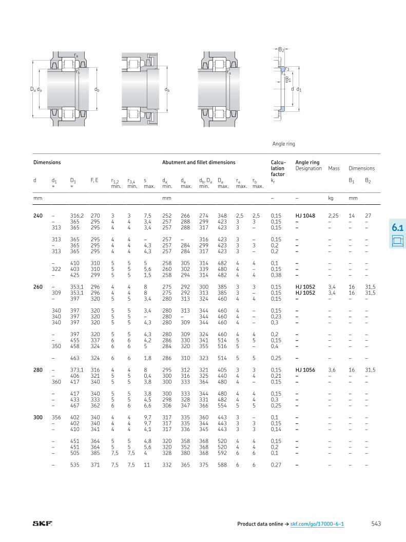
Product data online † skf.com/go/17000-6-1
Da da db
rb
ra
db
ra
d d1
B1
B2
r4r3
Angle ring
Dimensions Abutment and illet dimensions Calcu-lation factor
Angle ring Designation Mass Dimensions
d d1 D1 F, E r1,2 r3,4 s da da db, Da Da ra rb kr B1 B2≈ ≈ min min max min max min max max max
mm mm – – kg mm
240 – 316,2 270 3 3 7,5 252 266 274 348 2,5 2,5 0,15 HJ 1048 2,25 14 27 – 365 295 4 4 3,4 257 288 299 423 3 3 0,15 – – – – 313 365 295 4 4 3,4 257 288 317 423 3 – 0,15 – – – – 313 365 295 4 4 – 257 – 316 423 3 – 0,15 – – – – – 365 295 4 4 4,3 257 284 299 423 3 3 0,2 – – – – 313 365 295 4 4 4,3 257 284 317 423 3 – 0,2 – – – – – 410 310 5 5 5 258 305 314 482 4 4 0,1 – – – – 322 403 310 5 5 5,6 260 302 339 480 4 – 0,15 – – – – – 425 299 5 5 1,5 258 294 314 482 4 4 0,38 – – – – 260 – 353,1 296 4 4 8 275 292 300 385 3 3 0,15 HJ 1052 3,4 16 31,5 309 353,1 296 4 4 8 275 292 313 385 3 – 0,15 HJ 1052 3,4 16 31,5 – 397 320 5 5 3,4 280 313 324 460 4 4 0,15 – – – – 340 397 320 5 5 3,4 280 313 344 460 4 – 0,15 – – – – 340 397 320 5 5 – 280 – 344 460 4 – 0,23 – – – – 340 397 320 5 5 4,3 280 309 344 460 4 – 0,3 – – – – – 397 320 5 5 4,3 280 309 324 460 4 4 0,2 – – – – – 455 337 6 6 4,2 286 330 341 514 5 5 0,15 – – – – 350 458 324 6 6 5 284 320 355 516 5 – 0,4 – – – – – 463 324 6 6 1,8 286 310 323 514 5 5 0,25 – – – – 280 – 373,1 316 4 4 8 295 312 321 405 3 3 0,15 HJ 1056 3,6 16 31,5 – 406 321 5 5 0,4 300 316 325 440 4 4 0,21 – – – – 360 417 340 5 5 3,8 300 333 364 480 4 – 0,15 – – – – – 417 340 5 5 3,8 300 333 344 480 4 4 0,15 – – – – – 433 333 5 5 4,5 298 328 331 482 4 4 0,3 – – – – – 467 362 6 6 6,6 306 347 366 554 5 5 0,25 – – – – 300 356 402 340 4 4 9,7 317 335 360 443 3 – 0,1 – – – – – 402 340 4 4 9,7 317 335 344 443 3 3 0,15 – – – – – 410 341 4 4 4,1 317 336 345 443 3 3 0,14 – – – – – 451 364 5 5 4,8 320 358 368 520 4 4 0,15 – – – – – 451 364 5 5 5,6 320 352 368 520 4 4 0,2 – – – – – 505 385 7,5 7,5 4 328 380 368 592 6 6 0,1 – – – – – 535 371 7,5 7,5 11 332 365 375 588 6 6 0,27 – – – –
543
6.1
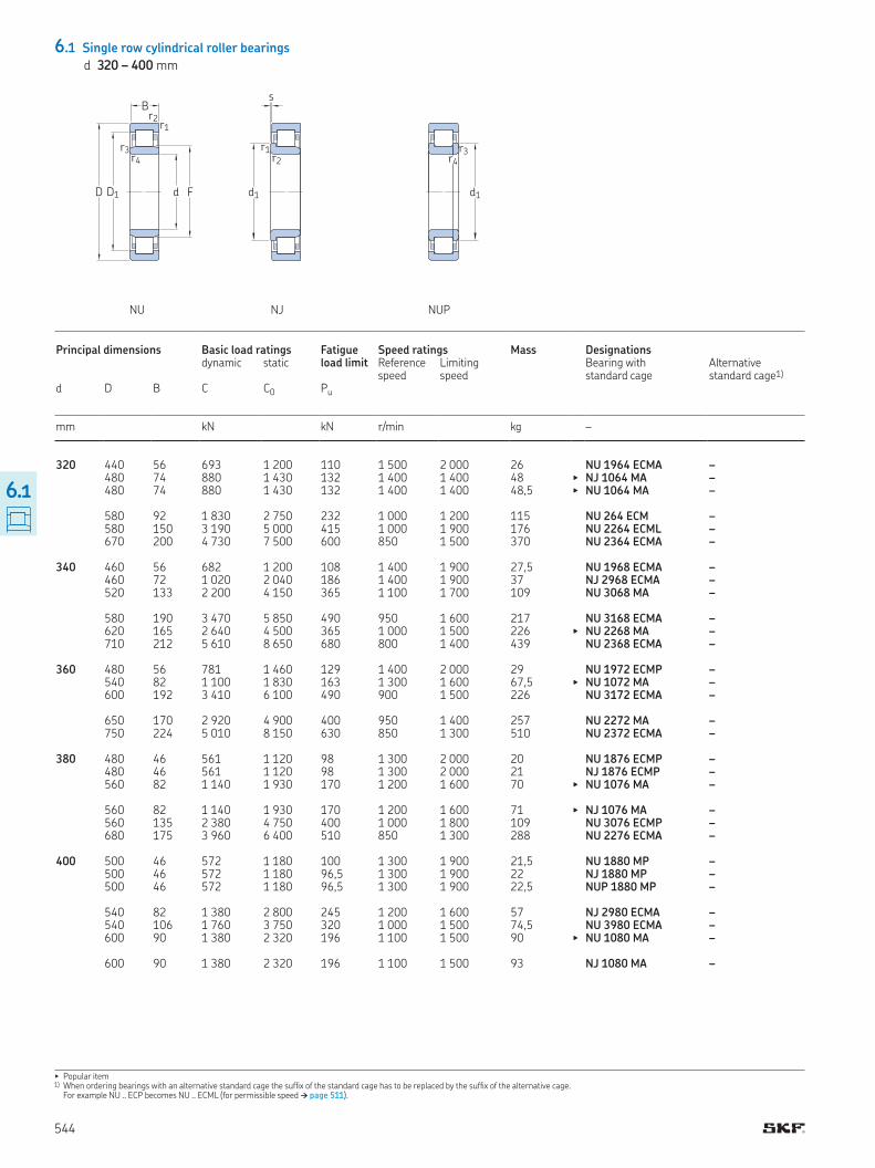
6.1 Single row cylindrical roller bearings
d 320 – 400 mm
▶ Popular item1) When ordering bearings with an alternative standard cage the sufix of the standard cage has to be replaced by the sufix of the alternative cage
For example NU ECP becomes NU ECML (for permissible speed † page 511)
D1D
B
d F
r1r2
r3r4
s
r1r2
d1
NU NJ NUP
r3r4
d1
Principal dimensions Basic load ratings Fatigue load limit
Speed ratings Mass Designations dynamic static Reference
speedLimiting speed
Bearing with standard cage
Alternative standard cage1)
d D B C C0 Pu
mm kN kN r/min kg –
320 440 56 693 1 200 110 1 500 2 000 26 NU 1964 ECMA – 480 74 880 1 430 132 1 400 1 400 48 ▶ NJ 1064 MA – 480 74 880 1 430 132 1 400 1 400 48,5 ▶ NU 1064 MA – 580 92 1 830 2 750 232 1 000 1 200 115 NU 264 ECM – 580 150 3 190 5 000 415 1 000 1 900 176 NU 2264 ECML – 670 200 4 730 7 500 600 850 1 500 370 NU 2364 ECMA – 340 460 56 682 1 200 108 1 400 1 900 27,5 NU 1968 ECMA – 460 72 1 020 2 040 186 1 400 1 900 37 NJ 2968 ECMA – 520 133 2 200 4 150 365 1 100 1 700 109 NU 3068 MA – 580 190 3 470 5 850 490 950 1 600 217 NU 3168 ECMA – 620 165 2 640 4 500 365 1 000 1 500 226 ▶ NU 2268 MA – 710 212 5 610 8 650 680 800 1 400 439 NU 2368 ECMA – 360 480 56 781 1 460 129 1 400 2 000 29 NU 1972 ECMP – 540 82 1 100 1 830 163 1 300 1 600 67,5 ▶ NU 1072 MA – 600 192 3 410 6 100 490 900 1 500 226 NU 3172 ECMA – 650 170 2 920 4 900 400 950 1 400 257 NU 2272 MA – 750 224 5 010 8 150 630 850 1 300 510 NU 2372 ECMA – 380 480 46 561 1 120 98 1 300 2 000 20 NU 1876 ECMP – 480 46 561 1 120 98 1 300 2 000 21 NJ 1876 ECMP – 560 82 1 140 1 930 170 1 200 1 600 70 ▶ NU 1076 MA – 560 82 1 140 1 930 170 1 200 1 600 71 ▶ NJ 1076 MA – 560 135 2 380 4 750 400 1 000 1 800 109 NU 3076 ECMP – 680 175 3 960 6 400 510 850 1 300 288 NU 2276 ECMA – 400 500 46 572 1 180 100 1 300 1 900 21,5 NU 1880 MP – 500 46 572 1 180 96,5 1 300 1 900 22 NJ 1880 MP – 500 46 572 1 180 96,5 1 300 1 900 22,5 NUP 1880 MP – 540 82 1 380 2 800 245 1 200 1 600 57 NJ 2980 ECMA – 540 106 1 760 3 750 320 1 000 1 500 74,5 NU 3980 ECMA – 600 90 1 380 2 320 196 1 100 1 500 90 ▶ NU 1080 MA – 600 90 1 380 2 320 196 1 100 1 500 93 NJ 1080 MA –
544
6.1
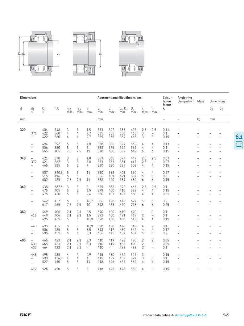
Product data online † skf.com/go/17000-6-1
Da da db
rb
ra
db
ra
Dimensions Abutment and illet dimensions Calcu-lation factor
Angle ring Designation Mass Dimensions
d d1 D1 F, E r1,2 r3,4 s da da db, Da Da ra rb kr B1 B2≈ ≈ min min max min max min max max max
mm mm – – kg mm
320 – 404 348 3 3 1,5 333 347 355 427 2,5 2,5 0,11 – – – – 376 422 360 4 4 9,7 335 355 380 465 3 – 0,1 – – – – – 422 360 4 4 9,7 335 355 364 465 3 3 0,15 – – – – – 494 392 5 5 4,8 338 386 394 562 4 4 0,13 – – – – – 506 380 5 5 5 338 376 394 562 4 4 0,1 – – – – – 565 405 7,5 7,5 11 348 400 394 642 6 6 0,15 – – – – 340 – 421 370 3 3 1,8 353 365 374 447 2,5 2,5 0,07 – – – – 377 421 367 3 3 3,8 353 363 381 447 2,5 – 0,07 – – – – – 465 385 5 5 7 360 380 389 502 4 4 0,15 – – – – – 507 390,5 5 5 14 360 388 403 560 4 4 0,27 – – – – – 515 416 6 6 8 366 401 421 594 5 5 0,3 – – – – – 602 425 7,5 7,5 11 368 420 389 682 6 6 0,15 – – – – 360 – 438 387,5 3 3 2 375 382 392 465 2,5 2,5 0,1 – – – – – 475 405 5 5 6,5 378 400 410 522 4 4 0,15 – – – – – 475 420 5 5 9,4 380 407 425 580 4 4 0,21 – – – – – 542 437 6 6 16,7 386 428 442 624 5 5 0,2 – – – – – 617 465 7,5 7,5 10 392 453 470 718 6 6 0,25 – – – – 380 – 449 406 2,1 2,1 2,5 390 400 410 470 1 1 0,1 – – – – 415 449 406 2,1 2,1 1,5 392 400 421 469 2 – 0,1 – – – – – 495 425 5 5 10,8 398 420 430 542 4 4 0,15 – – – – 443 495 425 5 5 10,8 398 420 448 542 4 – 0,1 – – – – – 506 425 5 5 8,5 398 417 430 542 4 4 0,17 – – – – – 595 451 6 6 8,3 406 445 457 654 5 5 0,2 – – – – 400 – 465 423 2,1 2,1 3,3 410 419 428 490 2 2 0,05 – – – – 433 465 423 2,1 2,1 3,3 410 419 436 490 2 – 0,05 – – – – 432 464 423 2,1 2,1 – 410 – 438 488 2 – 0,1 – – – – 448 495 435 4 4 0,9 415 430 454 525 3 – 0,15 – – – – – 500 434,5 4 4 4 415 429 439 524 3 3 0,1 – – – – – 527 450 5 5 14 418 446 455 582 4 4 0,15 – – – – 472 526 450 5 5 5 418 445 478 582 4 – 0,15 – – – –
545
6.1
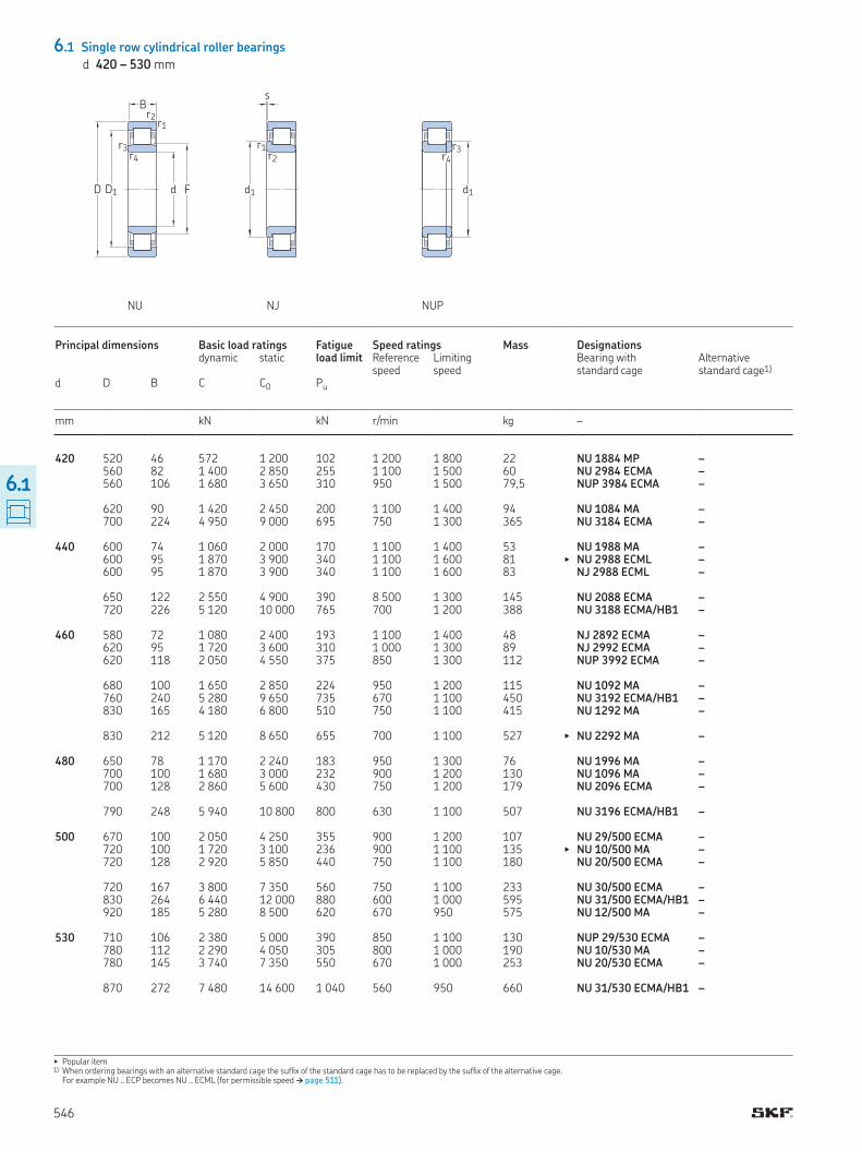
6.1 Single row cylindrical roller bearings
d 420 – 530 mm
▶ Popular item1) When ordering bearings with an alternative standard cage the sufix of the standard cage has to be replaced by the sufix of the alternative cage
For example NU ECP becomes NU ECML (for permissible speed † page 511)
D1D
B
d F
r1r2
r3r4
s
r1r2
d1
NU NJ NUP
r3r4
d1
Principal dimensions Basic load ratings Fatigue load limit
Speed ratings Mass Designations dynamic static Reference
speedLimiting speed
Bearing with standard cage
Alternative standard cage1)
d D B C C0 Pu
mm kN kN r/min kg –
420 520 46 572 1 200 102 1 200 1 800 22 NU 1884 MP – 560 82 1 400 2 850 255 1 100 1 500 60 NU 2984 ECMA – 560 106 1 680 3 650 310 950 1 500 79,5 NUP 3984 ECMA – 620 90 1 420 2 450 200 1 100 1 400 94 NU 1084 MA – 700 224 4 950 9 000 695 750 1 300 365 NU 3184 ECMA – 440 600 74 1 060 2 000 170 1 100 1 400 53 NU 1988 MA – 600 95 1 870 3 900 340 1 100 1 600 81 ▶ NU 2988 ECML – 600 95 1 870 3 900 340 1 100 1 600 83 NJ 2988 ECML – 650 122 2 550 4 900 390 8 500 1 300 145 NU 2088 ECMA – 720 226 5 120 10 000 765 700 1 200 388 NU 3188 ECMA/HB1 – 460 580 72 1 080 2 400 193 1 100 1 400 48 NJ 2892 ECMA – 620 95 1 720 3 600 310 1 000 1 300 89 NJ 2992 ECMA – 620 118 2 050 4 550 375 850 1 300 112 NUP 3992 ECMA – 680 100 1 650 2 850 224 950 1 200 115 NU 1092 MA – 760 240 5 280 9 650 735 670 1 100 450 NU 3192 ECMA/HB1 – 830 165 4 180 6 800 510 750 1 100 415 NU 1292 MA – 830 212 5 120 8 650 655 700 1 100 527 ▶ NU 2292 MA – 480 650 78 1 170 2 240 183 950 1 300 76 NU 1996 MA – 700 100 1 680 3 000 232 900 1 200 130 NU 1096 MA – 700 128 2 860 5 600 430 750 1 200 179 NU 2096 ECMA – 790 248 5 940 10 800 800 630 1 100 507 NU 3196 ECMA/HB1 – 500 670 100 2 050 4 250 355 900 1 200 107 NU 29/500 ECMA – 720 100 1 720 3 100 236 900 1 100 135 ▶ NU 10/500 MA – 720 128 2 920 5 850 440 750 1 100 180 NU 20/500 ECMA – 720 167 3 800 7 350 560 750 1 100 233 NU 30/500 ECMA – 830 264 6 440 12 000 880 600 1 000 595 NU 31/500 ECMA/HB1 – 920 185 5 280 8 500 620 670 950 575 NU 12/500 MA – 530 710 106 2 380 5 000 390 850 1 100 130 NUP 29/530 ECMA – 780 112 2 290 4 050 305 800 1 000 190 NU 10/530 MA – 780 145 3 740 7 350 550 670 1 000 253 NU 20/530 ECMA – 870 272 7 480 14 600 1 040 560 950 660 NU 31/530 ECMA/HB1 –
546
6.1

Product data online † skf.com/go/17000-6-1
Da da db
rb
ra
db
ra
Dimensions Abutment and illet dimensions Calcu-lation factor
Angle ring Designation Mass Dimensions
d d1 D1 F, E r1,2 r3,4 s da da db, Da Da ra rb kr B1 B2≈ ≈ min min max min max min max max max
mm mm – – kg mm
420 – 488 447 2,1 2,1 3,3 431 442 452 508 2 2 0,1 – – – – – 512 449 4 4 2,4 435 444 463 545 3 3 0,07 – – – – 468 518 455 4 4 – 436 – 472 544 3 – 0,15 – – – – – 547 470 5 5 14 438 466 475 602 4 4 0,15 – – – – – 613 485 6 6 14,2 446 478 490 694 5 5 0,21 – – – – 440 – 544 482 4 4 5,5 455 477 487 585 3 3 0,07 – – – – – 552 481,5 4 4 2,4 455 476 487 584 3 3 0,07 – – – – 496 551 481,5 4 4 1,5 455 475 502 585 3 – 0,15 – – – – – 577 487 6 6 11,9 463 483 492 627 5 5 0,14 – – – – – 637 509 6 6 12,5 466 500 514 694 5 5 0,21 – – – – 460 499 543 489 3 3 1,1 473 485 505 567 2,5 – 0,07 – – – – 508 566 495 4 4 4 475 490 515 605 3 – 0,07 – – – – 515 571 501 4 4 – 476 – 520 604 3 – 0,15 – – – – – 600 516 6 6 15,9 483 511 521 657 5 5 0,15 – – – – – 662 529,3 7,5 7,5 13 492 519 534 728 6 6 0,27 – – – – – 715 554 7,5 7,5 6,4 492 542 559 798 6 6 0,13 – – – – – 706 554 7,5 7,5 16,5 492 542 559 798 6 6 0,2 – – – – 480 – 592 525 5 5 6,5 498 517 530 632 4 4 0,07 – – – – – 620 536 6 6 15,9 503 531 541 677 5 5 0,15 – – – – – 629 533 6 6 12,7 503 529 538 677 5 5 0,14 – – – – – 699 547 7,5 7,5 16 512 536 552 758 6 6 0,21 – – – – 500 – 619 539,5 5 5 3 518 534 549 652 4 4 0,1 – – – – – 640 556 6 6 11,2 523 550 561 697 5 5 0,15 – – – – – 649 553 6 6 12,7 523 549 558 697 5 5 0,14 – – – – – 650 540,8 6 6 8,6 523 532 546 697 5 5 0,21 – – – – – 728 576 7,5 7,5 14,5 532 564 581 798 6 6 0,21 – – – – – 780 603,1 7,5 7,5 13,9 532 593 610 888 6 6 0,17 – – – – 530 590 656 573 5 5 – 548 – 595 692 4 – 0,15 – – – – – 692 593 6 6 10,4 553 585 598 757 5 5 0,15 – – – – – 704 591 6 6 6,8 553 587 596 757 5 5 0,2 – – – – – 764 612 7,5 7,5 3 562 605 617 838 6 6 0,21 – – – –
547
6.1
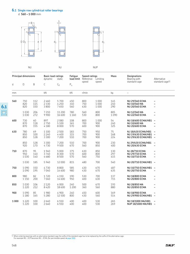
6.1 Single row cylindrical roller bearings
d 560 – 1 000 mm
1) When ordering bearings with an alternative standard cage the sufix of the standard cage has to be replaced by the sufix of the alternative cage For example NU ECP becomes NU ECML (for permissible speed † page 511)
D1D
B
d F
r1r2
r3r4
s
r1r2
d1
NU NJ NUP
r3r4
d1
Principal dimensions Basic load ratings Fatigue load limit
Speed ratings Mass Designations dynamic static Reference
speedLimiting speed
Bearing with standard cage
Alternative standard cage1)
d D B C C0 Pu
mm kN kN r/min kg –
560 750 112 2 460 5 700 450 800 1 000 145 NU 29/560 ECMA – 820 115 2 330 4 250 310 750 1 000 210 NU 10/560 MA – 820 150 3 800 7 650 560 630 1 000 290 NU 20/560 ECMA – 1 030 206 7 210 11 200 780 560 800 805 NU 12/560 MA – 1 030 272 9 900 16 600 1 160 530 800 1 090 NU 22/560 ECMA – 600 730 60 897 2 080 108 800 1 000 54 NU 18/600 ECMA/HB1 – 870 118 2 750 5 100 365 700 900 240 NU 10/600 MA – 870 155 4 180 8 000 570 600 900 325 NU 20/600 ECMA – 630 780 69 1 100 2 500 183 750 950 75 NJ 18/630 ECMA/HB1 – 850 100 2 240 4 400 315 700 900 168 NU 19/630 ECMA/HB1 – 850 128 3 300 7 200 510 700 900 224 NU 29/630 ECMA/HB1 – 850 128 3 300 7 200 510 700 900 230 NJ 29/630 ECMA/HB1 – 920 170 4 730 9 500 670 560 850 400 NU 20/630 ECMA – 710 870 95 1 940 5 000 375 630 850 130 NJ 28/710 ECMA – 950 140 3 740 8 300 570 600 800 297 NU 29/710 ECMA – 1 030 140 4 680 8 500 570 560 750 415 NU 10/710 ECMA – 1 030 185 5 940 12 000 815 480 700 540 NU 20/710 ECMA/HB1 – 750 1 090 150 4 730 8 800 585 430 670 487 NU 10/750 ECMA/HB1 – 1 090 195 7 040 14 600 980 430 670 635 NU 20/750 ECMA – 800 980 82 1 720 4 150 190 530 700 137 NU 18/800 ECMA – 1 150 200 7 040 14 600 950 400 630 715 NU 20/800 ECMA – 850 1 030 106 2 120 6 000 240 500 670 193 NU 28/850 MA – 1 220 212 8 420 18 600 1 200 360 560 880 NU 20/850 ECMA – 900 1 090 85 1 980 4 900 240 450 600 169 NU 18/900 ECMA – 1 180 165 5 280 12 500 800 430 560 514 NU 29/900 ECMA/HB1 – 1 000 1 220 100 2 640 6 550 400 400 530 265 NU 18/1000 MA/HB1 – 1 220 100 2 640 6 550 400 400 530 269 NUP 18/1000 MA/HB1 –
548
6.1
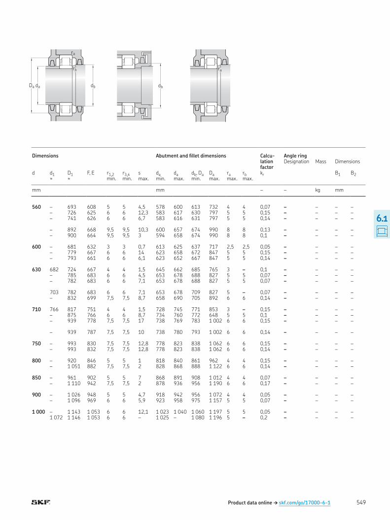
Product data online † skf.com/go/17000-6-1
Da da db
rb
ra
db
ra
Dimensions Abutment and illet dimensions Calcu-lation factor
Angle ring Designation Mass Dimensions
d d1 D1 F, E r1,2 r3,4 s da da db, Da Da ra rb kr B1 B2≈ ≈ min min max min max min max max max
mm mm – – kg mm
560 – 693 608 5 5 4,5 578 600 613 732 4 4 0,07 – – – – – 726 625 6 6 12,3 583 617 630 797 5 5 0,15 – – – – – 741 626 6 6 6,7 583 616 631 797 5 5 0,14 – – – – – 892 668 9,5 9,5 10,3 600 657 674 990 8 8 0,13 – – – – – 900 664 9,5 9,5 3 594 658 674 990 8 8 0,1 – – – – 600 – 681 632 3 3 0,7 613 625 637 717 2,5 2,5 0,05 – – – – – 779 667 6 6 14 623 658 672 847 5 5 0,15 – – – – – 793 661 6 6 6,1 623 652 667 847 5 5 0,14 – – – – 630 682 724 667 4 4 1,5 645 662 685 765 3 – 0,1 – – – – – 785 683 6 6 4,5 653 678 688 827 5 5 0,07 – – – – – 782 683 6 6 7,1 653 678 688 827 5 5 0,07 – – – – 703 782 683 6 6 7,1 653 678 709 827 5 – 0,07 – – – – – 832 699 7,5 7,5 8,7 658 690 705 892 6 6 0,14 – – – – 710 766 817 751 4 4 1,5 728 745 771 853 3 – 0,15 – – – – – 875 766 6 6 8,7 734 760 772 648 5 5 0,1 – – – – – 939 778 7,5 7,5 17 738 769 783 1 002 6 6 0,15 – – – – – 939 787 7,5 7,5 10 738 780 793 1 002 6 6 0,14 – – – – 750 – 993 830 7,5 7,5 12,8 778 823 838 1 062 6 6 0,15 – – – – – 993 832 7,5 7,5 12,8 778 823 838 1 062 6 6 0,14 – – – – 800 – 920 846 5 5 1 818 840 861 962 4 4 0,15 – – – – – 1 051 882 7,5 7,5 2 828 868 888 1 122 6 6 0,14 – – – – 850 – 961 902 5 5 7 868 891 908 1 012 4 4 0,07 – – – – – 1 110 942 7,5 7,5 2 878 936 956 1 190 6 6 0,17 – – – – 900 – 1 026 948 5 5 4,7 918 942 956 1 072 4 4 0,05 – – – – – 1 096 969 6 6 5,9 923 958 975 1 157 5 5 0,07 – – – – 1 000 – 1 143 1 053 6 6 12,1 1 023 1 040 1 060 1 197 5 5 0,05 – – – – 1 072 1 146 1 053 6 6 – 1 025 – 1 080 1 196 5 – 0,2 – – – –
549
6.1
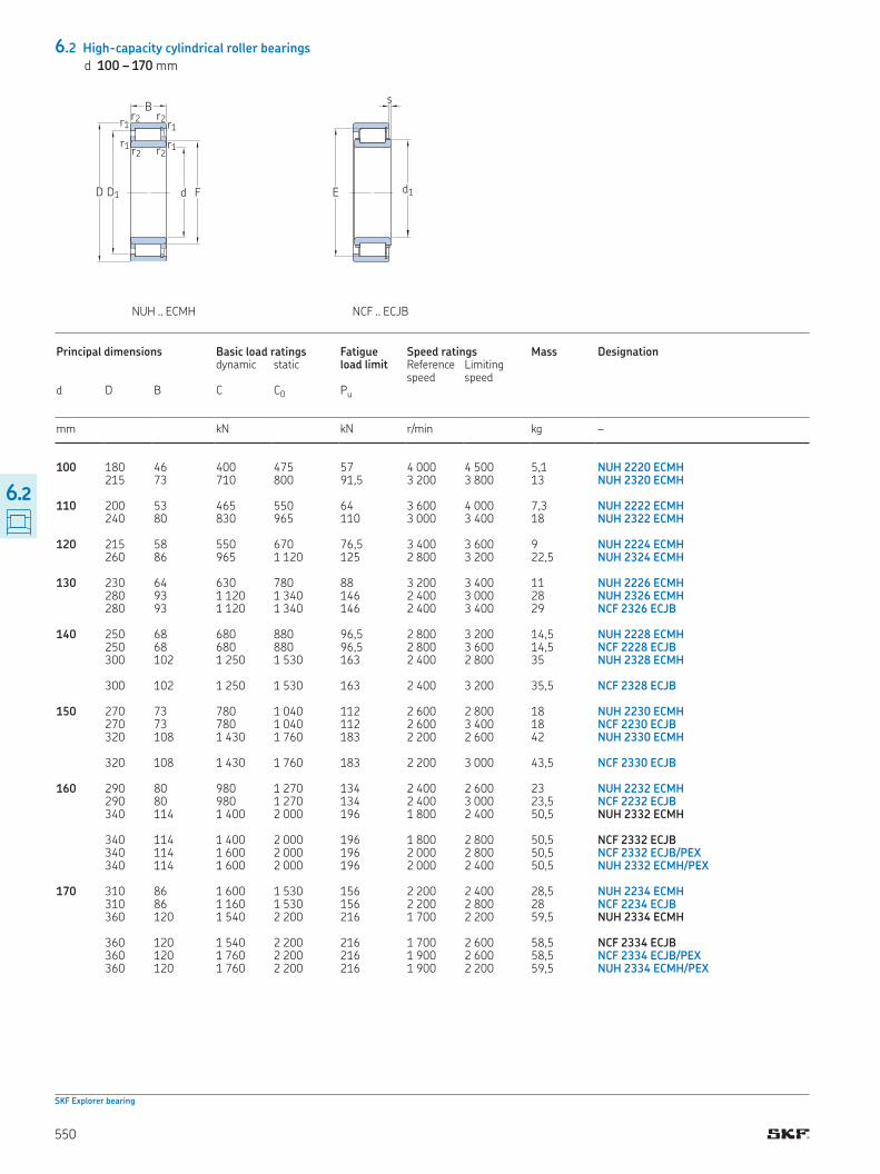
product tables
6.2 High-capacity cylindrical roller bearings
d 100 – 170 mm
SKF Explorer bearing
Principal dimensions Basic load ratings Fatigue load limit
Speed ratings Mass Designation dynamic static Reference
speedLimiting speed
d D B C C0 Pu
mm kN kN r/min kg –
100 180 46 400 475 57 4 000 4 500 5,1 NUH 2220 ECMH 215 73 710 800 91,5 3 200 3 800 13 NUH 2320 ECMH 110 200 53 465 550 64 3 600 4 000 7,3 NUH 2222 ECMH 240 80 830 965 110 3 000 3 400 18 NUH 2322 ECMH 120 215 58 550 670 76,5 3 400 3 600 9 NUH 2224 ECMH 260 86 965 1 120 125 2 800 3 200 22,5 NUH 2324 ECMH 130 230 64 630 780 88 3 200 3 400 11 NUH 2226 ECMH 280 93 1 120 1 340 146 2 400 3 000 28 NUH 2326 ECMH 280 93 1 120 1 340 146 2 400 3 400 29 NCF 2326 ECJB 140 250 68 680 880 96,5 2 800 3 200 14,5 NUH 2228 ECMH 250 68 680 880 96,5 2 800 3 600 14,5 NCF 2228 ECJB 300 102 1 250 1 530 163 2 400 2 800 35 NUH 2328 ECMH 300 102 1 250 1 530 163 2 400 3 200 35,5 NCF 2328 ECJB 150 270 73 780 1 040 112 2 600 2 800 18 NUH 2230 ECMH 270 73 780 1 040 112 2 600 3 400 18 NCF 2230 ECJB 320 108 1 430 1 760 183 2 200 2 600 42 NUH 2330 ECMH 320 108 1 430 1 760 183 2 200 3 000 43,5 NCF 2330 ECJB 160 290 80 980 1 270 134 2 400 2 600 23 NUH 2232 ECMH 290 80 980 1 270 134 2 400 3 000 23,5 NCF 2232 ECJB 340 114 1 400 2 000 196 1 800 2 400 50,5 NUH 2332 ECMH 340 114 1 400 2 000 196 1 800 2 800 50,5 NCF 2332 ECJB 340 114 1 600 2 000 196 2 000 2 800 50,5 NCF 2332 ECJB/PEX 340 114 1 600 2 000 196 2 000 2 400 50,5 NUH 2332 ECMH/PEX 170 310 86 1 600 1 530 156 2 200 2 400 28,5 NUH 2234 ECMH 310 86 1 160 1 530 156 2 200 2 800 28 NCF 2234 ECJB 360 120 1 540 2 200 216 1 700 2 200 59,5 NUH 2334 ECMH 360 120 1 540 2 200 216 1 700 2 600 58,5 NCF 2334 ECJB 360 120 1 760 2 200 216 1 900 2 600 58,5 NCF 2334 ECJB/PEX 360 120 1 760 2 200 216 1 900 2 200 59,5 NUH 2334 ECMH/PEX
FdD1D
B
r1r2
r1 r2r1r2
r1r2
s
E d1
NUH .. ECMH NCF .. ECJB
550
6.2
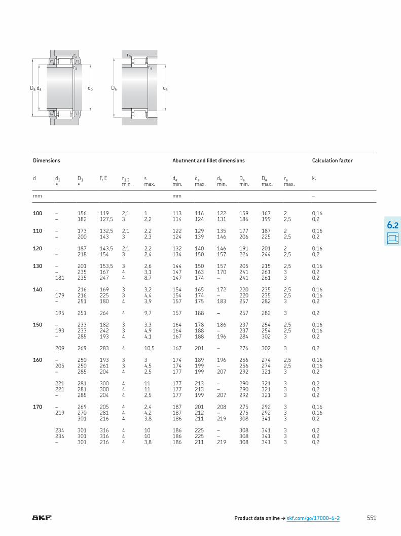
Dimensions Abutment and illet dimensions Calculation factor
d d1 D1 F, E r1,2 s da da db Da Da ra kr≈ ≈ min max min max min min max max
mm mm –
100 – 156 119 2,1 1 113 116 122 159 167 2 0,16 – 182 127,5 3 2,2 114 124 131 186 199 2,5 0,2 110 – 173 132,5 2,1 2,2 122 129 135 177 187 2 0,16 – 200 143 3 2,3 124 139 146 206 225 2,5 0,2 120 – 187 143,5 2,1 2,2 132 140 146 191 201 2 0,16 – 218 154 3 2,4 134 150 157 224 244 2,5 0,2 130 – 201 153,5 3 2,6 144 150 157 205 215 2,5 0,16 – 235 167 4 3,1 147 163 170 241 261 3 0,2 181 235 247 4 8,7 147 174 – 241 261 3 0,2 140 – 216 169 3 3,2 154 165 172 220 235 2,5 0,16 179 216 225 3 4,4 154 174 – 220 235 2,5 0,16 – 251 180 4 3,9 157 175 183 257 282 3 0,2 195 251 264 4 9,7 157 188 – 257 282 3 0,2 150 – 233 182 3 3,3 164 178 186 237 254 2,5 0,16 193 233 242 3 4,9 164 188 – 237 254 2,5 0,16 – 285 193 4 4,1 167 188 196 284 302 3 0,2 209 269 283 4 10,5 167 201 – 276 302 3 0,2 160 – 250 193 3 3 174 189 196 256 274 2,5 0,16 205 250 261 3 4,5 174 199 – 256 274 2,5 0,16 – 285 204 4 2,5 177 199 207 292 321 3 0,2 221 281 300 4 11 177 213 – 290 321 3 0,2 221 281 300 4 11 177 213 – 290 321 3 0,2 – 285 204 4 2,5 177 199 207 292 321 3 0,2 170 – 269 205 4 2,4 187 201 208 275 292 3 0,16 219 270 281 4 4,2 187 212 – 275 292 3 0,16 – 301 216 4 3,8 186 211 219 308 341 3 0,2 234 301 316 4 10 186 225 – 308 341 3 0,2 234 301 316 4 10 186 225 – 308 341 3 0,2 – 301 216 4 3,8 186 211 219 308 341 3 0,2
ra
ra
dbdaDa Da da
ra
ra
Product data online † skf.com/go/17000-6-2 551
6.2
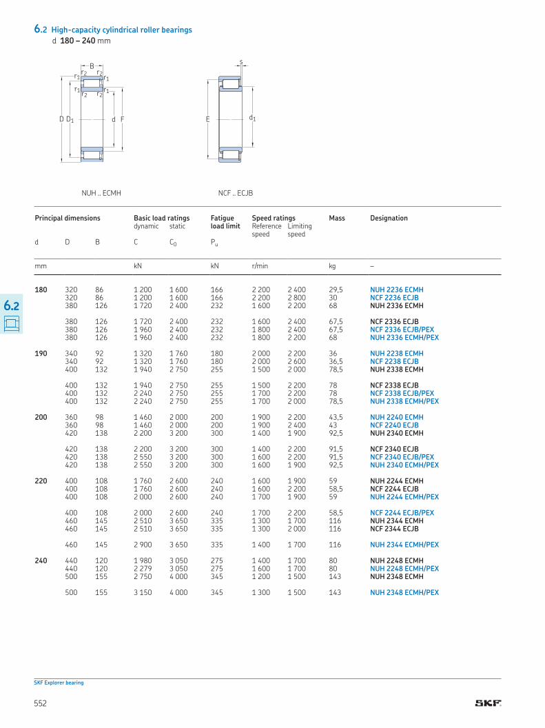
6.2 High-capacity cylindrical roller bearings
d 180 – 240 mm
SKF Explorer bearing
FdD1D
B
r1r2
r1 r2r1r2
r1r2
s
E d1
NUH ECMH NCF ECJB
Principal dimensions Basic load ratings Fatigue load limit
Speed ratings Mass Designation dynamic static Reference
speedLimiting speed
d D B C C0 Pu
mm kN kN r/min kg –
180 320 86 1 200 1 600 166 2 200 2 400 29,5 NUH 2236 ECMH 320 86 1 200 1 600 166 2 200 2 800 30 NCF 2236 ECJB 380 126 1 720 2 400 232 1 600 2 200 68 NUH 2336 ECMH 380 126 1 720 2 400 232 1 600 2 400 67,5 NCF 2336 ECJB 380 126 1 960 2 400 232 1 800 2 400 67,5 NCF 2336 ECJB/PEX 380 126 1 960 2 400 232 1 800 2 200 68 NUH 2336 ECMH/PEX 190 340 92 1 320 1 760 180 2 000 2 200 36 NUH 2238 ECMH 340 92 1 320 1 760 180 2 000 2 600 36,5 NCF 2238 ECJB 400 132 1 940 2 750 255 1 500 2 000 78,5 NUH 2338 ECMH 400 132 1 940 2 750 255 1 500 2 200 78 NCF 2338 ECJB 400 132 2 240 2 750 255 1 700 2 200 78 NCF 2338 ECJB/PEX 400 132 2 240 2 750 255 1 700 2 000 78,5 NUH 2338 ECMH/PEX 200 360 98 1 460 2 000 200 1 900 2 200 43,5 NUH 2240 ECMH 360 98 1 460 2 000 200 1 900 2 400 43 NCF 2240 ECJB 420 138 2 200 3 200 300 1 400 1 900 92,5 NUH 2340 ECMH 420 138 2 200 3 200 300 1 400 2 200 91,5 NCF 2340 ECJB 420 138 2 550 3 200 300 1 600 2 200 91,5 NCF 2340 ECJB/PEX 420 138 2 550 3 200 300 1 600 1 900 92,5 NUH 2340 ECMH/PEX 220 400 108 1 760 2 600 240 1 600 1 900 59 NUH 2244 ECMH 400 108 1 760 2 600 240 1 600 2 200 58,5 NCF 2244 ECJB 400 108 2 000 2 600 240 1 700 1 900 59 NUH 2244 ECMH/PEX 400 108 2 000 2 600 240 1 700 2 200 58,5 NCF 2244 ECJB/PEX 460 145 2 510 3 650 335 1 300 1 700 116 NUH 2344 ECMH 460 145 2 510 3 650 335 1 300 2 000 116 NCF 2344 ECJB 460 145 2 900 3 650 335 1 400 1 700 116 NUH 2344 ECMH/PEX 240 440 120 1 980 3 050 275 1 400 1 700 80 NUH 2248 ECMH 440 120 2 279 3 050 275 1 600 1 700 80 NUH 2248 ECMH/PEX 500 155 2 750 4 000 345 1 200 1 500 143 NUH 2348 ECMH 500 155 3 150 4 000 345 1 300 1 500 143 NUH 2348 ECMH/PEX
552
6.2
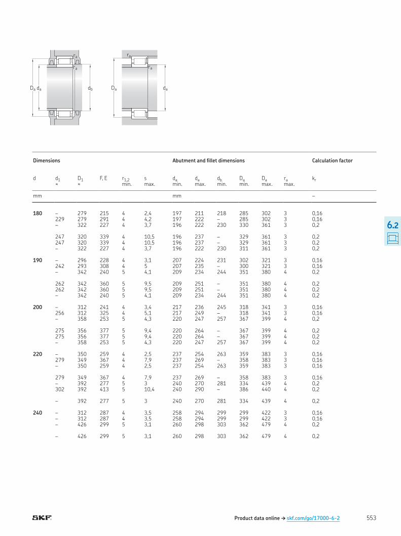
Product data online † skf.com/go/17000-6-2
ra
ra
dbdaDa Da da
ra
ra
Dimensions Abutment and illet dimensions Calculation factor
d d1 D1 F, E r1,2 s da da db Da Da ra kr≈ ≈ min max min max min min max max
mm mm –
180 – 279 215 4 2,4 197 211 218 285 302 3 0,16 229 279 291 4 4,2 197 222 – 285 302 3 0,16 – 322 227 4 3,7 196 222 230 330 361 3 0,2 247 320 339 4 10,5 196 237 – 329 361 3 0,2 247 320 339 4 10,5 196 237 – 329 361 3 0,2 – 322 227 4 3,7 196 222 230 311 361 3 0,2 190 – 296 228 4 3,1 207 224 231 302 321 3 0,16 242 293 308 4 5 207 235 – 300 321 3 0,16 – 342 240 5 4,1 209 234 244 351 380 4 0,2 262 342 360 5 9,5 209 251 – 351 380 4 0,2 262 342 360 5 9,5 209 251 – 351 380 4 0,2 – 342 240 5 4,1 209 234 244 351 380 4 0,2 200 – 312 241 4 3,4 217 236 245 318 341 3 0,16 256 312 325 4 5,1 217 249 – 318 341 3 0,16 – 358 253 5 4,3 220 247 257 367 399 4 0,2 275 356 377 5 9,4 220 264 – 367 399 4 0,2 275 356 377 5 9,4 220 264 – 367 399 4 0,2 – 358 253 5 4,3 220 247 257 367 399 4 0,2 220 – 350 259 4 2,5 237 254 263 359 383 3 0,16 279 349 367 4 7,9 237 269 – 358 383 3 0,16 – 350 259 4 2,5 237 254 263 359 383 3 0,16 279 349 367 4 7,9 237 269 – 358 383 3 0,16 – 392 277 5 3 240 270 281 334 439 4 0,2 302 392 413 5 10,4 240 290 – 386 440 4 0,2 – 392 277 5 3 240 270 281 334 439 4 0,2 240 – 312 287 4 3,5 258 294 299 299 422 3 0,16 – 312 287 4 3,5 258 294 299 299 422 3 0,16 – 426 299 5 3,1 260 298 303 362 479 4 0,2 – 426 299 5 3,1 260 298 303 362 479 4 0,2
553
6.2

product tables
6.3 Single row full complement cylindrical roller bearings
d 20 – 85 mm
▶ Popular item
Principal dimensions Basic load ratings Fatigue load limit
Speed ratings Mass Designation dynamic static Reference
speedLimiting speed
d D B C C0 Pu
mm kN kN r/min kg –
20 42 16 28,1 28,5 3,1 8 500 10 000 0,11 ▶ NCF 3004 CV 25 47 16 31,9 35,5 3,8 7 000 9 000 0,12 NCF 3005 CV 62 24 68,2 68 8,5 4 500 5 600 0,38 NJG 2305 VH 30 55 19 39,6 44 5,3 13 000 15 000 0,2 ▶ NCF 3006 CV 72 27 84,2 86,5 11 4 000 4 800 0,56 NJG 2306 VH 35 62 20 48,4 56 6,55 5 300 6 700 0,26 NCF 3007 CV 80 31 108 114 14,3 3 400 4 300 0,75 NJG 2307 VH 40 68 21 57,2 69,5 8,15 4 800 6 000 0,31 ▶ NCF 3008 CV 90 33 145 156 20 3 000 3 600 1 ▶ NJG 2308 VH 45 75 23 60,5 78 9,15 4 300 5 300 0,4 NCF 3009 CV 100 25 110 112 14 7 500 9 000 0,94 NJG 309 VH 100 36 172 196 25,5 2 800 3 400 1,4 NJG 2309 VH 50 80 23 76,5 98 11,8 4 000 5 000 0,43 ▶ NCF 3010 CV 55 90 26 105 140 17,3 3 400 4 300 0,64 NCF 3011 CV 120 43 233 260 33,5 2 200 2 800 2,3 NJG 2311 VH 60 85 16 55 80 9,15 3 600 4 500 0,27 NCF 2912 CV 95 26 106 146 18,3 3 400 4 000 0,69 NCF 3012 CV 65 90 16 58,3 88 10,2 3 200 4 000 0,31 NCF 2913 CV 100 26 112 163 20 3 000 3 800 0,73 NCF 3013 CV 140 48 303 360 46,5 1 900 2 400 3,55 NJG 2313 VH 70 100 19 76,5 116 13,7 3 000 3 800 0,49 ▶ NCF 2914 CV 110 30 128 173 22,4 6 000 7 000 1 NCF 3014 CV 150 51 336 400 50 1 800 2 200 4,4 NJG 2314 VH 75 105 19 79,2 125 14,6 2 800 3 600 0,52 NCF 2915 CV 115 30 134 190 24,5 2 600 3 200 1,05 NCF 3015 CV 160 55 396 480 60 1 600 2 000 5,35 NJG 2315 VH 80 110 19 80,9 132 15,6 2 600 3 400 0,55 ▶ NCF 2916 CV 125 34 165 228 29 2 400 3 000 1,45 NCF 3016 CV 170 58 457 570 71 1 500 1 900 6,4 NJG 2316 VH 85 120 22 102 166 20,4 6 300 6 300 0,81 NCF 2917 CV 130 34 172 236 30 2 400 3 000 1,5 NCF 3017 CV 180 60 484 620 76,5 1 400 1 800 7,4 NJG 2317 VH
d d1D1ED
B
r1r2
r1 r2r1
r2
r3r4
s
F
r1 r2
r1
r2
NCF NJG
554
6.3
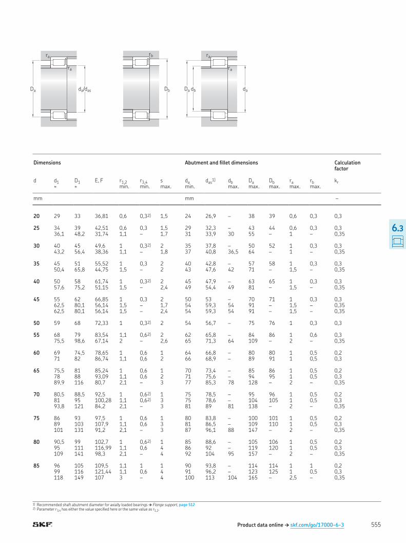
1) Recommended shaft abutment diameter for axially loaded bearings † Flange support, page 5122) Parameter r3,4 has either the value speciied here or the same value as r1,2
Dimensions Abutment and illet dimensions Calculation factor
d d1 D1 E, F r1,2 r3,4 s da das1) db Da Db ra rb kr
≈ ≈ � � min min max min max max max max max
mm mm –
20 29 33 36,81 0,6 0,32) 1,5 24 26,9 – 38 39 0,6 0,3 0,3 25 34 39 42,51 0,6 0,3 1,5 29 32,3 – 43 44 0,6 0,3 0,3 36,1 48,2 31,74 1,1 – 1,7 31 33,9 30 55 – 1 – 0,35 30 40 45 49,6 1 0,32) 2 35 37,8 – 50 52 1 0,3 0,3 43,2 56,4 38,36 1,1 – 1,8 37 40,8 36,5 64 – 1 – 0,35 35 45 51 55,52 1 0,3 2 40 42,8 – 57 58 1 0,3 0,3 50,4 65,8 44,75 1,5 – 2 43 47,6 42 71 – 1,5 – 0,35 40 50 58 61,74 1 0,32) 2 45 47,9 – 63 65 1 0,3 0,3 57,6 75,2 51,15 1,5 – 2,4 49 54,4 49 81 – 1,5 – 0,35 45 55 62 66,85 1 0,3 2 50 53 – 70 71 1 0,3 0,3 62,5 80,1 56,14 1,5 – 1,7 54 59,3 54 91 – 1,5 – 0,35 62,5 80,1 56,14 1,5 – 2,4 54 59,3 54 91 – 1,5 – 0,35 50 59 68 72,33 1 0,32) 2 54 56,7 – 75 76 1 0,3 0,3 55 68 79 83,54 1,1 0,62) 2 62 65,8 – 84 86 1 0,6 0,3 75,5 98,6 67,14 2 – 2,6 65 71,3 64 109 – 2 – 0,35 60 69 74,5 78,65 1 0,6 1 64 66,8 – 80 80 1 0,5 0,2 71 82 86,74 1,1 0,6 2 66 68,9 – 89 91 1 0,5 0,3 65 75,5 81 85,24 1 0,6 1 70 73,4 – 85 86 1 0,5 0,2 78 88 93,09 1,1 0,6 2 71 75,6 – 94 95 1 0,5 0,3 89,9 116 80,7 2,1 – 3 77 85,3 78 128 – 2 – 0,35 70 80,5 88,5 92,5 1 0,62) 1 75 78,5 – 95 96 1 0,5 0,2 81 95 100,28 1,1 0,62) 3 75 78,6 – 104 105 1 0,5 0,3 93,8 121 84,2 2,1 – 3 81 89 81 138 – 2 – 0,35 75 86 93 97,5 1 0,6 1 80 83,8 – 100 101 1 0,5 0,2 89 103 107,9 1,1 0,6 3 81 86,5 – 109 110 1 0,5 0,3 101 131 91,2 2,1 – 3 87 96,1 88 147 – 2 – 0,35 80 90,5 99 102,7 1 0,62) 1 85 88,6 – 105 106 1 0,5 0,2 95 111 116,99 1,1 0,6 4 86 92 – 119 120 1 0,5 0,3 109 141 98,3 2,1 – 4 92 104 95 157 – 2 – 0,35 85 96 105 109,5 1,1 1 1 90 93,8 – 114 114 1 1 0,2 99 116 121,44 1,1 0,6 4 91 96,2 – 123 125 1 0,5 0,3 118 149 107 3 – 4 100 113 104 165 – 2,5 – 0,35
Da da/das
ra
ra
db da
ra
ra
Da
Product data online † skf.com/go/17000-6-3
Db
rb
555
6.3
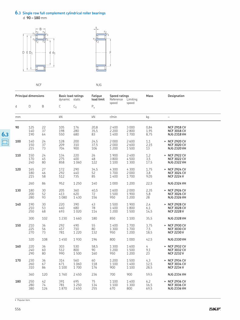
6.3 Single row full complement cylindrical roller bearings
d 90 – 180 mm
▶ Popular item
d d1D1ED
B
r1r2
r1 r2r1
r2
r3r4
s
F
r1 r2
r1
r2
NCF NJG
Principal dimensions Basic load ratings Fatigue load limit
Speed ratings Mass Designation dynamic static Reference
speedLimiting speed
d D B C C0 Pu
mm kN kN r/min kg –
90 125 22 105 176 20,8 2 400 3 000 0,84 NCF 2918 CV 140 37 198 280 35,5 2 200 2 800 1,95 NCF 3018 CV 190 64 550 680 83 1 400 1 700 8,75 NJG 2318 VH 100 140 24 128 200 24,5 2 000 2 600 1,1 ▶ NCF 2920 CV 150 37 209 310 37,5 2 000 2 600 2,15 NCF 3020 CV 215 73 704 900 106 1 200 1 500 13 NJG 2320 VH 110 150 24 134 220 26 1 900 2 400 1,2 ▶ NCF 2922 CV 170 45 275 400 48 3 800 4 500 3,5 NCF 3022 CV 240 80 858 1 060 122 1 100 1 300 17,5 NJG 2322 VH 120 165 27 172 290 34,5 4 300 4 300 1,75 ▶ NCF 2924 CV 180 46 292 440 52 1 700 2 000 3,8 NCF 3024 CV 215 58 512 735 85 1 400 1 700 9,05 NCF 2224 V 260 86 952 1 250 140 1 000 1 200 22,5 NJG 2324 VH 130 180 30 205 360 40,5 1 600 2 000 2,35 ▶ NCF 2926 CV 200 52 413 620 72 1 500 1 900 5,8 NCF 3026 CV 280 93 1 080 1 430 156 950 1 200 28 NJG 2326 VH 140 190 30 220 390 43 1 500 1 900 2,4 ▶ NCF 2928 CV 210 53 440 680 78 1 400 1 800 6,1 NCF 3028 CV 250 68 693 1 020 114 1 200 1 500 14,5 NCF 2228 V 300 102 1 230 1 660 180 850 1 100 35,5 NJG 2328 VH 150 210 36 292 490 55 1 400 1 700 3,75 ▶ NCF 2930 CV 225 56 457 710 80 1 300 1 700 7,5 NCF 3030 CV 270 73 781 1 220 132 950 1 200 18,5 NCF 2230 V 320 108 1 450 1 930 196 800 1 000 42,5 NJG 2330 VH 160 220 36 303 530 58,5 1 300 1 600 4 ▶ NCF 2932 CV 240 60 512 800 90 1 200 1 500 9,1 NCF 3032 CV 290 80 990 1 500 160 950 1 200 23 NCF 2232 V 170 230 36 314 560 60 1 200 1 500 4,3 ▶ NCF 2934 CV 260 67 671 1 060 118 1 100 1 400 12,5 NCF 3034 CV 310 86 1 100 1 700 176 900 1 100 28,5 NCF 2234 V 360 120 1 760 2 450 236 700 900 59,5 NJG 2334 VH 180 250 42 391 695 75 1 100 1 400 6,2 ▶ NCF 2936 CV 280 74 781 1 250 134 1 100 1 300 16,5 NCF 3036 CV 380 126 1 870 2 650 255 670 800 69,5 NJG 2336 VH
556
6.3

1) Recommended shaft abutment diameter for axially loaded bearings † Flange support, page 512
Product data online † skf.com/go/17000-6-3
Da da/das
ra
ra
db da
ra
ra
DaDb
rb
Dimensions Abutment and illet dimensions Calculation factor
d d1 D1 E, F r1,2 r3,4 s da das1) db Da Db ra rb kr
≈ ≈ � � min. min. max. min. max. max. max. max. max.
mm mm –
90 102 111 115,6 1,1 1 1 96 99,8 – 119 119 1 1 0,2 106 124 130,11 1,5 1 4 97 103 – 133 133 1,5 1 0,3 117 152 108,8 3 – 4 102 111 102 176 – 2,5 – 0,35 100 114 126 130,6 1,1 1 1,3 106 111 – 134 134 1 1 0,2 115 134 139,65 1,5 1 4 107 112 – 142 143 1,5 1 0,3 133 173 122,8 3 – 4 114 128 119 201 – 2,5 – 0,35 110 124 136 141,1 1,1 1 1,3 116 122 – 144 144 1 1 0,2 127 149 156,13 2 1 5,5 119 124 – 160 163 2 1 0,3 151 198 134,3 3 – 5 124 143 130 225 – 2,5 – 0,35 120 136 149 154,3 1,1 1 1,3 126 133 – 159 159 1 1 0,2 139 160 167,58 2 1 5,5 129 135 – 170 174 2 1 0,3 150 184 192,32 2,1 2,1 4 131 145 – 204 204 2 2 0,3 164 213 147,39 3 – 5 134 156 143 245 – 2,5 – 0,35 130 147 161 167,1 1,5 1,1 2 138 144 – 172 173 1,5 1 0,2 149 175 183,81 2 1 5,5 138 144 – 190 193 2 1 0,3 175 226 157,9 4 – 6 147 166 153 263 – 3 – 0,35 140 158 173 180 1,5 1,1 2 148 155 – 182 183 1,5 1 0,2 163 189 197,82 2 1 5,5 150 158 – 200 203 2 1 0,3 173 212 221,92 3 3 5 153 167 – 236 236 2,5 2,5 0,3 187 241 168,5 4 – 6,5 157 178 163 283 – 3 – 0,35 150 169 189 196,4 2 1,1 2 159 166 – 201 203 2 1 0,2 170 198 206,8 2,1 1,1 7 159 165 – 214 217 2 1 0,3 184 227 236,71 3 3 6 163 178 – 256 256 2,5 2,5 0,3 202 261 182,5 4 – 6,5 168 192 178 302 – 3 – 0,35 160 180 200 207,2 2 1,1 2,5 169 177 – 211 211 2 1 0,2 185 215 224,86 2,1 1,1 7 171 180 – 230 233 2 1 0,3 208 255 266,36 3 3 6 176 201 – 276 276 2,5 2,5 0,3 170 191 211 218 2 1,1 2,5 179 188 – 221 223 2 1 0,2 198 232 242,85 2,1 1,1 7 181 192 – 249 252 2 1 0,3 219 269 281,09 4 4 7 189 212 – 295 294 3 3 0,3 227 291 203,55 4 – 7 187 215 198 342 – 3 – 0,35 180 203 223 232 2 1,1 2,5 189 199 – 241 243 2 1 0,2 212 248 260,22 2,1 2,1 7 192 206 – 269 269 2 2 0,3 245 309 221,75 4 – 8 199 233 215 361 – 3 – 0,35
557
6.3

6.3 Single row full complement cylindrical roller bearings
d 190 – 340 mm
▶ Popular item
d d1D1ED
B
r1r2
r1 r2r1
r2
r3r4
s
F
r1 r2
r1
r2
NCF NJG
Principal dimensions Basic load ratings Fatigue load limit
Speed ratings Mass Designation dynamic static Reference
speedLimiting speed
d D B C C0 Pu
mm kN kN r/min kg –
190 260 42 440 780 81,5 1 100 1 400 6,5 ▶ NCF 2938 CV 290 75 792 1 290 140 1 000 1 300 17 NCF 3038 CV 340 92 1 250 1 900 196 800 1 000 35,5 NCF 2238 V 400 132 2 160 3 000 280 630 800 80 NJG 2338 VH 200 250 24 176 335 32,5 1 100 1 400 2,6 NCF 1840 V 280 48 528 965 100 1 000 1 300 9,1 ▶ NCF 2940 CV 310 82 913 1 530 160 950 1 200 22,5 NCF 3040 CV 420 138 2 290 3 200 290 600 750 92 NJG 2340 VH 220 270 24 183 365 34,5 1 000 1 200 2,85 NCF 1844 V 300 48 550 1 060 106 900 1 200 9,9 ▶ NCF 2944 CV 340 90 1 080 1 800 186 850 1 100 29,5 NCF 3044 CV 400 108 1 830 2 750 255 700 850 58 NCF 2244 V 460 145 2 700 3 750 335 530 670 111 NJG 2344 VH 240 300 28 260 510 47,5 900 1 100 4,4 NCF 1848 V 320 48 583 1 140 114 850 1 100 10,5 ▶ NCF 2948 CV 360 92 1 140 1 960 200 800 1 000 32 NCF 3048 CV 500 155 3 140 4 400 390 480 600 147 NJG 2348 VH 260 320 28 270 550 50 800 1 000 4,55 NCF 1852 V 360 60 737 1 430 143 750 950 18 ▶ NCF 2952 CV 400 104 1 540 2 550 250 700 900 46,5 NCF 3052 CV 540 165 3 580 5 000 430 430 530 177 NJG 2352 VH 280 350 33 341 695 64 750 950 7,1 NCF 1856 V 380 60 880 1 730 166 700 900 19,5 ▶ NCF 2956 CV 420 106 1 570 2 650 260 670 850 50 NCF 3056 CV 300 380 38 418 850 75 670 850 10 NCF 1860 V 420 72 1 120 2 200 208 630 800 31 ▶ NCF 2960 CV 460 118 1 900 3 250 300 600 750 65,5 NCF 3060 CV 320 400 38 440 900 80 630 800 10,5 NCF 1864 V 440 72 1 140 2 360 220 600 750 33 ▶ NCF 2964 V 480 121 1 980 3 450 310 560 700 71 NCF 3064 CV 340 420 38 446 950 83 600 750 11 NCF 1868 V 460 72 1 190 2 500 228 560 700 35 NCF 2968 V 520 133 2 380 4 150 355 530 670 95 NCF 3068 CV
558
6.3
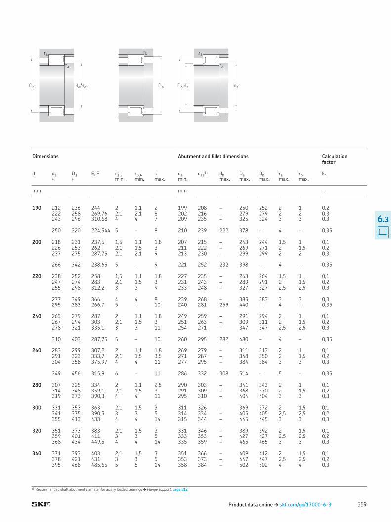
1) Recommended shaft abutment diameter for axially loaded bearings † Flange support, page 512
Product data online † skf.com/go/17000-6-3
Da da/das
ra
ra
db da
ra
ra
DaDb
rb
Dimensions Abutment and illet dimensions Calculation factor
d d1 D1 E, F r1,2 r3,4 s da das1) db Da Db ra rb kr
≈ ≈ � � min. min. max. min. max. max. max. max. max.
mm mm –
190 212 236 244 2 1,1 2 199 208 – 250 252 2 1 0,2 222 258 269,76 2,1 2,1 8 202 216 – 279 279 2 2 0,3 243 296 310,68 4 4 7 209 235 – 325 324 3 3 0,3 250 320 224,544 5 – 8 210 239 222 378 – 4 – 0,35 200 218 231 237,5 1,5 1,1 1,8 207 215 – 243 244 1,5 1 0,1 226 253 262 2,1 1,5 3 211 222 – 269 271 2 1,5 0,2 237 275 287,75 2,1 2,1 9 213 230 – 299 299 2 2 0,3 266 342 238,65 5 – 9 221 252 232 398 – 4 – 0,35 220 238 252 258 1,5 1,1 1,8 227 235 – 263 264 1,5 1 0,1 247 274 283 2,1 1,5 3 231 243 – 289 291 2 1,5 0,2 255 298 312,2 3 3 9 233 248 – 327 327 2,5 2,5 0,3 277 349 366 4 4 8 239 268 – 385 383 3 3 0,3 295 383 266,7 5 – 10 240 281 259 440 – 4 – 0,35 240 263 279 287 2 1,1 1,8 249 259 – 291 294 2 1 0,1 267 294 303 2,1 1,5 3 251 263 – 309 311 2 1,5 0,2 278 321 335,1 3 3 11 254 271 – 347 347 2,5 2,5 0,3 310 403 287,75 5 – 10 260 295 282 480 – 4 – 0,35 260 283 299 307,2 2 1,1 1,8 269 279 – 311 313 2 1 0,1 291 323 333,7 2,1 1,5 3,5 271 287 – 348 350 2 1,5 0,2 304 358 375,97 4 4 11 277 295 – 384 384 3 3 0,3 349 456 315,9 6 – 11 286 332 308 514 – 5 – 0,35 280 307 325 334 2 1,1 2,5 290 303 – 341 343 2 1 0,1 314 348 359,1 2,1 1,5 3 291 309 – 368 370 2 1,5 0,2 319 373 390,3 4 4 11 295 310 – 404 404 3 3 0,3 300 331 353 363 2,1 1,5 3 311 326 – 369 372 2 1,5 0,1 341 375 390,5 3 3 5 314 334 – 405 405 2,5 2,5 0,2 355 413 433 4 4 14 315 344 – 445 445 3 3 0,3 320 351 373 383 2,1 1,5 3 331 346 – 389 392 2 1,5 0,1 359 401 411 3 3 5 333 353 – 427 427 2,5 2,5 0,2 368 434 449,5 4 4 14 335 359 – 465 465 3 3 0,3 340 371 393 403 2,1 1,5 3 351 366 – 409 412 2 1,5 0,1 378 421 431 3 3 5 353 373 – 447 447 2,5 2,5 0,2 395 468 485,65 5 5 14 358 384 – 502 502 4 4 0,3
559
6.3
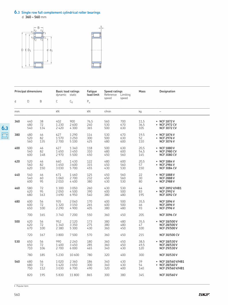
6.3 Single row full complement cylindrical roller bearings
d 360 – 560 mm
s
▶ Popular item
d d1D1ED
B
r1r2
r1 r2r1
r2
r3r4
Principal dimensions Basic load ratings Fatigue load limit
Speed ratings Mass Designation dynamic static Reference
speedLimiting speed
d D B C C0 Pu
mm kN kN r/min kg –
360 440 38 402 900 76,5 560 700 11,5 ▶ NCF 1872 V 480 72 1 230 2 600 240 530 670 36,5 ▶ NCF 2972 CV 540 134 2 420 4 300 365 500 630 105 NCF 3072 CV 380 480 46 627 1 290 114 530 670 19,5 ▶ NCF 1876 V 520 82 1 570 3 250 300 500 630 52 ▶ NCF 2976 V 560 135 2 700 5 100 425 480 600 110 NCF 3076 V 400 500 46 627 1 340 118 500 630 20,5 ▶ NCF 1880 V 540 82 1 650 3 450 310 480 600 54,5 ▶ NCF 2980 CV 600 148 2 970 5 500 450 450 560 145 NCF 3080 CV 420 520 46 660 1 430 122 480 600 20,5 ▶ NCF 1884 V 560 82 1 650 3 600 315 450 560 57 ▶ NCF 2984 V 620 150 3 030 5 700 455 430 530 150 NCF 3084 CV 440 540 46 671 1 460 125 450 560 22 ▶ NCF 1888 V 540 60 1 060 2 700 232 450 560 30 NCF 2888 V 600 95 2 010 4 400 380 430 530 80 ▶ NCF 2988 V 460 580 72 1 300 3 050 260 430 530 44 NCF 2892 V/HB1 620 95 2 050 4 500 390 400 500 83 ▶ NCF 2992 V 680 163 3 690 6 950 540 380 480 195 NCF 3092 CV 480 600 56 935 2 040 170 400 500 35,5 NCF 1896 V 600 72 1 320 3 150 265 400 500 46 NCF 2896 V 650 100 2 290 4 900 405 380 480 93 ▶ NCF 2996 V 700 165 3 740 7 200 550 360 450 205 NCF 3096 CV 500 620 56 952 2 120 173 380 480 35,5 ▶ NCF 18/500 V 620 72 1 340 3 350 275 380 480 47 NCF 28/500 V 670 100 2 380 5 300 430 360 450 100 NCF 29/500 V 720 167 3 800 7 500 570 360 450 215 NCF 30/500 CV 530 650 56 990 2 240 180 360 450 38,5 ▶ NCF 18/530 V 650 72 1 400 3 450 285 360 450 49,5 NCF 28/530 V 710 106 2 700 6 000 465 340 430 120 NCF 29/530 V 780 185 5 230 10 600 780 320 400 300 NCF 30/530 V 560 680 56 1 020 2 360 186 340 430 39 ▶ NCF 18/560 V/HB1 680 72 1 420 3 650 300 340 430 54 ▶ NCF 28/560 V 750 112 3 030 6 700 490 320 400 140 NCF 29/560 V/HB1 820 195 5 830 11 800 865 300 380 345 NCF 30/560 V
560
6.3
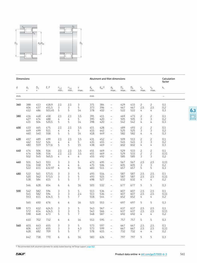
1) Recommended shaft abutment diameter for axially loaded bearings † Flange support, page 512
Product data online † skf.com/go/17000-6-3
Da da/das
ra
ra
Db
rb
Dimensions Abutment and illet dimensions Calculation factor
d d1 D1 E, F r1,2 r3,4 s da das1) db Da Db ra rb kr
≈ ≈ � � min. min. max. min. max. max. max. max. max.
mm mm –
360 388 413 418,9 2,1 2,1 3 371 384 – 429 433 2 2 0,1 404 437 451,5 3 3 5 373 396 – 467 467 2,5 2,5 0,2 412 486 503,45 5 5 14 378 402 – 522 522 4 4 0,3 380 416 448 458 2,1 2,1 3,5 391 411 – 469 473 2 2 0,1 427 474 488 4 4 5 395 420 – 505 505 3 3 0,2 431 504 520,5 5 5 14 398 420 – 542 542 4 4 0,3 400 433 465 475 2,1 2,1 3,5 411 428 – 489 493 2 2 0,1 449 499 511 4 4 5 415 442 – 525 525 3 3 0,2 460 540 558 5 5 14 418 449 – 582 582 4 4 0,3 420 457 489 499 2,1 2,1 3,5 431 452 – 509 513 2 2 0,1 462 512 524 4 4 5 435 455 – 545 545 3 3 0,2 480 559 577,6 5 5 15 438 469 – 602 602 4 4 0,3 440 474 506 516 2,1 2,1 3,5 451 469 – 529 533 2 2 0,1 474 508 516 2,1 2,1 3,5 451 469 – 529 533 2 2 0,11 502 545 565,5 4 4 6 455 492 – 585 585 3 3 0,2 460 501 543 553 3 3 5 473 495 – 567 567 2,5 2,5 0,11 516 558 579 4 4 6 475 506 – 605 605 3 3 0,2 522 611 632,97 6 6 16 483 511 – 657 657 5 5 0,3 480 522 561 573,5 3 3 5 493 516 – 587 587 2,5 2,5 0,1 520 562 573,5 3 3 5 493 515 – 587 587 2,5 2,5 0,11 538 584 615 5 5 7 498 527 – 632 632 4 4 0,2 546 628 654 6 6 16 503 532 – 677 677 5 5 0,3 500 542 582 594 3 3 5 513 536 – 607 607 2,5 2,5 0,1 541 582 594 3 3 2,4 513 536 – 607 607 2,5 2,5 0,11 553 611 634,5 5 5 7 518 544 – 652 652 4 4 0,2 565 650 676 6 6 16 523 553 – 697 697 5 5 0,3 530 573 612 624,5 3 3 5 543 567 – 637 637 2,5 2,5 0,1 572 614 624,5 3 3 5 543 566 – 637 637 2,5 2,5 0,11 598 648 673 5 5 7 548 587 – 692 692 4 4 0,2 610 702 732 6 6 16 553 595 – 757 757 5 5 0,3 560 603 643 655 3 3 5 573 597 – 667 667 2,5 2,5 0,1 606 637 655 3 3 4,3 573 599 – 667 667 2,5 2,5 0,11 628 682 709 5 5 7 578 615 – 732 732 4 4 0,2 642 738 770 6 6 16 583 626 – 797 797 5 5 0,3
561
6.3
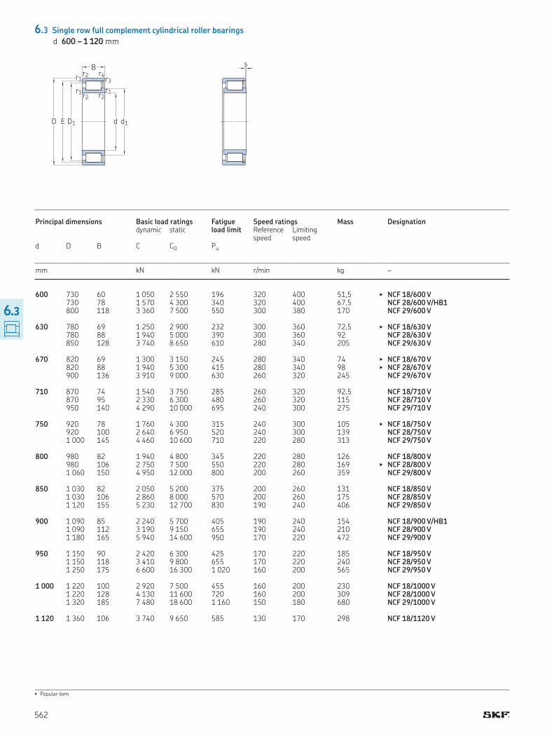
6.3 Single row full complement cylindrical roller bearings
d 600 – 1 120 mm
▶ Popular item
d d1D1ED
B
r1r2
r1 r2r1
r2
r3r4
s
Principal dimensions Basic load ratings Fatigue load limit
Speed ratings Mass Designation dynamic static Reference
speedLimiting speed
d D B C C0 Pu
mm kN kN r/min kg –
600 730 60 1 050 2 550 196 320 400 51,5 ▶ NCF 18/600 V 730 78 1 570 4 300 340 320 400 67,5 NCF 28/600 V/HB1 800 118 3 360 7 500 550 300 380 170 NCF 29/600 V 630 780 69 1 250 2 900 232 300 360 72,5 ▶ NCF 18/630 V 780 88 1 940 5 000 390 300 360 92 NCF 28/630 V 850 128 3 740 8 650 610 280 340 205 NCF 29/630 V 670 820 69 1 300 3 150 245 280 340 74 ▶ NCF 18/670 V 820 88 1 940 5 300 415 280 340 98 ▶ NCF 28/670 V 900 136 3 910 9 000 630 260 320 245 NCF 29/670 V 710 870 74 1 540 3 750 285 260 320 92,5 NCF 18/710 V 870 95 2 330 6 300 480 260 320 115 NCF 28/710 V 950 140 4 290 10 000 695 240 300 275 NCF 29/710 V 750 920 78 1 760 4 300 315 240 300 105 ▶ NCF 18/750 V 920 100 2 640 6 950 520 240 300 139 NCF 28/750 V 1 000 145 4 460 10 600 710 220 280 313 NCF 29/750 V 800 980 82 1 940 4 800 345 220 280 126 NCF 18/800 V 980 106 2 750 7 500 550 220 280 169 ▶ NCF 28/800 V 1 060 150 4 950 12 000 800 200 260 359 NCF 29/800 V 850 1 030 82 2 050 5 200 375 200 260 131 NCF 18/850 V 1 030 106 2 860 8 000 570 200 260 175 NCF 28/850 V 1 120 155 5 230 12 700 830 190 240 406 NCF 29/850 V 900 1 090 85 2 240 5 700 405 190 240 154 NCF 18/900 V/HB1 1 090 112 3 190 9 150 655 190 240 210 NCF 28/900 V 1 180 165 5 940 14 600 950 170 220 472 NCF 29/900 V 950 1 150 90 2 420 6 300 425 170 220 185 NCF 18/950 V 1 150 118 3 410 9 800 655 170 220 240 NCF 28/950 V 1 250 175 6 600 16 300 1 020 160 200 565 NCF 29/950 V 1 000 1 220 100 2 920 7 500 455 160 200 230 NCF 18/1000 V 1 220 128 4 130 11 600 720 160 200 309 NCF 28/1000 V 1 320 185 7 480 18 600 1 160 150 180 680 NCF 29/1000 V 1 120 1 360 106 3 740 9 650 585 130 170 298 NCF 18/1120 V
562
6.3
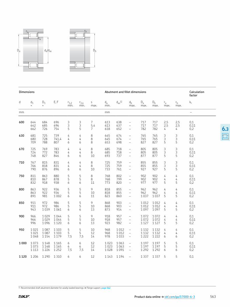
1) Recommended shaft abutment diameter for axially loaded bearings † Flange support, page 512
Product data online † skf.com/go/17000-6-3
Da da/das
ra
ra
Db
rb
Dimensions Abutment and illet dimensions Calculation factor
d d1 D1 E, F r1,2 r3,4 s da das1) db Da Db ra rb kr
≈ ≈ � � min. min. max. min. max. max. max. max. max.
mm mm –
600 644 684 696 3 3 7 613 638 – 717 717 2,5 2,5 0,1 642 685 696 3 3 5,4 613 637 – 717 717 2,5 2,5 0,11 662 726 754 5 5 7 618 652 – 782 782 4 4 0,2 630 681 725 739 4 4 8 645 674 – 765 765 3 3 0,1 680 728 741,4 4 4 8 645 674 – 765 765 3 3 0,11 709 788 807 6 6 8 653 698 – 827 827 5 5 0,2 670 725 769 783 4 4 8 685 718 – 805 805 3 3 0,1 724 772 783 4 4 8 685 718 – 805 805 3 3 0,11 748 827 846 6 6 10 693 737 – 877 877 5 5 0,2 710 767 815 831 4 4 8 725 759 – 855 855 3 3 0,1 766 818 831 4 4 8 725 759 – 855 855 3 3 0,11 790 876 896 6 6 10 733 761 – 927 927 5 5 0,2 750 811 863 880 5 5 8 768 802 – 902 902 4 4 0,1 810 867 878 5 5 8 768 799 – 902 902 4 4 0,11 832 918 938 6 6 11 773 820 – 977 977 5 5 0,2 800 863 922 936 5 5 9 818 855 – 962 962 4 4 0,1 863 922 936 5 5 10 818 855 – 962 962 4 4 0,11 891 981 1 002 6 6 11 823 860 – 1 037 1 037 5 5 0,2 850 911 972 986 5 5 9 868 903 – 1 012 1 012 4 4 0,1 911 972 986 5 5 10 868 903 – 1 012 1 012 4 4 0,11 943 1 039 1 061 6 6 13 873 914 – 1 097 1 097 5 5 0,2 900 966 1 029 1 044 5 5 9 918 957 – 1 072 1 072 4 4 0,1 966 1 029 1 044 5 5 10 918 957 – 1 072 1 072 4 4 0,11 996 1 096 1 120 6 6 13 923 982 – 1 127 1 127 5 5 0,2 950 1 021 1 087 1 103 5 5 10 968 1 012 – 1 132 1 132 4 4 0,1 1 021 1 087 1 103 5 5 12 968 1 012 – 1 132 1 132 4 4 0,11 1 048 1 154 1 179 7,5 7,5 14 978 1 033 – 1 222 1 222 6 6 0,2 1 000 1 073 1 148 1 165 6 6 12 1 023 1 063 – 1 197 1 197 5 5 0,1 1 073 1 148 1 165 6 6 12 1 023 1 063 – 1 197 1 197 5 5 0,11 1 113 1 226 1 252 7,5 7,5 14 1 028 1 091 – 1 292 1 292 6 6 0,2 1 120 1 206 1 290 1 310 6 6 12 1 143 1 194 – 1 337 1 337 5 5 0,1
563
6.3
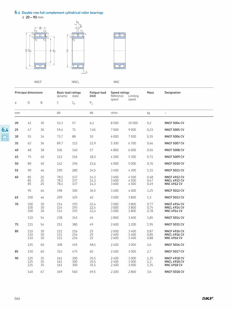
product tables
6.4 Double row full complement cylindrical roller bearings
d 20 – 90 mm
Principal dimensions Basic load ratings Fatigue load limit
Speed ratings Mass Designation dynamic static Reference
speedLimiting speed
d D B C C0 Pu
mm kN kN r/min kg –
20 42 30 52,3 57 6,2 8 500 10 000 0,2 NNCF 5004 CV 25 47 30 59,4 71 7,65 7 000 9 000 0,23 NNCF 5005 CV 30 55 34 73,7 88 10 6 000 7 500 0,35 NNCF 5006 CV 35 62 36 89,7 112 12,9 5 300 6 700 0,46 NNCF 5007 CV 40 68 38 106 140 17 4 800 6 000 0,56 NNCF 5008 CV 45 75 40 112 156 18,3 4 300 5 300 0,71 NNCF 5009 CV 50 80 40 142 196 23,6 4 000 5 000 0,76 NNCF 5010 CV 55 90 46 190 280 34,5 3 400 4 300 1,15 NNCF 5011 CV 60 85 25 78,1 137 14,3 3 600 4 500 0,48 NNCF 4912 CV
85 25 78,1 137 14,3 3 600 4 500 0,47 NNCL 4912 CV 85 25 78,1 137 14,3 3 600 4 500 0,49 NNC 4912 CV 95 46 198 300 36,5 3 400 4 000 1,25 NNCF 5012 CV 65 100 46 209 325 40 3 000 3 800 1,3 NNCF 5013 CV 70 100 30 114 193 22,4 3 000 3 800 0,77 NNCF 4914 CV
100 30 114 193 22,4 3 000 3 800 0,75 NNCL 4914 CV 100 30 114 193 22,4 3 000 3 800 0,78 NNC 4914 CV 110 54 238 345 45 2 800 3 600 1,85 NNCF 5014 CV 75 115 54 251 380 49 2 600 3 200 1,95 NNCF 5015 CV 80 110 30 121 216 25 2 600 3 400 0,87 NNCF 4916 CV
110 30 121 216 25 2 600 3 400 0,85 NNCL 4916 CV 110 30 121 216 25 2 600 3 400 0,88 NNC 4916 CV 125 60 308 455 58,5 2 400 3 000 2,6 NNCF 5016 CV 85 130 60 314 475 60 2 400 3 000 2,7 NNCF 5017 CV 90 125 35 161 300 35,5 2 400 3 000 1,35 NNCF 4918 CV
125 35 161 300 35,5 2 400 3 000 1,3 NNCL 4918 CV125 35 161 300 35,5 2 400 3 000 1,35 NNC 4918 CV
140 67 369 560 69,5 2 200 2 800 3,6 NNCF 5018 CV
NNCF NNCL NNC
d d1D
B
r1
r1
r1r2
r2
r2
r3
r4
D1
s
K
b1
r1r2
r1r2
E
564
6.4
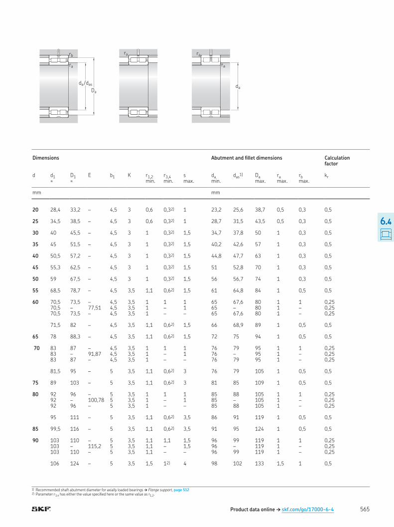
1) Recommended shaft abutment diameter for axially loaded bearings † Flange support, page 5122) Parameter r3,4 has either the value speciied here or the same value as r1,2
Dimensions Abutment and illet dimensions Calculation factor
d d1 D1 E b1 K r1,2 r3,4 s da das1) Da ra rb kr
≈ ≈ min min max min max max max
mm mm
20 28,4 33,2 – 4,5 3 0,6 0,32) 1 23,2 25,6 38,7 0,5 0,3 0,5 25 34,5 38,5 – 4,5 3 0,6 0,32) 1 28,7 31,5 43,5 0,5 0,3 0,5 30 40 45,5 – 4,5 3 1 0,32) 1,5 34,7 37,8 50 1 0,3 0,5 35 45 51,5 – 4,5 3 1 0,32) 1,5 40,2 42,6 57 1 0,3 0,5 40 50,5 57,2 – 4,5 3 1 0,32) 1,5 44,8 47,7 63 1 0,3 0,5 45 55,3 62,5 – 4,5 3 1 0,32) 1,5 51 52,8 70 1 0,3 0,5 50 59 67,5 – 4,5 3 1 0,32) 1,5 56 56,7 74 1 0,3 0,5 55 68,5 78,7 – 4,5 3,5 1,1 0,62) 1,5 61 64,8 84 1 0,5 0,5 60 70,5 73,5 – 4,5 3,5 1 1 1 65 67,6 80 1 1 0,25
70,5 – 77,51 4,5 3,5 1 – 1 65 – 80 1 – 0,25 70,5 73,5 – 4,5 3,5 1 – – 65 67,6 80 1 – 0,25 71,5 82 – 4,5 3,5 1,1 0,62) 1,5 66 68,9 89 1 0,5 0,5 65 78 88,3 – 4,5 3,5 1,1 0,62) 1,5 72 75 94 1 0,5 0,5 70 83 87 – 4,5 3,5 1 1 1 76 79 95 1 1 0,25
83 – 91,87 4,5 3,5 1 – 1 76 – 95 1 – 0,25 83 87 – 4,5 3,5 1 – – 76 79 95 1 – 0,25 81,5 95 – 5 3,5 1,1 0,62) 3 76 79 105 1 0,5 0,5 75 89 103 – 5 3,5 1,1 0,62) 3 81 85 109 1 0,5 0,5 80 92 96 – 5 3,5 1 1 1 85 88 105 1 1 0,25
92 – 100,78 5 3,5 1 – 1 85 – 105 1 – 0,25 92 96 – 5 3,5 1 – – 85 88 105 1 – 0,25 95 111 – 5 3,5 1,1 0,62) 3,5 86 91 119 1 0,5 0,5 85 99,5 116 – 5 3,5 1,1 0,62) 3,5 91 95 124 1 0,5 0,5 90 103 110 – 5 3,5 1,1 1,1 1,5 96 99 119 1 1 0,25
103 – 115,2 5 3,5 1,1 – 1,5 96 – 119 1 – 0,25103 110 – 5 3,5 1,1 – – 96 99 119 1 – 0,25
106 124 – 5 3,5 1,5 12) 4 98 102 133 1,5 1 0,5
Product data online † skf.com/go/17000-6-4
ra
ra
ra
daDa
ra
rb
da / das
565
6.4
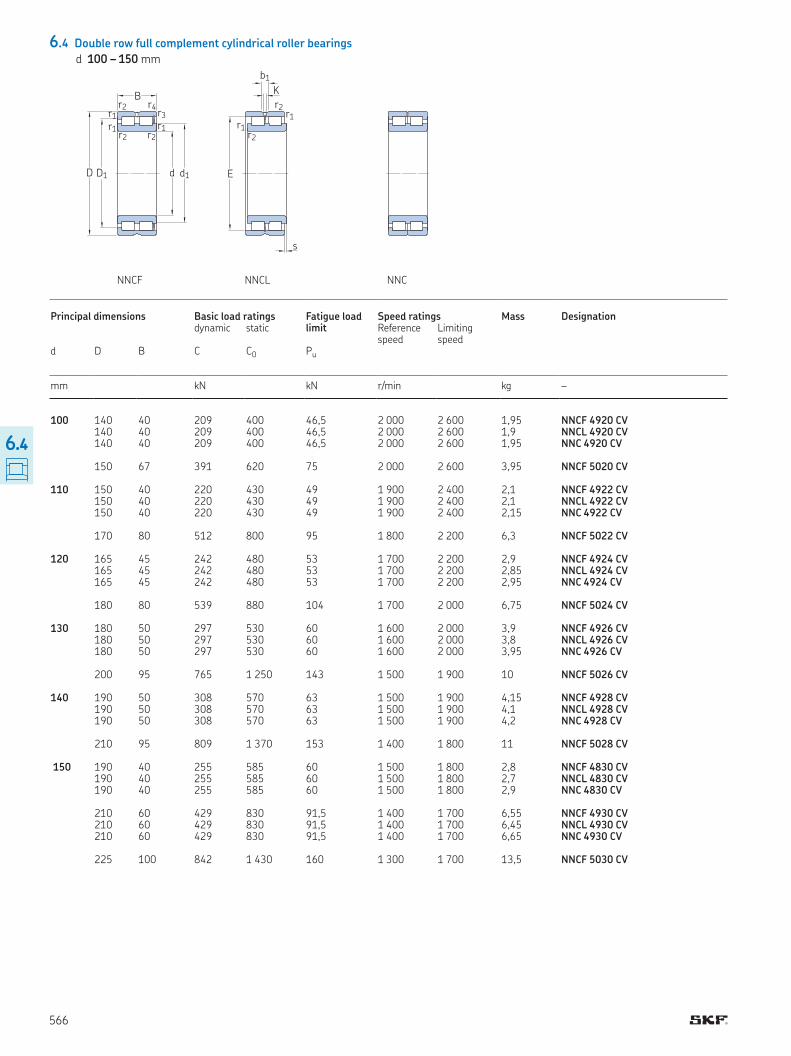
6.4 Double row full complement cylindrical roller bearings
d 100 – 150 mm
NNCF NNCL NNC
d d1D
B
r1
r1
r1r2
r2
r2
r3
r4
D1
s
K
b1
r1r2
r1r2
E
Principal dimensions Basic load ratings Fatigue load limit
Speed ratings Mass Designation dynamic static Reference
speedLimiting speed
d D B C C0 Pu
mm kN kN r/min kg –
100 140 40 209 400 46,5 2 000 2 600 1,95 NNCF 4920 CV140 40 209 400 46,5 2 000 2 600 1,9 NNCL 4920 CV
140 40 209 400 46,5 2 000 2 600 1,95 NNC 4920 CV 150 67 391 620 75 2 000 2 600 3,95 NNCF 5020 CV 110 150 40 220 430 49 1 900 2 400 2,1 NNCF 4922 CV 150 40 220 430 49 1 900 2 400 2,1 NNCL 4922 CV 150 40 220 430 49 1 900 2 400 2,15 NNC 4922 CV 170 80 512 800 95 1 800 2 200 6,3 NNCF 5022 CV 120 165 45 242 480 53 1 700 2 200 2,9 NNCF 4924 CV
165 45 242 480 53 1 700 2 200 2,85 NNCL 4924 CV 165 45 242 480 53 1 700 2 200 2,95 NNC 4924 CV 180 80 539 880 104 1 700 2 000 6,75 NNCF 5024 CV 130 180 50 297 530 60 1 600 2 000 3,9 NNCF 4926 CV
180 50 297 530 60 1 600 2 000 3,8 NNCL 4926 CV 180 50 297 530 60 1 600 2 000 3,95 NNC 4926 CV 200 95 765 1 250 143 1 500 1 900 10 NNCF 5026 CV 140 190 50 308 570 63 1 500 1 900 4,15 NNCF 4928 CV
190 50 308 570 63 1 500 1 900 4,1 NNCL 4928 CV 190 50 308 570 63 1 500 1 900 4,2 NNC 4928 CV 210 95 809 1 370 153 1 400 1 800 11 NNCF 5028 CV 150 190 40 255 585 60 1 500 1 800 2,8 NNCF 4830 CV
190 40 255 585 60 1 500 1 800 2,7 NNCL 4830 CV 190 40 255 585 60 1 500 1 800 2,9 NNC 4830 CV 210 60 429 830 91,5 1 400 1 700 6,55 NNCF 4930 CV 210 60 429 830 91,5 1 400 1 700 6,45 NNCL 4930 CV 210 60 429 830 91,5 1 400 1 700 6,65 NNC 4930 CV 225 100 842 1 430 160 1 300 1 700 13,5 NNCF 5030 CV
566
6.4
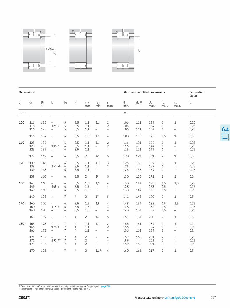
1) Recommended shaft abutment diameter for axially loaded bearings † Flange support, page 5122) Parameter r3,4 has either the value speciied here or the same value as r1,2
Product data online † skf.com/go/17000-6-4
ra
ra
ra
daDa
ra
rb
da / das
Dimensions Abutment and illet dimensions Calculation factor
d d1 D1 E b1 K r1,2 r3,4 s da das1) Da ra rb kr
≈ ≈ min min max min max max max
mm mm
100 116 125 – 5 3,5 1,1 1,1 2 106 111 134 1 1 0,25116 – 129,6 5 3,5 1,1 – 2 106 – 134 1 – 0,25
116 125 – 5 3,5 1,1 – – 106 111 134 1 – 0,25 116 134 – 6 3,5 1,5 12) 4 108 113 143 1,5 1 0,5 110 125 134 – 6 3,5 1,1 1,1 2 116 121 144 1 1 0,25 125 – 138,2 6 3,5 1,1 – 2 116 – 144 1 – 0,25 125 134 – 6 3,5 1,1 – – 116 121 144 1 – 0,25 127 149 – 6 3,5 2 12) 5 120 124 161 2 1 0,5 120 139 148 – 6 3,5 1,1 1,1 3 126 136 159 1 1 0,25
139 – 153,55 6 3,5 1,1 – 3 126 – 159 1 – 0,25 139 148 – 6 3,5 1,1 – – 126 133 159 1 – 0,25 139 160 – 6 3,5 2 12) 5 130 130 171 2 1 0,5 130 149 160 – 6 3,5 1,5 1,5 4 138 144 173 1,5 1,5 0,25
149 – 165,4 6 3,5 1,5 – 4 138 – 173 1,5 – 0,25 149 160 – 6 3,5 1,5 – – 138 144 173 1,5 – 0,25 149 175 – 7 4 2 12) 5 141 145 190 2 1 0,5 140 160 170 – 6 3,5 1,5 1,5 4 148 154 182 1,5 1,5 0,25
160 – 175,9 6 3,5 1,5 – 4 148 – 182 1,5 – 0,25 160 170 – 6 3,5 1,5 – – 148 154 182 1,5 – 0,25 163 189 – 7 4 2 12) 5 151 157 200 2 1 0,5 150 166 173 – 7 4 1,1 1,1 2 156 161 184 1 1 0,2
166 – 178,3 7 4 1,1 – 2 156 – 184 1 – 0,2 166 173 – 7 4 1,1 – – 156 161 184 1 – 0,2 171 187 – 7 4 2 2 4 159 165 201 2 2 0,25 171 – 192,77 7 4 2 – 4 159 – 201 2 – 0,25 171 187 – 7 4 2 – – 159 165 201 2 – 0,25 170 198 – 7 4 2 1,12) 6 160 166 217 2 1 0,5
567
6.4

6.4 Double row full complement cylindrical roller bearings
d 160 – 190 mm
NNCF NNCL NNC
d d1D
B
r1
r1
r1r2
r2
r2
r3
r4
D1
s
K
b1
r1r2
r1r2
E
Principal dimensions Basic load ratings Fatigue load limit
Speed ratings Mass Designation dynamic static Reference
speedLimiting speed
d D B C C0 Pu
mm kN kN r/min kg –
160 200 40 260 610 62 1 400 1 700 3 NNCF 4832 CV200 40 260 610 62 1 400 1 700 2,9 NNCL 4832 CV
200 40 260 610 62 1 400 1 700 3,1 NNC 4832 CV 220 60 446 915 96,5 1 300 1 600 6,9 NNCF 4932 CV 220 60 446 915 96,5 1 300 1 600 6,8 NNCL 4932 CV 220 60 446 915 96,5 1 300 1 600 7 NNC 4932 CV 240 109 952 1 600 180 1 200 1 500 16 NNCF 5032 CV 170 215 45 286 655 65,5 1 300 1 600 4 NNCF 4834 CV
215 45 286 655 65,5 1 300 1 600 3,9 NNCL 4834 CV 215 45 286 655 65,5 1 300 1 600 4 NNC 4834 CV 230 60 457 950 100 1 200 1 500 7,2 NNCF 4934 CV 230 60 457 950 100 1 200 1 500 7,1 NNCL 4934 CV 230 60 457 950 100 1 200 1 500 7,35 NNC 4934 CV 260 122 1 230 2 120 236 1 100 1 400 23 NNCF 5034 CV 180 225 45 297 695 69,5 1 200 1 500 4,2 NNCF 4836 CV
225 45 297 695 69,5 1 200 1 500 4,1 NNCL 4836 CV 225 45 297 695 69,5 1 200 1 500 4,3 NNC 4836 CV 250 69 594 1 220 127 1 100 1 400 10,5 NNCF 4936 CV 250 69 594 1 220 127 1 100 1 400 10,5 NNCL 4936 CV 250 69 594 1 220 127 1 100 1 400 11 NNC 4936 CV 280 136 1 420 2 500 270 1 100 1 300 30,5 NNCF 5036 CV 190 240 50 358 750 76,5 1 100 1 400 5,5 NNCF 4838 CV
240 50 358 750 76,5 1 100 1 400 5,3 NNCL 4838 CV 240 50 358 750 76,5 1 100 1 400 5,65 NNC 4838 CV 260 69 605 1 290 132 1 100 1 400 11 NNCF 4938 CV 260 69 605 1 290 132 1 100 1 400 11 NNCL 4938 CV 260 69 605 1 290 132 1 100 1 400 11 NNC 4938 CV 290 136 1 470 2 600 280 1 000 1 300 31,5 NNCF 5038 CV
568
6.4
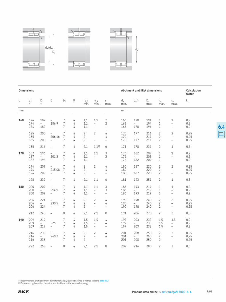
1) Recommended shaft abutment diameter for axially loaded bearings † Flange support, page 5122) Parameter r3,4 has either the value speciied here or the same value as r1,2
Product data online † skf.com/go/17000-6-4
ra
ra
ra
daDa
ra
rb
da / das
Dimensions Abutment and illet dimensions Calculation factor
d d1 D1 E b1 K r1,2 r3,4 s da das1) Da ra rb kr
≈ ≈ min min max min max max max
mm mm
160 174 182 – 7 4 1,1 1,1 2 166 170 194 1 1 0,2174 – 186,9 7 4 1,1 – 2 166 – 194 1 – 0,2
174 182 – 7 4 1,1 – – 166 170 194 1 – 0,2 185 200 – 7 4 2 2 4 170 177 211 2 2 0,25 185 – 206,16 7 4 2 – 4 170 – 211 2 – 0,25 185 200 – 7 4 2 – – 170 177 211 2 – 0,25 185 216 – 7 4 2,1 1,12) 6 171 178 231 2 1 0,5 170 187 196 – 7 4 1,1 1,1 3 176 182 209 1 1 0,2
187 – 201,3 7 4 1,1 – 3 176 – 209 1 – 0,2 187 196 – 7 4 1,1 – – 176 182 209 1 – 0,2 194 209 – 7 4 2 2 4 180 187 220 2 2 0,25 194 – 215,08 7 4 2 – 4 180 – 220 2 – 0,25 194 209 – 7 4 2 – – 180 187 220 2 – 0,25 198 232 – 7 4 2,1 1,1 6 181 193 251 2 1 0,5 180 200 209 – 7 4 1,1 1,1 3 186 193 219 1 1 0,2
200 – 214,1 7 4 1,1 – 3 186 – 219 1 – 0,2 200 209 – 7 4 1,1 – – 186 193 219 1 – 0,2 206 224 – 7 4 2 2 4 190 198 240 2 2 0,25 206 – 230,5 7 4 2 – 4 190 – 240 2 – 0,25 206 224 – 7 4 2 – – 190 198 240 2 – 0,25 212 248 – 8 4 2,1 2,1 8 191 206 270 2 2 0,5 190 209 219 – 7 4 1,5 1,5 4 197 203 233 1,5 1,5 0,2
209 – 225 7 4 1,5 – 4 197 – 233 1,5 – 0,2 209 219 – 7 4 1,5 – – 197 203 233 1,5 – 0,2 216 233 – 7 4 2 2 4 201 208 250 2 2 0,25 216 – 240,7 7 4 2 – 4 201 – 250 2 – 0,25 216 233 – 7 4 2 – – 201 208 250 2 – 0,25 222 258 – 8 4 2,1 2,1 8 202 216 280 2 2 0,5
569
6.4
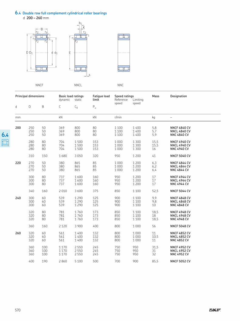
6.4 Double row full complement cylindrical roller bearings
d 200 – 260 mm
NNCF NNCL NNC
d d1D
B
r1
r1
r1r2
r2
r2
r3
r4
D1
s
K
b1
r1r2
r1r2
E
Principal dimensions Basic load ratings Fatigue load limit
Speed ratings Mass Designation dynamic static Reference
speedLimiting speed
d D B C C0 Pu
mm kN kN r/min kg –
200 250 50 369 800 80 1 100 1 400 5,8 NNCF 4840 CV250 50 369 800 80 1 100 1 400 5,7 NNCL 4840 CV
250 50 369 800 80 1 100 1 400 5,9 NNC 4840 CV 280 80 704 1 500 153 1 000 1 300 15,5 NNCF 4940 CV 280 80 704 1 500 153 1 000 1 300 15,5 NNCL 4940 CV 280 80 704 1 500 153 1 000 1 300 16 NNC 4940 CV 310 150 1 680 3 050 320 950 1 200 41 NNCF 5040 CV 220 270 50 380 865 85 1 000 1 200 6,3 NNCF 4844 CV
270 50 380 865 85 1 000 1 200 6,2 NNCL 4844 CV 270 50 380 865 85 1 000 1 200 6,4 NNC 4844 CV 300 80 737 1 600 160 950 1 200 17 NNCF 4944 CV 300 80 737 1 600 160 950 1 200 17 NNCL 4944 CV 300 80 737 1 600 160 950 1 200 17 NNC 4944 CV 340 160 2 010 3 600 375 850 1 100 52,5 NNCF 5044 CV 240 300 60 539 1 290 125 900 1 100 9,9 NNCF 4848 CV
300 60 539 1 290 125 900 1 100 9,8 NNCL 4848 CV 300 60 539 1 290 125 900 1 100 10 NNC 4848 CV 320 80 781 1 760 173 850 1 100 18,5 NNCF 4948 CV 320 80 781 1 760 173 850 1 100 18 NNCL 4948 CV 320 80 781 1 760 173 850 1 100 18,5 NNC 4948 CV 360 160 2 120 3 900 400 800 1 000 56 NNCF 5048 CV 260 320 60 561 1 400 132 800 1 000 11 NNCF 4852 CV
320 60 561 1 400 132 800 1 000 10,5 NNCL 4852 CV 320 60 561 1 400 132 800 1 000 11 NNC 4852 CV 360 100 1 170 2 550 245 750 950 31,5 NNCF 4952 CV 360 100 1 170 2 550 245 750 950 31 NNCL 4952 CV 360 100 1 170 2 550 245 750 950 32 NNC 4952 CV 400 190 2 860 5 100 500 700 900 85,5 NNCF 5052 CV
570
6.4
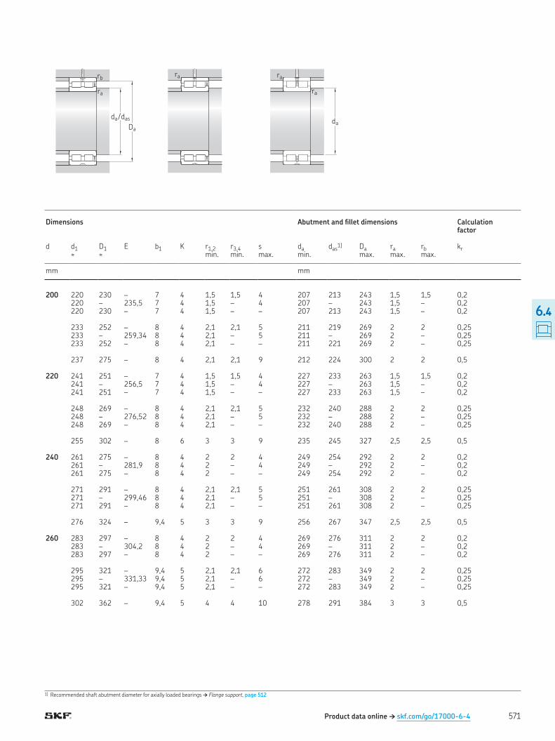
1) Recommended shaft abutment diameter for axially loaded bearings † Flange support, page 512
Product data online † skf.com/go/17000-6-4
ra
ra
ra
daDa
ra
rb
da / das
Dimensions Abutment and illet dimensions Calculation factor
d d1 D1 E b1 K r1,2 r3,4 s da das1) Da ra rb kr
≈ ≈ min. min. max. min. max. max. max.
mm mm
200 220 230 – 7 4 1,5 1,5 4 207 213 243 1,5 1,5 0,2220 – 235,5 7 4 1,5 – 4 207 – 243 1,5 – 0,2
220 230 – 7 4 1,5 – – 207 213 243 1,5 – 0,2 233 252 – 8 4 2,1 2,1 5 211 219 269 2 2 0,25 233 – 259,34 8 4 2,1 – 5 211 – 269 2 – 0,25 233 252 – 8 4 2,1 – – 211 221 269 2 – 0,25 237 275 – 8 4 2,1 2,1 9 212 224 300 2 2 0,5 220 241 251 – 7 4 1,5 1,5 4 227 233 263 1,5 1,5 0,2
241 – 256,5 7 4 1,5 – 4 227 – 263 1,5 – 0,2 241 251 – 7 4 1,5 – – 227 233 263 1,5 – 0,2 248 269 – 8 4 2,1 2,1 5 232 240 288 2 2 0,25 248 – 276,52 8 4 2,1 – 5 232 – 288 2 – 0,25 248 269 – 8 4 2,1 – – 232 240 288 2 – 0,25 255 302 – 8 6 3 3 9 235 245 327 2,5 2,5 0,5 240 261 275 – 8 4 2 2 4 249 254 292 2 2 0,2
261 – 281,9 8 4 2 – 4 249 – 292 2 – 0,2 261 275 – 8 4 2 – – 249 254 292 2 – 0,2 271 291 – 8 4 2,1 2,1 5 251 261 308 2 2 0,25 271 – 299,46 8 4 2,1 – 5 251 – 308 2 – 0,25 271 291 – 8 4 2,1 – – 251 261 308 2 – 0,25 276 324 – 9,4 5 3 3 9 256 267 347 2,5 2,5 0,5 260 283 297 – 8 4 2 2 4 269 276 311 2 2 0,2
283 – 304,2 8 4 2 – 4 269 – 311 2 – 0,2 283 297 – 8 4 2 – – 269 276 311 2 – 0,2 295 321 – 9,4 5 2,1 2,1 6 272 283 349 2 2 0,25 295 – 331,33 9,4 5 2,1 – 6 272 – 349 2 – 0,25 295 321 – 9,4 5 2,1 – – 272 283 349 2 – 0,25 302 362 – 9,4 5 4 4 10 278 291 384 3 3 0,5
571
6.4
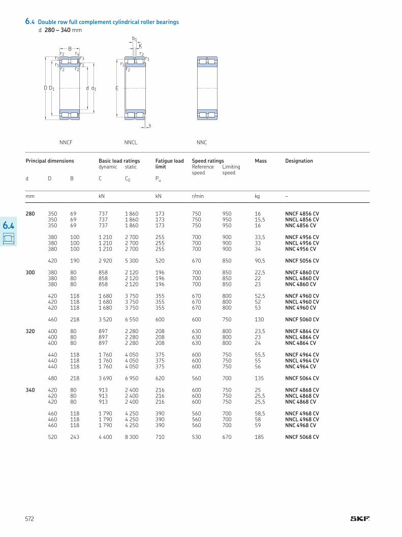
6.4 Double row full complement cylindrical roller bearings
d 280 – 340 mm
NNCF NNCL NNC
d d1D
B
r1
r1
r1r2
r2
r2
r3
r4
D1
s
K
b1
r1r2
r1r2
E
Principal dimensions Basic load ratings Fatigue load limit
Speed ratings Mass Designation dynamic static Reference
speedLimiting speed
d D B C C0 Pu
mm kN kN r/min kg –
280 350 69 737 1 860 173 750 950 16 NNCF 4856 CV350 69 737 1 860 173 750 950 15,5 NNCL 4856 CV
350 69 737 1 860 173 750 950 16 NNC 4856 CV 380 100 1 210 2 700 255 700 900 33,5 NNCF 4956 CV 380 100 1 210 2 700 255 700 900 33 NNCL 4956 CV 380 100 1 210 2 700 255 700 900 34 NNC 4956 CV 420 190 2 920 5 300 520 670 850 90,5 NNCF 5056 CV 300 380 80 858 2 120 196 700 850 22,5 NNCF 4860 CV
380 80 858 2 120 196 700 850 22 NNCL 4860 CV 380 80 858 2 120 196 700 850 23 NNC 4860 CV 420 118 1 680 3 750 355 670 800 52,5 NNCF 4960 CV 420 118 1 680 3 750 355 670 800 52 NNCL 4960 CV 420 118 1 680 3 750 355 670 800 53 NNC 4960 CV 460 218 3 520 6 550 600 600 750 130 NNCF 5060 CV 320 400 80 897 2 280 208 630 800 23,5 NNCF 4864 CV
400 80 897 2 280 208 630 800 23 NNCL 4864 CV 400 80 897 2 280 208 630 800 24 NNC 4864 CV 440 118 1 760 4 050 375 600 750 55,5 NNCF 4964 CV 440 118 1 760 4 050 375 600 750 55 NNCL 4964 CV 440 118 1 760 4 050 375 600 750 56 NNC 4964 CV 480 218 3 690 6 950 620 560 700 135 NNCF 5064 CV 340 420 80 913 2 400 216 600 750 25 NNCF 4868 CV 420 80 913 2 400 216 600 750 25,5 NNCL 4868 CV 420 80 913 2 400 216 600 750 25,5 NNC 4868 CV 460 118 1 790 4 250 390 560 700 58,5 NNCF 4968 CV 460 118 1 790 4 250 390 560 700 58 NNCL 4968 CV 460 118 1 790 4 250 390 560 700 59 NNC 4968 CV 520 243 4 400 8 300 710 530 670 185 NNCF 5068 CV
572
6.4
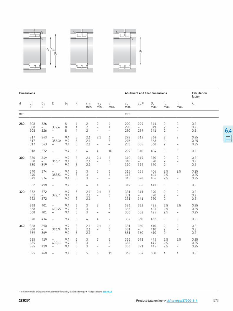
1) Recommended shaft abutment diameter for axially loaded bearings † Flange support, page 512
Product data online † skf.com/go/17000-6-4
ra
ra
ra
daDa
ra
rb
da / das
Dimensions Abutment and illet dimensions Calculation factor
d d1 D1 E b1 K r1,2 r3,4 s da das1) Da ra rb kr
≈ ≈ min. min. max. min. max. max. max.
mm mm
280 308 326 – 8 4 2 2 4 290 299 341 2 2 0,2308 – 332,4 8 4 2 – 4 290 – 341 2 – 0,2
308 326 – 8 4 2 – – 290 299 341 2 – 0,2 317 343 – 9,4 5 2,1 2,1 6 293 312 368 2 2 0,25 317 – 353,34 9,4 5 2,1 – 6 293 – 368 2 – 0,25 317 343 – 9,4 5 2,1 – – 293 305 368 2 – 0,25 318 372 – 9,4 5 4 4 10 299 310 404 3 3 0,5 300 330 349 – 9,4 5 2,1 2,1 6 310 319 370 2 2 0,2
330 – 356,7 9,4 5 2,1 – 6 310 – 370 2 – 0,2 330 349 – 9,4 5 2,1 – – 310 319 370 2 – 0,2 340 374 – 9,4 5 3 3 6 315 335 406 2,5 2,5 0,25 340 – 385,51 9,4 5 3 – 6 315 – 406 2,5 – 0,25 341 374 – 9,4 5 3 – – 315 328 406 2,5 – 0,25 352 418 – 9,4 5 4 4 9 319 336 443 3 3 0,5 320 352 372 – 9,4 5 2,1 2,1 6 331 341 390 2 2 0,2
352 – 379,7 9,4 5 2,1 – 6 331 – 390 2 – 0,2 352 372 – 9,4 5 2,1 – – 331 341 390 2 – 0,2 368 401 – 9,4 5 3 3 6 336 352 425 2,5 2,5 0,25 368 – 412,27 9,4 5 3 – 6 336 – 425 2,5 – 0,25 368 401 – 9,4 5 3 – – 336 352 425 2,5 – 0,25 370 434 – 9,4 5 4 4 9 339 360 462 3 3 0,5 340 368 390 – 9,4 5 2,1 2,1 6 351 360 410 2 2 0,2 368 – 396,9 9,4 5 2,1 – 6 351 – 410 2 – 0,2 369 369 – 9,4 5 2,1 – – 551 360 410 2 – 0,2 385 419 – 9,4 5 3 3 6 356 371 445 2,5 2,5 0,25 385 – 430,11 9,4 5 3 – 6 356 – 445 2,5 – 0,25 385 419 – 9,4 5 3 – – 356 371 445 2,5 – 0,25 395 468 – 9,4 5 5 5 11 362 384 500 4 4 0,5
573
6.4
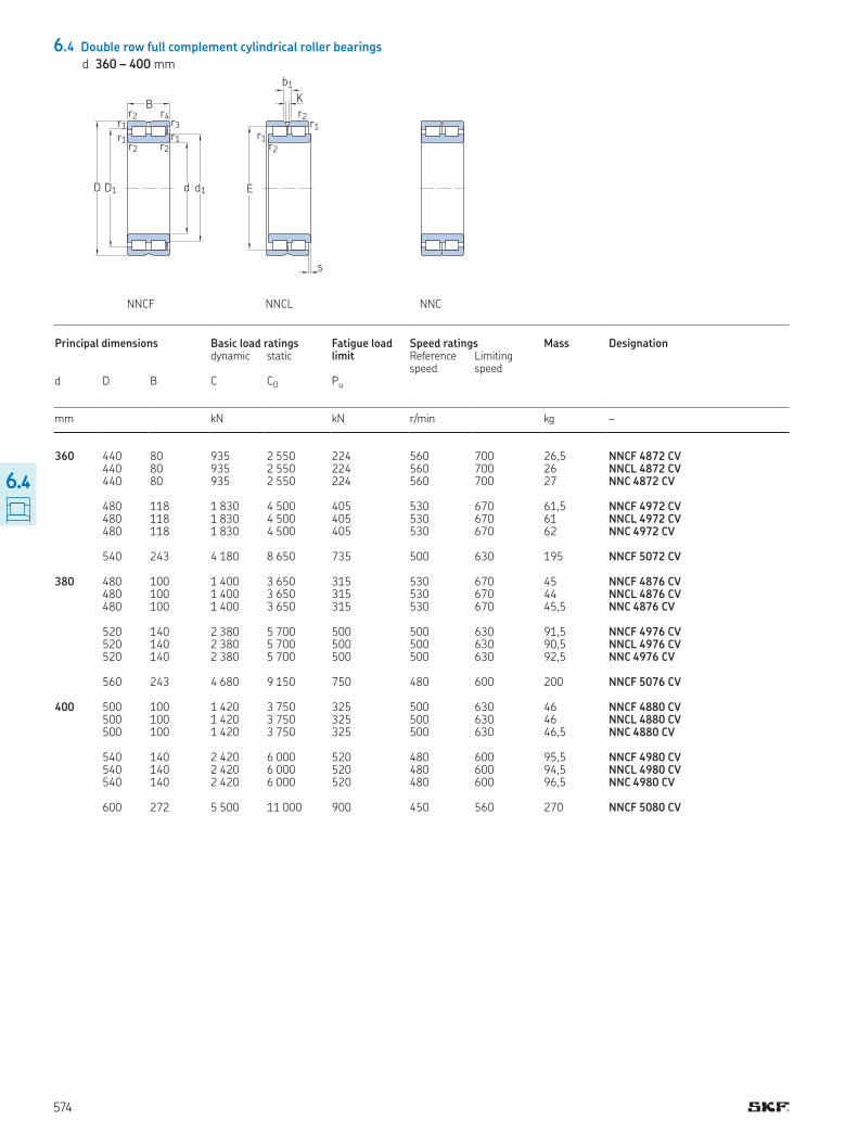
6.4 Double row full complement cylindrical roller bearings
d 360 – 400 mm
NNCF NNCL NNC
d d1D
B
r1
r1
r1r2
r2
r2
r3
r4
D1
s
K
b1
r1r2
r1r2
E
Principal dimensions Basic load ratings Fatigue load limit
Speed ratings Mass Designation dynamic static Reference
speedLimiting speed
d D B C C0 Pu
mm kN kN r/min kg –
360 440 80 935 2 550 224 560 700 26,5 NNCF 4872 CV440 80 935 2 550 224 560 700 26 NNCL 4872 CV
440 80 935 2 550 224 560 700 27 NNC 4872 CV 480 118 1 830 4 500 405 530 670 61,5 NNCF 4972 CV 480 118 1 830 4 500 405 530 670 61 NNCL 4972 CV 480 118 1 830 4 500 405 530 670 62 NNC 4972 CV 540 243 4 180 8 650 735 500 630 195 NNCF 5072 CV 380 480 100 1 400 3 650 315 530 670 45 NNCF 4876 CV
480 100 1 400 3 650 315 530 670 44 NNCL 4876 CV 480 100 1 400 3 650 315 530 670 45,5 NNC 4876 CV 520 140 2 380 5 700 500 500 630 91,5 NNCF 4976 CV 520 140 2 380 5 700 500 500 630 90,5 NNCL 4976 CV 520 140 2 380 5 700 500 500 630 92,5 NNC 4976 CV 560 243 4 680 9 150 750 480 600 200 NNCF 5076 CV 400 500 100 1 420 3 750 325 500 630 46 NNCF 4880 CV 500 100 1 420 3 750 325 500 630 46 NNCL 4880 CV 500 100 1 420 3 750 325 500 630 46,5 NNC 4880 CV 540 140 2 420 6 000 520 480 600 95,5 NNCF 4980 CV 540 140 2 420 6 000 520 480 600 94,5 NNCL 4980 CV 540 140 2 420 6 000 520 480 600 96,5 NNC 4980 CV 600 272 5 500 11 000 900 450 560 270 NNCF 5080 CV
574
6.4
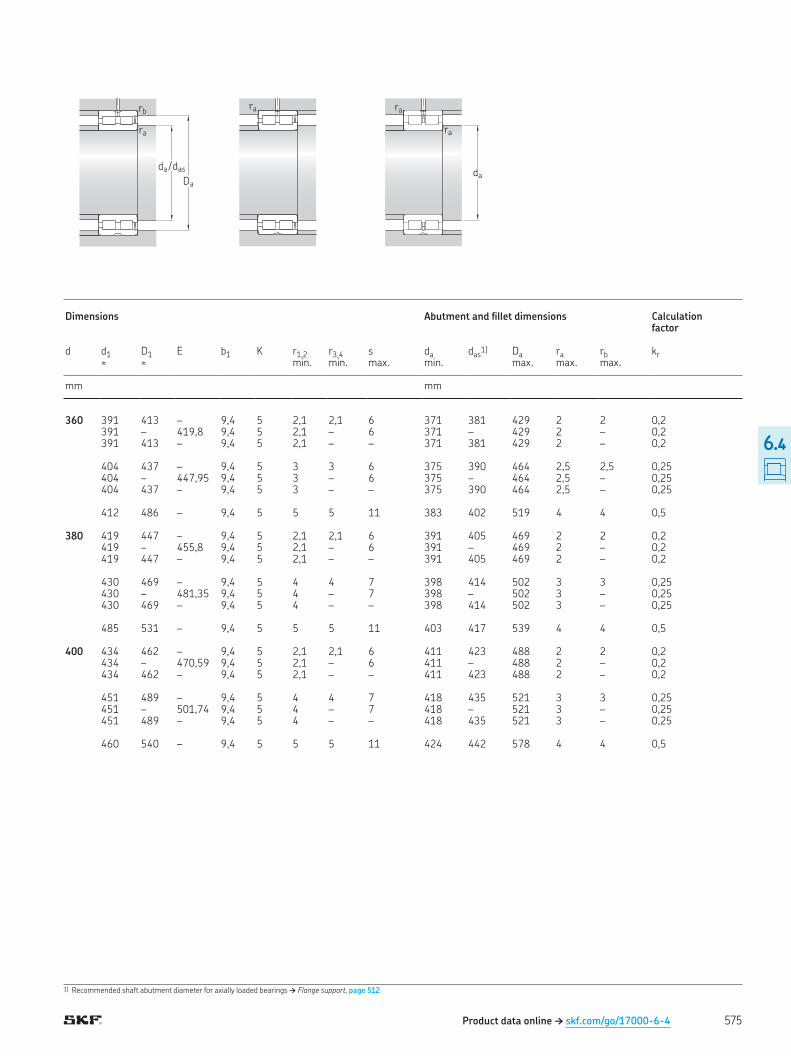
1) Recommended shaft abutment diameter for axially loaded bearings † Flange support, page 512
Product data online † skf.com/go/17000-6-4
ra
ra
ra
daDa
ra
rb
da / das
Dimensions Abutment and illet dimensions Calculation factor
d d1 D1 E b1 K r1,2 r3,4 s da das1) Da ra rb kr
≈ ≈ min. min. max. min. max. max. max.
mm mm
360 391 413 – 9,4 5 2,1 2,1 6 371 381 429 2 2 0,2391 – 419,8 9,4 5 2,1 – 6 371 – 429 2 – 0,2
391 413 – 9,4 5 2,1 – – 371 381 429 2 – 0,2 404 437 – 9,4 5 3 3 6 375 390 464 2,5 2,5 0,25 404 – 447,95 9,4 5 3 – 6 375 – 464 2,5 – 0,25 404 437 – 9,4 5 3 – – 375 390 464 2,5 – 0,25 412 486 – 9,4 5 5 5 11 383 402 519 4 4 0,5 380 419 447 – 9,4 5 2,1 2,1 6 391 405 469 2 2 0,2
419 – 455,8 9,4 5 2,1 – 6 391 – 469 2 – 0,2 419 447 – 9,4 5 2,1 – – 391 405 469 2 – 0,2 430 469 – 9,4 5 4 4 7 398 414 502 3 3 0,25 430 – 481,35 9,4 5 4 – 7 398 – 502 3 – 0,25 430 469 – 9,4 5 4 – – 398 414 502 3 – 0,25 485 531 – 9,4 5 5 5 11 403 417 539 4 4 0,5 400 434 462 – 9,4 5 2,1 2,1 6 411 423 488 2 2 0,2 434 – 470,59 9,4 5 2,1 – 6 411 – 488 2 – 0,2 434 462 – 9,4 5 2,1 – – 411 423 488 2 – 0,2 451 489 – 9,4 5 4 4 7 418 435 521 3 3 0,25 451 – 501,74 9,4 5 4 – 7 418 – 521 3 – 0,25 451 489 – 9,4 5 4 – – 418 435 521 3 – 0,25 460 540 – 9,4 5 5 5 11 424 442 578 4 4 0,5
575
6.4
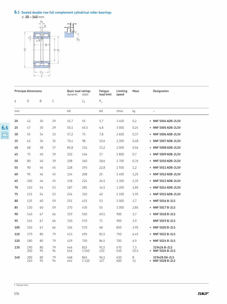
6.5 Sealed double row full complement cylindrical roller bearings
d 20 – 140 mm
Principal dimensions Basic load ratings Fatigue load limit
Limiting speed
Mass Designation dynamic static
d D B C C0 Pu
mm kN kN r/min kg –
20 42 30 29 45,7 55 5,7 3 400 0,2 ▶ NNF 5004 ADB-2LSV 25 47 30 29 50,1 65,5 6,8 3 000 0,24 ▶ NNF 5005 ADB-2LSV 30 55 34 33 57,2 75 7,8 2 600 0,37 ▶ NNF 5006 ADB-2LSV 35 62 36 35 70,4 98 10,6 2 200 0,48 ▶ NNF 5007 ADB-2LSV 40 68 38 37 85,8 116 13,2 2 000 0,56 ▶ NNF 5008 ADB-2LSV 45 75 40 39 102 146 17 1 800 0,7 ▶ NNF 5009 ADB-2LSV 50 80 40 39 108 160 18,6 1 700 0,76 ▶ NNF 5010 ADB-2LSV 55 90 46 45 128 193 22,8 1 500 1,2 ▶ NNF 5011 ADB-2LSV 60 95 46 45 134 208 25 1 400 1,25 ▶ NNF 5012 ADB-2LSV 65 100 46 45 138 224 26,5 1 300 1,35 ▶ NNF 5013 ADB-2LSV 70 110 54 53 187 285 34,5 1 200 1,85 ▶ NNF 5014 ADB-2LSV 75 115 54 53 224 310 40 1 100 1,95 ▶ NNF 5015 ADB-2LSV 80 125 60 59 251 415 53 1 000 2,7 ▶ NNF 5016 B-2LS 85 130 60 59 270 430 55 1 000 2,85 ▶ NNF 5017 B-2LS 90 140 67 66 319 550 69,5 900 3,7 ▶ NNF 5018 B-2LS 95 145 67 66 330 570 71 900 3,9 NNF 5019 B-2LS 100 150 67 66 336 570 68 850 3,95 ▶ NNF 5020 B-2LS 110 170 80 79 413 695 81,5 750 6,45 ▶ NNF 5022 B-2LS 120 180 80 79 429 750 86,5 700 6,9 ▶ NNF 5024 B-2LS 130 190 80 79 446 815 91,5 670 7,3 319426 B-2LS 200 95 94 616 1 040 120 630 10,5 ▶ NNF 5026 B-2LS 140 200 80 79 468 865 96,5 630 8 319428 DA-2LS 210 95 94 644 1 120 127 600 11 ▶ NNF 5028 B-2LS
▶ Popular item
d1D
C1
C
r
d
B
30° D3
C2b
r3r4
K
b1
576
6.5
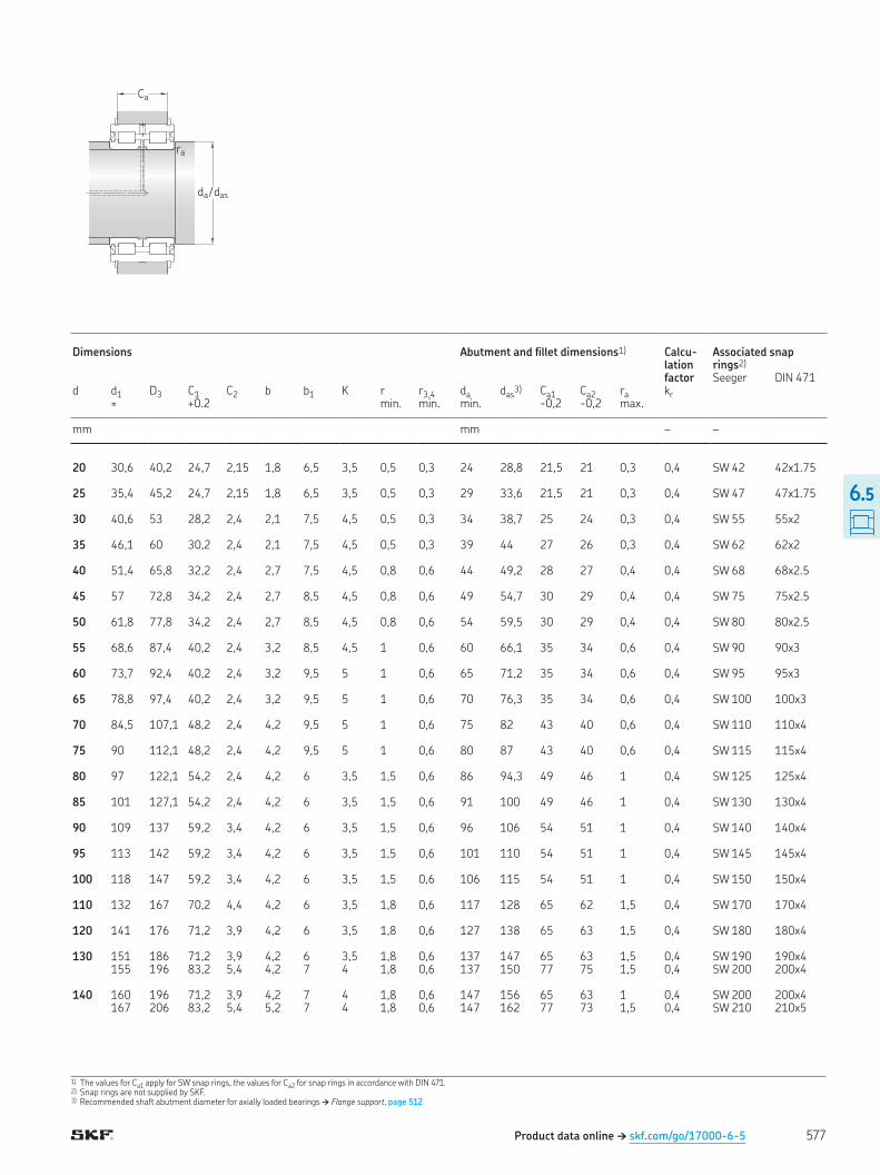
1) The values for Ca1 apply for SW snap rings, the values for Ca2 for snap rings in accordance with DIN 471 2) Snap rings are not supplied by SKF 3) Recommended shaft abutment diameter for axially loaded bearings † Flange support, page 512
Dimensions Abutment and illet dimensions1) Calcu-lation factor
Associated snap rings2) Seeger DIN 471
d d1 D3 C1 C2 b b1 K r r3,4 da das3) Ca1 Ca2 ra kr
≈ +0 2 min min min -0,2 -0,2 max
mm mm – –
20 30,6 40,2 24,7 2,15 1,8 6,5 3,5 0,5 0,3 24 28,8 21,5 21 0,3 0,4 SW 42 42x1 75 25 35,4 45,2 24,7 2,15 1,8 6,5 3,5 0,5 0,3 29 33,6 21,5 21 0,3 0,4 SW 47 47x1 75 30 40,6 53 28,2 2,4 2,1 7,5 4,5 0,5 0,3 34 38,7 25 24 0,3 0,4 SW 55 55x2 35 46,1 60 30,2 2,4 2,1 7,5 4,5 0,5 0,3 39 44 27 26 0,3 0,4 SW 62 62x2 40 51,4 65,8 32,2 2,4 2,7 7,5 4,5 0,8 0,6 44 49,2 28 27 0,4 0,4 SW 68 68x2 5 45 57 72,8 34,2 2,4 2,7 8,5 4,5 0,8 0,6 49 54,7 30 29 0,4 0,4 SW 75 75x2 5 50 61,8 77,8 34,2 2,4 2,7 8,5 4,5 0,8 0,6 54 59,5 30 29 0,4 0,4 SW 80 80x2 5 55 68,6 87,4 40,2 2,4 3,2 8,5 4,5 1 0,6 60 66,1 35 34 0,6 0,4 SW 90 90x3 60 73,7 92,4 40,2 2,4 3,2 9,5 5 1 0,6 65 71,2 35 34 0,6 0,4 SW 95 95x3 65 78,8 97,4 40,2 2,4 3,2 9,5 5 1 0,6 70 76,3 35 34 0,6 0,4 SW 100 100x3 70 84,5 107,1 48,2 2,4 4,2 9,5 5 1 0,6 75 82 43 40 0,6 0,4 SW 110 110x4 75 90 112,1 48,2 2,4 4,2 9,5 5 1 0,6 80 87 43 40 0,6 0,4 SW 115 115x4 80 97 122,1 54,2 2,4 4,2 6 3,5 1,5 0,6 86 94,3 49 46 1 0,4 SW 125 125x4 85 101 127,1 54,2 2,4 4,2 6 3,5 1,5 0,6 91 100 49 46 1 0,4 SW 130 130x4 90 109 137 59,2 3,4 4,2 6 3,5 1,5 0,6 96 106 54 51 1 0,4 SW 140 140x4 95 113 142 59,2 3,4 4,2 6 3,5 1,5 0,6 101 110 54 51 1 0,4 SW 145 145x4 100 118 147 59,2 3,4 4,2 6 3,5 1,5 0,6 106 115 54 51 1 0,4 SW 150 150x4 110 132 167 70,2 4,4 4,2 6 3,5 1,8 0,6 117 128 65 62 1,5 0,4 SW 170 170x4 120 141 176 71,2 3,9 4,2 6 3,5 1,8 0,6 127 138 65 63 1,5 0,4 SW 180 180x4 130 151 186 71,2 3,9 4,2 6 3,5 1,8 0,6 137 147 65 63 1,5 0,4 SW 190 190x4 155 196 83,2 5,4 4,2 7 4 1,8 0,6 137 150 77 75 1,5 0,4 SW 200 200x4 140 160 196 71,2 3,9 4,2 7 4 1,8 0,6 147 156 65 63 1 0,4 SW 200 200x4 167 206 83,2 5,4 5,2 7 4 1,8 0,6 147 162 77 73 1,5 0,4 SW 210 210x5
Product data online † skf.com/go/17000-6-5
Ca
ra
da / das
577
6.5
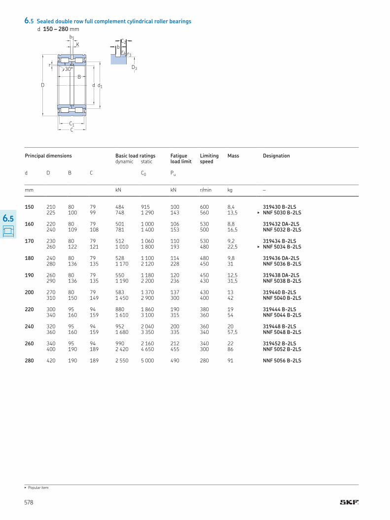
6.5 Sealed double row full complement cylindrical roller bearings
d 150 – 280 mm
▶ Popular item
d1D
C1
C
r
d
B
30° D3
C2b
r3r4
K
b1
Principal dimensions Basic load ratings Fatigue load limit
Limiting speed
Mass Designation dynamic static
d D B C C0 Pu
mm kN kN r/min kg –
150 210 80 79 484 915 100 600 8,4 319430 B-2LS 225 100 99 748 1 290 143 560 13,5 ▶ NNF 5030 B-2LS 160 220 80 79 501 1 000 106 530 8,8 319432 DA-2LS 240 109 108 781 1 400 153 500 16,5 NNF 5032 B-2LS 170 230 80 79 512 1 060 110 530 9,2 319434 B-2LS 260 122 121 1 010 1 800 193 480 22,5 ▶ NNF 5034 B-2LS 180 240 80 79 528 1 100 114 480 9,8 319436 DA-2LS 280 136 135 1 170 2 120 228 450 31 NNF 5036 B-2LS 190 260 80 79 550 1 180 120 450 12,5 319438 DA-2LS 290 136 135 1 190 2 200 236 430 31,5 NNF 5038 B-2LS 200 270 80 79 583 1 370 137 430 13 319440 B-2LS 310 150 149 1 450 2 900 300 400 42 NNF 5040 B-2LS 220 300 95 94 880 1 860 190 380 19 319444 B-2LS 340 160 159 1 610 3 100 315 360 54 NNF 5044 B-2LS 240 320 95 94 952 2 040 200 360 20 319448 B-2LS 360 160 159 1 680 3 350 335 340 57,5 NNF 5048 B-2LS 260 340 95 94 990 2 160 212 340 22 319452 B-2LS 400 190 189 2 420 4 650 455 300 86 NNF 5052 B-2LS 280 420 190 189 2 550 5 000 490 280 91 NNF 5056 B-2LS
578
6.5
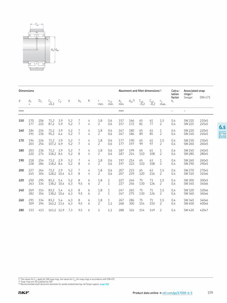
1) The values for Ca1 apply for SW snap rings, the values for Ca2 for snap rings in accordance with DIN 471 2) Snap rings are not supplied by SKF 3) Recommended shaft abutment diameter for axially loaded bearings † Flange support, page 512
Product data online † skf.com/go/17000-6-5
Ca
ra
da / das
Dimensions Abutment and illet dimensions1) Calcu-lation factor
Associated snap rings2) Seeger DIN 471
d d1 D3 C1 C2 b b1 K r r3,4 da das3) Ca1 Ca2 ra kr
≈ +0 2 min min min -0,2 -0,2 max
mm mm – –
150 170 206 71,2 3,9 5,2 7 4 1,8 0,6 157 166 65 61 1,5 0,4 SW 210 210x5 177 221 87,2 5,9 5,2 7 4 2 0,6 157 172 81 77 2 0,4 SW 225 225x5 160 184 216 71,2 3,9 5,2 7 4 1,8 0,6 167 180 65 61 1 0,4 SW 220 220x5 191 236 95,2 6,4 5,2 7 4 2 0,6 167 186 89 85 2 0,4 SW 240 240x5 170 194 226 71,2 3,9 5,2 7 4 1,8 0,6 177 190 65 61 1,5 0,4 SW 230 230x5 203 254 107,2 6,9 5,2 7 4 2 0,6 177 197 99 97 2 0,4 SW 260 260x5 180 203 236 71,2 3,9 5,2 7 4 1,8 0,6 187 199 65 61 1 0,4 SW 240 240x5 220 274 118,2 8,4 5,2 8 4 2 0,6 187 214 110 108 2 0,4 SW 280 280x5 190 218 254 73,2 2,9 5,2 7 4 1,8 0,6 197 214 65 63 1 0,4 SW 260 260x5 228 284 118,2 8,4 5,2 8 4 2 0,6 197 222 110 108 2 0,4 SW 290 290x5 200 227 264 73,2 2,9 5,2 7 4 1,8 0,6 207 223 65 63 1,5 0,4 SW 270 270x5 245 304 128,2 10,4 6,3 8 4 2 0,6 207 239 120 116 2 0,4 SW 310 310x6 220 250 295 83,2 5,4 5,2 8 6 1,8 1 227 246 75 73 1,5 0,4 SW 300 300x5 263 334 138,2 10,4 6,3 9,5 6 2 1 227 256 130 126 2 0,4 SW 340 340x6 240 269 314 83,2 5,4 6,3 8 6 1,8 1 247 265 75 71 1,5 0,4 SW 320 320x6 282 354 138,2 10,4 6,3 9,5 6 2 1 247 275 130 126 2 0,4 SW 360 360x6 260 291 334 83,2 5,4 6,3 8 6 1,8 1 267 286 75 71 1,5 0,4 SW 340 340x6 309 394 162,2 13,4 6,3 9,5 6 2 1,1 268 300 154 150 2 0,4 SW 400 400x6 280 333 413 163,2 12,9 7,3 9,5 6 2 1,1 288 324 154 149 2 0,4 SW 420 420x7
579
6.5