6 remote memory access protocol (normative) -...
TRANSCRIPT

ECSS-E-50-11 Draft F 4th December 2006
1
6 Remote memory access protocol
(normative)
6.1 General
6.1.1 Purpose The remote memory access protocol (RMAP) has been designed to support a wide range of SpaceWire applications. Its primary purpose however is to configure a SpaceWire network, to control SpaceWire units and to gather data and status information from those units. RMAP may operate alongside other communications protocols running over SpaceWire.
RMAP may be used to configure SpaceWire routing switches, setting their operating parameters and routing table information. It may also be used to monitor the status of those routing switches. RMAP may be used to configure and read the status of nodes on the SpaceWire network. For example, the operating data rate of a node may be set to 100 Mbits/s and the interface may be set to auto-start mode.
For simple SpaceWire units without an embedded processor, RMAP may be used to set application configuration registers, to read status information and to read or write data into memory in the unit.
For intelligent SpaceWire units RMAP can provide the basis for a wide range of communications services. Configuration, status gathering, and data transfer to and from memory or mailboxes can be supported.
6.1.2 RMAP Operations RMAP is used to write to and read from memory, registers, FIFO memory, mailboxes, etc, in a destination node on a SpaceWire network. Input/output registers, control/status registers and FIFOs are assumed to be memory mapped so are accessed as memory. Mailboxes are indirect memory areas that are referenced using a memory address.
All read and write operations defined in the RMAP protocol are posted operations i.e. the source does not wait for an acknowledgement or reply to be received. This means that many reads and writes can be outstanding at any time. It also means that there is no timeout mechanism implemented in RMAP for missing acknowledgements or replies. If an acknowledgement or reply timeout mechanism is required it must be implemented in the source user application.

ECSS-E-50-11 Draft F 4th December 2006
2
6.1.2.1 Write commands Write commands can be acknowledged or not acknowledged by the destination node when they have been received correctly. If the write is to be acknowledged and there is an error with the write request, the destination will send an error code to the source that sent the command. The error can only be sent to the source if the write command header was received intact, so that the destination that detected the error knows where to send the error message. If no acknowledgement is requested then the fact that an error occurred may be stored in a status register in the destination node.
Write commands can perform the write operation after verifying that the data has been transferred to the destination without error, or it can write the data without verification. To perform verification on the data requires buffering in the destination node to store the data while it is being verified, before it is written. The amount of buffering is likely to be limited so verified writes ought only be performed for relatively short sets of data, that will fit in the available buffer at the destination. Longer writes can be performed but without verification prior to writing. Verification in this case is done after the data has been written. Verified writes should always be used when writing to configuration or control registers.
The acknowledged/non-acknowledged and verified/non-verified options to the write command result in four different write operations:
• Write non-acknowledged, non-verified – writes zero or more bytes to memory in a destination node. The command is checked using a CRC before the data is written, but the data itself is not checked before it is written. No acknowledgement to indicate that the command has been executed is sent to the source of the write command. This command is typically used for writing large amounts of data to a destination where it can be safely assumed that the write operation completed successfully. For example the writing of camera data to a temporary working buffer.
• Write non-acknowledged, verified – writes zero or more bytes to memory in a destination node. Both the command and data are checked using CRCs before the data is written. This limits the amount of data that can be transferred in a single write operation, but erroneous data cannot be written to memory. No acknowledgement to indicate that the command has been executed is sent to the source of the write command. This command is typically used for writing command registers and small amounts of data to a destination where it can be safely assumed that the write operation completed successfully. For example writing many commands to different configuration registers in a device and then checking for an error using a status register
• Write acknowledged, non-verified – writes zero or more bytes to memory in a destination node. The command is checked using a CRC before the data is written, but the data itself is not checked before it is written. An acknowledgement to indicate that the command has been executed is sent to the source of the write command. This command is typically used for writing large amounts of data to a destination where it can be safely assumed that the write operation completed successfully, but an acknowledgement is required. For example writing sensor data to memory.

ECSS-E-50-11 Draft F 4th December 2006
3
• Write acknowledged, verified – writes zero or more bytes to memory in a destination node. Both the command and data are checked using CRCs before the data is written. This limits the amount of data that can be transferred in a single write operation, but erroneous data cannot be written to memory. An acknowledgement to indicate that the command has been executed is sent to the source of the write command. This command is typically used for writing small amounts of data to a destination where it is important to have confirmation that the write operation was executed successfully. For example writing to command or configuration registers.
6.1.2.2 Read commands The read command reads one or more bytes of data from a specified area of memory in a destination node. The data read is returned in a reply packet.
6.1.2.3 Read-modify-write The read-modify-write command reads a register (or memory) returning its value and then writes a new value, specified in the command, to the register. A mask can be included, in the command, so that only certain bits of the register are written. This provides an atomic operation that can be used for semaphores and other handshaking operations.
6.1.3 Nomenclature In this document hexadecimal numbers are written with the prefix 0x, for example 0x34 and 0xdf15. Binary numbers are written with the suffix b, for example 01001100b and 01b.
6.1.4 Guide to clause 6 A set of definitions is given in sub-clause 6.2. The various write commands are defined in sub-clause 6.3. The read command is described in sub-clause 6.4, and the read-modify-write command in sub-clause 6.5. The error codes that are used in RMAP replies and acknowledgments are listed in sub-clause 6.6. The way in which partial implementations of RMAP may be implemented is described in sub-clause 6.7. In sub-clause 6.8, several use cases for RMAP are presented giving examples of how RMAP can be used to support several different types of application. In sub-clause 6.9, a summary of the RMAP command codes is given. Sub-clause 6.10 specifies the conformance statements, sub-clauses that must be implemented and the ancillary information that must be provided, in order for a supplier to claim conformance to the SpaceWire RMAP standard. Example VHDL and C-code for the 8-bit CRC used by RMAP is given in section 6-11. Finally, in section 6.12 the changes since the last release of this document are listed.
6.2 Definitions The following definitions are presented in the order in which the respective fields are found in the RMAP commands and replies.
Path Address is a SpaceWire path address which defines the route to a destination node by specifying, for each router encountered on the way to the destination, the output port that a packet is to be forwarded through. A path address comprises one byte for each router on the path to the destination. Once a path address byte has been used to specify an output port of a router it is deleted to expose the next path address byte for the next router. All path

ECSS-E-50-11 Draft F 4th December 2006
4
address bytes will have been deleted by the time the packet reaches the destination
Logical Address byte is the logical address of the source or destination. This may be used to route the packet to the destination or, if path addressing is being used, to simply confirm that the final destination is the correct one i.e. that the logical address of the destination matches the logical address in the packet. If the logical address of the destination is unknown then the default logical address of 254 (0xFE) may be used (see sub-clause 5.2.1). The destination may choose to accept or reject packets with a logical address of 254.
Destination Path Address is the path address to the destination node on the SpaceWire network.
Destination Logical Address is the logical address of the destination node.
Source Path Address bytes provide a source path address for the reply to a command. The source path address is not needed if logical addressing is being used. The source path address is used by the destination node to send acknowledgements or data back to the source that requested a write or read operation using path addressing. The Source Path Address byte allows path addressing and regional logical addressing to be used to specify the source node. Leading zeros of the return address are ignored. If a packet is to be sent to address zero then this is done by setting all the extra return address bytes to zero. This will result in a single zero address byte being sent in front of the source address. The following examples illustrate this:
Source Path Address Field Resulting Path Address
0x00 0x00 0x00 0x00 0x00
0x00 0x00 0x01 0x02 0x01 0x02
0x00 0x01 0x00 0x02 0x01 0x00 0x02
0x00 0x01 0x02 0x00 0x01 0x02 0x00
0x00 0x00 0x00 0x00
0x01 0x02 0x03 0x04
0x01 0x02 0x03 0x04
0x00 0x00 0x00 0x01
0x02 0x03 0x04 0x05
0x01 0x02 0x03 0x04 0x05
Source Logical Address byte is the logical address to which the destination node for a command is to reply. The Source Address is normally set to the logical address of the source node that is sending the command. The Source Address byte may be set to 254 (0xFE) which is the default logical address, if the command source node does not have a logical address.
Protocol Identifier byte identifies the particular protocol being used for communication. For the Remote Memory Access protocol the protocol identifier has the value 1 (0x01).
Packet Type, Command, Source Address Length byte determines the type of the packet i.e. a command, a reply or an acknowledgement. This byte also includes two bits that determine the number of extra 4-byte return addresses. For example, if these bits are set to the value two then there will be eight extra source address bytes. If they are set to zero then there are no extra address bytes.

ECSS-E-50-11 Draft F 4th December 2006
5
Destination Key provides a one byte key which must be matched by the user destination application in order for the RMAP command to be accepted.
Transaction Identifier bytes are used to identify command, response, and acknowledge transactions that make up a particular read or write operation. The source of the command gives the command a unique transaction identity. This transaction identifier is returned in the reply to the command. This allows the command source to send many commands without having to wait for a reply to each command before sending the next command. When a reply or acknowledge comes in it can be quickly associated with the command that caused it by the transaction identifier.
Extended Address byte is used to extend the 32-bit memory address to 40-bits allowing a 1 Terabyte address space to be accessed directly in each node. For nodes that do not support a 40-bit address space this byte should be set to zero. The Extended Address may be used to differentiate between various address spaces in the destination. For example when set to 0x00 it may reference a 4G location directly addressable memory space and when set to 0x01 it may reference an array of mailboxes, which provide indirect addressing.
Memory Address bytes form the bottom 32-bits of the memory address to which the data in a write command is to be written or from where data is to be read for a read command. Input/output registers and control/status registers are assumed to be memory mapped. When combined with the Extended Write Address byte a 40-bit memory address is provided. The address can be separated into different fields and interpreted in a variety of different ways provided that the source and destination both agree on the interpretation. For example, the 40-bit address may be used as a single address space, it may be interpreted as a memory/register bank field followed by an address, it may reference a mailbox or it may use one field to identify a specific application, another to reference a bank of memory or mail box related to that application and a third field to reference the memory location within the memory bank. There are many possible ways in which the address fields can be used. The important feature of the Extended Memory and Memory Address fields is that together they define where in the destination node data is to be written to or read from.
Data Length bytes form the 24-bit length of the data that is to be written or read. The length is the length in bytes with the most-significant byte of the length sent first.
Header CRC byte is an 8-bit Cyclic Redundancy Check (CRC) used to confirm that the header is correct before executing the command. Each byte in the header starting with the destination logical address and ending with the byte before the header CRC itself is used in the CRC. See CRC definition below.
Data bytes are the data that is to be written in a write command or the data that is read in a read response.
Data CRC is an 8-bit Cyclic Redundancy Check (CRC) used to confirm that the data is correct before being written in a verified write command or was correctly transferred in a non-verified write command or read reply. The data CRC starts with the byte after the header CRC and covers all the data bytes. See CRC definition below.
EOP character is the End Of Packet marker of the SpaceWire packet.
CRC The CRC-8 code is used for both the Header CRC and the Data CRC. CRC-8 has the following polynomial: X8 + X2 + X1 + 1, with a starting value of 0x00. The Galois version of the CRC is used. VHDL and c-code

ECSS-E-50-11 Draft F 4th December 2006
6
implementations of this CRC algorithm are included in sub-clause 6.11, Annex A. If the length of the data is zero, then the Data CRC will be 0x00, i.e. the starting value. The CRC is calculated on the byte stream not the serial bit stream, since the RMAP protocol operates above the SpaceWire packet level (see ECSS-E50-12A). The equivalent serial representation takes the least significant bit of each byte first and does not include data/control or parity bits, nulls, FCT or other non-data characters. See section 6-11 (Annex A) for some examples of how the CRC may be implemented.
The correct operation of the CRC should result in the following CRC codes being generated for the following test patterns (all values below are in hex):
Test Pattern 1:
Input Data:
0x01, 0x02, 0x03, 0x04,
0x05, 0x06, 0x07, 0x08,
Resulting CRC value is: 0xB0
Test Pattern 2:
Input Data:
0x53, 0x70, 0x61, 0x63,
0x65, 0x57, 0x69, 0x72,
0x65, 0x20, 0x69, 0x73,
0x20, 0x62, 0x65, 0x61,
0x75, 0x74, 0x69, 0x66,
0x75, 0x6C, 0x21, 0x21,
Resulting CRC value is: 0x84
Test Pattern 3:
Input Data:
0x10, 0x56, 0xC3, 0x95,
0xA5, 0x75, 0x38, 0x63,
0x2F, 0x86, 0x7B, 0x01,
0x32, 0xDE, 0x35, 0x7A,
Resulting CRC value is: 0x18
6.3 Write Command The various types of write command are describe here.
6.3.1 Write command format (logical addressing) The write command provides a means for one node, the source node, to write one or more bytes of data into memory of another node, the destination node on a SpaceWire network. The format of the command when using logical addressing only is shown in Figure 6-1.

ECSS-E-50-11 Draft F 4th December 2006
7
Destination Logical Address Protocol Identifier Packet Type, Command,Source Path Addr Len Destination Key
Source Logical Address Transaction Identifier (MS) Transaction Identifier (LS) Extended Write Address
Write Address (MS) Write Address Write Address Write Address (LS)
Data Length (MS) Data Length Data Length (LS) Header CRC
Data Data Data Data
Data Data Data Data
Data Data CRC EOP
First byte transmitted
Last byte transmitted
Write = 1 Verify data(1)Don’t Verify (0)Command = 1 Increment/
No inc. addressAck (1)/
No ack (0)Reserved = 0 Source PathAddress Len = 0
Source PathAddress Len = 0
Bits in Packet Type / Command / Source Path Address Length Byte
MSB LSB
Packet Type Command Source Path Address Length
Figure 6-1 Write Command Format (Logical Addressing)
The Destination Logical Address is set to the logical address of the destination node.
The Protocol Identifier byte is set to the value 1 (0x01) which is the Protocol Identifier for the Remote Memory Access protocol.
The Packet Type field comprises a reserved bit and a command/reply bit which is set (1) for a command and clear (0) for a response. The packet type field for the write command is 01b, i.e. the command/reply bit is set, to indicate that the packet is a command packet, rather than a reply packet. The reserved bit is clear (0).
The Command field holds the direct write command.
The Write/Read bit is set (1) for a write command.
The Verify Data Before Write bit is set (1) if the data is to be verified before it is written to memory. The command header is always checked using a CRC (Header CRC see below) before the command is executed. If the Verify Data Before Write bit is set then the entire command must be buffered and verified using the Header CRC and the Data CRC before the command is executed. Since the entire command and data has to be buffered this places a limit on the amount of data that can be included in the write command. All RMAP compliant interfaces have to support the buffering and validation of write commands with at least four bytes of data. The buffering and validation of write commands with more than four bytes of data is dependent on the particular interface. If there is more data than will fit in the available buffer space then the command will not be executed and a reply with the “Verify Buffer Overrun” error code shall be sent back to the source, assuming that an acknowledgement has been requested in the command. If the Verify Data Before Write bit is not set (0) then the data is not verified before it is written. This enables much larger amounts of data than can be buffered to be written in a single command. The command header is verified with the Header CRC so that it is confirmed that the correct memory address and data length is being used. The data is then streamed into the memory space
ECSS-E-50-11 Draft F 4th December 2006
8
as it arrives without first being checked. Once all the data has been written to the specified memory area the data is verified using the Data CRC. This is acceptable because even if the wrong data has been written to memory, at least it has not been written in the wrong place. The error will be reported to the source node if the Ack/No_Ack bit has been set (1) to request an acknowledgement to the write command. If the source is able to resend the data then this can be done. When writing to control and configuration registers it is essential that the Verify Data Before Write bit is set (1).
The Ack/No_Ack bit is set (1) if an acknowledgement to the write command is required and cleared (0) if no acknowledgement is to be sent. If no acknowledgement is requested then the source will not be informed when an error occurs in the write command.
The command option “Increment / No Increment Address” is used for multiple data byte transfers. If set (1) it causes the write memory address in the destination to increment on every byte (or word as determined by the destination unit) written so that data bytes are written to consecutive memory locations. If not set (0) the write memory address is not incremented so successive data bytes (or words as determined by the destination unit) are written to the same memory location. Note that the width of the memory word is determined by the destination unit and can be any multiple of 8-bits. For example, if the width of the destination unit memory word is 32-bits then four data bytes from the data field of the command are written into one memory location in the destination unit. Normally the memory address would be aligned on a 32-bit boundary when doing 32-bit writes.
The Source Path Address Length field is set to zero when logical addressing is being used.
The Destination Key byte contains an eight-bit code holding the user destination key. This value is passed to the destination user application for authorisation. If it is not the value expected by the destination user application then the command will be rejected and not executed. An invalid destination key error will be returned to the source of the write command if an acknowledgement has been requested. Note that the Destination Key should only be used for command authorisation. It should not be used for other purposes (e.g. distinguishing between different applications in the destination node, see Extended Write Address).
The Source Logical Address byte contains the logical address of the source of the write command packet. If the source node does not have a logical address because only path addressing is being used then the Source Logical Address byte must be set to 254 (0xFE) (see sub-clause 5.2.1) which is the default logical address.
The Transaction Identifier bytes are set to the value provided by the user application in the source node. Typically transaction identifiers are an incrementing integer sequence, with each successive RMAP transaction being given the next number in the sequence. The intention of the transaction identifier is to uniquely identify a transaction. The reply to a write command contains the same transaction identifier as in the write command. Thus it can be readily matched, by the user application in the source node, to the specific command that caused the reply.
The Extended Write Address byte holds the most-significant 8-bits of the memory address to be written to. This extends the 32-bit memory address to 40-bits allowing access to 1 Terabyte of memory space in each node. The Extended Write Address may be used to identify different banks of memory or registers to be written to, to specify a target application for the data, or to reference a specific mail box.

ECSS-E-50-11 Draft F 4th December 2006
9
The four Write Address bytes hold the bottom 32-bits of the memory address to which the data in a write command is to be written. The first byte sent in the command is the most significant byte of the address.
The three Data Length bytes contain the length of the data that is to be written. This gives a maximum data length of 16 Mbytes -1 in a single write command. If a single byte is being written this field is set to one. If set to zero then no bytes will be written to memory which may be used as a test transaction. The first byte sent is the most significant byte of the data length.
The Header CRC byte is an 8-bit CRC used to confirm that the header is correct before executing the command.
The Data bytes contain the data that is to be written into the memory of the destination node. When writing to memory organised in words (e.g. 32-bit words) then the first byte sent is the most-significant byte of the word.
The Data CRC contains an 8-bit CRC error check code used to confirm that the data was correctly transferred. In a write command data is written to destination memory provided that the header CRC shows no error in the header. This helps to prevent inadvertent writing to incorrect areas of memory when there is an error in the header. If there is an error indicated by the data CRC then the wrong data might have been written to memory, but it will not have been written to the wrong place. The user application at destination will be informed that there was an error in the data transferred. The source will be informed of the data error if the acknowledge bit in the command has been set. Corrective action can then be taken where appropriate. Note that the data CRC is always present. When there is no data (data length is zero) the data CRC is set to 0x00.
EOP character is the End Of Packet marker of the SpaceWire packet.
6.3.2 Write reply format (logical addressing) The reply to a write command is sent by the destination back to source of the write command. The reply is used to indicate the success or failure of the write command. The format of the write reply when using logical addressing is shown in Figure 6-2.
Source Logical Address Protocol Identifier Packet Type, Command,Source Path Addr Len Status
Destination Logical Address Transaction Identifier (MS) Transaction Identifier (LS) Header CRC
EOP
First byte transmitted
Last byte transmitted
Write = 1 Verify data (1)Don’t Verify (0)Response = 0 Increment/
No inc. addressAck = 1Reserved = 0
Bits in Packet Type / Command / Source Path Address Length Byte
MSB
Packet Type Command
Source PathAddress Len = 0
Source PathAddress Len =0
LSB
Source Path Address Length
Figure 6-2 Write Reply Format (Logical Addressing)

ECSS-E-50-11 Draft F 4th December 2006
10
The Source Logical Address byte contains the logical address of the source of the write command packet, as specified in the write command Source Address field.
The Protocol Identifier byte is set to the value 1 (0x01) which is the Protocol Identifier for the Remote Memory Access protocol.
The Packet Type field is 00b to indicate that this is a reply packet.
The Command and Source Path Address Length field are set to the same values as in the command byte of the write command.
The Status byte provides the status of the write command. This is set to zero if the command executed successfully and to a non zero error code if there was an error. See error codes sub-clause 6.6.
Destination Logical Address the logical address of the unit sending the reply.
The Transaction Identifier bytes are set to the same value as provided in the write command. This is so that the source of the write command can associate the reply with the original write command.
The Header CRC byte is an 8-bit CRC used to confirm that the reply packet has been received without error.
EOP character is the End Of Packet marker of the SpaceWire packet.
6.3.3 Write command format (path addressing) The format of the command when using path addressing is shown in Figure 6-3.
Destination Path Address
Destination Logical Address Protocol Identifier Packet Type, Command,Source Path Addr Len Destination Key
Source Path Address Source Path Address Source Path Address Source Path Address
Source Logical Address Transaction Identifier (MS) Transaction Identifier (LS) Extended Write Address
Write Address (MS) Write Address Write Address Write Address (LS)
Data Length (MS) Data Length Data Length (LS) Header CRC
Data Data Data Data
Destination Path Address Destination Path Address
Data Data Data Data
Data Data CRC EOP
First byte transmitted
Last byte transmitted
Write = 1 Verify data(1)Don’t Verify (0)Command = 1 Increment/
No inc. addressAck (1)/
No ack (0)Reserved = 0 Source PathAddress Length
Source PathAddress Length
Bits in Packet Type / Command / Source Path Address Length Byte
MSB LSB
Packet Type Command Source Path Address Length
Figure 6-3 Write Command Format (Path Addressing)
The fields within the write command when using path addressing are the same as when using logical addressing with three exceptions. There is a Destination Path Address added, the command byte will contain the Source Path Address Length and the Source Path Address will be present.

ECSS-E-50-11 Draft F 4th December 2006
11
The Destination Path Address is the address on the SpaceWire network of the node that is to have data written into its memory. The destination address is made up of two parts: the Destination Path Address bytes which are optional (shaded in Figure 6-3) and the Logical Address. When path addressing is being used the Destination Path Address bytes contain the path to the destination node. The Destination Logical Address byte is then set to the logical address of the destination node or to the default value 254 (0xFE).
When path addressing (or regional logical addressing) is being used the Source Path Address Length field has to be set to the smallest number of 32-bit words that can be used to contain the path address from the destination node that is being written to back to the source of the command packet. For example, if three path address bytes are required then the Source Address Path Length field is set to one.
The Source Path Address bytes contain any required path address (or regional logical address) bytes needed to route the reply packet from the destination node back to the source node.
The Source Logical Address byte contains the logical address of the source of the write command packet. If the source node does not have a logical address because only path addressing is being used then the Source Logical Address byte must be set to 254 (0xFE) (see sub-clause 5.2.1) which is the default logical address.
6.3.4 Write reply format (path addressing) The format of the write reply when using path addressing is shown in Figure 6-4.
Source Path Address
Source Logical Address Protocol Identifier Packet Type, Command,Source Path Addr Len Status
Destination Logical Address Transaction Identifier (MS) Transaction Identifier (LS) Header CRC
Source Path Address Source Path Address
EOP
First byte transmitted
Last byte transmitted
Write = 1 Verify data (1)Don’t Verify (0)Response = 0 Increment/
No inc. addressAck = 1Reserved = 0
Bits in Packet Type / Command / Source Path Address Length Byte
MSB
Packet Type Command
Source PathAddress Length
Source PathAddress Length
LSB
Source Path Address Length
Figure 6-4 Write Reply Format (Path Addressing)
The Source Path Address bytes contain any required path address bytes needed to route the reply packet from the destination node back to the source node. The value of the Source Path Address bytes are as specified in the Source Path Address field of the write command. Any Source Path Address bytes are stripped off by the time the reply reaches the source of the write command.
The other fields are the same as when using logical addressing.

ECSS-E-50-11 Draft F 4th December 2006
12
6.3.5 Write action The operation of the write command is illustrated in the sequence diagram of Figure 6-5.
Write Request
Write DataRequest
WriteCommand
WriteReply
Write CompleteConfirmation
Source Destination
Write DataAuthorisation
Write Data
Write DataIndication
Figure 6-5 Write Command/Acknowledge Sequence
The write command sequence begins when an application requests to perform a write operation (Write Request). In reply to this the source node builds the write command and sends it across the SpaceWire network to the destination node (Write Command). When the Write Command arrives at the destination, the header is first checked for errors and if there are no errors the user application at the destination node is asked if it will accept the write operation (Write Data Request). Assuming that authorisation is given by the destination user application (Write Data Authorisation) the data contained in the write command is written into the specified memory location of the destination node (Write Data). If the Verify Data Before Write bit is set in the command field of the header then the data is buffered and checked using the data CRC before it is written to memory.
Once data has been written to memory the user application running on the destination node is informed that a write operation has taken place (Write Data Indication). If an acknowledgement has been requested by setting the Ack/No_Ack bit in the command field then the destination node will wait until the data has been written to memory in the destination node. It will then send a write reply packet back to the source of the write command (Write Reply). When the write reply is received, the source node indicates successful completion of the write request (Write Complete Confirmation).
If no acknowledgement is requested then the destination node waits for the data to be written into destination memory, but does not send an acknowledgement write reply to the source.
Note that the speed with which the destination user application responds to the Write Data Request with a Write Data Authorisation will limit the rate at which RMAP commands can be processed by the destination node. The SpaceWire interface will block during this period, since it can only process one command at a time. In some cases, for example writing to control or configuration registers, the Write Data Request and Write Data Indication

ECSS-E-50-11 Draft F 4th December 2006
13
are implicit in the actual write operation so there is no appreciable delay and one command can immediately follow the previous one.
The destination user application may reject the command for any reason it likes. For example the write address might not be 32-bit aligned, the length might not be a multiple of 4-bytes when the user application would like it to be, or the address range may fall partially or completely outside an acceptable memory address region.
6.3.6 Write errors There are four principal types of error that can arise during a write operation: Write Command Header Error, Write Authorisation Rejection, Write Command Data Error and Write Reply Error.
The sequence of events that occurs when there is an error in the header of the write command is illustrated in Figure 6-6.
Write RequestWriteCommand
Source Destination
RecordPacketError
Figure 6-6 Write Command Header Error
The Write Command packet arrives at the destination and its header is found to be in error. This fact is added to the error statistics in the destination node. The remainder of the packet is discarded. No other action is taken at the destination node, specifically no data is written into the memory of the destination node and no write reply packet is sent back to the source node. The source node does not receive a write reply packet so no action is taken by the RMAP protocol in the source node. The user application on the source node may set a timeout time when it requests RMAP to send the write command. When no reply is received this timer will time out and detect the fact that no write reply has been received in the time expected. It is up to the user application in the source node to provide any command reply timeout timers. This is not part of RMAP’s responsibilities. The reason for this is that if RMAP is made responsible for the timeout timers and if posted commands are to be implemented (i.e. many outstanding write commands) then separate timeout timer and reply-received flags will be required for each outstanding write request. This could be a large number and is very much application dependent. Hence the decision to put this responsibility in the user application at the source node. The user application knows how many outstanding requests it will need and can provide both posted and non-posted write operations.
If the write command header is valid, the user application at the destination node is asked if it will accept the write operation. If it rejects the write operation then a write error reply is returned to the source node (assuming that the Ack/No_Ack bit is set in the write command, requesting an

ECSS-E-50-11 Draft F 4th December 2006
14
acknowledgement or error code to be sent). This situation is illustrated in Figure 6-7. When the Write Reply containing the error code is received back at the source node, a write data error indication (Authorisation Failure) is signalled to the user application in the source node.
Write Request
Write DataRequest
WriteCommand
Write ReplyError
AuthorisationFailure
Source Destination
Write DataAuthorisationRejection
Figure 6-7 Write Data Authorisation Rejection
The situation that arises when there is an error in the data field of the write command is shown in Figure 6-8.
Write Request
Write DataError Indication
WriteCommandHeader
Write DataError Reply
Write DataFailure
Source Destination
RecordData Error
Write DataRequestWrite DataAuthorisation
WriteCommandData
Figure 6-8 Write Command Data Error
Since the header of the write command has been received without error, a request is made to write data to destination node memory (Write Data Request). This request is granted (Write Data Authorisation) and RMAP starts to transfer data from the data field of the received packet into destination node memory. If there is insufficient data in the data field (i.e. the data field is shorter than the data length provided in the write command header) then when the EOP is reached data will stop being transferred into destination memory and an error flag will be raised. Note that in this case

ECSS-E-50-11 Draft F 4th December 2006
15
the data CRC will also be transferred to memory. If there is too much data in the data field then the specified amount of data, defined by the data length field of the write command header, will be transferred to memory, the rest of the packet will be discarded and an error flag will be raised. If there is a data CRC error then an error flag will be raised after the data has been transferred to destination memory. These various errors will be reported to the user application running on the destination node (Write Data Error Indication). Since the header of the write command was intact it is possible to report the error back to the source. A write reply packet is sent back to the source node indicating the type of error that has occurred (Write Data Error Reply see Table 6-1 for a full list of error codes). When this is received at the source node the error is reported to the application that requested the write command (Write Data Failure).
It is possible that the write reply is corrupted or for some other reason does not reach the source node intact. This situation is illustrated in Figure 6-9.
Write RequestWriteCommand
WriteReply
Source Destination
RecordPacketError
Write DataRequestWrite DataAuthorisation
Write Data
Write DataIndication
Figure 6-9 Write Reply Error
The data has been correctly written into destination memory and the destination application has been informed. The write reply that is sent back to the source node is corrupted. If the corrupted packet arrives at the source node (or indeed any other node) it is recorded as a packet receive error.
RMAP informs the application when a write acknowledge is received. It is not responsible for informing the user application if no acknowledge is received.
6.3.7 Write command parameters The Write Data Request has to provide the following parameters:
• Destination address • Source address • Transaction identifier • Destination key • Write command options • Write address

ECSS-E-50-11 Draft F 4th December 2006
16
• Data length • Data
6.4 Read Command
6.4.1 Read command format (logical addressing) The read command provides a means for one node, the source node, to read one or more bytes of data from the memory of a destination node. The format of the command when using logical addressing is shown in Figure 6-10.
Read Address (MS) Read Address Read Address Read Address (LS)
Data Length (MS) Data Length Data Length (LS) Header CRC
EOP
First byte transmitted
Last byte transmitted
Destination Logical Address Protocol Identifier Packet Type, CommandSource Path Addr Len Destination Key
Source Logical Address Transaction Identifier (MS) Transaction Identifier (LS) Extended Read Address
Read = 0 Read = 0Command = 1 Increment/No inc. address
Read = 1(Ack/No_Ack)Reserved = 0
Bits in Packet Type / Command / Source Path Address Length Byte
MSB
Packet Type Command
Source PathAddress Len = 0
Source PathAddress Len = 0
LSB
Source Path Address Length
Figure 6-10 Read Command Format (Logical Addressing)
The Destination Logical Address is the logical address on the SpaceWire network of the node from which data is to be read.
The Protocol Identifier byte is set to the value 1 (0x01) which is the Protocol Identifier for the Remote Memory Access protocol.
The Packet Type field is set to 01b indicate that the packet is a command packet, rather than a reply packet.
The Command field holds the read command.
Write/Read bit is clear (0) to indicate that it is a read command.
Verify before write is clear (0) as there is no writing of data.
Ack/No_Ack is set (1) to indicate that a reply will be generated which will contain the data read.
The command option “Increment / No Increment Address” is used for multiple data byte transfers. If set (1) it causes the read address in the destination to be incremented after every byte (or word as determined by the destination unit) has been read so that data bytes are read from consecutive memory locations. If not set (0) the read address is not incremented so successive data bytes (or words as determined by the destination unit) are read from the same memory location. Note that the width of the memory word is determined by the destination unit and can be any multiple of 8-bits. For example, if the width of the destination unit memory word is 32-bits then four data bytes from the data field of the command are read from one memory location in the destination unit. Normally the memory address would be aligned on a 32-bit boundary when doing 32-bit reads.

ECSS-E-50-11 Draft F 4th December 2006
17
The Source Path Address Length field is set to zero when logical addressing is being used.
The Destination Key byte contains an eight-bit code holding the user destination key. This value is passed to the destination user application for authorisation. If it is not the value expected by the destination user application then the command will be rejected and not executed. An invalid destination key error will be returned to the source of the read command.
The Source Logical Address byte contains the logical address of the source of the read command packet.
The Transaction Identifier bytes are set to the next transaction identifier in the sequence held by the source node. This uniquely identifies the transaction being started by the read command. The reply to the read command will contain the same transaction identifier and can thus be readily matched to the specific command that caused the reply.
The Extended Read Address byte holds the most-significant 8-bits of the memory address to be read. This extends the 32-bit memory address to 40-bits allowing access to 1 Terabyte of memory space in each node.
The four Read Address bytes hold the bottom 32-bits of the memory address from which data is to be read. The first byte sent in the command is the most significant byte of the address.
The three Data Length bytes contain the length, in bytes, of the data that is to be read. If a single byte is to be read this field is set to one. If set to zero then no bytes will be read from memory which may be used as a test transaction. The first byte sent is the most significant byte of the data length.
The Header CRC byte is an 8-bit CRC used to confirm that the header is correct before executing the command.
EOP character is the End Of Packet marker of the SpaceWire packet.
6.4.2 Read reply format (logical addressing) The read reply contains either the data that was read from the destination node, or an error code indicating why data could not be read. The reply to a read command is sent by the destination node back to the source of the read command. The format of the read reply when using logical addressing is illustrated in Figure 6-11.
Source Logical Address Protocol Identifier Packet Type, Command,Source Path Addr Len Status
Destination Logical Address Transaction Identifier (MS) Transaction Identifier (LS) Reserved = 0
Data Length (MS) Data Length Data Length (LS) Header CRC
Data Data Data Data
Data Data Data Data
Data Data CRC EOP
First byte transmitted
Last byte transmitted
Read = 0 Read = 0Response = 0 Increment/No inc. address
Read = 1(Ack/No Ack)Reserved = 0
Bits in Packet Type / Command / Source Address Path Length Byte
MSB
Packet Type Command
Source PathAddress Length
Source PathAddress Length
LSB
Source Path Address Length

ECSS-E-50-11 Draft F 4th December 2006
18
Figure 6-11 Read Reply Format (Logical Addressing)
The Source Logical Address byte contains the logical address of the source of the read command packet, as specified in the read command Source Logical Address field.
The Protocol Identifier byte is set to the value 1 (0x01) which is the Protocol Identifier for the Remote Memory Access protocol.
The Packet Type field is 00b to indicate that this is a reply packet.
The Command and Source Path Address Length field are set to the same values as in the command byte of the read command.
The Status byte provides the status of the read command. This is set to zero if the command executed successfully and to a non zero error code if there was an error. See sub-clause 6.6 for a description of the possible error codes.
Destination Logical Address the logical address of the unit sending the reply.
The Transaction Identifier bytes are set to the same value as provided in the read command. This is so that the source of the read command can associate the reply and data in the reply with the original read command.
The three Data Length bytes contain the length, in bytes, of the data that is to be read and returned in the reply packet. The first byte sent is the most significant byte of the data length. If the read reply packet is indicating an error, i.e. the status byte is non-zero, then the Data Length will normally be zero and there will be no data. Note that the data length in the reply may be a different value to the data length in the command, if for whatever reason fewer bytes are returned than requested.
The Header CRC byte is an 8-bit CRC used to confirm that the header of the reply packet has been received without error.
The Data bytes contain the data that has been read from the memory of the destination node. When reading from memory organised in words (e.g. 32-bit words) then the first byte sent is the most-significant byte of the word.
The Data CRC is an 8-bit CRC error check code used to confirm that the data was correctly transferred. Note that the data CRC is always present. When there is no data (data length is zero) the data CRC is set to 0x00.
EOP character is the End Of Packet marker of the SpaceWire packet.
6.4.3 Read command format (path addressing) The format of the command when using path addressing is shown in Figure 6-12.

ECSS-E-50-11 Draft F 4th December 2006
19
Destination Path Address
Read Address (MS) Read Address Read Address Read Address (LS)
Data Length (MS) Data Length Data Length (LS) Header CRC
Destination Path Address Destination Path Address
EOP
First byte transmitted
Last byte transmitted
Destination Logical Address Protocol Identifier Packet Type, CommandSource Path Addr Len Destination Key
Source Path Address Source Path Address Source Path Address Source Path Address
Source Logical Address Transaction Identifier (MS) Transaction Identifier (LS) Extended Read Address
Read = 0 Read = 0Command = 1 Increment/No inc. address
Read = 1(Ack/No_Ack)Reserved = 0
Bits in Packet Type / Command / Source Path Address Length Byte
MSB
Packet Type Command
Source PathAddress Length
Source PathAddress Length
LSB
Source Path Address Length
Figure 6-12 Read Command Format (Path Addressing)
The Destination Address is the address on the SpaceWire network of the node from which data is to be read. When using path addressing the destination address is made up of two parts: the Destination Path Address bytes which are optional (shaded in Figure 6-12) and the Destination Logical Address. When path addressing is being used the Destination Path Address bytes contain the path to the destination node. The Destination Logical Address is byte is then set to the logical address of the destination node or to the default value 254 (0xFE).
When path addressing is being used the Source Path Address Length field has to be set to the smallest number of 32-bit words that can be used to contain the path address from the destination node that is being written to back to the source of the command packet. For example, if three path address bytes are required then the Source Path Address Length field is set to one.
The Source Path Address bytes contain any required path address bytes needed to route the reply packet from the destination node back to the source node. If logical addressing is being used then the Source Address bytes are not present.
All other fields are the same as when using logical addressing.
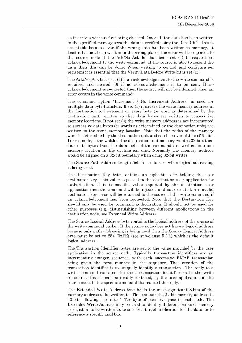
6.4.4 Read reply format (path addressing) The format of the read reply when using path addressing is illustrated in Figure 6-13.
ECSS-E-50-11 Draft F 4th December 2006
20
Source Path Address
Source Logical Address Protocol Identifier Packet Type, Command,Source Path Addr Len Status
Destination Logical Address Transaction Identifier (MS) Transaction Identifier (LS) Reserved = 0
Data Length (MS) Data Length Data Length (LS) Header CRC
Data Data Data Data
Source Path Address Source Path Address
Data Data Data Data
Data Data CRC EOP
First byte transmitted
Last byte transmitted
Read = 0 Read = 0Response = 0 Increment/No inc. address
Read = 1(Ack/No Ack)Reserved = 0
Bits in Packet Type / Command / Source Address Path Length Byte
MSB
Packet Type Command
Source PathAddress Length
Source PathAddress Length
LSB
Source Path Address Length
Figure 6-13 Read Reply Format (Path Addressing)
The Source Path Address bytes contain any required path address bytes needed to route the reply packet from the destination node back to the source node. The value of the Source Path Address bytes are as specified in the Source Address field of the read command. Any Source Path Address bytes are stripped off by the time the reply reaches the source of the read command.
The Command and Source Path Address Length field are set to the same values as in the command byte of the read command. In the reply the Source Path Address Length bits do not indicate extra words in the reply packet. They are just a copy of the values in the original command.
All other fields in the read reply when using path addressing are the same as when using logical addressing.
6.4.5 Read action The operation of the read command is illustrated in the sequence diagram of Figure 6-14.

ECSS-E-50-11 Draft F 4th December 2006
21
Read Request
Read DataRequest
ReadCommand
ReadReply
Read DataConfirmation
Source Destination
Read DataResponse
Figure 6-14 Read Command/Reply Sequence
The read command sequence starts when an application requests to perform a read operation (Read Request). The read command is constructed and sent to the destination node (Read Command). When the read command arrives at the destination it is flagged to the user application on the destination node (Read Data Request). The header of the read reply packet is formed and the requested data appended to it. The read reply containing the data is then sent back to the source of the read command. When it arrives there the user application that requested the data is informed (Read Data Confirmation).
6.4.6 Read errors There are four principal types of error that can occur when executing a read command: read command error, read authorisation rejection, read reply header error and read reply data error. These errors will now be considered.
The sequence of events following a read command error are illustrated in Figure 6-15.
Read RequestReadCommand
Source Destination
RecordPacket Error
Figure 6-15 Read Command Header Error
If the read command is corrupted but arrives at the destination node then a packet error will be recorded at the destination, but no other action will be taken by the destination node. It will not read any data and will not return a read reply packet. If the read command is lost altogether then the

ECSS-E-50-11 Draft F 4th December 2006
22
destination node would know nothing about the read command at all and would not be able to record a packet error.
If indication of this type of error is required at the source node then it is up to the user application at the source to set a timeout timer for the reply to the read command.
A read command may be received correctly (no header CRC error) but may still be rejected by the destination node. For example the read command may be for a different device type than that of the destination node, or the read command may be requesting data from an invalid memory address within the destination node. This situation is illustrated in Figure 6-16.
Read Request
Read DataRequest
ReadCommand
ReadReplyAuthorisationError
AuthorisationFailure
Source Destination
ReadAuthorisationRejection
Figure 6-16 Read Authorisation Rejection
When the read command arrives without error at the destination node its parameters are passed to the user application in the destination for authorisation. The read request, in this case, is rejected (Read Authorisation Rejection) and an error message is sent back to the source node (Read Reply Authorisation Error). When this error message arrives at the source node it causes an Authorisation Failure to be flagged to the user application in the source node.
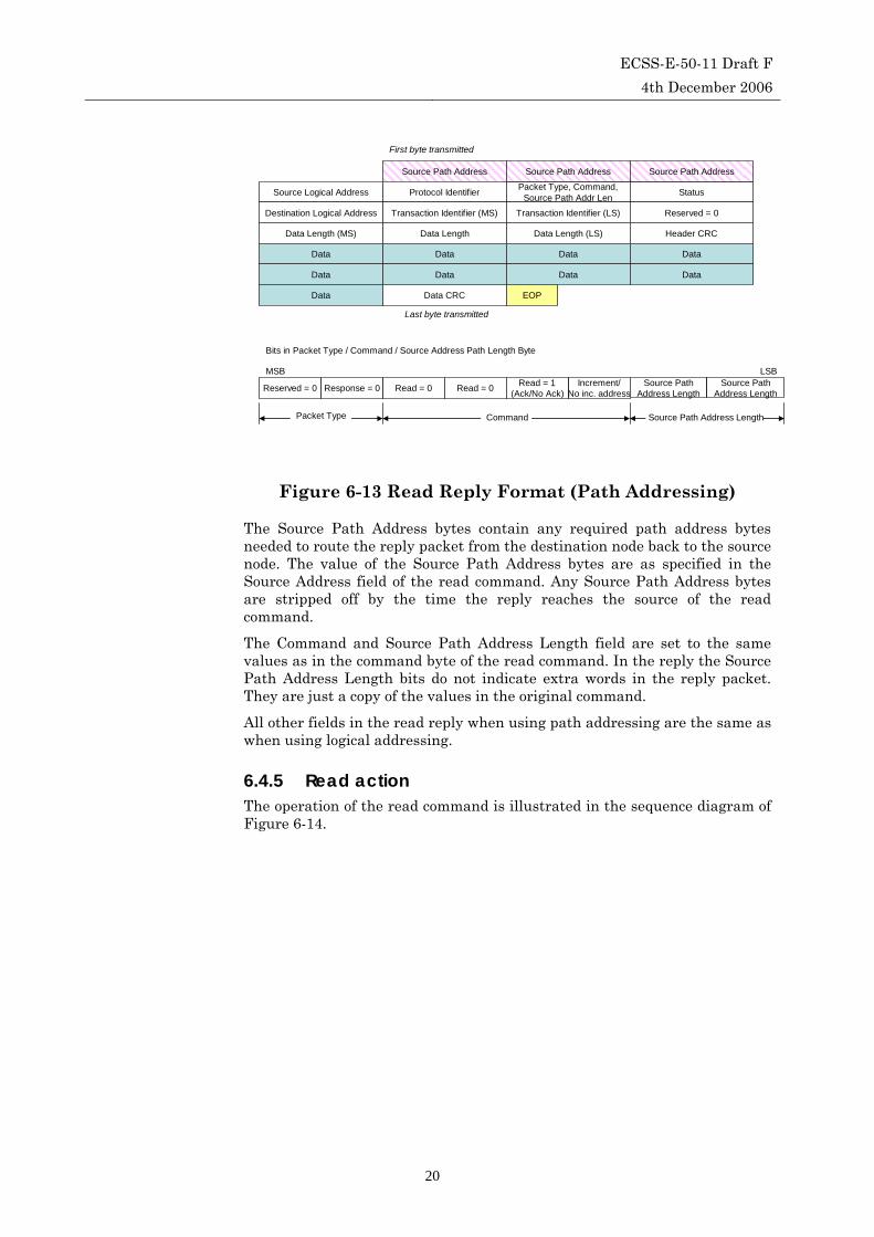
The situation that arises following a read reply header error is shown in Figure 6-17.
ECSS-E-50-11 Draft F 4th December 2006
23
Read Request
Read DataIndication
ReadCommand
ReadReply
Source Destination
Read DataResponse
RecordPacketError
Figure 6-17 Read Reply Header Error
The read command is received by the destination node and a reply returned to the source node containing the requested data. Either the reply packet gets lost altogether or the header of the read reply is received corrupted and a packet error is recorded at the source. Because there is an error in the header it is not known for certain what transaction identifier the reply packet is for, so nothing else can be done by RMAP.
If the user application at source has set a timeout timer for the read reply, then it will be able to detect the missing response, but this is outside the scope of the RMAP.
The result of an error in the data field of a read reply is illustrated in Figure 6-18.
Read Request
Read DataIndication
ReadCommand
ReadReply
Read DataFailure
Source Destination
Read DataResponse
Figure 6-18 Read Reply Data Error
If the header of the read reply packet is received intact but the data field is corrupted as indicated by an incorrect data field length (too long or too short) or by a CRC error, then an error can be flagged to the application immediately (Read Data Failure) without having to wait for a timeout.

ECSS-E-50-11 Draft F 4th December 2006
24
6.4.7 Read command parameters The Read Data Request has to provide the following parameters:
• Destination address • Source address • Transaction identifier • Destination key • Read command options • Read address • Data length
Note that RMAP does not handle the user application receive buffers, otherwise it would have to maintain at least a pointer for every outstanding read request. It is up to the user application to handle any receive buffers. The appropriate receive buffer for a read reply may be identified in the user application by the transaction identifier in the read reply.
6.5 Read-Modify-Write Command
6.5.1 Read-modify-write command format (logical addressing)
The read-modify-write command provides a means for a source node, to read a memory location in a destination node, modify some of the bits read and then write the new value back to the same memory location. The original value read from memory is returned to the source node. The format of the command when using logical addressing is shown in Figure 6-19.
Destination Logical Address Protocol Identifier Packet Type, CommandSource Path Addr Len Destination Key
Source Logical Address Transaction Identifier (MS) Transaction Identifier (LS) Extended RMW Address
RMW Address (MS) RMW Address RMW Address RMW Address (LS)
Data +Mask Length (MS)= 0x00
Data + Mask Length= 0x00
Data + Mask Length (LS) =0x00, 0x02, 0x04, 0x06 or 0x08 Header CRC
Data (MS) Data Data Data (LS)
Data/Mask CRC EOP
First byte transmitted
Last byte transmitted
Read = 0 Verify DataBefore WR = 1Command = 1 Incr. address
= 1Ack/No_Ack
= 1Reserved = 0
Bits in Packet Type / Command / Source Address Path Length Byte
MSB
Packet Type Command
Mask (MS) Mask Mask Mask (LS)
Source PathAddress Len = 0
Source PathAddress Len = 0
LSB
Source Path Address Length
Figure 6-19 Read-Modify-Write Command Format (Logical Addressing)
The Destination Logical Address is the same as for a read or write command.
The Protocol Identifier byte is set to the value 1 (0x01) which is the Protocol Identifier for the Remote Memory Access protocol.

ECSS-E-50-11 Draft F 4th December 2006
25
The Packet Type field is 01b, i.e. the command/reply bit is set, to indicate that the packet is a command packet, rather than a reply packet.
The Command field holds the read-modify-write command.
The Write/Read bit is clear (0) for a read-modify-write command.
The Verify Data Before Write bit is set (1) so that the data is always verified before it is used to update the memory location. This also distinguishes a read-modify-write from a read command.
The Ack/No_Ack bit is set (1) so that a reply to the read-modify-write command is always produced. This reply will contain the data initially read from the register in the destination node.
The “Increment / No Increment Address” bit is set (1) so that the destination memory address is incremented if the width of the memory is less than four bytes (32-bits). This means that when more than one byte is to be read-modified-written the address will be incremented if byte wide memory is being used. Note that the width of the memory word is determined by the destination unit and can be any multiple of 8-bits. For example, if the width of the destination unit memory word is 32-bits then four data bytes from the data field of the command are read and written into one memory location in the destination unit. Normally the memory address would be aligned on a 32-bit boundary when doing 32-bit read-modify-writes.
The Source Path Address Length field has the same function as for the read and write commands.
The Destination Key byte contains an eight-bit code holding the user destination key. This value is passed to the destination user application for authorisation. If it is not the value expected by the destination user application then the command will be rejected and not executed. An invalid destination key error will be returned to the source of the read-modify-write command.
The Source Logical Address byte contains the logical address of the source of the RMW command packet. If the source node does not have a logical address because only path addressing is being used then the Source Logical Address byte must be set to 254 (0xFE) which is the default logical address.
The Transaction Identifier bytes are set to the next transaction identifier in the sequence held by the source node. This uniquely identifies the transaction being started by the RMW command. The reply to the RMW command will contain the same transaction identifier and can thus be readily matched to the specific command that caused the reply.
The Extended RMW Address byte holds the most-significant 8-bits of the memory address to be read-modified-written. This effectively extends the 32-bit memory address to 40-bits allowing access to 1 Terabyte of memory space in each node.
The four RMW Address bytes hold the bottom 32-bits of the memory address which is to be read-modified-written. The first byte sent in the command is the most significant byte of the address. When combined with the Extended RMW Address byte a 40-bit memory address is provided.
The three Data Length bytes contain the length of the data that is to be written. In a read-modify write command this gives the total length of data (data and mask) sent in the command, which is twice the amount of data to be read and written. For example if a 2-byte word is to be written, then the data length will be 0x04. There will be two data bytes and two mask bytes in the command. Two bytes will be read from memory and returned to the

ECSS-E-50-11 Draft F 4th December 2006
26
source node. Two bytes will be written combining the read data, the data from the command and the mask. The maximum amount of data that can be read-modified-written with a read-modify-write command is 4 bytes. Hence the data length can only take on values of 0x00, 0x02, 0x04, 0x06 or 0x08. The first byte sent is the most significant byte of the data length. If an invalid data length (0x01, 0x03, 0x05, 0x07 or greater than 0x08) is specified then an error will be returned to the source. If the data length is zero no data will be read or written.
The Header CRC byte is an 8-bit CRC used to confirm that the header is correct before executing the command.
The Data bytes contain the data that is to be combined with the data read from memory and the mask, and then written into the memory of the destination node. When writing to memory organised in words (e.g. 32-bit words) then the first byte sent is the most-significant byte of the word. The set of 0, 1, 2, 3 or 4 data bytes precede the corresponding set of 0, 1, 2, 3, or 4 mask bytes.
The Mask bytes are used by the destination application to define how the data to be written to memory is formed. For example, data to be written could be selected on a bit by bit basis from the data send in the command when the corresponding mask bit is set (1) or from the data read in the reply when the mask bit is clear (0).
Written Data = (Mask AND Command_Data) OR (NOT Mask AND Read_Data).
This example is shown in Figure 6-20. The destination user application may implement different schemes for example test and set.
1 0 0 0 1 0 0 0
1 0 0 0 1 1 1 0
1 1 1 0 0 0 1 1
Data in command (Data)
Mask in command (Mask)
Data read from destination memory and returned to source (Read)
1 1 1 0 1 0 0 1 Data written to destination memory= (Mask AND Data) OR ( NOT Mask.Read)
Figure 6-20 Example Operation of Read-Modify-Write Command
The Data/Mask CRC contains an 8-bit CRC error check code used to confirm that the data and mask information was correctly transferred. The read-modify-write command will only be executed if there is no error in the data/mask. Note that the Data/Mask CRC is always present. When there is no data (data length is zero) the Data/Mask CRC is set to 0x00.
EOP character is the End Of Packet marker of the SpaceWire packet.
6.5.2 Read-modify-write reply format (logical addressing) The reply to a read-modify-write command is sent by the destination back to source of the command. The reply is used to indicate the success or failure of the read-modify-write command and to return the data originally read from

ECSS-E-50-11 Draft F 4th December 2006
27
the destination memory. The format of the read-modify-write reply when using logical addressing is shown in Figure 6-21.
Source Logical Address Protocol Identifier Packet Type, Command,Source Path Addr Len Status
Destination Logical Address Transaction Identifier (MS) Transaction Identifier (LS) Reserved = 0
Data Length (MS) = 0 Data Length = 0 Data Length (LS) =0x01, 0x02, 0x03 or 0x04 Header CRC
Data Data Data Data
Data CRC EOP
First byte transmitted
Last byte transmitted
Read = 0 Verify DataBefore WR = 1Response = 0 Inc. address
= 1Ack/No_Ack
= 1Reserved = 0
Bits in Packet Type / Command / Source Path Address Length Byte
MSB
Packet Type Command
Source PathAddress Len = 0
Source PathAddress Len = 0
LSB
Source Path Address Length
Figure 6-21 Read-Modify-Write Reply Format (Logical Addressing)
The Source Logical Address byte contains the logical address of the source of the read-modify-write command packet, as specified in the command Source Address field.
The Protocol Identifier byte is set to the value 1 (0x01) which is the Protocol Identifier for the Remote Memory Access protocol.
The Packet Type field is 00b to indicate that this is a reply packet.
The Command and Source Path Address Length field are set to the same values as in the command byte of the read-modify-write command.
The Status byte provides the status of the read-modify-write command. This is set to zero if the command executed successfully and to a non zero error code if there was an error. See error codes sub-clause 6.6.
The Transaction Identifier bytes are set to the same value as provided in the read-modify-write command. This is so that the source of the command can associate the reply with the original read-modify-write command.
The three Data Length bytes contain the length, in bytes, of the data that is to be read and returned in the reply packet. The first byte sent is the most significant byte of the data length. For a read-modify-write command the data length can be 0, 1, 2, 3 or 4 only. If the read reply packet is indicating an error, i.e. the status byte is non-zero, then the Data Length will normally be zero and there will be no data.
The Header CRC byte is an 8-bit CRC used to confirm that the header of the reply packet has been received without error.
The Data bytes contain the data that has been read from the memory of the destination node. When reading from memory organised in words (e.g. 32-bit words) then the first byte sent is the most-significant byte of the word.
The Data CRC is an 8-bit CRC error check code used to confirm that the data was correctly transferred. Note that the data CRC is always present. When there is no data (data length is zero) the data CRC is set to 0x00.
EOP character is the End Of Packet market of the SpaceWire packet.

ECSS-E-50-11 Draft F 4th December 2006
28
6.5.3 Read-modify-write command format (path addressing)
The format of the command when using path addressing is shown in Figure 6-22.
Destination Path Address
Destination Logical Address Protocol Identifier Packet Type, CommandSource Path Addr Len Destination Key
Source Path Address Source Path Address Source Path Address Source Path Address
Source Logical Address Transaction Identifier (MS) Transaction Identifier (LS) Extended RMW Address
RMW Address (MS) RMW Address RMW Address RMW Address (LS)
Data +Mask Length (MS)= 0x00
Data + Mask Length= 0x00
Data + Mask Length (LS) =0x00, 0x02, 0x04, 0x06 or 0x08 Header CRC
Data (MS) Data Data Data (LS)
Destination Path Address Destination Path Address
Data/Mask CRC EOP
First byte transmitted
Last byte transmitted
Read = 0 Verify DataBefore WR = 1Command = 1 Incr. address
= 1Ack/No_Ack
= 1Reserved = 0
Bits in Packet Type / Command / Source Address Path Length Byte
MSB
Packet Type Command
Mask (MS) Mask Mask Mask (LS)
Source PathAddress Length
Source PathAddress Length
LSB
Source Path Address Length
Figure 6-22 Read-Modify-Write Command Format (Path Addressing)
The Destination Address is the address on the SpaceWire network of the node from which data is to be read. When using path addressing the destination address is made up of two parts: the Destination Path Address bytes which are optional (shaded in Figure 6-22) and the Destination Logical Address. When path addressing is being used the Destination Path Address bytes contain the path to the destination node. The Destination Logical Address is byte is then set to the logical address of the destination node or to the default value 254 (0xFE).
When path addressing is being used the Source Path Address Length field has to be set to the smallest number of 32-bit words that can be used to contain the path address from the destination node that is being written to back to the source of the command packet. For example, if three path address bytes are required then the Source Path Address Length field is set to one.
The Source Path Address bytes contain any required path address bytes needed to route the reply packet from the destination node back to the source node. If logical addressing is being used then the Source Address bytes are not present.
All other fields are the same as when using logical addressing.
6.5.4 Read-modify-write reply format (path addressing) The reply to a read-modify-write command is sent by the destination back to source of the command. The reply is used to indicate the success or failure of the read-modify-write command and to return the data originally read from

ECSS-E-50-11 Draft F 4th December 2006
29
the destination memory. The format of the write reply is shown in Figure 6-23
Source Path Address
Source Logical Address Protocol Identifier Packet Type, Command,Source Path Addr Len Status
Destination Logical Address Transaction Identifier (MS) Transaction Identifier (LS) Reserved = 0
Data Length (MS) = 0 Data Length = 0 Data Length (LS) =0x00, 0x01, 0x02, 0x03 or 0x04 Header CRC
Data Data Data Data
Source Path Address Source Path Address
Data CRC EOP
First byte transmitted
Last byte transmitted
Read = 0 Verify DataBefore WR = 1Response = 0 Inc. address
= 1Ack/No_Ack
= 1Reserved = 0
Bits in Packet Type / Command / Source Path Address Length Byte
MSB
Packet Type Command
Source PathAddress Length
Source PathAddress Length
LSB
Source Path Address Length
Figure 6-23 Read-Modify-Write Reply Format (Path Addressing)
The Source Path Address bytes contain any required path address bytes needed to route the reply packet from the destination node back to the source node.
The Command and Source Path Address Length field are set to the same values as in the command byte of the read-modify-write command. In the reply the Source Path Address Length bits do not indicate extra words in the reply packet. They are just a copy of the values in the original command.
All other fields are the same as when using logical addressing.
6.5.5 Read-modify-write action The operation of the read-modify-write command is illustrated in the sequence diagram of Figure 6-24.

ECSS-E-50-11 Draft F 4th December 2006
30
RMW Request
RMW DataRequest
RMWCommand
RMWReply
RMW CompleteConfirmation
Source Destination
Data Read and WriteAuthorisation
Write Data
Write DataIndication
Figure 6-24 Read-Modify-Write Command/Reply Sequence
The read-modify-write command sequence begins when an application requests to perform a read-modify-write operation (RMW Request). In reply to this the source node builds the RMW command and sends it across the SpaceWire network to the destination node (RMW Command). When the RMW Command arrives at the destination, the header and data fields (including the mask bytes) are first checked for errors, since the Verify Before Write bit is always set in the RMW command. If the header and the data do not contain any errors then the user application at the destination node is asked if it will accept the RMW operation (RMW Data Request). If the user application accepts the request it will read the memory location(s) specified in the RMW command and return the data to RMAP (Data Read and Write Authorisation). The data to be written to the memory locations is then calculated from the data read from memory and the data and mask fields of the RMW command. The new data is then written to the memory location(s) that was previously read.
Once data has been written to memory the user application running on the destination node is informed that a RMW operation has taken place (RMW Indication). Since the acknowledgement bit (Ack/No_Ack) is always set for a RMW command, a reply will be sent back to the source of the command containing the data originally read from the destination memory (RMW Reply). When the write reply is received, the source node indicates successful completion of the write request (RMW Complete Confirmation).
6.5.6 Read-modify-write errors There are four principal types of error that can arise during a read-modify-write operation: RMW Command Error, RMW Authorisation Rejection, RMW Reply Header Error and RMW Reply Data Error.
The sequence of events that occurs when there is an error in the header of the RMW command is illustrated in Figure 6-25.

ECSS-E-50-11 Draft F 4th December 2006
31
RMW RequestRMWCommand
Source Destination
RecordPacketError
Figure 6-25 Read-Modify-Write Command Header Error
The RMW command packet arrives at the destination and its header is found to be in error. This fact is added to the error statistics in the destination node and the packet is discarded. No other action is taken at the destination or source nodes.
The situation that arises when there is an error in the data field of the read-modify-write command is shown in Figure 6-26.
RMW Request
RMW DataError Indication
RMWCommandHeader
RMW DataError Reply
RMW DataFailure
Source Destination
RecordData Error
RMWCommandData
Figure 6-26 Read-Modify-Write Command Data Error
The header of the RMW command has been received without error but the data CRC indicates that there has been an error in the data field. The RMW command shall not be executed. A data error is recorded in the destination node. The user application in the destination node is informed that a RMW command has been received with corrupted data. Since the header of the RMW command was intact it is also possible to report the error back to the source. A RMW reply packet containing the appropriate error code is sent back to the source node (RMW Data Error Reply). When this is received at the source node the error is reported to the user application (RMW Data Failure). RMAP returns the error code and the transaction identifier to the source node so that the user application can determine the original of the RMW command and the type of error that occurred.
If the RMW command is valid, the user application at the destination node is asked if it will accept the RMW operation (RMW Data Request). If it rejects the RMW operation (RMW Authorisation Rejection) then an RMW error

ECSS-E-50-11 Draft F 4th December 2006
32
reply is returned to the source node (RMW Reply Error). This situation is illustrated in Figure 6-27. When the RMW Reply containing the error code is received back at the source node, a RMW error indication (RMW Failure) is signalled to the user application in the source node.
RMW Request
RMW DataRequest
RMWCommand
RMW ReplyError
RMWFailure
Source Destination
RMWAuthorisationRejection
Figure 6-27 Read-Modify-Write Authorisation Rejection
It is possible that the RMW reply is corrupted or for some other reason does not reach the source node intact. This situation is illustrated in Figure 6-28.
RMWReply
Source Destination
RecordPacketError
RMW Request
RMW DataRequest
RMWCommand
Data Read and WriteAuthorisation
Write Data
Write DataIndication
Figure 6-28 Read-Modify-Write Reply Error
The data has been correctly written into destination memory and the destination application has been informed. The RMW reply that is sent back to the source node is corrupted. If the corrupted packet arrives at the source node (or indeed any other node) it is recorded as a packet receive error.
If the read operation succeeds but the write operation fails, due to for instance a write protected memory, then the complete transaction is considered an Authorisation failure. The source user application, in fact immediately rejects this as an authorisation failure as the command is trying to RMW an area of protected memory.
The result of an error in the data field of a RMW reply is illustrated in Figure 6-29.

ECSS-E-50-11 Draft F 4th December 2006
33
RMWReply
Source Destination
RMW Request
RMW DataRequest
RMWCommand
Data Read and WriteAuthorisation
Write Data
Write DataIndication
RMW DataFailure
Figure 6-29 RMW Reply Data Error
If the header of the RMW reply packet is received intact but the data field is corrupted as indicated by an incorrect data field length (too long or too short) or by a CRC error, then an error can be flagged to the application immediately (RMW Data Failure) without having to wait for an application timeout.
6.5.7 Read-modify-write command parameters The RMW Request has to provide the following parameters:
• Destination address • Source address • Transaction identifier • Destination key • RMW command • Memory address • Data length • Data • Mask
6.6 Error codes The possible error codes that can arise are listed in Table 6-1. These error codes are returned in the status field of any reply including acknowledgements and error replies.

ECSS-E-50-11 Draft F 4th December 2006
34
Table 6-1 Error Codes Error Code Error Error Description 0 Command executed
successfully
1 General error code The detected error does not fit into the other error cases or the node does not support further distinction between the errors
2 Unused RMAP Packet Type or Command Code
The header CRC was decoded correctly but the packet type is reserved or the command is not used by the RMAP protocol. No reply should be sent if the ACK bit is not set.
3 Invalid destination key
The header CRC was decoded correctly but the device key did not match that expected by the destination user application.
4 Invalid data CRC Error in the CRC of the data field 5 Early EOP EOP marker detected before the end of
the data. 6 Cargo too large The expected amount of SpaceWire
packet cargo has been received without receiving an EOP or EEP marker.
7 EEP EEP marker detected at or before the end of the data. Indicates that there was a communication failure of some sort on the network.
8 Reserved Reserved 9 Verify buffer
overrun The verify before write bit of the command was set so that the data field was buffered in order verify the data CRC before transferring the data to destination memory. The data field was longer than could fit inside the verify buffer resulting in a buffer overrun. Note that the command will not be executed in this case.
10 RMAP Command not implemented or not authorised
The destination user application did not authorise the requested operation. This may be because the command requested has not been implemented.
11 RMW data length error
The amount of data in a RMW command does not match the data length field or is invalid (0x01, 0x03, 0x05, 0x07 or greater than 0x08).
12 Invalid destination logical address
The header CRC was decoded correctly but the destination logical address was not the value expected by the destination.
13-255 Reserved All unused error codes are reserved

ECSS-E-50-11 Draft F 4th December 2006
35
The fields of a command shall be checked for errors in the order in which they arrive at a destination. In the event of more than one type of error being detected, the error code returned to the source of the command shall be the first error detected i.e. the first field in which there is an error shall determine the error code returned.
Note that the General Error Code (code number 1) should not normally be used as all the possible error codes have been included in the table.
The behaviour when reserved bits or fields are not received with the defined value is defined in Table 6-2. When Bit 7, a reserved bit, is set (1) then the command should not be executed and an error should be recorded. Only if bit 7 and bit 6 are both set and if the ACK bit is set should a reply be sent to the source of the command with error code 2.
Table 6-2 RMAP Packet Type and Node Action
Bit 7 Bit 6 Function Node action
0 0 Reply Packet Handle the packet as defined in this standard
0 1 Command Packet Handle the packet as defined in this standard
1 0 Reserved Packet Type Discard the packet and do nothing
1 1 Reserved Packet Type Discard the packet. If the ACK bit is set send reply with error code 2, otherwise do nothing
Similarly, when a reply is received with the reserved field in the command byte set (1) or with the ACK bit zero, RMAP shall discard the reply and should record the error in a status register.
Not all nodes have to be able to receive replies. Only those that send commands need to be able to receive replies. When a reply arrives at a node which is not designed to receive a reply, the reply packet shall be discarded. This error may be recorded in a status register.
Leading zeros in a source path address are ignored. A source path address containing any non-leading zeros or all zeros may be invalid depending on the application of RMAP. If the source path address is deemed invalid then no response is sent. The user application may also record this error in a status register.
6.7 Partial Implementation of RMAP Partial implementations of RMAP are permitted where only some commands or command options are supported. For example a unit might not implement the read-modify-write command if it did not need it. If a destination receives a command or a command with options that it does not support then it shall not authorise the command for execution. If a reply or acknowledgement has been requested then the Authorisation Failure error shall be sent back to the source, assuming that a reply has been requested in the command. See sub-clause 6.9.

ECSS-E-50-11 Draft F 4th December 2006
36
6.8 RMAP Use Cases (informative) RMAP is able to support many forms of system operation. In this section various applications of the RMAP protocol are considered to illustrate the many ways in which RMAP can be used. The interpretation of the contents of an RMAP command is dependent upon the application. For example RMAP may be used to write to memory via a DMA engine in the destination node, or it may write to memory via a host processor. In either of these two cases the memory addresses specified in the RMAP command may correspond directly to the memory address in the destination node that is to be written to. Here the source node determines where in memory in the destination node the data is to be written. Alternatively the memory address may be used to identify a mailbox or buffer in the destination into which the data in the RMAP command may be placed before being accessed by the destination application. In this case there is no direct correspondence between the memory address in the RMAP command and the actual area of memory where the data is finally written. The mapping between the two is up to the destination node. This flexibility is one of the key features of RMAP.
6.8.1 Write to memory This example assumes that the host application at the destination is a DMA controller attached to a bank of memory. This is illustrated in Figure 6-30. Table 6-3 gives an example of the corresponding RMAP command fields.
SpaceWireInterface
RMAPInterface
DMA Controller Memory
MemPtr = 001000h
DataCtr = 000010hData
Data
SpaceWire
SpaceWire-RMAP Interface Destination Application
Figure 6-30 Writing to memory with a DMA controller
Sixteen bytes of data are to be written into the destination memory starting at location 0x001000. The destination memory, in this example, is 16-bits wide so the 16 bytes will occupy eight 16-bit words of memory. The Increment bit in the write command is set to indicate that the DMA controller should increment its memory address pointer after every write to a memory location. An acknowledgement is required once the command has completed.
ECSS-E-50-11 Draft F 4th December 2006
37
Table 6-3 Example RMAP command writing to memory
Field No. Bytes Value
Destination Path Address 0 -
Destination Logical Address 1 0x54
Protocol Identifier 1 0x01
Packet Type 01b
Command 1 1011b
Extra Source Path Address Length 00b
Extra Source Path Address 0 -
Destination Key 1 0x42
Source Logical Address 1 0x76
Transaction Identifier 2 0x00 0x04
Extended Write Address 1 0x00
Write Address 4 0x00 0x00 0x10 0x00
Data Length 3 0x00 0x00 0x10
Header CRC 1 0x00
Data 16 0x00 0x01 0x02 0x03
0x04 0x05 0x06 0x07
0x08 0x09 0x0a 0x0b
0x0c 0x0d 0x0e 0x0f
Data CRC 1 0xc5
TOTAL 33
The command sent is a write command with the Acknowledge and Increment bits both set. The Verify Data Before Write is not set since, in this example application, it is not deemed necessary to check that the data has been received correctly before writing the data to memory. If there is an error in the data this will be indicated in the acknowledgment and the RMAP command can be resent by the source if required. Note that any resending is up to the source application and is not part of RMAP, although RMAP does provide a Transaction Identifier field to help with this.
The Write Address in the RMAP command is set to 0x00 0x00 0x10 0x00. The DMA controller, in this example, can only access 16 M words of memory so the top eight-bits of the memory address are not needed. They should be zero or the destination may reject the command. This is up to the destination application. The Extended Write Address should also be zero. The amount of data to be written (16 bytes) is specified in the Data Length field. The full command for the example is given in the Table 6-3. Note that most of the values in this table are example values and will change depending on the specific logical address of the destination, etc.
When the RMAP command arrives at the destination node. It is checked by the RMAP interface. If the header CRC is correct then the destination

ECSS-E-50-11 Draft F 4th December 2006
38
application is asked if it wishes to accept the command. For a DMA controller it would normally accept the RMAP command if the Write Address and Data Length specified an area of memory within the range of the DMA controller. In the example this is the case, so the Write Address is copied to the memory pointer in the DMA controller and the Data Length is copied to the DMA Data Counter. Data from the RMAP command is then transferred to the memory by the DMA controller. Two bytes of data are read from the RMAP interface and buffered by the DMA controller before being written to memory. The DMA Data Counter is then decremented by two, since two bytes have been written, and the DMA Memory Pointer is incremented to point to the next 16-bit word. Alternatively the Data Length could be divided by 2 when it is loaded into the DMA Counter, then it would be decremented by one, each time a 16-bit value is written to memory. The way that this is done is entirely dependent upon the destination application. When the entire 16-bytes of data have been written the DMA Counter will decrement to zero and the RMAP command will be complete. The Data CRC will be checked and if it is correct then the destination application will be informed that a successful transfer has taken place. If there is an error in the data, indicated by an invalid CRC, then the destination application will be informed of the error.
In this example, an acknowledgement has been requested (acknowledgement bit set in the command) so an acknowledgement will be returned to the source of the RMAP command. This acknowledgement will indicate if any errors have occurred.
It is worth noting that in the example command, logical addressing is being used to address the destination and source nodes: no path addressing is used. The destination key is to ensure that the RMAP command is for the node where it ended up. The Destination Logic Address should match the logical address of the destination and the Destination Key must be a value known to both the source and destination. If the Destination Key is not the value expected by the destination then the command will be rejected. There may be one Destination Key value for all possible RMAP commands to a particular destination, or there may be a different Destination Key value, for different types of command or for different memory address ranges. This is up to the application. All that is required is that the Destination Key in the command must be acceptable to the destination application.
The Transaction Identifier in the RMAP command is not used by the destination application, in this example. The destination application would take note of the Transaction Identifier if, for example, it was important that data was not written twice to the memory. This could happen if the acknowledgement sent back to the source was corrupted or went missing and if the source then resent the RMAP command. In the current example, it does not matter if the data is written twice to the memory. This would be important if it were a control register or FIFO that was being written to.
Although, in this example, the Transaction Identifier is not needed by the destination application, it is needed in the acknowledgement so that the source can associate the acknowledgement with a particular command. Note that if the source only sends one command at a time, waiting for any acknowledgement before proceeding, the value of the Transaction Identifier is not important. In general it is good practice to have an incrementing Transaction Identifier, incrementing for each new RMAP command that a source sends out. This is, however, up to the application.

ECSS-E-50-11 Draft F 4th December 2006
39
6.8.2 Read from memory Reading from memory is similar to writing to memory and a DMA controller may be used to control access to the memory, without a processor being present. In this example, however, a processor is being used instead of a DMA controller to control access to memory. This is illustrated in Figure 6-31.
SpaceWireInterface
RMAP Interface
HostProcessor
MemoryMem Addr RegSpaceWire
Data Len Reg
Data FIFO
Dest Key Reg
ProcessorBus
Status Reg
Figure 6-31 Reading from memory via a host processor
The RMAP interface is connected to the host processor and the memory by the processor bus. The host processor can access the RMAP interface through a series of registers which hold the fields of the current RMAP command. When an RMAP command is received the RMAP interface writes the fields of the command to the registers in the RMAP interface and then checks the header CRC. If the header CRC is valid then the host processor is interrupted, or otherwise flagged, so that it knows a new RMAP command has been received. The processor can then read the RMAP command information from the registers in the RMAP interface. The processor then decides whether it will accept the command.
If the command is not acceptable then the processor writes an appropriate error code to a status register in the RMAP interface. The RMAP interface will then send an acknowledgement containing the error code back to the source of the RMAP command, assuming that an acknowledgement was requested in the command.
If the command is acceptable then the processor will use the Read Address and Data Length information to perform the read operation. Words of data are read from memory and written to the Data FIFO in the RMAP interface. The Data FIFO has the same data-width as the memory and processor bus. The RMAP interface converts a (possibly) multi-byte wide data stream from the Data FIFO to a byte-wide stream as the data is passed to the SpaceWire interface. When the complete set of data has been read from the memory and written to the Data FIFO the processor can indicate that it has finished by writing to the status register in the RMAP interface.
An example of a RMAP command for reading data from memory is given in Table 6-4.

ECSS-E-50-11 Draft F 4th December 2006
40
Table 6-4 Example RMAP command reading from memory
Field No. Bytes Value
Destination Path Address 0 -
Destination Logical Address 1 0x54
Protocol Identifier 1 0x01
Packet Type 01b
Command 1 0011b
Extra Source Path Address Length 00b
Extra Source Path Address 0 -
Destination Key 1 0x57
Source Logical Address 1 0x76
Transaction Identifier 2 0x00 0x05
Extended Read Address 1 0x00
Read Address 4 0x00 0x00 0x20 0x00
Data Length 3 0x00 0x00 0x10
Header CRC 1 0x83
TOTAL 16
This RMAP command is being sent from the source node with logical address 0x76. It is requesting to read 16 bytes of data starting at address location 0x2000 in the destination node with logical address 0x54.
6.8.3 Reading and Writing to Registers RMAP can be used to write to configuration registers and to read from status registers in a destination node.
Reading from a register is done in the same way as reading from memory. If more than one register is to be read at a consecutive address then they may be read in one command by setting the Increment Address bit in the command field. If the destination application has registers which are wider than 8-bits then multiple bytes may be requested in a single command. For example to read a 32-bit register at memory location 0x0020 a command to read 4 bytes at location 0x0020, with the Increment Address bit not set, may be used.
Writing to a register is identical to writing to memory except that normally when writing to a register the RMAP interface would check that the data has been received correctly before writing it to the register. This prevents an invalid value being written to a configuration register, which could otherwise adversely affect the operation of the destination node. To ensure that the data is correct before data is written to the register the Verify Data Before Write bit has to be set in the Command field of the RMAP command. If this bit is set the RMAP interface will buffer the complete Data field of the RMAP command and check that the Data CRC is valid before writing the data to

ECSS-E-50-11 Draft F 4th December 2006
41
the register. Multiple registers, with contiguous addresses may be written, or read, if the increment address bit in the command field is set.
The Verify Data Before Write bit may also be set when writing to memory, but the RMAP interface must contain enough buffer space to buffer the entire Data field of the command so that it can be checked before any data is written to memory.
6.8.4 Write to FIFO Writing and reading from memory and registers is relatively straightforward with the RMAP protocol. Reading and writing to a FIFO is a bit more involved. This is because the FIFO may become full when writing, or empty when reading, and because it is not normally possible to recover from writing erroneous data to a FIFO by resending the correct data or to recover from loosing data read from a FIFO. Writing to a FIFO is considered in this sub-section and reading from a FIFO is covered in the following sub-section.
Writing to a FIFO is similar to writing to a register. The address of the FIFO is specified in the Write Address and the Increment/No Increment Bit is not set so that the data is written to the same address, that of the FIFO. The width of the FIFO can be any width provided that the RMAP interface performs the buffering of data before it is written to the FIFO.
A problem can arise if the FIFO becomes full. There are several possible ways in which this can be handled depending upon the requirements of the specific application.
If the FIFO is unlikely to become full for very long then it may be adequate to block the SpaceWire packet until the FIFO becomes not full again and can accept more data. The RMAP header is read and checked and data then starts to be written from the RMAP command data field to the FIFO. When the FIFO becomes full then no more data can be written so the rest of the SpaceWire packet cannot be read into the RMAP interface and remains in the SpaceWire network. When the FIFO can accept more data then more of the data in the SpaceWire packet can be read. This approach should only be used when the FIFO cannot become full for more than a very short time. It should also be noted that if the data is not verified before it is written then it is possible that erroneous data gets written into the FIFO.
An alternative approach when a FIFO becomes full is to stop writing to the FIFO and to discard the remainder of a packet. In this case an acknowledgment should be sent to the source of the RMAP command indicating the amount of data that was successfully written to the FIFO. The source can then resend the data that was not written in the previous command.
Another option is for the destination application to check how much room there is in the FIFO when it receives the RMAP command header. If there is insufficient room then either some of the data could be written and an indication of how much data was written could be sent back to the source, or the entire packet could be discarded.
Yet another option is for the source application to check the status of the destination FIFO by reading a status register, using an RMAP read command, thus finding out how much room is left in the FIFO. It would then send data up to the limit of the FIFO.
The final option is the most robust approach for writing to a FIFO. Since writing erroneous data to a FIFO is not desirable, it is better to send data for writing to a FIFO in small packets which can be verified before being written
ECSS-E-50-11 Draft F 4th December 2006
42
to the FIFO. This means that the entire data field of each command has to be buffered in the RMAP interface and checked before writing. If there is no room in the FIFO the RMAP interface can wait for the FIFO to start to empty without adversely affecting the operation of the rest of the SpaceWire network. Once the complete set of data has been written to the FIFO an acknowledgement can be sent to the source. The source can then send more data to the FIFO. If the data is found to be in error it is discarded and not written to the FIFO. An error code is then sent to the source and the source can resend the data. This may be implemented as a FIFO which can take in data in 256 byte chunks (for example). Data for the FIFO is sent in packets containing no more than 256 bytes. This data is written into the FIFO as it arrives. At the end of the packet the Data CRC is checked and if OK the data is accepted by the FIFO i.e. the FIFO write pointer is moved permanently to the end of the new data and the FIFO can read this new information. If there is an error in the data that has just been written then the write pointer is set to the start of the new data, as if it had not been written.
6.8.5 Read from FIFO Reading from a FIFO has a similar problem to writing to a FIFO. In this case, however, the FIFO may become empty during a read. For example, a read from a FIFO may request 100 bytes of data but the FIFO becomes empty after 20 bytes.
If the FIFO is unlikely to be empty for very long, the RMAP interface may wait for more data to become available, adding it to the end of the packet that is being sent as soon as possible. This does leave a packet strung out through the SpaceWire network while waiting for the rest of the data, which may adversely affect other traffic on the network.
An alternative is for the RMAP interface to stop reading the FIFO if it becomes empty and for it to send whatever data it has read in the reply to the command. In this case the reply to the read request would be terminated early, returning only the amount of data read. The reply would then contain the data field set to the desired amount of data (e.g. 100 bytes) but only 20 bytes would be attached to the packet. The 20 bytes of data would be followed by the one byte Data CRC code and the packet would be terminated by an EOP. The EOP would indicate that this was a valid packet, not one that was truncated by an error during transit across the network, in which case an EEP would have terminated the packet. To prevent the two bytes of the Data CRC being accepted as data by the source node the source must buffer the last two bytes received and check that they were not the last two bytes of the packet, before using them. If a read FIFO reply is received with less than the expected amount of data then the source may send another read request for the rest of the data (e.g. the remaining 80 bytes) or it may read the status of the destination first to check what happened.
Another possibility is for the RMAP interface in the destination to check the amount of data in FIFO first before it reads it. It can then return the actual amount of data read in the Data Length field of the reply, along with that much data.
A final option is for the FIFO data to be read into a buffer in the RMAP interface before the reply is sent. The correct amount of data can then be gathered, waiting if necessary for data to become available in the FIFO. Once the required amount of data has been read the reply can be sent in one go. This does require buffering in the RMAP interface which limits the amount of data that can be read in a single command. If the FIFO becomes empty for a long period of time then it may be appropriate for the RMAP interface to

ECSS-E-50-11 Draft F 4th December 2006
43
send what data it has got, indicating that the full amount of data could not be read within the time available. This approach could use the memory in the FIFO if, as for the write FIFO case, reading data from the FIFO was organised in chunks. Taking the same example as for the write FIFO case of 256 bytes chunks to be read from the FIFO, when an RMAP read command is received 256 bytes of data are read from the FIFO and returned to the source of the command. The read pointer of the FIFO is not updated until another read command is received with a different transaction identifier to the one that caused the last read. If the transaction identifier is the same as the previous read command then the same data can be sent again.
There are many ways in which FIFO type operations can be supported by RMAP. The choice depends upon the particular application requirements. What RMAP provides is a consistent means of using SpaceWire packets to perform a wide range of application functions.
6.8.6 Write to Mailbox RMAP supports reading and writing to mailboxes. A mailbox is a means passing data to an application without writing directly to memory in the application. The mailbox is an area of memory made available to the RMAP interface by the application and which has been given a unique identifier. This identifier is an RMAP write memory address which is reserved for accessing the mailbox. Many mailboxes may be used, as required by the application.
Writing to a mailbox is the same as far as RMAP is concerned as writing many bytes to a single address location. For example, the RMAP command in Table 6-5 writes a message to a mailbox. Source address 0x76 is writing to mailbox zero in destination 0x54. The mailbox address space in this example is differentiated from the normal directly writable memory space by the value of the Extended Write Address byte: when it is zero the Write Address accesses up to 4G locations of directly addressable memory. When it is 0x01 it references the mailbox space, allowing up to 4G mailboxes to be specified. Note this is an example use of the Extended Write Address byte. The Write Address is 0x00000000 referencing mailbox zero. The Increment Address bit is not set in the command byte and the Data Length is 16 bytes. The Destination Key is set to a value agreed by the source and destination to give access to the mailbox.

ECSS-E-50-11 Draft F 4th December 2006
44
Table 6-5 Example RMAP command writing to mailbox
Field No. Bytes Value
Destination Path Address 0 -
Destination Logical Address 1 0x54
Protocol Identifier 1 0x01
Packet Type 01b
Command 1 1010b
Extra Source Path Address Length 00b
Extra Source Path Address 0 -
Destination Key 1 0x99
Source Logical Address 1 0x76
Transaction Identifier 2 0x00 0x06
Extended Write Address 1 0x01
Write Address 4 0x00 0x00 0x00 0x00
Data Length 3 0x00 0x00 0x10
Header CRC 1 0xe7
Data 16 0x00 0x01 0x02 0x03
0x04 0x05 0x06 0x07
0x08 0x09 0x0a 0x0b
0x0c 0x0d 0x0e 0x0f
Data CRC 1 0xc5
TOTAL 33
When this command is received at the destination the header is first checked to make sure that there are no errors and then the fields of the command are authorised by the application. Assuming that all is in order, the application authorises writing to the mailbox.
One possible implementation of the mailbox system is a DMA based mailbox controller. This is illustrated in Figure 6-32. The mailbox DMA is configured by a host processor, or may have a predetermined configuration. There is a DMA channel for each mailbox. Each mailbox has a mailbox base pointer which determines where in memory the mailbox memory resides, and a mailbox maximum size which specifies the size of the mailbox memory. A mailbox status register holds the status of the mailbox, for example, whether the mailbox is empty or is in use.

ECSS-E-50-11 Draft F 4th December 2006
45
SpaceWireInterface
RMAPInterface
SpaceWire-RMAP Interface Destination Application
Mailbox DMA
Mailbox Base PtrMailbox Current PtrMailbox Max Size
Mailbox Status
Mailbox Data Size
Memory
Mailbox MemoryMailbox Memory
Mailbox Memory
Figure 6-32 Writing to mailbox
The RMAP command to write to a mailbox will be authorised if the command references a mailbox which is not currently in use, if the amount of data to be written is no larger than the size of the mailbox, and if the Destination Key is valid for that mailbox. The mailbox current pointer will be set to point to the start of the mailbox, by loading it with the contents of the mailbox base pointer. The data size will be loaded with the data length from the RMAP command. Data will then be transferred into the mailbox memory from the RMAP command. If the data is transferred successfully with no error, then the mailbox status will be updated and the host application will be informed that data is ready in the mailbox. An acknowledgment will be sent to the source indicating that the data has transferred correctly. If the data contains an error, then the mailbox status will reflect this and the mailbox will be considered empty. In this case the acknowledgement sent to the source will indicate the error and the mailbox write command can be resent, if required.
Mailbox status information may be read over SpaceWire using an RMAP read register command.
6.8.7 Read from Mailbox Reading from a mailbox is similar to writing multiple data to a register or FIFO. The read is done referencing a mailbox address with the Read Address. An example RMAP command for reading from a mailbox is given in Table 6-6.

ECSS-E-50-11 Draft F 4th December 2006
46
Table 6-6 Example RMAP command reading from mailbox
Field No. Bytes Value
Destination Path Address 0 -
Destination Logical Address 1 0x54
Protocol Identifier 1 0x01
Packet Type 01b
Command 1 0010b
Extra Source Path Address Length 00b
Extra Source Path Address 0 -
Destination Key 1 0x88
Source Logical Address 1 0x76
Transaction Identifier 2 0x00 0x07
Extended Read Address 1 0x01
Read Address 4 0x00 0x00 0x00 0x01
Data Length 3 0x00 0x00 0x10
Header CRC 1 0x08
TOTAL 16
In this example source 0x76 is requesting to read 16 bytes from mailbox one in destination 0x54. If the referenced mailbox contains data and the command is acceptable, then the contents of the mailbox is returned to the source node in the reply packet. If the mailbox does not have the full amount of data requested then the Data Length field in the reply would be set to the amount of data that was in the mailbox and only this amount of data would be returned in the reply.
Note that mailboxes may, if required by the application, be bi-directional i.e. able to accept both read and write commands. This permits one node to write data into a mailbox in another node, which is subsequently read by a third node.
6.8.8 Repeating Transaction ID If an acknowledgement to a write command fails to be received then it is possible that the command was received and executed by the destination, but the acknowledgement failed to get through successfully. If writing to a command register or to a FIFO it may be important that the same information is not written a second time. The source user application may send the same command again using the same transaction identifier. The destination user application may then use this repeated transaction identifier to prevent writing the same information to the command register or FIFO.

ECSS-E-50-11 Draft F 4th December 2006
47
6.8.9 Event Signalling RMAP can support event signalling in a simple but effective manner. This can replace interrupts in a distributed system. An RMAP command can be sent to a node registering to receive an event signal from the node. When the event occurs the reply to the source of the RMAP command is sent, signalling to the source that the event has occurred. A user program may sleep until the reply wakes up it. Data may be attached to the reply.
Event signalling in a node may be implemented using a register (the Event-Flag register). Registering to receive an event signal may be done by reading to the event-flag register. Writing to the event-flag register may cancel the request.
Bits in the event-flag register may indicate different conditions on an event.
Multiple event-flag registers may be used to register to receive multiple events.
A single event may be reported to multiple nodes if each of those nodes has registered to receive the event signal, provided, of course, that the destination node is designed to handle signalling to multiple nodes.
Care needs to be taken in the system design to avoid high latency. For example, the maximum packet length used must be kept to a reasonable size to avoid an event packet having to wait for a long time while a long packet completes transmission.

ECSS-E-50-11 Draft F 4th December 2006
48
6.9 RMAP Command Summary The RMAP command codes and their meanings are listed in Table 6-7.
Table 6-7 RMAP Command Codes
Bit 5 Bit 4 Bit 3 Bit 2 Command Field
Write/
Read
Verify Data Before Write
Ack Increment Address
Function
0 0 0 0 Not used
0 0 0 1 Not used
0 0 1 0 Read single address
0 0 1 1 Read incrementing addresses
0 1 0 0 Not used
0 1 0 1 Not used
0 1 1 0 Not used
0 1 1 1 Read-Modify-Write incrementing addresses
1 0 0 0 Write, single address, don’t verify before writing, no acknowledge
1 0 0 1 Write, incrementing addresses, don’t verify before writing, no acknowledge
1 0 1 0 Write, single address, don’t verify before writing, send acknowledge
1 0 1 1 Write, incrementing addresses, don’t verify before writing, send acknowledge
1 1 0 0 Write, single address, verify before writing, no acknowledge
1 1 0 1 Write, incrementing addresses, verify before writing, no acknowledge
1 1 1 0 Write, single address, verify before writing, send acknowledge
1 1 1 1 Write, incrementing addresses, verify before writing, send acknowledge
The RMAP Command Codes that are not used will result in an “RMAP command not supported by node” error code being returned to the source of the command.

ECSS-E-50-11 Draft F 4th December 2006
49
6.10 RMAP Conformance
6.10.1 Conformance statements Several SpaceWire RMAP compatible subsets can be identified each of which implements only a part of the SpaceWire RMAP standard:
• RMAP Write Command
• RMAP Read Command
• RMAP Read-Modify-Write Command
Corresponding subsets of the SpaceWire RMAP standard are defined to which implementations may claim conformance. The form of the conformance statement to use is the one given by the appropriate subset definition in the following subclauses.
An RMAP compliant product may implement one or more of these subsets.
6.10.2 Definition of subsets
6.10.2.1 RMAP Write Command An implementation of SpaceWire RMAP Write Command shall conform to all of the requirements given in all subclauses listed in Table 6-8.
NOTE A product meeting this specification may use the following conformance statement:
This product conforms to the SpaceWire RMAP Write specification of the ESA SpaceWire Standard (ECSS-E-50-12A Part 2).
Table 6-8: SpaceWire RMAP Write Command
Relevant clauses or subclauses
Title
5 Protocol Identifier
6.3 Write Command
6.6 Error Codes
The supplier of the RMAP equipment shall provide a table detailing the write command characteristics of the RMAP implementation. An example of the required table is given in Table 6-9.
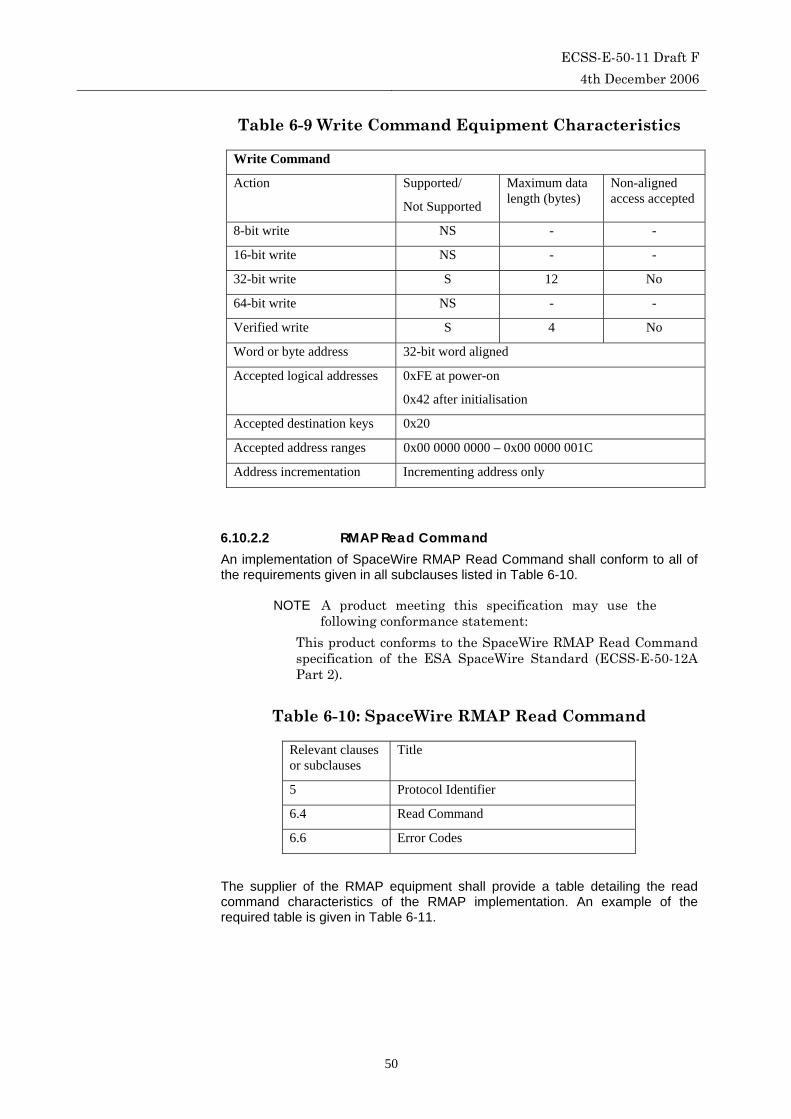
ECSS-E-50-11 Draft F 4th December 2006
50
Table 6-9 Write Command Equipment Characteristics
Write Command
Action Supported/
Not Supported
Maximum data length (bytes)
Non-aligned access accepted
8-bit write NS - -
16-bit write NS - -
32-bit write S 12 No
64-bit write NS - -
Verified write S 4 No
Word or byte address 32-bit word aligned
Accepted logical addresses 0xFE at power-on
0x42 after initialisation
Accepted destination keys 0x20
Accepted address ranges 0x00 0000 0000 – 0x00 0000 001C
Address incrementation Incrementing address only
6.10.2.2 RMAP Read Command An implementation of SpaceWire RMAP Read Command shall conform to all of the requirements given in all subclauses listed in Table 6-10.
NOTE A product meeting this specification may use the following conformance statement:
This product conforms to the SpaceWire RMAP Read Command specification of the ESA SpaceWire Standard (ECSS-E-50-12A Part 2).
Table 6-10: SpaceWire RMAP Read Command
Relevant clauses or subclauses
Title
5 Protocol Identifier
6.4 Read Command
6.6 Error Codes
The supplier of the RMAP equipment shall provide a table detailing the read command characteristics of the RMAP implementation. An example of the required table is given in Table 6-11.

ECSS-E-50-11 Draft F 4th December 2006
51
Table 6-11 Read Command Equipment Characteristics
Read Command
Action Supported/
Not Supported
Maximum data length (bytes)
Non-aligned access accepted
8-bit read NS - -
16-bit read NS - -
32-bit read S 12 No
64-bit read NS - -
Word or byte address 32-bit word aligned
Accepted logical addresses 0xFE at power-on
0x42 after initialisation
Accepted destination keys 0x20
Accepted address ranges 0x00 0000 0000 – 0x00 0000 001C
0x00 0000 0020 – 0x00 0000 003C
Address incrementation Incrementing address only
6.10.2.3 RMAP Read-Modify-Write Command An implementation of SpaceWire RMAP Read-Modify-Write Command shall conform to all of the requirements given in all subclauses listed in Table 6-12.
NOTE A product meeting this specification may use the following conformance statement:
This product conforms to the SpaceWire RMAP Read-Modify-Write specification of the ESA SpaceWire Standard (ECSS-E-50-12A Part 2).
Table 6-12: SpaceWire RMAP Read-Modify-Write Command
Relevant clauses or subclauses
Title
5 Protocol Identifier
6.5 Read-Modify-Write Command
6.6 Error Codes
The supplier of the RMAP equipment shall provide a table detailing the characteristics of the RMAP implementation. An example of the required table is given in Table 6-13.

ECSS-E-50-11 Draft F 4th December 2006
52
Table 6-13 Read-Modify-Write Command Equipment Characteristics
Read-Modify-Write Command
Action Supported/
Not Supported
Maximum data length (bytes)
Non-aligned access accepted
8-bit read-modify-write NS - -
16-bit read-modify-write NS - -
32-bit read-modify-write S 4 No
64-bit read-modify-write NS - -
Word or byte address 32-bit word aligned
Accepted logical addresses 0xFE at power-on
0x42 after initialisation
Accepted destination keys 0x20
Accepted address ranges 0x00 0000 0000 – 0x00 0000 001C
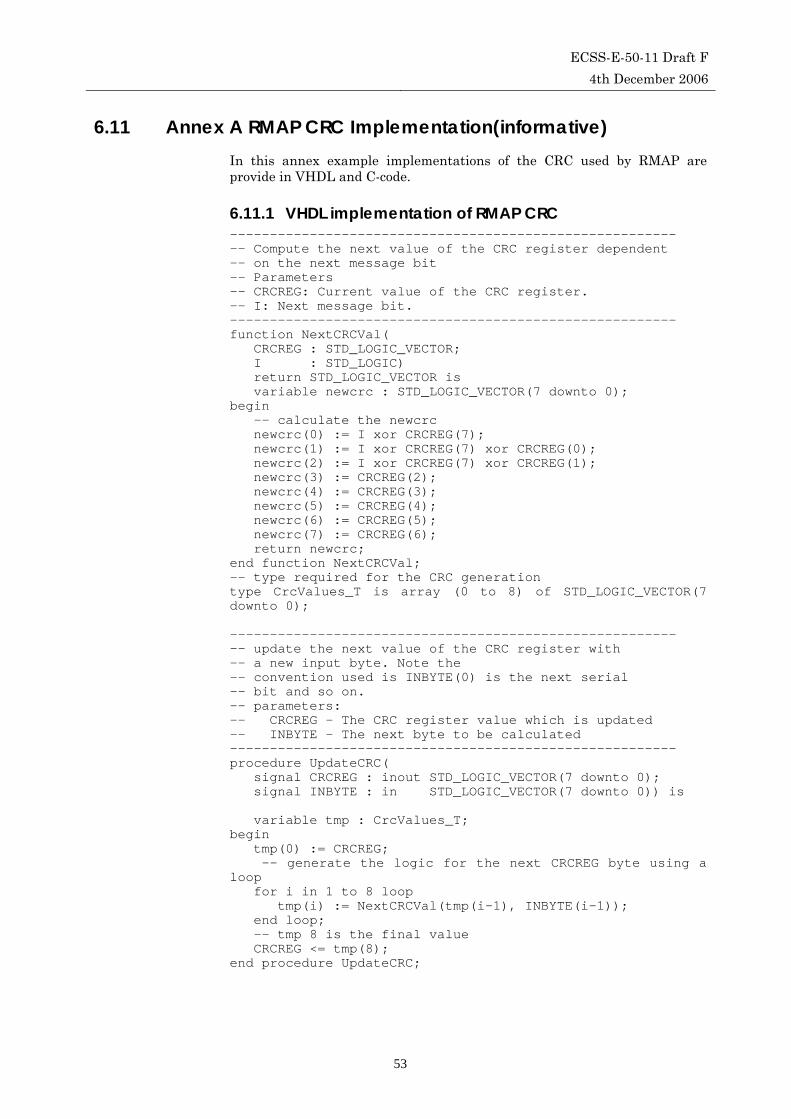
ECSS-E-50-11 Draft F 4th December 2006
53
6.11 Annex A RMAP CRC Implementation(informative) In this annex example implementations of the CRC used by RMAP are provide in VHDL and C-code.
6.11.1 VHDL implementation of RMAP CRC -------------------------------------------------------- -- Compute the next value of the CRC register dependent -- on the next message bit -- Parameters -- CRCREG: Current value of the CRC register. -- I: Next message bit. -------------------------------------------------------- function NextCRCVal( CRCREG : STD_LOGIC_VECTOR; I : STD_LOGIC) return STD_LOGIC_VECTOR is variable newcrc : STD_LOGIC_VECTOR(7 downto 0); begin -- calculate the newcrc newcrc(0) := I xor CRCREG(7); newcrc(1) := I xor CRCREG(7) xor CRCREG(0); newcrc(2) := I xor CRCREG(7) xor CRCREG(1); newcrc(3) := CRCREG(2); newcrc(4) := CRCREG(3); newcrc(5) := CRCREG(4); newcrc(6) := CRCREG(5); newcrc(7) := CRCREG(6); return newcrc; end function NextCRCVal; -- type required for the CRC generation type CrcValues_T is array (0 to 8) of STD_LOGIC_VECTOR(7 downto 0); -------------------------------------------------------- -- update the next value of the CRC register with -- a new input byte. Note the -- convention used is INBYTE(0) is the next serial -- bit and so on. -- parameters: -- CRCREG - The CRC register value which is updated -- INBYTE - The next byte to be calculated -------------------------------------------------------- procedure UpdateCRC( signal CRCREG : inout STD_LOGIC_VECTOR(7 downto 0); signal INBYTE : in STD_LOGIC_VECTOR(7 downto 0)) is variable tmp : CrcValues_T; begin tmp(0) := CRCREG; -- generate the logic for the next CRCREG byte using a loop for i in 1 to 8 loop tmp(i) := NextCRCVal(tmp(i-1), INBYTE(i-1)); end loop; -- tmp 8 is the final value CRCREG <= tmp(8); end procedure UpdateCRC;
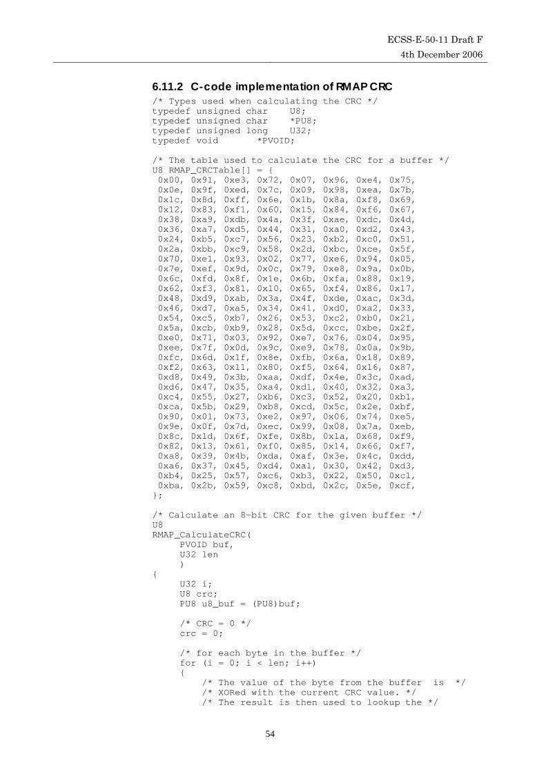
ECSS-E-50-11 Draft F 4th December 2006
54
6.11.2 C-code implementation of RMAP CRC /* Types used when calculating the CRC */ typedef unsigned char U8; typedef unsigned char *PU8; typedef unsigned long U32; typedef void *PVOID; /* The table used to calculate the CRC for a buffer */ U8 RMAP_CRCTable[] = { 0x00, 0x91, 0xe3, 0x72, 0x07, 0x96, 0xe4, 0x75, 0x0e, 0x9f, 0xed, 0x7c, 0x09, 0x98, 0xea, 0x7b, 0x1c, 0x8d, 0xff, 0x6e, 0x1b, 0x8a, 0xf8, 0x69, 0x12, 0x83, 0xf1, 0x60, 0x15, 0x84, 0xf6, 0x67, 0x38, 0xa9, 0xdb, 0x4a, 0x3f, 0xae, 0xdc, 0x4d, 0x36, 0xa7, 0xd5, 0x44, 0x31, 0xa0, 0xd2, 0x43, 0x24, 0xb5, 0xc7, 0x56, 0x23, 0xb2, 0xc0, 0x51, 0x2a, 0xbb, 0xc9, 0x58, 0x2d, 0xbc, 0xce, 0x5f, 0x70, 0xe1, 0x93, 0x02, 0x77, 0xe6, 0x94, 0x05, 0x7e, 0xef, 0x9d, 0x0c, 0x79, 0xe8, 0x9a, 0x0b, 0x6c, 0xfd, 0x8f, 0x1e, 0x6b, 0xfa, 0x88, 0x19, 0x62, 0xf3, 0x81, 0x10, 0x65, 0xf4, 0x86, 0x17, 0x48, 0xd9, 0xab, 0x3a, 0x4f, 0xde, 0xac, 0x3d, 0x46, 0xd7, 0xa5, 0x34, 0x41, 0xd0, 0xa2, 0x33, 0x54, 0xc5, 0xb7, 0x26, 0x53, 0xc2, 0xb0, 0x21, 0x5a, 0xcb, 0xb9, 0x28, 0x5d, 0xcc, 0xbe, 0x2f, 0xe0, 0x71, 0x03, 0x92, 0xe7, 0x76, 0x04, 0x95, 0xee, 0x7f, 0x0d, 0x9c, 0xe9, 0x78, 0x0a, 0x9b, 0xfc, 0x6d, 0x1f, 0x8e, 0xfb, 0x6a, 0x18, 0x89, 0xf2, 0x63, 0x11, 0x80, 0xf5, 0x64, 0x16, 0x87, 0xd8, 0x49, 0x3b, 0xaa, 0xdf, 0x4e, 0x3c, 0xad, 0xd6, 0x47, 0x35, 0xa4, 0xd1, 0x40, 0x32, 0xa3, 0xc4, 0x55, 0x27, 0xb6, 0xc3, 0x52, 0x20, 0xb1, 0xca, 0x5b, 0x29, 0xb8, 0xcd, 0x5c, 0x2e, 0xbf, 0x90, 0x01, 0x73, 0xe2, 0x97, 0x06, 0x74, 0xe5, 0x9e, 0x0f, 0x7d, 0xec, 0x99, 0x08, 0x7a, 0xeb, 0x8c, 0x1d, 0x6f, 0xfe, 0x8b, 0x1a, 0x68, 0xf9, 0x82, 0x13, 0x61, 0xf0, 0x85, 0x14, 0x66, 0xf7, 0xa8, 0x39, 0x4b, 0xda, 0xaf, 0x3e, 0x4c, 0xdd, 0xa6, 0x37, 0x45, 0xd4, 0xa1, 0x30, 0x42, 0xd3, 0xb4, 0x25, 0x57, 0xc6, 0xb3, 0x22, 0x50, 0xc1, 0xba, 0x2b, 0x59, 0xc8, 0xbd, 0x2c, 0x5e, 0xcf, }; /* Calculate an 8-bit CRC for the given buffer */ U8 RMAP_CalculateCRC( PVOID buf, U32 len ) { U32 i; U8 crc; PU8 u8_buf = (PU8)buf; /* CRC = 0 */ crc = 0; /* for each byte in the buffer */ for (i = 0; i < len; i++) { /* The value of the byte from the buffer is */ /* XORed with the current CRC value. */ /* The result is then used to lookup the */

ECSS-E-50-11 Draft F 4th December 2006
55
/* new CRC value from the CRC lookup table */ crc = RMAP_CRCTable[crc ^ *u8_buf++]; } /* return the CRC */ return crc; }

ECSS-E-50-11 Draft F 4th December 2006
56
6.12 List of changes
6.12.1 From draft E to draft F Figure 6-23 updated to include replies with data length of zero i.e. 0x00
also allowed in the last data length field. This is a correction to the figure to make it consistent with the associated text.
Table 6-1 updated with clarifications to the error code definitions. Specifically Error Code 2 and 7 have been clarified.
Additional text has been added to section 6.3.1 Data CRC paragraph, section 6.4.2 Data CRC paragraph, section 6.5.1 Data/Mask CRC paragraph and section 6.5.2 Data CRC paragraph. This extra text states “Note that the data CRC is always present. When there is no data (data length is zero) the data CRC is set to 0x00.”
Clarification has been added to the definition of the Header and Data CRC in section 6.2 Definitions. The CRC handles data least significant bit first. The information about the CRC algorithm has been put in a separate CRC definition paragraph and text has been added that states The CRC is calculated on the byte stream not the serial bit stream, since the RMAP protocol operates above the SpaceWire packet level (see ECSS-E50-12A). The equivalent serial representation takes the least significant bit of each byte first and does not include data/control or parity bits, nulls, FCT or other non-data characters. The informative implementation examples in VHDL and C-code given in section 6.11 (Annex A) have been updated to reflect that the CRC is calculated least-significant bit first.
Three CRC test patterns have also been added to section 6.2, CRC definition paragraph.
Clarification, in the form of some examples, has been added to the definition of the Source Path Address in section 6.2 Definitions.
Section 6.2 Definitions: sentence explaining the order of the definitions added as the beginning of this section.
Section 6.1.2 Nomenclature was inserted describing how hexadecimal and binary numbers are represented.
6.12.2 From draft D to draft E Table 6-2 added, in section 6-6, explaining what happened when a
command is received with the reserved bit set (1).
The action to take if a reply is received with the command reserved bit set or the Ack bit zero has been defined in section 6-6.
The action to take when a reply is received at a node not designed to send commands and receive replies is defined in section 6-6.
The single address mode for the RMW command has been changed to not used in Table 6-7.
The name for error code 2 has been changed to “Unused RMAP Packet Type or Command Code” as it is the standard that defines when to generate this code and not the node implementation.

ECSS-E-50-11 Draft F 4th December 2006
57
Error code 10 has been changed to “RMAP Command not implemented or not authorised.”
Section 6.8.9 has been added, describing how RMAP can be used to support event signalling.
Endian characteristic removed from equipment characteristic tables in section 6.10. Endian-ness of RMAP is explicit.
Sequence diagram added for RMW reply data error
Error code 6 changed to “Cargo too large”, rather than “Late EOP.”
Error code 8 now reserved rather than “Late EEP.” Late EEP is now covered by error code 6.
All unused error codes are reserved.
Reference to ATM in Header CRC definition removed.
Clarification added to RMW errors about the situation that occurs when a RMW command is requested for an area of write protected memory, so that the read works but the write fails.
Clarification added to section 6.3.1. The source is only informed of a data CRC error is the acknowledge bit is set in the write command.
Paragraph starting with “There are no timeout timers” on p. 14 has been deleted since it repeated text on p.11.
It was unclear whether the three Data Length bytes in the reply always should be the same as in the Read Command. The text on p. 43 (6.8.7) implied that the Data Length in the reply can be less than the Data Length in the command. A clarification has been added to section 6.4.2.
The term Reply CRC used in section 6.3.2 has been replace by Header CRC to be consistent with other sections.
The definition of Data CRC in section 6.2 has been expanded to include the value of the Data CRC when the data length is zero.
The use of the “General error code” has been clarified in section 6.6.
Minor editorial changes
6.12.3 From draft C to draft D Commands described for logical addressing first with a description of
the command using path addressing following the command action description. This is to simplify the overall description of RMAP by concentrating first on the simpler case of logical addressing and then expanding this to include path addressing.
Error code 12 has been added in section 6.6 to cover the detection of an invalid destination address.
The order of checking for errors and the error that is to be reported when there are multiple errors has been added to section 6.6.
The error code to send when a “Not Used” command code is received has been added to section 6.9.
Conformance statements have been added in section 6.10. This section is now referenced in section 6-7.
An informative annex (section 6.11) has been added providing possible implementations of the RMAP CRC in VHDL and C-code.

ECSS-E-50-11 Draft F 4th December 2006
58
Minor editorial changes.