60 hz model sp-520 - gillette generators, inc. · • full generator protection with deep sea 7420...
TRANSCRIPT
Gillette Generators, Inc. •••• 2921 Thorne Dr. •Elkhart, IN •46514 •Ph: 574-264-9639 •Fax: 574-262-1840 •Web: www.gillettegenerators.com •spc4-180810 1
60 HZ MODEL
SP-520
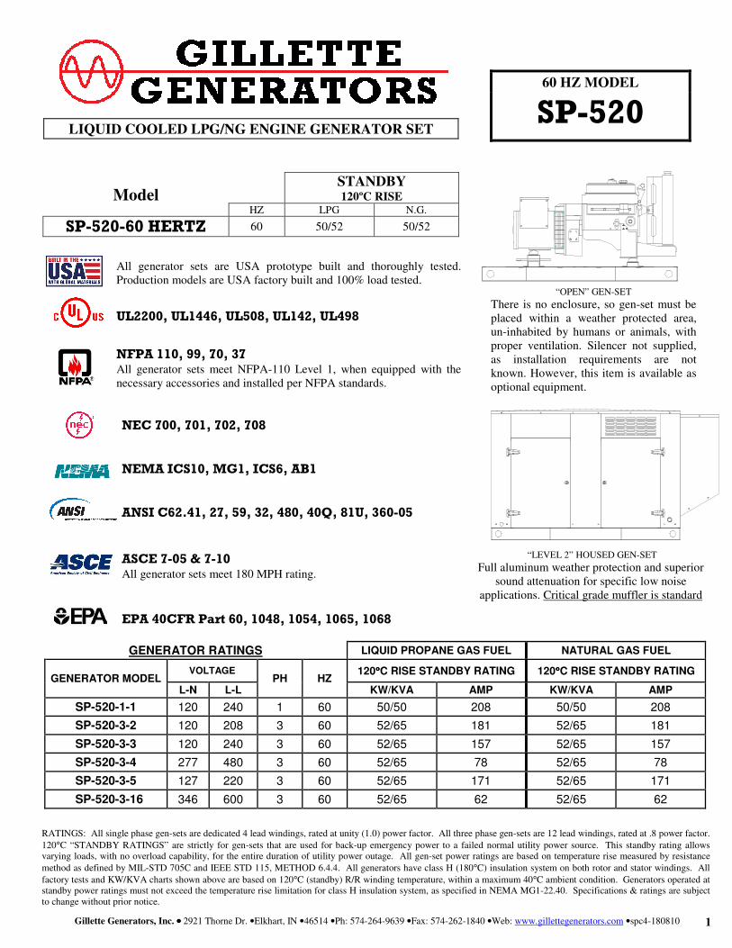
All generator sets are USA prototype built and thoroughly tested. Production models are USA factory built and 100% load tested.
UL2200, UL1446, UL508, UL142, UL498
NFPA 110, 99, 70, 37
All generator sets meet NFPA-110 Level 1, when equipped with the necessary accessories and installed per NFPA standards.
NEC 700, 701, 702, 708
NEMA ICS10, MG1, ICS6, AB1
ANSI C62.41, 27, 59, 32, 480, 40Q, 81U, 360-05
ASCE 7-05 & 7-10
All generator sets meet 180 MPH rating.
EPA 40CFR Part 60, 1048, 1054, 1065, 1068
RATINGS: All single phase gen-sets are dedicated 4 lead windings, rated at unity (1.0) power factor. All three phase gen-sets are 12 lead windings, rated at .8 power factor.
120°C “STANDBY RATINGS” are strictly for gen-sets that are used for back-up emergency power to a failed normal utility power source. This standby rating allows varying loads, with no overload capability, for the entire duration of utility power outage. All gen-set power ratings are based on temperature rise measured by resistance
method as defined by MIL-STD 705C and IEEE STD 115, METHOD 6.4.4. All generators have class H (180°C) insulation system on both rotor and stator windings. All
factory tests and KW/KVA charts shown above are based on 120°C (standby) R/R winding temperature, within a maximum 40°C ambient condition. Generators operated at standby power ratings must not exceed the temperature rise limitation for class H insulation system, as specified in NEMA MG1-22.40. Specifications & ratings are subject to change without prior notice.
LIQUID COOLED LPG/NG ENGINE GENERATOR SET
GENERATOR RATINGS LIQUID PROPANE GAS FUEL NATURAL GAS FUEL
GENERATOR MODEL VOLTAGE
PH HZ 120°°°°C RISE STANDBY RATING 120°°°°C RISE STANDBY RATING
L-N L-L KW/KVA AMP KW/KVA AMP
SP-520-1-1 120 240 1 60 50/50 208 50/50 208
SP-520-3-2 120 208 3 60 52/65 181 52/65 181
SP-520-3-3 120 240 3 60 52/65 157 52/65 157
SP-520-3-4 277 480 3 60 52/65 78 52/65 78
SP-520-3-5 127 220 3 60 52/65 171 52/65 171
SP-520-3-16 346 600 3 60 52/65 62 52/65 62
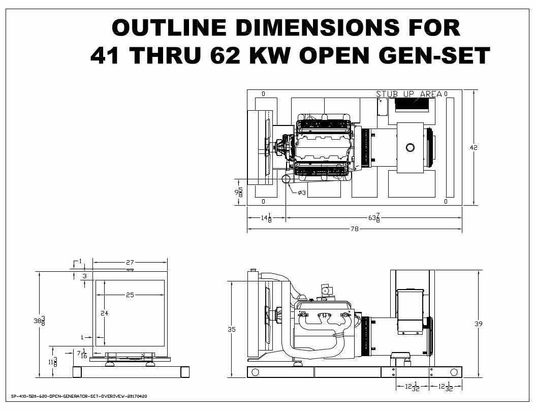
“OPEN” GEN-SET
There is no enclosure, so gen-set must be placed within a weather protected area, un-inhabited by humans or animals, with proper ventilation. Silencer not supplied, as installation requirements are not known. However, this item is available as optional equipment.
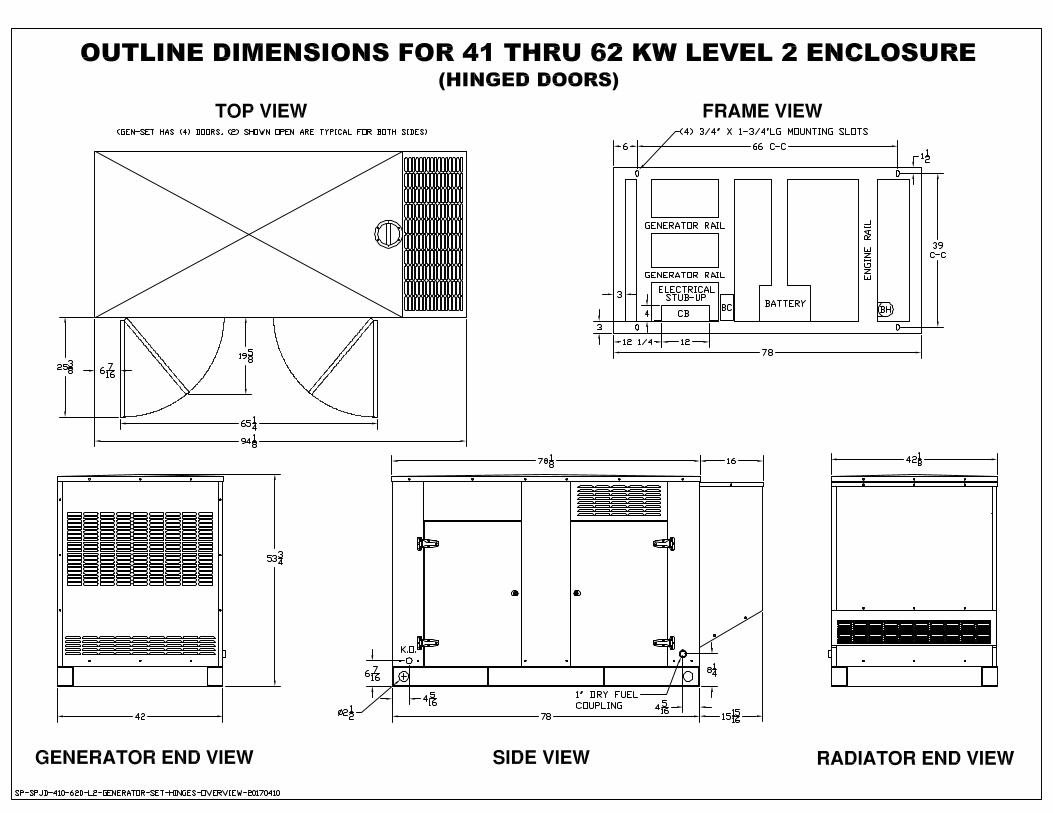
“LEVEL 2” HOUSED GEN-SET
Full aluminum weather protection and superior sound attenuation for specific low noise
applications. Critical grade muffler is standard
Model
STANDBY 120ºC RISE
HZ LPG N.G.
SP-520-60 HERTZ 60 50/52 50/52
Gillette Generators, Inc. •••• 2921 Thorne Dr. •Elkhart, IN •46514 •Ph: 574-264-9639 •Fax: 574-262-1840 •Web: www.gillettegenerators.com •spc4-180810 2
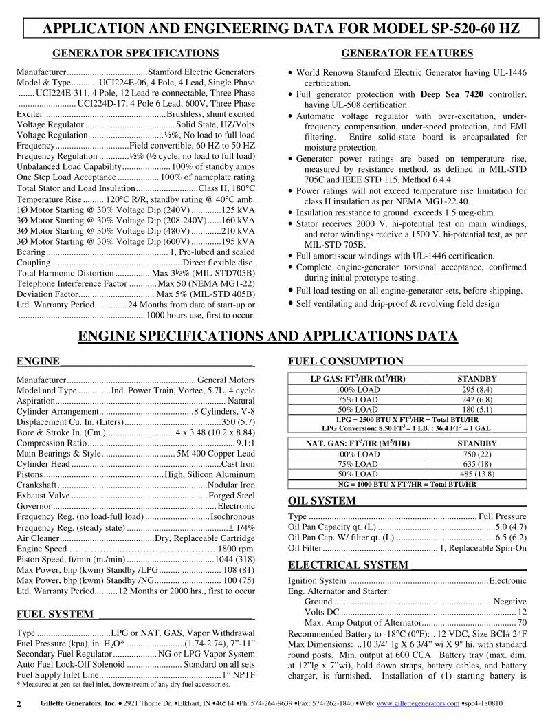
GENERATOR SPECIFICATIONS
Manufacturer ................................... Stamford Electric Generators Model & Type ........... UCI224E-06, 4 Pole, 4 Lead, Single Phase ....... UCI224E-311, 4 Pole, 12 Lead re-connectable, Three Phase ......................... UCI224D-17, 4 Pole 6 Lead, 600V, Three Phase Exciter ..................................................... Brushless, shunt excited Voltage Regulator ....................................... Solid State, HZ/Volts Voltage Regulation ................................ ½%, No load to full load Frequency ................................ Field convertible, 60 HZ to 50 HZ Frequency Regulation ............. ½% (½ cycle, no load to full load) Unbalanced Load Capability ..................... 100% of standby amps One Step Load Acceptance .................. 100% of nameplate rating
Total Stator and Load Insulation ........................... Class H, 180°C
Temperature Rise ......... 120°C R/R, standby rating @ 40°C amb. 1Ø Motor Starting @ 30% Voltage Dip (240V) ............. 125 kVA 3Ø Motor Starting @ 30% Voltage Dip (208-240V) ...... 160 kVA 3Ø Motor Starting @ 30% Voltage Dip (480V) ............. 210 kVA 3Ø Motor Starting @ 30% Voltage Dip (600V) ............. 195 kVA Bearing ..................................................... 1, Pre-lubed and sealed Coupling ......................................................... Direct flexible disc. Total Harmonic Distortion ............... Max 3½% (MIL-STD705B) Telephone Interference Factor ............ Max 50 (NEMA MG1-22) Deviation Factor ................................. Max 5% (MIL-STD 405B) Ltd. Warranty Period .............. 24 Months from date of start-up or ....................................................... 1000 hours use, first to occur.
ENGINE ___________________________________
Manufacturer ........................................................ General Motors Model and Type .............. Ind. Power Train, Vortec, 5.7L, 4 cycle Aspiration .......................................................................... Natural Cylinder Arrangement ......................................... 8 Cylinders, V-8 Displacement Cu. In. (Liters) .......................................... 350 (5.7) Bore & Stroke In. (Cm.) .............................. 4 x 3.48 (10.2 x 8.84) Compression Ratio ................................................................ 9.1:1 Main Bearings & Style ................................ 5M 400 Copper Lead Cylinder Head ................................................................. Cast Iron Pistons .................................................... High, Silicon Aluminum Crankshaft ................................................................. Nodular Iron Exhaust Valve ........................................................... Forged Steel Governor ....................................................................... Electronic Frequency Reg. (no load-full load) ............................ Isochronous
Frequency Reg. (steady state) ............................................ ± 1/4% Air Cleaner ......................................... Dry, Replaceable Cartridge Engine Speed ……………...…………………………. 1800 rpm Piston Speed, ft/min (m./min) ....................... .............. 1044 (318) Max Power, bhp (kwm) Standby /LPG ......... ................. 108 (81) Max Power, bhp (kwm) Standby /NG ........... ................. 100 (75) Ltd. Warranty Period .......... 12 Months or 2000 hrs., first to occur
FUEL SYSTEM ____________________________
Type ................................ LPG or NAT. GAS, Vapor Withdrawal Fuel Pressure (kpa), in. H2O* ......................... (1.74-2.74), 7”-11” Secondary Fuel Regulator ................... NG or LPG Vapor System Auto Fuel Lock-Off Solenoid ........................ Standard on all sets Fuel Supply Inlet Line ..................................................... 1” NPTF * Measured at gen-set fuel inlet, downstream of any dry fuel accessories.
GENERATOR FEATURES
• World Renown Stamford Electric Generator having UL-1446 certification.
• Full generator protection with Deep Sea 7420 controller, having UL-508 certification.
• Automatic voltage regulator with over-excitation, under-frequency compensation, under-speed protection, and EMI filtering. Entire solid-state board is encapsulated for moisture protection.
• Generator power ratings are based on temperature rise, measured by resistance method, as defined in MIL-STD 705C and IEEE STD 115, Method 6.4.4.
• Power ratings will not exceed temperature rise limitation for class H insulation as per NEMA MG1-22.40.
• Insulation resistance to ground, exceeds 1.5 meg-ohm.
• Stator receives 2000 V. hi-potential test on main windings, and rotor windings receive a 1500 V. hi-potential test, as per MIL-STD 705B.
• Full amortisseur windings with UL-1446 certification.
• Complete engine-generator torsional acceptance, confirmed during initial prototype testing.
• Full load testing on all engine-generator sets, before shipping. • Self ventilating and drip-proof & revolving field design
FUEL CONSUMPTION
LP GAS: FT3/HR (M3/HR) STANDBY
100% LOAD 295 (8.4)
75% LOAD 242 (6.8)
50% LOAD 180 (5.1)
LPG = 2500 BTU X FT3/HR = Total BTU/HR
LPG Conversion: 8.50 FT3 = 1 LB. : 36.4 FT3 = 1 GAL.
NAT. GAS: FT3/HR (M3/HR) STANDBY
100% LOAD 750 (22)
75% LOAD 635 (18)
50% LOAD 485 (13.8)
NG = 1000 BTU X FT3/HR = Total BTU/HR
OIL SYSTEM
Type ......................................................................... Full Pressure Oil Pan Capacity qt. (L) ...................................................5.0 (4.7) Oil Pan Cap. W/ filter qt. (L) ...........................................6.5 (6.2) Oil Filter .................................................. 1, Replaceable Spin-On
ELECTRICAL SYSTEM _____________________
Ignition System ............................................................. Electronic Eng. Alternator and Starter: Ground ..................................................................... Negative Volts DC ............................................................................ 12 Max. Amp Output of Alternator ......................................... 70
Recommended Battery to -18°C (0°F): .. 12 VDC, Size BCI# 24F Max Dimensions: .. 10 3/4" lg X 6 3/4” wi X 9" hi, with standard round posts. Min. output at 600 CCA. Battery tray (max. dim. at 12”lg x 7”wi), hold down straps, battery cables, and battery charger, is furnished. Installation of (1) starting battery is
APPLICATION AND ENGINEERING DATA FOR MODEL SP-520-60 HZ
ENGINE SPECIFICATIONS AND APPLICATIONS DATA
Gillette Generators, Inc. •••• 2921 Thorne Dr. •Elkhart, IN •46514 •Ph: 574-264-9639 •Fax: 574-262-1840 •Web: www.gillettegenerators.com •spc4-180810 3
required, with possible higher AMP/HR rating, as described
above, if normal environment averages -13°F (-25°C) or cooler.
COOLING SYSTEM
Type of System ................................ Pressurized, closed recovery Coolant Pump ..................................... Pre-lubricated, self-sealing Cooling Fan Type (no. of blades) ............................... Pusher (10) Fan Diameter inches (cm) .............................................. 21" (533)
Ambient Capacity of Radiator °F (°C) .......................... 125 (51.6) Engine Jacket Coolant Capacity Gal (L) .......................... 1.8 (6.8) Radiator Coolant Capacity Gal. (L) ............................... 5.2 (19.7) Maximum Restriction of Cooling Air Intake and discharge side of radiator in. H20 (kpa) .................. 0.5 (.125) Water Pump Capacity gpm (L/min) ....... 27 (100) ........... 23 (87) Heat Reject Coolant: Btu/min (kw) …………………3200 (54.9) Low Radiator Coolant Level Shutdown………………...Standard Note: Coolant temp. shut-down switch setting at 212°F (100°C) with 50/50 (water/antifreeze) mix.
COOLING AIR REQUIREMENTS Combustion Air, cfm (m3/min) ..................... ................. 185 (5.2) Radiator Air Flow cfm (m3/min) .................. .............. 6000 (170) Heat Rejected to Ambient: Engine: kw (btu/min) ............................ ............. 30.9 (1760) Alternator: kw (btu/min) ....................... ................. 7.5 (430)
EXHAUST SYSTEM Exhaust Outlet Size ................................................................. 2.5" Max. Back Pressure, in. hg (KPA) ................................ 3.0 (10.2) Exhaust Flow, at rated kw: cfm (m3/min) ..... ............... 580 (16.5)
Exhaust Temp., at rated kw: °F (ºC) ............ .............. 1200 (649)
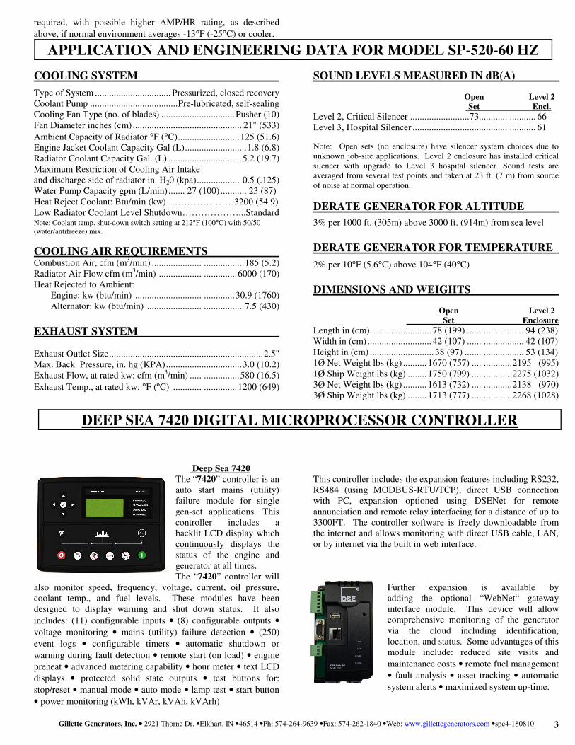
Deep Sea 7420
The “7420” controller is an auto start mains (utility) failure module for single gen-set applications. This controller includes a backlit LCD display which continuously displays the status of the engine and generator at all times. The “7420” controller will
also monitor speed, frequency, voltage, current, oil pressure, coolant temp., and fuel levels. These modules have been designed to display warning and shut down status. It also
includes: (11) configurable inputs • (8) configurable outputs •
voltage monitoring • mains (utility) failure detection • (250)
event logs • configurable timers • automatic shutdown or
warning during fault detection • remote start (on load) • engine
preheat • advanced metering capability • hour meter • text LCD
displays • protected solid state outputs • test buttons for:
stop/reset • manual mode • auto mode • lamp test • start button
• power monitoring (kWh, kVAr, kVAh, kVArh)
SOUND LEVELS MEASURED IN dB(A)
Open Level 2
Set Encl. Level 2, Critical Silencer ......................... 73............ ........... 66 Level 3, Hospital Silencer ........................................ ........... 61
Note: Open sets (no enclosure) have silencer system choices due to unknown job-site applications. Level 2 enclosure has installed critical silencer with upgrade to Level 3 hospital silencer. Sound tests are averaged from several test points and taken at 23 ft. (7 m) from source of noise at normal operation.
DERATE GENERATOR FOR ALTITUDE
3% per 1000 ft. (305m) above 3000 ft. (914m) from sea level
DERATE GENERATOR FOR TEMPERATURE
2% per 10°F (5.6°C) above 104°F (40°C)
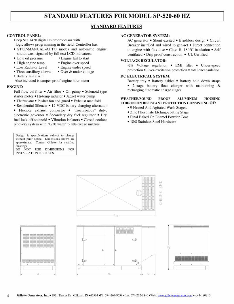
DIMENSIONS AND WEIGHTS
Open Level 2
Set Enclosure Length in (cm) .......................... 78 (199) ...... ................. 94 (238) Width in (cm) ........................... 42 (107) ...... ................. 42 (107) Height in (cm) ........................... 38 (97) ....... ................. 53 (134) 1Ø Net Weight lbs (kg) .......... 1670 (757) .... ............ 2195 (995) 1Ø Ship Weight lbs (kg) ........ 1750 (799) .... ............ 2275 (1032) 3Ø Net Weight lbs (kg) .......... 1613 (732) .... ............ 2138 (970) 3Ø Ship Weight lbs (kg) ........ 1713 (777) .... ............ 2268 (1028)
This controller includes the expansion features including RS232, RS484 (using MODBUS-RTU/TCP), direct USB connection with PC, expansion optioned using DSENet for remote annunciation and remote relay interfacing for a distance of up to 3300FT. The controller software is freely downloadable from the internet and allows monitoring with direct USB cable, LAN, or by internet via the built in web interface.
Further expansion is available by adding the optional “WebNet“ gateway interface module. This device will allow comprehensive monitoring of the generator via the cloud including identification, location, and status. Some advantages of this module include: reduced site visits and
maintenance costs • remote fuel management
• fault analysis • asset tracking • automatic
system alerts • maximized system up-time.
APPLICATION AND ENGINEERING DATA FOR MODEL SP-520-60 HZ
DEEP SEA 7420 DIGITAL MICROPROCESSOR CONTROLLER
Gillette Generators, Inc. •••• 2921 Thorne Dr. •Elkhart, IN •46514 •Ph: 574-264-9639 •Fax: 574-262-1840 •Web: www.gillettegenerators.com •spc4-180810 4
CONTROL PANEL:
Deep Sea 7420 digital microprocessor with logic allows programming in the field. Controller has:
• STOP-MANUAL-AUTO modes and automatic engine shutdowns, signaled by full text LCD indicators:
• Low oil pressure Engine fail to start
• High engine temp Engine over speed Low Radiator Level Engine under speed Three auxiliary alarms Over & under voltage Battery fail alarm
Also included is tamper-proof engine hour meter
ENGINE:
Full flow oil filter • Air filter • Oil pump • Solenoid type
starter motor • Hi-temp radiator • Jacket water pump
• Thermostat • Pusher fan and guard • Exhaust manifold
• Residential Silencer • 12 VDC battery charging alternator
• Flexible exhaust connector • ”Isochronous” duty,
electronic governor • Secondary dry fuel regulator • Dry
fuel lock-off solenoid • Vibration isolators • Closed coolant recovery system with 50/50 water to anti-freeze mixture
AC GENERATOR SYSTEM:
AC generator • Shunt excited • Brushless design • Circuit
Breaker installed and wired to gen-set • Direct connection
to engine with flex disc • Class H, 180°C insulation • Self
ventilated • Drip proof construction • UL Certified
VOLTAGE REGULATOR:
½% Voltage regulation • EMI filter • Under-speed
protection • Over-excitation protection • total encapsulation
DC ELECTRICAL SYSTEM:
Battery tray • Battery cables • Battery hold down straps
• 2-stage battery float charger with maintaining & recharging automatic charge stages
WEATHER/SOUND PROOF ALUMINUM HOUSING
CORROSION RESISTANT PROTECTION CONSISTING OF:
• 9 Heated And Agitated Wash Stages.
• Zinc Phosphate Etching-coating Stage
• Final Baked On Enamel Powder Coat
• 18/8 Stainless Steel Hardware
STANDARD FEATURES FOR MODEL SP-520-60 HZ
STANDARD FEATURES
Design & specifications subject to change without prior notice. Dimensions shown are approximate. Contact Gillette for certified drawings. DO NOT USE DIMENSIONS FOR INSTALLATION PURPOSES.

GM Industrial Engine Power by Power Solutions, Inc.
Industrial Engine
Feature/BenefitsDesigned to work with gasoline, liquid propane gas and natural gas.Nodular iron crankshaft has enlarged journal fillet radii for increased durability.World-class engine sealing system uses composite cylinder head gaskets with steel cores, a one-piece rear main crankshaft seal, a one-piece oil pan seal and moulded rocker cover seals.Hydraulic roller camshaft is optimized for maximum performance.Sintered powdered-metal exhaust valve seat inserts for enhanced durability.Exhaust valve rotators improve valve and valve seat durability.Positive inlet valve stem seals to control oil consumption.High Energy Ignition (HEI) distributor and coil and are standard.Common rear face on most GM industrial engines for easy hookup with housing.
OptionsCast iron 4 barrel intake manifold is standard.An Electronic control Module (ECM) utilizing state-of-the-art hybrid technology and related hardware to optimize fuel and spark requirements is availableFuel options LPG, NGSAE 3 flywheel housing (cast iron)SAE flywheelsCustom made flywheels for numerous applicationsCooling fansRadiatorsDry type industrial air cleaners (safety element air cleaners available)Electric governor systems available - High Output Camshaft
•
•
••••
•••
•
•
•
•
•
•
•
•
•
•
Power Solutions, Inc.
9.05
7.36
22.87
32 4032.40
28.78
PSI Offers Turn-Key Certified and Non-Certified Engine Packages
Product Engineering Data
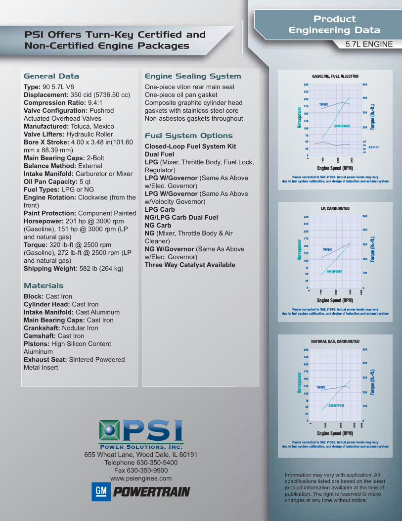
Information may vary with application. All specifications listed are based on the latest product information available at the time of publication. The right is reserved to make changes at any time without notice.
655 Wheat Lane, Wood Dale, IL 60191Telephone 630-350-9400
Fax 630-350-9900www.psiengines.com
5.7L ENGINE
General DataType: 90 5.7L V8Displacement: 350 cid (5736.50 cc)Compression Ratio: 9.4:1Valve Configuration: Pushrod Actuated Overhead ValvesManufactured: Toluca, MexicoValve Lifters: Hydraulic RollerBore X Stroke: 4.00 x 3.48 in(101.60 mm x 88.39 mm)Main Bearing Caps: 2-Bolt Balance Method: ExternalIntake Manifold: Carburetor or MixerOil Pan Capacity: 5 qtFuel Types: LPG or NGEngine Rotation: Clockwise (from the front)Paint Protection: Component PaintedHorsepower: 201 hp @ 3000 rpm (Gasoline), 151 hp @ 3000 rpm (LP and natural gas)Torque: 320 lb-ft @ 2500 rpm (Gasoline), 272 lb-ft @ 2500 rpm (LP and natural gas)Shipping Weight: 582 lb (264 kg)
MaterialsBlock: Cast IronCylinder Head: Cast Iron Intake Manifold: Cast Aluminum Main Bearing Caps: Cast Iron Crankshaft: Nodular IronCamshaft: Cast Iron Pistons: High Silicon Content AluminumExhaust Seat: Sintered Powdered Metal Insert
Engine Sealing SystemOne-piece viton rear main sealOne-piece oil pan gasketComposite graphite cylinder head gaskets with stainless steel coreNon-asbestos gaskets throughout
Fuel System OptionsClosed-Loop Fuel System KitDual FuelLPG (Mixer, Throttle Body, Fuel Lock, Regulator)LPG W/Governor (Same As Above w/Elec. Governor)LPG W/Governor (Same As Above w/Velocity Governor)LPG CarbNG/LPG Carb Dual FuelNG CarbNG (Mixer, Throttle Body & Air Cleaner)NG W/Governor (Same As Above w/Elec. Governor)Three Way Catalyst Available
AP
PR
OV
ED
DO
CU
ME
NT
UCI224E - Winding 06
Technical Data Sheet
AP
PR
OV
ED
DO
CU
ME
NT
UCI224ESPECIFICATIONS & OPTIONS
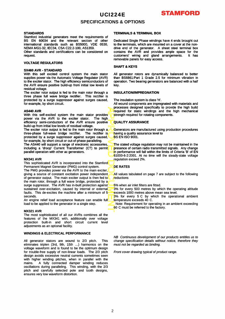
STANDARDSStamford industrial generators meet the requirements ofBS EN 60034 and the relevant section of otherinternational standards such as BS5000, VDE 0530,NEMA MG1-32, IEC34, CSA C22.2-100, AS1359.Other standards and certifications can be considered onrequest.
VOLTAGE REGULATORS
SX460 AVR - STANDARDWith this self excited control system the main statorsupplies power via the Automatic Voltage Regulator (AVR)to the exciter stator. The high efficiency semiconductors ofthe AVR ensure positive build-up from initial low levels ofresidual voltage.The exciter rotor output is fed to the main rotor through athree phase full wave bridge rectifier. This rectifier isprotected by a surge suppressor against surges caused,for example, by short circuit.
AS440 AVRWith this self-excited system the main stator providespower via the AVR to the exciter stator. The highefficiency semi-conductors of the AVR ensure positivebuild-up from initial low levels of residual voltage.The exciter rotor output is fed to the main rotor through athree-phase full-wave bridge rectifier. The rectifier isprotected by a surge suppressor against surges caused,for example, by short circuit or out-of-phase paralleling.The AS440 will support a range of electronic accessories,including a 'droop' Current Transformer (CT) to permitparallel operation with other ac generators.
TERMINALS & TERMINAL BOX
Dedicated Single Phase windings have 4 ends brought outto the terminals, which are mounted on a cover at the non-drive end of the generator. A sheet steel terminal boxcontains the AVR and provides ample space for thecustomers' wiring and gland arrangements. It hasremovable panels for easy access.
SHAFT & KEYS
All generator rotors are dynamically balanced to betterthan BS6861:Part 1 Grade 2.5 for minimum vibration inoperation. Two bearing generators are balanced with a halfkey.
INSULATION/IMPREGNATION
The insulation system is class 'H'.All wound components are impregnated with materials andprocesses designed specifically to provide the high buildrequired for static windings and the high mechanicalstrength required for rotating components.
QUALITY ASSURANCE
Generators are manufactured using production procedureshaving a quality assurance level toBS EN ISO 9001.
The stated voltage regulation may not be maintained in thepresence of certain radio transmitted signals. Any changein performance will fall within the limits of Criteria 'B' of EN61000 6 2:2001 At no time will the steady state voltage
STANDARDSStamford industrial generators meet the requirements ofBS EN 60034 and the relevant section of otherinternational standards such as BS5000, VDE 0530,NEMA MG1-32, IEC34, CSA C22.2-100, AS1359.Other standards and certifications can be considered onrequest.
VOLTAGE REGULATORS
SX460 AVR - STANDARDWith this self excited control system the main statorsupplies power via the Automatic Voltage Regulator (AVR)to the exciter stator. The high efficiency semiconductors ofthe AVR ensure positive build-up from initial low levels ofresidual voltage.The exciter rotor output is fed to the main rotor through athree phase full wave bridge rectifier. This rectifier isprotected by a surge suppressor against surges caused,for example, by short circuit.
AS440 AVRWith this self-excited system the main stator providespower via the AVR to the exciter stator. The highefficiency semi-conductors of the AVR ensure positivebuild-up from initial low levels of residual voltage.The exciter rotor output is fed to the main rotor through athree-phase full-wave bridge rectifier. The rectifier isprotected by a surge suppressor against surges caused,for example, by short circuit or out-of-phase paralleling.The AS440 will support a range of electronic accessories,including a 'droop' Current Transformer (CT) to permitparallel operation with other ac generators.
MX341 AVRThis sophisticated AVR is incorporated into the StamfordPermanent Magnet Generator (PMG) control system.The PMG provides power via the AVR to the main exciter,giving a source of constant excitation power independentof generator output. The main exciter output is then fed tothe main rotor, through a full wave bridge, protected by asurge suppressor. The AVR has in-built protection againstsustained over-excitation, caused by internal or externalfaults. This de-excites the machine after a minimum of 5seconds.An engine relief load acceptance feature can enable fullload to be applied to the generator in a single step.
MX321 AVRThe most sophisticated of all our AVRs combines all thefeatures of the MX341 with, additionally over voltageprotection built-in and short circuit current leveladjustments as an optional facility.
WINDINGS & ELECTRICAL PERFORMANCE
All generator stators are wound to 2/3 pitch. Thiseliminates triplen (3rd, 9th, 15th …) harmonics on thevoltage waveform and is found to be the optimum designfor trouble-free supply of non-linear loads. The 2/3 pitchdesign avoids excessive neutral currents sometimes seenwith higher winding pitches, when in parallel with themains. A fully connected damper winding reducesoscillations during paralleling. This winding, with the 2/3pitch and carefully selected pole and tooth designs,ensures very low waveform distortion.
TERMINALS & TERMINAL BOX
Dedicated Single Phase windings have 4 ends brought outto the terminals, which are mounted on a cover at the non-drive end of the generator. A sheet steel terminal boxcontains the AVR and provides ample space for thecustomers' wiring and gland arrangements. It hasremovable panels for easy access.
SHAFT & KEYS
All generator rotors are dynamically balanced to betterthan BS6861:Part 1 Grade 2.5 for minimum vibration inoperation. Two bearing generators are balanced with a halfkey.
INSULATION/IMPREGNATION
The insulation system is class 'H'.All wound components are impregnated with materials andprocesses designed specifically to provide the high buildrequired for static windings and the high mechanicalstrength required for rotating components.
QUALITY ASSURANCE
Generators are manufactured using production procedureshaving a quality assurance level toBS EN ISO 9001.
The stated voltage regulation may not be maintained in thepresence of certain radio transmitted signals. Any changein performance will fall within the limits of Criteria 'B' of EN61000-6-2:2001. At no time will the steady-state voltageregulation exceed 2%.
DE RATES
All values tabulated on page 7 are subject to the followingreductions
5% when air inlet filters are fitted.3% for every 500 metres by which the operating altitudeexceeds 1000 metres above mean sea level.3% for every 5 C by which the operational ambienttemperature exceeds 40 C.
Note: Requirement for operating in an ambient exceeding60 C must be referred to the factory.
NB Continuous development of our products entitles us tochange specification details without notice, therefore theymust not be regarded as binding.
Front cover drawing typical of product range.
2
AP
PR
OV
ED
DO
CU
ME
NT
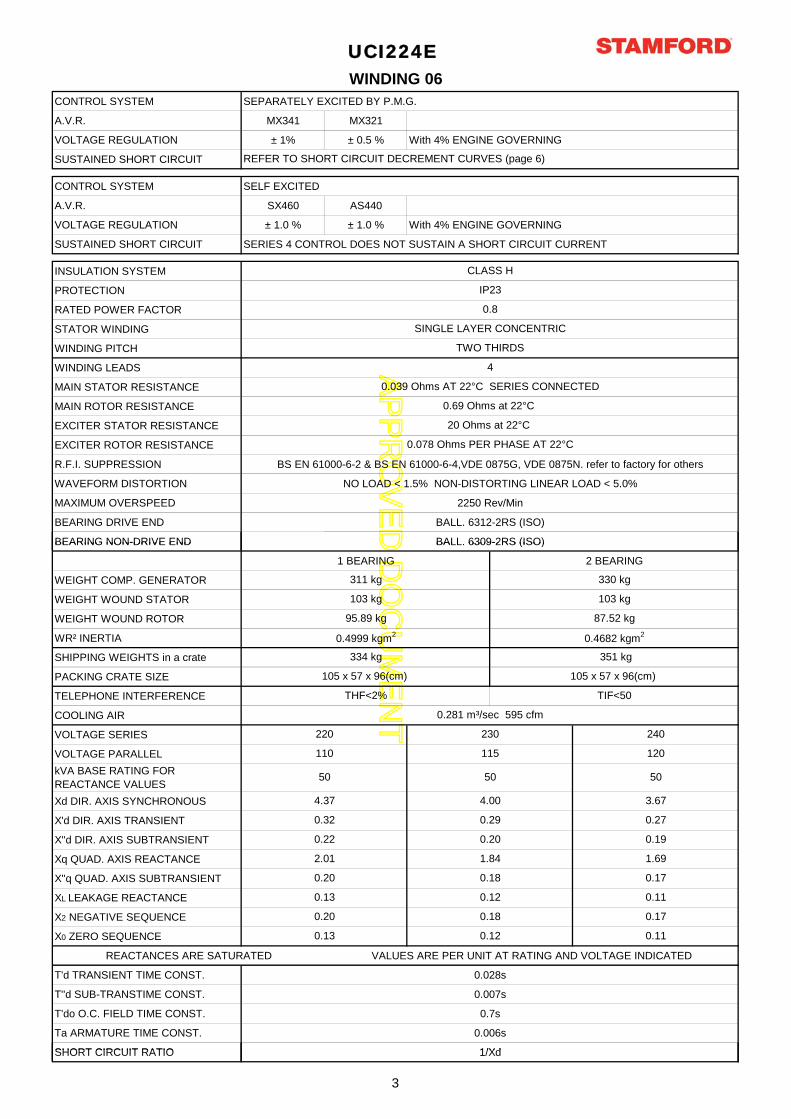
CONTROL SYSTEM SEPARATELY EXCITED BY P.M.G.
A.V.R. MX341 MX321
VOLTAGE REGULATION ± 1% ± 0.5 % With 4% ENGINE GOVERNING
SUSTAINED SHORT CIRCUIT
CONTROL SYSTEM SELF EXCITED
A.V.R. SX460 AS440
VOLTAGE REGULATION ± 1.0 % ± 1.0 % With 4% ENGINE GOVERNING
SUSTAINED SHORT CIRCUIT SERIES 4 CONTROL DOES NOT SUSTAIN A SHORT CIRCUIT CURRENT
INSULATION SYSTEM
PROTECTION
RATED POWER FACTOR
STATOR WINDING
WINDING PITCH
WINDING LEADS
MAIN STATOR RESISTANCE
MAIN ROTOR RESISTANCE
EXCITER STATOR RESISTANCE
EXCITER ROTOR RESISTANCE
R.F.I. SUPPRESSION BS EN 61000-6-2 & BS EN 61000-6-4,VDE 0875G, VDE 0875N. refer to factory for others
WAVEFORM DISTORTION NO LOAD < 1.5% NON-DISTORTING LINEAR LOAD < 5.0%
MAXIMUM OVERSPEED 2250 Rev/Min
BEARING DRIVE END BALL. 6312-2RS (ISO)
BEARING NON-DRIVE END BALL. 6309-2RS (ISO)
0.078 Ohms PER PHASE AT 22°C
WINDING 06
UCI224E
0.8
IP23
CLASS H
REFER TO SHORT CIRCUIT DECREMENT CURVES (page 6)
0.69 Ohms at 22°C
20 Ohms at 22°C
SINGLE LAYER CONCENTRIC
0.039 Ohms AT 22°C SERIES CONNECTED
4
TWO THIRDS
BEARING NON-DRIVE END BALL. 6309-2RS (ISO)
1 BEARING 2 BEARING
WEIGHT COMP. GENERATOR
WEIGHT WOUND STATOR
WEIGHT WOUND ROTOR
WR² INERTIA
SHIPPING WEIGHTS in a crate
PACKING CRATE SIZE
TELEPHONE INTERFERENCE
COOLING AIR
VOLTAGE SERIES
VOLTAGE PARALLEL
kVA BASE RATING FOR REACTANCE VALUES
Xd DIR. AXIS SYNCHRONOUS
X'd DIR. AXIS TRANSIENT
X''d DIR. AXIS SUBTRANSIENT
Xq QUAD. AXIS REACTANCE
X''q QUAD. AXIS SUBTRANSIENT
XL LEAKAGE REACTANCE
X2 NEGATIVE SEQUENCE
X0 ZERO SEQUENCE
REACTANCES ARE SATURATED VALUES ARE PER UNIT AT RATING AND VOLTAGE INDICATED
T'd TRANSIENT TIME CONST. 0.028s
T''d SUB-TRANSTIME CONST. 0.007s
T'do O.C. FIELD TIME CONST. 0.7s
Ta ARMATURE TIME CONST. 0.006s
SHORT CIRCUIT RATIO 1/Xd
1.69
0.17
0.13
0.20
0.13
0.18
0.12
0.17
0.11
0.110.12
95.89 kg
0.4999 kgm2
0.22
2.01
0.20
0.20
1.84
0.18
0.19
105 x 57 x 96(cm)
TIF<50
334 kg
0.32 0.29 0.27
311 kg
103 kg
105 x 57 x 96(cm)
THF<2%
330 kg
103 kg
87.52 kg
0.4682 kgm2
351 kg
115 120110
240
50
0.281 m³/sec 595 cfm
3.67
220
50
4.37
230
50
4.00
SHORT CIRCUIT RATIO 1/Xd
3
AP
PR
OV
ED
DO
CU
ME
NT
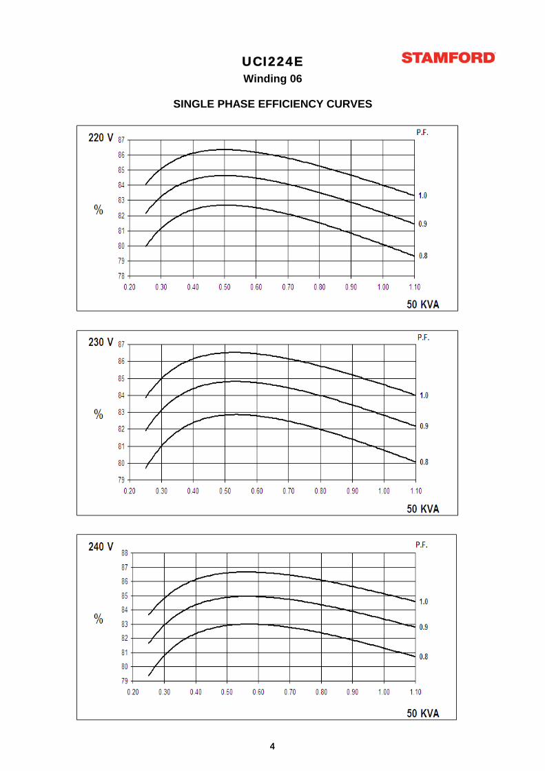
UCI224EWinding 06
SINGLE PHASE EFFICIENCY CURVES
44
AP
PR
OV
ED
DO
CU
ME
NT
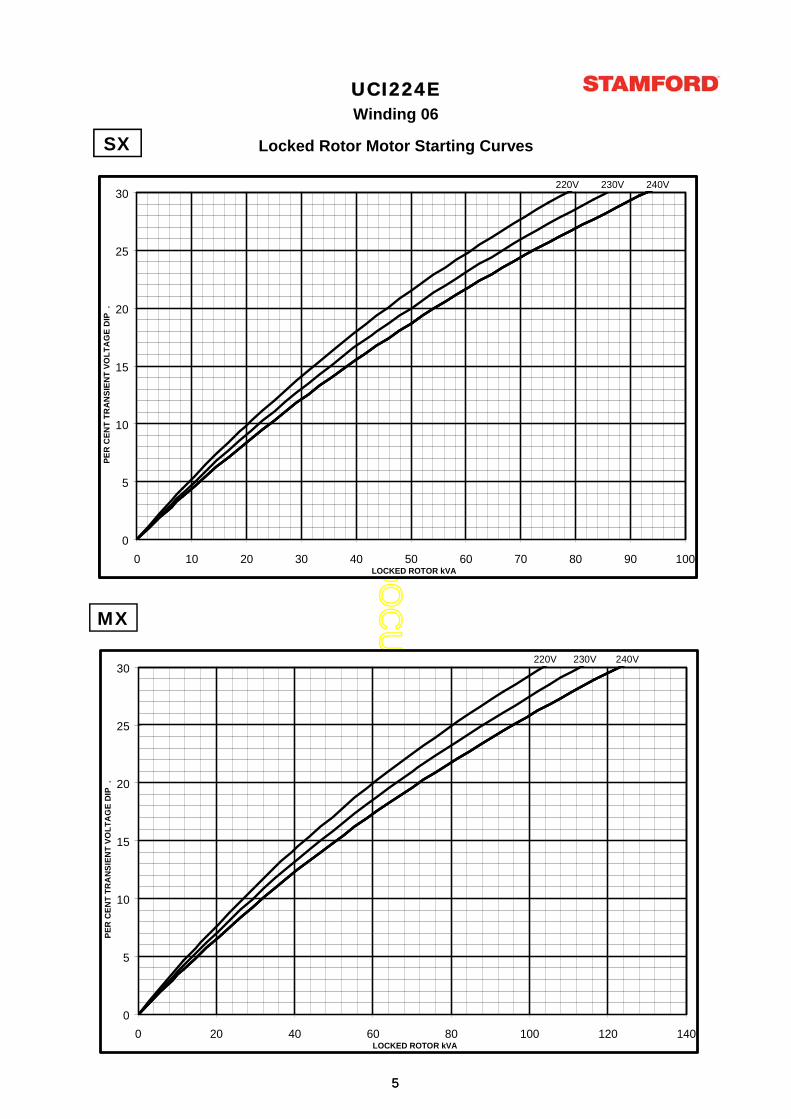
UCI224EWinding 06
Locked Rotor Motor Starting CurvesSX
0
5
10
15
20
25
30
0 10 20 30 40 50 60 70 80 90 100LOCKED ROTOR kVA
PE
R C
EN
T T
RA
NS
IEN
T V
OL
TA
GE
DIP
.
220V 230V 240V
SX
MX
0
5
10
15
20
25
30
0 10 20 30 40 50 60 70 80 90 100LOCKED ROTOR kVA
PE
R C
EN
T T
RA
NS
IEN
T V
OL
TA
GE
DIP
.
220V 230V 240V
0
5
10
15
20
25
30
0 20 40 60 80 100 120 140LOCKED ROTOR kVA
PE
R C
EN
T T
RA
NS
IEN
T V
OL
TA
GE
DIP
.
220V 230V 240V
55
AP
PR
OV
ED
DO
CU
ME
NT
UCI224EWinding 06
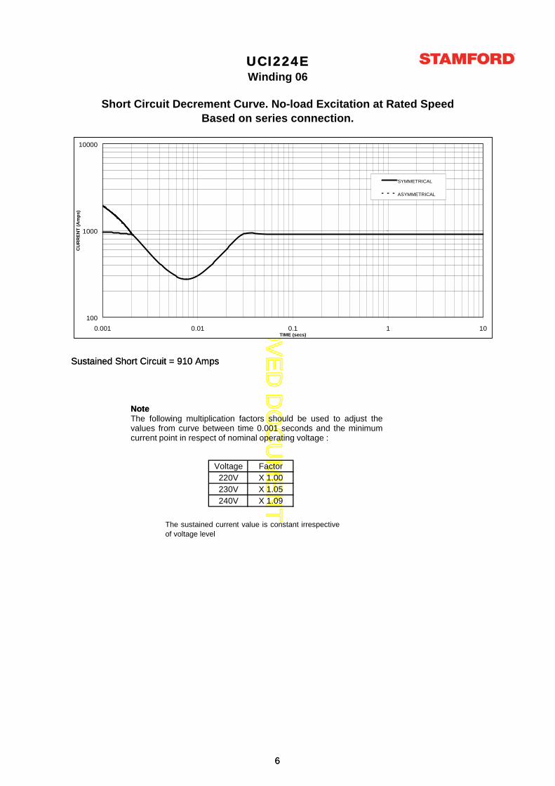
Based on series connection.Short Circuit Decrement Curve. No-load Excitation at Rated Speed
Sustained Short Circuit = 910 Amps
Note
100
1000
10000
0.001 0.01 0.1 1 10TIME (secs)
CU
RR
EN
T (
Am
ps)
SYMMETRICAL
ASYMMETRICAL
Voltage Factor220V X 1.00230V X 1.05240V X 1.09
The sustained current value is constant irrespectiveof voltage level
Sustained Short Circuit = 910 Amps
NoteThe following multiplication factors should be used to adjust thevalues from curve between time 0.001 seconds and the minimumcurrent point in respect of nominal operating voltage :
100
1000
10000
0.001 0.01 0.1 1 10TIME (secs)
CU
RR
EN
T (
Am
ps)
SYMMETRICAL
ASYMMETRICAL
66
AP
PR
OV
ED
DO
CU
ME
NT
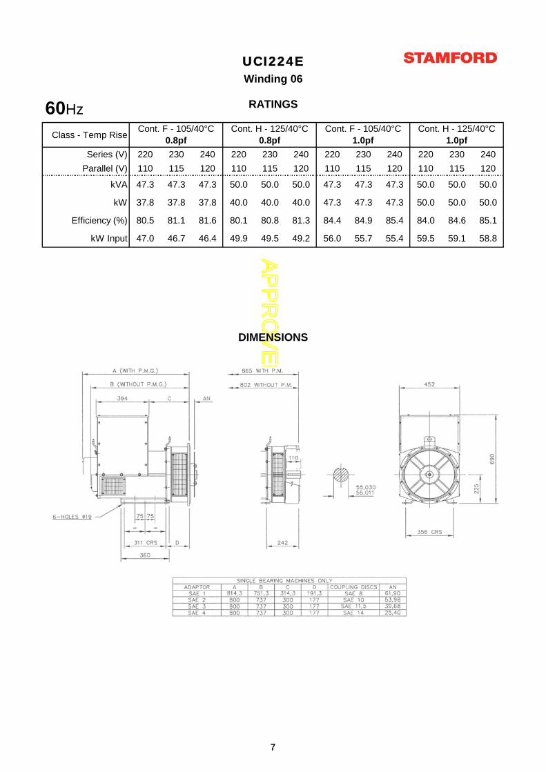
Class - Temp Rise
Series (V) 220 230 240 220 230 240 220 230 240 220 230 240
Parallel (V) 110 115 120 110 115 120 110 115 120 110 115 120
kVA 47.3 47.3 47.3 50.0 50.0 50.0 47.3 47.3 47.3 50.0 50.0 50.0
kW 37.8 37.8 37.8 40.0 40.0 40.0 47.3 47.3 47.3 50.0 50.0 50.0
Efficiency (%) 80.5 81.1 81.6 80.1 80.8 81.3 84.4 84.9 85.4 84.0 84.6 85.1
kW Input 47.0 46.7 46.4 49.9 49.5 49.2 56.0 55.7 55.4 59.5 59.1 58.8
DIMENSIONS
UCI224E
Cont. F - 105/40°C 0.8pf
Cont. H - 125/40°C 0.8pf
Cont. F - 105/40°C 1.0pf
Cont. H - 125/40°C 1.0pf
Winding 06
RATINGS60Hz60Hz
77

AP
PR
OV
ED
DO
CU
ME
NT
UCI224E-06-TD-EN-SG-A
Head Office Address:Barnack Road, StamfordLincolnshire, PE9 2NB
United KingdomTel: +44 (0) 1780 484000Fax: +44 (0) 1780 484100
www.cumminsgeneratortechnologies.com
Copyright 2010, Cummins Generator Technologies Ltd, All Rights ReservedStamford and AvK are registered trade marks of Cummins Generator Technologies Ltd
Cummins and the Cummins logo are registered trade marks of Cummins Inc.
AP
PR
OV
ED
DO
CU
ME
NT
UCI224E - Winding 311
Technical Data Sheet
AP
PR
OV
ED
DO
CU
ME
NT
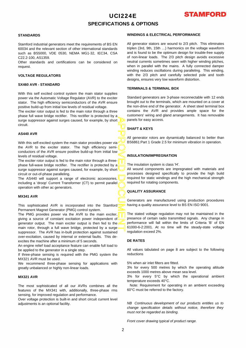
UCI224ESPECIFICATIONS & OPTIONS
STANDARDS
Stamford industrial generators meet the requirements of BS EN
60034 and the relevant section of other international standards
such as BS5000, VDE 0530, NEMA MG1-32, IEC34, CSA
C22.2-100, AS1359.
Other standards and certifications can be considered on
request.
VOLTAGE REGULATORS
SX460 AVR - STANDARD
With this self excited control system the main stator supplies
power via the Automatic Voltage Regulator (AVR) to the exciter
stator. The high efficiency semiconductors of the AVR ensure
positive build-up from initial low levels of residual voltage.
The exciter rotor output is fed to the main rotor through a three
phase full wave bridge rectifier. This rectifier is protected by a
surge suppressor against surges caused, for example, by short
circuit.
AS440 AVR
With this self-excited system the main stator provides power via
the AVR to the exciter stator. The high efficiency semi-
conductors of the AVR ensure positive build-up from initial low
levels of residual voltage.
The exciter rotor output is fed to the main rotor through a three-
phase full-wave bridge rectifier. The rectifier is protected by a
surge suppressor against surges caused, for example, by short
circuit or out-of-phase paralleling.
The AS440 will support a range of electronic accessories,
including a 'droop' Current Transformer (CT) to permit parallel
operation with other ac generators.
MX341 AVR
This sophisticated AVR is incorporated into the Stamford
Permanent Magnet Generator (PMG) control system.
The PMG provides power via the AVR to the main exciter,
giving a source of constant excitation power independent of
generator output. The main exciter output is then fed to the
main rotor, through a full wave bridge, protected by a surge
suppressor. The AVR has in-built protection against sustained
over-excitation, caused by internal or external faults. This de-
excites the machine after a minimum of 5 seconds.
An engine relief load acceptance feature can enable full load to
be applied to the generator in a single step.
If three-phase sensing is required with the PMG system the
MX321 AVR must be used.
We recommend three-phase sensing for applications with
greatly unbalanced or highly non-linear loads.
MX321 AVR
The most sophisticated of all our AVRs combines all the
features of the MX341 with, additionally, three-phase rms
sensing, for improved regulation and performance.
Over voltage protection is built-in and short circuit current level
adjustments is an optional facility.
WINDINGS & ELECTRICAL PERFORMANCE
All generator stators are wound to 2/3 pitch. This eliminates
triplen (3rd, 9th, 15th …) harmonics on the voltage waveform
and is found to be the optimum design for trouble-free supply
of non-linear loads. The 2/3 pitch design avoids excessive
neutral currents sometimes seen with higher winding pitches,
when in parallel with the mains. A fully connected damper
winding reduces oscillations during paralleling. This winding,
with the 2/3 pitch and carefully selected pole and tooth
designs, ensures very low waveform distortion.
TERMINALS & TERMINAL BOX
Standard generators are 3-phase reconnectable with 12 ends
brought out to the terminals, which are mounted on a cover at
the non-drive end of the generator. A sheet steel terminal box
contains the AVR and provides ample space for the
customers' wiring and gland arrangements. It has removable
panels for easy access.
SHAFT & KEYS
All generator rotors are dynamically balanced to better than
BS6861:Part 1 Grade 2.5 for minimum vibration in operation.
INSULATION/IMPREGNATION
The insulation system is class 'H'.
All wound components are impregnated with materials and
processes designed specifically to provide the high build
required for static windings and the high mechanical strength
required for rotating components.
QUALITY ASSURANCE
Generators are manufactured using production procedures
having a quality assurance level to BS EN ISO 9001.
The stated voltage regulation may not be maintained in the
presence of certain radio transmitted signals. Any change in
performance will fall within the limits of Criteria 'B' of EN
61000-6-2:2001. At no time will the steady-state voltage
regulation exceed 2%.
DE RATES
All values tabulated on page 8 are subject to the following
reductions
5% when air inlet filters are fitted.
3% for every 500 metres by which the operating altitude
exceeds 1000 metres above mean sea level.
3% for every 5°C by which the operational ambient
temperature exceeds 40°C.
Note: Requirement for operating in an ambient exceeding
60°C must be referred to the factory.
NB Continuous development of our products entitles us tochange specification details without notice, therefore theymust not be regarded as binding.
Front cover drawing typical of product range.
2
AP
PR
OV
ED
DO
CU
ME
NT
CONTROL SYSTEM SEPARATELY EXCITED BY P.M.G.
A.V.R. MX321 MX341
VOLTAGE REGULATION ± 0.5 % ± 1.0 % With 4% ENGINE GOVERNING
SUSTAINED SHORT CIRCUIT
CONTROL SYSTEM SELF EXCITED
A.V.R. SX460 AS440
VOLTAGE REGULATION ± 1.0 % ± 1.0 % With 4% ENGINE GOVERNING
SUSTAINED SHORT CIRCUIT SERIES 4 CONTROL DOES NOT SUSTAIN A SHORT CIRCUIT CURRENT
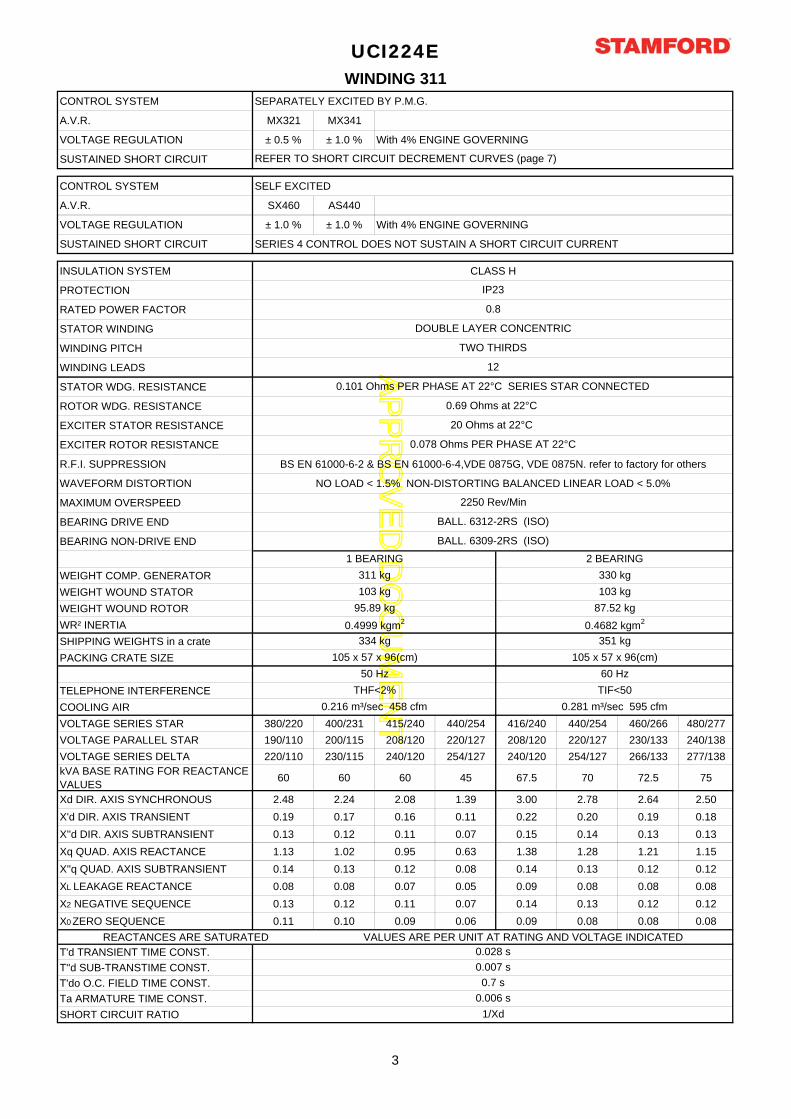
INSULATION SYSTEM CLASS H
PROTECTION
RATED POWER FACTOR
STATOR WINDING
WINDING PITCH
WINDING LEADS
STATOR WDG. RESISTANCE
ROTOR WDG. RESISTANCE
EXCITER STATOR RESISTANCE
EXCITER ROTOR RESISTANCE
R.F.I. SUPPRESSION BS EN 61000-6-2 & BS EN 61000-6-4,VDE 0875G, VDE 0875N. refer to factory for others
WAVEFORM DISTORTION NO LOAD < 1.5% NON-DISTORTING BALANCED LINEAR LOAD < 5.0%
MAXIMUM OVERSPEED
BEARING DRIVE END
BEARING NON-DRIVE END
WEIGHT COMP. GENERATOR
WEIGHT WOUND STATOR
WEIGHT WOUND ROTOR
WR² INERTIA
SHIPPING WEIGHTS in a crate
PACKING CRATE SIZE
TELEPHONE INTERFERENCE
COOLING AIR
VOLTAGE SERIES STAR 380/220 400/231 415/240 440/254 416/240 440/254 460/266 480/277
VOLTAGE PARALLEL STAR 190/110 200/115 208/120 220/127 208/120 220/127 230/133 240/138
VOLTAGE SERIES DELTA 220/110 230/115 240/120 254/127 240/120 254/127 266/133 277/138
kVA BASE RATING FOR REACTANCE
VALUES60 60 60 45 67.5 70 72.5 75
Xd DIR. AXIS SYNCHRONOUS 2.48 2.24 2.08 1.39 3.00 2.78 2.64 2.50
X'd DIR. AXIS TRANSIENT 0.19 0.17 0.16 0.11 0.22 0.20 0.19 0.18
X''d DIR. AXIS SUBTRANSIENT 0.13 0.12 0.11 0.07 0.15 0.14 0.13 0.13
Xq QUAD. AXIS REACTANCE 1.13 1.02 0.95 0.63 1.38 1.28 1.21 1.15
X''q QUAD. AXIS SUBTRANSIENT 0.14 0.13 0.12 0.08 0.14 0.13 0.12 0.12
XL LEAKAGE REACTANCE 0.08 0.08 0.07 0.05 0.09 0.08 0.08 0.08
X2 NEGATIVE SEQUENCE 0.13 0.12 0.11 0.07 0.14 0.13 0.12 0.12
X0 ZERO SEQUENCE 0.11 0.10 0.09 0.06 0.09 0.08 0.08 0.08
REACTANCES ARE SATURATED VALUES ARE PER UNIT AT RATING AND VOLTAGE INDICATED
T'd TRANSIENT TIME CONST.
T''d SUB-TRANSTIME CONST.
T'do O.C. FIELD TIME CONST.
Ta ARMATURE TIME CONST.
SHORT CIRCUIT RATIO
20 Ohms at 22°C
0.078 Ohms PER PHASE AT 22°C
351 kg
105 x 57 x 96(cm)
334 kg
105 x 57 x 96(cm)
1 BEARING 2 BEARING
2250 Rev/Min
103 kg
UCI224E
0.216 m³/sec 458 cfm 0.281 m³/sec 595 cfm
50 Hz
THF<2%
60 Hz
TIF<50
87.52 kg
0.4682 kgm2
WINDING 311
95.89 kg
0.4999 kgm2
IP23
0.8
DOUBLE LAYER CONCENTRIC
TWO THIRDS
12
330 kg311 kg
103 kg
REFER TO SHORT CIRCUIT DECREMENT CURVES (page 7)
BALL. 6309-2RS (ISO)
1/Xd
0.028 s
0.007 s
0.7 s
0.006 s
0.69 Ohms at 22°C
0.101 Ohms PER PHASE AT 22°C SERIES STAR CONNECTED
BALL. 6312-2RS (ISO)
3
AP
PR
OV
ED
DO
CU
ME
NT
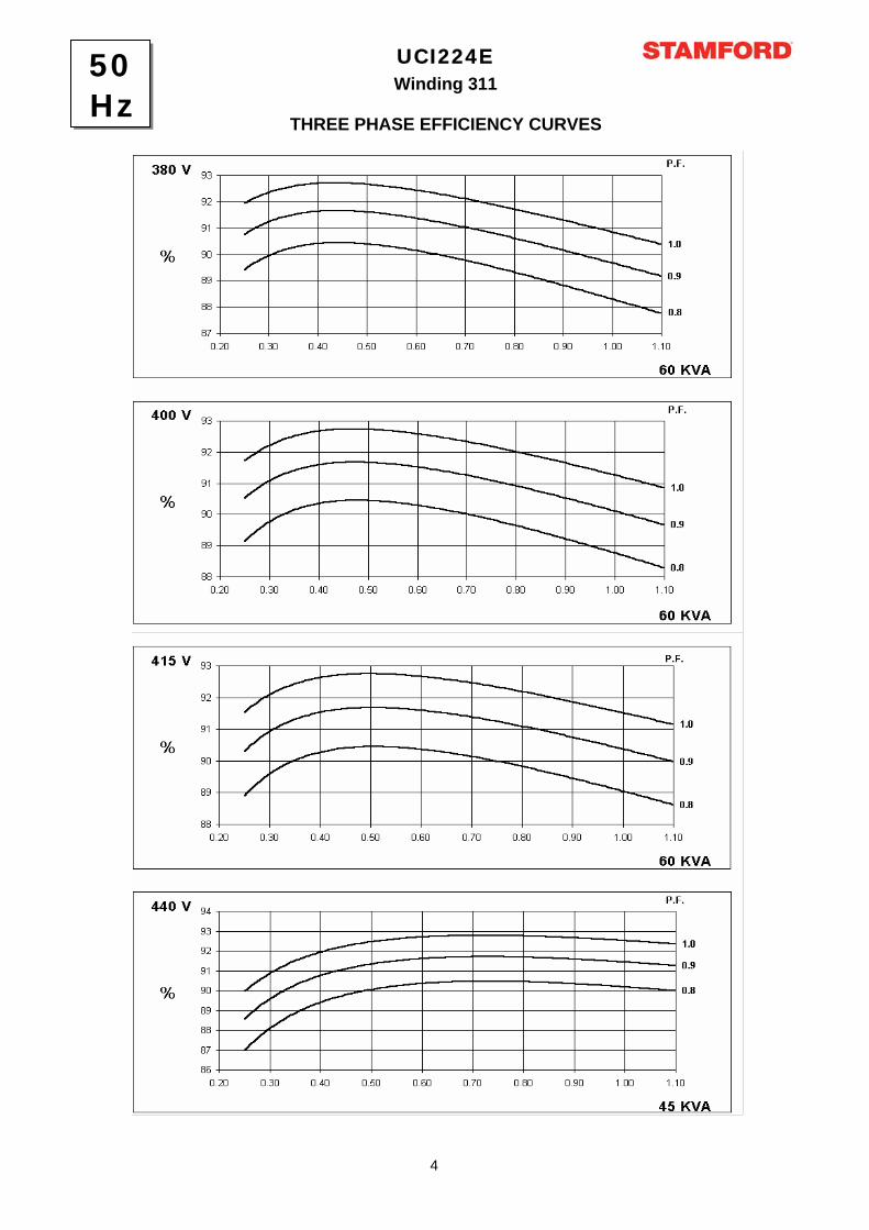
Winding 311
UCI224E
THREE PHASE EFFICIENCY CURVES
50Hz
4
AP
PR
OV
ED
DO
CU
ME
NT
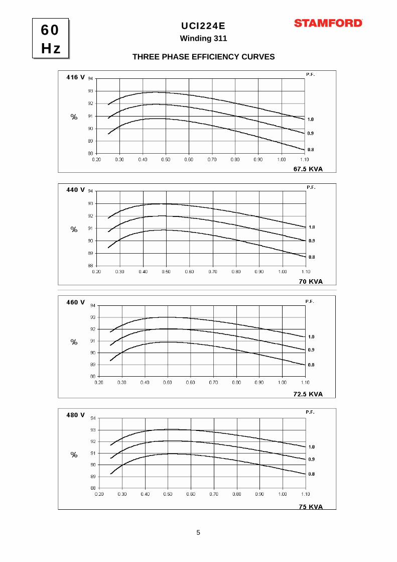
Winding 311
UCI224E
THREE PHASE EFFICIENCY CURVES
60Hz
5
AP
PR
OV
ED
DO
CU
ME
NT
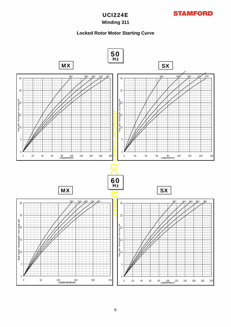
UCI224EWinding 311
Locked Rotor Motor Starting Curve
MX SX
50Hz
60Hz
MX SX
0
5
10
15
20
25
30
0 20 40 60 80 100 120 140 160 180LOCKED ROTOR kVA
PE
R C
EN
T T
RA
NS
IEN
T V
OL
TA
GE
DIP
346V 380V 400V 415V 440V
0
5
10
15
20
25
30
0 20 40 60 80 100 120 140 160LOCKED ROTOR kVA
PE
R C
EN
T T
RA
NS
IEN
T V
OL
TA
GE
DIP
346V 380V 400V 415V 440V
0
5
10
15
20
25
30
0 50 100 150 200 250LOCKED ROTOR kVA
PE
R C
EN
T T
RA
NS
IEN
T V
OL
TA
GE
DIP
380V 416V 440V 460V 480V
0
5
10
15
20
25
30
0 20 40 60 80 100 120 140 160 180 200LOCKED ROTOR kVA
PE
R C
EN
T T
RA
NS
IEN
T V
OL
TA
GE
DIP
380V 416V 440V 460V 480V
6
AP
PR
OV
ED
DO
CU
ME
NT
3-phase 2-phase L-L 1-phase L-N
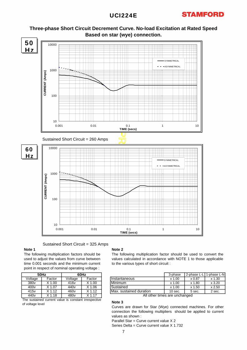
Voltage Factor Voltage Factor x 1.00 x 0.87 x 1.30
380v X 1.00 416v X 1.00 x 1.00 x 1.80 x 3.20
400v X 1.07 440v X 1.06 x 1.00 x 1.50 x 2.50
415v X 1.12 460v X 1.12 10 sec. 5 sec. 2 sec.
440v X 1.18 480v X 1.17
The sustained current value is constant irrespective
of voltage level
Three-phase Short Circuit Decrement Curve. No-load Excitation at Rated Speed
Based on star (wye) connection.
Max. sustained durationAll other times are unchanged
Instantaneous
SustainedMinimum
UCI224E
50Hz 60Hz
Sustained Short Circuit = 260 Amps
Sustained Short Circuit = 325 Amps
Note 1
The following multiplication factors should be
used to adjust the values from curve between
time 0.001 seconds and the minimum current
point in respect of nominal operating voltage :
Note 2
The following multiplication factor should be used to convert the
values calculated in accordance with NOTE 1 to those applicable
to the various types of short circuit :
Note 3
Curves are drawn for Star (Wye) connected machines. For other
connection the following multipliers should be applied to current
values as shown :
Parallel Star = Curve current value X 2
Series Delta = Curve current value X 1.732
50Hz
60Hz
10
100
1000
10000
0.001 0.01 0.1 1 10TIME (secs)
CU
RR
EN
T (
Am
ps
)
SYMMETRICAL
ASYMMETRICAL
10
100
1000
10000
0.001 0.01 0.1 1 10TIME (secs)
CU
RR
EN
T (
Am
ps
)
SYMMETRICAL
ASYMMETRICAL
7
AP
PR
OV
ED
DO
CU
ME
NT
Class - Temp Rise
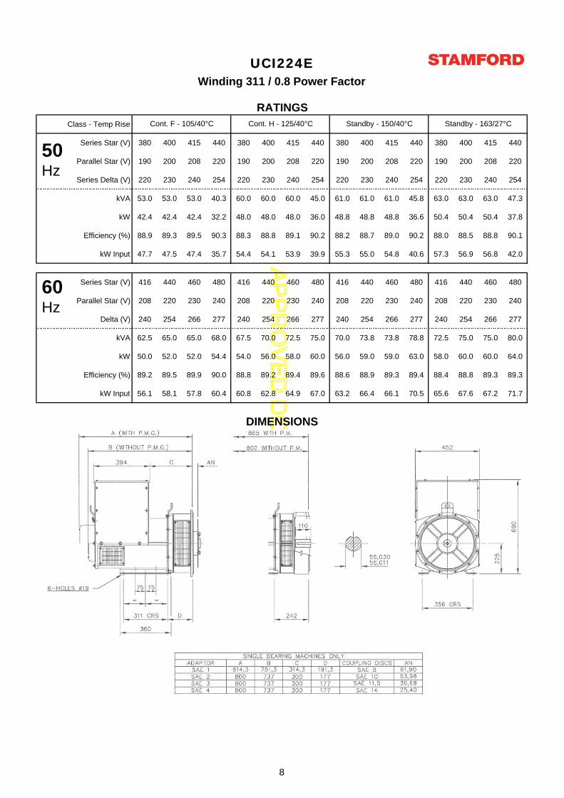
Series Star (V) 380 400 415 440 380 400 415 440 380 400 415 440 380 400 415 440
Parallel Star (V) 190 200 208 220 190 200 208 220 190 200 208 220 190 200 208 220
Series Delta (V) 220 230 240 254 220 230 240 254 220 230 240 254 220 230 240 254
kVA 53.0 53.0 53.0 40.3 60.0 60.0 60.0 45.0 61.0 61.0 61.0 45.8 63.0 63.0 63.0 47.3
kW 42.4 42.4 42.4 32.2 48.0 48.0 48.0 36.0 48.8 48.8 48.8 36.6 50.4 50.4 50.4 37.8
Efficiency (%) 88.9 89.3 89.5 90.3 88.3 88.8 89.1 90.2 88.2 88.7 89.0 90.2 88.0 88.5 88.8 90.1
kW Input 47.7 47.5 47.4 35.7 54.4 54.1 53.9 39.9 55.3 55.0 54.8 40.6 57.3 56.9 56.8 42.0
Series Star (V) 416 440 460 480 416 440 460 480 416 440 460 480 416 440 460 480
Parallel Star (V) 208 220 230 240 208 220 230 240 208 220 230 240 208 220 230 240
Delta (V) 240 254 266 277 240 254 266 277 240 254 266 277 240 254 266 277
kVA 62.5 65.0 65.0 68.0 67.5 70.0 72.5 75.0 70.0 73.8 73.8 78.8 72.5 75.0 75.0 80.0
kW 50.0 52.0 52.0 54.4 54.0 56.0 58.0 60.0 56.0 59.0 59.0 63.0 58.0 60.0 60.0 64.0
Efficiency (%) 89.2 89.5 89.9 90.0 88.8 89.2 89.4 89.6 88.6 88.9 89.3 89.4 88.4 88.8 89.3 89.3
kW Input 56.1 58.1 57.8 60.4 60.8 62.8 64.9 67.0 63.2 66.4 66.1 70.5 65.6 67.6 67.2 71.7
UCI224EWinding 311 / 0.8 Power Factor
RATINGS
Cont. F - 105/40°C Cont. H - 125/40°C Standby - 150/40°C Standby - 163/27°C
DIMENSIONS
50Hz
60Hz
8

AP
PR
OV
ED
DO
CU
ME
NT
UC224E-311-TD-EN-SG-A
Head Office Address:
Barnack Road, Stamford
Lincolnshire, PE9 2NB
United Kingdom
Tel: +44 (0) 1780 484000
Fax: +44 (0) 1780 484100
www.cumminsgeneratortechnologies.com
Copyright 2010, Cummins Generator Technologies Ltd, All Rights Reserved
Stamford and AvK are registered trade marks of Cummins Generator Technologies Ltd
Cummins and the Cummins logo are registered trade marks of Cummins Inc.
AP
PR
OV
ED
DO
CU
ME
NT
UCI224D - Winding 17
Technical Data Sheet
AP
PR
OV
ED
DO
CU
ME
NT
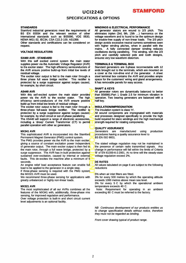
UCI224DSPECIFICATIONS & OPTIONS
STANDARDSStamford industrial generators meet the requirements ofBS EN 60034 and the relevant section of otherinternational standards such as BS5000, VDE 0530,NEMA MG1-32, IEC34, CSA C22.2-100, AS1359.Other standards and certifications can be considered onrequest.
VOLTAGE REGULATORS
SX460 AVR - STANDARDWith this self excited control system the main statorsupplies power via the Automatic Voltage Regulator (AVR)to the exciter stator. The high efficiency semiconductors ofthe AVR ensure positive build-up from initial low levels ofresidual voltage.The exciter rotor output is fed to the main rotor through athree phase full wave bridge rectifier. This rectifier isprotected by a surge suppressor against surges caused,for example, by short circuit.
AS440 AVRWith this self-excited system the main stator providespower via the AVR to the exciter stator. The highefficiency semi-conductors of the AVR ensure positivebuild-up from initial low levels of residual voltage.The exciter rotor output is fed to the main rotor through athree-phase full-wave bridge rectifier. The rectifier isprotected by a surge suppressor against surges caused,for example, by short circuit or out-of-phase paralleling.The AS440 will support a range of electronic accessories,including a 'droop' Current Transformer (CT) to permitparallel operation with other ac generators.
WINDINGS & ELECTRICAL PERFORMANCEAll generator stators are wound to 2/3 pitch. Thiseliminates triplen (3rd, 9th, 15th …) harmonics on thevoltage waveform and is found to be the optimum designfor trouble-free supply of non-linear loads. The 2/3 pitchdesign avoids excessive neutral currents sometimes seenwith higher winding pitches, when in parallel with themains. A fully connected damper winding reducesoscillations during paralleling. This winding, with the 2/3pitch and carefully selected pole and tooth designs,ensures very low waveform distortion.
TERMINALS & TERMINAL BOXStandard generators are 3-phase reconnectable with 12ends brought out to the terminals, which are mounted ona cover at the non-drive end of the generator. A sheetsteel terminal box contains the AVR and provides amplespace for the customers' wiring and gland arrangements.It has removable panels for easy access.
SHAFT & KEYSAll generator rotors are dynamically balanced to betterthan BS6861:Part 1 Grade 2.5 for minimum vibration inoperation. Two bearing generators are balanced with ahalf key.
INSULATION/IMPREGNATIONThe insulation system is class 'H'.All wound components are impregnated with materialsand processes designed specifically to provide the highbuild required for static windings and the high mechanicalstrength required for rotating components.
QUALITY ASSURANCE
STANDARDSStamford industrial generators meet the requirements ofBS EN 60034 and the relevant section of otherinternational standards such as BS5000, VDE 0530,NEMA MG1-32, IEC34, CSA C22.2-100, AS1359.Other standards and certifications can be considered onrequest.
VOLTAGE REGULATORS
SX460 AVR - STANDARDWith this self excited control system the main statorsupplies power via the Automatic Voltage Regulator (AVR)to the exciter stator. The high efficiency semiconductors ofthe AVR ensure positive build-up from initial low levels ofresidual voltage.The exciter rotor output is fed to the main rotor through athree phase full wave bridge rectifier. This rectifier isprotected by a surge suppressor against surges caused,for example, by short circuit.
AS440 AVRWith this self-excited system the main stator providespower via the AVR to the exciter stator. The highefficiency semi-conductors of the AVR ensure positivebuild-up from initial low levels of residual voltage.The exciter rotor output is fed to the main rotor through athree-phase full-wave bridge rectifier. The rectifier isprotected by a surge suppressor against surges caused,for example, by short circuit or out-of-phase paralleling.The AS440 will support a range of electronic accessories,including a 'droop' Current Transformer (CT) to permitparallel operation with other ac generators.
MX341 AVRThis sophisticated AVR is incorporated into the StamfordPermanent Magnet Generator (PMG) control system.The PMG provides power via the AVR to the main exciter,giving a source of constant excitation power independentof generator output. The main exciter output is then fed tothe main rotor, through a full wave bridge, protected by asurge suppressor. The AVR has in-built protection againstsustained over-excitation, caused by internal or externalfaults. This de-excites the machine after a minimum of 5seconds.An engine relief load acceptance feature can enable fullload to be applied to the generator in a single step.If three-phase sensing is required with the PMG systemthe MX321 AVR must be used.We recommend three-phase sensing for applications withgreatly unbalanced or highly non-linear loads.
MX321 AVRThe most sophisticated of all our AVRs combines all thefeatures of the MX341 with, additionally, three-phase rmssensing, for improved regulation and performance.Over voltage protection is built-in and short circuit currentlevel adjustments is an optional facility.
WINDINGS & ELECTRICAL PERFORMANCEAll generator stators are wound to 2/3 pitch. Thiseliminates triplen (3rd, 9th, 15th …) harmonics on thevoltage waveform and is found to be the optimum designfor trouble-free supply of non-linear loads. The 2/3 pitchdesign avoids excessive neutral currents sometimes seenwith higher winding pitches, when in parallel with themains. A fully connected damper winding reducesoscillations during paralleling. This winding, with the 2/3pitch and carefully selected pole and tooth designs,ensures very low waveform distortion.
TERMINALS & TERMINAL BOXStandard generators are 3-phase reconnectable with 12ends brought out to the terminals, which are mounted ona cover at the non-drive end of the generator. A sheetsteel terminal box contains the AVR and provides amplespace for the customers' wiring and gland arrangements.It has removable panels for easy access.
SHAFT & KEYSAll generator rotors are dynamically balanced to betterthan BS6861:Part 1 Grade 2.5 for minimum vibration inoperation. Two bearing generators are balanced with ahalf key.
INSULATION/IMPREGNATIONThe insulation system is class 'H'.All wound components are impregnated with materialsand processes designed specifically to provide the highbuild required for static windings and the high mechanicalstrength required for rotating components.
QUALITY ASSURANCEGenerators are manufactured using productionprocedures having a quality assurance level toBS EN ISO 9001.
The stated voltage regulation may not be maintained inthe presence of certain radio transmitted signals. Anychange in performance will fall within the limits of Criteria'B' of EN 61000-6-2:2001. At no time will the steady-statevoltage regulation exceed 2%.
DE RATESAll values tabulated on page 6 are subject to the followingreductions
5% when air inlet filters are fitted.3% for every 500 metres by which the operating altitudeexceeds 1000 metres above mean sea level.3% for every 5 C by which the operational ambienttemperature exceeds 40 C.
Note: Requirement for operating in an ambientexceeding 60 C must be referred to the factory.
NB Continuous development of our products entitles usto change specification details without notice, thereforethey must not be regarded as binding.
Front cover drawing typical of product range.
2
AP
PR
OV
ED
DO
CU
ME
NT
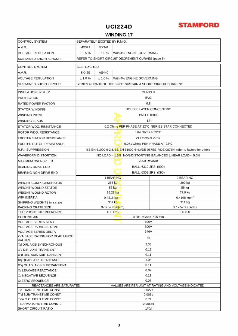
CONTROL SYSTEM SEPARATELY EXCITED BY P.M.G.
A.V.R. MX321 MX341
VOLTAGE REGULATION ± 0.5 % ± 1.0 % With 4% ENGINE GOVERNING
SUSTAINED SHORT CIRCUIT
CONTROL SYSTEM SELF EXCITED
A.V.R. SX460 AS440
VOLTAGE REGULATION ± 1.0 % ± 1.0 % With 4% ENGINE GOVERNING
SUSTAINED SHORT CIRCUIT SERIES 4 CONTROL DOES NOT SUSTAIN A SHORT CIRCUIT CURRENT
INSULATION SYSTEM CLASS H
PROTECTION
RATED POWER FACTOR
STATOR WINDING
WINDING PITCH
WINDING LEADS
STATOR WDG. RESISTANCE
ROTOR WDG. RESISTANCE
EXCITER STATOR RESISTANCE
EXCITER ROTOR RESISTANCE
R.F.I. SUPPRESSION BS EN 61000-6-2 & BS EN 61000-6-4,VDE 0875G, VDE 0875N. refer to factory for others
WAVEFORM DISTORTION NO LOAD < 1.5% NON-DISTORTING BALANCED LINEAR LOAD < 5.0%
MAXIMUM OVERSPEED
BEARING DRIVE END
BEARING NON-DRIVE END
2250 Rev/Min
UCI224DWINDING 17
21 Ohms at 22°C
0.071 Ohms PER PHASE AT 22°C
IP23
0.8
DOUBLE LAYER CONCENTRIC
TWO THIRDS
12
REFER TO SHORT CIRCUIT DECREMENT CURVES (page 5)
BALL. 6309-2RS (ISO)
0.64 Ohms at 22°C
0.2 Ohms PER PHASE AT 22°C SERIES STAR CONNECTED
BALL. 6312-2RS (ISO)
WEIGHT COMP. GENERATOR
WEIGHT WOUND STATOR
WEIGHT WOUND ROTOR
WR² INERTIA
SHIPPING WEIGHTS in a crate
PACKING CRATE SIZE
TELEPHONE INTERFERENCE
COOLING AIR
VOLTAGE SERIES STAR
VOLTAGE PARALLEL STAR
VOLTAGE SERIES DELTA
kVA BASE RATING FOR REACTANCE VALUES
Xd DIR. AXIS SYNCHRONOUS
X'd DIR. AXIS TRANSIENT
X''d DIR. AXIS SUBTRANSIENT
Xq QUAD. AXIS REACTANCE
X''q QUAD. AXIS SUBTRANSIENT
XL LEAKAGE REACTANCE
X2 NEGATIVE SEQUENCE
X0 ZERO SEQUENCE
REACTANCES ARE SATURATED VALUES ARE PER UNIT AT RATING AND VOLTAGE INDICATED
T'd TRANSIENT TIME CONST. 0.027s
T''d SUB-TRANSTIME CONST. 0.006s
T'do O.C. FIELD TIME CONST. 0.7s
Ta ARMATURE TIME CONST. 0.0055s
SHORT CIRCUIT RATIO 1/Xd
307 kg
97 x 57 x 96(cm)
1 BEARING 2 BEARING
86 kg
285 kg
86 kg
THF<2% TIF<50
77.9 kg
0.4198 kgm2
311 kg
97 x 57 x 96(cm)
86.28 kg
0.4216 kgm2
290 kg
0.07
2.35
0.16
0.11
1.08
( )
0.281 m³/sec 595 cfm
0.11
0.07
0.11
600V
300V
346V
65
33
AP
PR
OV
ED
DO
CU
ME
NT
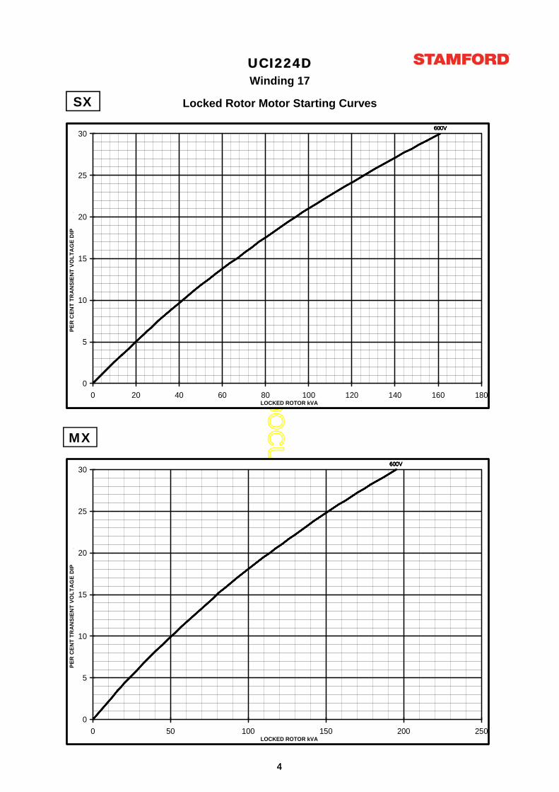
UCI224DWinding 17
Locked Rotor Motor Starting CurvesSX
600V600V600V600V600V
0
5
10
15
20
25
30
0 20 40 60 80 100 120 140 160 180LOCKED ROTOR kVA
PE
R C
EN
T T
RA
NS
IEN
T V
OL
TA
GE
DIP
.
SX
MX
600V600V600V600V600V
0
5
10
15
20
25
30
0 20 40 60 80 100 120 140 160 180LOCKED ROTOR kVA
PE
R C
EN
T T
RA
NS
IEN
T V
OL
TA
GE
DIP
.
600V600V600V600V600V
0
5
10
15
20
25
30
0 50 100 150 200 250LOCKED ROTOR kVA
PE
R C
EN
T T
RA
NS
IEN
T V
OL
TA
GE
DIP
.
44
AP
PR
OV
ED
DO
CU
ME
NT
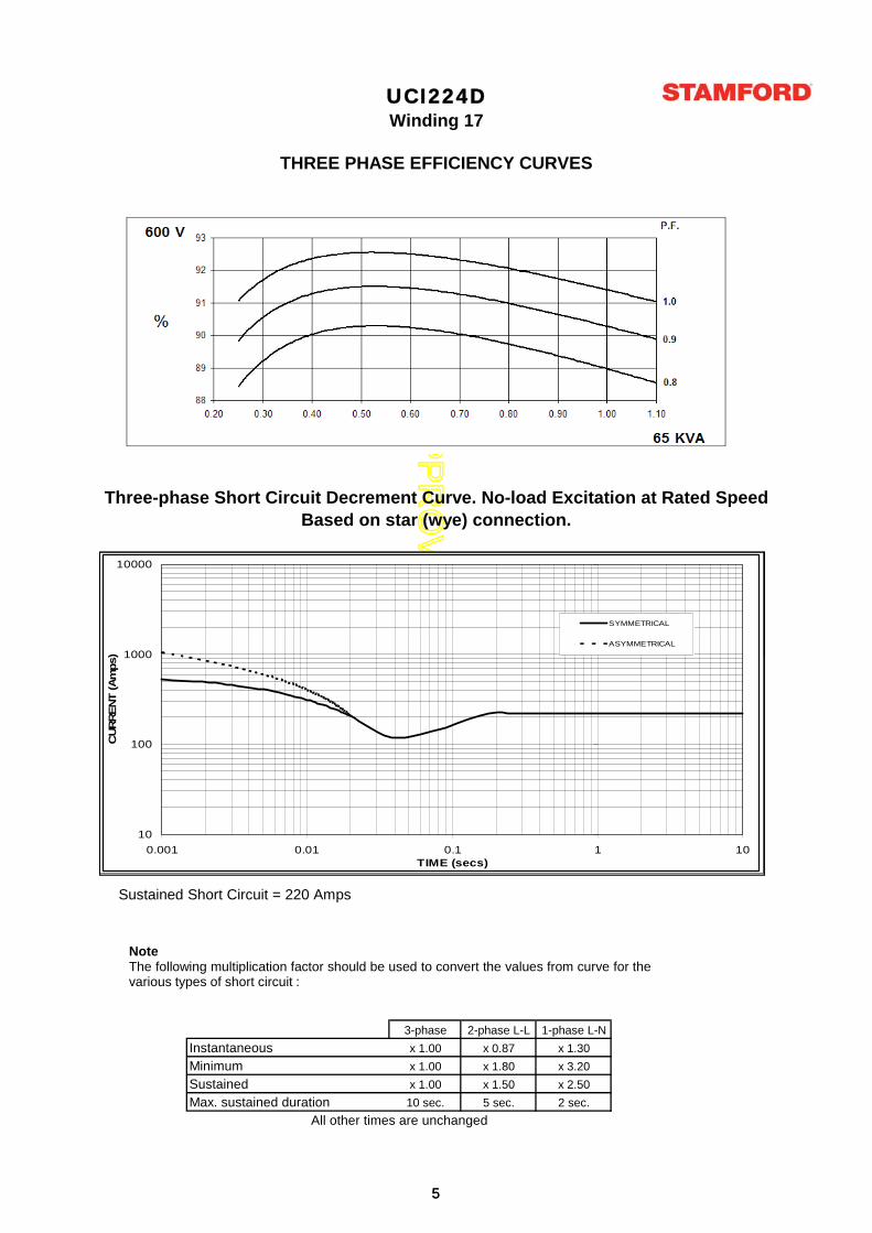
THREE PHASE EFFICIENCY CURVES
Based on star (wye) connection.
UCI224DWinding 17
Three-phase Short Circuit Decrement Curve. No-load Excitation at Rated Speed
1000
10000
)
SYMMETRICAL
ASYMMETRICAL
3-phase 2-phase L-L 1-phase L-N
x 1.00 x 0.87 x 1.30
x 1.00 x 1.80 x 3.20
x 1.00 x 1.50 x 2.50
10 sec. 5 sec. 2 sec.
All other times are unchanged
InstantaneousMinimumSustainedMax. sustained duration
Sustained Short Circuit = 220 Amps
NoteThe following multiplication factor should be used to convert the values from curve for thevarious types of short circuit :
10
100
1000
10000
0.001 0.01 0.1 1 10TIME (secs)
CU
RR
EN
T (A
mps)
SYMMETRICAL
ASYMMETRICAL
55
AP
PR
OV
ED
DO
CU
ME
NT
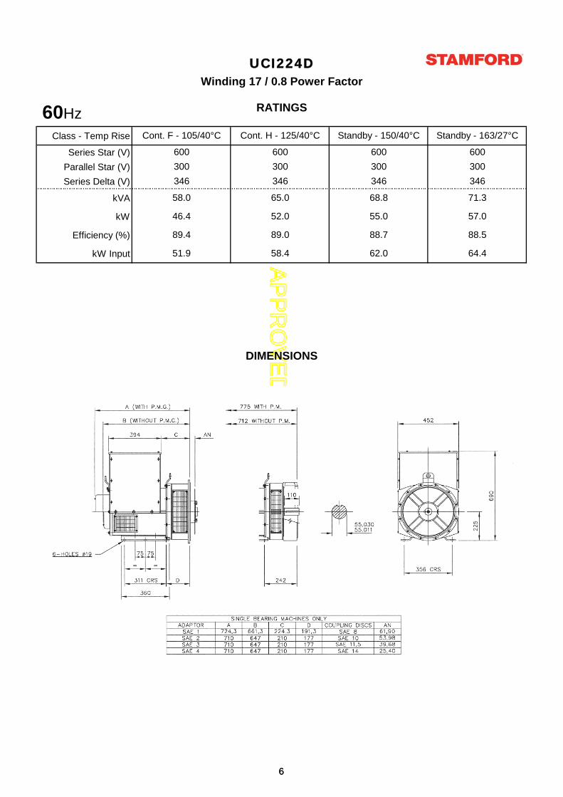
Class - Temp Rise
Series Star (V)
Parallel Star (V)
Series Delta (V)
kVA
kW
Efficiency (%)
kW Input
600
300
600
300
600
300
600
300
DIMENSIONS
UCI224D
Cont. F - 105/40°C Cont. H - 125/40°C Standby - 150/40°C Standby - 163/27°C
Winding 17 / 0.8 Power Factor
RATINGS
346
58.0
46.4
89.4
51.9
346
65.0
52.0
89.0
58.4 62.0
346
71.3
57.0
88.5
64.4
346
68.8
55.0
88.7
60Hz60Hz
66

AP
PR
OV
ED
DO
CU
ME
NT
UCI224D-17-TD-EN-SG-A
Head Office Address:Barnack Road, StamfordLincolnshire, PE9 2NB
United KingdomTel: +44 (0) 1780 484000Fax: +44 (0) 1780 484100
www.cumminsgeneratortechnologies.com
Copyright 2010, Cummins Generator Technologies Ltd, All Rights ReservedStamford and AvK are registered trade marks of Cummins Generator Technologies Ltd
Cummins and the Cummins logo are registered trade marks of Cummins Inc.
DSE7410/20AUTO START & AUTO MAINS FAILURE MODULES
DSEGenset
®
11ph2ph3phN
1ph2ph3phEN
1ph2ph3phN
1
11
232
6 4
MODEM
ISSUE 1
RS232 ANDRS485
CONFIGURABLEINPUTS
DC OUTPUTS ANALOGUESENDERS
EMERGENCY STOP
DC POWER SUPPLY 8-35V
DEUTZISUZUPERKINSCATERPILLARMTUVOLVOCUMMINSSCANIA
+D +W/L
GENERATOR SENSING
VOLTSVOLTS CURRENT
ELECTRONICENGINES &MAGNETIC PICK-UP
FUEL & CRANKOUTPUTSFLEXIBLE WITH CAN
CHARGEALTERNATOR
N/O VOLTFREE OUTPUT
N/C VOLT FREEOUTPUT
+
COMPREHENSIVE FEATURE LIST TO SUIT A WIDE VARIETY OFGEN-SET APPLICATIONS
7
OTHER
DSE7410/20
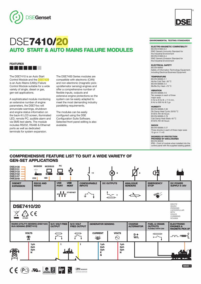
The DSE7410 is an Auto StartControl Module and the DSE7420is an Auto Mains (Utility) FailureControl Module suitable for a widevariety of single, diesel or gas, gen-set applications.
A sophisticated module monitoringan extensive number of engineparameters, the DSE74xx willannunciate warnings, shutdownand engine status information onthe back-lit LCD screen, illuminatedLED, remote PC, audible alarm andvia SMS text alerts. The moduleincludes RS232, RS485 & Ethernetports as well as dedicatedterminals for system expansion.
The DSE7400 Series modules arecompatible with electronic (CAN)and non-electronic (magnetic pick-up/alternator sensing) engines andoffer a comprehensive number offlexible inputs, outputs andextensive engine protections so thesystem can be easily adapted tomeet the most demanding industryparalleling requirements.
The modules can be easilyconfigured using the DSEConfiguration Suite Software.Selected front panel editing is alsoavailable.
FEATURES
ENVIRONMENTAL TESTING STANDARDS
ELECTRO-MAGNETIC COMPATIBILITYBS EN 61000-6-2EMC Generic Immunity Standard for the Industrial EnvironmentBS EN 61000-6-4EMC Generic Emission Standard for the Industrial Environment
ELECTRICAL SAFETYBS EN 60950Safety of Information Technology Equipment, including Electrical Business Equipment
TEMPERATUREBS EN 60068-2-1Ab/Ae Cold Test -30 oCBS EN 60068-2-2Bb/Be Dry Heat +70 oC
VIBRATIONBS EN 60068-2-6Ten sweeps in each of three major axes5 Hz to 8 Hz @ +/-7.5 mm, 8 Hz to 500 Hz @ 2 gn
HUMIDITYBS EN 60068-2-30Db Damp Heat Cyclic 20/55 oC@ 95% RH 48 HoursBS EN 60068-2-78Cab Damp Heat Static 40 oC@ 93% RH 48 Hours
SHOCKBS EN 60068-2-27Three shocks in each of three major axes15 gn in 11 mS
DEGREES OF PROTECTIONPROVIDED BY ENCLOSURESBS EN 60529IP65 - Front of module when installed into thecontrol panel with the supplied sealing gasket.
DSE2130DSE2131DSE2133DSE2152DSE2157DSE2548 485
MODBUS
USBPORT
USBHOST
ETHERNET
PC
DSENETEXPANSION
MAINS (UTILITY) SENSING (DSE7420)BUS SENSING (DSE7410)
DEEP SEA ELECTRONICS PLC UKHighfield House, Hunmanby Industrial Estate, Hunmanby YO14 0PHTELEPHONE +44 (0) 1723 890099 FACSIMILE +44 (0) 1723 893303EMAIL [email protected] WEBSITE www.deepseaplc.com
DEEP SEA ELECTRONICS INC USA3230 Williams Avenue, Rockford, IL 61101-2668 USATELEPHONE +1 (815) 316 8706 FACSIMILE +1 (815) 316 8708EMAIL [email protected] WEBSITE www.deepseausa.com
055-108/01/12 (1)
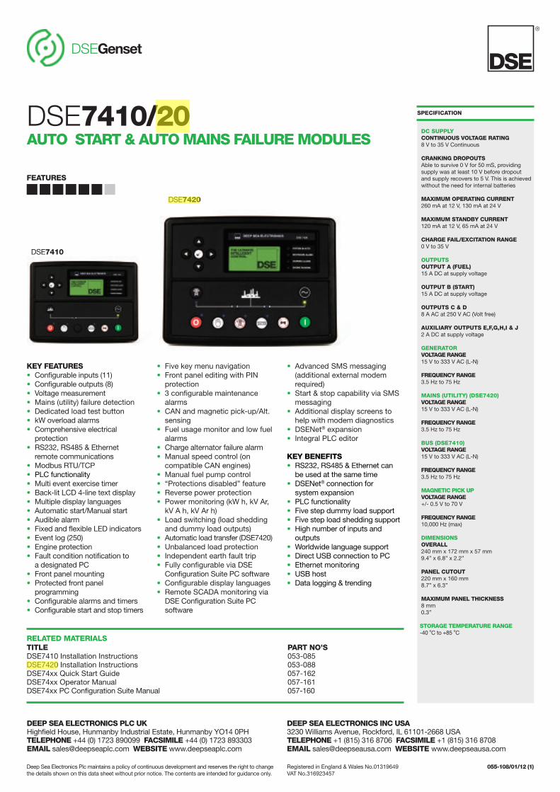
KEY FEATURES• Configurable inputs (11)• Configurable outputs (8)• Voltage measurement• Mains (utility) failure detection• Dedicated load test button• kW overload alarms• Comprehensive electrical
protection• RS232, RS485 & Ethernet
remote communications• Modbus RTU/TCP • PLC functionality• Multi event exercise timer • Back-lit LCD 4-line text display• Multiple display languages• Automatic start/Manual start• Audible alarm• Fixed and flexible LED indicators • Event log (250)• Engine protection• Fault condition notification to
a designated PC• Front panel mounting• Protected front panel
programming• Configurable alarms and timers• Configurable start and stop timers
• Five key menu navigation• Front panel editing with PIN
protection• 3 configurable maintenance
alarms• CAN and magnetic pick-up/Alt.
sensing• Fuel usage monitor and low fuel
alarms• Charge alternator failure alarm• Manual speed control (on
compatible CAN engines)• Manual fuel pump control • “Protections disabled” feature• Reverse power protection• Power monitoring (kW h, kV Ar,
kV A h, kV Ar h)• Load switching (load shedding
and dummy load outputs)• Automatic load transfer (DSE7420)• Unbalanced load protection• Independent earth fault trip• Fully configurable via DSE
Configuration Suite PC software• Configurable display languages• Remote SCADA monitoring via
DSE Configuration Suite PCsoftware
• Advanced SMS messaging(additional external modemrequired)
• Start & stop capability via SMSmessaging
• Additional display screens tohelp with modem diagnostics
• DSENet® expansion • Integral PLC editor
KEY BENEFITS• RS232, RS485 & Ethernet can
be used at the same time• DSENet® connection for
system expansion• PLC functionality• Five step dummy load support• Five step load shedding support• High number of inputs and
outputs• Worldwide language support• Direct USB connection to PC• Ethernet monitoring• USB host• Data logging & trending
RELATED MATERIALSTITLE PART NO’SDSE7410 Installation Instructions 053-085DSE7420 Installation Instructions 053-088DSE74xx Quick Start Guide 057-162DSE74xx Operator Manual 057-161DSE74xx PC Configuration Suite Manual 057-160
SPECIFICATION
DC SUPPLYCONTINUOUS VOLTAGE RATING8 V to 35 V Continuous
CRANKING DROPOUTSAble to survive 0 V for 50 mS, providing supply was at least 10 V before dropoutand supply recovers to 5 V. This is achieved without the need for internal batteries
MAXIMUM OPERATING CURRENT260 mA at 12 V, 130 mA at 24 V
MAXIMUM STANDBY CURRENT120 mA at 12 V, 65 mA at 24 V
CHARGE FAIL/EXCITATION RANGE0 V to 35 V
OUTPUTSOUTPUT A (FUEL)15 A DC at supply voltage
OUTPUT B (START)15 A DC at supply voltage
OUTPUTS C & D8 A AC at 250 V AC (Volt free)
AUXILIARY OUTPUTS E,F,G,H,I & J2 A DC at supply voltage
GENERATOR VOLTAGE RANGE 15 V to 333 V AC (L-N)
FREQUENCY RANGE3.5 Hz to 75 Hz
MAINS (UTILITY) (DSE7420)VOLTAGE RANGE 15 V to 333 V AC (L-N)
FREQUENCY RANGE3.5 Hz to 75 Hz
BUS (DSE7410)VOLTAGE RANGE 15 V to 333 V AC (L-N)
FREQUENCY RANGE3.5 Hz to 75 Hz
MAGNETIC PICK UPVOLTAGE RANGE+/- 0.5 V to 70 V
FREQUENCY RANGE10,000 Hz (max)
DIMENSIONSOVERALL240 mm x 172 mm x 57 mm 9.4” x 6.8” x 2.2”
PANEL CUTOUT 220 mm x 160 mm 8.7” x 6.3”
MAXIMUM PANEL THICKNESS8 mm0.3”
STORAGE TEMPERATURE RANGE-40 oC to +85 oC
DSE7410/20AUTO START & AUTO MAINS FAILURE MODULES
®
DSEGenset
FEATURES
Registered in England & Wales No.01319649VAT No.316923457
Deep Sea Electronics Plc maintains a policy of continuous development and reserves the right to changethe details shown on this data sheet without prior notice. The contents are intended for guidance only.
DSE7410
DSE7420
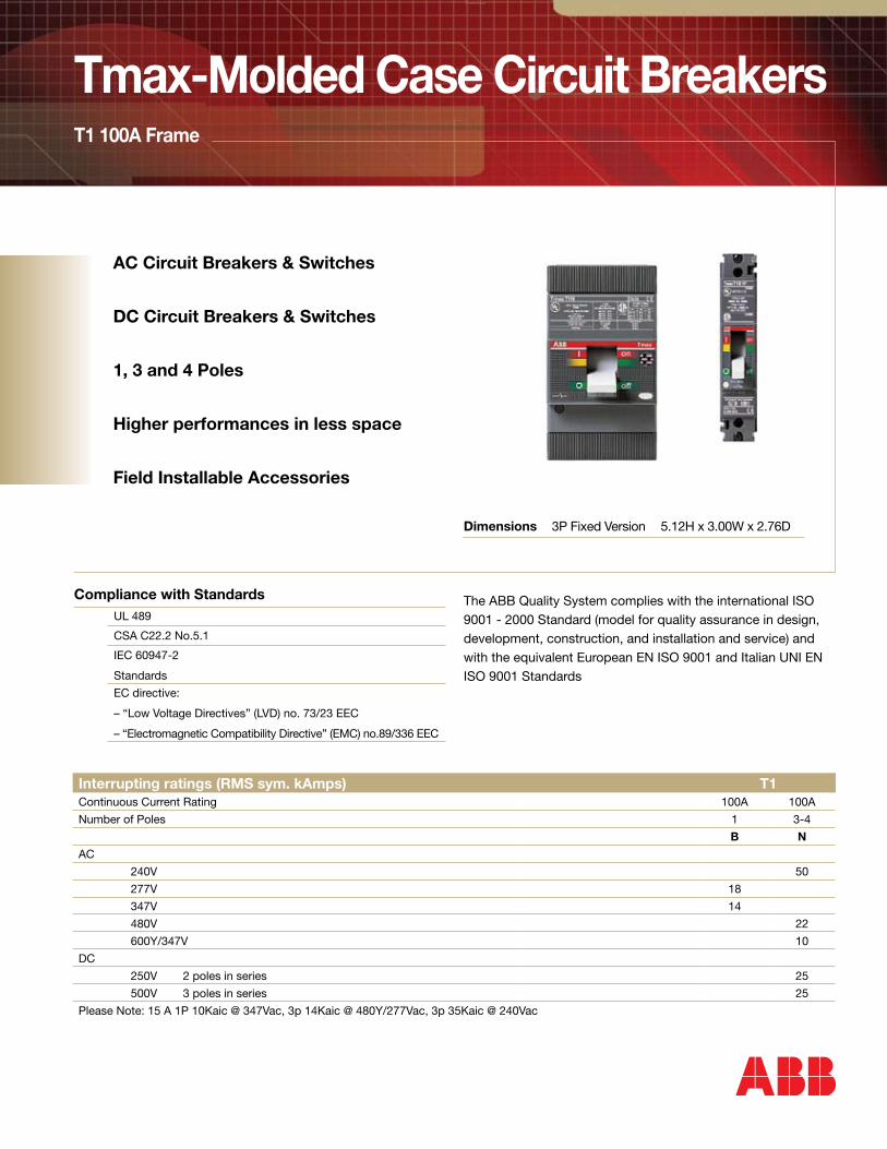
Tmax-Molded Case Circuit BreakersT1 100A Frame
AC Circuit Breakers & Switches
DC Circuit Breakers & Switches
1, 3 and 4 Poles
Higher performances in less space
Field Installable Accessories
Compliance with StandardsUL 489
CSA C22.2 No.5.1
IEC 60947-2
Standards
EC directive:
– “Low Voltage Directives” (LVD) no. 73/23 EEC
– “Electromagnetic Compatibility Directive” (EMC) no.89/336 EEC
Dimensions 3P Fixed Version 5.12H x 3.00W x 2.76D
The ABB Quality System complies with the international ISO 9001 - 2000 Standard (model for quality assurance in design, development, construction, and installation and service) and with the equivalent European EN ISO 9001 and Italian UNI EN ISO 9001 Standards
Interrupting ratings (RMS sym. kAmps) T1Continuous Current Rating 100A 100A
Number of Poles 1 3-4
B N
AC
240V 50
277V 18
347V 14
480V 22
600Y/347V 10
DC
250V 2 poles in series 25
500V 3 poles in series 25
Please Note: 15 A 1P 10Kaic @ 347Vac, 3p 14Kaic @ 480Y/277Vac, 3p 35Kaic @ 240Vac
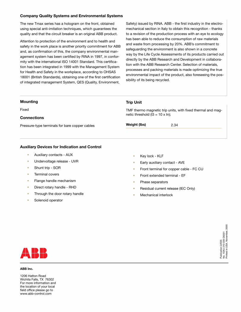
Auxiliary Devices for Indication and Control
• Auxiliary contacts - AUX
• Undervoltage release - UVR
• Shunt trip - SOR
• Terminal covers
• Flange handle mechanism
• Direct rotary handle - RHD
• Through the door rotary handle
• Solenoid operator
ABB Inc. 1206 Hatton RoadWichita Falls, TX 76302For more information and the location of your local field office please go to www.abb-control.com
Pub
licat
ion
LV03
5N
o. 1
SX
U 2
10 0
35 D
0201
Prin
ted
in U
SA
, Nov
emb
er, 2
005
• Key lock - KLF
• Early auxiliary contact - AVE
• Front terminal for copper cable - FC CU
• Front extended terminal - EF
• Phase separators
• Residual current release (IEC Only)
• Mechanical interlock
Mounting
Fixed
Connections
Pressure-type terminals for bare copper cables
Trip Unit
TMF thermo magnetic trip units, with fixed thermal and mag-netic threshold (I3 = 10 x In);
The new Tmax series has a hologram on the front, obtained using special anti-imitation techniques, which guarantees the quality and that the circuit breaker is an original ABB product.
Attention to protection of the environment and to health and safety in the work place is another priority commitment for ABB and, as confirmation of this, the company environmental man-agement system has been certified by RINA in 1997, in confor-mity with the international ISO 14001 Standard. This certifica-tion has been integrated in 1999 with the Management System for Health and Safety in the workplace, according to OHSAS 18001 (British Standards), obtaining one of the first certification of integrated management System, QES (Quality, Environment,
Safety) issued by RINA. ABB - the first industry in the electro-mechanical section in Italy to obtain this recognition - thanks to a revision of the production process with an eye to ecology has been able to reduce the consumption of raw materials and waste from processing by 20%. ABB’s commitment to safeguarding the environment is also shown in a concrete way by the Life Cycle Assessments of its products carried out directly by the ABB Research and Development in collabora-tion with the ABB Research Center. Selection of materials, processes and packing materials is made optimizing the true environmental impact of the product, also foreseeing the pos-sibility of its being recycled.
Company Quality Systems and Environmental Systems
Weight (Ibs) 2.34
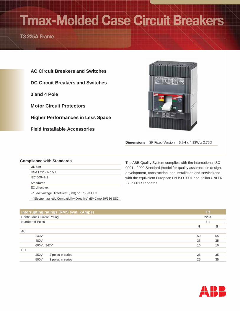
AC Circuit Breakers and Switches
DC Circuit Breakers and Switches
3 and 4 Pole
Motor Circuit Protectors
Higher Performances in Less Space
Field Installable Accessories
Compliance with StandardsUL 489
CSA C22.2 No.5.1
IEC 60947-2
Standards
EC directive:
– “Low Voltage Directives” (LVD) no. 73/23 EEC
– “Electromagnetic Compatibility Directive” (EMC) no.89/336 EEC
Dimensions 3P Fixed Version 5.9H x 4.13W x 2.76D
The ABB Quality System complies with the international ISO 9001 - 2000 Standard (model for quality assurance in design, development, construction, and installation and service) and with the equivalent European EN ISO 9001 and Italian UNI EN ISO 9001 Standards
Interrupting ratings (RMS sym. kAmps) T3Continuous Current Rating 225A
Number of Poles 3-4
N S
AC
240V 50 65
480V 25 35
600Y / 347V 10 10
DC
250V 2 poles in series 25 35
500V 3 poles in series 25 35
Auxiliary Devices for Indication and Control
• Auxiliary contacts - AUX
• Undervoltage release - UVR
• Shunt trip - SOR
• Terminal covers
• Front for lever operating mechanism - FLD
• Direct rotary handle - RHD
• Solenoid operator
• Key lock - KLF
• Early auxiliary contact - AUE
ABB Inc. 1206 Hatton RoadWichita Falls, TX 76302For more information and the location of your local fi eld offi ce please go to www.abb-control.com
Pub
licat
ion
LV03
7 N
o. 1
SX
U 2
10 0
37 D
0201
Prin
ted
in U
SA
, Nov
emb
er, 2
005
• Transmitted rotary handle - RHE
• Front terminal for copper cable - FC Cu
• Front extended terminal - EF
• Front terminal for copper-aluminum - FC CuAl
• Front extended spread terminal – ES
• Distribution lugs
• Rear orientated terminal - R
• Phase separators
• Residual current release (IEC Only)
Mounting
Fixed Plug-in
Connections
Busbar connection or compression lugs Pressure-type terminals for bare cables Rear connections
Trip Unit
TMF thermo magnetic trip units, with fi xed thermal and mag-netic threshold (I3 = 10 x In);
The new Tmax series has a hologram on the front, obtained using special anti-imitation techniques, which guarantees the quality and that the circuit breaker is an original ABB product.
Attention to protection of the environment and to health and safety in the work place is another priority commitment for ABB and, as confi rmation of this, the company environmental man-agement system has been certifi ed by RINA in 1997, in confor-mity with the international ISO 14001 Standard. This certifi ca-tion has been integrated in 1999 with the Management System for Health and Safety in the workplace, according to OHSAS 18001 (British Standards), obtaining one of the fi rst certifi cation of integrated management System, QES (Quality, Environment,
Safety) issued by RINA. ABB - the fi rst industry in the electro-mechanical section in Italy to obtain this recognition - thanks to a revision of the production process with an eye to ecology has been able to reduce the consumption of raw materials and waste from processing by 20%. ABB’s commitment to safeguarding the environment is also shown in a concrete way by the Life Cycle Assessments of its products carried out directly by the ABB Research and Development in collabora-tion with the ABB Research Center. Selection of materials, processes and packing materials is made optimizing the true environmental impact of the product, also foreseeing the pos-sibility of its being recycled.
Company Quality Systems and Environmental Systems
Weight (Ibs) 5.45
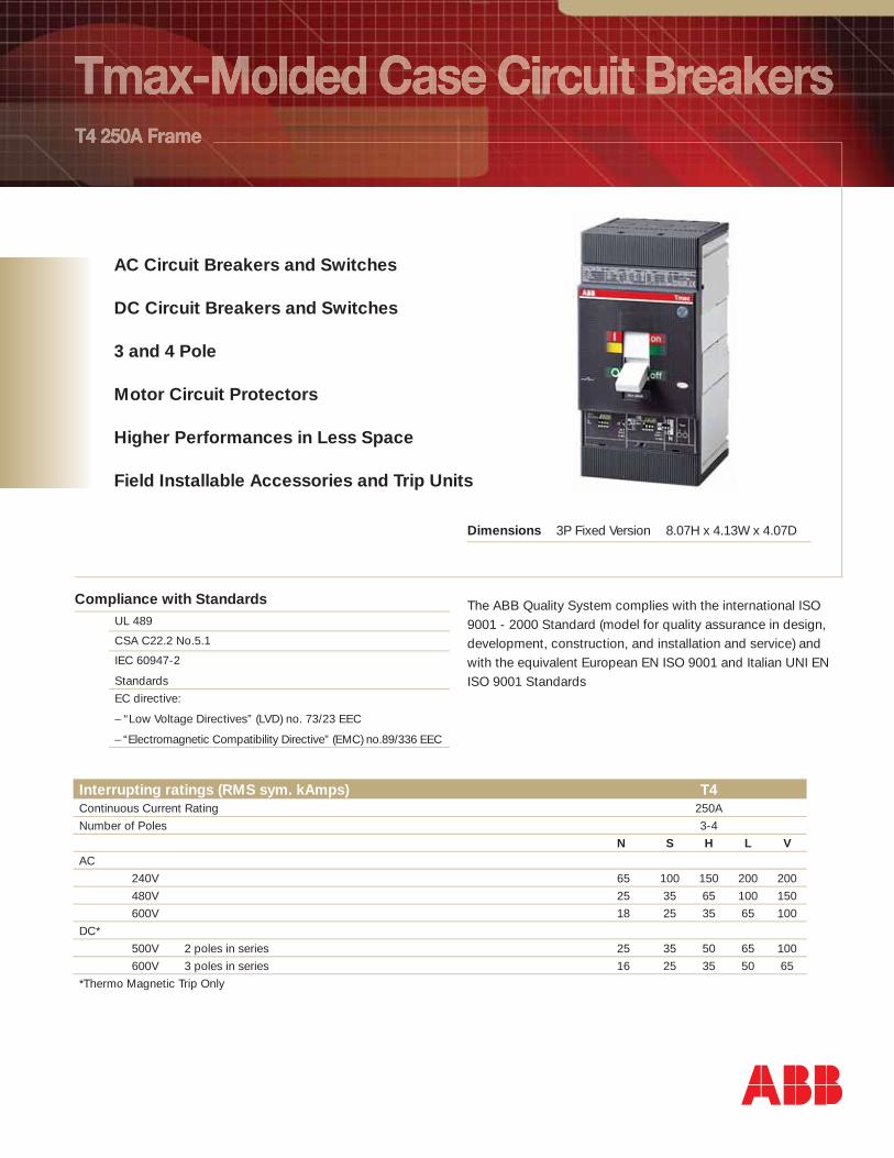
AC Circuit Breakers and Switches
DC Circuit Breakers and Switches
3 and 4 Pole
Motor Circuit Protectors
Higher Performances in Less Space
Field Installable Accessories and Trip Units
Compliance with StandardsUL 489
CSA C22.2 No.5.1
IEC 60947-2
Standards
EC directive:
– “Low Voltage Directives” (LVD) no. 73/23 EEC
– “Electromagnetic Compatibility Directive” (EMC) no.89/336 EEC
Dimensions 3P Fixed Version 8.07H x 4.13W x 4.07D
The ABB Quality System complies with the international ISO 9001 - 2000 Standard (model for quality assurance in design, development, construction, and installation and service) and with the equivalent European EN ISO 9001 and Italian UNI EN ISO 9001 Standards
Interrupting ratings (RMS sym. kAmps) T4Continuous Current Rating 250A
Number of Poles 3-4
N S H L V
AC
240V 65 100 150 200 200
480V 25 35 65 100 150
600V 18 25 35 65 100
DC*
500V 2 poles in series 25 35 50 65 100
600V 3 poles in series 16 25 35 50 65
*Thermo Magnetic Trip Only
Auxiliary Devices for Indication and Control
• Auxiliary contacts - AUX
• Undervoltage release - UVR
• Shunt trip - SOR
• Terminal covers
• Front for lever operating mechanism - FLD
• Direct rotary handle - RHD
• Stored energy motor operator - MOE
• Key lock - KLF
• Early auxiliary contact - AUE
ABB Inc. 1206 Hatton RoadWichita Falls, TX 76302For more information and the location of your local fi eld offi ce please go to www.abb-control.com
Pub
licat
ion
LV03
8N
o. 1
SX
U 2
10 0
38 D
0201
Prin
ted
in U
SA
, Nov
emb
er, 2
005
• Transmitted rotary handle - RHE
• Front terminal for copper cable - FC Cu
• Front extended terminal - EF
• Front terminal for copper-aluminum - FC CuAl
• Front extended spread terminal – ES
• Distribution lugs
• Rear orientated terminal - R
• Phase separators
• Residual current release (IEC Only)
Mounting
Fixed Plug-in Drawout
Connections
Busbar connection or compression lugs Pressure-type terminals for bare cables Rear connections
Trip Unit
TMF thermo magnetic trip units, with fi xed thermal and mag-netic threshold (I3 = 10 x In);
TMD (up to 50 A) thermo magnetic trip units with adjust-able thermal threshold (I1 = 0.7…1 x In) and fi xed magnetic threshold (I3 = 10 x In).
TMA thermo magnetic trip units, with adjustable thermal threshold (I1 = 0.7…1 x In) and adjustable magnetic thresh-old (I3 = 5…10 x In).
PR221DS, PR222DS/P and PR222DS/PD-A electronic trip unit
The new Tmax series has a hologram on the front, obtained using special anti-imitation techniques, which guarantees the quality and that the circuit breaker is an original ABB product.
Attention to protection of the environment and to health and safety in the work place is another priority commitment for ABB and, as confi rmation of this, the company environmental man-agement system has been certifi ed by RINA in 1997, in confor-mity with the international ISO 14001 Standard. This certifi ca-tion has been integrated in 1999 with the Management System for Health and Safety in the workplace, according to OHSAS 18001 (British Standards), obtaining one of the fi rst certifi cation of integrated management System, QES (Quality, Environment,
Safety) issued by RINA. ABB - the fi rst industry in the electro-mechanical section in Italy to obtain this recognition - thanks to a revision of the production process with an eye to ecology has been able to reduce the consumption of raw materials and waste from processing by 20%. ABB’s commitment to safeguarding the environment is also shown in a concrete way by the Life Cycle Assessments of its products carried out directly by the ABB Research and Development in collabora-tion with the ABB Research Center. Selection of materials, processes and packing materials is made optimizing the true environmental impact of the product, also foreseeing the pos-sibility of its being recycled.
Company Quality Systems and Environmental Systems
Weight (Ibs) 6.18
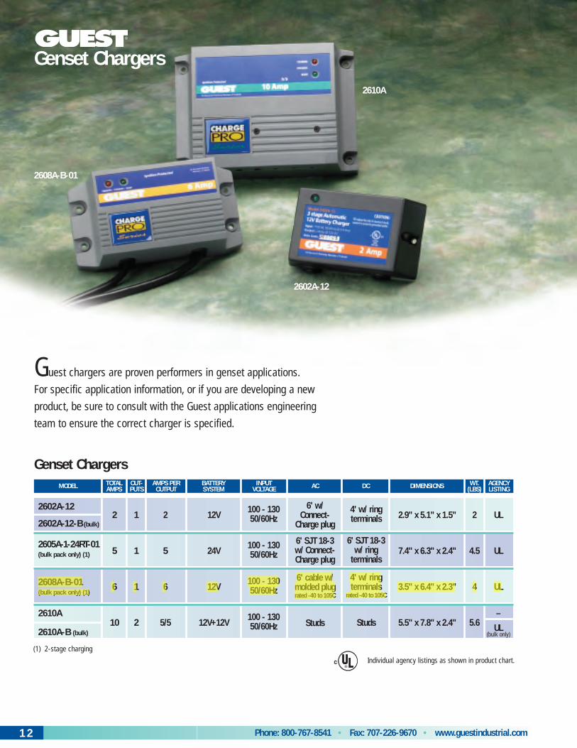
Phone: 800-767-8541 • Fax: 707-226-9670 • www.guestindustrial.com12
Genset Chargers
2
5
6
10
1
1
1
2
2
5
6
5/5
12V
24V
12V
12V+12V
100 - 13050/60Hz
100 - 13050/60Hz
100 - 13050/60Hz
100 - 13050/60Hz
6' w/ Connect-
Charge plug
6' SJT 18-3w/ Connect- Charge plug
6' cable w/molded plugrated -40 to 105C
Studs
4' w/ ring terminals
6' SJT 18-3w/ ring
terminals
4' w/ ring terminals
rated -40 to 105C
Studs
2.9" x 5.1" x 1.5"
7.4" x 6.3" x 2.4"
3.5" x 6.4" x 2.3"
5.5" x 7.8" x 2.4"
UL
UL
UL
–
UL
2
4.5
4
5.6
2602A-12
2602A-12-B (bulk)
2605A-1-24RT-01(bulk pack only) (1)
2608A-B-01 (bulk pack only) (1)
2610A
2610A-B (bulk)
MODEL TOTALAMPS
OUT-PUTS
AMPS PEROUTPUT
BATTERYSYSTEM
INPUTVOLTAGE AC DC DIMENSIONS AGENCY
LISTINGWT.
(LBS)
(bulk only)
Genset Chargers
Guest chargers are proven performers in genset applications.
For specific application information, or if you are developing a new
product, be sure to consult with the Guest applications engineering
team to ensure the correct charger is specified.
2602A-12
2610A
2608A-B-01
Individual agency listings as shown in product chart.
(1) 2-stage charging
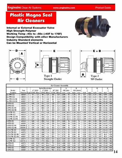
14
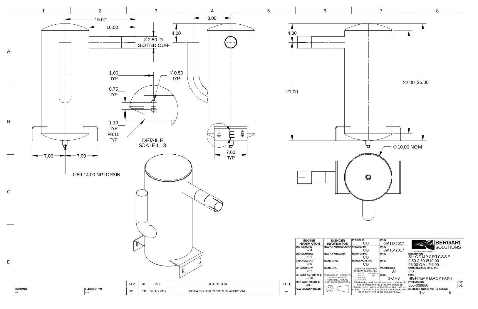
BERGARISOLUTIONS
member of the mandersgroup
BY DATEREV.
.XXX = ±0.0625
.XX = ±0.125
MANUFACTURING
TOLERANCES UNLESS
GAGE THICKNESS OR
DESCRIPTION
25.00 OAL F:4.00 ---
ECO
01 CB RELEASED FOR CUSTOMER APPROVAL copied or shared in any form without the express
09/15/2017
ALL ANGLES
INFORMATION
.X = ±0.25
40.8
--- OTHERWISE SPECIFIED
ENGINEERING
DRAWN BY
CHECKED BY
REV
TOLERANCES DO NOT APPLY TO ±1°
.XXXX = ±0.03125COMMERCIAL FEATURES
permission from Bergari Solutions, LLC.
DESCRIPTION
DATE
DATE
DATE
DATE
ENGINE INFORMATION
RESONATOR ALPHA
SILENCER Km
ENGINE MAKE
ENGINE MODEL
DISPLACEMENT
EXHAUST FLOW
EXHAUST TEMPERATURE
MAX BACK PRESSURE
RAW SOUND PRESSURE
CONSTRUCTION MATERIAL
FINISH
PART NUMBER
09/15/2017
37
SHEET SIZE
THIRD ANGLE PROJECTION
RESONATOR FREQUENCY
SCALE (DO NOT SCALE)
A
1
B
C
D
2 3 4 5 6 7
WEIGHT (LBS)
8
GM
5.7L
350
687
1250
---
---
---
---
1:6 B
CS
HIGH TEMP BLACK PAINT
500-008650 01
CB
2.50-2.50 Ø10.00SIL: COMP CRIT CS S-E
CB
CB
09/15/2017
CUSTOMER
CB
CUSTOMER P/N---
SILENCER IL
---
SHEET3 OF 3
This drawing and the information contained is confidential and the property of Bergari
Solutions, LLC. None of this information is to be
SILENCER
---
E
4.00
8.00
7.00TYP
4.00
22.00
21.00
25.00
10.00 NOM
0.50-14.00 NPT DRAIN
15.07 10.00
SLOTTED CUFF
7.00
2.50 ID
7.00
DETAIL ESCALE 1 : 3
TYP
TYP
TYP
TYP
1.13
0.50
0.75
1.00
R0.10TYP