600 series installation operation and maintenance...
TRANSCRIPT

600 Series
Installation
Operation and
Maintenance Manual
S16L-4
Jensen Mixers Int.
5354 South Garnett Rd.
Tulsa, OK. 74146
1-918-627-5770
WWW.JENSENMIXERS.COM

2
1. Remove blank cover plate from tank manway
and check mixer mount for correct size, hole
location and orientation.
2. Mount propeller and prop lock onto shaft IF
manway is large enough for propeller to “roll
through”.
3. Install gasket and bolt mixer mount with mix-
er to manway. Installation can be facilitated
by approaching the tank with the mixer on
the LEFT.
CAUTION- mixer pinion shaft must
be vertical when mixer is bolted to
manway.
4. Mount electrical motor to motor mount, if
not mounted at factory. Install motor mount
with motor on top of the mixer, lining up the
holes and installing cap screws. Align motor
coupling alignment.
Series 600 Vari-Angle Mixers — Installation

3
1. Remove blank tank cover plate from tank
manway and check mixer mount, if ordered from
factory, for correct size, hole location and
orientation.
2. If mixer mount is not ordered from factory, burn
hole nozzle in the blank mixer mount as follows:
[Allow at least 12” (309 mm) clearance between
tip of propeller and tank floor. Nozzle may be
mounted as low on plate as welding of nozzle
and gussets permits, keeping proper propeller
clearance in mind.]
3. Insert nozzle in burned hole and weld after
orienting “top” correctly.
4. Install Gasket and bolt mixer to nozzle. CAUTION
– The mixer pinion shaft must be in line with
“top” stamped on the thickness of the nozzle.
5. Mount propeller and prop lock onto shaft if
manway is large enough for propeller to “roll
through”.
6. Install gasket and bolt mixer mount with mixer to
manway. CAUTION- Mixer pinion shaft must be
vertical when mixer is bolted on manway.
7. Mount electric motor to motor mount if not
mounted at factory. Install motor mount, with
motor on top of the mixer, lining up the holes
and installing cap screw. For motor coupling
alignment, see page 5.
MODEL NOZZLE HOLE
605 6” 150# 7º 6 7/8 I.D. (175 mm)
620 8” 150# 7º 8 7/8 I.D. (225 mm)
650 10” 150# 10º 11 1/8 I.D. (283 mm)
680 12” 150# 10º 13 1/8 I.D. (333 mm)
Series 600 Fixed Angle Mixers — Installation

4
Alignment of motor coupling
Jensen Series 600 Mixer couplings have precisely machined edges for easy alignment using only
a straight edge. The following adjustment points on
the motor mount are used for coupling alignment:
(A) Oversize hole in motor.
(B) Shims under motor feet are used for parallel and
angular alignment.
(C) Set screw is used for angular alignment and
adjustment of the gap between coupling halves.
(D) Oversized holes in the motor mount base are used for
parallel alignment. Very small final adjustments are
made by tapping or bumping the motor mount while
the base bolts are snug but not tight.
Manway Propeller ROLL-THROUGH clearances:
Manway
depth
H 20 23 26 29 32 35
4 14 16 17 19 20 22
5 15 16 18 19 21 22
6 16 17 19 20 22 24
7 16 17 19 22 24 25
8 18 19 20 23 25 26
9 18 19 20 24 26 28
10 18 20 22 24 27 29
11 18 21 22 25 27 30
12 19 21 22 25 28 30
13 19 21 22 26 29 32
14 21 22 24 27 30 34
15 21 22 25 28 30 34
Propeller size /Manway I.D.
Example: A 29” propeller will rotate through a 23”
manway I.D. provided the depth of opening is 8” or
less
H
Man
way
Op
en
ing

5
Flexible Coupling Element Installation
For coupling element replacement
• Perform electrical lockout.
• Remove the coupling cover.
• Remove the bolts on the motor and gearbox coupling
halves.
• The flexible element will now slide out.
To install the flexible element
• Position as shown with one cap screw installed on top and
bottom.
• Pivot the element into position.
• Insert the rest of the bolts into the flexible element.
• Tighten to the torque values shown below.
Tighten screws evenly to prevent stripping threads and in a star pattern to prevent warping of coupling.
Model Torque GAP
605 120 lb-in 1.06” (27mm)
620 120 lb-in 1.12” (29mm)
650 240 lb-in 1.38” (35mm)
680 240 lb-in 1.5” (38mm)
.031 Max
B A
A -B .062 Max
Propeller Clearance & Fluid Levels
Almost every vibration problem experienced with Jensen Mixers has proved to be a result of too little clearance
between tank walls or floors and the mixer propeller. Operation of mixers with low fluid levels in the tank will
cause air to be drawn into the propeller flow stream and will also cause vibration.

6
Before Initial Mixer Startup:
1. Once fluid level is above the mixer, remove the upper vent
plug and open the valve until all the trapped air has been
released and the mixer is filled with tank fluid. Close the valve
and replace the plug. (Warning: As the mixer fills, some tank
fluid may escape through the vent tube.)
2. Fill gearbox with oil to the bottom of the threads on fill hole.
Start the mixer and run for 10 minutes. While mixer is still running fill to
bottom of the threads again.
3. Confirm correct rotation direction.
4. Because the assembly of the mixer is done in a dry environment, some
adjustment of the vari-angle ball packing will be necessary after the tank is
filled with product. If excessive leakage occurs around the ball, simply
tighten the four nuts at the packing gland evenly until the leakage is
reduced to a minimum. Some tightening may be necessary after the
machine has operated for a short while.
5. Change oil (while HOT) after first 10 hours operation.
Periodic Maintenance for normal operation:
• WEEKLY: Observe lower indicator glass on First Watch for fluid, this will be
indication of seal issues.
• WEEKLY: Check external moving parts for abnormal wear or misalignment.
• MONTHLY: With the mixer running, check for noise and vibration. (See
Troubleshooting if occurs)
• ANNUALLY: Change oil once each year and inspect flexible coupling.
IF UNIT OPERATED CONTINUALLY CHANGE OIL QUARTERLY AND INSPECT COUPLING.
Pre-Startup: Fixed and Vari-Angle Mixers
Run-in requirements: Jensen Mixers do not require any special run-in procedure. However, gearbox oil should be changed (while
hot) after the first 10 hours operation.
Normal Operation: Change once seasonally, inspect regularly.
To Inspect Oil Level: Remove fill plug. If indicator bar inside gear box is visible, oil is too low. Fill to bottom
of threads.
To Change Oil: While oil is hot, remove drain plug and drain. Replace plug and fill to bottom of threads.
Then start mixer and again fill to bottom of threads.
7
600 Variable Angle Mixers
Mixers with existing sediment accumulation should be operated continuously as long as
fluid level is two and a half times the diameter of the propeller above the arc of the
upper propeller tip and sediment content in outgoing stream is acceptable. Mixer angle
variation from full left to full right and to center should be made periodically – once each
day during continuous running. Mixer equipped with Jensen Variable Angle actuators
automatically reposition themselves.
Mixers to be used as effective sediment control on clean tanks, start mixer 4 hours
before pump-out begins and continue until tank is half full. This procedure will need to
be modified to suit climate and conditions. In controlling sediment, angle variation need
be made only about once each quarter. Mixers equipped with the Jensen Variable Angle
actuator will automatically make all angle changes. No scheduling or other attention is
necessary.
600 Fixed Angle Mixers
Jensen Fixed Angle Mixers are recommended for blending in accordance with your
company’s specification furnished at time of purchase. Blending times, fluid
characteristics, operating procedures etc., are spelled out in this specification. If
operating procedure have not been specified, Jensen recommends:
•If fluids to be mixed are pumped into tank at the same time, operate mixer during
filling.
•If fluids to be mixed are already blended and purpose of mixer is to prevent
stratification, automatic timer control is recommended with a cycle of 2 hours on, 6
hours off.
•If fixed angle mixers are to be used for reducing sediment deposits in crude oil storage
tanks, use the operating procedure recommended under “Vari-Angle Mixers”.
Mixer Operation:

8
1. If appropriate familiarize yourself with the Jensen FIRST-WATCH system.
2. Remove end bearing cap by first loosening vertical
pinch bolt and horizontal cap-to-gearcase bolt. Do not
operate mixer with end bearing cap removed.
3. Rotate the drive yoke so that “Pull-Turn” printed on
the yoke is in the 12 o’clock position.
4. Remove the bolts from the drive yoke.
5. Pull the yoke back to
stop (1/2” to 1-1/4”), and
then turn it counter-
clockwise till lock engages and shaft stops (90 degrees or more).
This seals off the tank contents. If the yoke cannot be pulled back
by hand, jack screw holes are
provided in the yoke.
6. Remove shaft bolt, drive
yoke and key. Mechanical
seal may now be removed. When removing the seal,
rotate it counter-clockwise only to avoid disturbing the
tank sealing function at the other end of the mixer.
7. To remove the seal, simply pull it off the shaft. Note
that the seal drive pin is located over the shaft keyway. If
the seal is to be replaced, push new seal onto shaft, also rotating the seal counter-clockwise
only, and observe the rest of this procedure. Be sure the seal drive pin extends into the hole
above the keyway in the drive yoke.
8. Install the key and the yoke. Note that the yoke must be
sliding fit on the shaft. (Anti-seize is recommended)
9. Slide the thrust bearing over the shaft and the yoke, securing
it with a cap screw to the end of shaft.
10. Unlock the mixer shaft and slide it forward till the yoke
engages with the drive sleeve fully. It will be forced away
from the drive sleeve about ¼ inch by the seal spring tension.
Do not force the yoke against the drive sleeve by using the yoke cap screw except to take up
the seal spring tension.
11. Bolt the yoke to the drive sleeve. Slip the yoke cover over the thrust bearing and secure it with
the housing bolts.
12. Now vent the mixer by carefully opening the vent valve (or plug) and either filling with light oil
or some material compatible with tank contents, then closing the valve or replacing plug.
13. Do not tighten the pinch bolt (on 605/620/650) until after the mixer has had a chance to run for
a few minutes. This stabilizes the location of the thrust bearing.
Mechanical Seal Replacement for models 605, 620 and 650

9
1. If appropriate familiarize yourself with the Jensen FIRST-WATCH system.
2. Remove (4) horizontal bearing housing – to –bearing cap screws.
(B) Remove horizontal bearing cap-to-gearcase bolts (C) take off
bearing cap. Do not operate mixer with bearing cap removed.
3. Remove the yoke-to-drive
sleeve bolts (D) Rotate the yoke so
that “pull-Lock” on the yoke is
facing up.
4. Pull the yoke back (A)
approximately ½” to 1 ¼” and
rotate ¼ turn counter clockwise until
lock engages and shaft stops (90º) or
more (B) This seals off the tank contents and holds the shaft securely. If
the yoke is difficult to pull back by hand, jack screw holes in the yoke
flange may be used as a light duty puller only. If strong resistance is
encountered, use a wheel or bearing puller.
5. Remove the shaft bolt, then the thrust
bearing assembly. Note that the thrust bearing
assembly comes off as a unit. It is not necessary to disassemble the
unit unless the bearing is to be replaced.
6. Remove the yoke. Note the position of
the seal drive pin opposite the shaft
keyway. When reassembling the mixer, be
sure that the matching hole in the yoke aligns with this drive pin.
7. If the drive pin and the yoke hole are not properly aligned, the
mechanical seal could be destroyed.
8. To remove the seal, simply pull it carefully off the shaft with a
counter-clockwise, twisting motion.
Mechanical Seal Replacement Model 680
Reassembly Notes • Install seal, noting location of driving pin. • Install Yoke key and Yoke—Confirm the seal drive pin extends into the
receiving hole in the drive yoke. • Install bearing assembly and shaft bolt. • Rotate Yoke and push forward to engage mechanical seal and unlock
mixer. • Install Yoke bolts and torque to specifications. • Install Yoke Cap and install 4 cap bolts and 4 bearing bolts. • Follow startup procedures.
(A)
(B) (C)
(D)
(A) (B)
10
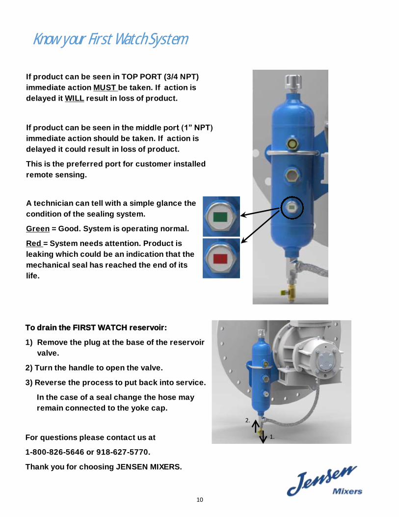
Know your First Watch System
A technician can tell with a simple glance the
condition of the sealing system.
Green = Good. System is operating normal.
Red = System needs attention. Product is
leaking which could be an indication that the
mechanical seal has reached the end of its
life.
If product can be seen in the middle port (1” NPT)
immediate action should be taken. If action is
delayed it could result in loss of product.
This is the preferred port for customer installed
remote sensing.
If product can be seen in TOP PORT (3/4 NPT)
immediate action MUST be taken. If action is
delayed it WILL result in loss of product.
To drain the FIRST WATCH reservoir:
1) Remove the plug at the base of the reservoir
valve.
2) Turn the handle to open the valve.
3) Reverse the process to put back into service.
In the case of a seal change the hose may
remain connected to the yoke cap.
For questions please contact us at
1-800-826-5646 or 918-627-5770.
Thank you for choosing JENSEN MIXERS.
2.
1.
11
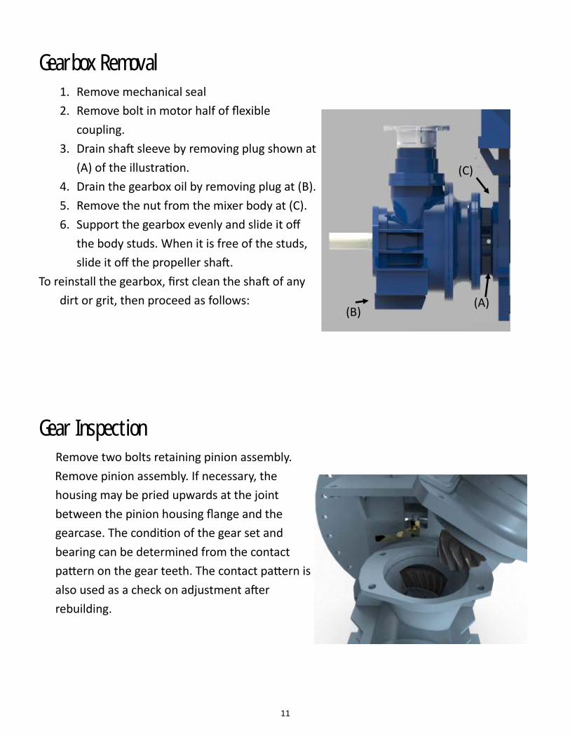
Gearbox Removal
1. Remove mechanical seal
2. Remove bolt in motor half of flexible
coupling.
3. Drain shaft sleeve by removing plug shown at
(A) of the illustration.
4. Drain the gearbox oil by removing plug at (B).
5. Remove the nut from the mixer body at (C).
6. Support the gearbox evenly and slide it off
the body studs. When it is free of the studs,
slide it off the propeller shaft.
To reinstall the gearbox, first clean the shaft of any
dirt or grit, then proceed as follows:
Gear Inspection
Remove two bolts retaining pinion assembly.
Remove pinion assembly. If necessary, the
housing may be pried upwards at the joint
between the pinion housing flange and the
gearcase. The condition of the gear set and
bearing can be determined from the contact
pattern on the gear teeth. The contact pattern is
also used as a check on adjustment after
rebuilding.
(A) (B)
(C)
12
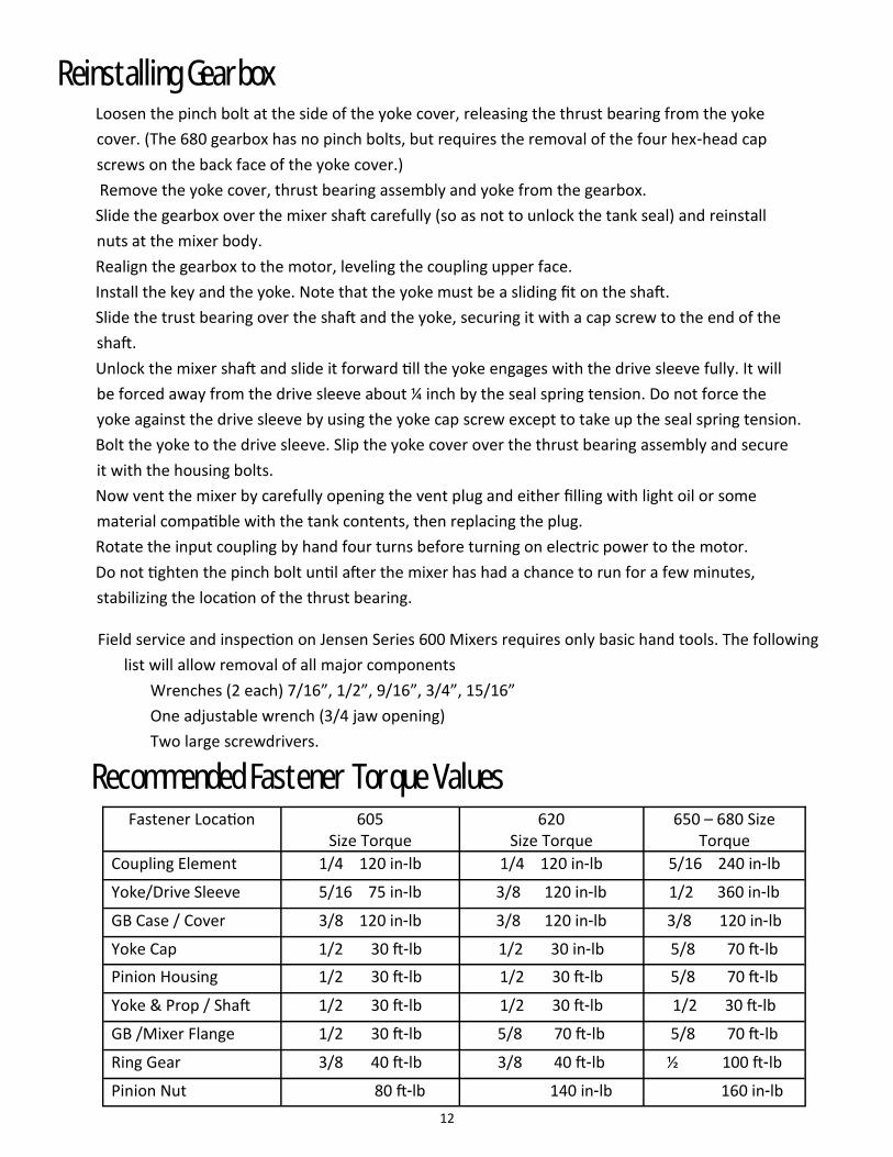
Recommended Fastener Torque Values
Field service and inspection on Jensen Series 600 Mixers requires only basic hand tools. The following
list will allow removal of all major components
Wrenches (2 each) 7/16”, 1/2”, 9/16”, 3/4”, 15/16”
One adjustable wrench (3/4 jaw opening)
Two large screwdrivers.
Fastener Location 605 Size Torque
620 Size Torque
650 – 680 Size Torque
Coupling Element 1/4 120 in-lb 1/4 120 in-lb 5/16 240 in-lb
Yoke/Drive Sleeve 5/16 75 in-lb 3/8 120 in-lb 1/2 360 in-lb
GB Case / Cover 3/8 120 in-lb 3/8 120 in-lb 3/8 120 in-lb
Yoke Cap 1/2 30 ft-lb 1/2 30 in-lb 5/8 70 ft-lb
Pinion Housing 1/2 30 ft-lb 1/2 30 ft-lb 5/8 70 ft-lb
Yoke & Prop / Shaft 1/2 30 ft-lb 1/2 30 ft-lb 1/2 30 ft-lb
GB /Mixer Flange 1/2 30 ft-lb 5/8 70 ft-lb 5/8 70 ft-lb
Ring Gear 3/8 40 ft-lb 3/8 40 ft-lb ½ 100 ft-lb
Pinion Nut 80 ft-lb 140 in-lb 160 in-lb
Reinstalling Gearbox
Loosen the pinch bolt at the side of the yoke cover, releasing the thrust bearing from the yoke
cover. (The 680 gearbox has no pinch bolts, but requires the removal of the four hex-head cap
screws on the back face of the yoke cover.)
Remove the yoke cover, thrust bearing assembly and yoke from the gearbox.
Slide the gearbox over the mixer shaft carefully (so as not to unlock the tank seal) and reinstall
nuts at the mixer body.
Realign the gearbox to the motor, leveling the coupling upper face.
Install the key and the yoke. Note that the yoke must be a sliding fit on the shaft.
Slide the trust bearing over the shaft and the yoke, securing it with a cap screw to the end of the
shaft.
Unlock the mixer shaft and slide it forward till the yoke engages with the drive sleeve fully. It will
be forced away from the drive sleeve about ¼ inch by the seal spring tension. Do not force the
yoke against the drive sleeve by using the yoke cap screw except to take up the seal spring tension.
Bolt the yoke to the drive sleeve. Slip the yoke cover over the thrust bearing assembly and secure
it with the housing bolts.
Now vent the mixer by carefully opening the vent plug and either filling with light oil or some
material compatible with the tank contents, then replacing the plug.
Rotate the input coupling by hand four turns before turning on electric power to the motor.
Do not tighten the pinch bolt until after the mixer has had a chance to run for a few minutes,
stabilizing the location of the thrust bearing.

13
Disassembly 1. Clamp pinion teeth in a vise equipped with soft jaws to prevent damage.
2. Remove pinion nut.
3. Remove coupling half. Pry between coupling and pinion housing or use a
bearing puller to start it off.
4. Tap the housing upwards lightly with a rubber mallet, then lift it off.
5. Pull both bearings. If either bearing is damaged, replace both.
Pinion Bearing and Gear Replacement
Reassembly
Reverse the procedure above. Start by using the same shim thickness under bearing as the original
assembly; this will serve as a starting point. When reassembled, the pinion housing should turn
freely, but with no slack that can be felt by rocking the housing. If it is too tight, disassemble and add
shims under the upper bearing; if it is too loose, reduce shim thickness. There should be no
measurable preload on this assembly.
Pinion Depth Adjustment The distance from the bottom face of the pinion to the housing flange
If (M) is greater than it should be, shims must be added as shown.
If the outside of the upper case flange is stamped with a number such as
+002, add .002” to the shim requirement. If stamped number is -001,
deduct .001” from the shims required.
Replace O-ring
Put pinion assembly in gearcase and install bolts. Torque to specifications.
Model “M” Dimensions
605 2.688” (68.275 mm)
620 3.000” (76.200 mm)
650 & 680 3.500” (88.900 mm)
M

14
Gear Set Contact Pattern
Using a suitable marking compound, check the contact
pattern. If the markings look like the first depiction, the
pattern is to accepted standards.
Gears are cut with a contact pattern about half the length
of the tooth, the location slightly favoring the toe end
of the tooth. Under load the pattern will shift
somewhat toward the heel of the tooth, and thus
become more central, under no circumstances must the pattern be concentrated on the ends of
the teeth.
If the contact pattern looks like the second
depiction, remove shims between the case and
pinion bearing housing. This pattern indicates
that the pinion is sitting too high.
If the contact pattern looks like the third depiction
add shims between the case and pinion bearing
housing. This pattern indicates that the pinion is sitting to low.
Ring Gear and Main Bearing Replacement
Disassembly
Clamp gearbox cover on workbench with the small end up.
Remove the case / cover bolts and lift off the gearcase.
Lift the drive sleeve up off the body. The gear and bearing
should be inspected at this point. Replace if gears or bearings
are excessively worn or loose. A bearing puller may be
required to remove the main bearing from the drive sleeve.

15
Reassemble – Backlash Adjustment
1. Bolt ring gear to drive sleeve. See recommended torque values.
2. Press main bearing onto drive sleeve.
3. Position the drive sleeve back over the body without shims.
4. Position gearcase, with pinion assembly, over the drive sleeve.
Do not install case/body bolts or the oil seal.
5. Bolt a bar to the drive sleeve as shown. Swing the bar back and forth through a short arc until
the backlash gap can be felt. Move the bar clockwise until tooth contact can just be noticed.
Carefully clamp a bar on the coupling half so
that it barely touches the left side of the drive
sleeve bar. Move the drive sleeve bar
counterclockwise until tooth contact is just
felt again. Measure the gap between the
bars. When the backlash is correct, this gap
will correspond to the values shown on the
illustration.
6. Since no shims were installed this first time, they will probably have to be added now to correct
the contact of the ring and pinion. Once complete
reassemble drive-sleeve and gearcase. Re-measure
and repeat this process until the backlash is in the
specified range.
7. When the adjustment is correct, remove the case
and position the case / body O-ring, replace the
case and fasten the case/body cap screws.
8. Install the oil seal.
605 = .025-.030” 0.7-0.8 mm
620 = .030-.035” 0.8-0.9 mm
650 & 680 = .035-.040” 0.9-1.0 mm

16
Shaft Bearing Inspection
When the gearbox is removed for repairs, it is important that the shaft bearing be inspected. Proceed
once tank product is below centerline of mixer:
1. Once the gearbox has been
removed, the inner sleeve which
holds the shaft bearing can be
removed. A groove is provided on
the exposed end of the inner sleeve;
a pair of screwdrivers may be used
here to extract the inner tube.
2. The shaft bearing is located inside
the inner sleeve at the propeller end. If it is
badly worn or scored, it should be replaced.
3. The bushing material is solid tungsten carbide
for greatest resistance to wear in the most abrasive environments. If it is worn it will be necessary
to replace the entire inner tube assembly.
4. To reinstall the inner sleeve, position the lugs on the gearbox end of the sleeve vertically, then push
the sleeve in until it stops. Replace the O-ring on the outside of the sleeve.
5. We recommend when mixing light products such as gasoline or materials containing abrasive
matter, the inner sleeve be removed and the TC bushing be inspected at least once every two
years.
Shaft Wear Sleeve
Jensen Series 600 mixers (excluding HT models) are equipped with a reversible shaft wear sleeve.
When the tank is out of service for periodic maintenance, the wear sleeve should be inspected. If it
is badly worn or scored, it should be
reversed or replaced. To change the
sleeve, remove the propeller and shaft
lock bushing, reverse the wear sleeve
and reassemble. See part 5 under Shaft
Bearing Inspection.

17
Long Term Shaft Lock Securing Device
Pipe dimensions required / If cap, yoke, and
seal are removed
Washer: with a 5/8” hole and OD larger than
pipe. Size and shape unimportant.
Install as shown. Use standard shaft cap screw
in end of shaft. Screw should be snug – not tight.
For all normal seal maintenance the shaft lock ring will provide adequate security for the tank shutoff
device. If it becomes necessary during mechanical seal or gearbox maintenance to leave the mixer
unattended for any appreciable length of time, we recommend that this shaft lock securing device
be fabricated and installed. We particularly recommend this procedure where two or more mixers
are installed in a tank. The fluid flow from one mixer may tend to turn the propeller of the mixer
being serviced, causing the tank shutoff device to disengage.
Dimensions Required (if gearbox is removed)
Washer: 5/8” dia. Hole. OD larger than pipe. Size and
shape unimportant.
Install as shown. Use standard shaft cap screw in end of
shaft. Screw should be snug – not tight.
Model B Pipe Size
605 3 7/8” 3” IPS
620 5 1/8” 4” IPS
650 5 7/8” 4” IPS
680 6 3/8” 6” IPS
Model A Pipe Size
605 13 1/4” 3” IPS
620 16 1/4” 4” IPS
650 20” 4” IPS
680 21 3/4” 6” IPS
(B)
(A)

18

19
Type “F” Mechanical Seal Parts Drawing

20
Lubrication schedule
Your Jensen Mixer International, Inc. mechanical actuator has been lubricated and grease-packed with high
quality Moly E.P. semi-synthetic grease at the factory.
For maximum protection and long life, grease regularly as specified with the recommended lubricant or
equivalent.
Grease Lubrication Intervals
Gearbox Recommended Lubrication based on yearly temperatures.
-20 degrees F (-29 degrees C) to 100 degrees F (38 degrees C) …. SAE 80 Multi-purpose gear lube (EP)
0 degrees F (-18 degrees C) to 120 degrees F (49 degrees C) …. SAE 90 Multi-purpose gear lube (EP)
32 degrees F (0 degrees C) up……………………………………………. …. SAE 140 Multi-purpose gear lube (EP)
Unit Check Repack
Drive Unit Every 6 Months Every 2 Years
Actuator Unit Every 6 Months Every 2 Years
Linkage Rod Zerks Every 6 Months Every 6 Months
Hinge Zerks Every 6 Months Every 6 Months
1. Oil leakage from Gear-box
A. Faulty or worn mechanical seal.
B. Faulty O-Ring.
2. Clicking Noise A. Misaligned motor. B. Misaligned Coupling. C. Low oil in Gearbox. C. Loose belt.
3. Vibration
If Vibration above .5 IN/
SEC PEAK LEVELS is ob-
served shut unit down.
A. Not enough clearance between propeller and tank wall. B. Bent or damaged propeller blade. C. Not enough fluid above mixer shaft. D. Bad main bearing. E. Worn shaft bearing. F. Motor running backwards. G. Diffuser or other inlet pointed toward mixer. H. Change of Tank fluid conditions.
4. Excessive belt wear A. Check for belt slip or worn pulley. B. Check for oil or rubber solvent on belt pulleys. C. Check for heat or chemical fumes. Belt should not get above 140 F.
(60 C). D. Check motor misalignment. E. Check Belt Tension. F. Foreign material embedded into belt
5. Hot electric motor A. Current overload.
B. Bad motor bearing.
C. Change of Tank fluid conditions.
Trouble Shooting Guide
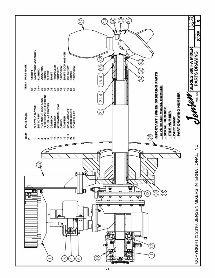
21
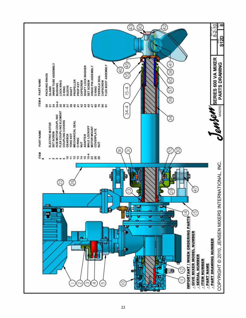
22
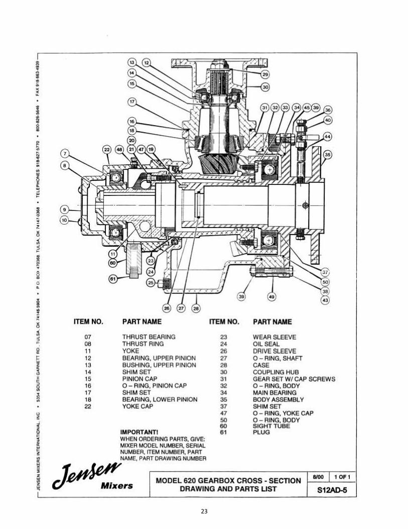
23

24

25
JEN
SEN
AM
S SE
AL
ITEM
#6
2 IN
STA
LLED
SER
IAL
NU
MB
ERS
WIL
L EN
D W
ITH
LET
TER
D

26

27
JENSEN AMS SEAL ITEM #62
INSTALLED
GEARBOX SERIAL NUMBERS
WILL END WITH LETTER D

28
Jensen Mechanical Actuator
Installation of The Drive unit
1. Remove the mixer bearing cap and take the nameplate off. Remove and discard the
nameplate and screws. Note that on unit with vertical pinch bolt on the bearing cap, the
vertical bolts must be loosened
first.
2. Fasten the drive hub to the
thrust bearing assembly with
the cap screws provided.
3. Bolt the mixer bearing cap back
on the gearbox.
4. Bolt the mechanical actuator
drive unit to the bearing cap
with the hex head screws and lock washers provided. Be sure that the two locating pins fit
the two holes in the bearing cap, and the square on the drive assembly properly engages
the square socket in the drive hub.
5. On mixers with vertical clamp bolts on the bearing cap, tighten these bolts securely.
The Actuator Unit
1. Bolt the actuator unit and mounting bracket assembly UNDER the “L” shaped plate on the
right side of the mixer flange with two ½ -13 NC by 2 inch long bolts and lock washers
provided. Caution: the flexible drive shaft connecting the drive unit to the actuator unit
must be free of all kinks and must not touch the ground.
2. Bolt the mixer mount bracket onto the “eye” that is already welded on the mixer mount.
Tighten the square head set screw.
3. Loosen the top bolt holding the actuator lever to the actuator unit. Raise lever to rotate.
4. Install the linkage rod assembly. Make sure the linkage rod assembly model number
agrees with the mixer model number on the serial plate. Serious damage to the actuator
would result if the numbers do not agree. Tighten the top bolt holding the actuator lever
to the actuator unit. Tighten linkage rod nuts and install cotter pins.

29
Synchronization – Two or more mixers If there are two mixers per tank, the mixers and actuators must be synchronized to operate together.
To synchronize mixers on the tank, loosen the bolt on top of the actuator lever so that the
serrations under lever skirt can be disengaged. Raise lever 1/8 inch and move the mixers until the
arrows marked on the lever skirts are pointing to the same number on all actuator units. When this
is accomplished, tighten all the bolts until the lever serrations are tight. All the mixers on the tank
should now be aligned properly. (See Figure below)
Under normal operation, an individual will not be able to see the actuator and mixer move. After
mixers are started, check in about an hour or more to see if the arrow marker has moved at least
1/2 mark on the actuator unit. The mixers should remain synchronized as long as all units start at
the same time and run the same amount of time. Over time, it may be necessary to re-align the
mixers; inspect mixer orientation quarterly.
30
LONG TERM STORAGE
Jensen recommends long term (more than 90 days) storage procedures to protect mixers
from atmospheric corrosion, physical damage and other harmful effects. Proper storage is
especially important in corrosive or high humidity environments. Store and maintain related
equipment (motors, control panels and similar devices) supplied by Jensen according to
manufacturers' instructions. Failure to store and protect Jensen mixers properly may void
any warranty, expressed or implied.
Pre-storage Inspection
When mixers are delivered, check impellers, impeller shafts and gearbox for shipping
damage. Report damage to carrier and Jensen Mixers. Protect, any carbon steel
components from corrosion, and check protective shipping coatings. Renew if necessary.
Use heavy grease with corrosion inhibitor or thick spray such as Holt Lloyd Corp. LPS-3.
New gear drives do not require additional internal protective procedures if storage is less
than 90 days.
Storage Preparation and Maintenance
Jensen recommends the customer store mixers mounted on factory-provided skids in
original crating.
1. Store each drive unit in its operating position, then fill gearbox to proper level with recommended lubricant. Rotate coupling until drive output shaft makes two complete evolutions.
2. Connect motor heaters, if supplied to a proper power source.
3. On side-entering mixer drives without motors installed, cover coupling half with heavy plastic sheet or bag and secure with cord or adhesive tape. Cover motors and mixers with plastic or tarpaulins; secure.
4. Check at 30-day intervals. Rotate motor shafts and rotate couplings for three or more complete rotations of output shafts.
5. Store and maintain mixers according to location-specific instructions.
Storage Locations
Each type of storage location requires different procedures.
• Location 1 (preferred): a dry, enclosed, temperature and humidity controlled environment. Relative humidity of 40% or lower is ideal.
• Location 2 (acceptable): a dry, enclosed area such as a warehouse.
Marginally acceptable is an open shed with concrete floor.
• Location 3 (not recommended): outdoors under waterproof covering or mounted in operating location.

31
Location-Specific Storage Instructions
Location l. Perform preparation and maintenance through step 4 above.
Location 2. Cover motor completely but do not seal off to prevent accumulation of moisture.
Cover gear drive securely. Extreme conditions may require use of portable
dehumidifiers or placement of renewable desiccant bags under coverings.
Location 3. Cover motor completely but do not seal off to prevent accumulation of moisture.
Cover gear drive securely. Secure all coverings against wind and rain. Extreme
conditions may require placement of renewable desiccant bags under
coverings.
Preparation for Service after long term storage:
1. Remove all protective materials and coverings. Wipe off dirt and oil.
2. Check greased bearings; re-grease if necessary.
3. Pour 32oz. tank compatible lubrication fluid into air vent to pre-lubricate seal. Hand
rotate mixer through three full prop revolutions.
4. If applicable: Drain 10 percent of storage lubricant volume to remove condensed
moisture. Adjust lubricant level with proper lubricant. Putting mixers in service with
contaminant-free storage lubricant is permissible.
5. Review mixer manual thoroughly and follow installation, start up and operating
procedures.

32
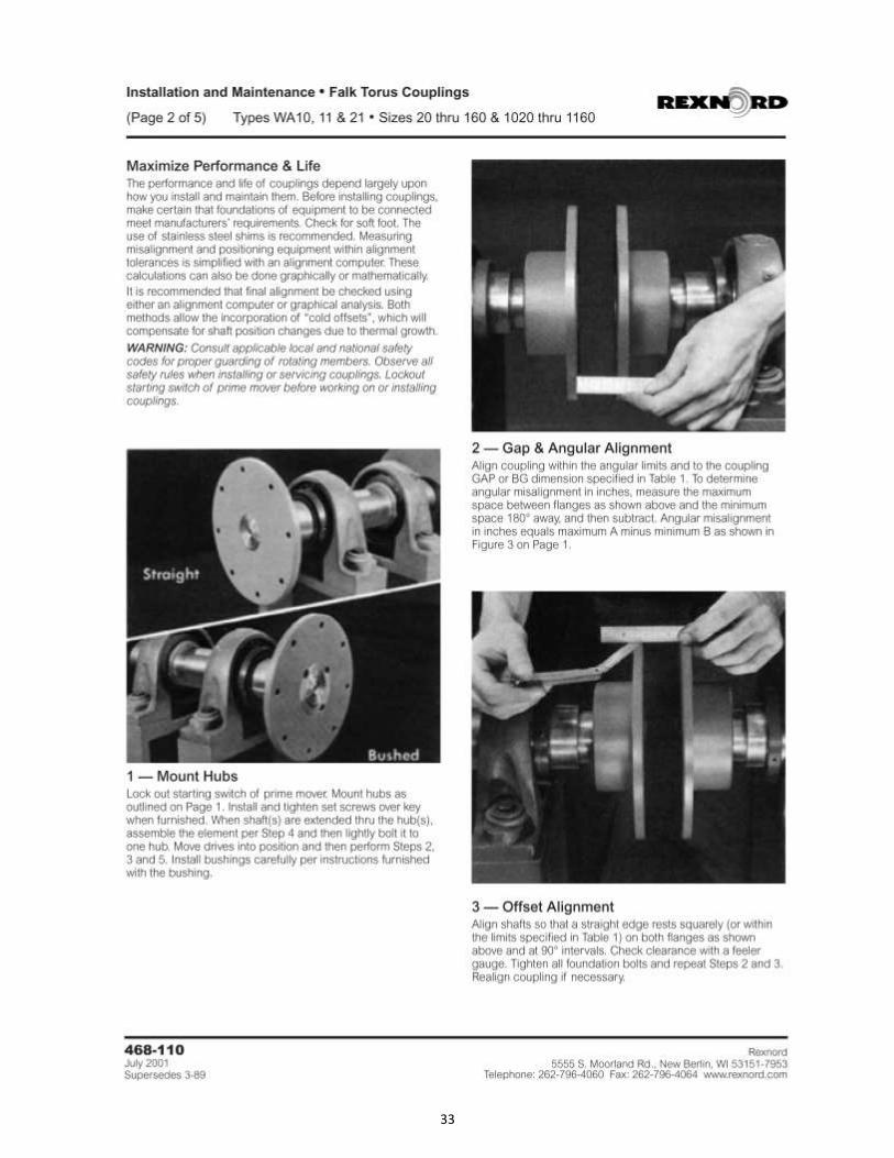
33
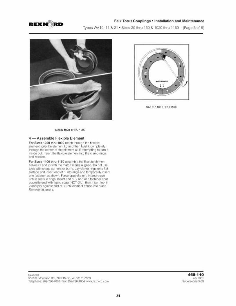
34

35

36