60427101-re en 301 489-1-17 certificate/ce/9500_e-s-r1-1.pdf12f, 333 dunhua s. rd., sec. 2 taipei,...
TRANSCRIPT
Compliance Certification Services Inc. Report No: 60427101-RE Date of Issue:June 8, 2006
Note: This report shall not be reproduced except in full, without the written approval of Compliance Certification Services Inc. This document may be altered or revised by Compliance Certification
Services Inc. personnel only, and shall be noted in the revision section of the document.
Page 1 Total Page: 42
Rev. 00
ETSI EN 301 489-17 V1.2.1: 2002
TEST REPORT
For
Terminal
Model Number: 9500
Trade Name: CipherLAB
Issued to
Cipherlab Co., Ltd. 12F, 333 Dunhua S. Rd., Sec. 2 Taipei,
Taiwan 106, Taiwan R.O.C.
Issued by
Compliance Certification Services Inc. No. 81-1, Lane 210, Bade Rd. 2, Luchu Hsiang,
Taoyuan Hsien, (338) Taiwan, R.O.C. http://www.ccsemc.com.tw

Compliance Certification Services Inc. Report No: 60427101-RE Date of Issue: June 8, 2006
Page 2 Rev. 00
TABLE OF CONTENTS 1. TEST RESULT CERTIFICATION ............................................................................................. 3
2. EUT DESCRIPTION..................................................................................................................... 4
3. TEST METHODOLOGY.............................................................................................................. 5 3.1 UNIT OF MEASUREMENT............................................................................................... 5 3.2 ANTENNA..................................................................................................................... 5 3.3 DECISION OF FINAL TEST MODE .................................................................................... 5
4. INSTRUMENT AND CALIBRATION........................................................................................ 6 4.1 MEASURING INSTRUMENT CALIBRATION...................................................... 6 4.2 MEASUREMENT EQUIPMENT USED .................................................................. 6
5. FACILITIES AND ACCREDITATIONS.................................................................................... 9 5.1 FACILITIES ................................................................................................................... 9 5.2 EQUIPMENT.................................................................................................................. 9 5.3 TABLE OF ACCREDITATIONS AND LISTINGS ............................................................... 10
6. SETUP OF EQUIPMENT UNDER TEST................................................................................. 11 6.1 SETUP CONFIGURATION OF EUT.................................................................................. 11 6.2 SUPPORT EQUIPMENT......................................................................................... 11 6.3 TEST SETUP ................................................................................................................ 12
7. ETSI EN 301 489-1/-17 REQUIREMENTS............................................................................... 13 7.1 RADIATED EMISSION .................................................................................................. 13 7.2 AC MAINS LINE CONDUCTED EMISSION....................................................................... 15 7.3 AC MAINS HARMONIC CURRENT EMISSION ................................................................. 18 7.4 AC MAINS VOLTAGE FLUCTUATION AND FLICKER ...................................................... 20 7.5 ELECTROSTATIC DISCHARGE...................................................................................... 22 7.6 RF ELECTROMAGNETIC FIELD..................................................................................... 26 7.7 AC MAINS FAST TRANSIENTS – COMMON MODE.......................................................... 29 7.8 AC MAINS SURGE........................................................................................................ 31 7.9 AC MAINS RF – COMMON MODE.................................................................................. 33 7.10 VOLTAGE DIPS AND INTERRUPTION ............................................................................ 35
APPENDIX I PHOTOGRAPHS OF TEST SETUP ....................................................................... 37

Compliance Certification Services Inc. Report No: 60427101-RE Date of Issue: June 8, 2006
Page 3 Rev. 00
1. TEST RESULT CERTIFICATION
Applicant: Cipherlab Co., Ltd. 12F, 333 Dunhua S. Rd., Sec. 2 Taipei, Taiwan 106, Taiwan R.O.C.
Equipment Under Test: Terminal
Trade Name: CipherLAB
Model Number: 9500
Date of Test: May 24 ~ June 6, 2006
APPLICABLE STANDARDS STANDARD TEST RESULT
ETSI EN 301 489-17 V1.2.1: 2002 No non-compliance noted Applicable Standard Class/Limit/Criterion Test Result
ETSI EN 301 489-1 V1.4.1: 2002 EN 55022: 1998 + A1: 2000 + A2: 2003 Class B No non-compliance noted EN 61000-3-2: 2000 Class D No non-compliance noted EN 61000-3-3: 1995 + A1: 2001 Limit No non-compliance noted EN 61000-4-2: 1995 + A1: 1998 + A2: 2001 Criterion B No non-compliance noted EN 61000-4-3: 2002 + A1: 2002 Criterion A No non-compliance noted EN 61000-4-4: 1995 + A1: 2001 + A2: 2001 Criterion B No non-compliance noted EN 61000-4-5: 1995 + A1: 2001 Criterion B No non-compliance noted EN 61000-4-6: 1996 + A1: 2001 Criterion A No non-compliance noted EN 61000-4-11: 1994 + A1: 2001 Criterion B/C/C No non-compliance noted
Deviation from Applicable Standard None
The above equipment was tested by Compliance Certification Services Inc. for compliance with the requirements set forth in ETSI EN 301 489-17 V1.2.1: 2002. The results of testing in this report apply only to the product/system, which was tested. Other similar equipment will not necessarily produce the same results due to production tolerance and measurement uncertainties.
Approved by: Reviewed by:
Gavin Lim Amanda Wu Section Manager Section Manager Compliance Certification Services Inc. Compliance Certification Services Inc.

Compliance Certification Services Inc. Report No: 60427101-RE Date of Issue: June 8, 2006
Page 4 Rev. 00
2. EUT DESCRIPTION
Product Terminal
Trade Name CipherLAB
Model Number 9500
Model Discrepancy N/A
Module Trade Name N/A
Module Model Number N/A
Power Supply LEADER ELECTRONICS INC. / NU40-2060330-I3 I/P: 100-240V, 1.2A, 50-60Hz O/P: 6.0V, 3.3A
Frequency Range WLAN (IEEE 802.11b): 2412 ~ 2472 MHz Bluetooth: 2402 ~ 2480 MHz
Transmit Power (mean EIRP)
WLAN (IEEE 802.11b): 19.56 dBm (90.36 mW) Bluetooth: 7.67 dBm (5.85mW)
Modulation Technique WLAN (IEEE 802.11b): DSSS (CCK, DQPSK, DBPSK) Bluetooth: FHSS (GFSK)
Number of Channels WLAN (IEEE 802.11b): 13 Channels Bluetooth: 79 Channels
Channels Spacing WLAN (IEEE 802.11b): 5MHz Bluetooth: 1MHz
Antenna Specification Multilayer Chip Antenna / Gain: 3.0 dBi
Temperature Range 0°C ~ +55°C
Remark: for more details, please refer to the User’s manual of the EUT.

Compliance Certification Services Inc. Report No: 60427101-RE Date of Issue: June 8, 2006
Page 5 Rev. 00
3. TEST METHODOLOGY All tests were performed in accordance with the procedure documented in ETSI EN 301 489-1 V1.4.1 (2002-04) as referenced in ETSI EN 301 489-17 V1.2.1 (2002-04).
3.1 UNIT OF MEASUREMENT Measurements of radiated interference are reported in terms of dB(uV/m) at a specified distance. The indicated readings on the Spectrum analyzers were converted to dB (uV/m) by use of appropriate conversion factors. Measurements of conducted interference are reported in terms of dB(uV).
3.2 ANTENNA The calibrated antennas used to sample the radiated field strength are mounted on a non-conductive, motorized antenna mast 10 meters from the leading edge of the turntable.
3.3 DECISION OF FINAL TEST MODE The EUT (model: 9500) had been tested under operating condition.
1. The following test mode was scanned during the preliminary test:
Mode 1 Transceiving --- WLAN (Operated at Channel 13 with 11Mbps data rate under IEEE 802.11b mode) +
BT (Operated at normal link function)
2. After the preliminary scan, the following test mode was found to produce the highest emission level.
Mode 1
Then, the EUT configuration and cable configuration of the above highest emission mode was chosen for all final test items.

Compliance Certification Services Inc. Report No: 60427101-RE Date of Issue: June 8, 2006
Page 6 Rev. 00
4. INSTRUMENT AND CALIBRATION 4.1 MEASURING INSTRUMENT CALIBRATION The measuring equipment, which was utilized in performing the tests documented herein, has been calibrated in accordance with the manufacturer’s recommendations for utilizing calibration equipment, which is traceable to recognized national standards.
4.2 MEASUREMENT EQUIPMENT USED Equipment Used for Emission Measurement
Remark: Each piece of equipment is scheduled for calibration once a year.
Open Area Test Site # 3 Name of Equipment Manufacturer Model Serial Number Calibration Due
EMI Test Receiver R&S ESVS20 838804/004 01/18/2007
Spectrum Analyzer R&S FSP30 100112 09/12/2006
Spectrum Analyzer Agilent E4446A MY43360131 01/18/2007
Pre-Amplifier MITEC AFS42-00102650 924206 N.C.R.
Pre-Amplifier MITEC AMF-6F-260400 945377 N.C.R.
Bilog Antenna SCHWAZBECK VULB9163 145 07/05/2006
Horn Antenna EMCO 3115 00022250 04/16/2007
Horn-Antenna TRC HA-1201A 02 07/04/2006
Horn-Antenna TRC HA-1301A 02 07/04/2006
Turn Table EMCO 2081-1.21 9709-1885 N.C.R.
Antenna Tower EMCO 2075-2 9707-2060 N.C.R.
Controller EMCO 2090 9709-1256 N.C.R.
RF Switch ANRITSU MP59B M53867 N.C.R.
Site NSA CCS N/A N/A 09/06/2006
DECOUPLING NETWORK FCC F-201-DCN-1-18MM 34 03/19/2007
Test S/W LABVIEW (V 6.1) Remark: The measurement uncertainty is less than +/- 2.16dB, which is evaluated as per the NAMAS NIS 81 and
CISPR/A/291/CDV.
Powerline Conducted Emission Test Site Name of Equipment Manufacturer Model Serial Number Calibration DueEMI TEST RECEIVER
9kHz-30MHz ROHDE & SCHWARZ ESHS30 828144/003 09/28/2006
TWO-LINE V-NETWORK 9kHz-30MHz SCHAFFNER NNB41 03/10013 06/13/2006
LISN 10kHz-100MHz EMCO 3825/2 9106-1809 03/21/2007
Test S/W LABVIEW (V 6.1) Remark: The measurement uncertainty is less than +/- 2.81dB, which is evaluated as per the NAMAS NIS 81 and
CISPR/A/291/CDV.

Compliance Certification Services Inc. Report No: 60427101-RE Date of Issue: June 8, 2006
Page 7 Rev. 00
Power Harmonic & Voltage Fluctuation/Flicker Measurement (EN 61000-3-2&-3-3) Name of Equipment Manufacturer Model Serial Number Calibration Due
Harmonic & Flicker Tester EMC-PARTNER HAR1000-1P 107 05/04/2007
Test S/W HARCS (Ver. 4.0)
Equipment Used for Immunity Measurement ESD Test Site (IEC/EN 61000-4-2)
Name of Equipment Manufacturer Model Serial Number Calibration DueESD Simulator NoiseKen ESS-2001 ESS0210582 10/11/2006
Radiated Electromagnetic Field Immunity Test Site (IEC/EN 61000-4-3)
Name of Equipment Manufacturer Model Serial Number Calibration DueSignal Generator Agilent 8648C 4108A05772 10/12/2006
150 Watts 80-1000MHz Amplifier Amplifier Research 150W1000M3 306730 N.C.R.
30 Watts 0.8-3.0GHz Amplifier Amplifier Research 30S1G3M1 306722 N.C.R.
Power Meter Boonton 4232A-01-02 98501 09/08/2006
Power Sensor Boonton 51011-EMC 32920 10/17/2006
Power Sensor Boonton 51011-EMC 32863 10/17/2006
Log-Periodic Antenna Amplifier Research AT1080 306709 N.C.R.
Microwave Horn Antenna Amplifier Research AT4002A 306750 N.C.R.
RF Test System Controller Amplifier Research SC1000M3 306666 N.C.R.
Field Probe Amplifier Research FP6001 305657 05/26/2007
0.8-4.2GHz Amplifier Research DC7144A N/A N.C.R.
80-1000MHz Amplifier Research DC6180A N/A N.C.R.
Antenna Tower Amplifier Research TP2000 N/A N.C.R.
Probe Stand Amplifier Research PS2000 N/A N.C.R.
Test S/W SW1005 (Release 1.4)
Fast Transients/Burst Test Site (IEC/EN 61000-4-4)
Name of Equipment Manufacturer Model Serial Number Calibration DueECAT Control Center KeyTek E-Class Series 100 9502325 02/14/2007
Capacitor Clamp KeyTek CCL-4 9503290 N.C.R.
Test S/W E400 Burstware (V4.19 (c)) Remark: The clamp is used only for EUT with signal cable connected and greater than 3m in length.

Compliance Certification Services Inc. Report No: 60427101-RE Date of Issue: June 8, 2006
Page 8 Rev. 00
Surge Immunity Test Site (IEC/EN EN 61000-4-5) Name of Equipment Manufacturer Model Serial Number Calibration DueECAT Control Center KeyTek E-Class Series 100 9502325 02/14/2007
External Coupler / Decoupler For Telecom Lines KeyTek CM-TELCD 0104399 N.C.R.
I/O Signal Line Coupler / Decoupler KeyTek CM-I / OCD 0103234 N.C.R.
Test S/W E500 Surgeware (V4.19cc)
CS Test Site (IEC/EN 61000-4-6)
Name of Equipment Manufacturer Model Serial Number Calibration DueSignal Generator Agilent 8648C 4108A05773 09/09/2006
75 Watts 10kHz-250MHz Amplifier Amplifier Research 75A250AM1 306334 N.C.R.
Power Meter Boonton 4232A-01-02 98501 09/08/2006
Power Sensor Boonton 51011-EMC 32862 09/08/2006
Power Sensor Boonton 51011-EMC 32864 09/08/2006 Power Line Coupling Decoupling Network
Fischer Custom Communications, Inc. FCC-801-M1-32A 03018 09/09/2006
Power Line Coupling Decoupling Network
Fischer Custom Communications, Inc. FCC-801-M2-16A 03026 09/09/2006
Power Line Coupling Decoupling Network
Fischer Custom Communications, Inc. FCC-801-M3-16A 03027 09/09/2006
Signal Line Coupling Decoupling Network
Fischer Custom Communications, Inc. FCC-801-T2 03016 09/08/2006
Signal Line Coupling Decoupling Network
Fischer Custom Communications, Inc. FCC-801-T4 03017 09/09/2006
EM Injection Clamp Fischer Custom Communications, Inc. F-203I-23mm 421 09/09/2006
Passive Impedance Adapters Fischer Custom Communications, Inc. FCC-801-150-50-CDN 03053&03054 09/08/2006
Calibration Fixture Fischer Custom Communications, Inc. F-203I-CF-23mm 408 09/09/2006
Signal Line Coupling Decoupling Network
Fischer Custom Communications, Inc. FCC-801-T8-RJ45 04024 09/09/2006
Attenuator Amplifier Research HFP-575-3/6-NM NF201875106 N.C.R.
Coupler Amplifier Research DC2600A 306621 N.C.R.
Test S/W SW1005 (Release 1.4)
Voltage Dips/Short Interruption and Voltage Variation Immunity Test Site (IEC/EN 61000-4-11)
Name of Equipment Manufacturer Model Serial Number Calibration DueDips/Interruption and Variations Simulator
HAEFELY TRENCH PLINE 1610 080 344-05 04/11/2007
Test S/W WinPATS (V. 3.26)

Compliance Certification Services Inc. Report No: 60427101-RE Date of Issue: June 8, 2006
Page 9 Rev. 00
5. FACILITIES AND ACCREDITATIONS
5.1 FACILITIES All measurement facilities used to collect the measurement data are located at
No.199, Chunghsen Road, Hsintien City, Taipei Hsien, Taiwan, R.O.C.
Tel: 886-2-2217-0894 / Fax: 886-2-2217-1029
No.11, Wugong 6th Rd., Wugu Industrial Park, Taipei Hsien 248, Taiwan
Tel: 886-2-2299-9720 / Fax: 886-2-2298-4045
No.81-1, Lane 210, Bade 2nd Rd., Luchu Hsiang, Taoyuan Hsien 338, Taiwan
Tel: 886-3-324-0332 / Fax: 886-3-324-5235 The sites are constructed in conformance with the requirements of ANSI C63.7, ANSI C63.4 and CISPR Publication 22.
5.2 EQUIPMENT Radiated emissions are measured with one or more of the following types of linearly polarized antennas: tuned dipole, biconical, log periodic, bi-log, and/or ridged waveguide, horn. Spectrum analyzers with preselectors and quasi-peak detectors are used to perform radiated measurements.
Conducted emissions are measured with Line Impedance Stabilization Networks and EMI Test Receivers.
Calibrated wideband preamplifiers, coaxial cables, and coaxial attenuators are also used for making measurements.
All receiving equipment conforms to CISPR Publication 16-1, “Radio Interference Measuring Apparatus and Measurement Methods.”

Compliance Certification Services Inc. Report No: 60427101-RE Date of Issue: June 8, 2006
Page 10 Rev. 00
5.3 TABLE OF ACCREDITATIONS AND LISTINGS Country Agency Scope of Accreditation Logo
USA A2LA
EN 55011, EN 55014-1/2, CISPR 11, CISPR 14-1/2, EN 55022, EN 55015, CISPR 22, CISPR 15, AS/NZS 3548, VCCI V3 (2001), CFR 47, FCC Part 15/18, CNS 13783-1, CNS 13439, CNS 13438, CNS 13803, CNS 14115, EN 55024, IEC 801-2, IEC 801-3, IEC 801-4, IEC/EN 61000-3-2, EIC/EN 61000-3-3, IEC/EN 61000-4-2/3/4/5/6/8/11, EN 50081-1/ EN 61000-6-3, EN 50081-2/EN 61000-6-4, EN 50081-2/EN 61000-6-1: 2001
0824-01
USA FCC 3/10 meter Open Area Test Sites (93105, 90471) / 3M Semi Anechoic Chamber (965860) to perform FCC Part 15/18 measurements
93105, 90471 965860
Japan VCCI 3/10 meter Open Area Test Sites to perform conducted/radiated measurements
R-393/1066/725/879 C-402/747/912
Norway NEMKO
EN 50081-1/2, EN 50082-1/2, IEC 61000-6-1/2, EN 50091-2, EN 50130-4, EN 55011, EN 55013, EN 55014-1/2, EN 55015, EN 55022, EN 55024, EN 61000-3-2/3, EN 61326-1, IEC 61000-4-2/3/4/5/6/8/11, EN 60601-1-2, EN 300 328, EN 300 422-2, EN 301 419-1, EN 301 489-01/03/07/08/09/17, EN 301 419-2/3, EN 300 454-2, EN 301 357-2
ELA 124a ELA 124b ELA 124c
Taiwan TAF
EN 300 328, EN 300 220-1, EN 300 220-2, EN 300 220-3, 47 CFR FCC Part 15 Subpart C, EN 61000-3-2, EN 61000-3-3, CNS 13439, CNS 13783-1, CNS 14115, CNS 13438, AS/NZS CISPR 22, CNS 13022-1, IEC 61000-4-2/3/4/5/6/8/11, CNS 13022-2/3
Taiwan BSMI CNS 13438, CNS 13783-1, CNS 13439, CNS 14115
SL2-IS-E-0014 SL2-IN-E-0014 SL2-A1-E-0014 SL2-R1-E-0014 SL2-R2-E-0014 SL2-L1-E-0014
Canada Industry Canada
3/10 meter Open Area Test Sites (IC 3991-3, IC 3991-4) / 3M Semi Anechoic Chamber (IC 6106) to perform RSS 212 Issue 1
IC 3991-3 IC 3991-4 IC 6106
* No part of this report may be used to claim or imply product endorsement by A2LA or any agency of the US Government.

Compliance Certification Services Inc. Report No: 60427101-RE Date of Issue: June 8, 2006
Page 11 Rev. 00
6. SETUP OF EQUIPMENT UNDER TEST 6.1 SETUP CONFIGURATION OF EUT See test photographs attached in Appendix 1 for the actual connections between EUT and support equipment.
6.2 SUPPORT EQUIPMENT
No. Device Type Brand Model Series No. FCC ID Data Cable Power Cord
1. Notebook PC IBM 2672(X31) 99PBTKB
WLAN: ANO20030400LEG
Bluetooth: ANO20020100MTN
N/A
AC I/P: Unshielded, 1.8m DC O/P: Unshielded, 1.8m with a core
Remark:
1. All the above equipment/cables were placed in worse case positions to maximize emission signals during emission test.
2. Grounding was established in accordance with the manufacturer’s requirements and conditions for the intended use.

Compliance Certification Services Inc. Report No: 60427101-RE Date of Issue: June 8, 2006
Page 12 Rev. 00
6.3 TEST SETUP The equipment under test was configured and operated in a manner to communicate with Terminal continuously. EUT tends to maximize its emission characteristics in a typical application for conducted and radiated emission measurement. The RF module plus ancillary (stand alone unit) was evaluated as per table 2 of clause 7.1 of ETSI EN 301 489-1 V1.4.1: 2002-08. The transmitter was active during the conducted and radiated emission measurements.
Software Used During the Test
Operating System Windows XP
Program Sequence 1. Boot up Windows XP. 2. Run ping.exe and link the EUT. 3. Run Bluesoleil and link the EUT.
RF Management Software S/W provided by applicant.
Remark: During the test, no modification is made to the EUT to comply with Class B limit levels.

Compliance Certification Services Inc. Report No: 60427101-RE Date of Issue: June 8, 2006
Page 13 Rev. 00
7. ETSI EN 301 489-1/-17 REQUIREMENTS
7.1 RADIATED EMISSION
LIMIT Please refer to ETSI EN 301 489-1 Clause 8.2.3, Table 4 and EN 55022 Clause 6, Table 6, Class B
TEST CONFIGURATION
Filter Filter Filter To Power
EUT
Ground Plane10 m
0.8 m
CoaxialCable
Turntable 1m ~ 4m
Power Cable
EMI Receiver
Filter
TEST PROCEDURE Please refer to ETSI EN 301 489-1 Clause 8.2.3 and EN 55022 Clause 6 for the measurement methods.

Compliance Certification Services Inc. Report No: 60427101-RE Date of Issue: June 8, 2006
Page 14 Rev. 00
TEST RESULTS No non-compliance noted
Test Data
Operation Mode: Mode 1 Test Date: June 6, 2006
Temperature: 26°C Tested by: Ryan Chen
Humidity: 55% RH Polarity: Ver. / Hor. Frequency
(MHz) Ant. Pol.
(H/V) Reading (dBuV)
Correction Factor(dB/m)
Result (dBuV/m)
Limit (dBuV/m)
Margin (dB)
DetectorMode
135.67 V 17.56 9.66 27.22 30.00 -2.78 QP
162.73 V 18.24 10.19 28.43 30.00 -1.57 QP
203.75 V 14.36 12.44 26.80 30.00 -3.20 QP
298.55 V 16.98 15.52 32.50 37.00 -4.50 Peak
455.25 V 8.38 18.98 27.36 37.00 -9.64 Peak
468.31 V 9.49 19.31 28.80 37.00 -8.20 Peak
54.24 H 10.35 13.26 23.61 30.00 -6.39 QP
135.61 H 18.36 9.67 28.03 30.00 -1.97 QP
162.74 H 17.60 10.19 27.79 30.00 -2.21 QP
196.65 H 8.50 12.10 20.60 30.00 -9.40 Peak
298.59 H 16.89 15.52 32.41 37.00 -4.59 Peak
454.75 H 6.37 18.97 25.34 37.00 -11.66 Peak
Remark: 1. Measuring frequencies from 30MHz to 1GHz.
2. Radiated emissions measured in frequency range from 30MHz to 1000MHz were made with an instrument using Peak /Quasi-peak detector mode.
3. Measurements above show only up to 6 maximum emissions noted, or would be lesser, with “ N/A ” remark, if no specific emissions from the EUT are recorded (ie: margin>20dB from the applicable limit) and considered that's already beyond the background noise floor.
4. The IF bandwidth of SPA between 30MHz and 1GHz was 100 kHz.
Compliance Certification Services Inc. Report No: 60427101-RE Date of Issue: June 8, 2006
Page 15 Rev. 00
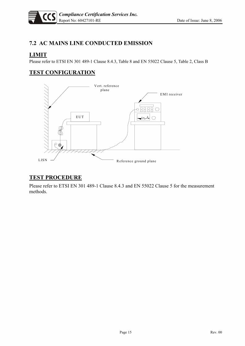
7.2 AC MAINS LINE CONDUCTED EMISSION
LIMIT Please refer to ETSI EN 301 489-1 Clause 8.4.3, Table 8 and EN 55022 Clause 5, Table 2, Class B
TEST CONFIGURATION
E U T
LISN
EM I receiver
R eference ground plane
V ert. reference plane
TEST PROCEDURE Please refer to ETSI EN 301 489-1 Clause 8.4.3 and EN 55022 Clause 5 for the measurement methods.

Compliance Certification Services Inc. Report No: 60427101-RE Date of Issue: June 8, 2006
Page 16 Rev. 00
TEST RESULTS No non-compliance noted
Test Data
Operation Mode: Mode 1 Test Date: May 24, 2006
Temperature: 25°C Tested by: Nan Tsai
Humidity: 55% RH
Freq. (MHz)
QP Reading (dBuV)
AV Reading (dBuV)
Corr. factor (dB)
QP Result (dBuV)
AV Result (dBuV)
QP Limit
(dBuV)
AV Limit
(dBuV)
QP Margin
(dB)
AV Margin
(dB) Note
0.154 37.560 24.100 0.192 37.752 24.292 65.781 55.781 -28.029 -31.489 L1
0.256 29.210 21.880 0.100 29.310 21.980 61.560 51.560 -32.250 -29.580 L1
0.480 33.750 32.210 0.100 33.850 32.310 56.339 46.339 -22.489 -14.029 L1
0.960 23.710 21.900 0.100 23.810 22.000 56.000 46.000 -32.190 -24.000 L1
2.182 22.910 20.800 0.100 23.010 20.900 56.000 46.000 -32.990 -25.100 L1
3.976 22.150 21.080 0.100 22.250 21.180 56.000 46.000 -33.750 -24.820 L1
0.154 33.730 18.600 0.192 33.922 18.792 65.781 55.781 -31.859 -36.989 L2
0.479 32.280 31.840 0.100 32.380 31.940 56.348 46.348 -23.968 -14.408 L2
0.960 22.690 21.530 0.100 22.790 21.630 56.000 46.000 -33.210 -24.370 L2
2.182 22.890 20.440 0.100 22.990 20.540 56.000 46.000 -33.010 -25.460 L2
4.614 23.700 21.890 0.161 23.861 22.051 56.000 46.000 -32.139 -23.949 L2
6.605 26.200 25.080 0.361 26.561 25.441 60.000 50.000 -33.439 -24.559 L2
Remark: 1. Measuring frequencies from 0.15MHz to 30MHz.
2. The emissions measured in the frequency range between 0.15MHz and 30MHz were made with an instrument using Quasi-peak detector and Average detector.
3. The IF bandwidth of SPA between 0.15MHz and 30MHz was 10 kHz; the IF bandwidth of Test Receiver between 0.15MHz and 30MHz was 9 kHz.
4. L1 = Line One (Live Line) / L2 = Line Two (Neutral Line)

Compliance Certification Services Inc. Report No: 60427101-RE Date of Issue: June 8, 2006
Page 17 Rev. 00
Test Plot
Conducted emissions (Line 1)
Conducted emissions (Line 2)
Compliance Certification Services Inc. Report No: 60427101-RE Date of Issue: June 8, 2006
Page 18 Rev. 00
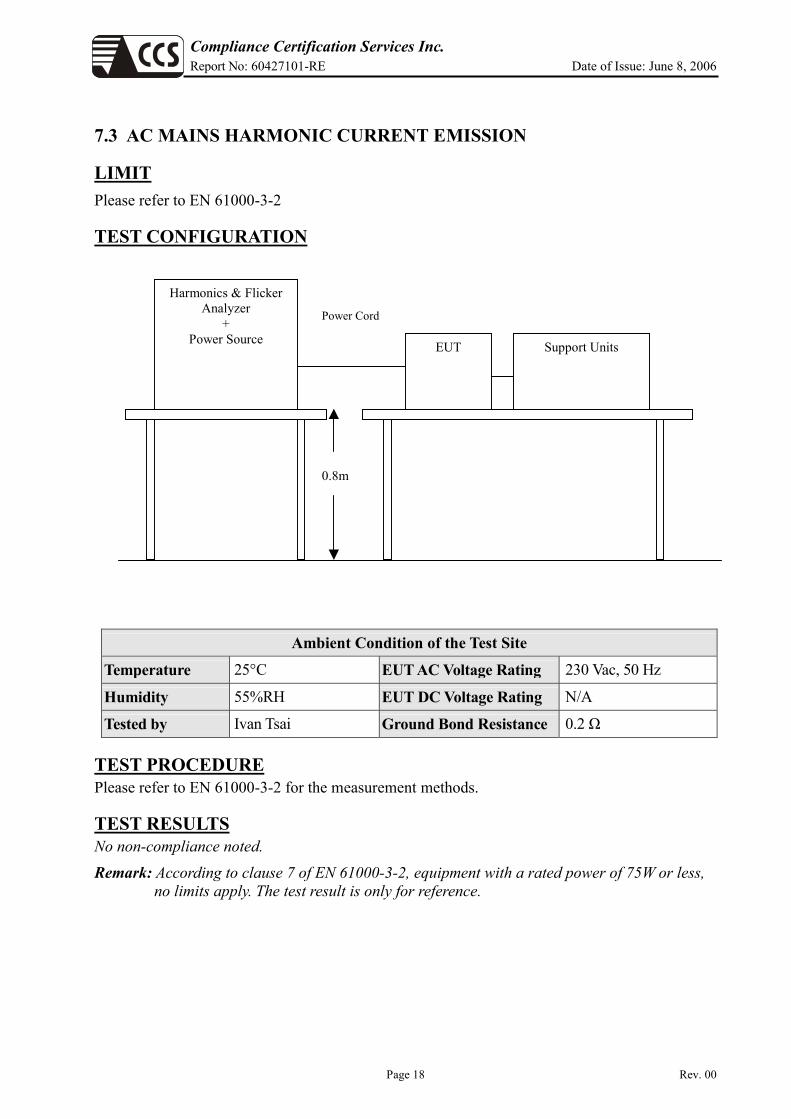
7.3 AC MAINS HARMONIC CURRENT EMISSION
LIMIT Please refer to EN 61000-3-2
TEST CONFIGURATION
Ambient Condition of the Test Site
Temperature 25°C EUT AC Voltage Rating 230 Vac, 50 Hz
Humidity 55%RH EUT DC Voltage Rating N/A
Tested by Ivan Tsai Ground Bond Resistance 0.2 Ω
TEST PROCEDURE Please refer to EN 61000-3-2 for the measurement methods.
TEST RESULTS No non-compliance noted.
Remark: According to clause 7 of EN 61000-3-2, equipment with a rated power of 75W or less, no limits apply. The test result is only for reference.
Harmonics & Flicker Analyzer
+ Power Source EUT Support Units
Power Cord
0.8m

Compliance Certification Services Inc. Report No: 60427101-RE Date of Issue: June 8, 2006
Page 19 Rev. 00
Harmonic Emission - IEC 61000-3-2 , EN 61000-3-2 , (EN60555-2)
HARCS Setup File : unnamed HARCS Report File : unnamed 9500
9500
IVAN
Remarks Temp : 25'C Humidity : 55% RH
Full Bar : Actual Values
Empty Bar : Maximum Values
Blue : Current , Green : Voltage , Red : Failed Important:
Pmax is below 75W. This seems not to be a class D equipment.
Compliance Certification Services Inc. Report No: 60427101-RE Date of Issue: June 8, 2006
Page 20 Rev. 00
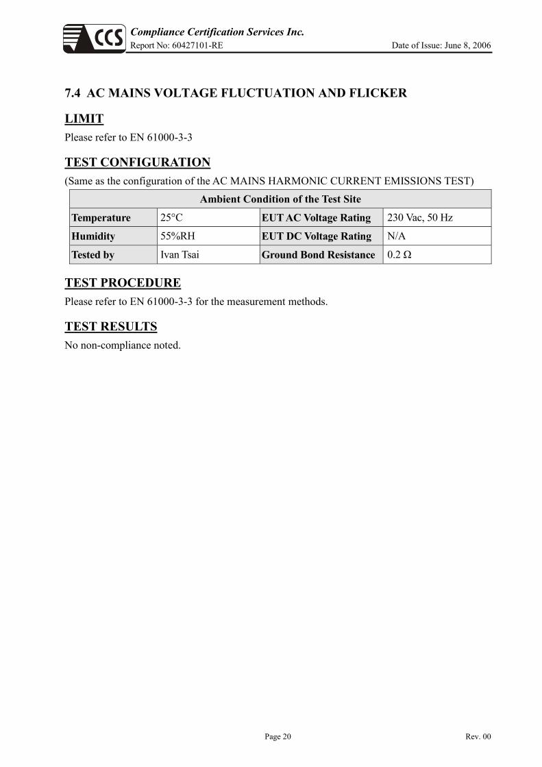
7.4 AC MAINS VOLTAGE FLUCTUATION AND FLICKER
LIMIT Please refer to EN 61000-3-3
TEST CONFIGURATION (Same as the configuration of the AC MAINS HARMONIC CURRENT EMISSIONS TEST)
Ambient Condition of the Test Site Temperature 25°C EUT AC Voltage Rating 230 Vac, 50 Hz
Humidity 55%RH EUT DC Voltage Rating N/A
Tested by Ivan Tsai Ground Bond Resistance 0.2 Ω
TEST PROCEDURE Please refer to EN 61000-3-3 for the measurement methods.
TEST RESULTS No non-compliance noted.
Compliance Certification Services Inc. Report No: 60427101-RE Date of Issue: June 8, 2006
Page 21 Rev. 00
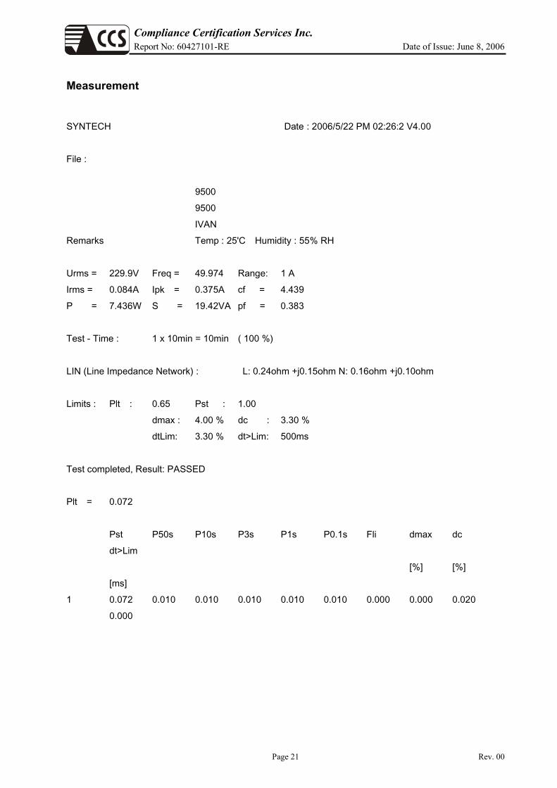
Measurement SYNTECH Date : 2006/5/22 PM 02:26:2 V4.00
File :
9500
9500
IVAN
Remarks Temp : 25'C Humidity : 55% RH
Urms = 229.9V Freq = 49.974 Range: 1 A
Irms = 0.084A Ipk = 0.375A cf = 4.439
P = 7.436W S = 19.42VA pf = 0.383
Test - Time : 1 x 10min = 10min ( 100 %)
LIN (Line Impedance Network) : L: 0.24ohm +j0.15ohm N: 0.16ohm +j0.10ohm
Limits : Plt : 0.65 Pst : 1.00
dmax : 4.00 % dc : 3.30 %
dtLim: 3.30 % dt>Lim: 500ms
Test completed, Result: PASSED
Plt = 0.072
Pst P50s P10s P3s P1s P0.1s Fli dmax dc
dt>Lim
[%] [%]
[ms]
1 0.072 0.010 0.010 0.010 0.010 0.010 0.000 0.000 0.020
0.000

Compliance Certification Services Inc. Report No: 60427101-RE Date of Issue: June 8, 2006
Page 22 Rev. 00
7.5 ELECTROSTATIC DISCHARGE
LIMIT Please refer to EN 61000-4-2
TEST CONFIGURATION
Ambient Condition of the Test Site Temperature 25°C EUT AC Voltage Rating 230 Vac, 50 Hz
Humidity 58%RH EUT DC Voltage Rating N/A
Pressure 1019 mbar Ground Bond Resistance 0.2 Ω
Tested by Ryan Chen
TEST PROCEDURE Please refer to ETSI EN 301 489-1 Clause 9.3.2 and EN 61000-4-2 for the measurement methods.
Ground Reference Plane
Wooden Table
Indirect Support units
EUT & its direct
Support Units
VCP
HCP >1m
0.8m

Compliance Certification Services Inc. Report No: 60427101-RE Date of Issue: June 8, 2006
Page 23 Rev. 00
TEST RESULTS PASS (Criteria A: EUT continued to operate normally during test)
Description of the Electrostatic Discharges (ESD)
Operating Mode
Amount of Discharges Voltage Coupling Test Result (Criterion)
Min. 20 / Point ±4kV Contact Discharge A Min. 20 / Point ±8kV Air Discharge A Min. 20 / Point ±4kV Indirect Discharge HCP A Min. 20 / Point ±4kV Indirect Discharge VCP A
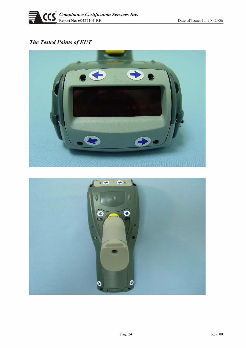
Remark: For tested points to EUT, refer to the enclosed pages. Be aware that the Blue mark is for contact discharge, and the red mark is for air discharge.
PERFORMANCE CRITERION Criteria requested A / B / C Criteria meet A / B / C
Standby Mode
Amount of Discharges Voltage Coupling Test Result (Criterion)
Min. 20 / Point ±4kV Contact Discharge A Min. 20 / Point ±8kV Air Discharge A Min. 20 / Point ±4kV Indirect Discharge HCP A Min. 20 / Point ±4kV Indirect Discharge VCP A
Remark: For tested points to EUT, refer to the enclosed pages. Be aware that the Blue mark is for contact discharge, and the red mark is for air discharge.
PERFORMANCE CRITERION Criteria requested A / B / C Criteria meet A / B / C
Compliance Certification Services Inc. Report No: 60427101-RE Date of Issue: June 8, 2006
Page 24 Rev. 00
The Tested Points of EUT

Compliance Certification Services Inc. Report No: 60427101-RE Date of Issue: June 8, 2006
Page 25 Rev. 00

Compliance Certification Services Inc. Report No: 60427101-RE Date of Issue: June 8, 2006
Page 26 Rev. 00
7.6 RF ELECTROMAGNETIC FIELD
LIMIT Please refer to EN 61000-4-3
TEST CONFIGURATION
Ambient Condition of the Test Site
Temperature 25°C EUT AC Voltage Rating 230 Vac, 50 Hz
Humidity 58%RH EUT DC Voltage Rating N/A
Pressure 1019 mbar Ground Bond Resistance 0.2 Ω
Tested by Ryan Chen
TEST PROCEDURE Please refer to ETSI EN 301 489-1 Clause 9.2.2 and EN 61000-4-3 for the measurement methods.
0.8m
Power Amp Signal Generator
EUT Monitoring by using a camera
Control Room
7x3x3
EUT & Support Units
PC Controller to control S.G. & PA as well as forward power
3 meter
1.5 meter
Compliance Certification Services Inc. Report No: 60427101-RE Date of Issue: June 8, 2006
Page 27 Rev. 00
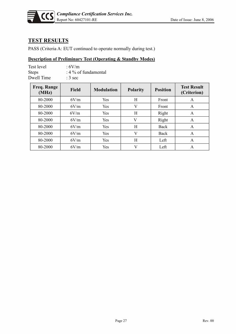
TEST RESULTS PASS (Criteria A: EUT continued to operate normally during test.)
Description of Preliminary Test (Operating & Standby Modes) Test level : 6V/m Steps : 4 % of fundamental Dwell Time : 3 sec
Freq. Range (MHz) Field Modulation Polarity Position Test Result
(Criterion) 80-2000 6V/m Yes H Front A 80-2000 6V/m Yes V Front A 80-2000 6V/m Yes H Right A 80-2000 6V/m Yes V Right A 80-2000 6V/m Yes H Back A 80-2000 6V/m Yes V Back A 80-2000 6V/m Yes H Left A 80-2000 6V/m Yes V Left A

Compliance Certification Services Inc. Report No: 60427101-RE Date of Issue: June 8, 2006
Page 28 Rev. 00
Result of Final Tests (Operating Mode) Test level : 3V/m Steps : 1 % of fundamental Dwell Time : 3 sec
Freq. Range (MHz) Field Modulation Polarity Position Test Result
(Criterion) 80-2000 3V/m Yes H Front A 80-2000 3V/m Yes V Front A
PERFORMANCE CRITERION Criteria requested A / B / C Criteria meet A / B / C
Results of Final Tests (Standby Mode) Test level : 3V/m Steps : 1 % of fundamental Dwell Time : 3 sec
Freq. Range (MHz) Field Modulation Polarity Position Test Result
(Criterion) 80-2000 3V/m Yes H Front A 80-2000 3V/m Yes V Front A
PERFORMANCE CRITERION Criteria requested A / B / C Criteria meet A / B / C

Compliance Certification Services Inc. Report No: 60427101-RE Date of Issue: June 8, 2006
Page 29 Rev. 00
7.7 AC MAINS FAST TRANSIENTS – COMMON MODE
LIMIT Please refer to EN 61000-4-4
TEST CONFIGURATION
Ambient Condition of the Test Site Temperature 25°C EUT AC Voltage Rating 230 Vac, 50 Hz
Humidity 58%RH EUT DC Voltage Rating N/A
Pressure 1019 mbar Ground Bond Resistance 0.2 Ω
Tested by Ryan Chen
TEST PROCEDURE Please refer to ETSI EN 301 489-1 Clause 9.4.2 and EN 61000-4-4 for the measurement methods.
Controller Computer
EFT/Burst/ Surge Generator
EUT Support Units
0.8m Non-Conductive Table AC Line
Injection Clamp Burst Generator
To Load
AC Line
Comm. Line ≧ 3 mEUT
0.8m Non-Conductive
Table
10cm

Compliance Certification Services Inc. Report No: 60427101-RE Date of Issue: June 8, 2006
Page 30 Rev. 00
TEST RESULTS PASS (Criteria A: EUT continued to operate normally during test)
Results of Final Tests (Operating Mode) Impulse Frequency: 5 kHz Tr/Th: 5/50ns Burst Duration: 15ms Burst Period: 3Hz
Injection Line Voltage (kV) Injected Method Test Result
(Criterion) Line ±1 Direct A Neutral ±1 Direct A PE ±1 Direct N/A Line + Neutral ±1 Direct A L + PE ±1 Direct N/A N + PE ±1 Direct N/A L + N + PE ±1 Direct N/A RJ45 port (LAN cable) ±0.5 Clamp N/A RJ11 port (Line cable) ±0.5 Clamp N/A
PERFORMANCE CRITERION Criteria requested A / B / C Criteria meet A / B / C
Results of Final Tests (Standby Mode) Impulse Frequency: 5 kHz Tr/Th: 5/50ns Burst Duration: 15ms Burst Period: 3Hz
Injection Line Voltage (kV) Injected Method Test Result
(Criterion) Line ±1 Direct A Neutral ±1 Direct A PE ±1 Direct N/A Line + Neutral ±1 Direct A L + PE ±1 Direct N/A N + PE ±1 Direct N/A L + N + PE ±1 Direct N/A RJ45 port (LAN cable) ±0.5 Clamp N/A RJ11 port (Line cable) ±0.5 Clamp N/A
PERFORMANCE CRITERION Criteria requested A / B / C Criteria meet A / B / C

Compliance Certification Services Inc. Report No: 60427101-RE Date of Issue: June 8, 2006
Page 31 Rev. 00
7.8 AC MAINS SURGE
LIMIT Please refer to EN 61000-4-5
TEST CONFIGURATION
Ambient Condition of the Test Site
Temperature 25°C EUT AC Voltage Rating 230 Vac, 50 Hz Humidity 58%RH EUT DC Voltage Rating N/A Pressure 1019 mbar Ground Bond Resistance 0.2 Ω Tested by Ryan Chen
TEST PROCEDURE Please refer to ETSI EN 301 489-1 Clause 9.8.2 and EN 61000-4-5 for the measurement methods.
Surge Immunity Test
Controller Computer
EUT &
Support Units
0.8m
To AC Source

Compliance Certification Services Inc. Report No: 60427101-RE Date of Issue: June 8, 2006
Page 32 Rev. 00
TEST RESULTS PASS (Criteria A: EUT continued to operate normally during test)
Results of Final Tests (Operating Mode) Voltage Waveform: 1.2/50 us Current Waveform: 8/20 us Polarity: Positive/Negative Phase angle: 0o, 90o, 270o
Coupling Line Voltage (kV) Polarity Coupling Method Test Result
(Criterion) Line + Neutral 0.5 Pos./ Neg. Capacitive A L + PE 1 Pos./ Neg. Capacitive N/A N + PE 1 Pos./ Neg. Capacitive N/A T, R-Ground 0.5 Pos./ Neg. Capacitive N/A L1, 2, 3, 4-G 0.5 Pos./ Neg. Capacitive N/A
PERFORMANCE CRITERION Criteria requested A / B / C Criteria meet A / B / C
Results of Final Tests (Standby Mode) Voltage Waveform: 1.2/50 us Current Waveform: 8/20 us Polarity: Positive/Negative Phase angle: 0o, 90o, 270o
Coupling Line Voltage (kV) Polarity Coupling Method Test Result
(Criterion) Line + Neutral 0.5 Pos./ Neg. Capacitive A L + PE 1 Pos./ Neg. Capacitive N/A N + PE 1 Pos./ Neg. Capacitive N/A T, R-Ground 0.5 Pos./ Neg. Capacitive N/A L1, 2, 3, 4-G 0.5 Pos./ Neg. Capacitive N/A
PERFORMANCE CRITERION Criteria requested A / B / C Criteria meet A / B / C

Compliance Certification Services Inc. Report No: 60427101-RE Date of Issue: June 8, 2006
Page 33 Rev. 00
CDN
EUT and Support units Power
Amplifier PC Controller
Ground Reference Plane
10 cm isolation supporter
0.1m< L <0.3m
7.9 AC MAINS RF – COMMON MODE
LIMIT
Please refer to EN 61000-4-6
TEST CONFIGURATION
Ambient Condition of the Test Site
Temperature 25°C EUT AC Voltage Rating 230 Vac, 50 Hz
Humidity 58%RH EUT DC Voltage Rating N/A
Pressure 1019 mbar Ground Bond Resistance 0.2 Ω
Tested by Ryan Chen
TEST PROCEDURE Please refer to ETSI EN 301 489-1 Clause 9.5.2, ETSI EN 301 489-17 Clause 7.2.2 and EN 61000-4-6 for the measurement methods.

Compliance Certification Services Inc. Report No: 60427101-RE Date of Issue: June 8, 2006
Page 34 Rev. 00
TEST RESULTS PASS (Criteria A: EUT continued to operate normally during test)
Results of Final Tests (Operating Mode) Frequency Range: 0.15MHz~80MHz Frequency Step: 1% of fundamental Dwell time: 3 Sec.
80% A.M., 1 kHz Sine wave (Field Strength: 3 V) CDN: FCC-801-M2-16A / FCC-801-M3-16A
FCC-801-T4 / FCC-801-T2
Range (MHz) Field Modulation Test Result (Criterion)
0.15-80 3V Yes A
PERFORMANCE CRITERION Criteria requested A / B / C Criteria meet A / B / C
Results of Final Tests (Standby Mode) Frequency Range: 0.15MHz~80MHz Frequency Step: 1% of fundamental Dwell time: 3 Sec.
80% A.M., 1 kHz Sine wave (Field Strength: 3 V) CDN: FCC-801-M2-16A / FCC-801-M3-16A
FCC-801-T4 / FCC-801-T2
Range (MHz) Field Modulation Test Result (Criterion)
0.15-80 3V Yes A
PERFORMANCE CRITERION Criteria requested A / B / C Criteria meet A / B / C

Compliance Certification Services Inc. Report No: 60427101-RE Date of Issue: June 8, 2006
Page 35 Rev. 00
7.10 VOLTAGE DIPS AND INTERRUPTION
LIMIT Please refer to EN 61000-4-11
Interruption at phase angles of 0, 45, 90, 135, 180, 225, 270 and 315 degree in a 10 sec-interval.
Test Level (% UT)
Reduction (%)
Duration (ms)
Performance Criterion
70 30% 10 B Voltage Dips 40 60% 100 C
Voltage Interruption <5 >95% 5000 C
Remark: The duration with a sequence of three dips/interruptions with a minimum interval of 10 s between each test event.
TEST CONFIGURATION
Ambient Condition of the Test Site
Temperature 25°C EUT AC Voltage Rating 230 Vac, 50 Hz
Humidity 58%RH EUT DC Voltage Rating N/A
Pressure 1019 mbar Ground Bond Resistance 0.2 Ω
Tested by Ryan Chen
TEST PROCEDURE Please refer to ETSI EN 301 489-1 Clause 9.7.2 and EN 61000-4-11 for the measurement methods.
Dips/Interruption and Variations
Simulator
Controller Computer
EUT &
Support Units
0.8m
To AC Source

Compliance Certification Services Inc. Report No: 60427101-RE Date of Issue: June 8, 2006
Page 36 Rev. 00
TEST RESULTS
Results of Final Tests (Operating Mode) Voltage Dips
Test Level (% UT)
Reduction (%)
Duration (ms) Observation Test Result
(Criterion)70 30 10 Normal A 40 60 100 Normal A
Voltage Interruption
Test Level (% UT)
Reduction (%)
Duration (ms) Observation Test Result
(Criterion)<5 95 5000 Normal A
Results of Final Tests (Standby Mode) Voltage Dips
Test Level (% UT)
Reduction (%)
Duration (ms) Observation Test Result
(Criterion)70 30 10 Normal A 40 60 100 Normal A
Voltage Interruption
Test Level (% UT)
Reduction (%)
Duration (ms) Observation Test Result
(Criterion)<5 95 5000 Normal A

Compliance Certification Services Inc. Report No: 60427101-RE Date of Issue: June 8, 2006
Page 37 Rev. 00
APPENDIX I PHOTOGRAPHS OF TEST SETUP RADIATED EMISSION TEST (EN 55022)

Compliance Certification Services Inc. Report No: 60427101-RE Date of Issue: June 8, 2006
Page 38 Rev. 00
POWERLINE CONDUCTED EMISSIONS TEST (EN 55022)

Compliance Certification Services Inc. Report No: 60427101-RE Date of Issue: June 8, 2006
Page 39 Rev. 00
POWER HARMONICS &VOLTAGE FLUCTUATION / FLICKER (EN 61000-3-2/EN 61000-3-3)

Compliance Certification Services Inc. Report No: 60427101-RE Date of Issue: June 8, 2006
Page 40 Rev. 00
ELECTROSTATIC DISCHARGE TEST (EN 61000-4-2)
RADIATED ELECTROMAGNETIC FIELD (EN 61000-4-3)
Compliance Certification Services Inc. Report No: 60427101-RE Date of Issue: June 8, 2006
Page 41 Rev. 00
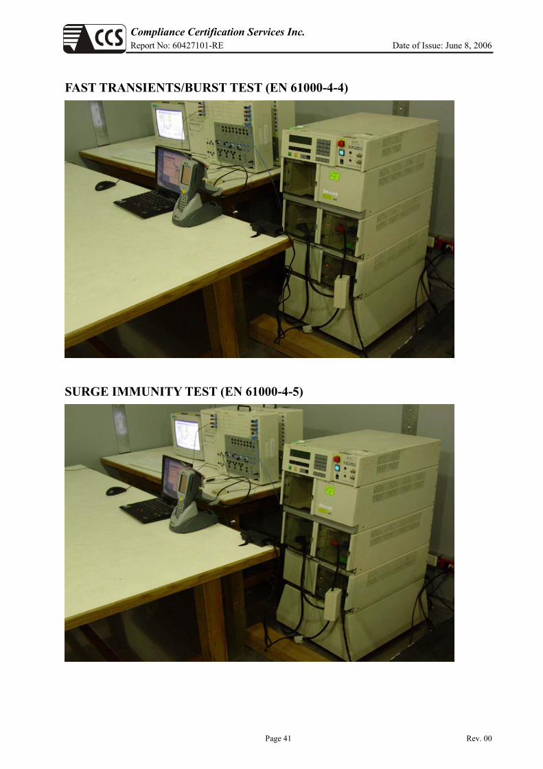
FAST TRANSIENTS/BURST TEST (EN 61000-4-4)
SURGE IMMUNITY TEST (EN 61000-4-5)

Compliance Certification Services Inc. Report No: 60427101-RE Date of Issue: June 8, 2006
Page 42 Rev. 00
CONDUCTED DISTURBANCE, INDUCED BY RADIO-FREQUENCY FIELDS TEST (EN 61000-4-6)
VOLTAGE DIPS/ INTERRUPTION TEST (EN 61000-4-11)