605b specification dannatt, johnson architects main
TRANSCRIPT

National Museum of the Royal Navy
Historic Ships Workshop
605b
SPECIFICATION DANNATT, JOHNSON ARCHITECTS
MAIN CONTRACT SPECIFICATION PART 2
WORK SECTIONS
March 2021 Tender Issue

WORK SECTIONS CONTENTS LIST INTERMEDIATE VERSION F31 Precast concrete sills/ lintels/ copings/ features G20 Carpentry/ Timber framing/ First fixing K10 Gypsum board dry linings/ partitions/ ceilings K11 Rigid sheet flooring/ sheathing/ decking/ sarking/ linings/ casings K13 Rigid Sheet Fine Linings and Panelling K32 Panel cubicles/ duct and wall linings/ screens L20 Doors/ Shutters/ Hatches L30 Stairs/ Ladders/ Walkways/ Handrails/ Balustrades L40 General Glazing M20 Plastered/ Rendered/ Roughcast coatings M40 Stone/ Concrete/ Quarry/ Ceramic tiling/ Mosaic M50 Rubber/ Plastics/ Cork/ Lino/ Carpet tiling/ sheeting M60 Painting/ Clear finishing M61 Intumescent coatings for fire protection of steelwork N10 General fixtures/ furnishings/ equipment N11 Domestic kitchen fittings, furnishings and equipment N13 Sanitary appliances and fittings P10 Sundry insulation/ proofing work P12 Fire stopping systems P20 Unframed isolated trims/ skirtings/ sundry items P31 Holes, Chases, Covers and supports for services S90 Hot and cold water supply systems – domestic T90 Heating Systems U90 General ventilation - domestic V90 Electrical installations - domestic Z10 Purpose made joinery Z11 Purpose made metalwork Z12 Preservative/ Fire retardant treatment Z20 Fixings and adhesives Z21 Mortars Z22 Sealants Z31 Powder Coatings
F31
605b-Historic Ships Workshop Tender Issue P01 page 1/3
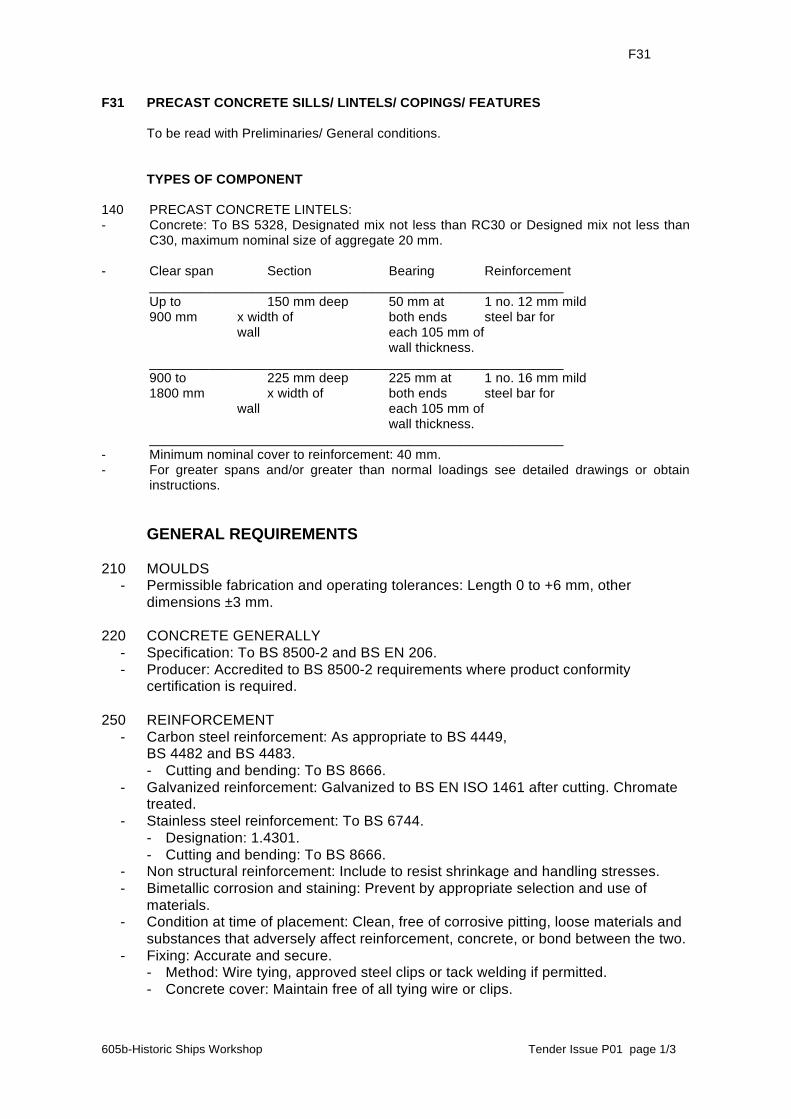
F31 PRECAST CONCRETE SILLS/ LINTELS/ COPINGS/ FEATURES To be read with Preliminaries/ General conditions. TYPES OF COMPONENT 140 PRECAST CONCRETE LINTELS: - Concrete: To BS 5328, Designated mix not less than RC30 or Designed mix not less than
C30, maximum nominal size of aggregate 20 mm. - Clear span Section Bearing Reinforcement ________________________________________________________ Up to 150 mm deep 50 mm at 1 no. 12 mm mild 900 mm x width of both ends steel bar for wall each 105 mm of wall thickness. ________________________________________________________ 900 to 225 mm deep 225 mm at 1 no. 16 mm mild 1800 mm x width of both ends steel bar for wall each 105 mm of wall thickness. ________________________________________________________ - Minimum nominal cover to reinforcement: 40 mm. - For greater spans and/or greater than normal loadings see detailed drawings or obtain
instructions. GENERAL REQUIREMENTS 210 MOULDS - Permissible fabrication and operating tolerances: Length 0 to +6 mm, other
dimensions ±3 mm. 220 CONCRETE GENERALLY - Specification: To BS 8500-2 and BS EN 206. - Producer: Accredited to BS 8500-2 requirements where product conformity
certification is required. 250 REINFORCEMENT - Carbon steel reinforcement: As appropriate to BS 4449, BS 4482 and BS 4483. - Cutting and bending: To BS 8666. - Galvanized reinforcement: Galvanized to BS EN ISO 1461 after cutting. Chromate
treated. - Stainless steel reinforcement: To BS 6744. - Designation: 1.4301. - Cutting and bending: To BS 8666. - Non structural reinforcement: Include to resist shrinkage and handling stresses. - Bimetallic corrosion and staining: Prevent by appropriate selection and use of
materials. - Condition at time of placement: Clean, free of corrosive pitting, loose materials and
substances that adversely affect reinforcement, concrete, or bond between the two. - Fixing: Accurate and secure. - Method: Wire tying, approved steel clips or tack welding if permitted. - Concrete cover: Maintain free of all tying wire or clips.

F31 Precast concrete sills/ Lintels/ Copings/ Features (continued) F31
605b-Historic Ships Workshop Tender Issue P01 page 2/3
260 CASTING AND CURING - Placing of concrete: Thoroughly compact. - Protection against drying out: Methods and duration to BS EN 13369. - Immature components: Avoid movement, vibration, overloading, physical shock,
rapid cooling and thermal shock. - Delivery to site: Minimum 14 days after casting. FAIR FACED COMPONENTS 310 CONTROL SAMPLES - Required samples: After finalization of design, one each of the following
components: ______ . - Approval of appearance: Obtain before manufacture of remaining units. - Identification and storage location: Clearly label and retain at factory for comparison
with production units. 330 MIXES FOR VISIBLE FACED COMPONENTS - Constituent materials and mix design for each finish type: To remain constant. - Colour and appearance of each finish type: To remain constant. - Aggregates: To BS EN 12620. - Origin: Single source for each finish type, having sufficient quantity for whole
contract. 341 CONDITIONS FOR SEPARATE FACING AND BACKING MIXES - Difference in cement content: Not greater than 80 kg/m³. - Thickness of facing mix: 10 mm greater than maximum aggregate size, minimum 25
mm. - Location of reinforcement: Minimum 20 mm away from the interface between mixes. - Compaction of facing and backing mix: Carry out to create monolithic construction. 350 QUALITY OF FINISHES - Appearance standard: As established by samples. 370 COVER ON VISIBLE FACES - Spacers: Not permitted. - Proposed method statement: Submit. 380 CONSISTENCY OF PRODUCTION METHODS - Production methods: To remain consistent for each matching type of finish. - Finish appearance: To remain within the range of variation indicated by the
samples submitted. - Changes to production methods: If variations are proposed for components of the
same finish, submit evidence that there will be no difference in appearance. 390 INSPECTION: All completed components must be carefully inspected and checked by the
manufacturer for match with approved sample(s) and compliance with specification before despatch to site. Make arrangements with the CM for him to inspect completed components in the factory.
400 DAMAGED COMPONENTS: Do not repair without approval. Such approval will not be
given where the components are badly damaged or where the proposed repair will impair appearance or performance.
INSTALLATION
F31 Precast concrete sills/ Lintels/ Copings/ Features (continued) F31
605b-Historic Ships Workshop Tender Issue P01 page 3/3
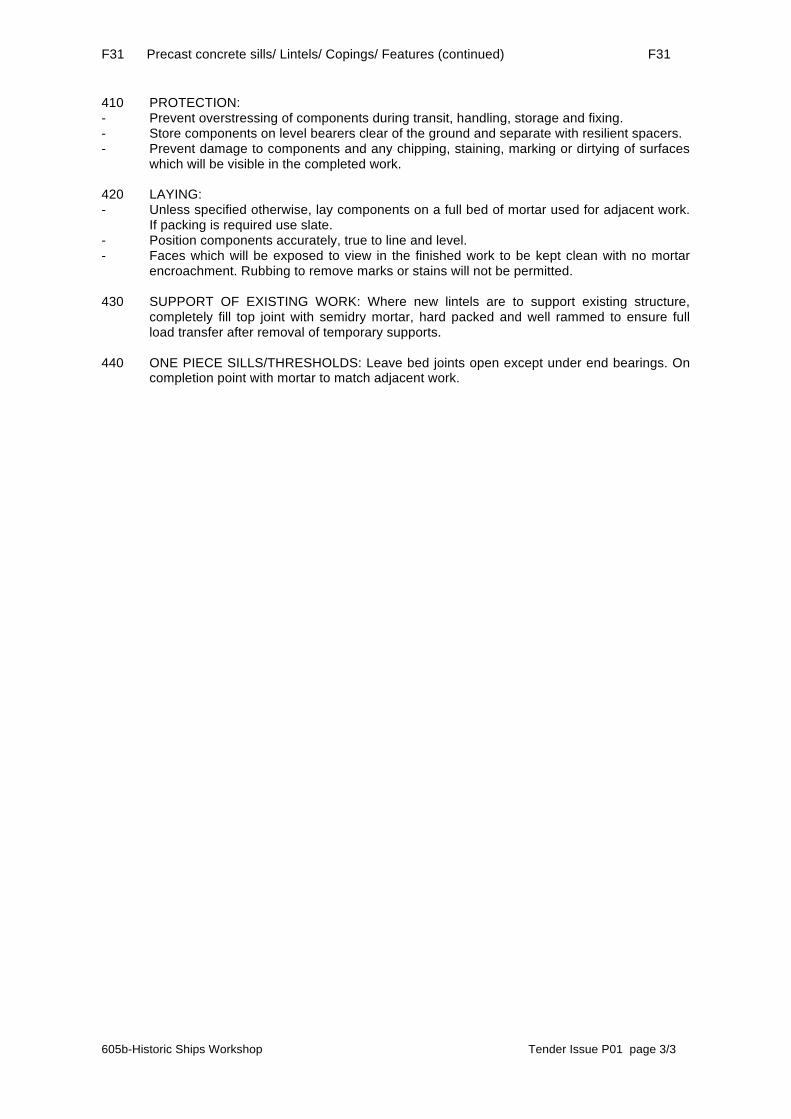
410 PROTECTION: - Prevent overstressing of components during transit, handling, storage and fixing. - Store components on level bearers clear of the ground and separate with resilient spacers. - Prevent damage to components and any chipping, staining, marking or dirtying of surfaces
which will be visible in the completed work. 420 LAYING: - Unless specified otherwise, lay components on a full bed of mortar used for adjacent work.
If packing is required use slate. - Position components accurately, true to line and level. - Faces which will be exposed to view in the finished work to be kept clean with no mortar
encroachment. Rubbing to remove marks or stains will not be permitted. 430 SUPPORT OF EXISTING WORK: Where new lintels are to support existing structure,
completely fill top joint with semidry mortar, hard packed and well rammed to ensure full load transfer after removal of temporary supports.
440 ONE PIECE SILLS/THRESHOLDS: Leave bed joints open except under end bearings. On
completion point with mortar to match adjacent work.

G20
605b-Historic Ships Workshop Tender Issue P01 page 1/6
G20 CARPENTRY/ TIMBER FRAMING FIRST FIXING To be read with Preliminaries/ General conditions. GENERAL 105 TIMBER PROCUREMENT - Timber (including timber for wood based products): Obtained from well managed
forests/ plantations in accordance with: - The laws governing forest management in the producer country or countries. - International agreements such as the Convention on International Trade in
Endangered Species of wild fauna and flora (CITES). - Documentation: Provide either: - Documentary evidence (which has been or can be independently verified)
regarding the provenance of all timber supplied, or - Evidence that suppliers have adopted and are implementing a formal
environmental purchasing policy for timber and wood based products. 120 STRUCTURAL DESIGN PROVIDED BY MNP - Description: For all structural work. - Requirements: - Generally: refer to structural engineer’s specifications - Additional requirements: as above. 150 STRENGTH GRADING OF TIMBER - Grader: A company currently registered under a third party quality assurance
scheme operated by a certification body approved by the UK Timber Grading Committee.
160 GRADING AND MARKING OF SOFTWOOD - Timber of a target/ finished thickness less than 100 mm and not specified for wet
exposure: Graded at an average moisture content not exceeding 20% with no reading being in excess of 24% and clearly marked as ‘DRY’ or ‘KD’ (kiln dried).
- Timber graded undried (green) and specified for installation at higher moisture contents: Clearly marked as ‘WET’ or ‘GRN’.
- Structural timber members cut from large graded sections: Regraded to approval and marked accordingly.
PRODUCTS 210 STRUCTURAL SOFTWOOD (GRADED DIRECT TO STRENGTH CLASS) FOR
NEW STUDWORK, JOISTS, TRIMMERS, NOGGINS, BLOCKING - Grading standard: To BS 4978, BS EN 14081-1, or other national equivalent and so
marked. - Strength class to BS EN 338: C24. - Treatment: - Preservative treatment: WPA Commodity Specification C8, Section Z12 and as
clause Z12/165. Design service life: 30 years. - Fire retardant treatment: not required.

G20 Carpentry/ timber framing first fixing (continued) G20
605b-Historic Ships Workshop Tender Issue P01 page 2/6
270 UNGRADED SOFTWOOD FOR INTERNAL NON STRUCTURAL USE - Quality of timber: Free from decay, insect attack (except pinhole borers) and with
no knots wider than half the width of the section. - Surface finish: PAR. - Treatment: - Preservative treatment: None. Design service life: 30 years. - Fire retardant treatment: None. 311 NON-STRUCTURAL PLYWOOD FOR INTERNAL USE IN PACKING,
STRAPPING, PATRESSES ETC - Standard: To an approved national standard. - Type: Finish Softwood Plywood - Thickness: as noted on drawings. - Appearance class to BS EN 635: II. - Use class to BS EN 335: 2. - Bond quality to BS EN 314-2: 2. - Finish: sanded. - Edges: plain square unless indicated otherwise on drawings. - Treatment: - Preservative treatment: None. Design service life: 30 years. - Fire retardant treatment: None. WORKMANSHIP GENERALLY 401 CROSS SECTION DIMENSIONS OF STRUCTURAL SOFTWOOD AND
HARDWOOD - Dimensions: Dimensions in this specification and shown on drawings are target
sizes as defined in BS EN 336. - Tolerances: The tolerance indicators (T1) and (T2) specify the maximum permitted
deviations from target sizes as stated in BS EN 336, clause 4.3: - Tolerance class 1 (T1) for sawn surfaces. - Tolerance class 2 (T2) for further processed surfaces. 402 CROSS SECTION DIMENSIONS OF NON-STRUCTURAL SOFTWOOD - Dimensions: Dimensions in this specification and shown on drawings are finished
sizes. - Maximum permitted deviations from finished sizes: As stated in BS EN 1313-1: - Clause 6 for sawn sections. 403 CROSS SECTION DIMENSIONS OF NON-STRUCTURAL HARDWOOD - Dimensions: Dimensions in this specification and shown on drawings are finished
sizes. - Maximum permitted deviations from finished sizes: As stated in BS EN 1313-2: - Clause 6 for sawn sections. - Clause NA.3 for further processed sections. 420 WARPING OF TIMBER - Bow, spring, twist and cup: Not greater than the limits set down in BS 4978 or BS
EN 519 for softwood, or BS 5756 for hardwood..
G20 Carpentry/ timber framing first fixing (continued) G20
605b-Historic Ships Workshop Tender Issue P01 page 3/6
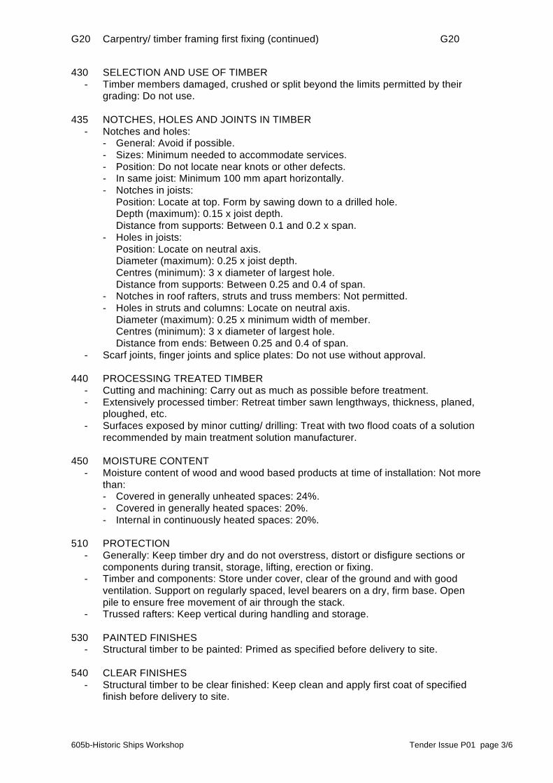
430 SELECTION AND USE OF TIMBER - Timber members damaged, crushed or split beyond the limits permitted by their
grading: Do not use. 435 NOTCHES, HOLES AND JOINTS IN TIMBER - Notches and holes: - General: Avoid if possible. - Sizes: Minimum needed to accommodate services. - Position: Do not locate near knots or other defects. - In same joist: Minimum 100 mm apart horizontally. - Notches in joists: Position: Locate at top. Form by sawing down to a drilled hole. Depth (maximum): 0.15 x joist depth. Distance from supports: Between 0.1 and 0.2 x span. - Holes in joists: Position: Locate on neutral axis. Diameter (maximum): 0.25 x joist depth. Centres (minimum): 3 x diameter of largest hole. Distance from supports: Between 0.25 and 0.4 of span. - Notches in roof rafters, struts and truss members: Not permitted. - Holes in struts and columns: Locate on neutral axis. Diameter (maximum): 0.25 x minimum width of member. Centres (minimum): 3 x diameter of largest hole. Distance from ends: Between 0.25 and 0.4 of span. - Scarf joints, finger joints and splice plates: Do not use without approval. 440 PROCESSING TREATED TIMBER - Cutting and machining: Carry out as much as possible before treatment. - Extensively processed timber: Retreat timber sawn lengthways, thickness, planed,
ploughed, etc. - Surfaces exposed by minor cutting/ drilling: Treat with two flood coats of a solution
recommended by main treatment solution manufacturer. 450 MOISTURE CONTENT - Moisture content of wood and wood based products at time of installation: Not more
than: - Covered in generally unheated spaces: 24%. - Covered in generally heated spaces: 20%. - Internal in continuously heated spaces: 20%. 510 PROTECTION - Generally: Keep timber dry and do not overstress, distort or disfigure sections or
components during transit, storage, lifting, erection or fixing. - Timber and components: Store under cover, clear of the ground and with good
ventilation. Support on regularly spaced, level bearers on a dry, firm base. Open pile to ensure free movement of air through the stack.
- Trussed rafters: Keep vertical during handling and storage. 530 PAINTED FINISHES - Structural timber to be painted: Primed as specified before delivery to site. 540 CLEAR FINISHES - Structural timber to be clear finished: Keep clean and apply first coat of specified
finish before delivery to site.
G20 Carpentry/ timber framing first fixing (continued) G20
605b-Historic Ships Workshop Tender Issue P01 page 4/6
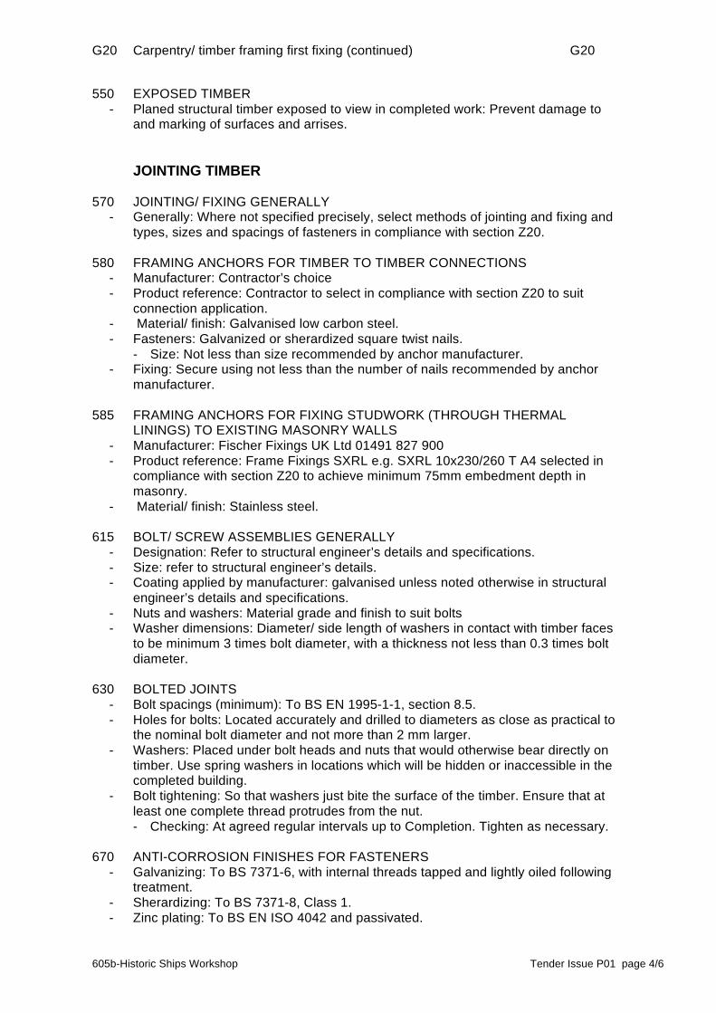
550 EXPOSED TIMBER - Planed structural timber exposed to view in completed work: Prevent damage to
and marking of surfaces and arrises. JOINTING TIMBER 570 JOINTING/ FIXING GENERALLY - Generally: Where not specified precisely, select methods of jointing and fixing and
types, sizes and spacings of fasteners in compliance with section Z20. 580 FRAMING ANCHORS FOR TIMBER TO TIMBER CONNECTIONS - Manufacturer: Contractor’s choice - Product reference: Contractor to select in compliance with section Z20 to suit
connection application. - Material/ finish: Galvanised low carbon steel. - Fasteners: Galvanized or sherardized square twist nails. - Size: Not less than size recommended by anchor manufacturer. - Fixing: Secure using not less than the number of nails recommended by anchor
manufacturer. 585 FRAMING ANCHORS FOR FIXING STUDWORK (THROUGH THERMAL
LININGS) TO EXISTING MASONRY WALLS - Manufacturer: Fischer Fixings UK Ltd 01491 827 900 - Product reference: Frame Fixings SXRL e.g. SXRL 10x230/260 T A4 selected in
compliance with section Z20 to achieve minimum 75mm embedment depth in masonry.
- Material/ finish: Stainless steel. 615 BOLT/ SCREW ASSEMBLIES GENERALLY - Designation: Refer to structural engineer’s details and specifications. - Size: refer to structural engineer’s details. - Coating applied by manufacturer: galvanised unless noted otherwise in structural
engineer’s details and specifications. - Nuts and washers: Material grade and finish to suit bolts - Washer dimensions: Diameter/ side length of washers in contact with timber faces
to be minimum 3 times bolt diameter, with a thickness not less than 0.3 times bolt diameter.
630 BOLTED JOINTS - Bolt spacings (minimum): To BS EN 1995-1-1, section 8.5. - Holes for bolts: Located accurately and drilled to diameters as close as practical to
the nominal bolt diameter and not more than 2 mm larger. - Washers: Placed under bolt heads and nuts that would otherwise bear directly on
timber. Use spring washers in locations which will be hidden or inaccessible in the completed building.
- Bolt tightening: So that washers just bite the surface of the timber. Ensure that at least one complete thread protrudes from the nut.
- Checking: At agreed regular intervals up to Completion. Tighten as necessary. 670 ANTI-CORROSION FINISHES FOR FASTENERS - Galvanizing: To BS 7371-6, with internal threads tapped and lightly oiled following
treatment. - Sherardizing: To BS 7371-8, Class 1. - Zinc plating: To BS EN ISO 4042 and passivated.

G20 Carpentry/ timber framing first fixing (continued) G20
605b-Historic Ships Workshop Tender Issue P01 page 5/6
ERECTION AND INSTALLATION 721 EXPANSION ANCHORS - Manufacturer: refer to structural engineer’s specifications. - Product reference: as above. - Size: as above. - Material/ finish: refer to structural engineer’s specifications. - Spacing/ edge distance (minimum): as above. - Obtain instructions if specified spacing or edge distance cannot be achieved. - Installation holes: Drilled to diameter and depth recommended by manufacturer.
Clean and free from dust. - Installation/ tightening: To manufacturer’s instructions. 760 TEMPORARY BRACING - Provision: As necessary to maintain structural timber components in position and to
ensure complete stability during construction. 770 ADDITIONAL SUPPORTS - Provision: Position and fix additional studs, noggings and/ or battens to support
edges of sheet materials, and wall/ floor/ ceiling mounted appliances, fixtures, etc. shown on drawings.
- Material properties: Additional studs, noggings and battens to be of adequate size and have the same treatment, if any, as adjacent timber supports.
775 BEARINGS - Timber surfaces which are to transmit loads: Finished to ensure close contact over
the whole of the designed bearing area. - Packings: Where provided, to cover the whole of the designated bearing area. - Crushing strength: Not less than timber being supported. - In external or inaccessible locations: rot and corrosion proof. 780 WALL PLATES - Position and alignment: To give the correct span and level for trusses, joists, etc. - Bedding: Fully in fresh mortar. - Joints: At corners and elsewhere where joints are unavoidable use nailed half lap
joints. Do not use short lengths of timber. 784 JOISTS GENERALLY - Centres: Equal, and not exceeding designed spacing. - Bowed joists: Installed with positive camber. - End joists: Positioned approximately 50 mm from masonry walls. 786 JOISTS ON HANGERS - Hangers: Bedded directly on and hard against supporting construction. Do not use
packs or bed on mortar. - Joists: Cut to leave not more than 6 mm gap between ends of joists and back of
hanger. Rebated to lie flush with underside of hangers. - Fixing to hangers: A nail in every hole. 791 PROPRIETARY JOIST HANGERS GENERALLY - Manufacturer: as clause 580. - Product reference: as clause 580. - Material/ finish: as clause 580.
G20 Carpentry/ timber framing first fixing (continued) G20
605b-Historic Ships Workshop Tender Issue P01 page 6/6
- Size: To suit joist, design load and crushing strength of supporting construction. 795 TRIMMING OPENINGS - Trimmers and trimming joists: When not specified otherwise, not less than 25 mm
wider than general joists. 840 STRUTTING TO FLOOR JOISTS - Type: - Solid strutting: At least 38 mm thick softwood and at least three quarters of joist
depth. - Fixing: Between joists as follows: - Joist spans of 2.5 to 4.5 m: One row at centre span. - Joist spans over 4.5 m: Two rows equally spaced. - Strutting must not project beyond top and bottom edges of joists. - Outer joists: Blocked solidly to perimeter walls. 850 INSPECTION GENERALLY - Structural timber-work: Give reasonable notice before covering up.

K10
605b-Historic Ships Workshop Tender Issue P01 page 1/10
K10 GYPSUM BOARD DRY LININGS/ PARTITIONS/ CEILINGS To be read with Preliminaries/ General conditions. TYPES OF DRY LINING 125 METAL STUD PARTITION SYSTEM – STAIR PARTITION TYPE P5 30 MINS
FIRE RESISTANCE Manufacturer: Fermacell - Product references: 1S31 - Studs: - Type: 100 DIN standard studes - Centres: 600mm - Head condition: underside of new timber joists - Deflection allowance: 25mm - Insulation: Knauf Earthwood Flexible Slab, 70mm thick as P10/190. - Recycled content: 75% minimum to BS EN ISO 14021 - Thickness: 60mm - Linings: 2 x Fermacell 12.5mm board either side - Fixings: Boards fixed with Fermacell Screws in accordance with manufacturers
requirements for length and spacing and according to board type. - Finishing: Fermacell Fine Surface Treatment FST - Primer/ Sealer: As required by manufacturer. - Accessories: Palco Flipfix plasterboard panel, lockable, 10mm style trim shadow
gap bead. - Other requirements: Timber head and sole plates to allow uneven levels. Acoustic
sealing and fire sealing compounds required at junction with walls. 165 WALL LINING SYSTEM (METAL FRAMING) – WALL LINING TYPE 1 - Manufacturer: (Framing system) British Gypsum - Product reference: GypLyner Universal system installed in accordance with
manufacturer’s installation instructions. - Wall: Existing solid brickwork walls. - Cavity between wall and back of lining: Generally 25mm wherever possible but
could increase where walls out of plumb/ out of line in plan. Line of setting out of bottom channels to be agreed with Architect before proceeding further.
- Framing centres: GL1 channels at 600mm centres, connected by GL3 connectors to run approx. 5.1m AFFL. Provide additional GL1 vertical framing channel at each location where a new timber studwork wall will abut the lining, offsetting one side of the channel 10mm from the centreline of the studwork wall to allow for the studs to be fixed through the lining board and into the solid masonry behind. Bottom channel/track fixed to concrete slab, isolated by Visqueen (0333) 2026800 Zedex CPT DPC strip. Top channel supported by continuous steel angle as details, also isolated from masonry by continuous DPC strip. Refer to details.
- Bracket centres (maximum): 800mm. Brackets fixed back to masonry walls with stainless steel screws and isolated from masonry background on pads of DPC material due to high moisture content of existing brickwork.
- Insulation: N/A - Recycled content: N/A.
K10 Gypsum board dry linings/ partitions/ ceilings (continued) K10
605b-Historic Ships Workshop Tender Issue P01 page 2/10
- Thickness: N/A - Vapour control layer: N/A - Resilient layer: not required. - Linings: 1 x 12.5mm fermacell board - Finishing: Fermacell Fine Surface Treatment FST - Primer/ Sealer: N/A. - Accessories: 10mm style trim shadow gap bead. - Other requirements: Boards fixed with Drywall screws in accordance with
manufacturers requirements for length and spacing and according to board type. Boards supported 10mm clear of floor level when fitted and joint filled with rot-proof non-corrosive sealing materials: closed cell polyethylene backer strip and neutral curing silicone sealant Adshead Ratcliffe Arbo 1096 with primer 2650 applied to concrete floor surface. Boards jointed in seamlessly at window reveals with Window reveal insulation boards P10/345 and P10/347.
166 WALL LINING SYSTEM (METAL FRAMING) – WALL LINING TYPE 2 TO
SHOWER WET AREAS - Manufacturer: (Framing system) British Gypsum - Product reference: GypLyner Universal system installed in accordance with
manufacturer’s installation instructions. - Wall: Existing solid brickwork walls. - Cavity between wall and back of lining: Generally 25mm wherever possible but
could increase where walls out of plumb/ out of line in plan. Line of setting out of bottom channels to be agreed with Architect before proceeding further.
- Framing centres: GL1 channels at 600mm centres, connected by GL3 connectors to run approx. 5.1m AFFL. Provide additional GL1 vertical framing channel at each location where a new timber studwork wall will abut the lining, offsetting one side of the channel 10mm from the centreline of the studwork wall to allow for the studs to be fixed through the lining board and into the solid masonry behind. Bottom channel/track fixed to concrete slab, isolated by Visqueen (0333) 2026800 Zedex CPT DPC strip. Top channel supported by continuous steel angle as details, also isolated from masonry by continuous DPC strip. Refer to details.
- Bracket centres (maximum): 800mm. Brackets fixed back to masonry walls with stainless steel screws and isolated from masonry background on pads of DPC material due to high moisture content of existing brickwork.
- Insulation: N/A - Recycled content: N/A. - Thickness: N/A - Vapour control layer: N/A - Resilient layer: not required. - Linings: 1 x Fermacell 12.5mm board, 1 x 12.5mm fermacell Powerpanel H20 board
on shower / tile side. - Fixings: as clause 205 - Joint Treatment: Fermacell Joint Reinforcement Tape and Fermacell Joint Filler.
Site cut boards Fermacell Joint Filler 5-7mm filled joint. Internal corner joints jointed using Joint Filler and/or semi flexible caulk at junctions with walls.
- Finishing: Fermacell Fine Surface Treatment FST - Primer/ Sealer: N/A. - Accessories: 10mm style trim shadow gap bead. - Other requirements: Boards fixed with Drywall screws in accordance with
manufacturers requirements for length and spacing and according to board type. Boards supported 10mm clear of floor level when fitted and joint filled with rot-proof non-corrosive sealing materials: closed cell polyethylene backer strip and neutral

K10 Gypsum board dry linings/ partitions/ ceilings (continued) K10
605b-Historic Ships Workshop Tender Issue P01 page 3/10
curing silicone sealant Adshead Ratcliffe Arbo 1096 with primer 2650 applied to concrete floor surface.
205 LINING ON TIMBER – LOAD BEARING WALL LINING TYPE 3 - Background: C24 100 x 50 Softwood studs at 600mm centres. - Insulation: 60mm Knauf earthwool flexible slab as P10/190 - Wall: Existing solid brickwork walls. - Cavity between wall and back of lining: Generally 25mm wherever possible but
could increase where walls out of plumb/ out of line in plan. Line of setting out of bottom channels to be agreed with Architect before proceeding further.
- Linings: 1 x 12.5mm - Fixing: Boards fixed with Fermacell Screws in accordance with manufacturers
requirements for length and spacing and according to board type. - Finishing: Fermacell Fine Surface Treatment FST. - Joint Treatment: Seamless tape and joint finish as clause 670 using Fermacell
Joint Reinforcement Tape and Fermacell Joint Filler. Site cut boards Fermacell Joint Filler 5-7mm filled joint. Internal corner joints jointed using Joint Filler.
- Primer/ Sealer: N/A. - Accessories: External corners reinforced with steel reinforced paper beads e.g.
British Gypsum Gyproc corner tape finish. 10mm recessed skirtings formed from aluminium shadow trim ref. R10, colour white. Plant on skirting where wall is 30mins fire resisting. Birch ply timber capping to partial height partitions as per drawings
- Other requirements: Install DPC between timber sole plate and existing concrete slab where partition is erected on ground floor. Visqueen Polyethylene Damp Proof Course or similar (Contractor’s choice to be approved). Tie wall to existing masonry with fixings with M8 screws and resin anchors into brickwork joints at max 600 centres.
206 TIMBER STUD WALLING GENERALLY – PARTITION TYPE 1 - Manufacturer: Fermacell
- Background: C24 100 x 50 Softwood studs at 600mm centres. - Metal resilient bars: N/A - Wall: Existing solid brickwork walls. - Cavity between wall and back of lining: Generally 25mm wherever possible but
could increase where walls out of plumb/ out of line in plan. Line of setting out of bottom channels to be agreed with Architect before proceeding further.
- Insulation: 60mm Knauf earthwool flexible slab as P10/190 - Linings: 1 x 12.5mm fermacell either side - Fixing: Boards fixed with Fermacell Screws in accordance with manufacturers
requirements for length and spacing and according to board type. - Finishing: Fermacell Fine Surface Treatment FST. - Joint Treatment: Seamless tape and joint finish as clause 670 using Fermacell
Joint Reinforcement Tape and Fermacell Joint Filler. Site cut boards Fermacell Joint Filler 5-7mm filled joint. Internal corner joints jointed using Joint Filler.
- Primer/ Sealer: N/A. - Accessories: External corners reinforced with steel reinforced paper beads e.g.
British Gypsum Gyproc corner tape finish. 10mm recessed skirtings formed from aluminium shadow trim ref. R10, colour white. Shadow gap beads around door frames and at vertical corner junctions with external wall linings ref. R10. Plant on skirting where wall is 30mins fire resisting.
- Other requirements: Install DPC between timber sole plate and existing concrete slab where partition is erected on ground floor. Visqueen Polyethylene Damp Proof Course or similar (Contractor’s choice to be approved). Resilient strip to head and jamb abutments and below foot track (Protektor UK DIN standard acoustic felt
K10 Gypsum board dry linings/ partitions/ ceilings (continued) K10
605b-Historic Ships Workshop Tender Issue P01 page 4/10
strip.) Fire rated isolation strips e.g. mineral wool <5mm to head and jamb abutments to walls required to be fire resisting. Fire stopping around service penetrations in walls required to be fire resisting as section P12 (by Fire Stopping Subcontractor). Sockets backed using baffle boxes, intumescent putty pads or suitable rock mineral wool, sufficient to maintain the fire/acoustic performance. Seal around services or other penetrations as sections P12 and P31 to maintain fire and acoustic integrity respectively, also seal full perimeter of partitions likewise.
207 DOUBLE TIMBER STUD WALLING GENERALLY – PARTITION TYPE 1a - Manufacturer: Fermacell - System reference: 1H23
- Background: C24 75 x 50 Softwood studs at 600mm centres. - Metal resilient bars: N/A
- Insulation: 60mm Knauf earthwool flexible slab as P10/190 - Linings: 1 x 12.5mm fermacell board each side - Fixing: as clause 206 - Finishing: as clause 206 - Joint Treatment: as clause 206 - Primer/ Sealer: N/A. - Accessories: coved movement profile M40/835 - Other requirements: Install DPC between timber sole plate and existing concrete
slab where partition is erected on ground floor. Visqueen Polyethylene Damp Proof Course or similar (Contractor’s choice to be approved)
208 TIMBER STUD WALLING – SHOWER AND WET AREAS
- Background: C24 100 x 50 Softwood studs at 600mm centres. - Metal resilient bars: N/A
- Insulation: 60mm Knauf earthwool flexible slab as P10/190 - Linings: 1 x Fermacell 12.5mm board, 1 x 12.5mm fermacell Powerpanel H20 board
on shower / tile side. - Fixing: as clause 206 - Finishing: as clause 206 - Joint Treatment: as clause 206 - Primer/ Sealer: N/A. - Accessories: coved movement profile M40/835 - Other requirements: Install DPC between timber sole plate and existing concrete
slab where partition is erected on ground floor. Visqueen Polyethylene Damp Proof Course or similar (Contractor’s choice to be approved)
207 TIMBER AND POLYCARBONATE LINING ON TIMBER STUD PARTITIONS –
PARTITION TYPE 3 / TYPE 4 SIMILAR - Manufacturer: Brett Martin Plastic Sheets, 24 Roughfort Road, Newtownabbey, Co.
Antrim, BT36 4RB, UK. Tel 02890849999 - System reference: Marlon clicklock easy-fit polycarbonate panel / also
distributed as Corotherm Clickfit by Ariel Plastics Ltd, Speedell Ind. Estate, Staveley Debryshire S43 3JP. Tel: 01246281111
- Background: C24 100 x 50 Softwood studs at 600mm centres. - Insulation: N/A - Linings: 18mm birch veneered plywood to 1100 height from floor level either side,
5mm routed grove at 600mm centres to align with timber studs centres. Easy-fit 16mm polycarbonate sheet (finish: Opal tbc) above 1100 either side as per drawing BD-71-002.
- Fixing: Birch panelling – pinned, punched and stopped. Polycarbonate - screw fix to noggins with channel washer as per manufacturer’s requirements and drawing

K10 Gypsum board dry linings/ partitions/ ceilings (continued) K10
605b-Historic Ships Workshop Tender Issue P01 page 5/10
BD-71-002 at top and bottom of panel. Centre fixing to white painted 25 x 100 noggin.
- Finishing: Fire retardant treatment to exposed timber surfaces as M60/180 and Z12. - Joint Treatment: connect easy-fit tongue and groove panels as per
manufacturer’s instructions - Primer/ Sealer: N/A. - Accessories: (Corotherm Clickfit) Aluminium F Profile 16mm mill finish,
Aluminium U Profile 16mm mill finish, Channel washer. - Other requirements: Wall type P4 – see drawing Bd-75-000. Use 150 x 50 softwood
studs at 600 centres and birch ply panelling to 2m. 225 PROPRIETARY SUSPENDED CEILING SYSTEM TO WC BLOCK - Standard: To BS EN 13964. - Evidence of compliance: All ceilings kits to be CE marked. Submit Declaration of
Performance (DoP). - Ceiling system manufacturer: Of linings: as clause 205. Of framing system: British
Gypsum - Product reference: 2S01. Of framing system: Casoline MF - Ceiling: - Soffit height above finished floor level: Refer to drawings. - Suspension system: - Hangers: MF 8 strap hanger or GA1 steel angle or equivalent. - Hanger centres: 1200mm. - Primary grid centres: Maximum 1200mm. - Secondary grid centres: 400mm. - Linings: Single layer Fermacell 12.5mm 4 edge tapered boards. - Joint Treatment: Fermacell Joint Reinforcement Tape and Fermacell Joint Filler.
Site cut boards Fermacell Joint Filler 5-7mm filled joint. Internal corner joints jointed using Joint Filler and/or semi flexible caulk at junctions with walls.
- Finishing: Fermacell Fine Surface Treatment FST. - Insulation: Not required. - Recycled content: N/A - Thickness: N/A - Access: Purpose made ceiling access panel(s), size as drawings, manufacturer
PALCO, with beaded frames, tamper proof locking, RAL 9003 low sheen finish. - Accessories: Locking handles/ keys for access panel, 2no. per panel required. - Integrated services fittings: N/A. - Electrical continuity and earth bonding: to Services Engineers requirements. - Other requirements: seal around services penetrations as sections P12 or P31 as
appropriate. Acoustic sealant and plasterboard stop beads around ceiling perimeter.
245 CEILING LINING ON TIMBER JOISTS UP TO 30 MINS FIRE RATED
- Background: Spaced off softwood timber joists with 25mm counterbattens as shown on drawings
- Insulation: Knauf Earthwood Flexible Slab, 70mm thick, as P10/240. - Metal resilient (acoustic) bars: N/A - Linings: single layer fermacell 12.5mm 4 edge tapered boards - Fixings: With Drywall screws. Inner and Outer layer boards joints staggered.
Boards closely butt jointed. - Joint Treatment: Seamless tape and joint finish as clause 670 using Fermacell Joint
Reinforcement Tape and Fermacell Joint Filler. Site cut boards Fermacell Joint Filler 5-7mm filled joint. Internal corner joints jointed using Joint Filler and/or semi flexible caulk at junctions with walls.
- Finishing: Fermacell Fine surface treatment FST

K10 Gypsum board dry linings/ partitions/ ceilings (continued) K10
605b-Historic Ships Workshop Tender Issue P01 page 6/10
- Primer/ Sealer: N/A - Accessories: Palco Flipfix plasterboard panel, lockable - Other requirements: Fire stopping as P12 for designated fire rated ceilings. Sealing
otherwise as P31. Acoustic sealant around ceiling perimeter. 305 GYPSUM BOARDS GENERALLY - Standard: - Gypsum plasterboard to BS EN 520. - Fibre reinforced gypsum board to BS EN 15283-2. - Evidence of compliance: All sheets to be CE marked. Submit Declaration of
Performance (DoP). INSTALLATION 335 ADDITIONAL SUPPORTS - Framing: Accurately position and securely fix to give full support to: - Partition heads running parallel with, but offset from main structural supports. - Fixtures, fittings and service outlets. Mark framing positions clearly and
accurately on linings. - Board edges and lining perimeters, as recommended by board manufacturer to
suit type and performance of lining. 375 NEW WET LAID BASES - Dpcs: Install under full width of partitions/ freestanding wall linings. - Material: Bituminous sheet or plastics. 435 DRY LININGS GENERALLY - General: Use fixing, jointing, sealing and finishing materials, components and
installation methods recommended by board manufacturer. - Cutting gypsum boards: Neatly and accurately without damaging core or tearing
paper facing. - Cut edges: Minimize and position at internal angles wherever possible. Mask
with bound edges of adjacent boards at external corners. - Fixings boards: Securely and firmly to suitably prepared and accurately levelled
backgrounds. - Finishing: Neatly to give flush, smooth, flat surfaces free from bowing and abrupt
changes of level. 445 CEILINGS - Sequence: Fix boards to ceilings before installing dry lined walls and partitions. - Orientation of boards: Fix with bound edges at right angles to supports and with
ends staggered in adjacent rows. - Two layer boarding: Stagger joints between layers. 455 METAL FRAMING FOR PARTITIONS/ WALL LININGS - Setting out: Accurately aligned and plumb. - Frame/ Stud positions: Equal centres to suit specified linings, maintaining
sequence across openings. - Additional studs: To support vertical edges of boards. - Fixing centres at perimeters (maximum): 600 mm. - Openings: Form accurately. - Doorsets: Use sleeved or boxed metal studs and/ or suitable timber framing to
achieve strength grade requirements for framing assembly and adequately support weight of door.

K10 Gypsum board dry linings/ partitions/ ceilings (continued) K10
605b-Historic Ships Workshop Tender Issue P01 page 7/10
- Services penetrations: Allow for associated fire stopping. 475 METAL FURRINGS FOR WALL LININGS - Setting out: Accurately aligned and plumb. - Vertical furring positions: Equal vertical centres to suit specified linings,
maintaining sequence across openings. Position adjacent to angles and openings.
- Additional vertical furrings: To support vertical edges of boards and at junctions with partitions.
- Horizontal furring positions: To provide continuous support to edges of boards. - Adhesive bedding to furrings: - Dabs: Length 200 mm (minimum). Located at ends of furrings and thereafter at
450 mm (maximum) centres. - Junctions with partitions: Continuous bed with no gaps across cavity. 485 SUSPENDED CEILING GRIDS - Setting out: Accurately aligned and level. - Grid members and hangers: Centres to suit specified linings and imposed loads. - Additional grid members: Provide bracing and stiffening at upstands, partition
heads, access hatches, etc. - Fixing: Securely at perimeters, grid joints, top and bottom hanger fixings. 505 INSTALLING MINERAL WOOL INSULATION - Fitting insulation: Closely butted joints and no gaps. Use fasteners to prevent
slumping or displacement. - Services: - Electrical cables overlaid by insulation: Sized accordingly. - Ceilings: Cut insulation around electrical fittings, etc. 510 SEALING GAPS AND AIR PATHS - Location of sealant: To perimeter abutments and around openings. - Pressurized shafts and ducts: At board-to-board and board-to-metal frame
junctions. - Application: To clean, dry and dust free surfaces as a continuous bead with no
gaps. - Gaps greater than 6 mm between floor and underside of gypsum board: After
sealing, fill with jointing compound. 545 CAVITY FIRE BARRIERS WITHIN SUSPENDED CEILINGS - Type: 50mm mineral wood wire reinforced mattress - Rockwool Fire Barrier or
similar approved - Fire resistance: 30 mins - Ceiling void subdivision: as drawings and to manfacturer’s requirements. No more
than 20m apart in any direction - Fixing at perimeters and joints: Secure, stable and continuous with no gaps, to
provide a complete barrier to smoke and flame. - Service penetrations: Cut and pack to maintain barrier integrity. Sleeve flexible
materials. Adequately support services passing through barrier. - Ceiling systems for fire protection: Do not impair fire resisting performance of ceiling
system. 560 JOINTS BETWEEN BOARDS - Tapered edged gypsum boards: - Bound edges: Lightly butted. - Cut/ unbound edges: 3 mm gap.

K10 Gypsum board dry linings/ partitions/ ceilings (continued) K10
605b-Historic Ships Workshop Tender Issue P01 page 8/10
- Square edged plasterboards: 3 mm gap. - Square edged gypsum fibre boards: 5 mm gap. 565 VERTICAL JOINTS - Joints: Centre on studs. - Partitions: Stagger joints on opposite sides of studs. - Two layer boarding: Stagger joints between layers. 570 HORIZONTAL JOINTS - Surfaces exposed to view: Horizontal joints not permitted. Seek instructions where
height of partition/ lining exceeds maximum available length of board. - Two layer boarding: Stagger joints between layers by at least 600 mm. - Edges of boards: Support using additional framing. - Two layer boarding: Support edges of outer layer. 580 INSULATION BACKED PLASTERBOARD - General: Do not damage or cut away insulation to accommodate services. - Installation at corners: Carefully cut back insulation or plasterboard as appropriate
along edges of boards to give a continuous plasterboard face, with no gaps in insulation.
590 FIXING GYPSUM BOARD TO METAL FRAMING/ FURRINGS - Partitions/ Wall linings: Fix securely and firmly at the following centres (maximum): - Single layer boarding: To all framing at 300 mm centres. Reduce to 200 mm
centres at external angles. - Multi-layer boarding: Face layer at 300 mm centres, and previous layers around
perimeters at 300 mm centres. - Ceilings: 230 mm. Reduce to 150 mm at board ends and at lining perimeters. - Position of screws from edges of boards (minimum): 10 mm. - Screw heads: Set in a depression. Do not break paper or gypsum core. 592 FIXING INSULATION BACKED PLASTERBOARD TO METAL FURRINGS - Fixing to furrings: In addition to screw fixings apply continuous beads of adhesive
sealant to furrings. 610 FIXING GYPSUM BOARD TO TIMBER - Fixing to timber: Securely at the following centres (maximum): - Nails: 150 mm. - Screws to partitions/ wall linings: 300 mm. Reduce to 200 mm at external angles. - Screws to ceilings: 230 mm. - Position of nails/ screws from edges of boards (minimum): - Bound edges: 10 mm. - Cut/ unbound edges: 13 mm. - Position of nails/ screws from edges of timber supports (minimum): 6 mm. 620 FIXING GYPSUM BOARD WITH ADHESIVE DABS - Setting out boards: Accurately aligned and plumb. - Fixing to substrates: Securely using adhesive dabs. - Adhesive dab spacings for each board: - Horizontally: One row along top edge and one continuous dab along bottom
edge. - Vertically: One row along each edge and thereafter at intermediate spacings to
suit size of board: Thickness (mm) Width (mm) Dab centres (mm) 9.5 1200 400
K10 Gypsum board dry linings/ partitions/ ceilings (continued) K10
605b-Historic Ships Workshop Tender Issue P01 page 9/10
9.5/12.5 900 450 12.5 1200 600 - Adhesive dab dimensions (width x length): At least 50–75 mm x 250 mm. - Position of dabs from edges/ ends of boards (minimum): 25 mm. 625 FIXING INSULATION BACKED PLASTERBOARD WITH ADHESIVE DABS - Fixing to substrates: In addition to adhesive dab fixings, secure boards with nailable
plugs in locations recommended by board manufacturer. 630 FIXING INSULATION BACKED PLASTERBOARD WITH ADHESIVE SPOTS - Setting out boards: Accurately aligned and plumb. - Fixing to substrates: Securely using adhesive spots and mechanical fastenings. - Adhesive spot spacings to each board: Four vertical rows, at 400 mm centres in
each row. - Adhesive spot diameters (minimum): 25 mm. - Mechanical fasteners: Nailable plugs in locations recommended by board
manufacturer. FINISHING 650 LEVEL OF DRY LINING ACROSS JOINTS - Sudden irregularities: Not permitted. - Joint deviations: Measure from faces of adjacent boards using methods and
straightedges (450 mm long with feet/ pads) to BS 8212, clause 3.3.5. - Tapered edge joints: Permissible deviation (maximum) across joints when measured with feet resting
on boards: 3 mm. - External angles: Permissible deviation (maximum) for both faces: 4 mm. - Internal angles: Permissible deviation (maximum) for both faces: 5 mm. 670 SEAMLESS JOINTING TO GYPSUM BOARDS - Cut edges of boards: Lightly sand to remove paper burrs. - Filling and taping: Fill joints, gaps and internal angles with jointing compound and
cover with continuous lengths of paper tape, fully bedded. - Protection of edges/ corners: Reinforce external angles, stop ends, etc. with
specified edge/ angle bead. - Finishing: Apply jointing compound. Feather out each application beyond previous
application to give a flush, smooth, seamless surface. - Nail/ screw depressions: Fill with jointing compound to give a flush surface. - Minor imperfections: Remove by light sanding. 680 SKIM COAT PLASTER FINISH - Plaster type: Thistle Board finish plaster. - Thickness: 2-3 mm. - Joints: Fill and tape except where coincident with metal beads. - Finish: Tight, matt, smooth surface with no hollows, abrupt changes of level or
trowel marks. 695 INSTALLING BEADS/ STOPS - Cutting: Neatly using mitres at return angles. - Fixing: Securely using longest possible lengths, plumb, square and true to line and
level, ensuring full contact of wings with substrate.

K10 Gypsum board dry linings/ partitions/ ceilings (continued) K10
605b-Historic Ships Workshop Tender Issue P01 page 10/10
- Finishing: After joint compounds/ plasters have been applied, remove surplus material while still wet from surfaces of beads exposed to view.
725 REPAIRS TO EXISTING GYPSUM BOARD - Filling small areas with broken cores: Cut away paper facing, remove loose core
material and fill with jointing compound. - Finish: Flush, smooth surface suitable for redecoration. - Large patch repairs: Cut out damaged area and form neat hole with rectangular
sides. Replace with matching gypsum board. - Fixing: Use methods to suit type of dry lining, ensuring full support to all edges of
existing and new gypsum board. - Finishing: Fill joints, tape and apply jointing compound to give a flush, smooth
surface suitable for redecoration.

K11
605b-Historic Ships Workshop Tender Issue P01 page 1/3
K11 RIGID SHEET FLOORING/ SHEATHING/ DECKING/ SARKING/ LININGS/ CASINGS
To be read with Preliminaries/ General conditions. TYPES OF FLOORING/ SHEATHING/ DECKING/ SARKING/ LINING/
CASING 110 WOOD-BASED SHEETS GENERALLY - Standard: To BS EN 13986. - Evidence of compliance: All sheets to be CE marked. Submit Declaration of
Performance (DoP). - Clear expansion gap around perimeter of floor area and upstands: 5mm. - Intermediate expansion/ movement joints: N/A 320 PLYWOOD SUBTRATE TO VINYL FLOORING GENERALLY - Substrate: 38mm chipboard - Flooring: Plywood manufactured to the relevant standards and quality control
procedures specified in BS EN 636, and so marked. - Type: Finnish Plywood MetsaWood UK 0800 004444 Metsa Wood Spruce. - Grade: II/III. - Nominal thickness/ number of plies: 6mm - Edges: Tongued and grooved long edges - Other requirements: N/A. - Setting out: Long edges running across joists. End joints central over joists and
staggered. - Fixing to joists: - Fasteners: Wood screws - Fixing centres (maximum): Around perimeter and along short edges of each board: 150 mm. Along intermediate supports: 300 mm. - Fixing distance from edges: 25 mm from long edges and minimum 10 mm from
short edges. - Joint treatment: unbonded. - Expansion provision: - expansion gap around perimeter of deck area (where abutting a vertical
surface): 3mm - Intermediate expansion/ movement joints: N/A 321 PLYWOOD DECK ABOVE FIRST FLOOR ENCLOSURES UP TO 30 MINUTES
FIRE RATED - Substrate: New C24 softwood joists at 400mm centres covered with one layer of
12.5mm Fermacell board fixed down with Fermacell screws, boards butt jointed. - Flooring: Plywood manufactured to the relevant standards and quality control
procedures specified in BS EN 636, and so marked. - Type: as clause 320 - Grade: as clause 320 - Nominal thickness/ number of plies: as clause 320 - Edges: as clause 320 - Other requirements: N/A. - Setting out: Long edges running across joists. End joints central over joists and
staggered.
K11 Rigid sheet flooring/ sheathing/ decking/ sarking/ linings/ casings (continued) K11
605b-Historic Ships Workshop Tender Issue P01 page 2/3
- Fixing to joists: - Fasteners: Wood screws - Fixing centres (maximum): Around perimeter and along short edges of each board: 150 mm. Along intermediate supports: 300 mm. - Fixing distance from edges: 25 mm from long edges and minimum 10 mm from
short edges. - Joint treatment: unbonded. - Expansion provision: - expansion gap around perimeter of deck area (where abutting a vertical
surface): 3mm - Intermediate expansion/ movement joints: N/A 535 ORIENTED STRAND BOARD INTERNAL ROOF DECKING - Substrate: 300-58 Timber I Beams at 600 centres - Additional supports: ______ . - Decking: Oriented strand board to BS EN 300, Type OSB/3. - Thickness: 22mm - Fire performance: Reaction to fire: Class 1 surface spread of flame to BS 476-7, Class 0 to Building
Regulations Part B Resistance to fire: ______ . Spread of fire: ______ . - Edges: tongue and grooved - Other requirements: Finished as M60/180 top coat white - Setting out: Long edges running across supports. End joints central over joists and
staggered. - Fixing: - Fasteners: screw fixed min length 50mm - Fixing centres: - Along each support: 25 mm from each long edge and at maximum 600 centres
between. - Around perimeter of roof area: Maximum 100mm centres. - Expansion provision: - Clear expansion gap around perimeter of roof area and upstands: 1.5 mm per
metre run of roof, with a minimum gap of 10 mm. - Intermediate expansion/ movement joints: As recommended by decking
manufacturer. WORKMANSHIP 910 INSTALLATION GENERALLY - Timing: Building to be weathertight before fixing boards internally. - Moisture content of timber supports (maximum): 18%. - Joints between boards: Accurately aligned, of constant width and parallel to
perimeter edges. - Methods of fixing, and fasteners: As section Z20 where not specified otherwise. 930 ADDITIONAL SUPPORTS - Additional studs, noggings/ dwangs (Scot) and battens: - Provision: In accordance with board manufacturer’s recommendations and as
follows: Tongue and groove jointed rigid board areas: To all unsupported perimeter
edges.
K11 Rigid sheet flooring/ sheathing/ decking/ sarking/ linings/ casings (continued) K11
605b-Historic Ships Workshop Tender Issue P01 page 3/3
Butt jointed rigid board areas: To all unsupported edges. - Size: Not less than 50 mm wide and of adequate thickness. - Quality of timber: As for adjacent timber supports. - Treatment (where required): As for adjacent timber supports. 940 BOARD MOISTURE CONTENT AND CONDITIONING - Moisture content of boards at time of fixing: Appropriate to end use. - Conditioning regime: Submit proposals. 960 FIXING GENERALLY - Boards/ sheets: Fixed securely to each support without distortion and true to line
and level. - Fasteners: Evenly spaced in straight lines and, unless otherwise recommended by
board manufacturer, in pairs across joints. - Distance from edge of board/ sheet: Sufficient to prevent damage. - Surplus adhesive: Removed as the work proceeds. 980 OPEN JOINTS - Perimeter joints, expansion joints and joints between boards: Free from plaster,
mortar droppings and other debris. - Temporary wedges and packings: Removed on completion of board fixing. 990 ACCESS PANELS - Size and position: Agree before boards are fixed. - Additional noggings/ dwangs (Scot), battens, etc: Provide and fix as necessary.

K13
605b-Historic Ships Workshop Tender Issue P01 page 1/3
K13 RIGID SHEET FINE LININGS AND PANELLING To be read with Preliminaries/ General conditions. TYPES OF LINING AND PANELLING 105 WOOD-BASED SHEETS GENERALLY - Standard: To BS EN 13986. - Evidence of compliance: All sheets to be CE marked. Submit Declaration of
Performance (DoP). 110 WOOD PANELLING TO PARTITION TYPES P3 and P4 - Substrate: C24 100 x 50 timber studs at 600 centres - Battens: Softwood free from decay and active insect attack and with no knots wider
than half the width of the section. - Finished size: 100 x 50 - Moisture content at time of fixing (maximum): 18%. - Spacing (centres): 600 - Method of fixing: - Panelling: - Materials: Generally to BS EN 942. Wood species: birch plywood Appearance class: _BS EN 635:I. - Panels: ______ . - Fire retardant impregnation treatment: M60/180 - Finish (to match approved sample): M60/180 - Moisture content at time of fixing: 9 -13% - Method of fixing: pinned punched and stopped - Joint treatment: butt jointed to centre of battens Adhesive: ______ . - Included features: 3mm routed groove at 600 centres to align with stud centres - Accessories: ______ . - Joinery workmanship: As section Z10. 145 PROPRIETARY PLASTICS CLADDING – POLYCARBONATE SHEETING - Substrate: as K10/207 - Battens: ______ . - Panels: - Manufacturer: Brett Martin Plastic Sheets, 24 Roughfort Road,
Newtownabbey, Co. Antrim, BT36 4RB, UK. Tel 02890849999 Product reference: Marlon clicklock easy-fit polycarbonate panel / also
distributed as Corotherm Clickfit by Ariel Plastics Ltd, Speedell Ind. Estate, Staveley Debryshire S43 3JP. Tel: 01246281111
- Thickness: 16mm - Colour/ Pattern/ Finish: Opal tbc - Edge treatment: Cut and finish with end channels as per manufacturer’s
requirements - Installation: ______ . - Method of fixing panels: Battens - Joint treatment: tongue and groove - Accessories: (Corotherm Clickfit) Aluminium F Profile 16mm mill finish, Aluminium
U Profile 16mm mill finish, Channel washer.

K13 Rigid sheet fine linings and panelling (continued) K13
605b-Historic Ships Workshop Tender Issue P01 page 2/3
GENERAL REQUIREMENTS 210 ADVANCE REGISTRATION - Materials registered in advance by the Employer: Obtain from supplier named in
Preliminaries section A56. - Ordering: Supersede Employer’s registration and take over responsibility by an
order to the supplier covering price, supply and delivery to suit progress of the work.
220 MATERIAL SAMPLES - Representative samples of designated materials: Submit before placing orders. Designated materials: polycarbonate sheeting 260 ENVIRONMENTAL CONDITIONS - General requirements prior to starting work specified in this section: Building
weathertight; wet trades completed and affected areas dried out. - Temperature and humidity before, during and after fixing lining/ panelling:
Maintained at levels approximating to those which will prevail after building is occupied.
270 HEATING SYSTEM - Operating mode: ______ . - Design output: The system has been designed to provide room temperatures in the
range ______ . - Operation up to Completion of the Works: Submit proposals. 280 AIR CONDITIONING SYSTEM - Design output: The system has been designed to provide ______ . - Operation up to Completion of the Works: Submit proposals. FABRICATION/ FIXING/ FINISHING 310 ACCURACY OF FABRICATION - Site dimensions: Take as necessary before starting fabrication. - Discrepancies with drawings: Report without delay and obtain instructions before
proceeding. - Permissible deviations for panels: - Length: ± 1.5 mm. - Width: ± 1.5 mm. - Squareness (taking the longer of 2 sides at a corner as a baseline and
measuring the deviation of the shorter side from the baseline perpendicular): ± 1.5 mm in 1 m.
- Flatness (of panels with a core thickness of 12 mm and over, as delivered to site): ± 1 mm under a 600 mm straightedge.
320 LAMINATED TIMBER CORES FOR WOOD VENEERED PANELS - Face grain direction: Perpendicular to specified direction of veneer grain. - Alternative arrangement: Panels cross veneered before applying face veneer. 350 FIXING LININGS AND PANELLING - Setting out: Accurate, true to line and level, free from undulations and lipping, with
lines and joints aligned, straight and parallel unless specified otherwise. - Movement allowance: Adequate for future moisture and temperature movement of
boards.
K13 Rigid sheet fine linings and panelling (continued) K13
605b-Historic Ships Workshop Tender Issue P01 page 3/3
- Fixing of panels: Secure, to prevent pulling away, bowing, or other movement during use.
- Methods of fixing and fasteners: As section Z20 unless specified otherwise. - Trims: Wherever possible, to be in unjointed lengths between angles or ends of
runs. - Running joints: Where unavoidable, submit proposals for location and method of
jointing. - Angle joints: Mitred, unless specified otherwise. 360 OPEN JOINTS (JOINTS WITHOUT COVER STRIPS OR SIMILAR) - General: Within a joint (including in-line continuations across transverse joints)
greatest width must not exceed the least width by more than: 0.5mm in 1 metre, 1mm in 2 metres, 1.5mm in 3 metres.
- Variations in width: Evenly distributed with no sudden changes. Joints with bevelled edges to be measured to the face arrises.
400 DOOR FRAMES - Hardwood packing between frames and reveals: To give even joints of specified
width. - Position of packs: Where fixings tighten frame against structure. - Positions of frames: Accurate, plumb, level, and aligned. - Fixing of frames: Secure, to prevent pulling away, deflection, or other movement
during use. - Fastener locations: 600 mm maximum centres with at least one fixing 150 mm
from each end of jambs and one adjacent to each hanging point. 410 FIRE RESISTING FRAMES - Gaps between frames and supporting construction: Filled as necessary in
accordance with requirements for certification and/ or door/ doorset manufacturer’s instructions.
480 CLEAR FINISHES - Nail holes: Filled with stopping coloured to match wood. - Prepared surface: Smooth, closed and free from sanding marks. - Finish: Smooth free from brushmarks, nibs, sags, runs and other defects.
K32
605b-Historic Ships Workshop Tender Issue P01 page 1/2
K32 PANEL CUBICLES/ DUCT AND WALL LININGS/ SCREENS To be read with Preliminaries/General conditions. 112 PANEL CUBICLES - FULLY FRAMED
- Drawing reference(s): Wc’s, Showers and Cleaners cupboard. - Manufacturer and reference: Venesta Washroom Systems, 1st Floor, Units 19-
23, St George’s Square, St George’s Shopping Centre, Gravesend, Kent, DA11 0TA. Tel 01474 353333.
- Product: ‘Titan SGL’ range. - Board/panel/door type: High Density Solid Grade laminate (SGL) with
decorative face each side. - Thickness: 13mm nominal. - Edge treatment: All edges radiused and polished (black). - Depth: 1925mm maximum recommended from face of back wall or rear
ducting. - Floor Clearance: At Panels – 0mm; at Door – 10mm. - Ceiling Clearance: 10mm - Pedestal adjustment: Site cutting of pilaster. - Range height: Maximum Height – 2560mm from FFL to top of headrail. - Headrail: High strength extruded aluminium ‘P’ angle complete with colour
matched cover insert. - Partition to wall and pilaster fixing: Continuous channel. - Pilaster to floor fixing: Unique aluminium shoe. - Partition to floor fixing: Unique aluminium skirting channel with height and
appearance matching pilaster shoe. - Hinges: Satin Anodised Aluminium Rise and Fall Hinge. - Indicator bolt and keep: Lever operated bolt with circular face plate and
emergency release facility. - Colour/Finish – Frame/Fittings: Light grey powder coated aluminium. - Colour/Finish - Panels/Doors: From Venesta’s standard colour range.
160 DUCT LININGS – PREPLUMBED PANELS AND PROPRIETARY
FRAMES
- Manufacturer and reference: Venesta Washroom Systems, Unit 19-23, St George’s Shopping Centre, Gravesend, Kent, DA11 0TA
- Product: ‘VEPPS SGL’ pre-plumbed washroom wall lining system. - Panel: High Density Solid Grade laminate with decorative surface, both sides
(SGL). - Panel Thickness: 13mm nominal. - Edge treatment: radiused and polished (colour black). - Flashgaps: High Density Solid Grade laminate (SGL) with decorative surface
both sides with 6mm extruded clip-on packer in clear UPVC. Flashgap Thickness: 13mm nominal.
- Panel/Flashgap Colour/Finish: From the Venesta standard colour range. - Site framing: Extruded aluminium base and headrail sections and rolled
galvanised ultra steel wall channels. - Baserail: 100mm high powdercoated 2 part aluminium baserail to secure
subframe units. - Subframe: Rolled galvanised ultra steel subframe with riveted aluminium
bracing bars, fitted to site frame with nylon click-fix locator brackets.
K32 Panel cubicles/ duct and wall linings/ screens (continued) K32
605b-Historic Ships Workshop Tender Issue P01 page 2/2
- Panel sections fitted to subframe with zinc plated steel clips with butt joints fitted with zinc plated steel dowel clips and mating nylon
dowel-docks. - Pre-plumbing: Sanitary appliances as specified in section N13, pre-fixed and
sealed to VEPPS unit, unless stated otherwise, all factory assembled.
- Included features: Hinged access panel using riveted linear-bearing hinges in zinc plated steel and nylon with riveted panel ratchets in zinc plated steel allowing 10 different opening heights. Subframe tie-back system using M8 zinc plated steel tie-back rods and supporting bracketry in zinc plated steel. Riveted slider brackets in nylon to allow the top panel to rise and fall where a mid-mounted panel is hinged. Riveted push-pull clips where applicable to allow bottom panels to be removed. Integrated factory fitted WC carrier in 26mm SGL for use with wall hung WC’s.
180 DUCT PANEL SUPPORT FRAMING – SITE FABRICATED SOFTWOOD AS
REQUIRED - Framing: Softwood, free from decay and active insect attack and with no knots
wider than half the width of the section. - Finished size: to detail - Moisture content at time of fixing (maximum): 18%. - Treatment: As section Z12 and wood Protection Association Commodity
Specification FR3, Type HR (Humidity resistant) 210 SAMPLES - General: Before placing orders submit representative samples of the following:
Representative sample as clauses 150,155,160. - Delivered materials/ products: To match samples. 220 CONTROL SAMPLES - General: Complete samples as part of finished work and obtain approval of
appearance before proceeding. 250 INSTALLATION - Programming: Do not install cubicles or duct/ wall panels before building is
weathertight, wet trades have finished their work, wall and floor finishes are complete, and the building is well dried out.
- Accuracy: Set out to ensure frames and/ or panels and doors are plumb, level and accurately aligned.
- Modifications: Do not cut, plane or sand prefinished components except where shown on drawings.
- Fixing: Secure components using methods and fasteners recommended by the cubicle manufacturer. Prevent pulling away, bowing or other distortions to frames, panels and doors.
- Moisture and thermal movement: Make adequate allowance for future movement.
L20
605b-Historic Ships Workshop Tender Issue P01 page 1/5
L20 DOORS/ SHUTTERS/ HATCHES To be read with Preliminaries/ General conditions. GENERAL 110 EVIDENCE OF PERFORMANCE - Certification: Provide independently certified evidence that all incorporated
components comply with specified performance requirements. 112 TIMBER PROCUREMENT - Timber (including timber for wood based products): Obtained from well-managed
forests and/ or plantations in accordance with: - The laws governing forest management in the producer country or countries. - International agreements such as the Convention on International Trade in
Endangered Species of wild fauna and flora (CITES). - Documentation: Provide either: - Documentary evidence (which has been or can be independently verified)
regarding the provenance of all timber supplied. - Evidence that suppliers have adopted and are implementing a formal
environmental purchasing policy for timber and wood based products. - Certification scheme: UK Timber Procurement Policy Category A evidence scheme. - Other evidence: submit proposals for acceptance. 115 FIRE RESISTING DOORS/ DOOR ASSEMBLIES/ DOORSETS - Door products: As defined in BS EN 12519. - Evidence of fire performance: Provide certified evidence, in the form of a product
conformity certificate, directly relevant fire test report or engineering assessment, that each door/ door assembly/ doorset supplied will comply with the specified requirements for fire or smoke resistance if tested to BS 476-22, BS EN 1634-1 or BS EN 1634-3. Such certification must cover door and frame materials, glass and glazing materials and their installation, essential and ancillary ironmongery, hinges and seals.
- Components and assemblies will be marked to the relevant product standard and/ or third party certification rating.
120 NON FIRE RESISTING DOORS/ DOOR ASSEMBLIES/ DOORSETS - Provide certified evidence, in the form of a product conformity certificate or
engineering assessment, that each door/ doorset/ assembly supplied will comply with the specified requirements to BS EN 14351-1. Such certification must cover door and frame materials, glass and glazing materials and their installation, essential and ancillary ironmongery, hinges and seals.
- Components and assemblies will be marked to the relevant product standard and/ or third party certification rating.
150 SITE DIMENSIONS - Procedure: Before starting work on designated items take site dimensions, record
on shop drawings and use to ensure accurate fabrication. - Designated items: All doors and screens fitting into existing openings.
L20 Doors/ shutters/ hatches (continued) L20
605b-Historic Ships Workshop Tender Issue P01 page 2/5
PRODUCTS 410 WOOD DOORSETS INTERNAL NON FIRE RATED FLUSH DOORS - Manufacturer: Hazlin of Ludlow Ltd (01584) 856 439. - Product reference: Severe duty solid timber strip laminated core 44mm thick
flush doors. - Door leaf: - Facings: MDF, factory finished with 4 no. coats spray applied pre-catalytic satin
lacquer, colour as Door Schedule. - Lippings: Square hardwood on four edges - Finish as delivered: Factory finished with 4 no. coats spray applied pre-catalytic
satin lacquer, samples required for approval, colour to match facing. - Frames: Hardwood, split frame type 44mm with integral architrave. - Wood species: Hardwood species to be agreed with Architect, confirmed on
fabrication drawings, optimal for strength and quality of final finish. Appearance class J2.
- Finish as delivered: To match door leaf. - Preservative treatment: not required. - Glazing/ Infill details: not required. - Manifestation: N/A. - Materials: Generally to BS EN 942 - Adhesive: PVAC to BS EN 204, Class D4. - Joinery workmanship: As section Z10. - Moisture content on delivery: 9-13%. - Accuracy: To BS 4787:Part 1. - Ironmongery: Refer to Ironmongery schedule and drawings. - Perimeter seals: Airtight sealing of gaps between wall and back of frame. Secondary seals where noted as required on Door Schedule: - To stops (jambs and head): Lorient (01626) 834 252 ref. LAS1010 Grey finish - Threshold seals: Lorient LAS 8012 si HD automatic drop seals - At meeting stiles: Lorient LAS 1011/1016 fir tree type seals (size to suit gap), two
continuous unbroken vertical lines required either side of lock forend plates on master leaf.
- Thermal performance (U-value maximum): N/A. - Other requirements: Submission of fabrication drawings for checking before
manufacture. - Fixing: As clause 790 and section Z20 with steel screws. 412 WOOD DOORSETS INTERNAL FIRE RATED FD30S FLUSH DOORS - Manufacturer: as clause 410. - Product reference: Severe duty solid timber strip laminated core 44mm thick
flush doors. - Door leaf: - Facings: as clause 410. - Lippings: as clause 410. - Finish as delivered: as clause 410. - Frames: as clause 410 - Wood species: as clause 410. - Finish as delivered: as clause 410 - Preservative treatment: not required. - Glazing/ Infill details: Where vision panels shown on drawings, glazed as clause
L40/505. - Manifestation: Not required.

L20 Doors/ shutters/ hatches (continued) L20
605b-Historic Ships Workshop Tender Issue P01 page 3/5
- Beading: as clause 410. - Materials: Generally to BS EN 942 - Adhesive: PVAC to BS EN 204, Class D4. - Joinery workmanship: As section Z10. - Moisture content on delivery: 9-13%. - Accuracy: To BS 4787:Part 1. - Ironmongery: Refer to Ironmongery schedule and drawings. - Perimeter seals: Airtight sealing of gaps between wall and back of frame with
appropriate flexible and/or intumescent filler of type to approval to ensure certification compliance for specified fire rating e.g. as clause P12/165. Frame fire seals Lorient DS type, colour black or white TBC, ref. LP1504DS or sized to meet performance requirements, recessed into frame so that cold smoke seals run uninterrupted past hinge cut outs, strike plates etc.
Secondary IPM seals where noted as required on Door Schedule: - To stops (jambs and head): as clause 410 - Threshold seals: as clause 410 - Meeting stiles: If the fins of the intumescent and smoke seals are interrupted at
the lock position resulting in an open air gap, 2 no. additional seals Lorient ref. LAS1011/1016 (size to suit gap) Fir tree type are required running full height uninterrupted either side of lock case forend plate of the master leaf.
- Thermal performance (U-value maximum): N/A. - Other requirements: as clause 410. Air transfer grille – Lorient LVN20S 248 x 248
where required by Door Schedule SCH-01 - Fixing: as clause 410. 414 WOOD DOORSETS INTERNAL FIRE RATED FD60S FLUSH DOORS SOME
WITH FIXED OVERPANELS - Manufacturer: as clause 410. - Product reference: Severe duty solid timber strip laminated core 54mm thick
flush doors. - Door leaf: - Facings: as clause 410. - Lippings: as clause 410. - Finish as delivered: as clause 410. - Frames: as clause 410 - Wood species: as clause 410. - Finish as delivered: as clause 410 - Preservative treatment: not required. - Glazing/ Infill details: Where vision panels shown on drawings, glazed as clause
L40/507. - Manifestation: Not required. - Beading: as clause 410. - Materials: Generally to BS EN 942 - Adhesive: PVAC to BS EN 204, Class D4. - Joinery workmanship: As section Z10. - Moisture content on delivery: 9-13%. - Accuracy: To BS 4787:Part 1. - Ironmongery: Refer to Ironmongery schedule and drawings. - Perimeter seals: Airtight sealing of gaps between wall and back of frame with
appropriate flexible and/or intumescent filler of type to approval to ensure certification compliance for specified fire rating e.g. as clause P12/165. Frame fire seals Lorient DS type, colour black or white TBC, ref. LP1504DS or sized to meet performance requirements, recessed into frame so that cold smoke seals run uninterrupted past hinge cut outs, strike plates etc.

L20 Doors/ shutters/ hatches (continued) L20
605b-Historic Ships Workshop Tender Issue P01 page 4/5
Secondary IPM seals where noted as required on Door Schedule: - To stops (jambs and head): as clause 410 - Threshold seals: as clause 410 - To meeting stiles: as clause 412 - Thermal performance (U-value maximum): N/A. - Other requirements: as clause 410. - Fixing: as clause 410. 535 SLIDING FOLDING SHUTTER DOORS TO SOUTH EAST EXIT - Manufacturer: tbc allow provisional sum for removal of existing and replacement - Product reference: ______ . - Performance: ______ . - Arrangement: ______ . - Track system: ______ . - Door leaf: ______ . - Finish as delivered: ______ . - Operation: ______ . - Ironmongery: - Other requirements: ______ . 560 PVC STRIP CURTAINS TO MACHINE ROOM - Manufacturer: DP Doors and Shutters - Product reference: PVC Strip Curtains - Performance: for thermal and extract separation - Arrangement: soffit fixed within reveal as per drawing BD-72-003 - Hanging system: static stainless steel hanging rail - Overlap: single overlap - Strips: self extinguishing - Size: 3mm x 300mm - Colour: Clear - Other requirements: ______ . 611 ROLLER SHUTTERS TO TIMBER LAMINATING FACILITY - Manufacturer: HAG, 0800 072 3444 or similar approved - Product reference: Armourguard Type F2 roller shutter or similar approved - Performance: Solid shutter with thermal performance - Arrangement: vertical roller shutter - Shutter/ Curtain material: 95mm twin skinned galvanised 22 gauge lath with foam
insulation - Finish as delivered: Polyester powder coated, Colour: TBC - Frame/ Guides: 90 x 32 x 2mm steel - Finish as delivered: Polyester powder coated - Operation: three phase electric - Ironmongery: lock TBC - Other requirements: security key switch EXECUTION 710 PROTECTION OF COMPONENTS - General: Do not deliver to site components that cannot be installed immediately or
placed in clean, dry, floored and covered storage. - Stored components: Stacked on level bearers, separated with spacers to prevent
damage by and to projecting ironmongery, beads, etc.
L20 Doors/ shutters/ hatches (continued) L20
605b-Historic Ships Workshop Tender Issue P01 page 5/5
730 PRIMING/ SEALING - Wood surfaces inaccessible after installation: Primed or sealed as specified before
fixing components. 760 BUILDING IN - General: Not permitted unless indicated on drawings. 770 DAMP PROOF COURSES ASSOCIATED WITH BUILT IN WOOD FRAMES - Method of fixing: To backs of frames using galvanized clout nails. 790 FIXING OF WOOD FRAMES - Spacing of fixings (frames not predrilled): Maximum 150 mm from ends of each
jamb and at 600 mm maximum centres. 810 FIRE RESISTING/ SMOKE CONTROL DOORS/ DOORSETS/ ROLLER
SHUTTERS/ CURTAINS - Gaps between frames and supporting construction: Filled as necessary in
accordance with requirements for certification and/ or door/ doorset manufacturer's instructions.
820 SEALANT JOINTS - Sealant: - Manufacturer: Where required in relation to glazing, fire or acoustic performance,
shown on fabrication drawings with manufacturer and product reference identified.
Product reference: see above. - Colour: identify on fabrication drawings for approval. - Application: As section Z22 to prepared joints. Triangular fillets finished to a flat
or slightly convex profile. 830 FIXING IRONMONGERY GENERALLY - Fasteners: Supplied by ironmongery manufacturer. - Finish/ Corrosion resistance: To match ironmongery. - Holes for components: No larger than required for satisfactory fit/ operation. - Adjacent surfaces: Undamaged. - Moving parts: Adjusted, lubricated and functioning correctly at completion. 840 FIXING IRONMONGERY TO FIRE RESISTING DOOR ASSEMBLIES - General: All items fixed in accordance with door leaf manufacturer's
recommendations ensuring that integrity of the assembly, as established by testing, is not compromised.
- Holes for through fixings and components: Accurately cut. - Clearances: Not more than 8 mm unless protected by intumescent paste or
similar. - Lock/ Latch cases for fire 60 doors requiring > 60 minutes integrity performance:
Coated with intumescent paint or paste before installation. 850 LOCATION OF HINGES - Primary hinges: Where not specified otherwise, positioned with centre lines 250 mm
from top and bottom of door leaf. - Third hinge: Where specified, positioned centrally. - Hinges for fire resisting doors: Positioned in accordance with door leaf
manufacturer's recommendations.

L30
605b-Historic Ships Workshop Tender Issue P01 page 1/3
L30 STAIRS/ LADDERS/ WALKWAYS/ HANDRAILS/ BALUSTRADES To be read with Preliminaries/ General conditions. PRELIMINARY INFORMATION/ REQUIREMENTS READ WITH REFERENCE TO DRAWINGS
605b-BD-70-000-Proprietary structures scope.pdf 605b-BD-70-001-Machine Room Mezzanine and Stair 2 Scope.pdf 605b-BD-70-002-Stair 2 - Stair 3 Scope.pdf
105 CONTRACTOR’S DESIGN - Description: To freestanding stairs, freestanding mezzanine floors, structural tie to
machine room blockwork wall, balustrades and handrails. - Design responsibility: Determine section sizes and strengths and type, sizes and
numbers of fixings for all elements. - Structural and Fire requirements: - Generally: As Section B50. Mezzanine floor to office live loading 3.5kN/m2.. All
structural elements to have 60mins fire resistance - Modifications: None - Design: Complete design in accordance with the designated code of practice to
satisfy specified performance criteria - Functional requirements: To Building Regulations approved Documents B, K and M - Additional requirements:
1. Level survey to be provided by main contractor 2. Locate movement joints where required 3. Provide thermal break detail to steel posts bearing onto existing ground floor
slab 4. Mezzanine floor structure to provide lateral restraint to existing machine
room blockwork wall – detail to be agreed with Structural engineer prior to install
5. Bearing detail for mezzanine floor over existing WC block to be agreed with structural engineer prior to install
- Design and production information: 6. Provide calculations to demonstrate compliance with specified structural and
functional criteria 7. Schedule defining location and magnitude of loads transmitted to supporting
structure not in the Contractor’s design 8. Fabrication drawings showing fixing between units, anchorages to
supporting structure, joint details, formation of upstands and lifting details, 9. Method statements and quality plan for manufacture, transportation and
installation - Timing of submissions: As Preliminaries section A31 - Preferred Supplier:
STS Storage Systems Unit 5 Lidstone Court, George Green, Bucks, SL3 6AG Contact: Mark Heard [email protected], 07890261961 Or equal approved contractor.
107 COMPLETION OF DESIGN TO MEZZANINE WINDOW GUARDING - Requirement: Complete the detailed design (Contractors Design) to satisfy
specified performance criteria and coordinate with the detailed design of related and adjacent work. Outline design as drawing 605b-BD-41-003, see also clause 550

L30 Stairs/ Ladders/ Walkways/ Handrails/ Balustrades (continued) L30
605b-Historic Ships Workshop Tender Issue P01 page 2/3
- Standard: BS 5395 - Structural requirements: To Building Regulations approved Documents K - Additional requirements: Responsibility and coordination at design interfaces - Design and production information: Fabrication drawings showing general
arrangement and all fixings - Timing of submissions: To suit main programme 130 SITE DIMENSIONS - Procedure: Before starting work on designated items take site dimensions, record
on shop drawings and use to ensure accurate fabrication. - Designated items: all components listed below COMPONENTS 270 STAIRS 1, STAIRS 2, STAIRS 3 and STEPS 4 - As indicated on drawing 605b-BD-70-000 - Component material, grade, finish as delivered: - Treads: as per drawing Slip resistance value of integral tread - water wet (minimum): ______ . Slip resistance value of integral nosing - water wet (minimum): ______ . Colour of integral nosing: tbc, LRV 30 to BS 8493 contrast of 30 (min) with tread - Risers: to be confirmed in level survey - Strings: Contractor’s design - Newels: Contractor’s design - Guarding: Contractor’s design - Handrails: Contractor’s design Lower handrail: Include - Workmanship: - Metalwork: ______ . - Other requirements: Applied slip resistant nosings with visual contrast 460 MEZZANINE FLOORS SECTIONS C, D, E - Component material, grade and finish as delivered: - Flooring: 38mm chipboard, substrate and vinyl covering as detailed in M40 Slip resistance value of finish - water wet (minimum): ______ . - Guarding: Contractor’s design to Building Regulations approved Documents K - Edge protection: 100mm upstand to BS 8300-2 to prevent transport dollies
overriding edge - Handrails: Contractor’s design Lower handrail: Include, Contractor’s design Workmanship: - Metalwork: ______ . - Other requirements: Mezzanine floor section E to provide lateral restraint to existing
machine room blockwork wall 550 PURPOSE MADE BALUSTRADES TO MEZZANINE WINDOWS As drawing 605b-BD-71-003 - Component material, grade and finish as delivered: - Guarding: Mild steel solid angle profile fabricated into 4 sided panels fixed down
to proprietary floor deck with countersunk stainless steel hexagon key bolts male/female csk both sides. Infill with 1.5mm mild steel sheet SHL7110 to pattern H11T14 by RMIG
- Handrails: N/A Lower handrail: N/A
L30 Stairs/ Ladders/ Walkways/ Handrails/ Balustrades (continued) L30
605b-Historic Ships Workshop Tender Issue P01 page 3/3
- Workmanship: as section Z11 - Joinery: N/A - Metalwork: As section Z11 - Other requirements: Take templates from site to ensure metalwork frames and
perforated sheet panels are delivered to site correct size with fixing holes in correct positions to minimize risk of fabrication to incorrect dimensions and subsequent delay to completion of installation. Submit fabrication drawings of installation for checking prior to commencement of manufacture.
- Fixing: All fixings stainless steel, countersunk, hex socket drive ad as section Z20 560 PROPRIETARY BALUSTRADES TO BOTH SIDES MEZZANINE FLOOR
SECTION E (OVER MACHINE ROOM) - Manufacturer: supplier for mezzanine floor - Product reference: ______ . - Component material and finish as delivered: - Guarding: Contractor’s design - Handrails: Contractor’s design Lower handrail: Contractor’s design - Other requirements: ______ . - Fixing: Contractor’s design - Centres: ______ . INSTALLATION 610 MOISTURE CONTENT - Temperature and humidity: Monitor and control internal conditions to achieve
specified moisture content in wood components at time of installation. 620 PRIMING/ SEALING/ PAINTING - Surfaces inaccessible after assembly/ installation: Before fixing components, apply
full protective/ decorative treatment/coating system. 630 CORROSION PROTECTION OF DISSIMILAR MATERIALS - Components/ substrates/ fasteners of dissimilar materials: Isolate using washers/
sleeves or other suitable means to separate materials to avoid corrosion and/ or staining.
640 INSTALLATION GENERALLY - Fasteners and methods of fixing: To section Z20. - Structural members: Do not modify, cut, notch or make holes in structural members,
except as indicated on drawings. - Temporary support: Do not use stairs, walkways or balustrades as temporary
support or strutting for other work. - Applied features: (finishes, inserts, nosings and the like): Substrates to be even,
dry, sound and free from contaminants. Make good substrate surfaces and prepare/ prime as applied feature manufacturer’s recommendations before application.
COMPLETION 910 INSPECTION - Timing: At completion of first fix installation and prior to installation of glazing, and
following installation of glazing - Period of notice (minimum): 3 working days
L40
605b-Historic Ships Workshop Tender Issue P01 page 1/4
L40 GENERAL GLAZING To be read with Preliminaries/ General conditions. GENERAL REQUIREMENTS 150 WORKMANSHIP AND POSITIONING GENERALLY - Glazing generally: In accordance with BS 6262 series. - Integrity: Glazing must be wind and watertight under all conditions with full
allowance made for deflections and other movements. - Dimensional tolerances: Panes/ sheets to be within ± 2 mm of specified
dimensions. - Materials: - Compatibility: Glass/ plastics, surround materials, sealers, primers and paints/
clear finishes to be used together to be compatible. Avoid contact between glazing panes/ units and alkaline materials such as cement and lime.
- Protection: Keep materials dry until fixed. Protect insulating glass units and plastics glazing sheets from the sun and other heat sources.
152 PREPARATION - Surrounds, rebates, grooves and beads: Clean and prepare before installing
glazing; ensure compliance with any certified installation requirements. 155 GLASS GENERALLY - Standards: To BS 952 and relevant parts of: - BS EN 572 for basic soda lime silicate glass. - BS EN 1096 for coated glass. - BS EN 1748-1-1 for borosilicate glass. - BS EN 1748-2-1 for ceramic glass. - BS EN 1863 for heat strengthened soda lime silicate glass. - BS EN 12150 for thermally toughened soda lime silicate safety glass - BS EN 12337 for chemically strengthened soda lime silicate glass. - BS EN 13024 for thermally toughened borosilicate safety glass. - BS EN ISO 12543 for laminated glass and laminated safety glass. - Panes/ sheets: Clean and free from obvious scratches, bubbles, cracks, rippling,
dimples and other defects. - Edges: Generally undamaged. Shells and chips not more than 2 mm deep and
extending not more than 5 mm across the surface are acceptable if ground out. 165 HEAT SOAKING OF THERMALLY TOUGHENED GLASS - Standard: BS EN 14179. - Holding period (minimum): 2 hours. - Mean glass temperature: 290° ±10°C. - Certified evidence of treatment: Submit. - Designated locations: All locations subject to incident solar radiation. 180 BEAD FIXING WITH PINS - Pin spacing: Regular at maximum 150 mm centres, and within 50 mm of each
corner. - Exposed pin heads: Punched just below wood surface. 181 BEAD FIXING WITH SCREWS - Screw spacing: Regular at maximum 225 mm centres, and within 75 mm of each
corner.
L40 General glazing (continued) L40
605b-Historic Ships Workshop Tender Issue P01 page 2/4
TYPES OF GLAZING 250 BEAD FIXED SINGLE GLAZING REPLACEMENT OF EXISTING GEORGIAN
WIRED GLAZING TO HOT DESK OFFICE WINDOWS - Pane material: Pilkington Pyrodur Plus 7mm. - Surround/ bead: as existing. - Preparation: carefully remove existing beads one side and glazing tapes,
retaining for re-use, remove and dispose of existing glazing and clean beads and rebate if required ready to receive new glazing.
- Bead location: as existing. - Bead fixing: as existing. - Glazing system: - Tape: Re-use existing or replace with new to match existing if necessary. - Bead bedding sealant: to match existing (if present). - Capping sealant: none. - Thermal performance (U-value maximum): N/A. - Glazing installation: to match existing, generally - Glass: Located centrally in surround using setting and location blocks. - Glazing tape: as existing: corners butt jointed with no gaps. - Thickness of glazing tape bed (minimum): to match existing. - Beads: Re-fixed securely. 260 BEAD FIXED SINGLE GLAZING TO NON FIRE RATED INTERNAL GLAZING TO TIMBER DOOR VISION PANELS - Drawing reference: Various - Pane material: Clear laminated BS 6206 class A safety glass nominally 6.8mm thick - Surround/bead: Hardwood. Bead fixing: with lost head pins, filled flush and decorated. - Glazing system: Black or grey glazing tape as recommended by the door
manufacturer either supplemented by narrow fillet of black sealant pointing to top edge or with top edge of tape concealed from view from by rebate profile incorporated in the glazing bead.
- Locate glazing centrally in surround using setting and location blocks. 505 FIRE RESISTANT GLAZING DOOR VISION PANELS FD30 = - Fire resistance rating: as doorset, Insulation and Integrity. - Pane material: Manufacturers proposal to achieve doorset performance
requirements, clear non-wired fire resisting glass to achieve minimum class B to BS 6206 Safety glass.
- Frame/ Surround material: Timber. - Beads: to match existing details. - Material: Hardwood. - Location: Inside - Fixing: as fire tested details, to provide appearance to match adjacent screens
and proprietary doors specified in section L20 - Glazing system: - Tape/ Strip: as fire test evidence requirements. - Pointing sealant: as fire test requirements, colour to be agreed with Architect. - Installation: By a firm currently registered under a UKAS certified accreditation
scheme for the installation of fire resistant glazing, in accordance with glazing manufacturer's recommendations.
510 FIRE RESISTANT TAPE/ STRIP GLAZING 30 MINUTES INTEGRITY ONLY

L40 General glazing (continued) L40
605b-Historic Ships Workshop Tender Issue P01 page 3/4
- Fire resistance: - Standard: To BS 476-22. - Rating: As above. - Pane material: Pilkington Pyrodur Plus 7mm thick or alternative clear non-wired fire
resisting safety glass (minimum class B to BS 6206) to suit manufacturer’s test certification.
- Orientation: N/A. - Frame/ Surround material: Replacement FR 30 mins window as clause 250 - Beads: - Material: Hardwood satisfying requirements of door manufacturers fire test, with
powder coated steel cover angles, as details, colour to match door leaf paint finish.
- Location: Both sides . - Fixing: timber bead components with screws or in accordance with requirements
of manufacturers fire tested system, metal cover angles bonded. - Glazing system: - Tape/ Strip: Haztape glazing tape or alternative to suit glass type. - Pointing sealant: Not required. - Thermal performance (U-value maximum): N/A. - Installation: Factory glazed by a firm currently registered under a UKAS certified
accreditation scheme for the installation of fire resistant glazing, in accordance with glazing manufacturer's recommendations.
- Certification: Submit fire test certification for system, including any framing, installation and maintenance requirements or restrictions.
550 GLASS MIRRORS TO WC AREAS AND GENERALLY - Manufacturer: Chelsea Artisans Unit 1& 2 Pylon Way Beddington Farm Road Croydon CRO 4XX - Chelsea Artisan Diamond - Mirror material: Float glass, silvered to give maximum reflection, free from
tarnishing, discoloration, scratches and other defects visible in the designed viewing conditions.
Thickness: 4 mm Backing: 3mm WBP plywood screw fixed to plasterboard partition surface with
countersunk screws within area bounded by tiling (tiled walls) or aluminium edge trim frame around plywood backing Schluter systems (01530) 813 396 reference Schiene-AE, anodized aluminium, (10mm profile height to suit mirror plus backing thickness).
Edge treatment: Polished edge - Background: as above - Fixing method: with proprietary cartridge mirror adhesive to backing. Silicone
pointing around edges to close joint to tiling, colour to match tile grout, where present.
- Installation: Fixed accurately and securely without overtightening fasteners, to provide a flat surface giving a distortion free reflection.
610 GROUND FLOOR WC PRIVACY WINDOW FILM - Type: Translucent privacy film - Supplier: Opalux 0845 026 1125 - Product reference: Fine acid etch frost film PA-902 - Colour: White

L40 General glazing (continued) L40
605b-Historic Ships Workshop Tender Issue P01 page 4/4
- Application: Carried out by a firm approved by the film manufacturer in accordance with manufacturer's recommendations. The film is to be installed to the interior side surface of the glass, and the unique product roll numbers used are to be registered in accordance with the manufacturer’s warranty procedure. opaluxwindowfilms.com.
- Evidence of applicator's competence and experience: Submit on request. - Sample area: Complete as part of the finished work, in an approved location and
obtain approval of appearance before proceeding. - Ambient air temperature at time of application: Above 5°C. - Installed film: Fully adhered to the glass with no peeling, and free from bubbles,
wrinkles, cracks or tears. - Further contact with applied films: Avoid until bonding adhesive has cured. - Cleaning and maintenance instructions: Submit copies. 655 INSULATED GLASS UNIT TO SECOND FLOOR ORIEL WINDOW - Manufacturer: SGG fabricator e.g. EE Glass (02392) 699 752 - Product reference: N/A -see below. - Standard: BS EN 1279. - Thermal performance (centre pane): manufacturer to confirm prior to fabrication. - Construction: - Inner pane: 6mm Planitherm total+ (low e) Securit toughened glass - Cavity: 8mm or 10mm argon filled, to suit glazing detail. - Intermediate pane: not applicable. - Cavity: N/A. - Outer pane: 6.8mm clear Stadip laminated glass. - Spacer: black, warm edge. - Unit thickness: 21mm/23mm. - Other requirements: glazed into door leafs in door manufacturer’s works.

M20
605b-Historic Ships Workshop Tender Issue P01 page 1/6
M20 PLASTERED/ RENDERED/ ROUGHCAST COATING To be read with Preliminaries/ General conditions. TYPES OF COATING 200 GYPSUM PLASTER ON CEMENT GAUGED UNDERCOATS: REPAIRS AND
MAKING GOOD TO EXISTING GYPSUM PLASTER ON CEMENT GAUGED UNDERCOAT FINISHES
- Substrate: Existing masonry. - Preparation: Neatly cut back existing plaster to sides and head to firm base and
undercut to form a key. Apply expanded metal lath reinforcement across new/existing background junction as clause 646. Rake out mortar joints or scabble surface to provide a key as appropriate.
- Undercoats: - Mix: One of the following mixes, in each case using sand to BS EN 13139 as
section Z21. a) Cement: lime: sand, using sulphate resisting Portland cement and ready mixed
lime: sand to BS EN 998-2 as section Z21. b) Cement: sand and plasticizer, using sulphate resisting Portland cement and an
air entraining admixture to BS EN 934-3 and compatible with other mortar constituents and as section Z21.
- Thickness (excluding dubbing out and keys): 12mm maximum. - Final coat: Gypsum plaster to BS EN 13279-1, class B. - Manufacturer: Contractor’s choice. - Product reference: Select product with controlled setting characteristics suitable
for use over selected undercoat. - Thickness: 3mm. - Finish: To match existing (smooth finish). - Accessories: metal stop and angle beads as necessary . 210 LIGHTWEIGHT GYPSUM PLASTER REPAIRS AND MAKING GOOD TO
EXISTING GYPSUM PLASTERED SURFACES - Substrate: Existing masonry, concrete, damaged lath and plaster ceilings. - Preparation: as clause 200. Apply GypPrime to very dry or high suction
backgrounds if required. - Manufacturer: British Gypsum. - Undercoats: To BS EN 13279-1. - Product reference: Thistle Bonding. - Thickness (excluding dubbing out and keys): 11mm. - Final coat: Finish plaster to BS EN 13279-1, class B. - Product reference: Thistle Multi-finish. - Thickness: 2–3 mm. - Finish: Smooth as clause 777. - Accessories: as clause 200. 210 LIGHTWEIGHT GYPSUM PLASTER TO TILED WC AND SHOWER WALLS - Substrate: Existing masonry. - Preparation: Apply GypPrime to very dry or high suction backgrounds if required. - Manufacturer: British Gypsum. - Undercoats: To BS EN 13279-1. - Product reference: Thistle Bonding. - Thickness (excluding dubbing out and keys): 11mm.
M20 Plastered/ rendered/ roughcast coating (continued) M20
605b-Historic Ships Workshop Tender Issue P01 page 2/6
- Final coat: Finish plaster to BS EN 13279-1, class B. Coat plaster with Ardex WPC waterproof protection system.
- Product reference: Thistle Multi-finish. - Thickness: 2–3 mm. - Finish: Smooth as clause 777. - Accessories: as clause 200. MATERIALS AND MAKING OF MORTAR 430 READY-TO-USE CEMENT GAUGED MORTARS - Time and temperature limitations: Use within limits prescribed by mortar
manufacturer. - Retempering: Restore workability with water only within prescribed time limits. 438 CEMENTS FOR MORTARS - Cement: To BS EN 197-1. - Types: Portland cement, CEM I. Portland slag cement, CEM II. Portland fly ash cement, CEM II. - Strength class: 32.5, 42.5 or 52.5. - White cement: To BS EN 197-1. - Type: Portland cement, CEM I. - Strength class: 52.5. - Sulfate resisting Portland cement: To BS EN 197-1. - Strength class: 42.5. - Masonry cement: To BS EN 998-1 and Kitemarked. 440 SAND FOR CEMENT GAUGED MORTARS - Standard: To BS EN 13139. - Grading: 0/2 or 0/4 (CP or MP); category 2 fines. - Colour and texture: Consistent. Obtain from one source. 443 LIME FOR CEMENT GAUGED MORTARS - Standard: To BS EN 459-1. - Type: CL 90S. 445 PIGMENT FOR COLOURED MORTARS - Standard: To BS EN 12878. 449 ADMIXTURES FOR CEMENT GAUGED MORTARS - Suitable admixtures: Select from: - Air entraining (plasticizing) admixtures: To BS EN 934-2 and compatible with
other mortar constituents. - Other admixtures: Submit proposals. - Prohibited admixtures: Calcium chloride and any admixture containing calcium
chloride. 495 MIXING - Render mortars (site-made): - Batching: By volume. Use clean and accurate gauge boxes or buckets. - Mix proportions: Based on damp sand. Adjust for dry sand. - Lime:sand: Mix thoroughly. Allow to stand, without drying out, for at least 16
hours before using.

M20 Plastered/ rendered/ roughcast coating (continued) M20
605b-Historic Ships Workshop Tender Issue P01 page 3/6
- Mixes: Of uniform consistence and free from lumps. Do not retemper or reconstitute mixes.
- Contamination: Prevent intermixing with other materials. 497 COLD WEATHER - General: Do not use frozen materials or apply coatings on frozen or frost bound
substrates. - External work: Avoid when air temperature is at or below 5°C and falling or below
3°C and rising. Maintain temperature of work above freezing until coatings have fully hardened.
- Internal work: Take precautions to enable internal coating work to proceed without detriment when air temperature is below 3°C.
PREPARING SUBSTRATES 500 SAMPLES: Upon discovery of any lime plastered areas requiring plaster repair
works take up to 2 samples of any existing plaster for analysis by a UKAS accredited laboratory to determine the mix and constituents of the coatings. Locations of samples to be agreed with Architect.
Provide results of analysis to the Architect and agree types and proportions of plaster mixes for new and repair works.
510 SUITABILITY OF SUBSTRATES - Soundness: Free from loose areas and significant cracks and gaps. - Cutting, chasing, making good, fixing of conduits and services outlets and the like:
Completed. - Tolerances: Permitting specified flatness/ regularity of finished coatings. - Cleanliness: Free from dirt, dust, efflorescence and mould, and other contaminants
incompatible with coatings. 538 STIPPLE KEY - Materials: - Cement: To BS EN 197-1. - Sand: Clean, coarse. - Admixture: none. - Mix proportions (cement:sand): 1:1.5–2. - Consistency: Thick slurry, well stirred. - Application: Brushed and stippled to form deep, close textured key. - Curing: Controlled to achieve a firm bond to substrate. 541 BONDING AGENT APPLICATION - General: Apply evenly to substrate to achieve effective bond of plaster/ render coat.
Protect adjacent surfaces. 556 REMOVING DEFECTIVE EXISTING RENDER - Render for removal: Detached, hollow, soft, friable, badly cracked, affected by
efflorescence or otherwise damaged. - Removing defective render: Cut out to regular rectangular areas with straight
edges. - Horizontal and vertical edges: Square cut or slightly undercut. - Bottom edges to external render: Do not undercut. - Render with imitation joints: Cut back to joint lines. - Cracks:
M20 Plastered/ rendered/ roughcast coating (continued) M20
605b-Historic Ships Workshop Tender Issue P01 page 4/6
- Fine hairline cracking/ crazing: Leave. - Other cracks: cut out to width of 75mm (minimum). - Dust and loose material: Remove from exposed substrates and edges. 566 REMOVING DEFECTIVE EXISTING PLASTER - Plaster for removal: Detached, soft, friable, badly cracked, affected by efflorescence
or otherwise damaged. - Hollow, detached areas: Remove where surface is unsound. If surface is sound,
seek instructions for extent of removal from Architect. - Stained plaster: Remove where surface is unsound. If surface is sound, seek
instructions for extent of removal from Architect. - Removing defective plaster. Cut back to a square, sound edge. - Faults in substrate (structural deficiencies, damp, etc.): Submit proposals. - Cracks: - Fine hairline cracking/ crazing: Leave. - Other cracks: cut out to width of 75mm (minimum). - Dust and loose material: Remove from exposed substrates and edges. 568 EXISTING DAMP AFFECTED PLASTER/ RENDER - Plaster affected by rising damp: Remove to a height of 300 mm above highest point
reached by damp or 1 m above dpc, whichever is higher. - Perished and salt contaminated masonry: - Mortar joints: Rake out. - Masonry units: Submit proposals. - Faults in substrate (structural deficiencies, additional sources of damp, etc.): Submit
proposals. - Drying out substrates: Established drying conditions. Leave walls to dry for as long
as possible before plastering. - Dust and loose material: Remove from exposed substrates and edges. BACKINGS/ BEADS/ JOINTS 605 GYPSUM PLASTERBOARD BACKINGS FOR ISOLATED REPAIR DETAILS - Type: To BS EN 520 Type A or F. (Seek instructions from Architect in relation to
specific instances). - Core density (minimum): 650 kg/m cu. - Exposed surface and edge profiles: Suitable to receive specified plaster finish. 610 FIXING PLASTERBOARD BACKINGS TO TIMBER - Fixings, accessories and installation methods: As recommended by board
manufacturer. - Fixing: At the following centres (maximum): - Nails: 150 mm. - Screws to partitions/ walls: 300 mm. Reduce to 200 mm at external angles. - Screws to ceilings: 230 mm. - Position of nails/ screws from edges of boards (minimum): - Bound edges: 10 mm. - Cut/ unbound edges: 13 mm. - Position of nails/ screws from edges of supports (minimum): 6 mm. - Nail/ screw heads: Set below surface. Do not break paper or gypsum core. 612 JOINTS IN PLASTERBOARD BACKINGS - Ceilings:

M20 Plastered/ rendered/ roughcast coating (continued) M20
605b-Historic Ships Workshop Tender Issue P01 page 5/6
- Bound edges: At right angles to supports and with ends staggered in adjacent rows.
- Two layer boarding: Stagger joints between layers. - Partitions/ walls: - Vertical joints: Centre on studs. Stagger joints on opposite sides of studs. Two layer boarding: Stagger joints between layers. - Horizontal joints: Two layer boarding: Stagger joints between layers by at least 600 mm. Support
edges of outer layer. - Joint widths (maximum): 3 mm. 630 BEADS/ STOPS FOR INTERNAL USE - Standard: In accordance with BS EN 13914-2. - Material: Galvanised steel to BS EN 13658-1. 640 BEADS/ STOPS GENERALLY - Location: External angles and stop ends, except where specified otherwise. - Corners: Neat mitres at return angles. - Fixing: Secure, using longest possible lengths, plumb, square and true to line and
level, ensuring full contact of wings with substrate. - Beads/ stops for external render: Fix mechanically. - Finishing: After coatings have been applied remove surplus material, while still wet,
from surfaces of beads/ stops exposed to view. 646 CRACK CONTROL AT JUNCTIONS BETWEEN DISSIMILAR SOLID
SUBSTRATES - Locations: Where defined movement joints are not required. Where dissimilar solid
substrate materials are in same plane and rigidly bonded or tied together. - Crack control materials: - Isolating layer: Building paper to BS 1521. - Metal lathing: stainless steel plain expanded metal. - Installation: Fix metal lathing over isolating layer. Stagger fixings along both edges
of lathing. - Width of installation over single junctions: - Isolating layer: 150 mm. - Lathing: 300 mm. - Width of installation across face of dissimilar substrate material (column, beam, etc.
with face width not greater than 450 mm): - Isolating layer: 25 mm (minimum) beyond junctions with adjacent substrate. - Lathing: 100 mm (minimum) beyond edges of isolating layer. 659 PLASTERBOARD JOINTS - Joints and angles (except where coincident with metal beads): Reinforce with
continuous lengths of jointing tape. INTERNAL PLASTERING 710 APPLICATION GENERALLY - Application of coatings: Firmly and in one continuous operation between angles and
joints. Achieve good adhesion. - Appearance of finished surfaces: Even and consistent. Free from rippling, hollows,
ridges, cracks and crazing.

M20 Plastered/ rendered/ roughcast coating (continued) M20
605b-Historic Ships Workshop Tender Issue P01 page 6/6
- Accuracy: Finish to a true plane, to correct line and level, with angles and corners to a right angle unless specified otherwise, and with walls and reveals plumb and square.
- Drying out: Prevent excessively rapid or localized drying out. 715 FLATNESS/ SURFACE REGULARITY - Sudden irregularities: Not permitted. - Deviation of plaster surface: Measure from underside of a straight edge placed
anywhere on surface. - Permissible deviation (maximum) for plaster not less than 13 mm thick: 3 mm in
any consecutive length of 1800 mm. 720 DUBBING OUT - General: Correct substrate inaccuracies. - New smooth, dense concrete and similar surfaces: Dubbing out prohibited unless
total plaster thickness is within range recommended by plaster manufacturer. - Thickness of any one coat (maximum): 10 mm. - Mix: As undercoat. - Application: Achieve firm bond. Allow each coat to set sufficiently before the next is
applied. Cross scratch surface of each coat. 725 UNDERCOATS GENERALLY - General: Rule to an even surface. Cross scratch to provide a key for the next coat. - Undercoats on metal lathing: Work well into interstices to obtain maximum key. - Undercoats gauged with Portland cement: Do not apply next coat until drying
shrinkage is substantially complete. 777 SMOOTH FINISH - Appearance: A tight, matt, smooth surface with no hollows, abrupt changes of level
or trowel marks. Avoid water brush, excessive trowelling and over polishing.
M40
605b-Historic Ships Workshop Tender Issue P01 page 1/4
M40 STONE/CONCRETE/QUARRY/CERAMIC TILING/MOSAIC To be read with Preliminaries/General conditions. TYPE(S) OF TILING/MOSAIC 110 Tiles to WC Floors:
- Manufacturer/ Supplier: Grestec Tiles Ltd, Tel: 0845 130 2241, Fax: 0845 130 2242, E: [email protected], W: www.grestec.co.uk.
- Product reference: Aggrestone - Colour: TBC. - Finish: NAT. - Size: 600x600mm. - Thickness: 10mm. - Background/ Base: existing concrete. - Preparation: as clause 310, 320, 355, 460 - Intermediate substrate: prime with Ardex P51 Level with Ardex Arditex NA. - Waterproof with Ardex WPC - Bedding: thin bed adhesive solid (floors) as clause 715. - Reinforcement: N/A. - Adhesive: Ardex X78. - Joint width: 3mm. - Grout: Ardex Flex FS
- Movement joints; as clause 825 (815 regarding penetrations and interruptions to floorcovering). Positioned as below
FLOORS
I. floor perimeters, base of columns etc. II. in large tiled areas, 10 metre control bays (4.5m on suspended
floors). III. over existing structural movement joints. IV. where tiling is continuous across junctions of different substrates. V. where tiling abuts other material.
VI. where stresses are likely to be concentrated, for example, changes of alignment.
115 Tiles to Walls to WC, Shower and New Kitchenette
- Tiles: Grestec Tiles Ltd, Tel: 0845 130 2241, Fax: 0845 130 2242, e-mail: [email protected], W: www.grestec.co.uk
- Product reference: Rhodes - Colour: TBC. - Finish: NAT.
- Size and thickness: 100x300x8mm - Background/Base: Brickwork / Fermacell / Gypliner - Intermediate background: prime all walls with Ardex P51, Brickwork to be levelled
with Ardex AM100 - Waterproofing: Ardex WPC - Preparation: as clause 310, 330,355,360,400,460 - Bedding: thin bed adhesive solid (walls) as clause 651 - Adhesive: Ardex X77 - Joint width: 3mm. - Grout: Ardex Flex FS - Accessories:
1. Edge trim to all exposed edges of tile Schluter Schiene-AE anodised aluminium 8mm .
M40 Stone/concrete/quarry/ceramic tiling/mosaic (continued) M40
605b-Historic Ships Workshop Tender Issue P01 page 2/4
2 2. Schluter REMA access panel
- Movement joints; as clause 815 positioned as below:
WALLS
I. internal vertical corners. II. over existing structural movement joints.
III. where tiling abuts other material. IV. where tiling is continuous across junctions of different substrates. V. in large tiled areas maximum 3 – 4.5 metre centres horizontally and
vertically. VI. where stresses are likely to be concentrated, for example, change of
alignment. GENERALLY 210 SUITABILITY OF BACKGROUNDS/BASES: Before starting work ensure that
backgrounds/bases: - Are such as to permit specified flatness/regularity of finished surfaces, bearing in
mind the permissible minimum and maximum thicknesses of the bedding material. - Have been allowed to dry out by exposure to the air for not less than the following: Concrete slabs: 6 weeks. Concrete walls: 6 weeks. Brick/block walls: 6 weeks. Cement:sand screeds: 3 weeks. Rendering: 2 weeks. Gypsum plaster: 4 weeks. PREPARATION 310 EXISTING BACKGROUNDS/BASES GENERALLY: - Remove efflorescence, laitance, dirt and other loose material by thoroughly dry
brushing. - Remove deposits of oil, grease and other materials incompatible with the bedding
using a suitable emulsion cleaner then washing with clean water. - Clean down all tile, paint and other nonporous surfaces by washing with water
containing detergent then with clean water. - Allow backgrounds/bases to dry before fixing tiles. 320 EXISTING CONCRETE/SCREEDS: Cut out all loose or hollow portions and remove
dust and debris. Make good with a suitable repair mortar. 330 EXISTING PLASTER: Remove plaster which is loose, soft, friable, badly cracked or
affected by efflorescence. Cut back to straight horizontal and vertical edges. Thoroughly dry brush the background and edges to remove dust, loose materials and efflorescence. Make good with plaster or nonshrinking filler.
355 OLD ADHESIVE RESIDUES ON CONCRETE/SCREED BASES: Carefully remove
any soft or unsound adhesive residues without damaging base. Ensure remaining adhesive residue is sound and firmly bonded to the base.
360 EXISTING PAINT: Check whether existing paint has satisfactory adhesion, and
where it has not, remove by mechanical means. Do not use paint strippers.

M40 Stone/concrete/quarry/ceramic tiling/mosaic (continued) M40
605b-Historic Ships Workshop Tender Issue P01 page 3/4
3 400 FERMACELL / GYPLINER BACKGROUNDS: Ensure that boards are dry, securely
fixed and rigid with no protruding fixings. Seal, prime and waterproof as per CA guidance and regulatory requirements.
460 SMOOTHING UNDERLAYMENT: - Apply to the base and allow to dry before fixing tiles. FIXING 510 FIXING GENERALLY: - Check that there are no unintended colour/shade variations within the tiles for use
in each area/room. Thoroughly mix variegated tiles. - Check that adhesive is compatible with background/base. Use a primer where
recommended by the adhesive manufacturer. - Cut tiles neatly and accurately. - Unless specified otherwise fix tiles so that there is adhesion over the whole of the
background/base and tile backs. - Before bedding material sets make adjustments necessary to give true, regular
appearance to tiles and joints when viewed under final lighting conditions. - Clean surplus bedding material from joints and face of tiles without disturbing tiles. 520 ADVERSE WEATHER: - Do not fix tiles if the temperature is below 5 degC or in damp conditions. - Do not use frozen materials or apply finishes to frozen or frost covered surfaces. - Comply with manufacturers’ recommendations for minimum/maximum
temperatures when using proprietary adhesives. - Take adequate precautions to protect work from inclement weather, frost and
premature drying out. 530 SETTING OUT: - Joints to be true to line, continuous and without steps. - Joints on walls to be truly horizontal, vertical and in alignment round corners. - Joints in floors to be parallel to the main axis of the space or specified features. - Cut tiles/slabs to be kept to the minimum, as large as possible and in unobtrusive
locations. - Joints in walls and floors to be in alignment. - Where positions of movement joints are not specified they are to be agreed with the
CA. - For setting out of Ceramic Tiles see drawings 550 FLATNESS/REGULARITY OF TILING: Sudden irregularities not permitted. When
checked with a 2 m straight edge with 3 mm feet at each end, placed anywhere on the surface, the straightedge should not be obstructed by the tiles and no gap should be greater than 6 mm.
560 LEVEL OF TILING ACROSS JOINTS: Maximum deviation between tile or slab surfaces either side of a joint, including
movement joints to be: 1 mm for joints less than 6 mm wide. 2 mm for joints 6 mm or greater in width. 651 THIN BED ADHESIVE - SOLID (WALLS): Apply floated coat of adhesive to dry
background in areas of approximately 1 sq m2
and comb the surface with the recommended solid bed trowel. Apply thin even coat of adhesive to backs of dry

M40 Stone/concrete/quarry/ceramic tiling/mosaic (continued) M40
605b-Historic Ships Workshop Tender Issue P01 page 4/4
4 tiles. Press tiles onto bedding with twisting/sliding action to give finished bed thickness of not more than 3 mm.
715 THIN BED ADHESIVE - SOLID (FLOORS): Apply a 2-3mm floated coat of adhesive
to dry base and comb the surface with the recommended solid bed trowel. Apply adhesive to backs of tiles as necessary to fill any depressions or keys. Press tiles firmly into position to give finished bed thickness within the range recommended by the manufacturer.
780 CHECKING TILE ADHESION: As work proceeds and before the bedding has set,
carefully remove random tiles to verify that there is the specified adhesion. Remove the initial adhesive, butter the removed tiles with fresh adhesive and refix.
MOVEMENT JOINTS/GROUTING/COMPLETION 815 SEALANT MOVEMENT JOINTS INTERRUPTIONS / PENETRATIONS AND
WALLS - Ensure that joints extend through tiles and bedding to substrate and that they
coincide with any movement joints in the substrate. Joint width: 6mm min - Sealant: Ardex ST Colour: to match grout - Prepare joints and apply sealant as section Z22. 835 METAL SECTION MOVEMENT JOINTS - Manufacturer and reference: at floor and wall junction; Schluter DILEX-HKS coved
movement joint (EB stainless steel). Mid floor areas; Schluter Dilex-KS 10mm (stainless steel)
Insert colour: to match grout - Fixing: Bed in 1:3 cement: sand centred over joint in base and to exact finished
level of floor. Fix securely to base. 875 GROUTING: - Grout tiles as soon as possible after bedding has set sufficiently to prevent
disturbance of tiles. - Ensure that joints are 6 mm deep (or the depth of the tile if less), and are free from
dust and debris. - Fill joints completely, tool to an approved profile, clean off surface and leave free
from blemishes. - Polish wall tiling with a dry cloth when joints are hard. 920 PROTECTION OF FLOORS: Keep completed floors clear of traffic for at least four
days and permit only light traffic for the next 10 days. 950 BUILDERS CLEAN: Grestec Deterdek should be used on new floors to clean off
cement stains from grouting and other building work, which once hardened, will not be removed during normal cleaning procedure. Furthermore, these residues will act as a key for dirt to cling to, making regular cleaning difficult if not ineffective. Dilute up to 1:10 with water.
M50
605b-Historic Ships Workshop Tender Issue P01 page 1/9
M50 RUBBER/ PLASTICS/ CORK/ LINO/ CARPET TILING/ SHEETING To be read with Preliminaries/ General conditions. TYPE(S) OF COVERING 150 PLASTICS FLOORING: - Location: Stairs and Mezzanine Space - Base: 38mm Particle Board - Preparation: See clauses: 410 and 440. - Fabricated underlay: Plywood underlay as clause 560 - Flooring roll: Homogenous PVC to BS EN 13845.
- Manufacturer and product reference: Altro Atlas 40 4mm thick Safety Floor by Altro Floors, telephone 01462 480480, fax 01462 480010.
- EN 10874class 34/43. - Slip potential: Slip resistance value (SRV) (minimum) / Pendulum test value (PTV)
(minimum) to BS7976: ≥36 (wet). - Surface roughness (Rz) (minimum) to BS 1134: ≥20 (wet) - Recycled content: 10% - Width: 2000 mm - Thickness: 4.0mm - Colour: Anvil X4094 (TBC)
- Adhesive (and primer if recommended by manufacturer): Altrofix 19 Plus - Seam welding: Hot-welding with matching Altro Welding Rod, as clause 680A. - Accessories: Sealant as clause 731 A, Edgings and cover strips as clauses 740
& 741A. - Skirting: Straight laid to timber skirting. - Maintenance and Finishing: Scrub clean as clauses 810 & 821A. - Special requirements: Where the flooring is used to form the coved skirting, make
certain that the wall background is smooth, clean and dry enough to allow full adhesion of the system.
NBS M50 ALTRO WALKWAY 20 SAFETY FLOORING
COMBINED PARAGRAPHS. TYPE(S) OF COVERING 150A PLASTICS FLOORING: - Location: M06 Hot desk space - Base: 38mm Particle Board - Preparation: See clauses: 410 and 440. - Fabricated underlay: Plywood underlay as clause 560 - Flooring roll: Homogenous PVC to BS EN 13845. Manufacturer and product reference: Altro Walkway 20 2mm thick Safety Floor
by Altro Floors, telephone 01462 480480, fax 01462 480010. EN ISO 10874 class 34/43.
- Slip potential: Slip resistance value (SRV) (minimum) / Pendulum test value (PTV) (minimum) to BS7976: ≥36 (wet). Surface roughness (Rz) (minimum) to BS 1134: ≥20 (wet)
- Recycled content: 20% Width: 2000 mm

M50 Rubber/ plastics/ cork/ lino/ carpet tiling/ sheeting (continued) M50
605b-Historic Ships Workshop Tender Issue P01 page 2/9
Thickness: 2mm Colour: Tundra VM20910 (TBC) - Adhesive (and primer if recommended by manufacturer): Altrofix 365 - Seam welding: Hot-welding with matching Altro Welding Rod, as clause 680A. - Accessories: Sealant as clause 731 A, Edgings and cover strips as clauses 740
& 741A. - Skirting: Straight laid to timber skirting. - Maintenance and Finishing: Scrub clean as clauses 810 & 821A. - Special requirements: Where the flooring is used to form the coved skirting, make
certain that the wall background is smooth, clean and dry enough to allow full adhesion of the system.
150B PLASTICS FLOORING: - Location: Kitchen - Base: Existing Concrete - Preparation: Check for damp as clause 430 and if required use a surface DPM
as per clause 531A. Use Smoothing compound Ardex Arditex as clause 462A. - Fabricated underlay: N/A - Flooring roll: Homogenous PVC to BS EN 13845. Manufacturer and product reference: Altro Walkway 20 2mm thick Safety Floor
by Altro Floors, telephone 01462 480480, fax 01462 480010. EN ISO 10874 class 34/43.
- Slip potential: Slip resistance value (SRV) (minimum) / Pendulum test value (PTV) (minimum) to BS7976: ≥36 (wet). Surface roughness (Rz) (minimum) to BS 1134: ≥20 (wet)
- Recycled content: 20% Width: 2000 mm Thickness: 2mm Colour: Tundra VM20910 (TBC) - Adhesive (and primer if recommended by manufacturer): Altrofix 365 - Seam welding: Hot-welding with matching Altro Welding Rod, as clause 680A. - Accessories: Sealant as clause 731 A, Edgings and cover strips as clauses 740
& 741A. - Skirting: Straight laid to timber skirting. - Maintenance and Finishing: Scrub clean as clauses 810 & 821A. - Special requirements: Where the flooring is used to form the coved skirting, make
certain that the wall background is smooth, clean and dry enough to allow full adhesion of the system.
NBS M50 ALTRO WALKWAY 20SD STATIC DISSIPATIVE SAFETY FLOORING
COMBINED PARAGRAPHS. TYPE(S) OF COVERING 152 PLASTICS FLOORING: - Location: Mezzanine Workshop - Base: 38mm Particle Board - Preparation: See clauses: 410 and 440.

M50 Rubber/ plastics/ cork/ lino/ carpet tiling/ sheeting (continued) M50
605b-Historic Ships Workshop Tender Issue P01 page 3/9
- Fabricated underlay: Plywood underlay as clause 560 - Flooring roll: Homogenous PVC to BS EN 13845. Manufacturer and product reference: Altro Walkway 20SD 2mm thick Static
Dissipative Safety Floor by Altro Floors, telephone 01462 480480, fax 01462 480010.
EN ISO 10874 class 34/43. - Slip potential: Slip resistance value (SRV) (minimum) / Pendulum test value (PTV)
(minimum) to BS7976: ≥36 (wet). Surface roughness (Rz) (minimum) to BS 1134: ≥20 (wet)
- Recycled content: 20% Width: 2000 mm Thickness: 2mm Colour: Fog VM20153 - Adhesive (and primer if recommended by manufacturer): Mapei G19C - Seam welding: Hot-welding with matching Altro Welding Rod, as clause 680A. - Accessories: Sealant as clause 731 A, Edgings and cover strips as clauses 740
& 741A. - Skirting: Straight laid to timber skirting. - Maintenance and Finishing: Scrub clean as clauses 810 & 821A. - Special requirements: Where the flooring is used to form the coved skirting, make
certain that the wall background is smooth, clean and dry enough to allow full adhesion of the system.
NBS M50 ALTRO AQUARIUS SAFETY FLOORING COMBINED PARAGRAPHS.
TYPE(S) OF COVERING 155 PVC SHEET FLOORING FOR SHOES & BAREFOOT IN WET ENVIRONMENTS - Location: Shower Cubicles - Base: Existing Concrete - Preparation: Remove existing Quarry tiles and make good as per clause 470.
Check for damp as clause 430 and if required use a surface DPM as per clause 531A. Use Smoothing compound Ardex Arditex as clause 462A.
- Fabricated underlay: n/a - Flooring roll: Homogenous PVC to BS EN 13553.
- Manufacturer and product reference: Altro Aquarius 2mm thick Safety Floor by Altro Floors, telephone 01462 480480, fax 01462 480010
- Identity Code: W2 EN ISO 10874 class 34/43.
- Slip potential: Slip resistance value (SRV) (minimum) / Pendulum test value (PTV) (minimum) to BS7976: ≥50 (wet).
- Surface roughness (Rz) (minimum) to BS 1134: ≥20 (wet) - Recycled content: 10% - Width: 2000 mm - Thickness: 2mm - Colour: Hippo AQI2013 (TBC)
- Adhesive (and primer if recommended by manufacturer): Altrofix 19 Plus - Seam welding: Hot-welding with matching Altro Welding Rod, as clause 680A. - Accessories: Sealant as clause 731 A, Edgings and cover strips as clauses 740
& 741A. - Skirting: Self-coved to tiles as per clause 771A. - Maintenance and Finishing: Scrub clean as clauses 810 & 821A.
M50 Rubber/ plastics/ cork/ lino/ carpet tiling/ sheeting (continued) M50
605b-Historic Ships Workshop Tender Issue P01 page 4/9
- Special requirements: Where the flooring is used to form the coved skirting, make certain that the wall background is smooth, clean and dry enough to allow full adhesion of the system.
This specification, in whatever format - electronic, is only valid if it is a true copy of the filed paper copy held at Altro. If you are in any doubt as to the authenticity of the copy, please ask for verification. GENERALLY 210 WORKMANSHIP GENERALLY: - All bases must be rigid, dry, sound, smooth and free from grease, dirt and other
contaminants before coverings are applied. - Finished coverings must be accurately fitted, tightly jointed, securely bonded,
smooth and free from air bubbles, rippling, adhesive marks and stains. 220 SAMPLES: Before placing orders, submit for approval a representative sample of each type of
covering. Ensure that delivered materials match samples. 250 LAYOUT: Agree setting out of seams before ordering roll materials for sheeting type(s)
M50/150. 251 LAYOUT:
Set out sheet coverings so that seams and cross seams are kept to a minimum. Cross seams will not be permitted.
270 EXTRA MATERIAL:
Provide 5% extra of each type of covering to be handed over to the Employer at completion.
310 MARKING:
Ensure that materials are delivered to site in original packing, clearly marked with batch number.
320 STORAGE:
Store materials in a clean, warm, dry, well ventilated place. Keep in original packing until conditioning commences.
330 COMMENCEMENT: Do not lay materials until building is weathertight, wet trades have finished their
work, the building is well dried out, all paintwork is finished and dry, conflicting overhead work completed, and floor service outlets, duct covers and other fixtures around which the materials are to be cut have been fixed. Inform CA not less than 48 hours before commencing laying.
340 CONDITIONING:
Before laying commences thoroughly condition materials by unpacking and separating in the spaces where they are to be laid. Maintain resilient flooring rolls in

M50 Rubber/ plastics/ cork/ lino/ carpet tiling/ sheeting (continued) M50
605b-Historic Ships Workshop Tender Issue P01 page 5/9
an upright position, unroll carpet and keep flat on a supporting surface. Minimum conditioning time and temperature to be as recommended by manufacturer. Extend period by a factor of 2 for materials stored or transported at a temperature of less than 10°C immediately prior to laying.
350 ENVIRONMENT:
Before, during and after laying, provide adequate ventilation and maintain temperature and humidity approximately at levels which will prevail after the building is occupied.
360 UNDERFLOOR HEATING:
In accordance with BS8203 2017 Underfloor heating should be switched off 48 hours prior to laying the floorcovering. The heating should not be turned on until at least 48 hours after laying and peak temperature should be avoided for a further 7 days.
PREPARING BASES 410 SUITABILITY OF NEW BASES AND CONDITIONS: Laying of coverings will be taken as joint acceptance by the Main Contractor and
Subcontractor of the suitability of the bases and conditions within any given area. 420 SUITABILITY OF EXISTING BASES AND CONDITIONS: - Before commencing work the subcontractor must confirm (through the Main
Contractor) that existing bases will, after the specified preparation, be suitable to receive the specified coverings.
- Laying of coverings will be taken as further acceptance of the suitability of the bases and also of the conditions within any given area.
430 DAMPNESS: Where coverings are to be laid on new wet-laid bases: - Ensure that drying aids have been turned off for not less than 4 days, then - Test for moisture content using an accurately calibrated hygrometer in accordance
with BS 5325, Annexe A or BS 8203, Annexe B. - Take readings in all corners, along edges, and at various points over the area being
tested. - Do not lay coverings until all readings show 75% relative humidity or less. 440 SUBSTRATES: The specifications for trowelled finishes to receive thin floor coverings require: - A uniform, smooth surface free from trowel marks and other blemishes, and
suitable to receive the specified floor finish material. - Adequate protection from construction traffic. - Allowance for making good by application of a smoothing compound by and to the
satisfaction of the flooring subcontractor in the event of the surface being unsuitable due to inadequate finishing or protection.
462A SMOOTHING UNDERLAYMENT COMPOUND: - Manufacturer and reference: Ardex UK Ltd, Arditex ‘NA’ smoothing compound. - Apply to base at a minimum thickness of 3mm in accordance with manufacturer’s
product data sheet incorporating aggregate for applications more than 12mm thick. - Allow to dry before laying floor tiling/sheeting. 470 EXISTING FLOOR COVERING TO BE REMOVED:

M50 Rubber/ plastics/ cork/ lino/ carpet tiling/ sheeting (continued) M50
605b-Historic Ships Workshop Tender Issue P01 page 6/9
Completely remove covering and as much adhesive as possible. Skim with smoothing underlayment compound to give a smooth, even surface.
531A SURFACE DAMP PROOF MEMBRANE:
- Manufacturer and reference: AltroProof Solo ‘Universal’ epoxy surface damp proof membrane by Altro Floors effective up to 97% R.H. NB: Please note AltroProof Solo ‘Fast Track’ is also available where floor coverings are to be laid same day. Conditions apply.
- In the event of underfloor heating please consult Altro Technical for conditions of use.
- Apply in accordance with manufacturer’s instructions. 560 PLYWOOD UNDERLAY: - To an approved national standard. Bonding quality to BS EN 314: Part 2: Class 3 Finish: Plywood SP101 equal or approved Thickness: 6mm. Sheet size: 2440 x 1220 mm. - Ensure that existing floor boards are securely fixed and acceptably level. Remove
or fill any gross irregularities. Punch in any protruding fasteners. - Lay sheets with cross joints staggered such that no joint within the base and
underlay is coincident and with a 0.5-1 mm gap between sheets. - Fix with 25 mm ring shanked or twisted shank nails or divergent staples,
commencing at the centre of one side of each sheet, at 150 mm grid centres over the area of each sheet and at 100 mm centres along perimeter, set in 12 mm from edge.
- Ensure that fasteners are driven well in, with heads set flush with surface, and do not project through underside of base. Remove and replace fasteners that deform while being driven.
LAYING COVERINGS 620 COLOUR CONSISTENCY: In any one area/room use only coverings from the same production batch to
prevent banding or patchiness resulting from colour/flash variation. 640 ADHESIVE FIXING GENERALLY: - Adhesive: when not specified otherwise, type to be as recommended by
covering/underlay manufacturer as appropriate or, in the absence of such recommendation, type to be approved.
- Use a primer where recommended by adhesive manufacturer. Allow to dry thoroughly before applying adhesive.
- Spread adhesive evenly and lay covering, pressing down firmly and rolling laterally and transversely (if recommended) to ensure full contact and a good bond overall. Reroll (if recommended) within 30 minutes.
- Remove all surplus adhesive from exposed faces of coverings as the work proceeds.
- Trowel ridges and high spots caused by particles on the substrate will not be accepted.
641A ADHESIVE FIXING – ALTRO SHEET FLOORING: - Place the material in position on the floor, allowing at least 25 mm each end for
trimming, and overlapping at least 15 mm at joints. - Cut-in material along joints.

M50 Rubber/ plastics/ cork/ lino/ carpet tiling/ sheeting (continued) M50
605b-Historic Ships Workshop Tender Issue P01 page 7/9
- Fold (do not roll) the material back along half its length. When adhesive is ready, refold material back onto adhesive. Repeat for second half of material.
- Consult data sheet on rolling requirements. 670 BORDERS/FEATURE STRIPS of sheet material: - Cut strips along the length of the sheet to prevent curl. - Mitre joints at corners. 671 Cut Altro butterfly mitres at internal and external corners. 680A SEAM WELDING: - Do not commence welding of coverings until a minimum of 24 hours after laying or
until adhesive has completely set. - Cut groove, 3 mm wide by 2/3 the depth of material, evenly along each joint using: - Altro hand grooving tool or - Automatic grooving machine fitted with diamond blade. - Hot-weld using hot air welding gun (fitted with high speed welding nozzle) and Altro
welding rod. Select colour of rod to match floor covering. Cut off surplus weld rod with spatula. Do not chemical weld.
- Form a neat, smooth, strongly bonded joint, flush with finished surface. 720 DOORWAYS: Make joint on centre line of door leaf unless specified otherwise. 731A SEALANT: - Manufacturer and reference: Altromastic 100 by Altro Floors, colour to match
floorcovering. - Location: To all exposed edges of flooring material around all protrusions through
floor and pipework as necessary. 740 DOOR THRESHOLD STRIP: - Manufacturer and reference(s): Lorient AAS4504 Threshold Plate Material/finish: anodised aluminium - Fix securely in accordance with manufacturers instructions. 741A EDGING TO Tiles or other: - Manufacturer and reference: Visedge VR Edge Strip by Howe Green Ltd. Size: 9 mm deep x 30 mm wide. - Cut recess in base, bed edge strip level in epoxy mortar, and securely screw to
base with neatly mitred joints. - Make good base by filling with smoothing compound to give a smooth, even
surface. - Cut, groove and hot weld PVC insert to Altro safety flooring.
Ø See Altro detail drawing D12.
750A STAIR NOSINGS: - Manufacturer and reference(s): Altro/Quantum TBC. Material/finish: Inserts: Altro safety flooring, colour _________ Adhesive: Laybond Gripfill / Similar Approved. Lay under adjacent flooring to provide smooth joint with nosing. Adhesive: as recommended by F Ball - Fix securely and level with neatly mitred joints. Screw fixing with matching plugs
______ required.
M50 Rubber/ plastics/ cork/ lino/ carpet tiling/ sheeting (continued) M50
605b-Historic Ships Workshop Tender Issue P01 page 8/9
751A STAIR TRIM: TBC - Manufacturer and reference: Altro ______ stairs trim with welded mitre angle by
Altro Floors. Material: Length of each return leg: 360 mm. Outer angle between treads and risers: ___ - Fixing: Securely bond with top edge parallel with stair tread. Accurately mitre inner
junction of each tread and riser. Adhesive: Laybond Gripfill / Similar Approved. 751B LANDING TRIM: TBC - Manufacturer and reference: Altro ______. Material: - Fixing: Securely bond with top edge straight and aligned with floor. Accurately mitre
at corners. Adhesive: Laybond Gripfill / Similar Approved. 760 STAIR COVERINGS: Neatly cut and tightly fit treads only. 771A SELF-COVED SKIRTINGS - GENERAL: - Cove former: Altro 38R. Securely bond to base and background. - Turn flooring material up wall and securely bond to cove former and background,
with top edge straight. Accurately mitre at corners. Height: Minimum 100mm Top edge: Altro: C7 Capping Strip / C8 Captile Strip - Adhesive: - Hot weld joints and mitred corners with matching Altro welding rod. Do not chemical
weld. Ø See Altro detail D4 (C7) / D5 (C8)
773A JUNCTIONS BETWEEN SELF-COVED SKIRTINGS AND DOOR
FRAMES/ARCHITRAVES: Trim back of cove formers in proximity to door openings, and terminate self-coved
skirtings against side of architraves. Ø See Altro detail drawing D9.
780A TRAFFIC: After laying, keep floor covering free from traffic until adhesive is set. COMPLETION 810 CLEANING GENERALLY: Remove all scrap, dust and dirt. Carefully remove adhesive and other marks from
coverings and adjacent surfaces, using approved cleaning agents and methods. 821A FINISHING PLASTICS FLOORING: GENERAL - Wash floor with water containing AltroClean 44 or equivalent alkaline cleaner.

M50 Rubber/ plastics/ cork/ lino/ carpet tiling/ sheeting (continued) M50
605b-Historic Ships Workshop Tender Issue P01 page 9/9
- Thoroughly rinse with clean water to remove detergent, and allow floor to dry. SMALL / LIGHTLY SOILED AREAS
- Scrub with a deck scrubber or Altro Unipad, 14” x 4” rectangular cleaning pad ref: AHCP 14/4/10 attached to a Multimop MM30 multi mop handle as instructed above. LARGE / HEAVILY SOILED AREAS
- Mechanically scrub using a rotary cleaning machine fitted with an Altro Unipad cleaning pad (or similar of the correct size) reference:
Ø AMCP 13/5 13” Ø AMCP 15/5 15” Ø AMCP 16/5 16” Ø AMCP 17/5 17”
Ø All of the above cleaning pads/Multipop and Altroclean 44 floor cleaner can
be obtained from: All Purpose Cleaning Supplies Ltd, 6 North Street, Melton Mowbray, Leicestershire, LE13 1NL, Tel: 01664 566599
Ø Contact Altro for detailed cleaning instructions: Altro Limited, tel:
+44(0)1462 707600, fax: +44 (0)1462 707515, email: [email protected] 870 PROTECTION: Cover flooring with clean dust sheets, or other nonstaining suitable material to
prevent damage from dirt and traffic prior to Practical Completion. Ensure any material with printed information on one face is laid with printed face uppermost.
880 WASTE / RECYCLING: ALTRO RECOFLOOR™
- Clean, adhesive-free off-cuts to be removed from site and taken to an Altro Recofloor collection points for recycling.
Ø Contact Altro for further details of this scheme and the Recowall recycling scheme. Altro Limited, tel: +44(0)1462 707600, fax: +44 (0)1462 707515, email: [email protected], website www.altro.com
M60
605b-Historic Ships Workshop Tender Issue P01 page 1/7
M60 PAINTING/ CLEAR FINISHING To be read with Preliminaries/ General conditions. COATING SYSTEMS 110 EMULSION PAINT INTERNAL TO NEW WALLS AND LININGS OR PREVIOUSLY
UNPAINTED FAIR-FACED SURFACES GENERALLY - Manufacturer: Dulux. - Product reference: Dulux Trade Diamond Matt. - Surfaces: Drylining as section K10, areas of existing unpainted plaster or masonry. - Preparation: as clause 400, 580, 590 and in accordance with manufacturer’s
specification and recommendations. - Initial coats: - Number of coats: 1 thinned coat. - Finishing coats: - Number of coats: 2 coats. - Application: Brush and roller or airless spray applied strictly in accordance with
manufacturer’s instructions. - Colour: Allow for 4 colours 115 EMULSION PAINT INTERNAL TO EXISTING PREVIOUSLY PAINTED
SURFACES GENERALLY - Manufacturer: Dulux. - Product reference: Dulux Trade Diamond Matt. - Surfaces: existing painted plaster or concrete walls and ceilings - Preparation: in accordance with manufacturer’s specification and
recommendations. As clauses 400, 420, 425, 440, 611, 622. If discovered, completely remove existing distemper paints, including locations where distemper has been over-painted by subsequent coatings. Completely remove paper wall coverings unless noted otherwise. Identify any porous or damp substrates and notify to the Employer’s representative sufficiently well in advance of commencing decorations to those areas for any remedial surface treatments required to be identified, specified, instructed and carried out without causing delay to the programme.
- Initial coats: Prime any powdery surfaces with Dulux Trade Primer Sealer as a binding coat.
- Number of coats: 1 coat (if required as above). - Undercoats: - Number of coats: 1 coat as recommended by the manufacturer. Undercoat to
have sufficient opacity to provide a consistent and uniform colour and texture to the surface to achieve a regular tone and appearance from the finishing coat.
- Finishing coats: - Number of coats: 2 coats. - Application: Brush and roller or airless spray applied strictly in accordance with
manufacturer’s instructions. - Colour: Allow for 4 colours 150 EGGSHELL/ SATIN PAINT INTERNAL TO NEW JOINERY SURFACES - Manufacturer: Dulux. - Product reference: Dulux Trade Diamond Eggshell. - Surfaces: Joinery, MDF boards, trim generally. - Preparation: as clauses 400, 471, 481 and in accordance with manufacturer’s
specification and recommendations.

M60 Painting/ clear finishing (continued) M60
605b-Historic Ships Workshop Tender Issue P01 page 2/7
- Initial coats: Prime any unprimed joinery with Dulux Trade Quick Dry Wood Primer Undercoat.
- Number of coats: 1 coat (if required as above.) - Undercoats: Dulux Trade Quick Dry Undercoat. - Number of coats: 1 coat. - Finishing coats: Dulux Trade Diamond Eggshell. - Number of coats: 2 coats. - Colour: Allow for 4 colours 153 EGGSHELL/ SATIN PAINT INTERNAL TO NEW METAL SURFACES - Manufacturer: Dulux. - Product reference: Dulux Trade. - Surfaces: New metalwork surfaces. - Preparation: as clauses 400, 500, 511, 521, 541 and in accordance with
manufacturer’s specification and recommendations. - Initial coats: All Purpose Primer to bare metal. - Number of coats: 1 coat (as required.) - Undercoats: Trade Undercoat - Number of coats: 1 coat. - Finishing coats: Trade Eggshell. - Number of coats: 2 coats. - Colour: TBC 155 EGGSHELL/ SATIN PAINT INTERNAL TO EXISTING JOINERY SURFACES - Manufacturer: Dulux. - Product reference: Dulux Trade Diamond Eggshell. - Surfaces: Joinery, MDF boards, trim generally. - Preparation: As clause 400, 425, 430, 440, 461, 622, 631 and in accordance
with manufacturer’s specification and recommendations. Do not use on UV cured factory applied surfaces without seeking further instructions on suitable primer.
- Initial coats: Prime any unprimed joinery with Dulux Trade Quick Dry Wood Primer Undercoat.
- Number of coats: 1 coat (if required as above.) - Undercoats: Dulux Trade Quick Dry Undercoat. - Number of coats: 1 coat. - Finishing coats: Dulux Trade Diamond Eggshell. - Number of coats: 2 coats. - Colour: Allow for 4 colours 161 DECORATIVE VARNISH SITE FINISHING SYSTEM FOR CLEAR FINISHED
TIMBER - Manufacturer: as clause 110. - Product reference: Dulux Trade Quick Drying Varnish Satin finish - Surfaces: New timber door frames, architraves, exposed timber surfaces not coated
as per M60/180. - Preparation: as clause 400, 481. Surfaces must be sound, clean and dry before treating. Clean off any wax polish,
grease or finger marks with white spirit. Remove any defective or poorly adhering factory applied initial coating.
When applying to factory sealed clear finished surfaces, rub down thoroughly along the grain of the wood to provide a ‘key’. Use ‘wet flatting’ methods where possible, then wipe off with a damp, lint free cloth.
- Initial coats: Bare or unsealed joinery: coat with Dulux Trade Quick Drying Varnish Satin

M60 Painting/ clear finishing (continued) M60
605b-Historic Ships Workshop Tender Issue P01 page 3/7
- Number of coats: 1. - Finishing coats: Dulux Trade Quick Drying Varnish Satin finish - Number of coats: 3. Lightly sand down along the grain of the wood between
coats with a fine grade abrasive paper, wipe off with a damp, lint free cloth. 180 FLAME RETARDANT COATING SYSTEM TO TIMBER - Manufacturer: Envirograf - Product reference: Q/VFR/C – clear fire rated @10m2 per litre per coat - Surfaces: Joinery, exposed birch plywood panels generally - Preparation: In accordance with manufacturer’s specification and
recommendations. Do not use on UV cured factory applied surfaces without seeking further instructions on suitable primer. Test area for approval before full application
- Top coat to walls: A/VFR/Premier – clear top coat @12m2 per litre - Number of coats: Allow for 2no. coats. - Colour: Clear. 181 FLOOR COATING: HAZARD MARKING PAINT - Manufacturer: Watco UK - Product reference: Watco Hazard Marking Paint - Surfaces: Existing concrete floor between D-G01-03 and D-G01-X2 - Preparation: Apply in accordance with manufacturer’s recommendations. Floor
temperature above -10°C and dry. Surface to be dust and grease free. Remove grease and oil using Watco Basics Floor Cleaner.
- Initial coats: - Number of coats: 1 coat. - Application: with short pile roller, thinly (50 microns) in accordance with
manufacturer’s requirements. - Other Requirements: Note curing times for Heavy Traffic use. GENERAL 215 HANDLING AND STORAGE - Coating materials: Deliver in sealed containers, labelled clearly with brand name,
type of material and manufacturer’s batch number. - Materials from more than one batch: Store separately. Allocate to distinct parts or
areas of the work. 240 SURFACES NOT TO BE COATED - Existing exposed brickwork other than that specifically indicated as requiring finish. - Existing handrails and other fittings to be retained. - Acoustic ceiling panels, floor finishes, surfaces concealed from view in finished
work, services fittings and associated controls and valves, fully pre-finished components.
250 SURFACES TO BE CLEANED BUT NOT COATED - All existing retained ironmongery, handrails. - Existing wall surfaces, joinery, windows, pipework etc that will be encapsulated
behind new wall or ceiling linings or casings. 280 PROTECTION - ‘Wet paint’ signs and barriers: Provide where necessary to protect other operatives
and general public, and to prevent damage to freshly applied coatings.
M60 Painting/ clear finishing (continued) M60
605b-Historic Ships Workshop Tender Issue P01 page 4/7
PREPARATION 400 PREPARATION GENERALLY - Standard: In accordance with BS 6150. - Refer to any pre-existing CDM Health and Safety File. - Refer to CDM Construction Phase Plan where applicable. - Suspected existing hazardous materials: Prepare risk assessments and method
statements covering operations, disposal of waste, containment, and reoccupation, and obtain approval before commencing work.
- Preparation materials: Types recommended by their manufacturers and the coating manufacturer for the situation and surfaces being prepared.
- Substrates: Sufficiently dry in depth to suit coating. - Efflorescence salts: Remove. - Dirt, grease and oil: Remove. Give notice if contamination of surfaces/ substrates
has occurred. - Surface irregularities: Remove. - Joints, cracks, holes and other depressions: Fill flush with surface, provide smooth
finish. - Dust, particles and residues from preparation: Remove and dispose of safely. - Water based stoppers and fillers: - Apply before priming unless recommended otherwise by manufacturer. - If applied after priming: Patch prime. - Oil based stoppers and fillers: Apply after priming. - Doors, opening windows and other moving parts: - Ease, if necessary, before coating. - Prime resulting bare areas. 420 FIXTURES AND FITTINGS - Removal: Before commencing work remove: ironmongery, light fittings to be
retained. - Replacement: Refurbish as necessary, refit when coating is dry. 425 IRONMONGERY - Removal: Before commencing work remove ironmongery from surfaces to be
coated. - Hinges: fully protect and ensure that all paint (existing and new) is fully removed
before inspection. - Replacement: Refurbish as necessary; refit when coating is dry. 430 EXISTING IRONMONGERY - Refurbishment: Remove old coating marks. Clean and polish. 440 PREVIOUSLY COATED SURFACES GENERALLY - Preparation: In accordance with BS 6150, clause 11.5. - Contaminated or hazardous surfaces: Give notice of: - Coatings suspected of containing lead. - Substrates suspected of containing asbestos or other hazardous materials. - Suspected existing hazardous materials: Prepare risk assessments and method
statements covering operations, disposal of waste, containment, and reoccupation, and obtain approval before commencing work.
- Significant rot, corrosion or other degradation of substrates. - Removing coatings: Do not damage substrate and adjacent surfaces or adversely
affect subsequent coatings.
M60 Painting/ clear finishing (continued) M60
605b-Historic Ships Workshop Tender Issue P01 page 5/7
- Loose, flaking or otherwise defective areas: Carefully remove to a firm edge. - Alkali affected coatings: Completely remove. - Retained coatings: - Thoroughly clean to remove dirt, grease and contaminants. - Gloss coated surfaces: Provide key. - Partly removed coatings: - Additional preparatory coats: Apply to restore original coating thicknesses. - Junctions: Provide flush surface. - Completely stripped surfaces: Prepare as for uncoated surfaces. 456 PREVIOUSLY COATED SURFACES - BURNING OFF NOT PERMITTED - Risk assessment and method statement: Prepare, and obtain approval before
commencing work. - Adjacent areas: Protect from excessive heat and falling scrapings. - Exposed resinous areas and knots: Apply two coats of knotting. - Removed coatings: Dispose of safely. 461 PREVIOUSLY COATED WOOD - Degraded or weathered surface wood: Take back to provide suitable substrate. - Degraded substrate wood: Repair with sound material of same species. - Exposed resinous areas and knots: Apply two coats of knotting. 471 PREPRIMED WOOD - Areas of defective primer: Take back to bare wood and re-prime. 481 UNCOATED WOOD - General: Provide smooth, even finish with arrises and moulding edges lightly
rounded or eased. - Heads of fasteners: Countersink sufficient to hold stoppers/ fillers. - Resinous areas and knots: Apply two coats of knotting. 490 PREVIOUSLY COATED STEEL - Defective paintwork: Remove to leave a firm edge and clean bright metal. - Sound paintwork: Provide key for subsequent coats. - Corrosion and loose scale: Take back to bare metal. - Residual rust: Treat with a proprietary removal solution. - Bare metal: Apply primer as soon as possible. - Remaining areas: Degrease. 500 PREPRIMED STEEL - Areas of defective primer, corrosion and loose scale: Take back to bare metal.
Reprime as soon as possible. 511 GALVANIZED, SHERARDIZED AND ELECTROPLATED STEEL - White rust: Remove. - Pretreatment: Apply one of the following: - Mordant solution to blacken whole surface. - Etching primer recommended by coating system manufacturer. 521 UNCOATED STEEL - MANUAL CLEANING - Oil and grease: Remove. - Corrosion, loose scale, welding slag and spatter: Remove. - Residual rust: Treat with a proprietary removal solution. - Primer: Apply as soon as possible.
M60 Painting/ clear finishing (continued) M60
605b-Historic Ships Workshop Tender Issue P01 page 6/7
541 UNCOATED ALUMINIUM/ COPPER/ LEAD - Surface corrosion: Remove, and lightly key surface. - Pretreatment: Etching primer, if recommended by coating system manufacturer. 570 UNCOATED MASONRY/ RENDERING - Loose and flaking material: remove. 580 UNCOATED PLASTER - Nibs, trowel marks and plaster splashes: Scrape off. - Overtrowelled ‘polished’ areas: Key lightly. 590 UNCOATED PLASTERBOARD - Depressions around fixings: Fill with stopper/ filler. 611 WALL COVERINGS - Retained wall coverings: Check that they are in good condition and well adhered to
substrate. - Previously covered walls: Wash down to remove paper residues, adhesive and
size. 622 ORGANIC GROWTHS - Dead and loose growths and infected coatings: Scrape off and remove from site. - Treatment biocide: Apply appropriate solution to growth areas and surrounding
surfaces. - Residual effect biocide: Apply appropriate solution to inhibit re-establishment of
growths. 631 PREVIOUSLY PAINTED WINDOW FRAMES - Paint encroaching beyond glass sight line: Remove. - Loose and defective putty: Remove. - Putty cavities and junctions between previously painted surfaces and glass: Clean
thoroughly. - Finishing: - Patch prime, reputty as necessary, and allow to set. - Seal and coat as soon as fully set. 645 SEALING OF INTERNAL MOVEMENT JOINTS - General: To junctions of walls and ceilings with architraves, skirtings and other
trims. - Sealant: Water-borne acrylic. - Manufacturer: Dow Corning. Product reference: Geocell Painter’s Mate. - Preparation and application: As section Z22. APPLICATION 711 COATING GENERALLY - Application: In accordance with BS 6150, clause 9. - Conditions: Maintain suitable temperature, humidity and air quality during
application and drying. - Surfaces: Clean and dry at time of application. - Thinning and intermixing of coatings: Not permitted unless recommended by
manufacturer. - Overpainting: Do not paint over intumescent strips or silicone mastics.

M60 Painting/ clear finishing (continued) M60
605b-Historic Ships Workshop Tender Issue P01 page 7/7
- Priming coats: - Thickness: To suit surface porosity. - Application: As soon as possible on same day as preparation is completed. - Finish: - Even, smooth and of uniform colour. - Free from brush marks, sags, runs and other defects. - Cut in neatly. - Doors, opening windows and other moving parts: Ease before coating and between
coats. 720 PRIMING JOINERY - Preservative treated timber: Retreat cut surfaces with two flood coats of a suitable
preservative before priming. - End grain: Coat liberally, allow to soak in and recoat. 730 WORKSHOP COATING OF CONCEALED JOINERY SURFACES - General: Apply coatings to all surfaces of components. 731 SITE COATING OF CONCEALED JOINERY SURFACES - General: After priming, apply additional coatings to surfaces that will be concealed
when fixed in place. - Components: Built-in joinery. - Additional coatings: Minimum 1 undercoat. 740 CONCEALED METAL SURFACES - General: Apply additional coatings to surfaces that will be concealed when
component is fixed in place. 751 STAINING WOOD - Primer: Apply, if recommended by stain manufacturer. - Application: Apply in flowing coats and brush out excess stain to produce uniform
appearance. 760 VARNISHING WOOD - First coat: Thin with white spirit if recommended by manufacturer. - Brush well in and lay off avoiding aeration. - Subsequent coats: Provide light key along the grain between coats. 770 EXTERNAL DOORS - Bottom edges: Prime and coat before hanging doors. 780 BEAD GLAZING TO COATED WOOD - Before glazing: Apply first two coats to rebates and beads. 790 LINSEED OIL PUTTY GLAZING - Setting: Allow putty to set for seven days. - Sealing: - Within a further 14 days, seal with a solvent-borne primer. - Fully protect putty with coating system as soon as it is sufficiently hard. - Extend finishing coats on to glass up to sight line.

M61
605b-Historic Ships Workshop Tender Issue P01 page 1/5
M61 INTUMESCENT COATINGS FOR FIRE PROTECTION OF STEELWORK To be read with Preliminaries/ General conditions. PROTECTIVE COATING SYSTEMS 110 FIRE PROTECTION TO STEELWORK WITH INTUMESCENT PAINT,
INTERNALLY, ON SITE SPRAY APPLIED, TO STEEL STRUCTURES TO ACHIEVE A FIRE PROTECTION OF 30 MINUTES
- Manufacturer: Solvent or water-based, Contractors choice depending on timing of installation: to be Leighs Paints/ Sherwin Williams (01204) 521 771 Specification FIRETEX system FP2 (solvent based) /Firetex 5060 (water based) or an equivalent product.
- Surfaces(s): mild steel factory components - Preparation: as clauses 400, 500, 511, 521 and blast clean existing
steelwork to Sa21/2 BS EN ISO 8501-1:2007 Clean surfaces in order that they are clean, dust and grease free.
- Initial coats(s): Prepare as recommended by the paint manufacturer. Apply 75 dft microns Epigrip C400V3 Epoxy Primer / Buildcoat,
For Solvent based apply FIRETEX FX 103 Intumescent coating site applied to provide 60 minutes fire protection, 50 dft microns FIRETEX M71V3 sheen intumescent sealer coat.
For Water based apply FIRETEX 5060 Intumescent coating site applied to provide 60 minutes fire protection, 50 dft microns FIRETEX M71V3 sheen intumescent sealer coat.
GENERAL REQUIREMENTS 205 VALIDATION OF MATERIALS - Project specific evaluation of intumescent coating materials: - Standard: In accordance with BS 8202-2, clause 4. - Test results: Submit on request. 210 WORKING PROCEDURES - Standard: In accordance with BS 8202-2. - Give notice: Before commencing surface preparation and coating application. - Quality control: Record project specific procedures for surface preparation and
coating application. 215 WORKING CONDITIONS - General: Maintain manufacturer’s recommended temperature, humidity and air
quality conditions during application and drying. - Surface condition: Clean and dry at time of coating application.
250 SPRAYED COATING APPLICATION ON SITE - Standard: In accordance with BS 8202-2.
- Spray drift: Minimize. - Uncoated areas of steel: connection surfaces and areas to be built in with other fire
protection . - Masking: Protect designated adjacent surfaces.

M61 Intumescent coatings for fire protection of steelwork (continued) M61
605b-Historic Ships Workshop Tender Issue P01 page 2/5
- Designated surfaces: All adjacent timber floor units and masonry walls. 270 INSPECTION - Permit intumescent manufacturer to: - Inspect work in progress. - Inspect quality control records. - Take dry film thickness and other measurements. - Take samples of products. - Intumescent manufacturer's inspection reports: Submit without delay. PREPARATION OF SURFACES 320 EXISTING STEEL - BLAST CLEANING - Preparation: Remove oil, grease and contaminants. - Blast cleaning: Remove existing coatings and rust. - Atmospheric condition: Dry. - Abrasive: Suitable type and size, free from fines, moisture and oil. - Finish: To BS EN ISO 8501-1, preparation grade SA2 1/2, with an average
profile of approximately 75 micrometres. - Abrasive residues and moisture: Remove. - Primer: Apply as soon as possible after cleaning and before gingering or blackening
appears. 330 EXISTING STEEL - MANUAL CLEANING - Preparation: Remove oil, grease and contaminants.
- Loose or unsound coatings: Remove to a firm edge. - Finish: To BS EN ISO 8501-1, preparation grade St2. Leave a clean but unpolished
dry surface. - Primer: Apply as soon as possible after cleaning and before gingering or blackening
appears. Remove coating edges that lift as a result of priming, and reprime. APPLICATION OF CASTINGS 402 INTUMESCENT CASTING THICKNESS - Required thickness: Determine for every steel member to give specified period of
fire resistance. Use intumescent casting manufacturer's current published loading tables.
- Special sections and partial fire exposure conditions: Obtain required thickness in writing from manufacturer.
- Schedule and drawings: Submit at least two weeks before starting work. - Schedule content: Member sizes, weights/ thicknesses, loading conditions, etc.
showing, for each variant, the exposed perimeter/ sectional area (Hp/A) ratio and required casting thickness.
- Drawing content: Steelwork drawings marked in colour to show required thickness for each member.
404 INTUMESCENT CASTING INSTALLATION - Assembly: Adhesive fix casting sections tight to steel substrate. - Filling: Apply intumescent filler to all joints and deformations to produce a smooth
and uniform finish.
M61 Intumescent coatings for fire protection of steelwork (continued) M61
605b-Historic Ships Workshop Tender Issue P01 page 3/5
APPLICATION OF COATINGS 410 INTUMESCENT COATING DRY FILM THICKNESS (DFT) - Applicable coatings: As clause 110 . - Apply coatings in accordance with the ASFP Technical Guidance Document TGD-
11 “Code of practice for the specification & on-site installation of intumescent coatings for fire protection of structural steelwork”
- Required dft: Determine for every steel member to give specified period of fire resistance. Use intumescent coating manufacturer's current published loading tables.
- Special sections and partial fire exposure conditions: Obtain required dft in writing from manufacturer.
- Schedule and drawings: Submit at least two weeks before starting work. - Schedule content: Member sizes, weights/ thicknesses, loading conditions, etc.
showing, for each variant, the exposed perimeter/ sectional area (Hp/A) ratio and required dft.
- Drawing content: Steelwork drawings marked in colour to show required dft for each member.
420 MEASUREMENT OF INTUMESCENT DFT - Primer dft: Determine average dft (for deduction from total dft after application of
intumescent). - Intumescent dft: Sections should be measured in accordance with the following
guidelines: - (i) I Sections, Tee Sections and Channels Webs: Two readings per metre
length on each face of web Flanges: Two readings per metre length on the outer face of each flange One reading per metre length on the inner face of each flange.
- (ii) Square and Rectangular Hollow Sections and Angles: Two readings per metre length on each face.
- (iii) Circular Hollow Sections: Eight readings per metre length evenly spread around the section Where members are less than 2m in length, three sets of readings shall be taken, one at each end and at the centre of the member. Each set shall comprise the number of readings on each face given by (i), (ii) or (iii) above, as appropriate.
- Whether carried out by an independent third party at completion of application or by the contractor on an ongoing basis, the following guidelines for setting out a film thickness survey would be recommended:
- The contractor must provide suitable and adequate means of access, including to difficult and / or partially inaccessible areas. It is therefore important that surveys are scheduled when the fullest possible access is still available on site.
- All equipment used must be correctly calibrated, and if more than one party is carrying out thickness checks, agreement regarding calibration of all instruments must be reached before commencing.

M61 Intumescent coatings for fire protection of steelwork (continued) M61
605b-Historic Ships Workshop Tender Issue P01 page 4/5
- At least 10% of steel sections should be measured in accordance with the frequency set out in 4.7.3 above. These should include a representative mix of section sizes, and difficult access sections as well as those that are easiest to access.
- All other sections should be measured with reduced frequency, unless the detailed survey (of 10% of sections) identifies a recurrent problem of thickness.
- If the detailed survey reveals a trend of unacceptable thickness, this should be taken into account when planning the remainder of the survey.
- In the worst case scenario, a full and detailed survey according to 4.7.3 may be required.
- If certain faces of the sections are repeatedly found to be unacceptable (e.g. top flange or one face known to be difficult to access), the remainder of the survey should include detailed measurements of that face as well as random measurements of other faces.
- Where no unacceptable trends are identified, the remainder of the survey should consist of random readings taken at a frequency of 4-5 readings per metre length.
- Unacceptable low areas should be marked up for remedial coating by the inspector.
- Acceptance standard: - Average intumescent dft: Not less than required dft (exclusive of primer and top
sealer). - The average measured dry film thickness on any face of any member shall not
be less than 80% of the specified nominal value. - Dry film thickness values less than 80% of the specified nominal value are
acceptable, provided that such values are isolated and that no more than 10% of the readings on a member are less than 80% of the specified nominal value. Where any single thickness reading is found to be less than 80% of the specified nominal value, a further two, or where possible three, readings shall be taken within 150 to 300 mm of the low reading. The initial reading may be considered isolated if all the additional readings are at least 80% of the specified nominal value. If one or more of the additional readings are less than 80% of the specified nominal value, further readings shall be made to determine the extent of the area of under thickness. In such cases, low thickness areas identified should be brought up to the required thickness before proceeding to the next application stage.
- All dry film thicknesses shall be at least 50% of the nominal value. - The average measured dry film thickness of any face of any member should not
exceed the manufacturer’s recommended maximum thickness for the particular member shape and orientation.
440 BASIC FINISH - Definition: Reasonably smooth and even. Orange peel, other texture, minor runs
and similar minor defects are acceptable. 450 NORMAL DECORATIVE FINISH - Definition: Good standard of cosmetic finish generally, when viewed from a distance
of 5 m or more. Minor orange peel or other texture is acceptable. 460 HIGH DECORATIVE FINISH - Definition: High standard of evenness, smoothness and gloss when viewed from a
minimum distance of 2 m.
490 TOP SEALER COAT
M61 Intumescent coatings for fire protection of steelwork (continued) M61
605b-Historic Ships Workshop Tender Issue P01 page 5/5
- Application: To achieve dft recommended by manufacturer and to give an even, solid, opaque appearance, free from runs, sags and other visual defects.
COMPLETION 530 RECORDS OF INTUMESCENT APPLICATION - On completion of intumescent work, submit: - Accurate surface preparation, coating and intumescent application records. - Fire resistance certificates. - Intumescent manufacturer's recommendations for maintenance and overcoating.

N10
605b-Historic Ships Workshop Tender Issue P01 page 1/2
N10 GENERAL FIXTURES/ FURNISHINGS/ EQUIPMENT To be read with Preliminaries/ General conditions. PRODUCTS 145 VANITY AND WASHROOM FURNITURE
- Drawing reference(s): 605b-WD-50 series - Manufacturer and reference: Venesta Washroom Systems, 1st Floor, Units 19-
23, St George’s Square, St George’s Shopping Centre, Gravesend, Kent, DA11 0TA. Tel 01474 353333.
- Vanity Unit: Profile ‘CV1’ to receive a semi inset washbasin. - Top: 350mm overall width bed, 300mm apron (downstand) and 115mm
upstand all in compact laminate recessed into flush fitting SAA or Black anodized aluminium extrusion to front radius and rear cove reinforced with moisture resistant chipboard divisions with 25mm MDF back rails all properly framed together including 18 x 18 x 75 softwood corner blocks, glued and screwed.
- Board/ Underpanel type: High Density Solid Grade laminate (SGL) with decorative face both sides.
- Panel Thickness: 13mm nominal. - Underframe: High Density Solid Grade laminate (SGL) with decorative face
both sides. - Edge treatment: radiused and polished. - Overall bed height: 800mm or 850mm. - Colour/Finish: From the Venesta standard colour range. - Method of fixing panels: Concealed plastic clips fixed to edge of underframe
cutouts and reverse of facing panels. - Joint treatment: Nominal 70mm wide flashgap between each panel section - Components/Accessories: Angle brackets, screws and plugs for fixing
underframe to floor and vanity top to underframe and back wall. - Included features: Removable access panels. - Pre-plumbing: Sanitary appliances, as specified in section N13-335, pre-fixed
and sealed to vanity unit by Venesta, all factory assembled.
350 KITCHEN CUPBOARD BINS TO ALL KITCHENETTES - Item: Pull out waste bin for cabinet width 600mm - Manufacturer: Vauth-Sagel - Product reference: VS ENVI Space XX Pro - Size/ Capacity: 91L trio containers - Material: Side panels, lid, frame housing and components: Epoxy coated steel
Bins: Plastic - Finish/ Colour: Lava Grey - Fixing: Door front fixing cabinet - Accessories: VS ENVI Kick foot operated door opener - Other requirements: soft close 352 DISH DRAINER FOR WALL CABINET - Item: dish drainer for wall cabinet - Manufacturer: Ikea - Product reference: Utrusta 202.046.14 - Size/ Capacity: 260 x 570 x 130

N10 General fixtures/ furnishings/ equipment (continued) N10
583 – Harrow Library Tender 20/04/2021 Dannatt, Johnson Architects
- Material: steel with lacquered finish - Finish/ Colour: - Fixing: as per manufacturer’s requirements - Accessories: - Other requirements: 352 CUTLERY DRAWER - Item: Cutlery drawer for kitchenettes - Manufacturer: Ikea - Product reference: Stödja cutlery tray - Size/ Capacity: 510 x 500 x 45 - Material: - Finish/ Colour: white - Fixing: as per manufacturer’s requirements - Accessories: - Other requirements:

N11
N11 DOMESTIC KITCHEN FITTINGS, FURNISHINGS AND EQUIPMENT To be read with Preliminaries and General Conditions. PRODUCTS 310 FITTED BASE UNITS TO FIRST FLOOR MESS ROOM KITCHENETTES - Standard: To BS 6222 -2 and -3, and BS EN 14749. - Manufacturer: Ikea - Product reference: Metod base cabinet frame W20 / W30 / W40 / W60 x D60 x
H80, W30as per drawings. White - Structural performance: To BS 6222-2, grade G. - Dimensions: To BS EN 1116. - Surface finishes: To BS 6222-3. - Doors and drawer fronts: - Product reference: Ikea Voxtorp cabinet fronts with integrated handle - Finishes and Colour: High gloss white Drawers: Exceptionell with push to open – 1 low, 1 mid, 1 high - Side panels, plinths and shelves: - Material: birch ply to rear, fenix faced ply to top and bottom surfaces of shelves - Finish and colour: to match wall units - Edges: exposed ply edges - Accessories: 4no Metod legs per base unit, 2no Hafele concealed cup hinge 110o
integrated soft close, full overlay mounting 312.20.850 or equal and approved, 1no Utrusta push opener per cabinet / drawer.
320 FITTED WALL UNITS - Standard: To BS 6222 -2 and -3, and BS EN 14749. - Manufacturer: Ikea - Product reference: Method wall cabinet frame, W40 / W60 /W80 x D37 x H80 as
per drawings. White - Structural performance: To BS 6222-2, test level grade G. - Dimensions: To BS EN 1116. - Surface finishes: To BS 6222-3. - Doors and drawer fronts: - Product reference: Ikea Voxtorp cabinet fronts with integrated handle - Finishes and Colour: High gloss white - Side panels and shelves: - Material: birch ply to rear, fenix faced ply to top and bottom surfaces of shelves - Finish and colour: to match wall units - Edges: exposed ply edges - Accessories: 2no Hafele concealed cup hinge 110o integrated soft close, full overlay
mounting 312.20.850 or equal and approved. 1no Utrusta push opener per cabinet 340 WORKTOPS TO KITCHEN - Standard: N/A - Manufacturer: Corian dupont - Product reference: Colour Linen tbc, allow band 2 - Material: 13mm solid surface on 18mm plywood substrate - Dimensions: 650mm depth nominal, refer to drawings - Exposed edges: Pencil round to 100mm upstand and 32mm downstand - Support: from base units - Other requirements: ______ .

N11 Domestic kitchen fittings / furnishings and equipment (continued) N11
350 SINKS, TAPS, TRAPS AND WASTES TO KITCHENETTE - Sinks: - Standard: To BS EN 13310. - Manufacturer: Franke Product reference: 101.0277.130 Ascona ASX 611-100 - Configuration: Inset, drainer orientation as per drawings - Overall size: Bowl 435 x 435 - Material: Stainless steel - Tap/ chainstay/ overflow holes: as standard - Taps: ______ . - Manufacturer: Franke Product reference: 115.0250.635 Ascona Chrome - Operation: quarter turn ceramic disc - Material: chrome plated - Wastes: pop-up waste included with sinks. - Standard: To BS EN 274-1, -2 and -3. - Manufacturer: Franke. Product reference: N/A. - Size: 90mm - Material: stainless steel. - Traps: ______ . - Standard: To BS EN 274-1, -2 and -3. - Manufacturer: contractor’s choice. Product reference: to suit installation . - Size: to suit wastes. - Material: Plastics. - Depth of seal (minimum): 75 mm. - Accessories: Franke Tap Brace and Franke Siphon I Other kit 360 INTEGRATED MICROWAVE - Item: Built-in microwave oven - Manufacturer: CDA - Product reference: VM550 - Colour and finish: Stainless steel - Service connections: 13A plug socket 365 INSTANT HOT WATER TAP - Item: Instant Hot Water/ Chilled Filtered Water unit. - Manufacturer: Zip Heaters (UK) Ltd. (0845) 600 5005 - Product reference: Zip Hydrotap BC 160/125+ - Colour and finish: Tap chrome. - Service connections: mains cold water inlet and electrical supply. - Other requirements: taphole required, to be formed in stainless steel sink unit:
location of hole to be confirmed and agreed with kitchen supplier prior to installation, overhanging drainer, shown on suppliers drawings.
370 PURPOSE MADE UNDER COUNTER SHELVING TO KITCHENETTE M01 - Manufacturer: Plykea 41 - 42 Fairways Business Park
Lammas Road, London, E10 7QB. Tel: 02080640780 - Product reference: ______ . - Shelves: - Material: Fenix faced ply - Finish and colour: tbc allow for FENIX NTM Collection to match wall and base
units - Accessories: ______ .

N11 Domestic kitchen fittings / furnishings and equipment (continued) N11
380 PURPOSE MADE UNITS ______ - Standard: To BS 6222-2 and -3 and BS EN 14749. - Manufacturer: ______ . - Product reference: ______ . - Structural performance: To BS 6222-2, test level ______ . - Surface finishes: To BS 6222-3. - Doors and drawer fronts: - Material: ______ . - Thickness: ______ . - Finish and colour: ______ . - Edges: ______ . - Other requirements: ______ . - Side panels, plinths and shelves: - Material: ______ . - Thickness: ______ . - Finish and colour: ______ . - Edges: ______ . - Accessories: ______ . 390 SEALANT - Standard: ______ . - Type: High Modulus one part Hygenic Sealant. - Manufacturer: Adshead Ratcliffe Derby Road Belper, Derbyshire DE56 1WJ Product reference: ______ .
- Colour: ______ .
444 MACERATORS TO NEW AND EXISTING KITCHEN WASTE - Description: Macerator and Pump to New kitchenette and replacement macerator
and pump to existing kitchen. - Manufacturer: Saniflo Systems - Product Reference: Saniflo Sanispeed+ Greywater pump
- Colour: ______ . - Accessories: 32mm pipe from new kitchenette to existing kitchenette
32mm pipe outlet up from replacement Sanispeed+ converting to 50mm from peak height.
EXECUTION 610 MOISTURE CONTENT OF WOOD AND WOOD BASED BOARDS - Control and monitoring: - Method statement: Submit. 620 INSTALLATION GENERALLY - Fixings and adhesives: As section Z20. - Services: ______ . 630 INSTALLING UNITS AND WORKTOPS - General: Well fitting, stable and secure.

N11 Domestic kitchen fittings / furnishings and equipment (continued) N11
640 INSTALLING APPLIANCES - Connections: Provide to electric, gas, and hot and cold water services. 650 INSTALLING SINKS, TAPS AND WASTES - Water supply: To BS EN 806-2 and -4. - Taps: - Fixing: Secure, watertight seal with the appliance. - Positioning: Hot tap to left of cold tap as viewed by the user of the appliance. - Wastes: - Bedding: Waterproof jointing compound. - Fixing: With resilient washer between appliance and backnut. 660 SEALANT BEDDING AND POINTING - Application: As section Z22. - Bedding: ______ . - Pointing: ______ . 670 INSTALLING TRIMS AND MOULDINGS - Lengths: Un-jointed between angles or ends of runs. - Angle joints: Mitred. COMPLETION 910 GENERAL - Doors and drawers: Accurately aligned, not binding. Adjusted to ensure smooth
operation. - Ironmongery: Checked, adjusted and lubricated to ensure correct functioning. 920 APPLIANCE COMMISSIONING - Appliance operation, functions and controls: Verify. - Documentation: Submit guarantees, instruction manuals, etc.
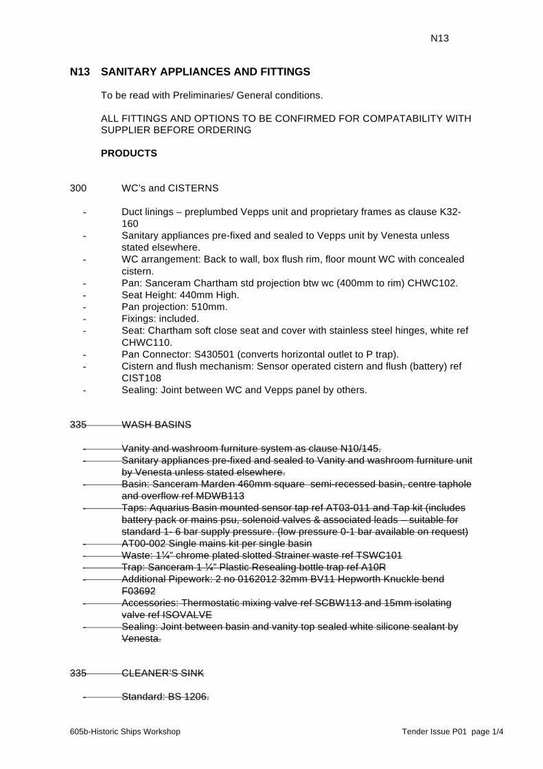
N13
605b-Historic Ships Workshop Tender Issue P01 page 1/4
N13 SANITARY APPLIANCES AND FITTINGS To be read with Preliminaries/ General conditions. ALL FITTINGS AND OPTIONS TO BE CONFIRMED FOR COMPATABILITY WITH
SUPPLIER BEFORE ORDERING PRODUCTS 300 WC’s and CISTERNS
- Duct linings – preplumbed Vepps unit and proprietary frames as clause K32-160
- Sanitary appliances pre-fixed and sealed to Vepps unit by Venesta unless stated elsewhere.
- WC arrangement: Back to wall, box flush rim, floor mount WC with concealed cistern.
- Pan: Sanceram Chartham std projection btw wc (400mm to rim) CHWC102. - Seat Height: 440mm High. - Pan projection: 510mm. - Fixings: included. - Seat: Chartham soft close seat and cover with stainless steel hinges, white ref
CHWC110. - Pan Connector: S430501 (converts horizontal outlet to P trap). - Cistern and flush mechanism: Sensor operated cistern and flush (battery) ref
CIST108 - Sealing: Joint between WC and Vepps panel by others.
335 WASH BASINS
- Vanity and washroom furniture system as clause N10/145. - Sanitary appliances pre-fixed and sealed to Vanity and washroom furniture unit
by Venesta unless stated elsewhere. - Basin: Sanceram Marden 460mm square semi-recessed basin, centre taphole
and overflow ref MDWB113 - Taps: Aquarius Basin mounted sensor tap ref AT03-011 and Tap kit (includes
battery pack or mains psu, solenoid valves & associated leads – suitable for standard 1- 6 bar supply pressure. (low pressure 0-1 bar available on request)
- AT00-002 Single mains kit per single basin - Waste: 1¼” chrome plated slotted Strainer waste ref TSWC101 - Trap: Sanceram 1 ¼” Plastic Resealing bottle trap ref A10R - Additional Pipework: 2 no 0162012 32mm BV11 Hepworth Knuckle bend
F03692 - Accessories: Thermostatic mixing valve ref SCBW113 and 15mm isolating
valve ref ISOVALVE - Sealing: Joint between basin and vanity top sealed white silicone sealant by
Venesta. 335 CLEANER’S SINK
- Standard: BS 1206.

N13 Sanitary appliances and fittings (continued) N13
605b-Historic Ships Workshop Tender Issue P01 page 2/4
- Manufacturer: Armitage Shanks. - Product reference: Birch Cleaner’s Sink ref. S5915(01). - Size: 46cm wide (455 x 390mm). - Material: Fireclay, White. - Configuration: Wall hung with supporting bearer and legs
- Tap/ Chainstay/ Overflow holes: none. - Water supply fittings: Wall mounted anti-vandal lever taps\ - Water supply temperature (maximum):____. - Flow rate (maximum): 6/l per minute. - Manufacturer: Armitage Shanks.
- Product reference: Alterna 21 bib taps 1⁄2” lever handles, anti vandal outlet, pair, ref. B1457, with 6 l/per minute flow restrictors fitted, pair, ref. S8011NU. Nimbus 21 exposed bib tap wall mounts self centralising installation, pair, ref. B1688.
- Wastes: Strainer type, brass, chrome plated - Standards: To BS EN 274-1, -2 and -3. - Manufacturer: Armitage Shanks.
- Product reference: S8726(AA). - Size: 11⁄2”. - Material: Brass. - Tail: 80mm unslotted.
- Traps: Bottle trap. - Standards: To BS EN 274-1, -2 and -3. - Manufacturer: Armitage Shanks.
- Product reference: S8915 11⁄2” bottle trap with 75mm seal. - Size: 11⁄2” . - Material: White plastic. - Depth of seal (minimum): 75 mm.
- Accessories: S9233 legs 350mm stainless steel plus 355mm long aluminium alloy wall bearers, with studs (pair). Legs to be cut down on site to suit installation inside joinery cabinet as shown on drawings.
375 SHOWER UNITS
- Duct linings – preplumbed Vepps unit and proprietary frames as clause K32-160
- Sanitary appliances pre-fixed and sealed to Vepps unit by Venesta unless stated elsewhere.
- Tray: STSQ909 Sanceram 900 x 900mm Shower tray - Shower Control: Sanceram Sequential lever operated concealed shower valve
with built in TMV3 control suitable for all users ref SHWR112 and Chrome hose union to use with concealed shower valve ref SPE01
- Water Outlet: Grab rail based shower kit SHWR115 including 2000mm hose, and 900mm White grab rail riser.
- Sealing: Joint between shower tray and Vepps panel/V-epps base rail, by others.
- Accessories: Thermostatic mixing valve ref SCBW113 and 15mm isolating valve ref ISOVALVE
442 PAPER TOWEL DISPENSER
- Quantity: As per drawing BD-50 series

N13 Sanitary appliances and fittings (continued) N13
605b-Historic Ships Workshop Tender Issue P01 page 3/4
- Supplier and reference: Venesta Washroom Systems, 1st Floor, Units 19-23, St George’s Square, St George’s Shopping Centre, Gravesend, Kent, DA11 0TA. Tel 01474 353333.
- Product: Lockable paper towel dispenser. - Product code: 0302526. - Materials: Brushed stainless steel, hinged cover with viewing windows. - Dimensions: 380mm high x 260mm wide x 125mm deep. - Weight: 2.5 kg. - Paper: Interleaved, c-fold or z-fold towels from 65mm deep (maximum 95mm),
up to 240mm wide. - Capacity: 750 sheets. - Fixing: Includes fixing kit for hard wall installations. Other wall or board types
will require a suitable fixing kit. 472 HAND DRIERS
- Quantity: As per drawing BD-50 series - Supplier and reference: Venesta Washroom Systems, 1st Floor, Units 19-23,
St George’s Square, St George’s Shopping Centre, Gravesend, Kent, DA11 0TA. Tel 01474 353333.
- Product: Automatic warm air warm air drier. - Product reference and colour: 0302535 - Silver. - Materials: Die cast aluminium. - Standard: to BS EN 60335-2-23. - Operation: Infrared fully automatic and self adjusting. - Operating voltage: 220 – 240V 50Hz. - Heater Element: 250W Thermal protected - Power Rating: 900 Watts. - Sound Level: 70dba at 1 metre from air outlet. - Air Speed: 90m/s (200m/h). - Drying time: 10 seconds. - Timing protection: 60 seconds to auto shut off - Unit dimensions: 300mm high x 280mm wide x 175mm deep. - Weight: 4.5 kg. - Fixing: Includes fixings for hard wall installation. Other wall or board types will
require a suitable fixing kit.
474 WASTE BINS
- Quantity: 1 no Required. - Supplier and reference: Venesta Washroom Systems, 1st Floor, Units 19-23,
St George’s Square, St George’s Shopping Centre, Gravesend, Kent, DA11 0TA. Tel 01474 353333.
- Product: Elite, fully recessed waste bin with a removable polypropylene integral waste bin for easy emptying and cleaning. It can be used with or without a waste sack.
- Product code: 0302046. - Materials: High quality brushed stainless steel. - Dimensions: 727mm high x 382mm wide x 206mm deep. - Recess dimensions: 717mm high x 357mm wide x minimum 191mm. - Weight: 11.6 kg. - Capacity: 25 litre.

N13 Sanitary appliances and fittings (continued) N13
605b-Historic Ships Workshop Tender Issue P01 page 4/4
- Fixing: Includes fixing kit for panel installations from 12 to 40mm thick. Other wall or board types will require a suitable fixing kit.

P10
605b-Historic Ships Workshop Tender Issue P01 page 1/2
P10 SUNDRY INSULATION/ PROOFING WORK To be read with Preliminaries/ General conditions. 200 INSULATION FITTED BETWEEN STUDS - Location: Between studs in new timber framed partition walls. - Manufacturer: Isover Saint Goban - Product reference: Isover APR 1200 - Material: Glass Mineral Wool. (Min 24kg/m3 density required) - Facing: None. - Recycled content: 75% recycled glass - Thickness: 50mm. - Installation requirements: - Joints: Butted, no gaps. - Fasteners: Use where necessary to retain insulation and/ or prevent slumping. 240 INSULATION FITTED BETWEEN FLOOR/CEILING JOISTS - Manufacturer: Knauf Insulation Ltd.. - Product reference: Earthwool Flexible Slab cut down in width if necessary to suit
joist centres. - Material: Rock Mineral Wool. (Min 30kg/m3 density required) - Recycled content: N/A. - Thickness: 70mm. - Installation requirements: - Support: with netting to prevent insulation dropping onto ceiling below. - Joints: Butted, no gaps. - Service holes: Sealed, and debris removed before laying insulation. 310 VAPOUR CONTROL LAYER - Manufacturer: Visqueen. - Product reference: Vapour Barrier plus VisqueenPro Tapes. - Material: 1200g polyethylene. - Minimum vapour resistance: >530 MNs/g . - Installation requirements: - Setting out: Joints minimized. - Method of fixing: in accordance with BS5250: 2002 Code of Practice - Joints: At supports only, lapped 150 mm minimum. - Openings: Membrane fixed to reveals. - Joints and edges: Sealed with double sided tape with vapour resistivity not less
than the vapour control layer. - Penetrations: Sealed. - Other requirements: Use VisqueenPro Vapour Tape for jointing and VisqueenPro
Vapour Edge Tape for sealing at perimeters. 320 BREATHER MEMBRANE - Manufacturer: A. Proctor Group Ltd., The Haugh, Blairgowrie, PH10 7ER - Product reference: Frameshield 100. - Installation requirements: - Setting out: Joints minimized. Membrane to form a continuous barrier to prevent
water, snow and wind blown dust reaching the substrate. - Method of fixing: top edges temporarily taped in position to substrate with
breather membrane tape then membrane permanently retained by SW battens fixed over.
- Joints: Lapped 100 mm minimum horizontally and 150 mm minimum vertically.

P10 Sundry insulation/ proofing work (continued) P10
605b-Historic Ships Workshop Tender Issue P01 page 2/2
- Openings: Membrane fixed to reveals. - Bottom edges: Membrane lapped over flashings, sills, etc. to allow free drainage
to the exterior. - Penetrations: Sealed.
P12
605b-Historic Ships Workshop Tender Issue P01 page 1/6
P12 FIRE STOPPING SYSTEMS To be read with Preliminaries/ General conditions. GENERAL 130 FIRE STOPPING SYSTEM TO DUCTWORK PASSING THROUGH FIRE
RESISTING WALLS OR PARTITIONS - Fire resistance: 1 hour. - Penetration seal: Thermal laminate compressible strips retained with sealant or
mineral wool batt system retained with sealant. Ablative coated mineral wool batt system may be used in non-visual locations or where white coated appearance will be acceptable to view. In visual locations check acceptability with Architect.
- Size: to suit clearance around ductwork in accordance with manufacturer’s requirements to achieve fire rating. Clearance to be kept to minimum by accurately forming service opening. Openings in framed partitions to be fully trimmed out with metal framing and linings around all four sides to provide flat surfaces to retain the seal material in place against the ductwork.
- Sealant: Low modulus silicone sealant to retain penetration seal material and form acoustic seal around ductwork. Sealant material compatible/ tested with penetration seal system.
- Colour: Black or to match wall finish, to be agreed with Architect. 131 FIRE STOPPING SYSTEM TO DUCTWORK PASSING THROUGH FIRE
RESISTING FLOORS - Fire resistance: 1 hour. - Penetration seal: Thermal laminate compressible strips retained with sealant or
mineral wool batt system retained with or without brackets, framing and sealant. Ablative coated mineral wool batt systems may be used in non-visual locations or where white coated appearance will be acceptable to view.
- Size: to suit clearance around ductwork (clearance to be kept to minimum) in accordance with manufacturer’s requirements to achieve fire rating.
- Sealant: Low modulus silicone sealant to retain penetration seal material and form acoustic seal around ductwork. Sealant material compatible/ tested with penetration seal system.
- Colour: to be agreed with Architect. 132 FIRE STOPPING SYSTEM TO METAL PIPEWORK PASSING THROUGH FIRE
RESISTING WALLS OR FLOORS - Fire resistance: 1 hour. - Penetration seal: metal pipe sleeves. - Size: to comply with requirements of services and services engineer’s
specifications. Sleeves to extend through full thickness of wall/ floor and be accurately positioned to give a minimum clearance around services of 10mm or diameter of service, whichever is the least. Ends of sleeves to finish flush with wall surfaces where exposed to view. Sleeves, whether built-in or installed in preformed holes, to be bedded solid. Sleeves through framed partitions to be supported by additional framing or plywood patresses. Gaps around sleeves through masonry construction to be filled with fire resisting mortar.
- Sealant: Seal annular space between service and sleeve by filling with compressed mineral wool and capping with sealant as clause 390.
- Colour: sealant colour to be agreed with Architect.
P12 Fire stopping systems (continued) P12
605b-Historic Ships Workshop Tender Issue P01 page 2/6
133 FIRE STOPPING SYSTEM TO PLASTICS PIPEWORK PASSING THROUGH FIRE RESISTING WALLS OR FLOORS
- Fire resistance: 1 hour. - Penetration seal: Pipe collar with concealed intumescent. - Size: sized to suit pipe diameters in accordance with manufacturers
requirements. Fixed in accordance with manufacturer’s requirements. Wherever possible located so that pipe collars are not exposed to view in finished accommodation. Where this is unavoidable, seek instructions from Architect and colour of collar is to be agreed.
- Sealant: Used where acoustic sealing is also required: sealing between service and pipe collar with low modulus silicone. Check compatibility of sealant product used in this application with pipe collar manufacturer.
- Colour: sealant colour to be agreed with Architect in visible locations. 134 FIRE STOPPING SYSTEM TO (NON DATA) CABLES OR CABLE BUNDLES
PASSING THROUGH FIRE RESISTING WALLS OR FLOORS - Fire resistance: 1 hour. - Penetration seal: as clause 132. - Size: as clause 132. - Sealant: as clause 132. - Colour: as clause 132. 135 FIRE STOPPING SYSTEM TO DATA CABLES OR DATA CABLE BUNDLES
PASSING THROUGH FIRE RESISTING WALLS OR FLOORS - Fire resistance: 1 hour. - Penetration seal: Pipe collar with concealed intumescent sized to allow additional
spare capacity of volume of data cables through aperture. In acoustically sealed applications with tightly packed Intumescent pillows around cabled services. Both to allow ease of rewire of data cabling installation.
- Size: varies, fixed in accordance with manufacturer’s requirements. Wherever possible located so that pipe collars are not exposed to view in finished accommodation. Where this is unavoidable, seek instructions from Architect and colour of collar is to be agreed.
- Sealant: none. - Colour: N/A. 136 FIRE STOPPING SYSTEM TO CABLE TRAYS PASSING THROUGH FIRE
RESISTING WALLS OR PARTITIONS - Fire resistance: 1 hour. - Penetration seal: Thermal laminate compressible strips tightly packed around
cables to seal tray volume and to seal around cable tray perimeter back to accurately formed builderswork service opening. In visual locations i.e. high level, materials will be black in colour or capable of accepting spraying out black without affecting performance.
- Size: to suit clearance around cable tray in accordance with manufacturer’s requirements to achieve fire rating. Clearance to be kept to minimum by accurately forming service opening. Openings in framed partitions to be fully trimmed out with metal framing and linings around all four sides to provide flat surfaces to retain the seal material in place against the sides of the cable tray.
- Sealant: Low modulus silicone sealant to retain penetration seal material and form acoustic seal around ductwork. Sealant material compatible/ tested with penetration seal system.
- Colour: Black or to match wall finish, to be agreed with Architect.
P12 Fire stopping systems (continued) P12
605b-Historic Ships Workshop Tender Issue P01 page 3/6
160 LINEAR GAP SEALING NARROW LINEAR GAPS LOW MOVEMENT SUCH AS
PERIMETERS OF FIRE RESISTING PARTITIONS - Fire resistance: 1 hour. - Gap width or height (nominal): 3mm-5mm. - Gap filler: compressed mineral wool or other fire rated isolation strip compressed
behind jamb studs or partition head detail. - Sealant: as clause 395. - Colour: grey or white selected to suit adjacent surfaces finish colours (grey for
darker colours). This sealant can be over painted in with walls/ ceilings. 165 LINEAR GAP SEALING NARROW LINEAR GAPS HIGH MOVEMENT SUCH AS
DOOR FRAME TO STRUCTURAL OPENING GAPS, LINEAR GAPS IN WALLS SUCH AS MOVEMENT JOINTS AND ABUTMENTS WITH SLABS
- Fire resistance: 1 hour. - Gap width or height (nominal): 6mm-25mm. - Gap filler: compressed mineral wool or sealant backing material. - Sealant: as clause 390. - Colour: Black, grey or white selected to suit adjacent surface finish colours if
sealant visible, see confirmation for particular instances. 240 FIRE PERFORMANCE OF FIRE RESISTING WALLS AND FLOORS GENERALLY - Resistance to fire: 1 hour integrity and insulation. - Reaction to fire: In accordance with Building Regulations, Class 0. - Smoke resistance: - Air leakage rate (maximum): 10 m3/m2/h when tested at 25 Pa to BS 476-31 . PRODUCTS 300 FIRE STOPPING SYSTEM PROPOSALS - For each different type of fire stopping application as per clauses 130-136, 160 and
165 (and any other applications or instances required to complete the fire stopping work) where the systems are specified generically, the Fire Stopping Subcontractor is to provide details of proposed method of fire stopping to be installed together with locations for agreement with the Architect and Design Team for checking sufficiently in advance of installations commencing. These proposals are to include selected product/ systems including colours of components and materials to be used.
305 PRODUCT CERTIFICATION - Requirement: All fire stopping products must: - Comply with the relevant British Standards - Be independent third party tested - Be approved or certified products listed or registered by one or more of the
following organisations: the British Board of Agrement (BBA), Warrington Certification (CERTIFIRE), Loss Prevention Certification Board (LPCB).
- Certification: For products specified generically, Installers to submit evidence of compliance with the above specification requirements for each product to be used for checking sufficiently in advance of installation commencing.
- Acceptable evidence: see above. Provide Certificates. 330 FIRE STOP LAMINATE -IN COMPRESSIBLE STRIP FORM EG FOAM PLUS
GRAPHITE INTUMESCENT - Manufacturer: Selected by Fire Stopping subcontractor.
P12 Fire stopping systems (continued) P12
605b-Historic Ships Workshop Tender Issue P01 page 4/6
- Product reference: Selected by Fire Stopping subcontractor. - Strip width: to suit installation. 335 INTUMESCENT FOAM FOR CONCEALED FROM VIEW APPLICATIONS
GENERIC - Manufacturer: Selected by Fire Stopping subcontractor. - Product reference: Selected by Fire Stopping subcontractor. 338 INTUMESCENT MASTIC - Manufacturer: Selected by Fire Stopping subcontractor. - Product reference: Selected by Fire Stopping subcontractor. 340 INTUMESCENT MORTAR - Manufacturer: Selected by Fire Stopping subcontractor. - Product reference: Selected by Fire Stopping subcontractor. 342 FIRE RESISTING MORTAR - Manufacturer: Selected by Fire Stopping subcontractor. - Product reference: Selected by Fire Stopping subcontractor. 360 MINERAL WOOL RIGID BATTS - Standard: To BS EN 13162. - Manufacturer: Selected by Fire Stopping subcontractor. - Product reference: Selected by Fire Stopping subcontractor. - Recycled content: N/A. 365 MINERAL WOOL RIGID BATTS - ABLATIVE COATED - Standard: To BS EN 13162. - Manufacturer: Selected by Fire Stopping subcontractor. - Product reference: Selected by Fire Stopping subcontractor. - Recycled content: N/A. 370 PIPE COLLAR - CONCEALED INTUMESCENT - Manufacturer: Selected by Fire Stopping subcontractor. - Product reference: Selected by Fire Stopping subcontractor. 385 SEALANT BACKING MATERIAL - Manufacturer: Selected by Fire Stopping subcontractor. - Product reference: closed cell compressible resilient strip/ tape/ profile or tightly
packed mineral wool. 390 SEALANTS - FIRE RESISTING SILICONE –HIGH MOVEMENT JOINTS - Standard: To BS 5889 Type A. - Manufacturer: Adshead Ratcliffe (01773) 826 661. - Product reference: Arbosil 1070 (grey/black) or Arbosil 1071 (white), plus primer
Arbo 2650. 395 SEALANTS - ONE-PART FIRE RESISTING ACRYLIC –LOW MOVEMENT JOINTS - Manufacturer: Adshead Ratcliffe (01773) 826 661. - Product reference: Arbo XL 1075.

P12 Fire stopping systems (continued) P12
605b-Historic Ships Workshop Tender Issue P01 page 5/6
EXECUTION 600 FIRE STOPPING INSTALLER - Fire Stopping is to be installed by a specialist third party certificated Fire Stopping
Installer certificated under appropriate schemes by a UKAS accredited third party certification body. The Fire Stopping Installer will also be a member of an approval scheme such as FIRAS, a member of the ASFP or be listed in the LPCB Red Book, and carry out their work in accordance with the recommendations of an industry recognised code of practice such as the ASFP Technical Guidance Document 17.
- Provide details of certification and scheme membership(s) of the proposed Fire Stopping Installer to the Contract Administrator for approval to proceed prior to letting subcontract.
- Exceptions: sealing and stopping associated with Fire Doors, which may be installed by FIRAS accredited door installation subcontractor, and sealing and stopping associated with drylined partition installations, which is to be carried out by the dry lining contractor. Fire stopping around services passing through partitions is to be carried out by the Fire Stopping subcontractor.
620 WORKMANSHIP GENERALLY - Gaps: Seal gaps between building elements and services, to provide fire resistance
and resist the passage of smoke. - Adjacent surfaces: Prevent overrun of sealant or mortar on to finished surfaces. 650 INSTALLING FIRE STOP LAMINATE - Fitting of strips: Compress strips and fit into gap so that, as they decompress, the
strips wedge themselves in the void. - Shrink wrapping: Follow manufacturer’s recommendations in respect of removal. - Joints: - Ends of strips: Fit intumescent ‘end piece’ at both ends of run of stop laminate. - Joints between strips: Fit two intumescent ‘end pieces’ at each butt joint. 660 APPLYING INTUMESCENT FOAM - New joints: Remove builder’s debris, mortar droppings, grease, and other
contaminants. - Old joints: Clean and remove existing sealant from each joint. - Priming: Lightly moisten substrate with water. - Application: Fill joint to approximately half its depth, and allow foam to expand to
face of joint. - Trimming: Check with manufacturer that this does not compromise performance
before trimming. 670 APPLYING INTUMESCENT MORTAR - Sequence: Install mortar after services are permanently installed. - Loose dust and combustible materials: Remove from the opening. - Shuttering: Install suitable shuttering panels to the faces of the opening. - Temperature: Do not apply mortar when it could be damaged by frost. - Powder:water ratio: as manufacturer’s requirements. - Mortar cure: Do not disturb mortar before final set has taken place. - Shuttering: Remove after mortar has cured. 710 INSTALLING MINERAL WOOL BATTS - Installing batts: Fit tight into void between the penetrating services and the
surrounding construction to form a solid barrier. - Brackets: in accordance with system manufacturer’s requirements, if required. Bracket fixing: in accordance with system manufacturer’s requirements.

P12 Fire stopping systems (continued) P12
605b-Historic Ships Workshop Tender Issue P01 page 6/6
- Face of batts: Flush with the surface of wall, floor or soffit. - Joints between batts: closed butted and sealed with adhesive or sealant as per
manufacturer’s requirements. - Gaps between services and barrier: Seal with fire resisting sealant. 730 FIXING PIPE COLLAR - Collar fixing: in accordance with manufacturer’s requirements and section Z20. - Gap around collar: Where collar inserted into thickness of wall rather than surface
mounted, annular gap to be 20mm, sealed fire resisting silicone sealant. - Length of wraps: If applicable, project 50mm from each side of the element. 740 INSERTING SEALANT BACKING MATERIAL - Preparation: Remove debris from service penetration. - Installation: To uniform depth and without gaps to allow a correct depth of sealant to
be installed. 745 APPLYING SEALANTS GENERALLY - Application: As section Z22. 750 APPLYING CAPPING SEALANT - Preparation: Degrease or use primer if required or recommended by sealant
manufacturer in the application used. - Priming: With primer recommended by sealant manufacturer if required. - Depth of sealant: To achieve the required fire resistance rating, typically 1 hour
minimum. - Temperature: Do not apply water based sealants when they could be damaged by
frost. COMPLETION 910 CLEANING - Masking tapes: Remove. - Cleaning: Clean off splashes and droppings. Wipe down finishes. 920 INSPECTION - Notice for inspection (minimum): 1 week.
P20
605b-Historic Ships Workshop Tender Issue P01 page 1/1
P20 UNFRAMED ISOLATED TRIMS/ SKIRTINGS/ SUNDRY ITEMS To be read with Preliminaries/ General conditions. 110 SOFTWOOD SKIRTINGS - Quality of wood and fixing: To BS 1186-3. - Species: Contractor’s Choice . - Class: 2 . - Moisture content at time of fixing: 8-12% . - Preservative treatment: Not required . - Fire rating: N/A . - Profile: Square edge Softened arris . - Finished size: to match existing on site - Finish as delivered: prime all sides and backs prior to installation, then site
decorated as section M60, colour tbc, Eggshell finish. - Recycled content: N/A. - Fixing: 38mm x no 10 woodscrews at 450mm centres. Pelleted and decorated 120 HARDWOOD FASCIA TO MEZZANINE FLOOR - Quality of wood and fixing: To BS 1186-3. - Species: Birch veneered plywood and birch solid capping piece - Class: J2 - Moisture content at time of fixing: 9-13%. - Preservative treatment: Not required. - Fire rating: N/A. - Profile: rectangular - Finished size: 68x18mm. - Finish as delivered: pre-sanded to fine grade finish for site staining as M60/160. - Fixing: with lost head pins. 240 PLYWOOD EXPOSED - Face ply species: Birch - Appearance class to BS EN 635: I - Bond quality to BS EN 314-2: - Fire rating: Finished to Class 0 fire rating as M60/180 - Thickness: To detail - Edges: To detail - Support/ Fixing: To detail 510 INSTALLATION GENERALLY - Joinery workmanship: As section Z10. - Metal workmanship: As section Z11. - Methods of fixing and fasteners: As section Z20 where not specified. - Straight runs: To be in one piece, or in long lengths with as few joints as possible. - Running joints: Location and method of forming to be agreed where not detailed. - Joints at angles: seek clarification whether butted or mitred in each instance. - Position and level: To be agreed where not detailed.

605b-Historic Ships Workshop Tender Issue P01 page 1/3
P31 HOLES, CHASES, COVERS AND SUPPORTS FOR SERVICES To be read with Preliminaries/ General conditions. PRODUCTS - REFER TO SERVICES ENGINEERS SPECIFICATION AND ALSO SECTION P12. EXECUTION 610 COORDINATION - Locations and dimensions of holes and chases for services: Submit details for
checking by Design Team prior to any work commencing, where holes or chases are not already set out on construction drawings. Do not commence formation of holes or chases until approval to proceed is received from the Architect.
620 HOLES, RECESSES AND CHASES IN IN SITU CONCRETE - Cast in: Holes larger than 10 mm diameter, recesses and chases. - Cutting and drilling: - Permitted for holes not larger than 10 mm diameter. - Not permitted for holes larger than 10 mm diameter except as indicated on
drawings, except after requesting and receiving express permission for the specific instance from the Design Team.
640 HOLES IN STRUCTURAL STEELWORK - Cutting and drilling: Not permitted except as indicated on drawings. 650 HOLES, RECESSES AND CHASES IN MASONRY
- Holes, recesses and chases in existing historic masonry (pre-20th Century fabric) must not be formed without permission of the Architect. Services routes requiring holes, recesses or chases in existing historic masonry (including plaster finishes) are to be agreed in advance by marking out on site for inspection and approval by the Architect and Structural and Services Engineers if necessary before proceeding.
- Locations: To maintain integrity of strength, stability and sound resistance of construction.
- Sizes: Minimum needed to accommodate services. - Holes (maximum): 300 mm sq. - Walls of hollow or cellular blocks: Do not chase. - Walls of other materials: - Vertical chases: No deeper than one third of single leaf thickness, excluding
finishes. - Horizontal or raking chases: No longer than 1 m. No deeper than one sixth of the
single leaf thickness, excluding finishes. - Chases and recesses: Do not set back to back. Offset by a clear distance at least
equal to the wall thickness. - Cutting: Do not cut until mortar is fully set. Cut carefully and neatly. Avoid spalling,
cracking and other damage to surrounding structure. 670 NOTCHES AND HOLES IN STRUCTURAL TIMBER - Holes or notches to existing historic structural timber (pre-20th Century fabric) must
not be formed without permission of the Architect. Services routes requiring holes or

P31 Holes, chases, covers and supports for services (continued) P31
605b-Historic Ships Workshop Tender Issue P01 page 2/3
notches to existing historic structural timber are to be agreed in advance and if necessary, at the request of the Architect, marked out on site for inspection and approval by the Architect and Structural and Services Engineers as necessary before proceeding.
- General: Avoid if possible. - Sizes: Minimum needed to accommodate services. - Position: Do not locate near knots or other defects. - Notches and holes in same joist: Minimum 100 mm apart horizontally. - Notches in joists: - Position: Locate at top. Form by sawing down to a drilled hole. - Depth (maximum): 0.15 x joist depth. - Distance from supports: Between 0.1 and 0.2 x span. - Holes in joists: Locate on neutral axis. - Diameter (maximum): 0.25 x joist depth. - Centres (minimum): 3 x diameter of largest hole. - Distance from supports: Between 0.25 and 0.4 of span. - Notches in roof rafters, struts and truss members: Not permitted. - Holes in struts and columns: Locate on neutral axis. - Diameter (maximum): 0.25 x minimum width of member. - Centres (minimum): 3 x diameter of largest hole. - Distance from ends: Between 0.25 and 0.4 of span. 690 INSTALLING PIPE SLEEVES - Sleeves: Fit to pipes passing through building fabric. - Material: Match pipeline. - Size: One or two sizes larger than pipe to allow clearance. - Finish: Install sleeves flush with building finish. In areas where floors are washed
down, install protruding 100 mm above floor finish. - Masking plates: Fit at visible penetrations, including through false ceilings of
occupied rooms. 710 SEALING AROUND DUCTWORK PENETRATIONS THROUGH NON-FIRE
RATED WALLS AND PARTITIONS - Service: supply and return air ductwork - Location: refer to Architect’s and Mechanical Engineers’s drawings. - Sealing material: low modulus silicone sealant, colour to match wall finishes,
supported on closed cell resilient backing strip. - Method: insert and pack mineral quilt insulation into gap around ductwork
penetration, fit backing strips both sides of partition to tight fit and point flush with sealant.
- Performance requirement: Airtight acoustic seal accommodating movement. 711 SEALING AROUND METAL PIPEWORK PENETRATIONS THROUGH NON-FIRE
RATED WALLS AND PARTITIONS - Service: as above. - Location: refer to Architect’s and Mechanical Engineers’s drawings.. - Sealing material: seal gaps larger than 5mm between pipe sleeve and wall with
filler, small air gaps with acrylic mastic sealant, seal annular space between service and sleeve with low modulus silicone sealant, neatly pointed flush both sides, colour to match wall finishes.
- Method: as above. - Performance requirement: Airtight acoustic seal accommodating movement.

P31 Holes, chases, covers and supports for services (continued) P31
605b-Historic Ships Workshop Tender Issue P01 page 3/3
712 SEALING AROUND ELECTRICAL CABLING PENETRATIONS THROUGH NON-FIRE RATED WALLS AND PARTITIONS
- Service: as above . - Location: refer to Architect’s and Mechanical Engineers’s drawings.. - Sealing material: seal gaps larger than 5mm between pipe sleeve and wall with
filler, small air gaps with acrylic mastic sealant, seal annular space between service and sleeve with low modulus silicone sealant, neatly pointed flush both sides, colour to match wall finishes..
- Method: as above. - Performance requirement: Airtight acoustic seal. 713 SEALING AROUND DATA CABLING PENETRATIONS THROUGH NON-FIRE
RATED WALLS AND PARTITIONS - Service: as above. - Location: refer to Architect’s and Mechanical Engineers’s drawings. - Sealing material: seal gaps larger than 5mm between pipe sleeve and wall with
filler, small air gaps with acrylic mastic sealant, seal annular space between service and sleeve with tightly compressed removable closed cell foam tape/ strip or mineral wool pillows set back 25mm into sleeve
- Method: as above. - Performance requirement: near-airtight acoustic seal (no direct sound paths or
visible gaps through sleeve.) 730 INSTALLING ACCESS COVERS/ GRATINGS AND FRAMES - Seating: as per manufacturers details. - Bedding and haunching of frames: Continuously. - Material: as per manufacturers details. - Top of haunching (where applicable): 30 mm below surrounding surfaces. - Horizontal positioning of frames: - Centred over openings. - Install square with joints in surrounding surfaces or to building grid. - Vertical positioning of frames: - Level; or - Marry in with levels of surrounding surfaces. - Permissible deviation in level of external covers and frames: +0 to -6 mm.

S90
605b-Historic Ships Workshop Tender Issue P01 page 1/5
S90 HOT AND COLD WATER SUPPLY SYSTEMS To be read with Preliminaries/ General conditions. GENERAL 110 MAINS COLD WATER SUPPLY EXTENDED FROM EXISTING SUPPLY 130 INSTANTANEOUS HOT WATER SUPPLY TO SHOWERS - Position of water heater: See drawings - Instantaneous water heater: Megaflow Eco Direct Unvented Cylinder Model 210
DDD (to be confirmed) supplied by Heatrae Sadia SYSTEM PERFORMANCE 210 DESIGN OF NEW SUPPLIES TO ALL FITTINGS INCLUDING SHOWERS AND
ALTERATIONS TO EXISTING SYSTEM - Design: Complete the design of the hot and cold water supply system. - Standard: To BS EN 806-2, BS 8558 and in accordance with HSE publication ‘The
control of legionella bacteria in water systems. Approved code of practice and guidance’.
- Proposals: Submit drawings (showing equipment positions and pipeline routes), technical information, calculations and manufacturers’ literature.
250 PIPELINE SIZES - Sizing: Calculate sizes to meet simultaneous demand for the building in accordance
with BS 8558 or BS EN 806-3. Submit proposals. - Performance: - Water velocity (maximum): 1.3 m/s for hot water and 2.0 m/s for cold water. 260 DRAW OFF REQUIREMENTS - Shower heads: - Discharge rate (minimum): 0.2 L/s. - Washbasins (pillar or mixer taps): - Discharge rate (design): 0.15 L/s. - WC cisterns (to fill in 2 minutes): - Discharge rate (design): 0.13 L/s. PRODUCTS 310 DEZINCIFICATION - Fittings, pipelines, equipment located below ground or in concealed or inaccessible
locations: Resistant to dezincification, e.g. gunmetal. 500 COPPER PIPELINES, CHROMIUM PLATED (VISIBLE PIPEWORK) - Standard: To BS EN 1057, Kitemark certified. - Finish: To BS EN ISO 1456, service condition 2. - Temper: Half hard R250. - Wall thicknesses (nominal): - OD 6, 8, 10 and 12 mm: 0.6 mm.

S90 Hot and cold water supply systems – domestic (continued) S90
605b-Historic Ships Workshop Tender Issue P01 page 2/5
- OD 15 mm, 0.9 mm for 22 and 28 mm: 0.7 mm. - OD 35 and 42 mm: 1.2 mm. - Jointing: Type A compression fittings to BS EN 1254-2. - Finish: Chromium plate to BS EN ISO 1456, service condition 3. - Connections to appliances and equipment: Select from: - Compression fittings: To BS EN 1254-2, Kitemark certified. - Fittings with threaded ends: To BS EN 1254-4. 510 COPPER PIPELINES FOR GENERAL USE - Standard: To BS EN 1057, Kitemark certified. - Temper: Half hard R250. - Finish: Natural - Colour: Natural - Wall thickness (nominal): - OD 6, 8, 10 and 12 mm: 0.6 mm. - OD 15 mm: 0.7 mm. - OD 22 and 28 mm: 0.9 mm. - OD 35 and 42 mm: 1.2 mm. - Jointing generally: Integral lead free solder ring capillary fittings to BS EN 1254-1,
Kitemark certified. - Connections to appliances and equipment: Select from: - Compression fittings: To BS EN 1254-2, Kitemark certified. - Fittings with threaded ends: To BS EN 1254-4. 620 VALVES GENERALLY - Types: Approved for the purpose by local water supply undertaker and of
appropriate pressure and/ or temperature ratings. - Control of valves: Fit with handwheels for isolation and lockshields for isolation and
regulation of circuits or equipment. 640 DRAINING TAPS - Standard: Copper alloy to BS 2879, Type 1, hose connection pattern, Kitemark
certified. 660 GATE VALVES - Standard: To BS 5154, Series B, Kitemark certified or BS EN 12288. EXECUTION 710 STRIPPING OUT - Extent of stripping out: Removal all redundant services runs from space, dead legs,
including those in boxings. - Complete installation. 715 INSTALLATION GENERALLY - Installation: To BS EN 806-4. - Performance: Free from leaks and the audible effects of expansion, vibration and
water hammer. - Fixing of equipment, components and accessories: Fix securely, parallel or
perpendicular to the structure of the building. - Preparation: Immediately before installing tanks and cisterns on a floor or platform,
clear the surface completely of debris and projections.

S90 Hot and cold water supply systems – domestic (continued) S90
605b-Historic Ships Workshop Tender Issue P01 page 3/5
- Corrosion resistance: In locations where moisture is present or may occur, provide corrosion resistant fittings/ fixings and avoid contact between dissimilar metals by use of suitable washers, gaskets, etc.
790 PIPELINES INSTALLATION - Appearance: Install pipes straight, and parallel or perpendicular to walls, floors,
ceilings, and other building elements. - Pipelines finish: Smooth, consistent bore, clean, free from defects, e.g. external
scratching, toolmarks, distortion, wrinkling, and cracks. - Concealment: Generally conceal pipelines within floor, ceiling and/ or roof voids. - Access: Locate runs to facilitate installation of equipment, accessories and
insulation and allow access for maintenance. - Arrangement of hot and cold pipelines: Run hot pipelines above cold where routed
together horizontally. Do not run cold water pipelines near to heating pipelines or through heated spaces.
- Electrical equipment: Install pipelines clear of electrical equipment. Do not run pipelines through electrical enclosures or above switch gear distribution boards or the like.
- Insulation allowance: Provide space around pipelines to fit insulation without compression.
810 SUPPORTS FOR COPPER AND STAINLESS STEEL PIPELINES - Spacing: Fix securely and true to line at the following maximum centres: - 15 and 22 mm pipe OD: 1200 mm horizontal, 1800 mm vertical. - 28 and 35 mm pipe OD: 1800 mm horizontal, 2400 mm vertical. - 42 and 54 mm pipe OD: 2400 mm horizontal, 3000 mm vertical. - Additional supports: Locate within 150 mm of connections, junctions and changes
of direction. 815 SUPPORTS FOR EXPOSED THERMOPLASTICS PIPELINES - Spacing: Fix securely and true to line at the following maximum centres: - Up to 16 mm pipe OD: 300 mm horizontal, 500 mm vertical. - 17–25 mm pipe OD: 500 mm horizontal, 800 mm vertical. - 26–32 mm pipe OD: 800 mm horizontal, 1000 mm vertical. - Additional supports: Locate within 150 mm of connections, junctions and changes
of direction. 820 BENDS IN THERMOPLASTICS PIPELINES - Bends: Do not use 90° elbow fittings instead of 90° bends. - Large radius bends: Support at maximum centres. - 90° bends: Fix pipe clips either side of bend. - Small radius bends: Fully support 90° bends with cold form bend fixtures. 830 PIPELINE SPACING - Clearance (minimum) to face of wall-fixed pipes or pipe insulation: - From floor: 150 mm. - From ceiling: 50 mm. - From wall: 15 mm. - Between pipes: 25 mm. - From electrical conduit, cables, etc: 150 mm. 840 JOINTS IN COPPER AND STAINLESS STEEL PIPELINES - Preparation: Cut pipes square. Remove burrs. - Joints: Neat, clean and fully sealed. Install pipe ends into joint fittings to full depth.

S90 Hot and cold water supply systems – domestic (continued) S90
605b-Historic Ships Workshop Tender Issue P01 page 4/5
- Bends: Do not use formed bends on exposed pipework, except for small offsets. Form changes of direction with radius fittings.
- Adaptors for connecting dissimilar materials: Purpose designed. - Substrate and plastics pipes and fittings: Do not damage, e.g. by heat when forming
soldered joints. - Flux residue: Clean off. 841 CAPILLARY JOINTS IN PLASTICS COATED PIPELINES - Plastics coating: Do not damage, e.g. by direct or indirect heat. Wrap completed
joint (when cool) with PVC tape of matching colour, half lapped. 845 JOINTS IN THERMOPLASTICS PIPELINES - Standard: Fusion jointing in accordance with WIS 4-32-08. - Fittings and accessories for joints: Purpose designed. - Preparation: Cut pipes square. Remove burrs. - Joints: Neat, clean and fully sealed. Install pipe ends into joint fittings to full depth. - Compression fittings: Do not overtighten. 870 INSTALLING VALVES - Isolation and regulation valves: Provide on equipment and subcircuits. - Access: Locate where valves can be readily operated and maintained and next to
equipment which is to be isolated. - Connection to pipework: Fit with joints to suit the pipe material. COMPLETION 910 FLUSHING AND FILLING - Standard: To BS EN 806-4. 920 SYSTEM DISINFECTION - Disinfection: To BS EN 806-4. 930 TESTING - Standard: To BS EN 806-4. - Notice (minimum): 3 days. - Preparation: Secure and clean pipework and equipment. Fit cistern and tank
covers. - Leak testing: Start boiler and run the system until all parts are at normal operating
temperatures and then allow to cool to cold condition for a period of 3 h. - Pressure testing: At both hot and cold conditions joints, fittings and components
must be free from leaks and signs of physical distress when tested for at least 1 h as follows:
- Systems fed directly from the mains, and systems downstream of a booster pump: Apply a test pressure equal to 1.5 times the maximum pressure to which the installation or relevant part is designed to be subjected in operation.
- Systems fed from storage: Apply a test pressure equal to the pressure produced when the storage cistern is filled to its normal maximum operating level.
- Inaccessible or buried pipelines: Carry out hydraulic pressure test to twice the working pressure.
940 COMMISSIONING - Standard: To BS EN 806-4. - Equipment: Check and adjust operation of equipment, controls and safety devices.

S90 Hot and cold water supply systems – domestic (continued) S90
605b-Historic Ships Workshop Tender Issue P01 page 5/5
- Outlets: Check operation of outlets for satisfactory rate of flow and temperature. 950 TESTING SERVICE PIPELINES - Test method: Disconnect from the mains, fill with potable water, exclude air, and
apply at least twice the working pressure for 1 h. - Test criterion: No leakage. 960 DOCUMENTATION - Manufacturers’ operating and maintenance instructions: Submit for equipment and
controls. - System operating and maintenance instructions: Submit for the system as a whole
giving optimum settings for controls. - Record drawings: Submit drawings showing the location of circuits and operating
controls. 970 OPERATING TOOLS - Tools: Supply tools for operation, maintenance and cleaning purposes. - Valve keys: Supply keys for valves and vents. 980 LABELS - Valve labels: Provide labels on isolating and regulating valves on primary circuits,
stating their function.

T90
605b-Historic Ships Workshop Tender Issue P01 page 1/2
T90 HEATING SYSTEMS To be read with Preliminaries/ General conditions. GENERAL 110 INDEPENDENT HEATING SYSTEM TO ACCOMMODATE NEW ROOM LAYOUT - System: Electric panel SYSTEM PERFORMANCE 210 DESIGN OF HEATING SYSTEM - Design: Complete the design and detailing of the heating system including
specifying final size and number of heating panels. - Proposals: Submit drawings (showing equipment positions and pipeline routes),
technical information, calculations and manufacturer’s literature. 220 BASIC DESIGN TEMPERATURES - Room temperatures: Design the system to provide the following temperatures for
the specified ventilation rates and an external air temperature of -4°C: - Office and workspaces: Temperature: 21°C, for 1.5 air changes per hour. - Workshops: Temperature: 18°C, for 2 air changes per hour. - Kitchens: Temperature: 18°C, for 2 air changes per hour. - Toilets: Temperature: 18°C, for 2 air changes per hour. PRODUCTS 455 ELECTRIC PANEL HEATERS TO WCs AND OFFICES - Type: Flat panel - Manufacturer: Dimplex - Product reference: Girona Panel Heater (Ref GFP200WE) - Output: 2.0kw 456 ELECTRIC OIL FILLED HEATERS TO WORKSHOPS - Type: Flat panel - Manufacturer: Dimplex - Product reference: Dimplex OFS oil filled panel heaters EXECUTION 610 INSTALLATION GENERALLY - Standard: To BS EN 14336. - Performance: Free from leaks and the audible effects of expansion, vibration and
water hammer. - Fixing of equipment, components and accessories: Fix securely, parallel or
perpendicular to the structure of the building. - Preparation: Immediately before installing tanks and cisterns on a floor or platform,
clear the surface completely of debris and projections.
T90 Heating systems – domestic (continued) T90
605b-Historic Ships Workshop Tender Issue P01 page 2/2
- Corrosion resistance: In locations where moisture is present or may occur, use corrosion resistant fittings/ fixings and avoid contact between dissimilar metals by use of suitable washers, gaskets, etc.
COMPLETION 810 TESTING - Standard: To manufacturers guidelines 820 SETTING TO WORK AND COMMISSIONING - Equipment: Check and adjust operation of equipment, controls and safety devices. - Outlets: Check operation of outlets for satisfactory temperature. 840 DOCUMENTATION - Manufacturers’ operating and maintenance instructions: Submit for equipment and
controls. - System operating and maintenance instructions: Submit for the system as a whole
giving optimum settings for controls. - Record drawings: Submit drawings showing the location of circuits and operating
controls. 850 LABELS - Valve labels: Provide labels on isolating and regulating valves on primary circuits,
stating their function.

U90
605b-Historic Ships Workshop Tender Issue P01 page 1/2
U90 GENERAL VENTILATION To be read with Preliminaries/ General conditions. GENERAL 130 LOCAL EXTRACT FAN VENTILATION WC BLOCK G002-004 - Room extract terminals: See drawings - Fan units: Addvent AVWH2N-DC energy saving version. Air supply drawn from
main space and stairwell. - Air ductwork: As shown on drawings - Air ductwork accessories: As shown on drawings - External exhaust air terminals: To detail on drawings - Controls: Trickle extract via multi vent and PIR control SYSTEM PERFORMANCE 210 DESIGN OF LOCAL EXTRACT PROVISION TO WC BLOCK G002-004 - Design: Complete the design of the ventilation system. - Ventilation rate: To comply with Building regulations and CIBSE guidance, minimum
of 15 litres/ sec per shower. - Proposals: Submit drawings (showing equipment positions and ductwork routes),
technical information, calculations and manufacturers’ literature including control via PIR sensors
EXECUTION 660 FLEXIBLE DUCTWORK - Installation: Fully extend without overstretching. - Support: Form smooth flowing curves without kinking, sagging or slumping. 670 RIGID DUCTWORK GENERALLY - Joints: Seal. Provide a robust airtight installation. - Support: Do not distort ductwork or reduce cross-sectional area. Do not strain
joints. - Falls: Fall away from fans, dampers and other in-line accessories. - Sleeves: Locate where ducts pass through building fabric. Bed solidly to the
surrounding construction. Leave a gap of 10-20 mm between sleeve and duct and fill completely.
690 SITE APPLIED INSULATION - Location: Fit insulation to ductwork in unheated spaces. - Installation: Fix securely. Leave no gaps. Make continuous. COMPLETION 910 COMMISSIONING - Ventilation system: Balance airflow using methods recommended by the system
manufacturer. - Operation: Examine ductwork for leakage. Test the operation of fans, equipment,
controls and sensors. Verify correct operation. Submit report.

U90 General ventilation - domestic (continued) U90
605b-Historic Ships Workshop Tender Issue P01 page 2/2
920 OPERATION AND MAINTENANCE - Operating and maintenance instructions: Submit copies of manufacturers’ operating
and maintenance instructions for equipment and controls. - Tools: Supply tools for operation, maintenance and cleaning purposes, including
keys for valves and vents.

V90
605b-Historic Ships Workshop Tender Issue P01 page 1/8
V90 ELECTRICAL SYSTEMS To be read with Preliminaries/ General conditions. GENERAL 110 LOW VOLTAGE SUPPLY - Nature of current: Alternating. - Contractor to examine existing installation- see drawings EX 31 001-003 131 LV CABLING FOR NEW WORK. - Cable: To match existing 132 CONTAINMENT AS SHOWN ON DRAWINGS. SYSTEM PERFORMANCE 210 DESIGN OF LOW VOLTAGE ELECTRICAL INSTALLATION GENERALLY - Design and detailing: Complete for the electrical installation. - Standards: In accordance with BS 7671 and the requirements of the Electricity
Distributor. - Proposals: Submit drawings, technical information, calculations and manufacturers’
literature. 220 DESIGN OF LOW VOLTAGE INCOMING SUPPLY - Design and detailing: Complete for the low voltage incoming supply. - Spare capacity: Not required. - Proposals: Submit drawings showing equipment positions and routes, technical
information and calculations. - Evidence of agreement with Electricity Distributor: Submit. - General: Manage and liaise with the Electricity Distributor and determine: - Maximum demand of the installation. - Nature of the supply, its suitability for the installation and type of earthing
arrangement. - Location of the incoming supply. - Space requirements and location of the cut-outs, switches, fuses and meters. - Electricity Supplier - Coordination: Liaise with the Electricity Supplier, complete an application for
supply of electricity and manage installation of metering equipment. 230 LV DISTRIBUTION SYSTEM DESIGN - Design: To cater for the complete working building. - Spare capacity of distribution equipment: Not required. - Equipment: Provide electrical supplies to equipment requiring power. 235 ARRANGEMENT OF PARTICULAR CIRCUITS - Separation: Divide installation into separately controlled circuits. - Further subdivision: As required. 240 DESIGN OF GENERAL LIGHTING SYSTEM - Purpose: New lighting for workspace .
V90 Electrical systems - domestic (continued) V90
605b-Historic Ships Workshop Tender Issue P01 page 2/8
- Design and detailing: Complete for the general lighting system. - Standard: To SLL ‘Code for lighting’. - Controls: Switched to locations shown on drawings - Maintenance: Submit proposals for the maintenance/ relamping regime. 250 DESIGN OF EMERGENCY LIGHTING SYSTEM - Purpose: To extend existing system to new areas - Design and detailing: Complete for the emergency lighting system. - Standards: - Emergency escape lighting: In accordance with BS 5266-1. - Escape route, open area, high risk task area and standby lighting: To BS EN
1838 and BS EN 50172. 265 DESIGN AND LIGHTING CALCULATIONS - Proposals: Submit drawings, technical information, calculations and manufacturers’
literature. - Lighting calculations: - Type: Computer generated point calculations. - Submit the following: - Luminaire layout drawings. - Luminaire photometric data including flux fraction ratios and polar intensity
curves. - Lamp technical information. - Maintenance factor calculations, including proposals for luminaire maintenance
and lamp replacement. - Reflectance values used for all wall, ceiling and floor surfaces. - Isolux contour plots for all relevant working planes, horizontal and vertical. - Schedule of design and calculated maintained average illuminance values. - Schedule of design and calculated uniformity values. 275 SMALL POWER SYSTEM DESIGN - Purpose: To cater for the modified electrical installations. - Small power outlets: Provide to serve the building and its equipment. - Fixed equipment: Provide supplies. 280 EARTHING AND BONDING DESIGN - Design: Complete the design of the earthing and bonding systems. - Earthing, main bonding, supplementary bonding and protective conductors: In
accordance with BS 7430. - Requirements: Submit proposals. PRODUCTS 310 PRODUCTS GENERALLY - Standard: In accordance with BS 7671. - CE marking: Required. 320 DISTRIBUTION BOARDS - Standards: To BS EN 61439-1 and BS EN 61439-3. - Manufacturer: To be agreed. - Product reference: To be agreed. - Third party certification: ASTA certified.
V90 Electrical systems - domestic (continued) V90
605b-Historic Ships Workshop Tender Issue P01 page 3/8
- Contractor to provide outline proposals with tender 330 CABLE TRAYS WHERE SHOWN ON DRAWINGS - Standard: To BS EN 61537. - Width: To suit installation requirements - Material: Galvanised perforated steel
Type: . Perforated steel not less than 20 swg up to 100mm width, or 18swg from 100mm to 150mm width and 16swg from 150mm to 300mm width
- Accessories and fittings: Factory made of the same material type, pattern, finish and thickness as cable tray.
342 RIGID CONDUIT AND FITTINGS - Standards: To BS EN 61386-1 and BS EN 61386-21. - Type: Suitable for location and use. - Accessories and fittings: Factory made by the conduit manufacturer of the same
material type and finish as the conduit. 350 STEEL CABLE TRUNKING AND CABLE DUCTING FOR WALL AND CEILING
MOUNTING - Standards: To BS EN 50085-1 and BS EN 50085-2-1. - Type: Zinc coated rust proofed steel by an approved manufacturer - Protection by enclosure: - Protection against ingress of solid objects (minimum): To BS EN 60529, IP4X. - Protection against ingress of water (minimum): To BS EN 60529, IPX1. - Protection against access to hazardous parts (minimum): To BS EN 60529,
IPXX-D. - Compartments: To meet requirements of installation - Accessories and fittings: Factory made by the cable trunking or ducting
manufacturer and of the same material type and finish as the cable trunking or ducting.
370 INTUMESCENT LINEAR GAP SEALS - Standard: To BS EN 1366-4. 410 CABLES GENERALLY - Approval: British Approvals Service for Cables (BASEC) certified. - Cable sizes not stated: Submit proposals and calculations. 420 PROTECTIVE CONDUCTORS - Type: Cable conductors with yellow/ green sheath. 430 ELECTRICAL ACCESSORIES - Standards: - Generally: To BS 5733. - Switches: To BS EN 60669-1. - Manufacturer: MK Metalclad Plus. - Finish: Natural Aluminium. 510 LUMINAIRES GENERALLY See drawings 511 LAMPS GENERALLY - Standards:
V90 Electrical systems - domestic (continued) V90
605b-Historic Ships Workshop Tender Issue P01 page 4/8
- Compact fluorescent lamps: To BS EN 60901 and BS EN 61199. - High pressure mercury lamps: To BS EN 60188 and BS EN 62035. - High pressure sodium lamps: To BS EN 62035. - Light emitting diodes (LEDs): To BS EN 62031. - Metal halide lamps: To BS EN 62035. - Tubular fluorescent lamps: Single-capped lamps: To BS EN 60901 and BS EN 61199. Double-capped lamps: To BS EN 60081 and BS EN 61195. - Tungsten halogen lamps: To BS EN 60432-2 and BS EN 60357. - Lamps of the same type and rating: Same manufacturer. 515 LUMINAIRE SUPPORTING COUPLERS - Standards: To BS 6972 and BS 7001. 580 EARTHING AND BONDING EQUIPMENT - Earth electrodes: In accordance with BS 7430. - Earth clamps: To BS 951. EXECUTION 610 ELECTRICAL INSTALLATION GENERALLY - Standard: In accordance with BS 7671. 615 INSTALLING CONNECTION TO INCOMING SUPPLY - Main switchboard/ distribution board: Connect to main incoming metering
equipment. - Nature of connection: Liaise with the DNO to ensure the correct size, quantity and
type of cable is provided for connection to their equipment. 630 INSTALLING SWITCHGEAR - Orientation: Accurate and square to vertical and horizontal axis. Align adjacent
items of switchgear on the same horizontal axis. - Clearance in front of switchgear (minimum): 1 m. - Labelling: Permanently label each way, identifying circuit function, rating and cable
size. 645 INSTALLING CABLE TRAY - Support: Submit proposals. - Access: Provide space encompassing cable trays to permit access for installing and
maintaining cables. - Supports and fasteners: Avoid contact between dissimilar metals. Use corrosion
resistant components in locations where moisture may occur. - Cutting: Along an unperforated line. Minimize. Make good edges. Treat surface as
the tray. - Earth protection: Ensure that, where utilized, tray jointing pieces are properly fixed
and provide satisfactory continuity between the separate sections of containment. 650 INSTALLING CABLE BASKET - Support: Submit proposals. - Access: Provide space encompassing cable basket to permit access for installing
and maintaining cables.

V90 Electrical systems - domestic (continued) V90
605b-Historic Ships Workshop Tender Issue P01 page 5/8
- Supports and fasteners: Avoid contact between dissimilar metals. Use corrosion resistant components in locations where moisture may occur.
- Earth protection: Ensure that, where utilized, basket jointing pieces are properly fixed and provide satisfactory continuity between the separate sections of containment.
655 INSTALLING STEEL CONDUIT AND FITTINGS - Fixing: Fix securely. Fix boxes independently of conduit. - Conduit drainage: Provide drainage outlets at lowest points. - Location: Position vertically and horizontally in line with equipment served, and
parallel with building lines. Locate where accessible. - Jointing: - Number of joints: Minimize. - Lengths of conduit: Maximize. - Cut ends: Remove burrs, and plug during construction works. - Movement joints in structure: Manufactured expansion coupling. - Threaded steel conduits: Tightly screw to ensure electrical continuity, with no
thread showing. - Conduit connections to boxes and items of equipment, other than those with
threaded entries: Earthing coupling/ male brass bush and protective conductor. - Connections to boxes, trunking, equipment and accessories: Screwed couplings,
adaptors, connectors and glands: Attach rubber bushes at open ends. - Mounting and support: Purpose made steel fixings - Earth protection: Ensure that satisfactory continuity is maintained between the
separate sections of conduit, equipment and accessories. 665 INSTALLING CONDUIT IN CONCRETE - Fixing: Fix conduit securely to reinforcement. Fix boxes to formwork to prevent
displacement. - Concrete cover to conduit (minimum): 50mm - Draw wires: Install to all conduit runs and confirm integrity immediately after the
concrete pour. 670 INSTALLING TRUNKING/ DUCTING SYSTEMS - Positioning: Accurate with respect to equipment served, and parallel with other
services and where relevant, floor level and other building lines. - Access: Provide space encompassing cable trunking to permit access for installing
and maintaining cables. - Jointing: - Number of joints: Minimize. - Lengths of trunking/ ducting: Maximize. - Steel systems: Mechanical couplings. Do not weld. Fit a copper link at each joint
to ensure that satisfactory electrical continuity is maintained between the separate sections of trunking, equipment and accessories.
- Movement: Fix securely. Restrain floor mounted systems during screeding. - Junctions and changes of direction: Proprietary jointing units. - Cable entries: Fit grommets, bushes or liners. - Internal fire barriers: Provide to maintain integrity of fire compartment. - Protection: Fit temporary blanking plates. Prevent ingress of screed and other
extraneous materials. - Service outlet units: Fit when cables are installed. 680 CABLE ROUTES - Cables generally: Conceal wherever possible.
V90 Electrical systems - domestic (continued) V90
605b-Historic Ships Workshop Tender Issue P01 page 6/8
- Concealed cable runs to wall switches and outlets: Align vertically or horizontally with the accessory.
- Exposed cable runs: Submit proposals. - Orientation: Straight, vertical and/ or horizontal and parallel to walls. - Distance from other services running parallel: 150 mm minimum. - Heating pipes: Position cables below. 685 INSTALLING CABLES - General: Install cables neatly and securely. Protect against accidental damage,
adverse environmental conditions, mechanical stress and deleterious substances. - Timing: Do not start internal cabling until building enclosure provides permanently
dry conditions. - Jointing: At equipment and terminal fittings only. - Cables passing through walls: Sleeve with conduit bushed at both ends. - Cables surrounded or covered by thermal insulation: Derate accordingly. 690 INSTALLING CABLES IN PLASTER - Protection: Cover with galvanized steel channel nailed to substrate. 695 INSTALLING CABLES IN VERTICAL TRUNKING/ DUCTS - Support: Pin racks or cleats at each floor level or at 5 m vertical centres, whichever
is less. - Heat barrier centres (maximum): 5 m. - Heat barriers: Required except where fire resisting barriers are not provided. 705 INSTALLING ARMOURED CABLE - Temperature: Do not start installation if cable or ambient temperature is below 0°C,
or has been below 0°C during the previous 24 hours. - Galvanized steel guards: Fit where cables are vulnerable to mechanical damage. - Earthing: Bond armour to equipment and main earthing system. - Connections to apparatus: Moisture proof, sealed glands and shrouds. 710 INSTALLING PVC SHEATHED CABLE - Temperature: Do not install cables if ambient temperature is below 5°C. 715 INSTALLING MICC CABLE - Bending: Do not corrugate sheath. - Sealing cable ends: Fit terminations as soon after cable installation as practicable.
Temporarily seal open cable ends to prevent the ingress of moisture where terminations are not fitted immediately.
- Connection to equipment and boxes: Fit shrouded glands. - Testing: Test each length immediately after fixing. Repeat test 24–48 hours later. 720 INSTALLING ELECTRICAL ACCESSORIES/ EQUIPMENT - Location: See drawings - Arrangement: Coordinate with other wall or ceiling mounted equipment. - Positioning: Accurately and square to vertical and horizontal axes. - Alignment: Align adjacent accessories on the same vertical or horizontal axis. - Mounting: See drawings - Mounting heights (finished floor level to underside of equipment/ accessory): See
drawings - Accessory face plates: Free from any traces of plaster, grout and paint or similar. 725 FINAL CONNECTIONS - Size: Determine.

V90 Electrical systems - domestic (continued) V90
605b-Historic Ships Workshop Tender Issue P01 page 7/8
- Cable: Heat resisting white flex. - Length: Allow for equipment removal and maintenance. 730 INSTALLING MULTIGANG SWITCHES - General: Connect switches so that there is a logical relationship with luminaire
positions. Fit blanks to unused switch spaces. - Segregation: Internally segregate each phase with phase barriers with warning
plates. 735 INSTALLING LUMINAIRES - Location: As set out on drawings. - Supports: Adequate for weight of luminaire. 740 INSTALLING EMERGENCY LUMINAIRES - Permanent electrical supplies: Derive from adjacent local lighting circuit. - Charge indicator: Position in a conspicuous location. 760 EQUIPMENT LABELLING - Electrical equipment: Install labels indicating purpose. - Voltage warning notices: - Location: Apply to equipment in a position where it can be seen prior to gaining
access to live parts when the voltage within exceeds 230 V. - Format: To BS EN ISO 7010, functional reference number, W012, include
warnings of the voltage present. - Distribution boards and consumer units: Card circuit chart within a reusable clear
plastic cover. Fit to the inside of each unit. Include typed information identifying the outgoing circuit references, their device rating, cable type, size, circuit location and details. Label each outgoing way corresponding to the circuit chart.
- Sub-main cables: Label at both ends with circuit reference using proprietary cable marker sleeves.
765 ENGRAVING - Metal and plastic accessories: Engrave, indicating their purpose. - Emergency lighting test key switches: Describe their function. - Multigang light switches: Describe the luminaire arrangement. COMPLETION 810 FINAL FIX - Accessory faceplates, luminaires and other equipment: Fit after completion of
building painting. 820 CLEANING - Electrical equipment: Clean immediately before handover. - Equipment not supplied but installed under the electrical works: Clean immediately
before handover. 830 INSPECTION AND TESTING GENERALLY - Standard: In accordance with BS 7671. - Notice before commencing tests (minimum): 24 hours. - Labels and signs: Fix securely before system is tested. - Certificates: Submit. - Number of copies: 2

V90 Electrical systems - domestic (continued) V90
605b-Historic Ships Workshop Tender Issue P01 page 8/8
860 INSPECTION AND TESTING OF EMERGENCY LIGHTING SYSTEMS - Standard: In accordance with BS 5266-1. - Certificate of testing: Submit. - Number of copies: 2 - System log book: To BS 5266-1. 880 DOCUMENTATION - Timing: Submit at practical completion. - Contents: - Full technical description of each system installed. - Manufacturers’ operating and maintenance instructions for fittings and apparatus
including relamping instructions for luminaire types. Identify hazardous lamps that require specialist disposal.
- Recommended frequency of testing and inspection, both for electrical safety and for matters such as the corrosion and security of lighting columns and luminaire fixings.
- Manufacturers’ guarantees and warranties. - As-installed drawings showing circuits and their ratings and locations of fittings
and apparatus. - List of normal consumable items.
Z10
605b-Historic Ships Workshop Tender Issue P01 page 1/1
Z10 PURPOSE MADE JOINERY To be read with Preliminaries/ General conditions. 110 FABRICATION - Standard: To BS 1186-2. - Sections: Accurate in profile and length, and free from twist and bowing. Formed
out of solid unless shown otherwise. - Machined surfaces: Smooth and free from tearing, wooliness, chip bruising and
other machining defects. - Joints: Tight and close fitting. - Assembled components: Rigid. Free from distortion. - Screws: Provide pilot holes. - Screws of 8 gauge (4 mm diameter) or more and screws into hardwood: Provide
clearance holes. - Countersink screws: Heads sunk at least 2 mm below surfaces visible in
completed work. - Adhesives: Compatible with wood preservatives applied and end uses of timber. 120 CROSS SECTION DIMENSIONS OF TIMBER - General: Dimensions on drawings are finished sizes. - Maximum permitted deviations from finished sizes: - Softwood sections: To BS EN 1313-1:- Clause 6 for sawn sections. - Hardwood sections: To BS EN 1313-2:- Clause 6 for sawn sections. Clause NA.3 for further processed sections. 130 PRESERVATIVE TREATED WOOD - Cutting and machining: Completed as far as possible before treatment. - Extensively processed timber: Retreat timber sawn lengthways, thicknessed,
planed, ploughed, etc. - Surfaces exposed by minor cutting and/ or drilling: Treat as recommended by main
treatment solution manufacturer. 140 MOISTURE CONTENT - Wood and wood based products: Maintained within range specified for the
component during manufacture and storage. 250 FINISHING - Surfaces: Smooth, even and suitable to receive finishes. - Arrises: Eased unless shown otherwise on drawings. - End grain in external components: Sealed with primer or sealer as section M60 and
allowed to dry before assembly.

Z11
605b-Historic Ship Workshop Tender Issue P01 page 1/3
Z11 PURPOSE MADE METALWORK To be read with Preliminaries/ General conditions. PRODUCTS 310 MATERIALS GENERALLY - Grades of metals, section dimensions and properties: To appropriate British
Standards. When not specified, select grades and sections appropriate for the purpose.
- Prefinished metal: May be used if methods of fabrication do not damage or alter appearance of finish, and finish is adequately protected.
- Fasteners: To appropriate British Standards and, unless specified otherwise, of same metal as component being fastened, with matching coating or finish.
FABRICATION 515 FABRICATION GENERALLY - Contact between dissimilar metals in components: Avoid. - Finished components: Rigid and free from distortion, cracks, burrs and sharp
arrises. - Moving parts: Free moving without binding. - Corner junctions of identical sections: Mitre. 520 COLD FORMED WORK - Profiles: Accurate, with straight arrises. 527 WELDING STEEL - Welding procedures: - Method and standard: Metal arc welding to BS EN 1011-1 and -2. - Welding Procedure Specification (WPS): Not required. - Preparation: - Joint preparation: Clean thoroughly. - Surfaces of materials that will be self-finished and visible in the completed work:
protect from weld splatter. - Jointing: - Joints: Fully bond parent and filler metal throughout with no inclusions, holes,
porosity or cracks. - Dissimilar metals: submit proposals for jointing. - Strength requirements: Welds to achieve design loads. - Heat straightening: may be required. - Complex assemblies: Agree priority for welding members to minimize distortion
caused by subsequent welds. - Tack welds: Use only for temporary attachment. - Jigs: Provide to support and restrain members during welding. - Filler plates: where required. - Lap joints: Minimum 5 x metal thickness or 25 mm, which ever is greater. - Weld terminations: Clean and sound. 528 WELDING STAINLESS STEEL - Welding procedures: - Method and standard: TIG welding to BS EN 1011-3.
Z11 Purpose made metalwork (continued) Z11
605b-Historic Ship Workshop Tender Issue P01 page 2/3
- Welding Procedure Specification (WPS): not required. - Preparation: - Joint preparation: Clean thoroughly. - Surfaces of materials that will be self-finished and visible in the completed work:
protect from weld splatter. - Jointing: - Joints: Fully bond parent and filler metal throughout with no inclusions, holes,
porosity or cracks. - Dissimilar metals: as clause 527. - Strength requirements: Welds to achieve design loads. - Heat straightening: as clause 527. - Complex assemblies: Agree priority for welding members to minimize distortion
caused by subsequent welds. - Tack welds: Use only for temporary attachment. - Jigs: Provide to support and restrain members during welding. - Filler plates: as clause 527. - Lap joints: Minimum 5 x metal thickness or 25 mm, which ever is greater. - Weld terminations: Clean and sound. 529 WELDING ALUMINIUM - Welding procedures: - Method and standard: TIG or MIG welding to BS EN 1011-4. - Welding Procedure Specification (WPS): not required. - Preparation: - Joint preparation: Clean thoroughly. - Surfaces of materials that will be self-finished and visible in the completed work:
protect from weld splatter. - Jointing: - Joints: Fully bond parent and filler metal throughout with no inclusions, holes,
porosity or cracks. - Dissimilar metals: as clause 527. - Strength requirements: Welds to achieve design loads. - Heat straightening: as clause 527. - Complex assemblies: Agree priority for welding members to minimize distortion
caused by subsequent welds. - Tack welds: Use only for temporary attachment. - Jigs: Provide to support and restrain members during welding. - Filler plates: as clause 527. - Lap joints: Minimum 5 x metal thickness or 25 mm, which ever is greater. - Weld terminations: Clean and sound. FINISHING 710 FINISHING WELDED AND BRAZED JOINTS VISIBLE IN COMPLETE WORK - Standard: To BS EN ISO 8501-3. - Preparation grade: to suit proposed finish. - Butt joints: Smooth, and flush with adjacent surfaces. - Fillet joints: Neat. - Grinding: Grind smooth where indicated on drawings. 745 PREPARATION FOR APPLICATION OF COATINGS - General: Complete fabrication, and drill fixing holes before applying coatings. - Paint, grease, flux, rust, burrs and sharp arrises: Remove.

Z11 Purpose made metalwork (continued) Z11
605b-Historic Ship Workshop Tender Issue P01 page 3/3
780 GALVANIZING - Standard: To BS EN ISO 1461. - Preparation: - Vent and drain holes: Provide in accordance with BS EN 14713-1 and -2. Seal
after sections have been drained and cooled. - Components subjected to cold working stresses: Heat treat to relieve stresses
before galvanizing. - Welding slag: Remove. - Component cleaning: To BS EN ISO 8501-3. Grade: Sa 3. COMPLETION 910 DOCUMENTATION - Submit: - Manufacturer's maintenance instructions. - Guarantees, warranties, test certificates, record schedules and log books. 920 COMPLETION - Protection: Remove. - Cleaning and maintenance: Carry out in accordance with procedures detailed in
fabricators' guarantees.

Z12
605b-Historic Ships Workshop Tender Issue P01 page 1/1
Z12 PRESERVATIVE/ FIRE RETARDANT TREATMENT To be read with Preliminaries/ General conditions. 110 TREATMENT APPLICATION - Timing: After cutting and machining timber, and before assembling components. - Processor: Licensed by manufacturer of specified treatment solution. - Operatives: subject to WPA quality scheme and/or with training provided by the
PCA. - Certification: For each batch of timber provide a certificate of assurance that
treatment has been carried out as specified. 120 COMMODITY SPECIFICATIONS - Standard: In accordance with the Wood Protection Association (WPA) publication
'Industrial wood preservation specification and practice'. 130 PRESERVATIVE TREATMENT SOLUTION STRENGTHS/ TREATMENT CYCLES - General: Select to achieve specified service life and to suit treatability of specified
wood species. 165 WATER BASED MICROEMULSION PRESERVATIVE TREATMENT - Solution: - Manufacturer: Contractors choice. Product reference: Contractor’s choice. Submit proof of timber pre-treatment. - Application: Double vacuum + low pressure impregnation. - Moisture content of wood: - At time of treatment: As specified for the timber/ component at time of fixing. - After treatment: Timber to be surface dry before use. 180 RECYCLED TIMBER CONTAINING CREOSOTE OR CHROMIUM/ ARSENIC
BASED PRESERVATIVE - Usage: Do not use. 210 FIRE RETARDANT TREATMENT - Standard: In accordance with the Wood Protection Association (WPA) publication
‘Industrial flame retardant treatment of wood and wood-based panel products’. - Solution type: See M60/180. 610 MAKING GOOD TO PRESERVATIVE TREATMENT ON SITE - Preservative solution: Compatible with off-site treatment. - Application: In accordance with preservative manufacturer’s recommendations. 620 MAKING GOOD TO FIRE RETARDANT TREATMENT ON SITE - Fire retardant: Compatible with off-site treatment. - Application: In accordance with fire retardant manufacturer’s recommendations.
Z20
605b-Historic Ships Workshop Tender Issue P01 page 1/2
Z20 FIXINGS AND ADHESIVES To be read with Preliminaries/ General conditions. PRODUCTS 310 FASTENERS GENERALLY - Materials: To have: - Bimetallic corrosion resistance appropriate to items being fixed. - Atmospheric corrosion resistance appropriate to fixing location. - Appearance: Submit samples on request. 320 PACKINGS - Materials: Noncompressible, corrosion proof. - Area of packings: Sufficient to transfer loads. 340 MASONRY FIXINGS - Light duty: Plugs and screws. - Heavy duty: Expansion anchors or chemical anchors. 350 PLUGS - Type: Proprietary types to suit substrate, loads to be supported and conditions
expected in use. 360 ANCHORS - Types:
- Expansion: For use in substrate strong enough to resist forces generated by expansion of anchor.
- Adhesive or chemical: For use in substrate where expansion of anchor would fracture substrate. For use in irregular substrate where expansion anchors cannot transfer load on
anchor. - Cavity: For use where the anchor is retained by toggles of the plug locking onto
the inside face of the cavity.
380 MISCELLANEOUS SCREWS - Type: To suit the fixing requirement of the components and substrate. - Pattern: All forms including Self-tapping, metallic drive screws, or power driven
screws. - Washers and screw cups: Where required to be of same material as screw. 390 ADHESIVES GENERALLY - Standards: - Hot-setting phenolic and aminoplastic: To BS 1203. - Thermosetting wood adhesives: To BS EN 12765. - Thermoplastic adhesives: To BS EN 204. 410 POWDER ACTUATED FIXING SYSTEMS - Types of fastener, accessories and consumables: As recommended by tool
manufacturer.

Z20 Fixings and adhesives (continued) Z20
605b-Historic Ships Workshop Tender Issue P01 page 2/2
610 FIXING GENERALLY - Integrity of supported components: Select types, sizes, quantities and spacings of
fixings, fasteners and packings to retain supported components without distortion or loss of support.
- Components, substrates, fixings and fasteners of dissimilar metals: Isolate with washers/ sleeves to avoid bimetallic corrosion.
- Appearance: Fixings to be in straight lines at regular centres. 620 FIXING THROUGH FINISHES - Penetration of fasteners and plugs into substrate: To achieve a secure fixing. 630 FIXING PACKINGS - Function: To take up tolerances and prevent distortion of materials and
components. - Limits: Do not use packings beyond thicknesses recommended by fixings and
fasteners manufacturer. - Locations: Not within zones to be filled with sealant. 640 FIXING CRAMPS - Cramp positions: Maximum 150 mm from each end of frame sections and at 600
mm maximum centres. - Fasteners: Fix cramps to frames with screws of same material as cramps. - Fixings in masonry work: Fully bed in mortar. 660 SCREW FIXING - Finished level of countersunk screw heads: - Exposed: Flush with timber surface. - Concealed (holes filled or stopped): Sink minimum 2 mm below surface. 670 PELLETED COUNTERSUNK SCREW FIXING - Finished level of countersunk screw heads: Minimum 6 mm below timber surface. - Pellets: Cut from matching timber, match grain and glue in to full depth of hole. - Finished level of pellets: Flush with surface. 680 PLUGGED COUNTERSUNK SCREW FIXING - Finished level of countersunk screw heads: Minimum 6 mm below timber surface. - Plugs: Glue in to full depth of hole. - Finished level of plugs: Projecting above surface. 690 USING POWDER ACTUATED FIXING SYSTEMS - Powder actuated fixing tools: To BS 4078-2 and Kitemark certified. - Operatives: Trained and certified as competent by tool manufacturer. 700 APPLYING ADHESIVES - Surfaces: Clean. Adjust regularity and texture to suit bonding and gap filling
characteristics of adhesive. - Support and clamping during setting: Provide as necessary. Do not mark
surfaces of or distort components being fixed. - Finished adhesive joints: Fully bonded. Free of surplus adhesive.

Z21
605b-Historic Ships Workshop Tender Issue P01 page 1/3
Z21 MORTARS To be read with Preliminaries/ General conditions. CEMENT GAUGED MORTARS 110 CEMENT GAUGED MORTAR MIXES - Specification: Proportions and additional requirements for mortar materials are
specified elsewhere. 120 SAND FOR SITE MADE CEMENT GAUGED MASONRY MORTARS - Standard: To BS EN 13139. - Grading: 0/2 (FP or MP). - Fines content where the proportion of sand in a mortar mix is specified as a
range (e.g. 1:1: 5–6): Lower proportion of sand: Use category 3 fines. Higher proportion of sand: Use category 2 fines. - Sand for facework mortar: Maintain consistent colour and texture. Obtain from one
source. 131 READY-MIXED LIME:SAND FOR CEMENT GAUGED MASONRY MORTARS - Standard: To BS EN 998-2. - Lime: Nonhydraulic to BS EN 459-1. - Type: CL 90S. - Pigments for coloured mortars: To BS EN 12878. 135 SITE MADE LIME:SAND FOR CEMENT GAUGED MASONRY MORTARS - Permitted use: Where a special colour is not required and in lieu of factory made
ready-mixed material. - Lime: Nonhydraulic to BS EN 459-1. - Type: CL 90S. - Mixing: Thoroughly mix lime with sand, in the dry state. Add water and mix again.
Allow to stand, without drying out, for at least 16 hours before using. 160 CEMENTS FOR MORTARS - Cement: To BS EN 197-1 and CE marked. - Types: Portland cement, CEM I. Portland limestone cement, CEM II/A-L or CEM II/A-LL. Portland slag cement, CEM II/B-S. Portland fly ash cement, CEM II/B-V. - Strength class: 32.5, 42.5 or 52.5. - White cement: To BS EN 197-1 and CE marked. - Type: Portland cement, CEM I. - Strength class: 52.5. - Sulfate resisting Portland cement: - Types: To BS EN 197-1 Sulfate resisting Portland cement, CEM I/SR and CE marked. To BS EN 197-1 fly ash cement, CEM II/B-V and CE marked. - Strength class: 32.5, 42.5 or 52.5. - Masonry cement: To BS EN 413-1 and CE marked. - Class: MC 12.5.

Z21 Mortars (continued) Z21
605b-Historic Ships Workshop Tender Issue P01 page 2/3
180 ADMIXTURES FOR SITE MADE CEMENT GAUGED MORTARS - Air entraining (plasticizing) admixtures: To BS EN 934-3 and compatible with other
mortar constituents. - Other admixtures: Submit proposals. - Prohibited admixtures: Calcium chloride, ethylene glycol and any admixture
containing calcium chloride. 190 RETARDED READY TO USE CEMENT GAUGED MASONRY MORTARS - Standard: BS EN 998-2. - Lime for cement:lime:sand mortars: Nonhydraulic to BS EN 459-1. - Type: CL 90S. - Pigments for coloured mortars: To BS EN 12878. - Time and temperature limitations: Use within limits prescribed by mortar
manufacturer. - Retempering: Restore workability with water only within prescribed time limits. 200 STORAGE OF CEMENT GAUGED MORTAR MATERIALS - Sands and aggregates: Keep different types/ grades in separate stockpiles on hard,
clean, free-draining bases. - Factory made ready-mixed lime:sand/ ready to use retarded mortars: Keep in
covered containers to prevent drying out or wetting. - Bagged cement/ hydrated lime: Store off the ground in dry conditions. 210 MAKING CEMENT GAUGED MORTARS - Batching: By volume. Use clean and accurate gauge boxes or buckets. - Mix proportions: Based on dry sand. Allow for bulking of damp sand. - Mixing: Mix materials thoroughly to uniform consistency, free from lumps. - Mortars containing air entraining admixtures: Mix mechanically. Do not overmix. - Working time (maximum): Two hours at normal temperatures. - Contamination: Prevent intermixing with other materials. LIME:SAND MORTARS 310 LIME:SAND MORTAR MIXES - Specification: Proportions and additional requirements for mortar materials are
specified elsewhere. 320 SAND FOR LIME:SAND MASONRY MORTARS - Type: Sharp, well graded. - Quality, sampling and testing: To BS EN 13139. - Grading/ Source: As specified elsewhere in relevant mortar mix items. 330 READY PREPARED LIME PUTTY - Type: Slaked directly from CL 90 quicklime to BS EN 459-1, using an excess of
water. - Maturation: In pits/ containers that allow excess water to drain away. - Density of matured lime putty: 1.3–1.4 kg/litre. - Maturation period before use (minimum): 90 days. 335 READY PREPARED LIME PUTTY - Manufacturer: Mike Wye & Associates Ltd, Buckland Filleigh Sawmills, Shebbear
Beaworthy, EX21 5RN, Tel: (01409) 281644 or alternative for agreement with Architect.
- Product reference: Lime Putty.
Z21 Mortars (continued) Z21
605b-Historic Ships Workshop Tender Issue P01 page 3/3
- Maturation period before use (minimum): 3 months. 340 POZZOLANIC ADDITIVES FOR NONHYDRAULIC LIME:SAND MORTARS - Manufacturer/ Supplier: as clause 335. - Product reference: Pozzolan: Argical M-1000. - Mixing: Mix thoroughly into mortar during knocking up. 345 ADMIXTURES FOR HYDRAULIC LIME:SAND MORTARS - Air entraining (plasticizing) admixtures: To BS EN 934-3 and compatible with other
mortar constituents. - Prohibited admixtures: Calcium chloride, ethylene glycol and any admixture
containing calcium chloride. 360 MAKING LIME:SAND MORTARS GENERALLY - Batching: By volume. Use clean and accurate gauge boxes or buckets. - Mixing: Mix materials thoroughly to uniform consistency, free from lumps. - Contamination: Prevent intermixing with other materials, including cement. 370 SITE PREPARED NONHYDRAULIC LIME:SAND MORTARS - Mixing: Mix materials thoroughly by compressing, beating and chopping. Do not
add water. - Equipment: Roller pan mixer or submit proposals. - Maturation period before use (maximum): in accordance with manufacturer’s
advice. 380 READY TO USE NONHYDRAULIC LIME:SAND MORTARS - Manufacturer: as clause 335. - Product reference: Traditional Lime Mortar, haired or unhaired. - Materials: Select from: - Lime putty slaked directly from quicklime to BS EN 459-1 and mixed thoroughly
with sand. - Quicklime to BS EN 459-1 slaked directly with sand. - Maturation period before use (maximum): in accordance with manufacturer’s
advice. 390 KNOCKING UP NONHYDRAULIC LIME:SAND MORTARS - Knocking up before and during use: Achieve and maintain a workable consistency
by compressing, beating and chopping. Do not add water. - Equipment: Roller pan mixer or submit proposals. 400 MAKING HYDRAULIC LIME:SAND MORTARS - Mixing hydrated hydraulic lime:sand: Follow the lime manufacturer’s
recommendations for each stage of the mix. - Water quantity: Only sufficient to produce a workable mix. - Working time: Within limits recommended by the hydraulic lime manufacturer.

Z22
605b-Historic Ships Workshop Tender Issue P01 page 1/1
Z22 SEALANTS To be read with Preliminaries/ General conditions. PRODUCTS 310 JOINTS GENERALLY - Primer, backing strip, bond breaker: Types recommended by sealant manufacturer. EXECUTION 610 SUITABILITY OF JOINTS - Presealing checks: - Joint dimensions: Within limits specified for the sealant. - Substrate quality: Surfaces regular, undamaged and stable. - Joints not fit to receive sealant: submit details of rectification required. 620 PREPARING JOINTS - Surfaces to which sealant must adhere: - Remove temporary coatings, tapes, loosely adhering material, dust, oil, grease,
surface water and contaminants that may affect bond. - Clean using materials and methods recommended by sealant manufacturer. - Vulnerable surfaces adjacent to joints: Mask to prevent staining or smearing with
primer or sealant. - Backing strip and/ or bond breaker installation: Insert into joint to correct depth,
without stretching or twisting, leaving no gaps. - Protection: Keep joints clean and protect from damage until sealant is applied. 630 APPLYING SEALANTS - Substrate: Dry (unless recommended otherwise) and unaffected by frost, ice or
snow. - Environmental conditions: Do not dry or raise temperature of joints by heating. - Sealant application: Fill joints completely and neatly, ensuring firm adhesion to
substrates. - Sealant profiles: - Butt and lap joints: Slightly concave. - Fillet joints: Flat or slightly convex. - Protection: Protect finished joints from contamination or damage until sealant has
cured.
Z31
605b-Historic Ships Workshop Tender Issue P01 page 1/3
Z31 POWDER COATINGS To be read with Preliminaries/ General conditions. 120 POWDER COATING MATERIALS - Manufacturer: Obtain from the following: Akzo Nobel Powder Coatings -Interpon. Axalta Powder Coating Systems UK Ltd -Alesta AP - Selected manufacturer: Submit details before commencement of powder coating
including: - Name and contact details. - Details of accreditation schemes. - Technical data of product including current Agrément certificates. 210 WORKING PROCEDURES - Comply with the follow following standards. - Aluminium components: To BS 6496 or BS EN 12206-1. - Steel components: To BS EN 13438. - Safety standards: To British Coatings Federation ‘Code of safe practice –
Application of thermosetting powder coatings by electrostatic spraying’. 220 POWDER COATING APPLICATORS - Applicator requirements: - Approved by powder coating manufacturer. - Currently certified to BS EN ISO 9001. - Comply with quality procedures, guarantee conditions, standards and tests
required by powder coating manufacturer. - Applicator to use only one plant. - Selected applicator: Submit details before commencement of powder coating
including: Name and contact details. Details of accreditation schemes. 225 GUARANTEES - Powder coating manufacturer and applicator guarantees: - Submit sample copies before commencement of powder coating. - Submit signed project specific copies on completion of work. 230 CONTROL SAMPLES - Sequence: Prior to ordering materials for the works, obtain approval of appearance
for: - Powder coated samples: Of various grades and forms of background metal to be
used, showing any colour, texture and gloss variation. - Fabrication samples: Showing joint assembly, how powder coating is affected
and how any cut metal edges are finished and protected. - Samples to include the following information: - Product reference. - Colour. - Reference number. - Name. - Gloss level.

Z31 Powder coatings (continued) Z31
605b-Historic Ships Workshop Tender Issue P01 page 2/3
250 COMPONENT DESIGN - Condition of components to be powder coated: - To comply with relevant recommendations of BS 4479-1, -3, and -4. - Of suitable size to fit plant capacity. - Of suitable thickness to withstand oven curing. 310 PRETREATMENT OF ALUMINIUM COMPONENTS - Condition of components to be pretreated: - Free from corrosion and damage. - All welding and jointing completed and finish off as specified. - Free from impurities including soil, grease, oil. - Suitable for and compatible with the pretreatment process. - Conversion coating requirements: - Chromate system: To BS 6496 or BS EN 12206-1. - Chromate-free system: To BS EN 12206-1. Submit details before using. - Rinsing requirements: Use demineralized water. Drain and dry. 320 PRETREATMENT OF STEEL COMPONENTS - Condition of components to be pretreated: - Free from corrosion and damage. - All welding and jointing completed and finish off as specified. - Free from impurities including soil, grease, oil. - Suitable for and compatible with the pretreatment process. - Conversion coating requirements: To BS EN 13438. - Rinsing requirements: Use demineralized water. Drain and dry. 430 EXTENT OF POWDER COATINGS - Application: To visible component surfaces, and concealed surfaces requiring
protection. Coated surfaces will be deemed ‘significant surfaces’ for relevant BS 6496 or BS EN 13438 performance requirements.
435 APPLICATION OF POWDER COATINGS - Surfaces to receive powder coatings: Free from dust or powder deposits. - Powder colours: Obtain from one batch of one manufacturer. - Commencement of powder coatings: To be continuous from pretreatment. - Jig points: Not visible on coated components. - Curing: Controlled to attain metal temperatures and hold periods recommended by
powder coating manufacturer. - Stripping and recoating of components: Only acceptable by prior agreement of
powder coating manufacturer. Stripping, pretreatment and powder coating are to be in accordance with manufacturer’s requirements.
- Overcoating of components: Not acceptable. 440 PERFORMANCE AND APPEARANCE OF POWDER COATINGS - For aluminium components: - Standard: To BS 6496 or BS EN 12206-1. - For steel components: - Standard: To BS EN 13438. - Visual inspection after powder coating: Significant surface viewing distances to be
as specified in the relevant Standard, unless specified otherwise. - Colour and gloss levels: To conform with approved samples. 450 ALUMINIUM ALLOY FABRICATIONS - Units may be assembled: - Before powder coating.

Z31 Powder coatings (continued) Z31
605b-Historic Ships Workshop Tender Issue P01 page 3/3
- From components powder coated after cutting to size. - Where approved, from components powder coated before cutting to size. - Exposure of uncoated background metal: Not acceptable. - Assembly sealants: Compatible with powder coatings. Obtain approval of colour if
sealants are visible after fabrication. 460 STEEL FABRICATIONS - Unit assembly: Wherever practical, before powder coating. - Exposure of uncoated background metal: Not acceptable. - Assembly sealants: Compatible with powder coatings. Obtain approval of colour if
sealants are visible after fabrication. 470 FIXINGS - Exposed metal fixings: Powder coat together with components, or coat with
matching repair paint system applied in accordance with the powder coating manufacturer’s recommendations.
480 DAMAGED COMPONENTS – REPAIR/ REPLACEMENT - Before delivery to site: Check all components for damage to powder coatings.
Replace damaged components. - Site damage: Submit proposals for repair or replacement. 510 PROTECTION - Powder coated surfaces of components: Protect from damage during handling and
installation, or by subsequent site operations. - Protective coverings: Must be: - Resistant to weather conditions. - Partially removable to suit building in and access to fixing points. - Protective tapes in contact with powder coatings: Must be: - Low tack, self adhesive and light in colour. - Applied and removed in accordance with tape and powder coating
manufacturers’ recommendations. Do not use solvents to remove residues as these are detrimental to the coating.
- Inspection of protection: Carry out monthly. Promptly repair any deterioration or deficiency.
535 DOCUMENTATION - Submit the following information for each batch of powder coated components: - Supplier. - Trade name. - Colour. - Type of powder. - Method of application. - Batch and reference number. - Statutory requirements. - Test certificates. - Maintenance instructions. 540 COMPLETION - Protection: Remove - Cleaning and maintenance of powder coatings: Carry out in accordance with
procedures detailed in powder coating manufacturer and applicator guarantees.