6080e na operator manual (en)d2z4qs2e3spnc1.cloudfront.net/product_file/file/... · the battery...
TRANSCRIPT

6080E
330020Rev. 04
é B!5ßê
Operator Manual

This manual is furnished with each new TENNANT Model 6080E sweeper. It provides necessaryoperating and preventive maintenance instructions. Read this manual completely and understand themachine before operating or servicing it.
This machine will provide excellent service. However, the best results will be obtained at minimumcosts if:
D The machine is operated with reasonable care.D The machine is maintained regularly -- per the maintenance instructions provided.D The machine is maintained with TENNANT supplied or approved parts.
Manual Number -- 330020
Revision: 04
Published: 01--00
Copyright E 1997, 1998, 1999, 2000 TENNANT, Printed in U.S.A.

CONTENTS
16080E 330020 (3--99)
CONTENTS
PageSAFETY PRECAUTIONS 3. . . . . . . . . . . . . . . . .OPERATION 5. . . . . . . . . . . . . . . . . . . . . . . . . .
OPERATOR RESPONSIBILITY 5. . . . . . . . .MACHINE COMPONENTS 6. . . . . . . . . . . . .SYMBOL DEFINITIONS 7. . . . . . . . . . . . . . . .CONTROLS AND INSTRUMENTS 8. . . . . .OPERATION OF CONTROLS 9. . . . . . . . . .
DIRECTIONAL CONTROL LEVER 9. . .CLUTCH HANDLE 11. . . . . . . . . . . . . . . . . .MAIN BRUSH LEVER 11. . . . . . . . . . . . . . .SIDE BRUSH LEVER 12. . . . . . . . . . . . . . .STEERING BAR 12. . . . . . . . . . . . . . . . . . .STEERING BAR ADJUSTMENT
KNOBS 12. . . . . . . . . . . . . . . . . . . . . . . .KEY SWITCH 13. . . . . . . . . . . . . . . . . . . . . .HOURMETER 13. . . . . . . . . . . . . . . . . . . . .BATTERY DISCHARGE INDICATOR 13.POWER KILL SWITCH
(OPTION) 14. . . . . . . . . . . . . . . . . . . . . .CIRCUIT BREAKERS 14. . . . . . . . . . . . . . .FILTER SHAKER SWITCH 15. . . . . . . . . .THERMO SENTRYt 15. . . . . . . . . . . . . . .VACUUM WAND 15. . . . . . . . . . . . . . . . . . .
HOW THE MACHINE WORKS 16. . . . . . . . . .PRE-OPERATION CHECKLIST 16. . . . . . . . .STARTING THE MACHINE 17. . . . . . . . . . . . .SWEEPING AND BRUSHINFORMATION 18. . . . . . . . . . . . . . . . . . . . . . .SWEEPING 19. . . . . . . . . . . . . . . . . . . . . . . . . .SWEEPING CARPET 20. . . . . . . . . . . . . . . . . .STOP SWEEPING 21. . . . . . . . . . . . . . . . . . . .EMPTYING THE DEBRIS HOPPER 23. . . . .STANDARD HOPPER 23. . . . . . . . . . . . . . . . .HOPPER DUMP ASSIST
HANDLE (OPTION) 24. . . . . . . . . . . . . . . . .REPLACING THE BAG FILTER 25. . . . . . . . .CLEANING THE FILTER
COMPARTMENT 26. . . . . . . . . . . . . . . . . . .POST-OPERATION CHECKLIST 27. . . . . . . .OPERATION ON INCLINES 27. . . . . . . . . . . .OPTIONS 28. . . . . . . . . . . . . . . . . . . . . . . . . .
WIDE TRACK TIRES AND HEAVY DUTYCASTERS 28. . . . . . . . . . . . . . . . . . . . . .
MACHINE TROUBLESHOOTING 29. . . . . . .MAINTENANCE 31. . . . . . . . . . . . . . . . . . . . . . . . .
MAINTENANCE CHART 31. . . . . . . . . . . . . . .BATTERIES 32. . . . . . . . . . . . . . . . . . . . . . . . . .
CHARGING THE BATTERIES 33. . . . . . .LUBRICATION
HEAVY DUTY CASTERS (OPTION) 35. .SKIRTS AND SEALS 36. . . . . . . . . . . . . . . . . .
MAIN BRUSH SKIRTS 36. . . . . . . . . . . . . .HOPPER DUST SEAL 36. . . . . . . . . . . . . .REAR SKIRT 36. . . . . . . . . . . . . . . . . . . . . .HOPPER LIP SKIRT 37. . . . . . . . . . . . . . . .FILTER COMPARTMENT
DOOR SEAL 37. . . . . . . . . . . . . . . . . . . .
PageVACUUM INLET PLATE 37. . . . . . . . . . . . . . . .CLEANING THE PANEL FILTER 38. . . . . . . .BRUSHES 39. . . . . . . . . . . . . . . . . . . . . . . . . .
MAIN BRUSH 39. . . . . . . . . . . . . . . . . . . . . .REPLACING THE MAIN BRUSH 39. .CHECKING AND ADJUSTING MAIN
BRUSH PATTERN 41. . . . . . . . . . . .ROTATING THE MAIN BRUSH 42. . . .
SIDE BRUSH(ES) 43. . . . . . . . . . . . . . . . . .REPLACING THE SIDE
BRUSH(ES) 43. . . . . . . . . . . . . . . . . .ELECTRIC MOTORS 43. . . . . . . . . . . . . . . . . .BELTS AND CHAINS 44. . . . . . . . . . . . . . . . . .
VACUUM FAN BELT 44. . . . . . . . . . . . .MAIN BRUSH BELT 44. . . . . . . . . . . . .STATIC DRAG CHAIN 44. . . . . . . . . . .
CLUTCH CABLE 44. . . . . . . . . . . . . . . . . . . . . .TIRES 45. . . . . . . . . . . . . . . . . . . . . . . . . . . . . . .PUSHING AND TRANSPORTING THE
MACHINE 45. . . . . . . . . . . . . . . . . . . . . . . . .STORING MACHINE 45. . . . . . . . . . . . . . . . . .
SPECIFICATIONS 46. . . . . . . . . . . . . . . . . . . . . . .GENERAL MACHINE
DIMENSIONS/CAPACITIES 46. . . . . . . . .GENERAL MACHINE PERFORMANCE 46. .POWER TYPE 47. . . . . . . . . . . . . . . . . . . . . . . .TIRES 47. . . . . . . . . . . . . . . . . . . . . . . . . .MACHINE DIMENSIONS 48. . . . . . . . . . . . . . .
INDEX 49. . . . . . . . . . . . . . . . . . . . . . . . . .

CONTENTS
6080E 330020 (9--97)2

SAFETY PRECAUTIONS
36080E 330020 (5--97)
SAFETY PRECAUTIONS
The following symbols are used throughout thismanual as indicated in their description:
WARNING: To warn of hazards orunsafe practices that could result insevere personal injury or death.
FOR SAFETY: To identify actions thatmust be followed for safe operation ofequipment.
The machine is suited to sweep disposabledebris. Do not use the machine other thandescribed in this Operator Manual. The machineis not designed for use on public roads.
The following information signals potentiallydangerous conditions to the operator orequipment:
FOR SAFETY:
1. Do not operate machine:-- Unless trained and authorized.-- Unless operation manual is read and
understood.-- In flammable or explosive areas unless
designed for use in those areas.
2. When starting machine:-- Keep directional lever in Park position.
3. When using machine:-- Go slowly on inclines and slippery
surfaces.-- Use care when reversing machine.-- Do not carry riders on machine.-- Always follow safety and traffic rules.-- Report machine damage or faulty
operation immediately.
4. Before leaving or servicing machine:-- Stop on level surface.-- Move directional lever into Park
position.-- Turn off machine and remove key.
5. When servicing machine:-- Avoid moving parts. Do not wear loose
jackets, shirts, or sleeves whenworking on machine.
-- Wear eye and ear protection if usingpressurized air or water.
-- Disconnect battery connections beforeworking on machine.
-- Avoid contact with battery acid.-- Use Tennant supplied or equivalent
replacement parts.
WARNING: Heavy hopper. Get help tohandle.
WARNING: Brush throws debris. Stopmotor before lifting hopper.
WARNING: Moving belt and fan. Keepaway.
WARNING: Batteries emit hydrogen gas.Explosion or fire can result. Keepsparks and open flame away. Keepcovers open when charging.

SAFETY PRECAUTIONS
6080E 330020 (5--97)4
The following safety labels are mounted on themachine in the locations indicated. If these or anylabels become damaged or illegible, install a newlabel in its place.
BATTERY CHARGING LABEL --LOCATED ON THE UNDERSIDE OFTHE BATTERY COMPARTMENT COVER
FOR SAFETY LABEL -- LOCATEDON THE CONTROL PANEL
BACK STRAIN LABEL -- LOCATED ON THEMOTOR COMPARTMENT COVER
FLYING DEBRIS WARNING LABEL -- LOCATEDON THE MOTOR COMPARTMENT COVER
350842

OPERATION
56080E 330020 (5--97)
OPERATION
OPERATOR RESPONSIBILITY
- The operator’s responsibility is to take careof the daily maintenance and checkups ofthe machine to keep it in good workingcondition. The operator must inform theservice mechanic or supervisor when themaintenance intervals are required as statedin the MAINTENANCE section of thismanual.
- Read this manual carefully before operatingthe machine. View the operation videosupplied with the machine.
FOR SAFETY: Do not operate machine,unless operation manual is read andunderstood.
- Check the machine for shipping damage.Check to make sure the machine iscomplete per shipping instructions.
- Keep your machine regularly maintained byfollowing the maintenance information in thismanual. We recommend taking advantageof a regularly scheduled service contractfrom your Tennant representative.
- Order parts and supplies directly from yourauthorized Tennant representative. Use theparts manual provided when ordering parts.
- After the first 50 hours of operation, followthe recommended procedures stated in theMAINTENANCE CHART.
07324
OPERATION
6080E 330020 (3--99)6
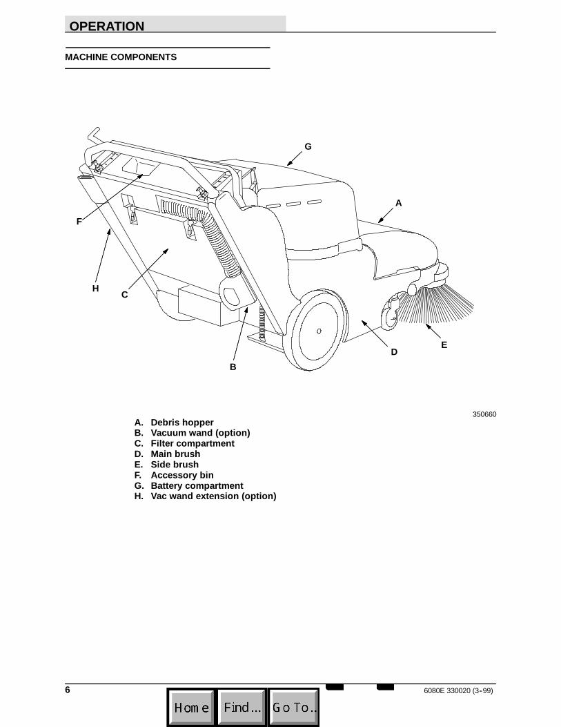
MACHINE COMPONENTS
A
B
C
DE
F
G
H
350660A. Debris hopperB. Vacuum wand (option)C. Filter compartmentD. Main brushE. Side brushF. Accessory binG. Battery compartmentH. Vac wand extension (option)

OPERATION
76080E 330020 (3--99)
SYMBOL DEFINITIONS
These symbols identify controls, displays, andfeatures on the machine:
Start
Filter shaker switch
Side brush(es) down and on
Side brush(es) up and off
Main brush down pressure
Main brush down and on
Main brush up and off
Battery discharge indicator
Circuit breaker #1
Circuit breaker #2

OPERATION
6080E 330020 (3--99)8
CONTROLS AND INSTRUMENTS
A
B
C
DE
F F
G
HIJKLMN
350658A. Main brush leverB. Side brush leverC. Directional control leverD. Clutch handleE. Steering barF. Steering bar adjustment knobs.G. Vacuum wand (option)H. Key switchI. Filter shaker switchJ. Battery discharge indicatorK. Battery disconnect button (option)L. HourmeterM. Circuit breakersN. Beverage holder
OPERATION
96080E 330020 (5--97)
OPERATION OF CONTROLS
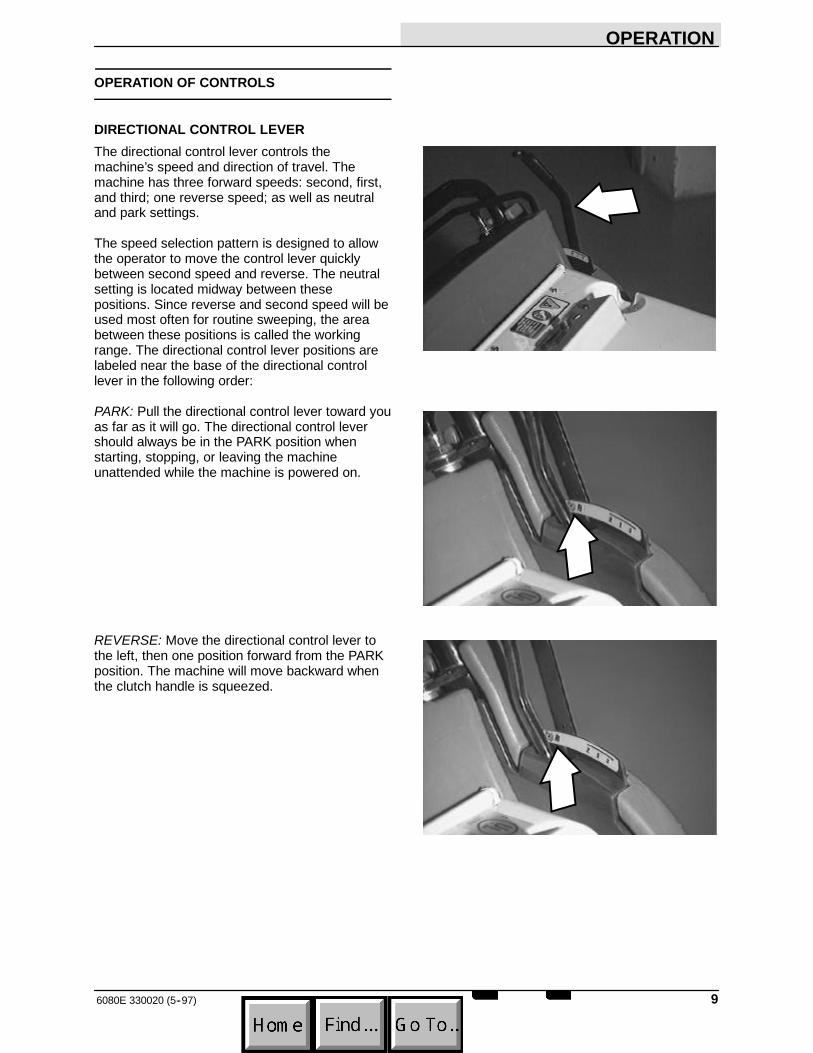
DIRECTIONAL CONTROL LEVERThe directional control lever controls themachine’s speed and direction of travel. Themachine has three forward speeds: second, first,and third; one reverse speed; as well as neutraland park settings.
The speed selection pattern is designed to allowthe operator to move the control lever quicklybetween second speed and reverse. The neutralsetting is located midway between thesepositions. Since reverse and second speed will beused most often for routine sweeping, the areabetween these positions is called the workingrange. The directional control lever positions arelabeled near the base of the directional controllever in the following order:
PARK: Pull the directional control lever toward youas far as it will go. The directional control levershould always be in the PARK position whenstarting, stopping, or leaving the machineunattended while the machine is powered on.
REVERSE: Move the directional control lever tothe left, then one position forward from the PARKposition. The machine will move backward whenthe clutch handle is squeezed.
OPERATION
6080E 330020 (5--97)10
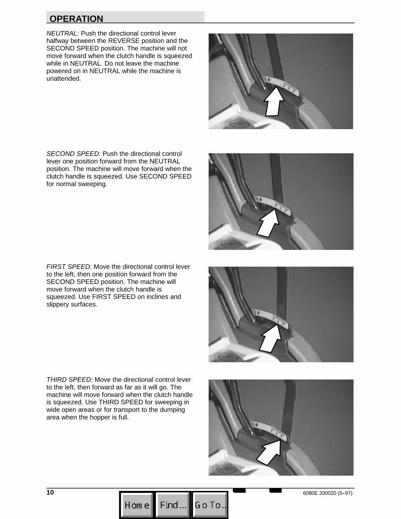
NEUTRAL: Push the directional control leverhalfway between the REVERSE position and theSECOND SPEED position. The machine will notmove forward when the clutch handle is squeezedwhile in NEUTRAL. Do not leave the machinepowered on in NEUTRAL while the machine isunattended.
SECOND SPEED: Push the directional controllever one position forward from the NEUTRALposition. The machine will move forward when theclutch handle is squeezed. Use SECOND SPEEDfor normal sweeping.
FIRST SPEED: Move the directional control leverto the left, then one position forward from theSECOND SPEED position. The machine willmove forward when the clutch handle issqueezed. Use FIRST SPEED on inclines andslippery surfaces.
THIRD SPEED: Move the directional control leverto the left, then forward as far as it will go. Themachine will move forward when the clutch handleis squeezed. Use THIRD SPEED for sweeping inwide open areas or for transport to the dumpingarea when the hopper is full.
OPERATION
116080E 330020 (5--97)
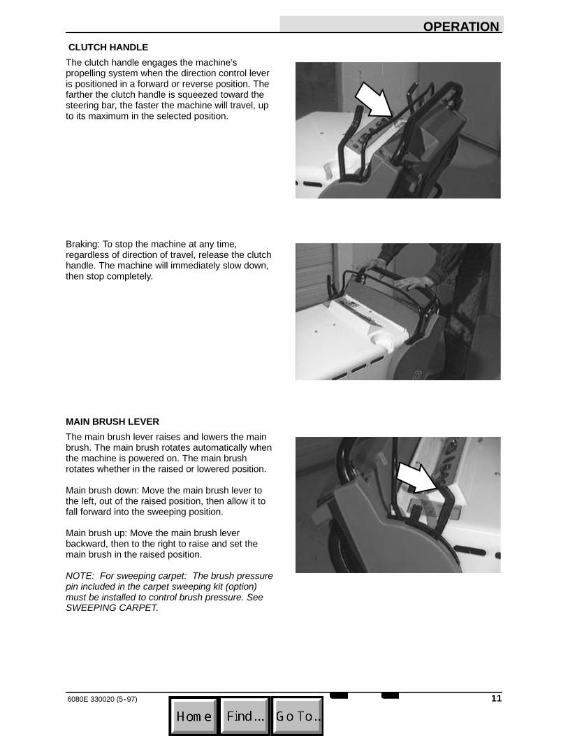
CLUTCH HANDLEThe clutch handle engages the machine’spropelling system when the direction control leveris positioned in a forward or reverse position. Thefarther the clutch handle is squeezed toward thesteering bar, the faster the machine will travel, upto its maximum in the selected position.
Braking: To stop the machine at any time,regardless of direction of travel, release the clutchhandle. The machine will immediately slow down,then stop completely.
MAIN BRUSH LEVERThe main brush lever raises and lowers the mainbrush. The main brush rotates automatically whenthe machine is powered on. The main brushrotates whether in the raised or lowered position.
Main brush down: Move the main brush lever tothe left, out of the raised position, then allow it tofall forward into the sweeping position.
Main brush up: Move the main brush leverbackward, then to the right to raise and set themain brush in the raised position.
NOTE: For sweeping carpet: The brush pressurepin included in the carpet sweeping kit (option)must be installed to control brush pressure. SeeSWEEPING CARPET.
OPERATION
6080E 330020 (5--97)12
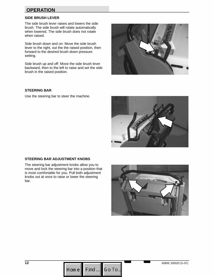
SIDE BRUSH LEVERThe side brush lever raises and lowers the sidebrush. The side brush will rotate automaticallywhen lowered. The side brush does not rotatewhen raised.
Side brush down and on: Move the side brushlever to the right, out the the raised position, thenforward to the desired brush down pressuresetting.
Side brush up and off: Move the side brush leverbackward, then to the left to raise and set the sidebrush in the raised position.
STEERING BARUse the steering bar to steer the machine.
STEERING BAR ADJUSTMENT KNOBSThe steering bar adjustment knobs allow you tomove and lock the steering bar into a position thatis most comfortable for you. Pull both adjustmentknobs out at once to raise or lower the steeringbar.

OPERATION
136080E 330020 (5--97)
KEY SWITCHThe ignition switch turns the power to the machineon and off using a key.
On: Turn the key clockwise as far as it will go andrelease it to the on position.
Off: Turn the key counterclockwise.
HOURMETERThe hourmeter records the number of hours themachine has been in use. Use this information asa guide to indicate when routine maintenanceneeds to be performed.
BATTERY DISCHARGE INDICATORThe battery discharge indicator displays thecharge level of the batteries while the machine isoperating.
When the batteries are fully charged, the indicatoron the far right is lit. As the batteries discharge,the indicator light will move across the displayfrom right to left. The batteries should berecharged when the second indicator from the farleft flashes. When two indicators on the left flash,the machine will gradually slow down, then stop.Drive, or push the machine in neutral, to thebattery charging area and charge the batteriesimmediately after the battery dischargeindicator(s) begin to flash.
NOTE: The reading on the battery dischargeindicator may not be accurate when the machineis first powered on. Operate the machine for a fewminutes before reading the charge level of thebatteries.
OPERATION
6080E 330020 (3--99)14
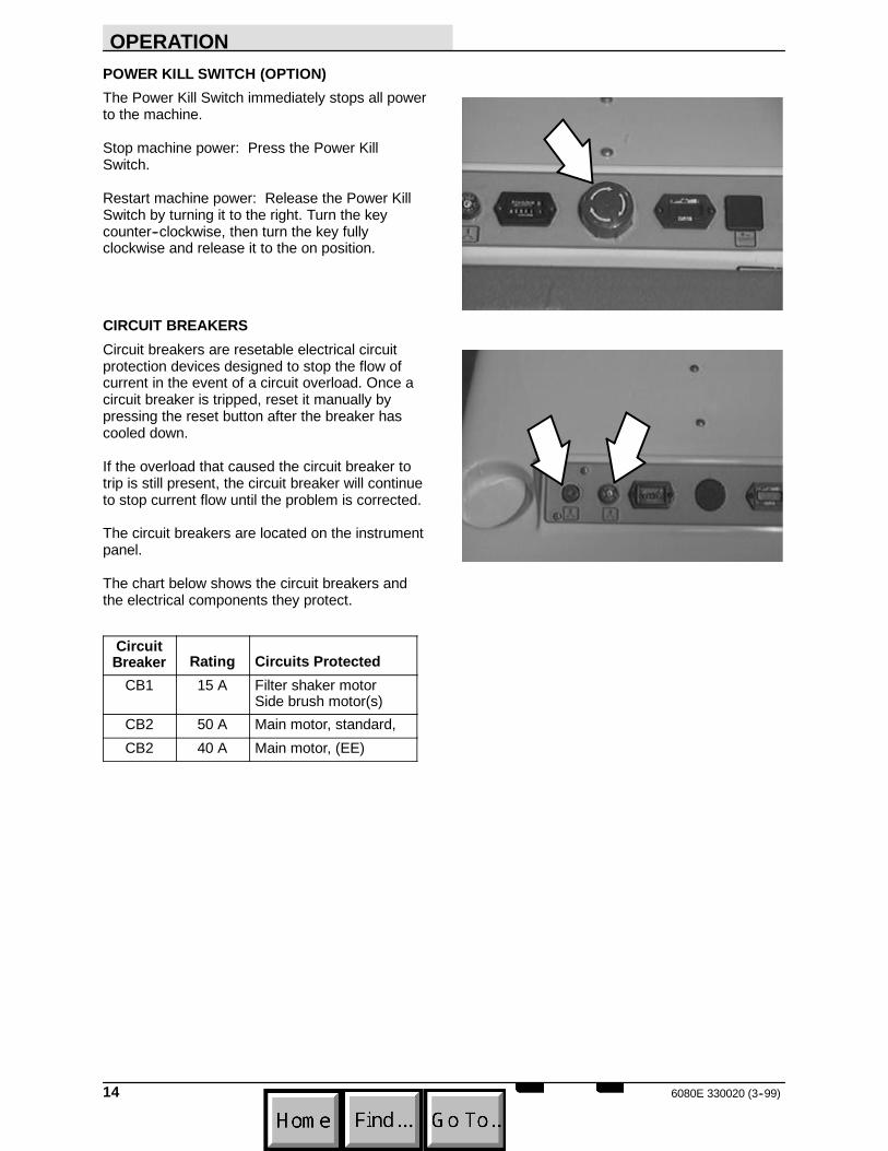
POWER KILL SWITCH (OPTION)The Power Kill Switch immediately stops all powerto the machine.
Stop machine power: Press the Power KillSwitch.
Restart machine power: Release the Power KillSwitch by turning it to the right. Turn the keycounter--clockwise, then turn the key fullyclockwise and release it to the on position.
CIRCUIT BREAKERSCircuit breakers are resetable electrical circuitprotection devices designed to stop the flow ofcurrent in the event of a circuit overload. Once acircuit breaker is tripped, reset it manually bypressing the reset button after the breaker hascooled down.
If the overload that caused the circuit breaker totrip is still present, the circuit breaker will continueto stop current flow until the problem is corrected.
The circuit breakers are located on the instrumentpanel.
The chart below shows the circuit breakers andthe electrical components they protect.
CircuitBreaker Rating Circuits Protected
CB1 15 A Filter shaker motorSide brush motor(s)
CB2 50 A Main motor, standard,CB2 40 A Main motor, (EE)
OPERATION
156080E 330020 (3--99)
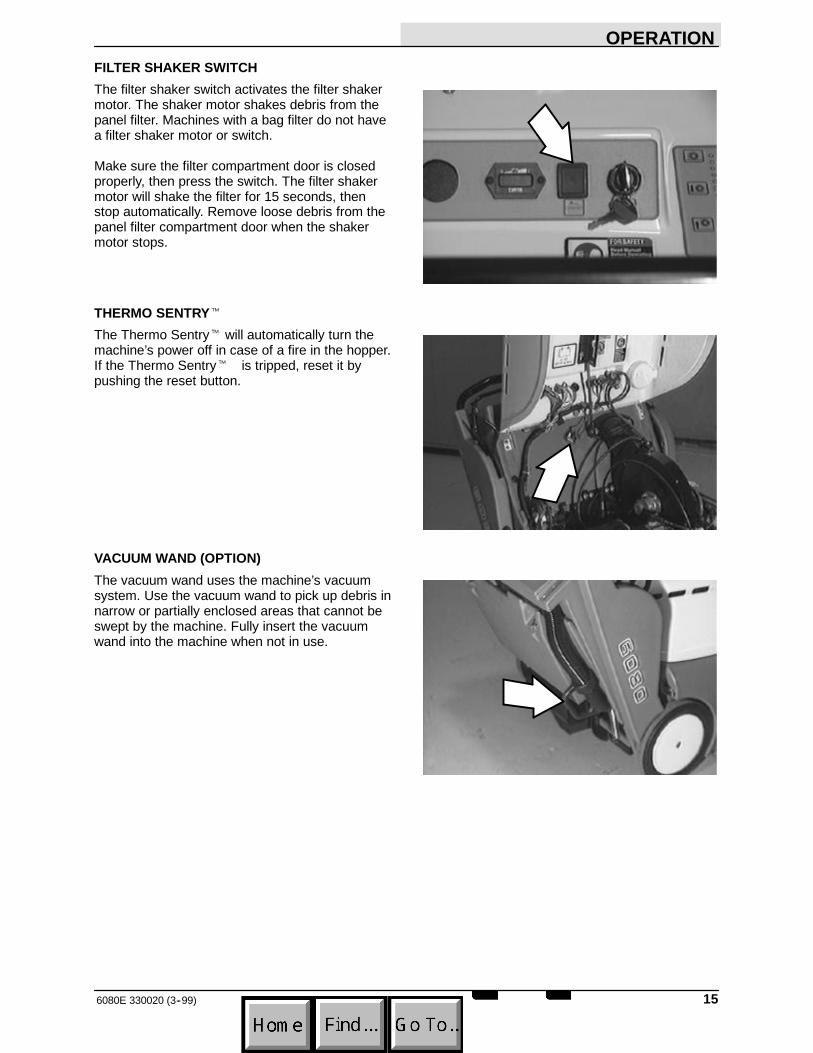
FILTER SHAKER SWITCHThe filter shaker switch activates the filter shakermotor. The shaker motor shakes debris from thepanel filter. Machines with a bag filter do not havea filter shaker motor or switch.
Make sure the filter compartment door is closedproperly, then press the switch. The filter shakermotor will shake the filter for 15 seconds, thenstop automatically. Remove loose debris from thepanel filter compartment door when the shakermotor stops.
THERMO SENTRYt
The Thermo Sentryt will automatically turn themachine’s power off in case of a fire in the hopper.If the Thermo Sentryt is tripped, reset it bypushing the reset button.
VACUUM WAND (OPTION)The vacuum wand uses the machine’s vacuumsystem. Use the vacuum wand to pick up debris innarrow or partially enclosed areas that cannot beswept by the machine. Fully insert the vacuumwand into the machine when not in use.
OPERATION
6080E 330020 (5--97)16
HOW THE MACHINE WORKS
The operator steers the machine by using thesteering bar. The directional control lever controlsthe forward or reverse direction of the machine.The clutch handle engages the propelling systemwhen it is squeezed toward the steering bar. Theclutch handle will also stop the machine when it isreleased.
The side brush sweeps debris into the path of themain brush. The main brush sweeps debris fromthe floor into the hopper. The vacuum systempulls dust and air through the main brushcompartment and the dust filter.
When sweeping is finished, press the filter shakerswitch (option) to clean the panel filter (option) ifthe machine has these options. Clean the panelfilter compartment. Empty the hopper.
If the machine has a bag filter, check the filter bagand replace if full. Empty the hopper.
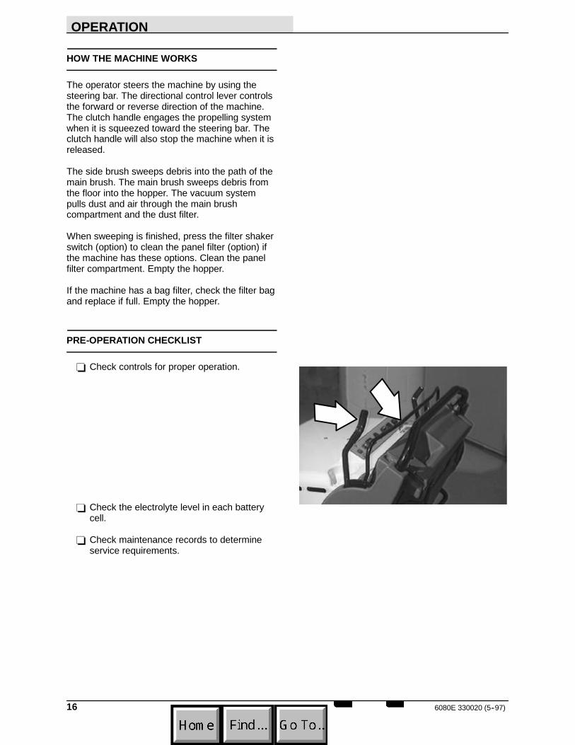
PRE-OPERATION CHECKLIST
- Check controls for proper operation.
- Check the electrolyte level in each batterycell.
- Check maintenance records to determineservice requirements.

OPERATION
176080E 330020 (5--97)
STARTING THE MACHINE
1. Turn the machine power on.
2. Move the directional control lever into thedesired forward speed (second, first, orthird).
3. Gently squeeze the clutch handle to movethe machine forward.
NOTE: The farther the clutch handle is squeezedtoward the steering bar, the faster the machinewill travel, up to its maximum in the selectedposition.
4. Drive the machine to the area to be swept.
OPERATION
6080E 330020 (5--97)18
SWEEPING AND BRUSH INFORMATION
Pick up oversized debris before sweeping. Flattenor remove bulky cartons from aisles beforesweeping. Pick up pieces of wire, twine, string,etc., which could become entangled in thebrushes or brush plugs.
Plan the sweeping in advance. Try to arrange longruns with minimum stopping and starting. Sweepdebris from very narrow aisles into the main aislesahead of time. Do an entire floor or section at onetime. Drive the straightest path possible. Avoidbumping into posts or scraping the sides of themachine. Overlap the sweeping paths.
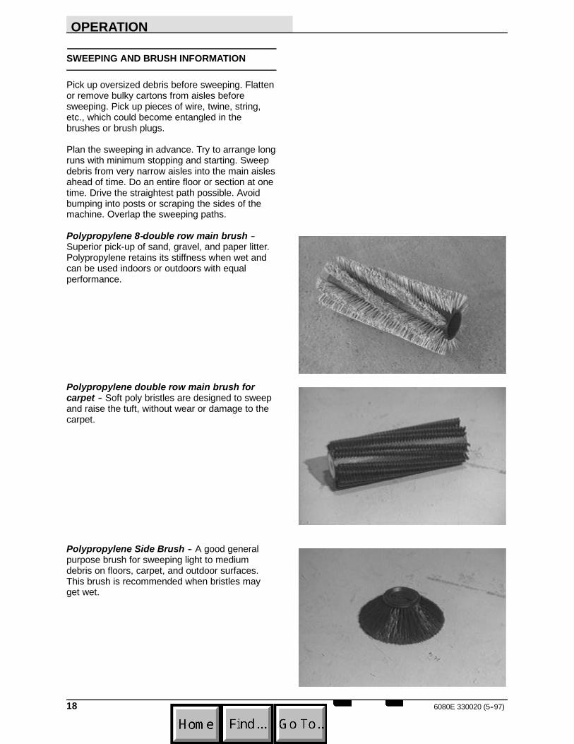
Polypropylene 8-double row main brush --Superior pick-up of sand, gravel, and paper litter.Polypropylene retains its stiffness when wet andcan be used indoors or outdoors with equalperformance.
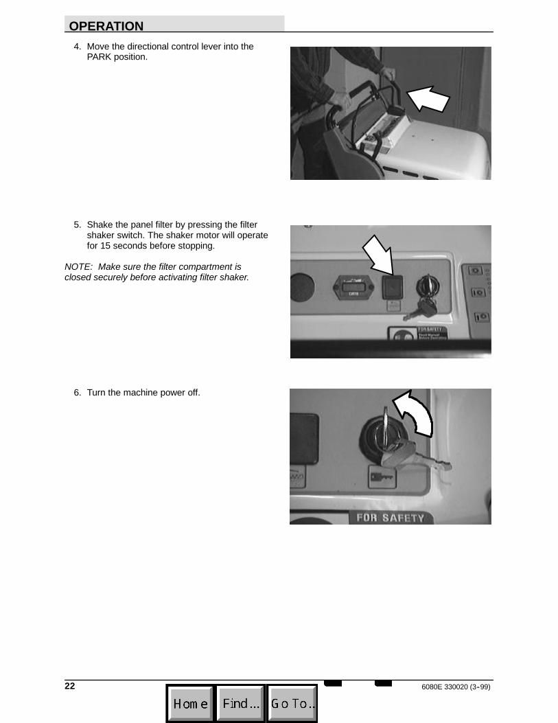
Polypropylene double row main brush forcarpet -- Soft poly bristles are designed to sweepand raise the tuft, without wear or damage to thecarpet.
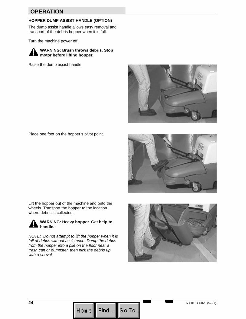
Polypropylene Side Brush -- A good generalpurpose brush for sweeping light to mediumdebris on floors, carpet, and outdoor surfaces.This brush is recommended when bristles mayget wet.

OPERATION
196080E 330020 (5--97)
SWEEPING
1. Drive the machine to the area to be swept.
2. Release the clutch handle to stop themachine.
3. Move the main brush lever to the left, out ofthe raised position, then allow it to fallforward into the sweeping position.
4. Move the side brush lever to the right, out ofthe raised position, then forward to thedesired brush down pressure setting.
5. Squeeze the clutch handle to beginsweeping.
6. Sweep as needed.

OPERATION
6080E 330020 (5--97)20
SWEEPING CARPET
1. If necessary, remove the floor sweepingbrush and install the carpet sweeping brush.
NOTE: DO NOT attempt to sweep carpet with afloor sweeping brush. Damage to the carpet couldresult.
2. Clean the rear wheels and front casters witha damp cloth before sweeping carpet.
3. Install the carpet sweeping pin into the mainbrush lever to control carpet brush downpressure. Do not attempt to sweep carpetwithout first installing the brush downpressure pin.
4. Ensure the battery bags are in place. Do notremove battery bags from machine.
NOTE: The battery bags are designed to preventan accidental overflow of battery acid fromdamaging the carpet.
5. If desired, move the side brush lever to theright, out of the raised position, then thenforward to the desired brush down pressuresetting.
NOTE: Sweeping carpet with the side brush(es)is optional.
6. Move the main brush lever to the left, out ofthe raised position, then forward to thedesired carpet brush down pressure setting.
7. Squeeze the clutch handle to beginsweeping.
8. Sweep as needed.

OPERATION
216080E 330020 (5--97)
STOP SWEEPING
1. Release the clutch handle.
NOTE: The machine will immediately slow down,then stop completely.
2. Move the main brush lever backward, thento the right to raise and set the main brush inthe raised position.
3. Move the side brush lever backward, then tothe left to raise and set the side brush(es) inthe raised position.
OPERATION
6080E 330020 (3--99)22
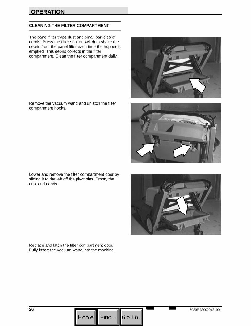
4. Move the directional control lever into thePARK position.
5. Shake the panel filter by pressing the filtershaker switch. The shaker motor will operatefor 15 seconds before stopping.
NOTE: Make sure the filter compartment isclosed securely before activating filter shaker.
6. Turn the machine power off.

OPERATION
236080E 330020 (5--97)
EMPTYING THE DEBRIS HOPPER
STANDARD HOPPERDrive the machine to the area where debris iscollected.
Turn the machine power off.
WARNING: Brush throws debris. Stopmotor before lifting hopper.
The debris hopper is equipped with one center,and two side finger grips to allow two people to liftand empty the hopper.
Pull the hopper slightly forward to unseat it fromthe machine frame.
With one person on each side, lift the debrishopper out of the machine.
NOTE: Do not attempt to lift the hopper when it isfull of debris without assistance. Dump the debrisfrom the hopper into a pile on the floor near atrash can or dumpster, then pick the debris upwith a shovel.
WARNING: Heavy hopper. Get help tohandle.
OPERATION
6080E 330020 (5--97)24
HOPPER DUMP ASSIST HANDLE (OPTION)The dump assist handle allows easy removal andtransport of the debris hopper when it is full.
Turn the machine power off.
WARNING: Brush throws debris. Stopmotor before lifting hopper.
Raise the dump assist handle.
Place one foot on the hopper’s pivot point.
Lift the hopper out of the machine and onto thewheels. Transport the hopper to the locationwhere debris is collected.
WARNING: Heavy hopper. Get help tohandle.
NOTE: Do not attempt to lift the hopper when it isfull of debris without assistance. Dump the debrisfrom the hopper into a pile on the floor near atrash can or dumpster, then pick the debris upwith a shovel.

OPERATION
256080E 330020 (3--99)
REPLACING THE BAG FILTER (OPTION)
The bag filter (option) traps dust and smallparticles of debris. Check the bag filter daily andreplace it when it becomes full of debris.
To access the bag filter, remove the vacuum wandand unlatch the filter compartment hooks.
Install a new bag filter by placing the cardboardtab on the filter around the vacuum inlet tube.
The vacuum inlet tube is located at the top of filtercompartment, on the inside of the machine.
Latch the filter compartment door. Fully insert thevacuum wand into the machine.
OPERATION
6080E 330020 (3--99)26
CLEANING THE FILTER COMPARTMENT
The panel filter traps dust and small particles ofdebris. Press the filter shaker switch to shake thedebris from the panel filter each time the hopper isemptied. This debris collects in the filtercompartment. Clean the filter compartment daily.
Remove the vacuum wand and unlatch the filtercompartment hooks.
Lower and remove the filter compartment door bysliding it to the left off the pivot pins. Empty thedust and debris.
Replace and latch the filter compartment door.Fully insert the vacuum wand into the machine.
OPERATION
276080E 330020 (3--99)
POST-OPERATION CHECKLIST
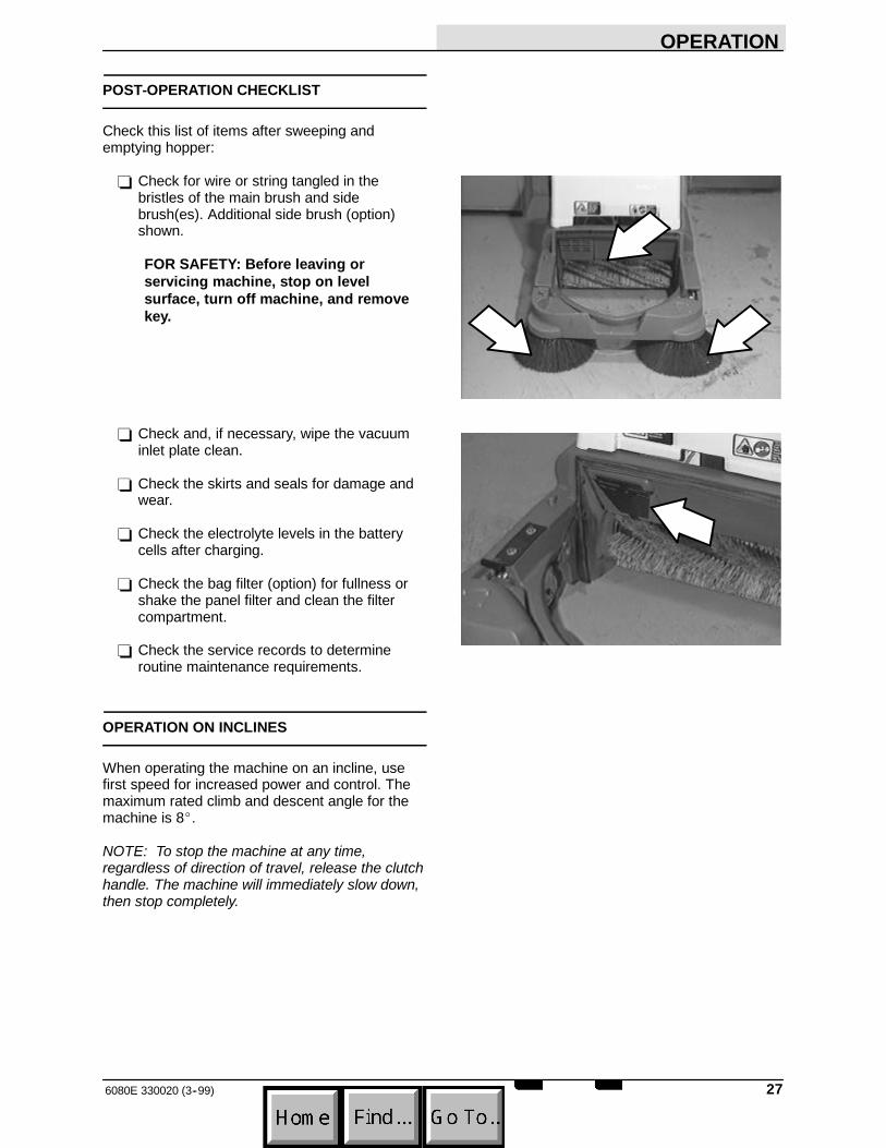
Check this list of items after sweeping andemptying hopper:
- Check for wire or string tangled in thebristles of the main brush and sidebrush(es). Additional side brush (option)shown.
FOR SAFETY: Before leaving orservicing machine, stop on levelsurface, turn off machine, and removekey.
- Check and, if necessary, wipe the vacuuminlet plate clean.
- Check the skirts and seals for damage andwear.
- Check the electrolyte levels in the batterycells after charging.
- Check the bag filter (option) for fullness orshake the panel filter and clean the filtercompartment.
- Check the service records to determineroutine maintenance requirements.
OPERATION ON INCLINES
When operating the machine on an incline, usefirst speed for increased power and control. Themaximum rated climb and descent angle for themachine is 8_.
NOTE: To stop the machine at any time,regardless of direction of travel, release the clutchhandle. The machine will immediately slow down,then stop completely.

OPERATION
6080E 330020 (9--97)28
OPTIONS
WIDE TRACK TIRES AND HEAVY DUTYCASTERSWide track tires and heavy duty casters provideincreased maneuverability and control on roughsurfaces.

OPERATION
296080E 330020 (5--97)
MACHINE TROUBLESHOOTING
Problem Cause RemedyExcessive dusting Vacuum hose clogged Unscrew hose from vac wand
handle and cleanBrush skirts and dust seals wornor damaged
Replace brush skirts or dust seals
Filter bag full or panel filterclogged
Shake and / or clean or replacebag or panel filter
Vacuum wand hose damaged Replace vacuum wand hoseVacuum wand not fully insertedinto machine
Insert fully
Vacuum inlet plate clogged Remove / clean plate. Cleanchamber if necessary
Vacuum fan failure Contact Tennant servicepersonnel
Poor sweeping performance Brush bristles worn Replace brushesBatteries low RechargeMain brush not touching floor Check brush linkage for binding or
contact Tennant service personnelMain brush not touching carpet Adjust main brush down pressureDebris caught in main brush drivemechanism
Remove debris from drivemechanism
Main brush drive failure Contact Tennant servicepersonnel
Side brush drive failure Contact Tennant servicepersonnel
Hopper full Empty hopperHopper / brush skirts worn ordamaged
Replace skirts
Wrong sweeping brush Use yellow / black brush w/75 mm (3 in) dia tube for floorsweepingUse black brush w/ 125 mm (5 in)dia tube for carpet sweeping
Rear skirt damaged Replace skirtMachine will not propel or shift Transmission will not go into gear Contact Tennant service
personnelClutch arm not pulling belt tightenough
Adjust clutch cable length
Propel belt stop bar not adjustedproperly
Contact Tennant servicepersonnel
Machine will not start Thermo Sentryt tripped Reset Thermo SentrytMachine will not startBatteries not properly reconnectedafter charging
Connect properly
Batteries discharged ChargeBattery disconnect button pushedin
Turn to the right to reset

OPERATION
6080E 330020 (9--97)30

MAINTENANCE
316080E 330020 (3--99)
MAINTENANCE
1
2
3
4
6
75
8350842
MAINTENANCE CHART
Interval Key Description ProcedureLubricant/
Fluid
No. ofServicePoints
Daily 1 Battery cells Check electrolyte level aftercharging
DW 2
4,5 Main brush and sidebrush(es)
Check for damage and wear -- 2 (3)
2 Vacuum inlet plate Check / clean -- 12 Skirts and seals Inspect -- 66 Bag filter (option) Check / Replace if full -- 16 Panel filter Shake filter, clean compartment
door-- 1
50 Hours 1 Vacuum fan belt Check tension and wear -- 150 Hours5 Main brush Rotate end for end and check
brush pattern-- 1
1 Battery cells Check electrolyte level DW 3100 Hours 6 Panel filter Remove and clean -- 1100 Hours
7 Wide track tires (option) Check for damage / pressure -- 28 Heavy duty casters
(option)Lubricate SPL 2
200 Hours 1 Battery terminals Clean and tighten -- 4500 Hours 3 Side brush motor(s) Check motor brush -- 1 (2)1000Hours
1 Main motor Check motor brush -- 1
LUBRICANT/FLUIDDW Distilled water. . . .SPL Special lubricant, Lubriplate EMB grease (TENNANT part no. 01433--1). . .

MAINTENANCE
6080E 330020 (3--99)32
BATTERIES
The batteries are designed to hold their power forlong periods of time. The lifetime of the batteriesis limited to number of charges the batteriesreceive. To get the most life from the batteries,recharge them immediately when the batterydischarge indicator begins to blink.
Every 200 hours of operation, check for loosebattery connections and clean the surface of thebatteries, including terminals and cable clamps,using a strong solution of baking soda and water.Brush the solution sparingly over the battery tops.Do not allow any baking soda solution to enter thebatteries. Use a wire brush to clean the terminalposts and the cable connectors. Wipe off allcleaning solution residue. After cleaning, apply acoating of clear battery post protectant to theterminals and the cable connectors. Keep the topsof the batteries clean and dry.
Objects made of metal can potentially short circuitthe batteries. Keep all metallic objects off thebatteries. Replace any worn or damaged wires.
Check the electrolyte level in each battery cellafter charging and after every 50 hours ofoperation. Never add acid to the batteries. Adddistilled water only. Always keep the battery capson, except when adding water or takinghydrometer readings.
MAINTENANCE
336080E 330020 (5--97)
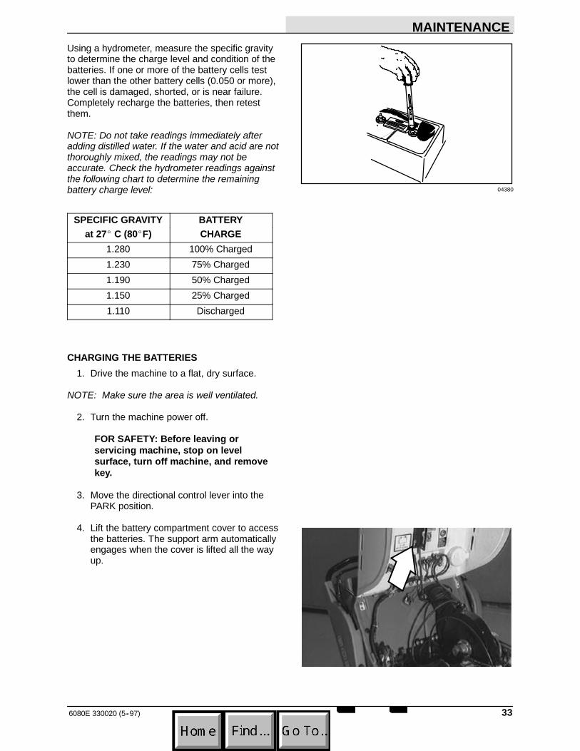
Using a hydrometer, measure the specific gravityto determine the charge level and condition of thebatteries. If one or more of the battery cells testlower than the other battery cells (0.050 or more),the cell is damaged, shorted, or is near failure.Completely recharge the batteries, then retestthem.
NOTE: Do not take readings immediately afteradding distilled water. If the water and acid are notthoroughly mixed, the readings may not beaccurate. Check the hydrometer readings againstthe following chart to determine the remainingbattery charge level:
SPECIFIC GRAVITY BATTERYSPECIFIC GRAVITYat 27_C (80_F)
BATTERYCHARGE
1.280 100% Charged1.230 75% Charged1.190 50% Charged1.150 25% Charged1.110 Discharged
CHARGING THE BATTERIES1. Drive the machine to a flat, dry surface.
NOTE: Make sure the area is well ventilated.
2. Turn the machine power off.
FOR SAFETY: Before leaving orservicing machine, stop on levelsurface, turn off machine, and removekey.
3. Move the directional control lever into thePARK position.
4. Lift the battery compartment cover to accessthe batteries. The support arm automaticallyengages when the cover is lifted all the wayup.
04380

MAINTENANCE
6080E 330020 (5--97)34
5. Check the water level in all battery cells. Ifthe level is low, add just enough distilledwater to cover the plates. DO NOTOVERFILL. The batteries can overflowduring charging due to expansion.
NOTE: Make sure the battery caps are in placewhile charging.
FOR SAFETY: When maintaining orservicing machine, avoid contact withbattery acid.
6. Unplug the machine connector from thebatteries.
7. Plug the charger connector into the batteryconnector.
WARNING: Batteries emit hydrogengas. Explosion or fire can result. Keepsparks and open flame away. Keepcovers open when charging.
8. Plug the battery charger into the wall outlet.
NOTE: If the red “ABNORMAL CYCLE”lamplights when the TENNANT charger is plugged intoa wall outlet, the charger cannot charge thebattery and there is something wrong with thebattery.
9. The TENNANT charger will startautomatically. When the batteries are fullycharged, the TENNANT charger willautomatically turn off.
10. After the charger has turned off, unplug thecharger from the wall outlet.
00879
07224

MAINTENANCE
356080E 330020 (3--99)
11. Unplug the charger connector from thebattery connector on the machine.
FOR SAFETY: When maintaining orservicing machine, avoid contact withbattery acid.
12. Connect the machine connector to thebattery connector.
13. Lower the battery compartment cover byslightly raising it while pushing the supportarm inward.
LUBRICATION
HEAVY DUTY CASTERS (OPTION)The heavy duty casters (option) each have onegrease fitting on the caster swivel. Lubricate eachcaster with a grease gun containing LubriplateEMB grease (Tennant part no. 01433--1) afterevery 100 hours of operation.
MAINTENANCE
6080E 330020 (5--97)36
SKIRTS AND SEALS
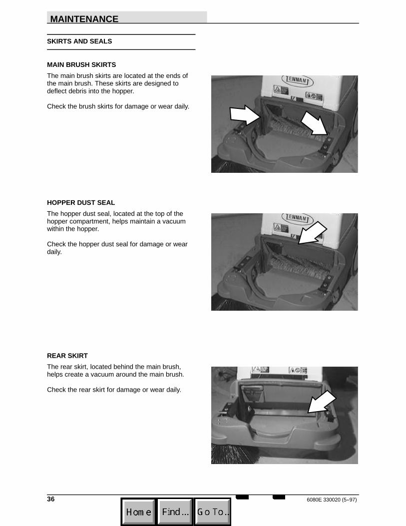
MAIN BRUSH SKIRTSThe main brush skirts are located at the ends ofthe main brush. These skirts are designed todeflect debris into the hopper.
Check the brush skirts for damage or wear daily.
HOPPER DUST SEALThe hopper dust seal, located at the top of thehopper compartment, helps maintain a vacuumwithin the hopper.
Check the hopper dust seal for damage or weardaily.
REAR SKIRTThe rear skirt, located behind the main brush,helps create a vacuum around the main brush.
Check the rear skirt for damage or wear daily.

MAINTENANCE
376080E 330020 (5--97)
HOPPER LIP SKIRTThe hopper lip skirt, located on the lip of thehopper, ensures debris thrown from the mainbrush will go into the hopper.
Check the hopper lip skirt for damage or weardaily.
FILTER COMPARTMENT DOOR SEALThe filter door seal, located around the perimeterof the filter compartment door, helps maintain avacuum around the filter.
Check the filter compartment door seal fordamage or wear daily.
VACUUM INLET PLATE
The vacuum inlet plate is located on the theleft-hand side of the hopper compartment. Thevacuum inlet plate prevents large pieces of debrisfrom entering the vacuum chamber.
Check the vacuum inlet plate daily. If necessaryremove and wipe it clean with a damp cloth.
MAINTENANCE
6080E 330020 (3--99)38
CLEANING THE PANEL FILTER
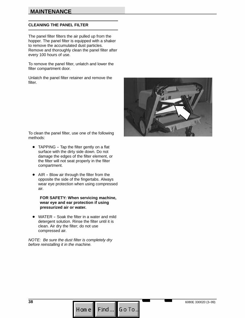
The panel filter filters the air pulled up from thehopper. The panel filter is equipped with a shakerto remove the accumulated dust particles.Remove and thoroughly clean the panel filter afterevery 100 hours of use.
To remove the panel filter, unlatch and lower thefilter compartment door.
Unlatch the panel filter retainer and remove thefilter.
To clean the panel filter, use one of the followingmethods:
D TAPPING -- Tap the filter gently on a flatsurface with the dirty side down. Do notdamage the edges of the filter element, orthe filter will not seat properly in the filtercompartment.
D AIR -- Blow air through the filter from theopposite the side of the fingertabs. Alwayswear eye protection when using compressedair.
FOR SAFETY: When servicing machine,wear eye and ear protection if usingpressurized air or water.
D WATER -- Soak the filter in a water and milddetergent solution. Rinse the filter until it isclean. Air dry the filter; do not usecompressed air.
NOTE: Be sure the dust filter is completely drybefore reinstalling it in the machine.
MAINTENANCE
396080E 330020 (3--99)
BRUSHES
MAIN BRUSHNOTE: The following procedures apply to boththe floor sweeping main brush and the carpetsweeping main brush.
The main brush spans the width of the machineand throws debris into the hopper.
Check the brush for damage and wear daily.Remove string or wire tangled in the main brushor the main brush hub.
Check the main brush pattern after every 50hours of use. Adjust the main brush pattern byloosening the nut at the left end of the brush armcrossbar.
Rotate the main brush after every 50 hours of usefor maximum brush life and sweepingperformance.
Replace floor or carpet sweeping brush whenbristle length is 9 to 12 mm (.375 to .5 in).
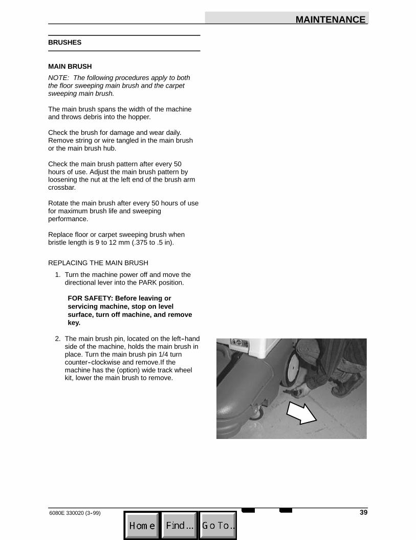
REPLACING THE MAIN BRUSH1. Turn the machine power off and move the
directional lever into the PARK position.
FOR SAFETY: Before leaving orservicing machine, stop on levelsurface, turn off machine, and removekey.
2. The main brush pin, located on the left--handside of the machine, holds the main brush inplace. Turn the main brush pin 1/4 turncounter--clockwise and remove.If themachine has the (option) wide track wheelkit, lower the main brush to remove.
MAINTENANCE
6080E 330020 (3--99)40
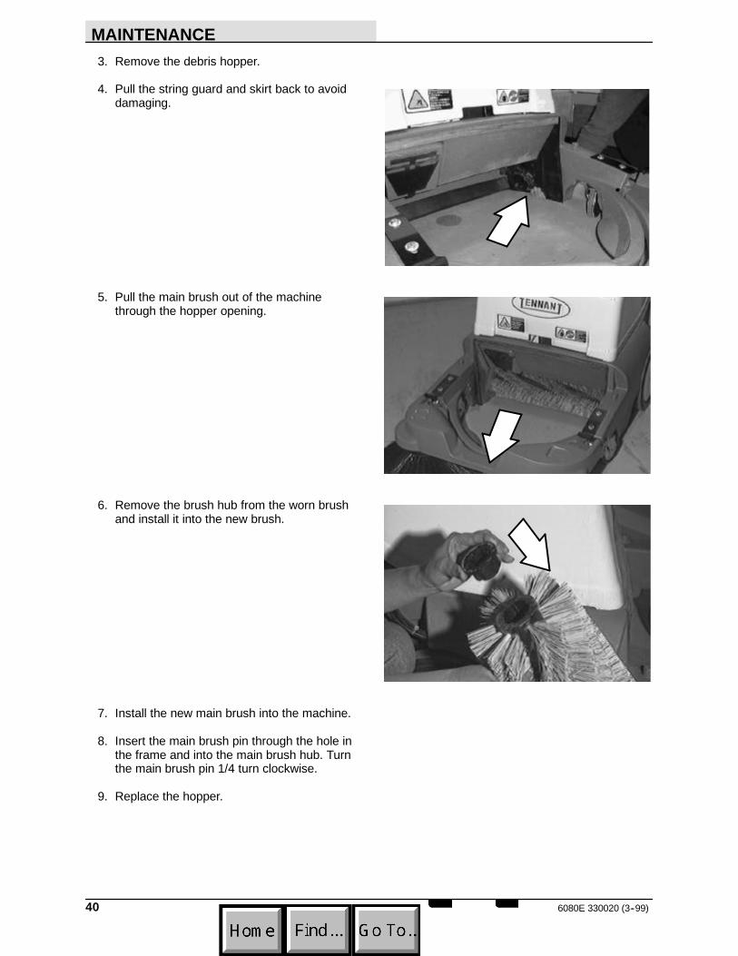
3. Remove the debris hopper.
4. Pull the string guard and skirt back to avoiddamaging.
5. Pull the main brush out of the machinethrough the hopper opening.
6. Remove the brush hub from the worn brushand install it into the new brush.
7. Install the new main brush into the machine.
8. Insert the main brush pin through the hole inthe frame and into the main brush hub. Turnthe main brush pin 1/4 turn clockwise.
9. Replace the hopper.
MAINTENANCE
416080E 330020 (5--97)
CHECKING AND ADJUSTING MAIN BRUSHPATTERN
1. Apply chalk (or another material that will noteasily blow away), to a smooth, level sectionof the floor.
2. Lower the main brush in the chalked area.Allow the machine to sweep in the sameplace for 15 to 20 seconds.
NOTE: If chalk or other material is not available,allow the brush to spin on the floor for twominutes. A polish mark will remain on the floor.
3. Raise the main brush and move the machineaway from the chalked area. Turn themachine power off.
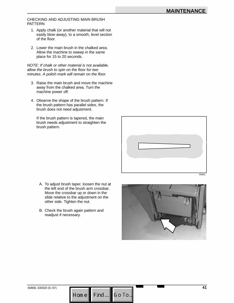
4. Observe the shape of the brush pattern. Ifthe brush pattern has parallel sides, thebrush does not need adjustment.
If the brush pattern is tapered, the mainbrush needs adjustment to straighten thebrush pattern.
A. To adjust brush taper, loosen the nut atthe left end of the brush arm crossbar.Move the crossbar up or down in theslide relative to the adjustment on theother side. Tighten the nut.
B. Check the brush again pattern andreadjust if necessary.
00601
MAINTENANCE
6080E 330020 (5--97)42
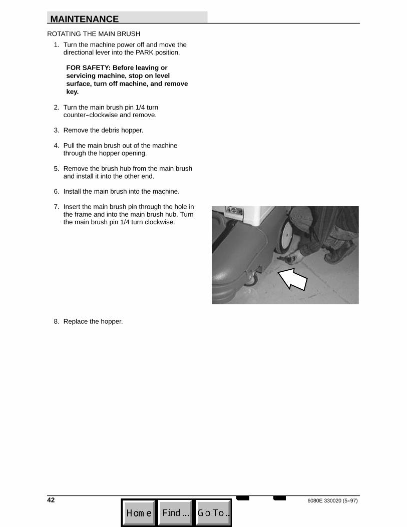
ROTATING THE MAIN BRUSH1. Turn the machine power off and move the
directional lever into the PARK position.
FOR SAFETY: Before leaving orservicing machine, stop on levelsurface, turn off machine, and removekey.
2. Turn the main brush pin 1/4 turncounter--clockwise and remove.
3. Remove the debris hopper.
4. Pull the main brush out of the machinethrough the hopper opening.
5. Remove the brush hub from the main brushand install it into the other end.
6. Install the main brush into the machine.
7. Insert the main brush pin through the hole inthe frame and into the main brush hub. Turnthe main brush pin 1/4 turn clockwise.
8. Replace the hopper.
MAINTENANCE
436080E 330020 (5--97)
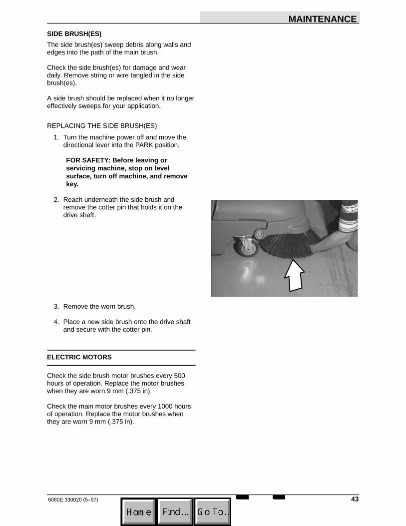
SIDE BRUSH(ES)The side brush(es) sweep debris along walls andedges into the path of the main brush.
Check the side brush(es) for damage and weardaily. Remove string or wire tangled in the sidebrush(es).
A side brush should be replaced when it no longereffectively sweeps for your application.
REPLACING THE SIDE BRUSH(ES)1. Turn the machine power off and move the
directional lever into the PARK position.
FOR SAFETY: Before leaving orservicing machine, stop on levelsurface, turn off machine, and removekey.
2. Reach underneath the side brush andremove the cotter pin that holds it on thedrive shaft.
3. Remove the worn brush.
4. Place a new side brush onto the drive shaftand secure with the cotter pin.
ELECTRIC MOTORS
Check the side brush motor brushes every 500hours of operation. Replace the motor brusheswhen they are worn 9 mm (.375 in).
Check the main motor brushes every 1000 hoursof operation. Replace the motor brushes whenthey are worn 9 mm (.375 in).

MAINTENANCE
6080E 330020 (5--97)44
BELTS AND CHAINS
VACUUM FAN BELTThe vacuum fan belt drives the vacuum system.Check the belt for wear and tension after every 50hours of operation.
Check belt tension by applying a force 1 kg (2 lb)at belt midpoint. The proper deflection should be5 mm (0.09 in).
WARNING: Moving belt and fan. Keepaway.
MAIN BRUSH BELTThe main brush drive belt is located behind theright rear tire. The belt drives the main brush. Theproper belt tension is automatically set by aspring--loaded idler.
STATIC DRAG CHAINThe static drag chain prevents the buildup ofstatic electricity in the machine. The chain isattached to the backstop bracket.
Make sure the chain is always touching the floor.
CLUTCH CABLE
The clutch handle engages the machine’spropelling system. The clutch handle is connectedto the clutch cable. The clutch cable may stretchover time and require adjustment.
Adjust cable length by turning the nut at the baseof the clutch cable.
MAINTENANCE
456080E 330020 (9--97)
TIRES (OPTION)
The heavy duty rear tires are pneumatic.
Check the rear tires after every 100 hours ofoperation for damage. Check the rear tirepressure after every 100 hours of operation. Theproper tire pressure is 345 kPa (50 psi).
PUSHING AND TRANSPORTING THEMACHINE
The machine can be pushed in neutral ifnecessary.
Tilt trailer or lower the tailgate so the machine canbe driven on to it. Position the machine so it restsagainst the front of the trailer. Secure the machinetoward the front of the trailer by wrapping a straparound the filter compartment and hooking theends near the front corners of the machine.Secure the machine down by wrapping a strapacross the battery compartment and hooking theends at the sides of the machine. Place smallpads or cushions under the straps to preventmachine damage. Make sure the directionalcontrol lever is in the park position. Block the tiresto keep the machine from rolling during transport.
STORING MACHINE
When storing the machine for extended periods oftime, the following procedures must be followed:
1. Raise the main and side brush(es).
2. Empty and clean the debris hopper.
3. Fully charge the batteries.
4. Disconnect the machine connector from thebattery connector.
5. Store the machine in a clean dry area.
SPECIFICATIONS
6080E 330020 (9--97)46
SPECIFICATIONS
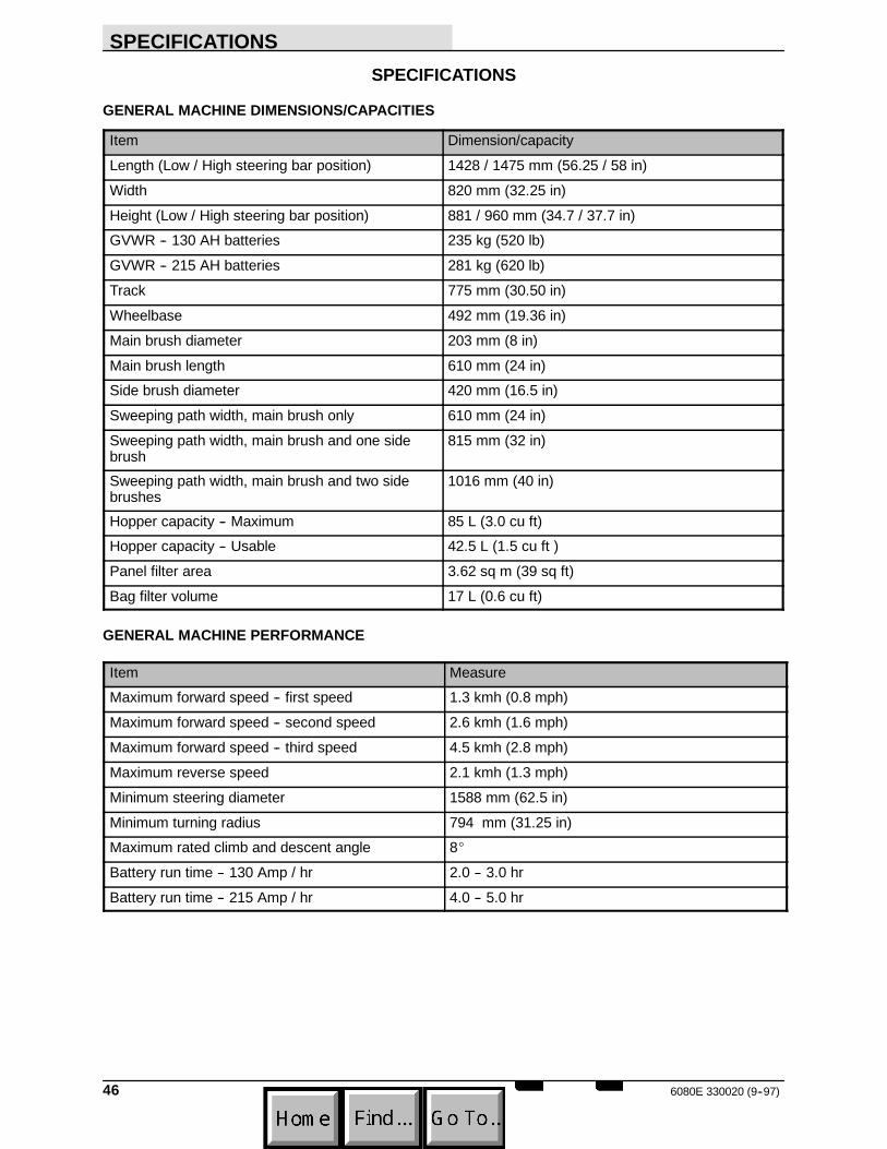
GENERAL MACHINE DIMENSIONS/CAPACITIES
Item Dimension/capacityLength (Low / High steering bar position) 1428 / 1475 mm (56.25 / 58 in)Width 820 mm (32.25 in)Height (Low / High steering bar position) 881 / 960 mm (34.7 / 37.7 in)GVWR -- 130 AH batteries 235 kg (520 lb)GVWR -- 215 AH batteries 281 kg (620 lb)Track 775 mm (30.50 in)Wheelbase 492 mm (19.36 in)Main brush diameter 203 mm (8 in)Main brush length 610 mm (24 in)Side brush diameter 420 mm (16.5 in)Sweeping path width, main brush only 610 mm (24 in)Sweeping path width, main brush and one sidebrush
815 mm (32 in)
Sweeping path width, main brush and two sidebrushes
1016 mm (40 in)
Hopper capacity -- Maximum 85 L (3.0 cu ft)Hopper capacity -- Usable 42.5 L (1.5 cu ft )Panel filter area 3.62 sq m (39 sq ft)Bag filter volume 17 L (0.6 cu ft)
GENERAL MACHINE PERFORMANCE
Item MeasureMaximum forward speed -- first speed 1.3 kmh (0.8 mph)Maximum forward speed -- second speed 2.6 kmh (1.6 mph)Maximum forward speed -- third speed 4.5 kmh (2.8 mph)Maximum reverse speed 2.1 kmh (1.3 mph)Minimum steering diameter 1588 mm (62.5 in)Minimum turning radius 794 mm (31.25 in)Maximum rated climb and descent angle 8_Battery run time -- 130 Amp / hr 2.0 -- 3.0 hrBattery run time -- 215 Amp / hr 4.0 -- 5.0 hr
SPECIFICATIONS
476080E 330020 (9--97)
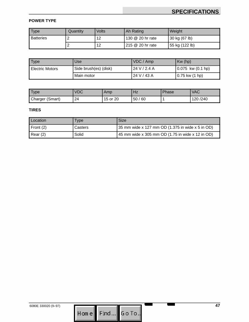
POWER TYPE
Type Quantity Volts Ah Rating WeightBatteries 2 12 130 @ 20 hr rate 30 kg (67 lb)
2 12 215 @ 20 hr rate 55 kg (122 lb)
Type Use VDC / Amp Kw (hp)Electric Motors Side brush(es) (disk) 24 V / 2.4 A 0.075 kw (0.1 hp)Electric Motors
Main motor 24 V / 43 A 0.75 kw (1 hp)
Type VDC Amp Hz Phase VACCharger (Smart) 24 15 or 20 50 / 60 1 120 /240
TIRES
Location Type SizeFront (2) Casters 35 mm wide x 127 mm OD (1.375 in wide x 5 in OD)Rear (2) Solid 45 mm wide x 305 mm OD (1.75 in wide x 12 in OD)

SPECIFICATIONS
6080E 330020 (9--97)48
960 mm(37.7 in)
820 mm(32.25 in)
815 mm(32 in)
1475 mm(58 in)
610 mm(24 in)
350910MACHINE DIMENSIONS

INDEX
496080E 330020 (3--99)
INDEX
BBag filter replacement, 25Batteries
Charging the batteries, 33General information, 32Maintenance, 32Measuring specific gravity, 33Run time, 46
Battery bags (option), 20Battery discharge indicator, 13Battery disconnect button (option), 14Belts
Main brush, 44Vacuum fan, 44
Braking, stopping machine, 11Brush information, 18Brushes
Main brush, 39Main brush pattern, checking, adjusting, 41Main brush, rotation, 42Replacing main brush, 39Replacing side brush(es), 43Side brush(es), 43
CCable, clutch, 44Carpet sweeping, 20Carpet sweeping kit (option)
Battery bags, 20Brush down pressure pin, 20Carpet brush, 18
Chain, static drag, 44Circuit breakers, 14Clutch cable, 44Clutch handle, 11Controls
Battery disconnect button (option), 14Clutch handle, 11Directional control lever, 9Key switch, 13Main brush lever, 11Side brush lever, 12Steering bar, 12Steering bar adjustment knobs, 12
Controls and Instruments, 8
DDirectional control lever, 9
EElectric motors, 43Electrical system
Batteries, 32Charging the batteries, 33Circuit breakers, 14
FFilter compartment, panel, Cleaning, 26Filter shaker switch, 15Filters
Bag filter replacement, 25Panel filter cleaning, 38
HHopper
Dump assist handle emptying (option), 24Standard hopper emptying, 23
Hourmeter, 13
IIndicators, Battery discharge indicator, 13Instruments, Hourmeter, 13
KKey switch, 13
LLevers
Directional control lever, 9Main brush lever, 11Side brush lever, 12
Lubrication, heavy duty casters (option), 35
INDEX
6080E 330020 (3--99)50
MMachine
Pushing, transporting, 45Storage, 45
Machine components, 6Machine dimensions, 48Machine troubleshooting, 29Main brush, 39
Checking and adjusting brush pattern, 41–43Replacement, 39Rotation, 42–44
Main brush lever, 11Maintenance, Recommended, 5Maintenance chart, 31Motors, electric, 43
OOperation
How the machine works, 16Post--operation checklist, 27Pre--operation checklist, 16Starting the machine, 17Stop sweeping, 21Stopping the machine, 11Sweeping and brush information, 18Sweeping carpet, 20Sweeping floors, 19Sweeping on inclines, 27
Operation of controls, 9Operator responsibility, 5Options
Battery disconnect button, 14Hopper dump assist handle, 24Wide track tires and casters, 28
PPanel filter, Cleaning, 38Panel filter compartment, Cleaning, 26Plate, vacuum inlet, 37
SSafety
Labels, 4Precautions, 3–5
Side brush lever, 12Side brush(es), 43–45Side brush(es) replacement, 43–45Skirts and seals
Filter compartment door seal, 37Hopper dust seal, 36Hopper lip skirt, 37Main brush skirts, 36Rear skirt, 36
SpecificationsBatteries, 47Battery charger, smart, 47Battery run time, 46Climb and descent angles, maximum, 46Electric motors, 47Machine capacities, 46Machine dimensions, 46Machine performance, 46Tires, 47Traveling speeds, 46Turning radius, 46
Steering bar, 12Steering bar adjustment knobs, 12Storing machine, 45Sweeping
Carpet, 20Floors, 19
Sweeping and brush information, 18Switches
Filter shaker switch, 15Key switch, 13
Symbols, definitions, 7
TThermo Sentry, 15Tires, 45
Specifications, 47Troubleshooting chart, 29
VVacuum inlet plate, 37Vacuum wand, 15