6.111 introductory digital systems laboratory · source of light and redirect to the eye. ... sid...
TRANSCRIPT

6.111 Digital System Laboratory---Spring 2006 Lecture 13 - Flat Panel Displays 1
Lecture 136.111 Flat Panel Display Devices
Outline
• Overview Flat Panel Display Devices– How do Displays Work?– Emissive Displays– Light Valve Displays
• Display Drivers– Addressing Schemes– Display Timing Generator– Gray Scale / Color Schemes
Courtesy of Akintunde Ibitayo Akinwande. Used with permission.
For more info take graduate course, 6.987 on flat panel displays

6.111 Digital System Laboratory---Spring 2006 Lecture 13 - Flat Panel Displays 2
Applications of Flat-Panel Displays
Personal Digital Assistant
Medical Defibrillator Car Navigation & Entertainment
SMALL FORMAT
Desktop Monitor (color) Large Screen Television (color)
LARGE FORMAT
MP3 Player
6.111 Digital System Laboratory---Spring 2006 Lecture 13 - Flat Panel Displays 3
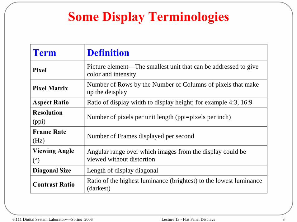
Some Display Terminologies
Term Definition Pixel Picture element⎯The smallest unit that can be addressed to give
color and intensity
Pixel Matrix Number of Rows by the Number of Columns of pixels that make up the deisplay
Aspect Ratio Ratio of display width to display height; for example 4:3, 16:9 Resolution (ppi)
Number of pixels per unit length (ppi=pixels per inch)
Frame Rate (Hz)
Number of Frames displayed per second
Viewing Angle (°)
Angular range over which images from the display could be viewed without distortion
Diagonal Size Length of display diagonal
Contrast Ratio Ratio of the highest luminance (brightest) to the lowest luminance (darkest)

6.111 Digital System Laboratory---Spring 2006 Lecture 13 - Flat Panel Displays 4
Information Capacity of Displays(Pixel Count)
RESOLUTION PIXEL RATIO
4:3
4:3
4:3
4:3
4:3
4:3
4:3
5:4
640 x 480 x RGB
800 x 600 x RGB
1,024 x 768 x RGB
1,280 x 1,024 x RGB
1,400 x 1,080 x RGB
1,600 x 1,200 x RGB
2048 x 1536 x RGB
2560 x 2048 x RGB
Video Graphic Array(VGA)Super Video Graphic Array(SVGA)eXtended Graphic Array(XGA)Super eXtended Graphic Array(SXGA)Super eXtended Graphic Array plus(SXGA+)Ultra eXtended Graphic Array(UXGA)Quad eXtended Graphics Array(QXGA)Quad Super eXtended Graphics Array(QSXGA)
Figure by MIT OpenCourseWare. Adapted from Display Devices, no. 21 (Spring 2000): 41.

6.111 Digital System Laboratory---Spring 2006 Lecture 13 - Flat Panel Displays 5
How Do Displays Work?
• Electronic display converts “Time Sequential Electrical Signals” into spatially and temporally configured light signal (images).– Electrical signals are appropriately routed to the various display elements
(similar to memory addressing)– Display element (pixel) converts the routed electrical signal at its input into
light of certain wavelength and intensity (inverse of image capture)
PankoveFigure by MIT OpenCourseWare. Adapted from Jacques Pankove.
Time SequentialElectronic Input Signal
Photon OutputSignal
Addressing FunctionDisplay Element
Display Element Array

6.111 Digital System Laboratory---Spring 2006 Lecture 13 - Flat Panel Displays 6
Human Eye— Spectral Response
Figure by MIT OpenCourseWare.
1.20
1.00
0.80
0.60
0.40
0.20
0.00400 450 500 550 600 650 700
Wavelength (nm)
Rel
ativ
e Se
nsis
tivity

6.111 Digital System Laboratory---Spring 2006 Lecture 13 - Flat Panel Displays 7
Emissive Displays• Displays that generate photons when an electrical signal is applied between the
terminals• Energy causes excitation followed by excitation relaxation
– Hole + Electron recombination – Exciton formation and annihilation– Relaxation of excited radicals in a plasma
• The different types of Luminescence differ mostly in the way the holes and electrons are generated
– holes and electrons are generated by UV in a phosphor which then recombine and generate red, green or blue light —Photoluminescence or Phosphorescence
– holes and electrons injected by pn junction or generated by impact ionization or excitation which then recombine and generate red, green or blue light —Electroluminescence
– holes and electrons generated by electron beam which then recombine and generate red, green or blue light — Cathodoluminescence
• Examples of Emissive Flat Panel Displays– Electroluminescence (Light Emitting Diode, Organic-Light Emitting Devices & In-
organic ELectroluminescent Displays)– Cathodoluminescence (Cathode Ray Tube, Vacuum Florescent Display, Field
Emission Display)– Photoluminescence (PLasma Displays)

6.111 Digital System Laboratory---Spring 2006 Lecture 13 - Flat Panel Displays 8
Light Valve Displays• Displays that “spatially and temporally” modulate ambient lighting or broad
source of light and redirect to the eye.• Display element spatially changes the intensity of plane wave of light using
– Refraction– Reflection– Polarization change
• These displays are part of a broader class of devices called Spatial Light Modulators which in general operate though local
– Amplitude change– Polarization change– Phase change– Intensity change
• Examples of Light Valve Displays– Liquid Crystal Displays (active & passive matrix)– Deformable Mirror Displays– Membrane Mirror Displays– Electrophoretic Displays (E-Ink)

6.111 Digital System Laboratory---Spring 2006 Lecture 13 - Flat Panel Displays 9
Cathode Ray Tube
Electrons beam “boiled off a metal” by heat (thermionicemission) is sequentially scanned across a phosphor screen by magnetic deflection. The electrons are accelerated to the screen acquiring energy and generate light on reaching the screen (cathodoluminescence)
Anode
CRT Display
Cathode
Phosphor Screen
Figure by MIT OpenCourseWare.
6.111 Digital System Laboratory---Spring 2006 Lecture 13 - Flat Panel Displays 10
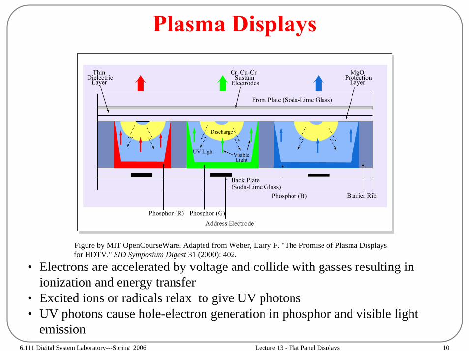
Plasma Displays
• Electrons are accelerated by voltage and collide with gasses resulting in ionization and energy transfer
• Excited ions or radicals relax to give UV photons• UV photons cause hole-electron generation in phosphor and visible light
emission
Figure by MIT OpenCourseWare. Adapted from Weber, Larry F. "The Promise of Plasma Displaysfor HDTV." SID Symposium Digest 31 (2000): 402.
ThinDielectric
LayerCr -Cu-Cr
SustainElectrodes
MgOProtection
Layer
Barrier RibPhosphor (B)
Back Plate(Soda-Lime Glass)
Address ElectrodePhosphor (G)Phosphor (R)
Discharge
UV Light VisibleLight
Front Plate (Soda-Lime Glass)
6.111 Digital System Laboratory---Spring 2006 Lecture 13 - Flat Panel Displays 11
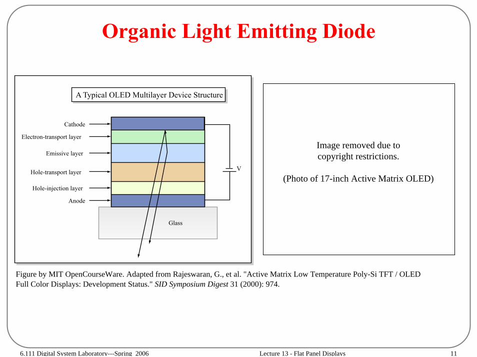
Organic Light Emitting Diode
Image removed due to copyright restrictions.
(Photo of 17-inch Active Matrix OLED)V
Cathode
Electron-transport layer
Emissive layer
Hole-transport layer
Hole-injection layer
Anode
Glass
A Typical OLED Multilayer Device Structure
Figure by MIT OpenCourseWare. Adapted from Rajeswaran, G., et al. "Active Matrix Low Temperature Poly-Si TFT / OLEDFull Color Displays: Development Status." SID Symposium Digest 31 (2000): 974.

6.111 Digital System Laboratory---Spring 2006 Lecture 13 - Flat Panel Displays 12
Digital Mirror Device
Applied voltage deflects Mirror and hence direct light
Vb (Bias)
Torsion Mirror
Yoke
+φL−φL
φa(-) φa(+)
(Address Voltage)
Landing Electrode
Address Electrode
Figure by MIT OpenCourseWare.
6.111 Digital System Laboratory---Spring 2006 Lecture 13 - Flat Panel Displays 13
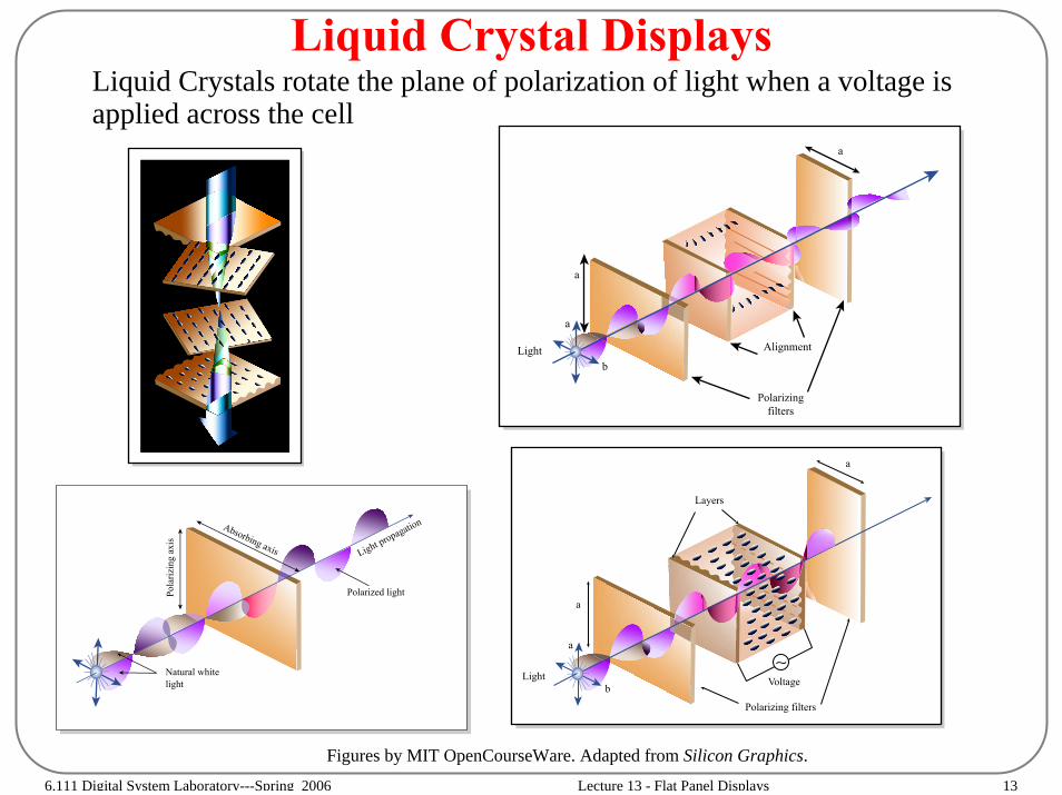
Liquid Crystal DisplaysLiquid Crystals rotate the plane of polarization of light when a voltage is applied across the cell
Figures by MIT OpenCourseWare. Adapted from Silicon Graphics.
Absorbing axis
Pola
rizin
g ax
is
Light propagation
Polarized light
Natural whitelight
a
a
a
bLight
Polarizingfilters
Alignment
6.111 Digital System Laboratory---Spring 2006 Lecture 13 - Flat Panel Displays 14
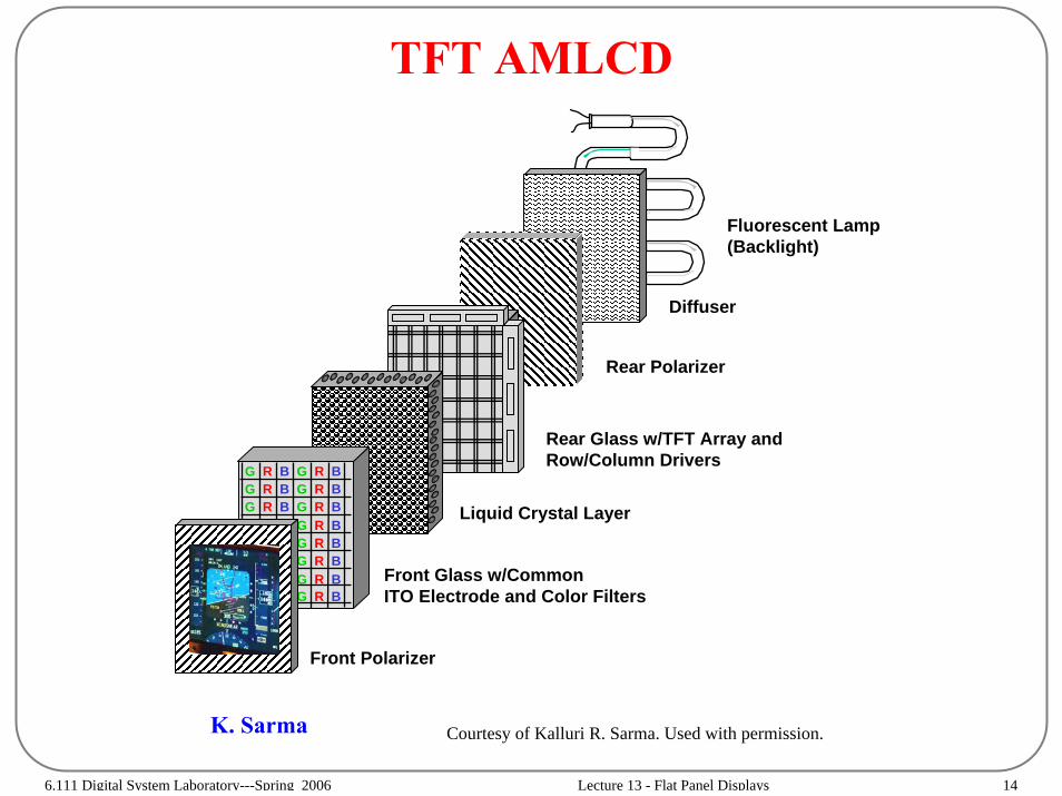
TFT AMLCD
Diffuser
Fluorescent Lamp(Backlight)
Front Polarizer
Front Glass w/CommonITO Electrode and Color Filters
Liquid Crystal Layer
Rear Glass w/TFT Array andRow/Column Drivers
Rear Polarizer
G R B G R BG R B G R BG R B G R B
G R B
G R B
G R BG R B
G R B
K. Sarma Courtesy of Kalluri R. Sarma. Used with permission.

6.111 Digital System Laboratory---Spring 2006 Lecture 13 - Flat Panel Displays 15
Standard Display Addressing Modes• Sequential Addressing (pixel at a time)
– CRT, Laser Projection Display
• Matrix Addressing (line at a time)– Row scanning, PM LCD, AMLCD, FED, PDPs, OLEDs
• Direct Addressing– 7-segment LCD
• Random Addressing– Stroke-mode CRT
6.111 Digital System Laboratory---Spring 2006 Lecture 13 - Flat Panel Displays 16
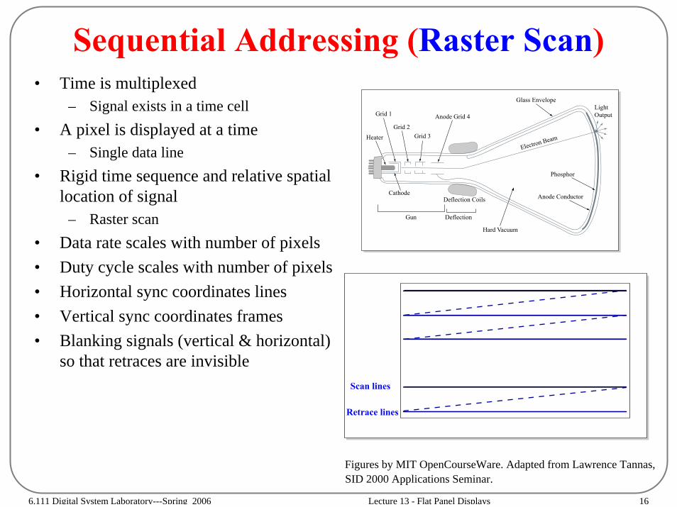
Sequential Addressing (Raster Scan)• Time is multiplexed
– Signal exists in a time cell• A pixel is displayed at a time
– Single data line• Rigid time sequence and relative spatial
location of signal– Raster scan
• Data rate scales with number of pixels• Duty cycle scales with number of pixels• Horizontal sync coordinates lines• Vertical sync coordinates frames• Blanking signals (vertical & horizontal)
so that retraces are invisible
Deflection Coils
DeflectionGun
Heater
Grid 1
Grid 2Grid 3
Anode Grid 4
Glass Envelope
Electron Beam
Phosphor
Anode Conductor
Hard Vacuum
Cathode
LightOutput
Figures by MIT OpenCourseWare. Adapted from Lawrence Tannas,SID 2000 Applications Seminar.
Scan lines
Retrace lines
6.111 Digital System Laboratory---Spring 2006 Lecture 13 - Flat Panel Displays 17
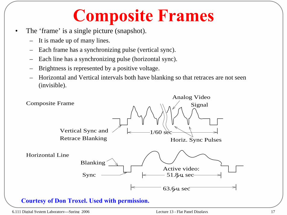
Composite Frames• The ‘frame’ is a single picture (snapshot).
– It is made up of many lines.– Each frame has a synchronizing pulse (vertical sync).– Each line has a synchronizing pulse (horizontal sync).– Brightness is represented by a positive voltage.– Horizontal and Vertical intervals both have blanking so that retraces are not seen
(invisible).
Sync u 51.8 sec
u
Active video:
63.6 sec
1/60 secVertical Sync andRetrace Blanking
Analog Video Signal
Horiz. Sync Pulses
Composite Frame
Horizontal LineBlanking
Courtesy of Don Troxel. Used with permission.

6.111 Digital System Laboratory---Spring 2006 Lecture 13 - Flat Panel Displays 18
Display Timing Generator Parameters
HTOT = Horizontal TotalHBS = Horizontal Blanking StartHSS = Horizontal Sync StartHSE = Horizontal Sync End
VTOT = Vertical TotalVBS = Vertical Blanking StartVSS = Vertical Sync StartVSE = Vertical Sync End
6.111 Digital System Laboratory---Spring 2006 Lecture 13 - Flat Panel Displays 19
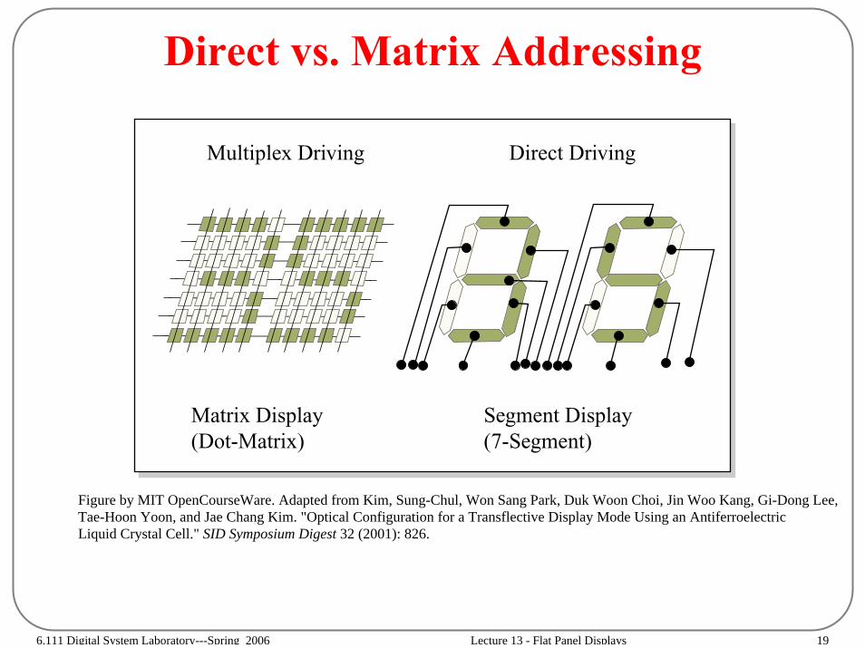
Direct vs. Matrix Addressing
Figure by MIT OpenCourseWare. Adapted from Kim, Sung-Chul, Won Sang Park, Duk Woon Choi, Jin Woo Kang, Gi-Dong Lee,Tae-Hoon Yoon, and Jae Chang Kim. "Optical Configuration for a Transflective Display Mode Using an AntiferroelectricLiquid Crystal Cell." SID Symposium Digest 32 (2001): 826.
Direct Driving
Segment Display(7-Segment)
Multiplex Driving
Matrix Display (Dot-Matrix)
6.111 Digital System Laboratory---Spring 2006 Lecture 13 - Flat Panel Displays 20
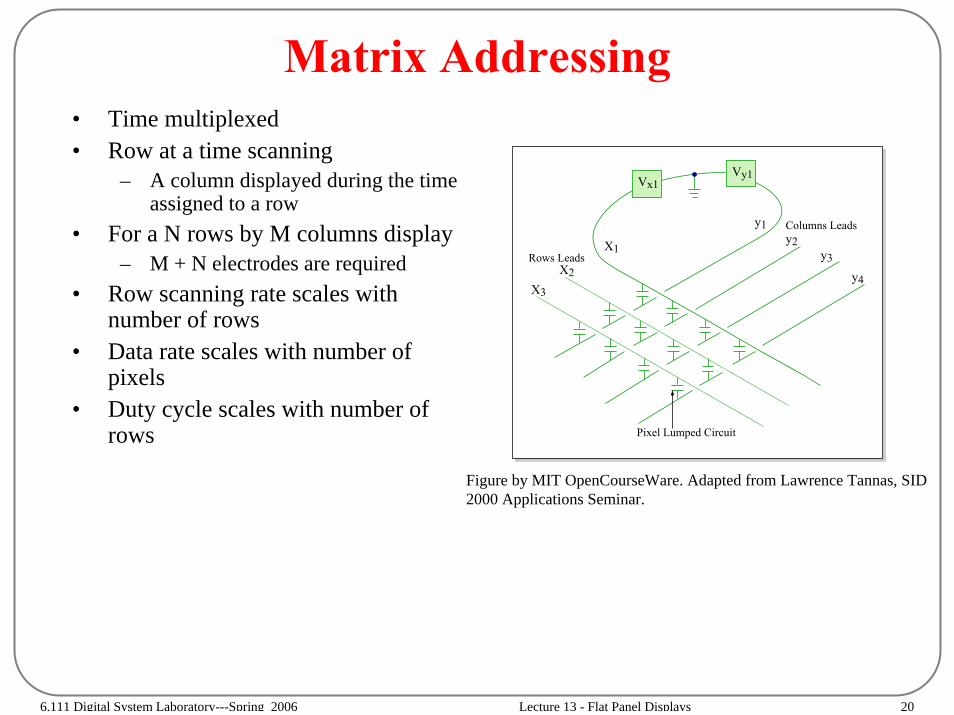
Matrix Addressing• Time multiplexed• Row at a time scanning
– A column displayed during the time assigned to a row
• For a N rows by M columns display– M + N electrodes are required
• Row scanning rate scales with number of rows
• Data rate scales with number of pixels
• Duty cycle scales with number of rows
X3
X2
X1
Pixel Lumped Circuit
Columns Leadsy1y2
y3
y4
Vx1Vy1
Rows Leads
Figure by MIT OpenCourseWare. Adapted from Lawrence Tannas, SID 2000 Applications Seminar.

6.111 Digital System Laboratory---Spring 2006 Lecture 13 - Flat Panel Displays 21
Active Matrix Addressing
•Introduce non linear device that improves the selection.
•Storage of data values on capacitor so that pixel duty cycle is 100%
•Improve brightness of display by a factor of N (# of rows) over passive matrix drive
•Display element could be LC, EL, OLED, FED etc
Upper Column Driver
Lower Column Driver
Row
Driv
er
D1 D3
G1
G2
G3
G4
D2 D4
Figure by MIT OpenCourseWare. Adapted from Yeh, Pochi, and Claire Gu. Optics of Liquid Crystal Displays. Wiley Series in Pure and Applied Optics. New York,NY: John Wiley & Sons, 1999. ISBN: 9780471182016.
6.111 Digital System Laboratory---Spring 2006 Lecture 13 - Flat Panel Displays 22
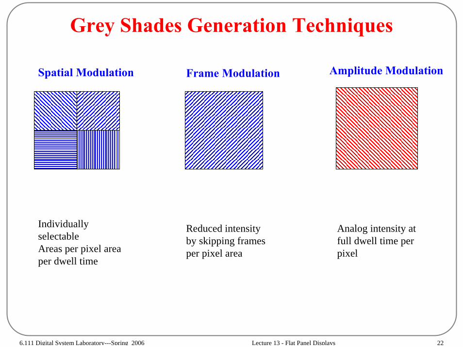
Grey Shades Generation Techniques
Individually selectableAreas per pixel area per dwell time
Reduced intensity by skipping frames per pixel area
Analog intensity at full dwell time per pixel
Spatial Modulation Frame Modulation Amplitude Modulation

6.111 Digital System Laboratory---Spring 2006 Lecture 13 - Flat Panel Displays 23
Grey Scale Generation(Spatial Modulation / Frame Rate Control)
6 5 3/4 5 2/4 5 1/4 5
(2x2)Unit Pixel
ReducedResolution
5
6
1st 2nd 3rd 4th frame Average
5
5 1/4
5 2/4
5 3/4
6
+ +
+++
+
+
+
+
+
+
+
+
+
+
=
=
=
=
=
Dith
erin
gFr
ame
Rat
e C
ontro
l (FR
C)
Figure by MIT OpenCourseWare. Adapted from Kim, Sung-Chul, Won Sang Park, Duk Woon Choi, Jin Woo Kang, Gi-Dong Lee,Tae-Hoon Yoon, and Jae Chang Kim. "Optical Configuration for a Transflective Display Mode Using an AntiferroelectricLiquid Crystal Cell." SID Symposium Digest 32 (2001): 826.

6.111 Digital System Laboratory---Spring 2006 Lecture 13 - Flat Panel Displays 24
Grey Scale Generation(Amplitude Modulation)
T1 T8T7T6T5T4T2 T3White Black
V1 V2 V3 V4 V5 V6 V7 V8
D2
D1
D0 1111
1 1 11
1111
0 0 0 0
0 0 0 0
0000
L/C Voltage
Digital Data(3-bit)
(000)(011)(101)(111)
8 Gray-scale
Transmittance
23 = 8 gray scales
T8T7
T2
T1
L/C Voltage (V)
V1 V2 V7 V8...
Figure by MIT OpenCourseWare. Adapted from Kim, Sung-Chul, Won Sang Park, Duk Woon Choi, Jin Woo Kang, Gi-Dong Lee,Tae-Hoon Yoon, and Jae Chang Kim. "Optical Configuration for a Transflective Display Mode Using an AntiferroelectricLiquid Crystal Cell." SID Symposium Digest 32 (2001): 826.
6.111 Digital System Laboratory---Spring 2006 Lecture 13 - Flat Panel Displays 25
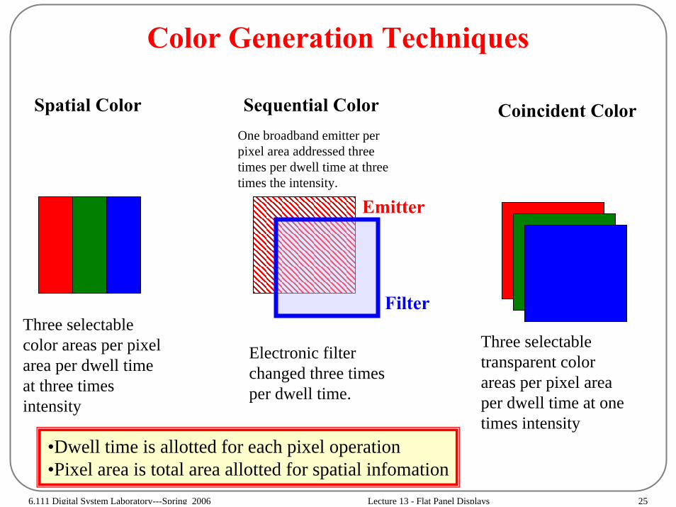
Color Generation Techniques
Spatial Color Sequential Color Coincident Color
Three selectable color areas per pixel area per dwell time at three times intensity
Electronic filter changed three times per dwell time.
Three selectable transparent color areas per pixel area per dwell time at one times intensity
One broadband emitter per pixel area addressed three times per dwell time at three times the intensity.
Filter
Emitter
•Dwell time is allotted for each pixel operation•Pixel area is total area allotted for spatial infomation

6.111 Digital System Laboratory---Spring 2006 Lecture 13 - Flat Panel Displays 26
Driver Circuits
Figure by MIT OpenCourseWare.
Shift Regs(256)
Shift Regs(256)
Shift Regs(256)
Shift Regs(256)
Redundant Column Drivers (1024)
1024 x 1024
Bi-Level
Pixel ElementsR
edundant Row
Drivers (1024)
n
n+1
m+1m
VghVgl
Vgl
FRAME(60 Hz)
VghVcom
Vclk(61 KHz)
Datain4Datain3Datain2Datain1
Pclk
(15.7 MH
z)
1024 Stage 1-Bit Shift R
egister
Level Shifters (1024)
Bi-Level O
utput Buffers (1024)
Tri-Level Output Buffers (1024)
Level Shifters (1024 x 2)
1-Bit Latches (1024)
Vcom
Cs CLC
6.111 Digital System Laboratory---Spring 2006 Lecture 13 - Flat Panel Displays 27
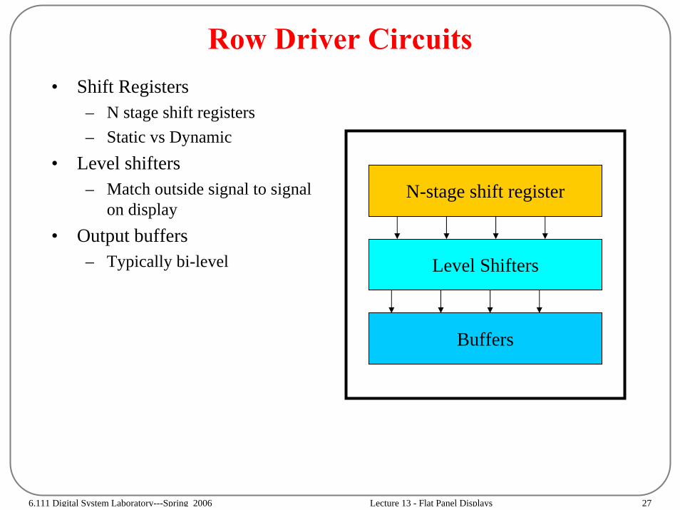
Row Driver Circuits• Shift Registers
– N stage shift registers– Static vs Dynamic
• Level shifters– Match outside signal to signal
on display• Output buffers
– Typically bi-level
N-stage shift register
Level Shifters
Buffers
6.111 Digital System Laboratory---Spring 2006 Lecture 13 - Flat Panel Displays 28
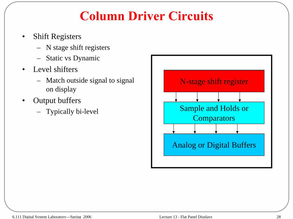
Column Driver Circuits• Shift Registers
– N stage shift registers– Static vs Dynamic
• Level shifters– Match outside signal to signal
on display• Output buffers
– Typically bi-level
N-stage shift register
Sample and Holds orComparators
Analog or Digital Buffers

6.111 Digital System Laboratory---Spring 2006 Lecture 13 - Flat Panel Displays 29
Analog Data Driver
Figure by MIT OpenCourseWare. Adapted from S. Morizumi, SID '00 Seminar notes.
S3S2S1
S/RS/RS/R
S3S2S1
S/RS/RS/R
Shift CL
VideoSignal
Shift CL
VideoSignal
D3D2D1
D3D2D1
CCC
AnalogBuffer
Shift Registers
Shift Registers
Point at a time
Line at a time

6.111 Digital System Laboratory---Spring 2006 Lecture 13 - Flat Panel Displays 30
Digital Data Drivers
ShiftRegisters
DACs
Figure by MIT OpenCourseWare. Adapted from Shinji Morozumi, SID 2000 Seminar Notes.
S3S2S1
AnalogBuffer
D3D2D1
6-8 BitsData
D-to-AConverter
S/RS/RS/R
DACDACDAC