$6+,1*721 3 - penn state engineering · pdf 2006 analysis... ... appendix b: wind and...
TRANSCRIPT

WASHINGTON PARK CONDOMINIUMSMT. LEBANON, PENNSYLVANIA
TECHNICAL REPORT #3LATERAL SYSTEM ANALYSIS AND CONFIRMATION DESIGN
ARCHITECTURAL ENGINEERING2008-2009 SENIOR THESIS
PREPARED BY:BENJAMIN FOLLETT - STRUCTURAL OPTION
PPREPARED FOR:DR. LINDA HANAGAN, P.E.
NOVEMBER 21, 2008
Technical Washington Park Condominiums Report #3 Mt. Lebanon, PA
B. Follett Page 2
Table of Contents:
Table of Contents …..……………………………………………………………………………………………………………. 2
Executive Summary …..……………………………………..………………………………………………….……………… 3
Introduction ……..……………………………………………………………………….………………………………………… 4
Existing Composite Joist and Precast Concrete Plank System…………….……………….…………………. 5
Applicable Codes, Design Criteria and Load Cases……..…………………………..……………….…….……… 8
Building Design Loads and Lateral Criteria………….………..………………………..……………….…..….…… 9
Load Distribution and Analysis …..……………………..……………………………………….……………………… 12
Determination of Relative Stiffness (k) and Center of Rigidity.………………………………... 12
Determination of Direct and Torsional Shear………………………..………………………….. 12, 13
Frame Analysis………………………………………………………………………………………………………………….. 15
Portal Frame Analysis.…………………………………...……………………………………….……………... 15
STAAD.Pro 2006 Analysis.……………………………………………………………………..………………... 15
Member Verification and Strength Checks………………………………………………………………. 17
Serviceability Check (Drift Analysis)……………………………………………………………………………….….. 26
Overturning Moment and Uplift…………………………………………………………………………………….….. 27
Conclusion…………………………………...………………..…………..……………………………………………………… 29
Appendix A: Building Layout ………….………………………….………………………………….…………………… 30
Appendix B: Wind and Seismic Design Data..……………..………………………………..…..………………… 33
Appendix C: Center of Mass and Rigidity.…………………………………………………………….……………… 36
Appendix D: Portal Frame Analysis Calculations.………………………………………………………...……… 38
Appendix E: Torsional Force Tables…………………..………………………………………………………...……… 44
Technical Washington Park Condominiums Report #3 Mt. Lebanon, PA
B. Follett Page 3
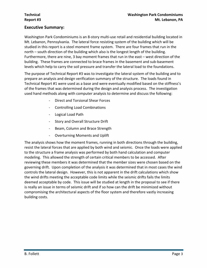
Executive Summary:
Washington Park Condominiums is an 8‐story multi‐use retail and residential building located in Mt. Lebanon, Pennsylvania. The lateral force resisting system of the building which will be studied in this report is a steel moment frame system. There are four frames that run in the north – south direction of the building which also is the longest length of the building. Furthermore, there are nine, 3 bay moment frames that run in the east – west direction of the building. These frames are connected to brace frames in the basement and sub‐basement levels which help to carry the soil pressure and transfer the lateral load to the foundations.
The purpose of Technical Report #3 was to investigate the lateral system of the building and to prepare an analysis and design verification summary of the structure. The loads found in Technical Report #1 were used as a base and were eventually modified based on the stiffness’s of the frames that was determined during the design and analysis process. The investigation used hand methods along with computer analysis to determine and discuss the following:
‐ Direct and Torsional Shear Forces
‐ Controlling Load Combinations
‐ Logical Load Path
‐ Story and Overall Structure Drift
‐ Beam, Column and Brace Strength
‐ Overturning Moments and Uplift
The analysis shows how the moment frames, running in both directions through the building, resist the lateral forces that are applied by both wind and seismic. Once the loads were applied to the structure a frame analysis was performed by both hand calculation and computer modeling. This allowed the strength of certain critical members to be accessed. After reviewing these members it was determined that the member sizes were chosen based on the governing drift. Upon completion of the analysis it was determined that in most cases the wind controls the lateral design. However, this is not apparent in the drift calculations which show the wind drifts meeting the acceptable code limits while the seismic drifts fails the limits deemed acceptable by code. This issue will be studied at length in the proposal to see if there is really an issue in terms of seismic drift and if so how can the drift be minimized without compromising the architectural aspects of the floor system and therefore vastly increasing building costs.

Technical Washington Park Condominiums Report #3 Mt. Lebanon, PA
B. Follett Page 4
Introduction:
Washington Park Condominiums is a multi‐use retail and residential building located at the intersection of Bower Hill Road and Washington Road in Mt. Lebanon, Pennsylvania. Site work and excavation has begun at the site and construction should begin sometime before the end of the fall 2008, with the project lasting until fall 2010. Washington Park Condominiums is the first of two buildings proposed to be built on the site. Building one is a nine‐story, 148,000 ft2
structure which is owned by Zamagias Properties of Pittsburgh, PA. The building was architecturally designed by Indovina Associates Architects and is being constructed by PJ Dick, Inc. for a price of $23,418,000. The building’s primary use is residential and it contains 7 stories of condominiums on the 2nd through 8th floors. The first floor of the building is used for retail space and as a location for extra amenities for the residents of Washington Park. The building also contains two below grade levels of parking. The enclosed parking garage contains 78 parking spaces that can be used by the residents. Two elevators and two stairs serve the parking areas that also contain resident storage, a wine room and trash collection along with mechanical and electrical rooms. The ground floor serves primarily as retail space with four separate areas available for possible tenants. Also contained on the floor are a resident exercise room and a private entrance and lobby for the residents.
As the building moves to the second floor, the function changes from primarily retail to one of solely residential with six upscale condominiums located on the floor. These condominiums each have different floor plans and layouts with overall areas ranging from 1523 ft2 to 2288 ft2. Each unit contains two or three bedrooms and bathrooms depending on size, along with a living room, dining room, kitchen, study, laundry, entry and in some cases a balcony. This floor layout continues throughout the next four floors, with a total of 30 units on floors 2 through 6. The 7th and 8th floors of the building are the penthouse level. This floor contains five condominiums that range from 1732 ft2 to 2453 ft2. These units contain the same amenities and spaces as the units on the below floors do. All of the condominiums floors are served by two elevators and two stairways that are connected by a hallway that runs through the center of the building in the long direction. Finally, the roof contains mechanical spaces that are accessed by using the northern most stairway or elevator.
The typical exterior wall system of the building consists mainly of 4” brick veneer backed by a 2” airspace and 2” of rigid XPS insulation, then containing another 2” layer of rigid spray‐foam insulation that is followed by an airspace and then 5/8” gypsum board. This exterior wall system is typical for the first 6 floors of the building. The 7th and 8th floors of the building consist of a similar wall construction except for the exterior façade which is a 5/16” layer of painted fiber‐cement siding.

Technical Washington Park Condominiums Report #3 Mt. Lebanon, PA
B. Follett Page 5
Existing Composite Joist and Precast Concrete Plank System:
Foundations
The foundation system can be best described as a spread footing system with attached concrete piers. The sizes for the spread footings range from the smallest, a 4’‐0” x 4’‐0” x 2’‐0” footing with #8 @ 12” each way, to a 14’‐0” x 14‐0” x 3’‐6” footing with #8 @ 6” each way with the deepest of the footings will be 25’‐0” below grade. In addition to the spread footings, interior and exterior wall footings were used and are either 2’‐0” or 3’‐0” wide by 1’‐4” deep. The steel reinforcing in these wall footings are (3) #5 continuous bars and #5 x 1’‐8” @ 16”.
The slab on grade in this system consist of either a 6” or 8” normal weight concrete slab reinforced with 6x6‐W2.9xW2.9 welded wire fabric or 6x6‐W4xW4 welded wire fabric. The slab on grade is also thickened to a minimum if 1’‐0” at non‐load bearing walls and (2) #4 bars are added for tensile strength. Connecting the columns to the slab on grade and the footings are column piers that range from 16” x 16” with (4) #7 of vertical reinforcement to 40” x 40” w/ (12) #7 of vertical reinforcement and f’c = 4000 psi concrete is used for the entire system.
Floor Systems
Two separate floors systems are typical within the structure of Washington Park. The first is a precast concrete plank system that is used in the parking areas as well as the first and second floor framing. The precast concrete plank is 8” thick and also contains a 2” thick structural topping. The reinforcing in the structural topping is 6x6‐W1.4xW1.4 welded wire fabric. The precast concrete plank system bears on W shapes which then carry the load to the columns. This system was used in the parking areas because of the systems diaphragm capacity (ability to transfer horizontal loading) and because of its durability and strength.
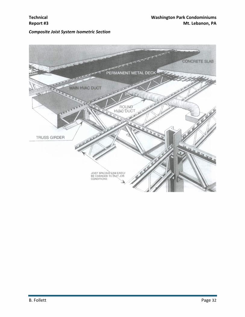
The second primary floor system in the building is the VESCOM composite joist floor system. The composite joist system interlocks the top chord of a joist with the concrete producing less deflection, less vibration and greater stiffness. The floor construction consists of a 2 11/16” reduced weight concrete slab that is poured on top of the 1 5/16”, 22 Gage galvanized floor decking. The bottom chord acts as the main tension member, and in the composite stage the embedded top chord serves as a continuous shear connection. The concrete is also reinforced with welded wire fabric and compressive strength of the concrete is f’c = 3500 psi. Finally, the system was used as an architectural element since the ceiling could be installed directly to the joist bottom chord and the mechanical systems (HVAC, plumbing, fire protection, electrical and telecommunications) could be installed with the joist system, saving space and allowing for higher ceilings and floor to floor height within the apartments. A section of the VESCOM Composite floor system can be found in Appendix B.

Technical Washington Park Condominiums Report #3 Mt. Lebanon, PA
B. Follett Page 6
Lateral System
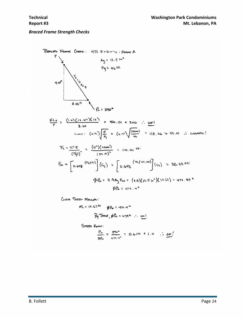
The lateral resisting system within the building is mainly moment resisting steel frames made up of wide flange beams. These frames begin on the second floor and continue up through the top of the building. These frames run in the north‐south direction and run along column lines A, B, C and D. Rigid connections also occur on these floors along column lines 1 through 9. Figure 1 below shows the four different types of moment frames that exist within the building. These four frames Since the VESCOM floor system is being used as a diaphragm to transfer shear loading the load path begins at the exterior beams and then continue on through the floor system to joist girders which are to be designed and manufactured by the joist manufacturer. The load is then transferred into the large W14 columns, and finally to the brace frames and the foundations. There are a total of eleven braced frames located in the basement and sub‐basement levels running along column lines 1 through 11 from column lines A.1 to B. The brace frames are 17’‐2” in length and they begin at the sub‐basement level and connect into the framing for the ground floor. The bracing in the frames consists of HSS 8x8x1/2 up to the basement level, and HSS 6x6x3/8 from the basement level to the ground floor. These frames are shown in Figure 2 below. This plan detail and the detail of the brace frames can be found in Figures 2 and 3.
Figure 1: Braced Frame Location
North – South Frames (A & D)
North – South Frames (B & C)
East – West Frames (F thru L)
East – West Frames (E & M)
(0,0)
Figure 1: Moment Frame Diagram

Technical Washington Park Condominiums Report #3 Mt. Lebanon, PA
B. Follett Page 7
Figure 3: Braced Frames Elevation
Figure 2: Braced Frame Location Diagram

Technical Washington Park Condominiums Report #3 Mt. Lebanon, PA
B. Follett Page 8
Applicable Codes, Design Criteria and Load Cases
Since an in depth lateral analysis was performed there were many reference manuals and materials that were used to complete the design, these are listed as follows:
‐ IBC 2003 with Amendments for Mt. Lebanon, Pennsylvania ‐ ASCE 7‐05 : Minimum Design Loads for Buildings and Other Structures ‐ ACI 318‐08 Building Code and Commentary ‐ Design of Concrete Structures Textbook (AE 431) ‐ AISC Specification for Structural Steel Buildings, 13th Edition ‐ RAM Structural System (Gravity Loads) ‐ STAAD Pro 2006 (Lateral Load Analysis)
Design Deflection Criterion The following design criterion was also used and can be found in IBC 2006 and ASCE 7‐05:
‐ Δ = H/400 for Allowable Story and Building Drift due to Wind Loading ‐ Δ = 0.015hsx for Allowable Story and Building Drift due to Seismic Loading
Design Load Combinations The following Load and Resistance Factor Design load combinations were considered for analysis, as noted in ASCE 7‐05 Chapter 2:
‐ 1.4(Dead) ‐ 1.2(Dead) + 1.6(Live) + 0.5(Roof Live) ‐ 1.2(Dead) + 1.6(Roof Live) + 0.8(Wind) ‐ 1.2(Dead) + 1.6(Snow) + 0.8(Wind) ‐ 1.2(Dead) + 1.6(Snow) + 1.0(Live) ‐ 1.2(Dead) + 1.6(Wind) + 1.0(Live) + 0.5(Snow) ‐ 1.2(Dead) + 1.6(Wind) + 1.0(Live) + 0.5(Roof Live) ‐ 1.2(Dead) + 1.0(Earthquake) + 1.0(Live) + 0.2(Snow)

Technical Washington Park Condominiums Report #3 Mt. Lebanon, PA
B. Follett Page 9
Building Design Loads and Lateral Criteria
In order to complete an analysis of Washington Park Condominiums, that gravity and lateral loads acting on the building need to be identified. The dead and live loads that are used were also used in Technical Report #1 because it was determined that those loads closely matched those used by the design engineer. The lateral loads were recalculated by determining the equivalent stiffness for each moment frame in the building. Finding the stiffness of each frame allowed for the direct shear and torsional shear at each level to be calculated and for the loads to be distributed throughout the building according to stiffness. These loads and the process in which they were determined will be discussed in detail in the next section. The tables below list the dead and live loads for the building as well as the wind and seismic design criteria used in the computation of the lateral loads.
Gravity Loads
Table 1: Dead Load Tables
Dead Load Table Floor Dead Load
Roof Dead Load Material/System Load Material/System Load
Normal Weight Concrete 145 pcf 4 11/16" RWC Slab on 1 5/16" FLR
Deck 68 psf
Steel Per Shape MEP 6 psf Brick Veneer w/ studs 40 psf Sprinklers 3 psf
8" P/C Plank w/ 2" Structural Topping 90 psf Ceiling 8 psf
VESCOM Joists 4 psf
MEP 6 psf Asphalt
Shingles/Felts 4 psf
Sprinklers 3 psf 1/2" Cement
Bonded Particle Board
5 psf
Ceiling 5 psf Light Gauge Roof Trusses @ 2'‐0"
O.C. 4 psf
Floor Finishes 5 psf Partitions 20 psf
VESCOM Joists 4 psf
2 11/16" RWC Slab on 1 5/16" FLR Deck
43 psf

Technical Washington Park Condominiums Report #3 Mt. Lebanon, PA
B. Follett Page 10
Live Load Table
Floor Live Load Table
Roof Live and Snow Load Table
Occupancy Load Material/System Load
Typ. Condominium Floor 40 psf Roof Live Load 20 psf
Stairs 100 psf Roof Live Load (Mechanical)
150 psf
First Level (Plaza and Traffic/Parking Areas
250 psf Ground Snow Load
(Pg) 25 psf
First Level (Non‐Plaza Areas) 100 psf Flat Roof Snow
Load (Pf) 23 psf
Basement Level Parking Areas/Ramps 50 psf Exposure Factor
(Ce) 1.2
Slabs‐on‐Grade 150 psf Thermal Factor (Ct) 1
Exercise Area at Ground Floor 150 psf Importance Factor
(I) 1.1
Corridors On 1st Floor 100 psf
Corridors Above 1st Floor 80 psf
Mech/Elec Spaces 150 psf
Second Floor Terrace 100 psf
Apartment Balconies 100 psf Table 2: Live Load Tables
Wind Criteria
The wind loads for Washington Park Condominiums were calculated using the design criteria found in ASCE 7‐05, Chapter 6 and it was determined that it was permitted to use Method 2 – Analytical Procedure for the design. The table below lists the applicable wind design factors.
Basic Wind Speed (V) 90 mph
Wind Direction Factor (Kd) 0.85
Importance Factor (I) 1
Exposure Category C
Velocity Pressure Coefficient (Kz) Case 2
Topographic Factor (Kzt) 1
Enclosure Class Enclosed Table 3: Wind Design Criteria

Technical Washington Park Condominiums Report #3 Mt. Lebanon, PA
B. Follett Page 11
Seismic Criteria
The seismic loads for Washington Park Condominiums were calculated using ASCE 7‐05, Chapter 12, as well as using the information provided by the structural engineer and the geotechnical engineer. From the geotechnical report, it was determined that the Site Class for construction would be Site Class C. The remainder of the information needed to calculate seismic loading and base shear was found in Chapter 12 of ASCE 7‐05. The table below lists the applicable seismic design factors.
Seismic Parameters for Washington Park Condominiums
Ss S1 Site Class Fa Fv Sds Sd1 Seismic Design
Category Seismic Use
Group
0.128 0.058 C 1.6 2.4 0.137 0.093 B I
I R Cu Ta TL Ts Cs k Period Coefficient
1 3.5 1.7 1.082 12 0.6333 0.01706 1.291 0.80 Table 4: Seismic Design Parameters

Technical Washington Park Condominiums Report #3 Mt. Lebanon, PA
B. Follett Page 12
Load Distribution and Analysis
The distribution of lateral forces throughout the structure can be determined using varying design methods. For this technical report the lateral loads were ascertained based on the relative stiffness of each frame in conjunction with the rest of the frames in the building. The composite joist floor system is used as a shear diaphragm and it distributes load to the various frames based on their respective relative stiffness. This process allows for a more accurate distribution of loads along with the ability to study how the frames work together to transfer the loads from the moment frames to the foundations. For the analysis, hand calculations, Microsoft Excel and STAAD.Pro 2006 were utilized as a way to obtain a more thorough understanding of the distribution.
Determination of Relative Stiffness (k) and Center of Rigidity
The determination of each frame’s relative stiffness was done using hand calculations and STAAD.Pro 2006. To begin the four different frames (interior and exterior in each direction) were constructed in STAAD using the steel sizes and connections given by the structural engineer. Next a one kip load was applied at the top of each moment frame to establish the amount of deflection that occurs at the top of the frame. From there, the inverse of this deflection was taken and these values were used for k. From these k values, the center of rigidity of the building was found. The x and y distance values used for the center of rigidity were taken from a (0,0) point chosen on the bottom right corner of the building as shown in Appendix C. The relative stiffness’s for each frame are included in the table for the direct and torsional shear shown below.
Determination of Direct Shear and Torsional Shear
After establishing the stiffness values for each frame, the direct and torsional shears for each frame at each level could be determined. For this analysis, it was decided that four regular frames could be chosen that would be representative of all the frames in the building. Frames A and E are the exterior frames in the north ‐ south and east ‐ west directions respectively. Also, frames C and F are the interior frames in the north ‐ south and east ‐ west directions respectively. The calculation for the moments for each frame at each floor used in the torsional force can be found in Appendix F. The direct and torsional shears are then found by using the following equations and variables. These variables can be found in Table 5 below along with the values for the forces of the four frames that are being studied:
Technical Washington Park Condominiums Report #3 Mt. Lebanon, PA
B. Follett Page 13
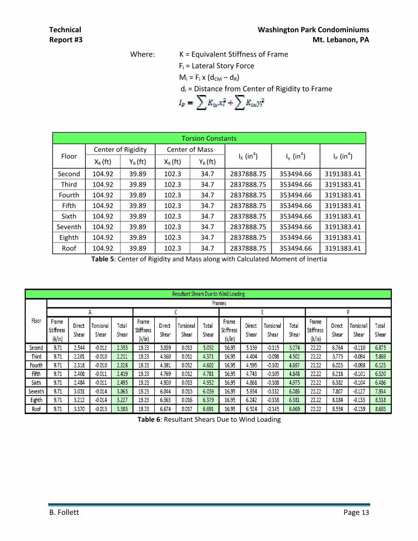
Where: K = Equivalent Stiffness of Frame Fi = Lateral Story Force
Mi = Fi x (dCM – dR) di = Distance from Center of Rigidity to Frame
Torsion Constants
Floor Center of Rigidity Center of Mass
IX (in4) Iy (in
4) IP (in4)
XR (ft) YR (ft) XR (ft) YR (ft)
Second 104.92 39.89 102.3 34.7 2837888.75 353494.66 3191383.41 Third 104.92 39.89 102.3 34.7 2837888.75 353494.66 3191383.41 Fourth 104.92 39.89 102.3 34.7 2837888.75 353494.66 3191383.41 Fifth 104.92 39.89 102.3 34.7 2837888.75 353494.66 3191383.41 Sixth 104.92 39.89 102.3 34.7 2837888.75 353494.66 3191383.41
Seventh 104.92 39.89 102.3 34.7 2837888.75 353494.66 3191383.41 Eighth 104.92 39.89 102.3 34.7 2837888.75 353494.66 3191383.41
Roof 104.92 39.89 102.3 34.7 2837888.75 353494.66 3191383.41 Table 5: Center of Rigidity and Mass along with Calculated Moment of Inertia
Table 6: Resultant Shears Due to Wind Loading

Technical Washington Park Condominiums Report #3 Mt. Lebanon, PA
B. Follett Page 14
Table 7: Resultant Shears Due to Seismic Loading
After obtaining the direct and torsional forces for each frame it is obvious that these values are smaller than that of story forces that are determined using tributary area. This could be due to the fact that using relative stiffness allows for the building to be analyzed as an entire structure since the direct shears are determined by using a ratio of frame stiffness to total stiffness. The method of tributary area does not take into account any other frame or how the other frames in the building may be working together to distribute the lateral load throughout the building. This allows for the calculated forces using the relative stiffness to be more accurate and therefore make the subsequent portal frame, strength and drift analyses more reliable.

Technical Washington Park Condominiums Report #3 Mt. Lebanon, PA
B. Follett Page 15
Frame Analysis
Portal Frame
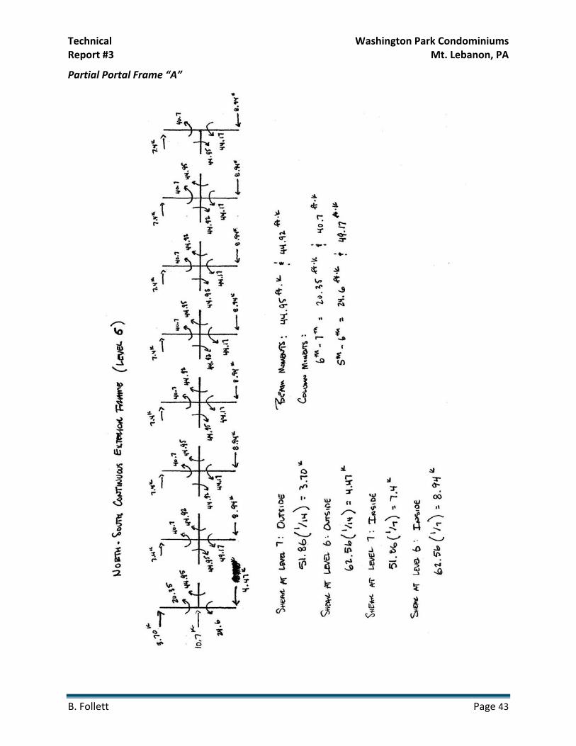
Following the determination of the direct and torsional forces through the establishment of relative stiffness, the story forces were applied to the structure and were analyzed using Portal Method. In this case, three different portal method analyses were performed. Frames E and F were analyzed using resultant shears due to wind since the value for total shear due to wind were greater than that of seismic. Next, a single floor of frame C was analyzed using the resultant shear due to seismic loading since for frame C the shear for seismic was greater than the shear due to wind. The moments in the beams and columns that were obtained from the portal frame analysis were used in the beam and column strength checks. The results of the portal frame analysis can be found in Appendix D.
STAAD Analysis
In conjunction with the portal frame analysis, a frame analysis using STAAD.Pro 2006 was performed. This analysis was useful in providing information concerning story and overall building drift as well as determining whether or not the steel members chosen in the design were adequate to carry the loads. Figures 4 and 5 below show the two frame constructions that were analyzed using STAAD. For ease of analysis along with a conservative design, frames A and C were analyzed as if they were straight moment frames. This was done because the entire frame works together and a continuous frame would be more conservative in terms of wind loads added to the building. Furthermore, both types of frames were analyzed twice for exterior and interior moment frame conditions. In each case, the lateral forces that were added to the frame were changed based on the values that were determined for total story shear in Tables 2 and 3 on the previous pages. Using these loads that story drifts and overall drift of the building was determined and was used in the comparison with the allowable drift values determined in Tables 4 and 5. STAAD was also used to determine the controlling load combinations in each direction. The following load combinations control in the given direction. Finally, the STAAD model was one of the ways that steel members used in the building’s design were verified. These steel shapes were also designed in the member and strength checks beginning on the next page. Overall, using STAAD allowed for a simplified method of member verification and drift analysis, as well as a method of comparison to the hand calculations performed for both member and frame checks.

Technical Washington Park Condominiums Report #3 Mt. Lebanon, PA
B. Follett Page 16
By the computer analysis it was determined that the controlling load combinations for each direction were as follows:
North – South Direction (Frames A thru D) : 1.2(Dead) + 1.0(Earthquake) + 1.0(Live) + 0.2(Snow)
East – West Direction (Frames E thru M) : 1.2(Dead) + 1.6(Wind) + 1.0(Live) + 0.5(Snow)
These combinations makes sense since the shorter of the moments frames would be controlled by the wind loads since the story shears on the frame would be a result of the wind pressures on the long side of the building. These load combinations were used to verify member sizes and strengths in the next section.
Figure 4: Frames E and F (East – West Direction)
Figure 5: Frames A and C (North – South Direction)

Technical Washington Park Condominiums Report #3 Mt. Lebanon, PA
B. Follett Page 17
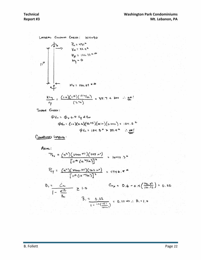
Member Verification and Strength Checks
Upon completion of the portal method, the moments from the analysis were used in conjunction with moments and forces found in the STAAD analysis to verify beam, column and brace frame members throughout the building. Members in frames running both north – south and east – west were analyzed using the controlling load combination and are denoted on the calculations. Although the members were designed and checked using STAAD, it is still necessary to check the computer output so that a competent understanding of member strength can be achieved. The members that were chosen are shown in Figure 6. Both the blue and red highlighted members are the longest spanning beams in their respective moment frames and therefore were chosen for analysis. The columns, denoted by circles, were chosen based because in the portal analysis the interior columns carry twice the shear when the lateral loads are distributed throughout the frame. Finally, a brace in each of the braced frames was designed for the axial load caused by dead, wind, live and soil pressure.
Figure 6: Members used for Verification (Frames C and F)
W18x97 (Frame F)
W18x97 (Frame C)
W14x90 (Frame F)
W14x90 (Frame C)

Technical Washington Park Condominiums Report #3 Mt. Lebanon, PA
B. Follett Page 18
Frame F: Beam and Column Strength Checks (Red on Plan)

Technical Washington Park Condominiums Report #3 Mt. Lebanon, PA
B. Follett Page 19

Technical Washington Park Condominiums Report #3 Mt. Lebanon, PA
B. Follett Page 20

Technical Washington Park Condominiums Report #3 Mt. Lebanon, PA
B. Follett Page 21
Frame C: Beam and Column Strength Checks (Blue on Plan)
Technical Washington Park Condominiums Report #3 Mt. Lebanon, PA
B. Follett Page 22

Technical Washington Park Condominiums Report #3 Mt. Lebanon, PA
B. Follett Page 23
Technical Washington Park Condominiums Report #3 Mt. Lebanon, PA
B. Follett Page 24
Braced Frame Strength Checks

Technical Washington Park Condominiums Report #3 Mt. Lebanon, PA
B. Follett Page 25

Technical Washington Park Condominiums Report #3 Mt. Lebanon, PA
B. Follett Page 26
Serviceability Check (Drift Analysis)
The drift of a structure is extremely important to the overall performance of the building. Too much story drift or total drift in a structure could result in damage to the building exterior and other systems causing repairs and obviously added costs due to maintenance. Because of this the IBC and ASCE 7‐05 have laid out parameters for drift control based on occupancy category, building height and structure type. In the case of Washington Park Condominiums the wind drift determined in STAAD was compared to Δw = H/400 for the entire building. The seismic drift, also determined in STAAD, was compared to ΔS = 0.015hsx where hsx is the story height of the building at a certain level. The allowable wind drift can be found on Table 1604.3 of the IBC and the allowable drift due to seismic is found on Table 12.12‐1 in ASCE 7‐05. The tables below display the comparison between actual and allowable drift for both wind and seismic.
Table 8: Actual Wind Drift Compared to Allowable Drift
Controlling Seismic Drift
Floor Story Height (ft)
Total Height (ft)
Story Drift (in)
Allowable Story Drift (in)
Δseismic = 0.020hsx Acceptable?
Total Drift (in)
Allowable Story Drift (in)
Δseismic = 0.020hsx Acceptable?
Second 14.333 14.33 0.232 < 0.287 Yes 0.232 < 0.287 Yes Third 11.000 25.33 0.314 < 0.22 No 0.546 < 0.506 No Fourth 11.000 36.33 0.336 < 0.22 No 0.882 < 0.727 No Fifth 11.000 47.33 0.332 < 0.22 No 1.214 < 0.947 No Sixth 11.000 58.33 0.311 < 0.22 No 1.525 < 1.17 No
Seventh 13.167 69.33 0.308 < 0.22 No 1.833 < 1.39 No Eighth 13.500 82.67 0.467 < 0.267 No 2.300 < 1.65 No Roof 13.833 96.33 0.349 < 0.273 No 2.649 < 1.93 No
Table 9: Actual Seismic Drift Compared to Allowable Drift
Controlling Wind Drift
Floor Story Height (ft)
Total Height (ft)
Story Drift (in)
Allowable Story Drift (in) Δwind = H/400
Acceptable? Total Drift (in)
Allowable Story Drift (in) Δwind = H/400
Acceptable?
Second 14.333 14.33 0.325 < 0.43 Yes 0.325 < 0.43 Yes Third 11.000 25.33 0.297 < 0.33 Yes 0.622 < 0.76 Yes Fourth 11.000 36.33 0.312 < 0.33 Yes 0.934 < 1.09 Yes Fifth 11.000 47.33 0.284 < 0.33 Yes 1.218 < 1.42 Yes Sixth 11.000 58.33 0.28 < 0.33 Yes 1.498 < 1.75 Yes
Seventh 13.167 69.33 0.248 < 0.33 Yes 1.746 < 2.08 Yes Eighth 13.500 82.67 0.274 < 0.40 Yes 2.020 < 2.48 Yes Roof 13.833 96.33 0.18 < 0.41 Yes 2.200 < 2.89 Yes

Technical Washington Park Condominiums Report #3 Mt. Lebanon, PA
B. Follett Page 27
As displayed in the above tables the controlling wind drift in the building is acceptable at both individual floors and for the overall height of the building when compared to the code allowable drift of Δw = H/400. However, the controlling seismic drift in the building is greater than the code allowable value of ΔS = 0.020hsx. A possible reason for this could be the fact that the individual moment frames were analyzed individually in STAAD. Another reason could be the fact that within the analysis that braced frames located on the basement and sub‐basement levels were not included in the calculation since they are considered to be below grade. These braced frames primarily serve to resist the soil pressure which can be seen in the braced frame strength checks. Another possibility is the fact that the stiffness of the composite joist floor system was not taken into account. Since, the floor system serves as a diaphragm, it can also be assumed that it also has some level of stiffness and therefore would help to resist and transfer some amount of lateral loading to the columns and ultimately the foundations. Many solutions to the problem could be used including, increase column and beam sizes and possibly added some braced frames throughout the building. Regardless of the solution that is used, the issue of more than allowable story and overall drift in the structure could be studied in more depth in the proposal and research later.
Overturning Moment and Uplift
One of the issues that are rarely considered when completing lateral analysis on a structure is how the lateral loads and ensuing transfer of those lateral loads to the foundations will impact their size. The impact of the foundations that needs to be considered is caused by wind and seismic forces producing an overturning moment for the building. In turn, the overturning moment, may cause uplift within the exterior columns and foundations of the building because there is not enough dead weight on the columns and foundations to resist the overturning moment. Tables 6 and 7 list the uplift found due to wind and seismic loading in both directions.
Uplift Due to Wind Loading
Moment (k‐ft)
Uplift Force (kips)
Dead Load Resistance (kips)
Uplift Problem?
East ‐ West Direction
24400.21 389.36 271.24 Yes
North‐ South Direction
6606.64 32.67 463.79 No
Table 10: Uplift due to Wind Loading
Technical Washington Park Condominiums Report #3 Mt. Lebanon, PA
B. Follett Page 28
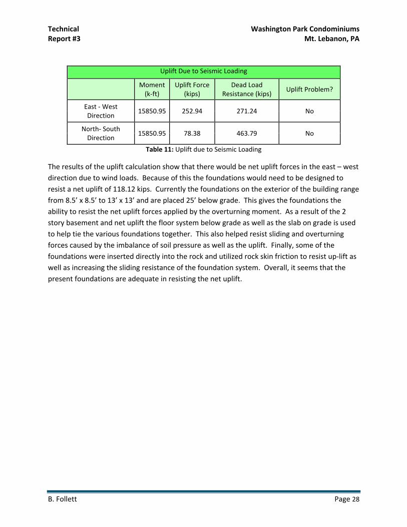
Uplift Due to Seismic Loading
Moment (k‐ft)
Uplift Force (kips)
Dead Load Resistance (kips)
Uplift Problem?
East ‐ West Direction
15850.95 252.94 271.24 No
North‐ South Direction
15850.95 78.38 463.79 No
Table 11: Uplift due to Seismic Loading
The results of the uplift calculation show that there would be net uplift forces in the east – west direction due to wind loads. Because of this the foundations would need to be designed to resist a net uplift of 118.12 kips. Currently the foundations on the exterior of the building range from 8.5’ x 8.5’ to 13’ x 13’ and are placed 25’ below grade. This gives the foundations the ability to resist the net uplift forces applied by the overturning moment. As a result of the 2 story basement and net uplift the floor system below grade as well as the slab on grade is used to help tie the various foundations together. This also helped resist sliding and overturning forces caused by the imbalance of soil pressure as well as the uplift. Finally, some of the foundations were inserted directly into the rock and utilized rock skin friction to resist up‐lift as well as increasing the sliding resistance of the foundation system. Overall, it seems that the present foundations are adequate in resisting the net uplift.

Technical Washington Park Condominiums Report #3 Mt. Lebanon, PA
B. Follett Page 29
Conclusion
The lateral analysis and design of the moment frame structure for Washington Park Condominiums was discussed in detailed throughout this technical report. The report examines the process which was taken to arrive at design of lateral members within the frames through both hand calculations and computer modeling. Both hand calculations and computer modeling were used to determine the relative stiffness factors for each frame. From there, the direct and torsional shear forces on each level of each frame were calculated so that they could applied to the frame and compared to the results found in Technical Report #1. After determining the forces to be applied to the separate frames, it was necessary to complete a portal frame analysis along with a computer analysis. The portal frame analysis rendered shear and moments in the beams and columns of the frames. The computer model analyzed in STAAD allowed for a comparison and check of the portal frame analysis. The STAAD model was also used to determine the controlling load cases for each frame and determine the drift of both in the individual stories and the entire frame. After obtaining the values for drift from STAAD they were compared to the allowable drift limits for both wind and seismic given in the International Building Code and ASCE 7‐05. The controlling wind drift was deemed acceptable by code, however the story drift and overall structure drift due to seismic loads were found to be above the acceptable code limits. Although the values did not meet the acceptable limits found in the code, it is believed that the reason for this could be contributed to the fact that the stiffness of the composite joist floor system was not taken into account. Since, the floor system serves as a diaphragm, it can also be assumed that it also has some level of stiffness and therefore would help to resist and transfer some amount of lateral loading to the columns and ultimately the foundations.
Along with the drift calculations, the design strength of several critical members of the different frames were analyzed based on the loads and moments found in the STAAD analysis. All members that were looked at were well within their ultimate capacity given by the AISC Specification for Structural Steel Buildings, 13th Edition. Finally, an overturning moment and uplift check was done to see if this would be an issue for the foundations. It was determined that in the east – west direction there may be an issue with uplift. This will be further examined in the proposal and could lead to further discussion of the foundation system used on the project.
Ultimately, it was concluded that the lateral system is sufficiently designed to carry the lateral loading of the building. The drift issues will be discussed and examined in greater detail through the proposal and following research.

Technical Washington Park Condominiums Report #3 Mt. Lebanon, PA
B. Follett Page 30
Appendix A: Building Layout

Technical Washington Park Condominiums Report #3 Mt. Lebanon, PA
B. Follett Page 31
Typical Floor Layout
Technical Washington Park Condominiums Report #3 Mt. Lebanon, PA
B. Follett Page 32
Composite Joist System Isometric Section

Technical Washington Park Condominiums Report #3 Mt. Lebanon, PA
B. Follett Page 33
Appendix B: Wind and Seismic Data

Technical Washington Park Condominiums Report #3 Mt. Lebanon, PA
B. Follett Page 34
Wind Loading Coefficients and Story Results
Floor Kz Kzt Kd Kh V (mph) I qh (lb/ft2) qz (lb/ft2)
2nd 0.849 1.0 0.85 1.253 90.0 1.0 22.085 14.964 3rd 0.948 1.0 0.85 1.253 90.0 1.0 22.085 16.709 4th 1.023 1.0 0.85 1.253 90.0 1.0 22.085 18.031 5th 1.081 1.0 0.85 1.253 90.0 1.0 22.085 19.053 6th 1.13 1.0 0.85 1.253 90.0 1.0 22.085 19.917 7th 1.172 1.0 0.85 1.253 90.0 1.0 22.085 20.657 8th 1.216 1.0 0.85 1.253 90.0 1.0 22.085 21.433
Roof 1.256 1.0 0.85 1.253 90.0 1.0 22.085 22.138 qz = 0.00256KzKztKdV
2I (lb/ft2) qh = 0.00256KhKztKdV2I (lb/ft2)
Wind (North - South Direction)
Floor Height (ft)
Tributary Height
(ft) Kz
qz (psf)
Windward (psf)
Leeward (psf)
Total (psf)
Story Force (kips)
Story Shear (kips)
Overturning Moment (ft-
k) Ground 0.00 0.00 0.849 0.00 0.00 0.00 0.00 0.00 128.694 6487.847 Second 14.33 13.667 0.849 14.964 10.403 -5.758 16.161 15.166 128.694 6487.847
Third 25.33 11.000 0.948 16.709 11.616 -5.758 17.374 13.123 113.528 4905.356 Fourth 36.33 11.000 1.023 18.031 12.535 -5.758 18.293 13.817 100.405 3728.723 Fifth 47.33 11.000 1.081 19.053 13.246 -5.758 19.003 14.354 86.588 2076.624 Sixth 58.33 11.000 1.130 19.917 13.846 -5.758 19.604 14.807 72.235 1826.709
Seventh 69.33 13.167 1.172 20.657 14.361 -5.758 20.118 18.190 57.427 1113.563 Eighth 82.67 13.500 1.216 21.433 14.900 -5.758 20.658 19.150 39.237 536.123 Roof 96.33 13.833 1.256 22.138 15.390 -5.758 21.148 20.088 20.088 277.877
Wind (East - West Direction)
Floor Height (ft)
Tributary Height
(ft) Kz
qz (psf)
Windward (psf)
Leeward (psf)
Total (psf)
Story Force (kips)
Story Shear (kips)
Overturning Moment (ft-
k) Ground 0.00 0.00 0.849 0.00 0.00 0.00 0.00 0.000 474.909 23767.869 Second 14.33 13.667 0.849 14.964 10.140 -9.353 19.493 57.664 474.909 23767.869
Third 25.33 11.000 0.948 16.709 11.322 -9.353 20.675 49.228 417.245 17927.222 Fourth 36.33 11.000 1.023 18.031 12.218 -9.353 21.571 51.361 368.017 13608.280 Fifth 47.33 11.000 1.081 19.053 12.910 -9.353 22.263 53.010 316.656 9889.078 Sixth 58.33 11.000 1.130 19.917 13.496 -9.353 22.849 54.404 263.646 6650.892
Seventh 69.33 13.167 1.172 20.657 13.997 -9.353 23.350 66.551 209.242 4050.000 Eighth 82.67 13.500 1.216 21.433 14.523 -9.353 23.876 69.770 142.692 1947.879 Roof 96.33 13.833 1.256 22.138 15.001 -9.353 24.354 72.922 72.922 1008.730
Technical Washington Park Condominiums Report #3 Mt. Lebanon, PA
B. Follett Page 35
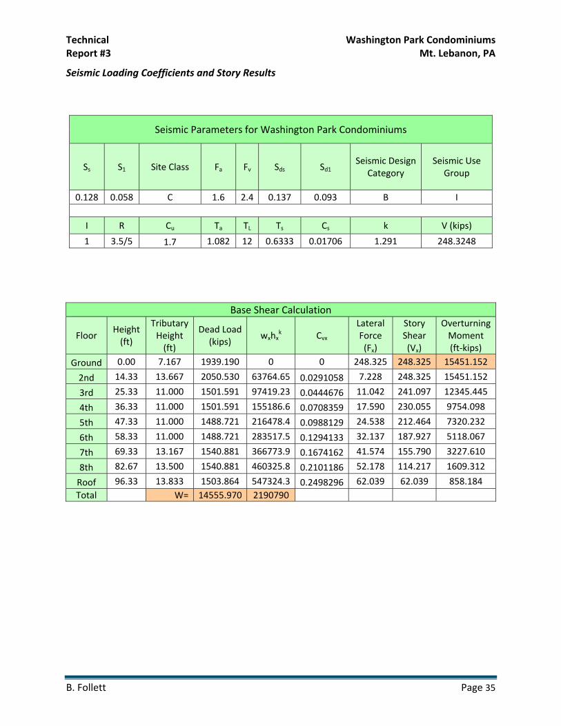
Seismic Loading Coefficients and Story Results
Seismic Parameters for Washington Park Condominiums
Ss S1 Site Class Fa Fv Sds Sd1 Seismic Design
Category Seismic Use
Group
0.128 0.058 C 1.6 2.4 0.137 0.093 B I
I R Cu Ta TL Ts Cs k V (kips)
1 3.5/5 1.7 1.082 12 0.6333 0.01706 1.291 248.3248
Base Shear Calculation
Floor Height (ft)
Tributary Height (ft)
Dead Load (kips)
wxhxk Cvx
Lateral Force (Fx)
Story Shear (Vx)
Overturning Moment (ft‐kips)
Ground 0.00 7.167 1939.190 0 0 248.325 248.325 15451.152
2nd 14.33 13.667 2050.530 63764.65 0.0291058 7.228 248.325 15451.152
3rd 25.33 11.000 1501.591 97419.23 0.0444676 11.042 241.097 12345.445
4th 36.33 11.000 1501.591 155186.6 0.0708359 17.590 230.055 9754.098
5th 47.33 11.000 1488.721 216478.4 0.0988129 24.538 212.464 7320.232
6th 58.33 11.000 1488.721 283517.5 0.1294133 32.137 187.927 5118.067
7th 69.33 13.167 1540.881 366773.9 0.1674162 41.574 155.790 3227.610
8th 82.67 13.500 1540.881 460325.8 0.2101186 52.178 114.217 1609.312
Roof 96.33 13.833 1503.864 547324.3 0.2498296 62.039 62.039 858.184 Total W= 14555.970 2190790

Technical Washington Park Condominiums Report #3 Mt. Lebanon, PA
B. Follett Page 36
Appendix C: Center of Mass and Rigidity
Area 1
Area 2 Area 3
Area 5 Area 4
(0,0)

Technical Washington Park Condominiums Report #3 Mt. Lebanon, PA
B. Follett Page 37
Torsion Constants
Floor Center of Rigidity Center of Mass
IX (in4) Iy (in
4) IP (in4)
XR (ft) YR (ft) XR (ft) YR (ft)
Second 104.92 39.89 102.3 34.7 2837888.75 353494.66 3191383.41 Third 104.92 39.89 102.3 34.7 2837888.75 353494.66 3191383.41 Fourth 104.92 39.89 102.3 34.7 2837888.75 353494.66 3191383.41 Fifth 104.92 39.89 102.3 34.7 2837888.75 353494.66 3191383.41 Sixth 104.92 39.89 102.3 34.7 2837888.75 353494.66 3191383.41
Seventh 104.92 39.89 102.3 34.7 2837888.75 353494.66 3191383.41 Eighth 104.92 39.89 102.3 34.7 2837888.75 353494.66 3191383.41
Roof 104.92 39.89 102.3 34.7 2837888.75 353494.66 3191383.41

Technical Washington Park Condominiums Report #3 Mt. Lebanon, PA
B. Follett Page 38
Appendix D: Portal Frame Analysis Calculations

Technical Washington Park Condominiums Report #3 Mt. Lebanon, PA
B. Follett Page 39
Portal Frame “E”

Technical Washington Park Condominiums Report #3 Mt. Lebanon, PA
B. Follett Page 40

Technical Washington Park Condominiums Report #3 Mt. Lebanon, PA
B. Follett Page 41
Portal Frame “F”

Technical Washington Park Condominiums Report #3 Mt. Lebanon, PA
B. Follett Page 42
Technical Washington Park Condominiums Report #3 Mt. Lebanon, PA
B. Follett Page 43
Partial Portal Frame “A”

Technical Washington Park Condominiums Report #3 Mt. Lebanon, PA
B. Follett Page 44
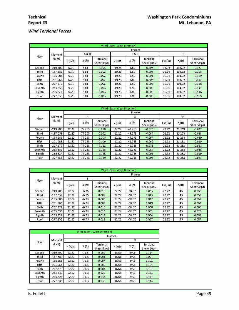
Appendix E: Torsional Force Tables
Technical Washington Park Condominiums Report #3 Mt. Lebanon, PA
B. Follett Page 45
Wind Torsional Forces

Technical Washington Park Condominiums Report #3 Mt. Lebanon, PA
B. Follett Page 46

Technical Washington Park Condominiums Report #3 Mt. Lebanon, PA
B. Follett Page 47
Seismic Torsional Forces