63-2599 - nxl variable frequency drive - honeywell · constant and variable torque variable speed...
TRANSCRIPT

NXL seriesConstant and variable torque
Variable Speed Drivesfor induction motors
Subject to changes without notice

AT LEAST THE 10 FOLLOWING STEPS OF THE START-UP QUICK GUIDE MUST BE PERFORMEDDURING THE INSTALLATION AND COMMISSIONING.
IF ANY PROBLEMS OCCUR, PLEASE CONTACT YOUR LOCAL DISTRIBUTOR.
Start-up Quick Guide
1. Check that the delivery corresponds to your order, see Chapter 3.
2. Before taking any commissioning actions read carefully the safety instructions in Chapter1.
3. Before the mechanical installation, check the minimum clearances around the unit andcheck the ambient conditions in Chapter 5.
4. Check the size of the motor cable, mains cable, mains fuses and check the cableconnections, read Chapter 6.
5. Follow the installation instructions, see Chapter 5.
6. Control cable sizes and the grounding system are explained in Chapter 6.2.1.
7. Instructions on using the keypad are given in Chapter 7.
8. All parameters have factory default values. In order to ensure proper operation, checkthe rating plate data for the values below and the corresponding parameters ofparameter group P2.1. See Chapter 8.3.2.
• nominal voltage of the motor, par. 2.1.6• nominal frequency of the motor, par. 2.1.7• nominal speed of the motor, par 2.1.8• nominal current of the motor, par. 2.1.9• motor cosϕ, par. 2.1.10
All parameters are explained in the Multi-Control Application Manual.
9. Follow the commissioning instructions, see Chapter 8.
10. The NXL Frequency Converter is now ready for use.
11. In the end of this manual, you will find a quick help with the default I/O, control panelmenus, monitoring values, fault codes and basic parameters
The Manufacturer is not responsible for the use of the frequency convertersagainst the instructions.
CONTENTS
NXL USER’S MANUAL
INDEX
1 SAFETY
2 EU DIRECTIVE
3 RECEIPT OF DELIVERY
4 TECHNICAL DATA
5 INSTALLATION
6 CABLING AND CONNECTIONS
7 CONTROL KEYPAD
8 COMMISSIONING
9 FAULT TRACING
10 DESCRIPTION OF BOARD NXOPTAA
MULTI-CONTROL APPLICATION MANUAL
Honeywell 3(79)
ABOUT THE NXL USER'S MANUALAND THE MULTI-CONTROL APPLICATION MANUAL
Congratulations for choosing the Smooth Control provided by NXL frequency converters!
The User's Manual will provide you with the necessary information about the installation,commissioning and operation of NXL Frequency Converter. We recommend that you carefullystudy these instructions before powering up the frequency converter for the first time.
In the Multi-Control Application Manual you will find information about the application used in theNXL General Purpose Drive.
This manual is available in both paper and electronic editions. We recommend you to use theelectronic version if possible. If you have the electronic version at your disposal you will be ableto benefit from the following features:
The manual contains several links and cross-references to other locations in the manual whichmakes it easier for the reader to move around in the manual, to check and find things faster.
The manual also contains hyperlinks to web pages. To visit these web pages through the links youmust have an internet browser installed on your computer.
NOTE: You will not be able to edit the Microsoft Word version of the manual without a validpassword. Open the manual file as a read-only version.

4(79) Honeywell
NXL User's Manual
Index
1.SAFETY........................................................................................................................................61.1 WARNINGS...................................................................................................................................... 61.2 SAFETY INSTRUCTIONS .................................................................................................................... 61.3 EARTHING AND EARTH FAULT PROTECTION........................................................................................ 61.4 RUNNING THE MOTOR ...................................................................................................................... 7
2. EU DIRECTIVE .......................................................................................................................82.1 CE MARKING................................................................................................................................... 82.2 EMC DIRECTIVE.............................................................................................................................. 82.2.1 General ..................................................................................................................................... 82.2.2 Technical criteria....................................................................................................................... 82.2.3 NXL frequency converter EMC classification............................................................................. 82.2.4 The installation of an external RFI filter ................................................................................... 102.2.5 Manufacturer's declaration of conformity ................................................................................. 10
3. RECEIPT OF DELIVERY ......................................................................................................123.1 TYPE DESIGNATION CODE .............................................................................................................. 123.2 STORAGE...................................................................................................................................... 123.3 MAINTENANCE............................................................................................................................... 133.4 WARRANTY................................................................................................................................... 13
4. TECHNICAL DATA...............................................................................................................144.1 INTRODUCTION.............................................................................................................................. 144.2 POWER RATINGS ........................................................................................................................... 154.2.1 NXL – Mains voltage 208 – 240 V ........................................................................................... 154.2.2 NXL – Mains voltage 380 – 500 V ........................................................................................... 154.3 TECHNICAL DATA........................................................................................................................... 16
5. INSTALLATION ....................................................................................................................185.1 MOUNTING.................................................................................................................................... 185.2 COOLING ...................................................................................................................................... 235.3 CHANGING EMC PROTECTION CLASS FROM H TO T......................................................................... 24
6. CABLING AND CONNECTIONS ..........................................................................................256.1 POWER CONNECTIONS................................................................................................................... 256.1.1 Cabling.................................................................................................................................... 276.1.1.1 Cable and fuse sizes.......................................................................................................... 276.1.2 Installation instructions............................................................................................................ 286.1.2.1 Stripping lengths of motor and mains cables ...................................................................... 296.1.2.2 Installation of cables to NXL............................................................................................... 306.1.3 Cable installation and the UL standards .................................................................................. 346.1.4 Cable and motor insulation checks.......................................................................................... 346.2 CONTROL UNIT .............................................................................................................................. 356.2.1 Control connections ................................................................................................................ 356.2.2 Control cables ......................................................................................................................... 366.2.2.1 Control I/O.......................................................................................................................... 366.2.3 Control terminal signals........................................................................................................... 376.2.3.1 Jumper selections on NXL basic board .............................................................................. 38

Honeywell 5(79)
7. CONTROL KEYPAD.............................................................................................................417.1 INDICATIONS ON THE KEYPAD DISPLAY............................................................................................ 417.1.1 Drive status indications ........................................................................................................... 417.1.2 Control place indications ......................................................................................................... 427.1.3 Numeric indications................................................................................................................. 427.2 KEYPAD PUSH-BUTTONS ................................................................................................................ 437.2.1 Button descriptions.................................................................................................................. 437.3 NAVIGATION ON THE CONTROL KEYPAD........................................................................................... 447.3.1 Monitoring menu (M1) ............................................................................................................. 487.3.2 Parameter menu (P2).............................................................................................................. 507.3.3 Keypad control menu (K3)....................................................................................................... 527.3.3.1 Selection of control place ................................................................................................... 527.3.3.2 Keypad reference............................................................................................................... 537.3.3.3 Keypad direction ................................................................................................................ 537.3.3.4 Stop button activation......................................................................................................... 537.3.4 Active faults menu (F4) ........................................................................................................... 547.3.4.1 Fault types ......................................................................................................................... 547.3.4.2 Fault codes ........................................................................................................................ 557.3.5 Fault history menu (H5)........................................................................................................... 587.3.6 System menu (S6) .................................................................................................................. 597.3.6.1 Copy parameters................................................................................................................ 617.3.6.2 Security.............................................................................................................................. 617.3.6.3 Keypad settings.................................................................................................................. 627.3.6.4 Hardware settings .............................................................................................................. 637.3.6.5 System information ............................................................................................................ 657.3.6.6 AI mode ............................................................................................................................. 677.3.6.7 Fieldbus parameters .......................................................................................................... 677.3.7 Expander board menu (E7) ..................................................................................................... 697.4 FURTHER KEYPAD FUNCTIONS........................................................................................................ 69
8. COMMISSIONING.................................................................................................................708.1 SAFETY ........................................................................................................................................ 708.2 COMMISSIONING OF THE FREQUENCY CONVERTER .......................................................................... 708.3 BASIC PARAMETERS ...................................................................................................................... 738.3.1 Monitoring values (Control keypad: menu M1) ........................................................................ 738.3.2 Basic parameters (Control keypad: Menu P2 B2.1) ............................................................ 74
9. FAULT TRACING .................................................................................................................76
10. DESCRIPTION OF EXPANDER BOARD NXOPTAA...........................................................79

6(79) Safety Honeywell
Automation and Control SolutionsHoneywell Honeywell Limited-Honeywell Limitée1985 Douglas Drive North 35 Dynamic DriveGolden Valley, MIN 55422 Scarborough, Ontario 63-2599 MIV 4Z9
www.honeywell.com
1
1. SAFETY
1.1 Warnings
1 The components of the power unit of the frequency converter are livewhen NXL is connected to mains potential. Coming into contact withthis voltage is extremely dangerous and may cause death or severeinjury. The control unit is isolated from the mains potential.
2 The motor terminals U, V, W (T1, T2, T3) and the DC-link/brake resistorterminals –/+ (in NXL ≥1.1 kW) are live when NXL is connected to mains,even if the motor is not running.
3 The control I/O-terminals are isolated from the mains potential. However,the relay outputs and other I/O-terminals may have a dangerous controlvoltage present even when NXL is disconnected from mains.
4 The frequency converter has a large capacitive leakage current.
5 If the frequency converter is used as a part of a machine, the machinemanufacturer is responsible for providing the machine with a main switch(EN 60204-1).
6 Only spare parts delivered by Honeywell can be used.
HOT SURFACE7 The heat sink of types MF2 and MF3 may be hot when the frequency
converter is in use. Coming into contact with the heat sink may causeburns.
1.2 Safety instructions
1 The NXL frequency converter is meant for fixed installations only.
2 Do not perform any measurements when the frequency converter isconnected to the mains.
3 After disconnecting the frequency converter from the mains, wait until thefan stops and the indicators on the display go out. Wait 5 more minutesbefore doing any work on NXL connections.
4 Do not perform any voltage withstand tests on any part of NXL. There isa certain procedure according to which the tests shall be performed.Ignoring this procedure may result in damaged product.
5 Prior to measurements on the motor or the motor cable, disconnect themotor cable from the frequency converter.
6 Do not touch the IC-circuits on the circuit boards. Static voltage dischargemay damage the components.
1.3 Earthing and earth fault protectionThe NXL frequency converter must always be earthed with an earthing conductor connected tothe earthing terminal .
ONLY A COMPETENT ELECTRICIAN MAY CARRY OUTTHE ELECTRICAL INSTALLATION
WARNING

Honeywell Safety 7(79)
Automation and Control SolutionsHoneywell Honeywell Limited-Honeywell Limitée1985 Douglas Drive North 35 Dynamic DriveGolden Valley, MIN 55422 Scarborough, Ontario 63-2599 MIV 4Z9
www.honeywell.com
1
The earth fault protection inside the frequency converter protects only the converter itself againstearth faults in the motor or the motor cable.
Due to the high capacitive currents present in the frequency converter, fault current protectiveswitches may not function properly. If fault current protective switches are used they must betested with the drive with earth fault currents that are possible to arise in fault situations.
1.4 Running the motorWarning symbolsFor your own safety, please pay special attention to the instructions marked with the followingsymbols:
= Dangerous voltage
WARNING = General warning
HOT SURFACE = Hot surface – Risk of burn
MOTOR RUN CHECK LIST
1 Before starting the motor, check that the motor is mounted properlyand ensure that the machine connected to the motor allows themotor to be started.
2 Set the maximum motor speed (frequency) according to the motorand the machine connected to it.
3 Before reversing the motor shaft rotation direction make sure thatthis can be done safely.
4 Make sure that no power correction capacitors are connected tothe motor cable.
5 Make sure that the motor terminals are not connected to mainspotential.
WARNING

8(79) Receipt of delivery Honeywell
Automation and Control SolutionsHoneywell Honeywell Limited-Honeywell Limitée1985 Douglas Drive North 35 Dynamic DriveGolden Valley, MIN 55422 Scarborough, Ontario 63-2599 MIV 4Z9
www.honeywell.com2
2. EU DIRECTIVE2.1 CE markingThe CE marking on the product guarantees the free movement of the product within the EEA(European Economic Area). It also guarantees that the product meets the various requirementsplaced upon it (such as the EMC Directive and possibly other directives according to the so-callednew procedure).
NXL frequency converters carry the CE label as a proof of compliance with the Low VoltageDirective (LVD) and the Electro Magnetic Compatibility (EMC). The company SGS FIMKO hasacted as the Competent Body.
2.2 EMC directive2.2.1 GeneralThe EMC Directive provides that the electrical apparatus must not excessively disturb theenvironment they are used in, and, on the other hand, it shall have an adequate level of immunitytoward other disturbances from the same environment.
The compliance of NXL frequency converters with the EMC directive is verified with TechnicalConstruction Files (TCF) checked and approved by SGS FIMKO, which is a Competent Body. TheTechnical Construction Files are used to authenticate the comformity of NXL frequency converterswith the Directive because such a large-sized product family is impossible to be tested in alaboratory environment and because the combinations of installation vary greatly.
2.2.2 Technical criteriaEMC compliance is a major consideration for NXL drives from the outset of the design. NXLfrequency converters are marketed throughout the world, a fact which makes the EMCrequirements of customers different. As far as the immunity is concerned, all NXL frequencyconverters are designed to fulfil even the strictest requirements, while as regards the emissionlevel, the customer may want to upgrade Vacon's already high ability to filter electro-magneticdisturbances.
2.2.3 NXL frequency converter EMC classificationNXL frequency converters are divided into two classes according to the level of electromagneticdisturbances emitted. There is no difference in the functions or the control electronics betweenthese classes but their EMC properties vary as follows:

Honeywell Receipt of delivery 9(79)
Automation and Control SolutionsHoneywell Honeywell Limited-Honeywell Limitée1985 Douglas Drive North 35 Dynamic DriveGolden Valley, MIN 55422 Scarborough, Ontario 63-2599 MIV 4Z9
www.honeywell.com 2
Class N:No EMC emission protection. NXL frames MF2 and MF3 are delivered from the factory without anexternal RFI filter as class N products.
Class H:With an external RFI filter (option) installed NXL frequency converters MF2 and MF3 fulfil therequirements of the product standard EN 61800-3 + A11 for the 1st environment restricteddistribution and the 2nd environment.The emission levels correspond to the requirements of EN 61000-6-4.
All NX frequency converters fulfil all EMC immunity requirements (standards EN 61000-6-1,61000-6-2 and EN 61800-3).

10(79) Receipt of delivery Honeywell
Automation and Control SolutionsHoneywell Honeywell Limited-Honeywell Limitée1985 Douglas Drive North 35 Dynamic DriveGolden Valley, MIN 55422 Scarborough, Ontario 63-2599 MIV 4Z9
www.honeywell.com2
Earthing cable
Filter cable
PE terminalL1 terminalL2 terminalL3 terminal
2.2.4 The installation of an external RFI filterThe EMC protection class of NXL frequency converters MF2 and MF3 can be changed from N toH with an optional external RFI filter. Install the power cables in terminals L1, L2 and L3 and thegrounding cable in terminal PE of the filter. See figure below. See also mounting instructions ofMF2 in Figure 5-2.
Figure 2-1. MF2 with an RFI filter
Figure 2-2. Connection of RFI filter cable in NXL
2.2.5 Manufacturer's declaration of conformityThe following page presents the photocopy of the Manufacturer's Declaration of Conformityassuring the compliance of NXL frequency converters with the EMC-directives.
L1 L2 L3 U/T1 V/T2 W/T3 BR+ BR-L1 L2 L3 U/T1 V/T2 W/T3
MF2 MF3
nxlk1.fh8

Honeywell Receipt of delivery 11(79)
Automation and Control SolutionsHoneywell Honeywell Limited-Honeywell Limitée1985 Douglas Drive North 35 Dynamic DriveGolden Valley, MIN 55422 Scarborough, Ontario 63-2599 MIV 4Z9
www.honeywell.com 2
EU DECLARATION OF CONFORMITYWe
Manufacturer's name: Vacon PLC
Manufacturer's address: P.O.Box 25Runsorintie 7FIN-65381 VaasaFinland
hereby declare that the product
Product name: Single Board General Purpose Drive
Model designation: NXL0001 5…to 0032 5…
has been designed and manufactured in accordance with the following standards:
Safety: EN 50178 (1997), EN 60204-1 (1996)EN 60950 (3rd edition 2000, as relevant)
EMC: EN 61800-3 (1996)+A11(2000), EN 61000-6-2 (1999), EN 61000-6-4 (2001)
and conforms to the relevant safety provisions of the Low Voltage Directive(73/23/EEC) as amended by the Directive (93/68/EEC) and EMC Directive89/336/EEC.It is ensured through internal measures and quality control that the product conformsat all times to the requirements of the current Directive and the relevant standards.
In Vaasa, 6th of September, 2002Vesa LaisiPresident
The year the CE marking was affixed: 2002

12(79) Receipt of delivery Honeywell
Automation and Control SolutionsHoneywell Honeywell Limited-Honeywell Limitée1985 Douglas Drive North 35 Dynamic DriveGolden Valley, MIN 55422 Scarborough, Ontario 63-2599 MIV 4Z9
www.honeywell.com
3
3. RECEIPT OF DELIVERYNXL frequency converters have undergone scrupulous tests and quality checks at the factorybefore they are delivered to the customer. However, after unpacking the product, check that nosigns of transport damages are to be found on the product and that the delivery is complete(compare the type designation of the product to the code below, Figure 3-1.
Should the drive have been damaged during the shipping, please contact primarily the cargoinsurance company or the carrier.
If the delivery does not correspond to your order, contact the supplier immediately.
3.1 Type designation code
Figure 3-1. NXL type designation code
3.2 StorageIf the frequency converter is to be kept in store before use make sure that the ambient conditionsare acceptable:
Storing temperature –40…+70°CRelative humidity <95%, no condensation
NXL 0050 B 12
Product Series NXSNXL
Motor Power (HP) 0005 1/2 HPLow overloadability: 0050 5 HP10% overload at 0400 40 HP etc40 deg C
Voltage range B 208-240 Vac 3 phaseA 380-500 Vac 3 phase
Enclosure 00 Open chassis10 Nema 112 Nema 12

Honeywell Receipt of delivery 13(79)
Automation and Control SolutionsHoneywell Honeywell Limited-Honeywell Limitée1985 Douglas Drive North 35 Dynamic DriveGolden Valley, MIN 55422 Scarborough, Ontario 63-2599 MIV 4Z9
www.honeywell.com
3
3.3 MaintenanceIn normal conditions, NXL frequency converters are maintenance-free. However, we recommendto clean the heatsink (using e.g. a small brush) whenever necessary.NXL drives from 2.2kW are equipped with a cooling fan, which can easily be changed ifnecessary.
3.4 WarrantyOnly manufacturing defects are covered by the warranty. The manufacturer assumes noresponsibility for damages caused during or resulting from transport, receipt of the delivery,installation, commissioning or use.
The manufacturer shall in no event and under no circumstances be held responsible for damagesand failures resulting from misuse, wrong installation, unacceptable ambient temperature, dust,corrosive substances or operation outside the rated specifications. Neither can the manufacturerbe held responsible for consequential damages.
The Manufacturer's time of warranty is 18 months from the delivery or 12 months from thecommissioning whichever expires first (General Conditions NL92/Orgalime S92).
The local distributor may grant a warranty time different from the above. This warranty time shallbe specified in the distributor's sales and warranty terms. The manufacturer assumes noresponsibility for any other warranties granted by offers.
In all matters concerning the warranty, please contact first your distributor.

14(79) Technical data Honeywell
Automation and Control SolutionsHoneywell Honeywell Limited-Honeywell Limitée1985 Douglas Drive North 35 Dynamic DriveGolden Valley, MIN 55422 Scarborough, Ontario 63-2599 MIV 4Z9
www.honeywell.com4
4. TECHNICAL DATA4.1 IntroductionNXL is a compact, small-sized frequency converter with the output ranging from 220 W to 30 kW.It is well adapted for HVAC and OEM applications where its possibilities of use are almostunlimited.
The Motor and Application Control Block is based on microprocessor software. Themicroprocessor controls the motor basing on the information it receives through measurements,parameter settings, control I/O and control keypad. The motor and application control blockcontrols the motor control microprocessor which, in turn, calculates the IGBT positions. Gatedrivers amplify these signals for driving the IGBT inverter bridge.
The control keypad constitutes a link between the user and the frequency converter. The controlkeypad is used for parameter setting, reading status data and giving control commands. Instead ofthe control keypad, also a PC can be used to control the frequency converter if connected througha cable and a serial interface adapter (optional equipment).
You can have your NXL drive equipped with control I/O boards NXOPTAA, NXOPTB_ orNXOPTC_.
All other sizes but MF2 have an internal brake chopper. For closer information, contact theManufacturer or your local distributor (see back cover). The input EMC filters are available asoptions externally for MF2 and MF3. In other sizes the filters are internal and included asstandard.
The NXL frequency converters are professional drives intended to be connected to industrialnetworks. They should not be connected to public low- voltage distribution systems. This is aproduct of the restricted sales distribution class according to IEC 61800-3. In a domesticenvironment this product may cause radio interference in which case the user may be required totake adequate measures.
Sizes MF4 – MF6:The three-phase AC-choke at the mains end together with the DC-link capacitor form an LC-filter,which, again, together with the diode bridge produce the DC-voltage supply to the IGBT InverterBridge block. The AC-choke also functions as a filter against High Frequency disturbances fromthe mains as well as against those caused by the frequency converter to the mains. It, in addition,enhances the waveform of the input current to the frequency converter. The entire power drawnby the frequency converter from the mains is active power.The IGBT Inverter Bridge produces a symmetrical, 3-phase PWM-modulated AC-voltage to themotor.

Honeywell Technical data 15(79)
Automation and Control SolutionsHoneywell Honeywell Limited-Honeywell Limitée1985 Douglas Drive North 35 Dynamic DriveGolden Valley, MIN 55422 Scarborough, Ontario 63-2599 MIV 4Z9
www.honeywell.com 4
4.2 Power ratings4.2.1 NXL – Mains voltage 208 – 240 V
Power range 0.25kW – 1,5kW as 1/3-phase
Mains voltage 230 V, 50/60 Hz, 3~ Series NXL IP00 (open chassis), EMC-level NMotor shaft power (230V) and currentLow overload High overload
Frequencyconvertertype P [Hp]
(500V)I(L) P [Hp]
(500V)I(H) I(max)
Mechanical sizeEnclosure and
protection class
DimensionsWxHxD(inch)
Weight
NXL 0005 B 0.5 2.4 1.7 2.6 MF2/IP00 2.36x5.12x5.67 35.27NXL 0007 B 0.75 3.7 0.5 2.8 4.2 MF3/IP00 3.31x7.24x6.85 67.02NXL 0010 B 1 4.8 0.75 3.7 5.6 MF3/IP00 3.31x7.24x6.85 67.02NXL 0015 B 1.5 6.6 1 4.8 7.2 MF3/IP00 3.31x8.66x6.85 70.55Table 4-1. Power ratings and dimensions of NXL, supply voltage 208—240V.
4.2.2 NXL – Mains voltage 380 – 500 VPower range 0.37kW – 15kW as 3-phase
Mains voltage 380-500 V, 50/60 Hz, 3~ Series NXLIP00 (open chassis), EMC-level N
Motor shaft power (500V) and currentLow overload High overload
Frequencyconvertertype P [Hp]
(500V)I(L) P [Hp]
(500V)I(H) I(max)
Mechanical sizeEnclosure and
protection class
DimensionsWxHxD(inch)
Weight
NXL 0007 A 0.75 1.9 0.5 1.3 2 MF2/IP00 2.36x5.12x5.67 35.27NXL 0010 A 1 2.4 0.75 1.9 2.9 MF2/IP00 2.36x5.12x5.67 35.27NXL 0015 A 1.5 3.3 1 2.4 3.6 MF3/IP00 3.31x7.24x6.85 67.02NXL 0020 A 2 4.3 1.5 3.3 5 MF3/IP00 3.31x7.24x6.85 67.02NXL 0030 A 3 5.4 2 4.3 6.5 MF3/IP00 3.31x8.66x6.85 70.55
NEMA1/12, EMC-level HNXL 0015 A 1.5 3.3 1 2.2 3.3 MF4/NEMA 1/12 5.04x11.5x7.48 11.02NXL 0020 A 2 4.3 1.5 3.3 5 MF4/NEMA 1/12 5.04x11.5x7.48 11.02NXL 0030 A 3 5.6 2 4.3 6.5 MF4/NEMA 1/12 5.04x11.5x7.48 11.02NXL 0040 5 4 7.6 3 5.6 8.4 MF4/NEMA 1/12 5.04x11.5x7.48 11.02NXL 0050 5 5 9 4 7.6 11.4 MF4/NEMA 1/12 5.04x11.5x7.48 11.02NXL 0075 5 7.5 12 5 9 13.5 MF4/NEMA 1/12 5.04x11.5x7.48 11.02NXL 0100 5 10 16 7.5 12 18 MF5/NEMA 1/12 5.67x15.4x8.43 17.86NXL 0150 5 15 23 10 16 24 MF5/NEMA 1/12 5.67x15.4x8.43 17.86NXL 0200 5 20 31 15 23 35 MF5/NEMA 1/12 5.67x15.4x8.43 17.86NXL 0250 A 25 38 20 31 47 MF6/NEMA 1/12 7.68x20.4x9.33 40.79NXL 0300 A 30 46 25 38 57 MF6/NEMA 1/12 7.68x20.4x9.33 40.79NXL 0400 A 40 61 30 46 69 MF6/NEMA 1/12 7.68x20.4x9.33 40.79
Table 4-2. Power ratings and dimensions of NXL, supply voltage 380 – 500V.

16(79) Technical data Honeywell
Automation and Control SolutionsHoneywell Honeywell Limited-Honeywell Limitée1985 Douglas Drive North 35 Dynamic DriveGolden Valley, MIN 55422 Scarborough, Ontario 63-2599 MIV 4Z9
www.honeywell.com4
4.3 Technical data
Input voltage Uin 208…240V; 380…500VInput frequency 45…66 Hz
Mainsconnection
Connection to mains Once per minute or less (normal case)Output voltage 0—UinContinuous outputcurrent
IH: Ambient temperature max. +50ºC, overload 1.5 x IH (1min/10min)IL: Ambient temperature max. +40ºC, overload 1.1 x IL (1min/10min)
Starting torque 150% (Low overload); 200% (High overload)Starting current 2 x IH 2 secs every 20 secs, if output frequency <30Hz
and temperature of heatsink <+60ºCOutput frequency 0…320 Hz
Motorconnection
Frequency resolution 0,01 HzControl method Frequency Control U/f
Open Loop Sensorless Vector Control
Switching frequency(See parameter 2.6.8)
1...16 kHz; Factory default 6 kHz
Frequency referenceAnalogue inputKeypad reference
Resolution 0.1% (10bit), accuracy ±1%Resolution 0.01 Hz
Field weakening point 30…320 HzAcceleration time 0…3000 secDeceleration time 0…3000 sec
Controlcharacteristrics
Braking torque DC-brake: 30%*TN (without brake option)Ambient operatingtemperature
–10°C (no frost)…+50°C: IH–10°C (no frost)…+40°C: IL
Storage temperature –40°C…+70°CRelative humidity 0…95% RH, non-condensing, non-corrosive,
no dripping waterAir quality:- chemical vapours- mechanical particles
IEC 721-3-3, unit in operation, class 3C2IEC 721-3-3, unit in operation, class 3S2
Altitude 100% load capacity (no derating) up to 1000m1-% derating for each 100m above 1000m; max. 3000m
Vibration:EN50178/EN60068-2-6
5...150 HzDisplacement amplitude 1(peak) mm at 5...15.8 HzMax acceleration amplitude 1 G at 15.8...150 Hz
ShockEN50178, IEC 68-2-27
UPS Drop Test (for applicable UPS weights)Storage and shipping: max 15 G, 11 ms (in package)
Ambientconditions
Enclosure class IP20; MF2 and MF3. IP21; MF4 and biggerImmunity Complies with EN50082-1, -2, EN61800-3EMCEmissions Coded series complies with EN61800-3, restricted
distribution.With an external filter attached compliance with EN50081-1,-2 and EN61800-3, unrestricted distribution
Technical data (continues on next page)

Honeywell Technical data 17(79)
Automation and Control SolutionsHoneywell Honeywell Limited-Honeywell Limitée1985 Douglas Drive North 35 Dynamic DriveGolden Valley, MIN 55422 Scarborough, Ontario 63-2599 MIV 4Z9
www.honeywell.com 4
Safety EN50178, EN60204-1, CE, UL, cUL, FI, GOST R, IEC61800-5(see unit nameplate for more detailed approvals)
Analogue input voltage 0...+10V, Ri = 200kΩ,Resolution 10 bit, accuracy ±1%
Analogue input current 0(4)…20 mA, Ri = 250Ω differentialDigital inputs (3) Positive logic; 18…24VDCAuxiliary voltage +24V, ±15%, max. 100mAOutput reference voltage +10V, +3%, max. load 10mAAnalogue output 0(4)…20mA; RL max. 500Ω; resolution 10 bit;
accuracy ±5%
Controlconnections
Relay outputs 1 programmable change over relay outputSwitching capacity: 24VDC/8A, 250VAC/8A, 125VDC/0.4A
Overvoltage protectionUndervoltage protection
NXL_2: 437VDC; NXL_5: 911VDCNXL_2: 183VDC; NXL_5: 333VDC
Earth-fault protection In case of earth fault in motor or motor cable, only thefrequency converter is protected
Unit overtemperatureprotection
Yes
Motor overload protection YesMotor stall protection YesMotor underloadprotection
Yes
Short-circuit protection of+24V and +10V referencevoltages
Yes
Protections
Overcurrent protection Trip limit 4,0*IH instantaneouslyTable 4- 3. Technical data

18(79) Cabling and connections Honeywell
Automation and Control SolutionsHoneywell Honeywell Limited-Honeywell Limitée1985 Douglas Drive North 35 Dynamic DriveGolden Valley, MIN 55422 Scarborough, Ontario 63-2599 MIV 4Z9
www.honeywell.com
5
5. INSTALLATION5.1 MountingThe NXL drive can be mounted on the wall or on the back plane of a cubicle. There are twopossible positions in the wall mounting for the frames MF2 and MF3 (see Figure 5-1)
The NXL type MF2 is mounted with two screws using the middle holes of the mounting plates. Ifan RFI filter is used, the upper mounting plate shall be attached with two screws. MF3 and biggertypes are always mounted with four screws, see Figure 5-2 and Figure 5-3.
Enough space shall be reserved above and underneath the frequency converter in order toensure a sufficient cooling, see Figure 5-7, and Table 5-4. Also see to that the mounting plane isrelatively even.
Below you will find the dimensions of NXL frequency converters with IP20 and IP21 enclosures onpages 20 -- 22.
Figure 5-1. The two possible mounting positions of NXL (MF2 and MF3)

Honeywell Cabling and connections 19(79)
Automation and Control SolutionsHoneywell Honeywell Limited-Honeywell Limitée1985 Douglas Drive North 35 Dynamic DriveGolden Valley, MIN 55422 Scarborough, Ontario 63-2599 MIV 4Z9
www.honeywell.com
5
Figure 5-2. Mounting of NXL, MF2
Figure 5-3. Mounting of NXL, MF3
X
X
X X
X
MF2 without a filter MF2 with a filter
X X
XX

20(79) Cabling and connections Honeywell
Automation and Control SolutionsHoneywell Honeywell Limited-Honeywell Limitée1985 Douglas Drive North 35 Dynamic DriveGolden Valley, MIN 55422 Scarborough, Ontario 63-2599 MIV 4Z9
www.honeywell.com
5
Figure 5-4. NXL dimensions, MF2
Table 5-1. Dimensions of NXL, MF2
Dimensions (inch)Type W1 W2 H1 H2 H3 H4 H5 H6 H7 H8 D1 D2 ∅MF2 1.18 2.36 6.77 5.98 5.51 5.12 3.15 1.65 0.43 0.24 5.91 5.67 0.24
W1
Ø
H2 H3
H8
H5
D1
D2
H1
H4
H6
H7
W2
nxlk7.fh8

Honeywell Cabling and connections 21(79)
Automation and Control SolutionsHoneywell Honeywell Limited-Honeywell Limitée1985 Douglas Drive North 35 Dynamic DriveGolden Valley, MIN 55422 Scarborough, Ontario 63-2599 MIV 4Z9
www.honeywell.com
5
Figure 5-5. NXL dimensions, MF3
W1 W2 W3 H1 H2 H3 H4 H5 H6 H7 D1 D2 ∅MF3 3.31 1.38 0.91 10.31 9.25 8.78 7.83 7.60 7.24 8.66 6.77 6.54 0.24
Table 5-2. Dimensions of NXL, MF3
Type Dimensions (inch)
W2W3
H5
Ø
D2
D1
H3H4 H2 H1 H6
W1
H7
nxlk8.fh8

22(79) Cabling and connections Honeywell
Automation and Control SolutionsHoneywell Honeywell Limited-Honeywell Limitée1985 Douglas Drive North 35 Dynamic DriveGolden Valley, MIN 55422 Scarborough, Ontario 63-2599 MIV 4Z9
www.honeywell.com
5
Figure 5-6. NXL dimensions, MF4 and MF5
DimensionsTypeW1 W2 H1 H2 H3 D1 ∅ E1∅ E2∅ *
MF4 5.04 3.94 12.87 12.32 11.5 7.48 0.28 3 x 1.11MF5 5.67 3.94 16.5 15.98 15.39 8.43 0.28 2 x 1.46 1 x 1.11
Table 5-3. Dimensions of NXL, MF4—MF5
* = MF5 only
W1
W2
H1 H2
Ø
D1
H3
fr5ip21.fh8
Ø
E1Ø
E2Ø*

Honeywell Cabling and connections 23(79)
Automation and Control SolutionsHoneywell Honeywell Limited-Honeywell Limitée1985 Douglas Drive North 35 Dynamic DriveGolden Valley, MIN 55422 Scarborough, Ontario 63-2599 MIV 4Z9
www.honeywell.com
5
C
A
NK5_2
D
B
A
B
5.2 CoolingThe cooling method in NXL drive is either convection or air cooling with a cooling fan. The coolingmethod for lower power ranges (frame MF2 and lower powers of MF3) is a convection typecooling. Forced air flow cooling is used for frames MF4, MF5, MF6 and higher powers of MF3.
Enough free space shall be left above and below the frequency converter to ensure sufficient aircirculation and cooling. You will find the required dimensions for free space in the table below.
Type Dimensions [inch]A B C D
NXL 0007-0010 ANXL 0005-0015 B
3.94 1.97
NXL 0015-0075 A 0.79 0.79 3.94 1.97NXL 0100-0200 A 0.79 0.79 4.72 2.36NXL 0250-0400 A 1.18 0.79 6.3 3.15
Table 5-4. Mounting space dimensions
Figure 5-7. Installation space
A = clearance around the freq. converter (see also B)B = distance from one frequency converter to another or
distance to cabinet wallC = free space above the frequency converterD = free space underneath the frequency converter

24(79) Cabling and connections Honeywell
Automation and Control SolutionsHoneywell Honeywell Limited-Honeywell Limitée1985 Douglas Drive North 35 Dynamic DriveGolden Valley, MIN 55422 Scarborough, Ontario 63-2599 MIV 4Z9
www.honeywell.com
5
5.3 Changing EMC protection class from H to TThe EMC protection class of NXL frequency converter types MF4 and MF5 can be changed fromclass H to class T with a simple procedure presented in the figures below.
Figure 5-8. Changing of EMC protection class, MF4
Figure 5-9. Changing of EMC protection class, MF5
Remove thisscrew
Remove thisscrew

Honeywell Cabling and connections 25(79)
Automation and Control SolutionsHoneywell Honeywell Limited-Honeywell Limitée1985 Douglas Drive North 35 Dynamic DriveGolden Valley, MIN 55422 Scarborough, Ontario 63-2599 MIV 4Z9
www.honeywell.com 6
6. CABLING AND CONNECTIONS6.1 Power connections
Figure 6-1. Power connections, MF2
Figure 6-2. Power connections, MF3
nxlk10.fh8
21 22 239 10 11 18 19 A B
1 2 3 4 5 6 7 8
L1 L2 L3 U/T1 V/T2 W/T3
nxlk11.fh8
21 22 23
9 10 11 18 19 A B
1 2 3 4 5 6 7 8L1 L2 L3 U/T1 V/T2 W/T3 BR+ BR-

26(79) Cabling and connections Honeywell
Automation and Control SolutionsHoneywell Honeywell Limited-Honeywell Limitée1985 Douglas Drive North 35 Dynamic DriveGolden Valley, MIN 55422 Scarborough, Ontario 63-2599 MIV 4Z9
www.honeywell.com6
Figure 6-3. Principal wiring diagram of NXL5 power unit, MF4 to MF5
U V WB+
M3~
L1* L2* L3
L1 L2 L3
nk6_1.fh8
R-B-
Power board
Externalfilter(option)
ExternalRFI-filter(option)
BR
BR(option)

Honeywell Cabling and connections 27(79)
Automation and Control SolutionsHoneywell Honeywell Limited-Honeywell Limitée1985 Douglas Drive North 35 Dynamic DriveGolden Valley, MIN 55422 Scarborough, Ontario 63-2599 MIV 4Z9
www.honeywell.com 6
6.1.1 CablingUse cables with heat resistance of at least +60°C. The cables and the fuses must be dimensionedaccording to the frequency converter nominal input current which you can find on the rating plate.Installation of cables according to UL regulations is presented in Chapter 6.1.3.
Table 6-1 shows the minimum dimensions of the Cu-cables and the corresponding GG/GL fusesizes. The dimensions of the fuses in the table have been given taking their function as a cableoverload protection into account.
If the motor temperature protection of the drive (see the Application Manual) is used as anoverload protection, the cable shall be chosen accordingly.
These instructions apply only to cases with one motor and one cable connection from thefrequency converter to the motor. In any other case, ask the factory for more information.
Mains cable Power cable intended for fixed installation andthe specific mains voltage. Shielded cable notrequired.(NKCABLES/MCMK or similar recommended)
Motor cable Power cable equipped with concentric protectionwire and intended for the specific mains voltage.(NKCABLES /MCMK or similar recommended).OR: If EN61800-3 1st environment is required, acable with low-impedance shield.
Control cable Screened cable equipped with compact low-impedance shield (NKCABLES /jamak,SAB/ÖZCuY-O or similar).
6.1.1.1 Cable and fuse sizesTerminal cable size (max)Frame Type IL
[A]Fuse[A]
Mainscable
Cu [mm2]Main terminal
[mm2]Earth terminal
[mm2]MF2 0007—0010 2-6 10 3*1.5+1.5 0.004 0.004MF3 0015—0030 1-5 10 3*1.5+1.5 0.004 0.004MF4 0015—0050 7—9 10 3*1.5+1.5 0.002—0.006 0.002—0.004MF4 0075 12 16 3*2.5+2.5 0.002—0.006 0.002—0.004MF5 0100 16 20 3*4+4 0.002—0.02 0.002—0.02MF5 0150 22 25 3*6+6 0.002—0.02 0.002—0.02MF5 0200 31 35 3*10+10 0.002—0.02 0.002—0.02
Table 6-1. Cable and fuse sizes for NXL
28(79) Cabling and connections Honeywell
Automation and Control SolutionsHoneywell Honeywell Limited-Honeywell Limitée1985 Douglas Drive North 35 Dynamic DriveGolden Valley, MIN 55422 Scarborough, Ontario 63-2599 MIV 4Z9
www.honeywell.com6
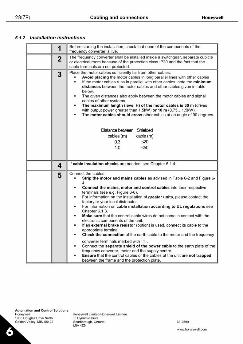
6.1.2 Installation instructions
1 Before starting the installation, check that none of the components of thefrequency converter is live.
2 The frequency converter shall be installed inside a switchgear, separate cubicleor electrical room because of the protection class IP20 and the fact that thecable terminals are not protected.
3 Place the motor cables sufficiently far from other cables: Avoid placing the motor cables in long parallel lines with other cables If the motor cables runs in parallel with other cables, note the minimum
distances between the motor cables and other cables given in tablebelow.
The given distances also apply between the motor cables and signalcables of other systems.
The maximum length (level H) of the motor cables is 30 m (driveswith output power greater than 1.5kW) or 10 m (0.75…1.5kW).
The motor cables should cross other cables at an angle of 90 degrees.
Distance between cables (m)
Shielded cable (m)
0.3 <201.0 <50
4 If cable insulation checks are needed, see Chapter 6.1.4.
5 Connect the cables: Strip the motor and mains cables as advised in Table 6-2 and Figure 6-
4. Connect the mains, motor and control cables into their respective
terminals (see e.g. Figure 6-6). For information on the installation of greater units, please contact the
factory or your local distributor. For Information on cable installation according to UL regulations see
Chapter 6.1.3. Make sure that the control cable wires do not come in contact with the
electronic components of the unit. If an external brake resistor (option) is used, connect its cable to the
appropriate terminal. Check the connection of the earth cable to the motor and the frequency
converter terminals marked with . Connect the separate shield of the power cable to the earth plate of the
frequency converter, motor and the supply centre. Ensure that the control cables or the cables of the unit are not trapped
between the frame and the protection plate.

Honeywell Cabling and connections 29(79)
Automation and Control SolutionsHoneywell Honeywell Limited-Honeywell Limitée1985 Douglas Drive North 35 Dynamic DriveGolden Valley, MIN 55422 Scarborough, Ontario 63-2599 MIV 4Z9
www.honeywell.com 6
6.1.2.1 Stripping lengths of motor and mains cables
Figure 6-4. Stripping of cables
Frame A1 B1 C1 D1 A2 B2 C2 D2MF2 0.28 1.38 0.28 0.79 0.28 1.97 0.28 1.38MF3 0.28 1.57 0.28 1.18 0.28 2.36 0.28 1.57MF4 0.59 1.38 0.39 0.79 0.28 1.97 0.28 1.38MF5 0.79 1.57 0.39 1.18 0.79 2.36 0.39 1.57
Table 6-2. Cables stripping lengths [inch]
nk6141.fh8
MAINS MOTOR
Earthconductor
Earthconductor
D1B1
C1A1
D2B2
C2A2

30(79) Cabling and connections Honeywell
Automation and Control SolutionsHoneywell Honeywell Limited-Honeywell Limitée1985 Douglas Drive North 35 Dynamic DriveGolden Valley, MIN 55422 Scarborough, Ontario 63-2599 MIV 4Z9
www.honeywell.com6
6.1.2.2 Installation of cables to NXLNote: In case you want to connect an external brake resistor (MF3 and bigger sizes), see separate BrakeResistor Manual. See also Chapter Internal brake resistor connection on page 63 in this manual.
Figure 6-5. NXL, MF2
Figure 6-6. Cable installation in NXL, MF2
Earth terminalControl cable
Motor cable
Mains cable

Honeywell Cabling and connections 31(79)
Automation and Control SolutionsHoneywell Honeywell Limited-Honeywell Limitée1985 Douglas Drive North 35 Dynamic DriveGolden Valley, MIN 55422 Scarborough, Ontario 63-2599 MIV 4Z9
www.honeywell.com 6
Figure 6-7. NXL, MF3
Figure 6-8. Cable installation in NXL, MF3
Control cable
Motor cable
Mains cable
Earth terminalBrake resistorterminals
BR+BR-
32(79) Cabling and connections Honeywell
Automation and Control SolutionsHoneywell Honeywell Limited-Honeywell Limitée1985 Douglas Drive North 35 Dynamic DriveGolden Valley, MIN 55422 Scarborough, Ontario 63-2599 MIV 4Z9
www.honeywell.com6
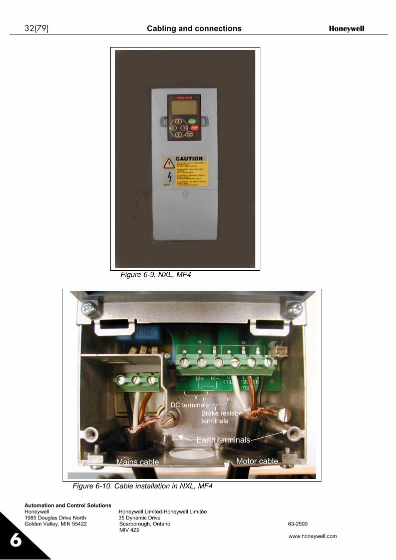
Figure 6-9. NXL, MF4
Figure 6-10. Cable installation in NXL, MF4
Earth terminals
Mains cable Motor cable
Brake resistorterminals
DC terminals

Honeywell Cabling and connections 33(79)
Automation and Control SolutionsHoneywell Honeywell Limited-Honeywell Limitée1985 Douglas Drive North 35 Dynamic DriveGolden Valley, MIN 55422 Scarborough, Ontario 63-2599 MIV 4Z9
www.honeywell.com 6
Figure 6-11. NXL, MF5
Figure 6-12. Cable installation in NXL, MF5
Mains cable Motor cable
Earth terminals
Brake resistorterminals
DC terminals
34(79) Cabling and connections Honeywell
Automation and Control SolutionsHoneywell Honeywell Limited-Honeywell Limitée1985 Douglas Drive North 35 Dynamic DriveGolden Valley, MIN 55422 Scarborough, Ontario 63-2599 MIV 4Z9
www.honeywell.com6
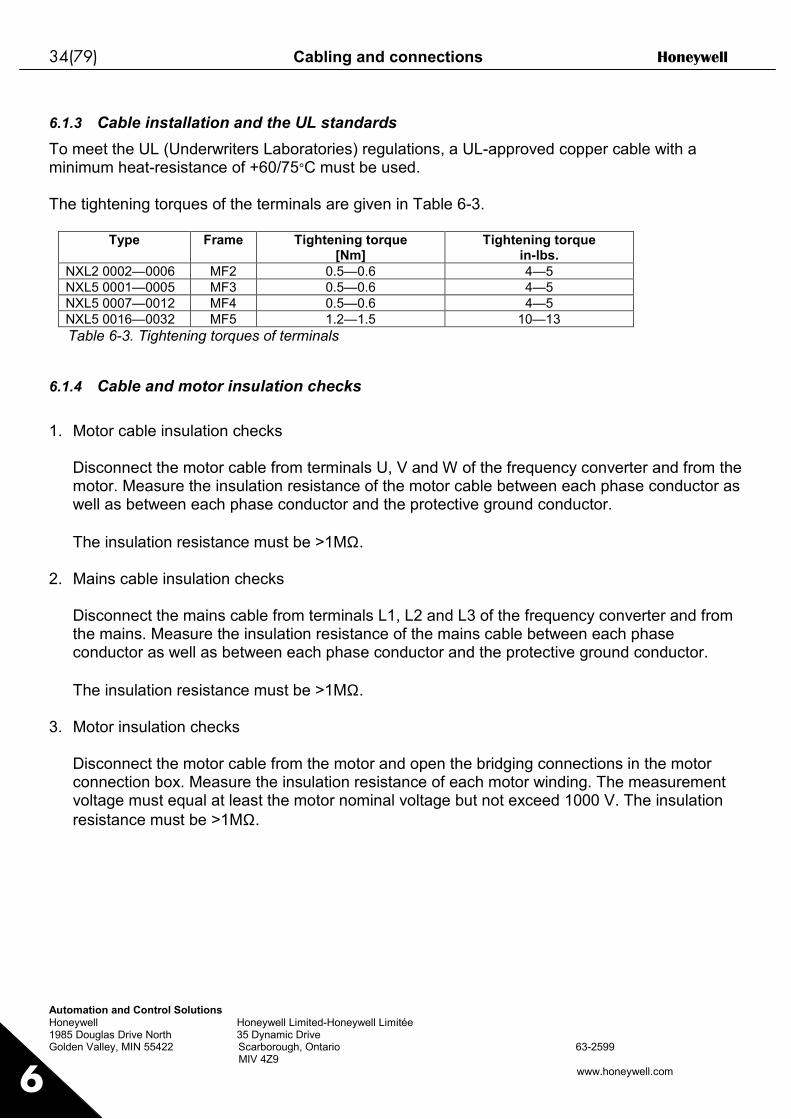
6.1.3 Cable installation and the UL standardsTo meet the UL (Underwriters Laboratories) regulations, a UL-approved copper cable with aminimum heat-resistance of +60/75°C must be used.
The tightening torques of the terminals are given in Table 6-3.
Type Frame Tightening torque[Nm]
Tightening torquein-lbs.
NXL2 0002—0006 MF2 0.5—0.6 4—5NXL5 0001—0005 MF3 0.5—0.6 4—5NXL5 0007—0012 MF4 0.5—0.6 4—5NXL5 0016—0032 MF5 1.2—1.5 10—13Table 6-3. Tightening torques of terminals
6.1.4 Cable and motor insulation checks
1. Motor cable insulation checks
Disconnect the motor cable from terminals U, V and W of the frequency converter and from themotor. Measure the insulation resistance of the motor cable between each phase conductor aswell as between each phase conductor and the protective ground conductor.
The insulation resistance must be >1MΩ.
2. Mains cable insulation checks
Disconnect the mains cable from terminals L1, L2 and L3 of the frequency converter and fromthe mains. Measure the insulation resistance of the mains cable between each phaseconductor as well as between each phase conductor and the protective ground conductor.
The insulation resistance must be >1MΩ.
3. Motor insulation checks
Disconnect the motor cable from the motor and open the bridging connections in the motorconnection box. Measure the insulation resistance of each motor winding. The measurementvoltage must equal at least the motor nominal voltage but not exceed 1000 V. The insulationresistance must be >1MΩ.

Honeywell Cabling and connections 35(79)
Automation and Control SolutionsHoneywell Honeywell Limited-Honeywell Limitée1985 Douglas Drive North 35 Dynamic DriveGolden Valley, MIN 55422 Scarborough, Ontario 63-2599 MIV 4Z9
www.honeywell.com 6
6.2 Control unitThe control unit of the NXL frequency converter is integrated with the power unit and consistsroughly of the control board and one optional board, which can be connected to the slot connectorof the control board.The frequency converter is delivered from the factory with the basic configuration without anoption board.
6.2.1 Control connectionsThe basic control connections are shown in Chapter 6.2.2.1.
The signal descriptions of the Multicontrol Application are presented below and in Chapter 2 of theApplication Manual.
Figure 6-13. Control connections, MF2
Figure 6-14. Control connections, MF3
Figure 6-15. Control connections, MF4, MF5
nxlk13.fh8
21 22 239 10 11 18 19 A B
1 2 3 4 5 6 7 8
L1 L2 L3 U/T1 V/T2 W/T3
nxlk14.fh8
21 22 23
9 10 11 18 19 A B
1 2 3 4 5 6 7 8L1 L2 L3 U/T1 V/T2 W/T3 BR+ BR-
nxlk49.fh8
309 10 11 18 19 A B
21 22 231 2 3 4 5 6 7 8

36(79) Cabling and connections Honeywell
Automation and Control SolutionsHoneywell Honeywell Limited-Honeywell Limitée1985 Douglas Drive North 35 Dynamic DriveGolden Valley, MIN 55422 Scarborough, Ontario 63-2599 MIV 4Z9
www.honeywell.com6
6.2.2 Control cablesThe control cables shall be at least 0.5 mm2 screened multicore cables, see chapter 6.1.1.1. Themaximum terminal wire size is 2.5 mm2 for the relay terminals and 1.5 mm2 for other terminals.
6.2.2.1 Control I/O
Terminal Signal Description1 +10Vref Reference output Voltage for potentiometer, etc.2 AI1+ Analogue input, voltage range
0—10V DC.Voltage input frequency referenceCan be programmed as DIN4
3 AI1- I/O Ground Ground for reference and controls4 AI2+5 AI2-
Analogue input, current range0/4—20mA
Current input frequency reference(programmable)
6 +24V Control voltage output Voltage for switches, etc. max 0.1 A7 GND I/O ground Ground for reference and controls8 DIN1 Start forward (programmable) Contact closed = start forward9 DIN2 Start reverse (programmable) Contact closed = start reverse
10 DIN3 Multi-step speed selection 1(programmable)
Contact closed = multi-step speed
11 GND I/O ground Ground for reference and controls
18 AO1+19 AO1-
Output frequencyAnalogue output
ProgrammableRange 0—20 mA/RL, max. 500Ω
A RS 485 Serial bus Termination resistor 0/4….20mAB RS 485 Serial bus Termination resistor 0/4….20mA
21 RO122 RO123 RO1
Relay output 1FAULT
Programmable
Table 6-4. Multicontrol application default I/O configuration (with 2-wiretransmitter).
Terminal Signal Description1 +10Vref Reference output Voltage for potentiometer, etc.2 AI1+
orDIN 4
Analogue input, voltage range0—10V DC
Voltage input frequency referenceCan be programmed as DIN4
3 AI1- I/O Ground Ground for reference and controls4 AI2+5 AI2-
Analogue input, current range0—20mA
Current input frequency reference
6 + 24 V Control voltage outputTable 6-5. The programming of AI1 as DIN4
Referencepotentiometer
2-wiretransmitter
mA
Actual value
I (0)4…20 mA
–+

Honeywell Cabling and connections 37(79)
Automation and Control SolutionsHoneywell Honeywell Limited-Honeywell Limitée1985 Douglas Drive North 35 Dynamic DriveGolden Valley, MIN 55422 Scarborough, Ontario 63-2599 MIV 4Z9
www.honeywell.com 6
6.2.3 Control terminal signals
Terminal Signal Technical information1 +10 Vref Reference voltage Maximum current 10 mA2 AI1+ Analogue input,
voltage(MF4 and bigger: voltage or current)
Selection V or mA with jumper block X4 (see page 38):Default: 0– +10V (Ri = 200 kΩ)
0– 20mA (Ri = 250 Ω)3 AI1– Analogue input common Differential input if not connected to ground;
Allows ±20V differential mode voltage to GND4 AI2+ Analogue input, voltage or
currentDefault: 0– 20mA (Ri = 250 Ω)
5 AI2– Analogue input common Differential input;Allows ±20V differential mode voltage to GND
6 24 Vout 24V auxiliary voltage ±10%, maximum current 100 mA7 GND I/O ground Ground for reference and controls8 DIN1 Digital input 19 DIN2 Digital input 210 DIN3 Digital input 3
Ri = min. 5kΩ
11 GND I/O ground Ground for reference and controls18 AO1+ Analogue signal (+output)19 AO1– Analogue output common
Output signal range:Current 0(4)–20mA, RL max 500Ω orVoltage 0—10V, RL >1kΩ
A RS 485 Serial busB RS 485 Serial bus
21 RO1/122 RO1/223 RO1/3
Relay output 1 Switching capacity: 24VDC/8A250VAC/8A125VDC/0,4A
Relay output terminals are galvanically isolated from theI/O ground
Table 6-6. Control I/O terminal signals

38(79) Cabling and connections Honeywell
Automation and Control SolutionsHoneywell Honeywell Limited-Honeywell Limitée1985 Douglas Drive North 35 Dynamic DriveGolden Valley, MIN 55422 Scarborough, Ontario 63-2599 MIV 4Z9
www.honeywell.com6
6.2.3.1 Jumper selections on NXL basic boardThe user is able to customise the functions of the frequency converter to better suit his needs byselecting certain positions for the jumpers on the NXL board. The positions of the jumpersdetermine the signal type of analogue input (terminal #2) and whether the termination resistorRS485 is used or not.
On the MF2 board, there is one jumper block X4 containing ten pins and two jumpers. On the MF3board there are two jumper blocks: X4 containing six pins and three jumpers and X7 containingfour pins and one jumper. The selectable positions of the jumpers are shown in the figure below.See also Figure 6-18 on the next page.
Figure 6-16. Jumper selection for NXL, MF2 and MF3nxlk15.fh8
Jumper block X4 in MF3:
Voltage input; 0...10VTermination resistor RS 485 is in use
0...20mA; Current input
Voltage input; 0...10V
= Factory default
0...20mA; Current inputTermination resistor RS 485 is not used
Jumper block X4 in MF2:
Jumper block X7 in MF3:
Termination resistor RS 485 is in use
Termination resistor RS 485 is not used
Termination resistor
Termination resistor

Honeywell Cabling and connections 39(79)
Automation and Control SolutionsHoneywell Honeywell Limited-Honeywell Limitée1985 Douglas Drive North 35 Dynamic DriveGolden Valley, MIN 55422 Scarborough, Ontario 63-2599 MIV 4Z9
www.honeywell.com 6
Figure 6-17. Jumper selection for NXL, MF4 and MF5
!WARNING
Check the correct positions of the jumpers. Running the motorwith signal settings different from the jumper positions will notharm the frequency converter but may damage the motor.
!NOTE
If you change the AI signal content also remember to changethe corresponding parameter S6.9 in System Menu.
= Factory default
Jumper block X9:
nxlk54.fh8
Voltage input; 0...10V
0...20mA; Current input
Jumper block X13:AI2 mode
Termination resistor RS 485 is in use
Termination resistor RS 485 is not used

40(79) Control keypad Honeywell
Automation and Control SolutionsHoneywell Honeywell Limited-Honeywell Limitée1985 Douglas Drive North 35 Dynamic DriveGolden Valley, MIN 55422 Scarborough, Ontario 63-2599 MIV 4Z9
www.honeywell.com
7
Figure 6-18. The location of jumper blocks in MF2 (left) and MF3 (right)
Figure 6-19. The location of jumper blocks in the control board of MF4 and MF5
Jumper block X4Jumper block X4
Jumper block X7
X13
X9

Honeywell Control keypad 41(79)
Automation and Control SolutionsHoneywell Honeywell Limited-Honeywell Limitée1985 Douglas Drive North 35 Dynamic DriveGolden Valley, MIN 55422 Scarborough, Ontario 63-2599 MIV 4Z9
www.honeywell.com
7
7. CONTROL KEYPADThe control keypad is the link between the NXL frequency converter and the user. The NXLcontrol keypad features a seven-segment display with seven indicators for the Run status (RUN,
, READY, STOP, ALARM, FAULT) and three indicators for the control place (I/O term/Keypad/BusComm).The control information, i.e. the number of menu, the displayed value and the numeric informationare presented with numeric symbols.
The frequency converter is operable through the seven push-buttons of the control keypad.Furthermore, the buttons serve the purposes of parameter setting and value monitoring.
The keypad is detachable and isolated from the input line potential.
7.1 Indications on the Keypad display
Figure 7-1. NXL control keypad and drive status indications
7.1.1 Drive status indicationsThe drive status indications tell the user what the status of the motor and the drive is and whetherthe motor control software has detected irregularities in motor or frequency converter functions.
RUN = Motor is running; Blinks when the stop command has been given but the frequency isstill ramping down.
= Indicates the direction of motor rotation.
STOP = Indicates that the drive is not running.
1
2
3

42(79) Control keypad Honeywell
Automation and Control SolutionsHoneywell Honeywell Limited-Honeywell Limitée1985 Douglas Drive North 35 Dynamic DriveGolden Valley, MIN 55422 Scarborough, Ontario 63-2599 MIV 4Z9
www.honeywell.com
7READY = Lights when AC power is on. In case of a fault, the symbol will not light up.
ALARM = Indicates that the drive is running outside a certain limit and a warning is given.
FAULT = Indicates that unsafe operating conditions were encountered due to which the drivewas stopped.
7.1.2 Control place indicationsThe symbols I/O term, Keypad and Bus/Comm (see chapter 7.3.3.1) indicate the choice ofcontrol place made in the Keypad control menu (see chapter 7.3.3).
I/O term = I/O terminals are the selected control place; i.e. START/STOPcommands or reference values etc. are given through the I/O terminals.
Keypad = Control keypad is the selected control place; i.e. the motor can bestarted or stopped, or its reference values etc. altered from the keypad.
Bus/Comm = The frequency converter is controlled through a fieldbus.
7.1.3 Numeric indicationsThe numeric indications provide the user with information on his present location in the keypadmenu structure as well as with information related to the operation of the drive.
4
5
6
b
c
a

Honeywell Control keypad 43(79)
Automation and Control SolutionsHoneywell Honeywell Limited-Honeywell Limitée1985 Douglas Drive North 35 Dynamic DriveGolden Valley, MIN 55422 Scarborough, Ontario 63-2599 MIV 4Z9
www.honeywell.com
7
7.2 Keypad push-buttonsThe NXL seven-segment control keypad features 7 push-buttons that are used for the control ofthe frequency converter (and motor), parameter setting and value monitoring.
Figure 7-2. Keypad push-buttons
7.2.1 Button descriptions
Resetenter = There are two operations integrated in this button. The button operates
mainly as reset button except in the parameter edit mode. The buttonoperation is shortly described below.
reset = This button is used to reset active faults.
enter = The Enter button serves for:1) confirmation of selections2) fault history reset (2…3 seconds)
= Browser button upBrowse the main menu and the pages of different submenus.Edit values.
= Browser button downBrowse the main menu and the pages of different submenus.Edit values.
–
+

44(79) Control keypad Honeywell
Automation and Control SolutionsHoneywell Honeywell Limited-Honeywell Limitée1985 Douglas Drive North 35 Dynamic DriveGolden Valley, MIN 55422 Scarborough, Ontario 63-2599 MIV 4Z9
www.honeywell.com
7
= Menu button leftMove backward in menu.Move cursor left (in parameter edit mode).Exit edit mode.Hold down for 2…3 seconds to return to main menu.
= Menu button rightMove forward in menu.Move cursor right (in parameter edit mode).Enter edit mode.
= Start button.Pressing this button starts the motor if the keypad is the active controlplace. See Chapter 7.3.3.1.
= Stop button.Pressing this button stops the motor (unless disabled by parameterR3.4/R3.6).
7.3 Navigation on the control keypadThe data on the control keypad are arranged in menus and submenus. The menus are used forexample for the display and editing of measurement and control signals, parameter settings(chapter 7.3.2), reference values and fault displays (chapter 7.3.4).
The first menu level consists of menus M1 to E7 and is called the Main menu. The user cannavigate in the main menu using the Browser buttons up and down. The desired submenu can beentered from the main menu using the Menu buttons. When there still are pages to enter underthe currently displayed menu or page, the last digit of the figure on the display is blinking and bypressing the Menu button right, you can reach the next menu level.
The control keypad navigation chart is shown on page 46. Please note that the menu M1 islocated in the lower left corner. From there you will be able to navigate your way up to the desiredmenu using the menu and browser buttons.
More detailed descriptions of the menus you will find later in this Chapter.
3333
4444
start
stop
Location

Honeywell Control keypad 45(79)
Automation and Control SolutionsHoneywell Honeywell Limited-Honeywell Limitée1985 Douglas Drive North 35 Dynamic DriveGolden Valley, MIN 55422 Scarborough, Ontario 63-2599 MIV 4Z9
www.honeywell.com
7
NOTE!
By default the System Menu (S6) and Expander Board Menu (E7) are hidden. In order to browsethese menus you have to set the value of parameter 2.1.22 (Parameter conceal) to 0:
Figure 7-3. Changing the value of parameter 2.1.22
enter
STOP I/O term
READY
STOP I/O term
READY
STOP I/O term
READY
STOP I/O termREADY
STOP I/O termREADY
STOP I/O termREADY
nxlk55.fh8
HzHzHz
STOP I/O term
READY

46(79) Control keypad Honeywell
Automation and Control SolutionsHoneywell Honeywell Limited-Honeywell Limitée1985 Douglas Drive North 35 Dynamic DriveGolden Valley, MIN 55422 Scarborough, Ontario 63-2599 MIV 4Z9
www.honeywell.com
7
Figure 7-4. Keypad navigation chart
STOP
READY
I/O term
enter
enter
resetenter
STOP I/O termREADY
STOP I/O term
READY
STOP I/O term
READY
STOP I/O termREADY
STOP I/O termREADY
STOP I/O termREADY
STOP I/O termREADY
STOP I/O term
READY
STOP I/O term
READY
STOP I/O termREADY
STOP I/O term
READYSTOP I/O term
READY
STOP I/O term
READY
STOP I/O term
READYI/O term
READYSTOP I/O term
READY
STOP I/O termREADY
STOP I/O termREADY
STOP I/O termREADY
STOP
No editing!
Changevalue
Changevalue
Browse
Browse
Browse
Press to reset

Honeywell Control keypad 47(79)
Automation and Control SolutionsHoneywell Honeywell Limited-Honeywell Limitée1985 Douglas Drive North 35 Dynamic DriveGolden Valley, MIN 55422 Scarborough, Ontario 63-2599 MIV 4Z9
www.honeywell.com
7
Menu functions
Code Menu Min Max Selections
M1 Monitoring menu V1.1 V1.23 See chapter 7.3.1 for themonitoring values
P2 Parameter menu P2.1 P2.9
P2.1 = Basic parametersP2.2 = Input signalsP2.3 = Output signalsP2.4 = Drive controlP2.5 = Prohibit frequenciesP2.6 = Motor controlP2.7 = ProtectionsP2.8 = AutorestartP2.9 = PID controlP2.10=Pump and fan controlSee the Multi-controlapplication manual fordetailed parameter lists
K3 Keypad control menu P3.1 R3.6
P3.1 = Selection of controlplace
R3.2 = Keypad referenceP3.3 = Keypad directionP3.4 = Stop button activationR3.5 = PID reference 1R3.6 = PID reference 2
F4 Active faults menu Shows the active faults andtheir types
H5 Fault history menu Shows the fault history list
S6 System menu S6.3 S6.10
S6.3 = Copy parametersS6.5 = SecurityS6.6 = Keypad settingsS6.7 = Hardware settingsS6.8 = System infoS6.9 = AI modeS6.10 = Fieldbus parametersParameters are described inchapter 7.3.6
E7 Expander board menu
Table 7-1. Main menu functions

48(79) Control keypad Honeywell
Automation and Control SolutionsHoneywell Honeywell Limited-Honeywell Limitée1985 Douglas Drive North 35 Dynamic DriveGolden Valley, MIN 55422 Scarborough, Ontario 63-2599 MIV 4Z9
www.honeywell.com
7
7.3.1 Monitoring menu (M1)You can enter the Monitoring menu from the Main menu by pushing the Menu button right whenthe location indication M1 is visible on the display. How to browse through the monitored values ispresented in Figure 7-5.The monitored signals carry the indication V#.# and they are listed in Table 7-2. The values areupdated once every 0.3 seconds.
This menu is meant only for signal checking. The values cannot be altered here. For changingvalues of parameters see Chapter 7.3.2.
Figure 7-5. Monitoring menu
Honeywell Control keypad 49(79)
Automation and Control SolutionsHoneywell Honeywell Limited-Honeywell Limitée1985 Douglas Drive North 35 Dynamic DriveGolden Valley, MIN 55422 Scarborough, Ontario 63-2599 MIV 4Z9
www.honeywell.com
7
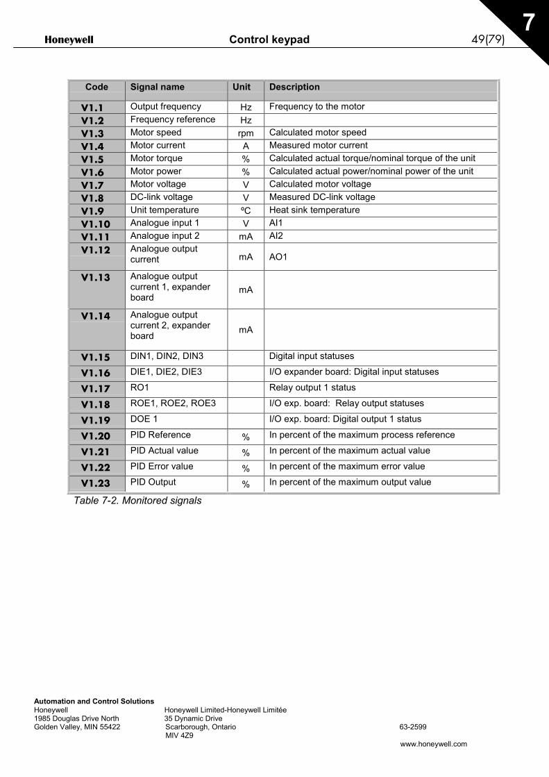
Code Signal name Unit Description
V1.1 Output frequency Hz Frequency to the motorV1.2 Frequency reference HzV1.3 Motor speed rpm Calculated motor speedV1.4 Motor current A Measured motor currentV1.5 Motor torque % Calculated actual torque/nominal torque of the unitV1.6 Motor power % Calculated actual power/nominal power of the unitV1.7 Motor voltage V Calculated motor voltageV1.8 DC-link voltage V Measured DC-link voltageV1.9 Unit temperature ºC Heat sink temperatureV1.10 Analogue input 1 V AI1V1.11 Analogue input 2 mA AI2V1.12 Analogue output
current mA AO1
V1.13 Analogue outputcurrent 1, expanderboard
mA
V1.14 Analogue outputcurrent 2, expanderboard mA
V1.15 DIN1, DIN2, DIN3 Digital input statuses
V1.16 DIE1, DIE2, DIE3 I/O expander board: Digital input statuses
V1.17 RO1 Relay output 1 status
V1.18 ROE1, ROE2, ROE3 I/O exp. board: Relay output statuses
V1.19 DOE 1 I/O exp. board: Digital output 1 status
V1.20 PID Reference % In percent of the maximum process reference
V1.21 PID Actual value % In percent of the maximum actual value
V1.22 PID Error value % In percent of the maximum error value
V1.23 PID Output % In percent of the maximum output value
Table 7-2. Monitored signals

50(79) Control keypad Honeywell
Automation and Control SolutionsHoneywell Honeywell Limited-Honeywell Limitée1985 Douglas Drive North 35 Dynamic DriveGolden Valley, MIN 55422 Scarborough, Ontario 63-2599 MIV 4Z9
www.honeywell.com
7
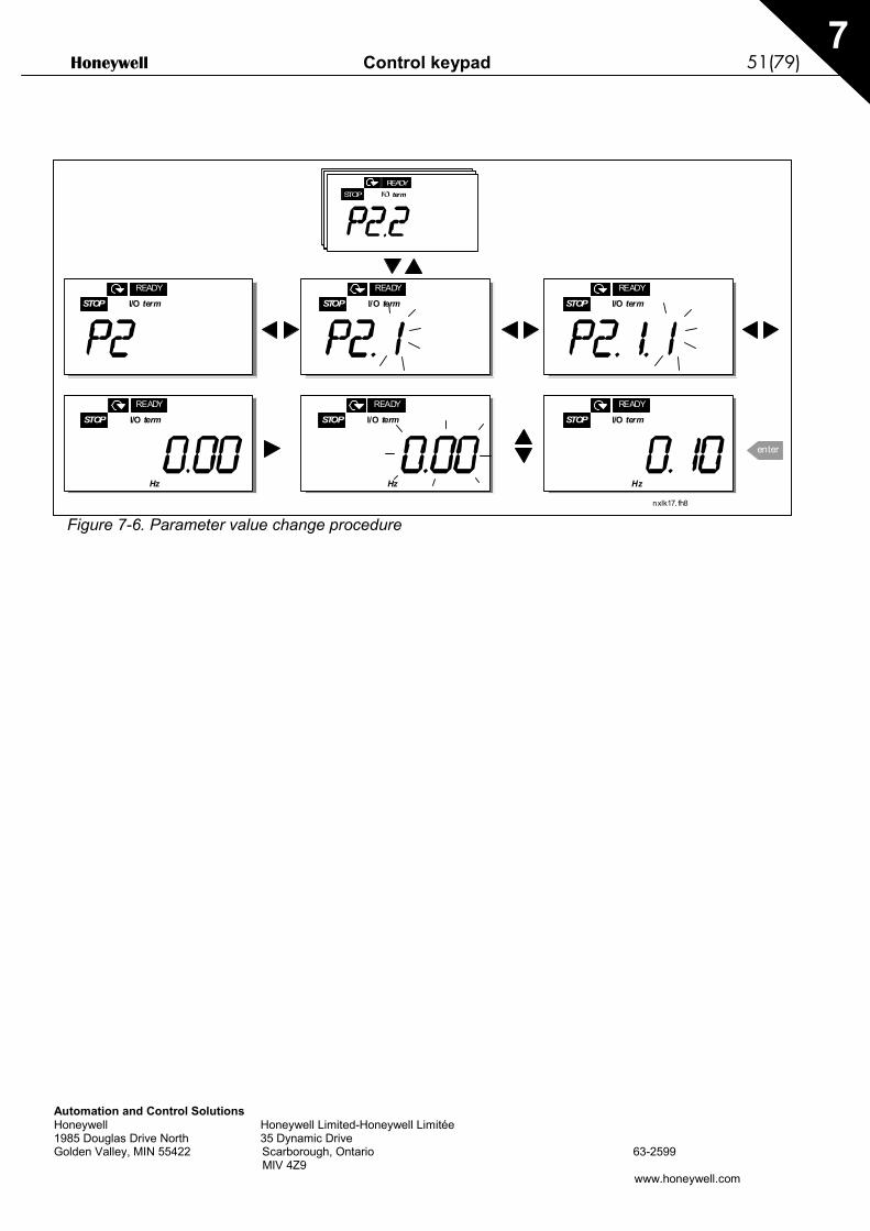
7.3.2 Parameter menu (P2)Parameters are the way of conveying the commands of the user to the frequency converter. Theparameter values can be edited by entering the Parameter Menu from the Main Menu when thelocation indication P2 is visible on the display. The value editing procedure is presented in Figure7-6.
Push the Menu button right once to move into the Parameter Group Menu (G#). Locate theparameter group desired by using the Browser buttons and push the Menu button right again toenter the group and its parameters. Use again the Browser buttons to find the parameter (P#) youwant to edit. From here you can proceed in two different ways: Pushing the Menu button righttakes you to the edit mode. As a sign of this, the parameter value starts to blink. You can nowchange the value in two different manners:
1 Just set the new desired value with the Browser buttons and confirm the change with theEnter button. Consequently, the blinking stops and the new value is visible in the value field.
2 Push the Menu button right once again. Now you will be able to edit the value digit by digit.This editing manner may come in handy, when a relatively greater or smaller value than thaton the display is desired. Confirm the change with the Enter button.
The value will not change unless the Enter button is pushed. Pressing the Menu button lefttakes you back to the previous menu.
Several parameters are locked, i.e. uneditable, when the drive is in RUN status. The frequencyconverter must be stopped in order to edit these parameters.The parameters values can also be locked using the function in menu S6 (see Chapter Parameterlock (P6.5.2)).
You can return to the Main menu anytime by pressing the Menu button left for 1—2 seconds.
The Multi-Control Application includes several sets of parameters. You will find the parameter listsin the Application Section of this manual.
Once in the last parameter of a parameter group, you can move directly to the first parameter ofthat group by pushing the Browser button up.
See the diagram for parameter value change procedure on page 51.
Honeywell Control keypad 51(79)
Automation and Control SolutionsHoneywell Honeywell Limited-Honeywell Limitée1985 Douglas Drive North 35 Dynamic DriveGolden Valley, MIN 55422 Scarborough, Ontario 63-2599 MIV 4Z9
www.honeywell.com
7
Figure 7-6. Parameter value change procedure
enter
STOP I/O term
READY
STOP I/O term
READY
STOP termREADY
STOP I/O term
READY
STOP I/O term
READY
STOP I/O term
READY
STOP I/O term
READY
nxlk17. fh8
HzHzHz

52(79) Control keypad Honeywell
Automation and Control SolutionsHoneywell Honeywell Limited-Honeywell Limitée1985 Douglas Drive North 35 Dynamic DriveGolden Valley, MIN 55422 Scarborough, Ontario 63-2599 MIV 4Z9
www.honeywell.com
7
7.3.3 Keypad control menu (K3)In the Keypad Controls Menu, you can choose the control place, edit the frequency reference andchange the direction of the motor. Enter the submenu level with the Menu button right.
Parameters in MenuK3
Selections
P3.1 = Selection of controlplace
1 = I/O terminals2 = Keypad3 = Fieldbus
R3.2 = Keypad reference
P3.3 = Keypad direction0 = Forward1 = Reverse
P3.4 = Stop button activation
0 = Limited function of Stopbutton
1 = Stop button alwaysenabled
R3.5 = PID reference 1R3.6 = PID reference 2
7.3.3.1 Selection of control placeThere are three different places (sources) which the frequency converter can be controlled from.For each control place, a different symbol will appear on the alphanumeric display:
Control place Symbol
I/O terminals I/O term
Keypad (panel) Keypad
Fieldbus Bus/Comm
Change the control place by entering the edit mode with the Menu button right. The options can then bebrowsed through with the Browser buttons. Select the desired control place with the Enter button. See thediagram below. See also 0 above.
Figure 7-7. Selection of control place

Honeywell Control keypad 53(79)
Automation and Control SolutionsHoneywell Honeywell Limited-Honeywell Limitée1985 Douglas Drive North 35 Dynamic DriveGolden Valley, MIN 55422 Scarborough, Ontario 63-2599 MIV 4Z9
www.honeywell.com
7
7.3.3.2 Keypad referenceThe keypad reference submenu (R3.2) displays and allows the operator to edit the frequencyreference. The changes will take place immediately. This reference value will not, however,influence the rotation speed of the motor unless the keypad has been selected as theactive control place.NOTE: The maximum difference between the output frequency and the keypad reference is 6 Hz.The application software monitors the keypad frequency automatically.See also 0 above.
See Figure 7-6 for how to edit the reference value (pressing the Enter button is not, however,necessary).
7.3.3.3 Keypad directionThe keypad direction submenu displays and allows the operator to change the rotating direction ofthe motor. This setting will not, however, influence the rotation direction of the motorunless the keypad has been selected as the active control place.See also 0 above.
See Figure 7-7 for how to change the rotation direction.
7.3.3.4 Stop button activationBy default, pushing the STOP button will always stop the motor regardless of the selected controlplace. You can disable this function by giving parameter 3.4 the value 0. If the value of thisparameter is 0, the STOP button will stop the motor only when the keypad has been selected asthe active control place.
See Figure 7-7 for how to change the value of this parameter.
54(79) Control keypad Honeywell
Automation and Control SolutionsHoneywell Honeywell Limited-Honeywell Limitée1985 Douglas Drive North 35 Dynamic DriveGolden Valley, MIN 55422 Scarborough, Ontario 63-2599 MIV 4Z9
www.honeywell.com
7
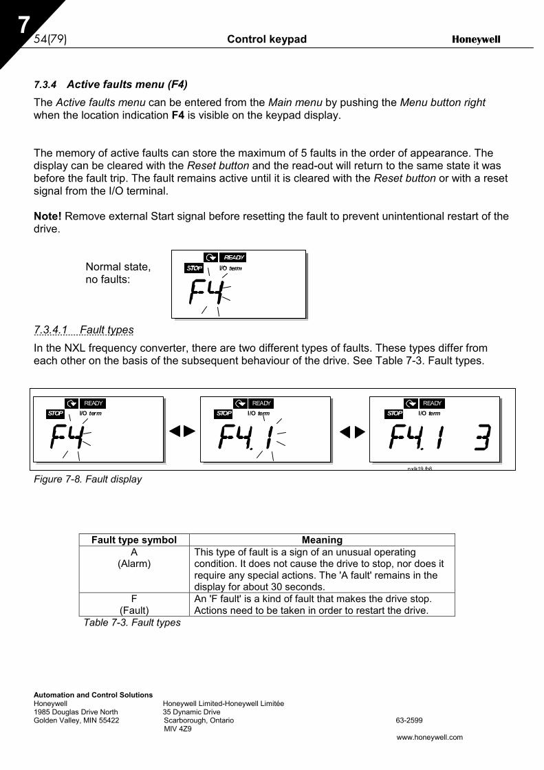
7.3.4 Active faults menu (F4)The Active faults menu can be entered from the Main menu by pushing the Menu button rightwhen the location indication F4 is visible on the keypad display.
The memory of active faults can store the maximum of 5 faults in the order of appearance. Thedisplay can be cleared with the Reset button and the read-out will return to the same state it wasbefore the fault trip. The fault remains active until it is cleared with the Reset button or with a resetsignal from the I/O terminal.
Note! Remove external Start signal before resetting the fault to prevent unintentional restart of thedrive.
Normal state,no faults:
7.3.4.1 Fault typesIn the NXL frequency converter, there are two different types of faults. These types differ fromeach other on the basis of the subsequent behaviour of the drive. See Table 7-3. Fault types.
Figure 7-8. Fault display
Fault type symbol MeaningA
(Alarm)This type of fault is a sign of an unusual operatingcondition. It does not cause the drive to stop, nor does itrequire any special actions. The 'A fault' remains in thedisplay for about 30 seconds.
F(Fault)
An 'F fault' is a kind of fault that makes the drive stop.Actions need to be taken in order to restart the drive.
Table 7-3. Fault types
STOP I/O termREADY
STOP I/O termREADY
STOP I/O termREADY
nxlk19.fh8

Honeywell Control keypad 55(79)
Automation and Control SolutionsHoneywell Honeywell Limited-Honeywell Limitée1985 Douglas Drive North 35 Dynamic DriveGolden Valley, MIN 55422 Scarborough, Ontario 63-2599 MIV 4Z9
www.honeywell.com
7
7.3.4.2 Fault codesThe fault codes, their causes and correcting actions are presented in the table below. Theshadowed faults are A faults only. The items written in white on black background present faultsfor which you can program different responses in the application. See parameter groupProtections.Note! When you contact the factory or the distributor due to a fault, it is advisable to write down allfault texts and codes that appear on the keypad
Faultcode
Fault Possible cause Correcting measures
1 Overcurrent Frequency converter has detected toohigh a current (>4*In) in the motor cable:− sudden heavy load increase− short circuit in motor cables− unsuitable motor
Check loading.Check motor size.Check cables.
2 Overvoltage The DC-link voltage has exceeded thelimits defined in Table 4-3.− too short a deceleration time− high overvoltage spikes in supply
Make the deceleration time longer.
3 Earth fault Current measurement has detected thatthe sum of motor phase current is notzero.− insulation failure in cables or motor
Check motor cables and motor.
5 Charging switch The charging switch is open, when theSTART command has been given.− faulty operation− component failure
Reset the fault and restart.Should the fault re-occur, contact thedistributor near to you.
8 System fault - component failure- faulty operation
Reset the fault and restart.Should the fault re-occur, contact thedistributor near to you.
9 Undervoltage DC-link voltage is under the voltage limitsdefined in Table 4-3.− most probable cause: too low a
supply voltage− frequency converter internal fault
In case of temporary supply voltagebreak reset the faultand restart thefrequency converter. Check the supplyvoltage. If it is adequate, an internalfailure has occurred.Contact the distributor near to you.
11 Output phasesupervision
Current measurement has detected thatthere is no current in one motor phase.
Check motor cable and motor.
13 Frequencyconverter under-temperature
Heatsink temperature is under –10°C
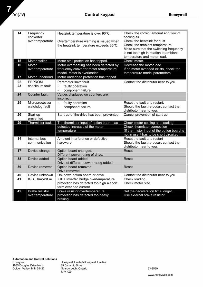
56(79) Control keypad Honeywell
Automation and Control SolutionsHoneywell Honeywell Limited-Honeywell Limitée1985 Douglas Drive North 35 Dynamic DriveGolden Valley, MIN 55422 Scarborough, Ontario 63-2599 MIV 4Z9
www.honeywell.com
7
14 Frequencyconverterovertemperature
Heatsink temperature is over 90°C.
Overtemperature warning is issued whenthe heatsink temperature exceeds 85°C.
Check the correct amount and flow ofcooling air.Check the heatsink for dust.Check the ambient temperature.Make sure that the switching frequencyis not too high in relation to ambienttemperature and motor load.
15 Motor stalled Motor stall protection has tripped. Check motor.16 Motor
overtemperatureMotor overheating has been detected byfrequency converter motor temperaturemodel. Motor is overloaded.
Decrease the motor load.If no motor overload exists, check thetemperature model parameters.
17 Motor underload Motor underload protection has tripped.2223
EEPROMchecksum fault
Parameter save fault− faulty operation− component failure
Contact the distributor near to you
24 Counter fault Values displayed on counters areincorrect
25 Microprocessorwatchdog fault
− faulty operation− component failure
Reset the fault and restart.Should the fault re-occur, contact thedistributor near to you.
26 Start-upprevented
Start-up of the drive has been prevented. Cancel prevention of start-up.
29 Thermistor fault The thermistor input of option board hasdetected increase of the motortemperature
Check motor cooling and loadingCheck thermistor connection(If thermistor input of the option board isnot in use it has to be short circuited)
34 Internal buscommunication
Ambient interference or defectivehardware
Reset the fault and restartShould the fault re-occur, contact thedistributor near to you.
37 Device change Option board changed.Different power rating of drive.
Reset
38 Device added Option board added.Drive of different power rating added.
Reset
39 Device removed Option board removed.Drive removed.
Reset
40 Device unknown Unknown option board or drive. Contact the distributor near to you.41 IGBT temperature IGBT Inverter Bridge overtemperature
protection has detected too high a shortterm overload current
Check loading.Check motor size.
42 Brake resistorovertemperature
Brake resistor overtemperatureprotection has detected too heavybraking
Set the deceleration time longer.Use external brake resistor.

Honeywell Control keypad 57(79)
Automation and Control SolutionsHoneywell Honeywell Limited-Honeywell Limitée1985 Douglas Drive North 35 Dynamic DriveGolden Valley, MIN 55422 Scarborough, Ontario 63-2599 MIV 4Z9
www.honeywell.com
7
44 Device change Option board changed.Different power rating of drive.
ResetNote: No fault time data record!Note: Application parameter valuesrestored to default.
45 Device added Option board added.Drive of different power rating added.
ResetNote: No fault time data record!Note: Application parameter valuesrestored to default.
50 Analogue inputIin<4mA(selected signalrange 4 to 20mA)
Current at the analogue input is < 4mA.− control cable is broken or loose− signal source has failed
Check the current loop circuitry.
51 External fault Digital input fault.52 Keypad
communicationfault
The connection between the controlkeypad and the frequency converter isbroken.
Check keypad connection and possiblekeypad cable.
53 Fieldbus fault The data connection between thefieldbus Master and the fieldbus board isbroken
Check installation.If installation is correct contact thenearest distributor
54 Slot fault Defective option board or slot Check board and slot.Contact the nearest distributor
55 Actual valuesupervision
Actual value has exceeded or fallenbelow (depending on par. 2.7.22) theactual value supervision limit (par.2.7.23)
Table 7-4. Fault codes
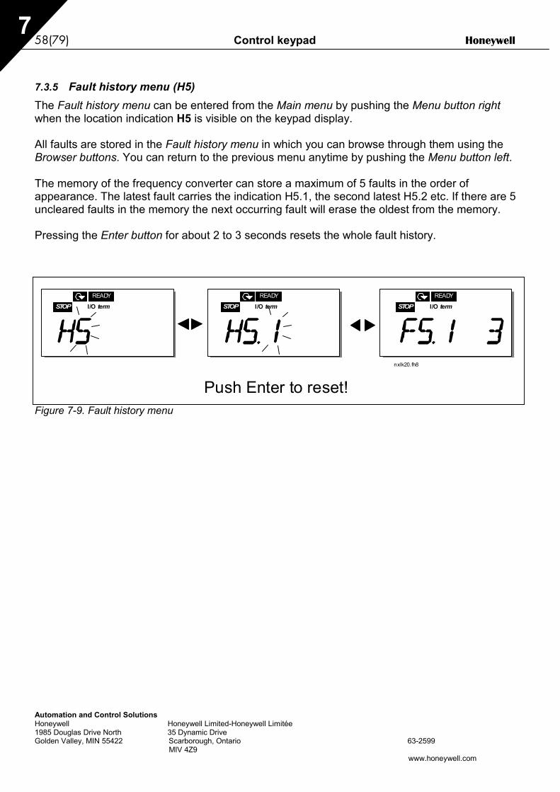
58(79) Control keypad Honeywell
Automation and Control SolutionsHoneywell Honeywell Limited-Honeywell Limitée1985 Douglas Drive North 35 Dynamic DriveGolden Valley, MIN 55422 Scarborough, Ontario 63-2599 MIV 4Z9
www.honeywell.com
7
7.3.5 Fault history menu (H5)The Fault history menu can be entered from the Main menu by pushing the Menu button rightwhen the location indication H5 is visible on the keypad display.
All faults are stored in the Fault history menu in which you can browse through them using theBrowser buttons. You can return to the previous menu anytime by pushing the Menu button left.
The memory of the frequency converter can store a maximum of 5 faults in the order ofappearance. The latest fault carries the indication H5.1, the second latest H5.2 etc. If there are 5uncleared faults in the memory the next occurring fault will erase the oldest from the memory.
Pressing the Enter button for about 2 to 3 seconds resets the whole fault history.
Figure 7-9. Fault history menu
STOP I/O term
READY
STOP I/O term
READY
STOP I/O term
READY
nxlk20.fh8
Push Enter to reset!
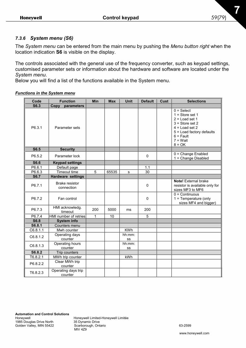
Honeywell Control keypad 59(79)
Automation and Control SolutionsHoneywell Honeywell Limited-Honeywell Limitée1985 Douglas Drive North 35 Dynamic DriveGolden Valley, MIN 55422 Scarborough, Ontario 63-2599 MIV 4Z9
www.honeywell.com
7
7.3.6 System menu (S6)The System menu can be entered from the main menu by pushing the Menu button right when thelocation indication S6 is visible on the display.
The controls associated with the general use of the frequency converter, such as keypad settings,customised parameter sets or information about the hardware and software are located under theSystem menu.Below you will find a list of the functions available in the System menu.
Functions in the System menu
Code Function Min Max Unit Default Cust SelectionsS6.3 Copy parameters
P6.3.1 Parameter sets
0 = Select1 = Store set 12 = Load set 13 = Store set 24 = Load set 25 = Load factory defaults6 = Fault7 = Wait8 = OK
S6.5 Security
P6.5.2 Parameter lock 0 0 = Change Enabled1 = Change Disabled
S6.6 Keypad settingsP6.6.1 Default page 1.1P6.6.3 Timeout time 5 65535 s 30S6.7 Hardware settings
P6.7.1 Brake resistorconnection 0
Note! External brakeresistor is available only forsizes MF3 to MF6
P6.7.2 Fan control 00 = Continuous1 = Temperature (only
sizes MF4 and bigger)
P6.7.3 HMI acknowledg.timeout 200 5000 ms 200
P6.7.4 HMI number of retries 1 10 5S6.8 System info
S6.8.1 Counters menuC6.8.1.1 Mwh counter KWh
C6.8.1.2 Operating dayscounter
hh:mm:ss
C6.8.1.3 Operating hourscounter
hh:mm:ss
S6.8.2 Trip countersT6.8.2.1 MWh trip counter kWh
P6.8.2.2 Clear MWh tripcounter
T6.8.2.3 Operating days tripcounter

60(79) Control keypad Honeywell
Automation and Control SolutionsHoneywell Honeywell Limited-Honeywell Limitée1985 Douglas Drive North 35 Dynamic DriveGolden Valley, MIN 55422 Scarborough, Ontario 63-2599 MIV 4Z9
www.honeywell.com
7
T6.8.2.4 Operating hours tripcounter
hh:mm:ss
P6.8.2.5 Clear operating timecounter
S6.8.3 Software infoI6.8.3.1 Software packageI6.8.3.2 System SW versionI6.8.3.3 Firmware interfaceI6.8.3.4 System load %S6.8.4 Application info
S6.8.4.1 ApplicationA6.8.4.1.1 Application idA6.8.4.1.2 Application versionA6.8.4.1.3 Firmware interface
S6.8.5 Hardware infoI6.8.5.2 Unit voltage VI6.8.5.3 Brake chopperI6.8.5.4 Brake resistorS6.8.6 Options
S6.8.6.1 NXOPTE6.8.6.1.1 StatusE6.8.6.1.2 Program version
S6.9 AI modeP6.9.2 AIA2 mode 0
S6.10 Fieldbusparameters
I6.10.1 Communication statusP6.10.2 Fieldbus protocol 1 1 1 1=Modbus protocolP6.10.3 Slave address 1 255 1 Addresses 1 – 255
P6.10.4 Baud rate 0 8 5
0=300 baud1=600 baud2=1200 baud3=2400 baud4=4800 baud5=9600 baud6=19200 baud7=38400 baud8=57600 baud
P6.10.5 Stop bits 0 1 0 0=11=2
P6.10.6 Parity type 0 2 00=None1=Odd2=Even
P6.10.7 Communicationtimeout 0 300 s 0
0=Not used1=1 second2=2 seconds, etc
Table 7-5. System menu functions

Honeywell Control keypad 61(79)
Automation and Control SolutionsHoneywell Honeywell Limited-Honeywell Limitée1985 Douglas Drive North 35 Dynamic DriveGolden Valley, MIN 55422 Scarborough, Ontario 63-2599 MIV 4Z9
www.honeywell.com
7
7.3.6.1 Copy parametersThe Copy parameters submenu (S6.3) is located under the System menu.The NXL frequency converter features a possibility for the user to store and load two customisedparameter sets (all parameters included in the application) and to load back the factory defaultparameter values.
Parameter sets (S6.3.1)
On Parameter sets page (S6.3.1), push the Menu button right to enter the Edit menu. You canstore or load two customised parameter sets or load back the factory defaults. Confirm with theEnter button. Wait, until 8 (=OK) appears on the display.
Figure 7-10. Storing and loading of parameter sets
7.3.6.2 SecurityThe Security submenu (S6.5) under the system menu has a function that allows the user toprohibit changes to the parameters.
Parameter lock (P6.5.2)
If the parameter lock is activated the parameter values cannot be edited.
NOTE: This function does not prevent unauthorised editing of parameter values.
Enter the edit mode by pushing the Menu button right. Use the Browser buttons to change theparameter lock status (0 = changes enabled, 1 = changes disabled). Accept the change with theEnter button or return to the previous level with the Menu button left.
enter
STOP I/O term
READY
STOP I/O term
READY
nxlk21.fh8
STOP I/O term
READY
STOP I/O term
READY
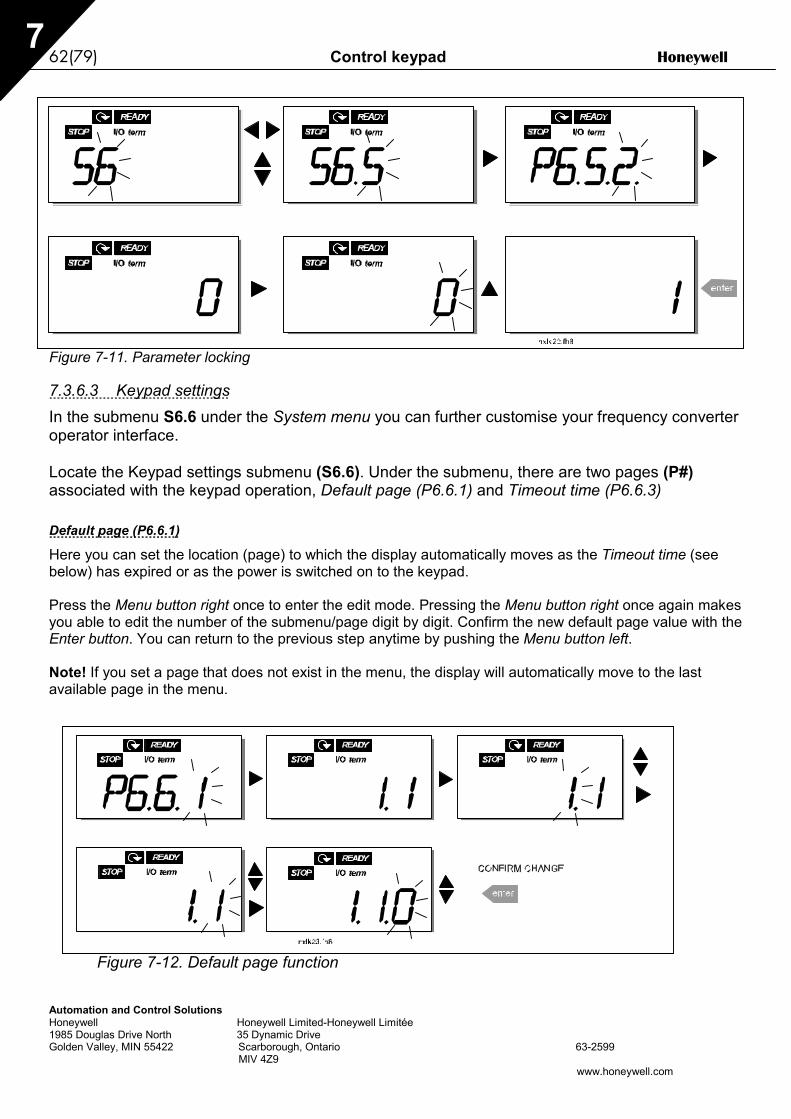
62(79) Control keypad Honeywell
Automation and Control SolutionsHoneywell Honeywell Limited-Honeywell Limitée1985 Douglas Drive North 35 Dynamic DriveGolden Valley, MIN 55422 Scarborough, Ontario 63-2599 MIV 4Z9
www.honeywell.com
7
Figure 7-11. Parameter locking
7.3.6.3 Keypad settingsIn the submenu S6.6 under the System menu you can further customise your frequency converteroperator interface.
Locate the Keypad settings submenu (S6.6). Under the submenu, there are two pages (P#)associated with the keypad operation, Default page (P6.6.1) and Timeout time (P6.6.3)
Default page (P6.6.1)
Here you can set the location (page) to which the display automatically moves as the Timeout time (seebelow) has expired or as the power is switched on to the keypad.
Press the Menu button right once to enter the edit mode. Pressing the Menu button right once again makesyou able to edit the number of the submenu/page digit by digit. Confirm the new default page value with theEnter button. You can return to the previous step anytime by pushing the Menu button left.
Note! If you set a page that does not exist in the menu, the display will automatically move to the lastavailable page in the menu.
Figure 7-12. Default page function

Honeywell Control keypad 63(79)
Automation and Control SolutionsHoneywell Honeywell Limited-Honeywell Limitée1985 Douglas Drive North 35 Dynamic DriveGolden Valley, MIN 55422 Scarborough, Ontario 63-2599 MIV 4Z9
www.honeywell.com
7
Timeout time (P6.6.3)
The Timeout time setting defines the time after which the keypad display returns to the DefaultPage (P6.6.1), see above.Move to the Edit menu by pressing the Menu button right. Set the timeout time you want andconfirm the change with the Enter button. You can return to the previous step anytime by pushingthe Menu button left.
NOTE: This function cannot be disabled.
Figure 7-13. Timeout time setting
7.3.6.4 Hardware settingsIn the Hardware settings submenu (S6.7) you can further customise the settings of the frequencyconverter with four parameters: Brake resistor connection, Fan control, HMIacknowledgement timeout and HMI retry.
Brake resistor connection (P6.7.1)
With this function you can tell the frequency converter whether the brake resistor is connected ornot.
0 = Not connected (Default)1 = Connected
NOTE! An external brake resistor can be connected to sizes MF3 and bigger. When a brakeresistor is not connected, the value of this parameter must not be changed to 1.

64(79) Control keypad Honeywell
Automation and Control SolutionsHoneywell Honeywell Limited-Honeywell Limitée1985 Douglas Drive North 35 Dynamic DriveGolden Valley, MIN 55422 Scarborough, Ontario 63-2599 MIV 4Z9
www.honeywell.com
7
Fan control (P6.7.2)
Note! Only the higher power modules of MF3 have been equipped with a cooling fan, inlower power modules of MF3 the cooling fan is available as optional equipment.
If the cooling fan has been installed in MF3 it runs continuously, when the power is switched on.
Sizes MF4 and bigger:This function allows you to control the frequency converter’s cooling fan. You can set the fan to runcontinuously when the power is switched on or depending on the temperature of the unit. If the latterfunction has been selected the fan is switched on automatically when the heat sink temperature reaches60°C. The fan receives a stop command when the heat sink temperature falls to 55°C. However the fanruns for about a minute after receiving the stop command, as well as after changing the value from 0(Continuous) to 1 (Temperature).
Enter the edit mode by pushing the Menu button right. The present mode shown starts to blink. Use theBrowser buttons to change the fan mode. Accept the change with the Enter button or return to the previouslevel with the Menu button left.
See Figure 7-11 for how to change the fan control function.
HMI acknowledge timeout (P6.7.3)
This function allows the user to change the timeout of the HMI acknowledgement time.Note! If the frequency converter has been connected to the PC with a normal cable, the default values ofparametres 6.7.3 and 6.7.4 (200 and 5) must not be changed.If the frequency converter has been connected to the PC via a modem and there is delay in transferringmessages, the value of par. 6.7.3 must be set according to the delay as follows:Example:
• Transfer delay between the frequency converter and the PC = 600 ms• The value of par. 6.7.3 is set to 1200 ms (2 x 600, sending delay + receiving delay)• The corresponding setting shall be entered in the [Misc]-part of the file NCDrive.ini:
Retries = 5AckTimeOut = 1200TimeOut = 6000
It must also be considered that intervals that are shorter than the AckTimeOut-time cannot be used in NC-Drive monitoring.Enter the edit mode by pushing the Menu button right. Use the Browser buttons to change theacknowledgement time. Accept the change with the Enter button or return to the previous level with theMenu button left. See Figure 7-14 for how to change the HMI acknowledgement timeout.
Figure 7-14. HMI acknowledge timeout
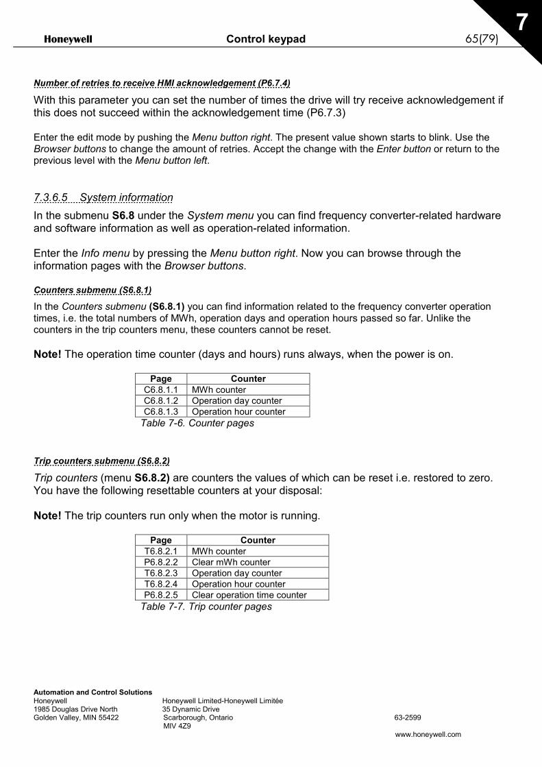
Honeywell Control keypad 65(79)
Automation and Control SolutionsHoneywell Honeywell Limited-Honeywell Limitée1985 Douglas Drive North 35 Dynamic DriveGolden Valley, MIN 55422 Scarborough, Ontario 63-2599 MIV 4Z9
www.honeywell.com
7
Number of retries to receive HMI acknowledgement (P6.7.4)
With this parameter you can set the number of times the drive will try receive acknowledgement ifthis does not succeed within the acknowledgement time (P6.7.3)
Enter the edit mode by pushing the Menu button right. The present value shown starts to blink. Use theBrowser buttons to change the amount of retries. Accept the change with the Enter button or return to theprevious level with the Menu button left.
7.3.6.5 System informationIn the submenu S6.8 under the System menu you can find frequency converter-related hardwareand software information as well as operation-related information.
Enter the Info menu by pressing the Menu button right. Now you can browse through theinformation pages with the Browser buttons.
Counters submenu (S6.8.1)
In the Counters submenu (S6.8.1) you can find information related to the frequency converter operationtimes, i.e. the total numbers of MWh, operation days and operation hours passed so far. Unlike thecounters in the trip counters menu, these counters cannot be reset.
Note! The operation time counter (days and hours) runs always, when the power is on.
Page CounterC6.8.1.1 MWh counterC6.8.1.2 Operation day counterC6.8.1.3 Operation hour counter
Table 7-6. Counter pages
Trip counters submenu (S6.8.2)
Trip counters (menu S6.8.2) are counters the values of which can be reset i.e. restored to zero.You have the following resettable counters at your disposal:
Note! The trip counters run only when the motor is running.
Page CounterT6.8.2.1 MWh counterP6.8.2.2 Clear mWh counterT6.8.2.3 Operation day counterT6.8.2.4 Operation hour counterP6.8.2.5 Clear operation time counter
Table 7-7. Trip counter pages

66(79) Control keypad Honeywell
Automation and Control SolutionsHoneywell Honeywell Limited-Honeywell Limitée1985 Douglas Drive North 35 Dynamic DriveGolden Valley, MIN 55422 Scarborough, Ontario 63-2599 MIV 4Z9
www.honeywell.com
7
Example: When you want to reset the operation counters, you should do the following:
Figure 7-15. MWh counter reset
Software info submenu (S6.8.3)
The following information can be found under the Software info submenu (S6.8.3):
Page ContentI6.8.3.1 Software packageI6.8.3.2 System software versionI6.8.3.3 Firmware interfaceI6.8.3.4 System load
Table 7-8. Software information pages
Application information submenu (S6.8.4)
You can find the following information from the Application info submenu (S6.8.4)
Page ContentA6.8.4.1 Application
D6.8.4.1.1 Application idD6.8.4.1.2 VersionD6.8.4.1.3 Firmware interface
Table 7-9. Application information pages
Hardware information submenu (S6.8.5)
You can find the following information from the Hardware info submenu (S6.8.5)
Page ContentI6.8.5.2 Unit voltageI6.8.5.3 Brake chopperI6.8.5.4 Brake resistor
Table 7-10. Hardware information pages

Honeywell Control keypad 67(79)
Automation and Control SolutionsHoneywell Honeywell Limited-Honeywell Limitée1985 Douglas Drive North 35 Dynamic DriveGolden Valley, MIN 55422 Scarborough, Ontario 63-2599 MIV 4Z9
www.honeywell.com
7
Connected options submenu (S6.8.6)
The Connected options submenu (S6.8.6) shows the following information on the option boardconnected to the frequency converter:
Page ContentE6.8.6.1 Option board
E6.8.6.1.1 Option board statusE6.8.6.1.2 Program versionTable 7-11. Connected options submenu
In this submenu you find information about the option board connected to the control board (see chapter6.2)
You can check the status of the slot by entering the board submenu with the Menu button right and usingthe Browser buttons. Push the Menu button right again to display the status of the board. The keypad willalso display the program version of the respective board when you push either one of the Browser buttons.
For more information on the expander board-related parameters, see Chapter 7.3.7.
Figure 7-16. Expander board information menu
7.3.6.6 AI modeThe parameter P6.9.2 selects the analogue input mode
Note! Make sure that the jumper selections correspond to the selections of this parameter. See Figure 6-16.
7.3.6.7 Fieldbus parametersThe parameters of Modbus protocol are only shortly described here. For further information,please refer to NX Modbus Option Board User’s Manual.
Expander board communication status (I6.10.1)
With this function you can check the status of the RS 485 termination resistor
0 = Not connected1 = Connected
STOP I/O termREADY
STOP I/O termREADY
nxlk27.fh8

68(79) Control keypad Honeywell
Automation and Control SolutionsHoneywell Honeywell Limited-Honeywell Limitée1985 Douglas Drive North 35 Dynamic DriveGolden Valley, MIN 55422 Scarborough, Ontario 63-2599 MIV 4Z9
www.honeywell.com
7
Fieldbus protocol (P6.10.2)
With this function you can select the fieldbus communications protocol.
0 = Not used1 = Modbus protocol
Slave address (P6.10.3)
Set here the slave address for the modbus protocol. You can set any address between 1 and 255.
Baud rate (P6.10.4)
Selects the baud rate used with the modbus communication.
0 = 300 baud1 = 600 baud2 = 1200 baud3 = 2400 baud4 = 4800 baud5 = 9600 baud6 = 19200 baud7 = 38400 baud8 = 57600 baud
Stop bits (P6.10.5)
Set the number of stop bits used in Modbus communication
0 = 1 stop bit1 = 2 stop bits
Parity type (P6.10.6)
Here you can select the type of parity checking used with the modbus communication.
0 = None1 = Even2 = Odd
Communication time-out (P6.10.7)
If communication between two messages is broken for a longer time than that defined by this parameter, acommunication error is initiated. If the value of this parameter is 0, the function is not used.
0 = Not used1 = 1 second2 = 2 seconds, etc
Honeywell Control keypad 69(79)
Automation and Control SolutionsHoneywell Honeywell Limited-Honeywell Limitée1985 Douglas Drive North 35 Dynamic DriveGolden Valley, MIN 55422 Scarborough, Ontario 63-2599 MIV 4Z9
www.honeywell.com
7
7.3.7 Expander board menu (E7)The Expander board menu makes it possible for the user 1) to see which expander board isconnected to the control board and 2) to reach and edit the parameters associated with theexpander board.Enter the following menu level (E#) with the Menu button right. You can view and edit theparameter values in the same way as described in chapter 7.3.2.
7.4 Further keypad functionsThe NXL control keypad embodies additional application-related functions. See MulticontrolApplication Manual for more information.
70(79) Commissioning Honeywell
Automation and Control SolutionsHoneywell Honeywell Limited-Honeywell Limitée1985 Douglas Drive North 35 Dynamic DriveGolden Valley, MIN 55422 Scarborough, Ontario 63-2599 MIV 4Z9
www.honeywell.com
:
8
8. COMMISSIONING8.1 SafetyBefore commissioning, note the following directions and warnings:
1 Internal components and circuit boards of the frequency converter(except for the galvanically isolated I/O terminals) are live when NXL isconnected to mains potential. Coming into contact with this voltage isextremely dangerous and may cause death or severe injury.
2 The motor terminals U, V, W and the DC-link/brake resistor terminals –/+are live when NXL is connected to mains, even if the motor is notrunning.
3 The control I/O-terminals are isolated from the mains potential. However,the relay outputs and other I/O-terminals may have a dangerous controlvoltage present even when NXL is disconnected from mains.
4 Do not make any connections with the frequency converter connected tothe mains.
5 After having disconnected the frequency converter from the mains, waituntil the fan stops and the indicators on the keypad go out (if no keypadis attached see the indicator through the keypad base). Wait 5 moreminutes before doing any work on NXL connections. Do not even openthe cover before this time has expired.
6 Before connecting the frequency converter to mains make sure that theNXL front cover is closed.
8.2 Commissioning of the frequency converter
1 Read carefully the safety instructions in Chapter 1 and above and follow them.
2 After the installation, pay attention to:
- that both the frequency converter and the motor are grounded.- that the mains and motor cables comply with the requirements given in Chapter 6.1.1.
- that the control cables are located as far as possible from the power cables (see Chapter
6.1.2, step 3) , the shields of the shielded cables are connected to protective earth . Thewires may not touch the electrical components of the frequency converter.
- For option boards only: make sure that the common ends of digital input groups areconnected to +24V or ground of the I/O terminal or the external supply.
3 Check the quality and quantity of cooling air (Chapter 5.2).
4 Check the inside of the frequency converter for condensation.
5 Check that all Start/Stop switches connected to the I/O terminals are in Stop-position.
6 Connect the frequency converter to mains.
WARNING

Honeywell Commissioning 71(79)
Automation and Control SolutionsHoneywell Honeywell Limited-Honeywell Limitée1985 Douglas Drive North 35 Dynamic DriveGolden Valley, MIN 55422 Scarborough, Ontario 63-2599 MIV 4Z9
www.honeywell.com 8
7 Set the parameters of group 1 according to the requirements of your application. At leastthe following parameters should be set:- motor nominal voltage- motor nominal frequency- motor nominal speed- motor nominal current
You will find the values needed for the parameters on the motor rating plate.
8 Perform run test without motorPerform either Test A or Test B:A Controls from the I/O terminals:
a) Turn the Start/Stop switch to ON position.
b) Change the frequency reference (potentiometer)
c) Check in the Monitoring menu (M1) that the value of Output frequency changesaccording to the change of frequency reference.
d) Turn the Start/Stop switch to OFF position.
B Control from the control keypad:
a) Change the control from the I/O terminals to the keypad as advised in Chapter 7.3.3.1.
b) Push the Start button on the keypad start
.
c) Move over to the Keypad Control Menu (K3) and Keypad Reference submenu(Chapter7.3.3) and change the frequency reference using the Browser buttons
+-
.
d) Check in the Monitoring menu (M1) that the value of Output frequency changesaccording to the change of frequency reference.
e) Push the Stop button on the keypad stop
.

72(79) Commissioning Honeywell
Automation and Control SolutionsHoneywell Honeywell Limited-Honeywell Limitée1985 Douglas Drive North 35 Dynamic DriveGolden Valley, MIN 55422 Scarborough, Ontario 63-2599 MIV 4Z9
www.honeywell.com
:
8
9 Run the start-up tests without the motor being connected to the process, if possible. Ifthis is not possible, secure the safety of each test prior to running it. Inform your co-workers of the tests.
a) Switch off the supply voltage and wait up until the drive has stopped as advised atChapter 8.1, step 5.
b) Connect the motor cable to the motor and to the motor cable terminals of the frequencyconverter.
c) See to that all Start/Stop switches are in Stop positions.
d) Switch the mains ON
e) Repeat test 8A or 8B.
10 Connect the motor to the process (if the startup test was run without the motor beingconnected)
a) Before running the tests, make sure that this can be done safely.
b) Inform your co-workers of the tests.
c) Repeat test 8A or 8B.

Honeywell Commissioning 73(79)
Automation and Control SolutionsHoneywell Honeywell Limited-Honeywell Limitée1985 Douglas Drive North 35 Dynamic DriveGolden Valley, MIN 55422 Scarborough, Ontario 63-2599 MIV 4Z9
www.honeywell.com 8
8.3 Basic parametersOn the next pages you will find the list of parameters that are essential for the commissioning ofthe frequency converter. You will find more details of these and other special parameters in theMulti-Control Application manual.
Note! If you wish to edit the special parameters, you must set the value of par. 2.1.22 to 0.
Column explanations:Code = Location indication on the keypad; Shows the operator the present param. numberParameter = Name of parameterMin = Minimum value of parameterMax = Maximum value of parameterUnit = Unit of parameter value; Given if availableDefault = Value preset by factoryCust = Customer’s own settingID = ID number of the parameter (used with PC tools) = On the parameter code: parameter value can only be changed after the FC has been
stopped.
8.3.1 Monitoring values (Control keypad: menu M1)The monitoring values are the actual values of parameters and signals as well as statuses andmeasurements. Monitoring values cannot be edited. See Chapter 7.3.1 for more information.
Code Parameter Unit ID DescriptionV1.1 Output frequency Hz 1 Frequency to the motorV1.2 Frequency reference Hz 25V1.3 Motor speed rpm 2 Calculated motor speedV1.4 Motor current A 3 Measured motor currentV1.5 Motor torque % 4 Calculated actual torque/nominal torque of the unitV1.6 Motor power % 5 Calculated actual power/nominal power of the unitV1.7 Motor voltage V 6 Calculated motor voltageV1.8 DC-link voltage V 7 Measured DC-link voltageV1.9 Unit temperature ºC 8 Heat sink temperature
V1.10 Analogue input 1 V 13 AI1V1.11 Analogue input 2 mA 14 AI2V1.12 Analogue output current mA 26 AO1V1.13 Analogue output current 1, expander board mA 31V1.14 Analogue output current 2, expander board mA 32V1.15 DIN1, DIN2, DIN3 15 Digital input statusesV1.16 DIE1, DIE2, DIE3 33 I/O expander board: Digital input statusesV1.17 RO1 34 Relay output 1 statusV1.18 ROE1, ROE2, ROE3 35 I/O exp. board: Relay output statusesV1.19 DOE 1 36 I/O exp. board: Digital output 1 statusV1.20 PID Reference % 20 In percent of the maximum frequencyV1.21 PID Actual value % 21 In percent of the maximum actual valueV1.22 PID Error value % 22 In percent of the maximum error valueV1.23 PID Output % 23 In percent of the maximum output value
Table 8-1. Monitoring values

74(79) Commissioning Honeywell
Automation and Control SolutionsHoneywell Honeywell Limited-Honeywell Limitée1985 Douglas Drive North 35 Dynamic DriveGolden Valley, MIN 55422 Scarborough, Ontario 63-2599 MIV 4Z9
www.honeywell.com
:
8
8.3.2 Basic parameters (Control keypad: Menu P2 B2.1)Code Parameter Min Max Unit Default Cust ID NoteP2.1.1 Min frequency 0,00 Par. 2.1.2 Hz 0,00 101
P2.1.2 Max frequency Par. 2.1.1 320,00 Hz 50,00 102
NOTE: If fmax > than themotor synchronous speed,check suitability for motorand drive system
P2.1.3 Acceleration time 1 0,1 3000,0 s 1,0 103P2.1.4 Deceleration time 1 0,1 3000,0 s 1,0 104
P2.1.5 Current limit 0,1 x IL 2,5 x IL A 1,5 x IL 107
NOTE: Formulas applyapproximately forfrequency converters up toMF3. For greater sizes,consult the factory.
P2.1.6 Nominal voltage ofthe motor 180 690 V NXL2:230V
NXL5:400V 110
P2.1.7 Nominal frequencyof the motor 30,00 320,00 Hz 50,00 111 Check the rating plate of
the motor
P2.1.8 Nominal speed ofthe motor 300 20 000 rpm 1440 112
The default applies for a 4-pole motor and a nominalsize frequency converter.
P2.1.9 Nominal current ofthe motor 1 x IL 2,5 x IL A IL 113 Check the rating plate of
the motor
P2.1.10 Motor cosϕ 0,30 1,00 0,85 120 Check the rating plate ofthe motor
P2.1.11 Start function 0 1 0 505 0=Ramp1=Flying start
P2.1.12 Stop function 0 1 0 506 0=Coasting1=Ramp
P2.1.13 U/f optimisation 0 1 0 109 0=Not used1=Automatic torque boost
P2.1.14 I/O reference 0 4 0 117
0=AI11=AI22=Keypad reference3=Fieldbus reference (FBSpeedReference)4=Motor potentiometer
P2.1.15 AI2 signal range 1 2 2 390
Not used if AI2 Custommin > 0% or AI2 custommax. < 100%1=0mA – 20mA2=4mA – 20mA3=0V – 10V4=2V – 10V

Honeywell Commissioning 75(79)
Automation and Control SolutionsHoneywell Honeywell Limited-Honeywell Limitée1985 Douglas Drive North 35 Dynamic DriveGolden Valley, MIN 55422 Scarborough, Ontario 63-2599 MIV 4Z9
www.honeywell.com 8
P2.1.16 Analogue outputfunction 0 12 1 307
0=Not used1=Output freq. (0—fmax)2=Freq. reference (0—fmax)3=Motor speed (0—Motor
nominal speed)4=Output current (0—
InMotor)5=Motor torque (0—
TnMotor)6=Motor power (0—PnMotor)7=Motor voltage (0--
UnMotor)8=DC-link volt (0—UnMotor)9=PI controller ref. value10=PI contr. act. value 111=PI contr. error value12=PI controller output
P2.1.17 DIN2 function 0 10 1 319
0=Not used1=Start Reverse2=Reverse3=Stop pulse4=External fault, cc5=External fault, oc6=Run enable7=Preset speed 28= Motor pot. UP (cc)9= Disable PID (Direct
freq. reference)10=Interlock 2
P2.1.18 DIN3 function 0 13 6 301
0=Not used1=Reverse2=External fault, cc3=External fault, oc4=Fault reset5=Run enable6=Preset speed 17=Preset speed 28=DC-braking command9=Motor pot. UP (cc)10=Motor pot. DOWN (cc)11=Disable PID (PID
control selection)12=PID Keypad ref. 2
selection13=Interlock 3
P2.1.19 Preset speed 1 0,00 Par. 2.1.2 Hz 10,00 105P2.1.20 Preset speed 2 0,00 Par. 2.1.2 Hz 50,00 106
P2.1.21 Automatic restart 0 1 0 731 0=Not used1=Used
P2.1.22 Parameter conceal 0 1 1 115
0=All parameters andmenus visible
1=Only group P2.1 andmenus M1 – H5 visible
Table 8-2. Basic parameters B2.1

76(79) Fault tracing Honeywell
Automation and Control SolutionsHoneywell Honeywell Limited-Honeywell Limitée1985 Douglas Drive North 35 Dynamic DriveGolden Valley, MIN 55422 Scarborough, Ontario 63-2599 MIV 4Z9
www.honeywell.com
9
9. FAULT TRACINGWhen a fault is detected by the frequency converter control electronics, the drive is stopped andthe symbol F together with the ordinal number of the fault and the fault code appear on thedisplay. The fault can be reset with the Reset button on the control keypad or via the I/O terminal.The faults are stored in the Fault history menu (H5) which can be browsed. The different faultcodes you will find in the table below.
The fault codes, their causes and correcting actions are presented in the table below. Theshadowed faults are A faults only. The items written in white on black background present faultsfor which you can program different responses in the application. See parameter groupProtections.
Faultcode
Fault Possible cause Correcting measures
1 Overcurrent Frequency converter has detected toohigh a current (>4*In) in the motor cable:− sudden heavy load increase− short circuit in motor cables− unsuitable motor
Check loading.Check motor size.Check cables.
2 Overvoltage The DC-link voltage has exceeded thelimits defined in.− too short a deceleration time− high overvoltage spikes in utility
Make the deceleration time longer.
3 Earth fault Current measurement has detected thatthe sum of motor phase current is notzero.− insulation failure in cables or motor
Check motor cables and motor.
5 Charging switch The charging switch is open, when theSTART command has been given.− faulty operation− component failure
Reset the fault and restart.Should the fault re-occur, contact thedistributor near to you.
8 System fault - component failure- faulty operation
Reset the fault and restart.Should the fault re-occur, contact thedistributor near to you.
9 Undervoltage DC-link voltage is under the voltage limitsdefined in.− most probable cause: too low a
supply voltage− frequency converter internal fault
In case of temporary supply voltagebreak reset the fault and restart thefrequency converter. Check the supplyvoltage. If it is adequate, an internalfailure has occurred.Contact the distributor near to you.
11 Output phasesupervision
Current measurement has detected thatthere is no current in one motor phase.
Check motor cable and motor.
13 Frequencyconverter under-temperature
Heatsink temperature is under –10°C
14 Frequencyconverterovertemperature
Heatsink temperature is over 90°C.
Overtemperature warning is issued whenthe heatsink temperature exceeds 85°C.
Check the correct amount and flow ofcooling air.Check the heatsink for dust.Check the ambient temperature.Make sure that the switching frequencyis not too high in relation to ambienttemperature and motor load.

Honeywell Fault tracing 77(79)
Automation and Control SolutionsHoneywell Honeywell Limited-Honeywell Limitée1985 Douglas Drive North 35 Dynamic DriveGolden Valley, MIN 55422 Scarborough, Ontario 63-2599 MIV 4Z9
www.honeywell.com
9
15 Motor stalled Motor stall protection has tripped. Check motor.16 Motor
overtemperatureMotor overheating has been detected byfrequency converter motor temperaturemodel. Motor is overloaded.
Decrease the motor load.If no motor overload exists, check thetemperature model parameters.
17 Motor underload Motor underload protection has tripped.2223
EEPROMchecksum fault
Parameter save fault− faulty operation− component failure
Contact the distributor near to you
24 Counter fault Values displayed on counters areincorrect
25 Microprocessorwatchdog fault
− faulty operation− component failure
Reset the fault and restart.Should the fault re-occur, contact thedistributor near to you.
26 Start-upprevented
Start-up of the drive has been prevented. Cancel prevention of start-up.
29 Thermistor fault The thermistor input of option board hasdetected increase of the motortemperature
Check motor cooling and loadingCheck thermistor connection(If thermistor input of the option board isnot in use it has to be short circuited)
34 Internal buscommunication
Ambient interference or defectivehardware
Should the fault re-occur, contact thedistributor near to you.
37 Device change Option board changed.Different power rating of drive.
Reset
38 Device added Option board added.Drive of different power rating added.
Reset
39 Device removed Option board removed.Drive removed.
Reset
40 Device unknown Unknown option board or drive. Contact the distributor near to you.41 IGBT temperature IGBT Inverter Bridge overtemperature
protection has detected too high a shortterm overload current
Check loading.Check motor size.
42 Brake resistorovertemperature
Brake resistor overtemperatureprotection has detected too heavybraking
Set the deceleration time longer.Use external brake resistor.
44 Device change Option board changed.Different power rating of drive.
ResetNote: No fault time data record!Note: Application parameter valuesrestored to default.
45 Device added Option board added.Drive of different power rating added.
ResetNote: No fault time data record!Note: Application parameter valuesrestored to default.
50 Analogue inputIin < 4mA(selected signalrange 4 to 20mA)
Current at the analogue input is < 4mA.− control cable is broken or loose− signal source has failed
Check the current loop circuitry.
51 External fault Digital input fault.52 Keypad
communicationfault
The connection between the controlkeypad and the frequency converter isbroken.
Check keypad connection and possiblekeypad cable.

78(79) Fault tracing Honeywell
Automation and Control SolutionsHoneywell Honeywell Limited-Honeywell Limitée1985 Douglas Drive North 35 Dynamic DriveGolden Valley, MIN 55422 Scarborough, Ontario 63-2599 MIV 4Z9
www.honeywell.com
9
53 Fieldbus fault The data connection between thefieldbus Master and the fieldbus board isbroken
Check installation.If installation is correct contact thenearest distributor.
54 Slot fault Defective option board or slot Check board and slot.Contact the nearest distributor.
55 Actual valuesupervision
Actual value has exceeded or fallenbelow (depending on par. 2.7.22) theactual value supervision limit (par.2.7.23)
Table 9-1. Fault codes
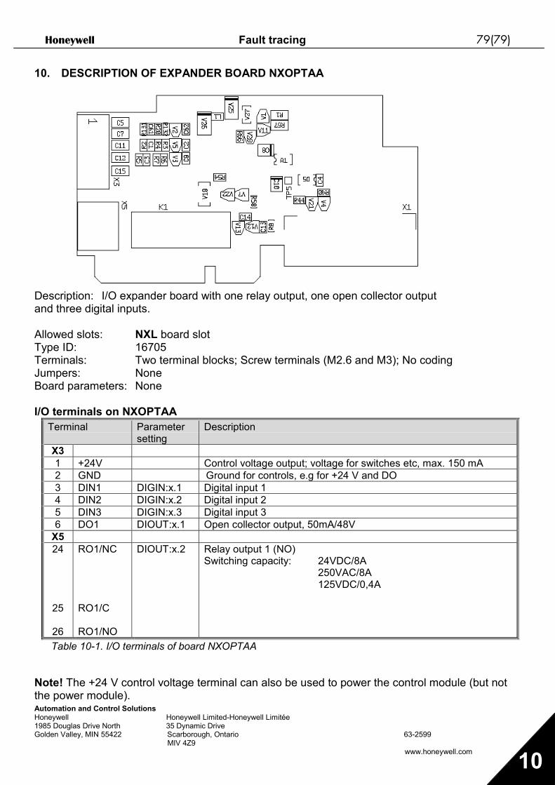
Honeywell Fault tracing 79(79)
Automation and Control SolutionsHoneywell Honeywell Limited-Honeywell Limitée1985 Douglas Drive North 35 Dynamic DriveGolden Valley, MIN 55422 Scarborough, Ontario 63-2599 MIV 4Z9
www.honeywell.com 10
10. DESCRIPTION OF EXPANDER BOARD NXOPTAA
Description: I/O expander board with one relay output, one open collector outputand three digital inputs.
Allowed slots: NXL board slotType ID: 16705Terminals: Two terminal blocks; Screw terminals (M2.6 and M3); No codingJumpers: NoneBoard parameters: None
I/O terminals on NXOPTAATerminal Parameter
settingDescription
X31 +24V Control voltage output; voltage for switches etc, max. 150 mA2 GND Ground for controls, e.g for +24 V and DO3 DIN1 DIGIN:x.1 Digital input 14 DIN2 DIGIN:x.2 Digital input 25 DIN3 DIGIN:x.3 Digital input 36 DO1 DIOUT:x.1 Open collector output, 50mA/48V
X524
25
26
RO1/NC
RO1/C
RO1/NO
DIOUT:x.2 Relay output 1 (NO)Switching capacity: 24VDC/8A
250VAC/8A125VDC/0,4A
Table 10-1. I/O terminals of board NXOPTAA
Note! The +24 V control voltage terminal can also be used to power the control module (but notthe power module).

Honeywell Multi-Control Application for NXL Page 1
Honeywell Honeywell Limited-Honeywell Limitée1985 Douglas Drive North 35 Dynamic DriveGolden Valley, MIN 55422 Scarborough, Ontario 63-2599 MIV 4Z9
www.honeywell.com
1
Multi-Control Application (Software ALFIFF20) Ver. 1.02
INDEX
1. INTRODUCTION ..............................................................................................................22. CONTROL I/O ................................................................................................................33. MULTI-CONTROL APPLICATION – PARAMETER LISTS.........................................................4
3.1 Monitoring values (Control keypad: menu M1) ........................................................43.2 Basic parameters (Control keypad: Menu P2 P2.1) ............................................53.3 Input signals (Control keypad: Menu P2 P2.2)....................................................73.4 Output signals (Control keypad: Menu P2 P2.3) .................................................93.5 Drive control parameters (Control keypad: Menu P2 P2.4)...............................103.6 Prohibit frequency parameters (Control keypad: Menu P2 P2.5) ......................103.7 Motor control parameters (Control keypad: Menu P2 P2.6) ..............................113.8 Protections (Control keypad: Menu P2 P2.7) ....................................................123.9 Autorestart parameters (Control keypad: Menu P2 P2.8) .................................133.10 PID reference parameters (Control keypad: Menu P2 P2.9).............................133.11 Pump & Fan control parameters (Control keypad: Menu P2 P2.10) .................143.12 Keypad control (Control keypad: Menu K3)...........................................................153.13 System menu (Control keypad: Menu S6).............................................................153.14 Expander boards (Control keypad: Menu E7) .......................................................15
4. DESCRIPTION OF PARAMETERS .....................................................................................164.1 BASIC PARAMETERS ..........................................................................................164.2 INPUT SIGNALS ...................................................................................................214.3 OUTPUT SIGNALS ...............................................................................................254.4 DRIVE CONTROL.................................................................................................284.5 PROHIBIT FREQUENCIES...................................................................................314.6 MOTOR CONTROL...............................................................................................324.7 PROTECTIONS.....................................................................................................354.8 AUTO RESTART PARAMETERS .........................................................................434.9 PID REFERENCE PARAMETERS........................................................................444.10 PUMP AND FAN CONTROL.................................................................................494.11 KEYPAD CONTROL PARAMETERS....................................................................58
5. CONTROL SIGNAL LOGIC IN MULTI-CONTROL APPLICATION..............................................59

Page 2 Multi-Control Application for NXL Honeywell
Honeywell Honeywell Limited-Honeywell Limitée1985 Douglas Drive North 35 Dynamic DriveGolden Valley, MIN 55422 Scarborough, Ontario 63-2599 MIV 4Z9
www.honeywell.com
1
Multicontrol Application
1. IntroductionThe Multicontrol Application for NXL uses direct frequency reference from the analogue input 1 as adefault. However, a PID controller can be used e.g. in pump and fan applications, which offersversatile internal measuring and adjusting functions. This means that external devices are notnecessary. When the drive is commissioned, the only visible parameter group is B2.1 (Basicparameters). The special parameters can be browsed and edited after changing the value of par.2.1.22 (Parameter conceal).The direct frequency reference can be used for the control without the PID controller and it can beselected from the analogue inputs, fieldbus, keypad, preset speeds or motor potentiometer.Special parameters for Pump and Fan Control (Group P2.10) can be browsed and edited afterchanging the value of par 2.9.1 to 2 (Pump and fan control activated).The PID controller reference can be selected from the analogue inputs, fieldbus, PID keypadreference 1 or by enabling the PID keypad reference 2 via digital input. The PID controller actualvalue can be selected from the analogue inputs, fieldbus or the actual values of the motor. PIDcontroller can also be used when the frequency converter is controlled via fieldbus or the controlkeypad.
• Digital inputs DIN2, DIN3, (DIN4) and optional dig. inputs DIE1, DIE2, DIE3 are freelyprogrammable.
• Internal and optional digital/relay and analogue outputs are freely programmable.• Analogue input 1 can be programmed as current input, voltage input or digital input DIN4.
NOTE! If the analogue input 1 has been programmed as DIN4 with parameter 2.2.6 (AI1 SignalRange), check that the jumper selections (Figure 1- 1) are correct.
Additional functions:• The PID controller can be used from control places I/O, keypad and fieldbus• Sleep function• Actual value supervision function: fully programmable; off, warning, fault• Programmable Start/Stop and Reverse signal logic• Reference scaling• 2 Preset speeds• Analogue input range selection, signal scaling, inversion and filtering• Frequency limit supervision• Programmable start and stop functions• DC-brake at start and stop• Prohibit frequency area• Programmable U/f curve and U/f optimisation• Adjustable switching frequency• Autorestart function after fault• Protections and supervisions (all fully programmable; off, warning, fault):
• Current input fault• External fault• Output phase• Under voltage• Earth fault
• Motor thermal, stall and underload protection• Thermistor• Fieldbus communication• Option board

Honeywell Multi-Control Application for NXL Page 3
Honeywell Honeywell Limited-Honeywell Limitée1985 Douglas Drive North 35 Dynamic DriveGolden Valley, MIN 55422 Scarborough, Ontario 63-2599 MIV 4Z9
www.honeywell.com
1
2. Control I/O
Terminal Signal Description1 +10Vref Reference output Voltage for potentiometer, etc.2 AI1+ Analogue input, voltage range
0—10V DC.Voltage input frequency referenceCan be programmed as DIN4
3 AI1- I/O Ground Ground for reference and controls4 AI2+5 AI2-
Analogue input, voltage range0—10V DC, or current range0/4—20mA
Current input frequency reference(programmable)
6 +24V Control voltage output Voltage for switches, etc. max 0.1 A7 GND I/O ground Ground for reference and controls8 DIN1 Start forward Contact closed = start forward9 DIN2 Start reverse (programmable) Contact closed = start reverse
10 DIN3 Multi-step speed selection 1(programmable)
Contact closed = multi-step speed
11 GND I/O ground Ground for reference and controls
18 AO1+19 AO1-
Output frequencyAnalogue output
ProgrammableRange 0—20 mA/RL, max. 500Ω
A RS 485 Serial bus Termination resistor is internally connectedwitha jumper
B RS 485 Serial bus Termination resistor is internally connectedwitha jumper
21 RO122 RO123 RO1
Relay output 1FAULT
Programmable
Table 1- 1. Multicontrol application default I/O configuration (with 2-wire transmitter).
Terminal Signal Description1 +10Vref Reference output Voltage for potentiometer, etc.2 AI1+
orDIN 4
Analogue input, voltage range0—10V DC
Voltage input frequency referenceCan be programmed as DIN4
3 AI1- I/O Ground Ground for reference and controls4 AI2+5 AI2-
Analogue input, current range0—20mA
Current input frequency reference
6 + 24 V Control voltage outputTable 1- 2. The programming of AI1 as DIN4
Referencepotentiometer
mA

Page 4 Multi-Control Application for NXL Honeywell
Honeywell Honeywell Limited-Honeywell Limitée1985 Douglas Drive North 35 Dynamic DriveGolden Valley, MIN 55422 Scarborough, Ontario 63-2599 MIV 4Z9
www.honeywell.com
1
3. Multi-Control Application – Parameter listsOn the next pages you will find the lists of parameters within the respective parametergroups. The parameter descriptions are given on pages 16 to 43.
Column explanations:
Code = Location indication on the keypad; Shows the operator the present param. numberParameter = Name of parameterMin = Minimum value of parameterMax = Maximum value of parameterUnit = Unit of parameter value; Given if availableDefault = Value preset by factoryCust = Customer’s own settingID = ID number of the parameter (used with PC tools) = On the parameter code: parameter value can only be changed after the FC has
been stopped.
3.1 Monitoring values (Control keypad: menu M1)The monitoring values are the actual values of parameters and signals as well as statusesand measurements. Monitoring values cannot be edited.See NXL User’s Manual, Chapter 7.3.1 for more information.
Code Parameter Unit ID DescriptionV1.1 Output frequency Hz 1 Frequency to the motorV1.2 Frequency reference Hz 25V1.3 Motor speed rpm 2 Calculated motor speedV1.4 Motor current A 3 Measured motor current
V1.5 Motor torque % 4 Calculated actual torque/nominal torque ofthe unit
V1.6 Motor power % 5 Calculated actual power/nominal power of theunit
V1.7 Motor voltage V 6 Calculated motor voltageV1.8 DC-link voltage V 7 Measured DC-link voltageV1.9 Unit temperature ºC 8 Heat sink temperature
V1.10 Analogue input 1 V 13 AI1V1.11 Analogue input 2 mA 14 AI2V1.12 Analogue output current mA 26 AO1V1.13 Analogue output current 1, expander board mA 31V1.14 Analogue output current 2, expander board mA 32V1.15 DIN1, DIN2, DIN3 15 Digital input statusesV1.16 DIE1, DIE2, DIE3 33 I/O expander board: Digital input statusesV1.17 RO1 34 Relay output 1 statusV1.18 ROE1, ROE2, ROE3 35 I/O exp. board: Relay output statusesV1.19 DOE 1 36 I/O exp. board: Digital output 1 statusV1.20 PID Reference % 20 In percent of the maximum process referenceV1.21 PID Actual value % 21 In percent of the maximum actual valueV1.22 PID Error value % 22 In percent of the maximum error valueV1.23 PID Output % 23 In percent of the maximum output value
Table 1- 3. Monitoring values

Honeywell Multi-Control Application for NXL Page 5
Honeywell Honeywell Limited-Honeywell Limitée1985 Douglas Drive North 35 Dynamic DriveGolden Valley, MIN 55422 Scarborough, Ontario 63-2599 MIV 4Z9
www.honeywell.com
1
3.2 Basic parameters (Control keypad: Menu P2 P2.1)Code Parameter Min Max Unit Default Cust ID NoteP2.1.1 Min frequency 0,00 Par. 2.1.2 Hz 0,00 101
P2.1.2 Max frequency Par. 2.1.1 320,00 Hz 50,00 102
NOTE: If fmax > than themotor synchronous speed,check suitability for motorand drive system
P2.1.3 Acceleration time 1 0,1 3000,0 s 1,0 103P2.1.4 Deceleration time 1 0,1 3000,0 s 1,0 104
P2.1.5 Current limit 0,1 x IL 2,5 x IL A 1,5 x IL 107
NOTE: Formulas applyapproximately forfrequency converters up toMF3. For greater sizes,consult the factory.
P2.1.6 Nominal voltage ofthe motor 180 690 V NXL2:230v
NXL5:400v 110
P2.1.7 Nominal frequencyof the motor 30,00 320,00 Hz 50,00 111 Check the rating plate of
the motor
P2.1.8 Nominal speed ofthe motor 300 20 000 rpm 1440 112
The default applies for a 4-pole motor and a nominalsize frequency converter.
P2.1.9 Nominal current ofthe motor 1 x IL 2,5 x IL A IL 113 Check the rating plate of
the motor
P2.1.10 Motor cosϕ 0,30 1,00 0,85 120 Check the rating plate ofthe motor
P2.1.11 Start function 0 1 0 505 0=Ramp1=Flying start
P2.1.12 Stop function 0 1 0 506 0=Coasting1=Ramp
P2.1.13 U/f optimisation 0 1 0 109 0=Not used1=Automatic torque boost
P2.1.14 I/O reference 0 4 0 117
0=AI11=AI22=Keypad reference3=Fieldbus reference (FBSpeedReference)4=Motor potentiometer
P2.1.15 AI2 signal range 1 4 2 390
Not used if AI2 Custommin <> 0% or AI2 custommax. <> 100%1=0—20 mA2=4—20 mA3=0V – 10V4=2V – 10V
P2.1.16 Analogue outputfunction 0 12 1 307
0=Not used1=Output freq. (0—fmax)2=Freq. reference (0—fmax)3=Motor speed (0—Motor
nominal speed)4=Output current (0—
InMotor)5=Motor torque (0—
TnMotor)6=Motor power (0—PnMotor)7=Motor voltage (0—
UnMotor)8=DC-link volt (0—UnMotor)9=PI controller ref. value10=PI contr. act. value 111=PI contr. error value12=PI controller output

Page 6 Multi-Control Application for NXL Honeywell
Honeywell Honeywell Limited-Honeywell Limitée1985 Douglas Drive North 35 Dynamic DriveGolden Valley, MIN 55422 Scarborough, Ontario 63-2599 MIV 4Z9
www.honeywell.com
1
P2.1.17 DIN2 function 0 10 1 319
0=Not used1=Start Reverse
(DIN1=Start forward)2=Reverse (DIN1=Start)3=Stop pulse (DIN1=Start
pulse)4=External fault, cc5=External fault, oc6=Run enable7=Preset speed 28= Motor pot. UP (cc)9= Disable PID (Direct
freq. reference)10=Interlock 2
P2.1.18 DIN3 function 0 13 6 301
0=Not used1=Reverse2=External fault, cc3=External fault, oc4=Fault reset5=Run enable6=Preset speed 17=Preset speed 28=DC-braking command9=Motor pot. UP (cc)10=Motor pot. DOWN (cc)11=Disable PID (Direct
freq. reference)12=PID Keypad ref. 2
selection13=Interlock 3
P2.1.19 Preset speed 1 0,00 Par. 2.1.2 Hz 10,00 105P2.1.20 Preset speed 2 0,00 Par. 2.1.2 Hz 50,00 106
P2.1.21 Automatic restart 0 1 0 731 0=Not used1=Used
P2.1.22 Parameter conceal 0 1 1 115
0=All parameters andmenus visible
1=Only group P2.1 andmenus M1 to H5 visible
Table 1- 4. Basic parameters B2.1

Honeywell Multi-Control Application for NXL Page 7
Honeywell Honeywell Limited-Honeywell Limitée1985 Douglas Drive North 35 Dynamic DriveGolden Valley, MIN 55422 Scarborough, Ontario 63-2599 MIV 4Z9
www.honeywell.com
1
3.3 Input signals (Control keypad: Menu P2 P2.2)Code Parameter Min Max Unit Default Cust ID Note
P2.2.1 Expander boardDIE1 function 0 12 7 368
0=Not used1=Reverse2=External fault, cc3=External fault, oc4=Fault reset5=Run enable6=Preset speed 17=Preset speed 28=DC-braking command9=Motor pot. UP (cc)10=Motor pot. DOWN
(cc)11=Disable PID (PID
control selection)12=PID Keypad ref. 2
selection
P2.2.2 Expander boardDIE2 function 0 12 4 330 See above
P2.2.3 Expander boardDIE3 function 0 12 11 369 See above
P2.2.4 DIN4 function (AI1) 0 12 2 499 Used if P2.2.6 = 0See the selections above
P2.2.5 AI1 signalselection 0 10 377
10=AI1 (1=Local, 0=input1)
11=AI2 (1=Local, 1=input 2)
20=Exp. AI1(2=exp.board0=input 1)
21=Exp AI2(2=exp.board1=input 2)
P2.2.6 AI1 signal range 1 4 3 379
0=Digital input 41=0mA – 20mA (MF4-->)2=4mA – 20mA (MF4-->)3=0V – 10V4=2V – 10VNot used if AI2 Custommin > 0% or AI2 custommax. < 100%Note! See NXL User’smanual, chapter 7.3.6: AI1mode
P2.2.7 AI1 custom minimumsetting 0,00 100,00 % 0,00 380
P2.2.8 AI1 custommaximum setting 0,00 100,00 % 100,00 381
P2.2.9 AI1 inversion 0 1 0 387 0=Not inverted1=Inverted
P2.2.10 AI1 filter time 0,00 10,00 s 0,10 378 0=No filteringP2.2.11 AI2 signal selection 0 11 388 As par. 2.2.5

Page 8 Multi-Control Application for NXL Honeywell
Honeywell Honeywell Limited-Honeywell Limitée1985 Douglas Drive North 35 Dynamic DriveGolden Valley, MIN 55422 Scarborough, Ontario 63-2599 MIV 4Z9
www.honeywell.com
1
P2.2.12 AI2 signal range 1 4 2 390
Not used if AI2 Custommin <> 0% or AI2 custommax. <> 100%1=0—20 mA2=4—20 mA3=0V – 10V4=2V – 10V
P2.2.13 AI2 custom minimumsetting 0,00 100,00 % 0,00 391
P2.2.14 AI2 custommaximum setting 0,00 100,00 % 100,00 392
P2.2.15 AI2 inversion 0 1 0 398 0=Not inverted1=Inverted
P2.2.16 AI2 filter time 0,00 10,00 s 0,10 389 0=No filtering
P2.2.17Motor potentiometerfrequency reference
memory reset0 2 1 367
0=No reset1=Reset if stopped or
powered down2=Reset if powered down
P2.2.18 Reference scalingminimum value 0,00 P2.2.19 0,00 344
P2.2.19 Reference scalingmaximum value P2.2.18 320,00 0,00 345
P2.2.20 Keypad controlreference selection 0 5 2 121
0=AI11=AI22=Keypad reference3=Fieldbus reference
(FBSpeedreference)4=Motor potentiometer5=PID controller
P2.2.21 Fieldbus controlreference selection 0 5 3 122 See above
Table 1- 5. Input signals, I2.2CP=control placecc=closing contactoc=opening contact
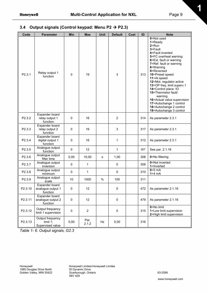
Honeywell Multi-Control Application for NXL Page 9
Honeywell Honeywell Limited-Honeywell Limitée1985 Douglas Drive North 35 Dynamic DriveGolden Valley, MIN 55422 Scarborough, Ontario 63-2599 MIV 4Z9
www.honeywell.com
1
3.4 Output signals (Control keypad: Menu P2 P2.3)Code Parameter Min Max Unit Default Cust ID Note
P2.3.1 Relay output 1function 0 19 3 313
0=Not used1=Ready2=Run3=Fault4=Fault inverted5=FC overheat warning6=Ext. fault or warning7=Ref. fault or warning8=Warning9=Reversed10=Preset speed11=At speed12=Mot. regulator active13=OP freq. limit superv.114=Control place: IO15=Thermistor fault/
warning16=Actual value supervision17=Autochange 1 control18=Autochange 2 control19=Autochange 3 control
P2.3.2Expander boardrelay output 1
function0 16 2 314 As parameter 2.3.1
P2.3.3Expander boardrelay output 2
function0 16 3 317 As parameter 2.3.1
P2.3.4Expander boarddigital output 1
function0 16 1 312 As parameter 2.3.1
P2.3.5 Analogue outputfunction 0 12 1 307 See par. 2.1.16
P2.3.6 Analogue outputfilter time 0,00 10,00 s 1,00 308 0=No filtering
P2.3.7 Analogue outputinversion 0 1 0 309 0=Not inverted
1=Inverted
P2.3.8 Analogue outputminimum 0 1 0 310 0=0 mA
1=4 mA
P2.3.9 Analogue outputscale 10 1000 % 100 311
P2.3.10Expander board
analogue output 1function
0 12 0 472 As parameter 2.1.16
P2.3.11Expander board
analogue output 2function
0 12 0 479 As parameter 2.1.16
P2.3.12 Output frequencylimit 1 supervision 0 2 0 315
0=No limit1=Low limit supervision2=High limit supervision
P2.3.13Output frequency
limit 1;Supervised value
0,00 Par.2.1.2 Hz 0,00 316
Table 1- 6. Output signals, G2.3

Page 10 Multi-Control Application for NXL Honeywell
Honeywell Honeywell Limited-Honeywell Limitée1985 Douglas Drive North 35 Dynamic DriveGolden Valley, MIN 55422 Scarborough, Ontario 63-2599 MIV 4Z9
www.honeywell.com
1
3.5 Drive control parameters (Control keypad: Menu P2 P2.4)Code Parameter Min Max Unit Default Cust ID Note
P2.4.1 Ramp 1 shape 0,0 10,0 s 0,0 500 0=Linear>0=S-curve ramp time
P2.4.2 Brake chopper 0 3 0 504
0=Disabled1=Used in Run state3=Used in Run and Stop
stateP2.4.3 DC braking current 0,15 x In 1,5 x In A Varies 507
P2.4.4 DC braking timeat stop 0,00 600,00 s 0,00 508 0=DC brake is off at stop
P2.4.5Frequency to startDC braking during
ramp stop0,10 10,00 Hz 1,50 515
P2.4.6 DC braking timeat start 0,00 600,00 s 0,00 516 0=DC brake is off at start
P2.4.7 Flux brake 0 1 0 520 0=Off1=On
P2.4.8 Flux braking current 0,0 Varies A 0,0 519Table 1- 7. Drive control parameters, D2.4
3.6 Prohibit frequency parameters (Control keypad: Menu P2 P2.5)Code Parameter Min Max Unit Default Cust ID Note
P2.5.1 Prohibit frequencyrange 1 low limit 0,0 Par.
2.5.2 Hz 0,0 509 0=Not used
P2.5.2 Prohibit frequencyrange 1 high limit 0,0 Par.
2.1.2 Hz 0,0 510 0=Not used
P2.5.3Prohibit frequencies
acc./dec. rampscaling
0,1 10,0 Times 1,0 518
Multiplier of the currentlyselected ramp timebetween prohibitfrequency limits
Table 1- 8. Prohibit frequency parameters, G2.5

Honeywell Multi-Control Application for NXL Page 11
Honeywell Honeywell Limited-Honeywell Limitée1985 Douglas Drive North 35 Dynamic DriveGolden Valley, MIN 55422 Scarborough, Ontario 63-2599 MIV 4Z9
www.honeywell.com
1
3.7 Motor control parameters (Control keypad: Menu P2 P2.6)Code Parameter Min Max Unit Default Cust ID Note
P2.6.1 Motor control mode 0 1 0 600 0=Frequency control1=Speed control
P2.6.2 U/f ratio selection 0 3 0 108
0=Linear1=Squared2=Programmable3=Linear with flux optim.
P2.6.3 Field weakeningpoint 30,00 320,00 Hz 50,00 602
P2.6.4 Voltage at fieldweakening point 10,00 200,00 % 100,00 603 n% x Unmot
P2.6.5 U/f curve midpointfrequency 0,00 par.
P2.6.3 Hz 50,00 604
P2.6.6 U/f curve midpointvoltage 0,00 100,00 % 100,00 605
n% x UnmotParameter max. value =par. 2.6.4
P2.6.7 Output voltage atzero frequency 0,00 40,00 % 0,00 606 n% x Unmot
P2.6.8 Switching frequency 1,0 16,0 kHz 6,0 601 Depends on kW
P2.6.9 Overvoltagecontroller 0 1 1 607 0=Not used
1=Used
P2.6.10 Undervoltagecontroller 0 1 1 608 0=Not used
1=Used
Table 1- 9. Motor control parameters, G2.6

Page 12 Multi-Control Application for NXL Honeywell
Honeywell Honeywell Limited-Honeywell Limitée1985 Douglas Drive North 35 Dynamic DriveGolden Valley, MIN 55422 Scarborough, Ontario 63-2599 MIV 4Z9
www.honeywell.com
1
3.8 Protections (Control keypad: Menu P2 P2.7)Code Parameter Min Max Unit Default Cust ID Note
P2.7.1 Response to 4mAreference fault 0 3 0 700
0=No response1=Warning2=Fault,stop acc. to 2.1.123=Fault,stop by coasting
P2.7.2 Response toexternal fault 0 3 2 701
P2.7.3 Response toundervoltage fault 1 3 2 727
P2.7.4 Output phasesupervision 0 3 2 702
P2.7.5 Earth fault protection 0 3 2 703
P2.7.6 Thermal protectionof the motor 0 3 2 704
0=No response1=Warning2=Fault,stop acc. to 2.1.123=Fault,stop by coasting
P2.7.7 Motor ambienttemperature factor –100,0 100,0 % 0,0 705
P2.7.8 Motor cooling factorat zero speed 0,0 150,0 % 40,0 706
P2.7.9 Motor thermal timeconstant 1 200 min 45 707
P2.7.10 Motor duty cycle 0 100 % 100 708P2.7.11 Stall protection 0 3 1 709 As par. 2.7.1
P2.7.12 Stall current limit 0,1 Inmotor x 2 A Inmotorx1.3 710
P2.7.13 Stall time limit 1,00 120,00 s 15,00 711P2.7.14 Stall frequency limit 1,0 P 2.1.2 Hz 25,0 712P2.7.15 Underload protection 0 3 0 713 As par. 2.7.1
P2.7.16 Underload curve atnominal frequency 10,0 150,0 % 50,0 714
P2.7.17 Underload curve atzero frequency 5,0 150,0 % 10,0 715
P2.7.18 Underloadprotection time limit 2,00 600,00 s 20,00 716
P2.7.19 Response tothermistor fault 0 3 0 732 As par. 2.7.1
P2.7.20 Response tofieldbus fault 0 3 2 733 As par. 2.7.1
P2.7.21 Response to slotfault 0 3 2 734 As par. 2.7.1
P2.7.22 Actual valuesupervision 0 4 0 735
0=No response1=Warning if below limit2=Warning if above limit3=Fault, if below limit4=Fault, if above limit
P2.7.23 Actual valuesupervision limit 0,0 100,0 % 10,0 736
P2.7.24 Actual valuesupervision delay 0 3600 s 5 737
Table 1- 10. Protections, G2.7
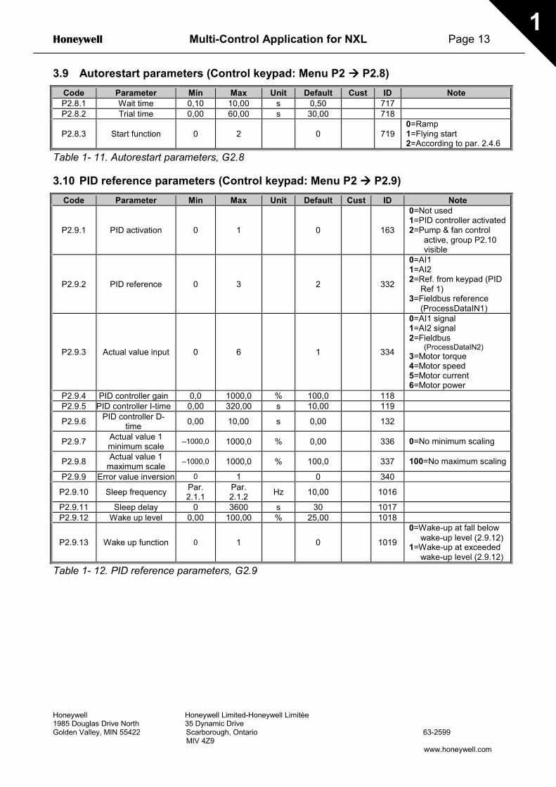
Honeywell Multi-Control Application for NXL Page 13
Honeywell Honeywell Limited-Honeywell Limitée1985 Douglas Drive North 35 Dynamic DriveGolden Valley, MIN 55422 Scarborough, Ontario 63-2599 MIV 4Z9
www.honeywell.com
1
3.9 Autorestart parameters (Control keypad: Menu P2 P2.8)Code Parameter Min Max Unit Default Cust ID NoteP2.8.1 Wait time 0,10 10,00 s 0,50 717P2.8.2 Trial time 0,00 60,00 s 30,00 718
P2.8.3 Start function 0 2 0 7190=Ramp1=Flying start2=According to par. 2.4.6
Table 1- 11. Autorestart parameters, G2.8
3.10 PID reference parameters (Control keypad: Menu P2 P2.9)Code Parameter Min Max Unit Default Cust ID Note
P2.9.1 PID activation 0 1 0 163
0=Not used1=PID controller activated2=Pump & fan control
active, group P2.10visible
P2.9.2 PID reference 0 3 2 332
0=AI11=AI22=Ref. from keypad (PID
Ref 1)3=Fieldbus reference
(ProcessDataIN1)
P2.9.3 Actual value input 0 6 1 334
0=AI1 signal1=AI2 signal2=Fieldbus
(ProcessDataIN2)3=Motor torque4=Motor speed5=Motor current6=Motor power
P2.9.4 PID controller gain 0,0 1000,0 % 100,0 118P2.9.5 PID controller I-time 0,00 320,00 s 10,00 119
P2.9.6 PID controller D-time 0,00 10,00 s 0,00 132
P2.9.7 Actual value 1minimum scale –1000,0 1000,0 % 0,00 336 0=No minimum scaling
P2.9.8 Actual value 1maximum scale –1000,0 1000,0 % 100,0 337 100=No maximum scaling
P2.9.9 Error value inversion 0 1 0 340
P2.9.10 Sleep frequency Par.2.1.1
Par.2.1.2 Hz 10,00 1016
P2.9.11 Sleep delay 0 3600 s 30 1017P2.9.12 Wake up level 0,00 100,00 % 25,00 1018
P2.9.13 Wake up function 0 1 0 1019
0=Wake-up at fall belowwake-up level (2.9.12)
1=Wake-up at exceededwake-up level (2.9.12)
Table 1- 12. PID reference parameters, G2.9

Page 14 Multi-Control Application for NXL Honeywell
Honeywell Honeywell Limited-Honeywell Limitée1985 Douglas Drive North 35 Dynamic DriveGolden Valley, MIN 55422 Scarborough, Ontario 63-2599 MIV 4Z9
www.honeywell.com
1
3.11 Pump & Fan control parameters (Control keypad: Menu P2 P2.10)NOTE! Group P2.10 is visible only if the value of par 2.9.1 is set to 2.
Code Parameter Min Max Unit Default Cust ID Note
P2.10.1 Number of auxiliarydrives 0 3 1 1001
P2.10.2 Start delay,auxiliary drives 0,0 300,0 s 4,0 1010
P2.10.3 Stop delay,auxiliary drives 0,0 300,0 s 2,0 1011
P2.10.4 Autochange 0 4 0 1027
0=Not used1= Autochange with aux
pumps2= Autochange with Freq.
conv & aux pumps3= Autochange and
interlocks (aux pumps)4= Autochange and
interlocks (Freq. conv &aux pumps)
NOTE! If interlocks areused, DIN 1 isautomatically the intelockfor Autochange output 1.Interlocks for Autochangeoutput 2 & 3 can beselected with par 2.1.17 &2.1.18. INTERLOCKINPUTS ARE ALSOSTART COMMANDS FORFREQUENCYCONVERTER! ( If one ofthese interlock inputs isactive --> first motor isstarted)
P2.10.5 Autochange interval 0,0 3000,0 h 48,0 10290,0=TEST=40 sElapsed time forautochange
P2.10.6Autochange;
Maximum number ofauxiliary drives
0 3 1 1030 Autochange level forauxiliary drives
P2.10.7 Autochangefrequency limit 0,00 par. 2.1.2 Hz 25,00 1031 Autochange frequency level
for variable speed driveTable 1- 13. Pump and fan control parameters

Honeywell Multi-Control Application for NXL Page 15
Honeywell Honeywell Limited-Honeywell Limitée1985 Douglas Drive North 35 Dynamic DriveGolden Valley, MIN 55422 Scarborough, Ontario 63-2599 MIV 4Z9
www.honeywell.com
1
3.12 Keypad control (Control keypad: Menu K3)The parameters for the selection of control place and direction on the keypad are listedbelow. See the Keypad control menu in the NXL User’s Manual.
Code Parameter Min Max Unit Default Cust ID Note
P3.1 Control place 1 3 1 1251 = I/O terminal2 = Keypad3 = Fieldbus
R3.2 Keypad reference Par.2.1.1
Par.2.1.2 Hz
P3.3 Direction (onkeypad) 0 1 0 123 0 = Forward
1 = Reverse
R3.4 Stop button 0 1 1 114
0=Limited function of Stopbutton
1=Stop button alwaysenabled
R3.5 PID reference 0,00 100,00 % 0,00R3.6 PID reference 2 0,00 100,00 % 0,00 Selected with digital inputs
Table 1- 14. Keypad control parameters, M3
3.13 System menu (Control keypad: Menu S6)For parameters and functions related to the general use of the frequency converter, such ascustomised parameter sets or information about the hardware and software, see Chapter7.3.6 in the NXL User’s Manual.
3.14 Expander boards (Control keypad: Menu E7)The E7 menu shows the expander boards attached to the control board and board-relatedinformation. For more information, see Chapter 7.3.7 in the NXL User’s Manual.
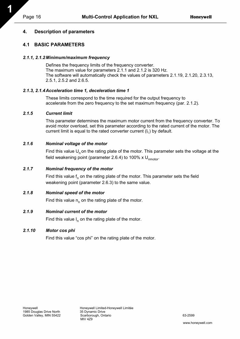
Page 16 Multi-Control Application for NXL Honeywell
Honeywell Honeywell Limited-Honeywell Limitée1985 Douglas Drive North 35 Dynamic DriveGolden Valley, MIN 55422 Scarborough, Ontario 63-2599 MIV 4Z9
www.honeywell.com
1
4. Description of parameters
4.1 BASIC PARAMETERS
2.1.1, 2.1.2Minimum/maximum frequencyDefines the frequency limits of the frequency converter.The maximum value for parameters 2.1.1 and 2.1.2 is 320 Hz.The software will automatically check the values of parameters 2.1.19, 2.1.20, 2.3.13,2.5.1, 2.5.2 and 2.6.5.
2.1.3, 2.1.4Acceleration time 1, deceleration time 1These limits correspond to the time required for the output frequency toaccelerate from the zero frequency to the set maximum frequency (par. 2.1.2).
2.1.5 Current limitThis parameter determines the maximum motor current from the frequency converter. Toavoid motor overload, set this parameter according to the rated current of the motor. Thecurrent limit is equal to the rated converter current (IL) by default.
2.1.6 Nominal voltage of the motorFind this value Un on the rating plate of the motor. This parameter sets the voltage at thefield weakening point (parameter 2.6.4) to 100% x Unmotor.
2.1.7 Nominal frequency of the motorFind this value fn on the rating plate of the motor. This parameter sets the fieldweakening point (parameter 2.6.3) to the same value.
2.1.8 Nominal speed of the motorFind this value nn on the rating plate of the motor.
2.1.9 Nominal current of the motorFind this value In on the rating plate of the motor.
2.1.10 Motor cos phiFind this value “cos phi” on the rating plate of the motor.

Honeywell Multi-Control Application for NXL Page 17
Honeywell Honeywell Limited-Honeywell Limitée1985 Douglas Drive North 35 Dynamic DriveGolden Valley, MIN 55422 Scarborough, Ontario 63-2599 MIV 4Z9
www.honeywell.com
1
2.1.11 Start function
Ramp:0 The frequency converter starts from 0 Hz and accelerates to maximum
frequency within the set acceleration time. (Load inertia or starting friction maycause prolonged acceleration times).
Flying start:1 The frequency converter is able to start into a running motor by applying a
small torque to motor and searching for the frequency corresponding to thespeed the motor is running at. The searching starts from the maximumfrequency towards the actual frequency until the correct value is detected.Thereafter, the output frequency will be increased/decreased to the setreference value according to the set acceleration/deceleration parameters.
Use this mode if the motor is coasting when the start command is given. Withthe flying start, it is possible to ride through short mains voltage interruptions.
2.1.12 Stop function
Coasting:0 The motor coasts to a halt without control from the frequency converter after
the Stop command.
Ramp:1 After the Stop command, the speed of the motor is decelerated according to
the set deceleration parameters.If the regenerated energy is high it may be necessary to use an external braking resistor for faster deceleration.

Page 18 Multi-Control Application for NXL Honeywell
Honeywell Honeywell Limited-Honeywell Limitée1985 Douglas Drive North 35 Dynamic DriveGolden Valley, MIN 55422 Scarborough, Ontario 63-2599 MIV 4Z9
www.honeywell.com
1
2.1.15 U/f optimisation
0 Not used
1 Automatic torque boostThe voltage to the motor changes automatically which makes themotor produce sufficient torque to start and run at lowfrequencies. The voltage increase depends on the motor type andpower. Automatic torque boost can be used in applications wherestarting torque due to starting friction is high, e.g. in conveyors.
NOTE! In high torque – low speed applications – it is likely that the motorwill overheat. If the motor has to run a prolonged time under theseconditions, special attention must be paid to cooling the motor. Useexternal cooling for the motor if the temperature tends to rise toohigh.
2.1.14 I/O Reference selectionDefines the selected frequency reference source when the drive is controlled from theI/O terminal.
0 AI1 reference (terminals 2 and 3, e.g. potentiometer)1 AI2 reference (terminals 5 and 6, e.g. transducer)2 Keypad reference (parameter 3.2)3 Reference from Fieldbus (FBSpeedReference)4 Motor potentiometer reference
2.1.15 AI2 (Iin) signal range1 Signal range 0…20 mA2 Signal range 4…20 mA
Note! The selections have no effect if par. 2.2.12 > 0%, or par. 2.2.13 < 100%.
2.1.16 Analogue output functionThis parameter selects the desired function for the analogue output signal.See the table on page 5 for the parameter values.

Honeywell Multi-Control Application Page 19
Honeywell Honeywell Limited-Honeywell Limitée1985 Douglas Drive North 35 Dynamic DriveGolden Valley, MIN 55422 Scarborough, Ontario 63-2599 MIV 4Z9
www.honeywell.com
1
2.1.17 DIN2 functionThis parameter has 9 selections. If digital input DIN2 need not be used, set theparameter value to 0.
1 Start reverse2 Reverse3 Stop pulse4 External fault
Contact closed: Fault is displayed and motor stopped when the input is active5 External fault
Contact open: Fault is displayed and motor stopped when the input is not active6 Run enable
Contact open: Start of motor disabledContact closed: Start of motor enabledCoast stop if dropped during RUN
7 Preset speed 28 Motor potentiometer UP
Contact closed: Reference increases until the contact is opened.9 Disable the PID-controller (Direct frequency reference)10 Interlock 2 (can only be selected, when pump and fan control is active, P2.9.1=2)
2.1.18 DIN3 functionThis parameter has 12 selections. If digital input DIN3 need not be used, set theparameter value to 0.
1 ReverseContact open: ForwardContact closed: Reverse
2 External faultContact closed: Fault is displayed and motor stopped when the input is active
3 External faultContact open: Fault is displayed and motor stopped when the input is not active
4 Fault resetContact closed: All faults reset
5 Run enableContact open: Start of motor disabledContact closed: Start of motor enabledCoast stop if dropped during RUN
6 Preset speed 17 Preset speed 28 DC braking command
Contact closed: In Stop mode, the DC braking operates until the contact is opened. See par.2.4.3 – 2.4.6
9 Motor potentiometer UPContact closed: Reference increases until the contact is opened.
10 Motor potentiometer DOWN.Contact closed: Reference decreases until the contact is opened
11 Disable the PID-controller (Direct frequency reference)12 PID Keypad reference 2 selection13 Interlock 3 (can only be selected, when pump and fan control is active, P2.9.1=2)
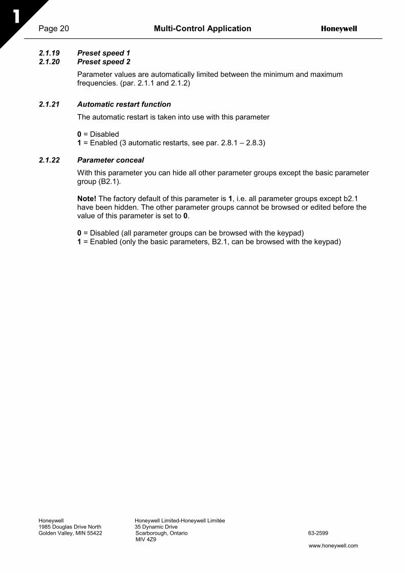
Page 20 Multi-Control Application Honeywell
Honeywell Honeywell Limited-Honeywell Limitée1985 Douglas Drive North 35 Dynamic DriveGolden Valley, MIN 55422 Scarborough, Ontario 63-2599 MIV 4Z9
www.honeywell.com
1
2.1.19 Preset speed 12.1.20 Preset speed 2
Parameter values are automatically limited between the minimum and maximumfrequencies. (par. 2.1.1 and 2.1.2)
2.1.21 Automatic restart functionThe automatic restart is taken into use with this parameter
0 = Disabled1 = Enabled (3 automatic restarts, see par. 2.8.1 – 2.8.3)
2.1.22 Parameter concealWith this parameter you can hide all other parameter groups except the basic parametergroup (B2.1).
Note! The factory default of this parameter is 1, i.e. all parameter groups except b2.1have been hidden. The other parameter groups cannot be browsed or edited before thevalue of this parameter is set to 0.
0 = Disabled (all parameter groups can be browsed with the keypad)1 = Enabled (only the basic parameters, B2.1, can be browsed with the keypad)

Honeywell Multi-Control Application Page 21
Honeywell Honeywell Limited-Honeywell Limitée1985 Douglas Drive North 35 Dynamic DriveGolden Valley, MIN 55422 Scarborough, Ontario 63-2599 MIV 4Z9
www.honeywell.com
1
4.2 INPUT SIGNALS
2.2.1 Expander board DIE1 functionThis parameter has 12 selections. If the expander board digital input DIN1 need not beused, set the parameter value to 0.
See parameter 2.1.18 for the selections.
2.2.2 Expander board DIE2 functionThe selections are the same as in parameter 2.2.1.
2.2.3 Expander board DIE3 functionThe selections are the same as in parameter 2.2.1.
2.2.4 DIN4 FunctionIf the value of par. 2.2.6 is set to 0, AI1 functions as digital input 4.The selections are the same as in parameter 2.2.1.
NOTE! If you program the analogue input as DIN4 check that the jumper selectionsof X4 are correct (see figure below).
Figure 1- 1. Jumper selections of X4 when AI1 functions as DIN4
2.2.5 AI1 signal selectionConnect the AI1 signal to the analogue input of your choice with this parameter.
Figure 1- 2. AI1 signal selection
MF2: MF3:
Jumperdin4.fh8
Voltage input; 0...10V Voltage input; 0...10V
STOP I/O term
READY
STOP I/O term
READY
nxlk29.fh8
Change
Input numberLocation indicator
Page 22 Multi-Control Application Honeywell
Honeywell Honeywell Limited-Honeywell Limitée1985 Douglas Drive North 35 Dynamic DriveGolden Valley, MIN 55422 Scarborough, Ontario 63-2599 MIV 4Z9
www.honeywell.com
1
The value of this parameter is formed of the board indicator and the respective inputterminal number. See Figure 1- 2.
Board indicator 1 = Local inputsBoard indicator 2 = Expander board inputs
Input number 0 = Input 1Input number 1 = Input 2Input number 2 = Input 3
Input number 9 = Input 10
Example:If you set the value of this parameter to 10, you have selected the local input 1 for theAI1 signal. Again, if the value is set to 21, the expander board input 2 has been selectedfor the AI1 signal.
If you want to use the values of analogue input signal for e.g. testing purposes only, youcan set the parameter value to 0 - 9. In this case, value 0 corresponds to 0%, value 1corresponds to 20% and any value between 2 and 9 corresponds to 100%.
2.2.6 AI1 signal rangeWith this parameter you can select the AI1 signal range.
0 = DIN 41 = Signal range 0…20mA (only for sizes MF4 and bigger)2 = Signal range 4…20mA (only for sizes MF4 and bigger)3 = Signal range 0…10V4 = Signal range 2…10V
Note! The selections have no effect if par. 2.2.7 > 0%, or par. 2.2.8 < 100%.
If the value of par. 2.2.6 is set to 0, AI1 functions as digital input 4.See par. 2.2.4
2.2.7 AI1 custom setting minimum2.2.8 AI1 custom setting maximum
Set the custom minimum and maximum levels for the AI1 signal within 0…10V.

Honeywell Multi-Control Application Page 23
Honeywell Honeywell Limited-Honeywell Limitée1985 Douglas Drive North 35 Dynamic DriveGolden Valley, MIN 55422 Scarborough, Ontario 63-2599 MIV 4Z9
www.honeywell.com
1
%
100%
63%
Par. 2.2.10
t [s]
N X 1 2K78
Fi l t e r e d s i g n a l
Unfiltered s i g n a l
2.2.9 AI1 signal inversionBy setting the parameter value to 1 the AI1 signal inversion takes place.
2.2.10 AI1 signal filter timeThis parameter, given a value greaterthan 0, activates the function thatfilters out disturbances from theincoming analogue Uin signal.Long filtering time makes theregulation response slower. SeeFigure 1- 3
Figure 1- 3. AI1 signal filtering
2.2.11 AI2 signal selectionConnect the AI2 signal to the analogue input of your choice with this parameter. See par.2.2.5 for the value setting procedure.
2.2.12 AI2 signal range0 Signal range 0…20 mA1 Signal range 4…20 mA
Note! The selections have no effect if par. 2.2.13 > 0%, or par. 2.2.14 < 100%.
2.2.13 AI2 custom minimum2.2.14 AI2 custom maximum
These parameters allow you to scale the input current signal between 0 and 20 mA.Cf. parameters 2.2.7 and 2.2.8.
2.2.15 Analogue input AI2 signal inversionSee corresponding parameter 2.2.9.

Page 24 Multi-Control Application Honeywell
Honeywell Honeywell Limited-Honeywell Limitée1985 Douglas Drive North 35 Dynamic DriveGolden Valley, MIN 55422 Scarborough, Ontario 63-2599 MIV 4Z9
www.honeywell.com
1
2.2.16 Analogue input AI2 signal filter timeSee corresponding parameter 2.2.10.
2.2.17 Motor potentiometer memory reset (Frequency reference)0 = No reset1 = Memory reset in stop and powerdown2 = Memory reset in powerdown
2.2.18 Reference scaling minimum value2.2.19 Reference scaling maximum value
You can choose a scaling range for the frequency reference between the Minimum andMaximum frequency. If no scaling is desired set the parameter value to 0.In the figures below, voltage input AI1 with signal range 0…10V is selected for reference.
Figure 1- 4. Left: Par. 2.1.18=0 (No reference scaling) Right: Reference scaling
2.2.20 Keypad frequency reference selectionDefines the selected reference source when the drive is controlled from the keypad
0 AI1 reference (by default AI1, terminals 2 and 3, e.g. potentiometer)1 AI2 reference (by default AI2, terminals 5 and 6, e.g. transducer)2 Keypad reference (parameter 3.2)3 Reference from Fieldbus (FBSpeedReference)4 Motor potentiometer reference5 PID-controller reference
2.2.21 Fieldbus frequency reference selectionDefines the selected reference source when the drive is controlled from the fieldbus. Forthe parameter values, see par. 2.2.20.
0
NX12K35
0
Outputfrequency
Max freq. par 2.1.2
Min freq. par 2.1.1
Outputfrequency
Max freq. par 2.1.2
Min freq. par 2.1.1Analogueinput [%]
Analogueinput [%]
Outputfrequency
Max freq. par 2.1.2
Min freq. par 2.1.1
Outputfrequency
Max freq. par 2.1.2
Min freq. par 2.1.1Analogueinput [%]
Analogueinput [%]
Par. 2.2.19
Par. 2.2.18

Honeywell Multi-Control Application Page 25
Honeywell Honeywell Limited-Honeywell Limitée1985 Douglas Drive North 35 Dynamic DriveGolden Valley, MIN 55422 Scarborough, Ontario 63-2599 MIV 4Z9
www.honeywell.com
1
4.3 OUTPUT SIGNALS
2.3.1 Relay output 1 function2.3.2 Expander board relay output 1 function2.3.3 Expander board relay output 2 function2.3.4 Expander board digital output 1 function
Setting value Signal content0 = Not used Out of operation
Relay output RO1 and expander boardprogrammable relays (RO1, RO2) are activatedwhen:
1 = Ready The frequency converter is ready to operate
2 = Run The frequency converter operates (motor is running)
3 = Fault A fault trip has occurred
4 = Fault inverted A fault trip not occurred5 = Frequency converter overheat
warning The heat-sink temperature exceeds +70°C
6 = External fault or warning Fault or warning depending on par. 2.7.2
7 = Reference fault or warning Fault or warning depending on par. 2.7.1- if analogue reference is 4—20 mA and signal is <4mA
8 = Warning Always if a warning exists
9 = Reversed The reverse command has been selected
10 = Preset speed A preset speed has been selected
11 = At speed The output frequency has reached the set reference
12 = Motor regulator activated Overvoltage or overcurrent regulator was activated
13 = Output frequency limit 1supervision
The output frequency goes outside the setsupervision low limit/high limit (see parameters2.3.12 and 2.3.13 below)
14 = Control from I/O terminals Selected control place (Menu K3; par. 3.1) is “I/Oterminal”
15 = Thermistor fault or warningThe thermistor input of option board indicatesovertemperature. Fault or warning depending onparameter 2.7.19.
16 = Actual value supervision active Parameters 2.7.22 – 2.7.24
17 = Autochange 1 control Pump 1 control, parameters 2.10.1 – 2.10.7
18 = Autochange 2 control Pump 2 control, parameters 2.10.1 – 2.10.7
19 = Autochange 3 control Pump 3 control, parameters 2.10.1 – 2.10.7
Table 1- 15. Output signals via RO1 and expander board RO1, RO2 and DO1.
2.3.5 Analogue output functionThis parameter selects the desired function for the analogue output signal.See the table on page 5 for the parameter values.

Page 26 Multi-Control Application Honeywell
Honeywell Honeywell Limited-Honeywell Limitée1985 Douglas Drive North 35 Dynamic DriveGolden Valley, MIN 55422 Scarborough, Ontario 63-2599 MIV 4Z9
www.honeywell.com
1
%
t [s]
NX12K16
Filtered signal
Unfiltered signal
Par. 2.3.6
1.00
20 mA
4 mA
10 mA
0.50 mA
12 mA
NX12K17
Param. 2.3.9= 200%
Param. 2.3.9= 100%
Param. 2.3.9= 50%
2.3.6 Analogue output filter timeDefines the filtering time of the analogueoutput signal.If you set value 0 for this parameter, nofiltering takes place.
Figure 1- 5. Analogue output filtering
2.3.7 Analogue output invertInverts the analogue output signal:
Maximum output signal = 0 %Minimum output signal = Maximum set value (parameter 2.3.9)
0 Not inverted1 Inverted
See parameter 2.3.9 below.
Figure 1- 6. Analogue output invert
2.3.8 Analogue output minimumSets the signal minimum to either 0 mA or 4 mA (living zero). Note the difference in theanalogue output scaling in parameter 2.3.9.

Honeywell Multi-Control Application Page 27
Honeywell Honeywell Limited-Honeywell Limitée1985 Douglas Drive North 35 Dynamic DriveGolden Valley, MIN 55422 Scarborough, Ontario 63-2599 MIV 4Z9
www.honeywell.com
1
1.00
20 mA
4 mA
10 mA
0.50 mA
nxlk49.fh8
12 mA
Par. 2.3.8 = 1
Par. 2.3.8 = 0
Par. 2.3.9=200% Par. 2.3.9=
100%
Par. 2.3.9=50%
Analogueoutputcurrent
Max. value of signalselected by param. 2.1.16
2.3.9 Analogue output scaleScaling factor for the analogue output.
Signal Max. value of the signalOutput frequency 100% x fmaxMotor speed 100% x Motor nom. speedOutput current 100% x InMotorMotor torque 100% x TnMotorMotor power 100% x PnMotorMotor voltage 100% x UnmotorDC-link voltagePI-ref. valuePI act. value 1PI error valuePI output
1000 V100% x ref. value max.100% x actual value max.100% x error value max.100% x output max.
Table 1- 16. Analogue output scaling Figure 1- 7. Analogue output scaling
2.3.10 Expander board analogue output 1 function2.3.11 Expander board analogue output 2 function
These parameters select the desired functions for the expander board analogue outputsignals. See par. 2.1.16 for the parameter values.
2.3.12 Output frequency limit 1 supervision function
0 No supervision1 Low limit supervision2 High limit supervision
If the output frequency goes under/over the set limit (par. 2.3.13) this function generatesa warning message via the relay outputs depending on the settings of parameters 2.3.1– 2.3.4.
2.3.13 Output frequency limit 1 supervised valueSelects the frequency value supervised by parameter 2.3.12.
Figure 1- 8. Output frequency supervision
f[Hz]
t
21 RO122 RO123 RO1
21 RO122 RO123 RO1
21 RO122 RO123 RO1
NX12K19
Example:
Par 2.3.13
Par 2.3.12 = 2
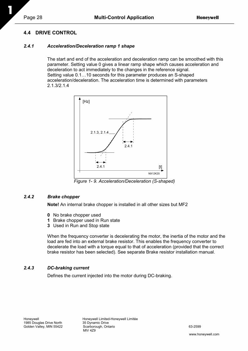
Page 28 Multi-Control Application Honeywell
Honeywell Honeywell Limited-Honeywell Limitée1985 Douglas Drive North 35 Dynamic DriveGolden Valley, MIN 55422 Scarborough, Ontario 63-2599 MIV 4Z9
www.honeywell.com
1
4.4 DRIVE CONTROL
2.4.1 Acceleration/Deceleration ramp 1 shape
The start and end of the acceleration and deceleration ramp can be smoothed with thisparameter. Setting value 0 gives a linear ramp shape which causes acceleration anddeceleration to act immediately to the changes in the reference signal.Setting value 0.1…10 seconds for this parameter produces an S-shapedacceleration/deceleration. The acceleration time is determined with parameters2.1.3/2.1.4
Figure 1- 9. Acceleration/Deceleration (S-shaped)
2.4.2 Brake chopperNote! An internal brake chopper is installed in all other sizes but MF2
0 No brake chopper used1 Brake chopper used in Run state3 Used in Run and Stop state
When the frequency converter is decelerating the motor, the inertia of the motor and theload are fed into an external brake resistor. This enables the frequency converter todecelerate the load with a torque equal to that of acceleration (provided that the correctbrake resistor has been selected). See separate Brake resistor installation manual.
2.4.3 DC-braking currentDefines the current injected into the motor during DC-braking.
2.1.3, 2.1.4
[Hz]
[t]
2.4.1
2.4.1
NX12K20

Honeywell Multi-Control Application Page 29
Honeywell Honeywell Limited-Honeywell Limitée1985 Douglas Drive North 35 Dynamic DriveGolden Valley, MIN 55422 Scarborough, Ontario 63-2599 MIV 4Z9
www.honeywell.com
1
2.4.4 DC-braking time at stopDetermines if braking is ON or OFF and the braking time of the DC-brake when themotor is stopping. The function of the DC-brake depends on the stop function, parameter2.1.12.
0 DC-brake is not used>0 DC-brake is in use and its function depends on the Stop function,
(par. 2.1.12). The DC-braking time is determined with this parameter
Par. 2.1.12 = 0 (Stop function = Coasting):
After the stop command, the motor coasts to a stop without control from the frequencyconverter.
With the DC injection, the motor can be electrically stopped in the shortest possible time,without using an optional external braking resistor.
The braking time is scaled by the frequency when the DC-braking starts. If the frequencyis greater than the nominal frequency of the motor, the set value of parameter 2.4.4determines the braking time. When the frequency is ≤10% of the nominal, the brakingtime is 10% of the set value of parameter 2.4.4.
Figure 1- 10. DC-braking time when Stop mode = Coasting.
fn fn
t t
t = 1 x Par. 2.4.4 t = 0,1 x Par. 2.4.4
NX12K21
0,1 x fn
RUNSTOP
RUNSTOP
Output frequency
Motor speed
Output frequency
Motor speed
DC-braking ON
DC-braking ON
fout fout

Page 30 Multi-Control Application Honeywell
Honeywell Honeywell Limited-Honeywell Limitée1985 Douglas Drive North 35 Dynamic DriveGolden Valley, MIN 55422 Scarborough, Ontario 63-2599 MIV 4Z9
www.honeywell.com
1
t = Par. 2.4.4
t
par. 2.4.5
NX12K23
Motor speed
Output frequency
DC-braking
RUNSTOP
fout
t
NX12K80
Par 2.4.6
RUNSTOP
Outputfrequency
Par. 2.1.12 = 1 (Stop function = Ramp):
After the Stop command, the speed ofthe motor is reduced according to theset deceleration parameters, as fastas possible, to the speed defined withparameter 2.4.5, where the DC-braking starts.
The braking time is defined withparameter 2.4.4. If high inertia exists,it is recommended to use an externalbraking resistor for fasterdeceleration. See Figure 1- 11.
Figure 1- 11. DC-braking time when Stop mode= Ramp
2.4.5 DC-braking frequency in ramp stopThe output frequency at which the DC-braking is applied. See Figure 1- 11.
2.4.6 DC-braking time at startDC-brake is activated when the startcommand is given. This parameter definesthe time before the brake is released. Afterthe brake is released, the output frequencyincreases according to the set startfunction by parameter 2.1.11. See Figure1- 12.
Figure 1- 12. DC braking time at start
2.4.7 Flux brakeThe flux braking can be set ON or OFF.
0 = Flux braking OFF1 = Flux braking ON
2.4.8 Flux braking currentDefines the flux braking current value. It can be set between 0.3 x IH (approximately) andthe Current limit.

Honeywell Multi-Control Application Page 31
Honeywell Honeywell Limited-Honeywell Limitée1985 Douglas Drive North 35 Dynamic DriveGolden Valley, MIN 55422 Scarborough, Ontario 63-2599 MIV 4Z9
www.honeywell.com
1
2.5.1 2.5.2
NX12K33
Reference [Hz]
Outputfrequency [Hz]
Par. 2.5.2
Par. 2.5.1
Par. 2.5.3 = 0,2
Par. 2.5.3 = 1,2
nxlk37.fh8
fout [Hz]
Time [s]
4.5 PROHIBIT FREQUENCIES
2.5.1 Prohibit frequency area 1; Low limit2.5.2 Prohibit frequency area 1; High limit
In some systems it may be necessaryto avoid certain frequencies because ofmechanical resonance problems. Withthese parameters it is possible to set alimit for the "skip frequency" region.See Figure 1- 13.
Figure 1- 13. Prohibit frequency area setting.
2.5.3 Acceleration/deceleration ramp speed scaling ratio between prohibit frequencylimits
Defines the acceleration/deceleration time when the output frequency is between theselected prohibit frequency range limits (parameters 2.5.1 and 2.5.2). The ramping time(selected acceleration/ deceleration time 1 or 2) is multiplied with this factor. E.g. value0.1 makes the acceleration time 10 times shorter than outside the prohibit frequencyrange limits.
Figure 1- 14. Ramp time scaling between prohibit frequencies

Page 32 Multi-Control Application Honeywell
Honeywell Honeywell Limited-Honeywell Limitée1985 Douglas Drive North 35 Dynamic DriveGolden Valley, MIN 55422 Scarborough, Ontario 63-2599 MIV 4Z9
www.honeywell.com
1
4.6 MOTOR CONTROL
2.6.1 Motor control mode
0 Frequency control: The I/O terminal and keypad references are frequencyreferences and the frequency converter controls the outputfrequency (output frequency resolution = 0.01 Hz)
1 Speed control: The I/O terminal and keypad references are speed referencesand the frequency converter controls the motor speed (accuracy± 0,5%).
2.6.2 U/f ratio selection
Linear: The voltage of the motor changes linearly with the frequency in the constant0 flux area from 0 Hz to the field weakening point where the nominal voltage is
supplied to the motor. Linear U/f ratio should be used in constant torqueapplications. See Figure 1- 15.This default setting should be used if there is no special need foranother setting.
Squared: The voltage of the motor changes following a squared curve form1 with the frequency in the area from 0 Hz to the field weakening point where
the nominal voltage is also supplied to the motor. The motor runs undermagnetised below the field weakening point and produces less torque andelectromechanical noise. Squared U/f ratio can be used in applicationswhere torque demand of the load is proportional to the square of the speed,e.g in centrifugal fans and pumps.
Figure 1- 15. Linear and squared change of motor voltage
Unpar.2.6.5
U[V]
f[Hz]
NX12K07par.2.6.3
Default: Nominalvoltage of the motor
Linear
Squared
Field weakeningpoint
Default: Nominalfrequency of themotor

Honeywell Multi-Control Application Page 33
Honeywell Honeywell Limited-Honeywell Limitée1985 Douglas Drive North 35 Dynamic DriveGolden Valley, MIN 55422 Scarborough, Ontario 63-2599 MIV 4Z9
www.honeywell.com
1
Programmable U/f curve:2 The U/f curve can be programmed with three different points. Programmable
U/f curve can be used if the other settings do not satisfy the needs of theapplication.
Figure 1- 16. Programmable U/f curve
Linear with flux optimisation:3 The frequency converter starts to search for the minimum motor current and in
order to save energy, lower the disturbance level and the noise. Can be usedin applications with constant motor load, such as fans, pumps etc.
2.6.3 Field weakening pointThe field weakening point is the output frequency at which the output voltage reachesthe set maximum value.
2.6.4 Voltage at field weakening pointAbove the frequency at the field weakening point, the output voltage remains at the setmaximum value. Below the frequency at the field weakening point, the output voltagedepends on the setting of the U/f curve parameters. See parameters 2.1.13, 2.6.2, 2.6.52.6.6 and 2.6.7 and Figure 1- 16.
When the parameters 2.1.6 and 2.1.7 (nominal voltage and nominal frequency of themotor) are set, the parameters 2.6.3 and 2.6.4 are automatically given the correspondingvalues. If you need different values for the field weakening point and the maximumoutput voltage, change these parameters after setting the parameters 2.1.6 and 2.1.7.
2.6.5 U/f curve, middle point frequencyIf the programmable U/f curve has been selected with parameter 2.6.2 this parameterdefines the middle point frequency of the curve. See Figure 1- 16.
U n P a r 2 . 6 . 4
Par. 2.6.3
U[V ]
f[Hz]
NX12K08P a r . 2 . 6 . 5 ( D e f . 5 H z )
P a r . 2 . 6 . 6 ( D e f . 1 0 % ) P a r . 2 . 6 . 7 ( D e f . 1 . 3 % )
Def a u l t : N o m i n a l volt a g e o f t h e m o t o r Field weakening point
Default: Nominalfrequency of the motor

Page 34 Multi-Control Application Honeywell
Honeywell Honeywell Limited-Honeywell Limitée1985 Douglas Drive North 35 Dynamic DriveGolden Valley, MIN 55422 Scarborough, Ontario 63-2599 MIV 4Z9
www.honeywell.com
1
2.6.6 U/f curve, middle point voltageIf the programmable U/f curve has been selected with the parameter 2.6.2 thisparameter defines the middle point voltage of the curve. See Figure 1- 16.
2.6.7 Output voltage at zero frequencyThis parameter defines the zero frequency voltage of the curve. See Figure 1- 16.
2.6.8 Switching frequencyMotor noise can be minimised using a high switching frequency. Increasing the switchingfrequency reduces the capacity of the frequency converter unit.
Switching frequency for NXL: 1…16 kHz
2.6.9 Overvoltage controller2.6.10 Undervoltage controller
These parameters allow the under-/overvoltage controllers to be switched out ofoperation. This may be useful, for example, if the mains supply voltage varies more than–15% to +10% and the application will not tolerate this over-/undervoltage. Thisregulator controls the output frequency taking the supply fluctuations into account.
Note: Over-/undervoltage trips may occur when controllers are switched out ofoperation.
0 Controller switched off1 Controller switched on
Honeywell Multi-Control Application Page 35
Honeywell Honeywell Limited-Honeywell Limitée1985 Douglas Drive North 35 Dynamic DriveGolden Valley, MIN 55422 Scarborough, Ontario 63-2599 MIV 4Z9
www.honeywell.com
1
4.7 PROTECTIONS
2.7.1 Response to 4mA reference fault0 = No response1 = Warning2 = Fault, stop mode after fault according to parameter 2.1.123 = Fault, stop mode after fault always by coasting
A warning or a fault action and message is generated if the 4…20 mA reference signalis used and the signal falls below 3.5 mA for 5 seconds or below 0.5 mA for 0.5 seconds.The information can also be programmed into relay outputs.
2.7.2 Response to external fault0 = No response1 = Warning2 = Fault, stop mode after fault according to parameter 2.1.123 = Fault, stop mode after fault always by coasting
A warning or a fault action and message is generated from the external fault signalin the programmable digital inputs. The information can also be programmed into relayoutputs.
2.7.3 Response to undervoltage fault1 = Warning2 = Fault, stop mode after fault according to parameter 2.1.123 = Fault, stop mode after fault always by coasting
For the undervoltage limits see NXL, User’s Manual, Table 4-3.Note: This protection can not be inactivated.
2.7.4 Output phase supervision0 = No response1 = Warning2 = Fault, stop mode after fault according to parameter 2.1.123 = Fault, stop mode after fault always by coasting
Output phase supervision of the motor ensures that the motor phases have anapproximately equal current.
Page 36 Multi-Control Application Honeywell
Honeywell Honeywell Limited-Honeywell Limitée1985 Douglas Drive North 35 Dynamic DriveGolden Valley, MIN 55422 Scarborough, Ontario 63-2599 MIV 4Z9
www.honeywell.com
1
2.7.5 Earth fault protection0 = No response1 = Warning2 = Fault, stop mode after fault according to parameter 2.1.123 = Fault, stop mode after fault always by coasting
Earth fault protection ensures that the sum of the motor phase currents is zero. Theovercurrent protection is always working and protects the frequency converter from earthfaults with high currents.
Parameters 2.7.6—2.7.10, Motor thermal protection:General
The motor thermal protection is to protect the motor from overheating. The NXL drive is capable ofsupplying higher than nominal current to the motor. If the load requires this high current there is arisk that the motor will be thermally overloaded. This is the case especially at low frequencies. At lowfrequencies the cooling effect of the motor is reduced as well as its capacity. If the motor is equippedwith an external fan the load reduction at low speeds is small.The motor thermal protection is based on a calculated model and it uses the output current of thedrive to determine the load on the motor.The motor thermal protection can be adjusted with parameters. The thermal current IT specifies theload current above which the motor is overloaded. This current limit is a function of the outputfrequency.
CAUTION! The calculated model does not protect the motor if the airflow to themotor is reduced by blocked air intake grill.
2.7.6 Motor thermal protection0 = No response1 = Warning2 = Fault, stop mode after fault according to parameter 2.1.123 = Fault, stop mode after fault always by coasting
If tripping is selected the drive will stop and activate the fault stage.Deactivating the protection, i.e. setting parameter to 0, will reset the thermal model ofthe motor to 0%.
2.7.7 Motor thermal protection: Motor ambient temperature factorWhen the motor ambient temperature must be taken into consideration, it isrecommended to set a value for this parameter. The value of the factor can be setbetween –100.0% and 100.0% where –100.0% corresponds to 0°C and 100.0% to themaximum running ambient temperature of the motor. Setting this parameter value to 0%assumes that the ambient temperature is the same as the temperature of the heatsink atpower-on.
!

Honeywell Multi-Control Application Page 37
Honeywell Honeywell Limited-Honeywell Limitée1985 Douglas Drive North 35 Dynamic DriveGolden Valley, MIN 55422 Scarborough, Ontario 63-2599 MIV 4Z9
www.honeywell.com
1
ffn
par.2.7.8=40%
100%
0N X 1 2 k 6 2
2.7.8 Motor thermal protection: Cooling factor at zero speedThe cooling power can be setbetween 0—150.0% x cooling powerat nominal frequency. See Figure 1-17.
Figure 1- 17. Motor cooling power
2.7.9 Motor thermal protection: Time constantThis time can be set between 1 and 200 minutes.
This is the thermal time constant of the motor. The bigger the motor, the bigger the timeconstant. The time constant is the time within which the calculated thermal model hasreached 63% of its final value.
The motor thermal time is specific to the motor design and it varies between differentmotor manufacturers.
If the motor's t6–time (t6 is the time in seconds the motor can safely operate at six timesthe rated current) is known (given by the motor manufacturer) the time constantparameter can be set basing on it. As a rule of thumb, the motor thermal time constant inminutes equals to 2xt6. If the drive is in stop state the time constant is internallyincreased to three times the set parameter value. The cooling in the stop state is basedon convection and the time constant is increased. See also Figure 1- 18.Note: If the nominal speed (par. 2.1.8) or the nominal current (par. 2.1.9) of the motorare changed this parameter is automatically set to the default value (45).
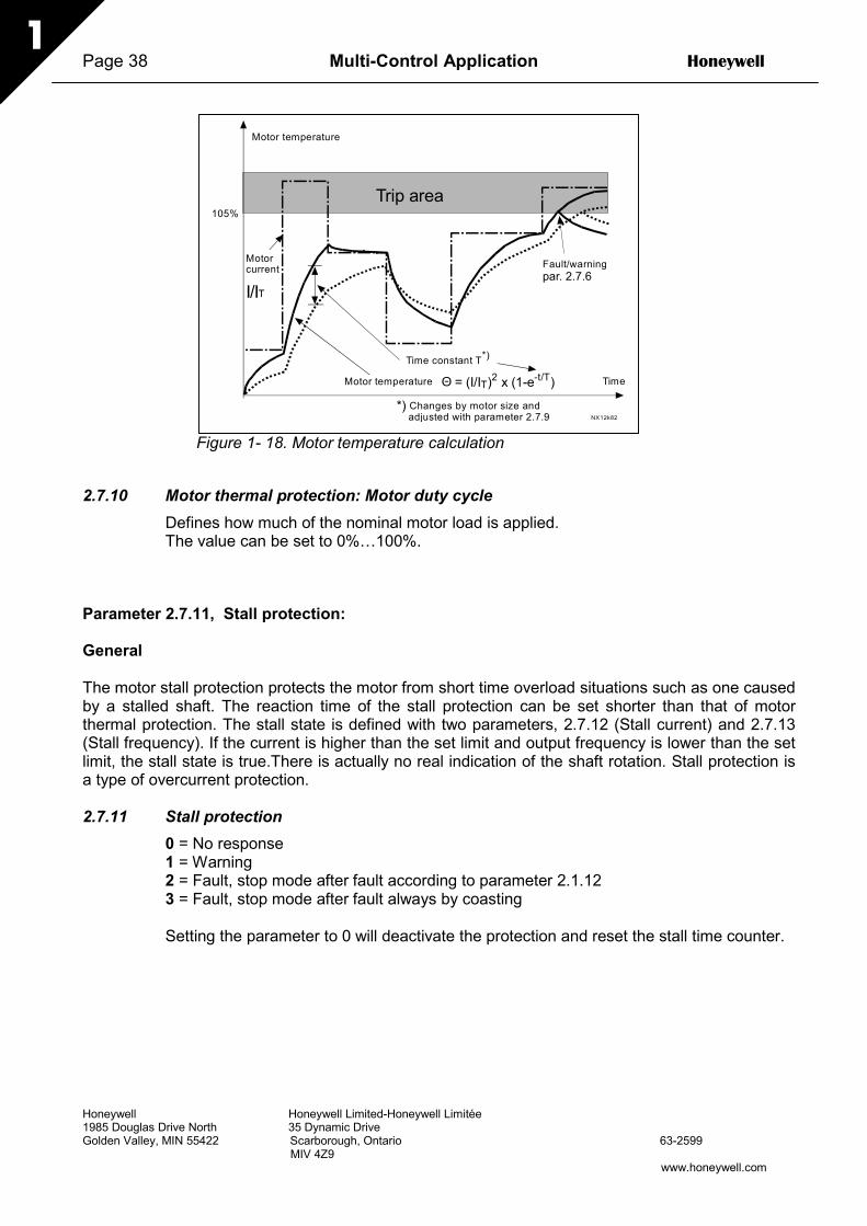
Page 38 Multi-Control Application Honeywell
Honeywell Honeywell Limited-Honeywell Limitée1985 Douglas Drive North 35 Dynamic DriveGolden Valley, MIN 55422 Scarborough, Ontario 63-2599 MIV 4Z9
www.honeywell.com
1
Figure 1- 18. Motor temperature calculation
2.7.10 Motor thermal protection: Motor duty cycleDefines how much of the nominal motor load is applied.The value can be set to 0%…100%.
Parameter 2.7.11, Stall protection:
General
The motor stall protection protects the motor from short time overload situations such as one causedby a stalled shaft. The reaction time of the stall protection can be set shorter than that of motorthermal protection. The stall state is defined with two parameters, 2.7.12 (Stall current) and 2.7.13(Stall frequency). If the current is higher than the set limit and output frequency is lower than the setlimit, the stall state is true.There is actually no real indication of the shaft rotation. Stall protection isa type of overcurrent protection.
2.7.11 Stall protection0 = No response1 = Warning2 = Fault, stop mode after fault according to parameter 2.1.123 = Fault, stop mode after fault always by coasting
Setting the parameter to 0 will deactivate the protection and reset the stall time counter.
1 0 5 %
par. 2.7.6
Θ = (I/IT)2 x (1-e-t/T)
I /IT
NX12k8 2
Trip area
Mot o r t e m p e r a t u r e
Tim e M otor temperature
Time constant T*)
*) Changes by motor size andadjusted with parameter 2.7.9
Fault/warningM oto r c urre n t

Honeywell Multi-Control Application Page 39
Honeywell Honeywell Limited-Honeywell Limitée1985 Douglas Drive North 35 Dynamic DriveGolden Valley, MIN 55422 Scarborough, Ontario 63-2599 MIV 4Z9
www.honeywell.com
1
f
I
Par. 2.7.12
P a r . 2 . 7 . 1 4 NX12k63
Stal l a r e a
Par. 2.7.13
NX12k64
Trip are a
T i m e
Stall time cou n t e r
StallNo stall
T r i p / w a r n i n gp a r . 2 . 7 . 1 1
2.7.12 Stall current limitThe current can be set to 0.0…InMotor*2.For a stall stage to occur, the currentmust have exceeded this limit. SeeFigure 1- 20. The software does notallow entering a greater value thanInMotor*2. If the parameter 2.1.9 Nominalcurrent of motor is changed, thisparameter is automatically restored tothe default value (InMotor*1.3).
Figure 1- 19. Stall characteristics settings
2.7.13 Stall timeThis time can be set between 1.0 and 120.0s.This is the maximum time allowed for astall event detection. The stall time iscounted by an internal up/down counter.If the stall time counter value goes abovethis limit the protection will cause a trip(see Figure 1- 20)
Figure 1- 20. Stall time count
2.7.14 Maximum stall frequencyThe frequency can be set between 1-fmax (par. 2.1.2).For a stall event to occur, the output frequency must have remained below this limit.
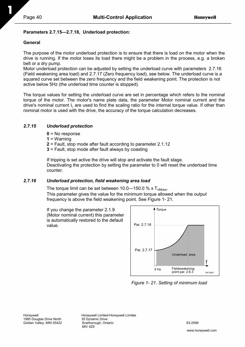
Page 40 Multi-Control Application Honeywell
Honeywell Honeywell Limited-Honeywell Limitée1985 Douglas Drive North 35 Dynamic DriveGolden Valley, MIN 55422 Scarborough, Ontario 63-2599 MIV 4Z9
www.honeywell.com
1
Par. 2.7.16
NX12k65
Par. 2.7.17
f5 Hz
Underload area
Torque
Fieldweakeningpoint par. 2.6.3
Parameters 2.7.15—2.7.18, Underload protection:
General
The purpose of the motor underload protection is to ensure that there is load on the motor when thedrive is running. If the motor loses its load there might be a problem in the process, e.g. a brokenbelt or a dry pump.Motor underload protection can be adjusted by setting the underload curve with parameters 2.7.16(Field weakening area load) and 2.7.17 (Zero frequency load), see below. The underload curve is asquared curve set between the zero frequency and the field weakening point. The protection is notactive below 5Hz (the underload time counter is stopped).
The torque values for setting the underload curve are set in percentage which refers to the nominaltorque of the motor. The motor's name plate data, the parameter Motor nominal current and thedrive's nominal current IL are used to find the scaling ratio for the internal torque value. If other thannominal motor is used with the drive, the accuracy of the torque calculation decreases.
2.7.15 Underload protection0 = No response1 = Warning2 = Fault, stop mode after fault according to parameter 2.1.123 = Fault, stop mode after fault always by coasting
If tripping is set active the drive will stop and activate the fault stage.Deactivating the protection by setting the parameter to 0 will reset the underload timecounter.
2.7.16 Underload protection, field weakening area loadThe torque limit can be set between 10.0—150.0 % x TnMotor.This parameter gives the value for the minimum torque allowed when the outputfrequency is above the field weakening point. See Figure 1- 21.
If you change the parameter 2.1.9(Motor nominal current) this parameteris automatically restored to the defaultvalue.
Figure 1- 21. Setting of minimum load

Honeywell Multi-Control Application Page 41
Honeywell Honeywell Limited-Honeywell Limitée1985 Douglas Drive North 35 Dynamic DriveGolden Valley, MIN 55422 Scarborough, Ontario 63-2599 MIV 4Z9
www.honeywell.com
1
Par. 2.7.18
NX12k66
Trip area
Time
Underload time counter
UnderloadNo underl.
Trip/warningpar. 2.7.15
2.7.17 Underload protection, zero frequency loadThe torque limit can be set between 5.0—150.0 % x TnMotor.This parameter gives value for the minimum torque allowed with zero frequency. SeeFigure 1- 21.
If you change the value of parameter 2.1.9 (Motor nominal current) this parameter isautomatically restored to the default value.
2.7.18 Underload timeThis time can be set between 2.0 and600.0 s.This is the maximum time allowed foran underload state to exist. An internalup/down counter counts theaccumulated underload time. If theunderload counter value goes abovethis limit the protection will cause a tripaccording to parameter 2.7.15). If thedrive is stopped the underload counteris reset to zero. See Figure 1- 22.
Figure 1- 22. Underload time counter function
2.7.19 Response to thermistor fault0 = No response1 = Warning2 = Fault, stop mode after fault according to parameter 2.1.123 = Fault, stop mode after fault always by coasting
Setting the parameter to 0 will deactivate the protection.
2.7.20 Response to fieldbus faultSet here the response mode for the fieldbus fault if a fieldbus board is used. For moreinformation, see the respective Fieldbus Board Manual.
See parameter 2.7.19.
2.7.21 Response to slot faultSet here the response mode for a board slot fault due to missing or broken board.
See parameter 2.7.19.

Page 42 Multi-Control Application Honeywell
Honeywell Honeywell Limited-Honeywell Limitée1985 Douglas Drive North 35 Dynamic DriveGolden Valley, MIN 55422 Scarborough, Ontario 63-2599 MIV 4Z9
www.honeywell.com
1
2.7.22 Actual value supervision function0 = Not used1 = Warning, if actual value falls below the limit set with par. 2.7.232 = Warning, if actual value exceeds the limit set with par. 2.7.233 = Fault, if actual value falls below the limit set with par. 2.7.234 = Fault, if actual value exceeds the limit set with par. 2.7.23
2.7.23 Actual value supervision limitWith this parameter you can set the limit of actual value supervised by par. 2.7.22
2.7.24 Actual value supervision delaySet here the delay for the actual value supervision function (par. 2.7.22)If this parameter is in use, the function of par. 2.7.22 will be active only when the actualvalue stays outside the defined limit for the time determined by this parameter.
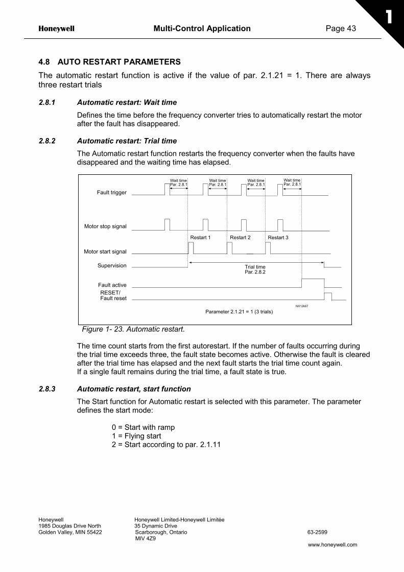
Honeywell Multi-Control Application Page 43
Honeywell Honeywell Limited-Honeywell Limitée1985 Douglas Drive North 35 Dynamic DriveGolden Valley, MIN 55422 Scarborough, Ontario 63-2599 MIV 4Z9
www.honeywell.com
1
4.8 AUTO RESTART PARAMETERSThe automatic restart function is active if the value of par. 2.1.21 = 1. There are alwaysthree restart trials
2.8.1 Automatic restart: Wait timeDefines the time before the frequency converter tries to automatically restart the motorafter the fault has disappeared.
2.8.2 Automatic restart: Trial timeThe Automatic restart function restarts the frequency converter when the faults havedisappeared and the waiting time has elapsed.
Figure 1- 23. Automatic restart.
The time count starts from the first autorestart. If the number of faults occurring duringthe trial time exceeds three, the fault state becomes active. Otherwise the fault is clearedafter the trial time has elapsed and the next fault starts the trial time count again.If a single fault remains during the trial time, a fault state is true.
2.8.3 Automatic restart, start functionThe Start function for Automatic restart is selected with this parameter. The parameterdefines the start mode:
0 = Start with ramp1 = Flying start2 = Start according to par. 2.1.11
NX12k67
Fault trigger
Motor stop signal
Motor start signal
Supervision
Wait timePar. 2.8.1
Restart 1 Restart 2
Trial timePar. 2.8.2
Fault activeRESET/Fault reset
Parameter 2.1.21 = 1 (3 trials)
Wait timePar. 2.8.1
Wait timePar. 2.8.1
Restart 3
Wait timePar. 2.8.1

Page 44 Multi-Control Application Honeywell
Honeywell Honeywell Limited-Honeywell Limitée1985 Douglas Drive North 35 Dynamic DriveGolden Valley, MIN 55422 Scarborough, Ontario 63-2599 MIV 4Z9
www.honeywell.com
1
4.9 PID REFERENCE PARAMETERS
2.9.1 PID activationWith this parameter you can activate or deactivate the PID controller or activate thepump and fan control parameters.
0 = PID controller deactivated1 = PID controller activated2 = Pump and fan control activated. Parameter group P2.10 becomes visible.
2.9.2 PID referenceDefines which frequency reference source is selected for the PID controller.Default value is 2.
0 = AI1 reference1 = AI2 reference2 = PID reference from the Keypad control page (Group K3, parameter P3.5)3 = Reference from the fieldbus (FBProcessDataIN1)
2.9.3 Actual value input1 AI12 AI23 Fieldbus (Actual value 1: FBProcessDataIN2; Actual value 2: FBProcessDataIN3)4 Motor torque5 Motor speed6 Motor current7 Motor power
2.9.4 PID controller gainThis parameter defines the gain of the PID controller. If the value of the parameter is setto 100% a change of 10% in the error value causes the controller output to change by10%.If the parameter value is set to 0 the PID controller operates as ID-controller.See examples below.
2.9.5 PID controller I-timeThis parameter defines the integration time of the PID controller. If this parameter is setto 1,00 second a change of 10% in the error value causes the controller output tochange by 10.00%/s. If the parameter value is set to 0.00 s the PID controller willoperate as PD-controller. See examples below.
2.9.6 PID controller D-timeThe parameter 2.9.5 defines the derivation time of the PID controller. If this parameter isset to 1,00 second a change of 10% in the error value during 1.00 s causes the controlleroutput to change by 10.00%. If the parameter value is set to 0.00 s the PID controller willoperate as PI-controller.See examples below.

Honeywell Multi-Control Application Page 45
Honeywell Honeywell Limited-Honeywell Limitée1985 Douglas Drive North 35 Dynamic DriveGolden Valley, MIN 55422 Scarborough, Ontario 63-2599 MIV 4Z9
www.honeywell.com
1
Example 1:
In order to reduce the error value to zero, with the given values, the frequency converteroutput behaves as follows:
Given values:Par. 2.9.4, P = 0% PID max limit = 100.0%Par. 2.9.5, I-time = 1.00 s PID min limit = 0.0%Par. 2.9.6, D-time = 0.00 s Min freq. = 0 HzError value (setpoint – process value) = 10.00% Max freq. = 50 Hz
In this example, the PID controller operates practically as ID-controller only.According to the given value of parameter 2.9.5 (I-time), the PID output increases by 5Hz (10% of the difference between the maximum and minimum frequency) every seconduntil the error value is 0.
Figure 1- 24. PID controller function as I-controller
Example 2:
Given values:
Par. 2.9.4, P = 100% PID max limit = 100.0%Par. 2.9.5, I-time = 1.00 s PID min limit = 0.0%Par. 2.9.6, D-time = 1.00 s Min freq. = 0 HzError value (setpoint – process value) = ±10% Max freq. = 50 Hz
Hz
t1s
Error=10%
10%
10%
10%
10% I-Part=5 Hz/s
I-Part=5 Hz/s
I-Part=5 Hz/s
I-Part=5 Hz/s
I-Part=5 Hz/s
PID outputError value
NX12k70

Page 46 Multi-Control Application Honeywell
Honeywell Honeywell Limited-Honeywell Limitée1985 Douglas Drive North 35 Dynamic DriveGolden Valley, MIN 55422 Scarborough, Ontario 63-2599 MIV 4Z9
www.honeywell.com
1
As the power is switched on, the system detects the difference between the setpoint andthe actual process value and starts to either raise or decrease (in case the error value isnegative) the PID output according to the I-time. Once the difference between thesetpoint and the process value has been reduced to 0 the output is reduced by theamount corresponding to the value of parameter 2.9.5.In case the error value is negative, the frequency converter reacts reducing the outputcorrespondingly.
Figure 1- 25. PID output curve with the values of Example 2
Example 3:
Given values:
Par. 2.9.4, P = 100% PID max limit = 100.0%Par. 2.9.5, I-time = 0.00 s PID min limit = 0.0%Par. 2.9.6, D-time = 1.00 s Min freq. = 0 HzError value (setpoint – process value) = ±10%/s Max freq. = 50 Hz
As the error value increases, also the PID output increases according to the set values(D-time = 1.00s).
Hz
t
D-part
D-part
P-part=5 Hz Error=10%
D-part
P-part= -5 HzError= -10%
PID output
NX12k69
Error value

Honeywell Multi-Control Application Page 47
Honeywell Honeywell Limited-Honeywell Limitée1985 Douglas Drive North 35 Dynamic DriveGolden Valley, MIN 55422 Scarborough, Ontario 63-2599 MIV 4Z9
www.honeywell.com
1
Figure 1- 26. PID output with the values of Example 3.
2.9.7 Actual value 1 minimum scaleSets the minimum scaling point for Actual value 1. See Figure 1- 27
2.9.8 Actual value 1 maximum scaleSets the maximum scaling point for Actual value 1. See Figure 1- 27
Figure 1- 27. Example of actual value signal scaling
Hz
t
D-part=10%=5,00 Hz
D-part= -10%= -5,00 Hz
P-part=100% *PID error = 5,00Hz/s
1,00 s
10%
PID output
NX12k72
Error value
100
01008030
004
10,0 V8,03,020,0 mA16,06,0
16,88,8 20,0 mA
Scaledinput signal [%]
Analogueinput [%]
Par. 2.9.7 = 30%Par. 2.9.8 = 80%

Page 48 Multi-Control Application Honeywell
Honeywell Honeywell Limited-Honeywell Limitée1985 Douglas Drive North 35 Dynamic DriveGolden Valley, MIN 55422 Scarborough, Ontario 63-2599 MIV 4Z9
www.honeywell.com
1
2.9.9 PID error value inversionThis parameter allows you to invert the error value of the PID controller (and thus theoperation of the PID controller).
0 No inversion1 Inverted
2.9.10 Sleep frequencyThe frequency converter is stopped automatically if the frequency of the drive falls belowthe Sleep level defined with this parameter for a time greater than that determined byparameter 2.9.11. During the Stop state, the PID controller is operating switching thefrequency converter to Run state when the actual value signal either falls below orexceeds (see par. 2.9.13) the Wake-up level determined by parameter 2.9.12. SeeFigure 1- 28
2.9.11 Sleep delayThe minimum amount of time the frequency has to remain below the Sleep level beforethe frequency converter is stopped. See Figure 1- 28
2.9.12 Wake-up levelThe wake-up level defines the frequency below which the actual value must fall or whichhas to be exceeded before the Run state of the frequency converter is restored. SeeFigure 1- 28
2.9.13 Wake-up functionThis parameter defines if the restoration of the Run state occurs when the actual valuesignal falls below or exceeds the Wake-up level (par. 2.9.12). See Figure 1- 28
Figure 1- 28. Frequency converter sleep functionNX12k56
t < param. 2.9.11
Wake up level (param. 2.9.12)
Actual value
Output frequency
Sleep levelparam. 2.9.10
Time
Time
Start/Stop status ofthe var. speed drive
running
stop
t < par 2.9.11
Honeywell Multi-Control Application Page 49
Honeywell Honeywell Limited-Honeywell Limitée1985 Douglas Drive North 35 Dynamic DriveGolden Valley, MIN 55422 Scarborough, Ontario 63-2599 MIV 4Z9
www.honeywell.com
1
4.10 PUMP AND FAN CONTROLThe Pump and Fan Control can be used to control one variable speed drive and up to 3auxiliary drives. The PID controller of the frequency converter controls the speed of thevariable speed drive and gives control signals to start and stop the auxiliary drives to controlthe total flow. In addition to the eight parameter groups provided as standard, a parametergroup for multi-pump and fan control functions is available.As already its name tells, the Pump and Fan Control is used to control the operation ofpumps and fans. The application utilizes external contactors for switching between themotors connected to the frequency converter. The autochange feature provides thecapability of changing the starting order of the auxiliary drives.
4.10.1 Short description of PFC function and essential parametersAutomatic changing between drives (Autochange & Interlockings selection, P2.10.4)
The automatic change of starting and stopping order is activated and applied to either theauxiliary drives only or the auxiliary drives and the drive controlled by the frequencyconverter depending on the setting of parameter 2.10.4.
The Autochange function allows the starting and stopping order of drives controlled by thepump and fan automatics to be changed at desired intervals. The drive controlled byfrequency converter can also be included in the automatic changing and locking sequence(par 2.10.4). The Autochange function makes it possible to equalize the run times of themotors and to prevent e.g. pump stalls due to too long running breaks.
• Apply the Autochange function with parameter 2.10.4, Autochange.• The autochange takes place when the time set with parameter 2.10.5 Autochange
interval, has expired and the capacity used is below the level defined with parameter2.10.7, Autochange frequency limit.
• The running drives are stopped and re-started according to the new order.• External contactors controlled through the relay outputs of the frequency converter
connect the drives to the frequency converter or to the mains. If the motor controlled bythe frequency converter is included in the autochange sequence, it is always controlledthrough the relay output activated first. The other relays activated later control theauxiliary drives
This parameter is used to activate the interlock inputs (Values 3 & 4). The interlockingsignals come from the motor switches. The signals (functions) are connected to digitalinputs which are programmed as interlock inputs using the corresponding parameters. Thepump and fan control automatics only control the motors with active interlock data.
• If the interlock of an auxiliary drive is inactivated and another unused auxiliary drive available,the latter will be put to use without stopping the frequency converter.
• If the interlock of the controlled drive is inactivated, all motors will be stopped and re-started withthe new set-up.

Page 50 Multi-Control Application Honeywell
Honeywell Honeywell Limited-Honeywell Limitée1985 Douglas Drive North 35 Dynamic DriveGolden Valley, MIN 55422 Scarborough, Ontario 63-2599 MIV 4Z9
www.honeywell.com
1
• If the interlock is re-activated in Run status, the automatics will stop all motors immediately andre-start with a new set-up. Example: [P1 P3] [P2 LOCKED] [STOP] [P1 P2 P3]
See Chapter 4.10.2, Examples.
Parameter 2.10.5, Autochange interval
After the expiry of the time defined with this parameter, the autochange function takes placeif the capacity used lies below the level defined with parameters 2.10.7 (Autochangefrequency limit) and 2.10.6 (Maximum number of auxiliary drives). Should the capacityexceed the value of par 2.10.7, the autochange will not take place before the capacity goesbelow this limit.
• The time count is activated only if the Start/Stop request is active.• The time count is reset after the autochange has taken place or on removal of Start request
Parameters 2.10.6, Maximum number of auxiliary drives and2.10.7, Autochange frequency limit
These parameters define the level below which the capacity used must remain so that theautochange can take place.
This level is defined as follows:
• If the number of running auxiliary drives is smaller than the value of parameter 2.10.6 theautochange function can take place.
• If the number of running auxiliary drives is equal to the value of parameter 2.10.6 and thefrequency of the controlled drive is below the value of parameter 2.10.7 the autochange cantake place.
• If the value of parameter 2.10.7 is 0.0 Hz, the autochange can take place only in rest position(Stop and Sleep) regardless of the value of parameter 2.10.6.
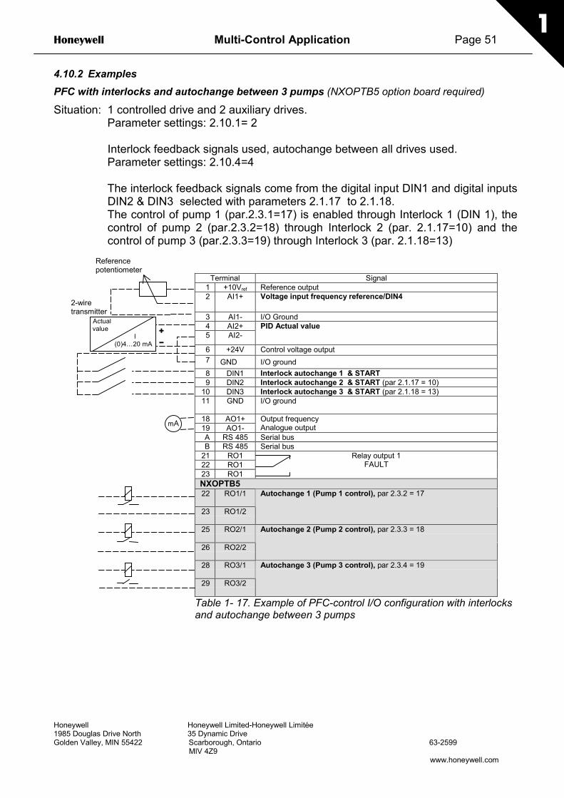
Honeywell Multi-Control Application Page 51
Honeywell Honeywell Limited-Honeywell Limitée1985 Douglas Drive North 35 Dynamic DriveGolden Valley, MIN 55422 Scarborough, Ontario 63-2599 MIV 4Z9
www.honeywell.com
1
4.10.2 ExamplesPFC with interlocks and autochange between 3 pumps (NXOPTB5 option board required)
Situation: 1 controlled drive and 2 auxiliary drives.Parameter settings: 2.10.1= 2
Interlock feedback signals used, autochange between all drives used.Parameter settings: 2.10.4=4
The interlock feedback signals come from the digital input DIN1 and digital inputsDIN2 & DIN3 selected with parameters 2.1.17 to 2.1.18.The control of pump 1 (par.2.3.1=17) is enabled through Interlock 1 (DIN 1), thecontrol of pump 2 (par.2.3.2=18) through Interlock 2 (par. 2.1.17=10) and thecontrol of pump 3 (par.2.3.3=19) through Interlock 3 (par. 2.1.18=13)
Terminal Signal1 +10Vref Reference output2 AI1+ Voltage input frequency reference/DIN4
3 AI1- I/O Ground4 AI2+5 AI2-
PID Actual value
6 +24V Control voltage output7 GND I/O ground8 DIN1 Interlock autochange 1 & START9 DIN2 Interlock autochange 2 & START (par 2.1.17 = 10)
10 DIN3 Interlock autochange 3 & START (par 2.1.18 = 13)11 GND I/O ground
18 AO1+19 AO1-
Output frequencyAnalogue output
A RS 485 Serial busB RS 485 Serial bus
21 RO122 RO123 RO1
Relay output 1FAULT
NXOPTB522 RO1/1
23 RO1/2
Autochange 1 (Pump 1 control), par 2.3.2 = 17
25 RO2/1
26 RO2/2
Autochange 2 (Pump 2 control), par 2.3.3 = 18
28 RO3/1
29 RO3/2
Autochange 3 (Pump 3 control), par 2.3.4 = 19
Table 1- 17. Example of PFC-control I/O configuration with interlocksand autochange between 3 pumps
Referencepotentiometer
Actual value
I (0)4…20 mA –
+
2-wiretransmitter
mA

Page 52 Multi-Control Application Honeywell
Honeywell Honeywell Limited-Honeywell Limitée1985 Douglas Drive North 35 Dynamic DriveGolden Valley, MIN 55422 Scarborough, Ontario 63-2599 MIV 4Z9
www.honeywell.com
1
Figure 1- 29. 3-pump autochange system, principal control diagram
Figure 1- 30. Example of 3-pump autochange, main diagram
22
23
DIN1
A O Mains A O Mains
25
26
230 VAC
S1
K1 K1.1
K1.1
K2
K2
K1
NXOPTB5
K1
K2
K2 K2.1
M1/Vacon M2/Vacon M2/mainsM1/mains
24 VDC
S2
K3K3
K2.1
K1
K3
DIN2
K3
28
29
A O Mains
S3
K3 K3.1
K3.1
K2
K2
K3
M3/Vacon M3/mains
K1K1
DIN3
NX12k106.dsf
96 8 10
VACON NXL
PEL1L2L3
U V W
PE
U V W
PE
M1 M2
F1 F2F3
VACON
U V W
L1 L2 L3
Q1
K1 K2
K1.1 K2.1
M M3 3
U V W
PE
M2
F2
K3
K3.1
M3
NX12k104.ds4
NXL

Honeywell Multi-Control Application Page 53
Honeywell Honeywell Limited-Honeywell Limitée1985 Douglas Drive North 35 Dynamic DriveGolden Valley, MIN 55422 Scarborough, Ontario 63-2599 MIV 4Z9
www.honeywell.com
1
PFC with interlocks and autochange between 2 pumps (NXOPTAA or NXOPTB5 option boardrequired
Situation: 1 controlled drive and 1 auxiliary drive.
Parameter settings: 2.10.1= 1
Interlock feedback signals used, autochange between pumps used.Parameter settings: 2.10.4=4
The interlock feedback signals come from the digital input DIN1 and digital inputDIN2 selected with parameters 2.1.17.The control of pump 1 (par.2.3.1=17) is enabled through Interlock 1 (DIN 1), thecontrol of pump 2 (par.2.3.2=18) through Interlock 2 (par. 2.1.17=10)
Terminal Signal1 +10Vref Reference output2 AI1+ Voltage input frequency reference/DIN4
3 AI1- I/O Ground4 AI2+5 AI2-
PID Actual value
6 +24V Control voltage output
7 GND I/O ground8 DIN1 Interlock autochange 1 & START9 DIN2 Interlock autochange 2 & START (par 2.1.17 = 10)
10 DIN3 Preset speed 1 (par 2.1.18 = 6)11 GND I/O ground
18 AO1+19 AO1-
Output frequencyAnalogue output
A RS 485 Serial busB RS 485 Serial bus
21 RO122 RO123 RO1
Autochange 1 (Pump 1 control)par 2.3.1. = 17
NXOPTAAX1
1 +24V Control voltage output max. 150 mA2 GND Ground for controls, e.g for +24V and DO3 DIN1 Preset speed 2, par 2.2.1 = 74 DIN2 Fault reset, par 2.2.2 = 45 DIN3 Disable PID (Freq reference from AI1), par 2.2.3 = 116 DO1 Ready, par 2.3.4 = 1
Open collector output, 50 mA/48VX222 RO1/NO23 RO1/COM
Autochange 2 (Pump 2 control), par 2.3.2 = 18
Table 1- 18. Example of PFC-control I/O configuration with interlocksand autochange between 2 pumps
Referencepotentiometer
Actual value
I (0)4…20 mA –
+
2-wiretransmitter
mA
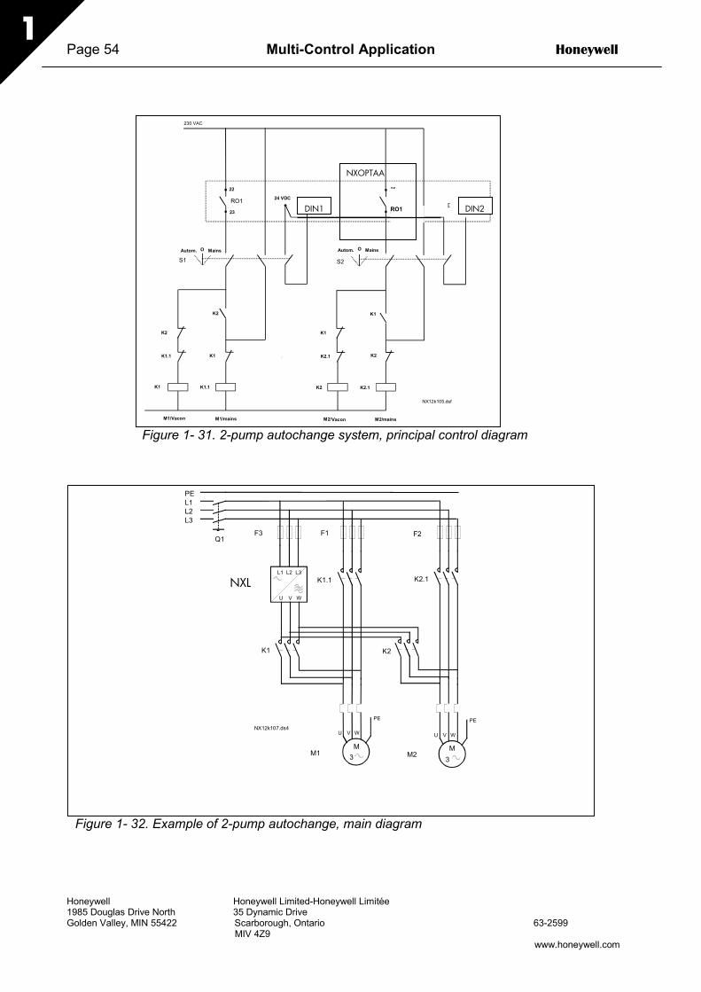
Page 54 Multi-Control Application Honeywell
Honeywell Honeywell Limited-Honeywell Limitée1985 Douglas Drive North 35 Dynamic DriveGolden Valley, MIN 55422 Scarborough, Ontario 63-2599 MIV 4Z9
www.honeywell.com
1
Figure 1- 31. 2-pump autochange system, principal control diagram
Figure 1- 32. Example of 2-pump autochange, main diagram
22
2312 9
Autom. O Mains
25
26
230 VAC
S1
K1 K1.1
K1.1
K2
K2
K1
VACON NXOPTA2
K1
K2
K2 K2.1
M1/Vacon M2/Vacon M2/mainsM1/mains
24 VDC
S2
K2.1
K1
10RO1 RO2
DIN2 DIN3
Autom. O Mains
NX12k105.dsf
RO1
NXOPTAA
DIN1 DIN2
PEL1L2L3
U V W
PE
U V W
PE
M1 M2
F1 F2F3
VACON
U V W
L1 L2 L3
Q1
K1 K2
K1.1 K2.1
M M3 3
NX12k107.ds4
NXL

Honeywell Multi-Control Application Page 55
Honeywell Honeywell Limited-Honeywell Limitée1985 Douglas Drive North 35 Dynamic DriveGolden Valley, MIN 55422 Scarborough, Ontario 63-2599 MIV 4Z9
www.honeywell.com
1
MM
NXL
M
NX12k96.fh8
Aux. drive 1 Aux. drive 2vuorot1.fh8
4.10.3 Description of Pump and Fan control parameters
2.10.1 Number of auxiliary drivesWith this parameter the number of auxiliary drives in use will be defined. The functionscontrolling the auxiliary drives (parameters 2.10.4 to 2.10.7) can be programmed to relayoutputs.
2.10.2 Start delay of auxiliary drivesThe frequency of the drive controlled by the frequency converter must remain above themaximum frequency for the time defined with this parameter before the auxiliary drive isstarted. The delay defined applies to all auxiliary drives. This prevents unnecessarystarts caused by momentary start limit exceedings..
2.10.3 Stop delay of auxiliary drivesThe frequency of the drive controlled by the frequency converter must remain below theminimum frequency for the time defined with this parameter before the drive is stopped.The delay defined applies to all auxiliary drives. This prevents unnecessary stopscaused by momentary falls below the stop limit.
2.10.4 Automatic changing between drives0= Not used1= Autochange with aux pumps
The drive controlled by the frequency converter remains the same. Therefore, mainscontactor is needed for one auxiliary drive only.
Figure 1- 33. Autochange applied to auxiliary drives only.

Page 56 Multi-Control Application Honeywell
Honeywell Honeywell Limited-Honeywell Limitée1985 Douglas Drive North 35 Dynamic DriveGolden Valley, MIN 55422 Scarborough, Ontario 63-2599 MIV 4Z9
www.honeywell.com
1
2= Autochange with frequency converter and auxiliary pumpsThe drive controlled by the frequency converter is included in the automatics and a contactoris needed for each drive to connect it to either the mains or the frequency converter
Figure 1- 34. Autochange with all drives
3= Autochange and interlocks (only auxiliary pumps)The drive controlled by the frequency converter remains the same. Therefore, mains contactoris needed for one auxiliary drive only. DIN 1 is automatically the interlock for autochangeoutput 1. Interlocks for autochange outputs 2 & 3 can be selected with par 2.1.17 and 2.1.18.
4= Autochange and interlocks ( Freq. conv & aux pumps )The drive controlled by the frequency converter is included in the automatics and a contactoris needed for each drive to connect it to either the mains or the frequency converter. DIN 1 isautomatically intelock for Autochange output 1. Interlocks for Autochange output 2 & 3 can beselected with Par.P2.1.17 & P2.1.18.
NOTE! INTERLOCK INPUTS ARE ALSO START COMMANDS FOR THEFREQUENCY CONVERTER! ( If one of these interlock inputs is active --> 1st
motor is started !!! )
2.10.5 Autochange interval
After the expiry of the time defined with this parameter, the autochange function takesplace if the capacity used lies below the level defined with parameters 2.10.7(Autochange frequency limit) and 2.10.6 (Maximum number of auxiliary drives). Shouldthe capacity exceed the value of P2.10.7, the autochange will not take place before thecapacity goes below this limit.
• The time count is activated only if the Start/Stop request is active.• The time count is reset after the autochange has taken place or on removal of Start
request
NXL
MM NX12k97.fh8Drive 1 Drive 2
auxiliaryconnection
auxiliaryconnection

Honeywell Multi-Control Application Page 57
Honeywell Honeywell Limited-Honeywell Limitée1985 Douglas Drive North 35 Dynamic DriveGolden Valley, MIN 55422 Scarborough, Ontario 63-2599 MIV 4Z9
www.honeywell.com
1
2.10.6 Maximum number of auxiliary drives2.10.7 Autochange frequency limit
These parameters define the level below which the capacity used must remain so thatthe autochange can take place.
This level is defined as follows:• If the number of running auxiliary drives is smaller than the value of parameter 2.10.6
the autochange function can take place.
• If the number of running auxiliary drives is equal to the value of parameter 2.10.6 andthe frequency of the controlled drive is below the value of parameter 2.10.7 theautochange can take place.
• If the value of parameter 2.10.7 is 0.0 Hz, the autochange can take place only in restposition (Stop and Sleep) regardless of the value of parameter 2.10.6.
Figure 1- 35. Autochange interval and limitsNXLK56.fh8
Time
Outputfrequency
Par. 2.10.5Par. 2.10.5
Autochange interval
Par. 2.10.7Autochangelevel, frequency
Autochange interval
Autochange moment
Aux. drive 1control
Aux. drive 2control
Par. 2.10.6 = 1Max.number ofauxiliary drives
w= 1

Page 58 Multi-Control Application Honeywell
Honeywell Honeywell Limited-Honeywell Limitée1985 Douglas Drive North 35 Dynamic DriveGolden Valley, MIN 55422 Scarborough, Ontario 63-2599 MIV 4Z9
www.honeywell.com
1
4.11 KEYPAD CONTROL PARAMETERS
3.1 Control placeThe active control place can be changed with this parameter. For more information, seeNXL User's Manual, Chapter 7.3.3.
3.2 Keypad referenceThe frequency reference can be adjusted from the keypad with this parameter. For moreinformation, see NXL User's Manual, Chapter 7.3.3.2.
3.3 Keypad direction0 Forward: The rotation of the motor is forward, when the keypad is the active
control place.
1 Reverse: The rotation of the motor is reversed, when the keypad is the activecontrol place.
For more information, see NXL User's Manual, Chapter 7.3.3.3.
3.4 Stop button activatedIf you wish to make the Stop button a "hotspot" which always stops the drive regardlessof the selected control place, give this parameter the value 1 (default). See NXL User'sManual, Chapter 7.3.3.
See also parameter 3.1.
3.5 PID reference 1The PID controller keypad reference can be set between 0% and 100%. This referencevalue is the active PID reference if parameter 2.9.2 = 2.
3.6 PID reference 2The PID controller keypad reference 2 can be set between 0% and 100%. This referenceis active if the DIN# function=12 and the DIN# contact is closed.

Honeywell Multi-Control Application Page 59
Honeywell Honeywell Limited-Honeywell Limitée1985 Douglas Drive North 35 Dynamic DriveGolden Valley, MIN 55422 Scarborough, Ontario 63-2599 MIV 4Z9
www.honeywell.com
1
5. Control signal logic in Multi-Control Application
Figure 1- 36. Control signal logic of the Multi-Control Application
Exp.DIE3
DIN2DIN3
AI1AI2
0123 PID
I/O ref2.1.14
01234
012345
K
012345
F
PID
DIN1DIN2
I/O
> 1DIN3Exp.DIE1
DIN3 & Exp.DIE1DIN3
Exp.DIE1
Internal reverse3.3 Keypad direction
Internal Start/Stop
Reference from fieldbusStart/Stop from fieldbusDirection from fieldbus
Motorpotentiometer
UpDown
2.9.2 PID reference
P3.5 PID keypad refer.
R3.2 Keypad reference
Actual value input, par. 2.9.3
R3.6 PID keypad ref. 2
Enable PID keypad ref. 2 (DIN#=12)
Start forward
Start/Stop buttons
Internalfrequency ref.Keypad
Fieldbus
Reset button
3.1 Control place
2.2.21 Fieldbus Ctrl Reference2.2.20 Keypad Crtl Reference2.1.14 I/O Reference
Disable PID
2.1.2 Max. frequency2.1.20 Preset speed 12.1.21 Preset speed 2
P2.9.1 PID activation
Start reverse
ProgrammableStart/Stop andReverse logic
Reference fromfieldbus(FBProcessData IN 1)
(programmable)
Preset speed 1
Preset speed 2
Exp. DIE2Fault reset input (programmable) Internal fault reset>1
----

Honeywell Honeywell Limited-Honeywell Limitée1985 Douglas Drive North 35 Dynamic DriveGolden Valley, MIN 55422 Scarborough, Ontario 63-2599 3-03
MIV 4Z9www.honeywell.com
By using this Honeywell literature, you agree that Honeywell will have no liability for any damages arising out of your use or modification to, the literature. You will defend and indemnify Honeywell, its affiliates and subsidiaries, from and against any liability, cost, or damages, including attorneys’ fees, arising out of, or resulting from, any modification to the literature by you.