63972-350 (user manual mtca 11850-016 emch) · 1 u mtca shelf product number: 11850-016 ... mch...
TRANSCRIPT
User Manual1 U MTCA Shelf
Product Number:11850-016
Doc-No: 63972-350_R1.0 February 2016

R1.0 February 2016 Initial release
Impressum:
Schroff GmbHLangenalber Str. 96 - 10075334 Straubenhardt, Germany
The details in this manual have been carefully compiled andchecked - supported by certified Quality Management Systemto EN ISO 9001/2000
The company cannot accept any liability for errors or misprints.The company reserves the right to amendments of technicalspecifications due to further development and improvement ofproducts.
Copyright2016
All rights and technical modifications reserved.

11850-016
1 Safety ....................................................................................................................... 11.1 Safety Symbols used in this document.............................................................................. 11.2 General Safety Precautions ............................................................................................... 11.3 References and Architecture Specifications...................................................................... 1
2 Hardware Platform ................................................................................................... 22.1 Front and Rear View.......................................................................................................... 32.2 ESD Wrist Strap Terminal .................................................................................................. 3
3 Backplane ................................................................................................................. 43.1 Backplane Topology .......................................................................................................... 43.2 Fabric Interface ................................................................................................................. 5
3.2.1 Common Options............................................................................................... 53.2.2 Fat Pipe .............................................................................................................. 53.2.3 Extended Fat Pipe .............................................................................................. 5
3.3 Intelligent Platform Management Bus (IPMB) .................................................................. 53.3.1 IPMB-L................................................................................................................ 5
3.4 Power Management.......................................................................................................... 5
4 Cooling ..................................................................................................................... 64.1 Air Filter............................................................................................................................. 64.2 Air filter swap .................................................................................................................... 64.3 Cooling .............................................................................................................................. 64.4 Power Supply..................................................................................................................... 7
5 EMCH (Embedded MicroTCA Carrier Hub)................................................................. 85.1 Front Panel and LEDs......................................................................................................... 95.2 Comand Line Interface (CLI) ............................................................................................ 10
5.2.1 COM-Settings ................................................................................................... 105.3 Firmware Update ............................................................................................................ 11
6 Technical Data ........................................................................................................ 12
R1.0, February 2016 I

11850-016
II R1.0, February 2016

11850-016
1 Safety
The intended audience of this User’s Manual is system integrators and hardware/software engineers.
1.1 Safety Symbols used in this document
1.2 General Safety Precautions
• Use of this product in a manner not specified by the manufacturer may impair the safety protec-tion of this equipment.
• Service personnel must know the necessary electrical safety, wiring and connection practices for installing this equipment.
• Install this equipment only in compliance with local and national electrical codes. • For additional information about this equipment, see the PICMG MicroTCA
Specification (www.picmg.com).
1.3 References and Architecture Specifications
• PICMG® MTCA.0 Specification(www.picmg.com)
• PICMG® AMC® Base Specification(www.picmg.com)
Hazardous voltage!This is the electrical hazard symbol. It indicates that there are dangerous voltages inside the Shelf.
Caution!This is the user caution symbol. It indicates a condition where damage of the equipment or injury of the service personnel could occur. To reduce the risk of damage or injury, follow all steps or procedures as instructed.
Danger of electrostatic discharge!The Shelf contains static sensitive devices. To prevent static damage you must wear an ESD wrist strap.
Warning!Voltages over 60 VDC can be present in this equipment. As defined in the PICMG 3.0 Speci-fication, this equipment is intended to be accessed, to be installed and maintained byqualified and trained service personnel only.
R1.0, February 2016 Safety 1

11850-016
2 Hardware Platform
The Schroff 11850-016 is an 1 U/2slot MicroTCA Shelf with EMCH (Embedded MicroTCA Carrier Hub) for AMC Single Full-size or Mid-size modules (with 2 HP filler panel).
Features:
• Shielded steel case • 2 AMC single Full-size slots• MicroTCA Backplane• EMCH (Embedded MicroTCA Carrier Hub) with basic MicroTCA functionality for switching
and managing two AMCs (Advanced Mezzanine Cards)• Power management controller on the backplane• Active cooling through:
4 fans for cooling the AMC modules1 fan for cooling the power supply
• Easy removable air inlet filter• Integrated 150 W AC Power Supply with wide range AC input and 12 V DC output.• AC mains/line module with IEC 320-C14 connector, integrated mains/line fuses and line
filter
2 Hardware Platform R1.0, February 2016

11850-016
2.1 Front and Rear ViewFigure 1: Front and RearView
2.2 ESD Wrist Strap Terminal
The ESD Wrist Strap Terminal (4 mm banana jack) is located left to the card cage.
1 ESD Wrist Strap Terminal 5 EMCH interfaces2 2 HP Filler panel 6 Ground Terminal (Equipotential bonding)3 AC input 7 PSU4 Mains/line switch 8 EMCH
Danger of electrostatic discharge!The Shelf contains static sensitive devices. To prevent static damage you must wear an ESD wrist strap.
R1.0, February 2016 Hardware Platform 3

11850-016
3 Backplane• 3.3 V management power generation on the backplane• Hot-Swap circuitry for enabling the management power and payload power by the EMCH• Fan connectors on the backplane (4-pin fan connectors)
3.1 Backplane Topology
Figure 2: Backplane Topology
AMC1 AMC2
Fabric 1/A (1000Base-BX)
Clocks - FCLKA AMC
(1:1 connection)
Clocks - TCLKB AMC (Output)
Clocks - TCLKC AMC
Clocks - TCLKD AMC (Output)
Clocks - TCLKA AMC
IPMB_L
DC/DC
Converter
+3,3V
HotSwap
AMC Port 2 (SATA)
AMC Port 3 (SATA)
MCH
AMC Port 4-7
(FAT PIPE)
Port 0
Port 1Fabric 2/A (1000Base-BX)
Common Options
Port 2
Port 3
A
4Port 4-7
A
B B
C C
D D
FAN1 FAN2 FAN3
FAN4 FAN5
+12V
FAN _Control
PPWR_2PPWR_1
PPWR
MP_2
PRESENT_1
MP
I²CCarrier Number
+12V FAN_Tacho5
EN_HSC_1
Current
Sense
EEPROM
FRU
PRESENT_2
EN_AMC1
MP_1
EN_AMC2
IR_HotSwap
4AMC Port 8-11
(EXT.FAT PIPE)Port 8-11
4 Backplane R1.0, February 2016
11850-016
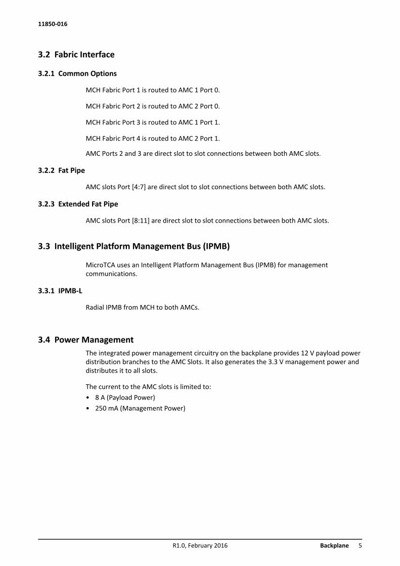
3.2 Fabric Interface
3.2.1 Common Options
MCH Fabric Port 1 is routed to AMC 1 Port 0.
MCH Fabric Port 2 is routed to AMC 2 Port 0.
MCH Fabric Port 3 is routed to AMC 1 Port 1.
MCH Fabric Port 4 is routed to AMC 2 Port 1.
AMC Ports 2 and 3 are direct slot to slot connections between both AMC slots.
3.2.2 Fat Pipe
AMC slots Port [4:7] are direct slot to slot connections between both AMC slots.
3.2.3 Extended Fat Pipe
AMC slots Port [8:11] are direct slot to slot connections between both AMC slots.
3.3 Intelligent Platform Management Bus (IPMB)
MicroTCA uses an Intelligent Platform Management Bus (IPMB) for management communications.
3.3.1 IPMB-L
Radial IPMB from MCH to both AMCs.
3.4 Power ManagementThe integrated power management circuitry on the backplane provides 12 V payload power distribution branches to the AMC Slots. It also generates the 3.3 V management power and distributes it to all slots.
The current to the AMC slots is limited to:• 8 A (Payload Power)• 250 mA (Management Power)
R1.0, February 2016 Backplane 5

11850-016
4 Cooling4.1 Air Filter
Figure 3: Air Filter
4.2 Air filter swap
The system provides a replaceable air filter. The air filter can be pulled out after removing the top cover. The filter meets the requirements of the Telcordia Technologies Generic Requirements GR-78-CORE specification.
4.3 CoolingFigure 4: Airflow
The MicroTCA Shelf is equipped with four 12 VDC fans for cooling the AMC modules and one 12 VDC fan for cooling the power supply. The fans are controlled as a group by the EMCH.e
1 Air Filter
6 Cooling R1.0, February 2016

11850-016
4.4 Power Supply
The system has a 150 W open frame AC power supply with wide range AC input and 12 V DC output.The DC output is connected directly to the power management circuitry on the backplane.
The power input is provided by an AC mains/line module with IEC 320-C14 connector, integrated mains/line fuses, line filter and a mains/line switch.
Fuse value is T2AH250V.
Figure 5: AC Input
Table 1: Data AC Power Supplye
Hazardous voltage!Parts of the power supply may be exposed with hazardous voltage.Always remove mains/line connector before carry out any assembly work.
Caution!The unit is designed in accordance with protection class 1! It must therefore be operated with protec-tive earth/GND connection. Use only a three conductor AC power cable with a protective earthconductor that meets the IEC safety standards!
Caution!There is a ground terminal at the right side. This ground terminal is only for equipotential bonding. Grounding is achieved through the protective earth conductor of the power cable!
1 AC Input 3 Equipotential bonding2 Mains switch 4 Fuse holder
Input voltage 100 - 240 VAC
Mains Frequency 50 / 60 Hz
Output (max.) 150 W
Output voltage 12 V DC
Output voltage ripple and noise 120 mVpp
Operating Temperature -5° C - +55° C
R1.0, February 2016 Cooling 7
11850-016
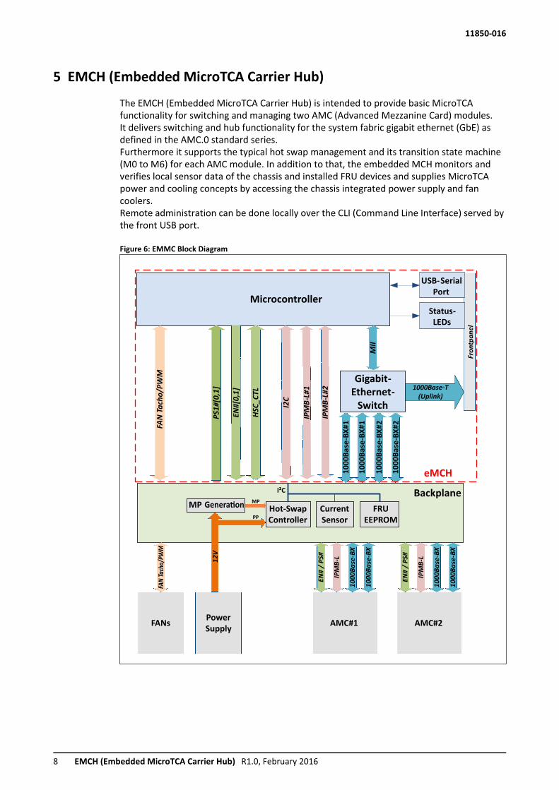
5 EMCH (Embedded MicroTCA Carrier Hub)
The EMCH (Embedded MicroTCA Carrier Hub) is intended to provide basic MicroTCA functionality for switching and managing two AMC (Advanced Mezzanine Card) modules.It delivers switching and hub functionality for the system fabric gigabit ethernet (GbE) as defined in the AMC.0 standard series.Furthermore it supports the typical hot swap management and its transition state machine (M0 to M6) for each AMC module. In addition to that, the embedded MCH monitors and verifies local sensor data of the chassis and installed FRU devices and supplies MicroTCA power and cooling concepts by accessing the chassis integrated power supply and fan coolers.Remote administration can be done locally over the CLI (Command Line Interface) served by the front USB port.
Figure 6: EMMC Block Diagram
Microcontroller
10
00
Ba
se-B
X#
2
MII
10
00
Ba
se-B
X#
1
1000Base-T
(Uplink)
IPM
B-L
#2
IPM
B-L
#1
Gigabit-
Ethernet-
Switch
FAN
Tach
o/P
WM
PS
1#
[0,1
]
EN
#[0
,1]
Hot-Swap
Controller
Current
Sensor
I2C
I²C Backplane
USB-Serial
Port
HS
C_
CT
L
AMC#2
10
00
Ba
se-B
X
IPM
B-L
EN
#/
PS
#
AMC#1
10
00
Ba
se-B
X
IPM
B-L
EN
#/
PS
#
Power
SupplyFANs
FAN
Tach
o/PW
M
12
V
eMCH
FRU
EEPROM
10
00
Ba
se-B
X#
2
10
00
Ba
se-B
X#
1
10
00
Ba
se-B
X
10
00
Ba
se-B
X
MP Genera�on
Status-
LEDs
MP
PP
Fro
ntp
an
el
8 EMCH (Embedded MicroTCA Carrier Hub) R1.0, February 2016
11850-016
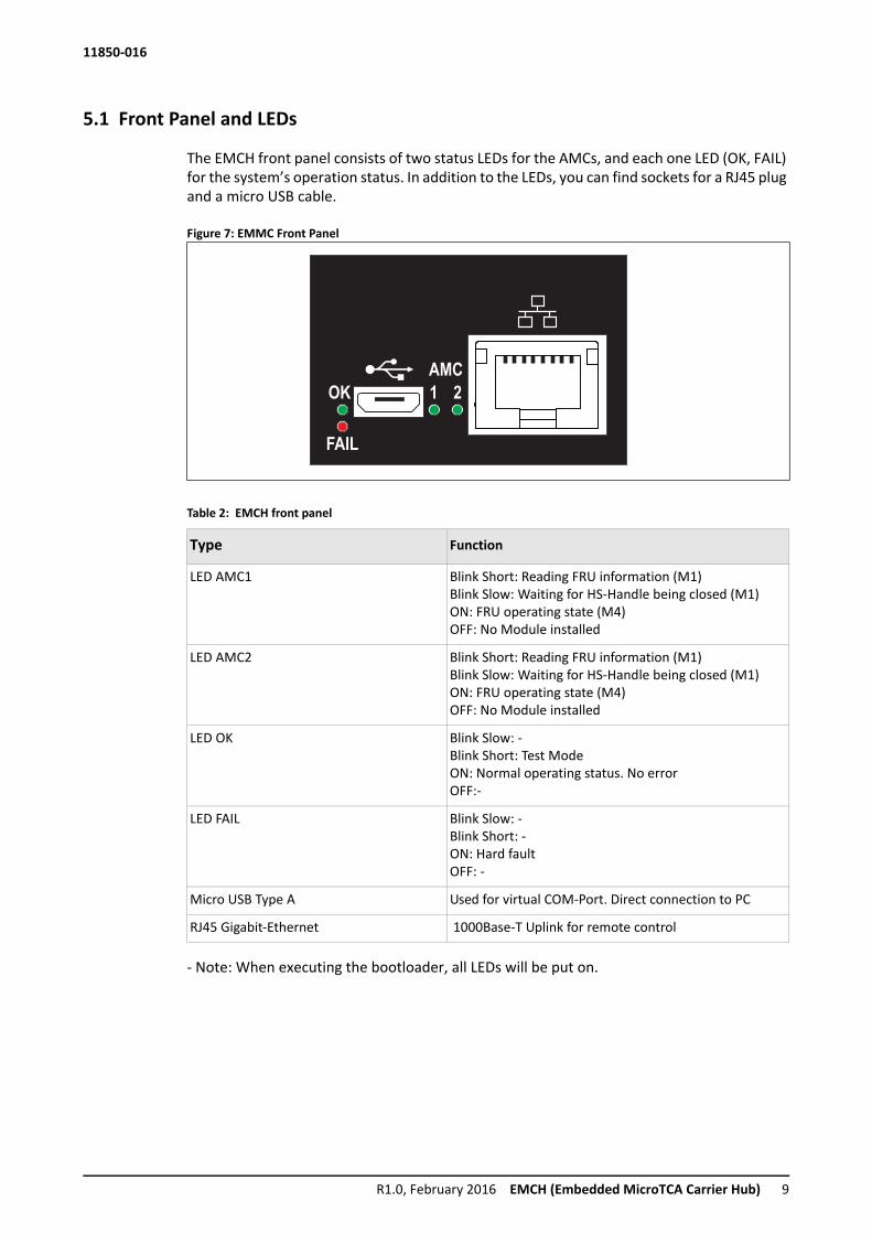
5.1 Front Panel and LEDs
The EMCH front panel consists of two status LEDs for the AMCs, and each one LED (OK, FAIL) for the system’s operation status. In addition to the LEDs, you can find sockets for a RJ45 plug and a micro USB cable.
Figure 7: EMMC Front Panel
Table 2: EMCH front panel
- Note: When executing the bootloader, all LEDs will be put on.
OK
FAIL
1 2
AMC
Type Function
LED AMC1 Blink Short: Reading FRU information (M1)Blink Slow: Waiting for HS-Handle being closed (M1)ON: FRU operating state (M4)OFF: No Module installed
LED AMC2 Blink Short: Reading FRU information (M1)Blink Slow: Waiting for HS-Handle being closed (M1)ON: FRU operating state (M4)OFF: No Module installed
LED OK Blink Slow: -Blink Short: Test ModeON: Normal operating status. No errorOFF:-
LED FAIL Blink Slow: -Blink Short: -ON: Hard faultOFF: -
Micro USB Type A Used for virtual COM-Port. Direct connection to PC
RJ45 Gigabit-Ethernet 1000Base-T Uplink for remote control
R1.0, February 2016 EMCH (Embedded MicroTCA Carrier Hub) 9

11850-016
5.2 Comand Line Interface (CLI)
The EMCH is providing a low level command line interface (CLI) which allows to set certain operational parameters and to display run time information from the MCH and the system.
5.2.1 COM-Settings
The CLI can be accessed over the front MicroUSB port. To establish a connection to a host PC, use a serial terminal program e.g. Terra-Term, HTerm, Putty, e.g.
Configure the COM port settings as followed:
Table 3: COM port settings
If the terminal is opened, press enter to see if the connection is established successfully.You can now type “help” to see the list of available commands. Press enter to call the previous command again.
NOTE: Depending on your operating system, you need to download and install the FTDI-chip driver manually. Drivers can be downloaded at http://www.ftdichip.com/FTDrivers.htm. Installing the driver automatically by the windows update may take up to a few minutes.
Table 4: CLI Commands
Baudrate 115200Data 8 bitParity NoneStop 1 bitFlow control NoneCOM The devices COM address defined by host
Command Parameter Descriptionbi Board Information
Prints the vital product information record (i.e. Serial num-ber, Hardware revision and release codes).
ip <ip><netmask><gateway>
IP configurationConfigures IP addresses, net mask, broadcast address and gateway. Parameters have to be in dotted representation <x.x.x.x>
ni Print network configurationti Print task informationbl Starts the bootloadershow_localsensors Show local sensor information of the chassisshow_fru Show all FRU’sshow_fruinfo <fru_id> FRU contents
Shows the contents of a FRU device selected by <fru_id>. For valid FRU numbers please refer to MTCA R1.0 table 3-3
show_sensorinfo <fru_id> Shows the sensor values of the selected FRUshow_pm Power Module Status
Shows the actual power allocation status for all AMC mod-ules
reboot Reboot the eMCHpassword <old_password>
<new_password>Changes the web password for accessing the update ser-vice
10 EMCH (Embedded MicroTCA Carrier Hub) R1.0, February 2016
11850-016
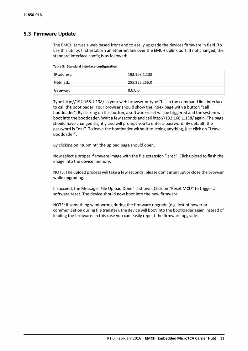
5.3 Firmware Update
The EMCH serves a web based front end to easily upgrade the devices firmware in field. To use this utility, first establish an ethernet link over the EMCH uplink port. If not changed, the standard interface config is as followed:
Table 5: Standard interface configuration
Type http://192.168.1.138/ in your web browser or type “bl” in the command line interface to call the bootloader. Your browser should show the index page with a button “call bootloader”. By clicking on this button, a software reset will be triggered and the system will boot into the bootloader. Wait a few seconds and call http://192.168.1.138/ again. The page should have changed slightly and will prompt you to enter a password. By default, the password is “nat”. To leave the bootloader without touching anything, just click on “Leave Bootloader”.
By clicking on “submint” the upload page should open.
Now select a proper firmware image with the file extension “.srec”. Click upload to flash the image into the device memory.
NOTE: The upload process will take a few seconds, please don’t interrupt or close the browser while upgrading.
If succeed, the Message “File Upload Done” is shown. Click on “Reset MCU” to trigger a software reset. The device should now boot into the new firmware.
NOTE: If something went wrong during the firmware upgrade (e.g. lost of power or communication during file transfer), the device will boot into the bootloader again instead of loading the firmware. In this case you can easily repeat the firmware upgrade.
IP address: 192.168.1.138
Netmask: 255.255.255.0
Gateway: 0.0.0.0
R1.0, February 2016 EMCH (Embedded MicroTCA Carrier Hub) 11

11850-016
6 Technical DataTable 6: Technical Data
Physical Dimensions
Height 43.60 mm (1 U)
Width 265 mm
Depth approx. 302 mm
Weight
Weight completely assembled approx. 2.7 Kg
Power Supply
Input Voltage 100 VAC to 240 VAC
Mains Frequency 50 Hz to 60 Hz
Input Current 1,2 A at 100 VAC; 0,5 A at 240 VAC
Input Fuse (2x) T2AH250V
Environmental
Ambient temperature -5°C…+45°C (long term)
Ambient temperature -5°C…+55°C (short term)
Humidity +5%...+85%, non-condensing
12 Technical Data R1.0, February 2016


Schroff GmbHLangenalber Str. 96 - 10075334 Straubenhardt, Germany Tel +49.7082.794.0Fax +49.7082.794.200
Doc-No: 63972-350_R1.0