64&3 ./6- - qimaging scientific cameras for life science … · · 2014-02-04you, the...
TRANSCRIPT

USER
MANUAL

Table of Contents
ii
COPYRIGHT NOTICE Copyright, 2010, 2013 Media Cybernetics, Inc. All Rights Reserved
TRADEMARK ACKNOWLEDGMENTS
Q-Capture Pro 7 is a registered trademark ofQImaging, Inc. All trademarks in this document are trademarks or registered trademarks of their respective companies.
Table of Contents
iii
IMPORTANT: PLEASE READ CAREFULLY LICENSE AGREEMENT THIS LICENSE AGREEMENT ("AGREEMENT") IS BETWEEN YOU, THE END USER, AND MEDIA CYBERNETICS, INC. ("MEDIA"). IT GOVERNS THE USE OF THE SOFTWARE, PROGRAM MEDIA AND DOCUMENTATION KNOWN AS Q-Capture Pro 7 (THE "PRODUCT"). IF YOU USE THE PRODUCT, THEN YOU AGREE TO THE TERMS OF THIS AGREEMENT. IF YOU ARE NOT WILLING TO BE BOUND BY THE TERMS OF THIS AGREEMENT, PROMPTLY RETURN THIS PACKAGE TO THE PLACE OF PURCHASE WITH A COPY OF THE RECEIPT, AND YOUR LICENSE FEE WILL BE REFUNDED. Media licenses use of the PRODUCT, which may be manufactured and distributed by Media or by a third party (either, the "Manufacturer"). You, the end-user, assume responsibility for the selection of the PRODUCT to achieve your intended results, and for its installation and subsequent use. GRANT OF LICENSE Media hereby grants you a non-exclusive license to use the PRODUCT in object code form only, upon the terms and conditions contained in this Agreement. You may: 1. Use the PRODUCT on the number of workstations for which you have purchased PRODUCT licenses. The workstations must be owned, leased or otherwise controlled by you, whether in a network or other configuration. 2. Create a quantity of backup copies of the PRODUCT, in any machine-readable or printed form, equal to the number of PRODUCT licenses you have purchased. 3. Transfer the PRODUCT and your rights under this Agreement to another party if the other party agrees to accept the terms and conditions of this Agreement. If you transfer the PRODUCT, you must, at the same time, either transfer all copies of PRODUCT to the same party, or destroy any copies

Table of Contents
iv
not transferred. You must immediately notify Media of the transfer. 4. Print out one copy of the Product documentation from the program media for each license purchased. If you print out any part of the Product documentation from the program media, you must reproduce and include all the copyright notices that appear in the documentation on any such copy of the documentation. You may not: 1. Use or copy the PRODUCT, in whole or in part, except as expressly provided in this Agreement, 2. Use the PRODUCT concurrently on more than the number of workstations for which you have purchased licenses, 3. Copy, rent, distribute, sell, license or sublicense, or otherwise transfer the PRODUCT or this license, in whole or in part, to another party, except as specifically set forth above. 4. Incorporate the PRODUCT or any portion of the PRODUCT into, or use the PRODUCT, or any portion of the PRODUCT to develop, other software without a license from Media, or otherwise modify or create a derivative work from the PRODUCT without a license from Media. 5. Re-distribute any of the Microsoft(R) VisualBasic(R) components, including but not limited to VBA, APC, Microsoft Forms, Core Technology, OLE Automation, VBA Installation Program, or the End User documentation for such components. 6. Reverse engineer, decompile or disassemble the PRODUCT. To use the PRODUCT as described in Sections 2 or 4 above, or for any other use not specifically set forth above, additional licensing from Media is required. For further information, please contact Media at: Media Cybernetics, Inc. 401 N. Washington St. Ste 350 Rockville, Maryland, 20850 U.S.A. Phone: (301) 495-3305 Fax: (301) 495-5964 WorldwideWeb:http://www.mediacy.com E-Mail: [email protected]
Table of Contents
v
PROPRIETARY RIGHTS This Agreement gives you ownership only of the physical program media on which the PRODUCT is stored, but not of the PRODUCT itself. You acknowledge that Media owns all right, title and interest in the PRODUCT, and that you will acquire no rights in the PRODUCT through your use of it. You agree that you will take no action that interferes with Media's rights in the PRODUCT. TERM This Agreement is effective until terminated. You may terminate it at any time by destroying the PRODUCT together with all copies and documentation in any form. This Agreement will also terminate automatically and without notice from Media if you fail to comply with any term or condition of this Agreement. You agree upon such termination to destroy the PRODUCT and all copies of the PRODUCT. DISCLAIMER; LIMITED WARRANTY EXCEPT AS PROVIDED BELOW, THE PRODUCT IS PROVIDED "AS IS" WITHOUT WARRANTY OF ANY KIND, EITHER EXPRESSED OR IMPLIED, INCLUDING, BUT NOT LIMITED TO THE IMPLIED WARRANTIES OF MERCHANTABILITY AND FITNESS FOR A PARTICULAR PURPOSE. THE ENTIRE RISK AS TO THE QUALITY AND PERFORMANCE OF THE PRODUCT IS WITH YOU. SOME JURISDICTIONS DO NOT ALLOW THE EXCLUSION OF IMPLIED WARRANTIES, SO THE ABOVE EXCLUSION MAY NOT APPLY TO YOU. NEITHER MEDIA NOR MANUFACTURER WARRANT THAT THE FUNCTIONS CONTAINED IN THE PRODUCT WILL MEET YOUR REQUIREMENTS OR THAT THE OPERATION OF THE PRODUCT WILL BE UNINTERRUPTED OR ERROR-FREE. However, where Media is the Manufacturer, Media warrants that the program media on which the software is furnished will be free from defects in materials and workmanship under normal use for a period of ninety (90) days from the date of delivery as evidenced by a copy of your receipt.

Table of Contents
vi
LIMITATION OF REMEDIES Where Media is the Manufacturer, Manufacturer’s entire liability and your exclusive remedy shall be: 1. the replacement of the program media not meeting the Limited Warranty, which is returned to Manufacturer with a copy of your receipt; 2. if Manufacturer is unable to deliver replacement program media which is free of defects in materials or workmanship, you may terminate this Agreement by returning the PRODUCT and a copy of your receipt to the place of purchase, and your money will be refunded. Where Media is not the Manufacturer, Media shall have no liability to replace or refund, and you agree to look to Manufacturer to meet the obligations described above. LIMITATION OF LIABILITY IN NO EVENT WILL MEDIA OR MANUFACTURER BE LIABLE TO YOU FOR ANY DAMAGES, INCLUDING, BUT NOT LIMITED TO, ANY LOST PROFITS, LOST SAVINGS, OR OTHER INDIRECT, SPECIAL, EXEMPLARY, INCIDENTAL OR CONSEQUENTIAL DAMAGES, ARISING OUT OF THE USE OR INABILITY TO USE THIS PRODUCT, EVEN IF MEDIA OR MANUFACTURER HAS BEEN ADVISED OF THE POSSIBILITY OF SUCH DAMAGES. FURTHER, IN NO EVENT WILL MEDIA OR MANUFACTURER BE LIABLE FOR ANY CLAIM BY ANY OTHER PARTY ARISING OUT OF YOUR USE OF THE PRODUCT. SOME JURISDICTIONS DO NOT ALLOW THE LIMITATION OR EXCLUSION OF LIABILITY FOR INCIDENTAL OR CONSEQUENTIAL DAMAGES, SO THE ABOVE LIMITATION OR EXCLUSION MAY NOT APPLY TO YOU. TRADEMARKS Q-Capture Pro 7™ is a trademark of Quantitative Imaging Corp., QImaging® is a registered trademark of Quantitative Imaging Corp., and Media Cybernetics™ is a trademark of Media Cybernetics, Inc. No right, license, or interest in such trademarks is granted hereunder.

Table of Contents
vii
U.S. GOVERNMENT RESTRICTED RIGHTS IN DATA This computer software product and documentation are provided with Restricted Rights. Use, duplication, or disclosure by the U.S. Government is subject to restrictions as set forth in the Rights in Technical Data and Computer Software clause at DFARS 252.227-7013, or subparagraphs (c)(1) and (2) of the Commercial Computer Software - Restricted Rights at 48 CFR 52.227-19, as applicable. Contractor/Manufacturer is Media Cybernetics, Inc., 401 N. Washington St., Suite 350, Rockville , Maryland 20850. EXPORT CONTROLS You agree not to export or re-export the PRODUCT, directly or indirectly, to any countries, end-users or for any end uses that are restricted by U.S. export laws and regulations, without first obtaining permission to do so as required by the U.S. Department of Commerce's Bureau of Industry and Security, or other appropriate government agency. These restrictions change from time to time. If you have any questions regarding your obligations under U.S. export regulations, you should contact the Bureau of Industry and Security, U.S. Department of Commerce, Exporter Counseling Division, Washington D.C. (202) 482-4811, http://www.bis.doc.gov. GENERAL 1. You may not sublicense, assign or transfer the license or the PRODUCT, in whole or in part, except as expressly provided in this Agreement. Any attempt to do so is null and void. 2. This Agreement will be governed by and construed in accordance with the law of the State of Maryland without regard to the conflict of laws provisions thereof, but shall not be governed by the Uniform Computer Information Transactions Act as adopted in Maryland, or the United Nations Convention on Contracts for the International Sale of Goods.

Table of Contents
viii
3. Should any part of this agreement be declared void or unenforceable by a court of competent jurisdiction, the remaining terms shall remain in full effect. 4. Failure of Media to enforce any of its rights in this agreement shall not be considered a waiver of its rights, including its rights to respond to subsequent breaches. 5. This Agreement is the complete and exclusive statement of the agreement between you and Media and supersedes any proposal or prior agreement, oral or written, any other communication between you and Media relating to the subject matter of this Agreement. Should you have any questions concerning this Agreement, you may contact Media in writing at the address above. BY USING THIS SOFTWARE YOU ACKNOWLEDGE THAT YOU HAVE READ THIS AGREEMENT, UNDERSTAND IT, AND AGREE TO BE BOUND BY ITS TERMS AND CONDITIONS.
.

Table of Contents
vii
Table of Contents Preface. Before You Begin ............................................................ vii
Product Features ...................................................................................... vii Conventions Used in this Guide .............................................................. viii
Chapter 1. Installing Q-Capture Pro 7 ™ ..................................... 1-1
System Requirements ............................................................................ 1-2 Installing Q-Capture Pro 7 ...................................................................... 1-3 Installing the QImaging Capture Interface .............................................. 1-8 Updating Your Q-Capture Pro 7 Product .............................................. 1-15
Software Registration and Updates .................................................. 1-15 Finding and Receiving Updates ........................................................ 1-18
Chapter 2. Getting Started ............................................................ 2-1
The Q-Capture Pro 7 Application Window ............................................. 2-2 The Q-Capture Pro 7 Ribbon ................................................................. 2-4 The Q-Capture Pro 7 Application button ................................................ 2-4 Q-Capture Pro 7 Application Options ..................................................... 2-6 Tabs and Ribbons ................................................................................ 2-18 Groups .................................................................................................. 2-20 Image Strip ........................................................................................... 2-21

Table of Contents
viii
Chapter 3. Capturing Images ....................................................... 3-1
The Capture Tab .................................................................................... 3-2 Using a Digital Camera .......................................................................... 3-2 Setting up a Digital Camera ................................................................... 3-2 Basic Steps for Capturing Images Using a Digital Camera .................... 3-3 Using Advanced Settings ....................................................................... 3-5 Saving Your Captured Images ............................................................. 3-11 Viewing Camera and Lens Characteristics .......................................... 3-12 Using Spatial Calibrations .................................................................... 3-13 Creating a Spatial Calibration ............................................................... 3-14 Saving Calibrations .............................................................................. 3-22 Applying a Calibration Marker to the Active Image .............................. 3-24 Intensity Features ................................................................................. 3-27
Chapter 4. Viewing Intensity Information ................................... 4-1
Viewing a Image Histogram ................................................................... 4-2 Viewing a Line Profile ............................................................................. 4-4 Using the Saturation Warning .............................................................. 4-11
Chapter 5. Working with Images .................................................. 5-1
Opening an Image .................................................................................. 5-3 Opening an Recent Document ............................................................ 5-5
Saving an Image .................................................................................... 5-6 Using Quick Save ................................................................................... 5-7 Zooming Images ..................................................................................... 5-9 Panning Images ................................................................................... 5-11 Enhancing an Image ............................................................................ 5-13
Resizing an Image ............................................................................ 5-13 Rotating an Image ............................................................................. 5-15 Using the Canvas .............................................................................. 5-17 Converting Images ............................................................................ 5-18 Using Color Group Commands ......................................................... 5-19 Dye/Tint Images ................................................................................ 5-19 Using Color Composite ..................................................................... 5-20 Pseudo-Coloring an Image ............................................................... 5-22 Adjusting Color Channels ................................................................. 5-25 Changing the Display Range ............................................................ 5-27 Adjusting Brightness, Contrast, and Gamma .................................... 5-27 Resetting the Image .......................................................................... 5-29

Table of Contents
ix
Making Enhancements Permanent ................................................... 5-29 Correcting the Background ................................................................... 5-30 Applying Filters ..................................................................................... 5-32 Image Sequences ................................................................................ 5-34
Chapter 6. Using Annotations ...................................................... 6-1
The Select Tab ....................................................................................... 6-2 Creating an Annotation ........................................................................... 6-2 Arranging Annotations ............................................................................ 6-7 Deleting an Annotation ......................................................................... 6-10 Setting the Appearance of Annotations ................................................ 6-10 Changing the Appearance of an Annotation ........................................ 6-10 Saving Annotations .............................................................................. 6-14
Chapter 7. Using ROIs ................................................................... 7-1
What is an ROI? ..................................................................................... 7-2 Defining an ROI ...................................................................................... 7-3 Placing Multiple ROIs on an Image ........................................................ 7-6 Arranging ROIs ....................................................................................... 7-6 Deleting an ROI ...................................................................................... 7-8 Setting the Appearance of ROIs ............................................................. 7-9
Chapter 8. Measuring Objects in Images .................................... 8-1
Overview of the Measurement Feature .................................................. 8-2 Making Manual Measurements .............................................................. 8-3 Measuring Features in an Image ............................................................ 8-3 Manual Tagging ...................................................................................... 8-6 Setting the Default Appearance for Measurement Labels ...................... 8-7 Viewing Measurement Data ................................................................. 8-10 Viewing a Data Table ........................................................................... 8-10
Chapter 9. Customizing the User Interface ................................. 9-1
Using the Quick Access Toolbar ............................................................ 9-2 Customizing the Image Strip .................................................................. 9-6

Table of Contents
x
Appendix A: File Format Specifications ................................... 10-1
Index ....................................................................................... Index-1

vii
Preface Before You Begin
Welcome to the Q-Capture Pro 7™ User’s Guide. This version of Q-Capture Pro 7™ is designed to run under the Microsoft® Windows® 32-bit or 64-bit systems: Windows XP Professional (service pack 3), or Windows® 7 Professional or Ultimate (service pack 1).
Product Features Q-Capture Pro 7™ is a new application for basic image acquisition and advanced measurement. It provides a set of basic acquisition and measurement functions designed to simplify routine image capture, inspection, and measurement tasks. This software makes it easy to preview, acquire, annotate, and perform basic analysis functions on an image or image sequence.
With Q-Capture Pro 7™, you can.....
Acquire images quickly and easily.
Read and write image data in many image file formats.
Use a customizable user interface, so that you can set up Q-Capture Pro 7 in the most efficient way for your work, including dockable tool bars and the ability to show or hide different toolbars and buttons. You can also reset your interface to “factory” or “default” settings if you don’t like what you’ve set up and want to start over.
Measure image features to ensure that they conform to defined standards.
Use the data viewer tools to view and analyze your data.
Work with gray scale data in 8-, 12-, 16-, or 32-bit floating point depths. Work with color data in 24-, 36-, or 48-bit format.
Make features of interest in images more defined by manipulating the settings for gamma, contrast, brightness, and intensity range.
Use a Region of Interest (ROI) to examine features in a specific part of the image.
Perform analysis using the tint and color composite features.

Conventions Used in this Guide
viii
Improve the quality of your images using the background correction and background subraction features.
Use filters to enhance obscure features in your image.
Conventions Used in this Guide The Q-Capture Pro 7 User’s Guide uses the following documentation conventions:
1. This is a numbered step in a process.
Bold Italic This indicates the name of a tab or ribbon
Italics This indicates the name of a dialog box or dialog box tab.
Bold This indicates an object on a dialog box, such as a text box, button, spin box, list box, etc.
“quoted text” This indicates information that you must type into the system exactly as shown.
<KEY> This indicates a key to press in order to perform an action.
1-1
Chapter 1 Installing Q-Capture Pro 7 ™
This chapter provides an overview of installation requirements and step-by-step instructions for installing and activating Q-Capture Pro 7.

Installation
1-2
System Requirements To install and work with Q-Capture Pro 7, you will need the following equipment and software:
Supported Operating Systems
Windows® XP SP 3 and later – 32-bit
Windows® 7 Professional and Ultimate SP 1 – 32 & 64-bit
Minimum Requirements
Pentium 4/AMD Athlon 64 processor
2 GB of RAM
500 MB of available hard-disk space
DVD/CD-ROM drive
Microsoft .NET 3.5 Framework (automatically installed by application)
USB port required for hard licenses and offline license activation
Internet connection required for online services
Recommended Requirements
Dual or multi-core processor
4 GB of RAM or more
20 GB or more of available hard-disk space. Suggested storage size if acquiring large image files.
DVD/CD-ROM drive
Microsoft .NET 3.5 Framework (automatically installed by application)
USB port required for hard licenses and offline license activation
Internet connection required for online services
Installation
1-3
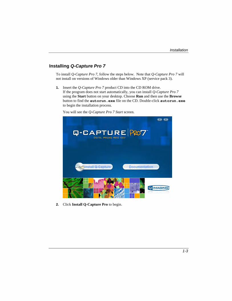
Installing Q-Capture Pro 7 To install Q-Capture Pro 7, follow the steps below. Note that Q-Capture Pro 7 will not install on versions of Windows older than Windows XP (service pack 3).
1. Insert the Q-Capture Pro 7 product CD into the CD ROM drive. If the program does not start automatically, you can install Q-Capture Pro 7 using the Start button on your desktop. Choose Run and then use the Browse button to find the autorun.exe file on the CD. Double-click autorun.exe to begin the installation process.
You will see the Q-Capture Pro 7 Start screen.
2. Click Install Q-Capture Pro to begin.

Installation
1-4
Please wait while Windows looks for the setup program.
You will see the Welcome screen:
3. Click Next.
Q-Capture Pro 7 requires the Microsoft *.NET framework. If this is not installed on your computer, the application will install it automatically.
You will see the Q-Capture Pro 7 License Agreement.

Installation
1-5
4. Check the box to accept the license agreement, and click Next. The Select Destination Folder screen appears.
5. Indicate the program location, and how many users will be using it, then click the Next button. The Ready to Install dialog box appears.
This screen indicates that your computer is ready to install Q-Capture Pro 7.
6. Click Next to continue.

Installation
1-6
7. The Installing dialog box appears.
8. The setup program will begin copying and installing files. Click Next when the installation is complete.
Note: During the installation process, you may see the following warning message:
This warning can be safely ignored, and installation of Q-Capture Pro 7 will complete successfully.

Installation
1-7
The final installation screen indicates that Q-Capture Pro 7 is now installed.
9. Click Finish to conclude this part of the installation process.

Installation
1-8
Installing the QImaging Capture Interface
To acquire images with your imaging software, you must first install the appropriate capture interface. The capture interface installation will begin automatically after the Q-Capture Pro 7 software installation is complete. These instructions cover the installation of the QImaging Capture Interface 9 only.
You should also install the QCAM driver from QImaging. The QCAM driver is available on the CD-ROM provided with your camera and can be downloaded from the QImaging website at http://www.qimaging.com/support/downloads/
Recent improvements to the QCAM driver may affect compatibility with older software products. If your system is already configured to use your QImaging camera in another software application, please confirm compatibility with your software vendor prior to installing the latest version of the QCAM driver. To install the QImaging capture interface, follow these steps.
1. Click Next to begin installing the QImaging capture interface.

Installation
1-9
You will see the QImaging Capture Interface End-User License Agreement.
2. Check the box to accept the license agreement, and click Next. The Select Target Application screen appears.
3. Check the box to indicate which software application you are using. Click Next to continue.
Note: If there is only one available application, you may not see this screen.

Installation
1-10
4. Click Next to continue. Notice the icons appearing next to the names of the various products. They illustrate three possible situations:
Already Installed: If the current version of the interface is already installed, you will see the information icon and this message:
Older Version Installed: If the application detects an older version of the
interface, you will see the question mark icon and this message:

Installation
1-11
Downgrade Not Permitted: If the application detects a newer version already exists on your system, you will see this message:
In any of these cases, click the Back button to return to the Select Target Application dialog to ensure that you are choosing the correct product installation. Then click Next to continue.
Note: If your system is configured with multiple QImaging software products, please make sure to upgrade all software installations with this version (7.0) of the QImaging Capture Interface. If you choose not to update (uncheck) an existing installation, that product may not be able to use your camera after updating to the current QCam driver version 2.0.13 . This lack of backward compatibility is apparent when using the QCam driver version 2.0.13 and higher with a QImaging Capture Interface in versions earlier than 7.0.

Installation
1-12
The Select Destination Folder screen appears.
5. Indicate the program location, then click the Next button. The Ready to Install dialog box appears.
This screen indicates that your computer is ready to install the QImaging capture interface.

Installation
1-13
6. Click Next to continue. The Installing dialog box appears.
7. The setup program will begin copying and installing files. Click Next when the installation is complete. The next page shows that the capture interface installation is complete.
8. Click the Finish button.

Installation
1-14
You may see the following message:
9. Click Yes to go to the QImaging web page: http://www.QImaging.com/support/downloads/
From here,you will be able to select and install the correct QImaging support software for your QImaging camera.

Installation
1-15
Installing the QImaging PVCAM Capture Interface
To acquire images with your imaging software, you must first install the appropriate capture interface. The capture interface installation will begin automatically after the Q-Capture Pro 7 software installation is complete.These instructions cover the installation of the QImaging PVCAM capture interface only.
You should also install the PVCAM driver from Photometrics. The PVCAM driver is available on the CD-ROM provided with your camera and can be downloaded from the Photometrics website at http://www.photometrics.com/support/downloads/
Recent improvements to the PVCAM driver may affect compatibility with older software products. If your system is already configured to use your camera in another software application, please confirm compatibility with your software vendor prior to installing the latest version of the PVCAM driver. To install the PVCAM capture interface, follow these steps.
1. Click Next to begin installing the QImaging PVCAM capture interface.

Installation
1-16
You will see the QImaging PVCAM Capture Interface End-User License Agreement.
2. Check the box to accept the license agreement, and click Next. The Select Target Application screen appears.
Note: If there is only one available application, you may not see this screen.

Installation
1-17
3. Check the box to indicate which software application you are using.
4. Click Next to continue. Notice the icons appearing next to the names of the various products. They illustrate three possible situations:
Already Installed: If the current version of the interface is already installed, you will see the information icon and a message saying that the software is alread y installed.
Older Version Installed: If the application detects an older version of the interface, you will see the question mark icon and a message asking you if ou want to continue with the installation.
Downgrade Not Permitted: If the application detects a newer version already exists on your system, you will see a message indicating that you cannot proceed.
In any of these cases, click the Back button to return to the Select Target Application dialog to ensure that you are choosing the correct product installation. Then click Next to continue. The Select Destination Folder screen appears.
5. Indicate the program location, then click the Next button.

Installation
1-18
The Ready to Install dialog box appears.
This screen indicates that your computer is ready to install the PVCAM capture interface.
6. Click Next to continue. The Installing dialog box appears.
7. The setup program will begin copying and installing files. Click Next when the installation is complete.

Installation
1-19
The next page shows that the capture interface installation is complete.
8. Click the Finish button. You may see the following message:
9. Click Yes to go to the QImaging web page: http://www.QImaging.com/support/downloads/
From here,you will be able to select and install the correct QImaging support software for your QImaging camera.

Installation
1-20
Updating Your Q-Capture Pro 7 Product Q-Capture Pro 7 runs on the following operating systems:
• Windows® XP SP 3 – 32-bit only
• Windows® 7 Professional and Ultimate SP 1 – 32 and 64-bit
Software Registration and Updates
Updates for Q-Capture Pro 7 through version 7.0.5 are available for users running older versions of the software. You do not need to re-register your product if you have previously done so. You can install and use version 7.0.4 of the product without registering, but you will not receive any future updates.
The version 7.0.4 release of Q-Capture Pro contains some changes to the licensing and updating processes.
• New Q-Capture-Pro 7 users can start using the software immediately. If you are a new user, you will receive a pop-up message asking you to register your license to be able to receive future product updates. All un-registered licenses will not be able to download new updates until they are registered.
• If you are an existing Q-Capture-Pro 7 user, you will receive an automatic message letting you know that a new update is available. You will be asked to register your license to receive the new calibration user interface update, and other future updates. You may choose to ignore the message, but you will not receive the update.
If you have NOT already registered you must register your software before you can install the 7.0.5 update for Q-Capture Pro 7.
If your temporary license has expired, you will be sent directly to the Q-Capture Pro 7 registration page!

Installation
1-21
1. If you have a hardware key (dongle) please plug it into your computer now. If you don’t have a key, you may see one of these messages:
1) This message appears if you are running an unlicensed copy of Q-Capture Pro 7:
2) If you are running an unregistered copy of the software, the message is
slightly different:
2. Click OK. This will load the registration web page in the built-in web browser.

Installation
1-22
3. Enter the Unlocking Code and Serial Number(s) that were sent with the product, together with standard registration information.
4. Click Submit. Once your information is received, the license file will be installed on your machine automatically.

Installation
1-23
Finding and Receiving Updates
Q-Capture Pro 7 uses the TrueUpdate 1 feature to ensure that you are running the most current version of the software. TrueUpdate is a small, unobtrusive feature that does not collect any personal information from you.
Most of the time, product updates happen automatically. If you have an Internet connection, your application software will check for updates when you start the product.
The Options button on the Application Tools dialog allows you to customize the user interface to reflect your personal preferences. Clicking the Options button displays a select of features that can be customized. To turn a feature on or off, check the box next to the name of the feature, or select an item from the drop-down menu.
The Application Options control how the application behaves. The General Options control the Automatic Update Check that allow you to check for updates automatically.
1 TrueUpdate is a registered trademark of Indigo Rose.
Options button

Installation
1-24
Select the Automatic Update Check in the Application page of the Application Options, as shown here:
Checking this box ensures that software updates will happen automatically. However, you must register your software to download and install future updates, beginning with version 7.0.5.
Check this box for Automatic Update Check

Installation
1-25
If the automatic update feature is turned off, the following instructions can be used to update your Q-Capture Pro 7 software though version 7.0.4. You cannot use this feature to install the 7.0.5 update even if you have a registered copy. Update instructions for version 7.0.5 appear later in these pages.
Follow the steps below:
1. From the Windows ® Start menu, go to All Programs.
2. Right-click the mouse to expand the Q-Capture Pro 7 menu.
3. Choose Update Q-Capture Pro 7. If you are runing the most current version of the software, you will see the following message:

Installation
1-26
Click Close.
Installation
1-27
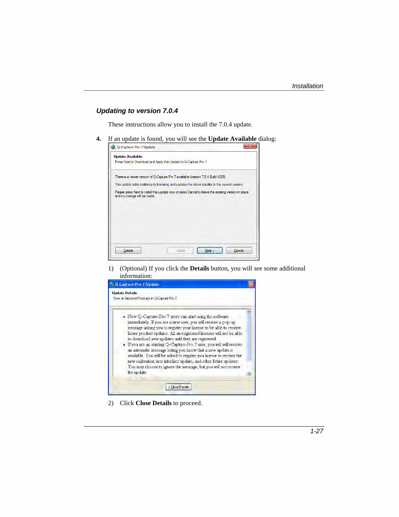
Updating to version 7.0.4
These instructions allow you to install the 7.0.4 update.
4. If an update is found, you will see the Update Available dialog:
1) (Optional) If you click the Details button, you will see some additional
information:
2) Click Close Details to proceed.

Installation
1-28
5. Click Next to continue Q-Capture-Pro will begin downloading the new software:
The next dialog asks if you want to install the software update:
6. Click Yes to continue. After downloading the file, Q-Capture Pro will extract the updated file:
The next dialog shows that the update is being installed:

Installation
1-29
The next dialog indicates that the installation is complete.
7. Click OK to begin using the updated product. You may need to restart your computer.
Installation
1-30
Updating to Version 7.0.5
New or Improved Features in Q-Capture Pro version 7.0.5:
• This release includes pre-installed capture settings created for your specific Q-Imaging camera.
• Significant changes have been made to the Calibration settings. The Capture tab features a new Setup group. In addition to simplifing the calibration process, this group allows you to add a new lens from the Predictive Calibration dialog.
• The Auto-Calibration and Zoom features are no longer available.
• The Optical Characteristics group now displays only the lens selection tool.
• The calibration drop-down list has been removed from the Characteristics and Calibration groups.
• System Calibration has been removed from the user interface. All new calibrations will automatically be Reference calibrations.
• Captured images are displayed behind the preview images.
• The time required to display captured images has been improved.
• A problem in Preview, Capture , and Locked where they sometimes need to be changed multiple times before they work has been fixed.
• When locked, display range adjustments on preview images can be applied to captured images
• When locked, gamma adjustments on preview images can be applied to captured images.
• A problem where the bit depth used while capturing an image is not the same after the image has been saved is fixed.
• An application freeze while moving the white balance sliders has been fixed.
• A problem with captured timelapse images in the Movie feature has been resolved.

Installation
1-31
Installing the 7.0.5 Update
If you are running an unregistered copy of the Q-Capture Pro 7 version 7.0.4 software, you will see this message indicating that an update is available.
3) (Optional) Click the Details button for more information. You will see this
message:
4) Click Close Details to proceed.

Installation
1-32
5) Once you have registered your software, restart Q-Capture Pro 7.
When a registered copy of Q-Capture Pro 7.0.4 is installed, you will receive a notice that an update is available. You must be running Q-Capture Pro 7 to receive the update.
8. You will see this message:
Note that if your software is NOT registered, or you are trying to run TrueUpdate from the Windows Start menu, the Next button will be disabled.
9. Click Next to install the update, or Cancel to stay with version 7.0.4 .
Installation
1-33
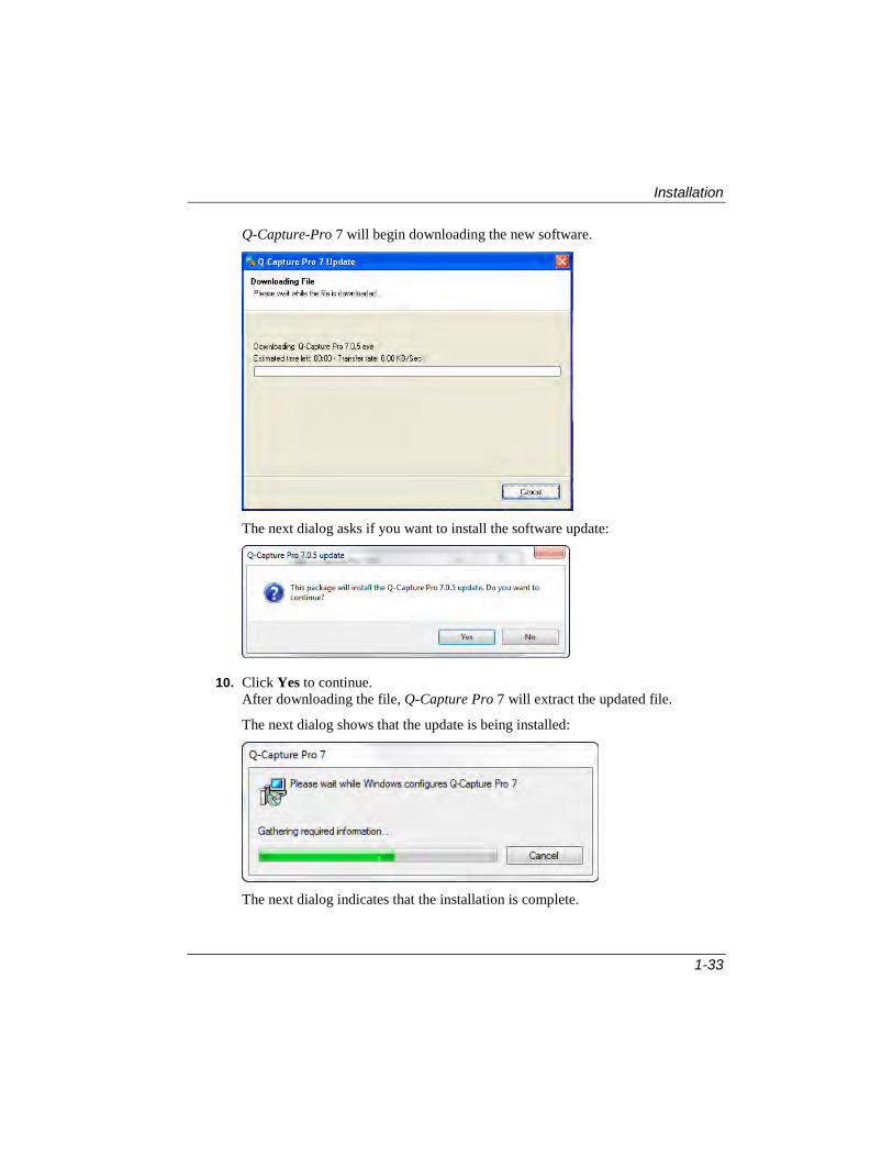
Q-Capture-Pro 7 will begin downloading the new software.
The next dialog asks if you want to install the software update:
10. Click Yes to continue. After downloading the file, Q-Capture Pro 7 will extract the updated file.
The next dialog shows that the update is being installed:
The next dialog indicates that the installation is complete.

Installation
1-34
11. Click OK to begin using the updated product. You may need to restart your computer before using Q-Capture Pro 7.0.5.

2-1
Chapter 2 Getting Started
This chapter introduces you to the Q-Capture Pro 7™ system, including an overview of its interface components and features.
The first thing you see when you start Q-Capture Pro 7 is the Welcome screen:
The Welcome screen offers quick access to tutorials, help files, and images. You can choose any of these options to begin working with images right away.
Recent documents: This pane displays a list of files that were recently opened.
Video tutorials: This pane displays a list of web-based tutorials for using Q-Capture Pro 7.
Open: Click this button to open an image or file.
Help: Click this button to access the Q-Capture Pro 7 online help.
Upgrade Options: Click this button to see if any upgrades are available.

The Q-Capture Pro 7 Application Window
2-2
Show this dialog on open: Check this box to see the Welcome screen each time that you start Q-Capture Pro 7.
Close: Click this button to close the Welcome screen.
The Q-Capture Pro 7 Application Window When you exit the Welcome screen, you will see the application window. When it is first opened, the application window consists of a menu bar and tabbed ribbons across the top of the application area, and a status bar at the bottom. If you have an image open, the image is centered in the Q-Capture Pro 7 workspace.
Tabs
Application button
Function Ribbon Bar
Function Groups
Workspace
Quick Access toolbar
Status Bar

The Q-Capture Pro 7 Application Window
2-3
The center of the window contains a set of panels or panes. The far-left panel is the Overview panel, which contains the image strip and tools that provide an overview of the workspace contents. The center panel contains the active content, which can be an image, sequence, or other rendering. The far-right Details panel contains additional dialogs that enable you to modify the contents of the workspace. An alternate details panel below the center panel contains other useful information, such as a table or graph.
The following sections explain these features of the Q-Capture Pro 7 application window in greater detail.
Image Strip
Active Content Panel
Details Panel

The Q-Capture Pro 7 Application Window
2-4
The Q-Capture Pro 7 Ribbon
The Q-Capture Pro 7 ribbon contains commands that affect or change the content in the main workspace. The overwhelming majority of the commands in the ribbon are buttons. In many cases, gallery controls roll up the effect of many button clicks and dialog settings into a single click. The ribbon displays commands organized into tabs and groups. The Capture tab’s ribbon is shown below:
The different ribbons will be examined in more detail later in this chapter.
The Q-Capture Pro 7 Application button
The Application button is located in the upper-left corner of the application window. The Application button menu contains commands that operate on the document as a whole, such as Print and Save, as well as other basic functions.
Application button
Recent Documents window
List of Commands

The Q-Capture Pro 7 Application Window
2-5
Clicking this button displays functions that are always available:
Open Image: Opens an exisiting image. You may also open a file as a sequence, and as a best fit image.
Save : Saves the active image(s) to a file.
Save As: Saves the active image as new file type.
Reload: Reloads the current active image from disk, overwriting any changes which were made to the current file since it was last saved.
Print: Selects a printer, number of copies and other printing options before printing.
o Quick Print: Send the image and any overlays to the default printer without making any changes.
o Print Preview: Preview and make changes to pages before printing.
Close: Closes the active image.
Options: Lists the different options available to you.
Exit: Closes the application.
The Recent Documents window lists the files that you opened recently:
Click the name of the file to open it. You can click the push-pin icon next to a recently opened file to "pin" the file name in the list. Click the push-pin icon again to "unpin" the name in the list.

The Q-Capture Pro 7 Application Window
2-6
Q-Capture Pro 7 Application Options
The Options button on the Application Tools dialog allows you to customize the user interface to reflect your personal preferences. Clicking the Options button displays the following dialogs. To turn a feature on or off, check the box next to the name of the feature, or select an item from the drop-down menu.
Options button

The Q-Capture Pro 7 Application Window
2-7
The Options button on the Application dialog displays the Options dialogs. These options allow you to set preferences for many aspects of the program and its features. To turn a feature on or off, just click its name and a drop-down menu or check box will appear.
Popular Options provide an opportunity to control how certain workspace options behave. The Image Options on this page allow you to set the preferences for closing modified images and reset the workspace to its default configuration

The Q-Capture Pro 7 Application Window
2-8
The Image Options page displays information about the image in the workspace. General options permit you to set the maximum number of “undos” allowed, decide on the transparency/opacity of inactive images, and set preferences for closing modified images. Image display options govern the display of the background areas outside of the active image. They also set the Zoom attributes.

The Q-Capture Pro 7 Application Window
2-9
The Application Options control how the application behaves. The General Options controls the Automatic Update Check that allows you to check for updates automatically. This group also allows you to turn the Welcome screen on or off. Multiple Document Interface (MDI) lets you control the layout of more than one document in the workspace. Display options let you set the application background color; control the Brightness, Contrast, and Gamma; and determine which characteristics and the data table are displayed in the application’s user interface. Panels Layout lets you move the application’s panels to new positions and then restore them to their original positions.

The Q-Capture Pro 7 Application Window
2-10
File Options let you decide how to save and load images and ROIs. General options ask you to specify a file name for new documents. Image Saving options allow you to save your ROIs and annotations with your image. Image Loading options let you turn the Best-Fit display on or off automatically when you open an image. Quick Save for Publication and Quick Save for Analysis allow you to specify the file, path, and format of any images that you want to save to work with at another time.
Quick Save for Publication and Quick Save for Analysis allow you to specify the file, path, and format of any images that you want to save to work with at another time.

The Q-Capture Pro 7 Application Window
2-11
Paste Options allow you to control the pasting, blending, and masking of data and images. Action Options let you preview blending and pasting on an image. ROI After Paste features a drop-down menu of choices for the source and destination ROIs. Blend Control lets you specify the degree of blending, and choose to apply blending to lighter, darker, or all pixels. Action Masking lets you decide how to apply masking to an ROI.

The Q-Capture Pro 7 Application Window
2-12
Histogram & Profile control the display of an image histogram or line profile. General Options control what type of histogram is displayed. View Options determine what information is displayed in the histogram legend. Additional Options let you decide what areas of the image will be included in the histogram. Line Profile Options determine what the initial display of the line profile will show.
An Image Histogram can be displayed in the workspace by going to the Capture ribbon and selecting Image Histogram from the Intensity group. A sample histogram is shown here:
Additional information about viewing and using histograms appears in Chapter 4.

The Q-Capture Pro 7 Application Window
2-13
Status Bar Options control the information that appears in the status bar at the bottom of the Capture-Pro workspace. General options include image type and size, frame number, cursor position, pixel values, ROI information, and calibrations are some of the choices. You can also turn the calibrated cursor position on or off.
A sample status bar, reflecting the options selected in the dialog above, appears here:
Date and Time
Cursor Positio
Pixel Value Image Viewer
Intensity Calibration
Frame Number

The Q-Capture Pro 7 Application Window
2-14
Capture Options allow you to make changes to the image capture and preview settings. General options let you reset the capture region to the default selection and apply the best-fit display when the image is captured. Preview options let you decide how to display the image preview before it is captured.

The Q-Capture Pro 7 Application Window
2-15
Display Options allow you to set the unit of measure for angles, and the number of digits that appear after the decimal point.

The Q-Capture Pro 7 Application Window
2-16
Quick Access Toolbar
This toolbar, located just above the tabs, contains controls which are usable regardless of which tab is active. You may add a copy of any almost any button or menu item to the Quick Access Toolbar. Added buttons will be retained from application session to application session.
You can customize the selections that appear in the Quick Access Toolbar. Click the drop-down arrow to activate the menu. A copy of the drop-down menu appears here:
Use More Commands to add items to the Quick Access Toolbar. You can find information about adding commands in Chapter 9.
In addition, right-clicking on any of the buttons in a ribbon displays a menu that allows you to add that button to the Quick Access Toolbar, as shown here:
The Q-Capture Pro 7 Status Bar
The Q-Capture Pro 7 Status Bar provides context-sensitive information about the status of your activities, including:
Current status of the selected or active object or window
Frame number of the image in the workspace
Date and time that the image was captured

The Q-Capture Pro 7 Application Window
2-17
Image type and size
Pixel location of the cursor
Image view icons to let you see a gallery view, or frames in a sequence
A zoom slider and a fixed-zoom control list allow you to control the size of the image in the workspace. Right-click the fixed-zoom control to see the control list:
Scale to Best Fit automatically adjusts the image display to show the best fit
Scale to Width automatically adjusts the image to the width of the workspace
Scale to Height automatically adjusts the image to the height of the workspace
Q-Capture Pro 7 allows you to enable or disable the Status Bar fields. Right-clicking on the Status Bar displays a menu that allows you to select what type of data you want to display in the status bar.
Click the cursor on the field you wish to enable or disable. Enabled fields are checked.

The Q-Capture Pro 7 Application Window
2-18
Tabs and Ribbons
Tabs are used to display different groups of functions . The tabs are arranged in a progressive left to right order following a common workflow where a person using the application acquires an image from a source, adjusts it in some fashion, selects objects in the image for study, measures properties of those objects, visualizes those objects in multiple potential contexts, then shares this information with others. The default tabs are named: Capture, Adjust, Select, Measure, and View. The Image tab is visible only when an image is open in the workspace. Each tab opens a specific ribbon displaying groups of related tools.
Capture Tab
The Capture tab dictates how images are brought into the application for viewing, manipulation and analysis. The Capture ribbon contains groups for camera control, color adjustment,calibration, intensity adjustment, and Quick Save options.
More information about capturing appears in Chapter 3.
Adjust Tab
The Adjust tab contains all the functions that allows you to manipulate the image for best viewing and interpretation. Some functions may require making new or composite images from other images or changing the pixel values within an image.

The Q-Capture Pro 7 Application Window
2-19
Select Tab
The Select tab ccontains features the Clipboard, ROI, and Annotation features that enable you to examine and annotate an image or part of an image.
Measure Tab
The Measure tab contains features that enable you to measure and analyze features in all or part of your image.
View Tab
The View tab contains specialized tools that let you turn different views of the image or user interface on or off.

The Q-Capture Pro 7 Application Window
2-20
Image Tab
The Image tab is only visible when there is an image open in the workspace. You can adjust the image display, show it in a gallery, or zoom/pan on a particular portion of the image.
Groups
When you click on a tab, you will see the ribbon with the tools and features associated with that tab arranged in groups. For example, these groups appear under the Capture tab:
The groups are related in some logical way. The Cameras group provides different ways of acquiring images. Each group contains a pull-down list of items that you can edit. The items in each pull-down list depends on what features are installed and how often you use them.
Drop-Down Menus
The small triangles beside or underneath each tool in a group open the drop-down menus.
Drop-Down Menu Symbol
The Q-Capture Pro 7 Application Window
2-21
For example, clicking the triangle next to the Settings button displays the following drop-down menu:
Most of the drop-down menus close automatically after you perform an action. Those which contain items that you may want to use several times do not close until you click the triangle again.
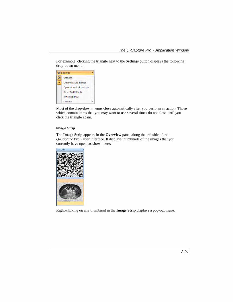
Image Strip
The Image Strip appears in the Overview panel along the left side of the Q-Capture Pro 7 user interface. It displays thumbnails of the images that you currently have open, as shown here:
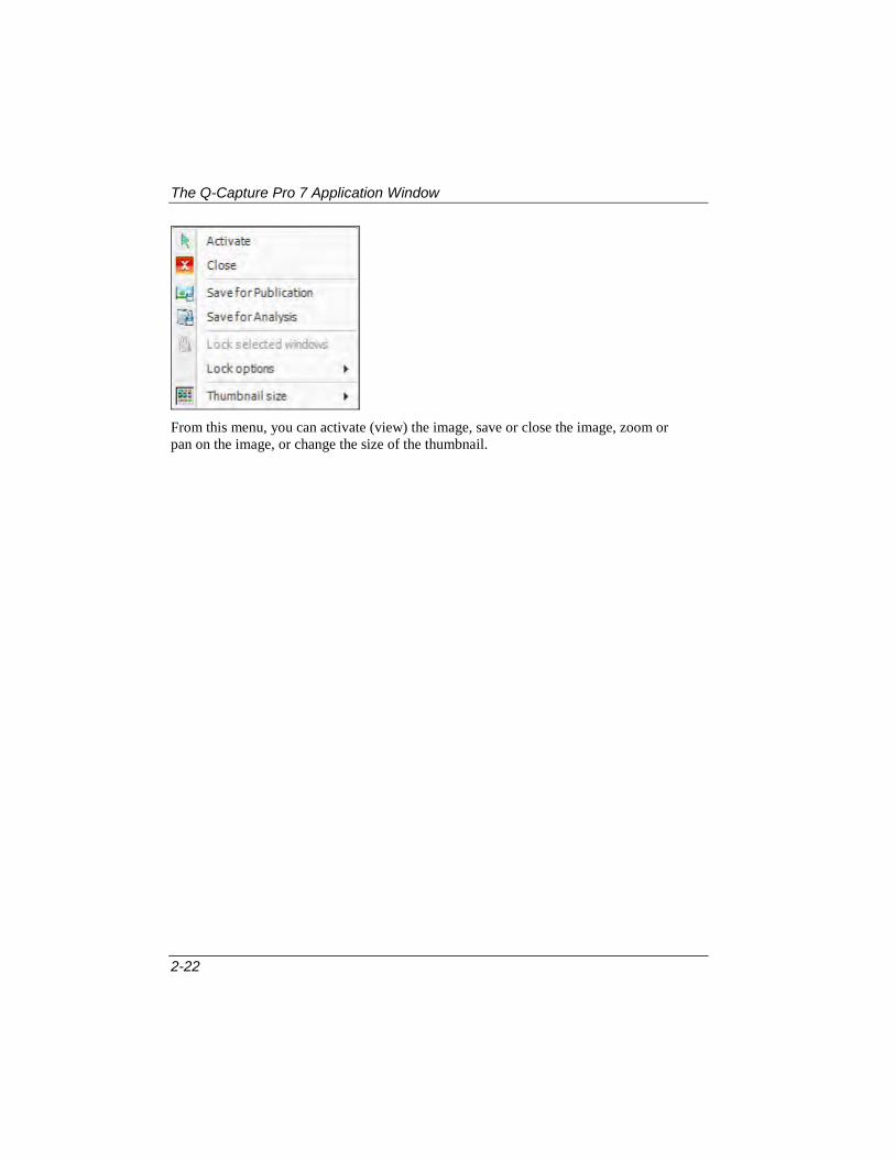
Right-clicking on any thumbnail in the Image Strip displays a pop-out menu.
The Q-Capture Pro 7 Application Window
2-22
From this menu, you can activate (view) the image, save or close the image, zoom or pan on the image, or change the size of the thumbnail.

3-1
Chapter 3 Capturing Images
This chapter provides basic instructions for setting up and capturing images from a camera attached to your computer.
The Capture Tab
3-2
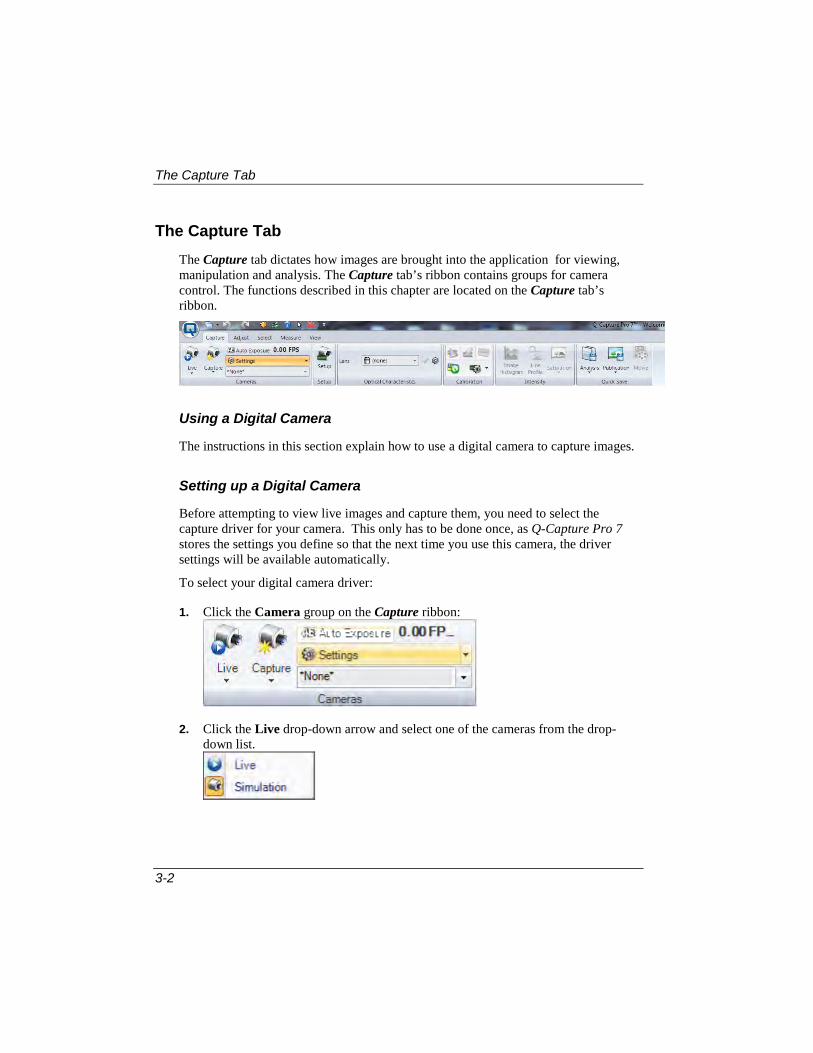
The Capture Tab The Capture tab dictates how images are brought into the application for viewing, manipulation and analysis. The Capture tab’s ribbon contains groups for camera control. The functions described in this chapter are located on the Capture tab’s ribbon.
Using a Digital Camera
The instructions in this section explain how to use a digital camera to capture images.
Setting up a Digital Camera
Before attempting to view live images and capture them, you need to select the capture driver for your camera. This only has to be done once, as Q-Capture Pro 7 stores the settings you define so that the next time you use this camera, the driver settings will be available automatically.
To select your digital camera driver:
1. Click the Camera group on the Capture ribbon:
2. Click the Live drop-down arrow and select one of the cameras from the drop-down list.
The Capture Tab
3-3
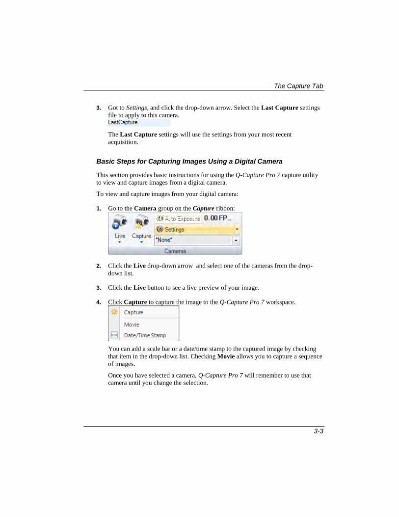
3. Got to Settings, and click the drop-down arrow. Select the Last Capture settings file to apply to this camera.
The Last Capture settings will use the settings from your most recent acquisition.
Basic Steps for Capturing Images Using a Digital Camera
This section provides basic instructions for using the Q-Capture Pro 7 capture utility to view and capture images from a digital camera.
To view and capture images from your digital camera:
1. Go to the Camera group on the Capture ribbon:
2. Click the Live drop-down arrow and select one of the cameras from the drop-down list.
3. Click the Live button to see a live preview of your image.
4. Click Capture to capture the image to the Q-Capture Pro 7 workspace.
You can add a scale bar or a date/time stamp to the captured image by checking that item in the drop-down list. Checking Movie allows you to capture a sequence of images.
Once you have selected a camera, Q-Capture Pro 7 will remember to use that camera until you change the selection.

The Capture Tab
3-4
Specifying Camera and Live Preview Settings
This section provides instructions for adjusting commonly-used capture settings that can be used to improve the quality of the live images being streamed from your camera.
To Use the Auto-White Balance Function
To have Q-Capture Pro 7 adjust the white balance automatically:
1. Go to the Camera group on the Capture ribbon:
2. Click Settings drop-down arrow. Choose White Balance.
Q-Capture Pro 7 automatically adjusts the colors so that they appear through the capture window as they appear to the eye. You can also set the Dynamic Auto-Range and Dynamic Auto-Exposure features by checking that selection Dynamic auto-range uses best-fit to set the display range on every preview frame.

The Capture Tab
3-5
Using Advanced Settings
The Advanced Settings allow you to adjust the capture speed and other image settings. These settings allow you to for fine-tune the way images appear through the Capture Preview window.
1. Click the Settings menu item to display the Advanced settings in the panel at the right side of the screen.
2. Click the arrow to expand the Capture Controls, as shown here:
From here, you can adjust the exposure time for capture, and set the binning and bit depth. The other settings can be expanded and adjusted in the same way.

The Capture Tab
3-6
Important Note: Preview and acquire settings may be adjusted individually or they may be locked together to set both simultaneously.This option appears in many of the Capture controls. Click the Locked drop-down arrow to see the following controls:
When Locked is selected, the preview and acquire/capture settings will be identical and locked together. To adjust the settings individually, select either Acquire Control or Preview Control.
3. From the Settings panel, expand the Capture Enhance Controls.
Use the sliders to adjust these settings:
Gain: These sliders control the digital gain for both preview and acquisition. Preview and acquire may be adjusted individually or they may be locked together to set both simultaneously. Click the Locked button to make the gain settings equal for both preview and acquisition.
Offset: This feature allows you to adjust the vertical and horizontal offset of the capture device for both preview and acquisition. Preview and acquire may be adjusted individually or they may be locked together to set both simultaneously. Click the Locked button to make the offset equal for both preview and acquisition.Use the Gain controls to increase or decrease the brightness of the image. This control makes all pixels uniformly brighter or darker.
Gamma: These sliders control the gamma for both preview and acquisition. Preview and acquire may be adjusted individually or they may be locked together to set both simultaneously. Click the Locked button to make the gamma settings equal for both preview and acquisition.
The Capture Tab
3-7
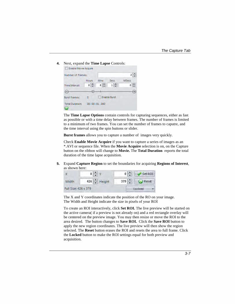
4. Next, expand the Time Lapse Controls:
The Time Lapse Options contain controls for capturing sequences, either as fast as possible or with a time delay between frames. The number of frames is limited to a minimum of two frames. You can set the number of frames to caputre, and the time interval using the spin buttons or slider.
Burst frames allows you to capture a number of images very quickly.
Check Enable Movie Acquire if you want to capture a series of images as an *.AVI or sequence file. When the Movie Acquire selection is on, on the Capture button on the ribbon will change to Movie. The Total Duration reports the total duration of the time lapse acquisition.
5. Expand Capture Region to set the boundaries for acquiring Regions of Interest, as shown here:
The X and Y coordinates indicate the position of the RO on your image. The Width and Height indicate the size in pixels of your ROI
To create an ROI interactively, click Set ROI. The live preview will be started on the active camera( if a preview is not already on) and a red rectangle overlay will be centered on the preview image. You may then resize or move the ROI to the area desired. The button changes to Save ROI. Click the Save ROI button to apply the new region coordinates. The live preview will then show the region selected. The Reset button erases the ROI and resets the area to full frame. Click the Locked button to make the ROI settings equal for both preview and acquisition.

The Capture Tab
3-8
6. To adjust the image color, expand the Color Controls, as shown here:
This option is available only when the camera is capable of capturing a color image. Each color channel may be changed individually using the slider or the numeric spin buttons. The Auto White Balance button will start a live preview, if one is not already active, and starts the process of calculating new color ratios, in order to establish a white balance based on the input image.
7. The Custom Controls contains camera manufacturer specific controls. The example shown below is for a QImaging camera.
You will need to consult your camera documentation to learn more about options for these settings.
8. The Naming Options let you assign a name to your captured image.
Check the Auto name captured images box if you want the application to automatically generate a name for each captured image. There are a number of
The Capture Tab
3-9
formats available. The prefix, such as “Acquire” lets you identify an image or series of images. Number suffix would be 01, 02, etc. and you can indicate the starting number and the number of digits. Min digits lets you specify how many digits the sequence number will use, i.e. 001, 002, etc. The Sample at the bottom of the dialog shows you how your image name(s) will appear.
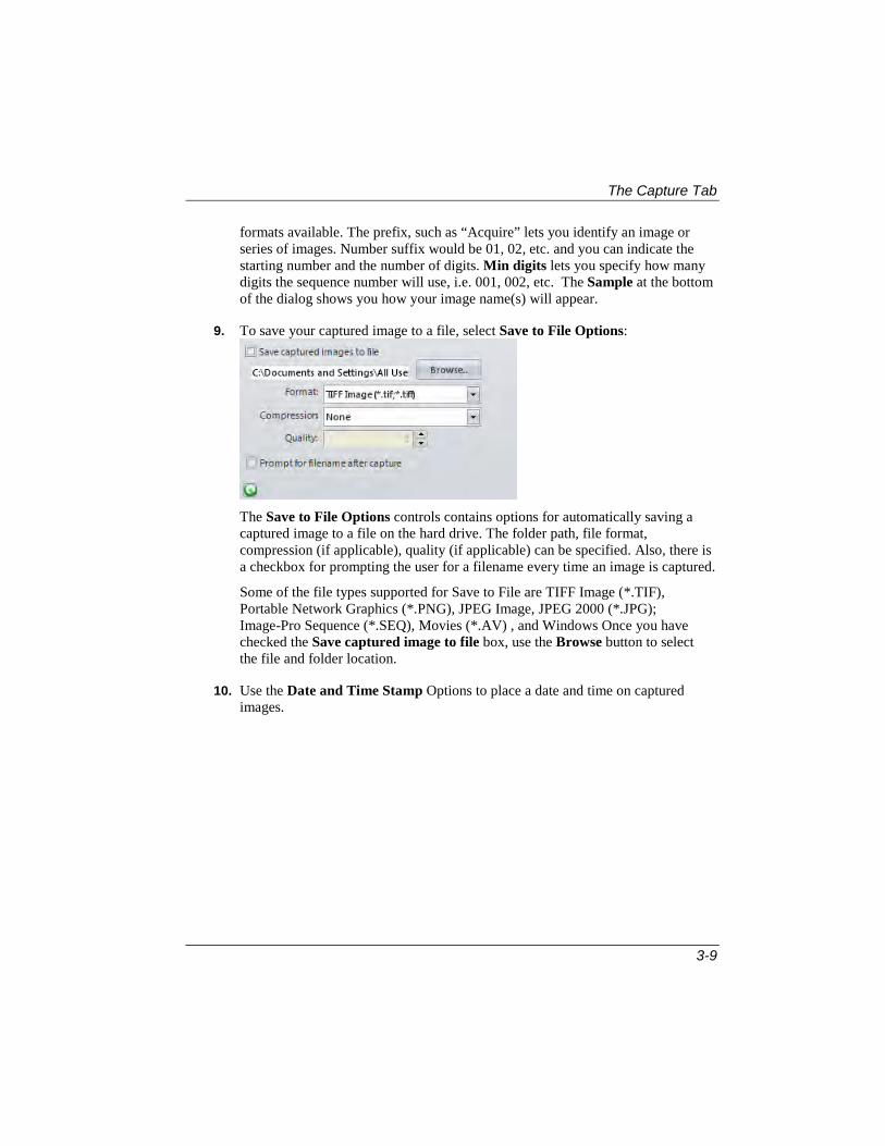
9. To save your captured image to a file, select Save to File Options:
The Save to File Options controls contains options for automatically saving a captured image to a file on the hard drive. The folder path, file format, compression (if applicable), quality (if applicable) can be specified. Also, there is a checkbox for prompting the user for a filename every time an image is captured.
Some of the file types supported for Save to File are TIFF Image (*.TIF), Portable Network Graphics (*.PNG), JPEG Image, JPEG 2000 (*.JPG); Image-Pro Sequence (*.SEQ), Movies (*.AV) , and Windows Once you have checked the Save captured image to file box, use the Browse button to select the file and folder location.
10. Use the Date and Time Stamp Options to place a date and time on captured images.

The Capture Tab
3-10
There is a large list of date only, time only, date and time and ISO standard formats available. The list shows the format as it appears with the current time and date on the system. There are options to set the font, text color, and text size as either a static pixel value or a dynamic percentage of image height. There are also controls to set the initial position of the text in one of the four corners of the image.
11. Use the Settings File controls to manage the camera settings files. Here you can select a settings file folder and a new settings file can be loaded from the list. Use Save Settings to save the current settings as a new file. A new settings file may be loaded to the current list from the file system using the Load Settings button.
If you save your settings, they will appear in the Settings drop-down menu in the Cameras group. This makes it easy for you to use the settings again.

The Capture Tab
3-11
Saving Your Captured Images
In addition to using the Save to File feature of the image settings, Q-Capture Pro 7 offers you a quick and easy method of saving your images.
1. Go to the Quick Save group on the Capture tab.
2. Choose Quick Save for Analysis or Quick Save for Publication. If you are saving a series of images, choose Quick Save as Movie.
When you select Analysis, you will see the following drop-down menu:
Quick Save for Analysis stores your images in *.TIF format so that they can
be retrieved for analysis at another time.
Open Saved Images goes to the Open dialog and lets you select a previously stored image.
Options takes you to the File Options page where you can change your preferences.
When you select Publication, you will see the following drop-down menu:
Publication stores your image in a *.JPG format that can be easily
incorporated into a report or spreadsheet.It also burns-in any annotations, ROIs, or measurements and resizes your image.

The Capture Tab
3-12
Auto Open will automatically open your saved image in the Q-Capture Pro 7 workspace.
Open Saved Images goes to the Open dialog and lets you select a previously stored image.
Options takes you to the File Options page where you can change your preferences.
Viewing Camera and Lens Characteristics
The Optical Characteristics group on the Capture tab’s ribbon lets you see what dye was used with your captured image:
1. To apply a different lens to your image, click the drop-down arrow and select an item from the drop-down list.
2. To edit the lens characteristics, click the Edit button at the far right. You will see an editing panel displayed on the right-hand side of the workspace.
3. From this panel, you can edit or change the lens used to capture your images.

The Capture Tab
3-13
Using Spatial Calibrations
Using a spatial calibration, Q-Capture Pro 7's pixel-level measurements can be converted to any unit of measurement. Spatial calibrations can also correct for irregularities in the image’s vertical and horizontal spacing.
There are two primary components to a spatial calibration:
Pixels per Unit.
Aspect Ratio.
Pixels per Unit
A spatial calibration tells Q-Capture Pro 7 the size to which a given image is scaled, just as the key of a roadmap tells us how many millimeters of image length represent one mile. Likewise, the spatial calibration tells Q-Capture Pro 7 how many pixels of image length represent some more meaningful unit of length in the image, for example, one micron, millimeter, or inch. To create a new spatial calibration, you must either know the number of pixels per unit to specify for the image, or there must be a feature pictured in the image that has a known length value in terms of the units of interest. If a feature of known length is pictured, Q-Capture Pro 7 can calculate the number of pixels per unit by determining the number of pixels it takes to represent the known length. (Companies often ‘plant’ an object of known length into images for this purpose.)
Aspect Ratio
Aspect ratio refers to the ratio of vertical to horizontal lengths. For example, when a television screen’s image appears flattened or squeezed, the ratio of horizontal length to vertical length is out of proportion. Similarly, cameras often inadvertantly skew images in the process of capturing them and translating them to digital format.
Such skewing results in inaccurate lengths being ascribed to features that are measured in the image. When a skewed aspect ratio has a flattening effect, vertical lengths will be recorded as shorter than they actually are; when it has a squeezing effect, horizontal lengths will be recorded as shorter than they actually are.
If an image has a known aspect ratio problem, Q-Capture Pro 7 can compensate for the flattening or squeezing of vertical and horizontal lengths, and calculate the actual number of units that measurements of its features represent. To do this, you must be able to supply it with the value l/h (length divided by height) for a perfect square as represented in the image, or there must be a feature pictured in the image that

The Capture Tab
3-14
represents a perfect square. If a square feature is pictured, Q-Capture Pro 7 can calculate the aspect ratio from that feature. (Companies often ‘plant’ a perfectly-square object into images for this purpose.)
Creating a Spatial Calibration
To create a new spatial calibration, you must either know the number of pixels per unit to specify for the image, or there must be a feature pictured in the image that has a known length value in terms of the units of interest (see “Pixels per Unit” under “About Spatial Calibrations” above).
Quick Calibration Method
1. Open the image you want to calibrate or that you want to use to create the calibration definition.
2. Click the Quick Calibration button in the Spatial Calibration group.on the Capture tab’s ribbon.
3. Draw a line over a feature in the image. You will see the Calibrate by Feature dialog:
4. Select a calibration name in the drop-down list.

The Capture Tab
3-15
5. Select the units in the drop-down list, and indicate the number of units in the selected feature.
6. Click OK.

The Capture Tab
3-16
Calibrating by Aspect Ratio
If your calibration must also correct for aspect ratio, you must either know the value l/h (length divided by height) for a perfect square as represented in the image, or there must be a feature pictured in the image that is known to be a perfect square (see “Aspect Ratio” under “About Spatial Calibrations” above).
To create a spatial calibration:
1. Open the image you want to calibrate or that you want to use to create the calibration definition.
2. On the Capture tab’s ribbon, select the Spatial Calibration group.
3. Click the Calibration options icon to open the Spatial Calibration dialog box in the panel on the right.
By default the Spatial Calibration panel contains contains the Spatial Calibration (basic view) and Advanced Options dialog boxes. The Advanced Options dialog box is collapsed by default. Click the header in either of the dialog boxes to expand or collapse the dialog box.
Click the Calibration Name drop-down arrow and select the set of calibration values you want to apply to the image. If you want to use the default values,

The Capture Tab
3-17
select (none). Any calibration sets that were loaded or created since the application window was last opened, will be listed in this list box.
You will not be able to enter calibration values until a name other than (none) has been selected in the Name list box. If (none) is the only set listed, you can create
a set by clicking the [New] button and specifying its calibration values.
By default, the name "Spatial Cal 0" will be assigned to a new calibration set; however, you may change this to a more descriptive name if you'd like.
4. Type over the default name “Spatial Cal 0” with a name that is more meaningful.
5. In the Units area, click the Name drop-down arrow and select the units to which you want the pixel-level measurements converted, as shown below: For example, if the size of objects in the image is best expressed in terms of micrometers, select “Micrometer” from the list.
6. In the Abbreviation text box, enter the text you want to use as the abbreviation for the selected units. For example, a typical abbreviation for ‘Micrometers’ is “um” as shown above. The specified abbreviation will appear on measurement reports.
7. In the Pixel/Unit group, do one of the following:
If you know the number of pixels per unit to specify:
1. In the X spin box, type the number of horizontal pixels it takes to represent one unit of length. For example, if you are converting to millimeters and 4 pixels equals one millimeter, type “4.”
2. Ignore the Y spin box.

The Capture Tab
3-18
If there is a feature pictured in the image that has a known length value:
(1) Click the From Image button [ ] in the Pixel/Unit area. A dialog box appears in the Spatial Calibration panel, and a horizontal annotation line appears in the image.
(2) Click and drag the line over the reference object, and then adjust the line’s control points so that the beginning and ending of the line correspond to the beginning and ending of the reference object.
TIP: For greatest accuracy, it is often helpful to zoom in on the reference object. To zoom in on the reference object, click on the
Zoom tool [ ] from the View tab’s ribbon. With the Zoom tool selected, position the cursor over the reference object, and click. Repeat these steps until the object is large enough to determine its starting and ending pixels.
(3) In the Reference length (units) spin box, type the known length of the pictured object.
(4) Click OK.
The Spatial Calibration dialog box is redisplayed and the calculated pixels/unit value appears in the X and Y spin boxes.
If you have an image of a micrometer, you can calibrate the image automatically:
(1) Click the Auto Calibrate button [ ] in the Pixel/Unit area.
(2) A dialog box appears over the image of the micrometer.
(3) Click OK., and the calibration will be calculated automatically.
8. Select the Advanced Options dialog box on the Spatial Calibration panel.

The Capture Tab
3-19
9. In the Apect Ratio area, do one of the following:
If you know the aspect ratio value to specify, or if there is no aspect ratio problem to correct for:
1. In the Aspect Ratio spin box, type the aspect ratio value to be used. For example, if there is no aspect ratio problem to correct for, enter “1.”
Q-Capture Pro 7 automatically adjusts the value for the X spin box to match the entered Aspect Ratio value.
If there is a feature pictured in the image that represents a perfect square:
(1) Click the From Image button [ ] in the Aspect Ratio area. A dialog box appears in the Q-Capture Pro 7 workspace, and a diagonal annotation line appears in the image.
(2) Click and drag the line over the reference object, and then adjust the line’s control points so that the beginning of the line corresponds with the bottom-left corner of the reference object and the end of the line corresponds with the top-right corner of the reference object. TIP: Again, for greatest accuracy, it is often helpful to zoom in on the reference object.
(3) Click OK.
The Spatial Calibration dialog box is redisplayed and the calculated aspect ratio value appears in the Aspect Ratio spin box. Additionally, the X and Y spin box values are automatically adjusted to account for the aspect ratio.

The Capture Tab
3-20
10. Click Apply to Active Image [ ].
The spatial calibration is applied and saved for the session. To make it available across sessions, you must save it to a file (see “Saving Calibrations” below).
11. Click Apply to Active Image in the spatial calibration toolbar.
The spatial calibration is applied and saved for the session. To make it available across sessions, you must save it to a file (see “Saving Calibrations” below).
Calibrating by Feature
Calibrate by feature option allow you to calibrate an image by a feature with known size. Any line measurement can be used for image calibration.
Calibration by feature can be done using the following steps:
1. Create a measurement of an object of known size. For example, the length of a bracket can be measured.
2. Click the Calibrate by feature length button (the same function can be called from the context menu in the Data Table).
3. Fill the feature size in calibration units and other calibration parameters, such as Units and Calibration name in the shown Calibrate by feature dialog:
4. (Optional) Use the Show calibration dialog to adjust the calibration measurements.

The Capture Tab
3-21
5. Click Ok to create a new calibration and apply it to the active image.
Predictive Calibration
Predictive calibration lets you create estimated spatial calibrations based on the optical characteristics of the camera and objectives. To use the predictive calibration feature, follow these steps:
1. Click the Setup button on the Capture tab.
You will see the Create Predictive Calibration dialog:
Each camera is defined by the Manufacturer and Camera Model fields
2. Select your camera manufacturer and model from the drop-down lists. The pixel and sensor size is determined by the camera make and model. If you want to set the pixel and sensor size manually for the new calibration, choose Other in the list of cameras. The Calibration prefix is also defined automatically the camera selection. You may type in a new prefix in the space provided.
3. Select the lenses from the calibration from the Lenses panel.

The Capture Tab
3-22
All active lenses are selected by default, so if some lenses should not be
calibrated,uncheck them using the button to select/deselect a lens.
4. Add additional Zoom settings in the Zoom panel. This list is empty by default.
5. Enter the calibration units in Units field under the Calibration parameters .
6. (Optional) Check the Show Calibration Dialog box if you want to edit the calibration after you’ve created it.
7. Click OK to create the predictive calibration. Clicking the OK button will generated multiple calibrations for the list of selected lenses and zooms for the given camera. If multiple zooms are present, the calibration with zoom closest to 1 will be used as default lens calibration.
The list of camera manufacturers and camera models is loaded from "Camera list.cfg" file in the Resources folder of the application.
Saving Calibrations
Calibration definitions are saved per-session whenever they are applied to an image. If you want calibration definitions to be saved between sessions, however, you must save them to a file. Once a calibration definition is saved to a file, you can load it whenever it is needed in the future.
To save calibration definitions:
1. Click the Save Calibration button [ ] on the calibration dialog. The Save Spatial Calibration list box appears.
If an active image is displayed in the Q-Capture Pro 7 workspace that has a calibration definition assigned to it, that calibration definition appears in the Spatial Calibration dialog box.
2. From the pull-down list box at the top of the Spatial Calibration dialog box, select the calibration definition you want to save.
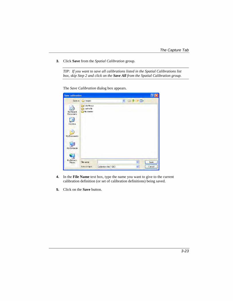
The Capture Tab
3-23
3. Click Save from the Spatial Calibration group.
TIP: If you want to save all calibrations listed in the Spatial Calibrations list box, skip Step 2 and click on the Save All from the Spatial Calibration group.
The Save Calibration dialog box appears.
4. In the File Name text box, type the name you want to give to the current calibration definition (or set of calibration definitions) being saved.
5. Click on the Save button.
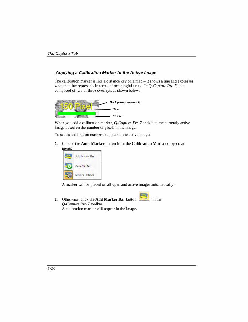
The Capture Tab
3-24
Applying a Calibration Marker to the Active Image
The calibration marker is like a distance key on a map – it shows a line and expresses what that line represents in terms of meaningful units. In Q-Capture Pro 7, it is composed of two or three overlays, as shown below:
When you add a calibration marker, Q-Capture Pro 7 adds it to the currently active image based on the number of pixels in the image.
To set the calibration marker to appear in the active image:
1. Choose the Auto-Marker button from the Calibration Marker drop-down menu:
A marker will be placed on all open and active images automatically.
2. Otherwise, click the Add Marker Bar button [ ] in the Q-Capture Pro 7 toolbar. A calibration marker will appear in the image.
Background (optional)
Text
Marker

The Capture Tab
3-25
1. To add a marker manually, select Marker Options from the drop-down list:
The Marker Options dialog box appears.
2. Use the Position buttons to place the marker on the image. You can resize the marker and the length and the label will be adjusted automatically based on the current size. The length is rounded to the nearest value from the list of 10 logarithmically equidistant values (1, 1.2, 1.5, 2, 2.5, 3, 4,…).
3. Set the Font and Text Size options the way you want them. To hide the text and only display the marker, set the font size to zero. Use the Size spin box to indicate the size, in points, to be used for the text. Use the Color button to change the text color.
Calibration Marker
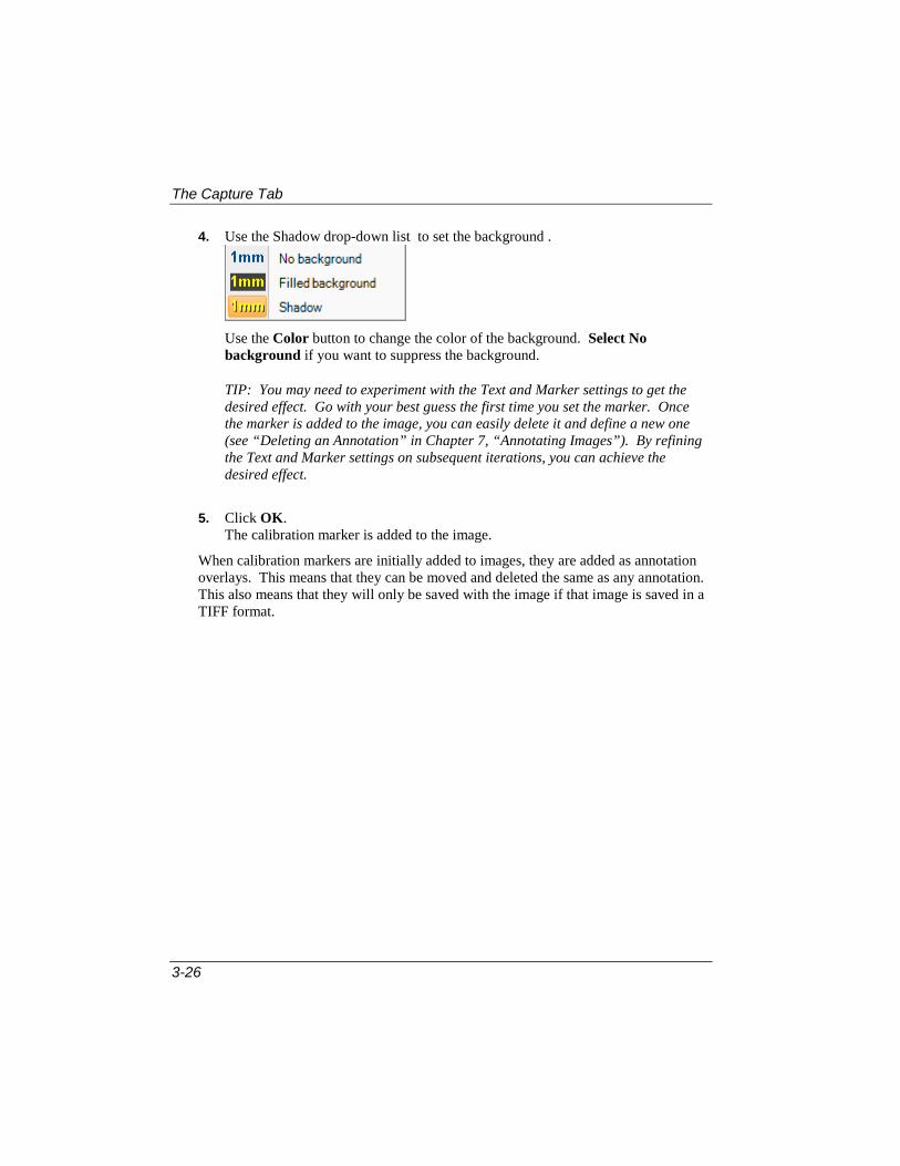
The Capture Tab
3-26
4. Use the Shadow drop-down list to set the background .
Use the Color button to change the color of the background. Select No background if you want to suppress the background.
TIP: You may need to experiment with the Text and Marker settings to get the desired effect. Go with your best guess the first time you set the marker. Once the marker is added to the image, you can easily delete it and define a new one (see “Deleting an Annotation” in Chapter 7, “Annotating Images”). By refining the Text and Marker settings on subsequent iterations, you can achieve the desired effect.
5. Click OK. The calibration marker is added to the image.
When calibration markers are initially added to images, they are added as annotation overlays. This means that they can be moved and deleted the same as any annotation. This also means that they will only be saved with the image if that image is saved in a TIFF format.

The Capture Tab
3-27
Intensity Features
The Image Histogram, Line Profile and Saturation features of Q-Capture Pro 7 appear in the Intensity group on the Capture ribbon.
Image histograms measure, and illustrate in graph form, the brightness and contrast characteristics of an image. Histogram data can be created and viewed for data gathering and analytical purposes or can be manipulated for image enhancement purposes.
Line profile analysis allows you to collect the actual index values along a line that you define. A profile plot shows the pixel positions of the line along the X-axis, and, on the Y-axis, measures the index value for each position along the line.
In a line profile, the X-axis represents the spatial scale (as defined by the spatial calibration), and the Y-axis measures the intensity value. You can display a line profile on both live and captured images.
Use Saturation to show overexposed and underexposed areas with a given color. It can be used with the live preview to set proper exposure time and avoid saturated areas, so that intensity measurements on the image will be correct.
All of these features are discussed in greater detail in the next chapter.

The Capture Tab
3-28

4-1
Chapter 4 Viewing Intensity Information
This chapter explains how to:
View an Image Histogram
View a Line Profile
Use the Saturation warning
The Image Histogram, Line Profile, and Saturation Warning tools appear in the Intensity group on the Capture ribbon:

Viewing a Image Histogram
4-2
Viewing a Image Histogram
Image histograms measure, and illustrate in graph form, the brightness and contrast characteristics of an image. Histogram data can be created and viewed for data gathering and analytical purposes or can be manipulated for image enhancement purposes. To create an image histogram:
1. Open the image that you want to measure if it is not already opened.
2. Select Image Histogram from the Intensity group on the Capture tab’s ribbon.
A histogram window appears in the Q-Capture Pro 7 workspace:
The degree of detail, such as the display of the x-axis, y-axis, legend, and statistics, are controlled by the Histogram and Profile Options found in the Q-Capture Pro 7 Application Options menu described in Chapter 2.
The Reset button automatically resets the histogram display.
Best Fit applies the best fit display to the image .
Auto-Range automatically adjusts the black and white levels on the image.

Viewing a Image Histogram
4-3
Right-click in the Histogram window to display the drop-down menu:
This menu lets you select a variety of options. You can copy your graph, or export it to Microsoft Word, Excel, or Powerpoint.
The View sub-menu allows you to display the graph legend and statistics.
You can adjust the threshold by using the right and left sliders.As you move the sliders, you will see the changes in the upper and lower limits reflected in the image, as shown here:
Sliders showing adjusted upper/lower limits Image showing adjusted limits

Viewing a Line Profile
4-4
Viewing a Line Profile
Line profile analysis allows you to collect the actual index values along a line that you define. A profile plot shows the pixel positions of the line along the X-axis, and, on the Y-axis, measures the index value for each position along the line.
In a line profile, the X-axis represents the spatial scale (as defined by the spatial calibration), and the Y-axis measures the intensity value. You can display a line profile on both live and captured images.
To view a line profile:
1. Open the image that you want to measure, if it isn’t open already.
2. Select Line Profile from the Capture tab’s ribbon.
You will see the Line Profile ribbon:
There are many different tools in the Line Profile ribbon. The drawing tools are similar to the ROI and Annotation tools.

Viewing a Line Profile
4-5
3. When you select the Line Profile, Q-Capture Pro 7 will automatically draw a single line on your image:
This profile is labeled “Line 1”. The Line Profile graph appears in a pane below the image:
As you draw more lines on the image, they will also appear in the profile pane.
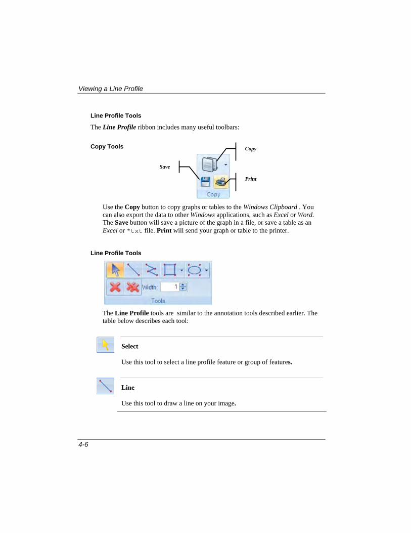
Viewing a Line Profile
4-6
Line Profile Tools
The Line Profile ribbon includes many useful toolbars:
Copy Tools
Use the Copy button to copy graphs or tables to the Windows Clipboard . You can also export the data to other Windows applications, such as Excel or Word. The Save button will save a picture of the graph in a file, or save a table as an Excel or *txt file. Print will send your graph or table to the printer.
Line Profile Tools
The Line Profile tools are similar to the annotation tools described earlier. The table below describes each tool:
Select
Use this tool to select a line profile feature or group of features.
Line
Use this tool to draw a line on your image.
Copy
Save

Viewing a Line Profile
4-7
Polygon/Polyline: This tool allows you draw poly-vertices lines and polygons, or freehand lines and shapes.
To draw freeform lines and shapes
Use this technique to create lines and shapes that have smooth edges. Hold the left mouse down while you draw with the cursor to create the desired freeform shape. Double-click to complete the shape.
To draw polyvertices lines and polygons
Use this technique to create lines and shapes that are made up of straight line segments. Click the left mouse button at each vertex (including the beginning point) of the polygon. Double-click to complete the polygon.
Rectangle
Click the left mouse button and hold it down to drag the rectangle to your desired size
Circle or Ellipse
Position the crosshair cursor anywhere in the image. Click and drag the mouse from the insertion point to the desired destination.
Delete Selected
Use this button to remove one line profile feature from your image.
Delete All
Use this button to remove all the line profile features from your image.

Viewing a Line Profile
4-8
Profile Tools
The Profile tools control the appearance of the line profile features and graph. You can show or hide the line profile label, adjust the opacity of the line, and change the colors that appear on the graph. The Left and Right arrows move the selected feature to the left or the right.
Background Tools
The Background combo box is used to select a background profile (values of background profile will be subtracted from all other profiles values). Background smoothing is used to select the type of smoothing for background profile values. The Points box indicates the number of points visible on the graph.

Viewing a Line Profile
4-9
The Options group contains controls for displaying the image.
The Log group displays the X and Y axis in a logarithmic scale.
To exit the Line Profile ribbon, click the Close button. .When you close the Line Profile ribbon, the Line Profile panel is no longer displayed, and all profile features are removed from the images they were created on.
Using the Auto-Trace feature
Activating the Auto Trace tool for an ROI or Annotation will cause the Polyline tool in Line Profile to behave the same as the Auto Trace tool. When you click on the Polyline feature and activate Auto Trace, you will see the following dialog:
The message at the top of the dialog indicates if auto-trace has started, or not.
Tracing speed: Use the slider to control the speed of the auto-trace.

Viewing a Line Profile
4-10
Edge quality: Indicate the number of pixels to use for the edge trace.
Noise reduction: Use the spin buttons to indicate the degree of noise reduction in the traced object.
Momentum: Use the spin buttons to indicate the degree of momentum in the traced object.
Smoothing: Use the spin buttons to indicate the degree smoothing in the traced object.
Check the box next to the auto trace feature that you want to use.
Auto Start Tracing: If this box is checked, the second mouse click made when creating a polygon or polyline will start the auto tracing. If uncheck, start auto trace by holding down the <Ctrl> key and clicking where you want the trace to start. The lightening bolt cursor shows you the auto trace path.
AutoAccept Final Trace: When this box is checked, the auto trace automatically returns to the starting point to finish tracing the object. If unchecked, you must press the <Enter> key or double-click the mouse to place the final point and complete the auto trace.
Trim Leading Points: Frequently, a trace will not return to its starting point but will interest with itself some distance from the starting point. If this box is checked, the points before the intersection point are removed if the intersection is close to the starting point. If this box is not checked, you must edit the trace manually to remove extraneous points.
Remove Redundant Points: If this box is checked, all horizontal, vertical, and diagonal runs leading to the auto trace are replaced by their end vertices in the final result. If this box is not checked, these points will be retained.
Monochrome Interpretation: When this box is checked, image color is ignored for edge detection; only average luminance is used. If unchecked, each color channel’s luminance gradient is considered when doing edge tracking.
Assume Clockwise: When this box is checked, the trace will begin moving clockwise around the object. This information is used to determine which side of the trace is the interior color. This option is useful when working with colored images. If this box is not checked, no assumption is made about which side of the trace is the interior.
Use Range Miniumu/Range Maximum: When checked, the range for full-scale luminance swings is assumed to be the full minimum/maximum range of the entire image. If this box is not checked, range for full-scale luminance swings is

Using the Saturation Warning
4-11
assumed to be the displayed range of image luminance. This option is usually left clear.
Bound Trace by ROI: When this box is checked, the trace object must stay within the bounds of the ROI. If this box is not checked, the boundaries of the ROI are ignored.
Disable Auto Trace: When this box is checked, auto-trace will be disable and you cannot use it until you uncheck the box.
Using the Saturation Warning
Use Saturation to show overexposed and underexposed areas with a given color. It can be used with the live preview to set proper exposure time and avoid saturated areas, so that an intensity measurements on the image will be correct.
Click the Saturation button to see the drop-down menu:
The colors are set using High level and Low level color pickers. Intensities that are greater than or equal to the High Level threshold will be colored with the designated high color.
Intensities that are less than or equal to Low Level threshold will be colored with the designated low color.
The channels used for saturation test can be selected using Red/Green/Blue checkboxes or by clicking the Channels button.

Using the Saturation Warning
4-12
This is a sample of a partial image with the high saturation areas visible:
The Reset button sets the controls back to their default values.

5-1
Chapter 5 Working with Images
This chapter introduces you to image processing in Q-Capture Pro 7. It provides instructions for opening, saving, and enhancing images through Q-Capture Pro 7.
When you start Q-Capture Pro 7, and the Welcome screen is turned on, you will see the list of your recent images in the Recent Documents pane.

Opening an Image
5-2
You can click the name of the image, and it will automatically open in the Q-Capture Pro 7 workspace:
If the Welcome screen is turned off, follow the directions below for opening an image.

Opening an Image
5-3
Opening an Image
To open a saved image:
1. Click the Application button.
The pull-down application menu appears.
2. Choose Open.
3. Select the type of image file that you want to open. Use the Look in pull-down list box to locate the folder in which it is stored.
Application button

Opening an Image
5-4
4. Click the Open button. The selected image is opened in the Q-Capture Pro 7 workspace.
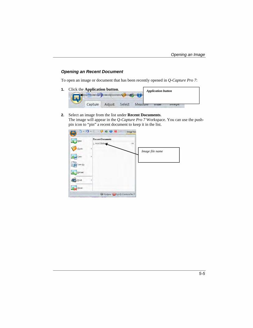
Opening an Image
5-5
Opening an Recent Document
To open an image or document that has been recently opened in Q-Capture Pro 7:
1. Click the Application button.
2. Select an image from the list under Recent Documents. The image will appear in the Q-Capture Pro 7 Workspace. You can use the push-pin icon to “pin” a recent document to keep it in the list.
Application button
Image file name

Opening an Image
5-6
Saving an Image
After you have finished working with your image, you will probably want to save it. To save an image, follow the steps below:
1. Click the Application button. The pull-down application menu appears.
2. Choose Save. You have a choice of saving only the active document (image) or saving all modified documents or images. Your image is saved automatically.

Opening an Image
5-7
Using Quick Save
In addition to using the Save to File feature of the image settings, Q-Capture Pro 7 offers you a quick and easy method of saving your images.
1. Go to the Quick Save group on the Capture tab.
2. Choose Quick Save for Analysis or Quick Save for Publication. If you are saving a series of images, choose Save as Movie.
When you select Analysis, you will see the following drop-down menu:
Quick Save for Analysis stores your images in *.TIF format so that they can
be retrieved for analysis at another time.
Open Saved Images goes to the Open dialog and lets you select a previously stored image.
Options takes you to the File Options page where you can change your preferences.
When you select Publication, you will see the following drop-down menu:
Publication stores your image in a *.JPG format that can be easily
incorporated into a report or spreadsheet.It also burns-in any annotations, ROIs, or measurements and resizes your image.

The Image Context Menu
5-8
Auto Open will automatically open your saved image in the Q-Capture Pro 7 workspace.
Open Saved Images goes to the Open dialog and lets you select a previously stored image.
Options takes you to the File Options page where you can change your preferences.
The Image Context Menu
Clicking the right mouse button on a image displays the following context menu
The Slider Bar allows you to adjust the size of the image by moving the slider to the right or left.
The Undo and Redo buttons let you reverse or repeat the last three action.
The Histogram button opens the image histogram .
The Image Properties button displays information about the image in a table below the image.
The Red, Green, Blue, and White tint buttons apply the appropriate color to the image.
The Delete and Delete All buttons remove tints from the active image or all open images.
Slider bar
Undo/Redo buttons
Red, Green, Blue, and White Tint
buttons
Image Histogram button
Image Properties button
Delete buttons
Selection tool

Zooming Images
5-9
Zooming Images
The zoom and pan controls allow you to resize the image or a portion of the image.
There are several ways to zoom in and out on an image, that is, to display it at different levels of magnification. You can:
Use the Zoom button in the Zoom group
Use Local Zoom
Use the wheel on your mouse (if available)
Use the scale bar.
Zooming by Using the Zoom Button
This method of zooming allows you to zoom in on specific areas of the image.
1. Click the Image tab from the Q-Capture Pro 7 menu bar. The Zoom group is displayed.
2. Click on the Zoom button [ ].
3. Do one of the following: Position your mouse over the area of the image you want to magnify, and click
the mouse.
Click and drag a rectangle around the area of interest on which you want to zoom.
The image is magnified. If needed, you can click or drag the mouse again to magnify the area of interest even further.

Zooming Images
5-10
Zooming with Local Zoom
The Local Zoom feature provides a tool to show a zoomed area of an image in a separate window with a given zoom factor. It can be used with manual measurements, the calibration marker, manual tagging, etc.
When you select Local Zoom, a new window opens on the right side of the application area.
The cross hairs in the Local Zoom window shows the current cursor location. This makes placing accurate manual measurements very easy, even on large images:
Zoom: Choose the required zoom factor from the drop-down list.
Cross hairs: Checking this box turns the cross hairs on; un-checking the box turns the cross hairs off. The color picker button selects the color of the cross hairs.
Zooming by Using the Mouse Wheel
If your mouse has a wheel on top between the left and right mouse buttons, you can use this wheel to zoom in and out on the image. Simply roll the wheel while the image is active in the Q-Capture Pro 7 workspace. Roll the wheel toward you to zoom out on the image, and roll the wheel away from you to zoom in on the image.
Zooming by Using the Scale Bar
This method for zooming allows you to take advantage of zoom presets, or to put the image in ‘fit to window’ mode so that whenever you resize the image window, the image is enlarged or reduced to the size of the window. For example, you can zoom the image to a specific percentage of its actual size, such as 50% or 200%.

Panning Images
5-11
1. Position the cursor over the image and right-click the mouse. You will see the scale bar.
2. Move the slider to the right to increase the size of the image, or to the left to decrease its size. You may also click the arrow to see the drop-down list of zoom presets. The scale bar also appears in the status bar at the bottom of the Q-Capture Pro 7 workspace.
Panning Images
The Pan tool is used to position an image that does not fit entirely within the image window. You can:
Use the Pan button in the Zoom group
Pan in the Image Strip
Panning Using the Pan Button
1. Click the Image tab from the Q-Capture Pro 7 menu bar. The Zoom group is displayed.
2. Click on the Pan button [ ].
3. Use your mouse to move the image around in the frame.

Panning Images
5-12
Panning in the Image Strip Using Image Navigator
The Image Strip displays a thumbnail of your entire image. When the active image is zoomed and doesn’t fit in the viewer, the viewing area is shown on the image strip thumbnail as a semitransparent overlay.
Click and drag the center of the viewing area on the thumbnail to control pan and scroll of the image.
The Image Navigator feature allows you to use your mouse to move the white rectangle around in the image strip. The zoomed portion of the image in the workspace will move as you move the thumbnail in the image strip.

Enhancing an Image
5-13
Enhancing an Image
There are several tools available through Q-Capture Pro 7’s Adjust tab for visually enhancing objects of interest in your images.
This section provides instructions for using some of them:
Colors
Filters
Background correction
Image transformaton.
Resizing an Image
Image transformation allows you to rotate or resize the image in the Q-Capture Pro 7 workspace. These options allow you to examine the image in more detail. To resize an image, follow these instructions.
1. Open the castiron.tif image in the Q-Capture Pro 7 workspace, as described earlier in this chapter.
2. Select the Transform group from the Adjust ribbon:
3. From the Resize pull-down menu, select an image size:

Enhancing an Image
5-14
4. Click the lock icon and select a measurement unit from the drop-down menu.
This will maintain the current aspect ratio of the image. To unlock the aspect ratio, click the icon again. You can find more information about aspect ratios in Chapter 3, Capturing Images.
5. From the second pull-down menu, select the type of smoothing you require in your resized image:
The resized image will appear in the workspace, with the name castiron_100resz*.

Enhancing an Image
5-15
Rotating an Image
Rotating an image allows you many different views of the same image. For example, you can rotate it 90 degrees counterclockwise, or flip it left to right. To try some of the image rotation features, follow these steps:
1. Open the image in the Q-Capture Pro 7 workspace, if it is not open already:
2. Select Rotate from the Transform group:
3. Use the pull-down menu to see the Rotate tools:
Rotate 90° clockwise
Rotate 90° counter clockwise
Flip left-right (mirror image)
Flip up/down
Rotate 180°
Swap lower left/upper right
View grid
Rotate and clip
Rotate and no clip
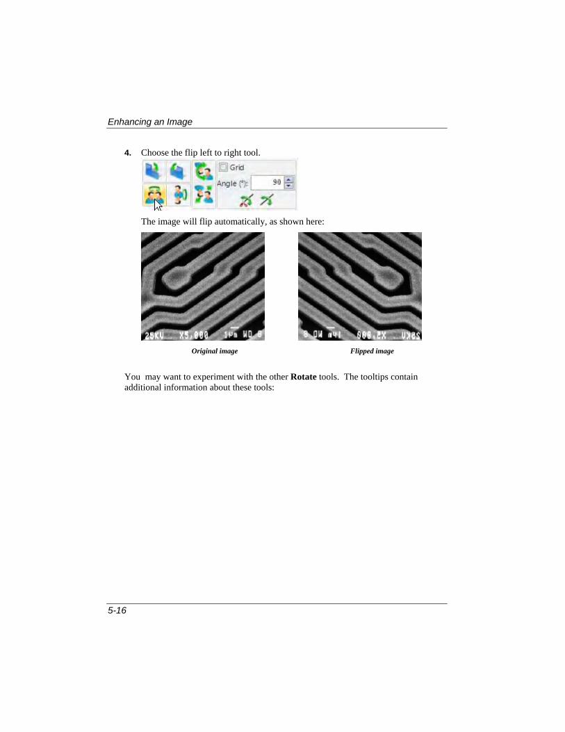
Enhancing an Image
5-16
4. Choose the flip left to right tool.
The image will flip automatically, as shown here:
Original image Flipped image
You may want to experiment with the other Rotate tools. The tooltips contain additional information about these tools:

Enhancing an Image
5-17
Using the Canvas
The drawing Canvas lets you add or remove space around an exisiting image.
1. To use the canvas, click on the Canvas button. You will see the drawing canvas, as shown here:
2. Use the Canvas size command from the drop-down arrow to position the image on the canvas, as shown here:
3. From here, you can add annotations and labels to the image on the canvas. You can also crop the image by removing space around it.

Enhancing an Image
5-18
Converting Images
Use the Convert group commands to transform an image to another color model, to extract a specific color channel from a color image, or to merge an active, 8-bit gray scale image into a True Color image. You might do this to perform editing or analysis upon the image in another model or to save the image data in a different model for use with an external program.
The Convert group is shown here:
To convert an image:
1. Select the Destination image type from the drop-down list.
2. Click Apply.
3. Select the type of conversion to perform. Your image is automatically converted to the new model. . Once you have set the conversion options the way that you want them, you can click the Apply button in the Convert group to convert the active image using the current settings without making furrther changes.

Enhancing an Image
5-19
Using Color Group Commands
Use the Color group commands to transform an image to another color model, to extract a specific color channel from a color image, or to merge an active, 8-bit gray scale image into a True Color image. The Color group is shown here:
Use the Extract selections to extract a specific color channel from a color image, and view it as an 8-bit Gray Scale image. You might do this to reduce the saturation values in a HSI image, or boost just the Blue values in an RGB image.
Use the Merge command to merge an active, Gray Scale image into a True Color image. This is usually done to return a channel, extracted with the Extract Channel command, to an image after the channel data have been manipulated. However, you might use it to merge any Gray Scale image to a color channel in a True Color image.
Dye/Tint Images
The Dye/Tint feature lets you apply color to your image(s). Click on the drop-down arrow to see the Dye/Tint dialog:
Check the Tint Image On/Off box to show or hide the tint on your image.

Enhancing an Image
5-20
Check Add to Color Composite to automatically add your tinted image to the color composite image.
The Dye drop-down list displays a list of your current set of favorite dyes. You may select a different dye from the drop-down list, and all the remaining controls will be updated to show the characteristics of the new dye. If the dyes you want are not in the
current set, click the settings button to display the Dye Editor dialog, where you can view a complete list of the available dyes. Here you can add select a new favorite dye, add a dye to the list, or delete old ones.
The Emission Wavelength drop-down displays the emission wavelength for the dye you have chosen. You can adjust the emission wavelength by clicking on the spectrum or entering a new value. The default Tint Color will change in response to changes in the emission wavelength.
The Tint Color box lets you choose a color to indicate a particular dye. Here you can change the color associated with the selected dye, or define a custom color. The default color is linked to the emission wavelength. When you change the emission wavelength, the tint color and hue change. The default Tint Color can be adjusted to a different hue by using the Hue slider or by entering an new Hue value. A completely custom Tint Color can be selected by clicking the down-arrow next to the Tint Color box, and selecting a standard or custom color.
The Emission Wavelength and Hue override a custom Tint Color, so to set a custom color, you should first set the wavelength, and then set the color using either the Hue controls or the Tint Color. Click Apply to add your dye or tint color to the active image.
Using Color Composite
Use Color Composite to create and configure color composites using black and white source images. You can access the Color Composite dialog box through the Color group on the Adjust tab.
You can combine grayscale images into a color composite. Any group of grayscale images that are of the same size can be mixed in a color composite. Images of 8-, 12-, 16-bit integer or floating point format are combined into a 24-bit color composite. Each input channel will have individual LUT adjustments, as well as a registration offset to line it up with the rest of the images. You can also combine individual channels from a single image. Each channel will be listed separately.
To create a color composite, follow the steps below.

Enhancing an Image
5-21
1. Open the images that you want to combine. In this example, we are using DemoRed.tif, DemoBlue.tif, and DemoGreen.tif.
2. Click the drop-down arrow in the Composite area in the Color Group on the Adjust tab.
3. Select Add All from the drop-down menu.
The three demo images are combined into a single color image in the Q-Capture Pro 7 workspace:
The three original images and the combined image appear as thumbnails in the image strip on the left side of the workspace.

Enhancing an Image
5-22
The color composite dialog on the right side of the workspace contains information about each image. Each of the original images represents a single channel in the composite image:
Detailed information about each color channels can be displayed by clicking on the + sign to expand the image information. You can make changes to the image information, change the color display, or remove one image/channel entirely.
Click the eye button to show, blink, or hide the composite images, as shown here:
Pseudo-Coloring an Image
Use the Pseudo-Color command to “colorize” an active monochrome (Gray Scale 8, Gray Scale 12, Gray Scale 16, or Floating Point) image. You might do this to highlight certain features in a gray scale image. For example, you might want to display all densities above a certain point in red, or, if your imaging device recorded thermal information, all temperatures below a certain point in blue.
You might also use it to visually amplify specific intensities that are very difficult to distinguish from their surroundings. For example, features produced by pixels with values of 122 in a field of pixels with similar values would be impossible to see in a gray tone image, but would jump out if that value were to be rendered in color.

Enhancing an Image
5-23
When you pseudo-color a monochrome image, you build a special palette through which your monochrome image is displayed. Pseudo-coloring an image does not modify the pixel values in your image bitmap in any way (it does not convert your image to True Color or Palette, for example). It simply associates a pseudo-color palette with the image, that interprets the gray-level values in the image as color.
Pseudo-colored images are very similar in structure to Palette class images, but they differ in a couple of important ways. First, the pixel values in a pseudo-colored image actually represent continuous-tone intensity information, whereas a Palette image's pixels carries no intensity significance. Secondly, a Palette image includes a palette table that is actually part of the image file.
The pseudo-color palette associated with a pseudo-colored image is not a permanent part of the image. It is a palette that you assign to the image while you work with it in Image-Pro. Pseudo-color palettes can be saved to a disk file, and later loaded for subsequent use with any monochrome (Gray Scale 8, Gray Scale 12, Gray Scale 16, or Floating Point) image.
The basic steps involved in pseudo-coloring the active, monochrome image are to:
1. Select the Pseudo button from the Color group on the Adjust ribbon:
2. Click the drop-down arrow to see the Pseudo-color dialog:
3. Check the Pseudocolor On/Off to show (or hide) the pseudo-coloring on the image.
4. Change the color assignments and refine the intensity division widths. This is done using the Spectrum and Type drop-down menus or the color bar.

Enhancing an Image
5-24
The Spectrum drop-down list lets you choose which colors will be used for coloring the images. Choices include Blue to Red, Red to Blue, Cyan, Magenta, and Yellow. You can also define a custom color spectrum.
Type lets you choose RGB, HSI CW, HSI CWW, or a custom type.
5. Specify the range of intensities you want to pseudo-color. The intensity range is specified using the Start and End spin buttons. You can load saved pseudo-color settings using the Load button.
6. Specify the number of distinct colors you want to associate with the selected intensity range. The number of colors is selected using the Divisions spin buttons.
7. Indicate the number of spins. If you want the spectrum to repeat over the intensity range of the image, you can set the Spins to the number of times to repeat the spectrum.
8. Save the settings for future use (with the current image, or with another). This step is optional. You do not need to save the pseudo-color assignments in order for them to be applied to the active image. If, however, you want to save it for continuing use or to exchange with a colleague, you need to save it. When you click the Save button, Q-Capture Pro 7 saves the current pseudo-color palette settings.

Enhancing an Image
5-25
Adjusting Color Channels
To adjust the color channels, or load a saved Look-Up Table (LUT) use the Channels group in the Display group.
The Channels feature contains the following tools:
1. Click the drop-down menu arrow.
2. Select the channel you want to adjust. The default is All channels.
9. Click the Advanced button. You will see the Advanced tools ribbon:
Reset Display
Invert Display
Apply Display to Image
Load LUT
Save LUT
Select Channel

Enhancing an Image
5-26
This tab contains all the features you may need to make and view changes to the Lookup Table.
As you make changes to the LUT, you will seem them reflected in the LUT profile graph at the bottom of the workspace:
Note: You will not get a dynamic LUT profile graph for *.AVI and *.SEQ files unless you select an active frame.
If you are working with a black and white image, you can adjust the black and white levels by using the BL: and WL: spin buttons, or typing new values in those fields.
Black Level
White Level
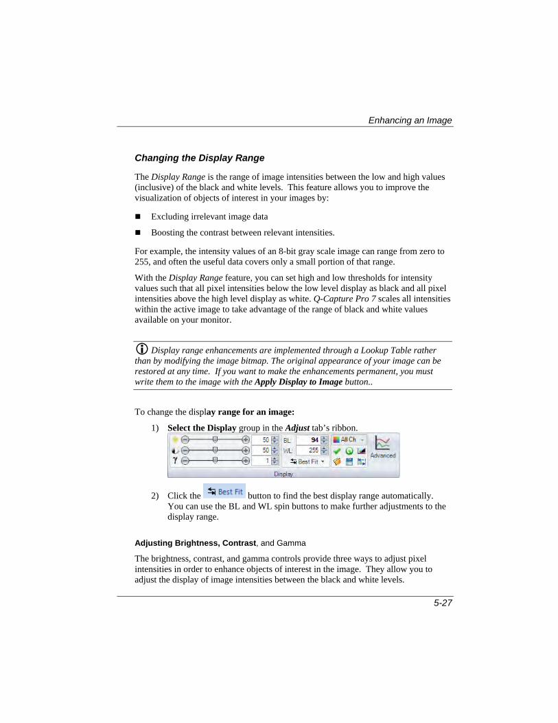
Enhancing an Image
5-27
Changing the Display Range
The Display Range is the range of image intensities between the low and high values (inclusive) of the black and white levels. This feature allows you to improve the visualization of objects of interest in your images by:
Excluding irrelevant image data
Boosting the contrast between relevant intensities.
For example, the intensity values of an 8-bit gray scale image can range from zero to 255, and often the useful data covers only a small portion of that range.
With the Display Range feature, you can set high and low thresholds for intensity values such that all pixel intensities below the low level display as black and all pixel intensities above the high level display as white. Q-Capture Pro 7 scales all intensities within the active image to take advantage of the range of black and white values available on your monitor.
Display range enhancements are implemented through a Lookup Table rather than by modifying the image bitmap. The original appearance of your image can be restored at any time. If you want to make the enhancements permanent, you must write them to the image with the Apply Display to Image button..
To change the display range for an image:
1) Select the Display group in the Adjust tab’s ribbon.
2) Click the button to find the best display range automatically. You can use the BL and WL spin buttons to make further adjustments to the display range.
Adjusting Brightness, Contrast, and Gamma
The brightness, contrast, and gamma controls provide three ways to adjust pixel intensities in order to enhance objects of interest in the image. They allow you to adjust the display of image intensities between the black and white levels.

Enhancing an Image
5-28
To adjust brightness, contrast, or gamma:
1. Click on the Display group in the Adjust tab’s ribbon:
As you move the sliders, the image in the workspace displays the changes in intensity.
2. Use your cursor to select the color channel that you want to adjust.
Brightness: Increases/decreases all intensity values uniformly. In the example below, brightness has been increased from the original.
Original After Brightness Increased
Contrast: Increases/decreases high and low intensity values reciprocally (that is, as the high values are increased, the corresponding low values are decreased, and vice versa). In the example below, contrast has been increased from the original.
Original After Contrast Increased
Gamma: Adjusts the contrast for the high and low intensity ranges simultaneously. In the example below, gamma has been decreased from the original.

Enhancing an Image
5-29
Original After Gamma Decreased
Resetting the Image
Because the enhancement features (Equalize, Contrast Enhancement, Display Range, and Invert Contrast) are implemented through a Lookup Table, the changes made to the appearance of your images are not permanent. You can restore the image to its original appearance at any time. To do this:
Click the Reset Display button from the Channels group.
The Lookup Table is reset and the image appears as it did before any enhancement options were defined.
Making Enhancements Permanent
Because the enhancement features (Equalize, Contrast Enhancement, Display Range, and Invert Contrast) are implemented through a Lookup Table, the changes made to the appearance of your images are not permanent. This means they will not be saved with the image. To make the enhancements permanent:
Click the Apply Display to Image button.
All Lookup Table values are permanently applied to the image and the Lookup Table is reset to its default state.

Enhancing an Image
5-30
Correcting the Background
Use the Background Correction command to make adjustments to the background of your image. This tool is used to better distinguish image background from image objects, making it easier to extract the objects during a counting or measurement operation. The Background Correction command can correct uneven background intensities, and compensate for irregularities due to uneven lighting, nonuniform camera response or minor optic imperfections. It might be used to remove evidence of dust on the lens, or to correct for bright spots caused by the light beneath the microscope's stage.
Q-Capture Pro 7 provides several tools that allow you to adjust the background of your image. They appear in the Background group on the Adjust ribbon:
Background Subtraction should be used for all images except those of
transmitted light experiments which will be used to measure optical density. You have the following choices:
Dark Background: Choose this setting to create a background image based on the maximum feature size and dark polarity of the active image.
Bright Background: Choose this setting to create a background image based the on maximum feature size and bright polarity of the active image
Background From Points: Choose this setting to create a background image based on a set of points on an image.
Background Correction should be used for optical density applications, as it accounts for the fact that optical density is not a linear function of the gray scale. You have the following choices:
Dark Background: Choose this setting to create a background image based on the maximum feature size and dark polarity of the active image.
Bright Background: Choose this setting to create a background image based the on maximum feature size and bright polarity of the active image

Enhancing an Image
5-31
Background From Points: Choose this setting to create a background image based on a set of points on an image.
The Options allow you to create a new image from the background image.
Extract background image displays the background image during black and white operations.
To use the background commands, follow these steps:
1. Open the image that you want to correct.
2. Click the Subtract drop-down arrow. You will see the following dialog:
You may use the browse button to choose a saved image to work with.
3. Choose a dark or light background to subtract, or create a background from a set of points.
4. Indicate the maximum feature size in pixels. The subtracted background will appear in the workspace.

Enhancing an Image
5-32
Applying Filters
Q-Capture Pro 7 filters are used to emphasize features of an image. The instructions below demonstrate how to apply the Sharpen filter to accentuate the edges in the castiron.tif image.
1. Open the castiron.tif image in the Q-Capture Pro 7 workspace, as described earlier in this chapter.
2. Select the Filters group on the Adjust tab’s ribbon:
3. Choose the Sharpen filter from the drop-down list of available filters.
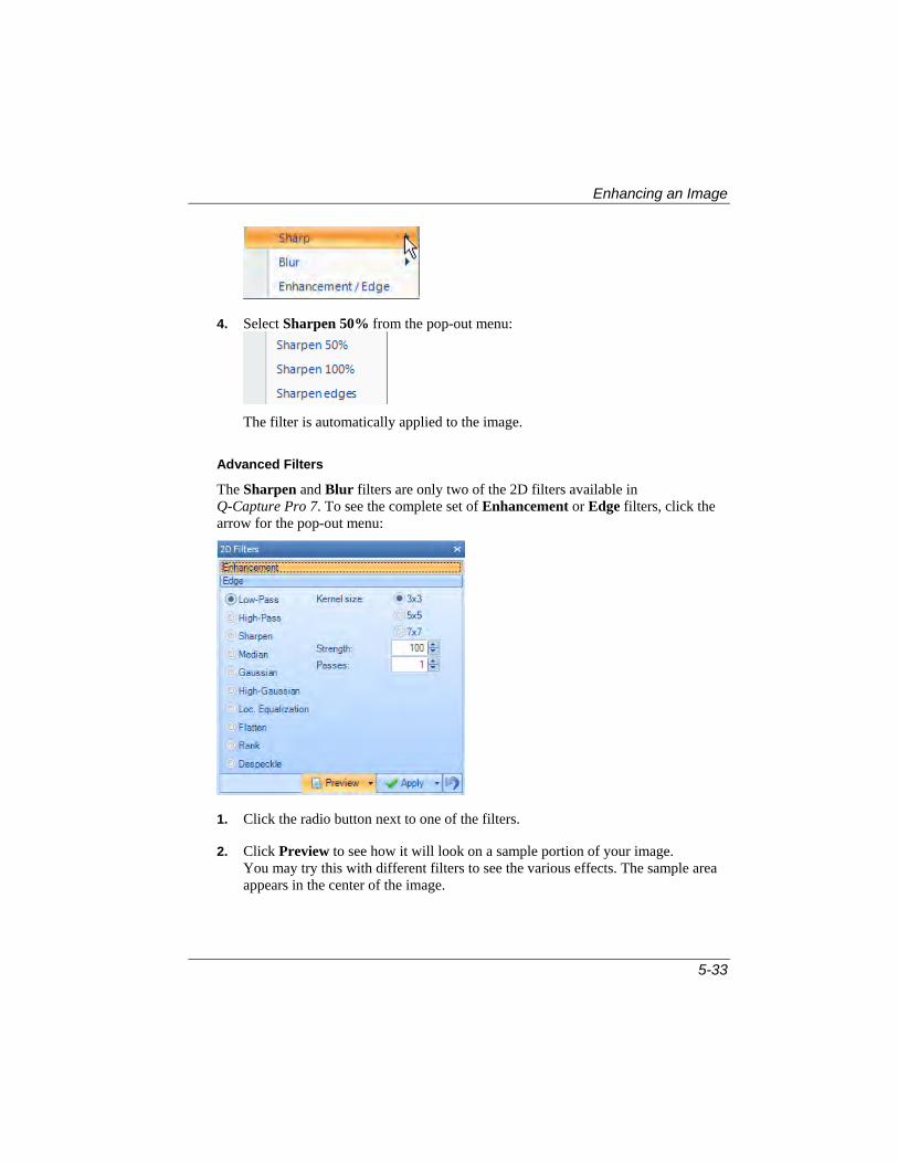
Enhancing an Image
5-33
4. Select Sharpen 50% from the pop-out menu:
The filter is automatically applied to the image.
Advanced Filters
The Sharpen and Blur filters are only two of the 2D filters available in Q-Capture Pro 7. To see the complete set of Enhancement or Edge filters, click the arrow for the pop-out menu:
1. Click the radio button next to one of the filters.
2. Click Preview to see how it will look on a sample portion of your image. You may try this with different filters to see the various effects. The sample area appears in the center of the image.

Image Sequences
5-34
Click Apply to apply the filter to the whole image.
Image Sequences
Q-Capture Pro 7 allows you to open and navigate multi-frame images saved in the .seq format. The sequence viewer is automatically used for images that have more than one frame. The sequence viewer has an on-screen toolbar, which appears only when you move your mouse over the image.
The example below shows the sequence toolbar at the bottom of the image area(as window decoration):
The toolbar has the following buttons:
Go to first frame
Go back one frame
Play sequence backward
Play sequence forward
Go forward one frame
Go to last frame

Image Sequences
5-35
Use active range applies filters and other operations to the active range of frames (on) or to the individual active frame only (off).
The playback options button opens the following options dialog:
Click Set Start or Set End to set the current frame as start or end of the active playback range of the sequence. By default the range is set to all frames.
The Rate control defines the playback speed in frames per second.
Loop combo-box determines the action taken during playback when the end or beginning of the sequence frame range is passed. Choose one of the following options:
Use this button to click and drag the sequence toolbar
Click this button to move the toolbar to the area above the status bar.
Clicking the button will move the toolbar back to the image.
This button also displays the Advanced Sequence Control toolbar.
This version of the toolbar contains all the functions of the smaller version and displays the frame numbers also.

Image Sequences
5-36
The Subsample feature on the Adjust tab allows you to create a new sequence from a portion of the original sequence. Subsampling builds a new sequence from copies of the selected frames. The operation always starts from the first frame in the active frame range. When the Interval is less than 1, the input sequence will be oversampled.
Note that all sequence operations work with the selected images. Multiple images can be selected in the image strip using <Ctrl> or <Shift > + left mouxe clicks. If no multiple images are selected, the active image sequence is used for processing.
Interval: This control allows you to specify the interval that will be used for the sub-sampling. In the example above, the sub-sampled sequence will be composed of every 2nd frame of the original sequence.
Difference: These controls calculate the frame-to-frame difference of selected portions of your sequence. New images are created using the subsampled portion of your sequence. The options define how the last or first frames will be processed:
Wrap Around : Calculates the last frame as the difference between the last and first frames
Diff only: Return only the difference frames (result will be one frame shorter than the original)
Pad First - Pad the result with the first frame of no difference
Pad Last - Pad the result with the last frame of no difference
Average: Calculates the average of all frames of the selected images.
Sum: Calculates the sum of all frames of the selected images. Note that the output image will be a floating point type with the number of channels corresponding to the source image.

Image Sequences
5-37
Maximum: Creates a maximum intensity projection of all frames.
Minimum: Creates a minimum intensity projection of all frames.
Saving a Movie
To save your image sequence as an *.AVI file, follow the steps below:
1. Go to the Quick Save group on the Capture tab.
2. Choose Save as Movie. You will see the Save As dialog:
Q-Capture Pro 7 takes a snapshot of your image sequence.
3. Click Save. Your snapshot is saved as an *.AVI file.

Image Sequences
5-38

6-1
Chapter 6 Using Annotations
Annotations are used to add text or drawings to your images. The annotations are in a graphics overlay that is displayed over the image without modifying the image data itself. This chapter provides instructions for creating text and graphical annotations, arranging them, and saving them with your images.
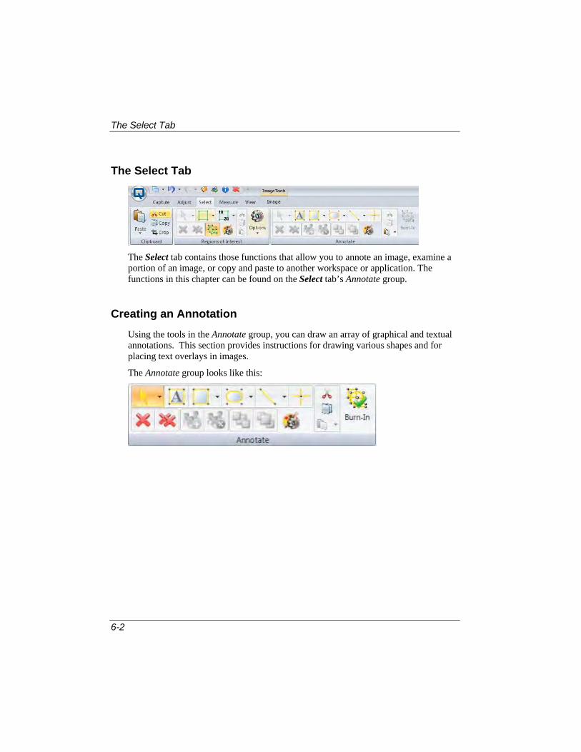
The Select Tab
6-2
The Select Tab
The Select tab contains those functions that allow you to annote an image, examine a portion of an image, or copy and paste to another workspace or application. The functions in this chapter can be found on the Select tab’s Annotate group.
Creating an Annotation
Using the tools in the Annotate group, you can draw an array of graphical and textual annotations. This section provides instructions for drawing various shapes and for placing text overlays in images.
The Annotate group looks like this:

Creating an Annotation
6-3
Creating a Graphical Annotation
There are a number of options for annotating your images with graphical overlays. You can define points, lines, rectangles, rounded rectangles, ellipses, polygons, and polylines.
To define a graphical annotation:
1. Go to the Annotate group in the Select tab’s ribbon. You will see these tools:
2. In the toolbar, click on the annotation tool you want to use, and draw the annotation in the image as described for that tool below.
Selection
Use this tool to select an annotation object or group of objects.
Text Box
Use this tool to add a text box annotation.
Line
Ellipse
Rounded Rectangle
Polyline
Points
Rectangle
Polygon

Creating an Annotation
6-4
Rectangle or Rounded Rectangle
Click the left mouse button and hold it down to drag the rectangle to your desired size
Circle or Ellipse
Position the crosshair cursor anywhere in the image. Click and drag the mouse from the insertion point to the desired destination.
‘
Polygon/Polyline This tool allows you draw poly-vertices lines and polygons, or freehand lines and shapes.
Note: Whether this tool draws a polygon or a polyline depends on the current setting for the Connect Start/End option. To change the status of this option, simply right-click the mouse over the object after it is drawn, and select Annotation|Object Properties…. The Connect Start/End option appears on the Polygon tab of the Graphic Object Properties dialog box.
To draw freeform lines and shapes
Use this technique to create lines and shapes that have smooth edges. Hold the left mouse down while you draw with the cursor to create the desired freeform shape. Double-click to complete the shape.
To draw polyvertices lines and polygons
Use this technique to create lines and shapes that are made up of straight line segments. Click the left mouse button at each vertex (including the beginning point) of the polygon. Double-click to complete the polygon.

Creating an Annotation
6-5
Auto-Trace. Use this tool to trace the outline of an irregular object in the image automatically. Place your cursor on the object and click two points. Q-Capture Pro 7 automatically traces the object.
Point
Position the crosshair cursor in the image where you want to place the point marker. Click the mouse to place the point.
Delete Selected/Delete All
Use the buttons to remove one or more of the annotations from your image.
Group/Ungroup
Use these buttons to collect your annotations into a group or to ungroup them.
Order
Use these buttons to order your annotations front to back or back to front.
Cut, Copy, Paste
Use these tools to cut, copy, or paste annotations.
Burn In
Use this button to make the current annotation a permanent part of the image.
Display Options
Use this button to see the Display Options panel.
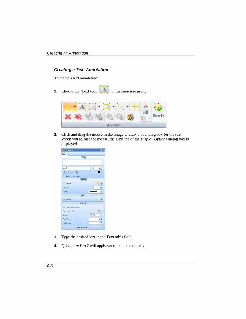
Creating an Annotation
6-6
Creating a Text Annotation
To create a text annotation:
1. Choose the Text tool [ ] in the Annotate group.
2. Click and drag the mouse in the image to draw a bounding box for the text. When you release the mouse, the Text tab of the Display Options dialog box is displayed.
3. Type the desired text in the Text tab’s field.
4. Q-Capture Pro 7 will apply your text automatically.

Arranging Annotations
6-7
The specified text appears as an overlay in the image. For instructions on changing the font, color, or bounding box attributes of the text annotation, please refer to “Setting the Appearance of Annotations” later in this chapter.
Arranging Annotations
After you have created a set of annotations, you can move them, resize them, layer them, and delete them.
Moving an Annotation
To move an annotation:
1. Click the Selection tool [ ] from the Annotate group.
2. Click on the annotation you want to move. The annotation is selected.
3. Position the cursor over the selected annotation. If the cursor is positioned correctly, the Dragging tool [ ] appears.
4. Click and drag the annotation to the desired location.
TIP: You can also move the annotation by pressing the <Shift> key along with the arrow keys (up/down, right/left). For example, press the <Shift> and <Up Arrow> keys and notice the annotation moving upwards.
Rotating an Annotation
Annotations can be rotated by using the Select tool and the <Control> key.
1. Click the Selection tool [ ] from the Annotate group.
2. Click on the annotation you want to rotate. The annotation is selected.
3. While the Annotation is selected, move your cursor to the center point of the Annotation. The rotate cursor (a double-ended arrow) will appear, enabling you

Arranging Annotations
6-8
to rotate the annotation either clockwise or counter-clockwise. Holding down the <Shift> key while rotating an annotation will move the annotation i 15-degree increments. You can also rotate an annotation while creating or editing it by holding down the <Control> key as you move the annotation.
Resizing/Reshaping an Annotation
Annotations can be resized and reshaped by moving their control points. To resize or reshape an annotation:
1. Click the Selection tool [ ] from the Annotate group.
2. Click on the annotation you want to resize or reshape. The annotation is selected.
3. Position the cursor over the control point that you want to move. If the cursor is positioned correctly, the Resize tool [ or ] appears over the control point.
4. Click and drag the control point to the desired location.
Grouping Annotations
The Annotation feature allows you to group annotations in the image. Annotations that are grouped are fixed in positioning relative to each other and they are otherwise treated as one object. To group annotations:
1. Click the Selection tool [ ] in the Annotate group.
2. While holding the <Ctrl> key down on the keyboard, click on the annotations you want to include in the group. For example, annotations #2 and #3 have been selected below.

Arranging Annotations
6-9
3. Click on the Group button [ ]on the Annotate panel. The selected annotations are grouped.
4. To ungroup an collection of annotations, click the Ungroup button[ ].
Ordering Annotations
The Annotation feature allows you to control the order in which annotations appear. To change the order in which an annotation appears:
1. Click the Selection tool [ ] in the Annotate group.
2. Click on the annotation you want to relocate in the order. For example, annotation #3 has been selected below.
3. Click the Order back to front button in the Annotate group.
The annotations are arranged in the order specified.
4. To reverse the order of the annotations, click the Move Front [ ] button.

Setting the Appearance of Annotations
6-10
Deleting an Annotation
To delete an annotation:
1. Click the Selection tool [ ] from the Annotate group.
2. Click on the annotation that you want to delete. The annotation is selected.
3. Click Delete [ ] from the Annotate group, or press the <Delete> key.
Setting the Appearance of Annotations
These instructions explain how to change the appearance of an existing annotation and how to set the default appearance attributes for the different annotation types.
Changing the Appearance of an Annotation
To change the appearance of an annotation:
1. Click the Selection tool [ ] from the Annotate group.
2. Click on the annotation that you want to change. The annotation is selected.
3. Click the Display Options button in the Annotate group. You will see the Display Options panel in the panel along the right side of the workspace.

Setting the Appearance of Annotations
6-11
4. Use the border, fill, and other options to change the appearance of the annotation.
Drawing Properties
Some common controls available for changing the appearance of graphical annotations are described below.
Border: Allows you to change the visibility, color, width, and line style of a border around your annotation.
Fill: Allows you to choose the fill color for your annotation, including opacity and/or transparency.
Options: These options allow you to change the size of the annotation when the size of the images changes, adjust the opacity/transparency of the annotation, and layer annotations on the image. If you are working with an image sequence,you can specify the first and last frrames where the annotation will appear.
Color: Click on the Color button to change the color of the bounding box border or fill, or to change the color of the text.
Zoom with Image: Check this box to make the annotate larger or smaller as the image is resized.

Setting the Appearance of Annotations
6-12
Label Properties
Some common controls available for changing the appearance of label annotations are described below.
Text: Click on the Text tab to change the text of the annotation.
Font : Allows you to change the font to be used for rendering text.
Size : Allows you to change the font size to be used for rendering text.
: Allows you to make the text bold, italics, underlined, or strike-though a letter.
5. When you have made the desired changes, close the Annotation Display Options dialog box.
The changes are applied to the selected annotation.
Setting the Default Appearance for Annotations
The default appearance attributes for annotations are set by designating the appearance attributes of an existing annotation as the default for future annotations of that type. Note that defaults exist independently for each type of annotation you can draw: rectangle, rounded rectangle, ellipse, polygon, point, and text. To set the default appearance for an annotation type:
1. Click the Selection tool [ ] from the Annotate group.
2. In the active image, click on an annotation of the type for which you want to set appearance defaults. For example, if you want to set the default appearance for ellipse-type annotations, click on an ellipse-type annotation in the active image. If one doesn’t exist, draw one.

Setting the Appearance of Annotations
6-13
3. Click the Display Options button in the Annotate group. You will see the Display Options dialog box along the right side of the workspace.
4. Click Save as Default The default appearance values are set. Future annotations of that type will appear as the selected annotation. Note that when you exit Q-Capture Pro 7, your appearance values are reset to the defaults.
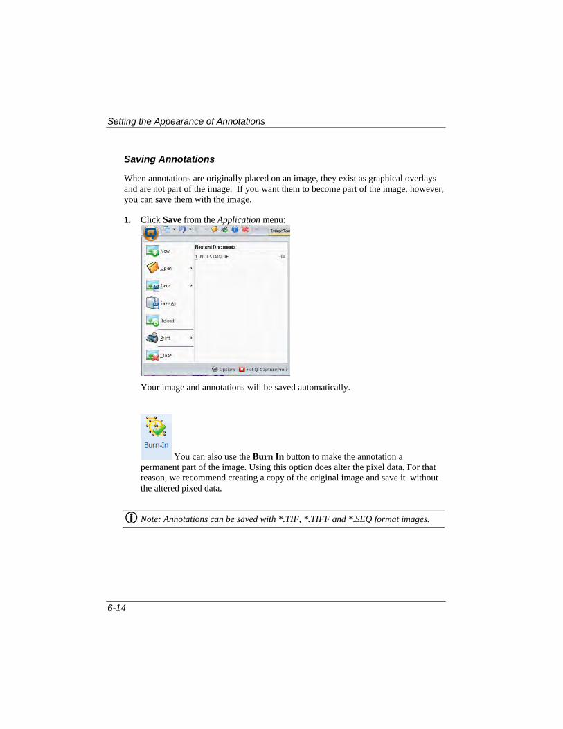
Setting the Appearance of Annotations
6-14
Saving Annotations
When annotations are originally placed on an image, they exist as graphical overlays and are not part of the image. If you want them to become part of the image, however, you can save them with the image.
1. Click Save from the Application menu:
Your image and annotations will be saved automatically.
You can also use the Burn In button to make the annotation a permanent part of the image. Using this option does alter the pixel data. For that reason, we recommend creating a copy of the original image and save it without the altered pixed data.
Note: Annotations can be saved with *.TIF, *.TIFF and *.SEQ format images.

7-1
Chapter 7 Using ROIs
You can define one or more Regions of Interest (ROIs) in a variety of shapes, and you can control the positioning, size, appearance and display status of ROIs. This chapter provides step-by-step instructions for defining and working with ROIs to isolate areas of interest in your images.
You can find the ROI feature on the Select tab’s ribbon:

What is an ROI?
7-2
What is an ROI?
An ROI is an Region of Interest that is isolated from the rest of the image. Certain Q-Capture Pro 7 commands can be constrained by an ROI. Once you have defined an ROI, the command applies to only the pixels within the ROI.
Examples of commands that are constrained by an ROI are: Save As, Cut, Copy, Duplicate, Rotate, and Resize.
For example, in Figure 7-1 below, a square-shaped ROI has been drawn around a particular object of interest in the image. When the Duplicate command is applied to the image, the ROI portion of the image is copied to a new image, as shown in Figure 7-2.
Figure 7-1 Figure 7-2
You can also apply a filter to an ROI. Figure 7-3 show an image with an ROI drawn on it, and a Sharpen filter applied to the selected area:
Figure 7-3
More information about applying filters appears in Chapter 5.

Defining an ROI
7-3
Defining an ROI
Before defining an ROI, be sure the image you want to work with is opened in the Q-Capture Pro 7 workspace. To define an ROI in the active image:
1. Go to the ROI group on the Select tab’s ribbon:
2. Click on the ROI tool you want to use, and draw the ROI in the image as described for that tool below.
Selection Tool: Use the arrow to select an ROI on the image. Click the drop-down arrow and use the Multiple ROI tool to select all the ROIS in an image.
Rectangle or Rounded Rectangle ROI: This tool allows you to define a rectangular or square ROI. Click and drag the mouse from one corner of the Region of Interest to the opposite corner. To force a perfect square, hold down the <Shift> key as you click and drag the mouse.
Circle or Ellipse: This tool allows you to define a circular or elliptical ROI in the image. To force a perfect circle, hold down the <Shift> key as you click and drag the mouse.

Defining an ROI
7-4
Rectangle by Numbers: This tool allows you to define a rectangular RO by entering the left, right, top, and bottom locations.
Polygon: This tool allows you define a polygon-shaped or freeform ROI in the image.
To define a freeform ROI
Use this technique to create smooth edges. Hold the left mouse down while you draw with the cursor to create the desired freeform shape. Double-click to complete the shape.
To define a polygon-shaped ROI
Use this technique to create polygons that are made up of straight line segments. Click the left mouse button at each vertex (including the beginning point) of the polygon. Double-click to complete the polygon.
Auto-Trace. Use this tool to trace the outline of an irregular object in the image automatically. Place your cursor on the object and click two points. Q-Capture Pro 7 automatically traces the object.
Display Options
Use this button to see the Display Options panel.

7-5
Delete Selected/Delete All:
Use the buttons to remove one or more of the ROIs from your image.
Multiple ROIs: Click this button to place mutiple ROIs on your image. This option is always on by default.
Display Options
Use this button to see some additional ROI options:
Invert ROI: Click this button to invert the ROI; for example, a black ROI on a white background.
XOR Pixels: Click this button to include or exclude pixels in overlapping ROIs. This option is always on by default.
Order: Use these buttons to arrange your ROIs from back to front, or front to back.

Placing Multiple ROIs on an Image
7-6
Placing Multiple ROIs on an Image
If you want to define more than one ROI in a single image, you can use the Allow Multiple ROIs tool.
Click on the Allow Multiple ROIs [ ] button in the ROI group so that it is highlighted. This is the default selection.
When this tool is selected, you can define multiple ROIs in a single image.
Arranging ROIs
After you have defined an ROI, you can move it, resize it, and delete it.
Moving an ROI
To move an ROI:
1. Click the Selection tool [ ] from the ROI group.
2. Click on the ROI you want to move. The ROI is selected.
3. Position the cursor over the selected ROI. If the cursor is positioned correctly, the Dragging tool [ ] appears.
4. Click and drag the ROI to the desired location.
Resizing an ROI
ROIs can be resized by moving their control points. To resize an ROI:
1. Click the Selection tool [ ] from the ROI group.
2. Click on the ROI you want to resize. The selected ROI is selected.
3. Position the cursor over the control point that you want to move.

Arranging ROIs
7-7
If the cursor is positioned correctly, the Resize tool [ or ] appears over the control point.
4. Click and drag the control point to the desired location.
Using XOR Pixels
Use this feature to examine pixels in overlapping ROIs on your image. To apply a filter using XOR pixels, follow these steps:
1. Draw two or more ROIs on your image, as shown here:
2. Go to the Adjust tab and select the Filters group.
3. Choose a filter from the filters list:
4. Click Apply

Arranging ROIs
7-8
Your filter will be applied to the area between the flags on the image.
Rotating an ROI
You can rotate a selected ROI without rotating the image.
1. Click the Selection tool [ ] from the ROI group.
2. Click on the ROI you want to resize. The selected ROI is selected.
3. Position the cursor over the center point in the ROI that you want to rotate. You will see the rotation cursor.
4. Click and drag to rotate the ROI.
Deleting an ROI
To delete an ROI:
1. Click the Selection tool [ ] from the ROI group.
2. Click on the ROI you want to delete.
3. Click the Delete [ ] button or Press the <Delete> key. Note that you can also use the delete button in the image context menu (click the right mouse button on the image when an ROI is selected) to delete the selected ROI.
TIP: You can use the Delete All tool in the ROI group to instantly remove all ROIs defined in the active image.

Setting the Appearance of ROIs
7-9
Setting the Appearance of ROIs
These instructions explain how to change the appearance of an existing ROI and how to set the default appearance attributes for the different ROI types.
Changing the Appearance of an ROI
Sometimes you might want to change the border or fill color or size of your ROI to make it easier to see on your image. To change the appearance of an ROI:
1. Click the Selection tool [ ] from the ROI group.
2. Click on the ROI that you want to change. The ROI is highlighted.
3. Click the Display Options button in the ROI group. You will see the Display Options dialog box in the panel along the right side of the workspace.
4. Use the controls available through this dialog box to change the appearance of the ROI.

Setting the Appearance of ROIs
7-10
Drawing Properties
Some common controls available for changing the appearance of graphical annotations are described below.
Border: Allows you to change the visibility, color, width, and line style of a border around your annotation.
Fill: Allows you to choose the fill color for your annotation, including opacity and/or transparency.
Options: These options allow you to change the size of the annotation when the size of the images changes, adjust the opacity/transparency of the annotation, and layer annotations on the image. If you are working with an image sequence,you can specify the first and last frrames where the annotation will appear.
Color: Click on the Color button to change the color of the bounding box border or fill, or to change the color of the text.
Zoom with Image: Check this box to make the annotate larger or smaller as the image is resized.

Setting the Appearance of ROIs
7-11
Label Properties
Some common controls available for changing the appearance of label annotations are described below.
Text: Click on the Text tab to change the text of the annotation.
Font : Allows you to change the font to be used for rendering text.
Size : Allows you to change the font size to be used for rendering text.
: Allows you to make the text bold, italics, underlined, or strike-though a letter.
5. When you have made the desired changes, click the ROI Display Options panel.
The changes are applied to the selected ROI.

Setting the Appearance of ROIs
7-12
Setting the Default Appearance for ROIs
The default appearance attributes for ROIs are set by designating the appearance attributes of an existing ROI as the default for future ROIs of that type. Note that defaults exist independently for each type of ROI you can draw: rectangle, rounded rectangle, ellipse, polygon, point, and text. To set the default appearance for an ROI type:
1. Click the Selection tool [ ] from the ROI group.
2. In the active image, click on an ROI of the type for which you want to set appearance defaults. For example, if you want to set the default appearance for ellipse-type ROIs, click on an ellipse-type ROI in the active image. If one doesn’t exist, draw one.
3. Click the Display Options button in the ROI group. You will see the Display Options panel along the right side of the workspace.
4. Click Save as Default The default appearance values are set. Future ROIs of that type will appear as the selected ROI.

8-1
Chapter 8 Measuring Objects in Images
This chapter describes how to measure features in images.
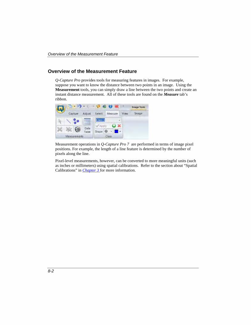
Overview of the Measurement Feature
8-2
Overview of the Measurement Feature
Q-Capture Pro provides tools for measuring features in images. For example, suppose you want to know the distance between two points in an image. Using the Measurement tools, you can simply draw a line between the two points and create an instant distance measurement. All of these tools are found on the Measure tab’s ribbon.
Measurement operations in Q-Capture Pro 7 are performed in terms of image pixel positions. For example, the length of a line feature is determined by the number of pixels along the line.
Pixel-level measurements, however, can be converted to more meaningful units (such as inches or millimeters) using spatial calibrations. Refer to the section about “Spatial Calibrations” in Chapter 3 for more information.

Making Manual Measurements
8-3
Making Manual Measurements
This section describes how to define measurements and view your measurement data.
Measuring Features in an Image
Q-Capture Pro includes line measurement and manual tagging tools:
Line tool Selection tool
Delete selected line Show Data Table
Delete all
Manual Tag tool
Measurement display options

Making Manual Measurements
8-4
To make line measurements in an image:
1. Open the image that has features you want to measure. The image appears in the Q-Capture Pro 7 workspace.
2. Go to the Measurements group on the Measure tab’s ribbon.
3. Select the line tool . This tool allows you to measure a line drawn on the image.
4. Apply or define the spatial calibration that you want to use. See “Managing Calibrations” in Chapter 3 for more information.
5. Draw a line on the image. The measurement information will appear in a label on the image. The label will appear near the center of the line without covering up the end symbol or much of the line itself.

Making Manual Measurements
8-5
You can make changes to the appearance of your measurements using the Class group on the Measure tab’s ribbon:
This feature allows you to classify different measurements and classes by assigning them different colors.You may also change the class name.
6. Use the Shape and Color buttons to assign properties to each class or group of measurements. Your changes are automatically applied to the measurements on the image.
7. You can export the data to an Excel spreadsheet or other program if you want.
Note: Measurements and Manual Tagging can be applied to live preview images for quick measurement previews. However, these measurements are not saved with the captured image.
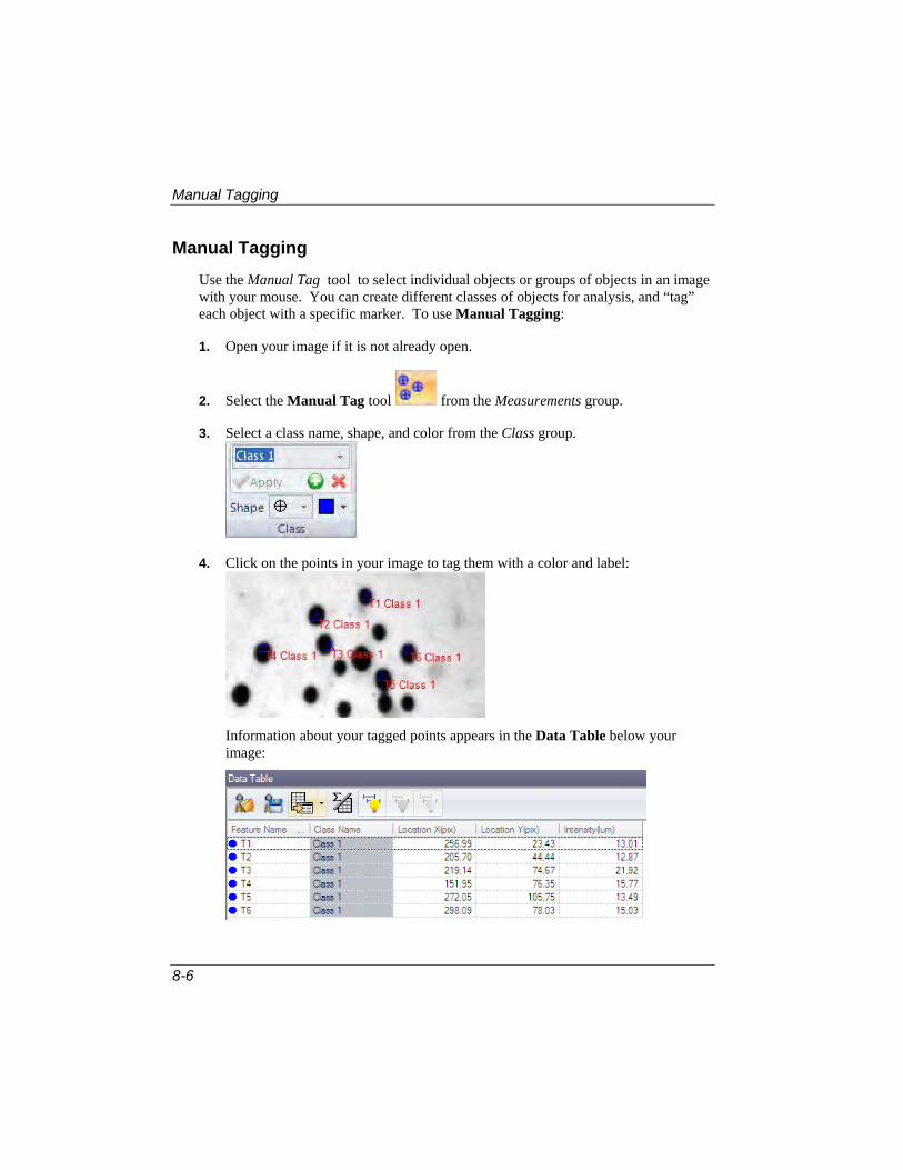
Manual Tagging
8-6
Manual Tagging
Use the Manual Tag tool to select individual objects or groups of objects in an image with your mouse. You can create different classes of objects for analysis, and “tag” each object with a specific marker. To use Manual Tagging:
1. Open your image if it is not already open.
2. Select the Manual Tag tool from the Measurements group.
3. Select a class name, shape, and color from the Class group.
4. Click on the points in your image to tag them with a color and label:
Information about your tagged points appears in the Data Table below your image:

Manual Tagging
8-7
5. Save your data to a file or export it to Excel.
Setting the Default Appearance for Measurement Labels
The default appearance attributes for measurement labels are set by designating the appearance attributes of an existing label as the default for future measurement labels. To set the default appearance for measurement labels:
1. Click Select [ ] from the Measurements group.
2. In the active image, click on a label of the type for which you want to set appearance defaults. Most labels appear at the top-left or bottom-right positions near the marker.
3. Click the Options button. You will see the Meaurement Options panel:

Manual Tagging
8-8
4. Go to the Font panel.
5. Choose a font from the drop-down list:
You will see the measurement labels change to the font you select. Use the color, style, and size buttons to make additional changes to the measurement labels.
6. In the Labels panel, select the text, position, and units of measure for the measurement labels:
The choices for Text include:
None – no labels
Name – measurement object name is displayed
Measurement – the label measurement is displayed
Name And Measurement – full name and measurement are displayed.
Units of measure and measurement abbreviations can be added to the measurement label by checking the appropriate boxes. You can also indicate the number of decimal points for each measurement.
Here is an example of measurements with labels:

Manual Tagging
8-9
7. Use the Outlines panel to define the style of the each object class and shape:
8. The Cursor panel lets you customize the measurements cursor:
Cross Bars are useful adjusting line ends on the features. They are only active
in the line editing mode.
Crosshair helps you to center horizontal or vertical measurements.
Tooltip shows measurement data on the image when you are moving the mouse over an object on the image.
Q-Capture Pro 7 automatically saves any changes you make and applies them to all future labels.

Viewing Measurement Data
8-10
Viewing Measurement Data
The Measure ribbon contains the data table feature to collect and view measurement data. This feature is described below.
Viewing a Data Table
The Data Table collects all the information from the measurements taken on your image. To view a data table:
1. Open the image if it is not already open.
2. Select the points or lines that you want to measure.
3. Click the Data button in the Measurements group.
4. The data table will appear in a pane below your image:

Viewing Measurement Data
8-11
The Data Table provides the following tools:
Load Data Table Measurements: This tool allows you to load measurements saved in a previous sesssion from a *.ipm file.
Save Data Table Measurements: This tool allows you to save your measurements in a *.ipm file for use at another time.
Export to Excel: This tool allows you to save your measurement data to a file or export it to an Excel spreadsheet.
Show all Statistics: This tool allows you to hide or show the statistics panel for the data table measurements. A sample statistics panel is shown here:
Show All, Show Selected Measurements, Hide Selected Measurements: These tools let you choose to display or hide some of the measurement statistics.

Viewing Measurement Data
8-12

9-1
Chapter 9 Customizing the User Interface
This chapter provides instructions for the many ways you can customize the Q-Capture Pro 7 application interface. Q-Capture Pro 7 allows you to set up the interface in the most efficient way for your work.

Using the Quick Access Toolbar
9-2
Using the Quick Access Toolbar
The Quick Access Toolbar appears at the top left of the Q-Capture Pro 7 interface.
The Quick Access Toolbar allows you to display icons that, when clicked, execute a system-supplied or user-defined command. In this way, the Quick Access Toolbar provides a shortcut to commonly used functions.
Application button
Quick Access Toolbar

Using the Quick Access Toolbar
9-3
To Add a Shortcut to the Quick Access Toolbar
1. Click the drop-down button next to the Quick Access Toolbar. The following menu appears.
2. Click on More Commands in the drop-down menu. The Customize Quick Access Toolbar dialog box appears.
The list box on the left displays all the available commands and icons. The list box on the right displays those commands and icons currently displayed in the Quick Access Toolbar.
The Choose commands from...drop-down list displays different groups of available commands, as shown here:

Using the Quick Access Toolbar
9-4
3. Select a group of commands to display in the list box.
4. In the list box box, highlight the command you want to add to the Quick Access Toolbar.
5. For example, if you regularly use the Paste command in Q-Capture Pro 7, you can make a shortcut that performs a paste by adding a Paste command and icon to the Quick Access Toolbar. If you are unsure which commands you need, choose All Commands.
6. Click the Add button and the command appears in the right hand list box.
7. Click on the OK button. The shortcut is added to the Quick Access Toolbar.

Using the Quick Access Toolbar
9-5
You can also add a group of commands to the Quick Access Toolbar.
1. Place your cursor along the buttom of one of the groups on the ribbon; for example, Annotate.
2. Click the right mouse button. You will see a pop-out menu.
3. Choose Add to Quick Access Toolbar. The Annotate icon appears in the Quick Access Toolbar.
Deleting a Shortcut from the Quick Access Toolbar
To remove a shortcut from the Quick Access Toolbar, follow these steps:
1. Place your cursor on the command icon that you wish to remove:
2. Click the right mouse button. You will see the following drop-down menu:
3. Choose Remove from Quick Access Toolbar, or press <Control> + <R>.

Customizing the Image Strip
9-6
Customizing the Image Strip
The Image Strip displays thumbnails of all opened images in the application and provides an easy way of activating and deleting images. The Image Strip controls are located in the Workspace group on the View tab’s ribbon:
Q-Capture Pro 7 opens the Image Strip automatically when you launch the application. It appears on the left side of the application window.
Image Strip

Customizing the Image Strip
9-7
If you have several images open, the Image Strip will display thumbnails of all of them:
The layout of the images can be selected from the Context menu. Click the right mouse button on the image thumbnail to see the Context menu.
To change how the thumbnails are displayed in the Image Strip, choose one of the options from the Thumbnail size pop-out menu.

Customizing the Image Strip
9-8
Auto Fill: all thumbnails are fitted to the strip window.
Single Row/Column: when this mode is activated the thumbnails are resized to fit the width or height of the window. Scrollbars become visible if the number of images exceeds the size of the window.
Fixed Small: thumbnails are 64x64 pixels
Fixed Medium: thumbnails are 128x128 pixels
Fixed Large: thumbnails are 256x256 pixels

Customizing the Image Strip
9-9
Viewing Tooltips
Tooltips show the basic image information:
To view an image tooltip, move your mouse cursor over the image thumbnail.
Lock Images
Q-Capture Pro 7 enables you to “lock” two images together so that they zoom, pan, and scroll in tandem. To use this feature:
1. Open a pair of images in Q-Capture Pro 7.
2. Hold down the <Shift> key while clicking on the images in the Image Strip.
3. Right click on on of the images in the Image Strip. You will see a pop-out menu:
4. Choose Lock Selected Windows. The selected images are now locked together. The pop-out menu will change to Unlock.

Customizing the Image Strip
9-10
5. Choose the appropriate Lock Options:
Pan Scroll
Zoom
Active Frame
Auto Arrange

Customizing the Image Strip
9-11
Activating and Closing
1. Click on a thumbnail in the image strip to activate the corresponding window. If the thumbnail represent a surface plot or 3D view (or other viewer) clicking will also update the thumbnail.
2. To close the image, click the Close menu item from the context menu, or click the X button:
To remove an image from the image strip, select that image and click the <Ctrl> or <Shift> keys. More than one image can be removed at the same time using this method.

Customizing the Image Strip
9-12

Appendix A – File Format Specifications
10-1
Appendix A: File Format Specifications
Supported File Formats
Q-Capture Pro 7 supports the following file formats. A brief description of each format will list the name used by Q-Capture Pro 7 in the File:Open and File:Save As dialogs, the typical file extensions that identify the file format, and any limitations such as formats that are supported for File:Open only.
AVI (*.AVI).
Q-Capture Pro 7 supports many of the video varieties of the Microsoft AVI file format, which will usually have the *.AVI file extension. The varieties that will be available in your copy of Q-Capture Pro 7 depend on the AVI file compression support that has been installed by the operating system and other multi-media components. You cannot annotate *.AVI files in Q-Capture Pro 7.
BMP (*.BMP, *.DIB, *.RLE)
Q-Capture Pro 7 supports all known varieties of the Microsoft BMP file format, which will usually have the *.BMP file extension but may also have a *.DIB or *.RLE extension. You cannot annotate *.BMP files in Q-Capture Pro 7.
FITS (*.FIT, *.FTS, *.FITS)
Q-Capture Pro supports most types of the FITS (Flex. Image Transport System) format. .
JPEG (*.JPG, *.JPEG, *.JP2, *.JPF) JPEG files will have a *.JPG or JPEG file extension. Q-Capture Pro 7 supports all standard varieties of the JPEG file format, including JPEG 2000.

Appendix A – File Format Specifications
10-2
Portable Internet Graphics (*.png) Portable Internet Graphics are a common format for all types of graphics. The extension is *.PNG. Q-Capture Pro 7 supports all types of *.PNG files.
Sequence (*.SEQ) Q-Capture Pro 7 supports multiple-image TIFF files with the .SEQ file extension.
TIFF (*.TIF, *.TIFF) Q-Capture Pro 7 supports all known varieties of the TIFF (the Tagged Image File Format) file format, including most multiple-image varieties and PowerPoint TIFF files.

Index-1
Index
* *.AVI, 10-1 *.BMP, 10-1 *.DIB, 10-1 *.FIT, 10-1 *.FITS, 10-1 *.FTS, 10-1 *.JP2, 10-1 *.JPF, 10-1 *.JPG, 10-1 *.RLE, 10-1 *.Seq, 10-2 *.TIF, 10-2
A Acquiring images, 3-3 Activating
with Internet access, 1-21 Activating Images, 9-11 Adding
shortcuts to the Quick Access Toolbar, 9-2 Adjust tab, 2-18, 5-13, 5-27, 5-28, 5-32 Adjusting brightness, contrast, or gamma using the mouse, 5-28 Advanced Filters, 5-33 Advanced LUT Adjustment, 5-25
Advanced Settings, 3-5 Annotate group, 6-2, 6-7, 6-8, 6-9, 6-10, 6-12, 6-13 Annotation Display Options, 6-5, 7-4 Annotations, 6-1
creating, 6-2 deleting, 6-10 grouping, 6-8 moving, 6-7 ordering, 6-9 resizing, 6-8 rotating, 6-7 setting the appearance of, 6-10
Apect Ratio, 3-19 Appearance
Annotations, 6-12 ROIs, 7-12
Application button, 2-4 Application Options, 1-23, 2-9 Application Tools, 1-23, 2-6 Application window components, 2-2 Applying enhancements to an image, 5-29 Arranging annotations, 6-7 Aspect Ratio, 3-13, 3-16, 3-19 Auto Trace, 4-9
Assume clockwise, 4-10 Auto accept, 4-10 Auto start, 4-10 Disable, 4-11

Index
Index-2
Edge quality, 4-10 Momentum, 4-10 Monochrome interpretation, 4-10 Noise reduction, 4-10 Range, 4-10 Remove redundant points, 4-10 ROI bound, 4-11 Smoothing, 4-10 Tracing speed, 4-9 Trim leading points, 4-10
Auto Trace tool (for defining ROIs), 7-4 Auto White Balance, 3-8 Auto-Range, 4-2 Auto-Trace tool, 6-5 AVI file formats, 10-1
B Background Correction, 5-30 Background Correction Command, 5-30 Background From Points, 5-30, 5-31 Background Subtraction, 5-30 Background Tools, 4-8 Best Fit, 4-2, 5-27 BMP file formats, 10-1 Bright Background, 5-30 Brightness, 5-27 Brightness, adjusting, 5-27 Burn In, 6-5
C Calibrate by feature, 3-14, 3-20 Calibration Marker, 3-24 Calibrations
applying a calibration marker to the image, 3-24
creating a new calibration definition, 3-14 described, 3-13 saving, 3-22
Camera group, 3-2, 3-3, 3-4 Canvas, 5-17 Capture controls, 3-5
Capture Enhance Controls, 3-6 Capture Options, 2-14 Capture tab, 2-4, 2-18, 2-20, 3-2, 4-2, 4-4 Capturing images, 3-1
using a digital camera, 3-3 Channels group, 5-25, 5-29 Circle tool, 6-4 Circle Tool, 4-7 Class group, 8-5, 8-6 Closing Images, 9-11 Color
changing the color of an annotation, 6-10 changing the color of an ROI, 7-9
Color channels, 5-25 Color Composite dialog box, 5-20 Color group, 5-18, 5-19 Commands, making shortcuts for, 9-2 Context menu, 9-7 Contrast, adjusting, 5-27 Contrast, adjusting with mouse, 5-27 Conventions used in this guide, viii Converting Images, 5-18 Copy Tools, 4-6 Cursor panel, 8-9 Custom Controls, 3-8 Customize Quick Access Toolbar, 9-3 Customizing
image strip, 9-6 user Interface, 9-1 Cut, copy , paste, 6-5
D Dark Background, 5-30 Data Table, 8-6, 8-10 Date and Time, 3-9 Defining
a new spatial calibration, 3-14 an ROI, 7-3
Delete, 6-5 Delete ROI, 7-5 Delete Tool, 4-7 Deleting
an ROI, 7-8

Index
Index-3
Deleting an annotation, 6-10
Details Panel, 2-3 Dialog boxes
Color Composite, 5-20 Digital camera, 3-2
setting up, 3-2 Display group, 5-25, 5-27, 5-28 Display Options, 2-15 Display Range feature, using, 5-27 Drawing Properties, 6-11, 7-10 Drop-Down Menus, 2-20 Dye/Tint, 5-19 Dynamic auto-range, 3-4
E Ellipse tool, 4-7, 6-4
for defining ROI, 7-3 Enhancing an Image, 5-13 Export Measurements, 8-11 Extract background image, 5-31 Extract Command, 5-19
F Features of Q-Capture Pro 7, vii File Format Specifications, 10-1 File Formats, 10-1
AVI, 10-1 Bitmap, 10-1 FITS, 10-1 JPEG, 10-1 TIFF, 10-2
File Options, 2-10 Filters, 5-32, 5-33 FITS file formats, 10-1 Font, changing in an annotation, 6-10 changing in an ROI, 7-9
G Gain, 3-6 Gamma, 3-6 Gamma, adjusting with mouse, 5-27 Graphic Object Properties, 6-4, 6-6, 6-12, 7-9, 7-11 graphical annotations, 6-3 Group tab
Color Composite, 5-20 Group/Ungroup, 6-5 Grouping annotations, 6-8 Groups, 2-20
H Hide Measurements, 8-11 Hide Statistics, 8-11 Histogram window, 4-3
I Image Histogram, 2-12, 3-17, 4-1, 4-2
viewing, 4-2 Image Histogram Options, 2-12 Image Navigator, 5-12 Image Options, 2-8 Image Sequences, 5-34 Image Strip, 2-21, 9-6 Image tab, 2-20, 5-9, 5-11 Images
adjusting brightness, contrast, and gamma, 5-27
capturing with a digital camera, 3-3 opening, 5-3 panning, 5-11 resetting, 5-29 zooming, 5-9
installation requirements, 1-1 Installing PVCAM Capture Interface, 1-15 installing Q-Capture Pro 7, 1-3 Installing Q-Imaging Capture Interface, 1-8 Intensity, 4-1

Index
Index-4
Intensity Features, 3-27 Invert ROI, 7-5
J JPG file formats, 10-1
L Label Properties, 6-12, 7-11 Labels
Measurement, 8-8 License agreement, 1-5, 1-9, 1-16 line measurements, 8-4 Line profile, 3-27 Line Profile, 4-1, 4-4, 4-9 Line Profile Options group, 4-9 Line Profile ribbon, 4-6 Line Profile Tools, 4-6 Line Tool, 4-6 Live Preview, 3-4 Load Measurements, 8-11 Local Zoom, 5-10 Lock icon, 3-6, 3-7 Lock Images, 9-9 Log group, 4-9 Look-Up Table, 5-25 Lookup Table for image enhancements, 5-27
M Macros, making shortcuts for, 9-2 Manual Measurements
using, 8-3 Manual Tag tool, 8-6 Manual Tagging, 8-6 Marker Options, 3-25 marker, calibration, 3-24 Measure tab, 2-19 Measurement Data
Viewing, 8-10 measurement labels, 8-7 Measurements
introduction to this feature, 8-2 Measurements group, 8-4, 8-6, 8-7, 8-10 Measuring Features in an Image, 8-3 Meaurement Options, 8-7 Merge command, 5-19 Mouse wheel, using to zoom, 5-10 mouse, to adjust brightness, contrast, or gamma using, 5-28 Movie Acquire, 3-7 Moving
an annotation, 6-7 an ROI, 7-6
Multiple Document Interface, 2-9 Multiple ROI tool, 7-5 Multiple ROIs tool., 7-6
N Naming Options, 3-8
O Offset, 3-6 Opening a Recent Document, 5-5 Opening an Image, 5-3 Options, 1-23, 2-6, 2-7
Application, 1-23, 2-9 Capture, 2-14 Display, 2-15 File, 2-10 Image, 2-8 Image Histogram, 2-12 Paste, 2-11 Popular, 2-7 Status Bar, 2-13
Order ROIs, 7-5 Ordering annotations, 6-9 Outlines panel, 8-9 Overview panel, 2-3

Index
Index-5
P Pan Tool, 5-11 Panels Layout, 2-9 Panning images, 5-11 Paste Options, 2-11 Pixels per Unit, 3-13, 3-14 Point tool, 6-5 Polygon tool, 6-4
for defining ROIs, 7-4 Polygon Tool, 4-7 Popular Options, 2-7 Predictive calibration, 3-21 Profile tools, 4-8 Pseudo-Color Command, 5-22 PVCAM Capture Interface
Installing, 1-15
Q Q-Capture Pro 7
overview of features, vii system requirements, 1-2
Q-Capture Pro 7 Ribbon, 2-4 Q-Imaging Capture Interface
Installing, 1-8 Quick Access Toolbar, 2-16, 9-2, 9-3, 9-4, 9-5
Adding commands to, 9-4 Quick Access Toolbar, using, 9-2 Quick Calibration Method, 3-14 Quick Save, 3-11, 5-7, 5-37 Quick Save as Movie, 3-11 Quick Save for Analysis, 2-10, 3-11, 5-7 Quick Save for Publication, 2-10, 3-11, 5-7
R Recent documents, 2-1, 5-1 Rectangle by Coordinates tool (for defining ROIs), 7-4 Rectangle tool, 4-7, 6-4 Rectangle tool (for defining ROIs), 7-3
Region of Interest. See "ROIs" Regions of Interest, 3-7, 7-1 Requirements, hardware and software, 1-2 Reset Display button, 5-29 Resetting images, 5-29 Resize, 5-13 Resizing
an annotation, 6-8 an ROI, 7-6
Resizing an Image, 5-13 ROI Display Options, 7-5 ROI group, 7-9, 7-12 ROIs
defining, 7-3 deleting, 7-8 described, 7-2 moving, 7-6 placing more than one ROI in an image,
7-6 resizing, 7-6 rotating, 7-8 setting the appearance of, 7-9 tools described, 7-3
Rotate, 5-15 Rotate tools, 5-15, 5-16 Rotating
an annotation, 6-7 an Image, 5-15
an ROI, 7-8
S Saturation, 3-27, 4-1 Saturation button, 4-11 Saturation Warning, 4-11 Save as Movie, 5-7, 5-37 Save Calibration dialog box, 3-23 Save Measurements, 8-11 Save to File Options, 3-9 Saving calibrations, 3-22 Saving an Image, 5-6 Saving Annotations, 6-14 Scale Bar, 5-10 Select tab, 2-19, 6-2, 6-3

Index
Index-6
Select tool, 6-7 Select Tool, 4-6 Selection tool
for ROIs, 7-3 Selection tool for annotations, 6-3 Sequence toolbar, 5-34, 5-35 Set Order, 6-5 Settings File, 3-10 Sharpen filter, 5-32 Shortcuts, 9-3, 9-5 Show Measurements, 8-11 Show Statistics, 8-11 Software license, 1-20 Software Registration, 1-20 Spatial Calibration, 3-14, 3-16, 3-18, 3-19, 3-22, 3-23 Spatial Calibration group, 3-14, 3-16 Status bar, 2-13, 2-16 Status bar of Q-Capture Pro 7, described, 2-16 Status Bar Options, 2-13 Subsample, 5-36 Subsample Sequence Dialog Box, 5-36 System requirements, 1-2
T Tagged Image File Format, 10-2 Text annotations, 6-6 Text tool, 6-3, 6-6 The Image ContextMenu, 5-8 Thumbnails, 9-7 Time Lapse Controls, 3-7 Toolbars
overview of customization options, 9-6 Tooltips, 5-16, 9-9 Transform group, 5-13, 5-15
TrueUpdate, 1-23
U Units
Spatial Calibration, 3-17 Units of measure, 8-8 Updating Your Product, 1-20 User Interface
Customizing, 9-1
V Version 7.0.4, 1-20, 1-25, 1-27, 1-31, 1-32 Version 7.0.5, 1-20, 1-24, 1-25, 1-30 Video tutorials, 2-1 View tab, 2-19
W Welcome screen, 2-1, 2-2, 5-1 White Balance, 3-4, 3-8 Windows XP. 1-3
X XOR pixels, 7-5, 7-7
Z Zoom and pan controls, 5-9 Zoom Button, 5-9, 5-11 Zooming images, 5-9

www.QIMAGING.com
tel +1 800.874.9789
© 2011 QImaging. All rights reserved.
This program is protected by US and International copyright lawsas described in the Help and About sections.