64th iuvsta workshop - kit · introduction to the ds-bgk method for gas flow in vacuum ... a....
TRANSCRIPT

64th IUVSTA Workshop
on Practical Applications and Methods of Gas Dynamics for Vacuum Science and Technology
Organised by
May 16-19. 2011
Leinsweiler Hof ~ Leinsweiler, Germany
Dr. Oleg B. Malyshev ASTeC, STFC Daresbury Laboratory, Warrington, UK
Prof. Felix Sharipov Physics Department, Federal University of Parana, Curitiba, Brazil
Dr. Christian Day Karlsruhe Institute of Technology, Karlsruhe, Germany
2
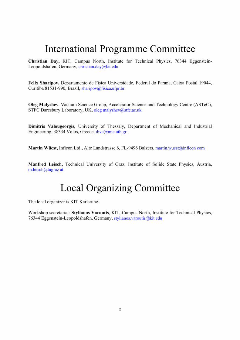
International Programme Committee Christian Day, KIT, Campus North, Institute for Technical Physics, 76344 Eggenstein-Leopoldshafen, Germany, [email protected] Felix Sharipov, Departamento de Fisica Universidade, Federal do Parana, Caixa Postal 19044, Curitiba 81531-990, Brazil, [email protected] Oleg Malyshev, Vacuum Science Group, Accelerator Science and Technology Centre (ASTeC), STFC Daresbury Laboratory, UK, oleg [email protected] Dimitris Valougeorgis, University of Thessaly, Department of Mechanical and Industrial Engineering, 38334 Volos, Greece, [email protected] Martin Wüest, Inficon Ltd., Alte Landstrasse 6, FL-9496 Balzers, martin.wuest@inficon com Manfred Leisch, Technical University of Graz, Institute of Solide State Physics, Austria, m.leisch@tugraz at
Local Organizing Committee
The local organizer is KIT Karlsruhe.
Workshop secretariat: Stylianos Varoutis, KIT, Campus North, Institute for Technical Physics, 76344 Eggenstein-Leopoldshafen, Germany, stylianos.varoutis@kit edu
3
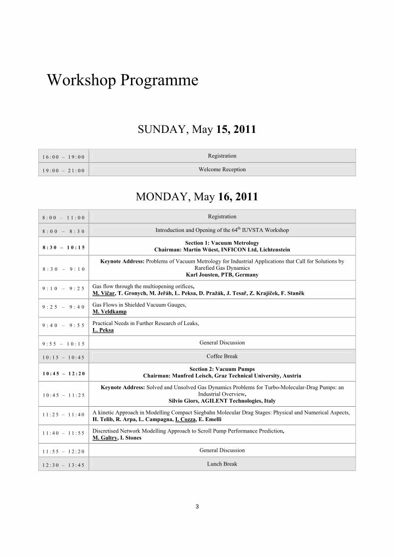
Workshop Programme
SUNDAY, May 15, 2011
1 6 : 0 0 – 1 9 : 0 0 Registration
1 9 : 0 0 – 2 1 : 0 0 Welcome Reception
MONDAY, May 16, 2011
8 : 0 0 – 1 1 : 0 0 Registration
8 : 0 0 – 8 : 3 0 Introduction and Opening of the 64th IUVSTA Workshop
8 : 3 0 – 1 0 : 1 5 Section 1: Vacuum Metrology
Chairman: Martin Wüest, INFICON Ltd, Lichtenstein
8 : 3 0 – 9 : 1 0 Keynote Address: Problems of Vacuum Metrology for Industrial Applications that Call for Solutions by
Rarefied Gas Dynamics Karl Jousten, PTB, Germany
9 : 1 0 – 9 : 2 5 Gas flow through the multiopening orifices, M. Vičar, T. Gronych, M. Jeřáb, L. Peksa, D. Pražák, J. Tesař, Z. Krajíček, F. Staněk
9 : 2 5 – 9 : 4 0 Gas Flows in Shielded Vacuum Gauges, M. Veldkamp
9 : 4 0 – 9 : 5 5 Practical Needs in Further Research of Leaks, L. Peksa
9 : 5 5 – 1 0 : 1 5 General Discussion
1 0 : 1 5 – 1 0 : 4 5 Coffee Break
1 0 : 4 5 – 1 2 : 2 0 Section 2: Vacuum Pumps
Chairman: Manfred Leisch, Graz Technical University, Austria
1 0 : 4 5 – 1 1 : 2 5 Keynote Address: Solved and Unsolved Gas Dynamics Problems for Turbo-Molecular-Drag Pumps: an
Industrial Overview, Silvio Giors, AGILENT Technologies, Italy
1 1 : 2 5 – 1 1 : 4 0 A kinetic Approach in Modelling Compact Siegbahn Molecular Drag Stages: Physical and Numerical Aspects, H. Telib, R. Arpa, L. Campagna, I. Cozza, E. Emelli
1 1 : 4 0 – 1 1 : 5 5 Discretised Network Modelling Approach to Scroll Pump Performance Prediction, M. Galtry, I. Stones
1 1 : 5 5 – 1 2 : 2 0 General Discussion
1 2 : 3 0 – 1 3 : 4 5 Lunch Break
4
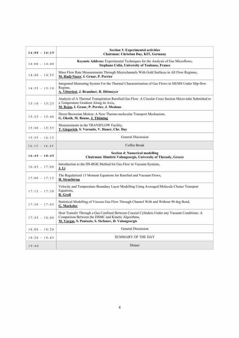
1 4 : 0 0 – 1 6 : 1 5 Section 3: Experimental activities
Chairman: Christian Day, KIT, Germany
1 4 : 0 0 – 1 4 : 4 0 Keynote Address: Experimental Techniques for the Analysis of Gas Microflows,
Stephane Colin, University of Toulouse, France
1 4 : 4 0 – 1 4 : 5 5 Mass Flow Rate Measurements Through Microchannels With Gold Surfaces in All Flow Regimes, M. Hadj-Nacer, I. Graur, P. Perrier
1 4 : 5 5 – 1 5 : 1 0 Integrated Measuring System For the Thermal Characterization of Gas Flows in MEMS Under Slip-flow Regime, A. Vittoriosi, J. Brandner, R. Dittmeyer
1 5 : 1 0 – 1 5 : 2 5 Analysis of A Thermal Transpiration Rarefied Gas Flow: A Circular Cross Section Micro-tube Submitted to a Temperature Gradient Along its Axis, M. Rojas, I. Graur, P. Perrier, J. Meolans
1 5 : 2 5 – 1 5 : 4 0 Direct Brownian Motion: A New Thermo-molecular Transport Mechanism, G. Okoth, M. Baune, J. Thöming
1 5 : 4 0 – 1 5 : 5 5 Measurements in the TRANSFLOW Facility, T. Giegerich, S. Varoutis, V. Hauer, Chr. Day
1 5 : 5 5 – 1 6 : 1 5 General Discussion
1 6 : 1 5 – 1 6 : 4 5 Coffee Break
1 6 : 4 5 – 1 8 : 4 5 Section 4: Numerical modelling
Chairman: Dimitris Valougeorgis, University of Thessaly, Greece
1 6 : 4 5 – 1 7 : 0 0 Introduction to the DS-BGK Method for Gas Flow in Vacuum Systems, J. Li
1 7 : 0 0 – 1 7 : 1 5 The Regularized 13 Moment Equations for Rarefied and Vacuum Flows, H. Struchtrup
1 7 : 1 5 – 1 7 : 3 0 Velocity and Temperature Boundary Layer Modelling Using Averaged Molecule Cluster Transport Equations, R. Groll
1 7 : 3 0 – 1 7 : 4 5 Statistical Modelling of Viscous Gas Flow Through Channel With and Without 90 deg Bend, G. Markelov
1 7 : 4 5 – 1 8 : 0 0 Heat Transfer Through a Gas Confined Between Coaxial Cylinders Under any Vacuum Conditions: A Comparison Between the DSMC and Kinetic Algorithms, M. Vargas, S. Pantazis, S. Stefanov, D. Valougeorgis
1 8 : 0 0 – 1 8 : 2 0 General Discussion
1 8 : 2 0 – 1 8 : 4 5 SUMMARY OF THE DAY
1 9 : 0 0 Dinner

5
TUESDAY, May 17, 2011
8 : 3 0 – 1 2 : 5 0 Section 5: Benchmark problems
Chairman: Felix Sharipov, Federal University of Parana, Brazil
8 : 3 0 – 9 : 1 0 Keynote Address: Deterministic Modelling of Multi-Dimensional Rarefied Gas Flows, Vladimir Titarev, Dorodnicyn Computing Centre of Russian Academy of Sciences
9 : 1 0 – 9 : 5 0 Keynote Address: Numerical Simulations and Applications of Rarefied Gas Mixtures Flows,
A. Frezzotti, G. Ghiroldi, L. Gibelli, Politecnico di Milano
9 : 5 0 – 1 0 : 1 5 General Discussion
1 0 : 1 5 – 1 0 : 4 5 Coffee Break
1 0 : 4 5 – 1 1 : 0 0 Benchmark Problem. Direct Simulation Monte Carlo of Gas Flow Through a Slit and Channel, F. Sharipov, S. Varoutis, Chr. Day, D. Kozak
1 1 : 0 0 – 1 1 : 1 5 Benchmark Problem. Direct Simulation Monte Carlo of Gas Flow Through an Orifice and Short Tube, S. Varoutis, F. Sharipov, D. Valougeorgis, O. Sazhin
1 1 : 1 5 – 1 1 : 3 0 Rarefied Gas Flows Through Slits and Orifices, S. Pantazis, S. Misdanitis, D. Valougeorgis
1 1 : 3 0 – 1 1 : 4 5 Benchmark Problem. Numerical Modelling of Gas Flow Through a Slit: Kinetic Approach, I. Graur, A. Polykarpov, F. Sharipov
1 1 : 4 5 – 1 2 : 0 0 Gas Flows Through Short Channels Studied by the Direct Solution of Boltzmann Equation, V.Aristov, A. Frolova, S. Zabelok, V. Kolobov, R. Arslanbekov
1 2 : 0 0 – 1 2 : 1 5 Benchmark Problems Solved With a Parallel Version of G. A. Bird’s DSMC, M. Rose
1 2 : 1 5 – 1 2 : 5 0 General Discussion
1 3 : 0 0 – 1 4 : 1 5 Lunch Break
1 4 : 3 0 – 1 5 : 1 5 Chairman: Felix Sharipov, Federal University of Parana, Brazil
Special Talk: Current Techniques and Challenges in the Design of Vacuum Pumps, Magnus Janicki, Oerlikon Leybold Vacuum GmbH, Germany
1 5 : 1 5 – 1 5 : 4 5 General Discussion and SUMMARY OF THE DAY
1 6 : 0 0 – 2 3 : 3 0 Workshop Excursion to Speyer and Walking Dinner
6
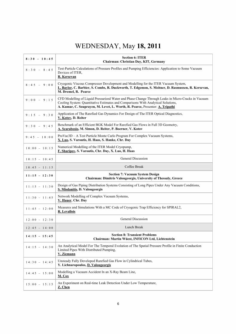
WEDNESDAY, May 18, 2011
8 : 3 0 – 1 0 : 4 5 Section 6: ITER Chairman: Christian Day, KIT, Germany
8 : 3 0 – 8 : 4 5 Test-Particle Calculations of Pressure Profiles and Pumping Efficiencies: Application to Some Vacuum Devices of ITER, R. Kersevan
8 : 4 5 – 9 : 0 0 Cryogenic Viscous Compressor Development and Modelling for the ITER Vacuum System, L. Baylor, C. Barbier, S. Combs, R. Duckworth, T. Edgemon, S. Meitner, D. Rasmussen, R. Kersevan, M. Dremel, R. Pearce
9 : 0 0 – 9 : 1 5 CFD Modelling of Liquid Pressurized Water and Phase Change Through Leaks in Micro-Cracks in Vacuum Cooling System: Quantitative Estimates and Comparisons With Analytical Solutions, A. Kumar, C. Souprayen, M. Levet, L. Worth, R. Pearce, Presenter: A. Tripathi
9 : 1 5 – 9 : 3 0 Application of The Rarefied Gas Dynamics For Design of The ITER Optical Diagnostics, V. Kotov, D. Reiter
9 : 3 0 – 9 : 4 5 Benchmark of an Efficient BGK Model For Rarefied Gas Flows in Full 3D Geometry, A. Scarabosio, M. Simon, D. Reiter, P. Boerner, V. Kotov
9 : 4 5 – 1 0 : 0 0 ProVac3D – A Test Particle Monte Carlo Program For Complex Vacuum Systems, X. Luo, S. Varoutis, H. Haas, S. Hanke, Chr. Day
1 0 : 0 0 – 1 0 : 1 5 Numerical Modelling of the ITER Model Cryopump, F. Sharipov, S. Varoutis, Chr. Day, X. Luo, H. Haas
1 0 : 1 5 – 1 0 : 4 5 General Discussion
1 0 : 4 5 – 1 1 : 1 5 Coffee Break
1 1 : 1 5 – 1 2 : 3 0 Section 7: Vacuum System Design Chairman: Dimitris Valougeorgis, University of Thessaly, Greece
1 1 : 1 5 – 1 1 : 3 0 Design of Gas Piping Distribution Systems Consisting of Long Pipes Under Any Vacuum Conditions, S. Misdanitis, D. Valougeorgis
1 1 : 3 0 – 1 1 : 4 5 Network Modelling of Complex Vacuum Systems, V. Hauer, Chr. Day
1 1 : 4 5 – 1 2 : 0 0 Measures and Simulations With a MC Code of Cryogenic Trap Efficiency for SPIRAL2, R. Levallois
1 2 : 0 0 – 1 2 : 3 0 General Discussion
1 2 : 4 5 – 1 4 : 0 0 Lunch Break
1 4 : 1 5 – 1 5 : 4 5 Section 8: Transient Problems Chairman: Martin Wüest, INFICON Ltd, Lichtenstein
1 4 : 1 5 – 1 4 : 3 0 An Analytical Model For The Temporal Evolution of The Spatial Pressure Profile in Finite Conduction Limited Pipes With Distributed Pumping, V. Ziemann
1 4 : 3 0 – 1 4 : 4 5 Unsteady Fully Developed Rarefied Gas Flow in Cylindrical Tubes, Y. Lichnaropoulos, D. Valougeorgis
1 4 : 4 5 – 1 5 : 0 0 Modelling a Vacuum Accident In an X-Ray Beam Line, M. Cox
1 5 : 0 0 – 1 5 : 1 5 An Experiment on Real-time Leak Detection Under Low Temperature, Z. Chen

7
1 5 : 1 5 – 1 5 : 4 5 General Discussion and SUMMARY OF THE DAY
1 6 : 0 0 – 1 8 : 0 0 Wine tasting tour
1 9 : 0 0 BBQ
THURSDAY, May 19, 2011
8 : 3 0 – 1 0 : 3 0 Section 9: Accelerator Vacuum Systems Chairman: Oleg Malyshev, ASTeC, STFC Daresbury Laboratory, UK
8 : 3 0 – 9 : 1 0 Keynote Address: Geometrical structure effects on the pumping delay time,
Yoshio Saito, KEK, Japan
9 : 1 0 – 9 : 2 5 Gas Dynamics Modelling For Particle Accelerators, O. Malyshev
9 : 2 5 – 9 : 4 0 Accelerator Design and Laboratory Studies of the LHC Vacuum System With the VASCO Code, G. Lanza, G. Bregliozzi
9 : 4 0 – 9 : 5 5 Numerical Simulation of a Pressure Distribution in Vacuum Chambers for Design and Optimization of Vacuum Systems For Accelerator Complexes, A. Tikhomirov
9 : 5 5 – 1 0 : 1 0 Vacuum at The ESRF, H. Marques, M. Hahn
1 0 : 1 0 – 1 0 : 3 0 General Discussion
1 0 : 3 0 – 1 1 : 0 0 Coffee Break
1 1 : 0 0 – 1 2 : 1 5 Round table
1 2 : 1 5 Lunch and Departure
Laboratorial visit in KIT Experimental Facilities(Upon request)
8
Sponsors International Union for Vacuum Science Technique and Applications (IUVSTA). The aim of this Union is to stimulate international collaboration in the fields of vacuum science, techniques and applications.
http://www.iuvsta.org
http://www.agilent.com
http://www.oerlikon.com/leyboldvacuum
http://www.pi-dsmc.com
http://www.pfeiffer-vacuum.de
http://www.vacom.de
http://www.kit.edu

9
Abstracts

10
MONDAY, May 16, 2011
Section 1: Vacuum Metrology
Keynote Address
PROBLEMS OF VACUUM METROLOGY FOR INDUSTRIAL APPLICATIONS THAT CALL FOR SOLUTIONS BY RAREFIED
GAS DYNAMICS
Karl Jousten Physikalisch-Technische Bundesanstalt, Abbestr. 2-12, 10587 Berlin - GERMANY
Vacuum is an indispensable tool for many industrial applications as e.g. in the semiconductor
industry, modern energy industry (solar cells, wind turbines, fusion), lightning industry, food packaging, and leak testing.
Vacuum metrology serves the industry to produce and use reliable vacuum gauges traceable to the SI units [1] and provides standard leaks for measurement of small gas flows [2]. Primary standards for vacuum pressures and small gas flow rates normally operate at quite ideal conditions [3], i.e. pure gases, temporally stable pressures, well defined and stable environmental conditions and so on. In industry, on the other hand, fast changing pressures (e.g. load locks), poorly defined and rough environmental conditions and gas mixtures are common. This opens the question to what extent the calibrations with primary standards are useful under such industrial conditions.
For this reason vacuum metrology laboratories have recently picked up these problems to help industry in the correct dissemination of the pressure scale and low flow rates. Herein rarefied gas dynamics can play a significant role to simulate and predict new standards and the conditions at use in industry.
This talk shall give an overview of the named problems and emphasize the need of a step wise procedure for solving such problems, where accurate vacuum metrology plays an important role to compare theory and experiment in order to improve algorithms, boundary conditions and data material.
REFERENCES [1] K. Jousten, S. Naef, J. Vac. Sci. Technol. A, to be published (2011). [2] W. Jitschin, G. Grosse, P. Röhl, Vacuum 38, 883-886 (1988). [3] K. Jousten, chapter 15 in Handbook of Vacuum Technology by K. Jousten (ed.), Wiley-VCH, ISBN
978-3-527-40723-1 (2008).
11
GAS FLOW THROUGH THE MULTIOPENING ORIFICES
M. Vičar1, T. Gronych2, M. Jeřáb2, L. Peksa2, D. Pražák1, J. Tesař1, Z. Krajíček1, F. Staněk1
1Czech Metrology Institute, Okružní 31, 638 00 Brno - CZECH REPUBLIC 2Faculty of Mathematics and Physics, Charles University in Prague, V Holešovičkách 2, 180 00
Praha 8 - CZECH REPUBLIC [email protected]
Gas flow measurement by means of an orifice is used very often in gas dynamics. From metrological
point of view it is particularly advantageous in cases when the gas flows through the orifice in molecular regime. The orifice conductance can be then calculated very accurately from its geometrical dimensions, one physically realisable shape – spherical duct (so-called NPL orifice) enables even to derive a simple analytical formula for conductance. Awkward factor is that molecular gas flow occurs only either at very low pressures or through very tiny opening and thus at very low conductance if one-opening orifice is employed.
Evident solution of this strait is to use the orifice with multiple openings in parallel – multiopening orifice (MOO). Question of mutual distances of the openings is important at practical MOO design. If it is necessary to increase n-times the pressure limit up to which the gas flow can be considered as molecular at a given total conductance the number of openings has to increase n2-times. In many devices the part with the orifice must not be too large, thus, there is interesting question about minimum necessary distance of the neighbouring openings to keep the gas flows through them mutually independent.
The problem has not been solved yet. Rough estimate can be done based on old more or less only qualitative Liepmann’s analysis [1]. Accurate solution can be obtained either theoretically by means of Boltzmann equation or experimentally.
Experiments with multiopening orifices formed by seven openings (one central surrounded with other six) were performed. The diameters of the openings were always the same, the distances center-center were various. The orifice with one opening of the same total area was measured as well for comparison. A vessel of large volume filled with pure gas was pumped down through single orifices. The borderline between molecular and transitional regime was evaluated from flex of the pumping curve. The results confirmed preliminary estimation according Liepmann.
REFERENCES [1] H. W. Liepmann, J Fluid Mech, 10, 65-79 (1961)
12
GAS FLOWS IN SHIELDED VACUUM GAUGES
M. Veldkamp VACOM Vakuum Komponenten und Messtechnik GmbH, Gabelsbergerstr. 9, 07749, Jena -
GERMANY [email protected]
Besides operation of vacuum gauges in standard vacuum environments, the use in industrial environments for process control grows in importance. A reliable, precise and reproducible measurement of the total pressure has to be ensured in the range fine vacuum to high vacuum. Some applications, e.g. film deposition processes, can reduce the lifetime of the sensors by depositing harmful films on filaments or electrical feedthroughs. To reduce this effect, a shielding of the sensor by putting a suitable baffle in place can be implemented.
Depending of the design of such a baffle, the conductance at the connection flange of the sensor to the vacuum chamber is changed severely; therefore the resulting pressure in the sensor can deviate significantly from the pressure in the vacuum chamber.
Theoretical models to account for the changed conductance can help to predict the correct pressure and could also contribute to select the correct baffle geometry for specific processes. Relevant question would also be a calculation of the growth rate of the corresponding films with time.
We are going to present experimental results on the measured pressure as a function of the baffle geometry over a wide pressure range and compare with the performance of an un-baffled sensor.

13
PRACTICAL NEEDS IN FURTHER RESEARCH OF LEAKS L. Peksa
Charles University in Prague, Faculty of Mathematics and Physics, V Holešovičkách 2, 18000 Praha 8 - CZECH REPUBLIC
Fluid flow (i.e. both liquid and gas flow) through leaks has been studied both experimentally and theoretically only rarely up to now considering practical importance of this topic. Main reason most likely is that the shape and dimensions of the duct are usually unknown. It is difficult to manufacture a duct of interesting conductance with accurately known dimensions or to measure the dimensions or even to manufacture at least repeatedly ducts of unknown but the same dimensions. It complicates computing, experiments and possibilities to compare their results.
Main activity in this field is characterize the leak quantitatively as a throughput of a certain gas species (e.g. helium) flowing through the leak under defined conditions – temperature, upstream and downstream pressure. Outflow into vacuum at room temperature are most convenient standard conditions for experimental measurement. Leak values critical for application are often assessed based on experiments.
Nevertheless progress in modern technology forces us to understand the flow in leaks better. Some “simple” tasks can be formulated without explicit requirement to know the duct shape and dimensions:
1) Leak can be measured with a test gas, interesting is the throughput of another gas species under the same conditions.
2) Leak can be measured with the gas really used in technological process but under different upstream and/or downstream pressure, than under which it actually acts.
3) Leak can be measured with a test gas, interesting is the throughput of a liquid through this leak. The conditions are of course quite different.
The first case is important at leakage in containment for hazardous, toxic, radioactive or environment polluting materials. The second task is nowadays typical e.g. in refrigerator industry and air condition manufacturing. The third task arises e.g. in connection with nuclear power stations.
Some procedures to overcome the nescience of the duct shape and dimensions were used up to now: - To “size up” the duct by the gas flow - some additional information can be obtained
experimentally varying some parameters - mainly upstream and downstream pressure. - Rendering based on “standard” gas flow theory (through wide ducts) – gas throughput under
different conditions can be sometimes computed from original throughput avoiding necessity to evaluate duct dimensions.
Correctness of “wide ducts theory” application for leaks is questionable. Marginal nowhere else occurring conditions can occur here: pressure drop e.g. 1E10 Pa/m, efficient heat exchange between gas and the wall, considerable influence of the boundary layer.
Result comparison of simultaneous theoretical and experimental researches and statistical approach could help in further study of these questions. Conversion gas leak – gas leak or even gas leak – liquid leak are interesting challenges both for theory and for experiment.

14
Section 2: Vacuum Pumps
Keynote Address
SOLVED AND UNSOLVED GAS DYNAMICS PROBLEMS FOR TURBO-MOLECULAR-DRAG PUMPS: AN INDUSTRIAL
OVERVIEW
Silvio Giors Agilent Technologies, Vacuum Products Division Via F.lli Varian 54, 10040 Leini (TO) – ITALY
Turbomolecular Pumps (TMP) theory in molecular regime dates back to the ‘60s, when Kruger and Shapiro performed the first 2D non-collisional Monte Carlo simulations and developed the first 2D analytical model of axial bladed stages in molecular regime [1]. At that time TMPs were prototypes manufactured in small numbers and were used almost only in ultra high vacuum systems for high energy physics experiments, where the molecular regime model was adequate for the early industrial design purposes. In the last two decades TMP has become an industrial product manufactured in several thousands of units per year, and its technology has evolved introducing molecular drag high pressure stages, originally designed as standalone pumps by Gaede, Holweck and Siegbahn, downstream axial stages, in order to keep the maximum compression ratio at higher discharge pressures (up to 20 mbar). Besides, the operating inlet pressure range has increased up to 10-2 mbar, progressively replacing diffusion and cryogenic pumps in plasma processes, furnaces and in mass spectrometry differential vacuum systems. In these systems a significant part of the TMP works in transition or even viscous flow regime and power dissipation and rotor heat exchange issues must be considered during pump design and validation. From the modelling perspective two approaches can be found in the literature, namely simplified analytical models and numerical solutions of complex 2D/3D models. The analytical models are very useful for understanding the physics of the pumps and for parametric design and optimization in the industry; unfortunately their scope is limited to a few simple geometrical cases [2] and/or to a specific pressure regime and often they don’t accurately model the leakage effects. Analytical models for molecular drag in the viscous regime normally ignore the inertia of the gas, claiming that as the mass density (i.e. the pressure) tends towards zero, the inertial force becomes zero. All articles and texts make this assumption, except for E. Moll [3], who concludes that “…the force of inertia does not disappear in high vacuum, but rather with modern, fast running TMPs may be comparable to friction.” The importance of inertial effect end centrifugal forces, in particular in Siegbahn technology molecular drag pumps and regenerative stages, is still unanswered.
Thanks to the increase in computational resources, a significant amount of numerical work was done in the last decade to address geometrically complex 3D problems and to extend their validity to the full range of Kn numbers, from molecular to viscous regime. These models are based on DSMC [4], numerical solution of model Boltzmann equation [5] or sometimes on Navier-Stokes equations for the viscous regime. The power dissipation and heat exchange problem is almost completely uncovered for TMPs: the issue is to understand the rotor heat balance, considering all the possible heat sources and heat exchange contributions, namely thermal radiation, conduction/convection in the gas and conduction in the solid parts supporting the rotor.
15
REFERENCES [1] C. H. Kruger, A. H. Shapiro, The Axial-Flow compressor in the Free-Molecule Range, in Rarefied
Gas Dynamics, Academic Press, p. 117 (1961). [2] J. Helmer, G. Levi, J. Vac. Sci. Technol. A, 13(5), 2592 (1995). [3] E. Moll, Le Vide, 201, 287 (1980). [4] J.S. Heo, Y.K. Hwang, J. Vac. Sci. Technol. A, 19(2), 656 (2001). [5] F. Sharipov, P. Fahrenbach, A. Zipp, J. Vac. Sci. Technol. A, 23, 1331 (2005).
16
A KINETIC APPROACH IN MODELLING COMPACT SIEGBAHN MOLECULAR DRAG STAGES: PHYSICAL AND
NUMERICAL ASPECTS
H. Telib1, R. Arpa2, L. Campagna3, I.F. Cozza3, E. Emelli3 1Politecnico di Torino, Corso Duca degli Abruzzi 24, 10129 Torino – ITALY
2Optimad Engineering s.r.l., via G.Collegno 18, 10143 Torino – ITALY 3Agilent Technologies Italia s.p.a., via F.lli Varian 54, 10040, Leinì – ITALY
A numerical analysis of a single stage disk-type drag pump performances, characterized by spiral channels [1], requires a careful modelling of the gas flow features. The main issue in simulating such kind of devices lies in the proper description of leakage and development of the rarefied flow along the channel under the presence of clearances. Here, pressure gradients and disk rotation speed are typical driving forces, and inertial centripetal and Coriolis effects appear and play an important role. Following the assumptions made for a Holweck model by Sharipov et al. in Ref. [2], we propose a lower-order model for steady flows in spiral molecular drag stages, based on the solution of the Boltzmann Equation (BE) with a BGK closure, in cylindrical coordinates, where the inertial effects explicitly appear in the equation. The order of the 3D original problem is reduced in the physical space (2D), by introducing the assumption of locally known flow development along the spiral channel ( ( ) ( )
channel section, knownr g r∂ • = • ). Thus, 2D-BE calculations of the flow rates and stresses will be
performed in a finite number of sections, suitably positioned along the spiral channel, from the outlet up to the inlet, in order to recover the pressure and torque distribution.
A Direct Velocity Method (DVM) is used to solve the Boltzmann Equation, with opportune solutions to speed up convergence in dense regimes (low Knudsen number) [3],[4]. The model assumptions will be discussed and verified by applying them also to an Holweck pump model. The performance prediction of both models will be assessed using test cases from the literature and compared to the available experimental data. A further verification test will be carried out, to test prediction capabilities in the continuum regime by direct comparison with result obtained by a Navier-Stokes solver, with slip-boundary conditions.
REFERENCES [1] M. Siegbahn, Arch. Mat. Astr. Phys., 30B, 261 (1943). [2] F. Sharipov, P.Fahrenbach, A.Zipp, J.Vac.Sci.Tech. A, 23, 1331 (2005). [3] L. Mieussens, J.Comp. Phys., 162(2), 429 (2000). [4] J. Lihnaropoulos, S.Naris, D.Valougeorgis, Transp. Th. Stat. Phys., 36, 513 (2007).
17
DISCRETISED NETWORK MODELLING APPROACH TO SCROLL PUMP PERFORMANCE PREDICTION
M. A. Galtry, I. D. Stones Edwards Ltd.Unit 2S 23 Dolphin Road Shoreham by Sea West Sussex BN14 8QG – UK
Traditionally the scroll mechanism for vacuum pumps has been modeled by compressing gas trapped
in pockets and leaking across the wall clearance to neighbouring pockets. This method is a first level approximation but fails to recognize the often significant pressure variations along the length of the pocket, which impacts the accuracy of the prediction. Using this method, it is also very difficult to model leakage across the tip seal, which connects different volumes as the pump rotates.
In this work the swept volume is discretised into small elements that expand and contract as the pump rotates. Gas is passed to neighbouring volumes by leakage according to the volume size. It becomes relatively simple to account for tip seal leakage with this method.

18
Section 3: Experimental Activities
Keynote Address
EXPERIMENTAL TECHNIQUES FOR THE ANALYSIS OF GAS MICROFLOWS
Stéphane Colin Université de Toulouse – FRANCE
The control of gas flows in fluidic microsystems is of great interest for a number of varied applications: fluidic micro-actuation for active control of aerodynamic flows, vacuum generation at microscale, micro heat-exchange for the cooling of electronic components or for chemical applications, micropumping and micromixing or separation for local gas analysis, mass spectrometry, measurement of low mass flow rates…
Numerous theoretical tools are now used for modelling the rarefied flows of gases inside these microsystems, covering all regimes from the continuum to the free molecular regime, with a special attention paid to the slip flow and transition regimes. Available experimental data for the validation of these models and notably for the discussion of the most appropriate boundary conditions in the slip flow regime are, however, still limited.
This talk gives an overview of the techniques currently used for the measurement of gas flow rates through microsystems [1,2]. These techniques provide accurate flow rate data in the whole Knudsen range. The experimental data are compared with the results from slip flow models and from kinetic theory both for simple gases and mixtures of gases. They allow determining the limits of various slip flow models, and lead to a discussion on their validity as well as on the value of the tangential momentum accommodation coefficient.
The possibilities of local measurement of pressure [3,4] and temperature [5] are also described. velocimetry techniques for analysing gas microflows are then discussed: the limitations of micro particle image velocimetry [6] as well as the potential of micro molecular tagging velocimetry [7] are presented. Future needs are emphasized.
REFERENCES [1] T. Ewart, et al., J. Fluid Mech., 584, 337-356 (2007). [2] J. Pitakarnnop et al., Microfluidics and Nanofluidics, 8(1), 57-72 (2010). [3] M.J. Kohl, et al., Int. J. of Heat and Mass Transfer, 48(8), 1518-1533 (2005). [4] Y. Matsuda et al., Microfluidics and Nanofluidics, 10(1), 165-171 (2011). [5] K. Tae Hoon and K. Sung Jin, Journal of Micromechanics and Microengineering, 16(11), 2502-2508
(2006). [6] S.Y.R. Yoon, M.M. Mench, and K.V. Sharp, Journal of Power Sources, 160, 1017-1025 (2006). [7] W.R. Lempert et al., Experiments in Fluids, 34(3), 403-411 (2003).

19
MASS FLOW RATE MEASUREMENTS THROUGH MICROCHANNELS WITH GOLD SURFACES IN ALL FLOW
REGIMES
M. Hadj Nacer, I. Graur, P. Perrier IUSTI UMR6595, Ecole Polytechnique Universitaire de Marseille Université de Provence, 5 rue
Enrico Fermi, 13453 Marseille – FRANCE [email protected]
The mass flow rate through microchannels with rectangular cross section is measured for a wide
Knudsen number range (from hydrodynamic to near free molecular regimes) in isothermal steady conditions. The experimental technique called ’Constant Volume Method’ is used for the measurements. This method consists of measuring small variations in the pressure in the tanks up and downstream of the microchannel. The measurements of the mass flow rate are carried out for three gases (Helium, Nitrogen and Argon). Layer of gold with mean roughness of about ~ 1 nm cover the internal surfaces of the microchannels.
The aim of this work is to determinate the slip and the tangential momentum accommodation coefficients TMAC by comparing between experimental results and analytical calculations of the non dimensional mass flow rate in the hydrodynamic and slip regimes and also the calculations based on the numerical solution of the linearized kinetic BGK equations in the transitional and near free molecular regimes. A comparison with other work carried out on rectangular channels will be done.
20
INTEGRATED MEASURING SYSTEM FOR THE THERMAL CHARACTERIZATION OF GAS FLOWS IN MEMS UNDER
SLIP-FLOW REGIME
A. Vittoriosi, J. J. Brandner, R. Dittmeyer Karlsruhe Institute of Technology, Institute for Micro Process Engineering D-76344 Karlsruhe –
GERMANY [email protected]
Microstructured devices are systems involving the flow of a fluid inside one or several channels, the
dimensions of which fall below the millimetre range. Gas flow applications in microelectromechanical systems (MEMS) have been increasingly used in many areas due to the high efficiencies they can offer in several practical purposes. The study and optimization of these systems is therefore of great importance for researchers and engineers.
With the reduction of the characteristic dimensions the phenomena governing the flow differ from those characteristic of conventionally sized systems. Particular attention should be paid during the designing phase to correctly predict this feature of micro flows. Gas flows in particular are usually classified according to their rarefaction degree, which is a measure of the deviation of the flow from the continuous approximation. This behaviour occurs both if the working pressure is lowered and if the system dimensions are reduced; it is particularly evident at the interface gas-solid, where the so-called “slip-conditions” might arise. Given the extremely local connotation of the problem, it is very difficult to retrieve direct experimental data of these features. In particular, the detection of the influence of the actual surface characteristics on the flow is very challenging and requires a local experimental approach.
In the present work an experimental procedure, developed for the local characterization of the gas-wall interaction for the microchannels is described. The newly designed experimental device includes an exchangeable test section, heating and cooling units to study heat transfer problems as well as an integrated measuring system.
Channels manufactured from different materials (and thus with different surface properties) can be tested with the same device and experimental procedure. At the same time an array of sensors developed with silicon micro-fabrication technology allows the monitoring of the temperature profile along the microchannel. This will be compared with a conventional measurement system, which however presents a major component of flow disturbance. For this purpose, an array of thermocouples (125 µm in diameter) to be included on the channel cover has been developed.
The main aim of the study is the hydrodynamic and thermal characterization of gas flows in micro channels under slip flow regime with varying boundary conditions and different geometrical and surface channel characteristics. By testing different materials and manufacturing processes it would be possible to understand which aspects of the flow are mainly influenced by the surface characteristics and to identify their role in determining the gas-wall interactions. Moreover, the available numerical and theoretical data for slip-flow could be compared with the actual measured data to optimize the modelling of gas flows in MEMS.
21
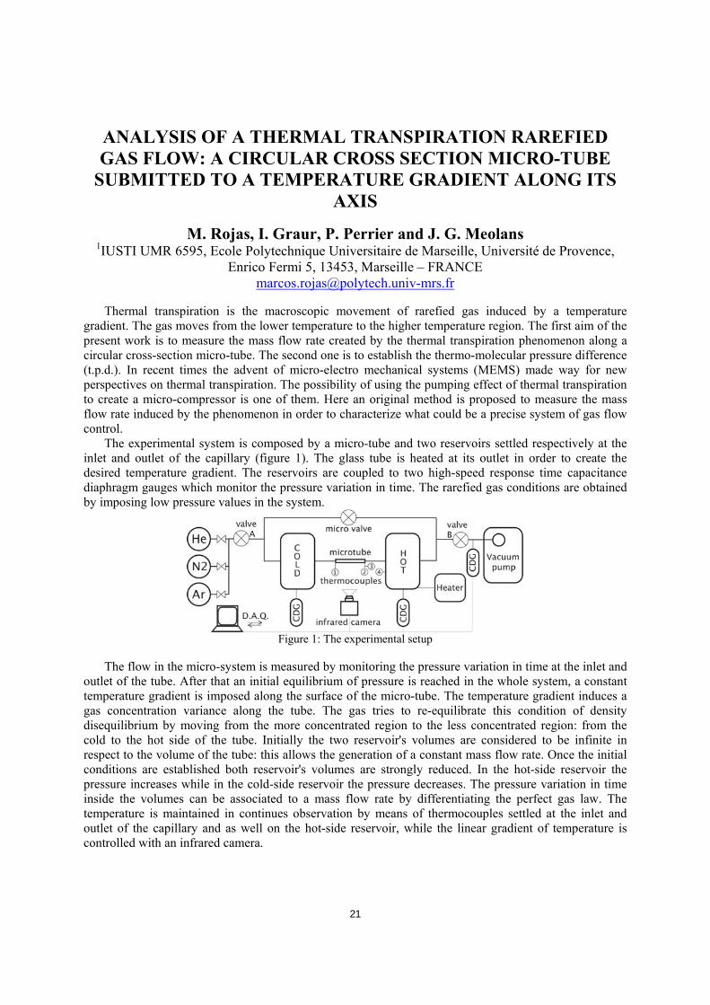
ANALYSIS OF A THERMAL TRANSPIRATION RAREFIED GAS FLOW: A CIRCULAR CROSS SECTION MICRO-TUBE
SUBMITTED TO A TEMPERATURE GRADIENT ALONG ITS AXIS
M. Rojas, I. Graur, P. Perrier and J. G. Meolans 1IUSTI UMR 6595, Ecole Polytechnique Universitaire de Marseille, Université de Provence,
Enrico Fermi 5, 13453, Marseille – FRANCE [email protected]
Thermal transpiration is the macroscopic movement of rarefied gas induced by a temperature gradient. The gas moves from the lower temperature to the higher temperature region. The first aim of the present work is to measure the mass flow rate created by the thermal transpiration phenomenon along a circular cross-section micro-tube. The second one is to establish the thermo-molecular pressure difference (t.p.d.). In recent times the advent of micro-electro mechanical systems (MEMS) made way for new perspectives on thermal transpiration. The possibility of using the pumping effect of thermal transpiration to create a micro-compressor is one of them. Here an original method is proposed to measure the mass flow rate induced by the phenomenon in order to characterize what could be a precise system of gas flow control.
The experimental system is composed by a micro-tube and two reservoirs settled respectively at the inlet and outlet of the capillary (figure 1). The glass tube is heated at its outlet in order to create the desired temperature gradient. The reservoirs are coupled to two high-speed response time capacitance diaphragm gauges which monitor the pressure variation in time. The rarefied gas conditions are obtained by imposing low pressure values in the system.
Figure 1: The experimental setup
The flow in the micro-system is measured by monitoring the pressure variation in time at the inlet and
outlet of the tube. After that an initial equilibrium of pressure is reached in the whole system, a constant temperature gradient is imposed along the surface of the micro-tube. The temperature gradient induces a gas concentration variance along the tube. The gas tries to re-equilibrate this condition of density disequilibrium by moving from the more concentrated region to the less concentrated region: from the cold to the hot side of the tube. Initially the two reservoir's volumes are considered to be infinite in respect to the volume of the tube: this allows the generation of a constant mass flow rate. Once the initial conditions are established both reservoir's volumes are strongly reduced. In the hot-side reservoir the pressure increases while in the cold-side reservoir the pressure decreases. The pressure variation in time inside the volumes can be associated to a mass flow rate by differentiating the perfect gas law. The temperature is maintained in continues observation by means of thermocouples settled at the inlet and outlet of the capillary and as well on the hot-side reservoir, while the linear gradient of temperature is controlled with an infrared camera.

22
The results are obtained for a large range of the rarefaction parameter, which is inverse proportional to the Knudsen number. The experiments are conducted for three different gases, Argon, Helium and Nitrogen, in a pressure range from 0.1 to 4 [torr] and for different temperature differences imposed between inlet and outlet of the tube. For these experimental conditions and for the here used tube the rarefaction parameter varies from 0.4 to 15 (Kn=0.06÷2.22). The gas rarefaction conditions go from transitional to slip regime.

23
DIRECT BROWNIAN MOTION: A NEW THERMO-MOLECULAR TRANSPORT MECHANISM
G. Okoth, M. Baune, J. Thöming Zentrum für Umweltforschung und nachhaltige Technologien – UFT, Universität Bremen, Leobener
Str., D 28359 Bremen, GERMANY [email protected]
The current models to describe gas flow through micro-channels are primarily based on the
convective flux and thermal creep with pressure and temperature as the driving potentials respectively. However these modes of transport are not sufficient to describe low-velocity gas flow with a strong diffusive component in long asymmetric micro-channels (LAM). We demonstrate, through experiments, that in LAMs with a high length to diameter ratio, direction-biased molecular flux (DBM), distinct from the thermal creep ensues (Figure 1) in the slip range.
In this work, a distinct form of thermo-molecular transport mechanism obtained by directing the Brownian motion of gas molecules upon interaction with the micro-channels surface which can be modelled through a modified Hertz-Knudsen flux. The ensuing transition leads to a biased flux of gas molecules that depend on the nature of gas-surface interaction as well as the conduit geometry. The net material transport in all cased is expressed as a sum of thermal creep, Poiseuille and DBM fluxes. The net diffusive flux can be appropriately set to act against the thermal creep leading to a diode-like behaviour.
0
‐0.8
‐0.4
‐1.2
8 16
25 kPa
50 kPa
75 kPa
102 kPa
Time / h
‐1.60 4 12 20
0.4
Δp/ kPa
Test gas: CO2
0
‐0.8
‐0.4
‐1.2
8 16
25 kPa
50 kPa
75 kPa
102 kPa
Time / h
‐1.60 4 12 20
0.4
Δp/ kPa
Test gas: CO2 Figure 1: Thermo-molecular transport in long asymmetric microchannels (LAMs). Gradual change of the pressure difference ∆p= pTip-pBase when both compartments were subjected to a continuous steady temperature difference ΔT = 8± 0.9 K and a starting pressure condition, pTip=pBase. Tests were carried out at pabs varying from 25 to 102 kPa, i.e. KnTip = 0.111 to 0.027 respectively. Whereas the net flux to the cold-base compartment can be attributed to thermal-creep, the opposite net flux suggests the existence of a distinct mode of thermally driven transport here referred to as DBM.
2
4
6
0 5 10 15
4
ΔT / K
(dn/
dt) t
= 0
x10-
8 / m
ol s
-1
80
-2
-3
-1
0
1
Δn T
ipx1
0-4 / m
ol
12time / h
ΔT = -1.5 K
ΔT = 2 K
a ba
Tip Base
LAM2
4
6
0 5 10 15
4
ΔT / K
(dn/
dt) t
= 0
x10-
8 / m
ol s
-1
80
-2
-3
-1
0
1
Δn T
ipx1
0-4 / m
ol
12time / h
ΔT = -1.5 K
ΔT = 2 K
a ba
Tip Base
LAM

24
Figure 2: One-way valve effect. a; change in number density of the tip chamber temperature differences as a function of the temperature difference. ΔT = TTip-TBase. b; the rate of material transport from the tip to the base compartment at t =0 s, when the chambers were subjected to different temperature differences.
25
MEASUREMENTS IN THE TRANSFLOW FACILITY T. Giegerich, S. Varoutis, V. Hauer and Chr. Day
Karlsruhe Institute of Technology, Institute for Technical Physics, 76021 Karlsruhe - GERMANY [email protected]
The calculation of gas flows through ducts in a wide range of rarefaction is a topic of prime
importance for the design of vacuum systems. In many industrial applications, the regime extends from laminar flow down to free molecular flow, including transitional flow. It is required to conduct calculations for long and short geometries, for large and small pressure differences and flow rates. For these measurements, some programs and codes (as e.g. ITERVAC [1]) are available or under development (LOPSTER).
For the benchmark tests of these tools, a test facility called TRANSFLOW (test facility for transitional flow range experiments) was set up at KIT in 2006. TRANSFLOW is based on the direct dynamic approach where a constant flow is adjusted and the pressure differential across a component is measured. The whole facility is designed for fundamental laboratory research, but sufficiently large to investigate 1:1 scale big vacuum components. It allows the measuring of the conductance for different geometries including ducts, bends and bellows with a maximum length of 1200 mm and a maximum diameter of 600 mm over a wide range of pressure and flow conditions including rarefied gases. Furthermore, this facility can also test and characterize technical components such as baffles and valves as important input to vacuum system design considerations in a wide range of Knudsen numbers Kn. A lot of interesting results obtained by this facility have been published in the past [2,3] and the measurements are still ongoing. Nevertheless, this facility is availably for benchmark measurements on different components.
In this talk, the TRANSFLOW facility will be described, the resolution discussed, limitations and future plans will be shown up and some examples of measured geometries are presented.
REFERENCES [1] C. Day et al., Development of a simulation code for ITER vacuum flows, 21st IAEA Fusion Energy
Conf., Chengdu, China, October 16-21 (2006). [2] S. Varoutis et al., Fusion Engineering and Design, 85 1798-1802 (2010). [3] S. Varoutis et al., J. Vac. Sci. Technol. A, 27 89-100 (2009).
26
Section 4: Numerical Modelling
INTRODUCTION TO THE DS-BGK METHOD FOR GAS FLOW IN VACUUM SYSTEMS
Jun Li King Abdullah University of Science and Technology (KAUST)
Kingdom of Saudi Arabia & Tsinghua University – CHINA [email protected]
For gas flows in vacuum systems and micro devices, the molecular mean free path is of the same order as the characteristic scale making the Navier-Stokes equation invalid. Such problems can be described by the Boltzmann equation and simulated by the DSMC method [1]. As their characteristic velocities are usually small, the DSMC simulation is very time-consuming due to large ratio of statistical noise to useful information.
To overcome the difficulty encountered by the DSMC method in low-velocity cases, many particle simulation methods including [2-9] among others had been proposed independently making modifications to the standard DSMC method and obtaining improvements of efficiency for low velocity cases. Among them is the DS-BGK method proposed recently, which is convergent to the BGK equation and very efficient for low-velocity cases. The main idea of the DS-BGK method is to track down the evolution of the distribution function due to intermolecular collisions along enormous molecular trajectories which are selected randomly when molecules reflect from boundary as in the DSMC method. The simple algorithmic structure of the DSMC method is employed but, besides position and velocity, each simulated molecule will carry two additional variables: one records the value of the distribution function and another records the number of real molecules represented by the related simulated molecule. The former is updated according to the Lagrangian description of the BGK equation and the latter is updated according to the former, after which the transitional macro-quantities defined for each cell are updated according to a special scheme which can make them evolve smoothly and finally converge to their solutions. As the basic algorithmic structure of the DSMC method is retained, it has some advantages like simplicity, numerical stability and convenience for complex configurations. This particle simulation method achieves its efficiency by avoiding generating random fractions during the intermolecular collision process and using the increments (instead of the transient values as in the DSMC method) of molecular variables to update the macro-quantities, which makes it have the feature that the total computational time will not increase with the decrease of characteristic velocity. In addition, it can use conveniently a more realistic boundary condition, namely the CLL reflection model, which is important in simulating gas flows in vacuum systems and micro devices where the molecular reflection on the boundary is the dominant effect compared to the intermolecular collisions.
REFERENCES [1] G. A. Bird, Molecular Gas Dynamics and the Direct Simulation of Gas Flows, Clarendon Press,
Oxford, (1994). [2] J. Fan, Ch. Shen, Proceedings of Rarefied Gas Dynamics Symposium, 2, 245-252, (1999) and J.
Comp. Phys. 167, 393-412 (2001). [3] L. Pan, G. Liu, B. Khoo, B. Song, J. Micromech. Microeng. 10, 21-27 (2000). [4] M. Macrossan, Rarefied Gas Dynamics, 426-433 (2000). [5] M. Gallis, J. Torczynski, 34th AIAA Thermophysics conference, Denver, CO (2000). [6] J. Chun, D. Koch, Phys. Fluids 17, 107107 (2005).
27
[7] T. M. M. Homolle, N.G. Hadjiconstantinou, Phys. Fluids 19, 041701 (2007). [8] Shr. Ramanathan, D. L. Koch, Phys. Fluids 21, 033103 (2009). [9] J. Li, Proceedings of 27th Rarefied Gas Dynamics Symposium, USA (2010).
28
THE REGULARIZED 13 MOMENT EQUATIONS FOR RAREFIED AND VACUUM FLOWS
H. Struchtrup Department of Mechanical Engineering, University of Victoria, PO 3055 Stn., Victoria
BCV8W3P6 – CANADA [email protected]
Computer simulations of the processes in vacuum devices are extremely useful for the prediction of device behavior, and for optimization of design performance. Indeed, good simulation models allow to reduce the amount of prototyping and give detailed insight into the detailed transport processes within devices, which are not accessible to measurements.
Processes in gases are governed by the Knudsen number, defined as the ratio between the mean distance gas particles travel between collisions and a typical length scale of the process. Vacuum flows are typically in the transition regime, where the mean free path is comparable to the size of the device, and the Knudsen number is approaching unity. Already when the Knudsen number is above ~0.05 (say), the well established laws of classical fluid dynamics - the laws of Navier-Stokes and Fourier - cease to be valid. Thus, classical fluid mechanics cannot be used for the simulation of vacuum gas flows, and more refined models are required.
The Boltzmann equation describes the gas on the microscopic level, as an ensemble of particles. While it gives an accurate description for gas processes at all Knudsen numbers, its numerical solution is very costly due to huge simulation times. Extended macroscopic transport equations can be derived from the Boltzmann equation by averaging in velocity (moment method), and subsequent reduction of the equations by properly accounting for the order of magnitude in terms of the Knudsen number. Classical fluid dynamics results from expansion to first order, and higher order expansions promise to describe rarefied and vacuum gas flows at lower computational cost than the Boltzmann equation.
Indeed, higher order Knudsen number expansions give meaningful equations sufficiently away from the wall, while the proper description of Knudsen boundary layers - which can be dominant in slow rarefied flows - is not tied to the Knudsen number in a simple manner. Nevertheless, tests with moment systems show that even a small number of moments can catch the most important Knudsen layer phenomena for Knudsen numbers below unity in sufficient accuracy.
The regularized 13 moment (R13) equations are obtained by expansion to third order. The R13 equations are linearly stable, are furnished with a complete set of boundary conditions, and contain sufficient information to describe Knudsen layers.
Analytical and numerical results for one- and two-dimensional flows in various geometries (Couette, Poiseuille, transpiration, cavity) exhibit rarefaction effects in good agreement with solutions of the Boltzmann equation. Analytical solutions offer direct insight into rarefaction effects. With suitable numerical methods, the computational times are well below those required for the Boltzmann equation.
The solutions give evidence that the R13 equations can, within their range of validity, predict all important linear and non-linear rarefaction effects with good accuracy. Thus, the R13 equations are a convenient and accurate tool for the simulation of vacuum gas flows in the early transition regime. The talk will close with a list of open problems, and plans for the future development of this approach. Based on joint work with M. Torrilhon (Zurich), P. Taheri (Victoria), and A. Rana (Victoria).

29
VELOCITY AND TEMPERATURE BOUNDARY LAYER MODELLING USING AVERAGED MOLECULE CLUSTER
TRASPORT EQUATIONS
R. Groll Center of Applied Space Technology and Microgravity, University of Bremen, Am Falltum, D-
28359, Bremen – GERMANY [email protected]
Describing molecular flows in Knudsen regime, molecular velocities are statistical distributed values.
Modelling the macroscopic transport variables density, velocity and temperature local averaging methods produce resulting values. Based on the Boltzmann transport equation including the BGK-approximation of particle collisions inside diluted gas flows in Knudsen regime momentum and energy transport are given by resulting transport relations inside such a diluted shear flow. Investigating the diffusion quantity inside a finite-volume simulation, relating to the modeled collision rate, transport relations inside a fully-developed molecular shear flow are resulting. The described relations are modeled in the full-length paper. The resulting boundary-layer model gives boundary conditions for macroscopic numerical simulations in a 3-D simulation. With this model no prescribed slip velocity is necessary, because resulting shear forces are given by the approximation of the statistical moments. The computed results show a very good approximation with BGK-results with a much lower memory and computation time need.
Modelling micro channel flows momentum and heat diffusion/convection are recent parameters modelling the molecule velocity distribution. Macroscopic models describe velocity and energy / enthalpy with integrals of mass increments. Using microscopic models motion and forces of a molecular flow have to be computed by models of physical properties, whose are described by statistical power moments of the molecule velocity. Therefore dilute flows have to be investigated in small channels with a mean free path length of molecules higher than the channel width of the micro channel itself (λ ≥ H). Modelling this process by a continuous flow the boundary conditions have to be modified (e.g. [9]). Instead of a simple Dirichlet boundary condition with a neglecting velocity directly at the channel wall, given slip models define a slip velocity of the ducted fluid depending on the shear stress at the wall.
High pressure gradient driven micro-channel flow modelling with very the high ratios of absolute
pressure and temperature [1] define the difference between physical and computational results using continuum approaches. In the present paper this deviation of the computational results is explained by the statistical correlation of the molecular number density and the single molecule velocity inside a compressible gas flow. Classical solutions of Navier-Stokes equations do not satisfy the physical conditions of compressible, dilute molecular flows [2,5,8]. Furthermore the consistent entropy production and the comparison between macroscopic physical values and the molecular diffusion closure are shown. Finally the computational results using this statistical model are compared with algebraic solutions verifying the thermodynamic consistence of the present statistical moment closure model.

30
The present model is validated computing Poiseuille (see figure) and Couette flows with different Knudsen numbers. Showing the advantages of the present model the simulation results are compared with simulation results of the wall-distance depending diffusivity model of Lockerby and Reese [6] and BGK results of a Lattice-Boltzmann simulation. REFERENCES [1] A. Agrawal, L. Djenidi and R. A. Antonia. J. Fluid Mechanics, 530, 135-144 (2005). [2] H. Brenner. Physica A, 349, 60-132 (2005). [3] N. Dongari, A. Sharma and F. Durst. Microfluidics and Nanofluidics, DOI 10.1007/s10404-008-0344-
y, (2008). [4] F. Durst, J. Gomes and R. Sambasivam. Proceedings of the 5th International Symposium of Heat an
Mass Transfer, Dubrovnik, 25-29 (2006). [5] C. J. Greenshields and J. M. Reese. J. Fluid Mech., 580, 407-429 (2007). [6] D.A. Lockerby and J.M.Reese. 5th international Conference on nanochannels, Microchannels and
Minichannels (IC-NMM07); (2007). [7] J. Maurer, P. Tabeling, P. Joseph and H. Willaime. Physics of Fluids, 15(9), 2613-2621 (2003). [8] S. Mizzi, X. J. Gu, D. R. Emerson, R. W. Barber and J. M. Reese. Int. J. Numerical Methods in
Fluids, 56, 1433-1439 (2008). [9] Y. Zheng, J.M. Reese and H. Struchtrup. J. Comp. Phys., 218, 748-769 (2006).

31
STATISTICAL MODELING OF VISCOUS GAS FLOW THROUGHT CHANNEL WITH AND WITHOUT 90 DEG BEND
G. Markelov AOES Group BV, 2201 DK Noordwijk (ZH) – THE NETHERLANDS
The direct simulation Monte Carlo (DSMC) method [1] has become a powerful numerical tool to study rarefied gas flows. The paper will present numerical results for viscous flow through straight channel and channel with 90 deg bend for different ratio of the channel height to the length. A pressure ratio over the channel is 2, 2.25, 2.5, 2.75, and 3.
The results have been obtained with well-known DSMC-based code, SMILE [2]. A comparison with numerical results obtained by other researchers using the DSMC-based code and Navier-Stokes solver will be given.
ACKNOWLEDGEMENT The research leading to these results has received funding from the European Community's Seventh Framework Program (ITN - FP7/2007-2013) under grant agreement n° 215504. REFERENCES [1] G. A. Bird, Molecular Gas Dynamics and the Direct Simulation of Gas Flows, Clarendon Press,
Oxford, (1994). [2] M.S. Ivanov, G.N. Markelov, S.F. Gimelshein, AIAA, 98, 2669 (1998).
32
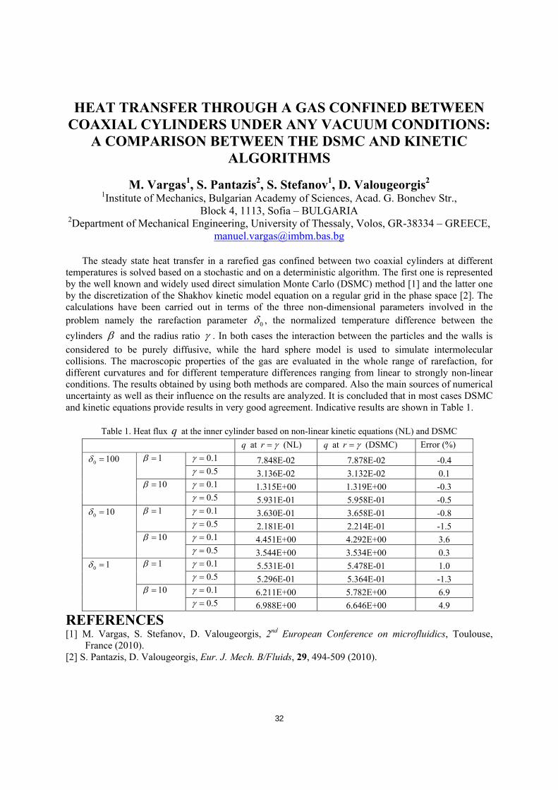
HEAT TRANSFER THROUGH A GAS CONFINED BETWEEN COAXIAL CYLINDERS UNDER ANY VACUUM CONDITIONS:
A COMPARISON BETWEEN THE DSMC AND KINETIC ALGORITHMS
M. Vargas1, S. Pantazis2, S. Stefanov1, D. Valougeorgis2 1Institute of Mechanics, Bulgarian Academy of Sciences, Acad. G. Bonchev Str.,
Block 4, 1113, Sofia – BULGARIA 2Department of Mechanical Engineering, University of Thessaly, Volos, GR-38334 – GREECE,
The steady state heat transfer in a rarefied gas confined between two coaxial cylinders at different temperatures is solved based on a stochastic and on a deterministic algorithm. The first one is represented by the well known and widely used direct simulation Monte Carlo (DSMC) method [1] and the latter one by the discretization of the Shakhov kinetic model equation on a regular grid in the phase space [2]. The calculations have been carried out in terms of the three non-dimensional parameters involved in the problem namely the rarefaction parameter 0δ , the normalized temperature difference between the cylinders β and the radius ratio γ . In both cases the interaction between the particles and the walls is considered to be purely diffusive, while the hard sphere model is used to simulate intermolecular collisions. The macroscopic properties of the gas are evaluated in the whole range of rarefaction, for different curvatures and for different temperature differences ranging from linear to strongly non-linear conditions. The results obtained by using both methods are compared. Also the main sources of numerical uncertainty as well as their influence on the results are analyzed. It is concluded that in most cases DSMC and kinetic equations provide results in very good agreement. Indicative results are shown in Table 1.
Table 1. Heat flux q at the inner cylinder based on non-linear kinetic equations (NL) and DSMC q at r γ= (NL) q at r γ= (DSMC) Error (%)
0.1γ = 7.848E-02 7.878E-02 -0.4 1β = 0.5γ = 3.136E-02 3.132E-02 0.1 0.1γ = 1.315E+00 1.319E+00 -0.3
0 100δ =
10β = 0.5γ = 5.931E-01 5.958E-01 -0.5 0.1γ = 3.630E-01 3.658E-01 -0.8 1β = 0.5γ = 2.181E-01 2.214E-01 -1.5 0.1γ = 4.451E+00 4.292E+00 3.6
0 10δ =
10β = 0.5γ = 3.544E+00 3.534E+00 0.3 0.1γ = 5.531E-01 5.478E-01 1.0 1β = 0.5γ = 5.296E-01 5.364E-01 -1.3 0.1γ = 6.211E+00 5.782E+00 6.9
0 1δ =
10β = 0.5γ = 6.988E+00 6.646E+00 4.9
REFERENCES [1] M. Vargas, S. Stefanov, D. Valougeorgis, 2nd European Conference on microfluidics, Toulouse,
France (2010). [2] S. Pantazis, D. Valougeorgis, Eur. J. Mech. B/Fluids, 29, 494-509 (2010).
33
TUESDAY, May 17, 2011
Section 5: Benchmark problems
Keynote Address
DETERMINISTIC MODELLING OF MULTI-DIMENSIONAL RAREFIED GAS FLOW
Vladimir A. Titarev 1Dorodnicyn Computing Centre of Russian Academy of Sciences, Moscow – RUSSIA
[email protected], [email protected]
Direct numerical solution of the Boltzmann kinetic equation with the exact or model collision integrals is a promising approach for numerical modelling of gaseous flows in low-pressure systems. The deterministic nature of the kinetic equation allows the development of efficient high-order accurate methods and thus makes it a potentially valuable tool for solving practical engineering problems. However, until recently the numerical solutions of the kinetic equations have been limited to simple geometries and relatively simple flows. This can be attributed to the lack of accurate and versatile methods suitable for the whole range of flow regimes both in terms of Knudsen number and pressure variations as well as for complicated geometries.
The present talk is devoted to the overview of very recent results on the numerical modelling of transitional flows on the basis of the kinetic equation. The main focus is on the methods and associated codes which can be potentially used in applied engineering studies. The discussion is centred (but not limited to) on three main areas: (i) flow in infinitely long channels with arbitrary cross-sectional areas [3, 7]; (ii) flows in long channels of finite length [2]; (iii) latest developments of three-dimensional methods and codes applicable to arbitrary flow problems of engineering interest. The latter includes a semi-unstructured second-order solver [4], first-order tetrahedral solver [1] and a recent family of implicit second-order methods on mixed-element unstructured meshes, put forward by the author [6, 5].
Further more, a discussion of ways forward for future development of deterministic modelling approaches is provided and requirements for such approaches are formulated and discussed, including formal order of accuracy, mesh handling, type of time marching as well as parallel scalability. A possible suit of test problems to assess the performance of such methods is suggested. REFERENCES [1] Yu.A. Anikin, Yu.Yu. Kloss, D.V. Martynov, and F.G. Tcheremissine. Journal of nano and
microsystem technique, 8, 2010. [2] K. Aoki, P. Degond, and L. Mieussens. Commun. Comput. Phys., 6(5), 919–954 (2009). [3] I. Graur and F. Sharipov. Eur.J. Mech. B/Fluids, 27(3), 335–345 (2008). [4] V.I. Kolobov, R.R. Arslanbekov, V.V. Aristov, A.A. Frolova, and S.A. Zabelok. J. Comp. Phys., 223,
589–608 (2007). [5] V.A. Titarev. Computational Mathematics and Mathematical Physics, 50(10), 1719–1733 (2010). [6] V.A. Titarev. Communications in Computational Physics, 8(2), 427–444 (2010). [7] V.A. Titarev and E.M. Shakhov. Computational Mathematics and Mathematical Physics, 50(12),
2131–2144 (2010).
34
Keynote Address
NUMERICAL SIMULATIONS AND APPLICATIONS OF RAREFIED GAS MIXTURES FLOWS
A. Frezzotti, G. P. Ghiroldi, L. Gibelli Dipartimento di Matematica del Politecnico di Milano Piazza Leonardo da Vinci 32, 20133, Milano – ITALY
Modelling of rarefied flows of multi-component gases is required in many areas of technology, ranging from evaporation/condensation phenomena in chemical reactors [1] to microfluidic devices [2]. The natural mathematical and numerical basis for rarefied gas flows studies is provided by the kinetic theory of gases and kinetic equations [3], whose complex structure forces the adoption of numerical methods which are computationally quite demanding. Although a large class of problems can be numerically approached by DSMC simulations [4], the adoption of the standard implementation of particles schemes can be problematic when applied to flows resulting from small deviations from equilibrium, to unsteady flows or to gas mixtures flows which contain small amounts of one or more components. In the cases listed above, deterministic schemes combined with kinetic model equations [5] or semi-deterministic schemes for the direct solution of the Boltzmann equation [6] offer interesting and computationally viable alternatives to particle schemes.
The present work aims at reviewing models and computational tools for rarefied gas mixtures flows and to present their applications to vapor deposition flows [5], where flow unsteadiness, small departures from equilibrium and trace components may all be present in some circumstances.
REFERENCES [1] A. Frezzotti, Proceedings of the 20th International Symposium, China (1997). [2] S. Naris et al., Phys. Fluids 17, 100607 (2005). [3] C. Cercignani, The Boltzmann Equation and Its Applications, Springer-Verlag, Berlin (1988). [4] G. A. Bird, Molecular Gas Dynamics and the Direct Simulation of Gas Flows, Clarendon Press,
Oxford (1994). [5] S. Kosuge et al., Phys. Fluids 22, 067101 (2010). [6] A. Frezzotti et al., Proceedings of the 2nd European Conference on Microfluidics, France (2010).
35
BENCHMARK PROBLEM. DIRECT SIMULATION MONTE CARLO OF GAS FLOW THROUGH A SLIT AND CHANNEL
F. Sharipov1, S. Varoutis2, Chr. Day2, D. V. Kozak3 1Depto Física, Universidade Federal do Paraná, Caixa Postal 19044, 81531-990 Curitiba –
BRAZIL 2Karlsruhe Institute of Technology, Institute for Technical Physics, 76021 Karlsruhe –
GERMANY 3Depto Eng. Comp., Pontifícia Univ. Católica do Paraná, Caixa Postal 16210, 81611-970
Curitiba – BRAZIL [email protected]
The flow rate of rarefied gas through a thin slit and channel is calculated on the basis of the direct simulation Monte Carlo method [1]. The calculations were carried out over the whole range of the gas rarefaction δ for various values of the pressure ratio 2 1/p p and aspect ratio L/H. The results to be
submitted for the comparison are resumed in Table 1, where 0/••
= MMW is the dimensionless flow rate, •
M is the flow rate at an arbitrary δ and arbitrary pressure ratio 12 / pp , while 0
•
M is the flow rate into vacuum 0/ 12 =pp in the free molecular regime 0=δ . The main sources of the numerical uncertainty are number of particles, time increment, size of the computational domain, size of cells. The influence of these parameters will be analyzed in the presentation. The total uncertainty is estimated to be equal to 1%.
Table 1. Reduced flow rate W vs aspect ratio L/H, pressure ratio 12 / pp and rarefaction parameter δ . W L/H=0 L/H=1
δ 0/ 12 =pp 5.0/ 12 =pp 0/ 12 =pp 5.0/ 12 =pp 0.01 1.001 0.502 0.6860 0.3448 0.1 1.026 0.520 0.6978 0.3540 1 1.148 0.640 0.7667 0.4187
10 1.479 1.237 1.038 0.8319 100 1.568 1.383 1.363 1.303
REFERENCES [1] G. A. Bird, Molecular Gas Dynamics and the Direct Simulation of Gas Flows, Clarendon Press,
Oxford, (1994). [2] F. Sharipov, D. Kozak, J. Vac. Sci. Technol. A 27(3), 479-484 (2009).
36
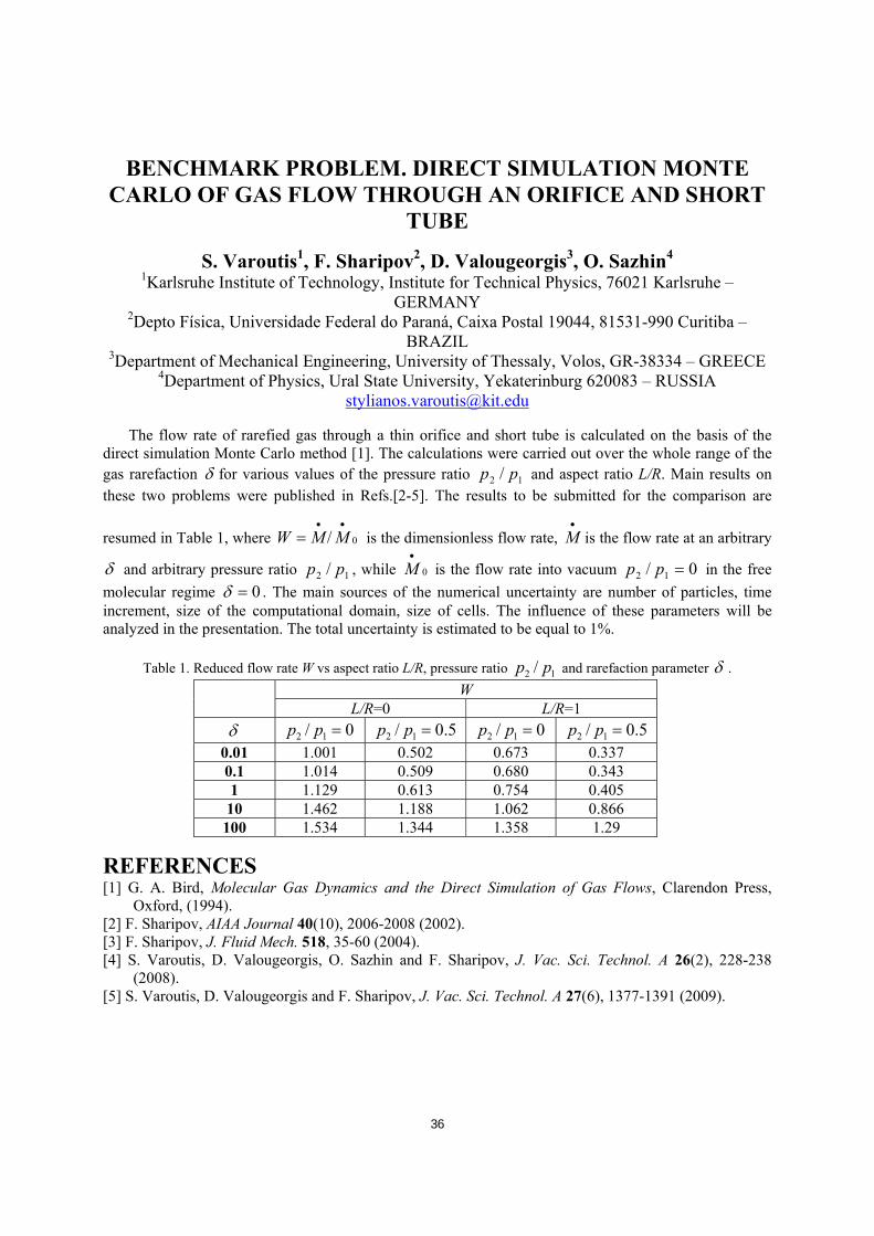
BENCHMARK PROBLEM. DIRECT SIMULATION MONTE CARLO OF GAS FLOW THROUGH AN ORIFICE AND SHORT
TUBE
S. Varoutis1, F. Sharipov2, D. Valougeorgis3, O. Sazhin4 1Karlsruhe Institute of Technology, Institute for Technical Physics, 76021 Karlsruhe –
GERMANY 2Depto Física, Universidade Federal do Paraná, Caixa Postal 19044, 81531-990 Curitiba –
BRAZIL 3Department of Mechanical Engineering, University of Thessaly, Volos, GR-38334 – GREECE
4Department of Physics, Ural State University, Yekaterinburg 620083 – RUSSIA [email protected]
The flow rate of rarefied gas through a thin orifice and short tube is calculated on the basis of the direct simulation Monte Carlo method [1]. The calculations were carried out over the whole range of the gas rarefaction δ for various values of the pressure ratio 12 / pp and aspect ratio L/R. Main results on these two problems were published in Refs.[2-5]. The results to be submitted for the comparison are
resumed in Table 1, where 0/••
= MMW is the dimensionless flow rate, •
M is the flow rate at an arbitrary
δ and arbitrary pressure ratio 12 / pp , while 0
•
M is the flow rate into vacuum 0/ 12 =pp in the free molecular regime 0=δ . The main sources of the numerical uncertainty are number of particles, time increment, size of the computational domain, size of cells. The influence of these parameters will be analyzed in the presentation. The total uncertainty is estimated to be equal to 1%.
Table 1. Reduced flow rate W vs aspect ratio L/R, pressure ratio 12 / pp and rarefaction parameter δ . W L/R=0 L/R=1
δ 0/ 12 =pp 5.0/ 12 =pp 0/ 12 =pp 5.0/ 12 =pp 0.01 1.001 0.502 0.673 0.337 0.1 1.014 0.509 0.680 0.343 1 1.129 0.613 0.754 0.405
10 1.462 1.188 1.062 0.866 100 1.534 1.344 1.358 1.29
REFERENCES [1] G. A. Bird, Molecular Gas Dynamics and the Direct Simulation of Gas Flows, Clarendon Press,
Oxford, (1994). [2] F. Sharipov, AIAA Journal 40(10), 2006-2008 (2002). [3] F. Sharipov, J. Fluid Mech. 518, 35-60 (2004). [4] S. Varoutis, D. Valougeorgis, O. Sazhin and F. Sharipov, J. Vac. Sci. Technol. A 26(2), 228-238
(2008). [5] S. Varoutis, D. Valougeorgis and F. Sharipov, J. Vac. Sci. Technol. A 27(6), 1377-1391 (2009).
37
RAREFIED GAS FLOWS THROUGH SLITS AND ORIFICES
S. Pantazis, S. Misdanitis and D. Valougeorgis Department of Mechanical Engineering, University of Thessaly, Volos, GR-38334 – GREECE
[email protected] Gas flow through slits and orifices connecting two reservoirs held at different pressures have been
solved based on nonlinear kinetic deterministic algorithms, as an alternative to the widely used Direct Simulation Monte Carlo (DSMC) approach. In particular, the non-linear form of the BGK kinetic model equation, subject to Maxwell diffuse boundary conditions, has been solved numerically, applying in the physical space a second-order finite volume scheme and in the molecular velocity space, the discrete velocity method. The slit flow is a 4D problem, while the orifice flow is a 5D problem. In an effort to decrease the involved computational effort an enhanced algorithm is implemented by applying certain computational techniques to accelerate convergence and improve accuracy. In particular, the typical iteration algorithm has been upgraded by implementing the Romberg integration rule and the Wynn-epsilon (We) acceleration algorithm. Also, the nonlinear fully deterministic algorithm is optimized by massive parallelization in the molecular velocity space and memory demands are reduced by proper handling of the allocated arrays [1,2].
Results for the flow rates as well as for the macroscopic quantities are presented in a wide range of the rarefaction parameter for various values of the pressure ratio between the two reservoirs. The performance of the algorithm with regard to the introduced numerical parameters (size of computational domain, discretization) as well as with regard to the flow parameters (degree of rarefaction, pressure ratio) is examined in detail. A systematic comparison with corresponding results based on the DSMC method [3,4] is performed. It is shown that the proposed fully deterministic kinetic approach may be considered as an alternative reliable and computationally efficient approach for solving high speed flows. Finally, by comparing linear and nonlinear results corresponding to the same conditions, it is concluded that linearized analysis can capture the correct behaviour of the flow configuration not only for infinitesimally small but also for finite pressure differences and that its range of applicability is wider than expected.
REFERENCES [1] S. Pantazis, D. Valougeorgis, Eur. J. Mech. B/Fluids, 29, 494-509 (2010). [2] S. Misdanitis, S. Pantazis, D. Valougeorgis, Rarefied flow between plates of finite length via an
efficient fully deterministic nonlinear algorithm, 2nd European Conference on microfluidics, Toulouse, France, (2010).
[3] F. Sharipov, J. Fluid Mech., 518, 35-60 (2004). [4] F. Sharipov, J. Vac. Sci. Tech. A, 27 (3), 479–484 (2009).
38
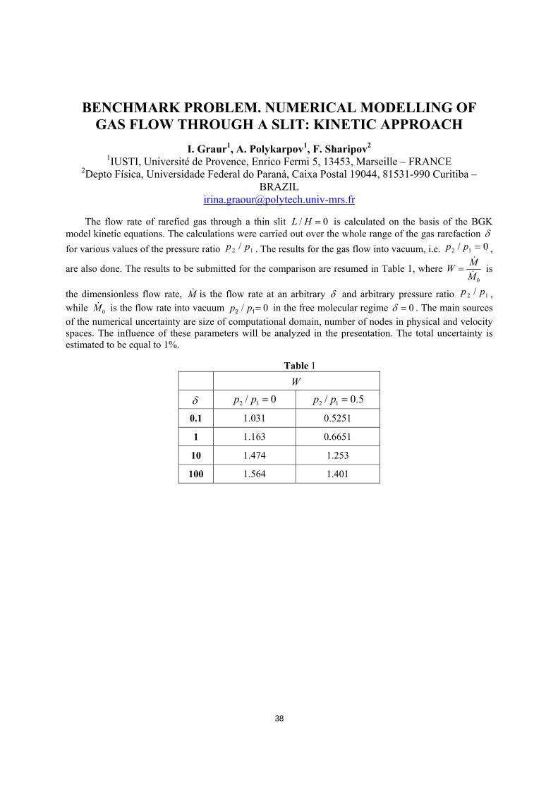
BENCHMARK PROBLEM. NUMERICAL MODELLING OF GAS FLOW THROUGH A SLIT: KINETIC APPROACH
I. Graur1, A. Polykarpov1, F. Sharipov2 1IUSTI, Université de Provence, Enrico Fermi 5, 13453, Marseille – FRANCE
2Depto Física, Universidade Federal do Paraná, Caixa Postal 19044, 81531-990 Curitiba – BRAZIL
The flow rate of rarefied gas through a thin slit / 0L H = is calculated on the basis of the BGK model kinetic equations. The calculations were carried out over the whole range of the gas rarefaction δ for various values of the pressure ratio 12 / pp . The results for the gas flow into vacuum, i.e. 0/ 12 =pp ,
are also done. The results to be submitted for the comparison are resumed in Table 1, where 0
MWM
=&
& is
the dimensionless flow rate, M& is the flow rate at an arbitrary δ and arbitrary pressure ratio 12 / pp , while 0M& is the flow rate into vacuum / 02 1p p = in the free molecular regime 0δ = . The main sources of the numerical uncertainty are size of computational domain, number of nodes in physical and velocity spaces. The influence of these parameters will be analyzed in the presentation. The total uncertainty is estimated to be equal to 1%. Table 1
W δ 0/ 12 =pp 5.0/ 12 =pp 0.1 1.031 0.5251
1 1.163 0.6651
10 1.474 1.253
100 1.564 1.401

39
GAS FLOWS THROUGH SHORT CHANNELS STUDIED BY THE DIRECT SOLUTION OF BOLTZMANN EQUATION
V.V.Aristov1, A.A.Frolova1, S.A.Zabelok1, V.I.Kolobov2, R.R.Arslanbekov2 1Dorodnicyn Computing Centre of Russian Academy of Sciences, Moscow – RUSSIA
2Computation Fluid Dynamics Research Corporation, Huntsville, AL – USA [email protected]
Both steady and unsteady problems of monatomic gas flows through a slit and a short channel
connecting two chambers are studied on the basis of Unified Flow Solver (UFS) [1] (and also by means of the others methods of the direct approaches for solving kinetic equations, see [2]). UFS includes solutions of the Boltzmann and BGK kinetic equations by Discrete Velocity Methods (DVM) and hybrid kinetic/fluid models with adaptive Cartesian mesh and automatic selection of kinetic-continuum solvers based on local flow properties. Gas flows through a short channel are studied for the entire range of the rarefaction parameter with exit into vacuum and into a finite pressure chamber. Different flow patterns are observed depending on flow conditions. Comparison with other methods including DSMC and model kinetic equations (such as BGK and S-model) is presented. Simulations of gas flow through a slit are performed for the entire range of the gas rarefaction for various pressure ratios and compared with computation results [3] performed on the basis of DSMC. The mass flow rate through a channel and a slit and flow field in both chambers are computed. Special attention is paid to evaluation of accuracy and efficiency of the DVM solution of the Boltzmann and BGK equations versus DSMC for low speed flows with small difference in pressures in the two chambers. REFERENCES [1] V.I.Kolobov, R.R.Arslanbekov, V.V.Aristov, A.A.Frolova, S.A.Zabelok. J. Comp. Phys., 223, 589-
608 (2007). [2] Aristov V.V. Direct methods for solving the Boltzmann equation and study of nonequilibrium flows.
Dordrecht: Kluwer Academic Publishers (2001). [3] F. Sharipov, D.Kozak. J.Vac.Sci.Technol. A, 27(3), 479-484 (2009).

40
THE BENCHMARK PROBLEMS SOLVED WITH A PARALLEL VERSION OF G. A. BIRD’S DSMC
Martin Rose Schwetzinger Str. 101, 68165 Mannheim – GERMANY
The rarefied gas flow through various channels and tubes of finite length was simulated using a parallelized version of G. A. Bird’s DSMC code. The reduced flow rate, the relative standard deviation of the sampled flow rate and the required wall clock time (WCT) are listed in the table below. In order to determine the numerical accuracy, multiple samples were calculated. The WTC is the time required to calculate all samples. A single sample can be obtained in a fraction of the given WTC within the given statistical range.
# Reduced flow rate channel
Rel. standard deviation [%]
Reduced flow rate tube (# of samples)
Rel. standard deviation [%] WTC [min]
1 1.006 1.26 0.994 (20) 0.58 < # 6 2 1.015 0.95 1.01 (15) 0.34 < # 7 3 1.120 0.45 1.133 (16) 0.24 < # 8 4 1.476 0.22 1.516 (20) 0.27 < # 9 5 1.613 0.37 1.560 (100) 0.35 < # 10 6 0.501 0.69 0.488 (8) 1.22 21 7 0.509 0.81 0.508 (15) 0.78 62 8 0.602 0.60 0.606 (16) 0.84 73 9 1.152 0.45 1.167 (20) 0.41 112 10 1.328 0.20 1.252 (20) 0.36 1351 (22,5 h) 11 0.685 1.28 0.659 (20) 0.66 < # 16 12 0.692 0.76 0.675 (15) 0.26 < # 17 13 0.749 0.43 0.750 (16) 0.40 < # 18 14 1.009 0.17 1.058 (20) 0.26 < # 19 15 1.331 0.06 1.129 (16) 0.27 < # 20 16 0.402 1.24 0.349 (8) 1.38 24 17 0.410 0.79 0.348 (8) 1.17 87 18 0.479 0.56 0.405 (8) 0.67 121 19 0.938 0.55 0.847 (20) 0.37 114 20 1.327 0.20 1.201 (20) 0.47 1409 (23.5 h)
The problems solved on an AMD Opteron workstation with 2 CPUs, where each CPU has 8 cores and all 16 cores were used. The number of simulated molecules was 1.2·105 for δ=0.01 and was increased by a factor 2.5 when δ increased by a factor of 10. All simulations started with a resting gas. The flow was simulated until a flow time of 2·10-2 s was reached. At this point the calculation was stopped and both the

41
collision cells and the sampling cells were adapted. After the adaption, the calculation resumed and the sampling of the flow rate commenced
42
Special Talk
CURRENT TECHNIQUES AND CHALLENGES IN THE DESIGN OF VACUUM PUMPS
Magnus Janicki Oerlikon Leybold Vacuum GmbH, Bonner Str. 498, 50698 Köln – GERMANY
The industrial design of vacuum pumps in general tries to optimize the vacuum performance and the energy efficiency of newly developed pumps in the limits of mechanical, thermal and financial possibilities [1]. Different simulation techniques are used to find the optimum design parameters prior to the prototype testing.
In most vacuum pumps all three flow regimes, the viscous, the transition and the molecular flow are to be found simultaneously at different locations. As most flow models show good accuracy only in a specific flow regime, the calculation of the vacuum performance of the integral pump is often not covered by a single simulation model. While CFD methods are very useful in the viscous flow regime, their accuracy decreases when the flow enters the transitional flow regime [2]. Monte Carlo methods on the other side are very helpful in calculating molecular flow but become computationally intensive with higher gas pressures due to the necessity of high particle numbers and the inclusion of collisions between the particles [3], [4]. Additionally there are nearly no commercial tools to calculate the flow of rarefied gases in three dimensional geometries.
This talk gives an overview of simulation models that are used in the industrial design of vacuum pumps, especially with screw vacuum pumps, roots blowers and turbo molecular pumps. It is shown, how far these techniques help during the development process of new pumps and where their simulation capabilities are limited.
REFERENCES [1] T. Dreifert, M. Janicki, Schraubenvakuumpumpen in VakuumPumpen, Verlag und Bildarchiv W.H.
Faragallah (2008). [2] L. A. Gochberg, Proceedings of the 23rd International RGD Symposium (2003). [3] F. Sharipov, J. Vac. Sci. Technol. A 28 (2010). [4] G.A. Bird, Molecular Gas Dynamics and the Direct Simulation of Gas Flows, Oxford University Press
(1994).

43
WEDNESDAY, May 18, 2011
Section 6: ITER
TEST-PARTICLE CALCULATIONS OF PRESSURE PROFILES AND PUMPING EFFICIENCIES: APPLICATION TO SOME
VACUUM DEVICES OF ITER
R. Kersevan ITER International Organization, Route de Vinon sur Verdon – 13115 St Paul Lez Durance –
FRANCE [email protected]
This paper describes the application of the Molflow+ code to the analysis and optimization of some
vacuum components envisaged for installation on ITER. Molflow+ is a code written in C/C++ and running on Windows-based PCs and laptops. It implements the Test-Particle Monte Carlo (TPMC) method [1]. It allows file import from the popular CAD export "STL" file format, allowing the analysis of complex geometries. The vacuum system of ITER is composed of a multitude of sub-components, ranging in size and vacuum level, going from the ~1000 cubic meter volume toroidal vacuum chamber in transition flow down to few liters volume components such as RF heating lines under ultra-high vacuum conditions. The complexity of ITER, and the large number of diagnostic systems, makes the optimization of space a very important issue. Pumps and pumping manifolds and geometries must be optimized also in view of cost-containment measures. Within the Vacuum Pumping Group of the Fuel Cycle Division, the optimization of the design of the ultra-high vacuum system of some subsystems and components has been undertaken. The paper will briefly highlight the main features of Molflow+ and then move on to show some applications to ITER. It will also discuss possible improvements of the code.
REFERENCES [1] R. Kersevan, J-L. Pons, J. Vac. Sci. Technol. A, 27, 1017 (2009).

44
CRYOGENIC VISCOUS COMPRESSOR DEVELOPMENT AND MODELLING FOR THE ITER VACUUM SYSTEM
L. R. Baylor1, C. N. Barbier2, S.K. Combs1, R.C. Duckworth1, T.D. Edgemon3, S.J. Meitner1, D.A. Rasmussen3, R. Kersevan4, M. Dremel4, and R. J.H.
Pearce4 1Fusion Energy Division, Oak Ridge National Laboratory, Oak Ridge, TN 37831, USA
2Computational Sciences and Engineering Division, Oak Ridge National Laboratory, Oak Ridge, TN 37831, USA
3U.S. ITER Project Office, Oak Ridge National Laboratory, Oak Ridge, TN 37831, USA 4ITER Organization, 13067 St. Paul-lez-Durance, FRANCE.
A specialized cryopump known as a cryogenic viscous compressor (CVC) is being developed for the ITER vacuum system to pump hydrogenic exhaust gases from the fusion reaction chamber and compress them to a high pressure by regeneration for pumping to the tritium exhaust processing facility. Several of these pumps will operate in parallel and are staged to maintain continuous pumping and regeneration during plasma operation. The pumps are cooled to operating temperatures by flowing supercritical helium at 4.5K outside the tubular pumping region. Helium impurity gas in the pumping stream that is a byproduct of the fusion reactions passes through the CVC and is pumped by conventional vacuum pumps. A conceptual design of the CVC has been developed and is undergoing concept testing before the detailed design is completed. To verify the concept of the full-scale CVC, a representative prototype has been designed, fabricated, and is undergoing testing. While cooling is provided by either cold helium gas or supercritical helium, hydrogen with trace amounts of helium gas is introduced into the central column of the cryopump at 100 Pa and 80 K at flow rates of 8 mg/s. Heat transfer between the laminar flowing gas and the cold pump tube is being enhanced with the use of internal petal fins. Temperature and pressure measurements are made along the pump gas stream in order to benchmark with design values and measure the heat transfer characteristics. Comparison with published tubular heat transfer phenomenological models and a fluid dynamics code is underway.
Modelling of the gas flowing into the pump and through the precooler heat exchanger and freezing zones is accomplished with the CFX computational fluid dynamics code [1]. The flows into the pump are at low pressure (~100 Pa) and are in a laminar low Reynolds number regime (Re < 300) that is handled well with the CFX code. As the gas begins to desublimate in the cold zone of the pump it reaches a rarified gas regime where the CFX model for flow and heat transfer breaks down. An ad hoc method of changing the hydrogen properties is presently used to model this part of the pump operation. A more refined method is desired for higher accuracy to better optimize the design. The modelling results are being compared with the prototype testing and will be used to further optimize and ensure reliable operation of the full CVC in the ITER application. ACKNOWLEDGEMENTS This work was supported by the Oak Ridge National Laboratory managed by UT-Battelle, LLC for the U.S. Department of Energy under Contract No. DE-AC05-00OR22725.
REFERENCES [1] ANSYS CFX, ANSYS, Inc., Canonsburg, PA 15317, USA.
45
CFD MODELLING OF LIQUID PRESSURIZED WATER AND PHASE CHANGE THROUGH LEAKS IN MOCRO-CRACKS IN
VACUUM COOLING SYSTEMS: QUANTITATIVE ESTIMATES AND COMPARISONS WITH ANALYTICAL SOLUTIONS
A. Kumar1, C. Souprayen1, M. Levet1, L. Worth2, R. Pearce2 1FLUIDYN, FRANCE
2ITER Organization, 13067 St. Paul-lez-Durance, FRANCE. [email protected]
The modeling studies reported here are done in relation to the design and operation of the Primary
Heat Transfer Systems (PHTS) surrounding the main vacuum vessel in a Tokamak. Typically, pressurized liquid water is circulated in manifolds and plasma facing components at high pressure (30 to 45 bars) and high temperatures (373 to 523 K). The occurrence of water leaks in the vacuum has to be avoided and, if any occurs, such a leak has to be detected and localized for repair. Systems for leak localization must be able to localize leaks from the PHTS into the vacuum vessel with sensitivity better than 10-11Kg/s with sub-centimeter spatial resolution.
Systems based on spectroscopic detection of the plume of water vapor expanding from a leak in the vessel have been proposed and in order to validate this methodology an understanding of the development of water flow through a leak in required. Given both the expected dimensions of the cracks, with the outlet under vacuum conditions (between 10-6 Pa and 10 Pa), the flow developing in the crevices are initially (upstream) single phase liquid in Poiseuille regime, then multiphase flow locally due to pressure decrease and finally gaseous phase in rarefied regime (toward or at the outlet). Due to the significant viscous effects and potentially pressure drop related to the phase change, the expected mass flow rates are very weak, order of 10-11Kg/s for a hole with a section of the order 1�m2 and length 1cm. The physics involved in the studies presented has been modeled initially with an analytical procedure solving for each regime (namely liquid Poiseuille upstream, and rarefied gas flow downstream) then matching for the steady state flow rate in isothermal conditions. This part of the work refers to recent publications in micro channel leak based on the assumption that the phase changes occurs on a sharp zone. Added to these first quantitative estimates based on analytical 1D modeling, a second approach with CFD 3D solution of Navier-Stokes equations with both slip conditions in the gaseous stream and phase change using an homogeneous equilibrium model has been performed on the same flow conditions. In this model a simple sub-model for the phase change mass transfer rate (and hence energy and momentum source) is designed for the evaporation process. An initially infinitesimal volume fraction of water vapor in injected at inlet and starts increasing where and when the calculated mixture flow reaches saturation conditions. In this 5 equations model the phase change happens to be localized if the isothermal flow conditions are assumed: namely if one supposes that both heat flux from the wall and in-fluid heat transfer are large and fast enough to keep the fluid mixture temperature uniform where phase change occurs. In such conditions, the CFD 3D results are matching with the 1D analytical solutions for pressures, densities, velocities and flow rates. Analyses in the non-isothermal flow regime (with heat transfer from liquid and from the steel wall surrounding structures) are discussed.
46
APPLICATION OF THE RAREFIED GAS DYNAMICS FOR DESIGN OF THE ITER OPTICAL DIAGNOSTICS
V. Kotov, D. Reiter
Institut für Energie- und Klimaforschung – Plasmaphysik, Forschungszentrum Jülich, Association EURATOM-FZJ, Trilateral Euregio Cluster, D-52425 Jülich, GERMANY
Optical diagnostics are essential for the ITER fusion experiment since they will provide the largest share of data for scientific analysis of the discharges. The diagnostic tools will be protected from the high neutron fluxes in long labyrinths. Mirrors are used to redirect light to the protected instruments. First mirrors which face the plasma directly are a critical element of this system. The first mirror itself is installed in a channel (diagnostic duct) which prevents its direct contact with magnetized plasma. However, neutral particles freely moving across the magnetic field can reach its surface. In particular, this applies to impurity atoms (Be, C, Fe etc.) produced by erosion of the in-vessel plasma facing components. Experiments [1] and numerical estimates [2] show that deposition of impurities can lead to unacceptable deterioration of the first mirror reflectivity, thus, failure of the diagnostic system, on a time scale much shorter than the projected ITER operation time.
Optimization of the diagnostic duct geometry can significantly reduce the incident impurity fluxes. Collisions with residual gas in the duct can be normally neglected; therefore, mathematically the problem is reduced to the free-molecular flow in a complex 3D structure. A distinguishing feature making this problem different from other applications is the physics of the particle-surface interaction. Impurity atoms which stick to the duct wall form deposited films there. Those films can be sputtered by the fast “main” (D, T) atoms originating from the hot plasma. Calculations show that under conditions of a fusion reactor this re-erosion is the main mechanism which pushes impurities towards the mirror in a long duct. The model and simulation results will be presented in the talk. The simulations are performed with the Monte-Carlo code EIRENE [3] which is well known in magnetic fusion community: its primary application is the interaction of neutral particles with highly ionized plasma.
If geometrical protection is not sufficient, then a gas puff in front of the mirror can be applied to expel impurity atoms back to plasma. The gas puffing rate must be as small as possible to avoid perturbation of the main plasma. Therefore, the flow is likely to be in a transition regime with Kn≈0.1..1 and techniques of rarefied gas dynamics have to be applied to model and design such a system. E.g. the non-linear (iterative) Monte-Carlo-BGK procedure available in the EIRENE code can be used. Statement of the problem as well as approaches to its solution will be discussed.
REFERENCES [1] A. Litnovsky et al., Nuclear Fusion, 49, 075015 (2009). [2] V. Kotov et al., Fusion Eng. Des., doi:10.1016/j.fusengdes.2010.12.048 (2011). [3] D. Reiter, M. Baelmans, P. Börner, Fus. Sc. Tech., 47, 172, www.eirene.de (2005).

47
BENCHMARK OF AN EFFICIENT BGK MODEL FOR RAREFIED GAS FLOWS IN FULL 3D GEOMETRY
A. Scarabosio1, M. Simon1, D. Reiter2, P. Boerner2 and V. Kotov2 1Max-Planck-Institut für Plasmaphysik, EURATOM-Association, Boltzmannstr. 2, D-85748,
Garching, GERMANY 2Institut für Energie und Klimaforschung - Plasmaphysik, Forschungszentrum Jülich Association
EURATOM-FZJ, Trilateral Euregio Cluster, D-52425 Jülich, GERMANY [email protected]
Magnetic fusion experiments require complex vacuum system with efficient pumping of the working
gas and impurities. Optimisation is often complicated by poor knowledge of the conductance and the fact that the gas flow is in the transition regime. The issue can be addressed numerically with DSMC method but this latter is very computationally expensive for real 3D problems. In this work an approach based on the BGK model implemented in the Monte-Carlo particle transport code EIRENE [1,2,3] is applied. The BGK model has been already proven to give quantitative good results for flows of rarefied gases for an appropriate choice of the relaxation time [4,5]. These results, however, are often obtained in condition of ‘well developed flow’ (linear BGK) or for specific cases with simplified geometry. Benchmark of BGK-EIRENE is therefore needed to gain confidence in the results. The EIRENE code incorporates a non-linear BGK into a fully 3D and flexible Monte-Carlo scheme, which solves multi-species Boltzmann equations. The numerical scheme uses an iterative procedure (’successive linearization‘) to calculate the parameters of the Maxwellian in the BGK model. At each iteration the linear problem is solved through Monte-Carlo methods. Further a velocity-independent relaxation time is chosen to match experimental viscosity. In this work we study the flow through a circular tube or rectangular channel from a vessel with pressure P1 into vessel with pressure P2 < P1. We consider various pipe/channel length and pressure differences in regimes ranging from the free molecular to slip-fluid regime (Kn≥ 0.01). The accuracy is limited by statistical noise, number of iterations and minimal grid size. This latter crucially determines the smallest Kn achievable with a given grid. We find good agreement (typically within 5%) with available experimental data and DSMC simulations [6,7,8] and a relatively small computational price on a single CPU.
REFERENCES [1] D. Reiter, M. Baelmans, P. Börner, Fus. Sc. Tech., 47, 172 (2005). [2] D. Reiter. The EIRENE code, Version 11/2009, User Manual. www.eirene.de. [3] D. Reiter et al., J. Nucl. Mat., 241-243, 342 (1997). [4] F. Sharipov and V. Seleznev, J. Phys. Chem Ref. Data, 27, 657 (1998). [5] S. Varoutis et al., J. Vac. Sci. Technol. A, 27(1), 89 (2009). [6] T. Fujimoto, M. Usami, J. Fluids. Eng., 106, 367 (1984). [7] S. Varoutis et. al, J. Vac. Sci. Technol. A, 26(2), 228 (2008). [8] S. Varoutis et. al, J. Vac. Sci. Technol. A, 27(2), 1377 (2009).
48
PROVAC3D – A TEST PARTICLE MONTE CARLO PROGRAM FOR COMPLEX VACUUM SYSTEMS
X. Luo, S. Varoutis, H. Hass, S. Hanke and Chr. Day Karlsruhe Institute of Technology, Institute for Technical Physics, 76021 Karlsruhe,
GERMANY [email protected]
ProVac3D, standing for “3D density PROfile in the VACuum system”, is a Test Particle Monte Carlo
(TPMC) simulation program developed by the Karlsruhe Institute of Technology (KIT) [1]. This program is very suitable to simulate a real 3D vacuum system characterized by complex geometry, great temperature gradients and distributed gas loads. The code has been recently modified to a new version which is running correctly on the HPC-FF system at Jülich Supercomputing Centre (JSC). Compared to the corresponding simulation carried out with a PC (Intel Core 2 at 2.67 GHz), the computation time is almost five times faster. In this presentation, the capability of the Provac3D is demonstrated by two applications to the ITER.
The first application is to study the model cryopump which has been manufactured and systematically tested in our TIMO facility (Test facility for the ITER Model Pump). Not only had the global parameters, such as effective capture factors and cryosorption distributions been determined, but also the macroscopic physical quantities such as temperature, pressure and pumping speed had been simulated for this type of high performance large scale cryopump needed by the ITER [2]. The simulation results showed good agreement with the experimental data when the flow rate is less than 1000 sccm (~ 1.69 Pa m3/s at T= 0°C). Since the pressure close to the active cryosorption panels always remains low, the obtained effective capture factors can be used as input parameters for DSMC studies for higher flow rates when the negligible collision between the gas molecules has to be considered.
The second application is to calculate the gas density distribution in the MITICA facility - a full scale test facility, which is currently being built up on the site of Consorzio RFX in Padova, Italy for the Neutral Beam Injector (NBI). The NBI is a vacuum facility which produces a beam of highly energetic hydrogen neutral particles which are injected into the plasma for heating and current drive purposes. In order to assist the design of the system components, such as the neutralizer of the ionised gas and the in-situ cryopumps, the gas density profile simulations were carried out with ProVac3D. It is shown how these were resulting in design modification and optimization [3]. REFERENCES [1] X. Luo, Chr. Day, Investigation of a New Monte Carlo Method for the Transitional Gas Flow,
Proceedings of 27th International Symposium on Rarefied Gas Dynamics, July 2010, California, accepted.
[2] X. Luo, Chr. Day, H. Haas, S. Varoutis, Experimental results and numerical modelling of a high performance large scale cryopump. Part I: Test Particle Monte Carlo simulation, submitted to Journal of Vacuum Science and Technology A.
[3] X. Luo, Chr. Day, Fusion Engineering and Design, 85, 1446–1450 (2010).

49
NUMERICAL MODELLING OF THE ITER MODEL CRYOPUMP
F. Sharipov1, S. Varoutis2, Chr. Day2, X. Luo2, H. Haas2 1Depto Física, Universidade Federal do Paraná, Caixa Postal 19044, 81531-990 Curitiba,
BRAZIL 2Karlsruhe Institute of Technology, Institute for Technical Physics, 76021 Karlsruhe,
GERMANY [email protected]
The main duty of the vacuum pumping system for the torus of ITER is to pump out a fusion exhaust gas during plasma burn and dwell. Such a system must meet many strict requirements. The concept for the cryovacuum system satisfying the requirements has been developed at Institute for Technical Physics of Karlsruhe Institute of Technology (KIT). A further development and improvement of the system requires a numerical modelling of the gas flow inside the vacuum chamber and near the cryopanels. When one deals with gas flows in a complicated geometrical configuration, usually, the Direct Simulation Monte Carlo (DSMC) or Test Particle Monte Carlo (TPMC) methods are employed. The first one can be used for arbitrary Knudsen number, but it requires simulating a huge number of model particles simultaneously. Such computational effort is justified when the intermolecular collisions must be taken into account. The second method consists of simulation of individual particle trajectories with a quite modest computational effort. The simplicity of this method allows us to consider three-dimensional flows with many surfaces of complex configuration. However, the TPMC method is valid only in the free-molecular regime. Since the cryovacuum pump elaborated for the torus of ITER has some regions where the intermolecular collisions cannot be neglected and other regions with many panels where the flow is free-molecular, a combination of the two methods would be reasonable.
The aim of the present work is a numerical modelling of the ITER model cryopump combining both DSMC and TPMC methods, namely, the flow between the cryopanels is simulated by the TPMC method and then these results are used as input data for the DSMC method. A detailed comparison with the corresponding experimental data is performed, which demonstrates the reliability of the computational tool. The numerical results provide detailed information about the gas flow field such as pressure distribution, number of particles and energy flux absorbed by each cryopanel, etc. These quantities can be used to optimize the pumping system in order to improve its performance.

50
Section 7: Vacuum System Design
DESIGN OF GAS PIPING DISTRIBUTION SYSTEMS CONSISTING OF LONG PIPES UNDER ANY VACUUM
CONDITIONS
S. Misdanitis and D. Valougeorgis Department of Mechanical Engineering, University of Thessaly, Volos, GR-38334 – GREECE
[email protected] Gas flows through single long channels of various cross sections have been extensively investigated over the years both numerically and experimentally [1]. It has been shown that in this case the most suitable approach to efficiently solve the problem in the whole range of the Knudsen number is linear kinetic theory [2,3].
However, in many vacuum applications, these single channels are combined together in order to form a pipe network. Computational algorithms for solving gas pipe networks in the viscous regime are well developed. However, corresponding tools for solving networks consisting of piping elements under any degree of gas rarefaction have not been developed so far. In the present work a complete algorithm is presented for the design of networks consisting of long tubes based on linear kinetic theory. The flow inside the network may vary from the free molecular, through the transition up to the viscous regime. The results are valid in the whole range of Knudsen number.
The objective is to compute the conductance at each piping element and the pressure head at each node of the network, provided that the geometry, i.e., the length and the diameter of each channel of the network is given. The system of equations describing the network consists of the pressure drop equations along each piping element and the mass conservation equations at each node of the network. When the network is properly defined the pressure drop equations may be reduced to a set of the energy balance equations along the closed loops of the network, which along with the mass conservation equations form a closed set, which may be solved for the mass flow rates. Then, the pressure heads at the nodes are estimated through the pressure drop equations. An iterative process between the system of equations and the pressure drop equations yields the converged values of the unknown quantities. The main problem, in the present rarefied conditions, compared to the typical network solvers in the viscous limit, is that in the later case the pressure drop along a channel is given by explicit algebraic expressions, while far from this limit no such expressions exist. Here, this information is obtained from a data base, which has been developed for this purpose by solving a linearized BGK kinetic equation in a wide range of the Knudsen number and obtaining the corresponding data. Several piping systems are simulated to demonstrate the feasibility of the approach. ACKNOWLEDGEMENTS This work has been supported by the European Communities under the contract of Association EURATOM/ Hellenic Republic. REFERENCES [1] S. Varoutis, S. Naris, V. Hauer, C. Day, D. Valougeorgis, J. Vac. Sci. & Tech. A, 27 (1), 89-100
(2009). [2] F. Sharipov, J. Vac. Sci. & Tech. A, 14 (4), 2627-2635 (1996). [3] S. Naris and D. Valougeorgis, Eur. J. Mech. B/Fluids, 27, 810-822 (2008).

51
[4] Z. Poulakis, D. Valougeorgis, K. Papadimitriou, Health monitoring of pipe networks using a probabilistic framework, 8th International Conference on Structural Safety and Reliability (ICOSSAR 2001), Newport Beach, California, USA (2001).
52
NETWORK MODELLING OF COMPLEX VACUUM SYSTEMS
V. Hauer, Chr. Day Karlsruhe Institute of Technology, Institute for Technical Physics, 76021 Karlsruhe –
GERMANY [email protected]
The ITERVAC code is a program for smooth simulation of the mass flow through a network of ducts
at isothermal conditions in a wide flow regime including the difficult to describe transitional flow regime. As the name indicates, it was developed to simulate the gas flows in the ITER torus vacuum system. However, it is versatile enough to be used for any multi-channel vacuum system. This shall be demonstrated in the present paper, taking an example from the nuclear fusion project ITER.
The reference design of the ITER torus exhaust pumping system is based on 8 large cryopumps, connected via 5 ducts to the torus. Due to the small burn-up fraction, the total gas throughputs are very high, control of which, especially for the helium ash, is one of the key issues affecting the performance and achievable burn time of a fusion reactor. The design governing requirement for the torus exhaust vacuum pumping system is to maintain a requested pressure level at a given position (between 1 and 10 Pa in the divertor private region) at a maximum gas flow (up to 200 (Pa·m³)/s). A key problem is the fact that the torus pumping systems have to compete against the plasma inside the torus, which acts like a black hole for the neutral gas.
A full network model of the ITER torus vacuum system was built including toroidal and radial conductances as well as by-pass leaks between various system components and the conductances between the vacuum vessel and inside the pumping ducts up to the cryopumps.
Simulations were performed for the burn and dwell mode of ITER; deuterium was used as model gas within the simulations. The final model contained more than 1400 channels to have a good representation of the complex flow pattern of the vacuum system. As main result was found that during plasma burn the total throughput towards the plasma is always higher than the one to the cryopumps; at the highest divertor pressure of 10 Pa, this corresponds to a factor 2. The integral molecular conductance of the complete pumping system could be calculated as well as its evolution under higher operating pressures.
The ITERVAC code is currently under upgrade to fully reflect recent experimental and theoretical results of vacuum flows. REFERENCES [1] C. Day et al., Development of a simulation code for ITER vacuum flows, 21st IAEA Fusion Energy
Conf., Chengdu, China, October 16-21 (2006). [2] V. Hauer, Chr. Day, Fusion Engineering and Design, 84, 903–907 (2009). [3] S. Varoutis et al., Fusion Engineering and Design, 85, 1798-1802 (2010).
53
MEASURES AND SIMULATIONS WITH A MC CODE OF CRYOGENIC TRAP EFFICIENCY FOR SPIRAL2
R. Levallois GANIL, Bd. Becquerel, 14000 Caen – FRANCE
The vacuum system of SPIRAL2 project (RIB facility) contributes to one of containment barriers for the volatile radioactive compounds. In order to strongly limit the transfer of these volatile compounds in the beam line, a high efficiency cryogenic trap has been studied. To determine which trap geometry was the best, an optimization study was conducted with MOVAK3D, a Monte Carlo code for calculations of particles transmission in molecular flow regime. So, after simulations, we got a structure limiting transfer to some 10-3 for the gases with the highest activity.
In order to validate the trap efficiency, but also integration of such system in an environment with strong constraints, a prototype was built. During the last year, after validation of mechanical and cryogenic parts, 3 kinds of gases were injected in the prototype in order to measure transmission coefficient. After calculations, we can say that the results coming from these transmission coefficient measurements are closed to MOVAK3D simulation results. So, we can design, for specific gases, a cryotrap with transmission coefficients searched.
54
Section 8: Transient Problems
AN ANALYTICAL MODEL FOR THE TEMPORAL EVOLUTION OF THE SPATIAL PRESSURE PROFILE IN
FINITE CONDUCTION LIMITED PIPES WITH DISTRIBUTED PUMPING
V. Ziemann Department of Physics and Astronomy, BOX 516, Uppsala University, 75120, Uppsala,
SWEDEN [email protected]
In the future linear collider CLIC beams are accelerated by radio-frequency (RF) waves to high
energy, which requires extremely high acceleration gradients in the 100 MeV/m range. The high electro-magnetic fields occasionally lead to spontaneous discharges, so-called RF-breakdown, in which a significant amount of energy is locally dissipated inside the acceleration structures. This leads to a local desorption of gas molecules from the walls and the question arises to what extent they can be pumped away before the next beam pulse arrives, typically 10 ms later. We therefore develop and discuss an analytical model to investigate the temporal evolution of the pressure profile in this conduction limited system. The effect of distributed pumping is taken into account. Apart from rapidly estimating the behavior of a system the model can be used to benchmark more elaborate numerical codes.
ACKNOWLEDGMENTS This work is supported by the 7th European Framework program EuCARD under grant number 227579.
55
UNSTEADY FULLY DEVELOPED RAREFIED GAS FLOW IN CYLINDRICAL TUBES
Yiannis Lihnaropoulos and Dimitris Valougeorgis
Department of Mechanical Engineering, University of Thessaly, Volos, GR-38334, Greece [email protected], [email protected]
The starting fully developed gas flow in a cylindrical channel is investigated in the whole range of the
Knudsen number by numerically solving the governing time dependent kinetic equations in a fully deterministic manner. The gas is initially at rest and then due to a suddenly imposed uniform pressure gradient, is starting to flow. The motion is time dependent up to the point where the steady-state flow conditions are recovered. The flow field is modelled by the linearized unsteady BGK equation subject to Maxwell purely diffuse boundary conditions. The solution provides a detailed description of the evolution of the flow field with regard to time from the starting point, where the gas is at rest up to a certain time where almost steady-state conditions are recovered. Based on the results some insight of how rapidly a vacuum flow will respond to a sudden change, related to an externally imposed pressure gradient coming from a vacuum pump or a valve, is obtained. The total time to recover the stationary solution in terms of the rarefaction parameter exhibits a minimum close to the well known Knudsen minimum. ACKNOWLEDGMENTS This work has been supported by the European Communities under the contract of Association EURATOM/ Hellenic Republic.
REFERENCES [1] J. Lihnaropoulos, D. Valougeorgis, Fusion Engineering and Design, doi:10.1016/
j.fusengdes.2011.02.005 (2011).
56
MODELLING A VACUUM ACCIDENT IN AN X-RAY BEAM LINE
M. Cox Diamond Light Source, Diamond House, Harwell Oxford Campus, Didcot, Oxfordshire OX11
0DE, UK [email protected]
Synchrotron light sources such as Diamond Light Source typically have a storage ring operating at
ultra-high vacuum, connected via a contiguous, windowless vacuum space with many x-ray beamlines. Considerable effort and expense goes into the design of both active and passive vacuum protection systems to protect the vacuum in the storage ring from a vacuum accident in one of the beamlines, such as the breakage of a window. Protection systems typically include a combination of methods such as fast-closing valve systems, acoustic delay lines, small apertures and differential pumping stages. Due to the difficulties of simulating a vacuum accident, a proper optimisation of such systems is generally not possible and designs are more often based on judgement and practical experience from past events rather than on hard design data. Currently we are not able to model the propagation of gas from a vacuum accident along a beamline in any realistic way as this would require a non-steady-state treatment across the whole pressure range from atmosphere (continuum flow) to ultra-high vacuum (free-molecular flow). In addition, an x-ray beamline typically consists of a linear chain of complex 3-dimensional components such as mirrors and monochromators which will themselves act as buffers to slow down gas propagation. We initially looked at using Monte Carlo Test Particle methods but quickly realised that inclusion of intermolecular collisions is vital to obtaining useful results. If we were able to model a vacuum accident in a realistic way across a wider pressure range (for example by using DSMC methods) then this could lead to a much better optimisation of the vacuum protection systems potentially with significant savings in design time and hardware costs. A practical simulation technique does not need to be very accurate but should reproduce the main features of a real event and ideally should be quick and simple to apply to a realistic design. This presentation will discuss the problem and possible solutions.

57
AN EXPERIMENT ON REAL-TIME LEAK DETECTION UNDER LOW TEMPERATURE
Z. Chen Fermilab - USA,
In modern particle accelerators, superconducting RF cavities, cryomodules and cryomagnets are used and operated at very low temperature (2-4K). Their internal components at very low temperature will serve naturally as cryopump with huge pumping speed, any leaking gases will be frozen as soon as reach the surfaces. As result, the total pressure gauges will not give a clear pressure rise signal in case of leak, and the ice coated on the surfaces will degrade the performance or even damage these critical devices. The purpose of the experiment is to probe vacuum leak by analyzing the changes of gas spectrum from real time RGA data of the vacuum system. The results will help to set some design and operational guidance for similar vacuum system, such as interlocks, spacing etc.
58
THURSDAY, May 19, 2011
Section 9: Accelerator Vacuum Systems
Keynote Address
GEOMETRICAL STRUCTURE EFFECTS ON THE PUMPING DELAY TIME
Yoshio Saito1, Namio Matuda2 1KEK, Tsukuba – JAPAN
2Tokio Denki University – JAPAN [email protected]
The vacuum people in the accelerators usually designs the systems by taking account of the outgassing rates and pump distribution. In order to reduce the residual gas pressure and suppress the outgassing due to incident particles, surface finishing methods of the materials for use as the vacuum components have been developed for these several tens years. Based on the outgassing rates measured for these surfaces, the pressure distribution along the accelerators with or without beam operation can be calculated depending on the distributed pumping speed and conductance.
One of the serious problems concerning the pressure distribution and pumping delay time takes place in the beam injection and extraction region in the accelerators. The electromagnet devices such as kicker and bump magnet installed in vacuum often have large outgassing rate from the materials, and also they are assembled in complicated structure; stacked laminations, small pumping slots, tapered pumping tubes and so on. Although a Monte-Carlo method is powerful for calculating the precise pressure distribution required for the optimized pumping system, a more convenient calculation method, if possible, is useful for the vacuum people.
We made the approximation formula applicable to conductance calculation of tube and narrow gap structure in the wide aspect ratio, which was analytically derived from the diffusion equation assuming molecular flow condition. This is one of the classical items in the vacuum technology, but it also gives the impinging numbers (hitting cycles) required for an emitted molecule from the surface to reach an exit of the structure, which is useful for estimating the pumping delay time.
REFERENCES [1] Y. Saito, Y. Sato, T. Kubo, J. Vac. Sci. Technol. A, 22, 2206 (2004). [2] Y. Saito, Y. Sato, N. Matuda, J. Vac. Soc. Jpn., 50, 366 (2007). [3] N. Matuda, J. Vac. Soc. Jpn., 52, 407 (2009) (in Japanese).
59
GAS DYNAMICS MODELLING FOR PARTICLE ACCELERATORS
O. B. Malyshev ASTeC, STFC Daresbury Laboratory, Daresbury, Warrington, UK
Design of accelerator vacuum chamber requires an input from different scientific disciplines such as surface science, material science, gas dynamics, particle beam dynamics, and many others. Although vacuum science works on the boundary field between these disciplines the gas dynamics is one that allows joining all these to the vacuum science for particle accelerators.
The particle accelerator requirement to vacuum defined by beam gas interactions that should be negligible comparing to the other phenomena and effects limiting the quality of the beam, so these requirements are in free molecular regimes: HV, UHV or even XHV. At such low pressures the main source of gas in the vacuum chamber is molecular desorption from materials used for vacuum chamber and in-vacuum components.
The outgassing rates depends on material, its cleaning procedure, treatments (polishing, etching, coatings, bakeout, etc.), time in vacuum, irradiation or bombardment by particles (photons, electrons, ions, etc.) and accumulated irradiation dose. Therefore, the outgassing rates vary in very wide range. The gas dynamic is used to design the research facilities to accurately measure and to study outgassing rates at different conditions, then it used for data analysis.
By applying these data to the accelerator vacuum design one have to consider that outgassing is often non-uniform and changes with time with different functions. Full 3D modelling is possible with TPMC codes, however, it is time consuming work and not ideal for pumping and design optimization, so it is used for components or for finalized design. Meanwhile, during the optimization study the most time-efficient way is using 1D diffusion model where all parameters are defined as a function of longitudinal coordinate (along the beam path).
The examples of calculation for a small research facility design, data analysis and accelerator vacuum chamber design will be shown in the talk for a few particle accelerators, such as SSC, LHC, DLS and FAIR. REFERENCES [1] V.V. Anashin, O.B. Malyshev et al., Vacuum, 48, 785 (1997). [2] O. B. Malyshev and A. Rossi, Proc. of EPAC-6, 948, Vienna, Austria, (2000). [3] V.V. Anashin, O.B. Malyshev et al., Vacuum, 53, 269 (1999). [4] O.B. Malyshev et al, Proc of EPAC-8, 2571, Paris, France (2002). [5] E. Hedlund, L. Westerberg, O.B. Malyshev et al., NIM A 586, 377 (2008). [6] O.B. Malyshev et al., J. Vac. Sci. Technol. A, 25, 791 (2007). [7] O.B. Malyshev and K.J. Middleman, Vacuum, 83, 976 (2009). [8] O.B. Malyshev, J. Vac. Sci. Technol. A, 26, 68 (2008).
60
ACCELERATOR DESIGN AND LABORATORY STUDIES OF THE LHC VACUUM SYSTEM WITH THE VASCO CODE
G. Lanza, G. Bregliozzi European Organization for Nuclear Research (CERN), CERN, M27400, CH - 1211 Geneva 23,
SWITZERLAND, [email protected]
The VASCO, Vacuum Stability Code developed at CERN in 2004, is a multi-gas code to calculate
the gas density profile in a UHV system. This code has been used to design the beam vacuum system for the Large Hadron Collider (LHC).
Inside VASCO, a vacuum system is treated as a sequence of elements linked with boundary conditions. The solution of the diffusion equation is solved for geometries with cylindrical symmetry and with distributed sources of gas and pumping.
This presentation describes the main features of the VASCO code and some of its applications. Examples taken from accelerator design, operation and laboratory studies are presented.
61
NUMERICAL SIMULATION OF A PRESSURE DISTRIBUTION IN VACUUM CHAMBERS FOR DESIGN AND OPTIMIZATION OF VACUUM SYSTEMS FOR ACCELERATOR COMPLEXES
A. V. Tikhomirov Joint Institute for Nuclear Research, Flerov Laboratory of Nuclear Reaction, 141980 Dubna,
Moscow Region, RUSSIAN FEDERARION [email protected]
The approaches and methodic for the numerical simulation of а pressure distribution in vacuum chambers applied by computer programs GENAP and VACLOS for a design and optimization of vacuum systems for accelerator complexes are described. These modelling programs have been tested on the basis of experiments in four cyclotrons of heavy ions at the Flerov Laboratory of Nuclear Reactions (FLNR). They have been applied for development of the vacuum systems for the number of new cyclotron complexes in order to maximize an efficiency of accelerated ion beams. The simulation programs estimate ion beam losses based on the pressure distribution simulation in vacuum chambers of any arbitrary geometry as well as on calculation of cross sections for a recharge of ions during acceleration in exchange reactions by electrons with molecules of the residual gas. The results of the simulation have the good accordance to experimental measurements of accelerated ion beam efficiencies in the DC-60 cyclotron complex designed, created and successfully launched by the FLNR for scientifically applied researches with ions from Carbon to Xenon at the Astana University in the Republic of Kazakhstan. Simulation results are also presented for the vacuum system of the DC-110 cyclotron complex that is being created now (up to 2012, in Dubna, future Centre of Nano- and Nuclear Technology).
62
VACUUM AT ESRF
H.P. Marques, M. Hahn ESRF, 6 Rue Jules Horowitz, BP 220, 38043 Grenoble Cedex 9, FRANCE
The ESRF is a third generation electron synchrotron which operates with a dynamic pressure in the high 10-10 mbar range. The Vacuum group is currently working on the six meter long insertion devices (ID) chambers upgrade program [1]. For vacuum purposes, these devices are long aluminium chambers with a narrow profile and conductance in the range of 1 mbar.L. s-1.m-1. The effects on the pressure distribution profile of the machine are mitigated by NEG coating these chambers which, not only provide distributed pumping, but also greatly reduces photodesorption yield of its surface. This program is having great success and currently we are installing the second generation of ID chambers which are without a central pumping port. The loss of pumping speed is balanced by a higher quality NEG coating which results in chambers that perform equally or better than the first generation.
The low pressures at which the machine run in dynamic conditions assure that the beam lifetime is dominated by intra-beam scattering (Touschek lifetime) and not by vacuum related losses. Even with improved NEG coatings, it is necessary to condition the newly installed chambers to achieve this state. Conditioning, or beam scrubbing, is a very interesting effect which is not so obvious to take in account when trying to predict the pressure profiles. The ESRF vacuum group is interested in questions related with the NEG coating and pressure simulation of the machine, in particular in simulations of sputtering depositions, distributed pumping, photodesoption and photoconditioning.
REFERENCES [1] P. Elleaume et al., Upgrade of the ESRF Accelerator Complex, 11th European Particle Accelerator
Conference, Genoa, Italy, WEPC010 (2008).
63
List of Participants
-A- Affiliation Country E-mail Page of Abstract
Aristov, V. Dorodnicyn Computing Centre of Russian Academy of Sciences
Russia [email protected]
Arpa R. OPTIMAD Engineering Italy [email protected]
Arslanbekov, R. Computation Fluid Dynamics Research Corporation USA -
-B- Barbier, C. Oak Ridge National Laboratory USA - Baune, M. University of Bremen Germany - Baylor, L. Oak Ridge National Laboratory USA [email protected] Boerner, P. Jülich Research Institute -
Brandner, J. Karlsruhe Institute of Technology (KIT) Germany -
Bregliozzi, G. European Organization for Nuclear Research (CERN) Switzerland [email protected]
-C- Campagna, L. AGILENT Technologies Italy -
Chen, Z. Fermi National Accelerator Laboratory USA [email protected]
Colin, S. University of Toulouse France [email protected] Combs, S. Oak Ridge National Laboratory USA - Cox, M. Diamond Light Source UK [email protected] Cozza, I. AGILENT Technologies Italy [email protected]
-D-
Day, C. Karlsruhe Institute of Technology (KIT) Germany [email protected]
Dittmeyer, R. Karlsruhe Institute of Technology (KIT) Germany -
Dremel, M. ITER Organization France - Duckworth, R. Oak Ridge National Laboratory USA -
-E- Edgemon, T. Oak Ridge National Laboratory USA - Emelli, E. AGILENT Technologies Italy -
-F- Frezzotti, A. Politecnico di Milano Italy [email protected]
Frolova, A. Dorodnicyn Computing Centre of Russian Academy of Sciences
Russia -
-G- Galtry, M. Edwards Ltd UK [email protected] Ghiroldi, G. Politecnico di Milano Italy - Gibelli, L. Politecnico di Milano Italy -
Giegerich, T. Karlsruhe Institute of Technology (KIT) Germany [email protected]

64
Giors, S. AGILENT Technologies Italy [email protected] Graur, I. University of Marseille France [email protected] Groll, R. University of Bremen Germany [email protected]
Gronych, T. Charles University in Prague Czech Republic -
Guanyuan, W. Shanghai Synchrotron Radiation Facility China [email protected]
-H- Hadj-Nacer, M. University of Marseille France [email protected] Hahn, M. ESRF France -
Hanke, S. Karlsruhe Institute of Technology (KIT) Germany [email protected]
Hass, H. Karlsruhe Institute of Technology (KIT) Germany [email protected]
Hauer, V. Karlsruhe Institute of Technology (KIT) Germany [email protected]
Hofmann, J. Pfeiffer Vacuum GmbH Germany [email protected]
-I- Ierardi, V. University of Genova Italy [email protected]
-J-
Janicki, M. Oerlikon Leybold Vacuum GmbH Germany [email protected]
Jeřáb, M. Charles University in Prague Czech Republic -
Jousten, K. Physikalisch-Technische Bundesanstalt (PTB) Germany [email protected]
Junnan, L. Shanghai Synchrotron Radiation Facility China [email protected]
-K- Kersevan, R. ITER Organization France [email protected]
Kolobov, V. Computation Fluid Dynamics Research Corporation USA -
Kotov, V. Jülich Research Institute Germany [email protected]
Kozak, V. Pontifícia Univ. Católica do Paraná Brazil -
Krajíček, Z. Czech Metrology Institute Czech Republic -
Kumar, A. FLUIDYN France -
-L-
Lanza, G. European Organization for Nuclear Research (CERN) Switzerland [email protected]
Leisch, M. Graz Technical University Austria [email protected] Levallois, R. GANIL France [email protected] Levet, M. FLUIDYN France -
Li, J. King Abdullah University of Science and Technology
Kingdom of Saudi Arabia [email protected]
Lihnaropoulos, Y. University of Thessaly Greece [email protected]
Luo, X. Karlsruhe Institute of Technology (KIT) Germany [email protected]
-M-
65
Malyshev, O. STFC Daresbury Laboratory, ASTeC UK [email protected]
Markelov G. AOES Netherlands BV Netherlands [email protected] Marques, H. ESRF France [email protected] Matuda, N. Tokio Denki University Japan - Meitner, S. Oak Ridge National Laboratory USA - Meolans, J. University of Marseille France - Misdanitis, S. University of Thessaly Greece [email protected]
-O- Okoth, G. University of Bremen Germany -
-P- Pantazis, S. University of Thessaly Greece [email protected] Pearse, R. ITER Organization France [email protected]
Peksa, L. Charles University in Prague Czech Republic [email protected]
Perrier, P. University of Marseille France - Polykarpov, A. University of Marseille France [email protected]
Pražák, D. Czech Metrology Institute Czech Republic -
-R- Rasmussen, D. Oak Ridge National Laboratory USA - Reiter, D. Jülich Research Institute Germany - Rojas, M. University of Marseille France [email protected] Rose, M. PI-DSMC Germany [email protected] Röthlein, C. Vacua GmbH Germany [email protected]
-S- Saito, Y. KEK Japan [email protected] Samouda, F. University of Toulouse France [email protected] Sazhin, O. Ural State University Russia -
Scarabosio, A. Max-Planck Institute for Plasma Physics Germany [email protected]
Sharipov, F. Federal University of Parana Brazil [email protected]
Simon, M. Max-Planck Institute for Plasma Physics Germany -
Souprayen, C. FLUIDYN France -
Staněk, F. Czech Metrology Institute Czech Republic -
Stefanov, S. Bulgarian Academy of Sciences Bulgaria -
Stones, I. Edwards Ltd UK - Struchtrup, H. University of Victoria Canada [email protected]
-T- Telib, H. Politecnico di Torino Italy [email protected]
Tesař, J. Czech Metrology Institute Czech Republic -
Thöming, J. University of Bremen Germany [email protected]
Tikhomirov, A. Joint Institute for Nuclear Research Russia [email protected]
Titarev, V. Dorodnicyn Computing Centre Russia [email protected]

66
of Russian Academy of Sciences
Torrilhon, M. RWTH Aachen Germany [email protected] Tripathi, A. FLUIDYN France [email protected]
-V- Valougeorgis, D. University of Thessaly Greece [email protected]
Vargas, M. Bulgarian Academy of Sciences Bulgaria [email protected]
Varoutis, S. Karlsruhe Institute of Technology (KIT) Germany [email protected]
Veldkamp, M. VACOM GmbH Germany [email protected]
Vicar, M. Czech Metrology Institute Czech Republic [email protected]
Vittoriosi, A. Karlsruhe Institute of Technology (KIT) Germany [email protected]
Voss, G. Oerlikon Leybold Vacuum GmbH Germany [email protected]
-W- Wüest, M. INFICON Ltd Lichtenstein [email protected]
-Z-
Zabelok, S. Dorodnicyn Computing Centre of Russian Academy of Sciences
Russia -
Ziemann, V. Uppsala University Sweden [email protected]