65-ton (60.0 mt) rough terrain crane€¦ · · 2015-09-20† caterpillar 3126b electronic engine...
TRANSCRIPT
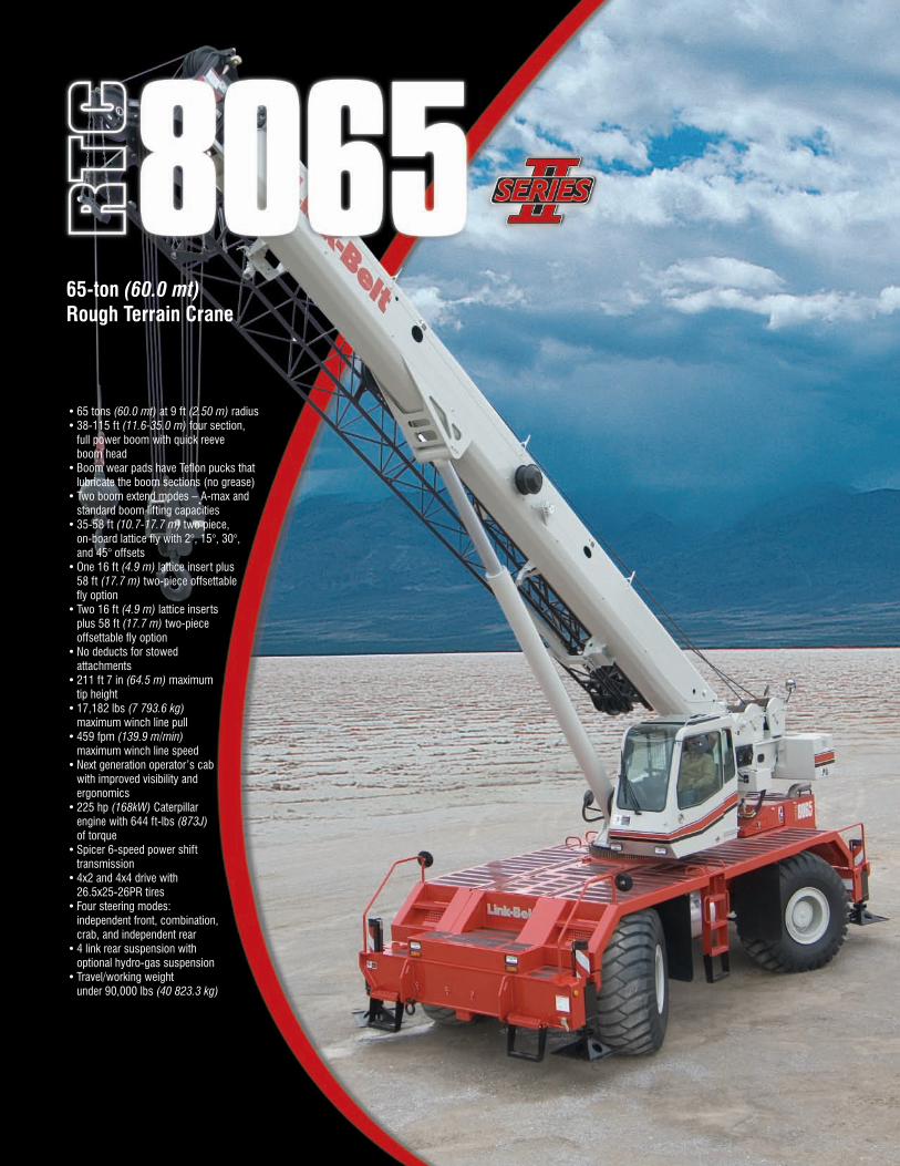
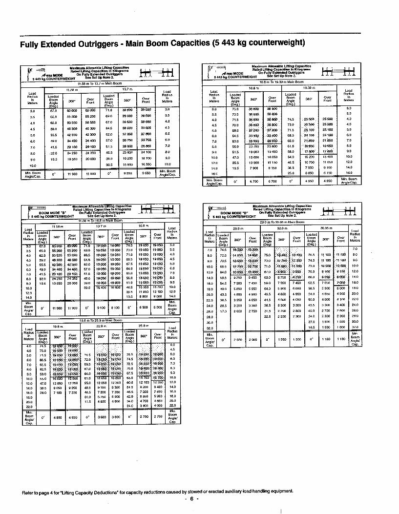
• 65 tons (60.0 mt) at 9 ft (2.50 m) radius• 38-115 ft (11.6-35.0 m) four section,
full power boom with quick reeveboom head
• Boom wear pads have Tefl on pucks that lubricate the boom sections (no grease)
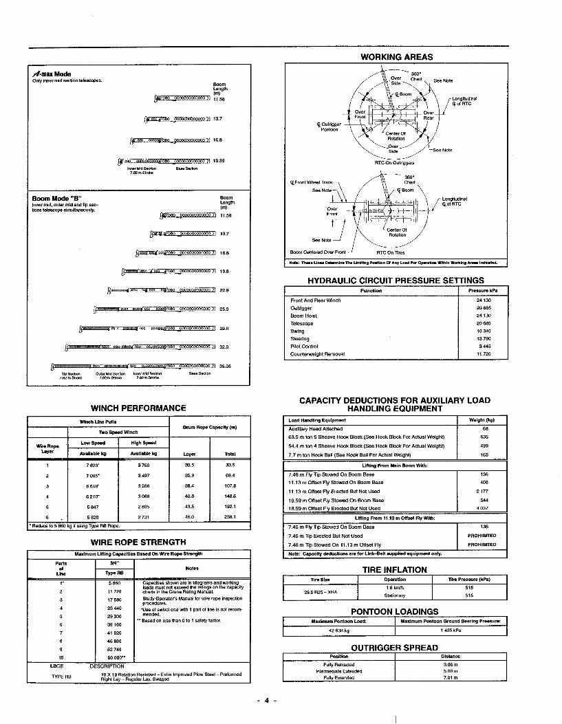
• Two boom extend modes – A-max and standard boom lifting capacities
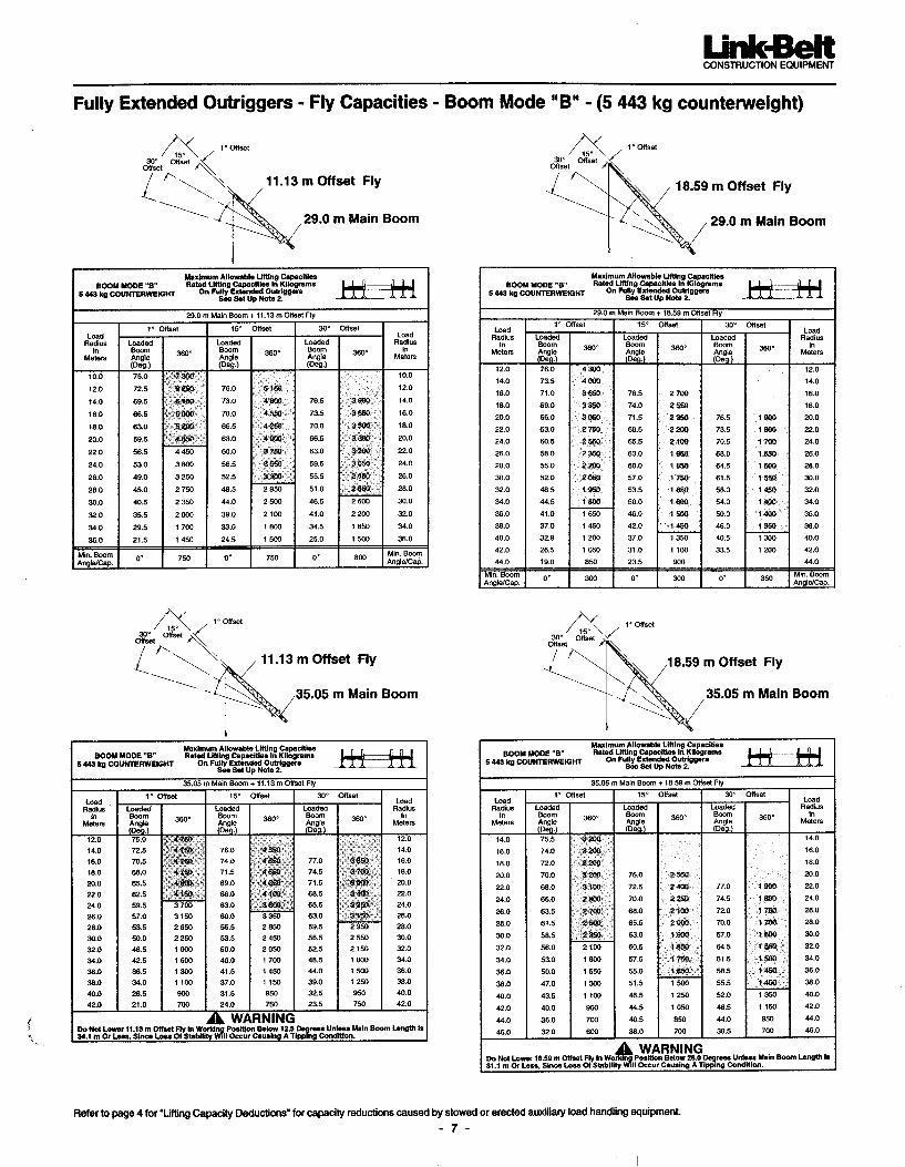
• 35-58 ft (10.7-17.7 m) two piece,on-board lattice fl y with 2°, 15°, 30°,and 45° offsets
• One 16 ft (4.9 m) lattice insert plus58 ft (17.7 m) two-piece offsettablefl y option
• Two 16 ft (4.9 m) lattice insertsplus 58 ft (17.7 m) two-pieceoffsettable fl y option
• No deducts for stowedattachments
• 211 ft 7 in (64.5 m) maximumtip height
• 17,182 lbs (7 793.6 kg)
maximum winch line pull • 459 fpm (139.9 m/min)
maximum winch line speed• Next generation operator’s cab
with improved visibility andergonomics
• 225 hp (168kW) Caterpillarengine with 644 ft-lbs (873J)
of torque• Spicer 6-speed power shift
transmission• 4x2 and 4x4 drive with
26.5x25-26PR tires• Four steering modes:
independent front, combination,crab, and independent rear
• 4 link rear suspension withoptional hydro-gas suspension
• Travel/working weightunder 90,000 lbs (40 823.3 kg)
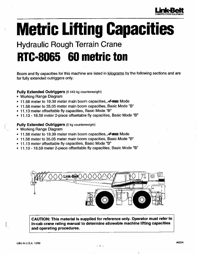
65-ton (60.0 mt)
Rough Terrain Crane
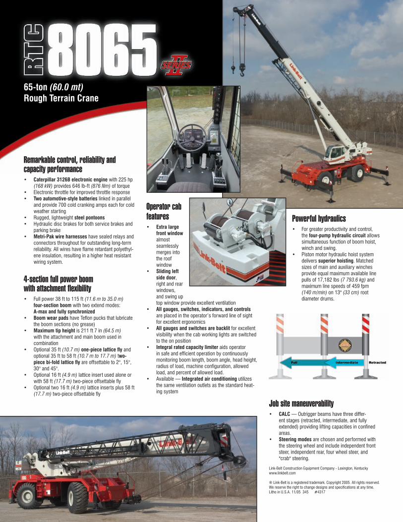
Remarkable control, reliability and capacity performance• Caterpillar 3126B electronic engine with 225 hp
(168 kW) provides 646 lb-ft (876 Nm) of torque• Electronic throttle for improved throttle response• Two automotive-style batteries linked in parallel
and provide 700 cold cranking amps each for cold weather starting
• Rugged, lightweight steel pontoons• Hydraulic disc brakes for both service brakes and
parking brake• Metri-Pak wire harnesses have sealed relays and
connectors throughout for outstanding long-term reliability. All wires have fl ame retardant polyethyl-ene insulation, resulting in a higher heat resistant wiring system.
4-section full power boomwith attachment flexibility• Full power 38 ft to 115 ft (11.6 m to 35.0 m)
four-section boom with two extend modes:A-max and fully synchronized
• Boom wear pads have Tefl on pucks that lubricate the boom sections (no grease)
• Maximum tip height is 211 ft 7 in (64.5 m)
with the attachment and main boom used in combination
• Optional 35 ft (10.7 m) one-piece lattice fl y and optional 35 ft to 58 ft (10.7 m to 17.7 m) two-piece bi-fold lattice fl y are offsettable to 2°, 15°, 30° and 45°.
• Optional 16 ft (4.9 m) lattice insert used alone or with 58 ft (17.7 m) two-piece offsettable fl y
• Optional two 16 ft (4.9 m) lattice inserts plus 58 ft (17.7 m) two-piece offsettable fl y
Operator cab features• Extra large
front window almost seamlessly merges into the roof window
• Sliding left side door, right and rear windows, and swing up top window provide excellent ventilation
• All gauges, switches, indicators, and controls are placed in the operator’s forward line of sight for excellent ergonomics
• All gauges and switches are backlit for excellent visibility when the cab working lights are switched to the on position
• Integral rated capacity limiter aids operator in safe and effi cient operation by continuously monitoring boom length, boom angle, head height, radius of load, machine confi guration, allowed load, and percent of allowed load.
• Available — Integrated air conditioning utilizes the same ventilation outlets as the standard heat-ing system
Powerful hydraulics• For greater productivity and control,
the four-pump hydraulic circuit allows simultaneous function of boom hoist, winch and swing.
• Piston motor hydraulic hoist system delivers superior hoisting. Matched sizes of main and auxiliary winches provide equal maximum available line pulls of 17,182 lbs (7 793.6 kg) and maximum line speeds of 459 fpm(140 m/min) on 13" (33 cm) root diameter drums.
Job site maneuverability• CALC — Outrigger beams have three differ-
ent stages (retracted, intermediate, and fully extended) providing lifting capacities in confi ned areas.
• Steering modes are chosen and performed with the steering wheel and include independent front steer, independent rear, four wheel steer, and "crab" steering.
Link-Belt Construction Equipment Company - Lexington, Kentuckywww.linkbelt.com
® Link-Belt is a registered trademark. Copyright 2005. All rights reserved.We reserve the right to change designs and specifi cations at any time.Litho in U.S.A. 11/05 345 #4317
65-ton (60.0 mt)
Rough Terrain Crane
Litho in USA 10/03 #5397 Supersedes #5372
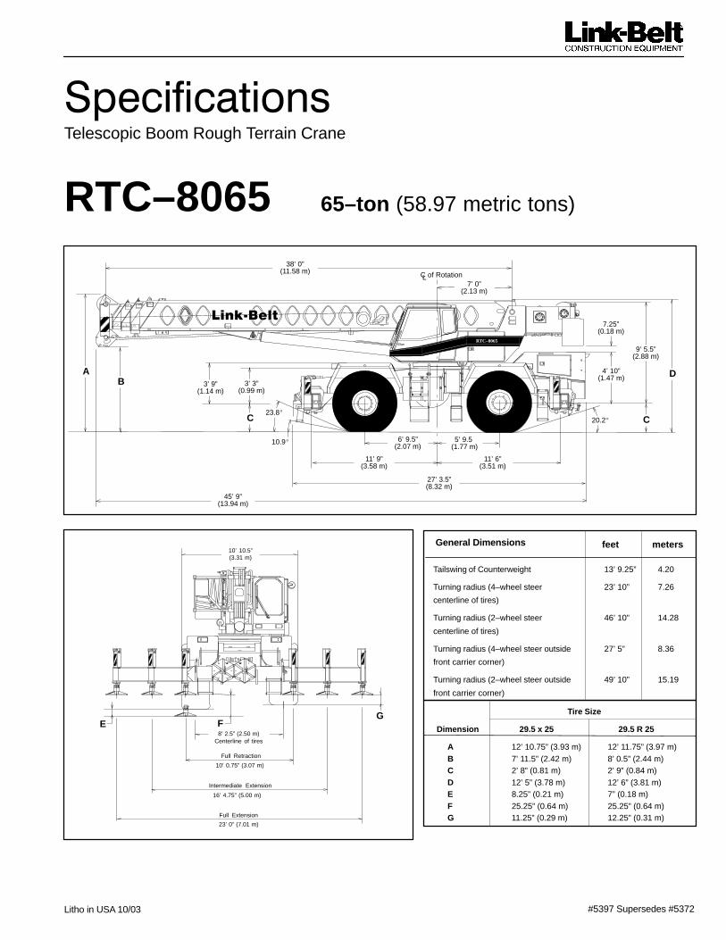
������������Telescopic Boom Rough Terrain Crane
RTC–8065 65–ton (58.97 metric tons)
FE
Tailswing of Counterweight 13’ 9.25” 4.20
Turning radius (4–wheel steer 23’ 10” 7.26
centerline of tires)
Turning radius (2–wheel steer 46’ 10” 14.28
centerline of tires)
Turning radius (4–wheel steer outside 27’ 5” 8.36
front carrier corner)
Turning radius (2–wheel steer outside 49’ 10” 15.19
front carrier corner)
General Dimensions feet meters
45’ 9”(13.94 m)
38’ 0”(11.58 m)
7’ 0”(2.13 m)
23.8�
10.9�
20.2�
6’ 9.5”(2.07 m)
11’ 9”(3.58 m)
5’ 9.5”(1.77 m)
11’ 6”(3.51 m)
27’ 3.5”(8.32 m)
4’ 10”(1.47 m)
10’ 0.75” (3.07 m)
8’ 2.5” (2.50 m)Centerline of tires
16’ 4.75” (5.00 m)
23’ 0” (7.01 m)
Tire Size
Dimension 29.5 x 25 29.5 R 25
A 12’ 10.75” (3.93 m) 12’ 11.75” (3.97 m)B 7’ 11.5” (2.42 m) 8’ 0.5” (2.44 m)C 2’ 8” (0.81 m) 2’ 9” (0.84 m)D 12’ 5” (3.78 m) 12’ 6” (3.81 m)E 8.25” (0.21 m) 7” (0.18 m)F 25.25” (0.64 m) 25.25” (0.64 m)G 11.25” (0.29 m) 12.25” (0.31 m)
10’ 10.5”(3.31 m)
AB
C C
D
9’ 5.5”(2.88 m)
3’ 9”(1.14 m)
3’ 3”(0.99 m)
7.25”(0.18 m)
G
Full Retraction
Intermediate Extension
Full Extension
C of RotationL
RTC–8065
��������
� �RTC–8065
Upper Structure� BoomPatented Design� Boom side plates have diamond shaped
impressions for superior strength to weightratio and 100,000 psi (689.5 mPa) steelangle chords for lateral stiffness.
� Boom telescope sections are supported bytop, bottom, and adjustable side wearshoes to prevent metal to metal contact.
Standard Boom� 38’ – 115’ (11.58 – 35.05 m) four –section
full power boom� Basic mode (or mode “B”) is the full pow-
er, synchronized mode of telescoping allsections proportionally 115’ (35.05 m).
� The exclusive A–max mode (or mode“A”) extends only the inner mid–sectionto 63’ 6” (19.35 m) offering increased ca-pacities for in–close, maximum capacitypicks.
� Mechanical Boom Angle Indicator
Boom Head� Five 16.5” (0.42 m) root diameter nylon
sheaves handle up to ten parts of wirerope.
� Quick reeve design.� Boom head designed for quick reeve of
hook block.� Rope dead end lugs provided on each side
of boom head.� Easily removable wire rope guards.� Fly pinning alignment tool.
Boom Elevation� Hydraulic cylinder with holding valve and
bushing in each end.� Hand control for controlling boom
elevation from –3� to +78�.
Optional Auxiliary Lifting Sheave� Single 16.5” (0.42 m) root diameter nylon
sheave with removable wire rope guardmounted on boom.
� Use with one or two parts of line.� Does not affect erection of fly or use of
main head sheaves for multiple reeving.
Optional� 70–ton (63.5 mt) 5–sheave, quick reeve
hook block� 60–ton (54.43 mt) 4–sheave, quick reeve
hook block� 40–ton (36.28 mt) 4–sheave, quick reeve
hook block� 8.5–ton (7.7 mt) hook ball� Boom floodlight
� FlyOptional� 36.5’ (11.13 m) one piece lattice fly, stow-
able, offsettable to 1�, 15�� or 30�� 36.5’ – 61’ (11.13 – 18.59 m) two piece (bi-
fold) lattice fly, stowable, offsettable to 1�,15�� or 30�
� Cab and ControlsEnvironmental ULTRA CAB�
� LFC–2000 construction process featuringlaminated fibrous composite material.
� Isolated from sound and vibration by aneoprene seal.
� Six–way adjustable operator’s seat with retractable seat belt.
� Four–way adjustable tilting and locking steering wheel.
� All windows are tinted and tempered safety glass.
� Slide by door opens to 3’ (0.91 m) width.� Sliding rear and right side windows and
swing up roof windows for maximum visibility and ventilation.
� Engine dependent warm–water heater withdefroster.
� Hand–held outrigger controls.� Sight level bubble � Hand throttle� Audible swing alarm � Warning horn� Backup alarm � Travel lights� Cab mounted work lights � Sun visor� Electric windshield wiper � Mirrors� Top hatch window wiper � Cup holder� Fire extinguisher � Circulating fan� Dome light
Optional� Amber strobe light and rotating beacon� Emergency steering system� Rear steer indicator� Air conditioning
ControlsHydraulic controls (joystick type) for:� Main winch � Boom hoist� Drum rotation indicators � Swing� Optional auxiliary winch� Optional single–axis controls
Foot controls for:� Boom telescope � Swing brake� Engine throttle with throttle lock
Cab InstrumentationCorner post mounted gauges for:� Hydraulic oil temperature � Fuel� Convertor temperature � Voltmeter� Water temperature � Oil pressure� Tachometer� Audio/visual warning system
� Rated Capacity Limiter� Microguard 434 Graphic audio–visual
warning system built into dash with anti–two block and function limiters.
Operating data available includes:� Crane configuration� Boom length � Boom angle� Head height � Radius of load� Allowed load � Actual load� % of allowed load
Presettable alarms include:� Maximum and minimum boom angles� Max tip height and boom length� Swing left/right positions� Operator defined area alarm is standard.� Anti–two block weight designed for quick
reeve of hookblock.
Optional� Internal RCL light bar: Visually informs
operator when crane is approaching maxi-mum load capacity with a series of lights;green, yellow, and red.
� External RCL light bar: Visually informsground crew when crane is approachingmaximum load capacity kickouts and pre-settable alarms with a series of lights;green, yellow, and red.
� Swing� Bi–directional hydraulic swing motor
mounted to a planetary reducer for 360�continuous smooth swing at 2 r.p.m.
� Swing park brake – 360� electric over hy-draulic (spring applied, hydraulic released)multi–disc brake mounted on the speedreducer. Operated by toggle switch in over-head control console.
� Swing brake – 360�, foot operated, hy-draulic applied disc brake mounted on thespeed reducer.
� Travel swing lock – Standard; two posi-tion travel lock (pin device) operated fromthe operator’s cab.
� Counterweight – Pinned to upper struc-ture frame. 12,000 lb (5 443 kg).Optional hydraulically controlled counter-weight removal.
Optional� 360� (pawl–in–gear) swing lock (meets
New York City requirements).
� Hydraulic SystemMain Pump� Four–section gear–type pump� Combined pump capacity 132 gpm (500
Lpm)� Mounted on torque converter, powered by
engine through a pump disconnect� Pump disconnect is a spline type clutch
engaged/disengaged from carrier.� Pump operates at 3,500 psi (24.1 mPa)
maximum system pressure.� O–Ring Face Seal (ORFS) technology
throughout with hydraulic oil cooler.
Pilot Pressure / Brake / CounterweightRemoval� Pressure compensated piston pump pow-
ered by carrier engine. Operates at 2,650psi (18.3 mPa) maximum.
Telescope/Outrigger/Steering Pump� Single gear–type pump, 24 gpm (91 Lpm)
maximum. Mounted on torque converter,powered by engine through a direct me-chanical drive.
� Pump operates at 3,000 psi (20.7 mPa)maximum system pressure.
Reservoir� 170 gal (643.5 L) capacity. Diffuser for
deaeration.
Filtration� One, 10–micron filter located inside
hydraulic reservoir. Accessible for easyreplacement.

RTC–8065–3–
Control Valves:� Six separate pilot operated control valves
allow simultaneous operation of all cranefunctions.
� Load Hoist SystemStandard� 2M rear winch with grooved lagging� Two–speed motor and automatic brake� Power up/down mode of operation� Controls for future addition of auxiliary
winch.
� Bi–directional piston–type hydraulic motor,driven through a planetary reduction unitfor positive operator control under all loadconditions.
� Asynchronous parallel double crossovergrooved drums minimize rope harmonic motion.
� Winch circuit control provides balanced oilflow to both winches for smooth, simulta-neous operation.
Line Pulls and Speeds� Maximum line pull 16,506 lb (7 487 kg) and
maximum line speed of 454 f.p.m. (138.4m/min) on standard 16” (0.41 m) root diam-eter grooved drum.
� Rotation resistant rope
Optional� 2M front winch with two–speed motor and
automatic brake, power up/down mode of operation.
� Hoist drum cable followers� Third wrap indicators
Carrier� Type� 10’ 10.5” (3.31 m) wide, 151” (3.84 m)
wheelbase.� 4 x 4 x 4 – (4–wheel steer, 4–wheel drive)
For rough terrain with limited turning area.
Frame� 100,000 psi (689.5 mPa) steel, double
walled construction.� Integral 100,000 psi (689.5 mPa) steel out-
rigger boxes.
Standard Carrier Equipment� Two front, rear, and mid–point carrier
steps.� Non–slip safety strips on carrier deck� Deep front storage� Fenders� Pontoon storage� Full lighting package� Front towing shackles
Optional� Front and rear mounted pintle hook� Front tow winch
� EngineEngine Caterpillar 3126B 7.2L
Cylinders – cycleBoreStrokeDisplacementMaximum brake hpPeak torque (ft. lb.)Electric systemStarting systemFuel capacityAlternatorCrankcase capacity(total system)
6 – 44.33 in. (110 mm)5.00 in. (127 mm)442 cu. in. (7.2 L)225 @ 2,200 rpm646 @ 1,500 rpm12 volt12 volt95 gal (359.6 L)130 amps30 qt (28.4 L)
� Water/fuel separator on engine� ��������ther injection package
� Transmission� Spicer off–highway three–speed, two–
range power shift transmission.� Six speeds forward and reverse.� Front axle disconnect for two or four–wheel
drive.
� Axles� Front and Rear – Heavy duty planetary
drive/steer type� Front axle disconnect
� SuspensionFront Axle� Rigid mounted to frame
Rear Axle� Pin mounted on bronze bushings. Auto-
matic hydraulic rear axle oscillation lock–out cylinders engage when upper structurerotates 2.5� past centerline.
� Steering� Hydraulic two–wheel, four–wheel, and
“crab” steering.� Modes selected by toggle switch on dash.� All modes fully controlled by steering
wheel.
Optional� Rear steer indicator
� TiresFront and Rear� Standard 29.5 x 25 (28–PR) Earthmover
type
Optional� 29.5R25 XHA 1 star radials� Spare tires and rims.
� BrakesService� Hydraulic disc–type brakes at each wheel
end.
Parking/Emergency� Disc–type, spring applied, hydraulic re-
leased, fade resistant, operated from cab,mounted on front axles.
� Outriggers� Three position operation capability.� Four hydraulic, telescoping beam and jack
outriggers.� Vertical jack cylinders equipped with
integral holding valve.� Beams extend to 23’ 0” (7.01 m) center-
line–to–centerline and retract to within 10’10.5” (3.31 m) overall width.
� Equipped with stowable, lightweight 23.5” x27.25” (59.7 x 69.2 cm) hexagonal steel pontoons.
� Controls and sight level bubble located incab.
Confined Area Lifting Capacities(CALC�) System� Three operational outrigger configurations
are available:� Full extension –23’ 0” (7.01 m)� Intermediate position – 16’ 4.75” (5.00 m)� Full retraction –10’ 0.75” (3.07 m)
� For confined area operation, rated liftingcapacities are provided for the intermedi-ate and fully retracted outrigger positions.
� When the outrigger position levers (locatedon the outrigger beams) are engaged, theoperator can set the crane in the intermedi-ate or full retraction outrigger position with-out having to leave the cab.
Optional� Outrigger cover package
� Travel Speeds and Gradeablity
Tires 29.5 x 25
Maximum Speed19.5 mph(31.4 km/h)
Gradeablity at 70% conver-tor efficiency 112.9%
Maximum Tractive Effort at70% convertor efficiency
76,715 lb (34 797 kg)
Gradeablity at 1.0 mph (1.6km/hr) 55.6%
Maximum Tractive Effort at1.0 mph (1.6 km/hr)
50,516 lb (22 914 kg)
Crane operating angle must not exceed 35� (77% grade).
Numbers reflect main hydraulic pump engaged.

���RTC–8065
� Axle LoadsBase crane with standard 38’ – 115’
�Upper facing front Upper facing rear
(11.58 – 35.05 m) four–section boom, 2Mmain winch with 2–speed hoisting and
G.V.W.�Front axle Rear axle Front axle Rear axle
power up/down, 630’ (192 m) 3/4” (19mm) wire rope. 4x4x4 carrier with Cater- lb kg lb kg lb kg lb kg lb kgpillar 3126B 7.2L engine, 29.5 x 25 tires,counterweight, and no fuel. 91,488 41 498 44,296 20 092 47,192 21 406 41,804 18 962 49,684 22 253
Remove 29.5 x 25 tires and wheels –6,732 –3 054 –3,366 –1 527 –3,366 –1 527 –3,366 –1 527 –3,366 –1 527
29.5R25 XHA Tires 964 438 482 219 482 219 482 219 482 219
Remove outrigger beams –5,235 –2 374 –2,461 –1 116 –2,774 –1 258 –2,461 –1 116 –2,774 –1 258
Tow winch 686 311 1,002 454 –316 –143 1,002 454 –316 –143
100 gal (378.5 L) fuel 685 310 364 165 321 145 364 165 321 145
2M auxiliary winch with 630’ (192 m) of3/4” (19 mm) rope 779 354 –203 –92 982 445 920 417 –141 –64
Remove front carrier counterweights –3628 –1 646 –4,858 –2 204 1,230 558 –4,858 –2 204 1230 558
Hydraulic counterweight removal 353 160 163 74 190 86 518 235 –165 –75
Remove counterweight –12,000 –5 443 6,586 2 987 –18,586 –8 430 –17,633 –7 998 5,633 2 555
Air conditioning 287 130 55 25 232 105 209 95 78 35
36.5’ (11.13 m) one–piece lattice fly, withtip lugs, stowable 1,542 700 2,485 1 115 –619 –415 –1,039 –471 2,581 1 171
36.5’ – 61’ (11.13 – 18.59 m) two–piece(bifold) lattice fly, stowable 2,250 1 021 3,165 1 436 –915 –415 –1,094 –496 3,344 1 517
Fly storage brackets with all fly options 160 73 228 103 –69 –30 –81 –36 241 109
Auxiliary lifting sheave assembly 110 50 355 152 –225 –102 –233 –106 343 156
8.5–ton (7.71 mt) hook ball @ front bumper 360 163 566 256 –206 –93 n/a n/a n/a n/a
70–ton (63.50 mt) 5–sheave hook block@ front bumper 1,390 631 2,186 992 –796 –361 n/a n/a n/a n/a
60–ton (54.43 mt) 4–sheave hook block@ front bumper 1,150 522 1,809 821 –659 –299 n/a n/a n/a n/a
� – Adjust gross weight and axle loading according to component weight. Note: All weights are � 3%.
Tire Max. Axle Load @ 20 mph (32.2 km/hr)
29.5 x 25 (28–PR)
29.5R25 XHA 1 Star
53,000 (24 041 kg)
53,000 (24 041 kg)
Link–Belt Construction Equipment Company Lexington, Kentucky www.linkbelt.com�Link–Belt is a registered trademark. Copyright 2003. All rights reserved. We are constantly improving our products and therefore reserve the right to change designs and specifications.
15488 (supersedes 5453)---0806---J9
RTC---8065 IILink-Belt Cranes
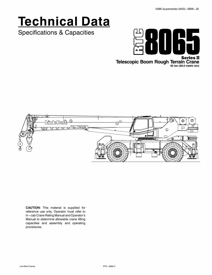
Technical DataSpecifications & Capacities
Telescopic Boom Rough Terrain Crane65 ton (60.0 metric ton)
CAUTION: This material is supplied forreference use only. Operator must refer toin---cab Crane RatingManual andOperator’sManual to determine allowable crane liftingcapacities and assembly and operatingprocedures.

5488 (supersedes 5453)---0806--- J9
RTC---8065 II Link-Belt Cranes
5488 (supersedes 5453)---0806--- J9
RTC---8065 IILink-Belt Cranes
Table Of ContentsBoom, Attachments, and Upper Structure 1. . . . . . . . . . . . . . . . . . . . . . . . . . . . . . . . . . . . . . . . . . . . . . . . . . . .Boom 1. . . . . . . . . . . . . . . . . . . . . . . . . . . . . . . . . . . . . . . . . . . . . . . . . . . . . . . . . . . . . . . . . . . . . . . . . . . . . . . . . . . .Boom Head 1. . . . . . . . . . . . . . . . . . . . . . . . . . . . . . . . . . . . . . . . . . . . . . . . . . . . . . . . . . . . . . . . . . . . . . . . . . . . .Boom Elevation 1. . . . . . . . . . . . . . . . . . . . . . . . . . . . . . . . . . . . . . . . . . . . . . . . . . . . . . . . . . . . . . . . . . . . . . . . . .Auxiliary Lifting Sheave --- Optional 1. . . . . . . . . . . . . . . . . . . . . . . . . . . . . . . . . . . . . . . . . . . . . . . . . . . . . . . . .Hook Blocks and Balls --- Optional 1. . . . . . . . . . . . . . . . . . . . . . . . . . . . . . . . . . . . . . . . . . . . . . . . . . . . . . . . . .Fly --- Optional 1. . . . . . . . . . . . . . . . . . . . . . . . . . . . . . . . . . . . . . . . . . . . . . . . . . . . . . . . . . . . . . . . . . . . . . . . . . .Fly Inserts --- Optional 1. . . . . . . . . . . . . . . . . . . . . . . . . . . . . . . . . . . . . . . . . . . . . . . . . . . . . . . . . . . . . . . . . . . . .Operator’s Cab and Controls 1. . . . . . . . . . . . . . . . . . . . . . . . . . . . . . . . . . . . . . . . . . . . . . . . . . . . . . . . . . . . . . . .Swing 2. . . . . . . . . . . . . . . . . . . . . . . . . . . . . . . . . . . . . . . . . . . . . . . . . . . . . . . . . . . . . . . . . . . . . . . . . . . . . . . . . . . .Electrical 2. . . . . . . . . . . . . . . . . . . . . . . . . . . . . . . . . . . . . . . . . . . . . . . . . . . . . . . . . . . . . . . . . . . . . . . . . . . . . . . . .Load Hoist System 3. . . . . . . . . . . . . . . . . . . . . . . . . . . . . . . . . . . . . . . . . . . . . . . . . . . . . . . . . . . . . . . . . . . . . . . . .Load Hoist Performance 3. . . . . . . . . . . . . . . . . . . . . . . . . . . . . . . . . . . . . . . . . . . . . . . . . . . . . . . . . . . . . . . . . . .2M Main and Optional Auxiliary Winches 3. . . . . . . . . . . . . . . . . . . . . . . . . . . . . . . . . . . . . . . . . . . . . . . . . . . .Hydraulic System 3. . . . . . . . . . . . . . . . . . . . . . . . . . . . . . . . . . . . . . . . . . . . . . . . . . . . . . . . . . . . . . . . . . . . . . . . . .Counterweight 3. . . . . . . . . . . . . . . . . . . . . . . . . . . . . . . . . . . . . . . . . . . . . . . . . . . . . . . . . . . . . . . . . . . . . . . . . . . .Carrier 4. . . . . . . . . . . . . . . . . . . . . . . . . . . . . . . . . . . . . . . . . . . . . . . . . . . . . . . . . . . . . . . . . . . . . . . . . . . . . . . . . . . .General 4. . . . . . . . . . . . . . . . . . . . . . . . . . . . . . . . . . . . . . . . . . . . . . . . . . . . . . . . . . . . . . . . . . . . . . . . . . . . . . . . . . .Outriggers 4. . . . . . . . . . . . . . . . . . . . . . . . . . . . . . . . . . . . . . . . . . . . . . . . . . . . . . . . . . . . . . . . . . . . . . . . . . . . . . . .Steering and Axles 4. . . . . . . . . . . . . . . . . . . . . . . . . . . . . . . . . . . . . . . . . . . . . . . . . . . . . . . . . . . . . . . . . . . . . . . . .Suspension 4. . . . . . . . . . . . . . . . . . . . . . . . . . . . . . . . . . . . . . . . . . . . . . . . . . . . . . . . . . . . . . . . . . . . . . . . . . . . . . .Tires and Wheels 4. . . . . . . . . . . . . . . . . . . . . . . . . . . . . . . . . . . . . . . . . . . . . . . . . . . . . . . . . . . . . . . . . . . . . . . . . .Brakes 4. . . . . . . . . . . . . . . . . . . . . . . . . . . . . . . . . . . . . . . . . . . . . . . . . . . . . . . . . . . . . . . . . . . . . . . . . . . . . . . . . . .Electrical 4. . . . . . . . . . . . . . . . . . . . . . . . . . . . . . . . . . . . . . . . . . . . . . . . . . . . . . . . . . . . . . . . . . . . . . . . . . . . . . . . .Engine 4. . . . . . . . . . . . . . . . . . . . . . . . . . . . . . . . . . . . . . . . . . . . . . . . . . . . . . . . . . . . . . . . . . . . . . . . . . . . . . . . . . .Transmission 4. . . . . . . . . . . . . . . . . . . . . . . . . . . . . . . . . . . . . . . . . . . . . . . . . . . . . . . . . . . . . . . . . . . . . . . . . . . . . .Carrier Speeds and Gradeability 5. . . . . . . . . . . . . . . . . . . . . . . . . . . . . . . . . . . . . . . . . . . . . . . . . . . . . . . . . . . . .Fuel Tank 5. . . . . . . . . . . . . . . . . . . . . . . . . . . . . . . . . . . . . . . . . . . . . . . . . . . . . . . . . . . . . . . . . . . . . . . . . . . . . . . . .Hydraulic System 5. . . . . . . . . . . . . . . . . . . . . . . . . . . . . . . . . . . . . . . . . . . . . . . . . . . . . . . . . . . . . . . . . . . . . . . . . .Pump Drive 5. . . . . . . . . . . . . . . . . . . . . . . . . . . . . . . . . . . . . . . . . . . . . . . . . . . . . . . . . . . . . . . . . . . . . . . . . . . . . . .Axle Loads 6. . . . . . . . . . . . . . . . . . . . . . . . . . . . . . . . . . . . . . . . . . . . . . . . . . . . . . . . . . . . . . . . . . . . . . . . . . . . . . . .General Dimensions 7. . . . . . . . . . . . . . . . . . . . . . . . . . . . . . . . . . . . . . . . . . . . . . . . . . . . . . . . . . . . . . . . . . . . . . . .Working Range Diagram 8. . . . . . . . . . . . . . . . . . . . . . . . . . . . . . . . . . . . . . . . . . . . . . . . . . . . . . . . . . . . . . . . . . . .Boom Extend Modes 9. . . . . . . . . . . . . . . . . . . . . . . . . . . . . . . . . . . . . . . . . . . . . . . . . . . . . . . . . . . . . . . . . . . . . . .Main Boom Lift Capacity Charts -- Standard 10. . . . . . . . . . . . . . . . . . . . . . . . . . . . . . . . . . . . . . . . . . . . . . . . .Fully Extended Outriggers --- 360˚ Rotation 10. . . . . . . . . . . . . . . . . . . . . . . . . . . . . . . . . . . . . . . . . . . . . . . . . . .On Tires --- Stationary --- Boom Centered Over Front Between Tire Tracks 11. . . . . . . . . . . . . . . . . . . . . . . . .On Tires --- Pick & Carry (Creep) --- Boom Centered Over Front 12. . . . . . . . . . . . . . . . . . . . . . . . . . . . . . . . . .On Tires --- Stationary --- 360˚ Rotation 12. . . . . . . . . . . . . . . . . . . . . . . . . . . . . . . . . . . . . . . . . . . . . . . . . . . . . . .Fly Attachment Lift Capacity Charts -- Optional 13. . . . . . . . . . . . . . . . . . . . . . . . . . . . . . . . . . . . . . . . . . . . . . .Fully Extended Outriggers --- 360˚ Rotation 13. . . . . . . . . . . . . . . . . . . . . . . . . . . . . . . . . . . . . . . . . . . . . . . . . . .115 ft Main Boom Length --- 2˚ Fly Offset 13. . . . . . . . . . . . . . . . . . . . . . . . . . . . . . . . . . . . . . . . . . . . . . . . . . . .115 ft Main Boom Length --- 15˚ Fly Offset 13. . . . . . . . . . . . . . . . . . . . . . . . . . . . . . . . . . . . . . . . . . . . . . . . . . .115 ft Main Boom Length --- 30˚ Fly Offset 14. . . . . . . . . . . . . . . . . . . . . . . . . . . . . . . . . . . . . . . . . . . . . . . . . . .115 ft Main Boom Length --- 45˚ Fly Offset 14. . . . . . . . . . . . . . . . . . . . . . . . . . . . . . . . . . . . . . . . . . . . . . . . . . .
5488 (supersedes 5453)---0806--- J9
RTC---8065 II Link-Belt Cranes
Main Boom Lift Capacity Charts -- Metric 15. . . . . . . . . . . . . . . . . . . . . . . . . . . . . . . . . . . . . . . . . . . . . . . . . . . .Fully Extended Outriggers --- 360˚ Rotation 15. . . . . . . . . . . . . . . . . . . . . . . . . . . . . . . . . . . . . . . . . . . . . . . . . . .On Tires --- Stationary --- Boom Centered Over Front Between Tire Tracks 16. . . . . . . . . . . . . . . . . . . . . . . . .On Tires --- Pick & Carry (Creep) --- Boom Centered Over Front 17. . . . . . . . . . . . . . . . . . . . . . . . . . . . . . . . . .On Tires --- Stationary --- 360˚ Rotation 17. . . . . . . . . . . . . . . . . . . . . . . . . . . . . . . . . . . . . . . . . . . . . . . . . . . . . . .Fly Attachment Lift Capacity Charts -- Optional 18. . . . . . . . . . . . . . . . . . . . . . . . . . . . . . . . . . . . . . . . . . . . . . .Fully Extended Outriggers --- 360˚ Rotation 18. . . . . . . . . . . . . . . . . . . . . . . . . . . . . . . . . . . . . . . . . . . . . . . . . . .35.05 m Main Boom Length --- 2˚ Fly Offset 18. . . . . . . . . . . . . . . . . . . . . . . . . . . . . . . . . . . . . . . . . . . . . . . . .35.05 m Main Boom Length --- 15˚ Fly Offset 18. . . . . . . . . . . . . . . . . . . . . . . . . . . . . . . . . . . . . . . . . . . . . . . .35.05 m Main Boom Length --- 30˚ Fly Offset 19. . . . . . . . . . . . . . . . . . . . . . . . . . . . . . . . . . . . . . . . . . . . . . . .35.05 m Main Boom Length --- 45˚ Fly Offset 19. . . . . . . . . . . . . . . . . . . . . . . . . . . . . . . . . . . . . . . . . . . . . . . .
15488 (supersedes 5453)---0806--- J9
RTC---8065 IILink-Belt Cranes
Boom, Attachments, and Upper StructureJ BoomDesign --- Four section, formed construction of extra hightensile steel consisting of one base section and three tele-scoping sections. The first telescoping section extendsindependently by means of one double---acting, singlestage hydraulic cylinder with integrated holding valves.The second and third telescoping sections extend propor-tionally by means of one double---acting, single stage cylin-der with integrated holding valves and cables.BoomS 38 ft---115 ft (11.6 ---35.0m) four section full power boomS Two mode boom extension: A---max mode provides su-perior capacities by extending the first telescoping sec-tion to 63 ft 8 in (19.4m). Standard mode synchronizesall the telescoping sections proportionally to 115 ft(35.0m). Controlled from the operator’s cab.
S Mechanical boom angle indicatorS Maximum tip height for A---max mode is 73 ft 6 in (22.4m)and standard mode is 123 ft 9 in (37.7m).Boom HeadS Four 16.5 in (41.9cm) root diameter nylon sheaves tohandle up to eight parts of line
S Easily removable wire rope guardsS Rope dead end lugs on each side of the boom headS Boom head is designed for quick---reeve of the hookblockBoom ElevationS One double acting hydraulic cylinder with integral hold-ing valve
S Boom elevation: ---3˚ to 78˚Auxiliary Lifting Sheave --- OptionalS Single 16.5 in (41.9m) root diameter nylon sheaveS Easily removable wire rope guardsS Does not affect erection of the fly or use of the main headsheavesHook Blocks and Balls --- OptionalS 40 ton (36.3mt) 4 sheave quick---reeve hook block withsafety latch
S 60 ton (54.4mt) 4 sheave quick---reeve hook block withsafety latch
S 70 ton (63.5mt) 5 sheave quick---reeve hook block withsafety latch
S 8.5 ton (7.7mt) swivel and non---swivel hook balls withsafety latch
Fly --- OptionalS 35 ft (10.7m) one piece lattice fly, stowable, offsettable to2˚, 15˚, 30˚, and 45˚. Maximum tip height is 158 ft(48.2m).
S 35 ft---58 ft (10.7 ---17.7m) two piece bi---fold lattice fly,stowable, offsettable to 2˚, 15˚, 30˚, and 45˚. Maximumtip height is 180 ft 5 in (55.0m).Fly Inserts --- OptionalS One 16 ft (4.9m) lattice insert, equipped with two 16.5 in(41.9cm) root diameter nylon sheaves, to be mountedbetween the boom head and fly options. Maximum tipheight is 196 ft (59.7m).
S Two 16 ft (4.9m) lattice inserts, one equipped with two16.5 in (41.9cm) root diameter nylon sheaves, to bemounted between the boom head and fly options. Maxi-mum tip height is 211 ft 7 in (64.5m).
J Operator’s Cab and ControlsEnvironmental Cab --- Fully enclosed, one person cab ofgalvaneal steel structure with acoustical insulationEquipped with:S Tinted and tempered glass windowsS Extra---large fixed front window with windshield wiper andwasher
S Swing up roof window with windshield wiperS Sliding left side door with large fixed windowS Sliding rear and right side windows for ventilationS Six way adjustable, cushioned seat with seat belt andstorage compartment
S Engine dependent warm---water heater with air ducts forfront windshield defroster and cab floor
S Defroster fan for the front windowS Bubble levelS Circulating fanS Adjustable sun visorS Dome lightS Cup holderS Fire extinguisherS Left side viewing mirrorS Two position travel swing lockAir Conditioning --- Optional --- Integral with cab heatingsystem utilizing the same ventilation outlets
2 5488 (supersedes 5453)---0806--- J9
RTC---8065 II Link-Belt Cranes
Steering Column --- Pedestal type with tilt and telescopefunctions for operator comfort. Column includes the follow-ing controls and indicators:Left and right levers include:
S Horn buttonS Turn signal switchS Driving light switchS Transmission direction switchPanel mounted switches for:
S Travel park brakeS Steer mode selectorS 2/4 wheel drive/range selectorS Transmission gear selectorS Hazard flasherPanel mounted indicator/warning lights for:
S Transmission temperatureS Engine oil pressureS Travel park brakeS Service brakeS Turn signalsS Rear wheel offset---optionalS Emergency steer --- optionalArmrest Controls --- Two dual axis hydraulic joystick con-trollers or optional single axis hydraulic controllers for:S SwingS Boom hoistS Main rear winchS Auxiliary front winch --- optionalS Drum rotation indicationS Drum rotation indicator activation switchS Winch high/low speed and disable switch(es)S Third wrap selector switch --- optionalS Telescopic override switchesS Warning horn buttonS Swing park brakeOutrigger Controls --- Hand held control box with umbilicalcord gives the operator the freedom to view operation whilesetting the outriggers.Foot ControlsS Boom telescopeS Swing brakeS Engine throttleS Service brakeRight Front Console --- Controls and indicators for:S Engine ignition S Console dimmer switchS Engine throttle lock S Bubble levelS Function disable S 12 volt power connectionS Front windshield wiper S Air conditioning --- optionaland washer S Boom floodlight --- optional
S Cab floodlights S Rotating beacon/StrobeS Warning horn light --- optionalS Heating controls S Third wrap indicator ---
optional
Cab Instrumentation --- Ergonomically positioned, analoginstrumentation for crane operation including:S Engine coolant temperature with warning indicatorS Hydraulic oil temperature with warning indicatorS Fuel level with warning indicatorS TachometerS Transmission temperature with warning indicatorS Voltmeter with warning indicatorRated Capacity Limiter --- Microguard graphic audio---visual warning system integrated into the dash with anti ---two block and function limiter. Operating data availableincludes:S Crane configurationS Boom length and angleS Boom head heightS Allowed load and % of allowed loadS Boom angleS Radius of loadS Actual loadS Operator settable alarms (include):S Maximum and minimum boom anglesS Maximum tip heightS Maximum boom lengthS Swing left/right positionsS Operator defined area (imaginary plane)Internal RCL Light Bar --- Optional --- Visually informs theoperator when crane is approaching maximum load capac-ity with a series of green, yellow, and red lights.External RCL Light Bar --- Optional --- Visually informs theground crew when crane is approaching maximum loadcapacity with a series of green, yellow, and red lights.
J SwingMotor/Planetary --- Bi ---directional hydraulic swing motormounted to a planetary reducer for 360˚ continuoussmooth swing at 2.0 rpmSwing Park Brake --- 360˚, electric over hydraulic, (springapplied/hydraulic released) multi ---disc brake mounted onthe speed reducer. Operated by a switch from the opera-tor’s cab.Swing Brake --- 360˚, foot operated, hydraulic applied discbrake mounted to the speed reducerSwing Lock --- Two---position swing lock (boom over frontor rear) operated from the operator’s cab360˚ Positive Swing Lock --- Optional --- Meets New YorkCity requirement
J ElectricalSwing Alarm --- Audio warning device signals when theupper is swinging.LightsS Two working lights on front of the cabS One rotating amber beacon on top of the cab --- optionalS One amber strobe beacon on top of the cab --- optionalS Boom floodlight --- optional

35488 (supersedes 5453)---0806--- J9
RTC---8065 IILink-Belt Cranes
J Load Hoist SystemLoad Hoist Performance
Main (Rear) and Auxiliary (Front) Winches --- 3/4 in (19mm) RopeMaximum Line Pull Normal Line Speed High Line Speed Layer Total
Layer lb kg ft/min m/min ft/min m/min ft m ft m1 17,182 7 793.6 171 52.1 322 98.1 86 26.2 86 26.22 15,523 7 041.1 190 57.9 356 108.5 96 29.3 182 55.53 14,157 6 421.5 208 63.4 390 118.9 105 32.0 287 87.54 13,011 5 901.7 226 68.9 425 129.5 114 34.7 401 122.25 12,038 5 460.3 245 74.7 459 139.9 123 37.5 524 159.76 --- --- --- --- --- --- --- --- --- --- --- --- --- --- --- --- --- --- 133 40.5 657 200.3
Wire Rope ApplicationDiameter
TypeMaximum
Permissible Loadin mm lb kg
Main (Rear)Winch
Standard 3/4 19 6x19 IWRC --- right regular lay (Type DB) 16,800 7 620.4Optional 3/4 19 18x19 rotation resistant --- right regular lay (Type RB) 12,920 5 860.4
Auxiliary (Front)Winch
Standard 3/4 19 6x19 IWRC --- right regular lay (Type DB) 16,800 7 620.4Optional 3/4 19 18x19 rotation resistant --- right regular lay (Type RB) 12,920 5 860.4
2M Main and Optional Auxiliary WinchesS Axial piston, full and half displacement (2---speed) motorsdriven through planetary reduction unit for positive con-trol under all load conditions
S Grooved laggingS Power up/down mode of operationS Drum rotation indicator(s)S Drum diameter: 13 in (33.0cm)S Rope length:S Front: 500 ft (152.4m)S Rear: 600 ft (182.9m)
S Maximum rope storage: 657 ft (200.3m)S Terminator style socket and wedgeS Hoist drum cable followers --- optionalThird wrap indicator --- optional --- Visually and audiblywarns the operator when the wire rope is on the first/bottomlayer and when the wire rope is down to the last threewraps
J Hydraulic SystemCounterbalance Valves --- All hoist motors, boom extendcylinders, and boom hoist cylinders are equipped withcounterbalance valves to provide load lowering and pre-vents accidental load drop when hydraulic power is sud-denly reduced.
J CounterweightTotal of 12,000 lb (5 443kg) of counterweight pinned to theupper structure frame with capacities for the 12,000 lb(5 443kg) configuration
4 5488 (supersedes 5453)---0806--- J9
RTC---8065 II Link-Belt Cranes
CarrierJ GeneralS 10 ft 7 in (3.22m) wideS 14 ft 7 in (4.45m) wheelbase (centerline of first axle tocenterline of second axle)Frame --- Box---type, torsion resistant, welded constructionmade of high tensile steel. Equipped with front and reartowing and tie---down lugs, tow connections, and accessladders.
J OutriggersBoxes --- Two double box, front and rear welded to carrierframeBeams and Jacks --- Four single stage beams with Con-fined Area Lifting Capacities (CALCt) provide selectableoutrigger extensions of full, intermediate, and retracted.Hydraulically controlled from the operator’s cab with inte-gral check valves.Pontoons --- Four lightweight, quick release, 23.5 x 23.5 in(59.7 x 59.7cm), steel pontoons with contact area of 460 in2(2 968cm2) can be stored for road travel in storage rackson the carrier.Main Jack Reaction --- 90,500 lb (41 050kg) force and197 psi (1 358kPa) ground bearing pressure
J Steering and AxlesSteering --- Four independent modes consisting of twowheel front, two wheel rear, four wheel, and crab. Eachmode is controlled from the steering wheel and is selectedby a switch in the operator’s cab.Drive --- Two modes: 4 x 2 and 4 x 4 for off highway travelAxle 1 --- Steered, non---driven for 4 x 2 and steered, drivenfor 4 x 4Axle 2 --- Steered, driven
J SuspensionFront --- Rigid mount to the carrier frameRear --- The rear axle is suspended on the oscillation cylin-ders with motion of the axle controlled by a four bar linkagesystem. The oscillation cylinders lockout when the upperstructure rotates 2.5˚ past centerline.S Hydro---gas rear suspension --- optional
J Tires and WheelsFront and Rear --- Four (single) 26.5 x 25---26 ply rating,earthmover type tires on steel disc wheelsS Spare tires and wheels --- optional
J BrakesService --- Full hydraulic, dual circuit, disc type brakes onall wheel endsParking/Emergency --- Spring applied type, acting on frontaxle
J ElectricalTwo batteries provide 12 volt starting and operationLightsS Front lighting includes two main headlights and two park-ing/directional indicators.
S Side lighting includes two parking/directional indicatorsper side.
S Rear lighting includes two parking/directional indicators,two parking/brake lights, and two reversing lights.
S Other equipment includes hazard/warning system, cablight, instrument panel light, and signal horn.
J EngineSpecification CAT C6.6
Numbers of Cylinders 6
Cycle 4
Bore and Stroke: inch (mm) 4.13 x 5.00 (105 x 127)
Piston Displacement: in3 (L) 403 (6.6)
Max. Brake Horsepower: hp (kW) 225 (167.8) @ 2,200 rpm
Peak Torque: ft lb (Nm) 727 (986) @ 1,400 rpm
Alternator: volts --- amps 12 --- 150
Crankcase Capacity: qt (L) 18.4 (17.4)
S Mechanically driven fan and thermostatically controlled radiator
J TransmissionPowershift --- Three speed with high/low range for 6 for-ward and 6 reverse gears. Front axle disconnect for two orfour wheel drive. Front axle disconnects in high range.

55488 (supersedes 5453)---0806--- J9
RTC---8065 IILink-Belt Cranes
J Carrier Speeds and Gradeability
Spicer Speed Gradeability(@ stall)
Gear Ratio mph km/h % Grade
6thForward &Reverse2WD/Hi
0.82 23.2 37.34 2.4
5th 2.25 9.7 15.61 10.1
4th 4.67 4.8 7.88 23.5
3rdForward &Reverse4WD/Low
2.4 9.1 14.64 10.9
2nd 6.54 3.5 5.63 34.8
1st 13.6 1.7 2.74 99.5
Based on a gross vehicle weight of 88,000 lb (39 916kg).Crane operating angle must not exceed 35˚ (77% grade).
J Fuel TankOne 75 gallon (283.9L) capacity tank
J Hydraulic SystemAll functions are hydraulically powered allowing positiveprecise control with independent or simultaneous operationof all functions.Main PumpsS One two section fixed displacement gear pump for thefront/rear winches and boom hoist circuits.
S One two section fixed displacement gear pump for theswing/telescope, power steering/outrigger/telescope,service brake, and oscillation circuits.
S Combined pump capacity of 138 gpm (522.4Lpm)Hydraulic Reservoir --- 153 gal (579.2L) capacity equippedwith sight level gauge. Diffusers built in for deaeration.Filtration --- One 10 micron, full flow line filter in the controlcircuit. All oil is filtered prior to return to reservoir. Accessi-ble for easy filter replacement.
J Pump DriveAll pumps are mounted on the transmission and mechani-cally driven by the diesel engine.S Front/rear winches and boom hoist pumps can be dis-connected with a manual pump disconnect to aid in coldweather starting --- optional.
6 5488 (supersedes 5453)---0806--- J9
RTC---8065 II Link-Belt Cranes
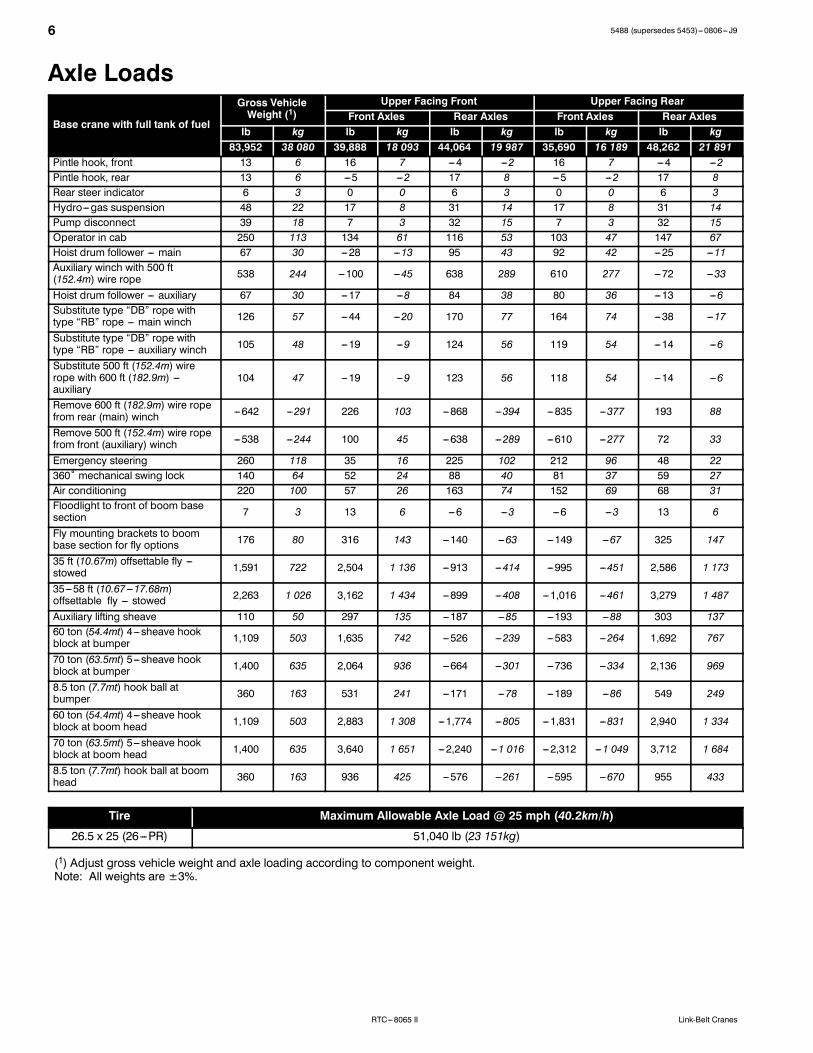
Axle Loads
Base crane with full tank of fuel
Gross VehicleWeight (1)
Upper Facing Front Upper Facing RearFront Axles Rear Axles Front Axles Rear Axles
lb kg lb kg lb kg lb kg lb kg83,952 38 080 39,888 18 093 44,064 19 987 35,690 16 189 48,262 21 891
Pintle hook, front 13 6 16 7 ---4 ---2 16 7 ---4 ---2Pintle hook, rear 13 6 ---5 ---2 17 8 ---5 ---2 17 8Rear steer indicator 6 3 0 0 6 3 0 0 6 3Hydro---gas suspension 48 22 17 8 31 14 17 8 31 14Pump disconnect 39 18 7 3 32 15 7 3 32 15Operator in cab 250 113 134 61 116 53 103 47 147 67Hoist drum follower --- main 67 30 ---28 ---13 95 43 92 42 ---25 ---11Auxiliary winch with 500 ft(152.4m) wire rope 538 244 ---100 ---45 638 289 610 277 ---72 ---33
Hoist drum follower --- auxiliary 67 30 ---17 ---8 84 38 80 36 ---13 ---6Substitute type “DB” rope withtype “RB” rope --- main winch 126 57 ---44 ---20 170 77 164 74 ---38 ---17
Substitute type “DB” rope withtype “RB” rope --- auxiliary winch 105 48 ---19 ---9 124 56 119 54 ---14 ---6
Substitute 500 ft (152.4m) wirerope with 600 ft (182.9m) ---auxiliary
104 47 ---19 ---9 123 56 118 54 ---14 ---6
Remove 600 ft (182.9m) wire ropefrom rear (main) winch ---642 ---291 226 103 ---868 ---394 ---835 ---377 193 88
Remove 500 ft (152.4m) wire ropefrom front (auxiliary) winch ---538 ---244 100 45 ---638 ---289 ---610 ---277 72 33
Emergency steering 260 118 35 16 225 102 212 96 48 22360˚ mechanical swing lock 140 64 52 24 88 40 81 37 59 27Air conditioning 220 100 57 26 163 74 152 69 68 31Floodlight to front of boom basesection 7 3 13 6 ---6 ---3 ---6 ---3 13 6
Fly mounting brackets to boombase section for fly options 176 80 316 143 ---140 ---63 ---149 ---67 325 147
35 ft (10.67m) offsettable fly ---stowed 1,591 722 2,504 1 136 ---913 ---414 ---995 ---451 2,586 1 173
35---58 ft (10.67---17.68m)offsettable fly --- stowed 2,263 1 026 3,162 1 434 ---899 ---408 ---1,016 ---461 3,279 1 487
Auxiliary lifting sheave 110 50 297 135 ---187 ---85 ---193 ---88 303 13760 ton (54.4mt) 4---sheave hookblock at bumper 1,109 503 1,635 742 ---526 ---239 ---583 ---264 1,692 767
70 ton (63.5mt) 5---sheave hookblock at bumper 1,400 635 2,064 936 ---664 ---301 ---736 ---334 2,136 969
8.5 ton (7.7mt) hook ball atbumper 360 163 531 241 ---171 ---78 ---189 ---86 549 249
60 ton (54.4mt) 4---sheave hookblock at boom head 1,109 503 2,883 1 308 ---1,774 ---805 ---1,831 ---831 2,940 1 334
70 ton (63.5mt) 5---sheave hookblock at boom head 1,400 635 3,640 1 651 ---2,240 ---1 016 ---2,312 ---1 049 3,712 1 684
8.5 ton (7.7mt) hook ball at boomhead 360 163 936 425 ---576 ---261 ---595 ---670 955 433
Tire Maximum Allowable Axle Load @ 25 mph (40.2km/h)
26.5 x 25 (26---PR) 51,040 lb (23 151kg)
(1) Adjust gross vehicle weight and axle loading according to component weight.Note: All weights are ±3%.
75488 (supersedes 5453)---0806--- J9
RTC---8065 IILink-Belt Cranes
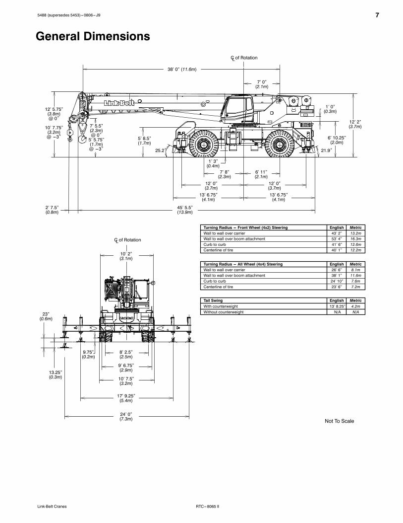
General Dimensions
Not To Scale
C of RotationL
C of RotationL
Turning Radius --- Front Wheel (4x2) Steering English MetricWall to wall over carrier 43’ 2” 13.2mWall to wall over boom attachment 53’ 4” 16.3mCurb to curb 41’ 6” 12.6mCenterline of tire 40’ 1” 12.2m
Tail Swing English MetricWith counterweight 13’ 8.25” 4.2m
Turning Radius --- All Wheel (4x4) Steering English MetricWall to wall over carrier 26’ 6” 8.1mWall to wall over boom attachment 38’ 1” 11.6mCurb to curb 24’ 10” 7.6mCenterline of tire 23’ 6” 7.2m
38’ 0” (11.6m)
7’ 0”(2.1m)
1’ 0”(0.3m)
12’ 2”(3.7m)
6’ 10.25”(2.0m)
21.9˚25.2˚
7’ 8”(2.3m)
6’ 11”(2.1m)
12’ 0”(3.7m)
12’ 0”(3.7m)13’ 6.75”(4.1m)
13’ 6.75”(4.1m)
45’ 5.5”(13.9m)
5’ 8.5”(1.7m)
7’ 5.5”(2.3m)@ 0˚5’ 5.75”(1.7m)@ ---3˚
10’ 2”(3.1m)
9.75”(0.2m)
13.25”(0.3m)
23”(0.6m)
8’ 2.5”(2.5m)
9’ 6.75”(2.9m)
10’ 7.5”(3.2m)
17’ 9.25”(5.4m)
24’ 0”(7.3m)
2’ 7.5”(0.8m)
1’ 3”(0.4m)
12’ 5.75”(3.8m)@ 0˚
10’ 7.75”(3.2m)@ ---3˚
Without counterweight N/A N/A

8 5488 (supersedes 5453)---0806--- J9
RTC---8065 II Link-Belt Cranes
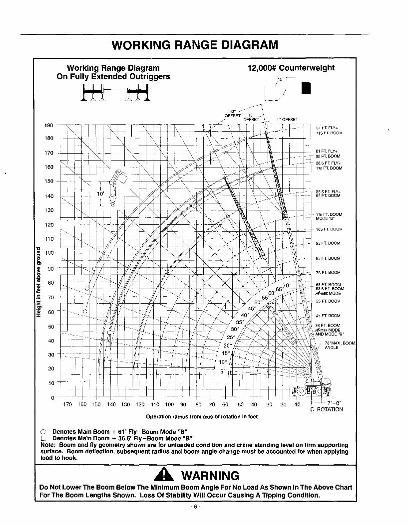
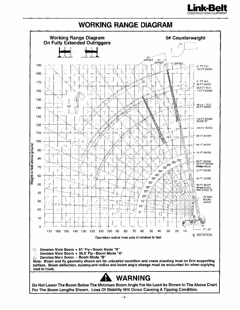
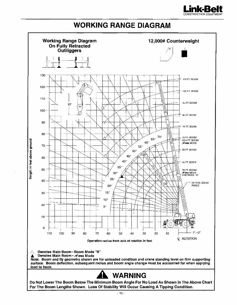
Working Range Diagram
15˚OFFSET
10
2040
50
60
70
80
90
100
30110130
120
170
160
150
140
Operating Radius From Axis Of Rotation In Feet (Meters)
HeightInFeet(Meters)AboveGround
(3.0)
(6.1)(12.2)
(15.2)
(18.3)
(21.3)
(24.4)
(27.4)
(30.5)
(9.1)(33.5)(39.6)
(36.6)
(51.8)
(48.8)
(45.7)
(42.7)
180(54.9)170(51.8)160(48.8)150(45.7)140(42.7)130(39.6)120(36.6)110(33.5)100(30.5)90
(27.4)80
(24.4)70
(21.3)60
(18.3)50
(15.2)40
(12.2)30(9.1)20(6.1)10(3.0)0
95’ (29.0m) +35’ (10.7m)
115’ (35.1m)Mode “B”
105’ (32.0m)
95’ (29.0m)
85’ (25.9m)
75’ (22.9m)
63.6’ (19.4m)Mode “A”
65’ (19.8m)
55’ (16.8m)
38’ (11.6m)Mode “A” & “B”
78˚ MaxBoom Angle
45’ (13.7m)
20˚
30˚
40˚
50˚
60˚70˚
10˚
45˚OFFSET 30˚
OFFSET
10’(3.0m)
8.5’(2.6m)
95’ (29.0m) +58’ (17.7m)115’ (35.1m) +35’ (10.7m)
190(57.9)
200(61.0)
210(64.0)
220(67.1)
180(54.9)
200(61.0)
190(57.9)
210(64.0)
115’ (35.1m) +58’ (17.7m)
115’ (35.1m) +74’ (22.6m)
115’ (35.1m) +90’ (27.4m)2˚ OFFSET
115’ (35.1m) +16’ (4.9m)
Boom+FlyLengthInFeet(Meters)
BoomLengthInFeet(Meters)
C of RotationL
95488 (supersedes 5453)---0806--- J9
RTC---8065 IILink-Belt Cranes
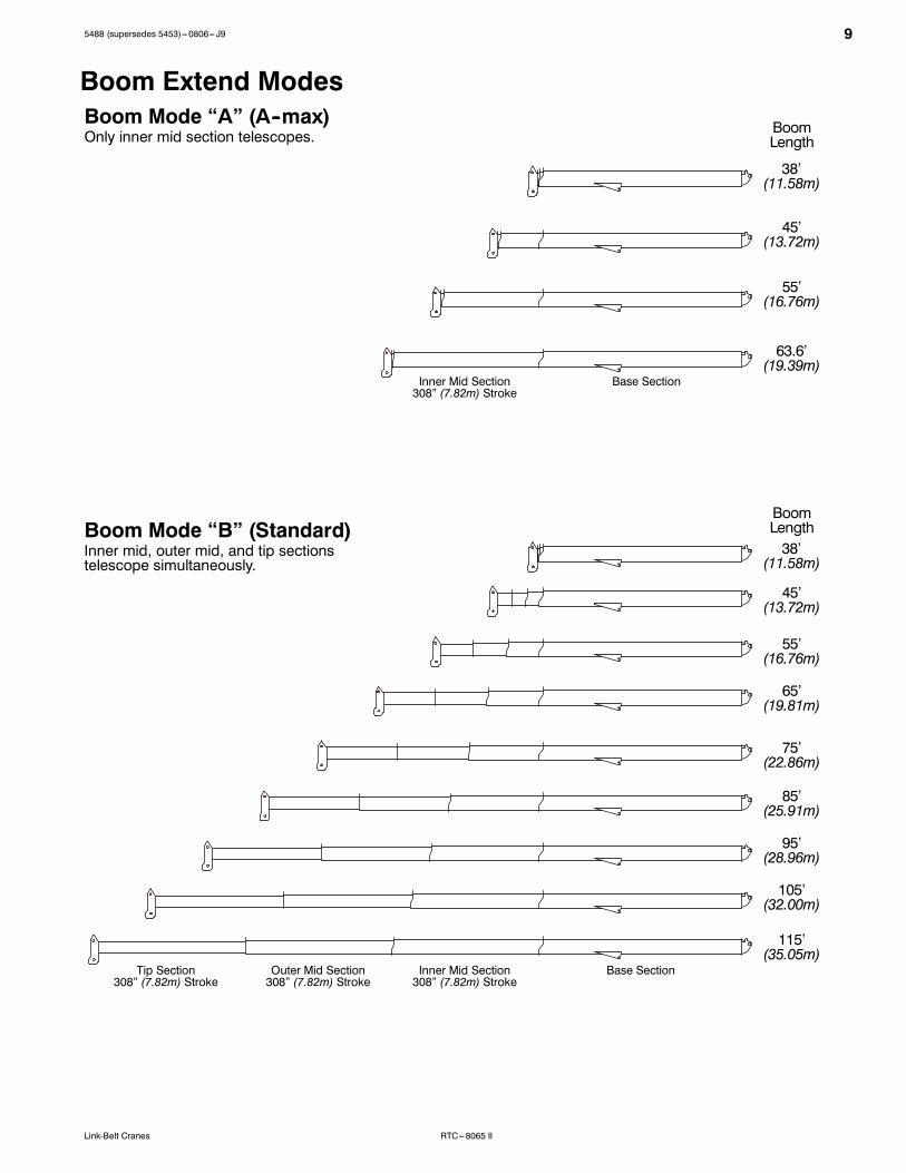
Boom Extend ModesBoom Mode “A” (A--max)
Boom Mode “B” (Standard)
Only inner mid section telescopes.
Inner mid, outer mid, and tip sectionstelescope simultaneously.
Base SectionTip Section308” (7.82m) Stroke
BoomLength
38’(11.58m)
45’(13.72m)
55’(16.76m)
63.6’(19.39m)
75’(22.86m)
85’(25.91m)
95’(28.96m)
105’(32.00m)
115’(35.05m)
Outer Mid Section308” (7.82m) Stroke
Inner Mid Section308” (7.82m) Stroke
Base SectionInner Mid Section308” (7.82m) Stroke
BoomLength38’
(11.58m)
45’(13.72m)
55’(16.76m)
65’(19.81m)
10 5488 (supersedes 5453)---0806--- J9
RTC---8065 II Link-Belt Cranes
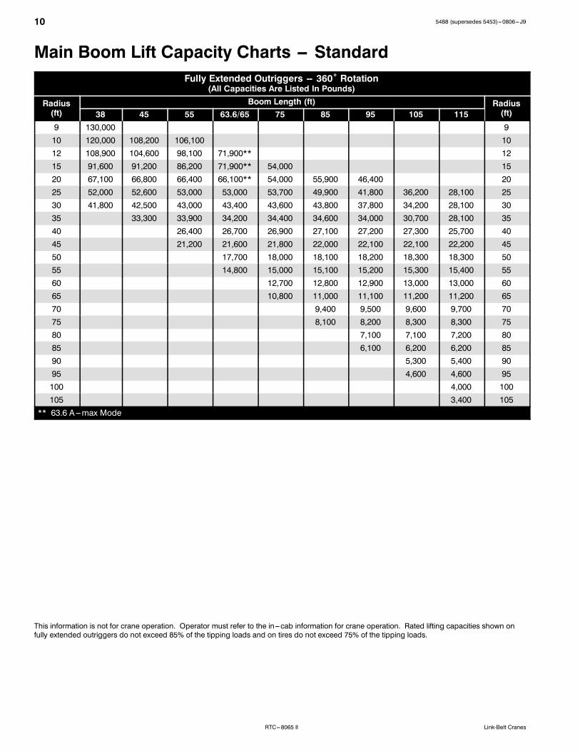
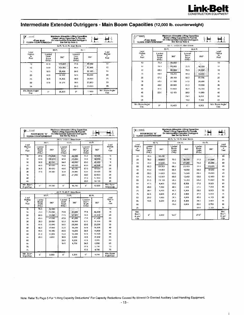
Main Boom Lift Capacity Charts -- StandardFully Extended Outriggers -- 360˚ Rotation
(All Capacities Are Listed In Pounds)
Radius(ft)
Boom Length (ft) Radius(ft)38 45 55 63.6/65 75 85 95 105 115
9 130,000 910 120,000 108,200 106,100 1012 108,900 104,600 98,100 71,900** 1215 91,600 91,200 86,200 71,900** 54,000 1520 67,100 66,800 66,400 66,100** 54,000 55,900 46,400 2025 52,000 52,600 53,000 53,000 53,700 49,900 41,800 36,200 28,100 2530 41,800 42,500 43,000 43,400 43,600 43,800 37,800 34,200 28,100 3035 33,300 33,900 34,200 34,400 34,600 34,000 30,700 28,100 3540 26,400 26,700 26,900 27,100 27,200 27,300 25,700 4045 21,200 21,600 21,800 22,000 22,100 22,100 22,200 4550 17,700 18,000 18,100 18,200 18,300 18,300 5055 14,800 15,000 15,100 15,200 15,300 15,400 5560 12,700 12,800 12,900 13,000 13,000 6065 10,800 11,000 11,100 11,200 11,200 6570 9,400 9,500 9,600 9,700 7075 8,100 8,200 8,300 8,300 7580 7,100 7,100 7,200 8085 6,100 6,200 6,200 8590 5,300 5,400 9095 4,600 4,600 95100 4,000 100105 3,400 105
** 63.6 A---max Mode
This information is not for crane operation. Operator must refer to the in---cab information for crane operation. Rated lifting capacities shown onfully extended outriggers do not exceed 85% of the tipping loads and on tires do not exceed 75% of the tipping loads.
115488 (supersedes 5453)---0806--- J9
RTC---8065 IILink-Belt Cranes
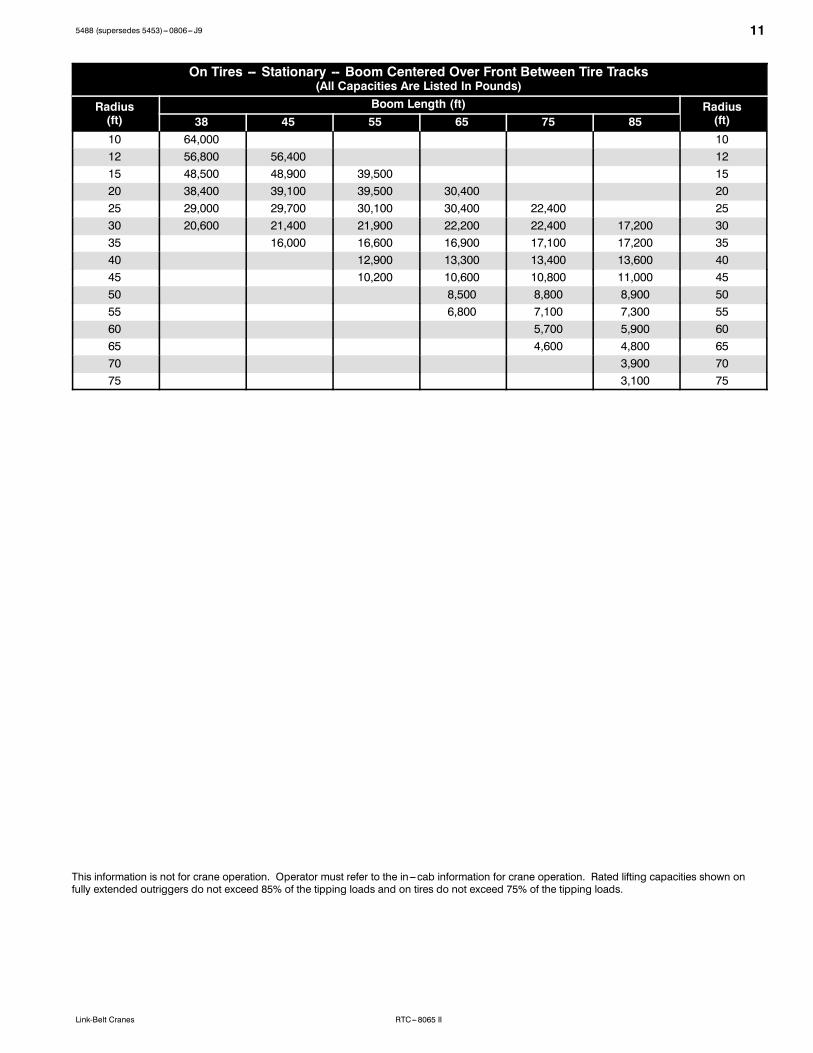
On Tires -- Stationary -- Boom Centered Over Front Between Tire Tracks(All Capacities Are Listed In Pounds)
Radius(ft)
Boom Length (ft) Radius(ft)38 45 55 65 75 85
10 64,000 1012 56,800 56,400 1215 48,500 48,900 39,500 1520 38,400 39,100 39,500 30,400 2025 29,000 29,700 30,100 30,400 22,400 2530 20,600 21,400 21,900 22,200 22,400 17,200 3035 16,000 16,600 16,900 17,100 17,200 3540 12,900 13,300 13,400 13,600 4045 10,200 10,600 10,800 11,000 4550 8,500 8,800 8,900 5055 6,800 7,100 7,300 5560 5,700 5,900 6065 4,600 4,800 6570 3,900 7075 3,100 75
This information is not for crane operation. Operator must refer to the in---cab information for crane operation. Rated lifting capacities shown onfully extended outriggers do not exceed 85% of the tipping loads and on tires do not exceed 75% of the tipping loads.

12 5488 (supersedes 5453)---0806--- J9
RTC---8065 II Link-Belt Cranes
On Tires -- Pick & Carry (Creep) -- Boom Centered Over Front(All Capacities Are Listed In Pounds)
Radius(ft)
Boom Length (ft) Radius(ft)38 45 55 65 75 85
10 63,000 1012 55,200 54,900 1215 46,300 46,700 39,500 1520 35,700 36,100 36,600 30,400 2025 28,300 28,800 29,300 29,600 22,400 2530 20,600 21,400 21,900 22,200 22,400 17,200 3035 16,000 16,600 16,900 17,100 17,200 3540 12,900 13,300 13,400 13,600 4045 10,200 10,600 10,800 11,000 4550 8,500 8,800 8,900 5055 6,800 7,100 7,300 5560 5,700 5,900 6065 4,600 4,800 6570 3,900 7075 3,100 75
On Tires -- Stationary -- 360˚ Rotation(All Capacities Are Listed In Pounds)
Radius(ft)
Boom Length (ft) Radius(ft)38 45 55 65 75 85
10 47,700 1012 39,000 39,500 1215 26,800 27,400 27,800 1520 16,200 16,800 17,300 17,600 2025 10,500 11,100 11,700 12,000 12,200 2530 6,800 7,500 8,100 8,400 8,600 8,800 3035 5,000 5,600 5,900 6,200 6,300 3540 3,800 4,100 4,400 4,600 4045 2,400 2,800 3,000 3,200 4550 1,700 1,900 2,100 5055 1,100 1,200 55
This information is not for crane operation. Operator must refer to the in---cab information for crane operation. Rated lifting capacities shown onfully extended outriggers do not exceed 85% of the tipping loads and on tires do not exceed 75% of the tipping loads.
135488 (supersedes 5453)---0806--- J9
RTC---8065 IILink-Belt Cranes
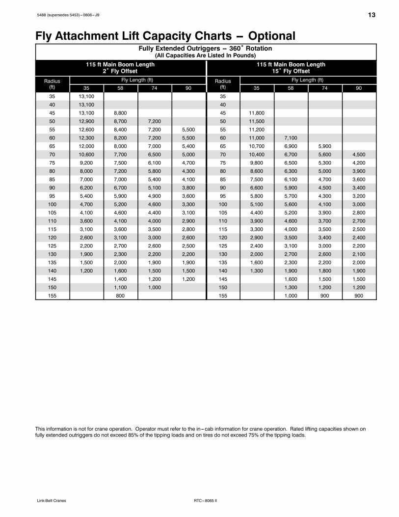
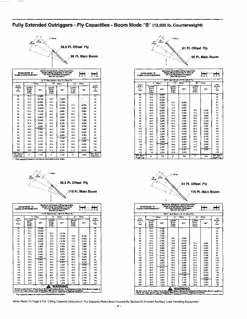
Fly Attachment Lift Capacity Charts -- OptionalFully Extended Outriggers -- 360˚ Rotation
(All Capacities Are Listed In Pounds)115 ft Main Boom Length
2˚ Fly Offset115 ft Main Boom Length
15˚ Fly Offset
Radius(ft)
Fly Length (ft) Radius(ft)
Fly Length (ft)35 58 74 90 35 58 74 90
35 13,100 35
40 13,100 40
45 13,100 8,800 45 11,800
50 12,900 8,700 7,200 50 11,500
55 12,600 8,400 7,200 5,500 55 11,200
60 12,300 8,200 7,200 5,500 60 11,000 7,100
65 12,000 8,000 7,000 5,400 65 10,700 6,900 5,900
70 10,600 7,700 6,500 5,000 70 10,400 6,700 5,600 4,500
75 9,200 7,500 6,100 4,700 75 9,800 6,500 5,300 4,200
80 8,000 7,200 5,800 4,300 80 8,600 6,300 5,000 3,900
85 7,000 7,000 5,400 4,100 85 7,500 6,100 4,700 3,600
90 6,200 6,700 5,100 3,800 90 6,600 5,900 4,500 3,400
95 5,400 5,900 4,900 3,600 95 5,800 5,700 4,300 3,200
100 4,700 5,200 4,600 3,300 100 5,100 5,600 4,100 3,000
105 4,100 4,600 4,400 3,100 105 4,400 5,200 3,900 2,800
110 3,600 4,100 4,000 2,900 110 3,900 4,600 3,700 2,700
115 3,100 3,600 3,500 2,800 115 3,300 4,000 3,500 2,500
120 2,600 3,100 3,000 2,600 120 2,900 3,500 3,400 2,400
125 2,200 2,700 2,600 2,500 125 2,400 3,100 3,000 2,200
130 1,900 2,300 2,200 2,200 130 2,000 2,700 2,600 2,100
135 1,500 2,000 1,900 1,900 135 1,600 2,300 2,200 2,000
140 1,200 1,600 1,500 1,500 140 1,300 1,900 1,800 1,900
145 1,400 1,200 1,200 145 1,600 1,500 1,500
150 1,100 1,000 150 1,300 1,200 1,200
155 800 155 1,000 900 900
This information is not for crane operation. Operator must refer to the in---cab information for crane operation. Rated lifting capacities shown onfully extended outriggers do not exceed 85% of the tipping loads and on tires do not exceed 75% of the tipping loads.

14 5488 (supersedes 5453)---0806--- J9
RTC---8065 II Link-Belt Cranes
Fully Extended Outriggers -- 360˚ Rotation(All Capacities Are Listed In Pounds)
115 ft Main Boom Length30˚ Fly Offset
115 ft Main Boom Length45˚ Fly Offset
Radius(ft)
Fly Length (ft) Radius(ft)
Fly Length (ft)35 58 74 90 35 58 74 90
40 40
45 45
50 50
55 9,900 55
60 9,700 60 8,900
65 9,500 65 8,800
70 9,400 70 8,700
75 9,200 5,600 75 8,600
80 9,100 5,500 4,200 80 8,600
85 8,000 5,300 4,000 3,200 85 8,400 4,900
90 7,000 5,200 3,800 3,000 90 7,300 4,800 3,400
95 6,200 5,100 3,700 2,900 95 6,400 4,700 3,300 2,600
100 5,400 5,000 3,500 2,700 100 5,600 4,700 3,200 2,500
105 4,700 4,900 3,400 2,500 105 4,900 4,700 3,100 2,300
110 4,100 4,900 3,200 2,400 110 4,200 4,600 3,000 2,200
115 3,500 4,500 3,100 2,300 115 3,600 4,600 2,900 2,100
120 3,000 3,900 3,000 2,100 120 4,200 2,800 2,000
125 2,500 3,400 2,900 2,000 125 3,700 2,700 1,900
130 2,100 3,000 2,800 1,900 130 3,200 2,700 1,800
135 2,500 2,500 1,800 135 2,700 2,600 1,700
140 2,200 2,200 1,700 140 2,200 2,300 1,600
145 1,800 1,800 1,600 145 1,900 1,600
150 1,400 1,400 1,500 150 1,600 1,500
155 1,100 1,100 1,200 155 1,400
160 800 900 160 1,000
This information is not for crane operation. Operator must refer to the in---cab information for crane operation. Rated lifting capacities shown onfully extended outriggers do not exceed 85% of the tipping loads and on tires do not exceed 75% of the tipping loads.

155488 (supersedes 5453)---0806--- J9
RTC---8065 IILink-Belt Cranes
Main Boom Lift Capacity Charts -- MetricFully Extended Outriggers -- 360˚ Rotation
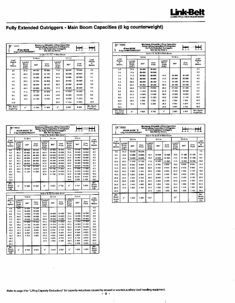
(All Capacities Are Listed In Kilograms)
Radius(m)
Boom Length (m) Radius(m)11.58 13.7 16.8 19.39/19.8 22.9 25.9 29.0 32.0 35.05
2.5 60 000 2.53 54 800 49 000 48 100 33.5 50 650 48 650 45 550 32 600** 3.54 46 900 45 250 42 300 32 600** 44.5 42 250 42 050 39 500 32 600** 24 450 4.55 37 800 37 600 37 100 32 600** 24 450 56 31 000 30 850 30 650 30 500** 24 450 25 550 21 150 67 26 050 25 900 25 750 25 650** 24 450 23 700 19 750 78 22 300 22 600 22 850 23 000 23 100 22 050 18 500 16 400 12 800 89 18 200 18 500 18 700 18 850 18 950 19 050 17 300 15 650 12 800 910 15 050 15 300 15 450 15 550 15 600 15 650 14 550 12 800 1012 10 900 11 050 11 100 11 200 11 250 11 250 11 300 1214 8 150 8 300 8 400 8 450 8 500 8 500 8 550 1416 6 450 6 550 6 600 6 650 6 650 6 700 1618 5 250 5 300 5 350 5 400 5 400 1820 4 250 4 300 4 350 4 400 4 400 2022 3 500 3 550 3 600 3 600 2224 2 900 2 950 3 000 2426 2 400 2 450 2 450 2628 2 000 2 050 2830 1 650 3032 1 350 32
** 19.39 A---max Mode
This information is not for crane operation. Operator must refer to the in---cab information for crane operation. Rated lifting capacities shown onfully extended outriggers do not exceed 75% of the tipping loads and on tires do not exceed 65% of the tipping loads.
16 5488 (supersedes 5453)---0806--- J9
RTC---8065 II Link-Belt Cranes
On Tires -- Stationary -- Boom Centered Over Front Between Tire Tracks(All Capacities Are Listed In Kilograms)
Radius(m)
Boom Length (m) Radius(m)11.58 13.7 16.8 19.8 22.9 25.9
3 29 000 33.5 26 500 3.54 24 200 24 050 44.5 22 250 22 450 17 900 4.55 20 550 20 750 17 900 56 17 700 17 950 17 900 13 750 67 13 350 13 600 13 750 13 750 78 10 400 10 700 10 900 11 000 10 150 89 8 350 8 650 8 850 8 950 9 000 7 800 910 7 100 7 350 7 450 7 500 7 550 1012 5 250 5 400 5 450 5 500 1214 3 800 4 000 4 100 4 150 1416 3 000 3 100 3 150 1618 2 350 2 400 1820 1 750 1 850 2022 1 400 22
This information is not for crane operation. Operator must refer to the in---cab information for crane operation. Rated lifting capacities shown onfully extended outriggers do not exceed 75% of the tipping loads and on tires do not exceed 65% of the tipping loads.

175488 (supersedes 5453)---0806--- J9
RTC---8065 IILink-Belt Cranes
On Tires -- Pick & Carry (Creep) -- Boom Centered Over Front(All Capacities Are Listed In Kilograms)
Radius(m)
Boom Length (m) Radius(m)11.58 13.7 16.8 19.8 22.9 25.9
3 28 550 33.5 25 900 3.54 23 400 23 550 44.5 21 250 21 450 17 900 4.55 19 400 19 600 17 900 56 16 400 16 650 16 850 13 750 67 13 350 13 600 13 750 13 750 78 10 400 10 700 10 900 11 000 10 150 89 8 350 8 650 8 850 8 950 9 000 7 800 910 7 100 7 350 7 450 7 500 7 550 1012 5 250 5 400 5 450 5 500 1214 3 800 4 000 4 100 4 150 1416 3 000 3 100 3 150 1618 2 350 2 400 1820 1 750 1 850 2022 1 400 22
On Tires -- Stationary -- 360˚ Rotation(All Capacities Are Listed In Kilograms)
Radius(m)
Boom Length (m) Radius(m)11.58 13.7 16.8 19.8 22.9 25.9
3 21 550 33.5 16 500 3.54 13 200 13 400 44.5 10 850 11 050 11 200 4.55 9 050 9 300 9 450 56 6 550 6 800 7 000 7 100 67 4 900 5 150 5 350 5 450 78 3 700 3 950 4 150 4 300 4 350 89 2 800 3 050 3 250 3 400 3 500 3 550 910 2 350 2 550 2 700 2 800 2 850 1012 1 550 1 700 1 800 1 850 1214 850 1 000 1 100 1 150 1416 450 550 650 16
This information is not for crane operation. Operator must refer to the in---cab information for crane operation. Rated lifting capacities shown onfully extended outriggers do not exceed 75% of the tipping loads and on tires do not exceed 65% of the tipping loads.

18 5488 (supersedes 5453)---0806--- J9
RTC---8065 II Link-Belt Cranes
Fly Attachment Lift Capacity Charts -- OptionalFully Extended Outriggers -- 360˚ Rotation
(All Capacities Are Listed In Kilograms)35.05 m Main Boom Length
2˚ Fly Offset35.05 m Main Boom Length
15˚ Fly Offset
Radius(m)
Fly Length (m) Radius(m)
Fly Length (m)10.67 17.68 22.56 27.43 10.67 17.68 22.56 27.43
12 5 900 12
14 5 900 4 000 14 5 350
16 5 750 3 850 3 250 16 5 150
18 5 600 3 750 3 250 2 500 18 5 000
20 4 750 3 600 3 150 2 400 20 4 850 3 100 2 650
22 3 950 3 450 2 900 2 200 22 4 200 3 000 2 450 1 950
24 3 300 3 300 2 650 2 000 24 3 550 2 850 2 300 1 800
26 2 800 3 000 2 450 1 850 26 2 950 2 750 2 150 1 650
28 2 350 2 550 2 300 1 700 28 2 500 2 650 2 000 1 500
30 1 950 2 150 2 100 1 550 30 2 100 2 400 1 850 1 400
32 1 650 1 850 1 800 1 400 32 1 750 2 050 1 750 1 300
34 1 350 1 550 1 500 1 300 34 1 450 1 750 1 650 1 200
36 1 100 1 300 1 250 1 200 36 1 200 1 450 1 450 1 100
38 900 1 050 1 050 1 050 38 950 1 250 1 200 1 000
40 700 900 850 850 40 750 1 000 950 950
42 550 700 650 650 42 550 800 800 800
44 550 500 500 44 650 600 600
46 400 46 500 450 450
48 48 350
This information is not for crane operation. Operator must refer to the in---cab information for crane operation. Rated lifting capacities shown onfully extended outriggers do not exceed 75% of the tipping loads and on tires do not exceed 65% of the tipping loads.
195488 (supersedes 5453)---0806--- J9
RTC---8065 IILink-Belt Cranes
Fully Extended Outriggers -- 360˚ Rotation(All Capacities Are Listed In Kilograms)
35.05 m Main Boom Length30˚ Fly Offset
35.05 m Main Boom Length45˚ Fly Offset
Radius(m)
Fly Length (m) Radius(m)
Fly Length (m)10.67 17.68 22.56 27.43 10.67 17.68 22.56 27.43
18 4 450 18
20 4 300 20 4 000
22 4 200 22 3 950
24 3 750 2 500 24 3 900
26 3 150 2 400 1 800 1 450 26 3 300 2 200
28 2 650 2 350 1 700 1 350 28 2 800 2 150 1 550
30 2 250 2 300 1 600 1 250 30 2 350 2 150 1 450 1 150
32 1 900 2 250 1 550 1 150 32 1 950 2 100 1 400 1 050
34 1 550 1 950 1 450 1 050 34 1 600 2 100 1 350 1 000
36 1 250 1 650 1 400 1 000 36 1 750 1 300 900
38 1 000 1 350 1 300 900 38 1 450 1 250 850
40 800 1 150 1 150 850 40 1 200 1 200 800
42 900 900 800 42 950 1 000 750
44 700 700 750 44 800 700
46 550 550 550 46 600 650
48 400 400 48 450
This information is not for crane operation. Operator must refer to the in---cab information for crane operation. Rated lifting capacities shown onfully extended outriggers do not exceed 75% of the tipping loads and on tires do not exceed 65% of the tipping loads.

5488 (supersedes 5453)---0806--- J9
RTC---8065 II Link-Belt Cranes
Link--Belt Construction Equipment Company Lexington, Kentucky www.linkbelt.comRLink--Belt is a registered trademark. Copyright 2006. We are constantly improving our products and therefore reserve the right to change designs and specifications.


���RTC–8065
� Axle LoadsBase machine with standard 38’ – 115’
�Upper facing front Upper facing rear
(11.58 – 35.05 m) four–section boom, 2Mmain winch with 2–speed hoisting and
G.V.W.�Front axle Rear axle Front axle Rear axle
power up/down, 630’ (192 m) 3/4” (19mm) wire rope. 4x4x4 carrier with Cum- lbs. kg. lbs. kg. lbs. kg. lbs. kg. lbs. kg.mins 6CT 8.3L engine, 29.5 x 25 tires,counterweight and no fuel. 91,816 41 647 44,280 20 085 47,536 21 562 41,791 18 956 50,025 22 691
Remove 29.5 x 25 tires and wheels –6,732 –3 054 –3,366 –1 527 –3,366 –1 527 –3,366 –1 527 –3,366 –1 527
29.5R25 XHA Tires 964 438 482 219 482 219 482 219 482 219
Remove outrigger beams –5,235 –2 374 –2,461 –1 116 –2,774 –1 258 –2,461 –1 116 –2,774 –1 258
Tow winch 686 311 1,002 454 –316 –143 1,002 454 –316 –143
100 gallons (378.5 L) fuel 685 310 364 165 321 145 364 165 321 145
2M auxiliary winch with 630’ (192 m) of3/4” (19 mm) rope 691 313 –180 –82 871 395 816 370 –125 –57
Remove front carrier counterweights –3628 –1 646 –4,858 –2 204 1,230 558 –4,858 –2 204 1230 558
Hydraulic counterweight removal 353 160 163 74 190 86 518 235 –165 –75
Remove counterweight –12,000 –5 443 6,586 2 987 –18,586 –8 430 –17,633 –7 998 5,633 2 555
Diesel heater with tank 70 32 19 9 51 23 45 21 25 11
Hydraulic heater 170 77 47 21 123 56 110 50 60 27
Air conditioning 287 130 55 25 232 105 209 95 78 35
36.5’ (11.13 m) One–piece lattice fly, withtip lugs, stowable 1,542 700 2,485 1 115 –619 –415 –1,039 –471 2,581 1 171
36.5’ – 61’ (11.13 – 18.59 m) Two–piece(bifold) lattice fly, stowable 2,250 1 021 3,165 1 436 –915 –415 –1,094 –496 3,344 1 517
Fly storage brackets with all fly options 160 73 228 103 –69 –30 –81 –36 241 109
Auxiliary lifting sheave assembly 110 50 355 152 –225 –102 –233 –106 343 156
8.5–ton (7.71 mt) hook ball @ front bumper 360 163 566 256 –206 –93 n/a n/a n/a n/a
70–ton (63.50 mt) 5–sheave hook block@ front bumper 1,390 631 2,186 992 –796 –361 n/a n/a n/a n/a
60–ton (54.43 mt) 4–sheave hook block@ front bumper 1,150 522 1,809 821 –659 –299 n/a n/a n/a n/a
� – Adjust gross weight and axle loading according to component weight. Note: All weights are � 3%.
Tire Max. Axle Load @ 20 mph (32.7 km/hr)
29.5 x 25 (28–PR)
29.5R25 XHA 1 Star
53,000 (24 041 kg)
53,000 (24 041 kg)
Link–Belt Construction Equipment Company Lexington, Kentucky www.linkbelt.com�Link–Belt is a registered trademark. Copyright 2001. All rights reserved. We are constantly improving our products and therefore reserve the right to change designs and specifications.