66 alternadores y arranques
TRANSCRIPT

Alternators andStarter Motors
TECHNICAL MANUALAlternators and Starter Motors
CTM77 18JUL05 (ENGLISH)
John Deere Power SystemsLITHO IN U.S.A.

Introduction
IFC,CTM77 –19–15JUL05–1/1
Foreword
This manual is written for an experienced technician.Essential tools required in performing certain servicework are identified in this manual and arerecommended for use.
Live with safety: Read the safety messages in theintroduction of this manual and the cautions presentedthroughout the text of the manual.
CAUTION: This is the safety-alert symbol.When you see this symbol on the machineor in this manual, be alert to the potential forpersonal injury.
This Component Technical Manual (CTM) contains thelatest available instructions necessary to repair enginealternators and starter motors. It includes theory ofoperation, and diagnostic and testing procedures tohelp troubleshoot and understand potential failuremodes.
The information is organized in sections and groups byvarious suppliers. At the beginning of each repairgroup are summary listings of all applicable essentialtools, service equipment and tools, other materialsneeded to do the job, service parts kits, specifications,wear tolerances, and torque values.
Component Technical Manuals are concise serviceguides for specific components. They are written asstand-alone manuals covering multiple machineapplications.
Fundamental service information is available fromother sources covering basic theory of operation,fundamentals of troubleshooting, general maintenance,and basic types of failures and their causes.
This manual covers alternator and starter motorapplications for all John Deere diesel engines—both older 300/400/500-Series and newerPOWERTECH and PowerTech Plus 2.4 L—13.5 Lengines. This manual covers components for bothDeere OEM engines and Deere machine engineapplications.
NOTE: Remanufactured alternators and starter motorsare available for replacement on mostapplications listed in this manual. Refer toJohn Deere’s “Remanufactured Components”catalogs PC2344 (Ag), PC2345 (CE) andPC2346 (C&CE) to cross-reference youroriginal equipment part number and obtain asuitable remanufactured replacement starter oralternator.
POWERTECH is a registered trademark of Deere & Company.
CTM77 (18JUL05) Alternators and Starter Motors071805
PN=2

Introduction
OURGP11,0000053 –19–15JUL05–1/1
John Deere Dealers
IMPORTANT: Please copy this page listing changesand route it through your servicedepartment.
This CTM is a complete revision of CTM77, Alternatorsand Starter Motors, dated 25 Sep 02. Discard CTM77dated 25 Sep 02 and replace it with this new manual.
This manual covers alternators and starter motors on allJohn Deere and OEM applications manufactured since1972, except 40, 50 and 55 Series Utility Tractors.
Revised information includes:
1. Updated test specifications for all current alternatorsand starter motors, including those adopted since the25 Sep 02 edition.
2. Added new applications for all current alternators andstarter motors.
3. Added new Bosch alternator pulley removal procedureto Section 30, Group 10.
4. Updated torque charts in Section 05, Group 10.
CTM77 (18JUL05) Alternators and Starter Motors071805
PN=3

Introduction
CTM77 (18JUL05) Alternators and Starter Motors071805
PN=4

Contents05
SECTION 05—Introduction and Safety Information SECTION 40—Magneton AlternatorsGroup 05—Magneton Alternator Theory ofGroup 05—Safety
Group 10—General Information OperationGroup 10—Magneton Alternator RepairGroup 15—Electrical System Basic Information and
Wiring Diagrams10
SECTION 45—Leece-Neville AlternatorsSECTION 10—Delco-Remy Alternators Group 05—Leece-Neville Alternator Theory of
Group 05—Delco-Remy Alternator Theory of OperationOperation Group 10—Leece-Neville Alternator Repair
Group 10—Delco-Remy (Delcotron) 10SI, 12SI and15SI Alternator Repair
SECTION 50—Prestolite AlternatorsGroup 15—Delco-Remy (Delcotron) 21SI AlternatorGroup 05—Prestolite Alternator Theory of OperationRepairGroup 10—Prestolite Alternator Repair
SECTION 15—Motorola AlternatorsSECTION 55—Iskra AlternatorsGroup 05—Motorola Alternator Theory of Operation
15
Group 05—Iskra Alternator Theory of OperationGroup 10—Motorola 8E-Series Alternator RepairGroup 10—Iskra Alternator RepairGroup 15—Motorola HC-, MA-, MR-Series
Alternator RepairGroup 20—Motorola A-, RA-, 8AR-Series Alternator SECTION 60—Delco-Remy Starter Motors
Repair Group 05—Starting Circuit Theory of OperationGroup 25—Motorola SA-Series Alternator Repair Group 10—Delco-Remy 10/20/22/25/27/28MTGroup 30—Motorola TA-Series Alternator Repair Starter Motor Repair
Group 15—Delco-Remy 30MT, 35MT, 37MT StarterSECTION 20—Niehoff Alternators Motor Repair
Group 05—Niehoff Alternator Theory of Operation Group 20—Delco-Remy 40MT, 41MT, 42MT, 50MTGroup 10—Niehoff 12-Volt, 110-Amp Alternator Starter Motor Repair
20
RepairGroup 15—Niehoff 24-Volt, 50-Amp Alternator
SECTION 65—John Deere/Denso Starter MotorsRepairGroup 05—Starting Circuit Theory of OperationGroup 10—John Deere/Denso Conventional StarterSECTION 25—Denso Alternators
Motor RepairGroup 05—Denso Alternator Theory of OperationGroup 15—John Deere/Denso Gear ReductionGroup 10—Denso Alternator with Add-On Regulator
Starter Motor RepairRepairGroup 20—John Deere/Denso Planetary StarterGroup 15—Denso Alternator with Built-In Regulator
Motor RepairRepair
25
SECTION 70—Bosch Starter MotorsSECTION 30—Bosch AlternatorsGroup 05—Starting Circuit Theory of OperationGroup 05—Bosch Alternator Theory of OperationGroup 10—Bosch Conventional Starter MotorGroup 10—Bosch Alternator Repair
RepairGroup 15—Bosch Planetary Gear Starter MotorSECTION 35—Valeo Alternators
Group 05—Valeo Alternator Theory of Operation RepairGroup 10—Valeo Alternator RepairGroup 15—Valeo A13N-Series Alternator Repair Continued on next page
All information, illustrations and specifications in this manual are based onthe latest information available at the time of publication. The right isreserved to make changes at any time without notice.
30
COPYRIGHT 2005DEERE & COMPANY
Moline, IllinoisAll rights reserved
A John Deere ILLUSTRUCTION ManualPrevious Editions
Copyright 1994, 1997, 2000, 2002
35
40
45
50
CTM77 (18JUL05) i Alternators and Starter Motors071805
PN=1

Contents
05SECTION 75—Iskra Starter Motors
Group 05—Starting Circuit Theory of OperationGroup 10—Iskra AZE/AZF/AZJ-Type Starter Motor
RepairGroup 15—Iskra AZE-Type Starter Motor Repair
10
SECTION 80—Valeo Starter MotorsGroup 05—Starting Circuit Theory of OperationGroup 10—Valeo Starter Motor Repair
SECTION 85—Magneton Starter MotorsGroup 05—Starting Circuit Theory of OperationGroup 10—Magneton Starter Motor Repair
15
20
25
30
35
40
45
50
CTM77 (18JUL05) ii Alternators and Starter Motors071805
PN=2

Contents
55
60
65
70
75
80
85
INDX
CTM77 (18JUL05) iii Alternators and Starter Motors071805
PN=3

Contents
55
60
65
70
75
80
85
INDX
CTM77 (18JUL05) iv Alternators and Starter Motors071805
PN=4

05
Section 05Introduction and Safety Information
Contents
Page
Group 05—Safety . . . . . . . . . . . . . . . . . . . . . .05-05-1
Group 10—General InformationUnified Inch Bolt and Screw Torque Values . . .05-10-1Metric Bolt and Screw Torque Values . . . . . . . .05-10-2
Group 15—Electrical System Basic Information andWiring Diagrams
Electrical Circuit Malfunctions . . . . . . . . . . . . . .05-15-1High Resistance Circuit . . . . . . . . . . . . . . . . . . .05-15-2Open Circuit . . . . . . . . . . . . . . . . . . . . . . . . . . .05-15-3Grounded Circuit . . . . . . . . . . . . . . . . . . . . . . . .05-15-5Shorted Circuit . . . . . . . . . . . . . . . . . . . . . . . . .05-15-7Seven Step Electrical Test Procedure . . . . . . . .05-15-8Multimeter . . . . . . . . . . . . . . . . . . . . . . . . . . . .05-15-10
CTM77 (18JUL05) 05-1 Alternators and Starter Motors071805
PN=1

Contents
05
CTM77 (18JUL05) 05-2 Alternators and Starter Motors071805
PN=2

Group 05Safety
05051
DX,FLAME –19–29SEP98–1/1
Handle Fluids Safely—Avoid Fires
TS
227
–UN
–23A
UG
88
When you work around fuel, do not smoke or work nearheaters or other fire hazards.
Store flammable fluids away from fire hazards. Do notincinerate or puncture pressurized containers.
Make sure machine is clean of trash, grease, and debris.
Do not store oily rags; they can ignite and burnspontaneously.
DX,SPARKS –19–03MAR93–1/1
Prevent Battery Explosions
TS
204
–UN
–23A
UG
88
Keep sparks, lighted matches, and open flame away fromthe top of battery. Battery gas can explode.
Never check battery charge by placing a metal objectacross the posts. Use a volt-meter or hydrometer.
Do not charge a frozen battery; it may explode. Warmbattery to 16°C (60°F).
DX,FIRE2 –19–03MAR93–1/1
Prepare for Emergencies
TS
291
–UN
–23A
UG
88
Be prepared if a fire starts.
Keep a first aid kit and fire extinguisher handy.
Keep emergency numbers for doctors, ambulance service,hospital, and fire department near your telephone.
CTM77 (18JUL05) 05-05-1 Alternators and Starter Motors071805
PN=9

Safety
0505
2
DPSG,OUO1004,2758 –19–11MAY00–1/1
Handling Batteries Safely
TS
204
–UN
–23A
UG
88T
S20
3–U
N–2
3AU
G88
CAUTION: Battery gas can explode. Keepsparks and flames away from batteries. Use aflashlight to check battery electrolyte level.
Never check battery charge by placing a metalobject across the posts. Use a voltmeter orhydrometer.
Always remove grounded (—) battery clampfirst and replace it last.
CAUTION: Sulfuric acid in battery electrolyte ispoisonous. It is strong enough to burn skin, eatholes in clothing, and cause blindness ifsplashed into eyes.
Avoid the hazard by:
1. Filling batteries in a well-ventilated area.2. Wearing eye protection and rubber gloves.3. Avoiding breathing fumes when electrolyte is
added.4. Avoiding spilling or dripping electrolyte.5. Using proper jump start procedure.
If you spill acid on yourself:
1. Flush your skin with water.2. Apply baking soda or lime to help neutralize
the acid.3. Flush your eyes with water for 15—30
minutes. Get medical attention immediately.
If acid is swallowed:
1. Do not induce vomiting.2. Drink large amounts of water or milk, but do
not exceed 2 L (2 quarts).3. Get medical attention immediately.
WARNING: Battery posts, terminals, and relatedaccessories contain lead and lead compounds, chemicalsknown to the State of California to cause cancer andreproductive harm. Wash hands after handling.
CTM77 (18JUL05) 05-05-2 Alternators and Starter Motors071805
PN=10

Safety
05053
DX,WEAR –19–10SEP90–1/1
Wear Protective Clothing
TS
206
–UN
–23A
UG
88
Wear close fitting clothing and safety equipmentappropriate to the job.
Prolonged exposure to loud noise can cause impairmentor loss of hearing.
Wear a suitable hearing protective device such asearmuffs or earplugs to protect against objectionable oruncomfortable loud noises.
Operating equipment safely requires the full attention ofthe operator. Do not wear radio or music headphoneswhile operating machine.
DX,CLEAN –19–04JUN90–1/1
Work in Clean Area
T66
42E
J–U
N–1
8OC
T88
Before starting a job:
• Clean work area and machine.• Make sure you have all necessary tools to do your job.• Have the right parts on hand.• Read all instructions thoroughly; do not attempt
shortcuts.
DX,LOOSE –19–04JUN90–1/1
Service Machines Safely
TS
228
–UN
–23A
UG
88
Tie long hair behind your head. Do not wear a necktie,scarf, loose clothing, or necklace when you work nearmachine tools or moving parts. If these items were to getcaught, severe injury could result.
Remove rings and other jewelry to prevent electricalshorts and entanglement in moving parts.
CTM77 (18JUL05) 05-05-3 Alternators and Starter Motors071805
PN=11

Safety
0505
4
DX,AIR –19–17FEB99–1/1
Work In Ventilated Area
TS
220
–UN
–23A
UG
88
Engine exhaust fumes can cause sickness or death. If it isnecessary to run an engine in an enclosed area, removethe exhaust fumes from the area with an exhaust pipeextension.
If you do not have an exhaust pipe extension, open thedoors and get outside air into the area
DX,LIGHT –19–04JUN90–1/1
Illuminate Work Area Safely
TS
223
–UN
–23A
UG
88
Illuminate your work area adequately but safely. Use aportable safety light for working inside or under themachine. Make sure the bulb is enclosed by a wire cage.The hot filament of an accidentally broken bulb can ignitespilled fuel or oil.
DX,LIFT –19–04JUN90–1/1
Use Proper Lifting Equipment
TS
226
–UN
–23A
UG
88
Lifting heavy components incorrectly can cause severeinjury or machine damage.
Follow recommended procedure for removal andinstallation of components in the manual.
CTM77 (18JUL05) 05-05-4 Alternators and Starter Motors071805
PN=12
Safety
05055
DX,PAINT –19–19JUL01–1/1
Remove Paint Before Welding or Heating
TS
220
–UN
–23A
UG
88
Avoid potentially toxic fumes and dust.
Hazardous fumes can be generated when paint is heatedby welding, soldering, or using a torch.
Remove paint before heating:
• Remove paint a minimum of 76 mm (3 in.) from area tobe affected by heating.
• If you sand or grind paint, avoid breathing the dust.Wear an approved respirator.
• If you use solvent or paint stripper, remove stripper withsoap and water before welding. Remove solvent orpaint stripper containers and other flammable materialfrom area. Allow fumes to disperse at least 15 minutesbefore welding or heating.
Do not use a chlorinated solvent in areas where weldingwill take place.
Do all work in an area that is well ventilated to carry toxicfumes and dust away.
Dispose of paint and solvent properly.
CTM77 (18JUL05) 05-05-5 Alternators and Starter Motors071805
PN=13

Safety
0505
6
DX,SERV –19–17FEB99–1/1
Practice Safe Maintenance
TS
218
–UN
–23A
UG
88
Understand service procedure before doing work. Keeparea clean and dry.
Never lubricate, service, or adjust machine while it ismoving. Keep hands, feet , and clothing frompower-driven parts. Disengage all power and operatecontrols to relieve pressure. Lower equipment to theground. Stop the engine. Remove the key. Allow machineto cool.
Securely support any machine elements that must beraised for service work.
Keep all parts in good condition and properly installed. Fixdamage immediately. Replace worn or broken parts.Remove any buildup of grease, oil, or debris.
On self-propelled equipment, disconnect battery groundcable (-) before making adjustments on electrical systemsor welding on machine.
On towed implements, disconnect wiring harnesses fromtractor before servicing electrical system components orwelding on machine.
DX,REPAIR –19–17FEB99–1/1
Use Proper Tools
TS
779
–UN
–08N
OV
89Use tools appropriate to the work. Makeshift tools andprocedures can create safety hazards.
Use power tools only to loosen threaded parts andfasteners.
For loosening and tightening hardware, use the correctsize tools. DO NOT use U.S. measurement tools onmetric fasteners. Avoid bodily injury caused by slippingwrenches.
Use only service parts meeting John Deere specifications.
CTM77 (18JUL05) 05-05-6 Alternators and Starter Motors071805
PN=14

Safety
05057
DX,DRAIN –19–03MAR93–1/1
Dispose of Waste Properly
TS
1133
–UN
–26N
OV
90
Improperly disposing of waste can threaten theenvironment and ecology. Potentially harmful waste usedwith John Deere equipment include such items as oil, fuel,coolant, brake fluid, filters, and batteries.
Use leakproof containers when draining fluids. Do not usefood or beverage containers that may mislead someoneinto drinking from them.
Do not pour waste onto the ground, down a drain, or intoany water source.
Air conditioning refrigerants escaping into the air candamage the Earth’s atmosphere. Government regulationsmay require a certified air conditioning service center torecover and recycle used air conditioning refrigerants.
Inquire on the proper way to recycle or dispose of wastefrom your local environmental or recycling center, or fromyour John Deere dealer.
DX,BYPAS1 –19–29SEP98–1/1
Prevent Machine Runaway
TS
177
–UN
–11J
AN
89
Avoid possible injury or death from machinery runaway.
Do not start engine by shorting across starter terminals.Machine will start in gear if normal circuitry is bypassed.
NEVER start engine while standing on ground. Startengine only from operator’s seat, with transmission inneutral or park.
DX,LIVE –19–25SEP92–1/1
Live With Safety
TS
231
–19–
07O
CT
88
Before returning machine to customer, make suremachine is functioning properly, especially the safetysystems. Install all guards and shields.
CTM77 (18JUL05) 05-05-7 Alternators and Starter Motors071805
PN=15

Safety
0505
8
CTM77 (18JUL05) 05-05-8 Alternators and Starter Motors071805
PN=16

Group 10General Information
05101
TORQ1 –19–24APR03–1/1
Unified Inch Bolt and Screw Torque ValuesTS1671 –UN–01MAY03
Bolt or SAE Grade 1 SAE Grade 2a SAE Grade 5, 5.1 or 5.2 SAE Grade 8 or 8.2
Screw Lubricatedb Dryc Lubricatedb Dryc Lubricatedb Dryc Lubricatedb Dryc
Size N•m lb-in N•m lb-in N•m lb-in N•m lb-in N•m lb-in N•m lb-in N•m lb-in N•m lb-in
1/4 3.7 33 4.7 42 6 53 7.5 66 9.5 84 12 106 13.5 120 17 150
N•m lb-ft N•m lb-ft
5/16 7.7 68 9.8 86 12 106 15.5 137 19.5 172 25 221 28 20.5 35 26
N•m lb-ft N•m lb-ft
3/8 13.5 120 17.5 155 22 194 27 240 35 26 44 32.5 49 36 63 46
N•m lb-ft N•m lb-ft N•m lb-ft
7/16 22 194 28 20.5 35 26 44 32.5 56 41 70 52 80 59 100 74
N•m lb-ft
1/2 34 25 42 31 53 39 67 49 85 63 110 80 120 88 155 115
9/16 48 35.5 60 45 76 56 95 70 125 92 155 115 175 130 220 165
5/8 67 49 85 63 105 77 135 100 170 125 215 160 240 175 305 225
3/4 120 88 150 110 190 140 240 175 300 220 380 280 425 315 540 400
7/8 190 140 240 175 190 140 240 175 490 360 615 455 690 510 870 640
1 285 210 360 265 285 210 360 265 730 540 920 680 1030 760 1300 960
1-1/8 400 300 510 375 400 300 510 375 910 670 1150 850 1450 1075 1850 1350
1-1/4 570 420 725 535 570 420 725 535 1280 945 1630 1200 2050 1500 2600 1920
1-3/8 750 550 950 700 750 550 950 700 1700 1250 2140 1580 2700 2000 3400 2500
1-1/2 990 730 1250 930 990 730 1250 930 2250 1650 2850 2100 3600 2650 4550 3350
Torque values listed are for general use only, based on the strength of the Replace fasteners with the same or higher grade. If higherbolt or screw. DO NOT use these values if a different torque value or grade fasteners are used, tighten these to the strength of thetightening procedure is given for a specific application. For plastic insert or original. Make sure fastener threads are clean and that youcrimped steel type lock nuts, for stainless steel fasteners, or for nuts on properly start thread engagement. When possible, lubricateU-bolts, see the tightening instructions for the specific application. Shear plain or zinc plated fasteners other than lock nuts, wheel boltsbolts are designed to fail under predetermined loads. Always replace shear or wheel nuts, unless different instructions are given for thebolts with identical grade. specific application.aGrade 2 applies for hex cap screws (not hex bolts) up to 6. in (152 mm) long. Grade 1 applies for hex cap screws over 6 in. (152 mm) long,and for all other types of bolts and screws of any length.b“Lubricated” means coated with a lubricant such as engine oil, fasteners with phosphate and oil coatings, or 7/8 in. and larger fasteners withJDM F13C zinc flake coating.c“Dry” means plain or zinc plated without any lubrication, or 1/4 to 3/4 in. fasteners with JDM F13B zinc flake coating.
CTM77 (18JUL05) 05-10-1 Alternators and Starter Motors071805
PN=17

General Information
0510
2
DX,TORQ2 –19–24APR03–1/1
Metric Bolt and Screw Torque Values
4.84.8 8.8 9.8 10.9 12.9 12.9
12.912.910.99.88.84.8
TS
1670
–UN
–01M
AY
03
Bolt or Class 4.8 Class 8.8 or 9.8 Class 10.9 Class 12.9
Screw Lubricateda Dryb Lubricateda Dryb Lubricateda Dryb Lubricateda Dryb
Size N•m lb-in N•m lb-in N•m lb-in N•m lb-in N•m lb-in N•m lb-in N•m lb-in N•m lb-in
M6 4.7 42 6 53 8.9 79 11.3 100 13 115 16.5 146 15.5 137 19.5 172
N•m lb-ft N•m lb-ft N•m lb-ft N•m lb-ft
M8 11.5 102 14.5 128 22 194 27.5 243 32 23.5 40 29.5 37 27.5 47 35
N•m lb-ft N•m lb-ft N•m lb-ft
M10 23 204 29 21 43 32 55 40 63 46 80 59 75 55 95 70
N•m lb-ft
M12 40 29.5 50 37 75 55 95 70 110 80 140 105 130 95 165 120
M14 63 46 80 59 120 88 150 110 175 130 220 165 205 150 260 190
M16 100 74 125 92 190 140 240 175 275 200 350 255 320 235 400 300
M18 135 100 170 125 265 195 330 245 375 275 475 350 440 325 560 410
M20 190 140 245 180 375 275 475 350 530 390 675 500 625 460 790 580
M22 265 195 330 245 510 375 650 480 725 535 920 680 850 625 1080 800
M24 330 245 425 315 650 480 820 600 920 680 1150 850 1080 800 1350 1000
M27 490 360 625 460 950 700 1200 885 1350 1000 1700 1250 1580 1160 2000 1475
M30 660 490 850 625 1290 950 1630 1200 1850 1350 2300 1700 2140 1580 2700 2000
M33 900 665 1150 850 1750 1300 2200 1625 2500 1850 3150 2325 2900 2150 3700 2730
M36 1150 850 1450 1075 2250 1650 2850 2100 3200 2350 4050 3000 3750 2770 4750 3500
Torque values listed are for general use only, based on the strength Shear bolts are designed to fail under predetermined loads. Alwaysof the bolt or screw. DO NOT use these values if a different torque replace shear bolts with identical property class. Replace fastenersvalue or tightening procedure is given for a specific application. For with the same or higher property class. If higher property classstainless steel fasteners or for nuts on U-bolts, see the tightening fasteners are used, tighten these to the strength of the original. Makeinstructions for the specific application. Tighten plastic insert or sure fastener threads are clean and that you properly start threadcrimped steel type lock nuts by turning the nut to the dry torque engagement. When possible, lubricate plain or zinc plated fastenersshown in the chart, unless different instructions are given for the other than lock nuts, wheel bolts or wheel nuts, unless differentspecific application. instructions are given for the specific application.a“Lubricated” means coated with a lubricant such as engine oil, fasteners with phosphate and oil coatings, or M20 and larger fasteners withJDM F13C zinc flake coating.b“Dry” means plain or zinc plated without any lubrication, or M6 to M18 fasteners with JDM F13B zinc flake coating.
CTM77 (18JUL05) 05-10-2 Alternators and Starter Motors071805
PN=18

Group 15Electrical System Basic Information and Wiring Diagrams
05151
DPSG,OUO1004,785 –19–19APR99–1/1
Electrical Circuit Malfunctions
T77
13A
D–1
9–27
FE
B92
A—Battery C—Switch D—Light E—GroundB—Fuse
1. There are four common circuit malfunctions.
• High-Resistance Circuit• Open Circuit• Grounded Circuit• Shorted Circuit
2. Three sections in a simple circuit where thesemalfunctions can occur:
• Before the controlling switch (C).• Between the controlling switch and before the
component, light (D).
• After the component.
Component malfunctions can easily be confused withcircuit malfunctions. Therefore, care must be exercisedwhen isolating the cause of a problem.
Example: Light does not operate or is dim when switchis turned ON, until switch connector is disconnectedand reconnected.
Reason: High resistance caused by a dirty switchconnector, caused a voltage drop which prevented theproper amount of current from flowing to the light.
CTM77 (18JUL05) 05-15-1 Alternators and Starter Motors071805
PN=19

Electrical System Basic Information and Wiring Diagrams
0515
2
DPSG,OUO1004,660 –19–15MAR99–1/1
High Resistance Circuit
T77
13A
G–1
9–26
FE
B92
A—Battery D—Switch Terminal F—Harness Connector H—LightB—Fuse E—High Resistance G—Light Terminal I—GroundC—Switch
A high resistance circuit can result in slow, dim or nocomponent operation.
Examples: Loose, corroded, dirty or oily terminals.Wire size too small. Strands broken inside the wire.Poor ground connection to frame.
To locate the cause of high resistance:
With switch (C) ON, check for battery voltage betweenswitch and ground (I) at an easily accessible location,like harness connector (F).
If less than battery voltage is indicated, check againcloser to switch.
If battery voltage is indicated, check closer to groundto locate point of voltage drop. The example showshigh resistance (E) between switch and harnessconnector.
Repair circuit as required. In the example, strandswere broken inside the wire. Replace that section ofwire.
Repeat check-out procedure after repair.
CTM77 (18JUL05) 05-15-2 Alternators and Starter Motors071805
PN=20

Electrical System Basic Information and Wiring Diagrams
05153
DPSG,OUO1004,661 –19–15MAR99–1/2
Open Circuit
T77
13A
F–1
9–27
FE
B92
A—Battery D—Switch Terminal F—Open Circuit H—LightB—Fuse E—Harness Connector G—Light Terminal I—GroundC—Switch
An open circuit will result in no components operating.Fuse may or may not be blown.
Example: Broken wire, disconnected componentterminal, pins inside a connector not making contact,blown fuse, open circuit breaker, failed switch orcomponent, or a disconnected ground wire.
To locate an open circuit:
Check fuse. If blown, replace and operate circuit. Iffuse blows a second time, continue check.
With switch (C) ON, check for battery voltage at switchterminal (D).
If no voltage is indicated, check switch, fuse and wiringto battery.
If battery voltage is indicated, check for voltage closerto ground at harness connector (E).
If no voltage is indicated, wire may be broken betweenswitch and connector.
If battery voltage is indicated, inspect connector pins. Ifpins are OK, check for voltage at light terminal (G).
In the example, zero voltage will be indicated at lightterminal, indicating a broken wire between harnessconnector and light terminal.
If battery voltage had been indicated, the next checkfor voltage would be at ground connection (I).
Normal indicated voltage at a ground connectionshould be 0.0 to 0.5 volts.
CTM77 (18JUL05) 05-15-3 Alternators and Starter Motors071805
PN=21
Continued on next page

Electrical System Basic Information and Wiring Diagrams
0515
4
DPSG,OUO1004,661 –19–15MAR99–2/2
If battery voltage is indicated, poor connection to frameor broken wire is indicated.
When problem is located, repair as needed, thenrepeat last check.
CTM77 (18JUL05) 05-15-4 Alternators and Starter Motors071805
PN=22

Electrical System Basic Information and Wiring Diagrams
05155
DPSG,OUO1004,662 –19–15MAR99–1/2
Grounded Circuit
T77
13A
E–1
9–27
FE
B92
A—Battery D—Switch G—Harness Connector J—LightB—Fuse E—Switch Terminal H—Grounded Circuit K—GroundC—Fuse Terminal F—Harness Connector I—Light (Component) Terminal
If no component operates, the fuse is blown andreplacement fuses blow immediately or the circuitbreaker is open and reopens when reset, a groundedcircuit exists. (Example: power wire contacting frameor other metal component). A wire may be pinched orinsulation may be worn from a wire. To isolate thelocation of a grounded circuit:
If circuit is grounded between battery and fuse, wirewill be burned and circuit will be open. Fuse will not beblown.
If fuse is blown, remove fuse from circuit, disconnectcircuit near its center, such as harness connector (F).Turn switch (D) ON and check for continuity to groundat harness connector (F). This will check harness fromharness connector to fuse.
If continuity to ground is indicated, there is a pinchedor bare wire between fuse terminal (C) and harnessconnector (F).
If continuity to ground does not exist, disconnectground (K) from frame. Measure continuity to groundat harness connector (G). This checks harness fromharness connector to ground terminal. In the example,continuity to ground will exist because circuit isgrounded (wire is pinched) at (H).
If continuity exists, disconnect circuit at light terminal(I) and measure continuity to ground on light terminal.This checks harness from light to ground terminal. Inthe example, continuity will not exist, indicating agrounded circuit between the light and harnessconnector (G).
CTM77 (18JUL05) 05-15-5 Alternators and Starter Motors071805
PN=23
Continued on next page

Electrical System Basic Information and Wiring Diagrams
0515
6
DPSG,OUO1004,662 –19–15MAR99–2/2
Repeat check-out procedure after repair.
CTM77 (18JUL05) 05-15-6 Alternators and Starter Motors071805
PN=24

Electrical System Basic Information and Wiring Diagrams
05157
DPSG,OUO1004,664 –19–15MAR99–1/2
Shorted Circuit
T77
13A
H–1
9–27
FE
B92
A—Battery E—Switch Terminal I—Harness Connector L—LightB—Fuse F—Switch J—Light M—GroundC—Fuse G—Harness Connector K—Light Terminal N—GroundD—Switch H—Shorted Circuit
A shorted circuit causes components in separatecircuits to operate when a switch in either circuit isturned ON. (Example: two harnesses rubbing togetheruntil insulation is worn through, allowing bare wires totouch). Components can also become shorted.However, shorted components will usually blow thefuse.
To locate a shorted circuit:
Turn switch (F) ON then OFF. Turn switch (D) ONthen OFF. Both lights (J and L) will be ON when eitherswitch (D or F) is ON.
Turn switch (F) ON. Both lights (J and L) will be ON;only light (L) should be ON.
Disconnect wire from switch of component that shouldnot be ON. In the example, disconnect wire fromterminal (E) at switch (D). Light (J) remains ON.
Disconnect circuit at convenient places like harnessconnectors (G) and (I) and light terminal (K) until light(J) goes OFF.
The short circuit will be between the last two placesthe circuit was disconnected. In the example, it isbetween harness connectors (G and I). Light (J) will goOFF when harness connector (I) is disconnected.Inspect harness between connectors (G and I).
CTM77 (18JUL05) 05-15-7 Alternators and Starter Motors071805
PN=25
Continued on next page

Electrical System Basic Information and Wiring Diagrams
0515
8
DPSG,OUO1004,664 –19–15MAR99–2/2
Repair or replace wires and harnesses as needed.Install tie bands and clamps on harnesses as requiredto prevent future problems.
Repeat check-out procedure after repair.
DPSG,OUO1004,666 –19–15MAR99–1/2
Seven Step Electrical Test Procedure
T77
19A
A–1
9–05
MA
R92
A—Battery Ground D—Fuse or Circuit Breaker G—Battery Side of Component I—Ground Side of ComponentB—Battery E—Component Side of Fuse or Terminal TerminalC—Battery Side of Fuse or Circuit Breaker H—Light (Component) J—Component Ground
Circuit Breaker F—Switch
Continued on next page
CTM77 (18JUL05) 05-15-8 Alternators and Starter Motors071805
PN=26

Electrical System Basic Information and Wiring Diagrams
05159
DPSG,OUO1004,666 –19–15MAR99–2/2
Step 1—Switch ON
Check battery side of circuit breaker (C) for battery voltage. Battery voltage normal, go to Step 2.Low voltage, repair high resistance. Open circuit from battery.
Step 2—Switch OFF
Check component side of circuit breaker (E) for battery voltage. Battery voltage normal, go to Step 4.Low voltage, repair high resistance.No voltage, go to Step 3.
Step 3—Switch OFF
Check component side of circuit breaker (E) for continuity to ground. Continuity to ground, repair grounded circuit at or before switch.No continuity to ground, replace circuit breaker.
Step 4—Switch ON
Check component side of circuit breaker (E) for battery voltage. Battery voltage normal, go to Step 6.Low voltage, repair high resistance.No voltage, go to Step 5.
Step 5 a
Disconnect wire at battery side of component (G). Switch ON. Check Battery voltage, repair component.wire at (G) for battery voltage. No voltage, repair grounded or open circuit at or after switch.
Step 6—Switch ON
Check lead to component at (G) for battery voltage. Battery voltage normal, go to Step 7.Low voltage, repair high resistance in circuit between fuse andcomponent.No voltage, repair high resistance or open circuit between fuse andcomponent.
Step 7—Switch ON
Check ground wire of component at (I) for voltage. No voltage, good continuity to ground, repair component.Voltage, poor continuity to ground, repair high resistance or openground circuit.
aA multimeter will not apply a load to the circuit at Step 5. The multimeter result is tested as a voltage condition in the result column.
CTM77 (18JUL05) 05-15-9 Alternators and Starter Motors071805
PN=27

Electrical System Basic Information and Wiring Diagrams
051510
DPSG,OUO1004,665 –19–15MAR99–1/1
Multimeter
T80
74A
A–1
9–03
SE
P93
A—DisplayB—Voltage AC (Alternating Current)C—Voltage DC (Direct Current)D—ResistanceE—Diode Test/ContinuityF—Current AC (Alternating Current)G—Current DC (Direct Current)H—Voltage, Resistance, Diode/Continuity (Red Lead
Input)I—Ground (Black Lead Input)J—Current/Amps (Red Lead Input)
The multimeter is an autoranging digital display thatallows very accurate readings to be taken.
CTM77 (18JUL05) 05-15-10 Alternators and Starter Motors071805
PN=28

Section 10Delco-Remy Alternators
Contents 10
Page Page
Group 05—Delco-Remy Alternator Theory of Slip Ring End Housing Assembly . . . . . . . . . .10-15-13Operation Final Assembly . . . . . . . . . . . . . . . . . . . . . . . .10-15-19
Delco-Remy (Delcotron) AlternatorOperation. . . . . . . . . . . . . . . . . . . . . . . . . . . .10-05-1
Delco-Remy (Delcotron) RegulatorOperation. . . . . . . . . . . . . . . . . . . . . . . . . . . .10-05-1
Group 10—Delco-Remy (Delcotron) 10SI, 12SI and15SI Alternator Repair
Essential Tools . . . . . . . . . . . . . . . . . . . . . . . . .10-10-1Other Material . . . . . . . . . . . . . . . . . . . . . . . . . .10-10-2Delco-Remy (Delcotron) 10SI, 12SI, and
15SI Charging Circuit RepairSpecifications. . . . . . . . . . . . . . . . . . . . . . . . .10-10-2
Delco-Remy (Delcotron) 10SI, 12SI, and15SI Charging Circuit Test Specifications . . .10-10-3
Remove Pulley Nut . . . . . . . . . . . . . . . . . . . . . .10-10-4Separate Housing . . . . . . . . . . . . . . . . . . . . . . .10-10-5Remove Front Bearing . . . . . . . . . . . . . . . . . . .10-10-6Install Front Bearing . . . . . . . . . . . . . . . . . . . . .10-10-7Remove and Install Rear Bearing . . . . . . . . . . .10-10-8Test Rotor for Grounds . . . . . . . . . . . . . . . . . . .10-10-8Test Rotor for Open Circuit . . . . . . . . . . . . . . . .10-10-9Test Rotor for Short Circuit . . . . . . . . . . . . . . . .10-10-9Repair Slip Rings . . . . . . . . . . . . . . . . . . . . . .10-10-10Inspect Stator . . . . . . . . . . . . . . . . . . . . . . . . .10-10-10Test Stator for Grounds. . . . . . . . . . . . . . . . . .10-10-11Test Stator for Short Circuit. . . . . . . . . . . . . . .10-10-11Test Brush Assembly for Grounds. . . . . . . . . .10-10-12Test Diode Trio . . . . . . . . . . . . . . . . . . . . . . . .10-10-12Test Rectifier Bridge . . . . . . . . . . . . . . . . . . . .10-10-13Regulator Test . . . . . . . . . . . . . . . . . . . . . . . .10-10-13Assemble the Alternator . . . . . . . . . . . . . . . . .10-10-14
Group 15—Delco-Remy (Delcotron) 21SI AlternatorRepair
Essential Tools . . . . . . . . . . . . . . . . . . . . . . . . .10-15-1Delco-Remy (Delcotron) 21SI Charging
Circuit Repair Specifications . . . . . . . . . . . . .10-15-2Delco-Remy (Delcotron) 21SI Charging
Circuit Test Specifications . . . . . . . . . . . . . . .10-15-3Disassemble Delco-Remy 21SI Alternator . . . . .10-15-4Disassemble Alternator . . . . . . . . . . . . . . . . . . .10-15-5Slip Ring End Housing and Components. . . . . .10-15-6Drive End Frame and Components . . . . . . . . .10-15-11Assemble Alternator . . . . . . . . . . . . . . . . . . . .10-15-13
CTM77 (18JUL05) 10-1 Alternators and Starter Motors071805
PN=1

Contents
10
CTM77 (18JUL05) 10-2 Alternators and Starter Motors071805
PN=2

Group 05Delco-Remy Alternator Theory of Operation
10051
RG,RG34710,2025 –19–15MAR97–1/1
Delco-Remy (Delcotron) Alternator Operation
RW
1010
L–U
N–0
7AP
R89
Delco-Remy (Delcotron) Alternator
A—DiodeB—SwitchC—BatteryD—Diode TrioE—RegulatorF—Rotor (Field)G—StatorH—Rectifier Bridge
The drawing at right shows alternator circuitry. Schematicof regulator (E) has been simplified. The regulator is anon-adjustable, sealed, solid-state unit mounted inside thealternator.
NOTE: To prevent battery run-down, R3 resistor hasextremely high resistance. It still allows a constantdrain on battery but this is insignificantly small. R3and R4 are needed to provide voltage differentialfor turning on transistors.
An alternator (unlike a generator) uses a rotating magneticfield with stationary windings. The magnetic field isexternally excited. This means that it requires an outsidecurrent source. The rotor (F) consists of two interlockingsoft iron sections and a wire coil wrapped around an ironcore. When current is passed through the wire coil, therotor becomes an electromagnet.
The rotating magnetic field induces an alternating currentin the stator windings (G). This is converted to directcurrent by six diodes in the rectifier bridge (H).
A capacitor inside rear housing protects rectifier bridgeand diode trio (D) from voltage surges. It also suppressesradio interference.
This alternator uses an “A” field circuit with regulatorlocated after field. Full output is obtained by groundingfield.
RG,RG34710,2026 –19–18OCT00–1/4
Delco-Remy (Delcotron) Regulator Operation
The solid-state regulator is mounted inside the alternator.It controls output by controlling current through field. Inoperation, regulator has the following three phases.
CTM77 (18JUL05) 10-05-1 Alternators and Starter Motors071805
PN=31
Continued on next page

Delco-Remy Alternator Theory of Operation
1005
2
RG,RG34710,2026 –19–18OCT00–2/4
RW
1010
7L–U
N–2
9NO
V89
Phase I—Alternator Stopped
A—DiodeB—Key SwitchC—BatteryD—Diode TrioE—RegulatorF—Rotor (Field)G—StatorH—Rectifier Bridge
Phase I—Alternator Stopped
(Phase 1 also applies when alternator is running but onlyif not running fast enough for output to exceed batteryvoltage.)
1. Current flows from battery through key switch (B) anddiode (A) to terminal 1.
2. From there, current flows through resistor R1 totransistor TR1 and turns it on.
3. Transistor TR1 then provides a path to ground socurrent can flow through field, enabling alternator togenerate electricity.
4. Zener diode D2 prevents flow of current from terminal2 to transistor TR2. A Zener diode is a special type ofdiode which will not permit current to pass until voltagereaches a certain preset level. If voltage exceeds thatlevel, current can pass through the Zener diode.
Continued on next page
CTM77 (18JUL05) 10-05-2 Alternators and Starter Motors071805
PN=32

Delco-Remy Alternator Theory of Operation
10053
RG,RG34710,2026 –19–18OCT00–3/4
RW
1010
8L–1
9–28
NO
V89
Phase II—Generating Electricity
Phase II—Generating Electricity
1. The diode trio, key switch, rectifier bridge, and terminal1 all have equal voltage. Therefore no current flowsthrough diode.
2. Current, now coming from diode trio, still flows throughresistor R1 to turn on transistor TR1.
3. Transistor TR1 still provides a path to ground socurrent can flow through field, enabling alternator togenerate electricity.
4. Since the field is rotating, it does generate electricity.Alternating current is included in the stator windings.The rectifier bridge converts it to direct current,providing current to run electrical accessories andcharge batteries.
5. Output voltage still has not reached critical voltage ofZener diode D2, so no current can flow from terminal 2to transistor TR2.
Continued on next page
CTM77 (18JUL05) 10-05-3 Alternators and Starter Motors071805
PN=33

Delco-Remy Alternator Theory of Operation
1005
4
RG,RG34710,2026 –19–18OCT00–4/4
RW
1013
1L–1
9–28
NO
V89
Phase III—Shut-Off
Phase III—Shut-Off
1. Output voltage reaches critical voltage of Zener diodeD2.
2. Current can now pass through Zener diode D2 to turnon transistor TR2.
3. Transistor TR2 now provides a direct path to groundfor any current coming through resistor R1.
4. This cuts off the current to transistor TR1, turning it off.There is now no path to ground for current throughfield.
5. Current through field is shut off instantly, and alternatorstops generating electricity.
6. Phase II and III are repeated many times per secondto maintain voltage at proper level.
CTM77 (18JUL05) 10-05-4 Alternators and Starter Motors071805
PN=34
Group 10Delco-Remy (Delcotron) 10SI, 12SI and 15SI Alternator Repair
10101
OUO1004,0000B4E –19–25APR02–1/5
Essential Tools
NOTE: Order tools according to information given in theU.S. SERVICEGARD Catalog or from theEuropean Microfiche Tool Catalog (MTC).
SERVICEGARD is a trademark of Deere & Company
OUO1004,0000B4E –19–25APR02–2/5
RW
1127
4–U
N–1
2DE
C88
JT05791
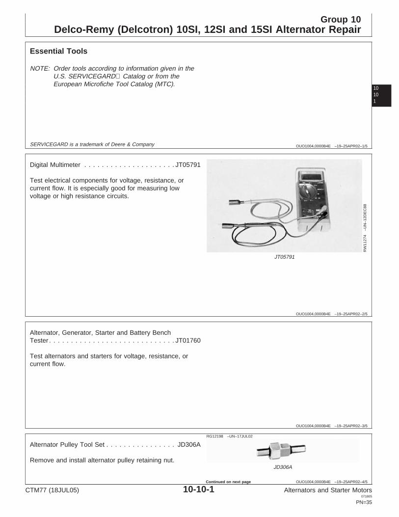
Digital Multimeter . . . . . . . . . . . . . . . . . . . . . JT05791
Test electrical components for voltage, resistance, orcurrent flow. It is especially good for measuring lowvoltage or high resistance circuits.
OUO1004,0000B4E –19–25APR02–3/5
Alternator, Generator, Starter and Battery BenchTester . . . . . . . . . . . . . . . . . . . . . . . . . . . . . JT01760
Test alternators and starters for voltage, resistance, orcurrent flow.
OUO1004,0000B4E –19–25APR02–4/5
RG12198 –UN–17JUL02
JD306A
Alternator Pulley Tool Set . . . . . . . . . . . . . . . . JD306A
Remove and install alternator pulley retaining nut.
CTM77 (18JUL05) 10-10-1 Alternators and Starter Motors071805
PN=35
Continued on next page

Delco-Remy (Delcotron) 10SI, 12SI and 15SI Alternator Repair
1010
2
OUO1004,0000B4E –19–25APR02–5/5
RG
1116
2–U
N–2
1SE
P00
D01045AA
Bushing, Bearing and Seal Driver Set . . . . . . D01045AA
Remove front bearing.
OUO1004,0000B50 –19–21SEP00–1/1
Other Material
Number Name Use
Delco-Remy Lubricant No. 1948791 Lubricate alternator bearings.
400-Grit Silicon Carbide Paper or 00 Polish slip rings.Sandpaper
OUO1004,0000B51 –19–21SEP00–1/1
Delco-Remy (Delcotron) 10SI, 12SI, and 15SICharging Circuit Repair Specifications
Item Measurement Specification
Delco-Remy Model 12SI Alternator Torque 100 N•m (75 lb-ft)Pulley Nut
Delco-Remy Model 10SI and 15SI Torque 80 N•m (60 lb-ft)Alternator Pulley Nut
CTM77 (18JUL05) 10-10-2 Alternators and Starter Motors071805
PN=36

Delco-Remy (Delcotron) 10SI, 12SI and 15SI Alternator Repair
10103
RG,RG34710,2031 –19–07JUL05–1/2
Delco-Remy (Delcotron) 10SI, 12SI, and 15SICharging Circuit Test Specifications
Field Current Rated (Hot) OutputCold Output
@27°C (80°F) at Rated Speed
JohnDeere Delcotron
Alternator AlternatorPart No. Model No. Series Type Amps Volts Amps RPM Amps RPM Amps
AR54793 1100490 10SI 106 4.0—4.5 12 25 2500 65 5000 72
AR54796 1104901 10SI 106 4.0—4.5 12 25 2000 51 5000 553022
AR56728 1102359 10SI 106 4.0—4.5 12 22 2000 33 5000 37
AR84305 1102926 10SI 116 4.0—5.0 12 30 2000 57 5000 61
AR84306 1102932 10SI 116 4.0—5.0 12 25 2000 65 5000 72
AR93445 1103124 10SI 116 4.0—5.0 12 30 2000 57 5000 61
AR93446 1103128 10SI 116 4.0—5.0 12 25 2000 65 5000 72
AT117390 1105539 15SI 116 4.0—5.0 12 56 2000 110 5000 105
AT130930 1101285 10SI 100 1.2—1.6 24 25 2600 41 7000 40
AT142267 10479850 12SI 100 4.0—5.0 12 51 2000 81 7000 78
AT157177 10480058 10SI 116 4.0—5.0 12 51 2000 81 7000 78
AT157178 10480060 10SI 116 1.2—1.6 24 25 2600 41 7000 40
AT58321 1102936 10SI 116 4.0—5.0 12 30 2000 57 5000 61
AT64718 1103131 10SI 116 4.0—5.0 12 28 2000 42 7000 42
RE13797 1105175 10SI 116 4.0—5.0 12 25 2000 65 5000 72
RE13966 1105068 10SI 116 4.0—5.0 12 30 2000 57 5000 61
RE17379 1105422 10SI 116 4.0—5.0 12 32 2000 60 5000 63
RE20034 1105510 10SI 116 4.0—5.0 24 25 2600 41 7000 40
RE27109 1101268 12SI 100 4.2—5.0 12 30 1600 75 6500 75
RE31694 1101345 12SI 100 4.2—5.0 12 30 1600 78 6500 78
RE501112 19009950 19SI — — 12 — — 110 — 105
Regulator Temperaturea Voltage
29°C (85°F) 13.8—14.9 volts
41°C (105°F) 13.6—14.7 volts
52°C (125°F) 13.4—14.6 volts
63°C (145°F) 13.2—14.4 voltsaMeasured 25.4 mm (1.0 in.) from regulator.
CTM77 (18JUL05) 10-10-3 Alternators and Starter Motors071805
PN=37
Continued on next page

Delco-Remy (Delcotron) 10SI, 12SI and 15SI Alternator Repair
1010
4
RG,RG34710,2031 –19–07JUL05–2/2
Stator Winding Field Resistance
37-amp, 12-volt 0.23 ohm
40-amp, 24-volt 0.23 ohm
42-amp, 12-volt 0.28 ohm
55-amp, 12-volt 0.20 ohm
61-amp, 12-volt 0.20 ohm
63-amp, 12-volt 0.20 ohm
72-amp, 12-volt 0.10 ohm
75-amp, 12-volt 0.10 ohm
78-amp, 12-volt 0.10 ohm
105-amp, 12-volt 0.10 ohm
130-amp, 12-volt 0.04 ohm
RG,RG34710,2032 –19–12SEP02–1/1
Remove Pulley Nut
RW
6036
–UN
–15D
EC
88
Remove Pulley Nut
A—15/16 in. SocketB—JD306A-1 Alternator Pulley Nut ToolC—JD306A-2 Alternator Pulley Nut Tool
NOTE: Pulley nut need not be removed if you are certainthat front bearing is in good condition. Separatehousing as described and leave rotor in fronthousing.
1. Install a 15/16 in. socket (A) on JD306A-1 AlternatorPulley Nut Tool (B) to hold nut.
2. Install JD306A-2 (C) on hex shaft of JD306A-1 to holdrotor shaft.
3. Hold rotor and remove nut.
CTM77 (18JUL05) 10-10-4 Alternators and Starter Motors071805
PN=38

Delco-Remy (Delcotron) 10SI, 12SI and 15SI Alternator Repair
10105
RG,RG34710,2033 –19–15MAR97–1/3
Separate Housing
RW
1065
7–U
N–1
6NO
V89
Separate Housing
A—WasherB—PulleyC—FanD—CollarE—Chalk markF—NutG—Through Bolts
1. Remove washer (A), pulley (B), fan (C), and collar (D).
2. Before separating, make a chalk mark (E) acrossseparation between front and rear housings foralignment when reassembling. Housings can beindexed any one of four ways.
RG,RG34710,2033 –19–15MAR97–2/3R
W60
11–U
N–2
2FE
B90
Separate Front and Rear Housing
A—Through Bolts (4 Used)
3. Remove four through bolts (A).
4. Separate front and rear housings. If necessary, prycarefully with two screwdrivers on opposite sides toforce housings apart.
Continued on next page
CTM77 (18JUL05) 10-10-5 Alternators and Starter Motors071805
PN=39

Delco-Remy (Delcotron) 10SI, 12SI and 15SI Alternator Repair
1010
6
RG,RG34710,2033 –19–15MAR97–3/3
RW
6012
–UN
–22F
EB
90
Lift Out Rotor
A—Alternator Rear HousingB—Alternator Front HousingC—Rotor
5. Set alternator on rear housing (A) and slide fronthousing (B) off. Lift out rotor (C).
6. Place a piece of masking tape over rear bearing tokeep trash out.
RG,RG34710,2034 –19–15MAR97–1/1
Remove Front Bearing
RW
6013
–UN
–22F
EB
90
Remove Bearing Retainer and BearingA—Bearing RetainerB—Bearing
Remove bearing retainer (A) and bearing (B).
NOTE: If bearing must be pressed in or out of housing,carefully support housing near bearing diameter.A 1-3/4 in. socket makes a suitable support. Usedisk No. 27494 from D01045AA Bushing DriverSet to press on inner diameter of bearing. Pressfrom outside to inside.
CTM77 (18JUL05) 10-10-6 Alternators and Starter Motors071805
PN=40

Delco-Remy (Delcotron) 10SI, 12SI and 15SI Alternator Repair
10107
RG,RG34710,2035 –19–12SEP02–1/2
Install Front Bearing
RW
6013
–UN
–22F
EB
90
Install Front BearingA—Bearing RetainerB—Bearing
Bearing may be reused if not damaged.
1. Clean bearing and fill it 1/4 full with Delco-RemyLubricant No. 1948791 before assembly. Do notoverfill.
NOTE: Lubrication is not required on sealed bearings.
2. Install bearing (B).
RG,RG34710,2035 –19–12SEP02–2/2R
W60
14–U
N–2
2FE
B90
Replace Retainer
A—Retainer PlateB—BearingC—Felt Seal
3. Fill cavity between retainer plate (A) and bearing (B)with Delco-Remy No. 1948791 Lubricant.
4. If felt seal (C) is hardened or worn, replace seal andretainer.
CTM77 (18JUL05) 10-10-7 Alternators and Starter Motors071805
PN=41

Delco-Remy (Delcotron) 10SI, 12SI and 15SI Alternator Repair
1010
8
RG,RG34710,2036 –19–18OCT00–1/1
Remove and Install Rear Bearing
RW
6015
–UN
–22F
EB
90
Rear Bearing
A—Rear BearingB—Support Housing
1. Replace rear bearing (A) if defective or its greasesupply is exhausted. Do not relubricate.
2. Support housing (B) near bearing diameter with a1-1/4 in. socket and press bearing to inside.
3. Press new bearing in until flush with housing.
NOTE: If seal is separate from bearing, install a new sealwhenever bearing is replaced. Install seal with lipof seal toward rotor when assembled. Coat seallip with oil when installing rotor shaft.
RG,RG34710,2038 –19–15MAR97–1/1
Test Rotor for Grounds
RW
6017
–UN
–10N
OV
88
Test Rotor for Grounds
A—OhmmeterB—Rotor ShaftC—Slip Ring
1. Use an ohmmeter (A) or test lamp to test for continuity.
2. Attach ohmmeter to rotor shaft (B) and each slip ring(C).
3. Replace rotor if test shows continuity.
CTM77 (18JUL05) 10-10-8 Alternators and Starter Motors071805
PN=42

Delco-Remy (Delcotron) 10SI, 12SI and 15SI Alternator Repair
10109
RG,RG34710,2039 –19–15MAR97–1/1
Test Rotor for Open Circuit
RW
6018
–UN
–10N
OV
88
Test Rotor for Open Circuit
A—OhmmeterB—Slip RingC—Slip Ring
1. Use ohmmeter (A) (or test lamp) to test for continuityfrom one slip ring (B) to the other (C).
2. If test does not show continuity, replace rotor.
RG,RG34710,2040 –19–18OCT00–1/1
Test Rotor for Short Circuit
RW
6019
–UN
–25A
PR
89
Test Rotor for Short Circuit
A—Slip RingB—12-Volt BatteryC—AmmeterD—Slip Ring
1. Connect slip ring (A) to one terminal of 12-volt battery(B).
2. Connect ammeter (C) to other terminal of battery andslip ring (D).
3. Current draw should be 4.0—4.5 amps at 12 volts.Excessive current draw indicates a short circuit.Replace rotor if current draw exceeds 5.0 amps.
CTM77 (18JUL05) 10-10-9 Alternators and Starter Motors071805
PN=43

Delco-Remy (Delcotron) 10SI, 12SI and 15SI Alternator Repair
101010
RG,RG34710,2041 –19–15MAR97–1/1
Repair Slip Rings
NOTE: Rough or out-of-round slip rings can cause shortbrush life.
1. Mount rotor assembly on plate.
2. If slip rings are rough or scored, turn them just enoughto eliminate roughness. If slip rings are out-of-round,turn them to within 0.005 mm (0.002 in.) of totalindicator reading.
3. Polish slip rings sparingly with No. 00 sandpaper or400-grit silicon carbide paper.
IMPORTANT: Clean rotor and stator with compressedair only. Cleaning solvent will damageinsulation.
RG,RG34710,2042 –19–15MAR97–1/1
Inspect Stator
RW
6020
–UN
–10N
OV
88
Inspect Stator
A—Stator
1. Inspect stator (A) for defective insulation.
2. Check for discoloration or a burned odor indicating ashort circuit.
3. Replace stator if you find any defect.
CTM77 (18JUL05) 10-10-10 Alternators and Starter Motors071805
PN=44

Delco-Remy (Delcotron) 10SI, 12SI and 15SI Alternator Repair
101011
RG,RG34710,2043 –19–15MAR97–1/1
Test Stator for Grounds
RW
1065
2–U
N–1
6NO
V89
Test Stator for Grounds
A—OhmmeterB—StatorC—Stator Frame
Connect an ohmmeter (A) (or test lamp) between eachstator (B) lead and stator frame (C). Replace stator if testindicates continuity.
NOTE: The stator cannot be tested for an open circuitunless terminals are disconnected from statorwindings.
RG,RG34710,2044 –19–15MAR97–1/1
Test Stator for Short Circuit
RW
6022
–UN
–25A
PR
89
Connect Ohmmeter Between Terminals
A—OhmmeterB—Terminals
A short-circuit in the stator can be difficult to identify. Usean ohmmeter that is sensitive to resistance of 0.0 to 1.0ohm.
Connect ohmmeter (A) between each pair of terminals(B). Resistance should be approximately 0.1 ohm.(Ohmmeter needle should deflect to zero if leads aretouched together.) If resistance is low, windings areshorted and must be replaced.
A stator will occasionally exhibit an open circuit or shortcircuit only when hot, making the defect even moredifficult to diagnose.
If a stator defect cannot be confirmed, re-check all othercomponents. If problem is not found elsewhere, replacestator.
CTM77 (18JUL05) 10-10-11 Alternators and Starter Motors071805
PN=45

Delco-Remy (Delcotron) 10SI, 12SI and 15SI Alternator Repair
101012
RG,RG34710,2045 –19–15MAR97–1/1
Test Brush Assembly for Grounds
RW
6023
–UN
–22F
EB
90
Test Brush Assembly for Grounds
A—Brush Contact from Diode TrioB—Brush Contact from RegulatorC—Test PointD—Test Point
A grounded brush assembly results in either no output oruncontrolled output, depending on where the ground islocated.
NOTE: A grounded brush assembly may also damage thediode trio. Before assembling alternator, checkdiode trio.
1. Check insulating washers on screws holding brushleads (A and B). Replace if necessary. If circuit isgrounded elsewhere, replace regulator.
2. Connect ohmmeter (or test lamp) between points (Band C) and between points (A and D). Replace brushassembly if either check shows no continuity.
RG,RG34710,2046 –19–15MAR97–1/2
Test Diode Trio
RW
6024
–UN
–22F
EB
90
Stator and Diode Trio
A—Stator and Diode Trio Attaching Nuts (4 Used)
1. Remove stator and diode trio attaching nuts (A). Noteposition of any insulating washers.
2. Remove diode trio, noting insulator position.
Continued on next page
CTM77 (18JUL05) 10-10-12 Alternators and Starter Motors071805
PN=46

Delco-Remy (Delcotron) 10SI, 12SI and 15SI Alternator Repair
101013
RG,RG34710,2046 –19–15MAR97–2/2
RW
6025
–UN
–22F
EB
90
Connect Ohmmeter
A—TerminalB—TerminalC—TerminalB—Terminal
3. Connect ohmmeter (or test lamp) to points (A and D).Check for continuity. Reverse leads and test forcontinuity between same points. A good diode trio willhave continuity only in one direction.
Repeat test between points (B and C) and (C and D).
Replace diode trio unless tests show continuity in onlyone direction in each case.
RG,RG34710,2047 –19–15MAR97–1/1
Test Rectifier Bridge
RW
6026
–UN
–22F
EB
90
Test Rectifier Bridge
A—Grounded Heat SinkB—TerminalC—TerminalD—TerminalE—Insulated Heat Sink
NOTE: Rectifier bridge has grounded heat sink (A) andinsulated heat sink (E).
Connect ohmmeter (or test lamp) to points A and B. Thenreverse leads between same two points. Continuity shouldbe in only one direction.
NOTE: On models 10-SI and 12-SI, connect ohmmeterlead to threaded stud of test points (B), (C), and(D). On all other models, connect ohmmeter bypressing down very firmly onto flat metalconnector, and not onto threaded stud.
RG,RG34710,2048 –19–15MAR97–1/1
Regulator Test
Regulator cannot be effectively tested. Replace regulatorif brush assembly tests indicate a failure.
CTM77 (18JUL05) 10-10-13 Alternators and Starter Motors071805
PN=47

Delco-Remy (Delcotron) 10SI, 12SI and 15SI Alternator Repair
101014
RG,RG34710,2049 –19–15MAR97–1/4
Assemble the Alternator
RW
6027
–UN
–22F
EB
90
Install Rectifier Bridge
A—Rectifier Bridge
1. Install rectifier bridge (A). Be sure insulating washersare in position.
RG,RG34710,2049 –19–15MAR97–2/4
RW
6028
–UN
–22F
EB
90
Install Brush Assembly and Diode Trio
A—Brush AssemblyB—Diode TrioC—Brush Assembly Insulating Screws (2 Used)
2. Install brush assembly (A) and diode trio (B). Be surebrush assembly insulating screws (C) are in position.
3. Push brushes back to clear slip rings. Insert a wirethrough hole in rear housing only far enough to holdbrushes back.
Continued on next page
CTM77 (18JUL05) 10-10-14 Alternators and Starter Motors071805
PN=48

Delco-Remy (Delcotron) 10SI, 12SI and 15SI Alternator Repair
101015
RG,RG34710,2049 –19–15MAR97–3/4
RW
6012
–UN
–22F
EB
90
Slip Rotor into Rear Housing
A—Rear HousingB—Front HousingC—Rotor
4. Remove tape over rear bearing and carefully slip rotor(C) into rear housing (A).
RG,RG34710,2049 –19–15MAR97–4/4
RW
1065
7–U
N–1
6NO
V89
Slip Front Housing Over Rotor Shaft
A—WasherB—PulleyC—FanD—CollarE—Chalk MarkF—NutG—Bolts
5. Carefully slip front housing over rotor shaft. Alignpreviously marked chalk mark (E).
6. Install four through bolts (G). Alternately tighten boltsuntil secure.
7. Remove wire from housing.
8. Install collar (D), fan (C), pulley (B), washer (A) and nut(F). Tighten pulley nut with JD306A Alternator PulleyTool to specifications.
SpecificationDelco-Remy Model 12SIAlternator Pulley Nut—Torque 100 N•m (75 lb-ft)......................................Delco-Remy Model 10SI and15SI Alternator Pulley Nut—Torque 80 N•m (60 lb-ft).............................................................................
.
CTM77 (18JUL05) 10-10-15 Alternators and Starter Motors071805
PN=49

Delco-Remy (Delcotron) 10SI, 12SI and 15SI Alternator Repair
101016
CTM77 (18JUL05) 10-10-16 Alternators and Starter Motors071805
PN=50

Group 15Delco-Remy (Delcotron) 21SI Alternator Repair
10151
OUO1004,0000B52 –19–21SEP00–1/3
Essential Tools
NOTE: Order tools according to information given in theU.S. SERVICEGARD Catalog or from theEuropean Microfiche Tool Catalog (MTC).
SERVICEGARD is a trademark of Deere & Company
OUO1004,0000B52 –19–21SEP00–2/3
RW
1127
4–U
N–1
2DE
C88
JT05791
Digital Multimeter . . . . . . . . . . . . . . . . . . . . . JT05791
Test electrical components for voltage, resistance, orcurrent flow. It is especially good for measuring lowvoltage or high resistance circuits.
OUO1004,0000B52 –19–21SEP00–3/3
Alternator, Generator, Starter and Battery BenchTester . . . . . . . . . . . . . . . . . . . . . . . . . . . . . JT01760
Test alternators and starters for voltage, resistance, orcurrent flow.
CTM77 (18JUL05) 10-15-1 Alternators and Starter Motors071805
PN=51

Delco-Remy (Delcotron) 21SI Alternator Repair
1015
2
OUO1004,0000BB1 –19–28SEP00–1/1
Delco-Remy (Delcotron) 21SI ChargingCircuit Repair Specifications
Item Measurement Specification
Delco-Remy Model 21SI Alternator Torque 100 N•m (75 lb-ft)Pulley Nut
Drive End Bearing Retainer Plate Torque 3.0 N•m (26 lb-in.)Cap Screws
Slip Ring End Housing Components
Inside Output Terminal Nut Torque 5.5 N•m (50 lb-in.)
Rectifier Bridge Attaching Screws Torque 3.0 N•m (25 lb-in.)
Capacitor Attaching Screw Torque 2.5 N•m (22 lb-in.)
“R” Terminal Nut Torque 2.5 N•m (22 lb-in.)
Regulator Mounting Screws Torque 2 N•m (20 lb-in.)
Regulator Mounting Nut Torque 2.5 N•m (22 lb-in.)
Brush Holder Pivot Attaching Torque 2 N•m (20 lb-in.)Screw
Stator Debris Shield Mounting Stud Torque 5.5 N•m (50 lb-in.)Nut
Rectifier Bridge Nuts Torque 2.5 N•m (22 lb-in.)
Drive End-to-Slip Ring End Housing Torque 5.5 N•m (50 lb-in.)Through Bolts
CTM77 (18JUL05) 10-15-2 Alternators and Starter Motors071805
PN=52

Delco-Remy (Delcotron) 21SI Alternator Repair
10153
RG,RG34710,2052 –19–07JUL05–1/1
Delco-Remy (Delcotron) 21SI ChargingCircuit Test Specifications
Field Current Cold Output Rated (Hot)@ 27°C (80°F) Output at
Rated Speed
John Deere Delcotron Amps Volts Amps RPM Amps RPM AmpsAlternator Alternator AlternatorModel No. Model No. Series Type
AT142246 1117909 21SI 355 6.7—7.1 12 50 1600 130 5000 130
Regulator Temperaturea Voltage
29°C (85°F) 13.8—14.9 volts
41°C (105°F) 13.6—14.7 volts
52°C (125°F) 13.4—14.6 volts
63°C (145°F) 13.2—14.4 voltsaMeasured 25.4 mm (1.0 in.) from regulator.
Stator Winding Field Resistance
130-amp, 12-volt 0.04 ohm
CTM77 (18JUL05) 10-15-3 Alternators and Starter Motors071805
PN=53

Delco-Remy (Delcotron) 21SI Alternator Repair
1015
4
RG,RG34710,2053 –19–15MAR97–1/1
Disassemble Delco-Remy 21SI Alternator
RG
6994
–UN
–30N
OV
93
Delco-Remy 21SI Alternator
1—Slip Ring End Housing 12—Regulator Stud Connector 22—Pulley 29—Regulator Attaching2—Slip Ring End Bearing 13—“I” Terminal Connector 23—Regulator Nut Screw (Insulated)3—Rotor Assembly 14—Capacitor 24—Rectifier Bridge Nut 30—Capacitor Attaching Screw4—Stator Assembly 15—Brush Holder Assembly 25—Shaft Nut 31—Bearing Retainer Plate5—Drive End Frame 16—Brush and Arm 26—Rectifier Bridge Attaching Screw6—Drive End Bearing 17—Drive End Retainer Plate Nut/Washer Assembly 32—Slip Ring End Frame7—Rectifier Bridge Assembly 18—Hinge Bushing 27—Brush Holder Attaching Ground Screw and Load8—Diode Trio 19—Regulator Terminal Cover Screw (Pivot) Washer9—Regulator 20—Terminal Cap 28—Regulator Attaching 33—Shaft Nut Washer10—BAT Terminal Assembly 21—Fan Screw (Ground) 34—Through Bolt11—“I” Terminal Assembly
CTM77 (18JUL05) 10-15-4 Alternators and Starter Motors071805
PN=54

Delco-Remy (Delcotron) 21SI Alternator Repair
10155
RG,RG34710,2054 –19–15MAR97–1/2
Disassemble Alternator
RG
6971
–UN
–30N
OV
93
Alignment Mark
A—Slip Ring End HousingB—Stator HousingC—Drive End Frame
1. Place alignment mark across slip ring end housing (A),stator housing (B), and drive end frame (C) forassembly after repair.
RG,RG34710,2054 –19–15MAR97–2/2R
G69
72–U
N–3
0NO
V93
Disassemble Alternator
A—Through BoltsB—Drive End FrameC—Slip Ring End HousingD—Screwdriver
2. Remove four through bolts (A).
3. Separate drive end frame (B) (with rotor) from slip ringend housing (C) (with stator). If necessary, carefullypry drive end frame from edge of stator withscrewdriver (D). After separation, place tape over slipring end housing bearing inside unit to prevent dirtfrom entering bearing.
CTM77 (18JUL05) 10-15-5 Alternators and Starter Motors071805
PN=55

Delco-Remy (Delcotron) 21SI Alternator Repair
1015
6
RG,RG34710,2055 –19–18OCT00–1/7
Slip Ring End Housing and Components
RG
6973
–UN
–30N
OV
93
Slip Ring End Housing and Components
A—Slip Ring End HousingB—Rectifier Bridge NutsC—StatorD—Screwdriver
1. Inspect slip ring end housing (A) for loose connectionsor other obvious conditions. Correct as necessary. Ifnone are found, proceed with slip ring end housingchecks which follow.
2. Remove three rectifier bridge nuts (B) to disconnectstator (C). If necessary, carefully pry stator (C) awayfrom slip ring end housing (A) with a screwdriver (D).
3. Inspect stator windings for dark, burned appearance.View windings from inside of unit; black paint onoutside of windings does not indicate burned windings.
If all windings are uniform in color and varnish coveringis not flaking off, proceed with electrical check, step 4below.
If some windings are dark and others are light, ashorted, open, or grounded condition is indicated.Replace the stator. The stator should also be replacedif the windings are uniformly dark and burned, with thevarnish flaking off to expose bare wires.
Continued on next page
CTM77 (18JUL05) 10-15-6 Alternators and Starter Motors071805
PN=56

Delco-Remy (Delcotron) 21SI Alternator Repair
10157
RG,RG34710,2055 –19–18OCT00–2/7
RG
6974
–UN
–30N
OV
93
Stator Leads and LaminationsA—Stator LeadsB—Stator Laminations
4. Perform electrical check on stator. Use digitalmultimeter on ohms setting (or a 110-volt test lamp).There should be no continuity between any of thestator leads (A) and the stator laminations (B).
If continuity is present, windings are grounded.Replace stator.
If there is no continuity, stator is probably good.However, there is no service electrical check forshorted or open delta stator windings. If all otherelectrical checks are normal and the generator did notproduce within 15 amps of the rated output, a shortedor open stator is indicated and the stator should bereplaced.
RG,RG34710,2055 –19–18OCT00–3/7
RG
6975
–UN
–30N
OV
93
Check Continuity
A—Insulated Regulator ScrewsB—Diode TrioC—Regulator StrapD—Rectifier Bridge Straps
5. Remove insulated regulator attaching screw (A) todisconnect diode trio (B). Lift diode trio from slip ringend housing assembly.
6. Place the negative ohmmeter lead on regulator strap(C) and use positive ohmmeter lead to check forcontinuity to each of the three rectifier bridge straps. Allthree readings should indicate continuity. Reverse theohmmeter leads and perform the checks again.Readings should all indicate open circuits.
If all readings are proper, diode trio is good.
If any reading is wrong, replace the diode trio.
CTM77 (18JUL05) 10-15-7 Alternators and Starter Motors071805
PN=57
Continued on next page

Delco-Remy (Delcotron) 21SI Alternator Repair
1015
8
RG,RG34710,2055 –19–18OCT00–4/7
RG
6976
–UN
–30N
OV
93
Check Rectifier Bridge
A—Grounded Heat SinkB—Metal Diode ClipsC—Insulated (Positive) Heat Sink
7. Use the digital multimeter to check the rectifier bridge.Rectifier bridge may also be checked while installed inthe slip ring end housing. Check rectifier bridge asfollows:
Place negative ohmmeter lead on grounded heat sink(A). Touch positive ohmmeter lead firmly to metaldiode clips (B) that surround each of the threethreaded studs. All three readings should be the sameand indicate open circuits. Reverse the ohmmeterleads and perform the checks again. All three readingsshould indicate continuity.
Repeat checks using insulated (positive) heat sink (C)in place of grounded heat sink. With negativeohmmeter lead on insulated heat sink (C), all threereadings should indicate continuity. Reverse theohmmeter leads and perform the checks again.Readings should all indicate open circuits.
If readings are good, the rectifier bridge is good.
If any reading is wrong, an open or shorted diode isindicated and the rectifier bridge should be replaced.
Continued on next page
CTM77 (18JUL05) 10-15-8 Alternators and Starter Motors071805
PN=58

Delco-Remy (Delcotron) 21SI Alternator Repair
10159
RG,RG34710,2055 –19–18OCT00–5/7
RG
6977
–UN
–30N
OV
93
Remove Rectifier Bridge
A—BAT Terminal NutB—Regulator NutC—Regulator Stud ConnectorD—Relay Terminal NutE—Relay Terminal ConnectorF—Bridge Attaching ScrewsG—Capacitor Attaching ScrewH—CapacitorI—Rectifier Bridge
8. To remove rectifier bridge, remove inside BAT terminalnut (A), regulator nut (B) and regulator stud connector(C) from regulator stud. Remove inside “R” (relay)terminal nut (D) and relay terminal connector (E) (ifused), two bridge attaching screws (F), and insulatedcapacitor attaching screw (G). Lift capacitor (H) andrectifier bridge (I) from slip ring end housing.
Continued on next page
CTM77 (18JUL05) 10-15-9 Alternators and Starter Motors071805
PN=59

Delco-Remy (Delcotron) 21SI Alternator Repair
101510
RG,RG34710,2055 –19–18OCT00–6/7
RG
6978
–UN
–30N
OV
93
Brush Holder Assembly
A—BrushB—Brush PinC—Regulator Attaching ScrewsD—Regulator Stud ConnectorE—Inside “I” Terminal NutF—“I” Terminal ConnectorG—Brush Holder PivotH—Brush Holder AssemblyI—Brush Lead ClipJ—SpacerK—Brush SpringsL—RegulatorM—Regulator Attaching Screw
9. Brush holder assembly must be removed to servicebrushes or regulator. Hold brushes (A) in retractedposition and insert brush pin (B) to keep brushes inretracted position. Remove insulated regulatorattaching screws (C). Remove regulator nut and studconnector (D) (if used). Loosen or remove inside “I”terminal nut (E) to move “I” terminal connector (F) (ifused) as necessary for clearance. Finally, removebrush holder pivot screw (G). Lift brush holderassembly (H) from housing without bending regulatorconnector from diode trio or “I” terminal connector.
10. Check brushes and leads for excessive wear,breakage, etc. If necessary to replace, note routing oflead wires and position of brush lead clips (I) for laterassembly. (Brushes are identical but leads and clipsare positioned differently.) Carefully remove brush pin(B) to release brushes (A). Remove brushes andspacer (J) one at a time, placing fingers aroundsprings (K) to prevent loss. It may be necessary tospread the brush lead clips slightly to disengageretaining tabs.
11. If previous checks lead to an instruction to replace theregulator (L), replace it. Remove remaining regulatorattaching (ground) screw (M).
Continued on next page
CTM77 (18JUL05) 10-15-10 Alternators and Starter Motors071805
PN=60

Delco-Remy (Delcotron) 21SI Alternator Repair
101511
RG,RG34710,2055 –19–18OCT00–7/7
RG
6979
–UN
–30N
OV
93
Check Bearing
A—Slip Ring End HousingB—Slip Ring End BearingC—TubeD—Hammer
12. Remove protective tape and check bearing (B) in slipring end housing (A). If bearing is dry or damaged,replace bearing.
NOTE: Bearings are permanently lubricated. Do not addgrease.
To remove bearing, use tube (C) slightly smaller thanopening in slip ring end housing and drive bearingthrough to inside of housing.
NOTE: If bearing is being replaced without removingbrushes from slip ring end housing, use brush pinto hold brushes in retracted position while bearingis removed.
13. Place tape over bearing until reassembly of alternator.
RG,RG34710,2056 –19–15MAR97–1/2
Drive End Frame and Components
RG
6980
–UN
–30N
OV
93
Drive End Frame and Components
A—Slip RingsB—Rotor FrameC—Rotor ShaftD—Drive End Frame
1. Use digital multimeter to check rotor field resistance.Place ohmmeter leads on two slip rings (A) on therotor shaft to make this check. Proper resistance is0.04 ohm.
Also check for a grounded field by touching one lead toa slip ring and one lead to rotor frame (B) or shaft (C).Reading should be infinite (open) to show that field isnot grounded.
If field resistance is outside specifications, or if field isgrounded, replace rotor as described in the followingsteps.
2. Hold drive end frame (D) and spin rotor by hand to seethat it spins freely in ball bearing. If bearing movementis rough or loose, replace bearing in drive end frameas described in the following steps.
NOTE: Bearing is permanently lubricated. Do not addgrease.
CTM77 (18JUL05) 10-15-11 Alternators and Starter Motors071805
PN=61
Continued on next page
Delco-Remy (Delcotron) 21SI Alternator Repair
101512
RG,RG34710,2056 –19–15MAR97–2/2
RG
6981
–UN
–30N
OV
93
Inspect Bearing
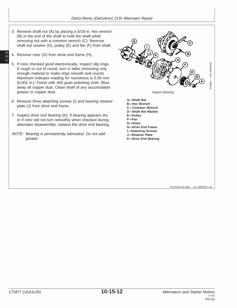
A—Shaft NutB—Hex WrenchC—Common WrenchD—Shaft Nut WasherE—PulleyF—FanG—RotorH—Drive End FrameI—Attaching ScrewsJ—Retainer PlateK—Drive End Bearing
3. Remove shaft nut (A) by placing a 5/16-in. hex wrench(B) in the end of the shaft to hold the shaft whileremoving nut with a common wrench (C). Removeshaft nut washer (D), pulley (E) and fan (F) from shaft.
4. Remove rotor (G) from drive end frame (H).
5. If rotor checked good electronically, inspect slip rings.If rough or out of round, turn in lathe (removing onlyenough material to make rings smooth and round).Maximum indicator reading for roundness is 0.05 mm(0.002 in.). Finish with 400 grain polishing cloth. Blowaway all copper dust. Clean shaft of any accumulatedgrease or copper dust.
6. Remove three attaching screws (I) and bearing retainerplate (J) from drive end frame.
7. Inspect drive end bearing (K). If bearing appears dry,or if rotor did not turn smoothly when checked duringalternator disassembly, replace the drive end bearing.
NOTE: Bearing is permanently lubricated. Do not addgrease.
CTM77 (18JUL05) 10-15-12 Alternators and Starter Motors071805
PN=62

Delco-Remy (Delcotron) 21SI Alternator Repair
101513
RG,RG34710,2057 –19–15MAR97–1/1
Assemble Alternator
RG
6981
–UN
–30N
OV
93
Alternator Components
A—Shaft NutB—Hex WrenchC—Common WrenchD—Shaft Nut WasherE—PulleyF—FanG—RotorH—Drive End FrameI—Attaching ScrewsJ—Retainer PlateK—Drive End Bearing
1. Install drive end bearing (K) and bearing retainer plate(J) on drive end frame (H) with three attaching screws(I). Tighten attaching screws to specifications.
SpecificationDrive End Bearing Retainer PlateCap Screws—Torque 3.0 N•m (26 lb-in.)....................................................
2. Install rotor shaft (G) into drive end bearing.
3. Install fan (F), pulley (E) and shaft nut washer (D) andshaft nut (A) onto rotor shaft. Hold rotor shaft with5/16-inch hex wrench (B) and tighten shaft nut withcommon wrench (C). Tighten shaft nut tospecifications.
SpecificationDelco-Remy Model 21SIAlternator Pulley Nut—Torque 100 N•m (75 lb-ft)......................................
RG,RG34710,2058 –19–06MAY02–1/10
Slip Ring End Housing Assembly
RG
6982
–UN
–30N
OV
93
Slip Ring End Housing Assembly
A—Slip Ring End BearingB—Slip Ring End HousingC—Tube
1. Install slip ring end bearing (A) into slip ring endhousing (B) using appropriate size tube (C). Installbearing flush with outside lip of housing. Coveropening in bearing with tape to prevent entry of dirt.
CTM77 (18JUL05) 10-15-13 Alternators and Starter Motors071805
PN=63
Continued on next page

Delco-Remy (Delcotron) 21SI Alternator Repair
101514
RG,RG34710,2058 –19–06MAY02–2/10
RG
6983
–UN
–30N
OV
93
Install Rectifier Bridge Assembly
A—Rectifier Bridge AssemblyB—Slip Ring End HousingC—Rectifier Bridge Attaching Screw
2. Install rectifier bridge assembly (A) in slip ring endhousing (B). Install one rectifier bridge attaching screw(C) through grounded heat sink portion of rectifierbridge as shown. Tighten attaching screw finger-tight.
RG,RG34710,2058 –19–06MAY02–3/10
RG
6984
–UN
–30N
OV
93
Install Terminal Connectors
A—“R” TerminalB—Slip Ring End HousingC—Insulating WasherD—“R” Terminal ConnectorE—Rectifier Bridge StudF—Inside Nut/Washer Assembly
NOTE: Shape of “R” terminal connector determineslocation of “R” terminal in slip ring end housing.
3. Install relay “R” terminal (A) in slip ring end housing(B). Place inside insulating washer (C) over “R”terminal stud. Place “R” terminal connector (D) overrectifier bridge stud (E) and “R” terminal stud.
NOTE: Be sure inside insulating washer is betweenconnector and slip ring end housing at terminalend. Connector must not touch housing. Also besure outside insulator is centered in hole toensure that terminal stud cannot touch housing.
4. Install inside nut/washer assembly (F) on “R” terminalstud. Tighten inside nut/washer assembly tospecifications.
Specification“R” Terminal Stud Nut—Torque 2.5 N•m (22 lb-in.)....................................
Continued on next page
CTM77 (18JUL05) 10-15-14 Alternators and Starter Motors071805
PN=64

Delco-Remy (Delcotron) 21SI Alternator Repair
101515
RG,RG34710,2058 –19–06MAY02–4/10
RG
6985
–UN
–30N
OV
93
Slip Ring End Housing
A—Output (BAT) TerminalB—Slip Ring End HousingC—Inside (BAT) Terminal Nut/Washer AssemblyD—CapacitorE—Rectifier Bridge Attaching Screw (Ground)F—Capacitor Attaching Screw (Insulated)
5. Install output (BAT) terminal (A) on slip ring endhousing (B). Be sure to seat square insulator flange inhole.
6. Install inside (BAT) terminal nut/washer assembly (C)on terminal stud and tighten finger-tight.
7. Position capacitor over holes in rectifier bridge andinstall rectifier bridge attaching screw (E) throughcapacitor connector and grounded heat sink into slipring end housing. Tighten screw finger-tight.
8. Install insulated capacitor attaching screw (F) throughcapacitor connector and insulated heat sink into slipring end housing. Tighten screw finger-tight.
RG,RG34710,2058 –19–06MAY02–5/10
RG
6986
–UN
–30N
OV
93
Install Regulator
A—Voltage RegulatorB—Slip Ring End HousingC—Voltage Regulator Attaching Screw
IMPORTANT: Do not immerse or wipe regulator withsolvent. Internal damage to regulatorcould result.
9. Before installing voltage regulator, be sure regulatorand regulator mounting bosses in slip ring end housingare free of all dirt and grease. Wipe all contact areaswith a clean, dry cloth.
10. Install regulator (A) to slip ring end housing (B) withregulator attaching screw (C) (ground). Tighten screwfinger-tight.
Continued on next page
CTM77 (18JUL05) 10-15-15 Alternators and Starter Motors071805
PN=65

Delco-Remy (Delcotron) 21SI Alternator Repair
101516
RG,RG34710,2058 –19–06MAY02–6/10
RG
6987
–UN
–30N
OV
93
Install Brushes, Springs and Spacer
A—Brush (with Arm)B—Brush SpringC—SpacerD—Brush HolderE—Brush Contact ClipF—Brush Pin
11. Install brushes (A), springs (B) and spacer (C) onbrush holder (D).
NOTE: Brushes are identical, but brush leads and contactclips (E) are positioned differently.
12. Pin brushes in retracted position with brush pin (F).
RG,RG34710,2058 –19–06MAY02–7/10
RG
6988
–UN
–30N
OV
93
Position Brush Holder AssemblyA—Brush PinB—Brush Holder AssemblyC—RegulatorD—Slip Ring End HousingE—Brush Holder Attaching (Pivot) ScrewF—Regulator Attaching Screw (Insulated)G—Diode TrioH—Rectifier Bridge
13. With brushes pinned in retracted position, positionbrush holder assembly (B) over holes in regulator (C)and slip ring end housing (D). Install brush holderattaching (pivot) screw (E) and one insulatedregulator attaching screw (F). Tighten both screwsfinger-tight.
NOTE: Brush pin (A) must remain in place until finalassembly.
Ensure that contact surfaces of brushes are freeof grease and dirt.
14. Install diode trio (G) onto three threaded studs onrectifier bridge assembly (H). Position long connectorstrap on diode trio over mounting hole in brush holderand regulator.
CTM77 (18JUL05) 10-15-16 Alternators and Starter Motors071805
PN=66
Continued on next page

Delco-Remy (Delcotron) 21SI Alternator Repair
101517
RG,RG34710,2058 –19–06MAY02–8/10
RG
6989
–UN
–30N
OV
93
BAT Terminal
A—Inside BAT Terminal Nut/Washer AssemblyB—Regulator Stud ConnectorC—Regulator StudD—BAT Terminal StudE—Regulator Stud Nut/Washer AssemblyF—“I” Terminal with Outside InsulatorG—Inside InsulatorH—“I” Terminal ConnectorI—Inside “I” Terminal Nut/Washer AssemblyJ—Diode Trio ConnectorK—Regulator Attaching Screw (Insulated)
15. Hold outside BAT terminal and temporarily removethe inside BAT terminal nut/washer assembly (A).Install regulator stud connector (B) to threadedregulator stud (C) and to inside BAT terminal stud(D). Reinstall inside BAT terminal nut/washerassembly (A) and install regulator nut/washerassembly (E) to regulator stud. Tighten two nutsfinger-tight.
16. Install “I” terminal with outside insulator (F) (if used) toslip ring end housing and hold in place. Install insideinsulator (G) and “I” terminal connector (H) over “I”terminal stud inside housing. Position other end of “I”terminal connector over mounting hole in brushholder. Install “I” terminal nut/washer assembly (I)onto “I” terminal stud. Tighten nut finger-tight.
17. Install insulated regulator attaching screw (K) tomounting hole in brush holder, passing through diodetrio connector (J) and “I” terminal connector (if used).Tighten screw finger-tight.
Continued on next page
CTM77 (18JUL05) 10-15-17 Alternators and Starter Motors071805
PN=67

Delco-Remy (Delcotron) 21SI Alternator Repair
101518
RG,RG34710,2058 –19–06MAY02–9/10
RG
6990
–UN
–30N
OV
93
Slip Ring End Housing Components
A—Inside Output Terminal NutB—Rectifier Bridge Attaching ScrewsC—Insulated Capacitor Attaching ScrewD—“R” Terminal NutE—Regulator Mounting ScrewF—Insulated Regulator Nut (If Used)G—Regulator NutH—Brush Holder Attaching (Pivot) Screw
18. Tighten the slip ring end housing components in thefollowing order to specifications listed below:
a. Inside output terminal nut (A).
b. Rectifier bridge attaching screws (B).
c. Insulated capacitor attaching screw (C).
d. “R” terminal nut (D). It may be necessary to holdterminal on outside while tightening.
e. Regulator mounting screw (E).
f. Insulated regulator attaching screw.
g. Regulator nut (G) (if used).
h. Brush holder attaching (pivot) screw (H).
Slip Ring End Housing Components—SpecificationInside Output Terminal Nut (A)—Torque 5.5 N•m (50 lb-in.)...........................................................................Rectifier Bridge Attaching Screws(B)—Torque 3.0 N•m (25 lb-in.)...................................................................Capacitor Attaching Screw (C)—Torque 2.5 N•m (22 lb-in.)...........................................................................“R” Terminal Nut (D)—Torque 2.5 N•m (22 lb-in.).......................................Regulator Mounting Screws (E)—Torque 2 N•m (20 lb-in.)..............................................................................Regulator Mounting Nut (G)—Torque 2.5 N•m (22 lb-in.)...........................................................................Brush Holder Pivot AttachingScrew (H)—Torque 2 N•m (20 lb-in.)...........................................................
Continued on next page
CTM77 (18JUL05) 10-15-18 Alternators and Starter Motors071805
PN=68

Delco-Remy (Delcotron) 21SI Alternator Repair
101519
RG,RG34710,2058 –19–06MAY02–10/10
RG
6991
–UN
–30N
OV
93
Install Components on Housing
A—StatorB—Slip Ring End HousingC—Phase LeadsD—Threaded Studs on Rectifier BridgeE—Rectifier Bridge Nuts
19. If used, install debris shield mounting stud in slip ringend housing with inside washer to “I” terminal hole inhousing. Install outside washer, lock washer andmounting stud on outside of housing. Tighten nut tospecifications.
SpecificationStator Debris Shield MountingStud Nut—Torque 5.5 N•m (50 lb-in.).........................................................
20. Install stator (A) in slip ring end housing (B), placingthree phase leads (C) over threaded studs (D) onrectifier bridge. Be sure stator is seated in registeraround edge of slip ring end housing.
21. Install rectifier bridge nuts on threaded studs. Tightennuts to specifications.
SpecificationRectifier Bridge Nuts—Torque 2.5 N•m (22 lb-in.)......................................
RG,RG34710,2059 –19–15MAR97–1/2
Final Assembly
RG
6992
–UN
–30N
OV
93
Final Assembly
A—Drive End Frame AssemblyB—Slip Ring End Housing AssemblyC—Alignment MarksD—Through Bolts
1. Assemble drive end frame assembly (A) and slip ringend housing assembly (B) using alignment marks (C)to ensure proper alignment to parts. Install four throughbolts (D) and tighten bolts to specifications.
SpecificationDrive End-to-Slip Ring EndHousing Through Bolts—Torque 5.5 N•m (50 lb-in.)...................................
Continued on next page
CTM77 (18JUL05) 10-15-19 Alternators and Starter Motors071805
PN=69

Delco-Remy (Delcotron) 21SI Alternator Repair
101520
RG,RG34710,2059 –19–15MAR97–2/2
RG
6993
–UN
–30N
OV
93
Remove Brush Pin
A—Brush PinB—Slip Ring End Housing
2. Remove brush pin (A) from slip ring end housing (B) torelease brushes onto slip rings inside unit.
CTM77 (18JUL05) 10-15-20 Alternators and Starter Motors071805
PN=70

Section 15Motorola Alternators
Contents
Page Page
Group 05—Motorola Alternator Theory of Operation Motorola SA-Series Charging Circuit Repair15Motorola Alternator Operation . . . . . . . . . . . . . .15-05-1 Specifications. . . . . . . . . . . . . . . . . . . . . . . . .15-25-2
Motorola Regulator Operation . . . . . . . . . . . . . .15-05-2 Motorola SA-Series Charging Circuit TestSpecifications. . . . . . . . . . . . . . . . . . . . . . . . .15-25-3
Remove Alternator for Repair . . . . . . . . . . . . . .15-25-3Group 10—Motorola 8E-Series Alternator RepairDisassemble and Test Motorola SA-SeriesEssential Tools . . . . . . . . . . . . . . . . . . . . . . . . .15-10-1
Alternator . . . . . . . . . . . . . . . . . . . . . . . . . . . .15-25-4Motorola 8E-Series Charging Circuit RepairAssemble Motorola SA-Series Alternator. . . . .15-25-14Specifications. . . . . . . . . . . . . . . . . . . . . . . . .15-10-2
Motorola 8E-Series Charging Circuit TestGroup 30—Motorola TA-Series Alternator RepairSpecifications. . . . . . . . . . . . . . . . . . . . . . . . .15-10-2Essential Tools . . . . . . . . . . . . . . . . . . . . . . . . .15-30-1General Information. . . . . . . . . . . . . . . . . . . . . .15-10-3Service Equipment and Tools . . . . . . . . . . . . . .15-30-2Remove Alternator for Repair . . . . . . . . . . . . . .15-10-3Motorola TA-Series Charging Circuit RepairDisassemble and Test Motorola 8E-Series
Specifications. . . . . . . . . . . . . . . . . . . . . . . . .15-30-3(12-Volt, 65 Amp) Alternator . . . . . . . . . . . . .15-10-4Motorola TA-Series Charging Circuit TestAssemble Motorola 8E-Series
Specifications. . . . . . . . . . . . . . . . . . . . . . . . .15-30-3(12-Volt, 65 Amp) Alternator . . . . . . . . . . . . .15-10-8Remove Alternator for Repair . . . . . . . . . . . . . .15-30-4Disassemble and Test Motorola TA-Series
Group 15—Motorola HC-, MA-, MR-Series Alternator . . . . . . . . . . . . . . . . . . . . . . . . . . . .15-30-4Alternator Repair Assemble Motorola TA-Series Alternator . . . . .15-30-14
Essential Tools . . . . . . . . . . . . . . . . . . . . . . . . .15-15-1Service Equipment and Tools . . . . . . . . . . . . . .15-15-2Motorola HC-, MA-, MR-Series Charging
Circuit Repair Specifications . . . . . . . . . . . . .15-15-2Motorola HC-, MA-, MR-Series Charging
Circuit Test Specifications . . . . . . . . . . . . . . .15-15-3Disassemble and Test Motorola HC-, MA-,
MR-Series Alternator . . . . . . . . . . . . . . . . . . .15-15-4Assemble Motorola HC-, MA-, MR-Series
Alternator . . . . . . . . . . . . . . . . . . . . . . . . . . .15-15-20
Group 20—Motorola A-, RA-, 8AR-Series AlternatorRepair
Essential Tools . . . . . . . . . . . . . . . . . . . . . . . . .15-20-1Motorola A-, RA-, 8AR-Series Charging
Circuit Repair Specifications . . . . . . . . . . . . .15-20-2Motorola A-, RA-, 8AR-Series Charging
Circuit Test Specifications . . . . . . . . . . . . . . .15-20-2Disassemble and Test Motorola A-, RA-,
8AR-Series Alternator . . . . . . . . . . . . . . . . . .15-20-3Assemble Motorola A-, RA-, 8AR-Series
Alternator . . . . . . . . . . . . . . . . . . . . . . . . . . .15-20-11
Group 25—Motorola SA-Series Alternator RepairEssential Tools . . . . . . . . . . . . . . . . . . . . . . . . .15-25-1Other Material . . . . . . . . . . . . . . . . . . . . . . . . . .15-25-2
CTM77 (18JUL05) 15-1 Alternators and Starter Motors071805
PN=1

Contents
15
CTM77 (18JUL05) 15-2 Alternators and Starter Motors071805
PN=2

Group 05Motorola Alternator Theory of Operation
15051
RG,RG34710,2060 –19–15MAR97–1/1
Motorola Alternator Operation
T52
184
–UN
–31M
AY
89
Motorola Alternator Operation
1—Stator2—Rotor Winding (Field)3—Rotor Slip Ring4—Brushes5—Regulator Terminal6—Output Terminal7—Isolation Diode8—Regulator
In an alternator, the magnetic field of the rotor is movedacross stationary conductors in the stator. This permitspermanent connection between the stator windings andthe output terminal. Slip rings are used to transmit thefield current to the rotor field winding.
The alternator produces power in the form of three-phasealternating current and voltage. The alternating current isrectified to direct current by a three-phase full-waverectifier circuit using six silicon rectifier diodes. Since thediode will pass current in only one direction (fromalternator to battery or load), the alternator does notrequire the use of cutout relay.
The entire DC output of the system passes through theisolation diode. This provides the system with severaldistinct advantages. It prevents the battery fromdischarging through the regulator and alternator fieldwithout the use of relays or switches. Electrically, theindicator lamp is connected across the isolation diode.When the system is operating properly, the alternatoroutput voltage is very nearly the same as the batteryvoltage. This means that the voltage potential across theisolation diode is low and the indicator lamp shows thatthe alternator is charging.
The alternator output current is controlled by the currentflow through the field coil (rotor). The amount of currentrequired is determined and controlled by the regulator.Since there is very little residual magnetism in thealternator, it is necessary to supply a small amount ofexcitation current to the field (rotor) to start the process ofcurrent generation. The excitation resistor supplies thisstarting current when the key switch is turned on. Thisresistor is enclosed in the sealed regulator case. Once thealternator is excited, a voltage is developed at theregulator terminal and the voltage regulator takes overcontrol of the system voltage.
CTM77 (18JUL05) 15-05-1 Alternators and Starter Motors071805
PN=73

Motorola Alternator Theory of Operation
1505
2
RG,RG34710,2061 –19–06MAY02–1/5
Motorola Regulator Operation
T51
537
–UN
–02J
UN
89
Motorola Regulator Operation
1—Thermistor (RT)2—Field Discharge Diode3—Transistor (T-2)4—Transistor (T-1)5—Zener Diode6—Excitation Resistor7—To Alternator Indicator Light
The transistor regulator is an electronic switching devicecomposed principally of transistors, resistors, and diodesto form a completely static unit containing no movingparts.
The transistors are used to switch the alternator fieldcurrent on and off, and are controlled by the resistors andthe Zener diode.
A Zener diode is a special diode that will break down andpermit a reverse flow of current when the voltage reachesa certain value, without damaging the semiconductormaterial. This diode is the trigger which senses themaximum desired voltage and turns the transistor on oroff to limit charging system voltage.
The field discharge diode provides an alternator currentpath to protect the transistors from induced high voltagefrom the alternator field windings. The sudden stopping offield current by the transistor and subsequent collapsing ofthe magnetic field causes an induced voltage in the rotorwindings.
The thermistor (RT) is a temperature compensatingresistor. Its resistance varies with temperature andcontrols the operating point of the Zener diode so that ahigh system voltage is produced in cold weather, whenneeded, and a lower system voltage in warm weather.
When the voltage appearing at the output terminal of thealternator rises to a predetermined value (14.4 volts), thevoltage which appears across the Zener diode conducts.This conduction of the Zener diode permits current to flowin the base of transistor T-1. This causes transistor T-1 toturn on and reverse bias transistor T-2, thus turning offthe current applied to the alternator field.
When the system voltage drops below the predeterminedvalue, the Zener diode stops conducting, T-1 turns off andT-2 turns on. When transistor T-2 is switched on, fieldcurrent again is supplied to the alternator.
CTM77 (18JUL05) 15-05-2 Alternators and Starter Motors071805
PN=74
Continued on next page

Motorola Alternator Theory of Operation
15053RG,RG34710,2061 –19–06MAY02–2/5
The operation of transistor T-2 is in effect like a switch,turning the alternator field current on and off as theelectrical supply varies due to the varying electrical load.This action occurs many times a second, so fast it cannotbe detected in the alternator output.
The solid-state regulator is either mounted on rear ofalternator or mounted internally. It controls output bycontrolling current through field. In operation, regulatorhas the following three phases.
Continued on next page
CTM77 (18JUL05) 15-05-3 Alternators and Starter Motors071805
PN=75

Motorola Alternator Theory of Operation
1505
4
RG,RG34710,2061 –19–06MAY02–3/5
N37
761
–UN
–02M
AY
89
Phase 1—Alternator Stopped
A—RegulatorB—BatteryC—Key SwitchD—RotorE—Field WindingsF—Delta StatorG—Rectifier DiodesH—Diode TrioI—Suppression Capacitor
Phase 1—Alternator Stopped
(Phase 1 also applies when alternator is turning but only ifnot running fast enough for output to exceed batteryvoltage.)
1. Current flows from battery (B) through key switch (C)to regulator (A).
2. From there, current flows through resistors R8, R7, andR1 to transistor Q2, turning it on.
3. Transistor Q2 then provides a path so current can flowthrough field (E) to ground, enabling alternator togenerate electricity.
4. Zener diode D1 prevents flow of current to transistorQ1. A Zener diode is a special type of diode which willnot permit current to pass until voltage reaches acertain preset level. If voltage exceeds that level,current can pass through the Zener diode.
Continued on next page
CTM77 (18JUL05) 15-05-4 Alternators and Starter Motors071805
PN=76

Motorola Alternator Theory of Operation
15055
RG,RG34710,2061 –19–06MAY02–4/5
N37
762
–UN
–02M
AY
89Phase II—Generating Electricity
A—RegulatorB—BatteryC—Key SwitchD—RotorE—Field WindingsF—Delta StatorG—Rectifier DiodesH—Diode TrioI—Suppression Capacitor
Phase II—Generating Electricity
1. The key switch (C) and rectifier bridge diodes (G) allhave equal voltage. Therefore, no current flows fromkey switch to regulator.
2. Current, now coming from rectifier bridge diodes, flowsthrough resistors R7 and R1 to turn on transistor Q2.
3. Transistor Q2 still provides path to ground through field(E), enabling alternator to generate electricity.
4. Since the field is rotating, it does generate electricity.Alternating current is included in the stator windings(F). The rectifier bridge converts it to direct current,providing current to run electrical accessories andcharge the battery.
5. Output voltage still has not reached critical voltage ofthe Zener diode D1.
Continued on next page
CTM77 (18JUL05) 15-05-5 Alternators and Starter Motors071805
PN=77

Motorola Alternator Theory of Operation
1505
6
RG,RG34710,2061 –19–06MAY02–5/5
N37
763
–UN
–02M
AY
89
Phase III—Shut-Off
A—RegulatorB—BatteryC—Key SwitchD—RotorE—Field WindingsF—Delta StatorG—Rectifier DiodesH—Diode TrioI—Suppression Capacitor
Phase III—Shut-Off
1. Output voltage reaches critical voltage of Zener diodeD1.
2. Current can now pass through Zener diode D1 to turnon control transistor Q1
3. Current from transistor Q1 cuts off voltage to transistorQ2, turning it off. There is now no path to ground forcurrent through field (E).
4. Current through field is shut off instantly, and alternatorstops generating electricity.
5. With transistor Q2 off, system voltage starts to drop inunrestricted fashion until it falls below the Zener diodeD1 critical voltage. When this occurs, Zener diode D1and transistor Q1 switch off and Q2 turns on again.
6. Phase II and III are repeated many times per secondto maintain voltage at proper level.
CTM77 (18JUL05) 15-05-6 Alternators and Starter Motors071805
PN=78

Group 10Motorola 8E-Series Alternator Repair
15101OUO1004,0000B5A –19–25APR02–1/3
Essential Tools
NOTE: Order tools according to information given in theU.S. SERVICEGARD Catalog or from theEuropean Microfiche Tool Catalog (MTC).
SERVICEGARD is a trademark of Deere & Company
OUO1004,0000B5A –19–25APR02–2/3
RW
1127
4–U
N–1
2DE
C88
JT05791
Digital Multimeter . . . . . . . . . . . . . . . . . . . . . JT05791
Test electrical components for voltage, resistance, orcurrent flow. It is especially good for measuring lowvoltage or high resistance circuits.
OUO1004,0000B5A –19–25APR02–3/3
Alternator, Generator, Starter and Battery BenchTester . . . . . . . . . . . . . . . . . . . . . . . . . . . . . JT01760
Test alternators and starters for voltage, resistance, orcurrent flow.
CTM77 (18JUL05) 15-10-1 Alternators and Starter Motors071805
PN=79

Motorola 8E-Series Alternator Repair
1510
2
OUO1004,0000B59 –19–21SEP00–1/1
Motorola 8E-Series Charging Circuit RepairSpecifications
Item Measurement Specification
Brush (24-Volt, 42-Amp) Minimum Exposed Length 6.4 mm (0.25 in.)
Brush (12-Volt, 65-Amp) Minimum Exposed Length 4.8 mm (0.189 in.)
Motorola 8E-Series Alternator
Pulley-to-Shaft Nut Torque 60 N•m (45 lb-ft)
Rear Housing-to-Front Housing Torque 7.0—8.3 N•m (50—60 lb-in.)Cap Screws
Bearing Retainer Cap Screws Torque 3.5—4.8 N•m (25—35 lb-in.)
Output Terminal Nut Torque 7 N•m (50 lb-in.)
Indicator Light Terminal Torque 2.3 N•m (20 lb-in.)
Slip Ring-to-Shaft Torque 40 N•m (30 lb-ft)
RG,RG34710,2066 –19–08SEP00–1/1
Motorola 8E-Series Charging Circuit TestSpecifications
John Deere Motorola Volts Rated Output Test Field Currentb WindingPart No. Part No. Amps Amps (Hot)a Amps Resistancec
Ohms
AT103344 8EM2009NB 12 65 54—62 3.2—3.7 4.0—4.7
AT115049 8EM3002GB 24 42 37—42 1.8—2.3 12.0—13.0
AT125414 8EM2009ND 12 65 54—62 3.2—3.7 4.0—4.7
AT125430 8EM3002GC 24 42 37—42 1.8—2.3 12.0—13.0
RE28186 8EM3002GA 24 42 37—42 1.8—2.3 12.0—13.0aOutput test @ 3000—4000 RPM.bField current @ 20—27°C (70—80°F); @ 10V for 12V systems and 20V for 24V systems.cWinding resistance @ 20—27°C (70—80°F).
CTM77 (18JUL05) 15-10-2 Alternators and Starter Motors071805
PN=80

Motorola 8E-Series Alternator Repair
15103
RG,RG34710,2067 –19–15MAR97–1/1
General Information
The Motorola 8E-Series charging systems are available intwo basic versions on John Deere Engines. One version(12-volt, 65-amp) includes an integral, solid-state voltageregulator. The other version (24-volt, 42-amp) is equippedwith a blade terminal for connection to a remote,externally-mounted voltage regulator.
Refer to the proper repair procedure for the chargingsystem used on your John Deere Engine.
RG,RG34710,2068 –19–15MAR97–1/1
Remove Alternator for Repair
Refer to your machine technical manual for removal ofalternator.
IMPORTANT: Never immerse alternator in cleaningsolvent. Remove dirt and grease byscraping and using a stiff brush withsolvent. Dry with compressed air.
ONLY rosin core solder should be usedfor soldering operations. The use ofacid core solder will result in rapidcorrosion of the windings and eventualfailure of the complete alternator unit.
CTM77 (18JUL05) 15-10-3 Alternators and Starter Motors071805
PN=81

Motorola 8E-Series Alternator Repair
1510
4
RG,RG34710,2069 –19–15MAR97–1/7
Disassemble and Test Motorola 8E-Series (12-Volt, 65 Amp) Alternator
T64
78A
B–U
N–0
2NO
V88
Motorola 8E-Series Alternator
1—Nut (2 Used) 10—Insulating Washer (2 18—Rear Housing 26—Front Bearing2—Screw (2 Used) Used) 19—O-Ring 27—Front Housing3—Rear Cover 11—AC Tap Strap 20—Stator Assembly 28—Fan Spacer4—Felt Gasket 12—B + Nut 21—Slip Ring 29—Fan5—Nut 13—Screw (4 Used) 22—Rear Bearing 30—Pulley6—D + Strap 14—Diode Field 23—Rotor Assembly 31—Lock Washer7—Brush Assembly 15—Screw (3 Used) 24—Woodruff Key 32—Nut8—Screw (2 Used) 16—Rectifier Diode Bridge 25—Bearing Retainer Screw (39—Voltage Regulator 17—Through Bolt (4 Used) Used)
CTM77 (18JUL05) 15-10-4 Alternators and Starter Motors071805
PN=82
Continued on next page

Motorola 8E-Series Alternator Repair
15105RG,RG34710,2069 –19–15MAR97–2/7
1. Inspect and test brush assembly. Brush set may bereused if brush length is within specification.
SpecificationBrush (24-Volt, 42-Amp)—Minimum Exposed Length 6.4 mm (0.25 in.).......................................
Brush (12-Volt, 65-Amp)—Minimum Exposed Length 4.8 mm (0.189 in.).....................................
Brushes must not be oil soaked, cracked or groovedon the sides. Replace defective brush assembly.
RG,RG34710,2069 –19–15MAR97–3/7
T64
78A
D–U
N–0
2NO
V88
Diode Trio
A—Diode TerminalsB—D+ Stud
2. Inspect and test diode trio. Test diode for continuityfrom each of three terminals (A) to D+ stud (B).Continuity must be observed in one direction only.
Replace entire diode trio if any one diode fails test.
RG,RG34710,2069 –19–15MAR97–4/7
T64
78A
E–U
N–0
2NO
V88
Test Continuity
A—TerminalsB—PlateC—Terminal
3. Inspect and test rectifier bridge. Test for continuitybetween plate (B) and each of three diode terminals(A). Then test for continuity between terminal (C) andeach of the three diode terminals. Continuity should beobserved in one direction only, and all diodes shouldcheck alike.
Replace entire rectifier bridge if any diode fails test.
CTM77 (18JUL05) 15-10-5 Alternators and Starter Motors071805
PN=83
Continued on next page

Motorola 8E-Series Alternator Repair
1510
6
RG,RG34710,2069 –19–15MAR97–5/7
T64
78A
F–U
N–0
2NO
V88
Inspect and Test Stator
A—TerminalB—TerminalC—TerminalD—Laminations
4. Inspect and test stator. Test for continuity betweenterminals (A, B and C). There should be no continuityfrom any terminals (A, B, or C) and laminations (D).
Replace stator if windings show any signs ofdiscoloration.
RG,RG34710,2069 –19–15MAR97–6/7
T64
78A
A–U
N–0
2NO
V88
Inspect and Test Rotor Assembly
A—Slip RingB—Pole Finger
5. Inspect and test rotor assembly. Test resistancebetween each slip ring (A). Then test for no continuitybetween each slip ring and pole finger (B).
Slip ring resistance should be 4.0—4.7 ohms @ 20—27°C (70—80°F) for 12-volt systems and 12.0—13.0ohm for 24-volt system.
Continued on next page
CTM77 (18JUL05) 15-10-6 Alternators and Starter Motors071805
PN=84

Motorola 8E-Series Alternator Repair
15107
RG,RG34710,2069 –19–15MAR97–7/7
T64
86A
H–U
N–0
2NO
V88
Unsolder Rotor LeadsA—Rotor LeadsB—No. 10 x 1 in. Cap Screw
6. If necessary to replace slip rings, unsolder rotor leads(A) from slip ring terminals. Straighten rotor leads (A)and insert a No. 10 x 1 in. cap screw (B) into center ofslip ring assembly. Remove slip ring assembly using abearing puller.
7. If necessary, remove rear bearing using a bearingpuller.
NOTE: Replace bearing if removed.
CTM77 (18JUL05) 15-10-7 Alternators and Starter Motors071805
PN=85

Motorola 8E-Series Alternator Repair
1510
8
RG,RG34710,2070 –19–15MAR97–1/1
Assemble Motorola 8E-Series(12-Volt, 65 Amp) Alternator
T64
93B
C–U
N–0
9DE
C88
Assemble Motorola 8E-Series Alternator
A—Diode Rectifier BridgeB—Front Bearing RetainerC—Shaft NutD—Inner Bearing
For alternator assembly, the following is a list of specialreassembly requirements:
Replace bearings if removed.
Guide rotor leads through one of the oval passages in theslip ring assembly. The oval passages must line up withthe groove in the rotor shaft. Solder rotor leads toterminals on slip ring.
Tighten front bearing retainer screws (B) to specifications.
Press front housing down until inner bearing (D) racecontacts shoulder on the shaft.
Apply a thin film of heat sink compound to back of dioderectifier bridge (A) and mating surface of rear housing.
Check to be sure felt gasket is installed.
Tighten shaft nut (C) to specifications.
Tighten through bolts (4 used) to specifications.
Motorola 8E-Series—SpecificationPulley-to-Shaft Nut—Torque 60 N•m (45 lb-ft)...........................................Rear Housing-to-Front HousingCap Screws—Torque 7.0—8.3 N•m (50—60 lb-in.)...................................Bearing Retainer Cap Screws—Torque 3.5—4.8 N•m (25—35 lb-in.)..........................................................Output Terminal Nut—Torque 7 N•m (50 lb-in.)..........................................Indicator Light Terminal—Torque 2.3 N•m (20 lb-in.)..................................Slip Ring-to-Shaft—Torque 40 N•m (30 lb-ft).............................................
CTM77 (18JUL05) 15-10-8 Alternators and Starter Motors071805
PN=86

Group 15Motorola HC-, MA-, MR-Series Alternator Repair
15151OUO1004,0000B5C –19–25APR02–1/3
Essential Tools
NOTE: Order tools according to information given in theU.S. SERVICEGARD Catalog or from theEuropean Microfiche Tool Catalog (MTC).
SERVICEGARD is a trademark of Deere & Company
OUO1004,0000B5C –19–25APR02–2/3
RW
1127
4–U
N–1
2DE
C88
JT05791
Digital Multimeter . . . . . . . . . . . . . . . . . . . . . JT05791
Test electrical components for voltage, resistance, orcurrent flow. It is especially good for measuring lowvoltage or high resistance circuits.
OUO1004,0000B5C –19–25APR02–3/3
Alternator, Generator, Starter and Battery BenchTester . . . . . . . . . . . . . . . . . . . . . . . . . . . . . JT01760
Test alternators and starters for voltage, resistance, orcurrent flow.
CTM77 (18JUL05) 15-15-1 Alternators and Starter Motors071805
PN=87

Motorola HC-, MA-, MR-Series Alternator Repair
1515
2 OUO1004,0000BBE –19–18OCT00–1/2
Service Equipment and Tools
NOTE: Order tools according to information given in theU.S. SERVICEGARD Catalog or from theEuropean Microfiche Tool Catalog (MTC). Sometools may be available from a local supplier.
SERVICEGARD is a trademark of Deere & Company
OUO1004,0000BBE –19–18OCT00–2/2
Battery Load Tester . . . . . . . . . . . . . . . . . . . . JT28001
Test rotor windings.
OUO1004,0000BB2 –19–28SEP00–1/1
Motorola HC-, MA-, MR-Series ChargingCircuit Repair Specifications
Item Measurement Specification
Brush Minimum Exposed Length 6.4 mm (0.25 in.)
Slip Ring Retainer Cap Screw Torque 5.1 N•m (45 lb-in.)
Fan Pulley-to-Shaft Nut Torque 47—68 N•m (35—50 lb-ft)
Stator Stud Lock Nuts Torque 3.5—4.5 N•m (33—40 lb-in.)
Housing Through Bolts Torque 5.5—7.0 N•m (50—60 lb-in.)
Brush Assembly Mounting Screws Torque 2.5—3.5 N•m (20—30 lb-in.)
Regulator Mounting Cap Screws Torque 4.5—5.0 N•m (40—45 lb-in.)
Isolation Diode Nuts Torque 2.5—3.5 N•m (20—30 lb-in.)
Alternator Terminal Nuts Torque 2.5—3.5 N•m (20—30 lb-in.)
CTM77 (18JUL05) 15-15-2 Alternators and Starter Motors071805
PN=88

Motorola HC-, MA-, MR-Series Alternator Repair
15153
RG,RG34710,2072 –19–08SEP00–1/1
Motorola HC-, MA-, MR-Series ChargingCircuit Test Specifications
John Deere Motorola Rated Output Testa Field Currentb Winding Resistancec
Part No. Part No. Volts Amps Amps (Hot) Amps Ohms
AH112211 8MR2030T 12 90 79—82 4.10—4.40 2.3—2.4
AR40420 70D44110C01 12 55 — — —
AR43989 8MA2003PA 12 72 — 1.8—2.0 5.0—5.4
AR50909 8MR2012P 12 72 — 1.8—2.0 5.0—5.4
AR52077 8MR2012PS,MA12JD602 12 70 — 1.8—2.0 5.0—5.4
AR52078 8HC2003PS 12 72 — 1.8—2.0 5.0—5.4
AR53261 70D44086B05 12 35 — — —
AT21618 A12NJD454 12 35 — 1.95—2.55 4.2—5.5
AT28453 MA12NJD603 12 55 43—46 1.65—2.25 4.0—5.2
AT31668 70D44160B 12 22 — — —
AT31670 8MA2002KS 12 51 43—46 1.65—2.55 4.0—5.2
AT41951 70D44725C03 12 37 — — —
AT44644 8HC3010G 24 42 30 1.28—1.88 11.0—14.0
AT49446 8HC3010G 24 42 30 1.28—1.88 11.0—14.0
AT55539 8HC2015L, 8HC2012F 12 62 51—54 2.10—2.50 4.1—4.7
RE50811 8MR2069T 12 90 79—82 4.10—4.40 2.3—2.4aOutput test @ 3000—4000 RPM.bField current @ 20—27°C (70—80°F); @ 10V for 12V systems and 20V for 24V systems.cWinding resistance @ 20—27°C (70—80°F).
CTM77 (18JUL05) 15-15-3 Alternators and Starter Motors071805
PN=89

Motorola HC-, MA-, MR-Series Alternator Repair
1515
4
RG,RG34710,2073 –19–06MAY02–1/30
Disassemble and Test Motorola HC-, MA-, MR-Series Alternator
N38
152
–UN
–22S
EP
88
HC-, MA-, MR-Series with Isolation Diode
1—Cover 11—Nut (6 Used) 21—Positive Ring 30—Rotor2—Tie Strap 12—Lock Washer (5 Used) 22—Negative Ring 31—Key3—Screw (2 Used) 13—Washer (4 Used) 23—Insulator 32—Retainer4—Lock Washer 14—Diode, Isolation 24—Bolt 33—Housing5—Regulator 15—Sleeve 25—Stator 34—Nut (4 Used)6—Gasket 16—Washer (2 Used) 26—O-Ring 35—Spacer7—Screws (2 Used) 17—Housing 27—Screw 36—Fan8—Brush Holder 18—Capacitor 28—Ring 37—Lock Washer9—Isolator 19—Bushing (2 Used) 29—Bearing (2 Used) 38—Nut10—Through Bolts (4 Used) 20—Wiring Lead
CTM77 (18JUL05) 15-15-4 Alternators and Starter Motors071805
PN=90
Continued on next page

Motorola HC-, MA-, MR-Series Alternator Repair
15155
RG,RG34710,2073 –19–06MAY02–2/30
N38
456
–UN
–22S
EP
88HC-, MA-, MR-Series With Diode Trio
1—Screen 10—Lock Washer (6 Used) 19—Rectifier Diode 28—Retainer2—Tie Strap 11—Isolation Washer (7 Used) 20—Isolation Diode 29—Front Housing3—Screw (4 Used) 12—Rear Housing 21—Bolt 30—Square Nuts4—Regulator 13—Capacitor 22—Stator 31—Spacer5—Gasket 14—Washer 23—Screw 32—Fan6—Screws (2 Used) 15—Spacer 24—Slip Rings 33—Washer7—Brush Holder 16—Nuts (2 Used) 25—Bearing (2 Used) 34—Nut8—Through Bolts (4 Used) 17—Diode Plate 26—Rotor Assembly 35—O-Ring9—Nuts (5 Used) 18—Diode Trio 27—Key
CTM77 (18JUL05) 15-15-5 Alternators and Starter Motors071805
PN=91
Continued on next page

Motorola HC-, MA-, MR-Series Alternator Repair
1515
6
RG,RG34710,2073 –19–06MAY02–3/30
T65
58A
I–U
N–0
2NO
V88
Output Terminals
A—Voltage RegulatorB—Negative Output WireC—Positive Output Wire
IMPORTANT: Voltage regulator wires must bedisconnected before testing diodes toobtain accurate results.
1. Disconnect voltage regulator wires on regulator (A),negative output (B) and positive output (C) terminals.
RG,RG34710,2073 –19–06MAY02–4/30
T84
666
–UN
–07N
OV
88
Test Diodes
A—Diode PlateB—Diode Lead
IMPORTANT: The diode test position must be usedon meters to get accurate results.Follow manufacturer’s instructions foryour meter to test diodes.
2. Test positive and negative diodes in both directionsusing an ohmmeter. Put one probe on a diode lead (B)and the other probe on diode plate (A) to get areading.
A diode with a high reading in one direction and a lowreading in the other direction is good. A diode with thesame reading in both directions is bad and should bereplaced.
Continued on next page
CTM77 (18JUL05) 15-15-6 Alternators and Starter Motors071805
PN=92

Motorola HC-, MA-, MR-Series Alternator Repair
15157
RG,RG34710,2073 –19–06MAY02–5/30
T60
15B
J–U
N–0
6AP
R90
Alternator with Isolation Diode Plate
NOTE: Illustration shows alternator equipped with anisolation diode plate. Some applications do notuse this plate.
3. Check isolation diode using volt-ohm-amp meter withselector indicator in diode test position.
The meter must register OL in one direction andapproximately 0.50 volts in the other. If it does not,replace diode.
RG,RG34710,2073 –19–06MAY02–6/30T
6015
AZ
–UN
–06A
PR
90
Regulator Cap Screws
A—Regulator Cap Screws (4 Used)
4. Loosen regulator cap screws (A). Remove two nuts toremove isolation diode plate, if equipped.
Continued on next page
CTM77 (18JUL05) 15-15-7 Alternators and Starter Motors071805
PN=93

Motorola HC-, MA-, MR-Series Alternator Repair
1515
8
RG,RG34710,2073 –19–06MAY02–7/30
T60
15A
T–U
N–0
6AP
R90
Remove Sleeve, Washer, and Wires
A—Regulator WiresB—Insulator WasherC—Sleeve
5. Remove sleeve (C), insulator washer (B) and regulatorwires (A) from alternator terminals.
RG,RG34710,2073 –19–06MAY02–8/30
T60
15A
L–U
N–0
6AP
R90
Test Negative DiodesA—Meter Probes
6. Test the three negative diodes with selector in diodetest position.
Touch one probe to a diode and the other probe to theground terminal. Take reading. Reverse probes (A) andtake another reading.
The meter must register OL in one direction andapproximately 0.50 volts in the other on all threediodes. If it does not, replace the negative diode plate.
Continued on next page
CTM77 (18JUL05) 15-15-8 Alternators and Starter Motors071805
PN=94

Motorola HC-, MA-, MR-Series Alternator Repair
15159
RG,RG34710,2073 –19–06MAY02–9/30
T60
15A
M–U
N–0
6AP
R90
Test Positive DiodesA—Three Positive Diodes
7. Test the three positive diodes (A) with selector in diodetest position.
Touch one probe to a diode (A) and the other probe todiode plate post. Take reading. Reverse probes andtake another reading.
The meter must register OL in one direction andapproximately 0.50 volts in the other on all threediodes. If it does not, replace the positive diode plate.
RG,RG34710,2073 –19–06MAY02–10/30T
6015
AD
–UN
–06A
PR
90
Check Stator Windings
A—DiodeB—Two Diodes
8. Check the stator windings for continuity.
Touch one probe to a diode (A) and the other probe toeach of the other two diodes (B) attached to the samediode plate. Repeat step for other diode plate.
If there is no continuity in any of the connections, thereis an open circuit in the stator windings and the statormust be replaced.
Continued on next page
CTM77 (18JUL05) 15-15-9 Alternators and Starter Motors071805
PN=95

Motorola HC-, MA-, MR-Series Alternator Repair
151510
RG,RG34710,2073 –19–06MAY02–11/30
T60
15B
A–U
N–0
6AP
R90
Check Stator for Grounded WindingA—DiodeB—Rear Alternator Housing
9. Check stator for a grounded winding.
Touch one probe to a diode (A) and the other probe tothe rear alternator housing (B). Take reading. Reverseprobes and take another reading.
The meter must register continuity in one directiononly. If continuity is registered in both directions, astator winding is grounded and the stator must bereplaced.
RG,RG34710,2073 –19–06MAY02–12/30
T60
15A
Y–U
N–0
6AP
R90
Remove Regulator and Brushes
A—WireB—Cap Screws (2 Used)
10. Remove screws and disconnect wire (A) to removeregulator.
11. Remove cap screws (B) to remove brushes.
RG,RG34710,2073 –19–06MAY02–13/30
T84
656
–UN
–07N
OV
88
Check Movement of Brushes
12. Check the condition of the springs, connections, andfor free movement of the brushes. If either brush isworn to less than specified length, or is cracked or oilsoaked, replace the brush assembly.
SpecificationBrush—Minimum Exposed Length 6.4 mm (0.25 in.).................................
CTM77 (18JUL05) 15-15-10 Alternators and Starter Motors071805
PN=96
Continued on next page

Motorola HC-, MA-, MR-Series Alternator Repair
151511
RG,RG34710,2073 –19–06MAY02–14/30
T87
568
–UN
–23F
EB
90
Check for ContinuityA—TerminalB—BrushC—BracketD—Brush
13. Check for continuity between terminal (A) and brush(B) and bracket (C) and brush (D). If there is nocontinuity at either brush, replace the brush assembly.
14. Check for continuity between terminal (A) and bracket(C). If there is continuity, replace the brush assembly.
15. Check for continuity between terminal (A) and brush(D). If there is continuity, replace the brush assembly.
RG,RG34710,2073 –19–06MAY02–15/30T
8467
4–U
N–0
7NO
V88
Check Soldered ConnectionsA—Soldered Connections
16. Check rotor windings for continuity (a low resistancereading will be seen) using an ohmmeter.
If there is no continuity (open circuit), check solderedconnections (A). If connections are good, replacerotor.
NOTE: Place meter probes on edges of slip rings toprevent scratching brush contact area.
Continued on next page
CTM77 (18JUL05) 15-15-11 Alternators and Starter Motors071805
PN=97

Motorola HC-, MA-, MR-Series Alternator Repair
151512
RG,RG34710,2073 –19–06MAY02–16/30
T60
15A
E–U
N–0
6AP
R90
Check for Grounded Rotor Windings
17. Check for grounded rotor windings. If there iscontinuity (short circuit), replace rotor.
RG,RG34710,2073 –19–06MAY02–17/30
T60
15A
P–U
N–0
6AP
R90
Disconnect Wiring Lead
A—Wiring Lead
18. Remove nut and isolation washer. Disconnect wiringlead (A).
19. Remove four cap screws to remove rear housingcover.
NOTE: Some units use square nuts with the throughbolts; others have threaded holes in the fronthousing.
RG,RG34710,2073 –19–06MAY02–18/30
T87
572
–UN
–23F
EB
90
Insert Screwdriver Blades
A—Two Screwdriver Blades
IMPORTANT: Inserting screwdriver blades fartherthan 1.6 mm (1/16 in.) may damagestator windings.
20. Carefully insert two screwdriver blades (A) in oppositeopenings between the stator and front housing andseparate the front housing from the rear.
CTM77 (18JUL05) 15-15-12 Alternators and Starter Motors071805
PN=98
Continued on next page

Motorola HC-, MA-, MR-Series Alternator Repair
151513
RG,RG34710,2073 –19–06MAY02–19/30
T89
073
–UN
–21F
EB
90
Unsolder Wiring Leads
21. Put identification tags on wiring leads to aidassembly.
22. Unsolder wiring leads from diode leads, as necessary,to replace diode assemblies, diode trio or stator. Useneedle-nose pliers as a heat sink on the leads ofgood diodes to protect them from too much heat.
Remove nut and insulating washers from regulatorterminal stud to remove diode trio from positive diodeassembly plate. Note location of insulating washersfor reassembly.
23. When soldering wiring leads to diodes, use needlenose pliers as a heat sink to protect diodes from toomuch heat. Use rosin core solder only.
24. Be sure to install insulating washer under nut whendiode trio is installed.
RG,RG34710,2073 –19–06MAY02–20/30
N38
452
–UN
–22S
EP
88
Commercial Diode Tester
For alternators equipped with a diode trio:
25. Using a commercial diode tester, volt-ohm-amp meterwith diode test position, or 12-volt DC test lamp,check for continuity from each lead separately tocenter contact stud. Continuity should be observed inone direction only. All three diodes should checkalike.
26. If any diode is defective, replace entire diode trioassembly.
Continued on next page
CTM77 (18JUL05) 15-15-13 Alternators and Starter Motors071805
PN=99

Motorola HC-, MA-, MR-Series Alternator Repair
151514
RG,RG34710,2073 –19–06MAY02–21/30
T89
074
–UN
–21F
EB
90
Remove Pulley and Fan
27. Clamp pulley in vise using an over-sized belt toprotect pulley. Remove nut to remove pulley and fan.
Inspect parts for wear or damage.
RG,RG34710,2073 –19–06MAY02–22/30
T87
605
–UN
–23F
EB
90
Remove Front Bearing Retainer
A—Front Bearing Retainer
28. Remove the front bearing retainer (A) by compressingears of bearing retainer with a long-nosed pliers andlifting retainer free of recess. On HC and MR units,remove three front bearing retainer screws and lockwashers.
RG,RG34710,2073 –19–06MAY02–23/30
T87
606
–UN
–23F
EB
90
Remove Rotor and Bearing
29. Use a plastic hammer to remove rotor and bearingfrom front housing. If front housing has felt dust sealspressed in casting, replace with new seals.
Continued on next page
CTM77 (18JUL05) 15-15-14 Alternators and Starter Motors071805
PN=100

Motorola HC-, MA-, MR-Series Alternator Repair
151515RG,RG34710,2073 –19–06MAY02–24/30
T87
607
–UN
–23F
EB
90
Remove Front Bearing
30. Use a suitable bearing puller to remove front bearing.
Continued on next page
CTM77 (18JUL05) 15-15-15 Alternators and Starter Motors071805
PN=101

Motorola HC-, MA-, MR-Series Alternator Repair
151516
RG,RG34710,2073 –19–06MAY02–25/30
N37
053
–UN
–22S
EP
88
Voltmeter and Ammeter
A—VoltmeterB—Variable ResistorC—12-Volt Power SourceD—Ammeter
31. Connect a voltmeter (A) to slip rings. (Make sure sliprings are clean.)
32. Connect an ammeter (D), a variable resistor (B), and12-volt power source (C) in series. Attach to sliprings.
NOTE: Use a second volt-ohm-amp meter for theammeter, and JT28001 Battery Load Tester asthe variable resistor.
33. Set battery load tester to maximum resistance.
34. Connect other slip ring to the power source.
35. Adjust battery load tester to obtain full battery voltage.
IMPORTANT: Do not remove rotor leads from sliprings at this time. It will cause an arc,damaging slip ring surface.
ROTOR WINDING TEST SPECIFICATIONS [Measured at 21—27°C(70—80°F)]
System Rated Current Draw Winding ResistanceVoltage Amps (Amps)a (Ohms)
12 37 1.95—2.55 4.2—5.5
12 51/55 1.65—2.55 4.0—5.2
12 62 2.1—2.5 4.1—4.7
12 72 1.8—2.0 5.0—5.4
12 90 4.1—4.4 2.3—2.4
24 42 1.28—1.88 11.0—14.0aCurrent draw at 10V for 12-Volt systems and 20V for 24-Voltsystems.
Shorted windings are indicated by excessive currentdraw, and open windings by no current draw.
Continued on next page
CTM77 (18JUL05) 15-15-16 Alternators and Starter Motors071805
PN=102

Motorola HC-, MA-, MR-Series Alternator Repair
151517
RG,RG34710,2073 –19–06MAY02–26/30
N35
990
–UN
–22S
EP
88
Ohmmeter or Test Lamp
A—Ohmmeter
36. Check rotor for grounds between each slip ring androtor shaft, using ohmmeter (A) or test lamp.
Ohmmeter resistance reading should be high (infinite)or test lamp should not light. If resistance is low ortest lamp lights, short exists between field coil androtor. Replace rotor.
RG,RG34710,2073 –19–06MAY02–27/30N
8516
2O1
–UN
–22S
EP
88
Inspect Rotor Shaft and Body
37. Inspect rotor shaft and body for stripped threads onshaft, worn key slot, worn bearing surface, scuffedpole fingers, or worn or dry bearing.
Replace rotor assembly if any of the above faults arefound.
NOTE: New rotors include new rear bearings and sliprings.
38. Unsolder rotor leads from slip ring terminals.
IMPORTANT: Do not overheat slip ring terminals.
39. Carefully unwind ends of rotor coil leads from slip ringterminals.
Continued on next page
CTM77 (18JUL05) 15-15-17 Alternators and Starter Motors071805
PN=103

Motorola HC-, MA-, MR-Series Alternator Repair
151518
RG,RG34710,2073 –19–06MAY02–28/30
N85
162P
1–U
N–2
2SE
P88
Remove Screw and Slip Ring Assembly
A—Hex Countersunk Head ScrewB—Slip Ring Assembly
40. Remove hex countersunk head screw (A) from end ofshaft.
41. Thread a 1/4 x 1 in. cap screw into slip ring hub. Thiswill back slip ring assembly (B) off shaft.
RG,RG34710,2073 –19–06MAY02–29/30
N29
582N
Y–U
N–0
3MA
R89
Remove Rear Bearing
A—Rear BearingB—Rotor LeadsC—Bearing Puller
42. Place rotor leads (B) away from bearing puller contactarea.
43. Using bearing puller (C), remove rear bearing (A).
NOTE: Remove bearing only if it will be replaced.
Continued on next page
CTM77 (18JUL05) 15-15-18 Alternators and Starter Motors071805
PN=104

Motorola HC-, MA-, MR-Series Alternator Repair
151519
RG,RG34710,2073 –19–06MAY02–30/30
R15
973
–UN
–15D
EC
88
Stator Leads
A—Stator LeadB—Stator LeadC—Stator LeadAA—Stator leadBB—Stator LeadCC—Stator Lead
44. Examine stator for discoloration or a burned odorindicating overheating from shorted windings. Statorshould be checked further with low resistance (0—1ohm) ohmmeter before it is replaced.
45. Disconnect stator leads from diode assemblies andcheck resistance from each lead to stator frame. Ifreading is not infinite, a winding is grounded.
46. Carefully zero the ohmmeter and connect the leadsbetween A and B.
The meter reading should be 0.6 ohms. An infinite orhigh reading indicates an open-circuited winding.
47. While measuring the resistance between A and B,touch AA and BB leads together. If ohmmeter pointerdoes not drop to 0, the windings are shorted.
48. Repeat steps 3 and 4 with leads connected to A andC, then to B and C.
49. When replacing stator, connect leads A to B, AA to C,and BB to CC. Connect to diode assemblies.
CTM77 (18JUL05) 15-15-19 Alternators and Starter Motors071805
PN=105

Motorola HC-, MA-, MR-Series Alternator Repair
151520
RG,RG34710,2074 –19–15MAR97–1/21
Assemble Motorola HC-, MA-, MR-Series Alternator
N38
152
–UN
–22S
EP
88
HC-, MA-, MR-Series with Isolation Diode
1—Cover 11—Nut (6 Used) 21—Positive Ring 30—Rotor2—Tie Strap 12—Lock Washer (5 Used) 22—Negative Ring 31—Key3—Screw (2 Used) 13—Washer (4 Used) 23—Insulator 32—Retainer4—Lock Washer (2 Used) 14—Diode, Isolation 24—Bolt 33—Housing5—Regulator 15—Sleeve 25—Stator 34—Nut (4 Used)6—Gasket 16—Washer (2 Used) 26—O-Ring 35—Spacer7—Screws (2 Used) 17—Housing 27—Screw 36—Fan8—Brush Holder 18—Capacitor 28—Ring 37—Lock Washer9—Isolator 19—Bushing (2 Used) 29—Bearing (2 Used) 38—Nut10—Through Bolts (4 Used) 20—Wiring Lead
CTM77 (18JUL05) 15-15-20 Alternators and Starter Motors071805
PN=106
Continued on next page

Motorola HC-, MA-, MR-Series Alternator Repair
151521
RG,RG34710,2074 –19–15MAR97–2/21
N38
456
–UN
–22S
EP
88HC-, MA-, MR-Series with Diode Trio
1—Screen 10—Lock Washer (6 Used) 19—Rectifier Diode 28—Retainer2—Tie Strap 11—Isolation Washer (7 Used) 20—Isolation Diode 29—Front Housing3—Screw (4 Used) 12—Rear Housing 21—Bolt 30—Square Nuts4—Regulator 13—Capacitor 22—Stator 31—Spacer5—Gasket 14—Washer 23—Screw 32—Fan6—Screws (2 Used) 15—Spacer 24—Slip Rings 33—Washer7—Brush Holder 16—Nuts (2 Used) 25—Bearing (2 Used) 34—Nut8—Through Bolts (4 Used) 17—Diode Plate 26—Rotor Assembly 35—O-Ring9—Nuts (5 Used) 18—Diode Trio 27—Key
CTM77 (18JUL05) 15-15-21 Alternators and Starter Motors071805
PN=107
Continued on next page

Motorola HC-, MA-, MR-Series Alternator Repair
151522
RG,RG34710,2074 –19–15MAR97–3/21
N38
455
–UN
–22S
EP
88
Install Bearing
1. Support pulley end of rotor on base of press assembly.
NOTE: Use new front and rear bearings for reassembly ofalternator.
2. Using push-puller, leg extensions, and bearing pullerattachment, and pressing only on inner bearing race,press bearing on shaft until inner race contacts theshaft shoulder.
RG,RG34710,2074 –19–15MAR97–4/21
N85
162P
1–U
N–2
2SE
P88
Slip Rings and Head Screw
A—Hex Countersunk Head ScrewB—Slip Rings
3. Guide rotor windings through one passage in slip ringhub.
4. Hand press slip rings (B) on shaft while maintainingalignment of winding leads and passage.
5. Tighten hex countersunk head screw (A) tospecifications.
SpecificationSlip Ring Retainer Cap Screw—Torque 5.1 N•m (45 lb-in.)...........................................................................
Continued on next page
CTM77 (18JUL05) 15-15-22 Alternators and Starter Motors071805
PN=108

Motorola HC-, MA-, MR-Series Alternator Repair
151523
RG,RG34710,2074 –19–15MAR97–5/21
N85
162Q
1–U
N–2
2SE
P88
Wrap Leads around Slip Ring Terminals
A—Wire Leads
6. Install a fiber washer on the non-soldered terminal ofslip rings. This is to prevent the inner slip ring fromtouching the outer slip ring, causing a short.
7. Wrap leads (A) around slip ring terminals, and solderwith rosin core solder. Do not overheat.
IMPORTANT: ONLY rosin core solder should be usedfor soldering operations. The use ofacid core solder will result in rapidcorrosion of the windings and eventualfailure of the complete alternator unit.
8. Secure wires to end of rotor with a synthetic sealer.
9. Retest rotor assembly to ensure that a ground or shortcircuit did not develop during repair.
RG,RG34710,2074 –19–15MAR97–6/21
T84
586
–UN
–07N
OV
88
Install Sleeve
A—Sleeve
10. For MA and MR units, install sleeve (A) into eitherside of front ball bearing using a 32 mm disk. Pushflange of sleeve tight against bearing race.
Continued on next page
CTM77 (18JUL05) 15-15-23 Alternators and Starter Motors071805
PN=109

Motorola HC-, MA-, MR-Series Alternator Repair
151524 RG,RG34710,2074 –19–15MAR97–7/21
T84
587
–UN
–07N
OV
88
Install Felt Seal and Washer
A—Felt SealB—Washer
11. Install felt seal (A) and washer (B) (if used) into fronthousing.
RG,RG34710,2074 –19–15MAR97–8/21
T84
588
–UN
–07N
OV
88
Install Front Ball Bearing
A—Front Ball Bearing
12. Install front ball bearing (A) into front housing sosleeve flange is toward rotor. Push bearing to thebottom of bore.
RG,RG34710,2074 –19–15MAR97–9/21
T87
609
–UN
–23F
EB
90
Bearing Retainer in Housing Recess
13. Place bearing retainer in housing recess, with earsupward and aligning them with opening in housing.Use a wooden dowel to exert pressure on retainerwhile locking retainer in recess.
Continued on next page
CTM77 (18JUL05) 15-15-24 Alternators and Starter Motors071805
PN=110

Motorola HC-, MA-, MR-Series Alternator Repair
151525
RG,RG34710,2074 –19–15MAR97–10/21R
G69
95–U
N–1
0DE
C93
35.6 mm (1.40 in.)
RG
6996
–UN
–10D
EC
93
46.9 mm (1.847 in.)
A—Housing Bore DimensionB—Bearing and Sleeve AssemblyC—Bearing RetainerD—Retainer ScrewsE—Lock WashersF—Felt SealG—Outer Bearing SealH—Felt Seal
14. For HC and MR units, assemble front bearing andsleeve as follows:
NOTE: There are two variations of assembly dependingon the dimension (A).
If the dimension of bore (A) is 35.6 mm (1.40 in.),install the front bearing and sleeve assembly (B) inthe housing and secure with bearing retainer (C),three retainer screws (D) and lock washers (E).
If the dimension of bore (A) is 46.9 mm (1.847 in.),the felt seal (F) must be installed flush with outersurface of housing. Remove outer bearing seal (G)from bearing before installing bearing and sleeveassembly in housing. Place felt seal (H) againstbearing retainer (C). Secure bearing retainer (C) withthree retainer screws (D) and lock washers (E).
NOTE: Extra grease may be placed between the outerfelt seal and the bearing.
RG,RG34710,2074 –19–15MAR97–11/21
T87
610
–UN
–23F
EB
90
Press Front Housing onto Rotor Shaft
15. Using a hollow drive that contacts inner bearing raceonly, press front housing onto rotor shaft until bearingrace contacts shaft shoulder.
CTM77 (18JUL05) 15-15-25 Alternators and Starter Motors071805
PN=111
Continued on next page

Motorola HC-, MA-, MR-Series Alternator Repair
151526
RG,RG34710,2074 –19–15MAR97–12/21
T89
075
–UN
–21F
EB
90
Install Spacer and Woodruff Key
A—SpacerB—Woodruff Key
16. Install spacer (A) and woodruff key (B).
RG,RG34710,2074 –19–15MAR97–13/21
T89
076
–UN
–21F
EB
90
Tighten Nut
17. Install fan, pulley, lock washer, and hex nut. Clamppulley in vise using an old over-sized belt to protectpulley and tighten nut to specifications.
SpecificationFan Pulley-to-Shaft Nut—Torque 47—68 N•m (35—50 lb-ft).....................
Continued on next page
CTM77 (18JUL05) 15-15-26 Alternators and Starter Motors071805
PN=112

Motorola HC-, MA-, MR-Series Alternator Repair
151527
RG,RG34710,2074 –19–15MAR97–14/21
T60
15A
J–U
N–0
6AP
R90
Install O-Ring
18. Install O-ring. Lubricate the exposed area of theO-ring with hydraulic brake fluid only.
DO NOT use oil.
RG,RG34710,2074 –19–15MAR97–15/21T
8907
7–U
N–2
1FE
B90
Install Insulator Washer and Cap Screw
A—Insulator Washer
19. Install insulator washer (A) and cap screw.
Continued on next page
CTM77 (18JUL05) 15-15-27 Alternators and Starter Motors071805
PN=113

Motorola HC-, MA-, MR-Series Alternator Repair
151528
RG,RG34710,2074 –19–15MAR97–16/21
T89
089
–UN
–21F
EB
90
Insulator Washers and Sleeves
A—Insulator WashersB—Sleeves
20. Install insulator washers (A) and sleeves (B).
IMPORTANT: To prevent shorting or grounding,position stator leads away from throughbolts and sharp corners of diodeassemblies. Squeeze rear housing andstator together to check wire positions.
RG,RG34710,2074 –19–15MAR97–17/21
T60
15A
R–U
N–0
6AP
R90
Rear Housing
A—Wire LeadB—Insulating WashersC—Nuts ( 4 Used)D—Through Bolts ( 4 Used)
21. Install rear housing on stator.
22. Install capacitor, if equipped.
23. Install insulating washers (B), wire lead (A) and fournuts (C). Tighten nuts to specifications.
SpecificationStator Stud Lock Nuts—Torque 3.5—4.5 N•m (33—40 lb-in.)...................
24. Install rear housing and stator on the front housing.Line up screw holes.
25. Install four through bolts (D) and square nuts, if used.Tighten bolts evenly to specifications.
SpecificationHousing Through Bolts—Torque 5.5—7.0 N•m (50—60 lb-in.)..................
NOTE: Spin rotor shaft by hand to ensure bearings arenot binding.
Continued on next page
CTM77 (18JUL05) 15-15-28 Alternators and Starter Motors071805
PN=114

Motorola HC-, MA-, MR-Series Alternator Repair
151529
RG,RG34710,2074 –19–15MAR97–18/21
T60
15A
C–U
N–0
6AP
R90
HC/MR Unit Shown
A—Regulator WireB—Screws (2 Used)
26. Install brush assembly (HC/MR unit shown).
27. Install and tighten screws (B) to specifications.
SpecificationBrush Assembly MountingScrews—Torque 2.5—3.5 N•m (20—30 lb-in.)...........................................
28. Connect regulator wire (A) to brush terminal.
RG,RG34710,2074 –19–15MAR97–19/21T
6015
AT
–UN
–06A
PR
90
Install Wires, Washer, and Sleeve
A—Regulator WiresB—Insulator WasherC—Sleeve
29. Install regulator wires (A). Install insulator washer (B)and sleeve (C).
Continued on next page
CTM77 (18JUL05) 15-15-29 Alternators and Starter Motors071805
PN=115

Motorola HC-, MA-, MR-Series Alternator Repair
151530
RG,RG34710,2074 –19–15MAR97–20/21
T60
15A
K–U
N–0
6AP
R90
Isolation Diode Plate/Insulation Washer
A—Regulator Cap Screws (4 Used)B—Insulated Washer
30. Install isolation diode plate and insulation washer (B)at negative terminal, if equipped.
IMPORTANT: The negative terminal post must beisolated from diode plate.
31. Install and tighten regulator cap screws (A) tospecifications.
SpecificationRegulator Mounting CapScrews—Torque 4.5—5.0 N•m (40—45 lb-in.)...........................................
RG,RG34710,2074 –19–15MAR97–21/21
T60
15B
I–U
N–0
6AP
R90
Tighten Nuts
32. Install and tighten two isolation diode nuts tospecifications.
SpecificationIsolation Diode Nuts—Torque 2.5—3.5 N•m (20—30 lb-in.)......................
33. Tighten alternator terminal nuts to specifications.
SpecificationAlternator Terminal Nuts—Torque 2.5—3.5 N•m (20—30 lb-in.)...............
CTM77 (18JUL05) 15-15-30 Alternators and Starter Motors071805
PN=116

Group 20Motorola A-, RA-, 8AR-Series Alternator Repair
15201OUO1004,0000B60 –19–08MAY02–1/3
Essential Tools
NOTE: Order tools according to information given in theU.S. SERVICEGARD Catalog or from theEuropean Microfiche Tool Catalog (MTC).
SERVICEGARD is a trademark of Deere & Company
OUO1004,0000B60 –19–08MAY02–2/3
RW
1127
4–U
N–1
2DE
C88
JT05791
Digital Multimeter . . . . . . . . . . . . . . . . . . . . . JT05791
Test electrical components for voltage, resistance, orcurrent flow. It is especially good for measuring lowvoltage or high resistance circuits.
OUO1004,0000B60 –19–08MAY02–3/3
Alternator, Generator, Starter and Battery BenchTester . . . . . . . . . . . . . . . . . . . . . . . . . . . . . JT01760
Test alternators and starters for voltage, resistance, orcurrent flow.
CTM77 (18JUL05) 15-20-1 Alternators and Starter Motors071805
PN=117

Motorola A-, RA-, 8AR-Series Alternator Repair
1520
2 OUO1004,0000B63 –19–21SEP00–1/1
Motorola A-, RA-, 8AR-Series ChargingCircuit Repair Specifications
Item Measurement Specification
Used Brush Minimum Exposed Length 6.4 mm (0.25 in.)
Housing Through Bolts Torque 3.5—4.0 N•m (30—35 lb-in.)
Pulley Shaft Nut Torque 68 N•m (50 lb-ft)
RG,RG34710,2076 –19–08SEP00–1/1
Motorola A-, RA-, 8AR-Series ChargingCircuit Test Specifications
John Deere Motorola Volts Rated Output Testa Field Currentb Winding Resistancec
Part No. Part No. Amps Amps (Hot) Amps Ohms
A221618 A12NJD454 12 35 — — —
AR38458 RA12NJD453, 12 35 33 1.90—2.55 4.2—5.570D44120C01
AR40419 RA2AJD9025, 24 35 — 1.28—1.88 —A24JD900
AR40420 RA12NJD604 12 55 52 1.65—2.25 4.0—5.2aOutput test @ 3000—5000 RPM.bField current @ 20—27°C (70—80°F); @ 10V for 12V systems and 20V for 24V systems.cWinding resistance @ 20—27°C (70—80°F).
CTM77 (18JUL05) 15-20-2 Alternators and Starter Motors071805
PN=118

Motorola A-, RA-, 8AR-Series Alternator Repair
15203
RG,RG34710,2077 –19–15MAR97–1/15
Disassemble and Test Motorola A-, RA-, 8AR-Series Alternator
RG
5477
–UN
–02F
EB
89
Motorola A-, RA-, 8AR-Series Alternator
1—Isolation Diode Plate 7—3/4 in. Insulating Washer 13—Slip Ring End Frame 18—Drive End Frame2—1/2 in. Insulating Washer 8—Long Insulating Bushing 14—Slip Ring End Bearing 19—Spacer3—Short Insulating Bushing 9—O-Ring Bearing Retainer 15—Rotor 20—Fan4—Brush Return Wire 10—Positive Diode 16—Bearing Retainer 21—Pulley5—Brush Holder 11—Stator 17—Drive End Bearing 22—Pulley Nut6—Through Bolt 12—Negative Diode
The regulator (not shown) may be mounted directly toend frame (13) or remotely mounted elsewhere on thevehicle.
Continued on next page
CTM77 (18JUL05) 15-20-3 Alternators and Starter Motors071805
PN=119

Motorola A-, RA-, 8AR-Series Alternator Repair
1520
4
RG,RG34710,2077 –19–15MAR97–2/15
T60
15B
J–U
N–0
6AP
R90
Check Isolation Diode Plate
1. Check isolation diode plate using digital multimeter withselector indicator in the diode test position.
The meter must register “OL” in one direction andapproximately 0.50 volts in the other. If it does not,replace diode.
RG,RG34710,2077 –19–15MAR97–3/15
T60
15A
L–U
N–0
6AP
R90
Test Negative DiodesA—Three Negative Diodes
2. Test the three negative diodes (A) with selector indiode test position.
Touch one probe to a diode (A) and the other probe tothe ground terminal. Take reading. Reverse probesand take another reading.
The meter must register “OL” in one direction andapproximately 0.50 volts in the other on all threediodes. If it does not, replace the negative diode plate.
Continued on next page
CTM77 (18JUL05) 15-20-4 Alternators and Starter Motors071805
PN=120

Motorola A-, RA-, 8AR-Series Alternator Repair
15205
RG,RG34710,2077 –19–15MAR97–4/15
T60
15A
M–U
N–0
6AP
R90
Test Positive DiodesA—Three Positive Diodes
3. Test the three positive diodes (A) with selector in diodetest position.
Touch one probe to a diode (A) and the other probe todiode plate post. Take reading. Reverse probe andtake another reading.
The meter must register “OL” in one direction andapproximately 0.50 volt in the other on all three diodes.If it does not, replace the positive diode plate.
RG,RG34710,2077 –19–15MAR97–5/15T
6015
AD
–UN
–06A
PR
90
Check Stator Windings for Continuity
A—DiodeB—Two Diodes
4. Check the stator windings for continuity.
Touch one probe to a diode (A) and the other probe toeach of the other two diodes (B) attached to the samediode plate. Repeat step for other diode plate.
If there is no continuity in any of the connections, thereis an open circuit in the stator windings and the statormust be replaced.
Continued on next page
CTM77 (18JUL05) 15-20-5 Alternators and Starter Motors071805
PN=121

Motorola A-, RA-, 8AR-Series Alternator Repair
1520
6
RG,RG34710,2077 –19–15MAR97–6/15
T60
15B
A–U
N–0
6AP
R90
Check Stator for Grounded Winding
A—Diode LeadB—Rear Alternator Housing
5. Check stator for a grounded winding.
Touch one probe to diode lead (A) and the other probeto the rear alternator housing (B). Take reading.Reverse the probes and take another reading.
The meter must register in one direction only. Ifcontinuity is registered in both directions, a statorwinding is grounded and the stator must be replaced.
RG,RG34710,2077 –19–15MAR97–7/15
T84
656
–UN
–07N
OV
88
Brush Assembly
6. Remove regulator from end frame, if so equipped.Remove brush cover.
7. Remove two cap screws to remove brushes.
8. Check the condition of the springs and connections,and for freedom of movement of brushes. If eitherbrush is worn beyond specification, or is cracked or oilsoaked, replace the brush assembly.
SpecificationUsed Brush—Minimum ExposedLength 6.4 mm (0.25 in.).............................................................................
Continued on next page
CTM77 (18JUL05) 15-20-6 Alternators and Starter Motors071805
PN=122

Motorola A-, RA-, 8AR-Series Alternator Repair
15207
RG,RG34710,2077 –19–15MAR97–8/15
T87
568
–UN
–23F
EB
90
Check for Continuity
A—TerminalB—BrushC—BracketD—Brush
9. Check for continuity between terminal (A) and brush(B). Next check for continuity between bracket (C) andbrush (D). If there is no continuity at either brush,replace the brush assembly.
10. Check for continuity between terminal (A) and bracket(C). If there is continuity, replace the brush assembly.
RG,RG34710,2077 –19–15MAR97–9/15T
8757
2–U
N–2
3FE
B90
Insert Screwdriver BladesA—Two Screwdriver Blades
11. Remove four through bolts and nuts.
IMPORTANT: Inserting screwdriver blades deeperthan 1.6 mm (1/16 in.) may damagestator windings.
12. Carefully insert two screwdriver blades (A) in oppositeopenings between the stator and front housing toseparate the front housing from the rear.
Continued on next page
CTM77 (18JUL05) 15-20-7 Alternators and Starter Motors071805
PN=123

Motorola A-, RA-, 8AR-Series Alternator Repair
1520
8
RG,RG34710,2077 –19–15MAR97–10/15
T89
073
–UN
–21F
EB
90
Soldering and Unscrewing Leads
13. Remove stator and diode assembly from the slip ringend frame.
14. If necessary to remove diodes from stator, carefullynote locations of insulators and washers for properreassembly. Do not unsolder stator-to-diode wirejunctions. Avoid bending stator wires at junction.
IMPORTANT: Do not use an acid-core solder whensoldering diode leads. Use rosin-coresolder only.
15. Use needle-nose pliers as a heat sink when solderingand unscrewing leads to and from diodes. Do notexert excessive stress on diode leads.
16. Note diode assembly-to-stator connections. Be surereplacement diode assembly connections are thesame as removed. The positive diode assembly hasred printing and the negative has black printing. DONOT INTERCHANGE.
RG,RG34710,2077 –19–15MAR97–11/15
T87
602
–UN
–23F
EB
90
Remove Slip Ring End Bearing
17. Use a bearing puller to remove slip ring end bearing.If bearing is to be reused, puller must contact innerrace only.
Continued on next page
CTM77 (18JUL05) 15-20-8 Alternators and Starter Motors071805
PN=124

Motorola A-, RA-, 8AR-Series Alternator Repair
15209
RG,RG34710,2077 –19–15MAR97–12/15
T89
074
–UN
–21F
EB
90
Remove Pulley and Fan
18. Remove nut to remove pulley and fan. Clamp pulleyin vise using an old over-sized belt to protect pulley.Remove woodruff key from shaft.
Inspect parts for wear or damage.
NOTE: Pulley nut need not be removed if front bearingwill not be replaced.
RG,RG34710,2077 –19–15MAR97–13/15
T87
605
–UN
–23F
EB
90
Remove Front Bearing Retainer
A—Front Bearing Retainer
19. Remove the front bearing retainer (A) by prying it outof its groove with an awl.
RG,RG34710,2077 –19–15MAR97–14/15
T87
606
–UN
–23F
EB
90
Use Plastic Hammer
20. Use a plastic hammer to remove rotor and bearingfrom front housing.
Continued on next page
CTM77 (18JUL05) 15-20-9 Alternators and Starter Motors071805
PN=125

Motorola A-, RA-, 8AR-Series Alternator Repair
152010 RG,RG34710,2077 –19–15MAR97–15/15
T87
607
–UN
–23F
EB
90
Remove Front Bearing
21. Use a suitable bearing puller to remove front bearing.
CTM77 (18JUL05) 15-20-10 Alternators and Starter Motors071805
PN=126

Motorola A-, RA-, 8AR-Series Alternator Repair
152011
RG,RG34710,2078 –19–15MAR97–1/2
Assemble Motorola A-, RA-, 8AR-Series Alternator
RG
5477
–UN
–02F
EB
89
Motorola A-, RA-, 8AR-Series Alternator
1—Isolation Diode Plate 7—3/4 in. Insulating Washer 13—Slip Ring End Frame 18—Drive End Frame2—1/2 in. Insulating Washer 8—Long Insulating Bushing 14—Slip Ring End Bearing 19—Spacer3—Short Insulating Bushing 9—O-Ring Bearing Retainer 15—Rotor 20—Fan4—Brush Return Wire 10—Positive Diode 16—Bearing Retainer 21—Pulley5—Brush Holder 11—Stator 17—Drive End Bearing 22—Pulley Nut6—Through Bolt 12—Negative Diode
For alternator assembly, the following is a list ofspecial requirements:
Replace bearings, if removed.
Guide rotor leads through one of the oval passages inthe slip ring assembly. The oval passage must line upwith the groove in the rotor shaft.
Press front housing down until inner bearing racecontacts shoulder on shaft.
Be sure front bearing retainer is firmly seated inhousing bore.
Tighten housing through bolts to specifications.
SpecificationHousing Through Bolts—Torque 3.5—4.0 N•m (30—35 lb-in.)....................................................
CTM77 (18JUL05) 15-20-11 Alternators and Starter Motors071805
PN=127
Continued on next page

Motorola A-, RA-, 8AR-Series Alternator Repair
RG,RG34710,2078 –19–15MAR97–2/2
Tighten pulley shaft nut to specifications.
SpecificationPulley Shaft Nut—Torque 68 N•m (50 lb-ft).........................................
152012
CTM77 (18JUL05) 15-20-12 Alternators and Starter Motors071805
PN=128

Group 25Motorola SA-Series Alternator Repair
15251OUO1004,0000B64 –19–08MAY02–1/3
Essential Tools
NOTE: Order tools according to information given in theU.S. SERVICEGARD Catalog or from theEuropean Microfiche Tool Catalog (MTC).
SERVICEGARD is a trademark of Deere & Company
OUO1004,0000B64 –19–08MAY02–2/3
RW
1127
4–U
N–1
2DE
C88
JT05791
Digital Multimeter . . . . . . . . . . . . . . . . . . . . . JT05791
Test electrical components for voltage, resistance, orcurrent flow. It is especially good for measuring lowvoltage or high resistance circuits.
OUO1004,0000B64 –19–08MAY02–3/3
Alternator, Generator, Starter and Battery BenchTester . . . . . . . . . . . . . . . . . . . . . . . . . . . . . JT01760
Test alternators and starters for voltage, resistance, orcurrent flow.
CTM77 (18JUL05) 15-25-1 Alternators and Starter Motors071805
PN=129

Motorola SA-Series Alternator Repair
1525
2 OUO1004,0000B66 –19–21SEP00–1/1
Other Material
Number Name Use
T43512 (U.S.) Thread Lock and Sealer (Medium Apply to front and rear bearingTY9473 (Canadian) Strength) retainer cap screws.242 (LOCTITE)
LOCTITE is a registered trademark of Loctite Corp.
OUO1004,0000B67 –19–21SEP00–1/1
Motorola SA-Series Charging Circuit RepairSpecifications
Item Measurement Specification
Brush Minimum Exposed Length 4.8 mm (0.189 in.)
Slip Ring Retainer Screw Torque 5.1 N•m (45 lb-in.)
Pulley Retaining Nut Torque 68 N•m (50 lb-ft)
Housing Through Bolts Torque 5.7—6.8 N•m (50—60 lb-in.)
CTM77 (18JUL05) 15-25-2 Alternators and Starter Motors071805
PN=130

Motorola SA-Series Alternator Repair
15253
RG,RG34710,2080 –19–08SEP00–1/1
Motorola SA-Series Charging Circuit TestSpecifications
John Deere Motorola Volts Rated Output Testa Field Currentb Winding Resistancec
Part No. Part No. Amps Amps (Hot) Amps Ohms
AT51042 8SA2016R 12 84 77—80 1.74—2.10 5.25
RE20486 8SA2035V 12 130 100—110 3.90—4.70 2.30aOutput test @ 3000—4000 RPM.bField current @ 20—27°C (70—80°F); @ 10V for 12V systems and 20V for 24V systems.cWinding resistance @ 20—27°C (70—80°F).
Item Specification
Stator Resistance 0.1—0.4 ohms
130 Amp Rotor Winding Resistance 2.0—3.0 ohms
84 Amp Rotor Winding Resistance 4.7—5.8 ohms
RG,RG34710,2081 –19–15MAR97–1/1
Remove Alternator for Repair
Refer to your machine technical manual for removal ofalternator.
IMPORTANT: Never immerse alternator in cleaningsolvent. Remove dirt and grease byscraping and using a stiff brush withsolvent. Dry with compressed air.
ONLY rosin core solder should be usedfor soldering operations. The use ofacid core solder will result in rapidcorrosion of the windings and eventualfailure of the complete alternator unit.
CTM77 (18JUL05) 15-25-3 Alternators and Starter Motors071805
PN=131

Motorola SA-Series Alternator Repair
1525
4
RG,RG34710,2082 –19–09MAY02–1/22
Disassemble and Test Motorola SA-SeriesAlternator
RW
1085
5–U
N–1
7NO
V89
Disassemble Motorola SA AlternatorA—Alternator Ground WireB—Regulator Ground LeadC—Regulator Positive LeadD—Cap Screws
1. Remove alternator ground wire (A), regulator groundlead (B) and regulator positive lead (C).
2. Remove regulator retaining cap screws (D).
3. Remove yellow wire leads from stator terminals andgreen wire leads from brush terminals.
RG,RG34710,2082 –19–09MAY02–2/22
RW
1085
6–U
N–1
7NO
V89
Brush Assembly Retaining Cap Screws
A—Brush Assembly Retaining Cap Screws (2 Used)
4. Remove brush assembly retaining cap screws (A), thenremove brush assembly.
Continued on next page
CTM77 (18JUL05) 15-25-4 Alternators and Starter Motors071805
PN=132

Motorola SA-Series Alternator Repair
15255
RG,RG34710,2082 –19–09MAY02–3/22
RW
1085
7–U
N–1
7NO
V89
Measure Brush Length
5. Examine brushes for roughness, cracks or oilcontamination. If damaged, replace assembly.
6. Measure unused brush length. If brush length is notwithin specification, replace brushes.
SpecificationBrush—Minimum Exposed Length 4.8 mm (0.189 in.)...............................
RG,RG34710,2082 –19–09MAY02–4/22R
W10
858
–UN
–17N
OV
89
Use Ohmmeter to Test Continuity
7. Use ohmmeter to test continuity between each terminaland attached brush.
8. Test continuity between the two brushes and betweeneach brush and ground. There should be no continuity.
9. If malfunction was indicated in regulator or brushassembly, replace parts as necessary and reassemble.If not, continue disassembly.
Continued on next page
CTM77 (18JUL05) 15-25-5 Alternators and Starter Motors071805
PN=133

Motorola SA-Series Alternator Repair
1525
6
RG,RG34710,2082 –19–09MAY02–5/22
RW
1085
9–U
N–1
7NO
V89
Remove Through Bolts
A—Through Bolts (4 Used)
10. Remove four through bolts (A).
RG,RG34710,2082 –19–09MAY02–6/22
RW
1086
0–U
N–1
7NO
V89
Separate Front Housing from Rear HousingA—Through Bolt EarsB—Soft Steel Conduit Driver
IMPORTANT: Avoid inserting sharp tools betweenstator and housing. Damage to statorwindings or laminations could occur.
11. Separate front housing from rear housing bysupporting rear housing at through bolt ears (A) withwood or steel blocks. Use 25.4 mm (1.0 in.) ID softsteel conduit (B) as a driver.
NOTE: Stator will stay with rear housing, rotor will staywith front housing.
Continued on next page
CTM77 (18JUL05) 15-25-6 Alternators and Starter Motors071805
PN=134

Motorola SA-Series Alternator Repair
15257
RG,RG34710,2082 –19–09MAY02–7/22
RW
1086
2–U
N–1
7NO
V89
Remove Stator Leads
A—Stator Tap Terminals (3 Used)B—“R” Terminal StudC—Stator
12. Remove stator leads from the three stator tapterminals (A).
13. Remove the “R” terminal stud (B).
14. Remove stator (C) from rear housing.
RG,RG34710,2082 –19–09MAY02–8/22
RW
1086
3–U
N–1
7NO
V89
Inspect Stator Lead and FrameA—Stator LeadsB—Stator Frame
15. Inspect stator for physical damage. Look for brokeninsulation, rotor striking laminations or foreign materialthat may restrict circulation of cooling air.
Discoloration or burned odor may indicateoverheating, which may cause short circuits. Replacestator if either condition exists.
16. Connect ohmmeter to each stator lead (A) and statorframe (B). Replace stator if test indicated continuity.
CTM77 (18JUL05) 15-25-7 Alternators and Starter Motors071805
PN=135
Continued on next page

Motorola SA-Series Alternator Repair
1525
8
RG,RG34710,2082 –19–09MAY02–9/22
RW
1086
4–U
N–1
7NO
V89
Ohmmeter
A—Stator Terminals
17. A short-circuit in the stator can be difficult to identify.Use an ohmmeter that is sensitive to resistance of 0to 1 ohm.
Connect ohmmeter between each pair of terminals(A). Resistance should be approximately 0.1 ohm.(Ohmmeter needle should deflect to zero if leads aretouched together.) If resistance is above 0.4 ohm,replace stator.
A stator will occasionally exhibit an open circuit orshort circuit only when hot, making the defect evenmore difficult to diagnose.
RG,RG34710,2082 –19–09MAY02–10/22
RW
1086
5–U
N–1
7NO
V89
Remove Diode Heat Sink Assembly
A—Positive StudB—Negative Stud
18. Remove positive stud (A) and negative stud (B) nuts,and leads to stator taps. Remove diode heat sinkassembly from rear housing.
CTM77 (18JUL05) 15-25-8 Alternators and Starter Motors071805
PN=136
Continued on next page

Motorola SA-Series Alternator Repair
15259
RG,RG34710,2082 –19–09MAY02–11/22
RW
1086
6–U
N–1
7NO
V89
Capacitor Leads
A—Capacitor LeadB—Leads
19. Disconnect capacitor lead (A) from heat sink.
NOTE: Make sure that heat sink halves are insulatedfrom each other.
20. Connect ohmmeter to each lead (B) and heat sink.Reverse leads and test for continuity between samepoints. Perform this check on both (+) and (—) heatsink assemblies. Good diodes will have continuity inonly one direction. Replace assembly if there is nocontinuity in either direction or continuity in bothdirections.
RG,RG34710,2082 –19–09MAY02–12/22
RW
1086
7–U
N–1
7NO
V89
Condenser Lead and Body
A—Condenser LeadB—Condenser Body
21. Set multimeter for highest resistance (ohms) scale ofdiode test position to test capacitor.
22. Connect meter test leads to condenser lead (A) andbody (B) as shown. Charge condenser for 15 secondsbefore disconnecting one test lead.
If the multimeter indicates continuity through thecondenser, it is leaking current and needs to bereplaced.
23. Reset multimeter for a low voltage scale.
24. Observe voltmeter needle (digital read-out) for avoltage increase as you reconnect the test lead.
If there was no voltage reading, the condenser wasnot charged and needs to be replaced.
25. Repeat the last four steps several times to verifycondenser performance.
Continued on next page
CTM77 (18JUL05) 15-25-9 Alternators and Starter Motors071805
PN=137

Motorola SA-Series Alternator Repair
152510
RG,RG34710,2082 –19–09MAY02–13/22
RW
1087
1–U
N–1
6NO
V89
Rotor Frame and Slip Ring
A—Rotor FrameB—Slip Ring
26. Use an ohmmeter to test rotor for continuity.
27. Attach ohmmeter to rotor frame (A) and each slip ring(B).
28. Replace rotor if test shows continuity.
RG,RG34710,2082 –19–09MAY02–14/22
RW
1087
2–U
N–1
6NO
V89
Ohmmeter
29. Use ohmmeter to test for continuity from one slip ringto the other or at soldered connections at end ofrotor.
If test does not show continuity, replace rotor.
30. Measure rotor winding resistance.
Rotor winding resistance should be 2.0—3.0 ohms for130-amp circuits and 4.7—5.8 ohms for 84-ampcircuits.
Continued on next page
CTM77 (18JUL05) 15-25-10 Alternators and Starter Motors071805
PN=138

Motorola SA-Series Alternator Repair
152511
RG,RG34710,2082 –19–09MAY02–15/22
RW
1087
3–U
N–1
6NO
V89
Inspect Components
A—Rotor Slip RingB—Rear BearingC—FanD—Pulley
31. Inspect rotor slip rings (A) for excessive wear orroughness. Use fine crocus cloth to remove minorroughness.
32. Check front and rear bearings (B) for roughness.
33. Check fan (C) for loose or bent blades.
34. Check pulley (D) for excessive wear.
If bearings, slip rings or pulley are rough or worn orfan is damaged, continue with disassembly.
RG,RG34710,2082 –19–09MAY02–16/22N
8516
2O1
–UN
–22S
EP
88
Unsolder Rotor Leads
35. Unsolder rotor leads from slip ring terminals.
IMPORTANT: Do not overheat slip ring terminals.
36. Carefully unwind ends of rotor coil leads from slip ringterminals.
Continued on next page
CTM77 (18JUL05) 15-25-11 Alternators and Starter Motors071805
PN=139

Motorola SA-Series Alternator Repair
152512
RG,RG34710,2082 –19–09MAY02–17/22
N85
162P
1–U
N–2
2SE
P88
Shaft
A—Hex Countersunk Head ScrewB—Slip Ring Assembly
37. Remove hex countersunk head screw (A) from end ofshaft.
38. Thread a 1/4 x 1 in. cap screw into slip ring hub. Thiswill back slip ring assembly (B) off shaft.
RG,RG34710,2082 –19–09MAY02–18/22
RW
1087
4–U
N–1
6NO
V89
IMPORTANT: Do not press on porcelain center of sliprings.
39. Use three-jaw puller and slide hammer to remove rearbearing from rotor.
RG,RG34710,2082 –19–09MAY02–19/22
RW
1087
5–U
N–1
6NO
V89
Remove Pulley and Fan
A—PulleyB—Fan
40. Place pulley in vise using soft jaws to protect pulley.Remove pulley nut and lock washer.
41. Remove pulley (A) and fan (B).
CTM77 (18JUL05) 15-25-12 Alternators and Starter Motors071805
PN=140
Continued on next page

Motorola SA-Series Alternator Repair
152513
RG,RG34710,2082 –19–09MAY02–20/22
RW
1087
6–U
N–1
6NO
V89
Remove Spacer and Woodruff Key
A—SpacerB—Woodruff KeyC—Retainer Screws
42. Remove spacer (A) and woodruff key (B).
43. Remove three bearing retainer screws (C).
RG,RG34710,2082 –19–09MAY02–21/22R
W10
877
–UN
–16N
OV
89
Three-Jaw Puller
IMPORTANT: To prevent damage to front housing DONOT support housing at outercircumference when removing rotor andfront bearing.
44. Using three-jaw puller, push rotor and front bearingfrom front housing.
Continued on next page
CTM77 (18JUL05) 15-25-13 Alternators and Starter Motors071805
PN=141

Motorola SA-Series Alternator Repair
152514
RG,RG34710,2082 –19–09MAY02–22/22
RW
1087
8–U
N–1
6NO
V89
Inspect Rotor Shaft, Body and Bearing
45. Remove front bearing only if bearing replacement isnecessary. Use a knife-edge, bearing pullingattachment to remove front bearing from rotor shaft.
46. Inspect rotor shaft, body, and rear bearing for strippedthreads on shaft, worn key slot, worn bearing surface,or scuffed pole finger. Replace rotor assembly if anyof the above defects are found.
RG,RG34710,2083 –19–09MAY02–1/13
Assemble Motorola SA-Series Alternator
RW
1087
9–U
N–1
6NO
V89
Motorola SA AlternatorA—Rear Bearing SpacerB—Rear BearingC—Front Bearing RetainerD—Front Bearing
1. Install rear bearing spacer (A), sealing felt, rear bearing(B), front bearing retainer (C), sealing felt and frontbearing (D).
2. Place assembly in small press. Using a 25.4 mm(1.0 in.) ID soft steel conduit, push assembly togetheruntil spacers and bearings are seated against rotorframe.
Continued on next page
CTM77 (18JUL05) 15-25-14 Alternators and Starter Motors071805
PN=142

Motorola SA-Series Alternator Repair
152515
RG,RG34710,2083 –19–09MAY02–2/13
N85
162P
1–U
N–2
2SE
P88
Slip Rings and Head Screw
A—Hex Countersunk Head ScrewB—Slip Rings
3. Guide rotor windings through one passage in slip ringhub.
4. Hand press slip rings (B) on shaft while maintainingalignment of winding leads and passage.
5. Tighten hex countersunk head screw (A) tospecifications.
SpecificationSlip Ring Retainer Screw—Torque 5.1 N•m (45 lb-in.)...........................................................................
RG,RG34710,2083 –19–09MAY02–3/13
N85
162Q
1–U
N–2
2SE
P88
Wrap Leads Around Terminals
A—Leads
6. Install a fiber washer on the non-soldered terminal ofslip rings. This is to prevent the inner slip ring fromtouching the outer slip ring, causing a short.
7. Wrap leads (A) around slip ring terminals and solderwith rosin-core solder. Do not overheat.
8. Secure wires to end of rotor with a synthetic sealer.
9. Retest rotor assembly to ensure that a ground or shortcircuit did not develop during repair.
CTM77 (18JUL05) 15-25-15 Alternators and Starter Motors071805
PN=143
Continued on next page

Motorola SA-Series Alternator Repair
152516
RG,RG34710,2083 –19–09MAY02–4/13
RW
1088
0–U
N–1
6NO
V89
Press Rotor Into Front Housing
IMPORTANT: Support front housing on bearing quill.
10. Press rotor with front bearing into front housing.
RG,RG34710,2083 –19–09MAY02–5/13
RW
1088
1–U
N–1
6NO
V89
Reinstall Spacer and Woodruff Key
A—Front Bearing Screws (3 Used)B—SpacerC—Woodruff Key
11. Apply LOCTITE 242 Thread Lock and Sealer to frontbearing screws (A) and reinstall.
12. Reinstall spacer (B) and woodruff key (C).
LOCTITE is a registered trademark of Loctite Corp. Continued on next page
CTM77 (18JUL05) 15-25-16 Alternators and Starter Motors071805
PN=144

Motorola SA-Series Alternator Repair
152517
RG,RG34710,2083 –19–09MAY02–6/13
RW
1087
5–U
N–1
6NO
V89
Install Fan and Pulley
A—PulleyB—Fan
13. Install fan (B), pulley (A), lock washer and nut.
14. Tighten pulley nut to specifications.
SpecificationPulley Retaining Nut—Torque 68 N•m (50 lb-ft).........................................
RG,RG34710,2083 –19–09MAY02–7/13
RW
1086
8–U
N–1
1AP
R90
Inspect Rear Housing
A—Rear Housing Bearing BoreB—Inside Insulators
15. Inspect rear housing bearing bore (A) for scuffs orcracks. Replace as necessary.
16. Check and install all inside insulators (B).
Continued on next page
CTM77 (18JUL05) 15-25-17 Alternators and Starter Motors071805
PN=145

Motorola SA-Series Alternator Repair
152518
RG,RG34710,2083 –19–09MAY02–8/13
RW
1086
9–U
N–1
7NO
V89
Outside Insulator
C—Outside Insulators
17. Check and install outside insulators (C).
NOTE: Do not attempt to remove rear bearing, nylonretaining ring. Retaining ring does not normallyneed to be replaced. Replace only if cracked orgouged or if there is evidence of bearing spin.
RG,RG34710,2083 –19–09MAY02–9/13
RW
1087
0–U
N–1
7NO
V89
Terminal Bolt and Insulators
A—“R” Terminal BoltB—Insulators (3 Used)
18. Install “R” terminal bolt (A) through stator lead anddiode lead eyelets with three insulators (B).
19. Install diode heat sink into rear housing.
Continued on next page
CTM77 (18JUL05) 15-25-18 Alternators and Starter Motors071805
PN=146

Motorola SA-Series Alternator Repair
152519
RG,RG34710,2083 –19–09MAY02–10/13
RW
1086
2–U
N–1
7NO
V89
Install Terminal Stud and Leads
A—Stator Terminals (3 Used)B—“R” Terminal StudC—Stator
20. Install stator assembly into rear housing.
21. Install the “R” terminal stud (B).
22. Install leads on three stator terminals (A).
RG,RG34710,2083 –19–09MAY02–11/13
RW
1085
9–U
N–1
7NO
V89
Through Bolts
A—Through Bolts (4 Used)
23. Install rear housing assembly to front housing.
24. Apply LOCTITE 242 Thread Lock and Sealer tothrough bolts (A) and install. Tighten evenly so rearrotor bearing is pressed into rear housing. Tightenuntil stator and housings are securely fastenedtogether.
25. Tighten through bolts to specifications.
SpecificationHousing Through Bolts—Torque 5.7—6.8 N•m (50—60 lb-in.)..................
NOTE: Lubricate rear retaining ring (in rear housingbearing bore) with liquid soap.
LOCTITE is a registered trademark of Loctite Corp.
CTM77 (18JUL05) 15-25-19 Alternators and Starter Motors071805
PN=147
Continued on next page

Motorola SA-Series Alternator Repair
152520
RG,RG34710,2083 –19–09MAY02–12/13
RW
1085
6–U
N–1
7NO
V89
Brush Assembly Retaining Cap Screws
A—Brush Assembly Retaining Cap Screws (2 Used)
26. Install brush assembly. Install and tighten brushassembly retaining cap screws (A) securely.
RG,RG34710,2083 –19–09MAY02–13/13
RW
1085
5–U
N–1
7NO
V89
Install Gasket
A—Alternator Ground WireB—Regulator Ground LeadC—Regulator Positive LeadD—Retaining Cap Screws
27. Install gasket on voltage regulator.
28. Connect two regulator brush leads to brush assembly.
29. Install regulator and tighten retaining cap screws (D)securely.
30. Install alternator ground wire (A) and regulator groundlead (B). Install washer and tighten nut securely.
31. Install regulator positive lead (C) with washer andtighten nut securely.
32. Refer to your machine technical manual forinstallation of alternator and proper adjustment ofV-belts.
CTM77 (18JUL05) 15-25-20 Alternators and Starter Motors071805
PN=148

Group 30Motorola TA-Series Alternator Repair
15301OUO1004,0000B68 –19–08MAY02–1/4
Essential Tools
NOTE: Order tools according to information given in theU.S. SERVICEGARD Catalog or from theEuropean Microfiche Tool Catalog (MTC).
SERVICEGARD is a trademark of Deere & Company
OUO1004,0000B68 –19–08MAY02–2/4
RW
1127
4–U
N–1
2DE
C88
JT05791
Digital Multimeter . . . . . . . . . . . . . . . . . . . . . JT05791
Test electrical components for voltage, resistance, orcurrent flow. It is especially good for measuring lowvoltage or high resistance circuits.
OUO1004,0000B68 –19–08MAY02–3/4
Alternator, Generator, Starter and Battery BenchTester . . . . . . . . . . . . . . . . . . . . . . . . . . . . . JT01760
Test alternators and starters for voltage, resistance, orcurrent flow.
Continued on next page
CTM77 (18JUL05) 15-30-1 Alternators and Starter Motors071805
PN=149

Motorola TA-Series Alternator Repair
1530
2
OUO1004,0000B68 –19–08MAY02–4/4
RG
1116
2–U
N–2
1SE
P00
D01045AA
Bushing, Bearing and Seal Driver Set . . . . . . D01045AA
Install seal in front housing of alternator.
OUO1004,0000B69 –19–21SEP00–1/2
Service Equipment and Tools
NOTE: Order tools according to information given in theU.S. SERVICEGARD Catalog or from theEuropean Microfiche Tool Catalog (MTC). Sometools may be available from a local supplier.
SERVICEGARD is a trademark of Deere & Company
OUO1004,0000B69 –19–21SEP00–2/2
17-1/2 Ton Puller Set . . . . . . . . . . . . . . . . . D01047AA
Remove alternator pulley.
CTM77 (18JUL05) 15-30-2 Alternators and Starter Motors071805
PN=150

Motorola TA-Series Alternator Repair
15303
OUO1004,0000B6B –19–21SEP00–1/1
Motorola TA-Series Charging Circuit RepairSpecifications
Item Measurement Specification
Brush Minimum Exposed Length 6.4 mm (0.25 in.)
Alternator Pulley Retaining Nut Torque 47—68 N•m (35—50 lb-ft)
Front-to-Rear Alternator Housing Torque 2.8—3.4 N•m (20—30 lb-in.)Cap Screws
Brush Holder Retaining Screws Torque 2.8—3.4 N•m (20—30 lb-in.)
RG,RG34710,2085 –19–08SEP00–1/1
Motorola TA-Series Charging Circuit TestSpecifications
John Deere Motorola Volts Rated Output Testa Field Currentb Winding Resistancec
Part No. Part No. Amps Amps (Hot) Amps Ohms
AN114058 8TA2009E 12 30 28—30 0.55—1.50 11.0—12.5
AT22870 TA12NJD400 12 30 28—30 0.55—1.50 11.0—12.5
AT31669 8TA2009EB 12 30 28—30 0.55—1.50 11.0—12.5
AT36220 8TA2003D 12 22 18—20 0.55—1.50 11.0—12.5
AT41070 8TA2006D 12 22 18—20 0.55—1.50 11.0—1.25
AT45618 8TA2017D 12 22 18—20 0.55—1.50 11.0—12.5
AT56246 8TA3025CS 24 16 10—14 0.08—1.20 27.0—29.0
AT56247 8TA3025C 24 16 10—14 0.08—1.20 27.0—29.0aOutput test @ 3000—4000 RPM.bField current @ 10V for 12V system and 20V for 24V systems; @ 20—27°C (70—80°F).cWinding resistance @ 20—27°C (70—80°F).
Item Specification
Rotor Current Draw @ 20—27°C (70—80°F) 0.55—1.56 amps
CTM77 (18JUL05) 15-30-3 Alternators and Starter Motors071805
PN=151

Motorola TA-Series Alternator Repair
1530
4
RG,RG34710,2086 –19–15MAR97–1/1
Remove Alternator for Repair
Refer to your machine technical manual for removal ofalternator.
IMPORTANT: Never immerse alternator in cleaningsolvent. Remove dirt and grease byscraping and using a stiff brush withsolvent. Dry with compressed air.
ONLY rosin core solder should be usedfor soldering operations. The use ofacid core solder will result in rapidcorrosion of the windings and eventualfailure of the complete alternator unit.
RG,RG34710,2087 –19–15MAR97–1/20
Disassemble and Test Motorola TA-SeriesAlternator
T91
362
–UN
–14F
EB
90
Remove Voltage Regulator and Capacitor
A—Voltage RegulatorB—Capacitor
1. Remove voltage regulator (A) and capacitor (B) fromalternator.
Continued on next page
CTM77 (18JUL05) 15-30-4 Alternators and Starter Motors071805
PN=152
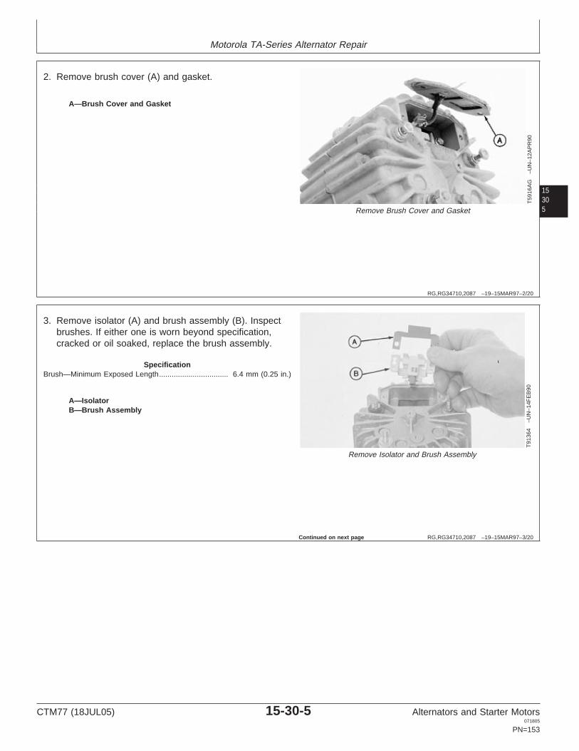
Motorola TA-Series Alternator Repair
15305
RG,RG34710,2087 –19–15MAR97–2/20
T59
16A
G–U
N–1
2AP
R90
Remove Brush Cover and Gasket
A—Brush Cover and Gasket
2. Remove brush cover (A) and gasket.
RG,RG34710,2087 –19–15MAR97–3/20
T91
364
–UN
–14F
EB
90
Remove Isolator and Brush Assembly
A—IsolatorB—Brush Assembly
3. Remove isolator (A) and brush assembly (B). Inspectbrushes. If either one is worn beyond specification,cracked or oil soaked, replace the brush assembly.
SpecificationBrush—Minimum Exposed Length 6.4 mm (0.25 in.).................................
Continued on next page
CTM77 (18JUL05) 15-30-5 Alternators and Starter Motors071805
PN=153

Motorola TA-Series Alternator Repair
1530
6
RG,RG34710,2087 –19–15MAR97–4/20
T87
568
–UN
–23F
EB
90
Check for ContinuityA—TerminalB—BrushC—BracketD—Brush
4. Check for continuity between terminal (A) and brush(B) and bracket (C) and brush (D). If there is nocontinuity at either brush, replace the brush assembly.
5. Check for continuity between terminal (A) and bracket(C). If there is continuity, replace the brush assembly.
6. Check for continuity between terminal (A) and brush(D). If there is continuity, replace the brush assembly.
RG,RG34710,2087 –19–15MAR97–5/20
T91
366
–UN
–14F
EB
90
Separate Front HousingA—Cap Screws (4 Used)B—Horseshoe Clip
7. Remove cap screws (A) to separate the housings.Note horseshoe clip (B) at lower cap screw.
IMPORTANT: Inserting screwdriver blades fartherthan 1.6 mm (1/16 in.) may damagestator windings.
8. Carefully insert two screwdriver blades in oppositeopenings between the stator and front housing andseparate the front housing from the rear.
Continued on next page
CTM77 (18JUL05) 15-30-6 Alternators and Starter Motors071805
PN=154

Motorola TA-Series Alternator Repair
15307
RG,RG34710,2087 –19–15MAR97–6/20
T91
367
–UN
–14F
EB
90
Disconnect Stator Leads
A—Nuts and Washers (3 Used)B—Stator Leads
9. Remove nuts and washers (A) to disconnect statorleads (B).
NOTE: Remove diode leads from stud terminal.
RG,RG34710,2087 –19–15MAR97–7/20
T91
373
–UN
–14F
EB
90
Check Rotor Windings
10. Use ohmmeter to check rotor windings by placing aprobe on each slip ring. If there is no continuity,replace the rotor.
Continued on next page
CTM77 (18JUL05) 15-30-7 Alternators and Starter Motors071805
PN=155

Motorola TA-Series Alternator Repair
1530
8
RG,RG34710,2087 –19–15MAR97–8/20
T91
374
–UN
–14F
EB
90
Check for Grounded Rotor Windings
11. Use ohmmeter to check for grounded rotor windings.If there is continuity, replace the rotor.
RG,RG34710,2087 –19–15MAR97–9/20
T91
375
–UN
–14F
EB
90
Check Stator and Leads
12. Use ohmmeter to check the stator for an openwinding. Check all the leads. If there is no continuityin any of the connections, there is an open circuit inthe stator windings and the stator must be replaced.
Continued on next page
CTM77 (18JUL05) 15-30-8 Alternators and Starter Motors071805
PN=156

Motorola TA-Series Alternator Repair
15309
RG,RG34710,2087 –19–15MAR97–10/20
T91
376
–UN
–14F
EB
90
Check Stator
13. Use ohmmeter to check the stator for a groundedwinding. Touch one probe to any of the leads andone to the ground. The meter must not registercontinuity. If it registers continuity, a stator winding isgrounded and the stator must be replaced.
RG,RG34710,2087 –19–15MAR97–11/20
T91
377
–UN
–14F
EB
90
Test Diodes
T59
16A
H–U
N–1
2AP
R90
Test Diodes
IMPORTANT: The diode test position must be usedon meters with test position to getaccurate results. Follow themanufacturer’s instructions for yourmeter to test diodes.
14. Test positive and negative diodes in both directionsusing a volt-ohm-amp meter. Put one probe on adiode lead and the other probe on the diode plate toget a reading.
A diode with a high reading in one direction and a lowreading in the other direction is good. A diode withthe same reading in both directions is defective andshould be replaced.
Test diode trio in both directions using avolt-ohm-amp meter. Put probes on each end ofdiode to get a reading.
A diode trio with a high reading in one direction and alow reading in the other direction is good. A diode triowith the same reading in both directions is defectiveand should be replaced.
CTM77 (18JUL05) 15-30-9 Alternators and Starter Motors071805
PN=157
Continued on next page

Motorola TA-Series Alternator Repair
153010
RG,RG34710,2087 –19–15MAR97–12/20
T91
378
–UN
–14F
EB
90
Stator and Ground Terminals
A—Stator TerminalB—Ground Terminal
15. To separate the diode plate from the alternator half,remove the nut and insulator on the stator terminal(A) and the nut on the ground terminal (B).
RG,RG34710,2087 –19–15MAR97–13/20
T91
379
–UN
–14F
EB
90
Remove Defective Diodes
16. Remove diodes if defective. Use a standard punch.
IMPORTANT: Support underside of casting to preventdamage when removing diodes.
The rectifying diode in TA-Seriesalternators have their leads welded, notsoldered, to the stems. Do not attemptto substitute diode and solder the leadto the diode stem.
Continued on next page
CTM77 (18JUL05) 15-30-10 Alternators and Starter Motors071805
PN=158

Motorola TA-Series Alternator Repair
153011
RG,RG34710,2087 –19–15MAR97–14/20
T91
380
–UN
–14F
EB
90
Replacing Diodes
17. To replace the diodes, use a piece of pipe to pressdiodes into diode plate.
IMPORTANT: Before installing diode plate, makecertain that it is properly insulated fromhousing. (See ASSEMBLE MOTOROLATA-SERIES ALTERNATOR in thisgroup.)
RG,RG34710,2087 –19–15MAR97–15/20
T91
381
–UN
–14F
EB
90
Remove Front Housing
18. Remove the front housing from the stator.
Continued on next page
CTM77 (18JUL05) 15-30-11 Alternators and Starter Motors071805
PN=159

Motorola TA-Series Alternator Repair
153012
RG,RG34710,2087 –19–15MAR97–16/20
T91
382
–UN
–14F
EB
90
Remove Pulley
19. Remove nut and lock washer. Remove the pulley witha gear puller from D01047AA 17-1/2 Ton Puller Set.
RG,RG34710,2087 –19–15MAR97–17/20
T91
383
–UN
–14F
EB
90
Remove Rotor
20. To remove rotor, remove the key from the shaft andtap on the shaft with a plastic hammer.
Continued on next page
CTM77 (18JUL05) 15-30-12 Alternators and Starter Motors071805
PN=160

Motorola TA-Series Alternator Repair
153013
RG,RG34710,2087 –19–15MAR97–18/20
T91
384
–UN
–14F
EB
90
Remove Bearing Retainer
21. Remove three screws and lock washers to removebearing retainer.
RG,RG34710,2087 –19–15MAR97–19/20
T91
385
–UN
–14F
EB
90
Remove Front Seal and Bearing
22. Remove the front seal and bearing using a 3/32 in.punch.
Continued on next page
CTM77 (18JUL05) 15-30-13 Alternators and Starter Motors071805
PN=161

Motorola TA-Series Alternator Repair
153014
RG,RG34710,2087 –19–15MAR97–20/20
T91
386
–UN
–14F
EB
90
Remove Rear Bearing if Necessary
23. Remove the rear bearing if bearing replacement isnecessary.
RG,RG34710,2088 –19–15MAR97–1/15
Assemble Motorola TA-Series Alternator
T91
387
–UN
–14F
EB
90
Install Seal in Housing Bore
1. Install seal open face to driver from the D01045AABushing, Bearing and Seal Driver Set. Install seal inhousing bore.
Continued on next page
CTM77 (18JUL05) 15-30-14 Alternators and Starter Motors071805
PN=162

Motorola TA-Series Alternator Repair
153015
RG,RG34710,2088 –19–15MAR97–2/15
T91
388
–UN
–14F
EB
90
Install Bearing
2. Install bearing using a driver that contacts the outerrace.
RG,RG34710,2088 –19–15MAR97–3/15
T91
389
–UN
–14F
EB
90
Install Bearing Retainer
3. Install bearing retainer using three screws andwashers.
Continued on next page
CTM77 (18JUL05) 15-30-15 Alternators and Starter Motors071805
PN=163

Motorola TA-Series Alternator Repair
153016
RG,RG34710,2088 –19–15MAR97–4/15
T59
16A
I–U
N–1
2AP
R90
Install Seals and Bearing
A—BearingB—Seals
4. Install seals (B) and bearing (A).
RG,RG34710,2088 –19–15MAR97–5/15
T91
390
–UN
–14F
EB
90
Install Rotor to Housing
5. Install rotor to housing. Install the spacer and shaftkey. Install the pulley, lock washer and hex nut.Tighten hex nut to specifications.
SpecificationAlternator Pulley Retaining Nut—Torque 47—68 N•m (35—50 lb-ft)..............................................................
IMPORTANT: Clamp pulley in a soft-jawed vise or usean old oversize belt to prevent damageto pulley.
Continued on next page
CTM77 (18JUL05) 15-30-16 Alternators and Starter Motors071805
PN=164
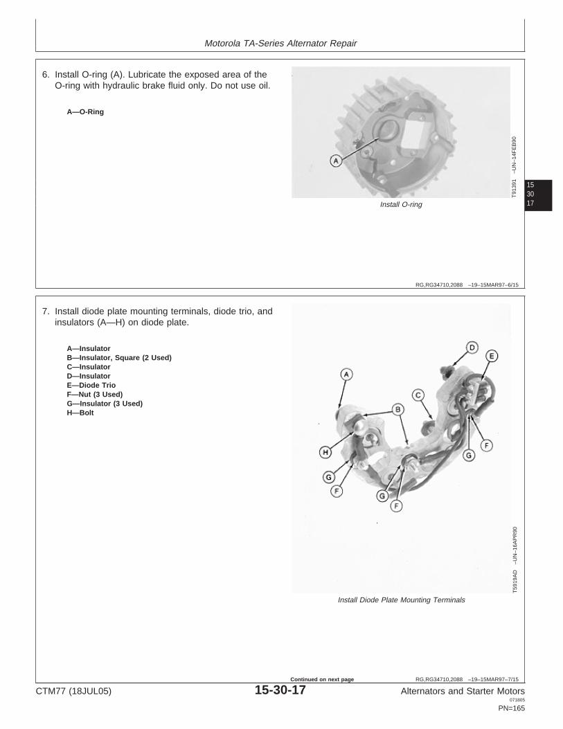
Motorola TA-Series Alternator Repair
153017
RG,RG34710,2088 –19–15MAR97–6/15
T91
391
–UN
–14F
EB
90
Install O-ring
A—O-Ring
6. Install O-ring (A). Lubricate the exposed area of theO-ring with hydraulic brake fluid only. Do not use oil.
RG,RG34710,2088 –19–15MAR97–7/15
T59
19A
D–U
N–1
6AP
R90
Install Diode Plate Mounting Terminals
A—InsulatorB—Insulator, Square (2 Used)C—InsulatorD—InsulatorE—Diode TrioF—Nut (3 Used)G—Insulator (3 Used)H—Bolt
7. Install diode plate mounting terminals, diode trio, andinsulators (A—H) on diode plate.
CTM77 (18JUL05) 15-30-17 Alternators and Starter Motors071805
PN=165
Continued on next page

Motorola TA-Series Alternator Repair
153018
RG,RG34710,2088 –19–15MAR97–8/15
T61
06A
G–U
N–0
2AP
R90
Install Diode Plate
A—Insulator SleeveB—InsulatorC—WasherD—NutE—InsulatorF—Flat WasherG—Lock WasherH—NutI—InsulatorJ—Nut
8. Install diode plate into rear housing. Install insulators,washers, and nuts (A—J).
RG,RG34710,2088 –19–15MAR97–9/15
T91
381
–UN
–14F
EB
90
Install Stator and Gasket
9. Install stator into front housing. Install gasket.
Continued on next page
CTM77 (18JUL05) 15-30-18 Alternators and Starter Motors071805
PN=166

Motorola TA-Series Alternator Repair
153019
RG,RG34710,2088 –19–15MAR97–10/15
T59
16A
J–U
N–1
2AP
R90
Connect Leads
A—Stator LeadsB—Terminals
10. Connect each diode lead to the terminal (B) adjacentto it. Also connect stator leads (A) leads to terminals(B). Fasten with nuts and lock washers.
RG,RG34710,2088 –19–15MAR97–11/15
T92
062
–UN
–12F
EB
90
Attach Leads
11. After stator leads are fastened to diode terminals,fasten the stator leads together using a tie band alongthe rear housing shell. Place stator leads as far aspossible from rotor.
Continued on next page
CTM77 (18JUL05) 15-30-19 Alternators and Starter Motors071805
PN=167

Motorola TA-Series Alternator Repair
153020
RG,RG34710,2088 –19–15MAR97–12/15
T91
366
–UN
–14F
EB
90
Screws and Horseshoe Clip
A—Cap Screws (4 Used)B—Horseshoe Clip
12. Install rear housing and stator into the front housing.Make sure grooves in stator line up with cap screwholes. Install four screws (A) and tighten tospecifications. Horseshoe clip (B) must be installed onlower screw.
SpecificationFront-to-Rear Alternator HousingCap Screws—Torque 2.8—3.4 N•m (20—30 lb-in.)...................................
After assembly, rotate the alternator pulley. The pulleymust rotate without any rough spots. Rough spots couldbe caused by the stator leads rubbing the rotor or a roughbearing. If rough spots are felt, disassemble rear housingand correct the problem.
RG,RG34710,2088 –19–15MAR97–13/15
T91
364
–UN
–14F
EB
90
Install Brush Assembly and Isolator
A—IsolatorB—Brush Assembly
13. Install the brush assembly (B). Isolator (A) must beinstalled with tab over the brush leads to preventbrush leads from touching housing. Tighten brushholder retaining cap screws to specifications.
SpecificationBrush Holder Retaining Screws—Torque 2.8—3.4 N•m (20—30 lb-in.)..........................................................
Continued on next page
CTM77 (18JUL05) 15-30-20 Alternators and Starter Motors071805
PN=168

Motorola TA-Series Alternator Repair
153021
RG,RG34710,2088 –19–15MAR97–14/15
T59
16A
G–U
N–1
2AP
R90
Brush Holder Cover and Shield
A—Brush Holder Cover and Dust Shield
14. Install brush holder cover (A) and dust shield.
RG,RG34710,2088 –19–15MAR97–15/15T
6106
AF
–UN
–02A
PR
90
Voltage Regulator
A—Voltage Regulator
15. Install voltage regulator (A) and wiring leads.
16. Refer to your machine technical manual forinstallation of alternator.
CTM77 (18JUL05) 15-30-21 Alternators and Starter Motors071805
PN=169

Motorola TA-Series Alternator Repair
153022
CTM77 (18JUL05) 15-30-22 Alternators and Starter Motors071805
PN=170

Section 20Niehoff Alternators
Contents
Page
Group 05—Niehoff Alternator Theory of OperationStarting the Niehoff Alternator . . . . . . . . . . . . . .20-05-1Niehoff Alternator Operation . . . . . . . . . . . . . . .20-05-1Niehoff Alternator Load Dump Circuit . . . . . . . .20-05-4
Group 10—Niehoff 12-Volt, 110-Amp AlternatorRepair
20Essential Tools . . . . . . . . . . . . . . . . . . . . . . . . .20-10-1Other Material . . . . . . . . . . . . . . . . . . . . . . . . . .20-10-3Niehoff 12-Volt Charging Circuit Repair
Specifications. . . . . . . . . . . . . . . . . . . . . . . . .20-10-3Niehoff 12-Volt Charging Circuit Test
Specifications. . . . . . . . . . . . . . . . . . . . . . . . .20-10-4Disassemble Niehoff 12-Volt, 110-Amp
Alternator . . . . . . . . . . . . . . . . . . . . . . . . . . . .20-10-4Test Niehoff 12-Volt, 110-Amp Alternator
Components . . . . . . . . . . . . . . . . . . . . . . . .20-10-17Assemble Niehoff 12-Volt, 110-Amp
Alternator . . . . . . . . . . . . . . . . . . . . . . . . . . .20-10-22Establish Magnetic Field . . . . . . . . . . . . . . . . .20-10-27
Group 15—Niehoff 24-Volt, 50-Amp AlternatorRepair
Essential Tools . . . . . . . . . . . . . . . . . . . . . . . . .20-15-1Other Material . . . . . . . . . . . . . . . . . . . . . . . . . .20-15-3Niehoff 24-Volt Charging Circuit Repair
Specifications. . . . . . . . . . . . . . . . . . . . . . . . .20-15-3Niehoff 24-Volt Charging Circuit Test
Specifications. . . . . . . . . . . . . . . . . . . . . . . . .20-15-4Disassemble Niehoff 24-Volt, 50-Amp
Alternator and Test Components . . . . . . . . . .20-15-5Assemble Niehoff 24-Volt, 50-Amp
Alternator . . . . . . . . . . . . . . . . . . . . . . . . . . .20-15-12Re-Establish Magnetic Field . . . . . . . . . . . . . .20-15-18
CTM77 (18JUL05) 20-1 Alternators and Starter Motors071805
PN=1

Contents
20
CTM77 (18JUL05) 20-2 Alternators and Starter Motors071805
PN=2

Group 05Niehoff Alternator Theory of Operation
20051
RG,RG34710,2089 –19–15MAR97–1/1
Starting the Niehoff Alternator
RW
5112
–UN
–06A
PR
89
Starting Niehoff Alternator
A—StatorB—Power Transistor
As the engine is cranking to start, the alternator rotor willturn. The residual magnetism in the rotor and stationaryforging creates a magnetic field. The turning rotor causesthe magnetic field to alternately increase and decrease instrength. This induces current into the stator (A). Thiscurrent is sufficient to turn on the power transistor (B).The alternator and regulator are now operating.
RG,RG34710,2090 –19–15MAR97–1/3
Niehoff Alternator Operation
RW
5113
–UN
–06A
PR
89
Niehoff Alternator Operation
A—Power TransistorB—Alternator Field WindingC—Battery
With the power transistor (A) on, field current is permittedto flow through the alternator field winding (B) from thebattery (C). The field coil current will produce a magneticfield.
CTM77 (18JUL05) 20-05-1 Alternators and Starter Motors071805
PN=173
Continued on next page

Niehoff Alternator Theory of Operation
2005
2
RG,RG34710,2090 –19–15MAR97–2/3
RW
5114
–UN
–06A
PR
89
Magnetic Field
A—Stator Coil WindingsB—Bridge RectifierC—BatteryD—Rotor WindingE—Field Winding
This magnetic field flows through a small air gap to therotor and to the stator windings. As the rotor turns, themagnetic field is alternately increased and decreased instrength. This induces an alternating three-phase voltageand current in the stator coil windings (A). The alternatingcurrent output from the stator is applied to a three-phasefull wave bridge rectifier (B), which provides direct currentto the battery (C).
The compound winding produces a magnetic field whichadds to the magnetic field created by the field coil. Thishelps the alternator produce output at the high end of theoutput range.
Continued on next page
CTM77 (18JUL05) 20-05-2 Alternators and Starter Motors071805
PN=174

Niehoff Alternator Theory of Operation
20053
RG,RG34710,2090 –19–15MAR97–3/3
RW
5115
–UN
–06A
PR
89
Voltage Regulator
A—Diode TrioB—Power TransistorC—Field WindingD—Zener Diode
The voltage regulator senses the voltage of the chargingsystem through the diode trio (A). If the alternator loadingdemand is high, the power transistor (B) becomesconductive for longer periods of time and supplies agreater amount of current to the field winding (C). Anincrease in current flow through the field winding causesan increase in alternator output voltage.
As the charging system builds up to the predeterminedsetting of the regulator, the Zener diode (D) in theregulator causes the power transistor (B) to turn off. Withthe power transistor (B) turned off, little or no current isapplied to the field winding, thereby decreasing thealternator output voltage.
This on/off field switching action is repeated as often asnecessary so that the average voltage output of thealternator is maintained at the regulator setting.
CTM77 (18JUL05) 20-05-3 Alternators and Starter Motors071805
PN=175

Niehoff Alternator Theory of Operation
2005
4
RG,RG34710,2091 –19–15MAR97–1/2
Niehoff Alternator Load Dump Circuit
RW
5164
–UN
–24M
AY
89
Load Dump Circuit
A—Alternator OutputB—Zener DiodeC—TransistorD—SCR’s (3 Used)
The load dump circuit protects the alternator and thevehicle’s electrical system when the battery connection isbroken.
When the battery connection is broken, a high voltageappears at the alternator output (A). This high voltagecauses the Zener diode (B) and the transistor (C) toconduct. This will turn on three SCR’s (D)
RG,RG34710,2091 –19–15MAR97–2/2
RW
5165
–UN
–04M
AY
89
SCR to Ground
A—SCR’s (3 Used)B—Ground
All the alternator output will flow through the three SCR’s(A) to ground (B).
After a short time, the high voltage is gone and theregulator will take control of the alternator. The alternatoroutput will remain at a level necessary to operate thevehicle’s electrical system.
Repeated operation of the load dump circuit will result inregulator failure.
CTM77 (18JUL05) 20-05-4 Alternators and Starter Motors071805
PN=176

Group 10Niehoff 12-Volt, 110-Amp Alternator Repair
OUO1004,0000B6C –19–08MAY02–1/6
Essential Tools
NOTE: Order tools according to information given in theU.S. SERVICEGARD Catalog or from theEuropean Microfiche Tool Catalog (MTC).
20101
SERVICEGARD is a trademark of Deere & Company
OUO1004,0000B6C –19–08MAY02–2/6
RW
1030
6–U
N–1
0NO
V89
JDG255
Stator Support . . . . . . . . . . . . . . . . . . . . . . . JDG255
Support shell while pressing out stator.
OUO1004,0000B6C –19–08MAY02–3/6
RG
1116
1–U
N–2
1SE
P00
D01061AA
Blind Hole Puller Set . . . . . . . . . . . . . . . . . D01061AA
Remove bearings from front housing assembly.
CTM77 (18JUL05) 20-10-1 Alternators and Starter Motors071805
PN=177
Continued on next page

Niehoff 12-Volt, 110-Amp Alternator Repair
2010
2
OUO1004,0000B6C –19–08MAY02–4/6
RG
1116
2–U
N–2
1SE
P00
D01045AA
Bushing, Bearing and Seal Driver Set . . . . . . D01045AA
Install bearings in front housing assembly.
OUO1004,0000B6C –19–08MAY02–5/6
RW
1127
4–U
N–1
2DE
C88
JT05791
Digital Multimeter . . . . . . . . . . . . . . . . . . . . . JT05791
Test electrical components for voltage, resistance, orcurrent flow. It is especially good for measuring lowvoltage or high resistance circuits.
OUO1004,0000B6C –19–08MAY02–6/6
Alternator, Generator, Starter and Battery BenchTester . . . . . . . . . . . . . . . . . . . . . . . . . . . . . JT01760
Test alternators and starters for voltage, resistance, orcurrent flow.
CTM77 (18JUL05) 20-10-2 Alternators and Starter Motors071805
PN=178

Niehoff 12-Volt, 110-Amp Alternator Repair
20103
OUO1004,0000B6E –19–21SEP00–1/1
Other Material
Number Name Use
TY16285 (U.S.) Thread Lock and Sealer (Low Apply to all cap screws and nutsCXTY24311 (Canadian) Strength) when assembling alternator.222 (LOCTITE)
High Temperature, Silicone Base Fill front and rear grease reservoir inGrease alternator housing.
Silicone Rubber Compound Apply to all internal wiring lead capscrews.
LOCTITE is a registered trademark of Loctite Corp.
OUO1004,0000B6F –19–21SEP00–1/1
Niehoff 12-Volt Charging Circuit RepairSpecifications
Item Measurement Specification
Fan Pulley Lock Nut Torque 95 N•m (70 lb-ft)
Front Housing-to-Stator Shell Nuts Torque 3.4 N•m (30 lb-in.)
Rotor Nut Torque 68 N•m (50 lb-ft)
Regulator Field Lead-to-Standoff Torque 0.9—1.1 N•m (8—10 lb-in.)Screw and Y-Lead-to-Load DumpScrew
Output and Relay Leads-to-Standoff Torque 2.3 N•m (20 lb-in.)Screw
Ground Lead-to-Load Dump Screw Torque 1.1—1.7 N•m (10—15 lb-in.)
Flanged Nuts Torque 5.1 N•m (45 lb-in.)
CTM77 (18JUL05) 20-10-3 Alternators and Starter Motors071805
PN=179

Niehoff 12-Volt, 110-Amp Alternator Repair
RG,RG34710,2094 –19–07JUL05–1/1
Niehoff 12-Volt Charging Circuit TestSpecifications
John Deere Niehoff Alternator Ground Voltage Rated Output WindingAlternator Model No. (Amps) Resistance @Part No. 21—27°C (70—
80°F) (Ohms)
AR94100 N1114-1 N 12 110 2.9—3.1
2010
4
RG,RG34710,2096 –19–15MAR97–1/26
Disassemble Niehoff 12-Volt, 110-Amp Alternator
RW
3289
–UN
–02M
AR
90Niehoff 12-Volt, 110-Amp Alternator
A—Screw (3 Used) I—Screw (4 Used) Q—Insulator (6 Used) Y—Front Housing AssemblyB—Dust Cover J—Washer (4 Used) R—Nut (6 Used) Z—ShaftC—Ground Bolt with Washer K—Screw (7 Used) S—Spacer (6 Used) AA—Woodruff KeyD—Battery Stud with Washers L—Regulator Assembly T—Stator Assembly BB—Bearing CoverE—Lock Nut M—Insulator U—Lock Nut CC—FanF—Insulator N—Nut (6 Used) V—Washer DD—PulleyG—Nut (6 Used) O—Insulator (6 Used) W—Rotor EE—WasherH—Rear Housing P—Rectifier Assembly X—Washer FF—Nut
Refer to your machine technical manual for removal ofalternator.
CTM77 (18JUL05) 20-10-4 Alternators and Starter Motors071805
PN=180
Continued on next page

Niehoff 12-Volt, 110-Amp Alternator Repair
20105
RG,RG34710,2096 –19–15MAR97–2/26
RW
3274
–UN
–02M
AR
90
Remove Dust Cover
A—Dust Cover
IMPORTANT: Never immerse alternator in cleaningsolution. Remove dirt and grease byscraping and using a stiff brush withsolvent. Dry with compressed air.
NOTE: Because of the manufacturer’s design of the rotorand the field flux noise, this alternator is noisierthan others.
Unnecessary disassembly may be prevented byfirst checking alternator output, shell temperatureand pulley nut tension before the decision todisassemble is made. (Refer to your machineOperation and Test manual for complete chargingcircuit diagnosis.
1. Remove dust cover (A).
NOTE: If alternator is being disassembled for testing,follow Steps 1 through 8 only. Refer to TESTNIEHOFF 12-VOLT, 110-AMP ALTERNATORCOMPONENTS, later in this group.
RG,RG34710,2096 –19–15MAR97–3/26
RW
3275
–UN
–02M
AR
90
Remove Bolts from Terminal
A—Battery Positive BoltB—Negative BoltC—Terminal
2. Remove battery positive bolt (A), negative bolt (B), andlock nut and insulator from terminal (C).
Continued on next page
CTM77 (18JUL05) 20-10-5 Alternators and Starter Motors071805
PN=181

Niehoff 12-Volt, 110-Amp Alternator Repair
2010
6
RG,RG34710,2096 –19–15MAR97–4/26
RW
3276
–UN
–02M
AR
90
Lift Off Rear Housing
A—Lock Nuts (6 Used)B—DetentC—Rear Housing
3. Remove six lock nuts (A) from studs and pry withscrewdriver in detent (B) to lift off rear housing (C).
RG,RG34710,2096 –19–15MAR97–5/26
RW
3277
–UN
–02M
AR
90
Detach Compound Winding Leads
A—Screws (2 Used)
4. Remove two screws (A) to detach compound windingleads.
Continued on next page
CTM77 (18JUL05) 20-10-6 Alternators and Starter Motors071805
PN=182

Niehoff 12-Volt, 110-Amp Alternator Repair
20107
RG,RG34710,2096 –19–15MAR97–6/26
RW
3278
–UN
–02M
AR
90
Detach Field Leads
A—Screws (2 Used)
5. Remove two screws (A) to detach field leads.
RG,RG34710,2096 –19–15MAR97–7/26R
W32
79–U
N–0
2MA
R90
Remove Screws at Stand-Offs
A—Screws (3 Used)
6. Remove three screws (A) with washers at stand-offs.
Continued on next page
CTM77 (18JUL05) 20-10-7 Alternators and Starter Motors071805
PN=183

Niehoff 12-Volt, 110-Amp Alternator Repair
2010
8
RG,RG34710,2096 –19–15MAR97–8/26
RW
3280
–UN
–02M
AR
90
Remove Screws to Detach Regulator
A—Screws with WashersB—Regulator
7. Remove three screws with washers (A) to detachregulator (B).
RG,RG34710,2096 –19–15MAR97–9/26
RW
3281
–UN
–02M
AR
90
Detach Stator Leads
A—Terminal Locks (3 Used)B—Stator Leads
8. Loosen three terminal locks (A) and detach statorleads (B).
NOTE: The alternator has now been disassembled fortesting. Refer to TEST NIEHOFF 12-VOLT,110-AMP ALTERNATOR COMPONENTS, later inthis group.
Continued on next page
CTM77 (18JUL05) 20-10-8 Alternators and Starter Motors071805
PN=184

Niehoff 12-Volt, 110-Amp Alternator Repair
20109
RG,RG34710,2096 –19–15MAR97–10/26
RW
3290
–UN
–02M
AR
90
Detach Rectifier Assembly
A—Nuts (6 Used)B—Insulators (6 Used)
9. Remove six nuts (A) and six insulators (B) to detachrectifier assembly.
RG,RG34710,2096 –19–15MAR97–11/26R
W32
91–U
N–0
2MA
R90
Remove Lock Nut and Washer
A—Lock NutB—Hardened Washer
IMPORTANT: Use soft-jawed vise when clampingpulley.
10. Remove lock nut (A) and hardened washer (B).
Continued on next page
CTM77 (18JUL05) 20-10-9 Alternators and Starter Motors071805
PN=185
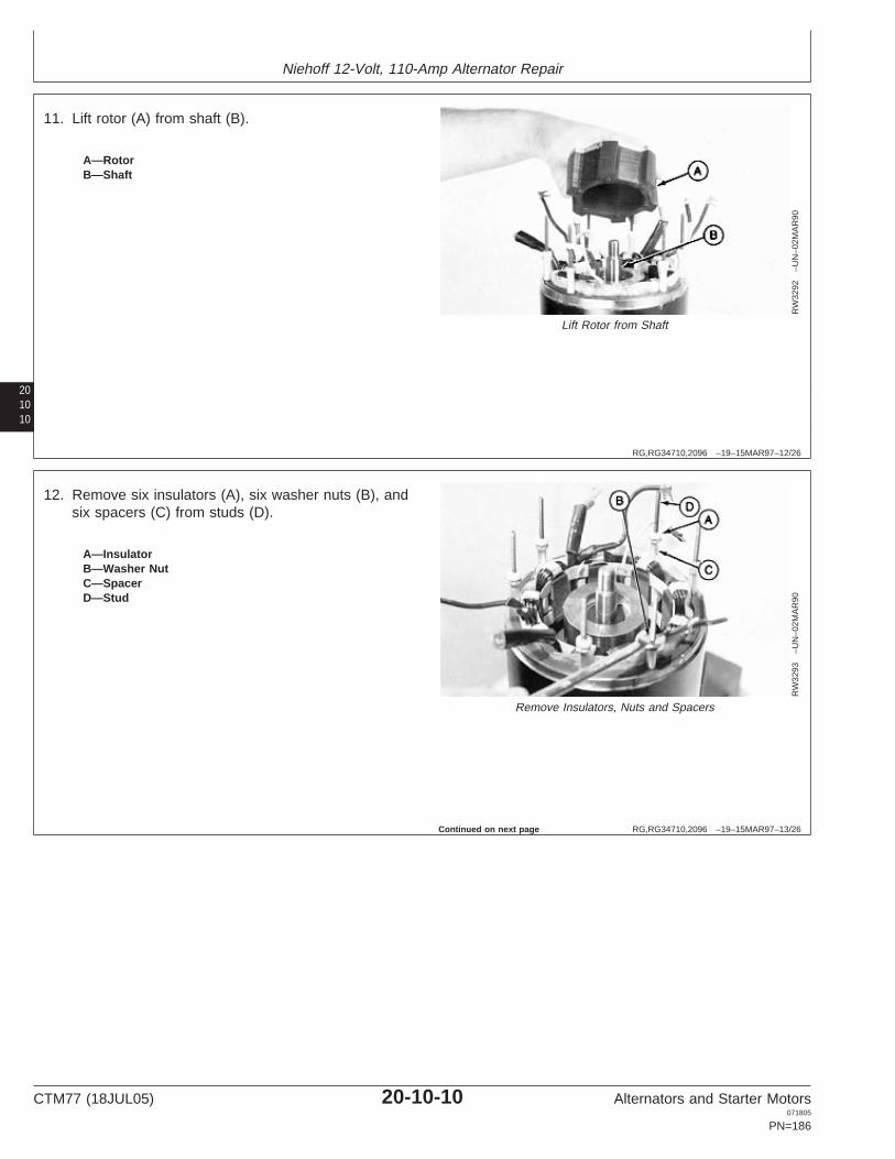
Niehoff 12-Volt, 110-Amp Alternator Repair
201010
RG,RG34710,2096 –19–15MAR97–12/26
RW
3292
–UN
–02M
AR
90
Lift Rotor from Shaft
A—RotorB—Shaft
11. Lift rotor (A) from shaft (B).
RG,RG34710,2096 –19–15MAR97–13/26
RW
3293
–UN
–02M
AR
90
Remove Insulators, Nuts and Spacers
A—InsulatorB—Washer NutC—SpacerD—Stud
12. Remove six insulators (A), six washer nuts (B), andsix spacers (C) from studs (D).
Continued on next page
CTM77 (18JUL05) 20-10-10 Alternators and Starter Motors071805
PN=186

Niehoff 12-Volt, 110-Amp Alternator Repair
201011
RG,RG34710,2096 –19–15MAR97–14/26
RW
3294
–UN
–02M
AR
90
Leads and Stator
A—Compound Winding LeadsB—Field Winding Leads (White)C—Stator
13. Identify wires for reassembly.
IMPORTANT: Note and mark position of compoundwinding leads (A) and field windingleads (B) to stator (C). All must be inoriginal position for correct assembly.
RG,RG34710,2096 –19–15MAR97–15/26R
W32
95–U
N–0
2MA
R90
Front Housing Assembly
A—ShellB—Housing Assembly
14. Tap shell (A) lightly with soft hammer to loosen it fromfront housing assembly (B).
Continued on next page
CTM77 (18JUL05) 20-10-11 Alternators and Starter Motors071805
PN=187

Niehoff 12-Volt, 110-Amp Alternator Repair
201012
RG,RG34710,2096 –19–15MAR97–16/26
RW
3296
–UN
–02M
AR
90
Front Housing Assembly
A—ShellB—Housing Assembly
15. Pry shell (A) from front housing assembly (B).
RG,RG34710,2096 –19–15MAR97–17/26
RW
1042
6–U
N–1
0NO
V89
Tap Stator Out
A—JDG255 Stator Support ToolB—Alternator Shell
IMPORTANT: Note and mark the relationship ofstator-to-shell before disassembly.
16. Press stator from shell. Use JDG255 Stator Support(A) to support shell (B). Using a punch, tap stator outevenly.
Continued on next page
CTM77 (18JUL05) 20-10-12 Alternators and Starter Motors071805
PN=188

Niehoff 12-Volt, 110-Amp Alternator Repair
201013
RG,RG34710,2096 –19–15MAR97–18/26
RW
3297
–UN
–02M
AR
90
Detach Pulley and Fan
A—PulleyB—FanC—Shaft
17. Remove nut and washer to detach pulley (A) and fan(B) from shaft (C).
RG,RG34710,2096 –19–15MAR97–19/26R
W32
98–U
N–0
2MA
R90
Remove Woodruff Key
A—Woodruff KeyB—Bearing Seal CoverC—Shaft
18. Remove Woodruff key (A) to detach bearing sealcover (B) from shaft (C).
Continued on next page
CTM77 (18JUL05) 20-10-13 Alternators and Starter Motors071805
PN=189

Niehoff 12-Volt, 110-Amp Alternator Repair
201014
RG,RG34710,2096 –19–15MAR97–20/26
RW
5120
–UN
–23F
EB
90
Remove Snap Ring
A—Snap RingB—BearingC—Shaft
NOTE: Remove bearings for replacement only, andreplace both ball and roller bearings. Bearings areprelubricated by supplier. Use D01061AA BlindHole Puller Set and ensure full ID contact whenremoving bearings.
19. Remove snap ring (A).
RG,RG34710,2096 –19–15MAR97–21/26
RW
3283
–UN
–02M
AR
90
Remove Ball Bearing
A—Ball Bearing
20. Remove ball bearing (A). Use 16 mm (5/8 in.) collet(No. 33860).1
1From the D01061AA Blind Hole Puller Set.
Continued on next page
CTM77 (18JUL05) 20-10-14 Alternators and Starter Motors071805
PN=190

Niehoff 12-Volt, 110-Amp Alternator Repair
201015
RG,RG34710,2096 –19–15MAR97–22/26
RW
3284
–UN
–02M
AR
90
Remove Roller Bearing and Seal
A—Roller Bearing and Seal
21. Remove roller bearing and seal (A). Use 26—32 mm(1—1-1/4 in.) collet (No. 33863).1
1From the D01061AA Blind Hole Puller Set.
RG,RG34710,2096 –19–15MAR97–23/26R
W32
86–U
N–0
2MA
R90
New Alternator Bearings
A—Roller BearingB—27 mm (1-1/16 in.) Pilot DiskC—46 mm (1-13/16 in.) Driver Disk (No. 24500 and
27512.) *
To install new alternator bearings:
22. Press roller bearing (A) into front housing assembly.Use 27 mm (1-1/16 in.) pilot disk (B) and 46 mm(1-13/16 in.) driver disk (C) (No. 27500 and 27512.)1
1 From the D01045AA Bushing, Bearing and Seal Driver Set.
Continued on next page
CTM77 (18JUL05) 20-10-15 Alternators and Starter Motors071805
PN=191

Niehoff 12-Volt, 110-Amp Alternator Repair
201016
RG,RG34710,2096 –19–15MAR97–24/26
RW
3287
–UN
–02M
AR
90
Roller Bearing Seal
A—Roller Bearing SealB—Front Housing AssemblyC—Driver Disk
IMPORTANT: Seal spring and lip must be visiblewhen seal is properly installed formaximum protection against dustpenetration into bearing.
23. Press roller bearing seal (A) into front housingassembly (B) using 54 mm (2-1/8 in.) driver disk (C),(No. 27517).1
1 From the D01045AA Bushing, Bearing and Seal Driver Set.
RG,RG34710,2096 –19–15MAR97–25/26
RW
3285
–UN
–02M
AR
90
Ball Bearing
A—Ball BearingB—16 mm (5/8 in.) DiskC—40 mm (1-9/16 in.) Driver Disk (No. 27493 and
27508)
24. Press ball bearing (A) into front housing using 16 mm(5/8 in.) disk (B) and 40 mm (1-9/16 in.) driver disk(C) (No. 27493 and 27508).1
1From the D01045AA Bushing, Bearing and Seal Driver Set.
Continued on next page
CTM77 (18JUL05) 20-10-16 Alternators and Starter Motors071805
PN=192

Niehoff 12-Volt, 110-Amp Alternator Repair
201017
RG,RG34710,2096 –19–15MAR97–26/26
RW
3282
–UN
–12M
AY
89
Assemble Snap Ring
A—Snap RingB—BearingC—Front Housing Assembly
NOTE: Snap ring (A) must be seated completely with flatside against the bearing (B) (bevel is away frombearing).
25. Assemble snap ring (A) to front housing assembly(C).
RG,RG34710,2097 –19–12SEP02–1/9
Test Niehoff 12-Volt, 110-Amp AlternatorComponents
RW
3265
–UN
–02M
AR
90
Stator Phase Leads
A—Stator Phase Leads
1. Test stator windings by measuring resistance in eachsuccessive pair of stator phase leads (A) (three pair).Use JT05791 Digital Multimeter to measure resistance.
Less than 0.5 ohm of resistance should be indicated ineach pair.
Continued on next page
CTM77 (18JUL05) 20-10-17 Alternators and Starter Motors071805
PN=193

Niehoff 12-Volt, 110-Amp Alternator Repair
201018
RG,RG34710,2097 –19–12SEP02–2/9
RW
3266
–UN
–02M
AR
90
Measure Resistance
A—Stator LeadB—Stator Frame
2. Test for shorted stator windings by measuringresistance between each stator lead (A) and statorframe (B).
Infinite resistance or “open” should be indicated.
RG,RG34710,2097 –19–12SEP02–3/9
RW
1129
2–U
N–1
7AP
R90
Test Field Windings
A—Field WindingsB—Compound Windings
NOTE: A resistance reading above or below specificationindicates a defective field winding. Front housingand field coil assembly should be replaced.
3. Test field windings (A) for a resistance of 2.9—3.1 ohms and compound windings (B) for less than 0.5ohms.
Continued on next page
CTM77 (18JUL05) 20-10-18 Alternators and Starter Motors071805
PN=194

Niehoff 12-Volt, 110-Amp Alternator Repair
201019
RG,RG34710,2097 –19–12SEP02–4/9
RW
3268
–UN
–02M
AR
90
Measure Resistance
A—Field LeadsB—Compound Winding Leads
4. Test for shorted field windings to compound windingsby measuring resistance between field leads (A) andcompound winding leads (B).
Infinite resistance or “open” should be indicated. If ashort is indicated, the front housing assembly must bereplaced.
RG,RG34710,2097 –19–12SEP02–5/9R
W32
69–U
N–0
2MA
R90
Field Leads and Housing/Shell Assembly
A—Field LeadsB—Front Housing/Shell Assembly
5. Test for shorted field windings to front housingassembly by checking resistance between field leads(A) and front housing/shell assembly (B).
Infinite resistance or “open” should be indicated. If ashort is indicated, the front housing assembly must bereplaced.
Continued on next page
CTM77 (18JUL05) 20-10-19 Alternators and Starter Motors071805
PN=195

Niehoff 12-Volt, 110-Amp Alternator Repair
201020
RG,RG34710,2097 –19–12SEP02–6/9
RW
3270
–UN
–02M
AR
90
Test Top Plate Diodes
A—Top PlateB—Output TerminalC—Stator Phase Terminal
NOTE: Evidence of defective diodes require replacementof rectifier diode and rectifier assembly. Whenchecking diodes with a digital meter, use thediode position.
6. Test top plate (A) diodes of rectifier assembly bychecking resistance between output terminal (B) andeach stator phase terminal (C).
All readings should be of low resistance or infiniteresistance, depending on direction of current flowthrough the diodes.
RG,RG34710,2097 –19–12SEP02–7/9
RW
3271
–UN
–02M
AR
90
Test Top Plate Diodes
A—Top PlateB—Output TerminalC—Stator Phase Terminal
7. Test top plate (A) diodes for reverse current flow byreversing test probes at output terminal. Measureresistance between output terminal (B) and statorphase terminals (C).
All readings should be the reverse of those in thepreceding step.
Continued on next page
CTM77 (18JUL05) 20-10-20 Alternators and Starter Motors071805
PN=196

Niehoff 12-Volt, 110-Amp Alternator Repair
201021
RG,RG34710,2097 –19–12SEP02–8/9
RW
3272
–UN
–02M
AR
90
Test Lower Plates Diodes
A—Lower PlateB—Output TerminalC—Stator Phase Terminals
8. Test the lower plate (A) diodes of the rectifier assemblyby checking the resistance between output terminal (B)and stator phase terminals (C).
All readings should be infinite or low depending ondirection of current flow through the diodes.
RG,RG34710,2097 –19–12SEP02–9/9R
W32
73–U
N–0
2MA
R90
Test Lower Plate Diodes
A—Lower PlateB—Output TerminalC—Stator Phase Terminal
9. Test lower plate (A) diodes for reverse current flow byreversing probes at output terminal (B) and statorphase terminals (C).
All readings should be the reverse of those in thepreceding step.
Example: An infinite reading in this step should havebeen a low resistance reading in step 8. If the samereading is indicated in steps 6 and 7 or 8 and 9,defective diodes are evident and the rectifier assemblymust be replaced.
CTM77 (18JUL05) 20-10-21 Alternators and Starter Motors071805
PN=197

Niehoff 12-Volt, 110-Amp Alternator Repair
201022
RG,RG34710,2098 –19–15MAR97–1/10
Assemble Niehoff 12-Volt, 110-AmpAlternator
RW
3298
–UN
–02M
AR
90
Assemble Roller Bearing Cover
A—Woodruff KeyB—Roller Bearing CoverC—Shaft
NOTE: Apply LOCTITE 222 Thread Lock and Sealer(low strength) on all cap screws and nuts whenassembling alternator.
1. Assemble roller bearing cover (B) to shaft (C) andinsert Woodruff key (A) in slot.
LOCTITE is a registered trademark of Loctite Corp.
RG,RG34710,2098 –19–15MAR97–2/10
RW
3297
–UN
–02M
AR
90
Assembly Fan and Pulley
A—PulleyB—FanC—Shaft
2. Assemble fan (B) and pulley (A) to shaft (C). Tightenlock nut to specifications.
SpecificationFan Pulley Lock Nut—Torque 95 N•m (70 lb-ft).........................................
Continued on next page
CTM77 (18JUL05) 20-10-22 Alternators and Starter Motors071805
PN=198

Niehoff 12-Volt, 110-Amp Alternator Repair
201023
RG,RG34710,2098 –19–15MAR97–3/10
RW
1042
7–U
N–1
0NO
V89
Assemble Stator to Shell
A—StatorB—Shell
IMPORTANT: Note your marked position of shell tostator as in disassembly.
3. Assemble stator (A) to shell (B), by tapping evenlyaround outside edge.
RG,RG34710,2098 –19–15MAR97–4/10
RW
3301
–UN
–02M
AR
90
Assemble Shell
A—ShellB—Front HousingC—Compound Winding LeadD—Field Winding LeadE—Stator
IMPORTANT: Note your marked position of shell (A)to front housing (B) as in disassembly.Also note the way compound windingleads (C) and field winding leads (D) arethreaded through stator (E). All must bein the original position before shell isseated onto front housing assembly.
4. Fill front and rear grease reservoir two-thirds full ofhigh temperature, silicone-base grease.
Assemble shell (A) to front housing (B).
Continued on next page
CTM77 (18JUL05) 20-10-23 Alternators and Starter Motors071805
PN=199

Niehoff 12-Volt, 110-Amp Alternator Repair
201024
RG,RG34710,2098 –19–15MAR97–5/10
RW
3299
–UN
–12M
AY
89
Assemble Hardware
A—SpacerB—NutC—InsulatorD—Rectifier AssemblyE—InsulatorF—NutG—Stud
IMPORTANT: Be sure to assemble spacer, nuts,insulators and rectifier assembly toalternator, in the order shown.
RG,RG34710,2098 –19–15MAR97–6/10
RW
3303
–UN
–02M
AR
90
Tighten Washer Nuts
A—Washer Nuts (6 Used)
5. Assemble six spacers and six washer nuts. Tightenwasher nuts (A) to specifications.
SpecificationFront Housing-to-Stator ShellNuts—Torque 3.4 N•m (30 lb-in.)................................................................
Continued on next page
CTM77 (18JUL05) 20-10-24 Alternators and Starter Motors071805
PN=200

Niehoff 12-Volt, 110-Amp Alternator Repair
201025
RG,RG34710,2098 –19–15MAR97–7/10
RW
3293
–UN
–02M
AR
90
Assemble Insulators
A—InsulatorsB—Washer NutsC—SpacerD—Studs
6. Assemble six insulators (A) to studs (D).
RG,RG34710,2098 –19–15MAR97–8/10R
W32
88–U
N–0
2MA
R90
Assemble Rotor and Washer to Shaft
A—RotorB—WasherC—Shaft
7. Assemble rotor (A) and washer (B) to shaft (C).
Continued on next page
CTM77 (18JUL05) 20-10-25 Alternators and Starter Motors071805
PN=201

Niehoff 12-Volt, 110-Amp Alternator Repair
201026
RG,RG34710,2098 –19–15MAR97–9/10
RW
3291
–UN
–02M
AR
90
Hardened Washer and Nut
A—NutB—Hardened Washer
8. Assemble hardened washer (B) and nut (A). Tighten tospecifications.
SpecificationRotor Nut—Torque 68 N•m (50 lb-ft)..........................................................
RG,RG34710,2098 –19–15MAR97–10/10
RW
3290
–UN
–02M
AR
90
Assemble Remaining Parts
A—Nuts (6 Used)B—Insulators (6 Used)
IMPORTANT: Coat all screw heads on regulator andrectifier assembly with silicone rubbercompound.
9. Assemble remaining alternator parts in reverse order ofdisassembly, starting with step 9 back to step 1.
SpecificationRegulator Field Lead-to-StandoffScrew and Y-Lead-to-Load DumpScrew—Torque 0.9—1.1 N•m (8—10 lb-in.)...............................................Output and RelayLeads-to-Standoff Screw—Torque 2.3 N•m (20 lb-in.)................................Ground Lead-to-Load DumpScrew—Torque 1.1—1.7 N•m (10—15 lb-in.).............................................Flanged Nuts—Torque 5.1 N•m (45 lb-in.)..................................................
10. Refer to your machine technical manual for alternatorinstallation.
CTM77 (18JUL05) 20-10-26 Alternators and Starter Motors071805
PN=202

Niehoff 12-Volt, 110-Amp Alternator Repair
201027
RG,RG34710,2099 –19–15MAR97–1/1
Establish Magnetic Field
RW
3305
–UN
–12M
AY
89
Establish Magnetic Field
A—Alternator Ground StudB—Inspection Hole
NOTE: This action will take only a few seconds.
Connect alternator ground stud (A) to field coil throughinspection hole (B) while alternator output is connected tobattery positive post and alternator ground is connected tobattery negative post.
CTM77 (18JUL05) 20-10-27 Alternators and Starter Motors071805
PN=203

Niehoff 12-Volt, 110-Amp Alternator Repair
201028
CTM77 (18JUL05) 20-10-28 Alternators and Starter Motors071805
PN=204

Group 15Niehoff 24-Volt, 50-Amp Alternator Repair
OUO1004,0000B70 –19–08MAY02–1/5
Essential Tools
NOTE: Order tools according to information given in theU.S. SERVICEGARD Catalog or from theEuropean Microfiche Tool Catalog (MTC).
20151
SERVICEGARD is a trademark of Deere & Company
OUO1004,0000B70 –19–08MAY02–2/5
RW
1127
4–U
N–1
2DE
C88
JT05791
Digital Multimeter . . . . . . . . . . . . . . . . . . . . . JT05791
Test electrical components for voltage, resistance, orcurrent flow. It is especially good for measuring lowvoltage or high resistance circuits.
OUO1004,0000B70 –19–08MAY02–3/5
Alternator, Generator, Starter and Battery BenchTester . . . . . . . . . . . . . . . . . . . . . . . . . . . . . JT01760
Test alternators and starters for voltage, resistance, orcurrent flow.
Continued on next page
CTM77 (18JUL05) 20-15-1 Alternators and Starter Motors071805
PN=205

Niehoff 24-Volt, 50-Amp Alternator Repair
2015
2
OUO1004,0000B70 –19–08MAY02–4/5
RG
1116
1–U
N–2
1SE
P00
D01061AA
Blind Hole Puller Set . . . . . . . . . . . . . . . . . D01061AA
Remove bearings from front housing assembly.
OUO1004,0000B70 –19–08MAY02–5/5
RG
1116
2–U
N–2
1SE
P00
D01045AA
Bushing, Bearing and Seal Driver Set . . . . . . D01045AA
Install bearings in front housing assembly.
CTM77 (18JUL05) 20-15-2 Alternators and Starter Motors071805
PN=206

Niehoff 24-Volt, 50-Amp Alternator Repair
20153
OUO1004,0000B72 –19–21SEP00–1/1
Other Material
Number Name Use
TY16285 (U.S.) Thread Lock and Sealer (Low Apply to all cap screws and nutsCXTY24311 (Canadian) Strength) when assembling alternator.222 (LOCTITE)
High Temperature, Silicone Base Fill front and rear grease reservoir inGrease alternator housing.
Silicone Rubber Compound Apply to all internal wiring lead capscrews.
LOCTITE is a registered trademark of Loctite Corp.
OUO1004,0000B73 –19–21SEP00–1/1
Niehoff 24-Volt Charging Circuit RepairSpecifications
Item Measurement Specification
Pulley Nut Torque 95 N•m (70 lb-ft)
Rotor Nut Torque 75 N•m (55 lb-ft)
Front Housing-to-Stator Nuts Torque 3.4 N•m (30 lb-in.)
Rotor-to-Stator Poles Minimum Air Gap 0.13 mm (0.005 in.)
Rotor Housing Stud Ground Lead Torque 2.8—3.4 N•m (25—30 lb-in.)Nut
Field Lead-to-Regulator Stand-Off Torque 0.91—1.1 N•m (8—10 lb-in.)Cap Screw
Output and Relay Lead Cap Screws Torque 2.3 N•m (20 lb-in.)
Ground Lead-to-Load Dump Screw Torque 1.1—1.7 N•m (10—15 lb-in.)
Y-Lead-to-Load Dump Screw Torque 0.9—1.1 N•m (8—10 lb-in.)
Load Dump Assembly Mounting Cap Torque 0.9—1.1 N•m (8—10 lb-in.)Screws
Rear Housing Flange Nuts Torque 5.1 N•m (45 lb-in.)
CTM77 (18JUL05) 20-15-3 Alternators and Starter Motors071805
PN=207

Niehoff 24-Volt, 50-Amp Alternator Repair
2015
4
RG,RG34710,2102 –19–07JUL05–1/1
Niehoff 24-Volt Charging Circuit TestSpecifications
John Deere Alternator Niehoff Alternator Ground Voltage Rated Output Winding Resistance @Part No. Model No. (Amps) 21—27°C (70—80°F)
(Ohms)
AT56873 N-1031 N 24 50 9.0—11.0
AT53676 N-1108 N 24 70—80a 11.0—13.0aAlternator output is adjustable on this model.
CTM77 (18JUL05) 20-15-4 Alternators and Starter Motors071805
PN=208

Niehoff 24-Volt, 50-Amp Alternator Repair
20155
RG,RG34710,2103 –19–15MAR97–1/13
Disassemble Niehoff 24-Volt, 50-Amp Alternator and Test Components
T60
90A
X–U
N–2
5MA
Y89
Niehoff 24-Volt, 50-Amp Alternator
1—Pulley Nut 14—Shorter Stud 28—Regulator Assembly 38—No. 6 Cap Screw2—Hardened Washer 15—Longer Stud (2 Used) 29—Spring Washer (4 Used) 39—Gasket3—Pulley 16—Rear Bearing 30—Double Chamfered Hex 40—Voltage Adjust Cover4—Fan 17—Retaining Ring Nut (3 Used) 41—Red Insulator5—Shaft Key 18—Flat Washer (2 Used) 31—No. 6 Cap Screw (2 Used) 42—Output Stud6—Shaft 19—Lock Nut 32—No. 10 Cap Screw (2 43—Rear Housing7—Shaft Seal 20—Flanged Hex Nut (3 Used) Used) 44—No. 6 Cap Screw8—Front Bearing 21—Spacer (3 Used) 33—No. 8 Cap Screw 45—Nameplate Cover9—Cap Screw (4 Used) 22—Hardened Washer 34—Spring Washer (8 Used) 46—White Insulator10—Terminal Lock (7 Used) 23—Stator and Shell Assembly 35—No. 6 Cap Screw (3 Used) 47—Flat Washer11—Cap Screw (7 Used) 24—Rotor 36—Insulator 48—Lock Nut12—Heat Sink Assembly 25—Hardened Washer 37—Single Flanged Hex Nut (3 49—Rubber Relay Terminal13—Front Housing and Field 26—Ground Lead Used) Cap
Winding Assembly 27—Lock Nut
Continued on next page
CTM77 (18JUL05) 20-15-5 Alternators and Starter Motors071805
PN=209

Niehoff 24-Volt, 50-Amp Alternator Repair
2015
6
RG,RG34710,2103 –19–15MAR97–2/13
T60
90A
P–U
N–2
9MA
R90
Remove Alternator Parts
1—Cover2—Lock Nut (3 Used)3—Voltage Adjusting Screw4—Output Terminal5—Name Plate Cover Cap Screw6—Regulator Support Screw7—Relay Terminal
NOTE: The alternator does not have to be completelydisassembled to test components.
1. Remove parts (1—7) to remove cover.
RG,RG34710,2103 –19–15MAR97–3/13
T60
90A
T–U
N–2
9MA
R90
Load Dump
1—Screws (3 Used)2—Load Dump
2. Remove insulation from screw heads.
3. Remove screws (1) and spring washers.
4. Turn load dump (2) over and remove insulation fromwire connections.
CTM77 (18JUL05) 20-15-6 Alternators and Starter Motors071805
PN=210
Continued on next page

Niehoff 24-Volt, 50-Amp Alternator Repair
20157
RG,RG34710,2103 –19–15MAR97–4/13
T60
90A
O2
–UN
–29M
AR
90
Remove Load Dump
1—Relay Lead (Brown)2—Field Lead (White)3—Output Lead (Red)4—Ground Lead (White)5—Load Dump6—Y-Lead (Brown)
5. Disconnect wiring leads (4 and 6) to remove loaddump (5).
6. Disconnect wiring leads (1, 2, and 3).
RG,RG34710,2103 –19–15MAR97–5/13T
6104
AB
–UN
–25M
AY
89
Remove Parts
1—Nut2—Hardened Washer3—Pulley4—Fan
7. Put alternator pulley in a vise. Use an oversize belt onpulley for protection or use a soft-jawed vise.
8. Remove parts (1—4).
Continued on next page
CTM77 (18JUL05) 20-15-7 Alternators and Starter Motors071805
PN=211

Niehoff 24-Volt, 50-Amp Alternator Repair
2015
8
RG,RG34710,2103 –19–15MAR97–6/13
T61
03A
H–U
N–0
2AP
R90
Check for Continuity1—Black Phase Leads2—Phase Lead3—Phase Lead
9. Disconnect wire leads (1—3).
10. Adjust ohmmeter to zero and check for continuitybetween each of the black phase leads (1). If there isno continuity, the stator is open and must bereplaced.
11. Check for continuity between each phase lead (1—3)and alternator housing. If there is continuity, the statoris grounded and must be replaced.
RG,RG34710,2103 –19–15MAR97–7/13
T61
03B
K–U
N–0
2AP
R90
Field Leads
1—White Field Lead2—Red Field Lead
12. Adjust ohmmeter to zero. Check for 9—13 ohmsresistance between white field lead (1) and thinnerred field lead (2). If resistance is not withinspecification, the coil or assembly must be replaced.
13. Check for continuity between either field lead andalternator housing. If there is continuity, replace theforging and coil assembly and field coil.
Continued on next page
CTM77 (18JUL05) 20-15-8 Alternators and Starter Motors071805
PN=212

Niehoff 24-Volt, 50-Amp Alternator Repair
20159
RG,RG34710,2103 –19–15MAR97–8/13
T61
03B
J–U
N–0
2AP
R90
Check Continuity1—Output Terminal2—Phase Lead Terminal
14. Make sure all leads are disconnected from, and arenot touching, the heat sink assembly.
15. Check continuity between output terminal (1) andeach phase lead terminal (2). All readings should bethe same.
16. Reverse leads and repeat step 15. All readings mustbe opposite of those recorded in step 15. If anyreading is the same as in step 15, one or morediodes are defective and heat sink must be replaced.
RG,RG34710,2103 –19–15MAR97–9/13T
6103
BH
–UN
–02A
PR
90
Check Continuity
1—Phase Terminals2—Heat Sink
17. Check continuity between phase terminals (1) andalternator housing. All readings must be the same.
18. Reverse probes and repeat step 17. If any reading isthe same as in step 17, a diode is defective and theheat sink must be replaced.
19. Remove heat sink (2).
Continued on next page
CTM77 (18JUL05) 20-15-9 Alternators and Starter Motors071805
PN=213

Niehoff 24-Volt, 50-Amp Alternator Repair
201510
RG,RG34710,2103 –19–15MAR97–10/13
T60
90A
O1
–UN
–29M
AR
90
Remove Nuts to Remove Regulator
1—Nuts2—Regulator
20. Remove nuts (1) to remove regulator (2).
RG,RG34710,2103 –19–15MAR97–11/13
T60
90A
U–U
N–2
9MA
R90
Remove Parts
1—Nut2—Special Washer (2 Used)3—Rotor4—Alternator5—Shaft Assembly
21. Remove parts (1—5).
Continued on next page
CTM77 (18JUL05) 20-15-10 Alternators and Starter Motors071805
PN=214

Niehoff 24-Volt, 50-Amp Alternator Repair
201511
RG,RG34710,2103 –19–15MAR97–12/13
T60
90A
Y–U
N–2
5MA
Y89
Remove Bearings
1—Shaft Seal2—Front Bearing3—Rear Bearing4—Snap Ring
NOTE: Remove bearings and seal only for replacement.
22. Remove shaft seal (1) and front bearing (2) using aD01061AA Blind Hole Puller Set.
23. Remove snap ring (4) and rear bearing (3).
RG,RG34710,2103 –19–15MAR97–13/13T
6090
AL1
–UN
–29M
AR
90
Clean and Inspect Parts1—Front Housing2—Shell3—Studs
24. Remove nuts from studs (3).
25. Hold front housing (1) upward and lightly tap housingusing a soft-faced hammer to remove shell (2).
NOTE: DO NOT soak front housing in solvent; wipe withclean cloth.
26. Clean and inspect all parts for damage. Replace partsas necessary.
CTM77 (18JUL05) 20-15-11 Alternators and Starter Motors071805
PN=215

Niehoff 24-Volt, 50-Amp Alternator Repair
201512
RG,RG34710,2104 –19–15MAR97–1/9
Assemble Niehoff 24-Volt, 50-Amp Alternator
T60
99A
P–U
N–2
9MA
R90
Assemble Alternator
1—Shorter Stud2—Longer Stud3—Housing
NOTE: Apply LOCTITE 222 Thread Lock and Sealer(low strength) on all cap screws and nuts whenassembling alternator.
1. Install short threaded end of studs (1 and 2) intohousing (3). Install shorter stud (1) in hole belowmounting ear.
LOCTITE is a registered trademark of Loctite Corp.
RG,RG34710,2104 –19–15MAR97–2/9
T60
99A
Q–U
N–2
5MA
Y89
Shell Assembly
1—Front Housing and Field Winding Assembly2—Shorter Stud3—Phase and Output Leads4—Ground Terminal5—Longer Stud (2 Used)
2. Align ground terminal (4) with shorter stud (2) andphase and output leads (3) toward front housing (1).
3. Put shell assembly on stud.
4. Put phase and output leads (3) through opening infront housing (1).
5. Push shell assembly against housing.
6. Tap shell with a soft-faced hammer until shell seats infront housing.
IMPORTANT: If the thicker stud nuts are not used, theregulator support screw and threadswill engage when installing cover.
7. Loosely install three thicker flange head nuts.
Continued on next page
CTM77 (18JUL05) 20-15-12 Alternators and Starter Motors071805
PN=216

Niehoff 24-Volt, 50-Amp Alternator Repair
201513
RG,RG34710,2104 –19–15MAR97–3/9
T60
93A
G–U
N–2
9MA
R90
Press Seal into Housing
T60
93A
H–U
N–2
5MA
Y89
Position Rear Bearing
1—44 mm Disk2—Seal3—Front Bearing4—Alternator Housing5—Rear Bearing
8.
Fill front and rear grease reservoir two-thirds full ofhigh-temperature, silicone-base grease.
9. Press front bearing (3) into housing (4) using a 44 mmdisk (1) (from D01045AA Bushing, Bearing and SealDriver Set) and press.
10. Put high-temperature, silicone-base grease on seal lipand fill space between front bearing and seal.
11. Position seal (2) with open side toward front bearingand press seal into housing using a 44 mm disk (1).
12. Position rear bearing (5) with open side towardhousing.
13. Press rear bearing into alternator using a 38 mm diskand press.
RG,RG34710,2104 –19–15MAR97–4/9
T60
90A
V–U
N–2
5MA
Y89
Install Snap Ring
1—Bearing2—Snap Ring3—Housing Core
14. Install snap ring (2) with flat side against bearing (1)in housing core (3).
CTM77 (18JUL05) 20-15-13 Alternators and Starter Motors071805
PN=217
Continued on next page

Niehoff 24-Volt, 50-Amp Alternator Repair
201514
RG,RG34710,2104 –19–15MAR97–5/9
T60
99A
O–U
N–2
5MA
Y89
Assemble Parts1—Pulley Nut2—Special Washer3—Pulley4—Fan5—Shaft Key6—Shaft
15. Install key (5) in shaft (6).
16. Assemble parts (1—6) and tighten nut (1) tospecifications.
SpecificationPulley Nut—Torque 95 N•m (70 lb-ft).........................................................
17. Put high-temperature, silicone-base grease on shaftlarge area.
RG,RG34710,2104 –19–15MAR97–6/9
T60
90A
U–U
N–2
9MA
R90
Assemble Parts
1—Rotor Nut2—Special Washer (2 Used)3—Rotor4—Front Housing and Field Winding Assembly5—Shaft Assembly
18. Carefully put shaft assembly (5) in front housing (4).
19. Assemble parts (1—3) and tighten rotor nut tospecifications.
SpecificationRotor Nut—Torque 75 N•m (55 lb-ft)..........................................................
IMPORTANT: Correct rotor-to-stator clearance isessential to operation of alternator.
20. Put a 25 x 76 mm (1 x 3 in.) piece of 0.2 mm(0.008 in.) shim stock between each pole of the rotorand adjacent poles of stator.
IMPORTANT: Shims must not overlap.
21. Move stator in shell for best free movement of shims.
Continued on next page
CTM77 (18JUL05) 20-15-14 Alternators and Starter Motors071805
PN=218

Niehoff 24-Volt, 50-Amp Alternator Repair
201515
RG,RG34710,2104 –19–15MAR97–7/9T
6090
AW
–UN
–25M
AY
89
Assemble Parts
1—Stud2—Flange Hex Nut (3 Used)3—Spacer (3 Used)4—Ground Lead (White)5—Regulator6—Spring Washer (3 Used)7—Double Chamfered Nut (3 Used)
22. Tighten the three thicker flange hex nuts (2) tospecifications.
SpecificationFront Housing-to-Stator Nuts—Torque 3.4 N•m (30 lb-in.)...........................................................................
23. Remove shims and check air gap between rotor andstator poles.
SpecificationRotor-to-Stator Poles—MinimumAir Gap 0.13 mm (0.005 in.).......................................................................
24. Install spacers (3).
25. Put white ground lead (4) on longer stud on alternatorright side.
26. Install regulator assembly (5) on studs with the fourvoltage adjustment stand-offs toward ground terminal.
27. Install spring washers (6) and nuts (7). Tighten tospecifications.
SpecificationRotor Housing Stud Ground LeadNut—Torque 2.8—3.4 N•m (25—30 lb-in.).................................................
Continued on next page
CTM77 (18JUL05) 20-15-15 Alternators and Starter Motors071805
PN=219

Niehoff 24-Volt, 50-Amp Alternator Repair
201516
RG,RG34710,2104 –19–15MAR97–8/9
T60
90A
O–U
N–2
9MA
R90
Leads
1—Relay Lead (Brown)2—Field Lead (White)3—Output Lead (Red)4—Ground Lead (White)5—Load Dump Assembly6—Y- Lead (Brown)7—Regulator8—Nut (3 Used)
28. Attach field lead (2) to regulator stand-off. Tightenscrews to specifications.
SpecificationField Lead-to-Regulator Stand-OffCap Screw—Torque 0.91—1.1 N•m (8—10 lb-in.).....................................
29. Install output leads (3), relay lead (1), spring washers,and screws. Tighten screws to specifications.
SpecificationOutput and Relay Lead CapScrews—Torque 2.3 N•m (20 lb-in.)............................................................
30. Install ground lead (4), spring washer, and screw.Tighten screw to specifications.
SpecificationGround Lead-to-Load DumpScrew—Torque 1.1—1.7 N•m (10—15 lb-in.).............................................
31. Install Y-lead (6), spring washer, and screw. Tightenscrew to specifications.
SpecificationY-Lead-to-Load Dump Screw—Torque 0.9—1.1 N•m (8—10 lb-in.)............................................................
32. Put silicone rubber compound on all connections.
33. Install load dump, spring washers, and screws.Tighten screws to specifications.
SpecificationLoad Dump Assembly MountingCap Screws—Torque 0.9—1.1 N•m (8—10 lb-in.).....................................
34. Put silicone rubber compound on load dump screws.
Continued on next page
CTM77 (18JUL05) 20-15-16 Alternators and Starter Motors071805
PN=220

Niehoff 24-Volt, 50-Amp Alternator Repair
201517
RG,RG34710,2104 –19–15MAR97–9/9T
6090
AP
–UN
–29M
AR
90
Components
1—Cover2—Lock Nut (3 Used)3—Voltage Adjusting Screw4—Output Terminal5—Name Plate Cover Cap Screw6—Regulator Support Screw7—Relay Terminal
35. Install housing and tighten nuts (2) to specifications.
SpecificationRear Housing Flange Nuts—Torque 5.1 N•m (45 lb-in.)...........................................................................
36. Install voltage adjusting screw (3), spring washer, andcover (1).
37. Install regulator support screw (6) and spring washer.
38. Install plate cover and screws (5).
39. Install flat washer, nut and cover on relay terminal (7).
40. Install output stud (4).
41. If rotor and stator were removed from alternatorduring repair, the magnetic field must bere-established. (See REESTABLISHING MAGNETICFIELD, later in this group.)
42. Install alternator. (See your machine technicalmanual.)
CTM77 (18JUL05) 20-15-17 Alternators and Starter Motors071805
PN=221

Niehoff 24-Volt, 50-Amp Alternator Repair
201518
RG,RG34710,2105 –19–15MAR97–1/1
Re-Establish Magnetic Field
T61
00A
V–U
N–2
5MA
Y89
Jumper Wire and Insulation
T61
00A
U–U
N–2
9MA
R90
Ground Stud
1—Jumper Wire2—1.5 mm (1/16 in.)3—Ground Stud4—Hole In Housing
1. Remove voltage adjustment cover.
2. Connect battery positive terminal to alternator outputand battery negative terminal to alternator ground.
3. Make a jumper wire (1) with an alligator clamp.Remove 1.5 mm (1/16 in.) of insulation (2) from end ofwiring lead.
4. Connect clamp to ground stud (3) and put the otherend of wiring lead momentarily into hole (4) in end ofhousing.
5. Remove jumper wire. Disconnect cables and installcover.
6. After alternator is installed, check that magnetic fieldhas been established. Turn key switch on, then checkvoltage reading (battery voltage) on voltmeter.
Start engine, then check voltage reading (chargingvoltage) on the voltmeter. Charging voltage must behigher than battery voltage to indicate magnetic fieldhas been established.
CTM77 (18JUL05) 20-15-18 Alternators and Starter Motors071805
PN=222

Section 25Denso Alternators
Contents
Page Page
Group 05—Denso Alternator Theory of Operation Other Material . . . . . . . . . . . . . . . . . . . . . . . . . .25-15-2Denso Alternator Operation. . . . . . . . . . . . . . . .25-05-1 Denso Charging Circuit RepairDenso Regulator Operation. . . . . . . . . . . . . . . .25-05-2 Specifications (Alternators with Built-In
Regulator) . . . . . . . . . . . . . . . . . . . . . . . . . . .25-15-3Group 10—Denso Alternator with Add-OnDenso Charging Circuit TestRegulator Repair
Specifications (Alternators with Built-InEssential Tools . . . . . . . . . . . . . . . . . . . . . . . . .25-10-1Regulator) . . . . . . . . . . . . . . . . . . . . . . . . . . .25-15-4Other Material . . . . . . . . . . . . . . . . . . . . . . . . . .25-10-2
Disassemble and Test Denso Alternator withDenso Charging Circuit RepairBuilt-In Regulator . . . . . . . . . . . . . . . . . . . . . .25-15-5Specifications (Alternators with Add-On
Disassemble Alternator . . . . . . . . . . . . . . . . . . .25-15-6Regulator) . . . . . . . . . . . . . . . . . . . . . . . . . . .25-10-2Assemble Denso Alternator . . . . . . . . . . . . . . .25-15-12Denso Charging Circuit Test
Specifications (Alternators with Add-On25
Regulator) . . . . . . . . . . . . . . . . . . . . . . . . . . .25-10-2Disassemble Denso Alternator with
Add-On Regulator and Test Components . . .25-10-3Separate Housing . . . . . . . . . . . . . . . . . . . . . . .25-10-4Separate Housing and Remove Rear
Bearing . . . . . . . . . . . . . . . . . . . . . . . . . . . . .25-10-5Inspect Rear Bearing . . . . . . . . . . . . . . . . . . . .25-10-8Install Rear Bearing. . . . . . . . . . . . . . . . . . . . . .25-10-8Remove Stator, Rectifier Bridge and Brush
Assembly. . . . . . . . . . . . . . . . . . . . . . . . . . . .25-10-8Test Brush Assembly . . . . . . . . . . . . . . . . . . . .25-10-9Install New Brushes . . . . . . . . . . . . . . . . . . . .25-10-11Inspect Stator . . . . . . . . . . . . . . . . . . . . . . . . .25-10-11Test Stator for Grounds. . . . . . . . . . . . . . . . . .25-10-12Test Stator for Open or Short . . . . . . . . . . . . .25-10-12Test Diodes in Rectifier Bridge . . . . . . . . . . . .25-10-13Test Diodes for Open or Short Circuit . . . . . . .25-10-13Test Diode/Resistor Trio . . . . . . . . . . . . . . . . .25-10-14Connect Stator Windings. . . . . . . . . . . . . . . . .25-10-15Test Regulator . . . . . . . . . . . . . . . . . . . . . . . .25-10-15Assemble Rear Frame . . . . . . . . . . . . . . . . . .25-10-16Remove Pulley Nut . . . . . . . . . . . . . . . . . . . . .25-10-17Remove and Inspect Front Bearing . . . . . . . . .25-10-17Install Front Bearing Assembly . . . . . . . . . . . .25-10-18Test Rotor for Grounds . . . . . . . . . . . . . . . . . .25-10-18Test Rotor for Open or Shorted Circuits . . . . .25-10-19Recondition Slip Rings . . . . . . . . . . . . . . . . . .25-10-19Install Rotor and Front Housing. . . . . . . . . . . .25-10-20Install Pulley Assembly . . . . . . . . . . . . . . . . . .25-10-21Install Regulator . . . . . . . . . . . . . . . . . . . . . . .25-10-21
Group 15—Denso Alternator with Built-In RegulatorRepair
Essential Tools . . . . . . . . . . . . . . . . . . . . . . . . .25-15-1
CTM77 (18JUL05) 25-1 Alternators and Starter Motors071805
PN=1

Contents
25
CTM77 (18JUL05) 25-2 Alternators and Starter Motors071805
PN=2

Group 05Denso Alternator Theory of Operation
25051
RG,RG34710,2106 –19–15MAR97–1/1
Denso Alternator Operation
RW
1011
8L–U
N–2
9NO
V89
Denso Alternator OperationA—DiodeB—SwitchC—BatteryD—Diode TrioE—RegulatorF—Rotor (Field)G—StatorH—Rectifier Bridge
The drawing at right shows alternator circuitry. Schematicof regulator (E) has been simplified.
An alternator (unlike generator) uses a rotating magneticfield with stationary windings. The magnetic field isexternally excited. This means that it requires an outsidecurrent source. The rotor (F) consists of two interlockingsoft iron sections and a wire coil wrapped around an ironcore. When current is passed through the wire coil, therotor becomes an electromagnet.
The rotating magnetic field induces an alternating currentin the stator windings (G). This is converted to directcurrent by six diodes in the rectifier bridge (H).
A capacitor inside rear housing protects rectifier bridgeand diode trio (D) from voltage surges. It also suppressesradio interference.
This alternator uses an “A” field circuit with regulatorlocated after field. Full output is obtained by groundingfield.
CTM77 (18JUL05) 25-05-1 Alternators and Starter Motors071805
PN=225

Denso Alternator Theory of Operation
2505
2
RG,RG34710,2107 –19–18OCT00–1/3
Denso Regulator Operation
RW
1011
9L–U
N–2
9NO
V89
Phase I—Alternator Stopped
The solid-state regulator is mounted inside the alternator.It controls output by controlling the current through thefield. In operation, the regulator has the following threephases.
Phase I—Alternator Stopped
(Phase I also applies when alternator is running but only ifnot running fast enough for output to exceed batteryvoltage.)
1. Current flows from battery through key switch anddiode to terminal IG.
2. From there, current flows through resistor R1 totransistor TR1 and turns it on.
3. Transistor TR1 then provides a path to ground socurrent can flow through field, enabling alternator togenerate electricity.
4. Zener diode Z prevents flow of current from terminal IGto transistor TR2. A Zener diode is a special type ofdiode which will not permit current to pass until voltagereaches a certain preset level. If voltage exceeds thatlevel, current can pass through the Zener diode.
Continued on next page
CTM77 (18JUL05) 25-05-2 Alternators and Starter Motors071805
PN=226

Denso Alternator Theory of Operation
25053
RG,RG34710,2107 –19–18OCT00–2/3
RW
1012
0L–U
N–2
9NO
V89
Phase II—Generating Electricity
Phase II—Generating Electricity
1. The diode trio, key switch, rectifier bridge, and terminal1 all have equal voltage. Therefore, no current flowsthrough diodes.
2. Current, now coming from diode/resistor trio, still flowsthrough resistor R1 to turn on transistor TR1.
3. Transistor TR1 still provides a path to ground socurrent can flow through field, enabling alternator togenerate electricity.
4. Since the field is rotating, it does generate electricity.Alternating current is induced in the stator windings.The rectifier bridge converts it to direction current,providing current to run electrical accessories andcharge batteries.
5. Output voltage still has not reached critical voltage ofZener diode Z, so no current can flow from terminal 2to transistor TR2.
RG,RG34710,2107 –19–18OCT00–3/3
RW
1012
1L–1
9–28
NO
V89
Phase III—Shut-Off
Phase III—Shut-Off
1. Output voltage reaches critical voltage of Zener diodeZ.
2. Current can now pass through Zener diode Z to turnon transistor TR2.
3. Transistor TR2 now provides a direct path to groundfor any current coming through resistor R1.
4. This cuts off the current to transistor TR1, turning it off.There is now no path to ground for current throughfield.
5. Current through field is shut off instantly, and alternatorstops generating electricity.
6. Phases II and III are repeated many times per secondto maintain voltage at proper level.
CTM77 (18JUL05) 25-05-3 Alternators and Starter Motors071805
PN=227

Denso Alternator Theory of Operation
2505
4
CTM77 (18JUL05) 25-05-4 Alternators and Starter Motors071805
PN=228

Group 10Denso Alternator with Add-On Regulator Repair
OUO1004,0000B74 –19–08MAY02–1/4
Essential Tools
NOTE: Order tools according to information given in theU.S. SERVICEGARD Catalog or from theEuropean Microfiche Tool Catalog (MTC).
SERVICEGARD is a trademark of Deere & Company
25101
OUO1004,0000B74 –19–08MAY02–2/4
RW
1127
4–U
N–1
2DE
C88
JT05791
Digital Multimeter . . . . . . . . . . . . . . . . . . . . . JT05791
Test electrical components for voltage, resistance, orcurrent flow. It is especially good for measuring lowvoltage or high resistance circuits.
OUO1004,0000B74 –19–08MAY02–3/4
Alternator, Generator, Starter and Battery BenchTester . . . . . . . . . . . . . . . . . . . . . . . . . . . . . JT01760
Test alternators and starters for voltage, resistance, orcurrent flow.
OUO1004,0000B74 –19–08MAY02–4/4
RG12198 –UN–17JUL02
JD306A
Alternator Pulley Tool Set . . . . . . . . . . . . . . . . JD306A
Remove and install alternator pulley retaining nut.
CTM77 (18JUL05) 25-10-1 Alternators and Starter Motors071805
PN=229

Denso Alternator with Add-On Regulator Repair
OUO1004,0000B76 –19–21SEP00–1/1
Other Material
Number Name Use
Chevron SR1-2 Grease Lubricate alternator bearings.
400-Grit Silicon Carbide Paper or 00 Polish slip rings.Sandpaper
2510
2
OUO1004,0000B77 –19–21SEP00–1/1
Denso Charging Circuit Repair Specifications(Alternators with Add-On Regulator)
Item Measurement Specification
Used Brushes Minimum Exposed Length 6 mm (0.25 in.)
New Brushes Exposed Length 16 mm (0.625 in.)
Pulley Nut Torque 66—87 N•m (50—65 lb-ft)
RG,RG34710,2110 –19–07JUL05–1/1
Denso Charging Circuit Test Specifications(Alternators with Add-On Regulator)
John Deere Denso Voltage Rated OutputAlternator Alternator (Amps)Part No. Part No.
AN193461 100211—5800 12 90
AR87205 100211—0081 12 90
AR93448 100211—0290, 100211—0291 12 90
AT103789 100211—0292 12 90
Item Specification
Regulator Output Voltage 13.8—14.8 volts
NOTE: Earlier Denso alternators may have the originalNippondenso label.
CTM77 (18JUL05) 25-10-2 Alternators and Starter Motors071805
PN=230

Denso Alternator with Add-On Regulator Repair
25103
RG,RG34710,2111 –19–15MAR97–1/1
Disassemble Denso Alternator with Add-On Regulator and Test Components
R31
563
–UN
–13A
PR
89
Denso Alternator
A—Fan G—Bearing Retainer M—Regulator Cover S—InsulatorB—Front Housing H—Condenser N—Through Bolt (4 Used) T—Brush (2 Used)C—Felt Washer (2 Used) I—Insulating Bushing O—Rear Housing U—StatorD—Collar (2 Used) J—Insulating Bushing P—Felt Washer V—Rear BearingE—Front Bearing K—Rear Cover Q—Insulating Bushings W—Felt WasherF—O-Ring L—Voltage Regulator R—Rectifier Bridge X—Rotor
Disassemble alternator only after making an externalexamination and performing alternator tests outlined inyour machine technical manual.
Refer to your machine technical manual for removal ofalternator from engine.
IMPORTANT: Never immerse alternator in cleaningsolvent. Remove dirt and grease byscraping and using a stiff brush withsolvent. Dry with compressed air.
CTM77 (18JUL05) 25-10-3 Alternators and Starter Motors071805
PN=231

Denso Alternator with Add-On Regulator Repair
2510
4
RG,RG34710,2112 –19–15MAR97–1/1
Separate Housing
RW
6037
–UN
–10N
OV
88
Remove Through Bolts
A—Through Bolts (4 Used)
1. Remove four through bolts (A).
NOTE: Pulley need not be removed at this time. SeeREMOVE PULLEY NUT in this group if onlypulley service is required.
IMPORTANT: Inserting screwdriver blade farther than1.6 mm (1/16 in.) may damage statorwindings.
2. Separate front and rear housings. Carefully prybetween the two end frames with a screwdriver oneach side.
3. If housings separate, set alternator on rear housingand slide off from housing; go to INSPECT REARBEARING, later in this group.
4. In some cases, removing the rotor and rear bearingmay be difficult. A vacuum may be created in thebearing cavity as the bearing and rotor are removed. Ifthis happens, see SEPARATE HOUSING ANDREMOVE REAR BEARING, later in this group.
CTM77 (18JUL05) 25-10-4 Alternators and Starter Motors071805
PN=232

Denso Alternator with Add-On Regulator Repair
25105
RG,RG34710,2113 –19–15MAR97–1/4
Separate Housing and Remove Rear Bearing
RW
1262
3–U
N–1
0NO
V88
Center Punch
A—Center Punch On CenterB—19 mm (0.741 in.)C—28 mm (1.092 in.)
IMPORTANT: Mark must be centered to preventoff-center drilling of rotor shaft iftapping is later required. (See step 3below.)
1. Carefully center punch and drill a 2 mm (1/16 in.) hole(A) in the center of the rear housing. This will allow airinto the bearing bore as bearing is removed.
Continued on next page
CTM77 (18JUL05) 25-10-5 Alternators and Starter Motors071805
PN=233

Denso Alternator with Add-On Regulator Repair
2510
6
RG,RG34710,2113 –19–15MAR97–2/4
RW
6054
–UN
–10N
OV
88
Remove Rotor and Bearing
A—PinB—Alternator
Again try to remove rotor and bearing. If rotor andbearing still cannot be removed, go to step 2. Ifbearing remains in end frame, do the following;
a. Install a pin (A) to hold brushes fully retracted.
b. Fill cavity behind bearing with grease throughbearing bore. Place end frame on a hard, flatsurface. Place a 12 mm (0.47 in.) screw or rod intobearing bore.
c. Strike end of screw or rod sharply with a hammer tohydraulically remove the bearing. Filling the cavityfour to six times may be required to completelyremove the bearing. Continue repairing alternator asdetailed under INSPECT REAR BEARING later inthis group.
2. Enlarge drilled hole with a 1/4 in. drill, 13 mm (1/2 in.)deep.
3. Measure length of a 1/16-27 NPT tap (JDG417, orequivalent) . Turn tap in hole until exposed end is 10—11 mm (0.390—0.430 in.) less than total length of tap.
Continued on next page
CTM77 (18JUL05) 25-10-6 Alternators and Starter Motors071805
PN=234

Denso Alternator with Add-On Regulator Repair
25107
RG,RG34710,2113 –19–15MAR97–3/4
RW
1262
8–U
N–1
8AP
R90
1/16-27 NPT Grease Zerk
A—Grease Zerk
4. Install a 1/16-27 NPT grease zerk (A) firmly in tappedhole.
5. Attach a grease gun to zerk and fill bearing cavity withgrease. Extend handle of grease gun and applyseveral quick, pumping strokes until alternator frameand stator separate approximately 3—6 mm (1/8—1/4in.)
IMPORTANT: Inserting screwdriver blade farther than1.6 mm (1/16 in.) may damage statorwindings.
6. Using two screwdrivers, complete alternator separationby prying between stator and front end frame.
7. Set alternator on rear housing and lift front housing.
RG,RG34710,2113 –19–15MAR97–4/4
RW
1262
7–U
N–1
8AP
R90
15H560 Allen Plug
A—15H560 Allen Plug
8. Remove grease zerk and install a 15H560 Allen plug(A) in drilled hole. If plug extends into bearing cavitymore than 2 mm (1/6 in.), grind a tapper on end ofplug and reinstall. Continue repairing alternator atINSPECT REAR BEARING, later in this group.
CTM77 (18JUL05) 25-10-7 Alternators and Starter Motors071805
PN=235

Denso Alternator with Add-On Regulator Repair
RG,RG34710,2114 –19–15MAR97–1/1
Inspect Rear Bearing
1. Check bearing ID and OD for damage.
2. Make sure bearing turns freely.
Replace bearing as required.
2510
8
RG,RG34710,2115 –19–15MAR97–1/1
Install Rear Bearing
RW
1262
9–U
N–1
0NO
V88
Install Rear Bearing
A—BearingB—Felt Washers
IMPORTANT: Do not clean bearing in solvent.
1. Install a pin to hold brushes fully retracted. Cleangrease and chips from bearing cavity.
2. Wipe bearing (A), bearing cavity and felt washers (B)with a clean cloth.
3. Coat bearing with a thin coat of grease to aid ininstallation of bearing in rear housing.
4. If a small hole 2 mm (1/16 in.) was drilled duringdisassembly, seal with a silicone sealer to preventcontaminant entry.
RG,RG34710,2116 –19–15MAR97–1/2
Remove Stator, Rectifier Bridge and BrushAssembly
RW
1065
4–U
N–1
0NO
V88
Regulator Components
A—ScrewsB—Regulator CoverC—RegulatorD—Condenser Wire
1. Remove screws (A), regulator cover (B) and regulator(C).
2. Disconnect condenser wire (D) and remove condenser.
CTM77 (18JUL05) 25-10-8 Alternators and Starter Motors071805
PN=236
Continued on next page

Denso Alternator with Add-On Regulator Repair
RG,RG34710,2116 –19–15MAR97–2/2
RW
6043
–UN
–10N
OV
88
Lift Out Parts
25109
A—NutsB—InsulatorsC—CondenserD—Rear Cover
3. Remove four nuts (A), insulators (B), condenser (C)and rear cover (D).
4. Lift out stator, rectifier bridge and brush assembly.
RG,RG34710,2117 –19–15MAR97–1/3
Test Brush Assembly
R78
111K
1–U
N–3
1JA
N89
Inspect Brush Assembly
1. Inspect assembly for damage. Be sure brushes slidefreely. Be sure springs hold brushes firmly against sliprings.
Continued on next page
CTM77 (18JUL05) 25-10-9 Alternators and Starter Motors071805
PN=237

Denso Alternator with Add-On Regulator Repair
RG,RG34710,2117 –19–15MAR97–2/3
R78
111L
1–U
N–3
1JA
N89
Measure Brushes for Wear
2. Measure brushes for wear. If exposed length is notwithin specification, replace brushes.
SpecificationUsed Brushes—MinimumExposed Length 6 mm (0.25 in.).................................................................
251010
RG,RG34710,2117 –19–15MAR97–3/3
R31
565
–UN
–31J
AN
89
Check Continuity
3. Connect ohmmeter (or test light) to check continuitybetween the two brushes and between each brush andground. There should be no continuity.
If brush holder is defective, rectifier bridge must bereplaced.
CTM77 (18JUL05) 25-10-10 Alternators and Starter Motors071805
PN=238

Denso Alternator with Add-On Regulator Repair
RG,RG34710,2118 –19–15MAR97–1/1
Install New Brushes
RW
1262
4–U
N–1
0NO
V88
Exposed Brush Length
251011
A—Brush Exposed Length 16 mm (5/8 in.)
1. Install new brushes, blocking them in position so thatexposed length (A) is within specification.
SpecificationNew Brushes—Exposed Length 16 mm (0.625 in.)...................................
2. Solder brush leads firmly in this position. Cut offexcess length of leads.
RG,RG34710,2119 –19–15MAR97–1/1
Inspect Stator
RW
6020
–UN
–10N
OV
88
Inspect Stator
A—Stator
1. Inspect stator (A) for defective insulation.
2. Check for discoloration or a burned odor indicating ashort circuit.
3. Replace stator if you find any defect.
CTM77 (18JUL05) 25-10-11 Alternators and Starter Motors071805
PN=239

Denso Alternator with Add-On Regulator Repair
RG,RG34710,2120 –19–15MAR97–1/1
Test Stator for Grounds
RW
6045
–UN
–10N
OV
88
Test Stator for Grounds
251012
A—OhmmeterB—Stator LeadC—Stator Frame
1. Connect ohmmeter (A) (or test lamp) to stator lead (B)and stator frame (C).
2. Repeat test for each stator lead.
3. If test shows continuity, replace stator.
RG,RG34710,2121 –19–15MAR97–1/1
Test Stator for Open or Short
NOTE: Stator cannot be tested for open circuit unlesswindings are disconnected.
A stator will occasionally exhibit an open or short circuitonly when hot, making the defect even more difficult todiagnose.
If a defective stator is suspected, but cannot beconfirmed, recheck all other electrical components. If aproblem is not found elsewhere, replace stator.
CTM77 (18JUL05) 25-10-12 Alternators and Starter Motors071805
PN=240

Denso Alternator with Add-On Regulator Repair
RG,RG34710,2122 –19–15MAR97–1/1
Test Diodes in Rectifier Bridge
RW
6046
–UN
–10N
OV
88
Test Diodes in Rectifier Bridge
A—Soldering IronB—Diode Connector
NOTE: Stator must be disconnected from rectifier bridgeto test diodes. Test diodes only if diagnostic testsindicate defective diodes.
1. Use a soldering iron (A) of at least 120-watt capacity.
2. Grasp diode connector (B) with needle-nose pliers toserve as heat sink and to protect diode fromoverheating.
3. Work quickly to disconnect.
251013
RG,RG34710,2123 –19–15MAR97–1/2
Test Diodes for Open or Short Circuit
RW
6047
–UN
–10N
OV
88
Test Diodes for Open or Short Circuit
A—Ohmmeter ProbeB—Ohmmeter ProbeC—Diodes
1. Connect one ohmmeter probe (A) to metal base.
2. With other ohmmeter probe (B), touch each of threediodes (C). Note ohmmeter readings.
Continued on next page
CTM77 (18JUL05) 25-10-13 Alternators and Starter Motors071805
PN=241

Denso Alternator with Add-On Regulator Repair
RG,RG34710,2123 –19–15MAR97–2/2
RW
6048
–UN
–10N
OV
88
Reverse Check
251014
A—Ohmmeter ProbeB—Ohmmeter ProbeC—Diodes
3. Reverse ohmmeter probes (A and B) and make thesame checks. Note ohmmeter readings.
4. Perform steps 1 through 3 on diodes (C) on theopposite side of rectifier bridge.
Ohmmeter readings should indicate that each diodehas continuity in only one direction. A shorted diodewould have continuity in both directions. An open diodewould not have continuity in either direction.
RG,RG34710,2124 –19–15MAR97–1/2
Test Diode/Resistor Trio
RW
6049
–UN
–10N
OV
88
Test Diode/Resistor Trio
A—Ohmmeter ProbeB—Ohmmeter ProbeC—Stator Winding TerminalD—Diodes
1. Touch one ohmmeter probe (A) against terminal “G”.Touch other ohmmeter probe (B) to the NEARERterminal (C) (the terminal that would be connected tostator windings) of each of the two diodes (D). Noteohmmeter readings.
2. Reverse ohmmeter probe.
Each diode should have continuity in only onedirection. If either diode is defective, rectifier bridgemust be replaced.
Continued on next page
CTM77 (18JUL05) 25-10-14 Alternators and Starter Motors071805
PN=242

Denso Alternator with Add-On Regulator Repair
RG,RG34710,2124 –19–15MAR97–2/2
RW
6050
–UN
–10N
OV
88
Check Resistor
251015
A—Ohmmeter ProbeB—Ohmmeter ProbeC—Resistor Terminal
3. Place one ohmmeter probe (A) against terminal “G”.Touch probe (B) to NEARER terminal of resistor (C).
4. Resistance should be about 100 ohms. If resistor isdefective, replace rectifier bridge.
RG,RG34710,2125 –19–15MAR97–1/1
Connect Stator Windings
RW
6046
–UN
–10N
OV
88
Connect Stator Windings
A—Soldering IronB—Diode Connector
1. Use a soldering iron (A) with 120-watt capacity.
2. Grasp diode connector (B) with needle-nose pliers toact as heat sink.
3. Connect triple leads of stator winding to side of rectifierbridge. Connect each triple lead to both a rectifierdiode and the diode/resistor trio.
4. Solder all nine connections quickly to preventoverheating. Use rosin-core solder only.
RG,RG34710,2126 –19–15MAR97–1/1
Test Regulator
The only suitable way to test a regulator is to install it onan alternator known to be good and measure regulatoroutput voltage. Normal regulator voltage is 13.8—14.8volts. Replace regulator if voltage is too high or too low.
CTM77 (18JUL05) 25-10-15 Alternators and Starter Motors071805
PN=243

Denso Alternator with Add-On Regulator Repair
RG,RG34710,2127 –19–15MAR97–1/2
Assemble Rear Frame
RW
6051
–UN
–10N
OV
88
Insulating Bushings
251016
A—Insulating Bushings
1. Place insulating bushings (A) on two screws on outputside of rectifier bridge.
RG,RG34710,2127 –19–15MAR97–2/2
RW
6052
–UN
–10N
OV
88
Install Parts
A—Rear CoverB—Insulator BushingsC—CondenserD—Condenser Wire
2. Install rectifier bridge/stator in rear housing.
3. Install rear cover (A).
4. Install insulator bushings (B).
5. Install condenser (C) and attach condenser wire (D).
CTM77 (18JUL05) 25-10-16 Alternators and Starter Motors071805
PN=244

Denso Alternator with Add-On Regulator Repair
RG,RG34710,2128 –19–15MAR97–1/1
Remove Pulley Nut
RW
6036
–UN
–15D
EC
88
Remove Pulley Nut
A—22 mm SocketB—JD306A-1 ToolC—JD306A-2 Tool
NOTE: Pulley nut need not be removed if you are certainthat front bearing is in good condition. Separatehousing as described earlier in this group andleave rotor in front housing.
1. Install a 22 mm socket (A) on JD306A-1 Tool (B) (fromJD306A Alternator Pulley Nut Tool Set) to hold nut.
2. Install JD306A-2 (C) on hex shaft of JD306A-1 to holdrotor shaft.
3. Hold rotor and remove nut, pulley and fan.
251017
RG,RG34710,2129 –19–15MAR97–1/2
Remove and Inspect Front Bearing
RW
6038
–UN
–10N
OV
88
Remove Screws
A—Screws (3 Used)
1. Remove three screws (A) holding bearing retainer tofront housing.
Continued on next page
CTM77 (18JUL05) 25-10-17 Alternators and Starter Motors071805
PN=245

Denso Alternator with Add-On Regulator Repair
RG,RG34710,2129 –19–15MAR97–2/2
RW
6039
–UN
–10N
OV
88
Inspect Parts for Damage
251018
A—Bearing RetainerB—CollarsC—BearingD—Bearing Bore
2. Remove bearing retainer (A), collars (B) and bearing(C).
3. Inspect bearing and bearing bore (D) for damage.Bearing may be reused, if not damaged.
4. Inspect collars (B) and felt washers on collars. Alsoinspect O-ring on bearing retainer.
RG,RG34710,2130 –19–15MAR97–1/1
Install Front Bearing Assembly
1. Wipe bearing, bearing cavity, collars and felt washerswith a clean cloth.
2. Coat bearing with a thin film of grease to aidinstallation of bearing in housing.
3. Install bearing assembly.
RG,RG34710,2131 –19–15MAR97–1/1
Test Rotor for Grounds
RW
6017
–UN
–10N
OV
88
Test Rotor for Grounds
A—OhmmeterB—Rotor ShaftC—Slip Rings
1. Use an ohmmeter (A) or test lamp to test for continuity.
2. Attach ohmmeter to rotor shaft (B) and each slip ring(C).
3. Replace rotor if test shows continuity.
CTM77 (18JUL05) 25-10-18 Alternators and Starter Motors071805
PN=246

Denso Alternator with Add-On Regulator Repair
RG,RG34710,2132 –19–15MAR97–1/1
Test Rotor for Open or Shorted Circuits
RW
6018
–UN
–10N
OV
88
Measure Resistance
251019
A—OhmmeterB—Slip RingC—Slip Ring
1. Connect ohmmeter (A) to each slip ring (B and C) tomeasure resistance.
2. Resistance should be 3—5 ohms. Replace rotor ifresistance is too high or too low.
RG,RG34710,2133 –19–15MAR97–1/1
Recondition Slip Rings
NOTE: Rough or out-of-round slip rings can cause shortbrush life.
1. Mount rotor assembly on lathe.
2. If slip rings are rough or scored, turn them just enoughto eliminate roughness. If slip rings are out-of-round,turn them to within 0.05 mm (0.002 in.) of totalindicator reading.
3. Polish slip rings sparingly with No. 00 sandpaper or400-grit silicon carbide paper.
IMPORTANT: Clean rotor and stator with compressedair only. Cleaning solvent will damageinsulation.
CTM77 (18JUL05) 25-10-19 Alternators and Starter Motors071805
PN=247

Denso Alternator with Add-On Regulator Repair
RG,RG34710,2134 –19–15MAR97–1/2
Install Rotor and Front Housing
RW
6054
–UN
–10N
OV
88
Install Rotor and Front Housing
251020
A—PinB—Rear Housing
1. Push back brushes to clear rear bearing.
2. Insert pin (A) through hole in rear housing to holdbrushes fully retracted.
3. Place felt washer on rear bearing end of rotor shaft,install rotor in rear housing (B) and remove wire. Besure brushes have good contact with rotor slip rings.
RG,RG34710,2134 –19–15MAR97–2/2
RW
6055
–UN
–10N
OV
88
Secure Front Housing
A—Front HousingB—Through Bolts (4 Used)
4. Slide front housing (A) onto rotor shaft and secure withfour through bolts (B). Rotate rotor to ensure that it isfree from any interferences.
CTM77 (18JUL05) 25-10-20 Alternators and Starter Motors071805
PN=248

Denso Alternator with Add-On Regulator Repair
RG,RG34710,2135 –19–15MAR97–1/1
Install Pulley Assembly
RW
6036
–UN
–15D
EC
88
Install Pulley Assembly
A—22 mm SocketB—JD306A-1 ToolC—JD306A-2 Tool
Install fan, pulley, washer and pulley nut. Tighten pulleynut to specifications using JD306A Alternator Pulley NutTool.
SpecificationPulley Nut—Torque 66—87 N•m (50—65 lb-ft)..........................................
1. Install a 22 mm socket (A) on JD306A-1 (B) to holdnut.
2. Install JD306A-2 (C) on hex shaft of JD306A-1 to holdrotor shaft.
3. Hold rotor shaft and tighten nut to torque above.
251021
RG,RG34710,2136 –19–15MAR97–1/1
Install Regulator
RW
6053
–UN
–10N
OV
88
Install Regulator
A—InsulatorB—RegulatorC—Cover
1. Slip insulator (A) over regulator terminals. Slip it backinto notches at base of terminals.
2. Attach regulator (B) and cover (C).
Refer to your machine technical manual for alternatorinstallation and correct V-belt adjustments.
CTM77 (18JUL05) 25-10-21 Alternators and Starter Motors071805
PN=249

Denso Alternator with Add-On Regulator Repair
251022
CTM77 (18JUL05) 25-10-22 Alternators and Starter Motors071805
PN=250

Group 15Denso Alternator with Built-In Regulator Repair
OUO1004,0000B78 –19–08MAY02–1/5
Essential Tools
NOTE: Order tools according to information given in theU.S. SERVICEGARD Catalog or from theEuropean Microfiche Tool Catalog (MTC).
SERVICEGARD is a trademark of Deere & Company
25151
OUO1004,0000B78 –19–08MAY02–2/5
RW
1127
4–U
N–1
2DE
C88
JT05791
Digital Multimeter . . . . . . . . . . . . . . . . . . . . . JT05791
Test electrical components for voltage, resistance, orcurrent flow. It is especially good for measuring lowvoltage or high resistance circuits.
OUO1004,0000B78 –19–08MAY02–3/5
Alternator, Generator, Starter and Battery BenchTester . . . . . . . . . . . . . . . . . . . . . . . . . . . . . JT01760
Test alternators and starters for voltage, resistance, orcurrent flow.
OUO1004,0000B78 –19–08MAY02–4/5
RG12198 –UN–17JUL02
JD306A
Alternator Pulley Tool Set . . . . . . . . . . . . . . . . JD306A
Remove and install alternator pulley retaining nut.
CTM77 (18JUL05) 25-15-1 Alternators and Starter Motors071805
PN=251
Continued on next page

Denso Alternator with Built-In Regulator Repair
OUO1004,0000B78 –19–08MAY02–5/5
RG
5495
–UN
–09J
AN
90
JDG672
Alternator Pulley Tool Set . . . . . . . . . . . . . . . . JDG672
Remove and install alternator pulley retaining nut on12-volt, 120-amp Denso alternator.
2515
2
OUO1004,0000B7A –19–21SEP00–1/1
Other Material
Number Name Use
400-Grit Silicon Carbide Paper or 00 Polish slip rings.Sandpaper
Chevron SR1-2 Grease Lubricate alternator bearing
CTM77 (18JUL05) 25-15-2 Alternators and Starter Motors071805
PN=252

Denso Alternator with Built-In Regulator Repair
25153
OUO1004,0000BB3 –19–28SEP00–1/1
Denso Charging Circuit Repair Specifications(Alternators with Built-In Regulator)
Item Measurement Specification
New Brush Exposed Length 10.5 mm (0.40 in.)
Used Brush Minimum Exposed Length 4.5 mm (0.18 in.)
Rotor Slip Ring OD 14.0—14.4 mm (0.55—0.57 in.)
Rear End Cover Torque 4.5 N•m (40 lb-in.)
Drive End-to-Rear End Frame Torque 4.5 N•m (40 lb-in.)
IC Regulator Torque 2.0 N•m (18 lb-in.)
Brush Assembly Torque 2.0 N•m (18 lb-in.)
Rectifier Terminal Torque 6.5 N•m (57 lb-in.)
Pulley Nut Torque 94—127 N•m (70—95 lb-ft)
CTM77 (18JUL05) 25-15-3 Alternators and Starter Motors071805
PN=253

Denso Alternator with Built-In Regulator Repair
2515
4
RG,RG34710,2139 –19–07JUL05–1/1
Denso Charging Circuit Test Specifications(Alternators with Built-In Regulator)
John Deere Denso Voltage Rated OutputAlternator Alternator (Amps)Part No. Part No.
CH10493 021000—7281 12 25
RE34888 100211—5030 12 90
RE34890 100211—7130 12 120
RE37201 100211—6031 12 120
RE42123 100211—6030 12 120
RE42778 100211—4200 12 40
RE44140 100311—6050 12 120
RE46043 100211—2470 12 60
RE46608 100211—6420 12 140
RE500226 101211—7780 12 140
RE500227 102211—1180 12 90
RE506145 101211—8620 12 60
RE51921 101211—6050 12 120
RE51922 100211—6040 12 120
RE60745 101211—7130 12 120
RE65414 102211—0040 24 60
RE70268 101211—133 12 40
RE71763 5—101211—148 12 65
RE72915 12 40
RE72916 101211—1131 12 40
RE72917 101211—2471 12 60
RE72918 102211—5121 12 65
Item Specification
Regulator Output Voltage 13.9—15.1 volts
NOTE: Earlier Denso alternators may have the originalNippondenso label.
CTM77 (18JUL05) 25-15-4 Alternators and Starter Motors071805
PN=254

Denso Alternator with Built-In Regulator Repair
25155
RG,RG34710,2140 –19–15MAR97–1/1
Disassemble and Test Denso Alternator with Built-In Regulator
RG
5480
–UN
–02F
EB
89
Test Denso Alternator with Regulator
A—V-Ribbed Pulley F—Bearing (2 Used) K—“S” Terminal Insulator O—Brush HolderB—Spacer Collar G—Bushing L—Rectifier P—SpringC—Drive End Frame H—Retainer Plate M—IC Regulator Q—BrushD—Stator I—Rotor N—Bearing Cover R—Rear End CoverE—Stud Bolt J—Rear End Frame
CTM77 (18JUL05) 25-15-5 Alternators and Starter Motors071805
PN=255

Denso Alternator with Built-In Regulator Repair
2515
6
RG,RG34710,2141 –19–15MAR97–1/13
Disassemble Alternator
RG
5481
–UN
–09J
AN
90
Install Sockets
A—JDG672 SocketB—Snap-On SIMM100, 10 mm Impact Socket
NOTE: Pulley nut need not be removed if you are surethat front bearing is in good condition. Separatehousing as described and leave rotor in fronthousing.
Remove alternator pulley using JD306A Alternator PulleyTool Set.
For 12-volt, 120-amp alternator, use JDG672 AlternatorPulley Tool Set as follows:
1. Install JDG672 Socket (A) on shaft nut. Hold socketusing a 24 mm wrench as shown.
2. Install Snap-On SIMM100, 10 mm Impact Socket (B)onto rotor shaft hex.
3. Hold rotor shaft and remove nut and pulley.
RG,RG34710,2141 –19–15MAR97–2/13
RG
5482
–UN
–09J
AN
90
Remove Nut from Rectifier Terminal
A—Rectifier Terminal
4. Remove nut and insulator from rectifier terminal (A).
5. Remove three nuts holding rear end cover to alternatorassembly and remove cover.
Continued on next page
CTM77 (18JUL05) 25-15-6 Alternators and Starter Motors071805
PN=256

Denso Alternator with Built-In Regulator Repair
RG,RG34710,2141 –19–15MAR97–3/13
RG
5483
–UN
–09J
AN
90
Remove Rubber Boot
25157
A—Rubber Boot
6. Remove rubber boot (A) from brush assembly.
7. Remove two screws securing brush holder assembly torectifier and remove brush holder assembly. Removegasket from below brushes.
RG,RG34710,2141 –19–15MAR97–4/13R
G54
84–U
N–0
2MA
R89
Measure Length of Brush
8. Measure length of brush protruding from the brushholder.
Replace brush assembly if length is not withinminimum serviceable length.
SpecificationNew Brush—Exposed Length 10.5 mm (0.40 in.)......................................Used Brush—Minimum ExposedLength 4.5 mm (0.18 in.).............................................................................
Continued on next page
CTM77 (18JUL05) 25-15-7 Alternators and Starter Motors071805
PN=257

Denso Alternator with Built-In Regulator Repair
RG,RG34710,2141 –19–15MAR97–5/13
RG
5485
–UN
–09J
AN
90
Remove IC Regulator Screws
2515
8
A—IC Regulator
9. Remove three screws securing IC regulator (A) to endframe and remove regulator.
RG,RG34710,2141 –19–15MAR97–6/13
RG
5487
–UN
–02M
AR
89Check Continuity
A—Rectifier Output TerminalB—Stator Attaching Points
10. Disconnect four stator lead wires. Remove rectifierfrom alternator end frame.
11. Connect red lead of multimeter to output terminal (A)of rectifier. Connect stator attaching points (B) withthe black lead of meter.
There should not be continuity.
12. Reverse polarity of multimeter leads and repeat testoutlined in step 11.
There should be continuity.
If there is continuity in both directions, diode isshorted. If no continuity in either direction, diode isopen.
If either diode is defective, rectifier bridge must bereplaced.
Continued on next page
CTM77 (18JUL05) 25-15-8 Alternators and Starter Motors071805
PN=258

Denso Alternator with Built-In Regulator Repair
RG,RG34710,2141 –19–15MAR97–7/13
RG
5488
–UN
–09J
AN
90
Remove Nuts and Bushings
25159
A—Rubber Bushings (4 Used)B—Nuts (4 Used)
13. Remove four rubber bushings (A) from stator leads.Do not stretch stator leads.
14. Remove four nuts (B) from stud bolts that hold driveand rear end frames together.
RG,RG34710,2141 –19–15MAR97–8/13R
G54
89–U
N–0
9JA
N90
15. Carefully insert two flat screwdrivers in oppositeopenings between front and rear end housing.
IMPORTANT: DO NOT insert screwdriver blade morethan 1.6 mm (1/16 in.). Damage to statorwindings may result.
16. Apply prying pressure at several points to separatehousings.
NOTE: If housings are difficult to separate, use a jaw-typepuller to bear on rotor shaft and pull on rear endframe.
RG,RG34710,2141 –19–15MAR97–9/13
RG
5490
–UN
–09J
AN
90
17. Remove rotor from housing by lightly tapping shaft(as shown) with a soft-faced hammer. Be careful notto drop rotor.
CTM77 (18JUL05) 25-15-9 Alternators and Starter Motors071805
PN=259
Continued on next page

Denso Alternator with Built-In Regulator Repair
RG,RG34710,2141 –19–15MAR97–10/13
RG
5491
–UN
–09J
AN
90
18. Remove screws holding bearing retainer plate andremove plate. Drive bearing from housing. Removebearing cover.
19. Install new bearing and bearing cover in housingbore. Install bearing retainer plate and tighten screwssecurely.
251510
RG,RG34710,2141 –19–15MAR97–11/13
RG
5492
–UN
–09J
AN
90
20. Connect ohmmeter leads to each slip ring (as shown)to measure resistance.
Resistance should be 2.0—4.0 ohms. Replace rotor ifresistance is not within specification.
21. Connect black (—) lead of ohmmeter to end of shaftand the red (+) lead to each slip ring.
There should be no continuity (0.1 ohm or less).Replace rotor if test shows continuity.
RG,RG34710,2141 –19–15MAR97–12/13
RG
5493
–UN
–09J
AN
90
22. Measure slip ring OD. Replace rotor if slip ring OD isbelow the acceptable limit.
SpecificationRotor Slip Ring—OD 14.0—14.4 mm (0.55—0.57 in.)...............................
23. If slip rings are rough or scored, turn them justenough to eliminate roughness. Polish sparingly withNo. 00 sandpaper or 400-grit silicon carbide paper.
Continued on next page
CTM77 (18JUL05) 25-15-10 Alternators and Starter Motors071805
PN=260

Denso Alternator with Built-In Regulator Repair
RG,RG34710,2141 –19–15MAR97–13/13
RG
5494
–UN
–09J
AN
90
IMPORTANT: Clean rotor and stator with compressedair only. Cleaning solvent will damageinsulation.
NOTE: Remove bearing only if replacement is necessary.
24. If necessary, remove bearing from rotor shaft using apuller as shown. If desired, rotor may be clamped in asoft-jawed vise.
251511
CTM77 (18JUL05) 25-15-11 Alternators and Starter Motors071805
PN=261

Denso Alternator with Built-In Regulator Repair
251512
RG,RG34710,2142 –19–15MAR97–1/1
Assemble Denso Alternator
RG
5479
–UN
–02F
EB
89
Assemble Denso Alternator
A—Driver End Frame E—Connector I—Slip Ring L—RotorB—Rear End Frame F—IC Regulator J—Rectifier M—Bearing (2 Used)C—Stator Windings G—Spring K—Rear End Cover N—PulleyD—“S” Terminal H—Brush
Assemble alternator in the reverse sequence ofdisassembly procedure while paying close attention tothe following details:
1. If one bearing needs replacing, replace bothbearings as a set. Lubricate bearings with grease.
2. Be sure screws securing IC regulator are in thecorrect position, so that too long of a screw will nottouch rear end frame and cause batteryovercharging.
3. Compress brush springs during assembly forclearance past slip rings.
4. Torque all hardware to specifications.
SpecificationRear End Cover—Torque 4.5 N•m (40 lb-in.).......................................Drive End-to-Rear EndFrame—Torque 4.5 N•m (40 lb-in.).......................................................IC Regulator—Torque 2.0 N•m (18 lb-in.).............................................Brush Assembly—Torque 2.0 N•m (18 lb-in.).......................................Rectifier Terminal—Torque 6.5 N•m (57 lb-in.).....................................Pulley Nut—Torque 94—127 N•m (70—95 lb-ft).................................
CTM77 (18JUL05) 25-15-12 Alternators and Starter Motors071805
PN=262

Section 30Bosch Alternators
Contents
Page
Group 05—Bosch Alternator Theory of OperationFunction of Alternator . . . . . . . . . . . . . . . . . . . .30-05-1
Group 10—Bosch Alternator RepairEssential Tools . . . . . . . . . . . . . . . . . . . . . . . . .30-10-1Other Material . . . . . . . . . . . . . . . . . . . . . . . . . .30-10-2Bosch Charging Circuit Repair
Specifications. . . . . . . . . . . . . . . . . . . . . . . . .30-10-3Bosch Charging Circuit Test Specifications . . . .30-10-4Alternator, Section View . . . . . . . . . . . . . . . . . .30-10-6Alternator Removal . . . . . . . . . . . . . . . . . . . . . .30-10-7Removing Brush Holder with Regulator. . . . . . .30-10-7Alternator Disassembly . . . . . . . . . . . . . . . . . . .30-10-8Stator Removal . . . . . . . . . . . . . . . . . . . . . . . . .30-10-8Diode Plate Removal . . . . . . . . . . . . . . . . . . . .30-10-9Alternator Exploded View . . . . . . . . . . . . . . . .30-10-10Testing Rotor for Short Circuit . . . . . . . . . . . . .30-10-11Testing Rotor for Ground. . . . . . . . . . . . . . . . .30-10-11
30Testing Slip Rings and Rotor Shaft for RadialRunout. . . . . . . . . . . . . . . . . . . . . . . . . . . . .30-10-12
Turning Down Slip Rings. . . . . . . . . . . . . . . . .30-10-12Testing Stator Coil for Short Circuit . . . . . . . . .30-10-13Testing Stator Coil for Grounds. . . . . . . . . . . .30-10-13Replacing Carbon Brushes . . . . . . . . . . . . . . .30-10-14Replacing Ball Bearings . . . . . . . . . . . . . . . . .30-10-14Checking Positive Diodes . . . . . . . . . . . . . . . .30-10-15Checking Negative Diodes . . . . . . . . . . . . . . .30-10-16Testing Exciting Diodes. . . . . . . . . . . . . . . . . .30-10-17Diode Plate Installation . . . . . . . . . . . . . . . . . .30-10-18Soldering Stator Coils . . . . . . . . . . . . . . . . . . .30-10-18Pressing Ball Bearing onto Rotor Shaft . . . . . .30-10-19Pressing Rotor into Drive End Frame . . . . . . .30-10-19Assemble Alternator . . . . . . . . . . . . . . . . . . . .30-10-20Installing Brush Holder with Regulator. . . . . . .30-10-20Fan and Belt Pulley Removal and
Installation . . . . . . . . . . . . . . . . . . . . . . . . . .30-10-21
CTM77 (18JUL05) 30-1 Alternators and Starter Motors071805
PN=1

Contents
30
CTM77 (18JUL05) 30-2 Alternators and Starter Motors071805
PN=2

Group 05Bosch Alternator Theory of Operation
30051
RG,RG34710,2143 –19–15MAR97–1/1
Function of Alternator
L110
749
–UN
–01F
EB
89
Bosch 14-Volt Alternator
A—Alternator C—Exciting Coil (Rotor) E—Battery G—Starter Motor SwitchB—Current Coil (Stator) D—Regulator F—Alternator Indicator Light
The Bosch 14-volt alternator is a 12-pole, self-inducedsynchronous generator. The current coil is located inthe stator, and the exciting coil in the rotor. Theexciting current is supplied by the rectifier (terminalD+) through the regulator, two carbon brushes and sliprings to the exciting coil in the rotor.
The alternator is normally driven by a fan belt from theengine crankshaft. The rotor is supported by twopermanently lubricated bearings.
The alternator generates alternating current which isthen transformed into direct current by the rectifierdiodes.
The alternator windings are Y-connected. The coilends U, V and W (see illustration) are connected tothe rectifier diodes. The current flows through the
diode and terminal B+ directly to the positive pole ofthe battery.
Alternator current is generated in each stator coil (B) ofthe alternator. During one revolution of the rotor (C),the voltage in the stator coil rises from 0 to the positivemaximum, drops to 0, rises to the negative maximumand again drops to 0. Then the process is repeated.
As the stator coils are Y-connected, a three-phase oralternating current is generated. The individual phasesare shifted 120°.
A sealed electronic regulator is used to regulate thealternator voltage. This regulator, which cannot beadjusted, limits the alternator voltage to approximately14 volts.
CTM77 (18JUL05) 30-05-1 Alternators and Starter Motors071805
PN=265

Bosch Alternator Theory of Operation
3005
2
CTM77 (18JUL05) 30-05-2 Alternators and Starter Motors071805
PN=266

Group 10Bosch Alternator Repair
OUO1004,0000B7C –19–07JUL05–1/4
Essential Tools
NOTE: Order tools according to information given in theU.S. SERVICEGARD Catalog or from theEuropean Microfiche Tool Catalog (MTC).
SERVICEGARD is a trademark of Deere & Company
30101
OUO1004,0000B7C –19–07JUL05–2/4
RW
1127
4–U
N–1
2DE
C88
JT05791
Digital Multimeter . . . . . . . . . . . . . . . . . . . . . JT05791
Test electrical components for voltage, resistance, orcurrent flow. It is especially good for measuring lowvoltage or high resistance circuits.
OUO1004,0000B7C –19–07JUL05–3/4
Alternator, Generator, Starter and Battery BenchTester . . . . . . . . . . . . . . . . . . . . . . . . . . . . . JT01760
Test alternators and starters for voltage, resistance, orcurrent flow.
Continued on next page
CTM77 (18JUL05) 30-10-1 Alternators and Starter Motors071805
PN=267

Bosch Alternator Repair
OUO1004,0000B7C –19–07JUL05–4/4
KJD10227 –UN–29JUL02
KJD10227
KJD10278 –UN–17OCT02
KJD10278
Alternator Pulley R & I Kit . . . . . . . . . . . . . . . JDG1747
Used to remove and reinstall the Bosch alternator pulleyon 6015, 6020, 7720, 7320, 7420 and 7520 Row Croptractors. (Bosch 14V/90A, 14V/115A & 14V/150A).Individual tools in kit are: KJD10227 - Alternator PulleyHolding Adapter, KJD10278 - Alternator Pulley Tool andJDG1939 - Socket.
3010
2
OUO1004,0000BBF –19–19OCT00–1/1
Other Material
Number Name Use
194891 (U.S.) Delco-Remy High Temperature Apply to end frame bearing seat.Bearing Grease
CTM77 (18JUL05) 30-10-2 Alternators and Starter Motors071805
PN=268

Bosch Alternator Repair
30OUO1004,0000B7F –19–21SEP00–1/1
Bosch Charging Circuit Repair Specifications
Item Measurement Specification
Slip Rings Maximum Radial Runout 0.03 mm (0.0012 in.)
Rotor Shaft Maximum Radial Runout 0.05 mm (0.002 in.)
Slip Rings Minimum Length 20 mm (0.79 in.)
Slip Rings Minimum OD 26.8 mm (1.055 in.)
Used Brushes Minimum Exposed Length 5 mm (0.2 in.)
New Brushes Exposed Length 10 mm (0.4 in.)
Alternator Housing Cap Screws Torque 4.0—5.5 N•m (33—48 lb-in.)
Armature End Play 0.1—0.3 mm (0.004—0.012 in.)
Alternator Pulley Nut Torque 35—45 N•m (25—32 lb-ft)
103
CTM77 (18JUL05) 30-10-3 Alternators and Starter Motors071805
PN=269

Bosch Alternator Repair
3010
4
RG,RG34710,2145 –19–07JUL05–1/2
Bosch Charging Circuit Test Specifications
Rating
John Deere Bosch Model/Series Volts AmpsAlternator AlternatorPart No. Part No.
AE52707 9 120 060 042 K1 12(14) 120
AE53101 9 120 060 042, 0 120 K1 12 (14) 120484 017, 0 120 484 019
AH137883 0 120 484 011 K1 12 (14) 95
AH165975 A 120 402 555 K1 12 120
AL111675 0 123 315 501 KC(R) 12 (14) 90
AL111676 0 123 512 500 NC(R) 12 (14) 115
AL119537 0 123 515 501 NC(R) 12 (14) 150
AL28516 0 120 489 704 K1 12 (14) 55
AL32141 0 120 339 512 G1 12 (14) 33
AL35998 0 120 489 704 K1 12 55
AL36100 0 120 339 545 G1 (14) 33
AL60033 0 120 484 003 K1 12 85
AL67175 0 120 488 218 K1 12 (14) 55
AL67176 0 120 402 425 K1 12 85
AL78689 0 120 488 267 K1 12 (14) 55
AL78690 0 120 484 016 K1 12 (14) 85
AL78692 0 120 484 017 K1 12 (14) 120
AL81436 0 120 488 290 K1 12 (14) 55
AL81437 0 120 484 020 K1 12 (14) 85
AL81438 0 120 488 019 K1 12 (14) 120
AR62401 0 120 300 535 G1 (14) 28
AT161324 0 120 488 206 K1 24 (28) 45
AT168711 0 120 468 136 N1 24 (28) 80
AT173624 0 120 488 205, 9 120 K1 12 (14) 65060 040
AT175194 9 120 060 041 K1 12 (14) 95
AT175195 9 120 060 039 K1 24 (28) 45
AT175839 0 120 468 055 N1R 12 (14) 135
AT185696 F 005 A00022 K1 24 45
AT185951 F 005 A00025 K1 12 120
AT207608 F 005 A00003 K1 24 55
AT208541 0 120 468 136 N1 24 80
AT220393 F 005 A0 0023 K1 12 65
AT220394 F 005 A0 0024 K1 12 95
AT221116 F 005 A0 0003 K1 24 (28) 55
AT85458 0 122 469 004 N1 24 (28) 50
CTM77 (18JUL05) 30-10-4 Alternators and Starter Motors071805
PN=270
Continued on next page

Bosch Alternator Repair
30RG,RG34710,2145 –19–07JUL05–2/2
Rating
John Deere Bosch Model/Series Volts AmpsAlternator AlternatorPart No. Part No.
AZ23575 0 120 339 512 G1 12 (14) 35
AZ31316 0 120 489 156 K1 12 65
AZ38462 0 120 484 012 K1 12 (14) 95
RE185213 0 123 515 5002 12 (14) 150
RE36267 0 120 484 011 K1 12 (14) 90
RE36268 0 120 468 055 N1 12 (14) 135
RE509648 0 124 0AB 5PB K1 12 (14) 70
Item Specification
Stator winding resistance 0.40—0.44 ohms
Rotor winding resistance 4.0—4.40 ohms
105
CTM77 (18JUL05) 30-10-5 Alternators and Starter Motors071805
PN=271

Bosch Alternator Repair
3010
6
RG,RG34710,2146 –19–15MAR97–1/1
Alternator, Section View
L106
767A
–UN
–06A
PR
89
Alternator, Section View
A—Stator Assembly D—Bearing and End Frame G—Regulator I—RotorB—Stator Winding E—Slip Ring H—Bearing and Drive EndC—Heat Sink F—Carbon Brush Frame
CTM77 (18JUL05) 30-10-6 Alternators and Starter Motors071805
PN=272

Bosch Alternator Repair
RG,RG34710,2147 –19–15MAR97–1/1
Alternator Removal
L106
768
–UN
–11J
UL8
9
Alternator Removal
Disconnect ground straps of battery.
Disconnect cables from alternator.
Remove alternator per instructions in machine technicalmanual.
30107
RG,RG34710,2148 –19–15MAR97–1/1
Removing Brush Holder with Regulator
L106
769
–UN
–11J
UL8
9
Remove Brush Holder with Regulator
NOTE: Before dismantling alternator, first remove brushholder with regulator so carbon brushes will notbreak during disassembly.
CTM77 (18JUL05) 30-10-7 Alternators and Starter Motors071805
PN=273

Bosch Alternator Repair
RG,RG34710,2149 –19–15MAR97–1/1
Alternator Disassembly
L106
770
–UN
–11J
UL8
9
Mark End Frames and Stator
3010
8
A—Position Marks
Mark position of both bearing end frames and stator forlater assembly (A).
Press rotor out of drive end frame.
RG,RG34710,2150 –19–15MAR97–1/1
Stator Removal
L106
771
–UN
–11J
UL8
9
Unsolder Stator Windings
Unsolder stator windings from diode leads of diode plate.
CTM77 (18JUL05) 30-10-8 Alternators and Starter Motors071805
PN=274

Bosch Alternator Repair
RG,RG34710,2151 –19–15MAR97–1/1
Diode Plate Removal
L106
772
–UN
–11J
UL8
9
Diode Plate Removal
Remove screws from connections “D+” and “B+”.
Lift out diode plate.
30109
CTM77 (18JUL05) 30-10-9 Alternators and Starter Motors071805
PN=275

Bosch Alternator Repair
301010
RG,RG34710,2152 –19–15MAR97–1/1
Alternator Exploded View
L106
773
–UN
–06A
PR
89
Alterator—Exploded View
1—Retaining Plate 8—Fan 15—Carbon Brush (2 Used) 24—Ball Bearing2—Ball Bearing 9—Belt Pulley Repair Set 16—Gasket 25—Slip Ring3—Washer 10—Snap Ring1 17—Suppression Capacitor 26—Rotor4—Stator Coil 11—Hex Nut1 18—Cylinder Screw 27—Woodruff Key1
5—Drive End Frame 12—Screw with Spring Washer 19—Gasket 28—Screw with Spring Washer6—Cylinder Screw (4 Used) (2 Used) 20—End Frame (3 Used)7—Countersunk Screw (4 13—Regulator with Brush 21—Diode Plate 29—Protective Cap
Used)1 Holder 22—Spring Washer1 30—Repair Kit for Terminals14—Compression Spring (2 23—O-Ring W, D+ and B+
Used)
1 Rotor Repair Kit.
CTM77 (18JUL05) 30-10-10 Alternators and Starter Motors071805
PN=276

Bosch Alternator Repair
RG,RG34710,2153 –19–15MAR97–1/1
Testing Rotor for Short Circuit
L106
774
–UN
–11J
UL8
9
Test Rotor for Short Circuit
With a test lamp:
Test lamp must light brightly.
With an ohmmeter:
Ohmmeter indication must be between 4.0 and 4.4 ohms.
If test fails, replace rotor.
301011
RG,RG34710,2154 –19–21SEP00–1/1
Testing Rotor for Ground
L106
775
–UN
–11J
UL8
9
Test Rotor for Ground
Use an ohmmeter to test for continuity.
Attach ohmmeter to rotor and each slip ring.
Replace rotor if test shows continuity.
CTM77 (18JUL05) 30-10-11 Alternators and Starter Motors071805
PN=277

Bosch Alternator Repair
RG,RG34710,2155 –19–15MAR97–1/1
Testing Slip Rings and Rotor Shaft for RadialRunout
L106
777
–UN
–11J
UL8
9
Rotor Shaft Test Point
301012
A—Rotor Shaft Test Point
Check maximum radial runout of slip rings and rotorshaft.
SpecificationSlip Rings—Maximum RadialRunout 0.03 mm (0.0012 in.)......................................................................Rotor Shaft—Maximum RadialRunout 0.05 mm (0.002 in.)........................................................................
RG,RG34710,2156 –19–15MAR97–1/1
Turning Down Slip Rings
L106
776
–UN
–11J
UL8
9
Turning Down Slip RingsA—Slip Ring Length
Turn down slip rings to length of only (A).
SpecificationSlip Rings—Minimum Length 20 mm (0.79 in.)..........................................
Check diameter of slip rings.
SpecificationSlip Rings—Minimum OD 26.8 mm (1.055 in.)...........................................
CTM77 (18JUL05) 30-10-12 Alternators and Starter Motors071805
PN=278

Bosch Alternator Repair
RG,RG34710,2157 –19–15MAR97–1/1
Testing Stator Coil for Short Circuit
L106
778
–UN
–11J
UL8
9
Test Phase Outlets
A—Phase OutletB—Phase OutletC—Phase Outlet
Test phase outlets with respect to each other as follows:A and B; B and C; A and C.
With test lamp:
Test lamp must light up brightly
With ohmmeter:
Indications between 0.40 and 0.44 ohms.
If test fails, replace stator coil.
301013
RG,RG34710,2158 –19–15MAR97–1/1
Testing Stator Coil for Grounds
L106
779
–UN
–11J
UL8
9
Test Stator Coil for Grounds
Connect ohmmeter (or test lamp) to stator lead and statorframe.
Repeat test for each stator lead.
If test shows continuity, replace stator.
CTM77 (18JUL05) 30-10-13 Alternators and Starter Motors071805
PN=279
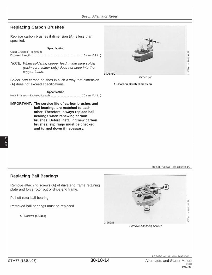
Bosch Alternator Repair
301014
RG,RG34710,2159 –19–19OCT00–1/1
Replacing Carbon Brushes
L106
780
–UN
–11J
UL8
9
Dimension
A—Carbon Brush Dimension
Replace carbon brushes if dimension (A) is less thanspecified.
SpecificationUsed Brushes—MinimumExposed Length 5 mm (0.2 in.)...................................................................
NOTE: When soldering copper lead, make sure solder(rosin-core solder only) does not seep into thecopper leads.
Solder new carbon brushes in such a way that dimension(A) does not exceed specifications.
SpecificationNew Brushes—Exposed Length 10 mm (0.4 in.).......................................
IMPORTANT: The service life of carbon brushes andball bearings are matched to eachother. Therefore, always replace ballbearings when renewing carbonbrushes. Before installing new carbonbrushes, slip rings must be checkedand turned down if necessary.
RG,RG34710,2160 –19–15MAR97–1/1
Replacing Ball Bearings
L106
781
–UN
–11J
UL8
9
Remove Attaching Screws
A—Screws (4 Used)
Remove attaching screws (A) of drive end frame retainingplate and force rotor out of drive end frame.
Pull off rotor ball bearing.
Removed ball bearings must be replaced.
CTM77 (18JUL05) 30-10-14 Alternators and Starter Motors071805
PN=280

Bosch Alternator Repair
RG,RG34710,2161 –19–15MAR97–1/2
Checking Positive Diodes
L106
782
–UN
–11J
UL8
9
Check Positive Diodes
301015
A—Positive Heat SinkB—Diode Leads
Consecutively place positive test probe of ohmmeter topositive heat sink (A) and negative test probe to leads (B)of diodes.
Meter must not show continuity.
RG,RG34710,2161 –19–15MAR97–2/2L1
0678
3–U
N–1
1JU
L89
Reversed Polarity
If no fault is found in the above described test, carry outthis test with reversed polarity (see illustration).
Meter must show continuity.
NOTE: Test voltage 6—12 volts DC.
CTM77 (18JUL05) 30-10-15 Alternators and Starter Motors071805
PN=281

Bosch Alternator Repair
RG,RG34710,2162 –19–15MAR97–1/2
Checking Negative Diodes
L106
784
–UN
–11J
UL8
9
Check Negative Diodes
301016
A—Diode LeadsB—Positive Heat Sink
Consecutively place positive test probe of ohmmeter topositive heat sink (B) and negative test probe to leads (A)of diodes.
Meter must not show continuity.
RG,RG34710,2162 –19–15MAR97–2/2
L106
785
–UN
–11J
UL8
9
Reverse Polarity
A—Diode LeadsB—Positive Heat Sink
If no fault is found in the above described test, carry outthis test with reversed polarity (see illustration).
Meter must show continuity.
NOTE: Test voltage 6—12 volts DC.
CTM77 (18JUL05) 30-10-16 Alternators and Starter Motors071805
PN=282

Bosch Alternator Repair
RG,RG34710,2163 –19–15MAR97–1/2
Testing Exciting Diodes
L106
786
–UN
–11J
UL8
9
Test Exciting Diodes
301017
A—Diode LeadsB—“D+” Connection
Place positive test probe of an ohmmeter on connection“D+” (B) and negative probe onto diode lead (A).
Meter must not show continuity.
RG,RG34710,2163 –19–15MAR97–2/2L1
0678
7–U
N–1
1JU
L89
Reverse Polarity
A—Diode LeadsB—“D+” Connection
If no fault is found in the above described test, carry outthis test with reversed polarity (see illustration).
Meter must show continuity.
NOTE: Test voltage 6—12 volts DC.
CTM77 (18JUL05) 30-10-17 Alternators and Starter Motors071805
PN=283

Bosch Alternator Repair
RG,RG34710,2164 –19–15MAR97–1/1
Diode Plate Installation
L106
772
–UN
–11J
UL8
9
Install Diode Plate
Pay attention to perfect insulation connections “B+”, “D+”and the positive diode heat sink in respect to end frame.
Install diode plate as shown and tighten screws.
301018
RG,RG34710,2165 –19–15MAR97–1/1
Soldering Stator Coils
L106
771
–UN
–11J
UL8
9
Solder Stator Coils
IMPORTANT: Use only rosin-core solder.
Make sure that no solder seeps inside diode plate.
Avoid overheating diodes.
CTM77 (18JUL05) 30-10-18 Alternators and Starter Motors071805
PN=284

Bosch Alternator Repair
RG,RG34710,2166 –19–15MAR97–1/1
Pressing Ball Bearing onto Rotor Shaft
L106
788
–UN
–11J
UL8
9
Pressing Ball Bearing Onto Rotor Shaft
For pressing on, use a sleeve which presses against theball bearing inner race.
IMPORTANT: Never press onto drive end frame;damage may result.
301019
RG,RG34710,2167 –19–15MAR97–1/1
Pressing Rotor into Drive End Frame
L106
789
–UN
–11J
UL8
9
Retaining Plate
A—Retaining Plate
Use a new retaining plate (A) when installing new ballbearing.
CTM77 (18JUL05) 30-10-19 Alternators and Starter Motors071805
PN=285

Bosch Alternator Repair
RG,RG34710,2168 –19–21SEP00–1/1
Assemble Alternator
L106
790
–UN
–11J
UL8
9
Alternator Assembly
A—Screws (4 Used)
Apply high temperature bearing grease such as BoschFT70V1 or Delco Remy No. 194891 to end frame bearingseat. Place spring washer end in frame and carefully joinboth alternator halves, paying attention to markings.
Tighten screws (A) to specifications.
SpecificationAlternator Housing Cap Screws—Torque 4.0—5.5 N•m (33—48 lb-in.)..........................................................
Check armature end play.
SpecificationArmature—End Play 0.1—0.3 mm (0.004—0.012 in.)................................
301020
RG,RG34710,2169 –19–15MAR97–1/1
Installing Brush Holder with Regulator
L106
791
–UN
–11J
UL8
9
Install Brush Holder with Regulator
A—Gasket
Carefully insert brush holder with regulator. Make surethat gasket (A) fits correctly. Tighten screws securely.
CTM77 (18JUL05) 30-10-20 Alternators and Starter Motors071805
PN=286

Bosch Alternator Repair
RG,RG34710,2170 –19–07JUL05–1/3
Fan and Belt Pulley Removal and Installation
LX10
3001
8–U
N–2
6JU
L02
Pulley
301021
A—Pulley
RG,RG34710,2170 –19–07JUL05–2/3
RX
A00
6604
3–U
N–0
5MA
R03
Pulley Tools
1. Open the hood or panels for access to pulley.
CAUTION: Disconnect negative (-) cable frombattery.
IMPORTANT: Always relieve tension on drive beltbefore removing the pulley.
2. Take the drive belt off the pulley.
3. Remove the pulley by installing KJD10227 adapter (A)in alternator pulley.
4. Using extension (C) with ratchet (D) and insertKJD10278 special socket (B) through KJD10227adapter holding alternator shaft.
5. Use a 17 mm wrench or crows foot (F) with torquewrench (E) to loosen pulley from alternator.
Continued on next page
CTM77 (18JUL05) 30-10-21 Alternators and Starter Motors071805
PN=287

Bosch Alternator Repair
301022
RG,RG34710,2170 –19–07JUL05–3/3
Ta
Tw
A
L
L+A
Tw = Ta xL
L+A
RX
A00
6121
4–U
N–1
9JU
N02
Torque Wrench
LA
900
Ta
Tw
L + A
RX
A00
6121
3–U
N–1
9JU
N02
Torque Wrench
Tw—Torque setting on wrench Ta—Torque actually being L—Length from point of force A—Application distance fromapplied to nut or cap (center of wrench handle) center of torque wrenchscrew to center of wrench head head to center of adapter
6. Using formula with torque wrench tighten alternatorpulley to specification.
Item Measurement Specification
Alternator Pulley Torque 80 N•m(60 lb-ft)
NOTE: To install alternator and adjust belt tension,refer to machine technical manual.
CTM77 (18JUL05) 30-10-22 Alternators and Starter Motors071805
PN=288

Section 35Valeo Alternators
Contents
Page
Group 05—Valeo Alternator Theory of OperationValeo Alternator Operation . . . . . . . . . . . . . . . .35-05-1Valeo Regulator Operation . . . . . . . . . . . . . . . .35-05-2
Group 10—Valeo Alternator RepairEssential Tools . . . . . . . . . . . . . . . . . . . . . . . . .35-10-1Other Material . . . . . . . . . . . . . . . . . . . . . . . . . .35-10-2Valeo Charging Circuit Repair Specifications. . .35-10-2Valeo Charging Circuit Test Specifications . . . .35-10-3Disassemble Alternator and Test
Components . . . . . . . . . . . . . . . . . . . . . . . . .35-10-3Assemble Alternator . . . . . . . . . . . . . . . . . . . . .35-10-9
Group 15—Valeo A13N-Series Alternator RepairEssential Tools . . . . . . . . . . . . . . . . . . . . . . . . .35-15-1Valeo A13N-Series Repair Specifications . . . . .35-15-2Valeo A13N-Series Test Specifications . . . . . . .35-15-2Disassemble and Test Valeo A13N-Series
Alternator . . . . . . . . . . . . . . . . . . . . . . . . . . . .35-15-3Assemble Valeo A13N-Series Alternator . . . . .35-15-10
35
CTM77 (18JUL05) 35-1 Alternators and Starter Motors071805
PN=1

Contents
35
CTM77 (18JUL05) 35-2 Alternators and Starter Motors071805
PN=2

Group 05Valeo Alternator Theory of Operation
35051
RG,RG34710,2171 –19–15MAR97–1/1
Valeo Alternator Operation
T52
184
–UN
–31M
AY
89
Valeo Alternator Operation
1—Stator2—Rotor Winding (Field)3—Rotor Slip Ring4—Brushes5—Regulator Terminal6—Output Terminal7—Isolation Diode8—Regulator
In an alternator, the magnetic field of the rotor is movedacross stationary conductors in the stator. This permits apermanent connection between the stator windings andthe output terminal. Slip rings are used to transmit thefield current to the rotor field winding.
The alternator produces power in the form of athree-phase alternating current and voltage. Thealternating current is rectified to direct current by athree-phase full-wave rectifier circuit using six siliconrectifier diodes. Since the diode will pass current in onlyone direction (from alternator to battery or load), thealternator does not require the use of a cutout relay.
The entire DC output of the system passes through theisolation diode. This provides the system with severaldistinct advantages. It prevents the battery fromdischarging through the regulator and alternator fieldwithout the use of relays or switches. Electrically, theindicator lamp is connected across the isolation diode.When the system is operating properly, the alternatoroutput voltage is very nearly the same as the batteryvoltage. This means that the voltage potential across theisolation diode is low and the indicator lamp shows thatthe alternator is charging.
The alternator output current is controlled by the currentflow through the field coil (rotor). The amount of currentrequired is determined and controlled by the regulator.Since there is very little residual magnetism in thealternator, it is necessary to supply a small amount ofexcitation current to the field (rotor) to start the process ofcurrent generation. The excitation resistor supplies thisstarting current when the key switch is turned on. Thisresistor is enclosed in the sealed regulator case. Once thealternator is excited, a voltage is developed at theregulator terminal and the voltage regulator takes overcontrol of the system voltage.
CTM77 (18JUL05) 35-05-1 Alternators and Starter Motors071805
PN=291

Valeo Alternator Theory of Operation
3505
2
RG,RG34710,2172 –19–06MAY02–1/5
Valeo Regulator Operation
T51
537
–UN
–02J
UN
89
Valeo Regulator Operation
1—Thermistor (RT)2—Field Discharge Diode3—Transistor (T-2)4—Transistor (T-1)5—Zener Diode6—Excitation Resistor7—To Alternator Indicator Light
The transistor regulator is an electronic switching devicecomposed principally of transistors, resistor, and diodes toform a completely static unit containing no moving parts.
The transistors are used to switch the alternator fieldcurrent on and off and are controlled by the resistors andthe Zener diode.
A Zener diode is a special diode that will break down andpermit a reverse flow of current when the voltage reachesa certain value, without damaging the semiconductormaterial. This diode is the trigger which senses themaximum desired voltage and turns the transistor on oroff to limit charging system voltage.
The field discharge diode provides an alternator currentpath to protect the transistors from induced high voltagefrom the alternator field windings. The sudden stopping offield current by the transistor and subsequent collapsing ofthe magnetic field cause an induced voltage in the rotorwindings.
The thermistor (RT) is a temperature compensatingresistor. Its resistance varies with temperature andcontrols the operating point of the Zener diode so that ahigh system voltage is produced in cold weather whenneeded, and a lower system voltage in warm weather.
When the voltage appearing at the output terminal of thealternator rises to a predetermined value (1.44 volts), thevoltage which appears across the Zener diode permitscurrent to flow in the base of transistor T-1. This causestransistor T-1 to turn on and reverse bias transistor T-2,thus turning off the current applied to the alternator field.
When the system voltage drops below the predeterminedvalue, the Zener diode stops conducting, T-1 turns off andT-2 turns on. When transistor T-2 is switched on, fieldcurrent again is supplied to the alternator.
The operation of transistor T-2 is in effect like a switch,turning the alternator field current on and off as theelectrical supply varies due to the varying electrical load.This action occurs many times a second, so fast it cannotbe detected in the alternator output.
CTM77 (18JUL05) 35-05-2 Alternators and Starter Motors071805
PN=292
Continued on next page

Valeo Alternator Theory of Operation
RG,RG34710,2172 –19–06MAY02–2/5
The solid-state regulator is either mounted on rear ofalternator or mounted internally. It controls output bycontrolling current through the field. In operation, theregulator has the following three phases.
35053
RG,RG34710,2172 –19–06MAY02–3/5
N37
761
–UN
–02M
AY
89
Phase I—Alternator Stopped
A—RegulatorB—BatteryC—Key SwitchD—RotorE—Field WindingsF—Delta StatorG—Rectifier DiodesH—Diode TrioI—Suppression Capacitor
Phase I—Alternator Stopped
(Phase I also applies when alternator is running but only ifnot running fast enough for output to exceed batteryvoltage.)
1. Current flows from battery (B) through key switch (C)to regulator (A).
2. From there, current flows through resistors R8, R7, andR1 to transistor Q2, turning it on.
3. Transistor Q2 then provides a path so current can flowthrough field (E) to ground, enabling alternator togenerate electricity.
4. Zener diode D1 prevents flow of current to transistorQ1. A Zener diode is a special type of diode which willnot permit current to pass until voltage reaches acertain preset level. If voltage exceeds that level,current can pass through the Zener diode.
CTM77 (18JUL05) 35-05-3 Alternators and Starter Motors071805
PN=293
Continued on next page

Valeo Alternator Theory of Operation
3505
4
RG,RG34710,2172 –19–06MAY02–4/5
N37
762
–UN
–02M
AY
89
Phase II—Generating Electricity
A—RegulatorB—BatteryC—Key SwitchD—RotorE—Field WindingsF—Delta StatorG—Rectifier DiodesH—Diode TrioI—Suppression Capacitor
Phase II—Generating Electricity
1. The key switch (C) and rectifier bridge diodes (G) allhave equal voltage. Therefore, no current flows fromkey switch to regulator.
2. Current, now coming from rectifier bridge diodes, flowsthrough resistors R7 and R1 to turn on transistor Q2.
3. Transistor Q2 still provides a path to ground throughfield (E), enabling alternator to generate electricity.
4. Since the field is rotating, it does generate electricity.Alternating current is induced in the stator windings (F).The rectifier bridge converts it to direct current,providing current to run electrical accessories andcharge the battery.
5. Output voltage still has not reached critical voltage ofthe Zener diode D1.
Continued on next page
CTM77 (18JUL05) 35-05-4 Alternators and Starter Motors071805
PN=294

Valeo Alternator Theory of Operation
35055
RG,RG34710,2172 –19–06MAY02–5/5
N37
763
–UN
–02M
AY
89Phase III—Shut-Off
A—RegulatorB—BatteryC—Key SwitchD—RotorE—Field WindingsF—Delta StatorG—Rectifier DiodesH—Diode TrioI—Suppression Capacitor
Phase III—Shut-Off
1. Output voltage reaches critical voltage of Zener diodeD1.
2. Current can now pass through Zener diode D1 to turnon control transistor Q1.
3. Current from transistor Q1 cuts off voltage to transistorQ2, turning it off. There is now no path to ground forcurrent through field (E).
4. Current through field is shut off instantly, and alternatorstops generating electricity.
5. With transistor Q2 off, system voltage starts to drop inunrestricted fashion until it falls below the Zener diodeD1 critical voltage. When this occurs, Zener diode D1and transistor Q1 switch off and Q2 turns on again.
6. Phases II and III are repeated many times per secondto maintain voltage at proper level.
CTM77 (18JUL05) 35-05-5 Alternators and Starter Motors071805
PN=295

Valeo Alternator Theory of Operation
3505
6
CTM77 (18JUL05) 35-05-6 Alternators and Starter Motors071805
PN=296

Group 10Valeo Alternator Repair
OUO1004,0000B80 –19–08MAY02–1/3
Essential Tools
NOTE: Order tools according to information given in theU.S. SERVICEGARD Catalog or from theEuropean Microfiche Tool Catalog (MTC).
SERVICEGARD is a trademark of Deere & Company
35101OUO1004,0000B80 –19–08MAY02–2/3
RW
1127
4–U
N–1
2DE
C88
JT05791
Digital Multimeter . . . . . . . . . . . . . . . . . . . . . JT05791
Test electrical components for voltage, resistance, orcurrent flow. It is especially good for measuring lowvoltage or high resistance circuits.
OUO1004,0000B80 –19–08MAY02–3/3
Alternator, Generator, Starter and Battery BenchTester . . . . . . . . . . . . . . . . . . . . . . . . . . . . . JT01760
Test alternators and starters for voltage, resistance, orcurrent flow.
CTM77 (18JUL05) 35-10-1 Alternators and Starter Motors071805
PN=297

Valeo Alternator Repair
OUO1004,0000B82 –19–21SEP00–1/1
Other Material
Number Name Use
TY16285 (U.S.) Thread Lock and Sealer (Low Apply to front bearing plate andCXTY24311 (Canadian) Strength) housing through bolts.222 (LOCTITE)
LOCTITE is a registered trademark of Loctite Corp.
3510
2 OUO1004,0000B83 –19–21SEP00–1/1
Valeo Charging Circuit Repair Specifications
Item Measurement Specification
Alternator Housing Through Bolts Torque 5 N•m (44 lb-in.)
Pulley Nut Torque 61 N•m (45 lb-ft)
Ground (—) Terminal Nut Torque 4 N•m (35 lb-in.)
Optional Terminal Nut Torque 4 N•m (35 lb-in.)
Battery Positive (+) Terminal Nut Torque 5 N•m (44 lb-in.)
CTM77 (18JUL05) 35-10-2 Alternators and Starter Motors071805
PN=298

Valeo Alternator Repair
35103RG,RG34710,2174 –19–07JUL05–1/1
Valeo Charging Circuit Test Specifications
NOTE: Formerly Motorola alternators made in France.
Min. Output @ 25°C (77°F)
John DeereValeo Alternator Field Current
Alternator Part Pulley Grooves Rated Amps Amps RPMPart No. (Volts)
No.
RE20600 2940090a W/O 35 14 26—30 3000—4000
RE30838 2518033b Dual 35 14 26—30 3000—4000
RE40575 2518032b Single 35 14 26—30 3000—4000
RE40576 2518073b Single 80 14 68—78 3000—4000aWith additional resistor.bWith included regulator (Packard connector).
Item Specification
Maximum Continuous Speed 12000 rpm
Maximum Intermittent Speed 16000 rpm
Maximum Recommended Working Temperature 80°C (176°F)
RG,RG34710,2175 –19–15MAR97–1/19
Disassemble Alternator and TestComponents
CD
5712
–UN
–26J
UL8
9
Unscrew Cover Attaching Screws
1—Screws (3 Used)
1. Remove regulator after having identified the colorcoding of the wires.
2. Unscrew the three cover attaching screws (1) andremove cover.
CTM77 (18JUL05) 35-10-3 Alternators and Starter Motors071805
PN=299
Continued on next page

Valeo Alternator Repair
RG,RG34710,2175 –19–15MAR97–2/19
CD
5713
–UN
–26J
UL8
9
Remove Brush Assembly
3. Remove the brush assembly with caution and turn ittoward the outside in order to protect the brushes.
4. Inspect brushes. If either one is worn, cracked or oilsoaked, replace the brush assembly.
RG,RG34710,2175 –19–15MAR97–3/19
CD
5714
–UN
–26J
UL8
9
JT05791 Digital Multimeter
5. Touch each brush with test leads using JT05791Digital Multimeter. No continuity should be found, evenif either brush has slid up or down in its channel. Ifthere is continuity, replace the brush assembly.
3510
4
RG,RG34710,2175 –19–15MAR97–4/19
CD
5715
–UN
–26J
UL8
9
Connect Test Leads
6. Connect the test leads of JT05791 Digital Multimeteron the field terminal and on its corresponding brush.Continuity should be found even when movingbrushes. If there is no continuity, replace the brushassembly.
RG,RG34710,2175 –19–15MAR97–5/19
CD
5716
–UN
–26J
UL8
9
Test for Continuity
7. Connect the test leads of JT05791 Digital Multimeteron the second terminal and on its corresponding brush.Continuity should be found even when movingbrushes. If there is no continuity, replace the brushassembly.
CTM77 (18JUL05) 35-10-4 Alternators and Starter Motors071805
PN=300
Continued on next page
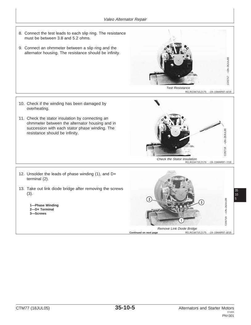
Valeo Alternator Repair
RG,RG34710,2175 –19–15MAR97–6/19
CD
5717
–UN
–26J
UL8
9
Test Resistance
8. Connect the test leads to each slip ring. The resistancemust be between 3.8 and 5.2 ohms.
9. Connect an ohmmeter between a slip ring and thealternator housing. The resistance should be infinity.
RG,RG34710,2175 –19–15MAR97–7/19
CD
5718
–UN
–26J
UL8
9
Check the Stator Insulation
10. Check if the winding has been damaged byoverheating.
11. Check the stator insulation by connecting anohmmeter between the alternator housing and insuccession with each stator phase winding. Theresistance should be infinity.
35105
RG,RG34710,2175 –19–15MAR97–8/19
CD
5719
–UN
–26J
UL8
9Remove Link Diode Bridge
1—Phase Winding2—D+ Terminal3—Screws
12. Unsolder the leads of phase winding (1), and D+terminal (2).
13. Take out link diode bridge after removing the screws(3).
Continued on next page
CTM77 (18JUL05) 35-10-5 Alternators and Starter Motors071805
PN=301

Valeo Alternator Repair
RG,RG34710,2175 –19–15MAR97–9/19
CD
5720
–UN
–26J
UL8
9
Test Diode
14. Using a power supply not exceeding 12 volts and anindicator lamp in series, check the current flowthrough each diode.
15. Test positive diodes by connecting the indicator lampbetween each phase terminal and the B+ terminal.Just touch the lamp probes briefly.
If the indicator lamp lights only in one direction, thediode is good. Continue testing diode as outlined instep 16.
If the indicator lamp lights in both directions, the diodeis shorted. Replace diode.
If the indicator lamp does not light in either direction,the diode circuit is open. Replace diode.
3510
6
RG,RG34710,2175 –19–15MAR97–10/19
CD
5721
–UN
–26J
UL8
9
Test Diodes
16. Test negative diodes by connecting the lamp betweeneach phase terminal and the heat sink.
If the indicator lamp lights only in one direction, thediode is good. Continue with step 17.
If the indicator lamp lights in both directions, the diodeis shorted. Replace diode.
If the indicator lamp does not light in either direction,the diode is open circuit. Replace diode.
17. Test the trio by connecting the test leads on the D+terminal and on each phase terminal in sequence.Then reverse the polarity.
Continued on next page
CTM77 (18JUL05) 35-10-6 Alternators and Starter Motors071805
PN=302

Valeo Alternator Repair
RG,RG34710,2175 –19–15MAR97–11/19
CD
5722
–UN
–26J
UL8
9
Remove Through Bolts
18. Note the orientation of the housing and take out thefour through bolts.
RG,RG34710,2175 –19–15MAR97–12/19
CD
5723
–UN
–26J
UL8
9
Remove Rear Housing
19. Remove the rear housing. If it is glued to the stator,take care not to damage the winding.
35107
RG,RG34710,2175 –19–15MAR97–13/19
CD
5724
–UN
–26J
UL8
9
Remove O-Ring
20. Remove O-ring from rear bearing bore.
RG,RG34710,2175 –19–15MAR97–14/19
CD
5725
–UN
–26J
UL8
9
Remove Stator
21. Remove stator from front housing.
CTM77 (18JUL05) 35-10-7 Alternators and Starter Motors071805
PN=303
Continued on next page

Valeo Alternator Repair
RG,RG34710,2175 –19–15MAR97–15/19
CD
5726
–UN
–26J
UL8
9
Remove Pulley Nut and Lock Washer
22. Remove pulley nut and lock washer.
23. Pull alternator from pulley. Remove fan.
RG,RG34710,2175 –19–15MAR97–16/19
CD
5727
–UN
–26J
UL8
9
Press Rotor Out
24. Press rotor out of front housing.
3510
8
RG,RG34710,2175 –19–15MAR97–17/19
CD
5728
–UN
–26J
UL8
9
Remove Rear Bearing
25. Remove rear bearing using a suitable puller.
RG,RG34710,2175 –19–15MAR97–18/19
CD
5729
–UN
–26J
UL8
9
Unscrew Screws
26. Unscrew the three screws securing the bearing plate.
CTM77 (18JUL05) 35-10-8 Alternators and Starter Motors071805
PN=304
Continued on next page

Valeo Alternator Repair
RG,RG34710,2175 –19–15MAR97–19/19
CD
5730
–UN
–26J
UL8
9
Extract the Front Bearing
27. Extract the front bearing.
RG,RG34710,2176 –19–15MAR97–1/11
Assemble Alternator
CD
5731
–UN
–26J
UL8
9
Assemble Alternator
1. Fit the front bearing to its housing by pressing on theouter ring as shown.
2. Install the bearing plate. Apply LOCTITE 222 ThreadLock and Sealer (low strength) on the threads of thethree screws and tighten.
35109
LOCTITE is a registered trademark of Loctite Corp.
RG,RG34710,2176 –19–15MAR97–2/11
CD
5732
–UN
–26J
UL8
9
Press Rear Bearing onto Rotor
3. Press rear bearing onto rotor using a suitable driver.
RG,RG34710,2176 –19–15MAR97–3/11
CD
5733
–UN
–26J
UL8
9
Install Rotor
4. Install rotor into front housing.
CTM77 (18JUL05) 35-10-9 Alternators and Starter Motors071805
PN=305
Continued on next page

Valeo Alternator Repair
RG,RG34710,2176 –19–15MAR97–4/11
CD
5725
–UN
–26J
UL8
9
Install Stator
5. Install stator.
RG,RG34710,2176 –19–15MAR97–5/11
CD
5734
–UN
–26J
UL8
9
Install Rear Housing
6. Install rear housing, taking care that marks made whendisassembling are in line. Use a new O-ring in rearbearing bore.
351010
RG,RG34710,2176 –19–15MAR97–6/11
CD
5722
–UN
–26J
UL8
9
Install Through Bolts
7. Install the four through bolts. Apply LOCTITE 222Thread Lock and Sealer (low strength) on the threadsof the through bolts and tighten to specifications.
SpecificationAlternator Housing ThroughBolts—Torque 5 N•m (44 lb-in.)...................................................................
LOCTITE is a registered trademark of Loctite Corp.
RG,RG34710,2176 –19–15MAR97–7/11
CD
5735
–UN
–26J
UL8
9
Install Fan
8. Install fan.
CTM77 (18JUL05) 35-10-10 Alternators and Starter Motors071805
PN=306
Continued on next page

Valeo Alternator Repair
RG,RG34710,2176 –19–15MAR97–8/11
CD
5726
–UN
–26J
UL8
9
Tighten Pulley Nut
9. Install pulley, nut and lock washer. Tighten the pulleynut to specifications.
SpecificationPulley Nut—Torque 61 N•m (45 lb-ft).........................................................
RG,RG34710,2176 –19–15MAR97–9/11
CD
5719
–UN
–26J
UL8
9
Install Diode Bridge
351011
1—Phase Winding2—D+ Terminal3—Screws
10. Install the diode bridge and tighten screws (3).
11. Solder the leads of phase winding (1) and D+ terminal(2). DO NOT use acid-core solder.
RG,RG34710,2176 –19–15MAR97–10/11
CD
5713
–UN
–26J
UL8
9
Install Brush Assembly
12. Install the brush assembly.
Continued on next page
CTM77 (18JUL05) 35-10-11 Alternators and Starter Motors071805
PN=307

Valeo Alternator Repair
RG,RG34710,2176 –19–15MAR97–11/11
CD
5712
–UN
–26J
UL8
9
Installation and Adjustments
1—Screws (3 Used)
13. Install the rear cover. Tighten the three screws (1).
14. Install regulator. It is essential that connections bemade correctly; reversals will cause damage.
15. Refer to your machine technical manual for alternatorinstallation and proper V-belt adjustments.
16. Tighten terminal nuts to specifications.
SpecificationGround (—) Terminal Nut—Torque 4 N•m (35 lb-in.)..............................................................................Optional Terminal Nut—Torque 4 N•m (35 lb-in.).......................................Battery Positive (+) TerminalNut—Torque 5 N•m (44 lb-in.).....................................................................
351012
CTM77 (18JUL05) 35-10-12 Alternators and Starter Motors071805
PN=308

Group 15Valeo A13N-Series Alternator Repair
OUO1004,0000B84 –19–08MAY02–1/3
Essential Tools
NOTE: Order tools according to information given in theU.S. SERVICEGARD Catalog or from theEuropean Microfiche Tool Catalog (MTC).
SERVICEGARD is a trademark of Deere & Company
35151OUO1004,0000B84 –19–08MAY02–2/3
RW
1127
4–U
N–1
2DE
C88
JT05791
Digital Multimeter . . . . . . . . . . . . . . . . . . . . . JT05791
Test electrical components for voltage, resistance, orcurrent flow. It is especially good for measuring lowvoltage or high resistance circuits.
OUO1004,0000B84 –19–08MAY02–3/3
Alternator, Generator, Starter and Battery BenchTester . . . . . . . . . . . . . . . . . . . . . . . . . . . . . JT01760
Test alternators and starters for voltage, resistance, orcurrent flow.
CTM77 (18JUL05) 35-15-1 Alternators and Starter Motors071805
PN=309

Valeo A13N-Series Alternator Repair
OUO1004,0000B87 –19–21SEP00–1/1
Valeo A13N-Series Repair Specifications
Item Measurement Specification
Ground (B—) Terminal Nut Torque 4 N•m (35 lb-in.)
Output (B+) Terminal Nut Torque 5 N•m (44 lb-in.)
Front-to-Rear Housing Through Bolts Torque 5 N•m (44 lb-in.)
Pulley-to-Shaft Nut Torque 55 N•m (41 lb-ft)
3515
2
RG,RG34710,2177 –19–07JUL05–1/1
Valeo A13N-Series Test Specifications
Min. Output@ 25°C (77°F)
John Deere Valeo Alternator Pulley Ground Rated Amps Alt. RPMAlternator Model No. Grooves (Amps)Part No.
RE53906 2541673 Single N 50 39—43 3000—4000
Item Specification
Rotor winding resistance 3.6 ohms
Stator resistance 0.000 ohms
Alternator output voltage 13.7—14.7 volts
Maximum recommended working temperature 80°C (176°F)
Maximum continuous alternator speed 9000 rpm
CTM77 (18JUL05) 35-15-2 Alternators and Starter Motors071805
PN=310

Valeo A13N-Series Alternator Repair
35153DPSG,RG34710,102 –19–13SEP99–1/15
Disassemble and Test Valeo A13N-Series Alternator
CD
3036
3–U
N–1
4AP
R94
Valeo A13N-Series Alternator
1—Nut 6—Fan Spacer 11—Rotor 16—Regulator and Brush2—Washer 7—Front Housing 12—Rear Ball Bearing Assembly3—Pulley 8—Through-Bolt (4 Used) 13—Plastic Ball Bearing Cage 17—Rear Cover4—Spacer 9—Front Ball Bearing 14—Rear Housing5—Fan 10—Stator 15—Rectifier Diode Bridge and
Diode-Trio Assembly
DPSG,RG34710,102 –19–13SEP99–2/15
CD
3036
4–U
N–1
4AP
R94
Remove Regulator/Brush Assembly
A—Rear CoverB—Regulator/Brush Assembly
1. Pull out the rear cover (A).
2. Remove regulator/brush assembly (B).
CTM77 (18JUL05) 35-15-3 Alternators and Starter Motors071805
PN=311
Continued on next page

Valeo A13N-Series Alternator Repair
DPSG,RG34710,102 –19–13SEP99–3/15
CD
3036
5–U
N–1
4AP
R94
Inspect Brushes
3. Inspect brushes. If either one is worn, cracked or oilsoaked, replace the regulator/brushes assembly.
4. Touch each brush with test leads. No continuity shouldbe found even if either brush has slid up or down in itschannel. If there is continuity, replace the brushassembly.
3515
4
DPSG,RG34710,102 –19–13SEP99–4/15
CD
3036
6–U
N–1
4AP
R94
Check for Continuity
A—TerminalB—BrushC—Metallic Regulator BoxD—Brush
5. Check for continuity between terminal (A) and brush(B) and between metallic box of regulator (C) andbrush (D). If there is no continuity at either brush,replace the brush assembly.
Continued on next page
CTM77 (18JUL05) 35-15-4 Alternators and Starter Motors071805
PN=312

Valeo A13N-Series Alternator Repair
DPSG,RG34710,102 –19–13SEP99–5/15
CD
3036
7–U
N–1
4AP
R94
Check Resistance
6. Connect the test leads to each slip ring of the rotor.The ohmmeter should read a resistance of 3.60 ohms.
7. Connect the ohmmeter between a slip ring and thealternator housing. The resistance should be infinity.
35155
DPSG,RG34710,102 –19–13SEP99–6/15C
D30
368
–UN
–14A
PR
94
Check Winding for Damage
8. Check if the winding has been damaged byoverheating.
9. Check the stator insulation by connecting an ohmmeterbetween the alternator housing and in succession witheach stator phase winding. The resistance should beinfinity.
Continued on next page
CTM77 (18JUL05) 35-15-5 Alternators and Starter Motors071805
PN=313

Valeo A13N-Series Alternator Repair
DPSG,RG34710,102 –19–13SEP99–7/15
CD
3036
9–U
N–1
4AP
R94
Remove Rectifier Diode Bridge/Diode Trio
3515
A—Phase WindingB—Screw and Nuts
10. Unsolder the leads of phase winding (A).
11. Take out the rectifier diode bridge/diode trio assemblyafter removing the screw and nuts (B).
6
DPSG,RG34710,102 –19–13SEP99–8/15
CD
3037
0–U
N–1
4AP
R94
Test Positive Diodes
A—Positive PlateB—Three Terminals
12. Test positive diodes. Test for continuity between thepositive plate (A) and each of three terminals (B).Continuity should be observed in one direction only.
Replace entire rectifier diode bridge if any diode failstest.
Continued on next page
CTM77 (18JUL05) 35-15-6 Alternators and Starter Motors071805
PN=314

Valeo A13N-Series Alternator Repair
DPSG,RG34710,102 –19–13SEP99–9/15
CD
3037
1–U
N–1
4AP
R94
Test Negative Diodes
3515
A—Negative PlateB—Three PhasesC—Diode Trio Terminal
13. Test negative diodes. Test for continuity between thenegative plate (A) and each of three phases (B).
14. Test the diode trio by connecting the test leads oneach phase (B) with the corresponding diode trioterminal (C).
Continuity should be observed in one direction only.Replace entire rectifier diode bridge if any diode failstest.
7
DPSG,RG34710,102 –19–13SEP99–10/15C
D30
372
–UN
–14A
PR
94
Remove Through Bolts
15. Note the orientation of the housing and take out thefour through bolts.
Continued on next page
CTM77 (18JUL05) 35-15-7 Alternators and Starter Motors071805
PN=315

Valeo A13N-Series Alternator Repair
DPSG,RG34710,102 –19–13SEP99–11/15
CD
3037
3–U
N–1
4AP
R94
Remove Rear Housing
16. Remove the rear housing. If it is glued to the stator,take care not to damage the winding.
3515
8 DPSG,RG34710,102 –19–13SEP99–12/15
CD
5725
–UN
–26J
UL8
9
Remove Stator
17. Remove stator from housing.
DPSG,RG34710,102 –19–13SEP99–13/15
CD
3037
4–U
N–1
4AP
R94
Remove Pulley and Fan
18. Remove pulley and fan. Note the order of washersand spacers to ensure a proper reinstallation.
CTM77 (18JUL05) 35-15-8 Alternators and Starter Motors071805
PN=316
Continued on next page

Valeo A13N-Series Alternator Repair
DPSG,RG34710,102 –19–13SEP99–14/15
CD
5727
–UN
–26J
UL8
9
Press Rotor Out of Front Housing
19. Press rotor out of front housing.
DPSG,RG34710,102 –19–13SEP99–15/15
CD
5728
–UN
–26J
UL8
9
Remove Rear Ball Bearing
20. Remove rear ball bearing using a suitable puller.
NOTE: Since the front ball bearing is set in front housing,it cannot be removed. If required, replace the fronthousing/ball bearing assembly.
35159
CTM77 (18JUL05) 35-15-9 Alternators and Starter Motors071805
PN=317

Valeo A13N-Series Alternator Repair
351510
RG,RG34710,2178 –19–15MAR97–1/1
Assemble Valeo A13N-Series Alternator
CD
3037
5–U
N–0
8DE
C94
Valeo A13N-Series Alternator
1—Through Bolt (4 Used) 2—Pulley Nut
Assemble alternator in the reverse sequence ofdisassembly procedure using the following torquespecifications.
Item Measurement Specification
Ground (B—) Terminal Nut Torque 4 N•m (35 lb-in.)
Output (B+) Terminal Nut Torque 5 N•m (44 lb-in.)
Front-to-Rear Housing Through Bolts Torque 5 N•m (44 lb-in.)
Pulley-to-Shaft Nut Torque 55 N•m (41 lb-ft)
CTM77 (18JUL05) 35-15-10 Alternators and Starter Motors071805
PN=318

Section 40Magneton Alternators
Contents
Page
Group 05—Magneton Alternator Theory ofOperation
Operation of Alternator . . . . . . . . . . . . . . . . . . .40-05-1
Group 10—Magneton Alternator RepairEssential Tools . . . . . . . . . . . . . . . . . . . . . . . . .40-10-1Magneton Charging Circuit Repair
Specifications. . . . . . . . . . . . . . . . . . . . . . . . .40-10-2Magneton Charging Circuit Test
Specifications. . . . . . . . . . . . . . . . . . . . . . . . .40-10-3Exploded View of Alternator . . . . . . . . . . . . . . .40-10-4Identification . . . . . . . . . . . . . . . . . . . . . . . . . . .40-10-5Troubleshooting. . . . . . . . . . . . . . . . . . . . . . . . .40-10-6Disassembly of Alternator . . . . . . . . . . . . . . . . .40-10-7Testing Brush/Regulator Assembly . . . . . . . . . .40-10-9Testing Rotor . . . . . . . . . . . . . . . . . . . . . . . . .40-10-10Testing Stator/Rectifier Bridge Assembly. . . . .40-10-11Rectifier Bridge Replacement . . . . . . . . . . . . .40-10-12Reassembly of Alternator . . . . . . . . . . . . . . . .40-10-12Installation of Alternator. . . . . . . . . . . . . . . . . .40-10-14
40
CTM77 (18JUL05) 40-1 Alternators and Starter Motors071805
PN=1

Contents
40
CTM77 (18JUL05) 40-2 Alternators and Starter Motors071805
PN=2

Group 05Magneton Alternator Theory of Operation
40051
RG,RG34710,2179 –19–06MAY02–1/1
Operation of Alternator
CD
3048
9–U
N–0
7JA
N97
Magneton Alternator
A—Alternator D—Regulator G—Ignition J—Diode TrioB—Current Coil (Stator) E—Battery H—Protection Device K—Rectifier Diode BridgeC—Exciting Coil (Rotor) F—Indicator Light
The Magneton alternator is a synchronous three-phasegenerator. The current coil is located in the stator, andthe exciting current is supplied by the diode trio (J)through the regulator (D+ circuit), two carbon brushesand slip rings to the exciting coil in the rotor.
The alternator is normally driven by the fan belt fromthe engine crankshaft. The rotor is supported by twopermanently lubricated bearings.
The alternator generates alternating current which isthen transformed into direct current by the rectifierdiode bridge (K).
The alternating windings are delta-connected. The coilends X, Y, and Z are connected to the rectifier diode
as shown. Alternating current is generated in eachstator coil (B) of the alternator. During one revolutionof the rotor (C), the voltage in the stator coil rises from0 to the positive maximum, drops to 0, rises to thenegative maximum and again drops to 0. The currentthen flows through the diode and terminal B+ directlyto the positive pole of the battery.
A sealed electronic regulator is used to regulatealternator voltage. This regulator, which cannot beadjusted, limits the alternator voltage to approximately14 volts.
A protection device (H), including a Zener diode and acapacitor, protects diode from voltage surges andsuppresses radio interference.
CTM77 (18JUL05) 40-05-1 Alternators and Starter Motors071805
PN=321

Magneton Alternator Theory of Operation
4005
2
CTM77 (18JUL05) 40-05-2 Alternators and Starter Motors071805
PN=322

Group 10Magneton Alternator Repair
OUO1004,0000B88 –19–08MAY02–1/3
Essential Tools
NOTE: Order tools according to information given in theU.S. SERVICEGARD Catalog or from theEuropean Microfiche Tool Catalog (MTC).
SERVICEGARD is a trademark of Deere & Company
OUO1004,0000B88 –19–08MAY02–2/3
RW
1127
4–U
N–1
2DE
C88
JT05791
Digital Multimeter . . . . . . . . . . . . . . . . . . . . . JT05791
Test electrical components for voltage, resistance, orcurrent flow. It is especially good for measuring lowvoltage or high resistance circuits.
40101
OUO1004,0000B88 –19–08MAY02–3/3
Alternator, Generator, Starter and Battery BenchTester . . . . . . . . . . . . . . . . . . . . . . . . . . . . . JT01760
Test alternators and starters for voltage, resistance, orcurrent flow.
CTM77 (18JUL05) 40-10-1 Alternators and Starter Motors071805
PN=323

Magneton Alternator Repair
OUO1004,0000B8B –19–21SEP00–1/1
Magneton Charging Circuit RepairSpecifications
Item Measurement Specification
Brush Minimum Exposed Length 7 mm (0.27 in.)
Rectifier Bridge-to-Rear Housing Torque 3 N•m (27 lb-in.)Nuts
Capacitor Mounting Nut Torque 3 N•m (27 lb-in.)
B+ Terminal Nut Torque 4 N•m (35 lb-in.)
“W” Terminal Nut Torque 3 N•m (27 lb-in.)
Front-to-Rear Housing Bolts Torque 3 N•m (27 lb-in.)
Alternator Pulley Nut Torque 40 N•m (29 lb-ft)
4010
2
CTM77 (18JUL05) 40-10-2 Alternators and Starter Motors071805
PN=324
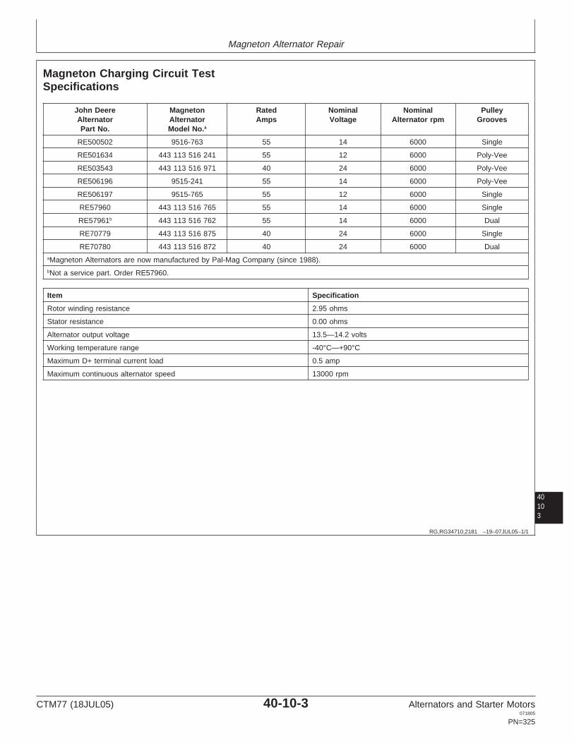
Magneton Alternator Repair
40103
RG,RG34710,2181 –19–07JUL05–1/1
Magneton Charging Circuit TestSpecifications
John Deere Magneton Rated Nominal Nominal PulleyAlternator Alternator Amps Voltage Alternator rpm GroovesPart No. Model No.a
RE500502 9516-763 55 14 6000 Single
RE501634 443 113 516 241 55 12 6000 Poly-Vee
RE503543 443 113 516 971 40 24 6000 Poly-Vee
RE506196 9515-241 55 14 6000 Poly-Vee
RE506197 9515-765 55 12 6000 Single
RE57960 443 113 516 765 55 14 6000 Single
RE57961b 443 113 516 762 55 14 6000 Dual
RE70779 443 113 516 875 40 24 6000 Single
RE70780 443 113 516 872 40 24 6000 DualaMagneton Alternators are now manufactured by Pal-Mag Company (since 1988).bNot a service part. Order RE57960.
Item Specification
Rotor winding resistance 2.95 ohms
Stator resistance 0.00 ohms
Alternator output voltage 13.5—14.2 volts
Working temperature range -40°C—+90°C
Maximum D+ terminal current load 0.5 amp
Maximum continuous alternator speed 13000 rpm
CTM77 (18JUL05) 40-10-3 Alternators and Starter Motors071805
PN=325

Magneton Alternator Repair
4010
4
RG,RG34710,2182 –19–15MAR97–1/1
Exploded View of Alternator
CD
3048
8–U
N–1
3DE
C96
Alternator—Exploded View
1—Pulley Nut, M14 x 1.5 5—Rotor 9—Front Bearing 12—Rectifier Bridge Assembly1
2—Lock Washer 6—Rear Bearing 10—Front Housing 13—Capacitor1
3—Pulley1 7—Spring Collar 11—Regulator and Brush 14—Rear Housing4—Fan 8—Stator Assembly1
1 Available as service parts.
CTM77 (18JUL05) 40-10-4 Alternators and Starter Motors071805
PN=326

Magneton Alternator Repair
RG,RG34710,2183 –19–15MAR97–1/1
Identification
CD
3047
0–U
N–1
3DE
C96
Parts Identification
The information for parts identification is stamped on thebody of the alternator.
40105
CTM77 (18JUL05) 40-10-5 Alternators and Starter Motors071805
PN=327

Magneton Alternator Repair
4010
6
RG,RG34710,2184 –19–19OCT00–1/1
Troubleshooting
Symptom Problem Solution
Alternator indicator light stays Loose connection Checkoff with ignition on and enginenot running.
Regulator failure Replace brush/regulator assembly
Stator failure (short-circuit) Replace complete alternator.
Alternator indicator light stays Drive belt loose or broken Adjust tension or replaceon with engine running(alternator is not charging) at anyspeed.
Loose connection Check
Brush/regulator or capacitor failure Replace
Diode failure Replace complete rectifier bridge
Stator failure Replace complete alternator
Rotor failure Replace complete alternator
Alternator indicator light stays Alternator speed too low Use smaller alternator pulleyon with engine running(alternator is not charging) at lowspeed.
Battery overcharging. Low electrical consumption Use regulator with narrowerregulation range (RE69380)
Regulator failure Replace
CTM77 (18JUL05) 40-10-6 Alternators and Starter Motors071805
PN=328

Magneton Alternator Repair
RG,RG34710,2185 –19–12SEP02–1/7
Disassembly of Alternator
ZT
0613
–UN
–01F
EB
94
Remove Pulley Nut
A—Pulley Nut
1. Remove pulley nut (A), lock washer, pulley and fanfrom shaft.
40107
RG,RG34710,2185 –19–12SEP02–2/7Z
T06
14–U
N–0
1FE
B94
Remove Shaft Key and Spacer
B—Shaft KeyC—Spacer
2. Remove shaft key (B) and spacer (C) from shaft.
Continued on next page
CTM77 (18JUL05) 40-10-7 Alternators and Starter Motors071805
PN=329

Magneton Alternator Repair
RG,RG34710,2185 –19–12SEP02–3/7
CD
3047
1–U
N–1
3DE
C96
Remove Brush/Regulator Assembly
D—WireE—Screws and Washers
3. Disconnect wire (D) from terminal. Remove screws andwashers (E). Remove brush/regulator assembly bytilting top of regulator up and away from alternator.
4010
8
RG,RG34710,2185 –19–12SEP02–4/7
ZT
0616
–UN
–01F
EB
94
Remove Bolts
A—Bolts (3 Used)
4. Remove the three bolts (A) from front housing side.
RG,RG34710,2185 –19–12SEP02–5/7
CD
3047
2–U
N–1
3DE
C96
Split Alternator
B—Slot
5. Place alignment marks along the alternator to note theorientation of housings. Split alternator by carefullyprying at slot (B) using a screwdriver against housing.
CTM77 (18JUL05) 40-10-8 Alternators and Starter Motors071805
PN=330
Continued on next page

Magneton Alternator Repair
RG,RG34710,2185 –19–12SEP02–6/7
CD
3047
3–U
N–1
3DE
C96
Housing Assemblies
C—Rotor/Front Housing AssemblyD—Stator/Rear Housing Assembly
6. Remove rotor/front housing assembly (C) fromstator/rear housing assembly (D).
RG,RG34710,2185 –19–12SEP02–7/7
CD
3047
4–U
N–1
3DE
C96
Remove Capacitor
40109
E—CapacitorF—Nuts and Washers (2 Used)G—“B+” Terminal Nut and WashersH—“W” Terminal Nut and WashersJ—Stator/Rectifer Bridge Assembly
7. Remove capacitor (E). Remove nuts and washers (F)from rear housing. Remove “B+” terminal nut andwashers (G). Remove “W” terminal nut and washers(H). Remove stator/rectifier bridge assembly (J) fromrear housing.
RG,RG34710,2186 –19–15MAR97–1/2
Testing Brush/Regulator Assembly
CD
3047
5–U
N–1
3DE
C96
Check Brushes
A—Brushes
1. Check brushes (A) for free movement against springtension. If either brush is worn beyond specification,replace the brush/regulator assembly. Also replace ifthe brushes are cracked or oil-soaked.
SpecificationBrush—Minimum Exposed Length 7 mm (0.27 in.)....................................
2. Touch each brush with meter test leads. No continuityshould be found, even if either brush can slip up ordown in its channel. If there is continuity, replace thebrush/regulator assembly.
CTM77 (18JUL05) 40-10-9 Alternators and Starter Motors071805
PN=331
Continued on next page

Magneton Alternator Repair
RG,RG34710,2186 –19–15MAR97–2/2
CD
3047
6–U
N–1
3DE
C96
Check for ContinuityB—BrushC—WireD—BrushE—“—” Body Ground
3. Check for continuity between brush (B) and wire (C).
4. Connect regulator to an electrical source correspondingto the nominal voltage, the “+” at the wire (C) and the“—” (ground) on the body (E). Continuity betweenbrush (D) and body should be observed in onedirection only.
If defective, replace the brush/regulator assembly.
RG,RG34710,2187 –19–15MAR97–1/2
Testing Rotor
CD
3047
7–U
N–1
3DE
C96
Inspect Slip Rings
401010
A—Slip Rings
1. Inspect slip rings (A) of rotor for scoring or roughsurface. Polish slip rings sparingly with No. 00sandpaper.
RG,RG34710,2187 –19–15MAR97–2/2
CD
3047
8–U
N–1
3DE
C96
Slip Ring and ShaftB—Shaft
2. Connect ohmmeter between both slip rings of the rotor.Resistance should be 2.95 ohms.
3. Check the rotor for insulation by connecting anohmmeter between each slip ring and shaft (B).Resistance should be infinity.
If insulation, resistance or slip ring are defective,replace complete alternator.
CTM77 (18JUL05) 40-10-10 Alternators and Starter Motors071805
PN=332

Magneton Alternator Repair
RG,RG34710,2188 –19–15MAR97–1/2
Testing Stator/Rectifier Bridge Assembly
CD
3047
9–U
N–1
3DE
C96
Test Stator/Rectifier Bridge AssemblyA—Stator WindingB—Stator LeadC—Stator Frame
1. Inspect stator winding (A) for discoloration or a burnedodor indicating a short circuit.
2. Check stator for grounds by connecting an ohmmeterbetween each stator lead (B) and stator frame (C).Resistance should be infinity.
Replace complete alternator if any defect is noted.
401011
RG,RG34710,2188 –19–15MAR97–2/2
CD
3048
0–U
N–1
3DE
C96
Check Positive Diodes
D—Phase TerminalE—“B+” PlateF—“B—” PlateG—“D+” Terminal
3. Check positive diodes by connecting an ohmmeterbetween each phase terminal (D) and the “B+” plate(E), then reverse the polarity.
4. Check negative diodes by connecting an ohmmeterbetween each phase terminal (D) and the “B—” plate(F) or ground, then reverse the polarity.
5. Check the diode trio by connecting an ohmmeterbetween each phase terminal (D) and the “D+” terminal(G), then reverse the polarity.
A diode with a high reading in one direction and a lowreading in the other direction is good. A diode with thesame reading in both directions is bad. If any diodefails the test, replace the entire rectifier bridge.
CTM77 (18JUL05) 40-10-11 Alternators and Starter Motors071805
PN=333

Magneton Alternator Repair
RG,RG34710,2189 –19–15MAR97–1/1
Rectifier Bridge Replacement
CD
3048
1–U
N–1
3DE
C96
Rectifier Bridge ReplacementA—Phase WindingB—“W” Terminal
1. To replace the rectifier bridge, unsolder the leads ofphase winding (A) and “W” terminal (B) using asoldering iron.
2. Position the replacement rectifier bridge and solderphase winding leads. Solder “W” terminal at the properlocation.
RG,RG34710,2190 –19–15MAR97–1/6
Reassembly of Alternator
CD
3048
2–U
N–1
3DE
C96
Reassembly of Alternator
NOTE: Refer to exploded view earlier in this group.
1. Install stator and rectifier bridge into rear housing usingalignment mark.
401012
Continued on next page
CTM77 (18JUL05) 40-10-12 Alternators and Starter Motors071805
PN=334

Magneton Alternator Repair
RG,RG34710,2190 –19–15MAR97–2/6
CD
3048
3–U
N–1
3DE
C96
Install Parts
A—Nuts and Washers (2 Used)B—CapacitorC—Nut and WasherD—“B+” TerminalE—“W” Terminal
2. Secure rectifier bridge to rear housing by the two nutsand washers (A). Install capacitor (B) with nut andwasher (C). Tighten nuts (A) and (C) to specifications.
SpecificationRectifier Bridge-to-Rear HousingNuts—Torque 3 N•m (27 lb-in.)...................................................................Capacitor Mounting Nut—Torque 3 N•m (27 lb-in.)....................................
3. Install insulated washer, flat washer, capacitor wire,lock washer and nut on “B+” terminal (D). Tighten tospecification.
SpecificationB+ Terminal Nut—Torque 4 N•m (35 lb-in.)................................................
4. Install insulated washer, flat washer, spade terminal,lock washer and nut on “W” terminal (E). Tighten tospecifications.
Specification“W” Terminal Nut—Torque 3 N•m (27 lb-in.)...............................................
401013
RG,RG34710,2190 –19–15MAR97–3/6
CD
3048
4–U
N–1
3DE
C96
Install Mounting BoltsF—Mounting Bolts (3 Used)
5. Place rotor/front housing assembly into rear housingusing alignment marks. Press by hand for finalinstallation.
6. Install the three mounting bolts (F) with washers.Tighten to specifications.
SpecificationFront-to-Rear Housing Bolts—Torque 3 N•m (27 lb-in.)..............................................................................
Continued on next page
CTM77 (18JUL05) 40-10-13 Alternators and Starter Motors071805
PN=335

Magneton Alternator Repair
RG,RG34710,2190 –19–15MAR97–4/6
CD
3048
5–U
N–1
3DE
C96
Install Brush/Regulator Assembly
G—Screws and Washers (2 Used)H—Terminal
7. Install brush/regulator assembly with caution. Tilt it sothat the brushes contact the rotor slip rings. Securebrush/regulator with the two screws and washers (G).Attach wire to terminal (H).
RG,RG34710,2190 –19–15MAR97–5/6
CD
3048
6–U
N–1
3DE
C96
Install Shaft Key, Spacer, and Fan
401014
J—Shaft KeyK—SpacerL—Fan
8. Install shaft key (J), spacer (K) and fan (L).
RG,RG34710,2190 –19–15MAR97–6/6
CD
3048
7–U
N–1
6DE
C96
Install Pulley
M—PulleyN—Lock Washer and Nut
9. Install pulley (M) with lock washer and nut (N). Tightento specifications.
SpecificationAlternator Pulley Nut—Torque 40 N•m (29 lb-ft)........................................
RG,RG34710,2191 –19–15MAR97–1/1
Installation of Alternator
Refer to machine technical manual to install alternator andto adjust belt tension.
CTM77 (18JUL05) 40-10-14 Alternators and Starter Motors071805
PN=336

Section 45Leece-Neville Alternators
Contents
Page
Group 05—Leece-Neville Alternator Theory ofOperation
Alternator Operation . . . . . . . . . . . . . . . . . . . . .45-05-1
Group 10—Leece-Neville Alternator RepairEssential Tools . . . . . . . . . . . . . . . . . . . . . . . . .45-10-1Leece-Neville Repair Specifications. . . . . . . . . .45-10-1Leece-Neville Charging Circuit Test
Specifications. . . . . . . . . . . . . . . . . . . . . . . . .45-10-2Repair Alternator . . . . . . . . . . . . . . . . . . . . . . . .45-10-2Charging System Failure . . . . . . . . . . . . . . . . . .45-10-2Alternator Troubleshooting . . . . . . . . . . . . . . . .45-10-3Alternator Output Test . . . . . . . . . . . . . . . . . . . .45-10-3Diode Trio Test . . . . . . . . . . . . . . . . . . . . . . . . .45-10-4Full Field Test . . . . . . . . . . . . . . . . . . . . . . . . . .45-10-5Adjust Regulator . . . . . . . . . . . . . . . . . . . . . . . .45-10-6
45
CTM77 (18JUL05) 45-1 Alternators and Starter Motors071805
PN=1

Contents
45
CTM77 (18JUL05) 45-2 Alternators and Starter Motors071805
PN=2

Group 05Leece-Neville Alternator Theory of Operation
OUO1004,0000B34 –19–11SEP00–1/1
Alternator Operation
RG
1115
5–U
N–1
2SE
P00
Alternator Operation
A—Ignition TerminalB—Battery
Vehicle battery power is applied to the ignition terminal(A), to supply excitation to the field coil (rotor coil) throughthe regulator and brushes. This creates a magnetic fieldaround the rotor and through the stator.
When the rotor is set in motion, the moving magnetic fieldinduces an alternating current (AC) in the stator windings.This output current increases with the speed of the rotor.
The AC produced in the stator is converted to directcurrent (DC) by the positive and negative rectifierassemblies. The rectifier assemblies are connected to thealternator output terminals to provide DC output forcharging the batteries and to satisfy the vehicle electricalloads.
The adjustable regulator monitors the output voltagethrough sensing leads which are connected to the positiveand negative rectifier assemblies. When the outputvoltage deviates from the set voltage, the regulator takescorrective action to maintain the output voltage at theproper level.
45051
CTM77 (18JUL05) 45-05-1 Alternators and Starter Motors071805
PN=339

Leece-Neville Alternator Theory of Operation
4505
2
CTM77 (18JUL05) 45-05-2 Alternators and Starter Motors071805
PN=340

Group 10Leece-Neville Alternator Repair
OUO1004,0000B8C –19–08MAY02–1/3
Essential Tools
NOTE: Order tools according to information given in theU.S. SERVICEGARD Catalog or from theEuropean Microfiche Tool Catalog (MTC).
SERVICEGARD is a trademark of Deere & Company
OUO1004,0000B8C –19–08MAY02–2/3
RW
1127
4–U
N–1
2DE
C88
Digital Multimeter . . . . . . . . . . . . . . . . . . . . . JT05791
Test electrical components for voltage, resistance, orcurrent flow. It is especially good for measuring lowvoltage or high resistance circuits.
OUO1004,0000B8C –19–08MAY02–3/3
Alternator, Generator, Starter and Battery BenchTester . . . . . . . . . . . . . . . . . . . . . . . . . . . . . JT01760
Test alternators and starters for voltage, resistance, orcurrent flow.
45101
OUO1004,0000B3B –19–13SEP00–1/1
Leece-Neville Repair Specifications
Item Measurement Specification
Alternator Pulley Nut Torque 95—108 N•m (70—80 lb-ft)
CTM77 (18JUL05) 45-10-1 Alternators and Starter Motors071805
PN=341

Leece-Neville Alternator Repair
OUO1022,0000002 –19–07JUL05–1/1
Leece-Neville Charging Circuit TestSpecifications
John Deere Alternator Part No. Leece-Neville Alternator Part Volts Rated AmpsNo.
RE500920 A0014860JB 12 200
RE522329 A0014730LC 24 (28) 140
OUO1004,0000B35 –19–11SEP00–1/1
Repair Alternator
There are no serviceable parts for the alternator availablefrom John Deere. Replace alternator as required. (Referto machine technical manual for removal and installation.)If alternator pulley is removed, reinstall and torque pulleynut to specifications.
SpecificationAlternator Pulley Nut—Torque 95—108 N•m (70—80 lb-ft).......................
4510
2
OUO1004,0000B3D –19–13SEP00–1/1
Charging System Failure
Causes of Charging System Failure:
• Charging system malfunction is identified by batterycondition.
Undercharged batteries caused by one or acombination of the following:
• Loose belts; corroded, broken, loose, or dirtyterminals; broken wiring; undersize wiring; defectivebatteries.
• Alternator field circuit malfunction caused by one ora combination of the following:– Poor contacts between regulator and brushes.– Defective diode trio.– No residual magnetism in rotor.– Defective or improperly adjusted regulator.– Damaged or worn brushes.
– Damaged or worn slip rings.– Poor connection between slip ring assembly and
field coil leads.– Rotor coil shorted, open, or grounded.
• Alternator generating section malfunction caused byone or a combination of the following:– Stator phase(s) shorted, open, or grounded.– Rectifier assembly grounded.– Rectifier(s) shorted or open.
Overcharged batteries caused by one or acombination of the following:
• Defective battery.• Defective diode trio.• Defective or improperly adjusted regulator.• Poor sensing lead contact to regulator or rectifier
assembly.
CTM77 (18JUL05) 45-10-2 Alternators and Starter Motors071805
PN=342
Leece-Neville Alternator Repair
OUO1004,0000B3E –19–13SEP00–1/1
Alternator Troubleshooting
NOTE: For fast and accurate troubleshooting, ensure thatbelts are properly tensioned, and that wiring andterminals are in good working condition. Checkbatteries per manufacturer’s specifications toestablish if they are defective. Ensure thatbatteries are 95—100% charged.
OUO1004,0000B3F –19–13SEP00–1/1
Alternator Output Test
1. Shut off all electrical accessories and run engine atapproximately 1000—1200 rpm.
IMPORTANT: Use an accurate voltmeter tomeasure output voltage. DO NOTrely on dashboard gauges.
2. Connect a DC voltmeter to the battery terminalsand measure voltage. Make a note of the readings,Compare to the values specified by the vehiclemanufacturer. If reading is above specified voltage,an OVERCHARGE condition is present.
3. If the reading is below specified voltage, anUNDERCHARGE condition is present.
If either condition is observed, perform DIODE TRIOTEST in this group.
NOTE: The following tests are designed to identify thesource of alternator failure. Refer to themanufacturer’s service manual for detaileddescriptions on how to disassemble, test, andproperly assemble the alternator. No repairparts are available from John Deere. Onlyreplacement alternators are available.
45103
CTM77 (18JUL05) 45-10-3 Alternators and Starter Motors071805
PN=343

Leece-Neville Alternator Repair
OUO1004,0000B40 –19–13SEP00–1/1
Diode Trio Test
1. Remove the diode trio from the alternator.
2. Connect the negative (—) ohmmeter test lead tothe diode trio lead terminal. Connect the positive (+)test lead to each of the three copper contact pads,one at a time. Observe the resistance at eachcontact pad and write down the resistance for eachcontact for later reference.
3. Reverse the leads so the positive (+) lead isconnected to the diode trio lead terminal and thenegative (—) test lead connects to the contactpads. Again observe the resistance at each of thecontact pads and record the results for eachcontact.
NOTE: The diode trio is OK when a LOW resistancereading is observed in one direction and aHIGH resistance is observed in the otherdirection. Occasionally the diode triomalfunctions under operating conditions only.
4. If the diode trio is malfunctioning, replace alternator.Otherwise, reinstall the diode trio on the alternator.
NOTE: There are no serviceable parts available fromJohn Deere. Replacement of entire alternatoris necessary if failure is detected.
4510
4
CTM77 (18JUL05) 45-10-4 Alternators and Starter Motors071805
PN=344

Leece-Neville Alternator Repair
45105
OUO1004,0000B38 –19–12SEP00–1/2
Full Field Test
RG
1115
7A–U
N–1
3SE
P00
Test Alternator
A—Ignition TerminalB—Full Field Access HoleC—Positive Battery TerminalD—Negative Output TerminalE—Terminal 3F—Terminal 2G—Terminal 1
1. Run engine at approximately 1000 rpm with allelectrical accessories OFF. Measure the output voltageacross the alternator terminals (C and D) and write itdown for later reference.
NOTE: Use a digital voltmeter with 0.01-volt readingcapabilities.
2. Attach a short jumper to a 51 mm (2 in.) piece of stiffwire (a paper clip is suitable).
3. Connect the other end of the jumper to the negative(—) alternator output terminal (D) and insert the wire inthe full field access hole (B). Hold the wire firmlyagainst the brush terminal inside the housing.
4. With the jumper in place, connect a voltmeter acrossthe alternator terminals (C and D) and run the engineat approximately 1000 rpm. Compare this voltagereading with the voltage reading obtained in Step 1.
5. With the jumper still hooked up and the wire in theFULL FIELD ACCESS HOLE, connect an AC voltmeteracross terminals 1 and 2 (G and F), 1 and 3 (G andE), and 2 and 3 (F and E), and note the voltages. If allof the voltages are approximately the same, they areconsidered “balanced.”
6. Remove the jumper and wire from the alternator. If thevoltage in step 4 is higher than the voltage in step 1,and the voltages measured in step 5 are balanced, thestator and alternator are OK.
If the voltage in step 4 is higher than the voltage instep 1, and the voltages measured in step 5 are notbalanced, the alternator stator or rectifier(s) aredefective. Replace alternator.
If the voltage in step 4 is lower or equal to the voltagein step 1, and the voltages measured in step 5 arebalanced, the alternator is defective. Replacealternator.
CTM77 (18JUL05) 45-10-5 Alternators and Starter Motors071805
PN=345
Continued on next page

Leece-Neville Alternator Repair
OUO1004,0000B38 –19–12SEP00–2/2
If the voltage in step 4 is lower or equal to the voltagein step 1, and the voltages measured in step 5 are notbalanced, alternator stator or rectifier(s) are defective.Replace alternator.
OUO1004,0000B37 –19–11SEP00–1/1
Adjust Regulator
RG
1115
6A–U
N–1
3SE
P00
Adjust Regulator
A—Plastic Screw
NOTE: Battery must be at least 95% charged prior toperforming this procedure. Also, make sure wireconnections and belt tension are OK.
1. Shut off all electrical accessories and run the engine atapproximately 1000 rpm.
2. Connect a voltmeter across alternator terminals.
3. Remove plastic screw (A) from regulator and insert asmall screwdriver through hole to engage in slottedadjustment screw inside regulator.
IMPORTANT: The adjustment potentiometer screwhas high and low stops. DO NOT exertexcessive pressure and force thescrewdriver past the stops.
4. Turn the adjustment screw clockwise to raise thevoltage or counterclockwise to lower the voltage. Setalternator voltage to vehicle specifications.
5. Reinstall plastic screw (A) in regulator.
4510
6
CTM77 (18JUL05) 45-10-6 Alternators and Starter Motors071805
PN=346

Section 50Prestolite Alternators
Contents
Page
Group 05—Prestolite Alternator Theory ofOperation
Alternator Operation . . . . . . . . . . . . . . . . . . . . .50-05-1
Group 10—Prestolite Alternator RepairEssential Tools . . . . . . . . . . . . . . . . . . . . . . . . .50-10-1Prestolite Charging Circuit Test
Specifications. . . . . . . . . . . . . . . . . . . . . . . . .50-10-2Repair Alternator . . . . . . . . . . . . . . . . . . . . . . . .50-10-2Charging System Failure . . . . . . . . . . . . . . . . . .50-10-3Alternator Troubleshooting . . . . . . . . . . . . . . . .50-10-3Test Alternator . . . . . . . . . . . . . . . . . . . . . . . . .50-10-4
50
CTM77 (18JUL05) 50-1 Alternators and Starter Motors071805
PN=1

Contents
50
CTM77 (18JUL05) 50-2 Alternators and Starter Motors071805
PN=2

Group 05Prestolite Alternator Theory of Operation
OUO1004,0000B43 –19–14SEP00–1/1
Alternator Operation
RG
1116
0–U
N–1
8SE
P00
Alternator Operation
A—Negative Diode AssemblyB—StatorC—RotorD—Negative OutputE—Diode TrioF—Regulator TerminalG—Positive OutputH—Positive Diode Assembly
The alternator converts mechanical and magnetic energyto AC current and voltage by the rotation of anelectromagnetic field/rotor (C) inside a three-phase statorassembly (B). The AC current and voltage are changed toDC by a three-phase, full-wave rectifier assembly usingnegative and positive diodes (A and H).
Since diodes pass current in only one direction, theirarrangement in the alternator eliminates the need for acut-out relay in the voltage regulator. The individualrectifier diodes, three positive (H) and three negative (A),are assembled in two temperature dissipating heat sinks.The heat sinks are placed in the alternator with threadedstuds that also serve as circuit terminals.
Maximum charging current is limited by the design andconnections in the stator assembly, eliminating the needfor a current regulating relay in the voltage regulator.
The diode trio (E) is a low-current version of the rectifierassembly and must be of the same polarity. The diode trioallows for the use of a charging lamp and prevents batterydrain when the charging system is not in operation.
The voltage regulator is an electronic switching devicewhich senses the system voltage level at regulatorterminal (F) and switches the voltage applied to the fieldin order to maintain proper system voltage.
50051
CTM77 (18JUL05) 50-05-1 Alternators and Starter Motors071805
PN=349

Prestolite Alternator Theory of Operation
5005
2
CTM77 (18JUL05) 50-05-2 Alternators and Starter Motors071805
PN=350
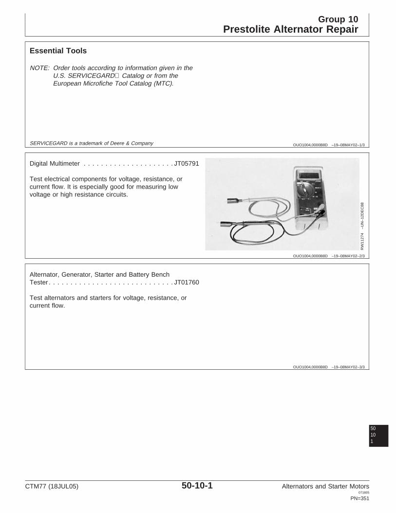
Group 10Prestolite Alternator Repair
OUO1004,0000B8D –19–08MAY02–1/3
Essential Tools
NOTE: Order tools according to information given in theU.S. SERVICEGARD Catalog or from theEuropean Microfiche Tool Catalog (MTC).
SERVICEGARD is a trademark of Deere & Company
OUO1004,0000B8D –19–08MAY02–2/3
RW
1127
4–U
N–1
2DE
C88
Digital Multimeter . . . . . . . . . . . . . . . . . . . . . JT05791
Test electrical components for voltage, resistance, orcurrent flow. It is especially good for measuring lowvoltage or high resistance circuits.
OUO1004,0000B8D –19–08MAY02–3/3
Alternator, Generator, Starter and Battery BenchTester . . . . . . . . . . . . . . . . . . . . . . . . . . . . . JT01760
Test alternators and starters for voltage, resistance, orcurrent flow.
50101
CTM77 (18JUL05) 50-10-1 Alternators and Starter Motors071805
PN=351

Prestolite Alternator Repair
OUO1022,0000001 –19–07JUL05–1/1
Prestolite Charging Circuit TestSpecifications
John Deere alternator Part No. Prestolite Alternator Part No. Volts Rated Amps
AH148633 8SC2020Z 12 185
AH211398 12 185
AT103344 8EM2009NB 12 65
AT178902 8MR2084KS 12 51
RE20486 70D43198S, 85AZ2035V 12 130
RE50811 8MR2069T, 70D43841T, 12 9070D43841T02
RE522329 A0014730LC 24 (28) 140
OUO1004,0000B42 –19–07JUL05–1/1
Repair Alternator
There are no serviceable parts from John Deere availablefor this alternator. Replace alternator as required.
Tighten pulley nut to specifications.
SpecificationAlternator Pulley Nut—Torque 80 N•m.......................................................
(59 lb-ft)
5010
2
CTM77 (18JUL05) 50-10-2 Alternators and Starter Motors071805
PN=352

Prestolite Alternator Repair
OUO1004,0000B3D –19–13SEP00–1/1
Charging System Failure
Causes of Charging System Failure:
• Charging system malfunction is identified by batterycondition.
Undercharged batteries caused by one or acombination of the following:
• Loose belts; corroded, broken, loose, or dirtyterminals; broken wiring; undersize wiring; defectivebatteries.
• Alternator field circuit malfunction caused by one ora combination of the following:– Poor contacts between regulator and brushes.– Defective diode trio.– No residual magnetism in rotor.– Defective or improperly adjusted regulator.– Damaged or worn brushes.
– Damaged or worn slip rings.– Poor connection between slip ring assembly and
field coil leads.– Rotor coil shorted, open, or grounded.
• Alternator generating section malfunction caused byone or a combination of the following:– Stator phase(s) shorted, open, or grounded.– Rectifier assembly grounded.– Rectifier(s) shorted or open.
Overcharged batteries caused by one or acombination of the following:
• Defective battery.• Defective diode trio.• Defective or improperly adjusted regulator.• Poor sensing lead contact to regulator or rectifier
assembly.
OUO1004,0000B3E –19–13SEP00–1/1
Alternator Troubleshooting
NOTE: For fast and accurate troubleshooting, ensure thatbelts are properly tensioned, and that wiring andterminals are in good working condition. Checkbatteries per manufacturer’s specifications toestablish if they are defective. Ensure thatbatteries are 95—100% charged.
50103
CTM77 (18JUL05) 50-10-3 Alternators and Starter Motors071805
PN=353

Prestolite Alternator Repair
5010
4
OUO1004,0000B46 –19–12SEP02–1/2
Test Alternator
RG
1115
8–U
N–1
5SE
P00
Typical Alternator Configuration
A—Ignition SwitchB—Charging LampC—Regulator TerminalD—Negative TerminalsE—GroundF—BatteryG—Positive Output TerminalH—Jumper Wire (Use Only for Diode Trio Test)
Alternator Output Test
NOTE: Ensure that belts are properly tensioned, and thatwiring and terminals are in good workingcondition. Check batteries per manufacturer’sspecifications to establish if they are defective.Ensure that batteries are 95—100% charged.
IMPORTANT: Use an accurate voltmeter to measureoutput voltage. DO NOT rely ondashboard gauges.
1. Start and run engine at approximately 1000 rpm. Turnon vehicle headlights and blower fan (low speed).Check system voltage by connecting voltmeter tooutput terminal (G) and negative battery post. Comparereading to the values specified by the vehiclemanufacturer.
2. If alternator voltage does not fall within the specifiedrange, replace alternator.
Diode Trio Test (MR Series Alternator)
1. Check for battery voltage at output terminal (G) and for1.5—3 volts at regulator terminal (C).
2. Install jumper wire (H) between terminals (C and G).
3. Operate engine at low idle with all electricalaccessories OFF.
4. If charging lamp (B) is off and charging voltage ispresent at output terminal (G), the diode trio isprobably open (defective). Replace alternator.
Field Diode Test (SC Series Alternators)
1. Check for battery voltage at output terminal.
2. Install jumper wire between alternator positive outputterminal and indicator lamp terminal.
3. Operate engine at low idle with all electricalaccessories OFF.
CTM77 (18JUL05) 50-10-4 Alternators and Starter Motors071805
PN=354
Continued on next page

Prestolite Alternator Repair
OUO1004,0000B46 –19–12SEP02–2/2
4. Connect voltmeter to positive and negative outputterminals on alternator.
5. If alternator output is 13.5—14.1 volts, the field diodeassembly is defective. Replace alternator.
50105
CTM77 (18JUL05) 50-10-5 Alternators and Starter Motors071805
PN=355

Prestolite Alternator Repair
5010
6
CTM77 (18JUL05) 50-10-6 Alternators and Starter Motors071805
PN=356

Section 5555Iskra Alternators
Contents
Page
Group 05—Iskra Alternator Theory of OperationOperation of Alternator . . . . . . . . . . . . . . . . . . .55-05-1
Group 10—Iskra Alternator RepairEssential Tools . . . . . . . . . . . . . . . . . . . . . . . . .55-10-1Iskra Charging Circuit Repair Specifications . . .55-10-2Iskra Charging Circuit Test Specifications . . . . .55-10-3Exploded View of Alternator . . . . . . . . . . . . . . .55-10-4Identification . . . . . . . . . . . . . . . . . . . . . . . . . . .55-10-5Troubleshooting. . . . . . . . . . . . . . . . . . . . . . . . .55-10-6Remove and Install Pulley. . . . . . . . . . . . . . . . .55-10-7Testing Brush/Regulator Assembly . . . . . . . . . .55-10-8Install Brush/Regulator Assembly . . . . . . . . . .55-10-10Installation of Alternator. . . . . . . . . . . . . . . . . .55-10-10
CTM77 (18JUL05) 55-1 Alternators and Starter Motors071805
PN=1

Contents
55
CTM77 (18JUL05) 55-2 Alternators and Starter Motors071805
PN=2

Group 05Iskra Alternator Theory of Operation
55051
OUOD006,0000038 –19–19JUN02–1/1
Operation of Alternator
RG
1222
5–U
N–2
9JU
L02
Iskra Alternator
A—Alternator D—Regulator G—Ignition J—Diode TrioB—Current Coil (Stator) E—Battery H—RFI Suppression Device K—Rectifier Diode BridgeC—Exciting Coil (Rotor) F—Indicator Light
The Iskra alternator is a synchronous three-phasegenerator. The current coils are located in the stator.Alternator is self-excited through diode trio (J), brushesand slip rings, to the exciting coil in the rotor, regulator,negative pole of the alternator (ground), and back tothe stator (current) coils (B).
The alternator is normally driven by the fan belt fromthe engine crankshaft. The rotor is supported by twopermanently lubricated bearings.
The alternator generates alternating current which isthen transformed into direct current by the rectifierdiode bridge (K).
The stator windings are delta-connected. The coil endsU, V and W are connected to the rectifier diode bridge
as shown. Alternating current is generated in eachstator coil (B) of the alternator. During one revolutionof the rotor (C), the voltage in the stator coil rises from0 to the positive maximum, drops to 0, rises to thenegative maximum and again drops to 0 per one rotorpole pair. The current then flows through the diode andterminal B+ directly to the positive pole of the battery.
A sealed electronic regulator is used to regulatealternator voltage. This regulator, which cannot beadjusted, regulates the alternator voltage toapproximately 14.5 volts.
A capacitor (H), suppresses radio interference.
CTM77 (18JUL05) 55-05-1 Alternators and Starter Motors071805
PN=359

Iskra Alternator Theory of Operation
5505
2
CTM77 (18JUL05) 55-05-2 Alternators and Starter Motors071805
PN=360

Group 10Iskra Alternator Repair
55101
OUO1004,0000B88 –19–19JUN02–1/3
Essential Tools
NOTE: Order tools according to information given in theU.S. SERVICEGARD Catalog or from theEuropean Microfiche Tool Catalog (MTC).
SERVICEGARD is a trademark of Deere & Company
OUO1004,0000B88 –19–19JUN02–2/3
RW
1127
4–U
N–1
2DE
C88
JT05791
Digital Multimeter . . . . . . . . . . . . . . . . . . . . . JT05791
Test electrical components for voltage, resistance, orcurrent flow. It is especially good for measuring lowvoltage or high resistance circuits.
OUO1004,0000B88 –19–19JUN02–3/3
Alternator, Generator, Starter and Battery BenchTester . . . . . . . . . . . . . . . . . . . . . . . . . . . . . JT01760
Test alternators and starters for voltage, resistance, orcurrent flow.
CTM77 (18JUL05) 55-10-1 Alternators and Starter Motors071805
PN=361

Iskra Alternator Repair
5510
2
OUOD006,000003A –19–19JUN02–1/1
Iskra Charging Circuit Repair Specifications
Item Measurement Specification
Brush Minimum Exposed Length 1 mm (0.04 in.)
Rectifier Bridge-to-Rear Housing Torque 2.9—4.1 N•m (26—36 lb-in.)Bolts
Capacitor Mounting Stud Torque 2.9—4.1 N•m (26—36 lb-in.)
B+ Terminal Nut (65 amp) Torque 4.2—6.0 N•m (37—53 lb-in.)
B+ Terminal Nut (75 amp) Torque 9.8—14.0 N•m (87—124 lb-in.)
“W” Terminal Nut Torque 2.7—4.1 N•m (24—36 lb-in.)
Front-to-Rear Housing Bolts Torque 4.2—6.0 N•m (37—53 lb-in.)
Alternator Pulley Nut Torque 60—70 N•m (44—52 lb-ft)
CTM77 (18JUL05) 55-10-2 Alternators and Starter Motors071805
PN=362

Iskra Alternator Repair
55103
OUOD006,000003B –19–07JUL05–1/1
Iskra Charging Circuit Test Specifications
John Deere Iskra Iskra Rated Nominal Nominal PulleyAlternator Alternator Alternator Amps Voltage Alternator rpm GroovesPart No. Model No. Part No.
RE505690 AAK4335 11.203.369 50 28 6000 8
RE505895 AAK3307 11.201.869 75 14 6000 8
RE505896 AAK5378 11.203.159 95 14 6000 8
RE509106 AAK3359 11.201.998 65 14 6000 1
RE525689 AAK4334 11.203.368 75 14 6000 8
RE505896A AAK5123 11.201.727 95 14 6000
69X56702A AAK3360 11.203.002 65 14 6000
RE204426 AAK5382 11.203.167 95 14 6000
— AAK3394 11.203.202 95 14 6000
RE523953A AAK3395 11.203.203 120 14 6000
RE522401 AAK5532 11.203.278 50 28 6000
Item Specification
Rotor winding resistance 2.70—2.97 ohms
Stator resistance (Phase resistance) 160—180 milliohms (65 amp); 101—111 milliohms (75 amp)
Alternator output voltage 14.3—14.6 volts (20°C), 0.5 I max, 0.5 n max)
Working temperature range -40°C—+110°C
Maximum D+ terminal current load 0.5 amp
Maximum continuous alternator speed 13000 rpm
CTM77 (18JUL05) 55-10-3 Alternators and Starter Motors071805
PN=363

Iskra Alternator Repair
5510
4
OUOD006,000003C –19–19JUN02–1/2
Exploded View of Alternator
RG
1247
4–U
N–1
8JU
L02
Alternator—Exploded View
CTM77 (18JUL05) 55-10-4 Alternators and Starter Motors071805
PN=364
Continued on next page

Iskra Alternator Repair
55105
OUOD006,000003C –19–19JUN02–2/2
1—Fan 5—Through Bolt 10—Rectifier 14—Gasket2—Drive End Housing 6—Rotor 11—Rear End Housing 15—Protective Cover3—Bearing With Cover 7—Pulley 12—Fixing Lug 16—Regulator/Brush Holder1
4—Stator 8—Pulley Kit1 13—Capacitor 17—Brush1
9—Ball Bearing
1 Available as service parts.
OUOD006,000003D –19–19JUN02–1/1
Identification
RG
1222
6–U
N–2
6JU
N02
Parts Identification
The information for parts identification is provided on thelabel attached to the body of the alternator.
CTM77 (18JUL05) 55-10-5 Alternators and Starter Motors071805
PN=365

Iskra Alternator Repair
5510
6
OUOD006,000003E –19–19JUN02–1/2
Troubleshooting
Symptom Problem Solution
Alternator indicator light stays Loose/bad connection Checkoff with ignition on and enginenot running.
Bad indicator light Replace indicator light
Discharged/defective battery Charge/replace battery
Regulator failure Replace brush/regulator assembly
Open rotor (exciting) circuit Replace alternator
Rectifier failure (breakdown of power Replace alternatordiode)
Alternator indicator light stays Drive belt loose or broken Adjust tension or replaceon with engine running at highspeed (alternator is notcharging).
Loose connection Check
Brush/regulator failure Replace brush/regulator assembly
Grounded conductor D+ Replace alternator
Defective rectifier bridge/short Replace alternatorcircuited conductor DF or rotorwinding
Alternator indicator light glows Excessive resistance in power circuit Check conductors and power circuitbrightly with engine not running, or conductorsand glows dimly with enginerunning.
Regulator failure Replace regulator/brush assembly
Alternator failure Replace alternator
Continued on next page
CTM77 (18JUL05) 55-10-6 Alternators and Starter Motors071805
PN=366

Iskra Alternator Repair
55107
OUOD006,000003E –19–19JUN02–2/2
Symptom Problem Solution
Discharged battery Loose drive belt Tension belt properly
Open or high resistance in power Check circuitcircuit
Defective battery Replace battery
Defective regulator Replace regulator/brush assembly
Defective alternator Replace alternator
OUOD006,000003F –19–19JUN02–1/1
Remove and Install Pulley
RG
1222
7–U
N–2
6JU
N02
Remove Pulley Nut
A—Pulley Nut
1. Remove pulley nut (A), washer(s) and pulley fromshaft.
2. Install pulley, washer(s) and pulley nut. Tighten tospecification.
SpecificationAlternator Pulley Nut—Torque 60—70 N•m (44—52 lb-ft).........................
CTM77 (18JUL05) 55-10-7 Alternators and Starter Motors071805
PN=367

Iskra Alternator Repair
5510
8
OUOD006,0000040 –19–19JUN02–1/4
Testing Brush/Regulator Assembly
RG
1222
8–U
N–2
6JU
N02
Remove Brush/Regulator Assembly
A—Screws (2 used)
1. Remove screws (A). Remove brush/regulator assemblyfrom rear end housing.
OUOD006,0000040 –19–19JUN02–2/4
RG
1222
9–U
N–2
6JU
N02
Remove Wire
B—Terminal
2. Remove wire from terminal (B).
Continued on next page
CTM77 (18JUL05) 55-10-8 Alternators and Starter Motors071805
PN=368

Iskra Alternator Repair
55109
OUOD006,0000040 –19–19JUN02–3/4
RG
1223
0–U
N–2
6JU
N02
Check Brushes
C—BrushesD—Brush Holder
3. Check brushes (C) mounted on brush holder (D) forfree movement against spring tension. If either brush isworn beyond specification, replace the brush/regulatorassembly. Also replace if the brushes are cracked oroil-soaked.
SpecificationBrush—Minimum Exposed Length 1 mm (0.04 in.)....................................
OUOD006,0000040 –19–19JUN02–4/4
RG
1249
4–U
N–2
9JU
L02
Terminal Identification
RG
1249
5–1
9–18
JUL0
2
Connections
4. To test voltage regulation of regulator, identifyterminals using top diagram on right, and makeconnections as shown in bottom diagram.
5. Increase rectifier voltage.
Lamp in circuit should glow when rectifier voltage isbelow 14.3V +/- 0.5V, and go out when rectifier voltageis 14.3V +/- 0.5V.
If lamp does not glow at all, or does not go out whenvoltage is 14.3V +/- 0.5V, regulator is defective andmust be replaced.
CTM77 (18JUL05) 55-10-9 Alternators and Starter Motors071805
PN=369

Iskra Alternator Repair
551010
OUOD006,0000041 –19–19JUN02–1/1
Install Brush/Regulator Assembly
RG
1222
8–U
N–2
6JU
N02
Install Brush/Regulator Assembly
A—Screws (2 Used)
1. Attach wire to terminal. Install brush/regulator assemblywith caution. Fasten brush/regulator with the two screws(A) and washers.
RG,RG34710,2191 –19–15MAR97–1/1
Installation of Alternator
Refer to machine technical manual to install alternator andto adjust belt tension.
CTM77 (18JUL05) 55-10-10 Alternators and Starter Motors071805
PN=370

Section 60Delco-Remy Starter Motors
Contents
PagePage 60
Check Pinion Clearance . . . . . . . . . . . . . . . . .60-10-24Group 05—Starting Circuit Theory of OperationMake Solenoid No-Load Test . . . . . . . . . . . . .60-10-25General Information. . . . . . . . . . . . . . . . . . . . . .60-05-1
Typical Starting Circuit Operation . . . . . . . . . . .60-05-1Group 15—Delco-Remy 30MT, 35MT, 37MT StarterTypical Starter Motor Operation. . . . . . . . . . . . .60-05-2
Motor RepairEssential Tools . . . . . . . . . . . . . . . . . . . . . . . . .60-15-1
Group 10—Delco-Remy 10/20/22/25/27/28MT Starter Service Equipment and Tools . . . . . . . . . . . . . .60-15-2Motor Repair Other Material . . . . . . . . . . . . . . . . . . . . . . . . . .60-15-2
Essential Tools . . . . . . . . . . . . . . . . . . . . . . . . .60-10-1 Delco-Remy 30MT, 35MT, and 37MTService Equipment and Tools . . . . . . . . . . . . . .60-10-2 Starter Motor Repair Specifications . . . . . . . .60-15-3Other Material . . . . . . . . . . . . . . . . . . . . . . . . . .60-10-2 Delco-Remy 30MT, 35MT, and 37MT
Starter Motor Test Specifications . . . . . . . . . .60-15-4Delco-Remy 10MT, 20MT, 22MT, 25MT,Diagnosing Starter Motor Malfunctions . . . . . . .60-15-627MT, 28MT Starter Motor RepairDelco-Remy Starter Motor CutawaySpecifications. . . . . . . . . . . . . . . . . . . . . . . . .60-10-3
View—Series 30MT, 35MT, and 37MT . . . . .60-15-7Delco-Remy 10MT, 20MT, 22MT, 25MT,Test Starter Motor Before Disassembly . . . . . . .60-15-827MT, 28MT Starter Motor TestMake No-Load Test for Solenoid. . . . . . . . . . .60-15-10Specifications. . . . . . . . . . . . . . . . . . . . . . . . .60-10-4Disassemble Delco-Remy Starter MotorDiagnosing Starter Motor Malfunctions . . . . . . .60-10-6
(Series 35MT Illustrated) . . . . . . . . . . . . . . .60-15-12Delco-Remy Starter Motor CutawayInstall New Bushings During Disassembly. . . .60-15-17View—Series 10MT, 20MT, 22MT, 25MT, 27MT,Clean Starter Motor Components . . . . . . . . . .60-15-1828MT . . . . . . . . . . . . . . . . . . . . . . . . . . . . . . .60-10-7Inspect Armature. . . . . . . . . . . . . . . . . . . . . . .60-15-19Check Operation of Motor Drive . . . . . . . . . . . .60-10-7Make Short Circuit Test. . . . . . . . . . . . . . . . . .60-15-19Make Solenoid Pull-In Test . . . . . . . . . . . . . . . .60-10-8Make Armature Ground Test . . . . . . . . . . . . . .60-15-20
Make Solenoid Hold-In Test . . . . . . . . . . . . . . .60-10-9 Make Open Circuit Test . . . . . . . . . . . . . . . . .60-15-20Make Solenoid No-Load Test . . . . . . . . . . . . . .60-10-9 Make Ground Circuit Test for FieldDisassemble Starter Motor and Test Windings . . . . . . . . . . . . . . . . . . . . . . . . . . .60-15-21
Components . . . . . . . . . . . . . . . . . . . . . . . .60-10-10 Make Open Circuit Test for ShuntClean Starter Motor Components . . . . . . . . . .60-10-13 Windings . . . . . . . . . . . . . . . . . . . . . . . . . . .60-15-21Inspect Armature. . . . . . . . . . . . . . . . . . . . . . .60-10-14 Make Open Circuit Test for Field Windings . . .60-15-22Make Short Circuit Test. . . . . . . . . . . . . . . . . .60-10-14 Remove Field Windings . . . . . . . . . . . . . . . . .60-15-22Make Armature Ground Test . . . . . . . . . . . . . .60-10-15 Inspect Brushes . . . . . . . . . . . . . . . . . . . . . . .60-15-23Make Open Circuit Test . . . . . . . . . . . . . . . . .60-10-15 Test Brush Holder for Ground . . . . . . . . . . . . .60-15-23
Inspect Brush Springs . . . . . . . . . . . . . . . . . . .60-15-24Make Ground Circuit Test for FieldInspect and Clean Solenoid . . . . . . . . . . . . . .60-15-24Windings . . . . . . . . . . . . . . . . . . . . . . . . . . .60-10-15Assemble Solenoid . . . . . . . . . . . . . . . . . . . . .60-15-24Make Open Circuit Test for Field Windings . . .60-10-16Inspect Plunger, Shift Lever, and OverrunningRemove Field Coils (If Necessary) . . . . . . . . .60-10-16
Clutch Assembly . . . . . . . . . . . . . . . . . . . . .60-15-25Install Field Windings . . . . . . . . . . . . . . . . . . .60-10-17Assemble Starter Motor. . . . . . . . . . . . . . . . . .60-15-25Disassemble Solenoid . . . . . . . . . . . . . . . . . . .60-10-17Check Armature End Play . . . . . . . . . . . . . . . .60-15-28Inspect and Clean Solenoid Parts . . . . . . . . . .60-10-18Check for Proper Pinion Clearance . . . . . . . . .60-15-29Assemble Solenoid . . . . . . . . . . . . . . . . . . . . .60-10-19Make No-Load Test (After Assembly) . . . . . . .60-15-30Remove Drive End Bushing and Wick. . . . . . .60-10-19
Install Drive End Bushing and Wick. . . . . . . . .60-10-20 Group 20—Delco-Remy 40MT, 41MT, 42MT, 50MTInspect Drive Motor ID . . . . . . . . . . . . . . . . . .60-10-20 Starter Motor RepairInspect Center Bushing ID . . . . . . . . . . . . . . .60-10-21 Essential Tools . . . . . . . . . . . . . . . . . . . . . . . . .60-20-1Inspect Commutator End Frame Bushing . . . .60-10-21
Continued on next pageAssemble Starter Motor. . . . . . . . . . . . . . . . . .60-10-22
CTM77 (18JUL05) 60-1 Alternators and Starter Motors071805
PN=1

Contents
Page
Other Material . . . . . . . . . . . . . . . . . . . . . . . . . .60-20-2Delco-Remy 40MT, 41MT, 42MT, and
50MT Starter Motor Repair Specifications . . .60-20-3Delco-Remy 40MT, 41MT, 42MT, and
50MT Starter Motor Test Specifications . . . . .60-20-4Diagnosing Starter Motor Malfunctions . . . . . . .60-20-5Delco-Remy Starter Motor Cutaway
View—Series 40MT, 41MT, 42MT, and
60
50MT . . . . . . . . . . . . . . . . . . . . . . . . . . . . . . .60-20-6Test Starter Motor Before Disassembly . . . . . . .60-20-6Test Pull-In and Hold-In Windings . . . . . . . . . . .60-20-9Make No-Load Test. . . . . . . . . . . . . . . . . . . . .60-20-10Disassemble Delco-Remy Starter Motor (
Series 50MT Illustrated). . . . . . . . . . . . . . . .60-20-12Make Ground Circuit Test for Field
Windings . . . . . . . . . . . . . . . . . . . . . . . . . . .60-20-17Make Open Circuit Test for Shunt
Windings . . . . . . . . . . . . . . . . . . . . . . . . . . .60-20-17Make Open Circuit Test for Field Windings . . .60-20-18Remove Field Windings . . . . . . . . . . . . . . . . .60-20-18Inspect Brushes . . . . . . . . . . . . . . . . . . . . . . .60-20-19Test Brush Holder for Ground . . . . . . . . . . . . .60-20-20Inspect Brush Springs . . . . . . . . . . . . . . . . . . .60-20-20Install New Bushings—40MT, 41MT, and
42MT . . . . . . . . . . . . . . . . . . . . . . . . . . . . . .60-20-21Install New Bushings—50MT. . . . . . . . . . . . . .60-20-23Clean Starter Motor Components . . . . . . . . . .60-20-24Inspect Armature. . . . . . . . . . . . . . . . . . . . . . .60-20-25Make Short Circuit Test. . . . . . . . . . . . . . . . . .60-20-25Make Armature Ground Test . . . . . . . . . . . . . .60-20-26Make Open Circuit Test . . . . . . . . . . . . . . . . .60-20-26Inspect Solenoid Plunger and Shift Lever
Assembly. . . . . . . . . . . . . . . . . . . . . . . . . . .60-20-27Inspect Overrunning Clutch and Pinion . . . . . .60-20-27Inspect and Clean Solenoid . . . . . . . . . . . . . .60-20-28Assemble Solenoid . . . . . . . . . . . . . . . . . . . . .60-20-28Assemble Starter Motor. . . . . . . . . . . . . . . . . .60-20-29Check for Proper Pinion Clearance . . . . . . . . .60-20-32
CTM77 (18JUL05) 60-2 Alternators and Starter Motors071805
PN=2

Group 05Starting Circuit Theory of Operation
60051
RG,RG34710,2192 –19–15MAR97–1/1
General Information
IMPORTANT: Never operate starter motor longer than30 seconds. Allow at least 2 minutes forcooling and battery recovery beforeoperating again. Overheating caused byexcessive operation will seriouslydamage starter motor.
RG,RG34710,2193 –19–09OCT00–1/1
Typical Starting Circuit Operation
RG
1313
–UN
–20A
PR
89
Typical Starting Circuit Operation
A—Wire from RelayB—Cable from BatteryC—Pull-In WindingD—Hold-In WindingE—Solenoid PlungerF—Main ContactsG—Field WindingsH—Commutator BrushesI—ArmatureJ—Shunt Windings
When wire from relay (A) is energized, current flowsthrough both pull-in winding (C) and hold-in winding (D) toground.
Current through windings engages solenoid plunger (E),which closes main contacts (F). When main contactsclose, current through pull-in windings stops. Currentcontinues through hold-in winding, keeping solenoidengaged and main contacts closed.
With main contacts closed, current flows from batterycable (B) to starter motor at a very high rate. Four heavyfield windings (G) carry current to commutator brushes(H).
Light shunt windings (J) are wrapped together with two ofthe heavy field windings. Shunt windings are connected tosolenoid switch terminal and directly to ground. Theyprovide additional low speed torque to assist enginerotation and prevent overheating of motor.
From field windings, current flows through armaturewindings (I) to ground, making contact throughcommutator brushes (H).
Strong magnetic fields are set up by current flow throughfield windings and armature windings. Windings arearranged so that magnetic fields constantly repel eachother, rotating armature.
CTM77 (18JUL05) 60-05-1 Alternators and Starter Motors071805
PN=373

Starting Circuit Theory of Operation
6005
2
RG,RG34710,2194 –19–15MAR97–1/1
Typical Starter Motor Operation
R25
228
–UN
–14N
OV
88
Typical Starter Motor Operation
1—Snap Ring 7—Field Connector 13—Field Windings 19—Brake Washer2—Drive End Housing 8—End Frame Cover 14—Armature 20—Wear Pads3—Shift Lever 9—Brush 15—Pole Shoe 21—Overrunning Clutch4—Plunger 10—Bushing 16—Oil Seal 22—Pinion Stop5—Shunt Field Terminal 11—Thrust Washers 17—Bushing 23—Bushing6—Solenoid Assembly 12—Commutator 18—Felt
When solenoid (6) engages, it pulls shift lever (3). Shiftlever pushes overrunning clutch drive (21) to engagepinion in starter gear on flywheel. As armature (14)turns, it cranks engine.
When engine starts, overrunning clutch spins freely onshaft. This prevents overspeeding of armature byflywheel.
When key switch is released, current to solenoidhold-in winding is shut off. Current can feed throughboth pull-in and hold-in windings from main contacts,
but direction of current is reversed in pull-in winding.The two windings cancel each other, and solenoid isreleased.
A spring pushes solenoid back to disengaged position.This opens main contacts and shuts off current to fieldwindings and armature.
Shift lever retracts overrunning clutch drive,disengaging pinion from flywheel. Brake washer (19)slows armature to a stop.
CTM77 (18JUL05) 60-05-2 Alternators and Starter Motors071805
PN=374

Group 10Delco-Remy 10/20/22/25/27/28MT Starter Motor Repair
60101
OUO1004,0000B8F –19–08MAY02–1/3
Essential Tools
NOTE: Order tools according to information given in theU.S. SERVICEGARD Catalog or from theEuropean Microfiche Tool Catalog (MTC).
SERVICEGARD is a trademark of Deere & Company
OUO1004,0000B8F –19–08MAY02–2/3
RW
1127
4–U
N–1
2DE
C88
JT05791
Digital Multimeter . . . . . . . . . . . . . . . . . . . . . JT05791
Test electrical components for voltage, resistance, orcurrent flow. It is especially good for measuring lowvoltage or high resistance circuits.
OUO1004,0000B8F –19–08MAY02–3/3
Alternator, Generator, Starter and Battery BenchTester . . . . . . . . . . . . . . . . . . . . . . . . . . . . . JT01760
Test alternators and starters for voltage, resistance, orcurrent flow.
CTM77 (18JUL05) 60-10-1 Alternators and Starter Motors071805
PN=375

Delco-Remy 10/20/22/25/27/28MT Starter Motor Repair
6010
2
OUO1004,0000B90 –19–25SEP00–1/2
Service Equipment and Tools
NOTE: Order tools according to information given in theU.S. SERVICEGARD Catalog or from theEuropean Microfiche Tool Catalog (MTC). Sometools may be available from a local supplier.
SERVICEGARD is a trademark of Deere & Company
OUO1004,0000B90 –19–25SEP00–2/2
Bushing, Bearing, and Seal Driver Set. . . . . . D01045AA
Remove and install all commutator, drive end, and centerbushings and/or bearings.
OUO1004,0000B91 –19–25SEP00–1/1
Other Material
Number Name Use
Mineral Spirits Clean armature, solenoid andbrushes.
00 Sandpaper Clean commutator.
CTM77 (18JUL05) 60-10-2 Alternators and Starter Motors071805
PN=376

Delco-Remy 10/20/22/25/27/28MT Starter Motor Repair
60103
OUO1004,0000B92 –19–12SEP02–1/1
Delco-Remy 10MT, 20MT, 22MT, 25MT, 27MT,28MT Starter Motor Repair Specifications
Item Measurement Specification
Brush Spring Minimum Tension 990 gram force (35 ounce-force)
Brushes Minimum Length Beyond Holder 7.9 mm (0.31 in.)
Field Pole Shoe Screws Torque 41 N•m (30 lb-ft)
Solenoid “R” Terminal Contact Height 1.59—2.38 mm (0.062—0.093 in.)
New Drive End Housing Bushing ID 11.709—11.811 mm (0.4610—0.4650 in.)
Wear Limit 12.065 mm (0.475 in.)Oil Clearance 0.051—0.127 mm (0.0020—0.0050
in.)Wear Limit 0.432 mm (0.0170 in.)
Motor Drive ID 14.275—14.300 mm (0.5620—0.5630 in.)
Wear Limit 14.579 mm (0.5740 in.)
New Center Bearing Plate Bushing ID 19.304—19.354 mm (0.7600—0.7620 in.)
Wear Limit 19.608 mm (0.7720 in.)Oil Clearance 0.254—0.381 mm (0.0100—0.0150
in.)Wear Limit 0.635 mm (0.0250 in.)
New Commutator End Frame ID 14.313—14.338 mm (0.5635—Bushing 0.5645 in.)
Wear Limit 14.554 mm (0.5730 in.)Oil Clearance 0.051—0.127 mm (0.0020—0.0050
in.)Wear Limit 0.406 mm (0.0160 in.)
Housing Attaching Cap Screws Torque 18—23 N•m (159—204 lb-in.)
Commutator End Frame Cap Screws Torque 18—23 N•m (159—204 lb-in.)
Pinion-to-Pinion Stop Clearance 0.25—3.56 mm (0.010—0.140 in.)
CTM77 (18JUL05) 60-10-3 Alternators and Starter Motors071805
PN=377

Delco-Remy 10/20/22/25/27/28MT Starter Motor Repair
6010
4
RG,RG34710,2198 –19–07JUL05–1/2
Delco-Remy 10MT, 20MT, 22MT, 25MT, 27MT,28MT Starter Motor Test Specifications
NOTE: Specification data for starters marked with anasterisk (*) was not available from Delco. Dataprovided for these asterisked starters in thefollowing table was obtained from the John DeereAlternator, Generator, Starter and Battery BenchTester Operator’s Manual (OMTY25323,14Dec01). This data is for remanufacturedstarters, provided by suppliers other than Delco,which can be used as replacements for the Delcostarters. Specifications for the remanufacturedstarters may not correspond exactly with theoriginal Delco starter specifications, and should beused for reference only. Delco does not eitherapprove nor disapprove the use of thesespecifications.
No Load Test (Includes Solenoid Current)
John Deere Delco-Remy System Motor Current Draw (Amps) Armature RPMStarter Motor Starter Motor Voltage Voltage
Part No. Model No. -Series
* AA6004R 1108989 12 10 85 Max 3500—5500
* AH76330 1108360-10MT 12 9 (10) 90 Max 3500—6000
* AP22652 1107972 12 9 155 Max 8000—13000
* AR11150 1103004 12 10 85 Max 3500—5500
AR11160 1109434 12 10 65—110 6500—10700
AR11161 1107547 24 23.5 60—130 4900—8500
AR60085 1109147-20MT 12 9 50—80 5500—9000
AR69750 1998364-22MT 12 10 75—175 6900—14900
AR91813 1109576-SD300 12 10 65—110 6500—10700
AT10806 1107736 12 9 50 3500—6000
AT10958 1113104 12 9 50—75 3500—5500
AT11324 1107175 6 5.6 70 5500
AT12283 1107879 12 9 55—80 3500—6000
AT12458 1108672 12 11.8 55—85 6300—8700
AT15335 1107547 24 23.5 60—130 4900—8500
AT16883 1107176 6 5.6 70 5500
AT17411 1107573 12 11.8 55—85 6300—8700
AT18025 1109421-SD300 12 10 60—90 6500—10500
AT18150 1107577-20MT 12 9 40—140 8000—13000
AT18150 1107599-20MT 12 9 40—140 8000—13000
AT18150 1107863-20MT 12 9 40—140 8000—13000
CTM77 (18JUL05) 60-10-4 Alternators and Starter Motors071805
PN=378
Continued on next page

Delco-Remy 10/20/22/25/27/28MT Starter Motor Repair
60105
RG,RG34710,2198 –19–07JUL05–2/2
No Load Test (Includes Solenoid Current)
John Deere Delco-Remy System Motor Current Draw (Amps) Armature RPMStarter Motor Starter Motor Voltage Voltage
Part No. Model No. -Series
AT18150 1107871-20MT 12 9 40—140 8000—13000
AT19196 1998364-20MT 12 10 75—175 6900—14900
AT25619 1107863-20MT 12 9 40—140 8000—13000
AT25619 1107871-20MT 12 10 75—175 8000—13000
AT418T 1107685 12 9 50—75 3500—6000
AT452T 1107713 12 9 50—75 3500—6000
RE19187 1998367-20MT 12 9 40—140 6900—14900
RE19737 1998519-20MT 24 20 40—80 8000—13700
* RE49033 1113271-28MT 12 9 180 Max 2800 (Output Gear)
RE50095 1113271-28MT 12 10 125—190 3000—5600
RE51723 1113283-28 MT 12 10 125—190 3000—5600
RE51725 1113272-28MT 24 20 75—100 3600—6300
RE52119 1113272-28MT 24 20 75—100 3600—6300
RE60654 10479628-28MT 12 10.6 135—190 3600—5600
RE62916 1113271-28MT 12 10 125—190 3000—5600
RE64647 10479630-28MT 12 10.6 135—190 3600—5600
CTM77 (18JUL05) 60-10-5 Alternators and Starter Motors071805
PN=379

Delco-Remy 10/20/22/25/27/28MT Starter Motor Repair
6010
6
RG,RG34710,2199 –19–15MAR97–1/1
Diagnosing Starter Motor Malfunctions
Fails to Operate, No Current Draw
Open field circuit (all field windings)
Open armature windings
Defective brush contact with commutator
Open solenoid windings
Defective solenoid contacts
Fails to Operate, High Current Draw
Grounded field windings or armature windings
Seized bearings
Low Speed, Low Current Draw
High internal resistance
Defective brush contact with commutator
Low Speed, High Current Draw
Excessive friction
Shorted armature
Grounded armature or field windings
High Speed, High Current Draw
Shorted field windings
NOTE: This test will not detect individualopen-circuited field coils—the stator wouldhave a slow cranking speed but would passthis test.
CTM77 (18JUL05) 60-10-6 Alternators and Starter Motors071805
PN=380

Delco-Remy 10/20/22/25/27/28MT Starter Motor Repair
60107
RG,RG34710,2200 –19–06MAY02–1/1
Delco-Remy Starter Motor Cutaway View—Series 10MT, 20MT, 22MT, 25MT, 27MT, 28MT
N27
622
–UN
–22S
EP
88
Series 20MT Shown
A—GrommetB—Field ConnectorsC—PlungerD—SolenoidE—Return SpringF—Shift LeverG—Brake WasherH—BushingI—Pinion StopJ—Overrunning ClutchK—Spiral SplinesL—Center BearingM—Field CoilN—ArmatureO—Bushing
IMPORTANT: Never operate starter motor more than30 seconds. Allow at least 2 minutes forcooling and battery recovery beforeoperating again. Overheating, causedby excessive operation, will seriouslydamage starter motor.
RG,RG34710,2201 –19–15MAR97–1/2
Check Operation of Motor Drive
T81
530
–UN
–01N
OV
88
Turn Overrunning Clutch Pinion
1. Turn overrunning clutch pinion by hand. Clutch pinionshould turn freely on shaft in overrunning directiononly.
Continued on next page
CTM77 (18JUL05) 60-10-7 Alternators and Starter Motors071805
PN=381

Delco-Remy 10/20/22/25/27/28MT Starter Motor Repair
6010
8
RG,RG34710,2201 –19–15MAR97–2/2
T81
531
–UN
–01N
OV
88
Turn Armature
2. Turn armature by prying against pinion withscrewdriver. Check for dragging armature, seizedbushings or bent shaft.
If there is any interference, disassemble and repairstarter motor.
NOTE: DO NOT conduct the no-load test unless armatureturns freely.
RG,RG34710,2202 –19–15MAR97–1/2
Make Solenoid Pull-In Test
T81
532
–UN
–01N
OV
88
Disconnect Field Connector
1. To prevent damage, solenoid must be on starter motorwhen testing the windings.
2. Disconnect field connector from solenoid “M” terminalas shown.
RG,RG34710,2202 –19–15MAR97–2/2
T81
519
–UN
–25M
AY
89
Make Connections
1—Voltmeter2—Carbon Pile Resistor3—Battery4—Ammeter
3. Make connections as shown. Quickly adjust the carbonpile resistor to obtain 5 volts. The ammeter readingmust be 13—15.5 amps.
CTM77 (18JUL05) 60-10-8 Alternators and Starter Motors071805
PN=382

Delco-Remy 10/20/22/25/27/28MT Starter Motor Repair
60109
RG,RG34710,2203 –19–15MAR97–1/1
Make Solenoid Hold-In Test
T81
520
–UN
–25M
AY
89
Make Solenoid Hold-In Test
1—Voltmeter2—Carbon Pile Resistor3—Battery4—Ammeter
Make connections as shown. Adjust the carbon pileresistor to obtain 10 volts. The ammeter reading shouldbe 14.5—16.5 amps.
A high ammeter reading indicates windings are groundedor short circuited.
A low ammeter reading indicates excessive resistance(usually in a connection).
No ammeter reading indicates windings are opencircuited.
To prevent overheating, do not energize the pull-inwinding longer than 15 seconds. Current draw willdecrease as the winding temperature increases.
If the fault cannot be repaired and the solenoidperformance is questionable, replace the windings.
DPSG,OUOE003,27 –19–17DEC98–1/1
Make Solenoid No-Load Test
T81
521
–UN
–25M
AY
89Make Solenoid No-Load Test
1—Carbon Pile Resistor2—Battery3—Ammeter4—Voltmeter5—Jumper Lead with Switch6—Tachometer
1. Clamp starter motor drive housing in vise.
2. Make connections as shown.
3. Close switch to operate starter motor and adjustcarbon pile resistor to obtain 9.0 volts.
Current draw must be to specifications given atbeginning of this group.
CTM77 (18JUL05) 60-10-9 Alternators and Starter Motors071805
PN=383

Delco-Remy 10/20/22/25/27/28MT Starter Motor Repair
601010
RG,RG34710,2204 –19–15MAR97–1/11
Disassemble Starter Motor and Test Components
N38
155
–UN
–20A
PR
89
Delco-Remy No. 1998367 Shown
1—Bushing 13—Armature 23—Snap Ring 33—Brush Pivot Pin (2 Used)2—Lubricating Wick 14—Thrust Washer 24—Thrust Collar 34—Brush Holder Kit3—Plug 15—Center Bearing Assembly 25—Dowel Pin 35—Bushing4—Drive End Housing 16—Brake Washer 26—Field Frame 36—Lubricating Wick5—Shifter Pivot Screw 17—Lock Wire 27—Insulating Bushing 37—Commutator End Frame6—Spring Pin 18—Collar 28—Field Winding Coil 38—Bolt (2 Used)7—Shifter 19—Overrunning Clutch 29—Brush Spring (2 Used) 39—Brush Ground Lead (28—Solenoid Plunger Spring 30—Grounded Brush Holder (2 Used)9—Solenoid Return Spring 20—Bushing Used) 40—Brush (4 Used)10—Gasket 21—Overrunning Clutch 31—Insulated Brush Holder (2 41—Field Pole Shoe11—Solenoid Assembly Assembly Used) 42—Pole Shoe Screw (8 Used)12—Field Coil Connector 22—Pinion Stop 32—Brush Mounting Screws (4
Used)
RG,RG34710,2204 –19–15MAR97–2/11
T81
535
–UN
–22M
AR
90
Remove Commutator End Frame
1. Remove commutator end frame cap screws andcommutator end frame.
CTM77 (18JUL05) 60-10-10 Alternators and Starter Motors071805
PN=384
Continued on next page

Delco-Remy 10/20/22/25/27/28MT Starter Motor Repair
601011
RG,RG34710,2204 –19–15MAR97–3/11
T81
536
–UN
–22M
AR
90
Remove Field Frame
2. Disconnect field coil connector and remove field frame.
RG,RG34710,2204 –19–15MAR97–4/11
T59
83A
V–U
N–1
2AP
R90
Check Brushes and Brush Springs
3. Make sure brushes are not binding holders. The fullbrush surface must ride on commutator.
4. Check by hand to make certain brush springs aregiving firm contact between brushes and commutator.If springs are distorted or discolored, replace them.
RG,RG34710,2204 –19–15MAR97–5/11
T81
537
–UN
–22M
AR
90
Remove Pins, Holders, and Springs
5. Remove brush pins, brush holders and brush springs.Check brush spring tension.
SpecificationBrush Spring—Minimum Tension 990 gram force (35 ounce-force)...........
Continued on next page
CTM77 (18JUL05) 60-10-11 Alternators and Starter Motors071805
PN=385

Delco-Remy 10/20/22/25/27/28MT Starter Motor Repair
601012
RG,RG34710,2204 –19–15MAR97–6/11
T81
523
–UN
–22M
AR
90
Measure Brushes
6. Check brushes for being oil soaked or worn beyondspecifications.
SpecificationBrushes—Minimum LengthBeyond Holder 7.9 mm (0.31 in.)................................................................
RG,RG34710,2204 –19–15MAR97–7/11
T81
538
–UN
–22M
AR
90
Tighten Screws Securely
7. Tighten screws securely when installing new brushes.
RG,RG34710,2204 –19–15MAR97–8/11
T81
539
–UN
–22M
AR
90
Remove Parts
8. Remove screws, solenoid switch assembly, solenoidgasket and plunger return spring.
RG,RG34710,2204 –19–15MAR97–9/11
T88
855
–UN
–21F
EB
90
Remove Armature
A—Bearing Screws
9. Remove the shift lever cap screw and center bearingscrews (A).
10. Remove armature.
CTM77 (18JUL05) 60-10-12 Alternators and Starter Motors071805
PN=386
Continued on next page

Delco-Remy 10/20/22/25/27/28MT Starter Motor Repair
601013
RG,RG34710,2204 –19–15MAR97–10/11
T81
541
–UN
–22M
AR
90
Drive Pinion Stop
11. Use a 1/2-in. pipe nipple or other suitable metalcylinder to drive pinion stop toward pinion.
RG,RG34710,2204 –19–15MAR97–11/11
T88
856
–UN
–21F
EB
90
Center Bearing Plate
A—Retaining RingB—Bearing Plate
12. Remove retaining ring (A), pinion stop, andoverrunning clutch drive.
13. Remove brake washer and center bearing plate (B).
DPSG,OUOE003,28 –19–17DEC98–1/1
Clean Starter Motor Components
IMPORTANT: Never clean armature, field windings, oroverrunning clutch drive in solvent. Allparts except overrunning clutch drivemay be cleaned with mineral spirits anda brush.
1. Clean components using mineral spirits and a brush.
2. Dry with compressed air or a clean cloth.
CTM77 (18JUL05) 60-10-13 Alternators and Starter Motors071805
PN=387

Delco-Remy 10/20/22/25/27/28MT Starter Motor Repair
601014
RG,RG34710,2205 –19–15MAR97–1/1
Inspect Armature
X14
51–U
N–2
5JA
N89
Inspect Armature
1. Place armature in V-blocks and check for a bent shaft.Replace armature if shaft is bent.
2. Inspect armature for signs of dragging against poleshoes or scoring under bushings.
3. Carefully check commutator for roughness, burnedcommutator bars or any material that might causeshort circuits between bars.
4. Clean and touch up commutator, if necessary, with 00sandpaper. NEVER use emery cloth.
NOTE: If commutator is out of round, badly burned orrough, it can be turned down slightly on a lathe.Remove only enough metal to eliminate problem.Do not undercut commutator after turning, as thiswill cause shorts between commutator bars.
RG,RG34710,2206 –19–15MAR97–1/1
Make Short Circuit Test
T81
543
–UN
–07D
EC
88
Make Short Circuit Test
Place armature in a growler and hold hacksaw bladeabove each slot while slowly rotating the armature.
If coil is shorted, the blade will be attracted to andrepelled from the slot.
Short circuit most often occurs because of copper dust orfilings between two commutator segments. Cleancommutator segments to correct this short.
CTM77 (18JUL05) 60-10-14 Alternators and Starter Motors071805
PN=388

Delco-Remy 10/20/22/25/27/28MT Starter Motor Repair
601015
RG,RG34710,2207 –19–15MAR97–1/1
Make Armature Ground Test
T90
253
–UN
–20N
OV
89
Make Armature Ground Test
1. Set ohmmeter to read on highest scale.
2. Place one test lead on the armature core or shaft.Place other lead on commutator.
If the test meter indicator swings toward zero, thearmature is grounded. Replace armature.
RG,RG34710,2208 –19–06MAY02–1/1
Make Open Circuit Test
T90
254
–UN
–19O
CT
88
Make Open Circuit Test
1. Set ohmmeter to read on lowest scale.
2. Place one test lead on commutator segment. Placeother test lead on an adjacent segment.
3. Repeat this operation for all segments by moving onelead at a time.
If the test meter indicator does not swing to zero andremain stationary, the armature coil between these twosegment is open. Replace armature.
RG,RG34710,2209 –19–15MAR97–1/1
Make Ground Circuit Test for Field Windings
T81
546
–UN
–22M
AR
90
Make Ground Circuit Test
1. Set ohmmeter to read on highest scale.
2. Connect one test lead to the field frame and the othertest lead to the field connector.
If the test meter indicator swings toward zero, the fieldcoils are grounded. Replace the field windings.
CTM77 (18JUL05) 60-10-15 Alternators and Starter Motors071805
PN=389

Delco-Remy 10/20/22/25/27/28MT Starter Motor Repair
601016
RG,RG34710,2210 –19–15MAR97–1/1
Make Open Circuit Test for Field Windings
T81
547
–UN
–22M
AR
90
Make Open Circuit Test
1. Set ohmmeter on its lowest scale.
2. Connect one test lead to a field coil lead. Connect theother test lead to the field connector.
If the test meter indicator does not swing to zero andremains stationary, the field coils have an open circuit.Replace field coils.
RG,RG34710,2211 –19–15MAR97–1/2
Remove Field Coils (If Necessary)
T81
548
–UN
–22M
AR
90
Remove Field Connector
1. The field connector must be removed before the fieldcoils can be removed from frame.
RG,RG34710,2211 –19–15MAR97–2/2
T81
549
–UN
–22M
AR
90
Remove Field Windings
2. Place field frame in a soft-jawed vise.
IMPORTANT: Do not squeeze sides of field frame invise or strike with a hammer. If animpact screwdriver is used to removepole shoe screws, support each poleshoe individually using a pole shoespreader or nose of anvil.
3. Make a scribe mark on pole shoe and field frame forproper assembly.
4. Use a large screwdriver bit and socket wrench toremove pole shoe screws.
5. Remove pole shoes. Then carefully remove fieldwindings as an assembly.
IMPORTANT: Handle windings very carefully.Windings are easily damaged, causingshorts, opens, or grounds.
CTM77 (18JUL05) 60-10-16 Alternators and Starter Motors071805
PN=390

Delco-Remy 10/20/22/25/27/28MT Starter Motor Repair
601017
RG,RG34710,2212 –19–15MAR97–1/1
Install Field Windings
1. Carefully insert field windings.
2. Align scribe marks on pole shoes and field frame.Assemble shoe so the long lip points in direction ofarmature rotation.
3. Tighten pole shoe screws to specifications. Use acenter punch to lightly stake one edge of each screw.
SpecificationField Pole Shoe Screws—Torque 41 N•m (30 lb-ft)...................................
RG,RG34710,2213 –19–15MAR97–1/1
Disassemble Solenoid
T59
66A
B–U
N–0
2AP
R90
Disassemble Solenoid
A—“M” TerminalB—“S” TerminalC—Cover Screws
1. Remove hex nuts from “M” and “S” terminals (A) and(B).
2. Remove the two screws (C) and cover.
CTM77 (18JUL05) 60-10-17 Alternators and Starter Motors071805
PN=391

Delco-Remy 10/20/22/25/27/28MT Starter Motor Repair
601018
RG,RG34710,2214 –19–15MAR97–1/3
Inspect and Clean Solenoid Parts
T59
66A
A–U
N–1
1AP
R90
Inspect and Clean Solenoid Parts
Inspect all solenoid parts for wear, dirt, and corrosion.
Wipe all parts and connections with mineral spirits and aclean cloth or brush. Dry with a clean cloth.
Firm pressure should be felt on the plunger when fullydepressed. If plunger is weak, replace solenoid windingand plunger assembly.
RG,RG34710,2214 –19–15MAR97–2/3
T88
858
–UN
–21F
EB
90
“R” Terminal Contact Finger
A—Main ContactB—“R” Terminal Contact Finger
The “R” terminal contact finger (B) height above thesurface of the main contact (A) must be 1.59—2.38 mm(1/16—3/32 in.). Bend contact finger if adjustment isnecessary.
SpecificationSolenoid “R” Terminal Contact—Height 1.59—2.38 mm (0.062—0.093 in.)..................................................
RG,RG34710,2214 –19–15MAR97–3/3
T81
553
–UN
–22M
AR
90
Replacement Stud Clips
Replacement “S” terminal and “M” terminal stud clips mustbe crimped to winding leads.
CTM77 (18JUL05) 60-10-18 Alternators and Starter Motors071805
PN=392

Delco-Remy 10/20/22/25/27/28MT Starter Motor Repair
601019
RG,RG34710,2215 –19–15MAR97–1/1
Assemble Solenoid
1. Place gasket on winding terminal.
2. Align main contact vertically.
3. Place packing on switch cover.
4. Tighten switch cover screws to solenoid winding andplunger assembly securely.
NOTE: Solenoid contacts and plunger will be damaged ifcurrent is applied to solenoid when removed fromstarter motor.
RG,RG34710,2216 –19–15MAR97–1/3
Remove Drive End Bushing and Wick
T81
524
–UN
–22M
AR
90
Measure Drive End Bushing
1. Measure drive end bushing.
SpecificationNew Drive End HousingBushing—ID 11.709—11.811 mm
(0.4610—0.4650 in.)...............................................................
Wear Limit 12.065 mm (0.475 in.)..............................................................Oil Clearance 0.051—0.127 mm
(0.0020—0.0050 in.).................................................................
Wear Limit 0.432 mm (0.0170 in.)..............................................................
RG,RG34710,2216 –19–15MAR97–2/3
T81
556
–UN
–22M
AR
90
Remove Plug and Drive End Wick
2. Remove plug and drive end wick.
CTM77 (18JUL05) 60-10-19 Alternators and Starter Motors071805
PN=393
Continued on next page

Delco-Remy 10/20/22/25/27/28MT Starter Motor Repair
601020
RG,RG34710,2216 –19–15MAR97–3/3
T81
557
–UN
–22M
AR
90
27493 Disk and 27491 Disk
1—27493 Disk2—27491 Disk
3. Use 27493 Disk (1) and 27491 Disk (2) fromD01045AA Bushing, Bearing and Seal Driver Set toremove the drive end bushing.
RG,RG34710,2217 –19–15MAR97–1/2
Install Drive End Bushing and Wick
T81
558
–UN
–22M
AR
90
Drive End Bushing and Wick
1. Install drive end bushing by pressing it from the outsidein. Press it even with the end of the drive housing.
RG,RG34710,2217 –19–15MAR97–2/2
T81
559
–UN
–22M
AR
90
Drive End Wick and Pipe Plug
2. Drill bushing through oil wick hole using same size drillas oil wick hole.
3. After drilling, ream bushing to maintain proper oilclearance between shaft and bushing.
4. Soak new wicks in SAE 10 engine oil. Install drive endwick and pipe plug.
RG,RG34710,2218 –19–15MAR97–1/1
Inspect Drive Motor ID
T81
525
–UN
–22M
AR
90
Inspect Drive Motor ID
Measure the motor drive ID.
SpecificationMotor Drive—ID 14.275—14.300 mm
(0.5620—0.5630 in.).........................................................
Wear Limit 14.579 mm (0.5740 in.)............................................................
The motor drive cannot be repaired and must be replacedif defective.
CTM77 (18JUL05) 60-10-20 Alternators and Starter Motors071805
PN=394

Delco-Remy 10/20/22/25/27/28MT Starter Motor Repair
601021
RG,RG34710,2219 –19–15MAR97–1/1
Inspect Center Bushing ID
T81
526
–UN
–22M
AR
90
Inspect Center Bushing ID
Measure the center bushing ID and oil clearance.
SpecificationNew Center Bearing PlateBushing—ID 19.304—19.354 mm
(0.7600—0.7620 in.)...............................................................
Wear Limit 19.608 mm (0.7720 in.)............................................................Oil Clearance 0.254—0.381 mm
(0.0100—0.0150 in.).................................................................
Wear Limit 0.635 mm (0.0250 in.)..............................................................
Burnish bushing to size if necessary.
RG,RG34710,2220 –19–18OCT00–1/1
Inspect Commutator End Frame Bushing
T81
527
–UN
–22M
AR
90
Inspect Commutator End Frame Bushing
Measure commutator end frame bushing ID and oilclearance.
SpecificationNew Commutator End FrameBushing—ID 14.313—14.338 mm
(0.5635—0.5645 in.)...............................................................
Wear Limit 14.554 mm (0.5730 in.)............................................................Oil Clearance 0.051—0.127 mm
(0.0020—0.0050 in.).................................................................
Wear Limit 0.406 mm (0.0160 in.)..............................................................
Burnish bushing to size if necessary.
CTM77 (18JUL05) 60-10-21 Alternators and Starter Motors071805
PN=395

Delco-Remy 10/20/22/25/27/28MT Starter Motor Repair
601022
RG,RG34710,2221 –19–15MAR97–1/7
Assemble Starter Motor
T81
560
–UN
–22M
AR
90
Lubricate Splines and Armature Shaft
1. Lubricate splines and drive end of armature shaft withSAE 10 engine oil.
2. Install center bearing plate and brake washer.
RG,RG34710,2221 –19–15MAR97–2/7
T88
860
–UN
–21F
EB
90
Armature Shaft
A—Pinion StopB—Drive End Thrust CollarC—Retaining Ring
3. With motor drive in place on armature shaft, installpinion stop (A) with cupped side toward drive end ofarmature shaft.
4. Use the drive end thrust collar (B) and a 1/2-in. pipenipple, or other suitable metal cylinder, to drive theretaining ring (C) into its groove on the armature shaft.
RG,RG34710,2221 –19–15MAR97–3/7
T88
861
–UN
–21F
EB
90
Hold Thrust Collar
A—Drive End Thrust Collar
5. Use pliers and the drive end thrust collar (A) to forcethe pinion stop into place over the retaining ring.
6. Hold thrust collar (A) in place while installing armature.
CTM77 (18JUL05) 60-10-22 Alternators and Starter Motors071805
PN=396
Continued on next page

Delco-Remy 10/20/22/25/27/28MT Starter Motor Repair
601023
RG,RG34710,2221 –19–15MAR97–4/7
T88
855
–UN
–21F
EB
90
Center Bearing Plate Screws
A—Center Bearing Plate Screws
7. With shift lever fork in motor drive collar, installarmature, shift lever and solenoid switch plunger indrive housing.
8. Install the shift lever cap screw and the center bearingplate screws (A).
RG,RG34710,2221 –19–15MAR97–5/7
T81
563
–UN
–22M
AR
90
Solenoid Gasket/Plunger Return Spring
9. Install solenoid gasket and plunger return spring.
RG,RG34710,2221 –19–15MAR97–6/7T
8886
2–U
N–2
1FE
B90
Commutator End Spacer Washer
A—Commutator End Spacer Washer
10. Install solenoid switch assembly and screws.
11. Install commutator end spacer washer (A).
Continued on next page
CTM77 (18JUL05) 60-10-23 Alternators and Starter Motors071805
PN=397

Delco-Remy 10/20/22/25/27/28MT Starter Motor Repair
601024
RG,RG34710,2221 –19–15MAR97–7/7
T81
535
–UN
–22M
AR
90
Install Commutator End Frame
12. Install frame, with field coil assembly and brushes,onto rotor.
SpecificationHousing Attaching Cap Screws—Torque 18—23 N•m (159—204 lb-in.)........................................................
13. Attach field connector to the solenoid switch “M”terminal.
14. Install commutator end frame and cap screws andtighten to specifications.
SpecificationCommutator End Frame CapScrews—Torque 18—23 N•m (159—204 lb-in.).........................................
RG,RG34710,2222 –19–15MAR97–1/2
Check Pinion Clearance
T88
952
–UN
–25M
AY
89
Check Pinion Clearance
A—BatteryB—SolenoidC—Starter MotorD—Jumper Wire
Pinion clearance cannot be adjusted, but must bechecked after reassembly of the starter motor. Improperclearance is an indication of worn parts.
1. Disconnect motor field coil connector from the solenoidmotor terminal and insulate it carefully.
2. Make connections as shown using a 12-volt battery.
Continued on next page
CTM77 (18JUL05) 60-10-24 Alternators and Starter Motors071805
PN=398

Delco-Remy 10/20/22/25/27/28MT Starter Motor Repair
601025
RG,RG34710,2222 –19–15MAR97–2/2
T81
528
–UN
–22M
AR
90
Push Pinion Toward Armature
3. Momentarily touch a jumper lead from the solenoidmotor terminal to solenoid frame. The pinion will shiftinto cranking position and remain until the battery isdisconnected.
4. Push pinion toward armature.
5. Measure the distance between pinion and pinion stop.
SpecificationPinion-to-Pinion Stop—Clearance 0.25—3.56 mm (0.010—0.140 in.).......
RG,RG34710,2223 –19–15MAR97–1/1
Make Solenoid No-Load Test
T81
521
–UN
–25M
AY
89
Make Solenoid No-Load Test1—Carbon Pile Resistor2—Battery3—Ammeter4—Voltmeter5—Jumper Lead with Switch6—Tachometer
1. Clamp starter motor drive housing in vise.
2. Make connections as shown.
3. Close switch to operate starter motor and adjustcarbon pile resistor to obtain 9.0 volts.
Current draw must be to specifications given atbeginning of this group.
CTM77 (18JUL05) 60-10-25 Alternators and Starter Motors071805
PN=399

Delco-Remy 10/20/22/25/27/28MT Starter Motor Repair
601026
CTM77 (18JUL05) 60-10-26 Alternators and Starter Motors071805
PN=400

Group 15Delco-Remy 30MT, 35MT, 37MT Starter Motor Repair
60151
OUO1004,0000B93 –19–08MAY02–1/3
Essential Tools
NOTE: Order tools according to information given in theU.S. SERVICEGARD Catalog or from theEuropean Microfiche Tool Catalog (MTC).
SERVICEGARD is a trademark of Deere & Company
OUO1004,0000B93 –19–08MAY02–2/3
RW
1127
4–U
N–1
2DE
C88
JT05791
Digital Multimeter . . . . . . . . . . . . . . . . . . . . . JT05791
Test electrical components for voltage, resistance, orcurrent flow. It is especially good for measuring lowvoltage or high resistance circuits.
OUO1004,0000B93 –19–08MAY02–3/3
Alternator, Generator, Starter and Battery BenchTester . . . . . . . . . . . . . . . . . . . . . . . . . . . . . JT01760
Test alternators and starters for voltage, resistance, orcurrent flow.
CTM77 (18JUL05) 60-15-1 Alternators and Starter Motors071805
PN=401
Delco-Remy 30MT, 35MT, 37MT Starter Motor Repair
6015
2
OUO1004,0000B94 –19–25SEP00–1/2
Service Equipment and Tools
NOTE: Order tools according to information given in theU.S. SERVICEGARD Catalog or from theEuropean Microfiche Tool Catalog (MTC). Sometools may be available from a local supplier.
SERVICEGARD is a trademark of Deere & Company
OUO1004,0000B94 –19–25SEP00–2/2
Bushing, Bearing, and Seal Driver Set. . . . . . D01045AA
Remove and install all commutator, drive end, and centerbushings and/or bearings.
OUO1004,0000B95 –19–25SEP00–1/1
Other Material
Number Name Use
Mineral Spirits Clean armature, solenoid andbrushes.
00 Sandpaper Clean commutator.
ESSO Beacon 325 or Delco-Remy Lubricate various stator components.No. 1960954 Lubricant
CTM77 (18JUL05) 60-15-2 Alternators and Starter Motors071805
PN=402

Delco-Remy 30MT, 35MT, 37MT Starter Motor Repair
60153
OUO1004,0000B96 –19–25SEP00–1/1
Delco-Remy 30MT, 35MT, and 37MT StarterMotor Repair Specifications
Item Measurement Specification
Drive Housing Bushing ID 14.28—14.33 mm (0.562—0.564 in.)Wear Tolerance 14.58 mm (0.574 in.)Oil Clearance 0.05—0.13 mm (0.002—0.005 in.)Wear Tolerance 0.43 mm (0.017 in.)
Lever Housing Bushing ID 19.23—19.25 mm (0.757—0.758 in.)Wear Tolerance 19.61 mm (0.772 in.)Oil Clearance 0.25—0.33 mm (0.010—0.013 in.)Wear Tolerance 0.69 mm (0.027 in.)
Commutator End Frame Bushing ID 14.28—14.33 mm (0.562—0.564 in.)Wear Tolerance 14.55 mm (0.573 in.)Oil Clearance 0.05—0.13 mm (0.002—0.005 in.)Wear Tolerance 0.41 mm (0.016 in.)
Brush Minimum Length 12 mm (0.50 in.)
Brush Minimum Tension 22 N (80 ounce-force)
Shift Lever Housing-to-Field Housing Torque 18—23 N•m (159—204 lb-in.)Cap Screws
Drive Housing-to-Shift Lever Housing Torque 18—23 N•m (159—204 lb-in.)Cap Screws
Commutator End-to-Field Frame Cap Torque 18—23 N•m (159—204 lb-in.)Screws
Armature End Play 0.13—1.27 mm (0.005—0.050 in.)Wear Limit 1.52 mm (0.060 in.)
Pinion-to-Pinion Stop Clearance 0.25—3.56 mm (0.010—0.140 in.)
CTM77 (18JUL05) 60-15-3 Alternators and Starter Motors071805
PN=403

Delco-Remy 30MT, 35MT, 37MT Starter Motor Repair
6015
4
RG,RG34710,2227 –19–07JUL05–1/2
Delco-Remy 30MT, 35MT, and 37MT StarterMotor Test Specifications
NOTE: Specification data for starters marked with anasterisk (*) was not available from Delco. Dataprovided for these asterisked starters in thefollowing table was obtained from the John DeereAlternator, Generator, Starter and Battery BenchTester Operator’s Manual (OMTY25323,14Dec01). This data is for remanufacturedstarters, provided by suppliers other than Delco,which can be used as replacements for the Delcostarters. Specifications for the remanufacturedstarters may not correspond exactly with theoriginal Delco starter specifications, and should beused for reference only. Delco does not eitherapprove nor disapprove the use of thesespecifications.
No Load Test (Includes Solenoid Current)
John Deere Delco-Remy System Motor Current Draw (Amps) Armature RPMStarter Motor Starter Motor Voltage Voltage
Part No. Model No. -Series
* AB2937R 1107445 6 5 Min 70 Max 6000
* AB4093R 1107445 6 5 Min 70 Max 6000
AB4094R 1107193 6 5 30—60 2900—5300
* AB4649R 1108144 12 10 90 Max 3500—6000
* AB4860R 1108155 12 10 90 Max 3500—6000
* AF1392R 1108990-30MT 12 10 60 Max 3500—5500
* AF1578R 110981 12 10 60 Max 3500—5500
AF2673R 1113304 12 — — —
AF3758R 1113079 12 — — —
* AM1802T 1107127 6 5 Min 140 Max 4500—6400
AM3397T 1107165 6 5.6 70 5500
AR11010 1107725 12 9 50—75 4500—6400
* AR11011 1113092-30MT 12 10 80 Max 7000 Min
AR11138 1107555 24 20 52—90 7000—13000
AR11141 1113135 24 20 50—70 7000—9500
* AR11151 1107193 6 5 65 Max 2900—5300
AR11152 1108180 12 9 50—75 3500—6000
* AR11159 1113005 12 10 60 Max 3500—5500
AR11300 1107785 12 9 55—80 3500—6000
AR28053 1113148 24 20 50—70 7000—9500
AR34406 1113656-35MT 12 9 75—105 5000—7000
CTM77 (18JUL05) 60-15-4 Alternators and Starter Motors071805
PN=404
Continued on next page
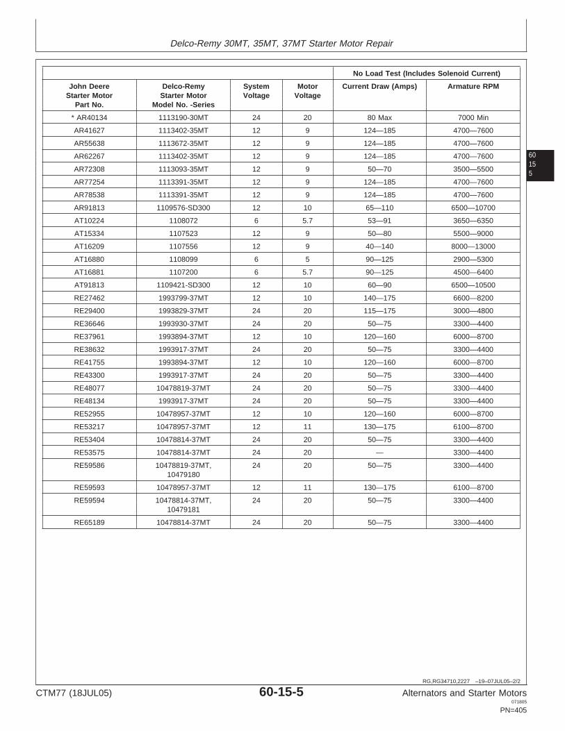
Delco-Remy 30MT, 35MT, 37MT Starter Motor Repair
60155
RG,RG34710,2227 –19–07JUL05–2/2
No Load Test (Includes Solenoid Current)
John Deere Delco-Remy System Motor Current Draw (Amps) Armature RPMStarter Motor Starter Motor Voltage Voltage
Part No. Model No. -Series
* AR40134 1113190-30MT 24 20 80 Max 7000 Min
AR41627 1113402-35MT 12 9 124—185 4700—7600
AR55638 1113672-35MT 12 9 124—185 4700—7600
AR62267 1113402-35MT 12 9 124—185 4700—7600
AR72308 1113093-35MT 12 9 50—70 3500—5500
AR77254 1113391-35MT 12 9 124—185 4700—7600
AR78538 1113391-35MT 12 9 124—185 4700—7600
AR91813 1109576-SD300 12 10 65—110 6500—10700
AT10224 1108072 6 5.7 53—91 3650—6350
AT15334 1107523 12 9 50—80 5500—9000
AT16209 1107556 12 9 40—140 8000—13000
AT16880 1108099 6 5 90—125 2900—5300
AT16881 1107200 6 5.7 90—125 4500—6400
AT91813 1109421-SD300 12 10 60—90 6500—10500
RE27462 1993799-37MT 12 10 140—175 6600—8200
RE29400 1993829-37MT 24 20 115—175 3000—4800
RE36646 1993930-37MT 24 20 50—75 3300—4400
RE37961 1993894-37MT 12 10 120—160 6000—8700
RE38632 1993917-37MT 24 20 50—75 3300—4400
RE41755 1993894-37MT 12 10 120—160 6000—8700
RE43300 1993917-37MT 24 20 50—75 3300—4400
RE48077 10478819-37MT 24 20 50—75 3300—4400
RE48134 1993917-37MT 24 20 50—75 3300—4400
RE52955 10478957-37MT 12 10 120—160 6000—8700
RE53217 10478957-37MT 12 11 130—175 6100—8700
RE53404 10478814-37MT 24 20 50—75 3300—4400
RE53575 10478814-37MT 24 20 — 3300—4400
RE59586 10478819-37MT, 24 20 50—75 3300—440010479180
RE59593 10478957-37MT 12 11 130—175 6100—8700
RE59594 10478814-37MT, 24 20 50—75 3300—440010479181
RE65189 10478814-37MT 24 20 50—75 3300—4400
CTM77 (18JUL05) 60-15-5 Alternators and Starter Motors071805
PN=405

Delco-Remy 30MT, 35MT, 37MT Starter Motor Repair
6015
6
RG,RG34710,2228 –19–15MAR97–1/1
Diagnosing Starter Motor Malfunctions
Fails to Operate, No Current Draw
Open field circuit (all field windings)
Open armature windings
Defective brush contact with commutator
Open solenoid windings
Defective solenoid contacts
Fails to Operate, High Current Draw
Grounded field windings or armature windings
Seized bearings
Low Speed, Low Current Draw
High internal resistance
Defective brush contact with commutator
Low Speed, High Current Draw
Excessive friction
Shorted armature
Grounded armature or field windings
High Speed, High Current Draw
Shorted field windings
NOTE: This test will not detect individualopen-circuited field coils—the stator wouldhave a slow cranking speed but would passthis test.
CTM77 (18JUL05) 60-15-6 Alternators and Starter Motors071805
PN=406

Delco-Remy 30MT, 35MT, 37MT Starter Motor Repair
60157
RG,RG34710,2229 –19–15MAR97–1/1
Delco-Remy Starter Motor Cutaway View—Series 30MT, 35MT, and 37MT
RG
4993
–UN
–19J
AN
90
Series 37MT ShownA—GrommetB—Field ConnectorsC—GasketsD—PlungerE—SolenoidF—O-RingG—Oil WickH—BootI—Shift LeverJ—BushingK—Overrunning ClutchL—SealM—Field CoilN—ArmatureO—BrushesP—End Cap
IMPORTANT: Never operate starter motor more than30 seconds. Allow at least 2 minutes forcooling and battery recovery beforeoperating again. Overheating, causedby excessive operation, will seriouslydamage starter motor.
NOTE: Series 37MT starter motors use TORX screwsfor all external fasteners. Two different sizeTORX drivers are required to service the 37MTmotor—T40 and E8. These drives can beprocured from a local tool source.
TORX is a registered trademark of Camcar/Textron.
CTM77 (18JUL05) 60-15-7 Alternators and Starter Motors071805
PN=407

Delco-Remy 30MT, 35MT, 37MT Starter Motor Repair
6015
8
RG,RG34710,2230 –19–15MAR97–1/4
Test Starter Motor Before Disassembly
R26
549N
–UN
–16S
EP
99
Turn Overrunning Clutch Pinion
1. Turn overrunning clutch pinion by hand. Clutch pinionshould turn freely on shaft in overrunning directiononly.
RG,RG34710,2230 –19–15MAR97–2/4
R26
550
–UN
–09F
EB
90
Turn Armature
2. Turn armature by prying against pinion withscrewdriver. Check for dragging armature, seizedbushings or bent shaft.
If you discover any interference, disassemble andrepair starter motor. Do not conduct no-load test unlessarmature turns freely.
Continued on next page
CTM77 (18JUL05) 60-15-8 Alternators and Starter Motors071805
PN=408

Delco-Remy 30MT, 35MT, 37MT Starter Motor Repair
60159
RG,RG34710,2230 –19–15MAR97–3/4
RG
4666
–UN
–06A
PR
89
Terminals
A—SolenoidB—Battery TerminalC—Motor TerminalD—Switch Terminal
3. Connect a 12-volt battery to solenoid (A) withheavy-duty jumper cables. Connect battery terminal (B)on solenoid to positive battery terminal and motorterminal (C) to negative battery terminal.
IMPORTANT: Do not engage solenoid longer than oneto two seconds, because closingsolenoid switch provides a dead shortacross battery.
4. Use a screwdriver blade to short across from batteryterminal to switch terminal (D). Solenoid shouldengage, pushing overrunning clutch drive to engageposition.
When screwdriver is removed, solenoid should returnsharply to the disengage position. If solenoid engagesbut then chatters instead of staying firmly engaged,hold-in winding is defective and solenoid must bereplaced. Be sure solenoid is connected securely tostart frame. If shift lever or overrunning clutch driveappears to bind, disassemble and repair starter.
RG,RG34710,2230 –19–15MAR97–4/4
R78
220P
1–U
N–2
3JA
N90
Check for Defects
5. If solenoid does not engage, remove solenoid andmanually move shift lever back and forth. If levermoves smoothly, pull-in winding is defective andsolenoid must be replaced. If there is pressure feltwhen moving the shift lever, but solenoid does notengage when tested, disassemble and repair starter.
CTM77 (18JUL05) 60-15-9 Alternators and Starter Motors071805
PN=409

Delco-Remy 30MT, 35MT, 37MT Starter Motor Repair
601510
RG,RG34710,2231 –19–15MAR97–1/1
Make No-Load Test for Solenoid
RG
4660
–UN
–06A
PR
89
Make No-Load Test for Solenoid
A—BatteryB—AmmeterC—ShuntD—SwitchE—VoltmeterF—Starter MotorG—TachometerH—Carbon Pile Resistor
1. If armature turns freely, make connections as shown.Use an ammeter capable of measuring severalhundred amps. Make sure the battery is fully charged.
2. Close switch to operate starter motor and adjustcarbon pile resistor to obtain specified voltage.Compare rpm and current draw with values given inspecifications at the beginning of this group.
3. If speed and current draw are slightly low, connect avoltmeter between motor terminal and field frame.Voltage during test may be reduced because of highcurrent draw on battery.
4. If speed or current draw is significantly different thanspecified, use the diagnostic list earlier in this group.
CTM77 (18JUL05) 60-15-10 Alternators and Starter Motors071805
PN=410

Delco-Remy 30MT, 35MT, 37MT Starter Motor Repair
601511
CTM77 (18JUL05) 60-15-11 Alternators and Starter Motors071805
PN=411

Delco-Remy 30MT, 35MT, 37MT Starter Motor Repair
601512
RG,RG34710,2232 –19–12SEP02–1/8
Disassemble Delco-Remy Starter Motor (Series 35MT Illustrated)
RG
4661
–UN
–06J
AN
94
Series 35MT
CTM77 (18JUL05) 60-15-12 Alternators and Starter Motors071805
PN=412
Continued on next page

Delco-Remy 30MT, 35MT, 37MT Starter Motor Repair
601513
RG,RG34710,2232 –19–12SEP02–2/8
1—Solenoid Case and Coil 17—Shift Lever 34—Washer 50—Field Winding Connector2—Switch Terminal Stud (2 18—O-Ring 35—Armature 51—Brush Support (2 Used)
Used) 19—Plug 36—Spacer 52—Brush Holder Support Pin3—Motor Terminal Stud 20—Brake Washer 37—Oil Seal (2 Used)4—Contact Disk and Push Rod 21—Gasket 38—O-Ring 53—Brush Holder Pin (2 Used)5—Return 22—O-Ring 39—Center Bushing 54—Brush Spring (2 Used)6—Battery Terminal Stud 23—Shift Lever Shaft 40—Pipe Plug 55—Brush Spring Lead (27—Cover Gasket 24—O-Ring 41—Wick Used)8—Cover 25—Shift Lever Housing 42—Retaining Ring 56—Brush Holder (2 Used)9—Sealing Washer 26—Special Nut 43—Field Winding Assembly 57—Brush Holder (2 Used)10—Rear Bushing 27—Retaining Ring 44—Pole Shoe (4 Used) 58—Brush (4 Used)11—Drive Housing 28—Spring Retainer 45—Insulator (2 Used) 59—Tapping Screw (4 Used)12—Wick 29—Shift Lever Spring 46—Field Terminal Stud 60—Front Bushing13—Pipe Plug 30—Spring Retainer 47—Insulator Bushing 61—Commutator End Frame14—Retaining Ring 31—Boot 48—Main Frame 62—Pipe Plug15—Pinion Stop 32—Washer 49—Machine Screw (8 Used) 63—Wick16—Overrunning Clutch Drive 33—Plunger
RG,RG34710,2232 –19–12SEP02–3/8R
G46
62–U
N–0
6AP
R89
Field Winding Connector and Cap ScrewsA—Field Winding ConnectorB—Solenoid Mounting Cap Screws
1. Clean exterior of starter motor with compressed airbefore disassembling.
2. Remove field winding connector (A).
3. Remove solenoid mounting cap screws (B).
4. Remove nuts and sealing washers (9) from solenoidmotor and “S” terminals. (See exploded view.)
5. Remove switch cover (8) and cover gasket (7).
Continued on next page
CTM77 (18JUL05) 60-15-13 Alternators and Starter Motors071805
PN=413

Delco-Remy 30MT, 35MT, 37MT Starter Motor Repair
601514
RG,RG34710,2232 –19–12SEP02–4/8
RG
2989
–UN
–17J
UL8
9
Solenoid Removed
1—Boot2—Plunger
6. Push boot (1) back, and slide solenoid away (shownremoved) from boot and plunger (2).
RG,RG34710,2232 –19–12SEP02–5/8
R78
220T
1–U
N–2
3JA
N90
Remove Commutator End Frame
7. IF NECESSARY, remove cover plug and disconnectsolenoid plunger from shift lever. Grasp plunger andremove self-locking nut.
NOTE: Pinion clearance is controlled by self-locking nut.Do not change adjustment unless completedisassembly is required. Check pinion clearance,covered later in this group.
8. Scribe a mark across main frame (48) and end frame(61) as reassembly reference. (See exploded view.)
9. Remove four cap screws attaching commutator endframe to main frame.
10. Remove commutator end frame.
Continued on next page
CTM77 (18JUL05) 60-15-14 Alternators and Starter Motors071805
PN=414

Delco-Remy 30MT, 35MT, 37MT Starter Motor Repair
601515
RG,RG34710,2232 –19–12SEP02–6/8
RG
4663
–UN
–19J
AN
90
Remove Drive Housing
A—BrushesB—Grounded Brush HoldersC—Insulated Brush HoldersD—Tapping ScrewsE—SupportF—Pin
11. Slide brush holder pin (F) out of support (E) toremove brushes (A). Remove tapping screws (D)which attach brushes to grounded brush holders (B)and insulated brush holders (C).
12. Scribe a mark across drive housing and shift leverhousing for proper assembly.
13. Remove drive end housing cap screws and removedrive housing.
RG,RG34710,2232 –19–12SEP02–7/8
R26
558
–UN
–09F
EB
90
Pinion Stop and Pipe Coupling
A—Pipe CouplingB—Pinion Stop
14. Remove pinion stop (B). Use a pipe coupling (A) orother metal cylinder to drive pinion stop toward pinionas shown. Remove retaining ring and slide pinionstop off shaft.
15. Slide shift lever housing and overrunning clutch driveoff shaft.
Continued on next page
CTM77 (18JUL05) 60-15-15 Alternators and Starter Motors071805
PN=415

Delco-Remy 30MT, 35MT, 37MT Starter Motor Repair
601516
RG,RG34710,2232 –19–12SEP02–8/8
RG
2992
–UN
–17J
UL8
9
Slide Armature
1—Armature
16. Carefully slide armature (1) out of field frame. Ifspacer washer remains in housing, pull it out andinstall on shaft.
CTM77 (18JUL05) 60-15-16 Alternators and Starter Motors071805
PN=416

Delco-Remy 30MT, 35MT, 37MT Starter Motor Repair
601517
RG,RG34710,2233 –19–15MAR97–1/2
Install New Bushings During Disassembly
NOTE: Refer to exploded view earlier in this group.
1. Remove plugs (13 and 62) and lubricating wicks (12and 63).
2. Replace bushings (10, 39, and 60) if worn longer thanwear tolerances given.
SpecificationDrive Housing Bushing—ID 14.28—14.33 mm (0.562—0.564
in.)...................
Wear Tolerance 14.58 mm (0.574 in.)........................................................Oil Clearance 0.05—0.13 mm (0.002—0.005 in.).......................................Wear Tolerance 0.43 mm (0.017 in.)..........................................................
SpecificationLever Housing Bushing—ID 19.23—19.25 mm (0.757—0.758
in.)..................
Wear Tolerance 19.61 mm (0.772 in.)........................................................Oil Clearance 0.25—0.33 mm (0.010—0.013 in.).......................................Wear Tolerance 0.69 mm (0.027 in.)..........................................................
SpecificationCommutator End FrameBushing—ID 14.28—14.33 mm (0.562—0.564
in.)...........................................
Wear Tolerance 14.55 mm (0.573 in.)........................................................Oil Clearance 0.05—0.13 mm (0.002—0.005 in.).......................................Wear Tolerance 0.41 mm (0.016 in.)..........................................................
3. Remove the commutator end frame housing (61) usinga blind hole puller. Remove other bushings usingdrivers from tool set listed below.
Use the following disks from D01045AA Bushing,Bearing and Seal Driver Set when replacing bushing.
Bushing Pilot Disk Drive Disk
Drive Housing Bushing 27491 27495
Commutator Bushing 27491 27494
Lever Housing Bushing 27494 27497
4. Drive new bushings into end frame to same depth asold bushing.
CTM77 (18JUL05) 60-15-17 Alternators and Starter Motors071805
PN=417
Continued on next page

Delco-Remy 30MT, 35MT, 37MT Starter Motor Repair
601518
RG,RG34710,2233 –19–15MAR97–2/2
T33
142N
–UN
–31M
AY
89
Install Plug
1—Drill Bushing2—Plug3—Oil Wick
5. Use a drill the same size as the oil wick hole and drillbushing (1).
Only if necessary, carefully ream bushing to size.
6. Saturate new wicks (3) with SAE 10W clean engine oiland install.
7. Install plug (2) and tighten securely.
RG,RG34710,2234 –19–15MAR97–1/1
Clean Starter Motor Components
IMPORTANT: Never clean armature, field windings, oroverrunning clutch drive in solvent. Allparts except overrunning clutch drivemay be cleaned with mineral spirits anda brush.
1. Clean components using mineral spirits and a brush.
2. Dry with compressed air or a clean cloth.
CTM77 (18JUL05) 60-15-18 Alternators and Starter Motors071805
PN=418

Delco-Remy 30MT, 35MT, 37MT Starter Motor Repair
601519
RG,RG34710,2235 –19–15MAR97–1/1
Inspect Armature
X14
51–U
N–2
5JA
N89
Inspect Armature
1. Place armature in V-blocks and check for a bent shaft.Replace armature if shaft is bent.
2. Inspect armature for signs of dragging against poleshoes or scoring under bushings.
3. Carefully check commutator for roughness, burnedcommutator bars or any material that might causeshort circuits between bars.
4. Clean and touch up commutator, if necessary, with 00sandpaper. NEVER use emery cloth.
NOTE: If commutator is out of round, badly burned orrough, it can be turned down slightly on a lathe.Remove only enough metal to eliminate problem.Do not undercut commutator after turning, as thiswill cause shorts between commutator bars.
RG,RG34710,2236 –19–15MAR97–1/1
Make Short Circuit Test
RG
7807
4C1
–UN
–09J
AN
90
Make Short Circuit Test
Place armature in a growler and hold hacksaw bladeabove each slot while slowly rotating the armature.
If coil is shorted, the blade will be attracted to andrepelled from the slot.
Short circuit most often occurs because of copper dust orfilings between segments. Clean commutator segments tocorrect this short.
CTM77 (18JUL05) 60-15-19 Alternators and Starter Motors071805
PN=419

Delco-Remy 30MT, 35MT, 37MT Starter Motor Repair
601520
RG,RG34710,2237 –19–15MAR97–1/1
Make Armature Ground Test
T90
253
–UN
–20N
OV
89
Make Armature Ground Test
1. Set ohmmeter to read on highest scale.
2. Place one test lead on the armature core or shaft.Place other lead on commutator.
If the test meter indicator swings toward zero, thearmature is grounded. Replace armature.
RG,RG34710,2238 –19–15MAR97–1/1
Make Open Circuit Test
T31
426
–UN
–27J
UL8
9
Make Open Circuit Test
1. Set ohmmeter to read on lowest scale.
2. Place one test lead on ohmmeter segment. Place othertest lead on an adjacent segment.
3. Repeat this operation for all segments by moving onelead at a time.
If the test meter indicator does not swing to zero andremains stationary, the armature coil between thesetwo segments is open. Replace armature.
CTM77 (18JUL05) 60-15-20 Alternators and Starter Motors071805
PN=420

Delco-Remy 30MT, 35MT, 37MT Starter Motor Repair
601521
RG,RG34710,2239 –19–06MAY02–1/1
Make Ground Circuit Test for Field Windings
RG
7807
6Q1
–UN
–09J
AN
90
Make Ground Circuit Test
1. Set the D09001TT Volt-Ohm-Amp Meter to read onhighest scale.
2. Place one test lead on a clean spot on field frame.Place other lead on the copper terminal bolt.
If the ohmmeter indicator swings toward zero, agrounded circuit is indicated. Replace the fieldwindings.
RG,RG34710,2240 –19–15MAR97–1/1
Make Open Circuit Test for Shunt Windings
1. Set ohmmeter on its lowest scale.
2. Place one test lead on the eyelet terminal. Place otherlead on the terminal bolt.
If the ohmmeter does not swing to zero, it is opencircuited. Replace the field winding assembly.
CTM77 (18JUL05) 60-15-21 Alternators and Starter Motors071805
PN=421

Delco-Remy 30MT, 35MT, 37MT Starter Motor Repair
601522
RG,RG34710,2241 –19–09OCT00–1/1
Make Open Circuit Test for Field Windings
R26
554N
–UN
–11A
PR
89
Make Open Circuit Test
A—1/4-Ohm ResistorB—12-Volt BatteryC—Field TerminalD—Insulated Brush LeadE—Hacksaw Blade
All four windings are connected in parallel. Test eachwinding for an open circuit.
1. Connect a test battery (B) to field terminal (C) andeither insulated brush lead (D) using a resistor (A) tolimit current draw.
2. Use a hacksaw blade (E) to test windings formagnetism. If any winding is not magnetic, the windingis open circuited. Repair or replace windings.
NOTE: Because 1/4 ohm resistors capable of carryingseveral hundred watts are not widely available, asuggested alternative is to connect four 1-ohmresistors in parallel. Each resistor should be ratedfor at least 150 watts. A carbon pile resistor canalso be used. Limit current to 40—70 amps.
There is no suitable way to check field windings forshort circuits. Winding resistance is too low to permitdetection of a short circuit.
RG,RG34710,2242 –19–15MAR97–1/2
Remove Field Windings
R78
221I
1–U
N–2
3JA
N90
Remove Field Windings
1. If field windings are suspected of being damaged,place field frame in a soft-jawed vise.
NOTE: Do not squeeze sides of field frame in vise orstrike with a hammer. If an impact screwdriver isused to remove pole shoe screws, support eachpole shoe individually using a pole shoe spreaderor the nose of an anvil.
2. Use a large screwdriver or bit and socket wrench onpole shoe screws.
Continued on next page
CTM77 (18JUL05) 60-15-22 Alternators and Starter Motors071805
PN=422

Delco-Remy 30MT, 35MT, 37MT Starter Motor Repair
601523
RG,RG34710,2242 –19–15MAR97–2/2
RG
2995
–UN
–17J
UL8
9
New Field Windings
1—Starter Field Frame2—Pole Shoe3—Notched End
3. Remove pole shoes (2). Then carefully remove fieldwindings as an assembly.
IMPORTANT: Handle windings very carefully.Windings are easily damaged, causingshorts, opens, or grounds.
4. Install new field windings and tighten pole shoe screwsas tight as possible. Use a center punch to lightly stakeone edge of each screw.
IMPORTANT: Make sure the notched end (3) on poleshoe is facing the brush end of the fieldframe starter (1).
RG,RG34710,2243 –19–09OCT00–1/1
Inspect Brushes
1. Inspect brushes (58) closely. (See exploded view thisgroup.) Make sure brush holders (56 and 57) are cleanand are not binding. Full width of brush should contactcommutator.
2. Replace brushes if they are oil soaked or are wornbeyond specifications.
SpecificationBrush—Minimum Length 12 mm (0.50 in.).................................................
RG,RG34710,2244 –19–15MAR97–1/1
Test Brush Holder for Ground
1. Set ohmmeter on its highest scale.
2. Place one test lead on commutator end frame. Placeother lead on brush holder.
If dial indicator swings toward zero, the positive brushholder is grounded and should be replaced.
CTM77 (18JUL05) 60-15-23 Alternators and Starter Motors071805
PN=423

Delco-Remy 30MT, 35MT, 37MT Starter Motor Repair
601524
RG,RG34710,2245 –19–15MAR97–1/1
Inspect Brush Springs
1. Inspect and replace brush springs if they are distortedor discolored.
2. Measure brush spring tension with a spring scale.
SpecificationBrush—Minimum Tension 22 N (80 ounce-force).......................................
RG,RG34710,2246 –19–15MAR97–1/1
Inspect and Clean Solenoid
1. Replace contact disk (4, see exploded view in thisgroup), if it is badly corroded.
2. Be sure all connections are clean and tight. Wipe partswith mineral spirits and brush. Dry clean with a cloth.
IMPORTANT: Solenoid contacts and plunger will bedamaged if current is applied tosolenoid when removed from startermotor.
RG,RG34710,2247 –19–15MAR97–1/1
Assemble Solenoid
NOTE: Replacement “S” terminal clips and motor terminalstuds are soldered to wiring leads.
1. Assemble solenoid parts using a new gasket (7, seeexploded view in this group) and sealing washers (9).
2. Tighten cover (8) screws securely.
CTM77 (18JUL05) 60-15-24 Alternators and Starter Motors071805
PN=424

Delco-Remy 30MT, 35MT, 37MT Starter Motor Repair
601525
RG,RG34710,2248 –19–09OCT00–1/1
Inspect Plunger, Shift Lever, andOverrunning Clutch Assembly
1. Remove plug (19, see exploded view in this group) andinspect shift lever spring (33) and shift lever assemblyfor wear or damage.
2. Press plunger inward and check tension on plungerspring (29). Spring should not compress easily.Replace plunger assembly if spring is weak.
3. Inspect overrunning clutch drive (16) for wear ordamage. Rotate the pinion. Pinion gear should rotatesmoothly (but not easily) in one direction. The piniongear should not rotate in the opposite direction.
4. If pinion gear does not rotate smoothly or if it is worn,chipped, or burred, replace clutch drive assembly.
IMPORTANT: Do not clean overrunning clutch drivewith solvent. Solvent would dissolvelubricant in clutch mechanism. Cleanonly by wiping with a clean cloth. Donot lubricate drive.
RG,RG34710,2249 –19–12SEP02–1/4
Assemble Starter Motor
RG
2992
–UN
–17J
UL8
9
Install Armature
1—Armature
1. Carefully install armature (1) into field frame. Be surespacer is installed on end of armature shaft beforeinstalling into main frame.
IMPORTANT: To avoid possible damage to brushholders, it is best to install brushassembly dismantled.
CTM77 (18JUL05) 60-15-25 Alternators and Starter Motors071805
PN=425
Continued on next page

Delco-Remy 30MT, 35MT, 37MT Starter Motor Repair
601526
RG,RG34710,2249 –19–12SEP02–2/4
T33
145N
Y–U
N–2
7JU
L89
Shift Lever Housing1—Gasket2—Shift Lever3—Seal Plug4—Shift Lever Shaft5—Brake Washer
NOTE: Always use new O-rings, packing, and gasketswhen assembling starter motor.
2. Lubricate bearing surface with Delco-Remy No.1960954 Lubricant or its equivalent.
3. Install seal plug (3), gasket (1) and brake washer (5)into shift lever housing.
4. Place overrunning clutch drive in shift lever housing,making certain that shift lever is engaged in slot.
5. Slide shift lever housing and overrunning clutch driveinto armature shaft.
Continued on next page
CTM77 (18JUL05) 60-15-26 Alternators and Starter Motors071805
PN=426

Delco-Remy 30MT, 35MT, 37MT Starter Motor Repair
601527
RG,RG34710,2249 –19–12SEP02–3/4R
2656
0N–U
N–0
9FE
B90
Pinion Stop
A—Pinion StopB—Retaining RingC—Washer
6. Slide pinion stop (A) onto shaft, with open side towardend of shaft. Install retaining ring (B) in groove. Forcepinion stop over ring, using a washer (C) and two pairsof pliers as shown. Remove washer.
NOTE: Series 37MT starter motors have TORX screwsfor all external fasteners. Tighten screws to sametorque values as given for conventional screws.
7. Install shift lever housing on field using five cap screwsand lock washers. Tighten screws to specifications.
SpecificationShift Lever Housing-to-FieldHousing Cap Screws—Torque 18—23 N•m (159—204 lb-in.)...................
8. Align scribe marks on drive housing and shift leverhousing (made during disassembly). Install the sixspecial screws in drive housing. Tighten screws tospecifications.
SpecificationDrive Housing-to-Shift LeverHousing Cap Screws—Torque 18—23 N•m (159—204 lb-in.)...................
9. If pinion clearance has not been changed, install holeplug (19, see exploded view in this group) in shift leverhousing. Otherwise, it should be left out until clearanceis adjusted at conclusion of assembly.
TORX is a registered trademark of Camcar/Textron. Continued on next page
CTM77 (18JUL05) 60-15-27 Alternators and Starter Motors071805
PN=427

Delco-Remy 30MT, 35MT, 37MT Starter Motor Repair
601528
RG,RG34710,2249 –19–12SEP02–4/4
RG
4664
–UN
–19J
AN
90
Brushes, Holders, and Springs
A—BrushesB—Grounded Brush HoldersC—Installed Brush HoldersD—Brush Springs
10. Install brush holders (B and C), brushes (A) andsprings (D). When installing brushes, turn longer sidetoward armature windings. Make sure full width ofeach brush contacts commutator and brush holdersare not binding.
11. Install commutator end frame on field frame (positionso scribe marks made during disassembly arealigned). Tighten cap screws securely and evenly tospecifications.
SpecificationCommutator End-to-Field FrameCap Screws—Torque 18—23 N•m (159—204 lb-in.).................................
12. Install solenoid on field frame. Be sure that plunger(33, see exploded view) and boot (31) are installedcorrectly. Tighten solenoid-to-field frame cap screwssecurely.
NOTE: Do not install field winding connector (50) untilpinion clearance has been checked.
13. Check armature end play and pinion clearance beforeinstalling starter motor.
RG,RG34710,2250 –19–15MAR97–1/1
Check Armature End Play
1. Attach a dial indicator on drive housing and positionindicator plunger on end of armature shaft to measureend play.
SpecificationArmature—End Play 0.13—1.27 mm (0.005—0.050 in.)............................Wear Limit 1.52 mm (0.060 in.)..................................................................
2. If end play is not within specifications, recheckinstallation to determine cause.
CTM77 (18JUL05) 60-15-28 Alternators and Starter Motors071805
PN=428

Delco-Remy 30MT, 35MT, 37MT Starter Motor Repair
601529
RG,RG34710,2251 –19–12SEP02–1/1
Check for Proper Pinion Clearance
R25
224
–UN
–09F
EB
90
Check for Proper Pinion Clearance
A—PinionB—Pinion StopC—Feeler GaugeD—Press on Clutch to Take Up MovementE—0.25—3.56 mm (0.010—0.140 in.) Clearance
1. Connect a 12-volt battery to the solenoid frame and “S”terminal.
2. Momentarily connect a jumper wire between solenoidframe and motor terminal to pull solenoid plunger in.
3. Press overrunning clutch (D) toward commutator andmeasure pinion clearance (E) with a feeler gauge (C).
4. Clearance between pinion (A) and pinion stop (B)should be as follows:
SpecificationPinion-to-Pinion Stop—Clearance 0.25—3.56 mm (0.010—0.140 in.).......
5. If pinion clearance is not within specifications, turnself-locking nut (26, see exploded view in this group) toadjust clearance.
6. After adjusting to correct pinion clearance, installadjusting hole plug (19) and tighten securely.
7. Install field winding connector (50). Tighten nutssecurely.
CTM77 (18JUL05) 60-15-29 Alternators and Starter Motors071805
PN=429

Delco-Remy 30MT, 35MT, 37MT Starter Motor Repair
601530
RG,RG34710,2252 –19–15MAR97–1/1
Make No-Load Test (After Assembly)
RG
4660
–UN
–06A
PR
89
Make No-Load Test
A—BatteryB—AmmeterC—ShuntD—SwitchE—VoltmeterF—Starter MotorG—TachometerH—Carbon Pile Resistor
1. Clamp starter in vise.
2. Connect a fully charged 12-volt battery (A), ammeter(B), shunt (C), control switch (D), voltmeter (E) carbonpile resistor (H), and tachometer (G) to starter motor(F).
3. Close switch to operate starter motor and adjustcarbon pile resistor to obtain specified voltage.
4. Starter motor should rotate smoothly at the specifiedspeed, voltage, and current draw given at thebeginning of this group.
CTM77 (18JUL05) 60-15-30 Alternators and Starter Motors071805
PN=430

Group 20Delco-Remy 40MT, 41MT, 42MT, 50MT Starter Motor Repair
60201
OUO1004,0000B97 –19–08MAY02–1/5
Essential Tools
NOTE: Order tools according to information given in theU.S. SERVICEGARD Catalog or from theEuropean Microfiche Tool Catalog (MTC).
SERVICEGARD is a trademark of Deere & Company
OUO1004,0000B97 –19–08MAY02–2/5
RW
1127
4–U
N–1
2DE
C88
JT05791
Digital Multimeter . . . . . . . . . . . . . . . . . . . . . JT05791
Test electrical components for voltage, resistance, orcurrent flow. It is especially good for measuring lowvoltage or high resistance circuits.
OUO1004,0000B97 –19–08MAY02–3/5
Alternator, Generator, Starter and Battery BenchTester . . . . . . . . . . . . . . . . . . . . . . . . . . . . . JT01760
Test alternators and starters for voltage, resistance, orcurrent flow.
Continued on next page
CTM77 (18JUL05) 60-20-1 Alternators and Starter Motors071805
PN=431

Delco-Remy 40MT, 41MT, 42MT, 50MT Starter Motor Repair
6020
2
OUO1004,0000B97 –19–08MAY02–4/5
RG
1116
2–U
N–2
1SE
P00
D01045AA
Bushing, Bearing and Seal Driver Set . . . . . . D01045AA
Install commutator end frame bushing.
OUO1004,0000B97 –19–08MAY02–5/5
RG
1116
1–U
N–2
1SE
P00
D01061AA
Blind Hole Puller Set . . . . . . . . . . . . . . . . . D01061AA
Remove commutator end frame bushing.
OUO1004,0000B99 –19–25SEP00–1/1
Other Material
Number Name Use
Mineral Spirits Clean armature, solenoid andbrushes.
00 Sandpaper Clean commutator.
ESSO Beacon 325 or Delco-Remy Lubricate various stator components.No. 1960954 Lubricant
CTM77 (18JUL05) 60-20-2 Alternators and Starter Motors071805
PN=432

Delco-Remy 40MT, 41MT, 42MT, 50MT Starter Motor Repair
60203
OUO1004,0000B9A –19–25SEP00–1/1
Delco-Remy 40MT, 41MT, 42MT, and 50MTStarter Motor Repair Specifications
Item Measurement Specification
Field Pole Shoe Cap Screws Torque 41 N•m (30 lb-ft)
New Brush Length 19 mm (0.75 in.)
Used Brush Minimum Length 16 mm (0.63 in.)
Brush Spring Minimum Tension 22 N (80 ounce-force)
Starter Motor Drive Housing Bushing ID 15.88—15.93 mm (0.625—0.627 in.)(40MT, 41MT, 42MT) Maximum Serviceable ID 16.18 mm (0.637 in.)
Starter Motor Lever Housing Bushing ID 24.46—24.51 mm (0.963—0.965 in.)(40MT, 41MT, 42MT) Maximum Serviceable ID 24.69 mm (0.972 in.)
Starter Motor Commutator End ID 16.87—16.97 mm (0.664—0.668 in.)Frame Bushing (40MT, 41MT, 42MT) Maximum Serviceable ID 17.22 mm (0.678 in.)
Starter Motor Drive Housing Bushing ID 15.88—15.90 mm (0.6250—0.6260(50MT) in.)
Wear Tolerance 16.15 mm (0.636 in.)Oil Clearance 0.05—0.10 mm (0.0020—0.0040 in.)Wear Tolerance 0.38 mm (0.0150 in.)
Starter Motor Lever Housing Bushing ID 21.41—21.44 mm (0.8430—0.8440(50MT) in.)
Wear Tolerance 21.59 mm (0.850 in.)Oil Clearance 0.48—0.53 mm (0.0190—0.0210 in.)Wear Tolerance 0.69 mm (0.0270 in.)
Starter Motor Commutator End ID 14.27—14.30 mm (0.5620—0.5630Frame Bushing (50MT) in.)
Wear Tolerance 14.55 mm (0.5730 in.)Oil Clearance 0.05—0.10mm (0.0020—0.0040 in.)Wear Tolerance 0.38 mm (0.0150 in.)
Shift Lever Housing Cap Screws Torque 18—23 N•m (159—204 lb-in.)
Drive End Housing Cap Screws Torque 18—23 N•m (159—204 lb-in.)
Commutator End Frame Cap Screws Torque 18—23 N•m (159—204 lb-in.)
Pinion-to-Drive Housing Clearance 8.33—9.92 mm (0.328—0.391 in.)
CTM77 (18JUL05) 60-20-3 Alternators and Starter Motors071805
PN=433

Delco-Remy 40MT, 41MT, 42MT, 50MT Starter Motor Repair
6020
4
RG,RG34710,2256 –19–07JUL05–1/2
Delco-Remy 40MT, 41MT, 42MT, and 50MTStarter Motor Test Specifications
No Load Test (Includes Solenoid Current)
John Deere Delco-Remy System Motor Current Draw (Amps) Armature RPMStarter Motor Starter Motor Voltage Voltage
Part No. Model No. -Series
AM3397T 1107165 6 5.6 70 5500
AR102188 1114831-40MT 12 10 140—215 4000—7000
AR102190 1109841-50MT 24 20 80—125 5500—8500
AR102770 1114869-40MT 24 20 95—120 5500—7500
AR102771 1114843-40MT 24 20 70—110 5500—9000
AR46886 1114191-40MT 12 9 140—215 4000—7000
AR55313 1114735-40MT 24 20 70—110 5500—9000
AR55314 1113827-40MT 24 20 75—95 5500—7500
AR62153 1114166-40MT 12 11 160—230 4900—8300
AR72308 1113093 12 9 50—70 3500—5500
AR78235 1109978-50MT 24 20 95—120 5500—7500
AT16311 1107326 12 9 55—80 3500—6000
AT16882 1108093 6 5.7 90—125 4500—6400
AT409T 1107166 12 10 115—170 6600—9000
RE10321 1114819-40MT 12 10 140—215 4000—7000
RE10464 1990269-50MT 24 20 95—120 5500—7500
RE12101 1990270-50MT 24 20 95—120 5500—7500
RE13942 1990325-40MT 12 10 140—215 4000—7000
RE24305 1990354-42MT 12 10 115—170 6600—9000
RE28781 1990356-42MT 12 10 100—170 5500—7800
RE28782 1990357-42MT 24 20 60—75 6500—7700
RE28783 1990358-42MT 12 10 100—170 5500—7800
RE38632 1993917-37MT, 24 2010479178-37MT
RE38633 1993935-42MT 12 10 115—170 6600—9000
RE38634 1993936-42MT 24 20 50—90 6300—8400
RE41756 1190325-42MT 12 10 140—215 4000—8300
RE51792 1993934-42MT 12 10 115—170 6600—9000
RE59593 10478957-41MT 12 11
RE61547 10479052-42MT 12 11 100—170 5500—7800
RE62911 1049071-41MT 12 11 130—175 6100—8700
RE63094 10479053-42MT 24 23 60—75 6300—8400
RE64474 10479071-41MT 12 11 130—175 6100—8700
RE65103 10479628 12 10.6 135—190 3600—5600
CTM77 (18JUL05) 60-20-4 Alternators and Starter Motors071805
PN=434
Continued on next page

Delco-Remy 40MT, 41MT, 42MT, 50MT Starter Motor Repair
60205
RG,RG34710,2256 –19–07JUL05–2/2
No Load Test (Includes Solenoid Current)
John Deere Delco-Remy System Motor Current Draw (Amps) Armature RPMStarter Motor Starter Motor Voltage Voltage
Part No. Model No. -Series
RE67432 10479098-41MT 12 11 130—175 6100—8700
RE69590 1193935-42MT 12 10 115—170 6600—9000
RG,RG34710,2258 –19–15MAR97–1/1
Diagnosing Starter Motor Malfunctions
Fails to Operate, No Current Draw
Open field circuit (all field windings)
Open armature windings
Defective brush contact with commutator
Open solenoid windings
Defective solenoid contacts
Fails to Operate, High Current Draw
Grounded field windings or armature windings
Seized bearings
Low Speed, Low Current Draw
High internal resistance
Defective brush contact with commutator
Low Speed, High Current Draw
Excessive friction
Shorted armature
Grounded armature or field windings
High Speed, High Current Draw
Shorted field windings
NOTE: This test will not detect individualopen-circuited field coils—the stator wouldhave a slow cranking speed but would passthis test.
CTM77 (18JUL05) 60-20-5 Alternators and Starter Motors071805
PN=435

Delco-Remy 40MT, 41MT, 42MT, 50MT Starter Motor Repair
6020
6
RG,RG34710,2259 –19–12SEP02–1/1
Delco-Remy Starter Motor Cutaway View—Series 40MT, 41MT, 42MT, and 50MT
RG
4994
–UN
–19J
AN
90
Series 42MT Shown
A—Field ConnectorsB—GasketC—BushingD—SolenoidE—O-RingF—BootG—Shift LeverH—BushingI—Overrunning ClutchJ—SealK—Field CoilL—ArmatureM—BrushesN—End CapO—Oil Wick
IMPORTANT: Never operate starter motor more than30 seconds. Allow at least 2 minutes forcooling and battery recovery beforeoperating again. Overheating, causedby excessive operation, will seriouslydamage starter motor.
NOTE: Series 42MT starter motors use TORX screwsfor all external fasteners. Two different sizeTORX drivers are required to service the motor—T40 and E8. These drivers can be procured froma local tool source.
TORX is a registered trademark of Camcar/Textron.
RG,RG34710,2260 –19–15MAR97–1/5
Test Starter Motor Before Disassembly
R78
220Q
1–U
N–2
3JA
N90
Turn Overrunning Clutch Pinion
1. Turn overrunning clutch pinion by hand. Clutch pinionshould turn freely on shaft in overrunning directiononly.
Continued on next page
CTM77 (18JUL05) 60-20-6 Alternators and Starter Motors071805
PN=436

Delco-Remy 40MT, 41MT, 42MT, 50MT Starter Motor Repair
60207
RG,RG34710,2260 –19–15MAR97–2/5
R78
220R
1–U
N–2
3JA
N90
Turn Armature
2. Turn armature by prying against pinion withscrewdriver. Check for dragging armature, seizedbushings or bent shaft.
If you discover any interference, disassemble andrepair starter motor.
NOTE: Do not conduct the no-load test unless armatureturns freely.
RG,RG34710,2260 –19–15MAR97–3/5
RG
3422
–UN
–25S
EP
89
Solenoid Ground Wire
A—Solenoid Ground Wire
3. Be sure solenoid ground wire (A) is connected securelyto starter end frame.
RG,RG34710,2260 –19–15MAR97–4/5
RG
3423
–UN
–31J
UL8
9
Connect 12-Volt Battery
4. Connect a 12-volt battery to solenoid with heavy-dutyjumper cables. Connect battery terminal on solenoid topositive (+) battery terminal. Connect motor terminal tonegative (-) battery terminal.
Continued on next page
CTM77 (18JUL05) 60-20-7 Alternators and Starter Motors071805
PN=437

Delco-Remy 40MT, 41MT, 42MT, 50MT Starter Motor Repair
6020
8
RG,RG34710,2260 –19–15MAR97–5/5
RG
3424
–UN
–31J
UL8
9
Use Screwdriver
IMPORTANT: DO NOT engage solenoid longer thanone or two seconds, because closingsolenoid switch provides a dead shortacross battery.
5. Use a screwdriver to short across from battery terminalto switch terminal. Solenoid should engage, pushingoverrunning clutch drive to engaged position.
When screwdriver is removed, solenoid should returnsharply to the disengaged position. If solenoidengages, but then chatters instead of staying firmlyengaged, hold-in winding is defective and solenoidmust be replaced. Be sure solenoid and ground wireare connected securely to starter frame. If shift lever oroverrunning clutch drive appears to bind, disassembleand repair starter.
CTM77 (18JUL05) 60-20-8 Alternators and Starter Motors071805
PN=438

Delco-Remy 40MT, 41MT, 42MT, 50MT Starter Motor Repair
60209
RG,RG34710,2261 –19–09OCT00–1/1
Test Pull-In and Hold-In Windings
RG
3418
–UN
–06A
PR
89
Exploded View
A—Ground Terminal C—Battery Terminal E—Ammeter G—24-Volt BatteryB—Motor Terminal D—Switch Terminal F—Switch
1. (See exploded view in this group.) Remove field coilconnector (42) and return wire (31).
2. Make connections shown by dashed lines fortesting pull-in windings.
IMPORTANT: DO NOT energize pull-in windingslonger than 15 seconds. Currentdraw will decrease as windingtemperature increases, which coulddamage windings.
3. Close switch (F) and observe ammeter (E).Ammeter should read 24—28 amps for 24-voltmotors and 55—63 amps for 12-volt motors.
4. Make connections shown by solid lines for testinghold-in windings.
5. Close switch and observe ammeter. Ammetershould read 4.1 amps maximum for 24-volt motorsand 6—9 amps for 12-volt motors.
6. Interpret test results as follows:
High Ammeter Reading
Windings are grounded or short circuited.
Low Ammeter Reading
Excessive resistance is present (usually in aconnection).
No Ammeter Reading
Windings are open circuited.
NOTE: If the fault cannot be repaired and the solenoidperformance is questionable, replace thewindings.
CTM77 (18JUL05) 60-20-9 Alternators and Starter Motors071805
PN=439

Delco-Remy 40MT, 41MT, 42MT, 50MT Starter Motor Repair
602010
RG,RG34710,2262 –19–15MAR97–1/1
Make No-Load Test
RG
3419
–UN
–06A
PR
89
Make No-Load Test
A—BatteriesB—TachometerC—SwitchD—AmmeterE—VoltmeterF—To VoltmeterG—To AmmeterH—To Switch
1. Install field connector and connect solenoid return lead.
2. Make connections as shown. Use an ammeter capableof measuring at least 300 amps.
3. Close switch to operate starter. Compare rpm andcurrent draw with specifications given at beginning ofthis group.
Battery voltage will drop due to high current draw. Ifspeed and current draw are slightly low, repeat test,observing voltmeter. Voltage may be reduced due tohigh current draw.
Interpret test results as follows:
Fails to Operate, No Current Draw
Open field circuit (all field windings)
Open armature windings
Defective brush contact with commutator
Fails to Operate, High Current Draw
Grounded terminal or field windings
Seized bearings
Low Speed, Low Current Draw
High internal resistance
Defective brush contact with commutator
Low Speed, High Current Draw
Excessive friction
Shorted armature
Grounded armature or field windings
High Speed, High Current Draw
Shorted field windings
CTM77 (18JUL05) 60-20-10 Alternators and Starter Motors071805
PN=440

Delco-Remy 40MT, 41MT, 42MT, 50MT Starter Motor Repair
602011
CTM77 (18JUL05) 60-20-11 Alternators and Starter Motors071805
PN=441

Delco-Remy 40MT, 41MT, 42MT, 50MT Starter Motor Repair
602012
RG,RG34710,2263 –19–12SEP02–1/9
Disassemble Delco-Remy Starter Motor ( Series 50MT Illustrated)
RG
4278
–UN
–03S
EP
91
Delco-Remy Starter Motor (50MT)
CTM77 (18JUL05) 60-20-12 Alternators and Starter Motors071805
PN=442
Continued on next page

Delco-Remy 40MT, 41MT, 42MT, 50MT Starter Motor Repair
602013
RG,RG34710,2263 –19–12SEP02–2/9
1—Terminal Plate Gasket 27—Wiring Lead 48—Insulator Bushing 72—Small O-Ring2—Terminal Stud (2 Used) 28—Bushing 49—O-Ring (2 Used) 73—Shift Lever Housing3—Machine Screw (2 Used) 29—Disk 50—Commutator End Frame 74—Lever Housing Bushing4—Solenoid Winding Terminal 30—Spring Bushing 75—Oil Seal5—Strip Insulator 31—Solenoid Return Wire 51—Commutator End Frame 76—Spacer Washer6—Insulator 32—Field Frame 52—Lubrication Wick (3 Used) 77—Armature7—Screw (4 Used) 33—Brush Plug Gasket (2 53—Plug (3 Used) 78—Thrust Washer8—Terminal Used) 54—Lock Washer (9 Used) 79—Drive End Housing9—Plate 34—Plug (3 Used) 55—Special Hex Screw (9 Bushing9A—Solenoid Cover 35—Field Lead Insulator (2 Used) 80—Special Screw 38 mm10—Nut (4 Used) Used) 56—Insulator (1-1/2 in.) Long (5 Used)11—Washer (2 Used) 36—Field Coil and Brush Lead 57—Brushes (4 Used) 81—Special Screw 22 mm (7/812—Lock Washer Insulator (2 Insulator 58—Machine Screw (4 Used) in.) Long (2 Used)
Used) 37—Field Terminal Stud 59—Spring (4 Used) 82—Drive End Housing13—Washer (2 Used) 38—Insulator 60—Plain Washer (3 Used) 83—Split Washer (2 Used)14—Lock Washer (2 Used) 39—Special Packing 61—Lock Washers (3 Used) 84—Pinion Stop Cup15—Nut (2 Used) 40—Insulating Washers 25 mm 62—Machine Screw (3 Used) 85—Pinion16—Nut (2 Used) (1 in.) OD (2 Used) 63—Field Pole Shoe (4 Used) 86—Small Washer17—Lock Nut 41—Solenoid Mounting (4 64—Field Coil Assembly 87—Spring18—Snap Ring Used) 65—Gasket 88—Spring Cup19—Retainer 42—Field Coil Connector 66—Brake Washer 89—Large Washer20—Spring 43—Jam Nut (3 Used) 67—Adjusting Hole Plug 90—Spacer21—Retainer 44—Washer (2 Used) Gasket 91—Overrunning Clutch22—Boot 45—Brush Holder Assembly 68—Seal Plug Bushing23—Washer 46—Insulating Washers 2 mm 69—Pole Shoe Screw (8 Used) 92—Overrunning Clutch24—Plunger (7/8 in.) OD (2 Used) 70—Shift Lever Shaft 93—Shift Lever25—Screw (4 Used) 47—Packing 71—O-Ring26—Solenoid Winding and
Case Assembly
RG,RG34710,2263 –19–12SEP02–3/9
RG
3427
–UN
–31J
UL8
9
Disassemble Starter Motor
A—Solenoid Ground WireB—Field Winding ConnectorC—Solenoid Mounting Cap Screws
1. Disconnect solenoid ground wire (A).
2. Remove field winding connector (B).
3. Remove solenoid mounting cap screws (C).
CTM77 (18JUL05) 60-20-13 Alternators and Starter Motors071805
PN=443
Continued on next page

Delco-Remy 40MT, 41MT, 42MT, 50MT Starter Motor Repair
602014
RG,RG34710,2263 –19–12SEP02–4/9
RG
3428
–UN
–31J
UL8
9
Push Boot Back
A—BootB—Plunger
4. Push boot (A) back, and slide solenoid away (shownremoved) from boot and plunger (B).
RG,RG34710,2263 –19–12SEP02–5/9
R78
220T
1–U
N–2
3JA
N90
Remove Self-Locking Nut
5. IF NECESSARY, remove cover plug and disconnectsolenoid plunger from shift lever. Grasp plunger andremove self-locking nut as shown.
NOTE: Pinion clearance is controlled by self-locking nut.Do not change adjustment unless completedisassembly is required. Check pinion clearanceas covered later in this group.
Continued on next page
CTM77 (18JUL05) 60-20-14 Alternators and Starter Motors071805
PN=444

Delco-Remy 40MT, 41MT, 42MT, 50MT Starter Motor Repair
602015
RG,RG34710,2263 –19–12SEP02–6/9
RG
3429
–UN
–31J
UL8
9
Brush Cover Plugs Shown Removed
A—O-Ring (2 Used)B—Cap Screw (2 Used)C—Reference MarksD—Cap Screw (4 Used)
6. Remove field brush cover plugs (shown removed) andO-rings (A). Remove screws (B) from field windingleads.
NOTE: Scribe reference marks (C) across end frame andfield frame for reassembly.
7. Remove end frame cap screws (D).
RG,RG34710,2263 –19–12SEP02–7/9R
G34
20–U
N–3
1JU
L89
Slide Brush Holder Assembly
A—Brush Strap Machine ScrewsB—Brush Leads
8. Carefully slide brush holder assembly away fromarmature. Remove brush strap machine screws (A).Inspect brush leads (B) for fraying or discoloration.
NOTE: If only brushes are going to be installed, it is notnecessary to remove brush holder assembly.
Continued on next page
CTM77 (18JUL05) 60-20-15 Alternators and Starter Motors071805
PN=445

Delco-Remy 40MT, 41MT, 42MT, 50MT Starter Motor Repair
602016
RG,RG34710,2263 –19–12SEP02–8/9
RG
3431
–UN
–31J
UL8
9
Remove Shift Lever Housing
A—Reference MarkB—Drive End HousingC—Shift Lever HousingD—Overrunning Clutch
9. Scribe a reference mark (A) across drive housing (B)and shift lever housing (C) for proper assembly.
10. Remove drive end housing cap screws and removedrive housing.
11. Remove shift lever housing with overrunning clutch(D).
RG,RG34710,2263 –19–12SEP02–9/9
RG
3432
–UN
–31J
UL8
9
Armature
A—Armature
12. Carefully slide armature (A) out. If spacer washerremains in housing, pull it out and install on shaft.
CTM77 (18JUL05) 60-20-16 Alternators and Starter Motors071805
PN=446

Delco-Remy 40MT, 41MT, 42MT, 50MT Starter Motor Repair
602017
RG,RG34710,2264 –19–15MAR97–1/1
Make Ground Circuit Test for Field Windings
RG
7807
6Q1
–UN
–09J
AN
90
Volt-Ohm-Amp Meter
1. Set the D09001TT Volt-Ohm-Amp Meter to read onhighest scale.
2. Place one test lead on a clean spot on field frame.Place other lead on the copper terminal bolt.
If the ohmmeter indicator swings toward zero, agrounded circuit is indicated. Replace the fieldwindings.
RG,RG34710,2265 –19–15MAR97–1/1
Make Open Circuit Test for Shunt Windings
1. Set ohmmeter on its lowest scale.
2. Place one test lead on the eyelet terminal. Place otherlead on the terminal bolt.
3. If the ohmmeter does not swing to zero, it is opencircuited. Replace the field winding assembly.
CTM77 (18JUL05) 60-20-17 Alternators and Starter Motors071805
PN=447

Delco-Remy 40MT, 41MT, 42MT, 50MT Starter Motor Repair
602018
RG,RG34710,2266 –19–09OCT00–1/1
Make Open Circuit Test for Field Windings
R26
554N
–UN
–11A
PR
89
Make Open Circuit Test
A—1/4-Ohm ResistorB—12-Volt BatteryC—Field TerminalD—Insulated Brush LeadE—Hacksaw Blade
All four field windings are connected in parallel. Test eachwinding for an open circuit.
1. Connect a test battery (B) to field terminal (C) and toeither insulated brush lead (D) using a resistor (A) tolimit current draw.
2. Use a hacksaw blade (E) to test windings formagnetism. If any winding is not magnetic, the windingis open circuited. Repair or replace windings.
NOTE: Because 1/4 ohm resistors capable of carryingseveral hundred watts are not widely available, asuggested alternative is to connect four 1-ohmresistors in parallel. Each resistor should be ratedfor at least 150 watts. A carbon pile resistor canalso be used. Limit current to 40—70 amps.
There is no suitable way to check field windings forshort circuits. Winding resistance is too low to permitdetection of a short circuit.
RG,RG34710,2267 –19–15MAR97–1/2
Remove Field Windings
R78
221I
1–U
N–2
3JA
N90
Field Frame in Vise
1. If field windings are suspected of being damaged,place field frame in a soft-jawed vise.
NOTE: Do not squeeze sides of field frame in vise orstrike with a hammer. If an impact screwdriver isused to remove pole shoe screws, support eachpole shoe individually using a pole shoe spreaderor the nose of an anvil.
2. Use a large screwdriver or bit and socket wrench onpole shoe screws.
Continued on next page
CTM77 (18JUL05) 60-20-18 Alternators and Starter Motors071805
PN=448

Delco-Remy 40MT, 41MT, 42MT, 50MT Starter Motor Repair
602019
RG,RG34710,2267 –19–15MAR97–2/2
R78
221H
1–U
N–2
3JA
N90
Notched End Facing Brush End
A—Field FrameB—Notched End on Pole Shoes
3. Remove pole shoes. Then carefully remove fieldwindings as an assembly.
IMPORTANT: Handle windings very carefully.Windings are easily damaged, causingshorts, opens, or grounds.
4. Install new field windings and tighten pole shoe screwsto specifications. Use a center punch to lightly stakeone edge of each screw.
SpecificationField Pole Shoe Cap Screws—Torque 41 N•m (30 lb-ft).............................................................................
IMPORTANT: Make sure the notched end (B) on poleshoe is facing the brush end of the fieldframe (A).
RG,RG34710,2268 –19–15MAR97–1/1
Inspect Brushes
RG
3421
–UN
–31J
UL8
9
Inspect Brushes
A—Brush SpringB—BrushesC—Brush Holders
1. Remove brushes (B) by lifting brush up and away frombrush spring (A).
2. Replace brushes if they are oil soaked, worn, pitted, ordamaged. If brushes are worn beyond specification,replace them.
SpecificationNew Brush—Length 19 mm (0.75 in.)........................................................Used Brush—Minimum Length 16 mm (0.63 in.).......................................
3. Make sure brush holders (C) are clean and brushesare not binding in holders. The full brush surfaceshould ride on the commutator.
CTM77 (18JUL05) 60-20-19 Alternators and Starter Motors071805
PN=449

Delco-Remy 40MT, 41MT, 42MT, 50MT Starter Motor Repair
602020
RG,RG34710,2269 –19–15MAR97–1/1
Test Brush Holder for Ground
1. Set ohmmeter on its highest scale.
2. Place one test lead on commutator end frame. Placeother lead on brush holder.
If dial indicator swings toward zero, the positive brushholder is grounded and should be replaced.
RG,RG34710,2270 –19–15MAR97–1/1
Inspect Brush Springs
1. Inspect and replace brush springs if they are distortedor discolored.
2. Measure brush spring tension with a spring scale.
SpecificationBrush Spring—Minimum Tension 22 N (80 ounce-force)............................
CTM77 (18JUL05) 60-20-20 Alternators and Starter Motors071805
PN=450

Delco-Remy 40MT, 41MT, 42MT, 50MT Starter Motor Repair
602021
RG,RG34710,2271 –19–09OCT00–1/2
Install New Bushings—40MT, 41MT, and42MT
NOTE: See exploded view earlier in this group.
1. Remove all plugs (53) and lubricating wick (52).
2. Replace bushings if worn beyond specification.
SpecificationStarter Motor Drive HousingBushing (40MT, 41MT, 42MT)—ID 15.88—15.93 mm (0.625—0.627
in.)...........................................................
Maximum Serviceable ID 16.18 mm (0.637 in.).........................................Starter Motor Lever HousingBushing (40MT, 41MT, 42MT)—ID 24.46—24.51 mm (0.963—0.965
in.)...........................................................
Maximum Serviceable ID 24.69 mm (0.972 in.).........................................Starter Motor Commutator EndFrame Bushing (40MT, 41MT,42MT)—ID 16.87—16.97 mm (0.664—0.668
in.).............................................
Maximum Serviceable ID 17.22 mm (0.678 in.).........................................
NOTE: The overrunning clutch drive bushing (91) is notreplaceable. Entire drive must be replaced ifbushing is worn.
NOTE: When replacing lever housing bushing, seal plug(68, refer to exploded view) must be removed.Install new seal plug after replacing bushing.
3. Remove commutator end frame bushing using theD01061AA Blind Hole Puller Set.
4. Drive old bushing out and drive new bushing in tosame depth as old bushing. Use the following disksfrom D01045AA Bushing, Bearing and Seal Driver Set.
Bushing Location Pilot Disk Disk Driver
Drive Housing 27492 27494
Lever Housing 27496 27498
Commutator 27491 27495
CTM77 (18JUL05) 60-20-21 Alternators and Starter Motors071805
PN=451
Continued on next page

Delco-Remy 40MT, 41MT, 42MT, 50MT Starter Motor Repair
602022
RG,RG34710,2271 –19–09OCT00–2/2
R25
221
–UN
–17A
PR
89
Install PlugA—Drill BushingB—PlugC—Oil Wick
5. Use a drill the same size as the oil wick hole and drillbushing (A).
Only if necessary, carefully ream bushing to size.
6. Saturate new wicks (C) with SAE 10W clean engine oiland install.
7. Install plug (B) and tighten securely.
CTM77 (18JUL05) 60-20-22 Alternators and Starter Motors071805
PN=452

Delco-Remy 40MT, 41MT, 42MT, 50MT Starter Motor Repair
602023
RG,RG34710,2272 –19–09OCT00–1/3
Install New Bushings—50MT
NOTE: See exploded view earlier in this group.
1. Remove plugs (53) and lubricating wicks (52).
2. Replace bushings if worn more than wear tolerancegiven.
SpecificationStarter Motor Drive HousingBushing (50MT)—ID 15.88—15.90 mm
(0.6250—0.6260 in.)......................................................
Wear Tolerance 16.15 mm (0.636 in.)........................................................Oil Clearance 0.05—0.10 mm (0.0020—0.0040
in.).........................................
Wear Tolerance 0.38 mm (0.0150 in.)........................................................Starter Motor Lever HousingBushing (50MT)—ID 21.41—21.44 mm
(0.8430—0.8440 in.)......................................................
Wear Tolerance 21.59 mm (0.850 in.)........................................................Oil Clearance 0.48—0.53 mm (0.0190—0.0210
in.).........................................
Wear Tolerance 0.69 mm (0.0270 in.)........................................................Starter Motor Commutator EndFrame Bushing (50MT)—ID 14.27—14.30 mm
(0.5620—0.5630 in.)..........................................
Wear Tolerance 14.55 mm (0.5730 in.)......................................................Oil Clearance 0.05—0.10mm (0.0020—0.0040
in.)...........................................
Wear Tolerance 0.38 mm (0.0150 in.)........................................................
NOTE: The overrunning clutch drive bushing (91) is notreplaceable. Entire drive must be replaced ifbushing is worn.
NOTE: When replacing lever housing bushing, seal plug(68, refer to exploded view) must be removed.Install new seal plug after replacing bushing.
3. Remove commutator end frame bushing using theD01061AA Blind Hole Puller Set.
4. Drive old bushing out and drive new bushing in tosame depth as old bushing. Use the following disksfrom D01045AA Bushing, Bearing and Seal Driver Set.
CTM77 (18JUL05) 60-20-23 Alternators and Starter Motors071805
PN=453
Continued on next page

Delco-Remy 40MT, 41MT, 42MT, 50MT Starter Motor Repair
602024
RG,RG34710,2272 –19–09OCT00–2/3
Bushing Location Pilot Disk Disk Driver
Drive Housing 27492 27494
Lever Housing 27496 27498
Commutator 27491 27495
RG,RG34710,2272 –19–09OCT00–3/3
R25
221
–UN
–17A
PR
89
Install PlugA—Drill BushingB—PlugC—Oil Wick
5. Use a drill the same size as the oil wick hole and drillbushing (A).
Only if necessary, carefully ream bushing to size.
6. Saturate new wicks (C) with SAE 10W clean engine oiland install.
7. Install plug (B) and tighten securely.
RG,RG34710,2273 –19–15MAR97–1/1
Clean Starter Motor Components
IMPORTANT: Never clean armature, field windings, oroverrunning clutch drive in solvent. Allparts except overrunning clutch drivemay be cleaned with mineral spirits anda brush.
1. Clean components using mineral spirits and a brush.
2. Dry with compressed air or a clean cloth.
CTM77 (18JUL05) 60-20-24 Alternators and Starter Motors071805
PN=454

Delco-Remy 40MT, 41MT, 42MT, 50MT Starter Motor Repair
602025
RG,RG34710,2274 –19–15MAR97–1/1
Inspect Armature
X14
51–U
N–2
5JA
N891. Place armature in V-blocks and check for a bent shaft.
Replace armature if shaft is bent.
2. Inspect armature for signs of dragging against poleshoes or scoring under bushings.
3. Carefully check commutator for roughness, burnedcommutator bars or any material that might causeshort circuits between bars.
4. Clean and touch up commutator, if necessary, with 00sandpaper. NEVER use emery cloth.
NOTE: If commutator is out of round, badly burned orrough, it can be turned down slightly on a lathe.Remove only enough metal to eliminate problem.Do not undercut commutator after turning, as thiswill cause shorts between commutator bars.
RG,RG34710,2275 –19–15MAR97–1/1
Make Short Circuit Test
RG
7807
4C1
–UN
–09J
AN
90
Make Short Circuit Test
Place armature in a growler and hold hacksaw bladeabove each slot while slowly rotating the armature.
If coil is shorted, the blade will be attracted to andrepelled from the slot.
A short circuit most often occurs because of copper dustor filings between segments. Clean commutator segmentsto correct this short.
CTM77 (18JUL05) 60-20-25 Alternators and Starter Motors071805
PN=455

Delco-Remy 40MT, 41MT, 42MT, 50MT Starter Motor Repair
602026
RG,RG34710,2276 –19–15MAR97–1/1
Make Armature Ground Test
T90
253
–UN
–20N
OV
89
Make Armature Ground Test
1. Set ohmmeter to read on highest scale.
2. Place one test lead on the armature core or shaft.Place other lead on commutator.
If the test meter indicator swings toward zero, thearmature is grounded. Replace armature.
RG,RG34710,2277 –19–15MAR97–1/1
Make Open Circuit Test
T31
426
–UN
–27J
UL8
9
Make Open Circuit Test
1. Set ohmmeter to read on lowest scale.
2. Place one test lead on ohmmeter segment. Place othertest lead on an adjacent segment.
3. Repeat this operation for all segments by moving onelead at a time.
If the test meter indicator does not swing to zero andremains stationary, the armature coil between thesetwo segments is open. Replace armature.
CTM77 (18JUL05) 60-20-26 Alternators and Starter Motors071805
PN=456

Delco-Remy 40MT, 41MT, 42MT, 50MT Starter Motor Repair
602027
RG,RG34710,2278 –19–15MAR97–1/1
Inspect Solenoid Plunger and Shift LeverAssembly
RG
3435
–UN
–31J
UL8
9
Solenoid Plunger/Shift Lever Assembly
A—PlugB—PlungerC—Wear PadsD—Overrunning Clutch
1. Remove plug (A) and inspect plunger and shift leverassembly for wear or damage.
2. Press plunger (B) inward and check tension on plungerspring. Spring should not compress easily. Replaceplunger assembly if spring is weak.
3. Inspect shift lever wear pads (C) for wear or damage.If damaged, replace both wear pads.
4. Inspect overrunning clutch (D) for wear or damage.Replace as necessary.
RG,RG34710,2279 –19–15MAR97–1/1
Inspect Overrunning Clutch and Pinion
Rotate the pinion. Pinion gear should rotate smoothly (butnot easily) in one direction. The pinion gear should notrotate in the opposite direction.
If pinion gear does not rotate smoothly or if it is worn,chipped, or burred, it should be replaced.
CTM77 (18JUL05) 60-20-27 Alternators and Starter Motors071805
PN=457

Delco-Remy 40MT, 41MT, 42MT, 50MT Starter Motor Repair
602028
RG,RG34710,2280 –19–15MAR97–1/1
Inspect and Clean Solenoid
RG
3436
–UN
–31J
UL8
9
Inspect and Clean Solenoid
A—Terminal PlateB—Contact DiskC—Terminal StudsD—Gasket
1. Remove terminal plate (A) and inspect all parts.Replace contact disk (B) and terminal studs (C), if theyare badly corroded.
Be sure all connections are clean and tight.
2. Replace gasket (D), if corroded or damaged.
3. Wipe parts with mineral spirits and brush. Dry with aclean cloth.
IMPORTANT: Solenoid contacts and plunger will bedamaged if current is applied tosolenoid when removed from startermotor.
RG,RG34710,2281 –19–15MAR97–1/1
Assemble Solenoid
RG
3436
–UN
–31J
UL8
9
Assemble Solenoid
A—Terminal PlateB—Contact DiskC—Terminal StudsD—Gasket
1. Place new gasket (D) on solenoid housing.
2. Align terminal studs (C) and contact disk (B).
3. Tighten terminal plate (A) cap screws securely.
CTM77 (18JUL05) 60-20-28 Alternators and Starter Motors071805
PN=458

Delco-Remy 40MT, 41MT, 42MT, 50MT Starter Motor Repair
602029
RG,RG34710,2282 –19–12SEP02–1/8
Assemble Starter Motor
RG
3437
–UN
–31J
UL8
9
Shift Lever Housing
A—GasketB—Shift LeverC—Seal plugD—Shift Lever ShaftE—Brake Washer
NOTE: Always use new O-rings, packing, and gasketswhen assembling starter motor.
1. Lubricate bearing surfaces with Delco-Remy No.1960954 Lubricant or its equivalent.
2. Install seal plug (C), gasket (A), and brake washer (E)into shift lever housing.
RG,RG34710,2282 –19–12SEP02–2/8R
G34
35–U
N–3
1JU
L89
Shift Lever
A—Adjusting Hole PlugB—PlungerC—Wear PadsD—Overrunning Clutch
3. Install wear pads (C) and overrunning clutch (D).
4. Make sure plunger (B) moves shift lever back and fortheasily.
NOTE: Do not install adjusting hole plug (A) until pinionclearance has been checked.
Continued on next page
CTM77 (18JUL05) 60-20-29 Alternators and Starter Motors071805
PN=459

Delco-Remy 40MT, 41MT, 42MT, 50MT Starter Motor Repair
602030
RG,RG34710,2282 –19–12SEP02–3/8
RG
3432
–UN
–31J
UL8
9
Install Armature
A—Armature
5. Carefully install armature (A) into field frame. Be surespacer is installed on end of armature shaft beforeinstalling into main frame.
RG,RG34710,2282 –19–12SEP02–4/8
RG
3431
–UN
–31J
UL8
9
Install Shift Lever Housing
A—Reference MarkB—Drive End HousingC—Shift Lever HousingD—Overrunning Clutch
NOTE: Series 42MT starter motors have TORX screwsfor all external fasteners. Tighten screws to sametorque values as given for conventional screws.
6. Install shift lever housing (C), making sure armatureshaft goes through overrunning clutch (D). Tighten capscrews to specifications.
SpecificationShift Lever Housing CapScrews—Torque 18—23 N•m (159—204 lb-in.).........................................
7. Align reference marks (A) (made prior to disassembly)and install drive end housing (B). Make sure armatureshaft fits through drive housing bushing. Tightenspecial screws to specifications.
SpecificationDrive End Housing Cap Screws—Torque 18—23 N•m (159—204 lb-in.)........................................................
TORX is a registered trademark of Camcar/Textron. Continued on next page
CTM77 (18JUL05) 60-20-30 Alternators and Starter Motors071805
PN=460

Delco-Remy 40MT, 41MT, 42MT, 50MT Starter Motor Repair
602031
RG,RG34710,2282 –19–12SEP02–5/8
RG
3421
–UN
–31J
UL8
9
Pull Brushes
A—SpringB—BrushesC—Brush Holder
8. Pull brushes (B) up against brush holder (C) andspring (A). Pull brushes up far enough to allowinstallation of the commutator.
RG,RG34710,2282 –19–12SEP02–6/8R
G34
20–U
N–3
1JU
L89
Install Bush Assembly
A—Brush Strap Machine ScrewsB—Brush Leads
9. Install bush assembly onto commutator. Press brushesdown until spring clips over brush.
10. Press brush leads (B) down onto brush holder. Besure that the leads DO NOT touch each other.
11. Install brush strap machine screws (A), and tightenbrush strap securely to brush holder.
Continued on next page
CTM77 (18JUL05) 60-20-31 Alternators and Starter Motors071805
PN=461

Delco-Remy 40MT, 41MT, 42MT, 50MT Starter Motor Repair
602032
RG,RG34710,2282 –19–12SEP02–7/8
RG
3429
–UN
–31J
UL8
9
Bush Assembly and End Frame
A—O-Ring (2 Used)B—Machine Screw (2 Used)C—Reference MarksD—Cap Screw (4 Used)
12. Carefully press brush assembly and end frame intomain frame and align reference mark (C) (made priorto disassembly).
13. Install O-ring (A) and install field windinglead-to-brush holder machine screws (B). Tighten capscrews securely. Install field brush cover plugs(shown removed).
14. Install commutator end frame cap screws and tightento specifications.
SpecificationCommutator End Frame CapScrews—Torque 18—23 N•m (159—204 lb-in.).........................................
RG,RG34710,2282 –19–12SEP02–8/8
RG
3427
–UN
–31J
UL8
9
Install Solenoid
A—Solenoid Ground WireB—Field Winding ConnectorC—Solenoid-to-Field Frame Cap Screws
15. Install solenoid. Be sure plunger and boot areinstalled correctly. Tighten solenoid-to-field frame capscrews (C) securely.
16. Install solenoid ground wire (A) and field windingconnector (B). Tighten all connections securely.
RG,RG34710,2283 –19–15MAR97–1/2
Check for Proper Pinion Clearance
RG
3424
–UN
–31J
UL8
9
Screwdriver Blade
1. Disconnect solenoid ground wire and connect a 12-voltbattery to solenoid “SW” and ground terminals.
2. Briefly touch a screwdriver blade across motor andground terminals to pull solenoid plunger in.
CTM77 (18JUL05) 60-20-32 Alternators and Starter Motors071805
PN=462
Continued on next page

Delco-Remy 40MT, 41MT, 42MT, 50MT Starter Motor Repair
602033
RG,RG34710,2283 –19–15MAR97–2/2
R32
571
–UN
–09J
AN
90
Pinion Clearance
A—Plug RemovedB—Self-Locking Nut (Turn to Adjust Clearance)C—PinionD—Press on Clutch to Take Up MovementE—8.33 to 9.92 mm (0.328—0.391 in.) Clearance
3. Push pinion back toward armature (arrow).
4. Measure distance between pinion (C) and drivehousing.
Correct pinion clearance (E) is as follows:
SpecificationPinion-to-Drive Housing—Clearance 8.33—9.92 mm (0.328—0.391 in.)............................................
5. If pinion clearance is not within specifications, turnself-locking nut (B) to adjust clearance.
6. After adjusting to correct pinion clearance, installadjusting hole plug and tighten securely.
CTM77 (18JUL05) 60-20-33 Alternators and Starter Motors071805
PN=463

Delco-Remy 40MT, 41MT, 42MT, 50MT Starter Motor Repair
602034
CTM77 (18JUL05) 60-20-34 Alternators and Starter Motors071805
PN=464

Section 65John Deere/Denso Starter Motors
Contents
Page Page
Group 05—Starting Circuit Theory of Operation Assemble Starter Motor. . . . . . . . . . . . . . . . . .65-10-25General Information. . . . . . . . . . . . . . . . . . . . . .65-05-1 Install Solenoid . . . . . . . . . . . . . . . . . . . . . . . .65-10-28Typical Starting Circuit Operation . . . . . . . . . . .65-05-1 Make No-Load Test. . . . . . . . . . . . . . . . . . . . .65-10-30Starter Motor Operation (Conventional
65Type) . . . . . . . . . . . . . . . . . . . . . . . . . . . . . . .65-05-2 Group 15—John Deere/Denso Gear ReductionStarter Motor Operation (Gear Reduction Starter Motor Repair
Type) . . . . . . . . . . . . . . . . . . . . . . . . . . . . . . .65-05-3 Essential Tools . . . . . . . . . . . . . . . . . . . . . . . . .65-15-1Starter Motor Operation (Planetary Type) . . . . .65-05-5 Service Equipment and Tools . . . . . . . . . . . . . .65-15-2
Other Material . . . . . . . . . . . . . . . . . . . . . . . . . .65-15-2John Deere/Denso Gear Reduction StarterGroup 10—John Deere/Denso Conventional Starter
Motor Repair Specifications . . . . . . . . . . . . . .65-15-3Motor RepairJohn Deere/Denso Gear Reduction StarterEssential Tools . . . . . . . . . . . . . . . . . . . . . . . . .65-10-1
Motor Test Specifications. . . . . . . . . . . . . . . .65-15-4Service Equipment and Tools . . . . . . . . . . . . . .65-10-2Bench Test Starter Motor . . . . . . . . . . . . . . . . .65-15-5Dealer Fabricated Tools . . . . . . . . . . . . . . . . . .65-10-3No-Load Test . . . . . . . . . . . . . . . . . . . . . . . . . .65-15-6Other Material . . . . . . . . . . . . . . . . . . . . . . . . . .65-10-4John Deere/Denso Gear Reduction StarterJohn Deere/Denso Conventional Starter
Motor Exploded View. . . . . . . . . . . . . . . . . . .65-15-7Motor Repair Specifications . . . . . . . . . . . . . .65-10-5Disassemble Field Frame, Armature, andJohn Deere/Denso Conventional Starter
Brush Holder . . . . . . . . . . . . . . . . . . . . . . . . .65-15-7Motor Test Specifications. . . . . . . . . . . . . . . .65-10-6Inspect and Repair Armature. . . . . . . . . . . . . . .65-15-9Test Starter Motor Before Disassembly . . . . . . .65-10-8Inspect Brushes and Brush Holder . . . . . . . . .65-15-13Make Solenoid Pull-In Test . . . . . . . . . . . . . . . .65-10-8Inspect Field Coils. . . . . . . . . . . . . . . . . . . . . .65-15-15Make Solenoid Return Test . . . . . . . . . . . . . . .65-10-10Assemble Field Frame, Armature, andMake No-Load Test. . . . . . . . . . . . . . . . . . . . .65-10-10
Brush Holder . . . . . . . . . . . . . . . . . . . . . . . .65-15-16Diagnose No-Load Test . . . . . . . . . . . . . . . . .65-10-11Disassemble Gear Train and OverrunningDisassemble Starter Motor . . . . . . . . . . . . . . .65-10-11
Clutch . . . . . . . . . . . . . . . . . . . . . . . . . . . . .65-15-19John Deere/Denso Conventional StarterAssemble Gear Train and OverrunningMotor Exploded View. . . . . . . . . . . . . . . . . .65-10-15
Clutch . . . . . . . . . . . . . . . . . . . . . . . . . . . . .65-15-22Install New Bushings/Needle Bearings . . . . . .65-10-16Disassemble, Inspect, and Repair StarterClean Starter Motor Components . . . . . . . . . .65-10-16
Solenoid . . . . . . . . . . . . . . . . . . . . . . . . . . .65-15-25Inspect Armature. . . . . . . . . . . . . . . . . . . . . . .65-10-17Assemble Solenoid Assembly . . . . . . . . . . . . .65-15-27Make Short Circuit Test. . . . . . . . . . . . . . . . . .65-10-17
Make Armature Ground Test . . . . . . . . . . . . . .65-10-18Make Open Circuit Test . . . . . . . . . . . . . . . . .65-10-18 Group 20—John Deere/Denso Planetary Starter
Motor RepairRepair Armature . . . . . . . . . . . . . . . . . . . . . . .65-10-19Inspect Overrunning Clutch and Pinion . . . . . .65-10-19 Essential Tools . . . . . . . . . . . . . . . . . . . . . . . . .65-20-1
Other Material . . . . . . . . . . . . . . . . . . . . . . . . . .65-20-2Make Grounded Circuit Test for FieldWindings . . . . . . . . . . . . . . . . . . . . . . . . . . .65-10-20 John Deere/Denso Planetary Starter Motor
Repair Specifications . . . . . . . . . . . . . . . . . . .65-20-2Make Open Circuit Test for ShuntWindings . . . . . . . . . . . . . . . . . . . . . . . . . . .65-10-20 John Deere/Denso Planetary Starter Motor
Test Specifications. . . . . . . . . . . . . . . . . . . . .65-20-3Make Open Circuit Test for Field Windings . . .65-10-21Remove Field Windings (If Necessary) . . . . . .65-10-21 Test Starter Motor Before Disassembly . . . . . . .65-20-3
Make Solenoid Pull-In Test . . . . . . . . . . . . . . . .65-20-4Install Field Windings . . . . . . . . . . . . . . . . . . .65-10-22Inspect and Repair Brushes . . . . . . . . . . . . . .65-10-22 Make Solenoid Hold-In Test . . . . . . . . . . . . . . .65-20-5
Make Return Test . . . . . . . . . . . . . . . . . . . . . . .65-20-6Test Brush Holder for Grounds . . . . . . . . . . . .65-10-23Measure Brush Spring Tension . . . . . . . . . . . .65-10-23
Continued on next pageDisassemble Solenoid . . . . . . . . . . . . . . . . . . .65-10-24
CTM77 (18JUL05) 65-1 Alternators and Starter Motors071805
PN=1

Contents
Page
Make No-Load Test. . . . . . . . . . . . . . . . . . . . . .65-20-6Diagnose No-Load Test . . . . . . . . . . . . . . . . . .65-20-7Disassemble Starter Motor . . . . . . . . . . . . . . . .65-20-7John Deere/Denso Planetary Starter Motor
Exploded View. . . . . . . . . . . . . . . . . . . . . . .65-20-14Clean Starter Motor Components . . . . . . . . . .65-20-15Inspect and Repair Brushes . . . . . . . . . . . . . .65-20-16Test Brush Holder for Grounds . . . . . . . . . . . .65-20-16Measure Brush Spring Tension . . . . . . . . . . . .65-20-17Assemble Starter Motor. . . . . . . . . . . . . . . . . .65-20-17Install Solenoid . . . . . . . . . . . . . . . . . . . . . . . .65-20-21Make No-Load Test. . . . . . . . . . . . . . . . . . . . .65-20-23
65
CTM77 (18JUL05) 65-2 Alternators and Starter Motors071805
PN=2

Group 05Starting Circuit Theory of Operation
RG,RG34710,2284 –19–15MAR97–1/1
General Information
IMPORTANT: Never operate starter motor longer than30 seconds. Allow at least 2 minutes forcooling and battery recovery beforeoperating again. Overheating caused byexcessive operation will seriouslydamage starter motor.
65051
RG,RG34710,2285 –19–15MAR97–1/1
Typical Starting Circuit Operation
RG
1313
–UN
–20A
PR
89
Starting Circuit Operation
A—Wire from RelayB—Cable from BatteryC—Pull-In WindingD—Hold-In WindingE—Solenoid PlungerF—Main ContactsG—Field WindingsH—Commutator BrushesI—ArmatureJ—Shunt Windings
When wire from relay (A) is energized, current flowsthrough both pull-in winding (C) and hold-in winding (D) ofstarter motor to ground.
Current through windings engages solenoid plunger (E),which closes main contacts (F). When main contactsclose, current through pull-in windings stops. Currentcontinues through hold-in winding, keeping solenoidengaged and main contacts closed.
With main contacts closed, current flows from batterycable (B) to starter motor at a very high rate. Four heavyfield windings (G) carry current to commutator brushes(H).
Light shunt windings (J) are wrapped together with two ofthe heavy field windings. Shunt windings are connected tosolenoid switch terminal and directly to ground. Theyprovide additional low speed torque to assist enginerotation and prevent overspeeding of motor.
From field windings, current flows through armaturewindings (I) to ground, making contact throughcommutator brushes (H).
Strong magnetic fields are set up by current flow throughfield windings and armature windings. Windings arearranged so that magnetic fields constantly repel eachother, rotating armature.
CTM77 (18JUL05) 65-05-1 Alternators and Starter Motors071805
PN=467

Starting Circuit Theory of Operation
6505
2
RG,RG34710,2286 –19–15MAR97–1/1
Starter Motor Operation (Conventional Type)
R25
228
–UN
–14N
OV
88
Starter Motor (Conventional Type)
1—Snap Ring 7—Field Connector 13—Field Windings 19—Brake Washer2—Drive End Housing 8—End Frame Cover 14—Armature 20—Wear Pads3—Shift Lever 9—Brush 15—Pole Shoe 21—Overrunning Clutch4—Plunger 10—Bushing 16—Oil Seal 22—Pinion Stop5—Shunt Field Terminal 11—Thrust Washer 17—Bushing 23—Bushing6—Solenoid Assembly 12—Commutator 18—Felt
When solenoid (6) engages, it pulls shift lever (3). Shiftlever pushes overrunning clutch drive (21) to engagepinion in starter gear on flywheel. As armature (14)turns, it cranks engine.
When engine starts, overrunning clutch spins freely onshaft. This prevents overspeeding of armature byflywheel.
When key switch is released, current to solenoidhold-in winding is shut off. Current can feed throughboth pull-in and hold-in windings from main contacts,but direction of current is reversed in pull-in winding.
The two windings cancel each other, and solenoid isreleased.
A spring pushes solenoid back to disengaged position.This opens main contacts and shuts off current to fieldwindings and armature.
Shift lever retracts overrunning clutch drive,disengaging pinion from flywheel. Brake washer (19)slows armature to a stop.
CTM77 (18JUL05) 65-05-2 Alternators and Starter Motors071805
PN=468

Starting Circuit Theory of Operation
65053
RG,RG34710,2287 –19–09OCT00–1/2
Starter Motor Operation (Gear Reduction Type)
RG
8614
–UN
–03D
EC
97
Starter Motor (Gear Reduction Type)
1—Pinion Gear 4—Brush 7—Field Windings 10—Solenoid Assembly2—Idle (Reducing) Gear 5—Brush Spring 8—Armature 11—Overrunning Clutch3—Drive Gear 6—Field Frame 9—Solenoid Plunger
The reduction or “R” type starter motor is a positiveshift type and consists of the motor, reduction gear,overrunning clutch, and solenoid switch. The solenoidswitch and overrunning clutch mechanism are on thesame axis as shown.
In a conventional starter motor the armature andoverrunning pinion rotate at the same speed. In areduction-type starter motor, the armature rotation isreduced by one-fourth to one-third by the reductiongears, and is transmitted to the pinion through theclutch mechanism.
Operation is as follows:
When solenoid (10) engages, it pushes overrunningclutch drive (11) to engage pinion gear (1) in startergear on flywheel. As armature (8) turns, it cranksengine.
When engine starts, overrunning clutch (11) spinsfreely on shaft. This prevents overspeeding ofarmature by flywheel.
When key switch is released, current to solenoidhold-in winding is shut off. Current can feed throughboth pull-in and hold-in windings from main contacts,but direction of current is reversed in pull-in winding.
CTM77 (18JUL05) 65-05-3 Alternators and Starter Motors071805
PN=469
Continued on next page

Starting Circuit Theory of Operation
RG,RG34710,2287 –19–09OCT00–2/2
The two windings cancel each other, and solenoid isreleased.
A spring pushes solenoid back to disengaged position.This opens main contacts and shuts off current to fieldwindings (7) and armature (8).
Overrunning clutch (11) retracts, disengaging piniongear (1) from flywheel.
6505
4
CTM77 (18JUL05) 65-05-4 Alternators and Starter Motors071805
PN=470

Starting Circuit Theory of Operation
65055
OUOD006,0000064 –19–28AUG02–1/1
Starter Motor Operation (Planetary Type)
RG
1249
6–U
N–2
5JU
L02
Starter Motor (Planetary Type)
1—Drive End Housing 5—Solenoid 8—Ball Bearing 11—Planetary Reduction Gear2—Overrunning Clutch 6—Brush 9—Field Coil 12—Grease Reservoir3—Shift Lever 7—Motor 10—Shunt Coil 13—Needle Bearing4—Sealing Boot
When solenoid (5) engages, it pulls shift lever (3). Shiftlever pushes overrunning clutch drive (2) to engagepinion in starter gear on flywheel. As motor (7) turns, itcranks engine through planetary reduction gears (11)which provide a speed reduction, with proportionaltorque increase, for the pinion gear.
When engine starts, overrunning clutch spins freely onshaft. This prevents overspeeding of armature byflywheel.
When key switch is released, current to solenoidhold-in winding is shut off. Current can feed through
both pull-in and hold-in windings from main contacts,but direction of current is reversed in pull-in winding.
The two windings cancel each other, and solenoid isreleased.
A spring pushes solenoid back to disengaged position.This opens main contacts and shuts off current to fieldwindings and armature.
Shift lever retracts overrunning clutch drive,disengaging pinion from flywheel.
CTM77 (18JUL05) 65-05-5 Alternators and Starter Motors071805
PN=471

Starting Circuit Theory of Operation
6505
6
CTM77 (18JUL05) 65-05-6 Alternators and Starter Motors071805
PN=472

Group 10John Deere/Denso Conventional Starter Motor Repair
OUO1004,0000B9B –19–08MAY02–1/3
Essential Tools
NOTE: Order tools according to information given in theU.S. SERVICEGARD Catalog or from theEuropean Microfiche Tool Catalog (MTC).
65101
SERVICEGARD is a trademark of Deere & Company
OUO1004,0000B9B –19–08MAY02–2/3
RW
1127
4–U
N–1
2DE
C88
JT05791
Digital Multimeter . . . . . . . . . . . . . . . . . . . . . JT05791
Test electrical components for voltage, resistance, orcurrent flow. It is especially good for measuring lowvoltage or high resistance circuits.
OUO1004,0000B9B –19–08MAY02–3/3
Alternator, Generator, Starter and Battery BenchTester . . . . . . . . . . . . . . . . . . . . . . . . . . . . . JT01760
Test alternators and starters for voltage, resistance, orcurrent flow.
CTM77 (18JUL05) 65-10-1 Alternators and Starter Motors071805
PN=473

John Deere/Denso Conventional Starter Motor Repair
OUO1004,0000B9C –19–25SEP00–1/2
Service Equipment and Tools
NOTE: Order tools according to information given in theU.S. SERVICEGARD Catalog or from theEuropean Microfiche Tool Catalog (MTC). Sometools may be available from a local supplier.
6510
2
SERVICEGARD is a trademark of Deere & Company
OUO1004,0000B9C –19–25SEP00–2/2
Bushing, Bearing, and Seal Driver Set. . . . . . D01045AA
Remove and install all commutator, drive end, and centerbushings and/or bearings.
CTM77 (18JUL05) 65-10-2 Alternators and Starter Motors071805
PN=474

John Deere/Denso Conventional Starter Motor Repair
65103
RG,RG34710,2290 –19–15MAR97–1/1
Dealer Fabricated Tools
R18
972
–UN
–11A
PR
89
Dealer Fabricated Tools
Starter Motor Commutator, Center Bearing and Drive EndBushing Tool
Commutator and Drive End Bushing Tool
Dimension Removal Installation
A 25.4 mm (1 in.) 25.4 mm (1 in.)
B 18.6—18.7 mm 18.6—18.7 mm (0.731—(0.731—0.736 in.) 0.736 in.)
C 16.8—16.9 mm 16.8—16.9 mm (0.661—(0.661—0.665 in.) 0.665 in.)
D 50.8 mm (2 in.) 100.08 mm (3.94 in.)
E 22.9—23.1 mm 0.46—0.56 mm (0.018—(0.901—0.909 in.) 0.022 in.)
F 19.9—20.1 mm 19.9—20.1 mm (0.783—(0.783—0.791 in.) 0.791 in.)
Center Bearing Bushing Tool
Dimension Removal Installation
A 39.9 mm (1.57 in.) 39.9 mm (1.57 in.)
B 34.5—34.8 mm 34.5—34.8 mm (1.36—(1.36—1.37 in.) 1.37 in.)
C 29.7—30.0 mm 29.7—30.0 mm (1.17—(1.17—1.18 in.) 1.18 in.)
D 50.8 mm (2 in.) 50.8 mm (2 in.)
E 24.1—25.9 mm 0.46—0.51 mm (0.018—(0.95—1.02 in.) 0.02 in.)
F 22.0—24.0 mm 25.3—25.4 mm (0.996—(0.866—0.945 in.) 1.000 in.)
CTM77 (18JUL05) 65-10-3 Alternators and Starter Motors071805
PN=475

John Deere/Denso Conventional Starter Motor Repair
OUO1004,0000B9D –19–25SEP00–1/1
Other Material
Number Name Use
Mineral Spirits Clean armature, solenoid andbrushes.
00 Sandpaper Clean commutator.
ESSO Beacon 325 or Delco-Remy Lubricate various stator components.No. 1960954 Lubricant
6510
4
CTM77 (18JUL05) 65-10-4 Alternators and Starter Motors071805
PN=476

John Deere/Denso Conventional Starter Motor Repair
65105
OUO1004,0000BB0 –19–26SEP00–1/1
John Deere/Denso Conventional StarterMotor Repair Specifications
Item Measurement Specification
Commutator and Drive End Bushing ID 17.000—17.028 mm (0.6693—0.6704 in.)
Wear Limit 17.120 mm (0.674 in.)Oil Clearance 0.091—0.178 mm (0.0036—0.0070
in.)Wear Limit 0.41 mm (0.016 in.)Bushing Depth 0.20—0.56 mm (0.008—0.022 in.)
Center Housing Bushing ID 30.023—30.074 mm (1.182—1.84in.)
Maximum Oil Clearance 0.599 mm (0.0236 in.)Bushing Depth 0.43—0.81 mm (0.017—0.032 in.)
Standard Commutator Runout 0.05 mm (0.002 in.)Wear Limit 0.38 mm (0.016 in.)
Armature Undercut Depth 0.79 mm (0.0312 in.)Wear Limit 0.20 mm (0.008 in.)
Commutator OD 48 mm (1.89 in.)Minimum OD 46 mm (1.81 in.)
Armature End Play 0.05—0.50 mm (0.002—0.020 in.)
Pole Shoe Cap Screws Torque 41 N•m (30 lb-ft)
New Brush Length 26 mm (1.02 in.)
Used Brush Minimum Length 16 mm (0.68 in.)
Brush Spring Minimum Tension 11 N (40 ounce-force)
Shift Lever Pivot Cap Screw Torque 41 N•m (30 lb-ft)
Center Housing-to-Field Frame Cap Torque 8 N•m (71 lb-in.)Screw
Armature End Play Torque 0.05—0.50 mm (0.002—0.020 in.)
Drive End Housing-to-Center Torque 14 N•m (124 lb-in.)Housing Cap Screws
Commutator End Frame Cap Screws Torque 14 N•m (124 lb-in.)
CTM77 (18JUL05) 65-10-5 Alternators and Starter Motors071805
PN=477

John Deere/Denso Conventional Starter Motor Repair
6510
6
RG,RG34710,2292 –19–07JUL05–1/2
John Deere/Denso Conventional StarterMotor Test Specifications
John Deere Denso Starter System Rating kW Motor No Load Test RPMStarter Motor Motor Part No. Voltage Type Voltage Current Draw (Min.)
Part No. Amps (Max.)
AR41627 028000-3290 12 F 4.0 11.7 130 3100
AR46886 028000-3811 12 F 5.0 11.7 130 3100
AR55639 028000-3290 12 F 4.0 11.7 130 3100
AR62154 028000-3810, 028000-3811 12 F 5.0 11.7 130 3100
AR63341 028000-3970 12 F 4.0 11.7 130 3100
AR63341 028000-3971 12 F 4.0 11.7 130 3100
AR77254 028000-3291 12 F 4.0 11.7 130 3100
AR77254 028000-3291 12 F 4.0 11.7 130 3100
AR84333 028000-5250 24 F 7.5 23.5 75 4200
CH12084 028000-7640 12 R 1.0 11.5 90 3000
CH12096 028000-5660 12 R 2.5 11.0 180 3500
CH15586 028000-7640 12 R 1.0 11.5 90 3000
CH19282 128000-0740 12 R 1.0 11.5 90 3000
CH19284 128000-0710 12 R 1.4 11.5 90 3500
CH19285 128000-0790 12 R 2.5 11.0 180 3500
RE13722 028000-3292 12 F 4.0 11.7 130 3100
RE15663 028000-5251 24 F 7.5 23.5 75 4200
RE15718 128000-0480 24 F 7.5 23.5 75 4800
RE23900 128000-3690 12 F 4.0 11.7 130 3100
RE38336 128000-5970, 128000-5971 12 IIF 4.0 11.7 130 3300
RE38369 128000-7170 24 IIF 7.5 23.5 80 3500
RE39832 128000-7230 12 IIF 4.0 11.7 130 3300
RE39833 128000-7240 24 IIF 7.5 23.5 80 3500
RE40595 128000-8303 24 R 4.5 23.0 90 3500
RE41799 028000-8400 12 R 2.5 11.0 180 3500
RE42670 128000-7250 12 IIF 4.0 11.7 130 3300
RE43266 128000-5972, 228000-2360 12 IIF 4.0 11.7 130 3300
RE43421 128000-7230 12 IIF 4.0 11.7 130 3300
RE43422 128000-0480 24 F 7.5 23.5 75 4800
RE44151 128000-7172 24 IIF 7.5 23.5 80 3500
RE44511 228000-2390 24 IIF 7.5 23.5 80 3500
RE44515 128000-7172 24 IIF 7.5 23.5 80 3500
RE45328 128000-7172, 228000-2390 24 IIF 7.5 23.5 80 3500
RE48827 128000-8301 24 R 4.5 23.0 90 3500
RE500199 228000-7011 24 R 7.8 23 120 3800
RE500345 228000-6570, 22800-7011A 24 R 7.5 23 120 3800
CTM77 (18JUL05) 65-10-6 Alternators and Starter Motors071805
PN=478
Continued on next page

John Deere/Denso Conventional Starter Motor Repair
65107
RG,RG34710,2292 –19–07JUL05–2/2
John Deere Denso Starter System Rating kW Motor No Load Test RPMStarter Motor Motor Part No. Voltage Type Voltage Current Draw (Min.)
Part No. Amps (Max.)
RE501060 228000-7411 24 R 7.8 23 120 3800
RE501150 228000-7410 24 R 7.8 23 120 3800
RE501294 228000-7871 12 R 4.8 11 220 4200
RE502811 228000-8470 12 R 4.8 11 220 4200
RE504244 228000-9140 12 R 4.8 11 220 4200
RE504245 228000-9150 24 R 7.8 23 120 3800
RE505465 228000-9630 24 R 7.8 23 120 3800
RE506825 42800-0120 12 R 4.8 11.5 200 2000
RE506826 42800-0130 24 R 7.8 23.5 120 2000
RE522851 42800-121 12 R 4.8 11.5 200 2000
RE522852 42800-131 24 R 7.8 23.5 120 2000
RE54416 128000-5973, 228000-2360 12 IIF 4.0 11.7 130 3300
RE54874 228000-2370 12 IIF 4.0 11.7 130 3300
RE54909 228002-2380 12 IIF 4.0 11.7 130 3300
RE55378 228000-2370 12 IIF 4.0 11.7 130 3300
RE55641 228000-2390 24 IIF 7.5 23.5 80 3500
RE57078 228000-2390 24 IIF 7.5 23.5 80 3500
RE59583 228000-4690 12 IIF 4.0 11.7 130 3300
RE59584 228000-4730 24 IIF 7.5 23.5 80 3500
RE59585 228000-4611 24 IIF 7.5 23.5 80 3500
RE59596 228000-4700 12 IIF 4.0 11.7 130 3300
RE59589 228000-4601 12 IIF 4.0 11.7 130 3300
RE61517 228000-4610 24 IIF 7.5 23.5 80 3500
RE65100 228000-4630 12 IIF 4.0 11.7 130 3300
RE65173 228000-4730 24 IIF 7.5 23.5 80 3500
RE65174 228000-4611 24 IIF 7.5 23.5 80 3500
RE65176 228000-4601 12 IIF 4.0 11.7 130 3300
RE65191 228000-4700 12 IIF 4.0 11.7 130 3300
RE70958 228000-6560 24 R 7.8 23 120 3800
RE70961 228000-7010 24 R 7.8 23 120 3800
RE79474 228000-6550 12 R 4.8 11 220 4200
NOTE: Earlier Denso starter motors may have the originalNippondenso label.
CTM77 (18JUL05) 65-10-7 Alternators and Starter Motors071805
PN=479

John Deere/Denso Conventional Starter Motor Repair
6510
8
RG,RG34710,2294 –19–15MAR97–1/2
Test Starter Motor Before Disassembly
R26
569N
–UN
–09F
EB
90
Turn Overrunning Clutch Drive
IMPORTANT: Never operate starter motor more than30 seconds. Allow at least 2 minutes forcooling and battery recovery beforeoperating again. Overheating, causedby excessive operation, will seriouslydamage starter motor.
1. Turn overrunning clutch drive by hand. Clutch driveshould turn freely on shaft in overrunning directiononly.
RG,RG34710,2294 –19–15MAR97–2/2
R26
570N
–UN
–09F
EB
90
Turn Armature
2. Turn armature by prying against pinion withscrewdriver. Check for dragging armature, seizedbushings, or bent shaft.
If you discover any interference, disassemble andrepair starter motor.
IMPORTANT: Do not conduct the no-load test unlessarmature turns freely. Damage to thestarter motor may result.
RG,RG34710,2295 –19–15MAR97–1/4
Make Solenoid Pull-In Test
RG
3892
–UN
–09N
OV
89
Shunt Field Winding Lead and Cover
A—Shunt Field Winding LeadB—Terminal Cover
1. To prevent damage, solenoid must be on starter motorwhen testing the windings.
2. Remove shunt field winding lead (A) from terminal onfield frame.
3. Remove terminal cover (B).
CTM77 (18JUL05) 65-10-8 Alternators and Starter Motors071805
PN=480
Continued on next page

John Deere/Denso Conventional Starter Motor Repair
RG,RG34710,2295 –19–15MAR97–2/4
RG
3893
–UN
–09N
OV
89
Remove Field Coil Connector
65109
A—Field Coil Connector
4. Remove field coil connector (A).
RG,RG34710,2295 –19–15MAR97–3/4
RG
4636
–UN
–06A
PR
89
Make Connections
A—12-Volt BatteryB—VoltmeterC—Carbon Pile ResistorD—Jumper Wire
5. Make connections as shown.
With 8 volts applied, the solenoid should push thepinion out to the pinion stop when the jumper wire (D)is connected. The drive gear should remain out at thepinion stop. Current through jumper wire will beapproximately 90 amps. Use a heavy jumper wire andremove as soon as the pinion is at stop.
RG,RG34710,2295 –19–15MAR97–4/4
RG
3895
–UN
–09N
OV
89
Move Shift Lever
A—Shift Lever
If solenoid does not engage, remove solenoid andmanually move shift lever (A) back and forth. If levermoves smoothly, pull-in winding is defective andsolenoid must be replaced. If not, disassemble andrepair starter.
If solenoid engages but then chatters instead of stayingfirmly engaged, the hold-in winding is defective andsolenoid must be replaced. Be sure solenoid groundwire is connected to starter frame.
CTM77 (18JUL05) 65-10-9 Alternators and Starter Motors071805
PN=481

John Deere/Denso Conventional Starter Motor Repair
651010
RG,RG34710,2296 –19–15MAR97–1/1
Make Solenoid Return Test
RG
3896
–UN
–05D
EC
97
Make Solenoid Return Test
A—Switch
1. Make connections as shown.
2. Close the switch (A).
3. Pull the drive out until the pinion contacts the pinionstop. When released, the drive should return withouthesitation.
RG,RG34710,2297 –19–15MAR97–1/1
Make No-Load Test
RG
1116
3–U
N–2
8SE
P00
Make Connections
A—AmmeterB—BatteryC—Starter FrameD—TachometerE—Battery TerminalF—SwitchG—Field Coil Connector
1. Make connections as shown, and use an ammeter (A)capable of measuring several hundred amps.
2. Measure current draw and compare with specificationsgiven earlier in this group.
3. If speed and current draw are slightly low, connect avoltmeter between motor terminal and frame. Observevoltage during test. Voltage may be reduced becauseof high current draw on battery.
4. If speed or current draw is significantly different thanspecified, diagnose problem as follows:
CTM77 (18JUL05) 65-10-10 Alternators and Starter Motors071805
PN=482

John Deere/Denso Conventional Starter Motor Repair
651011
RG,RG34710,2298 –19–15MAR97–1/1
Diagnose No-Load Test
Fails to Operate-Low Current Draw (Approx. 25Amps)
Open series field circuit.
Open armature coils.
Defective brush contact with commutator.
Fails to Operate-High Current Draw
Grounded terminal or fields.
Seized bearings.
Low Speed-Low Current Draw
High internal resistance
Defective brush contact with commutator
Low Speed-High Current Draw
Excessive friction
Shorted armature
Grounded armature or fields.
High Speed-Low Current Draw
Open shunt field circuit.
High Speed-High Current Draw
Shorted series field coils.
RG,RG34710,2299 –19–06MAY02–1/10
Disassemble Starter Motor
RG
3898
–UN
–09N
OV
89Solenoid Cap Screws
A—Solenoid Cap Screws
NOTE: Starter motor has metric bolts and nuts except forthose on switch cover.
1. Remove solenoid cap screws (A) and lock washers.
IMPORTANT: Whenever starter motor isdisassembled, for any reason, lubricateas follows: Apply a coat of ESSOBeacon 325 or Delco-Remy LubricantNo. 1960954 to both end bearings.Grease reservoirs for both endbearings, armature shaft except centerbearing area, brake washer, solenoidplunger, both ends of shift lever, wearpads, and shift lever pivot shaft.
CTM77 (18JUL05) 65-10-11 Alternators and Starter Motors071805
PN=483
Continued on next page
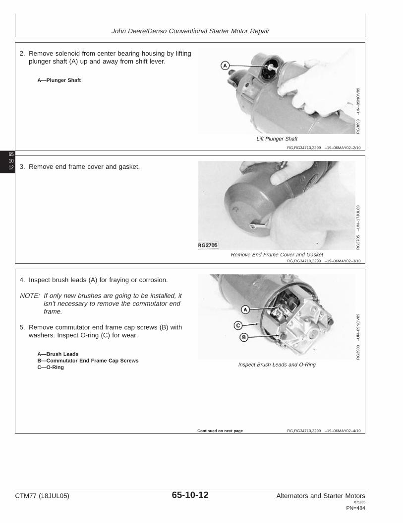
John Deere/Denso Conventional Starter Motor Repair
RG,RG34710,2299 –19–06MAY02–2/10
RG
3899
–UN
–09N
OV
89
Lift Plunger Shaft
651012
A—Plunger Shaft
2. Remove solenoid from center bearing housing by liftingplunger shaft (A) up and away from shift lever.
RG,RG34710,2299 –19–06MAY02–3/10
RG
2705
–UN
–17J
UL8
9
Remove End Frame Cover and Gasket
3. Remove end frame cover and gasket.
RG,RG34710,2299 –19–06MAY02–4/10
RG
3900
–UN
–09N
OV
89
Inspect Brush Leads and O-Ring
A—Brush LeadsB—Commutator End Frame Cap ScrewsC—O-Ring
4. Inspect brush leads (A) for fraying or corrosion.
NOTE: If only new brushes are going to be installed, itisn’t necessary to remove the commutator endframe.
5. Remove commutator end frame cap screws (B) withwashers. Inspect O-ring (C) for wear.
Continued on next page
CTM77 (18JUL05) 65-10-12 Alternators and Starter Motors071805
PN=484

John Deere/Denso Conventional Starter Motor Repair
RG,RG34710,2299 –19–06MAY02–5/10
RG
3901
–UN
–09N
OV
89
Remove Cap Screws and Ground Straps
651013
A—Brush Lead Cap ScrewsB—Brush Ground Straps
6. Remove brush lead cap screws (A).
7. Remove brush ground straps (B).
RG,RG34710,2299 –19–06MAY02–6/10
RG
3902
–UN
–09N
OV
89
Remove Brush
A—O-Ring PickB—Brush SpringC—Brush
8. Use an O-ring pick (A) or other suitable tool to pullbrush spring (B) back and remove brush (C).
RG,RG34710,2299 –19–06MAY02–7/10
RG
3903
–UN
–09N
OV
89
Remove Drive End HousingA—Shift Lever PivotB—Allen Screw (6 used)C—Drive End HousingD—Cap Screw (2 Used)
9. Remove shift lever pivot (A).
NOTE: Before removal of drive end housing, placealignment marks on drive end housing and centerbearing housing for aid in reassembly.
10. Remove drive end housing Allen screws (B) andcenter bearing housing cap screws (D).
11. Remove drive end housing (C).
Continued on next page
CTM77 (18JUL05) 65-10-13 Alternators and Starter Motors071805
PN=485

John Deere/Denso Conventional Starter Motor Repair
651014
RG,RG34710,2299 –19–06MAY02–8/10
R26
558
–UN
–09F
EB
90
Slide Pinion Stop
A—Pipe CouplingB—Pinion Stop
12. Use a pipe coupling (A) or other metal cylinder todrive pinion stop (B) toward pinion.
13. Remove retaining ring and slide pinion stop off shaft.
RG,RG34710,2299 –19–06MAY02–9/10
RG
3904
–UN
–09N
OV
89
Inspect for Damage
A—Overrunning ClutchB—Brake WasherC—Shift LeverD—Wear Pads
14. Carefully remove overrunning clutch (A), brakewasher (B), shift lever (C), and wear pads (D) fromcenter bearing housing and armature shaft. Inspectwear pads for excessive wear or damage. Replacewear pads if necessary.
RG,RG34710,2299 –19–06MAY02–10/10
RG
3905
–UN
–09N
OV
89
Remove Armature
A—Field FrameB—ArmatureC—Center Bearing Housing
15. Remove center bearing housing (C).
16. Carefully remove armature (B) from field frame (A).
CTM77 (18JUL05) 65-10-14 Alternators and Starter Motors071805
PN=486

John Deere/Denso Conventional Starter Motor Repair
651015
OUO1004,0000B48 –19–15SEP00–1/1
John Deere/Denso Conventional Starter Motor Exploded View
RG
4541
–UN
–15D
EC
88
Starter Motor Components
1—Drive End Bushing 11—Shunt Winding Lead 21—Field Winding 31—Gasket2—Drive End Housing 12—Armature 22—Pole Shoe (4 Used) 32—Commutator End Frame3—O-Ring 13—Bakelite Washer 23—Square Washer Bushing4—Overrunning Clutch 14—Oil Seal 24—Insulating Bushing 33—Brush (4 Used)5—Shift Lever Pivot 15—Center Bearing Bushing 25—Square Insulator 34—Brush Spring (4 Used)6—O-Ring 16—Oil Felt 26—Special Bolt 35—Commutator End Frame7—Shift Lever 17—Brake Washer 27—Field Coil Connector Bushing8—Center Bearing Housing 18—Pinion Stop 28—Terminal Cover 36—Field Frame9—Solenoid Winding 19—Snap Ring 29—Brush Ground Strap 37—Shims (as required)10—Solenoid Switch Cover 20—Shunt Winding Ground 30—End Frame Cover
Screw
CTM77 (18JUL05) 65-10-15 Alternators and Starter Motors071805
PN=487

John Deere/Denso Conventional Starter Motor Repair
651016
RG,RG34710,2300 –19–09OCT00–1/1
Install New Bushings/Needle Bearings
NOTE: Refer to exploded view on previous page.
1. If needed, install new bushings (1, 15, and 32).
2. Install a new oil seal (14) and oil felt (16) saturatedwith clean engine oil.
3. Make a bushing tool as shown earlier in DealerFabricated Tools or use the following componentsfrom the D01045AA Bushing, Bearing, and SealDriver Set.
Commutator and Drive End Bushing Tools
Bushing BushingComponent Removal Installation
Handle 27487 27487
Disk (Spacers) 27491 27492
Disk (Pilot) 27493 27493
Disk 27494 27495
4. Install commutator and drive end bushing anddetermine depth. Compare to specification below.
5. Ream bushing, if necessary, so followingspecifications are maintained.
SpecificationCommutator and Drive EndBushing—ID 17.000—17.028 mm
(0.6693—0.6704 in.)........................................................
Wear Limit 17.120 mm (0.674 in.)........................................................Oil Clearance 0.091—0.178 mm
(0.0036—0.0070 in.)..........................................................
Wear Limit 0.41 mm (0.016 in.)............................................................Bushing Depth 0.20—0.56 mm (0.008—0.022
in.)....................................
6. Install center bushing and oil seal using tools andspecifications listed below.
Center Bushing Tools
Component Bushing Oil Seal
Handle 27487 27487
Disk 27505 27512
Disk (pilot) 27501 27501
SpecificationCenter Housing Bushing—ID 30.023—30.074 mm
(1.182—1.84 in.).............................
Maximum Oil Clearance 0.599 mm (0.0236 in.)..................................Bushing Depth 0.43—0.81 mm (0.017—0.032
in.)....................................
RG,RG34710,2301 –19–15MAR97–1/1
Clean Starter Motor Components
IMPORTANT: Do not immerse the solenoid, fieldwindings, or armature in cleaningsolvent because it may damage theinsulation.
1. Clean parts by wiping with a cloth or brush,moistened with mineral spirits.
2. Dry with compressed air.
3. Clean the drive end housing, overrunning clutch,center bearing housing, and commutator end framethe same way.
All other parts which are not made of rubber ormentioned previously, can be dipped in cleaningsolvent to remove all oil and dirt.
CTM77 (18JUL05) 65-10-16 Alternators and Starter Motors071805
PN=488

John Deere/Denso Conventional Starter Motor Repair
651017
RG,RG34710,2302 –19–15MAR97–1/1
Inspect Armature
X14
51–U
N–2
5JA
N89
Inspect Armature
1. Place armature in V-blocks and check for bent shaft. Ifshaft is bent, replace armature.
Inspect armature using the following specifications:
SpecificationStandard Commutator—Runout 0.05 mm (0.002 in.).................................Wear Limit 0.38 mm (0.016 in.)..................................................................Armature—Undercut Depth 0.79 mm (0.0312 in.)......................................Wear Limit 0.20 mm (0.008 in.)..................................................................Commutator—OD 48 mm (1.89 in.)............................................................Minimum OD 46 mm (1.81 in.)....................................................................Armature—End Play 0.05—0.50 mm (0.002—0.020 in.)............................
2. Check armature for opens, shorts and grounds. Burnededge of commutator bar indicates an open circuit.
DPSG,OUOE003,29 –19–18DEC98–1/1
Make Short Circuit Test
RG
7807
4C1
–UN
–09J
AN
90
Place Armature in Growler
1. Place armature in a growler and hold hacksaw bladeabove each slot while slowly rotating the armature.
2. If coil is shorted, the blade will be attracted to andrepelled from the slot.
A short circuit most often occurs because of copperdust or filings between two commutator segments.Clean commutator segments to correct this short.
CTM77 (18JUL05) 65-10-17 Alternators and Starter Motors071805
PN=489

John Deere/Denso Conventional Starter Motor Repair
651018
RG,RG34710,2303 –19–15MAR97–1/1
Make Armature Ground Test
T90
253
–UN
–20N
OV
89
Make Armature Ground Test
1. Set ohmmeter to read on highest scale.
2. Place one test lead on the armature core or shaft.Place other lead on commutator.
If the test meter indicator swings toward zero, thearmature is grounded. Replace armature.
RG,RG34710,2304 –19–15MAR97–1/1
Make Open Circuit Test
T31
426N
Y–U
N–2
7JU
L89
Make Open Circuit Test
1. Set ohmmeter to read on lowest scale.
2. Place one test lead on ohmmeter segment. Place othertest lead on an adjacent segment.
3. Repeat this operation for all segments by moving onelead at a time.
If the test meter indicator does not swing to zero andremains stationary, the armature coil between thesetwo segment is open. Replace armature.
CTM77 (18JUL05) 65-10-18 Alternators and Starter Motors071805
PN=490

John Deere/Denso Conventional Starter Motor Repair
651019
RG,RG34710,2305 –19–15MAR97–1/1
Repair Armature
1. If commutator bars are rough or burned, clean with 00sandpaper. Never use emery cloth.
2. Clean all dust from armature.
IMPORTANT: Do not clean armature with solvent.Solvent could damage insulation onwindings. Use only mineral spirits and aclean cloth or brush. Wipe dry with aclean cloth.
RG,RG34710,2306 –19–15MAR97–1/1
Inspect Overrunning Clutch and Pinion
1. Rotate the pinion. Pinion gear should rotate smoothly(but not easily) in one direction. The pinion gear shouldnot rotate in the opposite direction.
If pinion gear does not rotate smoothly or if it is worn,chipped, or burred, it should be replaced.
CTM77 (18JUL05) 65-10-19 Alternators and Starter Motors071805
PN=491

John Deere/Denso Conventional Starter Motor Repair
651020
RG,RG34710,2307 –19–15MAR97–1/1
Make Grounded Circuit Test for FieldWindings
T35
198
–UN
–28J
UL8
9
Make Grounded Circuit Test
1. Remove screw and hang eyelet terminal in the air.
2. Set ohmmeter to read on highest scale.
3. Place one test lead on a clean spot on the field frame.Place other leads on the copper terminal bolt asshown.
If the ohmmeter indicator swings toward zero, agrounded circuit is indicated. Replace the fieldwindings.
RG,RG34710,2308 –19–15MAR97–1/1
Make Open Circuit Test for Shunt Windings
T31
428N
Y–U
N–2
7JU
L89
Make Open Circuit Test for Shunt Windings
1. Set the ohmmeter on its lowest scale.
2. Place one test lead on the eyelet terminal. Place otherlead on the terminal bolt.
If the ohmmeter does not swing to zero, it is opencircuited. Replace the field winding assembly.
CTM77 (18JUL05) 65-10-20 Alternators and Starter Motors071805
PN=492

John Deere/Denso Conventional Starter Motor Repair
651021
RG,RG34710,2309 –19–15MAR97–1/1
Make Open Circuit Test for Field Windings
T31
429N
Y–U
N–2
7JU
L89
Make Open Circuit Test for Field Windings
1. Set ohmmeter on its lowest scale.
2. Place one test lead on the naked field end. Place otherlead on the copper terminal bolt.
If ohmmeter dial indicator does not swing to zero, thefield windings are open circuited. Replace fieldwindings.
RG,RG34710,2310 –19–15MAR97–1/1
Remove Field Windings (If Necessary)
R26
555N
–UN
–09F
EB
90
Remove Field Windings
1. Use a large screwdriver bit and socket wrench on poleshoe cap screws.
2. Scribe mark on pole shoe and field frame for properassembly.
IMPORTANT: Do not tightly squeeze side of mainframe in a vise or strike with a hammer.Damage may result.
If an impact screwdriver is used to loosen screws,support each pole shoe individually using a pole shoespreader or the nose of an anvil.
Remove windings very carefully. Windings are easilydamaged, causing shorts, opens, or grounds.
CTM77 (18JUL05) 65-10-21 Alternators and Starter Motors071805
PN=493

John Deere/Denso Conventional Starter Motor Repair
651022
RG,RG34710,2311 –19–15MAR97–1/1
Install Field Windings
RG
4958
–UN
–06A
PR
89
Install Field Windings
A—Earlier Field Winding Shunt LeadB—Later Field Winding Shunt Lead
NOTE: Two different field winding assemblies areavailable. Starter motors with date code 9U0001and lower have shunt wire lead (A), while thosewith date code 10U001 and higher have shuntwire lead (B). Shunt wire lead (A) will be too shortfor the later starter motors.
1. Carefully insert field windings.
2. Align scribe marks on pole shoes and field frame.
3. Tighten pole shoe screws to specifications.
SpecificationPole Shoe Cap Screws—Torque 41 N•m (30 lb-ft)....................................
RG,RG34710,2312 –19–15MAR97–1/1
Inspect and Repair Brushes
Replace brushes if they are oil soaked, worn, damaged,or worn beyond specification.
SpecificationNew Brush—Length 26 mm (1.02 in.)........................................................Used Brush—Minimum Length 16 mm (0.68 in.).......................................
If brushes are burned or rough, use 00 sandpaper toclean commutator contact area of brushes. Never useemery cloth. Clean all dust from brush before reassembly.
CTM77 (18JUL05) 65-10-22 Alternators and Starter Motors071805
PN=494

John Deere/Denso Conventional Starter Motor Repair
651023
RG,RG34710,2313 –19–15MAR97–1/1
Test Brush Holder for Grounds
T31
430N
Y–U
N–2
7JU
L89
Test Brush Holder for Grounds
1. Set ohmmeter on its highest scale.
2. Place one test lead on commutator end frame. Placeother lead on brush holder.
If needle swings toward zero, the positive brush holderis grounded and should be replaced.
RG,RG34710,2314 –19–15MAR97–1/1
Measure Brush Spring Tension
T31
431N
Y–U
N–2
7JU
L89
Measure Brush Spring Tension
Measure spring tension with a spring scale.
Brush spring tension should be as specified, just as thespring leaves the brush holder.
SpecificationBrush Spring—Minimum Tension 11 N (40 ounce-force)............................
When measuring tension, scale should be parallel withedge of brush holder.
CTM77 (18JUL05) 65-10-23 Alternators and Starter Motors071805
PN=495

John Deere/Denso Conventional Starter Motor Repair
651024
RG,RG34710,2315 –19–15MAR97–1/1
Disassemble Solenoid
RG
3906
–UN
–09N
OV
89
Disassemble Solenoid
A—Switch CoverB—Shunt Winding LeadC—“S” TerminalD—Solenoid Winding and Plunger AssemblyE—Plunger CoverF—Pull-In Winding TerminalG—GasketsH—Packing
1. Remove nut, washer and gasket from solenoid “S”terminal (C).
2. Remove nut, washer and gasket from pull-in terminal(F).
3. Remove switch cover (A).
4. Inspect all solenoid parts for wear, dirt, and corrosion.
5. Wipe all parts and connections with mineral spirits anda clean cloth or brush. Dry with a clean cloth.
Firm pressure should be felt on the plunger when fullydepressed. If plunger is weak, replace solenoid windingand plunger assembly.
6. Place gaskets on pull-in terminal and “S” terminal.
7. Align main contact vertically.
8. Place packing on switch cover.
9. Tighten switch cover screws to solenoid winding andplunger assembly securely.
IMPORTANT: Solenoid contacts and plunger will bedamaged if current is applied tosolenoid when removed from startermotor.
CTM77 (18JUL05) 65-10-24 Alternators and Starter Motors071805
PN=496

John Deere/Denso Conventional Starter Motor Repair
651025
RG,RG34710,2316 –19–15MAR97–1/9
Assemble Starter Motor
RG
3904
–UN
–09N
OV
89
Assemble Starter MotorA—Overrunning ClutchB—Brake WasherC—Shift LeverD—Wear Pads
1. Lubricate both ends of shift lever (C) and wear pads(D) on overrunning clutch (A), with a multi-purposelubricant.
2. Lubricate brake washer (B) and place on end ofoverrunning clutch.
NOTE: Avoid excessive lubrication.
RG,RG34710,2316 –19–15MAR97–2/9
RG
3907
–UN
–09N
OV
89
Install and Inspect
A—Overrunning ClutchB—Center Bearing HousingC—Shift Lever PivotD—O-Ring
3. Place shift lever and overrunning clutch (A) up intocenter bearing housing (B).
4. Install shift lever pivot (C) through shift lever andtighten to specifications.
SpecificationShift Lever Pivot Cap Screw—Torque 41 N•m (30 lb-ft).............................................................................
5. Bend washered edge of shift lever pivot down toprevent loosening.
6. Lubricate bearing in center bearing housinggenerously, but not excessively with either EssoBeacon 325 or Delco-Remy Lubricant No. 1960954.
7. Inspect O-ring (D) for wear and damage. Replace ifnecessary.
Continued on next page
CTM77 (18JUL05) 65-10-25 Alternators and Starter Motors071805
PN=497

John Deere/Denso Conventional Starter Motor Repair
651026
RG,RG34710,2316 –19–15MAR97–3/9
RG
3908
–UN
–09N
OV
89
Install Center Bearing Housing
A—Field FrameB—Overrunning Clutch AssemblyC—Armature ShaftD—Pinion StopE—Retaining RingF—Washer (remove after using)G—Cap Screws
8. Carefully install armature into field frame (A).
9. Place center bearing housing with overrunning clutchassembly (B) onto armature shaft (C) and against fieldframe.
Make sure O-ring in center bearing housing is nottwisted or crimped when placed against field frame.
10. Slide pinion stop over ring using a washer (F) andtwo pair of pliers.
11. Remove washer.
12. Tighten all center bearing housing cap screws (G) infield frame to specifications.
SpecificationCenter Housing-to-Field FrameCap Screw—Torque 8 N•m (71 lb-in.).........................................................
NOTE: Before installing drive end housing, checkarmature end play. Using a dial indicator, place atip against end of armature shaft on drive end. Ifend play is not within specifications, add orremove shims (37, see exploded view) to obtaincorrect end play.
SpecificationArmature End Play—Torque 0.05—0.50 mm (0.002—0.020 in.)...............
RG,RG34710,2316 –19–15MAR97–4/9
RG
4205
–UN
–08S
EP
89
Install Drive End HousingA—Drive End HousingB—Drive End BushingC—Drive End Allen-Head Bolts
13. Install drive end housing (A) against center bearinghousing. Armature shaft must come through drive endbushing (B).
14. Tighten drive end Allen-head bolts (C) tospecifications.
SpecificationDrive End Housing-to-CenterHousing Cap Screws—Torque 14 N•m (124 lb-in.).....................................
CTM77 (18JUL05) 65-10-26 Alternators and Starter Motors071805
PN=498
Continued on next page

John Deere/Denso Conventional Starter Motor Repair
651027
RG,RG34710,2316 –19–15MAR97–5/9
RG
3902
–UN
–09N
OV
89
Install Brushes
A—O-Ring PickB—Brush SpringsC—Brushes
15. Place commutator end frame over armature.
NOTE: Be sure commutator end frame notches fitcorrectly in field frame.
16. Using O-ring pick (A) or other suitable tool, raisebrush springs (B) and install brushes (C).
RG,RG34710,2316 –19–15MAR97–6/9
RG
3909
–UN
–09N
OV
89
Twist Brush Leads
A—Insulated BrushB—Brush LeadsC—Spring
17. Twist brush leads (B) 180 degrees.
18. Press leads of insulated brush (A) down againstbrush. Make sure spring (C) is fully seated on top ofbrush.
RG,RG34710,2316 –19–15MAR97–7/9
RG
3901
–UN
–09N
OV
89
Install Brush Ground Straps
A—Brush Cap ScrewsB—Brush Ground Straps
19. Install brush ground straps (B).
20. Screw brush cap screws (A) down securely.
NOTE: Make sure field winding lead and shunt windingleads are tightened down with the brush capscrews.
Continued on next page
CTM77 (18JUL05) 65-10-27 Alternators and Starter Motors071805
PN=499

John Deere/Denso Conventional Starter Motor Repair
651028
RG,RG34710,2316 –19–15MAR97–8/9
RG
3900
–UN
–09N
OV
89
Position Brush Leads
A—Brush LeadsB—Washers and Cap ScrewsC—O-Ring
21. Install washers and cap screws (B) throughcommutator end frame.
22. Tighten screws to specifications.
SpecificationCommutator End Frame CapScrews—Torque 14 N•m (124 lb-in.)...........................................................
Make sure brush leads (A) are properly positioned.
NOTE: Replace O-ring (C) if cracked or worn.
RG,RG34710,2316 –19–15MAR97–9/9
RG
2705
–UN
–17J
UL8
9
End Frame Cover
23. Place end frame cover onto field frame.
24. Install end frame cover washers, lock washers andcap screws. Tighten securely.
RG,RG34710,2317 –19–15MAR97–1/4
Install Solenoid
RG
3899
–UN
–09N
OV
89
Solenoid Plunger Shaft
A—Solenoid Plunger Shaft
1. Install solenoid plunger shaft (A) up onto shift lever.
Continued on next page
CTM77 (18JUL05) 65-10-28 Alternators and Starter Motors071805
PN=500

John Deere/Denso Conventional Starter Motor Repair
RG,RG34710,2317 –19–15MAR97–2/4
RG
3898
–UN
–09N
OV
89
Lock Washers
651029
A—Solenoid Cap Screws and Lock Washers
2. Push solenoid assembly forward up against centerbearing housing.
3. Screw solenoid cap screws with lock washers (A) intosolenoid and tighten securely.
RG,RG34710,2317 –19–15MAR97–3/4
RG
3893
–UN
–09N
OV
89
Install Field Coil Connector
A—Field Coil Connector
4. Install field coil connector (A), washers and nuts.Tighten nuts securely.
RG,RG34710,2317 –19–15MAR97–4/4R
G38
92–U
N–0
9NO
V89
Install Terminal Cover
A—Shunt Lead WireB—Terminal Cover
5. Install shunt lead wire (A), lock washer, and nut.Tighten nut securely.
6. Install terminal cover (B) on solenoid securely.
CTM77 (18JUL05) 65-10-29 Alternators and Starter Motors071805
PN=501

John Deere/Denso Conventional Starter Motor Repair
651030
RG,RG34710,2318 –19–15MAR97–1/1
Make No-Load Test
RG
1116
3–U
N–2
8SE
P00
Make No-Load Test
A—AmmeterB—BatteryC—Start FrameD—TachometerE—Battery TerminalF—SwitchG—Field Coil Connector
1. Make connections as shown, and use an ammeter (A)capable of measuring several hundred amps.
2. Measure current draw and compare with specificationsgiven earlier in this group.
3. If speed and current draw are slightly low, connect avoltmeter between motor terminal and frame. Observevoltage during test. Voltage may be reduced becauseof high current draw on battery.
4. If speed or current draw is significantly different thanspecified, diagnose problem by referring to DiagnoseNo-Load Test chart earlier in this group.
CTM77 (18JUL05) 65-10-30 Alternators and Starter Motors071805
PN=502

Group 15John Deere/Denso Gear Reduction Starter Motor Repair
OUO1004,0000B9F –19–08MAY02–1/3
Essential Tools
NOTE: Order tools according to information given in theU.S. SERVICEGARD Catalog or from theEuropean Microfiche Tool Catalog (MTC).
65151
SERVICEGARD is a trademark of Deere & Company
OUO1004,0000B9F –19–08MAY02–2/3
RW
1127
4–U
N–1
2DE
C88
JT05791
Digital Multimeter . . . . . . . . . . . . . . . . . . . . . JT05791
Test electrical components for voltage, resistance, orcurrent flow. It is especially good for measuring lowvoltage or high resistance circuits.
OUO1004,0000B9F –19–08MAY02–3/3
Alternator, Generator, Starter and Battery BenchTester . . . . . . . . . . . . . . . . . . . . . . . . . . . . . JT01760
Test alternators and starters for voltage, resistance, orcurrent flow.
CTM77 (18JUL05) 65-15-1 Alternators and Starter Motors071805
PN=503

John Deere/Denso Gear Reduction Starter Motor Repair
OUO1004,0000BA0 –19–25SEP00–1/5
Service Equipment and Tools
NOTE: Order tools according to information given in theU.S. SERVICEGARD Catalog or from theEuropean Microfiche Tool Catalog (MTC). Sometools may be available from a local supplier.
6515
2
SERVICEGARD is a trademark of Deere & Company
OUO1004,0000BA0 –19–25SEP00–2/5
Armature Growler
Test windings for shorts.
OUO1004,0000BA0 –19–25SEP00–3/5
Bearing Puller. . . . . . . . . . . . . . . . . . . . . . D01203AA
Remove bearings.
OUO1004,0000BA0 –19–25SEP00–4/5
Bearing Puller. . . . . . . . . . . . . . . . . . . . . . D01217AA
Remove bearings.
OUO1004,0000BA0 –19–25SEP00–5/5
Bushing, Bearing and Seal Drive Set. . . . . . . D01045AA
Remove and install all commutator, drive end, and centerbushings.
OUO1004,0000BA1 –19–25SEP00–1/1
Other Material
Number Name Use
Mineral Spirits Clean armature, solenoid andbrushes.
00 Sandpaper Clean commutator.
ESSO Beacon 325 or Delco-Remy Lubricate various stator components.No. 1960954 Lubricant
CTM77 (18JUL05) 65-15-2 Alternators and Starter Motors071805
PN=504

John Deere/Denso Gear Reduction Starter Motor Repair
65153
OUO1004,0000BA2 –19–25SEP00–1/1
John Deere/Denso Gear Reduction StarterMotor Repair Specifications
Item Measurement Specification
Armature Undercut Depth 0.08 mm (0.031 in.)Service Minimum 0.20 mm (0.008 in.)
Commutator OD (New Part) 36 mm (1.41 in.)Wear Limit 35 mm (1.38 in.)
Commutator Runout (New Part) 0.02 mm (0.0008 in.)Wear Limit 0.05 mm (0.002 in.)
Negative Brushes Minimum Length 9.0 mm (0.35 in.)
Field Coil Brushes Minimum Length 12.7 mm (0.500 in.)
CTM77 (18JUL05) 65-15-3 Alternators and Starter Motors071805
PN=505

John Deere/Denso Gear Reduction Starter Motor Repair
6515
4
RG,RG34710,2322 –19–07JUL05–1/1
John Deere/Denso Gear Reduction StarterMotor Test Specifications
John Deere Denso System Rating kW Motor No Load Test RPM (Min.)Starter Motor Starter Motor Voltage Type Voltage Current Draw
Part No. Part No. Amps (Max.)
AM879743 22800-7111 12 R 2.0 11
AM877284 22800- 12 R 2.0 11
RE19275 028000-8400 12 R 2.5 11 180 3500
RE40092 028000-8290 12 R 2.5 11 200 3000
RE500199 228000-7010 24 R 7.5 23 120 3800
RE501060 228000-7410, 24 R 7.8 23 Min 120 3800228000-7411
RE501294 228000-7873 12 R 4.0 11 220 4200
RE50165 228000-0840 12 R 2.5 11 200 3000
RE51447 028000-8401 12 R 2.5 11 200 3000
RE54090 128000-8291 12 R 2.5 11 200 3000
RE54091 228000-0841 12 R 2.5 11 200 3000
RE54092 028000-8402 12 R 2.5 11 200 3000
RE59588 228000-0844 12 R 2.5 11 200 3000
RE59595 128000-8294 12 R 2.5 11 200 3000
RE68470 228000-6471 12 R 2.7 11 200 3000
RE69704 228000-6530, 12 R 4.0 11 220 4200228000-6531
RE69705 228000-6560 24 R 7.5 23 120 3800
RE70473 228000-6540 12 R 4.8 11 220 4200
RE70474 228000-6550, 12 R 4.8 11 220 4200228000-6551
RE70475 228000-6570 24 R 7.5 23 120 3800
RE70957 228000-6530 12 R 4.8 11 220 4200
RE70959 228000-6540 12 R 4.8 11 220 4200
RE70960 228000-6550 12 R 4.8 11 220 4200
NOTE: Earlier Denso starter motors may have the originalNippondenso label.
CTM77 (18JUL05) 65-15-4 Alternators and Starter Motors071805
PN=506

John Deere/Denso Gear Reduction Starter Motor Repair
65155
RG,RG34710,2323 –19–15MAR97–1/1
Bench Test Starter Motor
RW
2158
–UN
–06M
AR
90
Turn Overrunning Clutch
IMPORTANT: Never operate starter motor more than30 seconds. Allow at least 2 minutes forcooling and battery recovery beforeoperating again. Overheating, causedby excessive operation, will seriouslydamage starter motor.
NOTE: Perform bench tests before disassembling thestarter motor to determine the cause of theproblem.
1. Turn overrunning clutch drive clockwise by hand.Pinion should turn freely.
2. Turn pinion counterclockwise. A definite resistanceshould be felt. If clutch assembly is defective,disassemble the starter clutch.
3. If armature turns freely and the clutch is not defective,test starter under no-load conditions as follows.
NOTE: Starter motors illustrated in this group areequipped with a four-hole mounting flange insteadof one that has two holes. In addition, later R 4.0kW and R 7.5 kW starter motors have the brushassemblies at the opposite end of the armature.Service procedures are not affected.
CTM77 (18JUL05) 65-15-5 Alternators and Starter Motors071805
PN=507

John Deere/Denso Gear Reduction Starter Motor Repair
6515
6
RG,RG34710,2324 –19–15MAR97–1/1
No-Load Test
RW
2159
–UN
–01D
EC
88
No-Load Test
A—12-Volt BatteryB—Battery TerminalC—Starter FrameD—Remote Start SwitchE—Switch Terminal
NOTE: Do not conduct the no-load test unless thearmature turns freely.
1. Connect a 12-volt battery (A) to starter battery terminal(B) and starter frame (C) as shown. Use heavy-dutycables.
2. Connect a remote start switch (D) between switchterminal (E) and battery terminal (B).
3. When switch is activated, starter should engage andrun.
4. If solenoid only chatters, hold-in winding isopen-circuited. If nothing happens, either the pull-inwinding is open-circuited or mechanical parts aresticking. To check for sticking, remove solenoid endcover and push plunger by hand.
5. If solenoid engages properly, but motor does not run,check main contact points, bearings, brushes,reduction gears, armature, and field windings.
NOTE: The solenoid cannot be repaired, althoughmechanical parts may be replaced. Disassemblesolenoid to determine cause of problem.
CTM77 (18JUL05) 65-15-6 Alternators and Starter Motors071805
PN=508

John Deere/Denso Gear Reduction Starter Motor Repair
65157
RG,RG34710,2334 –19–15MAR97–1/1
John Deere/Denso Gear Reduction Starter Motor Exploded View
RG
8615
–UN
–16S
EP
99
Gear-Reduction Starter Motor
1—End Frame 6—Armature 11—Idler Gear 15—Return Spring2—O-Ring 7—Front Bearing 12—Retainer 16—Steel Ball3—Field Frame 8—Brush (4 Used) 13—Roller (5 Used) 17—Overrunning Clutch4—O-Ring 9—Brush Holder 14—Solenoid Assembly 18—Motor Frame5—Rear Bearing 10—Drive Gear
RG,RG34710,2325 –19–15MAR97–1/4
Disassemble Field Frame, Armature, andBrush Holder
RW
1005
8–U
N–1
0NO
V89
Disconnect Field Lead
A—Field LeadB—Through Bolts (2 Used)
NOTE: Bench test the starter motor before disassembly.
1. Disconnect field lead (A) from solenoid.
2. Remove two through bolts (B) and separate field frameassembly from motor frame.
CTM77 (18JUL05) 65-15-7 Alternators and Starter Motors071805
PN=509
Continued on next page

John Deere/Denso Gear Reduction Starter Motor Repair
6515
8
RG,RG34710,2325 –19–15MAR97–2/4
RW
1005
9–U
N–1
0NO
V89
Remove Cap from Frame Assembly
3. Remove two screws from brush end cap and removecap from frame assembly.
RG,RG34710,2325 –19–15MAR97–3/4
RW
1006
7–U
N–1
0NO
V89
Field Coil Brushes
A—Field Coil Brushes
4. Lift two field coil brush springs away and pull field coilbrushes (A) away from brush holder assembly.
Continued on next page
CTM77 (18JUL05) 65-15-8 Alternators and Starter Motors071805
PN=510

John Deere/Denso Gear Reduction Starter Motor Repair
65159
RG,RG34710,2325 –19–15MAR97–4/4
RW
1006
8–U
N–1
0NO
V89
Brush Holder
A—Brush Holder
5. Lift two negative brush springs away and pull brushesback about 6 mm (0.250 in.). Release springs to holdbrushes in place in brush holder (A).
6. Remove brush holder from frame assembly andarmature.
7. Remove armature from frame assembly.
RG,RG34710,2326 –19–15MAR97–1/8
Inspect and Repair Armature
RW
2166
–UN
–06M
AR
90
Inspect and Repair Armature
1. Remove armature from field frame assembly. SeeDisassemble Field Frame, Armature and Brush Holderearlier in this group.
IMPORTANT: Do not clean armature with solvent.Solvent could damage insulation onwindings. Use only mineral spirits and abrush.
2. Visually inspect armature. Look for signs of draggingagainst pole shoes.
SpecificationArmature—Undercut Depth 0.08 mm (0.031 in.)........................................Service Minimum 0.20 mm (0.008 in.)........................................................
Continued on next page
CTM77 (18JUL05) 65-15-9 Alternators and Starter Motors071805
PN=511

John Deere/Denso Gear Reduction Starter Motor Repair
651510
RG,RG34710,2326 –19–15MAR97–2/8
RW
2167
–UN
–26F
EB
93
Ohmmeter
3. Check for grounded windings using an ohmmeter asshown, or a test lamp. Place ohmmeter probes oncommutator bar and armature shaft. If test showscontinuity (needle movement) a winding is groundedand the armature must be replaced.
NOTE: Operating symptoms of grounded windings wouldbe that the starter motor cranks engine slowly ornot at all. On no-load test, the starter motor wouldhave low armature speed and high current draw,or fail to operate and have high current draw.
RG,RG34710,2326 –19–15MAR97–3/8
RW
2168
–UN
–01D
EC
88
Growler
NOTE: Operating symptoms of short-circuited windingswould be that the starter motor cranks engineslowly. On no-load test, motor has low armaturespeed and high current draw.
4. Check for short-circuited windings using a growler suchas shown.
5. Place armature in growler and hold a hacksaw bladeabove each slot while slowly rotating the armature. Theblade will be attracted to and repelled (vibratingmotion) from the slot.
NOTE: A short circuit most often occurs because ofcopper dust or fillings between two commutatorsegments.
6. If test indicates short-circuited windings, clean thecommutator of dust and filings and recheck thearmature. If test still indicates a short circuit, replacethe armature.
Continued on next page
CTM77 (18JUL05) 65-15-10 Alternators and Starter Motors071805
PN=512

John Deere/Denso Gear Reduction Starter Motor Repair
651511
RG,RG34710,2326 –19–15MAR97–4/8
RW
1006
0–U
N–1
0NO
V89
Ohmmeter Probes
7. Check for open-circuited windings using an ohmmeteras shown, or a test lamp. Place ohmmeter probes ontwo different commutator bars. If test shows nocontinuity (no needle movement), there is an opencircuit and the armature must be replaced.
NOTE: Operating symptoms of open-circuited windingswould be that the starter motor cranks engineslowly. On no-load test, motor has low armaturespeed and high current draw.
RG,RG34710,2326 –19–15MAR97–5/8
RW
1006
1–U
N–1
0NO
V89
Check Commutator
A—Commutator
8. Check commutator (A), looking for roughness orburned commutator bars.
9. If necessary, clean and touch up with 00 sandpaper.NEVER use emery cloth. Clean all dust from armaturewhen finished.
10. Turn down slightly on a lathe if commutator is out ofround, badly burned, or rough. Remove only enoughmetal to eliminate the problem. After turning down,undercut the insulation between bars to 0.5—0.8 mm(0.019—0.031 in.) deep. Touch up commutator withsandpaper and clean metal chips and dust fromarmature when finished.
SpecificationCommutator—OD (New Part) 36 mm (1.41 in.).........................................Wear Limit 35 mm (1.38 in.).......................................................................Commutator—Runout (New Part) 0.02 mm (0.0008 in.)............................Wear Limit 0.05 mm (0.002 in.)..................................................................
Continued on next page
CTM77 (18JUL05) 65-15-11 Alternators and Starter Motors071805
PN=513

John Deere/Denso Gear Reduction Starter Motor Repair
651512
RG,RG34710,2326 –19–15MAR97–6/8
RW
1006
9–U
N–1
0NO
V89
Front and Rear Armature Bearings
11. Inspect front and rear armature bearings for smooth,quiet operation. Replace as necessary.
12. Remove bearings by using D01217AA Bearing Pullerand D01203AA Bearing Puller as shown.
RG,RG34710,2326 –19–15MAR97–7/8
RW
1007
0–U
N–1
0NO
V89
15.88 mm (0.625 in.) ID PipeA—15.88 mm (0.625 in.) ID Pipe
IMPORTANT: Install both bearings with the sealedside toward the middle of the armature.
13. Install new bearing on the rear of armature using apiece of 15.88 mm (0.625 in.) ID pipe (A) drilled outto 17.45 mm (0.687 in.) ID. Be sure to drive only onthe inner race. Make sure bearing is tight againstshoulder of shaft.
NOTE: Pipe must be drilled out to the larger size to allowit to pass over the splined end of the armature.
Continued on next page
CTM77 (18JUL05) 65-15-12 Alternators and Starter Motors071805
PN=514

John Deere/Denso Gear Reduction Starter Motor Repair
651513
RG,RG34710,2326 –19–15MAR97–8/8
RW
1007
1–U
N–1
0NO
V89
Install Bearing
A—Bearing
14. Install bearing (A) with sealed side of bearing towardmiddle of armature on commutator end of armatureusing 27491 1/2 in. driver disk from D01045AABushing, Bearing and Seal Drive Set. Drive only onthe inner race. Install bearing until tight againstshoulder of shaft.
RG,RG34710,2327 –19–15MAR97–1/4
Inspect Brushes and Brush Holder
RW
1007
2–U
N–1
0NO
V89
Measure Negative Brushes
1. Measure negative brushes mounted on brush holder. Ifworn below specification, replace the brush holderassembly.
SpecificationNegative Brushes—MinimumLength 9.0 mm (0.35 in.).............................................................................
Continued on next page
CTM77 (18JUL05) 65-15-13 Alternators and Starter Motors071805
PN=515

John Deere/Denso Gear Reduction Starter Motor Repair
651514
RG,RG34710,2327 –19–15MAR97–2/4
RW
1007
3–U
N–1
0NO
V89
Measure Field Coil Brushes
2. Measure the field coil brushes attached to the fieldframe assembly. If worn below specified length,replace the entire field frame assembly.
SpecificationField Coil Brushes—MinimumLength 12.7 mm (0.500 in.).........................................................................
RG,RG34710,2327 –19–15MAR97–3/4
RW
1007
4–U
N–1
0NO
V89
Test Brush Holder with Ohmmeter
3. Test the brush holder using an ohmmeter as shown, ora test light. Place one lead of tester to the negativebrush holder and the other lead to field brush holder. Ifthere is continuity (needle movement), replace thebrush holder.
Continued on next page
CTM77 (18JUL05) 65-15-14 Alternators and Starter Motors071805
PN=516

John Deere/Denso Gear Reduction Starter Motor Repair
651515
RG,RG34710,2327 –19–15MAR97–4/4
RW
1007
5–U
N–1
0NO
V89
Check Brush Springs
4. Check the brush springs to be sure they are not weakor distorted. Replace as necessary.
5. Remove spring using a pair of needle nose pliers.Raise brush end of spring from holder and pry springupward from lug on holder with a screwdriver.
6. To install, start spring on lug and wind spring so brushend of spring fits in brush holder, while at the sametime pushing the spring on the lug.
RG,RG34710,2328 –19–12SEP02–1/2
Inspect Field Coils
RW
1007
6–U
N–1
0NO
V89
Check for Grounded Field Winding
1. Check for grounded field winding using an ohmmeteras shown, or a test light. Touch one lead to a field coilbrush and the other lead to the field frame. Be sure thebrush lead is not touching the frame. If there iscontinuity (needle movement), the coil is grounded andthe field frame assembly must be replaced.
Continued on next page
CTM77 (18JUL05) 65-15-15 Alternators and Starter Motors071805
PN=517

John Deere/Denso Gear Reduction Starter Motor Repair
651516
RG,RG34710,2328 –19–12SEP02–2/2
RW
1007
7–U
N–1
0NO
V89
Check for Open Field Coil
2. Check for open field coil using an ohmmeter as shown,or a test light. Touch a lead to each field coil brush. Ifthere is no continuity (no needle movement), the fieldcoil is open and the field frame assembly must bereplaced.
RG,RG34710,2329 –19–15MAR97–1/5
Assemble Field Frame, Armature, and BrushHolder
RW
1009
5–U
N–1
0NO
V89
Field Frame, Armature and Brush Holder
1. Place armature in field frame assembly and place invise.
2. Lift the two negative brush springs away and pullbrushes back about 6 mm (0.250 in.). Release thespring to lock the brushes in the outward position.
3. Place brush holder on armature and frame assembly.
Continued on next page
CTM77 (18JUL05) 65-15-16 Alternators and Starter Motors071805
PN=518

John Deere/Denso Gear Reduction Starter Motor Repair
651517
RG,RG34710,2329 –19–15MAR97–2/5
RW
1006
7–U
N–1
0NO
V89
Place Brushes in Holders
A—Brushes
4. Lift two field coil brush springs away from holder andplace brushes (A) in holders. Allow springs to holdbrushes against commutator.
5. Push negative brushes inward to allow springs to holdbrushes against commutator.
RG,RG34710,2329 –19–15MAR97–3/5R
W10
059
–UN
–10N
OV
89
Install Brush End Cap
6. Apply a small amount of Delco-Remy Lubricant No.1960954, or equivalent, to the open side of the brushend bearing.
7. Install brush end cap in place and install and tightentwo screws from brush end cap to field frameassembly.
Continued on next page
CTM77 (18JUL05) 65-15-17 Alternators and Starter Motors071805
PN=519

John Deere/Denso Gear Reduction Starter Motor Repair
651518
RG,RG34710,2329 –19–15MAR97–4/5
RW
1007
8–U
N–1
0NO
V89
Install Felt Washer
A—Felt WasherB—Indexing SlotC—Field Frame Assembly
8. Apply a small amount of Delco-Remy Lubricant No.1960954, or equivalent, to the open side of the driveend bearing.
9. Install felt washer (A) in place on armature shaft.
10. Align indexing slot in solenoid frame (B) with flangeon lip of field frame assembly (C).
NOTE: Some starter motors may have a small-squareshaped locking key which fits into the cast slot (B)in solenoid frame.
RG,RG34710,2329 –19–15MAR97–5/5
RW
1005
8–U
N–1
0NO
V89
Connect Field Lead to Solenoid
A—Field LeadB—Through Bolts (2 Used)
11. Install field frame assembly to motor frame.
12. Install and tighten two through bolts (B).
13. Connect field lead (A) to solenoid.
14. Bench test the repaired starter motor as instructedearlier in this group.
15. If bench tests indicate that the starter motor isworking, install starter motor on engine as instructedin machine technical manual.
CTM77 (18JUL05) 65-15-18 Alternators and Starter Motors071805
PN=520

John Deere/Denso Gear Reduction Starter Motor Repair
651519
RG,RG34710,2330 –19–15MAR97–1/6
Disassemble Gear Train and OverrunningClutch
RW
1006
2–U
N–1
0NO
V89
Remove Screws
A—Screws (3 Used)
1. Disassemble the field frame assembly from thehousing as previously instructed in this group.
2. Remove three screws (A) and separate gear trainassembly from motor frame.
RG,RG34710,2330 –19–15MAR97–2/6
R30
383
–UN
–12F
EB
90
Compress Pinion
3. Place gear assembly in a soft-jaw vise as shown. Besure rear vise jaw is against shaft and front jaw isagainst pinion.
4. Slowly tighten vise until pinion compresses.
Continued on next page
CTM77 (18JUL05) 65-15-19 Alternators and Starter Motors071805
PN=521

John Deere/Denso Gear Reduction Starter Motor Repair
651520
RG,RG34710,2330 –19–15MAR97–3/6
R30
384
–UN
–12F
EB
90
Remove Snap Ring and Retainer
A—5/8 in. ID PipeB—Retainer
5. Drive back retainer (B) until snap ring is exposed,using a short length of 5/8 in. ID pipe (A).
6. Remove snap ring and retainer from pinion shaft.
CAUTION: Shaft could be propelled from clutchunit with considerable force, if spring is notallowed to extend fully while in vise.
7. Slowly open vise until all spring tension is relieved andremove gear assembly from vise.
RG,RG34710,2330 –19–15MAR97–4/6
RW
1008
0–U
N–1
0NO
V89
Remove Shaft
A—Shaft with SpringsB—Clutch Unit
8. Remove drive pinion from shaft.
9. Remove shaft with springs (A) and clutch unit (B) fromhousing.
Continued on next page
CTM77 (18JUL05) 65-15-20 Alternators and Starter Motors071805
PN=522

John Deere/Denso Gear Reduction Starter Motor Repair
651521
RG,RG34710,2330 –19–15MAR97–5/6
RW
1008
1–U
N–1
0NO
V89
Inspect Parts for Wear or Damage
A—ShaftB—SpringC—SpringD—RetainerE—Clutch Unit
10. Inspect all parts for wear or damage. Replace asnecessary.
11. If clutch unit (E) is defective, the entire unit must bereplaced.
RG,RG34710,2330 –19–15MAR97–6/6R
W10
082
–UN
–10N
OV
89
Inspect Parts
A—Thrust WasherB—PinionC—Needle Rollers (6 used)D—Needle Roller RetainerE—Solenoid Plunger SpringF—Solenoid Housing
12. Remove the starter pinion (B), needle roller retainer(D) with six needle rollers (C), and thrust washer (A)from housing.
13. Remove the spring (E) from the solenoid plunger.
14. Inspect all parts for wear or damage. Replace asnecessary.
CTM77 (18JUL05) 65-15-21 Alternators and Starter Motors071805
PN=523

John Deere/Denso Gear Reduction Starter Motor Repair
651522
RG,RG34710,2331 –19–15MAR97–1/7
Assemble Gear Train and OverrunningClutch
RW
1007
9–U
N–1
0NO
V89
Solenoid Plunger Ball in Shaft Bore
A—Solenoid Plunger BallB—Shaft Bore
NOTE: Use Delco-Remy No. 1960954 Lubricant or asimilar lubricant when assembling starter motor.
1. Make sure the solenoid plunger ball (A) is in place inthe shaft bore (B). Apply a light coat of grease to theball to hold in place.
RG,RG34710,2331 –19–15MAR97–2/7
RW
1008
1–U
N–1
0NO
V89
Install Pinion Shaft Assembly into Clutch Unit
A—Pinion ShaftB—SpringC—SpringD—Spring RetainerE—Clutch Unit
NOTE: Lubricate the shaft lightly with lubricant beforeinstalling springs.
2. First place the long spring (B) on the pinion shaft, thenthe short spring (C), and spring retainer (D).
3. Install pinion shaft assembly into clutch unit (E), asshown.
Continued on next page
CTM77 (18JUL05) 65-15-22 Alternators and Starter Motors071805
PN=524

John Deere/Denso Gear Reduction Starter Motor Repair
651523
RG,RG34710,2331 –19–15MAR97–3/7
RW
1008
0–U
N–1
0NO
V89
Clutch Unit with Pinion Shaft Assembly
A—Pinion Shaft AssemblyB—Clutch Unit
4. Install clutch unit (B) with pinion shaft assembly (A)into housing.
RG,RG34710,2331 –19–15MAR97–4/7R
W10
083
–UN
–10N
OV
89
Retaining Ring
A—Retaining Ring
5. Make sure retaining ring (A) is in drive pinion and isnot worn or damaged.
Continued on next page
CTM77 (18JUL05) 65-15-23 Alternators and Starter Motors071805
PN=525

John Deere/Denso Gear Reduction Starter Motor Repair
651524
RG,RG34710,2331 –19–15MAR97–5/7
RW
1008
4–U
N–1
0NO
V89
Install Retainer and Snap Ring
A—Drive PinionB—RetainerC—Snap Ring
6. Lightly lubricate the pinon shaft and install drive pinion(A) onto pinion shaft, as shown, with large flange to theoutside of clutch.
7. Place gear assembly in a soft jaw vise, as shown. Besure rear vise jaw is against shaft and front jaw isagainst pinion.
8. Slowly tighten vise until pinion compresses enough toallow installation of retainer and retaining ring.
9. Install retainer (B) and snap ring (C) and remove fromvise. Make sure snap ring is seated in retainer.
RG,RG34710,2331 –19–15MAR97–6/7
RW
1008
2–U
N–1
0NO
V89
Components
A—Thrust WasherB—PinionC—Needle Rollers (6 used)D—Needle Roller RetainerE—Solenoid Plunger SpringF—Solenoid Housing
10. Apply a thin coating of lubricant to the thrust washer(A) and install on shaft.
11. Apply a thin coating of lubricant to the needle rollers(C) and install them into retainer (D).
12. Install the needle roller retainer with needle rollersinto the starter pinion (B).
13. Place the pinion assembly onto the shaft with theopen side of the retainer facing the thrust washer.
14. Install spring (E) on solenoid plunger.
Continued on next page
CTM77 (18JUL05) 65-15-24 Alternators and Starter Motors071805
PN=526

John Deere/Denso Gear Reduction Starter Motor Repair
651525
RG,RG34710,2331 –19–15MAR97–7/7
RW
1006
2–U
N–1
0NO
V89
Screws
A—Screws (3 Used)
15. Assemble gear train assembly to frame and installand tighten three screws (A).
16. Assemble field frame assembly to housing and benchtest the starter as previously instructed in this group.
RG,RG34710,2332 –19–15MAR97–1/3
Disassemble, Inspect, and Repair StarterSolenoid
RW
1008
6–U
N–1
0NO
V89
Remove Solenoid Cover and Gasket
A—Field Frame LeadB—Screws (3 Used)
1. Remove starter motor from engine.
2. Disconnect field frame lead (A).
3. Remove three screws (B) and remove solenoid coverand gasket.
Continued on next page
CTM77 (18JUL05) 65-15-25 Alternators and Starter Motors071805
PN=527

John Deere/Denso Gear Reduction Starter Motor Repair
651526
RG,RG34710,2332 –19–15MAR97–2/3
RW
1008
7–U
N–1
0NO
V89
Remove Plunger
A—Plunger
4. Remove plunger (A).
RG,RG34710,2332 –19–15MAR97–3/3
RW
1008
8–U
N–1
0NO
V89
Remove Plunger Spring
A—Plunger Spring
5. Remove plunger spring (A).
CTM77 (18JUL05) 65-15-26 Alternators and Starter Motors071805
PN=528

John Deere/Denso Gear Reduction Starter Motor Repair
651527
RG,RG34710,2333 –19–15MAR97–1/4
Assemble Solenoid Assembly
RW
1008
5L–U
N–2
9NO
V89
Exploded View of Solenoid Assembly
A—Screw (3 Used) E—Bolt H—Nut (2 Used) K—Solenoid HousingB—Solenoid Cover F—Plate (2 Used) I—Special Washer (2 Used) L—BoltC—Gasket G—Bushing (2 Used) J—Bushing M—Plunger SpringD—Plunger
1. Inspect all solenoid components shown and replaceas necessary if broken or worn.
2. The complete solenoid housing must be replaced ifthere is a solenoid problem other than the looseparts shown.
Continued on next page
CTM77 (18JUL05) 65-15-27 Alternators and Starter Motors071805
PN=529

John Deere/Denso Gear Reduction Starter Motor Repair
651528
RG,RG34710,2333 –19–15MAR97–2/4
RW
1008
8–U
N–1
0NO
V89
Plunger Spring
A—Plunger Spring
3. Place plunger spring (A) in housing.
RG,RG34710,2333 –19–15MAR97–3/4
RW
1008
7–U
N–1
0NO
V89
Solenoid Plunger
A—Plunger
4. Place solenoid plunger (A) into spring in housing.
Continued on next page
CTM77 (18JUL05) 65-15-28 Alternators and Starter Motors071805
PN=530

John Deere/Denso Gear Reduction Starter Motor Repair
651529
RG,RG34710,2333 –19–15MAR97–4/4
RW
1008
6–U
N–1
0NO
V89
Connect Field Frame Lead
A—Field Frame LeadB—Screws (3 Used)
5. Carefully inspect gasket and replace if hard and brittleor torn.
6. Install solenoid cover and gasket onto solenoid housingand install and tighten three screws (B).
7. Connect field frame lead (A).
CTM77 (18JUL05) 65-15-29 Alternators and Starter Motors071805
PN=531

John Deere/Denso Gear Reduction Starter Motor Repair
651530
CTM77 (18JUL05) 65-15-30 Alternators and Starter Motors071805
PN=532

Group 20John Deere/Denso Planetary Starter Motor Repair
OUO1004,0000B9B –19–08MAY02–1/3
Essential Tools
NOTE: Order tools according to information given in theU.S. SERVICEGARD Catalog or from theEuropean Microfiche Tool Catalog (MTC).
65201
SERVICEGARD is a trademark of Deere & Company
OUO1004,0000B9B –19–08MAY02–2/3
RW
1127
4–U
N–1
2DE
C88
JT05791
Digital Multimeter . . . . . . . . . . . . . . . . . . . . . JT05791
Test electrical components for voltage, resistance, orcurrent flow. It is especially good for measuring lowvoltage or high resistance circuits.
OUO1004,0000B9B –19–08MAY02–3/3
Alternator, Generator, Starter and Battery BenchTester . . . . . . . . . . . . . . . . . . . . . . . . . . . . . JT01760
Test alternators and starters for voltage, resistance, orcurrent flow.
CTM77 (18JUL05) 65-20-1 Alternators and Starter Motors071805
PN=533

John Deere/Denso Planetary Starter Motor Repair
OUO1004,0000B9D –19–25SEP00–1/1
Other Material
Number Name Use
Mineral Spirits Clean armature, solenoid andbrushes.
00 Sandpaper Clean commutator.
Moribten Grease 7129 or equivalent Lubricate various components.
6520
2
OUOD006,000004B –19–08JUL02–1/1
John Deere/Denso Planetary Starter MotorRepair Specifications
Item Measurement Specification
New Brush Length 26 mm (1.02 in.)
Used Brush Minimum Length 18 mm (0.71 in.)
Brush Spring Minimum Tension 26.5 N (6.0 lb-force)
Brush Lead Screws Torque 2.2—3.4 N•m (19.4—30.1 lb-in.)
Drive End Housing-to-Center Torque 17.6—25.4 N•m (13.0—18.7 lb-ft)Housing Cap Screws
Rear End Cover to Field Frame Bolts Torque 26.5—29.4 N•m (19.5—21.7 lb-ft)(M8)
Brush Holder Assy to Rear Cover Torque 27.5—33.3 N•m (20.3—24.5 lb-ft)Nut (Ground Terminal) (1/2 in.)
Brush Holder Assy to Rear Cover Torque 3.2—4.4 N•m (28.3—38.9 lb-in.)Nut (1/4 in.)
Solenoid to Center Housing Cap Torque 10.5—14.5 N•m (7.7—10.7 lb-ft)Screws (M6)
”M” Terminal Nut (1/2 in.) Torque 19.6—29.4 N•m (14.4—21.7 lb-ft)
Shunt Field Terminal Nut (Yoke) Torque 2.94—4.71 N•m (26.0—41.6 lb-in.)(M5)
CTM77 (18JUL05) 65-20-2 Alternators and Starter Motors071805
PN=534

John Deere/Denso Planetary Starter Motor Repair
OUOD006,000004C –19–07JUL05–1/1
John Deere/Denso Planetary Starter MotorTest Specifications
John Deere Denso Starter Motor Part System Rating kW Motor No Load Test RPMStarter Motor No. Voltage Type Voltage Current Draw (Min.)
Part No. Amps (Max.)
RE506825 428000-0120 12 P 5.0 11.5 200 2000
RE506826 428000-0130 24 P 8.0 23.5 120 2000
65203
OUOD006,0000043 –19–05JUL02–1/2
Test Starter Motor Before Disassembly
RG
1247
5–U
N–0
5JU
L02
Turn Overrunning Clutch Drive
IMPORTANT: Never operate starter motor more than30 seconds. Allow at least 2 minutes forcooling and battery recovery beforeoperating again. Overheating, causedby excessive operation, will seriouslydamage starter motor.
1. Turn overrunning clutch drive by hand. Clutch driveshould turn freely on shaft in overrunning directiononly.
OUOD006,0000043 –19–05JUL02–2/2
RG
1247
6–U
N–0
5JU
L02
Turn Armature
2. Turn armature by prying against pinion withscrewdriver. Check for dragging armature, seizedbushings, or bent shaft.
If you discover any interference, disassemble andrepair starter motor.
IMPORTANT: Do not conduct the no-load test unlessarmature turns freely. Damage to thestarter motor may result.
CTM77 (18JUL05) 65-20-3 Alternators and Starter Motors071805
PN=535

John Deere/Denso Planetary Starter Motor Repair
6520
4
OUOD006,0000044 –19–05JUL02–1/2
Make Solenoid Pull-In Test
RG
1254
8–U
N–0
6AU
G02
Make Connections
A—Ground TerminalB—“50” Terminal
IMPORTANT: To prevent damage, solenoid must beon starter motor when testing thewindings.
IMPORTANT: To prevent solenoid switch windingfrom burning, disconnect leads as soonas pinion is at stop. Do not test formore than 3 to 5 seconds.
Make connections as shown, using heavy wire. (Currentthrough wire will be approximately 90 amps.)
NOTE: ”50” terminal is terminal for lead from the startingswitch.
With 8 volts applied to a 12 volt starter, or 16 volts appliedto a 24 volt starter, solenoid should pull the pinion in tothe pinion stop and slowly rotate.
OUOD006,0000044 –19–05JUL02–2/2
RG
1248
1–U
N–0
5JU
L02
Move Shift Lever
A—Shift Lever
If solenoid does not engage, remove solenoid (See Steps1 through 4 of “Disassemble Starter Motor” on followingpages), and manually move shift lever (A) back and forth.If lever moves smoothly, pull-in winding is defective andsolenoid must be replaced. If not, disassemble and repairstarter.
CTM77 (18JUL05) 65-20-4 Alternators and Starter Motors071805
PN=536

John Deere/Denso Planetary Starter Motor Repair
65205
OUOD006,0000061 –19–20AUG02–1/2
Make Solenoid Hold-In Test
RG
1247
8–U
N–0
5JU
L02
Remove Field Coil ConnectorA—Field Coil Connector
After pull-in test, remove the field connector (A). Withconnections as shown on the previous page for thesolenoid pull-in test, and the pinion in the extendedposition, the pinion should remain in the jumped out(extended) position with a minimum of 3 volts applied fora 12 volt system, or 6 volts for a 24 volt system. If thepinion does not remain in the jumped out position, thehold-in winding or the shunt field winding is defective.
OUOD006,0000061 –19–20AUG02–2/2
RG
1256
3–U
N–2
2AU
G02
Perform Continuity Checks
A—Shunt Field Winding LeadB—”50” TerminalC—Shunt Field Winding Terminal (Solenoid)D—Shunt Field Winding Terminal (Yoke)E—Ground Terminal
Perform continuity check on hold-in winding and on shuntfield winding to determine which is defective (open).
Disconnect power source.
Disconnect shunt field winding lead (A).
Hold-in Winding Check: Connect ohmmeter between “50”terminal (B) and shunt field winding terminal (C) onsolenoid. If check indicates hold-in winding is open,replace solenoid.
Shunt Field Winding Check: Connect ohmmeter betweenshunt field winding terminal (D) at yoke and groundterminal (E). If check indicates shunt field winding is open,the field coils are defective and the starter must bereplaced .
CTM77 (18JUL05) 65-20-5 Alternators and Starter Motors071805
PN=537

John Deere/Denso Planetary Starter Motor Repair
OUOD006,0000062 –19–20AUG02–1/1
Make Return Test
RG
1256
2–U
N–2
2AU
G02
Return Test Connections
6520
6
A—Ground TerminalB—”50” TerminalC—Motor (“M”) Terminal
After hold-in test, connect jumper wire from battery tomotor (“M”) terminal (C), and disconnect the “50” terminal(B) jumper wire. The pinion should return immediately.
RG,RG34710,2297 –19–20AUG02–1/1
Make No-Load Test
RG
1254
9–U
N–2
0AU
G02
Make Connections
A—AmmeterB—BatteryC—Ground TerminalD—“B” (Battery) TerminalE—SwitchF—“50” Terminal
1. Fasten starter in a vise and, using ammeter (A)(capable of measuring several hundred amps), connectthe positive lead of battery (B) to plus (+) terminal ofammeter.
2. Connect ammeter negative (-) terminal to solenoid’s“B” (battery) terminal (D). Also connect “50” terminal(F) through switch (E) to positive lead of battery.
3. Connect battery negative (-) lead to ground terminal(C).Starter should show smooth and steady rotationimmediately after pinion jumps out, and should drawless than specified current. (Refer to “TestSpecifications” at beginning of this group.)
CTM77 (18JUL05) 65-20-6 Alternators and Starter Motors071805
PN=538

John Deere/Denso Planetary Starter Motor Repair
65207
RG,RG34710,2298 –19–15MAR97–1/1
Diagnose No-Load Test
Fails to Operate-Low Current Draw (Approx. 25Amps)
Open series field circuit.
Open armature coils.
Defective brush contact with commutator.
Fails to Operate-High Current Draw
Grounded terminal or fields.
Seized bearings.
Low Speed-Low Current Draw
High internal resistance
Defective brush contact with commutator
Low Speed-High Current Draw
Excessive friction
Shorted armature
Grounded armature or fields.
High Speed-Low Current Draw
Open shunt field circuit.
High Speed-High Current Draw
Shorted series field coils.
OUOD006,0000045 –19–05JUL02–1/11
Disassemble Starter Motor
RG
1247
7–U
N–0
5JU
L02
Remove Shunt Field Winding Lead
A—Shunt Field Winding Lead
NOTE: Starter motor has metric bolts and nuts except forthose on switch cover.
1. Remove shunt field winding lead (A) from terminal onfield frame (if not previously removed).
Continued on next page
CTM77 (18JUL05) 65-20-7 Alternators and Starter Motors071805
PN=539

John Deere/Denso Planetary Starter Motor Repair
6520
8
OUOD006,0000045 –19–05JUL02–2/11
RG
1247
8–U
N–0
5JU
L02
Remove Field Coil Connector
A—Field Coil Connector
2. Remove field coil connector (A) (if not previouslyremoved).
OUOD006,0000045 –19–05JUL02–3/11
RG
1247
9–U
N–0
5JU
L02
Solenoid Cap ScrewsA—Solenoid Cap Screw (2 used)
3. Remove solenoid cap screws (A).
IMPORTANT: Whenever starter motor isdisassembled, for any reason, lubricateas follows: Apply a coat of MoribtenGrease 7129 or equivalent to both endbearings. Grease overrunning clutch,planetary shaft , planetary gears,solenoid plunger, both ends of shiftlever, wear pads and shift lever pivotshaft.
Continued on next page
CTM77 (18JUL05) 65-20-8 Alternators and Starter Motors071805
PN=540

John Deere/Denso Planetary Starter Motor Repair
65209
OUOD006,0000045 –19–05JUL02–4/11
RG
1248
0–U
N–0
5JU
L02
Lift Plunger Shaft
A—Plunger Shaft
4. Remove solenoid from center bearing housing by liftingplunger shaft (A) up and away from shift lever.
OUOD006,0000045 –19–05JUL02–5/11
RG
1248
2–U
N–0
5JU
L02
Remove End Frame Cover
A—NutB—Lock WasherC—Flat WasherD—Fiber WasherE—Bolt (2 used)
5. Remove nuts (A), lock washers (B), flat washers (C)and fiber washers (D) from small and large studs inrear end frame cover.
6. Remove two bolts (E).
7. Remove rear end frame cover.
Continued on next page
CTM77 (18JUL05) 65-20-9 Alternators and Starter Motors071805
PN=541

John Deere/Denso Planetary Starter Motor Repair
652010
OUOD006,0000045 –19–05JUL02–6/11
RG
1248
3–U
N–0
5JU
L02
Inspect Brush Leads, O-Rings and Bushings
A—Brush Leads (8 used)B—O-RingC—O-RingsD—Bushings
8. Inspect brush leads (A) for fraying or corrosion.
NOTE: If only new brushes are going to be installed, itisn’t necessary to remove the commutator endframe.
9. Inspect rear cover O-ring (B) for wear.
10. Inspect O-rings (C) and bushings (D) on small andlarge studs.
OUOD006,0000045 –19–05JUL02–7/11
RG
1248
4–U
N–0
5JU
L02
Remove Brush Lead Screws
A—Brush Lead Screw (4 used)
11. Remove brush lead screws (A).
Continued on next page
CTM77 (18JUL05) 65-20-10 Alternators and Starter Motors071805
PN=542

John Deere/Denso Planetary Starter Motor Repair
652011
OUOD006,0000045 –19–05JUL02–8/11
RG
1248
5–U
N–0
5JU
L02
Remove Brushes
A—Brush Spring (4 used)B—Brush (4 used)
12. Pull brush spring (A) back and remove brush (B).
OUOD006,0000045 –19–05JUL02–9/11
RG
1248
6–U
N–0
5JU
L02
Remove Drive End Housing
A—Shift Lever PivotB—Hex Head Bolt (6 used)C—Drive End Housing
13. Remove snap ring and shift lever pivot (A).
NOTE: Before removal of drive end housing, placealignment marks on drive end housing and centerbearing housing for aid in reassembly.
14. Remove drive end housing hex head bolts (B).
15. Remove drive end housing (C).
Continued on next page
CTM77 (18JUL05) 65-20-11 Alternators and Starter Motors071805
PN=543

John Deere/Denso Planetary Starter Motor Repair
652012
OUOD006,0000045 –19–05JUL02–10/11
R26
558
–UN
–09F
EB
90
Slide Pinion Stop
A—Pipe CouplingB—Pinion Stop
16. Use a pipe coupling (A) or other metal cylinder todrive pinion stop (B) toward pinion.
17. Remove retaining ring and slide pinion stop off shaft.
OUOD006,0000045 –19–05JUL02–11/11
RG
1255
0–U
N–0
6AU
G02
Inspect for Damage
A—Overrunning ClutchB—Shift LeverC—Wear Pads
18. Carefully remove overrunning clutch (A), shift lever(B), and wear pads (C) from center bearing housingand armature shaft. Inspect wear pads for excessivewear or damage. Replace wear pads if necessary.
CTM77 (18JUL05) 65-20-12 Alternators and Starter Motors071805
PN=544

John Deere/Denso Planetary Starter Motor Repair
652013
CTM77 (18JUL05) 65-20-13 Alternators and Starter Motors071805
PN=545

John Deere/Denso Planetary Starter Motor Repair
652014
OUOD006,000004D –19–08JUL02–1/2
John Deere/Denso Planetary Starter Motor Exploded View
RG
1249
2–U
N–2
0AU
G02
Starter Motor Components (12 Volt Model Illustrated)
CTM77 (18JUL05) 65-20-14 Alternators and Starter Motors071805
PN=546
Continued on next page

John Deere/Denso Planetary Starter Motor Repair
652015
OUOD006,000004D –19–08JUL02–2/2
1—Yoke Assembly 9—Solenoid Switch Assembly 15—O-Ring 31—Washer1-1—Terminal 9-1—Plunger Cover 16—O-Ring 32—Washer2—Armature Assembly 9-2—Connecting Wire 17—Snap Ring 33—Washer2-1—Bearing 9-3—Lock Washer, M5 (4 used) 18—Bolt, M6x40.5 (2 used) 34—Brush Screw (4 used)3—Overrunning Clutch 9-4—Nut, M5 (3 used) 19—Bolt, M7x26.5 (6 used) 35—Fiber Washer4—Drive End Housing 9-5—Bolt 20—Planetary Gear (3 used) 36—Nonferrous Metal Bushing
Assembly 9-6—Nut, U4.83 21—Seal 37—O-Ring (ID12.3)4-1—Needle Bearing 9-7—Terminal 22—Internal Gear 38—Washer (4 used)5—Center Bearing Assembly 9-8—Lock Washer (2 used) 23—O-Ring (ID 105) (2 used) 39—Flat Washer5-1—Bearing (Not shown) 9-9—Nut (2 used) 24—Ball 40—Nut, U12.7 (2 Used)5-2—Seal 10—Pinion Stop Collar 25—Bolt (2 used) 41—Lock Washer5-3—Gasket 11—Snap Ring 26—Fiber Washer 42—Lock Washer5-4—Bolt (2 used) 12—Planetary Shaft 27—Nonferrous Metal Bushing 43—Flat Washer5-5—Washer (2 used) 13—Shift Lever Assembly 28—Nut 44—Wave Washer6—Frame Assembly 13-1—Shift Lever Ring (2 29—Washer (Thrust) 45—Seal7—Brush Holder Assembly used) 30—Nut, M5 46—Terminal Insulation Cover8—Brush (4 used) 14—Shift Lever Pin
RG,RG34710,2301 –19–15MAR97–1/1
Clean Starter Motor Components
IMPORTANT: Do not immerse the solenoid, fieldwindings, or armature in cleaningsolvent because it may damage theinsulation.
1. Clean parts by wiping with a cloth or brush,moistened with mineral spirits.
2. Dry with compressed air.
3. Clean the drive end housing, overrunning clutch,center bearing housing, and commutator end framethe same way.
All other parts which are not made of rubber ormentioned previously, can be dipped in cleaningsolvent to remove all oil and dirt.
CTM77 (18JUL05) 65-20-15 Alternators and Starter Motors071805
PN=547

John Deere/Denso Planetary Starter Motor Repair
652016
OUOD006,000004E –19–08JUL02–1/1
Inspect and Repair Brushes
Replace brushes if they are oil soaked, worn, damaged,or worn beyond specification.
SpecificationNew Brush—Length 26 mm (1.02 in.)........................................................Used Brush—Minimum Length 18 mm (0.71 in.).......................................
If brushes are burned or rough, use 00 sandpaper toclean commutator contact area of brushes. Never useemery cloth. Clean all dust from brush before reassembly.
OUOD006,0000046 –19–08JUL02–1/1
Test Brush Holder for Grounds
RG
1248
7–U
N–0
5JU
L02
Test Brush Holder for Grounds
A—Commutator End FrameB—Brush Holder
1. Set ohmmeter on its highest scale.
2. Place one test lead on commutator end frame (A).Place other lead on positive brush holder (B).
If needle swings toward zero, the positive brush holderis grounded and should be replaced.
CTM77 (18JUL05) 65-20-16 Alternators and Starter Motors071805
PN=548

John Deere/Denso Planetary Starter Motor Repair
652017
OUOD006,0000047 –19–08JUL02–1/1
Measure Brush Spring Tension
RG
1248
8–U
N–0
5JU
L02
Measure Brush Spring Tension
A—Brush Spring
Measure spring tension at end of brush spring (A) with aspring scale.
Brush spring tension should be specified just as the springleaves the brush holder.
SpecificationBrush Spring—Minimum Tension 26.5 N (6.0 lb-force)...............................
When measuring tension, scale should be parallel withedge of brush holder.
OUOD006,0000048 –19–08JUL02–1/9
Assemble Starter Motor
RG
1255
0–U
N–0
6AU
G02
Assemble Starter Motor
A—Overrunning ClutchB—Shift LeverC—Wear Pads
1. Lubricate both ends of shift lever (B), wear pads (C) onoverrunning clutch (A), with a multi-purpose lubricant.
NOTE: Avoid excessive lubrication.
OUOD006,0000048 –19–08JUL02–2/9
RG
1248
9–U
N–0
5JU
L02
Install and Inspect
A—Overrunning ClutchB—Center Bearing HousingC—Shift Lever PivotD—Dust Seal
2. Place shift lever and overrunning clutch (A) up intocenter bearing housing (B).
NOTE: Do not expand snap ring more than 8 mm (0.3 in.)during shift lever pivot installation.
3. Install shift lever pivot (C) with snap ring.
4. Lubricate bearing in center bearing housinggenerously, but not excessively, with Moribten Grease7129 or equivalent.
5. Inspect black dust seal (D) around clutch barrel.
CTM77 (18JUL05) 65-20-17 Alternators and Starter Motors071805
PN=549
Continued on next page

John Deere/Denso Planetary Starter Motor Repair
652018
OUOD006,0000048 –19–08JUL02–3/9
RG
1255
1–U
N–0
6AU
G02
Install Center Housing
A—Overrunning Clutch AssemblyB—Armature ShaftC—Pinion StopD—Retaining RingE—Washer (remove after using)
6. Carefully install armature into center housing.
7. Place center bearing housing with overrunning clutchassembly (A) onto armature shaft (B) and field frame.
Make sure O-ring in center bearing housing is nottwisted or crimped when placed against field frame.
8. Slide pinion stop (C) over retaining ring (D) using awasher (E) and two pair of pliers.
9. Remove washer.
OUOD006,0000048 –19–08JUL02–4/9
RG
1249
1–U
N–0
8JU
L02
Install Drive End Housing
A—Drive End HousingB—Hex Head Bolts
10. Align marks made during disassembly and installdrive end housing (A) against center bearing housingusing hex head bolts (B).
11. Tighten drive end hex head bolts (B) to specifications.
SpecificationDrive End Housing-to-CenterHousing Cap Screws—Torque 17.6—25.4 N•m (13.0—18.7 lb-ft).............
Continued on next page
CTM77 (18JUL05) 65-20-18 Alternators and Starter Motors071805
PN=550

John Deere/Denso Planetary Starter Motor Repair
652019
OUOD006,0000048 –19–08JUL02–5/9
RG
1248
5–U
N–0
5JU
L02
Install Brushes
A—Brush Springs (4 used)B—Brushes (4 used)
12. Place commutator end frame over armature.
NOTE: Be sure commutator end frame notches fitcorrectly in field frame.
13. Raise brush springs (A) and install brushes (B).
OUOD006,0000048 –19–08JUL02–6/9
RG
1248
4–U
N–0
5JU
L02
Install Brush Lead Screws
A—Brush Lead Screw (4 used)
14. Twist brush screws 180 degrees so they cross asshown.
15. Press brush into brush holder so brush spring is fullyseated on top of brush.
16. Install brush lead screws (A) and tighten tospecifications.
NOTE: Make sure field winding lead and shunt windingleads are tightened down with the brush leadscrews.
SpecificationBrush Lead Screws—Torque 2.2—3.4 N•m (19.4—30.1 lb-in.).................
Continued on next page
CTM77 (18JUL05) 65-20-19 Alternators and Starter Motors071805
PN=551

John Deere/Denso Planetary Starter Motor Repair
652020
OUOD006,0000048 –19–08JUL02–7/9
RG
1249
0–U
N–0
6AU
G02
Before Cover Installation
A—Brush LeadsB—Rear Cover O-RingC—Stud O-RingsD—Stud Bushings
17. Before rear cover installation, verify brush leads (A)are installed as illustrated.
18. Check that rear cover O-ring (B), and stud O-rings (C)and bushings (D) are in good condition and areproperly installed.
OUOD006,0000048 –19–08JUL02–8/9
RG
1255
2–U
N–0
7AU
G02
Thrust Washer
A—Thrust Washer
19. Install thrust washer (A) in rear end frame.
Continued on next page
CTM77 (18JUL05) 65-20-20 Alternators and Starter Motors071805
PN=552

John Deere/Denso Planetary Starter Motor Repair
652021
OUOD006,0000048 –19–08JUL02–9/9
RG
1248
2–U
N–0
5JU
L02
Rear End Frame Cover
A—NutsB—Lock WashersC—Flat WashersD—Fiber WashersE—Bolt (2 used)
20. Place rear end frame cover onto field frame.
21. Fasten end frame cover with two bolts (E). Tighten tospecifications.
SpecificationRear End Frame Cover to FieldFrame Bolts (M8)—Torque 26.5—29.4 N•m (19.5—21.7 lb-ft)...................
22. Install fiber washers (D) on brush holder assemblystuds, followed by flat washers (C) and lock washers(B). Tighten nuts (A) to specifications.
SpecificationBrush Holder Assy to Rear CoverNut (Ground Terminal) (1/2 in.)—Torque 27.5—33.3 N•m (20.3—24.5 lb-ft)..................................................Brush Holder Assy to Rear CoverNut (1/4 in.)—Torque 3.2—4.4 N•m (28.3—38.9 lb-in.)..............................
OUOD006,0000049 –19–08JUL02–1/4
Install Solenoid
RG
1248
0–U
N–0
5JU
L02
Solenoid Plunger Shaft
A—Solenoid Plunger Shaft
1. Install solenoid plunger shaft (A) up onto shift lever.
Continued on next page
CTM77 (18JUL05) 65-20-21 Alternators and Starter Motors071805
PN=553

John Deere/Denso Planetary Starter Motor Repair
652022
OUOD006,0000049 –19–08JUL02–2/4
RG
1247
9–U
N–0
5JU
L02
Solenoid Cap Screws
A—Solenoid Cap Screws
2. Push solenoid assembly forward up against centerbearing housing.
3. Attach solenoid with solenoid cap screws (A). Tightento specifications.
SpecificationSolenoid Cap Screws—Torque 10.5—14.5 N•m (7.7—10.7 lb-ft)..............
OUOD006,0000049 –19–08JUL02–3/4
RG
1247
8–U
N–0
5JU
L02
Install Field Coil Connector
A—Field Coil Connector
4. Install field coil connector (A). Tighten motor (“M”)terminal nut to specifications.
SpecificationMotor (“M”) Terminal Nut—Torque 19.6—29.4 N•m (14.4—21.7 lb-ft)..................................................
Continued on next page
CTM77 (18JUL05) 65-20-22 Alternators and Starter Motors071805
PN=554

John Deere/Denso Planetary Starter Motor Repair
652023
OUOD006,0000049 –19–08JUL02–4/4
RG
1247
7–U
N–0
5JU
L02
Install Shunt Lead
A—Shunt Lead
5. Install shunt lead (A). Tighten nut to specifications.
SpecificationShunt Field Lead Nut (Yoke)(M5)—Torque 2.94—4.71 N•m (26.0—41.6
lb-in.)................................................
6. Install terminal cover on solenoid. (Not shown).
RG,RG34710,2297 –19–20AUG02–1/1
Make No-Load Test
RG
1254
9–U
N–2
0AU
G02
Make Connections
A—AmmeterB—BatteryC—Ground TerminalD—“B” (Battery) TerminalE—SwitchF—“50” Terminal
1. Fasten starter in a vise and, using ammeter (A)(capable of measuring several hundred amps), connectthe positive lead of battery (B) to plus (+) terminal ofammeter.
2. Connect ammeter negative (-) terminal to solenoid’s“B” (battery) terminal (D). Also connect “50” terminal(F) through switch (E) to positive lead of battery.
3. Connect battery negative (-) lead to ground terminal(C).Starter should show smooth and steady rotationimmediately after pinion jumps out, and should drawless than specified current. (Refer to “TestSpecifications” at beginning of this group.)
CTM77 (18JUL05) 65-20-23 Alternators and Starter Motors071805
PN=555

John Deere/Denso Planetary Starter Motor Repair
652024
CTM77 (18JUL05) 65-20-24 Alternators and Starter Motors071805
PN=556

Section 70Bosch Starter Motors
Contents
PagePage
Group 05—Starting Circuit Theory of Operation Bosch Planetary Gear Starter Motor TestSpecifications. . . . . . . . . . . . . . . . . . . . . . . . .70-15-2General Information. . . . . . . . . . . . . . . . . . . . . .70-05-1
Make No-Load Test. . . . . . . . . . . . . . . . . . . . . .70-15-2Typical Starting Circuit Operation . . . . . . . . . . .70-05-1Diagnosing Starter Motor Malfunctions . . . . . . .70-15-3Typical Starter Motor Operation. . . . . . . . . . . . .70-05-2Bosch Planetary Gear Starter Motor
Cutaway View . . . . . . . . . . . . . . . . . . . . . . . .70-15-4Group 10—Bosch Conventional Starter MotorDisassemble Solenoid Switch . . . . . . . . . . . . . .70-15-5RepairTest Solenoid Switch. . . . . . . . . . . . . . . . . . . . .70-15-6Essential Tools . . . . . . . . . . . . . . . . . . . . . . . . .70-10-1Assemble Solenoid Switch . . . . . . . . . . . . . . . .70-15-7Bosch Conventional Starter Motor Repair
70Specifications. . . . . . . . . . . . . . . . . . . . . . . . .70-10-2Bosch Conventional Starter Motor Test
Specifications. . . . . . . . . . . . . . . . . . . . . . . . .70-10-3Make No-Load Test. . . . . . . . . . . . . . . . . . . . . .70-10-4Diagnosing Starter Motor Malfunctions . . . . . . .70-10-5Bosch Conventional Starter Motor
Cutaway View . . . . . . . . . . . . . . . . . . . . . . . .70-10-6Bosch Conventional Starter Motor
Exploded View. . . . . . . . . . . . . . . . . . . . . . . .70-10-7Disassembly . . . . . . . . . . . . . . . . . . . . . . . . . . .70-10-8Solenoid Switch—Removal . . . . . . . . . . . . . . . .70-10-8Carbon Brush Plate—Removal . . . . . . . . . . . . .70-10-9Armature—Removal . . . . . . . . . . . . . . . . . . . . .70-10-9Snap Ring—Removal . . . . . . . . . . . . . . . . . . .70-10-10Cleaning Parts . . . . . . . . . . . . . . . . . . . . . . . .70-10-10Testing Armature for Grounds . . . . . . . . . . . . .70-10-10Testing Armature for Short Circuit . . . . . . . . . .70-10-11Testing Armature for Open Circuit . . . . . . . . . .70-10-11Turning Commutator Down . . . . . . . . . . . . . . .70-10-12Testing Commutator for Out-of-Roundness . . .70-10-12Testing Field Winding for Grounded Circuit . . .70-10-13Field Winding—Removal . . . . . . . . . . . . . . . . .70-10-13Make Open Circuit Test for Field Windings . . .70-10-14Lubrication of Starter Motor (Before and
During Assembly) . . . . . . . . . . . . . . . . . . . .70-10-14Field Winding—Installation . . . . . . . . . . . . . . .70-10-15Checking Carbon Brush Plate for Grounds . . .70-10-15Testing Carbon Brushes . . . . . . . . . . . . . . . . .70-10-16Replace Carbon Brushes . . . . . . . . . . . . . . . .70-10-16Engaging Lever—Installation . . . . . . . . . . . . . .70-10-17Checking Armature End Play and Torque . . . .70-10-17Installing Starter Motor . . . . . . . . . . . . . . . . . .70-10-17
Group 15—Bosch Planetary Gear Starter MotorRepair
Essential Tools . . . . . . . . . . . . . . . . . . . . . . . . .70-15-1
CTM77 (18JUL05) 70-1 Alternators and Starter Motors071805
PN=1

Contents
70
CTM77 (18JUL05) 70-2 Alternators and Starter Motors071805
PN=2

Group 05Starting Circuit Theory of Operation
RG,RG34710,2335 –19–15MAR97–1/1
General Information
IMPORTANT: Never operate starter motor longer than30 seconds. Allow at least 2 minutes forcooling and battery recovery beforeoperating again. Overheating caused byexcessive operation will seriouslydamage starter motor.
70051
RG,RG34710,2336 –19–15MAR97–1/1
Typical Starting Circuit Operation
RG
1313
–UN
–20A
PR
89
Typical Starting Circuit
A—Wire From RelayB—Cable from BatteryC—Pull-In WindingD—Hold-In WindingE—Solenoid PlungerF—Main ContactsG—Field WindingsH—Commutator BrushesI—ArmatureJ—Shunt Windings
When wire from relay (A) is energized, current flowsthrough both pull-in winding (C) and hold-in winding (D) toground.
Current through windings engages solenoid plunger (E),which closes main contacts (F). When main contactsclose, current through pull-in windings stops. Currentcontinues through hold-in winding, keeping solenoidengaged and main contacts closed.
With main contacts closed, current flows from batterycable (B) to starter motor at a very high rate. Four heavyfield windings (G) carry current to commutator brushes(H).
Light shunt windings (J) are wrapped together with two ofthe heavy field windings. Shunt windings are connected tosolenoid switch terminal and directly to ground. Theyprovide additional low-speed torque to assist enginerotation and prevent overspeeding of motor.
From field windings, current flows through armaturewindings (I) to ground, making contact throughcommutator brushes (H).
Strong magnetic fields are set up by current flow throughfield windings and armature windings. Windings arearranged so that magnetic fields constantly repel eachother, rotating armature.
CTM77 (18JUL05) 70-05-1 Alternators and Starter Motors071805
PN=559

Starting Circuit Theory of Operation
7005
2
RG,RG34710,2337 –19–23JUL02–1/1
Typical Starter Motor Operation
R25
228
–UN
–14N
OV
88
Typical Starter Motor Operation
1—Snap Ring 7—Field Connector 13—Field Windings 19—Brake Washer2—Drive End Housing 8—End Frame Cover 14—Armature 20—Wear Pads3—Shift Lever 9—Brush 15—Pole Shoe 21—Overrunning Clutch4—Plunger 10—Bushing 16—Oil Seal 22—Pinion Stop5—Shunt Field Terminal 11—Thrust Washer 17—Bushing 23—Bushing6—Solenoid Assembly 12—Commutator 18—Felt
When solenoid (6) engages, it pulls shift lever (3). Shiftlever pushes overrunning clutch drive (21) to engagepinion in starter gear on flywheel. As armature (14)turns, it cranks engine.
When engine starts, overrunning clutch spins freely onshaft. This prevents overspeeding of armature byflywheel.
When key switch is released, current to solenoidhold-in winding is shut off. Current can feed throughboth pull-in and hold-in windings from main contacts,but direction of current is reversed in pull-in winding.
The two windings cancel each other, and solenoid isreleased.
A spring pushes solenoid back to disengaged position.This opens main contacts and shuts off current to fieldwindings and armature.
Shift lever retracts overrunning clutch drive,disengaging pinion from flywheel. Brake washer (19)slows armature to a stop.
The main difference between a conventional starter(illustrated above) and a planetary gear reductionstarter is the addition of a planetary gear systembetween the field frame and the drive end housing.The planetary gear system reduces motor speed whileproportionally increasing its torque.
CTM77 (18JUL05) 70-05-2 Alternators and Starter Motors071805
PN=560

Group 10Bosch Conventional Starter Motor Repair
OUO1004,0000BA3 –19–08MAY02–1/3
Essential Tools
NOTE: Order tools according to information given in theU.S. SERVICEGARD Catalog or from theEuropean Microfiche Tool Catalog (MTC).
70
SERVICEGARD is a trademark of Deere & Company
101
OUO1004,0000BA3 –19–08MAY02–2/3
RW
1127
4–U
N–1
2DE
C88
JT05791
Digital Multimeter . . . . . . . . . . . . . . . . . . . . . JT05791
Test electrical components for voltage, resistance, orcurrent flow. It is especially good for measuring lowvoltage or high resistance circuits.
OUO1004,0000BA3 –19–08MAY02–3/3
Alternator, Generator, Starter and Battery BenchTester . . . . . . . . . . . . . . . . . . . . . . . . . . . . . JT01760
Test alternators and starters for voltage, resistance, orcurrent flow.
CTM77 (18JUL05) 70-10-1 Alternators and Starter Motors071805
PN=561
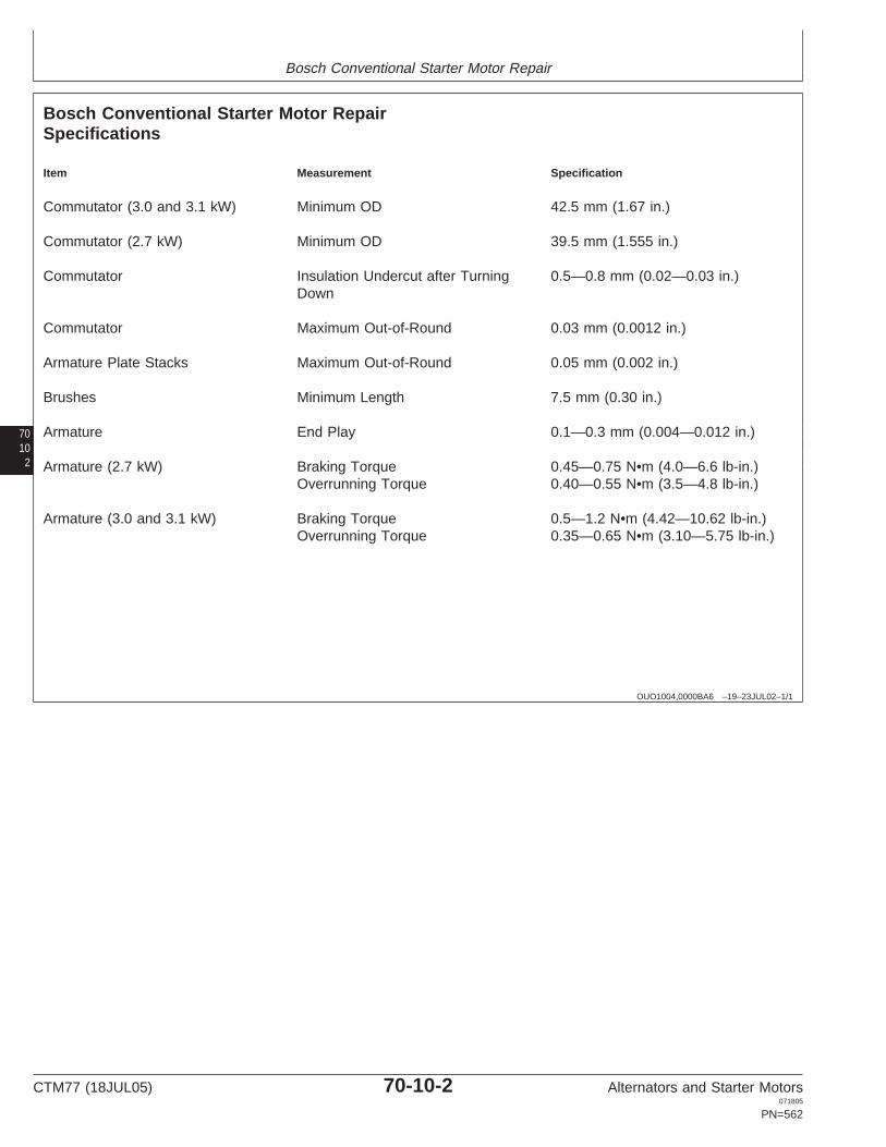
Bosch Conventional Starter Motor Repair
7010
2
OUO1004,0000BA6 –19–23JUL02–1/1
Bosch Conventional Starter Motor RepairSpecifications
Item Measurement Specification
Commutator (3.0 and 3.1 kW) Minimum OD 42.5 mm (1.67 in.)
Commutator (2.7 kW) Minimum OD 39.5 mm (1.555 in.)
Commutator Insulation Undercut after Turning 0.5—0.8 mm (0.02—0.03 in.)Down
Commutator Maximum Out-of-Round 0.03 mm (0.0012 in.)
Armature Plate Stacks Maximum Out-of-Round 0.05 mm (0.002 in.)
Brushes Minimum Length 7.5 mm (0.30 in.)
Armature End Play 0.1—0.3 mm (0.004—0.012 in.)
Armature (2.7 kW) Braking Torque 0.45—0.75 N•m (4.0—6.6 lb-in.)Overrunning Torque 0.40—0.55 N•m (3.5—4.8 lb-in.)
Armature (3.0 and 3.1 kW) Braking Torque 0.5—1.2 N•m (4.42—10.62 lb-in.)Overrunning Torque 0.35—0.65 N•m (3.10—5.75 lb-in.)
CTM77 (18JUL05) 70-10-2 Alternators and Starter Motors071805
PN=562

Bosch Conventional Starter Motor Repair
70103
RG,RG34710,2339 –19–07JUL05–1/1
Bosch Conventional Starter Motor TestSpecifications
No Load Test
John Deere Bosch System Rating Motor Voltage Amps RPMStarter Motor Starter Motor Voltage kW (Max.)
Part No. Model No.
AL110503 0 001 367 078 12 3.0 11.5 130 7000
AL110504 0 001 369 022 12 3.1 11.5 170 8000
AL39700 0 001 369 001 12 3.1 9.0 Min 205 9400
AL41247 0 001 362 312 12 2.7 11.5 125 7000
AL62690 0 001 362 316 12 2.7 11.5 125 7000
AL62772 0 001 369 005 12 3.1 11.5 170 8000
AL78760 0 001 367 075 12 3.0 11.5 130 7000
AL81154 0 001 367 077 12 3.0 11.5 130 7000
AR70436 0 001 359 090 12 3.0 9.0 Min 190 7000
RE30493 0 001 362 324 12 2.7 11.5 125 7000
RE508922 6 004 AK3 014 12 2.2 10.5
RE526375 0 001 B00 039 12 3.8 11.5 220 9000
RE527400 0 001 B00 039 12 3.8 11.5 220 9000
RE62448 0 001 369 012 12 3.1 11.5 170 8000
RE65169 0 001 369 021 12 3.1 11.5 170 8000
Item Specification
Minimum voltage of solenoid 8 volts
Testing armature for grounded circuit, voltage 40 volts AC
Testing field coils for grounded circuit, voltage 40 volts AC
Testing field coils for open windings, voltage 6—12 volts DC
Testing brush holder insulation for grounded circuit, voltage 40 volts AC
CTM77 (18JUL05) 70-10-3 Alternators and Starter Motors071805
PN=563

Bosch Conventional Starter Motor Repair
7010
4
RG,RG34710,2340 –19–15MAR97–1/1
Make No-Load Test
RG
1116
3–U
N–2
8SE
P00
Make Connections
A—AmmeterB—BatteryC—Starter FrameD—TachometerE—Battery TerminalF—SwitchG—Field Coil Connector
1. Make connections as shown, and use an ammeter (A)capable of measuring several hundred amps.
2. Measure current draw in amps and compare withspecifications given earlier in this group.
3. If speed and current draw are slightly low, connect avoltmeter between motor terminal and frame. Observevoltage during test. Voltage may be reduced becauseof high current draw on battery.
4. If speed or current draw is significantly different thanspecified, diagnose problem per chart which follows.
CTM77 (18JUL05) 70-10-4 Alternators and Starter Motors071805
PN=564

Bosch Conventional Starter Motor Repair
70105
RG,RG34710,2341 –19–15MAR97–1/1
Diagnosing Starter Motor Malfunctions
Fails to Operate, No Current Draw
Open field circuit (all field windings)
Open armature windings
Defective brush contact with commutator
Open solenoid windings
Defective solenoid contacts
Fails to Operate, High Current Draw
Grounded field windings or armature windings
Seized bearings
Low Speed, Low Current Draw
High internal resistance
Defective brush contact with commutator
Low Speed, High Current Draw
Excessive friction
Shorted armature
Grounded armature or field windings
High Speed, High Current Draw
Shorted field windings
NOTE: This test will not detect individualopen-circuited field coils—the stator wouldhave a slow cranking speed but would passthis test.
CTM77 (18JUL05) 70-10-5 Alternators and Starter Motors071805
PN=565

Bosch Conventional Starter Motor Repair
7010
6
RG,RG34710,2342 –19–23JUL02–1/1
Bosch Conventional Starter Motor Cutaway View
L107
007
–UN
–06A
PR
89
Bosch Conventional Starter Motor
A—Solenoid Switch E—Commutator I—Overrunning Clutch K—Drive HubB—Commutator End Frame F—Field Winding (Roller-Type) L—Engaging SpringC—Compression Spring G—Field Frame J—Pinion M—Engaging LeverD—Carbon Brush H—Guide Ring
CTM77 (18JUL05) 70-10-6 Alternators and Starter Motors071805
PN=566

Bosch Conventional Starter Motor Repair
70107
RG,RG34710,2343 –19–23JUL02–1/1
Bosch Conventional Starter Motor Exploded View
L117
559
–UN
–02F
EB
89
Conventional Starter Motor—Exploded View
1—Starter Motor Assembly 11—Pivot Screw 19—Center Bearing 28—Commutator End Frame2—Hex Nut 12—Countersunk Screw (3 20—Bushing 29—Bushing3—Stud Used) 21—Washer (2 Used) 30—Carbon Brushes (Kit)4—Cap Screw 13—Drive End Frame 22—Hex Nut (2 Used) 31—Compression Spring (45—Solenoid Switch Assembly 23—Cylinder Head Screw (2 Used)6—Securing Clip 14—Bushing Used) 32—Carbon Brush Plate7—Cylinder Head Screw 15—Snap Ring 24—Cover Cap 33—Winding8—Hex Nuts (4 Used) 16—Stop Ring 25—Rubber Ring 34—Armature9—Hex Nut 17—Bushing 26—Fixing Washer 35—Stud (2 Used)10—Engaging Lever 18—Drive with Pinion 27—Shims 36—Field Frame
CTM77 (18JUL05) 70-10-7 Alternators and Starter Motors071805
PN=567

Bosch Conventional Starter Motor Repair
7010 RG,RG34710,2344 –19–26JUN02–1/1
Disassembly
L107
008
–UN
–17J
UL8
9
Unscrew Cover Cap and Remove Hex Nuts
8
A—Cover CapB—Hex Nuts (2 Used)
NOTE: Not all parts for Bosch conventional and gearreduction starters are available through JohnDeere for service. Repair and test proceduresprovided in the following pages for othercomponents are for reference only.
Unscrew cover cap (A) and remove fixing washer andshims. Be careful with rubber ring.
Remove hex nuts (B).
RG,RG34710,2345 –19–15MAR97–1/1
Solenoid Switch—Removal
L107
009
–UN
–17J
UL8
9
Remove Attaching Screws
A—Screws (3 Used)
Disconnect wiring connection from solenoid switch.
Remove attaching screws (A) and pull out solenoid switchwith pinion head.
CTM77 (18JUL05) 70-10-8 Alternators and Starter Motors071805
PN=568

Bosch Conventional Starter Motor Repair
7010RG,RG34710,2346 –19–15MAR97–1/1
Carbon Brush Plate—Removal
L107
010
–UN
–17J
UL8
9
Remove Commutator End Frame
Carefully remove commutator end frame as shown.
NOTE: When removing commutator end frame, the brushcompression springs may spring out of the brushholders.
Pull carbon brushes out of carbon brush plate and removecarbon brush plate from armature shaft.
9
RG,RG34710,2347 –19–15MAR97–1/1
Armature—Removal
L107
011
–UN
–17J
UL8
9
Armature Removal
Carefully pull armature with drive end frame assemblyfrom field frame (do not damage windings).
Remove engaging lever and armature jointly out of driveend frame assembly.
CTM77 (18JUL05) 70-10-9 Alternators and Starter Motors071805
PN=569

Bosch Conventional Starter Motor Repair
7010 RG,RG34710,2348 –19–15MAR97–1/1
Snap Ring—Removal
L107
013
–UN
–17J
UL8
9
Snap Ring Removal
10
A—Stop RingB—Snap Ring
Drive back stop ring (A) and bend open snap ring (B).
Remove drive with pinion and center bearing fromarmature shaft.
RG,RG34710,2349 –19–15MAR97–1/1
Cleaning Parts
Wash parts in solvent and dry with compressed air.
NOTE: Armature, windings and drive with pinion must notbe placed in cleaning fluid.
Inspect all parts for wear and mechanical damage.
RG,RG34710,2350 –19–15MAR97–1/1
Testing Armature for Grounds
L107
014
–UN
–17J
UL8
9
Test Armature for Grounds
Set ohmmeter to read on highest scale.
Place one test lead on the armature core or shaft. Placeother lead on commutator.
If the test meter indicator swings toward zero, thearmature is grounded. Replace armature.
CTM77 (18JUL05) 70-10-10 Alternators and Starter Motors071805
PN=570

Bosch Conventional Starter Motor Repair
7010RG,RG34710,2351 –19–15MAR97–1/1
Testing Armature for Short Circuit
RG
7807
4C1
–UN
–09J
AN
90
Test Armature for Short Circuit
Place armature in a growler and hold hacksaw bladeabove each slot while slowly rotating the armature.
If coil is shorted, the blade will be attracted to andrepelled from the slot.
Short circuit most often occurs because of copper dust orfilings between two commutator segments. Cleancommutator segments to correct this short.
11
RG,RG34710,2352 –19–15MAR97–1/1
Testing Armature for Open Circuit
Set ohmmeter to read on lowest scale.
Place one test lead on commutator segment. Place othertest lead on an adjacent segment. Repeat this operationfor all segments by moving one lead at a time.
If the test meter indicator does not swing to zero andremains stationary, the armature coil between these twosegments is open. Replace armature.
CTM77 (18JUL05) 70-10-11 Alternators and Starter Motors071805
PN=571

Bosch Conventional Starter Motor Repair
701012
RG,RG34710,2353 –19–15MAR97–1/1
Turning Commutator Down
L107
016
–UN
–06A
PR
89
Turning Commutator DownA—Solenoid LugB—ClawC—Turn Down Only to Here
Check commutator OD and compare to specifications.
After turning the commutator down, undercut its insulationto specification with a commutator saw and thenfinish-turn.
SpecificationCommutator (3.0 and 3.1 kW)—Minimum OD 42.5 mm (1.67 in.).................................................................Commutator (2.7 kW)—MinimumOD 39.5 mm (1.555 in.)..............................................................................Commutator—Insulation Undercutafter Turning Down 0.5—0.8 mm (0.02—0.03 in.)......................................
RG,RG34710,2354 –19–15MAR97–1/1
Testing Commutator for Out-of-Roundness
L107
017
–UN
–17J
UL8
9
Test Commutator for Out-of-Roundness
Check commutator out-of-round.
SpecificationCommutator—MaximumOut-of-Round 0.03 mm (0.0012 in.)............................................................Armature Plate Stacks—Maximum Out-of-Round 0.05 mm (0.002 in.).............................................
Check armature once again for grounds and short circuits.
CTM77 (18JUL05) 70-10-12 Alternators and Starter Motors071805
PN=572

Bosch Conventional Starter Motor Repair
7010RG,RG34710,2355 –19–15MAR97–1/1
Testing Field Winding for Grounded Circuit
L107
018
–UN
–17J
UL8
9
Test Field Winding for Grounded Circuits
Set ohmmeter to read on highest scale.
Place one test lead on a clean spot on field frame. Placeother lead on brush lead.
If the ohmmeter indicator swings toward zero, a groundedcircuit is indicated. Replace the field windings.
13
RG,RG34710,2356 –19–15MAR97–1/1
Field Winding—Removal
L107
019
–UN
–17J
UL8
9
Unscrew Pole Shoe Screws
A—Pole Shoe Screws
Mark position of pole shoes and winding ends andunscrew pole shoe screws (A).
CTM77 (18JUL05) 70-10-13 Alternators and Starter Motors071805
PN=573

Bosch Conventional Starter Motor Repair
701014
RG,RG34710,2357 –19–15MAR97–1/1
Make Open Circuit Test for Field Windings
L113
431
–UN
–02F
EB
89
Make Open Circuit Test for Field Windings
A—1/4-Ohm ResistorB—12-Volt BatteryC—Field TerminalD—Insulated Brush LeadE—Hacksaw Blade
All four field windings are connected in parallel. Test eachwinding for an open circuit.
Connect a test battery (B) to field terminal (C) and eitherinsulated brush lead (D), using a resistor (A) to limitcurrent draw.
Use a hacksaw blade (E) to test winding for magnetism. Ifany winding is not magnetic, the winding is open circuited.Repair or replace windings.
NOTE: Because 1/4-ohm resistors capable of carryingseveral hundred watts are not widely available, asuggested alternative is to connect four 1-ohmresistors in parallel. Each resistor should be ratedfor at least 150 watts. A carbon pile resistor canalso be used. Limit current to 40—70 amps.
There is no suitable way to check field windings for shortcircuits. Winding resistance is too low to permit detectionof a short circuit.
RG,RG34710,2358 –19–15MAR97–1/1
Lubrication of Starter Motor (Before andDuring Assembly)
Lubrication Point Lubrication Instructions
Bushings Soak new bushings for at least 1/2 hour before installation.
Armature shaft Coat drive and commutator end journals of shaft, splines and bearing surfaces ofclutch drive with a light film of grease.
Shift Lever Lubricate bearing surfaces and pivot bolts liberally with grease.
Solenoid switch Coat inside of yoke and bolt threads with a light film of grease.
NOTE: Keep contacts free from grease.
CTM77 (18JUL05) 70-10-14 Alternators and Starter Motors071805
PN=574

Bosch Conventional Starter Motor Repair
7010RG,RG34710,2359 –19–15MAR97–1/1
Field Winding—Installation
L555
71A
–UN
–09M
AY
89
Field Winding Installation
15
a—85 mm (3.35 in.)b—5° Chamferc—12—14 mm (0.47—0.55 in.)d—75.80—75.85 mm (2.984—2.986 in.)e—Wall Thickness 12—15 mm (0.47—0.59 in.)
Slightly warm windings and insert together with poleshoes into field frame. Insert pole shoe screws.
Press suitable mandrel (see illustration) between poleshoes.
Firmly tighten pole shoe screws and press out mandrel.
Check installed windings for shorted or open circuits.
RG,RG34710,2360 –19–15MAR97–1/1
Checking Carbon Brush Plate for Grounds
L107
020
–UN
–17J
UL8
9
Check Carbon Brush Plate for Grounds
Set ohmmeter on its highest scale.
Place one test lead on commutator end frame. Placeother lead on brush holder.
If needle swings toward zero, the positive brush holder isgrounded and should be replaced.
CTM77 (18JUL05) 70-10-15 Alternators and Starter Motors071805
PN=575

Bosch Conventional Starter Motor Repair
7010 RG,RG34710,2361 –19–15MAR97–1/1
Testing Carbon Brushes
L107
021
–UN
–17J
UL8
9
Test Carbon Brushes
16
a—Brush Length
The carbon brushes must move freely in their guides.
Check brush length and compare to specifications.
SpecificationBrushes—Minimum Length 7.5 mm (0.30 in.)............................................
RG,RG34710,2362 –19–15MAR97–1/1
Replace Carbon Brushes
L117
234
–UN
–17J
UL8
9
Secure Brushes in BoresA—Brush Bores
Cut off old brushes at end of brush strands.
Secure new brushes in bores (A).
Check for easy movement of carbon brushes in brushholders.
NOTE: Screws and hex nuts are included in the repair kit.
CTM77 (18JUL05) 70-10-16 Alternators and Starter Motors071805
PN=576

Bosch Conventional Starter Motor Repair
7010RG,RG34710,2363 –19–15MAR97–1/1
Engaging Lever—Installation
L107
023
–UN
–17J
UL8
9
Engaging Lever Installation
17
A—Engaging LeverB—PinsC—Guide
Driving hub pins (B) of engaging lever (A) must engage inguide (C) of drive pinion.
Screw in studs and slide field frame over armature.
RG,RG34710,2364 –19–25SEP00–1/1
Checking Armature End Play and Torque
L107
024
–UN
–17J
UL8
9
Test Armature End Play
Check end play of armature using a dial indicator.
SpecificationArmature—End Play 0.1—0.3 mm (0.004—0.012 in.)................................
Check armature torque.
SpecificationArmature (2.7 kW)—BrakingTorque 0.45—0.75 N•m (4.0—6.6 lb-in.)....................................................Overrunning Torque 0.40—0.55 N•m (3.5—4.8 lb-in.)...............................Armature (3.0 and 3.1 kW)—Braking Torque 0.5—1.2 N•m (4.42—10.62 lb-in.).....................................Overrunning Torque 0.35—0.65 N•m (3.10—5.75
lb-in.)......................................
RG,RG34710,2365 –19–15MAR97–1/1
Installing Starter Motor
Refer to machine technical manual for installing startermotor and adjusting belt tension.
CTM77 (18JUL05) 70-10-17 Alternators and Starter Motors071805
PN=577

Bosch Conventional Starter Motor Repair
701018
CTM77 (18JUL05) 70-10-18 Alternators and Starter Motors071805
PN=578

Group 15Bosch Planetary Gear Starter Motor Repair
OUOD006,000004F –19–23JUL02–1/3
Essential Tools
NOTE: Order tools according to information given in theU.S. SERVICEGARD Catalog or from theEuropean Microfiche Tool Catalog (MTC).
70
SERVICEGARD is a trademark of Deere & Company
151
OUOD006,000004F –19–23JUL02–2/3
RW
1127
4–U
N–1
2DE
C88
JT05791
Digital Multimeter . . . . . . . . . . . . . . . . . . . . . JT05791
Test electrical components for voltage, resistance, orcurrent flow. It is especially good for measuring lowvoltage or high resistance circuits.
OUOD006,000004F –19–23JUL02–3/3
Alternator, Generator, Starter and Battery BenchTester . . . . . . . . . . . . . . . . . . . . . . . . . . . . . JT01760
Test alternators and starters for voltage, resistance, orcurrent flow.
CTM77 (18JUL05) 70-15-1 Alternators and Starter Motors071805
PN=579

Bosch Planetary Gear Starter Motor Repair
7015 OUOD006,0000050 –19–07JUL05–1/1
Bosch Planetary Gear Starter Motor TestSpecifications
No Load Test
John Deere Bosch System Rating Motor Voltage Amps RPMStarter Motor Starter Motor Voltage kW (Max.)
Part No. Model No.
RE500819 0 001 230 005 12 3.0 11.4 204 4735—6500
RE501347 0 001 223 502 12 2.6 11.4 142 5300
RE501551 0 001 230 008 12 3.0 11.4 204 4735—6500
RE503226 0 001 230 002 12 3.0 11.4 204 4735—6500
RE506589 0 001 230 003 12 3.0 11.4 204 4735—6500
RE507943 0 001 230 018 12 3.0 11.4 204 4735—6500
2
RG,RG34710,2340 –19–15MAR97–1/1
Make No-Load Test
RG
1116
3–U
N–2
8SE
P00
Make Connections
A—AmmeterB—BatteryC—Starter FrameD—TachometerE—Battery TerminalF—SwitchG—Field Coil Connector
1. Make connections as shown, and use an ammeter (A)capable of measuring several hundred amps.
2. Measure current draw in amps and compare withspecifications given earlier in this group.
3. If speed and current draw are slightly low, connect avoltmeter between motor terminal and frame. Observevoltage during test. Voltage may be reduced becauseof high current draw on battery.
4. If speed or current draw is significantly different thanspecified, diagnose problem per chart which follows.
CTM77 (18JUL05) 70-15-2 Alternators and Starter Motors071805
PN=580

Bosch Planetary Gear Starter Motor Repair
70153
RG,RG34710,2341 –19–15MAR97–1/1
Diagnosing Starter Motor Malfunctions
Fails to Operate, No Current Draw
Open field circuit (all field windings)
Open armature windings
Defective brush contact with commutator
Open solenoid windings
Defective solenoid contacts
Fails to Operate, High Current Draw
Grounded field windings or armature windings
Seized bearings
Low Speed, Low Current Draw
High internal resistance
Defective brush contact with commutator
Low Speed, High Current Draw
Excessive friction
Shorted armature
Grounded armature or field windings
High Speed, High Current Draw
Shorted field windings
NOTE: This test will not detect individualopen-circuited field coils—the stator wouldhave a slow cranking speed but would passthis test.
CTM77 (18JUL05) 70-15-3 Alternators and Starter Motors071805
PN=581

Bosch Planetary Gear Starter Motor Repair
7015
4
OUOD006,0000051 –19–23JUL02–1/1
Bosch Planetary Gear Starter Motor Cutaway View
RG
1249
3–U
N–2
4JU
L02
Bosch Planetary Gear Starter Motor
A—Drive End Housing E—Commutator End Frame H—Field Frame K—Planetary GearB—Pinion F—Brush Plate with Carbon I—Armature L—Shift LeverC—Solenoid Switch Brushes J—Pole Shoe M—Pinion-engaging DriveD—Terminal G—Excitation Winding
CTM77 (18JUL05) 70-15-4 Alternators and Starter Motors071805
PN=582

Bosch Planetary Gear Starter Motor Repair
7015OUOD006,0000052 –19–23JUL02–1/3
Disassemble Solenoid Switch
RG
1249
7–U
N–2
4JU
L02
Remove Excitation Winding
5
A—Excitation Winding Connection
Clamp starting motor in fixture.
Remove excitation winding connection (A) from solenoid.
OUOD006,0000052 –19–23JUL02–2/3
RG
1249
8–U
N–2
4JU
L02
Remove Solenoid Switch
Mark position of solenoid switch.
CAUTION: Return spring is pretensioned, andcan cause injury when released.
Remove solenoid switch screws.
Remove solenoid switch from solenoid plunger asillustrated.
Continued on next page
CTM77 (18JUL05) 70-15-5 Alternators and Starter Motors071805
PN=583
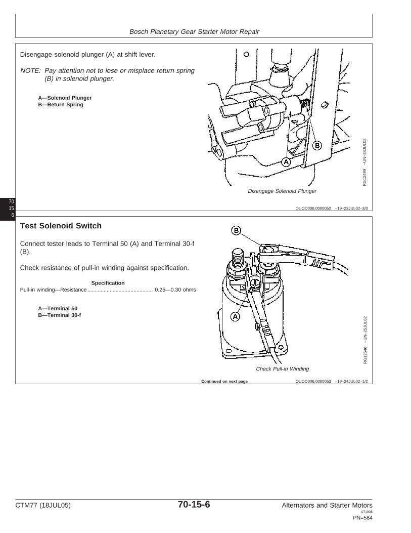
Bosch Planetary Gear Starter Motor Repair
7015 OUOD006,0000052 –19–23JUL02–3/3
RG
1249
9–U
N–2
4JU
L02
Disengage Solenoid Plunger
6
A—Solenoid PlungerB—Return Spring
Disengage solenoid plunger (A) at shift lever.
NOTE: Pay attention not to lose or misplace return spring(B) in solenoid plunger.
OUOD006,0000053 –19–24JUL02–1/2
Test Solenoid Switch
RG
1254
6–U
N–2
5JU
L02
Check Pull-in Winding
A—Terminal 50B—Terminal 30-f
Connect tester leads to Terminal 50 (A) and Terminal 30-f(B).
Check resistance of pull-in winding against specification.
SpecificationPull-in winding—Resistance 0.25—0.30 ohms............................................
Continued on next page
CTM77 (18JUL05) 70-15-6 Alternators and Starter Motors071805
PN=584

Bosch Planetary Gear Starter Motor Repair
7015OUOD006,0000053 –19–24JUL02–2/2
RG
1254
7–U
N–2
5JU
L02
Check Hold-in Winding
7
A—Terminal 50
Connect tester leads to Terminal 50 (A) and Ground.
Check resistance of hold-in winding against specification.
SpecificationHold-in winding—Resistance 1.1—1.3 ohms...............................................
OUOD006,0000054 –19–24JUL02–1/2
Assemble Solenoid Switch
RG
1249
9–U
N–2
4JU
L02
Assemble Solenoid Switch
A—Solenoid PlungerB—Return Spring
Press pinion against stop ring, hook solenoid plunger (A)into engaging lever, and grease lightly around periphery.
NOTE: Pay attention not to lose or misplace return spring(B) in solenoid plunger.
Continued on next page
CTM77 (18JUL05) 70-15-7 Alternators and Starter Motors071805
PN=585

Bosch Planetary Gear Starter Motor Repair
7015 OUOD006,0000054 –19–24JUL02–2/2
RG
1249
8–U
N–2
4JU
L02
Attach Solenoid Switch
8
Using solenoid position mark made previously, alignsolenoid switch with drive end bearing housing and fastenwith screws.
Torque to specification.
SpecificationSolenoid Switch Screws—Torque 4.5—5.5 N•m (40—49 lb-in.)................
CTM77 (18JUL05) 70-15-8 Alternators and Starter Motors071805
PN=586

Section 75Iskra Starter Motors
Contents
Page Page
Group 05—Starting Circuit Theory of Operation Installing Solenoid Switch . . . . . . . . . . . . . . . . .75-15-8General Information. . . . . . . . . . . . . . . . . . . . . .75-05-1Typical Starting Circuit Operation . . . . . . . . . . .75-05-1Starter Motor Operation. . . . . . . . . . . . . . . . . . .75-05-2
Group 10—Iskra AZE/AZF/AZJ-Type Starter MotorRepair
Essential Tools . . . . . . . . . . . . . . . . . . . . . . . . .75-10-1Dealer Fabricated Tools . . . . . . . . . . . . . . . . . .75-10-2Iskra AZF-Type Starter Motor Repair
Specifications. . . . . . . . . . . . . . . . . . . . . . . . .75-10-5Iskra AZJ-Type Starter Motor Repair
Specifications. . . . . . . . . . . . . . . . . . . . . . . . .75-10-5Iskra AZE, AZF-Type Starter Motor Test
Specifications. . . . . . . . . . . . . . . . . . . . . . . . .75-10-675Iskra AZJ-Type Starter Motor Test
Specifications. . . . . . . . . . . . . . . . . . . . . . . . .75-10-7Exploded View of Iskra Starter Motor
(AZF-Type) . . . . . . . . . . . . . . . . . . . . . . . . . .75-10-8Exploded View of Iskra Starter Motor
(AZJ-Type). . . . . . . . . . . . . . . . . . . . . . . . . . .75-10-9Troubleshooting. . . . . . . . . . . . . . . . . . . . . . . .75-10-10Identification . . . . . . . . . . . . . . . . . . . . . . . . . .75-10-11Disassembly of Starter Motor . . . . . . . . . . . . .75-10-11Testing Solenoid Switch . . . . . . . . . . . . . . . . .75-10-15Testing Brushes . . . . . . . . . . . . . . . . . . . . . . .75-10-15Brush Replacement. . . . . . . . . . . . . . . . . . . . .75-10-16Testing Armature. . . . . . . . . . . . . . . . . . . . . . .75-10-16Testing Field Windings . . . . . . . . . . . . . . . . . .75-10-17Checking Engaging Lever . . . . . . . . . . . . . . . .75-10-17Checking Overrunning Clutch Pinion . . . . . . . .75-10-18Reassembly of Starter Motor. . . . . . . . . . . . . .75-10-18
Group 15—Iskra AZE-Type Starter Motor RepairEssential Tools . . . . . . . . . . . . . . . . . . . . . . . . .75-15-1Dealer Fabricated Tools . . . . . . . . . . . . . . . . . .75-15-2Iskra AZE-Type Starter Motor Repair
Specifications. . . . . . . . . . . . . . . . . . . . . . . . .75-15-3Iskra AZE-Type Starter Motor Test
Specifications. . . . . . . . . . . . . . . . . . . . . . . . .75-15-3Exploded View of AZE (Noseless)-Type
Starter Motor . . . . . . . . . . . . . . . . . . . . . . . . .75-15-4Troubleshooting. . . . . . . . . . . . . . . . . . . . . . . . .75-15-5Identification . . . . . . . . . . . . . . . . . . . . . . . . . . .75-15-6Removing Solenoid Switch . . . . . . . . . . . . . . . .75-15-6Testing Solenoid Switch . . . . . . . . . . . . . . . . . .75-15-7
CTM77 (18JUL05) 75-1 Alternators and Starter Motors071805
PN=1

Contents
75
CTM77 (18JUL05) 75-2 Alternators and Starter Motors071805
PN=2

Group 05Starting Circuit Theory of Operation
RG,RG34710,2366 –19–15MAR97–1/1
General Information
IMPORTANT: Never operate starter motor longer than30 seconds. Allow at least 2 minutes forcooling and battery recovery beforeoperating again. Overheating caused byexcessive operation will seriouslydamage starter motor.
75051
RG,RG34710,2367 –19–15MAR97–1/1
Typical Starting Circuit Operation
RG
1313
–UN
–20A
PR
89
Typical Starting Circuit Operation
A—Wire from RelayB—Cable from BatteryC—Pull-In WindingD—Hold-Iin WindingE—Solenoid PlungerF—Main ContactsG—Field WindingsH—Commutator BrushesI—ArmatureJ—Shunt Windings
When wire from relay (A) is energized, current flowsthrough both pull-in winding (C) and hold-in winding (D) toground.
Current through windings engages solenoid plunger (E),which closes main contacts (F). When main contactsclose, current through pull-in windings stops. Currentcontinues through hold-in winding, keeping solenoidengaged and main contacts closed.
With main contacts closed, current flows from batterycable (B) to starter motor at a very high rate. Four heavyfield windings (G) carry current to commutator brushes(H).
From field windings, current flows through armaturewindings (I) to ground, making contact throughcommutator brushes (H).
Strong magnetic fields are set up by current flow throughfield windings and armature windings. Windings arearranged so that magnetic fields constantly repel eachother, rotating armature.
CTM77 (18JUL05) 75-05-1 Alternators and Starter Motors071805
PN=589

Starting Circuit Theory of Operation
7505
2
RG,RG34710,2368 –19–07MAY02–1/1
Starter Motor Operation
RG
1255
3–U
N–1
3AU
G02
Starter Motor Operation
1—Engaging Lever 5—Bearing 9—Field Coil 12—Drive End Bracket2—Plunger 6—Brush Holder 10—Armature 13—Overrunning Clutch Drive3—Solenoid 7—Brush Kit 11—Reduction Gear Assembly Assembly4—Commutator End Bracket 8—Commutator
When solenoid (3) engages, it pulls engaging lever (1).Engaging lever pushes overrunning clutch drive (13) toengage pinion in starter gear on flywheel. As armature(10) turns, it cranks engine.
When engine starts, overrunning clutch spins freely onshaft. This prevents overspeeding of armature byflywheel.
When key switch is released, current to solenoidhold-in winding is shut off. Current can feed through
both pull-in and hold-in windings from main contacts,but direction of current is reversed in pull-in winding.The two windings cancel each other, and solenoid isreleased.
A spring pushes solenoid back to disengaged position.This opens main contacts and shuts off current to fieldwindings and armature.
Engaging lever retracts overrunning clutch drive,disengaging pinion from flywheel.
CTM77 (18JUL05) 75-05-2 Alternators and Starter Motors071805
PN=590

Group 10Iskra AZE/AZF/AZJ-Type Starter Motor Repair
OUO1004,0000BA7 –19–08MAY02–1/3
Essential Tools
NOTE: Order tools according to information given in theU.S. SERVICEGARD Catalog or from theEuropean Microfiche Tool Catalog (MTC).
SERVICEGARD is a trademark of Deere & Company
75101
OUO1004,0000BA7 –19–08MAY02–2/3
RW
1127
4–U
N–1
2DE
C88
JT05791
Digital Multimeter . . . . . . . . . . . . . . . . . . . . . JT05791
Test electrical components for voltage, resistance, orcurrent flow. It is especially good for measuring lowvoltage or high resistance circuits.
OUO1004,0000BA7 –19–08MAY02–3/3
Alternator, Generator, Starter and Battery BenchTester . . . . . . . . . . . . . . . . . . . . . . . . . . . . . JT01760
Test alternators and starters for voltage, resistance, orcurrent flow.
CTM77 (18JUL05) 75-10-1 Alternators and Starter Motors071805
PN=591

Iskra AZE/AZF/AZJ-Type Starter Motor Repair
OUOD006,000005F –19–14AUG02–1/6
Dealer Fabricated Tools
CD
3049
2–U
N–3
1JA
N97
Pilot for Retaining Ring
7510
2
a—Dia. 15.4 mm (0.606 in.)b—Dia. 14.4 mm (0.567 in.)c—50 mm (1.97 in.)d—18.5 mm (0.728 in.)e—5 mm (0.20 in.)f—30°g—R10 mm (0.39 in.)
Pilot for Retaining Ring Installation- AZF Type
OUOD006,000005F –19–14AUG02–2/6
CD
3049
2–U
N–3
1JA
N97
Pilot for Retaining Ring
a—Dia. 15.4—15.5 mm (0.606—0.610 in.)b—Dia. 14.4—14.5 mm (0.567—0.571 in.)c—50 mm (1.97 in.)d—25 mm (0.98 in.)e—5 mm (0.20 in.)f—30°g—R10 mm (0.39 in.)
Pilot for Retaining Ring Installation- AZJ Type
Continued on next page
CTM77 (18JUL05) 75-10-2 Alternators and Starter Motors071805
PN=592

Iskra AZE/AZF/AZJ-Type Starter Motor Repair
OUOD006,000005F –19–14AUG02–3/6
CD
3049
3–U
N–0
3FE
B97
Driver for Retaining Ring and Pinion Stop
75103
a—Dia. 18.5 mm (0.728 in.)b—Dia. 15.4 mm (0.606 in.)c—75 mm (2.95 in.)d—60 mm (2.36 in.)e—Chamfer 45° x 2 mm (0.08 in.)f—Chamfer 45° x 0.5 mm (0.02 in.)
Driver for Retaining Ring Installation and for PinionStop Removal- AZF Type
OUOD006,000005F –19–14AUG02–4/6
CD
3049
3–U
N–0
3FE
B97
Driver for Retaining Ring and Pinion Stop
a—Dia. 25 mm (0.98 in.)b—Dia. 15.5—15.6 mm (0.610—0.614 in.)c—75 mm (2.95 in.)d—60 mm (2.36 in.)e—Chamfer 45° x 2 mm (0.08 in.)f—Chamfer 45° x 0.5 mm (0.02 in.)
Driver for Retaining Ring Installation and for PinionStop Removal- AZJ Type
Continued on next page
CTM77 (18JUL05) 75-10-3 Alternators and Starter Motors071805
PN=593

Iskra AZE/AZF/AZJ-Type Starter Motor Repair
OUOD006,000005F –19–14AUG02–5/6
CD
3049
4–U
N–3
1JA
N97
Dummy Commutator for Brush Holder
7510
4
a—Dia. 36 mm (1.42 in.)b—Dia. 16 mm (0.63 in.)c—Dia. 40 mm (1.57 in.)d—35 mm (1.38 in.)e—2.5 mm (0.10 in.)f—Chamfer 15°g—2 mm (0.08 in.)
Dummy Commutator for Brush Holder Removal andInstallation- AZF Type
Material: Plastic
OUOD006,000005F –19–14AUG02–6/6
CD
3049
4–U
N–3
1JA
N97
Dummy Commutator for Brush Holder
a—Dia. 44.9—45.1 mm (1.768—1.775 in.)b—Dia. 20 mm (0.79 in.)c—Dia. 50 mm (1.97 in.)d—35 mm (1.38 in.)e—2.5 mm (0.10 in.)f—Chamfer 15°g—2.5 mm (0.10 in.)
Dummy Commutator for Brush Holder Removal andInstallation-AZJ Type
Material: Plastic
CTM77 (18JUL05) 75-10-4 Alternators and Starter Motors071805
PN=594

Iskra AZE/AZF/AZJ-Type Starter Motor Repair
OUOD006,0000059 –19–13AUG02–1/1
Iskra AZF-Type Starter Motor RepairSpecifications
Item Measurement Specification
New Brush Length 19.5 mm (0.77 in.)
Used Brush Minimum Length 7 mm (0.27 in.)
Commutator End Frame Nuts Torque 6 N•m (53 lb-in.)
Field Winding Terminal Nut Torque 15 N•m (132 lb-in.)
75105
OUO1004,0000BAA –19–25SEP00–1/1
Iskra AZJ-Type Starter Motor RepairSpecifications
Item Measurement Specification
New Brush Length 23 mm (0.91 in.)
Used Brush Minimum Length 13 mm (0.51 in.)
Engaging Lever Pivot Pin Torque 12 N•m (106 lb-in.)
Commutator End Frame Nuts Torque 6 N•m (53 lb-in.)
Field Winding Terminal Nut Torque 15 N•m (132 lb-in.)
CTM77 (18JUL05) 75-10-5 Alternators and Starter Motors071805
PN=595

Iskra AZE/AZF/AZJ-Type Starter Motor Repair
7510
6OUOD006,000005A –19–07JUL05–1/1
Iskra AZE, AZF-Type Starter Motor TestSpecifications
Solenoid Current Pinion
John Deere Iskra Starter Pull-In Hold-In ToothStarter Motor Starter Motor Motor System Rating Winding Winding No. of SpacingPart Number Part Number Model Voltage (kW) (Amps) (Amps) Teeth (Modul)
RE505744 11.130.794 AZF4522 12 4.2 62 14 10 3.175
RE505745 11.130.793 AZF4521 12 3.4 62 14 10 2.54
RE505746 11.131.063 AZE4603 12 2.8 62 14 10 2.54
RE508322 11.131.060 AZF4541 12 4.2 62 14 10 3.175
RE509025 11.131.145 AZF4553 12 4.2 62 14 10 3.175
RE509903 11.131.092 AZF4550 12 4.2 62 14 10 3.175
RE516455 11.920.209 AZE4534 12 2.8 62 14 10 2.54
RE519568 11.920.209 AZE4534 12 2.8 62 14 10 2.54
RE521488 11.131.294 AZE4625 12 2.8 62 14 10 2.54
RE522334 11.131.266 AZF4575 24 4.0 30 6 10 3.175
RE522738 11.131.274 AZF4573 24 4.0 30 6 10 2.54
RE528532 11.131.254 AZF4571 24 4.0 30 630 10 3.175
CTM77 (18JUL05) 75-10-6 Alternators and Starter Motors071805
PN=596

Iskra AZE/AZF/AZJ-Type Starter Motor Repair
75107
RG,RG34710,2371 –19–07JUL05–1/1
Iskra AZJ-Type Starter Motor TestSpecifications
Solenoid Current Pinion
John Deere Iskra Starter Pull-In Hold-In ToothStarter Motor Starter motor Motor System Rating Winding Winding No. of SpacingPart Number Part Number Model Voltage (kW) (Amps) (Amps) Teeth (Modul)
RE500733 11.130.819 AZJ3283 12 3.1 62 14 10 2.54
RE501002a 11.130.762 AZJ3274 12 3.1 62 14 10 2.54
RE501766a 11.130.679 AZJ3326 12 3.1 62 14 10 3.175
RE501767
RE501769a 11.130.745 AZJ3265 24 4.0 30 6 10 3.175
RE503093 11.130.796 AZJ3325 12 3.0 62 12 10 3.175
RE503118 11.130.797 AZJ3326 24 4.0 30 6 10 2.54
RE503119 11.130.798 AZJ3327 24 4.0 30 6 10 3.175
RE503120 11.130.799 AZJ3328 12 3.1 62 14 10 3.175
RE503632 11.130.936 AZJ3338 24 4.0 30 6 10 3.175
RE504009 11.130.940 AZJ3342 12 3.0 62 12 10 3.175
RE504915 11.130.977 AZJ3350 24 4.0 30 6 10 3.175
RE509100 11.131.072 AZJ3370 12 3.0 62 12 10 3.175
RE59010 11.130.605 AZJ3190 12 3.0 62 14 10 3.175
RE60239a 11.130.679 AZJ3226 12 3.1 62 14 10 3.175
RE60384 11.130.569 AZJ3181 12 3.1 62 14 10 2.54
RE67086 11.130.662 AZJ3214 24 4.0 30 6 10 2.54
RE67087 11.130.678 AZJ3225 24 4.0 30 6 10 3.175
RE68783 11.130.703 AZJ3241 12 3.1 62 14 10 3.175
RE71007a 111.307.45 AZJ3265 24 4.0 30 6 10 3.175aNot a service part. For service, consult parts catalog.
CTM77 (18JUL05) 75-10-7 Alternators and Starter Motors071805
PN=597

Iskra AZE/AZF/AZJ-Type Starter Motor Repair
7510
8
OUOD006,000005B –19–13AUG02–1/1
Exploded View of Iskra Starter Motor (AZF-Type)
RG
1255
4–U
N–1
3AU
G02
Iskra Starter Motor (AZF-Type)
1—Drive End Housing 4—Drive Assembly 8—Bearing 11—Brush Holder2—Bushing, Drive End Bearing 5—Engaging Lever1 9—Parts Kit1 12—Brush Kit1
3—Solenoid1 6—Gear Reduction Assembly 10—Field Coil 13—Commutator End Frame7—Armature
1 Available as service parts.
CTM77 (18JUL05) 75-10-8 Alternators and Starter Motors071805
PN=598

Iskra AZE/AZF/AZJ-Type Starter Motor Repair
75109
RG,RG34710,2372 –19–14AUG02–1/1
Exploded View of Iskra Starter Motor (AZJ-Type)
RG
1255
9–U
N–1
3AU
G02
Iskra Starter Motor (AZJ-Type)
1—Drive End Housing 5—Field Winding 9—Bushing 12—Center Bearing2—Solenoid1 6—Brush Holder 10—Armature 13—Service Parts Kit1
3—Engaging Lever1 7—Brushes1 (4 Used) 11—Overrunning Clutch4—Bushing 8—Commutator End Frame Pinion1
1 Available as service parts.
CTM77 (18JUL05) 75-10-9 Alternators and Starter Motors071805
PN=599

Iskra AZE/AZF/AZJ-Type Starter Motor Repair
751010
RG,RG34710,2373 –19–15MAR97–1/1
Troubleshooting
Symptom Problem Solution
Fails to operate, no current draw Open field circuit Replace starter motor
Open armature windings Replace starter motor
Defective brush contact with Clean brush holder or replacecommutator brushes
Open solenoid windings Replace solenoid
Defective solenoid contact Replace solenoid
Fails to operate, high current Grounded field windings or armature Replace starter motordraw windings
Seized bearings Replace starter motor
Low speed, low current draw High internal resistance Replace starter motor
Defective brush contact with Clean brush holder or replacecommutator brushes
Low speed, high current draw Shorted armature Replace starter motor
Grounded armature or field windings Replace starter motor
High speed, high current draw Shorted field windings Replace starter motor
Solenoid switch operates but Worn or broken brushes Clean brush holder and commutatorarmature does not rotate and replace brushes
Shorted field windings Replace starter motor
Solenoid quickly engages and Shorted hold-in windings Replace solenoiddisengages
Starter motor spins, but does not Overrunning clutch slipping Replace overrunning clutchcrank the engine
Pinion does not move into mesh with Replace engaging lever or clutchthe gear ring
CTM77 (18JUL05) 75-10-10 Alternators and Starter Motors071805
PN=600

Iskra AZE/AZF/AZJ-Type Starter Motor Repair
RG,RG34710,2374 –19–15MAR97–1/1
Identification
CD
3049
0–U
N–0
3FE
B97
Parts Identification
The information for parts identification is stamped on thebody of the starter motor as shown.
751011
RG,RG34710,2375 –19–15AUG02–1/7
Disassembly of Starter Motor
CD
3049
5–U
N–0
3FE
B97
Field Winding Cable and Solenoid Switch
A—Field Winding CableB—Solenoid switch
NOTE: Before separating, mark parts so that they can bereinstalled in their original positions.
1. Disconnect field winding cable (A).
2. Remove the three screws holding the solenoid switch(B).
Continued on next page
CTM77 (18JUL05) 75-10-11 Alternators and Starter Motors071805
PN=601

Iskra AZE/AZF/AZJ-Type Starter Motor Repair
RG,RG34710,2375 –19–15AUG02–2/7
CD
3049
6–U
N–0
3FE
B97
Remove Solenoid Switch
751012
C—SpringD—Plunger
3. Remove solenoid switch.
4. Extract spring (C) and plunger (D).
RG,RG34710,2375 –19–15AUG02–3/7
CD
3049
7–U
N–0
3FE
B97
Remove Components
E—CoverF—Clip and WasherG—Brush Holder Fixing ScrewsH—NutsJ—Commutator End Frame
5. AZJ Only: Remove cover (E).
6. AZJ Only: Remove clip and washers (F).
7. Remove screws (G) fixing the brush holder.
8. Unscrew nuts (H) and remove commutator end frame(J).
Continued on next page
CTM77 (18JUL05) 75-10-12 Alternators and Starter Motors071805
PN=602

Iskra AZE/AZF/AZJ-Type Starter Motor Repair
751013
RG,RG34710,2375 –19–15AUG02–4/7
CD
3049
8–U
N–0
3FE
B97
Remove Brush Holder
K—Insulation WasherL—Brushes
9. Remove insulation washer (K).
NOTE: Brushes are installed from the inside on AZF-typestarters, and from the outside on AZJ-typestarters.
10. AZJ Only: Extract positive brushes (L).
11. Install a dummy commutator as shown in DealerFabricated Tools earlier in this group.
AZJ Only: Remove brush holder.
AZF Only: Remove field coil together with brushholder away from armature. Remove dummycommutator from brush holder and pull brushes awayfrom brush holder assembly, then remove brushholder.
RG,RG34710,2375 –19–15AUG02–5/7
CD
3049
9–U
N–0
3FE
B97
Separate Field Winding Frame
M—Pivot PinN—Field Winding FrameP—Armature/Drive End Housing Assembly
12. Remove pivot pin (M) from engaging lever.
13. Separate field winding frame (N) from armature/driveend housing assembly (P).
Continued on next page
CTM77 (18JUL05) 75-10-13 Alternators and Starter Motors071805
PN=603

Iskra AZE/AZF/AZJ-Type Starter Motor Repair
RG,RG34710,2375 –19–15AUG02–6/7
CD
3050
0–U
N–0
3FE
B97
Drive End Housing
751014
Q—Drive End Housing
14. Remove studs.
15. AZJ Only: Extract armature with clutch and engaginglever from drive end housing (Q).
AZF Only: Extract planetary gear assembly withclutch and engaging lever from drive end housing.
RG,RG34710,2375 –19–15AUG02–7/7
CD
3050
1–U
N–0
3FE
B97
Remove Components
R—Pinion StopS—Retaining RingT—Overrunning ClutchU—Center Bearing
16. Using appropriate tool or self-made driver, as shownin Dealer Fabricated Tools earlier in this group, pushin pinion stop (R) to have access to retaining ring (S).
17. Remove retaining ring and slide out of armature shaftthe overrunning clutch (T), the center bearing (U) and,if equipped, the armature brake component.
CTM77 (18JUL05) 75-10-14 Alternators and Starter Motors071805
PN=604

Iskra AZE/AZF/AZJ-Type Starter Motor Repair
751015
RG,RG34710,2376 –19–20SEP02–1/1
Testing Solenoid Switch
CD
3050
2–U
N–0
3FE
B97
Testing Solenoid Switch
A—Solenoid TerminalB—Battery TerminalC—Motor Terminal
1. Check for continuity between solenoid terminal (A) andmotor terminal (C). If there is no continuity, replace thesolenoid switch. (Resistance should be approximately0.3 ohms.)
2. Check for continuity between solenoid terminal (A) andthe steel casing. If there is no continuity, replace thesolenoid switch. (Resistance should be approximately0.9 ohms.)
3. Perform this test with the plunger and spring in thesolenoid body. Prevent the plunger from falling outafter disconnecting power. Apply appropriate voltage(12 volts or 24 volts) between solenoid terminal (A)and the steel casing. Connect a ground wire capable of60 amps between motor terminal (C) and the steelcasing. The plunger should pull in. Disconnect theground wire, and the plunger should remain held in.Connect the ohmmeter between terminals (B) and (C).There should be continuity only when the plunger isheld in. Disconnect power, and the pinion plungershould extend. If any test above fails, replace thesolenoid switch.
RG,RG34710,2377 –19–16AUG02–1/1
Testing Brushes
CD
3050
3–U
N–0
3FE
B97
Test Brushes
A—Brush Holder
1. Check positive brush holder (A) by connecting anohmmeter between brushes and plate. If the resistanceis not infinity, replace starter motor.
2. Inspect brushes. Brushes must move freely in theirguides. Check brush overall length. Replace brushes iffrozen or too worn.
SpecificationNew Brush (AZF)—Length 19.5 mm (0.77 in.)...........................................New Brush (AZJ)—Length 23 mm (0.91 in.)..............................................Used Brush (AZF)—MinimumLength 7 mm (0.27 in.)................................................................................Used Brush (AZJ)—MinimumLength 13 mm (0.51 in.)..............................................................................
CTM77 (18JUL05) 75-10-15 Alternators and Starter Motors071805
PN=605

Iskra AZE/AZF/AZJ-Type Starter Motor Repair
DPSG,OUOE003,30 –19–18DEC98–1/1
Brush Replacement
CD
3050
4–U
N–0
3FE
B97
Cut off Brush at End of Strand
751016
A—Brush Strand
1. Cut off old brush at end of brush strand (A).
2. Solder new brush using a 40—60% tin-lead mix. Heatto 230°C (446°F).
NOTE: This operation needs a specialized tooling.Eventually, have the brushes replaced by a localelectrical repair station.
RG,RG34710,2378 –19–15MAR97–1/1
Testing Armature
CD
3050
5–U
N–0
3FE
B97
Test Armature
A—CommutatorB—Shaft
1. Check the armature insulation by connecting anohmmeter between the commutator (A) and the shaft(B). If test shows continuity (needle movement), thearmature is grounded.
2. Check for armature condition. Space between barsmust be clean and regular. Small defects can beeliminated using sandpaper and lathe.
3. If insulation is defective or armature is quite worn,replace the complete starter motor.
CTM77 (18JUL05) 75-10-16 Alternators and Starter Motors071805
PN=606

Iskra AZE/AZF/AZJ-Type Starter Motor Repair
RG,RG34710,2379 –19–15MAR97–1/1
Testing Field Windings
CD
3050
6–U
N–0
3FE
B97
Test Field Windings
751017
A—BrushB—Field Frame
Check insulation by connecting an ohmmeter betweenbrush (A) and field frame (B). If ohmmeter swings towardzero, a grounded circuit is indicated. If defective, replacethe complete starter motor.
RG,RG34710,2380 –19–16AUG02–1/1
Checking Engaging Lever
CD
3050
7–U
N–0
3FE
B97
Inspect Wear Pads
A—Wear Pads
NOTE: Engaging lever on AZF-type starters looksdifferent than on AZJ-type starters, but theinspection is the same.
Inspect wear pads (A) for excessive wear or damage.Replace engaging lever if necessary.
CTM77 (18JUL05) 75-10-17 Alternators and Starter Motors071805
PN=607

Iskra AZE/AZF/AZJ-Type Starter Motor Repair
RG,RG34710,2381 –19–15MAR97–1/1
Checking Overrunning Clutch Pinion
CD
3050
8–U
N–0
3FE
B97
Check Overrunning Clutch Pinion
1. Check for pinion tooth condition. Slight damage toteeth can be eliminated by grinding.
NOTE: Damage to teeth can be caused by a malfunctionof electrical system. Also check electrical circuitfor proper operation (switch, relay etc.).
2. Turn overrunning clutch pinion by hand. Clutch pinionshould turn freely on shaft in overrunning directiononly.
3. If defective, replace overrunning clutch pinion.
751018
RG,RG34710,2382 –19–16AUG02–1/8
Reassembly of Starter Motor
CD
3050
9–U
N–0
3FE
B97
Reassemble Starter Motor
A—Pinion StopB—Retaining Ring
NOTE: Use petrolatum-base grease to lubricatemechanical parts such as shaft in nose bushing,overrunning clutch pinion on shaft, and shaft inrear bearing.
Use service parts kit when reassembling thestarter motor. (See (N) in exploded view earlier inthis group.)
1. Install pinion stop (A) with cupped side toward shaftend.
2. Install retaining ring (B) using suitable tools orself-made tools as shown in Dealer Fabricated Toolsearlier in this group.
3. Force pinion stop over retaining ring.
Continued on next page
CTM77 (18JUL05) 75-10-18 Alternators and Starter Motors071805
PN=608

Iskra AZE/AZF/AZJ-Type Starter Motor Repair
RG,RG34710,2382 –19–16AUG02–2/8
CD
3051
0–U
N–0
3FE
B97
Armature and Engaging Lever
751019
C—Engaging Lever PadsD—Drive Pinion Groove
4. Install armature and engaging lever into drive endhousing. Engaging lever pads (C) must engage ingroove (D) of drive pinion.
RG,RG34710,2382 –19–16AUG02–3/8
CD
3051
1–U
N–0
3FE
B97
Field Winding Frame
E—Pivot PinF—StudsG—Field Winding Frame
NOTE: Tightening specification applies to AZJ-typestarters only. AZF-type starters use a pin andsnap ring.
5. Install pivot pin (E). Tighten to specifications. (AZJ-typestarters only.)
SpecificationEngaging Lever Pivot Pin—Torque 12 N•m (106 lb-in.)..........................................................................
6. Screw in studs (F) with insulation sleeve.
7. Slide field winding frame (G) over armature.
Continued on next page
CTM77 (18JUL05) 75-10-19 Alternators and Starter Motors071805
PN=609

Iskra AZE/AZF/AZJ-Type Starter Motor Repair
RG,RG34710,2382 –19–16AUG02–4/8
CD
3051
2–U
N–0
3FE
B97
Install Parts
751020
H—Brush HolderJ—BrushesK—Insulation Washer
8. Slide brush holder (H) onto commutator. Remove thedummy commutator.
9. Install positive brushes (J).
10. Install insulation washer (K).
RG,RG34710,2382 –19–16AUG02–5/8
CD
3051
3–U
N–0
3FE
B97
Install Commutator End Frame
L—ScrewsM—Washers and NutsN—Thrust Washers and Clip
11. Install commutator end frame.
12. Screw in screws (L) for the brush holder and secure.
13. Install washers and nuts (M). Tighten tospecifications.
SpecificationCommutator End Frame Nuts—Torque 6 N•m (53 lb-in.)..............................................................................
14. Install thrust washers and clip (N).
Continued on next page
CTM77 (18JUL05) 75-10-20 Alternators and Starter Motors071805
PN=610

Iskra AZE/AZF/AZJ-Type Starter Motor Repair
RG,RG34710,2382 –19–16AUG02–6/8
CD
3051
4–U
N–0
3FE
B97
Install Cover
751021
P—GrooveQ—CoverR—Screws (2 Used)
15. Install O-ring into groove (P).
16. Put grease into cover (Q) and install cover. Tightenscrews (R).
RG,RG34710,2382 –19–16AUG02–7/8
CD
3051
5–U
N–0
3FE
B97
Assemble Parts
S—PlungerT—SpringU—O-RingV—Solenoid Body Pilot Groove
17. Install plunger end (S) onto engaging lever.
18. Slide spring (T) into solenoid body.
19. Install O-ring (U) into groove of body pilot (V).
Continued on next page
CTM77 (18JUL05) 75-10-21 Alternators and Starter Motors071805
PN=611

Iskra AZE/AZF/AZJ-Type Starter Motor Repair
RG,RG34710,2382 –19–16AUG02–8/8
CD
3051
6–U
N–0
3FE
B97
Tighten Screw and Nut
751022
W—Solenoid Body ScrewsX—Field Winding Cable Nut
20. Install solenoid body onto starter motor. Tightenscrews (W).
21. Connect field winding cable. Tighten nut (X) tospecifications.
SpecificationField Winding Terminal Nut—Torque 15 N•m (132 lb-in.)..........................................................................
CTM77 (18JUL05) 75-10-22 Alternators and Starter Motors071805
PN=612

Group 15Iskra AZE-Type Starter Motor Repair
OUO1004,0000BA7 –19–08MAY02–1/3
Essential Tools
NOTE: Order tools according to information given in theU.S. SERVICEGARD Catalog or from theEuropean Microfiche Tool Catalog (MTC).
SERVICEGARD is a trademark of Deere & Company
75151
OUO1004,0000BA7 –19–08MAY02–2/3
RW
1127
4–U
N–1
2DE
C88
JT05791
Digital Multimeter . . . . . . . . . . . . . . . . . . . . . JT05791
Test electrical components for voltage, resistance, orcurrent flow. It is especially good for measuring lowvoltage or high resistance circuits.
OUO1004,0000BA7 –19–08MAY02–3/3
Alternator, Generator, Starter and Battery BenchTester . . . . . . . . . . . . . . . . . . . . . . . . . . . . . JT01760
Test alternators and starters for voltage, resistance, orcurrent flow.
CTM77 (18JUL05) 75-15-1 Alternators and Starter Motors071805
PN=613

Iskra AZE-Type Starter Motor Repair
OUOD006,0000060 –19–14AUG02–1/3
Dealer Fabricated Tools
CD
3049
2–U
N–3
1JA
N97
Pilot for Retaining Ring
7515
2
a—Dia. 11.40 mm (0.449 in.)b—Dia. 10.24 mm (0.403 in.)c—50 mm (1.97 in.)d—18.50 mm (0.728 in.)e—5 mm (0.20 in.)f—30°g—R10 mm (0.39 in.)
Pilot for Retaining Ring Installation
OUOD006,0000060 –19–14AUG02–2/3
CD
3049
3–U
N–0
3FE
B97
Driver for Retaining Ring and Pinion Stop
a—Dia. 16 mm (0.63 in.)b—Dia. 11.5 mm (0.453 in.)c—75 mm (2.95 in.)d—60 mm (2.36 in.)e—Chamfer 45° x 2 mm (0.08 in.)f—Chamfer 45° x 2 mm (0.08 in.)
Driver for Retaining Ring Installation and for PinionStop Removal
Continued on next page
CTM77 (18JUL05) 75-15-2 Alternators and Starter Motors071805
PN=614

Iskra AZE-Type Starter Motor Repair
OUOD006,0000060 –19–14AUG02–3/3
CD
3049
4–U
N–3
1JA
N97
Dummy Commutator for Brush Holder
75153
a—Dia. 31 mm (1.22 in.)b—Dia. 11 mm (0.43 in.)c—Dia. 35 mm (1.38 in.)d—35 mm (1.38 in.)e—2.5 mm (0.10 in.)f—Chamfer 15°g—2 mm (0.08 in.)
Dummy Commutator for Brush Holder Removal andInstallation
Material: Plastic
OUO1004,0000BAA –19–07MAY02–1/1
Iskra AZE-Type Starter Motor RepairSpecifications
Item Measurement Specification
New Brush Length 14.5 mm (0.57 in.)
Used Brush Minimum Length 7 mm (0.27 in.)
Commutator End Frame Nuts Torque 5.8 N•m (51 lb-in.)
Field Winding Terminal Nut Torque 15 N•m (132 lb-in.)
RG,RG34710,2371 –19–07MAY02–1/1
Iskra AZE-Type Starter Motor TestSpecifications
Solenoid Current Pinion
Pull-In Hold-In ToothJohn Deere Iskra Motor System Rating Winding Winding No. of SpacingPart Number Part Number Model Voltage (kW) (Amps) (Amps) Teeth (Modul)
RE505746 11.131.063 AZE4603 12 2.8 62 14 10 2.54
CTM77 (18JUL05) 75-15-3 Alternators and Starter Motors071805
PN=615

Iskra AZE-Type Starter Motor Repair
7515
4
OUOD006,0000012 –19–07MAY02–1/1
Exploded View of AZE (Noseless)-Type Starter Motor
RG
1255
5–U
N–1
3AU
G02
Iskra Starter Motor (AZE-Type)
1—Drive End Housing 4—Drive Assembly 8—Bearing 11—Brush Holder2—Bushing, Drive End Bearing 5—Engaging Lever 9—Parts Kit 12—Brush Kit3—Solenoid1 6—Gear Reduction Assembly 10—Field Coil 13—Commutator End Frame
7—Armature
1 Available as service parts.
CTM77 (18JUL05) 75-15-4 Alternators and Starter Motors071805
PN=616

Iskra AZE-Type Starter Motor Repair
75155
OUOD006,0000013 –19–07MAY02–1/1
Troubleshooting
Symptom Problem Solution
Fails to operate, no current draw Open field circuit Replace starter motor
Open armature windings Replace starter motor
Defective brush contact with Clean brush holder or replacecommutator brushes
Open solenoid windings Replace solenoid
Defective solenoid contact Replace solenoid
Fails to operate, high current Grounded field windings or armature Replace starter motordraw windings
Seized bearings Replace starter motor
Low speed, low current draw High internal resistance Replace starter motor
Defective brush contact with Clean brush holder or replacecommutator brushes
Low speed, high current draw Shorted armature Replace starter motor
Grounded armature or field windings Replace starter motor
High speed, high current draw Shorted field windings Replace starter motor
Solenoid switch operates but Worn or broken brushes Clean brush holder and commutatorarmature does not rotate and replace brushes
Shorted field windings Replace starter motor
Solenoid quickly engages and Shorted hold-in windings Replace solenoiddisengages
Starter motor spins, but does not Overrunning clutch slipping Replace overrunning clutchcrank the engine
Pinion does not move into mesh with Replace engaging lever or clutchthe gear ring
CTM77 (18JUL05) 75-15-5 Alternators and Starter Motors071805
PN=617

Iskra AZE-Type Starter Motor Repair
OUOD006,0000014 –19–07MAY02–1/1
Identification
RG
1255
6–U
N–2
7AU
G02
Parts Identification
The information for parts identification is stamped on thebody of the starter motor as shown.
7515
6
OUOD006,000005C –19–13AUG02–1/1
Removing Solenoid Switch
RG
1255
7–U
N–2
7AU
G02
Remove Solenoid Switch
A—Nut (Field Lead)B—Cap Screw (3 used)
NOTE: Before separating, mark parts for reinstallation inoriginal position.
1. Disconnect nut (A) and field lead from solenoid.
2. Remove three cap screws (B) holding solenoid switchto housing.
3. Remove solenoid switch.
CTM77 (18JUL05) 75-15-6 Alternators and Starter Motors071805
PN=618
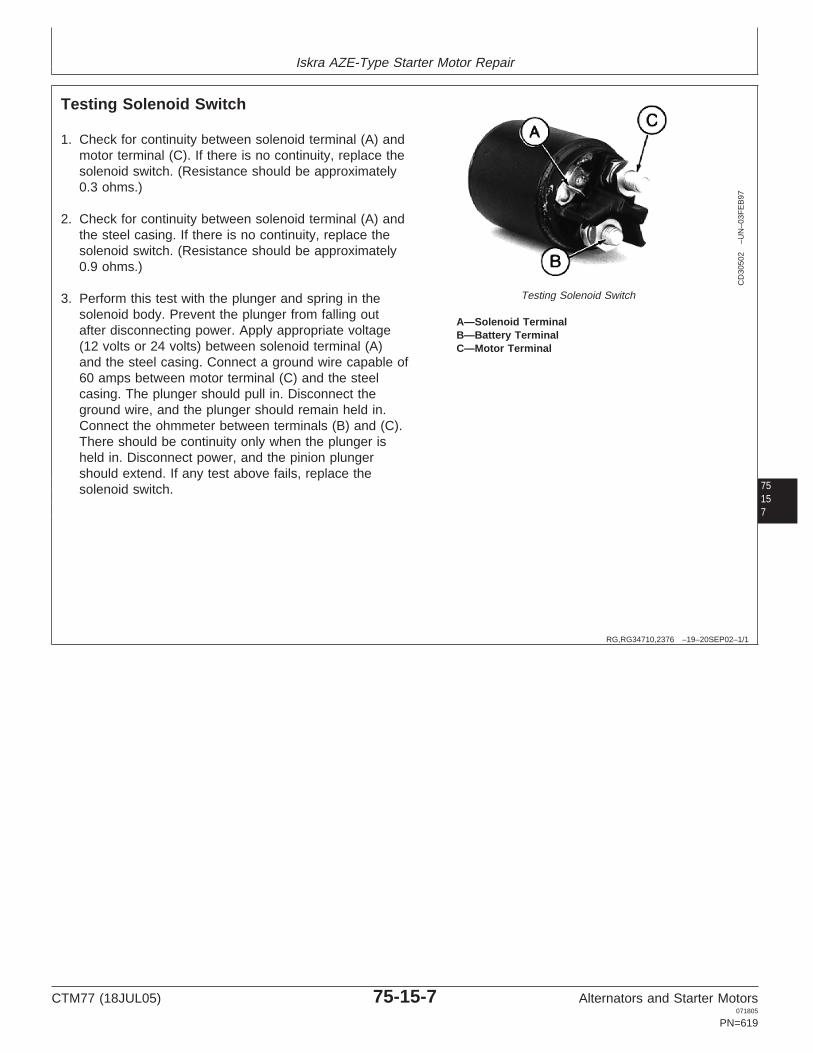
Iskra AZE-Type Starter Motor Repair
75157
RG,RG34710,2376 –19–20SEP02–1/1
Testing Solenoid Switch
CD
3050
2–U
N–0
3FE
B97
Testing Solenoid Switch
A—Solenoid TerminalB—Battery TerminalC—Motor Terminal
1. Check for continuity between solenoid terminal (A) andmotor terminal (C). If there is no continuity, replace thesolenoid switch. (Resistance should be approximately0.3 ohms.)
2. Check for continuity between solenoid terminal (A) andthe steel casing. If there is no continuity, replace thesolenoid switch. (Resistance should be approximately0.9 ohms.)
3. Perform this test with the plunger and spring in thesolenoid body. Prevent the plunger from falling outafter disconnecting power. Apply appropriate voltage(12 volts or 24 volts) between solenoid terminal (A)and the steel casing. Connect a ground wire capable of60 amps between motor terminal (C) and the steelcasing. The plunger should pull in. Disconnect theground wire, and the plunger should remain held in.Connect the ohmmeter between terminals (B) and (C).There should be continuity only when the plunger isheld in. Disconnect power, and the pinion plungershould extend. If any test above fails, replace thesolenoid switch.
CTM77 (18JUL05) 75-15-7 Alternators and Starter Motors071805
PN=619

Iskra AZE-Type Starter Motor Repair
7515
8OUOD006,000005E –19–13AUG02–1/1
Installing Solenoid SwitchRG12558 –UN–27AUG02
Check Plunger Handle Connection
RG
1256
1–U
N–2
7AU
G02
Install Solenoid Switch
A—HandleB—PlungerC—Cap Screw (3 used)D—Nut (Field Lead)
IMPORTANT: Handle (A) of plunger (B) must beconnected to engaging lever.
1. Install three cap screws (C).
2. Install field lead onto terminal with nut (D). Tighten tospecifications.
SpecificationField Lead Terminal Nut—Torque 15 N•m (132 lb-in.)..............................
CTM77 (18JUL05) 75-15-8 Alternators and Starter Motors071805
PN=620

Section 80Valeo Starter Motors
Contents
Page
Group 05—Starting Circuit Theory of OperationGeneral Information. . . . . . . . . . . . . . . . . . . . . .80-05-1Typical Starting Circuit Operation . . . . . . . . . . .80-05-1Typical Starter Motor Operation. . . . . . . . . . . . .80-05-2
Group 10—Valeo Starter Motor RepairEssential Tools . . . . . . . . . . . . . . . . . . . . . . . . .80-10-1Valeo Starter Motor Repair Specifications . . . . .80-10-2Valeo Starter Motor Test Specifications. . . . . . .80-10-2Exploded View of Starter Motor. . . . . . . . . . . . .80-10-3Disassembly of Starter Motor . . . . . . . . . . . . . .80-10-4Testing Solenoid Switch . . . . . . . . . . . . . . . . . .80-10-9Testing Brushes . . . . . . . . . . . . . . . . . . . . . . .80-10-10Positive Brush Replacement . . . . . . . . . . . . . .80-10-10Testing Armature. . . . . . . . . . . . . . . . . . . . . . .80-10-11Testing Field Winding . . . . . . . . . . . . . . . . . . .80-10-11Checking Overrunning Clutch Pinion . . . . . . . .80-10-12Reassembly of Starter Motor. . . . . . . . . . . . . .80-10-13
80
CTM77 (18JUL05) 80-1 Alternators and Starter Motors071805
PN=1

Contents
80
CTM77 (18JUL05) 80-2 Alternators and Starter Motors071805
PN=2

Group 05Starting Circuit Theory of Operation
RG,RG34710,2383 –19–15MAR97–1/1
General Information
IMPORTANT: Never operate starter motor longer than30 seconds. Allow at least 2 minutes forcooling and battery recovery beforeoperating again. Overheating caused byexcessive operation will seriouslydamage starter motor.
80051
RG,RG34710,2384 –19–15MAR97–1/1
Typical Starting Circuit Operation
RG
1313
–UN
–20A
PR
89
Typical Starting Circuit Operation
A—Wire From RelayB—Cable from BatteryC—Pull-In WindingD—Hold-In WindingE—Solenoid PlungerF—Main ContactsG—Field WindingsH—Commutator BrushesI—ArmatureJ—Shunt Windings
When wire from relay (A) is energized, current flowsthrough both pull-in winding (C) and hold-in winding (D) toground.
Current through windings engages solenoid plunger (E),which closes main contacts (F). When main contactsclose, current through pull-in windings stops. Currentcontinues through hold-in winding, keeping solenoidengaged and main contacts closed.
With main contacts closed, current flows from batterycable (B) to starter motor at a very high rate. Four heavyfield windings (G) carry current to commutator brushes(H).
Light shunt windings (J) are wrapped together with two ofthe heavy field windings. Shunt windings are connected tosolenoid switch terminal and directly to ground. Theyprovide additional low speed torque to assist enginerotation and prevent overspeeding of motor.
From field windings, current flows through armaturewindings (I) to ground, making contact throughcommutator brushes (H).
Strong magnetic fields are set up by current flow throughfield windings and armature windings. Windings arearranged so that magnetic fields constantly repel eachother, rotating armature.
CTM77 (18JUL05) 80-05-1 Alternators and Starter Motors071805
PN=623

Starting Circuit Theory of Operation
8005
2
RG,RG34710,2385 –19–15MAR97–1/1
Typical Starter Motor Operation
CD
3045
0–U
N–1
7JU
L96
Typical Starter Motor Operation
A—Solenoid Switch D—Brush F—Gear Reduction Assembly H—PinionB—Field Winding E—Commutator G—Overrunning Clutch J—Engaging LeverC—Rear Bearing
When solenoid (A) engages, it pulls engaging lever (J).Lever pushes overrunning clutch drive (G) to engagepinion in starter gear on flywheel. As armature turns, itcranks engine.
When engine starts, overrunning clutch spins freely onshaft. This prevents overspeeding of armature byflywheel.
When key switch is released, current to solenoidhold-in winding is shut off. Current can feed throughboth pull-in and hold-in windings from main contacts,but direction of current is reversed in pull-in winding.
The two windings cancel each other, and solenoid isreleased.
A spring pushes solenoid back to disengaged position.This opens main contacts and shuts off current to fieldwindings and armature.
Shift lever retracts overrunning clutch drive,disengaging pinion from flywheel.
In this reduction-type starter, the speed of armaturerotation is reduced by the gear reduction assembly (F).
CTM77 (18JUL05) 80-05-2 Alternators and Starter Motors071805
PN=624

Group 10Valeo Starter Motor Repair
OUO1004,0000BAB –19–08MAY02–1/3
Essential Tools
NOTE: Order tools according to information given in theU.S. SERVICEGARD Catalog or from theEuropean Microfiche Tool Catalog (MTC).
SERVICEGARD is a trademark of Deere & Company
80101
OUO1004,0000BAB –19–08MAY02–2/3
RW
1127
4–U
N–1
2DE
C88
JT05791
Digital Multimeter . . . . . . . . . . . . . . . . . . . . . JT05791
Test electrical components for voltage, resistance, orcurrent flow. It is especially good for measuring lowvoltage or high resistance circuits.
OUO1004,0000BAB –19–08MAY02–3/3
Alternator, Generator, Starter and Battery BenchTester . . . . . . . . . . . . . . . . . . . . . . . . . . . . . JT01760
Test alternators and starters for voltage, resistance, orcurrent flow.
CTM77 (18JUL05) 80-10-1 Alternators and Starter Motors071805
PN=625

Valeo Starter Motor Repair
OUO1004,0000BAE –19–25SEP00–1/1
Valeo Starter Motor Repair Specifications
Item Measurement Specification
New Brush Length 14 mm (0.55 in.)
Used Brush Minimum Length 8.5 mm (0.22 in.)
Starter Solenoid Mounting Cap Torque 3 N•m (27 lb-in.)Screws
Housing Through Bolts Torque 7 N•m (62 lb-in.)
Field Winding Terminal Screw Torque 10 N•m (88 lb-in.)
8010
2
RG,RG34710,2387 –19–07JUL05–1/1
Valeo Starter Motor Test Specifications
John Deere Valeo Valeo Model System Rating Solenoid CurrentStarter Motor Starter Motor Voltage (kW) Hold-In Windings
Part No. Part No. (Amps)
RE501680 187031 D7R14 12 2.5 32
RE502156 187031 D7R14 12 2.5 32
RE60641a 187031 D7R14 12 2.5 32aNot a service part. For service, consult parts catalog.
CTM77 (18JUL05) 80-10-2 Alternators and Starter Motors071805
PN=626

Valeo Starter Motor Repair
80103
RG,RG34710,2395 –19–15MAR97–1/1
Exploded View of Starter Motor
CD
3045
1–U
N–1
7JU
L96
Starter Motor
1—Pivot Pin1 7—Overrunning Clutch Pinion1 14—Shim1 21—Clip1
2—Engaging Lever/Plunger 8—Pinion Stop1 15—Rear Bearing 22—Field WindingAssembly 9—Retaining Ring1 16—Clip1 23—Pole Shoe Screw
3—Solenoid Spring 10—Bushing1 17—Plastic Cap1 24—Field Winding Terminal4—Gear Reduction Assembly 11—Armature 18—Through Bolt1 (2 used) Nut5—Solenoid Body1 12—Field Frame 19—Brush1 (4 used) 25—Solenoid Attaching Screw6—Cover 13—Brush Plate1 20—Brush Spring1 (3 Used)
1 Available as service parts.
CTM77 (18JUL05) 80-10-3 Alternators and Starter Motors071805
PN=627

Valeo Starter Motor Repair
RG,RG34710,2388 –19–12SEP02–1/11
Disassembly of Starter Motor
CD
3045
2–U
N–2
2JU
L96
Starter Motor Disassembly
8010
4
A—Field Winding CableB—Through Bolts (2 Used)
1. Disconnect field winding cable (A).
2. Unscrew the two through bolts (B).
RG,RG34710,2388 –19–12SEP02–2/11
CD
3045
3–U
N–2
2JU
L96
Separate Electric Motor
A—Electric MotorB—Front AssemblyC—Contactor ScrewD—Pole Shoe Screws
3. Separate electric motor (A) from complete frontassembly (B).
4. Unscrew the screw (C) holding the contactor using aTORX screwdriver.
NOTE: Do not unscrew the pole shoe screws (D) as it isdifficult to perform the tightening procedure.
TORX is a registered trademark of Camcar/Textron. Continued on next page
CTM77 (18JUL05) 80-10-4 Alternators and Starter Motors071805
PN=628

Valeo Starter Motor Repair
RG,RG34710,2388 –19–12SEP02–3/11
CD
3045
4–U
N–2
2JU
L96
Slide Pinion Stop Off Shaft
80105
A—Gear Reduction/Solenoid/Overrunning ClutchAssembly
B—Drive End HousingC—Pinion StopD—Retaining Ring
5. Separate gear reduction/solenoid/overrunning clutchassembly (A) from drive end housing (B).
6. Push pinion stop (C) toward pinion to have access tothe retaining ring (D).
7. Remove retaining ring and slide pinion stop off shaft.
RG,RG34710,2388 –19–12SEP02–4/11
CD
3045
5–U
N–2
2JU
L96
Remove Pivot Pin
A—Pivot Pin
8. Remove pivot pin (A).
Continued on next page
CTM77 (18JUL05) 80-10-5 Alternators and Starter Motors071805
PN=629

Valeo Starter Motor Repair
RG,RG34710,2388 –19–12SEP02–5/11
CD
3045
6–U
N–2
2JU
L96
Separate Assemblies
8010
6
A—Overrunning Clutch/Engaging Lever/Mobile CoreAssembly
B—Gear Reduction/Solenoid Body Assembly
9. Separate overrunning clutch/engaging lever/mobilecore assembly (A) from gear reduction/solenoid bodyassembly (B).
RG,RG34710,2388 –19–12SEP02–6/11
CD
3045
7–U
N–2
2JU
L96
Contactor
A—Screws (2 used)
10. Unscrew the two screws holding the contactor (A)using TORX screwdriver.
TORX is a registered trademark of Camcar/Textron. Continued on next page
CTM77 (18JUL05) 80-10-6 Alternators and Starter Motors071805
PN=630

Valeo Starter Motor Repair
RG,RG34710,2388 –19–12SEP02–7/11
CD
3045
8–U
N–2
2JU
L96
Cap and Clip
80107
A—Rear BearingB—Field FrameC—Rear Plastic CapD—Clip
11. Before disassembly, mark both the rear bearing (A)and the field frame (B).
12. Remove rear plastic cap (C) and clip (D).
RG,RG34710,2388 –19–12SEP02–8/11
CD
3045
9–U
N–2
2JU
L96
Remove Rear Bearing
A—Rear BearingB—Shims (4 Used)
13. Remove the rear bearing (A).
NOTE: Two shims (B) are located on each side of rearbearing.
Continued on next page
CTM77 (18JUL05) 80-10-7 Alternators and Starter Motors071805
PN=631

Valeo Starter Motor Repair
RG,RG34710,2388 –19–12SEP02–9/11
CD
3046
0–U
N–2
2JU
L96
Disassembly Sleeve
8010
8
A—Disassembly Sleeve
14. Position and push the disassembly sleeve (A) on theshaft to hold brushes in their housing and remove thearmature.
NOTE: The disassembly sleeve (A) is provided with thebrush repair kit available through John Deere.
RG,RG34710,2388 –19–12SEP02–10/11
CD
3046
1–U
N–2
2JU
L96
Remove the Disassembly Sleeve
15. Slide carbon brush plate away from the field frame.
16. Loosen and remove the four brush clips from theplate. Take care to avoid losing the four springs.
17. Remove the disassembly sleeve.
Continued on next page
CTM77 (18JUL05) 80-10-8 Alternators and Starter Motors071805
PN=632

Valeo Starter Motor Repair
RG,RG34710,2388 –19–12SEP02–11/11
CD
3046
2–U
N–2
2JU
L96
Remove Brush Plate
18. Push the two positive brushes inwards and removethe brush plate from the field frame.
80109
RG,RG34710,2389 –19–20SEP02–1/1
Testing Solenoid Switch
CD
3046
3–U
N–2
2JU
L96
Testing Solenoid Switch
A—Solenoid TerminalB—Battery TerminalC—Motor Terminal
1. Check for continuity between solenoid terminal (A) andmotor terminal (C). If there is no continuity, replace thesolenoid switch. (Resistance should be approximately0.3 ohms.)
2. Check for continuity between solenoid terminal (A) andthe steel casing. If there is no continuity, replace thesolenoid switch. (Resistance should be approximately0.9 ohms.)
3. Perform this test with the plunger and spring in thesolenoid body. Prevent the plunger from falling outafter disconnecting power. Apply appropriate voltage(12 volts or 24 volts) between solenoid terminal (A)and the steel casing. Connect a ground wire capable of60 amps between motor terminal (C) and the steelcasing. The plunger should pull in. Disconnect theground wire, and the plunger should remain held in.Connect the ohmmeter between terminals (B) and (C).There should be continuity only when the plunger isheld in. Disconnect power, and the pinion plungershould extend. If any test above fails, replace thesolenoid switch.
CTM77 (18JUL05) 80-10-9 Alternators and Starter Motors071805
PN=633

Valeo Starter Motor Repair
RG,RG34710,2390 –19–15MAR97–1/1
Testing Brushes
CD
3046
4–U
N–2
2JU
L96
Test Brushes
A—Brushes
1. Check positive brushes (A) by connecting anohmmeter between brushes and plate. The resistanceshould be infinity.
2. Inspect brushes. Brushes must move freely in theirguides. Check brush overall length.
SpecificationNew Brush—Length 14 mm (0.55 in.)........................................................Used Brush—Minimum Length 8.5 mm (0.22 in.)......................................
3. If defective, replace the brush plate assembly.
NOTE: Brush plate assembly is available as a JohnDeere Service part.
801010
RG,RG34710,2391 –19–15MAR97–1/1
Positive Brush Replacement
CD
3046
5–U
N–2
2JU
L96
Positive Brush ReplacementA—Brush Strand
1. Cut off old brush at end of brush strand (A).
2. Solder new brush using a 40—60% tin-lead mix. Heatto 230°C (446°F).
NOTE: This operation requires specialized solderingtools. If not available, have the brushes replacedby a local electrical repair station.
CTM77 (18JUL05) 80-10-10 Alternators and Starter Motors071805
PN=634

Valeo Starter Motor Repair
RG,RG34710,2392 –19–15MAR97–1/1
Testing Armature
CD
3046
6–U
N–2
2JU
L96
Test Armature
A—CommutatorB—Shaft
1. Check the armature insulation by connecting anohmmeter between the commutator (A) and the shaft(B). If test shows continuity (needle movement), thearmature is grounded.
2. Check for armature condition. Space between barsmust be clean and of even depth. Small defects can beeliminated using sandpaper and a lathe.
3. If insulation is defective or armature is quite worn,replace the complete starter motor.
801011
RG,RG34710,2393 –19–15MAR97–1/1
Testing Field Winding
CD
3046
7–U
N–2
2JU
L96
Test Field WindingA—BrushB—Field FrameC—Field Frame Terminal
1. Check insulation by connecting an ohmmeter betweenbrush (A) and field frame (B). If ohmmeter indicatorswings toward zero, a grounded circuit is indicated.
2. Connect ohmmeter between brush (A) and terminal(C). Resistance should be below 1 ohm.
3. If defective, replace the complete starter motor.
CTM77 (18JUL05) 80-10-11 Alternators and Starter Motors071805
PN=635

Valeo Starter Motor Repair
RG,RG34710,2394 –19–12SEP02–1/1
Checking Overrunning Clutch Pinion
CD
3046
8–U
N–2
2JU
L96
Check Overrunning Clutch Pinion
1. Check for pinion tooth condition. Slight damage onteeth can be eliminated by grinding.
NOTE: Damage on teeth can be caused by a malfunctionof electrical system. Also check electrical circuitfor proper operation (switch, relay etc.).
2. Turn overrunning clutch pinion by hand. Clutch pinionshould turn freely on shaft in overrunning directiononly.
3. If defective, replace overrunning clutch pinion.
NOTE: Overrunning clutch pinion is available as a JohnDeere service part.
801012
CTM77 (18JUL05) 80-10-12 Alternators and Starter Motors071805
PN=636

Valeo Starter Motor Repair
801013
RG,RG34710,2396 –19–15MAR97–1/1
Reassembly of Starter Motor
CD
3046
9–U
N–1
7JU
L96
Reassemble Starter Motor
Reassemble starter motor in the reverse sequence ofdisassembly procedure.
Use petroleum-base grease to lightly coat mechanicalpart assemblies such as shaft in nose bushing, gear
reduction train, overrunning clutch pinion on shaft, andshaft rear bearing.
Refer to machine technical manual to install startermotor and adjust belt tension.
Item Measurement Specification
Starter Solenoid Mounting Cap Torque 3 N•m (27 lb-in.)Screws
Housing Through Bolts Torque 7 N•m (62 lb-in.)
Field Winding Terminal Screw Torque 10 N•m (88 lb-in.)
CTM77 (18JUL05) 80-10-13 Alternators and Starter Motors071805
PN=637

Valeo Starter Motor Repair
801014
CTM77 (18JUL05) 80-10-14 Alternators and Starter Motors071805
PN=638

Section 85Magneton Starter Motors
Contents
Page
Group 05—Starting Circuit Theory of OperationGeneral Information. . . . . . . . . . . . . . . . . . . . . .85-05-1Typical Starting Circuit Operation . . . . . . . . . . .85-05-1Starter Motor Operation. . . . . . . . . . . . . . . . . . .85-05-2
Group 10—Magneton Starter Motor RepairEssential Tools . . . . . . . . . . . . . . . . . . . . . . . . .85-10-1Dealer Fabricated Tools . . . . . . . . . . . . . . . . . .85-10-2Magneton Starter Motor Repair
Specifications. . . . . . . . . . . . . . . . . . . . . . . . .85-10-2Magneton Starter Motor Test Specifications . . .85-10-3Exploded View of Starter Motor. . . . . . . . . . . . .85-10-4Identification . . . . . . . . . . . . . . . . . . . . . . . . . . .85-10-5Troubleshooting. . . . . . . . . . . . . . . . . . . . . . . . .85-10-6Disassembly of Starter Motor . . . . . . . . . . . . . .85-10-7Testing Solenoid Switch . . . . . . . . . . . . . . . . .85-10-11Testing Brushes . . . . . . . . . . . . . . . . . . . . . . .85-10-12Brush Holder Replacement . . . . . . . . . . . . . . .85-10-12Testing Armature. . . . . . . . . . . . . . . . . . . . . . .85-10-13Testing Field Winding . . . . . . . . . . . . . . . . . . .85-10-13Checking Overrunning Clutch Pinion . . . . . . . .85-10-14Reassembly of Starter Motor. . . . . . . . . . . . . .85-10-15
85
CTM77 (18JUL05) 85-1 Alternators and Starter Motors071805
PN=1

Contents
85
CTM77 (18JUL05) 85-2 Alternators and Starter Motors071805
PN=2

Group 05Starting Circuit Theory of Operation
CD03523,00000D5 –19–30JUL02–1/1
General Information
IMPORTANT: Never operate starter motor longer than5 seconds. Allow at least 20 secondsfor cooling and battery recovery beforeoperating again. Overheating caused byexcessive operation will seriouslydamage starter motor.
85051
CD03523,00000D6 –19–17JUL02–1/1
Typical Starting Circuit Operation
RG
1313
–UN
–20A
PR
89
Typical Starting Circuit Operation
A—Wire From RelayB—Cable from BatteryC—Pull-In WindingD—Hold-In WindingE—Solenoid PlungerF—Main ContactsG—Field WindingsH—Commutator BrushesI—ArmatureJ—Shunt Windings
When wire from relay (A) is energized, current flowsthrough both pull-in winding (C) and hold-in winding (D) toground.
Current through windings engages solenoid plunger (E),which closes main contacts (F). When main contactsclose, current through pull-in windings stops. Currentcontinues through hold-in winding, keeping solenoidengaged and main contacts closed.
With main contacts closed, current flows from batterycable (B) to starter motor at a very high rate. Four heavyfield windings (G) carry current to commutator brushes(H).
Light shunt windings (J) are wrapped together with two ofthe heavy field windings. Shunt windings are connected tosolenoid switch terminal and directly to ground. Theyprovide additional low speed torque to assist enginerotation and prevent overspeeding of motor.
From field windings, current flows through armaturewindings (I) to ground, making contact throughcommutator brushes (H).
Strong magnetic fields are set up by current flow throughfield windings and armature windings. Windings arearranged so that magnetic fields constantly repel eachother, rotating armature.
CTM77 (18JUL05) 85-05-1 Alternators and Starter Motors071805
PN=641

Starting Circuit Theory of Operation
8505
2
CD03523,00000D7 –19–29JUL02–1/1
Starter Motor Operation
CD
3082
1–U
N–2
6JU
L02
Magneton Starter Operation
A—Solenoid assembly C—Overrunning clutch drive E—Clutch drive external gear F—BrushesB—Shift lever D—Armature
When solenoid (A) engages, it pulls shift lever (B).Lever pushes overrunning clutch drive (C) to engagepinion in starter gear on flywheel. As armature (D)turns, it cranks engine.
When engine starts, overrunning clutch spins freely onshaft. This prevents overspeeding of armature byflywheel.
When key switch is released, current to solenoidhold-in winding is shut off. Current can feed throughboth pull-in and hold-in windings from main contacts,but direction of current is reversed in pull-in winding.
The two windings cancel each other, and solenoid isreleased.
A spring pushes solenoid back to disengaged position.This opens main contacts and shuts off current to fieldwindings and armature.
Shift lever retracts overrunning clutch drive,disengaging pinion from flywheel.
In this reduction-type starter, the speed of armaturerotation is reduced by the external gear (E) of theclutch drive.
CTM77 (18JUL05) 85-05-2 Alternators and Starter Motors071805
PN=642

Group 10Magneton Starter Motor Repair
OUO1004,0000BAB –19–08MAY02–1/3
Essential Tools
NOTE: Order tools according to information given in theU.S. SERVICEGARD Catalog or from theEuropean Microfiche Tool Catalog (MTC).
SERVICEGARD is a trademark of Deere & Company
OUO1004,0000BAB –19–08MAY02–2/3
RW
1127
4–U
N–1
2DE
C88
JT05791
Digital Multimeter . . . . . . . . . . . . . . . . . . . . . JT05791
Test electrical components for voltage, resistance, orcurrent flow. It is especially good for measuring lowvoltage or high resistance circuits.
85101
OUO1004,0000BAB –19–08MAY02–3/3
Alternator, Generator, Starter and Battery BenchTester . . . . . . . . . . . . . . . . . . . . . . . . . . . . . JT01760
Test alternators and starters for voltage, resistance, orcurrent flow.
CTM77 (18JUL05) 85-10-1 Alternators and Starter Motors071805
PN=643

Magneton Starter Motor Repair
CD03523,00000D4 –19–17JUL02–1/1
Dealer Fabricated Tools
CD
3049
4–U
N–3
1JA
N97
Dummy Commutator for Brush Holder
a—Dia. 36.4—36.6 mm (1.433—1.441 in.)b—Dia. 24.5 mm (0.96 in.)c—Dia. 42 mm (1.65 in.)d—35 mm (1.38 in.)e—2.5 mm (0.10 in.)f—Chamfer 15°g—2.5 mm (0.10 in.)
Dummy Commutator for Brush Holder Removal andInstallation
Material: Plastic
8510
2
CD03523,00000D8 –19–17JUL02–1/1
Magneton Starter Motor RepairSpecifications
Item Measurement Specification
New Brush Length 18 mm (0.71 in.)
Used Brush Minimum Length 7.5 mm (0.30 in.)
Solenoid Switch Screws Torque 4 N•m (35 lb-in.)
Rear Cover Nut Torque 6 N•m (53 lb-in.)
Field Winding Terminal Nut Torque 7 N•m (62 lb-in.)
Front Flange Screw Torque 7 N•m (62 lb-in.)
Terminal nut (from battery) Torque 15 N•m (11 lb-ft)
Terminal nut (from relay) Torque 2 N•m (17 lb-in.)
CTM77 (18JUL05) 85-10-2 Alternators and Starter Motors071805
PN=644

Magneton Starter Motor Repair
CD03523,00000D9 –19–07JUL05–1/1
Magneton Starter Motor Test Specifications
Solenoid Current Pinion
John Deere Magneton Pull-In Hold-In ToothStarter Motor Starter Motor System Rating Winding Winding SpacingPart Number Part Number Voltage (kW) (Amps) (Amps) No. of Teeth (Modul)
RE507236 9142 740 12 2.7 65 20 10 3.175
85103
CTM77 (18JUL05) 85-10-3 Alternators and Starter Motors071805
PN=645

Magneton Starter Motor Repair
8510
4
CD03523,00000DA –19–29JUL02–1/1
Exploded View of Starter Motor
CD
3082
2–U
N–2
6JU
L02
Exploded view
1—M6x25 Screw 7—Transmission Housing 15—Solenoid Body1 23—Lock Washer2—Lock Washer 8—Vent Pipe 16—Lock Washer 24—Rear Cover3—Front Flange/Ball Bearing 9—Shift Lever 17—M10 Nut 25—Stator
Housing 10—Pivot 18—Field Winding Cable 26—Brush Holder1
4—Overrunning Clutch Pinion1 11—Pivot Spring 19—Washer 27—Ball Bearing5—M5x35 Screw 12—Plunger 20—Lock Washer 28—Armature6—Lock Washer 13—Plunger Spring 21—M8 Nut 29—Housing Through Stud
14—Sealing 22—M6 Nut 30—Roller Bearing
1Available as service parts.
CTM77 (18JUL05) 85-10-4 Alternators and Starter Motors071805
PN=646

Magneton Starter Motor Repair
CD03523,00000DB –19–29JUL02–1/1
Identification
CD
3082
3–U
N–2
6JU
L02
Identification
The information for part identification is located on thebody of the starter motor as shown.
85105
CTM77 (18JUL05) 85-10-5 Alternators and Starter Motors071805
PN=647

Magneton Starter Motor Repair
8510
6
RG,RG34710,2373 –19–15MAR97–1/1
Troubleshooting
Symptom Problem Solution
Fails to operate, no current draw Open field circuit Replace starter motor
Open armature windings Replace starter motor
Defective brush contact with Clean brush holder or replacecommutator brushes
Open solenoid windings Replace solenoid
Defective solenoid contact Replace solenoid
Fails to operate, high current Grounded field windings or armature Replace starter motordraw windings
Seized bearings Replace starter motor
Low speed, low current draw High internal resistance Replace starter motor
Defective brush contact with Clean brush holder or replacecommutator brushes
Low speed, high current draw Shorted armature Replace starter motor
Grounded armature or field windings Replace starter motor
High speed, high current draw Shorted field windings Replace starter motor
Solenoid switch operates but Worn or broken brushes Clean brush holder and commutatorarmature does not rotate and replace brushes
Shorted field windings Replace starter motor
Solenoid quickly engages and Shorted hold-in windings Replace solenoiddisengages
Starter motor spins, but does not Overrunning clutch slipping Replace overrunning clutchcrank the engine
Pinion does not move into mesh with Replace engaging lever or clutchthe gear ring
CTM77 (18JUL05) 85-10-6 Alternators and Starter Motors071805
PN=648

Magneton Starter Motor Repair
CD03523,00000DC –19–27AUG02–1/9
Disassembly of Starter Motor
CD
3082
4–U
N–2
6JU
L02
Unfasten Solenoid Switch
8510
A—Field Winding CableB—Screw (3 used)
NOTE: Before separating, mark parts so that they can bereinstalled in their original positions.
1. Disconnect field winding cable (A).
2. Remove the three screws (B) holding the solenoidswitch.
7
CD03523,00000DC –19–27AUG02–2/9C
D30
825
–UN
–26J
UL0
2
Remove Solenoid Switch
A—Solenoid Switch
3. Remove solenoid switch (A).
Continued on next page
CTM77 (18JUL05) 85-10-7 Alternators and Starter Motors071805
PN=649

Magneton Starter Motor Repair
CD03523,00000DC –19–27AUG02–3/9
CD
3082
6–U
N–2
6JU
L02
Remove Screws
A—ScrewB—Front Flange
4. Unscrew the four screws (A) holding the front flange(B)
CD03523,00000DC –19–27AUG02–4/9
CD
3082
7–U
N–2
6JU
L02
Remove Overrunning Clutch
8510
8
A—Front FlangeB—Overrunning Clutch Assembly
5. Separate front flange (A) and overrunning clutchassembly (B) from transmission housing.
CD03523,00000DC –19–27AUG02–5/9
CD
3082
8–U
N–2
6JU
L02
Remove Nuts
A—Nut (2 used)
6. Unscrew nuts (A).
CTM77 (18JUL05) 85-10-8 Alternators and Starter Motors071805
PN=650
Continued on next page

Magneton Starter Motor Repair
CD03523,00000DC –19–27AUG02–6/9
CD
3082
9–U
N–2
6JU
L02
Remove Transmission Cover
A—Transmission CoverB—Stator/Armature Assembly
7. Separate transmission cover (A) from stator/armature(B).
85109
CD03523,00000DC –19–27AUG02–7/9C
D30
830
–UN
–26J
UL0
2
Remove Rear Cover
A—Rear Cover
8. Remove the rear cover (A).
Continued on next page
CTM77 (18JUL05) 85-10-9 Alternators and Starter Motors071805
PN=651

Magneton Starter Motor Repair
CD03523,00000DC –19–27AUG02–8/9
CD
3083
1–U
N–2
6JU
L02
Install Dummy Commutator
A—Dummy Commutator
9. Install a dummy commutator (A) as shown in DealerFabricated Tools earlier in this group.
CD03523,00000DC –19–27AUG02–9/9
CD
3083
2–U
N–2
6JU
L02
Remove Armature
851010
A—ArmatureB—Stator
10. Separate armature (A) from stator (B).
CTM77 (18JUL05) 85-10-10 Alternators and Starter Motors071805
PN=652

Magneton Starter Motor Repair
CD03523,00000DD –19–29JUL02–1/1
Testing Solenoid Switch
CD
3083
3–U
N–2
6JU
L02
Testing Solenoid Switch
A—Solenoid TerminalB—Motor TerminalC—Battery Terminal
1. Check for continuity between solenoid terminal (A) andmotor terminal (B). If there is no continuity, replace thesolenoid switch. (Resistance should be approximately0.3 ohms.)
2. Check for continuity between solenoid terminal (A) andthe steel casing. If there is no continuity, replace thesolenoid switch. (Resistance should be approximately0.9 ohms.)
3. Perform this test with the plunger and spring in thesolenoid body. Prevent the plunger from falling outafter disconnecting power. Apply appropriate voltage(12 volts or 24 volts) between solenoid terminal (A)and the steel casing. Connect a ground wire capable of60 amps between motor terminal (B) and the steelcasing. The plunger should pull in. Disconnect theground wire, and the plunger should remain held in.Connect the ohmmeter between terminals (B) and (C).There should be continuity only when the plunger isheld in. Disconnect power, and the pinion plungershould extend. If any test above fails, replace thesolenoid switch.
851011
CTM77 (18JUL05) 85-10-11 Alternators and Starter Motors071805
PN=653

Magneton Starter Motor Repair
CD03523,00000DE –19–29JUL02–1/1
Testing Brushes
CD
3083
4–U
N–2
6JU
L02
Testing Brushes
851012
A—Positive Brush LeadB—Ground Plate
1. Check positive brush holder by connecting anohmmeter between brush lead (A) and ground plate(B). If the resistance is not infinity, replace brushholder.
2. Inspect brushes. Brushes must move freely in theirguides. Check brush overall length. Replace brushholder if brushes are frozen or too worn.
SpecificationNew Brush—Length 18 mm (0.71 in.)........................................................Used Brush—Minimum Length 7.5 mm (0.30 in.)......................................
CD03523,00000DF –19–27AUG02–1/1
Brush Holder Replacement
CD
3083
5–U
N–2
6JU
L02
Brush Holder ReplacementA—Brush Stranded WireB—Old Brush HolderC—New Brush Holder
1. Cut off old brushes at end of brush stranded wire (A).
2. Solder new brush wire using a 40—60% tin-lead mix.Heat to 230°C (446°F).
NOTE: This operation needs a specialized tooling.Eventually, have the brush holder replaced by alocal electrical repair station.
CTM77 (18JUL05) 85-10-12 Alternators and Starter Motors071805
PN=654

Magneton Starter Motor Repair
RG,RG34710,2392 –19–29JUL02–1/1
Testing Armature
CD
3083
6–U
N–2
6JU
L02
Testing Armature
A—CommutatorB—Shaft
1. Check the armature insulation by connecting anohmmeter between the commutator (A) and the shaft(B). If test shows continuity (needle movement), thearmature is grounded.
2. Check for armature condition. Space between barsmust be clean and of even depth. Small defects can beeliminated using sandpaper and a lathe.
3. If insulation is defective or armature is quite worn,replace the complete starter motor.
851013
CD03523,00000E0 –19–29JUL02–1/1
Testing Field Winding
CD
3083
7–U
N–2
6JU
L02
Testing Field Winding
A—BrushB—Brush HolderC—Field Frame Cable
Connect ohmmeter between positive brush (A) and fieldwinding cable (C). Resistance should be below 1 Ohm. Ifdefective, replace complete starter motor.
CTM77 (18JUL05) 85-10-13 Alternators and Starter Motors071805
PN=655

Magneton Starter Motor Repair
CD03523,00000E1 –19–29JUL02–1/1
Checking Overrunning Clutch Pinion
CD
3083
8–U
N–2
9JU
L02
Checking Overrunning Clutch Pinion
1. Check for pinion tooth condition. Slight damage toteeth can be eliminated by grinding.
NOTE: Damage to teeth can be caused by a malfunctionof electrical system. Also check electrical circuitfor proper operation (switch, relay etc.).
2. Turn overrunning clutch pinion by hand. Clutch pinionshould turn freely on shaft in overrunning directiononly.
3. If defective, replace the overrunning clutch pinionassembly.
851014
CTM77 (18JUL05) 85-10-14 Alternators and Starter Motors071805
PN=656

Magneton Starter Motor Repair
851015
CD03523,00000E2 –19–30JUL02–1/2
Reassembly of Starter Motor
CD
3083
9–U
N–2
6JU
L02
Reassembly of Starter Motor
A—Solenoid Switch C—Rear Cover Nut E—Front Flange Screw F—Terminal (from battery) NutB—Solenoid Switch Screw D—Field Winding Terminal Nut
Reassemble starter motor in the reverse sequence ofdisassembly procedure. It is recommended toassemble solenoid switch (A) with transmissionhousing first.
Apply sealing compound on contact surface and onthreads of cap screws.
Use petroleum-base grease to lightly coat mechanicalpart assemblies such as shaft in front bearing, gearreduction train, overrunning clutch pinion on shaft, andshaft rear bearing.
Refer to machine technical manual to install startermotor on engine.
Item Measurement Specification
Solenoid Switch Screws (B) Torque 4 N•m (35 lb-in.)
Rear Cover Nuts (C) Torque 6 N•m (53 lb-in.)
Field Winding Terminal Nut (D) Torque 7 N•m (62 lb-in.)
Front Flange Screws (E) Torque 7 N•m (62 lb-in.)
CTM77 (18JUL05) 85-10-15 Alternators and Starter Motors071805
PN=657
Continued on next page
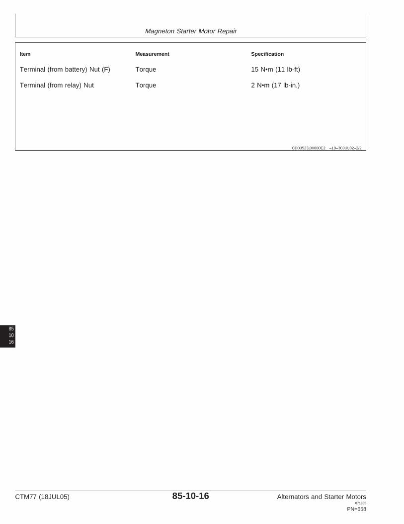
Magneton Starter Motor Repair
CD03523,00000E2 –19–30JUL02–2/2
Item Measurement Specification
Terminal (from battery) Nut (F) Torque 15 N•m (11 lb-ft)
Terminal (from relay) Nut Torque 2 N•m (17 lb-in.)
851016
CTM77 (18JUL05) 85-10-16 Alternators and Starter Motors071805
PN=658

IndexPage Page
B Specifications, repair. . . . . . . . . . . . . . . . . .60-20-3Specifications, test . . . . . . . . . . . . . . . . . . .60-20-4Troubleshooting . . . . . . . . . . . . . . . . . . . . .60-20-5Bosch alternator
Delco-Remy 10SI, 12SI, and 15SI alternatorAlternator operation. . . . . . . . . . . . . . . . . . .30-05-1Repair and test . . . . . . . . . . . . . . .10-10-4, 10-15-4Exploded view. . . . . . . . . . . . . . . . . . . . . .30-10-10Specifications, repair. . . . . . . . . . .10-10-2, 10-15-2Repair and test . . . . . . . . . . . . . . . . . . . . . .30-10-7Specifications, test . . . . . . . . . . . .10-10-3, 10-15-3Sectional view. . . . . . . . . . . . . . . . . . . . . . .30-10-6
Denso alternatorSpecifications, repair. . . . . . . . . . . . . . . . . .30-10-3Alternator operation. . . . . . . . . . . . . . . . . . .25-05-1Specifications, test . . . . . . . . . . . . . . . . . . .30-10-4Regulator operation. . . . . . . . . . . . . . . . . . .25-05-2Bosch conventional starter motor
Denso alternator (with add-on regulator)Cutaway view . . . . . . . . . . . . . . . . . . . . . . .70-10-6Repair and test . . . . . . . . . . . . . . . . . . . . . .25-10-3Exploded view. . . . . . . . . . . . . . . . . . . . . . .70-10-7Specifications, repair. . . . . . . . . . . . . . . . . .25-10-2Repair and test . . . . . . . . . . . . . . . . . . . . . .70-10-4Specifications, test . . . . . . . . . . . . . . . . . . .25-10-2Specifications, repair. . . . . . . . . . . . . . . . . .70-10-2
Denso alternator (with built-in regulator)Specifications, test . . . . . . . . . . . . . . . . . . .70-10-3Repair and test . . . . . . . . . . . . . . . . . . . . . .25-15-5Bosch planetary gear starter motorSpecifications, repair. . . . . . . . . . . . . . . . . .25-15-3Cutaway view . . . . . . . . . . . . . . . . . . . . . . .70-15-4Specifications, test . . . . . . . . . . . . . . . . . . .25-15-4Repair and test . . . . . . . . . . . . . . . . . . . . . .70-15-2
Denso/John Deere starter motorSpecifications, test . . . . . . . . . . . . . . . . . . .70-15-2Starting circuit operation . . . . . . . . . . . . . . .65-05-1Bosch starter motor
Denso/John Deere starter motor (conventional type)General information. . . . . . . . . . . . . . . . . . .70-05-1Exploded view. . . . . . . . . . . . . . . . . . . . . .65-10-15Starter motor operation . . . . . . . . . . . . . . . .70-05-2Repair and test . . . . . . . . . . . . . . . . . . . . . .65-10-8Starting circuit operation . . . . . . . . . . . . . . .70-05-1Specifications, test . . . . . . . . . . . . . . . . . . .65-10-6Troubleshooting . . . . . . . . . . . . . .70-10-5, 70-15-3Starter operation . . . . . . . . . . . . . . . . . . . . .65-05-2
Denso/John Deere starter motor (gear reductiontype)
D Exploded view. . . . . . . . . . . . . . . . . . . . . . .65-15-7Repair and test . . . . . . . . . . . . . . . . . . . . . .65-15-5Specifications, test . . . . . . . . . . . . . . . . . . .65-15-4Delco-Remy alternator
Alternator operation. . . . . . . . . . . . . . . . . . .10-05-1 Starter operation . . . . . . . . . . . . . . . . . . . . .65-05-3Denso/John Deere starter motor (planetary type)Regulator operation. . . . . . . . . . . . . . . . . . .10-05-1
Delco-Remy starter motor Exploded view. . . . . . . . . . . . . . . . . . . . . .65-20-14Repair and test . . . . . . . . . . . . . . . . . . . . . .65-20-3General information. . . . . . . . . . . . . . . . . . .60-05-1
Starter motor operation . . . . . . . . . . . . . . . .60-05-2 Specifications, test . . . . . . . . . . . . . . . . . . .65-20-3Starter operation . . . . . . . . . . . . . . . . . . . . .65-05-5Starting circuit operation . . . . . . . . . . . . . . .60-05-1
Delco-Remy starter motor (10MT, 20MT, 22MT,25MT, 27MT, 28MT)
ECutaway view . . . . . . . . . . . . . . . . . . . . . . .60-10-7Repair and test . . . . . . . . . . . . . . . . . . . . . .60-10-7 IndxElectrical system 1Specifications, repair. . . . . . . . . . . . . . . . . .60-10-3
Circuit malfunctions. . . . . . . . . . . . . . . . . . .05-15-1Specifications, test . . . . . . . . . . . . . . . . . . .60-10-4
Grounded circuit . . . . . . . . . . . . . . . . . . . . .05-15-5Troubleshooting . . . . . . . . . . . . . . . . . . . . .60-10-6
High resistance circuit . . . . . . . . . . . . . . . . .05-15-2Delco-Remy starter motor (30MT, 35MT, 37MT)
Open circuit . . . . . . . . . . . . . . . . . . . . . . . .05-15-3Cutaway view . . . . . . . . . . . . . . . . . . . . . . .60-15-7
Seven step test procedure . . . . . . . . . . . . .05-15-8Repair and test . . . . . . . . . . . . . . . . . . . . . .60-15-8
Shorted circuit. . . . . . . . . . . . . . . . . . . . . . .05-15-7Specifications, repair. . . . . . . . . . . . . . . . . .60-15-3
Test equipment . . . . . . . . . . . . . . . . . . . . .05-15-10Specifications, test . . . . . . . . . . . . . . . . . . .60-15-4Troubleshooting . . . . . . . . . . . . . . . . . . . . .60-15-6
Delco-Remy starter motor (40MT, 41MT, 42MT, I50MT)Cutaway view . . . . . . . . . . . . . . . . . . . . . . .60-20-6 Iskra alternator
Alternator operation. . . . . . . . . . . . . . . . . . .55-05-1Repair and test . . . . . . . . . . . . . . . . . . . . . .60-20-6
CTM77 (18JUL05) Index-1 Alternators and Starter Motors071805
PN=1
Index
Page Page
LExploded view. . . . . . . . . . . . . . . . . . . . . . .55-10-4Identification . . . . . . . . . . . . . . . . . . . . . . . .55-10-5Repair and test . . . . . . . . . . . . . . . . . . . . . .55-10-7 Leece-Neville alternatorSpecifications, repair. . . . . . . . . . . . . . . . . .55-10-2 Alternator operation. . . . . . . . . . . . . . . . . . .45-05-1Specifications, test . . . . . . . . . . . . . . . . . . .55-10-3 Repair and test . . . . . . . . . . . . . . . . . . . . . .45-10-2Troubleshooting . . . . . . . . . . . . . . . . . . . . .55-10-6 Specifications, repair. . . . . . . . . . . . . . . . . .45-10-1
Iskra AZE-type starter motor Specifications, test . . . . . . . . . . . . . . . . . . .45-10-2Exploded view. . . . . . . . . . . . . . . . . . . . . . .75-15-4Identification . . . . . . . . . . . . . . . . . . . . . . . .75-15-6Specifications, repair. . . . . . . . . . . . . . . . . .75-15-3Specifications, test . . . . . . . . . . . . . . . . . . .75-15-3 MTroubleshooting . . . . . . . . . . . . . . . . . . . . .75-15-5
Iskra AZF-type starter motorMagneton alternatorExploded view. . . . . . . . . . . . . . . . . . . . . . .75-10-8
Alternator operation. . . . . . . . . . . . . . . . . . .40-05-1Specifications, repair. . . . . . . . . . . . . . . . . .75-10-5Exploded view. . . . . . . . . . . . . . . . . . . . . . .40-10-4Specifications, test . . . . . . . . . . . . . . . . . . .75-10-6Identification . . . . . . . . . . . . . . . . . . . . . . . .40-10-5Iskra AZF/AZJ-type starter motorRepair and test . . . . . . . . . . . . . . . . . . . . . .40-10-7Identification . . . . . . . . . . . . . . . . . . . . . . .75-10-11Specifications, repair. . . . . . . . . . . . . . . . . .40-10-2Repair and test . . . . . . . . . . . . . . . . . . . . .75-10-11Specifications, test . . . . . . . . . . . . . . . . . . .40-10-3Troubleshooting . . . . . . . . . . . . . . . . . . . .75-10-10Troubleshooting . . . . . . . . . . . . . . . . . . . . .40-10-6Iskra AZJ-type starter motor
Magneton starter motorExploded view. . . . . . . . . . . . . . . . . . . . . . .75-10-9Brush holder replacement . . . . . . . . . . . . .85-10-12Specifications, repair. . . . . . . . . . . . . . . . . .75-10-5Checking overrunning clutch pinion. . . . . .85-10-14Specifications, test . . . . . . . . . . . . . . . . . . .75-10-7Exploded view. . . . . . . . . . . . . . . . . . . . . . .85-10-4Iskra starter motorGeneral information. . . . . . . . . . . . . . . . . . .85-05-1General information. . . . . . . . . . . . . . . . . . .75-05-1Identification . . . . . . . . . . . . . . . . . . . . . . . .85-10-5Starter motor operation . . . . . . . . . . . . . . . .75-05-2Reassembly of starter motor . . . . . . . . . . .85-10-15Starting circuit operation . . . . . . . . . . . . . . .75-05-1Repair and test . . . . . . . . . . . . . . . . . . . . . .85-10-7Specifications, repair. . . . . . . . . . . . . . . . . .85-10-2Specifications, test . . . . . . . . . . . . . . . . . . .85-10-3Starter motor operation . . . . . . . . . . . . . . . .85-05-2
J Starting circuit operation . . . . . . . . . . . . . . .85-05-1Testing armature. . . . . . . . . . . . . . . . . . . .85-10-13
John Deere/Denso starter motor Testing brushes . . . . . . . . . . . . . . . . . . . .85-10-12General information. . . . . . . . . . . . . . . . . . .65-05-1 Testing field winding . . . . . . . . . . . . . . . . .85-10-13Starting circuit operation . . . . . . . . . . . . . . .65-05-1 Testing solenoid switch . . . . . . . . . . . . . . .85-10-11
John Deere/Denso starter motor (conventional type) Troubleshooting . . . . . . . . . . . . . . . . . . . . .85-10-6Exploded view. . . . . . . . . . . . . . . . . . . . . .65-10-15 Motorola A-, RA-, 8AR-Series alternatorRepair and test . . . . . . . . . . . . . . . . . . . . . .65-10-8 Repair and test . . . . . . . . . . . . . . . . . . . . . .15-20-3Specifications, test . . . . . . . . . . . . . . . . . . .65-10-6 Specifications, repair. . . . . . . . . . . . . . . . . .15-20-2Starter operation . . . . . . . . . . . . . . . . . . . . .65-05-2 Specifications, test . . . . . . . . . . . . . . . . . . .15-20-2
Indx2
John Deere/Denso starter motor (gear reduction Motorola alternatortype) Alternator operation. . . . . . . . . . . . . . . . . . .15-05-1Exploded view. . . . . . . . . . . . . . . . . . . . . . .65-15-7 Regulator operation. . . . . . . . . . . . . . . . . . .15-05-2Repair and test . . . . . . . . . . . . . . . . . . . . . .65-15-5 Motorola HC-, MA-, MR-Series alternatorSpecifications, test . . . . . . . . . . . . . . . . . . .65-15-4 Repair and test . . . . . . . . . . . . . . . . . . . . . .15-15-4Starter operation . . . . . . . . . . . . . . . . . . . . .65-05-3 Specifications, repair. . . . . . . . . . . . . . . . . .15-15-2
John Deere/Denso starter motor (planetary type) Specifications, test . . . . . . . . . . . . . . . . . . .15-15-3Exploded view. . . . . . . . . . . . . . . . . . . . . .65-20-14 Motorola SA-Series alternatorRepair and test . . . . . . . . . . . . . . . . . . . . . .65-20-3 Repair and test . . . . . . . . . . . . . . . . . . . . . .15-25-3Specifications, test . . . . . . . . . . . . . . . . . . .65-20-3 Specifications, repair. . . . . . . . . . . . . . . . . .15-25-2
Specifications, test . . . . . . . . . . . . . . . . . . .15-25-3Starter operation . . . . . . . . . . . . . . . . . . . . .65-05-5
CTM77 (18JUL05) Index-2 Alternators and Starter Motors071805
PN=2

Index
Page Page
Motorola TA-Series alternator Specifications, repair. . . . . . . . . . . . . . . . . .80-10-2Specifications, test . . . . . . . . . . . . . . . . . . .80-10-2Repair and test . . . . . . . . . . . . . . . . . . . . . .15-30-4
Specifications, repair. . . . . . . . . . . . . . . . . .15-30-3 Starter motor operation . . . . . . . . . . . . . . . .80-05-2Starting circuit operation . . . . . . . . . . . . . . .80-05-1Specifications, test . . . . . . . . . . . . . . . . . . .15-30-3
Motorola 8E-Series alternatorGeneral information. . . . . . . . . . . . . . . . . . .15-10-3Repair and test . . . . . . . . . . . . . . . . . . . . . .15-10-3Specifications, repair. . . . . . . . . . . . . . . . . .15-10-2Specifications, test . . . . . . . . . . . . . . . . . . .15-10-2
N
Niehoff alternatorAlternator operation. . . . . . . . . . . . . . . . . . .20-05-1Load dump circuit . . . . . . . . . . . . . . . . . . . .20-05-4Starting alternator . . . . . . . . . . . . . . . . . . . .20-05-1
Niehoff 12-volt, 110-amp alternatorRepair and test . . . . . . . . . . . . . . . . . . . . . .20-10-4Specifications, repair. . . . . . . . . . . . . . . . . .20-10-3Specifications, test . . . . . . . . . . . . . . . . . . .20-10-4
Niehoff 24-volt, 50-amp alternatorRepair and test . . . . . . . . . . . . . . . . . . . . . .20-15-5Specifications, repair. . . . . . . . . . . . . . . . . .20-15-3Specifications, test . . . . . . . . . . . . . . . . . . .20-15-4
P
Prestolite alternatorAlternator operation. . . . . . . . . . . . . . . . . . .50-05-1Repair and test . . . . . . . . . . . . . . . . . . . . . .50-10-2Specifications, test . . . . . . . . . . . . . . . . . . .50-10-2
V
IndxValeo alternator3Alternator operation. . . . . . . . . . . . . . . . . . .35-05-1
Regulator operation. . . . . . . . . . . . . . . . . . .35-05-2Repair and test . . . . . . . . . . . . . . . . . . . . . .35-10-3Specifications, repair. . . . . . . . . . . . . . . . . .35-10-2Specifications, test . . . . . . . . . . . . . . . . . . .35-10-3
Valeo A13N-Series alternatorRepair and test . . . . . . . . . . . . . . . . . . . . . .35-15-3Specifications, repair. . . . . . . . . . . . . . . . . .35-15-2Specifications, test . . . . . . . . . . . . . . . . . . .35-15-2
Valeo starter motorExploded view. . . . . . . . . . . . . . . . . . . . . . .80-10-3General information. . . . . . . . . . . . . . . . . . .80-05-1Repair and test . . . . . . . . . . . . . . . . . . . . . .80-10-4
CTM77 (18JUL05) Index-3 Alternators and Starter Motors071805
PN=3

Index
Indx4
CTM77 (18JUL05) Index-4 Alternators and Starter Motors071805
PN=4