$66:22'%5,'*(6 - asee peer document repository
TRANSCRIPT
AC 2008-1952: BASSWOOD BRIDGES
Harvey Abramowitz, Purdue University CalumetHARVEY ABRAMOWITZ
Harvey Abramowitz received a BS in Materials Science, and MS and EngScD degrees inExtractive Metallurgy/Mineral Engineering, all from Columbia University. After graduating, hewas a Research Engineer for Inland Steel, where he worked on metal recovery from wastestreams. He is currently Professor of Mechanical Engineering at Purdue University Calumet. Prof.Abramowitz teaches courses in materials science and engineering, solid waste management,introduction to engineering design, and the freshman experience.
© American Society for Engineering Education, 2008
Page 13.248.1
Basswood Bridges
Abstract
The “Elementary Engineering Design” course for freshmen students at Purdue University
Calumet consists of two components: one ME and one EE. Due to the two part structure and in
order to expose the students to the faculty, it is also team taught. The course counts as two
credits, with the format one hour lecture and three hours lab. The basswood bridge is the major
project of the ME half and counts for one quarter of the total course grade. The object, as is
usual with bridge projects, is to design, build and test a truss bridge having a high strength to
weight ratio. The design process includes statics analysis in combination with the tensile and
compressive properties of the basswood. The details of the project from initial design to final
testing are provided.
Background
At Purdue University Calumet (PUC), freshmen engineering students have been required to take
the course “Elementary Engineering Design” (ENGR190) for over three decades. The goals of
the course are:
1. To acquaint students with the design process and the creative
challenge inherent in design engineering through the medium of
individual design and construction projects.
2. To provide insight into what design engineers do.
The course is a two credit course that consists of a one hour lecture and a three hour laboratory.
Every semester the course is given. The Fall semester, which is the first semester for a typical
freshman entering college directly from high school, will have two to three sections. Each
section can handle 25 students, so for the Fall a maximum of 75 students can take the course.
For the Spring semester, the course is scheduled for late afternoon or evening to accommodate
students who work full time. One to two sections are usually on the schedule, so up to 50
students can fulfill the requirement in the Spring.
For many years, the laboratory projects were strictly mechanical in nature: a basswood bridge
and a mousetrap spring driven car. Since the projects were in a single discipline, the course was
taught by a single instructor for both the lectures and laboratories, with additional instructors
added to laboratory sections as needed. Around ten years ago, it was decided to split the course
in two, with half being oriented to mechanical engineering and the other half to electrical
engineering. This made sense since the Department of Engineering offered majors in
mechanical, electrical and computer engineering, and student surveys indicated a desire for an
electrical component in the course. In recent years, the single Department has been divided into
a Department of Mechanical Engineering and a Department of Electrical and Computer
Engineering. Therefore, it was decided to team teach the course using instructors from the
different disciplines. The first time this was tried, five instructors were used with each teaching
for 3 weeks. The three from ME had expertise in structures, heat transfer and fluid flow, and
Page 13.248.2
materials. Those from EE/CompE specialized in circuit design and electronic digital systems.
Each professor gave lectures and designed accompanying laboratory exercises. The use of five
instructors meant frequent changes in personnel and teaching methods. These changes were too
many for the students and the feedback asked for fewer instructors. Based on student surveys, a
professor from ME and one from EE were chosen to further develop the course.
Learning Objectives
Once the team teaching concept was established, specific learning objectives were set so that the
goals could be met. By the end of the course, each student should be able to:
1. Solve simple statics problems.
2. Analyze forces on trusses.
3. Design a basswood bridge, using statics analysis and material properties, that will have a
high strength to weight ratio.
4. Show that the design process is iterative in nature.
5. Write a technical laboratory report.
6. Determine simple types of equations that can represent a set of data, using x-y, semilog
and log-log plots.
7. Use EXCEL for analyzing data. Make x-y, semilog and log-log plots.
8. Solve simple DC circuits for voltage, current and power. This will include the use of
Ohm’s Law, series and parallel reduction, passive sign convention and Kirchoff’s
voltage and current laws.
9. Simulate simple DC circuits in PSpice.
10. Design timer circuits based on the LM555 timer.
11. Construct Truth Tables necessary for small scale design problems.
12. Implement logic functions with AND OR and NOT gates.
13. Perform longhand binary arithmetic operations including addition, subtraction using
complements, and multiplication.
Topics Covered
In order for the learning objectives to be met, the following are the lecture and laboratory topics
covered:
Week Lecture Topics Laboratory Topic
1. Introduction/Statics Statics Problem Set
2. Truss Calculations Bridge Problem Set
3. Bridge Design I Sample Truss Design
4. Bridge Design II Bridge Design Check-in
5. Determination of Tin M.P. Tin M.P. or Viscosity of Glycerin1
Experiment
Truss Completion Check-in
6. Data Analysis I Bridge Completion Check-in/
Bridge Testing
7. Data Analysis II Data Analysis/Bridge Critique Due
8. Electrical Introduction Mechanical Exam
9. DC Circuits 1 DC circuit lab, Pspice simulation
Page 13.248.3
10. RC circuits, 555 Timer, BCD counter 555 clock and 7447 BCD counter
11. Digital Logic 1 Counter with 7 segment display
12. Digital Logic 2 Gate implementation of adder circuit
13. System level engineering design Case study of 2 engineering
design processes
14. Review for Electrical final No Lab
Grading Policy
The final grade is based on an average of the electrical and mechanical engineering halves.
Material for the mechanical component (50% of Total) consists of:
Bridge Design 50%
Tin Melting Point or Viscosity of Glycerin 15%
Data Analysis Using EXCEL 15%
Exam 20%
Total 50%
Material for the electrical component (50% of Total) consists of:
Electrical Labs 25%
PSpice Simulations 5%
Electrical Homework 5%
Test over Electrical Material 15%
Total 50%
Basswood Bridge Project
The focus of this paper is to describe the bridge project from inception to final testing and
evaluation.
Basswood Bridge Project Description
A basswood bridge is to be designed, constructed, tested and critiqued. The design parameters
for the bridge are:
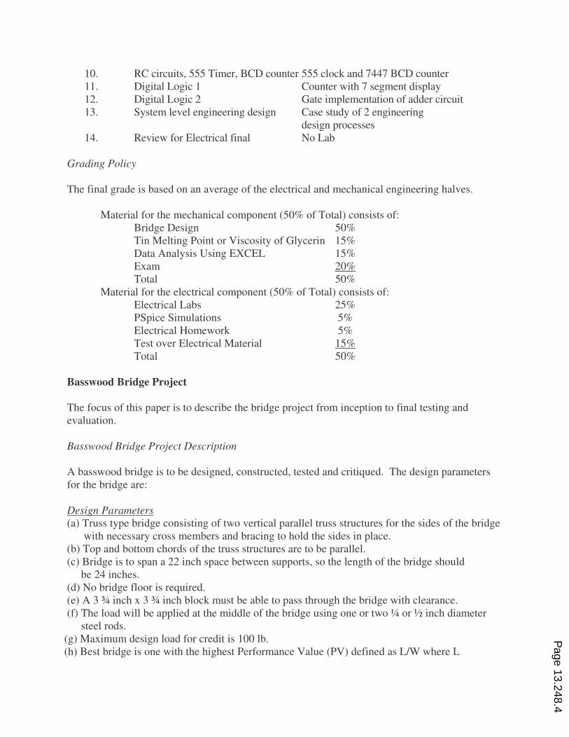
Design Parameters
(a) Truss type bridge consisting of two vertical parallel truss structures for the sides of the bridge
with necessary cross members and bracing to hold the sides in place.
(b) Top and bottom chords of the truss structures are to be parallel.
(c) Bridge is to span a 22 inch space between supports, so the length of the bridge should
be 24 inches.
(d) No bridge floor is required.
(e) A 3 ¾ inch x 3 ¾ inch block must be able to pass through the bridge with clearance.
(f) The load will be applied at the middle of the bridge using one or two ¼ or ½ inch diameter
steel rods.
(g) Maximum design load for credit is 100 lb.
(h) Best bridge is one with the highest Performance Value (PV) defined as L/W where L
Page 13.248.4
is the test load (lb) and W is the weight of the bridge (gm).
Bridge Grade
The bridge project counts for ½ of the grade for the mechanical engineering half. The project
grade is divided as follows:
%
Design Check In 10
Truss Check In 10
Bridge Check In 10
Bridge Testing 65
Bridge Critique 5
Total 100
Prerequisite Knowledge
The level of the course has been set to allow both those taking calculus and those taking pre-
calculus to succeed. Therefore, all the problem sets and designs can be calculated using
elementary algebra and similar triangles. Knowledge of trigonometry, while useful, is not a
requirement. By doing this, an attempt is made to encourage any student to major in
engineering.
Class Schedule
In the Topics Covered section the full semester’s lectures and laboratories were given. While
there are only four lectures necessary to learn how to make the bridge, it takes a full seven weeks
to finish the bridge project. Additional time may be required, if the bridge needs to be retested.
In Week 3 an assignment to design a bridge is given. The check-in and review of the design
takes place in the laboratory session of Week 4. The next week (5) an experiment is done in lab.
While this is being done, a truss completion check-in is made. Only one truss is to be
constructed. The check-in prevents erroneous construction. In Week 6, the completed bridge is
checked-in and tested. The following week (7) the bridge critique is due. The critique will be
delayed if the bridge needs to be retested. Retesting can be done if the bridge fell apart due to
glue failure, or there was a bad piece of wood that broke long before it should have.
Lectures and Laboratories
Lecture and Problem Set 1
For the introductory lecture (Appendix A), the students do not need knowledge of vector algebra.
In recent years, many of the students have taken physics in high school and do have this
understanding. Concepts covered are: (1) Parallelogram law; (2) Equilibrant; (3) Components of
a vector or force; (4) Determination of tension or compression in a member; (5) Definition of a
truss; (6) Free body diagrams; and (7) Method of similar triangles. The use of similar triangles
alleviates the need for using trigonometry and allows students with a variety of mathematical
levels to participate in the project. A number of examples are provided showing how to
Page 13.248.5
determine the forces in members of simple trusses using free body diagrams. Details for Lecture
1 are found in Appendix A. Problem Set 1 (Appendix B) consists of 2 simple statics problems.
They are similar to the examples given at the end of Lecture 1.
Lecture and Problem Set 2
This lecture (Appendix C) is focused on understanding trusses and truss bridges. Three basic
types of bridges are introduced – Pratt, Howe and Warren bridges. Bridges to be analyzed have
parallel top and bottom chords. Arch bridges are not allowed for the project. Examples using
free body diagrams to find the forces in the side trusses of each type of bridge are given.
Problem Set 2 (Appendix D) has three truss problems; one for each type of truss.
Lecture 3 – Design a Basswood Bridge
Lecture 3 (Appendix E) gives the steps needed to design and build the side trusses of the bridge.
The procedure to follow is: (1) Assume a design load; (2) Choose a truss design; (3) Calculate
forces in the members; (4) Determine which size basswood sticks to use, based on the load on
the member and whether it is in tension or compression; (5) Calculate the weight of one truss; (6)
Determine cross member size; (7) Calculate weight of the bridge; (8) Increase load to maximize
PV; and (9) Calculate final design PV. If the final design PV is not 2 or above, the design or
design load needs to be changed.
Additional information about past successful designs, materials allowed, material properties,
construction, and supplies and suppliers are also provided.
Based on this lecture, the student is to design a bridge and have the design checked during the
laboratory of week 4.
Lecture 4 – Detailed Construction Information
The construction lecture (Appendix F) covers all remaining items on the bridge construction,
with recommendations based on what has previously worked. Content includes: (1) Plates for
stressed joints; (2) Plates where loading rods are placed; (3) Cutting plates, (4) Cross members;
(5) Glues and gluing; and (6) Assembly.
Testing of Bridges
Testing Apparatus
Old
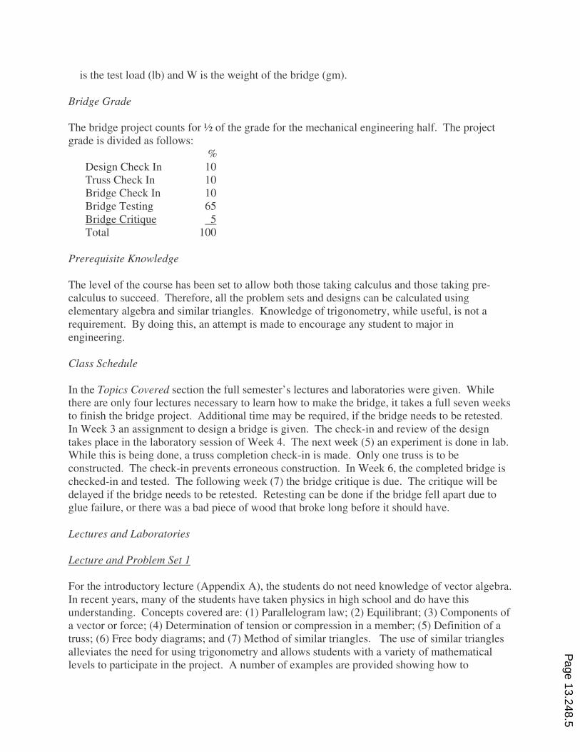
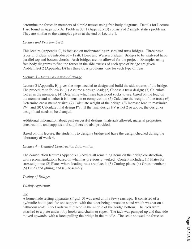
A homemade testing apparatus (Figs.1-3) was used until a few years ago. It consisted of a
hydraulic bottle jack for one support, with the other being a wooden stand which was sat on a
bathroom scale. Steel rods were placed in the middle of the bridge bottom. The rods were
attached to a plate under it by hooks and chains or ropes. The jack was pumped up and that side
moved upwards, with a force pulling the bridge in the middle. The scale showed the force on
Page 13.248.6
one support. That number was doubled to find the total load on the bridge. The student
controlled the rate of loading. Since the student was in control, there were many hesitating,
anticipatory and exciting moments while testing. Unfortunately, the load was not always applied
evenly, and sometimes the results were less than expected.
Fig. 1 Old Test Apparatus – Overall View Fig. 2 Old Test Apparatus – Steel Rod
Attachment and Scale Used to Measure
Loading
Fig. 3 Old Test Apparatus – Hydraulic Bottle Jack Used to Load Bridge
New
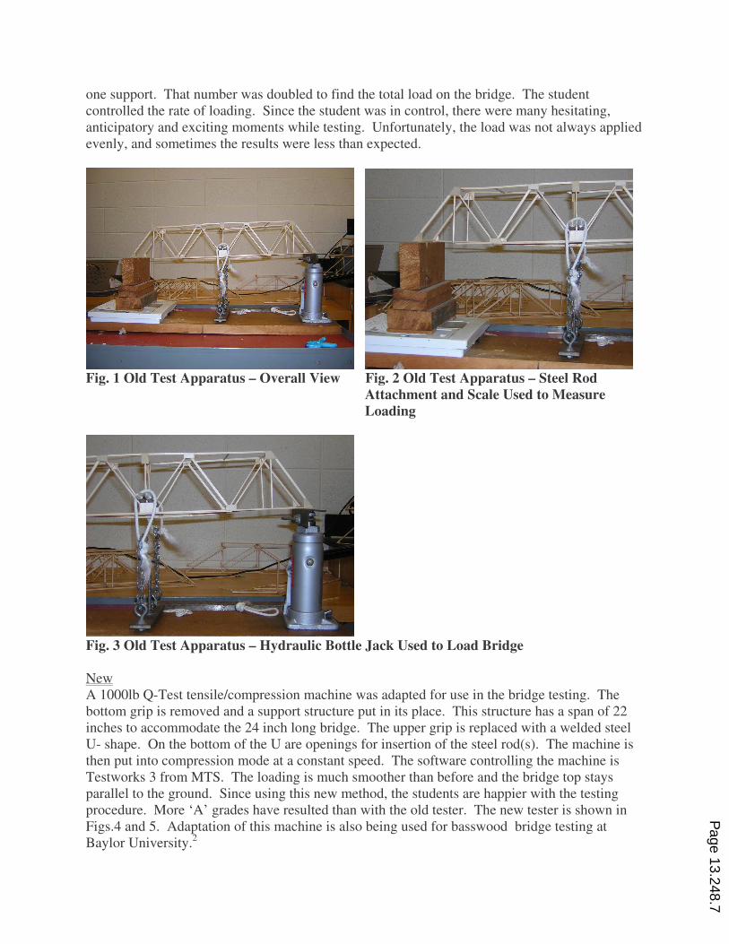
A 1000lb Q-Test tensile/compression machine was adapted for use in the bridge testing. The
bottom grip is removed and a support structure put in its place. This structure has a span of 22
inches to accommodate the 24 inch long bridge. The upper grip is replaced with a welded steel
U- shape. On the bottom of the U are openings for insertion of the steel rod(s). The machine is
then put into compression mode at a constant speed. The software controlling the machine is
Testworks 3 from MTS. The loading is much smoother than before and the bridge top stays
parallel to the ground. Since using this new method, the students are happier with the testing
procedure. More ‘A’ grades have resulted than with the old tester. The new tester is shown in
Figs.4 and 5. Adaptation of this machine is also being used for basswood bridge testing at
Baylor University.2
Page 13.248.7
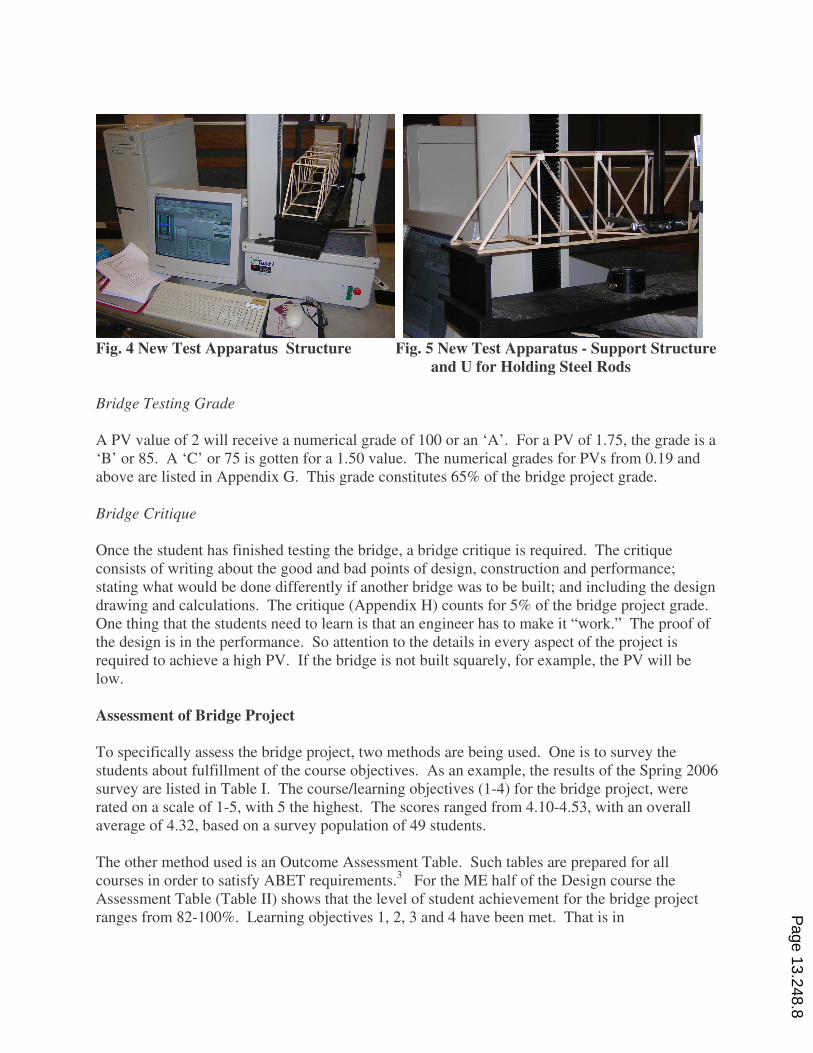
Fig. 4 New Test Apparatus Structure Fig. 5 New Test Apparatus - Support Structure
and U for Holding Steel Rods
Bridge Testing Grade
A PV value of 2 will receive a numerical grade of 100 or an ‘A’. For a PV of 1.75, the grade is a
‘B’ or 85. A ‘C’ or 75 is gotten for a 1.50 value. The numerical grades for PVs from 0.19 and
above are listed in Appendix G. This grade constitutes 65% of the bridge project grade.
Bridge Critique
Once the student has finished testing the bridge, a bridge critique is required. The critique
consists of writing about the good and bad points of design, construction and performance;
stating what would be done differently if another bridge was to be built; and including the design
drawing and calculations. The critique (Appendix H) counts for 5% of the bridge project grade.
One thing that the students need to learn is that an engineer has to make it “work.” The proof of
the design is in the performance. So attention to the details in every aspect of the project is
required to achieve a high PV. If the bridge is not built squarely, for example, the PV will be
low.
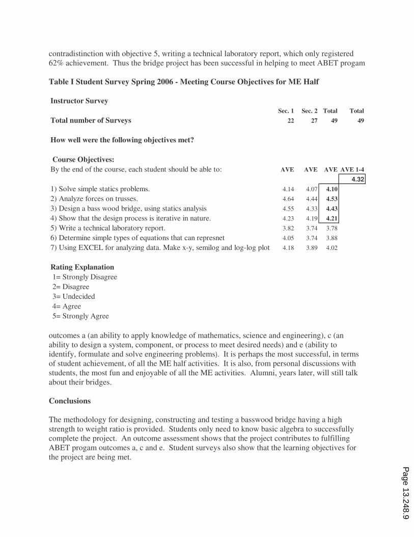
Assessment of Bridge Project
To specifically assess the bridge project, two methods are being used. One is to survey the
students about fulfillment of the course objectives. As an example, the results of the Spring 2006
survey are listed in Table I. The course/learning objectives (1-4) for the bridge project, were
rated on a scale of 1-5, with 5 the highest. The scores ranged from 4.10-4.53, with an overall
average of 4.32, based on a survey population of 49 students.
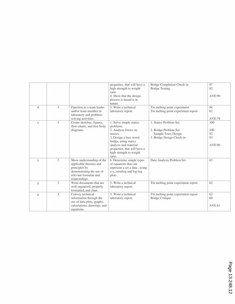
The other method used is an Outcome Assessment Table. Such tables are prepared for all
courses in order to satisfy ABET requirements.3 For the ME half of the Design course the
Assessment Table (Table II) shows that the level of student achievement for the bridge project
ranges from 82-100%. Learning objectives 1, 2, 3 and 4 have been met. That is in Page 13.248.8
contradistinction with objective 5, writing a technical laboratory report, which only registered
62% achievement. Thus the bridge project has been successful in helping to meet ABET progam
Table I Student Survey Spring 2006 - Meeting Course Objectives for ME Half
Instructor Survey
Sec. 1 Sec. 2 Total Total
Total number of Surveys 22 27 49 49
How well were the following objectives met?
Course Objectives:
By the end of the course, each student should be able to: AVE AVE AVE AVE 1-4
4.32
1) Solve simple statics problems. 4.14 4.07 4.10
2) Analyze forces on trusses. 4.64 4.44 4.53
3) Design a bass wood bridge, using statics analysis 4.55 4.33 4.43
4) Show that the design process is iterative in nature. 4.23 4.19 4.21
5) Write a technical laboratory report. 3.82 3.74 3.78
6) Determine simple types of equations that can represnet 4.05 3.74 3.88
7) Using EXCEL for analyzing data. Make x-y, semilog and log-log plots 4.18 3.89 4.02
Rating Explanation
1= Strongly Disagree
2= Disagree
3= Undecided
4= Agree
5= Strongly Agree
outcomes a (an ability to apply knowledge of mathematics, science and engineering), c (an
ability to design a system, component, or process to meet desired needs) and e (ability to
identify, formulate and solve engineering problems). It is perhaps the most successful, in terms
of student achievement, of all the ME half activities. It is also, from personal discussions with
students, the most fun and enjoyable of all the ME activities. Alumni, years later, will still talk
about their bridges.
Conclusions
The methodology for designing, constructing and testing a basswood bridge having a high
strength to weight ratio is provided. Students only need to know basic algebra to successfully
complete the project. An outcome assessment shows that the project contributes to fulfilling
ABET progam outcomes a, c and e. Student surveys also show that the learning objectives for
the project are being met.
Page 13.248.9
Bibliography
1. Abramowitz, H., “Determination of Viscosity Using a Falling Sphere Viscometer,” National
Educators’ Workshop New Update 2000 Standard Experiments in Engineering, Materials
Science, and Technology, Kettering, OH, Oct./Nov. 2000, pp.183-196.
2. Skurla, C., Thomas, B. and Bradley, W.L., “Teaching Freshman Engineering Using Design Projects and
Laboratory Exercises to Increase Retention,” Proceedings of the 2004 American Society for Engineering
Education Annual Conference & Exposition, Salt Lake City, Utah, June 2004.
3. Houshangi, N., “Curriculum Outcome Assessment and Implementation Challenges,” Proceedings of ASEE 2006
Illinois-Indiana and North Central Joint Section Conference, Fort Wayne, Indiana, March 2006.
Appendices
Appendix A - Bridge Design Lecture 1
Appendix B – Bridge Design Problem Set 1
Appendix C – Bridge Design Lecture 2
Appendix D – Bridge Design Problem Set 2
Appendix E – Bridge Design Lecture 3
Appendix F – Bridge Design Lecture 4
Appendix G – Bridge Testing Grades
Appendix H – Bridge Critique
Page 13.248.10
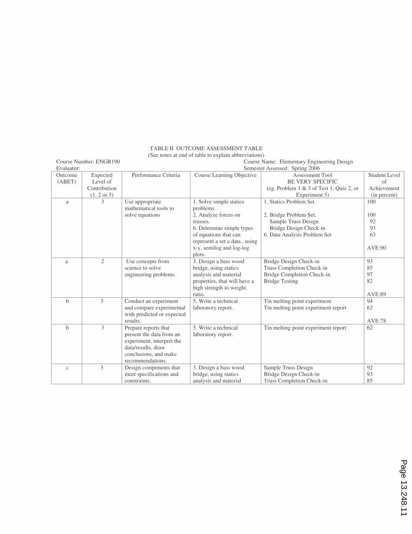
TABLE II OUTCOME ASSESSMENT TABLE
(See notes at end of table to explain abbreviations)
Course Number: ENGR190 Course Name: Elementary Engineering Design
Evaluator: Semester Assessed: Spring 2006
Outcome
(ABET)
Expected
Level of
Contribution
(1, 2 or 3)
Performance Criteria Course Learning Objective Assessment Tool
BE VERY SPECIFIC
(eg. Problem 1 & 3 of Test 1, Quiz 2, or
Experiment 5)
Student Level
of
Achievement
(in percent)
a 3 Use appropriate
mathematical tools to
solve equations
1. Solve simple statics
problems.
2. Analyze forces on
trusses.
6. Determine simple types
of equations that can
represent a set a data , using
x-y, semilog and log-log
plots.
1. Statics Problem Set.
2. Bridge Problem Set.
Sample Truss Design
Bridge Design Check-in
6. Data Analysis Problem Set
100
100
92
93
63
AVE:90
a 2 Use concepts from
science to solve
engineering problems.
3. Design a bass wood
bridge, using statics
analysis and material
properties, that will have a
high strength to weight
ratio.
Bridge Design Check-in
Truss Completion Check-in
Bridge Completion Check-in
Bridge Testing
93
85
97
82
AVE:89
b 3 Conduct an experiment
and compare experimental
with predicted or expected
results.
5. Write a technical
laboratory report.
Tin melting point experiment
Tin melting point experiment report
94
62
AVE:78
b 3 Prepare reports that
present the data from an
experiment, interpret the
data/results, draw
conclusions, and make
recommendations.
5. Write a technical
laboratory report.
Tin melting point experiment report 62
c 3 Design components that
meet specifications and
constraints.
3. Design a bass wood
bridge, using statics
analysis and material
Sample Truss Design
Bridge Design Check-in
Truss Completion Check-in
92
93
85
Page 13.248.11
properties, that will have a
high strength to weight
ratio.
4. Show that the design
process is iterative in
nature.
Bridge Completion Check-in
Bridge Testing
97
82
AVE:90
d 3 Function as a team leader
and/or team member in
laboratory and problem-
solving activities.
5. Write a technical
laboratory report.
Tin melting point experiment
Tin melting point experiment report
94
62
AVE:78
e 3 Create sketches, figures,
flow-charts, and free-body
diagrams.
1. Solve simple statics
problems.
2. Analyze forces on
trusses.
3. Design a bass wood
bridge, using statics
analysis and material
properties, that will have a
high strength to weight
ratio.
1. Statics Problem Set.
2. Bridge Problem Set.
Sample Truss Design
3. Bridge Design Check-in
100
100
92
93
AVE:96
e 2 Show understanding of the
applicable theories and
principles by
demonstrating the use of
relevant formulae and
relationships.
6. Determine simple types
of equations that can
represent a set a data , using
x-y, semilog and log-log
plots.
Data Analysis Problem Set 63
g 3 Write documents that are
well organized, properly
formatted, and clear.
5. Write a technical
laboratory report.
Tin melting point experiment report 62
g 3 Convey technical
information through the
use of data plots, graphs,
calculations, drawings, and
equations.
5. Write a technical
laboratory report.
Tin melting point experiment report
Bridge Critique
62
60
AVE:61
Page 13.248.12
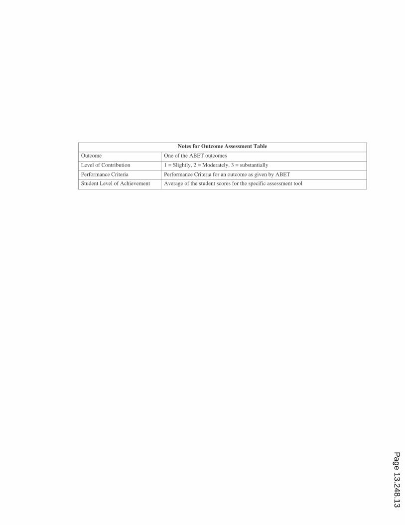
Notes for Outcome Assessment Table
Outcome One of the ABET outcomes
Level of Contribution 1 = Slightly, 2 = Moderately, 3 = substantially
Performance Criteria Performance Criteria for an outcome as given by ABET
Student Level of Achievement Average of the student scores for the specific assessment tool
Page 13.248.13
Appendix A - Bridge Design Lecture 1
ENGR 190 BRIDGE DESIGN LECTURE 1
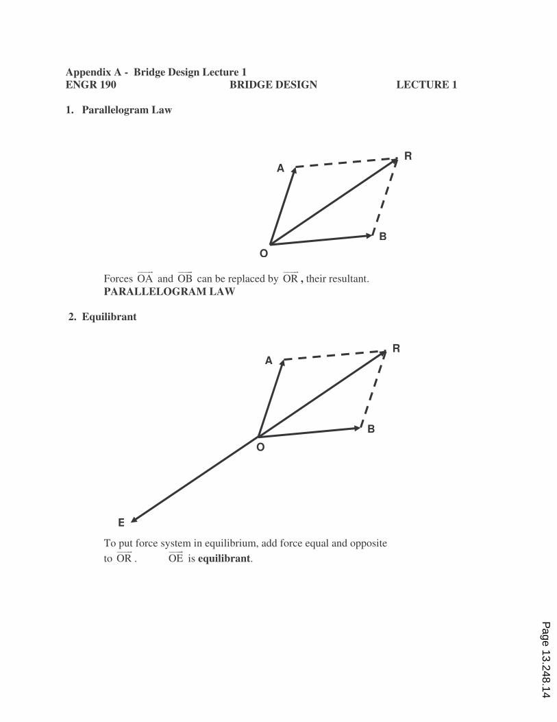
1. Parallelogram Law
Forces OA)))&
and OB)))&
can be replaced by OR)))&
, their resultant.
PARALLELOGRAM LAW
2. Equilibrant
To put force system in equilibrium, add force equal and opposite
to OR)))&
. OE)))&
is equilibrant.
O
A R
B
O
A R
B
E
Page 13.248.14
ENGR 190 BRIDGE DESIGN LECTURE 1
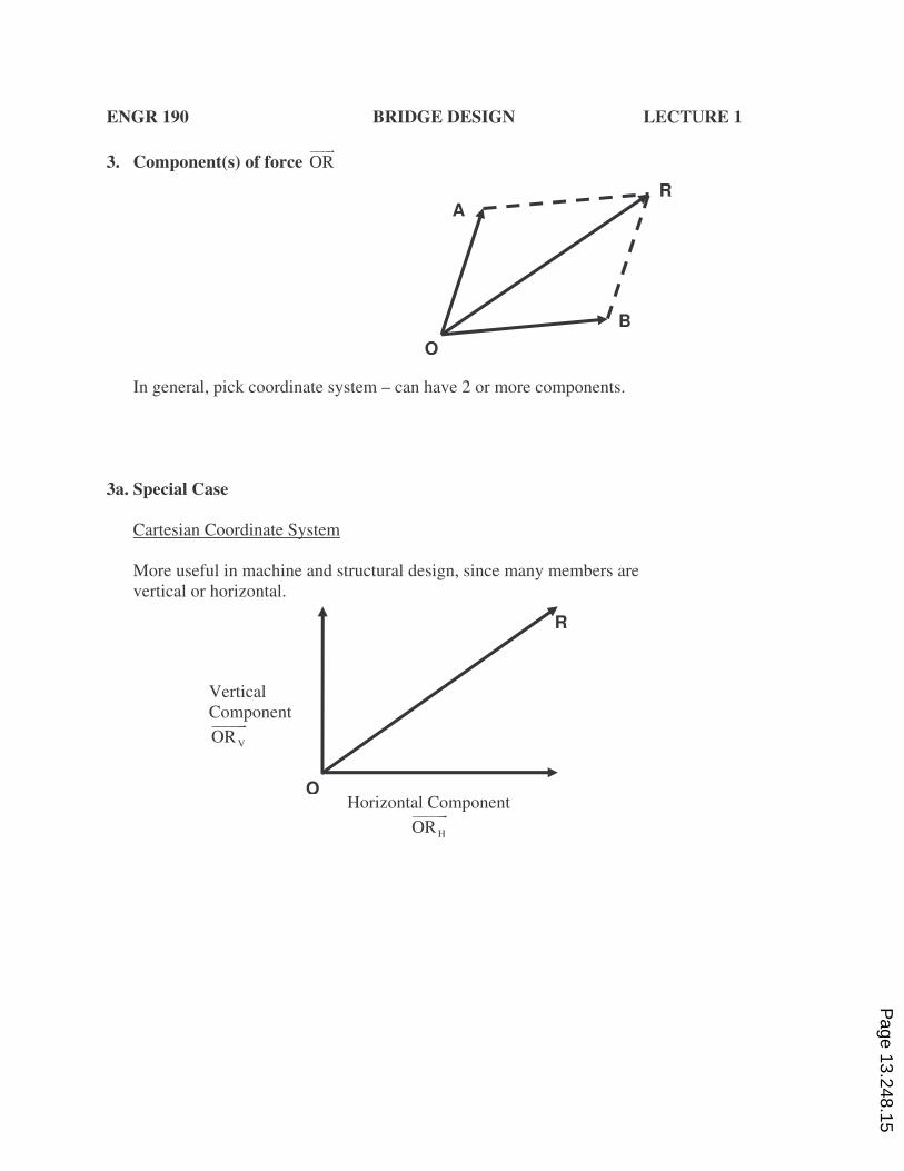
3. Component(s) of force OR)))&
In general, pick coordinate system – can have 2 or more components.
3a. Special Case
Cartesian Coordinate System
More useful in machine and structural design, since many members are
vertical or horizontal.
R
O
Vertical
Component
VOR)))))&
Horizontal Component
HOR)))))&
O
A R
B
Page 13.248.15
ENGR 190 BRIDGE DESIGN LECTURE 1
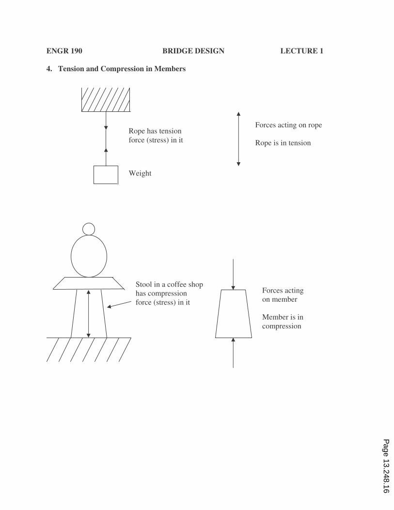
4. Tension and Compression in Members
Rope has tension
force (stress) in it
Weight
Forces acting on rope
Rope is in tension
Stool in a coffee shop
has compression
force (stress) in it
Forces acting
on member
Member is in
compression
Page 13.248.16
ENGR 190 BRIDGE DESIGN LECTURE 1
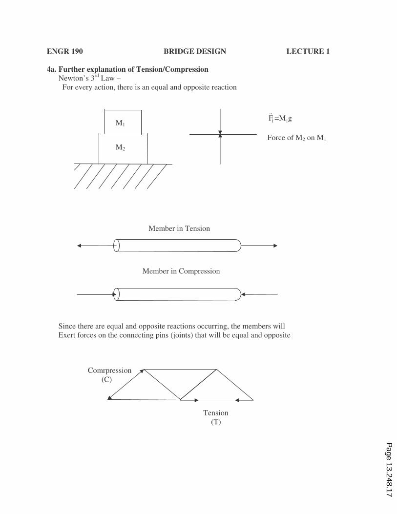
4a. Further explanation of Tension/Compression
Newton’s 3rd
Law –
For every action, there is an equal and opposite reaction
Since there are equal and opposite reactions occurring, the members will
Exert forces on the connecting pins (joints) that will be equal and opposite
M2
M1 1 1F =M g&
Force of M2 on M1
Member in Tension
Member in Compression
Comrpression
(C)
Tension
(T)
Page 13.248.17
ENGR 190 BRIDGE DESIGN LECTURE 1
Demonstrations: Tension – Use rubber bands
Stretch rubber band between thumbs
What do your thumbs (pins or joints) feel?
Compression – Use springs
Compress spring between thumb and forefinger
What do your fingers (pins or joints) feel?
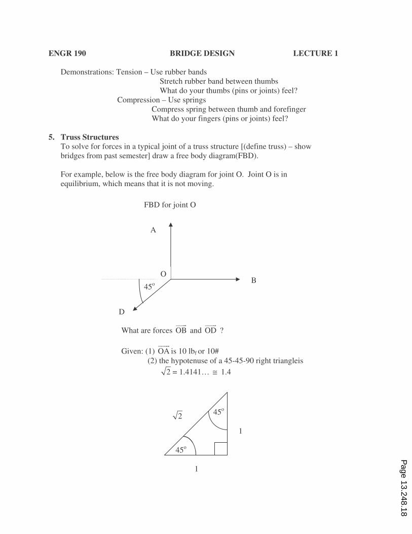
5. Truss Structures
To solve for forces in a typical joint of a truss structure [(define truss) – show
bridges from past semester] draw a free body diagram(FBD).
For example, below is the free body diagram for joint O. Joint O is in
equilibrium, which means that it is not moving.
What are forces OB)))&
and OD)))&
?
Given: (1) OA)))&
is 10 lbf or 10#
(2) the hypotenuse of a 45-45-90 right triangleis
2 = 1.4141… ≅ 1.4
FBD for joint O
A
B
D
45o
O
45o
45o
1
1
2
Page 13.248.18
ENGR 190 BRIDGE DESIGN LECTURE 1
The FBD is solved as follows, so that forces OB)))&
and OD)))&
can be
determined:
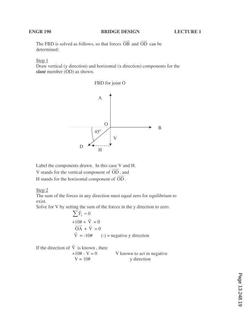
Step 1
Draw vertical (y direction) and horizontal (x direction) components for the
slant member (OD) as shown.
Label the components drawn. In this case V and H.
V stands for the vertical component of OD)))&
, and
H stands for the horizontal component of OD)))&
.
Step 2
The sum of the forces in any direction must equal zero for equilibrium to
exist.
Solve for V by setting the sum of the forces in the y direction to zero.
yF 0=ƒ&
+10# + V&
= 0
OA)))&
+ V&
= 0
V&
= -10# (-) = negative y direction
If the direction of V&
is known , then:
+10# - V = 0 V known to act in negative
V = 10# y direction
FBD for joint O
A
B
D
45o
V
H
O
Page 13.248.19
ENGR 190 BRIDGE DESIGN LECTURE 1
Step 3
Solve for H&
by setting the sum of the forces in the x direction to zero.
xF 0=ƒ&
H + OB 0=)))&&
can a value for H&
be found?
No, there are two unknowns ( H&
& OB)))&
) and only 1 equation
Step 4
Use geometry and trigonometry to solve for H&
.
Each side of a 45-45-90 right triangle has the same magnitude.
(See diagram in point 5)
So by proportion, method of similar triangles, H&
can be found
H H1 1;
1 10 1V= =
& &
& .
H 10∴ =
H = 10# magnitude of H&
Since V=-10#&
, H&
is acting to the left, or negative x direction
Thus H&
= -10#
Step 5
OD)))&
can now be found, using the similar triangle method
OD OD1.4 1.4
;1 10 1H
= =
)))& )))&
&
OD 14#∴ =)))&
Direction is SW, as shown on diagram
Alternatively:
OD OD1.4 1.4
;1 10 1V
= =
)))& )))&
&
OD 14#∴ =)))&
since both sides of the triangle are equal
Step 6
Find OB)))&
We can now go back to Step 3
xF 0=ƒ&
H + OB 0=)))&&
Page 13.248.20
ENGR 190 BRIDGE DESIGN LECTURE 1
-10# + OB)))&
= 0
OB)))&
= 10# positive x direction, or to the right
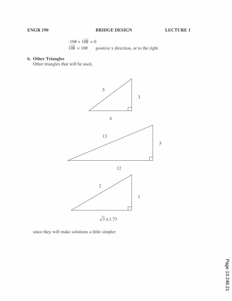
6. Other Triangles
Other triangles that will be used,
since they will make solutions a little simpler
3
4
5
5
12
13
1
2
3 1.73≅
Page 13.248.21
ENGR 190 BRIDGE DESIGN LECTURE 1
7. Method of Similar Triangles
Most solutions can be found using the method of similar triangles.
Trigonometry can also be used.
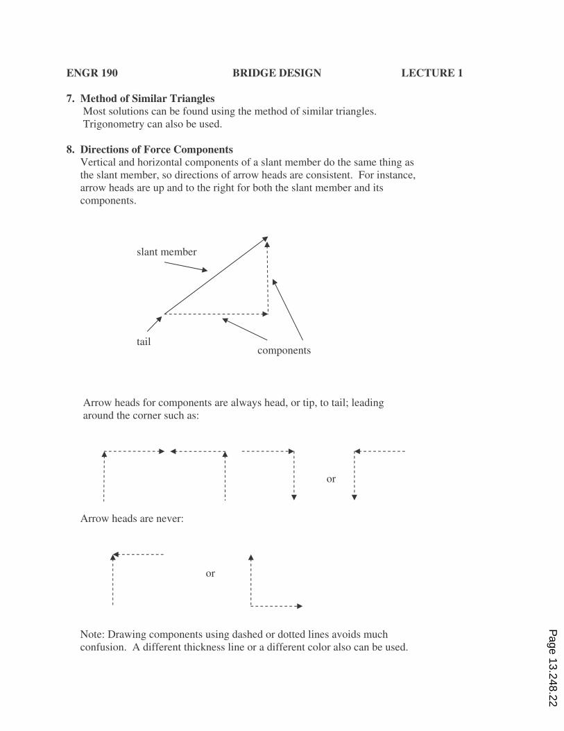
8. Directions of Force Components
Vertical and horizontal components of a slant member do the same thing as
the slant member, so directions of arrow heads are consistent. For instance,
arrow heads are up and to the right for both the slant member and its
components.
Arrow heads for components are always head, or tip, to tail; leading
around the corner such as:
Arrow heads are never:
Note: Drawing components using dashed or dotted lines avoids much
confusion. A different thickness line or a different color also can be used.
tail
slant member
components
or
or
Page 13.248.22
ENGR 190 BRIDGE DESIGN LECTURE 1
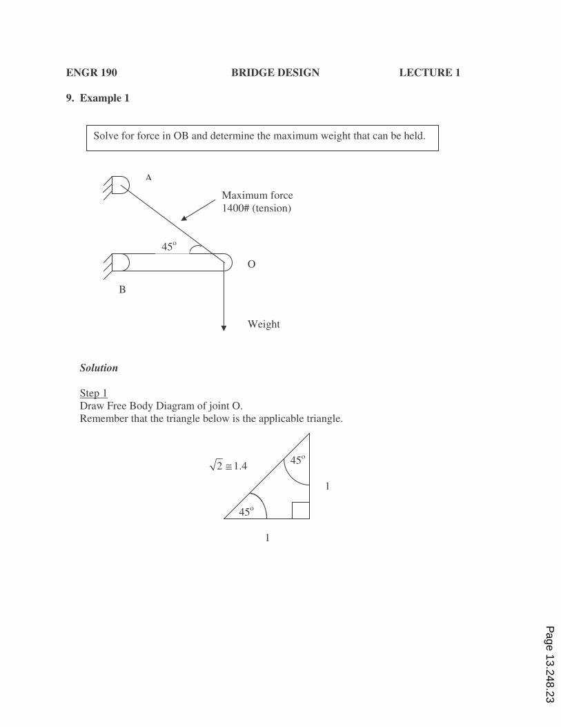
9. Example 1
Solution
Step 1
Draw Free Body Diagram of joint O.
Remember that the triangle below is the applicable triangle.
A
B
O
45o
Weight
Maximum force
1400# (tension)
Solve for force in OB and determine the maximum weight that can be held.
45o
45o
1
1
2 1.4≅
Page 13.248.23
ENGR 190 BRIDGE DESIGN LECTURE 1
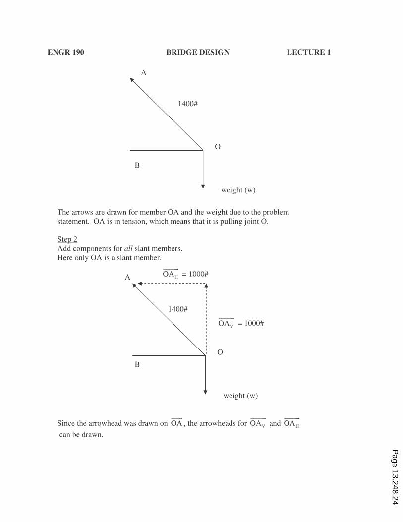
The arrows are drawn for member OA and the weight due to the problem
statement. OA is in tension, which means that it is pulling joint O.
Step 2
Add components for all slant members.
Here only OA is a slant member.
Since the arrowhead was drawn on OA)))&
, the arrowheads for VOA)))))&
and HOA)))))&
can be drawn.
1400#
A
B
weight (w)
O
1400#
A
B
weight (w)
O
VOA)))))&
= 1000#
HOA)))))&
= 1000#
Page 13.248.24
ENGR 190 BRIDGE DESIGN LECTURE 1
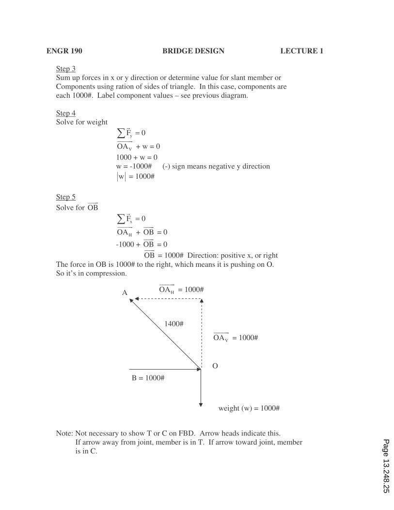
Step 3
Sum up forces in x or y direction or determine value for slant member or
Components using ration of sides of triangle. In this case, components are
each 1000#. Label component values – see previous diagram.
Step 4
Solve for weight
yF 0=ƒ&
VOA)))))&
+ w = 0
1000 + w = 0
w = -1000# (-) sign means negative y direction
w = 1000#
Step 5
Solve for OB)))&
xF 0=ƒ&
HOA)))))&
+ OB)))&
= 0
-1000 + OB)))&
= 0
OB)))&
= 1000# Direction: positive x, or right
The force in OB is 1000# to the right, which means it is pushing on O.
So it’s in compression.
Note: Not necessary to show T or C on FBD. Arrow heads indicate this.
If arrow away from joint, member is in T. If arrow toward joint, member
is in C.
1400#
A
B = 1000#
weight (w) = 1000#
O
VOA)))))&
= 1000#
HOA)))))&
= 1000#
Page 13.248.25
ENGR 190 BRIDGE DESIGN LECTURE 1
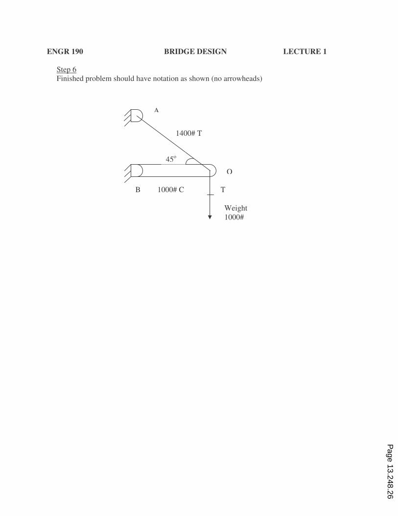
Step 6
Finished problem should have notation as shown (no arrowheads)
A
B
O
45o
Weight
1000#
1400# T
1000# C T
Page 13.248.26
ENGR 190 BRIDGE DESIGN LECTURE 1
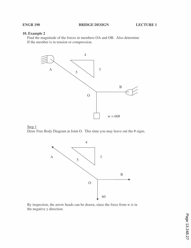
10. Example 2
Find the magnitude of the forces in members OA and OB. Also determine
If the member is in tension or compression.
Step 1
Draw Free Body Diagram at Joint O. This time you may leave out the # signs.
By inspection, the arrow heads can be drawn, since the force from w is in
the negative y direction.
3
4
5 A
O
B
w = 60#
3
4
5 A
O
B
60
Page 13.248.27
ENGR 190 BRIDGE DESIGN LECTURE 1
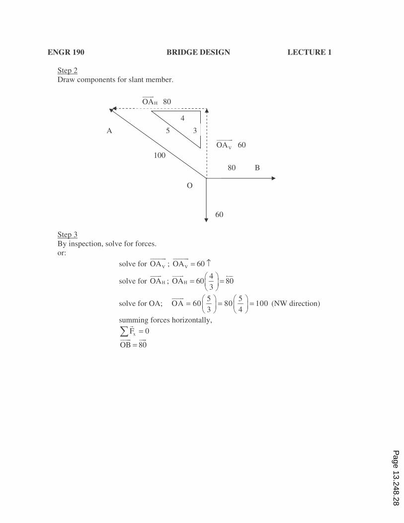
Step 2
Draw components for slant member.
Step 3
By inspection, solve for forces.
or:
solve for VOA)))))&
; VOA 60= ↑)))))&
solve for HOA)))&
; H
4OA 60 80
3
♣ •= =♦ ÷
♥ ≠
)))& ∋))
solve for OA; 5 5
OA 60 80 1003 4
♣ • ♣ •= = =♦ ÷ ♦ ÷
♥ ≠ ♥ ≠
)))&
(NW direction)
summing forces horizontally,
xF 0=ƒ&
OB 80=)))& ))&
3
4
5 A
O
B
60
80
100
HOA)))&
80
VOA)))))&
60
Page 13.248.28
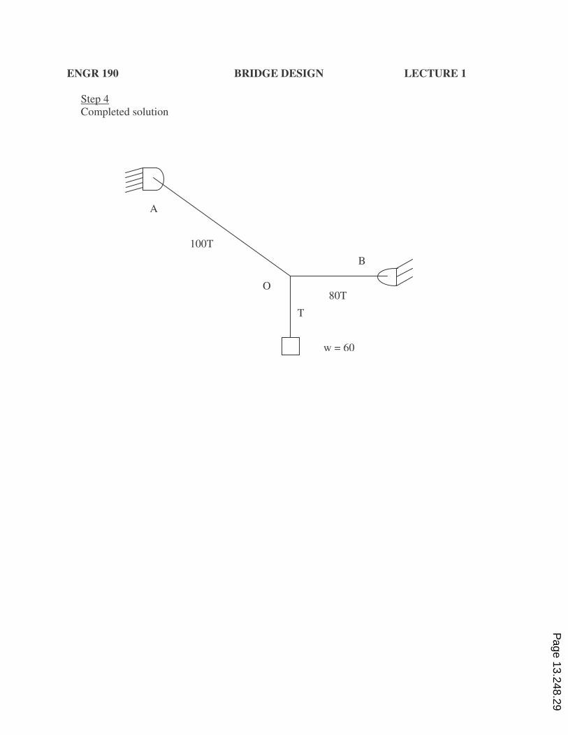
ENGR 190 BRIDGE DESIGN LECTURE 1
Step 4
Completed solution
A
O
B
w = 60
80T
100T
T
Page 13.248.29
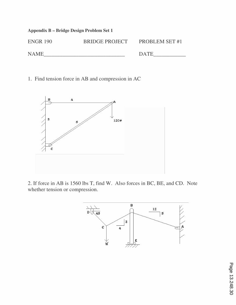
Appendix B – Bridge Design Problem Set 1
ENGR 190 BRIDGE PROJECT PROBLEM SET #1
NAME______________________________ DATE____________
1. Find tension force in AB and compression in AC
2. If force in AB is 1560 lbs T, find W. Also forces in BC, BE, and CD. Note
whether tension or compression.
Page 13.248.30
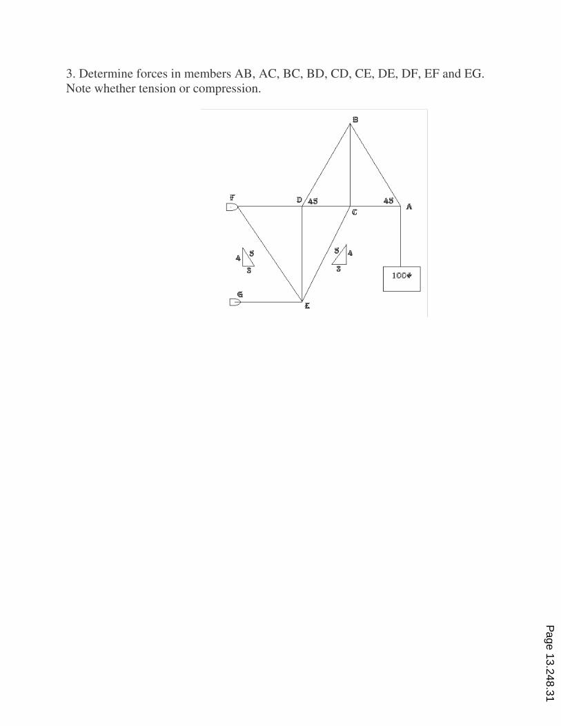
3. Determine forces in members AB, AC, BC, BD, CD, CE, DE, DF, EF and EG.
Note whether tension or compression.
Page 13.248.31
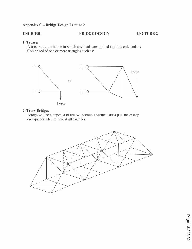
Appendix C – Bridge Design Lecture 2
ENGR 190 BRIDGE DESIGN LECTURE 2
1. Trusses
A truss structure is one in which any loads are applied at joints only and are
Comprised of one or more triangles such as:
2. Truss Bridges
Bridge will be composed of the two identical vertical sides plus necessary
crosspieces, etc., to hold it all together.
Force
or
Force
Page 13.248.32
ENGR 190 BRIDGE DESIGN LECTURE 2
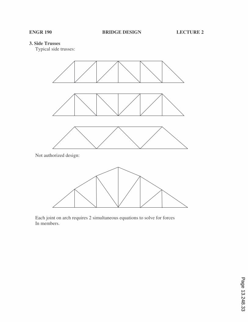
3. Side Trusses
Typical side trusses:
Not authorized design:
Each joint on arch requires 2 simultaneous equations to solve for forces
In members.
Page 13.248.33
ENGR 190 BRIDGE DESIGN LECTURE 2
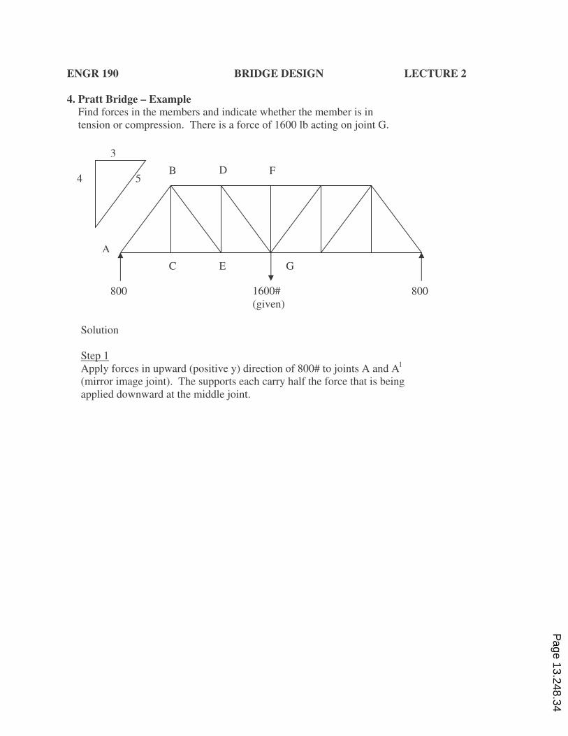
4. Pratt Bridge – Example
Find forces in the members and indicate whether the member is in
tension or compression. There is a force of 1600 lb acting on joint G.
Solution
Step 1
Apply forces in upward (positive y) direction of 800# to joints A and Al
(mirror image joint). The supports each carry half the force that is being
applied downward at the middle joint.
3
4 5
A
B D F
C E G
1600#
(given)
800 800
Page 13.248.34
ENGR 190 BRIDGE DESIGN LECTURE 2
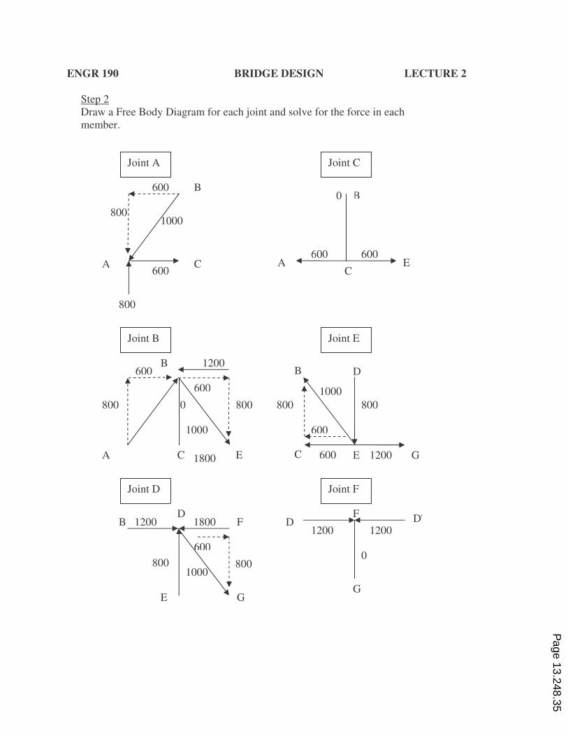
Step 2
Draw a Free Body Diagram for each joint and solve for the force in each
member.
B
C A
800
600
1000
600
Joint A
A C
B
Joint C
600 600
0
800
Joint E
A C E
800
600 B
800
1200
600
1000
0
Joint B
Joint D
E
G
B
800 800
D
1000
600
600 1200 C E
B D
F
E G
800
1200 1800
800
600
1000
D |D
G
0
F
Joint F
1800
1200 1200
Page 13.248.35
ENGR 190 BRIDGE DESIGN LECTURE 2
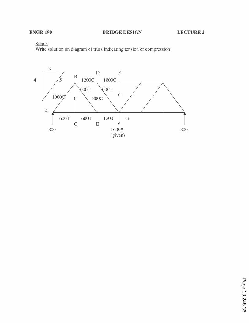
Step 3
Write solution on diagram of truss indicating tension or compression
3
4 5
A
B F
C
G
1600#
(given)
800 800
1200C 1800C
D
00
600T 600T 1200
T E
1000C
1000T 1000T
800C
Page 13.248.36
ENGR 190 BRIDGE DESIGN LECTURE 2
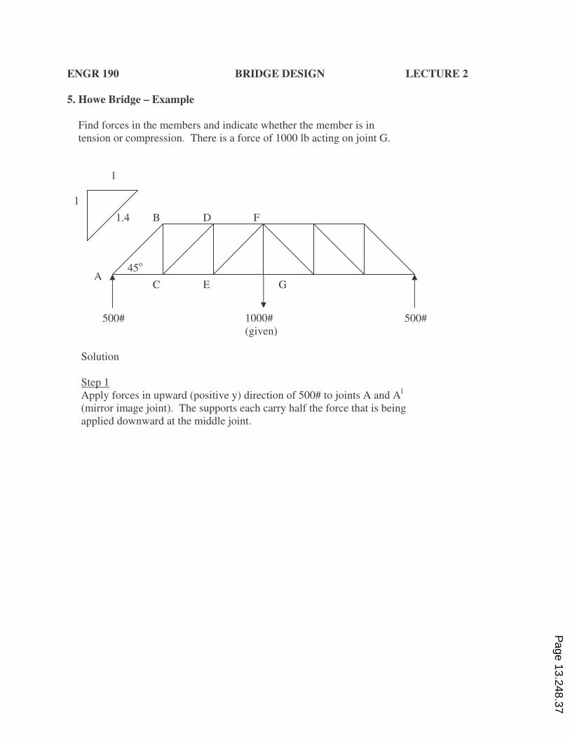
5. Howe Bridge – Example
Find forces in the members and indicate whether the member is in
tension or compression. There is a force of 1000 lb acting on joint G.
Solution
Step 1
Apply forces in upward (positive y) direction of 500# to joints A and Al
(mirror image joint). The supports each carry half the force that is being
applied downward at the middle joint.
1000#
(given)
500# 500#
45o
C E G A
B D F
1
1
1.4
Page 13.248.37
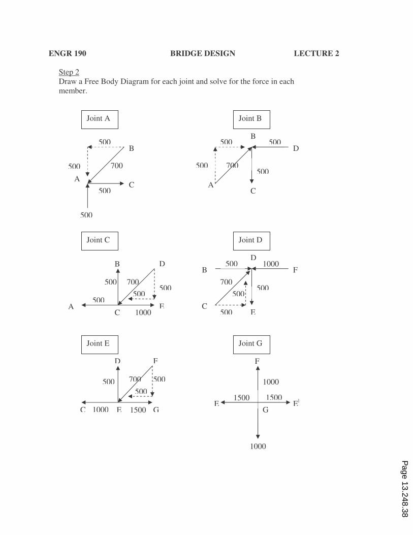
ENGR 190 BRIDGE DESIGN LECTURE 2
Step 2
Draw a Free Body Diagram for each joint and solve for the force in each
member.
1500
Joint A
500 B
500
500
C A
500 700
D
C A
500
500
500 B
500 700
Joint B
Joint C
A
B
C
500
500 500
D
500
1000 E
700
D
Joint D
B F
C E
500 1000
700 500
500
500
E E|
G
F
Joint G
1000
1000
1500 1500
D F
C G
500
500
500 700
1000 E
Joint E
Page 13.248.38
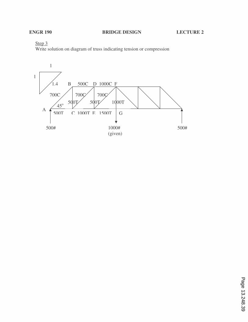
ENGR 190 BRIDGE DESIGN LECTURE 2
Step 3
Write solution on diagram of truss indicating tension or compression
700C
500T
1000#
(given)
500# 500#
45o
G A
B
1
1
1.4 500C D 1000C F
500T C 1000T E 1500T
700C 700C
500T 1000T
Page 13.248.39
ENGR 190 BRIDGE DESIGN LECTURE 2
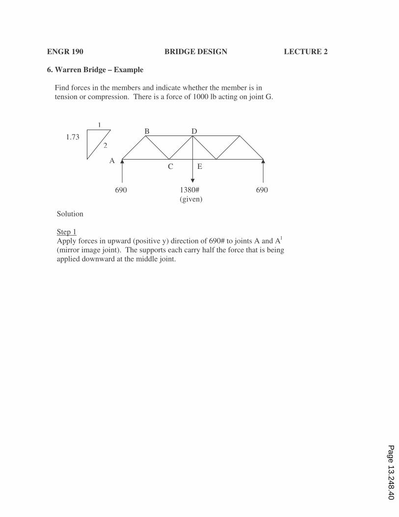
6. Warren Bridge – Example
Find forces in the members and indicate whether the member is in
tension or compression. There is a force of 1000 lb acting on joint G.
Solution
Step 1
Apply forces in upward (positive y) direction of 690# to joints A and Al
(mirror image joint). The supports each carry half the force that is being
applied downward at the middle joint.
A C E
B D
1380#
(given)
690 690
1
2 1.73
Page 13.248.40
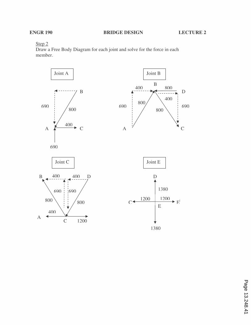
ENGR 190 BRIDGE DESIGN LECTURE 2
Step 2
Draw a Free Body Diagram for each joint and solve for the force in each
member.
Joint A
400
B
C A
690 800
D
A
400 800 B
Joint B
Joint C
A
Joint E
C E|
E
D
1380
1200
690
690 690
C
400 800
800
1200
1380
C
B D 400 400
400
1200
690 690
800 800
Page 13.248.41
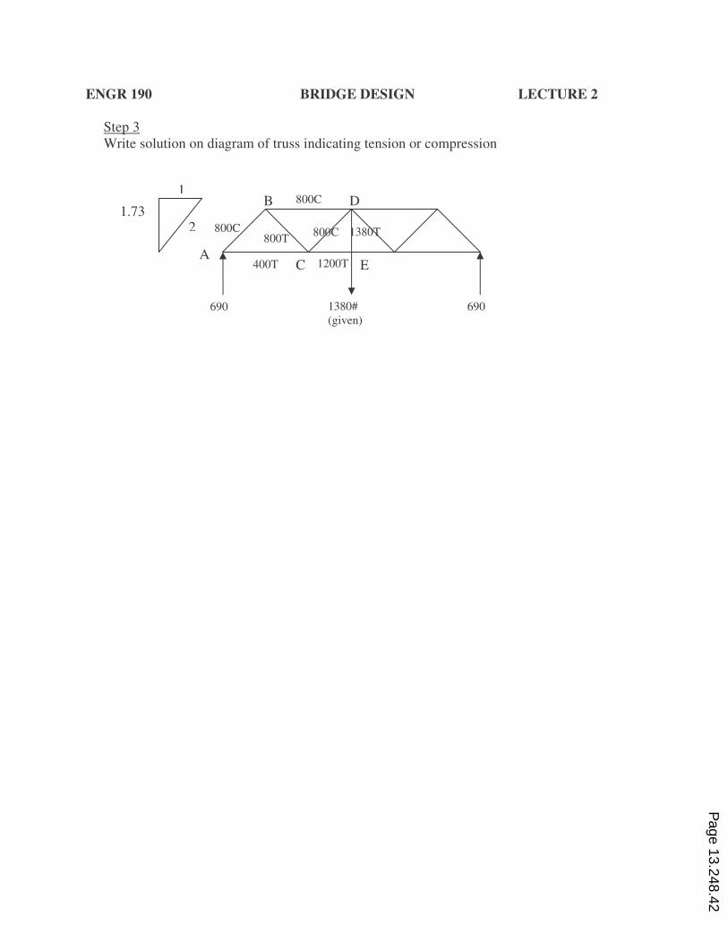
ENGR 190 BRIDGE DESIGN LECTURE 2
Step 3
Write solution on diagram of truss indicating tension or compression
A C E
B D
1380#
(given)
690 690
1
2 1.73
800C
800C 800C 1380T 800T
400T 1200T
Page 13.248.42
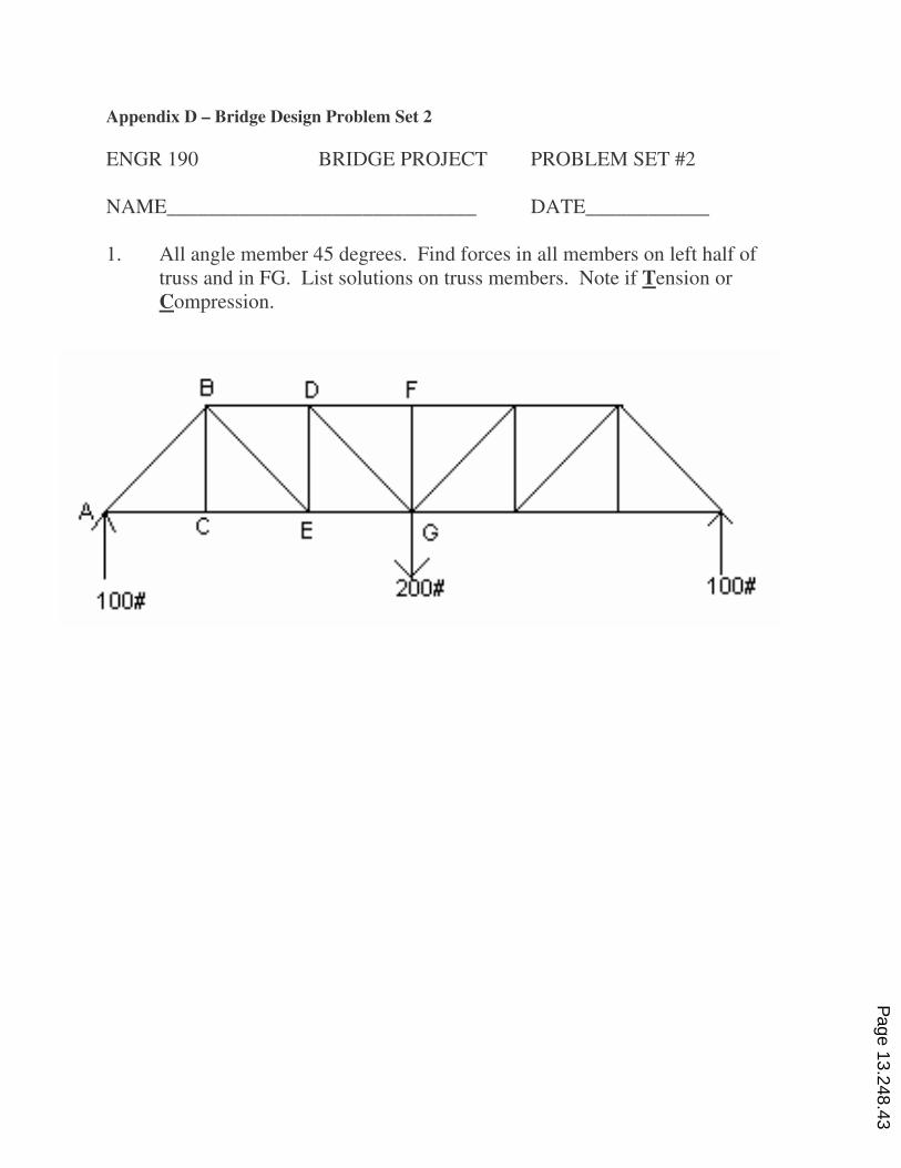
Appendix D – Bridge Design Problem Set 2
ENGR 190 BRIDGE PROJECT PROBLEM SET #2
NAME______________________________ DATE____________
1. All angle member 45 degrees. Find forces in all members on left half of
truss and in FG. List solutions on truss members. Note if Tension or
Compression.
Page 13.248.43
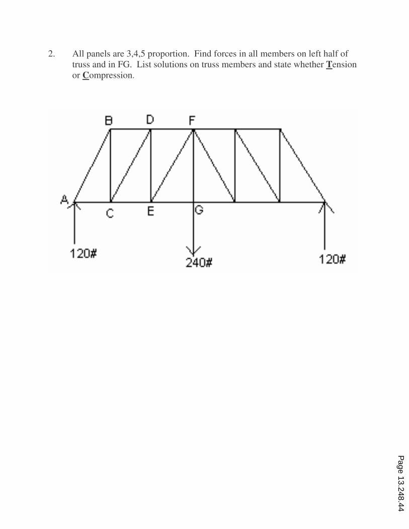
2. All panels are 3,4,5 proportion. Find forces in all members on left half of
truss and in FG. List solutions on truss members and state whether Tension
or Compression.
Page 13.248.44
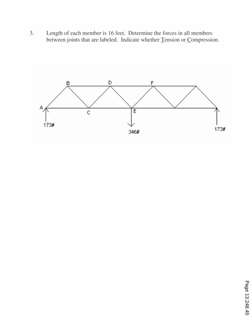
3. Length of each member is 16 feet. Determine the forces in all members
between joints that are labeled. Indicate whether Tension or Compression.
Page 13.248.45
Appendix E – Bridge Design Lecture 3
ENGR 190 BRIDGE DESIGN LECTURE 3
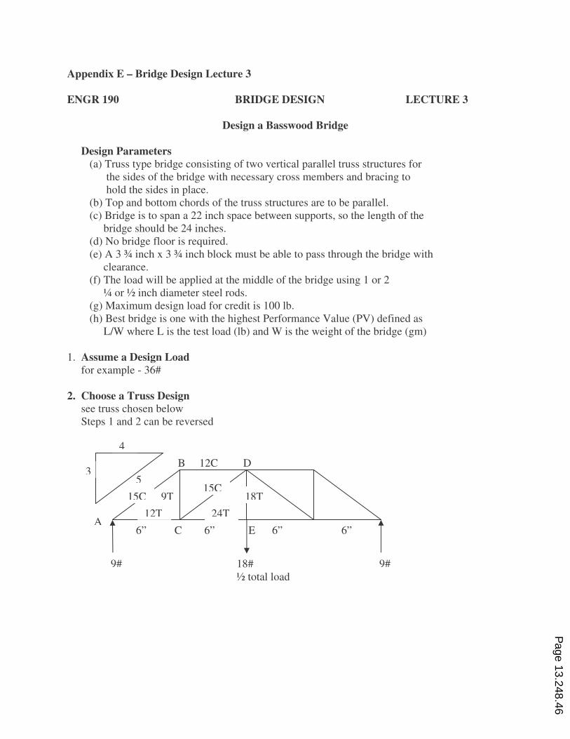
Design a Basswood Bridge
Design Parameters
(a) Truss type bridge consisting of two vertical parallel truss structures for
the sides of the bridge with necessary cross members and bracing to
hold the sides in place.
(b) Top and bottom chords of the truss structures are to be parallel.
(c) Bridge is to span a 22 inch space between supports, so the length of the
bridge should be 24 inches.
(d) No bridge floor is required.
(e) A 3 ¾ inch x 3 ¾ inch block must be able to pass through the bridge with
clearance.
(f) The load will be applied at the middle of the bridge using 1 or 2
¼ or ½ inch diameter steel rods.
(g) Maximum design load for credit is 100 lb.
(h) Best bridge is one with the highest Performance Value (PV) defined as
L/W where L is the test load (lb) and W is the weight of the bridge (gm)
1. Assume a Design Load
for example - 36#
2. Choose a Truss Design
see truss chosen below
Steps 1 and 2 can be reversed
4
35
B 12C D
A 6” C 6” E 6” 6”
12T 24T
15C 9T 15C 18T
9# 9# 18#
½ total load
Page 13.248.46
ENGR 190 BRIDGE DESIGN LECTURE 3
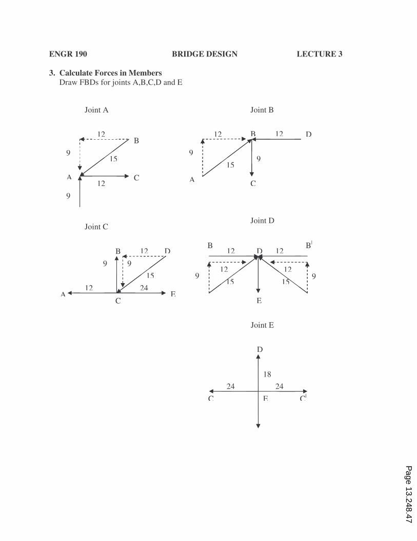
3. Calculate Forces in Members
Draw FBDs for joints A,B,C,D and E
Joint A Joint B
Joint C Joint D
Joint E
9
9
C
B 12
12
15
A A
B D
C
12 12
9 9
15
C E C|
D
18
24 24
D B
C E
24 12 A
12
9 9
15
B B|
E
12 12 D
9 9 15 15
12 12
Joint A Joint B
Joint C Joint D
Joint E
9
9
C
B 12
12
15
A A
B D
C
12 12
9 9
15
C E C|
D
18
24 24
D B
C E
24 12 A
12
9 9
15
B B|
D
E
Page 13.248.47
ENGR 190 BRIDGE DESIGN LECTURE 3
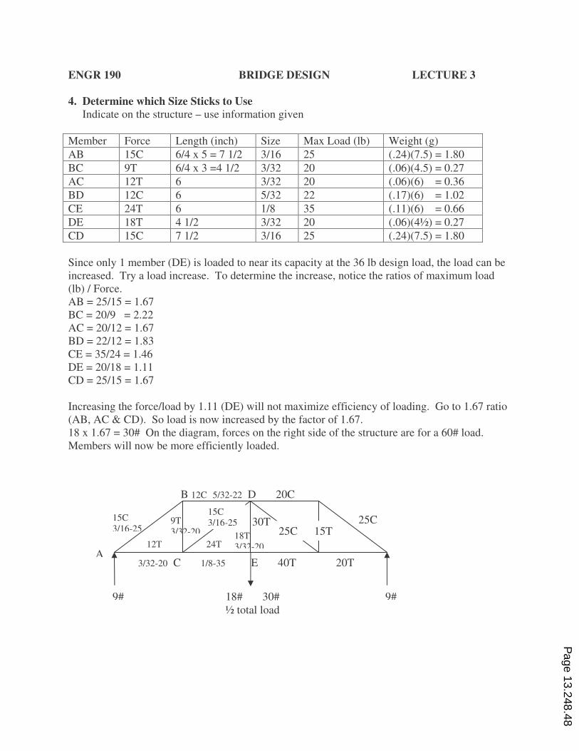
4. Determine which Size Sticks to Use
Indicate on the structure – use information given
Member Force Length (inch) Size Max Load (lb) Weight (g)
AB 15C 6/4 x 5 = 7 1/2 3/16 25 (.24)(7.5) = 1.80
BC 9T 6/4 x 3 =4 1/2 3/32 20 (.06)(4.5) = 0.27
AC 12T 6 3/32 20 (.06)(6) = 0.36
BD 12C 6 5/32 22 (.17)(6) = 1.02
CE 24T 6 1/8 35 (.11)(6) = 0.66
DE 18T 4 1/2 3/32 20 (.06)(4½) = 0.27
CD 15C 7 1/2 3/16 25 (.24)(7.5) = 1.80
Since only 1 member (DE) is loaded to near its capacity at the 36 lb design load, the load can be
increased. Try a load increase. To determine the increase, notice the ratios of maximum load
(lb) / Force.
AB = 25/15 = 1.67
BC = 20/9 = 2.22
AC = 20/12 = 1.67
BD = 22/12 = 1.83
CE = 35/24 = 1.46
DE = 20/18 = 1.11
CD = 25/15 = 1.67
Increasing the force/load by 1.11 (DE) will not maximize efficiency of loading. Go to 1.67 ratio
(AB, AC & CD). So load is now increased by the factor of 1.67.
18 x 1.67 = 30# On the diagram, forces on the right side of the structure are for a 60# load.
Members will now be more efficiently loaded.
B 12C 5/32-22 D 20C
A 12T 24T
9T
3/32-20
15C
3/16-25
9# 9# 18# 30#
½ total load
15C
3/16-25
18T
3/32-20
30T
3/32-20 C 1/8-35 E 40T 20T
25C 25C 15T
Page 13.248.48
ENGR 190 BRIDGE DESIGN LECTURE 3
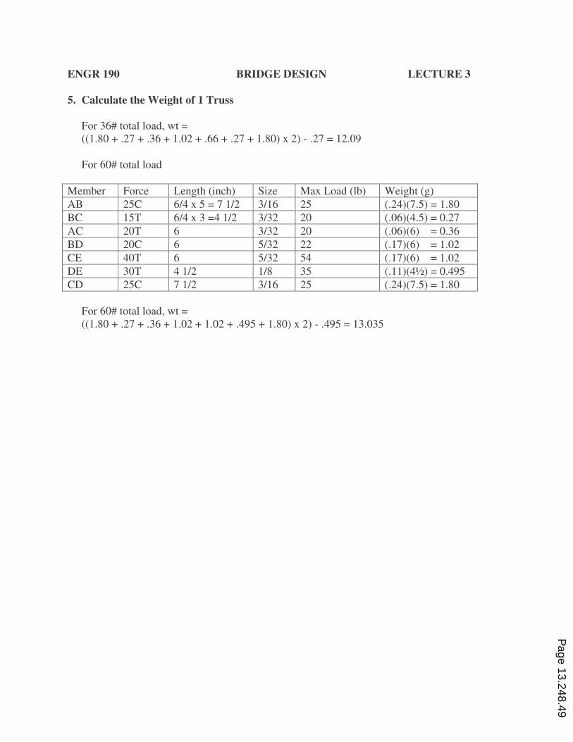
5. Calculate the Weight of 1 Truss
For 36# total load, wt =
((1.80 + .27 + .36 + 1.02 + .66 + .27 + 1.80) x 2) - .27 = 12.09
For 60# total load
Member Force Length (inch) Size Max Load (lb) Weight (g)
AB 25C 6/4 x 5 = 7 1/2 3/16 25 (.24)(7.5) = 1.80
BC 15T 6/4 x 3 =4 1/2 3/32 20 (.06)(4.5) = 0.27
AC 20T 6 3/32 20 (.06)(6) = 0.36
BD 20C 6 5/32 22 (.17)(6) = 1.02
CE 40T 6 5/32 54 (.17)(6) = 1.02
DE 30T 4 1/2 1/8 35 (.11)(4½) = 0.495
CD 25C 7 1/2 3/16 25 (.24)(7.5) = 1.80
For 60# total load, wt =
((1.80 + .27 + .36 + 1.02 + 1.02 + .495 + 1.80) x 2) - .495 = 13.035
Page 13.248.49
ENGR 190 BRIDGE DESIGN LECTURE 3
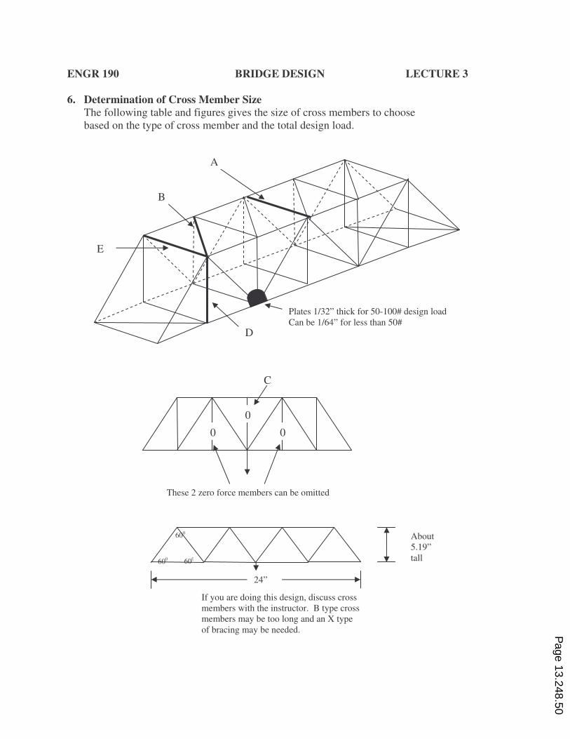
6. Determination of Cross Member Size
The following table and figures gives the size of cross members to choose
based on the type of cross member and the total design load.
A
B
E
D
Plates 1/32” thick for 50-100# design load
Can be 1/64” for less than 50#
0 0
0
C
These 2 zero force members can be omitted
24”
About
5.19”
tall
600
600 600
If you are doing this design, discuss cross
members with the instructor. B type cross
members may be too long and an X type
of bracing may be needed. Page 13.248.50
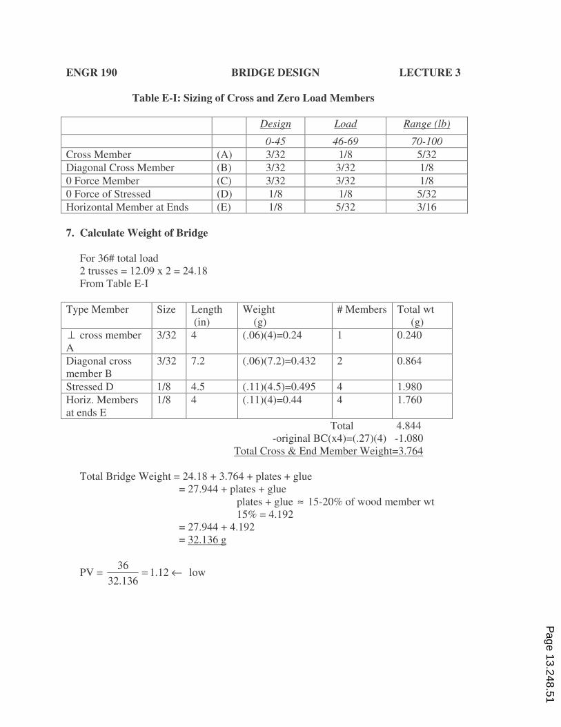
ENGR 190 BRIDGE DESIGN LECTURE 3
Table E-I: Sizing of Cross and Zero Load Members
Design Load Range (lb)
0-45 46-69 70-100
Cross Member (A) 3/32 1/8 5/32
Diagonal Cross Member (B) 3/32 3/32 1/8
0 Force Member (C) 3/32 3/32 1/8
0 Force of Stressed (D) 1/8 1/8 5/32
Horizontal Member at Ends (E) 1/8 5/32 3/16
7. Calculate Weight of Bridge
For 36# total load
2 trusses = 12.09 x 2 = 24.18
From Table E-I
Type Member Size Length
(in)
Weight
(g)
# Members Total wt
(g)
⊥ cross member
A
3/32 4 (.06)(4)=0.24 1 0.240
Diagonal cross
member B
3/32 7.2 (.06)(7.2)=0.432 2 0.864
Stressed D 1/8 4.5 (.11)(4.5)=0.495 4 1.980
Horiz. Members
at ends E
1/8 4 (.11)(4)=0.44 4 1.760
Total 4.844
-original BC(x4)=(.27)(4) -1.080
Total Cross & End Member Weight=3.764
Total Bridge Weight = 24.18 + 3.764 + plates + glue
= 27.944 + plates + glue
plates + glue ≈ 15-20% of wood member wt
15% = 4.192
= 27.944 + 4.192
= 32.136 g
PV = 36
1.1232.136
= ← low
Page 13.248.51
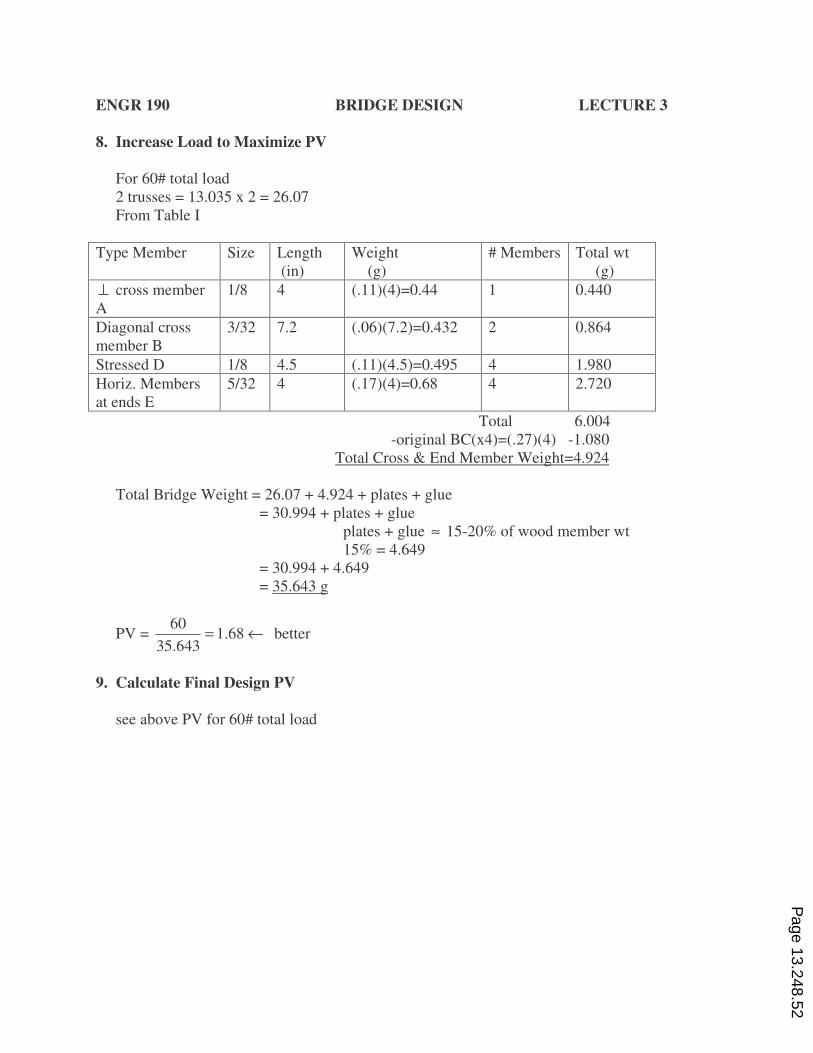
ENGR 190 BRIDGE DESIGN LECTURE 3
8. Increase Load to Maximize PV
For 60# total load
2 trusses = 13.035 x 2 = 26.07
From Table I
Type Member Size Length
(in)
Weight
(g)
# Members Total wt
(g)
⊥ cross member
A
1/8 4 (.11)(4)=0.44 1 0.440
Diagonal cross
member B
3/32 7.2 (.06)(7.2)=0.432 2 0.864
Stressed D 1/8 4.5 (.11)(4.5)=0.495 4 1.980
Horiz. Members
at ends E
5/32 4 (.17)(4)=0.68 4 2.720
Total 6.004
-original BC(x4)=(.27)(4) -1.080
Total Cross & End Member Weight=4.924
Total Bridge Weight = 26.07 + 4.924 + plates + glue
= 30.994 + plates + glue
plates + glue ≈ 15-20% of wood member wt
15% = 4.649
= 30.994 + 4.649
= 35.643 g
PV = 60
1.6835.643
= ← better
9. Calculate Final Design PV
see above PV for 60# total load
Page 13.248.52
ENGR 190 BRIDGE DESIGN LECTURE 3
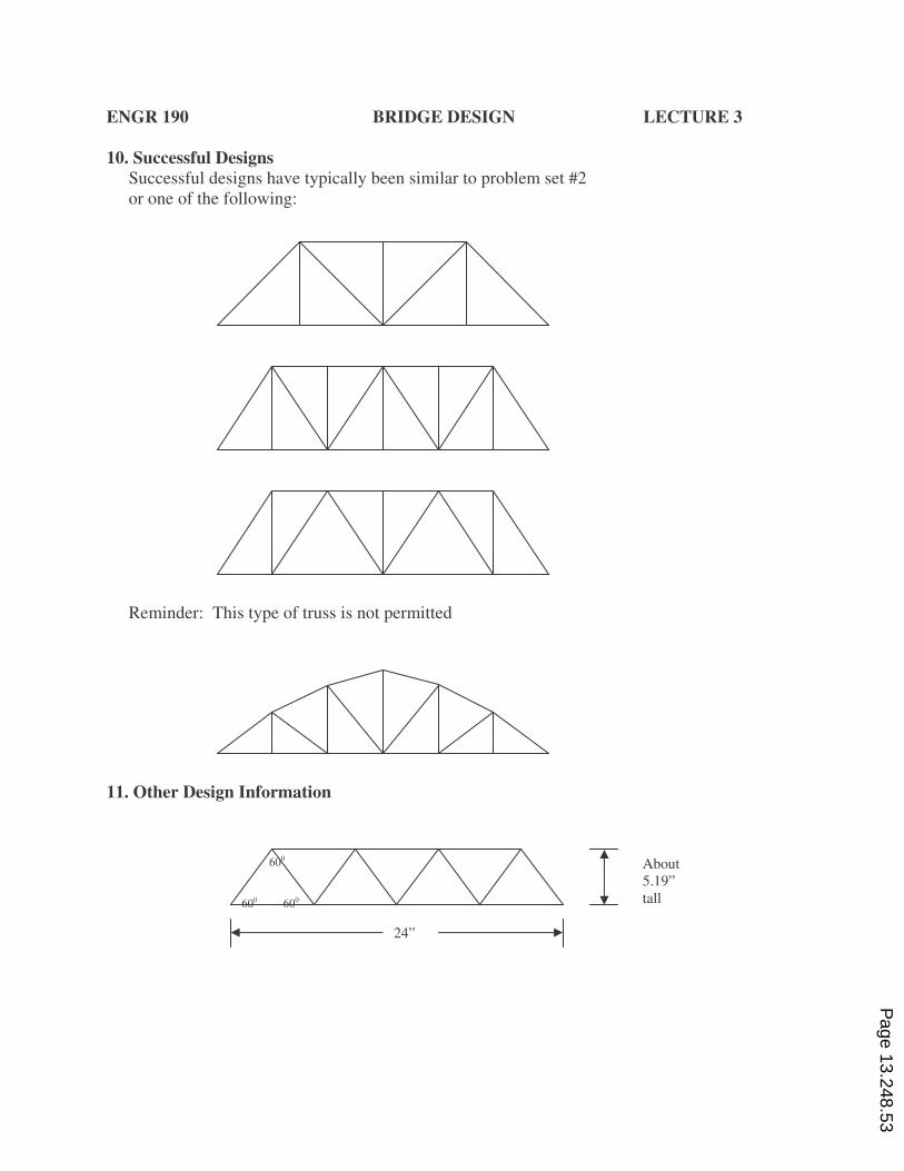
10. Successful Designs
Successful designs have typically been similar to problem set #2
or one of the following:
Reminder: This type of truss is not permitted
11. Other Design Information
24”
About
5.19”
tall
600
600 600
Page 13.248.53
ENGR 190 BRIDGE DESIGN LECTURE 3
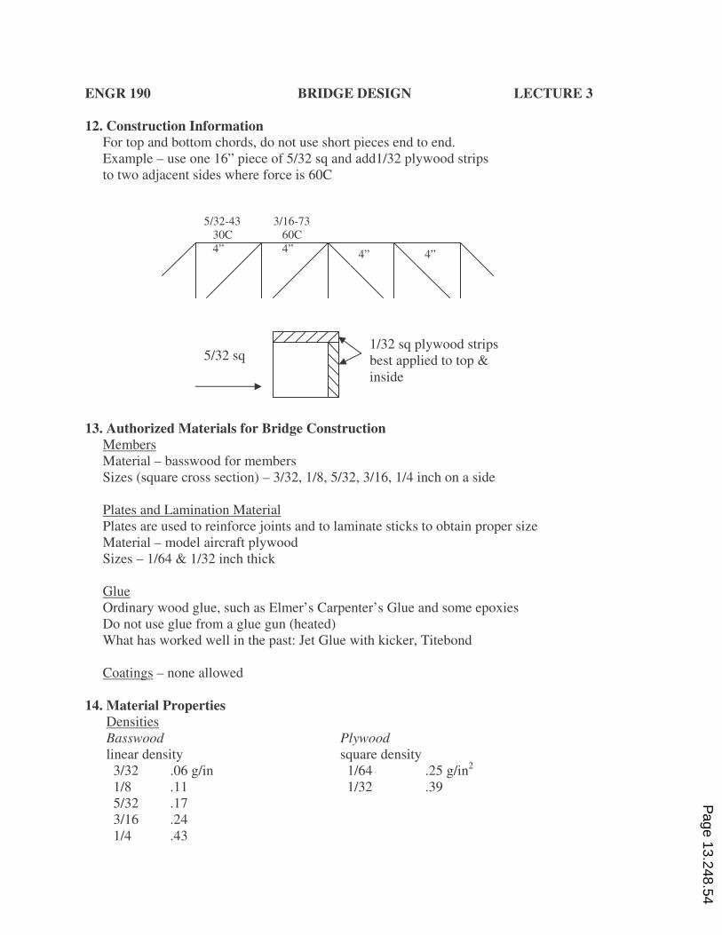
12. Construction Information
For top and bottom chords, do not use short pieces end to end.
Example – use one 16” piece of 5/32 sq and add1/32 plywood strips
to two adjacent sides where force is 60C
13. Authorized Materials for Bridge Construction
Members
Material – basswood for members
Sizes (square cross section) – 3/32, 1/8, 5/32, 3/16, 1/4 inch on a side
Plates and Lamination Material
Plates are used to reinforce joints and to laminate sticks to obtain proper size
Material – model aircraft plywood
Sizes – 1/64 & 1/32 inch thick
Glue
Ordinary wood glue, such as Elmer’s Carpenter’s Glue and some epoxies
Do not use glue from a glue gun (heated)
What has worked well in the past: Jet Glue with kicker, Titebond
Coatings – none allowed
14. Material Properties
Densities
Basswood Plywood
linear density square density
3/32 .06 g/in 1/64 .25 g/in2
1/8 .11 1/32 .39
5/32 .17
3/16 .24
1/4 .43
5/32-43
30C
4”
3/16-73
60C
4” 4” 4”
5/32 sq 1/32 sq plywood strips
best applied to top &
inside
Page 13.248.54
ENGR 190 BRIDGE DESIGN LECTURE 3
Tensile Strength for Basswood Sticks
Permissible tension loads for basswood (any length) are:
Size Tensile Strength
(in) (lb)
3/32 20
1/8 35
5/32 54
3/16 80
1/4 140
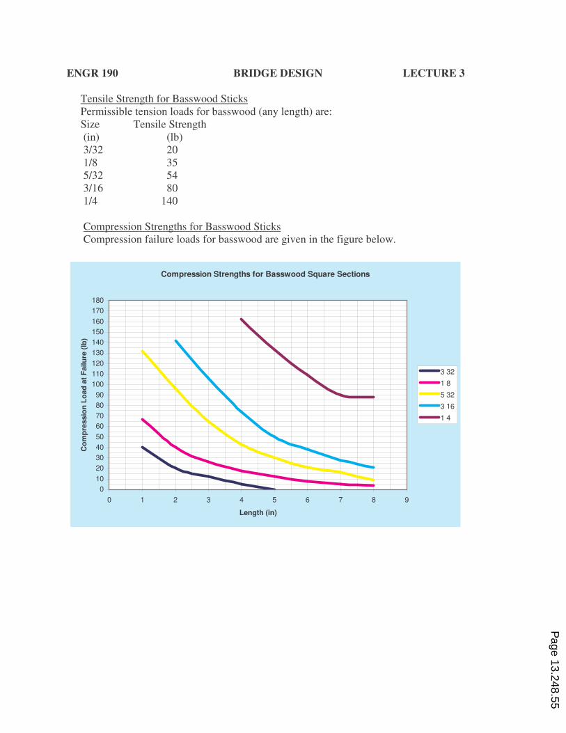
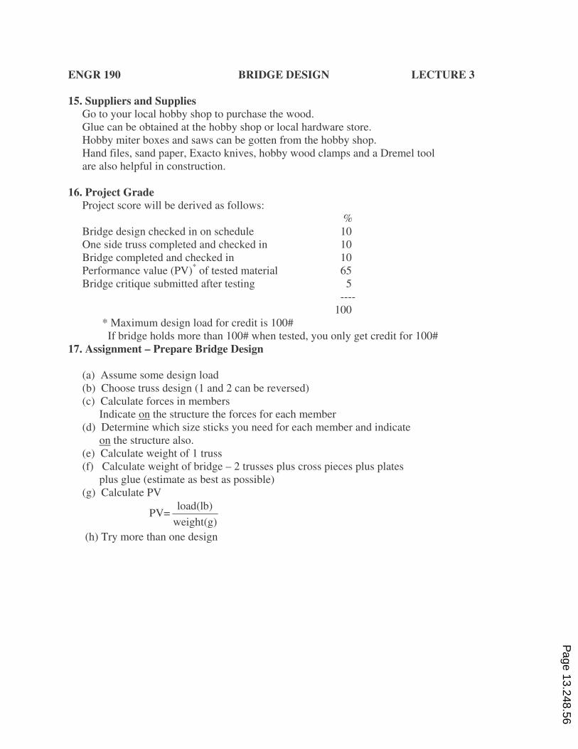
Compression Strengths for Basswood Sticks
Compression failure loads for basswood are given in the figure below.
Compression Strengths for Basswood Square Sections
0
10
20
30
40
50
60
70
80
90
100
110
120
130
140
150
160
170
180
0 1 2 3 4 5 6 7 8 9
Length (in)
Co
mp
ressio
n L
oad
at
Failu
re (
lb)
3 32
1 8
5 32
3 16
1 4
Page 13.248.55
ENGR 190 BRIDGE DESIGN LECTURE 3
15. Suppliers and Supplies
Go to your local hobby shop to purchase the wood.
Glue can be obtained at the hobby shop or local hardware store.
Hobby miter boxes and saws can be gotten from the hobby shop.
Hand files, sand paper, Exacto knives, hobby wood clamps and a Dremel tool
are also helpful in construction.
16. Project Grade
Project score will be derived as follows:
%
Bridge design checked in on schedule 10
One side truss completed and checked in 10
Bridge completed and checked in 10
Performance value (PV)* of tested material 65
Bridge critique submitted after testing 5
----
100
* Maximum design load for credit is 100#
If bridge holds more than 100# when tested, you only get credit for 100#
17. Assignment – Prepare Bridge Design
(a) Assume some design load
(b) Choose truss design (1 and 2 can be reversed)
(c) Calculate forces in members
Indicate on the structure the forces for each member
(d) Determine which size sticks you need for each member and indicate
on the structure also.
(e) Calculate weight of 1 truss
(f) Calculate weight of bridge – 2 trusses plus cross pieces plus plates
plus glue (estimate as best as possible)
(g) Calculate PV
load(lb)
PV=weight(g)
(h) Try more than one design
Page 13.248.56
Appendix F – Bridge Design Lecture 4
ENGR 190 BRIDGE DESIGN LECTURE 4
Detailed Construction Information
This lecture covers all remaining items on the bridge construction, with
recommendations based on what has worked before.
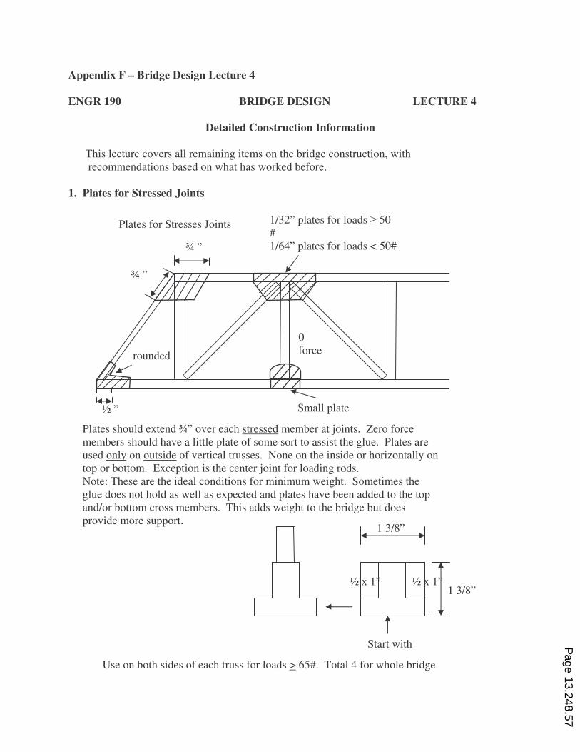
1. Plates for Stressed Joints
Plates should extend ¾” over each stressed member at joints. Zero force
members should have a little plate of some sort to assist the glue. Plates are
used only on outside of vertical trusses. None on the inside or horizontally on
top or bottom. Exception is the center joint for loading rods.
Note: These are the ideal conditions for minimum weight. Sometimes the
glue does not hold as well as expected and plates have been added to the top
and/or bottom cross members. This adds weight to the bridge but does
provide more support.
Use on both sides of each truss for loads > 65#. Total 4 for whole bridge
½ ”
rounded
Plates for Stresses Joints
Small plate
0
force
1/32” plates for loads � 50
#
1/64” plates for loads < 50# ¾ ” ¾ ”
¾ ”
1 3/8”
1 3/8” ½ x 1” ½ x 1”
Start with Page 13.248.57
ENGR 190 BRIDGE DESIGN LECTURE 4
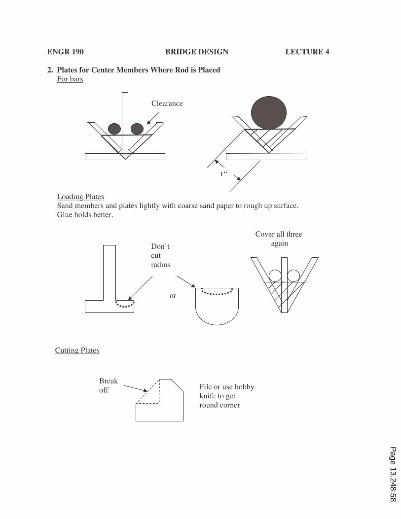
2. Plates for Center Members Where Rod is Placed
For bars
Loading Plates
Sand members and plates lightly with coarse sand paper to rough up surface.
Glue holds better.
Cutting Plates
Clearance
1”
Don’t
cut
radius
or
Cover all three
again
File or use hobby
knife to get
round corner
Break
off
Page 13.248.58
ENGR 190 BRIDGE DESIGN LECTURE 4
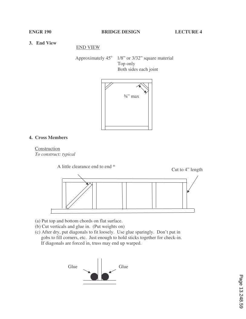
3. End View
4. Cross Members
Construction
To construct: typical
(a) Put top and bottom chords on flat surface.
(b) Cut verticals and glue in. (Put weights on)
(c) After dry, put diagonals to fit loosely. Use glue sparingly. Don’t put in
gobs to fill corners, etc. Just enough to hold sticks together for check-in.
If diagonals are forced in, truss may end up warped.
Glue Glue
A little clearance end to end * Cut to 4” length
END VIEW
Approximately 45o 1/8” or 3/32” square material
Top only
Both sides each joint
¾” max
Page 13.248.59
ENGR 190 BRIDGE DESIGN LECTURE 4
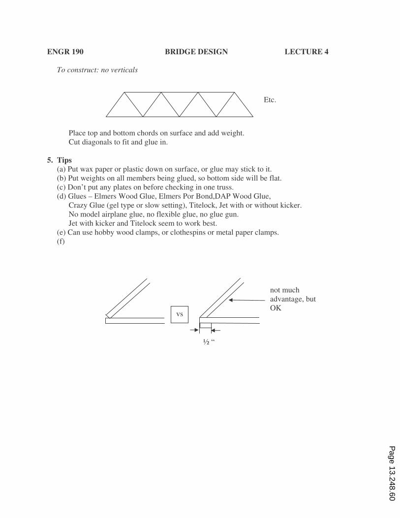
To construct: no verticals
Place top and bottom chords on surface and add weight.
Cut diagonals to fit and glue in.
5. Tips
(a) Put wax paper or plastic down on surface, or glue may stick to it.
(b) Put weights on all members being glued, so bottom side will be flat.
(c) Don’t put any plates on before checking in one truss.
(d) Glues – Elmers Wood Glue, Elmers Por Bond,DAP Wood Glue,
Crazy Glue (gel type or slow setting), Titelock, Jet with or without kicker.
No model airplane glue, no flexible glue, no glue gun.
Jet with kicker and Titelock seem to work best.
(e) Can use hobby wood clamps, or clothespins or metal paper clamps.
(f)
vs
.
not much
advantage, but
OK
½ “
Etc.
Page 13.248.60
ENGR 190 BRIDGE DESIGN LECTURE 4
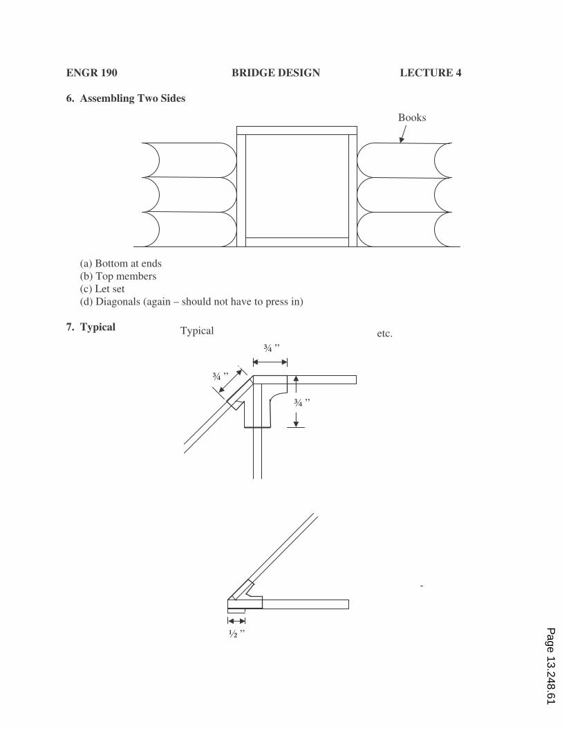
6. Assembling Two Sides
(a) Bottom at ends
(b) Top members
(c) Let set
(d) Diagonals (again – should not have to press in)
7. Typical
Typical etc.
¾ ”
¾ ”
¾ ”
½ ”
Books
Page 13.248.61
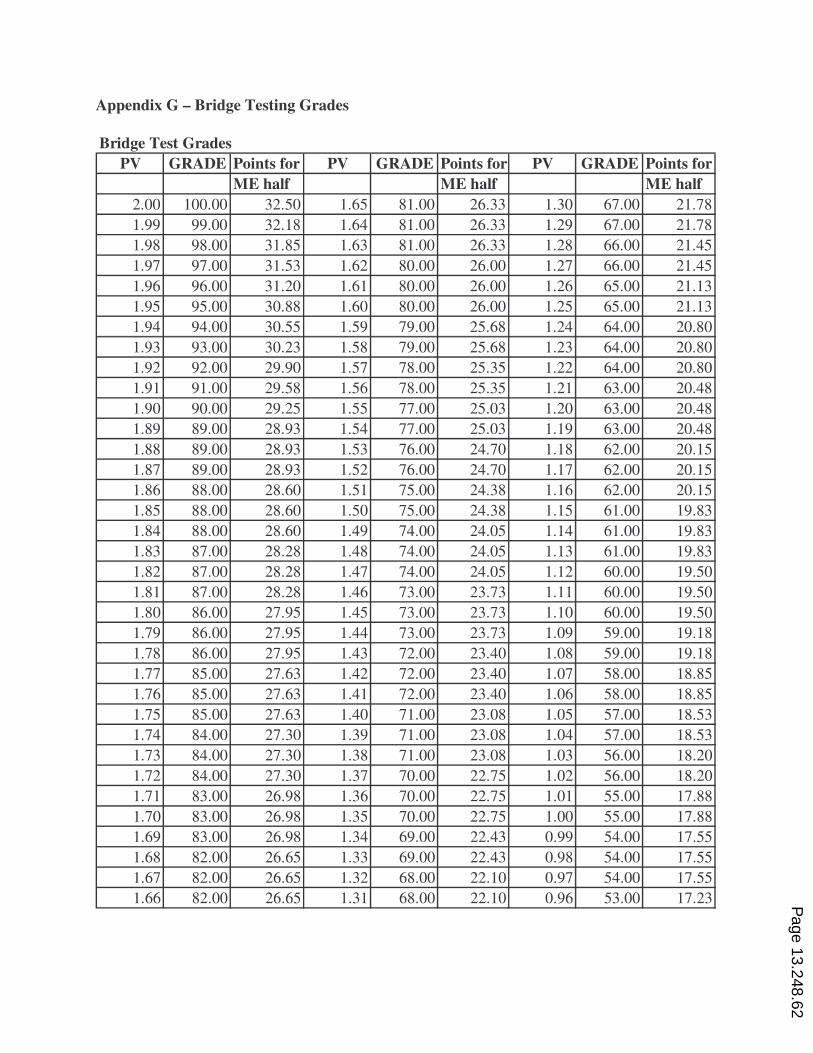
Appendix G – Bridge Testing Grades
Bridge Test Grades
PV GRADE Points for PV GRADE Points for PV GRADE Points for
ME half ME half ME half
2.00 100.00 32.50 1.65 81.00 26.33 1.30 67.00 21.78
1.99 99.00 32.18 1.64 81.00 26.33 1.29 67.00 21.78
1.98 98.00 31.85 1.63 81.00 26.33 1.28 66.00 21.45
1.97 97.00 31.53 1.62 80.00 26.00 1.27 66.00 21.45
1.96 96.00 31.20 1.61 80.00 26.00 1.26 65.00 21.13
1.95 95.00 30.88 1.60 80.00 26.00 1.25 65.00 21.13
1.94 94.00 30.55 1.59 79.00 25.68 1.24 64.00 20.80
1.93 93.00 30.23 1.58 79.00 25.68 1.23 64.00 20.80
1.92 92.00 29.90 1.57 78.00 25.35 1.22 64.00 20.80
1.91 91.00 29.58 1.56 78.00 25.35 1.21 63.00 20.48
1.90 90.00 29.25 1.55 77.00 25.03 1.20 63.00 20.48
1.89 89.00 28.93 1.54 77.00 25.03 1.19 63.00 20.48
1.88 89.00 28.93 1.53 76.00 24.70 1.18 62.00 20.15
1.87 89.00 28.93 1.52 76.00 24.70 1.17 62.00 20.15
1.86 88.00 28.60 1.51 75.00 24.38 1.16 62.00 20.15
1.85 88.00 28.60 1.50 75.00 24.38 1.15 61.00 19.83
1.84 88.00 28.60 1.49 74.00 24.05 1.14 61.00 19.83
1.83 87.00 28.28 1.48 74.00 24.05 1.13 61.00 19.83
1.82 87.00 28.28 1.47 74.00 24.05 1.12 60.00 19.50
1.81 87.00 28.28 1.46 73.00 23.73 1.11 60.00 19.50
1.80 86.00 27.95 1.45 73.00 23.73 1.10 60.00 19.50
1.79 86.00 27.95 1.44 73.00 23.73 1.09 59.00 19.18
1.78 86.00 27.95 1.43 72.00 23.40 1.08 59.00 19.18
1.77 85.00 27.63 1.42 72.00 23.40 1.07 58.00 18.85
1.76 85.00 27.63 1.41 72.00 23.40 1.06 58.00 18.85
1.75 85.00 27.63 1.40 71.00 23.08 1.05 57.00 18.53
1.74 84.00 27.30 1.39 71.00 23.08 1.04 57.00 18.53
1.73 84.00 27.30 1.38 71.00 23.08 1.03 56.00 18.20
1.72 84.00 27.30 1.37 70.00 22.75 1.02 56.00 18.20
1.71 83.00 26.98 1.36 70.00 22.75 1.01 55.00 17.88
1.70 83.00 26.98 1.35 70.00 22.75 1.00 55.00 17.88
1.69 83.00 26.98 1.34 69.00 22.43 0.99 54.00 17.55
1.68 82.00 26.65 1.33 69.00 22.43 0.98 54.00 17.55
1.67 82.00 26.65 1.32 68.00 22.10 0.97 54.00 17.55
1.66 82.00 26.65 1.31 68.00 22.10 0.96 53.00 17.23
Page 13.248.62
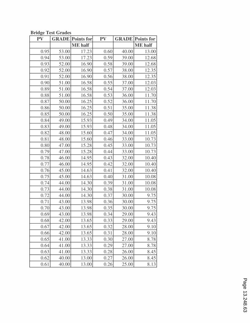
Bridge Test Grades
PV GRADE Points for PV GRADE Points for
ME half ME half
0.95 53.00 17.23 0.60 40.00 13.00
0.94 53.00 17.23 0.59 39.00 12.68
0.93 52.00 16.90 0.58 39.00 12.68
0.92 52.00 16.90 0.57 38.00 12.35
0.91 52.00 16.90 0.56 38.00 12.35
0.90 51.00 16.58 0.55 37.00 12.03
0.89 51.00 16.58 0.54 37.00 12.03
0.88 51.00 16.58 0.53 36.00 11.70
0.87 50.00 16.25 0.52 36.00 11.70
0.86 50.00 16.25 0.51 35.00 11.38
0.85 50.00 16.25 0.50 35.00 11.38
0.84 49.00 15.93 0.49 34.00 11.05
0.83 49.00 15.93 0.48 34.00 11.05
0.82 48.00 15.60 0.47 34.00 11.05
0.81 48.00 15.60 0.46 33.00 10.73
0.80 47.00 15.28 0.45 33.00 10.73
0.79 47.00 15.28 0.44 33.00 10.73
0.78 46.00 14.95 0.43 32.00 10.40
0.77 46.00 14.95 0.42 32.00 10.40
0.76 45.00 14.63 0.41 32.00 10.40
0.75 45.00 14.63 0.40 31.00 10.08
0.74 44.00 14.30 0.39 31.00 10.08
0.73 44.00 14.30 0.38 31.00 10.08
0.72 44.00 14.30 0.37 30.00 9.75
0.71 43.00 13.98 0.36 30.00 9.75
0.70 43.00 13.98 0.35 30.00 9.75
0.69 43.00 13.98 0.34 29.00 9.43
0.68 42.00 13.65 0.33 29.00 9.43
0.67 42.00 13.65 0.32 28.00 9.10
0.66 42.00 13.65 0.31 28.00 9.10
0.65 41.00 13.33 0.30 27.00 8.78
0.64 41.00 13.33 0.29 27.00 8.78
0.63 41.00 13.33 0.28 26.00 8.45
0.62 40.00 13.00 0.27 26.00 8.45
0.61 40.00 13.00 0.26 25.00 8.13
Page 13.248.63
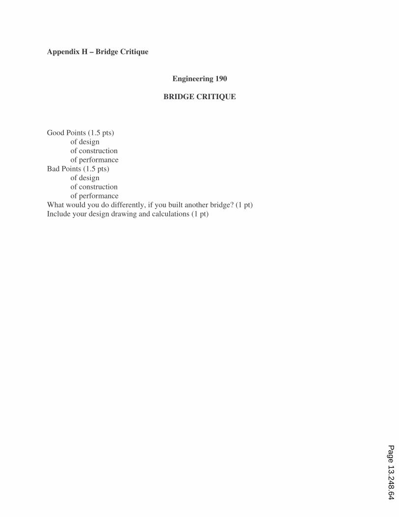
Appendix H – Bridge Critique
Engineering 190
BRIDGE CRITIQUE
Good Points (1.5 pts)
of design
of construction
of performance
Bad Points (1.5 pts)
of design
of construction
of performance
What would you do differently, if you built another bridge? (1 pt)
Include your design drawing and calculations (1 pt)
Page 13.248.64