66514 coverw spine:66514 coverw spine 3/14/11 7:58 am … screw-vent restorative... · •forms a...
TRANSCRIPT
©20
06 Z
imm
er D
enta
l Inc
. All
right
s re
serv
ed. 4
941,
Rev
. 10/
06. L
ocat
or is
are
gist
ered
trad
emar
k of
Zes
t Anc
hors
, Inc
. Had
er B
ar is
a re
gist
ered
trad
emar
k of
Ern
st M
uhlb
auer
Gm
bH &
Co.
KG
.
www.zimmerdental.com
1900 Aston AvenueCarlsbad, CA 92008-7308, USAIn the U.S. 800 854 7019
For more information about our Products, Professional Programs and Educational Opportunities, contact us:
To fax an order 888 225 2483Outside the U.S. +1 760 929 4300Australia +61 (0)2 9950 5444 or 1 800 241 916Canada +1 905 567 2073 or 1 800 265 0968
France +33 (0)1 45 12 35 35Germany +49 (0)761 4584 722/723Israel +972 (0)3 6124242Spain +34 93 846 05 43
To receive our eNews visit us at http://www.zimmerdental.com/news_eNewsLetterSignUp.aspxPartially and Fully Edentulous
Tapered Screw-Vent®
and AdVent®
RestorativeManual
Tape
red
Scre
w-V
ent a
nd A
dVen
t Res
tora
tive
Man
ual –
Par
tially
and
Ful
ly E
dent
ulou
sZi
mm
er D
enta
l66514_CoverW_Spine:66514_CoverW_Spine 3/14/11 7:58 AM Page 1
Tapered Screw-Vent and AdVent Restorative Manual
Figure 1
Table of Contents
General Information
Overview 1
Restorative Options 2
Surgical Procedures and Healing Components 4
Selecting Abutments 6
Abutment Flowchart 8
Restorative Procedures
Indirect or Closed-Tray Transfer Technique 12
Direct or Open-Tray Transfer Technique 15
Immediate Impression Transfer Technique 18
Hex-Lock™ Plastic Temporary Abutments 20
Hex-Lock Contour Abutment System 26
Hex-Lock Abutment System 32
Angled Abutment System 40
“Cast-To” Gold Abutment System, Engaging 52
PureForm™ Ceramic System 60
Tapered Abutment System 68
Locator ® Overdenture Attachment System 80
Ball Abutment System 86
Immediate Bar Fabrication 96
Non-Engaging Gold Abutment System 104
Information
Prosthetic Armamentaria and Auxiliary Components 109
*Note: Images shown in the catalog may not be to scale.
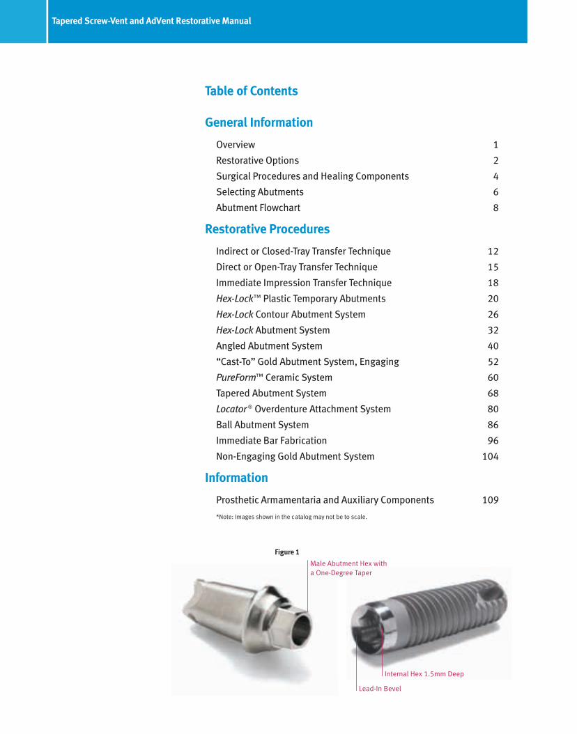
Lead-In Bevel
Internal Hex 1.5mm Deep
Male Abutment Hex witha One-Degree Taper
109Prosthetic armamentaria and auxiliary components
TW1.25L
Reamers for “Cast-To” orCastable Components
Reamer forCopings
PR
Reamer for HLAand NEA
“Cast-To” SeriesMRI
Torque Wrenches and Inserts
TW30
HX1.25
TLRT2
OHRT
Hex Tools1.25mmD Hex Tools for Abutment Screws and
Fixation Screws
Removal Tool for 3-piece20° Angled Abutments
1) To remove 20° Angled Abutment Head fromthe Abutment Connector attached to InternalHex Implants.
TW20
HXL1.25 THX1.25 THXL1.25 0721
TW1.2530 Ncm Torque Wrench used to tighten all components and screwsattaching directly into the implant.
20 Ncm Torque Wrench used to tighten screws attaching directlyinto an abutment.
Hader Clip Bar System - BS1Round Gold Bar System - HGBDolder Gold Bar System - DGB
Removal Toolfor Internal Hex Implant Abutments
1) Hex-Lock Contour Abutments2) Hex-Lock Abutments3) 20° Angled Abutment Assemblies4) “Cast-To” Gold Abutments5) Core Abutments for PureForm
Ceramic System
Cap Attachment System - CAS Locator Core Tool - LOCCT2
Locator Torque Wrench Insert Driver,15mmL - LOCTW15
Locator Torque Wrench Insert Driver,21mmL - LOCTW21
Nylon Liner Insertion Tool
Mandril for Castable Ball Pattern
Nylon Liner Reaming Tool
Cap Attachment Instruments - CAI
66514_CoverW_Spine:66514_CoverW_Spine 3/14/11 7:58 AM Page 2
Tapered Screw-Vent and AdVent Prosthetics Overview 1
Figure 3 - SEM at 150X magnification displaysthe mechanical interlock in the hexagonalengagement area between the flats of theimplant and abutment.
Figure 4 - To remove a fully seated friction-fitabutment from the implant, the abutmentscrew must first be unthreaded and removedfrom the abutment body. An AbutmentRemoval Tool [TLRT2] is then threaded throughthe abutment and into the implant. As thetool continues rotating, it will disengage the friction-fit connection and gently lift theabutment body off of the implant.
The Prosthetic Products Manual for Tapered Screw-Vent and AdVent product lines is designed to provide a detailed overview of the prosthetic procedures applicable to these implant systems. It also applies to prosthetics used for Screw-Vent® Implants that feature the proprietary internal hex with friction-fit connection.
Overview of the internal hex with friction-fit connectionAbutments for the internal hex implants have a male hex that tapers one degree from the base of the abutment body to the bottom of thehex (Figure 1). As the abutment is seated into the implant under applied torque, the abutment hex frictionally engages the walls of theimplant’s internal hex. The result is a friction-fit that virtually eliminates rotation between components. Scanning Electron Micrographsreveal the intimate fit that results in a virtual “cold weld” of components (Figures 2, 3).
• 1.5mm deep internal hex distributes forces deeper within the implant, minimizing stress concentrations.
• Lead-in bevel improves ability to seat the abutment properly (Figure 1).
• Connection virtually eliminates rotational micromovement, tipping and effects of occlusal vibration on the abutment, the leading causesof screw loosening.
• Low profile of the internal connection improves esthetics and allows for a better emergence profile.
• Once the friction-fit is established, abutments can only be unseated from the implant with a special Abutment Removal Tool (Figure 4).
• Three prosthetic platforms are available for Tapered Screw-Vent Implants: 3.5mmD, 4.5mmD and 5.7mmD, and two AdVent prostheticplatforms: 4.5mmD and 5.7mmD.
• Components of both 5.7mmD platforms are cross-compatible. The 4.5mmD platform components are not.
Figure 2 - SEM at 50X magnification showsintimate contact of the internal hex implant atboth the beveled implant/abutment interfaceand the hexagonal engagement area.
66514_Pg01_35:66514_Pg01_35 3/14/11 2:20 PM Page 2

2 Options for partially edentulous restorations
Abutment for cemented crownImplant-supported prosthesis• The prosthesis is removable only by the dentist.
• Interdigitates with the implant’s hex for anti-rotational stability.
• Forms a friction-fit that virtually eliminates the major causes of screw loosening.
• Prosthetic design should reflect cosmetic and hygiene considerations.
• Provides restorative ease and flexibility with Hex-Lock Contour, Hex-Lock,Angled and “Cast-To” Gold Abutment options.
Abutment for screw-retained crown or combined post & crownImplant-supported prosthesis• The prosthesis is removable only by the dentist.
• Interdigitates with the implant’s hex for anti-rotational stability.
• Forms a friction-fit that virtually eliminates the major causes of screw loosening.
• Prosthetic design should reflect cosmetic and hygiene considerations.
• Provides options for screw-retained crown and combined post & crown.
• Abutment type: “Cast-To” Gold Abutment.
Abutment for fixed partial denturesImplant-supported prosthesis• The prosthesis is removable only by the dentist.
• Interdigitates with the implant’s hex for anti-rotational stability.
• Forms a friction-fit that virtually eliminates the major causes of screw loosening.
• Prosthetic design should reflect cosmetic and hygiene considerations.
• Provides restorative ease and flexibility with Hex-Lock Contour, Hex-Lock,Angled and “Cast-To” Gold Abutment options.
Abutment for screw-retained fixed partial dentureImplant-supported prosthesis• The prosthesis is removable only by the dentist.
• Prosthetic design should reflect cosmetic and hygiene considerations.
• Abutment types: Tapered Abutment, Non-Engaging Gold Abutment orAdVent Bar Copings.
66514_Pg01_35:66514_Pg01_35 3/14/11 2:20 PM Page 3

3Options for fully edentulous restorations
Screw-retained dentureImplant-retained, implant-supported prosthesis• This prosthesis is recommended primarily for the mandible.
• The prosthesis is removable only by the dentist.
• The secure fit offers the psychological advantage of a fixed prosthesis.
• Five to six implants are preferred for the mandibular prosthesis.
• Six to ten implants are preferred for the maxillary prosthesis.
• Prosthetic design should reflect cosmetic and hygiene considerations.
• Abutment types: Tapered Abutment, Non-Engaging Gold Abutment orAdVent Bar Copings.
Bar overdentureImplant-retained, implant-supported prosthesis• This prosthesis is recommended for the maxilla and mandible.
• The overdenture is removable by the patient to facilitate hygiene and eliminate stress on the implant/prosthetic system when removed.
• The overdenture is stable and feels natural to the patient.
• Four to six implants are preferred for the mandibular prosthesis.
• Six to ten implants are preferred for the maxillary prosthesis.
• Various attachments are used to affix the denture to the bar.
• Abutment types: Tapered Abutment, Non-Engaging Gold Abutment orAdVent Bar Copings.
Ball bar overdentureImplant-retained, tissue-supported prosthesis• This prosthesis is recommended primarily for the mandible.
• The overdenture is removable by the patient to facilitate hygiene and eliminate stress on the implant/prosthetic system when removed.
• Slight prosthetic movement, but is stable and feels natural to the patient.
• Four implants are preferred for the Ball Bar Overdenture.
• Abutment types: Tapered Abutment, Non-Engaging Gold Abutment orAdVent Bar Copings. Locator Bar Attachments and Castable ball patternsalso available.
Ball abutment or Locator abutment overdentureImplant-retained, tissue-supported prosthesis• This prosthesis is recommended primarily for the mandible.
• The overdenture is removable by the patient to facilitate hygiene and eliminate stress on the implant/prosthetic system when removed.
• Denture movement is necessary, due to the limited number of implants.
• Retained by Ball Abutments or Locator Abutments on two implants.
• Two implants are required for a Ball Abutment or Locator AbutmentOverdenture.
• Abutment type: Ball Abutment, Locator Abutment.
66514_Pg01_35:66514_Pg01_35 3/14/11 2:21 PM Page 4

4 Surgical procedures for submerged and non-submerged implants — Selecting and placing healing components
Submerged (two-stage) surgical protocolThe submerged surgical protocol is the traditional method of placing root-form dental implants. Two-stage implant designs come preattached to a fixture mount, and are presterilized in double-vial packaging. After the implant is placed, the fixture mount is removedand a low-profile Titanium Surgical Cover Screw is threaded into the top of the implant. The soft tissue is then sutured over the implant,which remains submerged until osseointegration is achieved. A second surgery is then performed to expose the top of the implant. At thistime, the cover screw is removed and a transmucosal Healing Collar is attached to the implant. Healing Collars are available in 3mm, 5mmand 7mm lengths, and in diameters of 3.5mm, 4.5mm, 5.5mm, and 6.5 mm. The soft tissue is sutured around the Healing Collar andallowed to heal. Once the peri-implant soft tissue sulcus has formed, prosthetic procedures are initiated by removing the Healing Collar togain access to top of the implant.
Select a 3mm- or 5mm-long HealingCollar according to the thickness of thesurrounding soft tissue. Use a 1.25mmDHex Tool to thread the Healing Collar intothe implant.
Suture the soft tissue around theHealing Collar.
After the top of the implant is surgically exposed, unthread theTitanium Surgical Cover Screw from the implant with a 1.25mmDHex Tool.
Placing a Healing Collar at the second-stage surgery
At time of implant placement thread theTitanium Surgical Cover Screw [AVSC orAV6SC] into the implant with a 1.25mmDHex Tool.
A 3mmL Implant Extender [AVE or AV6E],which extends 1mmL past the implantinterface, can be attached to the implantprior to placement of the Surgical CoverScrew. The extender increases the transmucosal portion of the implant by2mmL in areas of thick mucosa.
Suture the soft tissue around theImplant or healing component.
Non-submerged (one-stage) surgical protocolThe one-stage surgical protocol eliminates the implant-uncovering, second-stage surgery mentioned above. The AdVent Implant features a3mm high machined neck which in standard implant placement is supracrestal. If clinical conditions warrant it, the implant can also beplaced with up to 2mm of its machined neck subcrestal to allow for either an esthetic type restoration or to accommodate for variations insoft tissue height or prosthesis fabrication.
Included with the implant is an Extender [AVE or AV6E] which can be used to maintain soft tissue opening when the top of the implant isplaced subgingival. It can also be utilized with select bar overdenture components (only 4.5mmD platform) to provide a variety of abutment height options.
Placing a healing component at the first-stage surgery
66514_Pg01_35:66514_Pg01_35 3/14/11 2:21 PM Page 5

5Surgical procedures for submerged and non-submerged implants — Healing components
Healing Collars for Tapered Screw-Vent and Screw-Vent Implants
Implant Extender for AdVent Implants with 4.5mm and 5.7mm platform diameters
Length
4.5mmD 5.7mmD
3mmL 3mmL
AVE AV6E
4.5mmD and 5.7mmDPlatform Diameter
Diameter Diameter
5.1mmD 6.4mmD
TH5C3/6TH5C5/6
THCW3/6THCW5/6
THCW3/5THCW5/5
THC3/3THC5/3
THC3/4THC5/4THC7/4
THC3/5THC5/5
THCW3/4THCW5/4THCW7/4
3.5mmD Platform
4.5mmD Platform
5.7mmD Platform*
*Note: 5.7mmD platform components are also compatible with AdVent 5.7mmD platform.
3mmL
(shown, 5mmL available)
3mmL
(shown, 5mmL available)
3mmL
(shown, 5mmL
and 7mmL available)
3mmL
(shown, 5mmL
and 7mmL available)
3mmL
(shown, 5mmL available)
3mmL
(shown, 5mmL available)
3mmL
(shown, 5mmL available)
3.5mmD 4.5mmD 5.5mmD
4.5mmD 5.5mmD
6.5mmD
6.5mmD
66514_Pg01_35:66514_Pg01_35 3/14/11 2:21 PM Page 6
6 Selecting abutments — Submerged and 5.7mmD platform non-submerged AdVent Implants
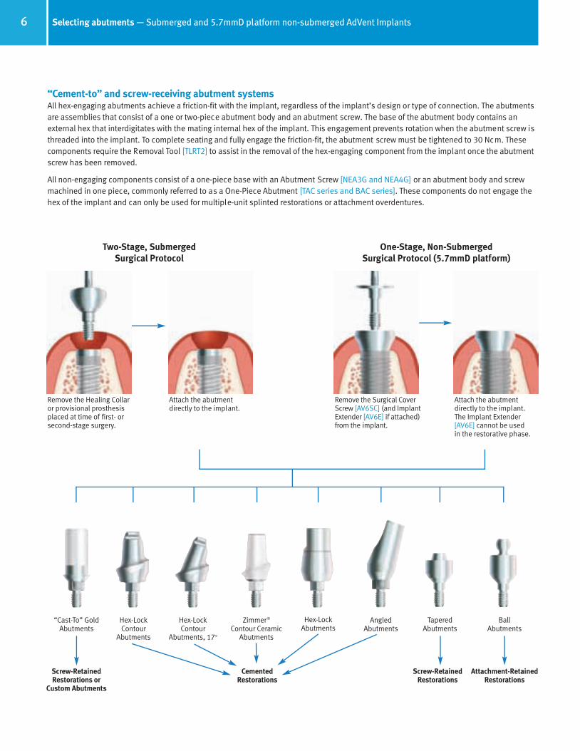
Remove the Healing Collaror provisional prosthesisplaced at time of first- orsecond-stage surgery.
Attach the abutment directly to the implant.
“Cast-To” GoldAbutments
Hex-Lock Contour
Abutments
Hex-Lock Contour
Abutments, 17o
AngledAbutments
Zimmer®
Contour CeramicAbutments
Hex-LockAbutments
TaperedAbutments
Screw-RetainedRestorations
Attachment-RetainedRestorations
Cemented Restorations
Screw-Retained Restorations or
Custom Abutments
BallAbutments
Two-Stage, Submerged Surgical Protocol
Remove the Surgical CoverScrew [AV6SC] (and ImplantExtender [AV6E] if attached)from the implant.
Attach the abutment directly to the implant. The Implant Extender[AV6E] cannot be used in the restorative phase.
One-Stage, Non-Submerged Surgical Protocol (5.7mmD platform)
“Cement-to” and screw-receiving abutment systemsAll hex-engaging abutments achieve a friction-fit with the implant, regardless of the implant’s design or type of connection. The abutmentsare assemblies that consist of a one or two-piece abutment body and an abutment screw. The base of the abutment body contains anexternal hex that interdigitates with the mating internal hex of the implant. This engagement prevents rotation when the abutment screw isthreaded into the implant. To complete seating and fully engage the friction-fit, the abutment screw must be tightened to 30 Ncm. Thesecomponents require the Removal Tool [TLRT2] to assist in the removal of the hex-engaging component from the implant once the abutmentscrew has been removed.
All non-engaging components consist of a one-piece base with an Abutment Screw [NEA3G and NEA4G] or an abutment body and screwmachined in one piece, commonly referred to as a One-Piece Abutment [TAC series and BAC series]. These components do not engage thehex of the implant and can only be used for multiple-unit splinted restorations or attachment overdentures.
66514_Pg01_35:66514_Pg01_35 3/14/11 2:21 PM Page 7

7Selecting abutments — Non-submerged 4.5mmD platform AdVent Implants
OR
“Cast-To” GoldAbutments
AngledAbutments
Hex-LockAbutments
Tapered Abutments
Non-Engaging Bar Coping
Screw-Retained Restorations
Attachment-RetainedRestorations
Cemented Restorations
Screw-RetainedRestorations or
Custom Abutments
BallAbutments
Attach the abutment directly to the implant. Hex-engagingcomponents cannot be usedwith the Implant Extender [AVE].
Attach the non-engagingabutment to the ImplantExtender [AVE] to add2mm to the final height.
Remove the ImplantExtender and connectthe abutment directly to the implant.
Remove the Surgical CoverScrew [AVSC] (and ImplantExtender [AVE] if attached)from the implant.
Remove the SurgicalCover Screw [AVSC]from the implant.
One-Stage, Non-SubmergedSurgical Protocol
OR
“Cement-to” and screw-receiving abutment systemsAll hex-engaging abutments achieve a friction-fit with the implant. The abutments are assemblies that consist of a one- or two-piece abutment body and an abutment screw. The base of the abutment body contains an external hex that interdigitates with the mating internal hex of the implant. This engagement prevents rotation when the abutment screw is threaded into the implant. To complete seatingand fully engage the friction-fit, the abutment screw must be tightened to 30 Ncm. These components require the Removal Tool [TLRT2] toassist in the removal of the hex-engaging component from the implant once the abutment screw has been removed.
All non-engaging components consist of a one-piece base with an Abutment Screw [AVGC3 and AVGC5] or an abutment body and screwmachined in one piece, commonly referred to as a One-Piece Abutment [AVACT, AVACT3 and AVBA]. These components do not engage thehex of the implant and can only be used for multiple-unit splinted restorations or attachment overdentures.
66514_Pg01_35:66514_Pg01_35 3/14/11 2:21 PM Page 8

8 Tissue healing, impression transfer and provisional restorative components
Zimmer Dental offers a full range of easy-to-use components to meet all your restorative needs. To use this guide, choose the column for the implant platform you wish to restore. You can follow the column down each page to identify the appropriatehealing collars, transfer components and abutments for the type of restoration you are restoring: cement-retained, screw-retained or overdenture. Provisional abutments are also available.
Impression Transfer
Indirect Transfer(w/ screw for
Closed Tray Impressions)
5.5mmDFlare
6.5mmDFlare
4.5mmDFlare
HLT5/6HLT4/6HLT4/5HLT3/3 HLT3/4 HLT3/5
DHT3/4
5.5mmDFlare
DHT3/5 DHT4/6DHT4/5
4.5mmDFlare
HLT4/4
DHT4/4
3.5mmDFlare
DHT3/3
AVIT/4
AVIT/4 DHTS
Provisional Restorations
IA3 IA4 IA5 AVR
HLPT5HLPT4HLPT3
3.5mmD Platform AdVent 4.5mmD Platform5.7mmD Platform*4.5mmD Platform
Tissue Healing
Healing Collar(3mm length pictured.
Part #’s for 3mmL,
5mmL & 7mmL are listed) TH5C3/6TH5C5/6
THCW3/6THCW5/6
THCW3/5THCW5/5
THC3/3THC5/3
THC3/4THC5/4THC7/4
THC3/5THC5/5
THCW3/4THCW5/4THCW7/4
AVE(Implant Extender)
3.5mmD Platform 4.5mmD Platform 5.7mmD Platform* AdVent 4.5mmD Platform
3.5mmD Platform 4.5mmD Platform 5.7mmD Platform* AdVent 4.5mmD Platform
Plastic TemporaryAbutment
(w/ screw) can beused for Cement- or
Screw-RetainedRestorations
Fixture Mount/Transfer(w/ screw)
FMT5FMT4FMT3 FMA4
Note: AdVent Implant 5.7mmD platform uses FMA5.
*Note: 5.7mmD platform components are compatible with AdVent 5.7mmD platform.
• Tapered Screw-Vent Implants are offered with three color-coded prosthetic platforms: 3.5mmD, 4.5mmD & 5.7mmD.
• AdVent Implants feature a 4.5mmD platform that is different from the Tapered Screw-Vent 4.5mmD platform,and a 5.7mmD platform that utilizes Tapered Screw-Vent5.7mm prosthetics.
• Tapered Screw-Vent (and soon AdVent) Implants are packaged with a proprietary Fixture Mount/Transfer whichfunctions as a fixture mount, an impression post and/or apreparable temporary abutment. These parts can also bepurchased individually.
Implant Analog
Direct Transfer(w/ screw for
Open Tray Impressions)
66514_Pg01_35:66514_Pg01_35 3/14/11 2:22 PM Page 9

9Cement-retained and custom restorations
Single-UnitRestorations
(Engaging)
Multi-UnitRestorations
(Non-Engaging)
HLA5GHLA4GHLA3G AVGA
NEA4GNEA3G AVGC3
Bar Gold Coping w/ Screw
Custom Restorations
5.7mmD Platform*4.5mmD Platform3.5mmD Platform AdVent 4.5mmD Platform
AH20/4 AH20W A5H20AH20W/5 A5H20/6 AVH20/4AH20
Cement-Retained Restorations, Straight
Zimmer ContourCeramic Abutment**
(w/ screw)
ZRA341S ZRA342S
3.5mmD Platform 4.5mmD Platform 5.7mmD Platform* AdVent 4.5mmD Platform
Note: Impression caps, analogs, provisional copings and waxing copings sold separately by flare diameter. Call for availability.
ZRA451S ZRA452S
4.5mm flare 5.5mm flare
4.5mm flare 5.5mm flareHex-Lock ContourAbutment
(w/ screw)(Abutments for
4.5mmD x 4.5mm flare are listed but not pictured)
ZOA342S ZOA343SZOA341S
3.5mmFlare
ZOA452SZOA442S
ZOA453SZOA443S
ZOA451SZOA441S
6.5mm flare
ZOA562S ZOA563SZOA561S
Hex-Lock Abutment(w/ screw)
HLA3/4 HLA3/5HLA3/3 HLA4/5 HLA4/6HLA4/4 HLA5/6
4.5mmFlare
5.5mmFlare
4.5mmFlare
5.5mmFlare
6.5mmFlare
6.5mmFlare
AVHL/4 AVHL/6
4.5mmFlare
6.5mmFlare
Cement-Retained Restorations, Angled
3.5mmD Platform 4.5mmD Platform 5.7mmD Platform* AdVent 4.5mmD Platform
Hex-Lock ContourAbutment, 17°
(w/ screw)(Abutments for
4.5mmD x 4.5mm flare are listed but not pictured) ZOA341A ZOA342A ZOA451A
ZOA441AZOA452AZOA442A
4.5mm flare 5.5mm flare
ZOA561A ZOA562A
6.5mm flare
20° Angled Abutment for
6 and 24 positions (w/ screw)
“Cast-To” Gold Abutment w/ screw
Note: Impression caps, analogs, provisional copings and waxing copings sold separately by flare diameter. Call for availability.
*Note: 5.7mmD platform components are compatible with AdVent 5.7mmD platform.
**Call for availability.
66514_Pg01_35:66514_Pg01_35 3/14/11 2:22 PM Page 10

Screw-Retained Restorations
Tapered Abutment
TAC33mm
TAC10.75mm
TAC44mm
TACW22mm
TACW33mm
TACW10.75mm
TACW44mm
TA5C44mm
TA5C22mm
TA5C33mm
AVACT AVACT3
Tapered Abutment Indirect and Direct
Transfers
Tapered Abutment GoldCoping w/ Screw
Tapered Abutment ReplicaRepresents Tapered Abutment
Attached to Implant
Tapered AbutmentTitanium Bar Coping
Tapered Abutment Bar GoldCopings w/ Screw
ACTIT ACTDT ACTGC TGC5TGC3ACTR
Overdenture Restorations
Ball Abutments w/Cap Attachment
Housing and Nylon Liner
Ball TransferComponents
BAC2 BAC6BAC4 BACW2 BACW6 BA5C2 BA5C4 AVBABACW4
Ball Abutment Transfer
BAT
Cap Attachment Transfer Ball Abutment Replica
CAT BAR
5.7mmD Platform*4.5mmD Platform3.5mmD Platform AdVent 4.5mmD Platform
Green Purple Yellow3.5mm Implant Platform 4.5mm Implant Platform 5.7mm Implant Platform
Color-Coding for Internal Hex Platform
The chart below indicates which color corresponds to each Tapered Screw-Vent and Screw-Vent internal hex platform diameter.
*Note: TSV 4.5mmD platform components are not interchangeable with AdVent 4.5mmD platform. 5.7mmD platform components can be used with TSV or AdVent Implants.
5.7mmD Platform*4.5mmD Platform3.5mmD Platform AdVent 4.5mmD Platform
Note: Use AVE for additional 2mm of collar height when using Tapered Abutments on AdVent Implants. TAC5 and TACW5 also available.
Note: BAT and BAR not for use with the 5.7mmD platform abutment. Use AVE for additional 2mm of collar height when using Ball Abutments on AdVent Implants.
TAC22mm
TA5C10.75mm
TTC5
Overdenture Restorations
Locator Abutment
LocatorComponents
TLOC3/3TLOC3/1 TLOC3/4 TLOC4/2 TLOC4/3 TLOC4/1 TLOC4/4 TLOC5/4TLOC5/2 TLOC5/3 AVLOC4/1 AVLOC4/2
Male Processing Package Abutment AnalogImpression Coping Parallel Post Bar Female
LOCMP2 LOCAN/4 LOCCTBLOCBF2LOCIMP
5.7mmD Platform*4.5mmD Platform3.5mmD Platform AdVent 4.5mmD Platform
Note: Additional cuff options are available. See product catalog for complete list.
TLOC3/2 TLOC5/1
LOCPP
AVLOC4/3
Cast-ToBar Female
LOCLBF
Laser BarFemale
Note: Additional Locator Bar Components and Replacement Males are available. See product catalog.
CA
Cap Attachment Housing and Nylon Liner
Tapered AbutmentComponents
10 Screw-retained and overdenture restorative components
66514_Pg01_35:66514_Pg01_35 3/21/11 9:55 AM Page 11

Impression Transfer System
RestorativeManual
66514_Pg01_35:66514_Pg01_35 3/14/11 2:23 PM Page 12

12 Indirect (closed-tray) transfer technique
Implant-level Indirect Transfers for closed-tray, transfer impression techniqueDesigned to transfer the soft tissue profile as well as the implant’s position and hex orientation, Indirect Transfers remain attached to the implants when the closed-tray impression is removed from the mouth. The transfer is then retrieved from the implant, mated to the corresponding Implant Analog, and placed into its corresponding impression hole. To fabricate a working cast containing a replica of theimplant in the patient’s mouth, the impression is poured in dental stone. In areas where a longer transfer is required, the transfer’s screwcan be replaced by the Transfer Extension Screw [HLTE for internal hex implants], which adds an additional 3mm to the overall length of the transfer.
3.5mmD PlatformFlared to 4.5mmD*
[HLT3/4]
4.5mmD PlatformFlared to 5.5mmD*
[HLT4/5]
5.7mmD PlatformFlared to 6.5mmD ONLY
[HLT5/6]
4.5mmD PlatformFlared to 4.5mmD ONLY
[AVIT/4]
Heavier- and Light-Body Impression
Material
Indirect Transfer
ImplantAnalog
Impression Tray
*Available in all three profile diameters.
Exposing the tops of the implantsTapered Screw-Vent and Screw-Vent Implants: • Remove the Healing Collars with the 1.25mmD Hex Tool.
AdVent Implants: • Remove the Surgical Cover Screws [AVSC] with the Hex Tool and
Implant Extender [AVE] if present.
Attaching the transfersIndirect Transfers are available in various profile diameters to replicateanatomical tissue sulcus in the working cast. Orient the flat side of theIndirect Transfer [HLT Series or AVIT/4] or Fixture Mount/Transfer toward the buccal surface, interdigitate its hex with the implant’s hex and press thetransfer onto the implant. Thread the transfer screw into the implant and finger-tighten with the 1.25mmD Hex Tool.
66514_Pg01_35:66514_Pg01_35 3/14/11 2:23 PM Page 13

13Indirect (closed-tray) transfer technique
Verifying the fit of the impression trayVerify that the Indirect Transfers fit within the confines of the custom tray or the modified stocktray prior to injecting the impression material.
In areas where a greater length of transfer body is required, replace the transfer screw with the Extension Screw [HLTE] for two-stage internal heximplants. This will increase the length of the transferby 3mm and provide another circumferential groovefor added vertical retention.
Completed Transfer Assembly
Making the transfer impressionTake a radiograph or use a non-abrading explorer to verify that the IndirectTransfers are fully seated. Block out the hex holes in the tops of the transferscrews with medium of choice to prevent the ingress of impression material.Remove excess material so that the block-out is flush with the ends of thetransfer screws. Failure to do so may prevent an accurate transfer procedure.
Injecting the impression materialAn elastomeric impression material is recommended, such as vinyl polysiloxane. Inject light-body impression material around the transfers and fill the closed tray with heavier-body impression material. Make a full-arch impression, and allow the material to set according to the manufacturer’s recommendations before removing. Unthread the IndirectTransfers from the implants in the patient’s mouth. Make interocclusalrecords and an impression of the opposing arch. Send the impressions andtransfer assemblies to the laboratory for fabrication of the working casts. Replace the Healing Collars on the implants in the patient’s mouth.
Seating the transfer assemblyAttach the Indirect Transfers to corresponding Implant Analogs with the Hex Tool:• Implant Analog for an internal hex implant, 3.5mmD platform: IA3.
• Implant Analog for an internal hex implant, 4.5mmD platform: IA4.
• Implant Analog for an internal hex implant, 5.7mmD platform: IA5.
• Implant Analog for an AdVent Implant with 4.5mmD platform: AVR.
• Implant Analog for an AdVent Implant with 5.7mmD platform: IA5.
Align the flat side of each transfer with the flat side of its corresponding hole in the impression and insert the transfer assembly into the impression material. A double-click will indicate when the assembly has fully seated.
3mm
Extension Screw
66514_Pg01_35:66514_Pg01_35 3/14/11 2:24 PM Page 14

14 Indirect (closed-tray) transfer technique
Heavier Impression Material
Light Impression Material
Transfer/Analog Assembly
Impression TrayCross-section of transfer impressionFrom the cross-section of the Indirect Transfer impression, note that there is no access to the transfers from outside of the impression tray.
Fabricating the working castPlace soft tissue replication material around the junctions of the assembledImplant Analogs and the transfers inside the impression. Take care not tocover the retention grooves of the Implant Analogs with the material. After the material sets, pour the impression in dental stone.
Fabricating the working castAfter the dental stone sets separate the cast from the impression. The Implant Analogs will be incorporated within the stone cast with thesame hex positions and orientations as the implants in the patient’s mouth. Unthread and remove the transfers from the Implant Analogs withthe Hex Tool. The soft tissue replication material can be removed for a visual inspection of the abutment/Implant Analog connections, if desired.
Pour the opposing-arch impression in dental stone, then utilize the interocclusal records to articulate the casts.
66514_Pg01_35:66514_Pg01_35 3/14/11 2:24 PM Page 15

15Direct (open-tray) transfer technique
4.5mmD PlatformFlared to 5.5mmD*
[DHT4/5]
Fabricating a custom trayMake a full-arch impression of the Healing Collars or Surgical Cover Screws,edentulous areas and remaining dentition. Send it to the laboratory for fabrication of a preliminary cast and custom impression tray. Alternatively,select a stock tray and mold the border with greenstick compound material.The patient’s existing, modified prosthesis can continue to be worn duringthe laboratory phase.
Fabricating a custom trayPour the impression in dental stone and separate the preliminary cast after it sets. Block out the areas above the Healing Collars or Surgical CoverScrews with baseplate wax to simulate the positions of the implant transfersthat will be used.
Fabricate the custom impression tray with autopolymerizing or light-cure trayresin. Create an opening above the implant areas to allow for access to theDirect Transfer screws.
Implant-level Direct Transfers for open-tray, pick-up impression techniqueDesigned to transfer the soft tissue profile as well as the implant’s position and hex orientation, Direct Transfers are held firmly within the open-tray impression as it is removed from the mouth. Therefore, the central transfer screw must be removed before the impressioncan be released from the mouth. This transfer procedure requires a custom tray or modified stock tray with screw access holes in the areasocclusal to the implants. The Implant Analog is connected to the Transfer embedded within the impression, then the impression is pouredin dental stone to fabricate a working cast containing a replica of the implant in the patient’s mouth.
3.5mmD PlatformFlared to 4.5mmD*
[DHT3/4]
4.5mmD AdVent PlatformFlared to 4.5mmD ONLY**
[AVIT/4]
Heavier- and Light-BodyImpression Material
Direct Transfer body
Implant Analog
Impression Tray
Direct Transfer Screw**This assembly isobtained with an
optional purchase ofthe [DHTS] Open-Tray
Transfer Screw.
*Available in all three profile diameters.
66514_Pg01_35:66514_Pg01_35 3/14/11 2:25 PM Page 16
16 Direct (open-tray) transfer technique
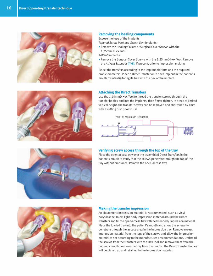
Point of Maximum Reduction
Removing the healing componentsExpose the tops of the implants:Tapered Screw-Vent and Screw-Vent Implants: • Remove the Healing Collars or Surgical Cover Screws with the
1.25mmD Hex Tool.AdVent Implants: • Remove the Surgical Cover Screws with the 1.25mmD Hex Tool. Remove
the AdVent Extender [AVE], if present, prior to impression making.
Select the transfers according to the implant platform and the required profile diameters. Place a Direct Transfer onto each implant in the patient’smouth by interdigitating its hex with the hex of the implant.
Verifying screw access through the top of the trayPlace the open-access tray over the assembled Direct Transfers in thepatient’s mouth to verify that the screws penetrate through the top of thetray without hindrance. Remove the open-access tray.
Making the transfer impressionAn elastomeric impression material is recommended, such as vinylpolysiloxane. Inject light-body impression material around the DirectTransfers and fill the open-access tray with heavier-body impression material.Place the loaded tray into the patient’s mouth and allow the screws to penetrate through the access area in the impression tray. Remove excessimpression material from the tops of the screws and allow the impressionmaterial to set according to the manufacturer’s recommendations. Unthreadthe screws from the transfers with the Hex Tool and remove them from thepatient’s mouth. Remove the tray from the mouth. The Direct Transfer bodieswill be picked up and retained in the impression material.
Attaching the Direct TransfersUse the 1.25mmD Hex Tool to thread the transfer screws through the transfer bodies and into the implants, then finger-tighten. In areas of limitedvertical height, the transfer screws can be removed and shortened by 4mmwith a cutting disc prior to use.
66514_Pg01_35:66514_Pg01_35 3/14/11 2:26 PM Page 17

17Direct (open-tray) transfer technique
Heavier ImpressionMaterial
Light ImpressionMaterial
Transfer/AnalogAssembly
Impression Tray
Completing the transfer procedureReplace the healing components on the implants in the patient’s mouth.Fabricate an opposing-arch impression and make interocclusal records.Send the impressions with included transfers to the laboratory for fabricationof the working casts. Stabilize each Implant Analog [IA3, IA4, IA5 and AVR]with forceps to prevent rotation, and insert the screw-receiving end of a corresponding Implant Analog into the base of the transfer body within theimpression material.
Attach the transfer screw to the 1.25mmD Hex Tool, and insert it through the respective access hole in the back of the transfer tray. Pass the screwthrough the embedded transfer body and thread it into the attached Implant Analog to lock the components together.
Cross-section of transfer impressionFrom the cross-section of the Direct Transfer impression, note that there isaccess to the transfer screw from outside of the impression tray.
Fabricating the working castPlace soft tissue replication material around the junctions of the assembledImplant Analogs and the transfers inside the impression. Take care not tocover the retention grooves of the Implant Analogs with the material. After the material sets, pour the impression in dental stone.
Fabricating the working castUse the 1.25mmD Hex Tool to unthread and remove the transfer screws after the dental stone sets. Separate the cast from the impression (the open-tray transfer bodies will remain in the impression). The ImplantAnalogs will be incorporated within the stone cast with the same hex positionsand orientations as the implants in the patient’s mouth. The soft tissuereplication material can be removed for a visual inspection of the abutment/implant analog connections, if desired.
Pour the opposing-arch impression in dental stone, then utilize the interocclusal records to articulate the casts.
66514_Pg01_35:66514_Pg01_35 3/14/11 11:47 AM Page 18

18 Immediate impression transfer technique — Making an impression at time of implant placement
Option 1: making an implant-level impressionAfter threaded implant placement, block out the top of the FixtureMount/Transfer. If implant does not have a transfer, attach transfer of choicewith 1.25mmD Hex Tool. Place light-body impression material around thetransfer and record a full-arch impression with standard body material.
Remove the impression after it fully sets. Remove transfer and forward withimpression to the laboratory. If impression is done at the bone level, informthe laboratory. Optional: Long Impression Screw [DHTS] may be used foropen-tray impression technique.
Option 2: using the surgical guide for indexingAfter threaded implant placement, use a Long (Open-Tray) Impression Screw[DHTS] to project through surgical guide. Lute the Fixture Mount/Transfer ortransfer post to the surgical guide with resin of choice. Unscrew the transferand remove the guide with transfer attached. Forward guide and transfer tothe laboratory for retrofitting of the properative model.
Attaching components for healing period1) Place Surgical Cover Screw using 1.25mmD Hex Tool and then suture for
traditional two-stage protocol.2) Attach a Healing Collar with the corresponding profile and platform
diameter for single-stage protocol.
Forward the impression, transfer and diagnostic models to the laboratory for fabrication of the working cast.
Fabricating the working castPlace soft tissue replication material around the junctions of the assembledImplant Analog and the transfer inside the impression. After the materialsets, pour the impression in dental stone. Separate the cast from theimpression. The Implant Analog will be incorporated within the stone castwith the same hex positions and orientations as the implant in the patient’smouth. Unthread and remove the transfer from the Implant Analog with the1.25mmD Hex Tool. The soft tissue replication material can be removed for a visual inspection of the abutment/Implant Analog connections, if desired.
Pour the opposing-arch impression in dental stone, then utilize the interocclusal records to articulate the casts.
66514_Pg01_35:66514_Pg01_35 3/14/11 11:48 AM Page 19

Hex-Lock Plastic Temporary Abutments
RestorativeManual
66514_Pg01_35:66514_Pg01_35 3/14/11 11:48 AM Page 20

20 Hex-Lock Plastic Temporary Abutments
Restorative options with Hex-Lock Plastic Temporary AbutmentsThe Hex-Lock Plastic Temporary Abutment consists of a plastic cylinder with retentive parallel walls. The flared cuff of the Temporary Abutmenthelps create a natural emergence profile during tissue healing. The Temporary Abutment may be used for cement- or screw-retained crownsand in a laboratory or chairside procedure. The abutment’s long retaining screw is useful for maintaining the screw access channel in ascrew-retained prosthesis or is easily prepared to allow for a cement-retained restoration. The Hex-Lock Plastic Temporary Abutment is indicated for short-term restorations (28 days or less) and is not to be used in interocclusal spaces less than 4mm or to correct divergence of more than 25°. The temporary abutment is contraindicated for use as a final abutment.
Point of Maximum Reduction Corresponding to 4mmL AboveImplant Interface.
Fabricating the articulated castsPour the working cast in dental stone. Use soft tissue material to representgingival contours if desired. Remove transfers from cast. Pour the opposing-arch impression in dental stone and utilize interocclusal bite registration toarticulate the casts.
Creating a diagnostic wax-upCreate a diagnostic wax-up of the teeth to be replaced using traditionalprosthodontic techniques with proper tooth morphology. Duplicate the diagnostic wax-up by recording an alginate impression, and pour a plaster cast. Use a vacuform machine to create the plastic matrix.
Figure 1 - Hex-Lock Plastic TemporaryAbutment and Retaining Screw
Figure 2 - The Hex-Lock Temporary Abutment should not be reduced to less than 4mm in height. A groove on theabutment’s cylinder indicates 4mm.
66514_Pg01_35:66514_Pg01_35 3/14/11 11:48 AM Page 21

Preparing the plastic shell formRemove the plastic matrix and form the duplicated cast. Trim and re-seat theclear matrix and check fit. Drill a small hole in the occlusal aspect of thematrix and reseat it over the Temporary Abutment, allowing the abutmentscrew of the Plastic Temporary Abutment to protrude through.
Attaching the abutments to the working castAttach the corresponding Plastic Temporary Abutments to the ImplantAnalogs or to the implants in a chairside procedure. Use a 1.25mmD HexTool to tighten the abutment screw, using finger-pressure only.
21Hex-Lock Plastic Temporary Abutments
Preparing the Temporary AbutmentMark the required modifications on the abutment to allow for the appropriateocclusal clearance, gingival contouring and prosthesis design for adequatethickness of veneering material. Note: When fabricating multiple-unit screw-retained restorations, one or all of the abutment’s hex connection may needto be removed to avoid interference of the multiple hexes when seating the restoration.
Modifying the abutmentScrew-retained (molar shown): Reduce the abutment height as necessary,leaving the abutment screw long to protrude through the vacuform. Roughen the entire abutment surface to enhance retention of the acrylic.
Cement-retained (canine shown): Reduce and prepare the abutment andscrew as needed. Roughen the abutment surface to enhance retention of the cemented restoration.
Point of Maximum Reduction Corresponding to 4mmL AboveImplant Interface.
66514_Pg01_35:66514_Pg01_35 3/14/11 11:48 AM Page 22
22 Hex-Lock Plastic Temporary Abutments
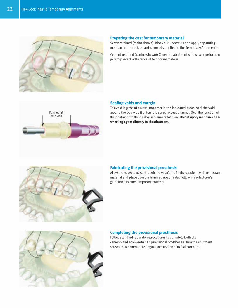
Preparing the cast for temporary materialScrew-retained (molar shown): Block out undercuts and apply separatingmedium to the cast, ensuring none is applied to the Temporary Abutments.
Cement-retained (canine shown): Cover the abutment with wax or petroleumjelly to prevent adherence of temporary material.
Sealing voids and marginTo avoid ingress of excess monomer in the indicated areas, seal the voidaround the screw as it enters the screw access channel. Seal the junction ofthe abutment to the analog in a similar fashion. Do not apply monomer as awhetting agent directly to the abutment.
Seal margin with wax.
Fabricating the provisional prosthesisAllow the screw to pass through the vacuform, fill the vacuform with temporarymaterial and place over the trimmed abutments. Follow manufacturer’sguidelines to cure temporary material.
Completing the provisional prosthesisFollow standard laboratory procedures to complete both the cement- and screw-retained provisional prostheses. Trim the abutmentscrews to accommodate lingual, occlusal and incisal contours.
66514_Pg01_35:66514_Pg01_35 3/14/11 11:49 AM Page 23

23Hex-Lock Plastic Temporary Abutments
Delivering the provisional prosthesisScrew-retained (molar shown): Attach the one-piece abutment/provisionalto the implant and check the occlusion. Tighten the abutment screw, reducethe screw shaft by cutting with a fissure bur and block out the screw access hole.
Cement-retained (canine shown): Tighten the abutment screw and block outthe screw access hole. Cement the provisional with temporary cement andcheck the occlusion.
The provisional prosthesisCompleted provisional restorations are in place. Note: The gingival contoursof the temporary prosthesis may not match the flare of the temporary cuffsor the final prosthetic abutment. Additional treatment planning and or modifications to the Temporary Abutment may be needed to accommodatespecific tissue contour. Note: Do not use a torque wrench to secure theTemporary Abutment to the implant body. Hand-tighten only.
66514_Pg01_35:66514_Pg01_35 3/14/11 11:49 AM Page 24
Notes
24 Notes
66514_Pg01_35:66514_Pg01_35 3/14/11 11:49 AM Page 25

Hex-Lock Contour Abutment System
RestorativeManual
66514_Pg01_35:66514_Pg01_35 3/14/11 11:49 AM Page 26

26 Hex-Lock Contour Abutment System
Restorative options with Hex-Lock Contour Abutment SystemHex-Lock Contour Abutments are designed with predefined margins and varying cuff heights. The height of the cuff is higher on the lingualaspect by 1.5mm to mimic the soft tissue profile. The contoured design minimizes preparation time and reduces the potential for metalexposure due to tissue remodeling.
Figure 1 - Mesial/distal view.
Figure 2 - Contour Impression Cap on Abutment.
Figure 3 - Contour Provisional Coping, Abutment Analog andWaxing Coping.
Hex-Lock Contour Abutments can be used to support single- or multiple-unitcement-retained restorations. The cone of the abutment is 6.25mm inheight above the buccal margin and 4.75mm above the lingual margin with an 8° taper (4° per side). The abutments are available in straight and 17° preangled versions in a variety of emergence profiles. Like original Hex-Lock Abutments, Hex-Lock Contour Abutments are made from titaniumalloy and have a hex configuration with a one-degree taper to create a friction-fit connection to the implant.
A system of caps and copings fit over the Hex-Lock Contour Abutments to aid in making restorations using traditional prosthodontic techniques.
• Color-coded snap-on impression caps allow for simple abutment-levelimpressions.
• Provisional copings help in creating a provisional crown to shape gingivaltissue while the final restoration is being fabricated.
• Analogs and waxing copings assist the laboratory in fabrication of thefinal restoration.
• All four restorative components are sold together as a Contour RestorativeKit or may be purchased individually.
• Abutment Try-ins can be used in the laboratory or in the clinician’s office.
• Contour Healing Caps are available for long-term tissue healing.
The Contour Impression Cap snaps into a groove on the Hex-Lock ContourAbutment to facilitate easy impression-taking. The impression cap is pickedup in the cured impression and is fit together with the Contour AbutmentAnalog for model creation. The impression caps are color-coded by flarediameter, and abutment analogs have the same corresponding color (see Color-Coding Chart below).
Tan
Rose
Yellow
4.5mm
Color-Coding for Contour Impression Caps and Contour Abutment AnalogsColor Emergence Profile Diameter
5.5mm
6.5mm
6.25 mm4.75 mm
1 mm2.5 mm
66514_Pg01_35:66514_Pg01_35 3/14/11 11:49 AM Page 27
27Hex-Lock Contour Abutment System
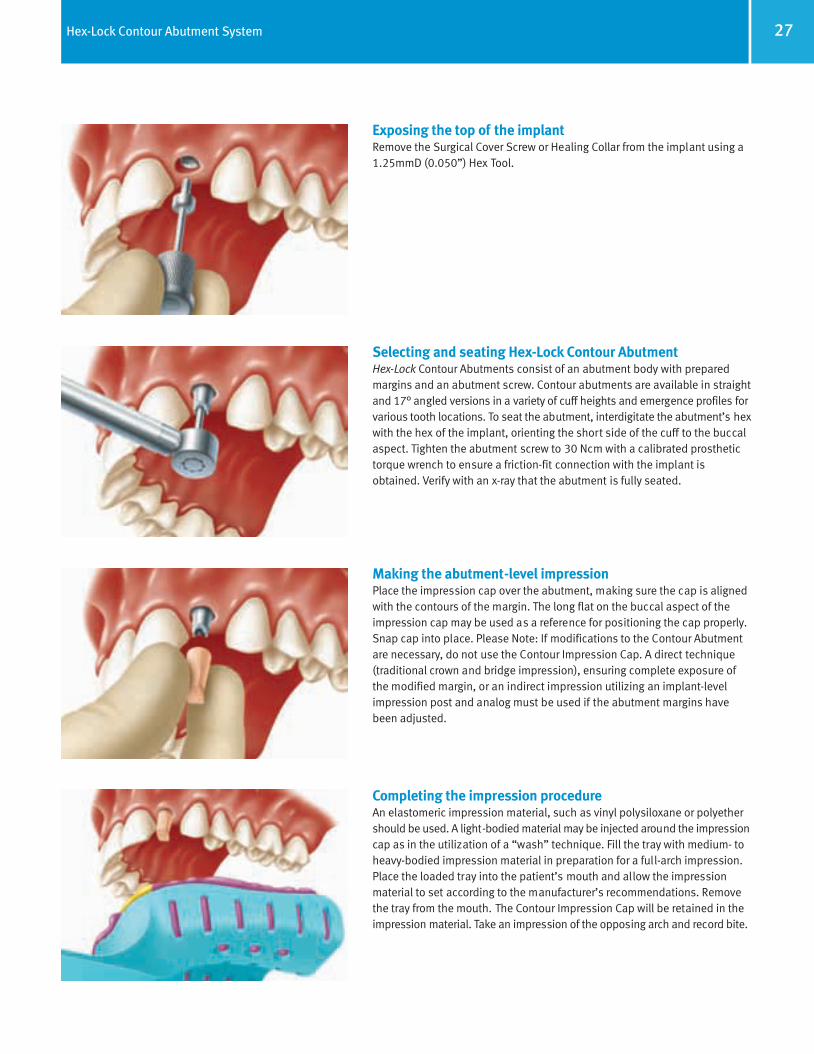
Exposing the top of the implantRemove the Surgical Cover Screw or Healing Collar from the implant using a1.25mmD (0.050”) Hex Tool.
Selecting and seating Hex-Lock Contour AbutmentHex-Lock Contour Abutments consist of an abutment body with preparedmargins and an abutment screw. Contour abutments are available in straightand 17° angled versions in a variety of cuff heights and emergence profiles forvarious tooth locations. To seat the abutment, interdigitate the abutment’s hexwith the hex of the implant, orienting the short side of the cuff to the buccalaspect. Tighten the abutment screw to 30 Ncm with a calibrated prosthetictorque wrench to ensure a friction-fit connection with the implant isobtained. Verify with an x-ray that the abutment is fully seated.
Making the abutment-level impressionPlace the impression cap over the abutment, making sure the cap is alignedwith the contours of the margin. The long flat on the buccal aspect of theimpression cap may be used as a reference for positioning the cap properly.Snap cap into place. Please Note: If modifications to the Contour Abutmentare necessary, do not use the Contour Impression Cap. A direct technique(traditional crown and bridge impression), ensuring complete exposure ofthe modified margin, or an indirect impression utilizing an implant-levelimpression post and analog must be used if the abutment margins havebeen adjusted.
Completing the impression procedureAn elastomeric impression material, such as vinyl polysiloxane or polyethershould be used. A light-bodied material may be injected around the impressioncap as in the utilization of a “wash” technique. Fill the tray with medium- toheavy-bodied impression material in preparation for a full-arch impression.Place the loaded tray into the patient’s mouth and allow the impressionmaterial to set according to the manufacturer’s recommendations. Removethe tray from the mouth. The Contour Impression Cap will be retained in theimpression material. Take an impression of the opposing arch and record bite.
66514_Pg01_35:66514_Pg01_35 3/14/11 11:49 AM Page 28

28 Hex-Lock Contour Abutment System
Fabricating and cementing the provisional prosthesisPrepare the provisional crown by applying acrylic to the Contour ProvisionalCoping according to traditional prosthodontic techniques. Block out thescrew access hole and cement the provisional prosthesis onto the Hex-LockContour Abutment with soft-access cement. Alternatively, use the provisionalcoping as a base for the fitting of a pre-fabricated shell crown as the temporary restoration.
Attaching the Contour Abutment AnalogAlign the Contour Abutment Analog with the corresponding color-codedContour Impression Cap in the impression and snap the analog into place.The abutment analog will replicate the Hex-Lock Contour Abutment in thestone model.
Pouring the working castUsing soft tissue material to represent gingival contours, pour the model indie stone. Utilize interocclusal bite registration to articulate the working castwith the opposing model.
Utilizing the Contour Waxing CopingPlace the Contour Waxing Coping on the abutment analog in the model,aligning the coping with the contours of the margin. Use wax, resin or otherwaxing materials to seal the margin area.
66514_Pg01_35:66514_Pg01_35 3/14/11 11:49 AM Page 29

Fabricating the wax copingCreate the wax coping according to traditional crown and bridge procedures.Attach a 10-gauge sprue with reservoir to the thickest part of the wax coping.Add an auxiliary sprue and vent as needed.
Casting the wax patternFollow traditional techniques to cast and finish the wax-up coping or metalframe. Send it to the clinician for a patient try-in. The dentist should confirmfit and marginal integrity before the veneering material is applied.
Finishing the final prosthesisApply the veneering material to the metal coping according to routine laboratory procedures. Send the finished restoration to the clinician for final delivery.
Delivering the final prosthesisRemove the provisional restoration and any remaining cement from theabutment. Retorque the abutment to 30 Ncm with a calibrated torquewrench. Seal the screw access channel in the abutment with a c otton pellet,light-curing resilient material or gutta-percha. This will ensure future accessto the screw head. Seat the final prosthesis onto the abutments and confirmfit, contour and marginal integrity. Check the bite for function and occlusion.Cement the final prosthesis with a cement of choice. To facilitate futureretrievability, a soft-access or temporary cement may be used. Provide thepatient with oral hygiene instructions prior to release.
29Hex-Lock Abutment System
66514_Pg01_35:66514_Pg01_35 3/14/11 11:49 AM Page 30

Notes
30 Notes
66514_Pg01_35:66514_Pg01_35 3/14/11 11:49 AM Page 31

Hex-Lock Abutment System
RestorativeManual
66514_Pg01_35:66514_Pg01_35 3/14/11 11:49 AM Page 32

Hex-Lock Abutments are manufactured from titanium alloy and used as the support foundation for single- or multiple-unit cement-retained,partially edentulous fixed restorations. These abutments consist of an abutment (fixation) screw and a preparable base which consists of a profiled upper portion, and an apex with a hex configuration with one-degree tapered flats, enabling it to friction-fit to the hex of theimplant. The abutment base can be modified either chairside or in the laboratory, to create a variety of contoured margins and abutmentprofiles to emulate the contours of the natural teeth it is replacing. Once prepared, these abutments are attached to the implant andimpressed following conventional crown and bridge techniques.
Hex-Lock Abutment[HLA3/4]
Hex-LockAbutment[AVHL/4]
Hex-LockAbutment[HLA5/6]
Hex-LockAbutment[HLA5/6]
Hex-LockAbutment[HLA4/5]
Cemented Crown Cemented Fixed Partial Denture Cemented Fixed Partial Denture
Abutment for the Internal Hex
Implant, 3.5mmDplatform
Abutment for the Internal Hex
Implant, 4.5mmDplatform
Abutment for the Internal Hex
Implant, 5.7mmD platform
Abutment for theAdVent Implant,
4.5mmD platform
Abutment for theWide Platform
AdVent, 5.7mmDplatform
32 Restorative options with Hex-Lock Abutments
66514_Pg01_35:66514_Pg01_35 3/14/11 11:50 AM Page 33

Fig. A
Implant/AbutmentInterface
MinimumHeight
4.7mmL
Hex-Lock Abutment with optionalAbutment Screw [HLTS2].
Hex-Lock Abutment with standardAbutment Screw [MHLAS].
Fig. B
AdVent Hex-Lock Abutmentwith Abutment Screw [AVHLS].
MinimumHeight
3.7mmL
MinimumHeight
3.2mmL
Implant/AbutmentInterface
Determining Hex-Lock Abutment modificationsHex-Lock Abutments extend 8.7mm vertically above the implant/abutmentinterface. Visually determine the modifications necessary for establishingmarginal and vertical contours. The abutments have one score line placed4.7mm above the top of the implant. When using the [MHLAS] Screw (includedwith the abutment), the maximum preparation on the abutment is 1mm belowthis line (Fig. B). If using the taller [HLTS2] Screw (sold separately), do not prepare the abutment below the score line in order to preserve adequate hex engagement within the screw (Fig. A).
Determining AdVent Hex-Lock Abutment modificationsHex-Lock Abutments for the AdVent Implant extend 7.0mm vertically above the top of the implant/abutment interface. Visually determine the modifications necessary for establishing marginal and vertical contours. To preserve sufficient hex engagement within the abutment screw, do notvertically reduce the abutment below the score line. This reduction will produce an abutment 3.2mm in height above the top of the Implant Analog (or implant).
Selecting the Hex-Lock AbutmentsFabricate the working cast utilizing one of the transfer procedures mentionedin the previous section. Hex-Lock Abutments (“abutment”) consist of an abutment body and an abutment screw. Abutments and corresponding transfers are available in a variety of diameters and flares designated for specific tooth locations. Note: The abutment should have the same profile as the Healing Collar and Direct or Indirect Transfer. For the AdVent Implantwith the 4.5mmD platform, the Indirect Transfer [AVIT/4] is used for both the4.5mmD and 6.5mmD Hex-Lock Abutments. The AdVent Implant with the5.7mmD platform uses the Indirect Transfer [HLT5/6], matching the 5.7mmDplatform of the Tapered Screw-Vent product line.
Fig. C
Implant/AbutmentInterface
Seating the Hex-Lock AbutmentsInterdigitate the abutment’s hex with the hex of the Implant Analog in theworking cast (or implant in the patient’s mouth) and place the abutment onto the Implant Analog (or implant). Thread the abutment screw throughthe abutment body and into the Implant Analog (or implant) with the HexTool. To complete seating and create a friction-fit connection, tighten theabutment screw to 30 Ncm with a calibrated torque wrench.
33Hex-Lock Abutment System – Selecting the abutment
66514_Pg01_35:66514_Pg01_35 3/14/11 11:50 AM Page 34
34 Hex-Lock Abutment System — Preparing the abutment
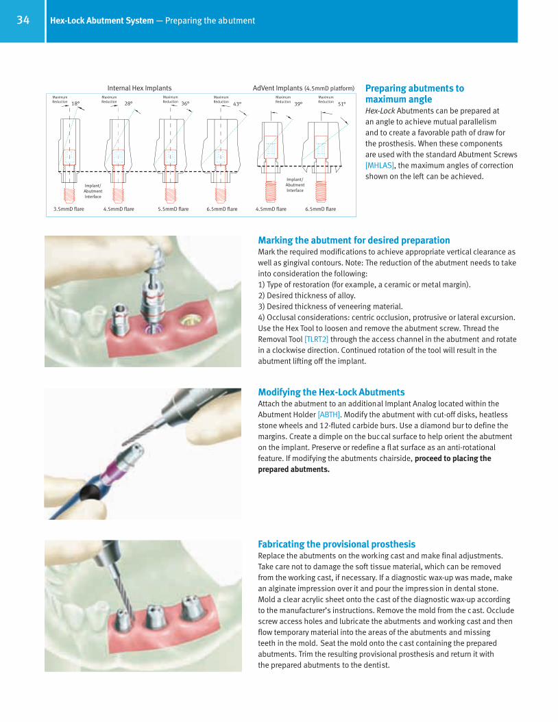
18° 28° 36° 43° 39° 51°
3.5mmD flare 4.5mmD flare 5.5mmD flare 6.5mmD flare 4.5mmD flare 6.5mmD flare
Implant/AbutmentInterface
Implant/AbutmentInterface
MaximumReduction
MaximumReduction
MaximumReduction
MaximumReduction
MaximumReduction
MaximumReduction
Internal Hex Implants AdVent Implants (4.5mmD platform) Preparing abutments to maximum angleHex-Lock Abutments can be prepared at an angle to achieve mutual parallelism and to create a favorable path of draw forthe prosthesis. When these components are used with the standard Abutment Screws[MHLAS], the maximum angles of correctionshown on the left can be achieved.
Marking the abutment for desired preparationMark the required modifications to achieve appropriate vertical clearance aswell as gingival contours. Note: The reduction of the abutment needs to takeinto consideration the following:1) Type of restoration (for example, a ceramic or metal margin).2) Desired thickness of alloy.3) Desired thickness of veneering material.4) Occlusal considerations: centric occlusion, protrusive or lateral excursion.Use the Hex Tool to loosen and remove the abutment screw. Thread theRemoval Tool [TLRT2] through the access channel in the abutment and rotatein a clockwise direction. Continued rotation of the tool will result in the abutment lifting off the implant.
Modifying the Hex-Lock AbutmentsAttach the abutment to an additional Implant Analog located within theAbutment Holder [ABTH]. Modify the abutment with cut-off disks, heatlessstone wheels and 12-fluted carbide burs. Use a diamond bur to define themargins. Create a dimple on the buccal surface to help orient the abutmenton the implant. Preserve or redefine a flat surface as an anti-rotational feature. If modifying the abutments chairside, proceed to placing the prepared abutments.
Fabricating the provisional prosthesisReplace the abutments on the working cast and make final adjustments.Take care not to damage the soft tissue material, which can be removedfrom the working cast, if necessary. If a diagnostic wax-up was made, makean alginate impression over it and pour the impression in dental stone.Mold a clear acrylic sheet onto the cast of the diagnostic wax-up accordingto the manufacturer’s instructions. Remove the mold from the cast. Occludescrew access holes and lubricate the abutments and working cast and thenflow temporary material into the areas of the abutments and missing teeth in the mold. Seat the mold onto the cast containing the prepared abutments. Trim the resulting provisional prosthesis and return it with the prepared abutments to the dentist.
66514_Pg01_35:66514_Pg01_35 3/21/11 2:53 PM Page 35

35Hex-Lock Abutment System — Making the impression
Placing the prepared abutmentsSterilize the prepared abutments before replacing them into the patient’smouth. Interdigitate the hexes of each abutment and implant utilizing thedimple to orient the abutment in the correct spatial position. Thread theabutment screw through the abutment body and into the implant with theHex Tool. Tighten each abutment screw to 30 Ncm with a calibrated torque wrench.
Making final adjustments to the abutmentsWith a round-end, 12-fluted carbide bur in a high-speed handpiece, makeminor modifications to the gingival and vertical contours of the abutmentsunder copious irrigation. After completing final modifications, retighten theabutment screws to the recommended torque. Take a radiograph to confirmthat the abutments are fully seated.
Making an impression of the prepared abutmentsBlock out the hex holes in the tops of the abutment screws with a mediumof choice to prevent the ingress of impression material. Remove excessmaterial so that the block-out is flush with the ends of the abutment screws.Make a conventional, full-arch, crown and bridge impression with an elastomeric impression material, such as vinyl polysiloxane. To insure aproper fit of the finished restoration, the abutments must remain in thepatient’s mouth after completing the impression procedure. Send theimpression to the laboratory to fabricate a porcelain-fused-to-metal bridge.
Cementing the provisional prosthesisBlock out the hex holes in the tops of the abutment screws with material ofchoice. If the laboratory has fabricated a provisional prosthesis, cement itonto the prepared abutments with soft-access cement. If a provisional prosthesis has not been fabricated, block out any undercuts and lightly lubricate the abutments. Fabricate a prosthesis over the abutments chairsidewith a light-cure or autopolymerizing tooth-colored acrylic material. For a more dense cure, remove the set provisional prosthesis from the mouth and place it in a curing unit. After curing, remove the restoration from themold, trim and polish, then cement the finished provisional prosthesis ontothe abutments.
66514_Pg01_35:66514_Pg01_35 3/14/11 11:52 AM Page 36
36 Prosthesis fabrication for Hex-Lock Abutment System — Fabricating the framework pattern
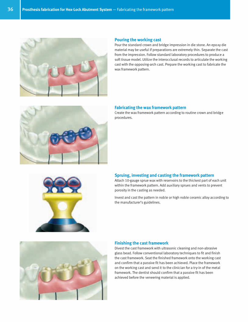
Pouring the working castPour the standard crown and bridge impression in die stone. An epoxy diematerial may be useful if preparations are extremely thin. Separate the castfrom the impression. Follow standard laboratory procedures to produce asoft tissue model. Utilize the interocclusal records to articulate the workingcast with the opposing-arch cast. Prepare the working cast to fabricate thewax framework pattern.
Fabricating the wax framework patternCreate the wax framework pattern according to routine crown and bridgeprocedures.
Spruing, investing and casting the framework patternAttach 10-gauge sprue wax with reservoirs to the thickest part of each unitwithin the framework pattern. Add auxiliary sprues and vents to preventporosity in the casting as needed.
Invest and cast the pattern in noble or high noble ceramic alloy according tothe manufacturer’s guidelines.
Finishing the cast frameworkDivest the cast framework with ultrasonic cleaning and non-abrasive glass bead. Follow conventional laboratory techniques to fit and finish the cast framework. Seat the finished framework onto the working cast and confirm that a passive fit has been achieved. Place the framework on the working cast and send it to the clinician for a try-in of the metalframework. The dentist should confirm that a passive fit has been achieved before the veneering material is applied.
66514_Pg36_55:66514_Pg36-55 3/14/11 1:19 PM Page 1

37Hex-Lock Abutment System — Seating the final restoration
Trying in the finished frameworkRemove the provisional restoration from the patient’s mouth. Retorque the abutment screws to 30 Ncm with a calibrated torque wrench. Seat thefinished framework onto the abutments. Verify that it fits passively, and thatno additional finishing or adjustment is required. Remove the framework.Reseat the provisional prosthesis with soft-access cement.
Return the framework to the laboratory on the working cast for completion of the fixed partial denture.
Applying the porcelain (veneering material)Prepare the framework to receive the opaque layer according to routine laboratory procedures.
Finishing the final prosthesisApply porcelain to the framework according to routine laboratory procedures.
Finish the porcelain and polish any metal margins, seat the finished prosthesis on the working cast and send it to the clinician for final delivery.
Delivering the final prosthesisRemove the provisional restoration from the patient’s mouth. Retorque theabutments to 30 Ncm with the calibrated torque wrench. Wait ten minutes,then retighten. This is done to compensate for clamping force lost due toscrew embedment. Seal the screw access channel in each abutment withcotton pellets and light-curing resilient material or gutta-percha. This willensure future access to the screw head. Seat the final prosthesis onto theabutments and confirm fit and contour. Check the occlusion. Verify that noadditional finishing or adjustment is required. Cement the final prosthesiswith a cement of choice. To facilitate future retrievability, a soft-accesscement may be used. Provide the patient with oral hygiene instructions prior to release.
66514_Pg36_55:66514_Pg36-55 3/14/11 1:19 PM Page 2

38 Notes
Notes
66514_Pg36_55:66514_Pg36-55 3/14/11 1:19 PM Page 3

Angled Abutment System
RestorativeManual
66514_Pg36_55:66514_Pg36-55 3/14/11 1:19 PM Page 4

40 Selecting Angled Abutments for fixed partial dentures
Connector: This intermediate component links the abutment head to the implant. It has acoronal octagon that interdigitates andforms a friction-fit with a mating octagon in the bottom of the abutment head, and a male hexagon at the base that interdigi-tates and forms a friction-fit connectionwith the implant’s hex. By combining amating hexagon with a mating octagon,
the abutment head can be oriented to 24 rotational positions for optimum placement.Inside the connector is a threaded bore that provides access for the abutment screw. When the abutment is fully assembled, the bottom of the abutment head interfaces directly with the top of the implant, and the connector strictly functions internally to linkthe two components together.
Friction-Fits with theAbutment’s Octagon
Friction-Fits with theImplant’s Hexagon
Adds No Transmucosal
Height
Angled Abutments are used for cemented single- and multi-unit restorations when the long axis of the implant is approximately 15° to 30°out of parallelism with the clinical long axis of the adjacent teeth. There must be acceptable soft tissue thickness to establish margins atleast 0.5mm subgingival for esthetics.
These abutment assemblies require minimum preparation, and consist of the following two options whichare used accordingly, depending on the hex orientation of the implant.
1) When the hex of the implant is oriented at time of implant surgery, so that the flat surface of one side ofthe hexagon of the implant is toward the direction of the implant angulation, then use the two-pieceAngled Abutment (Fig. 1). This design allows for 6 positional changes of 60°.
2) When the hex of the implant is not oriented with one of its flats in the direction of the implant angulation,then use what is referred to as the three-piece Angled Abutment assembly. This assembly consists of a20° angled head (Fig. 2) with a female octagon in the base that interdigitates with the male octagon ofthe abutment connector (Fig. 3). A vertical hole through the component provides access for the abutmentscrew (Fig. 4). This design allows for 24 positional changes of 15°.
Three-piece abutment components:Head: Angled at 20°, this portion of the abutment assembly functions as a support for the prosthesis,and can be prepared chairside or in the laboratory.
20° Head for 3-PieceAssembly
(24 positions)
Common Abutment Screw: To form the friction-fit between the components, the abutment screw shouldbe torqued to 30 Ncm. An internal hex in the top of the abutment screw accepts a 1.25mmD Hex Tool.
Internal Hex Accepts the1.25mmD Hex Tool.
20° Head for 2-Piece Assembly
(6 positions)
Fig. 2
Fig. 1
Fig. 3Connector for 3-PieceAssembly
Cemented Crown Cemented Fixed Partial Denture Cemented Fixed Partial Denture
Restorative applications with the Angled Abutment
Connector
Head
Screw
Fig. 4 Abutment Screw
66514_Pg36_55:66514_Pg36-55 3/14/11 1:19 PM Page 5

41Preparation guidelines for Angled Abutments
Implant
Abutment Screw
3.15mm
Hex/OctagonConnector
20° AbutmentHead
1.25mm
1.6mm
Angulation and transmucosal height requirements of the final abutment assemblyTo allow for an esthetic, subgingival connection between the abutment and prosthesis interface, determine the appropriate tissue depthon the labial or buccal surface. The prosthesis type (i.e. whether the prosthesis will have a metal or porcelain margin) and the depth of thelingual sulcus must also be considered. Prior to selecting the abutment assembly, make a final assessment of the appropriate angulationand emergence profile requirements. Trim abutments to accommodate for variations in final shape and gingival contours of the restoration.
When fully seated, the bottom of the head component interfaces directly with the top of the implant.
After all the abutment components are in place, the minimum vertical clearance between the implant interface and the opposing dentitionis 2.85mm for two-stage internal hex implants and 2.3mm for the one-stage AdVent Implants, as measured from top of the implant to thetop of the abutment screw. These are maximum reduction heights although prosthodontic requirements for cement retention of prostheses might be higher.
Once seated, use the appropriate tools to disengage the friction-fit abutment connector from both the head component and the implant.Use the Removal Tool [TLRT2] to remove the assembled abutment or individual connector from the implant. Use the octagon-hexagonRemoval Tool [OHRT] to remove the head component from the friction-fit connector if additional repositioning is required.
ImplantInterface
Bone Height
3.5mm
Total Height is 9.5mm5° Taper20° Angle25° Taper 8° Taper
MaximumReduction
66514_Pg36_55:66514_Pg36-55 3/14/11 1:19 PM Page 6

42 Two-piece Angled Abutment System — Selecting and placing the abutment
Selecting the type of Angled AbutmentAbutment selection is based upon the orientation of the implant’sinternal hex in relation to the angulation of the implant, relativeto the surrounding anatomical features. If one of the flat surfacesof the implant’s internal hex is oriented toward the angulation of the implant, then use the two-piece Angled Abutment as willbe discussed in the following pages. If there is no correlationbetween the angle of the implant and the flat surface of theinternal hex of the implant, then select the three-piece AngledAbutment, whose usage is discussed in the following section.
Exposing the top of the implantTapered Screw-Vent and Screw-Vent Implants: • Remove the Healing Collar with the 1.25mmD Hex Tool.
AdVent Implants: • Remove the Surgical Cover Screws [AVSC] with the 1.25mmD Hex Tool
and the Implant Extender [AVE] if present.
Initially seating the Angled AbutmentSelect the two-piece Angled Abutment corresponding to the dimensions ofthe implant platform being restored.
Remove the abutment from the packaging. Use the 1.25mmD hex tool toremove the abutment screw to allow for easy placement and alignment ofthe abutment. Carry the component to the implant (analog), interdigitateand press-fit the abutment’s hex to the implant’s (analog) hex.
Seating the Angled AbutmentThread the abutment screw through the access channel within the abutmentusing the 1.25mmD Hex Tool. Tighten the abutment screw to 30 Ncm with a calibrated torque wrench.
66514_Pg36_55:66514_Pg36-55 3/14/11 1:19 PM Page 7
43Two-piece Angled Abutment System — Preparing the abutment
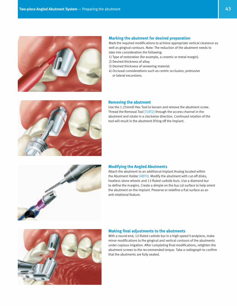
Marking the abutment for desired preparationMark the required modifications to achieve appropriate vertical clearance aswell as gingival contours. Note: The reduction of the abutment needs totake into consideration the following:1) Type of restoration (for example, a ceramic or metal margin).2) Desired thickness of alloy.3) Desired thickness of veneering material.4) Occlusal considerations such as centric occlusion, protrusive
or lateral excursions.
Removing the abutmentUse the 1.25mmD Hex Tool to loosen and remove the abutment screw.Thread the Removal Tool [TLRT2] through the access channel in the abutment and rotate in a clockwise direction. Continued rotation of the tool will result in the abutment lif ting off the implant.
Modifying the Angled AbutmentsAttach the abutment to an additional Implant Analog located within the Abutment Holder [ABTH]. Modify the abutment with cut-off disks, heatless stone wheels and 12-fluted carbide burs. Use a diamond bur to define the margins. Create a dimple on the buccal surface to help orientthe abutment on the implant. Preserve or redefine a flat surface as an anti-rotational feature.
Making final adjustments to the abutmentsWith a round-end, 12-fluted carbide bur in a high-speed handpiece, makeminor modifications to the gingival and vertical contours of the abutmentsunder copious irrigation. After completing final modifications, retighten theabutment screws to the recommended torque. Take a radiograph to confirmthat the abutments are fully seated.
66514_Pg36_55:66514_Pg36-55 3/14/11 1:19 PM Page 8

44 Two-piece Angled Abutment System — Making the impression
Making an impression of the prepared abutmentBlock out the screw access channel in the top of the abutment with a mediumof choice to prevent the ingress of impression material. Remove excessmaterial so that the block-out is flush with the contour of the abutment.Failure to do so may prevent an accurate impression procedure. Make aconventional, full-arch, crown and bridge impression with an elastomericimpression material, such as vinyl polysiloxane. To insure a proper fit of thefinished restoration, the abutment must remain in the patient’s mouth aftercompleting the impression procedure. Send the impression to the laboratoryto fabricate a porcelain-fused-to-metal prosthesis.
Fabricating the provisional prosthesisIf a diagnostic wax-up was made, make an alginate impression over it and pour the impression in dental stone. Mold a clear acrylic sheet onto theduplicate cast of the diagnostic wax-up according to the manufacturer’sinstructions. Remove the mold from the cast and flow temporary materialinto the area of the abutment and edentulous space. Lubricate the preparedabutment and then seat the mold onto the abutment in the patient’s mouth.After the material sets, remove it from the mouth and trim and poli sh theresulting provisional prosthesis.
Cementing the provisional prosthesisBlock out the hex hole in the tops of the abutment screw with material of choice. Cement the provisional prosthesis onto the prepared abutmentwith soft-access cement. Alternatively, lightly lubricate the abutment and fabricate a provisional prosthesis over the abutment chairside withlight-curing material. Once the material is cured, remove the provisionalrestoration from the patient’s mouth, trim and polish it prior to cementationof the finished provisional prosthesis onto the abutment.
Pouring the working castPour the standard crown and bridge impression in die stone. An epoxy diemay be useful with an extremely thin preparation. Separate the cast from theimpression. Use the interocclusal records to articulate the working cast withthe opposing-arch cast. Prepare the working cast for fabrication of the waxframework pattern.
Proceed to common procedures for fabricatingthe framework pattern on page 49
66514_Pg36_55:66514_Pg36-55 3/14/11 1:19 PM Page 9
45Three-piece Angled Abutment System — Aligning the abutment
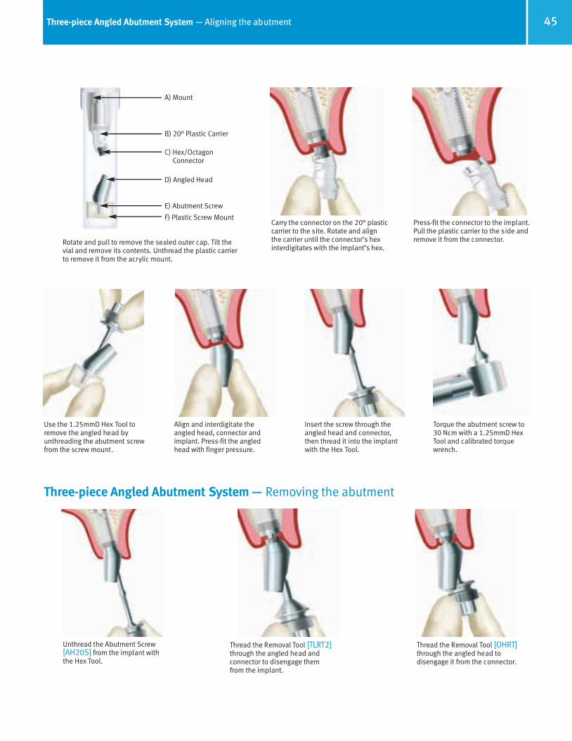
Rotate and pull to remove the sealed outer cap. Tilt thevial and remove its contents. Unthread the plastic carrierto remove it from the acrylic mount.
Carry the connector on the 20° plasticcarrier to the site. Rotate and align the carrier until the connector’s hexinterdigitates with the implant’s hex.
Press-fit the connector to the implant.Pull the plastic carrier to the side andremove it from the connector.
Use the 1.25mmD Hex Tool toremove the angled head byunthreading the abutment screwfrom the screw mount.
Insert the screw through theangled head and connector,then thread it into the implantwith the Hex Tool.
E) Abutment Screw
B) 20° Plastic Carrier
D) Angled Head
C) Hex/OctagonConnector
F) Plastic Screw Mount
A) Mount
Torque the abutment screw to30 Ncm with a 1.25mmD HexTool and calibrated torquewrench.
Align and interdigitate theangled head, connector andimplant. Press-fit the angledhead with finger pressure.
Three-piece Angled Abutment System — Removing the abutment
Thread the Removal Tool [TLRT2]through the angled head and connector to disengage them from the implant.
Thread the Removal Tool [OHRT]through the angled head to disengage it from the connector.
Unthread the Abutment Screw[AH20S] from the implant withthe Hex Tool.
66514_Pg36_55:66514_Pg36-55 3/14/11 11:06 AM Page 10

46 Three-piece Angled Abutment System — Attaching the abutment
Initially seating the three-piece Angled AbutmentUse standard laboratory procedures to fabricate the implant level soft tissueworking cast from the open- or closed-tray impression. The 20° AngledAbutment comes packaged on a carrier angled at 20° to aid in the c orrectplacement of the connector and angled head.Use the angled carrier to gently position and place the connector:• Rotate the carrier which simulates the final position of the angled head,
to obtain optimum orientation of the connector.
• Align the hexagon of the connector with the hexagon of the Implant Analogand press-fit the connector into position.
• Pull the angled carrier to the side and remove it from the connector.
Initially seating the three-piece Angled Abutment Visually determine the optimal rotational position of the angled abutmenthead. If the angled carrier was aligned correctly at the time the connectorwas placed, the angled head will be in its correct orientation. Place the abutment head on the connector by interdigitating the octagon in the bottom of the head component with the mating octagon on the top of the connector.
Reorienting the abutment head componentRemove the abutment head from the connector. Mark the buccal facet of theconnector with a felt-tipped pen to help visualize its correct reorientation.Rotate the head counter-clockwise 1/8 of a turn until one facet of its internaloctagon aligns with the next adjacent facet of the mating octagon on top ofthe connector. Interdigitate the octagons and place the head onto the connector. This allows orienting the head to eight positions at 45° increments. If further adjustment is required remove the combined abutment head and connector from the working cast with the Removal Tool[TLRT2]. Rotate assembly 1/6 of a turn clockwise until one facet of the connector’s bottom hex aligns with the next adjacent facet of the ImplantAnalog’s hex. Interdigitate the hexes and replace the abutment onto theimplant. This allows orienting the base to six positions at 60° increments.
Tightening the abutment screwOnce the Angled Abutment head is placed in the optimal position for the case,insert the abutment screw through the an gled head, and thread it throughthe connector and into the Implant Analog with the 1.25mmD Hex Tool.
Finger-tighten the abutment screw, then tighten to 30 Ncm with a calibratedtorque wrench.
CONNECTORDouble-Sided Friction-Fit
Mates with the Implant andAbutment Head
ABUTMENT SCREW(Included, but Not Shown Here)
Mating Octagons
HEAD COMPONENTAngled at 20°
66514_Pg36_55:66514_Pg36-55 3/14/11 11:06 AM Page 11

47Three-piece Angled Abutment System — Modifying the abutment
Modifying the Angled AbutmentAttach the abutment to an additional Implant Analog located within theAbutment Holder [ABTH]. Modify the abutment with cut-off disks, heatlessstone wheels and 12-fluted carbide burs. Use a diamond bur to define themargins. Create a dimple on the buccal surface to help orient the abutment onthe implant. Preserve or redefine a flat surface as an anti-rotational feature.
Fabricating the provisional prosthesisReplace the abutment on the working cast and make final adjustments.Remove the soft tissue material from the working cast if necessary. If a diagnostic wax-up was made, make an alginate impression over it and pourthe impression in dental stone. Mold a clear acrylic sheet onto the cast ofthe diagnostic wax-up according to the manufacturer’s instructions. Removethe mold from the cast. Block out the screw access hole and lubricate theabutment and working cast, then flow temporary material into the area ofthe abutment and missing tooth in the mold. Seat the mold onto the castcontaining the prepared abutment. Trim the resulting provisional prosthesisand return it with the prepared abutment to the dentist.
Removing the Angled AbutmentA Removal Tool [TLRT2] is required to disengage the Angled Abutment’s friction-fit connection once the assembly has been fully seated. Remove the abutment screw with the 1.25mmD Hex Tool. Insert the Removal Toolthrough the head component, thread it through the connector and into theImplant Analog until the abutment assembly lifts out of the working cast.
Send the prepared abutment and provisional prosthesis to the clinician for placement.
Placing the final abutmentSterilize the prepared, assembled Angled Abutment before placing it intothe patient’s mouth. Interdigitate the hexagons and press-fit the abutmentassembly to the implant. Insert the abutment screw into the Angled Abutmentassembly, thread it through the assembly and into the implant with the Hex Tool. Tighten the abutment screw to 30 Ncm with a calibrated torquewrench. Take an x-ray to confirm that the abutment is fully seated.
Wait ten minutes, then retighten the abutment.
66514_Pg36_55:66514_Pg36-55 3/14/11 11:06 AM Page 12

48 Three-piece Angled Abutment System — Making the impression
Modifying the abutmentVisually determine any further modifications necessary for establishingmarginal, labial and vertical contours. Make any modifications to the abutment with copious irrigation, and a round-end diamond or 12-fluted carbide bur in a high-speed handpiece.
Making an impression of the prepared abutmentBlock out the access hole to the abutment screw with a light-curing resilientmaterial or gutta-percha to preserve easy access to the screw head. Make aconventional, full-arch, crown and bridge impression with an elastomericimpression material, such as vinyl polysiloxane. Make an impression of theopposing arch and take a bite registration.
Cementing the provisional prosthesisCement the prosthesis onto the prepared abutment with soft-access cement.Alternatively, lightly lubricate the abutment and fabricate a provisional prosthesis over the abutment chairside with light-curing material. Once thematerial is cured, remove the provisional restoration from the patient’smouth, trim and polish, and then cement the finished provisional prosthesisonto the abutment.
Send the impressions and interocclusal records to the laboratory for fabrication of the porcelain-fused-to-metal crown.
Pouring the working castPour the standard crown and bridge impression in die stone. An epoxy diemay be useful with an extremely thin preparation. Separate the cast from theimpression. Use the interocclusal records to articulate the working cast withthe opposing-arch cast. Prepare the working cast for fabrication of the waxframework pattern.
Proceed to common procedures for fabricatingthe framework pattern on page 49
66514_Pg36_55:66514_Pg36-55 3/14/11 11:06 AM Page 13

49Prosthesis fabrication with the Angled Abutment System — Common procedures for fabricating the framework pattern
Prepare the framework for applying porce-lain.
Fabricating the wax framework patternCreate the wax framework pattern according to standard crown and bridgeprocedures.
Spruing, investing and casting the framework patternAttach 10-gauge sprue wax with reservoir to the thickest part of the framework pattern. Add an auxiliary sprue and vent to prevent porosity inthe casting as needed.
Invest and cast the pattern in noble or high noble ceramic alloy according tothe manufacturer’s guidelines.
Finishing the cast frameworkDivest the cast framework with ultrasonic cleaning and non-abrasive glassbead. Remove the soft tissue replica from the working cast and follow routine laboratory procedures to fit and finish the framework. Seat the finished framework onto the working cast.
Applying the porcelain (veneering material)Prepare the framework to receive the opaque layer according to routine laboratory procedures.
66514_Pg36_55:66514_Pg36-55 3/14/11 11:06 AM Page 14

50 Prosthesis fabrication with the Angled Abutment System — Seating the final restoration
Finishing the final prosthesisApply porcelain to the framework, finish the porcelain, and polish any metal margins according to routine laboratory procedures. Seat the finished prosthesis on the working cast and send it to the clinician for final delivery.
Delivering the final prosthesisRemove the provisional restoration from the patient’s mouth. Retorque theabutment screw to 30 Ncm with a calibrated torque wrench.
Delivering the final prosthesisSeal the screw access channel in the abutment with cotton pellets and light-curing resilient material or gutta-percha. This will ensure easy access to the screw head. Seat the final prosthesis onto the abutment and confirmfit and contour. Check the occlusion. Verify that no additional finishing oradjustment is required.
Delivering the final prosthesisCement the final prosthesis with cement of choice. To facilitate future retrievability, a soft-access cement may be used. Provide the patient withoral hygiene instructions prior to release.
66514_Pg36_55:66514_Pg36-55 3/14/11 11:06 AM Page 15

“Cast-To” Gold Abutment System
RestorativeManual
66514_Pg36_55:66514_Pg36-55 3/14/11 11:06 AM Page 16

52 Restorative options with “Cast-To” Gold Abutments
“Cast-To” Gold Abutments are used to fabricate implant-level, custom cast restorations that provide subgingival margins for esthetics,reduced height for vertical occlusal clearance and/or custom angles. These abutment assemblies consist of a hex-engaging gold base, an abutment screw and a castable press-fit Plastic Sheath.
The press-fit Plastic Sheath is modified and incorporated into the wax framework pattern. After investing, the wax and Plastic Sheath are burned out of the pattern following the lost wax process. When molten alloy is cast into the investment mold, the base component is incorporated into the casting and provides a machined interface that mates directly with the implant. The finished casting can be used as a custom abutment that receives a cemented single- or multiple-unit restoration, or it can be veneered and used as a single-unit, screw-retained, combined abutment-and-crown. Caution: Multi-unit, screw-retained restorations cannot be fabricated with these abutments; use non-engaging abutments for these types of restorations.
The gold base is fabricated from a non-oxidizing alloy that promotes chemical adhesion of the cast alloy, but does not permit the adhesion of porcelain. Therefore, a porcelain bonding alloy must be added to all areas of the gold base where porcelain veneering is desired.
Screw-Retained Crown Custom Angled Abutment Custom Abutments
“Cast-To” Gold Abutment
[HLA3G]
“Cast-To” Gold Abutment
[AVGA]
“Cast-To”Gold Abutment
[HLA5G]
“Cast-To” Gold Abutment
[HLA4G]Abutment for the AdVent
Implant, 4.5mmD platform
Abutment for the Wide PlatformAdVent, 5.7mmD
platform
Abutment for the Internal Hex
Implant, 4.5mmD platform
Abutment for the Internal Hex
Implant, 5.7mmDplatform
Abutment for the Internal Hex
Implant, 3.5mmD platform
“Cast-To” Gold Abutment
[HLA5G]
66514_Pg36_55:66514_Pg36-55 3/14/11 11:06 AM Page 17
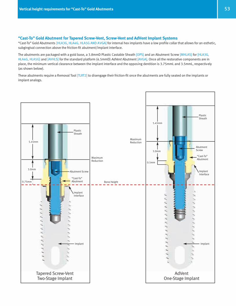
53Vertical height requirements for “Cast-To” Gold Abutments
“Cast-To” Gold Abutment for Tapered Screw-Vent, Screw-Vent and AdVent Implant Systems“Cast-To” Gold Abutments [HLA3G, HLA4G, HLA5G AND AVGA] for internal hex implants have a low profile collar that allows for an esthetic,subgingival connection above the friction-fit abutment/implant interface.
The abutments are packaged with a gold base, a 3.8mmD Plastic Castable Sheath [OPS] and an Abutment Screw [MHLAS] for [HLA3G,HLA4G, HLA5G] and [AVHLS] for the standard platform (4.5mmD) AdVent Abutment [AVGA]. Once all the restorative components are inplace, the minimum vertical clearance between the implant interface and the opposing dentition is 3.75mmL and 3.5mmL, respectively (as shown below).
These abutments require a Removal Tool [TLRT2] to disengage their friction-fit once the abutments are fully seated on the implants orimplant analogs.
ImplantImplant
Abutment Screw
“Cast-To”Abutment
ImplantInterface
0.75mm
3.0mm
0.5mm
3.0mm
Bone Height
MaximumReduction
MaximumReduction
Tapered Screw-VentTwo-Stage Implant
AdVentOne-Stage Implant
PlasticSheath
AbutmentScrew
“Cast-To”Abutment
PlasticSheath
ImplantInterface
5.45mm
5.45mm
66514_Pg36_55:66514_Pg36-55 3/14/11 11:06 AM Page 18
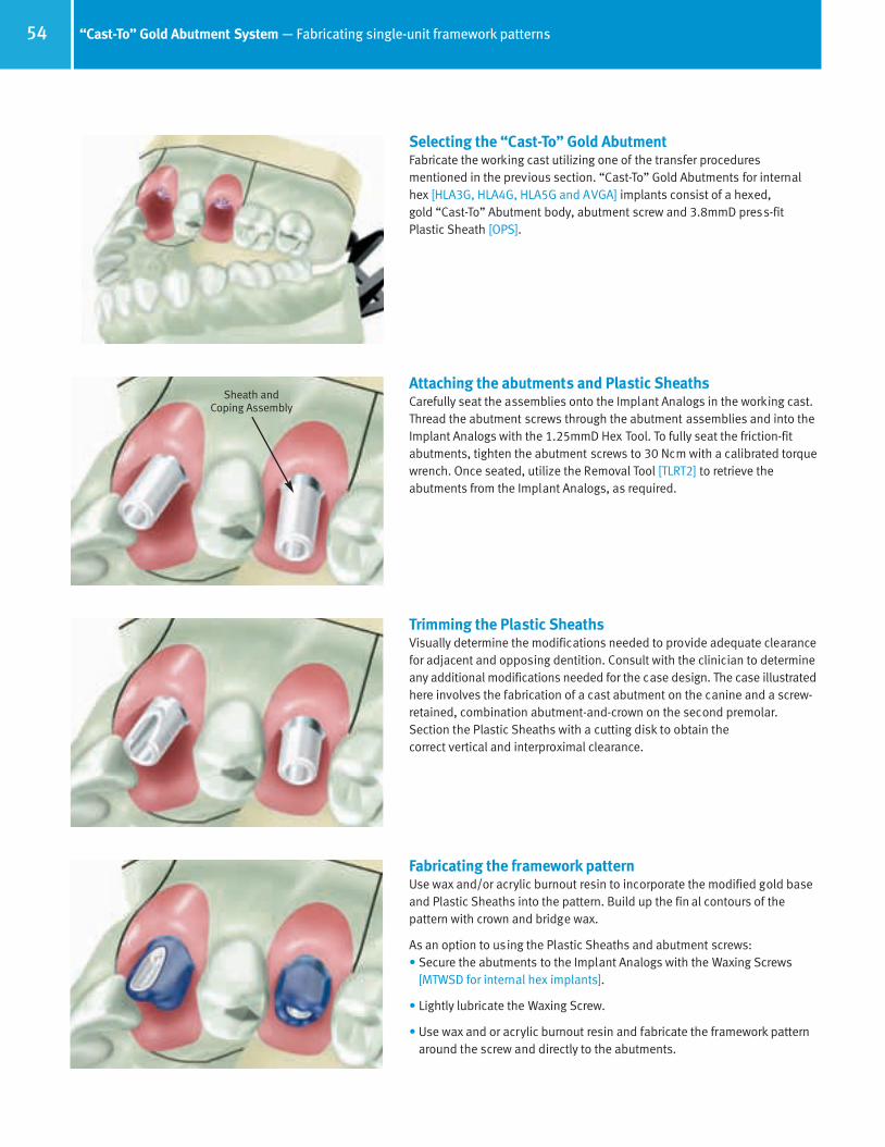
54 “Cast-To” Gold Abutment System — Fabricating single-unit framework patterns
Sheath and Coping Assembly
Selecting the “Cast-To” Gold AbutmentFabricate the working cast utilizing one of the transfer procedures mentioned in the previous section. “Cast-To” Gold Abutments for internalhex [HLA3G, HLA4G, HLA5G and AVGA] implants consist of a hexed, gold “Cast-To” Abutment body, abutment screw and 3.8mmD press-fit Plastic Sheath [OPS].
Attaching the abutments and Plastic SheathsCarefully seat the assemblies onto the Implant Analogs in the working cast.Thread the abutment screws through the abutment assemblies and into theImplant Analogs with the 1.25mmD Hex Tool. To fully seat the friction-fitabutments, tighten the abutment screws to 30 Ncm with a calibrated torquewrench. Once seated, utilize the Removal Tool [TLRT2] to retrieve the abutments from the Implant Analogs, as required.
Trimming the Plastic SheathsVisually determine the modifications needed to provide adequate clearancefor adjacent and opposing dentition. Consult with the clinician to determineany additional modifications needed for the case design. The case illustratedhere involves the fabrication of a cast abutment on the canine and a screw-retained, combination abutment-and-crown on the second premolar. Section the Plastic Sheaths with a cutting disk to obtain the correct vertical and interproximal clearance.
Fabricating the framework patternUse wax and/or acrylic burnout resin to incorporate the modified gold baseand Plastic Sheaths into the pattern. Build up the fin al contours of the pattern with crown and bridge wax.
As an option to using the Plastic Sheaths and abutment screws:• Secure the abutments to the Implant Analogs with the Waxing Screws
[MTWSD for internal hex implants].
• Lightly lubricate the Waxing Screw.
• Use wax and or acrylic burnout resin and fabricate the framework patternaround the screw and directly to the abutments.
66514_Pg36_55:66514_Pg36-55 3/14/11 11:06 AM Page 19

55“Cast-To” Gold Abutment System — Fabricating the metal frameworks
Spruing, casting and divesting of the metal frameworkAttach 10-gauge sprue wax with reservoirs to the thickest part of each unit.Carefully apply a thin layer of wax or burnout resin at the junction of theabutment and the Plastic Sheath to ensure a smooth casting. Add auxiliarysprues and vents to prevent porosity in the casting as needed. Do not use a debubblizer when investing the gold or plastic components.
When casting to gold components, the casting alloy must not exceed a casting temperature of 2350°F/1288°C. Cast the framework pattern according to conventional techniques utilizing a two-stage burnout, which is standard practice with patterns containing plastic or resin. The burnouttemperature should not exceed 1500°F/815°C, with a hold time of no longerthan 1 hour. Utilize high noble or noble alloy with a compatible investmentmaterial, as described in the manufacturer’s guidelines.
Divest the casting; chemical investment removers may also be used withgold components. To ensure that the fitting surface of the incorporated copings are not damaged, protect the abutment interface while blasting the abutment with glass bead. Clean the casting in an ultrasonic unit. Refinethe screw access holes within the casting by hand-rotating the Reamer for“Cast-To”Abutments [MRI for HLA3G, HLA4G and HLA5G; PR for A VGA].
Removing the framework patternRemove the abutment screw with the 1.25mmD Hex Tool. Thread theRemoval Tool [TLRT2] through the abutment pattern and into the implant toremove the pattern from the Implant Analog.
Finishing the metal frameworkConfirm that a passive fit has been achieved on the corresponding ImplantAnalog in the working cast. The soft tissue replica can be removed from theworking cast to provide visual access to the cast abutment/implant analogconnection, if desired. Use the abutment screws to secure the finished castmetal abutments to the Implant Analogs in the working cast and return it tothe clinician for try-in. Make sure the clinician has the appropriate RemovalTool [TLRT2] to disengage the incorporated “Cast-To” Gold Abutments fromthe working cast.
66514_Pg36_55:66514_Pg36-55 3/14/11 11:06 AM Page 20

56 “Cast-To” Gold Abutment System — Trying in the metal frameworks
Removing the healing componentsUnthread the abutment screws with the 1.25mmD Hex Tool. Remove the abutments from the working cast with the appropriate removal tool. Sterilize the components according to standard clinical procedures. Remove the provisional restoration from the patient’s mouth. Unthread theHealing Collars or Surgical Cover Screws with the 1.25mmD Hex Tool. Cleanand sterilize the components for placement after the cast abutment try-in.
Placing the cast abutmentsInterdigitate the hex of each cast post with its corresponding implant, thenuse the 1.25mmD Hex Tool to thread the abutment screw through the castpost body and into the implant. Tighten the abutment screw to 30 Nc m with a calibrated torque wrench. Wait ten minutes, then retighten the cast posts to 30 Ncm. Take a radiograph to verify that the cast posts are completely seated.
Canine: cemented crown — option 1Make a crown and bridge impression of the seated cast post. Place the provisional fabricated by the laboratory or chairside on the cast abutment. Return the impression to the laboratory for the fabrication of a porcelain-fused-to-metal prosthesis according to routine laboratory procedures for crown and bridge.
Making the adjustments to the cast abutmentsThe premolar will be a screw-retained, combination post-and-porcelain-fused-to-metal crown. The canine will be a cast abutment with a porcelain-fused-to-metal crown cemented onto it. To make allowance for the different restorative procedures, make the required modifications to the gingival, occlusal and interproximal contours of the cast abutmentswith a round-end diamond or 12-fluted carbide bur in a high-speed handpiece, and under copious irrigation.
Follow appropriate procedures for each type or restoration listed below. Note that two options are available for restoring the cast abutment in thecanine position.
66514_Pg56_93:66514_Pg56_93 3/14/11 11:12 AM Page 1

57“Cast-To” Gold Abutment System — Finishing the metal frameworks
Implant
Porcelain Veneer
Cast Post
Cement Layer(White)
Metal Coping
Screw AccessHole
Canine: cemented crown — option 2Unthread the abutment screw with the Hex Tool. Remove the abutment postfrom the mouth with the appropriate Removal Tool [TLRT2]. Sterilize the castpost assembly according to standard clinical procedures and reseat it on the working cast. Select a tooth shade for the restoration, reseat the healingcomponents with the 1.25mmD Hex Tool and replace the provisional restoration in the patient’s mouth. Send the working cast with the cast post to the laboratory for fabrication of the final porcelain-fused-to-metal restoration. The laboratory can use the cast post as a die to fabricate the coping.
Canine: cemented crown — option 2Prepare the abutment for fabrication of a porcelain-fused-to-metal restoration. Seal the abutment screw access hole of the cast post with aresilient material. Lubricate the cast post and flow autopolymerizing burnoutresin over the contour of the cast post above the proposed restoration finishline. Do not use crown and bridge wax directly on the cast post, as it can pullaway from the metal and cause inaccuracies in the final metal coping.
Canine: cemented crown — options 1 & 2 Build up the final contour of the coping with crown and bridge wax. Attach 10-gauge sprue wax to the thickest part of the coping.Invest the coping:• Option 1: Follow standard setting expansion of the investment material
when using a stone die.
• Option 2: Allow for a greater setting expansion of the investment materialwhen using a metal die (abutment). This will compensate for the lack ofdie spacer used on the abutment when the coping pattern was fabricated.
Canine: cemented crown — options 1 & 2 Fabricate the porcelain-fused-to-metal crown according to routine laboratoryprocedures. The result will be a three-piece prosthesis consisting of a screw-retained post (two-piece) for the implant, and a porcelain-fused-to-metal crown that will be cemented onto the post.
66514_Pg56_93:66514_Pg56_93 3/14/11 11:12 AM Page 2
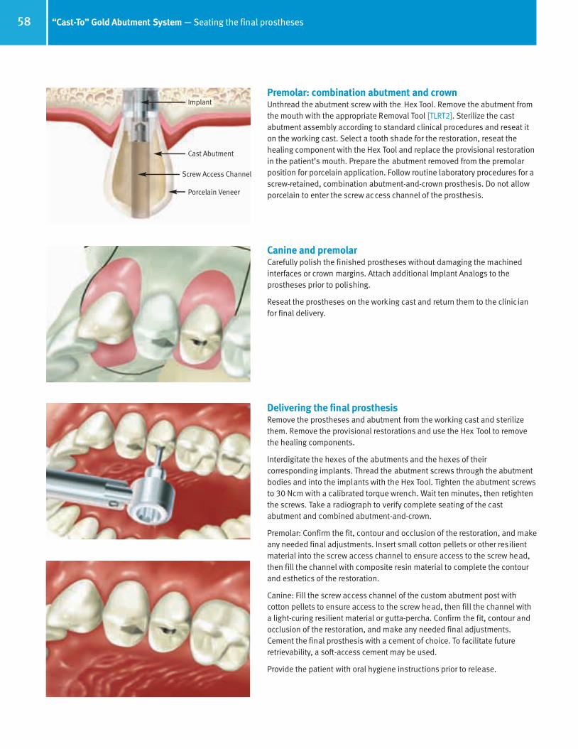
58 “Cast-To” Gold Abutment System — Seating the final prostheses
Implant
Porcelain Veneer
Cast Abutment
Screw Access Channel
Premolar: combination abutment and crownUnthread the abutment screw with the Hex Tool. Remove the abutment fromthe mouth with the appropriate Removal Tool [TLRT2]. Sterilize the cast abutment assembly according to standard clinical procedures and reseat iton the working cast. Select a tooth shade for the restoration, reseat thehealing component with the Hex Tool and replace the provisional restorationin the patient’s mouth. Prepare the abutment removed from the premolarposition for porcelain application. Follow routine laboratory procedures for ascrew-retained, combination abutment-and-crown prosthesis. Do not allowporcelain to enter the screw access channel of the prosthesis.
Canine and premolarCarefully polish the finished prostheses without damaging the machinedinterfaces or crown margins. Attach additional Implant Analogs to the prostheses prior to polishing.
Reseat the prostheses on the working cast and return them to the clinicianfor final delivery.
Delivering the final prosthesisRemove the prostheses and abutment from the working cast and sterilizethem. Remove the provisional restorations and use the Hex Tool to removethe healing components.
Interdigitate the hexes of the abutments and the hexes of their corresponding implants. Thread the abutment screws through the abutmentbodies and into the implants with the Hex Tool. Tighten the abutment screwsto 30 Ncm with a calibrated torque wrench. Wait ten minutes, then retightenthe screws. Take a radiograph to verify complete seating of the cast abutment and combined abutment-and-crown.
Premolar: Confirm the fit, contour and occlusion of the restoration, and makeany needed final adjustments. Insert small cotton pellets or other resilientmaterial into the screw access channel to ensure access to the screw head,then fill the channel with composite resin material to complete the contourand esthetics of the restoration.
Canine: Fill the screw access channel of the custom abutment post with cotton pellets to ensure access to the screw head, then fill the channel with a light-curing resilient material or gutta-percha. Confirm the fit, contour andocclusion of the restoration, and make any needed final adjustments.Cement the final prosthesis with a cement of choice. To facilitate futureretrievability, a soft-access cement may be used.
Provide the patient with oral hygiene instructions prior to release.
66514_Pg56_93:66514_Pg56_93 3/14/11 11:12 AM Page 3

PureForm Ceramic System
RestorativeManual
66514_Pg56_93:66514_Pg56_93 3/14/11 11:12 AM Page 4

60 Restorative options with PureForm Ceramic System
The PureForm Ceramic System is designed to fabricate single-unit fixed restorations in areas of the mouth with high esthetic demands,specifically the anterior and premolar regions. This product should not be splinted together for multiple-unit cases, removable partial dentures or bridgework.
The PureForm Ceramic System consists of a Ceramic Coping (Fig. 1), a titanium alloy metal Core Abutment (Fig. 2) and an abutment (retaining) screw (Fig. 3).
The Ceramic Copings are molded from a material with a base composition of 70% Alumina and 30%Zirconia. The material has an A2 shade which is added to the material prior to the forming and sinteringprocess. The copings are molded to resemble the proportionally undersized shape of natural teeth tolend support to the porcelain veneering material: central incisor, lateral incisor, canine and premolar. Twoadditional shapes are available to assist with angled implants, molded to form a 17° pre angled lateralincisor and a 17° preangled central incisor. The undersized shape of the copings allows the technician in many cases to apply an even thickness of ceramic veneering material without further modification. In case the Ceramic Copings need to be reduced, they can be prepared to a wall thickness of 0.5mm.Internally the coping has a conical shape with one flat surface on the buccal/labial wall. This flat willinterdigitate with the corresponding flat of the Try-in and Core Abutment.
The Core Abutment is available for the Tapered Screw-Vent and Screw-Vent 3.5mmD and 4.5mmD platforms. Each Core Abutment has a base with a hex configuration having one-degree tapered flats,enabling it to friction-fit to the hex of the implant. The profiled upper portion (cuff) flares to a standard4.5mmD and can be used with any shape of Ceramic Coping. The height of the Core Abutment is 4.9mmabove the cuff which is available in two heights: 0.5mm and 1.5mm. The conical upper portion has a flat surface on one side which is oriented to the buccal/labial when connecting to the implant. The Core Abutment comes packaged with the Abutment Screw [MHLAS].
To assist the technician and the clinician in the selection of the correct height of Core Abutment and Ceramic Coping, the following Try-inKits are available:
1) Abutment Try-in Kit [CAHKIT]: Metal Try-ins manufactured to similar specifications as the Core Abutments. Supplied in the two availableheights and implant platform diameters (4 pieces in total). They are color-coded to ensure ease of use. The kit comes packaged with thetwo separate abutment screws.
2) Plastic Try-in Kit [PTKIT]: Plastic components molded to the same shapes as the six Ceramic Copings. These parts are used to determineshape, contour and angle of the required Ceramic Coping, as well as if the ceramic abutment system is the best restorative option priorto acquiring the components.
ContraindicationsNot for screw-retained prosthetics. Not to be used to restore molars. Metal Core Abutment should not be prepped. Plastic Try-ins shouldnot be used for temporary restorations.
Core Abutment
Ceramic Coping(6 Configurations)
Fig. 2
Fig. 1
Fig. 3 Abutment Screw
66514_Pg56_93:66514_Pg56_93 3/14/11 11:12 AM Page 5
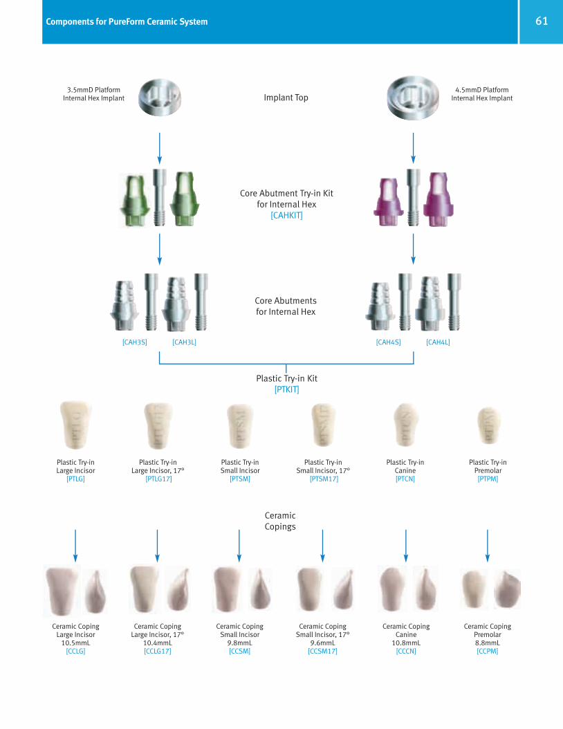
61Components for PureForm Ceramic System
Implant Top
Ceramic CopingLarge Incisor
10.5mmL[CCLG]
3.5mmD PlatformInternal Hex Implant
4.5mmD PlatformInternal Hex Implant
Ceramic CopingLarge Incisor, 17°
10.4mmL[CCLG17]
Ceramic CopingSmall Incisor
9.8mmL[CCSM]
Ceramic CopingSmall Incisor, 17°
9.6mmL[CCSM17]
Ceramic CopingCanine
10.8mmL [CCCN]
Ceramic CopingPremolar8.8mmL [CCPM]
[CAH3S] [CAH3L]
CeramicCopings
[CAH4S] [CAH4L]
Plastic Try-inLarge Incisor
[PTLG]
Plastic Try-inLarge Incisor, 17°
[PTLG17]
Plastic Try-inSmall Incisor
[PTSM]
Plastic Try-inSmall Incisor, 17°
[PTSM17]
Plastic Try-inCanine [PTCN]
Plastic Try-inPremolar [PTPM]
Plastic Try-in Kit [PTKIT]
Core Abutmentsfor Internal Hex
Core Abutment Try-in Kitfor Internal Hex
[CAHKIT]
66514_Pg56_93:66514_Pg56_93 3/14/11 11:14 AM Page 6
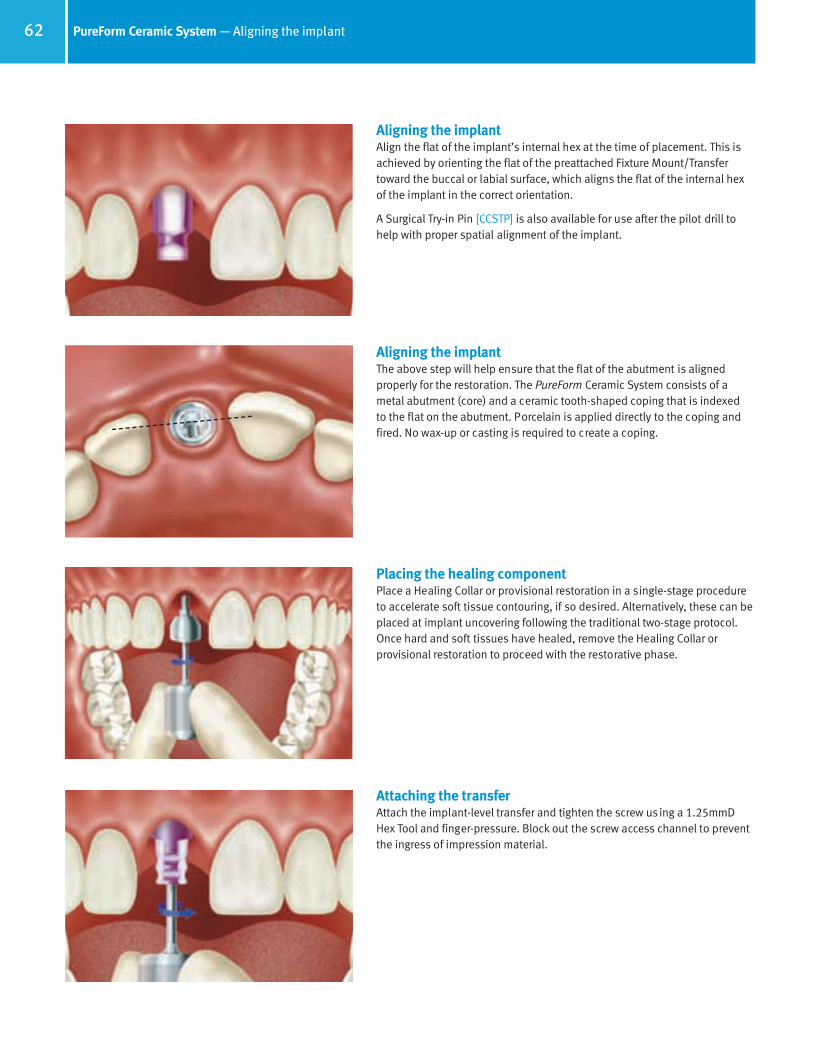
62 PureForm Ceramic System — Aligning the implant
Aligning the implantAlign the flat of the implant’s internal hex at the time of placement. This isachieved by orienting the flat of the preattached Fixture Mount/Transfertoward the buccal or labial surface, which aligns the flat of the internal hex of the implant in the correct orientation.
A Surgical Try-in Pin [CCSTP] is also available for use after the pilot drill tohelp with proper spatial alignment of the implant.
Aligning the implantThe above step will help ensure that the flat of the abutment is aligned properly for the restoration. The PureForm Ceramic System consists of ametal abutment (core) and a ceramic tooth-shaped coping that is indexed to the flat on the abutment. Porcelain is applied directly to the coping andfired. No wax-up or casting is required to create a coping.
Placing the healing componentPlace a Healing Collar or provisional restoration in a single-stage procedureto accelerate soft tissue contouring, if so desired. Alternatively, these can beplaced at implant uncovering following the traditional two-stage protocol.Once hard and soft tissues have healed, remove the Healing Collar or provisional restoration to proceed with the restorative phase.
Attaching the transferAttach the implant-level transfer and tighten the screw using a 1.25mmDHex Tool and finger-pressure. Block out the screw access channel to preventthe ingress of impression material.
66514_Pg56_93:66514_Pg56_93 3/14/11 11:14 AM Page 7
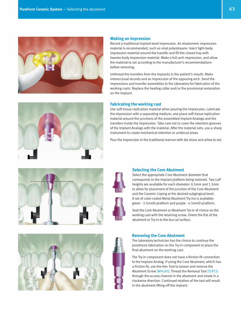
63PureForm Ceramic System — Selecting the abutment
Making an impressionRecord a traditional implant-level impression. An elastomeric impressionmaterial is recommended, such as vinyl polysiloxane. Inject light-bodyimpression material around the transfer and fill the closed tray with heavier-body impression material. Make a full-arch impression, and allowthe material to set according to the manufacturer’s recommendations before removing.
Unthread the transfers from the implants in the patient’s mouth. Make interocclusal records and an impression of the opposing arch. Send theimpressions and transfer assemblies to the laboratory for fabrication of theworking casts. Replace the healing collar and/or the provisional restorationon the implant.
Fabricating the working castUse soft tissue replication material when pouring the impression. Lubricatethe impression with a separating medium, and place soft tissue replicationmaterial around the junctions of the assembled Implant Analogs and thetransfers inside the impression. Take care not to cover the retention groovesof the Implant Analogs with the material. After the material sets, use a sharpinstrument to create mechanical retention or undercut areas.
Pour the impression in the traditional manner with die stone and allow to set.
Selecting the Core AbutmentSelect the appropriate Core Abutment diameter that corresponds to the implant platform being restored. Two cuffheights are available for each diameter: 0.5mm and 1.5mmto allow for placement of the junction of the Core Abutmentand the Ceramic Coping at the desired subgingival level. A set of color-coded Metal Abutment Try-ins is available:green - 3.5mmD platform and purple - 4.5mmD platform.
Seat the Core Abutment or Abutment Try-in of choice on theworking cast with the retaining screw. Orient the flat of theabutment or Try-in to the buccal surface.
Removing the Core AbutmentThe laboratory technician has the choice to continue theprosthesis fabrication on the Try-in component or place thefinal abutment on the working cast.
The Try-in component does not have a friction-fit connectionto the Implant Analog. If using the Core Abutment, which hasa friction-fit, use the Hex Tool to loosen and remove the Abutment Screw [MHLAS]. Thread the Removal Tool [TLRT2]through the access channel in the abutment and rotate in aclockwise direction. Continued rotation of the tool will resultin the abutment lifting off the implant.
66514_Pg56_93:66514_Pg56_93 3/14/11 11:14 AM Page 8

64 PureForm Ceramic System — Selecting and preparing the Ceramic Coping
Selecting the Ceramic CopingUse the replicas provided in the Plastic Try-in Kit [PTKIT] to select the coping closest to the size and geometry of the final tooth being replaced.The plastic replicas in the Try-in Kit represent the size and shape of theCeramic Copings.
Six shapes are available: Straight Large Incisor [PTLG] and 17° Angled LargeIncisor [PTLG17]), Straight Small Incisor [PTSM] and 17° Angled Small Incisor[PTSM17], Canine [PTCN] and Premolar [PTPM].
Each Ceramic Coping flares from 4.5mmD at the base and will fit any sizeCore Abutment.
Ordering the Ceramic CopingOrder the Ceramic Coping that corresponds to the Try-in selected. Part numbers are etched on each Plastic Try-in replica for easy identificationand reference. A table inside the Try-in Kit lists the corresponding CeramicCoping part numbers for easy reference and ordering.
Orienting the Ceramic CopingRemove the coping from the plastic holder. Align the flat on the Try-in or Core Abutment with the flat inside the Ceramic Coping.
Preparing the Ceramic CopingReduce the Ceramic Coping to the correct dimensions to allow for therequired thickness of porcelain veneering material. Use the appropriate finishing burs to finesse the profile as required. The plastic holder suppliedwith the coping is used to assist holding the coping while trimming.
Care must be taken not to overheat the Ceramic Coping during preparation.
66514_Pg56_93:66514_Pg56_93 3/14/11 11:14 AM Page 9

65PureForm Ceramic System — Fabricating the restoration
Trimming the Ceramic CopingUtilize standard laboratory procedures to ensure the additional trimming ofthe Ceramic Coping does not reduce the wall thickness to less than 0.5mm.
Sand blast the surface of the coping with 120 micron aluminum oxide at 35-38 PSI and clean the coping with steam or distilled water in the ultrasonic cleaning unit.
Applying porcelainWhen applying porcelain to the coping follow the manufacturer’s guidelinesfor application of color modifiers, ceramic build-up and firing temperatures.The coefficient of thermal expansion of the Ceramic Coping is 8.1x10⁻⁶/°Cbetween 0-500°C (932°F).
Applied porcelains should be selected to accommodate for the parametersof the underlying coping.
Finishing the restorationComplete the restoration using conventional laboratory techniques for “full ceramic” crowns.
Tightening the Core AbutmentRemove the prosthesis from the working cast. Unthread the abutment screwwith the 1.25mmD Hex Tool and remove the Core Abutment. Sterilize thecomponents according to standard clinical procedures.
Remove the healing components and seat the Metal Core Abutment into theimplant. Be sure the flat of the Core Abutment is oriented to the buccal/labial.Tighten the abutment screw to 30 Ncm with a calibrated torque wrench. Takean x-ray to confirm that the Core Abutment is fully seated.
66514_Pg56_93:66514_Pg56_93 3/21/11 9:42 AM Page 10

66 PureForm Ceramic System — Delivering the final prosthesis
Delivering the final prosthesisBlock out the screw access channel in the abutment with cotton pellets andlight-curing resilient material or gutta-percha. This will ensure easy access tothe screw head.
Delivering the final prosthesisSeat the final prosthesis onto the abutment. Confirm esthetics, fit, contour and check the occlusion. Verify that no additional finishing oradjustment is required.
Apply cement and seat the crown onto the Core Abutment in a typical fashion as when seating any all ceramic crown on an implant abutment or natural tooth.
Note: Cements that are known to expand during setting are not recommended.
Delivering the final prosthesisAdjust the occlusion and bite on the crown after it is cemented. Remove anyexuded cement from the margin area.
Provide the patient with oral hygiene instructions prior to release.
66514_Pg56_93:66514_Pg56_93 3/14/11 11:14 AM Page 11
Tapered Abutment System
RestorativeManual
66514_Pg56_93:66514_Pg56_93 3/14/11 11:14 AM Page 12

68 Restorative options with Tapered Abutments
Tapered Abutment
[TA5C3]
Tapered Abutments are used as the transmucosal extension during the fabrication of partially or fully edentulous splinted, screw-retainedmultiple-unit prostheses. Once connected to the implant, they extend through the soft tissue to create a common screw-receiving platformon which a restorative prosthesis is attached. In esthetic areas the margin of the screw-receiving platform is located slightly subgingival,whereas in the bar type overdentures the platform is normally located 1mm supragingival.
The Tapered Abutment is a one-piece titanium alloy component having a 4.5mmD platform (except the AdVent Screw [AVACT]) with a raisedcentral section having 15° tapered walls. This angulation requires implants to be within 30° of parallelism to each other for a splinted prosthesis to have a passive path of draw. Located within the raised area are the threads which receive the fixation screw for holding downthe prosthesis. Below the internally threaded area of the abutment is a 1.25mmD matrix (female) hex designed to receive the standard1.25mmD Hex Tool. Rotation of the Hex Tool to a calibrated 30 Ncm will fully seat the abutment sealing the abutment/implant interface.Each abutment is supplied with a Protective Cap [TATHC] to seal the abutment platform during prosthesis fabrication.
Screw-Retained Denture Ball Bar Overdenture Screw-Retained Partial Denture
TaperedAbutment
[TAC3]
Tapered Abutment
[AVACT]
Tapered Abutment [TACW3]
Abutment for the Internal Hex Implant,
3.5mmD platform
Abutment for the Internal Hex Implant,
4.5mmD platform
Abutment for the Internal HexImplant, 5.7mmD platform
Abutment for the WidePlatform AdVent, 5.7mmD platform
Abutment for the AdVent Implant,
4.5mmD platform
TaperedAbutment
[TA5C3]
66514_Pg56_93:66514_Pg56_93 3/14/11 11:14 AM Page 13
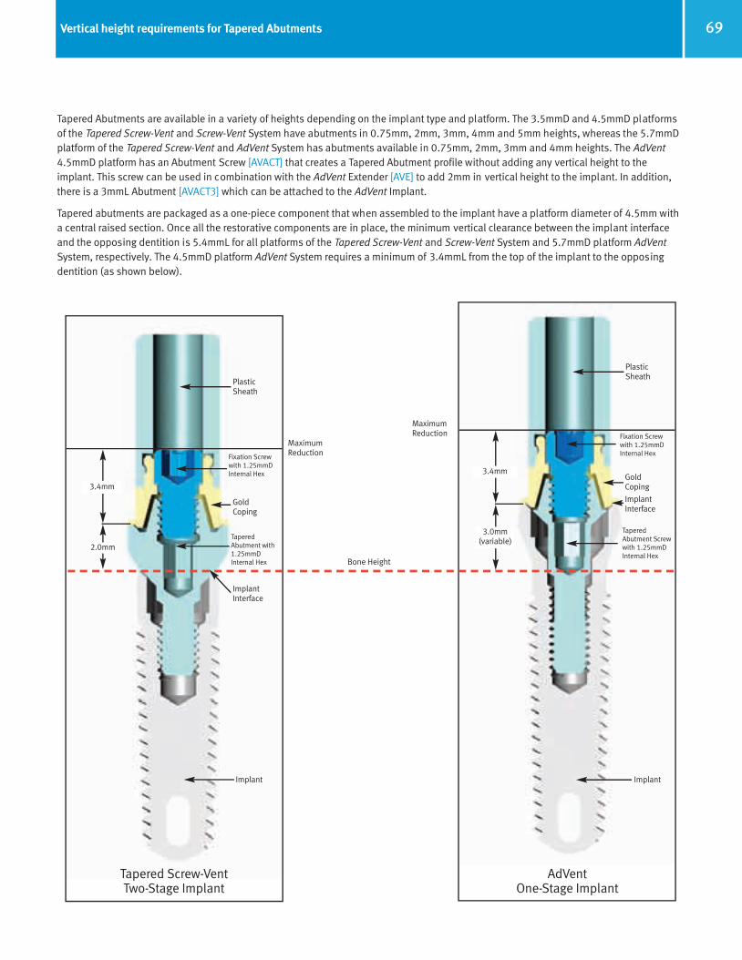
69Vertical height requirements for Tapered Abutments
Tapered Abutments are available in a variety of heights depending on the implant type and platform. The 3.5mmD and 4.5mmD platforms of the Tapered Screw-Vent and Screw-Vent System have abutments in 0.75mm, 2mm, 3mm, 4mm and 5mm heights, whereas the 5.7mmDplatform of the Tapered Screw-Vent and AdVent System has abutments available in 0.75mm, 2mm, 3mm and 4mm heights. The AdVent4.5mmD platform has an Abutment Screw [AVACT] that creates a Tapered Abutment profile without adding any vertical height to theimplant. This screw can be used in combination with the AdVent Extender [AVE] to add 2mm in vertical height to the implant. In addition,there is a 3mmL Abutment [AVACT3] which can be attached to the AdVent Implant.
Tapered abutments are packaged as a one-piece component that when assembled to the implant have a platform diameter of 4.5mm witha central raised section. Once all the restorative components are in place, the minimum vertical clearance between the implant interfaceand the opposing dentition is 5.4mmL for all platforms of the Tapered Screw-Vent and Screw-Vent System and 5.7mmD platform AdVentSystem, respectively. The 4.5mmD platform AdVent System requires a minimum of 3.4mmL from the top of the implant to the opposing dentition (as shown below).
ImplantImplant
TaperedAbutment with1.25mmD Internal Hex
ImplantInterface
2.0mm
3.4mm
Bone Height
MaximumReduction
Tapered Screw-Vent Two-Stage Implant
AdVentOne-Stage Implant
Fixation Screwwith 1.25mmDInternal Hex
GoldCoping
PlasticSheath
TaperedAbutment Screwwith 1.25mmDInternal Hex
ImplantInterface
3.0mm(variable)
3.4mm
Fixation Screwwith 1.25mmDInternal Hex
GoldCoping
PlasticSheath
MaximumReduction
66514_Pg56_93:66514_Pg56_93 3/14/11 11:14 AM Page 14
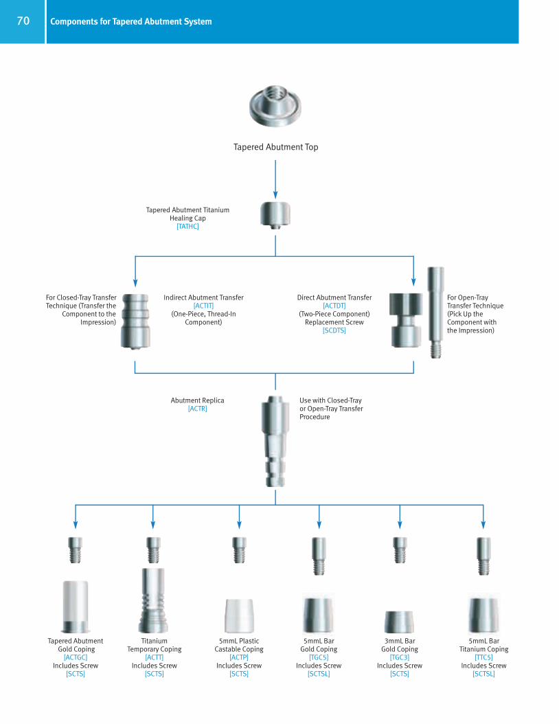
70 Components for Tapered Abutment System
Tapered Abutment Gold Coping
[ACTGC]Includes Screw
[SCTS]
Indirect Abutment Transfer[ACTIT]
(One-Piece, Thread-In Component)
Direct Abutment Transfer[ACTDT]
(Two-Piece Component) Replacement Screw
[SCDTS]
Abutment Replica[ACTR]
Tapered Abutment Top
For Closed-Tray TransferTechnique (Transfer the
Component to theImpression)
For Open-Tray Transfer Technique(Pick Up theComponent with the Impression)
Use with Closed-Tray or Open-Tray Transfer Procedure
Tapered Abutment Titanium Healing Cap
[TATHC]
Titanium Temporary Coping
[ACTT]Includes Screw
[SCTS]
5mmL Plastic Castable Coping
[ACTP]Includes Screw
[SCTS]
5mmL Bar Gold Coping
[TGC5]Includes Screw
[SCTSL]
5mmL Bar Titanium Coping
[TTC5]Includes Screw
[SCTSL]
3mmL Bar Gold Coping
[TGC3]Includes Screw
[SCTS]
66514_Pg56_93:66514_Pg56_93 3/14/11 11:14 AM Page 15
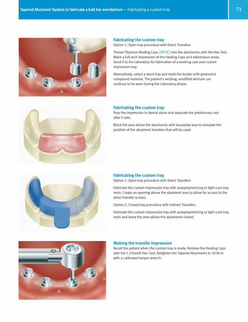
71Tapered Abutment System to fabricate a ball bar overdenture — Fabricating a custom tray
Fabricating the custom trayOption 1: Open-tray procedure with Direct Transfers
Thread Titanium Healing Caps [TATHC] into the abutments with the Hex Tool.Make a full-arch impression of the Healing Caps and edentulous areas. Send it to the laboratory for fabrication of a working cast and customimpression tray.
Alternatively, select a stock tray and mold the border with greenstick compound material. The patient’s existing, modified denture can continue to be worn during the l aboratory phase.
Fabricating the custom trayPour the impression in dental stone and separate the preliminary cast after it sets.
Block the area above the abutments with baseplate wax to simulate theposition of the abutment transfers that will be used.
Fabricating the custom trayOption 1: Open-tray procedure with Direct Transfers
Fabricate the custom impression tray with autopolymerizing or light-cure trayresin. Create an opening above the abutment area to allow for access to thedirect transfer screws.
Option 2: Closed-tray procedure with Indirect Transfers
Fabricate the custom impression tray with autopolymerizing or light-cure trayresin and leave the area above the abutments closed.
Making the transfer impressionRecall the patient when the custom tray is ready. Remove the Healing Capswith the 1.25mmD Hex Tool. Retighten the Tapered Abutments to 30 Ncmwith a calibrated torque wrench.
66514_Pg56_93:66514_Pg56_93 3/14/11 11:14 AM Page 16

72 Tapered Abutment System to fabricate a ball bar overdenture — Making a direct (open-tray) transfer
Option 1: attaching the Direct TransfersPlace the body of the Tapered Abutment Direct Transfer [ACTDT] onto the top of the abutment. Insert the transfer screw through the transfer body,thread it into the abutment and finger-tighten with the 1.25mmD Hex Tool. If needed, a Replacement Screw [SCDTS] for the Tapered Abutment DirectTransfer is available.
In areas of limited vertical height, the transfer screws can be shortened with a cutting disc prior to use. During the impression procedure, the Tapered Abutment Direct Transfer bodies will be picked up by the impression material.
TaperedAbutment
Replica
Tapered Abutment Direct Transfer
Option 1: verifying fit of the custom trayPlace the open-access tray over the assembled Direct Transfers in thepatient’s mouth to verify that the screws penetrate through the top of thetray without hindrance. Remove the open-access tray and place a softenedpiece of baseplate wax on the top of the tray to cover the access opening.This will help contain the impression material. Carefully try in the tray andallow the screws to create access holes through the wax. Remove the trayfrom the mouth, chill in water, dry, then apply adhesive. Block out the hex holes in the tops of the screws with material of choice to prevent theingress of impression material.
Option 1: making the impressionAn elastomeric impression material is recommended, such as vinylpolysiloxane. Inject light-body impression material around the DirectTransfers and fill the open-access tray with heavier body impression material. Place the loaded tray into the patient’s mouth and allow thescrews to penetrate through their respective access holes in the hardenedbaseplate wax. Remove excess impression material from the tops of thescrews and allow the impression material to set according to the manufacturer’s recommendations. Unthread the screws from the transferswith the Hex Tool and remove them from the patient’s mouth. Remove thetray from the mouth. Replace the Healing Caps. The Direct Transfer bodieswill be retained in the impression material.
Option 1: completing the transfer procedureStabilize the Tapered Abutment Replica [ACTR] with forceps to prevent rotation and insert the screw-receiving end of the replica into the base of the transfer body within the impression material.
Attach the transfer screw to the Hex Tool, and insert it through the respectiveaccess hole in the back of the impression tray. Pass the screw through theembedded transfer body and thread it into the attached replica to lock thecomponents together.
Make an opposing-arch impression. Send all the materials to the laboratoryfor fabrication of a stabilized baseplate with occlusal registration rim.
Point of Maximum Reduction
66514_Pg56_93:66514_Pg56_93 3/14/11 11:14 AM Page 17

73Tapered Abutment System to fabricate a ball bar overdenture — Making a indirect (closed-tray) transfer
Tapered AbutmentIndirect Transfer
Tapered AbutmentCoping
TaperedAbutment
Replica
Option 2: attaching the Indirect TransfersThread the Tapered Abutment Indirect Transfers [ACTIT] into the tops of theTapered Abutments with the Hex Tool and finger-tighten.
Option 2: making the impressionBlock out the hex holes in the tops of the transfers with material of choice to prevent the ingress of impression material. An elastomeric impressionmaterial is recommended, such as vinyl polysiloxane. Inject light-bodyimpression material around the Indirect Transfers and fill the closed tray withheavier-body impression material. Make a full-arch impression, and allowthe material to set according to the manufacturer’s recommendations beforeremoving. Unthread the Indirect Transfers from the Tapered Abutments withthe Hex Tool and set them aside. Replace the Healing Caps.
Option 2: completing the transfer procedureThread the transfer onto the Tapered Abutment Replica [ACTR] and finger-tighten with the Hex Tool.
Insert the replica/transfer assembly into the impression hole. A double-clickindicates that the transfers are fully seated. Make an opposing-arch impression. Send all the materials to the laboratory for the fabrication of a stabilized baseplate with occlusal registration rim.
Fabricating the verification jigPour the impression in die stone. To separate the cast from the impression:• Open-tray impression: First unthread and remove the transfer screws with
the Hex Tool. Remove the tray from the cast.
• Closed-tray impression: Remove the tray from the cast. Unthread andremove the transfer bodies from the cast with the Hex Tool. Gold Copings[ACTGC] will be used to fabricate a stabilized baseplate and occlusal registration rim. These components consist of the metal coping, fixationscrew [SCTS] and 3.8mmD press-fit Plastic Sheath [OPS]. Attach the cylinders to the abutment replicas with Waxing Screws [SCWS] to maintainaccess. Set the coping fixation screws and Plastic Sheaths aside for later use.
66514_Pg56_93:66514_Pg56_93 3/14/11 11:14 AM Page 18

74 Tapered Abutment System to fabricate a ball bar overdenture — Fabricating a verification jig and occlusal rims
Fabricating a verification jigBlock out undercuts beneath the copings with baseplate wax. Lubricate theworking cast. Lute the copings together with autopolymerizing or light-cureresin. To prevent distortion from contraction, section the pattern between thecopings with a thin separating disk, then relute the sections together. To con-firm a passive fit, remove the waxing screws from the pattern and reattachthe framework pattern to the most distal abutment replica with a singlescrew and finger-tighten with the Hex Tool. Verify that the remaining copingswithin the framework pattern rest passively on the abutment replicas. Sendthe resin framework pattern to the dentist with the coping fixation screws forpatient try-in. A passive fit will confirm that an accurate transfer has beenachieved.
Fabricating a stabilized baseplate/occlusal rimAfter the patient try-in, use the Hex Tool to replace the coping fixation screwswith the longer Tapered Abutment Waxing Screws [SCWS]. Position a sheetof light-curing baseplate material over the tops of the assembled waxingscrews and framework pattern. Gently press the modified sheet onto theworking cast and allow the screws to penetrate the material. Form the material around the framework and to the contours of the edentulous arch to fabricate a stabilized baseplate.
Create a wax occlusal registration rim on the stabilized baseplate. Send theassembly to the dentist for interocclusal records.
Making an interocclusal recordRemove the Healing Caps [TATHC] from the abutments in the patient’s mouthwith the Hex Tool. Attach the baseplate and occlusal rim assembly to theabutments with the fixation screws and gently finger-tighten with the Hex Tool.
Contour the wax occlusal rim and mark the midline and smile line. Make a bite registration at the vertical dimension of occlusion. Remove the baseplate and bite registration from the patient’s mouth and reassemble it on the working cast with the fixation screws. Reattach the Healing Caps tothe abutments. Select the prosthetic teeth and send the materials to thelaboratory for fabrication of a stabilized denture wax try-in.
Fabricating a stabilized denture wax try-inMount the working and opposing-arch casts on an articulator.
Set up the denture teeth on the stabilized baseplate. At this point, access to some of the copings will be covered up with denture teeth. Do not createaccess holes through the denture teeth. Two copings lingual to the anteriorteeth will sufficiently stabilize the wax-up for patient try-in. Send the stabilized denture wax-up to the dentist for a patient try-in.
66514_Pg56_93:66514_Pg56_93 3/14/11 11:15 AM Page 19

75Tapered Abutment System to fabricate a ball bar overdenture — Fabricating a matrix and framework pattern
Patient try-inRemove the Healing Caps from the abutments in the patient’s mouth withthe Hex Tool. Torque the abutments to 30 Ncm with a calibrated torquewrench. Place the try-in onto the abutments. Attach the fixation screwsthrough the access holes in the wax-up and gently finger-tighten (note:some of the copings will be covered by the denture teeth). Make necessaryadjustments and obtain patient approval. Remove the denture wax try-infrom the patient’s mouth and replace the Healing Caps on the abutments.Use the Hex Tool to secure the stabilized baseplate wax-up on the abutmentreplicas in the working cast with the fixation screws, and return it to the laboratory for fabrication of the metal framework.
Fabricating the framework patternFabricate a silicone or plaster labial/occlusal matrix to record tooth positionand the labial borders of the prosthesis relative to the working cast.
An alternate procedure for immediate framework fabrication would be toattach Bar Gold Copings [TGC3 or TGC5] to the replicas. Splint the copingswith Gold Bars [HGB or DGB] using an autopolymerizing acrylic. Invest, solder and finish the framework via standard procedures (discussed in the Immediate Bar Fabrication Section page 96).
Fabricating the framework patternRemove the teeth from the denture wax try-in, place them back into theirrespective locations in the matrix and lute them into position with stickywax. Retrieve the gold copings from the baseplate and retain them on theabutment replicas with the fixation screws. Press the Plastic BurnoutSheaths [OPS] onto the copings. Place the matrix with the attached teethback onto the working cast to guide shortening of the Plastic Sheaths anddesign of the framework. Section the Plastic Sheaths with a cutting disk toprovide adequate clearance for the teeth suspended in the matrix. Insteadof using the Plastic Sheaths and fixation screws, the framework pattern canbe waxed directly to the copings and around the Waxing Screws [SCWS].
Fabricating the framework patternIncorporate the Gold/Plastic Combination [ACTGC] into a bar overdenturedesign using the preformed patterns from the Bar System [BS1]. Use themandril from the Cap Attachment Instruments [CAI] in a surveyor to incorporate castable ball patterns from the Cap Attachment System [CAS]into the distal ends of the bar pattern, avoiding excessive cantilevers.
Use the teeth suspended in the m atrix as a guide to provide adequate clearance for the attachments, teeth and the denture base thickness. The ball patterns are the same 2.5mm diameter as the machined titaniumBall Abutments and accept the standard Cap Attachments [CA].
66514_Pg56_93:66514_Pg56_93 3/14/11 11:15 AM Page 20

76 Tapered Abutment System to fabricate a ball bar overdenture — Fabricating the metal framework
Spruing the framework patternSprue the bar pattern with 10-gauge sprue wax with reservoirs. Invest theframework pattern with a high-heat, phosphate-bonded investment materialfollowing the manufacturer’s instructions. Do not use a debubblizer wheninvesting the gold or plastic components. A two-stage burnout is recom-mended when using any type of acrylic burnout resin or large volume of wax.The burnout temperature should not exceed 1500°F (815°C), with a holdtime of no longer than 1 hour. Cast the framework in a high noble or noblealloy exhibiting a high tensile strength. The casting temperature of the alloymust not exceed 2350°F (1288°C). After casting, the ring should be allowedto bench-cool. Do not quench.
Divesting and finishing the metal frameworkTo ensure that the fitting surface of the incorporated copings are not damaged, divest the casting, blast it with glass bead while protecting thecoping interface, then clean the casting in an ultrasonic unit. Refine thescrew access holes within the casting by rotating the Reamer [PR] forTapered Abutment Copings by hand. Confirm that a passive fit has beenachieved. Send the assembly to the dentist for try-in of the metal framework to verify the passive fit.
Patient try-inRemove the Healing Caps from the abutments in the patient’s mouth withthe 1.25mmD Hex Tool. Retighten the abutments to 30 Ncm with a calibrated torque wrench. Seat the metal framework on the abutments.Beginning with one of the distal abutments, thread in the fixation screw and finger-tighten with the Hex Tool. If the framework lifts off the other abutments when the screw is tightened, the framework is not fitting passively. Determine where the framework should be sectioned and markthe location on the framework with a felt-tipped pen. Remove the frameworkand replace the Healing Caps. If a passive fit was achieved, attach theremaining screws and tighten to 20 Ncm with a calibrated torque wrench.
Correcting the framework for a passive fitRemove the framework from the patient’s mouth. Use a very thin separatingdisk and a high speed handpiece to section the framework diagonally to itsocclusal surface for maximum strength after reconnection. Take care not tosection in areas that have been designated for attachment placement.Incorrect sectioning of the framework may cause a weak solder joint, which will compromise the strength of the final prosthesis.
66514_Pg56_93:66514_Pg56_93 3/14/11 11:15 AM Page 21

77Tapered Abutment System to fabricate a ball bar overdenture — Correcting the framework fit
Correcting the framework for a passive fitRemove the Healing Caps from the abutments with the Hex Tool. Tighten theabutments to 30 Ncm with a calibrated torque wrench. Attach the frameworksections to the abutments with the fixation screws and tighten to 20 Ncmwith the torque wrench. Apply fast-setting autopolymerizing resin to the sectioned areas. The resin will flow into the joint via capillary action. Applyadditional resin to form a callous that encapsulates reinforcement across thesectioned area to strengthen the connection. After the resin has fully set,remove the reassembled framework. Do not reattach the luted framework tothe working cast. Replace the Healing Caps on the patient’s abutments andsend the unattached, luted framework and working cast to the laboratory.
Correcting the framework for a passive fitFollow standard laboratory procedures to invest, solder and finish the framework. Return the soldered framework and fixation screws to the dentistto verify that a passive fit has been achieved. Once a passive fit has beenverified, the working cast must be adjusted to accommodate the solderedframework. Use a fissure bur to remove the misaligned abutment replicasfrom the working cast one at a time until the framework rests passively.Attach the removed replicas to the framework at the appropriate locations,then attach the framework to the remaining replicas in the working cast withthe fixation screws. Soak the working cast in water, then carefully vibratestone into the voids and around the retentive features of the replicas.
Fabricating a final stabilized denture wax try-inSnap the yellow Cap Attachment Transfers [CAT] onto the distal ball components. Place the Metal Housings [CAH] onto the Cap AttachmentTransfers. Align the Metal Housings for a common path of draw. Snap theBar System [BS1] Processing Clip (green) onto the anterior bar segment.Block out undercuts then process a light-cure denture base that incorporatesthe attachments. Using the silicone index or matrix as a guide, lute the prosthetic teeth to the denture base with baseplate wax. To prevent fractureof the light-cure baseplate, place the yellow Cap Attachment Transfers on the Bar Ball components for the stabilized tooth try-in. Send the denture wax-up and metal framework to the dentist for try-in and final approval priorto final processing.
Patient try-inRemove the Healing Caps from the abutments with the Hex Tool. Torque theabutments to 30 Ncm with the torque wrench and Hex Tool. Seat the metalframework onto the abutments, thread in the fixation screws with the HexTool and tighten to 20 Ncm with the torque wrench. Snap the yellow CapAttachment Transfers onto the ball components of the metal framework.Place the denture wax try-in into the patient’s mouth and allow the yellowtransfers to insert into the Metal Housings in the baseplate. Verify that theanterior clip attaches to the bar. Evaluate and validate esthetics and phonetics.Place the set-up, metal framework and Cap Attachment Transfers back ontothe working cast, and return them to the laboratory for final processing.Replace the Healing Caps onto the abutments in the patient’s mouth.
66514_Pg56_93:66514_Pg56_93 3/14/11 11:15 AM Page 22

78 Tapered Abutment System to fabricate a ball bar overdenture — Seating the final prosthesis
Processing the final prosthesisProcess the denture with the appropriate attachments. In the anterior, utilizea green Hader® Processing Clip from the Clip Bar System [BS1] or similarattachment system. In the posterior, snap yellow Cap Attachment Transfers[CAT] onto the ball components. Place the Cap Attachment Housings [CAH]from the Cap Attachment System [CAS] onto the transfers. Align the MetalHousings for a common path of draw and then block out the undercutsbeneath the metal housings with appropriate block-out material. Process thedenture according to conventional laboratory procedures. If the Hader Clip isused, remove the green Processing Clip and use the Hader Clip InsertionTool to insert the final yellow Hader Clip after the denture is processed.
Processing the Cap AttachmentsWhen the processed denture returns from the laboratory, remove theHealing Caps from the abutments in the patient’s mouth with the Hex Tool.Tighten the abutments to 30 Ncm with a calibrated torque wrench. Seat themetal framework on the abutments, thread in the fixation screws with theHex Tool and tighten to 20 Ncm with a calibrated torque wrench.
Place one Nylon Liner [CAN] from the Cap Attachment System [CAS] onto the end of the Insertion Tool from the Cap Attachment Instruments [CAI].Press the Nylon Liner into one of the Metal Housings in the denture base.
Processing the Cap AttachmentsCheck the retention of the liner by snapping the denture on and off the BallBar in the patient’s mouth. If necessary, decrease the retention of the NylonLiner by inserting the Reaming Tool from the Cap Attachment Instruments[CAI] into the Nylon Liner and rotating in a clockwise direction to reduce theretention of the liner’s walls. When adequate retention has been achieved,process the second liner in the same manner. Process only one Nylon Linerat a time.
Seating the final prosthesisInsert the finished prosthesis into the patient’s mouth and snap the incorporated attachments onto the Ball Bar. Make final adjustments to theocclusion. Instruct the patient in the use and care of the prosthesis, and provide oral hygiene instructions. Caution the patient not to use bleach onthe prosthesis, which can damage the Cap Attachment Nylon Liners, and toinsert/remove the overdenture by using vertical forces instead of twisting orlateral forces. Proper care will prolong the use of the Nylon Liners. If the NylonLiners lose retention, they can be easily replaced at a recall appointment.For patients who require stronger Cap Attachment retention, a gray CapAttachment Liner [CAN-G] with greater retention is also available.
66514_Pg56_93:66514_Pg56_93 3/14/11 11:15 AM Page 23

Locator Overdenture Attachment System
RestorativeManual
66514_Pg56_93:66514_Pg56_93 3/14/11 11:15 AM Page 24

80 Locator Overdenture Attachment System
Restorative options with Locator Overdenture AttachmentsLocator Overdenture Attachments are designed for retention of implant- or tissue-supported overdentures and partial dentures. The self-locating design of the Locator Attachment System helps guide the attachment into place on the abutment, allowing the patient to position their denture into place easily.
The Nylon Locator Male pivots within the Metal Housing for a resilient connection. The retentive Nylon Liner remains completely in contactwith the abutment socket while its titanium denture cap has a full range of rotational movement.
Figure 1 - The self-aligning design of theLocator Attachment System helps guide theattachment into place on the abutment.
Figure 2 - Locator Overdenture Restoration Flowchart.
The low vertical height of Locator Overdenture Attachments makes it an effective treatmentoption for a wide variety of patients, and the abutments are available in a variety of cuffheights to accommodate varying tissue depths. The cuff height is chosen by measuring tissue depth and ordering the cuff height that equals the tissue measurement or is the next closest higher size. Ordering the abutment by exact tissue height will position the working attachment above the surrounding tissue appropriately.
Impression Copings are available for standard impression-taking, and the Processing Capis used for a reline impression. The Male Processing Package (LOCMP2) includes two fullsets of Processing Caps with black Processing Males, Block-Out Spacers and clear, pinkand blue Replacement Male Liners.
A full selection of Nylon Liners allow flexibility and varying levels of retention. For cases within 10° parallel per abutment, three levels of retention are available: 1.5 pounds (blue), 3 pounds (pink) and 5 pounds (clear). Special Nylon Males accommodate up to 40° of divergence (20° for one implant) with two levels of retention: 4 pounds (green) and 1.5 pounds (red). Locator Attachments are not appropriate where a totally rigid connection is required and should not be used on a single implant with divergence of greater than 20°.
Locator Abutment
(TLOC)
LocatorImpression Coping
(LOCIMP)Locator
Abutment Analog(LOCAN)
Locator Male Processing Package
(LOCMP2)
Figure 3 - Locator Replacement Males. Figure 4 - The Locator Core Tool (LOCCT2) consists ofthree pieces used throughout the restorative process: 1) Male Component Removal Tool2) Male Component Seating Tool3) Locator Abutment Driver
66514_Pg56_93:66514_Pg56_93 3/14/11 11:15 AM Page 25
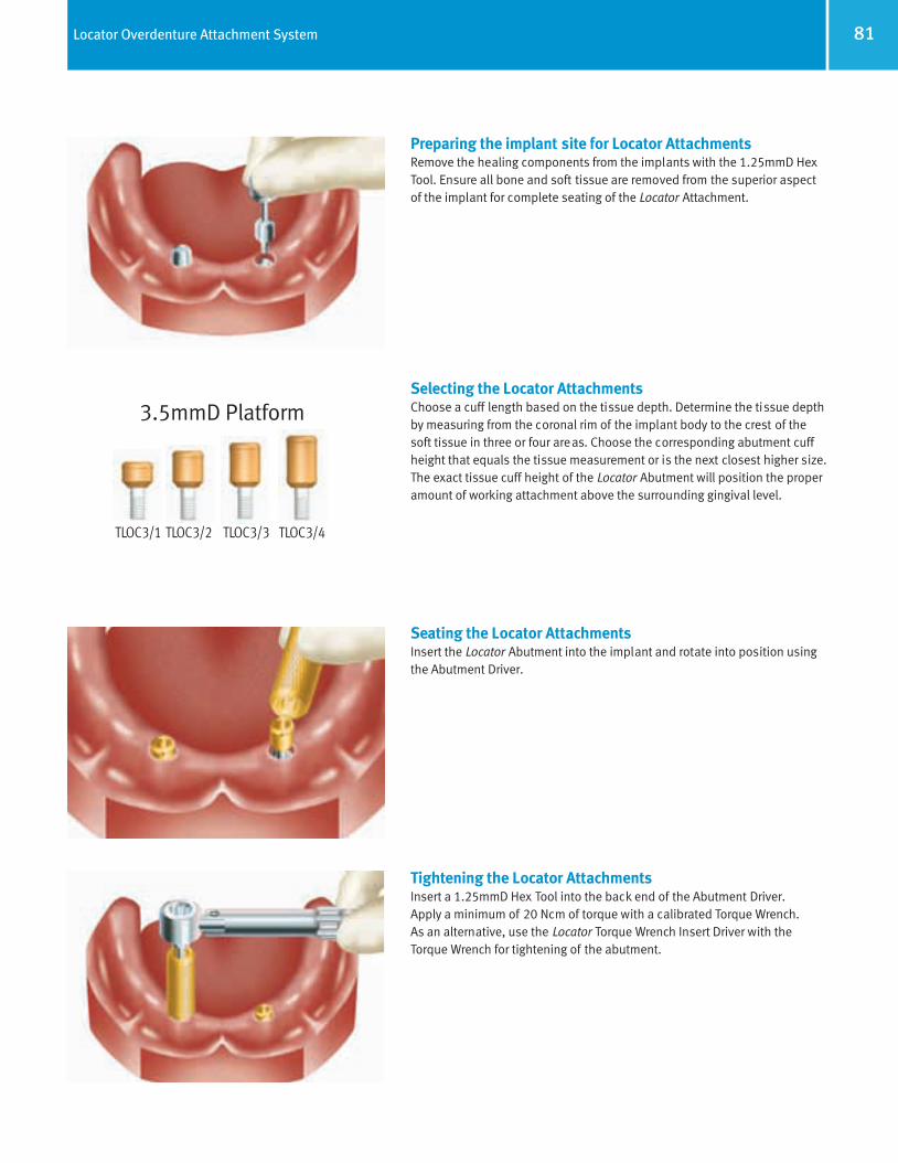
81Locator Overdenture Attachment System
Preparing the implant site for Locator AttachmentsRemove the healing components from the implants with the 1.25mmD HexTool. Ensure all bone and soft tissue are removed from the superior aspectof the implant for complete seating of the Locator Attachment.
Selecting the Locator Attachments Choose a cuff length based on the tissue depth. Determine the tissue depthby measuring from the coronal rim of the implant body to the crest of thesoft tissue in three or four areas. Choose the corresponding abutment cuffheight that equals the tissue measurement or is the next closest higher size.The exact tissue cuff height of the Locator Abutment will position the properamount of working attachment above the surrounding gingival level.
Seating the Locator AttachmentsInsert the Locator Abutment into the implant and rotate into position usingthe Abutment Driver.
Tightening the Locator AttachmentsInsert a 1.25mmD Hex Tool into the back end of the Abutment Driver. Apply a minimum of 20 Ncm of torque with a calibrated Torque Wrench. As an alternative, use the Locator Torque Wrench Insert Driver with theTorque Wrench for tightening of the abutment.
TLOC3/3TLOC3/1 TLOC3/4
3.5mmD Platform
TLOC3/2
66514_Pg56_93:66514_Pg56_93 3/14/11 11:15 AM Page 26
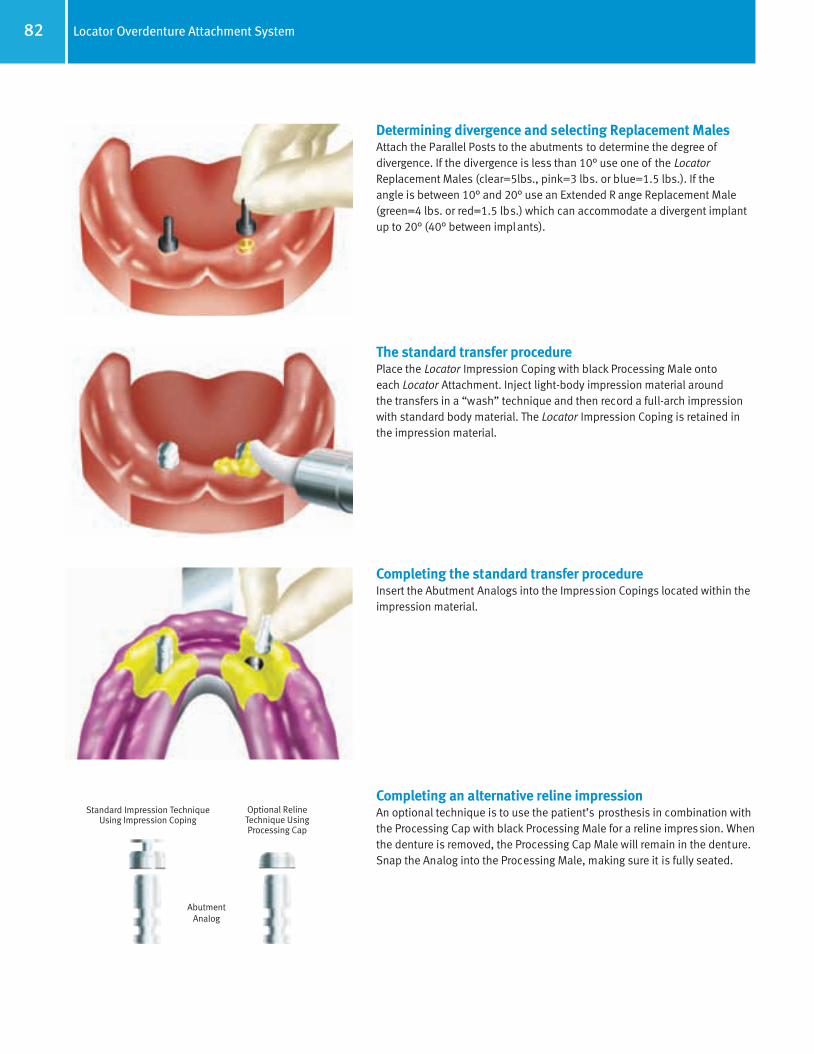
82 Locator Overdenture Attachment System
Determining divergence and selecting Replacement MalesAttach the Parallel Posts to the abutments to determine the degree of divergence. If the divergence is less than 10° use one of the LocatorReplacement Males (clear=5lbs., pink=3 lbs. or blue=1.5 lbs.). If the angle is between 10° and 20° use an Extended R ange Replacement Male(green=4 lbs. or red=1.5 lbs.) which can accommodate a divergent implant up to 20° (40° between implants).
The standard transfer procedure Place the Locator Impression Coping with black Processing Male onto each Locator Attachment. Inject light-body impression material around the transfers in a “wash” technique and then record a full-arch impression with standard body material. The Locator Impression Coping is retained inthe impression material.
Completing the standard transfer procedureInsert the Abutment Analogs into the Impression Copings located within theimpression material.
Completing an alternative reline impressionAn optional technique is to use the patient’s prosthesis in combination withthe Processing Cap with black Processing Male for a reline impression. Whenthe denture is removed, the Processing Cap Male will remain in the denture.Snap the Analog into the Processing Male, making sure it is fully seated.
Optional Reline Technique UsingProcessing Cap
AbutmentAnalog
Standard Impression TechniqueUsing Impression Coping
66514_Pg56_93:66514_Pg56_93 3/14/11 11:15 AM Page 27

83Locator Overdenture Attachment System
Processing the denturePour the working cast. The Locator Abutment Analog replicates the positionof the Locator Attachment on the model. Place the white Block-Out Spacerover the head of the Locator Abutment Analog. The space created will allowthe full resilient function of the pivoting metal denture cap over the LocatorMale. Attach the Processing Cap with black Processing Male and ensure it isfully seated. The black Processing Male will maintain the overdenture in theupper limit of its vertical resiliency during the processing procedure. Processthe denture following standard procedures. Discard the white spacer. Beforechanging to the final male, polish the denture base.
Removing the black Processing MaleLoosen the Locator Male Removal Tool tip a full two turns counter-clockwiseand insert the tip into the cap/male assembly and push straight in (Fig. 1).The sharp edge of the tip will grab the Nylon Male and allow you to pull it out.Tighten the tip clockwise back into the Core Tool to release the liner (Fig. 2).
Seating the Replacement MaleUse the Locator Male Seating Tool to firmly push the Locator ReplacementMale into the empty metal cap located within the denture. The male componentmust sit flush with the rim of the metal cap.
Delivering the final prosthesisThe Locator Attachments should be retightened with a minimum of 20 Ncmof torque. Instruct the patient in the path of insertion. Have the patientinsert and remove the appliance several times. The self-locating designhelps guide the attachment into place on the abutments.
Fig. 1
Fig. 2
66514_Pg56_93:66514_Pg56_93 3/14/11 11:15 AM Page 28

84 Notes
Notes
66514_Pg56_93:66514_Pg56_93 3/14/11 11:15 AM Page 29

Ball Abutment System
RestorativeManual
66514_Pg56_93:66514_Pg56_93 3/14/11 11:15 AM Page 30

86 Restorative options with Ball Abutments
Ball Abutments are used in attachment-retained, tissue-supported restorations where the patient is fully edentulous in the arch to berestored. The extra-coronal type of attachment mechanism consists of a one-piece abutment with a superior ball projection secured to theimplant. A Metal Housing [CAH] and retentive Nylon Liner [CAN] mechanically retained within the Metal Housing, collectively referred to asthe Cap Attachment [CA], is fixed within the patient’s denture. The inner receptacle of the Nylon Liner acts as the 360-degree universal rotational connection between the denture and the abutment/implant assembly and allows for only slight compressive vertical movement.These abutments can be processed into the denture either in a chairside pick-up technique or a laboratory technique. Both techniques willbe discussed in this section.
This type of restoration requires sufficient depth of the posterior vestibule to protect the abutment/implant assembly from excessive lateral/horizontal force during mastication (Fig 1a-c). It is recommended to use implants with a length in excess of 12mm and abutmentheights should be kept to a minimum to maintain an acceptable implant/abutment height ratio. Therefore single-arch fully edentulouspatients with excessive resorption of the edentulous ridge might not be candidates for a restoration inclusive of this type of abutment system.
In most cases the restoration is done utilizing two implants with corresponding Ball Abutments placed in the canine area, creating a fulcrum around which the attached denture will rotate (Fig. 1d). Absolute parallelism is not a prerequisite for success as the rotationalaspect of the Cap Attachment on the ball component allows for adjustment of up to 28 degrees of relative divergence between implants. It should be noted that the long-term stability and maintenance of the retentive connection is reliant on three-dimensional alignment of the abutments and Cap Attachments (as shown below, Fig. 1e-1f) for increased longevity and success:
1) The implants should be placed anterior/posteriorly so that the fulcrum line through the center of the components is parallel to themandibular hinge axis (Fig. 1e).
2) The implants should be placed vertically so that the tops of the metal housings are parallel to the occlusal plane of the patient’s dentureand corresponding opposing arch (Fig. 1f).
3) The implants should be parallel to each other along their long axis and perpendicular to the plane of occlusion to be in optimum position (Fig. 1g).
Fig. 1a Fig. 1cFig. 1b Fig. 1d
Fig. 1gFig. 1fFig. 1e
Occlusal Plane
Mandibular Hinge Axis
66514_Pg56_93:66514_Pg56_93 3/14/11 11:16 AM Page 31

87Vertical height requirements for Ball Abutments
Ball Abutment for Tapered Screw-Vent, Screw-Vent and AdVent Implant SystemsBall Abutments are manufactured from titanium alloy and come packaged with the stainless steel Cap Attachment Housing [CAH] and CapAttachment Nylon Liner [CAN]. The abutments for the Tapered and Straight Screw-Vent 3.5 and 4.5mmD Platform Implants are available inthree collar heights (2mmL, 4mmL and 6mmL). The 5.7mmD platform Tapered Screw-Vent and AdVent Implant abutments have collar heightsof 2mm and 4mm only. The 4.5mmD platform AdVent Implant System, however, has only one collar height (1mmL) which can be utilized withor without the AdVent Extender [AVE] to create variable heights, depending on the depth of implant placement and surrounding soft tissue.
The Ball Abutment collar is regularly placed 1mm supragingival and has a coronal diameter of 4.5mm, while the ball component itself is2.5mmD. When assembled, the vertical height of the Cap Attachment [CA] above the coronal aspect of the Ball Abutment collar is 4.28mmand its diameter is 5.00mm. Care should be taken to ensure sufficient denture acrylic surrounds the housing to prevent it from perforatingthe denture during function.
ImplantImplant
BallAbutment
ImplantInterface
2.0mm
3.0mm(variable)
Bone Height
Abutment Collar Height(2mmL, 4mmL or 6mmL)
Tapered Screw-VentTwo-Stage Implant
AdVentOne-Stage Implant
MetalHousing
ImplantInterface
4.28mm
Nylon Liner
Denture Acrylic(1.5-2mmL minimum)
Abutment Collar Height(1mmL or 3mmL withAdVent Extender [AVE])
Denture Acrylic(1.5-2mmL minimum)
BallAbutment
MetalHousing
Nylon Liner
4.5mmD
4.5mmD
4.28mm
66514_Pg56_93:66514_Pg56_93 3/14/11 11:16 AM Page 32

88 Components for Ball Abutment System
Cap Attachment[CA]
(Included with allBall Abutments)
Cap Attachment [CA] assemblies are includedwith the Ball Abutment, and consist of a MetalHousing and retentive liner. Replacement Housings [CAH] and Nylon Liners [CAN] are also available. A more rigid Retentive Liner[CAN-G] is also available.
Ball Abutment Top
Metal Housing
Laboratory Technique Chairside Technique
Ball AbutmentTransfer
[BAT]
Cap Attachment Transfer
[CAT]
Chairside Pick-Up
Nylon Liner
This process cannot be utilizedwith the 5.7mmD platform
implant systems.
Ball Abutment Replica[BAR]
66514_Pg56_93:66514_Pg56_93 3/14/11 11:16 AM Page 33

89Ball Abutment System: laboratory technique — Fabricating and utilizing a custom tray
Fabricating a custom trayPrior to attaching the abutments, make a full-arch, alginate impression ofthe Healing Collars and edentulous areas. Send the impression to the laboratory for fabrication of a working cast and an impression tray with aspacer to accommodate the Ball Abutment Transfers. Fabricate the customtray with light-cured or autopolymerizing tray material. The patient’s existing,modified overdenture can continue to be worn during the l aboratory phase.Alternatively, select a stock tray to provide access for the transfers, and molda border with greenstick compound material.
Attaching the ball componentsRecall the patient when the custom tray is ready. Remove the Healing Collars or Surgical Cover Screws with the 1.25mmD Hex Tool. Select BallAbutment components according to the implant type and transmucosalheight requirements. Place the selected Ball Abutments into the implantsand tighten with to 30 Ncm with a calibrated torque wrench.
Seating the transfersPress the Ball Abutment Transfers [BAT] for all 4.5mmD collar componentsonto the Ball Abutments. This step cannot be done on the 5.7mmD pl atformimplant systems.
The transfer will engage the outer portion of the abutment beneath the ball for maximum stabilization. An elastomeric impression material is recommended, such as vinyl polysiloxane. Inject light-body impressionmaterial around the Ball Abutments and fill the impression tray with heavier-body impression material. Place the loaded tray into the patient’s mouthand allow the impression material to set according to the manufacturer’srecommendations. Remove the impression from the mouth.
Completing the transfer procedureRemove the Ball Abutment Transfers from the Ball Abutments, press themonto the Ball Abutment Replicas [BAR], and insert them back into theimpression holes. A double-click indicates that the transfers are fully seated.Make an opposing-arch impression. Send all the materials to the laboratoryfor fabrication of a stabilized baseplate with occlusal registration rim.
66514_Pg56_93:66514_Pg56_93 3/14/11 11:16 AM Page 34
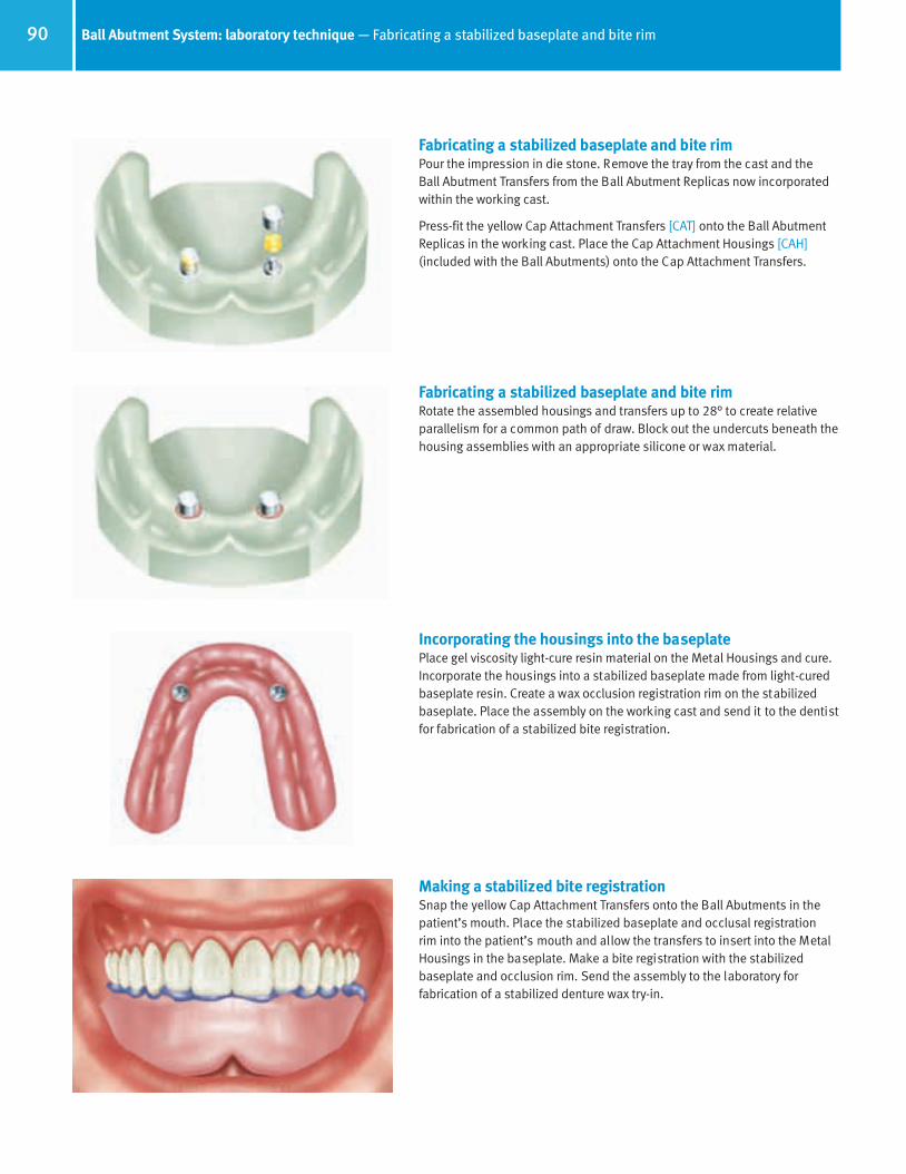
90 Ball Abutment System: laboratory technique — Fabricating a stabilized baseplate and bite rim
Making a stabilized bite registrationSnap the yellow Cap Attachment Transfers onto the Ball Abutments in thepatient’s mouth. Place the stabilized baseplate and occlusal registration rim into the patient’s mouth and allow the transfers to insert into the MetalHousings in the baseplate. Make a bite registration with the stabilized baseplate and occlusion rim. Send the assembly to the laboratory for fabrication of a stabilized denture wax try-in.
Incorporating the housings into the baseplatePlace gel viscosity light-cure resin material on the Metal Housings and cure.Incorporate the housings into a stabilized baseplate made from light-curedbaseplate resin. Create a wax occlusion registration rim on the stabilizedbaseplate. Place the assembly on the working cast and send it to the dentistfor fabrication of a stabilized bite registration.
Fabricating a stabilized baseplate and bite rimRotate the assembled housings and transfers up to 28° to create relativeparallelism for a common path of draw. Block out the undercuts beneath thehousing assemblies with an appropriate silicone or wax material.
Fabricating a stabilized baseplate and bite rimPour the impression in die stone. Remove the tray from the cast and the Ball Abutment Transfers from the Ball Abutment Replicas now incorporatedwithin the working cast.
Press-fit the yellow Cap Attachment Transfers [CAT] onto the Ball AbutmentReplicas in the working cast. Place the Cap Attachment Housings [CAH](included with the Ball Abutments) onto the Cap Attachment Transfers.
66514_Pg56_93:66514_Pg56_93 3/14/11 11:16 AM Page 35

91Ball Abutment System: laboratory technique — Delivering the final prosthesis
Making a stabilized denture wax try-inAfter the laboratory fabricates a stabilized denture wax-up, recall the patientfor try-in. Snap the yellow Cap Attachment Transfers onto the Ball Abutmentsin the patient’s mouth. Place the denture wax try-in into the patient’s mouthand allow the transfers to insert into the Metal Housings in the baseplate.Evaluate esthetics and phonetics, and verify that the wax-up fits passively. If changes in tooth position are prescribed, schedule additional try-inappointments until acceptable tooth arrangement is verified and approvedby dentist and the patient. Place the approved stabilized denture wax try-inon the working cast with the Cap Attachment Transfers and send it to thelaboratory for final processing.
Processing the final prosthesisWhen the processed denture returns from the laboratory, retighten the Ball Abutments to 30 Ncm with a calibrated torque wrench. Place one NylonLiner [CAN] from the Cap Attachments [CA] onto the end of the insertion tool.Use the Insertion Tool to press the Nylon Liner into one of the metal housingsin the denture base. Check the retention of the liner by snapping the dentureon and off the ball component in the patient’s mouth. If necessary, use theReaming Tool to decrease the retention of the Nylon Liner. When adequateretention has been achieved, process the second Nylon Liner in the samemanner. Insert and adjust only one Nylon Liner at a time.
Delivering the final prosthesisInsert the finished prosthesis into the patient’s mouth and snap the incorporated Cap Attachments onto the Ball Abutments. Make final adjustments to the occlusion. Instruct the patient in the use and care of theprosthesis, and provide oral hygiene instructions. Caution the patient not touse bleach on the prosthesis, which can damage the nylon Cap Attachmentliners. To prolong the use of the Nylon Liners, instruct the patient to insertand remove the overdenture by lifting the prosthesis vertically instead of laterally or by twisting. If the Nylon Liners lose retention, they can be easilyreplaced at a recall appointment. For patients who require stronger CapAttachment retention, gray Nylon Liners [CAN-G] with a more rigid retentionare also available.
Cap Attachment Instruments [CAI]
Nylon Liner Reaming Tool
Nylon Liner Insertion Tool
Mandril for Castable Ball Pattern
Cap Attachment instrumentsA) Nylon Liner Insertion Tool: Used to carry and assist in the insertion
of the Nylon Liner into the Met al Housing.B) Reaming Tool: When the Nylon Liner is too retentive for the respective
patient, the Reaming Tool is inserted into the liner and rotated in a clock-wise direction. This action reduces the amount of retention between theBall Component and the Cap Attachment by reducing the dimension of theliner’s inner walls. Care should be taken to do this in small increments soas not to eliminate the required retention levels of the Nylon Liner.
C) Paralleling Mandril: Used by the technician in combination with a surveyorto align the castable ball patterns in the correct position when fabricatinga ball bar overdenture.
66514_Pg56_93:66514_Pg56_93 3/14/11 11:16 AM Page 36

92 Ball Abutment System: chairside technique — Attaching Cap Attachments to an existing denture
Attaching the ball componentsRecall the patient when the custom tray is ready. Remove the Healing Collars or Surgical Cover Screws with the 1.25mmD Hex Tool. Select BallAbutment Components according to the implant type and transmucosalheight requirements. Place the selected ball components into the implants and tighten to 30 Ncm with a calibrated torque wrench.
Preparing the housings for pick-upSnap the yellow Cap Attachment Transfers [CAT] onto the Ball Abutments.Place the Cap Attachment Stainless Steel Housings [CAH] over the transfers.
Preparing the housings for pick-upRotate the assembled Cap Attachment Transfers [CAT] and Metal Housings[CAH] on the Ball Abutments up to 28° to create relative parallelism for acommon path of draw. Try and ensure that the components are aligned taking into consideration the occlusal plane of the denture; this will helpwith the smooth rotation of the denture around the Ball Abutment.
Preparing the denture for pick-upSeat the denture into the patient’s mouth to determine the locations of theMetal Housings relative to the tissue-bearing surface of the prosthesis.Remove the denture from the patient’s mouth and mark the locations of theassembled housings on the bottom of the prosthesis. Relieve the areas overthe housings with an acrylic bur until the denture can be fully seated in thepatient’s mouth without contacting the Metal Housings.
Small relief holes can be drilled through the top of the recess to allowexcess acrylic to exude through.
66514_Pg56_93:66514_Pg56_93 3/14/11 11:16 AM Page 37
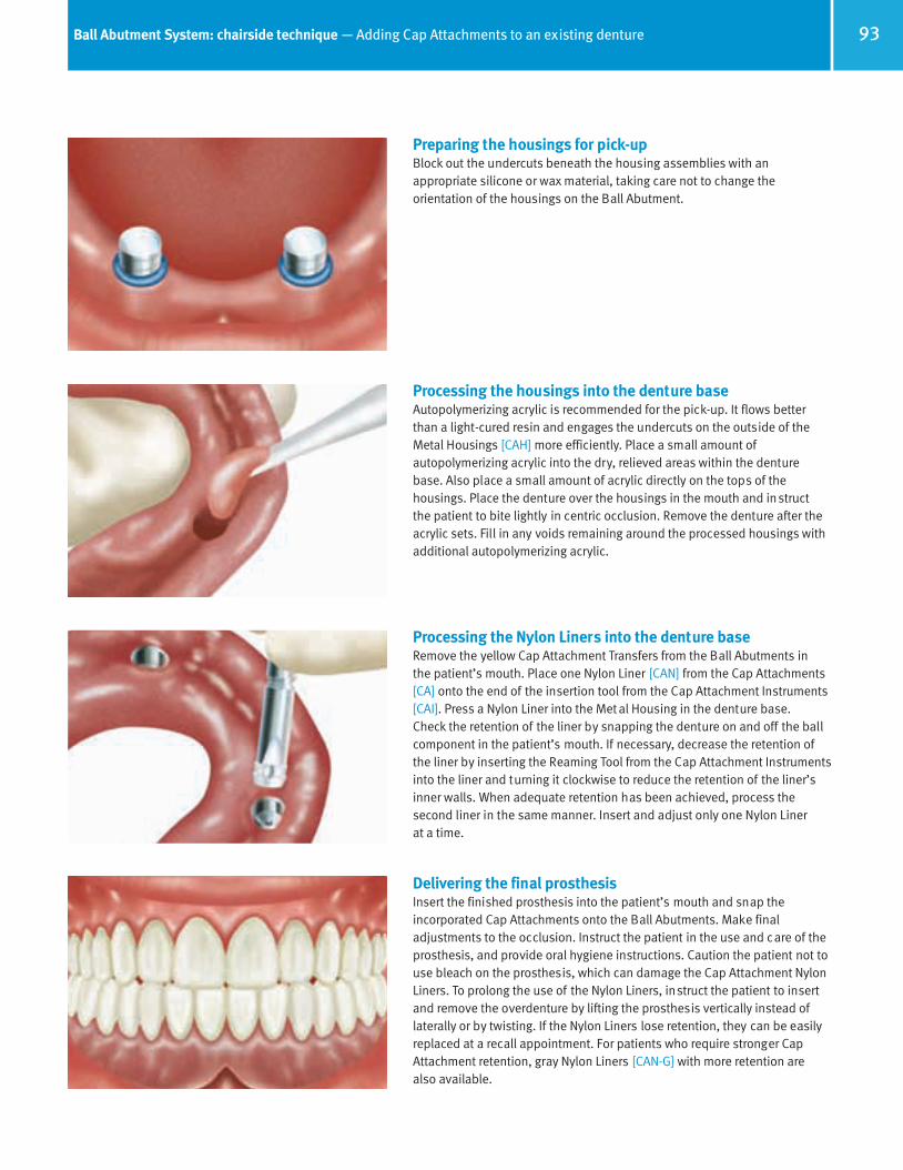
93Ball Abutment System: chairside technique — Adding Cap Attachments to an existing denture
Preparing the housings for pick-upBlock out the undercuts beneath the housing assemblies with an appropriate silicone or wax material, taking care not to change the orientation of the housings on the Ball Abutment.
Processing the housings into the denture baseAutopolymerizing acrylic is recommended for the pick-up. It flows betterthan a light-cured resin and engages the undercuts on the outside of theMetal Housings [CAH] more efficiently. Place a small amount of autopolymerizing acrylic into the dry, relieved areas within the denture base. Also place a small amount of acrylic directly on the tops of the housings. Place the denture over the housings in the mouth and instruct the patient to bite lightly in centric occlusion. Remove the denture after theacrylic sets. Fill in any voids remaining around the processed housings withadditional autopolymerizing acrylic.
Processing the Nylon Liners into the denture baseRemove the yellow Cap Attachment Transfers from the Ball Abutments in the patient’s mouth. Place one Nylon Liner [CAN] from the Cap Attachments[CA] onto the end of the insertion tool from the Cap Attachment Instruments[CAI]. Press a Nylon Liner into the Met al Housing in the denture base. Check the retention of the liner by snapping the denture on and off the ball component in the patient’s mouth. If necessary, decrease the retention ofthe liner by inserting the Reaming Tool from the Cap Attachment Instrumentsinto the liner and turning it clockwise to reduce the retention of the liner’sinner walls. When adequate retention has been achieved, process the second liner in the same manner. Insert and adjust only one Nylon Liner at a time.
Delivering the final prosthesisInsert the finished prosthesis into the patient’s mouth and snap the incorporated Cap Attachments onto the Ball Abutments. Make final adjustments to the occlusion. Instruct the patient in the use and care of theprosthesis, and provide oral hygiene instructions. Caution the patient not touse bleach on the prosthesis, which can damage the Cap Attachment NylonLiners. To prolong the use of the Nylon Liners, instruct the patient to insertand remove the overdenture by lifting the prosthesis vertically instead of laterally or by twisting. If the Nylon Liners lose retention, they can be easilyreplaced at a recall appointment. For patients who require stronger CapAttachment retention, gray Nylon Liners [CAN-G] with more retention are also available.
66514_Pg56_93:66514_Pg56_93 3/14/11 11:16 AM Page 38

94 Notes
Notes
66514_Pg094_108:66514_Pg094_108 3/14/11 2:33 PM Page 1
Immediate Bar Fabrication
RestorativeManual
66514_Pg094_108:66514_Pg094_108 3/14/11 2:33 PM Page 2

96 Components for 4.5mmD platform AdVent immediate bar fabrication
Indirect Transfer[AVIT/4]
Includes Screw [AVITS]
OptionalDirect Transfer
Use Closed-Tray Transfer with Open-Tray
Transfer Screw[DHTS]
Implant Replica[AVR]
AdVent Implant Top
For Closed-Tray Transfer Technique
For Open-Tray Transfer Technique
Use with Closed-Tray or Open-Tray Transfer Procedure
Surgical Cover Screw[AVSC]
and 2mmL Implant Extender[AVE]
Titanium Temporary Coping
[AVTT]Includes Screw
[AVGCS]
Plastic Castable Coping
[AVPC]Includes Screw
[AVGCS]
5mmL Bar Gold Coping
[AVGC5]Includes Screw
[AVGCS]
3mmL Bar Gold Coping
[TGC3]Includes Screw
[AVGCS]
66514_Pg094_108:66514_Pg094_108 3/14/11 2:33 PM Page 3

97Immediate bar overdenture — Option 1 - Laboratory splinting of bar
Attaching the transfersAfter threaded implant placement, attach Transfers [AVIT/4] with 1.25mmD Hex Tool.
For implants with a Fixture Mount/Transfer already attached, proceed to next step.
Optional: Long Impression Screws [DHTS] may be used for open-tray impression technique.
Making the impressionBlock out the top of the transfer and any exposed sutures. Place light-bodyimpression material around each transfer and record a full-arch impressionwith standard body material. Remove the impression after it fully sets.
A silicone putty bite registration and opposing-arch impression can also bemade at this time. This optional procedure will assist the technician in aligning the bar segments parallel to the plane of occlusion.
Unscrew the transfers from implants and forward with the impression forfabrication of a working cast.
Attaching the healing componentsAttach the Surgical Cover Screws [AVSC] using the 1.25mmD Hex Tool. Seatthe AdVent Extenders [AVE] onto the implants prior to threading the screwsinto the implants if an increase in transmucosal height is required.
Fabricating the working castConnect the transfer to a corresponding Replica [AVR] and insert the repli-ca/transfer assembly into the impression hole. A double-click indicates thatthe transfers are fully seated. Pour the impression in die stone to create theworking cast. If desired, use soft tissue material to represent the gingival tissues.
Remove the tray from the cast. Unthread the Transfer Screw [AVITS] with theHex Tool prior to removing the transfer bodies from the cast.
66514_Pg094_108:66514_Pg094_108 3/14/11 2:33 PM Page 4

98 Immediate bar overdenture — Option 1 - Laboratory splinting of bar
Attaching the bar componentsAttach Bar Gold Copings to replicas with a 1.25mmD Hex Tool. Use variableheight Bar Gold Copings [AVGC3 - 3mmL or AVGC5 - 5mmL] to adjust theheight of the final bar depending on the heights of the implants relative tothe surrounding tissue.
Alternative technique involves use of screw-retained abutments with gold or plastic copings for cast bar fabrication shown in section on Tapered Abutment System on page 68.
Measuring the gold barMeasure gold bar segments to fit between the Bar Gold Copings. Design thesegments to run parallel to the plane of occlusion and to allow sufficientspace between the bar and soft tissue to ensure easy access for cleansing.
Luting the gold barCut and shape gold bar patterns to fit between the Bar Gold Copings.Roughen the surface of the coping to enhance attachment of the lutingmaterial. Lute the bar segments in place with an autopolymerizing resin parallel to the plane of occlusion.
Remove framework from working cast and prepare for placement in soldering investment material.
Proceed to common procedures forprosthesis fabrication on page 101
Fig. A
Fig. C
Fig. B
Fig. D
Fig. E
Selecting gold bar design1) Dolder Gold Bar [DGB] is an oval-shaped bar 2.3mm in height and an
adjustable 50mm in length (Fig. A). Used in conjunction with a matchingmetal sleeve (Fig. B) and processing spacer (Fig. C) it is designed to allowrotational and vertical movement.
2) Hader Gold Bar [HGB] is a round-shaped bar 1.8mm in diameter and anadjustable 50mm in length (Fig. D). Used in conjunction with a matchingyellow plastic rider (Hader Clip) and green Processing Clip (Fig. E) it isdesigned to allow rotational movement.
The melting range of the prefabricated bars is 1670-1823°F or 910-995°C.
66514_Pg094_108:66514_Pg094_108 3/14/11 2:33 PM Page 5

99Immediate bar overdenture — Option 2 - Intraoral splinting of bar components
Fig. A
Fig. C
Fig. B
Fig. D
Fig. E
Removing the healing componentsRemove sutures after the required soft tissue healing period. Remove the Surgical Cover Screw [AVSC] and Extender [AVE] if placed, prior to restorative procedures.
Attaching the bar componentsSeat the Bar Gold Coping on the implant. Use a 1.25mmD Hex Tool to threadthe Coping Screw [AVGCS] into the implant and tighten to 20 Ncm with a calibrated torque wrench.
Note: This screw which connects directly to the implant should ultimately be tightened to 30 Ncm once a satisfactory period for hard tissue healing has occurred.
Measuring the gold barMeasure gold bar segments to fit between the Bar Gold Copings. Design thesegments to run parallel to the plane of occlusion as well as allow sufficientspace between the bar and soft tissue to ensure easy access for cleansing.
Selecting gold bar design1) Dolder Gold Bar [DGB] is an oval-shaped bar 2.3mm in height and an
adjustable 50mm in length (Fig. A). Used in conjunction with a matchingmetal sleeve (Fig. B) and processing spacer (Fig. C) it is designed to allowrotational and vertical movement.
2) Hader Gold Bar [HGB] is a round-shaped bar 1.8mm in diameter and anadjustable 50mm in length (Fig. D). Used in conjunction with a matchingyellow plastic rider (Hader Clip) and green Processing Clip (Fig. E) it isdesigned to allow rotational movement.
The melting range of the prefabricated bars is 1670-1823°F or 910-995°C.
66514_Pg094_108:66514_Pg094_108 3/14/11 2:33 PM Page 6
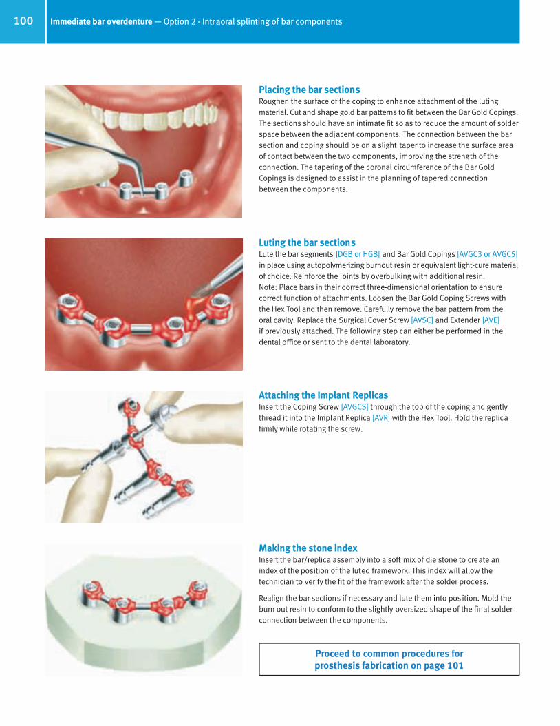
100 Immediate bar overdenture — Option 2 - Intraoral splinting of bar components
Luting the bar sectionsLute the bar segments [DGB or HGB] and Bar Gold Copings [AVGC3 or AVGC5]in place using autopolymerizing burnout resin or equivalent light-cure materialof choice. Reinforce the joints by overbulking with additional resin. Note: Place bars in their correct three-dimensional orientation to ensure correct function of attachments. Loosen the Bar Gold Coping Screws with the Hex Tool and then remove. Carefully remove the bar pattern from the oral cavity. Replace the Surgical Cover Screw [AVSC] and Extender [AVE]if previously attached. The following step can either be performed in thedental office or sent to the dental laboratory.
Attaching the Implant ReplicasInsert the Coping Screw [AVGCS] through the top of the coping and gentlythread it into the Implant Replica [AVR] with the Hex Tool. Hold the replicafirmly while rotating the screw.
Making the stone indexInsert the bar/replica assembly into a soft mix of die stone to create anindex of the position of the luted framework. This index will allow the technician to verify the fit of the framework after the solder process.
Realign the bar sections if necessary and lute them into position. Mold theburn out resin to conform to the slightly oversized shape of the final solderconnection between the components.
Placing the bar sectionsRoughen the surface of the coping to enhance attachment of the lutingmaterial. Cut and shape gold bar patterns to fit between the Bar Gold Copings.The sections should have an intimate fit so as to reduce the amount of solderspace between the adjacent components. The connection between the barsection and coping should be on a slight taper to increase the surface areaof contact between the two components, improving the strength of the connection. The tapering of the coronal circumference of the Bar GoldCopings is designed to assist in the planning of tapered connection between the components.
Proceed to common procedures forprosthesis fabrication on page 101
66514_Pg094_108:66514_Pg094_108 3/14/11 2:33 PM Page 7

101Immediate bar overdenture — Common procedures for bar fabrication
Preparing luted bar for solderingCarefully remove the luted bar assembly from the stone die index or workingcast, depending on which method was utilized to create the assembly.
Place the bar assembly into a slurry of silica-bonded soldering investmentmaterial, ensuring that all metal components are covered and held in posi-tion by the material. Remove excess investment material from around thejoint to ensure easy access for flow of heat and solder. Place the set materialinto the burn out oven to eliminate the resin material.
Soldering of bar segmentsSolder using the direct-oven or the open-flame technique, ensuring that thetemperature to melt the low-fusing solder does not exceed 1544°F or 840°C.
After bench-cooling, the soldered bar is divested. Finish the soldered jointsand lightly polish the bar following standard laboratory procedures. Takecare not to alter the dimensions of the bar segments or the Bar Gold Coping interface.
An option to the above solder technique would be to join the componentsusing laser welding. Temperatures must be regulated to accommodate forthe melting range of the gold bars.
Attaching the soldered barRemove the Surgical Cover Screws with the Hex Tool. Remove ImplantExtenders [AVE] if previously attached. The sterilized bar is seated on theimplants in the patient’s mouth.
To determine a passive fit on the implants, a distal gold cylinder incorporated within the bar was attached to its corresponding implant with an Abutment Screw [AVGCS]. Finger-tighten the screw with the 1.25mmDHex Tool. Visually inspect to verify that no discernable gaps are presentbetween the remaining gold cylinders and implants. If a gap is presentbetween the bar and any of the other implants, section the bar appropriately,relute in position and send back to the laboratory for resoldering.
Creating void in the dentureThe patient’s existing or newly-created denture can be used. Create adequate clearance in the denture base to accommodate the bar andimplants without contact when the denture is seated over them and placed into occlusion with the opposing dentition.
Techniques for processing the clips in the denture:1) Laboratory: Make a reline impression of the bar attached to the
implants, then send bar and denture to the laboratory for relining of the denture and processing of the clips on the working cast (described on following page).
2) Intraoral: Pick up the clips off the bar, following traditional prosthodontictechniques, ensuring sufficient block-out of the bar.
66514_Pg094_108:66514_Pg094_108 3/14/11 2:33 PM Page 8

102 Immediate bar overdenture — Common procedures for bar fabrication
Making the impressionBlock out undercuts beneath the bar with a material dissimilar to theimpression material. Keep the block-out area to a minimum to ensure thatthe profile of the bar is transferred accurately to the final impression. The defined profile within the impression will assist the technician inretrofitting the bar with attached Implant Replicas [AVR] into the impressionin its correct spatial position. Apply tray adhesive to the under surface of theprepared denture. Make a full-arch impression. Gently close into centricocclusion and simultaneously check that the vertical dimension of occlusiondoes not change. Remove the bar, attach healing components to theimplants. Send impression and bar to laboratory for processing of denture.
Processing the denturePour the impression and attached bar and implant replicas in die stone. Trim then mount the working cast in a reline jig. Follow standard laboratory procedures for relining or rebasing and processing of bar/clip dentures.
Use a scalpel to produce a longitudinal slit in the green Processing Clip. Foldthe sides of the clip on each other then remove. Use the Hader Clip SeatingTool, supplied with the Bar Kit [HGB], to insert the final yellow Hader Clipinto the recess created by the Processing Clip.
Trimming the dentureThe denture must be processed or trimmed to allow for free rotation of thedenture around the yellow clip on the bar, which acts as the fulcrum for thedenture. This free rotation will allow the surrounding soft tissue to assist incarrying load applied to the prosthesis during the healing process.
Return the processed denture and bar to the clinician for final delivery.
Delivering the final prosthesisSterilize the components prior to insertion in the patient’s mouth.
Secure the bar in place with the Bar Gold Coping Screws and tighten to 20 Ncm with a calibrated torque wrench. Reseat the denture and make finaladjustments. Note: This screw which connects directly to the implant shouldultimately be tightened to 30 Ncm once a satisfactory period for hard tissuehealing has occured.
Instruct the patient in the use and care of the prosthesis, and provide oralhygiene instructions. Caution the patient not to use bleach on the prosthesis, which can damage the nylon clip.
66514_Pg094_108:66514_Pg094_108 3/14/11 2:33 PM Page 9

Non-Engaging Gold Abutment System
RestorativeManual
66514_Pg094_108:66514_Pg094_108 3/14/11 2:33 PM Page 10
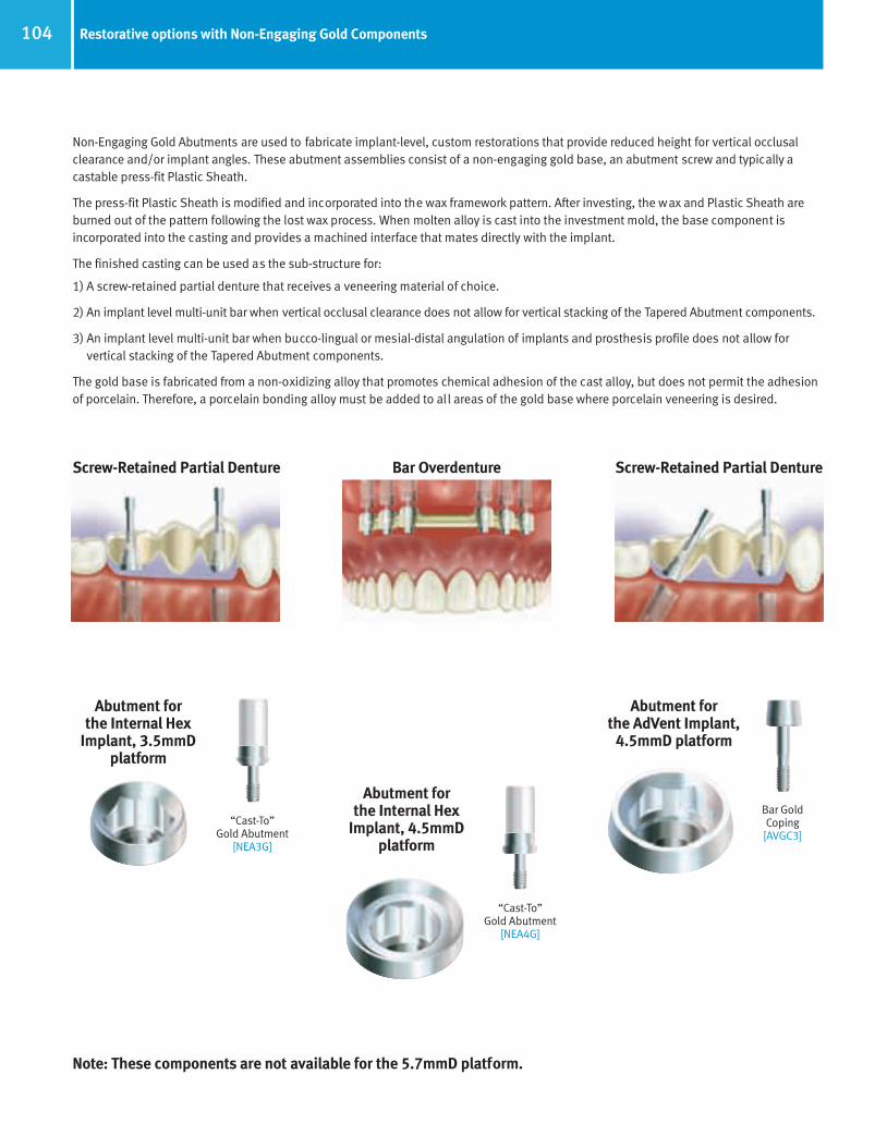
104 Restorative options with Non-Engaging Gold Components
Non-Engaging Gold Abutments are used to fabricate implant-level, custom restorations that provide reduced height for vertical occlusalclearance and/or implant angles. These abutment assemblies consist of a non-engaging gold base, an abutment screw and typically acastable press-fit Plastic Sheath.
The press-fit Plastic Sheath is modified and incorporated into the wax framework pattern. After investing, the wax and Plastic Sheath areburned out of the pattern following the lost wax process. When molten alloy is cast into the investment mold, the base component is incorporated into the casting and provides a machined interface that mates directly with the implant.
The finished casting can be used as the sub-structure for:
1) A screw-retained partial denture that receives a veneering material of choice.
2) An implant level multi-unit bar when vertical occlusal clearance does not allow for vertical stacking of the Tapered Abutment components.
3) An implant level multi-unit bar when bucco-lingual or mesial-distal angulation of implants and prosthesis profile does not allow for vertical stacking of the Tapered Abutment components.
The gold base is fabricated from a non-oxidizing alloy that promotes chemical adhesion of the cast alloy, but does not permit the adhesionof porcelain. Therefore, a porcelain bonding alloy must be added to all areas of the gold base where porcelain veneering is desired.
Screw-Retained Partial Denture Bar Overdenture Screw-Retained Partial Denture
“Cast-To”Gold Abutment
[NEA3G]
Bar Gold Coping
[AVGC3]
Note: These components are not available for the 5.7mmD platform.
Abutment for the AdVent Implant,
4.5mmD platform
“Cast-To”Gold Abutment
[NEA4G]
Abutment for the Internal Hex
Implant, 4.5mmD platform
Abutment for the Internal Hex
Implant, 3.5mmD platform
66514_Pg094_108:66514_Pg094_108 3/14/11 2:33 PM Page 11

105Vertical height requirements for Non-Engaging Gold Abutments
Non-Engaging Gold Abutments for Tapered Screw-Vent, Screw-Vent and AdVent Implant SystemsNon-Engaging Gold Abutments [NEA3G and NEA4G] for Tapered Screw-Vent and Screw-Vent implants with a 3.5mmD and 4.5mmD platform, have a low profile that allows for a subgingival connection to the implant platform.
The abutments are packaged with a gold base, a 3.8mmD Plastic Castable Sheath [OPS] and an Abutment Screw [MHLAS] for [NEA3G and NEA4G]. The Abutment Screw [AVGCS] is for the standard platform (4.5mmD) AdVent Bar Gold Coping [AVGC3 or AVGC5].
Once all the restorative components are in place, the minimum vertical clearance between the implant interface and the opposing dentition is 3.75mmL and 3.5mmL, respectively (as shown below).
ImplantImplant
AbutmentScrew
“Cast-To”Abutment
ImplantInterface
0.75mm
3.0mm
3.5mm
Bone Height
MaximumReduction
MaximumReduction
Tapered Screw-VentTwo-Stage Implant
AdVentOne-Stage Implant
PlasticSheath
AbutmentScrew
“Cast-To”Abutment
ImplantInterface
5.45mm
3.0mm variable
66514_Pg094_108:66514_Pg094_108 3/14/11 2:33 PM Page 12
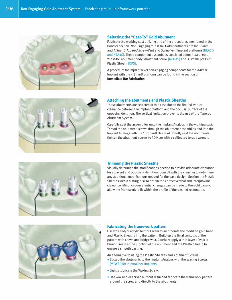
106 Non-Engaging Gold Abutment System — Fabricating multi-unit framework patterns
Selecting the “Cast-To” Gold AbutmentFabricate the working cast utilizing one of the procedures mentioned in thetransfer section. Non-Engaging “Cast-To” Gold Abutments are for 3.5mmDand 4.5mmD Tapered Screw-Vent and Screw-Vent Implant platforms [NEA3Gand NEA4G]. These component assemblies consist of a non-hexed, gold“Cast-To” abutment body, Abutment Screw [MHLAS] and 3.8mmD press-fitPlastic Sheath [OPS].
A procedure for implant level non-engaging components for the AdVentImplant with the 4.5mmD platform can be found in the section onImmediate Bar Fabrication.
Attaching the abutments and Plastic SheathsThese abutments are selected in this case due to the limited vertical clearance between the implant platform and the occlusal surface of theopposing dentition. The vertical limitation prevents the use of the TaperedAbutment System.
Carefully seat the assemblies onto the Implant Analogs in the working cast.Thread the abutment screws through the abutment assemblies and into theImplant Analogs with the 1.25mmD Hex Tool. To fully seat the abutments,tighten the abutment screws to 30 Ncm with a calibrated torque wrench.
Trimming the Plastic SheathsVisually determine the modifications needed to provide adequate clearancefor adjacent and opposing dentition. Consult with the clinician to determineany additional modifications needed for the case design. Section the PlasticSheaths with a cutting disk to obtain the correct vertical and interproximalclearance. Minor circumferential changes can be made to the gold base toallow the framework to fit within the profile of the desired restoration.
Fabricating the framework patternUse wax and/or acrylic burnout resin to incorporate the modified gold baseand Plastic Sheaths into the pattern. Build up the fin al contours of the pattern with crown and bridge wax. Carefully apply a thin layer of wax orburnout resin at the junction of the abutment and the Plastic Sheath toensure a smooth casting.
An alternative to using the Plastic Sheaths and Abutment Screws:• Secure the abutments to the Implant Analogs with the Waxing Screws
[MTWSD for internal hex implants].
• Lightly lubricate the Waxing Screw.
• Use wax and or acrylic burnout resin and fabricate the framework patternaround the screw and directly to the abutments.
66514_Pg094_108:66514_Pg094_108 3/14/11 2:33 PM Page 13
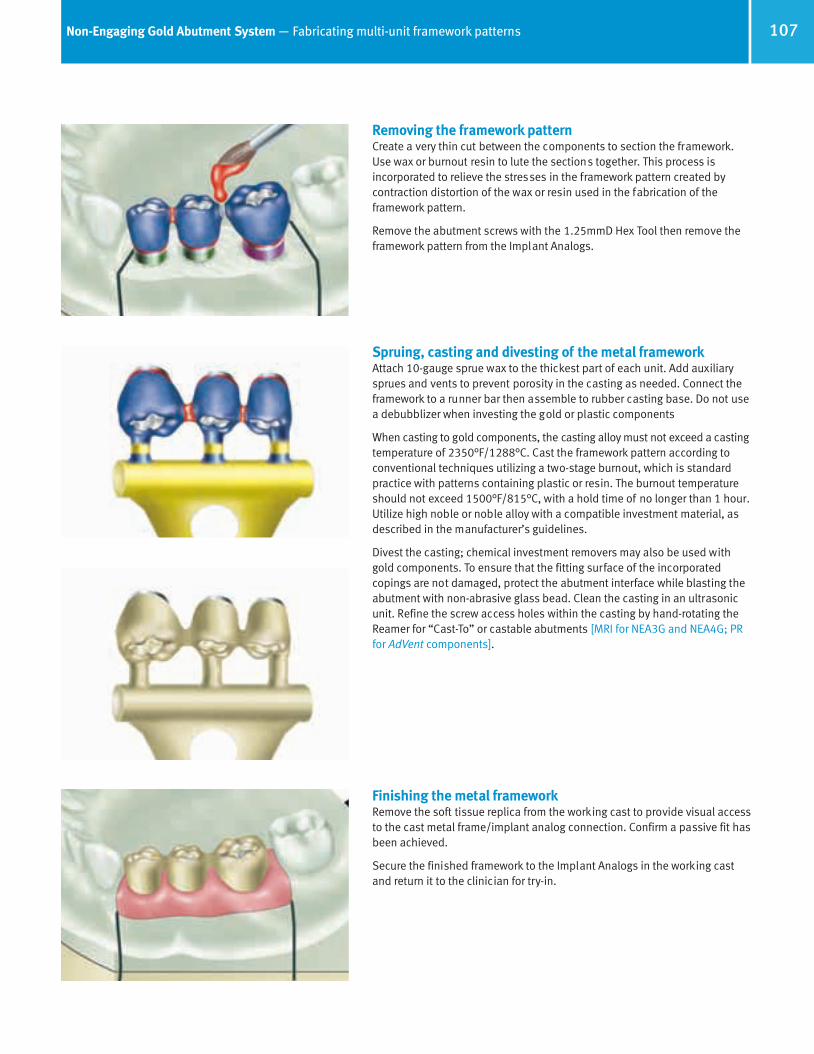
107Non-Engaging Gold Abutment System — Fabricating multi-unit framework patterns
Spruing, casting and divesting of the metal frameworkAttach 10-gauge sprue wax to the thickest part of each unit. Add auxiliarysprues and vents to prevent porosity in the casting as needed. Connect theframework to a runner bar then assemble to rubber casting base. Do not usea debubblizer when investing the gold or plastic components
When casting to gold components, the casting alloy must not exceed a castingtemperature of 2350°F/1288°C. Cast the framework pattern according toconventional techniques utilizing a two-stage burnout, which is standardpractice with patterns containing plastic or resin. The burnout temperatureshould not exceed 1500°F/815°C, with a hold time of no longer than 1 hour.Utilize high noble or noble alloy with a compatible investment material, asdescribed in the manufacturer’s guidelines.
Divest the casting; chemical investment removers may also be used withgold components. To ensure that the fitting surface of the incorporated copings are not damaged, protect the abutment interface while blasting theabutment with non-abrasive glass bead. Clean the casting in an ultrasonicunit. Refine the screw access holes within the casting by hand-rotating theReamer for “Cast-To” or castable abutments [MRI for NEA3G and NEA4G; PRfor AdVent components].
Removing the framework patternCreate a very thin cut between the components to section the framework.Use wax or burnout resin to lute the sections together. This process is incorporated to relieve the stresses in the framework pattern created by contraction distortion of the wax or resin used in the fabrication of theframework pattern.
Remove the abutment screws with the 1.25mmD Hex Tool then remove theframework pattern from the Implant Analogs.
Finishing the metal frameworkRemove the soft tissue replica from the working cast to provide visual accessto the cast metal frame/implant analog connection. Confirm a passive fit hasbeen achieved.
Secure the finished framework to the Implant Analogs in the working castand return it to the clinician for try-in.
66514_Pg094_108:66514_Pg094_108 3/14/11 2:33 PM Page 14
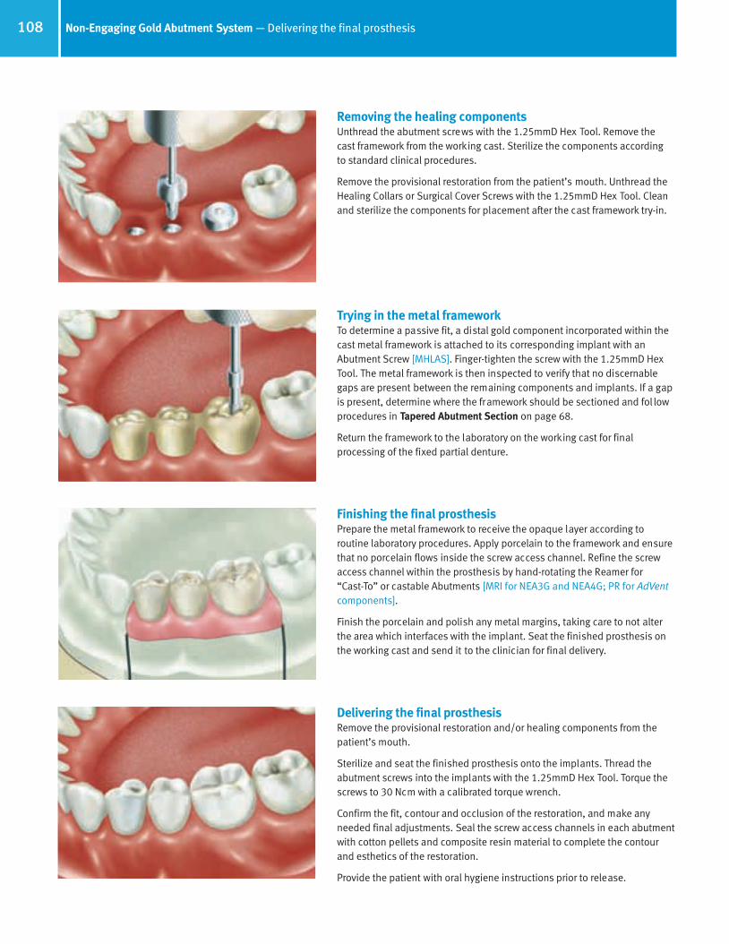
108 Non-Engaging Gold Abutment System — Delivering the final prosthesis
Trying in the metal frameworkTo determine a passive fit, a distal gold component incorporated within thecast metal framework is attached to its corresponding implant with an Abutment Screw [MHLAS]. Finger-tighten the screw with the 1.25mmD HexTool. The metal framework is then inspected to verify that no discernablegaps are present between the remaining components and implants. If a gapis present, determine where the framework should be sectioned and fol lowprocedures in Tapered Abutment Section on page 68.
Return the framework to the laboratory on the working cast for final processing of the fixed partial denture.
Finishing the final prosthesisPrepare the metal framework to receive the opaque layer according to routine laboratory procedures. Apply porcelain to the framework and ensurethat no porcelain flows inside the screw access channel. Refine the screwaccess channel within the prosthesis by hand-rotating the Reamer for “Cast-To” or castable Abutments [MRI for NEA3G and NEA4G; PR for AdVentcomponents].
Finish the porcelain and polish any metal margins, taking care to not alterthe area which interfaces with the implant. Seat the finished prosthesis onthe working cast and send it to the clinician for final delivery.
Delivering the final prosthesisRemove the provisional restoration and/or healing components from thepatient’s mouth.
Sterilize and seat the finished prosthesis onto the implants. Thread theabutment screws into the implants with the 1.25mmD Hex Tool. Torque thescrews to 30 Ncm with a calibrated torque wrench.
Confirm the fit, contour and occlusion of the restoration, and make any needed final adjustments. Seal the screw access channels in each abutmentwith cotton pellets and composite resin material to complete the contourand esthetics of the restoration.
Provide the patient with oral hygiene instructions prior to release.
Removing the healing componentsUnthread the abutment screws with the 1.25mmD Hex Tool. Remove the cast framework from the working cast. Sterilize the components according to standard clinical procedures.
Remove the provisional restoration from the patient’s mouth. Unthread theHealing Collars or Surgical Cover Screws with the 1.25mmD Hex Tool. Cleanand sterilize the components for placement after the cast framework try-in.
66514_Pg094_108:66514_Pg094_108 3/14/11 2:33 PM Page 15

Tapered Screw-Vent and AdVent Restorative Manual
Figure 1
Table of Contents
General Information
Overview 1
Restorative Options 2
Surgical Procedures and Healing Components 4
Selecting Abutments 6
Abutment Flowchart 8
Restorative Procedures
Indirect or Closed-Tray Transfer Technique 12
Direct or Open-Tray Transfer Technique 15
Immediate Impression Transfer Technique 18
Hex-Lock™ Plastic Temporary Abutments 20
Hex-Lock Contour Abutment System 26
Hex-Lock Abutment System 32
Angled Abutment System 40
“Cast-To” Gold Abutment System, Engaging 52
PureForm™ Ceramic System 60
Tapered Abutment System 68
Locator ® Overdenture Attachment System 80
Ball Abutment System 86
Immediate Bar Fabrication 96
Non-Engaging Gold Abutment System 104
Information
Prosthetic Armamentaria and Auxiliary Components 109
*Note: Images shown in the catalog may not be to scale.
Lead-In Bevel
Internal Hex 1.5mm Deep
Male Abutment Hex witha One-Degree Taper
109Prosthetic armamentaria and auxiliary components
TW1.25L
Reamers for “Cast-To” orCastable Components
Reamer forCopings
PR
Reamer for HLAand NEA
“Cast-To” SeriesMRI
Torque Wrenches and Inserts
TW30
HX1.25
TLRT2
OHRT
Hex Tools1.25mmD Hex Tools for Abutment Screws and
Fixation Screws
Removal Tool for 3-piece20° Angled Abutments
1) To remove 20° Angled Abutment Head fromthe Abutment Connector attached to InternalHex Implants.
TW20
HXL1.25 THX1.25 THXL1.25 0721
TW1.2530 Ncm Torque Wrench used to tighten all components and screwsattaching directly into the implant.
20 Ncm Torque Wrench used to tighten screws attaching directlyinto an abutment.
Hader Clip Bar System - BS1Round Gold Bar System - HGBDolder Gold Bar System - DGB
Removal Toolfor Internal Hex Implant Abutments
1) Hex-Lock Contour Abutments2) Hex-Lock Abutments3) 20° Angled Abutment Assemblies4) “Cast-To” Gold Abutments5) Core Abutments for PureForm
Ceramic System
Cap Attachment System - CAS Locator Core Tool - LOCCT2
Locator Torque Wrench Insert Driver,15mmL - LOCTW15
Locator Torque Wrench Insert Driver,21mmL - LOCTW21
Nylon Liner Insertion Tool
Mandril for Castable Ball Pattern
Nylon Liner Reaming Tool
Cap Attachment Instruments - CAI
66514_CoverW_Spine:66514_CoverW_Spine 3/14/11 7:58 AM Page 2

©20
06 Z
imm
er D
enta
l Inc
. All
right
s re
serv
ed. 4
941,
Rev
. 10/
06. L
ocat
or is
are
gist
ered
trad
emar
k of
Zes
t Anc
hors
, Inc
. Had
er B
ar is
a re
gist
ered
trad
emar
k of
Ern
st M
uhlb
auer
Gm
bH &
Co.
KG
.
www.zimmerdental.com
1900 Aston AvenueCarlsbad, CA 92008-7308, USAIn the U.S. 800 854 7019
For more information about our Products, Professional Programs and Educational Opportunities, contact us:
To fax an order 888 225 2483Outside the U.S. +1 760 929 4300Australia +61 (0)2 9950 5444 or 1 800 241 916Canada +1 905 567 2073 or 1 800 265 0968
France +33 (0)1 45 12 35 35Germany +49 (0)761 4584 722/723Israel +972 (0)3 6124242Spain +34 93 846 05 43
To receive our eNews visit us at http://www.zimmerdental.com/news_eNewsLetterSignUp.aspxPartially and Fully Edentulous
Tapered Screw-Vent®
and AdVent®
RestorativeManual
Tape
red
Scre
w-V
ent a
nd A
dVen
t Res
tora
tive
Man
ual –
Par
tially
and
Ful
ly E
dent
ulou
sZi
mm
er D
enta
l
66514_CoverW_Spine:66514_CoverW_Spine 3/14/11 7:58 AM Page 1