670 - aemc · 2017. 7. 7. · 6 clamp-on meter models 670 and 675 chapter 2 product features...
TRANSCRIPT
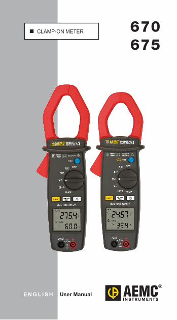
CLAMP-ON METER 670675
E N G L I S H User Manual
Certificate of Compliance
Chauvin Arnoux®, Inc. d.b.a. AEMC® Instruments certifies that this instrument has been calibrated using standards and instruments traceable to international standards.
We guarantee that at the time of shipping your instrument has met its published specifications.
An NIST traceable certificate may be requested at the time of purchase, or obtained by returning the instrument to our repair and calibration facility, for a nominal charge.
The recommended calibration interval for this instrument is 12 months and begins on the date of receipt by the customer. For recalibration, please use our calibration services. Refer to our repair and calibration section at www.aemc.com.
Serial #: ________________________________
Catalog #: 2117.49 / 2117.50
Model #: 670 / 675
Please fill in the appropriate date as indicated:
Date Received: ___________________________
Date Calibration Due: ______________________
Chauvin Arnoux®, Inc. d.b.a AEMC® Instruments
www.aemc.com

Table of Contents
1. INTRODUCTION ........................................ 31.1 International Electrical Symbols .............. 41.2 DefinitionofMeasurementCategories .... 41.3 ReceivingYourShipment ........................ 51.4 OrderingInformation ............................... 5
1.4.1 Accessories/ReplacementParts .. 5
2. PRODUCT FEATURES ............................... 62.1 Description .............................................. 62.2 Model670/675ControlFeatures ............. 72.3 LCDDisplay ............................................ 82.4 ButtonFunctions ..................................... 9
2.4.1 HOLDButton ............................... 92.4.2 CorrectionofZeroin DCmeasurement ........................ 92.4.3 AutoPowerOFF .......................... 92.4.4 DISPLAYButton ........................ 102.4.5 MIN/MAXFunction(500ms) ...... 102.4.6 PeakFunction(1ms) .................. 102.4.7 BacklightButton ......................... 10
3. SPECIFICATIONS .................................... 113.1 ElectricalSpecifications ........................ 113.2 MechanicalSpecifications ..................... 133.3 EnvironmentalSpecifications ................ 143.4 SafetySpecifications ............................. 14
4. OPERATION ............................................ 154.1 ACCurrentMeasurement ..................... 154.2 ACVoltageandCurrent MeasurementSimultaneously ............... 16
4.3 DCCurrentMeasurement(675only) ......174.4 ACVoltMeasurement ........................... 184.5 DCVoltMeasurement ........................... 194.6 ResistanceMeasurement ..................... 204.7 ContinuityMeasurement ....................... 214.8 TemperatureMeasurement ................... 224.9 FrequencyMeasurementUsing VoltageInput ......................................... 234.10 FrequencyMeasurementUsing CurrentInput ......................................... 24
5. MAINTENANCE ....................................... 255.1 Warning! ................................................ 255.2 Cleaning ................................................ 255.3 BatteryReplacement ............................. 25
RepairandCalibration ............................................ 27TechnicalandSalesAssistance ............................. 27Limited Warranty .................................................... 28WarrantyRepairs .................................................... 28

Clamp-onMeterModels670and675 3
CHAPTER 1
INTRODUCTION
Warning
Readtheusermanualbeforeoperatingandfollowallsafetyinformation.
Onlyusethemeterasspecifiedinthisusermanual.
Neverusethismeteronacircuitwithvolt-agesgreaterthan600Vrms@50/60Hz,CATIVor1000V,CATIII.
Nevermeasurecurrentwhilethetestleadsareconnectedtotheinputjacks.
Donotoperatethemeterifthebodyortestleadslookdamaged.
Checktherotaryrangeswitchandmakesureitisatthecorrectpositionbeforeeachmeasurement.
Donotperformresistanceandcontinuitytestonalivecircuit.
Useextremecautionwhenmeasuringlivesystemswithvoltagesgreaterthan60VDC or 30VAC.
Useextremecarewhenworkingaroundbusbarsandbareconductors.
Donotusethemeterinoverrange/overloadconditions( ).
Foraccuratereadings,changethebatterywhenthe symbolappears.

4 Clamp-onMeterModels670and675
1.1 International Electrical Symbols
This symbol signifies that the instrument is protected by double or reinforced insulation.
This symbol on the instrument indicates a WARNING and that the operator must refer to the user manual for instructions before operating the instrument. In this manual, the symbol preceding instructions indicates that if the instructions are not followed, bodily injury, installation/sample and product damage may result.
Risk of electric shock. The voltage at the parts marked with this symbol may be dangerous.
This symbol refers to a type A current sensor. This symbol sig-nifies that application around and removal from HAZARDOUS LIVE conductors is permitted.
Ground.
In conformity with WEEE 2002/96/EC.
1.2 Definition of Measurement CategoriesCAT II: Formeasurementsperformedoncircuitsdirectly
connected to the electrical distribution system.Examples are measurements on householdappliancesorportabletools.
CAT III: For measurements performed in the buildinginstallation at the distribution level such as onhardwired equipment in fixed installation andcircuitbreakers.
CAT IV: For measurements performed at the primaryelectrical supply (<1000V) such as on primaryovercurrent protection devices, ripple controlunits,ormeters.

Clamp-onMeterModels670and675 5
1.3 Receiving Your ShipmentUpon receiving your shipment,make sure that the con-tentsareconsistentwiththepackinglist.Notifyyourdis-tributorofanymissingitems.Iftheequipmentappearstobedamaged,fileaclaimimmediatelywiththecarrierandnotifyyourdistributoratonce,givingadetaileddescriptionofanydamage.Save thedamagedpackingcontainer tosubstantiateyourclaim.
1.4 Ordering Information
TRMS Clamp-on Meter Model 670 ............Cat. #2117.49Includes meter, set of test leads (red/black with safety needle tips), K-type thermocouple, one 9V battery, soft carrying case and a user manual.
TRMS Clamp-on Meter Model 675 ............Cat. #2117.50Includes meter, set of test leads (red/black with safety needle tips), K-type thermocouple, one 9V battery, soft carrying case and a user manual.
1.4.1 Accessories and Replacement PartsSoftCarryingCase ......................................Cat. #2118.89K-typeThermocouple ..................................Cat. #2118.90
Set of 2, 5 ft color-coded leads....................Cat. #2152.05

6 Clamp-onMeterModels670and675
CHAPTER 2
PRODUCT FEATURES
2.1 Description
The AEMC® Models 670 and 675 are general purposeprofessional clamp-on meters that measure up to thetougheststandards.Thesemetersofferacompletesetofmeasurementranges(ACAmps,DCAmps[675only],ACVolts,DCVolts,Ohms,Continuitywithbeeper,Frequencyfrom V or A, and Temperature) and are in compliancewith international safety andquality standards to ensureprofessionalandreliablemeasuringtools.
Thesemetersaredesignedtomeasureanddisplayampsand volts at the same time. They are also auto-rangingandprovide thebestmeasurement rangeand resolutionfortroubleshooting.
The Models 670 and 675 are sized for comfortable,one-handed operation. The tapered and hooked jawdesign facilitates maneuvering in crowded wiring andbreaker panels, making it easy to select conductors. The jaw opening accommodates one 750 kcmil cable ortwo 350kcmil cables. The large and easy-to-read 9999-count LCD features comprehensive user informationsymbols, such as low battery, polarity, overload, and ananalog bargraph for easy trend readings. Both modelsareequippedwith aDataHold function that freezes themeasurementforlaterviewing,Min/Max,andPeakfunctionforcaptureofsignals.
TheModel670and675areTrueRMSclamp-onmetersthat provide RMS measurements for today’s non-linearelectrical environments.

Clamp-onMeterModels670and675 7
2.2 Model 670/675 Control Features
DISPLAY MIN MAXPEAK
HOLD
DUAL TRMS DISPLAY
1000A1000V CAT III600V CAT IV
1000VCAT III
MODEL 670TRMS CLAMP METER
1
2
3
4
5
6
7
8
DUAL TRMS DISPLAY
ZEROPress 2s
1
2
3
4
5
6
7
8
1000A1000V CAT III600V CAT IV
MODEL 675TRMS CLAMP METER
1400A
1000VCAT III
1. JawAssemblyModel670-1.65"(42mm) Model675-1.58"(40mm)2. SafetyBarrierAnti-slipGuard3. LeverforJawOpening/Closing4. ButtonFunctions(see§2.4)5. LCDDisplay6. Positive(red)InputandCOM(black)Input7. DataHoldButton8. RotaryRangeSelectorSwitch

8 Clamp-onMeterModels670and675
2.3 LCD Display
Icon Function
AUTO Automatic Range
HOLD Freezes the Display
MIN Minimum Value
MAX Maximum Value
PEAK Peak Value
ZERO ADC Zero Function (675 only)
DC Input
AC Input
Auto Power OFF Indication
Low Battery
Continuity Beeper Enabled
Ω Resistance Measurement Indicator
A V Current /Voltage Indicator
C°/ F° Degrees Celsius/Fahrenheit
Hz Frequency Measurement Indicator

Clamp-onMeterModels670and675 9
2.4 Button Functions
2.4.1 HOLD Button
• ThelastreadingmaybeheldonthedisplaybypressingtheHOLDbutton.TheHOLD symbolwillappearwhenthisfunctionisactivated.
• Todeactivate,presstheHOLDbuttonasecondtime.
2.4.2 Correction of Zero in DC measurement
• ThisfunctionontheModel675allowstheusertozerooutmagnetizationeffectsinDCcurrentmeasurements.
• This operation must be performed after each highamplitudecurrentmeasurement.
• TurntherotaryswitchtoADC,withnoconductorinsertedinto theclamp, thenpresstheHOLDbutton(approxi-mately2seconds)untilthedisplayshowszerocurrent.ThisisalsoindicatedbyanaudiobeepandthesymbolZERO onthedisplay.
2.4.3 Auto Power OFF
• Ifthereisnoactivityforapproximately10minutes,theclampwillautomaticallyshutdownandthe symbol willappear
• To disableAuto Power OFF function, turn the rotaryswitchtoOFF.
• Press and hold down the HOLD button and set therotaryswitchtoanypositionotherthanOFF.
• The symbol disappears and Auto Power OFF isdeactivated.

10 Clamp-onMeterModels670and675
2.4.4 DISPLAY Button
• Whenmeasuring voltage orAC current, pressing theDISPLAY buttonreplacesthemeasurementshowninthe lowerdisplaywith the frequencymeasurement ofthevariableshowninthemaindisplay.Pressingagainreturnstothepreviousdisplay.
• In temperature measurement, pressing DISPLAY switches the displays from °C to °F of themeasuredtemperature.
2.4.5 MIN/MAX Function (500ms)• PressingtheMIN/MAXbuttononcewillsetthemeterto
MIN mode.
• PressingittwicewillsetthemetertoMAX mode.
• Pressingitthreetimeswillsetthemeterbacktonormaloperation.
2.4.6 Peak Function (1ms)
• Thisfunctionisusedformeasuring1-mspeakvaluesinvoltageorcurrent.
• To activate the function, press the MIN MAX PEAK buttonforatleast2seconds,untilPEAKisdisplayed.
• Toexitthisfunction,pressthebuttonagainforatleast2secondsorpresstheHOLDbuttontwice.Theclampwillthenreturntonormalmode.
2.4.7 Backlight Button
• Pressthe buttononcetoturnthebacklighton.Pressitagaintoturnitoff.
• Whenbacklightison,themeterwillautomaticallyturnthebacklightoffafterapproximately3minutes.

Clamp-onMeterModels670and675 11
CHAPTER 3
SPECIFICATIONS
Thetolerancesassignedtothevalues,ordeclaredlimits,constitute only the values guaranteed by themanufac-turer.Valueswithoutatoleranceareforinformationonly.
Thesymbol isdisplayedwhentheinputsignalsexceedthelimitvaluespossibleineachmeasurementrange.
Thesymbol- isdisplayedin°C/°Fmeasurementwhenthereisnoinputsignal(opencircuit).
3.1 Electrical SpecificationsReference Conditions: 23°C ±3°C, 48 to 65Hz, no DC component,sinusoidalFC= 2 ,10%to100%ofrange,noexternalalternativemagnetic field,noelectricalfield,conductorcenteredinjaws(inA).
AC AmperesRange Measuring Range Resolution Accuracy
100A 0.00 to 99.99A 0.01A 1.5% ± 5cts (50 to 60Hz)2.0% ± 5cts (60 to 500Hz)
4.5% ± 5cts (500Hz to 3kHz)1000A 100 to 1000 A 0.1A
Overload: 1000Arms
DC Amperes (Model 675 only)Range Measuring Range Resolution Accuracy
100A 0.00 to 99.99A 0.01A 1.2% ± 5cts
1000A 100.0 to 999.9A 0.1A2.5% ± 5cts
1400A 1000 to 1400A 1A
Overload: 1400ADC

12 Clamp-onMeterModels670and675
AC VoltsRange Measuring Range Resolution Accuracy
1000V 0.0 to 999.9V 0.1V1.0% ± 5cts (50 to 60Hz)1.2% ± 5cts (60 to 500Hz)
2.5% ± 5cts (500Hz to 3kHz)
Input Resistance: 1MW
Overload: 1000Vrms
DC VoltsRange Measuring Range Resolution Accuracy
1000V 0.0 to 999.9V 0.1V1% ± 2cts
1400V 1000 to 1400V 1V
Input Resistance: 1MW
Overload: 1400vDC
Resistance - Ohms (Ω)Range Measuring Range Resolution Accuracy
1000W 0.0 to 999.9W 0.1W 1% ± 3cts3.3VDC (Vmax)10,000W 1000 to 9999W 1W
Protection: 1000Vrms
Continuity ( )Range Beeper Activation Accuracy
< 35W 1% ± 3cts3.3VDC (Vmax)
Protection: 1000Vrms
Frequency (Hz)Function Range Resolution Sensitivity Accuracy
A - Hz 1000Hz 0.1Hz 3Arms1.0% ± 2cts
V - Hz 10,000Hz 1Hz 5Vrms

Clamp-onMeterModels670and675 13
Temperature (°C / °F)Range Measuring Range Resolution Accuracy
1000°C -40 to 999.5°C 0.5°C1.0% ± 2°C
1200°C 1000 to 1200°C 1°C
2192°F -40 to 2192°F 1°F 1.0% ± 4°F
Low Battery Indicator:isdisplayedwhenthevoltagesuppliedbythebattery
is lower than theoperatingvoltage.Themeasurementsarethenguaranteedforonlyashortperiod.
Power supply:9V,NEDA1604(6F22)alkaline
Battery Life (no buzzer or backlight):35hours(670)30hours(675)
Polarity:displayedwhennegativesignalappliedtoinput
3.2 Mechanical Specifications
Digital Display:33/4digitsLCDdualdisplay(maxreading9999)
Jaw Opening:670:1.65"(42mm)675:1.57"(40mm)
Dimension (L x W x D):670:10.71x3.15x1.69"(272x80x43mm)675:10.12x3.15x1.69"(257x80x43mm)
Weight:670:17oz(480g)withbattery675:15.5oz(440g)withbattery
Protection Index of Housing:IP30accordingtoEN60529Ed.92

14 Clamp-onMeterModels670and675
3.3 Environmental SpecificationsAltitude: 2000 meters
Operating Temperature:-14°to122°F(-25to50°C),80%RH,non-condensingNOTE: If the meter is to be used below 32°F (0°C), we suggest that the battery be replaced to ensure proper results.
Storage Temperature:-14°to140°F(-25°to60°C)<80%RH
3.4 Safety Specifications
EN 61010-1 Ed.2001EN 61010-2-032 Ed.2002600VCATIV,1000VCATIIIPollutionDegree2
Electromagnetic Compatibility (perNFEN61326)CompliantwithelectromagneticcompatibilitystandardNFEN61326-1(07/97)+A1(10/98)+A2(09/2001)- Radiatedandconductedemission(NFEN55022)- RadiatedImmunity,criterionB(NFEN61000-4-3)- ConductedImmunity,criterionA(NFEN61000-4-6)- Electrostaticdischarges,criterionA(NFEN61000-4-2)- Transients,criterionB(NFEN61000-4-4)- Shockwaves,criterionA(NFEN61000-4-5)
Note:Certainhighpowerradio-electricfrequenciesare,under certain conditions, capableof interferingwith themetrologicalintegrityofthemeter.
*Specifications are subject to change without notice
Clamp-onMeterModels670and675 15
CHAPTER 4
OPERATION
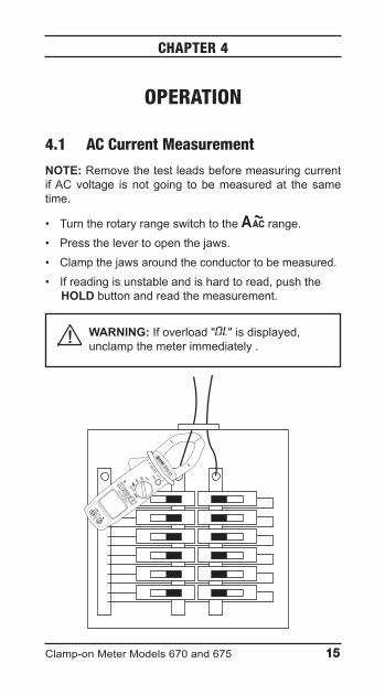
4.1 AC Current Measurement
NOTE: RemovethetestleadsbeforemeasuringcurrentifACvoltage isnotgoing tobemeasuredat the sametime.
• Turntherotaryrangeswitchtothe range.• Pressthelevertoopenthejaws.• Clampthejawsaroundtheconductortobemeasured.• Ifreadingisunstableandishardtoread,pushthe
HOLD buttonandreadthemeasurement.
WARNING: Ifoverload" "isdisplayed,unclampthemeterimmediately.
DISPLAY
MIN MAX
PEAK
HOLD
DUAL TRMS DISPLAY
1000A
1000V CAT III
600V CAT IV
1000V
CAT III
MODEL 670
TRMS CLAM
P METER

16 Clamp-onMeterModels670and675
4.2 AC Voltage and Current Measurement Simultaneously
• Turntherotaryrangeswitchtothe or range.• Connectthetestprobetipstothevoltagetobe
measured.• Pressthelevertoopenthejaws.• Clampthejawsaroundtheconductortobemeasured.• Voltageandcurrentmeasurementswillbedisplayed
simultaneously.• Ifreadingisunstableandishardtoread,pushthe
HOLD buttonandreadthemeasurement.
WARNING: Ifoverload" "isdisplayed,unclampthemeterimmediately.
DISPLAY
MIN MAX
PEAK
HOLD
DUAL TRMS DISPLAY
1000A
1000V CAT III
600V CAT IV
1000V
CAT III
MODEL 670
TRMS CLAM
P METER

Clamp-onMeterModels670and675 17
4.3 DC Current Measurement (675 only)
NOTE: RemovethetestleadsbeforemeasuringcurrentifDCvoltage isnotgoing tobemeasuredat thesametime
• Turntherotaryrangeswitchtothe range.• Ifneeded,thedisplaymaybe“zeroed”.Pressand
holddowntheHOLDbuttonforapprox2s.• Clampthejawsaroundtheconductortobemeasured.• ThemaindisplayisADC,thesecondarydisplayisVDC.
TheDISPLAYbuttonisinoperative.• Ifreadingisunstableandishardtoread,pushthe
HOLD buttonandreadthemeasurement.
WARNING: Ifoverload" "isdisplayed,unclampthemeterimmediately.
DUAL TRMS DISPLAY
ZERO
Press 2s
1000A
1000V CAT III
600V CAT IV
MODEL 675
TRMS CLAMP METER
1400A
1000V
CAT III
18 Clamp-onMeterModels670and675
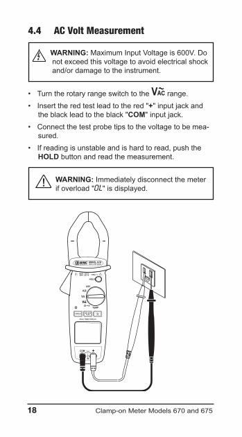
4.4 AC Volt Measurement
WARNING: MaximumInputVoltageis600V.Donotexceedthisvoltagetoavoidelectricalshockand/ordamagetotheinstrument.
• Turntherotaryrangeswitchtothe range.• Inserttheredtestleadtothered"+"inputjackand
theblackleadtotheblack"COM"inputjack.• Connectthetestprobetipstothevoltagetobemea-
sured.• Ifreadingisunstableandishardtoread,pushthe
HOLD buttonandreadthemeasurement.
WARNING: Immediatelydisconnectthemeterifoverload" "isdisplayed.
DISPLAY MIN MAXPEAK
HOLD
DUAL TRMS DISPLAY
1000A1000V CAT III600V CAT IV
1000VCAT III
MODEL 670TRMS CLAMP METER
Clamp-onMeterModels670and675 19
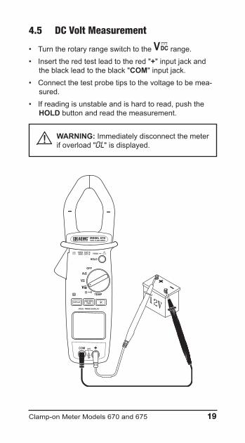
4.5 DC Volt Measurement
• Turntherotaryrangeswitchtothe range.• Inserttheredtestleadtothered"+"inputjackand
theblackleadtotheblack"COM"inputjack.• Connectthetestprobetipstothevoltagetobemea-
sured.• Ifreadingisunstableandishardtoread,pushthe
HOLD buttonandreadthemeasurement.
WARNING: Immediatelydisconnectthemeterifoverload" "isdisplayed.
DISPLAY MIN MAXPEAK
HOLD
DUAL TRMS DISPLAY
1000A1000V CAT III600V CAT IV
1000VCAT III
MODEL 670TRMS CLAMP METER

20 Clamp-onMeterModels670and675
4.6 Resistance Measurement
• Turntherotaryrangeswitchtothe range.• Inserttheredtestleadtothered"+"inputjackand
theblackleadtotheblack"COM"inputjack.• Bringthetestprobetipsintocontactwiththesample
undertest.
WARNING: Immediatelydisconnectthemeterifoverload“ ”isdisplayed.
WARNING: Whenmakingaresistancemea-surement, make sure that the power is off(dead circuit), and that all capacitors in themeasuredcircuitarefullydischarged.
DISPLAY MIN MAXPEAK
HOLD
DUAL TRMS DISPLAY
1000A1000V CAT III600V CAT IV
1000VCAT III
MODEL 670TRMS CLAMP METER

Clamp-onMeterModels670and675 21
4.7 Continuity Measurement
WARNING: When testing continuity, makesure that there is no power in the testedsampleorcircuit (deadcircuit).Thismaybecheckedbyusingthevoltagefunctions.
• Turntherotaryrangeswitchtothe range.• Insertredtestleadtothered"+"inputjackandthe
blackleadtotheblack"COM"inputjack.• Bringthetestprobetipsintocontactwiththesample
undertest.• Iftheresistanceislessthan40W,thebeeperemitsa
continuoussound.
WARNING: Immediatelydisconnectthemeterifoverload“ ”isdisplayed.
DISPLAY MIN MAXPEAK
HOLD
DUAL TRMS DISPLAY
1000A1000V CAT III600V CAT IV
1000VCAT III
MODEL 670TRMS CLAMP METER
DISPLAY MIN MAXPEAK
HOLD
DUAL TRMS DISPLAY
1000A1000V CAT III600V CAT IV
1000VCAT III
MODEL 670TRMS CLAMP METER
22 Clamp-onMeterModels670and675
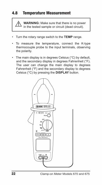
4.8 Temperature Measurement
WARNING: Makesurethatthereisnopowerinthetestedsampleorcircuit(deadcircuit).
• TurntherotaryrangeswitchtotheTEMP range.
• To measure the temperature, connect the K-typethermocoupleprobetotheinputterminals,observingthepolarity.
• ThemaindisplayisindegreesCelsius(°C)bydefault,andthesecondarydisplayindegreesFahrenheit(°F).The user can change the main display to degreesFahrenheit(°F)andthesecondarydisplaytodegreesCelsius(°C)bypressingtheDISPLAY button.
DISPLAY MIN MAXPEAK
HOLD
DUAL TRMS DISPLAY
1000A1000V CAT III600V CAT IV
1000VCAT III
MODEL 670TRMS CLAMP METER

Clamp-onMeterModels670and675 23
4.9 Frequency Measurement Using Voltage Input
• Turn the rotary range switch to the range andpresstheDISPLAYbutton.
• Insertredtestleadtothered"+"inputjackandtheblackleadtotheblack"COM"inputjack.
• Bringthetestprobetipsintocontactwiththesampleundertest.
WARNING: Immediatelydisconnectthemeterifoverload“ ”isdisplayed.
DISPLAY MIN MAXPEAK
HOLD
DUAL TRMS DISPLAY
1000A1000V CAT III600V CAT IV
1000VCAT III
MODEL 670TRMS CLAMP METER

24 Clamp-onMeterModels670and675
4.10 Frequency Measurement Using Current Input
NOTE: RemovethetestleadsbeforemeasuringcurrentifACvoltageisnotgoingtobemeasuredatthesametime.
• Turntherotaryrangeswitchtothe rangeandpresstheDISPLAYbutton.
• Pressthelevertoopenthejaws.• Clampthejawsaroundtheconductortobemeasured.
WARNING: Ifoverload" "isdisplayed,unclampthemeterimmediately.
DISPLAY MIN MAXPEAK
HOLD
DUAL TRMS DISPLAY
1000A1000V CAT III600V CAT IV
1000VCAT III
MODEL 670TRMS CLAMP METER

Clamp-onMeterModels670and675 25
CHAPTER 5
MAINTENANCE
5.1 Warning!
• Removethetestleadsonanyinputbeforeopeningthecase.
• Donotoperate theclamp-onmeterwithoutabatterycase cover.
• To avoid electrical shock, do not attempt to performanyservicingunlessyouarequalifiedtodoso.
• Toavoidelectricalshockand/ordamagetotheinstru-ment,donotgetwaterorotherforeignagentsintotheprobe.
5.2 Cleaning
• Toclean themeter,wipe thecasewithadampclothandmilddetergent.
• Donotuseabrasivesorsolvents.
• Do not get water inside the case. This may lead toelectricalshockordamagetotheinstrument.
5.3 Battery Replacement
• TheClamp-onMeterModels670and675arepoweredbya9Vbattery.The symbolwillappearontheLCDdisplaywhen thesupplyvoltagedropsbelowproperoperatingrange.Thisindicatesthatthebatteryneedstobechanged.

26 Clamp-onMeterModels670and675
• Themetermust be in theOFF position and discon-nectedfromanycircuitorinput.
• Placethemeterfacedownandremovethe2screwswithascrewdriver.
• Replacetheoldbatterywithanew9Vbattery,makingsureofthecorrectpositioningofthewirestopreventanypinchingatclosing.
• Replace the battery compartment cover and tightenthescrews.
Clamp-onMeterModels670and675 27
Repair and CalibrationToensurethatyourinstrumentmeetsfactoryspecifications,we recommend that it be submitted to our factory ServiceCenteratone-yearintervalsforrecalibration,orasrequiredbyotherstandardsorinternalprocedures.
For instrument repair and calibration:YoumustcontactourServiceCenterforaCustomerServiceAuthorization Number (CSA#). This will ensure that whenyour instrument arrives, it will be tracked and processedpromptly.PleasewritetheCSA#ontheoutsideoftheship-pingcontainer.Iftheinstrumentisreturnedforcalibration,weneedtoknowifyouwantastandardcalibration,oracalibra-tiontraceabletoN.I.S.T.(Includescalibrationcertificateplusrecordedcalibrationdata). ChauvinArnoux®,Inc.d.b.a. AEMC®Instruments 15FaradayDrive•Dover,NH03820USA Phone: (800)945-2362or(603)749-6434(Ext.360) Fax: (603)742-2346or(603)749-6309 [email protected](Orcontactyourauthorizeddistributor)Costs for repair, standardcalibration,andcalibration trace-able to N.I.S.T. are available.NOTE: A CSA# must be obtained before returning any instrument.
Technical and Sales AssistanceIfyouareexperiencinganytechnicalproblems,orrequireanyassistancewith the proper operation or application of yourinstrument,pleasecall,mail,faxore-mailourtechnicalsup-porthotline: ChauvinArnoux®,Inc.d.b.a.AEMC®Instruments 200FoxboroughBlvd•Foxborough,MA02035,USA Phone: (800)343-1391or(508)698-2115 Fax: (508)698-2118 [email protected] www.aemc.com
NOTE: Do not ship instruments to our Foxborough, MA address.

28 Clamp-onMeterModels670and675
Limited WarrantyTheModels670and675arewarranted to theowner foraperiod of two years from the date of original purchaseagainst defects in manufacture. This limited warranty isgiven by AEMC® Instruments, not by the distributor fromwhomitwaspurchased.Thiswarrantyisvoidiftheunithasbeen tampered with, abused or if the defect is related toservicenotperformedbyAEMC®Instruments.
For full warranty coverage detail and registration, go to www.aemc.com
What AEMC® Instruments will do:Ifamalfunctionoccurswithinthewarrantyperiod,youmayreturntheinstrumenttous for repair or replacement free of charge, provided wehave your registration information on file or proof ofpurchase. AEMC® Instruments will, at its option, repair orreplacethefaultymaterial.
REGISTER ONLINE AT: www.aemc.com
Warranty RepairsWhat you must do to return an Instrument for Warranty Repair: First, request a Customer Service Authorization Number(CSA#) by phone or by fax from our Service Department(seeaddressbelow), then return the instrumentalongwiththesignedCSAForm.PleasewritetheCSA#ontheoutsideoftheshippingcontainer.Returntheinstrument,postageorshipmentpre-paidto:
ChauvinArnoux®,Inc.d.b.a.AEMC®InstrumentsServiceDept•15FaradayDr•Dover,NH03820USAPhone: (800)945-2362or(603)749-6434(Ext.360)Fax: (603)742-2346or(603)[email protected]
Caution:Toprotectyourselfagainst in-transit loss,werec-ommendyouinsureyourreturnedmaterial.NOTE: All customers must obtain a CSA# before returning any instrument.


03/1799-MAN 100335 v8
Chauvin Arnoux®, Inc. d.b.a. AEMC® Instruments15FaradayDrive•Dover,NH03820USA
www.aemc.com