675443
TRANSCRIPT

8/12/2019 675443
http://slidepdf.com/reader/full/675443 1/399
r
J
f
*
^ U S U V L A B S T E C H N I C A L R E P O RT 6 7 * 5
^
10 6 H U F L I C H T T E S T R E S E A R C H P R 9 & R A M
in
I. iefirs 1.1. Tiipkiis
I. . Silibirt
lofist 1 S 8 8
O C T 1 Wl
I I . S . I I H I Y » Y U T I O N M AT E R I E L L A B O R AT O R I E S
F O RT E I I S T I S , V I R G i l A
CONTRACT DA-44-177-AMC-154(T)
PiASECKI AIRCRAFT CORPORATION
PHILADELPHIA, PENNSYLVANIA
L Thi* iocumfni as rrn approvfd
f^r public elease otui ale; us
ttri/)ü« n s nlimited.
JV

8/12/2019 675443
http://slidepdf.com/reader/full/675443 2/399
■
DEPARTMENT OF THE ARMY U >. AMMY AVIATIOH MATCfMCl . LABCIUTOMCS
FOOT C U S T S . VIRCINI* 2>*04
The 16H-1A f l ight tes t research effort was conducted as part of th e exploratory development program in support of AAFSS (Advanced Aerial Fire Suppor t System). hi s effort wa s Ini t i - ated in May 1964, an d f l ights of th e 16H-IA aircraft were ended in July 1966. he object ive of th e program wa s to obtain f l ight tes t data at speeds up to 200 knots for future hlgh-perfonaance rotary-wing aircraft designs . he 16H-1A at tained a maxiinum true airspeed in level f l ight of 16 0 knots a t sea-level standard-day cond i t ions and at a gross weight of approximately 6200 pounds. This speed performance wa s less than ant icipated; consequent ly, use of th e program resul ts for high-speed des ign cri ter ia is limited.
Tais report is publ i shed to release th e data obtained under Ch« contract. urther analysis or interpretat ion of th e resul t« contained in this report is subject to th e l imi t a t ions an d scat ter of the data obta ined under the program. he analyses , conclusions , an d reconaendatlons cont i ined herein ar e those of . the invest igator and ar e not confirmed or endorsed by the Government through the publ icat ion of this report .

8/12/2019 675443
http://slidepdf.com/reader/full/675443 3/399
*
Di»cUi»er»
When Governaent drawings, specificat ions, or other data ar e used for any purpose other than in connection with a def in i te ly related Govenwent procuroKcnt operation, the United States Government thereby incurs no responsibil i ty nor any obligation whatsoever; an d the fact that the Govern-
•Mt My have fonu la ted , furnished, or i n any way supplied the said drawings, specifications, or other data is not to be regarded by impli- cation or otherwise as in any Banner l icensing the holder or any other person or corporat ion, or conveying an y r ights or pcraission, to manu- facture, use, o r sel l any patented invention that may in any wa y be related thereto.
Trade names cited in this report do not consti tute an official emiorse- B t e n t or approval of the use of such coaaercial hardware or software.
vm
Disposit ion Instructions
Destroy this report when no longer needed. o not return i t t o originator.
nm KCTW H

8/12/2019 675443
http://slidepdf.com/reader/full/675443 4/399
·•·
THIS DOCUMENT IS BEST
QUALITY AVAILABLE TH COPYFURNISHED TO DTIC CONTAINED
SIGNIFICANT NUMBER OF
PAGES WHICH DO NOTREPRODUCE LEGI LYo

8/12/2019 675443
http://slidepdf.com/reader/full/675443 5/399
*> Task 1F162203A14311
Contract A-iJil-lTT-AMC-lS^CT)
ÜSAAVLAüS echnical eport 7-58
August 968
16K-1A FLIGHT TEST RESEARCH PROGRAM
Final Repor t
by
D.N. Meyers , L . V. Tompklns , J .H. G oldbe rg
Prepa red by
Plaseck l Aircraf t C o rpo ra t ion
Philadelphia , Pennsy lvan ia
f o r
U. S . ARMY AVIATION MATERIEL LABORATORIES
PORT EUSTIS, VIRGINIA
This document has been approved
for public elease and ale; ts
distribution s unlimited.
» ii miiiw—MiiiiiwiMiiiiriMwiMW n w r

8/12/2019 675443
http://slidepdf.com/reader/full/675443 6/399
SUMMARY
This eport resents he esults f light est rogram conducted y iaseckl ircraft orporation f he iaseckl M odel 6H-1A haft-driven ompound elicopter. The lying qualities nd erforaance f he 6H-1A ircraft ere nvesti-
gated ver evel-flight peed ange f o 67 nots nd dive peeds p o 95 nots. These ests esulted n etter understanding f he ndependent esign arameters n he om - pound helicopter, uch s he all ropeiier/main otor power distribution nd he istribution f ift etween he ing nd main otor.
The nterrelationship
f
he xea
f
ift,
hrust, rag,
and ngular ttitudes f he ing, fuselage, nd otor xis had een nvestigatei reviously uring ore han 0 0 ours f ground nd light esting f M otael 6H-i t The odel PH^IA
test rogram has rovided ecorded easurements f hese param- eters« In btainin.5 hese ata, he 6ii-1Ä ade 71 lights and ccumulated 6-1/2 ours f ight ime, n ddition o 6 hours f round esting.
Lift haring enween ain otor nd wing as investigated over road ange f he light nvelope. It as etermined that aximum peed erformance equired ower ollective itch settings ith he esultant nloading f he ain otor. Rotor
lift oading was educed o inumua? f 1
» percent f he gross eight in evel light
Flying quality nd performance ata were btained hrough comprehensive nstrumentation f he ircraft nd y xternal photo overage rom he round nd rom hase lane.
Throughout he ntire est peed ange, and n ll ested flight egimes, he KiH-lA roved o ave uitable controlla- bility ith he wo xceptions oted elow, oth f which could e liminated y ncorporating onventional ileron oll control. The ircraft ossesses igh egree f ositive y- namic tability bout ll xes t orward light peeds bove
35 nots. Positive verall ongitudinal tatic tability s evident rom pproximately 0 nots o aximum peed ttained. The lateral yclic ontrol as ntentionally ade ensitive because t as nticipated hat, ithout ailerons, t ould e needed n igh-speed nloaded light. At peeds bove 150 knots nd ollective itch ettings f 3 egrees r ess, the ateral ontrol esponse ecreased ecause f he low otcr loading. Compensation or his decrease n ontrol esponse could e btained y connecting he xisting ilerons (flaper- ons) to he yclic tick. In overing, although he ilot at no ime ad ny ifficulty ith he ateral ontrol ecause f
ill
tm a - . . . - ' - ■

8/12/2019 675443
http://slidepdf.com/reader/full/675443 7/399
this yclic igging. t was ound o e ore ensitive han permitted y IL-H-8501A, Ailerons ould permit he ateral cyclic o e educed o he llowable ensitivity.
The ing-tall method of counteracting main otor orque by eflecting he irflow at he all propeller duct proved o be ntirely dequate n axiing, n hovering, nd n ideward, backward, nd ransition light.
Plight andling qualities f he odel 6H-1A during TO L tests were onsidered y he pilot o e imilar o hose f conventional ixed-wing aircraft.
round un peeds s igh
as 5 knots were experienced during akeoff with o endency to werve. orward peed andings ith partial ower proved equally onventional nd controllable*
The maximum rue irspeed emonstrated was 95 nots, which was chieved n 10-degree ive. One major actor which imited extension of he peed envelope uring his flight est program was he nadequacy f he nlet ir duct to he uried engine nstallation. The ir nlet sed or these ests recluded ull engine orsepower ue o ir star- vation at igh powers.
Vibration was not imiting actor p o he a:.iinum speeds ttained n exploring he performance id lying quali- ties f he 6H-1A. A hree-per-revolution ibration ospo- nent imited operation n he arlier tage f he rogram. However, tiffening of he ontrol ystem alleviated his condition.
■
All he easured tresses n he ynamic omponents er- mit nlimited atigue ife. Bearings nd other wear-limited components ere perating at oads hich would permit at east ^20 hours f ervice t he highest peeds ested.
1
i
iv

8/12/2019 675443
http://slidepdf.com/reader/full/675443 8/399
—"
■
.
F O R E W O R D
This eport unm arlzes he esults f n exploratory flight est esearch rogram o eterm ine igh peed aspects of otary-wing aircraft tilising he 6H-1A haft riven, compound helicopter. The rogram as onducted y iasecki Aircraft orporation nder S A AV L A B S ontract A -177-AM C- 15*(T).
The ehicle escribed herein, he 6H-1A, s n utgrowth of he 6H-1, reviously uilt nd ested y he ontractor n a om pany-funded rogram.
All lights er e onducted n ccordance with A A Experi- m ental Certificate f Airworthiness o. 616H dated 0 Septem ber 1955, nd ook place etween November 965 nd July I§c6,
1
m m m am

8/12/2019 675443
http://slidepdf.com/reader/full/675443 9/399
■■■■ — — ■ . —
f
CONT E NT S
SUMMARY
l l
\ F ORE WORD
LIST O P I L L U S T R AT I O N S
l l l
• | L I S T O F TABL E S
X i l
L IS T O F S YMBOL S
xl v
INT RODUCT ION
DE S CRIP T ION OF T E S T ART ICL E
TEST INS T RUME NTAT ION
2
DE S CRIP T ION O F F L I G H T T E S T S 7
P E RF ORMANCE AN D POWER DISTRIBUTION 1
VIBRAT ION
0 1
F LYING AND HANDL ING Q U A L I T I E S ANDM A N E U V E R A B I L I T Y . . 1 9
S T RE S S E S AND L OADS
9 4
TECHNICAL P ROBL E MS 7 9
CONCL US IONS
8 8
RE COMME NDAT IONS 9 0
REFERENCES
9 1
APPENDIXES ...
^ I . D E S C R I P T I O N AND R E S U LT S O F GROUND T E S T S ... 9 2 I I . P E RT INE NT DATA O N INS T RUME NTAT ION, A I R C R A F T
D R A G , W E I G H T, A ND CENTER O F G R AV I T Y ... 9 8 I I I . S TABIL IT Y AND CONT ROL ANALYS E S 2 2
DIS T RIBUT ION 6 9
vl i
/

8/12/2019 675443
http://slidepdf.com/reader/full/675443 10/399
& * *xi*&**>m* MBi miHmji mL UfmW ' ** -. MW II»Xl,BlS3 U9JMmKSIii liSf9lS ■
LIST P LLUSTRATIONS
PIQIIRE
AGE
1 6K-1 n Plight
2
6H-1A athfinder
3
hree-view rawing f 6H-1A, howing C. . Envelope
k
6H-1A nstrumentation Locations ..... 3
5 6U-1A Altitude lanning Chart . 8
6 earward Flight 0 nots
2
7 6H-1A Level Flight Airspeed Calibration 9
8
echanical Efficiency f Drive ystem versus ombined Rotor nd Propeller Power or given Ratios f Rotor ower to Combined ower ...... 3
9
over ower versus Gross Weight, in round
Effect
2
10 over ower versus Gross Weight, ut f Ground Effect 3
11 otor Hover Performance. versus „ . . k P
12
ail ropeller erformance n Hover nd Vertical Climb-Propeller ower o- effecient ersus otor ower Coef- ficient 5
13
overing ropeller ower nd itch
versus udder Deflection ....... 6
11 uel low ersus Gross eight n Hover, n Ground Effect nd ut f Ground Effect. 7
15
ower versus Airspeed, ideward Flight . 0
16
udder osition ersus peed, ideward Flight
1
17
ower ersus Airspeed, earward light . . 3
vili

8/12/2019 675443
http://slidepdf.com/reader/full/675443 11/399
: 1 8
\19
20
2 1
%
2 2 2 3
2 4
2 5
26
27
2 8
PIOÜRE
AQE
Rudder Pos i t ion versus Speed , Rearward Pl ight I 1
Rate of Cl imb versus Speed 5
Rotor /Wing Lif t D i s t r i b u t i o n in Cl imb . ... 7
Autoro ta t ive Rate of Descent versus Speed
8
Rotor /Wing Li f t Dis t r ibu t ion in A u to r o t a t i o n
9
Autoro ta t iona l Ent ry at 48.5 Kn o t s 0
A u t o r o t a t i o n Ent ry at 139 Kn o t s l
Vert ical Cl imb; R o to r F igure o f Meri t versus Nondlmens lona l C l i m b Veloc i ty
3
Vert ical Rate of C l i m b ve rsus Power
4
16H-1A Pl igh t Tr im Parameters
5
Rotor Power Coeff i c i en t versus Advance Ratio. 7
29 rope l l e r Power Coeff i c i en t v e rsus Advance Ratio .
3
30 ower Versus Speed , Forward Pl igh t o
31 urb ine Power versus Speed , Forward Fl igh t
5
32 nve lope of Mi n i m u m Power versus
Speed
7
33 i v i s i o n of Power Between Rotor and Prope l l e r versus Airspeed . ... 9
34 otor /Wing Lif t D i s t r i b u t i o n versus Speed.
Q
35 uel Flow versus Horsepower
3
Ix
' m m

8/12/2019 675443
http://slidepdf.com/reader/full/675443 12/399
FIGORE
AGE
36 udde r Pos i t i on ve rsus Speed, Level Fl igh t
9 4
37 round Rol l Dis t ance ve rsus Li f t -Off Speed
100
38 st Haraon ic Ver t i ca l Acce le ra t ion at Pilo t Sta t ion ve rsus True Airspeed 10 2
39 nd Harmon ic Ver t i ca l Acce le ra t i on at Pi lo t S t a t i o n ve rsus True A i r speed 10 3
40 rd Harmonic Ver t i ca l Acce le ra t i on at Pi lo t Sta t ion ve rsus True Airspeed
104
4 1 t h Harmon ic Ver t i ca l Ac c e l e r a t i o n at Pilo t Sta t ion ve rsus True Airspeed ...... 10 5
4 2 t h Harmon ic Ver t i ca l Acce le ra t ion at Pilo t S t a t i o n ve rsus True Airspeed 10 6
4 3 th Harmonic Ver t i ca l Ac c e l e r a t i o n at Pilo t Sta t ion ve rsus Tzue Airspeed 107
4 4 t h Ha rmon ic Ver t i ca l Acce le ra t ion at Pilo t Sta t ion ve rsus True Airspeed 108
45 t h Harmonic: Ver t i ca l Acce le ra t ion at Pilo t
Sta t ion ve rsus True Airspeed 109
4 6 th Harmonic Ver t i ca l Acce le ra t i on at Pi lo t Sta t ion versus True Airspeed 110
4 7 0 t h Harmon ic Ver t i ca l Acce le ra t i on at Pilo t Sta t ion ve rsus True Airspeed I l l
4 8 otor-Transmiss ion Main Case Vibra t ion 113
i

8/12/2019 675443
http://slidepdf.com/reader/full/675443 13/399
FIGURE PAGE k9 all-Rotor rive haft earing-Support
Vib ra t io n
i l *
50 er t ica l Vibra t ion , Pro p e l l e r S haf t 115
5 1 ongi tud ina l Vibra t ion , Pro p e l l e r Shaf t 116
52 ateral Vibra t ion , Prope l l e r Shaf t .... 117
5 3 er t ica l Vibra t ion , Fuselage, S ta t ion 9 .5
(Loca t ion of Instrument Panel )
118
54 ongitudinal tability-Level light, Stick osition ersus peed 20
55 ongitudinal tick osition hange ersus Elevator Trim: 130+ nots 21
56
ontrol osition ersus irspeed, Rear- ward light
22
57
itch esponse-Rearward light, itch Down
23
5S im e istory of ontrol Motions uring Steady over
, 25
59 irplane ode cceleration, orward . G., 26
60 uick top, Forward . G
27
61
irplane ode cceleration, Aft C. G. . ,
28
62
uick top, ft CO
29
63
elicopter Mode cceleration 50
6'» uick top
31
65 itch esponse-Hover, Pitch own, C. G. 8.5
33
66 itch esponse-Hover, Pitch p, C. G. 8.5
34
67
i tch Response-Hover, P i t c h Down, C . G . 5 .1
1 35
x l

8/12/2019 675443
http://slidepdf.com/reader/full/675443 14/399

8/12/2019 675443
http://slidepdf.com/reader/full/675443 15/399
?
*
FIQURE
AQE
166 86 Roll esponse-Left ideward Plight, Roll
Right
87 itch esponse-Left ideward light,
Pitch own
67
88
itch esponse-Left ideward light, Pitch p
68
89
aw esponse-Left ideward light, aw
Left
69
90 aw esponse-Left ideward light, aw Right
70
91 oll esponse-Right ideward light, oll Left
71
92
oll esponse-Right ideward light, oll Right
72
93
itch esponse-Right ideward light,
Pitch own
73
94 itch esponse-Right ideward light, Pitch p
7*
95 aw esponse-Right ideward light, aw Left
75
96
aw esponse-Right ideward light, aw Right t
76
97
oll esponse n over-Acceleration ersus Lateral tick osition 77
98 ynamic tability, oll eft, peed 50 Knots, C. . 9.7
78
99 ynamic tability, oll ight peed 50
Knots, C. . 9.7
79
*
00
overing Turn-Left 82
10 1
overing Turn-Right 83
10 2
ontrol osition ersus irspeed,
Autorotation 85
xill

8/12/2019 675443
http://slidepdf.com/reader/full/675443 16/399
T
FIGURE
A G E
103 i r ec t iona l Stab i l i ty, Late ra l St ick and Rudder Pedal Pos i t ion versus Sid e s l i p Angle
1 86
10 4
ontrol osition ersus ate f limb (Vertical)
88
10 5
ateral ontrol osition ersus irspeed . 89
10 6
elicopter Handling Quailties-Criteria n
Roll From eference )
92
10 7 otor Blade lapwise ending ersus ir- speed, evel nd limb, teady omponent, Station » 6
98
108
otor Blade lapwise ending versus ir- speed, evel nd limb, lternating Conponent, tation 6 99
10 9
otor Blade lapwise ending ersus ir- speed evel nd limb, teady ompon- ent, tation 9.5
0 0
110 otor Blade lapwise ending versus ir- speed, evel nd limb, lternating Conponent, tation 9.5 0 1
111 otor Blade lapwise ending versus ir- speed, evel nd limb, teady om- ponent, Station 9.2
0 ?
112
otor lade lapwise ending ersus ir- speed, evel nd limb, lternating Component, tation 9.2 0 3
113
otor Blade lapwise ending ersus ir-
speed, evel nd limb, teady om- ponent, tation 05.6
04
114 otor lade lapwise ending ersus ir- speed, evel nd limb, lternating Component , S ta t i on 1 0 5 . 6 ,,«.,... 2 0 5
115
otor Blade lapwise ending ersus ir- speed, evel nd limb, teady om- ponent, tation 24
0 6
/
xiv

8/12/2019 675443
http://slidepdf.com/reader/full/675443 17/399
FIGURE PAGE
•
116 otor Blade lapwlse ending ersus Air- speed, evel nd limb, lternating Component, tation 24
117
otor Blade lapwlse ending ersus ir- speed, evel nd limb, teady ompon- ent, tation 32
118
otor lade lapwlse ending ersus ir- speed, evel nd limb, lternating
Component, Station 32 119 otor Blade lapwlse ending versus ir-
speed, evel nd limb, teady ompon- ent, tation 58.4
12 0 otor lade lapwlse ending ersus ir- speed, evel nd limb, Alternating Component, tation 58.4
121
otor lade lapwlse ending ersus ir- speed, evel nd limb, teadv onaaon- ent. tation 84.8
..
12 2 otor Blade lapwlse ending ersus ir- speed, evel nd limb, lternating Component, tation 84.8
12 3 otor Blade lapwlse ending ersus ir- speed, evel nd limb, teady ompon- ent, tation 11.2 .«.....<
124
otor Blade lapwlse ending ersus ir- speed, evel nd limb B lternating Component, tation 11.2 ,
12 5
otor lade lapwlse ending ersus ir-
speed, evel nd limb, teady ompon- ent, tation 37.6 .
12 6 otor Blade lapwlse ending ersus ir- speed, evel nd limb, lternating Component, tation 37.6
12 7
otcr lade lapwlse ending Moment ersus Blade tation . s
207
208
209
210
211
212
213
214
215
216
217
218
xv

8/12/2019 675443
http://slidepdf.com/reader/full/675443 18/399
H
FIGURE
128
129
130
131
132
133
1 3 ^ 1
135
136
137
138
139
Rotor Blade Flapwlse ending Moment versus lade tation
Rotor Blade hordwise ending versus Air-
speed, Level nl Climb, teady ompon- ent, tation 6
Rotor Blade hordwise ending versus Air- speed, Level nd Climb, Alternating
Com ponent, tation 6
Rotor Blade hordwise ending versus Air-
speed, Level nd Climb, teady ompon- ent, tation 31.5
.
Rotor Blade hordwise ending ersus Air- speed, Level nd Climb, Alternating Com ponents, tation 31*5 • •
Rotor Blade lapwise ending versus Air- speed, Autorotation, teady om ponent, Station 6
Rotor Blade Flapwise ending versus Air-
speed, Autorotation, Alternating om - ponent, tation 6
Rotor Blade lapwise ending versus Air-
speed, Autorotation, teady om ponent, Station 9.5
Rotor Blade lapwise ending versus Air- speed, Autorotation, Alternating om - ponent, tation 9.5
Rotor Blade lapwise ending ersus Air-
speed, Autorotation, teady om ponent, Station 9.2
Rotor lade Flapwise ending ersus Air-
speed Autorotation, Alternating om - ponent, tation 9.2
Rotor Blade Flapwise ending versus Air-
speed, Autorotation, teady om ponent, Station 05.6
PAGE
219
220
221
222
223
224
225
226
227
228
229
230
> 4
xvl

8/12/2019 675443
http://slidepdf.com/reader/full/675443 19/399
FIGURE PAGE 140 otor Blade Plapwlse B e n d in g versus Alr-
speed f Autoro ta t ion , A l te rna t ing Co m - ponen t , Sta t ion 105 .6 2 31
mi Roto r Blade Plapwlse B end ing versus Air- speed, Autoro ta t ion , Steady Componen t , Sta t i o n 124
2 32
142 o to r Blade Plapwlse B e n d in g versus Air- speed, Autoro ta t ion , A l te r n a t i n g Com- ponent , Sta t i o n 124
2 33
143 o t o r Blade Plapwlse B e n d in g versus Air- speed, Autoro ta t ion , Steady Componen t , Sta t ion 132
2 34
14 4 otor Blade Plapwlse Bend ing versus A i r- speed, A u t o r o t a t i o n , A l te r n a t i n g Com- ponen t , Sta t i o n 132 2 35
145 o t o r Blade Plapwlse B e n d in g versus Air- speed, A u to r o t a t i o n , Steady Comoonen t , Sta t ion 158 ,4
236
14 6 o t o r Blade Plapwlse Bend ing versus Air- speed, Autoro ta t ion , A l te r n a t i n g Co m - ponent , Sta t ion 158 .4 2 37
14 7 otor Blade Plapwlse B a n d in g versus Air- speed , Autoro ta t ion , Steady Componen t , S t a t i o n 184 .8 2 38
148 o t o r Blade Plapwlse B e n d in g versus Air- speed , Autoro ta t ion , A l te rna t ing Com- ponent , Sta t ion 184.8 2 39
149 otor Blade Plapwlse B e n d in g versus Air- speed , A u t o r o t a t i o n , Steady Componen t , Sta t ion 211 .2 ..... 240
150 o to r Blade Plapwlse Bend ing versus A ir- speed , Autoro ta t ion , A l te r n a t i n g Co m - ponent , Sta t ion 211 .2 2 41
151 o t o r Blade Chordwise B end ing versus Air- speed , Autorc ta t lon , Steady C o m p o n e n t , Sta t ion 46
2 42
xvii
a JJWd r m r i

8/12/2019 675443
http://slidepdf.com/reader/full/675443 20/399
PIQURE
152 otor Blade Chordwlse ending ersus ir- speed, Autorotation, lternating om- ponent, tation 6
15 3
otor lade hordwlse ending ersus ir- speed, utorotation, teady omponent, Station 31*5 ••
* • ••
ISM Rotor Blade hordwlse ending ersus ir- speed, Autorotation, lternating om- ponent, tation 31.5
155 otor lade lapping ngle ersus irspeed
156 otor itch ink oad versus irspeed . .
157
otor Shaft orque ersus irspeed ....
158
otor haft ift ersus irspeed
15 9
eometry f otor haft
160
lternating Bending Moment ersus irspeed*
Rotor haft, ower Gage
161 lternating Bending Moment ersus irspeed- Rotor Shaft, pper Qage
.
16? Rotor haft orizontal eaction t ower Bearing ersus irspeed
163 Rotor haft orizontal eaction t pper Bearing ersus irspeed .
lö'l Rotor haft, orlsontal eaction t otor Head ersus irspeed
165 otor haft, ending Moment t otor ead versus irspeed
166 all ropeller haft orsion ersus ir-
speed
167
all ropeller ub ending ersus irspeed
168
ropeller lade lapwise tress ersus Airspeed, tation 3.2
PAGE
213
2M
* 4.
2 ^ 5 2 4 8
2 4 9
2 5 0
2 5 1
2 5 2
2 5 9
2 6 0
2 6 1
2 6 2
2 6 3 2 6 4 1
2 6 6
2 6 7 i
268
xvlii

8/12/2019 675443
http://slidepdf.com/reader/full/675443 21/399
F I G U R E
A G E . 1 69 rope l le r B lade P lapwi se Stress versus
Airspeed , S ta t i on 16.5 6 9
1 70 rope l le r bxade F lapwi se Stress versus • Airspeed
7 1 ^
171
ropeller Blade Flapwise tress versus Airspeed
72
172
ropeller Blade lapwise, teady ending
Moment ersus pan 73
173 ropeller itch ink oad ersus Airspeed 7 ^ 1
1 7 ^ 1 Longeron lternating Stress ersus irspeed 276
175
lternating tress ersus rue Airspeed Forward tructure, Lower eam, Left Side, tation 5
77
176
ypical M ain anding Gear oads
78
177
orward uselage ertical ibration . . .
85
178 robable rrors f ata ersus umber f Parameters
13
179 ongitudii.? tick osition ersus . 0. Position overing, eutral levator 23
180
ongitudinal tick osition ersus leva- tor rim overing light
2I
181
itch esponse n over cceleration versus ongitudinal tick osition . .
26
182 itch esponse n over - itch p, C. G. 3.1
27
183 i t ch Response i n H o v e r - P i t c h Down, C , G. 3.1
32 8
1 84 aw Response i n H o v e r - Acce le r a t io n versus Rudder Pedal P os i t i on , C . G . 8 .5 ..
32 9
185 a « ? Response i n H o v e r - Y aw Left , C G. 5 .1
330
x i x

8/12/2019 675443
http://slidepdf.com/reader/full/675443 22/399
a w
j*mHmBmm**rifi.-
PIQÜRE
A GE
186 aw Re oonse n over - aw ight, C. . *1
31
187 aw Response I n Hover - Y aw Left, C . 0 . 3.1
332
188
aw Response n over - aw Right, C . 3.1
33
189 ol l Response I n Hover - Rol l Left, C . Q . 8.5
3 31»
190 ol l Response I n Hover - Rol l Right, C . Q . 8.5
3 3 5
191 ul l Rrsponse I n Hover - Rol l Left, C . 0 . 3.1
3 3 6
192 ol l Response I n Hover - Rol l Right, C a . 3.1
337
193 ol l Response I n Hover - Rol l Left, C . a . 5 .1
338
19^ Yaw Response I n Hover - Left Yaw, C . 0 . 8.5
343
195 ew Response n over - ight aw, C . 0 . 8.5 ... 314
196 ynamic Stabi l i ty - Pitch Up, Speed 50 Knots, C . Q . 3.1
3 5 0
197 ynamic Stab i l i ty - Pi tch Down, Speed 5 0 Knots, C . Q . 3.1 •
351
198 ynamic tability oll eft, peed 50 nots, . . 8.6
54
199 ynamic tability oll ight, peed 5 0 Knots, C . 0 . 8.6 355
20 0 ynamic Stab i l i ty - Rol l Left, Soeed 50 Knots, C . Q . 3.1 3 5 6
201 ynamic Stabi l i ty - Rol l Right, Speed 5 0 Knots, C . Q . 3.1
357
xx
•

8/12/2019 675443
http://slidepdf.com/reader/full/675443 23/399
FIGURE
202
203
201
Dynamic S t a b i l i t y - Yaw Left , Soeed 50 Knot s , C . Q. 3.1 ......
Dynamic Stab i l i ty - Yaw Right , Speed 50 Kno t s , C . G. 3.1
Dynamic S t a b i l i t y - Pi tch Up, Speed 150 Knot s , C . G. 9 .7
PAGE
361
362
365
x x i

8/12/2019 675443
http://slidepdf.com/reader/full/675443 24/399
LIST F ABLES
TABLE
I
II
III
IV
V
V I
VII
VIII
IX
X
XI
XII
XIII
XIV
X V
XVI
Description f he est rticle
Flight nd lip umbers or ata sed n . . Mechanical fficiency urves
Flight nd lip umbers or ata sed n Performance urves
Forward elocity akeoff ata
Forward elocity/Fixed ollective-Pitch Run-on andings ....
Flight nd lip umbers or ata sed Flying nd andling Qualities .....
Rotor lade ection roperties nd Centrigugal orce .....
Flight nd lip umbers or ata sed n
Rotor lade Flapping Angle urve
Rotor haft lternating oads nd oments, Hover
Rotor haft lternating oads nd Moments,
Right ideward light
Rotor haft lternating oaus and oments, Left ideward light
Rotor haft lternating oads and Moments,
Rearward light
, . , ,
Rotor haft lternating oads nd Moments, Vertical Climb
Rotor haft lternating oads and Moments, Forward peed limb . .
Rotor haft lternating oads nd Moments, Level light
Tie-down est ower istribution chedule .
PA G E
8
3 6 - '
9 5 1
9 7
9 8
1 4 7
1 9 7
2 ^ 7
25*
,25*
2 5 5
2 5 5
2 5 6 •
2 5 7
t 2 5 8
2 9 6
xxii

8/12/2019 675443
http://slidepdf.com/reader/full/675443 25/399
TA B L E
X V I I
X V I I I
X I X
X X
16H-1A nstrumentation
Summary of Measurement Accuracy
1 6 H - 1 A Weig h t and Cente r-o f -Grav l ty L og
Es t imated Drag Breakdown, 1 6 H - 1 A
PA G E
2 98
30 7
32 1
x x l l l

8/12/2019 675443
http://slidepdf.com/reader/full/675443 26/399

8/12/2019 675443
http://slidepdf.com/reader/full/675443 27/399
L ^
ngine i n l e t pressure l o s s
L p rolling moment derivative with r o l l r a t e , foot-pound-seconds per radian
L y l i f t derivative with s p e e d , pounds per f o o t *
er second
La l i f t derivative with a n g l e of attack c h a n g e , pounds per radian
' L6 l i f t derivative with longitudinal stick dis- placement , pounds per i n c h
o r
rolling moment derivative with lateral stick displacement, foot-pounds per inch
N Mach number
MH calculated moment i n rotor s h a f t a t rotor h u b , inch-pounds
MLQ measured moment i n rotor s h a f t a t lower strain
g a g e location, inch-pounds
MQ pitching moment derivative with pitch r a t e , foot-pound-seconds per radian
Myg calculated moment i n rotor s h a f t a t upper bearing location, inch-pounds
M J J Q measured moment i n rotor s h a f t a t upper strain gage location, inch-pounds
My pitching moment derivative with velocity change (velocity stability), foot-pound- seconds per f o o t
M0 pitching moment derivative with angle o f attack change ( a n g l e of attack stability), f o o t - pounds per radian
M6 pitching moment derivative with longitudinal stick displacement, foot-pounds per i n c h
m aircraft m a s s , s l u g s
N engine output s h a f t RPM
X X V
. i^ggpwwv*—** ■

8/12/2019 675443
http://slidepdf.com/reader/full/675443 28/399
(
N REP
N 6
n
n o
n t
OAT
P
P E
PSHP
*V P2 P t2 / P S6
Qp
QR
R
RSHF
%
s p
referred eng ine ou tpu t shaf t PPM
yaw moment de r iva t ive wi th yaw ra te , foo t -pound- seconds p er r ad ian
yawing moment with s ides l ip der iva t ive , foo t - pounds per radian
yaw moment der iva t ive with pedal d isp lacemen t , foo t -pounds per Inch
bl ip number ; a l so load fac to r
s t l c k - f l x e d neu t ra l poin t , f rac t ion of C
t o t a l number o f bl ips In a f l igh t
ou ts ide ai r tempera ture , degrees cen t ig rade
p e r io d of osc i l l a t ion , seconds
eng ine to rquemete r pressure , pounds per square i nch
prope l le r shaf t horsepower
ram pressu re r a t io
t o t a l engine pressu re ra t io
prope l le r torque, inch -pounds
ro to r torque, inch -pounds
r ad ius , feet ( subscr ip t P refers to propel ler ; subsc r ip t R (or none) refers to main ro tor)
ro to r shaf t horsepower
ca lcu la ted hor izon ta l r e a c t i o n at lewer bea r ing suppor t ing ro to r shaf t , pounds
ca lcu la ted hor izon ta l r eac t ion at upper bea r ing s u p p o r t i n g ro to r shaf t , pounds
Laplace var iab le
long i tud ina l shor t per iod mode t ime cons tan t , seconds
»
I
xxvl

8/12/2019 675443
http://slidepdf.com/reader/full/675443 29/399
•
2
Tt2 / T2
V
V o
V C
V C A L
VC O R R
Vc O B S V C R E P
Vc S T D VT
V T R U E W
WR E F
W S T D W TO
f C O R R X C G
XV
X x
temperature at engine compressor In l e t , degrees cent igrade
ram temperature ra t io
l ong i t ud ina l ve loc i t y, feet per second
t r im f l igh t speed, feet per second
rate of c l imb , feet per minute
cal ibra ted airspeed, knots
corrected airspeed, knots
observed rate of c l imb , feet per m in u te
referred rate of c l imb , feet per minute
standard rate of c l imb , feet per minute
ti p speed, feet per second (sub-subscript P refers to propel ler ; sub-subscr ipt R (or none) refers to rotor)
true airspeed, knots gross weight , pounds
referred gross weight , pounds
standard gross weight , pounds
takeoff gross weight , pounds
fuel f low, pounds per hour
corrected fuel f low, pounds per hour
center-uf-gravlty locat ion , f ract ion of C
longi tudinal force d e r i v a t i v e wi th v e l o c i t y, pound-seconds per foot
l ong i t ud ina l force d e r iv a t iv e w i t h long i tud ina l s t ick disp lacement» pounds per Inch
change I n aircraft angle of attack from t r im, radians
x x v l i

8/12/2019 675443
http://slidepdf.com/reader/full/675443 30/399
s
&SHP
AVC
6
«o
6(t)
C
n
e
e 2
M
P
P o
0
(R/C)
aircraf t s ides l ip angle , raölana
increment in horsepower due t o ver t ica l speed
increment In ra te of c l lmo due to horsepower d isc repancy
c o n t r o l p o s i t i o n ( s t ick or peda l ) . Inches
ambient pressu re ra t io
s t i ck or pedal d isp lacemen t f rom t r im input t ime func t ion , inches
c r i t i ca l damping r a t io
overal l eff ic iency
r o to r t r an smis s ion loss
change i n a i rc ra f t p i tch ang le f rom t r im, rad ians
t empera tu re ra t io at eng ine compresso r in le t
r o to r t ip speed ra t io
ambient dens i ty
mass a i r dens i ty at sea level - - ' • b - s e c ft H
dens i ty r a t io
ro l l ang le
yaw ang le
undamped na tura l f requency, rad ians per second
t
xxvl i l

8/12/2019 675443
http://slidepdf.com/reader/full/675443 31/399
«
I N T R O D U C T I O N
T h i s report presents the f l igh t test resu l t s of the Plaseck l 1 6 H - 1 A , shaf t -dr iven ompound hel icopter. hi s pro- gram w as conducted under Contract D A M-iyT-AMC-lSMT) awarded
* by th e Qoveminen t i n M ay 1 9 6 ^ to obtain test data r e l a t i ve to the high-speed aspects of ro tary-wing ai rcraf t .
T he m a i n ob jec t ive of th e f l i gh t test program was to i n- ves t iga te the f l y i n g qua l i t i e s and performance of the 1 6 H - 1 A over th e speed range of hover to "max. secondary object ive was to g a i n a bet ter unders tanding of the interdependent de-
s ign parameters
n the compound hel icopter, such as the pro- pe l l e r /ma in rotor power d i s t r i bu t i on and th e d i s t r i bu t i on of l i f t between the w i n g and m a i n rotor.
D E S I G N B A C K G R O U N D
In rder o ccomplish he bjectives, it as ecessary o modify he xisting laseckl 6H-1 ompound Helicopter see Figure ) to he *odel esignated 6H-1A. Principal modifi- cations equired or he igh-speed egime ncluded: nstal- lation f General lectric 58 urbine; ncorporation f H-21 otor and ontrols; esign, fabrication, and nstallation of ew ransmission ystem; engthening f he uselage;
development f ew ropeller; nd eef-up f arious truc- tural omponents.
F o l l o w i n g mod i f i ca ti ons , the 1 6 H - 1 A completed 66 hours of ground t es t ing that i nc luded th e fo l lowing :
1 . omponent Tes t i ng a. ai l P rope l l e r and Ta i l Rudders b. ransfer and M a i n Transmis s ions
2 . i e ' D o w n Tes t in g a• i r f rame Shake Tes t b. i ng P roof Load c• ontrol Proof Load d. anding ear tress e. est ummary nd esults f. ear-Down nspection
In fo rmat ion on th e ground test phase of the contract i s g i v en i n Append ix I .
F L I G H T T E S T I N G
F l i g h t t es t ing was conducted from 13 November 1 9 6 5 to 6 Ju ly 1966 under Federal Av i a t i o n Agency Exper imen ta l A i r -

8/12/2019 675443
http://slidepdf.com/reader/full/675443 32/399
I ^ S I5^SS* ?| HW ff* - «ffl
I
O u bß
aMMWWHil m w i illMMil illMinWliKimnilHiiimni'i

8/12/2019 675443
http://slidepdf.com/reader/full/675443 33/399
worth iness C er t i f i c a t e N6 1 6 H da ted 10 S e p t e mb e r 1965, in ac- cordance with the objec t ives set fo r th in t he Flight Test Agenda, PiAC Report 16-Y-13. he tes t phases were as fo l lows :
1 . ax i 2. overing n nd ut f round Effect 3* Sideward nd ackward light 1. ransition rom over o orward light
and Back o over 5 . orward Speed Cl imb 6 . u to ro ta t ion 7 . er t ica l C l imb 8 .
evel Fl igh t
9 . aneuverab i l i ty 10. ynamic S tab i l i t y 11 . TOL Performance
In th is repor t each phase of t e s t i n g is d i scussed i n i n - dependent sec t ions tha t inc lude descr ip t ion of t e s t s , tes t da ta and resu l t s , and ana lys is of resu l ts .
The f l igh t condi t ions have been assembled in to one s ec - t ion and presen ted i n Tab le XIX.
Stresses and load da ta were ob ta ined f rom many of t he
tes t phases and have been presen ted in a sepa ra te sec t ion .
&»«*»;»»

8/12/2019 675443
http://slidepdf.com/reader/full/675443 34/399
DESCRIPTION OF TEST ARTICLE
The 6H-1A s ow-wing, ingle-engine, haft-turbine- powered ompound elicopter (see igure ), A t he uselage aft nd, he ircraft s quipped with ucted usher ro- peller nd with et f ertical nd horizontal ail urfaces. The ertical ail urfaces (rudder anes) laced ehind he propeller erve o ontrol he ircraft n aw, oth n over- ing nd n orward light egimes. They re lso sed o ro- duce ide, ntitorque orce n overing. The orizontal ail surface s omposed f ixed tabilizer nd rim elevator.
The ngine rives oth he ain otor nd the ropeller mechanically» through n verrunning lutch hich llows he rotor o rive he ropeller, r ice ersa, hen he ngine is lowed ow n r topped in utorotation). The ngine ut- put peed s ontrolled y onventional urbine overnor, and ts ower istribution etween he otor nd he ropeller depends n he ower emanded y he lade itch etting f each.
The otor ystem onsists f odel 21-C etal otor blades nd hub ssembly. It s hree-bladed, ully rticu- lated ystem, sing ension/torsion traps for he lade e-
tention.
The hree-bladed pusher propeller onsists f he lades, designed nd manufactured y iasecki ircraft Corporation, and he ub, hich s f tandard irplane manufacture, odi- fled o ccept echanical lade-pitch ontrol n ieu f he hydraulic ontrol ystem normally sed.
As est ehicle, he ircraft as quipped ith wo seats: one or he ilot n he ight ide nd ne or he flight est ngineer 1. he eft ide. The emaining portion of he cabin as sed o ouse he nstrumentation, allast, etc.
The ing onsists f he enter ortion nd f he uter panels. The enter portion s f wo-spar onstruction nd houses he ladder-type ain uel ank. The uter wing panels are f ouble kin oneycomb onstruction nd re ealed o form ntegral uel anks The ft ortion f ach uter ing panel orms ull pan laperon.
The anding ear s f onventional, ain wheel/tail e- sign nd t ses ir-oil hock bsorbers. The ain heels re attached o he enter ing panel nd etract nboard, nto wells n he nderside f he uselage, y eans f lectri- cally perated crew acks. Emergency peration s y ech-

8/12/2019 675443
http://slidepdf.com/reader/full/675443 35/399
«i •o c
p
(X ,
u bO

8/12/2019 675443
http://slidepdf.com/reader/full/675443 36/399
a o
> c w
Ü
w c
o
I
rH
o
c
C O u Q
0) H > I
0) u
xi
on
0 ) U n H
6

8/12/2019 675443
http://slidepdf.com/reader/full/675443 37/399

8/12/2019 675443
http://slidepdf.com/reader/full/675443 38/399
1 TABLE I . DESCRIPTION OP T E S T ARTICLE " l
b e n e r a l Uni t s
l b 5 , 7 8 2 to 8 1 3 5 » j e s i g n Qross Weight
Fuel Capac i ty (41 gals , p lus 1 60 ga l s . ) l b 2 7 9 + ^09 I
Normal Crew no. 2 1
p n p t y Weight l b 1 U 1 5 j [Overall Length - b lades ex tended f t HH
lOverali Leng th - blades fo lded f t 3 7 . 3
Height f t 11 . 2
Land ing Gear Type Retractable main wheel s - nonre- t ractable t a i l i w h e e l J
{Wheel Base f t - in . 19-9 | Number o f Ro tor s (Loca t ion & Type) — O ne m a i n rotor 1
O ne pusher prop
Istructure —* Alum, a l loy semi- j monocoque and | honeycomb f
main Ro t o r
~ F u l l y ar t i cu la ted 1 (H-21) w i t h ten-
s ion tors ion j straps
Type
•Diameter f t i\H
{Blades n o . 3 (metal) |
Blade Chord i n . is
{•Various componen t s were designed {weight was l imi ted by s t r eng th of
to di f fe ren t l imi t s . est fuse lage and l a nd ing gear.
»

8/12/2019 675443
http://slidepdf.com/reader/full/675443 39/399
4ain Roto r (Cont^d)
TABLE I . - C on t inued
Air fo i l Sec t ion
Blade Taper
Blade Twist (Root A ir f o i l to Tip Air fo i l )
Rota t iona l Axis Ti l t to F use Ax i s
Disc Area
Total Blade Area
Disc Loading (based on 6500 pounds gross weight)
formal Opera t ion Speed
Normal Tip Speed
Tall Group
ni ts
N A C A 0 0 1 2
— C ons tan t chord
deg 7.3
deg 3
sq f t 1520
sq ft 99
Ib /sq f t 4 .28
RPM 279
f t /sec 6^3
The all roup onsists f propeller nd a ing or hroud surrounding he ropeller, upported n ront y orizontal and ertical tators nd 6 n urn, upporting n levator ur- face nd n ssembly f udder urfaces n he ropeller llp- tream.
Ring-Tali pan
Ring urface rea Outside)
Arm o otor enterllne rom
Vertical urface enter f Pressure
Rudder rea
Elevator rea
Horizontal tabilizer rea
Tall ropeller
ft
sq t
ft
6,i|
47.5
20.5
sq f t 20 ,3
sq f t 3.7
sq f t 4.9
Diameter ft 5.5
:, . . - ."v. . - --- , t & 4 a £ ^ H > M * . u M w m W » -- ,:»^ J^^kHtm-aik-HuMimtlIM MWÜiW ti toUl(m r iMiM l

8/12/2019 675443
http://slidepdf.com/reader/full/675443 40/399

8/12/2019 675443
http://slidepdf.com/reader/full/675443 41/399
TABLE . - ontinued-
Wing (Cont'd) Units
n deg 40 lap Deflectlo
Powerplant
— O ne E ree
Shaft urbine
T-58-8
Type
Maximum ower (takeoff 0 in) SKP 1250 ea
Level
formal ower SHP 1050 ea
Level
Fuel ype — JP-il
R P M (at output
gears) of peed ecreaser
R P M 6000
Drive ystem
to ain otor
69.89 o atio ngine
Ratio ngine to rop 7.22 o
Controls
late ontrolling blade itch hrough
links
Upper washp
rotor
pitch
Lower tainless teel ables;
pulleys; ush-pull ods;
rotor ontrol ual ervo
units
11
-> .

8/12/2019 675443
http://slidepdf.com/reader/full/675443 42/399
TEST INSTRUMENTATION
GENERAL DESCRIPTION
Key po in t s In the dr ive sys tem d i s t r i b u t i n g the power to t * i e ro to r and to t he prope l l e r were se l ec t ed in order to meas- ure proper ly t he power g o i n g to t he se two componen t s as wel l as t he t o t a l power deve loped by the turb ine .
In orde r t o de te rmine f l ight loads and t o Insure s t ruc - t u ra l i n t eg r i t y with safe ty marg ins in the h igh speed f l ight
reg imes , one meta l ro to r blade was In s t rumen ted . he ro to r hinge assembly was comple te ly Ins t rumented for mot ions abou t al l axes, and one p i t ch l ink force measurement gave the pi t ch- ing moment of t he blade. imi la r ly t he p i lo t con t ro l mot ions were measured in t he cockp i t and the a t t i tude of the ai rcraf t t h roughout al l f l igh t cond i t i ons was measured about al l axes. Parameters which wou ld no t vary s i g n i f i c a n t l y in shor t t ime i n t e rva l s ( less than one-ha l f second) , such as speed , RPM, a l t i t ude , f lap se t t i ng , etc . , were taken f rom t he photopane l l oca ted i n s ide t he cabin. he res t of t he i n fo rmat ion was recorded o n th ree 18-channel osc i l l og raphs . oca t ions of t he va r ious t r ansducer s and reco rde rs are shown on the per- spec t ive drawing . Figu re 4 .
The highes t qua l i ty i ns t rumenta t ion was used t h roughou t . However, whereve r r ewi r ing was necessa ry, a l a rge r gage wire was used, as the i n i t i a l l ight gage wire i n s t a l l ed was d i f f i - cult to main ta in .
Many of t he pa rame te rs were checked by photograph ic coverage f rom the ground and/or chase p lane dur ing f l igh t t r i m a t t i t u d e t es t s . i ve camera pos i t i ons were bu i l t on the ai rcraf t t o record local cond i t i ons o f opera t ion in ad- d i t i o n to the ground and chase p lane photograph ic coverage . Several of t he se cameras were high- speed gun cameras capable of 64 f rames per second. On e of them was capab le of over 1000 f rames per second. uch photograph ic coverage a ided c o r r e l a t i o n between effect and cause, espec ia l ly dur ing the vibra t ion part of the program.
A cons iderab le number of s t r a in gages had to be r ep laced in order to improve thei r readabi l i ty, and cons t an t main tenance was r equ i r ed fo r the i n s t rumenta t ion wir ing which was a ff ec ted by fa t i gue cond i t i ons .
The pr imary r ecord ing sys tem cons i s t ed of th ree o sc i l l o - graphs wi th 18 channels each, p rov id ing a t o t a l of 54 channels . The use o f th ree osc i l lographs permi t t ed r ecord ing at th ree
d i ffe ren t speeds so that the necessa ry f requency r esponse cou ld be recorded wi th a min imum of exposed footage.
12
$
HWLW HWW

8/12/2019 675443
http://slidepdf.com/reader/full/675443 43/399
ni I M l «. i* • I I £ k i & KM uC Cik
§ 1 U S
s
III
w c o •H tJ to Üo
c o •H pC O *» c
i pn c
I
0 ) u 3
13
ijaww a » '

8/12/2019 675443
http://slidepdf.com/reader/full/675443 44/399
In ddition o he above-mentioned utomatic ecorders, a arge mount f bserved ata as ollected y anually e- cording ockpit instrument eadings. Some f he cockpit n- struments ere duplicated ither n he hoto anel r y re- cording n ne f he hree scillographs. This redundancy provided uick ook t he aircraft ' s erformance mmediately after he light.
Three asic ypes f ransducers ere sed o rive he galvanometers nd ndicators n he 6H-1A: 350-ohm train gages, linear nd otary otentiometers, nd utosyn rans-
mitters«
In-flight loads ere measured y eans of 50-ohm, foil- type train ages onded o he oad-carrying embers. Vibra- tion nd ccelerations ere easured y eans of eismic ype strain age ccelerometers ounted n he ppropriate ortions of he ircraft. Signal-conditioning or oth he onded nd seismic train age ridges as ccomplished y eans f ine 6-channel alance anels. These nits rovide eans f al- ancing he train age ransducer o ero utput at ny oad within he ange f he nstrument. They lso rovide ain control o ive he esired alvanometer eflection t he maximum oad xpected n light. Provision s lso ade or a hunt-type alibration esistor o hat ensitivity f ach channel an e hecked efore nd fter ach light, nd or
correlating he light ata with he atest oad alibration. Calibration esistors re 1* film- r ire-wound ith 0- PPM. temperature coefficient.
Position ransducers ere enerally f he otentiometer type n which ariable esistor s isplaced n roportion to he otion f om e omponent n he ircraft. To acili- tate echanical nstallation, otary ype as hosen n ome cases nd inear ype n thers, ut lectrically hey re considered nterchangeable. For hose channels hat could e moved hrough ull ravel efore nd fter each light, ignal conditioning was rovided or y he iasecki ignal ondi- tioning box. This rovides a alance otentiometer which er-
mits djustment f ircuit utput o ero t he esired e- ference osition nd ixed esistors o djust circuit ensi- tivity nd alvanometer amping. Pre- and oatflight sensiti- vity checks ere erformed y ecording while oving he
aircraft component through ull ravel rom top o top.
Those otentiometers hich ould ot be conveniently run through ull ravel efore nd fter ach light o heck sensitivity ere andled n he ame anner s he train age channels. In hese cases (rate nd ttitude yros) the oten- tiometer was connected cross wo egs f 50-ohm ummy
» s
in

8/12/2019 675443
http://slidepdf.com/reader/full/675443 45/399
-
bridge abricated roR ixed recision esistors ith ow
temperature oefficient f esistance. his rovided our- arm bridge hich ould e onnected nto ne f he alance panels. s n he ase f he train age ransducers, he balance anels rovided ensitivity djustment, alance d- justment and hunt resistance calibration capability for re-
* nd ostfllght sensitivity checks.
Excitation oltage for ll ransducers discussed o ar was rovided y a '4-volt lead-acid attery hich as cotn-
•
letely eparate from he aircraft lectrical ystem. This battery as apped t , 12, l8,and k volts o hat he e- sired ensitivity f ach hannel as ithin he ange f he
gain djustment n he alance anels. The attery as n-
grounded nd as ot charged n light, ut as charged n normal attery charger t ight nd einstalled n ully- charged ondition ach orning. The voltage of he attery was onitored n he scillographs n light y mpressing the 4-volt utput on he rotor ne-per-revolution races of Number nd umber scillographs, hus ermitting he e- cording f attery oltage ith o oss n ata hannels. his voltage-monitor ystem as a ackup or he hunt alibration, since ny hange n attery oltage as eflected n he al- vanometer eflection uring he hunt calibration nd ull throw ecordings hat ere aken efore nd fter ach light.
The bove entioned otentiometer ystems re nsuitable for ertain arameters hich ave epeated yclic otion nd thus end o ear t apid ate, articularly n he ase f the otor-blade osition ransmitters (pitch, ead-lag, nd flap ngles}« In hese hannels, autosyn ransmitters ere used, ince hey ave irtually o ear nd ave xcellent e- peatability. Excitation ower as rovided y static-type Inverter hat converts 28 volts .C. to 15 olts, AüO-cpa, A.C., a oltage regulation ccuracy of 1% , The output of ne hase of he autosyn s rectified, filtered, and ttenuated n he signal-conditioning ox o rovide a .C, voltage o he gal- vanometer roportional o ransmitter ngle. This same ystem was used or ngle of ttack, since t rovided inimum rag
on he vane and herefore minimum ysteresis.
D I S C U S S I O N O F A C C U R A C Y
A l l performance parameters (torque of rotor, t a l l pro- • pel ler, and engine, al l tachometers, airspeed, al t i tude and
outs ide- ai r temperature together w i t h th e combined values of turbine, rotor and propel le r powers, true ai rspeed, and den- s i ty al t i tude) had errors of 5 percent or less . n add i t i on , 8 ? percent of th e r emain ing data submi t ted has p robable i n- st rumentat ion errors less than percent.
15

8/12/2019 675443
http://slidepdf.com/reader/full/675443 46/399
T he fact that the probable error for each channel i s usu a l ly based on maximum v a lue presented resul ts i n a h igh percen tage number for the error, s ince f l igh t data were a lways s ign i f i c a n t ly lower than the c r i t ica l value. or example , the rotor p i t ch l i n k force data have an abso lu te max i mu m error of only 4 3 . 5 pounds; but s ince pi tch l i n k loads i n f l igh t never exceeded S ^S pounds, th e convers ion to a percentage resul ts i n a mis lead ing , h igh f igure for the error. or th is reason the abso lu te errors should be cons ide red more s ign i f ican t than the percentage errors.
A s the data were reduced and plot ted, i t became apparent
that ce r ta in channe ls were p ro v i d i n g Inconsis tent data and were not as accura te as desired. hese channels were mo d i f i ed to inc rease the i r accuracy dur ing th e tests; as a resul t , the ove r a l l accuracy of the sys tem w as Improved throughout the program. or instance , the or ig ina l method of checking sensi- t i v i t y of the at t i tude and rate gyros proved to be Inadequate. These c i rcu i t s were redes igned to p r ov ide for sens i t iv i ty checks before and after each f l ight .
T he w i n g l i f t c i r cu i t s were par t i cu la r ly t roublesome from the start. round tests at v a ry i n g ambient tempera tures i n- dicated la rge amounts of dr i f t due to expans ion of the struc- ture on w hic h th e gages were bonded. mo d i f i ed tempera ture
compensat ing sys tem w as i n s t a l l e d w hic h so lve d the drif t pro- blem, but l i f t data i n f l igh t s t i l l proved to be inconsis tent , e v e n though ground ca l ib ra t ions appeared to be exce l len t . t i s poss ib l e that th e errors i n these channels were du e to the di f fe ren t s tress patterns exper ienced i n f l ight w i th th e wings loaded aerodynamlca l ly as compared to the concentra ted loads exper ienced dur ing ground ca l ib ra t ion . n the other hand, th e rotor l i f t measurements were determined to be consis tent , and these were used i n the dete rmina t ion of ro tor /wing l i f t dis t r ibu t ion .
I n other cases, large errors were uncovered dur ing a nor- mal reca l lb ra t ion when the f a i l u r e to repeat the previous
ca l ib ra t ion w i t h i n the des i red accuracy ind ica ted a trans- ducer fa i lure . n these cases the t ransducer was replaced before th e next f l ight .
S p e c i f i c accuracies for each channel are Ind ica ted i n the data presented i n A ppe nd ix I I .
1 6
n IT. an» l an -w * « * P»a«B*W

8/12/2019 675443
http://slidepdf.com/reader/full/675443 47/399
DESCRIPTION F FLIGHT ESTS
Prior o light esting he asic ircraft as eighed, and he mpty eight as etermined t 15 ounds. Gross weight as hen alculated or ach lighty and xact eights were alculated or rew, fuej and allast.
Instrumentation as et p o hat he scillographs e» corded ontrol ositions, fuselage angle f ttack, ttitude, angular cceleration, nd oads and tresses from ritical static nd ynamic ocations n he ircraft. They lso e- corded he ead-lag ngle f he nstrumented otor lade, its
pitch ngle nd ts zimuth osition, ccelerations n he aircraft,and he landing ear oads. Blade otions, lade stresses, otor nd propeller orque,and ertical rive haft stresses ere ecorded or ll lights; ther ata were e- corded nly s eeded o eet he bjectives f he pecific tests.
The hoto anel ecorded irspeed, ltitude, ime, as generator PH, ower-turbine PM , ngine orque, ir empera- ture, fuel low, ertical ate f llmb >a nd ideslip ngle.
Before nd fter ach light est,an nstrumentation
sensitivity heck
as onducted* This rocedure, opularly
called R a i , as ccomplished y he light est nstru- mentation roup ?ter refllght nspection nd ervicing (prior o he light) and efore ostflight nspection nd servicing after he light).
All axi, over, ideward nd ackward light, nd er- tical limb ests ere onducted ver he concrete at reas adjacent o he iasecki acilities t hiladelphia nter- national irport, The emainder f he ests ere enerally conducted within utorotation istance f he irport.
U se f he ross eight/density ltitude atio ystem
required ata o e athered t pecific ltitudes hich re dependent pon akeoff eight, the mbient emperature,and the ross eight o hich he ata were o e eferred. Since conditions ight ary etween lights, a raph (Figure was constructed similar o he xample iven n eference ) for the eight ange f he 16H-1A hat nabled he ilot o e- termine he roper ltitude or ny est. Entering he raph with he 6H-1A ctual ross eight (less stimated uel sed before eaching est ltitude), he roper ressure ltitude can e ound or he equired eferred eight. Flights ere made t ross eights anging rom 689 o 50 0 ounds, nd at ombinations f ltitude nd emperature hich roduced
weight/density atios ranging rom 3 70 o 0^10 ounds,
17
inrmftftf if if' f-"* *

8/12/2019 675443
http://slidepdf.com/reader/full/675443 48/399
;
4 -> t. C O -C o
C O Q K2 c D •H O c a, c
rj ^H C U
^ X 0) a •3 H d w u3 H
-P C O .-t C O < o K < o ,H
1 ►J
T«
< VO 3 H ^ Ü< •
ir>
c u u 3b C
*
i L 3 3 d aanjiiiiv Aiiswaa
18

8/12/2019 675443
http://slidepdf.com/reader/full/675443 49/399
The vu lne rab i l i ty of the p r o p e l l e r and duct to fo re ign object damage was m o n i to r e d th roughou t the tes t program. W h i l e t es t s i n v o lv in g de l ibe ra te i n j e c t i o n of var ious kinds and s izes of mate r ia l s were not made, t he amount an d degree of foreign object damage were con t inua l ly observed under normal f l igh t opera t ions . Except for an emergency power-off l and ing in a rough f i e ld wi th t a l l reeds (see Technica l Prob lems ) , only occas iona l minor nicks and abras ions were found; these never in te r fe red wi th schedu led f l igh t opera t ions ,
TAXI
This hase f esting was evised o etermine he ability f he 16H-1A o erform axi aneuvers ith nd ith- out rakes n arying ind onditions nd elocities p o 5 knots. The ollowing maneuvers ere stablished s he axi requirements:
1, Taxi pwind, ross wind, nd downwind without brakes at ground peeds p o 0 nots.
2, xecute igure ights ithout he se f rakes,
3, etermine ain otor lade o uct clearance
with C0 J rotor P M nd inimum ollective pitch hile axiing ownwind n 5-knot inds.
^, Demonstrate he bility o top he ircraft at ny ime hile erforming hese aneuvers by he pplication f rakes nd/or yclic control.
H O V E R
These ests over he nvestigation f erformance, flying qualities, nd tresses ncountered n he 6H-1A
during hover, oth n round ffect nd ut of round ffect.
Total ower equired nd ower i mined s a unction f ross eight, required as determined s a unction gross eight. Data ere recorded when bilized ith he desired otor P M nd in alm winds. Data ere athered t ncnconsecutive times for ach eight ( out f round ffect) over ange f from 70 0 o 50 0 ounds.
stribution ere eter- Tail ropeller ower of ane eflection nd
the ircraft as ta- tail ropeller itch
least hree eparate, in round ffect and actual ross eights
Flying ualities ere investigated y stablishing on-
trol ositions and esponse rates hen aking 60-degree
19

8/12/2019 675443
http://slidepdf.com/reader/full/675443 50/399
fSISS%- ^*? '**>* k= :
hover ing t u rns i n winds of 0 to 20 knot s (gus t lng to 3 0 knot s ) . I n c lu d in g t u rns In winds in g r o u n d effect at the most cr i t i ca l cen te r o f gravi ty. Sta t ic s t a b i l i t y and con t ro l mot ions were inves t iga ted whi le hover ing in winds o f less than 3 knots . Var ia t ions in c e n t e r- o f - g r a v i t y loca t ion of 9.3 inches were inves t iga ted , and con t ro l p o s i t i o n s were de te rmined as r e la ted to g r o s s weight , hor izon ta l t r i m se t t ing , and t a l l prope l le r pi tch . i me h is to r ie s of con t ro l p o s i t i o n s and angu la r ac- ce le ra t ions were obta ined about al l three axes Ind iv idua l ly for abrupt p u l se Inpu t s of pi tch , ro l l , and yaw. ests for re sponse ra tes were conduc ted f rom a s tab i l i zed hover with the most c r i t i ca l combina t ion of rudde r def lec t ion and prope l le r pi tch . he most c r i t i ca l c o m b in a t i o n was se lec ted such that a 1- inch l e f t -peda l d isp lacemen t f rom t r im (to turn to the l e f t ) brought t he pedal to fu l l t rave l .
In orde r to use cons i s ten t heights for ln -ground~effec t and out -of -ground-effec t hover ing , a ca l ib ra ted weigh ted l ine of 6 fee t and 60 feet (as measured f rom t he main l and ing gear wheels) as used fo r the re spec t ive tes t categor ies . hi s l ine was on a reel and was lowered only a f te r the a i r c ra f t was ai rborne. g r o u n d observer s ta t ioned to one s ide o f the a i rc ra f t would convey t o the pi lo t the exac t height o f his hover, a l lowing a to le rance o f 1 to 2 feet. he hover t es t s
were al l conduc ted with the a i rc ra f t f ac ing In to the wind.
In o b ta in in g a da ta poin t , the pi lo t would hover and ad- Jus t h i s co l lec t ive p i tch and cycl ic s t i ck se t t ings unt i l the a i rc ra f t was stable ; then the f l igh t eng inee r would t ake a bl ip of at l eas t 3 seconds ' dura t ion . he p i l o t would then change the a t t i tude of t he a i r c ra f t by means of e leva to r t r im and s t ab i l i ze ; then the f l igh t engineer wou ld take ano the r bl ip .
The ducted pusher-prope l le r def lec ted -vane ar rangement in t he ta i l fo r a n t l t o r q u e yaw con t ro l presents an approach that combines the func t ions of the conven t iona l he l icop te r t a i l ro to r and p r o p u l s io n propel ler. o prov ide an t l to rque force and d i rec t iona l con t ro l , the prope l le r and the vanes work toge ther. hat i s, d i rec t iona l con t ro l in hover can be main- t a ined by keep ing a re la t ive ly high prope l le r pi t ch se t t ing and a modera te vane d e f l e c t i o n angle , or by keep ing a h ighe r vane ang le but lower prope l le r p i tch se t t ing . Tests were con- duc ted to inves t iga te both extremes.
The effect of the hor izon ta l t r im pos i t ion and prope l le r pi t ch was measured i n hover ing. he t r immab le elevator, be- cause of i ts p o s i t i o n beh ind the duc ted propel ler, is effec- t ive in al l regimes of f l igh t , inc lud ing hover, and can be used
to adjust for nose -up or rose -down a i r c ra f t a t t i tudes . This
*
2 0

8/12/2019 675443
http://slidepdf.com/reader/full/675443 51/399
w as valuated s o ts ffect n otal ower equirements nd allowable center-of-gravlty ravel.
S I D E WA R D A N D B A C K WA R D F L I G H T T E S T S
« * These tests cover the In v es t ig a t io n of performance, f l y -
i ng qua l i t ie s , and stresses encountered i n the 16H-1A ai rcraf t dur ing s ideward and backward f l i g h t at speeds up to 30 Knots.
Total power requi red and power d i s t r i bu t i on both i n and out of ground effect were recorded i n lOknot increments up
to 30 knots, i n s ideward f l i gh t , i n ca lm air.
he same data were recorded for backward f l igh t .
T he f l y ing qua l i t i e s were i n v es t ig a t ed by de te rmin ing con- trol pos i t ions as a funct ion of speed i n both s ideward and backward f l igh t . Response rates and the effect of rap id con- t rol Inputs were a l so evaluated. he control power a v a i l a b l e was determined for each control at 30 knots i n each direct ion. T he f l y ing qua l i t i e s were determined w i t h the ai rcraft gross weigh t v a r y i n g from 6 0 0 0 to 6 3 8 2 pounds and w i t h the center of grav i ty 3 , 1 , 5 , 1 , and 1 2 , 1 inches forward of the rotor ax is .
S ideward and backward f l i g h t tests of th e aircraft were al l performed at the P i aseck i ramp area, pace car w i t h a ca l i b ra t ed speedometer was used to es t ab l i sh speed, wind- meter, suspended outside th e car dur ing the run, was used to v e r i fy speeds and to check w i n d correct ion. he pace car ac- celera ted to , and held , the des i r ed speed. hen the appro- priate speed had been reached, a card was d i sp l ayed f rom the car n o t i fy in g the p i l o t and f l i g h t test engineer to main t a in this speed and to take a bl ip .
From a hover, th e ai rcraft was rotated 90 ° to the w i n d and was f lown l a t e ra l ly i n to the wind. Afte r be ing s t ab i l i zed long enough for a b l i p to be taken by the f l i g h t engineer, the ai rcraf t could be rotated i n to backward f l igh t and s t ab i l i z ed for another bl ip . he f o l l o w i n g excerpt from Fl i g h t 2 6 3 Tes t Report i nd ica tes one p i l o t t echnique used i n gather ing data for th i s por t ion of the program,
" , , , T h e th i rd maneuver was r ight s ideward f l igh t of 2 0 knots, wi th fu l l lef t rudder and then va ry ing t a i l prop pi tch to br ing the ai rcraf t around to the pos i t i on 1 8 0 ° out of the w i n d and cont inuing at 2 0 knots rearward f l igh t n « «,,
The rocedure as repeated ntil he required ata oints had een chieved nd erified s eeded.
Figure shows the 16H-1A erforming earward light.
21

8/12/2019 675443
http://slidepdf.com/reader/full/675443 52/399
22
to po c
9) U
b O
+3 x: ■
b O *H rH fc
•d b c a » ^ C O i
4} C C
■ ..

8/12/2019 675443
http://slidepdf.com/reader/full/675443 53/399
TRANSITION ESTS
Transition epresents he flight regimes of cceleration from hover o orward light nd eceleration from orward flight ack o over.
The flying qualities f he ircraft uring ransition were stablished y eterrriniag ne ositions f ll controls (longitudinal nd ateral yclic, collective, rudder eaal,
• ongitudinal rim ane,and ail ropeller pitch) as he air- craft accelerated nd ecelerated hrough he 0 o 0-knot speed ange.
Level flight accelerations an d quick tops ere er- formed etween he airspeeds f o 0 nots at center-of- gravity locations ^.8 nches and 2.M Inches forward f he rotor xis.
The following erbal ime istory describes an ccelera- tion from hover hrough ransition nd ack o over sing technique here he ail ropeller rovides he required thrust or ranslation. Acceleration n his anner esults in uch maller pitch change nd omewhat slower ccelera- tion hem ould ccur sing he rotor o rovide he ft com-
ponent of hrust. The echnique sed as:
1. over ith xcessive ail ropeller itch and old ft longitudinal yclic.
2. tart oscillograph ecordings.
3 « dd t a i l propel le r pi tch w h i l e m ain ta in in g at t i tude w i t h l ong i t ud ina l c y c l i c and d i rec t i on wi th rudder.
4 « ecrease co l l ec t i ve p i tch as necessary w h i l e adding t a i l propel le r pi tch (w i t h i n torque l imi t s ) .
5 . t 70 knots forward speed, decrease t a i l pro- p e l l e r pi tch to minimum.
6 , ecrease co l l ec t i ve pi tch to minimum.
7 . lare wi th af t cyc l i c w h i l e m ain ta in in g con- stant al t i tude.
8 , educe turbine speed control to keep the engine R P M constant (required du e to 8$
engine gove aor droop).
2 3
„SigSig.:. ' - , . .j MMMalWMMa WUB lCT« »«
L

8/12/2019 675443
http://slidepdf.com/reader/full/675443 54/399
9« Add n ecessa ry ta l l prope l l e r pi tch for hover.
10 . tabilize over.
11. urn off oscillographs.
The rocedure sed when aximum acceleration s esired and attitude hange n nimportant ollows:
1. over using high ane eflection with low propeller pitch etting.
2. tart scillograph ecordings.
3. pply forward cyclic nd ollective s re- quired or orward otion,
4. ncrease ropeller pitch nd radually ower collective, smoothly ringing he ircraft o a evel light ttitude t bout 0 nots.
5. low-up nd lare re s reviously escribed.
F O RWA R D - S P E E D C L I M B These ests cover he nvestigation f he performance,
flying qualities, and tresses ncountered n he 16H-1A uring forward-speed limb t true airspeeds etween 2 nd 'll nots.
The ates f climb ere etermined s unction f ir- speed, ower istribution, nd lap etting. Fiate-of-climb tests ere onducted etween peed ange f 2 o 41 nots in nominal 0-knot Increments at normal ated ower with nominal ross eight and enter f ravity. The saw-tooth technique was tilized or determining he erformance f he 16H-1A n orward-speed limb ests. During hese ests, the
aircraft lternately erformed tabilized limb and hen sta- bilized evel light or escent to ecord ate of limb as a function f irspeed, ower, and lap setting. Each climb as maintained hrough t east 000 eet f ltitude.
Flying qualities n climb ere stablished y determining control positions as a unction f airspeed, flap deflection, and enter f ravity. The tests ere conducted with centers of ravity f .6 nd .1 nches forward of he otor xis, with etracted laps at the ominal ross eight. Tests ere repeated with laps fully xtended t irspeeds f 0 o 0 knots*
24

8/12/2019 675443
http://slidepdf.com/reader/full/675443 55/399
A U T O R O TAT I O N
Procedure was es tab l i shed whereby the P h i l a d e l p h i a In ter- nat ional A i rpor t runways or other adjacent clear areas were se lec ted for autoro ta t lve approaches, ormal ly, at a prede- t e rmined alti tude, a power recovery was executed, A procedure was e s t ab l i shed whereby many test f l igh t s that were conducted i n other phases of t es t ing ended w i t h an i n t en t i ona l auto- rotat ion.
T he f i rs t autorotat ion i n the 1 6 H - 1 A became an emergency when power could not be appl ied because of a malfunct ion i n the turbine speed se lec tor sys tem (see "Techn i ca l P roblems") , Al though this was th e f i rs t autoro ta t ion attempted w i t h t h i s ai rcraf t , th e p i l o t was able to complete a successful auto- ro tat ion to touch down i n to a se lec ted clear area. u r in g the f la re Just p r i o r to touchdown, th e heign t over a ground pro- t rus ion adjacent to the c l ea r i ng was misjudged and the r i ng - t a i l was dragged, shear ing the t a i l wheel and damaging the bottom of th e t r a i l i n g edge of the rudder vanes. I t i s s i g n i - ficant that the r ing- ta l l protected th e t a i l p ro p e l l e r and prevented a qu ick stoppage of the d r ive sys tem and the ser ious damage that i s common to such an occurrence.
T he p i lo t t echnique i n autorotat ion was s i m i l a r to the technique used i n convent ional hel icopters . o i l l u s t r a t e th i s , the f o l l o w i n g excerpt from the F l i g h t Report for F l i g h t 2 76 i s presented;
" , , , T h e ai rcraf t was t r immed out at 60 knots w i t h 11° ta l l prop pitch. C o l l e c t i v e was lowered and the th ro t t l e was reduced at 5 8 O O R P H . he needles sp l i t and the ai rcraf t entered autoro ta t ion wi thou t an y d i f f i cu l t y at a l l - T he t a i l prop pi tch was a t m in im u m throughout th e f l i g h t , , , . P i t c h at- t i tude control of th e ai rcraf t , power off, requires more longi tudinal cy c l i c movement than i t does w i t h power on, 6 0 knots i n autorotat ion was es tab l i shed; we then went to 80 k n o t s
and then approximate ly 90 to 1 0 0 knots. hroughout t h i s t ime th e rate of descent (Indicated) was pegged at 2 0 0 0 feet per minute ,"
" . . .Th e col iec p la te ly bottomed. R P H increase to ab o engine R P M ) and the avo id ing a di tch an clear area of what tered and th e ta i l the t ime that I tho forward airspeed an
t i v e pi tch was then conf i rmed to be com- I reduced to 60 knots w h i c h l et my rotor u t 5 9 0 0 R P H (rotor R P H equ iva l en t to 5 9 0 0
only t h ing I concentrated on was f i rs t d a cement culvert i n o rder to reach a looked l i k e grave l . A f la re was then en- wheel was felt to hi t the ground pr io r to ught i t would. e s t i l l had 30 to 4 0 knots d I had not p u l l ed an y co l l ec t i ve yet, so
2 5

8/12/2019 675443
http://slidepdf.com/reader/full/675443 56/399
flare as continued nd ollective itch as applied nd he tall heel ounced nce r wice. W e ere ery close to ero airspeed when finally let he ront ear ome own o he ground. In he final landing, there as lenty f otor n- ertia nd he final landing f he ircraft as very smooth and ike normal anding...'.'
VERTICAL LIMB
These ests cover he Investigation f he 16U-1A er- formance, flying ualities, and tresses in ertical limb.
Power equired nd otor/tail ropeller wvrer istribu- tion ere etermined s unction f ross eig'it nd er- tical ate f limb. Vertical limb ests ere concucted t 100X ain otor P M t referred ross weights of 20 0 and 0 0 0 pounds nd eferred ower arying rom GM o 226 orsepower
The ircraft lying ualities n ertical limb ere s- tablished y howing ontrol ositions as a unction f er- tical ate f limb.
A tandard ilot echnique as used or ll ertical rate-
of-climb ata cquisition. From tabilized over ver he
Piaseckl amp rea, the ower was increased o redetermined level nd he ircraft climbed ertically. When he rate of climb ad tabilized, hree lips ere aken t 00-foot n- tervals.
LEVEL LIGHT
This ortion f he est rogram overs he nvestigation of he erformance^ lying ualities, nd tructural ntegrity of he 16H-1A n evel flight.
Total ower equired nd ower istribution etween he
main otor nd he tail ropeller ere determined or tabi- lized light by he eight/density ratio ethod entioned earlier. In rder o etermine the ptimum least power) points, power istribution t a iven peed as varied y ap- propriate changes in ropeller nd otor ollective itch. For each ombination, airspeed as aintained ith ongitudinal stick, hich lso roduced pecific attitude.
Static, irectional nd ongitudinal ontrol-fixed ta-
bility were investigated t arious ircraft peeds, ngles f attack, nd enters f ravity.
he argin f ontrol vail- able as investigated or arious centers of ravity.
26

8/12/2019 675443
http://slidepdf.com/reader/full/675443 57/399
As the ata ere o e acquired sing he eight/density method, it as ecessary to ly at he roper ensity altltudo to chieve he desired eferred ross eight (w/o). The method f stablishing he roper ensity altitude and hart used or ltitude selection re discussed t the beginning f this section.
formal rocedure as to limb to he required ensity al- titude, stabilize at the first speed oint, and ake a 3- o - second nstrumentation ecord. Pertinent cockpit instruments were recorded anually on he flight card s a ackup for he automatic ecorders and o rovide a uick look t the air- craft's erformance immediately after he flight. Records were aken ver rue airspeed ange from 0 o 16? nots in level light nd o 95 nots in ives up o 10 egrees. Angle of ttack as varied y eans of he levator rim ane and y using ifferent combinations f otor nd ail ropel- ler pitch.
Longitudinal tatic tability as investigated ver he speed ange y determining tick osition s a unction f speed n level light, climb, and utorotation. In ddition, the ircraft as trimmed t a pecific peed, and he changes in tick osition ere determined which ould roduce peed
changes from rim f 10 m ts and 20 nots.
Dynamic tability as investigated t rim peeds f , 50, nd 50 nots t wo enters f ravity (8.6 o .7 nches, and .1 nches forward f otor xis) and t ominal ross weight f 10 0 ounds, ith flaps retracted. The est ro- cedure as to ecord n scillographs a ime istory of he control otions and ircraft responses from which he eriod and amping hi.racteristics f he aircraft ere derived. At no ime as it ecessary for he ilot to se an bnormal con- trol recovery rocedure, and e as reported hat the aircraft appeared o ave ery high egree of ositive dynamic ta- bility.
It as found hat originally lanned tick-free stability tests ere ot feasible because the 16H-1A ockpit controls act hrough rreversible ydraulic ervos and re not quipped with entering ungees of ny ind. Thus the tick will tay in ny osition n hich t is laced, regardless of he force at the output end f he system. In he beginning f he ro- gram, the servos ere located nder he cockpit floor, and friction as so low hat the tick ould all ff n any di- rection f ts own eight. After he servos ere relocated n the ylon (see "Technical roblems"), there as nough fric- tion o revent his falling ff, ut tick-free tability as still ithout significance.
27

8/12/2019 675443
http://slidepdf.com/reader/full/675443 58/399
-
The hugold r onoperlod scillation cnaracterlatics were btained y olding ontrols ssentially fixed nd l- lowing he ircraft to eviate from ts trim peed nd itch attitude nd y ecording he ime istory f he nsuing onp;- period scillation.
For urposes f irspeed alibration, he osition rror affecting he ltot-static ystem was determined y he round Speed ourse Method. Several peed ourses ere laid ut adjacent o unways at he hiladelphia nternational irport. The löH-lA as flown ver hese courses of nown istance in both irections t n ltitude f ess han 00 feet so hat
transit tiroes could e ccurately measured (+.1 econd). The selection f he articular ourse as n he asis f inimum crosswind. True irspeed as determined from he esultant time/distance ata.
Figure 7 ives the results of he level light cali- bration f he irspeed ndicating ystem. Since he nstru- ment eliability below he peed f 0 nots is low, he calibration s nly useful or peeds bove his alue.
The alibration urve as onstructed n w o tages, coinciding with he peeds concurrently being ested. The first eries f ests overed n ndicated irspeed p o 29
knots, and he econd eries covered he peed ange bove his speed. For he irst eries, he urve as rawn s hown y a otted ine, ince t hat ime he oints from lights ^02 and 11 ad not et een btained. It as ubsequently or- rected s hown y olid ine. It as xtrapolated s hown in hantom ines or peeds bove 60 nots (indicated) e- cause ower imitations revented alibration t igher peed by he ethod sed. Maximum eviation f easured oints from the final alibration urve s less than nots, nd verage deviation s less han 3 nots.
STOL
This ortion f he est rogram overs he nvestigation of he TO L performance f he I6h-1A nd he tresses n- countered uring imulated TO L perations.
STOL erformance as valuated y conducting orward velocity akeoffs nd andings ver easured oncrete per- ating trip. STOL perations ere conducted t various cross weights nd ith ifferent flap ettings. In ddition o e- cording power nd light data, landing oads n he landing gear hock trut ere easured nd ecorded. Since he 16H-1A landing ear as ot esigned or TO L weights, the ests ere actually conducted t eights for hich T O L peration ould
28

8/12/2019 675443
http://slidepdf.com/reader/full/675443 59/399
- *
2 0 0 -
^150 o
a . C O K 10 a
Q
C Q M
5 0
OO " 1
I N D I C AT E D A I R S P E E D - K N O T S 2 0 0
F igu re 7 . 1 6 H - 1 A Lev e l P l i g h t Airspeed C al ib ra t i on .
2 9

8/12/2019 675443
http://slidepdf.com/reader/full/675443 60/399
1
have been poss ib le , TOL opera t ion was s imula ted by main-
t a i n in g reduced co l lec t ive p i t c h se t t i n g s t h roughout the take- of f run.
Maximum s t a t i c t a l l - p r o p e l l e r horsepower with in brake h o ld in g power was set p r io r to the s t a r t of the t akeo ff run. Afte r brake re lease , the pi lo t Inc reased prope l le r pi t ch in orde r t o ob ta in max imum thrust . he a i r c ra f t was a l lowed to f ly of f withou t a t a k e o ff ro ta t ion . he co l l ec t ive p i tch s e t t i n g was he ld cons tan t du r ing the en t i re t a k e o ff run. hi s procedure did not permi t the m in im u m t a k e o ff di s t ance cap- ab i l i ty t o be ach ieved , s ince u t i l i z a t i o n o f the fo rward com- ponen t o f ro to r t h rus t cou ld have inc reased t he fo rward ac- ce le ra t ion cons ide rab ly.
STOL approaches and l and ings were a l so performed wi th a cons tan t co l lec t ive p i t c h se t t ing . he prope l le r p i tch was var ied to con t ro l t he ra te of descent and was reduced to min- imum jus t p r io r to touchdown. Long i tud ina l cycl ic con t ro l was used to con t ro l ai rspeed, which was main ta ined at 60 knots dur ing t he approach and was then reduced by a f la re to 43 knot s Jus t p r io r t o touchdown«
*
D ATA E D U C T I O N M E T H O D S
All erformance ata have een educed o tandard ea
level 59 egrees Fahrenheit, 9.92 nches f mercury), on- stant ross weight, nd onstant otor P M . M ethods f or- rection o hese tandards followed hose n Reference , nd included orrections for pressure altitude, mbient empera- ture, nd irspeed alibration rrors. For evel light ata, correction n ower as ade or ncidental ate f limb r descent. For onstant-power limb ata, correction or ate f climb as ade or inor ariations from tandard ower.
The pecific quations mployed n he ata eduction program re escribed elow.
For he urpose f omputing nstantaneous weight for test blip, he uel low uring ny ne light as een s- sum ed onstant from akeoff o anding. Therefore, he vehicle weight for ny lip s
W T0 [ ( n + 1 ) (--I2)] (1)
where the fuel comsumpt ion in t akeoff nd l and ing por t ions of the f l igh t ha s een accoun ted for in the propor t ion .
3 0

8/12/2019 675443
http://slidepdf.com/reader/full/675443 61/399
The mbient ressure nd ensity ratios are given s
60 l-(6,88Hx CT6 ) ] 5 , 2 5
2a)
and
& r 288o LOAT 273J
2b)
respectively.
Equation (2a) yields the ressure ratio f he tandard atmosphere o etter han hree ignificant figures, o igher
than 0,000 feet.
Calibrated lrspeeed n orward light s obtained rom indicated irspeed s read rom he hoto anel y eans f calibration curves. True airspeed an e calculated s
TRUE ~ ^-
3)
Turbine ower s calculated irectly rom engine orque- meter pressure s ead rom hoto anel nstrumentation,
E S H P .711 (PE lW
i,)
Rotor nd ropeller haft ower re determined rom oscillograph train age nstrumentation s
^ R n,5xbj t öö6
5)
QpxN P£HP .22x63,000
6 )
where he constants 21,5 and .2? are he respective gear ratios etween ngine nd otor nd etween ngine nd ro- peller.
The ollowing orrection s pplied o eight o ccount for mbient ir ensity,
u WSTD o
7)
Rotor nd ropeller ip peed nd hrust nd ower oeffi- cients re btained rom equations 8) hrough 12), here the inal ubscripts nd efer o otor nd ropeller, respectively.
31

8/12/2019 675443
http://slidepdf.com/reader/full/675443 62/399
r
- R t Rp N 30x21 .5
( 8 )
VT p
CTR
t Rp N
Mechanical Eff ic iency
3 0 x 2 . 2 2
WS TD
r . 50 RSHP Cp R PO«ARV
, , 50 PSHP P P PooApVTp3
( 9 )
(10)
(11)
(12)
Turb ine shaf t torque, ro to r shaf t torque, and p r o p e l l e r shaf t to rque were al l measured Independen t ly by three sepa ra te
to rquemeters . hus, ESHP, RSHP, and PSHP, computed f rom equa- t i ons ( * l ) , (5) , and (6), re spec t ive ly, represent Independen t de te rmina t ions of these quan t i t i e s . he mechan ica l losses m the dr ive s y s t e m can be asc r ibed to th ree separate sources: (1) a ccesso r ie s , such as pumps, gene ra to r, and o i l -coo le r fan, which are re la t ive ly cons tan t ; (2) losses in the t r ans - miss io n sys tem be tween tu rb ine and p r o p e l l e r shaf t , which are a func t ion of p r o p e l l e r power ;and (3) losses In the t r ans - m is s io n sys tem be tween t u rb ine and ro tor, which are a func t ion of r o to r power. unc t ions (2) and (3) are not the same, s ince d i ffe ren t gea r t r a ins are involved. ence, t he overa l l l osses depend not only upon t he t o t a l use fu l power but also upon i ts di s t r ibu t ion . Accord ing ly, p l o t s were made of e ff ic iency versus combined power ( ro to r plus prope l le r ) , fo r d i ffe ren t ra t ios of r o to r power to combined p o w e r , , f rom measuremen ts t aken dur ing the var ious types of s teady-s ta te f l igh t (hover, ver t i ca l cl imb, fo rward cl imb, level f l lgn t ) . nese p lo t s are shown i n Figure 8 : (a, b, c, d) and a susimary of al l four Is shown i n Figure 8 (e).
In t he p r e s e n t a t i o n of f ina l curves for hover, ve r t i ca l c l imb, and level f l igh t , ro to r power and prope l le r power are der ived f rom the i r re spec t ive p lo t t ed power coeff i c i en t s .
#
3 2

8/12/2019 675443
http://slidepdf.com/reader/full/675443 63/399
J.» A
RSxiP r 75 o
1
.85
1 -
RSHP PSHP
1.0
-
- G /
-
.9 -
€ 3Ü tl
f% -
- X O > (a) -
" .8
- -
M tJ M B t i R f a U
^ i . l o M z < o
- RSHP >5 o .65 -
RSHP S HP
1.0
-
o
-
i
0
G «i. -
.9 -
U
0 ^
^G o o -
-
s 0 < )
(b) -
.8 — i— — 1— . —L— _ _i_ i, — L— —L —1—
200 300 i l 0 0 00 600 700 800 9 00 1000 1100 1$00
SUM OF PROPELLER AND ROTOR S H A F T HORSEPOWER
Figure 8 . Mechanica l Eff ic iency of Drive S ys tem versus Combined Rotor and Prope l l e r Power fo r Oiven Ratios of Rotor Power to C ombined Power.
3 3

8/12/2019 675443
http://slidepdf.com/reader/full/675443 64/399
■
"
i
1 . 1
1 . 0
. 9
ü
U M O M
w
< Ü M
< X o w
. 8
1 - risa? RSHP PSkF "
35 c .i»5 -j
u i US
□ -1
u □ 3 Jl— -1
[- E x^ 13 □ -j
[- X 3
I i (c)
*" 1
L ;
1 . 1
1 . 0
• 9
[- 1 8SHP
i L-.15 o .25 -j R S H P ' St P
1 - -j
[- ^ —S
^A A
-1
k 4 -
l- (d) -
i L-J-,- » « i, „L. _ i 1 -
, 8 2 0 0 30 0 i lO O 0 0 0 0 0 0 0 0 90 0 1 0 0 0 1100 1 2 0 0
S U M O F P R O P E L L E R A N D R O T O R S H A F T H O R S E P O W E R
F igu re 8 . ont inued.
3

8/12/2019 675443
http://slidepdf.com/reader/full/675443 65/399
4
«
1 . 1
1 . 0
2 0 0 30 0 0 0 5 0 0 0 0 0* 80 0 0 0 1 0 0 0 11 0 0 1 2 0 0 S U M O P P R O P E L L E R A N D I J T O R S H A F T H O R S E P O W E R
N O T E : S ee Ta b l e I I for l i s t of F l i g h t and B l i p numbers plotted i n th is figure.
Fig u re 8. -Cont inued .
3 5

8/12/2019 675443
http://slidepdf.com/reader/full/675443 66/399
m a m m uMW- m
Turfoin« ower s erived ron he ppropriate om bination f rotor nd propeller ower, sing he efficiencies f Figure .
TABLE I I . F L I G H T AND B L I P N U M B E R S FOR D ATA U S E E I N M E C H A N I C A L E F F I C I E N C Y C U RV E S ( F I G U R E 8 )
FLIGHT B L I P S FUGHT B L I P S F L I G H T B L I P S
P5 5 5 2 9 6 2 3 5 0 4 , 6 , 8
P * 7 6 3 0 1 1 . 2 3 5 5 7 £ 5 9 2 3 0 2 4 3 5 7 1 . 2 § 6 1 5 ,8 3 0 1 2.3 3 9 9 6 hen l .B,*, 3 0 5 1 4 0 1 1.M.7
7 , 1 0 . 11 . 1 5 , 1 6 , 1 8 ,
3 0 6 5 . 6 4 0 2 2 . 3 3 0 7 2 4 0 8 5 , 6
1 9 3 0 6 1 . 6 4 0 9 2 1 b ? * 1 . 2 , 7 3 0 9 5 4 1 2 1 .2 ,3 ,5J p90 1 . 2 , 3 , 7 , 3 1 7 2 . 5 , 6 , 9 , 8
9 1 0 4 1 3 2 bn 3 3 3 2 2 ,3 4 1 6 3 , 7 1 p92 4 , 6 , 7 , 8 , 3 3 3 1 4 2 0 7 . 8 , 9
1 1 3 3 7 3 . 4 4 2 1 2 , 3
J 2 9 5 2 , i »,7 ,9 3 4 4 3 . * . 7 , 8 , 4 2 3 1 9 , 1 0 4 3 8 1 . 2 . 3
The ollowing m ethods mployed n he ata eduction program are presented with eference o he pplicable light m aneuver.
Level Flight
Having derived he ower om ponents (ESHP, SKP, SHP) as unction of gross weight nd peed, he orsepower or- rection ue o n ncidental ate f l imb s
S T D ASHP (R/c) J 7 T O w
( STD) 1 0 (13)
36

8/12/2019 675443
http://slidepdf.com/reader/full/675443 67/399
W ith he xception f hree lips t peeds n xcess f 173 nots, hich er e n ives (10 egrees ax imum) , he ean rate f limb (absolute alue) or all ther lips sed or plotting as 150 eet er minute, o hat his orrection as normally uite mall, f he rder f 5 orsepower.
* xcept or he hree lips ust mentioned, he orrected powers re
ESHP SHP ASHP,R /C)
14)
R S H P (|||P)ESHP
15)
PSHP (IÜF)E SHP
l >
For he hree xceptional blips, he eparture f he flight ath rom horizontal as onsidered ufficiently arge (up o 0 egrees) hat he ower istribution ould e igni- ficantly istorted y he orrections f equations (15) nd (16). Since he rimary ffect n hese ases as or ravity to roduce om ponent f propulsive orce long he light path, he orrections wer e applied s
A R S H P A E S H P Jn2
Y
17)
and APSHP • AESHP cos 2 T
18)
when Y - light ath ngle o orizontal
(positive ownward)
. -1
0BS " sln 1.69x60 TRÜE
19)
Power oefficients for he otor nd ropeller re hen
ulculated rom equations (11) nd 12).
In rder o present ngine uel low erformance he ol- lowing orrections ave een pplied o he ata.
Calibrated irspeed ecom es
V V C0RR TT
37

8/12/2019 675443
http://slidepdf.com/reader/full/675443 68/399
f r o m which Mach number is determined;
M - _v£ Q f i E _ . - . - i»9.c i.BCöAirrnr^
2.0
The ram t empera tu re and pressu re are ca lcu la ted as
Tt y - 1 ,2H 2
22)
2
and
(23) t / 2 " (Tt2 V 1 ' 5
The verall ngine ressure atio s
? H m V 2 (1-Li) ( L-Le) (2H}
The ressure nd emperature atios t he ompressor Inlet re
« 2 «0 (I-4)
82 ( 2HF"J 6P
(25)
R A M
Specific eat orrections o haft orsepower nd uel
flow re ncluded nd rise ue o ariations n ompressor Inlet otal emperature
T2 88 2 73
The orrection actors re
Kw .001025 2 .986
and
Kp .99 .5 0"" 2
Finally e btain orreetöd uel low;
W
Wf C0RR W6 2\ / T 2
(26)
(27)
(28)
(29)
38

8/12/2019 675443
http://slidepdf.com/reader/full/675443 69/399
and
orrected
ngine haft
ower
s;
ESilP CO R R Kp62 B^
30)
Forward l imb
Test ata eduction nvolves orrections o ate f limb due o ariations rom rogrammed ower evel. Data re re- sented t onstant ltitude ea evel tandard.
T he ncrement ue o ariation n ower evel s
33,000 (105 0-§p^)n A Vc ÜT"
31)
where 1050 epresents ea-level o r ma l ated power.
Then eferred ate f limb s
Hover
WSTD, SHP, nd SHP er e om puted y eans f quations (7)i 5)i nd 6). p nd ^ or he otor er e btained y ublng equations l)and 13) , and p as lotted gainst CT ) 3 / (Figure 1). traight ine, hich s he roper unctional relationship ccording o omentum heory, as hen itted o the ata points. he lots f otor horsepower ersus ross weight Figures nd 0) or tandard ea evel er e hen constructed rom hese C p < p plots.
The all ropeller hrust (TpR0 p) In over s directly
proportional o otor orque, nd t s asily h o w n hat he tall ropeller hrust oefficient T s roportional o he rotor ower oefficient C pR .
TPR0P • i R
Where , Is onstant etermined y ircraft eometry,
T
K ^ORSHP X R
„.T PROP
Ki —VT
33)
39

8/12/2019 675443
http://slidepdf.com/reader/full/675443 70/399

8/12/2019 675443
http://slidepdf.com/reader/full/675443 71/399
P E R F O R M A N C E A N D P O W E R D I S T R I B U T I O N
H O V E R
Po wer requ i red i s plo t ted agains t gross weigh t I n ground effect (F igure 9 ) and out of ground effect (F igure 10) . Th ese f igures show the total turbine power requi red , as wel l as the components of rotor and propel ler power. Rotor and pro- p e l l e r power were d e r iv ed from the fa i red l i n e s of Figures 11 and 1 2 , respec t ive ly. hown for reference on Fig u re 11 are f l i gh t test resu l t s (per rotor) on an H - 2 1 B and an H - 2 1 C he l icop te r obta ined from data I n References 6 an d 3 , re- spec t ive ly. he power was measured I n tne tests of References 6 and 3 by reading . I n the cockpi t , m an i fo ld pressure and R P M and by ob ta in ing engine brake horsepower from engine per- formance curves corrected for ambient temperature and pressure. T he 1 6 H - 1 A rotor power was obta ined from torque measurements at th e rotor shaft . Co n s id e r in g these different measurement techniques, the rotor power measured on the 1 6 H 1A I s I n good agreement wi th the H-21 data (I n general w i t h i n 3 per- cent ) .
A n at tempt was made to f i nd trends I n power required as affected by e leva to r t r im. he poin ts show no d is t ingu i sh - able trend, however, and only a s in g le set of curves has been drawn through the points I n Figures 11 and 12 . ote that F igu re 12 (propel ler power coeff ic ien t ) shows poin ts obta ined I n ver t ica l c l i mb as we l l as hover. Sin ce the pro- p e l l e r I s opera t ing I n essen t i a l ly the same envi ronment dur ing ver t ica l c l imb , the points fa l l on the same curve, except for a bi t more scatter, wh ich I s probably at t r ibutable to th e d i f f i cu l ty of main ta in ing zero a i r speed dur ing a pro- tracted cl imb.
Pro p e l l e r power I n hover I s used to generate s ide force for antl torque and for yaw control. igure 13 shows how th e power requ i red for antl torque var i es w i t h rudder-vane angle. A s expected, the power and propel le r pi tch decrease w i t h increas ing vane def lec t ion . F or m a x i m u m h o v e r perform- ance, p i lo t technique w as to ho ld fu l l le f t rudder pedal and make minor yaw correct ions by means of the propel ler-p i tch- control beep swi t ch located on the co l l ec t iv e p i t ch handle . F or normal operat ion, however, the technique was to use enough propel ler pi tch to prov ide at leas t a 1 - lnch marg in of lef t pedal , wh ich was equiva len t to 3 degrees of vane def lec t ion . I n a s ide wind , when power i s not a l i m i t i n g factor, more p ro p e l l e r pi tch and less le f t rudder can be used for antl torque, l eav ing mere le f t rudder a v a i l a b l e for
yaw control.
n
i-
. ■■ - - -

8/12/2019 675443
http://slidepdf.com/reader/full/675443 72/399
o o 00 CO
o o A
a- f CO
• 0
*
o 0 ) o «H ♦ o «-I • CO
•0 c 3
o 0 o u VD 0t- c
c /l « OQ p02 £CUD 8 1 t-O H
0*
1
0)
n ot« n OK O 000 (4VOM O u
» n 3
C O n OOT b00 0 ) 3-DC > VOO
0 (L i 00 U \o 9)
> O
0 * 0 o\ VO I tn
3
•H 0 PE I 0 * C \J •• ITi
0000
1 O O
-
D
*
* s a a H Q N n H a M o a a s n o H
42
o sr

8/12/2019 675443
http://slidepdf.com/reader/full/675443 73/399
r-i a s co r« - vo ir> -
s a a H d N n H HawodasaoH
^3
■■ ■ ■ i Hm m ^f mm u i •iMmUMtrntm» MHtrnttMianm tirm-im

8/12/2019 675443
http://slidepdf.com/reader/full/675443 74/399
—
.22 24 26 28 30 32 34 36 38 40 42 44 , 3 6 .38 40 4 2 44 .46 .48 50 52 54 .56 .5 8
CT X 102
Figure 11. Rotor Hover Performance, C p versus C I J « ,
«
4 4

8/12/2019 675443
http://slidepdf.com/reader/full/675443 75/399
4
^0 - L NaiOL MaOO HMOd S'iigdOHd-qiVJ,
15
imtimim&am***

8/12/2019 675443
http://slidepdf.com/reader/full/675443 76/399
—-
(dii aavia ,V ) 0 3a - HOiU H 3 11 3 d O H d
dH - H 3 M 0 d H 3 T I 3 d O H d
c 0
•H PÜ
a > rH <U 0> Q
^ a >
=J t- ^3 •a
n
iC O^r S J
3 a
O t. tr\ 0 > CV £ra O
O 3 W
ao Q L . OJ
1 o a- ^S « V 0
M U
Orvj 6d O J U fe
vö W fH Q )
r-t KrH
r> i U 4 » i-s Q O.
Q O S * c c a. 00
W ) B C
_ &-. -rl ^ W f.
.J < U
4 X
=r • 1 00
1 1 H
00 a > 1 F - 4 ^
5 3 c b0 1- Tl a , ft .
V
4 6

8/12/2019 675443
http://slidepdf.com/reader/full/675443 77/399
•
s
O Oo
oo * co e** >o -H O
•«M h^«w
o > o o-o VO Ä \o 3
C O •HI U
o w a
OQ -CV. oz too =r E3 •H SQ §;*J
04 3 0 O
1 to »•o
OH Q C OK si
f\J O SVO M Pw « o s >»
« -• C O »Vi
O O ow oo H OK fccg VO O c
rH3 u o 1U
fado • o •a - CO Hirv
« U 3
bO o H o fe vo iT »
ooZT LH
unoH ad aNncd woid 3nd
17

8/12/2019 675443
http://slidepdf.com/reader/full/675443 78/399
-
1 I I
Turb ine power In Figures 9 and 10 Is der ived f rom t he coab lned fa i red curves of r o to r and prope l le r power ( shown as do t t ed l i nes In Figures 9 and 10), cor rec ted for mechan- i ca l losses as exp la ined under Data Reduc t ion Methods .
Throughout the range of gross weigh ts tes ted , 5200 to 8800 pounds referred weight ( refer red t o sea level , 59 degrees Fahrenhe i t , and s tandard ro to r speed; actua l weight r ange was 5700 to 7500 pounds) , t a l l p r o p e l l e r power Inc reased gradu- al ly f rom 12 percent to 25 percent o f to ta l power required. This Is In good agreemen t with t he r esu l t s ob ta ined In aeasurements o f power and s ide force dur ing the ground t es t phase o f t he program. he balanced power requ i remen ts of t he 16H-1A con f igu ra t ion are such that the In s ta l l ed power as de te rmined by high-speed requ i remen ts a l so prov ides ample power f o r hover ing , inc lud ing the power requ i remen ts of the r ing - ta i l .
SIDEWARD AN D REARWAPX' FLIGHT
I
f
Several f ac to r s In f luenced t he sca t te r of the poin t s presen ted . s t he program progressed , p i l o t technique and ab i l i ty t o manage t he a i rc ra f t necessa r i ly improved. n an
e ffo r t to c o m p e n s a t e fo r th i s bu i l t - i n error, ce r ta in po in t s were de le ted a f t s r research showed tha t a di ff e ren t tech- n iq u e was used . o r example , al l poin t s used in r ight s ide- ward f l igh t were t aken while the pi lo t used the t echn ique of app ly ing fu l l left rudder, then caus ing the ai rcraf t to t r a n s l a t e by a p p ly in g cyc l i c and co l lec t ive as r equ i red whi le keep ing t he aircraf t d l rec t iona l ly or ien ted by vary ing p rop e l l e r pi tch . i t h in l imi t s , the same maneuver cou ld have been ca r r ied out by hover ing at a h ighe r p r o p e l l e r p i tch se t t ing , and then, whi le t r a n s l a t i n g s ideward, by vary ing rudde r and/or p r o p e l l e r p i tch to keep the aircraf t d i rec t ion - a l ly or ien ted .
In performing these maneuvers In ground effect , the a i r- craf t was genera l ly f lown with t he wheels 7 to 12 feet o f f the ground . he ro to r disc was thus a lmost 1/2 ro to r d iamete r f rom the g round . In hover ing , th i s would mean that approx i - mate ly 10 percen t less power would be needed to l i f t the a i r c ra f t ; but as t he a i rc ra f t begins to t rans l f e s ideward, much of th is g round effect is los t . he resul t ng d i ffe r- ence between t he po in t s t aken on f l igh t s in ground effect and out of ground effec t was so s l igh t tha t they fe l l with in the sca t te r fo r t he t es t ser ies .
As can be seen f rom the pho tographs , even the ln -g round-
effect f l i g h t s were conduc ted at an a l t i tude at which ground
effect was cons ide rab ly d imin i shed . or th i s reason, out -
U S

8/12/2019 675443
http://slidepdf.com/reader/full/675443 79/399
o f - g r o u n d effect da ta are d i f f i c u l t to d i ff e r e n t i a t e f r o m i n -g round-e ff ec t data.
Maneuver ing c lo se to t he ground i s not a s i t u a t i o n which lends i t s e l f to l ong bl ips of s tab i l i zed f l igh t c o n d i t i o n s , and i t was thus a source of error. Some e r ro r a l so comes f r o i a the method used to de te rmine the la tera l speed o f the ai r- craft . l t hough the best means ava i l ab le and the method spec i f i ed in the contract were used, t he da ta w o u ld have been improved i f speeds cou ld have been more accura te ly asce r ta ined .
Power versus a i r speed in s ideward f l igh t is shown in Figu re 15. l though d a t a poin t s were cons iderab ly sca t te red« the d a t a presen ted are be l ieved to ref lect the ac tua l power cond i t ion ( c o n s i d e r i n g the number o f var iab les impl i c i t in the data) . otor- and prope l le r-power curves are f a i r ed through the measured po in t s . urb ine power i s cons t ruc ted f rom the combined r o to r and p r o p e l l e r power, co r rec ted f o r mechan ica l l o sse s as exp la ined under Data Reduc t ion Methods . The poin t s fo r zero speed are t aken f rom t he hover curves . Figures 9 and 10. ess nower is r equ i r ed f o r f l y i n g to the l e f t than to t he r i gh t , because of t he inc reased t a l l pro- pe l le r p o w e r needed t o f ly t o t he r igh t whi le def lec t ing
ai r to t he lef t . he t r end of the poin t s i nd ica tes tha t t he most power is r equ i red at about 18 knot s to t he r igh t , with power requ i red dropp ing as the speed changes f rom th i s va lue .
The r o to r p o w e r requ i red decreases wi th speed , at an i nc reas ing ra te , up to 30 knot s in each direct ion. he sm a l l di ff e rence in r o t o r power between f l igh t to the lef t and to the r igh t may be a t t r ibu tab le to the fac t that t he plane o f the r o t o r i s at a g rea te r ang le in f l i gh t to t he lef t , and/or that the a i r c ra f t is ro l l ed more in f l i gh t to the le f t t han in f l ight to the r igh t . he reason fo r the grea te r r o to r ang le in f l i gh t to t he lef t is that the r o t o r must overcome the s ide component o f th rus t f rom t he t a i l propel ler.
Tai l p r o p e l l e r power r equ i r ed increases at an i n c r e a s in g ra te f rom a m in im u m at about 20 kno t s to the lef t . t becomes l i near p a ss i n g t h rough the hover po in t and Increases at a constan t ra te to 30 knot s t o the r ight . s speed t o t he l e f t Increases , less t a i l p r o p e l l e r power is needed because i t is augmented by t he di rec t iona l s t a b i l i t y of the a i r c ra f t (see Figure 16 , showing rudder vane def lec t ion i n s ideward f l igh t ) .
4 9
«ntWiiMMnnmMk«

8/12/2019 675443
http://slidepdf.com/reader/full/675443 80/399
1 '
o in
o ^ 3 "
En Xo
O M
o * f\l
x: to
o ti t-H C o
•H w .-/T H
O O M a: TJ
*: 0)
i a Q tl o U •H
rH a, < to m a: 3 M m <
O U 4 > rv i 3
D S fn H 0)
O PL ,
o • on in rH
^ " U H 3
o UH h O -3- a
c
o in
50

8/12/2019 675443
http://slidepdf.com/reader/full/675443 81/399
P" ( - t
1
, r. m1
2 D 1 ^ o 00-1 o
i2 l I i
9 C E O ^r >v o cn
^ A A A A j
K M r « * > « I 1
ry
C3 M K +
1 i
ö
u
öSÜ r-f \JVO P- 1
< MVpvOVOVO t^ _3 oj c\j cv \4
rH 1 1
\
u 1
I~\
1
1 ,1 r >
1 - 1 : i i
| i
l;
1 .
\
^
0
. .. 1
■
i 1
i i
1
1 1
i
o .
\
E H \
9 1
.H i
E -« to M 1
| ....
i S an r
ry 1
I —
i — i T\ W
J:U_ in
*> .C M vH r-l P C
-o u C O » 0 ) •a •H
02 C O H O A
•o M <u
0 ) 1 a C O
Q W 0 ] W 3 CU n C O b cc 0) M > < c w o 3 •H K pE n •H
to o 0-
IH 0 )
•a X J 3 ffi
vo
4)
3
•H
OCO
in o in m . < n UN
iHOIH saaaosa I&NV aaanH idai
5 1

8/12/2019 675443
http://slidepdf.com/reader/full/675443 82/399
Power versus a i r speed in rearward f l igh t Is shown In Figure 17. Because o f t he inherent danger impl i c i t in f ly ing rap id ly backward c lose to t he ground , the in -g round- effec t rearward f l igh t s were f lown at an a l t i tude o f aoout 15 feet , ra the r than 5 t o 7 feet as in t he hover t es t s . Since some ground effect t ends to be los t in t r a n s l a t i o n a l f l igh t , in any case , the r e s u l t i n g da ta are such that in g ro u n d e ffec t cannot be e ffec t ive ly di ffe ren t ia ted f rom out o f g round effec t , and only one set of curves is drawn. Roto r power d?c reases with inc reas ing rearward f l igh t speed with in t he r ange tes ted , as i t does in fo rward or s ideward
f l igh t . Prope l le r power Increases , however, s ince t he pro- pe l le r e ff ic iency i t se l f is reduced by t he reverse f low.
Figure 18 shows that , s ince the rudde r vanes are less e ffec t ive i n rearward f l igh t , more def lec t ion is required. Wnen fu l l def lec t ion was reached, fu r the r inc rease in rear- ward speed requ i red inc reased prope l le r pi tch .
FORWARD-SPEED CLIMB
Rate of cl imb versus a i r speed is shown in Fig u r e 19. The curves were not ex t rapo la ted beyond t he reg ion of measured data, and where curves were fa i red t h r o u g h l ess than f ive
points , they were drawn s u b s t a n t i a l l y para l le l to curves fa i red th rough f ive or more points .
The da ta presen ted at cons tan t a l t i tude (sea level s tanda rd ) , power, gross weight , and r o to r speed exhibi t the usual t rends with fo rward speed. hat is , ra te of cl imb inc reased to a maximum recorded value of 2300 feet per minu te f o r the f laps- up con f igu ra t ion at 80 knot s and then de- c reased with fu r the r Increase in airspeed. Power used in these t e s t s was 1050 horsepower, t he normal r a t ing of t he turbine. No t e s t s were made at mil i t a ry power (1250 horse - power) .
Of pr imary Impor tance is t he effect of a i rc ra f t a t t i tude at a g iven fo rward speed dur ing t he cl imb maneuver. y vary ing t he ro to r shaf t a t t i tude ( r e l a t ive to ver t ical ) f rom approx ima te ly -4 to +10 degrees ( f laps up) , the fuse lage ang le of a t tack var ied f rom approx ima te ly -5 to -15 degrees ( re la t ive to the f l igh t path) . The high ly nega t ive ang le of a t tack Is ind ica t ive o f the he l icop te r f l igh t t echn ique (nose down).
Since the pi lo t had no presen ta t ion of ang le of a t t ack , th i s i n f o r m a t io n became ava i lab le only a f t e r the da ta were reduced. As a resul t , some of t he angles of a t tack were
obta ined th rough only a l im i t e d speed range. here i s,
5 2

8/12/2019 675443
http://slidepdf.com/reader/full/675443 83/399
—
r C rr\ f T C C CU • m t. H t-f\i OOD i —
»-I « H « C O Q rH r 4 u, " V] E -" OX
L i O rjvo f O I \b < <M >OVO A mc K rv * ro < T
—
§ <i t. a - K c
' 0 — U 1 •• r 3: tc _ O 1 u s K
m
cu 3o 3 mm
id 1 O U ^ 1 2 l ta
m
M 1 c c 0 - ;—». a a I u >T
K 1 tH K S3 I o 04 o. " " H 1 {£ . . c c
\s v N t— •
\ f. ' k 4 4 rvjoQ
\ f
% K \ r o - b] \ i QOS \ i Win ^—
O \ i Uvo oc a. \ i Oi
_
\ ü CO
o u Ka. w4 \ \ O
—
j \ I H « u \ \ OO Oi \ \ K
Q C \ \ s&r \
• u > o ^
—
Ui
\ \ L3 ft. \ \
m
o 1 1
\ -
• \ \ " u \ / \ "
• \ / \C3 o < \ / \M
\ \ l _1_ «L- -I« \ — L. L .JL- ..I..
\L-L.. \ 1 ^
o -3-
oo rj
-a rH »I
1 -= r E cv
V} • H o O « •
a 1 s
a < w w a yj Oi 3 I-J CO
K E M « < > a t. o « < V J cc >
ao
B o
• H
2 3 , S
H
a\ ao t- vo ir . ^ 3 - ro
SaSHaNflH ~ HMOd^SHOH
oj
53

8/12/2019 675443
http://slidepdf.com/reader/full/675443 84/399
*
0 0
u I u
:e n
0*
s . C O
9
«>
§
O
u «
5 0 0
« u
s a a u o a a - SIONV H a a a n n
5

8/12/2019 675443
http://slidepdf.com/reader/full/675443 85/399
•
O O
o oo
O
o •o ^r V r-i 0 ) a
CO
(0 c o 3
O H M OJ o h i-l (U
1
>
E u •H
o w iH o u O,-i fc .
C O «H K O M < 0)
w rt o Ö K oo ft :
H • C7 \
u o 3 'O b O
- wno o iva 55

8/12/2019 675443
http://slidepdf.com/reader/full/675443 86/399
1 * *«•»- v
however, an I n d i c a t i o n that t he he l icop te r t echn ique of c l imb is supe r io r at speeds be low 80 knots . n the other hand , t e s t s with f l aps fu l l down (HO degrees) and a fuse lage ang le o f a t t ack o f about +3 degrees re su l ted in t he highes t ra te o f c l imb obta ined (2380 feet pe r minu te at 67 kno t s . )
Rotor and wing l i f t in c l imb are shown in Figu re 20. As m e n t io n e d above , t he c l imbs were per fo rmed pr imar i ly by the h e l i c o p t e r t echnique . s a resu l t , the wing l i f t in c l imb is n ega t ive . Figure 20 shows tna t the effect of the f laps Is to reduce the nega t ive wing load , but that ang le o f a t t ack has l i t t l e e ffect (p robab ly because the ro to r
downwash i s t he dominan t i n f luence ) .
AUTOROTATION
Data were obta ined f rom steady a u t o r o t a t i o n descents f rom 19 to 101» kno t s wi th f l aps up and f rom H? to 102 kno t s with f laps down kO degrees. Land ing gear was extended in al l cases. Thro t t l e chops were conduc ted at speeds up to 139 kno t s , bu t the a i r speed s lowed so rap id ly f rom the higher speeds that i t was reduced be low 110 kno t s by the t ime t he needles sp l i t and s t eady a u to r o t a t i o n ha d occurred . i gure 21 shows the resu l t s of t he s t eady au to ro ta t ion t es t s in the form of ra te of descent versus a i r speed at cons t an t
gross weight and ro to r speed. Lowest r a t « ; of descent re- corded was wi th f l ap s up, and was 131' 0 feet per m i n u t e at 58 knots . he ra te of descent i nc reased wi th speed unt i l i t » r a s approx imate ly 3200 feet per m i n u t e at lOH k n o f t s . he da ta do not y i e l d a clear m in im u m poin t because the photo panel malfunc t ioned d u r i n g several t r i a l s , but f rom p i lo t repor t s , the m in im u m appea rs to be between 50 and 60 knots . The f l aps-down ra te -o f -descen t curve is di sp laced f rom the f l aps-up curve, i nd ica t ing , as expected, tha t the a i rcraf t l i f t /d rag r a t io i s lower in the f l aps-down con f igu ra t i on .
The r a t e -o f -descen t da ta were al l ob ta ined at m i n i m u m prope l l e r pitch. An i n i t i a l objec t ive was to ob ta in addi - t i ona l d a t a wi th prope l le r p i t c h i nc reased 5 degrees. It was found, however, that the ro to r speed cou ld not be main ta ined a t or nea r the tes t va lue wi th a 5-degree increase in pi tch . The s t ab i l i zed ro to r speed at the higher prope l l e r p i t ch se t t ing cou ld no t be de te rmined because o f the engine governor l imi ta t ions descr ibed in the next paragraph .
Time hi s to r i es of sudden and complete loss of power could not be obta ined because of the ac t ion of the t u rb ine fuel con t ro l sys tem, which i s d iscussed under Technical Problems . However, t ime hi s to r i es wi th in the opera t ion l imi ta t ions of the t u rb ine g o v e r n o r were obta ined . Figure 23
56
MMMMMWMWMU WUMHUHMH»

8/12/2019 675443
http://slidepdf.com/reader/full/675443 87/399
.LHDIHW SSOHO lall QO a NV ÜHlfi
r\j <\j VD OO
jiHoiHM soaoALdn oioa
57
. rlMW

8/12/2019 675443
http://slidepdf.com/reader/full/675443 88/399
OIJiVH JJSNaa/ aifiNiK aad Mad aHawnH M
J0 g^
T 3 0) 0) aco
w 3 1 0
0) > -p c ttJ o to
a > Q
O
i)
C O c c 0) > •P tö
o
o •p 3 <
4)
3b O
*
I
58

8/12/2019 675443
http://slidepdf.com/reader/full/675443 89/399
mFM SOTm
5
I.H0I3M SOHO/iMn HOIOH
59

8/12/2019 675443
http://slidepdf.com/reader/full/675443 90/399
3 T" V "6 7 8 9 1 0 1 T I M E - S E C O N D S
Figure 2 3 . Autorotatlonal Entry a t ^8.5 Knots.
6 0

8/12/2019 675443
http://slidepdf.com/reader/full/675443 91/399
5
6 8 i o 1 2 ^ 6 8 ' 0 2 T I M E - S E C O N D S
Figure 2H. Autoro ta t ion Entry at 139 Knots
6 1

8/12/2019 675443
http://slidepdf.com/reader/full/675443 92/399
1
Rotor and w i n g l i f t are shown I n F igu r e 22 . i th flaps up , the rotor I s J J O percent unloaded at about 1 0 0 knots. Wi t h i n the speed range tested (45 to 1 0 0 knots) , f lap ex - tens ion further unloads the rotor an add i t iona l 1 0 percent of gross weight at a g ive n speed.
V E RT I C A L C L I M B
Ver t i ca l rate of c l imb versus power I s shown I n F igu r e 2 6 for tw o different referred gross weights . otor and prope l l e r power are d e r i v ed f rom Figures 25 and 12 , respec- t i v e ly. uro lne power i s d e r i v ed f rom th e combined f a i r ed curves of rotor and prope l l e r powerj corrected for mechanical losses as ex p l a i n ed under " D a ta Reduct ion Methods" . oints from the out-of-ground-effect hover curves (F lgurs 10) are used for the zero ra t e -o f -c l lmb points .
L E V E L F L I G H T
•
shows one at an entry speed of 4 8 .5 knots, and F igu r e 2k
shows one at a true ai rspeed of 139 knots. rom the behav io r of the ai rcraf t under the decreases I n power t y p i f i ed by these t ime h i s to r i es , the ind ica t ions were that no s ign i f i - cant differences w o u l d have occurred, except that the rotor speed would have i n i t i a l l y drooped to a lower va lue than that sus ta ined by the turbine governor. n the actual case, C as soon as th e turbine R P M dropped be low th e mi n i mu m governor se t t ing, the governor w o u l d cause the tu rb ine to supply enough power to mai n t a i n that R P M . n the 139-knot case (F igure 24) i t i s c lea r ly seen that reduct ion of prope l l e r • p i t ch not only arrested the R P M decay but caused i t to i n- crease momentar i ly s l i gh t ly above i ts i n i t i a l value. he w i n d m i l l i n g prope l l e r supp l i es power to the rotor and a lso creates addi t ional drag to decelerate the aircraft . n the 48-knot case (F igure 23) . the prope l l e r was already at es - s en t i a l l y min imum pitch, and th is effec t does not appear. A i r s p eed i s no t p lo t t ed i n Fi g u re 23, but i t was main ta ined at 48 to 5 0 knots.
Lev e l f l igh t power data are presented for var ious ranges * of fuselage at t i tude i n terms of prope l l e r and rotcr power coeff ic ients , as a func t ion of rotor advance rat io. esul ts ar e g i v en for two di f fe ren t test g ross -weigh t - to -dens l ty ra t ios: W /o « 6 2 0 0 pounds, and W /o « 6 7 0 0 pounds. ro- cedures set forth pr io r to actual f l igh t tes t ing s t ipu la ted that data be obtained at 20-knot In te rva ls , s tar t ing w i th 30 knots, for fuse lage at t i tude increments of +5 degrees to th e maximum t r lmmable at t i tude for each steady-state speed. Si n ce the p i lo t had no direc t presentat ion of angle of attack, hi s procedure was to f l y at var ious combinat ions of propel ler
62
W MWM m6 » ; * * * , ^ . k '

8/12/2019 675443
http://slidepdf.com/reader/full/675443 93/399
r in iH ■
A
JT rH
LT U o/ (U - V M-S- i •
O J " •>rH /C C Q H 1 H /
< -« J HA t-r ICVJ /< O \J > rH Of
M POJ - 3- 7
/
o y o 4-> R rg n /^r -a- /o o / o o /
e • /N
/ c* /O i
1 o
o ON MD LA
U H 3 W O HnOIi O IO H
o Of o
o 0 )
S »
CO o • ti •-• o ti
«•j D
s fJ M E -" o e
> « s o •^ 9 P (4 »4 a > •>
r-\ • O lA • rg
0) ti a 60
63

8/12/2019 675443
http://slidepdf.com/reader/full/675443 94/399
o c
•H
O O
.-• o o • ro tH • O U o <0 OJ ? r- o •
& < v O O n r-l 3 r-i n
o a « o > o r-H J3
E o --1
o rH ON O
K t-. o W o o 36 OG O 0 )
Pu •p U s o
O CO a: O OC
t- O M
X
o •H o -P \D
o >
o c u^ •
o (N
o ^r 0)
3 n h 0 o
m
•H
o o (M I o O
•NIW ad JA wno o U V H VOIJLHHA
61

8/12/2019 675443
http://slidepdf.com/reader/full/675443 95/399
■
-
kl
*** J.
«^ - «
C O a.
u
JC
fc
I
0 )
bO
65

8/12/2019 675443
http://slidepdf.com/reader/full/675443 96/399
\
and co l l ec t ive pi tch . he re su l t ing f l aps-up da ta are pre- sen ted as a f u n c t i o n of advance r a t io In l eve l f l igh t for ranges of fuse lage ang le of a t t ack of (1) -M to -6 degrees, Figures 28a, 28c, 29a, and 29c ; (2) -1 to +1 degree , Figures 28b, 28d, 29b, and 29d; (3) + ' » to +6 degrees . Figures 28b and 29b. Data f o r t e s t s wi th UO degree f laps down are given In Figures 28e and 2 9 e for an ang le of a t t ack of -0 .5 to +2 .5 degrees. The spec i f i c ranges of fu se l age angle of a t t ack were de te rmined (1) on the bas i s of the abundance of d a t a ava i l ab le with in an In te rva l and (2) because the midpo in t s of the In te rva l s are sepa ra ted by 5-degree Inc remen t s .
Sign i f i can t add i t iona l da ta were a lso produced In the ang le - of -a t t ack range of -1 .5 to -3 .5 degrees (Figures 28a, 28c, 29a , and 29c) .
The fa i red curves o f f l a p s - u p ro to r and prope l le r power coeff i c i en t as a f u n c t i o n of advance r a t io are compared fo r t he two gross weigh ts and the ang le -o f -a t t ack var ia t ions in the summary plo t s of Figures 2 8f and 29f . Two cons i s t en t fami l ies of curves r esu l t , exh ib i t ing the effects of both a t t i tude and weight on the component power coeff i c i en t s . These curves have been u t i l i zed to e s t a b l i sh t he dimens iona l , component power fo r ro to r and prope l le r based on s t andard atmosphere sea - leve l d e n s i t y and the refer red ro to r speed of
279 RPM shown on Figure 30 . Inc luded in Figure 30 are the f l aps-down componen t power curves ob ta ined f rom the d a t a of Figures 28c and 29e .
The equ iva len t f l a t -p la t e area of the bas i c a i rcraf t , as f lown, is ca lcu la ted to be 13 .53 square feet , as shown in Table XX in Appendix II . he ex t ra drag of t e s t - equ ip - ment i t ems and u n ln s t a l l e d fa i r i ngs o r ig ina l ly planned r a i sed the f l a t - p l a t e area for some f l i gh t s up to 1.2 square feet more. The net effec t of these i tems i s that the tes ts were conduc ted at an average d rag pena l ty of ^ O square feet more t han the c o n f i g u r a t i o n as designed . This ex t ra drag amounts to 50^ horsepower at 200 kno t s at sea level , and, combined wi th t he lack of ram recovery in the eng ine- in le t duct (equivalent t o 95 horsepower) , was the l i m i t i n g f ac to r on the l eve l f l igh t speed reached.
The h ighes t t rue a i r speed reached was 19 5 k n o t s in a 10-degree dive at an a l t i tude of 4 2 0 0 feet. ighes t true air- speeds reached in l eve l f l i gh t were 160 k n o t s a t sea leve l (F l igh t 411) , an d 167 k n o t s at 3670 feet (F l igh t 406) .
6 6
«

8/12/2019 675443
http://slidepdf.com/reader/full/675443 97/399
C Ö
o VO
OEH
o
C Q aJ O
o<o C M a
w o c o »fa
r
£0OM
P t, lQ vp VO N
D
tr r »EH
X <o
Ob
♦ roc
in TTT
lnt\j m
m M
ICMrHl^. C7\to-a-
O
-d
/
^
t
in CM in
00 CM cn
GO CM C M
O \S^ TQ - o
NO
C M in
-3- -a -
atr :
V o
>
<
3 n
> o » \>>
e o a
Sä voSPOOCO
' w u
C M Q
O 4* O
o
a> (M
rv j
o
CO CM
«
bO
000T *
/ JHH
l^ "
H<l0 i ai0I 'ä
': a00
aM0<I
aoiOH
67

8/12/2019 675443
http://slidepdf.com/reader/full/675443 98/399
r c» \
o\ r-l "^ « «
GO (M J A H
« H s 0« O rH -1 o Ht- t" i-l A
E J • k A O —i ft« CQVO< ^rvJ a vo m »M 4
Q "*I
C O Ö is "1 < o r> < acnr- r^^r t^ONO > ^E -« MOO Tstnsa m-sr 5\CT\r >
<D Ik .
M mc imm nnm- i o
1 1 1 D
1
0 A — j
o 0 Z a + O o ~\r t« H D T "i
0 , 4
r-t a- \0 T~
( A« -j M \ Ü < \
v\ J
|t \x 4
o T -M.
il -1
o5 -« J o oCMW i5 — 4 VO O 2 5
< -| W
D W < //X \o hJ
//T
>• '»fc fc 1
J j
C\J
IP
CO a-
o
I M
mac O
O M I
S • tv «COro C \J
• W o t> Z . <: 3> M O-H
oo < C t«
O
VO
C M in
oo a- O VO tN J a- cn on
O O JT O VD C \J O O t\J C M C M H iH O
•a- o
C OOT X t CH iL A Hvd
UHH) OSS " a d0 'iNaiOIddHOO SMOd doi
68

8/12/2019 675443
http://slidepdf.com/reader/full/675443 99/399
1
i A -
Q O y i ~ W 2 /H O jr /
j — O M >«<1 /1 W H / TS*. /1 K < > ^^cy 1 K 3 / iV
i O G f ^ /—
( O W > L
Q O *- a/m. 2 2 • if
i :< M p%
//i <" o < 3 > —
I -^ H /ffl u ^ ^m
i > ü /^
• ' - JL MX o
—
1 : <J H Q o ;q I P i r - - »- um i n o in 2 J 1 Ja
M ec^- AIM ■
j l m K. v i" 1 ^ L Q J H , 1 / c —
p o U W ^ z 5 > / -
n _ HMI- \ll
T i H^ i i i H OH I - H 1
t
< Hp i —
S « 1 d i - m f 1 :
£; 1 VO £ L n
fc O HOO t>--=3- r- i on jxvrt 3- O K H " » • " « *» _
1—Mi) nt-u \vo%o ru fv j inmir mrH
c a j j Q i J C 3 k w -
z c w o < ^ '-t
O 3 c t-W ij < 3 inc CX 3 -l U>VOol )vo a a- in _ vßO 5 EH H 0\C o>o o o >mo O.-l
II J Q ki w _ ^ %
D o H
ü XD j3Efc i«
-
—
Ml 1 1 _J.J 1 t.. i J i _L_ 1 | . , .
rvj IT »
O
o
H >'0 oo\ •m> 3
• ■ -H
VO **
mac•
•ÜäTOmH
•H I
< I
(M K m
• U • ooo
o 2 rv i m<
•äs VO CM
C \J
o rvj
oo
VOin
(M in
CO vo oo tvi
o CM
VO OJ OS o
•3- o
000T X
TdHH H >
ol? H^0 ' iNSIOIAäSOO SMOd 010H
69
^m^x ms ta mtL

8/12/2019 675443
http://slidepdf.com/reader/full/675443 100/399
£0- O
& H :
to 36-
< C
<:^ au.
o
+ o
Ü
O
J O 2P<
O 5
—r-n
i
-I - I
i
i
oo i--t-~crN mmrnrn
J U
0 I
Q
IT.
E-fO o > t) ^r \ 3
• >
B 4-> c a o Ü
m o • M E ' < too
rj u
• < 3 > M
< fc
CO
in oo o m on
oo o \o aj—ar H o
orj
000IX "öS dHH) ad o .iwaioiuaoo H M O J oioa
70

8/12/2019 675443
http://slidepdf.com/reader/full/675443 101/399
O
•
x, e g j
—
w J ^
Q a -
W O
3 H - < D t-r- H -1 HI. T < J onr ■>
Q
-
D
-in [ •
+ _
o 4->
3 - inr
f-\ -
& 9 —
< "G 4 [H ,/ H /<
/b /O / —
• 30 o 0
i /
1 i '-' 13 -sr / o.< / - o ^ / oiU O J — i .o
« a ; (•1 , 1 N pn
lU O1?° C O < c i >N 3 J
; \ - 3 &H fe \
« — -
i .L _ 1 1 . 1 1 i _J L 1 -L- ' ..,.1,1 -i.
OO
> -ö 0 ) =f> i
C ■ «H
a C O
"O V O oCO M
• E -. . <oo 05 M
o
•>Q
oo C V J
u
C V J
o
V£)
in in oo ^ 3 " -3-
O CO
co OJ OJ
o OJ
VC OJ OO o
-3- o
o o o i x d H H) o ^ c ^ ad
3 Naioiddaoo nawod HOiOH
7 1

8/12/2019 675443
http://slidepdf.com/reader/full/675443 102/399
«
000TX um) ^ HdO iNHIOUdiaOO 3 M 0 d OiOH
72
ummjWM i

8/12/2019 675443
http://slidepdf.com/reader/full/675443 103/399
t, *
1 m
C o VD H
« 1 — c\ «\o « —
£ a, -3- m « > D n M A i
c c J nc y in rH- r vj P b 03 -
DU w D
^< O N J H ITi f\J V J oEH M O- r Tvr- ON H0O
< J m( nmzt CM nro a b —
I X
V
1 1 N -
O D N v-x —0 ? v . in LAS
• vm so
I ^1 c- \ m
O O E n EH
v —
L0
a k Q
-
ir\ * > w 7 \ _
G \
^ □ —
\ s F L »fH EH r - <
\ \—
O \\« m \
C Q J J \ij
2 K\
O «< H 1 — * - O 3 1 C V J WJ " \o S-Z-J '•i ■~ N
w a. t1 -
C D w < T edN, DJ "" -S b fe i
-
I T v
rvi in o
CJ a: 0)
oo a = T
id
>
<
0 } 3- 3 3- H
• Hfc.
> p
I C O 0) •s r .<H
o
M V. EH ) < o
\o S Üm • U
U
< o
Q C4< ro a >
«l a o u
CO (X , C V J
oo
o o o o
o nj o
oo vo C \J oo o o
o o o o
a s
C\J
a n U
*T c\i b O •H Ik ,
o rg
oo o o
• j n «»** ••
73
^xiaJ^ tÜHIttWttffiWtt '- -*" "t '1Lii*w1*'''< 1 • " -' - bjiaiiWMiüj'iiiJuMawirJiitw»^

8/12/2019 675443
http://slidepdf.com/reader/full/675443 104/399
-j
FR
M
B
P 1
oo -
- in(\l — i
R -|
< u
< w Qfx.
O 1 cr\m.
r-i-=T a T T
oo vj
- i 1
1 — I
r \ 1 s
\
o rH
o
f
O 0 \
\
— 1
1 + o \ so — j
il 0 \
- i
o \
\-i
.hi
JO 5 2 « D < H
P b
\
i\V \
— i
1 & W/o
FUSE
0
< \\
1
— i
i -i
1 1 i 1 .„J..„ 1 -1,
1 i
1 1 ..J L i —i_. i s i
rv j
m
00 < ^
C M
O CM
vo
oo o
a-
OJ \j M o o o
(M CM
ooCM
O
O O v r> r\j CO ^o -3" OJ o o o oo o o o
UHU) ^5 = d d0 ' i N H I O I d d S O O H H M O d a 3 11 3 d O U d
7 f 4

8/12/2019 675443
http://slidepdf.com/reader/full/675443 105/399
* •
C O KD
T
M
OOVOCTOJCNJ
Nr\ J{\ JrH
HH
OO
O
C
O
= \| H
O
INHIOIJJHOO H3 M0 d H3113dOHd
75

8/12/2019 675443
http://slidepdf.com/reader/full/675443 106/399
I
• —
— ]
J
^ o k . s -j
e < H ["N -j
8 -
N ^ J
K H V •
> \o J u \
^ -j
\-1
s P vo \ -j
1 1 DOS
1 ^ 1
^ i ö
C D m<
— j 3 o W 0
Bfc,
S ; Q i
M JT ►Jrrn to
i
T
— I
IT -
IT
co
00 VO
9- W CM
M
O O
• H» > 3 N C ><H
• C O O
O I M tl
«•< « CO tM •M
> M
CO
a-
o
nj CM o
o fVJ o
03 VO »
a o CM rH o
O -H O
CD
OO
VO
o o
o o
CM O O
(dHd) OSS J
0 *iN3I0Iii300 H H M O d 3T13<iOHd
76

8/12/2019 675443
http://slidepdf.com/reader/full/675443 107/399
VO
- -__
-
4»
ITif* 1 ~
m k — v- U J o o - ( — f> J •fq , a - U J w
— 3
< 3 ~-r- -
< J O-KV C J * * —
■>
• i n M ■
+
O U
r\ • — 1
a ^
<H - H J~\ <
\-^"
i, X 5 — O s
0 \• 35 \ _ J L3 S
V ^m
O <2 \o \ - 0.i J O Nj ^ 1 *tj
< c N <
II
471 \-
^ -^ 4 M \O J /I < \ —
3r u t, o\ -
\c ) l
J 1 w-L- u-L- LJL- -1- J — uJ— „J,- u-L- —L- -L- L—1— L_l_ _ J_
CD
> o O \ ) » >
C -H
> o • o vo O mM
•EH <
Id
u (VZ 4 m<
•> Q H < b
GO
OC N J
VO
SO
O (M
NJ O ^3-
O CO
o o c
CO vo f\j CO VD -3- C\J o o o o o c o o
(dHdt oil d0
'LN a
iOI
^a
oo ^ M O d anadOHd 77
.. . . .. _ - - •.^,». -o«.'.. ü

8/12/2019 675443
http://slidepdf.com/reader/full/675443 108/399
V ' i — |
1 7 j ' H
o 1 :
k E - I 1 ; { j V 1 sSl 1 I i
i v ^ * \ \ i i ; v ^ 1 ' 1 ~ ~ j
x /i i
^ / N 1 1 1 1 i j
1 >vV \ 111 i I^H
- i N 1 j
' 1 1 4 N iti \
i ^ ^ -v X ^1 k ;\ 1 - j 1
1 i Of Jx i i ; i H
1
j
i Q
"1 N
^t.1
i o
1 i j ' \
1
j
^
1 1
s . 1 C
1
o r
? \ \N \/.** o o \ V V n ^ < 5 nu \ > u\ • « &H LO • 1 \ \ i u H • r\j ct o \
^
w — ] o < 1 + c* o. \i x v \ =
* \ —j J *• \H • \ \
• Ic Q J
o [ -^ N L \ in I
r ^ i M TiX P » . \ i \tr. 1 Jo 0 \ X \ ^\ \ i
o1 o gg OVÖrH
2 + + \^AJ v Ai' rv j p- UJ 2 \. \ i —
1 V£) N O ^ i o o \ 1 ,.>in I 1 üJEH H KX iV-^ \, — i
l O ; o V . 'x [\ | TV. 0 r ^ \ i 1 ID <
w + 7 VAM j 1 ^' 3i
pcu. C O . v \ \ i 3 K' \ v ~
&4
" \\
|
1 .I_.J •
1
i i
,
1
1 1 .1.. 1
i
1 i 1
OO
D
T (M
M
\l O CM
o
.1 dlA-d
o CM O
OD VD c v oo vo « J - (M o o o Oo o o O
(dHd) O^b V - ^
LT
^3- fH • > - \ -o >
31 C
vc a 4J rn c
• * - 0 o ot-
EH 1 < C C ■
CM opn |i] CM
• o2 0 ) < tn > 3a b C < H
cc fc C M
3-
o C M
V£)
o jiNaioidiaoo H M O J a adOHd
78

8/12/2019 675443
http://slidepdf.com/reader/full/675443 109/399

8/12/2019 675443
http://slidepdf.com/reader/full/675443 110/399
I
U 3M C M 3 SH 0 H
80
(«»wni'iWirrtu.k^jAT» »

8/12/2019 675443
http://slidepdf.com/reader/full/675443 111/399
aaMOdasHOH
i 8l
t u mo Mtn

8/12/2019 675443
http://slidepdf.com/reader/full/675443 112/399

8/12/2019 675443
http://slidepdf.com/reader/full/675443 113/399
I. 1 i
EH
—
M
M \-3 ~ U — 2M
s 3H QO — GO - ir\
0 1
V \ \ \£) \ \ \ "' + \ \ \ o \ \ \ H \
s , \
V \ \ a- \ \+ H \ \
L Ü 1 / \
1 T T
En s 1 / \ EH 04 / / \ < P5 / / 1 _ fe ON / / 1 O t~ -
ro il il 'jj ——i J H J ) •z . a < JN M 1 K " 2 a Q E : r\ OQ C T U
< J Ul L H D C 1 -t J "" a ^ J D ( ) J Mi D a, :j
D c o 3 EH s U3
CL , n \j x j Q J VO C O J o c a O , a, —
-^CO l H : =C •o is O J J — ^ fc , t C -, L O
_i -
c c
o CO
o
O =r f-i •
T 3 C O «I
O Z-H
o « *» c\i C rH I O
Q UJ
M
O O o K o rH M m
<
(C o o EH-H CO «
I
o o o (M
o o ao
o o VD
o o =3[
o o
o o o
o o oo
o o
o o
o o
o
o
o OC\J
H S M O d S S H O H
83

8/12/2019 675443
http://slidepdf.com/reader/full/675443 114/399
-
—
—
—
if\ •
CM
\ 1
•
O *1
\\ /
-
0
• N
v / \ -1 \ / \ —
\/
\-
? 5 < it EH <
1
\-fa • ON A
/\ / i C3
J
k3 g
o s o tv j vo y
a
: : 1
M ( o H O
1
a. <(4
W
R
TOR
FA
P
S
A L
V J 5
0« —
o o rv
o T O
C
o o o O O o o o o o o o c o o o O o o o o CO yo ^r S M o CO VO 3- r\j rj rH i-t H r-i rH
H3 M Od 3 S H0 H
•a CO > H 3 o c * *
C I Ü
Q u b ] (U
goso
K O
o fe
OR
o 3-
o
8
immm .-^•***tt**\m<iitommw*imi^H^&m&*^

8/12/2019 675443
http://slidepdf.com/reader/full/675443 115/399
f
o oo rH
C^£- m
M £ ~
t* « H _ o r u " VO 7 N < l-i • n Q U \ U
2M
^
4 Oi > o a: - H J i?
^ s o P u J i. — p X J3
o ^ rH TJ
d o oo
1 / "
/3 K 00 \ ^ IS O o fc IT.
1 EH- /
\ k R N
fU
- l-f ••o C O tt
\\
\
\ - Z C O o x s o a
1 > \ \ \ rH 1 3
I v \( " a
1 ' \ } \ . ^ tx ) t) ; 1 i \ \ W > > \ a « c \ H O CO 14 ^ 1 , QO « O H
\ 1 M *c /, — < O i i i
//
a. > i ?
1 1 — C C C • t 1 0 O E -i H J J
: on 1 3
SO i3
o • CO 1 0 in H o VD • *\D « m m
AJI J 1 O + C M VO ( 3 H + v — •
CO ( > o o •- • 3 1^ *3
JT <*1
^« Jo •( 0 — t t> a : 3^3- H . i 9 0 s
H 1 1 1 *• in m 3 L J
• i &
I ■ T
I O ft, C O a. r^ o OJ
a, < » : rs o < (X , J oaJ 3 Et. Q& <
1 1 1 1 J 1 1 1 i 1 . 1 1 o o o o a o a D o a b o o o o o o o o o o o oo vo ^ r\j o c o vo JT ru C \ J r H r H fH » H H
U3M0<I3SU0H dVHS NieHflJ.
85
i
V

8/12/2019 675443
http://slidepdf.com/reader/full/675443 116/399
-
— 1
-j
-1
\ — 1
^> -j
^
M s i M k
~l \\
j td \v "J z \M \ 1 C Q \O S \ -J D
oo \ _1
C O \ in
U 1 E H •
1 ^ a s U i ^ H W | ' d
k . 1 a\ O '
1 ' (Q J U > [ i Jo
•J 3n Q Km
o <o 1 b 4 H — 4 1 o vo
H
^ 3 J
f~ - i] )H- ^ ;j . -i
1 ^ 3 t •I W •rz> L» ij
1 »JE-^o P £ 0 0 J i ^ " 4 i r o Oi H
Wo
t 1 [l K JW -J
o o
o 0D
O at
C O ) E -< O C
o pC o Ü
I
Q W U tu C O
O K H
O M CO
« (- 1 3
o oo
o
o 3-
EH
O o o o o CO
o o VO
o o o o c v
o o o
o o en
o o >o
o o 3-
o o
o O C V J
y3M0<I3Sa0H LiVHS Kiaafii
86

8/12/2019 675443
http://slidepdf.com/reader/full/675443 117/399
1 —
< i
-
ß^ s
l-t
V _
ro \UJ ^ \
—
3 Xv 1 -
M 3 \fc' M
C Q \ - o C C \ ^ m
% 3EHH
M^v ~
g* \
H 1 Mr r» CO J
in \\ " i A \ —
D \ —
C 5
/ , \fc /
>
O /
f fy
K / V b
/ 1 \■
." £ m 1 v C L , ►J \. * ►J E i C Q u o / iJ «M
1 C o /M t-- O —
u (\J ft. vo o
e H 0 M vo M C N M 3 e Q in s H O W _ _ fe a. » £ C O >
rri
£ K JH O ^.J
2 E -« <M O ►J r —
£ K to "
o o
o C O
3)
o o o
o C O
r-H 55
0)
o > ^T ^ - ^1
0 1 W » E H o O U
a ^ - S- " ^ rxi 3 rH 1 fc
Q C W »i U 3 £ 04
n C O Vi
n o c o r-H M
< p.
g o K «
o H > an 5
A
Ov £ > 3)
o o QO
O O
O O
o o o o o
o o C O
o o vo
o o
o o
o
o Oc\j
a a M O d H s a o H L d V H s Niaanj,
87

8/12/2019 675443
http://slidepdf.com/reader/full/675443 118/399
BBilBÜHP fiKf *~
of r o to r power t o t o t a l power was p l o t t e d on Figu re 33 s a func t ion o f ai rspeed for t he var ious ranges of fu se l age ang le of a t t ack wi th f laps neu t r a l and extended.
Figu re 3 | l shows the var ia t ion In r o t o r - l l f t - t o - g r o s s - welght ra t i o as a func t ion of t rue a i r speed with fu se l age * a t t i t ude cons idered as a parameter. he ro to r l l f t - to - weight r a t io s are somewhat higher for the heavier gros s w e i g h t , s i n c e the wing l i f t at a g iven ang le of a t t ack is cons t an t and the added weight must be ca r r i ed by the rotor. , The var ia t ion in ro to r l oad ing wi th ang le of a t t ack shown *
in the p lo t re f l ec t s t he i nc rease in wing l i f t wi th i nc rease In angle.
Rudder Po si t i o n In Level Fl igh t
Rudder p o s i t i o n i s » presen ted as a func t ion of t rue a i r- speed fo r va r ious fu se l age angles of attack. sepa ra t e curve Is p l o t t e d for each fu se l age ang le of at tack cons ide red , an d each p lo t shows the measured po in t s f rom which i t was cons t ruc ted (F igure 36).
These curves show that rudder def lec t ion changes in a di rec t ion tha t i s to be expec ted as a func t ion of a i r speed
and fu se l age ang le of at tack . he i nd iv idua l p lo t s fo r each fu se l age ang le of a t t ack show that the lef t rudder de- c reases as forward speed increases . n the l ower speed rang - es o f p t o approx imate ly 60 kno ts , wi th a fu se l age ang le o f a t t ack o f *\ to +6 deg rees , the r educ t ion i n lef t rudder ang le is large. his is due to the rap id reduc t ion in main ro to r power as fo rward speed i s i nc reased f rom hover t o ap- prox imate ly 60 knots . In add i t i on , as a i r f l ow ove r the t a l l vanes i s i nc reas ing with i nc reas ing fo rward speed, less le f t rudder de f l ec t i on is requ i red to counterac t main ro to r torque. hi s effec t causes lef t rudder angle to con t inue to decrease wi th i nc reas ing fo rward speed even t hough main ro to r power s t a r t s to i nc rease as a i r speed increases beyond
the 60 knot range. he ra te of dec rease of lef t rudder ang le s ta r t s t o dec rease as ai rspeed increases beyond the 60 kno t range, due t o the effec t of i nc reas ing main r o t o r power an d * the rudder approach ing neut ra l .
Compar i son of the four curves for di fferen t angles o f a t tack shows that lef t rudder decreases as fu se l age ang le of a t t ack var ies f rom nega t ive to pos i t ive . his is as expected and re su l t s f rom the fact that , at a given speed, main r o t o r power decreases wi th i nc reas ing fu se l age ang le o f at tack .
8 8

8/12/2019 675443
http://slidepdf.com/reader/full/675443 119/399
ÜHMOcI ÜQJ.Oa H3 MQd dOUd
H S M O d d O H d O r-t C\ • • • IT «v D t- • er
/ — .
1 - d f~S. 1 u o 1 2 c^
f • t- v_^
< • A ^
E - o 1 c c M ' « c fc / V ' J £ /' ( Y E- O s
* /
A /M
< tr s s / / \ > / c u.
J
/
A "
'-1 - V \ "7 \* s L. ^ x \ s /^ ^ \/
\ — • o< X x s \ \/ r^V s / \
v \ •HM
/, X Ki \ — / t/V, / / X L N,
// / /\ s s
" o / \ < 1 \\
Min / Ns/ ^ JC V a • / > v / . C N J / / >S '1 - + / A J . i
c / ^^ _ r \
M O ( ,/ u/ _ a 4 r 1
rv j \ / / / i , CT\ 0 i / ü
r \ C3 • n y w / l W —
ON • y ' " ^ Qr\i | / \, >
j / x • io 1
• / s J o _ o • / //.. i< -a - •« w fc « : f ^ Qü » 3 U ^ H O O j X J< 0 • r» * 3 <Q N < 1 /7 tn IT > 3 EH O ino —
S 2 m E H / 7 3^ 3 ^ «0 no « i
3 -« • • •
^Q-/ V J 4- 7 1 ( V J • III' Ob ♦ V 3 PU
in cc x. ' O O tJ o o OO OO
r--H < o K 31 H 8- f B n o 1 EH HH _ _ ry L, Q / u ' p W W 2 3 / B -3 o o o 3t J o r>o ^
■ Ü < J- M r* ^
Hir-a- > i o • • • a a w 2 < r* •
1 i ' 1 a •-* W 1 w (X . tl, W UJ o 0C O a> o <; 'i <
U J < ij a tC 3 J ^ M U]
fr* M rf) i
C < O p DO q w s E fo
l K e c o o —
o OO
*i «i a n u <
n 3
>
u
a o
(O . HO* OO C \J 2
I
"O c O S
u o
o Q
U Ob] oou e
c c c M « < ) (d + > oo «
OOOC CD E -<
o vo
ON OO vo t/N OO f\J
o
c o
a O T H •= r >
m
4) In 3 < b 0
O
U3M0d 0J.0H U3M0d dOUd
H S M O d OiOU
89
i ii ' -iiiVt.i njWiigftiiWfltaTi«t<^f '--r--^^- jt --r- - ■ -"'-r-rrt-rrir - in iTf -T-H —- -f-,t i ° :;ja? ^ j ";j ^- . - ~ WkM

8/12/2019 675443
http://slidepdf.com/reader/full/675443 120/399
lH0I3ft SSOUO/idn ONIM
I
f \ j o n u V D O O (T s
oVX ) H
O L^ • r-t a
o 0 ) •= •
c.
rH C O
O n on 3 iHCO n
H U OO 0 3 ru Z > rliC
c O 1 o rH T*
o 5 * 3 Xi
o H rHUJ u
r 4-> K m
O F-i T^
ÜN> Q^- •P
O Q V4 uu Ul H U J0-,
o C ^ l b O t~ - K C M H •a : S
o \\o Q u
Cd 0 H *->
o < o ITi a: c
a M
O J * ^T <-=r
o on
o a > on
3
O •H t\j PL,
i
i H O I S M S S O U O / M I l H O i O H
9 0

8/12/2019 675443
http://slidepdf.com/reader/full/675443 121/399
I
XH0I3M SOHO/idll OHIM At a
i r> o CC a >
j - 1 -
- /
-
LB
//<
V / -
7 v
0
/-
i/ /
- o
- 3:
/ / /Fly
/ -
13
/
-
- V 7 < oo -
- //
0 in
♦o -
- /
O O O EH H
-
-
/
0
1
0 0 iTirH
• 1
i i i -
- _Lr •
Ü
1 -
- < -
- O -
5^ i • ^m* *
O 2
-
O b 1 ^s-
3- nj- • * Hr-I ^3- 7 w c d
v . -
a
> CO E -
EH 5 Ch H O1 XT
H n mm
a - Lnc nmo
O rH \o o
5- rvv o o 3- ij-;
) or ^x
- Q
1
4
1 i I.-J 1 1 1 J I i —i. .,_j J
o
o
c S T
IC O EH O
o
a»
c p
D O C C O EH
a u a
O L, OOW
K
Q W
OEH vo <
O C
M
< Üo
o
C\i H 0> O \o ir \ T m \ j
1 H 0 I 3 M S S O H O / i d n U O i O H 91
o
3 • H
- --

8/12/2019 675443
http://slidepdf.com/reader/full/675443 122/399
I 1 H 0 I 3 M S S O U O / i d l T O N I f t
fN j m ja - to vo t^ CD o> O
■ JMDim SOUO/Ldll OiOU
92
«s» f .««»«»»Vf. »

8/12/2019 675443
http://slidepdf.com/reader/full/675443 123/399
u 0 ) s o a a » t/i
u o
m
3 a u >
o r-i
m
o o o o o o o o o o o o o o o o o o o o o o\ 0 0 » "- VJ O in •= r m rv j -H
w n o H n a j s a N r o d - wid a n d a a x o a H H O o
0 3
- ........

8/12/2019 675443
http://slidepdf.com/reader/full/675443 124/399
ll 01 t
1 ,f (•i j-
„ r h
0 \ / OO C M -r \S \ I r-i
•* rr» Q 1 —
fr 1 = >f-4 . . i i t-\ 3 > Oo ) < G
H i /l, »O O t-i < -» o I-« L
Eh O
U
1 +
3tMO
+
5
y a
i
1 l • »' « 2» T r-t^-J 3- 4 i H0 / H < 1 1 + rt- ; ^J u
ii o < l 1 < 3 Xz />
j
C/l J ll 1 i rit tl _ «-i
i 3 1
|
T f. b C M H h
i/yi / L_ i i r / /<c0 D f / i a n | A- .1 / > " a a frl i /U f
a O.
i|
/f / / 'H h CO
a s ij c
-
// K Q C ec
//v t-l
p " H
// /'? o 0 > r// p l )
-
a3 // : / / H D 3 Vfl
IJ J i
°//| ^
3-H
O __
of A i ,v-« a w 1 -H H i / 1 kJ 4, (-
t
1 ;M n 4 ->
3- o o /
T3 C 1 ü C H
1 l-H d / i LQ T3 1
/ j rt .3 b 1 / 1 j^ q.-" o 1
/ i fc0w rvi 1 / j t) -H O
/ i (U -H r-(
/ i w fe a |_ 1
_J_
rH
>
JO c
C O
C O u
c
C ;
C )
^
O
idSl
in o IT» O m o tn rH rH
1 <— —ssauoaa aDNV aaany
o in o rH
I
QU

8/12/2019 675443
http://slidepdf.com/reader/full/675443 125/399
r PAbLE I I I . F L I G H T AN D B L I P N U M B E R S F OR D ATA USED I N P E R F O R M A N C E C U RV E S
P I G . NO. | F L I G H T B L I P S F L I G H T B L I P S
255 5 293 1 i 25 7 1 ,2 ,3 .1 ,5 .6 ,
7 ,8 ,9 .10 ,11 , 12 .11 ,15 .16
4 1 2 1 .2 .3 ,1 ,5 , 6 .7 ,8 ,9
262 1,8 120 1 .2 .3 ,1 .5 1 1 261 1 , 2 , 3 , 1 , 5 , 6 , 6 , 7 , 8 , 1 0 , 11
7 . 8 , 9 , 11 , 1 3
11 .17 .18 .19
122 1 .2 ,3
261 3,1.5 285 1 ,8
262 1, 8 412 1 .2 .3 ,1 264 1 .2 .3 .1 .5 ,6
7 ,8 ,9 ,10 .11 , 6 , 7 , 8 . 9 , 1 0 , 1 2 , 13 ,11 ,15
1 2 , 1 3 , 11 , 1 5 , 1 6 ^ 101 1 .2 ,3 17 ,18 ,19 ,20 420 1 * 2 , 3 , 1 , 5 , 6 ,
1 2 | 281
285 293
3 ,1 ,5
1,8 1 . 2
122 7 , 6 , 9 , 1 0 , 11 1 .2 ,3
327
286
1,2 .1
2 297 2 290 1.2 .3 ,1 306 1 .2
1 9 292 2 ,3 309 1.2 291 1.2 ,3 317 1 . 2 . 3 , 5 , 6 295 1 .2 ,3 ,1 3 9 9 1.2 .3 296 1,2 406 1.5
272 5 .7 271 5 , 7 337 1.2 .1 275 7 ,8 ,10 31 1 2 .1 ,7 285 1.6.7 3 1 1 5 290 7 31 7 5 , 6 , 7
3 6 292 1 .5 ,6 ,7 , 3 5 0 1.7 10 ,11 353 3.1,5
295 1 0 3 5 5 1 ,5 ,7 296 1 3 5 6 2 , 3 3 0 2 1 3 5 7 1.2 .3 3 0 6 1 ,5 ,7 3 7 5 1 3 0 7 1 , 2 , 3 3 8 0 2 ,3 3 0 9 5 ,6 ß 97
p.6 0 1 _ i i 3 .. I 0 t
6
3 2 B
95

8/12/2019 675443
http://slidepdf.com/reader/full/675443 126/399

8/12/2019 675443
http://slidepdf.com/reader/full/675443 127/399
t
l 1 • w "■»• ——
1 '^ w «o o o o o o o o o o o o o o o O o o u: bo: u o o O C\J CM OM OJ oj CM CM CM o o o o o o
1 «< 6.H Q m fn on H rH M M M M M M ro no oo oo oo oo 1 H o o^—
b.
R
U
U
TO
A
E
F
F
i
o o o o O C M m a- O O O o o o o o o 1
•a- oo in in o (\| »"- CM ^r oo in o in oo •a- in JT - s a - VO r- t- m m m. -a- ^T oo oo (M in -a on -a -
O « E 5 --
fc hO Q 1
E - . idfe.KU 2: in o in n in ^ > n o Ov O I in o o o o o H MO. « -3- vo in JS t ^r ^ *r oo i oo «r in in in in J <ül w
< E-t Q •<-% < zJs: t- t^- t— n in in n n in in o CM o o M t^ - r- Q 5^S M M M
& , b ^ O Q «O o o o o o o o o o o o o O o O o oü ZOC d OJ t\J CJ a- 3- JT JT CO V O vo M OO OO M OO in in « MM Q CJ rj CJ n; (\J CM CM CM M M M M M < M CO oo oo < 3 QwH « X N * H MS O M • C M W o o o o o O O O o o o o o O o o o O OOiQO X•J r 1 ^
O M 2 O < C O O W o o o o o o o o o o o o o O o o o
Q JOM Q M rj on r ar a- a- tt fi, u EH ^-N
< s 3 B^ O u DC C U , O 3 KO O -< W LA in in n m u -v in n in n n in in in oo 00 b • K M Q C\i CM r\i V J (\i CM CM CM CM CM CM C\J CM CM CM CM o
o o
• •K VO > JO o in M « J EH W
O M Q in CV zr sr =r •a - -a- -a- oo m n ro oo (M in i
o id IJ O Q«' J 1 a C Q • •'% P E < O Q 2 t> - C-- t«- ^ r- t> - c » - r^ oo o o VO VO in r-i M M •H a > H • S M • • » • • • • • • • • • • « • • • a J C
1 Ü c v 03 CO oo o vo VO VO VO ON CT \ C7 \ a\ OV ON o M
O M
Or-i o
H o CO Ä f^ OJ f\i n in in n n oo o o in VO O O O Ü M CO O-» cv C\J CJ M M M M M M a- sr ^a r vo VO O o O MO M Q J» - 3- -3- M M M M M M M M M r-i M o o O a < K U J vo vo VO VJ 3 VO VO VO VO VO VO VO vo M D VO r- f- t-~ H N-^
o a•a S
a. V a « M SK T3 S J ^ W M m in OO in -- M •a- in =r LH M 00 CM OO U o a 2 C Q M M o
o o o
HK « « V vo 53 U « * K in O CQ c\ a\ a\ - t- t-~ t^ vo (M C M -a- in in a- ON O O
3§ ru f\j rg o VO VO VO VO ON ON OV ON ON o H CM CM * ft CO m m n OO on oo on oo o o oo oo 3- a- -a ^r ft
la aa fc2
97
»amt HtaWiM

8/12/2019 675443
http://slidepdf.com/reader/full/675443 128/399
o M Q
2:
K
Ü
I
o ÜQ
w XM
M Üo
Q K
K O
3
PO 55H 3 {L, 00
OSS OE-< in
O K o ^^
i 02»|W p 3 a; \oo2 < t* o w
Q o 2 K W «i M Q
>i Q IE*'-» 2J M 2M w ou: » >o>-'
Z C d M M Q
MS: OCM W OOCQ Xto-'I ^
M2 O COO w OMQ
X ^ " a, o o OH W XM Q ft« Onw
•X '~►JOO
OH Q Ü Oi w
a Q2•3M
O fe'-' E -t
C O Xto C3 O M Q Xb] t4
a« M S KJ3 W X2 C 3
E-<K X w OCQH x JS
in
o C M
o
in l
t~
CO
rv j c\ j 3-
f\i
en
m
t— 00 m 1 1 0 in 0 0 in 1 n. r\j nj 1 « m r\j 0 0 rH 1 m m ra 1 1 ro n n in « ro 1
t~ - in vo rv j o in m ^- jg- ^r ^ 3 - ^r ^- j-
0000C NJ v j r v j oj
in C M
VJO
OOOo c o m ft ^ s
en T\ m m n
0000C V J o "» ^ TS- 3" rv j rvj t\i ry rvi nj M
m j-
c\j rvj
in in
o o
in
o
co on
in
o o 00
VO VO
o
0000H rj m
in n n n in in n
I I I I I I I
t- f- o\ t— t- t- —
C O C O 00 V O UJ V O V O
t\j g n n n n OJ V J -l H H 3" 3" -* -4 H -( VO C O O O O o
C T v ON VO VO C*- f— ^-
oj rvj m vo vo vo vo (*\ pö fi 00 co m ro
vo
m
vo O O
o
o a-
V O vo
m
o •a-
f\j
vo V O
O ^3-
O o m
vo
0 0 0 0 a- m as 0rvi rg < \ 00
n OJ rg 04 1 H rH M
1 1 1
fO o in (> -
VO £)
C \J
c— vo rv i in VO ON 0 rH en no 3- 3-
4J •H
a x o o o
-a a >
0 o 0 ) X
98

8/12/2019 675443
http://slidepdf.com/reader/full/675443 129/399
-g ( 3 7 )
wnere S g = ground rol l d is tance, feet
p
W = gross weigh t , pounds g = 32.2 feet per second per second
V i p . Q - takeoff speed, feet per second Favr = th e average propu l s ive force which
i s the sum of th e rotor force hor izonta l component and th e propel le r thrust.
T h i s re la t ion I s shown i n Figure 3 7 .
9 9

8/12/2019 675443
http://slidepdf.com/reader/full/675443 130/399

8/12/2019 675443
http://slidepdf.com/reader/full/675443 131/399
VIBRATION
Vlbration ecords ere btained t wiafeer f uselage locations hroughout he est perational ange. Suitable data or nalysis nd iscussion 1 ibration mplitude nd frequencies ere onfined o he ata btaineo 'c he ilot's station. (Actually, t as he opilot's tation, hich as structure dentical o he ilot's). Effort as oncentrated on his tem because f ts mportance n stablishing c- ceptable lying qualities.
Fourier nalyses of he easured ertical ccelerations
at he ilot's tation ere erformed n rder o etermine the mplitudes t iscrete otor anaonic requencies. This was one ecause ilot erception nd olerance evels epend upon requency. (M IL-H-8501A Reference 4) ives pper imits of cceptable ccelerations s unction f requency.) The extracted irst hrough he enth otor armonic omponents f the ertical cceleration re lotted n igures 38 hrough 47 s unction f orward peed. Included n ach igure s the cceleration rom he ata btained ith he riginal on- trol ystem} hat s, efore tiffening. This spect s is- cussed n he Technical roblems'* ection, nd It s p- parent hat cceleration evels ere arkedly educed y tif-
fening, articularly t he hird otor armonic, hich s he largest cceleration omponent.
In IL-H-8301A t s tated hat ccelerations t ir- speeds elow ruise peed re o e ess han .15g or .*e- quencies p o 2 ycles er econd through he ixth otor harmonic or he 6H-1A); t irspeeds bove ruise, cceler- ations re o e ess han .20g or requencies p o 6 cycles er econd through he eventh cvor harmonic or he 16H-1A). At requencies igher han hesej, he pecification cites ibration imits n erms f isplacement, o hat he allowable cceleration s unction f requency. These l- lowable cceleration imits re hown n igures 38 hrough
47. Cruise peed s aken s peed or est ange, hich s 13 0 nots rue irspeed or he est ircraft.
Figures 8 hrough 7 how hat ibration mplitudes throughout he peed ange re ell elow he limits llowed by IL-H-8501A, ith he xception f he hird haraonic. The atter s ithin he pecification imit t peeds e- tween 0 nd 20 nots. It s lightly n xcess f his limit t peeds etween 30 nd 55 nots nd n he ransi- tion ange etween 0 nd 5 nots. O ut oint btained n 195-knot, 10-degree ive h o w s hird - haraonic omponent f
0.55g.
?
10 1

8/12/2019 675443
http://slidepdf.com/reader/full/675443 132/399
o
3 i >id Ä i h. U j S &H " 1 1 U M n loo
-r O 1 i_j u (C K I o M i i BE.
fc i i 1 Jo tu C O
CE. MS \ JrH C
o ^ J 1 oU O
1 T 41 (0 • i Jo CO
\ ■* i I j e drH .p' fi o
i U H i t"1 -« H
CL.
| ^ Jo
.CM
CO
o 4J
i jFI C O i / >- < z: i 1 « C
M 0
\ 11 i H
i &
ti 1 .
r Q
U td a. to
cd
j 1
1
s 1-
PC D 1 . 4 > _
rH 0) O
i
c 1 1 H < <
Et y 1 pco rH •
i c i 5 i « 3 TJ i S2 i c c o « 1 \
<* -
p E -c H «I \ [ 4J a O \, t.
* \ l| < < u i t-- i 1 >-H
i 1 j c <
ol inis- i L ;vo C
i P f: C * * . CD 3 «>>m
i x O
o SUI
•
-u1
muK • i
: EH HI •
•JJ- H M H t 1 j
fl J 0cd « a s a
i r-i rH 1 i ^ r a «5 1
< 3 K P »4 E' n
10 «< CO
inr- C\J rH N m« J A vü r~ <t H >
t>-o IONCT^ T»a\c V iH M CT\ON rv c\ rv i m nron ^ ooro ■
CO ; J 0
1 W ro
0)
f 3 h O
x H
1 1 1 | I . 1 . I 1 , 1 i 1 i 1 -4 fc
^B
VO
ITI
C M
OIiVHSaaOOV VOIiHSA NI.LVNU3.nV
102

8/12/2019 675443
http://slidepdf.com/reader/full/675443 133/399
1 o 1 1 1 T i 2: 0 \ 1 H 2 V "I 1 2 M i 1
1 w *-* i 1 1 ^ ^
^ l ■
j L 1 M t. \ 1 «H »-I 1 \ j C O
C O i r - 11 -1 1 a 1 •
c c rr : i 1 1 0 1 C u
C d j I 1 1 _l
'a fc 1 1 UL: < *
1
t
1 1 1 0 < i
1 i 1 1 "•
j 1
i \ • I 1 | j 1
| 1
1 1 \v 1 T \
1 i P to { 1 1 1/ ' P
i 1
i 1/ \ j
i I ; | Hf
i ,1 1 i i /1 . 1 | "h 4 j SR iMK 1 -^fc j T
i oft i 1
i 00 ^ A "
m
\E iJ3
O m i\ j1 * ""
1 \ i 8 • i v 1 j 00 U ovoko j \
*** 0
a.) • fi * i M C~0O p\ +3 >l M LH rH . • j « « •>
~ 1 H j 1 1 1 4
& -,1 3" r-« j r-l ^T ra - 1
i w - < E-ij lT » i-t M H n mco rv j in 1 « ^Q to
J- j (M C 4 \cr\c\ iH H i
00-1 1-
^ ( 1 H <y
L- .JL- 1 1 1 1 1 1 t _ _ A
o
ccv
c00
0VO r-H
c 0
-H
*JC O O iJ =r C O rH
* > O
r-"
Hto O u
C H rv j O 4-» rH to
itc
1 c *H
Q 4J c W rt 0 W t. rHO^ 4)
W rH (T tt M O < C
< w
0 ^J rH • oc ir « •o
CH Ü «
28. u « 0) > H >^
0 < \c O
H «
§2 gH
05 B 0 3 3 .= r «
T3 W C «
ry
• 0
O < C M
0) t3 b O
fe
v o
8,0 -
in
a-
n
vj
H
•
Noiivaaiaoov voiiHHA Ni.LVfrd3.nv
10 3
-<n9«rHBci(WH«M

8/12/2019 675443
http://slidepdf.com/reader/full/675443 134/399
o o CM
o 00
o VO r-i
c o •H *J
c d o p^r c o rH
4J o rH «H
C O O U EH
OO 4-> C M 2 « r-tS*
c ( o
vi Q a W C O
O W t. o a « (L > <H O <H
K tt ) H U < Ü
< w
OCD rH • OO C « Ö fl
£ -< u « tt C D
a » >H
o *< \o b
•H « C 3 o u |Hc d «
o a s -=r « -o u
tn V CO >
o o JT ry
a > u 3 b O
p t.
SiO NOI.IVH31300V VOIiHSA NIiVNUaill
10^

8/12/2019 675443
http://slidepdf.com/reader/full/675443 135/399
1
o 1— r 2 O - Z M U « n
i M fc H M i W E -<
to m
w pr. {C ■
o m id fc ^ **
■
O < < i / < 1 1 ■ /
/
M 0
"~
(
1 s^ r' og NT \
\
k \
^i ^ i.
CO • . <
o in T i 3
•3- h • m M J fa onvi vo i ? CM «b J3 ^ • • *
O M h-a 0*i V I \J \u\r-4 iH H fY*
J * • * •
4 1 t.
a JT H Ha
::r
< <i < E-t Q to tn H fV J rH \j ma i ry in us tr- 4 i f-
U t-CT OCTv 7\asc \H H over» | E-t rv j t\ C M on oror »jr-a- mm i
< * /,
i -.1- „Lw „i« -i_ _L_, -_L- i 1 L-i„ LL- J—
o o
o as
o vo
o
C O
(M O r-IS5
M
I
QOb3 OU r-ICU
u
^1
o vo
C o
to
o
a) C O
« fa •> H
«
O o <
cd 19 o •
•J S a •H •
04
fa * 2
it >
« > fa 36C
ft.
^O
A
T
\J
H
S.O OIlVHaiaOOV VOUHHA NIJ.VNHai.lV
105
mat i m m t a m M m m a i m

8/12/2019 675443
http://slidepdf.com/reader/full/675443 136/399
r l
: I
o 1 i
4 i ' ^ C3 l J i * - * 2 i 2 M i
1 W •— -| [ b 'Jj i i M fc
1 \ j
1 H M 1 i H CO fr*
CO 1 H d ii K tc ,1 -j P (z.
W 1 E -» ü a fc 1
c a < ' 1 H O < fl J
' 1 i <M i i 1 l j
n 1 i
V" j fH \ oP ( \
i MI 1 <J n
1 | \ 1 \\ J
i i E < 1 H 1 H | I 1
P 1 ° i i p 1 Ts 1 1 • i J as 1 03 1 i i 1 '
• • X P 1 NO c . ll, • 1 u IvJ i M ir \ a M ^n rH • ü" g "~ - r~ • Lii
| 3 • • i |9 1 03 h mv£»«J3 1 "1
• JC • * 2 Ou] r-a3bN-pogrMir\ir\ • m * m
H rH i | i
o H :
1 rv >Jl ST r-l rH r-g- 1
C e . al 1 ' <
i ^ -J
< £-•1 irvtH M H ru rooo rg in so ^ 1 00 t ON T\ C T\ r\ a: a r-i -i s as
hj mrhrry mi^r ZT n mrvj eg l Hl i 1
i | j y
| 4
1 1 i i i i < 3
' 1 _ J _L • M 1 k il^-i - —V — «w
o o
o oo
oV£ ) rH c
o •H pcd
o 4-> CO
iH
o rH
O CO ro H tö r-l o
2t« ä c
o 1 •H
.po Q (0 o E d b rH
w 0)
(U rH CO 0) K ü M o < <
oOD w rH •
s c d T J « u EH
P 0u u o 0) n
o >-HVO
rmonlc
True A
o a 3-
5th
versu
o•
CM C V I
fe VO in o
s,0 NOII.VH31300V V O I i H S A NIIiVNHHnV
10 6

8/12/2019 675443
http://slidepdf.com/reader/full/675443 137/399
o o CVJ
o
V T )
B t,
c - 0 1
•H ♦ 3 «
o W^ 3- W f*4
o •H
.
CO u, OE-* cy O *> MR 0?
c o Q 49
O J 83 o m t, r-iOi
4> 2 H) O < Ü
m o D rH • oo K CO'O
H
Vertic
Irape«
o < <sD
ar
monlc
Tru«
O
x: u
•
o a- rj
0)
3
in
s.O
•^
^
M
H
NoiiVHaaaoov rvoiiuvA Nij.VNHaj.av
10 7

8/12/2019 675443
http://slidepdf.com/reader/full/675443 138/399
jpmmmm--
o J 2 o M s H
\ •x . M u 2 {-l
Ik . ^ ^H | -\
| t0 C O |_ J
1 w 5
K e 1 I
1 ^ I : 00 < 1 1 F
o < T—\ 1
1 i 1
flf J
r—* tff
\m m \< 1
n 1 P i
II h i
1 1 s ■
RJ
1 s lil « i
oo d o H
• •
(A • 1
4 I
1 r ^ P- | 1 T A h • • i 1 2
C O Ja 4>
cn v o M D o u l •
^ < v
c a t r H 1 i w \ d d
< Hi ir\r- HiH<\ mooi M in v > ^- o HI
^cr\o
mm- HiH r\0\
»m
<A \
- i
4
1JL„ i ...±- «J -J- J— 1 I — LJ -L-, _L- -.
o o C\J
o oo
o
w
CVÄ MM
I
Q
o w oo« H C O
O D O O K
H
o so
o -3-
o c v
VO
T V
O
M
H
s.o*- NOMviaiaoov voiiaaA'D NiiV M Hanv
108
C O
o
44 O S
r . o •r t 49 C O
h rH «
O « < ;
•S •
o 9
P Si
0) b
O
« •
4i
h0
^«a.

8/12/2019 675443
http://slidepdf.com/reader/full/675443 139/399

8/12/2019 675443
http://slidepdf.com/reader/full/675443 140/399
^ W • _ ^ l i V
1 :1
' i f a ä 1 i «H • 1 1 1 — ; 1— '
1 K Hi 1 i 1 i 1 1 W 2 j 1 1 1 1 .
^ 1 i i
1 . f i |i — fc. i j 1 E H »-t 1 1 I I —"i
1 " C O j
1 1 1 i : 1
1 1 —• .t 1 » — * i i i 1 c: S T . i : o M
f • i•
u PE , 1 1 { 1 C Q < I
jjf 0 < 3 I : j 1 i j
1 1 1 1.
<] ' 1 i * j
I \ M M i i P —i
i 1 : o . 1 1 "
i 1
1 I -4
; 1 i 1 f <r- j ( «
. 1 1 4 _I i i 0 |
1 1 i i
' 1 ; 1 1 i :
. CO ' j
*
•J
j 1 i > 1
i ^ j 1 1 o n 3
; '-' • i O r [ i^r t^ • ^ i d
, 3 * • ^ Z M —i 1 co u mo o WE 1
r a Ö l
• x; • •t—OOION+> aj nj mni-* r T*
• i mm» 1 / 4 y 1 —
£ ä\ ^r >- < «Hij-j-sr y 1 i 41 ri III < | < ^1 lArH M n r
1
j ooooiry LA HO *- < ri m l r—cn PNC^C NCTvONrH H ^ 3 " ? n H
C M vj M mr > oo <*izT sr i I i M 1 H
vH .-L. . 1 1 1 1 1 1 1 t - -U W i
vc i-i c o
•H *J0 5
O 4-> -3" C O H
uc
rH 1
w fc cE-t eve •U r- 2 «
s < : C
i o •H
Q +i otd « 3 o W t.
^-iCU (U w <H o c V M o < Ü
< w
CD r-i • oo a: c 6 O
E - o « H A -P ct. (U w
>o <UD o
H C 3 O »4 E H (H n ? «
O 33 S iT SI
x: -p « c^
• O ^r C M
0) u 3 b O
f c
\ o L O C M
0 - N 0 I i V U 3 l 3 0 0 V I V O I i H S A O K I i V N H a i l V l i O

8/12/2019 675443
http://slidepdf.com/reader/full/675443 141/399
' lli■ ■T i——
i 1 i
j i o 1 1 I i H 2 1 / 2 M I /'
u 1 I 1 1
i J u . ' 1 i M 1 EH M i 1 O E- | | M O i ' 1 M I i1 o
K i | 1 1 1 u fc ; Q < I ; i<\
il O i <l
i 1 1 | 1 IM i i * 1 ^ / H
fti 0
Mi \<-\ , i
1
i h 4 i ^1
1 IM 1 -
1 i ' \ I o . \ ~ j - \ IM oi in 3o A <\\
3 . • : ' rL O U OOvpvO KX /» J
s o E C
HI -2
• •-»r-a
4 3 1 » • • )ON*i|(MrvimtnH'-'
* ;•
HI H r -p - /C c al i / < 3
. , < ; /
J < ^ 1 e n
C-H|
t—inr < M H (\i roc 3 f\i Lfj vo < 3 »J ast -c NCryO> a\cT\(. ffH UN mcj c J oj on ooont oir ^ J t ^ -j
I H
1 i |
i < 3
1
|<a] i LA.. . 1 1 1 i 1 1 1 1 — U . J — ,_1,_ J y~* Li-
c o
c
c c o
c d
C O
o
rvj
to H O 2
QW W
CM C O K
« a c o
Pc d u 4)
1-t 0) (J Ü <
o
o
•H •
h 6. « ) «
o<vi C •
cd 9
^ s o «
-3-
3
•H
«o
n
r
n
y
s.D NOIiVHHlHOOV I V O I M S A * MI.IVNH3.nv
111

8/12/2019 675443
http://slidepdf.com/reader/full/675443 142/399
.
Vlbrational Frequencies —w^^w wTii , nn JHI .I I — ■ »in m ^i iii
The lbrational requencies f he ominant cceleration conponents ave een m easured at he otor ransmission main case Figure 8), t he propeller drive haft earing upport (Figure 9)» t he propeller haft (Figures 0, 1» nd 52), and at uselage tation *5 (Figure 3)« It s een hat he vlbratlonal requencies r e bout 36 ycles er econd or he transmission nd tall propeller drive haft bearing upport. The ail propeller haft otational peed s 5 evolutions per econd. The easured propeller haft requencies r e 40 cycles per econd n he ongitudinal, ertical, nd ateral directions, nd are hus loser o he ropeller otational speed. At uselage tation *5, he requencies re pproxi- m ately 2 ycles er econd. Three-per-rotor evolution s Ik ycles er econd.
In general, t a y e een hat he igher-frequency i- brations resent t he ransmission, ail propeller haft« and tail propeller bearing upport r e nfluenced m ostly y th e orced vibrations rom he ail propeller, hereas he i- brations f he orward uselage tation *5 nose f aircraft) are nfluenced mostly y he hree-per-revolution orced vi-
brations f he otor. There ppeared o e o ignificant
interaction etween he igh armonics f he otor nd he corresponding tail propeller requencies.
112
' qraw—aw

8/12/2019 675443
http://slidepdf.com/reader/full/675443 143/399
Q
O U ta w 72
KW O.
W
> * o
i
u a
h
o M
< KC O M >
< O M
C C
18
10
32
W < o »211 M <
O to 6 to M
w
i D C o
§ 0 0
_
DA ' ¥
'A , J G H ' 75
5 E D 1 Bl
1
' R O M •IP
'5 7,8 9f l j _
86
;9i •91» '96
3 5
5 4
6.7
6./
8
—
m 100
502
4
4
5 3 1
• 6.7
,_
106 107 106 JC9 nr .
3
3 4
6 ?
5
,5.6
6,7
_ m 6 ,8
— Q
- D 1
Q 3
im
th
Ü0
)T0R
I 0 o0 c
0
> o m 0 (|0GBG 0 )O0a
0O>0 0
—
0G 3 E )
- 318
J32 I
7 3 16,8
;
—
pi? 355
5
5 ; t i f
1
-JL. i -J- „I» < i i i -U -i_.
20 40 0 80 1 0 0 1 2 0 1 40 1 6 0 1 80 2 0 0 C A L I B R AT E D A I R S P E E D - K N O T S
F igu re 48. Ro to r-Tran sm iss io n M a i n Case Vibra t i on .
1 13

8/12/2019 675443
http://slidepdf.com/reader/full/675443 144/399
■» ■ ■
-
: o
i Z o M
O Q
72
6i4
>
<
o
w o
<
C O
g H
Q
« O
O S i
H <
§i»8 o u w to
K
C O
o 32
2 1 »
16
u DA I FI
A £
IGH1
83
ED F
B
?
ROM
IP
6,7
U - in
296
i
8,
6.7
9
—
j
• i
lOO
101
102 |0H
tns
i
3 1
5.6
u 106 107 J0 8
J09 110
3,
5
»5,6,
»3
,6
7
Er" — : 32
133-1 137 1*1
3
— 2
1 3,?
L s= .6,1 ,5,6
PEED 5nAF
th _P0T 3R
0 o
i
(beoo D effaeoa o
r o OQOD o G O o eaoGa BO O
h jROTO
7
3
2
4
15,6 38J 5.6
P5 . 6 L8
3ü )
1 - 3^B 5
\ 1
j- 1
r r i 1 i - |
r 1 1 ,1 , 1 ._ .- 1 _L„ i
i
I
0 20 ^0 60 80 1 0 0 1 20 U0 16 0 180 2 0 0 C A L I B R AT E D A I R S P E E D - K N O T S
F igu re H9. Ta l l - R o t o r D r i v e Shaf t Bear ing- Support Vibrat ion .

8/12/2019 675443
http://slidepdf.com/reader/full/675443 145/399
Q O u w CO
u CO a J o > - < o
7 2
en
56
§Ü8
u
o M <
4 0
< ü M
>
E H
< c o K U
w a . o D C a ,
3 2
2 4
1 6
_
-
? ATA LVßS ) H m
^^
T E
38
37
5T
3
)
JLIP
,3, L,2.
».5
\
—
-
-
-
- »ROP liUuC, I H iFT
—
/TR O 'O R < >
0
— •
.
i O ? 0 R ) <8t]
—
-
-
_
—
—
-
_J 1 ,- J i _L- -jj -J- _L- .„i_ -L.
0 20 0 0 80 0 0 120 140 l 60 180 2 0 0 C A L I B R AT E D A I R S P E E D - K N O T S
Fig u re 50 . Ver t i ca l Vib ra t io n , Prope l le r Shaf t
115
8/12/2019 675443
http://slidepdf.com/reader/full/675443 146/399

8/12/2019 675443
http://slidepdf.com/reader/full/675443 147/399

8/12/2019 675443
http://slidepdf.com/reader/full/675443 148/399
ip» e 0
7 2 w w
o . 6 4 CO
o o 5 6
7 S .
K
< 3 2
i O N
1 6
— - | 1 " - - "*" * * "
. _ - - -
p
D l VTA S E D FRO] 4 r* PLIGHT BLI > r—
5fc 2 .1 p- 35F
15B 1»1
362 i»r 36 3 i
h
36
37 TIT
9
2
i. 5 '
LO -
1
3T / i 'ii
i
1
I
1
1
1-
1- i )
Y
;
i | I OTOR c
3 I R EV. v i 1 i I
\
\k j— V
i- j
i
LJ- I 1 J . ' It -LJ
W
w
0 2 0 0 0 0 1 0 0 12 0 1 40 1 60 80 2 0 0 C A L I B R AT E D A I R S P E E D - K N O T S
Figure 53. Ver t i ca l Vibra t i on , Fuselage , S ta t i on 9.5 (Loca t ion of Ins t rument Pane l ) . 1 1 8

8/12/2019 675443
http://slidepdf.com/reader/full/675443 149/399
FLYING A N D HANDLI NG QUALI TI ES A ND MANEUVERABILITY T h i s section contains t h e t e s t r e s u l t s a n d related a n -
a l y s i s , t h e o r y , and discussion on t h e 16H-1A flying and han- d l i n g qualities. t s major purpose i s t o compare t h e per- tinent f l i g h t characteristics with t h e corresponding require- m e n t s a s given i n t h e Military Specification MIL-H-8501A ( R e f e r e n c e h). Throughout, t h e cited paragraphs refer t o t h o s e o f t h i s reference.
t I n addition, Appendix I I I contains t h e basic dynamic a n d « static stability and control t e s t data a n d analyses required
f o r t h i s s e c t i o n .
LONGI TUDI NAL CHARACTERI S TI CS
3 . 2 . 1 Reference M ) A sufficient margin of longitudinal control power i s r e -
quired s o t h a t 1 0 percent o f t h e maximum attainable pitching moment i n hover shall be available throughout t h e steady f l i g h t operating r a n g e .
From Figure 5 i t i s seen t h a t t h e hover trim position i s 1 . 9 inches forward, leaving 5 - 6 i n c h e s of forward displace- ment a v a i l a b l e . t 1 6 7 k n o t s , ( h i g h e s t speed reached i n l e v e l f l i g h t ) , t h e trim position i s 5 . 0 inches forward with a 2 . 5 i n c h margin remaining, a n d t h e pitching moment per i n c h of stick i s 7 7 percent of t h e hover v a l u e . h u s , t o m e e t t h e r e q u i r e m e n t , stick displacement available a t t h e high speed condition should b e
0 . 1 0 X 5 . 6 „ „ J . T 7 7— = 0 . 7 i n c h
H e n c e , sufficient margin i s available f o r t h i s center o f gravity position ( 9 . 6 i n c h e s forward). t t h e critical t e s t center o f gravity o f 3 . 1 i n c h e s forward, elevator trim a l o n e c a n b e made t o compensate t h e center of gravity shift f o r t h e s a m e stick p o s i t i o n . rom t h e data o f Figure 5 5 , which were obtained a t 1 3 0 k n o t s , i t i s estimated t h a t t h e
' elevator deflection p e r i n c h o f a f t center o f gravity move- ment i s 1 . 9 degrees per i n c h a t the high-speed condition. T h u s , 1 0 degrees o f d o w n elevator, o r 5 5 percent o f f u l l d e - f l e c t i o n , i s r e q u i r e d . xamination of a l l maneuvers p e r f o r m e d ,
I
ncluding autorotatlnn, quick s t o p s , rearward a n d sideward f l i g h t ( s e e Figures 1 0 2 , 6 0 , 5 6 , 5 7 , 8 ^ , 8 8 , and 9 ^ ) , shows t h a t c o n t r o l margin f o r a f t stick w a s a l w a y s more than a m p l e .
1 1 9

8/12/2019 675443
http://slidepdf.com/reader/full/675443 150/399
.
—
50 1 Q 0 15 0 T R U E A I R S P E E D - K N O T S
? 0 0
Figure 51» . Long i tud ina l S t a b i l i t y - Lev e l Pl i g h t , S t i c k P o s i t i o n versus Speed.
1 2 0

8/12/2019 675443
http://slidepdf.com/reader/full/675443 151/399

8/12/2019 675443
http://slidepdf.com/reader/full/675443 152/399
J Mr-:
J f < Q '
M XU1MZ Q5QM O _
n > 21 o c
-2
-U
l--i- i
-r- t
o M U H>M MOT
OÜXfr . UO
ttiJM UO MO
O T
2 * M 10 OTiJU OS 0 00 o
E -« C O
>
-8
^
L
o » M ft
to 3 O O OW
M Ü»CPU zÜ -1»
C O t< „
i
L::-::TS
t=S: 4
H T^
D n.q. kji Pin, E n i rnR IAYT.^I
A .q. > ?v O
D. F qroR
LIMITS — *
run X IS
ny. O F CTQ
i- T 4 ^
JDATA JSED R QH j LIGriT BLIP
jjw a
- + - —f J - - -
2 or »
10
LJMIT
Id
U-4--i-i -
0 5 10 15 20 2 5 30 S P E E D - K N O T S
Figure 56. Control P os i t i on versus Airspeed, Rearward Flight ,
1 2 2

8/12/2019 675443
http://slidepdf.com/reader/full/675443 153/399

8/12/2019 675443
http://slidepdf.com/reader/full/675443 154/399
i 3 . 2 . 2 Reference 1)
T h i s paragraph spec i f ie s a max i mu m longi tud ina l control motion of + 1 inch for s t i l l ai r prec is ion hove r i n ground effect . hi s test was performed i n F l i g h t 2 6 ^ , B l i p 10 i n w hic h the max i mu m mot ions recorded were less than + 1 . 0 inch ove r a recorded b l i p length o^ 17 seconds (see F igu r e 56) . Therefore , the r equ i rement i s sat is f ied .
3 .2 .3 . 3 . 2 . ^ t 3 . 2 . 6 , 3 . 2 . 7 and 3 .2 .8 L on g i tud ina l Contro l Forces.
(Reference * )
The ircraft, s ested, ad ully owered controls ith forces lways educed o ero (as erified y pilot's om- ments) ut ith o elf-centering. A n djustable ungee system dded o he ully owered ontrols ould atisfy he requireutent or positive elf-centering characteristics nd force gradient imitations.
3.2.3 (Reference
Tr a ns i t i ons f rom hover to an Ind ica ted airspeed of 70 knots i n 1 8 seconds and dece le ra t ions from 70 knots to hover i n 16 seconds were performed at constant a l t i tude withou t excess ive control motions and w i th greater var ia t ions of technique pe r mis s ib l e than i n conventional he l icop te r f l igh t . Records of two methods of acce le ra t ion were obtained. he least change i n at t i tude was by ma in ta in ing the sh ip l eve l l ong i tud ina l ly and inc reas ing the prope l le r pi tch to ac- celerate th e aircraf t in to forward speed. hi s w ould be the preferred method i n I P R opera t ions where the p i l o t w ou ld desire to I t e e p hi s instruments and at t i tude of the aircraf t to a mi n i mu m change. t ime his to ry of th is method at a forward center of grav i ty i s shown i n Figure 5 9« he qu ick stop from the second part of t h i s same b l i p i s shown i n F i g - ure 60 . Figures 6 l and 62 show cor responding maneuvers at an aft center of gravi ty.
T he convent iona l hel i cop te r mode of p i t c h ing down an d us ing the rotor thrust fo r accelera t ion i s i l lus t r a ted by th e t ime history i n Figure 63. pproxima te ly the same accelera- t ion was a c h ie ve d ( .26 g) , as measured from th e s lope of th e ve loc i ty - t ime curve. igure 6^ shows the quick stop w h ic h was performed immedia te ly afterward.
T he hor izonta l dis tance t r ave led during the t rans i t ions e i the r way was about 1 , 0 0 0 feet. he acce le ra t ing por t ion of the maneuver of Figure 5 9 was a ccompl ished almost en t i re ly w i t h th e propel ler. he at t i tude was never a l lowed to pi tch nose down more than 5 degrees. n th e other hand, as shown
12 H
*rmt im mmmrt*& emKm»MB&*&i *m ' *A '^ mm m *v»mi**^ä&simtot>i -mtmi&mm* m mmvw &***9m*&&*mp&f% _<

8/12/2019 675443
http://slidepdf.com/reader/full/675443 155/399
I
8 0 12 h 16 8 0 22 4
T I M E - S E C O N D S Figure 5 8. Ti m e H i s t o r y of Control Mot ions
D u r i n g Steady Hover.
1 2 5

8/12/2019 675443
http://slidepdf.com/reader/full/675443 156/399

8/12/2019 675443
http://slidepdf.com/reader/full/675443 157/399
B ox KM
1 6 8 10
TIME E C O N D S
Figure 0. Quick top, Forward .G.
127
lim iimmsm immmm

8/12/2019 675443
http://slidepdf.com/reader/full/675443 158/399

8/12/2019 675443
http://slidepdf.com/reader/full/675443 159/399
i^ 'r«QZ
I
fcf
i&t/i OS HO
X:ö %*
«SK .- r ;-a
• ^ r - W .- ' V-*
w , '* ' *
n c? i: f;
M
^^MDS
Figure 2. Qnum ->:op, .ft .3 ,
.? 9
iX - T r r ,. /. ^ 'S^r^^tfr-»-''*»'**^^ 1' - i': - ,s

8/12/2019 675443
http://slidepdf.com/reader/full/675443 160/399
i . -. ^ *VJIBR >•>•'i tsttaemsvmf^^-
N .« \, " **' T. ' "f * "*'**' ** " >*" '^J " '** '*" "'
»4 '1 1 ' ' ^
j h^OTi. 4M& h—«^——|-' - l —-•—f —-1"
-~—|
I vary. iM r-^ w
i r T T Pf 'T '
t O ,
£? 5S
K
B:3
Flgut^ 1
t H .• , t? n. 16 ra ?o
Hslieost«r o - , < ? .c?cl«>^a^icn,
.«jrJft*;, -,*0--^ ^^-.-t' . ^- »« « «.. . .v. i .' jVr.V. -^ . - .K, - ' > ^««.»^-« -^«««ajtiwKlSS.is «-«^;>,- ,s>:-< ,Vi-U '«•,,» < \ l»«^.,..,*,:, -^^Ä'^^^&^Ä^rtsiW^^SK^^wsiSJSSilS^jfl^i

8/12/2019 675443
http://slidepdf.com/reader/full/675443 161/399
0 2 16 8 T I M E
1 0 1 2 1 1 1 6 ] y 0 SE C ONDS
r igure 6^ . u ick Stop.
131
tifefrTtai Mffmt
'f' "" Hfiiinililnrniii n i Wi m . «fMF **-' Uil-A#»^ o

8/12/2019 675443
http://slidepdf.com/reader/full/675443 162/399
In Figure 6 3, the p ro p e l l e r pi tch was reduced as speed I n- creased, s ince the p ro p e l l e r was used on ly for ant i torque and yaw control .
A t h i rd method w o u l d be th e combina t i on of th e previous two, where some cy c l i c long i tud ina l s t ick motion forward i s g i v e n to i n c l i n e the rotor thrust , and s imul taneously pro- pe l l e r pi tch i s increased to accelera te the ai rcraf t . he t ime of i n i t i a t io n of the maneuvers can be observed from both the propel le r p i t ch and the cy c l i c s t i ck motion.
3 .2 .9 Reference ** )
T he requi rement i s that angu lar accelera t ions be de- veloped, i n the proper d i rec t i on , w i t h i n 0 .2 second after app l i ca t i on of long i tud ina l control for the speed range sp ec i f i ed i n paragraph 3*2 .1 . n examinat ion of the f o l l o w i n g control responses i nd i ca t es that th e 1 6 H - I A meets this re- quirement .
F l i g h t S peed Tes t B l i p F igu re
H o v e r 3 3 5 3 6 5 H o v e r 3 3 5 H 6 6 H o v e r 2 6 0 1 6 7 H o v e r 2 6 0 2 6 8 5 0 Knots 3 1 5 5 6 9 1 5 0 Knots ni ü 1 7 0 15 0 Knots 1 l H 2 7 1
3 .2 .1 0 Reference 4 )
T h i s paragraph states the requi rement for pos i t i ve con- trol force and pos i t i on s t a t i c s t ab i l i t y as ev idenced by a pos i t i ve s lope of the l ong i t ud ina l s t i ck pos i t i on and force
versus speed curves.
moderate i n s t ab i l i t y i s a l l owed at forward speeds of 15 to 5 0 knots an d at rearward speeds of 10 to 3 0 knots. i th a power-boost system, i n conjunct ion w i t h a r t i f i c i a l feel, the force s t ab i l i t y w i l l be pos i t i ve i f th e p o s i t io n s t ab i l i t y i s p o s i t i v e .
T he 1 6 H - 1 A possesses p o s i t i v e c according to th e requirement . hi s f l igh t s t ick pos i t i on versus speed th e s lope i s p o s i t i v e from about 70 speed, w i t h a s t ick reversal of O.k
50 knots. aragraph 3 .2 .1 0 a l l o w s 0 .5 inch i n this speed range. he obta ined us ing the s t i f fened contro Problems") and are s ig n i f i can t ly di
ontrol pos i t i on s t ab i l i t y i s seen i n th e l eve l
plot of Figure 5 ^, where knots to th e m ax im u m inch between hover and
a m ax im u m reversal of data for this curve were 1 system (see"Technicai fferent from the i n i t i a l
1 3 2

8/12/2019 675443
http://slidepdf.com/reader/full/675443 163/399
* ASrJMKr IN I UTS p B L SEE PPI:NDI] : i], . co fc -8 f r I rt I f
5678TIME - ECONDS
Figure 5. Pitch esponse over, Pitch own, C.G. 8.5,
13 3
•k&mm mjmsi**&m i mmm '(imiiim ^ i

8/12/2019 675443
http://slidepdf.com/reader/full/675443 164/399
^ 67 8 9 0 1 T I M E - S E C O N D S
F igu re 66. Pi t ch Response - Hover, Pi tch U p, CG. B .r . ,
7h

8/12/2019 675443
http://slidepdf.com/reader/full/675443 165/399
< ui CC C O
2 0 p i
P t l G H T 2DC. B L I P 1
J 7 8 T I M E - S E C O N D S
Figure 5 7 . P i t ch Response - Hover, P i t c h Down, C . G . 5 .1
1 3 5
-

8/12/2019 675443
http://slidepdf.com/reader/full/675443 166/399

8/12/2019 675443
http://slidepdf.com/reader/full/675443 167/399
T l O H I H O I H S 3 3 H 0 3 C
o
i*- S S H O N I —• - T I O U
M O I i l S O d XOUS
an soN -NQ SO N an^soH 'm soN Q M ^ I aHONi MV
oas/oaa
aanoaa
HOiid
-aJiVU HOXId
BTDNV HOXId
NOIUSOd 0II.S
CO
o o
O c
o in
•a v a to
c o Q
x: o P
0-,
4 ->
X 3 (Ö •P CO
6
cd c >. Q
0)
3b O •H
13 7

8/12/2019 675443
http://slidepdf.com/reader/full/675443 168/399
s i i
H *- saaHoaa -*• i -saoNv iou
i « * — S3HONI -^ r
-noH 'KOIlISOd MOIlS
o o » o rv i-i
i i ru H O r
1 J
w o -1
1 x 1 **
• -|
M
-] pft , « 2
-j XT M EH W
-j
i" ® <2
-4
§4 an i 1 1
Q -j ^ ,r*,* I
O
O -j
•1 1 -1
i 3 i H
1 i
| i 1 1
^1
s E - t- 0
1 i "I
1 § P a 1 i i I
< /H
< (
1 M 1 H
C O i I f C /Q ]
I
u 1 h J J3:
V 1 ^ 1 l J i
« H C M
n 1 ' o
M 1 -j I r i 1 ^
>t: n
vn in in I
C M
vo
V £>
in oo r-l
o -3- H Ü
to
o c
<M o in
r -H T J •H
« ao to
c o * a a o ü ÄW O
GO O P i a.
M >>
in
-T
ro
f\J
I
a s •P CO
c
a o
0 )
dfl S0N N O soN oas/oaa
-a-IVH HOJJd an soN 'NQ soN
saanoaa -aaoNV Oiid
QM Ä SaHONI M V -HOild
NOIilSOd MOIiS
13 8

8/12/2019 675443
http://slidepdf.com/reader/full/675443 169/399
dn SSON-*—'"Nd 3 S 0 N S 3 3 H 0 3 a
-3 aONV H O i l d o
QM *— S 3 H 0 N I - H O i l d
' N O I l I C O d M0IJ.S
- S 3 3 H 0 3 a — 1
3 1 0 N V l l O H S3H0NI—»-T
* N O I i IS O < I M O I i S
139

8/12/2019 675443
http://slidepdf.com/reader/full/675443 170/399
resul ts obta ined , which showed a curve of t he same genera l shape but with s l cpea 70 t o 30 percent g rea ter. In genera l , abso lu te values of p o s i t i o n are reduced as a resul t o f t he control modi f i ca t ion .
The s p e c i f i e d s p e e d range f or p o s i t i v e s t a t i c s tab i l i ty in au to ro ta t ion is f rom 60 to 100 percent of the m a x im u m au to ro ta t ive speed. hi s r ange Is covered in the da ta of Figu re 102 where a p o s i t i v e s lope for both f l aps-up and f l aps-down c o n d i t i o n s i s shown. he c l imb c o n d i t i o n fo r which t he s l o p e must be pos i t ive is t he speed fo r m a x im u m ra te of c l imb +15 knots . i nce the normal ra ted power c l imb curve shown in Figure 72 has a p o s i t i v e s l o p e at speeds above 65 knot s , and s ince speed fo r m a x im u m ra te of c l imb i s 75 t o 80 kno ts» th i s r equ i r ement is sa t i s f i ed .
The curves of Figures 5 * * and 72 are based on da ta f rom many di ff e ren t f l i gh t s . In orde r to i nves t iga te the s t a t i c l o n g i t u d i n a l s tab i l i ty more c l o se ly, f l i gh t s were per fo rmed i n which the a i r c r a f t was t r im m e d t o a p a r t i c u l a r speed in level f l i gh t , and a b l ip was t aken . hen, h o ld in g a l l o the r con t ro l s f ixed , t he l o n g i t u d i n a l s t i c k was success ive ly t r immed to new speeds (not necessa r i ly l eve l f l i gh t ) +10 knot s and +20 knot s f rom t he i n i t i a l t r immed l eve l - f l igh t
Speed , and b l i p s were t aken at each t r im po in t .
he same
procedure was used in c l imbs , where t he i n i t i a l t r im po in t was in a c l imb at normal r a t ed power ra ther than l eve l f l ight . This procedure i s in s t r i c t accordance wi th Reference 4 .
Resul ts of these t e s t s are shown in Figure 73 fo r i n i t i a l t r im speeds o f 60 kno t s in level f l igh t nd 50 knot s in climb. Reference t o Figures 74 and 72 shows tha t at these speeds the 16H-1A has leas t s t a t i c s t a b i l i t y in l eve l f l ight and c l imb, respect ively. Figure 7 ' » , in which the curves of Figure 73 are s u p e r im p o s e d on t hose of Figures 5^ and 72 , shows somewhat g r e a t e r s t a t i c s t a b i l i t y when t he maneuvers are per fo rmed in the presc r ibed manner, even wi th a r ß o r e af t
center o f grav i ty.
3 . 2 . 1 0 . 1 Reference 4 )
This parag raph re fers to the opera t ing cond i t ions to be cons ide red i n 3-2 .10 . Al l s t eady f l i gh t s fo r more than sho r t t ime i n t e rva l s are to be considered, as wel l as the most cr i t i ca l cen te r-o f -g rav i ty pos i t ion . he da t a refer red to in t he preced ing parag raph cover al l cond i t ions spec i f ied in MI L- H - 8 5 0 1 A except par t i a l power descen t s , fo r which da ta were not requi red . Cons ide r ing the overa l l s t a b i l i t y charac te r i s t i c s o f the 16H-1A there is no i n d i c a t i o n o f in- s t a b i l i t y fo r th i s o p e r a t i n g cond i t i on . es t s at centers
1 M 0

8/12/2019 675443
http://slidepdf.com/reader/full/675443 171/399
H
CO
f
i. «- 11 ■(.■ma'«» -WW»««;
w tf* j gfuTpit^w>w»»iai]| JM i^y>i» i MiW'A-
I T E S T S S3| BEtHT7fTT3
.3r »«-a ww sf <frt^w. mmftmm
O FLAPS |?
F L AP S O W M O0
VATOR ED^HAL
1 A i *1- 5
TRUE IKSPEED 150
KNOTS 2G 0
Figure %?. Long5,tuilins;i, tability
K-: - V-S - . ? ' : „ . : , ; {■ ..-

8/12/2019 675443
http://slidepdf.com/reader/full/675443 172/399
»"-Z* -' »T>«W* [*»*«M^O*:
ffCUAJiiE N fRCPi:>: XTRIK f-^ 2 - f=—
•C.üi .05 IH. o>--~4r« s.'* ^uAP 1 -« W^TlfÄL LAP ; r I
H DAiAi RUifi
'f'iguPe fj. Change In O/cxic tick osition rom rim ersus Chang«* .n iliröpeed rom rim.
U2

8/12/2019 675443
http://slidepdf.com/reader/full/675443 173/399

8/12/2019 675443
http://slidepdf.com/reader/full/675443 174/399
WIliiMWlMAe *^?»^ - 7' -,
< 2
NOTE: (ATA OR nimTNfn Fgnww OMJBOLS lJtt STIPPEtED. SEE 4BLE I OIj IST
OP LKHT N D LIP UMBERS PLOTTED.
o LAPS
2 LAPS
A X I S BLBVATOR EI|1RAL
FIGURE
UP
D O W N ^ Q0
CG a 8. il—EMU>F QTOB
WERE
5 00
50
TRUE IRSPEED NOTS 2 0 0
Figure 7 5 . Longi tud ina l Stab i l i ty r C l i m b St i ck
Pos i t ion versus Speed, C.G. 8.6.
•

8/12/2019 675443
http://slidepdf.com/reader/full/675443 175/399
•
of grav i ty between 9 .6 Inches and 3 .1 inches forward of the shaft do no t ind ica te any s ig n i f i can t a l t e ra t ion of the s t ab i l i t y and control der iva t ives .
^ . 2 . 1 0 . 2 Reference 4 )
T he long i tud ina l control v a r i a t io n s for t r im i n c l imb , l evel f l igh t , or part ia l power descent at a constant speed w i t h i n th e f l i gh t enve lope are sp ec i f i ed to be not more than + 3 inches. T he speeds mentioned as need ing th e most sp ec i f i c i n v es t ig a t io n ar e Vraax and speeds between zero and one-half th e speed for m i n i m u m power (5 0 knots for the 16H-1A) .
Refer r ing to th e curves of Fig u re s 51* and 72 for l eve l f l igh t and c l imb , respec t ive ly, i t i s seen that at zero forward speed, the apparent s t ick pos i t ion change i s 3-^ inches, and i t becomes less than 3 inches at speeds between 3 0 knots and 80 knots. t 10 0 knots, the ind ica ted change between c l imb and l eve l f l i gh t i s 3.5 inches. I t should be rea l ized that the c l imb data were obta ined for a center-of- grav i ty p o s i t io n of 3.1 inches forward, and th e l eve l f l i g h t resul ts are for a center-of -gravi ty pos i t ion of 9 .6 inches forward. he cen ter-o f -g rav i ty difference wo u ld tend to ind ica te sm a l l e r changes when cons ider ing the same center- of -grav i ty pos i t ion .
Although part ia l power descents were made on many oc- casions, data thereon were no t required under th e contract, and were no t obtained. owever, compar ison of data for full autorota t ive descents (from Fig u re 1 0 2 ) w i t h c l imb data (from Figure 72) shows a maximum t r im change of 5 inches at 70 knots between zero power descent and normal rated power cl imb. gain , part of th i s t r im change can be at t r ibuted to a cen ter-o f -g rav i ty diffe rence of 6 inches.
3 .2 .11 (Reference 4 )
T h i s sp ec i f i ca t io n f i x e s the long i tud ina l d y n am ic sta- b i l i t y requirements . I t i s stated that sat isfactory dynamic s t ab i l i t y charac te r i s t ics shal l be exhib i ted . p e c i f i c a l l y, th e short-per iod and phugoid mode m i n i m u m damping require- ments are g i v e n as a function of the o s c i l l a t i o n per iod . These s t ab i l i t y l i m i t s i n terms of th e t ime to damp to h a l f ampl i tude or th e t ime to double ampl i tude , f o l l o w i n g lo n g i - tudinal disturbances, are presented i n Fig u re 76; the cor- responding spec i f i ca t ion paragraph i s noted. hey appear as shaded l i m i t l i nes denoting the m i n i m u m damping, and they have been made functions of inverse t ime i n order to obtain a continuous boundary over th e en t i re per iod range.
/
1 1 5
. ' . w ^Mn m*:i*>* £*$m&-*

8/12/2019 675443
http://slidepdf.com/reader/full/675443 176/399
f
I_ 03S /T (TiaViS) -03S ~ ""i/I (aiSVXSNfl) aanxndwv Ti e n o a u o aanindwv J I V H O X awn i o SSHMNI
1 1 6

8/12/2019 675443
http://slidepdf.com/reader/full/675443 177/399

8/12/2019 675443
http://slidepdf.com/reader/full/675443 178/399
temtm*»**'*
an MMOG 3 S C N ^--vHSON
S3 3 H 0 3 a S i O M ü - H I O N V HDild - O H H d S H I V -QNI
o o c »V I -» O -
3 c o V D o j c C ; ~ l - i oc - ^ c
sasHoaa -HOl-Id H3n2dOHd
o m o o
o rH
I
sanoKi - N O I i l S O d
M D I i S a A I i O H T I O O
- S3H0NI- H - N O I i l S C d
avasd H3aanH
Q M d -» —S 3H0NI-«"IidV " H O i l d
N O I i l S O d M O I i S
148
O B" ; C T i J ) n i i t T t i i r i ^ n i ' T * i r T r ^ [ i r ",' - i
J w n r r T i T r Tm—— - - - - - M ^'w»**«j»tJ=-»-fti.f>aÄs J - : . . - . ' - - .

8/12/2019 675443
http://slidepdf.com/reader/full/675443 179/399
I- *:
« #
da
M o a
I S O « -— ►HSON SS3H03Ö
- 3 1 D N V HOJ-ia SJ .CNM
-G3HdSHIV • Q M I S33H03a
• H O X I d H 3r n3dOHd
S S i l O N I - N O I i l S O d
M O I i S 3 A Il L 0 3r
n00
i
- « 3 H0NI—~ H -NOIilSOd
avasi 3aanH
^9
i
-KOJild
MOIiTSOd HOIiS
j.,;, .. r. v - ^v^^ ..-.-....*
- - •
- ■ . ;-,,-.-.,- *-..' . .. .

8/12/2019 675443
http://slidepdf.com/reader/full/675443 180/399
i n N ä ü G 3 5 0 % 3S0N -*- S33U03a —-3 I0NV HOXId
c c +
S X O N M - G T I d S H I V -QNI
S 3 3 H 0 3 G H O i l d H3n3d0ad
o
S 3 H 0 N I - N O I i l S O d
M O I i S H A I i O S T I O O
1 '* — S 3 H 0 N I - »
- N O I J J S O d -•iva3d saanu
CO
I Q M i —S3H0NI
- H O i l d N 0 I , L I S 0 d M O I i S
1 5 0

8/12/2019 675443
http://slidepdf.com/reader/full/675443 181/399

8/12/2019 675443
http://slidepdf.com/reader/full/675443 182/399

8/12/2019 675443
http://slidepdf.com/reader/full/675443 183/399
In cmU' of he aplace *r:.i: ." »* | .? .omP'-9
1 15.600 1t 0 0 7.000
1.^2 3.7C :ö st " 1
k « 6,05.0 ijvr;
O.'JOS g/inch
,cfd^ ill)
1*500 <H1)
- .25 /inch
C 0.430
3.52 ad/sec
An S ) 0.40 5 U~2 2 ß) . »,"»- *->/ («5i
and he nverse riuisfvrja or irce ;-;; > > ?
An .325 .ivgs" 1 -5 2 * ir,, ... C^3)
Equating he econd erivative f n o >vro s rdc.?- o determine he nflection-point ime ields
^r^ (1.52) 2 (3.18) 2 1 in 3.l8t .57)
(2 .52 .18) O S (3.i8t ,57)
or tan(3.l8t -57) 1.2^
and
« 0.57 ec
153
Ki&mimi&tämmiäKS&yMsm MaMw fciMagäia^rtii-ww» <•- . . jtrtn-awtT- t, j«»*i«v»i>tä#*«n^- • ek bv. füia-' «atJNfc. ;.b«.«

8/12/2019 675443
http://slidepdf.com/reader/full/675443 184/399
' -., ; '-. - omal * $ itr st ion esponse c ea gmjz./e >;;«•:, -: • , > üft r .^e :,art f he aneuver, nd lnce
i i i':i: n .. > U s ,u«jjfpt , . i ,?^ -id-order oscillation, it ust V^f t f c tN -r.^,--^ v v Wa ^c •..$ -lsae ntil he aximuffl s
| GStt*a.* tX tMrViu '-^c-t'. i&en pproximately 0 nots I
(Miztsi'Ki.u $<*.-. v^:,i;?'^:. _. i-C *0 nots,the nflection-point f
4^« Vill *r j,;' -'t , .^i- nt will e ithin he equired 1
l&tc f 5 ect-'va .
I
v^f : :?fc- ,.•,-.-.- >-.:.i.it^a n aragraph .2.11.1 a),
I h« **-..- .• ,.;.. . .u- -. ^ >^ftii lso ecorae or.eav« ow n I Jtu'ft • - . -.-t'- ;w fivi -f he Ba,neuv*r. ««-re ll | '.^a^i .^.;-v-^ -^-\;CX'..£. i-v-fc %re e e onsidered. Because
« ''.;' ;'.{' ; MUv,' ejiaiö^fft i.Ofjs n cv^r are «öanlngless ) • :• >:,--- . .? . ":. i,?^ tti-* /«tfCicÄi e-sporae ode hich tga o i 9\*^i»,,' y(>> rtJ^t/onxcrJ ß« Q.P* overs perati-iv -rendition ;
v f :C lavo.';- s «ai,y-A£?c or his ase.
l-m; itch-rate esponse quation o ontrol o^Jnr; 3 '
iven by
where K M 6
1 a , M a Y L i iV ^ mV ,
and the r emain ing parameters are as p rev io u s ly defined.
or a 1 - ln ch af t step control disp lacement , and wi th the 5 0 - knot d e r iv a t iv e s (as g i v e n i n Appendix I I I ) appl ied , th i s equat ion i n terms of th e Lap lace v a r i ab le and i n degree-per- second units i s
*( s) 3[ Jt ffrrM .59J2] >
and the t ime so lu t ion , or Inverse transform, i s then
6 • ^-65 - 5.-«0e- 0 ' 9 1 t s in (1 .3 1 t + 2 . 1 0 ) (48)
#
1 5 4

8/12/2019 675443
http://slidepdf.com/reader/full/675443 185/399
Equa t ing the s tconü der iva t ive of e to zero in o r d e r to es tab l i sh t he in f l ec t ion -po in t t ime yie lds
f-i » 1(0 ,91 ) 2 - {1.31) 2 ] s in (1 . 31 t + 2 .10 ) -
( 2 X 0 . 9 1 X 1.31) cos ( 1 .3 1 t + 2 .10 ) » 0 {^9)
or
an (1 .31t +2.10) = 2 .69
and
. 2 6 sec (50)
I
hus , under the most cr i t ica l condi t ion , the i n f l ec t i on -
| oin t t ime exceeds t he s p e c i f i e d maximum, bu t only by 13 I ercent . ince the response is a damped second-o rde r o s c i l - | at lon, i t must r * f ~ i a i n concave down f rom the i n f l e c t i o n po in t I o t he maximum p i t ch rate.
3 .2 .11 .2 (Reference 1 )
This paragraph concerns t r i e c a p a b i l i t y of Inherent
l imi t ing o f
acce le ra t ion
re sponse
due to shor t
d u r a t i o n
d i s -
tu rbances . p e r a t i n g speeds are not spec i f led , but t he h igh- speed (150-kno t ) case is f i r s t analyzed . t is s t a t e d tha t when t he s t i ck mo t i o n is a 0 .5 - s e c o n d af t square pu l se ( to s imula te a d is tu rbance ) the change i n normal a c c e l e r a t i o n magn i tude sha l l not exceed 0 .25 g a f te r the c o n t r o l has been re tu rned to t r im. he cont ro l input ma g n i t u d e is to be the leas t of: 1 inch , the s tep s ize requ i red to produce a 0 .2 radian per second p i t ch ra te with in 2 seconds , or the s tep s ize requ i red to deve lop a normal a c c e l e r a t i o n ( to ta l ) o f 1.5 g with in 3 seconds . Co n s i d e r i n g s t e a d y - s t a t e va lues , i t is found f rom the re sponse equa t ions g iven in t he preced- ing paragraphs tha t t he s t i ck def lec t ion for the p i t c h - r a t e
cr i te r ion is
6 1' -^MJ 7'3
5 1 )
= - 2 .46 inches
For t he normal acce le ra t ion cr i te r ion , the s t i c k d e f l e c t i o n is
62 = - Qjj - 11
52)
^ 5 7 3 2 5
= - 1. inches
155

8/12/2019 675443
http://slidepdf.com/reader/full/675443 186/399
w i th re sponse t imes less than the maximum t imes ci ted. hus, a 1- lnch af t square pu lse Is adop ted , and for the purposes of analys i s , th is re sponse can be c lose ly app rox ima ted by an Impulse Inpu t o f -0 .5 Inch- second .
Since on ly acce le ra t ions a f t e r con t ro l is r e tu rned to t r im need be cons ide red , the direct con t ro l con t r ibu t ion to a c c e l e r a t i o n Is omi t ted and only that due to ang le o f a t tack is computed. I t can be seen f rom t he r esponse equa- t i o n of paragraph 3 .2 .11 .1 (a) that , for a -0 .5 inch -second i m p u l se i npu t , t he r e sponse equa t ion in the Laplace var iab le Is
«
(An)a 3 ) -0 .5 X 0 . 4 0 5 ( s -2 .28)
[s 2 + 2(Q.H30) (3 .52 ) s + (3 .52) 2 ](53)
and the t ime so lu t ion i s then
(An)a - -0 .315 e- ^sin (3 . l8 t + 5 .60) (5 M
E x amina t ion o f t h i s re sponse Ind ica tes that a nega t ive peak of -0 .120 g is reached at 0 .568 second^ ucceed ing peaks are smal le r in magn i tude as the r esponse is damped.
At a 50-kno t fo rward speed, the acce le ra t ion r esponse due to a is l a rge r than at 150 knot s , whereas that produced by direct con t ro l con t r ibu t ion i s sma l le r ( -0 .07 g/ inch com- pared t o - 0 . 2 5 g/ lnch) , so that th i s peak acce le ra t ion change s h o u ld be Inc reased accord ing ly. I f a cor rec t ion propor- t i ona l to the r a t io of s teady s t a t e (An)a f rom a s tep input at t he two speeds i s app l i ed .
peak (An) 0 .13 t 4 * ( -0 .12) (55)
- -0 .215 g
This is less than the max imum a l lowab le of 0.25 g and hence t he s p e c i f i c a t i o n requ i remen t is sa t i s f i ed .
3.2 .12 (Reference 4 )
The requ i remen t is that , fo r the maneuver of parag raph 3.2.11.1 , the normal a c c e l e r a t i o n always increases with t ime unt i l the maximum i s at ta ined. As the bas ic acce le ra t ion re sponse es tab l i shed in the preced ing analyses is damped second-order re sponse and akes place only in t he shor t -
1 5 6

8/12/2019 675443
http://slidepdf.com/reader/full/675443 187/399
per iod mode, i t I s apparent that acce le ra t ion reversa l as descr ibed i n t h i s paragraph does not occur.
3 .2 .1 3 Reference H)
Long i tud ina l control power i n h o v e r at m a x i m u m o v e r lo ad weight or rated power shal l be such that a 1- inch step input from t r im w i l l produce, w i t h i n 1 second, a m i n i m u m p i t ch change of
6 s V" ^ l o o o ' degrees
T he test weight of 6 0 0 0 pounds i s app l i ed . ence,
. 5
(56 )
{J 0 0 0 + 1 0 0 0
=2.35 degrees
(57 )
R efe r r i ng to the hover pi tch-ang le response equat ion presented i n Appendix I I I , t h e p i t ch angle response to a 1- inch af t s tep i s g i ven by
i(s) 7 .8 0 ( s • > • 0. 0 0 6^ )
8 ( s 0 . 6 2 2 ) [ s2 + 2 ( -0 .3 0 5 ) (0 . i < 0 3 ) s + (0.i»03) 2 3 (58)
and he orresponding nverse ransform or ime olution s
e .50 l.r'»- 0 ' 6 2 t +2i».ile0 -1 2 3 t s l n(0 . 3B5t .80)
F rom this equat ion, at t « 1 second, « 3 .36 degrees. Therefore the requirement i s sa t i s f i ed T or th e test weight . At h ig h e r gross weights, th e requi rement w o u l d be sa t i s f i ed by an increas ing margin , s ince control power i n h o v e r i s es sen t i a l l y proport ional to weight , w h i l e th e required response becomes less as weight increases .
T he paragraph a l so s t ipu la tes that when m ax im u m a v a i l a b l e displacement from t r im of the l ong i t ud ina l control i s app l i ed , th e pi tch angle sha l l be at leas t 4 t imes as great as the pi tch change fur a 1 - l r . c h displacement . T he control p o s i t io n curve for tn e 1 6 H - I A reveals that t r im i s at 1 .9 inches forward i n trver. i nce 5 .6 inches of t ravel remains, and a l i nea r ana lys i s approacu i ^ appl icable , th i s requi rement i s also sat is f ied .
1 5 7
, „ S * » ««l««*^«*»**»« . . . . « -»«««Ssasjsss^MiÄi««»

8/12/2019 675443
http://slidepdf.com/reader/full/675443 188/399

8/12/2019 675443
http://slidepdf.com/reader/full/675443 189/399
»
r.
avH/oas i-xd DMUMva
c r^ x:
• C J
cc •M A. 0-
c v^ : >r H r> .
• C O
j; u f\ V
• 4->
r- u c v zz 0• o
2: IN M c I- H 0) rv &. •H
• cc *J J O ^H
cc 1 =3 — ( r-t H J R 3
• Ix . C O 3
u; 1 l-i t£
• a: C lü ^H
3- 3 r-i
r-tO < •O • a. 1-4 c • E -« as^ C\i J K XCO
•-A O W * IC 2 U '
E- M 0) -, 2 4J 4) o o aa:
r-( Ü 0 • u E •H O
CO M . c 03 &.
• X — '
VO o •
♦
CC -3- o (l > •
3 Oj bd o *-i
159
--,j*:j>«i«a»>ias*«»

8/12/2019 675443
http://slidepdf.com/reader/full/675443 190/399
w i th af t cycl ic con t ro l were required to s top the ai rcraf t .
2 . Figure e igh t s and box pa t t e rns were acccmpl l shed at g r o u n d speeds o f up t o 10 knot s wi thou t the use of brakes. Above 10 kno t s In the above wind cond i t ion , brakes and/or increased co l lec t ive pi t ch were required.
3 . Main r o to r blade c learances were ample at al l t imes with 100 percent ro to r RPM and m l n i r a u r a co l lec t ive p i tch . Rotor engagements were a c c o m p l i s h e d withou t d i ff i cu l ty in the above winds .
' J . The a i rc ra f t cou ld be s topped at any t ime while p e r f o r m in g t hese maneuvers by the a p p l i c a t i o n o f brakes or cycl ic con t ro l and the add i t ion of co l lec t ive pi tch .
The con t ro l p o s i t i o n s ( co l l ec t ive pi tch , t a i l p r o p e l l e r pi tch , t a i l vane se t t ings an d r o to r cyc l i c p i t ch ) were moni tored by t he p i lo t and cop i lo t -eng inee r dur ing most of these t es t s . s c i l l o g r a p h records were ob ta ined for two f igu re -e igh t maneuvers i n 10-kno t winds . n g i n e RPM was
he ld cons tan t by t he eng ine governor.
A camera was used to reco rd the clearance between the ro to r t ip pa th p lane and t he t a i l duct , which never was less than 41 inches .
The f o l l o w in g techniques were developed:
1 . When t ax i ing upwind or crosswind , the t a l l p r o p e l l e r pi t ch was used fo r acce le ra t ion and dece le ra t ion a id the rudders were used f or d i rec t iona l cont ro l . The cyc l i c s t i c k was he ld neutra l fo r acce le ra t ion , back f o r dece le ra t ion , and i n to the wind at all
t imes du r ing c rosswind t ax i ing .
2 . When t ax i ing downwind , co l lec t ive pi t ch was increased and cycl ic con t ro l was used fo r acce le ra t ion and dece le ra t ion .
All o f the above t ax i ing was repeated at 93 percent main- ro to r RPM (5600 eng ine RPM) withou t di ff i cu l ty. Dece le ra t ion was more eas i ly per fo rmed under these power cond i t ions . Figures 82 and 83 i l lu s t ra te th i s capab i l i ty i n the recorded da ta for f igu re -e igh t maneuvers in 10-kno t winds.
1 6 0
m^iimtnu^m^msi^^iammÄki^vi^iiämi

8/12/2019 675443
http://slidepdf.com/reader/full/675443 191/399
I
S 3 H 0 N I - N O I i l S O n
M O l i C 3AIJ .031100
S 3 3 U 0 3 G NOIJ- ISOd
H O i l d dOHd
i
*— S 3 H 0 N I — H - N O I I I S O d
H -* — S 3 H 0 N I -*~ i-nOH N O I i X S O d
M O I i S OnOAO - H O i l d NOII>I?Od
1 6 1
—:r. i r- ^ . i - v ^ W '*aäMU*i*«i»^«MiNt»d*tSfcS^*^^

8/12/2019 675443
http://slidepdf.com/reader/full/675443 192/399
SIMONI s33yo:-iG -MOIlI^Cd -flOIlISOd
XOUS AIJ03n00 HOild dOHd c c c c
VC - f\j O ro <\ r -( C — i
9
c>
^ *
0)
£4
E l
C)
J O
i f-r
l
• O t-tt
tt -«*-
M
CO
e M
lt n H
I f- J -i—
t
33 ü
fl^- o
-r-
Z
H -M
rH ca-
ve
LT
(H , » *-> • x: m hO
(H H IT
C N J * rH
0) rH > rH
C ■
c jrr—
c ^ : 4J O £
02 bC o •H ü UJ W .
C O O 0) fc . i a
b e t^ u T-i -
• -- fe :
M 1 TH i vc
X cd
"
ITN & -< i
=t • j
ao • • 0)
m
bC
C M fc
I
-* ~ S 3 H 0 N I -^ H - N O I X I S O d
iva^id Hsaann
OD O
CD co i
H -« 53H0NI 1
-TI0H NOIJJSOd Moiis onoio
a M J — S - I H O N I — M V -HOild MOI.LISOd
xons noAO
162

8/12/2019 675443
http://slidepdf.com/reader/full/675443 193/399
3.3-2 Reference t )
Figure SM presents the required control pos i t ions for s ideward f l igh t i n both di rect ions up to speeds of 30 knots , th e contract requirement .
Marg in of Control Power
30-Knot Lef t S ideward Fl i g h t
A n examina t i on of Fi g u re 8^ reveals that the m a x i m u f f i control pos i t ions are Inches af t s t ick , 2 inches l a tera l s t ick» and 1 inch r ight pedal . hus, control disp lacement margins for longi tudinal s t ick , lateral s t ick v and pedal respect ively are ^7 percent, 69 percent, and 69 percent of t ravel from neutral .
30-Knot Righ t Sid eward F l i g h t
Fi g u re S * » also ind icates maxiamms for t h i s f l igh t condi t ion of 3.5 inches forward s t ick , 2 Inches r ight s t ick , and 2 .5 inches le f t pedal . he resu l t ing control marg ins are then 5 3 percent l ong i t ud ina l s t ick , 69 percent l a tera l s t ick , and 23 percent pedal .
C ons ide ra t i on should a l so be g i v e n to the data contained i n Figures 85 through 96 i n connect ion w i t h s ideward f l i g h t control margins. I t i s ev iden t i n these t ime h i s to r i e s that r o l l , pi tch , and y aw maneuvers du r ing s ideward f l i g h t i n each d i rec t i on were s u c c e s s f u l l y performed.
3.3 .3 Reference ^ )
Hover over a g i v e n spot should be p o ss ib l e w i t h no more than + 1 inch of la teral and d i rec t i ona l control motions. Hover data for Fl i g h t 2 6 4 , B l i p 10 (F igure 5 8 ) , Ind i ca t e that lateral s t i ck mot ions were less than + 0 . 7 5 i nch and pedal mot ions were less than + 0 . 6 0 inch , for the 17-second dura t ion of th e bl ip .
3 .3 .^ Reference 4 )
I n al l steady opera t ing condi t ions , su ff i c i en t l a tera l control margin amount ing to at least 10 percent of the m a x i - mum hover control moment shal l be av a i l ab l e .
T he hover la teral t r im pos i t i on i s 1 inch le f t (F igure 97), l eav ing a m ax im u m lef t control d i sp lacement f r o n i t r im of 5 .3 inches. he control power, based on the ra t io of
1 6 3
W-.fflÖÄ^ .Ä i.fcWCSN^Wt-

8/12/2019 675443
http://slidepdf.com/reader/full/675443 194/399
Ä W W « w ^ » » * ^ * * * ^ -
»
Figure
0 10 20 30 S P E E D - K N O T S
I G H T Cont ro l P os i t i on versus Airspeed , S ideward Fl ight
1 6 4
» > » a f e a > > » t e i ^ . ; - r ^ a » » «^^

8/12/2019 675443
http://slidepdf.com/reader/full/675443 195/399
Ü 5 5 T I M E - S E C O N D S
1 0 1 1 1 2
Figure 8 5 . R o l l Response - Left Sideward F l igh t , R o l l Lef t
165

8/12/2019 675443
http://slidepdf.com/reader/full/675443 196/399
f
P C to
as OQ K -10 =
•
J
JO g
o
W J W OJXft.O o
CSS S M J HÜM
CO
2 3 5 6 7 8
TI ME - ECONDS 9 0 1 1 2
Figure 86. ol l Response - Left S ideward P l i g h t . R o l l Right .
166
«

8/12/2019 675443
http://slidepdf.com/reader/full/675443 197/399

8/12/2019 675443
http://slidepdf.com/reader/full/675443 198/399
O i O OSft.O
HO «MSC OflbiHi -1) H
15 6 7
TIME - ECONDS
Figure 8. Pitch esponse Left ideward Pxight, itch p.
168

8/12/2019 675443
http://slidepdf.com/reader/full/675443 199/399
3 5 6 7 8 9 10 11 12
T I M E - S E C O N D S
Figure 9. Yaw esponse eft ideward light, aw eft
3.69
•*-«t*..w:-wS)n.W,*?Svft»«;». '" "iTnit ir rnnfMweri giiiiiTfiiiP M f t Mii iii « r

8/12/2019 675443
http://slidepdf.com/reader/full/675443 200/399
•ass MOco O L I M w
GOH
5 PS
M 5 6 7 8
TIME ECONDS 10 11 12
Figu re 90 . aw Response - Lef t Si d ew ard P l igh t , Y aw R i g h t
1 7 0

8/12/2019 675443
http://slidepdf.com/reader/full/675443 201/399
5 S 7 8
T I M E - S EC O N D S 9 1 0 1 2
Figure 91.
ol l Response - R i g h t Sideward F l i g h t , R ol l Left
171

8/12/2019 675443
http://slidepdf.com/reader/full/675443 202/399
. --.•_
-~ .- ;
M I C O w o
•JCOZ o w zu<CK2
H O
I 5 5 7 ? 9 Q 1 2 T I M E - SE C ONDS
Figure 92. Ro l l Response - Ri g h t S ideward Fl i g h t , R o l l R i g h t
1 7 2

8/12/2019 675443
http://slidepdf.com/reader/full/675443 203/399

8/12/2019 675443
http://slidepdf.com/reader/full/675443 204/399
■: FWBfWBasS^e;
11 M I C O C O J w o ^S PUOO
« M
I
I
•J to t
o JW j
o
o H
H 5
TIME 6 7 8 9 10 11 12
SECONDS
Figure ^. Pitch esponse ight ideward light, Pitch p,
n n

8/12/2019 675443
http://slidepdf.com/reader/full/675443 205/399
I HüEH ü < C O KV
O J w •JQ O I-
20
10
0
10
-20
£ 20
10 eft M O E - i OZ < W ) o s w o xo SQ ö ^.io 0- Cd
C O
§-20
20
i w < c o PS\ o
f 10 - sl —
I- -20
^ 4 « < a 2: W O O O n M U
E n X«MOW O 2QOH OCL. I -2
-* t
Figure
0123 45678 10
TIME ECONDS
Y aw Response - R i g h t Sid eward P l i g h t , Y aw Lef t
1 7 5
**mAi8iwmm\wi»'*i

8/12/2019 675443
http://slidepdf.com/reader/full/675443 206/399

8/12/2019 675443
http://slidepdf.com/reader/full/675443 207/399
c o
J.HOIU
JTI
u
177

8/12/2019 675443
http://slidepdf.com/reader/full/675443 208/399
saaHoaa -TIONV HOild
r-« in o in ri
HDiU M OIilSOa JIOIIS
G M i - 3H0NT
o I
S 3 3 H 0 3 a S 3 H 0 N I -^OU N O I i l S O d M O I i S
»
1 7 8

8/12/2019 675443
http://slidepdf.com/reader/full/675443 209/399
dn NMoa
saaaoaa -3TDNV Oild o
o
aMi—S3H0NI - HOild
'nOIlISOd MOLLS
a -» — - k .
SHaHDsa .310NV noH
179
S3H0NI —* «L-m -7 1 OH
N O l M I S O d M O I i S

8/12/2019 675443
http://slidepdf.com/reader/full/675443 210/399
W „
"
con t ro l moment per inch to iner t ia , I s 5 1 . 0 degrees/second 2
p er inch I n hover (Appendix I I I , page 3?^) . hl c g i v es a requ i red marg in of at least
0 . 1 0 X 5 .3 X 5 1 . 0 - 2 7 degrees per second 2
The c r i t i ca l opera t ing cond i t ion i s at h igh speed (150 knots) where the t r i m pos i t ion i s 2 .3 inches le f t (Figures 96 and 99). t th is speed, lateral control power i s 35 .8 degrees per second per second per inch (Appendix I I I , page 367) . Thus the m ln lm u x av a i l ab l e control i s
1 .0 X 3 5 . 8 « 143 degrees per second 2
or 5 .3 t imes the required value.
3 .3»5 Reference 1 )
Direc t iona l control power shou ld be such that i n the hover cond i t ion a 1 - lnch step pedal input w i l l produce a yaw ang le di sp lacement at the end of 1 second of at least
1 1 0
or, fo r t he 16H-1A test gross we igh t
(61)
1 1 0 ^ 7 f f o o o + 1 0 0 0 (62)
»5.71 degrees
In hover, t he yaw response to a 1- inch pedal step dis- p l c c c » . < ; n t is computed for the 1 6 H - 1 A f rom the di rect ional
r esponse equa t ion g i v e n i n Append ix I I I , page 3^5, equa t ion (81). his so lu t ion has been v e r i f i ed by dynamic response correlat ions as descr ibed i n th e append . n the Lap lace va r i a b l e , the equat ion for a unit step i s
* K ( s + |)
(63)
where - 11 .1 degrees per second per second for left pedal
i « 0 . 1 5 9 sec' 1
T
1 8 0

8/12/2019 675443
http://slidepdf.com/reader/full/675443 211/399
I
Wi t h these parameters , th e response so lu t i on for a 1- inch lef t-pedal step displacement i s
i = - 5 7 0 ( e - * - 1 5 9 1 + 0 . 1 5 9 t - l ) 61 )
Th i s response ind icates a yaw motion at the end of 1 second of - 6 . 8 3 degrees, which i s approx imate ly 2 0 percent better han th e m i n i m u m requirement . F or a r igh t -peda l displacement, the ya« angle at the end of 1 second i s 1 5 0 percent oetter than he sp ec i f i ed value , s ince i n t h i s case
K - 3 0 . 0 degrees per second per second, as g i v e n i n Append ix I I I .
When m a x i m u m a v a i l a b l e pedal motion from tz la i s appl ied , the yaw angle at th e end of 1 second should be 3 t imes the 1- inch requirement . T he 1 6 H - 1 A was tested i n accordance wi th contract requirements, wi th the "most cr i t ica l t a i l - propel le r-p i tch /vane combina t ion" , so that only 1- inch l e f t - pedal t ravel from t r im remains, wh ich i s not the normal p i l o t technique. i th th e combina t ion of p ro p e l l e r pi tch and vane d e f l ec t io n used i n normal technique, th is r equ i rement can be met.
3-3.6 (Reference 1 )
I t should be poss ib l e to execute complete turns i n h o v e r i n a 35-knot wind. I n a steady h o v e r at the most c r i t i c a l azimuth angle r e l a t i ve to the wind , fu l l pedal d i sp lacement i n th e c r i t i ca l d i rec t ion should produce a y aw disp lacement (for the 1 6 H - 1 A ) of at least 5 .7 ^ degrees at the end of 1 second.
Complete h o v e r in g turn data i n both direc t ions ar e shown i n F igu res 10 0 and 10 1 for a 15-knot w i n d ve loc i t y. T he s t ick posi t ion shown I s wel l w i t h i n l i m i t s ; however, i n th e le f t turn, ful l le f t pedal was required. However, aga in i t i s noted that th e maneuver was performed wi th th e "most cr i t i ca l t a l l - propel le r-p i tch /vane combinat ion" , wh ich i s not the normal conf igura t ion of pi tch an d vane def lec t ion . Using a more favorable combinat ion , th e requirement can eas i l y be met i n a 15-knot wind , and probably i n the required 35-knot wind as w el l , al though such winds di d not occur dur ing the test period.
3 .3 .7 Reference 1 )
T h i s paragraph spec i f ies a max imum direc t iona l control power value i n h o v e r as that wh ich produces a 50-degree y aw disp lacement at the end of 1 second fo l lo win g a sudden 1 - in ch pedal displacement .
181
. -.j,.:.--

8/12/2019 675443
http://slidepdf.com/reader/full/675443 212/399
an
M oa 3S0N-»- -*- S0 N
03S/oaa -HiVU HDlId
awj *— — - V
S3H0NI
•HOild 'NOIJilSOd .ons
o ir o in i
032/030
BiV U IO H
o o
1 o c
T
03s/oaa -SiVH M V A
-^ r\ i o (\ i ^r I
7- - SHDNI — NOIXISOd
-ava3d saanu
18?

8/12/2019 675443
http://slidepdf.com/reader/full/675443 213/399
d f i N M C Q 3 S 0 N * - -* - 3 S 0 N 0 3 2 / 0 3 0
- 3 J . V H H D i l d o
.1
S3H0NI -HOild 'NOIlISOd M O I L S
IT
oas/oaa 3 LV H HO'd
0 3 2 / 0 3 0 - a iV H M V A
-• - S3 H0 NI - ^ - U N O I X I S O d
- 7va 3d U3aanu
183

8/12/2019 675443
http://slidepdf.com/reader/full/675443 214/399
"-"'•"Hi .
A t t h e lightest normal service loading ( a s included i n t h e specification), t h e estimated ratio of control m o m e n t t o inertia i s 3 0 . 0 degrees per second per second per i n c h f o r right-pedal i n p u t s . ased o n t h e results contained i n t h e paragraph 3 . 3 . 5 analysis, t h i s value will produce a yaw change of 1 6 degrees a t t h e e n d of 1 second f o r a 1 - i n c h pedal step i n p u t . h u s , maximum directional control i s well within t h e l i m i t .
3.3.8 Reference Ü )
Although coordinated turn t e s t s were made i n autorotation, data thereon were not required under t h e contract a n d w e r e n o t obtained. owever, based o n t h e near-neutral stick posi- t i o n s and v a n e deflections shown i n t h e control position v e r s u s autorotative speed c u r v e s o f F i g u r e 1 0 2 , t h i s require- m e n t posed no difficulty.
3 . 3 . 9 Reference k)
This paragraph c o v e r s t h e general requirement f o r posi- t i v e static directional stability and positive effective dihedral, a s indicated b y a positive s l o p e o f t h e pedal- displacement and lateral-stick position versus sideslip c u r v e s . he 16H-1Ä static directional characteristics a r e analyzed i n Appendix 1 1 1 with t h e t e s t data a s shown i n Figure 1 0 3 . e r e , positive static stability i s indicated from a minimum forward speed of 5 0 k n o t s ( t h e l o w e r require- ment l i m i t ) t o high s p e e d . t l o w speed, a sideslip a n g l e r a n g e of + 2 5 degrees w a s c o v e r e d .
*
Essentially knots b y a c o n s t degree sideslip a n g l e range d i d
speed dihedral e near zero ( g e o m e effects); howeve i n g . ence, a t 16H-1A possesses
z e r o dihedral e f f e c t w a s indicated a t 5 0 a n t lateral-stick position over t h e + 2 5 - r a n g e . t 1 0 0 k n o t s , the limited sideslip n o t permit conclusive evaluation o f t h e high
f f e c t . he 16H-1A wing contribution i s t r i e dihedral p l u s t h e wing-fuselage Juncture r , t h e rotor contribution i s a l w a y s stablliz- a n d a b o v e 1 0 0 k n o t s , i t i s estimated t h a t t h e
a positive l e v e l o f effective d i h e d r a l .
3 . 3 . 1 0 , 3 . 3 . 1 1 . 3 . 3. 1 2. 3 . 3 . 1 3 . 3 . 3 . 11* R e f e r e n c e 1 )
Lateral and Directional Control Forces
A s discussed under longitudinal characteristics, t h e air- c r a f t , a s tested, had f u l l y powered controls w i t h f o r c e s
IS H

8/12/2019 675443
http://slidepdf.com/reader/full/675443 215/399
I
80 10 0 1 20 T R U E A I R S P E E D - K N O T S
Figure 10?. Control Po s i t i o n versus Airspeed , Autorotaclon,
1 8 5

8/12/2019 675443
http://slidepdf.com/reader/full/675443 216/399
J.HOIU S3H0NI id'qn "ICH 'NOIJiISOd M O I i S
en
M
H
t3
C O
oo -a --(
fH O S3 J-, if]
a ; d
> > . c *J
Q «5
iJCL,
'/)
^H C O C O 3 C V O - i
•H 4J U o , a) -a
H 3 Q K
m o
0)
M H
*
» • ^Hoia
S H H O N i - NoiJjsod a v a a a usaann
1 8 6

8/12/2019 675443
http://slidepdf.com/reader/full/675443 217/399
P f r K - . , - H . , . . . , » I..l
E
r
i s
1 r
i lways reduced to zero j bu t w i t h no se l f -cen ter ing . A n a d - justable bungee system added to the fu l ly powered cont ro l s would sa t i s fy th e requirement for p o s i t i v e sel f -center ing character i s t i cs and force gradient l im i t a t i ons .
j * 3 .15 (Reference k) 3
T h i s parafrraph speci f ies an upper l i m i t on response to lateral control def lec t ion at al l speeds. he m a x i m u m rate of ro l l per Inch of lateral s t i ck disp lacement I s no t to
ü s l n s only lateral cyc l i c control as p ro v id ed i n the research ai rcraf t , i t was necessary to have a h ig h degree of control power i n hover i n order to have adequate control at V j r ^ j f . Control modif ica t ion i n v o l v i n g reduced l a t e ra l - s t i ck -eyc l i c gear ing i n conjunction wi th a i l e rons (d i ffer- ent ial f laperon def lec t ion) operated by th e s t ick wo u ld y i e l d m ax im u m rol l ^ates of less than 20 degrees per second and yet o* " suff ic ien t magni tude at ai l opera t ing speeds.
3.3 .16 (Reference h)
T h i s paragraph l i m i t s the delay i n th e deve lopment of angular ve loc i t y to la teral or direc t iona l control to 0 .2 second.
I i
An examina t i on of th e la teral and direc t iona l control responses conta ined i n Appendix I I I (Figures 1 9 ^ , 195 , and 1 98 through 203) ind icates t^at th i s requi rement i s sa t i s f ied ,
3 .3 .17 (Reference k)
T he hel icop ter shal l not ex h i b i t lateral t r im changes i n excess of 2 inches w i t h charges i n power and/or co l l ec t iv e pitch.
A n examina t i on of control pos i t ions i n steady ver t ica l c l imb at various co l l ec t i ve and power se t t ings (F igure 1 0 ^ ) shows that the lateral t r im pos i t i on i s essen t i a l ly constant over the test range. n Figure 105 lateral s t i ck p o s i t io n
187
«tesal tMmmuKK:, f»e mi

8/12/2019 675443
http://slidepdf.com/reader/full/675443 218/399
I *
ccz M O O U M C O
KM?WfOÜ Q O SQ O . M
K i
K r 13 H
4 ^ j r.-'i «= «
i o to U3M £4
j >6-tSM M O
; f-t 63 =; U O M U4&. •J >4 o
T
piyrcs
T ,_ ;
1
U-h
-+
TT- -
o
-I 0 :0 J W O JSi, O OiC M U
iO
-H
-8
/3 I O D X U 3u O E
E- i Ü ^ - 2L J a. M -n
-8 i
-0-A JS,
. - "• ^ L Q
CL ^ 'DATA SZD RDI-
LIMITS
12T
BLIP
777
T
376-
LCMIT;
t l
i . IMITS
LLLd 0 2 Ü 6 8 10 2 H 6 8 0 2
R AT E O F C L I M B - H U N D R E D S O F F E E T P E R M I N U T E f igure 1 0 ^ 1 . Control P os i t i on versus Rate of C l i m b (Vert ical )
1 8 8
m mmummnm mmmtMstimmm

8/12/2019 675443
http://slidepdf.com/reader/full/675443 219/399
I
1 » o rTCO ' r- ( U3 • l—
« •* * • •* •* i
Omh- mmooLn 1 _ KM ■ "VO • H • • I
vl Q rH LO rH r-t H m rti a 1 ° ÖE-i i A
X >? < C3 on oo a\ o rH w
\^ CV\
Qtx, j
T
i T s. 1 i
o 1 -rH 1 m
• i 3 ' r -1 I ti
I ^
C Q £ 1 i — X O j K —
Ü fc. . r r H« Z
P
1 i —
33« 0 03 H -H •,—
HO H 1 "f i -1ft. < 4§ -it,
►4 fe f- I T T cr» " i
it C
r" -3-vc o I -
WO 3z
3 oo m H 1 i—
> < \ll 1 i >0bÖ J
r I > H T /
1 n —
e B e ] coo
u
//, -"
t , O - fefe fe , / / -
1 \ \ \ I / \
\\ , /
•
\\ \ / •
LHOIH * iV LW - x < 31 . * Y V W -._i-J 1 1 1 -UH iOLi uJ i
o Q O
oV£) H
• aa « Q J
O a =r w rH (H
•H <m 3
o n A» h rH 9)
to > H O C
§ o •H
o *JO 1 >H rH 0) a O
^a.
cu -H n o O 5 h C O H •u
< c o
§ o
« r-i E - t tt
o u VO A )
+> (0 J
O •
^3 - O rH
• 60
-H fo
of\J
C O V O OJ I I
vO I
COI
; 3H0NI - N O L L I S O d X O I I S I V U H i V T
1 8 9

8/12/2019 675443
http://slidepdf.com/reader/full/675443 220/399
> -
I s p lo t ted against bpeed for l eve l f l igh t , c l i mb and auto- rotation. T h i s f igure shows that throughout the range tested la tera l t r im does not vary more than the a l lowed 2 inches .
3.3 .18 Reference 1 )
Latera l control power i n hover sha l l be such that a r ap id 1- inch la tera l control step displacement shal l produce an angular change at the end of 0 .5 second of at least
21
♦ * . 3 , I T " . \} ' + 1 0 0 Ö (65) »
2 7 3/ 6 00 0 + 1 0 0 0
* l. kl degrees
T he 1 6 H - 1 A response i s determined from the tes t -ver i - f ied character is t ics g i v e n i n Append ix I I I (page 353) . he uni t step response i s g i v e n by
♦ ( s ) = K
^1 ( 6 6 )
where, based on the 50 - kn o t dynamic response corre la t ion,
K = 53 .8 deg/sec 2 per inch
5 ? » 1 .38 sec 1
Wi t h these va lues ,
th e response so lu t ion i s 0 = 28 .2 (e- 1 ' 3 8 t + 1 .38 t - l )
Set t ing t = 0 .5 second i n th i s express ion yie lds a ro l l angle of ♦ « 5 . ^ 0 degrees. Thus the 16 H - 1A more than f u l f i l l s th e spec i f i ca t ion requirement by a factor of 3-8. eferr ing back to paragraph 3 . 3 . 1 5 , I t was shown that the rol l s en s i t i v i t y i n hover exceeded the maximum permit ted i n that paragraph by a factor of 1.9. Hence, cutt ing th e l a t e ra l - s t i ck swash-plate gear r a t io i n h a l f would resul t i n meet ing that requirement w h i l e s t i l l s a t i s fy i n g th i s one.
190

8/12/2019 675443
http://slidepdf.com/reader/full/675443 221/399

8/12/2019 675443
http://slidepdf.com/reader/full/675443 222/399
. 2 3 ^ ö C ON T R O L P O W E R
. 6 7 8 F T- L B / I N C H
S L U G - P T 2 F igu re 106 . Hel i co p te r Han d l in g Q u a l i t i e s » Cr i t e r i a i n Ro l l (From Reference 8).
1 9 2
mtm ' ' n ws > * « •■« » «

8/12/2019 675443
http://slidepdf.com/reader/full/675443 223/399
of he ircraft s pproximately evel t ina _ the yclic stick may e held n he ame ongitudinal position, lthough some ft longitudinal yclic will id n nducing he ir- speed nd maintaining or ncreasing he otor P M . The collective itch s of econdary mportance n ntry nto autorotation rom V^x because t s already t ow setting. Therefore, t ay e educed after he nitial deceleration or after he irspeed s educed o 00 o 120 nots.
For east rate of escent, a 60-knot glide ith minimum
tail propeller pitch nd minimum collective pitch hould be stablishsd.
A tep-by-step rocedure follows:
1. educe ail propeller pitch.
2. ecelerate, olding light ft ongitudinal cyclic stick.
3 . educe ollective itch o minimum at 10 0 to 25 nots.
M . Establish Q-knot glide.
193
. . T iTlBMirftiiwiiriiirw . ^»»feft äKM jwaastM^a afeh'.-

8/12/2019 675443
http://slidepdf.com/reader/full/675443 224/399
STRESSES AND LOADS
OBJECTIVES
The pr imary reason fo r measuremen t of loads and s t resses f
was t o assure s a fe ty of f l igh t In the conduct of the t es t program. Fo r th is reason , the ob jec t ive was to ga ther data dur ing a l l reg imes of f l igh t n ro to r and p rope l l e r bending
moments , both f l apwlse and chcrdwlse , shaf t to r s ion , ro to r • shaf t ben d ing and t ens ion , and ro to r and p rope l l e r blade con- • t ro l moments .
DESCRIP TION OF TESTS
On e ro to r blade was ins t rumented to read f l apwlse bending at s ta t ions 46. 5 9 . 5 , 79.2 , 105.6 , 124, 132, 158.4 , 184.8 , 211*2, end 237.6 , he choice o f these s ta t ions for measurement of f l apwlse bend ing was based o r . seve ra l factors as fo l lows:
1 . o have gages spaced c lose enough toge ther (every
10} of blade r ad ius) to give a reasonab ly clear p ic tu re of blade f l apwlse moments and s t re sses a long t he en t i re l eng th of the blade.
2 . o de te rmine the f l apwlse moments and s t resses at loca t ions on t he blade s p a r where there are t r ans i - t ions f r o m one size and/or shape cross sec t ion to another. Ins tances of th is are s t a t ion 46, which is a round sec t ion ; s ta t ion 5 9 . 5 » which is in a t rans i t ion area Jus t inboard of the f i r s t t r a i l i ng edge box; and s ta t ions 124 and 132, which are at each end a t r an s i t i on sec t ion on t he D spar.
3 . o use 1 . at lons for gages prev ious ly used on t e s t s of the H-21 metal b lade fo r purposes of compar ison.
St ra in gages were i n s t a l l ed on the ro to r shaf t to measure ro to r l i f e ( t ens ion) , bend ing moment in two perpendicu la r p lanes , and t o r s ion .
On the t a i l prope l le r, s t ra in gages were Ins ta l led to . measure hub bending; f l apwlse bend ing s t resses on one blade ac 40, 50, 70, and 90 percent blade span; and prope l le r p i t c h l ink load.
1 9 4

8/12/2019 675443
http://slidepdf.com/reader/full/675443 225/399

8/12/2019 675443
http://slidepdf.com/reader/full/675443 226/399
Referring o Figures 07 hrough 26, he lots f teady and lternating lapwlse om ents nd tresses ersus lrsoeed show, n eneral, hat he teady tresses n he otor blade inboard f tation 32 ecrease lightly nd utborad f ta- tion 32 ncrease lightly, with n ncrease n orward peed. The lternating lapwlse om ents nd tresses nc.ease radu- ally with n ncrease n orward peed.
Variation f otor-blade lapwlse om ents nd tresses
along he lade pan or ypical lights t irspeeds f 0, 120, 50, nd 95 nots how hat nboard, he teady lap- wise om ents re hose which ut ension n he ottom ur- face f he otor blade, nd utboard, he teady lapwlse moments re hose which ut ension n he op urface f the otor blade. The oint f nflection, or ero teady moment , oves nboard s he peed f he ircraft ncreases (see Figures 27 nd 28)* The otor-blade lapwlse alter- nating bending moments eak t 0 ercent adius t all ir- speeds lotted, rom 0 nots o 93 nots.
Chordwise om ents nd tresses lso how definite at- tern. T he teady hordwise om ents nd tresses ecrease
with n ncrease n irspeed t tation 6 nd t tation 131.5» hereas he lternating hordwise om ents nd tresses increase with n ncrease n irspeed.
Examination f he lternating tresses n he otor- blade teel par t ach lade tation h o w s hat hey re all below he llowable lternating tress or nfinite fatigue ift f 25,000 ounds er quare nch.
♦
196
WBÜWVMMNWMWHHKMUKM r*iiiMnmMi

8/12/2019 675443
http://slidepdf.com/reader/full/675443 227/399

8/12/2019 675443
http://slidepdf.com/reader/full/675443 228/399
■
I
ISd dO aKVSnOHJ.-(30HOd '1H30 "lONI) 9S3HIS aV3.LS vo a- \j o o - ^
< J tl(\J M aaa
T
C O
r4 iH «\i
C T \
< J M <\
O
Hid
o 0- M W
b Q K
3
S PL ,
0 0
1
1
_L
T
imv o mjr a- r -
»«n i t « » i o
r<-i( nm
IT .
-a -
co pot n ro * « M ^
C M < M s i V J v
C M r\i
»41» M «
IS J OXO. c\j cv
I
n~r
~-vovr
cn^r 3 oo o «H
. T it -a--sr-^
(M > j eg f* C M
0 ONr-.
»» ^ X »l ^-»-
C M CO
r I—r
Ui
cy
SO C O Ovi < *> o > ro role*
i rvbo
I
T-TT —11 I r
w«-
<4i
J. -i_
u
"O
i
■ ^Q_
^ -0 <
d
^ o
X
< I
1
-a - ry orv j
oo vo nj CD ^ ^ ry o
SaHONI-dNflOd O SONVSnOHJ, ,N3W0W NIQNaa AOVSIS
«N O
•a-a- 0 ) O C a o r a -H
•H d < -P
co n 3 m >
U 4 ) > > o b o aC •H O •o üc 0 ) >
O Q 3
0) ) C O J
H 10
« S x> <H
rH a > o
rtTJ rH C (Q i
fc . H O «)
o
o
0)
3
•r l
»
;
198

8/12/2019 675443
http://slidepdf.com/reader/full/675443 229/399
ISd dO GWSnOHJ. SSHÜiS ONI.LVNyaX'IV OO D T \j r HHHHHOOVO^ T J
r~r
> »
T 1 I
o<i
n
Oft
E
QM 3
M
IQ CJN-3
-a i o
a- o
J Q O .) Ij T
H M C\
m
O N N
i—n
w
-I
•» •» * ir\vo rii cy m
3-a- ril -1 i-t
H t—
noro> qN 0\ONCT\
mrtoT « •* » mry ri V J
TiON
Jrr rmHrl r
r>>o h.cnwj o\o
o ry
VD -3-
o oc C r-( o
T3 P 0) S
n aco
-o C O r -H
sAr
nn
O
rH
3 o m . ^ E 0; >CJ
MhC M c c
nj 5 H 2 TJ-P
C 3 0 )
l C D 4 >
Q 0)4. O d n<H O i) •H <•H Qu
C O K i— i
a ed£>
<
o U H CO O 4J U
E •o H (O-O
M c
n ^^Vß o >
O J
O^3- ao
o
4)
3 O hö
VO
<\j
o (M
oo C M
SHHONI-aNflOd O SdNVSnOHi - N H W O W NiaNHa DNIiVNUanV
199
fc .
ft lM toew -MMii m i mm

8/12/2019 675443
http://slidepdf.com/reader/full/675443 230/399
i
ISd dO Q N V S n O H i - O D H O d MN3D "lONI) SS3HJ.S AOVSiS
cc
IP o • s o «er. I-
a o • m H * U +i
o H C O -5- < J H
esu
en S
O > c Oj o ^H ho a
C O C M H O C J o2 c S 0 ) >
C Q 3 o i «5 o 0 / 0) H Q C O J
W HCO
w 2p -, a C O C fl > K rH P
O M c H GO < rH
a>o W 3 3 rt Tj K ^ E ffl t
O & < H <D
R
o
L
O •
' - o
rH
0) t 3b O
o H CM fe
a- o rH
H
s a H O N i - a N n o d d o s a N v s n o H i , - i N a w o w o N i a N a a A a v a i s
2 0 0

8/12/2019 675443
http://slidepdf.com/reader/full/675443 231/399
ISd dO aNVSflOHiI SSSHiS DNIiVMHaj/IV
o oo • r-i
• cr,
O o K D «*H
rspeed
tat
o •H > ^r < C rH
ersus
ompone
O > o ro rH 60 O w c ;
EH Ti T H O 3 -> 2 C 0 ^ 0) c o C Q o 1 9 1
l-t V P Q W H U H < u s a. a C O C O Q ccr-\
O M r. H O O < rH
t t ? o W 3 s «-a K -( C Ei O Q s
o U H ^ o
Roto
Leve
i O
O
U
3b O
•H
COVO T
NJOOOVO ^ -
JOrH
H
-t
H
H
ssHONi-aNnod ^ o saNvsnoHi - iNawow 0NiaN39 O N i i V M H a j / i v C M
O
2 0 1

8/12/2019 675443
http://slidepdf.com/reader/full/675443 232/399
«
isi o aKvsnoKi-oouM iNao IOHI ) sanis Q V S X S o IT« O o
i\ h#»
HOO
MO tun
rH
€0 ro ro c "^ rn
NCMdMCM M
t~f1 V »V *
OJONCJN
M
Ü
xut OP*
H W » 4
4-4-
WO •JDt.
0<l
J-
oo
V kO
c^
t\OW\0\
r-t t*.
mm
<MCM
•-I rH 4fl ' ~'
i I
avo in 4 *
• • ä
a\o o o
i
m
« M «".nruoj
4>» o ooo
unrr
J.
o a-
in CO
o m
9 -
<ft
< J
C M
. l
<
Al ZT O OO voa t vooovoa f vo
r-l
H
-t
H
s a H O N i - O N n o d do a N V s n o H i - i ^ a w o w O N i a N a e x a v a i s
■
o e- 0 ) ai a o
H C O < +» w
5
3 05 PU QJ D
> C O
hD ac H
c 0 ) >
C D O d 05 ->
^ W s
H rH
V Ü
a s O rH C C O d
o o
0)
• r
202

8/12/2019 675443
http://slidepdf.com/reader/full/675443 233/399
I S d dO SdNVSnOHI . ~ S S S U I S O N I I V N U a X I V
o o
oo
o
to
C \j o
I
o
o St
C M
\i
J
-t
H
-l
H
SaHONI-dNflOd dO aNVSnOHi. iN^WOW oo vo -a- ro o
DNIQNSg NiivNHanv
c o
«^ •o ^ 0 ) C O
aco C O
< c 0) c
3 to
i)
o a s o
> Ü
S
T3 C 0)
CQ
0) W H •H <
4-> «0 c
0) •p
Q S t OU a O d C O > rH C U 'H W
K H rH *C a , ü
•o u C O J
OS rH C a o c C Q d EH
u o •p o a:
> a)
C M
rH
0 ) t. 3 60 •H
203
IWiMWBII

8/12/2019 675443
http://slidepdf.com/reader/full/675443 234/399

8/12/2019 675443
http://slidepdf.com/reader/full/675443 235/399
I S d dO SaNVSnOM - SS3HJ,S O N I i V N U H i l V c o r^ •
c H
occ c r-i
peed
Statlo
O P3 vc t, • H
rsus l
mponent
O 9) Q -3- > o r-t
h O O C O c c H *H -( O 3 J
O Z c « CM « ; (U c rH
i CQ S-
93
Q m ^ M •H < W s
O C a • O O «3 X) rH ft ^ e
M fc H < rH
0) O w -o a c c a K H C
o -< Q t oo
Rotor
Level
o> £> •
rH rH
o 3-3"
•H
oC M
ssHONi-aNnod O aNvsnoHJ, .N 3 W 0 W NiaNsa Nii.VNuaj.iy
205
•

8/12/2019 675443
http://slidepdf.com/reader/full/675443 236/399
ISd O QNVS nOHX-OOUOÄ 'L KäO -lOHl) SS3HJ.S aV3XS
o 3-
"CVJ X) H 0 ) t C o
00 a o M P
vH C O < J C O
01 o 3 " vc « P i-H t.
a > ) > c o w ) a
o c e =r •H O r-\ o o c o >
CQ XJ
C O (Ö OE-i (D Q) (\J O w +> 12 ^-i co
s » a i C Ö Q
O U rH E
O U r— ( rH PL, « ) Ü
to vJ c c (Ö 3 M rH C < C Q ) Ui
OO oo K
EH
O 0)
O ) K J
o
O
0
OJ
-t
vo^ OJ OOOVDJ TO J O
H H S3H0NI-(INnOd O ONVSnOHil - L N S W O W NIdKaa OVJ-IS
20 6
in
0 ) u 3 b ß
•H
*mmmmmmmimB*im/mki.m

8/12/2019 675443
http://slidepdf.com/reader/full/675443 237/399
ISd O SdNVSnOHJ. SSHIS NIJ.VNHS.nV
C M 3- s i c > co \o -9 n ooovot <MO ^ N J H H SaHONI-OMflOd O QNVSnOHJ, L N 3 W 0 W NiaNae NIJiVNHaj/IV
207
(M
c o
•a » ->
ato n
< c 0) c o ce o
> Ü
2« T D P C C O 0/ C a u
0) a; +i c r > H
< H < 3 a n a J £)
rH B ft, H
Q J ÜT3
^ C C Q C S
U O •P o
cc
(1 ) >
rH
U 3
.
:...,. ■ , .:. K-::

8/12/2019 675443
http://slidepdf.com/reader/full/675443 238/399
ISd O ONVSnOHl-OOaOd 'iNSO "lONI) SS3HXS OVHIS o in O IT O u^ O ir o LT o IT'. C7 NODOO - I > VOVOP I Tr JT OO o
l I ^ '
1 T ' r r i r 1 7 £ c
1 ^
J /©- •
^u | o «on "/ I 1 OO "O -H
i / 1 1 rH (1 )
y/ I / ©
0 / c a o S 1 "" W H
QU. s
0 U 4J
< 0 M> c < w VD 00
i o r' »o\vo .o en 3 C rH M CM A » w * •» t CO 3 " M n c ii*-m mrg < 2 C O 40 |J n » m W t- u c CQ H tr ivo^r >- i i- i S a » > o- > c
& _ o o
-.M ?\ONC iOO OOr i i ^ rH C E
^^ *->cr».q .3-.=r a . -
$CO H O
s ( E-« T) O o c
& , 1 o 2 4) >5 • T. I c « Q O < m
_ _ 1 1
C (0
•;<ör A • IT» m I CM U 4) rH C O P
QM M CVi C\ ru > \ n Q H CO ij •k A k ar A G W 5CQ HrH - 1 rH ST C V ) üJ a >
fc C O D
CO f\oo a »C M X3 1 - CO rH E
o cc pt, H f-t . j—» »...-. • Q ^ r 4
E T \i (*M*Hm m m rH < 0) O
0" T3 U O 3
- ^> rH C CC Q O EH
/ f-i H C O 0) CO +J >i
S: O 4)
K J
M J 1 i
^ip O
O rH iH W 1 ^ 1 o- \0 rH
X w i 1 /Itc3 a, f 1 (U
M CO < i ^
b Q i 1 € •H
u3 3c > K
1 c -= r
w o 1 < 3 Jfc
1 " \
0 1 . — J o
vo ^r vJ ooovo ^o ooouD rt v cCM
) r J r j r CN r- r- r- r- i-
saHONi-aNnod o aNVsnoHi iwawow NiaNaa avais
208

8/12/2019 675443
http://slidepdf.com/reader/full/675443 239/399
ISd dC QNVSnOHX - SS3HJ,S ONIJ.VNHS.LIV o o o o o n
« IT N a- m t\J rH
1 1 1 i 1 I 1
K > \
1
— 1
1 o\ -1 cc> T ""I DM -4 co V H
< \ HI £ f
OOf TOWO m SM\ J
c u A ^ M « •* i I M CM rue J VO m VO M 1 1 — 1 iJ % «t v A % 1 CQ ^- iH -4 ^ r-i nrH -t < jl I J
0 \ W^J- DO ONC 5 OJVO 03 OM n « 3
a :EHO^ a>CTvC >o o O O
T W - . c c MB J 1 0 i ^M1
p i
C 0 0 1 -j
1
f - cr\ n ' ^rv D | |
< ;&4 « «I > A 9k 1 I Jc M V J OJ * ' cn < o 0 1
CQr-t r-l ^r CM. \ - l
W r» ö C M in< \ Enrvj 00 o 1© -i
i t
m \ -j H \ 4 i H
^»- J p ^ O
t * n * cl X il
C 3 « < l - M CO
a, Q 0 < 1 < J U 3 c u o ^ jJ c
Q< i
o o CM 1
CM on rH
C O o oo "^H r-\
rpd
Sa
O ▼H JV£> < c r-l 0)
n 3 n . U 4) O
o > Ü^3" r-t b O O
CO C C EH H H O O P 2: c d « « C
o C Q CM 1 a > rH 0) 4J
Q U H W ^H <
W » & , a C O « > o
OK rH e O Hc H rH < rH
v a W J D C d 3 K H C EH 03 « J
O t< -t OO
Ro
L
o oo VD rH
rH
i) u 3
O H ^3- fc
C M C M < M O OD vo
C M
SSHONI-dNflOd Ä0 QNVSnOHJ,
C M o o v o . = r M H r H
i N S W O W O N i a N S O O N I l V K H a i l V
2 0 9

8/12/2019 675443
http://slidepdf.com/reader/full/675443 240/399
i
:
ISd O O N V S n O H i - O O a O d ' I N a O ^OMI) S S 3 H . L S avais o m o
C O
o • c c- -3- rH ♦
OO «IT»
T) H 0)
o 0) C
VO a o r^ 0 3 H
tl p H d
< 4J C O
0] O -3- 3
0 3 4J u a) > > c o
W b o a OfH c e tv O H -HZ •O Üc 1 a) .
C Q O Q (0
b i
a) > o W 0 3 P o & < •H O r-tCO 5
M a rH e
H fa H OD r-H oo K tt ) O
H ö c o n rH C CQ C O
5 o 0) 4J > 0 0 ) K J
o • rH
i) u 3 o b D
O oovo- ar rv j o eo so JT C M O rH
-t
-H
-t
H
S S H O N I - O H n O d d0 SQNVSnOHJ. - i N H W O W O N I Q N a a A O V H i S
210
*«&*vT;im< Mm6mim,m . . K S K «

8/12/2019 675443
http://slidepdf.com/reader/full/675443 241/399
I S d dO SQKVSnCHJ. - S S 3 H I S O N I i V N U H . T I V o ^r o <\i 00
u^ rH
C o O CO " H r-t O ^
to ) 0) 4->
awra t, >
o •H 4J ViD < c nH 0)
c o 3 Kl O. ^ S
c (1 > O .3- > O rH
b C o c c •H H TJ -> C 0
c ^ - 5 a > rH « CQ M
(U ; 0) J
C O H Q ^H <bi
a C O >
O W
rH O cc >H E M fc TH< .-)
Q J OM o
O Ö C O O 00 K H E -< c a ö
U rH O 4) +>
O O 0 ) \n C C 3
OC M
0 rH
•3- 0) fcl 3b O
•HO fc r\j
VO « C \J O oo \o -3 - f\j
C \J OJ fN J OJ rH H rH r-H
S S H O N I - O N n O d ä0 SQNVSrOHd,
o 00 ^o -a- C M o
iNHWOW 0NiaN30 ON IlVM HSJi lV
211
. -

8/12/2019 675443
http://slidepdf.com/reader/full/675443 242/399
i
ISd Ä O QNVSnOHi-OOaOd - iNHO -lOHl) SlSSUiS OVSiS o oo
o o o IT
o O rn
s ti
< Q
T
0\
IT»
CO
9
mot 00 H Aj rH H
OJl^SLlC
-L
aw H W ]
b Q K
UI2O ft.
o<
T
Vß
irwo foe-)
«• JT J -( t4 rH rH
sr » mm m
imn«
rj IM cv I-» m m
tf> tu I T> ml f> 0\0\
rt
(» » >if\
oc m«*>
_L JL
T
•"IVD
00 TN
mm 3 o
C M
Om
*u\ »mmcM
3 O
VOVß
U^mr-t -(
VO00
o o ONlTi
O H
C O
CT> O H comc^
J_J-
T
m
e n
lOi-
«
<\J
o
_ _ a- (M o oo
vo - srcvoo ovo - aruolH
H
H
H
SSHONI - a Nf l Od dO SdNVSnOHJ, - i N S W O W D N I O N a a A u V S i S
CO
c T
00 •<oo iH •O rH
a » i) c a o C O H
O H a
00
c a .' c o aE o •H
T 3 OC o >
03 O
0 3 0) D C O p
•H O
a cd D H
rH a) o •o C O J rH C
o o K
1) > (1)
C V J
0)
w •H
^12

8/12/2019 675443
http://slidepdf.com/reader/full/675443 243/399
isa o auvsnoHJ. O VD Ti a-
- SS3H.LS NUVNUailV o m
o
S T? H ro f > ro co
H « i c i C M OJKVI mrprg 0 H r r-l -t
-L
T—r
n
•i
•n f^ 01 Cü fg
O M
(1 1
O
-a.
. 3 > K * a 3 o <J
fna- a - j -i h- -i rH
ma-
f\j. iri\o t-o\H
j-
mvo «tiro
li t -
J.
oo
m
roe» -
IMNCICM (•*
-U
f\j
m
HVO UlrH
UJ Cl'\
mmo o
•»IT»
(M O CO
m m
TX'
\*t^ -
V «ITi
<H H
-o- im
O r-i •« a-
-tnoT
«00 Vl «I •
mr-(
J3
rr«
iVD a- C \J o CD VO C M C >J C M eg H H
o.
-»
%
@
< 3 y
-L.
o
3
-L
o oOJ 00 •
a- oo rH
o oo c rH
e ta
o
o awV£ m rH
s Ar
nn
r> 3 -n m r-l U 6
0) > o
b O o o foj OrH 2
c c
i < ü
C O P 0
Q 0) P O U « H
O W rH d. CO
M «0 XJ < rH £
U I-i o s t t J o 00 S T» H
r a
n
o O 0) UD •P
O 1 )
O
• C\J ar rvj rH
0 )
3 n bO OJ rH
a- CJOOOD -a-r vorH
H
H
S3H0NI-aNnOcI O QNVSnOHJ. ,N3W0W NiaN3a NUVNHanv
b.
213

8/12/2019 675443
http://slidepdf.com/reader/full/675443 244/399
IS d 0 ONVSnOHl-OOHOd iNaO 'lOHl) SHHXS avais o
^1
^
IS
QH
ID I M
1
ä H -3 k . Q
w_at
3
0 3
T
ii
f ^^r «•
ftfr, I» en«-
m <nm( n
r^ »n
•sr M f\i
HfOfl C M -( r- (
3 ^ T ft»c o> cjsKy. Cl
i wooc 0\CT ^;
tj
4ew4-<* o
rg (\
'ir\
o
^
C 7 S O
eg > - M
rvvo Hi
<y\fM CT\O
ooo cmD O
ir \
C M Oi
«D
O O roro
Cl H
CO O rH
O
< J
lo
o
.J*l
o CO
o
to
O O (M Z
Q w O W O X rH O
d
00 C EH
o
o 3-
o C N J
VD •3" (M o QO CJ r\j C O C O r-<
< wO oo vo C M
s a H O N i - Q N n o d d o s a N v s n o H i L - i N a w o w O N i a N s e A a v s i s
211
r\j
•a j 0) ca o 50 H
CO
> c o b e aC E
•H C 'O oc
«0 (1) ) (0 P
TH O
a » (o X) H E
OJU T3 c d 3 rH C C Q O
U rH O t)
O Ü
C N J
0)
3bO •H

8/12/2019 675443
http://slidepdf.com/reader/full/675443 245/399

8/12/2019 675443
http://slidepdf.com/reader/full/675443 246/399
I S d JO Sa NVSn QHJ , - ( 3 0 U0 d ' I NSD ' lO N I ) SS3HJ.S A O V H i S
VD
fV C M
o o cin
o o c
1 1 1 1 III j i 1
1 i 1 i 1 1 1
' i i 1 i
1 i 1
; IT »
i i 1
j 1
i _ |
PRO 4 * <
in . » -a -
1 j i
i A
- j
if 1
C M i -j
1 s? • CM f\ m 1
i | i 1 -j
l
i i i i
1 < 1
I
1
i a*i| <a <I t 1 i
1
H
j FLIGHT
RD PEED
i
LEVElJ
FORWÄ
I i i
i I 1 i
1
o< i
C M O oo Vß fM o oo VD C\i
o00 * H VC
•
o (Ü c K D a o H
s
i
rs
Sta
ti
O 3 - ^3 - to v rH f c
> o
CO C o E- H O OJ o rs or-t 2 c
e
e
eady
Q C O JO Id TH O o M s rH &. a C O « £)
e n rH e M &, H < rH
W O o t> (0 J OO K H C
E -< Q t
fcl rH O 4) P >O )
O
•
H
O 0) -T
hß
C M O
(k ,
S H H O N I - G N n O d JO SdNVSnOHJ, - i N S W O W O N I Q M a a Ä Q V S i S
2 1 6

8/12/2019 675443
http://slidepdf.com/reader/full/675443 247/399

8/12/2019 675443
http://slidepdf.com/reader/full/675443 248/399
2
j
\
\— j
M
M Fi
i
i i w
H
\
J
\ H
M s QC
c
2C o
ri in
j 1
\A 1 — J
<« E o c M OK
c J < 1
<
( V
2
(1 — ]
& <
1 / i — I
1
:
\ l -j
//s -4
M 2« j
i
in
4
I \
4
1 w J
i
1 ^
4
i, i , „ 1- l
j
i ^ J .. i 1 i
c C cr 0
* ->
o 0 ) a: T> • a )
H
n o to t» - u
0) >
c
c E \D X o
■ \ru
u 2: t».
O H M J
O H c u>< 0) • H Q
to 0 w to
Q H < 5O ►J a ^r Q S t)
•
0) Tl
o r-t m P Q
0 4J O
Ko OJ
r o
• H
^ D ( M C O VO 1 1
M3 1
CO 1
O H 1
S S H O N I - a N n O d dG SGNVSnOHJ, - X N 3 W 0 W 0 N i a N 3 9 A O V S i S 2 18

8/12/2019 675443
http://slidepdf.com/reader/full/675443 249/399
SSHONI-GNnOd dO SaNVSHOHi-iNaWOW ONIQNHa ONII.VNHai.1V
219
.
L

8/12/2019 675443
http://slidepdf.com/reader/full/675443 250/399
I -
ISd dO O N V S n O R L - O O U O i ' 1N3D IOHI) SS3H.LS QVHiS m m c m
o c o.
(V c
p —r— -1 ' r
— 1
0 H
o q . i -i
5\ 4
o I Q Q a- -a - mru —f
V 4 j
E -: SCO o «
jLx,
>-oo
nm mm mm
—1
*1 *
I 0
o
o DATA
BLIP
m
'OJ •> "IT*
o -4
1 <
<
f E -<
EH« nm
oo o m — \
< \< J < o c i a 1
H - A
< 1 w*3 A
* L Q
■
< 3 < b
LIGHT
1RD PEE
— 1
W 3 > D C W O ►- 3 fc i
0 < -4
_ 1
1 1 r L_J..J 1U3 1 "
1 1 ._ L i . i— I 1 —w LJ
o c
c T3VC ^ d)^r—(
Alrspe
atlon
c +J ^r n M H 3
0» > 0) c
C hO o fN. c a rH -i
W 3 O H c üO t> 2 O > *: •o
o Q ) C o i «0 0) rH •H ->
Q SM Id 3 tt* IH « CU 0 XI w x: E a; o -H
o H rH 03 < o o
" O U J < 0 O O -H C (C O ) EH
U rH O O ) K D
9
ot
Lev
O f\j 3- rH
ft ) t - . 3 b O •H
o fc f\J
V£ 3 «M OJ
O J
O; OOVO ^ T
i
OOVO OOrH
H
H
H
H
S 3 H D N i - a N n o d d o s a N v s n o H i - i N a w c w o N i a N s e x a v g i s o o .
2 2 0

8/12/2019 675443
http://slidepdf.com/reader/full/675443 251/399

8/12/2019 675443
http://slidepdf.com/reader/full/675443 252/399
;
W S d dC SaMVSnOHJ.-(30HOd ' INaO lOHl) S S 3 HI S Ä a V 3 J , S
ru cc ST o vn C \J CO .^r O K O rjir\ -^r r - on m rv i OJ C M H H
C C
s3HONi-aNnod do saNVsnoHi - j , N 3 w o w oNiaMaa xavais
222

8/12/2019 675443
http://slidepdf.com/reader/full/675443 253/399
w ISd AO SaNVSnOH,l-(30U0d ,
l LN3D-a0MI)SS3UJ.S DNIiVNH3XaV
04 CO ^T O ' £) OJ oo ^7 o L^ St S T -3- m m C v C\J rj
s s H O N i - Q N n o d i o s a N v s n o H j , - i N S w o w 0 N i a N 3 g ONiiVNaanv 223

8/12/2019 675443
http://slidepdf.com/reader/full/675443 254/399
xsd o aNvsnoHi-Caoaod INHO IONI) sanis wvaxs
on C M C
fM o . r . O
[T"—7 ._ T_ T" 1 1 i I i i i i T—r t I
— I
— I
M
tnl m
-HOOOC o
» CO rH m
oa in *
i
i i
"1 ii 1 1 1 1 1 l
1 1
H C O
HI
» rH r\j • o o • ^r - a -
STVO t O O -co o>
> o o r .a--=r
<
0 / 1
1 s 0 .1 M
^ 1 r i p- j^
* o "poi o 1
K fr 1 k 1 1 1 I 1 1 0 o T
1 ** i &
«* P
m I
CTVrH 1 O r-i »mm
t^-t-t 1-1 fri- onrof
-H t\jj r miri ncnrn o
-1 i i -i
SO
00
o
o ^3 -
0 ) •
w u c
o
H
3
to H O O 2
-1
P cC 4)
W W u > -P c
c c o o. B
0) O 030
•H tö » t)
m co <: c
0 )
KEH
C M o oo ^o OJ
vo
o
c r: SO Ol o
sauoNi-aM nod O aNvsnoHi wrawow NiaNHa QVHXS
o
o
o u o •p 3<
m
4) IH 3bD H
2?'J
&?*»&»*

8/12/2019 675443
http://slidepdf.com/reader/full/675443 255/399
I S d dO SQNVSn OHv SS3HJ.S D N I l V N a a i l V J O
(H — o
r-i 9P w ^ T "l J 1 1 i 1 r T 1 1 1 T ) f
—
—
a. M
33 >rjQO mooc o
► o\t>-
u —
E-t C O L
II 1 OTrv
IOOO
I oo o
1 1 1
H C\J.3 3 O C r a- =
1
o o
l l
-oo c DOC 1 0 o Ob o —
(X . M ^
c c
1 a b1
—
O K
< E-t < <
Sir
E -<
1
j CM aj
t
O O
l
H eg -
omf*
H —
i 1
icom
1
-»t-
vim
o vr
0 , T5
0 DO —
J
—
cc
o
n T3 C 0) O 6) «H a*» to C O U *i
'H tO <
3 K ) (U fc . c 9) O
> a E
b C O to ÜE-i-H O 3 M s: c c « «) <H
C Q -> I t
« Q - W H J U » > (X ar-i to ö< K H M fc « < c
0) W S H D « > K H C O E -< Q » o
o o p p O 3
fM o co vo -H
o
« % J
S 3 H 0 N I - a N n 0 d dO SQNVSnOHJ . -
o oo U3 ^r rv j orH
.LN3W0W NiaN3a ONI.LVNHa.L'IV
3 H
1 225

8/12/2019 675443
http://slidepdf.com/reader/full/675443 256/399
ISd dO O N V S n O H i - O O U O i 'J-NSO "lONI) SS3H.LC AaVHiS -a- in
o-3-
ST m
om
1 r 1
—
1 T 1
_
— |
HI ON m o
im — i
o
Tli fr i
t 1 -1
1 1 1 i i 1 1 1 1
o 0 1
^ 1 CO Id HI
lno\cTims
»in vj > o o ooc -oo cr
5 o o< o
^
u o 0 ^]
Z
0-1
ml ivi-> «» o\ o
on 3 o
1 1 l l 1 l i 8 8
o
< 1 a
Hi
w H
o^o c
C-ONO r-i -l
l" l
1
'.O rv j
c T3 O Vir 0) • rH
rsp
o5
o -p ■ ^ to O ^H 3 4->
O T O
0 ) * > 4J c
O O bO 1 > OJ -• c c H C) •H O
2 D C
1
C (U
O Q
a) »
O U W 1 rH W -H « «
OL . S 0 ) C O a+i K C O CO M rH < fr , " >
O c O O W i)
D a -HK C O J En -1 (0
C Q 4J O
U U o O O VO
3
Ro
A
o
u 3bß
o C r t\J
f\i CM O CO V£3 r\j o o o vo c\j
ssHONi-aNnod o aNvsnoHi, LNSWOW NiaN39 avaxs
226

8/12/2019 675443
http://slidepdf.com/reader/full/675443 257/399
f
I Sd dO SQNVSnOHJ, - S S H U i S O N I i V N H H i L a V CM
c f\J
r-j 00
o K
< EH <
I;- .
CQ
r r i
w
C O
o • ooacir-i a\
:3 O r- o a
I I I
(4
-r-r
o o -3- •^
I
a
I I
\a o c a- -a
o
t»-<Ti<JO -i -l ~-C7N
11(1
O rH 4 rH O, OH /"» on m |o on rn p o m
< 9 O i
?
a in 00 *— i ON
n
ii o ^ H ' - ^ T ' S.«J iH J O C O
•H CO <
O 3 ar £ 0 C iH
vonpn
w c o O n H (\J O 3 tfl rH 2 c c
eBe
P (0 uo w H > O W 2t J H a, ar-t
C O cc a; C C H fH fe « < c
4i O W 3 H
O 3 «J +i o o D S F^ nl
Ho ^ O
u o o •p Jj O 3
o C C C
o
m rH
0)
--jr u 3
b . ,
^3- o OO V£3 H
O OO
D
vo OJ
sHHONi-aNnod o aNvsnoiu i N a w o w Niawaa Nij.VNHa.nv
227

8/12/2019 675443
http://slidepdf.com/reader/full/675443 258/399
IM
o do o N V s n o H i - c a o u o ^ • J - M S O * I O N I ) S S H H X S A a v a i s
V X " O IT O
IT LT
r\j co \o
u" a
o QO
O
0~
p
4~o-
Q Q
13 a4i o 0) er
^c ar~- H M
S L i c: TH 0 < £
ta « C 3 4J ^r n to -H U
<v K
> Pc
b C V & 0 c c
OF-. >ri o rg O X> a^H 2: C E
^ 0) O aa oV >a « S
c U -H 03 o W 2 0 ) ^t a. a.p
w (Ö wC K H Mfc - < C
0 ) o Pü n •H
o — ej 3 öD c r-H td
E -4 Q P o
^ h o c
i p o 3
o cc <\o
V
3
C M o
S S H D N I - d N n O d d O S Ü N V S n O H J , - i H 3 W 0 W O N I Q N H a A c v a i s
? 2 8
eiMrH<H

8/12/2019 675443
http://slidepdf.com/reader/full/675443 259/399
ISd dO SGNVSnOHJ, - SS3HJ,S DNI.1VNH3J.1V o u c ir c m a
^ r ^mj r j r-* Hr
1 1 1 1 1 1 r 1
—
—
—
-
& o — H N rH aJ m C • i
CO >ooao rH OM >-ir\ ^r rv
Hi
1 1
) O « -• 1
CVJ^TV
1 1
3 —OC
1
O ( b .
w NO O O O 3 O C o o @ a » • r -3--3-4 T =T ^ if ^T -
c rO,: Q
a. i i 5 —
M > t/ s J * < 3 ~
—# _ai3 Jinao ^t- ( ^-r- O^iO.I S— 1 1 1 l l o 8° _
< H >U3 > =r ONr* « C\J r- r-i M i o B W -o\o> o o irH rv mm < b u E H
J CM \J rorot nmcrj mm -
—
o
c
c-3"
c--
•o «i
Q. «J (0 (0
TH O <
3 n » ^
W
O O
I
Q W
w O M O O i-H K
0 ) >
o a E
M O C Ü
C C H
CQ P (0
0) n -
T H >
Q.iH
C O <
u
o e n CO -•
c
u T3 C C
ca
c
o K
c o H ua d 4-o u o
3 <-
(M C M oC\J
CD vc ry o c MD
o-3-
oCM
cn on
8)
3
•H
rv i
S 3 H 0 N I - G N n 0 d JO SaNVSnOHJ, - .LN3W0W L N i a N 3 e 0NI. IVNH3I.1V
2 2 9
. . JC*** ^*

8/12/2019 675443
http://slidepdf.com/reader/full/675443 260/399
ISd o
dO aNVSnOHJ . - (30UOd '1^130 "IDND SS3UXS If c IT c IT c If
m Äav3j.s
c1—1— 1 I — 1 T '1 " 1 — r i
-J
— ]
— 1
— 1
§3
s a.1
QCOJX ON *
icoao
c r
oO H
» 1
Nt~-UV
0 t * 0 i cPi 0 ^ 1 —nr
1 ^ < <
1 QMl*
1
b C^r-
i 1
Q O oCTNO
1
3 O a - ^- ^
1
» o o 3- a"
1 D O a\ o o
0
c
1
G
— ^ ^ ^ ^
— I
oc
»' T3 • 0) ir O J o
c; w* ^D n i—
us ir
tatl
on
c n co ^r brH
to C H CC ) Ü c c 2 H O
o « n aOJ C rH (
Q
0 )
U 0) >> UJ C O 3 P H C C
Q C O 5 J O K aw H M rt e n < H
fc 'u c n 0 ) CC 3 » -< H C O w
O r-\ C O oo
Rotor
Autorot
Ovo •
cr cn
o U =r 3
bC
— c
c\j orvj
C X D
O-a
\ JOOOO= J
NJOrH
H
H H
SaHONI-aNflOcI O S QNVS n OHi - L N H W O W NiaN39 AC IVMS
230

8/12/2019 675443
http://slidepdf.com/reader/full/675443 261/399
ISd dC QNVSnOHI - SSSUXS 0NI.LVNH3.nV I T If O if
LT
' 1 —-r— — ' T 1 t— T
—
—
—
—
G O —
o
a. M
O Q >co cr *
coooc
c
o 3 rH O
QO
inc—
n m
3-
( —
<
< Q
co q U3 f
1
i vj or
co o CTiO 0nJ3-
1
3 O C T - 3
l
o o
1
o er
o J o —
—
-3- aj ViD OJ
OJ
cac • /-i
IT OrH
c * VC T3 C 1—1
Irspee
St
atic
o < ^* M
rH W -> 3 (0 ) t. O J O > a
O E nj co b O o H E n c ü
O H zn c
i
c
C O u c (0 O Q 0) crH W W {4
M •H > a. S u C O arH c c C O <M rH < fc •>
o c CO hi 0) 0
S 3 H K C O ->
in
r
l
rota
o 0 M D
0
ot
Aut
C =rJT
(1 ) u 3
o TH r\j fc o VD O
S 3 H 0 N I - G N n 0 d dO SaNVSOOHJ, - i N S W O W ONiaNaa D N I I V MH H J/ I V
231

8/12/2019 675443
http://slidepdf.com/reader/full/675443 262/399
ISd dü saNvsnoHi-c^ouod •J.N30 ' 10NI) SSSHiS ÄGV3iSir o ir- o L'" c ir o *C Vf J U^ iT •= r m ro
1 i « I I 1 1
' I
C-k7\ CO r\
— I
t" • » - J j[x> »CO c ) O — mi«--: T
1 1 1 1 i ^ - I H»» D iH f »■srvo t»-CO T\ :> —i y o\ DOC >o o o o 3 (3 l »» a-^3- - rjs- a- -sr st r Hi i
o o o^
oul yo d H "4
S OICVJ X3\0 f -cr>ON t^-CAV o d 1 K c
a. 1 i 1 1 1 i o i < Hlt"- o\sr \r-t r-i r~rH a | %l
j Ei wko CTNOC I H fV mtn» ■> 1 3 ] < UJl<'J ry mr hoor- mm« n
1 Q Hi
4 -J
1
o cc rH
* T5 •
C OJ-a-
VC 1 C\J H t .rH «
10 • ^1 < H
PC n d ^T 3 +3 r-l 10 CO
u
CO c H t£ )
C O c cC \J z: "H O r-f «: a .
C E i 0)
C D O o u CJ ^
O W «-a C i. H «0 t CO » 4)
K O.'P M COM < H
Et, .U J c
C a 0) CC C 3 H
H
rBa
roa
o C P > vc O
C\J
CVo CO so ro CO
o -3"
\£) rvj
0)
3b C H
S3KDNI"CNnC)d dO dNVSnOHJ, L N 3 W 0 W Nioraa aV3J,S
232

8/12/2019 675443
http://slidepdf.com/reader/full/675443 263/399
ISd dO SONVSnOHJ. - SS3HI.S DNI.IVNH3.nV O if
m C CM
o LP c
•
i f
1 I i i T f i
— j
i
— 1
— j
— j
Oc
2
• - •1 g vi T vo ~-( 7Nf~0 »moo D O co ; »int- -a-
c 6 > o
1 o Q
d d
<
< Q
to
1 1
-ON O- o fy vi
1
O O
1 1 1
H cnir nonfv
....
oj oo o -) -1 LA ON p O
t^oo 1 o of ^r -a-
1
o
o D
^
1
; i i
— j
o vD
cOD rH •
-3-
rH
T3 C O a » V£> a > ^ r-i
Alrsp
tat
o O T J -3- 3 C r-\ S i 0)
t. C u o > a
CO E H M O
O O c o C \J 2 H H « rJ M c c
{ t) H ta *->
Q a) U J O J c
o W n u O u ^( 0) M o » +J
(X arH
H (0 < < ^ pr. w
U J ^ o = > 0) oO O c o H
H
or la
orotat
o p J W 3 O
a: <
• OJ
O H
-^r U 3 h C •H
org
ru vo C N J
jaHDNI-aNflOd dO SGNVSnCHI - J,N3W0W 0NiaN39 ONIiVNHa.ITV
233
-. lV-

8/12/2019 675443
http://slidepdf.com/reader/full/675443 264/399
TGd 40 QNVSnOHl-OOHOi 'INSD 10HI) SSSHiS GVS.LS o CO H3 o C- If c IT
T r ■ i I T T 1 1 1 1 1 1
-1
— |
_J
-1
f] J J
1 o £1 MX)0Q 03 O
3hi
ao in •> n
it—-a- o 1 i K
1 t 1 1 1 1 1 1 c 0 J < i Q
6 4 1 ; 3oo arscriO j mir
HfVJJ O O ^- -3- -
3 O C o o
-i i
^3 " CM
o 00 vc
o oc »— i
c a » on ^ an rH
s
irs
atlon
c 3 -> ^r to wr-t
W > ^ H c O bO U 2 c c
c Ü •H O (M •o a r-i 1 c e
0) o o a o u cu 0 ) , PH tO J
o co H d
O K 3 0) r-{ W 0.+J < C3C0
W fc '1 c K C J
o E "3 H CO
tor la
torotat
o O 3^£ )
m
H o ^r 0)
(X,
OO J
OJ o OD VC C o
S 3 H 0 N I - a N n O d d O S O N V S n O H i - I N a W O W D N I Q N S a Aavsis
2 3

8/12/2019 675443
http://slidepdf.com/reader/full/675443 265/399
isd o aNvsnoHi O ^ T T
- SS3H.IS ONIiVMHH.nV
rv j C N J
o c
r i i 1 1 1 1 i i I 1 1
—
o c 0 —
c il ooa
o
O •1 H C T s
t « 1
i 1 c
o -
IE ft
<
< C
il 1
O O -
rio c
1
o o
)
vO -C DOC 3- T =
) o o o
1 D
. .
—
rv j o 00 £ ry o CO «3
o o o ^H •
CO rH
o o v o < u rH
Alrspe
Statl
O •> ^T W 4-> r-t 3 C
C O 0) f- c 0) o
CO > a E- E o o 60 O
C \J 2 C O <H «: H
o O 1 c c
O J H Q Q +J W S O w < u o a, K U,
O O H C J rH C > J M Qr-H
< < 0 <rH
w fc 3 C o o; 0) o o o EH 3 TH
(0 % > r-i i.C Q J
o U U O O o •U J v c O 3 K <
•
o (H -^ r
1)
3b O •H 5- i o
A,
SHHONI-dNflOd dO SONVSnOHi
-,
n M
1 N 3 W 0 W O N I Q N a a D N I i V N H S . n V
2 3 5

8/12/2019 675443
http://slidepdf.com/reader/full/675443 266/399
isa o aNVsnoHJr(aoaod iNao IOHD S S M I S avaxs c o
o c e c o
I f o m
—i— T 1 "I 1 T I "~ 7" i—r IJ
j —J
~J
1
——
C h ] o s -]
s a.] Hi
CQ|u "xoo t-~ a\co s <
-a\ac 0OCX3
O
H TN r
C O in N
a-
0 4
N 1 1 l 1 1 1 1 1 1 1 1 l t 1 J>tr-
<
2 if r-(f\J t
mm» 1
-rHOU
amr*
o ^ O O 3 O o o
^3 - ^T o
S o '
1
— 1
vo -3- C M c CD U D r\j r\j OJ rj H rH
c c
•«^r -a •
c OJCD U3 a » m H GrH
O T J- C
•H O < >H
4J O W CJ = 3 J r» i w m
t. <D '
to > u ^ c o W )
o 2: c r\j itf •H C r-i -a a
i C ft )
Q O oM W 4) >
C X , to a
O O •H C C rH K S 0M G*J < 0 3 CO
r-t td t. 'S c
O C ft ) oc -i O H
(0 prH C O CQ J
o U U o
c 4J JJ vo O 3
K <
o
H H r H S 3 H O N i ~ a N n o d d o s a N v s n o H i - i N a w o w O N i a n a e A a v a i s
C \ J
L O
f t )
3
• H
2 3 6

8/12/2019 675443
http://slidepdf.com/reader/full/675443 267/399
i sa de a n v s n o H i - s s a a i s o N i i v N u a n v o 3 c o
rn C o
r
I 1 1 f 1 T 1 1 1 1 1 i
-
c
—
>
-
u
M
'«oo - ONOC
o
-ma i i COQO H —u
b —
I 1 i i 1 1 1 1
< E H
< Ei > o\cr
o a rH rH 1 -r-HCC OLTVC
O rH .o a 3 O C
3- 3- i
-QO T > 1 O O o
—
coc • r— I A;
oc LT rH
o v VD i) O H 0) H
ajC D (0 U 4J
•H M <
O M
^T (0 -> H 3 C
C O 0) t, C 0) o
W > atH E
O O b O orvj 2: C ÜrH ^ -H
n u 1 c c
4) H Q Q *iU «]
O W 0) co a, n Li rH W H «) a: » J
t-H arH < C O <
rH W c. "
o Ö c oo a: 4 » O
HTJ ^e a » 3 -H (0 e n >
o u
C o U3 4-i J
O K <
oVO
0 )
3
-3- o T o
CO MD OJ c oo
oVß rg O
S S H O N I - d N n O d d0 Q N V S n O H J , N S W O W Nicme 0 N I I . V N H a . n V
237
I

8/12/2019 675443
http://slidepdf.com/reader/full/675443 268/399
I
I ISd dO aNVSnolU-OOHOd • LNSO •lOHl) SSHHiS" QVHIS
o CO
O c c o c m 1 —r ... .j
1 1 1 1 -1 1 1
• — 1
— 1
Ml
Lplcn fTvooa o
C O m m
r
-J
i I I 1 1 1 i •
E-II
p g O r \r\o c o o
r--oo o o ;
^ 3 r \ r — 1
IUS
s ^ n * rN
(
r
Ok
o
—
PC I 1 i 1 l i
u o -1
<
<
E-ik> o cr>-
M w r
•C O CT \ I o o
H rg j m o -j
-] -1
(M o a o VD
cc
►co •D • a^^r n;cc
c O.r-1 vx ; 10 H
s
ir
atlon
C 3 J ^r n o o rH
0) - 10 > JH c r^ bC D z C C
c «• HO(M XJ a H 1 C
O J C 3 OU5 u o . CL , W 3
O O •H C d O CE 3 0 ) i-l H a+j< « 3 O
rH W DH - Ö c C E v E H T3 H
O rt3 4-> CC
otor l
utorota
o c c < VC
•
rH
o -3-
0)
3
o rg
saHONi-aNnod o aNvsnoiu
t\ i o o o v o • s r rv i o H H
- L N H W O W NIQNHg A Q V H X S
* *.
238

8/12/2019 675443
http://slidepdf.com/reader/full/675443 269/399
ISd dO GNVSaOIi i SS3U.LS ONLLVNH3.I/IV
o c in
c
:T rr 1 n 1 I r' 'T 1 1 i j
-1
- j
i
f H
CM| a T« — j
MI M m «J
vJ< kiAoc oa o — mti -sy —ä4- —m*~ „
k I l 1 1 l l ,
^0Ht k f\j c r-\ OJS D -OC l CT i / Q J COll hmQ O O DOC ' O 6h v nm a- ^T^ 3- ^r :: ^r _ J E-t|
j-if
0 ' i
p-.k O
fid ^-t| « h •A s ►J ir.oo vo cr, — ONcr; OMS-
1 i^\ nnl /?v .
i «
_ ^y G , l i i t 1 1 1 1 t
<: B h O MD a ^r 'a 7\r-{ \ 1 -J t-( ^ e
m 00 -ONO" o o D rH - oj o
<«
ak J \J \J
coro
•ncio ion on
Q E -«
j
O
o
00
oc
•o c OJ
H O
<
3 0 1 ) ^ c 0) >
o ag
b o O c o
b D c
a p c d
O J < n H >
C Ü <
w
as O H
OO
o
PC
0)
-a C O
DQ
U O
o
C o
+ J o u o
<
c\j o eg
oo
o 3-
o
-33
3hO
^ r-l
c oo vO OJ
SaHOMI-QNnOd dö QNVSnOHi - I.H3K0W DKiaNSg DMIiVNHHJ/IV
239
. .:, ... -

8/12/2019 675443
http://slidepdf.com/reader/full/675443 270/399
;
ISd O GNVSHOHl-OOHOd 'LH1D IDfil) SS3UXS OVHiS
t i
o CO
o c o o o en o
1 l I I 1 1 1 1 1 1 I 1
—
—
1
1
—
i
c i) —
Ü U
§ H
m lr i mi
o\
%
n
—
P d 1 1 1 1
o _
< < Q
-ONOa\r-i ( O H
~
-
-
o CO m iH •
o 0 ) rH V H
%
o RLCVJ
VO (0 H t. C a
•H O » < H P
m d 3 +i
C n w - IH r-t
n
n
n
W ^( o -« O &. ro O c rH 2 0)
>e : Q Ü
1 4) >0) 3
Q H
O M > 4 » o W a+i r-{ U rt co
0 0 H K fc - M c< 4) O
•O-H w C O >
O 3 H 0 1 CO C 3 p
EH
R
o
A
oo
o VD
r
3-
0) o b ^T 3
y
fc
VO rv j
C \J o CD VO CM QO OJ
VO f\J
saHONi-QNnod O aNvsnoHj, INSWOW Niawaa QV^XS
2 0

8/12/2019 675443
http://slidepdf.com/reader/full/675443 271/399
I Sd ÄO S a N V j n O H X - SSSHXS ONIlVKHaJ / IV
f
c o IT
o om
o o 1
1 T 1 f 1 1 1 I 1 I I
-
-
-
-
-
t OM - c CL
s a. M
X >v O f - -.ao OMA r\ DC PC 1 1 ä 1
1
1 o 1 < <Q
H o 3%- c (T\0 rv r.ir
iH M
—
rv o o o
rH o H
00
c i '<a i oc • rH i-H I H
C\. , tk
n c v o
c OJ-H vo a *> rH « O
t, J•H C O <
M
n -) O 3
« a J rH C H
o o > a
E t« O CO
c (n -H C\i fr-t •a e IC5 c s
K 4J H bd 3 J
to ft ) n b
O ß H « ) O U Si > r-l w ÄrH a. «J<
W rH K &. - H c <
o w « S P00 S3 H «
o: U Q P EH
to too
o O 3 '-i5
o -H
o •) «r 3bC
^H PC
o OJ
Vß <\ J
S3H0NI-a .Mn0d O dNVSnOHiL L N 3W 0W NiaN a NiiVNHanv
211

8/12/2019 675443
http://slidepdf.com/reader/full/675443 272/399
isa o aNVsnoHi-caoHOd .LNao ONI) sTdiS OVSI-S
CO CO
c v (M o
(M
' 1 p-Tp, ~I f— r . ,.—1 1 'I I i
*
"1 SJOOsC t^ov
ON »r-t > O MTV
— j
<\ ft
1 O Ml HI
1 1 OSrH
ram
1 1 1
HCVJ n nmr 3
3
— |
— j
1 0 - j
0 o -j
o
^)
-
i
— |
o Ö o — j
— j
o cc
c
rs
is
4) • Q.KO
U •n C < O
CO OE-« e\j o
t
a o M O td i-( OL .
w
n 3 C O (H
>
c <H -a c <b
CD
n
•P a•P
M O
pc a > c o a B o o
c d
O O
.C
E-t
o
c o p
PO u o P
0 ) -O rt
CQ
U O PÜ
CM rv .
o 00
o
m
a)
u
3
fa
VO OJ O CO VD C M
saHONi-aNnod o aNvsnoHi L N a w o w NIGNSO avais
2^ 2

8/12/2019 675443
http://slidepdf.com/reader/full/675443 273/399
oc ISd J aNV5L0H.L .S3HI.S Ni.iVNya.nv
r-i C O U-J f\J
1 - r T" r rr - -i—r — r "T" 1 1—T T" T" r, T 1
-
—-
—m m
-
C ~
( > ( ) "
s g | n *
i r-a% cr\t«*< MT»
■
Ü ( 0 o —
ft. W 4K
1 1 l 1 I O
O - 4
< a
col W HI
D a»- «-ChC •V J vir
OXrH
»mm rv j mi mmr •>m -
- —
-_ -
C \J CM o
H K O
S 3 H 0 N I - a N n 0 d d O aNVsnoHi
C O
O 4D T
\j
iNawow NiGNae NII VNH3J,IV
c oc • l-( VO
o c 0 ) o
c O.TH v o 0} J ^1
< O
n - .- 3 4J
o w c -3- U s rH
g
mp
c o . C O H o
o {- > 3 rvj O M -HZ J
U J Q H 4->
1 V i m c -
Q ri ' o td » v OWO *i r-tO* Ur*
C O < « C
MO«< c 0 ) o
WO-H OÖ « J +> CO « rH C d
EH Q -> ■
o t, U o o p > O 3
O cc « a ; VO
• in - >H
1
o < l> 3"
IU
3 b C " -fc
O OJ
2^ 3

8/12/2019 675443
http://slidepdf.com/reader/full/675443 274/399
I M
ISd O Q N V S n O H i - O O H O d -INSO 'lONI) SS3HiS dYHtLS
w
<
ifeg
<
a
JL o
3 l i7\
l I
OOM
I
J L
o C O
-n a
vo m
1
t\i oc -3- O Vi) C xJ 03 -3- O U ^ v •= r ^r 3- » >n r OJ C V J C M
vc rj CO
J. 0 0
O
I
n u o w O -<
•o l^ 0 ) > C rH D.m n H U
Ti C < o m 3
r« t V) ->
t. O
> • pto c
c o a B o
ü
•o c «J
OQ
m , •H a > •O t)
o to x: ü c 4) T3 H at -P
cd
o VO
o
o
U 0
O
P o u o 3 <
00 in
U dbO
•H
S3H0Ni-aNnod o aNvsnoHi. NSWOW Nicme avais
21^
I tm mm ti mm&mmmitm m H- ' -Mw »—

8/12/2019 675443
http://slidepdf.com/reader/full/675443 275/399
jj
<
4 Wco
ISd
3-
dO aNVSnOHi-OOHOdlNSO'lONDSSSHlS DNIJ,VNU3J.aV vo
s-
v j
T o (\J
3H
H
-9» k Ü I I
LT — r 7 CO
t\l CO ^T o vn C M oo -3- oU N ^T =r ^3- on ro OJ C\J C M
'O
rH rH m
"rH a9) 4) O
o a<H VO m 4J H t, )
•H J < O
S3 « 3 *i
O n c -W t< 4) rH 0) > o a
tOE c o
tO H ÜO En O t\i O ) rHZ 0 ) C
u: C Q H P
1 0) O m c
QH tn
O W » ft) C W T) -> rH L , c, -t
to o < K.CMO«< C
« WO y
O Ö «I J OO K H (d
EH lQ » O
U U O » J JO 3
o X <VO
• J3 - cn r
o 4) ar U
3 hO ^H fc
CD (\J
(M a;
saHONi-aNnod o a N V s n o H J . N a w o w N i a N a a NiiVNaai'iv
? ^ 5
jSaä«M e^rKÜk MMHaSMNHMdM

8/12/2019 675443
http://slidepdf.com/reader/full/675443 276/399
BLADE FLAPPING MOTIONS
Blade f l app ing da ta are given In terms o f the s t eady f i r s t harmonic l o n g i t u d i n a l and la tera l f l a p p i n g componen t s wi th respec t to the shaf t . hese resu l t s fo r al l s teady f l igh t cond i t ions over the o p e r a t i n g speed range are pre- sen ted In Figu re 155* he ver t i ca l spread In the t es t poin t s at a g iven speed Is predomina te ly due t o cyc l i c »t ick t r i m p o s i t i o n var ia t ions i n fu se l age angl? at tack . It Is evident that even with the changes In opera t ing cond i t i ons , the f l app ing angles are r e s t r i c t e d to r e l a t ive ly l imi ted ampl i t udes o t exceed ing 6 degrees l o n g i t u d i n a l l y o r 4 degrees l a t e ra l l y.
ROTOR PITCH LINK
The s teady r o to r p i t c h l ink loads were main ly c aircresslve an d l ow in magni tude .
The a l te rna t ing p i t c h l ink loads were sma l l at low air- speed an d inc reased gradua l ly an d s t ead i ly wi th speed.
In genera l , they were o f l e sse r magni tude than o r i g i n a l l y p r e d i c t e d and summar ized in PiAC Report 16-S-27 , where the maxi&us a l te rna t ing p i t c h l i nk l oad der ived was +562 pounds at 220 knots . l l par t s have been analyzed fo r This fa t igue load» and m in im u m fa t i gue l i fe of pa r t s under th is l oad i s ' 1 2 0 hours (see Figure 156) .
ROTOR SHAFT TORQUE
The otor haft orque s well elow he llowable imit torque f 111,703 pound-inches- ultimate orque 62,555 pound-inches) for which t as esigned. T he lot f otor shaft orque ersus irspeed Figure 57) h o ws he easured steady orque or oth evel light nd orward peed limb.
The lternating orque s ery mall nd ncreases slightly with n ncrease n irspeed. It s well elow the llowable esign
lternating orque f 19,523 ound-
inches or nfinite atigue ife.
R O T O R H A F T IFT
T he otor haft lift urve (Figure 58) hows, as x- pected, hat he teady ift n he otor ecreases with ir- speed ecause f nloading y he wing.
The lternating ift s pproximately constant with or- ward peed« Except for ew solated points t s less har
246

8/12/2019 675443
http://slidepdf.com/reader/full/675443 277/399
the 1073-pound llowable lternating oad or nfinite
design atigue ife.
TABLE V I I I . F L I G H T AND BLIP NUMBERS FOR D A I A USED I N ROTOR B L A D E FLAPPING A N G L E CURVE ( F I G U R E 1 5 5 )
F L I G H T B L I P FLIGHT B L I P
219 5 357 1 , 2 , 3 , 4 , 5 , 6 | 27^ 1,2,3,5.6.7 392 9
285 2,3, ,5,6,7 394 2 , 3 , 4 , 5 , 6 , 7 , 8 , 9 290 5,6,7,9,10 396 1,2 292 1 0 , 1 1 , 1 2 397 1 , 2 , 3 , 4 , 6 3 0 0 t.s 398 4 , 5 , 6 , 7 308 4 . 5 . 6 399 4 , 5 , 6 , 7 , 8 , 9 , 1 0 3 1 0 1 , 2 11 , 1 2 , 1 3 3 1 2 4 400 4 , 5 , 6 , 7 3 1 8 3 404 2 , 3 , 4 , 5 , 6 , 7 3 3 2 1 , 2 , J , 1 » 405 1 .3 .4 333 1.8 ' , 0 6 1 .2 .3 350 1 , 2 . 3 , 4 , 5 , 6 , 7 407 2 , 3 , 4 3 5 5 4,5.6,7 409 1.3 3 5 6 2 , 3 , ^ , 5 , 6 , 7 . 8, 9 411 1 . 2 J
ROTOR-HEAD ORIZONTAL ORCE N D O M E N T N D EACTIONS T PPER A N D O W E R O T O R HAFT UPPORT EARIU(35 (See igure 159)
The ertical otor haft as loads pplied o t t he rotor head: the ift, a ocal oment caused y ffset f he rotor lade orizontal in rom he xis f otation, nd horizontal orce aused y rag n he otor nd nclination of he otor hrunt ector. From train gage measurements n the otor haft aken n light ests,the ending-iboment ia- gram, hear iagr»' reactions f he pper nd ower earings,
and orizontal orce t he otor ub ay e btained s ol-
lows .
AsTuming hat o ixity n ending s fforded y ither the pper r ower earing, s n he tress nalysis, he horizontal eaction n he lower earing an e btained directly from he oment at the lower ending age I
R. » h MLQ /21.87 (68)
247

8/12/2019 675443
http://slidepdf.com/reader/full/675443 278/399
i
n
o. m U
<M 3 n U 9) >
4) rH bO C
•a ;
b O c •H a a
— fc
a > o cd
O
o •
in in
0)
S 3 3 H 0 3 a - H ^ D N V ONIddV^ I V N i a m i O N O T *
S
I B saawuSu WIüM
2HB

8/12/2019 675443
http://slidepdf.com/reader/full/675443 279/399
00
G VO l-H
• tt «
a a sr C O TH
<C Q 3 o
fV u rH 0 )
C O > H O •o z C S « O
O iJ o 1 rH M
Q c W •H W i4 O. C O J R K o
OM 43 0 0 < •H
PM W Ö b E O EH o
O K VO
• in
o fl) 3-
Fgu
o C M
saNnod + i
ONIiVNHaJ/IV - avoi mil. HOiid
219

8/12/2019 675443
http://slidepdf.com/reader/full/675443 280/399
a w
W
C O
a > >
0) 3 D* U o
E H
-C w
^ o Po
3
o o o o o ^ o o o o m. in o in o in o in H. •► CO m C M ' N i-l i-t -t-l
xavais ONIiVNHailV
SdMnCM-HONI 0 QNVSnOHJ, - nbHoi
250

8/12/2019 675443
http://slidepdf.com/reader/full/675443 281/399
;
fVJ
o CO l-i
* 4> o 0)
VD a i-t «
t. H < «
o 3JT w iHCO ^
tH 0; o > 2: M P
«H 0 •H 01 J<-(0
u4->
w 4H a. a s JC
CO O K1 C< h i-i 0
w 4J 3 O K tc ^
O • 00 00
in r-l
O J b 3
O h O U3 =H
fx
o
o
saNnod O dNVSnOHl .LilT idVHS 0J.0U
251

8/12/2019 675443
http://slidepdf.com/reader/full/675443 282/399
. .« . .
£ R O T O R
C R O TO R H O B
BENDING ^H 19 .47 ÄQE 1.00
iama B R Q ,
1.20
BENDING fH GAGE
32 .96
BÜÖTOR BRG. S H E A R M O M E N T
Fig u re 159 . Geometry of Rotor Shaf t (Showing Be a r i n g Supports, St r a in Gages for B e n d i n g and Ty p ica l Shear and Moment Diagrams with Sy m b o l s . )
252

8/12/2019 675443
http://slidepdf.com/reader/full/675443 283/399
The lope f he endlng-m om ent urve s constant ntil It eaches the pper earing upport nd he alue f he bending oment t he pper earing s
M U B 1.5071 LQ (69)
Above he upper earing, the oment curve Is also a straight ine f onstant lope. Knowing he ending oment at the pper earing nd lso t the pper ending age, he
moment at he otor ub an e etermined. The otor ub moment s
MH U G [ UB U G) x llleij
" U G [(MU B i\]Q (0.6727)]
(70)
The loca l moment at t he r o t o r head Is caused by t he ef - fect ive offse t of the ro to r blade l i f t . A l l o the r moments are caused by drag or long i tud ina l o r l a t e ra l forces on the ro tor.
The ro to r l i f t lo known f rom f l igh t tes t measurements .
The hor izon ta l force of t he ro to r hub F^ may be o b t a i n e d f rom k n o wi n g the moment at t he upper bear ing :
' H (Mrm - Mu ) / 19 .^7 U B ' H (71)
The orizontal eaction t he pper earing ., an e
obtained y aking oments about he pper age ocation:
For heck,
Ru (H.60R L MUQ)/ 11.64 (72)
I (FH * R y + RL)
Tabulations f hese loads and om ents on he rotor haft fol- low or arious flight conditons.
253

8/12/2019 675443
http://slidepdf.com/reader/full/675443 284/399
OJ iT fNJ zr 1 ^ 1 rv j iH in H
3 X > o \ JT C\i ^ f K M m « • * 1
V* iH r-i C V > rH
| r- rH •5- O
^-N o ^ a r VO <jv X 13 . iH VO t^- o
B, »-4 « m • l l
r-i r^ l ^
IT. ■= r~ - *» is *-» r-t c- QO C \J
\ a J O 00 t— •= r
vo K -4 * 1 * ' v-' rH 1 rt
1 u x *- » 1 s C •ST PI rH in 1 0
i1 H r-i ^ VO in ii *• X t m o VO vo
£ S3 * « m i 1 Q i H lf\ CO ^r
1 s-' r-i rH
1 C O 1 A 1 ^1 *< c 00 > ~ ro 00
1 o 03 ^ VO c v o f~J 1 D i co in o in f 1 * S JO • • « • Ix o H \o in O V o IM S5 OS ? ^^ (\J (M ^T w
all |0Q 2 X
^ CM m OJ = > IM U O -rt oo vo t- OO
1 ^ i 3 ' ON o ■^ CO
1 -1 E A • * ■k « 1 1 < H m oo 00 ** " ^ - iH .-( rv i
g 1 < | ; f * 1 o | 1 C O c 1 0 CO in 3- 1
O -rl fNJ ro rH in 1 K ^ 1 CO O V in VO
o S Q * « * O k 1
1 B H t~- VO (M m o 1 "" H rH ro H
| ^
W'-» O O O O0 « .
W O 3«t*J «M-H<
• 1 o
B"»a oo CN H rH X 1 1 1 1 OH U ON r- in O MHO H o r-i in 0 O I
1 JWi-Ti m m m CV j
1 h^R
O in ss- • • OO ^r (\i OO I 3 i3 ' in VO CO VO
X rH • » m * s-^ .H rH rj (\i
1 I O o o C N J s~* oc m 0^ CN
x o oo c^ OO ON i £i. rH
v_
i
rH -= r ON VO ^ o rH on JT J O r— r- ^r NO
X rH « * * • "
rH H C O 1 H
1 a i I w O« s: 1 c t- o t- O N 1 s o •H 0Ü C N J rH M :l E X • ON ■ ^ rH ON
| S J O m • * • { i ö rH in ITS o -w I
§ i v oo ^
1 C O o 1 Q 1 < M
•J o rj ^3 - 3- o tk . X ^H r\j « C N J =r j
ii ,-, i 3 • rH ir\ -3- c\» Ö 2 JQ « b m m *
1 • o X H m OO t~ •3 - 1 X 2 <{ ' ^ - CM C N J -3- in
1 M 3 3 5 Q
fQ M *> 1 < c 2 C O c t-- rH t— rH
H (d O -H 0O O O ON
^ EH Z3 I oo t— o VO 1 •J X S Xi m m m « < O 1 H C\J (M t CM
M 1 ,*"> rH rH ro Zf
£ X
1 < t X
^ c o r-i ON f- (N J
3 =T o VO ON 1 K m VO 3- ON
1 0 S J 3 m « • M
EH H 1 ^ in rH in o s*> ' H rH OO on
Ij oc i Q w
1
m in o in O I cu • • • •
w co q 3X5
o rH rH M CM oo
X HH <
1
* En »02 1 H rj OO 3- X 1 1 1 1 OE-«a. ^ o NO VO f- 1 M O M rH rH rH rH ^ WJ ^3 - ^r ^T -3-
iÄ.&««
254
^

8/12/2019 675443
http://slidepdf.com/reader/full/675443 285/399
CO in J" ^T ^ « ^ r-i t*- vo O 1
D /J m o tn vo K rH * « > «
v_^ rH r-j rH H \
1 VO O C\J O -v i ys •^r CM oo nj
.- n .a \o OJ VO in j fc rH •
^ rH
fn If» rH VO ^^ f- in OO t-
J £» vo oo ^O O I, C rH *
1 m N_ H
CO i ^ z 1 w -> i s c CM ^r vo ^r
o -H ru rg in t*- s X l vo -3- rH •H
S .Q * w * «k
Q H o\ T ON in 1 *~ * •^ tM
<H x
C O O Q -t i ^ "
<t*\ « J ^T in ^r H i O hi 0 1 -H C T \ f- ^ a - t- j
i • S3 1 i-l r-t ^r a» " K« Q S J3 « • « «
x a K H <\i CD C\J in •z <\ ^• C\J f\J C\J or, i
W M ; J H c a < Q < 2 M B c O
i 3 oo VD o »n w 1 O -H t*- C~ - o lH En &H I o 3 a\ IT » ro • M S .Q • • • «
< w i-4 ^r ro ^T ON \ J *- ^- rH rH rH C M
EH | «4
< i W
^ co VO in eg VO j j O -H f\J cr \ crs m
K j J 1 r- VD oo in 1 0 S X3 m m « •
^ H ' co ^3 - ro
I O »w' r~ \ r-t r-H CM a;
y ^ — . ^T O in O a « • • • •
i o O rH rH rH r\j PO
«H>- 1 1 EH :
• O
& H »» 2 in O t-- in 3 3 1 1 1 > i a E H u VO o 'X) t-M O M r-( rH rH H J W J •sr J? " ^3 - ST
1 . H Q
in o CD t^ y~s vo vo in o
3 iD (Ti Ov ON 3T \ CC iH « * 1
N_* rH rH
t— rH ^r in s t- on VO «
1 X J3 oo C V J oo =T
fc rH ^
av C T o^ , i-H *^ % co r\j o r , r-
J J Q in t- O o> X ^ 1 « * ^^ rH
Ü to EH 2
2 CT i rH o> ON o H t>- m oo OJ
] E X i o m r-l in S £» • « « « *
Q rH rv j Ov C T v on ^^ rH rH rH C M |
i W Q E '-> < S ß -a- t^ o SO |
i • O h 03 ^H rv j m CM ON M J *-* S3 1 -a - o O ON H •J X JO m « • •
; x fc H o\ -3- VO H 5 5 v-* rH OJ on on
W M QI J E H ^
G Q < < < 3 3 OE H S c c 1 C m ro oo -3-
m « s 1 O -H on ^T in on
& C4 O o on a\ ON 1 J S S XI * • •> «
i "* j i-H in rH in VO
1 r-i K^ rH OJ rg CM
1 '«H
<X CO 1 CO ON o o
\ C3 -H CO 3- o on
K J oo ON av « M 3 o s ^ « « •» o
EH 1
H (M un
m H
o i ^ rH rH CM CM ( K
Q
I W'-* rv j l ) CO 0cu • • • •
w co D K «
o o orH rv i on i
K M wEH <
OEH a 2 rH N J on t— X 1 1 1 1 C3EH . in m in c- M O M cr\ a\ o\ H
K-iu J m on on 3-
1 j CI,EH 3 m
255
^jWEU n n ^V MO t-WK M Ü#«t . ' b M U M M W M '-x»
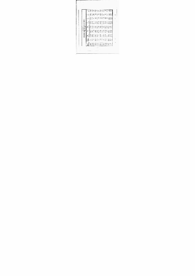
8/12/2019 675443
http://slidepdf.com/reader/full/675443 286/399
8
CO Q< o
o H f r* <
C Q S M
U
o M
£ K M W
3 >
<
CO
cc o
o
OO in u\ O C\ ^^ ON t*- r-i M C T)
3 ä o o r\j VO rv j (C r-i • • * • *
^ " r-i rg r-i f\J r-t
00 r-t -= r O O *^ . m vo c o Q
X f> co o ^r in •3- b i-t « *
O ir. rg o. 00
r f » " ^ VO iH r-i o ro J x» t- O co rH co K rH m m
c t>- o cr\ U-N N•r t VÄ r-t o (*•* cg X ^J C O er-. m cu
S ^ 4 m « « r-i JO rvj OO t*. a» *~ * rH rH ^ t-i
c 3 I
£ X »
C O I
S X )
o
in
OJ
vo t» 9 t-
vo
ry
VO
o
0
in
*
OO o
m
VO
fy
in
c 3- 3- ^ r rH o Q •H (M O vo in C\J i-S l vo rv j t- fM m
S i3 • m * • • rH
vo OJ t^- ^ r oo
> •— rH rvj rH OJ H
Q Id W-* o o o o O a. •
SSiS KH'-' EH«
• O
E - t » 2 ,-« ar in m (M X 1 1 1 ) 1 O H 04 f- t- t- t» C- M O M nj AJ r\i OJ (M ►J W J m m ro or. m fe H Q
256

8/12/2019 675443
http://slidepdf.com/reader/full/675443 287/399

8/12/2019 675443
http://slidepdf.com/reader/full/675443 288/399
g 55
OSS
» a
^ s
M C 3 2 C H
^ >
a :' o
s P S
no in
*-> CM
& 4 H j •
fig
S B £ JO
(-1
ro
C
a -H
a s a
c
a
O &♦ •» a O £-• 0* Ht W H
fe EHCQ
CO
•
in in
in in
I in ao
m t»
eg
ÖS
O N
I
oo in
GO CO
in
m C M
t-C\i
ovo o
m
o\ n n in o n ro -t
• H o
in rH O
oo o^
rvj c\j r v j r v j
r u
ro ^r
VOi
fn o
VO
03i-l O
C7 \
GO
*o
O
in
vo
r-f
* ro
I
VO
in ro
vo vo CO
ao
SO
o
c-
o
as ao •3 5 o
I
VO M
OS T
-« CO O
O
OO
CO VO
O N
w 00
in ■^
co
CO oo
ON
vo oo
CO JT
O
I
oo o
CO
r v j
^ o o sr ON ON
Ov
o o ro
vo
ro oj
HCM in
oo vo
oo in
vo cv
in in
vo in n
vo oCM
oo GO
f--3-
VO
CM
in vo
0O oo rv ;
o oo
vO
i-i
vo
ro
o =r o o CM CM CM r H rH rH
VO
o
COC M
oo
O CM
rH CM
VO
O CM
CM in o -3-
in
oo
I in oo
vo I
CO
C M
O O
I VO
oo C M
C M
I VD
O N
C M
O N
O O
in
rjHOO
3"
o H I
iM
C M
oo
C M
tn
CO
C M
-3- I
OO o m
oo oo
in I
oo ooo
rH
CO
C M
oo oo CD
O O
VO
CM rH in C M in o
CM
o
in
m C M
CM ^-
fM CM in
f- v o rH 3- o o o O O O N V O • 3 - V O O O v o v o V O O O O C M O N C O t - - i n rH C M o V O C O V O v o O N zr rH rH r H 3- O O r H o o ^ T
C M
V O o o o o 0 0 o o O N o o t- t- • a - f- CM t- C O c v o Ov i n o O N a \ O N i n i n v o o o o o
CM
in O N
O N
o oo
C- vo
CM O rH
O N
oo
O V
oo o\
-3- -3-
in O N
'O i n V O . H 1 l 1 1
O O O O C O i n o o o H o o a - -3 - = r
258

8/12/2019 675443
http://slidepdf.com/reader/full/675443 289/399
04 00 ^r o vo (M oo ^ T Oir\ ^r -3 - -3 - m on (M f\ J f\J
S Q N n O d - H O N I dO SdNVSnOHJ, - I N H W O W 0 N i a N 3 H
2 5 9

8/12/2019 675443
http://slidepdf.com/reader/full/675443 290/399
■ ■
•
TB" -a - S v S rT~ öS ~ o v vß rTrroncM C M N H H
SdMnOd-HONI dO QNVSnOHJ. NSWOW NICIN3g
260

8/12/2019 675443
http://slidepdf.com/reader/full/675443 291/399
I
t
,, I^BWM o 13 1 1 1 i ^
i C M
i / * C.
| ^ i I \ <H
r i > / \ \ m m m o
CO
<
I li, r M U> J • C / 0 o\
3 KC Q |t\J 0r t -) mjrH 1 / \ L
/i i \
0) >
jEuJ Hi-trumorH Q co \ o tiC U H »'"' "" i-i i
T U \ "" m m m
g r O C 1 ; DO j \ • f ^ ' »M \ L
1 j c o a < \ C O
0 □ «I w z i 1 < W > -
• « fa E M i . \
QO. • t- n O t.
J r « • • im v 0 33 p V rH r H rH rH| CO
\ i r*.
g H j j : A
C' ^ — «
c /3 r\vo\( f-ooi o\ i Q> ) O CD KCTIO o i S H u \j r i oj mj m n 1 o c
| i I c i ' 1 \ r-( ^ o
i 1 1 i I Q rt i i V ^ 0
4-. .1 j8 o a fy* i "l 3" o a.
i 1 «H O c d
< 4- > c c
i i _< d. O O* * - • QO 2 b
C Q i > - C ; s 1 " 1 M 1
1 J ( ^> rj i C^ ,
n j j l o o
—
:- H a 1 V ->
= y ; u ; -J a, • d p t.
H O T O
i i O / 0 p r* | jv;
1 ,1 ? Lä_ O « * i ^ rv
:> - VD : . - J o . 1 H ^ e, / w-
1 / C J i i / In
iO<3 /1
o C V J
3
bC r* •H t
I
j
1
i
i i 1 1
i
i /
ÄW ._ _ _ o
& ,
VO '^
r
^
M
sawnod O aNVsnoHi voa NOZiHOH
261

8/12/2019 675443
http://slidepdf.com/reader/full/675443 292/399
: V P K Al rvi • KJ ^ \ •o
\ /"k 0) \ UX ^ Q W a
n \ Vt i UMi 1 t > i / t:>j o ' i o
( \ 30 3D
<
31 \ to ; \ SH
i \ ' ' o a > , (V \ i \ i r-H
P L, \ :-£ M r> . VO \ c
DQOO • c
M 0\r- m
H i\ i f-t
cd v d o V t/i O yt r- r- 1 TiCD in o j D a
s Ui o -1 H O IlTiO H 1 \ — ( u
1 Q EH m nmr« »m^T 3- i \1 K l tu o < \ o ""
0) a a
i * P : io X OCO t\J H
o
i VO sr •3- ** \ *i
|j C * •KO IfNJ • i \
i-l o2
e d
J • • «k » "»ITi O K c 00 \J H H - |iH
i { 1 o
: ; j u OQO W
Po W OO O CTtO \o i 1 <i j cd t.CM tM tvr im i
i 1 _ ,.
a.
3 4)
; \ 1 M C O ; i " < +J
i ; < 3 p o W
c 1 " i o
' 1 oo D N a 1 K H
E 1 j tn b H O
i 9 o p
X i 1 1
0
VO
o >i i x: M w J ro ►4 O P E < § Al
o o
J < ^ ~ »->
UJ s 1 ^3- o > K: : it K M o ; / ►J ^ 1 / " c n o d
r-l o CM s
/ 5 / h.
LJL- -J— ' .iJ id L-I— 4- 9-b- eU LJ uJ o vo
r>
c \i
saNfiod o awsnoiiJ. voa V^NOZIHOH
262

8/12/2019 675443
http://slidepdf.com/reader/full/675443 293/399

8/12/2019 675443
http://slidepdf.com/reader/full/675443 294/399
I
i IN O / \ r\ * ji
/ \ •s in / \ - s * 1 \ o v o ^- i ^r , T i \ n; Ou * « 1 * 4 H i L u. M oofnrvj r« oj j n • v£ )
A \ J •, * * k • » (i) f\ \ < J Q \J M >- r-f HOOl TWÄr-IL'" f--i 7 \ H 1 ;
V \ < H f \ ^ ( 5 \ O w m « 5 v o 4 - OD CT \ V J r-ri « rvco in i L woo « o a\a 'O o < - t r-i at a>a •H
\H vj N ry ot cnoS ?nm(pro •3- -j
^
Vm \ i J
^ M
k
CO Q \ ^H i s \ _j E M \ o
i ' o 01
;\i 6 0 — j
6 \
o \
tfJ
— J
ii
i ; 1 1 -.J i
' x" -j
i — 1
O n _ rA
i 1 0 t* "* l
•
O A
WD ;< i
i / 0 1
> , if 1
i
r
— j
1 /- 1
, , — j | / -1
LUJ.-LJ 1 -€*J /bl ' 1 ,1, i-L 1 —LJ
o o CM
• -a 93
o U CO Q rH n
t. •H < n
O 3 \D n H u
c >
X) cö
O i) ^ r Xr—•
t. o •p o
CO IX o H C N J O tf >H 2 e «
M +J
1 C a »
Q E O w o O U s: r-* OU
CO b O o c c M ri
< x s c
w i) O 3 aC O cc
E-i « 4- > ^H rt fi CO
o U3 t. o
po K
o Ul ^T vo
rH
0) (4 3«)
O •H ru b
33CM
o ^o C M co
I I
f\j -o ^
H
saNfiod-HONi o aNvsnoHi NSWOW NiaNaa o C \J 1
264
m mm äs*»* :

8/12/2019 675443
http://slidepdf.com/reader/full/675443 295/399
r
R O T O R H A F T E N D I N G
The rotor haft lternating ending oments at he ower and pper train age ocations # he orizontal oad t he rotor head, he orizontal eactions t he ower nd pper bearings, and he oment t ne otor head re lotted ersus airspeed f he ircraft n evel light nd orward-speed climb (Figures 160 through 65).
They all xhibit imilar haracteristics eginning with a alue t over, hen ecreasing lightly with n ncrease n
airspeed .o bout 80 nots, nd inally ncreasing with ur- ther ncrease n peed.
For irspeed p o pproximately 160 nots, the otor- shaft oments re within he atigue imits for nfinite ife. Moments t peed bove pproximately 160 nots could imit the ife f he otor shaft, epending n he esults f ench fatigue ests, hich er e ot ade nder his rogram,
TAIL R O P E L L E R HAFT
A lot f propeller-shaft orsion ersus forward peed s shown n igure 166, It h o w s hat he teady orsion n he
propeller haft ncreases with n ncrease n irspeed. T he alternating orsion emains constant with irspeed t alue of pproximately 1000 nch-pounds. This s well elow he fatigue esign llowable f 1000 il650 nch-pounds for nfi- nite atigue life.
TAIL R O P E L L E R
Propeller ub ending oments re ather mall. The steady oments ecrease lightly with n ncrease n irspeed, while he lternating ending moments emain early onstant with orward peed (see igure 167).
The ail ropeller tresses re calculated sing he bending om ents measured n light. Centrifugal-force tress is added irectly o he teady ending tress o btain otal steady tress. The calculated ending tresses re lightly conservative, since he inimum ection odulus is used. Actually, he irfo.il ection s nsymmetrical, o hat al- though he oment of nertia s one value for ny articular blade tation, the distance from he eutral xis to he x- tr em e iber iffers etween urfaces.
Propeller lapwise tresses t lade tations 13,2 (kO
percent) and 6.5 (50 ercent) show inimum f catter
(Figures 168 nd 69), ut for hose t lade tations 23.1
265

8/12/2019 675443
http://slidepdf.com/reader/full/675443 296/399
I
•ft-
« a :
< Q
lY
a. » MI -x j| a3|^-r-)v "lV£> r-t r«
M
« < -£4-aC
n
0c r.
0oo • t-i T)
0) <D a w U
c •H VO < --I
tn 3 m IH
0) c > -3- i-H c
0 C O H tj n 0 t, 2 0
O X H C\J (H 1 4->
^ Q 01 U x: U to (Li
w u OK 8) O M H r-i < rH
O M a ra 0 c: t. ^ a. 0CO rH
H Al
E -<
• 0 ^o UD M
0 ) t. 3 b O •H
O & . =T
o
0 vo AJ co -3- O =r ro m f\j fM OJ
^£) f\J 00
S a H O N I - G N n O d dO SdNVSnOHI , - N0ISH0J ,
2 6 6

8/12/2019 675443
http://slidepdf.com/reader/full/675443 297/399
o o (M
O 00 r- i
o
o •3-
c> a;
m
w 3 W u t o >
bC o c o n C\J9-< ^ H rHO r) X p« a >
1 a a
OQ
Ob] x rHWa . t, W i) tn rH M rH < 0)
Ob] a n oo 3 t, u c a. H
rH H rt
o tn
\o
o -5 -
o
UD
0 )
3bO
vo 3 c i ocDvOr
v j rH
H
H
H
H
saHONi-aNfiod G aaaaNHH NSWow NIQNHH
267

8/12/2019 675443
http://slidepdf.com/reader/full/675443 298/399
^
£ ^ -B,
ä • 1 s 4- m ^
• < ** — i O T
o — 1 2
oE H
s < — 1 1 W>-i 3 5 s 8 1 riEH J 0 <
Ö M || 1 -1
0 <3 c r» Id * 0 ^ 3
•» T OH i r-D i 1 J H rr « f
<i J i in i 1
1 M t^C\i J
E "1 i ~|
gg O -» iH mrof
O S 1 ^
o < 3 L — 1
i < 1 H f vn i i
j| QO M i i A
o < T C Q CMrtirj c^ - 1 i— i
I E H < r 4
1 ^ ino H (\ A n XB. s t 1
ll ^ (\j c\j vi rg T 1
1 • - ] 1 rH
z O *_ J H H — 1 < 1
C O 1 -1
o c t\l
c c C O 0 1 — 1 TH
+ -> id
4J
C O
o . VD x s <-i 0)
0) a « n u ^H
c < =r
^ n 3m
e n U EH V o >
C 2c v i< to iH c o
1 0) t.
Q 4J W 0 0 UJ
oo. 0) C O c o rH C •H M 5< a
C O w < -* 3 bi* c c
C r« 0) CO T 3
« o rH C Q
^ (l >
o r'v£ ) -H
4) a o t, &,
O
CO ^c rH
0) t,
o 3 C\J bC
VD L T N m (% J + j
Aavais I Sd dO SaNVSnOHi - S S S H i S
268
D N I l V N U a i l V

8/12/2019 675443
http://slidepdf.com/reader/full/675443 299/399
-
/— . -" t i * 1 —
Q \ D I \ «\ \ ) ^ p
C Q i \G V S\ 4\
+ M X C Q
i \ \
C O ^ G f> V M ~ r ^T
•• W O2 R M 4 ^ j M EH
< [
f l> C O
> H 3 Lj
C5 < Z i\\ <: 12 W O K '1 jj 5 ji J < M 1 - 5 S H T ^
J y' J M C O < i.l L ~ 1 N 1
0
1% - 0 <
i O t in i Q Ö - a, • i 1
M- OO VO C^
J • > « • CatNJVO ^r inn - 1
C O HVO rHOO CM 1
A*" U-3--3- o o o 1 _ o E- ^ -a-^- r 1 01
j tc [ «— N i < 1 i ""
<| < ^O sri ol i a a , •
• *in in t C M -X J ~- C M ,
1 _a M H 1 EH et Q f LdOO O ON cr\ o O rH Hi
1 0 H CM M i>J M or oomor -
in 1 :vo 0 J , 2 e f - i 1 1 M i _ H < _ tH
1 1 ' 1 . 1 " 1 , 1 . 1 i
o o «M
I T
v a
o C oo O <H
C O *->
CO
C < . VO X} rH a »
C D a m
1H O < -3- rH '0
3
CO u H 0 ) O >
C 7' CM *£ . n r-(
1
Q 4->
W O w c a. O J c c o M r— cc •H
M 5 < a W rH D fc K
OtH (U cr-
C O rH
0) O rH VO rH
a o
o =r •
CTN
rH
o 3 CM b O
u * KO i n C M ( \
I S d dO S Q N V S nO H J , - D M I i V N H a i l V
ssaais
2 6 9
-

8/12/2019 675443
http://slidepdf.com/reader/full/675443 300/399

8/12/2019 675443
http://slidepdf.com/reader/full/675443 301/399
A d v a x s i s d äO s a N v s n o H i - S S S U i S
D N i x v N u a . n v
2 7 1

8/12/2019 675443
http://slidepdf.com/reader/full/675443 302/399
o o rj
o CD • -H " O
0) 0) a n ^
C H
vo < H m 3 m U 0 )
O > H «
m C O 0) Ej h O •p 2 C O
O xi tv a .» rH 1 w
t-i Q 3e W a W <fl ( rH
O O & . o cc rH H O J
< T3 a ) w rH
D ca K
OFH u CO ( U
r-i rH 0) a o k
o a. ^o
•H
_ O C M
>X 3 LT » on r\j
AQvais
C \J
H
+ +1 D NIJ.VM Hai.7V
ISd dO SONVSnOH.- SS3H.LS
272
tuMBa niiMiiiiwu i-iMMrTgirw

8/12/2019 675443
http://slidepdf.com/reader/full/675443 303/399
FT" t 1 "
•
J K in C7N o —
• c
rv i n « C O v > •«• ^^ c H -S o w •~-"~" T J" f 1 / ^ T' ON
1 2 • / M • O » i X W 1 V M X z 31 • j \ \ . S « J _ (0
cr> o i \
ü IL i 1 ^r • '" / • t- 0)
rH O K» 1 / M 0 0 > 1 ^ \ k
t " | r ' \ c 1 no ^ui o / \ u c
(H > ro J \ > 2 ~ |
X 0 w / \ o O _ E O rc / J \ •x . M O M ' / \ ^ E J ^ / \ < " fcvO / \ _fc O b ?
1 / L \ ^ h- C
J o> k / \ ^^ K . -H W o \i \^ -" O " TJ
; > oo J \ H C
/ X <* - D —
j \ " a J \ ON >= — _ t *— • \ _
tf> ct "O / \ « 0
1 i 1 4) \ I +>
\ , / K*^ SS to c \ / 1
\ "• M
1/
v \ OE-t U
W 1 \ \ />< W / v \ • "H
\ \—
S
law
/ I I \ i " M fc / \ \ ( o a
\ 9 Z 1 i \ i • < 1 / a, )
\\ \ y "
co -a
rH C Q
o \
f
co / f
rH a. m \ / — 0) M i —
s
i o. ►J m V o a 3 ^O \ / o u
• c \fa E- t
33 V • < a \ rs ^v^ C M E - t M ) o N, r- < J f j o rH a fc ^X O
rH »
3/ N
-» •H fc
_.J 1 1 i i i i L on (M ^ O r H ry
\ 1
saNr.od-HONi o aNvsnoHj, L N S W O W NiaN39 avais
273
■ :j-AfciipB. ^ j ^^ i r ^W ':

8/12/2019 675443
http://slidepdf.com/reader/full/675443 304/399
K°\ ^ V '<]|, T
/\\
\ 0i J ^T CQ t-1 r-j r-( 3- LT r-*SS ^ i J /
/
lG V C f. 3 H ^ ro ^r -a r Eu -i po (v ) o~ ro f»1
O 04 H LfMAO
a> OMT O O H ^ 3 - .^ r ^ f
-|
u R^
r P N 1 Ik < Ha. H
rt\ (V-W/l A — > u 01 \
* ^ 3 - nua H<1
ME
ASI
IN
r \C/J f-C ^ 3 - ^r r
ONO aV£ ) ~-CC
o o o 00 4 iG
• 4
0J 4
1
H
O
M M 61 .
G
\ G
I0 T
]
1 STEADY
ALTERN
TENS 101
' L 1 < : 5
• T M
1
1
G C
Ü 4
•1 (1
n 1 f
i i 4
tl
G /
t
}
i ' ; t
< f 4
1 ^ |
/r :
i i of
L I _ I —i— 1 _. . . 1 „ i
o c
c or: — (
-a 0 )
S
c a vc n r-4
<
n ^ O n
^ H 0)
> CO T3 H C Q O O
O 2 ^ C\J «r-<
i C
Q JM U -C
O 04 o o to -^ > r- K K T4
M
a. < t, \A 0) •-> rH K -H
OH 0) oo a
o a.
o •
\o
0) U
bC
fc
a o
o o o c o o o a o o o o o o o o en OJ H
\ 1 m 1
H +
xavais DNIiVNH3J,7V
saNfiod - avoi XNIl HOUd
21

8/12/2019 675443
http://slidepdf.com/reader/full/675443 305/399
airspeed Figure 7^).
here s pproximately he ame aisni- tude f lternating tress n ach ongeron^ o nly ne urve was drawn o epresent both.
The lternating tress was small nd ncreased lightly
with n ncrease in irspeed.
i . MAIN LAUDING GEAR
Axial load elt by the nock trut and xial load nd bending n he ain ember ere easured n run-on landing. A
plot of hese loads versus time for ypical un-on landing r
s hown n igure 176.
All oads are ell within he limit design loads for he gear. Maximum oad n he shock trut in his typical un-on
landing s 1900 ounds, compared o imit load or he hock strut of 560 ounds compression.
Maximum oad n he ain ember s 920 ounds compression plus 16,500 inch-pounds bending, hereas limit design load s 3830 ounds compression lus 6,700 nch-pounds moment. Other recorded oads in anding ere less han hese.
275

8/12/2019 675443
http://slidepdf.com/reader/full/675443 306/399
o ü
o CD
-o c a ; ^D tt --1 c
'/ ) T
L >
•H <
O (0 3- 3 H
> '0
o w f\I O 0) rHR t. '
O pZ C O
1 c o •H
OQ JJ r-ilii a s
u » c a . t. C O 4 J K 4-> M l-{
< < Oo o w c
=3 o a: b E H
b C c o
o Jvo
o
o
3
•H
r~ vo ri ^r \j i s >d o aNvsnoüj, ssuxs M IJ-VNHS J/IV
276
«tarn

8/12/2019 675443
http://slidepdf.com/reader/full/675443 307/399
—
-
-
—
. /„ "
0 4 —
7 f\ / v/
/ - / t^ _ _ / « 4 i
/ £ a , • m
/K ft ,
i
-
/
< EH CO M
:
-
o J - w u
—
,1 i i 1 —1_- «. „ ' . 1 —t . i
o c r^
IT
C c o oc »H
i-H
c o i ~
O « U 3 •O 3 r-l
Irspee
eft I
o < J =r
rH 4, -. C O
t. a O H « 2 C Q « n
O 3 rv j 1 n J r-i u »
Q 0 ) U > J w a, n • c o e o t O K 0; .
O M t. 3 r-t< •P *i
c o w 3D hOfc. O C C J H ^H O
•p O n j 3 CO
Altern
Forwar
OVO •
rH
i> U
O 3 •^ r W
fc
in ^
O
\i
H
isd o aauaNOH saaic Nii.vNua.nv
o
277
* mjmwwaM

8/12/2019 675443
http://slidepdf.com/reader/full/675443 308/399
QQÖ2 22 < < < C J J J
<<<
j ws
6 8 0 2 1 1 6 8 0
TI ME - S E C O N D S Figure 1 7 6 . Typical Main Landing Gear Loads
278

8/12/2019 675443
http://slidepdf.com/reader/full/675443 309/399
T E C H N I C A L P R O B L E M S
»
D u r ing tne performance of th e ground- and f i ign t - t es t program with th e l 6 H - l A , a numoer of problems developed, most of which had th e effect of causing delays unt i l they were so lved ut di d no t prevent cont inuat ion of th e f l i gh t - test program. F or th e most part, the problems encountered were the mechanica l structura l type common i n the deve lopment of new equipment rather than "state-of-the-art" knowledge .
P R O B L E M S E N C O U N T E R E D D U R I N G G R O U N D T E S T I N G
These were p r ima r i l y structural i n nature an d were t yp ica l of th e tes t ing of almost an y new dynamic components.
1 . O i l pump d r i v e - O n two occasions, a draw-bolt w h i ch holds a l ube-o i l -pump d r i v e adapter i n d r i v i n g en- gagement w i t h a gear shaft i n the t ransfer gearbox f a i led at th e base of the threads. O ne of the f a i lu res occurred on the pressure-pump d r ive of the lube sys tem; th e o ther occurred on the scavenge-pump d r ive i n a lmost the iden t ica l manner. he f a i lu res were a t t r ibu ted to la tera l v ib r a t i o n of th e bol t , which , i f t i gh tened to the standard torque, w o u l d be nea r ly I n resonance with th e gear- tcoth-mesh f requency and could be brought exac t ly to resonance by over torquirg. T he des ign was mo d i f i ed to Incorporate a phenol ic p lug i n s ide the h o l lo w gear shaft whicn surroundad the draw bol t and prevented I t f rom v i b ra t i n g l a te ra l ly.
On two other occasions, th e lube-pressure-purap d r iv e shaft f a i led at a keyway. n both occasions, the pump continued to run, and th e f a i lu re was only found after d i sassembly for other reasons. he f i rs t f a i l u r e was at t r ibuted to fa t igue caused by inadequate chamfers on the key and Inadequate f i l l e t s i n the keyway. Afte r the second fa i lure , however, the key d r ive was rep laced w i th a sp l ined connect ion many t imes stronger. A f t e r
only 3 0 minutes of operat ion w i th the new s p l i n ed shaft, th e shaft suddenly se ized i n i ts journal bearings , shea r ing th e s p l i n ed sect ion and caus ing s toppage and se izure of th e oi l pump. A na lys i s of th is f a i l u r e gave pos i t i ve ev idence of the basic t rouble . Def lec t ions of th e shaft connect ion r e l a t i ve to the pump were causing a rota t ing bending moment between th e pump shaft and th e gear shaft to w hic h s t i f f sp l ine connect ion permit ted be c a r r ied in to the pump, causing bronze Journal bearing. Ex p an s i o n
i t was spl ined. T he the bending moment to loca l h ea t i n g of i ts
of th e pump-hous ing face eventua l ly caused a se izure w h i ch sheared the
279
•

8/12/2019 675443
http://slidepdf.com/reader/full/675443 310/399
spline n ure orsion, (The am e -ctlon ad pparently previously roken ut he former keyway, ut hen he rigidity as reduced nough o hat he rive ontinued to unction with he roken iece rapped n lace.) At this oint, the um p rive as edesigned o ncorporate a loating quill haft, pllned t oth nds, hich could not ransmit oment esulting rom gear eflec- tions. The unp rive hen ave o urther rouble.
2. racks n he fuselage kin art of he round ests
Involved unning t igh ower evels n he otor nd propeller, with he ircraft ied ow n o he oncrete apron. As esult f ocal oad oncentrations t the ie-down oints, cracks hich equired epair e- veloped n he uselage kin nder hese oints. These loads er e aused y he ethod f estraint during he ie-down ests, nd er e ot epresentative of light conditions. Local atigue racks ecame evident n he airings nd n red ling-edge tructure. Sandwich anels er e ubstituted or he iveted airing skins which were eing oil anned" nd howing igns of racks. After uch modifications, o urther racks appeared or he emainder f he round esting r
throughout he light ro g ram.
3. ropeller pitch-control earing - After 8 ours of running, xcessive lay eveloped n he ropeller itch- control mechanism. Disassembly evealed hat he ronze retainer-cage ad roken n all earing nside he propeller upport ox. This as eplaced with tain- less-steel age f heavier ross ection, hich ad to e upplied y he earing manufacturer. The earing caused o urther rouble fter his epair.
4. Propeller pinner Near he conclusion f he 0-hour
ground unning, the ropeller pinner uffered atigue failure t n ttachment oint which esulted n ts tearing oose. It as truck y he ropeller, disin- tegrated, and aused om e damage o he ropeller lades and he ing-tail uct. The amage o he laues and the uct as repaired romptly, ut he pinner equired redesign. Some f he arly light esting, involving hover nd ow-speed lights, as erforraed without spinner.
280

8/12/2019 675443
http://slidepdf.com/reader/full/675443 311/399
P R O B L E M S E N C O U N T E R E D D U R I N G F L I G H T T E S T I N G
1. Turbine speed ont ol he -58 urbine s quipped with uel ontrol ystem which ncludes a peed- selector ever, the osition f which causes overnor to upply fuel n esponse o hanges in utput peed. The ange f he overnor etting, at o oad, la from about 50 0 to 80 0 R P M (at he utput of he peed- decreaser earbox). Because of built-in roop char- acteristics of he governor, this range, at full load,
is from 0 0 0 to bout 20 0 RPM. If he lever s moved beyond he lowest overnor etting, it asses through a ransition egion here he overnor will ot control the peed, thence o round dle, nd inally, to ut- off. Friction nd ther orces acting n he lever are uch hat ilot-effort oads on he onventional twist-grip control ere too igh for irect echanical linkage. Hence, a roduction lectric ervo ystem was nstalled wherein he osition f he wist-grip positioned potentiometer dualized or afety f flight), he ignal rom which, n urn, ositioned an electric ctuator onnected o he urbine oeed selector ever.
During he first utorotative descent n he 16H-1A the turbine speed-control ystem malfunctioned and the flight nded with n ctual mergency ower-off landing. When he ilot ttempted his lanned ower recovery y wisting is grip o he full-speed osition, the urbine did ot respond, ut emained t round idle. As a esult of anding n ough ield djacent to he airport, damage as ustained by he ail anding gear, ropeller, duct, and udder anes, ll f hich w ere epaired n ue ourse. The peed-control ailure was found o e an lectrical pen ircuit hich e-
veloped nside he ctuator.
To nsure that such an vent could ot reoccur, a limit-switch n he actuator as adjusted o hat the actuator ould ot run eyond he lower imit of he governed ange nless a eparate witch ere operr.ded from he ockpit. This switch as used nly to hut down he urbine, and was always ept,in he afety
281
■
... fc— 1 i»» ,

8/12/2019 675443
http://slidepdf.com/reader/full/675443 312/399
posi t ion I n f l ight . Thus , no elect r ica l fa i lure of any sort could place the speed se t t ing lower than the m i n i - mum governed set t ing, where near-ful l power would be Immed ia t e ly avai lab le . Th i s so lu t ion permit ted trouble- free operat ion for the remainder of the test program. However, i t di d place a res t ra in t on s im u la t in g abrupt power fai lures . he R P M of the autorotat lng rotor could not drop oelow that main ta ined by th e governor at i ts m i n i m u m set t ing, which , at no load, was only 3 percent below the normal powered R PM. A s soon as the decay ing R P M reached that value, the governor would
demand fuel and the tu rb ine wo u ld supply torque to sus ta in that R P M .
2 . Measurement of w i n g l i f t - O ne of th e object ives of the f l igh t test program was to eva lua te the effect of var ia t ions i n l i f t ' i s t r ibu t ion between w i n g and rotor on per fo rmance . I * . , vas planned to measure the rotor thrust by measur ing tension i n the rotor shaft , and to measure wing l i f t Independen t ly wi th s t ra in gages on t he fuse lage frames to wh ich the wing spars are attached. C al ib ra t ion of both systems was performed by hanging t he a i rc ra f t at the rotor, through a dynamometer. Read ings were t aken of the rotor-shaft t ens ion st rain gage b r idge and of the tw o br idges on each s ide of the fuse lage f rame which , when combined, measured the wing l i f t . The weight of the a i rcraf t was then incrementa l ly s u p p o r t e d on t he wings and unloaded from th e rotor w h i l e t he changes in read ings were recorded. hi s procedure was repea ted with two di fferen t spanwise points of suppor t fo r the w ings , to permit a so lu t i on independent of the spanwise center of l i f t , which was not known preci se ly. A ser ies of m u l t i p l y i n g constants for the four wi n g bridges was worked out which checked th e ca l ib r a t io n for both sets of loadings . owever, th e i n- f l igh t readings for these four bridges were so var i ab l e
and inconsis ten t that no
useful
data could be
der ived f rom them, e i ther i n d i v i d u a l l y or i n combinat ion. T he data from the rotor-shaft tens ion, i n conjunct ion wi th the known gross weights , on th e other hand, were suff ic ien t ly consis tent to supply the required informa- t ion. Consequen t ly, they were used I n this report to the ex c lu s io n of the w i n g l i f t measurements .
3 . Turb ine ai r in take - I n order to make use of ex i s t i ng gear ing and other power- t ransmiss ion components, the T- 5 8 tu rb ine was mounted i n a bur ied i n s t a l l a t i on i n s ide the fuselage, behind the rotor t ransmission. T he a i r- in take was designed to be of the s ide- in le t type, w i t h a forward-facing scoop. T he ai r entered a
282

8/12/2019 675443
http://slidepdf.com/reader/full/675443 313/399
plenum chamber af ter making a 90-degree turn nd then entered th e turbine through a be l lmou th i n i e t from another ex i s t ing he l icop te r i n s t a l l a t io n . Ear ly i n th e f l i gh t test program i t became ev iden t that th e in let losses i n hover were so severe that the aircraf t performance was l i m i t e d by turbine i n l e t temperature at power l eve l s wel l below th e turb ine rat ing. T he losses were main ly caused by too sm a l l a rad ius i n the 90 - degree turn. T he external por t ion of th e i n l e t was therefore removed, so tuat th e ai r s im p ly entered a rectangular f lush opening i n th e si Je of the fuselage, th e area of wh ich was over tw ice as l a rge as the throat of the or ig ina l external in le t . Although t h i s expe- diency di d not permit any ram-pressure recovery, i t reduced th e i n l e t losses su ff i c ien t ly that most of th e f l igh t test program was conducted wi th th i s conf igura- t ion. F or f l igh ts at speeds above about l 6 0 knots, however, the problem of l i m i t i n g turbine i n l e t tempera- ture again arose. B e g i n n i n g with test 403 , the ex - ternal i n l e t was r e ins ta l l ed i n conjunct ion with an improved be l lmou th f rom the p lenum chamber i n to the turbine. A n improvement i n turb ine performance at h igh speed was noted, but l i m i t turb ine i n l e t tempera- ture was always reached before rated power could be
obtained. A n Improved i n l e t was des igned and fabr ica- t ion was started, but i t was not completed i n t ime for use i n th e test program. I ts use would h av e increased th e power at ta inable at high speed by an es t imated l 60 horsepower, wh ich would have increased th e true airspeed to 17^ knots.
4 . Rotor control sys tem s t i ffness - T he 1 6 H - 1 A , as modi f i ed from th e 1 6 H - 1 and as ground tested, used an H - 2 1 rotor, I n c l u d i n g blades, hub, and swash plate. T he remainder of th e rotor control sys tem was the same as that f lown i n th e 16H-1 , w i t h only those changes neces- sary to adapt to the H - 2 1 swash plate. T he system i n- corporated three i r r ever s ib le hydrau l ic servo actuators , one each for longi tudinal cyc l ic , la teral cyc l ic , and co l l ec t iv e pi tch. T he system was s t ress -checked for th e an t ic ipated h igher loads of th e larger rotor and h igher f l i gh t speeds and was found to be adequate.
I n th e course of exp lo r ing progres s ive ly h ighe r f l i gh t speeds, a v ib ra t ion appeared at about 120 knots which increased rap id ly wi th speed and became severe enough to l i m i t the f l i gh t tes t ing to about 140 knots. I n- v es t ig a t io n of the f requencies of v ib ra t ion showed the largest contr ibutors to be the second, th i rd , and tenth harmonics of rotor speed. T he tenth harmonic was
283

8/12/2019 675443
http://slidepdf.com/reader/full/675443 314/399
a t t r ibu ted to the ta l i p rope l le r, which has a speed o f 9 -7 t imes ro to r speed. Inspec t ion uncovered a malad jus tment which resu l ted in one p r o p e l l e r b lade having a p i tch of near ly 2 degrees more taan t he other two. Correc t ion of this cond i t ion e l imina ted most of the t en -pe r- r evo iu t ion v ib ra t ion . Attempts were made to reduce t he th i rd harmonic componen t with a tuned dynamic v ib ra t ion absorber which was placed at var ious loca t ions in t he a i rcraf t rang ing f rom the center o f grav i ty to a pos i t i on Just ahead of the cockp i t nose. Figure 177 shows the effec t of the ab- sorber mounted in th is las t pos i t ion , an equ iva len t
dead weight mounted there, and a l so with noth ing mounted. Although t he th i rd harmonic componen t was s ig n i f i c an t ly reduced , t he other vibra t ions not ab- sorbed resu l ted in a compos i te vibra t ion spec t rum s t i l l u nsa t i s f ac to ry t o the pi lo t .
At th is po in t , a mot ion pic tu re camera was i n s t a l l ed on the py lon to take in - f l igh t p ic tu res of swash-p la te mot ion . he resu l t ing pic tu res c lear ly showed swash- p la te motions a l lowing the ro to r blades ' two- and th ree- p e r- r evo lu t ion p i tch changes of t he order of +.5 degree , a l though the contro ls in t he cockp i t showed prac t ica l ly
zero mot ion . he s t i ffness o f the con t ro l sys tem cables , pu l ley brackets , push-pu l l rods, and be l lc ranks between t he swash p la te and t he i r revers ib le ac tua tors under t he f loo r was insuff ic ien t , and the r o t o r blades were changing pi tch in r e sponse to harmonic ai r load com- ponen t s .
To correc t the s i tua t ion , the ro to r con t ro l sys tem was changed to incorpora te a set if dual i r revers ib le hy- drau l ic servo ac tua to rs , mounted in t he py lon immed- ia te ly under the swash pla te , in the p lace of those under the f loor. Thus, mot ion of the swash p ia te was ar res ted s t i ff ly at i t s source . This change, which
lowered t he v ib ra t ion level markedly, permi t ted tes t f ly ing to con t inue and to proceed to the maximum speed reached in the p rog ram (195 knot s ) . Figures 3 8 th rough ' » 7 show the Improvement th roughou t the speed range brought about by the con t ro l s t i ffen ing .
5 . Prope l le r blade des ign - Measurements of t a i l prope l le r power at speeds up to 140 knot s ( the temporary vibra- t ion l imi t , see Roto r cont ro l sys tem s t i f fne s s dis- cussed above) ndica ted that the prope l l e r-b lade ang le o f a t tack at h igh speed wo u l d be above op t imum, w i th a t tendan t low prope l le r e ff ic iency. During t he per iod in
which the con t ro l sys t em was be ing modif ied , new blades
28K
~--Hi mc:*mb»namm\taiaamm)tm

8/12/2019 675443
http://slidepdf.com/reader/full/675443 315/399
♦
c o
n J u
u
u >i)
s o 0 1
r-i
a
M 3
0
o
3 H
X N 3 H 0 d W 0 0 O I N O W H V H QHIHJ, 0 - N O I .LV H 31 300V A H O i V H a i A a V O I I H S A S D V T ^ S n d
1 2 8 5

8/12/2019 675443
http://slidepdf.com/reader/full/675443 316/399
were fabr icated for the propel ler. A l l of the data preiented for speeds above 1 ^ 0 knots was obtained wi th th t new p ro p e l l e r blades . Data obtained i n hover and at e l ower forward speeds wi th th e new p ro p e l l e r were not s ig n i f i can t ly different from those obtained wi th the or ig ina l one.
Pod-end i n rotor control sys tem - Dur ing th e period of v ib ra t io n inves t iga t ion , pr ior to control s t i f fen ing , one of th e rod-ends i n the long i tud ina l cyc l i c control system f a i l ed at the bear ing-re ta in ing lug. Upon ro l - l i n g out of a c l i m b i n g turn , there was a loud noise and the ai rcraf t pi tched to a nose-high atti tude. Control was recovered, and a caut ious check revea led at leas t part ial control about al l axes. he p i lo t dec ided to make a ro l l - o n l and ing s ing propel le r pi tch control to control rate of descent. Dur ing the approach and l anding , the c y c l i c s t ick w as used only for lateral control . Long i tud ina l t r im was main ta ined wi th th e e lev a to r t r im, and co l l ec t iv e pi tch was not used.
normal ro l l - o n land ing was performed, wi th touchdown between 5 0 and 60 knots.
A l l l o n g i tu d in a l , l a tera l , and co l l ec t iv e push-pull rods, bel lc ranks , levers , and quadrants subject to rotor control loads were inspected, w i th no other ev idence of damage. owever, th e fa i l ed rod-end and others s i m i l a r to i t, i f subject to loads of th e same order, were rep laced wi th new, stronger parts.
T he a b i l i t y of the e leva tor t r im to serve as a backup for l o n g i tu d in a l cyc l i c pi tch i n an emergency was a feature not apprec ia ted i n th e or ig inal design concept I ts emergency usefulness proved to be a s ign i f ican t asset, and i n this ins tance i t probably saved the aircraft .
Landing-gear emergency ex tension - T he l and ing gear
i s extended m an u a l ly on the 1 6 H - 1 A i n th e event of fa i lure of the normal e l ec t r i ca l ly operated retract ion system. he emergency sys tem consis ts of a hand- crank i n the cockpi t , on which i s mounted a sprocket connected by ro l l e r- ch a in to another sprocket on the retract ion actuat ing shafi . he hand-crank dr ives through a spr ing- loaded clutch, so that i t remains stat ionary dur ing e lec t r ica l actuat ion of th e gear, bu t th e chain and sprockets are i n motion. O n on e occasion, w h i l e th e aircraft was i n th e shop for maintenance, the r o l l e r- ch a in broke during a t r ia l gear- re t ract ion cycle and became Jammed, preven t ing
286

8/12/2019 675443
http://slidepdf.com/reader/full/675443 317/399
both e lec t r ica l and manual operat ion.
T he f a i l u re was traced to th e faulty i n s t a l l a t io n of th e removable s i d e - l i n k at th e spot where the two ends of chain ar e jo ined to make the chain "endless". A f a i l u re of t h i s type occurr ing i n f l igh t wo u ld h av e prevented a . normal landing. Hence, to preclude such an event , the sprocket on th e m ain actuat ing shaft was remounted to d r i v e through a shear-pin , designed to shear at a load wel l above the hand-crank ex tens ion load bu t we l l below th e torque of th e e lec t r ic actuator. T n i s would permit e lec t r ica l operat ion, even wi th a Jammed chain. N o fur ther d i f f i cu l ty was encountered
wi th th e
re t rac t ion system.
287

8/12/2019 675443
http://slidepdf.com/reader/full/675443 318/399
C O N C L U S I O N S
i . The use of a v a r i ab le pi tch pusher propel le r mounted I n- s ide a duct, i n conjunction wi th m o v ab le d i rec t iona l and long i tud ina l control surfaces, prov ides a convenient and eff ic ien t method of effec t ing th e desired power d i s t r i bu - t ion between that u t i l i z e d for forward propuls ion and that required for rotor l i f t over th e entire speed range. Power management can be accompl ished eas i l y by control of both rotor and propel le r pi tch by on e p i lo t , w i t h on e hand.
2 . T he use of a ducted pusher p ro p e l l e r for forward propul- s ion of a compound hel icop ter i s an effec t ive method of ex ten d in g the speed capab i l i t y by r e l i e v i n g the m ain rotor of i ts p ro p u l s iv e function. At speeds above 150 knots, th e rotor required as l i t t l e as 15 percent of th e total power used.
3 . T he stators and the propel le r duct render a h igh degree of long i tud ina l and direc t iona l s ta t i c s t ab i l i t y and pro- duce aerodynamic damping for dynamic s tab i l i ty. he longl tud inal control surface acts as an effec t ive t r im control even i n a hover, where i t produces an appreciab le moment
equiva len t to a center-of-gravity sh i f t of ' l .1
» inches i n the 16H - 1A .
k. T he employment of a ducted pusher p ro p e l l e r and of de- f lector vanes i n a compound he l icop te r i s a feas ib le and adequate means of main- ro to r torque compensation and di - rec t ional control . Control was found to be suff ic ien t for h o v e r in g and maneuver ing s ideward 0 to 30 knot« an d rearward 0 to 30 knots .
5 . T he employment of a ducted pusher propel le r w i t h rudder control surfaces provides favorab le direct ional control for making running ( S TO L ) takeoffs. Takeoffs at ground speed as h igh as 5 5 knots were conducted dur ing t h i s test program.
6 . I n the conf igura t ion tested, th e 1 6 H - 1 A was power l imi ted . L e v e l - f l i g h t true airspeeds approaching 20 0 knots wo u ld be poss ib le wi th an engine a i r- in take and wi th th e incor- porat ion of drag-reduction i tems.
7 . T he m ax im u m true airspeed of 1 95 knots was a t ta ined i n a 10-degree dive . T he l i m i t i n g v ib ra t io n l ev e l s , exper i - enced i n the ear ly part of th e test program i n the speed range from 11 0 to l ^O knots, were a l l ev ia t ed by the i n-
corporat ion of a s t i f fe r rotor control system.
2 8 8

8/12/2019 675443
http://slidepdf.com/reader/full/675443 319/399
T he steady component of the rotor-blade bending moments and p i t ch l i nk loads, and th e a l te rna t ing component of propel ler-b lade bending moments and p i t ch l i n k loads, tend to remain nearly Independent of ai rspeed. O n the other hand, the a l t e rna t i ng component of rotor-blade bend- i ng moments and p i t ch l i nk loads, and the steady component of propel ler-b lade bending moments and p i t ch l i n k loads, tend to increase gradual ly w i t h ai rspeed. o wev e r, th e net fat igue effect of th e combined l oad ings remained w i t h i n ample st ructural margins and showed only a gradual Increase wi th speed.
Si n ce th e w i n g supports an ever greater proport ion of th e a i rcraf t weigh t as speed increases , and the rotor supports a correspondingly smal l e r propor t ion , th e rotor at some point begins to lose I ts effec t iveness for con- t ro l l i ng th e a i rcraf t i n ro l l . F or compound ai rcraf t des igned to unload the rotor much beyond 5 0 percent. Incorporat ion of convent ional a i l erons should be bene- f ic ia l i n two respects.
a . R o l l control at h i g h speed should be improved.
b . Si n ce the rotor now need not supply al l of the roll control at h igh speed, i ts la teral cy c l i c control can be reduced wi th r esu l t i ng improved hover ing ro l l response.
289

8/12/2019 675443
http://slidepdf.com/reader/full/675443 320/399
RECOMMENDATIONS
Plight tes ts of the r ing- ta l l sha f t -d r iven compound h e l i - copter should be continued with a f l l ghc test a r t ic le hav ing add i t i ona l powt r and an improved ai r i nduc t ion sys t em to permit exp lo ra t ion of th e f l i gh t cha rac te r i s t ic s at higher speeds.
The a i rcraf t for these extended tests should incorpora te a i le rons wi th an adjustable l inkage ra t io i n the la tera l cycl ic cont ro l . The f l ight p r o g r a m should Inves t iga te var ious p r o p o r t i o n s o f these t wo la tera l control inputs to obta in the opt imum con t ro l s for both low-speed, he l i - copter type f l igh t and high- speed unloaded rotor f l ight .
290

8/12/2019 675443
http://slidepdf.com/reader/full/675443 321/399
R E F E R E N C E S 1 . oldberg, J . H . , Automat ic Control : Pr in c ip l e s of Sy s tem s
Damamlcs . A l l y n and Bacon Incorporated, Boston, Kassa- chuset ts , 1961 .
2 . eckel , E . , S t a b i l i t y an d Control of Airp lan es and Hel i co p te r s . Academic Press , N ew York, 19&1
3 . -2 1 C Phase I V - Performance Ev a lu a t io n , Edwards A i r Force F l i g h t Test Center, Cal i fo rn ia , Report A F F T C - T R - 5 5 - 2 6 , December 1955 -
^ 4 . Hel icop te r F l y i n g and Ground H a n d l i n g Qu a l i t i e s ; Ground Requirements for . M i l i t a r y Spec i f i ca t ion M I L - H - 8 5 Ö 1 A , September 1961.
5 . e l i cop te r Performance Tes t in g Manual. Nava l A i r Tes t Center Test P i l o t S choo l , Patuxen t Nava l A i r Sta t ion , Maryland , January 1965 .
6 . hase I V Performance and S t a b i l i t y Tests of th e H - 2 1 Bf Edwards A i r Force F l i g h t Test Center, Cal i fo rn ia , Report A F F T C - T R - 5 7 - ^ , March 1957 .
7 . tapleford, R . L . , et al . Systems Techno logy, Incorporated, A n An a ly t i ca l S tudy of V / S T O L H a n d l i n g Q u a l i t i e s i n ;
H o v e r and Tr a n s i t i o n . Report A F F D L - T R - 6 5 - 7 3 . A i r Force F l i g h t Dynamics Laboratory, Wr igh t - Patterson A i r Force Base, O h i o ; October 1965 -
8 . apscott , R . J. , Cr i t e r i a for Control and Response Charac te r i s t ics of Hel i co p te r s and V T O L Aircraf t i n Ho v er in g and Lo w-Sp eed F l i g h t , Aerospace Engineer ing . Vo lu m e 19, June i 960 .
9 . eat Requirements. Ground. Hel icop ter. M i l i t a r y
Spec i f i ca t ion M I L - H - 8 6 7 9 , 5 March 1 9 5 ^ . 10. B u l l e t i n A N C - l B , Des ign of Wood Aircraf t Structures.
Aircraf t Committee, Mu n i t io n s Board, June 1951. Super in tenden t of Documents, U . S . Government Pr in t in g Off i ce , Washing ton , D.C.
291

8/12/2019 675443
http://slidepdf.com/reader/full/675443 322/399
A P P E N D I X I
D E S C R I P T I O N A N D R E S U LT S O F G R O U N D T E S T S
1 6 H - 1 A W I N G P R O O F L O A D T E S T
T he purpose of th e test was to prove that the 1 6 H - 1 A w i n g could safely withs tand 120 percent of th e l i m i t loads expected I n f l i gh t tes t ing of th e model 1 6 H - 1 A aircraf t . T he test was performed w i t h th e w i n g i n s t a l l ed on th e air- craft.
T he w i n g was loaded downward i n s t ead of upward täte the tes t ing, al though th e greatest a i r load act Th i s was poss ib le , s ince phys i ca l l y the outboard wi i s symmetr ica l about th e horizontal Jhord l ine , an d sect ion i s nearly symmet r i ca l . w o l oad ing condit i executed. I n C ond i t i on I , the w i n g was un i fo rmly 1 spanwise and chordwise w i t h th e center of pressure 25-percent chordl ine, represent ing a maximum spanwi condit ion. I n C ond i t i on I I , the w i n g was un i fo rmly spanwise and chordwise w i t h the center of pressure 35-percent chordl ine. he l oad ing was 71 percent o l oad ing of C ond i t i on I , and represented a m a x i m u m w s ion condi t ion.
to f ac i l l - s uoward. ng panel the center on s were oaded at the se bending
loaded at th e f the i ng tor-
I n each of th e above l oad ing condi t ions , th e port w i n g was loaded to 1 2 C percent of th e expected f l igh t test load, w h i l e the starboard w i n g was loaded to approx imate ly 70 percent of th i s load. T h i s dissymmetry of l oad ing represents the unsymmetr ica l f l igh t cond i t ion and i s cr i t i ca l for the w i n g spar webs i n the w i n g center section.
A f t e r th e comple t ion cf th e test, the w i n g was inspected and was found to be free of an y ev idence of damage.
C O N T R O L S Y S T E M P R O O F T E S T S
T he purpose of these tests was to proof load the 1 6 H - 1 A control sys tem ( long i tud ina l and la teral cyc l ic , co l l ec t ive , and rudder) i n order to insure i ts structural in tegri ty and to determine whether an y exces s ive deflect ions ex i s t ed throughout the system.
F or tests beyond th e stops (tests 1 and 3) , th e rotor was locked out at th e main rotor pi tch locks on th e rotor hub, thereby prevent ing an y movement of th e swash pla te i n c yc l i c and co l l ec t i v e pitch. In al l tests, loads were app l i ed w i t h a tens ion scale to th e handgr ip of th e par t icu lar s t ick being tested. Boost pressure of 1 7 0 0 pounds per square inch was
2 92

8/12/2019 675443
http://slidepdf.com/reader/full/675443 323/399
appl ied with hand-operated h y d rau l i c equipment. F or th e test up to the stops (test 3), th e fore and af t loads on the cyc- l i c s t ick were ap p l i ed wi th the ai d of a tu rnbuck le I n ser ies wi th a spr ing balance. T he system was observed throughout, and def lec t ions of p i lo t s t ick were measured.
T he rudder was blocked out at th e ta l l w i t h a wood frame. Boost pressure was ap p l i ed w i t h hand-operated hydrau l ic equip- ment. Proof loads were ap p l i ed to the foot pedal by the test operator s i t t i n g i n the p i lo t ' s seat. Loads were meas- ured wi th a compression scale.
Resul t s
T he cyc l i c and c o l l e c t i v e pi tch system withs tood al l loads sa t i s fac to r i ly, and no apparent ex cess iv e def lect ions were noted i n th e p u l l ey s or brackets i n tests 1 and 2 . I n test 3 , def lec t ions and permanent se t occurred i n the stop of th e copi lo t ' s s t ick and were corrected by s tructural modif ica t ion .
T he rudder sys tem withs tood al l loads sa t i s fac to r i ly. T he on ly apparent def lec t ion not iceab le was the "walk ing beam" which , under r igh t pedal load, def lec ted a s l i gh t amount.
A I R F R A M E S H A K E T E S T
T he purpose of th is test was to determine the magni tude of v ib ra t io n throughout the aircraf t w h i l e i t waa suspended from the boom and t i ed down i n the ground tes t ing i n order that any cond i t ion considered undesi rab le , in to le rab le , or unsafe could be corrected before f l igh t tests. I t was no t Intended to supply absolute v ib ra t io n l eve l s , as the en- vironmental condit ions of these tests wo u ld no t permi t the s im u la t io n of th e same v ib ra t io n l eve l s that w i l l occur i n f l ight . Vib ra t io n l eve l s var ied great ly w i t h th e tens ion on th e t i e -down cables , th e number of t ie -down cables that were Ins ta l led , the dead load placed i n the aircraf t , and the degree of cyc l i c s t ick used. A l s o , ground win d condi t ions affected the v ib r a t io n l eve l s .
T he most severe v ib r a t io n s were obtained w i t h th e a i r- craft t i ed down and occurred i n the rudders, hor izonta l sta- b i l i ze r, an d stators. Some v ib ra t io n also occurred i n the
♦ s ide sk in of the fuselage. ib ra t ion i n th e cockpit was minor. Some of th e v ib r a t io n that th e aircraf t exper ienced w h i l e t i ed down was Induced or aggravated by the t i e -down cables. T he a ircraf t , when undergoing tes ts suspended by i ts rotor head, was observed to ru n wi th less v ib ra t ion than
2 93

8/12/2019 675443
http://slidepdf.com/reader/full/675443 324/399
when t i ed down to the ground.
Exces s ive v ib ra t i on I n the rudder control cable I n th e bot tom hatch area was observed. A l s o , s l i g h t ver t ica l move- ments of th e rotor l ong i t ud ina l control rods a t th e swash plate were noted. I n order to improve maintenance i n the areas ou t l i ned above, th e f o l l o w i n g was accomplished:
T he rudders and f i t t ings were s t i ffened an d the toler- ances i n the rudder controls were reduced to a m in im u m to reduce dynamic loads on the system. T he hor izonta l s t ab i l i - zer was reinforced by add i t i on of doublers and sk in s t i ffen- ers , making use of bonding to increase fat igue l i fe further. T he t h in a lu m in u m sk in of the stators was changed to sand- w i ch cons t ruct ion .25 inch t h i ck w i t h a luminum honeycomb cores and a lu m in u m faces bonded together. he s ides of the fuselage, wh erev e r the th in a lu m in u m sk in was buckl ing , were re in fo rced wi th a . 6 2 -b y - .6 2 -b y - .0 3 2 - in ch 2 0 2 ^ T 3 angle s t i f - fener i n s t a l l ed c i rcumferen t ia l ly to break the 7 - inch sk in panels i n to two 3*5- inch -wide panels wherever needed. A n a luminum bracket w i t h a phenol ic guide was i n s t a l l ed to d i v i d e the rudder cable length i n two parts where i t was v ib ra t i ng excess ive ly.
T he ro to r long i tud ina l control rods and f i t t i ngs were s t reng thened*as well as the at tachment of the f i t t i ngs to the rods .
Changes that were made to the t ie -down arrangement were a s fo l lows :
1 . he ve r t i ca l rest raints , from th e pylon to th e ground, were moved to a more near ly ver t ica l pos i t i on i n order t o react the ver t ica l thrust loads as close to th e or ig in as poss ible .
2 . dd i t i ona l ve r t i ca l cables were added from the wing- root to th e ground i n order to take ou t th e hor i - zontal thrust load produced by the ro-or.
3 . orizontal rest raints were added, from eh e underside of the fuselage, near the center of gravi ty af t ap - prox imate ly 8 feet, i n order to take ou t the hor i - zontal thrust load produced by th e propel ler.
After th e incorporat ion of the changes described, th e v ib ra t i on l eve l was considered to be acceptable by th e p i l o t even a t th e extreme propel le r and/or co l l ec t i ve p i tch set- t ings. he degree of v ib ra t i on va r i ed from pract ica l ly neg-
l i g i b l e wi th controls neutral to moderate when the cyc l i c
29^

8/12/2019 675443
http://slidepdf.com/reader/full/675443 325/399
was f u l l y disp laced (near ly to th e stops). A t no t ime during th e
a s feedback, i n the c yc l i c though h igh frequency v i b r rudder pedals , no fur ther changes were incorporated. d u c t . o n f v i b ra t i o n caus a r r a n g e . - n e n t and the practi with th e aircraft suspende correlat ion between vibra t that m i g h ' : become apparent
T I E - D O W N T E S T S
t es t ing was any v i b ra t i o n fe l t , or co l l ec t i ve pi tch levers . A i -
at icns were i n i t i a l l y noted i n the v i b ra t i o n s were noted after the
Because of the s ign i f i can t re- ed by th e changes i n th e t i e -aown ca l ly v ib ra t i on - f ree ta i l tests d, i t was concluded that no i on dur ing ground tests and those
during f l i gh t test could be made.
T he purpose of these tests was to subject the a i r f r ame systems, t ransmiss ion sys tem,and other dynamic components to a ser ies of tests to check t he i r st ructural in tegr i ty and funct ional operat ion pr io r to f l igh t . T he ground tests commenced 8 A pr i l 1965 and 45 hours were completed 8 J u l y 1965 . hey were conducted u t i l i z i n g the ent i re ai r f rame and dynamic components, i nc lud ing the rotor and t a i l pro- peller. Consequen t ly, the ai rcraf t had to be res t ra ined to resist al l loads induced by the mai n rotor, ta l l p rope l - ler, and rudder vanes.
T he f i rs t 15 hours of tes t ing were conducted pr imar i l y to prove the mai n rotor and th e t ransfer t ransmiss ion and to d i scover any discrepancies so that they mi g h t be corrected before f l ight .
T he main rotor loads (rotor l i f t and s ide loads) were taken out by four cables extending down at 45 degrees from the rotor py lon to anchor points I r the ground. hese cables were tens loned to 80 0 pounds, g i v i n g a total of l 6 0 0 pounds downward load. T o decrease the load i n th e cables dur ing high co l l e c t i v e sett ing, approxiraatley 1 0 0 0 pounds of bal l as t was pos i t ioned i n the ai rcraf t di rect ly beneath the
t ransmiss ion. Cables were a l so at tached to the w i n g f i t - t ings and extended to anchor points i n the ground to ac t as backup to the cables attached to the rotor pylon. T he thrust loads from th e propel ler were taken ou t by cables at tached to the lower longerons at s ta t ion 1 69 and extending af t at 25 degrees to the hor izonta l to anchor points on th e ground. T he side loads at th e ta i l were taken ou t by cables wrapped around s t a t ion 3^5 and extending l a t e ra l l y and downward to th e ground. T he ai rcraf t , i t se l f , was res t ing on wooden blocks w i t h the mai n and ta i l gear o leos comple te ly de- pressed to obv ia te an y poss ib i l i t y of ground resonance and to make the t i e -down conf igura t ion more r ig id . T he power
295

8/12/2019 675443
http://slidepdf.com/reader/full/675443 326/399
M«» '
d is t r ibu t ion schedule shown I n Tab l e X V I was repeated te n t laes to complete the 15 hours.
TABLE XVI . T I E - D O W N T E S T P O W E R D I S T R I B U T I O N S C H E D U L E
TRANSMISSION H P T O H P T O T I M E PEST NUMBER M A I N R O T O R TA I L R O T O R ( M I N U T E S )
1 5 0 200 5 2 5 0 t o o 5 3 5 0 600 5
4 50 800 5 5 5 0 1 0 0 0 2 0 6 5 0 11 0 0 5 7 M00 200 5 8 HOO t o o 5 9 t o o 600 5
1 0 t o o 8 0 0 5 1 1 60 0 20 0 5 1 2 60 0 t o o 5 13 600 600 5 I t 800 20 0 5 1 5 800 t o o 5
T he test revealed a def ic iency i n the t ransmiss ion oi l pump bo l t ( 1 6 D 5 2 5 1 ) , the des ign of w h i ch was subsequent ly changed.
T he next 30 hours of tes t ing was performed accord ing to a schedule der ived rom paragraph 3.6 .3 3 of M I L - H - 8 6 7 9 (Re- ference 9), except that the t imes for uach test were reduced. D u r i n g the tests , data were recorded 0 1 rotor and propel ler stresses; rotor, prope l l e r, and tu rb ine power and R P M ; engine mount v ib ra t ions ; rotor and propel ler pi tch set t ings ; and powerplant and t ransmiss ion oi l temperatures and pressures.
R E S U LT S
1 . Transmis s ion Sy s tem
Wi t h the except ion of several o l ] -pump-dr ive fai lures w h i ch « re d i scussed under "Tecl nical Prob lems" , the t rans- m i s s i o n funct ioned sa t i s fac to r i ly. T he pump dr ives were redesigned before f l igh t t es t ing began, were retested, and gave no further trouble.
2 . Rotor S ys t em
T he rotor sys tem. I t se l f , performed without showing any
problems. However, shortcomings i n the ins t rumenta t ion came
2 9 6

8/12/2019 675443
http://slidepdf.com/reader/full/675443 327/399
to l igh t during these tests. he rotor-shaf t- torque s t ra in gage bridges had two ac t ive arms on the shaft and tw o dummy arms i n th e external circui t . he br idges picked up spur i - ous s ignals from rotor-shaft bending which were super imposed on th e torque s igna l s and resul ted i n a loss of accuracy. T he br idges were rep laced wi th four-ac t ive-arm br idges for the f l igh t test program; these bridges proved much more sat is factory.
3 . Ta i l P rope l l e r
T he propel ler blade, hub, and pi tch l i n k st resses were wel l w i t h i n safe l e ve l s throughout the ground tests. I n- st rumentat ion operated sa t i s f ac to r i l y except for b lad e f l app ing moment at s t a t ion 29 .7 . everal at tempts were made to repai r th e gages at th i s s tat ion, but none w as successful . (They were f i n a l l y repai red pr ior to the f l igh t test phase).
A t the conclus ion of the 45 hours of t ie -down t es t ing , th e prope l l e r- r i ng - t a i l combinat ion was tes ted for an addi t ional 5 .8 hours. ur ing these ser ies of tests , the rotor blades and hub were removed and the a i rcraf t w as suspended by cable from a boom to the rotor pylon. upport- i ng structure at the r ing- ta i l was instrumented wi th s t ra in
gages to provide longi tudinal , la teral , and ver t ica l force data. rope l l e r torque, R P M , and pi tch , as wel l as rudder def lec t ions ere measured i n the normal manner y u s i ng th e 1 6 H - 1 A inst rumentat icn.
2 9 7

8/12/2019 675443
http://slidepdf.com/reader/full/675443 328/399
A P P EN D I X I I P E RT I N E N T D ATA O N I N S T R U M E N TAT I O N , A I R C R A F T
D R A G , W E I G H T, A N D C E N T E R O F G R AV I T Y
Infttrumtntation used i n the f l igh t test program i s shown i n Tab l e X V I I .
TA B L E X V I I . l 6 U - i A I N S T R U M E N TAT I O N
t R A M E T E R
Mrspeed
Altitude
Clock
3as enerator
tngine R P M
Engine orque
Air Töqpera-
ture
Fuel low
Flight ounter
Vertical Rate
Rudder Po s i - t i on
Prope l le r
Pitch
C y c l i c Force Pi tch
C y c l i c Force Ro l l
"adder Force
R E A D O U T
Photo Panel
Photo Panel
Photo Panel
Photo Pane l
Photo Panel
Photo Panel
Photo Panel
Photo Panel
Photo Panel
Photo Pane l
Osc i l lo g rap h
Osc i l lo g rap h
Osc i l lo g rap h
Osc i l lo g rap h
Osc i l lo g rap h
T R A N S D U C E R
r . ' ; Reqd.
N ot Reqd,
N ot Reqd.
A.C. Generator
A.C. Generator
Autosyn
Resis tance
Autosyn
N ot Reqd.
N ot Reqd.
Potent iometer
S t ra in Gage
St ra in Gage
S t ra in Gage
S E N S I T I V I T Y C H E C K
N oc Reqd,
N ot Reqü ,
N ot Reqd.
N ot Reqd.
N ot Reqd.
N ot Reqd.
N ot Reqd.
N ot Reqcu
N ot Reqd.
N ot Reqd.
Fu l l Throw
Potentiometer F u l l Throw
Real»
Real»
Heal*
* S ee Note at E nd of Table .
298

8/12/2019 675443
http://slidepdf.com/reader/full/675443 329/399
TABLE X V I I . Continued
PA R A M E T E R READOUT TRANSDUCER SENSITIVITY C H E C K
C o l l e c t i v e Oscillograph Strain Ga g e R e a l » Fo r c e
C y c l i c P i t c h P o s i t i o n
Oscillograph Fotentiometer F u l l Throw
C y c l i c R o l l Position
Oscillograph Potentiometer F u l l Threw
C o l l e c t i v e S t i c k Position
Oscillograph Potentiometer F u l l Throw
R u d d e r P e d a l Position
Oscillograph Potentiometer F u l l Throw
P i t c h R a t e Oscillograph Potentiometer R e a l »
R o l l Rate Oscillograph Potentiometer R e a l »
Y aw R ' . . f c j Oscillograph Potentiometer R e a l »
A n g l e of Attack
Oscillograph Autosyn Regulated P o w e r Supply
S i d e s l i p P h o t o P a n e l D . C . Äutosyn N ot R e q d .
R o l l A n g l e Oscillograph Potentiometer R e a l »
P i t c h A n g l e Oscillograph Potentiometer R e a l »
Rotor Azimuth Indicator
Oscillograph Magnetic P i c k u p
N ot R e q d .
B l a d e F l a p A n g l e
Oscillograph A u t o s y n Regulated Power Supply
B l a d e Lead-Lag A n g l e
Oscillograph Autosyn Regulated Power S u p p l y
B l a d e P i t c h A n g le
Oscillogra.h
c To f Ta b l e .
A u t o s y n Regulated Power Supply
» S ee No t e at E n
299

8/12/2019 675443
http://slidepdf.com/reader/full/675443 330/399
1
300
TABLE VII. - ontinued
» A R A M E T E R R E A D O U T- TRANSDUCER SENSITIVITY CHECK
»Itch ink Load
Oscillograph Strain age Real»
ilade lap
Bending Station 6
Oscillograph Strain age Real*
Slade lap Bending
Station .5
Oscillograph Strain age Real»
älade lap Bending Station 9.2
Oscillograph Strain age Real»
älade lap Bending
Station 05.6
Oscillograph Strain age Real»
dlade lap Bending Station 21
Oscillograph Strain age Real»
31ade lap Bending Station 32
Oscillograph Strain age Real»
3lade lap Bending Station 58.4
Oscillograph Strain age Real»
älade lap Bending Station 84e8
Oscillograph Strain age Real»
älade lap Bending Station 11.2
Oscillograph Strain age Real»
älade lap Bending Station 37.2
Oscillograph
d f able,
Scrain age Real»
• ee ote t n

8/12/2019 675443
http://slidepdf.com/reader/full/675443 331/399
TABLE VII. ontinued
SENSITIVITY CHECK
Real»
PA RA METER R E A D O U T TRANSDUCER
I 3lade Chord
Bending Station 46
Oscillograph Strain age
• •
Blade Chord Bending
Station 31.5
Oscillograph Strain age Real 1
Blade Trail- ing dge Station 2
Oscillograph Strain age Real»
Blade Trail- ing dge
Station 31.5
Oscillograph Strain age Real«
Blade Trail- ing dge
Station 10
Oscillograph Strain age Real*
Rotor haft Bending Upper 0 °
Oscillograph Strain age Real»
Rotor haft Binding
Upper °
Oscillograph Strain Gage Real»
Rotor haft Torsion
Oscillograph Strain age Real»
j Rote- haft Bending Lower 0°
Oscillograph Strain age Real*
Rotor haft Bending Lower °
Oscillograph Strain age Peal*
• Rotor haft
Lift Oscillograph Strain age Real»
» ee ote at End f able.
30 1
mmü**&timBflm*im**** i*y**w.-f**- - - -

8/12/2019 675443
http://slidepdf.com/reader/full/675443 332/399
TA B L E X V I I , - Cont inued
S E N S I T I V I T Y C H E C K
Rea l »
PARAMETER R E A D O U T T R A i l S D U C E R
S t ra in Gage rop H ub Fl ap Bend ing
Osc i l l og raph
Prop Blade Flap Bending Sta t i o n 13.2
Osc i l l og raph St ra in Gage Rea l »
Prop Blade Flap Bending Sta t i o n 16 .5
Osc i l l og raph S t ra in Gage Rea l »
Prop Blade Flap B end ing Sta t i o n 2 3 . 1
Osc i l l og raph St r a i n Gage Rea l »
Prop Blade Flap B end ing Sta t i o n 2 9 .7
Osc i l l og raph St ra in Gage Rea l »
Prop Blade C h o r d Bending S ta t ion 13.2
Osc i l l og raph St r a i n Gage Rea l »
Prop Shaf t Tors ion
Osc i l lo g rap h S t ra in Gage Rea l »
Prop Pi t ch Cont ro l Lever Load
Cockpi t St ra in Gage Rea l »
Prop Pi tch Link Load
Osc i l l og raph St r a i n Gage Rea l »
Left Wi n g L i f t Forward
Osc i l l og raph S t ra in Gage Rea l »
Left Wi n g L i f t A ft
Osc i l l og raph St r a i n Gage Rea l »
Ri g h t Wi n g L i f t Forward
Osc i l l og raph St r a i n Gage Rs a l »
• See Note at E nd of Table.
302

8/12/2019 675443
http://slidepdf.com/reader/full/675443 333/399
TA B L E X V I I . - Cont inued
S E N S I T I V I T Y C H E C K
PA R A M E T E R R E A D O U T T R A i J S D U C E H
Rig h t Wi n g Li f t A ft
Osc i l l og raph S t ra in Gage R e a l *
Uoper Left Longeron S ta t i on 1 7 5
Osc i l l og raph S t ra in Gage Rea l «
Lower Left Longeron S ta t i on 17 5
Osc i l l og raph St r a i n Gage Rea l »
Left M a i n Gear B end ing (Fore & Aft)
Osc i l l og raph S t r a i n Gage Rea l »
Fuse lage Structure Lo w er Longeron St a t i o n 65
Osc i l l og raph S t ra in Gage Rea l »
Left M a i n Gear A x i a l
Osc i l l og raph S t r a i n Gage R e a l »
Left M a i n Gear Shock St ru t
Osc i l l og raph S t ra in Gage R e a l »
Engine Mount Lo w er A ft
Osc i l l og raph S t ra in Gage Rea l »
Engine
Mount Upper j A ft
Osc i l l og raph St r a i n Gage Rea l »
[Engine Mount Lower Forward
(Engine Mount Upper Forward
Osc i l l og raph
Osc i l l og raph
St r a i n Gage
S t ra in Gage
* S ee Note at E nd of Table .
Rea l »
Rea l »
3 0 :
.

8/12/2019 675443
http://slidepdf.com/reader/full/675443 334/399
TABLE XVII. - Co n t i n u e d
»ARAMETER READOUT TRANSDUCER
St ra in Gage Acce le romete r
SENSITIVITY CHECK
Real« G. Ver t ica l Acce le ra t ion
Osci l lograph
»ilot 's Com- par tment Ver t i ca l Acce le ra t ion
Osci l lograph St ra in Gage Acce le romete r
Real»
' u s e läge Lateral Acce le ra t ion S t a t i o n 286
Osc i l log raph St ra in Gage Acce le romete r
Real»
'uselage Ver t i ca l Acce le ra t ion S t a t i o n 180
Osc i l log raph St ra in Gage Acce le romete r
Real»
^otor Trans- m i ss i o n Ver t i ca l Acce le ra t ion
Osci l lograph St ra in Gage Acce le romete r
Real»
\otor Shaft Vert ica l Acce le ra t ion
Osci l lograph St ra in Gage Acce le romete r
Real»
'rope Her Shaft Lateral Acce le ra t ion
Osc i l log raph St ra in Gage Acce le romete r
Real»
Pylon Lateral Acce le ra t ion
Osci l lograph St ra in Gage Acce le romete r Real»
Pylon Longi tud ina l Acce le ra t ion
Osci l lograph St ra in Gage Acce le romete r
Peal»
Vert ical Acce le ra t ion Sta t ion 8?
Osci l lograph
End of Table.
St ra in Gage Acce le romete r
Real»
» See Note at
? 0
"""•"«ä»"«" 6"*"-»' ^

8/12/2019 675443
http://slidepdf.com/reader/full/675443 335/399
TA B L E X V I I . - Cont inued
PA R A M E T E R R E A D O U T T R A N S D U C E R S E N S I T I V I T Y C H E C K
Ver t i ca l Accele ra t ion Sta t ion 9-5
Osc i l l og raph St r a i n Gage Accelercmeter
Real*
IVert lca l Accele ra t ion Station Ilk
Osc i l l og raph St r a i n Gage Accelercmeter
Rea l »
Prope l l e r B ox Ver t i ca l Accele ra t ion
Osc i l l og raph St r a i n Gage Accelerometer
Rea l »
Pro p e l l e r B ox Lateral Accelera t ion
Osc i l l og raph S t ra in Gage Accelerometer
Rea l »
p l a p Def l ec t i on Photo Pans l Potent iometer F u l l Throw
»Real : C a l i t 1 wi th
ra t ion by b ias ing known e lec t r i ca l
measurement c i rcu i t resis tance . j
305
- tt...:fi#j**«*P

8/12/2019 675443
http://slidepdf.com/reader/full/675443 336/399

8/12/2019 675443
http://slidepdf.com/reader/full/675443 337/399
TA B L E XVI I I .
I T E M
Forces, Moments, Stresses
S U M M A RY O F M E A S U R E M E N T A C C U R A C Y
O V E R A L L A C C U R A C Y ( Inc lud ing Readout)
M a x i m u m R e l a t i v e Absolu te Erro r E r ro r i
_ of M a x i m u m Value Recorded
Rotor Bla de Pi t ch L ink Force
Rotor Blade F l ap w i s e Moment
S ta t i on ^6 59.5 79.2
105.6 12 4 13 2 158.4 184.8 211.2 237.2
Rotor Blade Chordwise
Moment Station 46
131.5 Rotor haft Bending
Upper 0 ° Azimuth Upper 0° Azimuth Lower 0 ° Azimuth Lower 0 ° Azimuth
Rotor haft orque Rotor haft Lift Propeller ub oment Propeller lade lap
Flapwise oment Station 3.2 16.5 23.1 29.7
Propeller haft orque Turbine orquemeter
Pressure Propeller lade Pitch
Link Force
43.5
646 5 90 639 412 5 5 9 393 360 175 2 3 1 446
1 5 3 0 1 9 0 0
2 8 5 0 2 1 7 0 2 0 3 0 3 6 2 0 9 0 7 0
2 98 2 1 8 . 5
92 .0 181 .0 1 6 4 . 5
2 7 . 9 4 80 36 7
6 . 5 3
U n i t s
L b .
In . -Lb . I n , - L b . In . -Lo . In . -Lb . In , -Lb . In . -Lb . In«-Lb. In . -Lb . I n . - L b . In . -Lb .
I n . - L b . In . -Lb «
P S I P S I P S I P S I
In . -Lb . L b.
In . -Lb .
I n . - L b . I In . -Lb . j In . -Lb . i In , -Lb . ' In . -Lb . In . -Lb .
L b.
1 2 . 6
3.8 4 .8 5 .2 2 .9 5 .1 4 .2 3.1 1.6 3.1 1 .9
7 .1 5 .6
6 .8 5 .2 4 .4 7 .9 5 .1 3 .8 2 .4
1 .6 4 .9 3.8 4.2 2 .5 3.9
4 .4
. _ . i
30 7
: i

8/12/2019 675443
http://slidepdf.com/reader/full/675443 338/399
I i
Stresses (Cont'd)
T A B L E XVIII. - Continued
Control lotions
Aircraft
M otions
ITEM OVERALL CCURACY (Including eadout)
Maximum Absolute rror
Upper Left Longeron Stress tation 75 Lower Left Longeron
Stress tation 75 Forward tructure,
Lower eam. Left Station 5
Main anding Gear nee Main anding Gear Axial Main anding ear hock
Longitudinal tick Lateral tick
Rudder edal Collective tick Propeller itch Rudder Vane ngle Rotor lade itch ngle Elevator r im
Deflection Flap Deflection Rotor lade Flap Angle Rotor lade Lag ngle
Pitch Attitude Roll Attitude
Sideslip Angle Pitch ate Roll ate Y a w ate Angle of Attack
.665
• Ml
.122
.27 J » 1.427 1.058
.519
.72
1.0 .238
1.H2
.683
2.35
.56 2.32
.997 2.55 2.32
Deg. Deg. Deg.
Deg./Sec Deg./Sec Deg./Sec
Deg.
Relative Error of aximum Value Recorded
»•2.0 ••3.6
••1.8
••^.7
»•1.2 ••5.2 ••2.2
5.6 6.6
• Calibrating heoretical, accuracy ndeterminate
• Relative rror or tems arked * s n f ull ravel
30 B
« rinrtiiMW imeiitmr-

8/12/2019 675443
http://slidepdf.com/reader/full/675443 339/399
ft
TA B L E X V I I I , - C on t inued
I T E M OVE R i L L A C C U R A C Y (Incls ding Readout)
M a x i m u m R e l a t i v e Absolu te Er ro r Error %
of M a x i m u m Va l u e U n i t a
. 085
Recorded
Vibra- CG, Ver t i ca l G 4.0 t ions Accelera t ion
and P i l o t Compartment . 085 G 4.0 Accelera- Ver t i ca l Acce l e ra t i on
t ions Transmis s ion Case Vert ica l Acce l e ra t i on
N e g l i - g ib l e
C yc/S ec N e g l i g i b l e
P rope l l e r Shaft B ea r ing N e g l i - C yc/S ec N e g l i g i b l e Support Vi b r a t i o n g ib l e i
P rope l l e r Shaft N e g l i - C y c / S e c N eg l i g i b l e Vibra t i on - Ver t ica l g ib l e
P rope l l e r Shaf t Vibra - N e g l i - C yc/S ec N e g l i g i b l e t i on - Long i tud ina l g i b l e
P rope l l e r Shaf t N e g l i - C yc/S ec N e g l i g i b l e Vibra t i on - Lateral g ib l e
M i s c e l - Airspeed (Indicated) 2 . 2 ^ 4 K n . 1.2
laneous Pressure A l t i t u d e 11 .2 F t . 0 .5 Clock . 5 Sec. N e g l i g i b l e
0 .8 urbine R P M 5 0 R P M Outs ide A i r Temperature 2 . 2 ^ Deg. (C ) 0 .8 Fuel F l o w 12 .2 Lb. /Hr. 2 .0 Rate of C l i m b 173 Ft. /Min. 5 .7 Gas Generator R P M 15 6
5 5 . 8
R P M
H P
0 .5
3.9 t ombined Turb ine Power Quant i - (Torque X R P M )
t ies Rotor Power (Torque X R P M ) 14 .1 HP 5 . 1 6 P rope l l e r Power 31 .8 HP 2 . 6 2
(Torque X R P M ) True A i r speed ( I . A . S , , 2 . 5 2 Kn. 1 .3 3
Pressure Alt i tude, O AT ) i
Dens i ty Rat i o . 0 0 8 0 .8
309
^Vif.m&toi im MhWifMMWWH uMMfci "' ^«W. wttftqipl aB OWtfttgfc t rai i ^
'

8/12/2019 675443
http://slidepdf.com/reader/full/675443 340/399
un i t s by u s i n g t h u - c i rcu i t sens i t iv i ty.
The di ff e rence between the In i t i a l and f inal s t a t i c read ings of a paramete r leads to an unce r t a in ty as t o the zero read ing for any bl ip . hen a di ff e rence occurred , the dr i f t was d i s t r i b u t e d l i nea r ly t h roughou t each f l igh t b l ip in the d a t a reduc t ion compu te r program. a t a f rom any c i rcu i t s hav ing a dr i f t of 10 percen t o r grea te r were disregarded . I t »cs cons idered that t he most p robab le d r i f t d i s t r i b u t i o n was one-ha l f of the worst case. he dr i f t e r ro r does no t apply to a l t e r n a t i n g readings .
The on ly probab le er ror o r i g i n a t i n g f rom the osc i l l o -
graphs i s the input f requency e ffec t s on the galvanometer. This effec t was corrected in the compute r program.
Pythagorean add i t ion of errors was used where t he pa ram- e te r i s a de te rmina te func t ion o f the quan t i t y measured . Where there is not a di rec t re l a t i on , the more conse rva t ive a lgebra ic add i t ion was used.
The t a b u l a t e d errors are to ta l errors fo r each pa rame te r ; the percen tage f i gu res re l a t e t o the maximum measurements (sec Table XVIII ) .
All per fo rmance pa rame te rs ( to rque of ro tor, t a i l pro-
pel ler, and engine, al l t a chomete rs , a i rspeed , a l t i t ude and ou t s ide a i r t empera tu re t oge ther wi th t he combined values of tu rb ine , r o t o r and prope l l e r powers , t rue a i rspeed , and densi ty a l t i t ude ) have errors o f 5 pe rcen t or less . n add i t ion , 85 pe rcen t of the r emain ing da ta submi t t ed have probab le i ns t rumenta t ion errors less than 5 percent.
SAMPLE CALCULATION
Roto r shaf t to rque measu remen t e rrors f rom ca l ib ra t i on of 2 Augus t 1956.
Real* 121 K ohms
l ea l* C- 5 3 0
Lever Arm « 258 in. + 1/16 in. - 258 in. +.031
Scale - Cha t l l l i an S/N 2 07 Accuracy +1 .3* at U8 lb.
* ca l is the va l ue ln t housands of ohms of the shunt re- s i s t o r used in ca l ib ra t ion and sens i t i v i t y checks,
leal is the s igna l change caused by the shunt re s io to r ex- pressed in degrees of ga lvanomete r def lect ion .
3 1 0

8/12/2019 675443
http://slidepdf.com/reader/full/675443 341/399
A P P L I E D NE T AV E R A G E R E A D I N G W E I G H T M O M E N T AV E R A G E G Ä LV O G A LV O N U M B E R (LB) ( I N V L B ) M O M E N T D E F L E C T I O N D E F L E C T I O N
1 i » 3 11 0 9 1 1 0 8 3 6 1 . 7 9 1 1 . 9 1 5 2 6 i | 1 6 5 1 2 U286 2 . 9 7 5 3 . 1 5 0 3 8 i » 2 1 6 ? 2 2 2 9 6 2 1 . 3 5 8 1 . 8 9 3 1 105 2 7 0 9 0 2 8 2 5 1 5 - 7 0 2 6 . 1 9 7 5 119 3 0 7 0 2 3 11 7 6 6 . 7 0 5 7 . 0 3 6 6 135 3^ 830 3 5 6 0 1 7 . 5 6 3 7 . 9 7 8 7 1*8 38181 3 8 1 8 1 8 .1 3 7 8 . 137 8 141 3 6 3 7 8 8 . 2 9 2 9 125 3 2 2 5 0 7 .3 6 7
1 0 111 2 9 11 2 6 .6 9 2 l i 9 1 2 1 2 5 2 5 . 1 2 7
1 2 7 0 1 8 0 6 0 3-925 1 3 1 1 1 0 5 7 8 2 . 0 9 5
These readings are averages of Increas ing and decreas ing readings.
Curve f i t t ing by method of averages .
Total of f irst four average moments 1 0 8 3 6 1 7 2 8 6 2 2 9 6 2 2 8 2 5 1 7 9 3 5 5
Total of f i rs t four average def lec t ions 1 .9 1 5 3 . ^ 5 0 1 .8 9 3 6 . 1 9 7
Using equat ion of s t raight l i n e
Moment na X def l ec t i on + b
Where n i s the number of readings 1
7 9 , 3 3 5 ■ l a X 1 6 . 1 8 5 + b
Total o ' * second four average moments (us ing number 1 twice because of odd number of readings) 2 8 2 5 1
31176 3 5 6 0 1 38181
1 3 3 5 1 5
3 1 1

8/12/2019 675443
http://slidepdf.com/reader/full/675443 342/399
Tota l o f second f o u r ave rage de / lec t lons 6 .197 7 .035
8 . ' ? 3 7
133 .515 - * < & X 2 9 . 6 4 8 + b
S o lu t ion o f the two s imul taneous equa t ions y ie lds
Moment ■ Mll6 Deflec t ion + 2870
In t he I c a i value 20 .53° , t he moment ■ 84 ,501 4.n.-lb.
Value of augment used - 81 ,900 - lb.
Erro r in s lope - . ,501 -JjUaJM • 3 .08J
Assume 3- inch t race , f o r two read ings w i th in .01 inch
Readout error - 2 ^ ^ 1 - 66«
Overal l accuracy f o r ca l ib ra t ion
.03 l eve r a r r * . l eng th er ror 1.30 sca le e r ro r 3 .08 s lope e r ro r
.66 readou t e r ro r 5 . 0 7 percent
No res i s to r change between ca l ib ra t ion and f l igh t s , the re fo re no er ror f rom th i s source .
Er r o r i n s ta t i c read ing . 0 1 in. Erro r i n t race read ing . 02 in.
Error in leal read ing +.01 in.
Probab le er ror in read ing i.Ol) 2 + ( .02) 2 + ( .01) 2
- . 0245 in.
Drif t ■ .0085 in. ( f rom random samples) S ens i t i v i ty - 43 .323 In.- ih/ln. def lec t ion
Maximum t o rque » 1 9 2 , 0 0 0 in.-ib, ( reference Figure 149)
Reading error 0 2 i ?A% ^3 2 ^ -553
Drif t er ror
Overal l er ror
. " 3 , 3 2 3 192,000
.0085 X 4 3 . 3 2 0 - .192* 1 9 2 , 0 0 0
y(5.07) 2 .553) z .192) 2
- .11%
312
» m u i m m n u

8/12/2019 675443
http://slidepdf.com/reader/full/675443 343/399
o H VO
A
^
*" »
s H 3 i 3 W V H V d o aawfiN fV
313
tmmiu

8/12/2019 675443
http://slidepdf.com/reader/full/675443 344/399
p i
1 1 : i
\
i X vo
s
C
in
c
JO H
O O O O O VDVOvOVO
m JQ
rgruMCMrvivDvovovovo UM nuM ninvo oo o o
HHHH
j»ar«j»j»(y\oooo
VOVO oo
oo unin
rx s
5 •-• vo o
x t o
M9VO^OM}\ONOOOOO OOOOOOOOOoooeoommuMnirMriirMninmLninin ( HMH 4HHHi-tr<«-li-IHHi-li-»r-tHrH
ooooootntnirM/MnuMrMnuMnuMAin tf>US«M/>tn0^4HHHHi-»Hf-li-IHi-IHH
H(M(M(MfM(MIMtM(MCM(MrM<\iiM
OOOOOOOOOOOOOOOOOOOOOOin mmmm UM Ai n tr\ mm ov o« < 7\ 7t o\ o\ ov o\ o\ C N o\ H»-IHHi-IHf-lr4Hi-«Hr4Hi-*r-lHiHr-4HH«HiH
mmmmmmmmi/M» ,» f o < n m m p " > c ? ' » m r o m m m c rHrtiHHHHr-«HHO«r-«J r« « J»J3'-a J »J».sr-a' CMHCM M
o c
at • O
OiH
WV0 HVO
►JO
mo\ooocoHHHvorvi4-4-.sr-4' in mm-a--a-co o o t> - . •
2 2 z
iinfMm-sTa-inminiHrviitvojcvjt-if-t ^-aaooi«- t^oo o o o ti ) f-IHiHHr-«
OS««
+ + ♦""♦• + +♦ + + + + + + » • + + + ♦• + + + + QQ Q Q 22 22O O *— t Q tnoNONOorvirgcvo m\o vovooot— 0M ^-CM 04-=r.=r-sroo ooooo inintnt-oococoo H H HOW H o iH t^e>~fnm eo O S K «
t-vo ^-^omfnmco<^r)pnmrofou ^a^O'^o^o^o^o^o^o^o O oininmvovovovovovovovovovo i rvüCM ninLninm inin
>>>>>>UUOUUOOOOUOOOOUOOü cc oooooo4)W«ja»4)a)(ü'U9)a>a>Q)aiaj(uaja)a> u c d 22SS222QOQQQOQQOQOQOQQQQQvo i-3
jar .-r t-a\<j\r-i i-tcv rr\cnm cnvo vovor-oooOrHCMOjmt— C TNonrn OJCVJ<MCVt<M<\l
HHiHHHrj(\I(\jrMC\jHHiH
mvot-oo a\o H C V J «n^r invo t^-oa cr>o H e g co^r invo t^-oo N O mmmininvovovovovovovovov^vo t>-t— t-b-t^f-t^t^-s— -oo t\iCM f\ifM OJOjcM (\jCM rvjc\ifM f\jc\j(\j cv j m v i e g v» rv j m c y c u C M C U
a K « S
^ O •P O
4)
o
'S
o
(0 0) JC u c
0 ) e c o
c d Ü o
o Ü
p
< tl
r-H a)
03
314

8/12/2019 675443
http://slidepdf.com/reader/full/675443 345/399

8/12/2019 675443
http://slidepdf.com/reader/full/675443 346/399
1 1 ' ' f
\
in
g s •p c o o
H
3
fO
o1-1
m
C N J
o c
oooooooooooooo oooooin mm in irMninin in in minm in minmmm H rH i-l r-l -4 rH H rH -l -4 H r-l H H
-( rH rH -< rH
mmmmmmmmmmmmmm mmmmm rH i - t rH rH r - » i H rH H r H r - i H i H H i H rH rH rH H rH cvjfMfMcvjcjrgcMfvjcvirvitvjrMCMOJ M CM OJCv j rv j
oooooooooooooo
oooorH rH r - « H rH rH rH H H rH rH sH H r - rH rH rH H H
f n o n co c o fo ro r o co r n m c o c^ r o c o corocoroco
vovovo VOVOVO
0\ONC\
rococo
O O M 3 VO ♦*mmo o orHH rH H rH
mmo o o rHrH O O O (\)(M H rH rH
OOOOO00 OX ON ON rH rH rH rH r-t
CO CO CO CO CO Ü- J T JT -a- T
VJ0\O*J0VOV£»VOVOVOUDVC>VOVO\OVO
Ü 3 vovovovot^-MMoooommm
• • •
;« ....
OOCOOOOOCOCOOOOOOOOOCOCDCOCOSZSOOaOOOCOOOU 0 03 03 00 03 00 ^ 3 3
+ + + • + + + + + »;ai+ + +
3t •
< ON öd
FT
N
Q Q 2 Z b) OO Q
OOOOCOOT-'"iCOCOCOCOfOCOmCOCOOO' ,r >fOCOOfNJ<l|<ONONCOOOOO OOOOCNJC\JtMaiCNJCM{MCNjrvitNJfV)tMKB:CNJOjC\iON(giJJ(\J(MV£>VOVO CJN ONOOOOOOO OOOOOO OOOO ON T Q Q ON ON fv j \J V J mmvovovjDvo vovovo'-oysvovovo
ovo mvo
mvovovo
1 - -j i« t, fe c c fe fe &, & < ft, fc i fe fe
h « H (U(ü(<ja>a)(i)a»(u<i)4)(ö ö(ö
JJ H ^ x, c < c o < ^ c c s: : s:
c7NONrHi-irH-3-.=r-a mmmmt~c~-ONONONONCoorH(\irvjc\ivoi--t—fNJ NJ
H rH rH H H H rH
(JNO H \| CO.i3- n^O ^-OO ON O H M »L-3- m\0 ^-00 ONO H N J CO-ST mvO OrHrHrHrHrHrHfHHi-HrHrvlOjrNjajfMCNJCNjrvirgrNirOCOCOCOfOCOrOoocococoo*. cococooTcococococococoroi ocoforococorococococo
316
I
10 •H KC O
u o *> o u 9)
Xi
p
o
•o u cS
I o
1 0 0) JC o
c H
tl 3 n a )
£
c o •H p a o
o
C5
u
a
p « C O
HrH
0 3

8/12/2019 675443
http://slidepdf.com/reader/full/675443 347/399

8/12/2019 675443
http://slidepdf.com/reader/full/675443 348/399
i i
• c
• JO
» c •H
4* •
HI
C O •H K a)
O
<M
• • o E H c vo C O •H SO •o < m u J a
•o »J • I 3 «< A o C Q H o o
c 4»
m
O S
§ •
c VOUJVOVOVOVDVO o o o o o o o o o o oooooa > J3 u H ovovovovovovo mmmmmuMnuMn ifv urMmrMnin
rH H r-l » -« H H H H iH H H H H iH H rH C 1 OJ •H
• X» O O OOOOOOOOO O O O O O O O O O O OOOOO c X r-l mo oromromo o o o o o o o o o ooooo •H H com C M u rv i c u v j ru rv j C M v i C M CMCMCMCMCM X • P 9 c oooooooooooooooo o ooooo u
H o\o\o\o\o\o\o\o\o\o\o\o\o\o\a\o\ o \ a\a\o\o\os 3
3 H H H iH r-l r- t H r-t H H rH r-l H r-< rH H r- ( H H r-l r- i r- l r- l n
cd
3 «
1 A roror r t<vi( ,oroo' iropoc'irno r >rinrnroro ci rocinrocn H ja-sTsT sr stjarzrzTxrjTsr AT jj- ra-a-JT
§ •H * HE-« EHHE HEH
• C9
• •H
00h-t«-OOOO00CMCM000000a00000WW ,r >C0C0OTWC0t>~t ,-^-t>-VO ..« M *... ... .. w i r.t . M rJ foi r» i r« i • • • • • cd
o nvo v£>oooooooo< y\Ho\(T»ONON{T»o \C7\EHEvaNE-iEHE^E -iHa\(y \ONaNON O w H o
•♦•■ ♦• + + + + + + + f + + + + + + WW + WWWWW + » - + + + M
Ü o oooooMM H M MM M • >> >>>>> o
• *~s UMrMnMMMOOHOOMMMMMMMDSKmtrKDSDSKlfMTiin^O • a arMHooo r t t-r- -t -t-h-r-MWMoawwwwf « «n« o
• Ä OMMOOOONOCMOOOOOOOCOCOMCOWWWCOHMMHM OH Vi>VX>VOVOVOVO ir\V3VOOV£>VOVOVO\OVO vo vovovovovo T 3
^-N •PI
SS SSSSS SSJESZSESS XSSSSS SSSS SSSS M ri
<o\ C M M M ^-sr -s r mvo voooa\ONO\ooHMC7NOOooHMcnuMr\ifMn M CMCMCMCMCVICMCMCMCMCMCMCMCMf^m MMCMCMCMCMCJCMtMCMf.Vjrvjrvj M
cd
H • mvi3 t—oo ON o r-i C M oo-» invo r>-oo ON o M v i ^-sr mvo t>-oo C T \ o H C M m C Q
JO VOMSVOVOVO h-t^t'- 'fr-h-t»^^t—coaocoooooooooooaooo ONCTNCTNON
*a? rocncnrocncnrnfnmfnrnrirofnrnricocornn^^fncnrnrnootvimfv^ •
318

8/12/2019 675443
http://slidepdf.com/reader/full/675443 349/399
o
§ c: P c o o
X H X
g
lA
o o o o o
•a -. T .=r-a--a- inininmin
O V J \j V J OJ M
a\o\oso\o\ O' l CO fO ci ro
c CO
c •H
rv j
vovovovovovovo^ovovovovovovovov^vovovo oooooooooooooooooooiHrHrHi-HrHHHi-lr-lrHrHiH iHrHiHrHi-IH
OOOOOOOOOOOOOOOOOOO
oooooooooooooooooooooooooooooHrHf-IHrHi-ti-lrHf-»Hr-«Hr-«rSi-IHi-IHiHrHiH«-»r-li-IHHrHrH
ooooooooooooooooooooooooooooo ooooooooooooooooooooooooooooo OJC\ifMCMC\Jf\JC\J{MfV|fVlfMfMCMfM(MCVifVJCMrMCNJf\jrviC\jrvjHHrHHH
ooooooooooooooooooooooooooooo HiHHHrHr-IHHrHfHHrH lr-lr-lr-liHHiHiHH iHMHiH rHr-«
• • O
• 3 OH
[x]VO
< cr\ Q H
E H • JO
CT\CT\0\0\0\CrvCT\0%CJ\<3>CT\ONO%0\CT\0\ONCT\Cr\0\0\^CTS^O O O O O N H H H H
+ + + + + + + + + + + + + ♦ + + + + ♦ + + ++ + + + + + +
OOOOOOOO OnmvOVOVO HrHHiHrHcHiHHi-IOOCMOOOrOO ja-jj-ja-^rja-jT-a-jrin tnvo vovof-t^-t—c^t-t^t^-t^txonoooofno rHHHHHrHHi-lHHHHrHHiHiHrHrHrH rHrHiHOOOOOOlfV
if « f *f*r^t5§$i i § § § § § i i i § i § ii § § § sssassssssass»-3>-j>-j >-jt-3t-ji-jt-3t-j"-3t i-3>-j>-3f-»Hsh,
ITWOVOOO ONCTlONrHHHi-IHiHrM mrOCa^T^T JT^S-VOVOVJO COmCOJT - rvicviajcvrvjojrvjfomm
viojcvirvifvi
9 tf\\o t^-oo o\o IH M na- m\o t~ao mo H a m^r mvo t~-oo o\o H v i cr>a\cria\cr>ONOOoooooooopHi-%- rHHrHHr-*iHHcvif\jf\j ro co ro ro en m JT jr jr - -jf -jj- jf. .a- jr.a-.q- ^ r ^ - a - JW JT a- JT
n H K at JU o p
o u uo o Pi 4
o
n 4) J3 u
C
T3 0) U 3 a cd
B
C o •H
cd o o
-p n cd
319

8/12/2019 675443
http://slidepdf.com/reader/full/675443 350/399
tam wmmt rn m-
1 n •
c « 4
in • JO
• c •H
^r « m
A •H
rH el U o
• • ** t* C o
? *4 u
• m u J • o < Qn r-l •o
u •o i a
3 I R • O o ^ c •H u 44 ** 5 a
o C M • o • ON J 2 x> C \J o
1 l-l H c
• ^H
X c H ^H X • OOOOOOOOOOOOOOOO
c rHrHiHiHi-»HrHrHrHHr-IHHier»iHi-i T J
a H H 2 9 • ONONCTNONONONONONONONONCJXONfOCJNCN
3 I
s O f\ic\jc\jr\jrvrvj(\ioj(\j(MC\j(\j{v-3-fMrvj H rH iHHr-» rH HHrH H rH HH H rH rH i
C
* rHrHrlrHrHrHHrHrHHrHHrH TrHrH o
•H
o c ro rn ro ro ro ro ro ro ro ro ro ro rn- ro ro
*» • ^1 « 1 O-w + + + + + + + »-+ + + + + + --»- o
rH • ^ 5 • oooomuMr. mininirimLnooi/Mn • • xi ooooooooooooo-sr oo Cl
a HI OOOOOOOOOOOOOOOO • x - VOVOVOVOVOVOVOVOVOVOVOVOVO^OVOVO o
av-v rHrHrH-lrHrHrHrHrHHrHHrH-HrHrH § ^o 333333333^33333 3
Hvo ► ►-»• ►-»•-»•-?»-jt-»'-» -j>->->-»'-» , -> <; o. 4J Q H mmr»".mo r>.=r^--3- inLTVLninvovovovo a
v- c d H H
• « J
E -« • coir LT ^ oo cr\o rH C M on3" mvo t eo
C Q JO rv(c\jrM(M{MtMrvjmmf»icomfvifn?ncn fez: tt
320

8/12/2019 675443
http://slidepdf.com/reader/full/675443 351/399
TABLE X X . ESTIMATED D R A G BREAKDOWN, 1 6 H - 1 A
A P P L I C A B L E QUIVALENT I T E M PARASITE N E T W E T T E D
A re a ( F i ' 2 ) Area (F T2 ) Fuselage 6 . 2 7
A. Drag
B a s i c Fuselage 2 . 5 0 408 Surface Imperfections . 1 0 Blisters, G a p s . 0 6 N o s e Boom . 2 1 N o s e Weights . 2 9 Antenna . 0 4
P y l o n . 6 6 4 2 Engine I n l e t . 2 8 Engine E x h a u s t . 6 0
B. Momentum L o s s e s j O i l Cooling F an . H O
Engine N et D r a g • 35 , Fuselage Ventilation . 7 8
Landing Gear . 9 5
Main Gear ( Op e n We l l s ) . 6 1 Ta i l Gear . 3 4
Rotor 3 .15 H i n g e Assembly 2 . 8 5 B l a d e S h a n k s . 3 0
Wi n g 1 .2 0 140
R i n g Ta l l 1 .9 b Duct ( I n c l u d i n g S u r f a c e . 9 5 9 6
Imperfection) R u d d e r s ( F i t t i n g s , . 6 0 4 9
B o l t s , etc. ) Elevators and Horizontal • 1 7 1 8
Stabilizer S t a t o r s . 2 1
1 3 . 5 3
33
TOTALS 786
i Ö T E : W h e e l s and F l a p s U p. f c
-
321
rt.Mfc Ji&iit>ih'iMaii>W^hi liii>CTlwilMirifcWiiftaH

8/12/2019 675443
http://slidepdf.com/reader/full/675443 352/399
• ;
APPENDIX I I I
STABILITY AK D CONTROL ANALYSES
LONGITUDINAL CONTROL POWER A N D ELEVATOR TRIM POWER IN HOVER
S t i ck pos i t i on requ i red fo r t r i m has been measured in the hover co nd i t ion for var ious cen te r-o f -g rav l ty loca t ions and e leva to r def lec t ions . hese resu l t s are shown in Figures 179 and 180.
The fa i red curves of s t i ck p o s i t i o n versus cen te r-of - grav i ty loca t ions and versus e l e v a t o r se t t ing are cons is ten t with t he f ina l level f l igh t s t i ck p o s i t i o n versus speed curve which i l l u s t r a t e s t he l 6H - iA long i tud ina l s t a t i c s t ab i l i t y (Figure S * « ) .
The ra te of change of s t ick grav i ty sh i f t shown in t he plo t ieri raental iy conf i rmed es t ima te d i s c u s s e d in the hover response essen t i a l ly independent o f gross fo l lows:
d isp lacement with c e n t e r- o f - i s subs tan t i a tec by t he ex- of l ong i tud ina l con t ro l power ana lys i s . his parameter,
weight j is computed as
M« - ' 1 , 500 f t - lb / inch , based on W « 6000 lb
dx _1 12 M ,
(73)
-6 .000 12 x 1 ,500
■ - 0 .3 3 3 inch s t i ck p er inch cen te r-of -grav l ty d is - placement
With th is parameter, the e leva to r t r im effec t iveness in hover cam be de te rmined in te rms of both cen te r-of -grav l ty d isp lacement and p i t c h i n g moment . These parameters are found as fo l lows :
dx d6 e
where
di d6
d6/d6,
d6/dx
-0 . 0375 ln/deg. f rom Figure 180
(7^)
e
3 2 2

8/12/2019 675443
http://slidepdf.com/reader/full/675443 353/399
-
CG. P O S I T I O N - I N C H E S F O RWA R D T T T
O F S H A F T F igu re 179« Long i tud ina l St i ck P o s i t i o n versus
C . G . P os i t i on - Hover ing , Neut ra l Eleva to r,
3 2 3

8/12/2019 675443
http://slidepdf.com/reader/full/675443 354/399
KIMU MJ. :e*£*im>t**
NOSE ? « O SE O W N E L E VAT O R T R I K - D E G R E E S
F igu r e 180. Longi tud ina l S t i c k Po s i t i o n versus El ev a t o r Tr i m - H o v er i n g Fl igh t .
3 2 4

8/12/2019 675443
http://slidepdf.com/reader/full/675443 355/399
dx
die -0.0375 -0.333
0.113 nch enter-of-gravlty isplacement per degree f levator.
Thus the levator s capable f alancing .'J-inch center-of~gravity hift in over t ixed tick osition. The corresponding itchlng-moment effectiveness is
V = -M6 fr (75)
-(-l J 500) ( - . 0375)
-56.3 t-lb/deg
A N G U L A R A C C E L E R AT I O N I N H O V E R
Control power, expressed i n terms of i n i t i a l angu lar ac - ce le ra t ion per inch of control mot ion , has been ev a lu a ted from hover control response tests . An g u la r rate traces were used to obta in control power considered as th e ra t io of con- trol moment pe r inch to the i ne r t i a about th e cor responding motion axis .
T he resul tant control power i s g iv en by the slopes of the plo t ted angular ve loc i t y data (Figures 97, l 8 l and 3 8^). T he exper imenta l values for these tests are compared wi th th e exper imenta l resul ts from th e 50-knot dynamic tests i n the f o l l o w i n g table, together wi th th e minirrum requirements based on M I L - H - 8 5 0 1 A hover sp ec i f i ca t io n (assuming a pure i n e r t i a system), and i s summarized below.
C O N T R O L P O W E R ( D E G / S E C2 P E R IN . )
H O V E R
5 0 - K N O T D Y N A M I C
T E S T S
M I N I M U M H O V E R R E Q U I R E M E N T, M I L - H - B 5 0 1 A
P i t ch -9.2 -7 .8 - ' 1 . 7
R o l l 5 1 . 0 5 3 .8 11 .2
Y aw (Right Pedal) -3 0 .0 -33.^ -11 . 5
Y aw (Left Pedal) -ih.H -23 . 9 -11 . 5
32
„ , . . . '» •- . vt^jmrnummmmmmi

8/12/2019 675443
http://slidepdf.com/reader/full/675443 356/399
i n 3S0N 3 r v j m 3 - N M O Q 3S0N
o
203S/03a - HOIiVHTiaOOV H O i l d
3 2 6

8/12/2019 675443
http://slidepdf.com/reader/full/675443 357/399
mmm - * ' ' " '
1 20 1- c: i i i 10
~ E - w - «C O nr - n
1 E * i O f i-U
1 U _ 5n ^
' * a, 20 S3
— f w , r i^ . CJ i'J
£ -< ÜO< sas» K ^ o
' X 5 • r
H -10
E fc U 2
0 --. g
1 1 1 2
E - « E - < CO & <
< - 8 t J i « 5 6 7 8
T I M E - S E C O N D S Figure 1 8 2 . Pitch Response i n Hover - Pitch Up, C.G. 3 . 1 .
3 2 7

8/12/2019 675443
http://slidepdf.com/reader/full/675443 358/399
wr v m m n m m » nwg w w
» «WSH^aä»*» ä* - ' <
1 M 14 C O 10 JCOO.
^g^ i <K n O .
COSEH Q_ H
10 a . u
C O o 20
Q 8 2 »O fc M i ^ 4 K ol
i | C /l S «O O X 0 D, -< u
M 2«ft. Ml 0 t M -t | EH C O EH
-B ^56?
T I . 1 E - S E C O N D S Figure 183. Pi t ch Response i n H o v er - Pi tch Down, C . G. 3 . ? ,
3 2 8

8/12/2019 675443
http://slidepdf.com/reader/full/675443 359/399
1
- i
' M ~
-
- /
,<
/-
s y
s* -
-
"' r "
H OS - £ o M
" o OS
^ 3 o c b - $1 o- c
••c o •
Q-
Q cog 3B
-
COM C
C O 1 H HX
N
o
in
•
CO
u < m
1
-
« 9 EH 3 b n
mw t-J 0) >
Ic o •H P
rv j a ) • ^ T«
C O ) • W rHOO S ) Ü o • zooM < •
iH Ü1 1
2 ^ O ) O
M > H E-t O+JM rc-H
O CO C O o c o a. H J
►J 0 ) rH < o ) Q CT3 MOO)
rHO a.C O
tc V u W « i Q T J Q * O D J 3 K >H«
) ,
- o
tH a >
(nEH ^ 1 S 3
o o
fK c
C> l.->
o o o o m l
o o IT i
•LHOIU oas/naa Noiivnaiaoov V A Mai
329

8/12/2019 675443
http://slidepdf.com/reader/full/675443 360/399
m m
I
"sm EH H Wiiw
0 12 3 5 6 7 TINE ECDNDS
9 10 11 12
F igu re 185 . aw Response i n H o v e r - Y aw Left , .G . 5 -1
330
CTWWIJIWI—»* IW*l i'mto im m *,*

8/12/2019 675443
http://slidepdf.com/reader/full/675443 361/399
— — ---
^ .1 D C O
J o
o O i 0r
20
10
0
10
'-20
IS t w
W CO
S us s CO
Ä 5 Ü w HQSBH Q
I C O O2
20
10
-10
IS.
I55
K
, f O
E-tU < eo K o aw» 1
►J_
< Q2 W O O
EH SK H ü w co z : QOMQ a.
20
n o
20
0
-20
n o
H
2
0
-2
-i»
| -
PltTfiHli P^H. RUTH A
SJ— Ai ;.?• 5,-1
1 [ I
I F W D ; OP
X R O TO R iXIS
a > =Ui
/
:
/STICK mzv. lON
"T
ii N
^ ^i P I 'CH
LIM ITS o i
n
^ — ^ TV 1
--
L . I _^
8
8
*r Pt-s I
- — - — 1 - - T i - —
l)
i LIM IT S 0
j** r^ STICK C ISIT] O N J i
\y < r V vi- . 1
l — —
8
1 n
Y / W i iT E
I 'ITCF AN C LE
R
i
\^
i
n
—i—K
— T — » — ■ — - ^ — — 1 —
r *—
\r -" I TRIN
L j [MIT
i 5
L— — — -i- — .I..,. —. _ i.
Q
O ft, h '.I M I C O Xoo a, t.
M MO, Ü
C O <
a s o M E -<
M O O •JU
O JKfX , O Oe z o M En CO
>-3
I
JCODO W ZUMo: K co oc aq u 2: OQ EH M a.
»15 6 7 8 T I M E - S E C O N D S
10 1 2
Fig u re 186. aw Response in H o v e r - Y aw Right , C.G . 5 .1 .
331
in iwrniuM ii m * im .»

8/12/2019 675443
http://slidepdf.com/reader/full/675443 362/399
1
< DZ[dC 0< H O
KM a s C d W ÜQO 2Dft, M
Figure 187. Yaw esponse n over aw eft, C.G, 3.1
332

8/12/2019 675443
http://slidepdf.com/reader/full/675443 363/399
I
1 0
10
0 =
I M o E -« d < C O K \
O
-20
/^r
T h S'J jj, BIT F
FWD. CF O t T O R
STICKJ POSIYIOK, ROLL LIM [T S
ea- ^- l-TR
AXI£ 8 g«
H . O O
- Hl W
0 n n: M uC O 2
-l\ a.
< Q 2W O O a* M x J „.
EH 3 '» tn M o U J o 2; Q O M -J Q X , 4
S ( - 3^ 6 7 R 9
T I M E - S E C O N D S
Figure 1 8 8 . Y aw Response i n Ho v e r- Y aw R igh t , C.G . 3.1
133
• JiU:vj-TiL' ,^wi< .'tWt"^a' T'^ Jlf" i-to5 -t* a -j * tt - A -'c-"j -"'', 'i-j -j ''--- . ^.-^.laüv^^ai^:. -> » m m m m m a M m u m

8/12/2019 675443
http://slidepdf.com/reader/full/675443 364/399
_
2 3 ^ 5 6 T I M E - S E C O N D S
F igu re 189. ol l Response i n H o v e r - R o l l Left , CG 8 . 5
3 3 4

8/12/2019 675443
http://slidepdf.com/reader/full/675443 365/399
3567
T I M E - S E C O N D S Figure 190. Roll Response in H o v e r - R o l l R igh t , CG.
8.5.
3 3 5

8/12/2019 675443
http://slidepdf.com/reader/full/675443 366/399
-=
.1 = b] » f-
< • O
M
ü HOC
O u Q e a o n
i • WOBW<co OE:\
o
OP C
SL I
20
1
0
•10
20
20
10
0
10
J -20
ow 2W<W
JC3
OQ 0C
^ 20
1
§
-10
-20
ct A
H CO
a,oo
M E n vC O T
-'
-8
_<i^_ cnr'l \tn li * Iü t T ri 1. 1
/ — V y ^
-Tot J, UUJ.1
y \
\ y*
nu CG,
n r\ - 3- [N. • VTOl
r J \
/ V /^ \ A k V N v" j
/ T] ;CK OSII ION- /—
PITC H r \r Y _/
|
K ^
^ V — ■ LI MITS
\ J R O I L f, GLE
— — X -
|
L i
i
. — _ — i
—
I JM 11 S
K _ '- ^
_j i I — — —
_i
\ — — i
—
I • 0 X Q
EH fc H
HXM O
M
C O
EH
10 11 12 12 3^ 56789T I M E - S E C O N D S
F igu re 191. Ro l l Response i n Ho v er - Ro l l L e t : - , C .G 3 . 1
3 3 6

8/12/2019 675443
http://slidepdf.com/reader/full/675443 367/399
. r
5 6 7 8 9 0 11 2 T I M E - S E C O N D S
Figure 1^2. Ro l l Response i n Ho v er - Rol l R igh t , CG. 3
3 3 7
«Mrt ifT tJ .
*. ,„ ,

8/12/2019 675443
http://slidepdf.com/reader/full/675443 368/399
10 11 1 2 j -8
0123 <5 6789
T I M E - S E C O N D S Fig u re 193- H o l l Response I n Hover - R o l l Lef t , C.G. 5 ,
338
1 .

8/12/2019 675443
http://slidepdf.com/reader/full/675443 369/399
i
♦ 1
.
I t i s seen t h a t the comparison of t h e test-program r e - s u l t s with t h e MIL-H-8501A specification I s quite satis- f a c t o r y . t I s evident t h a t t h e control power about a l l a x e s satisfies t h e minimum requirements.
ANALYSIS O F D Y N A MIC S AND C O N T R O L R E S P O N S E I N HOVEq
P i t c h Response
A theoretical analysis o f t h e 16H-1A control response characteristics I n hover h a s been m a d e . Calculated responses f o r t h e
t e s t control
I n p u t conditions
have
been
compared
t o
t h e measured r e s p o n s e s . ethods o f solution o f a l l response equations a r e taken from Reference 1 , a n d the longitudinal equations of motion a r e given I n Reference 7 . O n t h e basis of t h e c l o s e agreement obtained, t h e estimated values f o r control p o w e r , damping, velocity stability, and the resultant stability r o o t s were verified. I t I s shown t h a t the 16H-1A design exhibits a typical helicopter c u b i c characteristic equation with a short-period t i m e constant and phugoid characteristics comparable t o those o f single-rotor heli- c o p t e r s b u t with a longer period. ontrol power exceeds the minimum MIL-H-85OIA requirements.
T h e hover equations o f motion i n dimensional f o r m , e x - cluding t h e uncoupled plunging m o d e , a r e given a s follows f o r t h e pitch angle a n d velocity degrees o f f r e e d o m .
( Xv -mD) V - ( m g ) 6 » - Xö 6 ( t )
7 6 )
( Mv ) V + ( Mq D - I y D2 ) 8 - - M6 ö ( t )
7 7 )
Solutions of these equations for t h e pitch angle response d u e t o stick i n p u t , with z e r o initial conditions, yields the following third-order response with a lead time constant t e r m .
K(D + i - ) 6 { t ) 6 - * •
7 8 ' ) ( D + =i-)(D2 + 2C t oD + « 2 )
l 0 i
w h e r e K = ü i . I y
T ^ s p
T h e i n v e r s e lead t i m e constant i s
1 x 6 ^v x v
fTrt ,
l Hr x M^- T
79)
339

8/12/2019 675443
http://slidepdf.com/reader/full/675443 370/399
1
and he haracteristic quation s iven y
(D i—KD 2 + cU o D .02 ) » 3 - ( }a.) D2 +
ls p
g M
^ j) D (-17) Xv M q
(80)
Estimates f he tability nd ontrol erivatives fcr
hover re
Xv 5.3 b-sec/ft X6 80 lb/in Mv 1» .1 ft-lb-sec/ft M q 3,8AO ft-lb-sec/rad M ä 1,500 ft-lb/ln ly 1,000 slug-ft 2
m 86 s lugs
T he r e su l t i ng l ong i t ud ina l dynamic parameteio are
K -7 .8 0 deg/sec 2 per inch
i- » 0 . 0 0 6 1 se c - 1 TL
_L. 0.622 ec" 1
•Lsp
c = 0.305
< « i0 = .403 ad/sec
and he oscillatory ode eriod s found s follows
2*
.-.21. 0.103 \/l-(0.305) ;
(81) T/
= 16.3 ec.
31 0

8/12/2019 675443
http://slidepdf.com/reader/full/675443 371/399
I
T he long i tud ina l control Inputs and corresponding pi tch angle responses for Tes t 3 3 5 , t J l i p s 3 and k (F igures 65 and 66) , have been u t i l i z ed for the cor re la t ion of the dynamic characteris t ics . I n these tests, the control motions are best represented by success ive pulss Inputs. Im p u l se re- sponses of v a ry in g magnitudes and I n i t i a t i o n t imes are there- fore adopted I n th e ana 1 , 'sls. T he bas ic response equat ion for a unit impulse input of 1 inch-second i s g i v e n i n degree units , i n terms of th e Lap lace var iab le , as
7 . ^ - 0 ( s + . 0 0 6 ^ )
e(s) = ( s+0 . 622) [ s 2 + 2( -0 . 305X0 . '<03)s + (0 .H 0 3 ) 2 ]
The nverse ransform, or ime olution, is
6 = .80 -0 - 6 2 t - -75 0 "1 23 t :Ln(0.385 + .77)
Tes t 3 3 5 , 3 11 ? 3 (F igure 6 5 ) i s adequately represented by i n d iv id u a l Jrpuis of 1 .8 inch-second at t 0 . -0 .5 inch- second a t t ■ 1 c^cond, and -2 .0 inch-seconds at = 2 sec- onds. T he total response produced by the three inputs w as calculated us ing th e above so lu t ion by super impos ing the i n d iv id u a l responses weighted by tne i r respec t ive Im p u l se magnitudes. he same procedure was employed for Test 335, B l i p h (F igure 66) , wi th impulses of -1 .1 inch-seconds at t * 0 , O . l J inch-second at t » 1 .5 seconds, and 1 .3 inch- seconds at t 2 .5 seconds. hese responses are p lo t ted together wi th th e test measurements, and good agreement i s shown. hese assumed impulse magnitudes are sm a l l e r than the in tegrated pulse areas shown i n tn e actual s t ick mot ion curves i n order to correct for the effects of control sys tem e l as t i c i t y present on only the early f l i gh t s (see Technica l Problems sect ion) .
Rol l Response
Rol l responses i n hover are g iv en by the data of Tes t 3 3 5 , B l i p s 5 and 6 , (Figure 97). F rom these tests and the lateral dynamic analys i s at 5 0 knots, a l a tera l control power to i ne r t i a rat io of approx imate ly 50 degrees per second pe r second per inch has been es tab l i shed . I t i s est imated, based on the 50-knot lateral dynamic response resul ts , that the steady-state rol l ve loc i t y per i nch i s approx imate ly 39.0 degrees per second i n hover. T h i s l eve l of i n i t i a l rol l accelerat ion an d maximum ro l l v e lo c i ty i s f a i r l y ev iden t i n the h o v e r responses where only r e l a t iv e ly small s t ick def lec t ions from t r im are required to produce momentary ro l l rates of 1 0 to 15 degrees per second.
3^1

8/12/2019 675443
http://slidepdf.com/reader/full/675443 372/399
I t should be noted that strong la teral control was pro- v ided I n th e 1 6 H - 1 A i n order to ^nsure adequate cont ro la- b i l i t y n the unloaded rotor high-speed f l igh t condi t ion. U se of properly proport ioned a i l e ron control i n conjunct ion wi th cy c l i c can be u t i l i z e d to obta in constant lateral con- trol power characteris t ics .
Y aw Response
Y aw responses i n hover have been analyzed on th e bas i s of a s ing le-degree-of - f reedom sys tem us..ng es t imated s t ab i l i t y and control der iva t ives . he measureu responses are shown i n Tes t 335, B l i p s 7 and 8 , (Figures 1?4 and 195 ) , together
wi th the t heo re t i ca l l y der ived yaw responses which ar e seen to ver i fy the es t imated der ivat ives . rom th i s corre la t ion , the d i rec t ional character i s t i cs i n h o v e r ind icate an i n i t i a l y aw accelera t ion to the r ight of 30 degrees per second per second per inch, w i t h a steady-state yaw rate of 1 88 degreec per second per inch. or y aw to the left , th e i n i t i a l ac- celera t ion I s Ib.U degrees per second per second per inch wi th a steady-state y aw rate of 9 0 .5 degrees per second per Inch. he response t ime constant i s 6 .3 seconds, and the I n i t i a l accelera t ions i n both di rect ions exceed th e m i n i m u m M I L - H - 8 5 0 1 A requirements .
T he equat ion of mot ion i n yaw i s
( I Z D - Nr ) D * = N6 6(t)
S o l v i n g for th e yaw rate response g i v es
(82)
D K 6(t)
T (83)
where
and th e i nverse t ime constant i s
1 T
- N ,
Est imates of th e d i rec t ional response parameters are
Nr = - 1 , 6 4 0 f t - lb-sec/ rad Nx = - 5 , ^ 0 0 f t - lb / inch (r ight pedal)
- - 2 , 6 0 0 f t - lb / inch (left pedal) I z « 1 0 , 3 0 0 s lug-f t 2
3^2

8/12/2019 675443
http://slidepdf.com/reader/full/675443 373/399
cc
I w u E H U < W K
►JC P C
Si
20
10
1 0
-20
a, 20
w in E-"ü Of < U Zcc oo n
ü W 2* ^QO l l
M
g-20
C L
H O D C
w ♦ 20 E n O I
\< u
20
•t U O O a. M u
E H X K M O W W 2QO M Q O. I P i c
-no
Ü
2
0
2
-4 K. —
y \
T E S B
3 3 JP
- C . . 5 F
R0T( W D . » R A :
OF. as
^
H E O r
^<
^
/
X R I M
z: ^ s _
/- —
T I L-J
L I I s
— . _ _ . 1
—
0 3 9 10 11 12 5 6 7 8 T I M E - S E C O N D S
Figure 194. Y aw Response i n H o v e r - Lef t Yaw, C.G . 8.5,
3 ^ 3
. >■ mummmmm»

8/12/2019 675443
http://slidepdf.com/reader/full/675443 374/399
' J 8 10 11 12 T I M E - S E C O N D S
F i g u r e 1 9 5 . Y aw R e s p o n s e i n H o v e r - R i g h t Yaw, C . G . 8 .5
3 1 ) 4

8/12/2019 675443
http://slidepdf.com/reader/full/675443 375/399

8/12/2019 675443
http://slidepdf.com/reader/full/675443 376/399
T he overa l l stat ic s t ab i l i t y, proport ional to tn e s tat ic margin , can be expressed i n terms of the s t ick posi t ion wi th a i rspeed s lope:
d6 dV
1 -M6
[MV + C L v ( n0 - XC G ) ] (85)
Est imates of th e above parameters for steady l ev e l f l igh t operat ion at 15 0 knots have been made and ar e g i v e n as fo l lows
M6 * -1 3 0 0 f t - lb / inch Mv « 3 7 f t- lb /f t /sec
C = 5 feet L y = ^1 lb/ f t /sec no 0 . 5 1
AC G - 0 - 2 7
T he s t ick posi t ion s lope i s then
d« W [3 7 + 5 x 2 1 ( 0 . 5 4 - 0 . 2 7 ) ] (86) 30 0
» .050 in/ft/sec
» 0 . 0 8 5 in /knot
This va lue i s seen to be wel l represented by the slope at 15 0 kno ts of the fai red curve for s t ick pos i t ions , thus ver i fy ing the es t imated der iva t i ves . he pos i t i ve s lope i nd ica t ing p o s i t iv e overa l l s ta t i c s t ab i l i t y i s ev iden t th roughou t the operat ing reg ime above about a 70-knot for- ward speed.
T h i s ana lys i s was for test data obtained at forward cen te r of grav i ty (9.6 inches) . he long i tud ina l s ta t i c s t ab i l i t y for the af t center-of-gravity pos i t i on (3-1 inches) can be eva lua ted by th e v e r i f i ed approach g i v e n above. he only parameters which are center-of-gravity dependent are M y and X Q. At the aft pos i t ion , M y = 16 foot-pounds per foot per second and XC Q ■ 0.37 .
Thus,
d ö dV [1 6 + 5 x 21 ( 0 . 51 - 0 .3 7 ) ] 1300
0 . 0 1 9 in /f t /sec
0 . 0 8 3 in/knot
31 6

8/12/2019 675443
http://slidepdf.com/reader/full/675443 377/399
>
T he reduct ion i n s t a b i l i t y due to center-of-gravlty shi f t i s compensated by the increase i n ve loc i ty s tab i l i ty. I t should be r ea l i zed that t h i s tendency for af t center-of- gravi ty sh i f t to have only m in o r effect on th e l ong i t ud ina l control pos i t ion gradien t i s typ ical of hel icop ter character- i s t i cs (Reference 2, pages B1*2* and ^ 58 ) . ;t these speeds he 1 6 H - 1 A un load ing i s such that t h - » rotor i n f l u - ences govern this s ta t i c s t ab i l i t y parameter rather than the pure f i xed -wing cont r ibut ions .
r '
Direc t i ona l
T he steady s i d e s l i p pedal pos i t i on curves of F igu re 10 3 i l l u s t r a t e d i rec t l y the p o s i t iv e direc t iona l s ta t i c s t ab i l i t y of th e 1 6 H - 1 A at al l speeds above hover. I n addi t ion , these pos i t i on curves a l l o w the computat ion of the stat ic s t ab i l i t y der iva t i ve Na u t i l i z i n g es t imated direc t iona l control power values. Control power at h o v e r has been v e r i f i e d by the con- trol response ana lys i s and cor re la t ion g i v e n prev ious ly, and control power es t imates at 5 0 knots ar e v e r i f i e d i n the for- ward speed dynamic ana lys i s i n a f o l l o w i n g sect ion of t h i s appendix .
T he steady s i d e s l i p e q u i l i b r i u m equation i s
Nß x 0 + N x 6 = , ( 8 7 ) g i v i n g
6 -H-^ F or s ides l i p at 50 knots, the es t imated control power
der ivat ives are
N6 = - 6 , 0 0 0 f t - lb / in . (r ight pedal)
= -i | ,300 f t - lb / in . ( le f t pedal)
and rom he osition urve, he lopes are een o e
H =0.92 in / rad ( r ight pedal)
=1.26 in / rad ( left pedal)
Apply ing these measured slopes y i e l d s
Nß = - 0 .9 2 ( -6 ,0 0 0 )
5 , 5 0 0 f t- lb /rad
3^7

8/12/2019 675443
http://slidepdf.com/reader/full/675443 378/399
and Nß 1.26 (-U,300)
« ,^00 ft-lb/rad
with n verage alue f g J1*50 t-lb/rad
At 10 0 knots, the es t imated control power i s symmetr ical w i th a Va lue N r- - 9»800 foot-pounds per inch. he pos i t ion curve s lope at th is speed i s
HI » 2 . 5 2 i n / r a d UP
giving irectional tability alue f
Nß 2.52 (-9,800)
= ^,600 ft-lb/rad
D Y N A M I C S TA B I L I T Y A T 5 0 K N O T S
Longi tud ina l
A theoret ical ana lys is has been undertaken i n order to es t ab l i sh the major parameters govern ing th e l ong i tud ina l h an d l i n g q u a l i t i e s of the 1 6 H -1 A . hese resul ts have been ap p l i ed to the t rans ient responses obtained i n the test pro- gram. A su ff i c i en t ly h igh degree of correlat ion i s shown to ve r i f y ehe ana lys is procedures and s t ab i l i t y estimates. I t i s demonstrated that at a l ow forward speed of 50 knots (the hover regime considered to apply up to 30 knots) , the 1 6 H - 1 A design e xh ib i t s a w e l l damped shor t -per iod mode w i th a per iod of ^ .8 seconds and a c r i t ica l damping ra t io of 0 . 5 7 . he s t i ck - f i x ed neutral poin t i s at 5 1 percent of th e mean aerrdynamic chord. he control power to i nerc la r a t io produces an i n i t i a l p i tch accelerat ion of 7 .8 degrees per second per second per inch an d the steady state pi tch veloc i ty i s ^ .7 degrees per second per inch. T he p i tch rate response meets th e i n f l ec t ion point t ime requirements of M I L - H - 8 5 0 1 A .
T he s t ab i l i t y - ax es equations of mot ion i n dimensional form ar e g i v en as fo l lows for th e shor t -per iod control re- sponse, i n w h i ch the f l igh t speed may oe considered constant
[L a + (mV0 ) D] a - ( Fn V0 ) 0 6 -L 6 6(t)
(Ma ) a + (Mq D-I y D2 ) 6 = -M6 6(t)
3^ 8
(88)
(89)

8/12/2019 675443
http://slidepdf.com/reader/full/675443 379/399
*
1
Solut ion of these eauations for the pitch angle response due to stick Input, with zero In i t ia l condit ions, yields the fol lowing second-order rate response with a lead t ime- constant t e r m .
K ü + i ) 6(t) e = D ( D2 + 2 ; a )0 D + u .0
2 ) ( 9 0 )
where
= « .
9 1 )
I y (Inverse Lead i _ L
a Mq L 6
.
Time Constant) T S mV0 " M6 mV0
92 ^
Iy 7jr- MQ
(Critical r „ a n C /
—
93) Damping atio) L , M M u a
2\/l y (-Ma-M q ^ )
fMa Mc ' (Undamped
"o-"q ^j-
Natural
o /
9^)
Frequency)
y
Estimates of he stability erivatives for teady level flight at 50 nots are
La 7,000 Ib/rad L6 ^20 lb/inch
Ma 20,000 ft-lb/rad
Mq 6,800 ft-lb-sec/rad
M6 1,500 ft-lb/inch I 1,000 slug-ft 2
mVj 5,000 lb-sec
The resulting esponse parameters are
K = 7.80 deg/sec 2 per nch
sr 1.513 ec -
C = .570 ü )0 1.59 rad/sec
3^9

8/12/2019 675443
http://slidepdf.com/reader/full/675443 380/399
(
H
o
S3H0NI
-aaoH 'N o i i i s o d MOüS
dn 3 S 0 N NQ aeon oas/oaa
- 3 . LV H H D i l d
d f l 3 S 0 N 'N O 3 S 0 N S 3 3 H 0 3 a
^33DMV H O i l d
QM S 3 H 0 N I - H O X I d
N O I J J S O d M O I i S
3 5 0

8/12/2019 675443
http://slidepdf.com/reader/full/675443 381/399
H — S33H03a- -3T0NV HÖH
S 3 H O N I - T - a i O H ' N O I U S O d M O I i S
d f l 3S0N ' N O 3S0N 032/030
- 3 J , V H H O i l d
d f l 3 S 0 N ' N Q 3S0N S33H03a
- BI O N V HOJJd
ßM S 3 H O N I - H O . L I d
N O I J i l S O d M O I i S
351
n in iiii ^Mi iMrw r > Ti >

8/12/2019 675443
http://slidepdf.com/reader/full/675443 382/399
■
T he long i tud ina l control input and pi tch angle response f or Test 3 1 5 , B l i p 5 , (F igure 69) , have been u t i l i z e d for the corre la t ion of the dynamic character i s t i cs . ere, for con- venience , th e control i npu t i s rapresented by a s ing l e i m- pulse- type input of 0 . 7 5 inch-second magni tude I n i t i a t e d at zero t ime. he pulse durat ion i s short enough compared to the system per iod to a l l o w th is approach. ak ing th e L a- place t ransform of the p i t ch response, i n degree uni ts ,
e(s) -.75 .8 0 (s > • . 513}
s[s 2 + (0.5"7)(1.59) s+(l.591*1 (95)
The inverse ransform, or ime olution, is
-0.9l tft = 3-50 .056 sin(l.31 + .1) (96)
T h i s respons, s plo t ted w i t h the test measurement and shows very c l o s * » greement for the f i rs t 3-5 seconds of the t r ans ien t . After this t ime, the r e l a t i ve ly smal l correct ive s t i ck mot ion evident i n the control trace causes the actual response to d ive rge toward the i n i t i a l pi tch att i tude.
Latera l
A theore t ica l analys i s , s i m i l a r to that of the longi tu- dinal case, has been made for the pure rol l response to la t- eral s t ick motion. I n these runs, th e s t i ck was pulsed l a t e ra l l y i n alternate di rect ions so as to produce ro l l ex - cursions which were rather quickly returned to tr im. A s a resul t , the usual at tendant yaw and s i des l i p mot ions were small enough compared to the ro l l response to be cons idered n eg l ig ib l e i n th e ana lys i s .
T he s ing le-degree-of - f reedom ro l l equat ion of mot ion i s
( I X D2 - Lp D) * = L6 6(t)
97)
S o l v i n g th is equation for the ro l l angle g ives K6(t)
D ( D + ^ ) (98)
where LAK = ^
and T, th e f i rs t order response t ime constant , i s g iven by
1 Lx
352
iiummat HmiiiM

8/12/2019 675443
http://slidepdf.com/reader/full/675443 383/399
i
T he est imates of the la teral parameters at a f l igh t speed of 5 0 knots ar e
I x = 1 , 6 0 0 slug-ft 2
Lp = - 2 , 5 3 0 f t - lb-sec/ rad L g = 1 , 5 0 0 f t - lb / lnch
resu l t ing i n a la teral control ga in and inverse t ime con- stant of
K = 53 . 8 deg/sec 2 per inch
fv 1 . 5 8 sec 1
Consider ing a unit im p u l se input of 1 inch-second, the Laplace var i ab l e response equat ion i s
♦ (s) = ^3 .8 s ( s+1 .5 8 ) ( 9 9 )
and i ts inverse i s
4
4 3^.0 ( l -e- 1 - 5 8 ^ ) ( 100 )
T wo lateral test responses were s tud ied i n the analys i s . I n Tes t 315 , B l i p s 7 and 8 , th e former i s adequately repre- sented by a -0 .26 - inch- second impulse at zero t im e and a correct ive impulse of 0.M inch-second taking p lace at 1 .2 5 seconds; the la t ter input I s a 0 . 2 1 inch-second impulse at zero t ime fo l lo wed by a cor rec t ive im p u l se of - 0 . 2 8 inch- second appl ied at 1 .2 5 seconds. These assumed im p u l se magni - tudes ar e sm a l l e r than the in tegrated pulse areas shown i n th e actual s t ick motion curves i n order to correct for th e effects of control sys tem e la s t i c i ty present on only the ear ly f l igh t s (see Techn ica l Problems sect ion). T he total response due to both inputs was calcula ted for each case using the above so lu t ion and super impos ing th e i n d iv id u a l responses weigh ted by the i r respec t ive impulse magnitudes.
T he r esu l t ing equations for both cases are:
Test 315 , B l i p 7 (F igure 198) :
From t = 0 to t = 1 .2 5 seconds
* = -8 .84 (l-e ' 1 ' 5 8 * ) (101)
353

8/12/2019 675443
http://slidepdf.com/reader/full/675443 384/399
t dfl S0N 'N Q SSON
C
S3F10N I
-HOild 'NCIilSOJ MOIXS
03S/Ü3a S H 3 U 0 3 a
- 330NV IIOU
*- SHHONI- i oa
'MOIilSOd M O I i S
35'i
v/MMHuronam i tuimmW -*;fmmrf f9&jm r > rM iUf'<* i /«m »-.

8/12/2019 675443
http://slidepdf.com/reader/full/675443 385/399
J
d f l 3 G 0 N "NO 3 S 0 N -~ 3 3 3 8 0 3 0 — *-
-3TJNV i J O i l d c
S 3 H 0 N I
- H O i l d ' N O I I I S O d XOIi IS
0 3 S / D 3 a S 3 3 y ü 3 a a —- S 3 H 0 N I - * • i
-33oa ' N O I l I S O d M O I i S
3 5 5
. ,c*wii Wi*aaÄ«w«5w«^**- ' -

8/12/2019 675443
http://slidepdf.com/reader/full/675443 386/399
a n a s o N Nd 3S0N S33H03a
- S I O N V woiid QMi — S3HDNI
-HOXId 'NOIi lSOd MOIiS
03S/fj3a - 3 J , v u lion
S33H03a CJ3 I0NI-^ 1 - I TO H
' N O I i l S O d MOUS
356

8/12/2019 675443
http://slidepdf.com/reader/full/675443 387/399
J
a n a s o M Na 3SON " • " " " S33H03a ~ * ' 'G M 3H0NI -HOIId 'NOIilSOd MOIXS
r - » m
032/030 -3 iVH l l O H
U — —»- S 3 3 H 0 3 a
-31DNV 110H
S 3 H 0 MI -non
N O I X I S O d M O I i S
357

8/12/2019 675443
http://slidepdf.com/reader/full/675443 388/399
I i
Fro m t 1.25 seconds, continuous
4 - 6 .12 ( 1 - 16 .1 e -1 - 5 ^
Test 315, Bl ip 8 (Figure 199) :
From t " 0 to t « 1 , 2 5 seconds,
* » 7 . I f (l-e- l - 5 8 t )
From t 1 . 2 5 seconds, continuous
« .38 (1-25.8 - - 5 8 *)
(102)
(103)
(1014)
These responses are included n he lots of he easured roll esponses. It can e een hat correlation s atis- factory for he first 3-5 econds in lip (Figure 192) and or more han econds in lip (Figure 199)-
The bservations rawn rom he verified tability nd control haracteristics are ased n the usual onsideration of -inch tep nput. The teady-state oll ate er inch f tick otion s 3^.0 egrees er econd. This re- sults in helix ngle er nch f & . .070. In ddition,
2V the s teady s t a t e is reached, essen t i a l ly, iu 3 t ime constants
or
3T = Y^ «1.9 seconds,
w hic h i s a s u f f i c i en t l y r ap id response t ime. Direc t iona l
Direc t iona l dynamics have been i nves t iga ted i n analyses of f l igh t t es t records of th e d i rec t iona l response to input con t ro l mot ions . In the 50-kno t response data,the aircraf t was s t ab i l i zed in pi t ch and ro l l so that only d i rec t iona l motions i n which t he s i d e s l i p angle i s equal and opposi te to yaw angle resulted. I t shou ld also be pointed ou t that coupled l a t e ra l -d i rec t iona l dynamics are mi n i ma l at 5 0 knots,
du e es s en t i a l l y to the favorably l ow l e ve l of ne t dihedral effert of the 16H - 1A configurat ion.
Analyses have been performed by first dete rmin ing the d i rec t iona l s t ab i l i t y and control der iva t ives and then ap- p l y i n g these to th e aircraf t equat ion of motion. he p r inc i - pa l factors, control power and sta t ic s tab i l i ty, have been es tab l i shed by the data correlat ions g i v en prev ious ly i n th is appendix.
358

8/12/2019 675443
http://slidepdf.com/reader/full/675443 389/399
The single egree f reedom esponse quation n aw s
(I Z D2 - ir ß ) * Jä 6(t)
105)
and ne resulting xpression for he aw ate esponse
to edal displacement time function is
^
* _*e- üt i
1 o6)
D + 2;CJ 0 D D0Z
where
.'
_
or,
z
C =
-u I
LZ
$ = 108) V^ ß
(109) T,
The tability nd ontrol erivatives, as previously obtained, are
N6 = 6,000 ft-lb/in (right pedal)
= ^,300 ft-lb/ln (left edal)
I z 0,300 lug-ft 2
Nß ,^50 t-lb/rad
and he stimated irectional am; ng s
Nr -A, 600 ft-lb-sec/rad
With tnese arameters,
K 33. deg/ssc 2 per nch (ri;ht pedal)
= 23-9 deg/sec 2 per nch (left pedal)
r . = .307 u )0 = .726 rad/sec
Also, the damped atural frequency is
u ) = JJ/TT2
110)
= 0 .7 2 6 v/ l - ( 0 . 3 0 7 ) 2
= 0 .6 9 0 rad/sec
35 9

8/12/2019 675443
http://slidepdf.com/reader/full/675443 390/399
1 and t he corresponding osc i l l a t o ry per iod I s
P - £1 u
(111)
- 6 . 2 8 0 . 6 9 0
■ 9 .10 seconds
These results Indicate a moderately damped long-per iod o s c i l l a t i o n w i t h h i g h control effect iveness I n yaw at l ew speed. t moderate and h igh speed, the response I s of shorter per iod.
T he control responses to be s tudied are the 50-kno t pedal Inpu t cases for P l l g n t ^ 3 5 , B l i p s 1 and 2, shown I n Figures 2 0 2 and 203 . I n these p lots I t i s seen that th e control mot ions are pu l se type. ecause of the long o s c i l - la tory per iod compared to the actual pu l se durat ions , an Impulse approach to the theore t ica l response I s app l i cab le . n ad - dit ion, lengthy response corre la t ions up to 1 5 seconds are feas ib le due to the previous ly ment ioned condi t ion of pure y aw response.
T he yaw rate response. I n degrees-per-second uni ts , for a uni t Impulse funct ion (1 Inch-second r ight and le f t pedal input) i s g i v e n i n the Laplace v a r i ab l e as
♦ (s) K s s 2 + 2 ( 0 . 3 0 7 ) ( 0 . 7 2 6 ) s + ( 0 . 726 ) 2
and th e resu l t ing response t ime so lu t ions are
* « 35 .1 e- 0 - 2 2 3 t s i n ( 0 . 6 9 0 t + 1 . 8 8 )
for r ight pedal uni t impulse disp lacement from t r im and
I = -2 5 .1 e- 0 - 2 2 3 t si n ( 0 . 6 9 0 t + 1 .88)
for lef t pedal uni t impulse inputs.
(112)
(113)
(111)
Ex am in a t io n of the actual control pulses Ind ica tes that a representat ive input for Tes t 4 3 5 , B l i p 2 (F igure 203 ) , i s -0 .5 Inch-second and for Tes t I 35 B l i p 1 (F igure 2 0 2 ) , i s 0 .7 inch-second. U se of the above so lu t ions , weigh t ed by t he i r respect ive incut magnitudes, y i e l d s the theoret ical responses shown i n Figures 2 0 3 and 2 0 2 . he expected d i f - ferences between th e i n i t i a l spikes because of the f i n i t e
3 6 0
i'wiwingiinMBft Mwktm*»**um*~

8/12/2019 675443
http://slidepdf.com/reader/full/675443 391/399
H O J J d N O L L I S O d M O I i S •Q MJ- ^ 3 H 0 N I
7 1 0 U N O I i l S O d X O I 1 S S 3 H O N I - T
^
a - « - o a s / o a a
- 3 I V U . M VA
- » - a - 10iMV Oild
H O 3 1 O N V a a o a
- S 3 H 0 N I - K O I I I S O d
imid a a a n a
I , , , .
3 6 1
I—

8/12/2019 675443
http://slidepdf.com/reader/full/675443 392/399
CI M d - « — S 3 H 0 N I - H O J - I d
' N O I i l S O d M 3 I J . S
SHHONI—- r
H O I i l S O d M O I i S
0 3 5 / 0 3 0 - 3 i LV U M V A
d f l 3 S 0 H -N d H S O M 1 U O H H O T •DM - 3 1 0 N V H O J - I d
H O 3 1 0 H V T I O H
S 3 H 0 M I H - M O I i l S O d
7 v a3 d HsaanH
V
362

8/12/2019 675443
http://slidepdf.com/reader/full/675443 393/399
j
rate of control applicat ion required in any actual system are apparent i n the comparisons between the actual and theo- retical responses. Nevertheless, t h e response correlations are satisfactory and they substantiate th e der iva t ive evaluations a s well a s the corresponding direct ional dynamic characteristics described.
A N A LY S E S OF R E S U LT S A T 15 0 KNOT S
Longitudinal Dynamics
• Control responses obtained a t 150 knots have been an- alyzed In a s imi la r manner t o that used for the 50-knot dynamic tests presented i n this appendix. A g a i n , a suf- ficiently close agreement i s shown so that the analysis approach and stabi l i ty der ivat ive estimates are considered verified. I t i s shown that the 16H-1A a t 1 5 0 knots ex - hibi ts a damped short-period mode with a period of 2 .0 seconds and a critical damping ratio of 0.^3« T he stick- fixed neutral point i s a t 5 percent of the mean aerodynamic chord. he control power to iner t ia ratio produces an ini t ia l pitch accelerat ion of 6.8 degrees per second per second pe r inch and the steady-state pitch veloci ty i s 2 .^ degrees per second pe r inch. T he normal accelerat ion and pitch
rate response meet th e inf lect ion point requirements of MIL-H-8501A.
The stabil i ty-axes equations of motion i n dimensional form are g iven a s fol lows for th e short-period mode response, i n which the fl ight speed may be considered constant.
[ L0 + (mV0 ) D] a -(mVo)De = -L 6 6(t) (115) 1
( Ma ) a + ( Mq D -I y D2 ) e = -M6 ö(t) ( l l6)
Solut ion of these equations for the pitch angle response due to stick input, with zero In i t ia l conditions, yields the fol lowing second-order rate response with a lead t ime con- stant term.
4
(D+i) 6 ( t )
9 = D(D2 + iT^D + a .02 )
117)
where
= T-
118)
Inverse ead
La Ma 6
Time Constant
vo 17^
y
363

8/12/2019 675443
http://slidepdf.com/reader/full/675443 394/399
C r i t i c a l Damping Ratio
Ly v; - Mr
/"= ^ / IyC-Ma-Mq. ^
(120)
Undamped
Natura l
Frequency
/-Ma - Mq ü
" o (121)
Es t imates of th e s t a b i l i t y d e r i v a t i v e s for steady l eve l f l l gn t at 1 5 0 knots are
M q
it
m v j
7 6 , 0 0 0 Ib /rad - 1 , 5 0 0 lb / Inch - 11 2 , 0 0 0 f t - lb / rad - 1 5 , 6 0 0 f t - lb-sec/rad - 1 , 3 0 0 f t - lb / lnch 11 , 0 0 0 s lug-f t 2
4 7 , 0 0 0 lb-sec
T he r e su l t ing response parameters are
K -6 . 7 8 deg/sec 2 per Inch
4 « 4.37 sec" 1 T C
Wo0 . 4 3 c 3 .52 rad/sec
T he long i tud ina l control Inputs and p i tch angle responses for Test 414, B l i p s 1 and 2 (Figures 2 0 4 and 71) , have been
u t i l i zed for
the cor re la t ion of
dynamic character is t ics . I n these tests th e control inputs were (for convenience) represented by s ing le impu lse inputs in i t i a ted at zero t ime. They are -1 inch-second for B l i p 1 (Figure i ; 0 4 ) and -2 i nch- seconds for B l i p 2 (F igure 71). he actual pulse durat ions are fa i r ly long compared to the sys tem response period of 2 .0 seconds. or th is reason, an al ternate input represen- ta t ion for Test 414, B l i p 2, has a l so been considered. I n this case tw o success ive steps ar e used; a - 1 . 5 - inc h step at t « 0 i n combina t ion w i t h a 2 . 0 - l n c h step i n i t i a t e d at t 1 second.
3 6 4

8/12/2019 675443
http://slidepdf.com/reader/full/675443 395/399
i
X
*
1
H— aauoaa—• -saoNv aoH
o -I m o in
crH O r
S3H0NI 1
'NCLIISOd MOIiS
H fv m -
• ON
_ CO CH IO fc / M
1
\
1
— rH
Ü
O
M H
CQS < (j EH
0
\M
EH \
EH M -P4
rH C Q
O CM C
^T t-O
— r rr\ ^v frl \2O > /
j
20 -M
rH «
O rH ITi
>EH CO CJ
CO ): 1 1 & (
r/3 \ s . j
1 I M W -O
rH rH
•O O 0)
EH O
1
ltd
C5 I«»
: c ^ I « - CJ
rH 0) a to
n r -
1 B 1 ri
» M 1 > r I EH
W -
1
ON a to D 0
i
X
\
EH
? a, j
\ k ) : l /-00 a: c
0 Ü >
1 V ^(%
j
i 1 1
>i
1
j N I VD W >> £*» M K
EHrH
/f 2
D 1] R 1 /
1
\ Z
10 »H i3 Ri «1
/
& H
L /
» I /c C i
> e
53- CO
O H
/ > kk \ 4 _ J 1
4- 1 " i c
> >
\ J P. •
/i
rH =t Orv i
0rH
dn
ir\ 0 rv 0 vo 1/ 1 rH
3S0N r lia S0N G M . s33Hoaa
aiONV HO.LId 'NO
-= r c 1 c\ 0 4)
1 U 3
I S3 -H
CIISO
HON Oil,
d ;
1 I )IJ,S
365

8/12/2019 675443
http://slidepdf.com/reader/full/675443 396/399
Considering a unit impulse Input ( 1 inch-second), the Laplace transform of the pitch response equation, i n degree units. I s
e ( s ) - -6.78 (3-^.37) ( 1 2 ? ) s[ s 2 + 2( 0 J i30)(3.52)s + (3.52) 2 ]
and the inverse or time solution i s
e = -2 .38 + 2 .58 e - l - 5 2 t sin(3 . l8 t+1.97) ( 1 2 3 )
F or a unit step function, the response equation i s
. , 6.78(s-^. 3 7 ) _ . h ( s
' s2 [ s 2 + 2(0 .n30)(3 .52)s+(3 .52) 2 ] ^
and the corresponding time solution i s
6 = 0.0H 2 . 3 8 t - 0.me' x ' t
si n (3.18 t + 3 . 0 f i )
These solutions have been applied with the Inputs de- scribed previously. They are compared t o the recorded re- sponses i n Figures 20 4 and 1 , I t i s seen that for the impulse-input, comparisons are satisfactory for approximately the first 3 seconds, part icular ly considering the corrective stick motion present i n each blip, but the first portions of the pitch rates are overestimated. This i s a n expected result because of the pulse durations mentioned. n ex - amination of the combination-step comparison for Test 4 1 ' ) , B l i p 2 (Figure 71), shows good correlation fo r the first portion of th e pitch angle trace b u t - includes a n unexplain- able delay i n the recorded pitch angle peak of about 1 second. he overal l analysis indicates that i f th n precise stick motion were generated a s an input t o the theoretical system model, th e correlation accuracy would be within 1 degree throughout.
Lateral Dynamics
A theoretical analysis of the pure lateral dynamic response simi lar t o that for the 50-knot case has been made for tne 150-knot tests. I n these runs the stick was pulsed la teral ly i n alternate directions b u t t h e attendant roll angle excursions were not rapidly attenuated, a s i n t h e 50-knot case. This occurred a s a result of excitat ion of the Dutch roll mode wnich i s essential ly nonexistent a t speeds near hover. Consequently, the consideration of tae
3 6 6

8/12/2019 675443
http://slidepdf.com/reader/full/675443 397/399

8/12/2019 675443
http://slidepdf.com/reader/full/675443 398/399
and ts nverse s
* 5.Ml-e* 2' m ) (1^0) Two la tera l tes t r e sponses were s tud ied . They are Test
*1«, Bl ips 3 and t (Figures 98 and 99) , In which the fo rmer i s adequa te ly r epresen ted by a -0 .9 i nch- second impu l se at sero t ime and a correct ive impul se of 1.7 i nch- second t ak ing p lace at 0.75 second , and the l a t t e r input is a 1.1 i nch- second impul se at zero t ime fo l lower by a correct ive impulse of -1 .1 i nch- second app l i ed at 0.5 second. The to ta l r esponse due to both Inpu t s was ca l cu la ted fo r each case us ing the above so lu t ion and super impos ing the i nd iv idua l re sponses weigh ted by thel: respect ive impu l se magn i tudes .
These r esponses are shown in the p lo t s of the measured ro l l re sponses . It i s seen that the cor re la t ion is q u i t e sa t i s f ac to ry f o r t h « * i n i t i a l ro l l responses .
The ver i f i ed con t ro l power and damping levels i nd ica te a s teady-s ta te ro l l ra te of 15 «f t degrees per second per inch o f s t i c k mot ion . In a d d i t i o n the cor respond ing he l ix
ang le o r g^ a lue fo r fu l l con t ro l is 0 .080 , which i s a ® favorable maneuwerab i l l ty level . i t h regard to response t ime, the s t eady s t a t e is reached , essen t i a l ly, in 3 t ime co.istants o r in
3 T 5 7 3 1 1.3 seconds (131)
which is a su ff ic ien t ly rap id response,
3 6 8
r

8/12/2019 675443
http://slidepdf.com/reader/full/675443 399/399
I?nrlagsifi<-H Src^ntvClasaificatM«
DOCUMENT CONTROL DATA R * D (S*t*n r tmamilumtima »t ill*. o*y / *fi*mtt m * nSmmti mlcitem mm»i W mt mmd h wn <in»4)
(C.
Piasecki Aircraft Corporation
Philadelphia, Pennsylvania
1*. ncrOWT tKCUNiTT CLAIOrtCATlO«
Unclassified
1» 6«OU»
1 ■K^OMT TITLC
16H-1A Flight est Research rogram
1(TTP* »lr
Final Report
»I mnc r'.lumtwm *m*9m)
% AOTKOKH- f A<..i rn m * . mUm» mlifl, ••(
J. H . Goldberg
D. N. Mayers
L. V. Tompkins v mtromr O«TK
August 968
T«. TOTAL
39 8 Tfc. MO. or ncrs
10
•*. COMTMACT OR «MANT M O-
DA 44-177-^MC-154(T) ». rnojlc T HO
Task F162203Al43 l
•A. OHI«INATOI*** RC^ONT NUA«»CM(A»
USAAVLABS Technical Report 67-58
M. OTM«« ««»OTT NOI» fi4jV
10 ntTMOUTIOM TATCMCHT
This document has been approved or public elease and ale;
its distribution s nlimited.
II. •U^n.UaCMTAItT MOT CS 11 - SROMaOnm« MILITANT ACTIVITY
U. S. Army Aviation Materiel Laboratoriei
Fort Eustis, Virginia
1» ASkTMACT
Thi» eport resents he esults f a light est rogram onducted by he
Piasecki Aircraft Corporation on he iasecki Model 6H-1A haft-driven ompound
helicopter. The main omponents f he Model 6H-1A aircraft ncluded: n
H-21 articulated otor, a wing with ontrollable laperons nd hrouded usher
propeller. The aircraft was owered by ingle T58-8 urbine ngine. Aircreit
performance, flying qualities, vibration and ift istibution between main otor
and wing were nvestigated over evel light peed ange of o 67 knots nd dive peeds p o 95 knots.