6850a control module user informationdpoe/chem4243/docs/agilent gc 6850a controller.pdf · 789 456...
TRANSCRIPT

6850A Control Module User Information
Contents
Important
Safety information ..............................3
Electromagnetic compatibility .........4
Safety symbols ....................................5
Introduction
Control Module elements ..................6
Navigating the screens .......................9
GC configuration ..............................13
Viewing IP address settings .............15
Adjusting IP address settings ..........16
Configuring the GC display and keypad ..........................................18
Plotting a signal ................................20
Plotting multiple signals ..................23
Methods
Designing a method ..........................25
Saving the active method as a named method ............................26
Saving the active method as the SERVICE method .......................28
Restoring the default method .........28
Using PC cards ..................................28
Accessing methods in GCmemory ........................................31
Automation
Injector control .................................33
Sequence parameters .......................37
Controlling a sequence ....................39
Run Table ...........................................40
Clock Table .......................................43
Flow and Pressure Control
Hydrogen shutdown .........................45
Column shutdown ............................45
Electronic pneumatic control .........46
Turning gas flows on and off ...........46
Interpreting flow and pressure displays ........................................46
Configuring the column ...................47
Column modes ..................................48
Initial column flow or pressure ......50
Flow or pressure programming ......52
Solving flow and pressure problems ......................................53
Split/Splitless Inlet
Using hydrogen .................................56
Inlet and column ...............................56
Inlet setup ..........................................57
Prep Run ............................................57
Inlet modes ........................................58
Pressure pulse modes ......................59
Split mode ..........................................60
Splitless mode ...................................63
Gas saver ...........................................66
Purged Packed Inlet
Using hydrogen .................................68
Inlet and column controls ...............68
Released: 11/02 6850A Control Module User Information Page 1 of 124
Contents
Inlet setup ..........................................69
Using a purged packed inlet ............70
Column Oven
Oven capabilities ..............................72
Oven safety ........................................72
Oven setup .........................................73
Creating an isothermal run ..............74
Temperature programming .............75
Column compensation .....................79
Thermal Conductivity Detector
Using hydrogen .................................81
The detector will not work if ..........81
TCD parameters ................................81
Makeup gas ........................................85
Polarity ...............................................86
Signal selection .................................87
Analog output ....................................89
Using the TCD ...................................90
Flame Ionization Detector
Using hydrogen .................................91
The detector will not work if ..........91
Jets ......................................................92
Electrometer .....................................92
Makeup gas ........................................93
Signal selection .................................94
Analog output ....................................95
Automatic reignition—Lit Offset ....96
FID parameters .................................97
Using the FID ....................................99
Valves
Valve types .......................................101
Configuring valves ..........................102
Sample valves ..................................102
Multi Valve with Sample Valve ......104
Controlling valves manually ..........104
Setting the valve temperature .......105
Service Mode
The Service Screen .........................106
The Log Book ..................................106
Diagnostics ......................................107
Calibration .......................................114
Maintenance ....................................118
Update functions ............................121
Released: 11/02 6850A Control Module User Information Page 2 of 124

ImportantSafety Information
Important
6850 Series Gas Chromatograph© Agilent Technologies 1998-2002
All Rights Reserved. Reproduction, adaptation, or translation without permis-sion is prohibited, except as allowed under the copyright laws.
Part No. G2629-90328
First edition, NOV 2002
Replaces Part No. G2629-90327, Control Module User Information
Printed in USA
Safety Information
The 6850 Gas Chromatograph meets the following IEC (International Electro-technical Commission) classifications: Safety Class 1, Transient Overvoltage Category II, and Pollution Degree 2.
This unit has been designed and tested in accordance with recognized safety standards and designed for non-classified indoor use. If the instrument is used in a manner not specified by the manufacturer, the protection provided by the instrument may be impaired. Whenever the safety protection of the 6850 has been compromised, disconnect the unit from all power sources and secure the unit against unintended operation.
Refer servicing to qualified service personnel. Substituting parts or performing any unauthorized modification to the instrument may result in a safety hazard. Disconnect the AC power cord before removing covers. The customer should not attempt to replace the battery or fuses in this instrument. The battery con-tained in this instrument is recyclable.
The unit and all of its components should be shipped back to the factory for recycling.
Sound Emission Certification for Federal Republic of Germany
Sound pressure Lp < 48 dB(A)During normal operationAt the operator position
Released: 11/02 6850A Control Module User Information Page 3 of 124

ImportantElectromagnetic compatibility
According to ISO 7779 (Type Test)
When operating the 6850 with cryo valve option, the sound pressure is less than 92.5 dB(A) during cryo valve operation for short burst pulses.
Schallemission
Schalldruckpegel LP < 48 dB(A)Am ArbeitsplatzNormaler BetriebNach DIN 45635 T. 19 (Typprüfung)
Bei Betrieb des 6850 mit Cryo Ventil Option treten beim Oeffnen des Ventils impulsfoermig Schalldrucke Lp bis ca. 92.5 dB(A) auf.
Electromagnetic compatibility
This device complies with the requirements of CISPR 11. Operation is subject to the following two conditions:
1. This device may not cause harmful interference.
2. This device must accept any interference received, including interference that may cause undesired operation.
If this equipment does cause harmful interference to radio or television recep-tion, which can be determined by turning the equipment off and on, the user is encouraged to try one or more of the following measures:
1. Relocate the radio or television antenna.
2. Move the device away from the radio or television.
3. Plug the device into a different electrical outlet, so that the device and the radio or television are on separate electrical circuits.
4. Make sure that all peripheral devices are also certified.
5. Make sure that appropriate cables are used to connect the device to peripheral equipment.
6. Consult your equipment dealer, Agilent Technologies, or an experienced technician for assistance.
7. Changes or modifications not expressly approved by Agilent Technologies could void the user’s authority to operate the equipment.
Released: 11/02 6850A Control Module User Information Page 4 of 124

ImportantSafety symbols
Safety symbols
Warnings in the manual or on the instrument must be observed during all phases of operation, service, and repair of this instrument. Failure to comply with these precautions violates both the safety standards of design and the intended use of the instrument. Agilent Technologies assumes no liability for the customer's failure to comply with these requirements.
Warning WARNING
A warning calls attention to a condition or possible situation that could cause injury to the user.
Caution CAUTION
A caution calls attention to a condition or possible situation that could damage or destroy the product or the user's work.
See accompanying instructions for more information.
Indicates a hot surface.
Indicates hazardous voltages.
Pinch hazard.
Indicates radio-active hazard.
Indicates explosion hazard
Released: 11/02 6850A Control Module User Information Page 5 of 124

IntroductionControl Module elements
IntroductionThe Control Module provides complete programming and control of the 6850 Gas Chromatograph (the GC), the 6850 automatic injector, and valves.
When connected to a 6850 GC, the Control Module can:
• Run analytical methods
• Create, edit, and transfer analytical methods between GCs via a PC memory card
• Set GC temperatures and flows and configure GC parts (columns, inlet, detector, etc.)
• Display real-time signals such as oven temperature or detector output
• Run diagnostic tests
• Provide context-sensitive information on messages, setpoints, needed actions, etc.
• Perform a number of other functions
Control Module elements
Figure 1. The Control Module
F8
F7
F6
F5F4F3
7 8 9
4 5 6
1 2 3
0 . -
F2F1
Esc Enter
m
i
Released: 11/02 6850A Control Module User Information Page 6 of 124

IntroductionControl Module elements
The Control Module consists of a display, a keyboard, and a connecting cable to a 6850 GC. A slot on the left side—not visible in the figure—can accommo-date a PCMCIA flash memory card (called a PC card hereafter).
The Control Module is operated by entering instructions from the keyboard into a set of screens in the display. These instructions can then be stored as a named method.
Screens
Figure 1 shows a typical Status screen. This is the starting point for all screen-based operations. The five labels along the bottom of this screen refer to the five keys (F1 through F5) just below them. The three labels on the right side refer to the three keys (F6 through F8) to their right. The key label functions change from screen to screen.
A complete list of screens appears in Table 2 on page 12.
Keyboard
The keyboard is used to navigate through the screens and enter instructions and data.
F1 to F5 Navigation keys. See the labels at the bottom of the screen.
F6 to F8 Action keys. See the labels on the right edge of the screen.
Esc(ape) Cancel an action or return to the previous screen.
← → Move the cursor in the display.
↑ ↓ Select settings, values, or alphanumeric characters.
m(enu) Display additional dialogs.
i(nfo) Context-sensitive help for the item presently selected; presstwice to see the help index.
0 to 9 Enter numbers and letters.
. Enter a decimal point.
- Enter a minus sign.
Enter Accept present input entry or action.
The 0 to 9 keys, plus the . and - keys, are also used to enter alphabetic charac-ters. The special technique used is described later in this section.
Released: 11/02 6850A Control Module User Information Page 7 of 124
IntroductionControl Module elements
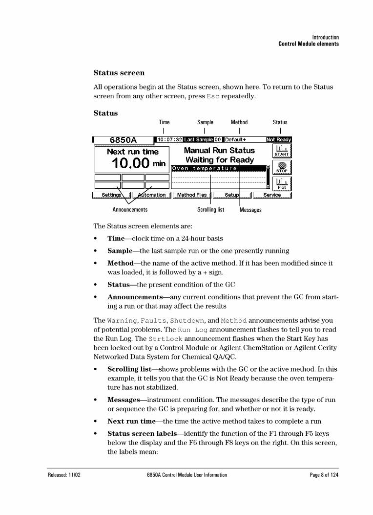
Status screen
All operations begin at the Status screen, shown here. To return to the Status screen from any other screen, press Esc repeatedly.
Status
The Status screen elements are:
• Time—clock time on a 24-hour basis
• Sample—the last sample run or the one presently running
• Method—the name of the active method. If it has been modified since it was loaded, it is followed by a + sign.
• Status—the present condition of the GC
• Announcements—any current conditions that prevent the GC from start-ing a run or that may affect the results
The Warning, Faults, Shutdown, and Method announcements advise you of potential problems. The Run Log announcement flashes to tell you to read the Run Log. The StrtLock announcement flashes when the Start Key has been locked out by a Control Module or Agilent ChemStation or Agilent Cerity Networked Data System for Chemical QA/QC.
• Scrolling list—shows problems with the GC or the active method. In this example, it tells you that the GC is Not Ready because the oven tempera-ture has not stabilized.
• Messages—instrument condition. The messages describe the type of run or sequence the GC is preparing for, and whether or not it is ready.
• Next run time—the time the active method takes to complete a run
• Status screen labels—identify the function of the F1 through F5 keys below the display and the F6 through F8 keys on the right. On this screen, the labels mean:
Time Sample Method Status
Announcements Scrolling list Messages
Released: 11/02 6850A Control Module User Information Page 8 of 124

IntroductionNavigating the screens
Table 1. Status Screen Labels
Navigating the screens
This example illustrates the use of the Control Module to define (configure) the column so that the instrument can convert flows to pressures and the reverse.
Example: Configuring a column
1. Begin at the Status screen. If you are at any other screen, press Esc repeatedly until this screen appears.
Status
2. Press Setup (F4) to display the next screen. In this document, most screens are preceded by the route to follow to get to them from the Status screen.
Key Screen label Function
F1 Settings Things you change frequently, such as oven temperature and hold times, inlet temperatures, and so on
F2 Automation Valve and injector control, the clock and run tables
F3 Method Files Creating and saving sets of control values
F4 Setup Things you don’t change very often, such as the maximum oven temperature, choice of pressure units, etc.
F5 Service Log files, tests, temperature and pressure calibrations, etc.
F6 Plot Shows a developing signal in real time on the display
F7 Stop Stops a run or sequence
F8 Start Starts a run or sequence
F1 F2 F3 F4 F5
F8
F7
F6
Released: 11/02 6850A Control Module User Information Page 9 of 124

IntroductionNavigating the screens
Status / Setup
3. Press Column Setup (F3) to get to the next screen.
Status / Setup / Column Setup
4. Check that the column source and outlet connections are correct. If not, use the ←and →keys to get to the correct set of choices and the ↑ and ↓ keys for the specific choice. Press Enter.
5. The column has not been defined, as shown by the ? mark and the mes-sage in the center. To correct this, press More (F6) to display the popup menu.
Status / Setup / Column Setup / More
6. Use ↑ and ↓ to select Configure Column and press Enter, or press the number 1 key.
F1 F2 F3 F4 F5
F6
F7
F8
F1 F2 F3 F4 F5
F6
F7
F8
F1 F2 F3 F4 F5
F6
F7
F8
Released: 11/02 6850A Control Module User Information Page 10 of 124
IntroductionNavigating the screens
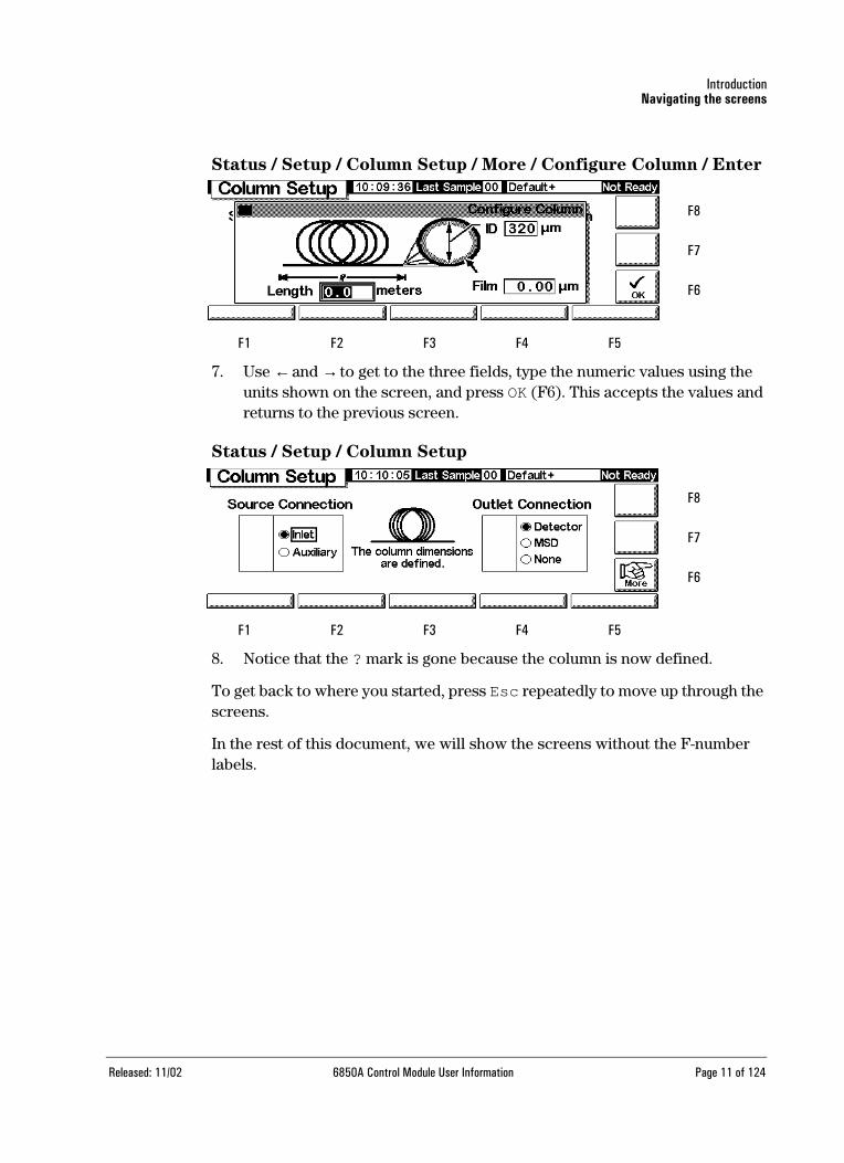
Status / Setup / Column Setup / More / Configure Column / Enter
7. Use ←and → to get to the three fields, type the numeric values using the units shown on the screen, and press OK (F6). This accepts the values and returns to the previous screen.
Status / Setup / Column Setup
8. Notice that the ? mark is gone because the column is now defined.
To get back to where you started, press Esc repeatedly to move up through the screens.
In the rest of this document, we will show the screens without the F-number labels.
F8
F7
F6
F5F4F3F2F1
F1 F2 F3 F4 F5
F6
F7
F8
Released: 11/02 6850A Control Module User Information Page 11 of 124

IntroductionNavigating the screens
Table 2. Control Module Screens
F1 Settings
F1 Inlet F2 Oven F3 Column F4 Detector F5 Auxiliary
Temperature, pres-sure, flows, inlet mode*, pulse mode*, gas saver mode*
Temperature, pro-grams
Flow and pressure program, column mode, configuration
Temperature, flows, signal, outputs, gas type
Temperature
F2 Automation (sequence type, samples used, sequence repeat, sequence controls)
F1 Injector F2 Valves F4 Clock Table F5 Run Table
Volume, pumps, washes, depth, dwell times, viscosity, slow plunger
Toggle valves Add & delete events Add & delete events
F3 Method Files (view active, save active, save service, revert to default)
F4 PC Card F5 GC Methods
Save, load & delete Load & delete
F4 Setup (column compensation)
F1 Inlet Setup F2 Oven Setup F3 Column Setup F4 Automation F5 Configure
Carrier, pressure units, vacuum cor-rect
Equilibrium time, maximum tempera-ture, cryo control
Source & outlet con-nections, configure, mode
Injector, sample valve, multi valve, auto prep run
Oven, serial #, mfg date, clock, serial & LAN comm, local UI locks, beeps, and dis-play
F5 Service (run log, start service, exit service)
F1 Log Book F2 Diagnostics F3 Calibration F4 Maintenance F5 Update
View/save log book Status, inlet, detec-tor, keyboard
Factory settings or oven, inlet, column, and detector
Service limits, early maintenance feed-back
Update GC, Injector, Control Modulefirmware
F6 Plot signals
F7, F8 Start & Stop Runs* Split/Splitless inlet only
Released: 11/02 6850A Control Module User Information Page 12 of 124
IntroductionGC configuration
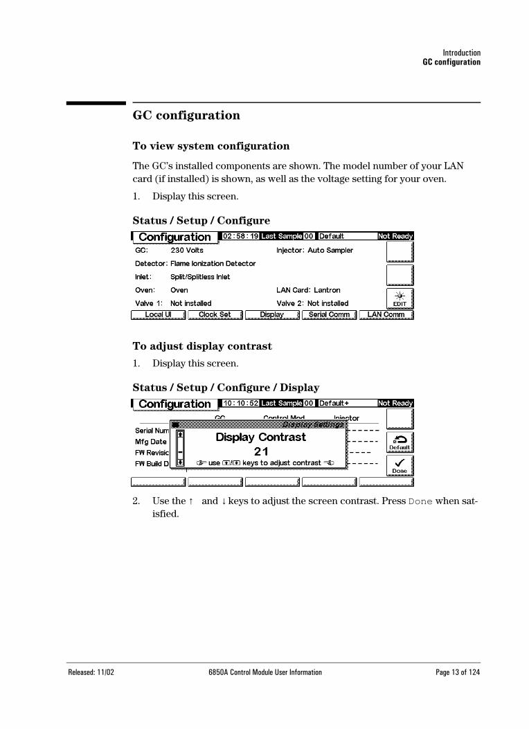
GC configuration
To view system configuration
The GC’s installed components are shown. The model number of your LAN card (if installed) is shown, as well as the voltage setting for your oven.
1. Display this screen.
Status / Setup / Configure
To adjust display contrast
1. Display this screen.
Status / Setup / Configure / Display
2. Use the ↑ and ↓ keys to adjust the screen contrast. Press Done when sat-isfied.
Released: 11/02 6850A Control Module User Information Page 13 of 124

IntroductionGC configuration
To configure the RS-232 port
This refers to the connector labeled RS-232 on the back of the GC. It does not affect Control Module/GC communications.
1. Display this screen.
Status / Setup / Configure / Serial Comm
2. Adjust the controls to meet the needs of the external device. Press Esc when finished.
To set time and date
1. Display this screen.
Status / Setup / Configure / Clock Set
2. Set the date and time. The clock resets when you press Done.
Released: 11/02 6850A Control Module User Information Page 14 of 124

IntroductionViewing IP address settings
Viewing IP address settings
Display this screen.
Status / Setup / Configure / LAN Comm
If installed, the current LAN card settings are shown for reference. The IP address, subnet mask, default gateway, and timeout values are set when the LAN card/GC is installed. The control mode is explained below.
Control modes
The control mode displayed on the LAN Setup screen indicates the current method of obtaining LAN configuration settings. The available control modes depend on the LAN card installed (see Table 3). For information on how to identify which LAN card is installed in your GC, see To view system configura-
tion on page 13.
Table 3. Available Control Modes
• If a J2552B or J4100A LAN card is installed, the message “Supports BootP Control Mode Only” is displayed. While it is possible to set the LAN address from the Control Module, this practice is not recommended. The resulting connection will be very slow.
• Use BootP/DHCP to get address: Your GC is set to receive LAN
addressing from the BootP program or Windows NT® DHCP.
• Use locally entered settings: Your GC is set to use IP address, subnet mask, and gateway values that you will provide via the Control Module or GC front panel. See Adjusting IP address settings on page 16.
LAN card Available control modes Enter settings
J2552B BootP N/A
J4100A BootP, Locally entered settings At GC front panel
Lantronics DHCP, Locally entered settings At GC front panel, Control Module
Released: 11/02 6850A Control Module User Information Page 15 of 124

IntroductionAdjusting IP address settings
Adjusting IP address settings
Display this screen
Status / Setup / Configure / LAN Comm / Set IP
To use BootP or DHCP to provide IP address settings
1. Select BootP/DHCP to use the BootP program or DHCP to set the GC LAN card configuration. The GC will automatically use the appropriate method.
2. Press Done. The new settings will not take effect until the GC is restarted. To restart now, select Yes when the following window appears:
To provide specific IP address settings
The Control Module can be used to adjust LAN settings for 6850 GCs that use the Lantronics LAN card. See To view system configuration on page 13 for information on how to identify which LAN card is installed in your GC.
Released: 11/02 6850A Control Module User Information Page 16 of 124

IntroductionAdjusting IP address settings
1. Display this screen.
Status / Setup / Configure / LAN Comm / Set LAN
2. Select Local to use IP address, subnet, and gateway settings that you will provide.
3. Use ← and → to move from field to field and use the number keys to adjust the values.
4. Make sure the settings are correct and press Done. The new settings will not take effect until the GC is restarted. To restart now, select Yes when the following window appears:
Released: 11/02 6850A Control Module User Information Page 17 of 124

IntroductionConfiguring the GC display and keypad
Configuring the GC display and keypad
The Control Module can define the functions available at the GC keypad and display. This is useful when, for example, a GC is to be used as a dedicated ana-lyzer or operated by a remote ChemStation or Cerity Chemical.
To define the GC keypad and display functions
1. Display this screen.
Status / Setup / Configure / Local UI
• Oven Temp, Message Line, Inlet Pressure, Column Flow, Signal,
and Run Time are display-only features—changing the values requires a Control Module or a ChemStation
• Service Mode—Allows the SERVICE method to be loaded from the keypad (see Service Mode on page 106 for details of the SERVICE method)
• Stored Methods—Places the list of methods stored in the GC in the scrolling display so they can be selected and loaded from the keypad
• Run Time Mode—Controls whether the Run Time, if displayed, counts up (time elapsed since Start) or down (time to end of run). This choice does not affect the Run Table.
2. Select the items you want displayed on the GC display, the actions you want to be able to perform at the GC keypad, and, if Run Time is selected, the Run Time Mode.
3. Press Beeps to display the next screen.
Released: 11/02 6850A Control Module User Information Page 18 of 124

IntroductionConfiguring the GC display and keypad
Status / Setup / Local UI / Beeps
4. Select the beep behaviors you want.
5. Press Esc to return to the Local UI screen, then press Locks to display the next screen.
Status / Setup / Local UI / Locks
• Lock Local Keyboard deactivates all parameter changes from the Control Module
• Lock Local Start Key deactivates the Start key on the GC keypad
• Lock Remote Start deactivates the Start function of the REMOTE connector on the back of the GC. You can still start a run using a Control Module.
• Host Lock— A reported value. On means that a ChemStation or other computer is controlling the GC, and you cannot change setpoints from the Control Module.
• Sequence Lock—Locks out sequence execution from the GC
• Clock Table Lock—Locks out clock table access
• Clock Table Exec Lock—Locks out execution of clock table events
• Method & Sequence & Clock Table Lock—Locks out method loading from the GC Keypad or the Control Module, plus the Sequence and Clock Table locks
Released: 11/02 6850A Control Module User Information Page 19 of 124

IntroductionPlotting a signal
Plotting a signal
The Control Module screen can display up to three real-time plots at the same time. Plotting is best explained with examples.
To plot one signal
1. Display this screen.
Status / Plot
2. The screen is presently plotting Oven Temperature. Press Select to see a list of the available signals.
Status / Plot / Select
Signal, in the Available Signals list, is the signal selected on the detector screen.
It may be any of the following:
• Detector
• Column Comp
• Detector - Col Comp
• Test Chromatogram
• Other
See the detector section for more details.
Released: 11/02 6850A Control Module User Information Page 20 of 124

IntroductionPlotting a signal
3. To move a signal from one list to the other, select it and press Move. Although you can have up to three Selected Signals, we will consider the one signal case first.
4. For this example, we assume that you moved Oven Temperature back to Available Signals and move Signal to Selected Signals.
5. After making these moves, the Selection screen reads as follows:
6. Enter a Time Range. This is the width, in minutes, of the plot. If the run lasts longer than this, the plot scrolls off the screen to the left.
7. At this time, you can press Setup to set the vertical scale (Y Range). This is not absolutely necessary because you can always rescale the plot later.
8. Press Done to return to the signal selection screen, then press Done again to see the plot. If you did not set a Y Range, and possibly even if you did but set it too large, the plot may look like this.
Released: 11/02 6850A Control Module User Information Page 21 of 124

IntroductionPlotting a signal
9. Press Rescale. This changes the Y range so that the plot fills the window.
10. To refine the scaling, use ←and → to adjust the horizontal scale and ↑ and ↓ to adjust the vertical scale. In this example, the vertical scale is too sensitive and needs adjusting.
11. Inject a sample—air was used for this example—and press Start. A verti-cal line marks the start of the run.
Released: 11/02 6850A Control Module User Information Page 22 of 124

IntroductionPlotting multiple signals
12. When the peak appears, it goes off scale. Wait for the trailing edge to appear, then press Rescale to bring the top of the peak on scale. Press ↓ once.
13. To explore the plot in detail, press Cursor. An arrow appears on the screen, and the values of time and Signal appear in the top right corner of the screen.
Use the ←and →keys to move the cursor. The next screen shows the retention time and peak height of the smaller peak.
14. To remove the cursor, press Cursor again.
Plotting multiple signals
This is the rescaled plot of the detector signal described on the preceding pages. We will add a plot of the oven temperature.
Released: 11/02 6850A Control Module User Information Page 23 of 124

IntroductionPlotting multiple signals
1. Display this screen.
Status / Plot
2. Press Select to display the list of signals. Select Oven Temperature and press Move. This screen appears:
3. Use the ↑ and ↓ keys, or press 2, to highlight Oven Temperature. Press Setup to set the Y Range for this signal. We suggest a range of 0°C to 150°C.
4. Press Done to return to Plot selection, then press Done again to show both plots.
The two plots are superimposed but have independent Y scales. Note the small ➀ and ➁ that identify the two plots. Use the 1 and 2 keys to select these plots. As you do so, the Y scale changes to that of the selected plot.
For example, to rescale the Oven Temperature plot, press 2 to select the plot, then press Rescale. Similarly, the ← , → , ↑ , and ↓ keys work independently for the two plots to adjust their scaling.
Released: 11/02 6850A Control Module User Information Page 24 of 124

MethodsDesigning a method
MethodsThere is always an active method in the GC memory. It is the set of control values that are presently operating the GC, including Run Table events and automatic injector controls.
The active method changes as you adjust conditions to perform your analysis. To save the changes and make a permanent method:
1. Modify the active method to suit your needs.
2. Name the method and save it in GC memory. Five named methods and a method named SERVICE can be stored.
This section describes how to save the active method, either as a named method or as the SERVICE method.
We also describe the use of a PC Card to copy named methods from the GC and to download them to the GC.
The content of the method—the details of all the things that can be con-trolled—is described in the sections following this one.
Designing a method
A method is a set of control values that determines what the GC does. Methods are created using a Control Module or ChemStation and are executed by the GC.
• The content of many screens depends on what hardware is present. While the GC can sense many of its components, some information (such as what carrier gas is in use) must be entered by you. Always configure (define) instrument elements before trying to use them.
• When setting up a method, configure the carrier gas first, then the column, and finally the inlet. Detectors can be set up at any time.
• The i key on the Control Module provides information about the current screen. Press it again to access the information system index.
Released: 11/02 6850A Control Module User Information Page 25 of 124

MethodsSaving the active method as a named method
Saving the active method as a named method
To name and save the active method
1. Display this screen.
Status / Method Files
2. The screen displays the beginning of the active method. Use the ↑ and ↓ keys to examine it and verify that all values are correct.
3. Press Save to display this screen.
Status / Method Files / Save
4. The Control Module keys have both labeled and hidden values (seeTable 4). The hidden values apply only for entering text in an alphanu-meric field, such as the Method Name field on this screen.
5. Move the cursor to the left end of the name field. Use the keyboard to enter a Method Name.
a. Move the cursor using the ←and →keys.
b. Press a labeled key multiple times to reach the hidden values. If you go too far, keep pressing because the values loop.
c. Do not add an extension to the method name.
Released: 11/02 6850A Control Module User Information Page 26 of 124

MethodsSaving the active method as a named method
Table 4. Key Labels and Hidden Characters
6. Press OK when you finish to save the method in GC long-term memory. See Table 5.
Table 5. Saved Method Content
Key label Hidden characters
1 A B C
2 D E F
3 G H I
4 J K L
5 M N O
6 P Q R
7 S T U
8 V W X
9 Y Z _
0 none
. , ; :
- + * /
Item Saved?
Oven controls yes
Injector controls yes
Injector/valve sample list not saved
Inlet yes
Column yes
Detector yes
Signal yes
Column compensation yes
Aux 1 yes
Run Table yes
Sample valve yes
Multi valve yes
Sequence sample list not saved
Clock table not saved
Released: 11/02 6850A Control Module User Information Page 27 of 124

MethodsSaving the active method as the SERVICE method
Saving the active method as the SERVICE method
1. Display the method using Status / Method Files.
2. Press Service to save the active method as the SERVICE method. This replaces the existing SERVICE method with the contents of the active method.
Restoring the default method
The default method, loaded at the factory, contains parameters that are a rea-sonable starting point for many analyses. This method can be edited to better meet your needs.
To restore the original factory settings, press Default. This screen appears.
Status / Method Files / Default
• Press Yes to load the default method. This becomes the new active method. The previous active method is lost unless it has been saved.
• Press No to cancel the load operation. The active method remains intact.
Using PC cards
Methods can be stored in the GC or on a PC card in the Control Module. By using multiple PC cards, an extensive library of methods can be stored for any GC. You can also save a listing for each method. A listing is a text file of the method’s setpoints exactly as they appear on the control module.
To use a PC card, insert it into the Control Module before connecting to the GC. If you would like use another PC card, you must first disconnect the Con-trol Module before changing cards.
PC cards are available in various memory capacities at most computer stores. A PC card is not provided with the Control Module.
Released: 11/02 6850A Control Module User Information Page 28 of 124

MethodsUsing PC cards
To copy a method from the GC to a PC card
1. Display this screen.
Status / Method Files / PC Card
2. Select a method on the right-hand list.
3. Press Save to copy it to the PC card.
To copy a method from a PC card to a GC
Methods stored on a PC card can be downloaded to the original or a different GC.
1. Display the Status / Method Files / PC Card screen.
2. Select a method name on the left-hand list.
3. Press Load. The selected method becomes the active method on the GC.
4. Execute Save on the Status / Method Files screen and supply a name to save the method to the GC long-term memory.
Released: 11/02 6850A Control Module User Information Page 29 of 124

MethodsUsing PC cards
To delete methods from a PC card
1. Display this screen.
Status / Method Files / PC Card
2. Select a method in the left list.
3. Press Delete. A popup menu appears.
Status / Method Files / PC Card
4. Select the deletion mode and press Enter.
5. A confirmation screen will be displayed. Select Yes or No and press Enter.
To save a method listing to a PC card
If you can access data on a PC card, (using a portable computer, for example), saving a method listing conveniently lists all method parameters and settings in text file format.
Released: 11/02 6850A Control Module User Information Page 30 of 124
MethodsAccessing methods in GC memory
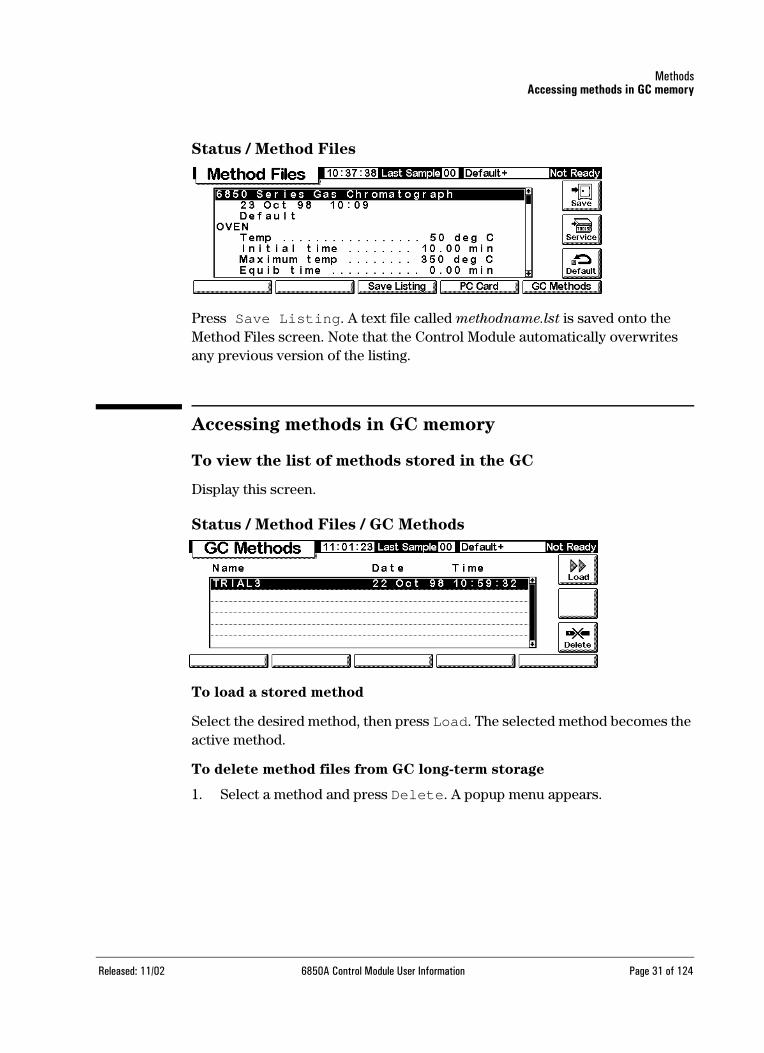
Status / Method Files
Press Save Listing. A text file called methodname.lst is saved onto the Method Files screen. Note that the Control Module automatically overwrites any previous version of the listing.
Accessing methods in GC memory
To view the list of methods stored in the GC
Display this screen.
Status / Method Files / GC Methods
To load a stored method
Select the desired method, then press Load. The selected method becomes the active method.
To delete method files from GC long-term storage
1. Select a method and press Delete. A popup menu appears.
Released: 11/02 6850A Control Module User Information Page 31 of 124
MethodsAccessing methods in GC memory
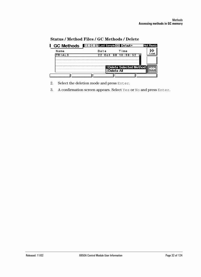
Status / Method Files / GC Methods / Delete
2. Select the deletion mode and press Enter.
3. A confirmation screen appears. Select Yes or No and press Enter.
Released: 11/02 6850A Control Module User Information Page 32 of 124

AutomationInjector control
AutomationThis section describes how to control the automation features of the GC using the Control Module. Items discussed are:
• Injector control
• The sequence
• Run Tables
• The Clock Table
Injector control
This set of screens governs how an auto injector handles a sample. It specifies such things as the amount of sample to inject, how to wash the syringe before and after injection, and other related settings. Injector control is saved as part of a method.
To set up the injector
1. Display the Status / Setup / Automation screen. The type of screen you see depends on the firmware in your GC and the type and configuration of the auto injector that you are using, as shown below.
Released: 11/02 6850A Control Module User Information Page 33 of 124

AutomationInjector control
Status / Setup / Automation / Injector
2. Make your choices for fan on/off, waste bottle usage (if present), and syringe capacity.
• Normally, leave the fan on to help cool the injector and keep your samples stable.
• Note that the fan will briefly turn off once per day for a short time. This extends fan life.
• To turn the fan off on a GC with firmware ≥ A.03 and a three vial posi-tion turret, press the More key to display the fan control screen.
GC firmware ≥ A.03.xx and you are using a three vial position turret.
GC firmware ≥ A.03.xx and you are using an eight vial position turret or the 6850 Automatic Liquid Sampler system (22 or 27 vial position turret).
GC firmware < A.03.xx.
Released: 11/02 6850A Control Module User Information Page 34 of 124

AutomationInjector control
3. Set solvent bottle usage, if available. Newer versions of the GC (firmware ≥ A.03.xx) support extended solvent capacity, which is useful when you run large numbers of samples. If the method specifies solvent A or B usage, your solvent capacity can be extended as shown below:
Remember that the solvents you use (A and/or B) are set within the method. See Wash parameters on page 36. Refer to the GC User Informa-tion CD-ROM for more information about solvent bottle positions in your auto injector or auto sampler system.
4. Press Esc when finished.
To set injection parameters
1. Display this screen.
Status / Automation / Injector
2. Enter:
Plunger Pumps—The number of times to pump the plunger with the needle in the sample to expel bubbles before drawing up the measured sample amount.
Sample Size—The amount to be injected. The choices depend on the syringe size specified during setup (see To set up the injector on page 33).
Viscosity Delay—The number of seconds the plunger pauses at the top of the pump and inject strokes. This time allows viscous samples to flow into the vacuum created by the plunger.
Injector Turret typeExtended solvent setting Solvent bottle usage
G2613 3 vial position Use A, B, and B2 The injector alternates between bot-tles B and B2 when using solvent B.
G2613 8 vial position Not available Normal
6850 Automatic Liquid Sampler
All Use A, A+ and B, B+
The injector alternates between A and A+ solvent bottles, and between B and B+ solvent bottles.
Released: 11/02 6850A Control Module User Information Page 35 of 124

AutomationInjector control
Slow plunger—Reduces the plunger speed during injection from normal (about 100 µL/sec with a 10 µL syringe) to about 5 µL/sec.
Wash parameters
1. Press Washes to display this screen.
Status / Automation / Injector / Washes
2. The syringe can be washed with sample before drawing up the amount to be injected. It can also be washed with solvent both before (pre-washes) and after (post-washes) an injection. The order of events is:
• Wash syringe with solvent A Solvent-A-Pre-Washes times
• Wash syringe with solvent B Solvent-B-Pre-Washes times
• Rinse syringe with sample Sample-Pre-Washes times
• Draw up sample and make injection
• Wash syringe with solvent A Solvent-A-Post-Washes times
• Wash syringe with solvent B Solvent-B-Post-Washes times
3. Enter your choices, then press Esc to return to the previous screen.
Needle depth
1. Press Depth Offset to display this screen.
Status / Automation / Injector / Depth Offset
Released: 11/02 6850A Control Module User Information Page 36 of 124

AutomationSequence parameters
2. The default value, 0 mm, includes a small safety factor to avoid striking the bottom of the vial. This parameter can also be used to sample headspace instead of the liquid or solid sample. See your Sampler manual.
3. Enter your choices, then press Esc to return to the previous screen.
Dwell times
1. Press Dwell Times to display this screen.
Status / Automation / Injector / Dwell Times
2. For most uses, both dwell times will be zero. This gives a fast injection with a minimum of boil-out from a hot needle.
3. Enter your choices.
4. Press Esc to return to the previous screen.
Sequence parameters
The Sequence is a list of samples to be analyzed using the active method. The samples may be either locations of vials in an injector turret or positions of a stream selection valve. The sequence list is not saved with a method.
To set up the sequence of samples to be analyzed
Display this screen.
Released: 11/02 6850A Control Module User Information Page 37 of 124

AutomationSequence parameters
Status / Automation
To enter the injector parameters
1. Select the Injector Sequence Type. The screen is shown above.
2. Enter these parameters:
• First and Last Vial—The lowest and highest numbered turret position to be sampled. See your sampler manual for the numbering scheme.
• # Inj per Vial—The number of times to analyze each sample before moving on to the next one. Default is 1.
• Repeat Sequence—Select repeat to have the sequence start over at the beginning. Select no repeat to have the sequence stop after all samples have been analyzed.
To enter the valve parameters
1. Select the Valve Sequence Type.
Status / Automation
2. Enter these parameters:
• First and Last Position—The lowest and highest numbered valve position to be sampled
• # Inj per Position—The number of analyses to make at each valve position before moving on to the next one. Default is 1.
Released: 11/02 6850A Control Module User Information Page 38 of 124

AutomationControlling a sequence
• Repeat Valve Range—The number of times the valve should cycle through its range of positions, making analyses at each position (possibly multiple runs)
• Repeat Sequence—Select repeat to have the sequence start over at the beginning. Select no repeat to have the sequence stop after all streams have been analyzed.
To operate without a sequence
Select the None Sequence Type.
Controlling a sequence
To start the sequence
Press Start on the GC keypad, the Control Module Status screen, or the Control Module Status/Automation screen.
To pause the sequence
Press Pause on the Status/Automation screen to pause (halt) the sequence. If a run is in progress, the GC will complete the run and then pause the sequence.
The word PAUSE will appear on the screen and blink while the sequence is paused.
Status / Automation / Pause
To resume a paused sequence
Press Pause again. The sequence will resume with the sample run following the last one before the sequence paused.
Released: 11/02 6850A Control Module User Information Page 39 of 124
AutomationRun Table
To cancel a paused sequence
Press Stop Seq.
To stop the sequence
The Stop key on the GC and Stop button on the Status screen stop the run and sequence. The Stop Seq button on the Automation screen stops the sequence only. The current run continues. A stopped sequence cannot be resumed.
Run Table
A Run Table is a list of events to be performed at specified times in every run. Typical events are changing signal attenuation, rezeroing after a signal distur-bance, and switching a valve. The Run Table is saved as part of the method.
All times in the Run Table are run times, that is, the elapsed time in minutes since the start of the run.
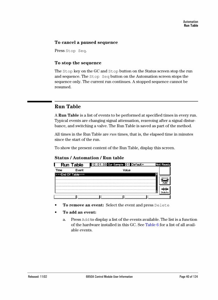
To show the present content of the Run Table, display this screen.
Status / Automation / Run table
• To remove an event: Select the event and press Delete
• To add an event:
a. Press Add to display a list of the events available. The list is a function of the hardware installed in this GC. See Table 6 for a list of all avail-able events.
Released: 11/02 6850A Control Module User Information Page 40 of 124
AutomationRun Table
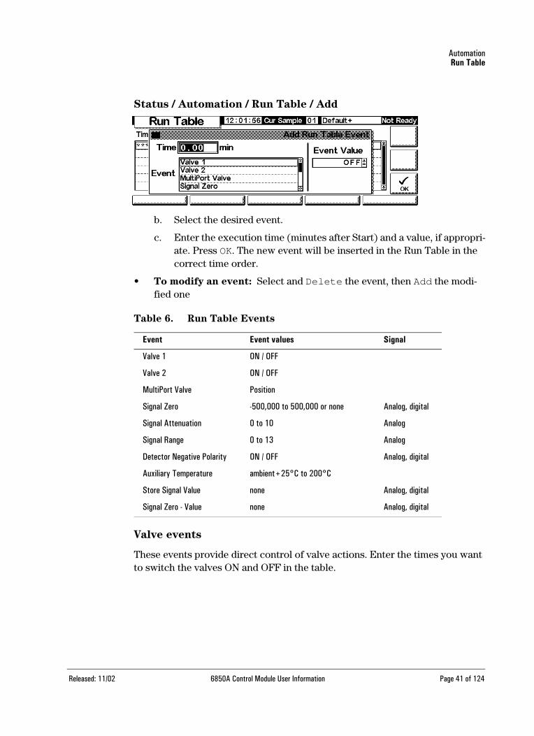
Status / Automation / Run Table / Add
b. Select the desired event.
c. Enter the execution time (minutes after Start) and a value, if appropri-ate. Press OK. The new event will be inserted in the Run Table in the correct time order.
• To modify an event: Select and Delete the event, then Add the modi-fied one
Table 6. Run Table Events
Valve events
These events provide direct control of valve actions. Enter the times you want to switch the valves ON and OFF in the table.
Event Event values Signal
Valve 1 ON / OFF
Valve 2 ON / OFF
MultiPort Valve Position
Signal Zero -500,000 to 500,000 or none Analog, digital
Signal Attenuation 0 to 10 Analog
Signal Range 0 to 13 Analog
Detector Negative Polarity ON / OFF Analog, digital
Auxiliary Temperature ambient+25°C to 200°C
Store Signal Value none Analog, digital
Signal Zero - Value none Analog, digital
Released: 11/02 6850A Control Module User Information Page 41 of 124

AutomationRun Table
Signal Zero event
• Enter a value to be subtracted from all future signal values
OR
• Leave the event value blank. The GC stores the value of the signal at the time of the event and subtracts that value from all future signal values.
Signal Range event and Signal Attenuation event
• The Signal Range event scales the signal available through the 0–1 V or 0–10 V, and 0–1 mV outputs
• The Signal Attenuation event scales the 0–1 mV output only
Both events are binary scalers—a change of 1 in the event value scales the signal by a factor of 2
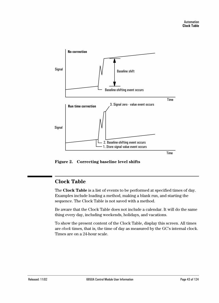
Store Signal Value event and Signal zero - value event
These two events are used together to restore the baseline level after a distur-bance, such as a valve operation, has shifted it.
• Store Signal Value—This event stores the value of the signal at the time of the event. It should occur on baseline
• Signal Zero - Value—This shifts the disturbed baseline by subtracting the value stored by a Store Signal Value event from all future signal values. When these two events surround a baseline-shifting action, the effect is to bring the new baseline to the previous level. The Store event must occur before the baseline shift, and the Zero - Value event must occur after the baseline has stabilized at the shifted level.
Released: 11/02 6850A Control Module User Information Page 42 of 124
AutomationClock Table
Figure 2. Correcting baseline level shifts
Clock Table
The Clock Table is a list of events to be performed at specified times of day. Examples include loading a method, making a blank run, and starting the sequence. The Clock Table is not saved with a method.
Be aware that the Clock Table does not include a calendar. It will do the same thing every day, including weekends, holidays, and vacations.
To show the present content of the Clock Table, display this screen. All times are clock times, that is, the time of day as measured by the GC’s internal clock. Times are on a 24-hour scale.
Signal
Signal
Time
Time
Baseline shift
Baseline-shifting event occurs
No correction
Run time correction
2. Baseline-shifting event occurs1. Store signal value event occurs
3. Signal zero - value event occurs
Released: 11/02 6850A Control Module User Information Page 43 of 124

AutomationClock Table
Status / Automation / Clock Table
• To remove an event: Select the event and press Delete
• To add an event: Press Add to display a list of the events available. The type of events in the list depends on the hardware installed in this GC.
Status / Automation / Clock Table / Add
Select the desired event, enter the execution time (24-hour clock) and a value, if appropriate, and press OK. The new event will be inserted in the clock table in the correct time order.
• To modify an event: Select and Delete the event, then Add the modi-fied one
Table 7. Clock Table Events
Event Event values
Valve 1 ON / OFF
Valve 2 ON / OFF
MultiPort Valve ON / OFF
Start Blank Run none
Start Sequence none
Execute Prep Run none
Column Compensation Run none
Load GC Method Method Name
Released: 11/02 6850A Control Module User Information Page 44 of 124

Flow and Pressure ControlHydrogen shutdown
Flow and Pressure Control
Hydrogen shutdown
Hydrogen gas may be used as a carrier or as fuel for an FID detector.
Warning When using hydrogen (H2) as a carrier gas or fuel gas, be aware that hydrogen can flow into the oven and create an explosion hazard. Be sure that the hydro-gen supply is off until all connections are made and ensure that the inlet and detector column fittings are either connected to a column or capped at all times when hydrogen gas is supplied to the instrument.
Hydrogen is flammable. Leaks, when confined in an enclosed space, may create a fire or explosion hazard. In any application using hydrogen, leak test all connections, lines, and valves before operating the instrument. Always turn off the hydrogen supply at its source before working on the instrument.
The GC monitors flow rates and pressures. If a stream shuts down because it is unable to reach its flow or pressure setpoint and if that stream is configured to use hydrogen, the GC assumes that a leak has occurred and causes a hydrogen
safety shutdown.
• The carrier supply valve to the inlet closes
• The split valve in the split/splitless inlet opens
• The oven heater turns off. The oven flaps open fully.
To recover from this state, fix the cause of the shutdown (tank valve closed, serious leak, etc.). Turn the instrument off, then back on.
Column shutdown
If the carrier gas source shuts down, the oven heater turns off to avoid column damage from heat without carrier gas. The oven flaps open halfway.
To recover from this state, fix the cause of the shutdown (tank valve closed, serious leak, etc.). Turn the oven and the offending inlet or auxiliary channel back on.
Released: 11/02 6850A Control Module User Information Page 45 of 124

Flow and Pressure ControlElectronic pneumatic control
Electronic pneumatic control
The GC electronically controls all gas flows and pressures. This provides:
• Flow and/or pressure control for the inlet, including flow or pressure pro-gramming for the carrier gas through the column
• Flow control via pressure regulation across fixed restrictors for all detec-tor gases
• A gas saver mode to reduce carrier gas consumption between sample runs (split/splitless inlet)
• Direct entry of split ratios, provided the column is configured (split/split-less inlet)
Turning gas flows on and off
All gas flows have an OFF setting so they can be turned on or off without dis-turbing the flow or pressure setpoints. To turn a flow off, select the setpoint and press either the ↑ or ↓ key.
The valves in the gas control modules are designed for gas metering rather than ON/OFF operation. When this type of valve is driven to the OFF state, there may still be a small flow, as much as 0.2 mL/min, through it.
Interpreting flow and pressure displays
The GC measures atmospheric pressure and temperature to eliminate local conditions as causes of retention time variability.
All flow and pressure displays are corrected to a defined set of conditions. These conditions, which we call Normal Temperature and Pressure (NTP), are 25°C and 1 atmosphere pressure. Similarly, setpoints are adjusted for the local conditions.
Thus a flow displayed on the instrument and the flow measured with a bubble meter may not agree, because the bubble meter readings are local conditions rather than NTP conditions. However, retention times become independent of the local environment.
To convert bubble meter flow rate measurements to NTP (25°C and 1 atmosphere), you must know the local atmospheric pressure and the bubble meter temperature at the time of measurement.
Released: 11/02 6850A Control Module User Information Page 46 of 124
Flow and Pressure ControlConfiguring the column
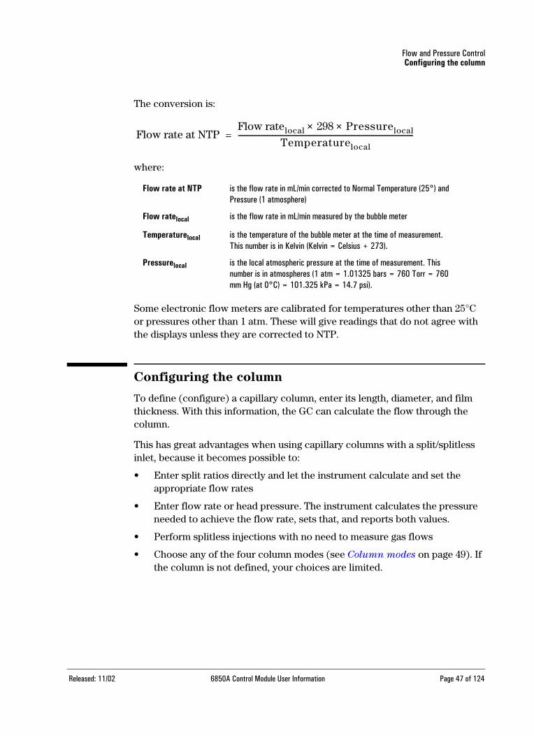
The conversion is:
where:
Some electronic flow meters are calibrated for temperatures other than 25°C or pressures other than 1 atm. These will give readings that do not agree with the displays unless they are corrected to NTP.
Configuring the column
To define (configure) a capillary column, enter its length, diameter, and film thickness. With this information, the GC can calculate the flow through the column.
This has great advantages when using capillary columns with a split/splitless inlet, because it becomes possible to:
• Enter split ratios directly and let the instrument calculate and set the appropriate flow rates
• Enter flow rate or head pressure. The instrument calculates the pressure needed to achieve the flow rate, sets that, and reports both values.
• Perform splitless injections with no need to measure gas flows
• Choose any of the four column modes (see Column modes on page 49). If the column is not defined, your choices are limited.
Flow rate at NTP is the flow rate in mL/min corrected to Normal Temperature (25°) and Pressure (1 atmosphere)
Flow ratelocal is the flow rate in mL/min measured by the bubble meter
Temperaturelocal is the temperature of the bubble meter at the time of measurement. This number is in Kelvin (Kelvin = Celsius + 273).
Pressurelocal is the local atmospheric pressure at the time of measurement. This number is in atmospheres (1 atm = 1.01325 bars = 760 Torr = 760 mm Hg (at 0°C) = 101.325 kPa = 14.7 psi).
Flow rate at NTPFlow ratelocal 298 Pressurelocal××
Temperaturelocal-----------------------------------------------------------------------------------------------------------------=
Released: 11/02 6850A Control Module User Information Page 47 of 124

Flow and Pressure ControlConfiguring the column
To configure the column
1. Display this screen.
Status / Settings / Column
2. Note the question mark at the left, indicating that the column is not defined. To define it, press More, select Configure Column, and press Enter to display the next screen.
Status / Settings / Column / More / Configure Column / Enter
3. Enter values for Length, ID (internal diameter), and Film (thickness).
4. Press OK.
If you do not know the column dimensions—they are usually supplied with the column—or if you do not wish to use the GC calculating features, enter 0 for either length or ID. The column will be not defined and you will only be able to use pressure setpoints with a split/splitless inlet, or total flow with a purged packed inlet.
Released: 11/02 6850A Control Module User Information Page 48 of 124

Flow and Pressure ControlColumn modes
Column modes
Flow modes
Flow rates are corrected to NTP (normal temperature and pressure, 25°C and1 atmosphere).
• Constant flow—Maintains a constant mass flow rate of carrier gas in the column throughout the run. If the column resistance changes due to a tem-perature program, the column head pressure is adjusted to keep the flow rate constant. This can shorten runs significantly.
• Ramped flow—Increases the mass flow rate in the column during the run according to a program you enter.
Pressure modes
Pressures are gauge pressures—the difference between the absolute pressure and the local atmospheric pressure. Because most detectors present little resis-tance to the column flow, the gauge pressure at the column head is usually the same as the pressure difference between column inlet and exit. The mass selec-tive detector and the atomic emission detector are two exceptions.
• Constant pressure—Maintains a constant gauge pressure at the head of the column throughout the run. If the column resistance changes, the gauge pressure does not change but the mass flow rate does.
• Ramped pressure—Increases the column head gauge pressure during the run according to a program you enter
To select a column mode
Display this screen.
Status / Settings / Column / More
1. Select Column Mode and press Enter to display the next screen.
Released: 11/02 6850A Control Module User Information Page 49 of 124
Flow and Pressure ControlInitial column flow or pressure
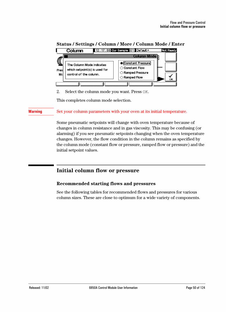
Status / Settings / Column / More / Column Mode / Enter
2. Select the column mode you want. Press OK.
This completes column mode selection.
Warning Set your column parameters with your oven at its initial temperature.
Some pneumatic setpoints will change with oven temperature because of changes in column resistance and in gas viscosity. This may be confusing (or alarming) if you see pneumatic setpoints changing when the oven temperature changes. However, the flow condition in the column remains as specified by the column mode (constant flow or pressure, ramped flow or pressure) and the initial setpoint values.
Initial column flow or pressure
Recommended starting flows and pressures
See the following tables for recommended flows and pressures for various column sizes. These are close to optimum for a wide variety of components.
Released: 11/02 6850A Control Module User Information Page 50 of 124

Flow and Pressure ControlInitial column flow or pressure
Table 8. Column Size and Carrier Gas Flow Rate
Table 9. Recommended Gas Pressures for Capillary Columns
Split/splitless inlet
If the column is defined (see Configuring the column on page 47), you can enter either flow or pressure, depending on which column mode you selected.
If the column is not defined, you can only enter pressure.
Column type Column size Carrier gas flow rate, mL/min
Hydrogen Helium Nitrogen
Capillary 50 µm id 0.5 0.4
100 µm id 1.0 0.8
200 µm id 2.0 1.6
250 µm id 2.5 2.0
320 µm id 3.2 2.6
530 µm id 5.3 4.2
Packed metal 1/8-in. id 30 30
1/4-in. id 60 30-60
Packed glass 2 mm id 30 30
4 mm id 30-60 30-60
These flow rates, in mL/min at NTP (25°C and 1 atm) are recommended for all column temperatures.For capillary columns, flow rates are proportional to column diameter and are 20% lower for helium than for hydrogen.
Recommended gas pressure, psi (kPa)
Inside diameter
Length, m 0.10 µm 0.20 µm 0.25 µm 0.32 µm 0.53 µm
10 25 (170) 6 (40) 3.7 (26) 2.3 (16) 0.9 (6.4)
15 39 (270) 9 (61) 5.6 (39) 3.4 (24) 1.4 (9.7)
25 68 (470) 15 (104) 9.5 (65) 5.7 (40) 2.3 (16)
30 83 (570) 18 (126) 12 (80) 7 (48) 2.8 (19)
50 32 (220) 20 (135) 12 (81) 4.7 (32)
60 39 (267) 24 (164) 14 (98) 5.6 (39)
Released: 11/02 6850A Control Module User Information Page 51 of 124

Flow and Pressure ControlFlow or pressure programming
Purged packed inlet
If using a defined capillary column (see Configuring the column on page 47), you can enter only column head pressure.
If the column is not defined, you can enter only total flow rate.
To set initial flow or pressure
Display this screen.
Status / Settings / Column
1. Scroll to the psi (pressure mode) or mL/min (flow mode) field.
2. Type the desired initial value, followed by Enter.
Flow or pressure programming
If you selected either the ramped pressure or ramped flow column mode, the column screen contains entries for setting up a single-ramp program.
You begin with an initial value, either pressure or flow, and an initial time. At the end of that time, the pressure or flow ramp begins and runs until it reaches the final value. It remains at that value for a speci-fied time.
The oven program determines the length of the run. If a flow or pressure pro-gram ends before the analytical run does, the flow (or pressure) remains at the last final value. If the oven includes a Post-Run period, you can enter a Post-Run pressure or flow for the column.
To create a flow or pressure program
Display this screen.
Released: 11/02 6850A Control Module User Information Page 52 of 124

Flow and Pressure ControlSolving flow and pressure problems
Status / Settings / Column
1. The column is in constant flow mode, which is why the ramp setpoints are grayed out. Press More and use the Column Mode screen (see Column
modes on page 49) to change to Ramped Flow.
Status / Settings / Column
2. Enter the starting value in the mL/min field.
3. Use the ←and →keys and enter values in the remaining fields to complete the ramp. If desired, enter a Post Run value.
4. Use a similar procedure to set up a pressure program.
Solving flow and pressure problems
A gas does not reach the setpoint pressure or flow
If the condition persists longer than the time specified for that stream, the inlet or detector will shut down. The time depends on the specific device involved. Possible causes/corrections include:
• The gas supply pressure is too low to reach the setpoint. The pressure at the supply should be at least 10 psi greater than the desired setpoint.
• A large leak is present somewhere in the system. Use an electronic leak detector to find leaks; correct them. Don’t forget to check the column—a broken column is a very large leak.
Released: 11/02 6850A Control Module User Information Page 53 of 124

Flow and Pressure ControlSolving flow and pressure problems
• If you are using gas saver, be sure that the gas saver flow rate is high enough to maintain the highest column-head pressure during a run
• The flow is too low for the column in use
• The column is plugged or mis-installed
• The inlet or detector pressure sensor is not operating correctly. Contact your Agilent service representative.
If you are using a split/splitless inlet
• The split ratio is too low. Increase the amount of split flow.
• The inlet proportional control valve is stuck because of contamination or other fault. Contact your Agilent service representative.
If you are using a purge packed inlet
• The inlet control valve is stuck closed because of contamination of other fault. Contact your Agilent service representative.
A gas exceeds the setpoint pressure or flow
Possible causes/corrections include:
• The pressure sensor for that device is not operating properly. Contact your Agilent service representative.
If you are using a split/splitless inlet
• The split ratio is too high. Decrease the split ratio.
• The proportional control valve is stuck closed. Contact your Agilent service representative.
• The trap on the split vent line is contaminated. Contact your Agilent service representative.
If you are using a purge packed inlet
• The inlet proportional control valve is stuck open. Contact your Agilent service representative.
The inlet pressure or flow fluctuates
A fluctuation in inlet pressure will cause variations in the flow rate and reten-tion times during a run. Possible causes/corrections include:
• A small leak is present in the flow system. Use an electronic leak detector to find leaks; correct them. You should also check for leaks in the gas supply plumbing.
Released: 11/02 6850A Control Module User Information Page 54 of 124

Flow and Pressure ControlSolving flow and pressure problems
• Large restrictions are present in the split/splitless inlet, such as a blockage in a liner or the split vent trap. Make sure that you are using the correct liner. Replace liners with large pressure drops caused by design or tight packaging. If the liner does not appear to be causing the problem, the split vent trap may be blocked. Contact your Agilent service representative.
• Extreme changes in room temperature during runs. Correct laboratory temperature problem or move the instrument to a more suitable location.
• Large volumes have been added to the system (this may occur if you are using a sampling valve). Decrease the sample volume.
The measured flow is not equal to the displayed flow
You checked the flow at an inlet with a bubble flow meter, corrected the mea-surement to NTP conditions, and find that it does not match the flow you set. Possible causes/corrections include:
• Column length, internal diameter, or gas type is configured incorrectly. Enter the correct information. If a considerable amount has been cut off a capillary column, its actual length may no longer match the original. Cor-rect the length value.
• A new pressure setpoint was not entered after constant flow mode was selected. Enter a new pressure setpoint each time constant flow is turned on or off.
• A short (<15 m) 0.58 to 0.75 µm id WCOT column is being used. Total flow is set for a high flow rate, which creates some pressure in the inlet and causes column flow even with a setpoint pressure of zero.With short, 530 to 750 µm columns, keep the total flow rate as low as possible (for exam-ple, 20 to 30 mL/min). Install a longer column with higher resistance (for example, 15 to 30 m).
• The split vent line may be partly plugged, creating an actual inlet pressure higher than the setpoint pressure. See Split Vent Test (split/splitless inlet
only) on page 110.
• A Mass Selective Detector is in use and vacuum compensation is not selected
Released: 11/02 6850A Control Module User Information Page 55 of 124

Split/Splitless InletUsing hydrogen
Split/Splitless Inlet
Using hydrogen
Warning When using hydrogen (H2) as a carrier gas or fuel gas, be aware that hydrogen gas can flow into the oven and create an explosion hazard. Therefore, be sure that the supply is off until all connections are made and ensure that the inlet and detector column fittings are either connected to a column or capped at all times when hydrogen gas is supplied to the instrument.
Warning Hydrogen is flammable. Leaks, when confined in an enclosed space, may create a fire or explosion hazard. In any application using hydrogen, leak test all connections, lines, and valves before operating the instrument. Always turn off the hydrogen supply at its source before working on the instrument.
Inlet and column
The inlet and column controls are related, and the relationship depends on whether or not the column is defined. We strongly recommend that you set up the GC in this order:
1. Configure (define) the column (see Configuring the column on page 47). If you don’t, only the pressure modes of the column and inlet can be used. The flow-dependent features of the inlet, such as setting a split ratio directly, are not available.
2. Select the column mode (see Column modes on page 49).
3. Program column flow or pressure, if desired (see Flow or pressure pro-
gramming on page 52).
4. Set up the inlet (see Inlet setup on page 57).
5. Set up the oven (Oven setup on page 73) and detector (TCD, Using the
TCD on page 90; FID, Using the FID on page 99).
Released: 11/02 6850A Control Module User Information Page 56 of 124

Split/Splitless InletInlet setup
Inlet setup
To set up the inlet
Display this screen.
Status / Setup / Inlet Setup
1. Select the carrier gas you will use.
2. Select the pressure units you prefer (Table 10 shows the conversions).
3. Select Vacuum correct for Mass Spec if the column empties into a vacuum (e.g., if using a Mass Selective Detector or mass spectrometer).
Table 10. Pressure Unit Conversions
Prep Run
When you are performing analyses using manual injection and gas saver, split-less mode, and/or pressure pulse, the GC will display "Waiting for prep run" and one or more of these messages:
• Gas saver active
• Inlet purging
• Inlet pulse inactive
To convert to Multiply by
psi bar 0.0689476
kPa 6.89476
bar psi 14.5038
kPa 100
kPa psi 0.145038
bar 0.01
Released: 11/02 6850A Control Module User Information Page 57 of 124

Split/Splitless InletInlet modes
In these cases, you must press the Prep Run key to reset the setpoints, wait for the "Ready for" message, and then make the injection and press Start.
If this is not practical, you can have the GC issue an automatic Prep Run com-mand at the end of each run. To do so, display this screen.
Status / Setup / Automation / Auto Prep Run
Select Enable Auto Prep Run and press Esc.
This disables Gas Saver and raises the inlet pressure to the Pulse Pressure level immediately. The inlet purge valve closes. Deselect Enable Auto Prep Run when you are finished making runs to conserve carrier gas.
Inlet modes
The split/splitless inlet has four operating modes:
• Split—The sample is divided between the column and a vent flow
• Splitless—The sample is not divided. Most of it enters the column. A small amount is purged from the inlet to avoid excessive peak broadening and solvent tailing.
• Split with a pressure pulse—Similar to split, except that the inlet pressure is raised before and during injection and returned to normal at a user-specified time. Total flow is increased so that the split ratio does not change. This special kind of “programming” is independent of flow or pres-sure programming (see Split mode on page 60 ).
• Splitless with a pressure pulse—Like split with a pulse, but splitless
The split/splitless inlet has a gas saver feature that reduces the flow of carrier into the inlet and out the split vent after the injection is complete. It does not alter the flow through the column. See Gas saver on page 66 for details.
The septum purge line is near the septum where the sample is injected. A small amount of carrier gas exits through this line to sweep out any bleed. This flow rate is set automatically, as shown in Table 11.
Released: 11/02 6850A Control Module User Information Page 58 of 124

Split/Splitless InletPressure pulse modes
Table 11. Septum Purge Flows
Pressure pulse modes
The pressure pulse modes increase inlet pressure just before the beginning of a run and return it to the normal value after a specified amount of time. The pres-sure pulse sweeps the sample out of the inlet and into the column faster, reduc-ing the chance for sample decomposition in the inlet. If your chromatography is degraded by the pressure pulse, a retention gap may help restore peak shape.
Pressure pulses may be used in either split or splitless mode and can be com-bined with column pressure or flow programming. The pressure pulse takes precedence over the column pressure or flow ramp, as shown in Figure 3.
The pressure pulse must start before the sample is injected. The GC will do this automatically if you are using an automatic injector or a sequence.
If you are using manual injection, you must press the Prep Run key to start the pulse and wait for the "Ready for manual inj" message.
Figure 3. Pressure pulse and column flow or pressure
Carrier Septum purge
He, N2, 95%Ar/5%Me 3 mL/min
H2 6 mL/min
0 1 2 3 4 5 6 7 8
Pressure pulse
Pressure (or flow) program
Actualpressure
Time (min)
Released: 11/02 6850A Control Module User Information Page 59 of 124

Split/Splitless InletSplit mode
To set up a pressure pulse
1. Set up the flow conditions through the column, including a flow or pres-sure program (see Flow or pressure programming on page 52) if desired. Then display this screen.
Status / Settings / Inlet / More
2. Select Pulse Mode and press Enter to display the next screen.
Status / Settings / More / Pulse Mode / Enter
3. Select Pulsed. Enter values for Pulse Pressure and Pulse Time.
• Pressure is the inlet pressure from Prep Run to Pulse Time.
• Time (minutes after Start) is the time when the inlet pressure changes from Pulse Pressure to the pressure called for by the flow or pressure program (see Flow or pressure programming on page 52).
4. Press OK to accept these values or Esc to cancel.
Split mode
Pneumatics
During a split injection, a liquid sample is rapidly vaporized in a hot inlet. A small amount of the vapor enters the column while the rest exits through the split/purge vent. The ratio of column flow to split flow, the split ratio, is controlled by the user. Split injections are mainly used for high concentration
Released: 11/02 6850A Control Module User Information Page 60 of 124

Split/Splitless InletSplit mode
samples when you can afford to lose most of the sample out the split/purge vent. It is also used for samples that cannot be diluted.
Figure 4 shows the pneumatics for this inlet in split mode operation.
Figure 4. Split flow pneumatics
To change to split mode
Display this screen.
Status / Settings / Inlet / More / Inlet Mode / Enter
1. The inlet is presently in Splitless mode. Change the selection to Split and press OK to return to the previous screen.
Total flowcontrol loop
Proportionalvalve 1
Flow
FS
Septum holder Pressuresensor
Septum purgeregulator (not
adjustable)
PS SPR Vent
Trap Purgevalve open
Proportionalvalve 2
Split vent flow
Column head pressurecontrol loop
Safety shutdown mode:Proportional valve 1 closedProportional valve 2 openPurge valve open
To detector
sensor
Flowlimiting
frit
Released: 11/02 6850A Control Module User Information Page 61 of 124

Split/Splitless InletSplit mode
2. The inlet is now in split mode.
To use split mode with the column defined
1. Verify that the column is in either Constant Flow or Ramped Flow mode.
2. Display this screen:
Status / Settings / Inlet
3. Set Temperature. Set column mL/min. Then enter the Ratio or, if you prefer, the split mL/min. In either case, the instrument calculates and displays the other value.
To use split mode with the column not defined
Display this screen.
Status / Settings / Inlet
1. If necessary, change the inlet mode to split mode.
2. Set Temp and Pressure. Measure flow out of the split vent using a flow meter.
Septum purge
Split vent
Released: 11/02 6850A Control Module User Information Page 62 of 124

Split/Splitless InletSplitless mode
3. Subtract split vent flow and septum purge flow (see Septum Purge Flows on page 59 for nominal septum purge flows by carrier gas type) from Total flow to get column flow.
4. Calculate the split ratio. Adjust as needed.
Splitless mode
Pneumatics
In this mode, the purge valve is closed during the injection and remains so while the sample vaporizes in the liner and transfers to the column. At a time after injection that you specify, the purge valve opens to sweep any vapors left in the liner out the split vent. This avoids solvent tailing that would occur due to the large inlet volume and small column flow rate.
If you are using gas saver, the gas saver time should be after the purge time (see Gas saver on page 66 for details on the gas saver).
Figure 5. Splitless flow diagram, pre-run to purge time
Split ratio = Split flow Column flow
Flow limiting
frit
Proportionalvalve 1
Flowsensor
FS
Inlet pressure control loop
Septum holder
PS
Pressure sensor
SPR
Septum purgeregulator (not
adjustable)
Vent
Trap Purgevalve
closed
Proportionalvalve 2
To detector
Safety shutdown mode:Proportional valve 1 closedProportional valve 2 openPurge valve open
Released: 11/02 6850A Control Module User Information Page 63 of 124
Split/Splitless InletSplitless mode
To change to splitless mode
Display this screen.
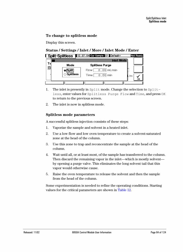
Status / Settings / Inlet / More / Inlet Mode / Enter
1. The inlet is presently in Split mode. Change the selection to Split-less, enter values for Splitless Purge Flow and Time, and press OK to return to the previous screen.
2. The inlet is now in splitless mode.
Splitless mode parameters
A successful splitless injection consists of these steps:
1. Vaporize the sample and solvent in a heated inlet.
2. Use a low flow and low oven temperature to create a solvent-saturated zone at the head of the column.
3. Use this zone to trap and reconcentrate the sample at the head of the column.
4. Wait until all, or at least most, of the sample has transferred to the column. Then discard the remaining vapor in the inlet—which is mostly solvent—by opening a purge valve. This eliminates the long solvent tail that this vapor would otherwise cause.
5. Raise the oven temperature to release the solvent and then the sample from the head of the column.
Some experimentation is needed to refine the operating conditions. Starting values for the critical parameters are shown in Table 12.
Released: 11/02 6850A Control Module User Information Page 64 of 124

Split/Splitless InletSplitless mode
Table 12. Splitless Mode Inlet Parameters
To use splitless mode with the column defined
1. Verify that the column, carrier gas, and flow or pressure program (if used) are configured correctly.
2. Display this screen.
Status / Settings / Inlet
3. If necessary, change the inlet mode to splitless.
4. Enter values for Temp and column mL/min.
5. Use the Prep Run key (see Prep Run on page 57) before manually inject-ing a sample.
Parameter Allowed setpoint range Suggested starting value
Oven temperature No cryo, 24°C to 350°CCO2 cryo, -20°C to 350°C
30°C below solventboiling point
Oven initial time 0 to 999.9 minutes ≥ Inlet purge time
Inlet purge time 0 to 999.9 minutes Liner volume / Column flow
Gas saver time 0 to 999.9 minutes After purge time
Gas saver flow 15 to 1000 mL/min 15 mL/min greater than maxi-mum column flow
Released: 11/02 6850A Control Module User Information Page 65 of 124

Split/Splitless InletGas saver
To use splitless mode with the column not defined
Display this screen.
Status / Settings / Inlet
1. If necessary, change the inlet mode to splitless.
2. Enter values for Temp and Pressure.
3. Use the Prep Run key (see Prep Run on page 57) before manually inject-ing a sample.
Gas saver
Gas saver reduces carrier gas flow from the split vent after the sample is on the column. Column head pressure and flow rate are maintained, while purge and split vent flows decrease. Flows—except column flow—remain at the reduced level until you press Start (sequence or auto injector operation) or the Prep Run key (manual injection).
Released: 11/02 6850A Control Module User Information Page 66 of 124

Split/Splitless InletGas saver
Figure 6. Gas saver operation
To set up the gas saver
Display this screen.
Status / Settings / Inlet / More / Gas Saver / Enter
1. Select Gas Saver. Enter values for Flow and Time.
• Flow is the reduced flow level between sample runs.
• Time (minutes after injection) is when the normal flow changes to Saver Flow. It remains at the reduced level until the next Prep Run event, whether manual or automatic.
2. Press OK to accept these values or Esc to cancel.
0 1 2 3 4 5 6 7 8
10
20
30
40
50
-1-2
0 1 2 3 4 5 6 7 8
10
20
30
40
50
-1-2
Gas saverflow
[Prep run]
[Start]
Regular flow
Gas saver time (3 min)
Gas saver flow
Run ends
Split mode
Split ventflow(mL/min)
Splitless mode
Split ventflow(mL/min)
Gas saverflow
[Prep run]
Gas saver time (5 min)
Run endsPurge flow
Gas saver flow
Purge time(2 min)
[Start]
Time (min)
Time (min)
Released: 11/02 6850A Control Module User Information Page 67 of 124

Purged Packed InletUsing hydrogen
Purged Packed Inlet
Using hydrogen
Warning When using hydrogen (H2) as a carrier gas or fuel gas, be aware that hydrogen gas can flow into the oven and create an explosion hazard. Therefore, be sure that the supply is off until all connections are made and ensure that the inlet and detector column fittings are either connected to a column or capped at all times when hydrogen gas is supplied to the instrument.
Warning Hydrogen is flammable. Leaks, when confined in an enclosed space, may cre-ate a fire or explosion hazard. In any application using hydrogen, leak test all connections, lines, and valves before operating the instrument. Always turn off the hydrogen supply at its source before working on the instrument.
Inlet and column controls
The inlet and column controls are related, and the relationship depends on whether or not the column is defined. Set up the GC as described below.
1. If you are using a packed column, or a undefined wide-bore capillary column, only the flow modes are available. This is the default control method for the purged packed inlet.
If you are using a wide-bore capillary column, you can configure (define) the column (see Configuring the column on page 47) and use column and inlet pressure modes instead of flow modes.
2. Select the column mode (see Column modes on page 49).
3. Program column flow or pressure, if desired (see Flow or pressure pro-
gramming on page 52).
4. Set up the inlet (see Inlet setup on page 69).
5. Set up the oven (Oven setup on page 73) and detector (TCD, Using the
TCD on page 90; FID, Using the FID on page 99).
Released: 11/02 6850A Control Module User Information Page 68 of 124

Purged Packed InletInlet setup
Inlet setup
To set up the inlet, display the following screen.
Status / Setup / Inlet Setup
1. Select the carrier gas you will use.
2. Select the pressure units you prefer (see Table 13 for conversions).
3. Select Vacuum Correct or Pressure Correct if the column emp-ties into a vacuum (e.g., if using a Mass Selective Detector or mass spec-trometer) or if other pressure correction is required. (Pressure correction is not available in all GC configurations.)
Table 13. Pressure Unit Conversions
To convert To Multiply by
psi bar 0.0689476
kPa 6.89476
bar psi 14.5038
kPa 100
kPa psi 0.145038
bar 0.01
Released: 11/02 6850A Control Module User Information Page 69 of 124

Purged Packed InletUsing a purged packed inlet
Using a purged packed inlet
This inlet is used with packed columns when high-efficiency separations are not required. It can also be used with wide-bore capillary columns, provided that flows greater than 10 mL/min are acceptable.
If a capillary column is used and the column is defined, the inlet is pressure-controlled. If the column is not defined (packed columns and undefined capil-lary columns), the inlet is flow-controlled.
Figure 7. Purged packed inlet flow diagram
Flow
limitingfrit
Proportionalvalve
Flowsensor
Pressure sensor
Septum holderSeptum purgeregulator (not
adjustable)
Flowlimiting
fritProportional
valveFlow
sensorPressure
sensorSeptum holder
Septum purgeregulator (not
adjustable
Purge VentFlow
Purge VentFlow
Flow-controlled mode (for packed and undefined capillary columns)
Pressure-controlled mode (recommended for defined capillary columns)
Total flowcontrol loop
Inlet pressurecontrol loop
To columnand detector
To columnand detector
FS PS SPR
FS PS SPR
Released: 11/02 6850A Control Module User Information Page 70 of 124
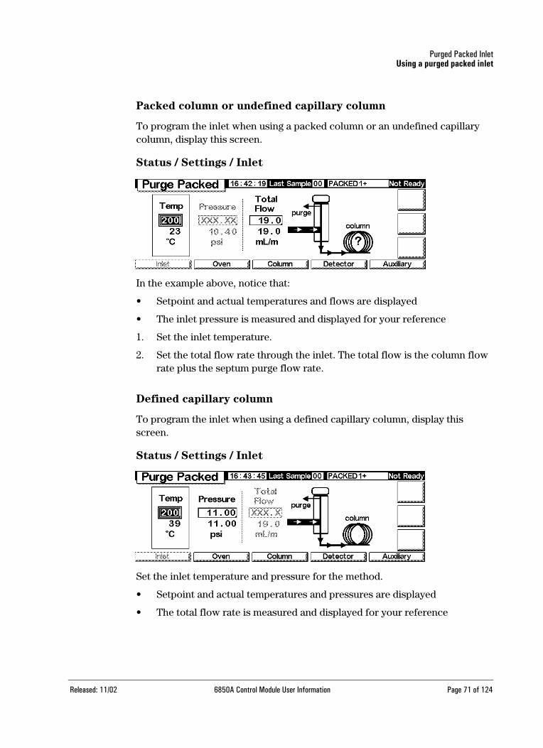
Purged Packed InletUsing a purged packed inlet
Packed column or undefined capillary column
To program the inlet when using a packed column or an undefined capillary column, display this screen.
Status / Settings / Inlet
In the example above, notice that:
• Setpoint and actual temperatures and flows are displayed
• The inlet pressure is measured and displayed for your reference
1. Set the inlet temperature.
2. Set the total flow rate through the inlet. The total flow is the column flow rate plus the septum purge flow rate.
Defined capillary column
To program the inlet when using a defined capillary column, display this screen.
Status / Settings / Inlet
Set the inlet temperature and pressure for the method.
• Setpoint and actual temperatures and pressures are displayed
• The total flow rate is measured and displayed for your reference
Released: 11/02 6850A Control Module User Information Page 71 of 124

Column OvenOven capabilities
Column Oven
Oven capabilities
• Temperature range 10°C above ambient to 350°C –20°C with CO2 cooling to 350°C
• Temperature programming Up to six ramps
• Maximum run time 999.99 minutes
• Temperature ramp rates 0 to 120°C/min
• The oven accommodates one inlet, one detector, and one column.
Oven safety
Manual shutdown
Raising the oven lid turns off power to the oven heater, fan, and cryogenic valve (if installed) but maintains the setpoints in memory. Closing the oven lid returns the oven to normal operation.
Automatic shutdown
If the oven cannot attain or maintain an entered setpoint temperature during normal operation, the GC turns the oven fan and heater off, flashes the shut-down announcement on the Status screen, and displays a message.
Possible problems include:
• The oven vent flaps are not working
• The oven fan, heater, or temperature sensor is not working properly
• There is an electronic problem
When an automatic shutdown occurs, the oven remains off until it is reset using the Control Module (Status / Settings / Oven). You may need to turn the instrument power off, then on again.
Released: 11/02 6850A Control Module User Information Page 72 of 124

Column OvenOven setup
Oven setup
To set up the oven
Display this screen.
Status / Setup / Oven Setup
1. Enter values for Equib Time and Max Temp.
• Equib Time—When the oven temperature reaches ± 1°C of setpoint. The GC waits for the time specified before declaring the oven ready.
• Max Temp—The oven temperature limit. Most columns and many accessories have specific temperature limits. When configuring Max Temp, these limits should be considered to prevent damage.
2. If a cryogenic valve is installed and you wish to use it, select Enable Oven Cryo. Enter values for Cryo ambient temp and Cryo Time-out.
Caution If you are using cryogenic oven cooling, the flanged column hanger must be used to avoid column cold spots.
When cryogenic cooling is not needed or cryogenic coolant is not avail-able, do not select this item. If this is not done, proper oven temperature control may not be possible, particularly at temperatures near ambient.
• Cryo ambient temp—The temperature in the laboratory. This setpoint determines the temperature at which cryogenic cooling begins. For regular cryo operation, the temperature is Cryo ambient temp + 25°C. For Quick Cryo Cool, the temperature is Cryo ambient temp +45°C.
• Cryo Timeout—Timeout occurs, and the oven shuts off, when a run does not start within a specified time (10 to 120 minutes) after the oven equilibrates. Turning Cryo Timeout off disables this feature. We recommend that it be turned on to conserve coolant at the end of a method or if automation fails.
Released: 11/02 6850A Control Module User Information Page 73 of 124

Column OvenCreating an isothermal run
3. If desired, select Cryo Fault and Quick Cryo Cool.
• Cryo Fault-Shuts the oven down if it does not reach (stabilization will take longer) setpoint temperature after 16 minutes of continuous cryo operation
• Quick Cryo Cool-This feature is separate from Enable Oven Cryo. Quick Cryo Cool makes the oven cool faster after a run. This feature is useful when maximum sample throughput is necessary; however, it uses more coolant. Quick Cryo Cool turns off soon after the oven reaches its setpoint and Enable Oven Cryo takes over, if needed.
Creating an isothermal run
An isothermal run is one in which the oven is maintained at a constant temper-ature. To create an isothermal run, set the programming rate (°C/min) to zero.
To set up an isothermal oven program
Display this screen.
Status / Settings / Oven
1. Enter the oven temperature for the run in the isothermal temperature field (°C ). Press Enter.
2. In the Isothermal time ( min ) field, enter the number of minutes that you want the oven to stay at this temperature. This time is the duration of the run (maximum 999.99 minutes). Press Enter.
3. Set the Rate (°C/min ) to 0.00. Press Enter. This completes the isother-mal run setup.
4. Enter a Post-Run temperature and time if you want to flush remaining high-boiling components out of the column.
Isothermal temperature
Isothermal time
Rate
Released: 11/02 6850A Control Module User Information Page 74 of 124
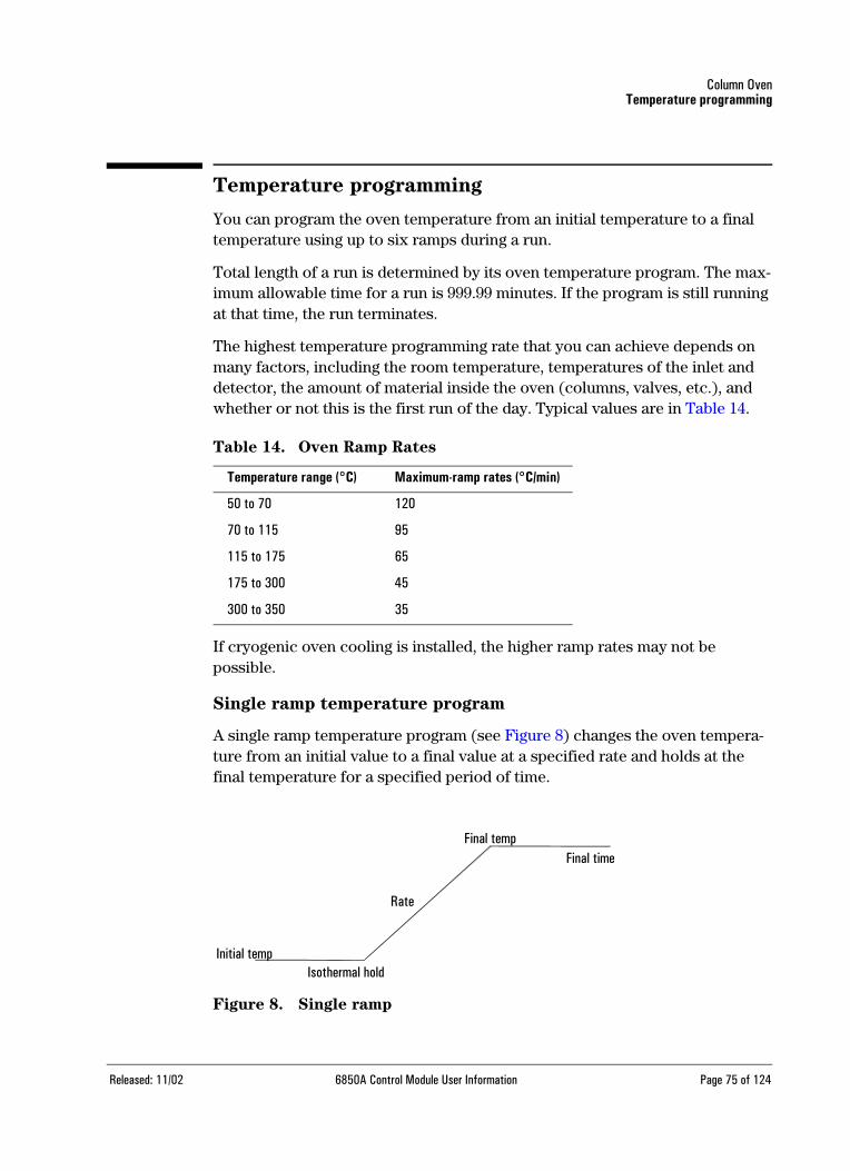
Column OvenTemperature programming
Temperature programming
You can program the oven temperature from an initial temperature to a final temperature using up to six ramps during a run.
Total length of a run is determined by its oven temperature program. The max-imum allowable time for a run is 999.99 minutes. If the program is still running at that time, the run terminates.
The highest temperature programming rate that you can achieve depends on many factors, including the room temperature, temperatures of the inlet and detector, the amount of material inside the oven (columns, valves, etc.), and whether or not this is the first run of the day. Typical values are in Table 14.
Table 14. Oven Ramp Rates
If cryogenic oven cooling is installed, the higher ramp rates may not be possible.
Single ramp temperature program
A single ramp temperature program (see Figure 8) changes the oven tempera-ture from an initial value to a final value at a specified rate and holds at the final temperature for a specified period of time.
Figure 8. Single ramp
Temperature range (°C) Maximum-ramp rates (°C/min)
50 to 70 120
70 to 115 95
115 to 175 65
175 to 300 45
300 to 350 35
Initial tempIsothermal hold
Rate
Final timeFinal temp
Released: 11/02 6850A Control Module User Information Page 75 of 124

Column OvenTemperature programming
To create a single-ramp program
This example begins at 50°C, holds that temperature for 2 minutes, then increases temperature to 150°C at a rate of 10°C/minute and stays there for 5 minutes.
Display this screen.
Status / Settings / Oven
1. Enter the starting conditions—Initial temperature (50°C) and Initial time (2 min).
2. Enter the rate (10°C/min) at which the oven temperature is to increase.
Status / Settings / Oven
3. Enter the Final temperature and Final time (150°C for 5 min ).
Initial temperature Initial time
Rate Final temperature Final time
Post run temperature Post run time
Released: 11/02 6850A Control Module User Information Page 76 of 124

Column OvenTemperature programming
Status / Settings / Oven
4. If you wish to clean out the column before cooling to the starting tempera-ture, enter Post Run temperature and Post Run time.
5. If you are certain that the most recent program used a single ramp, you can skip the remaining steps. If you’re not sure, continue by pressing Ramps.
Status / Settings / Oven / Ramps
6. Select Ramp 2 and press Enter.
Status / Settings / Oven / Ramps / Ramp 2
7. To ensure that the program is single-ramp, set the °C/min value to OFF, then press OK. The program ends when it encounters a rate of OFF.
Multiple ramp temperature program
A multiple-ramp temperature program (see Figure 9) changes the oven temper-ature from an initial value to a final temperature, but with various rates, times,
Released: 11/02 6850A Control Module User Information Page 77 of 124

Column OvenTemperature programming
and temperatures in between. Multiple ramps can be programmed for tempera-ture decreases as well as increases..
Figure 9. Multiple ramp
To create a multiple-ramp program
This example begins at 50°C, holds that temperature for 2 minutes, then increases temperature to 150°C at a rate of 10°C/minute and stays at 150°C for 5 minutes. It then rises at 4°C/minute to 200°C and holds for 2 minutes.
1. Set up the first oven ramp as described on the preceding page.
2. When setting up Ramp 2, enter 4 in the °C/min field, 200 in the °C field, and 2 in the min field.
Status / Settings / Oven / Ramps / Ramp 2
3. Press OK to return to the previous screen
4. If you are certain that the most recent program used only two ramps, you can skip the remaining steps. If you’re not sure, continue by pressing Ramps. Select Ramp 3 and press Enter.
5. Set the °C/min value to OFF, then press OK. The program ends when it encounters a rate of OFF.
6. Add more ramps, up to a maximum of six, in the same way.
Temp
Final temp 2Final time 2
Rate 2
Final time 1Final temp 1
Isothermal hold
Rate 1
Released: 11/02 6850A Control Module User Information Page 78 of 124

Column OvenColumn compensation
Column compensation
Although temperature programming improves peak shapes, it also causes a rising baseline that may make integration difficult. This is usually not a prob-lem with a thermal conductivity detector because of its low sensitivity, but it can be a severe problem with a flame ionization detector.
Column compensation corrects for baseline rise by storing a profile of a blank run—one made with no sample injection. This profile is subtracted from subse-quent sample runs to eliminate the rising baseline. Figure 10 illustrates the concept.
All conditions must be identical in the compensation run and the real run: same detector and column, same temperature and gas flow conditions.
Figure 10. Column compensation
Chromatogramwith a risingbaseline
Blank columncompensation run
Chromatogramwith columncompensation
Released: 11/02 6850A Control Module User Information Page 79 of 124

Column OvenColumn compensation
To create a column compensation profile
Display this screen.
Status / Setup
1. Load the method for which the blank run profile is to be created. Press COMP.
The GC will wait until it has equilibrated, make one blank run (no sample injected), and store the data as the column compensation profile.
To apply the column compensation profile
Display this screen.
Status / Settings / Detector / More / Signal / Enter
1. Select Detector - Column Comp and press OK.
2. The output signal is now the detector output minus the stored column compensation profile.
Released: 11/02 6850A Control Module User Information Page 80 of 124
Thermal Conductivity DetectorUsing hydrogen
Thermal Conductivity Detector
Using hydrogen
Warning When using hydrogen (H2) as a carrier gas or fuel gas, be aware that hydrogen gas can flow into the oven and create an explosion hazard. Therefore, be sure that the supply is off until all connections are made and ensure that the inlet and detector column fittings are either connected to a column or capped at all times when hydrogen gas is supplied to the instrument.
Warning Hydrogen is flammable. Leaks, when confined in an enclosed space, may create a fire or explosion hazard. In any application using hydrogen, leak test all connections, lines, and valves before operating the instrument. Always turn off the hydrogen supply at its source before working on the instrument.
The detector will not work if
• Temperature is set below 150°C
• Filament is broken or shorted
• Reference gas flow is set less than 5 mL/min
TCD parameters
Use the same gas for the reference gas, makeup gas, and carrier gas. Configure your inlet and detector accordingly. Refer to Table 16 for maximum gas flow.
Use Table 15 to select temperatures and flows for the TCD. Use Figure 12 to find minimum source pressures.
Released: 11/02 6850A Control Module User Information Page 81 of 124
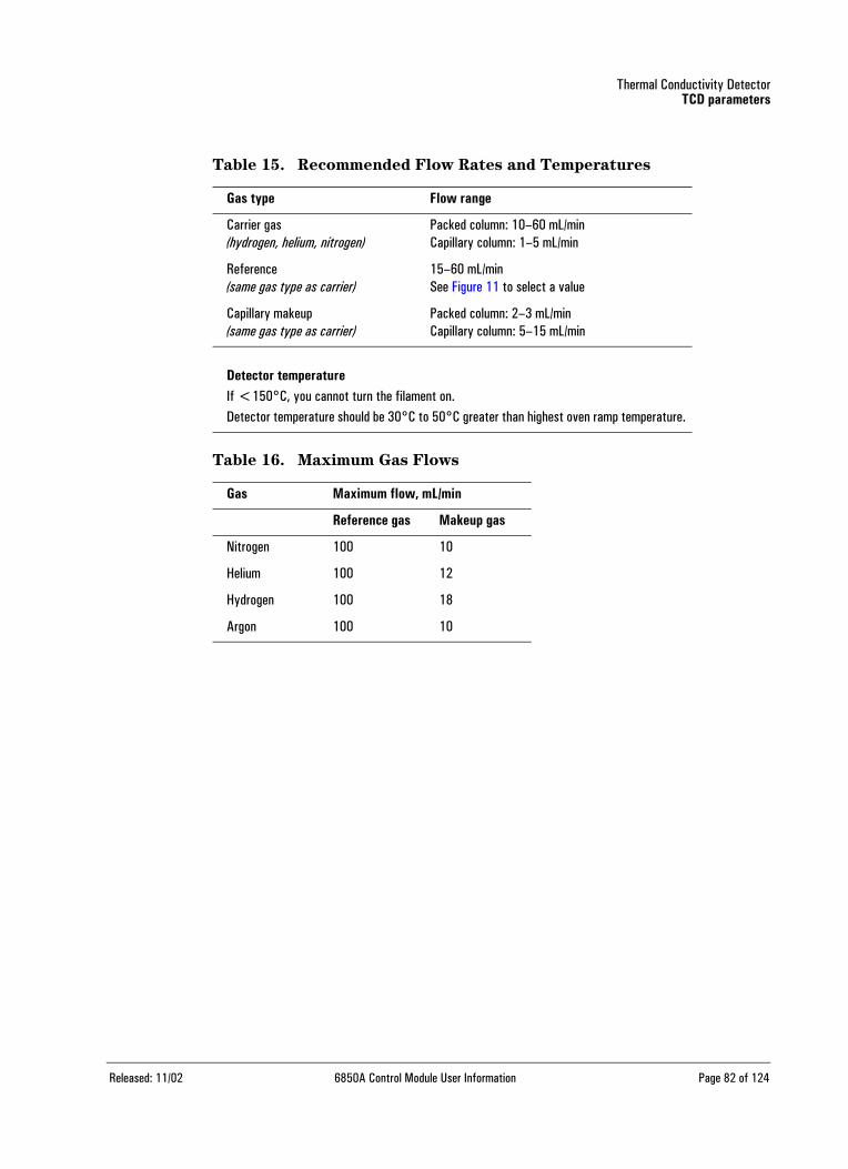
Thermal Conductivity DetectorTCD parameters
Table 15. Recommended Flow Rates and Temperatures
Table 16. Maximum Gas Flows
Gas type Flow range
Carrier gas(hydrogen, helium, nitrogen)
Packed column: 10–60 mL/minCapillary column: 1–5 mL/min
Reference (same gas type as carrier)
15–60 mL/min See Figure 11 to select a value
Capillary makeup (same gas type as carrier)
Packed column: 2–3 mL/minCapillary column: 5–15 mL/min
Detector temperatureIf <150°C, you cannot turn the filament on.Detector temperature should be 30°C to 50°C greater than highest oven ramp temperature.
Gas Maximum flow, mL/min
Reference gas Makeup gas
Nitrogen 100 10
Helium 100 12
Hydrogen 100 18
Argon 100 10
Released: 11/02 6850A Control Module User Information Page 82 of 124
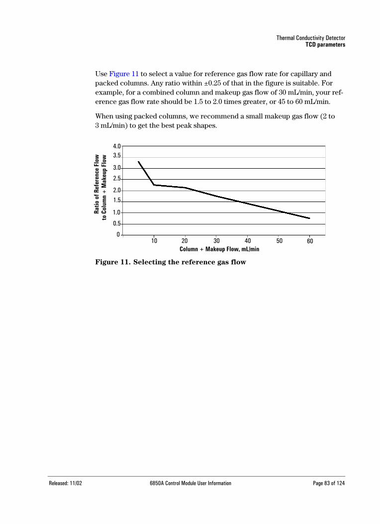
Thermal Conductivity DetectorTCD parameters
Use Figure 11 to select a value for reference gas flow rate for capillary and packed columns. Any ratio within ±0.25 of that in the figure is suitable. For example, for a combined column and makeup gas flow of 30 mL/min, your ref-erence gas flow rate should be 1.5 to 2.0 times greater, or 45 to 60 mL/min.
When using packed columns, we recommend a small makeup gas flow (2 to 3 mL/min) to get the best peak shapes.
Figure 11. Selecting the reference gas flow
4.03.5
3.0
2.5
2.0
1.5
1.0
0.5
010 20 30 40 50 60
Ratio
of R
efer
ence
Flo
wto
Col
umn
+ M
akeu
p Fl
ow
Column + Makeup Flow, mL/min
Released: 11/02 6850A Control Module User Information Page 83 of 124

Thermal Conductivity DetectorTCD parameters
Figure 12. Typical source pressure/flow relationships, makeup and
reference gases at 25°C and 1 atmosphere pressure
20 30 40 50 60 70
10
20
30
40
50
60
70
0
Hydrogen Helium
Nitrogen
138 207 276 414 483Pressure
(kPa)
Referencegas flow
345(psig)
(mL/min)
20 30
20740
276 34550 60
41470
483
Nitrogen
Helium
Hydrogen
(psig)Pressure(kPa)
20
181614
12
10
9
6
4
20
Makeupgas flow(mL/min)
138
* Pressures include an allowance for the pressure drop in the pneumatics module.
Released: 11/02 6850A Control Module User Information Page 84 of 124

Thermal Conductivity DetectorMakeup gas
Makeup gas
Makeup gas enters the detector near the end of the column. It speeds thesample through so that the separation achieved by the column is not lost by remixing in the detector. Makeup gas is not required with packed columns.
If the capillary column is not defined, the makeup flow is constant. See Config-
uring the column on page 47 for how to define a column.
If the capillary column is defined, you have a choice of two makeup gas modes.
To select the makeup gas mode
The Constant Makeup mode gives a constant flow of makeup gas to the detector.
The Constant Combo mode gives a variable flow of makeup gas to the detec-tor. As column flow changes, the makeup flow adjusts to provide a constant combined flow to the detector.
Display this screen.
Status / Settings / Detector / More / Makeup Mode / Enter
Select a makeup mode and press OK.
Status / Settings / Detector
Released: 11/02 6850A Control Module User Information Page 85 of 124
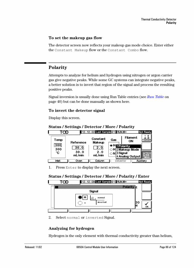
Thermal Conductivity DetectorPolarity
To set the makeup gas flow
The detector screen now reflects your makeup gas mode choice. Enter either the Constant Makeup flow or the Constant Combo flow.
Polarity
Attempts to analyze for helium and hydrogen using nitrogen or argon carrier gas give negative peaks. While some GC systems can integrate negative peaks, a better solution is to invert that region of the signal and process the resulting positive peaks.
Signal inversion is usually done using Run Table entries (see Run Table on page 40) but can be done manually as shown here.
To invert the detector signal
Display this screen.
Status / Settings / Detector / More / Polarity
1. Press Enter to display the next screen.
Status / Settings / Detector / More / Polarity / Enter
2. Select normal or inverted Signal.
Analyzing for hydrogen
Hydrogen is the only element with thermal conductivity greater than helium,
Released: 11/02 6850A Control Module User Information Page 86 of 124

Thermal Conductivity DetectorSignal selection
and small amounts of hydrogen (<20%) in helium at moderate temperatures have thermal conductivities less than either component alone. If you are using helium carrier gas, a hydrogen peak may appear as positive, negative, or as a split peak.
There are two solutions to this problem:
• Use nitrogen or argon as carrier gas. This eliminates problems inherent with using helium as carrier, but reduces sensitivity to components other than hydrogen.
• Operate the detector at higher temperatures—from 200°C to 300°C
To find a suitable detector operating temperature, analyze a known range of hydrogen concentrations, raising the detector temperature until the hydrogen peak shows normal shape and is always in the same direction (negative relative to response to air or propane) for all concentrations.
Since hydrogen peaks are negative, you must use signal inversion at appropri-ate times during the analysis.
Signal selection
Several types of signals can be selected as the signal output. The selected signal type is available as the SIG connector on the rear panel for processing by an integrator, strip chart recorder, or other external device. The selected signal is also digitally output through the RS-232 connector and optional LAN commu-nications card.
To select the output signal
Display this screen.
Status / Settings / Detector / More / Signal
1. Press Enter to display the next screen.
Released: 11/02 6850A Control Module User Information Page 87 of 124

Thermal Conductivity DetectorSignal selection
Status / Settings / Detector / More / Signal / Enter
2. Select one of the four signals in the list.
a. Detector is the raw signal produced by the detector.
b. Column Comp is the stored column compensation profile for this detector.
c. Detector - Column Comp is the result of subtracting the column compensation profile from the detector signal.
d. Test Chromatogram is stored in the instrument. It provides a repro-ducible signal to test external signal processing equipment.
e. The signal type can be changed to other types by the ChemStation or Cerity Chemical.
To zero the signal
• Enter a value in the Zero field. The value is subtracted from all future signal values.
OR
• Leave the Zero field blank, then press the Zero key. The GC saves the present value of the signal and subtracts it from all future signal values.
The peak width (PW) window
This window displays the optimal peak width for the displayed digital signal data rate.
Released: 11/02 6850A Control Module User Information Page 88 of 124
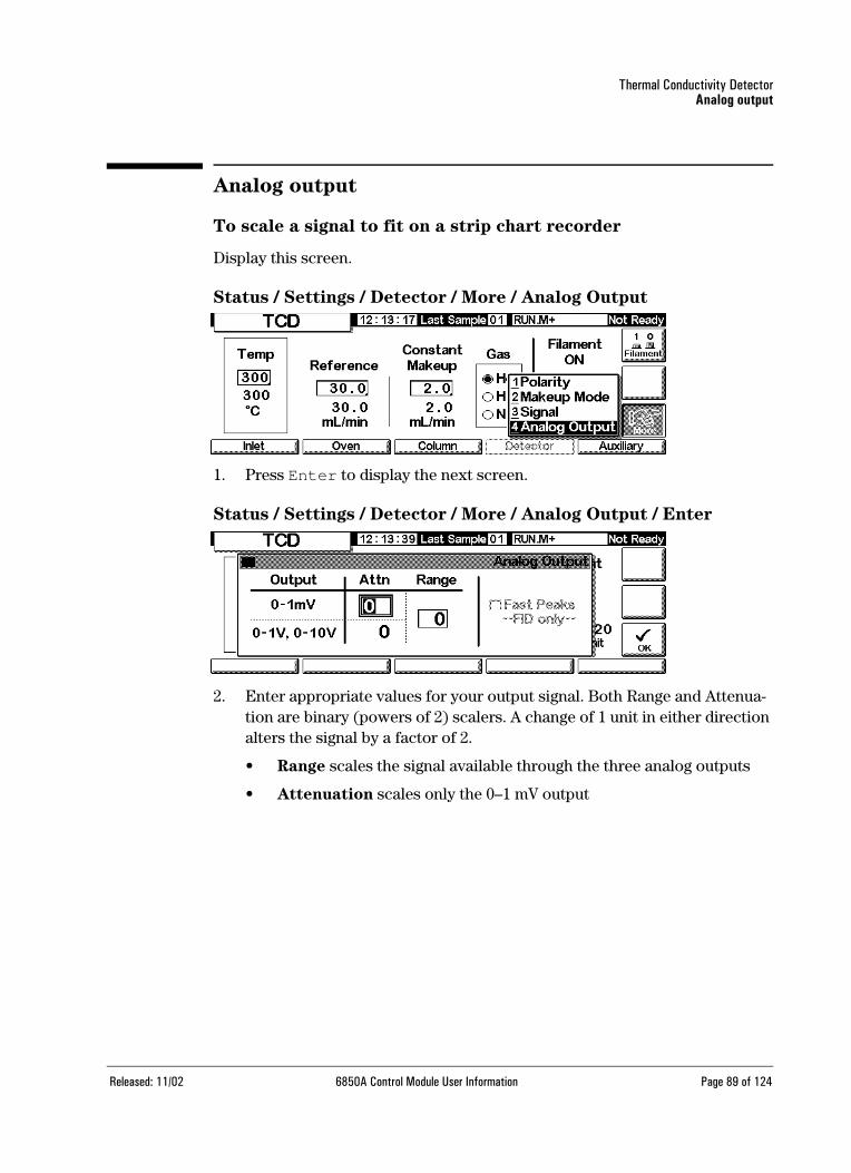
Thermal Conductivity DetectorAnalog output
Analog output
To scale a signal to fit on a strip chart recorder
Display this screen.
Status / Settings / Detector / More / Analog Output
1. Press Enter to display the next screen.
Status / Settings / Detector / More / Analog Output / Enter
2. Enter appropriate values for your output signal. Both Range and Attenua-tion are binary (powers of 2) scalers. A change of 1 unit in either direction alters the signal by a factor of 2.
• Range scales the signal available through the three analog outputs
• Attenuation scales only the 0–1 mV output
Released: 11/02 6850A Control Module User Information Page 89 of 124
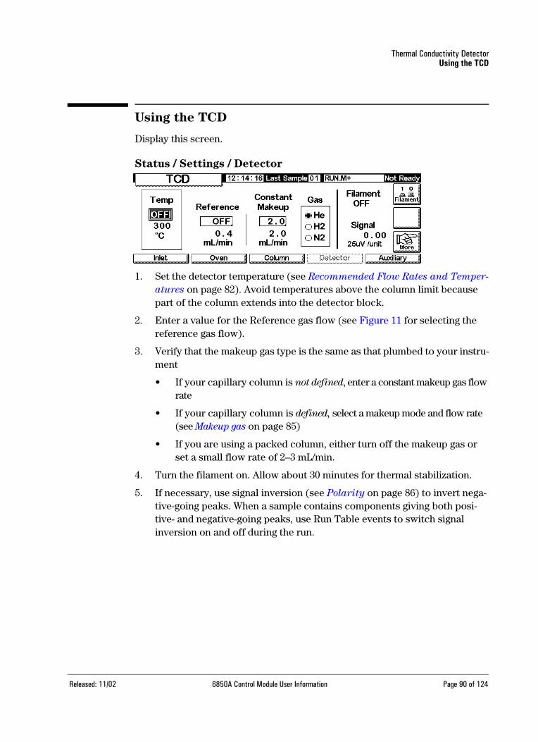
Thermal Conductivity DetectorUsing the TCD
Using the TCD
Display this screen.
Status / Settings / Detector
1. Set the detector temperature (see Recommended Flow Rates and Temper-
atures on page 82). Avoid temperatures above the column limit because part of the column extends into the detector block.
2. Enter a value for the Reference gas flow (see Figure 11 for selecting the reference gas flow).
3. Verify that the makeup gas type is the same as that plumbed to your instru-ment
• If your capillary column is not defined, enter a constant makeup gas flow rate
• If your capillary column is defined, select a makeup mode and flow rate (see Makeup gas on page 85)
• If you are using a packed column, either turn off the makeup gas or set a small flow rate of 2–3 mL/min.
4. Turn the filament on. Allow about 30 minutes for thermal stabilization.
5. If necessary, use signal inversion (see Polarity on page 86) to invert nega-tive-going peaks. When a sample contains components giving both posi-tive- and negative-going peaks, use Run Table events to switch signal inversion on and off during the run.
Released: 11/02 6850A Control Module User Information Page 90 of 124
Flame Ionization DetectorUsing hydrogen
Flame Ionization Detector
Using hydrogen
Warning When using hydrogen (H2) as a carrier gas or fuel gas, be aware that hydrogen gas can flow into the oven and create an explosion hazard. Therefore, be sure that the supply is off until all connections are made and ensure that the inlet and detector column fittings are either connected to a column or capped at all times when hydrogen gas is supplied to the instrument.
Warning Hydrogen is flammable. Leaks, when confined in an enclosed space, may create a fire or explosion hazard. In any application using hydrogen, leak test all connections, lines, and valves before operating the instrument. Always turn off the hydrogen supply at its source before working on the instrument.
The detector will not work if
• Temperature is set below 150°C
• Air or hydrogen flow is set at Off or set at 0.0
• The flame won’t light
Detector shutdown
If the GC shuts a detector gas down due to a pneumatics or ignition failure, it also turns off all detector functions except the heater and the makeup gas flow.
Released: 11/02 6850A Control Module User Information Page 91 of 124
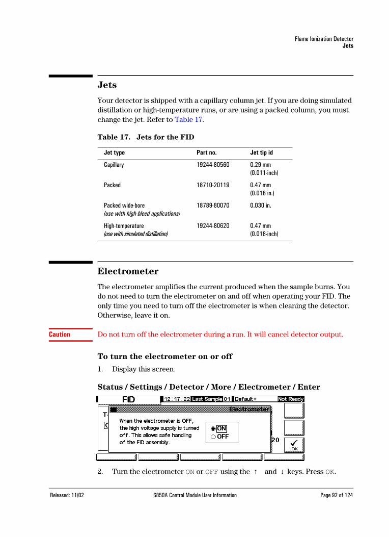
Flame Ionization DetectorJets
Jets
Your detector is shipped with a capillary column jet. If you are doing simulated distillation or high-temperature runs, or are using a packed column, you must change the jet. Refer to Table 17.
Table 17. Jets for the FID
Electrometer
The electrometer amplifies the current produced when the sample burns. You do not need to turn the electrometer on and off when operating your FID. The only time you need to turn off the electrometer is when cleaning the detector. Otherwise, leave it on.
Caution Do not turn off the electrometer during a run. It will cancel detector output.
To turn the electrometer on or off
1. Display this screen.
Status / Settings / Detector / More / Electrometer / Enter
2. Turn the electrometer ON or OFF using the ↑ and ↓ keys. Press OK.
Jet type Part no. Jet tip id
Capillary 19244-80560 0.29 mm(0.011-inch)
Packed 18710-20119 0.47 mm(0.018 in.)
Packed wide-bore(use with high-bleed applications)
18789-80070 0.030 in.
High-temperature(use with simulated distillation)
19244-80620 0.47 mm(0.018-inch)
Released: 11/02 6850A Control Module User Information Page 92 of 124
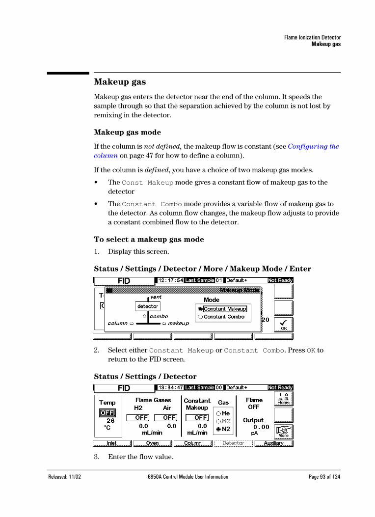
Flame Ionization DetectorMakeup gas
Makeup gas
Makeup gas enters the detector near the end of the column. It speeds thesample through so that the separation achieved by the column is not lost by remixing in the detector.
Makeup gas mode
If the column is not defined, the makeup flow is constant (see Configuring the
column on page 47 for how to define a column).
If the column is defined, you have a choice of two makeup gas modes.
• The Const Makeup mode gives a constant flow of makeup gas to the detector
• The Constant Combo mode provides a variable flow of makeup gas to the detector. As column flow changes, the makeup flow adjusts to provide a constant combined flow to the detector.
To select a makeup gas mode
1. Display this screen.
Status / Settings / Detector / More / Makeup Mode / Enter
2. Select either Constant Makeup or Constant Combo. Press OK to return to the FID screen.
Status / Settings / Detector
3. Enter the flow value.
Released: 11/02 6850A Control Module User Information Page 93 of 124
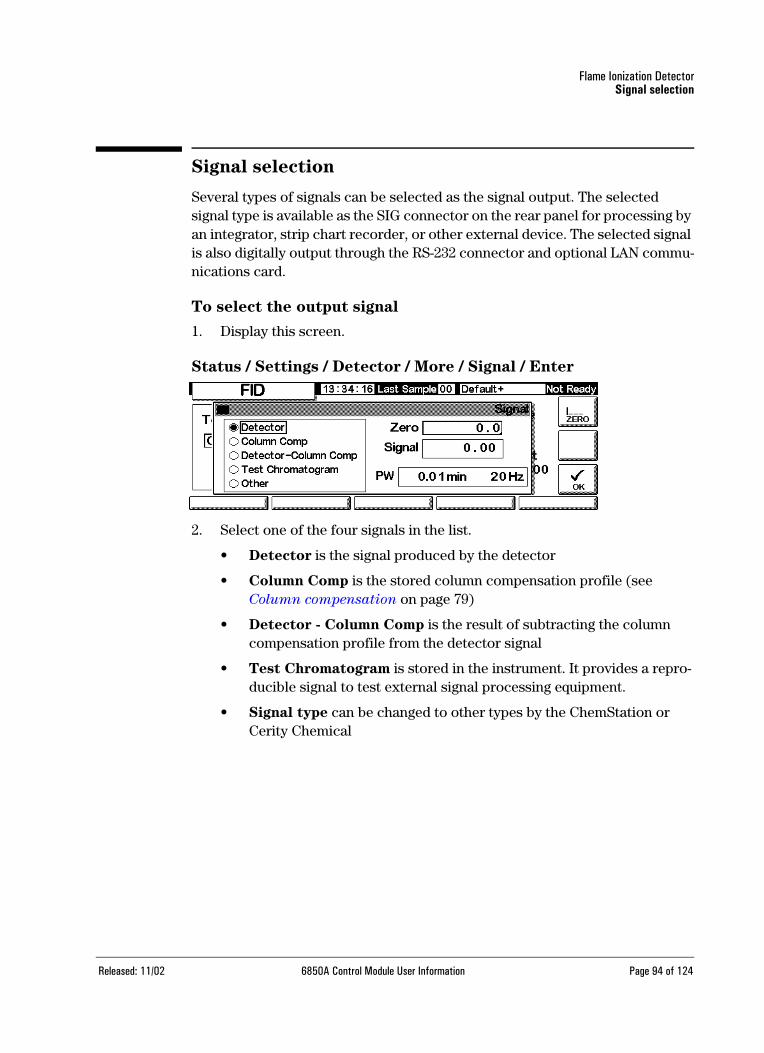
Flame Ionization DetectorSignal selection
Signal selection
Several types of signals can be selected as the signal output. The selected signal type is available as the SIG connector on the rear panel for processing by an integrator, strip chart recorder, or other external device. The selected signal is also digitally output through the RS-232 connector and optional LAN commu-nications card.
To select the output signal
1. Display this screen.
Status / Settings / Detector / More / Signal / Enter
2. Select one of the four signals in the list.
• Detector is the signal produced by the detector
• Column Comp is the stored column compensation profile (seeColumn compensation on page 79)
• Detector - Column Comp is the result of subtracting the column compensation profile from the detector signal
• Test Chromatogram is stored in the instrument. It provides a repro-ducible signal to test external signal processing equipment.
• Signal type can be changed to other types by the ChemStation or Cerity Chemical
Released: 11/02 6850A Control Module User Information Page 94 of 124

Flame Ionization DetectorAnalog output
To zero the signal
• Enter a value in the Zero field. The value is subtracted from all futuresignal values.
OR
• Leave the Zero field blank, then press the Zero key. The GC saves the present value of the signal and subtracts it from all future signal values.
The Peak Width window
This window displays the digital signal data rate.
Analog output
These controls scale a signal to fit on a strip chart recorder.
To adjust the output signal
1. Display this screen.
Status / Settings / Detector / More / Analog Output / Enter
2. Enter appropriate values for your output signal. Both Range and Attenua-tion are binary (powers of 2) scalers. A change of 1 unit in either direction alters the signal by a factor of 2.
• Range scales all three analog outputs
• Attenuation scales only the 0–1 mV output
3. The Fast Peaks feature allows the FID to detect peaks as narrow as 0.004 minutes, while the minimum width for the standard speed is 0.01 minutes. To use the Fast Peaks feature, your integrator must be fast enough (at least a 15 Hz bandwidth) to process the data coming from the GC.
Released: 11/02 6850A Control Module User Information Page 95 of 124

Flame Ionization DetectorAutomatic reignition—Lit Offset
Automatic reignition—Lit Offset
Lit Offset is the expected difference between the FID output with the flame lit and the output with the flame off. If the output falls below this value, the FID assumes that the flame is out and tries to reignite several times. If the output does not increase by at least the Lit Offset, the detector shuts down all functions except temperature and makeup gas flow.
The default setting for Lit Offset is 2.0 picoamps. This is a good working value for all but very clean gases and systems. You may want to change this set-point if:
• Your detector is attempting to reignite when the flame is still on, thus pro-ducing a shutdown
• Your detector is not trying to reignite when the flame is out
To adjust the Lit Offset
1. Display this screen.
Status / Settings / Detector / More / Lit Offset / Enter
2. Adjust the value as indicated by the discussion above. Press OK.
Released: 11/02 6850A Control Module User Information Page 96 of 124

Flame Ionization DetectorFID parameters
FID parameters
Use the information in Table 18 when selecting flows. Choose a minimum source pressure from Figure 13.
Table 18. Recommended Flow Rates
Gas type Flow rangemL/min
Suggested flowmL/min
Carrier gas(hydrogen, helium, nitrogen)
Capillary columns: 1 to 5Packed columns: 10 to 60
Detector gasesHydrogen
Air
24 to 60*
200 to 600*
40 450
Column plus capillary makeupRecommended: nitrogenAlternate: helium
10 to 60 50
* The hydrogen-to-air ratio should be between 8% and 12% to keep the flame lit.
Released: 11/02 6850A Control Module User Information Page 97 of 124

Flame Ionization DetectorFID parameters
Figure 13. Typical source pressure/flow relationships for FID gases at
25°C and 1 atmosphere pressure
20 30 40 50 60 70 800
10
20
30
40
50
60
70
80
(psig)kPa
Pressure138 207 276 345 414 483 552
FLOW(mL/min)
20 30 40 50 60 70 80(psig)kPa
Pressure 138 207 276 345 414 483 552
100
200
300
400
500
600
700
0
Hydrogen Helium
Nitrogen
AirFLOW(mL/min)
* Pressures include an allowance for the pressure drop in the pneumatics manifold.
Released: 11/02 6850A Control Module User Information Page 98 of 124

Flame Ionization DetectorUsing the FID
Using the FID
Warning Verify that a column is installed or the FID column fitting is plugged before turning on the air or hydrogen. An explosion may occur if air and hydrogen are allowed to leak into the oven.
1. Display this screen.
Status / Settings / Detector
2. Set the detector temperature. The temperature must be greater than 150°C for the flame to light and should be approximately 20°C higher than the highest oven temperature.
3. Enter values for the hydrogen and air flow rates.
4. Verify that the makeup gas type is the same as that plumbed to your instru-ment.
• If your capillary column is not defined, enter a makeup gas flow. Only constant flow is available in this case. See Configuring the column on page 47 for how to define a column.
• If your capillary column is defined, press More, select Makeup Mode, and press Enter to display the next screen
• If you are using a packed column, turn the makeup gas flow off
Status / Settings / Detector / More / Makeup Mode / Enter
5. Select a makeup mode. Press OK to return to the previous screen. Enter the makeup or combo flow rate.
Released: 11/02 6850A Control Module User Information Page 99 of 124

Flame Ionization DetectorUsing the FID
6. Press the Flame key to turn on the air and hydrogen and initiate the igni-tion process. The signal typically increases to 5 to 20 pA after ignition.Verify that the flame is lit by holding a cold, shiny surface, such as a mirror or chrome-plated wrench, over the collector exit. Steady condensation indicates that the flame is lit.
Released: 11/02 6850A Control Module User Information Page 100 of 124

ValvesValve types
ValvesThe 6850 Series Gas Chromatograph holds either one gas or one liquid sam-pling valve in a heated valve box on top of the oven. A stream-selection valve (the Multi Valve), mounted outside the GC, can be controlled.
Valves can be controlled:
• Automatically, using a valve sequence (see To enter the valve parameters
on page 38).
• Manually (see Controlling valves manually on page 104).
• Using Run Table events. Mainly used with switching valves (see Valve
events on page 41).
• Using Clock Table events. To perform analyses when you will not be present (see Clock Table on page 43).
Valve types
There are four possible valve types:
• Gas sample valve—a two-state (load and inject) valve. In the load state, an external gas stream flows through an attached sampling loop and out to waste. In the inject state, the filled sampling loop is inserted into the car-rier gas stream. Sample loops are available in various sizes.
• Liquid sample valves—similar to the gas sample valve but with different physical construction, they can handle liquified gases at pressures up to 300 psi and are available in 0.5 µL and 1 µL capacities.
• Switching valves—used to backflush a column, to select a column, and other uses depending on how it is plumbed.
• Multiposition valve (Multi Valve)—provided by the user. A Multi Valve selects one from a number of sample streams and feeds the selected stream to a sample valve. See Multi Valve with Sample Valve on page 104 for an example of this combination.
Released: 11/02 6850A Control Module User Information Page 101 of 124

ValvesConfiguring valves
Configuring valves
To configure the GC for valves
1. Display this screen:
Status / Setup / Automation
2. Select the types for Valve 1 and Valve 2.
Sample valves
Plumbing
There are two ways to plumb a sample valve:
• Inserted between an inlet flow module and the inlet. The sample flows through the inlet to the head of the column.
• Inserted between a purged packed inlet flow module and the head of the column (a split/splitless inlet can’t be used). The sample bypasses the inlet.
With this arrangement and an undefined column, you can only set flow modes for the column. Total flow setpoint and readings work as expected.
If the column is defined, the GC corrects column flow setpoints and read-ings for the septum purge flow. With no inlet, that value is zero. The actual column flow is 1 to 2 mL/min less than the setpoint in the flow modes. In the pressure modes, the Total flow is the actual column flow.
To configure a sample valve
1. Display this screen.
Released: 11/02 6850A Control Module User Information Page 102 of 124

ValvesSample valves
Status / Setup / Automation / Sample Valve
2. Enter the Load time in minutes.
3. You may enter the Sample Loop Volume. This entry is for reference only; it has no effect on the valve.
4. Enter the Inject time in minutes.
5. Press Esc to save the values and return to the previous screen.
Sample valve cycle
1. The sampling valve changes to the Load state. Load min begins. Valve is not ready.
Load state—The between-runs rest state. The loop is flushed with a stream of the sample, either constantly by plumbing it directly or with a gas or liquid syringe. The column is flushed with carrier gas.
2. Load min ends. The valve becomes ready.
3. If everything else is ready, the GC becomes ready.
4. The user loads the sample loop (if there is no sample stream plumbed to the valve) and presses Start.
5. The sampling valve changes to the Inject state. Inject min begins. The run begins.
Inject state—The activated state. The filled loop is inserted into the car-rier gas stream. The sample is flushed onto the column. The run starts automatically. After Inject min ends, the valve changes back to Load.
6. Inject min ends. Return to step 1.
Released: 11/02 6850A Control Module User Information Page 103 of 124

ValvesMulti Valve with Sample Valve
Multi Valve with Sample Valve
If both a Sample Valve and a Multi Valve are configured, the GC assumes that they will be used with the Multi Valve (Valve 2) feeding the Sample Valve (Valve 1).
Several manufacturers provide multiposition valves that can be driven by the 6850 GC. If a valve is configured as a Multi Valve and has a BCD position output connected to the GC, the valve position can be selected directly.
The GC reads the present position of the valve from the BCD input. If the desired position is different, it cycles the driver (close contacts, open contacts) one time and rechecks position. This repeats until the valve reaches the correct position. If the valve does not move, takes too long to move, or does not report that it is in the correct final position, an error will occur.
To configure a Multi Valve
1. Display this screen:
Status / Setup / Automation / Multi Valve
2. Enter a Switching Time in seconds. Viscous samples may require longer times. The default time is 1.0 second.
3. Select Normal or Invert BCD. Invert complements the BCD input—1’s become 0’s and 0’s become 1’s. This accommodates coding convention dif-ferences among valve manufacturers. The default value is Normal.
Controlling valves manually
When developing a valve-based method, it may be necessary to operate the valves manually.
To move a valve manually
1. Display this screen.
Released: 11/02 6850A Control Module User Information Page 104 of 124

ValvesSetting the valve temperature
Status / Automation / Valves
This GC has a sample valve (Valve 1) and a multiposition valve (Valve 2).
2. Select the valves to be controlled and the directions of the moves. Press ACTION to make the changes. Press RESET to clear the screen without performing any actions.
Sample valves and switching valves toggle between their two possible states. With a multiposition valve, you can enter the desired position (1 to 16) in the Next field. When ACTION is pressed, the valve will advance to that position if the BCD sensing is connected—it is not in this example—and the external driving circuitry is correct.
Setting the valve temperature
The valve box contains a heated block with one valve mounting location. The temperature is controlled by the Auxiliary heater.
To set the valve box temperature
1. Display this screen.
Status / Settings / Auxiliary
2. Enter the desired temperature (maximum is 200°C). Press Esc to close the screen.
Released: 11/02 6850A Control Module User Information Page 105 of 124
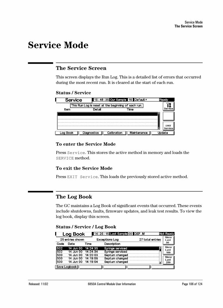
Service ModeThe Service Screen
Service Mode
The Service Screen
This screen displays the Run Log. This is a detailed list of errors that occurred during the most recent run. It is cleared at the start of each run.
Status / Service
To enter the Service Mode
Press Service. This stores the active method in memory and loads the SERVICE method.
To exit the Service Mode
Press EXIT Service. This loads the previously stored active method.
The Log Book
The GC maintains a Log Book of significant events that occurred. These events include shutdowns, faults, firmware updates, and leak test results. To view the log book, display this screen.
Status / Service / Log Book
Released: 11/02 6850A Control Module User Information Page 106 of 124

Service ModeDiagnostics
Normally, the most recent 25 events are listed. You can also view the most recent 50, 100, or 250 events.
To save the entire logbook (up to 1024 entries) to a text file on a PC card, press Save Logbook. (See also Using PC cards on page 28.)
Diagnostics
To view the diagnostic status
Display this screen.
Status / Service / Diagnostics
The detector test is only available if you are using an FID.
The atmospheric pressure shown is the value measured by the instrument and used in all calculations.
Two Inlet Tests are available: The Leak Test (for all inlet types) and the Split Vent Test (for the split/splitless inlet only).
Leak Test
The Leak Test pressurizes the inlet and checks the pressure decay over time. The test should be performed after routine inlet maintenance and under nor-mal operating conditions (temperature). If the inlet fails the test, check all fit-tings for leaks.
The Leak Tests results are entered in the Log Book.
Released: 11/02 6850A Control Module User Information Page 107 of 124

Service ModeDiagnostics
Table 19. Leak Test Parts
To run the Leak test
1. Display this screen.
Status / Service / Diagnostics / Inlet Test
2. Press the Leak Test key.
3. Follow the instructions on the screens.
Item Part no.
1/8-inch brass nut 5180-4103
1/8-inch Vespel/graphite blank ferrule 0100-1372
Column nut 5181-8830
Vespel/graphite blank ferrule 5020-8294
Released: 11/02 6850A Control Module User Information Page 108 of 124

Service ModeDiagnostics
4. After you cap the septum purge vent, the Inlet Leak Test screen appears:
When the GC reaches operating conditions, the test starts automatically. Normally, wait for the test to start. If you want to start the test without waiting for the inlet to reach operating temperature, press Test Now.
If you select Yes, the test begins immediately.
5. When completed, the test result is shown.
The possible test results are:
• Passed: No leaks at operating temperature
• Failed: Check for leaks at all fittings
• Override: The inlet passed the test, but the test was started using the Test Now key before the inlet reached operating temperatures. The inlet is leak free as tested, but may leak at operating temperatures.
Released: 11/02 6850A Control Module User Information Page 109 of 124

Service ModeDiagnostics
Split Vent Test (split/splitless inlet only)
The Split Vent Test checks the inlet liner and vent trap for restrictions. Over time, the vent trap and inlet liner can become restricted with sample condensa-tion. If the inlet fails the test, the most likely causes are the vent trap, inlet liner and the gold seal. See your Agilent 6850 User Information documentation for further details.
Split vent test results are entered in the Log Book.
Table 20. Split Vent Test Parts
To run the Split vent test
1. Display this screen.
Status / Service / Diagnostics / Inlet Test
2. Press the Split Vent Test key.
3. Follow the instructions on the screens.
Item Part no.
Column nut 5181-8830
Vespel/graphite blank ferrule 5020-8294
Released: 11/02 6850A Control Module User Information Page 110 of 124

Service ModeDiagnostics
4. After you cap the septum purge vent, the Inlet Leak Test screen appears:
When the GC reaches operating conditions, the test starts automatically. Normally, wait for the test to start. If you want to start the test without waiting for the inlet to reach operating temperature, press Test Now.
If you select Yes, the test begins immediately.
5. When completed, the test result is shown.
The possible test results are:
• Passed: No leaks at operating temperature
• Failed: Check for leaks at all fittings
• Override: The inlet passed the test, but the test was started using the Test Now key before the inlet reached operating temperatures. The inlet is leak free as tested, but may leak at operating temperatures.
Released: 11/02 6850A Control Module User Information Page 111 of 124

Service ModeDiagnostics
Detector (Jet) Test
The FID jet test should be performed when the flame does not ignite or when it unexpectedly re-ignites during a run. The test checks for restrictions in the jet tip. If the jet fails the test, replace or clean it. See your Agilent 6850 User Infor-mation documentation for further details.
Jet test results are entered in the Log Book.
To be sure that the test results are valid, perform the test under operating conditions.
Table 21. Jet Test Parts
To run the detector test
1. Display this screen.
Status / Service / Diagnostics / Detector Test
2. Press Jet Test and follow the instructions on the screen.
Item Part no.
Column nut 5181-8830
Vespel/graphite blank ferrule 5020-8294
Released: 11/02 6850A Control Module User Information Page 112 of 124

Service ModeDiagnostics
3. After you cap the detector column fitting, the FID Jet Test screen appears:
When the GC reaches operating conditions, the test starts automatically. Normally, wait for the test to start. If you want to start the test without waiting for the detector to reach operating conditions, press Test Now, then select Yes to begin the test immediately.
4. When completed, the test result is shown.
The possible test results are:
• Passed: The jet is sufficiently clear or restrictions
• Failed: Clean or replace the jet
• Override: The jet passed the test, but the test was started using the Test Now key before the detector reached operating temperatures. The jet may be acceptable as tested, but may still be restricted at oper-ating temperatures.
Released: 11/02 6850A Control Module User Information Page 113 of 124

Service ModeCalibration
Keyboard Test
1. Display this screen.
Status / Service / Keyboard Test
2. Press each key on the Control Module. Its screen image should turn gray.
Calibration
To view the calibration status
Display this screen. The dates of custom calibrations, which overrule the origi-nal factory calibrations, are shown.
Status / Service / Calibration
To restore the factory calibration(s)
On the above screen, select the item(s) and press Enter.
Flow and pressure sensors
The slopes (sensitivities) of these sensors are quite stable, but the zero offset should be checked periodically.
The split/splitless inlet module uses a flow sensor. Select the Enable Auto Flow Zero feature (see To zero the inlet sensors on page 115) to automati-cally zero this sensor after each run.
Released: 11/02 6850A Control Module User Information Page 114 of 124
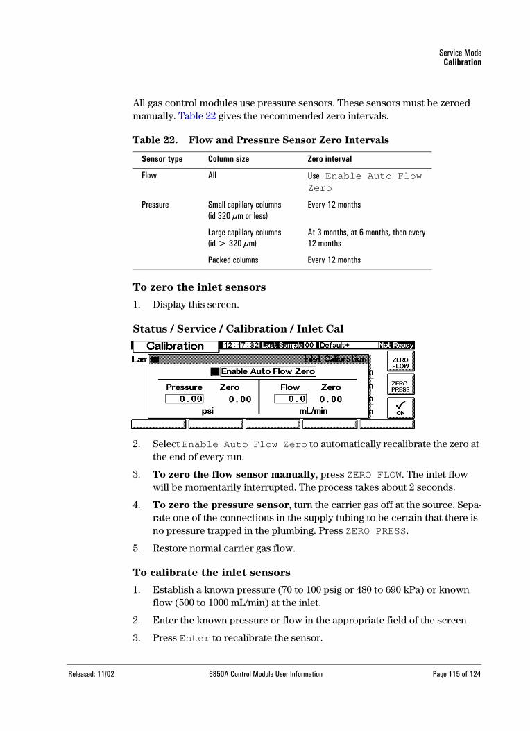
Service ModeCalibration
All gas control modules use pressure sensors. These sensors must be zeroed manually. Table 22 gives the recommended zero intervals.
Table 22. Flow and Pressure Sensor Zero Intervals
To zero the inlet sensors
1. Display this screen.
Status / Service / Calibration / Inlet Cal
2. Select Enable Auto Flow Zero to automatically recalibrate the zero at the end of every run.
3. To zero the flow sensor manually, press ZERO FLOW. The inlet flow will be momentarily interrupted. The process takes about 2 seconds.
4. To zero the pressure sensor, turn the carrier gas off at the source. Sepa-rate one of the connections in the supply tubing to be certain that there is no pressure trapped in the plumbing. Press ZERO PRESS.
5. Restore normal carrier gas flow.
To calibrate the inlet sensors
1. Establish a known pressure (70 to 100 psig or 480 to 690 kPa) or known flow (500 to 1000 mL/min) at the inlet.
2. Enter the known pressure or flow in the appropriate field of the screen.
3. Press Enter to recalibrate the sensor.
Sensor type Column size Zero interval
Flow All Use Enable Auto Flow Zero
Pressure Small capillary columns(id 320 µm or less)
Every 12 months
Large capillary columns(id > 320 µm)
At 3 months, at 6 months, then every 12 months
Packed columns Every 12 months
Released: 11/02 6850A Control Module User Information Page 115 of 124

Service ModeCalibration
To recalibrate the oven temperature sensor
1. Attach a thermocouple to the column hanger as shown here. This is the position used at the factory. Be sure that it is suspended in air and not touching anything in the oven.
Figure 14. Thermocouple and column hanger
2. Set the oven temperature to a typical value that you use. Let the oven sta-bilize at that temperature for at least 5 minutes.
3. Subtract the true temperature (the thermocouple measurement) from the instrument reading to obtain the Correction.
4. Display this screen and enter the Correction value.
Status / Service / Calibration / Oven Cal
5. Press OK to accept the new calibration or Cancel to retain the existing one.
1-inch
Thermocouple
Released: 11/02 6850A Control Module User Information Page 116 of 124

Service ModeCalibration
To calibrate a column
If one or more of the column dimensions are unknown and impractical to mea-sure, use this function to estimate the missing information.
1. Display this screen.
Status / Service / Calibration / Column Cal
2. Mount the column in the oven. Establish a flow of carrier gas.
3. On the left side of the screen, select the dimension(s) you need to esti-mate.
• To estimate column length or diameter, you will need to input either the measured column flow rate or the unretained peak elution time
• To estimate both length and diameter, you need to input the measured column flow rate and the unretained peak elution time
4. To determine Measured Flow: This is the flow exiting the column, and can be measured at the detector exit. (Be sure to turn off detector gases.) An electronic flow sensor is preferred, but you can also use a bubble meter and stopwatch. Make several measurements and average the results. Be sure to convert your measurements to NTP conditions (see Interpreting
flow and pressure displays on page 46).
5. To determine Unretained Peak: This is the time in minutes from injec-tion to appearance at the detector of a peak that does not interact with the column.
6. Enter the data in the appropriate fields, pressing Enter after each one. The instrument will calculate and display the column dimensions.
7. Press OK to close the screen.
Released: 11/02 6850A Control Module User Information Page 117 of 124

Service ModeMaintenance
To zero the detector flows
1. Display this screen.
Status / Service / Calibration / Detector Cal
2. With the gases on, press each of the ZERO keys separately. Allow enough time between key presses for the zero operation to occur. Ten seconds minimum is recommended.
Maintenance
The 6850 GC incorporates a feature called Early Maintenance Feedback (EMF), which you can use to track the usage of the inlet septum, inlet liner, the column, and the syringe. By setting a usage limit on these items, you can have the instrument prompt you when it is time to change or service them. For example, the GC can prompt you to change the septum after every 200injections.
Early maintenance feedback works by tracking the number of automatic injec-tions that have taken place since the last time you changed/serviced each item. It does not count manual injections. You set an upper limit for an item—for example, the septum—and when this limit of injections is reached, a “service warning” massage appears on the GC front display. This message does not affect GC readiness; the message is for information only. You can still use the GC normally. Also, each EMF item is activated and set independently.
Released: 11/02 6850A Control Module User Information Page 118 of 124

Service ModeMaintenance
Using early maintenance feedback
To use early maintenance feedback, display this screen.
Status / Service / Maintenance
Each of the trackable items is displayed, along with an indicator for percent of useful life remaining. As an example, we will set the septum service limit.
1. Press Service Limits.
2. Select the Septum field, then use the keypad to enter a value. In this exam-ple, we will use 200 injections.
3. Return to the previous screen. Note that the status bar for the septum
Released: 11/02 6850A Control Module User Information Page 119 of 124

Service ModeMaintenance
shows 100%, and the number of injections remaining is 200.
The GC will now track septum usage.
Resetting the service limits
When the service limit for an item expires, a warning message appears on the GC display and on the Control Module. To clear the message, you must either turn off EMF for that item, or reset the counter.
Reset the counters as described below.
1. Wait until you are not in a run or sequence and are ready to replace/service the item(s), then display the following screen.
Status / Service / Maintenance / Start Service
2. Select the item(s) that you will service, and press OK.
3. The following screen appears. Choose Yes or No.
Released: 11/02 6850A Control Module User Information Page 120 of 124

Service ModeUpdate functions
Yes: The GC will load the SERVICE method for you, so the inlet and oven are cooled to safe handling temperatures (See your 6850 GC Information CD-ROM for details about the settings in a good SERVICE method.)
No: Does not load the SERVICE method. You do not normally need to cool the GC to service the syringe, for example. If handling hot parts, be sure to protect yourself from burns.
4. The following screen appears. When you have serviced the item(s), press Yes to reset the counters you selected above. If you press No (for exam-ple, if you did not make any changes), the counters will not be reset and the service warning message(s) will remain.
Determining service limits
The service limits to use for the septum, syringe, inlet liner, and column depend on your usage. Pick limits that prompt you to change or service the parts before you expect to see degradation in performance due to a leaky septum or syringe, contamination due to septum coring, etc.
Update functions
To see the current GC, injector and Control Module model number, serial number, and firmware information, display this screen:
Status / Service / Update
Released: 11/02 6850A Control Module User Information Page 121 of 124
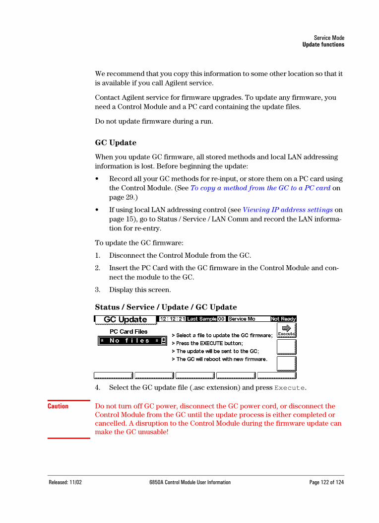
Service ModeUpdate functions
We recommend that you copy this information to some other location so that it is available if you call Agilent service.
Contact Agilent service for firmware upgrades. To update any firmware, you need a Control Module and a PC card containing the update files.
Do not update firmware during a run.
GC Update
When you update GC firmware, all stored methods and local LAN addressing information is lost. Before beginning the update:
• Record all your GC methods for re-input, or store them on a PC card using the Control Module. (See To copy a method from the GC to a PC card on page 29.)
• If using local LAN addressing control (see Viewing IP address settings on page 15), go to Status / Service / LAN Comm and record the LAN informa-tion for re-entry.
To update the GC firmware:
1. Disconnect the Control Module from the GC.
2. Insert the PC Card with the GC firmware in the Control Module and con-nect the module to the GC.
3. Display this screen.
Status / Service / Update / GC Update
4. Select the GC update file (.asc extension) and press Execute.
Caution Do not turn off GC power, disconnect the GC power cord, or disconnect the Control Module from the GC until the update process is either completed or cancelled. A disruption to the Control Module during the firmware update can make the GC unusable!
Released: 11/02 6850A Control Module User Information Page 122 of 124
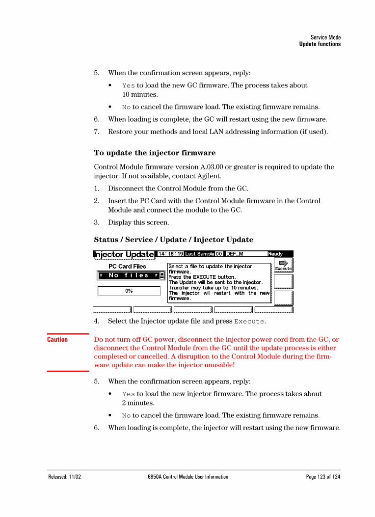
Service ModeUpdate functions
5. When the confirmation screen appears, reply:
• Yes to load the new GC firmware. The process takes about 10 minutes.
• No to cancel the firmware load. The existing firmware remains.
6. When loading is complete, the GC will restart using the new firmware.
7. Restore your methods and local LAN addressing information (if used).
To update the injector firmware
Control Module firmware version A.03.00 or greater is required to update the injector. If not available, contact Agilent.
1. Disconnect the Control Module from the GC.
2. Insert the PC Card with the Control Module firmware in the ControlModule and connect the module to the GC.
3. Display this screen.
Status / Service / Update / Injector Update
4. Select the Injector update file and press Execute.
Caution Do not turn off GC power, disconnect the injector power cord from the GC, or disconnect the Control Module from the GC until the update process is either completed or cancelled. A disruption to the Control Module during the firm-ware update can make the injector unusable!
5. When the confirmation screen appears, reply:
• Yes to load the new injector firmware. The process takes about2 minutes.
• No to cancel the firmware load. The existing firmware remains.
6. When loading is complete, the injector will restart using the new firmware.end
Released: 11/02 6850A Control Module User Information Page 123 of 124

Service ModeUpdate functions
To update the Control Module firmware
1. Disconnect the Control Module from the GC.
2. Insert the PC Card with the Control Module firmware in the ControlModule and connect the module to the GC.
3. Display this screen.
Status / Service / Update / Mod Update
4. Select the Control Module update file and press Execute.
Caution Do not disconnect the Control Module from the GC or turn off the GC until the update process is either completed or cancelled. Doing so can destroy the programs in the Control Module and make the Control Module unusable.
5. When the confirmation screen appears, reply:
• Yes to load the new Control Module firmware. The process takes about 2 minutes.
• No to cancel the firmware load. The existing firmware remains.
6. When loading is complete, the Control Module will restart using the new firmware.
end
Released: 11/02 6850A Control Module User Information Page 124 of 124