69-5307ttk - discount auto parts online
TRANSCRIPT

69-5307TTK
TOOLS NEEDED:
NOTE: FAILURE TO FOLLOW INSTALLATION INSTRUCTIONS AND NOT USING THE PROVIDEDHARDWARE MAY DAMAGE THE INTAKE TUBE, THROTTLE BODY AND ENGINE.
1. Turn off the ignition and disconnect the negative battery cable.NOTE: Disconnecting the negative battery cable erases pre-programmed electronic memories. Write down all memory settings before disconnecting the negative battery cable. Some radios will require an anti-theft code to be entered after the battery is reconnected. The anti-theft code is typically supplied with your owner’s manual. In the event your vehicles’ anti-theft code cannot be recovered, contact an authorized dealership to obtain your vehicles anti-theft code.
TO START:
PARTS LIST: Description Qty. Part # Description Qty. Part # Description Qty. Part #
®
2. Lift up and remove the engine cover from the engine.
3. Release the spring clamp and then disconnect the crankcase vent hose from the valve cover port.
4. On vehicles equipped with EVAP vent line, release the spring clamp and then disconnect the EVAP vent line from the factory intake tube.
5. Loosen the hose clamp that secures the factory intake tube to the throttle body.
6. Remove the two bolts securing the fresh air intake duct to the core support and then remove the fresh air duct from the airbox.
7. Release the four upper airbox retaining clips and then remove the upper airbox and intake tube from the vehicle.
8. Remove the two bolts shown securing the lower airbox.
9. Lift the airbox/ECU assembly up and lean it towards the engine, then remove the four bolts securing the ECU to the airbox.
KIA2010-13 ForteL4-2.0L2010-13 Forte KoupL4-2.4L
A Hose Clamp #44 Stainless 2 08560B Hose; 3” To 2-3/4” ID X 2” L TPRD 1 084036C Intake Tube 1 27477TKD Vent; STRT, 3/8” Hose, 1/4” NPT, Plas. 1 08047E Plug; 1/4 NPT, Plastic, Blk. 1 08032F Hose Clamp #6 Mini 1 08407G Hose; 1/2” ID X 9” L 1 08401H Vent; 90° 1/2” Hose, 1/4NPT, Blk. Plastic 1 08110FKI Hose Clamp # 48 1 08601J Hose; 3-1/2” To 3” ID X 2-1/2” L Hump 1 084079K Hose Clamp #52 1 08610
L Bolt; M6 X 1.00 X 16mm, Buttonhead 2 07730M Washer, M6 Split Lock Zinc 14 1-3025N Washer; 6mm Flat, SS 19 08269O Heat Shield 1 074096P Edge Trim (61”) 1 102492Q Stud; Rubber Mount, M6 X 1, 1”T, M/F 1 02033R Bolt; 6mm-1.00 X 16mm, SS 5 07812S Stud; Rubber MNT, M/F, 1/2”L X 1” W 6 070228T Washer; 1.25D X. 28 HOL ZN062 FIT 2 08151U Washer; 1” X .300 X .100 Rubber 1 21685V Nut; 6mm Nylock, Hexhead, SS 6 07512
W Bracket; “C”, STL, TK/PC 1 083159X Bolt; 8mm-1.25 X 20mm Hex Head, Zn 1 07787Y Washer; 8mm, Flat, SS 1 08272Z Washer; 8mm Spring (Wave) 1 08239AA Bolt; M6-1.00 X 25mm, SS 4 07858AB Bracket; ECU Mount, TK/PC 1 083160AC Bolt; M6 X 1.00 X 12mm, Hexhead, SS 3 07727AD Bracket; Mild STL, TB/PC 1 074073AE Adapter; Universal, 6” Filter 3.5” Coupler 1 21512-1AF Hose Clamp #104 1 08697AG Air Filter 1 RU-4600
A B A
C D E H
G
F
IJ K
LM
M N
N
O
P
AD
AE AFAG
VUT
T
SQN
R
NW
XY
Z
R
N
AC
NM
AA
N SN
MAA
V
V
M MN
ACVN
S
M
NAA
S N
M
AA
VN
RMN
M
MS
AB
RatchetExtension13mm Socket12mm Socket10mm Socket10mm Wrench4mm Allen WrenchPliersFlat Blade Screwdriver
INSTALLATION INSTRUCTIONSContinued
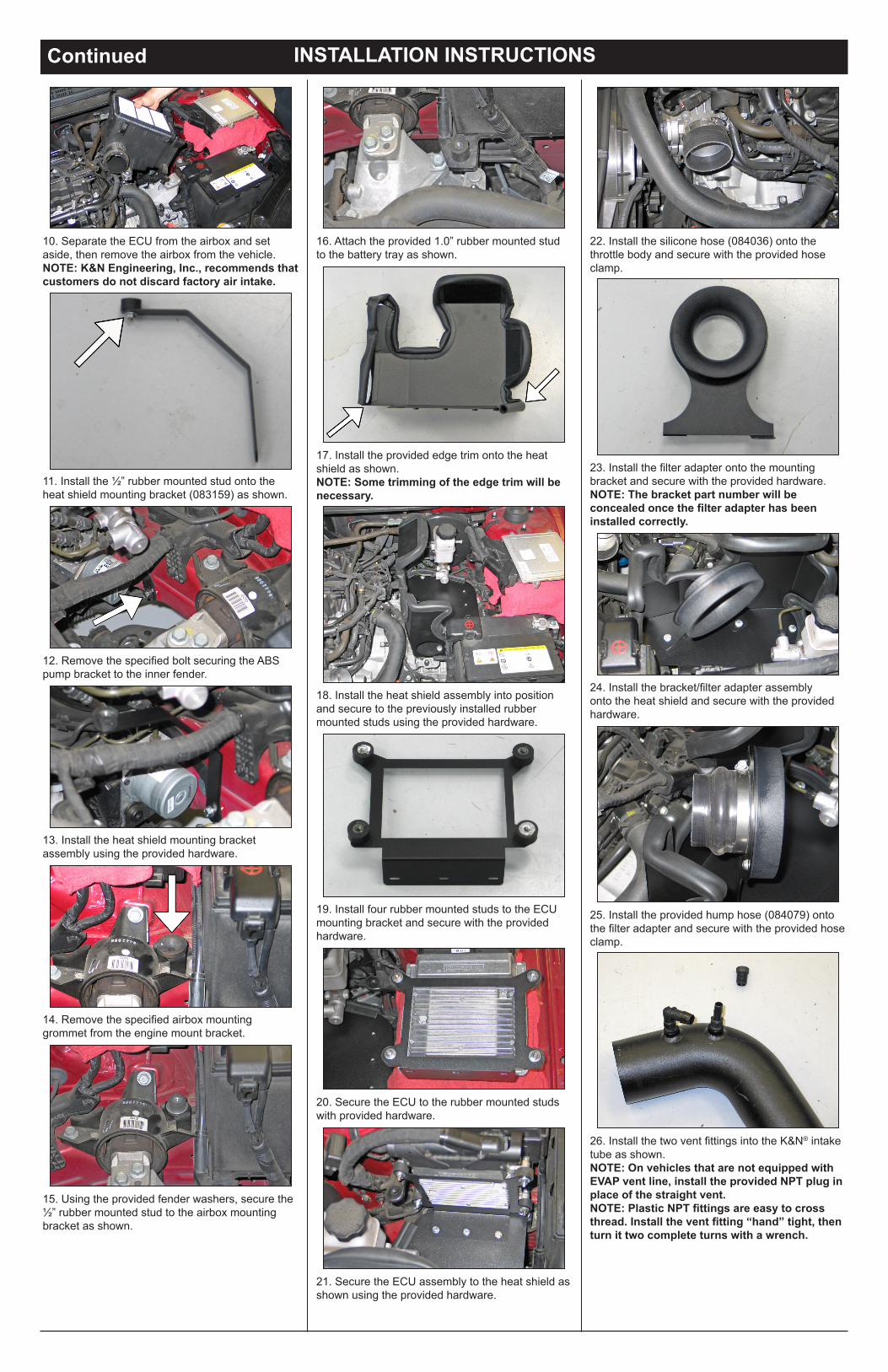
10. Separate the ECU from the airbox and set aside, then remove the airbox from the vehicle.NOTE: K&N Engineering, Inc., recommends that customers do not discard factory air intake.
11. Install the ½” rubber mounted stud onto the heat shield mounting bracket (083159) as shown.
12. Remove the specified bolt securing the ABS pump bracket to the inner fender.
13. Install the heat shield mounting bracket assembly using the provided hardware.
14. Remove the specified airbox mounting grommet from the engine mount bracket.
15. Using the provided fender washers, secure the ½” rubber mounted stud to the airbox mounting bracket as shown.
16. Attach the provided 1.0” rubber mounted stud to the battery tray as shown.
17. Install the provided edge trim onto the heat shield as shown.NOTE: Some trimming of the edge trim will be necessary.
18. Install the heat shield assembly into position and secure to the previously installed rubber mounted studs using the provided hardware.
19. Install four rubber mounted studs to the ECU mounting bracket and secure with the provided hardware.
20. Secure the ECU to the rubber mounted studs with provided hardware.
21. Secure the ECU assembly to the heat shield as shown using the provided hardware.
22. Install the silicone hose (084036) onto the throttle body and secure with the provided hose clamp.
23. Install the filter adapter onto the mounting bracket and secure with the provided hardware. NOTE: The bracket part number will be concealed once the filter adapter has been installed correctly.
24. Install the bracket/filter adapter assembly onto the heat shield and secure with the provided hardware.
25. Install the provided hump hose (084079) onto the filter adapter and secure with the provided hose clamp.
26. Install the two vent fittings into the K&N® intake tube as shown.NOTE: On vehicles that are not equipped with EVAP vent line, install the provided NPT plug in place of the straight vent.NOTE: Plastic NPT fittings are easy to cross thread. Install the vent fitting “hand” tight, then turn it two complete turns with a wrench.
* FREE K&N® decal To register your warranty, please see us online at knfilters.com/register. FREE K&N® decal *
INSTALLATION INSTRUCTIONSContinued
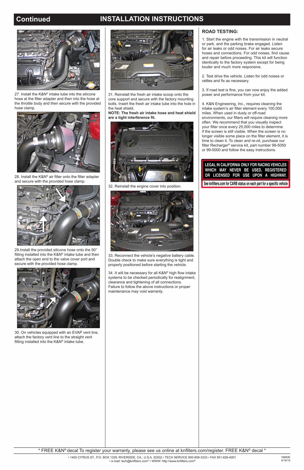
1. Start the engine with the transmission in neutral or park, and the parking brake engaged. Listen for air leaks or odd noises. For air leaks secure hoses and connections. For odd noises, find cause and repair before proceeding. This kit will function identically to the factory system except for being louder and much more responsive.
2. Test drive the vehicle. Listen for odd noises or rattles and fix as necessary.
3. If road test is fine, you can now enjoy the added power and performance from your kit.
4. K&N Engineering, Inc., requires cleaning the intake system’s air filter element every 100,000miles. When used in dusty or off-road environments, our filters will require cleaning moreoften. We recommend that you visually inspect your filter once every 25,000 miles to determine if the screen is still visible. When the screen is no longer visible some place on the filter element, it is time to clean it. To clean and re-oil, purchase our filter Recharger® service kit, part number 99-5050 or 99-5000 and follow the easy instructions.
ROAD TESTING:
• 1455 CITRUS ST., P.O. BOX 1329, RIVERSIDE, CA., U.S.A. 92502 • TECH SERVICE 800-858-3333 • FAX 951-826-4001 • e-mail: [email protected]® • WWW: http://www.knfilters.com®
28. Install the K&N® air filter onto the filter adapter and secure with the provided hose clamp.
29.Install the provided silicone hose onto the 90° fitting installed into the K&N® intake tube and then attach the open end to the valve cover port and secure with the provided hose clamp.
30. On vehicles equipped with an EVAP vent line, attach the factory vent line to the straight vent fitting installed into the K&N® intake tube.
32. Reinstall the engine cover into position.
33. Reconnect the vehicle’s negative battery cable. Double check to make sure everything is tight and properly positioned before starting the vehicle.
31. Reinstall the fresh air intake scoop onto the core support and secure with the factory mounting bolts. Insert the fresh air intake tube into the hole in the heat shield.NOTE: The fresh air intake hose and heat shield are a tight interference fit.
34. It will be necessary for all K&N® high flow intake systems to be checked periodically for realignment, clearance and tightening of all connections. Failure to follow the above instructions or proper maintenance may void warranty.
18880E6/19/15
27. Install the K&N® intake tube into the silicone hose at the filter adapter and then into the hose at the throttle body and then secure with the provided hose clamp.