6shfwud&rpp,6’ 135,& dug - general datacomm · 6shfwud&rpp,6’ 135,& dug gdc...
TRANSCRIPT

Installation and Operation
6SHFWUD&RPP�,6'1�35,�&DUG
GDC 076R114-000-01Issue 1 - May 1997
General DataComm

WarningThis equipment generates, uses, and can radiate radio frequency energy and if not installed and used in accordancewith the instruction manual, may cause interference to radio communications. It has been tested and found to complywith the limits for a Class A computing device pursuant to CISPR 22 which is designed to provide reasonableprotection against such interference when operated in a commercial environment. Operation of this equipment in aresidential area is likely to cause interference, in which case the user at his own expense will be required to takewhatever measures may be required to correct the interference. The user is cautioned that any changes ormodifications not expressly approved by General DataComm void the user’s authority to operate the equipment.
This digital apparatus does not exceed Class A limits for radio noise emissions from digital apparatus described inthe Radio Interference Regulations of the Canadian Department of Communications.
Le présent appareil numérique n’émet pas de bruits radioélectriques dépassant les limites applicables aux appareilsnumériques de la classe A prescrites dans le Règlement sur le brouillage radioélectrique édicté par le ministère desCommunications du Canada.
Warranty
General DataComm warrants that its equipment is free from defects in materials and workmanship. The warrantyperiod is one year from the date of shipment. GDC's sole obligation under its warranty is limited to the repair orreplacement of the defective equipment provided it is returned to GDC, transportation prepaid, within a reasonableperiod. This warranty will not extend to equipment subjected to accident, misuse, or alterations or repair not madeby GDC or authorized by GDC in writing. The foregoing warranty is exclusive and in lieu of all other warranties,express or implied, including but not limited to, warranties of merchantability and fitness for purpose.
Trademarks and PatentsGeneral DataComm, the General DataComm logo and the following are trademarks of General DataComm, Inc inthe United States and other countries: ACCULINE, ANALOOP, AUTOFRAME, BERT 901, DATACOMMSECURE-PAK, DATALOOP, DIGIDIAL, ENmacs, FASTPRO, FIRST RESPONSE, GDC, GDC APEX,GENERAL DATACOMM X-PRESS, GEN*NET, GEN*PAC, IMAGE*TMS, KILOMUX, LAN*TMS,MEGA*BRIDGE, MEGAMUX, MEGAMUX TMS, MEGANET, MEGASPLIT, MEGASWITCH, MEGAVIEW,NETCON, NETSWITCH, NMC, QUIKSHIPPERS, SERVI-CHECK, SERVI-SNAP, WINmacs.
ANALOOP and DATALOOP respectively are protected by U.S. patents 3,655,915 and 3,769,454. All other productsor services mentioned in this document are identified by the trademarks, service marks, or product names asdesignated by the companies who market those products. Inquiries concerning such trademarks should be madedirectly to those companies.
Copyright© 1997 General DataComm, Inc. All rights reserved.P.O. Box 1299, Middlebury, Connecticut 06762-1299 U.S.A.
This publication and the software it describes contain proprietary and confidential information. No part of thisdocument may be copied, photocopied, reproduced, translated or reduced to any electronic or machine-readableformat without prior written permission of General DataComm, Inc.
The information in this document is subject to change without notice. General DataComm assumes no responsibilityfor any damages arising from the use of this document, including but not limited to, lost revenue, lost data, claims bythird parties, or other damages. If you have comments or suggestions concerning this manual, please write toTechnical Publication Services or call 1-203-758-1811.

. 1-1
. 1-1
. 1-1
. 1-1
1-1
-2
1-2
1-2
. 2-1
.. 2-1
. 2-2
. 2-3
.. 2-4
2-4
2-4
. 3-1
. 3-2
3-3
3-4
. 3-5
Table of Contents
Preface
1 Technical Overview
Introduction .........................................................................................................................
Description ..........................................................................................................................
System Components .....................................................................................................
PC Card.........................................................................................................................
Function .........................................................................................................................
SC PRI Card Installed with Two LTUs......................................................................... 1
AT Commands...............................................................................................................
Installation Environment ...............................................................................................
2 Installation
Overview .............................................................................................................................
SpectraComm Shelf............................................................................................................
Unpacking and Handling.....................................................................................................
Shelf Layout ........................................................................................................................
Power Up Sequence ...........................................................................................................
Configuration .......................................................................................................................
AT Commands...............................................................................................................
3 Operation
Overview .............................................................................................................................
AT Commands ....................................................................................................................
AT Help Command........................................................................................................
AT SC (System Configuration) Command....................................................................
AT SS (System Status) Command................................................................................
A Technical Characteristics
Index
GDC 076R114-000-01

ii Table of Contents
2-1
2-2
3-1
-3
-4
-5
-3
2-3
-6
-2
-6
Figures
2-1 SpectraComm Shelf Back Panel...............................................................................
2-2 SpectraComm RLN System Shelf Back Panel.........................................................
3-1 Front Panel Indicators...............................................................................................
3-2 AT Help Display.......................................................................................................3
3-3 AT System Configuration Display ...........................................................................3
3-4 AT System Status Display........................................................................................3
Tables
1-1 Equipment List .........................................................................................................1
2-1 Component Arrangement and Timeslot/DS0 Assignments – SpectraComm Shelves Used with the SC PRI Card.................................................
2-2 AT Configuration Commands for the SC PRI Card.................................................2
3-1 AT Display Commands for the SC PRI Card...........................................................3
3-2 Correlation of Shelf Slots and Channels to Timeslot/DS0 Assignments .................3
GDC 076R114-000-01
m e
nts.
s:
nds
Preface
ScopeThis manual documents the SpectraComm PRI card, manufactured by General DataComIndustries, Inc. The card performs D-Channel signalling so that a SpectraComm 5001 LinTerminating Unit can be connected to a Primary Rate ISDN (PRI) line.
The manual is written for installers, service technicians, and users. It assumes a workingknowledge of ISDN transmission service and GDC SpectraComm 5000 system compone
Revision HistoryThis is the first issue of the manual.
OrganizationThis manual has three chapters and one appendix. The information is arranged as follow
• Chapter 1 - Introduction describes the SC PRI card, its features, and its options. Thischapter contains the Equipment List table.
• Chapter 2 - Installation provides directions for installing the SC PRI card in a SpectraComm Shelf and for performing configuration by means of AT commands.
• Chapter 3 - Operation describes the SC PRI card front panel indicators and AT commathat can be used to display information about the unit.
• Appendix A- Technical Characteristics
GDC 076R114-000-01

iv Preface
prod-
n-
anage, h your
ervice
t avail-
basic nd are e a
Document Conventions
Level 1 paragraph headers introduce major topics.
Level 2 paragraph headers introduce subsections of major topics.
Level 3 paragraph headers introduce subsections of secondary topics.
This typewriter font shows output that is displayed on the screen.
Related PublicationsThe following documents have additional information that may be helpful when using this uct:
• GDC SC 5001 Line Terminating Unit Installation and OperationGDC 032R101-000
• GDC SC 5034 Data Set Emulator Installation and OperationGDC 076R106-000
GDC publication numbers (e.g., GDC 032R101-000) are used to track and order technical mauals. Publication numbers use the following format:
GDC NNNRnnn-000 or GDC NNNRnnn-Vnnn
• NNN identifies the product family (e.g. SC 5000)
• R denotes a technical publication
• nnn a number assigned by Technical Publications
• 000 identifies a hardware product and does not change
The Issue Number changes when a hardware manual is revised.
Service and SupportGeneral DataComm is committed to providing the service and support needed to install, mand maintain your equipment. For information about service programs or for assistance witsupport requirements, contact your local Sales Representative or call General DataComm Sat the 24-hour, toll-free number listed below.
• in the U.S. dial 1-800-243-1030
• outside the U.S. dial 1-203-598-7526
Be ready with the site name and phone number, and a description of the problem. The nexable support representative will promptly return your call.
Hands-on training courses are provided by GDC Educational Services. Courses range fromdata communications, modems and multiplexers, to complex network and ATM systems ataught in Connecticut or at a customer location. To discuss educational services or receivcourse schedule, call 1-800-243-1030 and follow the menu instructions.
Notes present special instructions, helpful hints or general rules.
NOTE
GDC 076R114-000-01
Preface v
puter static
ndling ds, and c floor
nnect- er
Cau-
ny l
Safety Instructions
Antistatic Precautions
Electrostatic discharge (ESD) results from the buildup of static electricity and can cause comcomponents to fail. Electrostatic discharge occurs when a person whose body contains a buildup touches a computer component.
The equipment may contain static-sensitive devices that are easily damaged, so proper haand grounding are essential. Use ESD precautionary measures when installing parts or carkeep the parts and cards in antistatic packaging when not in use. If possible, use antistatipads and workbench pads.
When handling components or setting switch options always use an antistatic wrist strap coed to a grounded equipment frame or chassis. If a wrist strap is not available, periodically touchan unpainted metal surface on the equipment. Never use a conductive tool, such as a screwdrivor a paper clip, to set switches.
Safety Guidelines
The following symbols are used in this manual to draw your attention to potential hazards. Ation indicates a hazard to equipment or data. A Warning indicates a hazard to personnel.
Always use caution and common sense. To reduce the risk of electrical shock, do not operate aequipment with the cover removed. Repairs must be performed by qualified service personneonly.
Caution statements identify conditions or practices that can result in damage to the equipment or in loss of data.
Warning statements identify conditions or practices that can result in personal injury or loss of life.
GDC 076R114-000-01

vi Preface
ta and plane
by dai-
Each unit at larly
tions.
Glossary of Terms
Backplane Data Highway
High speed bus built into the SpectraComm Shelf backplane to support the exchange of datiming signals between a line terminating unit and its group of data set emulators. The backcontains four data highways. Two backplanes, and their data highways, can be connectedsy-chain cables so that a total of 32 shelf slots are supported.
Data Set Emulator (DSE)
Term for the units in the SpectraComm 5000 system that provide DTE interface functions.DSE is designed to be compatible with a GDC device that can be installed as a standalonea remote site. An SC 5034 DSE, for example, is compatible with remote modems, particuthose that operate in V.34 mode.
Line Terminating Unit
Term for the unit in the SpectraComm 5000 system that provides T1 network interface func
GDC 076R114-000-01

m e
r
U
helf. the pc
function
cm). a DB25 The PRI f
ust be
nd 23
data. 0 24
1 Technical Overview
IntroductionThis manual documents the SpectraComm PRI card, manufactured by General DataComIndustries, Inc. The card performs D-Channel signalling so that a SpectraComm 5001 LinTerminating Unit can be connected to a Primary Rate ISDN (PRI) line.
This chapter describes the SC PRI card’s function and the system in which it operates.
Description
System Components
The SC PRI card functions in a system populated with three types of device:
• PRI card – performs signalling functions for switching; one per system
• Line Terminating Unit (LTU) – performs network interface functions; one or two pesystem
• Data Set Emulator (DSE) – performs DTE interface functions; a system with one LTcan support up to 23 DTE data channels, a system with two LTUs up to 47
The devices are all built on printed circuit (pc) cards that are housed in a SpectraComm sThe shelf consists of 16 card slots and a backplane that enables communication betweencards. The backplanes of two shelves can be connected by ribbon cables so the shelves as a single unit with 32 card slots.
PC Card
The SC PRI card conforms to the GDC SpectraComm format. It is 7" x 9.5" (17.8 cm x 24.1The rear edge of the card is occupied by two sets of edge connector fingers, separated by connector. The fingers connect the pc card to the backplane of the SpectraComm shelf. DB25 connector is the interface for connection of a terminal by which you configure the SCcard. Figures in Chapter 2, Installation, illustrate the outline of the pc card and the position oexternal connections on the SpectraComm shelf backplane.
That chapter also describes how the SC PRI card and the other pc cards in its system marranged in the SpectraComm shelf.
The front panel of the SC PRI card contains six LED indicators. Chapter 3, Operation, fully describes the functions of the indicators.
Function
The SC PRI card provides D-Channel signaling for an Integrated Services Digital NetworkPrimary Rate Interface line connected to an LTU. The PRI line consists of one D channel aB channels. Signals on the D channel direct the switching of the B channels, which carryWhen the PRI card is installed in conjunction with one LTU it performs its signaling on DS
GDC 076R114-000-01

1-2 Technical Overview
els.
pes:
. shelf
ration ach
ith the lling -to-one
r or
r.
ls, A
e ISDN
iving ivalent fice. rries
be two carry the D
ention.
igured
that isplay
of the ISDN PRI line connected to that LTU. DS0s 1 through 23 are available for B chann
A single configuration command establishes the SC PRI card’s compatibility with the ISDNswitch in use at the service provider’s Central Office. The card can function with switch ty
4ESS
5ESS
NT
NI2
The SpectraComm 5001 Line Terminating Unit is the LTU compatible with the SC PRI cardIt conveys channel data for a group of DSEs installed with it in the SpectraComm shelf. Thebackplane contains four data highways, each able to support the exchange of channel data between one LTU and its group of DSEs. A DSE’s DTE interface functions emulate the opeof the unit at the far end of the link. Data highway traffic is divided into timeslots that are eequivalent to a DS0 at the network interface.
The PRI card uses timeslot 24 of its assigned data highway to exchange D channel data wLTU and DS0 24 of the PRI line. The card monitors all timeslots of its data highway for diasignals from the DSEs. The SC PRI card relates data highway timeslots to DS0s on a onebasis, timeslot 1 to DS0 1 and so on.
When an inbound call seeks connection on a DS0, the PRI directs the ringing signal to thecorresponding timeslot. Provisioning of incoming calls, whether through a common numbeassigning an individual number for each DS0, has to be arranged with the service provide
The SpectraComm 5034 Data Set Emulator is the one DSE currently compatible with the SCPRI card. An SC 5034 DSE is the equivalent of two V.34 modems. Its two modem channeand B, operate independently; each supports a DTE connection and requires a DS0 on thPRI line connected to the LTU.
The DSE modem channel can perform all the functions of a V.34 modem, placing and rececalls on the switched network. Each B channel DS0 of the ISDN PRI line serves as the equof a voice frequency (VF) line between the user site and the service provider switching ofThe switching office directs each B channel individually to its destination. The D channel cathe equivalent of dialling and ringing signals for all of its B channels.
SC PRI Card Installed with Two LTUs
Multiple ISDN PRI lines can be provisioned, by arrangement with the service provider, to controlled by a single, common D channel. The PRI card supports D channel signaling forPRI lines connected to individual LTUs. All 24 DS0s of the second PRI line are available to data, so 47 B channels can be supported by one D channel. As in a one-LTU installation,channel occupies DS0 24 of the line connected to the first LTU.
AT Commands
Once installed and configured, the SC PRI card does not need operator intervention or attThe configuration that it requires at the time of installation is performed by means of AT commands. The LTU(s) and DSEs installed in the shelf with the PRI card must also be confand controlled by means of AT commands.
In addition to the configuration commands, the SC PRI card accepts a command (AT SS)causes it to send a System Status display to the terminal that issues the command. The didentifies channels by their timeslot/DS0 numbers. Chapter 3, Operation, includes a table that correlates the DS0 numbers to shelf slots.
GDC 076R114-000-01

Technical Overview 1-3
talled a its
ized n SC . The
Installation Environment
A standard SpectraComm shelf provides individual back panel connectors for the cards insin it. When the SC PRI card is installed in a standard shelf it accepts AT commands from VT100-compatible ASCII terminal that you connect to the appropriate DB25 connector forshelf slot.
In a Remote LAN Node (RLN) system, the SpectraComm shelf is equipped with a specialback panel that facilitates DTE interface functions under the direction of an RLN server. APRI card installed in an RLN system receives its AT commands by way of the RLN serverRLN server can be configured to configure the PRI card automatically by means of an initialization string made up of AT commands.
Table 1-1 Equipment List
In some applications LTUs and DSEs are installed in conjunction with a SpectraComm Manager (SCM) card that enables them to be configured and controlled by SNMP commands or terminal interface routines. The SCM card is not compatible with the SC PRI card, and it must not be present in a shelf (or pair of shelves) that contains a PRI card.
Description GDC Part No.
GDC SC PRI Card 076P017-001
GDC 076R114-000-01


ware op-
t and
oes not ounts
-inch total of require-shelf.
2 Installation
OverviewThis chapter describes the installation of the SC PRI card.
The SC PRI card is shipped pre-assembled, tested, and ready to use. There are no hardtions to be set on the SC PRI card.
The normal procedure after unpacking the unit is simply to insert it in its intended shelf sloperform the configuration described in this chapter.
The SC PRI card should be installed in a ventilated area where the ambient temperature dexceed 122°F (50°C). Do not install the card above other equipment that generates large amof heat (e.g., power supplies).
SpectraComm ShelfA rack-mountable SpectraComm Shelf can house up to 16 plug-ins. It fits into 19- and 23wide equipment racks. The backplanes of two shelves can be linked by cables so that a 32 card slots function as though connected to the same backplane. There are positioning ments that govern how the SC PRI card, the LTU, and the DSEs can be arranged in the The requirements are described below, under the heading Shelf Layout.
Figure 2-1 SpectraComm Shelf Back Panel
J51: 40-pin signal
J50: Shelf address
J49: 50-pin power Slot B Slot A
Power
J52: 30-pin signal
Zone 1
Zone 2
Zone 3
16-slot Zone 3 connector panel shown
Connect to the Terminal Interface for SC PRI card
bus connector
jumper
bus connector
supplysection
bus connector
to the slot containing the card.configuration through the DB25 that corresponds
with one DB25S connector (J1 to J16) per slot.
GDC 076R114-000-01
2-2 Installation
transfer
LTUs holds s in the
)
)
– 24)
only which
mm rface
rial. In-.
The shelf backplane contains four separate data highways. Each highway can support the of data between one LTU and its DSEs. Traffic on a data highway is divided into assignedtimeslots, each of which is equivalent to a DS0 at the LTU’s network interface.
The shelf layout requirements are such that when the SC PRI card is to operate with two the system must occupy a pair of linked shelves. Each LTU occupies one shelf, which alsothe DSEs that are supported by the LTU. Components are divided between the two shelvefollowing way:
• Shelf 1
SC PRI card
LTU responsible for supporting the D channel (D channel uses timeslot/DS0 24
Up to 12 DSEs associated with that LTU (DSEs can use timeslots/DS0s 1 – 23
• Shelf 2
LTU
Up to 12 DSEs associated with the second LTU (DSEs can use timeslots/DS0s 1
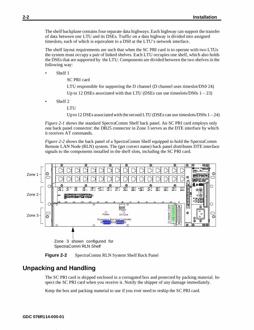
Figure 2-1 shows the standard SpectraComm Shelf back panel. An SC PRI card employs one back panel connector: the DB25 connector in Zone 3 serves as the DTE interface by it receives AT commands.
Figure 2-2 shows the back panel of a SpectraComm Shelf equipped to hold the SpectraCoRemote LAN Node (RLN) system. The (get correct name) back panel distributes DTE intesignals to the components installed in the shelf slots, including the SC PRI card.
Figure 2-2 SpectraComm RLN System Shelf Back Panel
Unpacking and HandlingThe SC PRI card is shipped enclosed in a corrugated box and protected by packing matespect the SC PRI card when you receive it. Notify the shipper of any damage immediately
Keep the box and packing material to use if you ever need to reship the SC PRI card.
Zone 1
Zone 2
Zone 3Expansion Bus Host Controller
Power On Line
Power
J1 A
dap
ter
Cab
le
Zone 3 shown configured forSpectraComm RLN Shelf
GDC 076R114-000-01

Installation 2-3
shelf helf in a sys-
ssign-mple,
Shelf Layout The default configurations for the LTU(s) and DSEs require each LTU to occupy slot 16 of its and the DSEs to be in slots 2 through 13. The SC PRI card should occupy slot 15 of the first sthe system. Table 2-1 presents the component arrangements for the first and second shelves intem. It also shows the timeslot/DS0 assignment for each card slot/channel in the shelves.
The default condition for the SC 5034 DSEs configures them to adopt data highway timeslot aments determined by their physical location in the SpectraComm shelf. Timeslot/DS0 1, for exais always channel A of the DSE in slot 2.
Table 2-1 Component Arrangement and Timeslot/DS0 Assignments – SpectraComm Shelves Used with the SC PRI Card
Shelf Slot/DSE Channel Timeslot/DS0
Slot 1 – to be left empty for RLN system
Slot 2 – DSE Channel A 1
DSE Channel B 2
Slot 3 – DSE Channel A 3
DSE Channel B 4
Slot 4 – DSE Channel A 5
DSE Channel B 6
Slot 5 – DSE Channel A 7
DSE Channel B 8
Slot 6 – DSE Channel A 9
DSE Channel B 10
Slot 7 – DSE Channel A 11
DSE Channel B 12
Slot 8 – DSE Channel A 13
DSE Channel B 14
Slot 9 – DSE Channel A 15
DSE Channel B 16
Slot 10 – DSE Channel A 17
DSE Channel B 18
Slot 11 – DSE Channel A 19
DSE Channel B 20
Slot 12 – DSE Channel A 21
DSE Channel B 22
Slot 13 – DSE Channel A 23
DSE Channel B, Shelf 1 - unused
DSE Channel B, Shelf 2 24
Slot 14 – Empty
Slot 15 – SC PRI card D-Channel, Shelf 1 24
Empty, Shelf 2
Slot 16 – LTU
GDC 076R114-000-01

2-4 Installation
d data
ose it
e data each
pan-
are
rminal een
r format
st be th.
parate
card. uses ilable
I card ll 24
ree re- to the
ted to
Power Up SequenceThe following events occur when the SC PRI card is inserted into the Spectracomm shelf:
1. The card automatically initiates a Power Up Test.
2. After completing the test successfully, the card monitors the timeslots of its assignehighway(s) to identify which are in use.
3. The card establishes the D channel link with the ISDN service provider. For that purpuses timeslot 24 and DS0 24 of the highway it shares with the LTU in its shelf.
4. Based on the D channel signaling, the service provider’s switch then provisions thcarrying B channels for the ISDN PRI line. The switch has to support a B channel foractive DSE modem channel.
You can verify that the SC PRI card is in good electrical working order by watching the frontel during the Power Up Test and the start-up of operation:
• All LEDs should light initially
• CI, RSP, and TM indicators then go out
• INS and ON indicators remain lit
• ALM indicator remains lit until the D channel is operational; blinks until all B channels operational, then goes out.
ConfigurationTo configure the SC PRI card, connect a VT100-compatible terminal (or a computer running teemulation) to the DB-25 connector for its slot in the SpectraComm Shelf and follow the on-scrprompts.
The card’s terminal port operates at 19.2 kbps asynchronous, and supports an 8/N/1 characte– 8 data bits, no parity, 1 stop bit.
There are four parameters that you must configure in the SC PRI card when you install it:
• Switch Type in use by the service provider supplying the ISDN PRI line. The card muconfigured for compatibility with the switch type it exchanges D channel signaling wi
• Number of ISDN PRI lines the card is to support; either 1 or 2. Each line requires a seLTU.
• Backplane data highway used by the LTU located in the same shelf with the SC PRIThis is the LTU that supports the D channel for the SC PRI card on DS0 24. The cardtimeslot 24 to exchange D channel data with the LTU. The other 23 timeslots are avafor B channel data.
• Backplane data highway used by the LTU located in the second shelf when the SC PRis configured to operate with two ISDN PRI lines. The LTU in the second shelf has aDS0s and timeslots available for B channel data.
AT Commands
The SC PRI card accepts eleven AT commands. Six of those are configuration commands, thquest displays from the card, and two relate to the function of downloading operating firmwarecard. Table 2-3 lists the configuration commands, the values they accept, and their functions.
The functions of the other AT commands are described in Chapter 3, Operation.
AT commands can be input to the SC PRI card from a VT100-compatible terminal connec
GDC 076R114-000-01

Installation 2-5
RLN hmate
ation tring re
mand turns
card p until
etween
d until tion and
from ands.
art
kette, , you you e
enter
the Zone 3 DB25 connector for the card’s shelf slot. When the card is installed as part of ansystem the AT commands are directed to it through the RLN Access Server, using the AttacRLN Server software.
You can send the AT configuration commands to the SC PRI card in the form of an initializstring from the RLN manager or a command line from a terminal. Begin each initialization sor command line with the prefix AT, which alerts the card that the characters following it acommands.
You can send multiple commands to the SC PRI card in a single initialization string or comline, up to a maximum of 60 characters. The AT prefix, spaces, line feeds, and carriage redo not count as part of the 60-character limit.
Each initialization string or command line must end with a carriage return (Enter key). Thedoes not begin processing the commands until it receives the carriage return character. Uyou press the Enter key you can make changes by backspacing and typing over.
The SC PRI card returns a result code for each initialization string or command line it receives:
OK when the line is valid
ERROR if the line contains one or more invalid commands.
The result code ERROR indicates that the card has rejected at least one of the commands bthe AT prefix and the carriage return.
When using a terminal or terminal emulator you cannot send a new command line to the carthe result code for the previous command line is received. In the case of a terminal emulaprogram that ignores result codes, a three-character wait time must elapse between commlines sent to the card.
DownloadingThe SC PRI card can be downloaded with new operating firmware without being removedits installed location. The download employs the same DB-25 connector used for AT commThe card is able to store two sets of firmware and switch between them on command.
Loading new firmware into the SC PRI card requires the GDC Download General Utility (PNo. 080Z039-201A). The utility is supplied separately.
GDC may deliver new firmware to be loaded into the card by means of several media: distape, CD ROM, or on-line TFTP transfer. However the application software file is deliveredmust prepare for the download by copying it onto your computer. The directory into whichcopy the download file must also contain a copy of the download utility. When you copy thutility file to your directory from the diskette on which it is supplied, its name is dlvfast.exe .
The download utility runs in the DOS command-line environment, not under Windows. Toperform the download, get a DOS prompt on-screen, go to the appropriate directory, and dlvfast . On-screen prompts lead you through the process once the utility is launched.
The Set to Defaults AT command (F) must always be sent by itself. Other commands included with it in a command line or initialization string are disregarded. NOTE
GDC 076R114-000-01

2-6 Installation
Table 2-2 AT Configuration Commands for the SC PRI Card
Command ConfigurationValues/Default
Function
4ESS5ESSNTNI2
(Default 4ESS) Switch Names of the four types with which the SC PRI card can be compatible. The name of each switch is the AT command that sets the card for compatibility with the switch. The card is compat-ible only with the switch type for which it was most recently con-figured.
Does not take effect until &W command is issued.
DSLn n = 1 or 2
(Default DSL1)
Number of lines the SC PRI card is to support. Enter 1 for a sin-gle-shelf installation with one LTU. Enter 2 for a two-shelf instal-lation with an LTU in each shelf. Each LTU is connected to an ISDN PRI line.
Does not take effect until &W command is issued.
DHWn n = 1, 2, 3, or 4
(Default DHW1)
Data Highway Number assigned to the LTU located in the same shelf with the SC PRI card. The card uses timeslot 24 of the spec-ified data highway to exchange D channel data with the LTU, and DS0 24 of the line connected at the LTU to exchange D channel signaling with the service provider’s switch.
Does not take effect until &W command is issued.
SHWn n = 1, 2, 3, or 4(must not be same value assigned to
DHWn)
(Default SHW2)
Second Highway Number is the highway assigned to the LTU lo-cated in the second shelf when the SC PRI card is supporting two lines. The value of this command has no effect when the card is configured to support one line (DSL1).
Does not take effect until &W command is issued.
DUn n = 1 or 2
(Default DU1)
Download Mode determines the SC PRI card’s response when firmware is downloaded:
DU1 configures the card to automatically unzip firmware and put it into service when the download is complete. DU2 configures the card to store newly downloaded firmware zipped and inactive until it is put into service by a U command.
DUn does not have to be sent each time a download is performed. The card stays in the selected mode.
Does not take effect until &W command is issued.
&W Activate Configuration commands the SC PRI card to store and begin using new configuration. Configuration changes made with the preceding five commands do not go into effect until the &W command is sent.
It may either be included as the last item in a command line or ini-tialization string, or be issued as a separate command.
F Set to defaults instructs the five configuration commands to as-sume their default values. This command does not require the &W; it goes into effect immediately when sent to the card. It can-not be combined with others in a command line or initialization string.
U Unzip and Execute commands the SC PRI card to unzip (decom-press) stored firmware and begin using it as the active operating firmware. The command can be used to switch back and forth be-tween the two sets of firmware as many times as needed.
GDC 076R114-000-01

he AT
3 Operation
OverviewThis chapter describes the functions of the SC PRI card front panel indicator displays and tcommands that cause the SC PRI card to display information.
Figure 3-1 Front Panel Indicators
INS ON
CI RSP
TM ALM
SC PRI
Green
Red
Power On -Lit while power is applied to the card
In Service -Lit when the card is placed into service
Response -Lit when the card responds to an AT command
Alarm -At initial power-up remains On until D channel is oper-ating, then flashes until B channels are operating for all installed DSE modem channels.
When an additional DSE is inserted while the card is powered up, blinks until B channels are operational for the DSE modem channels.
Test Mode -Flashes while firmware is being downloaded to the card. Flashes while standby firmware is being unzipped.
Call Indicator -Flashes each time the card detects an incoming or out-going call on any B channel.
GDC 076R114-000-01

3-2 Operation
request card.
), and
ted to RLN hmate
rminal een
r format
mand turns
card p until
AT
d until tion and
AT CommandsThe SC PRI card accepts 11 AT commands. Six of those are configuration commands, three displays from the card, and two relate to the function of downloading operating firmware to theThe configuration commands are described in detail in Chapter 2, Installation. The use of the display and download commands is covered in the following paragraphs.
Table 3-1 lists the display and download commands, the values they accept (where applicabletheir functions.
AT commands can be input to the SC PRI card from a VT100-compatible terminal connecthe Zone 3 DB25 connector for the card’s shelf slot. When the card is installed as part of ansystem the AT commands are directed to it through the RLN Access Server, using the AttacRLN Server software.
To configure the SC PRI card, connect a VT100-compatible terminal (or a computer running teemulation) to the DB-25 connector for its slot in the SpectraComm Shelf and follow the on-scrprompts.
The card’s terminal port operates at 19.2 kbps asynchronous, and supports an 8/N/1 characte– 8 data bits, no parity, 1 stop bit.
You can send multiple commands to the SC PRI card in a single initialization string or comline, up to a maximum of 60 characters. The AT prefix, spaces, line feeds, and carriage redo not count as part of the 60-character limit.
Each initialization string or command line must end with a carriage return (Enter key). Thedoes not begin processing the commands until it receives the carriage return character. Uyou press the Enter key you can make changes by backspacing and typing over.
The SC PRI card returns a result code for each initialization string or command line it receives:
OK when the line is valid
ERROR if the line contains one or more invalid commands.
The result code ERROR indicates that the card has rejected every command between theprefix and the carriage return.
When using a terminal or terminal emulator you cannot send a new command line to the carthe result code for the previous command line is received. In the case of a terminal emulaprogram that ignores result codes, a three-character wait time must elapse between commlines sent to the card.
Table 3-1 AT Display Commands for the SC PRI Card
Command Command Type
Function
H Displaycommand
On-screen Help, instructs the card to display on-screen the definitions of the AT commands. See Figure 3-2 for an example of the display.
SC Displaycommand
System Configuration, instructs the card to dis-play on-screen a description of its current config-uration. See Figure 3-3 for an example of the display.
SS Displaycommand
System Status, instructs the card to display on-screen version information on its operating firm-ware, its serial number, and status information. See Figure 3-4 for an example of the display.
GDC 076R114-000-01

Operation 3-3
can result
.
AT Help Command
The SC PRI card includes an AT help function. From a terminal, or terminal emulator, youinterrogate the unit for the names of the AT commands, the valid settings for each, and theeach setting produces.
To display the AT command set for the SC PRI card:
type AT H and press the Enter key
The result is an on-screen display, shown in Figure 3-2, that lists and describes the commands
Figure 3-2 AT Help Display
ATHThe following commands are supported. Each line must be prefaced with AT and terminated by return.
To specify a switch type, enter the switch name: 4ESS 5ESS NT NI2To specify the number of lines supported by this ISDN PRI card, enter: DSLn (n = 1 or 2)To specify which Data Highway contains the D-Channel, enter: DHWn (n = 1, 2, 3 or 4)To specify the second Data Highway when DSL2 is entered, enter: SHWn (n = 1, 2, 3 or 4. but must not be equal to the DHWn setting)To retrieve the System Status, enter: SSTo retrieve the System Configuration, enter: SCTo configure the actions taken after downloading new firmware, enter: DU1 To have the newly downloaded firmware unzipped and executed automatically.or DU2 To have the newly downloaded firmware remain zipped and inactive.To unzip and execute the firmware, enter: UTo configure the system to factory defaults, enter: FTo Save and Activate changes, enter: &w
To exit interactive mode, press the ESC key.
OK
Command H (Help), precededby AT prefix and followed byEnter.
Help text display
AT Response Code
GDC 076R114-000-01

3-4 Operation
er than
AT SC (System Configuration) Command
To display the current settings for all configuration options:
type AT SC and press the Enter key
The result is an on-screen display that describes the current settings of all configuration parameters. The display identifies options by name and describes functional settings rathby the AT command that was input to achieve the setting.
Figure 3-3 AT System Configuration Display
AT SCSYSTEM CONFIGURATION
Line Type: T1
Switch Type: 4ESS
ISDN PRI to service 2 line(s).
D-Channel located in Data Highway: 1
Second Data Highway: 2
Newly downloaded firmware to be unzipped and executed automatically.
OK
Command SC (System Configuration), preceded by AT prefix and followed by Enter.
Line Type, fixed to T1
AT Response Code
Set by switch name command
Set by DSLn
Set by DHWn
Set by SHWn
Set by DUn
GDC 076R114-000-01

Operation 3-5
s)
AT SS (System Status) Command
To display status information on-screen:
type AT SS and press the Enter key
Figure 3-4 AT System Status Display (Display Shown for a System with Two PRI Line
ATSS
SYSTEM STATUS
Application Version is 2.1.26Application Checksum is 295eFirmware Rev. level is --Boot Version is 2.1.1Boot Checksum e0e0C50 Version is 1.0.1Serial Number: 0084090421970002
Legend: Out of Service = 0, In Service = 1, No Shelf Signals = 2, Reserved for D-channel = XChannel 1 2 3 4 5 6 7 8 9 10 11 12 13 14 15 16 17 18 19 20 21 22 23 24
DSE 1 1 1 1 1 1 1 1 1 1 1 1 1 1 1 1 1 1 1 1 1 1 1 X 1 1 1 1 1 1 1 1 1 1 1 1 1 1 1 1 1 1 1 1 1 1 1 1
B-Chan 1 1 1 1 1 1 1 1 1 1 1 1 1 1 1 1 1 1 1 1 1 1 1 1 1 1 1 1 1 1 1 1 1 1 1 1 1 1 1 1 1 1 1 1 1 1 1 1
Command SS (for System Status), preceded by AT prefix and followed by Enter.
Application firmware version i.d. and checksum
System Status display, Channel Status:
Channel = data highway timeslot, network interface DS0 (see Table 2-1 for channel to shelf slot correlations)
DSE = 2 represents channel assigned but LTU not supplying requiredtiming signals on the 1 represents channel in service as a timeslot assignment on the backplane data highway0 represents unused timeslot on the data highway
B-Chan = 1 represents ISDN B channel in service as a DS0 assignment at the network interface 0 represents unused DS0 at the network interface
The first display lines shown here for DSE and for B-Chan represent the firstshelf and LTU served by the SC PRI card. These are always present.
The second lines displayed for DSE and B-Chan represent the second shelfand LTU served by the SC PRI card. They are only present when the SC PRIcard is configured for two shelves and LTUs (DSL2).
SC PRI card Serial Number
Boot code firmware version i.d. and checksum
Firmware Revision level: initial release is -- Increments with each change to Application or Boot firmware
C50 Processor application firmware version
GDC 076R114-000-01

3-6 Operation
Table 3-2 Correlation of Shelf Slots and Channels to Timeslot/DS0 Assignments
Timeslot/DS0
Shelf Slot/DSE Channel
1 Slot 2 – DSE Channel A
2 DSE Channel B
3 Slot 3 – DSE Channel A
4 DSE Channel B
5 Slot 4 – DSE Channel A
6 DSE Channel B
7 Slot 5 – DSE Channel A
8 DSE Channel B
9 Slot 6 – DSE Channel A
10 DSE Channel B
11 Slot 7 – DSE Channel A
12 DSE Channel B
13 Slot 8 – DSE Channel A
14 DSE Channel B
15 Slot 9 – DSE Channel A
16 DSE Channel B
17 Slot 10 – DSE Channel A
18 DSE Channel B
19 Slot 11 – DSE Channel A
20 DSE Channel B
21 Slot 12 – DSE Channel A
22 DSE Channel B
23 Slot 13 – DSE Channel A
24 Shelf 1 – D-Channel for SC PRI card in Slot 15 (Slot 13 DSE Channel B is unused)
Shelf 2 – Slot 13 DSE Channel B
GDC 076R114-000-01

A Technical Characteristics
Item Specification
Physical
PC card (rackmount installation)
Height 0.81 in. (21 mm)
Width 7 in. (178 mm)
Depth 9.5 in. (241 mm)
Weight 10 oz (0.28 kg)
Shipping weight 1 Ib 10 oz (0.74 kg)
Environmental
Temperature
Operating 32° to 122°F (0° to 50°C) (Derate by 1°C/1000 ft above sea level)
Non-operating –40° to 185°F (–40° to 85°C)
Humidity, operating 5% to 95% without condensation
Altitude
Operating 0 ft to 10,000 ft (0 m to 3,047 m)
Non-operating 0 ft to 40,000 ft (0 m to 12,191 m)
Electrical
Power dissipation) 4 W maximum
Fusing Two 2.5 A, 125 V (GDC Part No. 215-201-009)One 5 A, 125 V (GDC Part No. 215-201-021)
GDC 076R114-000-01


Index
AT Commands 1-2, 2-4, 3-2AT Configuration Commands 2-6AT Display Commands 3-2AT Help Command 3-3AT Help Display 3-3AT SC Command 3-4AT SS Command 3-5
AT System Configuration Display 3-4AT System Status Display 3-5Channels and Timeslot/DS0 Assignments 3-6Component Arrangement with PRI Card 2-3Configuration Commands 2-6Configuration 2-4Description 1-1Display Commands 3-2Downloading 2-5Equipment List 1-3Front Panel Indicators 3-1Function 1-1Help Display 3-3Installation 2-1Installation Environment 1-2Installed with Two LTUs 1-2Operation 3-1PC Card 1-1Power Up Sequence 2-4RLN System Shelf Back Panel 2-2SC Command 3-4Shelf Layout 2-3Shelf Slots and Channels 3-6SpectraComm Shelf Back Panel 2-1SpectraComm Shelf 2-1SS Command 3-5System Components 1-1System Configuration Command 3-4System Configuration Display 3-4System Status Command 3-5System Status Display 3-5Technical Characteristics A-1Technical Overview 1-1Timeslot/DS0 Assignments with PRI Card 2-3Timeslot/DS0 Assignments 3-6Two LTU Application 1-2Unpacking and Handling 2-2
GDC 076R114-000-01


General DataComm