_6w1p7kfqmlit
TRANSCRIPT

Fibers are ubiquitous. They exist in synthetic and natural forms, as polymers, metals andceramics. This book is about the processing, microstructure and properties of materialsin fibrous form, and is the first to cover the whole range of fibers. Special emphasis is givento major developments in high strength and high stiffness polymeric fibers as well as hightemperature ceramic fibers.
The range of fibrous materials covered spans natural polymeric fibers such as silk,synthetic polymeric fibers such as aramid and polyethylene, metallic fibers such as steeland tungsten, and ceramic fibers such as alumina and silicon carbide. The author explainsthe fundamentals in a clear and concise manner and describes important advances in theproduction and control of microstructure in high stiffness and high strength fibers. Thetext contains large numbers of diagrams and micrographs to bring home to the reader theimportant principles and concepts.
The book will be of value to senior undergraduates, beginning graduate students andresearchers in the fields of materials science and engineering, metallurgy, ceramics, textilephysics and engineering, mechanical engineering and chemical engineering.

Cambridge Solid State Science Series
EDITORS
Professor D.R. ClarkeDepartment of Materials,University of California, Santa Barbara
Professor S. SureshRichard E. Simmons Professor,Department of Materials Science and Engineering,Massachusetts Institute of Technology
Professor I.M. Ward FRSIRC in Polymer Science and Techonology,University of Leeds

Fibrous Materials

TITLES IN PRINT IN THIS SERIES
S.W.S. McKeeverThermoluminescence of solids
P.L. RossiterThe electrical resistivity ofmetals and alloys
D.I. Bower and W.F. MaddamsThe vibrational spectroscopyof polymers
S. SureshFatigue of materials
J. ZarzyckiGlasses and the vitreous state
R.A. StreetHydrogenated amorphous silicon
T-W. ChouMicrostructural design offiber composites
A.M. Donald and A.H. WindleLiquid crystalline polymers
B.R. LawnFracture of brittle solids - secondedition
T.W. Clyne and PJ. WithersAn introduction to metal matrixcomposites
V.J. McBrierty and KJ. PackerNuclear magnetic resonance insolid polymers
R.H. Boyd and PJ. PhillipsThe science of polymer molecules
D.P. Woodruff and T.A. DelcharModern techniques of surfacescience — second edition
J.S. DugdaleElectrical properties of metallic glasses
M. Nastasi, J.M. Mayerand J.K. Hirvonen
Ion—solid interactions:fundamentals and applications
D.Hull and T.W. ClyneAn introduction to compositematerials — second edition
J.W. Martin, R.H. Dohertyand B. Cantor
Stability of microstructure inmetallic systems - second edition
T.G.Nieh,O.Sherbyand J. Wads worth
Superplasticity in metals and ceramics
L.V. Gibson and M.F. AshbyCellular solids - second edition

Fibrous materialsK . K . C h a w l aDepartment of Materials & Metallurgical EngineeringNew Mexico Institute of Mining and Technology
CAMBRIDGEUNIVERSITY PRESS

PUBLISHED BY THE PRESS SYNDICATE OF THE UNIVERSITY OF CAMBRIDGEThe Pitt Building, Trumpington Street, Cambridge, United Kingdom
CAMBRIDGE UNIVERSITY PRESSThe Edinburgh Building, Cambridge CB2 2RU, UK40 West 20th Street, New York NY 10011-4211, USA477 Williamstown Road, Port Melbourne, VIC 3207, AustraliaRuiz de Alarcon 13, 28014 Madrid, Spain
Dock House, The Waterfront, Cape Town 8001, South Africa
http ://www. Cambridge. org
©K.K. Chawla, 1998
This book is in copyright. Subject to statutory exceptionand to the provisions of relevant collective licensing agreements,no reproduction of any part may take place withoutthe written permission of Cambridge University Press.First published 1998
First paperback edition 2005
Typeset in lOVJUYi pt Monotype Times [SE]
A catalogue record for this book is available from the British Library
Library of Congress cataloguing in publication dataChawla, Krishan Kumar, 1942-
Fibrous materials / K.K. Chawla.p. cm. — (Cambridge solid state science series)
Includes index.ISBN 0 521 57079 4 (hardback)1. Fibers. I. Title. II. Series.
TA418.9.F5C47 1997620.1'l-dc21 96-51098 CIP
ISBN 0 521 57079 4 hardbackISBN 0 521 61985 8 paperback

The truth is only one;wise men call it by different names.
- Rigveda
In loving memory of my dear mother, Sumitra Chawla


Contents
Preface xiiiAcknowledgments xv
Chapter 1 Introduction 1
1.1 Some history 31.2 Classification of fibers 41.3 Stiff and strong fibers 6
Chapter 2 Fibers and fiber products 8
2.1 Definitions 92.2 Some important attributes of fibers 212.3 Important fiber types 292.4 General applications 312.5 Health hazards 35
Chapter 3 Natural polymeric fibers 37
3.1 Structure and properties of polymers 383.2 Natural fibers 433.3 Applications of natural polymeric fibers 56
IX

Contents
Chapter 4 Synthetic polymeric fibers 58
4.1 Brief history of organic fibers 584.2 Processing 594.3 Environmental effects on polymeric fibers 654.4 Some important low modulus synthetic polymeric fibers 664.5 Strong and stiff polymeric fibers 734.6 Polymeric fibers with unusual characteristics 954.7 Applications of synthetic polymeric fibers 100
Chapter 5 Metallic fibers 108
5.1 General characteristics of metals 1085.2 Processing of metallic filaments 1105.3 Microstructure and properties of metallic fibers 1155.4 Applications 129
Chapter 6 Ceramic fibers 132
6.1 Some important ceramics 1326.2 Creep in ceramics 1386.3 Natural ceramic fibers 1396.4 Synthetic ceramic fibers 1416.5 Ceramic whiskers 1806.6 Applications 181
Chapter 7 Glass fibers 184
7.1 Basic physics of optical communication 1847.2 Fabrication 1877.3 Chemical composition 1997.4 Structure 2027.5 Properties 2037.6 Applications 207
Chapter 8 Carbon fibers 211
8.1 Structure and properties of graphite 2118.2 Processing of carbon fibers 2148.3 Structure of carbon fibers 2208.4 Properties of carbon fibers 2218.5 High thermal conductivity carbon fibers 227
Contents xi
8.6 Hollow carbon fibers 2308.7 Hazards of carbon fibers 2308.8 Applications of carbon fibers 231
Chapter 9 Experimental determination of fiber properties 234
9.1 Physical properties 2349.2 Mechanical properties 242
Chapter 1.0 Statistical treatment of fiber strength 254
10.1 Variability of fiber strength 25610.2 Weibull statistics 25610.3 Weibull distribution of fiber strength 25810.4 Experimental determination of Weibull parameters
for a fiber 26210.5 Fiber bundle strength 265
References 269Suggested further reading 278Appendix A Some important units and conversion factors 281Author index 285Subject index 290


Preface
This book is about materials in fibrous form, precisely what the title says.Perhaps the only thing that needs to be emphasized is that the materials aspectsof fibers are highlighted. The main focus is on the triad of processing,microstructure, and properties of materials in a fibrous form. I have kept themathematics to the bare minimum necessary. More emphasis is placed on phys-ical and chemical insights. Although all kinds of fibers are touched upon, thereis a distinct tilt toward synthetic, nonapparel-type fibers. This is understandableinasmuch as the second half of the twentieth century has seen tremendousresearch and development activity in this area of high performance fibers, mainlyfor use as a reinforcement in a variety of matrix materials.
The field of fibrous materials is indeed very vast. To compress all the infor-mation available in a reasonable amount of space is a daunting task. My aim inwriting this text has been to provide a broad coverage of the field that wouldmake the text suitable for anyone generally interested in fibrous materials. I haveprovided ample references to the original literature and review articles to directthe reader with a special interest in any particular area.
The plan of the book is as follows. After an introductory chapter, somegeneral terms and attributes regarding fibers and products thereof are describedin Chapter 2. This chapter also serves to provide a mutually comprehensible lan-guage to textile and nontextile users of fibers. There is no gainsaying the fact thatmany definitions, units and terms about fibers owe their origin to the textileindustry. Thus, it behoves a materials scientist or engineer to take cognizance ofthose and be at home with them. At the same time, it is not unreasonable toexpect that a textile engineer should know the stress-strain curves of fibers in
Xlll

xiv Preface
engineering units. This general chapter is followed by Chapters 3 and 4 onnatural and synthetic polymeric fibers, respectively. Chapter 5 covers metallicfibers, which are quite widely used in a variety of engineering applications,although generally not so recognized. Chapter 6 describes ceramic fibers wheremuch innovative processing work has been done during the last quarter of thetwentieth century. This is followed by two chapters (7 and 8) on glass and carbonfibers; two fibers that have been commercially most successful and find wide-spread use as engineered materials, for example both are used as reinforcementsin a variety of composites, and optical glass fiber has an enormous market intelecommunications. Chapter 9 describes some of the testing and characteriza-tion techniques used with fibers. Finally, Chapter 10 provides a statistical treat-ment of strength of fibrous materials. One of the major sources of confusionsabout fiber characteristics is due to the different units that are used, especiallythe textile and engineering units. An appendix giving different units and theirconversion factors is provided. A book on the materials aspects of fibers, or forthat matter any other entity, must have photomicrographs to illustrate themicrostructural aspects pertinent to that particular material form and the pro-cessing that resulted in that material form. Never was the adage, A picture isworth a thousand words', truer than in the present case. I have tried to includeas many micrographs as possible. The sources of these are acknowledged in thefigure captions.

Acknowledgments
Over the years I have had the good fortune of interacting with a number of extra-ordinary people who have been of great a source of encouragement and help tome in my work. They are (in alphabetical order): M.E. Fine, S.G. Fishman, J.C.Hurt, B. Ilschner, O.T. Inal, S. Kumar, B.A. MacDonald, J.M. Rigsbee, P.Rohatgi, S. Suresh, H. Schneider, N.S. Stoloff, and A.K. Vasudevan. Among mystudents and post-docs, I would like to thank I Alba, Jr., B. Furman, A.Neuman, G. Gladysz, J.-S. Ha, and Z.R. Xu. They really made the work seemlike fun! No amount of words can convey my debt to Nivi, Nikhil and Kanika.Portions of the book were read by N. Chawla, B. Fureman and S. Kumar. I amgrateful to them for their comments. Kanika's help in word processing wasinvaluable. A special bouquet of thanks to B. Ilschner and J.-A. Manson for theirhospitality at Ecole Polytechnique Federale de Lausanne, Switzerland duringthe summer of 1996. The stay at EPFL provided me with a distraction-free timein very pleasant surroundings to complete this undertaking. Last but not least,I am grateful to my parents, Manohar L. and Sumitra Chawla for all they havedone for me!
xv

Chapter 1
Introduction
The term fiber conjures up an image of flexible threads, beautiful garments anddresses, and perhaps even some lowly items such as ropes and cords for tyingthings, and burlap sacks used for transporting commodities, etc. Nature providesus with an immense catalog of examples where materials in a fibrous form areused to make highly complex and multifunctional parts. Protein, which is chem-ically a variety of complexes of amino acids, is frequently found in nature in afibrous form. Collagen, for example, is a fibrous protein that forms part of bothhard and soft connective tissues. A more well-known natural fiber that is essen-tially pure protein, is silk fiber. Silk is a very important natural, biological fiberproduced by spider and silkworm. It is a solution spun fiber, with the solution,in this case, being produced by the silkworm or the spider. The silkworm silk hasbeen commercialized for many years while scientists and engineers are beginningto realize the potential of spidersilk.
Indeed, materials in a fibrous form have been used by mankind for a long time.Fiber yarns have been used for making fabrics, ropes, and cords, and for manyother uses since prehistoric times, long before scientists had any idea of the inter-nal structure of these materials. Weaving of cloth has been an important part ofmost ancient societies. The term fabric is frequently employed as a metaphor forsociety. One talks of the social fabric or moral fiber of a society, etc. It is inter-esting to note that an archeological excavation of a 9000-year-old site in Turkeyled to the discovery of a piece of fabric, a piece of linen, woven from the fibers ofa flax plant (New York Times, 1993). Normally, archeologists date an era by thepottery of that era. It would appear from this discovery that even before thepottery, there were textile fabrics. There is also recorded use of sutures as stitches

Introduction
in wound repairs in prehistoric times (Lyman, 1991). An ancient medical trea-tise, about 800 BC, called The Sushruta Samhita, written by the Indian surgeonSushruta, describes the use of braided fibers such as horse hair, cotton fibers,animal sinews, and fibrous bark as sutures.
The importance of fibrous materials in an industrialized economy can hardlybe overstated. For example, the fiber related industry is a very large sector of theUS economy. According to US fiber industry sources, Americans consume overeight billion (8 X 10⁹) kg fibers per year. In the US, it is an over US $ 200 billionindustry, employs about 12% of the manufacturing workforce, and consumesabout 6% of the energy. The fiber industry has about the same importance inEurope, Asia, South America, and other parts of the world. Thus, by anymeasure, fiber related industrial activity represents a very important sector of theworld's economy! Fibrous materials are, in one form or another, part of our dailylife. One has only to look at one's surroundings and reflect a little bit to realizethe all pervading influence of fibrous materials in our society. From daily usessuch as apparel, carpets to artificial turfs, barrier liners under highways and rail-road tracks, fiber reinforced composites in sporting goods (rackets, golf shafts,etc.), boats, civil construction, aerospace industry, and defense applicationsinvolving aircraft, rocket nozzles and nose cones of missiles and the spaceshuttle. In short, a quick perusal of our surroundings will show that fibers, albeitin a variety of forms, are used in all kinds of products. A commonplace examplethat many of us tea drinkers go through everyday involves the use of a tea bag.The proper tea bag needs to be porous, should not impart a taste to the brew,and of course, should have enough wet strength so that it does not fall apart inthe hot water. The introduction of the tea bag has an interesting history. FayeOsborne of Dexter Corporation, Windsor Locks, CT, USA is credited with theinvention of the tea bag (Sharp, 1995). After trying a number of vegetable fibers,he arrived at wild abaca fiber (or manila hemp) and wood pulp to make the paperfor the tea bag. World War II disrupted the availability of manila hemp fiber. In1942, Osborne came up with rayon fiber made from old rope from which oil hadbeen extracted. A coating of melamine resin helped increase the wet strength ofthe paper. Of course, there are more sophisticated but less appreciated uses suchas fibers for medical uses involving drug delivery, optical fiber that allowsexamination of inaccessible body parts, etc. Modern usage of fibers in medicineis, of course, quite extensive: surgical dressings and masks, caps, gowns; implant-able fibers for sutures, fabrics for vascular grafts and heart repairs; and extra cor-poreal uses such as fabrics for dialysis and oxygenator membranes, etc. Thus, welive in a world in which matter in a fibrous form is ever present around us.
In this chapter we examine the recent history of synthetic fiber production,provide a convenient classification of fibers, and then introduce the subject ofstrong and stiff fibers. Strong and stiff fibers came about in the second half of thetwentieth century because of many improvements in synthesis and processing,

1.1 Some history
but most of all, owing to a growing realization of the importance of a pro-cessing-structure-property triad. This triad of processing-structure-propertycorrelations as applied to the fibrous materials is indeed the basic theme of thisbook. What we mean by this is that the processing of a material into a fibrousform determines its microstructure, and the microstructure, in turn, determinesthe ultimate properties of the fiber. Time and again we shall come back to thisbasic theme in this book.
l.l Some history
Natural fibers have been around in one form or another from prehistoric times.Natural silk fiber has been a valuable commodity for a very long time. However,it was not until about 1880 that a Frenchman, Count Hilaire de Chardonnetbecame successful in imitating silkworms and produced the first synthetic fiberfrom mulberry pulp. This was rayon, not quite silk, but it had the same silky feelto it. Thus began the era of regenerated cellulosic, natural fibers such as rayonand acetate. Later, in the mid-1920s synthetic fibers started appearing. The bigbreakthrough came when Carothers discovered the process of condensationpolymerization to produce a variety of polymers such as polyamides, polyesters,and polyurethanes. I think a reasonable case can be made that the modern ageof man-made fibers started with the discovery of the nylon in the 1930s. Thenames of two chemists, an American, Wallace Carothers and a German, PaulSchlack, are linked to the pioneering work that led to the discovery of nylon fiber.Du Pont Co. started producing nylon fiber in 1939. That can be regarded as thebeginning of the age of man-made fibers; the Second World War, however, inter-rupted the progress in the development of synthetic fibers. A series of other syn-thetic fibers was discovered soon after the war, e.g. acrylic, polyester, etc., andthe progress toward the development of synthetic fibers was resumed. It was alsoduring the second quarter of the twentieth century that scientists started tounravel the internal microstructure of some of the natural fibers and soon there-after produced synthetic fibers that rivaled or were improvements on the naturalfibers. Most of this work had to do with applications of fibers for apparel andsimilar uses; understandably, therefore, most of the information during the 1940sand 1950s about fibrous materials came from people involved, in one way or theother, with textiles. Parallel to the developments in the field of organic fibers(natural and synthetic), in the late 1930s and early 1940s, it was discovered thatsilica-based glass could be drawn into a very high strength fiber. The stiffness ofglass fiber does not differ from that of the bulk glass. This is because glass is anamorphous material, and therefore, there does not occur any preferentialorientation after the fiber drawing operation. The stiffness of glass is, however,quite high compared to that of most polymers and therefore glass fiber is quite

Introduction
suitable for reinforcement of polymeric materials. The advent of glass fibers canbe regarded as the harbinger of making and using of fibers in the nontextiledomain. Of course, metal wires have been in use for various specific purposes,e.g. copper wire for electrical conduction, tungsten wire for lamp filaments,thermocouple wires made of a variety of alloys for measurement of temperature,steel and other metallic alloy-based wires for a variety of musical instrumentssuch as piano, violin, etc. The last quarter of the twentieth century has seenextensive work in the area of producing high modulus fibers, organic as well asinorganic. In the 1950s, it was realized that the carbon-carbon bond in the back-bone chain of polymers is a very strong one and that if we could only orient themolecular chains, we should get a high modulus fiber from the organic fibers.This was attempted, at first, by applying ever increasing stretch or draw ratios tothe spun organic fibers. This resulted in some improvement in the stiffness of thefiber, but no better than what was available with glass fiber, i.e. a tensile orYoung's modulus of about 70GPa in the fiber direction. In time, however,researchers realized that what one needed was orientation and extension of themolecular chains in order to realize the full potential of the carbon-carbonbond. Aramid and ultra-high molecular weight polyethylene fibers, with Young'smodulus over 100 GPa, epitomize this oriented and extended chain structure.The last quarter of the twentieth century also saw an increasing amount of workin the area of ceramic fibers having low density, high stiffness, high strength, but,more importantly, possessing these characteristics at high temperatures (as highas 1000°C and over). Examples of such high temperature fibers include boron,carbon, alumina, silicon carbide, etc. Some very novel and innovative techniquesbased on sol-gel and the use of polymeric precursors to obtain inorganic com-pounds or ceramic fibers such as silicon carbide, alumina, etc. came into being.These very significant advances opened up an entirely new chapter in the field offibrous materials, namely fibers that have very high elastic stiffness, highstrength, low density, and are capable of withstanding extremely high tempera-tures. The driving force for this development was the use of these fibers as rein-forcements for metals and ceramics, i.e. at medium to very high temperatures.
l .2 Classification of fibers
One can classify fibers in a variety of ways. For example, one may divide thewhole field of fibers into apparel and nonapparel fibers, i.e. based upon the finaluse of fibrous material. The apparel fibers include synthetic fibers such as nylon,polyester, spandex, and natural fibers such as cotton, jute, sisal, ramie, silk, etc.Nonapparel fibers include aramid, polyethylene, steel, copper, carbon, glass,silicon carbide, and alumina. These nonapparel fibers are used for making cordsand ropes, geotextiles, and structural applications such as fiber reinforcements

1.2 Classification of fibers
Continuous Staple fiber Figure 1.1 Classificationfiber of fibers based on fiber
length. Also shown are thedifferent product forms.
Yarn I IFelt Nonwoven
Woven Knitted Braided
in a variety of composites. These fibers possess higher stiffness and strength anda lower strain to failure than the apparel fibers. They are also characterized byrather difficult processing and a drastic strength degradation by the presence ofsmall flaws, i.e. they generally have a low toughness. Another classification offibers can be made in terms of fiber length, continuous or staple fiber.Continuous fibers have practically an infinite length while staple fibers haveshort, discrete lengths (10^00 mm). Like continuous fibers, these staple fiberscan also be spun into a yarn, called staple fiber yarn (see Chapter 2). This abilityto be spun into a yarn can be improved if the fiber is imparted a waviness orcrimp. Staple fibers are excellent for providing bulkiness for filling, filtration, etc.Frequently, staple natural fibers (cotton, wool) and staple synthetic fibers (nylon,polester) are blended to obtain the desirable characteristics of both. Figure 1.1shows this classification based on fiber size, and the different product forms thatare commonly available, e.g. woven or nonwoven. Yet another convenientclassification of fibers is based on natural and synthetic fibers, as shown in Fig.1.2. Natural fibers occurring in the vegetable or animal kingdom are polymericin terms of their chemical constitution, while natural fibers in the form of miner-als are akin to crystalline ceramics. A distinctive feature of natural fibers is thatthey are generally a mixture (chemical or physical) of different compounds. Onecan further classify synthetic fibers as polymers, metals, and ceramics or glass.Here, one should also mention a very special and unique subclass of fibers,whiskers. Whiskers are monocrystalline, short fibers with extremely highstrength. This high strength, approaching the theoretical strength, comes aboutbecause of the absence of crystalline imperfections such as dislocations. Beingmonocrystalline, there are no grain boundaries either. Whiskers are normallyobtained by vapor phase growth. Typically, they have a diameter of a fewmicrometers and a length of a few millimeters. Thus, their aspect ratio(length/diameter) can vary from 50 to 10000. Perhaps the greatest drawback ofwhiskers is that they do not have uniform dimensions or properties. This results

Introduction
Fibers
Natural Synthetic
Animal Vegetable Mineral Polymer Metal Ceramicand
glass
Figure 1.2 Classification of fibers based on natural and synthetic fibers.
in an extremely large spread in their properties. Handling and alignment ofwhiskers in a matrix to produce a composite are other problems.
1.3 Stiff and strong fibers
As we pointed out earlier, fibrous material is found extensively in nature. Upuntil the mid-twentieth century, most of the usage of fibers had been in clothingand other household uses. About the middle of the twentieth century, high per-formance fibers became available for use in a fabric form or as reinforcementsfor making composites. Our main focus in this text will be on processing, micro-structure, properties, and applications of materials in a fibrous form, with a dis-tinct emphasis on synthetic fibers for nontextile applications. Such fibers aregenerally very stiff and strong. This is where some of the important develop-ments have occurred in the second half of the twentieth century. The use of fibersas high performance materials in structural engineering applications is based onthree important characteristics:
(i) A small diameter with respect to its grain size or other microstructuralunit. This allows a higher fraction of the theoretical strength to beattained than that possible in a bulk form. This is a direct result of theso-called size effect, namely the smaller the size, the lower the probabilityof having an imperfection of a critical size that would lead to failure ofthe material. Thus, even for a material in its fibrous form, its strengthdecreases as its diameter increases.
(ii) A very high degree of flexibility which is really a characteristic of amaterial having a high modulus and a small diameter. This flexibilitypermits a variety of techniques to be employed for making fabrics, ropes,cords, and fiber reinforced composites with these fibers.

1.3 Stiff and strong fibers
(iii) A high aspect ratio (length/diameter, lid) which allows a very large frac-tion of applied load to be transferred via the matrix to the stiff andstrong fiber in a fiber reinforced composite (Chawla, 1987)
The most distinctive feature of a fibrous material is that it has propertieshighly biased along its length. Fibers, in general, and continuous fibers, in par-ticular, are very attractive for the reasons given above. A given material in afibrous form has a high aspect ratio (length/diameter) and can be highly flexible.Such a flexible fiber can be made into yarn, which in turn can be braided, knitted,or woven into rather complex shapes and forms. Think of some materials thatare inherently brittle in their bulk form such as glass, alumina, or silicon carbide,etc. In the form of an ultrafine diameter fiber, they can be as flexible as anyorganic textile fiber, such as nylon that is commonly used to make women'sstockings. Quite frequently, as we mentioned earlier, a material in a fibrous formhas a higher strength and, sometimes, as in a highly oriented fiber, even a higherelastic modulus than in the bulk form. These characteristics have led to thedevelopment of fiber reinforced composites with a variety of matrix materialssuch as polymers, metals, glasses, and ceramics (see, for example, Chawla, 1987,1993; Chou and Ko, 1989; Hull and Clyne, 1996; Piggott, 1980; Taya andArsenault, 1989; Suresh et al9 1993; Clyne and Withers, 1993). In the chaptersto follow we describe the processing-microstructure-properties of some of thesefibrous materials.

Chapter 2
Fibers and fiber products
In this chapter, we define some important terms and parameters that are com-monly used with fibers and fiber products such as yarns, fabrics, etc., and thendescribe some general features of fibers and their products. These definitions,parameters, and features serve to characterize a variety of fibers and productsmade from them, excluding items such as fiber reinforced composites. Thesedefinitions and features are generally independent of fiber type, i.e. polymeric,metallic, glass or ceramic fibers. They depend on the geometry rather than anymaterial characteristics.
Fiber is the fundamental unit in making textile yarns and fabrics. Fibers canbe naturally occurring or synthetic, i.e. man-made. There are many natural fibers,organic and inorganic. Examples include organic fibers such as silk, wool,cotton, jute, sisal and inorganic fibers such as asbestos and basalt. There is alarge variety of synthetic fibers available commercially. Polymer fibers such aspolypropylene, polyethylene, polyamides, polyethyleneterephthalate (PET),polyacrylonitrile (PAN), polytetrafluoroethylene (PTFE), aramid, etc. are well-established fibers. Metallic wires or filaments have been available for a long time.Examples include steel, aluminum, copper, tungsten, molybdenum, gold, silver,etc. Among ceramic and glass fibers, glass fiber for polymer reinforcement hasbeen available since the 1940s; optical glass fiber for telecommunication pur-poses made its debut in the 1950s, while ceramic fibers such as carbon, siliconcarbide, alumina, etc. became available from the 1960s onward.
One can transform practically any material, polymer, metal, or ceramic, intoa fibrous form. As we pointed out in Chapter 1, historically and traditionally,fibers formed part of the textile industry domain for uses such as clothing, uphol-

2.1 Definitions
stery and draperies, sacks, ropes, cords, sails, and containers, etc. Gradually,their use entered the realm of more engineered items such as conveyor belts, drivebelts, geotextiles, etc. With the advent of high modulus fibers, the use of fibershas extended to highly engineered materials such as composites.Understandably, therefore, some of the terms commonly used with fibers havetheir origin in textile technology terminology. We examine some of this termi-nology next. This will prepare some common ground among people interestedin fibers, in one way or another, but who come from different disciplines.
2.1 Definitions
We first define some terms commonly used in the field of fibrous materials. Weshould add that some of these definitions are expanded upon later in this chapter.However, before one can define the term fiber, one needs to define the mostimportant attribute of the fiber that serves to define a fiber, namely the fiberaspect ratio. The aspect ratio of a fiber is the ratio of its length to diameter (orthickness). A fiber can be defined as an elongated material having a more or lessuniform diameter or thickness less than 250 fxm and an aspect ratio greater than100. This is an operational definition of fiber. It is also a purely geometrical onein that it applies to any material. Having defined the basic unit, the fiber, we arenow in a position to define some other commonly used terms related to fibers.These are given below in alphabetical order:
• Aspect ratio: The ratio of length to diameter of a fiber.• Bicomponent fibers: A fiber made by spinning two compositions concur-
rently in each capillary of the spinneret.• Blend: A mix of natural staple fibers such as cotton or wool and synthetic
staple fibers such as nylon, polyester. Blends are made to take advantagesof the natural and synthetic fibers.
• Braiding: Two or more yarns are intertwined to form an elongatedstructure. The long direction is called the bias direction or machine direc-tion.
• Carding: Process of making fibers parallel by using rollers covered withneedles.
• Chopped strand: Fibers are chopped to various lengths, 3 to 50 mm, formixing with resins.
• Continuous fibers: Continuous strands of fibers, generally, available aswound fiber spools.
• Cord: A relatively thick fibrous product made by twisting together two ormore plies of yarn.

10 Fibers and fiber products
• Covering power: The ability of fibers to occupy space. Noncircular fibershave a greater covering power than circular fibers.
• Crimp: Waviness along the fiber length. Some natural fibers, e.g. wool,have a natural crimp. In synthetic polymeric fibers crimp can be intro-duced by passing the filament between rollers having teeth. Crimp canalso be introduced by chemical means. This is done by controlling thecoagulation of the filament to produce an asymmetrical cross-section.
• Denier: A unit of linear density. It is the weight in grams of 9000 m longyarn. This unit is commonly used in the US textile industry.
• Fabric: A kind of planar fibrous assembly. It allows the high degree ofanisotropy characteristic of yarn to be minimized, although not com-pletely eliminated.
• Felt: Homogeneous fibrous structure made by interlocking fibers viaapplication of heat, moisture, and pressure.
• Filament: Continuous fiber, i.e. fiber with aspect ratio approaching infin-ity.
• Fill: see Weft.m Handle: Also known as softness of handle. It is a function of denier (or
tex), compliance, cross-section, crimp, moisture absorption, and surfaceroughness of the fiber.
• Knitted fabric: One set of yarn is looped and interlocked to form a planarstructure.
• Knitting: This involves drawing loops of yarns over previous loops, alsocalled interlooping.
• Mat: Randomly dispersed chopped fibers or continuous fiber strands,held together with a binder. The binder can be resin compatible, if themat is to be used to make a polymeric composite.
• Microfibers: Also known as microdenier fibers. These are fibers havingless than 1 denier per filament (or less than 0.11 tex per filament). Fabricsmade of such microfibers have superior silk-like handle and denseconstruction. They find applications in stretch fabrics, lingerie, rain wear,etc.
• Monofilament: A large diameter continuous fiber, generally, with a diam-eter greater than 100 |xm.
• Nonwovens: Randomly arranged fibers without making fiber yarns.Nonwovens can be formed by spunbonding, resin bonding, or needlepunching. A planar sheet-like fabric is produced from fibers withoutgoing through the yarn spinning step. Chemical bonding and/or mechan-ical interlocking is achieved. Fibers (continuous or staple) are dispersedin a fluid (i.e. a liquid or air) and laid in a sheet-like planar form on a

2.1 Definitions 11
support and then chemically bonded or mechanically interlocked. Paperis perhaps the best example of a wet-laid nonwoven fabric where wegenerally use wood or cellulosic fibers. In spunbonded nonwovens,continuous fibers are extruded and collected in random planar networkand bonded.Particle: Extreme case of a fibrous form: it has a more or less equiaxialform, i.e. the aspect ratio is about 1.Plaiting: see Braiding.Rayon: Term used to designate any of the regenerated fibers made by theviscose, cuprammonium, or acetate processes. They are considered to benatural fibers because they are made from regenerated, natural cellulose.Retting: A biological process of degrading pectin and lignin associatedwith vegetable fibers, loosening the stem and fibers, followed by theirseparation.Ribbon: Fiber of rectangular cross-section with width to thickness ratiogreater than 4.Rope: Linear flexible structure with a minimum diameter of 4 mm. Itgenerally has three strands twisted together in a helix. The ropecharacteristics are defined by two parameters, unit mass and breaklength. Unit mass is simply g/m or ktex, while breaking length is thelength of rope that will break under the force of its own weight whenfreely suspended. Thus, break length equals mass at break/unit mass.Roving: A bundle of yarns or tows of continuous filaments (twisted oruntwisted).Spinneret: A vessel with numerous shaped holes at the bottom throughwhich a material in molten state is forced out in the form of fine filamentsor threads.Spunbonding: Process of producing a bond between nonwoven fibers byheating the fibers to near their melting point.Staple fiber: Fibers having short, discrete lengths (10-400 mm long) thatcan be spun into a yarn are called staple fibers. This spinning quality canbe improved if the fiber is imparted a waviness or crimp. Staple fibers areexcellent for providing bulkiness for filling, filtration, etc. Frequently,staple natural fibers, e.g. cotton or wool, are blended with staple syn-thetic fibers, e.g. nylon or polyester, to obtain the best of both types.Tenacity: A measure of fiber strength that is commonly used in the textileindustry. Commonly, the units are gram-force per denier, gram-force pertex, or newtons per tex. It is a specific strength unit, i.e. there is a factorof density involved. Thus, although the tensile strength of glass fiber ismore than double that of nylon fiber, both glass and nylon fiber have a

12 Fibers and fiber products
tenacity of about 6g/den. This is because the density of glass is abouttwice that of nylon.
• Tex: A unit of linear density. It is the weight in grams of 1000 m of yarn.Tex is commonly used in Europe.
• Tow: Bundle of twisted or untwisted continuous fibers. A tow maycontain tens or hundreds of thousands of individual filaments.
• Twist: The angle of twist that individual filaments may have about theyarn axis. Most yarns have filaments twisted because it is easier to handlea twisted yarn than an untwisted one.
• Wire: Metallic filament.• Warp: Lengthwise yarn in a woven fabric.• Weft: Transverse yarn in a woven fabric. Also called/z//.• Whisker: Tiny, whisker-like fiber (a few mm long, a few |uim in diameter)
that is a single crystal and almost free of dislocations. Note that thisterm involves a material requirement. The small size and crystalline per-fection make whiskers extremely strong, approaching the theoreticalstrength.
• Woven fabric: Flat, drapeable sheet made by interlacing yarns or tows.• Woven roving: Heavy, drapeable fabric woven from continuous rovings.• Yarn: A generic term for a bundle of untwisted or twisted fibers (short or
continuous). A yarn can be produced from staple fibers by yarn spinning.The yarn spinning process consists of some fiber alignment, followed bylocking together by twisting. Continuous synthetic fibers are also used tomake yarns. Continuous fibers are easy to align parallel to the yarn axis.Generally, the degree of twist is low, just enough to give some interfila-ment cohesion.
2.1.1 Yarn
Fibers can be made into a variety of very useful product forms. Most of thesecan be classified under the categories of woven or nonwoven. Most of the wovenproduct forms are based on fibrous yarns. Next we describe some of theseproduct forms involving yarn.
Fibers are frequently used in the form of a yarn, mainly because a multifila-ment yarn is more flexible and pliable than a solid monofilament of the samediameter. The process of making a continuous, multifilament thread or yarnfrom continuous or staple fibers is called spinning. This nomenclature is ratherunfortunate because the same term is also used to denote the process of makingindividual fibers by extruding through a spinneret. The fibers in a yarn are heldin place through radial frictional compressive force generated by the twist that

2.1 Definitions 13
Figure 2.1 Two types ofyarn twists: a clockwisetwist or Z twist and acounterclockwise twist orS twist.
is given to the yarn. When such a twisted yarn is pulled in tension, the individ-ual filaments are forced together and the load is shared evenly by the multifila-ments in the yarn. The frictional force increases with the angle of twist.
A fiber yarn is a multifilament assembly. A yarn is frequently employed inmaking woven forms. There are certain yarn structural parameters that areimportant in determining its properties. Some of the important yarn structuralparameters are described below.
Linear density: This gives us an idea of the yarn size. Denier is the weight ingrams of a 9000m length of yarn. This is commonly used in the US. Tex is theweight in grams of 1000 m of yarn. Tex is commonly used in Europe. Strictlyspeaking, these linear density terms can be applied to single fibers as well. Thebasic idea is that the higher the linear density (denier or tex), the heavier the yarn.
For example, an individual fiber may be 1.5 den, while a yarn made of a collec-tion of the same fibers may be available in 200 den, 400 den, and all the way to1500 den. Clearly, as the denier, or tex, increases, the larger is the number of indi-vidual fibers in the yarn.
Number of fibers: This gives the number of individual filaments in the yarn.This parameter is really fixed by the number of holes in the spinneret.
Twist in the yarn: Most yarns have filaments that are twisted. The main reasonfor this is that an untwisted yarn is difficult to weave or knit. Two types of twistscan be given to the yarn, a counterclockwise twist or S twist and a clockwise twistor a Z twist. Figure 2.1 shows these twists. We can also make a ply yarn by usingreverse twist directions. This serves to balance out residual stresses. We can alsotwist together two or more plies to make a cord. Commonly, yarn designationon a fiber spool provides information such as name, linear density, number offibers and fiber type.
Next we describe some general features of the fiber spinning process and someuseful but very general characteristics of fibers. These features allow fibers to bemade into yarns which can be woven, braided or knitted to make rather diverseand useful structural forms. We give below a summary of these.

14 Fibers and fiber products
Spinning Continuous Filament
SpinningSolution
IndividualFilamentsBroughtTogetheras Yarn
Figure 2.2 Schematic ofa generic fiber spinningprocess.
2.1.2 Fiber spinningThe process of producing a fibrous form from the liquid state is called spinning.There are quite a few variants of the basic fiber spinning process. The mostcommon is called melt spinning, which as the name implies means that the fiber isproduced from a melt. This process is used for producing fibers from organic poly-mers and inorganic silica-based glasses. An appropriate thermoplastic polymer,generally in the form of dry pellets, is fed into an extruder where it is melted andthen pumped through a spinneret to form filaments. A spinneret has multipleholes through which the molten material exits as fine filaments. Figure 2.2 showsa schematic of a generic fiber spinning process. We shall describe the detailed vari-ants of this process in subsequent chapters. Suffice it here to mention three impor-tant types of polymeric fiber spinning processes: dry spinning, wet spinning anddry jet-wet spinning. In the dry spinning process the polymer melt or solution isextruded into an evaporating gaseous stream. In the wet spinning process moltenjets are extruded into a precipitating liquid medium. In dry jet-wet spinning theextruded solution passes through an air gap before entering a coagulation bath.
The following process variables are very important in any fiber spinningprocess:

2.1 Definitions 15
Plain 2X2 Basket 2/1 Twill 2/2 Twill
Crow foot satin Eight harness satin Five harness satin
••••••••••••••••In••••••••••••
••••••••••••
Figure 2.3 Basic weaves.
• flow rate of the melt;• take-up velocity of the wound filaments;• extrusion temperature;• dimensions and shape of the spinneret holes;• cooling conditions.
We describe the detailed spinning process of different individual fibers in theirrespective chapters.
2.1.3 Weave
Weaving is a common method of making a planar fabric. Some of the importantweave patterns used to make woven fabrics are shown in Fig. 2.3. Warp yarns arethe lengthwise fibers, while the fill or weft yarns are in the transverse direction.Figure 2.3 shows these warp and fill (or weft) directions in two types of weaves:plain and satin. A plain weave has warp ends going alternately over and under afill yarn (or weft) yarn. A plain weave provides a firm construction, i.e. very littleslippage occurs. The tensile strength of the fabric is high and uniform in the twoorthogonal directions, but its in-plane shear strength is rather poor. Such a fabrichas high porosity. In the satin weave, warp ends go over a certain number of fillyarns and then under one fill yarn. For example, in the five-harness satin, shownin Fig. 2.3, warp ends go over, successively, four fill yarns and then under one. Asatin weave is more pliable or drapeable than a plain weave and can take complexshapes and contours. It is also less porous than a plain weave.
It should be clear that the characteristics of a fabric depend on the character-istics of the fibrous materials used as well as the geometry of the yarn and weave.

16 Fibers and fiber products
Fiber compositionand microstructure
Figure 2.4 Flow chart forobtaining a fabric withspecific characteristicsstarting from a fiber.
Figure 2.5 Interloopingof a yarn (after Mohamed,1990).
Weft knitting Warp knitting
Figure 2.4 summarizes the process of obtaining a fabric with specific character-istics starting from a fiber.
2.1.4 Knitting
Knitting is another way of producing a fabric. This process involves interloopingone set of yarns, i.e. drawing loops of one yarn over previous loops. Figure 2.5shows the interlooping of a yarn in two different ways: weft knitting and warpknitting (Mohamed, 1990). One great advantage of a knitted fabric is highextensibility in all directions: think of putting a knitted sweater over your head!

2.1 Definitions 17
Figure 2.6 Schematic ofa braided fabric structurein relaxed and stressedconditions.
Relaxed
Stressed
Different knitting patterns can be tailored to requirements of directional elonga-tion and stability. The disadvantages of this process of making a fabric includethe following:
(a) The pores in knitted fabric are not of a uniform size and shape.(b) Knitted fabrics have relatively large thickness, i.e. the yarn consumption
per unit area is high.
2.1.5 Braiding
Braiding involves interlacing of a yarn in what is called the bias direction. Figure2.6 shows a braided fabric structure. It is similar to a woven fabric rotated

18 Fibers and fiber products
Figure 2.7 Braiding of a sleeve in progress (courtesy of Atkins & Pierce Co.).
through 45°. A biaxially braided fabric has a high torsional stability but is highlydeformable under tension. A triaxial braiding has longitudinal yarns in additionto the two in biaxial braiding. This enhances its tensile and compressive strength.
Yarns can be braided to make a variety of useful products. For example, braid-ing is a common technique to make sleevings of carbon, aramid, glass, ceramicfibers for use as reinforcement in a variety of matrix materials. Braiding of com-mingled and hybrid yarns (say, carbon and glass) to make flat or tubular prod-ucts is quite common. Typical examples of the use of fiber reinforcements can befound in aerospace and defense (weapon systems), industrial uses such as auto-motive and electric wire sleeving, and recreational equipment parts such astubular parts used in a bicycle. A new 'mandrel-less' braiding process has beendeveloped to produce braided preforms for fishing rods and golf club shafts.Figure 2.6 shows schematically a braided piece in relaxed and stressed conditions.A picture of actual braiding being done is shown in Fig. 2.7. A comparison ofbraiding, weaving, and knitting techniques is presented in Table 2.1 (Ko, 1987).
2.1.6 NonwovensNonwovens is a general term used to denote fibrous products that are madewithout using the weaving, knitting or braiding processes described above.
2.1 Definitions 19
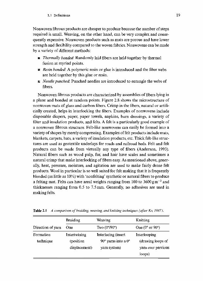
Nonwoven fibrous products are cheaper to produce because the number of stepsrequired is small. Weaving, on the other hand, can be very complex and conse-quently expensive. Nonwoven products such as mats are porous and have lowerstrength and flexibility compared to the woven fabrics. Nonwovens can be madeby a variety of different methods:
• Thermally bonded: Randomly laid fibers are held together by thermalfusion at myriad points.
m Resin bonded: A polymeric resin or glue is introduced and the fiber websare held together by this glue or resin.
w Needle punched: Punched needles are introduced to entangle the webs offibers.
Nonwoven fibrous products are characterized by assemblies of fibers lying ina plane and bonded at random points. Figure 2.8 shows the microstructure ofnonwoven mats of glass and carbon fibers. Crimp in the fibers, natural or artifi-cially created, helps in interlocking the fibers. Examples of nonwovens includedisposable diapers, paper, paper towels, napkins, burn dressings, a variety offilter and insulation products, and felts. A felt is a particularly good example ofa nonwoven fibrous structure. Felt-like nonwovens can easily be formed into avariety of shapes by merely compressing. Examples of felt products include mats,blankets, carpets, hats, a variety of insulation products, etc. Thick felt-like struc-tures are used as geotextile underlays for roads and railroad beds. Felt and feltproducts can be made from virtually any type of fibers (Anderson, 1993).Natural fibers such as wood pulp, fur, and hair have scales and sometimes anatural crimp that make interlocking of fibers easy. As mentioned above, gener-ally, heat, pressure, moisture, and agitation are used to make fairly dense feltproducts. Wool in particular is so well suited for felt making that it is frequentlyblended (as little as 10%) with 'nonfelting' synthetic or natural fibers to producea felting mat. Felts can have areal weights ranging from 100 to 3600 gm"2 andthicknesses ranging from 0.5 to 7.5 mm. Generally, no adhesives are used inmaking felts.
Table 2.1 A comparison of braiding, weaving, and knitting techniques (after Ko, 1987).
Braiding Weaving Knitting
Direction of yarn
Formationtechnique
One
Intertwining(positiondisplacement)
Two (0°/90°)
Interlacing (insert90° yarns into a 0°yarn system)
One (0° or 90°)
Interlooping(drawing loops ofyarn over previousloops)

20 Fibers and fiber products
Figure 2.8Microstructure of non-woven mats of (a) glassand (b) carbon fibers.

2.2 Some important attributes of fibers 21
CardingNonwoven webs can be made by a process called carding which involvesmechanically opening, combing, and aligning staple fibers (Crook, 1993).Rotating cylinders or plates covered with a metal wire are used to make cardedwebs. The process results in nonwovens containing quite uniform fiber distribu-tion. The cardability of a staple fiber depends on its geometry, diameter, length,frictional characteristics, crimp, etc.
2.1.7 Rope
Rope represents a very useful form of fibrous product. A rope or cord consistsof a bundle of fibers. The fibers may be continuous or they may be made of staplefibers, i.e. short, fine fibers. The tensile strength of a rope comes from the strengthof individual fibers and the friction between them. The interfiber friction pre-vents their slip past one another. Quite obviously, a rope or a cord has veryanisotropic properties. It is strong in tension along the axis direction but not inthe transverse or radial direction. Strength in compression is also very poor.
2.2 Some important attributes of fibers
A material in fibrous form has a series of attributes characteristic of its fibrousstate. Some of these are obvious, e.g. the properties of a fiber are highly biasedin the fiber direction, while others are not so obvious. Some of these character-istics stem mainly from their small cross-section and large aspect ratio, forexample:
• a high degree of flexibility;• a higher strength than the bulk material of the same composition.
These characteristics of fibers lead to some unique features which must be con-sidered in any product that uses fibrous materials. In this section, we describesome of these features that stem from its fibrous nature.
2.2.1 Fiber length per unit weight or volumeWe can readily obtain some simple geometric relationships. For example, fiberlength per unit weight or volume. We can write fiber volume v as
V=7Td2€/4
where dis the fiber diameter and € is the fiber length. Rearranging, we can write
(2.1)

22 Fibers and fiber products
10000
0.1 1 10 100Diameter (fxm)
1000
Figure 2.9 Fiber surfacearea per unit volumeversus fiber diameter, d.
Similarly, if we consider the mass of the fiber, m, rather than its volume, we canwrite
€=4m/pm/2 (2.2)
where p is the material density.Both of these simple expressions (Eqs (2.1) and (2.2)) tell us that for a given
mass or volume of fiber, its length varies inversely as the square of the fiber diam-eter. Thus, if we halve the fiber diameter, we will increase its length fourfold.
2.2.2 Fiber surface areaA given material in a fibrous form can have a very large surface area. Considera fiber of length € and diameter d. Then, for the fiber volume, we can write
TTvf= volume of fiber=~d2£* 4
The fiber surface area, SA, can be expressed as
(2.3)
(2.4)
From Eqs (2.3) and (2.4), we obtain
=vf d
(2.5)
Equation (2.5) says that the fiber surface area, for a given fiber volume, variesinversely as the fiber diameter. Figure 2.9 shows a plot of the fiber surface area

2.2 Some important attributes of fibers 23
per unit volume as a function of fiber diameter. As one goes from the large diam-eter CVD type fibers such as SiC, B, etc., to extremely small fibers such ascarbon, aramid, alumina, etc., the fiber surface area per unit volume increases.This has very important implications in composite materials because thefiber/matrix interface has a crucial role in determining the ultimate properties ofa composite (Chawla, 1987, 1993). For a given fiber volume fraction in a com-posite, the fiber surface area will determine the fiber/matrix interfacial area.Equation (2.5) tells us that as the fiber diameter decreases, the fiber surfaceincreases, and, consequently, the interfacial area in a fibrous composite willincrease.
2.2.3 Fiber cr imp
Crimp is a term used to describe the waviness of a fiber. We can describe thecrimp of a fiber in purely geometric terms such as wave amplitude or frequency.We can also describe this in terms of the force or energy required to uncrimp afiber. Crimp in a fiber is desirable because it makes it easy to process the fiberinto a variety of forms such as a spun yarn. Commonly, one encounters suchwaviness in protein-based animal fibers, such as human hair, and especially wool.Figure 2.10 shows a scanning electron microscopy (SEM) micrograph of ahuman hair where scales can be seen. In the synthetic polymeric fibers suchcrimp can be introduced by passing the filament between rollers having teeth.Crimp can also be introduced by chemical means. This is done by controlling thecoagulation of the filament to produce an asymmetrical cross-section. Anotherchemical means of introducing crimp is to have a bicomponent fiber. Miraflexfiber is such a fiber. It is a glass fiber with different chemical compositions in twohalves of its cross-sections (see Chapter 7). Fibers having short, discrete lengthsthat can be spun into a yarn are called staple fibers. Staple fibers are, generally,spun into a long yarn suitable for subsequent textile processing. The spinningquality of staple fibers can be improved if the fiber is imparted a waviness orcrimp.
2.2.4 Fiber flexibilityFlexibility of a fiber, i.e. its ability to be bent to an arbitrary radius is one of theimportant attributes of a fibrous material and worth discussing in some detail.It is easy to visualize that many operations such as weaving, braiding, winding,etc., depend on the ability of a fiber to be bent without breaking. This flexibil-ity is also of great importance in composites because it permits a variety of tech-niques to be employed for making composites with these fibers. If we treat thefiber as an elastic beam of circular cross-section, then we can easily see that thefiber flexibility corresponds to the ability of the elastic beam to be bent to an

24 Fibers and fiber products
Figure 2.10 SEM micro-graph of a human hairshowing scales.
arbitrary radius of curvature. A high degree of flexibility is really a character-istic of a material having a low modulus and a small diameter (Dresher, 1969).The flexibility of a given fiber is a function of its stiffness or elastic modulus, E,and the moment of inertia of its cross-section, I. The elastic modulus of amaterial is quite independent of its form or size. It is generally a material con-stant for a given chemical composition and fully dense material. Thus, for agiven composition and density, the flexibility of a material is determined by itsshape, the size of its cross-section, and its radius of curvature, which is a func-tion of its strength. We can use the inverse of the product of bending moment(M) and the radius of curvature (R) as a measure of flexibility. From elementarystrength of materials, we have the following relationship for a beam:

2.2 Some important attributes of fibers 25
nylon
_j | I I I I l I i
Figure 2.11 Diameter ofvarious fibers with a flex-ibility equal to that of a25 jjLm diameter nylonfiber. Given a sufficientlysmall diameter, it is possi-ble to produce, in princi-ple, an equally flexiblefiber from a polymer, ametal, or a ceramic.
100 200 300 400 500
Young's modulus (GPa)
MII=EIR
Rearranging and remembering that the moment of inertia, /, for a beam of cir-cular cross-section of diameter d, is equal to ra/4/64, we can write
MR=EI=ETTC14/64
Or, we can write for the flexibility of a fiber,
UMR=64/E7rd4~20/Ed4 (2.6)
Equation (2.6) indicates that (1/MR), a measure of flexibility, is a very sensitivefunction of diameter, d. If we take a 25 jim diameter nylon fiber as a quintessen-tial example of a flexible fiber, we can compute the diameter of various otherfibers that will be required to have a flexibility equal to that of a 25 |mm diameternylon fiber. Figure 2.11 shows this. It follows from this curve that, given asufficiently small diameter, it is possible to produce, in principle, an equally flex-ible fiber from a polymer, a metal, or a ceramic. In other words, one can makevery flexible fiber out of a ceramic such as silicon carbide or alumina providedone can make it into a fine enough diameter. Making a fine diameter ceramicfiber, however, can be a formidable problem in ceramic processing.
2.2.5 Skin—core structureAs we shall see in the chapters to follow, melt or solution spinning is perhaps themost common method of giving a fibrous form to a material. Even in the case ofceramic fibers that are produced from polymeric precursor fibers, high speed
26 Fibers and fiber products
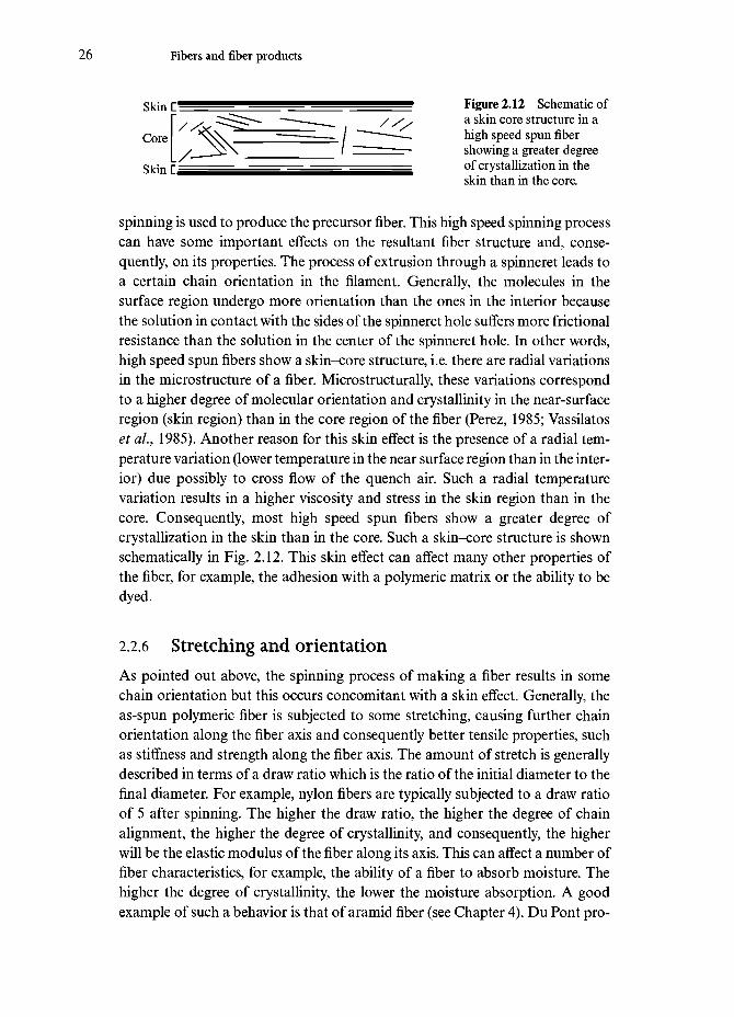
Skin r ^ l l ^ ^ ^ ^ ^ ^ ^ M M M ^ ^ ^ ^ M ^ ^ g Figure 2.12 Schematic of" . . C ^ ^ ^ —•—-^^ / s, a skin core structure in a
Core ^ S \ / " " " ^ high speed spun fiber• __J^\ / " showing a greater degree
Skin C ^ _ _ ^ ^ ^ ^ ^ ^ ^ ^ ^ ^ ^ I ^ ^ ^ _ _ ^ ^ — °f crystallization in theskin than in the core.
spinning is used to produce the precursor fiber. This high speed spinning processcan have some important effects on the resultant fiber structure and, conse-quently, on its properties. The process of extrusion through a spinneret leads toa certain chain orientation in the filament. Generally, the molecules in thesurface region undergo more orientation than the ones in the interior becausethe solution in contact with the sides of the spinneret hole suffers more frictionalresistance than the solution in the center of the spinneret hole. In other words,high speed spun fibers show a skin-core structure, i.e. there are radial variationsin the microstructure of a fiber. Microstructurally, these variations correspondto a higher degree of molecular orientation and crystallinity in the near-surfaceregion (skin region) than in the core region of the fiber (Perez, 1985; Vassilatoset aL, 1985). Another reason for this skin effect is the presence of a radial tem-perature variation (lower temperature in the near surface region than in the inter-ior) due possibly to cross flow of the quench air. Such a radial temperaturevariation results in a higher viscosity and stress in the skin region than in thecore. Consequently, most high speed spun fibers show a greater degree ofcrystallization in the skin than in the core. Such a skin-core structure is shownschematically in Fig. 2.12. This skin effect can affect many other properties ofthe fiber, for example, the adhesion with a polymeric matrix or the ability to bedyed.
2.2.6 Stretching and orientationAs pointed out above, the spinning process of making a fiber results in somechain orientation but this occurs concomitant with a skin effect. Generally, theas-spun polymeric fiber is subjected to some stretching, causing further chainorientation along the fiber axis and consequently better tensile properties, suchas stiffness and strength along the fiber axis. The amount of stretch is generallydescribed in terms of a draw ratio which is the ratio of the initial diameter to thefinal diameter. For example, nylon fibers are typically subjected to a draw ratioof 5 after spinning. The higher the draw ratio, the higher the degree of chainalignment, the higher the degree of crystallinity, and consequently, the higherwill be the elastic modulus of the fiber along its axis. This can affect a number offiber characteristics, for example, the ability of a fiber to absorb moisture. Thehigher the degree of crystallinity, the lower the moisture absorption. A goodexample of such a behavior is that of aramid fiber (see Chapter 4). Du Pont pro-
2.2 Some important attributes of fibers 27
duces a series of aramid fibers under the trade name of Kevlar. In particular,Kevlar 149 fiber has a higher degree of crystallinity than Kevlar 49.Consequently, Kevlar 149 has a higher elastic modulus and absorbs less mois-ture than Kevlar 49. In general, one can say, that a higher degree of crystallinityin a polymeric fiber translates into a higher resistance to penetration by foreignmolecules. This means a greater chemical stability. This can have importanteffects on textile fibers as it affects the dyeing characteristics of fiber. A highdegree of crystallinity makes it difficult for the dye molecules to penetrate thefiber.
There is, however, a limit to the amount of stretch that can be given to apolymer because the phenomenon of necking can intervene and cause ruptureof the fiber. In other words, in a polymeric fiber there is a limit to the modulusenhancement that can be obtained by subjecting it to an ever higher draw ratio.As we shall see in Chapter 4, this led to other means of obtaining high stiffnesspolymeric fibers such as aramid and polyethylene.
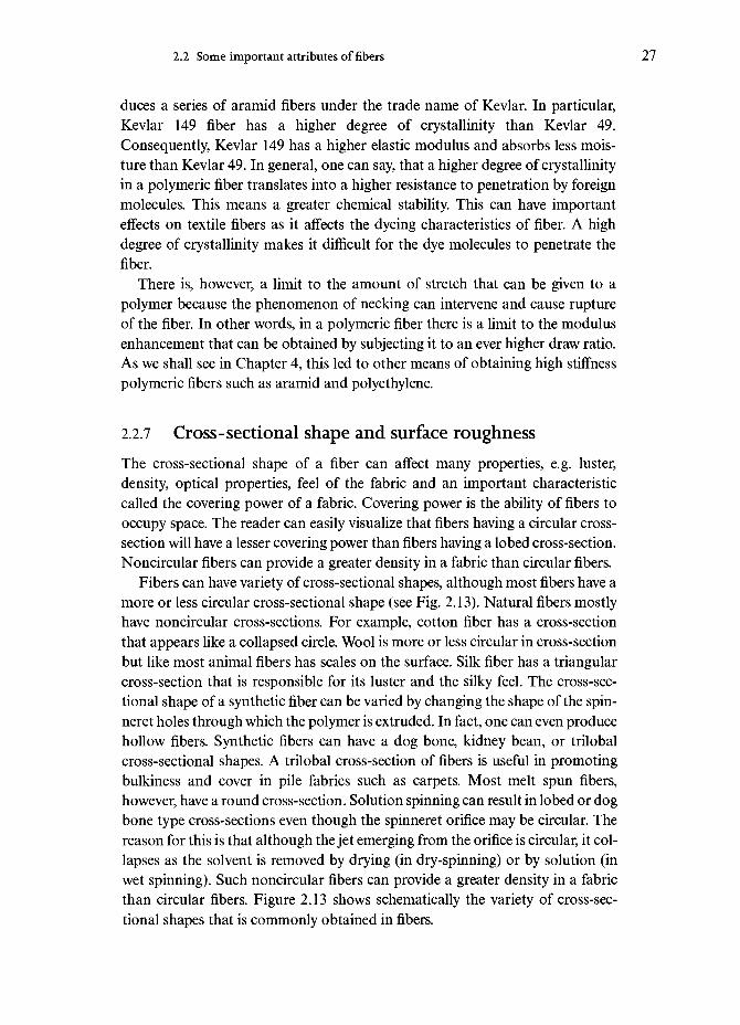
2.2.7 Cross-sectional shape and surface roughnessThe cross-sectional shape of a fiber can affect many properties, e.g. luster,density, optical properties, feel of the fabric and an important characteristiccalled the covering power of a fabric. Covering power is the ability of fibers tooccupy space. The reader can easily visualize that fibers having a circular cross-section will have a lesser covering power than fibers having a lobed cross-section.Noncircular fibers can provide a greater density in a fabric than circular fibers.
Fibers can have variety of cross-sectional shapes, although most fibers have amore or less circular cross-sectional shape (see Fig. 2.13). Natural fibers mostlyhave noncircular cross-sections. For example, cotton fiber has a cross-sectionthat appears like a collapsed circle. Wool is more or less circular in cross-sectionbut like most animal fibers has scales on the surface. Silk fiber has a triangularcross-section that is responsible for its luster and the silky feel. The cross-sec-tional shape of a synthetic fiber can be varied by changing the shape of the spin-neret holes through which the polymer is extruded. In fact, one can even producehollow fibers. Synthetic fibers can have a dog bone, kidney bean, or trilobalcross-sectional shapes. A trilobal cross-section of fibers is useful in promotingbulkiness and cover in pile fabrics such as carpets. Most melt spun fibers,however, have a round cross-section. Solution spinning can result in lobed or dogbone type cross-sections even though the spinneret orifice may be circular. Thereason for this is that although the jet emerging from the orifice is circular, it col-lapses as the solvent is removed by drying (in dry-spinning) or by solution (inwet spinning). Such noncircular fibers can provide a greater density in a fabricthan circular fibers. Figure 2.13 shows schematically the variety of cross-sec-tional shapes that is commonly obtained in fibers.

28 Fibers and fiber products
OCircular
[Glass, Carbon, organicfibers, Alumina, SiliconCarbide]
Elliptical[Alumina, Mullite]
Figure 2.13 Fibers canhave variety of cross-sec-tional shapes, althoughmost fibers have a more orless circular cross-section.
Triangular[Silk, SiC whiskers]
Hexagonal[Sapphire (AI2O3) whiskers]
RoundedTriangular
[Sapphire (AI2O3) singlecrystalfiber]
Kidney bean[Carbon]
Trilobal[Carbon, Rayon]
The surface texture of fibers can also vary considerably. Vegetable kingdomfibers such as cotton, jute, sisal, etc., have an irregular surface, while most animalfibers such as hair have scales. Compared to the natural fibers, synthetic fibersgenerally have relatively smooth surfaces. However, synthetic fibers can alsoshow a large degree of variation in their surface texture. Striation markings dueto drawing are commonly observed on the surface of metallic filaments. Figure2.14 shows an example of such markings on the surface of a tungsten filament.Similar markings but on a finer scale are observed on the surface of carbonfibers. Very fine-grained ceramic fibers can show surface roughness that scaleswith the grain size of the fiber (Chawla et ai, 1993). Such surface roughnesscharacteristics can have important bearing in regard to mechanical bonding offibers with matrix materials in different composites (Chawla, 1993).
2.2.8 Density
The density of fibers is a very important attribute. We mentioned above the useof linear density or mass per unit length. That term is really suitable for givingan idea of the fiber size. Bulk density or mass per unit volume tells us how heavya material is. Bulk density values of some important fibers are given in Table 2.2.The reader can easily verify that if we divide the linear density of a fiber by its

2.3 Important fiber types 29
Figure 2.14 Surface markings on a tungsten filament resulting from the dieused for wire drawing (SEM).
bulk density, we get the cross-sectional area of the fiber. Most polymeric fibershave bulk densities varying between 0.9 and 1.5 g cm"3 (polypropylene 0.9, poly-ethylene 0.97, polyester 1.4, cotton 1.5gcm~3). Ceramic fibers have densitiesvarying between 2 and 4 gem"3 while metallic fibers can have densities in therange 2 to 20 gem"3. The closer the value of the density of a fiber to its theoret-ical value, the smaller will be the amount of microvoids in the fiber and the closerit will be to its theoretical composition. For example, the theoretical bulk densityof carbon is 2.1 g cm"3, while the actual bulk density of carbon fiber can rangefrom about 1.6-1.8 g cm"3 to close to 2 g cm"3 for highly aligned graphitic fibersobtained from a pitch precursor. The reason for this is that the pitch-basedgraphitic fibers have fewer non-carbon atoms and microvoids than ordinarycarbon fibers.
2.3 Important fiber types
One may divide the whole field of fibers in many different ways. One may dividethem as natural and synthetic fibers or as polymeric, metallic, and ceramic fibers,etc. One convenient classification is based upon the fiber end use, i.e. apparel andnonapparel fibers. The apparel fibers include synthetic fibers such as nylon,rayon, polyester, spandex, and natural fibers such as wool, cotton, jute, sisal,
30 Fibers and fiber products
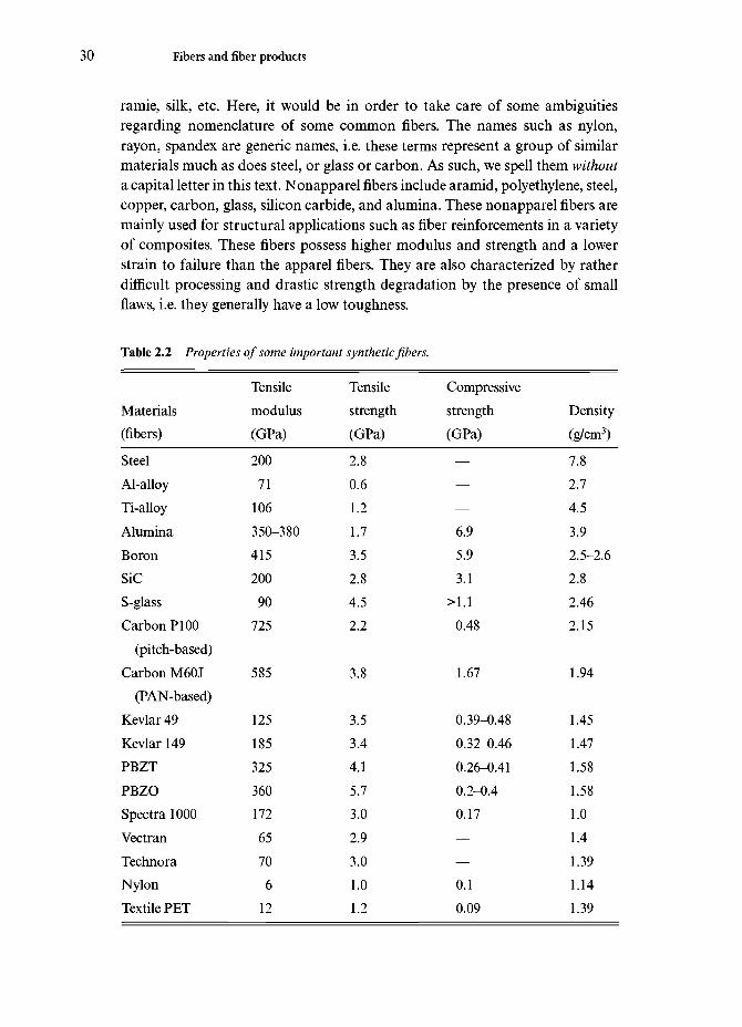
ramie, silk, etc. Here, it would be in order to take care of some ambiguitiesregarding nomenclature of some common fibers. The names such as nylon,rayon, spandex are generic names, i.e. these terms represent a group of similarmaterials much as does steel, or glass or carbon. As such, we spell them withouta capital letter in this text. Nonapparel fibers include aramid, polyethylene, steel,copper, carbon, glass, silicon carbide, and alumina. These nonapparel fibers aremainly used for structural applications such as fiber reinforcements in a varietyof composites. These fibers possess higher modulus and strength and a lowerstrain to failure than the apparel fibers. They are also characterized by ratherdifficult processing and drastic strength degradation by the presence of smallflaws, i.e. they generally have a low toughness.
Table 2.2 Properties of some important synthetic fibers.
Materials(fibers)
SteelAl-alloyTi-alloyAluminaBoronSiCS-glassCarbon PI00
(pitch-based)Carbon M60J
(PAN-based)Kevlar49Kevlar 149PBZTPBZOSpectra 1000VectranTechnoraNylonTextile PET
Tensilemodulus(GPa)
20071
106350-38041520090
725
585
12518532536017265706
12
Tensilestrength(GPa)
2.80.61.21.73.52.84.52.2
3.8
3.53.44.15.73.02.93.01.01.2
Compressivestrength(GPa)
———6.95.93.1
>1.10.48
1.67
0.39-0.480.32-0.460.26-0.410.2-0.40.17——0.10.09
Density(g/cm3)
7.82.74.53.92.5-2.62.82.462.15
1.94
1.451.471.581.581.01.41.391.141.39

2.4 General applications 31
2.4 General applications
There are many applications where fibers can be used in the form of a yarn orfabric (woven, nonwoven or knitted), e.g. optical fibers, ropes, cords, woven orknitted fabrics for clothing, nonwovens in the form of felts etc. for paper, blan-kets, insulation or filtration purposes, and last but not least, as a reinforcementin composites. In all of these applications, it is easy to see that the attribute offiber flexibility is very important. As an example, let us examine an applicationinvolving fiberoptic technology, flexible fiberscopes. These instruments providea flexible probe and working length that allow one to obtain images as deep as6 m inside a machine or structure where straight line access is not possible. Suchinstruments are also being used in medical diagnostics. Thousands of flexibleoptical glass fibers make a fiberoptic image bundle that carries a live image of anarticle to the eyepiece. We discuss optical glass fibers in Chapter 7.
Besides the commonplace uses as textiles and the more sophisticated uses asreinforcements to make composite materials, woven fabrics made of a fibrousyarn can be used to make versatile yet low cost structures. Such constructionalternatives can provide the following advantages:
• Fabrics can be translucent and thus result in energy efficiency.• They can meet diverse needs, e.g. recreational, industrial, and defense
requirements.• Extreme weather conditions, ranging from frozen arctic to hot deserts
and strong winds can be handled.• There is virtually no size limit to air-supported structures made of
fabrics.
A variety of structures can be made by fabrics. In the soft shell structure, a tensileloading of the fabric occurs, while in air-supported structures, the fabric is putin tension by a very slight internal pressure. A common example of air-supportedstructures made of light weight fabrics are the bubbles used for sports activities.Figure 2.15 shows such a bubble on a swimming pool during the winter seasonat New Mexico Institute of Mining & Technology. The space inside the bubbleis heated and the hot air supports the bubble. In tension-membrane structures,the fabric is supported by a structural skeleton of arches, masts or cables. Thereare many examples worldwide where some fabric made of fibers has been usedfor structural purposes. Just to give an example of such a structure we cite theDenver airport in the US. Its main terminal building has a 45000m2, tent-likestructural roof that is made of a Teflon-coated glass fiber fabric. Teflon is thetrade name of Du Pont for polytetrafluoroethylene (PTFE). The fabric is light-weight, translucent and lets in the natural light, and thus results in a reductionin the construction and building operating costs. The building consists of 17 tent

32 Fibers and fiber products
Figure 2.15 A bubble made of nylon fabric on a swimming pool during thewinter season at New Mexico Institute of Mining and Technology.
modules supported by two rows of masts, 30 to 37 m high. The nonstick Tefloncoating gives protection from chemical attacks and improves the dirt-removingeffects of rain.
Paper of course is perhaps the most commonplace example of a fibrousproduct. Although most common paper products are made of cellulosic fibers,paper-like products can also be made from the so-called high performance fiberssuch as aramid, glass, carbon, or other ceramic fibers.
Use of fibers as reinforcements to make composites is, of course, well estab-lished. These are structural applications where, because of the characteristicallylong length of fibers, they are incorporated in a continuous medium, called thematrix. We describe some of these applications in subsequent chapters in moredetail. Yet another common use of fibers of various kinds is in making ropes. Inprehistoric times, ropes were made of braided leather strips and vines. Later, veg-etable fibers such as jute, hemp, etc., were used to make ropes. More recently,ropes have been made of synthetic polymers and metallic fibers. Ropes can bemade by a variety of construction methods: twisted, braided, plaited, parallelcore and fiber, and wire rope.
Yet another example of a unique application where materials in a fibrous formare necessary is that of filters of all kinds. We have already mentioned one com-monplace example of a fibrous product, namely a tea bag. The proper tea bag

2.4 General applications 33
needs to be porous, should not impart a taste to the brew, and of course, shouldhave enough wet strength so that it does not fall apart in the hot water. Filtersmade of fabrics are commonly used for air cleaning. Industrial baghouses arecommonly used to collect dust and particles in various operations where dustladen gases are passed through a filtration medium. The dust (e.g. carbon black,fly ash, etc.) is collected on the filter and the clean gases come out of the otherside. Woven or felt types of fabrics are used for filters. Woven fabrics offer lowerresistance to gas flow than nonwovens. They also have a smooth finish whichprovides an easy release of dust. Essentially, the woven structure provides a gridto capture the particulate matter. Nonwoven fabrics provide a greater resistanceto gas flow and they work better with heavier dust such as sand, limestone, grain,etc. A measure of how much gas is driven by unit area of filter is given by
Gas volume (G)/cloth area(Q=GIC ratio
In very simple terms, a filter fabric intercepts a particle moving along a gasstream. When a particle impacts a fiber in the filter, the fiber does not get out ofthe way and the particle cannot go around the fiber. The gas stream, of course,can go around the fiber. The particle has mass and thus cannot follow the gasstream. Very small and light particles can be influenced by the bombardment ofgas molecules, changing their path until they bump into the fiber and aretrapped. Then there is also electrical entrapment when fibers in the fabric anddust particles carry opposite charges. In this case particles are attracted to thefiber and are trapped there. Fabrics made of cotton, polypropylene, nylon, poly-ester, Nomex, Teflon, glass, and wool are used as filters.
With the commercial availability of high temperature ceramic fibers, filtersmade of ceramic fibers such as Nextel 312 (alumina+silica+boron) are used ascandle filters.
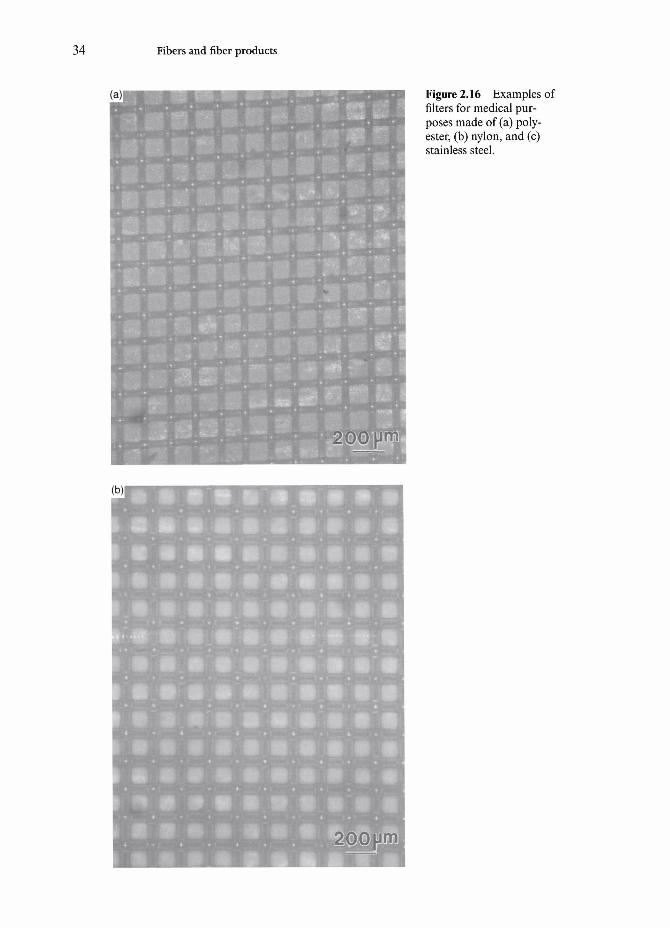
Fiber characteristics that should be taken into account for making filtersinclude: temperature capability, corrosion resistance (withstand acids, alkalies,solvents, etc.), hydrolysis (humidity levels), dimensional stability, and cost.Among important medical application of fibers, we should mention sutures andfilters. Sutures are used to close the wound during surgical operations. Fibersused as sutures can be absorbable or nonabsorbable. The main requirements arethat the suture must have only a minimal amount of reaction with the tissue and,in the case of absorption, there must be minimal chemical irritation (Lyman,1991). Absorbable sutures are collagen sutures, polyglycolic acid and its lactidecopolymers, and polydioxanone. Nonabsorbable sutures include silk, cotton,polyethylene, polypropylene, nylon, PET, and stainless steel. These fibers can beused as monofilaments or multifilaments (twisted or braided). Figure 2.16 showsexamples of filters for medical purposes made of polyester, nylon, and metallicfibers. In summary, fibers are used in almost everything that we can see in our
34 Fibers and fiber products
Figure 2.16 Examples offilters for medical pur-poses made of (a) poly-ester, (b) nylon, and (c)stainless steel.
! !1 ft
• • -
I fti Wk
•
'•*.*'«•
*••ft
-'ftft
'ft'ft'm•'•
wft
ft'ft'ft'ft'ftft
*•. •
W'ft•i
'ft
ft'ft'ftft
'*'ft'ft•fta
ftV
' ••
• • • «
'ft' •'ft'ft' •m•IKw
i
ft'a
• •'ft'ft'ft'ft•ft ft
V#'ft'ft' • •VSI ft
W m•
' ••••
•ftm'ft.«ft'
«IP
t
•
•
ft.

2.5 Health hazards 35
Figure 2.16 (cont.)
daily life. They range from vegetable to synthetic polymeric fibers to metallic,glassy, and ceramic fibers. The final useful product is, more often than not, basedupon a woven, knitted, braided, or a twisted rope or cord form of fiber, althoughnonwoven fibrous products are also used in less demanding situations, e.g.insulation pads and blankets, etc.
2.5 Health hazards
There are certain potential health hazards associated with the handling offibrous materials. These came to prominence when the health hazards associatedwith asbestos fiber came to light (see Chapter 6). We provide a summary of these.The following characteristics of fibers relate to potential biological activity:
• physical dimensions;• exposure or airborne concentration;• solubility in the lung.
Physical dimensions or size of a fiber determine whether or not it is respirable.For example, for silica-based glass fiber, fibers less than 3 |mm in diameter and

36 Fibers and fiber products
less than 200 |xm in length can become respirable. In terms of exposure or air-borne concentration of fibers, the Occupational Safety and Health Agency(OSHA) of the United States has proposed a permissible exposure limit of1.0 fiber/cm3 during any processing or handling. Fiber solubility refers to thespeed at which fibers disappear from the lung. In all cases, good work practiceskeep the exposure to respirable fibers quite low. Gloves and eye protectionshould be worn at all times.

Chapter 3
Natural polymeric fibers
Commercially, polymeric fibers are perhaps the most important of all, coveringas they do a vast range of applications. There are two broad categories of poly-meric fibers: natural and synthetic. Natural fibers can be from the vegetablekingdom such as cotton, sisal and jute or from the animal kingdom such as wool,silk, etc. Natural fibers are mostly polymeric in nature. There are, however, somenatural fibers that occur in rock formations. These fibers are minerals and cantherefore be treated as a ceramic, e.g. asbestos and basalt. We describe thesenatural mineral fibers in Chapter 6. In this and the following chapter, we describepolymeric fibers. We first briefly review some of the fundamental aspects of poly-mers and then describe the natural polymeric fibers. We devote Chapter 4 to thesynthetic polymeric fibers, which have seen tremendous advancement in the lasthalf of the twentieth century. A vast range of natural polymeric fibers is availableand they find large-scale commercial applications. Much research effort isfocused on a very special natural fiber originating in the animal kingdom, spidersilk. The idea here is to learn about the processing, structure, and properties ofsilk fibers which are very strong and stiff. More about this later in this chapter.The volume of other natural fibers such cotton, jute, sisal, ramie, etc. in indus-trial and non-industrial applications has always been quite large because of theirmany attributes such as the wear-comfort of cotton and the fact that all naturalfibers represent a renewable resource. The main disadvantage of natural fibers isthe immense variability in their physical, chemical, and mechanical attributes.
First, in order to understand the processing, structure, and properties of poly-meric fibers, the main focus of Chapters 3 and 4, it will be useful to review somegeneral and basic concepts regarding the structure of polymeric materials, and
37

38 Natural polymeric fibers
especially, some of the important features associated with the macromolecularchains that do not have their counterparts in metals and ceramics. Readers moreversed in these aspects of polymers may skip to Section 3.2. In what follows, wefirst examine the salient structural aspects of polymers and then describe theprocessing, structure, and properties of some important natural polymericfibers.
3. l Structure and properties of polymers
Polymers, natural or synthetic, are characterized by an extended chain structure.Giant molecules called macromolecules are formed by joining the chain elementsin different ways. Each unit or building block of the chain is called a monomerand a polymer results when we join many monomers to form a chain. Wedescribe below some important classes of polymers, their structure, and some oftheir important attributes.
3.1.1 Classification of polymersPolymers can be classified in many ways. An easy way to classify polymers isbased on the processing used to make them. There are two main types of poly-merization process:
(i) Condensation polymerization. In this polymerization, a stepwise polymer-ization reaction of molecules takes place with a molecule of a simplecompound forming at each step. Generally, the simple by-product is awater molecule.
(ii) Addition polymerization. In this process, polymerization occurs withoutthe formation of any by-product. This type of polymerization is generallydone in the presence of catalysts.
Another convenient classification of polymers involves the behavior of polymerwhen heated. A thermoplastic polymer softens on heating. Many linear polymersshow this behavior. Such thermoplastic polymers can be processed by liquid flowforming methods. They also have the advantage of being recyclable. Examplesinclude low and high density polyethylene, polystyrene, polymethyl methacrylate(PMM A), etc. When the molecules in a polymer are cross-linked in the form ofa network, they do not soften on heating. These cross-linked polymers are calledthermosetting polymers. Thermosetting polymers decompose when heated.Examples include epoxy, phenolic, polyester, etc.
We can also classify polymers based on their structure. The basic structuralunit of a polymer is a flexible macromolecular chain (Fig. 3.1a). When there isno long-range molecular order and the flexible molecular chains are arranged

3.1 Structure and properties of polymers 39
(a) Figure 3.1(a) Amorphous structurein a polymer with noapparent order among themolecules and the chainsarranged randomly.(b) Crystalline, lamellarstructure in a polymerwhere long molecularchains are folded in aregular manner.
(b)
randomly, we have an amorphous structure; such a polymer is called an amor-phous or glassy polymer. Under certain conditions, one can obtain a crystallineor, more appropriately, a semi-crystalline polymer. Lamellar crystals formwhen a crystallizable polymer such as a linear polymer is cooled very slowlyfrom its melting point. Small, plate-like lamellar single crystals can also beobtained by precipitation of the polymer from a dilute solution. In such lamel-lae, long molecular chains are folded in a regular manner as shown in Fig. 3.1b.Many such lamellar crystallites can group together and form what are calledspherulites.
Yet another type of classification of polymers is based on the type of repeat-ing unit. A homopolymer has one type of repeat unit. Copolymers are polymersthat have more than one type of monomers or repeat units. If the monomers ina copolymer are distributed randomly along the chain, it is called a regular orrandom copolymer. If, on the other hand, a sequence of one type of monomer isfollowed by a sequence of another type of monomer, it is called a block copoly-mer. If the main chain is one type of monomer and the branch chains are ofanother monomer, it is called a graft copolymer.
Next we describe some of the important attributes and properties of polymers.

40 Natural polymeric fibers
1.l.2 Degree of crystallinity
Unlike metals and ceramics, a 100% crystalline polymer is very difficult toobtain. In practice, depending on the polymer type, molecular mass andcrystallization temperature, the amount of crystallinity in a semi-crystallinepolymer can vary from 30 to 90%. Under special circumstances, such as in a gel-drawn polyethylene fiber, the degree of crystallinity can be as high as 98% whilein the case of polydiacetylene, single crystal fibers have been obtained by solidstate polymerization (Young, 1989). The inability to attain a fully crystallinestructure stems mainly from the long chain structure of polymers. Twisted andentangled segments of chains that become trapped between crystalline regionsnever undergo the conformational reorganization necessary to achieve a fullycrystalline state. Molecular architecture also has an important bearing onpolymer crystallization behavior. Linear molecules with small or no side groupscrystallize easily. Branched chain molecules with bulky side groups do not crys-tallize so easily. For example, linear high-density polyethylene can be crystallizedto 90% while branched polyethylene can only be crystallized to about 65%.Generally, the stiffness and strength of a polymer increase with the degree ofcrystallinity.
3.1.3 Molecular mass
Polymers are structurally much more complex than metals and ceramics. Onemanifestation of this complexity is the parameter molecular weight or, moreappropriately, molecular mass. The molecular mass of a polymer is a very impor-tant attribute. Any molecule has a molecular mass. The molecular mass of ordi-nary compounds, however, is not of great importance for most purposes. Theimportance of this parameter in the case of polymers stems from their long chainstructure. Macromolecular chains can encompass a whole range of molecularmasses from very low to very high. Even with a simple polymer chain, say poly-ethylene, one can have a whole range of molecular weights, structural mor-phologies, and properties. In general, the mechanical characteristics such asstrength improve with increasing molecular mass until a plateau is reached.
3.1.4 Melting point and glass transition temperature
A pure, crystalline material has a well defined melting point. The melting pointis the temperature at which crystalline order is completely destroyed on heating.Such a phase transition is absent in an amorphous material. However, an amor-phous material can be characterized by its glass transition temperature. Figure3.2 shows specific volume (volume/unit mass) versus temperature curves for anamorphous and a semicrystalline polymer. When a polymer liquid is cooled, it

3.1 Structure and properties of polymers 41
Amorphouspolymer
Figure 3.2 Specificvolume (volume/unitmass) versus temperaturecurves for an amorphousand a semicrystallinepolymer.
Temperature
contracts. The contraction occurs due to a decrease in the thermal vibration ofmolecules and a reduction in the free space, i.e. the molecules occupy the spaceless loosely. In the case of amorphous polymers, this contraction continues totemperatures below the melting point of crystalline polymer, Tm, until the super-cooled liquid polymer becomes rigid due to its extremely high viscosity.Although there is no sharp transition like a melting point, we can define a transi-tion temperature, T 9 corresponding to the onset of rigidity in the material. Notethat the structure of an amorphous material below T is still that of a liquid. Asthis is a phenomenon typical of glasses, we call the transition temperature theglass transition temperature. The terms glass and amorphous are used inter-changeably. Most inorganic glasses are silica based. Some metallic alloys can beproduced in a glassy state by very rapid quenching. In the case of amorphouspolymers, we have a glassy structure made of organic molecules. The glass transi-tion temperature, T' is in many ways akin to the melting point, Tm, for the crys-talline solids. Many physical properties (e.g. viscosity, heat capacity, elasticmodulus, expansion coefficient, etc.) change abruptly at T. Polystyrene, forexample, has a T of about 100°C and is therefore rigid at room temperature.Rubber, on the other hand, has a T of about — 75°C and, therefore, is flexible atroom temperature. The glass transition temperature of a polymer depends on itschemical structure. If a polymer has a rigid backbone chain or bulky sidegroups,then its T value will be higher than that of a polymer without a rigid backboneor bulky sidegroups. Table 3.1 gives typical T values of some common polymers.
Glass transition temperature is a characteristic of any material having a glassystructure, organic polymers, inorganic silica-based glasses, or even metallicglasses. The glass transition temperature, T, of inorganic glasses, however, is

42 Natural polymeric fibers
several hundred degrees Celsius higher than that of organic polymers. Thereason for this is the different types of bonding and the amount of cross-linkingin organic polymers and silica-based inorganic glasses. Silica-based glasses havemixed covalent and ionic bonding and are highly cross-linked. This gives them ahigher thermal stability than polymers which have covalent bonding only andless cross-linking than is found in inorganic glasses. The glass transition tem-perature of a polymer increases with its molecular mass. This is because thelarger the molecule, the less mobile it is, and consequently one needs to raise itstemperature higher to obtain sufficient energy for the chains to slide. A higherdegree of cross-linking also makes chain sliding more difficult and a higher glasstransition temperature will result. On the other hand, the introduction of a lightmolecule in a high molecular mass polymer will reduce the glass transition tem-perature by a certain amount. In other words, the range of the molecular massof a polymer determines the range of its glass transition temperature. This is veryimportant because, more often than not, polymers do show a range of molecu-lar masses and, consequently, they have a range of glass transition temperaturesrather than a fixed glass transition temperature.
3.1.5 Mechanical behavior of polymersPolymeric materials show a wide range of stress-strain characteristics. Onecharacteristic of polymers that is markedly different from metals and ceramics isthat their mechanical properties are highly time- and temperature-dependent.An elastomer or a rubbery polymer shows a stress-strain curve that is nonlinear.
Table 3.1 Glass transition temperatures, Tg, for somecommon polymers.
Polymer
Polyethylene0
Polypropylene"PolystyreneNylon 66*Poly (methyl methacrylate)Natural rubber
Glass transitiontemperature (°C)
-80 to-125-18 t o - 2 510050
12075
Note:a These have a crystalline component, which will alsohave a melting point.

3.2 Natural fibers 43
ujo
Increasingcrystallinity
Figure 3.3 Variation ofelastic modulus of apolymer with temperature.As the degree ofcrystallinity increases, theextent of rubbery plateauregion decreases.
Temperature, T
The characteristically large elastic range shown by elastomers results from aneasy reorganization of the tangled chains under the action of an applied stress.Polymers, much more than metals and ceramics, show temperature dependenceof their elastic moduli. Figure 3.3 shows schematically the variation of elasticmodulus of a polymer with temperature. Also shown is the trend with increas-ing crystallinity. As the degree of crystallinity increases, the extent of the rubberyplateau region decreases. At a temperature below the glass transition tempera-ture, T, the polymer is hard and a typical value of elastic modulus would beabout 5 GPa. Above T, the modulus value drops significantly and the polymershows a rubbery behavior.
Yet another important aspect of polymers is associated with environmentaleffects: polymers can degrade at moderately high temperatures and throughmoisture absorption. Absorption of moisture from the environment causesswelling in the polymer as well as a reduction in its glass transition temperature,Tg. Polymers can also undergo chain scission when exposed to ultraviolet radia-tion.
3.2 Natural fibers
Natural polymeric fibers can originate in the animal kingdom or vegetablekingdom. We give below a brief description of these.
3.2.1 Animal kingdom fibersAnimal fibers are basically made up of some kind of protein. Collagen, a crys-talline material, is the basic structural fiber of the animal kingdom. It is foundin virtually all animals, usually as a component of a complex plant connectivetissue. Its structure is based on a helical arrangement of three, noncoaxial,helical polypeptides, stabilized by interchain hydrogen bonds. The three helical

44 Natural polymeric fibers
polypeptides form a second-order helix with a long pitch around a central axisto give a coiled structure. This is analogous to a three-strand rope, each strandconsisting of a polypeptide chain.
All fibers obtained from the animal kingdom consist of elongated proteincrystals, aligned more or less along the fiber axis. The protein crystals are embed-ded in a protein matrix, thus forming a kind of natural composite. Keratin is ageneral term for fibrous, proteinaceous products of epidermal cell of vertebrates.Human hair is a natural polymeric fiber that we are all familiar with. Figure 2.10in Chapter 2 shows the scaly surface texture of human hair. Human hair is amammalian keratin and is very flexible because of its small diameter. Horn,hoof, quill, etc., on the other hand, contain stiff keratins and make rather stifffibrous composites. Other examples of protein-based fibers include hair-likefibers such as wool and cocoon fibers such as silk. Wool is the fleece obtainedfrom sheep. Wool fibers are generally between 20 and 50 |xm in diameter. Themain constituent of wool is also keratin. Its strain to failure is about 30%, andlike cotton it can absorb moisture, up to one-third of its weight. It can be easilydyed to a variety of colors. Wool also has an outer membrane, called the epicut-ile, which repels water. All these characteristics make wool a very versatile andprestigious textile fiber. Wool fiber, like many other protein-based natural fibers,shows a scaly texture on the surface. This leads to a directional frictional effect,friction being greater when pulled against the scales than when pulled along thescales (Makinson, 1972). Sliding against scales is difficult because of the rough-ness. Besides its use in clothing, wool fiber finds uses in blankets, insulatingmaterials, upholstery, carpets and rugs, and felts. Other wool-like fibers areobtained from goat, camel, etc. They are, however, more commonly referred toas hair. The hair of an Angora goat is termed mohair.
All natural fibers derived from animals have a proteinaceous constituent: col-lagen, keratin, or fibroin. Fibroin is the fibrous constituent in silk fiber (seebelow). The basic building block of a protein is an amino acid which has the fol-lowing formula:
H
H2N—C—CO 2H
R
where (-H2N) is the amino group, (-CO2H) is the acidic group and R is a sidegroup. The amino and acidic groups react to form an amide linkage(-CO-NH-), as in a polyamide (see Chapter 4). The distinctive feature ofprotein-based fibrous materials is that the R group is different in different aminoacids. The following chemical formula shows the linkage of amino acids via anamide linkage (-CO-NH-):

3.2 Natural fibers 45
HO HO H
H 2 N—C—C—N—C—C—N—C—CO 2 H
Rj H R2 H R3
Note the three different side groups, Rp R2 and R3. That is what makes collagen,keratin and fibroin different from one another.
Silk fiberSilk fiber is said to have originated in China, from where it is thought to havespread to Japan, India, and Iran, and eventually to Europe. Silk fabrics havebeen highly valued through the ages because of silk fiber's strength, elasticity,softness, affinity for dyes, etc. Fabrics made of silk fiber form part of the folkloreall over the world. It has been a luxury fiber for making dresses, Japanese kimono,and Indian sarees. Although many synthetic fibers have replaced silk, partiallyor completely, in some products, it still retains a great appeal for luxury appareland specialized goods. For the reader interested in the allure of silk through theages, there is ample information available in the lay literature, e.g. Feltwell(1990), Hyde (1984).
Silk fiber is the secretory product of the spinning glands found in a variety ofinsects and spiders. Different spinning glands of an insect produce differentkinds of silk, but all silks are proteinaceous and belong to the fibroins. Althougha variety of insects produce silk fiber, only bombyx mori and antheraea pernyi,two species of moth, are commercially grown for textile purposes. Of these two,the more important variety of silk fiber is the one secreted as a continuous fila-ment by the bombyx mori silk worm. The practice of cultivation of the silk mothis called sericulture. The cocoon variety of silk has been around for a long timeand is a well-established industry. In the sericulture practice, silk worms are fedon leaves from mulberry or oak trees. The silk worm has two sacs of fibroin, acrystalline protein. In the process of silk fiber production, the worm attachesitself to a twig and extrudes the fibroin by a muscular action through a hole orspinneret. Silk fiber (produced by a silk worm or spider) has a complex structureconsisting of two strands of fibroin surrounded by an amorphous sheath ofsericin, a gummy material. This gummy material is usually removed before spin-ning the fiber into yarn. The extended protein chains that form the fibroinsconsist of amino acids, predominantly glycine (44%) and alanine (30%). Thereis a growing interest in exploring other varieties of silk as well as learning fromnature, especially the spider, about the processing and microstructural design ofsilk fibers. As a spider spins silk fiber, the water-soluble liquid transforms to theinsoluble solid silk fiber. The exact mechanism of this transformation is not yetfully understood, but apparently the molecules of the polypeptide chain change

46 Natural polymeric fibers
FLAGELLIFOFIMTOUGH OUTER SILK
OF EGG SAC
INNER SILKOF EGG SAC
CEMENT FOR JOINTSAND ATTACHMENTS
Figure 3.4 Different silks for different functions can be produced by the samespider (after Vollrath, 1992).
their configuration. In a silk worm it is known that this happens simply bypulling on the chain. The reason for the interest in spiders is that they produce avariety of silk fibers that show superb mechanical characteristics, are producedat ambient temperatures and with an aqueous solvent, and are biodegradable.Compare this to the processing conditions required for making Kevlar aramidfiber (see Chapter 4), such as the use of boiling sulfuric acid as a solvent, etc.Hence, the great interest in understanding the structure and properties of spidersilk, i.e. the materials science of these spider silk fibers.
All spiders produce silk, but the orb-web spinning araneid and uloboridspiders are of special interest because they spin seven types of silks. Orbs are'two-dimensional, point-symmetrical arrays' that form a silk frame enclosing aseries of radiating lines (Shear, 1994). There are other types of aerial webs, verydifferent from the orb, but we shall not discuss these. Spider silk is one of thestrongest materials known. Two of these seven spider silks, frame silk and viscidsilk, have been studied in some detail (Gosline et al., 1986, 1995; Vollrath et al,1990, Kerkam etai, 1991). The frame silk is the one that is used to make the webframe and radii of the orb-web and the dragline. The viscid silk forms the spiralof the orb-web that is used for catching of the prey. A spider can produce morethan 30 m of silk in a single stretch. Different silks for different functions can beproduced by the same spider as seen in Fig. 3.4 (Vollrath, 1992). Different silkscan have different amino acid compositions. These silks are synthesized and spunby different glands and spinnerets located on the posterior end of the spider'sabdomen. Seven kinds of silk are produced from abdominal glands and spigots.

3.2 Natural fibers 47
Figure 3.5 Detailedstructure of the majorampullate gland silk. Allmicrostructures are in thelongitudinal direction.NPL = non-periodic lattice(after Thiel and Viney,1995).
5 nm
NPL crystalcontains polyalanine crystals
Gly Gly Qly
Gly or Gly or Gly
Pro Gly Gin
Gly other 3-sheet
Gly
Q;ly IGly
X2 J
10 A
NPL crystal
For example, in the major ampullate gland silk, glutamine (Glu), proline (Pro),glycine (Gly), and alanine (Ala) form 80% of the silk. The amount of Pro canvary considerably from one species to another. Although each gland has its ownshape and size, their function is more or less the same. The major ampullategland silk has been studied the most because of its easy accessibility. One suchdetailed structure, shown in Fig. 3.5, is the hierarchical structure in the longitu-dinal direction of major ampullate gland silk (MAS) (Thiel and Viney, 1995).The acronym NPL in the figure stands for a new term coined by these authors,namely 'non-periodic lattice' crystals. These NPL crystals have an ordered mol-ecular arrangement that does show diffraction although it does not contain truelong-range periodicity. Figure 3.5 shows short irregular sequences in the NPLcrystals while longer irregular sequences occur in the matrix region. Clearly, thestructures of silk can become quite complex.
X-ray diffraction studies on frame silk indicate it to be a microcomposite, con-sisting of a cross-linked, amorphous network (about 55-60%) reinforced by stiff

48 Natural polymeric fibers
(a)
(b) 1 2 3
0 ]500 nm
500 nm
Figure 3.6 Two possiblestructures of spider frame-silk: (a) microcompositestructure consisting ofrandomly distributedprotein crystallites inanamorphous matrix(after Gosline et al., 1986);and (b) skin-core struc-ture. The two core regionsare marked 1 and 2 andthe thin skin is marked 3.Both the core regionscontain pleated fibril-likestrands (after Li et al.,1994).
crystalline protein fibers. Figure 3.6a shows a schematic of the microcompositestructure of the frame silk. Li et al. (1994) made a three-dimensional, nanome-ter scale study of the structure of dragline or frame silk by atomic forcemicroscopy. The three-dimensional structure of silk was determined from longi-tudinal sections and sections made at 45° and 90° to the fiber axis. The structuralmodel of spider dragline silk, due to Li et al. (1994), is shown in Fig. 3.6b. Unlikethe structure shown in Fig. 3.6a (randomly distributed protein crystallites in anamorphous matrix) their model consists of an organized skin-core structure. In

3.2 Natural fibers 49
Steel
0.1 0.2Strain
Figure 3.7 Tensilestress-strain curves of avariety of different materi-als: steel, cellulose,tendon, and frame silk.Note the high fractureenergy (area under thestress-strain curve) of theframe silk fiber. Thestrain-to-failure of framesilk can be as high as 30%(after Gosline et al., 1986).
the figure the two core regions are marked 1 and 2 and the thin skin is marked 3.Both the core regions contain pleated fibril-like strands. This model of spider silkstructure is very similar to the structure of Kevlar aramid fiber (see Chapter 4).
The tensile stress-strain curve of frame silk is shown in Fig. 3.7. The curvesfor a number of different materials, steel, cellulose, tendon, are also included forcomparison. Note the high fracture energy (area under the stress-strain curve)of the frame silk fiber. The strain to failure of frame silk can be as high as 30%.
However, unlike the cocoon silk fiber from the larvae, the spider silk, althoughmuch stronger than the silkworm silk, is not available in large quantities(Vollrath, 1992; Gosline et al., 1986). It is so difficult to produce that a commer-cial production is not viable. One of the reasons for this is that the spiders needa steady stock of live insects to eat, and if they are put too close to other spiders,say in a spider silk producing factory, they end up eating each other (Berenbaum,1995). Efforts are being made in the area of genetic engineering to produce silk-like proteins in microbial culture and spin fibers from them (Gosline et al., 1995;Kaplan et ah, 1994). Researchers at the US Army Research and Developmentand Engineering Center (Natick, MA) are developing E. Coli bacteria that aregenetically altered to produce silk (Kaplan et al, 1994).
The cocoon silk of the silk worm is an excellent textile material and the com-mercial activity in this realm attests to that. Its mechanical properties, however,are rather modest. This has been attributed to the fact that superior mechanicalcharacteristics are not required in the cocoon. On the other hand, in spider's orb-web silk, the spider needs a fiber that can absorb the impact of the falling insectprey. Hence, the need for superior mechanical characteristics.
Silk is combustible, but self-extinguishing. It is a good electrical insulator andcan accumulate static electricity easily, which is the reason why silk fiber pro-cessing is done at high humidity. It is 1-3 |xm in diameter, has a density of1.25 gcm~3, a strain to failure of between 20% and 30%, and a tenacity between3 and 5 gram/denier. The elastic modulus of spider silk is about lOGPa. The

50 Natural polymeric fibers
cross-section of a silk fiber is an irregularly shaped triangle, or crescent, or anelongated wedge. It is this more or less triangular cross - sectional shape of alarge number of fine silk fibers in a fabric that makes them reflect light like prismsand gives the fabric that characteristic luster.
3.2.2 Vegetable fibersThe vegetable kingdom is, in fact, the largest source of fibrous materials. Thegreat advantage in this case, of course, is that of low cost. Cellulosic fibers in theform of cotton, flax, jute, hemp, sisal, ramie, etc. have been used in the textileindustry while wood and straw have been used in the paper industry. We describenow, very briefly, some important vegetable fibers. The interested reader isdirected to a number of good review articles for greater details (Batra, 1985;Meredith, 1970; Robinson, 1985; Stout, 1985; Segal and Wakelyn, 1985; Rohatgiet aL, 1992, Chand and Rohatgi, 1994).
Fibers having origin in the vegetable kingdom can be obtained from variousparts of the parent plant. Some examples of vegetable fibers obtained fromdifferent parts of the plant as follows:
» seed hairs (cotton, kapok);• stem or bast fibers (flax, hemp, jute);• leaf fibers (pifia, sisal).
These fibers serve a variety of functions in their parent plants. Most commonly,they serve to stiffen the stems and leaves of plants. This allows the plants toweather the storms and high winds to which they are frequently subjected. Insome plants, they also provide buoyancy to the seeds.
The main constituent of any vegetable fiber is cellulose. Cellulose is oftenfound as a relatively high modulus, fibrillar component of many naturally occur-ring composites, such as wood, where it is found in association with lignin.Cotton fiber, for example, contains 80-85% cellulose, while other vegetable fiberssuch as ramie, hemp, jute, flax and sisal have between 65 and 70% cellulose.Cellulose is composed of three elements, C, H and O, with the general formulaof C6H10O5 and is crystalline. An easy way to check this is to use an X-ray diffrac-tion technique (Barkakaty, 1976). An amorphous polymer will give diffuse halos.A diffuse halo indicates an irregular atomic arrangement, i.e. an amorphousstructure. There may also occur some alignment of chains in the amorphousregions. An X-ray diffraction pattern of a highly crystalline polymer would showregular spots and/or regular rings indicating regular spacing characteristic of anorderly arrangement in a single crystal. Sometimes the discrete spots take theform of streaks or arcs because of a preferential alignment of polymeric chains.Well-spaced regular rings would indicate a random, polycrystalline region.Figure 3.8 shows a Debye-Scherer X-ray diffraction pattern of a sisal fiber. The

3.2 Natural fibers 51
Figure 3.8Debye-Scherer X-raydiffraction pattern of asisal fiber. The arcs in thispattern indicate the crys-talline nature of the mainconstituent, cellulose.
arcs in this pattern indicate the crystalline nature of cellulose, the main constitu-ent of sisal. Besides cellulose, vegetable fibers contain significant amounts ofother chemicals such as lignin, hemicellulose, pectin substances, resins, mineralmatter, fats, and waxes. After their isolation from the plant, these fibers are sub-jected to some treatments to remove hemicellulose and lignin, etc. Most of the

52 Natural polymeric fibers
lignin and other non-cellulosic substances are associated with the cell walls andtheir presence does modify the final properties of the fiber. The non-cellulosicmaterial is hardly ever removed completely from these fibers, mainly because itis prohibitively expensive to do so.
An important attribute of vegetable fibers is that they can absorb moisturefrom the atmosphere in comparatively large quantities. This is because the cel-lulose is hygroscopic, i.e. it absorbs moisture from the atmosphere at high humid-ities and releases it when dry. This absorption leads to alterations in weight anddimensions as well as in strength and stiffness. The moisture content can be mea-sured as the percentage loss in weight of the fiber when it is dried in an oven ata given temperature and for a specified time. Frequently, we express the moisturecontent as 'moisture regain', which is the loss in weight on drying expressed as apercentage of the weight of the dried fiber, i.e. we take the weight of the dry fiberas the basis because the dry weight of the fiber is a constant, whereas the origi-nal weight can vary according to the moisture content before drying.
Another important attribute of vegetable fibers is that they are subject to bio-logical decay. Most vegetable fibers darken and weaken with age and exposureto light. They are not as durable as synthetic polymeric fibers. All of them geteasily attacked by a variety of organisms, at high humidity and temperature,leading to rot and mildew.
We provide below a brief description of some of the important vegetablefibers.
CottonCotton has been called the king of fibers. Cotton is a hollow fiber when it isgrowing, but its lumens, the internal space of a cell, collapse when it is harvested.Thus, its cross section is flat and one can see the microfibrils composing thecotton fiber in a low magnification optical microscope. The composition ofcotton is mainly crystalline cellulose with varying amounts of pectin, fat andwax. The cellulose molecule takes a helical form with the helix angle varyingbetween 20 and 30°. Figure 3.9 shows the structure of cotton fiber (Jefferies etai, 1969). The density of cotton fiber is about 1.5 gem"3.
Cotton is really a very versatile fiber in that it takes color easily, absorbs mois-ture readily, and is durable in a wide variety of environments. Cotton yarn findsuse in all kinds of clothing, often mixed with synthetic fibers. In fact, accordingto one estimate almost half of all textiles worldwide are made of cotton(Thompson, 1994). Besides apparel, cotton fiber is used in coffee filters, fishnets,lace, upholstery, etc. It is biodegradable and can be used as a sorbent in oil spills.
JuteJute fiber is obtained from the inner bark of plants of the genus corchorus. It isproduced mainly in Bangladesh, Brazil and India. It is used extensively in

3.2 Natural fibers 53
Lumen Figure 3.9 Structure of acotton fiber. The cellulosemolecule takes a helicalform with the helix anglevarying between 20 and30° (after Jefferies et aL,1969).
making cords, coarse cloth and sacks. Occasionally, one can even find a dinnerjacket made of lustrous golden colored jute fiber.
Jute fibers are separated from the woody part of the stem by a process calledretting. The process involves laying bundles of stems flat in water, side by side,to form a platform. The platform is then covered first with weeds and then withheavy logs to keep the bundles submerged in the water. The period of rettingvaries with the water type and temperature. The fiber strands are then removed,manually, from the stems. They are cleaned by spreading on the water surface,squeezed to remove the excess water and hung on frames to dry in the sun for2-3 days. The dried jute fibers are then tied in bundles and packed for ship-ment.
The jute fiber can have a color from lustrous yellow to brown The commer-cially obtained strands consist of individual jute fiber cemented together bynatural gums. When observed in an optical microscope, the cross section of a jute

54 Natural polymeric fibers
50 Mm
Figure 3.10 Polygonalcells of jute fiber. Note thethick walls and easilyobservable lumens.
fiber shows polygonal cells. These cells are about 2.5 mm long. The cells havethick walls and easily observable lumens (see Fig. 3.10).
As with most fibers derived from the vegetable kingdom, the individual fibersvary considerably in strength. Their strain to fracture is about 1.7%. The densityof jute is 1.5gcm~3. Jute fibers absorb a considerable amount of water, typicallyshowing a regain value of about 15 wt% at 65% relative humidity.
SisalSisal is a leafy fiber that comes from the plant agave sisalana which is native toCentral America. Tropical climate with a moderate humidity is required for sisalfiber and it is commonly found in Eastern Africa and Brazil.
The plant has a short, thick stem from which grows a rosette of leaves con-taining sisal fibers. The leaves are cut off at the point where they join the mainstem and are sent for extraction of the fiber. This must be done as soon as pos-sible after harvesting as the cut leaves deteriorate very quickly. The fibers areextracted by crushing or scraping to remove green matter surrounding them. Theextracted fiber is dried in the sun. Strands of commercially obtained sisal fibercan vary in length from 0.5 to 1.25 m. Like jute fiber, a large number of individ-ual fibers are generally cemented together by natural gums. The color of sisalfiber varies from white to pale yellow.
Sisal fiber finds use in a variety of items such as in the manufacture of bindertwine and baler twine, mattings, rugs, marine ropes, padding material for cars,upholstery, etc.
RamieRamie is another important vegetable fiber. It has a shiny, white color. Its strainto failure is 3-4%, and compared to other vegetable fibers, it has an exception-

3.2 Natural fibers 55
ally high resistance to bacteria, fungi, and mildew. Often, it is blended with otherfibers for use in making clothing.
Rayon
Rayon fiber, produced by conversion of cellulose, is commonly referred to asregenerated cellulose. In these fibers, the primary component is cellulose, origi-nating in the plant kingdom. That is why rayon is generally included in the cat-egory of natural fibers. Cellulose from a variety of sources can be used toproduce rayon fibers. For example, cellulose pulp obtained from cotton linters(short fibers sticking to the cottonseed) or from timber containing more than90% cellulose is suitable for making rayon fiber. Cellulose does not melt or dis-solve in common solvents. Therefore, it is converted into a different chemicalform. For example, to make rayon, one dissolves wood pulp in a solution ofsodium hydroxide. Carbon disulfide is added to this to produce sodium cellulosexanthate. This chemical form of cellulose is soluble in dilute, aqueous sodiumhydroxide, resulting in a solution with molasses-like consistency, called viscose.Viscose is wet spun through a spinneret into a sulfuric acid bath where theextruded fibers are reconverted to cellulose and coagulated to form solid fila-ments. The rayon fibers are then wound as continuous fiber on to spools or cutinto short lengths to make a staple rayon fiber and washed to remove the pro-cessing chemicals. Variations in cross-sectional shape, stretching, dyeing, intro-duction of crimp, or chopping into short lengths can be done during the spinningprocess.
A summary of important properties of some vegetable fibers is given in Table3.2 (Rohatgi^a/. , 1992).
Table 3.2 Properties of some vegetable fibers (adapted from Rohatgi et ah, 1992).
Fiber
JuteRamieHempFlax
Density(gcnr3)
1.501.501.501.50
Strength(GPa)
0.850.930.901.08
Young'smodulus(GPa)
645969
100
Specificstrength*7
0.570.620.600.71
Specificmodulus0
43394667
Note:a Specific strength and modulus are strength/density and modulus/ density,respectively.

56 Natural polymeric fibers
3.2.3 Environmental effects on polymeric fibersEnvironmental factors such as humidity, temperature, pH, ultraviolet radiation,and micro-organisms can affect polymer fibers. Natural polymeric fibers aremore susceptible to environmental degradation than synthetic polymeric fibers.Larvae of some insects may feed on a wide variety of dry materials with a highcellulose and protein content, i.e. vegetable as well as animal fibers. Thereforefibers such as silk, wool, cotton, jute, etc. and the products made of such fibers,e.g. textiles (sweaters, coats, etc.) and carpets are susceptible to damage by micro-organisms. Cellulose, in particular, is attacked by a variety of bacteria, fungi, andalgae. Micro-organisms use cellulose as a food source. Such attack can be pre-vented to some extent by giving a durable moth-resist treatment during manu-facture. A good example of such a treatment is that given to wool fiber. Perhaps,the most widely used treating agent is permethrin, a synthetic pyrethroid.Pyrethroid is chemically similar to pyrethrum, an insecticide occurring naturallyin a number of chrysanthemum varieties. Permethrin is widely used in agricul-ture, for the domestic control of insects and as a wood preservative.
Natural fibers based on cellulose or protein are more prone to degradationdue to humidity and temperature than synthetic organic fibers. Photo-degrada-tion occurs when exposed to light (both visible as well as ultraviolet) whichshows up as a discoloration and loss in mechanical properties. Most polymericfibers (natural or synthetic) swell due to moisture absorption. The swelling isgenerally more in natural fibers. We discuss this topic again in Chapter 4.
3.3 Applications of natural polymeric fibers
Natural polymeric fibers find extensive applications in all walks of life. We givesome examples.
Natural polymeric fibers are used for a variety of textile applications rangingfrom clothing to upholstery to sacks and cordage. Frequently, these are blendedwith synthetic fibers to obtain an optimum set of properties. Many naturallyoccurring fibers can be and are used in composites, but mostly in applicationsinvolving not very high stresses (Chawla, 1976; Chawla and Bastos, 1979; Roeand Ansell, 1985; Chand and Rohatgi, 1994)
Many natural fibers are finding uses in automobiles, trucks, and railway cars.One of the reasons for this is the concern for the environment and the need touse renewable resources. Natural fibers are a renewable resource and they do notexacerbate the CO2 emission problem. Not only are natural fibers environ-mentally friendly, they possess reasonably good mechanical properties, such asimpact resistance, at a very low weight. Examples of applications of naturalfibers include, among others, the Mercedes-Benz E-class automobile. More

3.3 Applications of natural polymeric fibers 57
specifically, in this automobile shredded cotton is used in rear shelves and insu-lating mats, while padding elements of coconut fiber, animal hair, and naturallatex, and structural parts of flax and sisal fiber reinforced polymers are used. Itshould be pointed out that flax fiber is native to Germany while sisal is native toBrazil and many other countries. Natural fibers are also being used as geotextilesfor soil stabilization (Datye and Gore, 1994; Kaniraj and Rao, 1994).
Chapter 4
Synthetic polymeric fibers
In this chapter we describe synthetic polymeric fibers, which saw tremendousadvancement in the last half of the twentieth century. In fact, a reasonable casecan be made that the so-called age of fibers began with the advent of syntheticfibers such as nylon, polyester, etc. in the late 1930s and early 1940s. Many com-panies such as Du Pont, Monsanto, BASF, Hoechst, ICI, etc. contributed sig-nificantly in this area. For a historical account of the scientific and technologicalprogress made in this area, the reader is referred to a study of research anddevelopment activities at Du Pont during the period 1902-1980 (Hounshell andSmith, 1988). Most of these synthetic polymeric fibers such as polyester, nylon,etc. have very uniform and reproducible properties. They, however, have a ratherlow elastic modulus, which restricts them mostly to the apparel or textile market.It was the research work aimed at making strong and stiff synthetic polymericfibers for use as reinforcements in polymers, which started sometime in the late1950s and early 1960s, that resulted in the commercial availability of strong andstiff fibers such as aramid and extended-chain polyethylene. We describe belowthe processing, structure, and properties of some important synthetic polymericfibers in some detail.
4. l Brief history of organic fibers
A brief historical review of the work in the area of organic fibers will be helpfulin placing things in perspective. We begin with the discovery of nylon. Nylon wasdiscovered and commercialized by Du Pont in 1938 (Magat and Morrison,
58

4.2 Processing 59
1976). Wallace Carothers of Du Pont is generally regarded as the father of nylon.Nylon first penetrated the silk hosiery market just before the start of the SecondWorld War. In fact, 1988 marked the 50th anniversary of the introduction ofnylon silk stockings. Nylon is made by melt spinning. It is a very flexible, knit-table, and durable fiber; all these attributes have made it one of the most impor-tant fibers for the textile industry. Nylon's high strength, good impact and fatigueresistance also led to its use in the tire industry. It should be noted that the termnylon is a generic term that represents a group of similar materials, in the samevein as glass, steel or carbon. Accordingly, we spell it without a capital letter.
After nylon, poly (ethylene terephthalate) (PET) and polyacrylonitrile (PAN)were the next two major discoveries. PET is made by polymer melt spinning whilePAN uses a spinnable polymer solution dope. PET, a thermoplastic polyester,and PAN soon found uses as substitutes for wool, cotton and rayon in carpets,blankets, etc. PAN is also used as a precursor for making carbon fibers (seeChapter 8). Among the major attributes that made the synthetic fibers such asnylon, PET, and PAN, etc. a great success story were the characteristics of wash-and-wear, resistance to wrinkling, and durability. Synthetic polymeric fibers sawtremendous advances in the last half of the twentieth century. More importantly,however, a new era in the age of man-made fibers was launched when the impor-tance of structure-property relationships in polymers was realized. Someimpressive work on polymer crystallization in the late 1960s started this new eraof structure-property relations in polymeric materials. One of the major out-comes of this structure-property work on polymers was the realization that anextended and oriented polymer chain arrangement leads to improved mechanicalcharacteristics. Organic fibers of high tensile strength and modulus, such asaramid and polyethylene, were a direct result of this effort. As we shall see inSection 4.5, two different structural approaches have been used to obtain highstiffness, high strength fibers. In rigid rod polymers such as aramids, we make useof the inherent high stiffness of the aromatic groups in the main chain coupledwith the physical ordering of chains, while in flexible chain polymers such aspolyethylene, we use the physical ordering of chains to obtain a high modulus.
In what follows, we first describe general processing techniques used to makesynthetic polymeric fibers, followed by a description of the processing, structure,and properties of some important low modulus organic fibers. Finally, wedescribe, in some detail, two commercially important, high-stiffness fibers:aramid and polyethylene.
4.2 Processing
Generally, synthetic polymers are made into fibers by a process known as fiberspinning. Fiber spinning is the process of extruding a liquid through small holes

60 Synthetic polymeric fibers
Polymer solution or melt
0 3 Metering pump
Spinneret
Figure 4.1 General viewof solution or melt spin-ning. Filaments emergeout of the holes in a spin-neret, pass through a bathand an oven before beingwound as a yarn on abobbin.
Bath Oven Fiber yarn
in a spinneret to form solid filaments. Figure 4.1 shows a schematic of theprocess. A polymer melt or solution is the starting material. Filaments emergeout of the holes in a spinneret, may pass through a bath and an oven before beingwound as a yarn on a bobbin. It is an unfortunate fact that the term spinning isalso used to denote an important process called yarn spinning. In nature, silkworm and spiders produce continuous filaments by this general process. Theprocess of spinning solid fibers by making a liquid pass through tiny orificesexploits the fact that certain materials such as organic polymers and silica-basedinorganic glasses (see Chapter 7) have the right viscosity to produce a stable jetas the liquid comes out of the orifice. The jet may be stabilized by an air streamor a coagulating bath (see below). If the viscosity is low, then the molten jetbecomes unstable with respect to surface tension because of a surface wave phe-nomenon. These waves, called Rayleigh waves, form on the surface of the low-viscosity jet stream (see also Chapter 6). Rayleigh waves grow exponentially inamplitude along the length of the jet and thus tend to break the jet up into drop-lets. Molten metals have very low viscosity (close to that of water), and thus wedo not normally use melt spinning to produce metal filaments. The key point torecognize is that if we can somehow stabilize the low-viscosity molten jet againstbreakup by the Rayleigh waves, then we can have a continuous fiber. One way todo this is to extrude such a low viscosity jet through an orifice into a chemicallyreactive environment. In the case of glasses and organic polymers, the melts havehigh enough viscosity (more than 104Pas or 105 poise), which delays theRayleigh breakup until the molten jet freezes. In the case of a low-viscosity melt,one can avoid the breakup of the molten jet by chemically stabilizing it. For

4.2 Processing 61
(a) Figure 4.2 Differentspinning processes, (a)Melt spinning: the fiber-forming material is heatedabove its melting pointand the molten material isextruded through a spin-neret.
example, Wallenberger et al (1992) developed a process to make fibers of(alumina+calcia), wherein a low-viscosity (1 Pas or 10 poise) jet is chemicallystabilized with propane before the Rayleigh waves can break the stream intodroplets. The low-viscosity jet must be stabilized in about 10~3 seconds or it willbreak up into droplets. We discuss this topic further in Chapter 7. Suffice to sayhere that in the case of polymers, the viscosity is high enough that it does notpose the problem of Rayleigh instability leading to a breakup of the molten jetstream. A brief description of some of the common methods of spinning syn-thetic polymeric fibers follows:
(a) Melt spinning. The fiber forming material is heated above its melting pointand the molten material is extruded through a spinneret (see Fig. 4.2a). Theliquid jets solidify into filaments in air on emerging from the spinneret holes.Melt spinning is very commonly used to make organic fibers such as nylon, poly-ester, and polypropylene fibers.
(b) Dry spinning. A solution of a fiber forming polymeric material in a volatileorganic solvent is extruded through a spinneret into a hot environment. A streamof hot air impinges on the jets of solution emerging from the spinneret, evapo-rates the solvent, and leaves the solid filaments (Fig. 4.2b). Fibers such as acetate,

62 Synthetic polymeric fibers
(b) DRY SPINNING
Closedspinning
cell
Polymerin
solution
Spinneret
Warmair
flow
Figure 4.2 (cont.) (b) Dryspinning: a stream of hotair impinges on the jets ofsolution emerging fromthe spinneret, evaporatesthe solvent, and leaves thesolid filaments.
acrylic, and polyurethane elastomer are obtained by dry spinning of appropri-ate solutions in hot air.
(c) Wet spinning. A polymer solution in an organic or inorganic liquid isextruded through holes in a spinneret into a coagulating bath. The jets of liquidcoalesce in the coagulating bath as result of chemical or physical changes and aredrawn out as a fiber. Figure 4.2c shows this process. Examples of organic fibersobtained by this process include rayon and acrylic fibers.
(d) Dry jet-wet spinning. Aramid fibers are processed by the dry jet-wet spin-ning process. In this process, the anisotropic solution is extruded through thespinneret holes into an air gap (about 1 cm) and then into a coagulating bath.The coagulated fibers are washed, neutralized and dried. We discuss this processin detail in Section 4.5.
(e) Gel spinning. In this process, filaments coming out of the spinneret holesform a rubbery or gel-like solid on cooling. The process is applicable to linearflexible chain polymers such as polyethylene. A gelled fiber is produced whenan appropriate solution coming out of the spinneret is quenched by air. The

4.2 Processing 63
(c)
Coagulating bath
Polymer insolution
Spinneret
Figure 4.2 (cont.) (c) Wet spinning: the jets of liquid coalesce in the coagulatingbath as result of chemical or physical changes and are drawn out as a fiber.
gelled fiber has the structure of a swollen network of entangled chains, whichallows drawing into fibers with very high draw ratios and below the meltingpoint. High strength and high stiffness ultrahigh molecular weight poly-ethylene (UHMWPE) fibers are made by this process as described in Section4.5.
(f) Fibers from films. Techniques (a) through (e), described above, are thecommon variants of making polymeric fibers, namely extrusion of a spinningdope or melt through a large number of small holes in a spinneret. There is a verydifferent method of making fibrous polymers that involves using films (Krassiget al, 1984). This technique exploits the ease of making polymer films that arehighly oriented and inexpensive to produce. Such films show a markedanisotropy in strength along the two principal directions (longitudinal andtransverse), the strength along the longitudinal or draw direction being muchhigher than that in the transverse direction. This stems from the preferentialpolymer chain alignment in the draw direction. This anisotropy allows easy split-ting of such films into fibrous products by simple mechanical actions, such asbrushing, rubbing or twisting. The cross-section of such fibers from films issquare or rectangular rather than circular because of the starting material.
4.2.1 Stretching and orientationWe have repeatedly pointed out that a very important characteristic of any poly-meric fiber is the degree of molecular chain orientation along the fiber axis. The

64 Synthetic polymeric fibers
20
CO 4 c
O
3 1 0
PET (axial)
PET (transverse)T • I
2 3 4 5
Strain ratio
Figure 4.3 Variation ofmodulus as a function ofstrain or draw ratio forpolyethylene terephthalate(PET) and polypropylene(PP) in the axial andtransverse directions(Hadleyefa/., 1969). Notethe rather small effect inthe transverse direction.
process of extrusion through a spinneret results in some chain orientation in thefilament. Generally, the molecules in the surface region undergo more orienta-tion than the ones in the interior because the near surface molecules are moreaffected by the edges of the spinneret hole. This is known as the skin effect orskin-core effect (see Chapter 1). It can affect many other properties of the fiber,for example, the adhesion with a polymeric matrix or the ability to be dyed.
Most as-spun polymeric fibers are subjected to some stretching, causingfurther chain orientation along the fiber axis and consequently better stiffnessand strength in tension along the fiber axis. The amount of stretch imparted isgenerally given in terms of draw or strain ratio, A, which is the ratio of the initialdiameter to the final diameter. For example, nylon fibers are typically subjectedto a draw ratio of 5 after spinning. A higher draw ratio results in an increasedalignment of chains, and consequently a higher elastic modulus. Figure 4.3shows the variation of modulus as a function of strain or draw ratio for poly-ethylene terephthalate (PET) and polypropylene (PP) in the axial and transversedirections (Hadley et aL, 1969). Note the rather small effect in the transversedirection.
Orientation of macromolecular chains also affects the ability of a fiber toabsorb moisture. An increased chain alignment results in a higher degree ofcrystallinity and a lower moisture absorption. In general, the stretching treat-ment translates into a higher resistance to penetration by foreign molecules, i.e.a greater chemical stability. In particular, it affects the dyeing characteristics offiber, because the dye molecules cannot easily penetrate the fiber. There is,however, a limit to the amount of stretch that can be given to a polymer becausethe phenomenon of necking can intervene and cause rupture of the fiber.Necking results in an accentuated but very localized plastic deformation at a par-ticular site, which eventually leads to fracture of the material at that site. Itshould be pointed out that the phenomenon of necking can be observed in anymaterial that shows plasticity under tension. An important result of this chainalignment along the fiber axis is the marked anisotropy in the characteristics ofa polymeric fiber.

4.3 Environmental effects on polymeric fibers 65
Oriented, long chain polymeric fiber
Figure 4.4 Schematic ofanisotropic swelling in apolymeric fiber.
Water molecule
Polymeric fiber + moisture
4.3 Environmental effects on polymeric fibers
Environmental factors such as humidity, temperature, pH, ultraviolet radiation,and micro-organisms can affect polymer fibers. Natural polymeric fibers aremore susceptible to environmental degradation than synthetic polymeric fibers.Cellulose is attacked by a variety of bacteria, fungi, and algae. Micro-organismsuse cellulose as a food source. Natural fibers based on protein such as wool, hair,silk, etc. can also be a food source for micro-organisms, but such fibers are moreprone to degradation due to humidity and temperature. Polymeric fibers, naturalor synthetic, undergo photo-degradation when exposed to light (both visible andultraviolet). Physically this results in discoloration, but is also accompanied bya worsening of mechanical characteristics.
Most polymeric fibers (natural or synthetic) swell due to moisture absorption.The degree of swelling is generally more in natural fibers. In the case of syntheticfibers, especially the ones showing a high degree of crystallinity, and thusanisotropy, more swelling occurs in the transverse direction than in the longitu-dinal direction. This is because water molecules that penetrate a fiber end upseparating polymeric chains laterally more than along the fiber axis. Figure 4.4

66 Synthetic polymeric fibers
H H H H H H H O H H H H O Figure 4.5 Chemical\ N-i.^i-i^-i-N-C-C-C-C-C-C-O-H structure of nylon'
H H H H H H H H H H H H
shows, in a schematic manner, this phenomenon of anisotropic swelling in apolymeric fiber. An important characteristic of woven fabrics is that they havedistinct pores (see Chapter 2). Such pores in woven fabrics can close, partially orcompletely, when fibers swell due to moisture absorption.
4.4 Some important low modulus syntheticpolymeric fibers
In this section we describe the processing, structure, and properties of someimportant low modulus synthetic polymeric fibers.
4.4.1 NylonNylon is a generic name for any long-chain polyamide thermoplastic containingmore than 85% aliphatic groups in the main chain. It is worth pointing out thatnylon and polyamide are accepted generic names for the same group of fibers.The term nylon is commonly used in North America and UK while polyamideis more prevalent in continental Europe. The chemical structure of nylon 66 isgiven in Fig. 4.5. The recurring part of the chain, -CONH-, is the amide group.The amide groups in adjacent chains lead to interchain hydrogen bonding andallow close packing. We can use the definition of nylon fiber provided by the USFederal Trade Commission (FTC). According to the FTC, a nylon fiber is amanufactured fiber in which the fiber-forming substance is a long-chain syn-thetic polyamide in which less than 85% of the amide linkages are attacheddirectly to two aromatic rings. This term 'less than 85%' serves to distinguishnylon from aramid fibers (Section 4.5). The term nylon, as we said above, refersto the whole family called polyamides. There are, however, two important typesof nylon, nylon 66 and nylon 6, with nylon 66 being the major polyacid fiber. Theexplanation for this nomenclature of nylon is as follows. Processing of nylon fiberinvolves making the basic polymer, followed by melt spinning of the fiber. Thefour basic elements, C, H, N and O are combined into adipic acid hexamethyl-ene diamine and caprolactam. Condensation polymerization provides the long-chain molecule of polyamide. The 66 in nylon 66 refers to the number of carbonatoms in the constituents of nylon, i.e. both diamine and dibasic acid contain 6carbon atoms each. If, however, the polyamide is obtained by self-condensationof a single constituent (e.g. an amino acid), a single number is used to indicatethe number of carbon atoms in the original constituent, i.e. nylon 6. The poly-
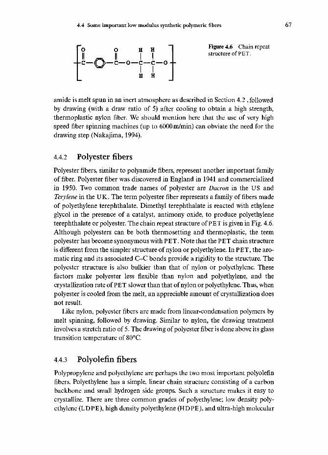
4.4 Some important low modulus synthetic polymeric fibers 67
„ „ "I Figure 4.6 Chain repeatI I structure of PET.
•c—(C 1>— c—o—c—c—o - -
H H
amide is melt spun in an inert atmosphere as described in Section 4.2 , followedby drawing (with a draw ratio of 5) after cooling to obtain a high strength,thermoplastic nylon fiber. We should mention here that the use of very highspeed fiber spinning machines (up to 6000m/min) can obviate the need for thedrawing step (Nakajima, 1994).
4.4.2 Polyester fibersPolyester fibers, similar to polyamide fibers, represent another important familyof fiber. Polyester fiber was discovered in England in 1941 and commercializedin 1950. Two common trade names of polyester are Dacron in the US andTerylene in the UK. The term polyester fiber represents a family of fibers madeof polyethylene terephthalate. Dimethyl terephthalate is reacted with ethyleneglycol in the presence of a catalyst, antimony oxide, to produce polyethyleneterephthalate or polyester. The chain repeat structure of PET is given in Fig. 4.6.Although polyesters can be both thermosetting and thermoplastic, the termpolyester has become synonymous with PET. Note that the PET chain structureis different from the simpler structure of nylon or polyethylene. In PET, the aro-matic ring and its associated C-C bonds provide a rigidity to the structure. Thepolyester structure is also bulkier than that of nylon or polyethylene. Thesefactors make polyester less flexible than nylon and polyethylene, and thecrystallization rate of PET slower than that of nylon or polyethylene. Thus, whenpolyester is cooled from the melt, an appreciable amount of crystallization doesnot result.
Like nylon, polyester fibers are made from linear-condensation polymers bymelt spinning, followed by drawing. Similar to nylon, the drawing treatmentinvolves a stretch ratio of 5. The drawing of polyester fiber is done above its glasstransition temperature of 80°C.
4.4.3 Polyolefin fibersPolypropylene and polyethylene are perhaps the two most important polyolefinfibers. Polyethylene has a simple, linear chain structure consisting of a carbonbackbone and small hydrogen side groups. Such a structure makes it easy tocrystallize. There are three common grades of polyethylene; low density poly-ethylene (LDPE), high density polyethylene (HDPE), and ultra-high molecular

68 Synthetic polymeric fibers
Extruder
Quenchtank
Pull rolls Draw oven
Wind-up Relax rolls Annealing oven Draw rolls
Figure 4.7 Schematic of the melt spinning process of making polypropylenefibers.
weight polyethylene (UHMWPE). It is the ultra-high molecular weight poly-ethylene variety that is used to make high modulus fibers. We describe theUHMWPE polyethylene fiber in some detail in Section 4.5 because of its com-mercial importance as a high strength and high modulus fiber. Polypropylene isan important fiber, although it does not possess a very high modulus. The degreeof crystallinity achievable in polypropylene is generally less than that in poly-ethylene. This is because polypropylene has side groups while polyethylene is ahighly linear polymer. In general, bulky side groups make it difficult to obtainan orderly arrangement of molecular chains, i.e. crystallization. The spatialarrangement of groups (tacticity) is also important in this regard. Polyolefinfibers are spun from polymers or copolymers of olefins such as ethylene and pro-pylene. Polypropylene fibers are made by melt spinning, involving extrusionthrough an extruder followed by thermal and mechanical treatment. Figure 4.7shows a schematic of this process. The extruder has a spinneret at the one end.As in other cases, the spinneret has orifices generally arranged in a circularfashion. The melt temperature is about 250°C. The filaments go through a water-filled quench tank to pull rolls and then on to a draw oven, followed by drawrolls, an annealing oven, and finally to a windup drum. As with any otherpolymer, the degree of chain orientation in the polymer is a function of the drawratio. In this case, the draw ratio is simply the ratio of the speed of the draw rollto that of the pull rolls. Commonly, this draw ratio is 9, which gives a highstrength fiber. The annealing treatment serves to relieve any processing inducedresidual stresses.

4.4 Some important low modulus synthetic polymeric fibers 69
4.4.4 Polydiacetylene single crystal fiber
We discussed the concept of degree of crystallinity in a polymer and the fact thatit is very difficult to obtain a 100% crystalline polymer. Under careful conditions,it is possible to produce a fully crystalline or even a single crystal polymer. In par-ticular, polydiacetylene single crystal fibers have been obtained by solid statepolymerization (Young, 1989). The process involves preparation of single crys-tals of monomer by vapor phase deposition or precipitation from a dilute solu-tion. The monomer is subjected to solid state polymerization (homogeneously orheterogeneously) by means of synchrotron radiation, gamma-rays, or thermally.
Fibers produced in this manner have some shortcomings. For example, thesefibers are of very short length, no more than 5-10 cm long, and are producedrather slowly. One should also add that the only single crystal fiber produced isbased on solid state polymerization of certain substituted diacetylenes and thetechnique does not seem to be applicable to other systems.
4.4.5 Elastomeric fibers
Elastomers can be described, in a very general way, as polymers that exhibit arubbery behavior, i.e. they exhibit nonlinear elastic behavior and are capable ofbeing stretched extensively. The American Society for Testing and Materials(ASTM) provides a more precise definition of an elastomer; an elastomer is 'amaterial which at room temperature can be stretched repeatedly to at least twiceits original length, and, upon immediate release of the stretch, will return withforce to its approximate original length'. There are many segmented blockcopolymers (see Chapter 3) that fit this requirement of being able to be stretched200% and thus can be called elastomers. However, not all of these can be con-verted into a fibrous form. In short, elastomers are materials that show a veryhigh degree of elastic, nonlinear strain. Most elastomers have a very low Young'smodulus, E. Elastomeric materials, although they have rather low stiffness,possess very good damping properties. Their main characteristic is that theyhave a long range of nonlinear, reversible elastic strain. For example, an elas-tomer can be elastically stressed to a strain of 700% while steel can be elasticallystressed only to about 0.1% strain. This is because in metals and ceramics,elasticity corresponds to small elastic displacements of atoms from their equi-librium position. Microstructurally elastomers are long chain polymers with aglass transition temperature, T <room temperature (293 K). Their unstrainedstate corresponds to a random coil structure of the macromolecular chains whilein the strained state, these macromolecules become extended chains. Thus,straining results in chain orientation which results in a decrease in entropy, S.Entropy is a measure of disorder in the chain configuration. We can write thefree energy change on straining as
70 Synthetic polymeric fibers
AG=AH-TAS
where AH is the change in enthalpy, T is the temperature, and AS is the changein entropy. The enthalpy does not change when an elastomer is strained.Therefore, the free energy change resulting from straining an elastomeric bandcan be written as:
AG=-TAS
Consider a polymer chain extending between two points. The flexible chain canhave many configurations between these points. For the configurational entropy,we can write an expression from statistical mechanics,
where k is Boltzmann's constant and/? is the number of configurations. Whenwe stretch a rubber band, we move the two fixed points further apart and thenumber of chain configurations possible will be reduced compared to thenumber of configurations possible in the unstrained state. This means that theentropy, S, is reduced on straining. Since T is always positive and AS is nega-tive on straining, we have a positive AG. That is to say that the strained stateof a rubber band is thermodynamically not favored! That is why when werelease a strained rubber band (a high entropy state), the unstrained state isregained.
The essential characteristic of an elastomeric fiber is that the material can bestretched several times its original length and when unloaded, it returns to itsoriginal dimensions. This characteristic can be imparted to a polymer in twoways:
(i) Chemically cross-link flexible polymeric chains. For example, this is doneby vulcanization of rubber by sulfur.
(ii) Make a two-phase, multiblock polymer, more commonly known as a seg-mented polymer. An example of such a polymer is the segmented poly-urethanes.
Elastomeric fibers can be made out of natural rubber. Rubber latex, which is asuspension of rubber spheres in water, is mixed with a vulcanizing agent, and themixture is wet spun. The fibers from the spinneret are extruded into a coagulat-ing bath and then vulcanized to produce the cross-linking of chains. Such fibersare used in woven and knitted fabrics, and more often than not they are mixedwith other textile fibers to form fabrics for garments. Most natural rubber fibers,however, have been supplanted by synthetic elastomeric fibers, especially in thearea of athletic wear. This is attributable to the poor dyeability, abrasion resis-

4.4 Some important low modulus synthetic polymeric fibers 71
tance, and chemical stability of rubber fiber vis-a-vis the segmented polyurethanefibers. The term Spandex (or Lycra) is used as a generic term to denote syntheticfibers that consist of at least 85% of segmented polyurethane polymer. The termelastane is more common in Europe.
Processing of elastomeric fibersElastomeric fibers such as Spandex (or Lycra) are polyurethane fibers and areobtained by spinning from polymers in which molecular linkage occurs throughurethane groups. The processing involves a series of chemical reactions, start-ing with the production of a low MW polymer (prepolymer), followed by reac-tion of the prepolymer with diisocyanate. The isocyanate-terminatedprepolymer is then coupled to form the segmented polyurethane. Soluble poly-urethanes that are essentially linear can be dissolved in any number of solventsand subjected to wet or dry spinning. As described above, in the wet spinningprocess, the fibers from the spinneret pass through a coagulating bath while inthe dry spinning process they pass through an atmosphere that removes thesolvent. Dry spinning is by far the most common method of making elas-tomeric fibers. The spinning dope has a variety of additives such as TiO2 fordelustering, stabilizers, antioxidants, lubricants, antitacking agents, dye stuffreceptive agents, etc. The dope is extruded through a spinneret and the solventis removed by flowing hot gases. Single filaments are coalesced to form a fusedmultifilament assembly. The spinning rates are from 200-800 m/min. Generally,a post-spinning stretching treatment is given at 150°C to obtain enhancedorientation of the hard segments parallel to the fiber axis and thus enhancedstrength.
If the polyurethane molecule is allowed to form a three-dimensional structure,it becomes insoluble and neither wet nor dry spinning processes can be used. Achemical spinning process must be used in this case. The trick is to spin the iso-cyanate-terminated prepolymer at a stage where it forms a viscous melt, and withthe jets produced in an environment that contains a chain extender. This chainextender diffuses into the fibers and reacts to couple the prepolymer molecules(Couper, 1985).
Structure and properties of elastomeric fibersPolyurethanes that form the basis of these elastomeric fibers are made by react-ing glycols and diisocyanates. Such elastomeric fibers are block copolymers. Theirmain characteristic is, as we said above, that they can be stretched repeatedly.Structurally, these block copolymers consist of a soft and flexible chain segment(random-coiled aliphatic polyethers or copolyesters) and a hard segment (aro-matic-aliphatic polyureas). Urethane linkages connect the hard segment blocksto the soft segments. Figure 4.8a shows schematically how an elastomeric fiberconsisting of hard and soft segments can show high stretchability. The soft

72 Synthetic polymeric fibers
Soft segments Hard segments
Relaxed
Under tension
Recovery after removal of tension
Figure 4.8 (a) An elastomeric fiber consists of hard and soft chain segments and canshow high stretchability.
segment domains, comprising 65-90% by weight, are unoriented in the relaxedstate of the fiber but straighten out when stretched. The soft segments allow thepolyurethane to stretch while the hard segments act as anchors that allow thefibers to recover to their original shape when the load is removed. One can controlthe amount of stretching by controlling the ratio of hard to soft segments.Spandex fibers have linear density between 1 and 500 tex and a strain to failurein the range 400-800%. Figure 4.8b shows specific stress-strain curves of Lycra(Spandex) and natural rubber fibers (Wilson, 1967,1968). Spandex or Lycra fiber

4.5 Strong and stiff polymeric fibers 73
200 400Strain (%)
600
Figure 4.8 (cont.) (b)Specific stress-straincurves of Lycra (Spandex)and natural rubber fibers(Wilson, 1967, 1968).
is stronger than rubber fibers. It has a lower modulus than nylon but it can bestretched to much higher values of strain.
Spandex-type polyurethane fibers are chemically quite stable under normalwashing and chlorine containing swimming pool water conditions. Special sta-bilizers are required for protection against ultraviolet radiation, suntan lotions,human perspiration, etc.
4.5 Strong and stiff polymeric fibers
As described in Chapter 3 and above, in general, macromolecular polymers havethe chains in a random coil configuration, i.e. they have the so-called cooked-spaghetti structure. In this random coil structure, the macromolecular chains areneither aligned in one direction nor stretched out. Thus, they have pre-dominantly weak van der Waals interactions rather than strong covalent inter-actions, resulting in a low strength and stiffness. Since the covalentcarbon-carbon bond is a very strong bond, one would expect that linear chainpolymers such as polyethylene would be potentially very strong and stiff.Conventional, isotropic polymers show a Young's modulus, E, of about 10 GPa.Highly drawn polymers having a Young's modulus of about 70 GPa are availablecommercially. The most important message of the extensive work done in thesecond half of the twentieth century in the area of structure-property relationsin polymers is that if one wants strong and stiff organic fibers (e.g. polyethylene),then one must obtain oriented molecular chains with full extension. Thus, in orderto obtain high stiffness and strength polymers, we must extend these polymerchains and pack them in a parallel array. The orientation of these polymer chainswith respect to the fiber axis and the manner in which they fit together (i.e. orderor crystallinity) are controlled by their chemical nature and the processing route.

74 Synthetic polymeric fibers
FiberAxis
Figure 4.9 (a) Molecularorientation without highmolecular extension, (b)Molecular orientationwith high molecular exten-sion.
(b)
There are two ways of achieving molecular orientation, one without high mole-cular extension, Fig. 4.9a, and the other with high molecular extension, Fig.4.9b. It is the kind of chain structure shown in Fig. 4.9b, i.e. molecular chainorientation coupled with molecular chain extension, that is needed for high stiff-ness and strength. In the polymer fiber literature sometimes the term ultra-highmodulus fibers is used for fibers with extremely high modulus that results froman oriented and extended chain structure. What is really implied here is a Young'smodulus greater than 70 GPa, which is the modulus of aluminum and glass. Toobtain a Young's modulus value greater than 70 GPa requires high draw ratios,i.e. a very high degree of elongation must be carried out under such conditionsthat macroscopic elongation results in a corresponding elongation at a molecu-lar level. It turns out that the Young's modulus, E, of a polymeric fiber increaseslinearly with the deformation ratio (draw ratio in tensile drawing or die drawingand extrusion ratio in hydrostatic extrusion). The drawing behavior of a polymeris sensitive to:
(i) molecular weight and molecular weight distribution;(ii) deformation conditions (temperature and strain rate).
Too low a drawing temperature produces voids, while too high a drawing tem-perature results in flow drawing, i.e. the macroscopic elongation of the materialdoes not result in a molecular alignment, and consequently, no stiffnessenhancement results. An oriented and extended macromolecular chain struc-ture, however, is not easy to achieve in practice in flexible polymers.Nevertheless, considerable progress in this area has been made during the lastquarter of the twentieth century. Organic fibers such as aramid and polyethylenepossessing high strength and modulus are the fruits of this work. Two very

4.5 Strong and stiff polymeric fibers 75
different approaches have been taken to make high modulus organic fibers.These are:
(i) Processing of the conventional flexible-chain polymers in such a way thatthe internal structure takes a highly oriented and extended-chainarrangement. Structural modification of 'conventional' polymers such ashigh modulus polyethylene was developed by choosing appropriate mole-cular weight distributions, followed by drawing at suitable temperaturesto convert the original folded-chain structure into an oriented, extendedchain structure. It should be pointed out that Mark (1936) predicted wayback in 1936 that the theoretical modulus of polyethylene with alignedchains should approach 250 GPa.
(ii) The second approach, radically different, involves synthesis, followed byextrusion of a new class of polymers, called liquid crystal polymers.These have a rigid-rod molecular chain structure. The liquid crystallinestate, as we shall presently see, has played a very significant role in pro-viding highly ordered, extended chain fibers.
Let us consider these two approaches in some detail. Recall that stretchingpolymers at temperatures below their melting point improves their stiffness andstrength. Techniques involving some stretching are used commercially for nylon,polyester, and polypropylene fibers (as well as some polymer films) (see Section4.4). Fairly high strength can be obtained but modulus is low compared to glassor aluminum. The two approaches mentioned above have resulted in twocommercialized high strength and high stiffness fibers; polyethylene and aramid.Next we describe the processing, structure, and properties of these two fibers.
4.5.1 Oriented polyethylene fibersThe ultra-high molecular weight polyethylene fiber is a highly crystalline fiberwith very high stiffness and strength. All of this results from some innovativeprocessing and control of structure of polyethylene.
ProcessingDrawing of melt crystallized polyethylene (molecular mass 104 to 105) to veryhigh draw ratios can result in moduli of up to 70 GPa. Tensile drawing, diedrawing or hydrostatic extrusion can be used to obtain the high permanent orplastic strains required to obtain a high modulus. It turns out that modulus isdependent on the draw ratio, but independent of how the draw ratio is obtained(Capaccio et ai, 1979). In all these drawing processes, the polymer chainsbecome merely oriented without undergoing molecular extension, and we obtainthe kind of structure shown in Fig. 4.9a.

76 Synthetic polymeric fibers
Figure 4.10 Schematic ofa gel structure with crys-talline regions at thenetwork junctions.
Later developments involving solution and gel spinning of very high molecu-lar mass polyethylene (>106) resulted in moduli as high as 200 GPa. In thesemethods, molecular orientation is achieved together with chain extension, i.e. themolecular chain structure shown in Fig. 4.9b is obtained. Lamellar single crys-tals of polyethylene can be obtained from an appropriate solution by crystalliza-tion, aligning the molecular chains in the direction of flow. In another method,a crystallized shish kebab structure is obtained from the polymer solution. Ashish kebab structure consists of a continuous array of fibrous crystals, the shishkebabs, in which the molecular chains are highly extended.
The method that has become technologically and commercially most success-ful involves gel spinning of polyethylene fibers. Pennings and colleagues (1972,1976) made high modulus polyethylene fiber by solution spinning. Their workwas followed by Smith and Lemstra (1976, 1980) who made polyethylene fiberby gel spinning. The gel spinning process of making polyethylene was industri-alized in the 1980s. Gels are nothing but swollen networks in which crystallineregions form the network junctions (Fig. 4.10). Essentially, an appropriatepolymer solution is converted into gel which can be processed by a variety ofmethods to give the fiber. The aligned and extended chain structure is obtainedby drawing the gelled fiber. At least three commercial firms produce orientedpolyethylene fiber using very similar techniques. DSM (Dutch State Mines), pro-duces a fiber called Dyneema; AlliedSignal, a US company produces Spectrafiber under license from DSM; while Mitsui, a Japanese company, produces apolyethylene fiber with the trade name Tekmilon.
Gel-spinning of polyethylene fiberPolyethylene (PE) is a particularly simple, linear macromolecule, with the fol-lowing chemical formula

4.5 Strong and stiff polymeric fibers 77
Polyethylene in paraffin oil
Dissolution at 150°C
Extrusion at 130°C
±Quenching in air
±Gel spun fiber
±Extraction with n-hexane
Porous fiber
Hot drawing
±
Figure 4.11 Flowdiagram of the gel-spin-ning process of makingultra high molecularweight polyethylene fiber.
Ultra high molecular weight polyethylene fiber
-[-CH2-CH2-]-
Thus, compared to other polymers, it is easier to obtain an extended and ori-ented chain structure in polyethylene. High density polyethylene (HDPE) is pre-ferred to other types of polyethylene because HDPE has fewer branch pointsalong its backbone and a high degree of crystallinity. These characteristics oflinearity and crystallinity are important to obtain a high degree of orientationalorder and an extended chain structure in the final fiber.
Figure 4.11 provides a flow diagram of the gel-spinning process of makinghigh modulus polyethylene fiber. The three companies mentioned earlier usedifferent solvents (decalin, paraffin oil and paraffin wax) to make a dilute (2-10%) solution of polymer in solvent at about 150°C. A dilute solution ensures lesschain entanglement, which makes it easier for the final fiber to be highly ori-ented. A polyethylene gel is produced when the solution coming out of the spin-neret is quenched by air. The as-spun gelled fiber enters a cooling bath. At thisstage the fiber is thought to have a structure consisting of folded chain lamellaewith solvent between them and a swollen network of entanglements. Theseentanglements allow the as-spun fiber to be drawn to very high draw ratios; drawratios can be as high as 200. The maximum draw ratio is related to the average

78 Synthetic polymeric fibers
= Carbon O = Hydrogen
0.254 nm
Figure 4.12 Unit cell of asingle crystal of poly-ethylene (after Bunn,1939; Swan, 1962). Thesides of the unit cell havedimensions 0.741, 0.494and 0.254 nm.
Fiber axis 0.741 nm
distance between the entanglements, i.e. the solution concentration. The gelledfibers are drawn at 120°C. One problem with this gel route is the rather low spin-ning rates of l.Smmin"1. At higher rates, the properties obtained are not verygood (Kalb and Pennings, 1980; Smook and Pennings, 1984).
Structure and properties of polyethylene fiberThe crystal structure of polyethylene has been studied extensively. Figure 4.12shows the unit cell of a single crystal of polyethylene (Bunn, 1939; Swan, 1962).The sides of the unit cell have the dimensions 0.741, 0.494 and 0.255 nm. Thereare four carbon and eight hydrogen atoms per unit cell. One can then computethe theoretical density of polyethylene (i.e. assuming a 100% single crystal poly-ethylene) to be 0.9979 g cm"3. Of course, in practice, one can only tend toward thistheoretical value. As it turns out, the highly crystalline UHMWPE fiber has adensity of 0.97 g cm"3; very close to the theoretical value. Thus, polyethylene fiberis very light; in fact, it is lighter than water and thus floats on water. A summaryof some commercially available polyethylene fibers is provided in Table 4.1.
Its strength and modulus are slightly lower than those of aramid fibers on aper-unit-weight basis, i.e. specific property values are about 30^-0% higher thanthose of aramid. It should be pointed out that both polyethylene and aramidfibers, as is true of most organic fibers, must be limited to low temperature (lessthan 150°C) applications.
Another effect of the high degree of chain alignment in these fibers is mani-fested when they are put in a polymeric matrix to form a fiber reinforced com-posite. High modulus polyethylene fibers such as Spectra or Dyneema are hard

4.5 Strong and stiff polymeric fibers 79
to bond with any polymeric matrix. Some kind of surface treatment must begiven to the polyethylene fiber for it to bond with resins such as epoxy, PMMA,etc. By far the most successful surface treatment involves a cold gas (air,ammonia, argon, etc.) plasma (Kaplan et al9 1988). A plasma consists of gasmolecules in an excited state, i.e. highly reactive, dissociated molecules. Whenpolyethylene, or any other fiber, is treated with a plasma, surface modificationoccurs by removal of any surface contaminants and highly oriented surfacelayers, addition of polar and functional groups on the surface and introductionof surface roughness, all these factors contribute to enhanced fiber/matrix inter-facial strength (Biro et al., 1992; Brown et al.; 1992, Hild and Schwartz, 1992a,1992b; Kaplan et al., 1988; Li et al, 1992). An exposure of just a few minutes tothe plasma is sufficient to do the job!
Commercially available polyethylene fiber has a degree of crystallinitybetween 70 and 80% and a density 0.97 gcm~3. There is a linear relationshipbetween density and crystallinity for polyethylene. A 100% crystalline poly-ethylene will have a theoretical density, based upon an orthorhombic unit cell,of about lgcm"3. A totally amorphous polyethylene (0% crystallinity) willhave a density of about 0.85gcm~3. Khosravi et al. (1995) used nitric acidattack on gel-spun polyethylene fibers to observe structural imperfections suchas fold, molecular kinks and uncrystallized regions. Raman spectroscopy hasbeen used to study the deformation behavior of polyethylene fiber. This tech-nique gives peaks for the crystalline and amorphous states of polyethylene (seeChapter 9).
4.5.2 Aramid fibersThe second approach mentioned above to making high stiffness and highstrength polymeric fiber is the liquid crystal route. This involves synthesis and
Table 4.1 Properties of polyethylene fibers.a
Property
Density (g cm"3)Diameter (jum)Tensile strength (GPa)Tensile modulus (GPa)Tensile strain-to-fracture (%)
Spectra900
0.97382.7
1193.5
Spectra1000
0.97273.0
1752.7
Note:a AlliedSignal's data. Indicative values.

80 Synthetic polymeric fibers
extrusion of rigid-rod molecular chain polymers. From a historical perspective,it can be said that research into the production of stiff chain aromatic poly-amides started some time in the mid-twentieth century. It was soon discovered,however, that there was a severe processing bottleneck, namely the extremeinsolubility of aromatic polyamides. In 1965, Stephanie Kwolek, a research sci-entist at Du Pont, discovered that para aminobenzoic acid could be polymer-ized and solubilized, under certain conditions, to form a rigid rod liquidcrystalline solution that was spinnable. That discovery can be marked as thebeginning of aramid fibers. Later on it was found that the polymer obtained byreacting p-phenylene diamine and terephthalic acid was better. It should be rec-ognized that important contributions were made by researchers at Monsanto,although Monsanto decided against commercializing an aramid fiber. Weprovide below a summary of the processing, structure and properties of aramidfibers.
Processing of aramid fibersThe term aramid in aramid fiber is a short form for aromatic polyamide. Asdescribed above, conventional polyamides, e.g. nylon, contain mostly aliphaticand cycloaliphatic units in the macromolecular chain structure. Aramid is ageneric term that represents an important class of fibers. The United StatesFederal Trade Commission defines aramid as 'a manufactured fiber in which thefiber forming substance is a long chain synthetic polyamide in which 85% of theamide linkages are attached directly to two aromatic rings'. Commercial namesof aramid fibers include Kevlar and Nomex (Du Pont); Teijinconex andTechnora (Teijin); and Twaron (Akzo). The basic difference between Kevlar andNomex is that Kevlar has/?ara-oriented aromatic rings, i.e. it has a symmetricalmolecule, with bonds from each aromatic ring being parallel, while Nomex ismeta-oriented, with bonds at an angle of 120° to each other.
Perhaps it is worth repeating and clarifying some of the nomenclatureinformation at this point. Aramid fiber is a generic name of a class of syntheticorganic fibers called aromatic polyamide fibers. Nylon is a generic name for anylong chain polyamide containing less than 85% aromatic groups. Aramid fiberssuch as Nomex or Kevlar are ring compounds based on the structure of benzene,as opposed to linear compounds used to make nylon. The basic chemical struc-ture of Kevlar aramid fibers consists of oriented para-substituted aromatic unitswhich limits conformational freedom and makes them rigid rodlike polymers.This rigid rodlike structure results in a high glass transition temperature andpoor solubility, which makes fabrication of these polymers, by conventionaldrawing techniques difficult. Instead, they are spun from liquid crystallinepolymer solutions as described below. Many aromatic polymers can be con-verted to high modulus fibers via the liquid-crystal route. In theory, it wasexpected that such a rigid-rod molecular structure should result in a highly ori-

4.5 Strong and stiff polymeric fibers 81
ented fiber structure in the as-spun state, i.e. without any need to resort todrawing after spinning. There were, however, two practical problems:
(i) These aromatic polyamides have relatively high melting points or theydegrade thermally at high temperatures. Thus, they could not be meltspun.
(ii) The viscosity of their isotropic solutions is very high which renders themunsuitable for spinning.
It was, however, observed that such systems under appropriate conditions ofconcentration, solvent, molecular weight, temperature, etc. form a liquid crys-talline solution. Perhaps a little digression is in order here to say a few wordsabout liquid crystals. A liquid crystal has a structure intermediate between athree-dimensionally ordered crystal and a disordered isotropic liquid. There aretwo main classes of liquid crystals: lyotropic and thermotropic. Lyotropic liquidcrystals are obtained from low viscosity polymer solutions in a criticalconcentration range while thermotropic liquid crystals are obtained frompolymer melts where a low viscosity phase forms over a certain temperaturerange. Aromatic polyamides and aramid type fibers are lyotropic liquid crystalpolymers. These polymers have a melting point that is high and close to theirdecomposition temperature. One must therefore spin these from a solution in anappropriate solvent such as sulfuric acid. Aromatic polyesters, on the otherhand, are thermotropic liquid crystal polymers. These can be injection molded,extruded or melt spun.
There are many types of liquid crystals. Figure 4.13 shows the structure ofsome of these. All of them contain ordered domains. The main difference is inthe orientation of these ordered domains in the liquid. It is the nematic varietythat is of interest to us here. In order to see under what conditions one can obtaina liquid crystal, a phase diagram indicating different forms present under differ-ent conditions is of great help. For example, Fig. 4.14a shows a typical phasediagram for a poly (p-phenylene terephthalamide)-sulfuric acid system, a solu-tion that is used to make Kevlar fiber. The key to processability of aramid fibersis that the viscosity of an isotropic solution increases with polymer concentra-tion until an anisotropic phase starts separating out, at which point the viscos-ity shows a marked drop as shown in Fig. 4.14b. Solutions of rodlike polymersshow a spontaneous transition between isotropic and nematic liquid crystalphase above a critical polymer phase concentration. Actually, with hindsight wecan say that Flory's (1956) statistical theory predicts this transition, i.e. the onsetof solution anisotropy in liquid crystal solutions at a critical concentration ofpolymer. His theory tackles the problem of packing the rigid rodlike moleculesin a given volume.
Recall that conventional polyamides (e.g. nylon) contain mostly aliphatic andcycloaliphatic units in the macromolecular chain structure. These can be melt

82 Synthetic polymeric fibers
Figure 4.13 Differenttypes of liquid crystals.
Nematic
Smectic-A
t— — — — n
V
V
Cholesteric
Smectic-C
spun into fibers. Processing of aramid fibers involves solution polycondensationof diamines and diacid halides at low temperatures (Hodd and Turley, 1978;Morgan, 1979; Magat, 1980; Panar et al9 1983), for example, low temperaturepolycondensation of /7-phenylene diamine (PPD) and terephthaloyl chloride(TCI) in a dialkyl amide solvent. The amide solvents used are N-methyl pyrroli-done and dimethyl acetamide, separately or mixed, and generally in the presenceof inorganic salts such as LiCl or CaCl3. The polymer is precipitated with water,neutralized, washed, and dried. Poly p-phenylene terephthalamide (PPTA)polymer is insoluble in ordinary solvents but dissolves in strong acids such asconcentrated sulfuric acid. The most important prerequisite is that the startingspinnable solution have a nematic liquid crystalline order, which results in highstrength and high modulus fibers. Figure 4.15 schematically shows various statesof a polymer in solution. Figure 4.15a shows two-dimensional, linear, flexiblechain polymers in solution. These are called random coils as the figure suggests.If the polymer chains can be made of rigid units, i.e. rodlike, we can representthem as a random array of rods, Fig.4.15b. Any associated solvent may contrib-ute to the rigidity and to the volume occupied by each polymer molecule. Withincreasing concentration of rodlike molecules, one can dissolve more polymer byforming regions of partial order, i.e. regions in which the chains form a parallelarray. This partially ordered state is called a liquid crystalline state, Fig. 4.15c.When the rodlike chains become approximately arranged in parallel to their longaxes but their centers remain unorganized or randomly distributed, we have what

4.5 Strong and stiff polymeric fibers 83
(a)
u
140
120
100
80
60
40
20
0
4.81.31.3
H2SO4
98%98%98%
Isotropic
Solid
5 10 15 20 25Polymer concentration (wt%)
30
Figure 4.14 (a) A typicalphase diagram for a poly(p-phenylene terephthala-mide)-sulfuric acidsystem, a solution that isused to make Kevlar fiber(after Kikuchi, 1982). (b)Viscosity versus polymerconcentration inPPTA/H2SO4 solution.Note the sharp drop inviscosity at about 20%which corresponds to atransition between iso-tropic and nematic liquidcrystal phase.
(b)
5 10 15 20
Concentration (wt %)
is called a nematic (Greek for threaded) liquid crystal, Fig. 4.15d. It is this kindof order which is found in the extended chain polyamides.
Liquid crystals, due to the presence of the ordered domains, are opticallyanisotropic, i.e. birefringent. This can be easily verified by observing the liquidcrystal, e.g. aramid and sulfuric acid solution, at rest between crossed polarizers.The parallel arrays of polymer chains in liquid crystalline state become evenmore ordered when these solutions are subjected to shear as, for example, inextruding through a spinneret hole. It is this inherent property of liquid crystal

84 Synthetic polymeric fibers
(a) (b)
(c) (d)
Figure 4.15 (a) Two-dimensional, linear, flex-ible chain polymers insolution, (b) Randomarray of rods, (c) Liquidcrystalline state, (d)Nematic liquid crystal.
solutions which is exploited in the manufacture of aramid fibers. The character-istic fibrillar structure of aramid fibers is due to alignment of polymer crystal-lites along the fiber axes. Para-oriented aromatic polyamides form liquid crystalsolutions under certain conditions of concentration, temperature, solvent andmolecular weight. Such a liquid crystal shows the anomalous relationshipbetween viscosity and polymer concentration described above. Initially, thereoccurs an increase in viscosity as the concentration of polymer in solutionincreases, as would be expected in any ordinary polymer solution. At a criticalpoint where the solution starts assuming an anisotropic liquid crystalline shape,there occurs a sharp drop in the viscosity. The liquid crystalline regions act likedispersed particles and do not contribute to solution. With increasing polymerconcentration, the amount of liquid crystalline phase increases up to a pointwhen the viscosity tends to rise again. There are other requirements for forminga liquid crystalline solution from aromatic polyamides. Molecular mass must beabove some minimum value and solubility must exceed the critical concentrationrequired for liquid crystallinity. Thus, starting from liquid crystalline spinningsolutions containing highly ordered arrays of extended polymer chains, fiberscan be spun directly into an extremely oriented, chain extended form. These as-spun fibers are quite strong, and as the chains are highly extended and oriented,one does not need to use conventional drawing techniques. Any such post-drawing stretching will, of course, result in some improvement in the chain align-ment. Para-oriented rigid diamines and dibasic acids give polyamides whichyield, under appropriate conditions of solvent, concentration and polymer mol-ecular weight, the desired nematic liquid crystal structure. One would like tohave, for any solution spinning process, a high molecular weight in order to haveimproved mechanical properties, a low viscosity to ease processing conditions,and a high polymer concentration for high yield. For para-aramid, poly/>-pheny-

4.5 Strong and stiff polymeric fibers 85
Textile finish
Kevlar 49Twaron HM Hot draw
Coagulation, extraction,drying Solvent recovery |
Dissolution
Dry jet-wet spinning + 1H2O,H2SO4|
Washing, neutralizing,drying
Rubber-compatible finish |
Kevlar 29, Twaron
1 Kevlar, Twaron |
-| Textile finish]
Figure 4.16 Flow diagram for making different types of aramid fibers(Ohta, 1983).
lene terephthalamide (PPTA), trade name Kevlar, the nematic liquid crystallinestate is obtained in 100% sulfuric acid at a polymer concentration of about 20%.The polymer solution, often referred to as the dope, has concentrated sulfuricacid as a solvent for PPTA. Five moles of sulfuric acid are needed per PPTAamide bond, which translates into about 4 kg of sulfuric acid per kg of polymer.The spent acid after spinning is converted to calcium sulfate (gypsum). For everykg of fiber, 7 kg of gypsum is produced. Figure 4.16 shows the flow diagram formaking different types of aramid fibers (Kevlar, Twaron, etc.) (Ohta, 1983).
For aramid fibers, the dry jet-wet spinning method is employed. The processis illustrated in Fig. 4.17. Solution-polycondensation of diamines and diacidhalides at low temperatures (near 0°C) gives the aramid-forming polyamides.Low temperatures are used to inhibit any by-product generation and promotelinear polyamide formation. The resulting polymer is pulverized, washed anddried, mixed with concentrated H2SO4 and extruded through a spinneret at about100°C. The jets from the orifices pass through about 1 cm of air layer before enter-ing a cold water (0^°C) bath. The fiber precipitates in the air gap, and the acidis removed in the coagulation bath. The spinneret capillary and air gap causealignment of the domains resulting in highly ordered, crystalline and oriented as-spun fibers. The air gap also allows the dope to be at a higher temperature than
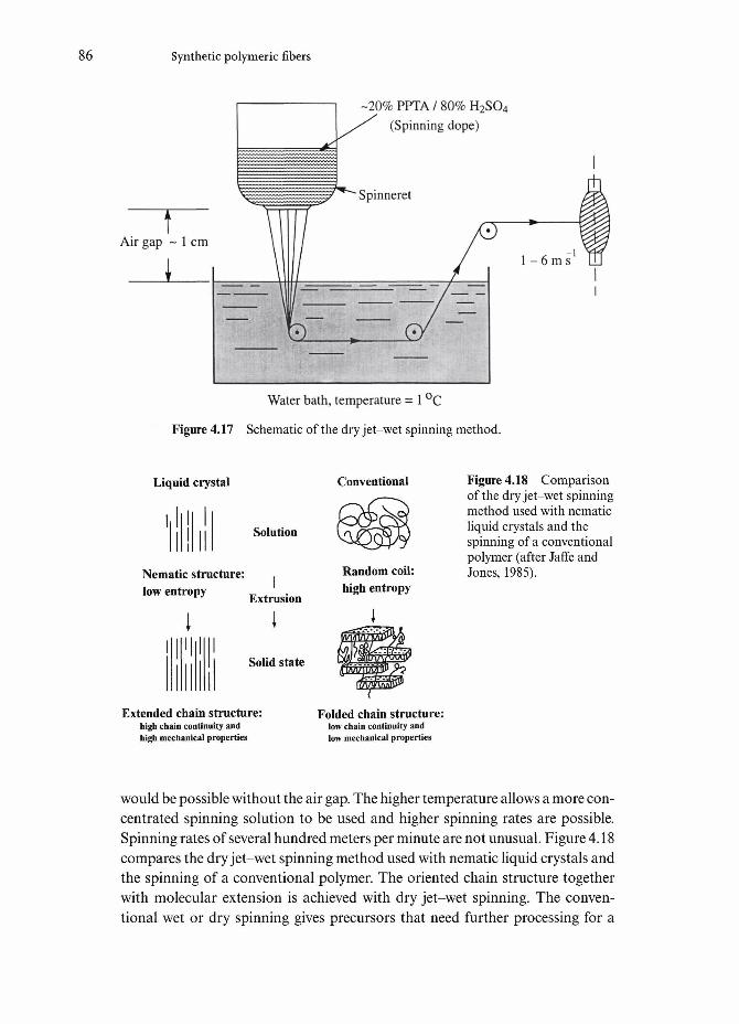
86 Synthetic polymeric fibers
-20% PPTA / 80% H2SO4
(Spinning dope)
Water bath, temperature - 1 °C
Figure 4.17 Schematic of the dry jet-wet spinning method.
Liquid crystal
Solution
Nematic structure:low entropy Extrusion
Solid state
Conventional
Random coil:high entropy
Extended chain structure:high chain continuity andhigh mechanical properties
Folded chain structure:low chain continuity andlow mechanical properties
Figure 4.18 Comparisonof the dry jet-wet spinningmethod used with nematicliquid crystals and thespinning of a conventionalpolymer (after Jaffe andJones, 1985).
would be possible without the air gap. The higher temperature allows a more con-centrated spinning solution to be used and higher spinning rates are possible.Spinning rates of several hundred meters per minute are not unusual. Figure 4.18compares the dry jet-wet spinning method used with nematic liquid crystals andthe spinning of a conventional polymer. The oriented chain structure togetherwith molecular extension is achieved with dry jet-wet spinning. The conven-tional wet or dry spinning gives precursors that need further processing for a

4.5 Strong and stiff polymeric fibers 87
Figure 4.19 Different forms in which Kevlar aramid fiber is available: pulp,floe, staple, and continuous fiber woven into a variety of fabrics (courtesy ofDu Pont).
marked improvement in properties (Jaffe and Jones, 1985). The as-spun fibers arewashed in water, wound on a bobbin and dried. Fiber properties are modified bythe use of appropriate solvent additives, by changing the spinning conditions,and by means of some post-spinning heat treatments.
In addition to the continuous filament yarn, Kevlar aramid fiber is also avail-able in several short forms such as staple, floe and highly fibrillated, pulp form.Kevlar pulp can be used in adhesion, sealants and coatings. Such products canbe used to provide control in addition to the general reinforcement of resins suchas epoxy. Figure 4.19 shows some of these forms of Kevlar aramid fiber. Kevlararamid staple fiber is generally preion-cut to lengths of 6 mm or greater. It canbe used to manufacture spun yarns, felts and nonwovens for thermal insulationand vibration damping purposes. Kevlar floe refers to fiber shorter than staple(~1 mm length) and can be used as reinforcement for resins.

Synthetic polymeric fibers
Amide solvent Figure 4.20 ChemicalNH2 + aco-y>-coci - synthesis formula for
PPD TCI aramid fiber.
- < ^ ) - N H - CO _ < ^ ) - C O ^ - + 2 HC1
PPTA
Teijin aramid fiber, known as Technora (formerly as HM-50), is made slightlydifferently from the liquid crystal route described above. Three monomers,terephthalic acid, p-phenylenediamine (PDA), and 3,4-diamino diphenyl etherare used. The ether monomer provides more flexibility to the backbone chainwhich results in a fiber that has slightly better compressive properties than PPTAaramid fiber made via the liquid crystal route. An amide solvent with a smallamount of salt (calcium chloride or lithium chloride) is used as a solvent (Ozawaet al, 1978). The polymerization is done at 0-80°C in 1-5 h and with a polymerconcentration of 6-12%. The reaction mixture is spun from a spinneret into acoagulating bath containing 35-50% CaCl2. Draw ratios between 6 and 10 areused.
StructureChemically, the Kevlar or Twaron type aramid fiber is poly(p-phenylene tereph-thalamide) which is a poly-condensation product of terephthaloyol chloride(TCI) and p-phenylene diamine (PPD). Its chemical formula is given in Fig. 4.20.The aromatic rings impart the rigid rodlike characteristics of Kevlar. Thesechains are highly oriented and extended along the fiber axis with the resultanthigh axial modulus. Kevlar has a highly crystalline structure and the linearity ofthe polymer chains results in a high packing efficiency. The unit cell of Kevlarfiber is orthorhomic with the dimensions: a=0.785nm, &=0.515nm andc=1.28nm (Northolt, 1974). An important feature of aramid fiber is the direc-tional bonding: strong covalent bonding in the fiber direction and weak hydro-gen bonding in the transverse direction, see Fig. 4.21a. This results in highlyanisotropic properties of aramid fiber. Dobbs et al (1980) examined the struc-ture of Kevlar fiber by electron microscopy and diffraction. Based upon thiswork, a schematic representation of the supramolecular structure of Kevlar 49 isshown in Fig. 4.21b. It shows radially arranged, axially pleated crystallinesupramolecular sheets. The molecules form a planar array with interchain hydro-gen bonding. The stacking sheets form a crystalline array, but between the sheetsthe bonding is weak. Each pleat is about 500 nm long and the pleats are separ-

4.5 Strong and stiff polymeric fibers 89
o
Trans Cis
Figure 4.21 (a) Bondingin an aramid fiber. Strongcovalent bonding in thefiber direction and weakhydrogen bonding in thetransverse direction, (b)Schematic representationof the supramolecularstructure of Kevlar 49(after Dobbseffl/., 1980).(c) Molecular rotation ofthe amide carbon-nitro-gen bond from the normalextended trans configura-tion to a kinkedconfiguration, causing a45° bend in the chain.
ated by transitional bands. The adjacent components of a pleat make an angleof 170°. Such a structure would appear to be consistent with the experimentallyobserved low longitudinal shear modulus and poor properties in compression inaxial as well as transverse directions. Poor shear and compressive properties are,however, also observed in polyethylene and PBO fibers which do not show apleated structure. A correlation between good compressive characteristics and ahigh glass transition temperature (or melting point) has been suggested

90 Synthetic polymeric fibers
(Northolt, 1981; Kozey and Kumar, 1994). Thus, with the glass transition tem-perature of organic fibers being lower than that of inorganic fibers, the formerwould be expected to show poorer properties in compression. For aramid andsimilar fibers, compression results in the formation of kink bands leading toeventual ductile failure. Yielding is observed at about 0.5% strain. This is thoughtto correspond to a molecular rotation of the amide carbon-nitrogen bond fromthe normal extended trans configuration to a kinked cis configuration. Thiscauses a 45° bend in the chain as shown in Fig. 4.21c. This bend propagatesacross the unit cell, the microfibrils, and a kink band results in the fiber. Thisanisotropic behavior of aramid fiber can be easily demonstrated by knotting thefiber and observing it in a microscope. Buckling or kink marks will be visible onthe compressive side of a knotted aramid fiber. Such markings on the surface ofaramid-type fibers have been reported by many researchers. DeTeresa et al(1989), for example, observed kink bands in Kevlar when subjected to uniformcompression or torsion. This phenomenon of low compressive strength of highperformance organic fibers is very important and is described in Section 4.5.3.
Properties of aramid fibersSome of the important properties of Kevlar aramid fibers are summarized inTable 4.2. As can be seen from this table, the Kevlar aramid fiber is very light andhas very high stiffness and strength in tension. The two well-known varieties areKevlar 49 and Kevlar 29. Kevlar 29 has about half the modulus but double thestrain to failure of Kevlar 49. It is this high strain to failure of Kevlar 29 thatmakes it useful for making vests that are used for protection against small arms.It should be emphasized that aramid fiber, like other high performance organicfibers, has rather poor characteristics in compression, its compressive strengthbeing only about one-eighth of its tensile strength. This follows from theanisotropic nature of the fiber as discussed above. In tensile loading, the load iscarried by the strong covalent bonds while in compressive loading, weak hydro-gen bonding and van der Waals bonds come into play which lead to rather easylocal yielding, buckling and kinking of the fiber. Thus, aramid-type high per-formance fibers are not recommended for applications involving compressiveforces.
Kevlar aramid fiber has good vibration damping characteristics. Dynamic(commonly sinusoidal) perturbations are used to study the damping behavior ofa material. The material is subjected to an oscillatory strain. We can character-ize the damping behavior in terms of a quantity called the logarithmic decre-ment, A, which is defined as the natural logarithm of the ratio of amplitudes ofsuccessive vibrations, i.e.
A=ln ——

4.5 Strong and stiff polymeric fibers 91
where 6n and 6n+l are the two successive amplitudes. The logarithmic decrementis proportional to the ratio of maximum energy dissipated per cycle/maximumenergy stored in the cycle. Composites of Kevlar aramid fiber/epoxy matrix showabout five times the loss decrement of glass fiber/epoxy.
Like other polymers, aramid fibers are sensitive to ultraviolet (UV) light.When exposed to ultraviolet light for an extended period, they discolor fromyellow to brown and lose mechanical properties. Radiation of a particular wave-length can cause degradation because of absorption by the polymer and break-age of chemical bonds. According to Du Pont data, if one compares the energyabsorption by Kevlar fiber and the incident energy during a typical midsummerday, the region of overlap is in the wavelength range between 300 and 400 nm (seeFig. 4.22). This spans the near-UV and part of the visible spectrum. It is recom-mended that this wavelength range should be avoided for outdoor applicationsinvolving the use of unprotected aramid fibers. A small amount of such lightemanates from incandescent and fluorescent lamps or sunlight filtered bywindow glass. Du Pont Co. recommends that Kevlar aramid yarn should not bestored within one foot (0.3 m) of fluorescent lamps or near windows.
Table 4.2 Properties of Kevlar aramid fiber yarns.a
Property K29 K49 K68 K119 K129 K149
Density (g cm-3) 1.44 1.45 1.44 1.44 1.45 1.47Diameter (|um) 12 12 12 12 12 12Tensile strength 2.8 2.8 2.8 3.0 3.4 2.4
(GPa)Tensile strain- 3.5-4.0 2.8 3.0 4.4 3.3 1.5-1.9
to-fracture (%)Tensile modulus 65 125 101 55 100 147
(GPa)Moisture regain 6 4.3 4.3 — — 1.5
(%)@25°C,65% RH
Coefficient of -4.0 -4.9 — — — —expansion
Note:a All data from Du Pont brochures. Indicative values only. 25 cm yarn length wasused in tests (ASTM D-885). K stands for Kevlar, a trade mark of Du Pont.

92 Synthetic polymeric fibers
1,000
Midsummer daylightenergy intensity,
Cleveland, OH
Criticalwavelengthregion forKevlar
300 400 500 600 700Wavelength (nm)
800
Figure 4.22 Energyabsorption by Kevlar fiberand the incident energyduring a typical mid-summer day (Du Pont'sdata). The region ofoverlap is in the wave-length range between 300and 400nm.
The Technora fiber made by Teijin shows properties that are a compromisebetween conventional fibers and rigid-rod fibers. Table 4.3 provides a summaryof these. In terms of its stress-strain behavior, it can be said that Technora fiberlies in between Kevlar 49 and Kevlar 29.
Other liquid crystal fibersAlthough aramid fiber is by far the most successful fiber made via the liquidcrystal route, there are some other important fibers that have been made by thisprocess. For example, poly(p-phenylene benzobisthiazole) (PBT) (Wolfe et aL,1981a, 1981b) is synthesized from terephthalic acid and 2,5-diamino-l,4-ben-zenedithiol dihydrochloride (DBD). The DBD is first dissolved in poly-phosphoric acid (PPA), followed by dehydrochlorination. Terephthalic acid andmore PPA are then added and the mixture is heated to 160°C to make a solu-tion. The solution is heated to 180°C and reacted for 18 hours to obtain the
Table 4.3 Properties of Technora fiber a
Density (gcm~3)Diameter (urn)Tensile strength (GPa)Tensile modulus (GPa)Tensile strain-to-fracture (%)
1.39123.1
714.4
Note:a Manufacturer's data. Indicative values only.

4.5 Strong and stiff polymeric fibers 93
Figure 4.23 The chem-ical structure of P B O.
Poly(p-phenylenebenzobisoxazole)
desired molecular weight. This is followed by a dry jet-wet spinning technique,similar to the one described above for spinning the aramid fibers. Drawing isdone after spinning to improve the orientation to the fiber. The final step involvesprocessing in a tubular oven in a nitrogen atmosphere. Thus, PBT is anotherexample of a rodlike polymer made by dry jet-wet spinning of a lytropic liquidcrystal. It is difficult to process but shows a very high tensile modulus.
Copolyesters combine an aromatic backbone and flexible segments. They canbe melt processed. Melt processable nematic thermotropic polyesters have beenproduced under Vectran fiber trademark by Hoechst Celanese. Another promis-ing rigid-rod lyotropic liquid crystal based fiber is poly(p-phenylene benzo-bisoxazole), PBO (Hokudoh et al, 1995). The chemical structure of PBO isgiven in Fig. 4.23. It is reported to have a tensile strength of over 5 GPa and atensile modulus close to 300 GPa. As can be seen from these values, this fiber hasbetter mechanical characteristics than aramid fiber. It also has higher thermaland fire resistance than aramid. Toyobo Co. in Japan has commercialized thisfiber. The processing of this fiber involves a very viscous polymer solution andToyobo Co. claims to have devised a special nozzle and control technology forfiber spinning.
4.5.3 Axial compressive strengthHighly oriented polymeric fibers such as polyethylene, aramid, etc., show super-ior tensile properties along the axis, but poor properties in longitudinal compres-sion and transverse to the fiber axis. For example, the ratio of compressivestrength to tensile strength can be as low as 10-20%. Such is not the case with iso-tropic fibers such as glass, boron and silicon carbide. PAN-based carbon fibersshow better compression properties than pitch-based fibers. This discrepancybetween the tensile and compressive properties has been the subject of investiga-tion by a number of researchers (DeTeresa et al, 1982, 1984, 1985, 1988; Allen,1987; Kozey et al., 1994; Kumar et al, 1988; Kumar and Helminiack, 1989b;Kumar, 1989, 1990a, b, 1991; Kumar and Adams, 1990; Martin and Thomas,1989; Jiang et al, 1991a, b). Figure 4.24 shows tensile and compressivestress-strain curves of poly (p-phenylene benzobisthiazole) (PBZO) fibers underdifferent conditions: as spun, as coagulated, and heat-treated (Martin andThomas, 1989; Kumar, 1990a). Examples of kinking under compression in differ-

94 Synthetic polymeric fibers
O
-2Heat-treated
-1
-2
-3
Heat-treated
As coagulated(wet)
3 4 5Strain (%)
Figure 4.24 Tensile andcompressive stress-straincurves of PBZO fibersunder different conditions:as spun, as coagulated,and heat-treated (Martinand Thomas, 1989;Kumar, 1990a). Note thevery low strength incompression.
ent high performance polymeric fibers (Kevlar 49, PBZT and PBO) are shownin Fig. 4.25. Exact mechanism(s) of failure under compression in these fibers isan open question. It would appear that the failure mechanisms in compressionare different from those in tension. Various models have been proposed to explainthis behavior of high performance fibers. Figure 4.26 shows two compressivefailure models: (a) elastic microbuckling of polymeric chains; and (b) misorienta-tion. The microbuckling model involves cooperative in-phase buckling of closelyspaced chain in a small region of fiber. The misorientation model takes intoaccount structural imperfections or misorientations that are invariably present ina fiber. In the composites literature it has been reported that regions of mis-orientation in a unidirectional composite lead to kink formation under com-pressive loading (Argon, 1972). The model shown in Figure 4.26b is based uponthe presence of such a local misorientation in the fiber leading to kink formationunder compression. Failure in compression is commonly associated with theformation and propagation of kinks. These kink bands generally start near thefiber surface and then grow to the center of the fiber. It has also been attributedto the ease of microbuckling in such fibers as well as to the presence of microvoidsand the skin-core structure of these fibers. An estimate of compressive strengthbased upon the microbuckling model is (Schuerch, 1966; Greszczuk, 1975)
comp

4.6 Polymeric fibers with unusual characteristics 95
Figure 4.25 Examples of kinking under compression in different high per-formance polymeric fibers (a) Kevlar 49, (b,c,d) PBZT, and (e) PBO. (Courtesyof S. Kumar.) For (b, c, d) and (e) see overleaf.
where G is the longitudinal shear modulus. Experimentally, this relationshipgives an overestimate. This expression assumes microbuckling failure to occurnormal to the fiber axis. However, kink formation generally occurs at anglesother than 90°. DeTeresa et al. (1984) treated a fiber under axial compression asan end loaded column on an elastic base, i.e. the axial compressive failure ofthese fibers occurs by elastic microbuckling instability and not by bending. Theysuggested an empirical relationship for the strength in compression as
where G is the shear modulus. Crystal misorientation away from the fiber axisoccurs during compression.
Efforts to improve the compressive properties of rigid-rod polymer fibers haveinvolved introduction of cross-linking in the transverse direction (Bhattacharya,1989; Spillman et al., 1993) and coating the fiber surface with a thin layer of ahigh modulus material (McGarry and Moalli, 1991, 1992).
4.6 Polymeric fibers with unusual characteristics
Polymeric fibers can have some very unusual characteristics. We describe someof these.

96 Synthetic polymeric fibers
Figure 4.25 (cont.)

4.6 Polymeric fibers with unusual characteristics 97
Figure 4.25 (cont.)
(b)
Band of buckledchains/fibrils
• Kink
Localm isorientation
Figure 4.26 Compressive failure models in high-performance fibers: (a) micro-buckling model; and (b) misorientation model (after Kozey and Kumar, 1994).
4.6.1 FrictionIn a multifilament yarn or in a braided fabric, normal (i.e. in the radial direc-tion) frictional force holds the fibers together. Such an interfiber friction is desir-able if we wish to have strong yarns and fabrics. However, there are situationswhere we would like to have a smooth fiber surface. For example, in a yarnpassing round a guide, a smooth fiber surface is desirable. If the fiber surface is

98 Synthetic polymeric fibers
rough, then high tensile stress will occur, which, in turn, can lead to fiber break-age. In general, in textile applications, frictional characteristics can affecthandle, feel, wear-resistance, etc. In fibrous composites, the frictional character-istics of fiber can affect its interface strength and toughness characteristics.Extremely smooth polymeric fibers with a very low coefficient of friction, /JL (aslow as 0.05) can be produced from a variety of polymers. Examples includepoly(tetrafluorethylene), PTFE or Teflon as it is commonly called. PTFE isused as a coating material to produce non-stick surfaces. Highly oriented poly-meric fibers such Spectra and Dyneema are also very smooth, which makes itdifficult to have them bond well to polymeric matrix materials in a composite.Generally, some kind of plasma surface treatment is used to overcome thisproblem.
4.6.2 Static electricity and conductive polymeric fibersStatic electricity in fibers can cause a number of problems, during processing aswell as in service. The phenomenon is common in polymeric fibers. There can betwo types of problem. One problem results when we have like charges. Likecharges repel, which can make handling difficult. For example, filaments in acharged yarn will tend to bow out. Fabrics made with fibers that accumulatestatic electricity will not stay in place. Most of us have experienced this problemwhen wearing clothes made of synthetic fibers, especially in dry weather. Thesecond type of problem results when we have unlike charges. Unlike charges, aswe know, attract. This can cause difficulties in the opening of parachutes,garment sticking, and attraction of oppositely charged dirt and soot particles toa charged body. It should be pointed out that there is always a preponderance ofnegatively charged dust particles. Thus, soiling of garments is worse when thefabric is positively charged because it attracts negatively charged dust particlesfrom the atmosphere. Natural fibers such as cotton rarely give static while someother natural fibers such as wool and silk do show some static problems.Synthetic fibers such as nylon, PET, aramid, etc. can show extensive chargeaccumulation. The problem of static can be attenuated by increasing humidityby simply moistening the fabric.
Normally one thinks of polymers and polymeric fibers as electrical insulators.However, there is some laboratory-scale work that has resulted in electricallyconducting PBZT and PPTA fibers, which are based on rigid-rod polymers. Thetrick to impart conductivity is to mix metallophthalocyanine into the spinningdope (Wynne et al, 1985; Polis et al, 1989). However, the mechanical propertiesof these fibers deteriorate with increasing content of metallophthalocyanine.
There are some unusual applications that involve a combination of fibers.Consider the problem of static electricity that is generated from fabric-to-fabricor fabric-to-surface rubbing. It is generally thought of as a minor nuisance. It

4.6 Polymeric fibers with unusual characteristics 99
(a)
(b)
Polyamide sheath
Carbon core
(c)
Figure 4.27 A blend ofNomex, Kevlar, and acore of pitch-based carbonfiber, P-140. (a) Thecarbon fiber forms thecore, (b) Static charges onthe polyamide fabricinduce opposite chargeson the carbon core, (c)When the induced chargeson the carbon core buildto a high energy level, sur-rounding air moleculesionize. Positive and nega-tive ions neutralizecharges on the polyamidefabric and the carboncore, thus dissipating thestatic electricity.
can, however, become a great danger in explosive atmospheres. It would behighly desirable to provide anti-static characteristics to a fabric made of Nomexfiber. To that end, Du Pont company produced a blended fiber called NomexDelta A, which is a blend of Nomex, Kevlar, and a core of pitch-based carbonfiber, P-140. The carbon fiber forms the core (Fig. 4.27a). Static charges on thepolyamide fabric induce opposite charges on the carbon core (Fig. 4.27b). Whenthe induced charges on the carbon core build to a high energy level, surround-ing air molecules ionize. Positive and negative ions neutralize charges on thepolyamide fabric and the carbon core, thus dissipating the static electricity (Fig.4.27c).
4.6.3 Flame retardant polymeric fibersThere is a great deal of interest in flame retardant textiles. This is understandablein view of the fact that many investigations show textiles to be the primary causeof flame spreading after ignition. The characteristics that provide high strengthand stiffness also lead to high-temperature stability and flame resistance. Table4.4 provides a comparison of high-temperature properties of some syntheticorganic fibers (Irwin, 1997). The m-aramid and p-aramid in this table refer toNomex and Kevlar type aramid fibers, respectively, while PTFE refers to polytetrafluorethylene fiber. The limiting oxygen index (L 01) is a convenient indexfor rating the various fibers in regard to their flame resistance. LOI is the per-centage of oxygen needed in an air atmosphere, i.e. oxygen/nitrogen atmosphere,to sustain burning. Recall that air contains about 21% oxygen; materials withLOI over 21 are not readily flammable in air.
Two basic approaches to deal with the problem of flammability are:

100 Synthetic polymeric fibers
Table 4.4 High-temperature properties of some synthetic organic fibers(after Irwin, 1997).
Percentage Time (h) forstrength 50% strength Shrinkageretained at loss at 180°C Melting (%) at 180°C Flammability260°C in air point (°C) in air LOI
Nylon 66PETPTFEm-aramid/7-aramid
meltsmelts6%5863
100300yearsyearsyears
254256310410none
4-113-1270.4
<0.1
24 (melts)23 (melts)952929
(i) Use a polymer whose chemical structure is flame retardant. A goodexample of such a fiber is the Nomex aramid fiber which is widely used asa flame retardant fiber,
(ii) Add a flame retardant additive to the flammable polymer. For example, aflame retardant conventional rayon fiber called the Lensing FR fiber hasa thiosulfate as a flame retardant.
For more detail on this subject, the reader is referred to Hall and Horrocks(1993) and Holme (1994).
4.6.4 Hollow fibersHollow membrane fibers are required for many medical application, e.g. for dis-posable dialysis. Such fibers are made by using an appropriate fiber spinningtechnique with a special inlet in the center of the spinneret through which thefiber core forming medium (liquid or gas) is injected. The membrane materialmay be made by melt-spinning, chemical activated spinning or phase separation.The thin wall (15-500 |xm thickness) acts as a semi-permeable membrane.Commonly, such fibers are made of cellulose-based membrane materials such ascellulose nitrate, or polyacrylonitrile, polymethylmethacrylate, polyamide andpolypropylene (van Stone, 1985).
4.7 Applications of synthetic polymeric fibers
Synthetic polymeric fibers find extensive applications in all walks of life.Fibers such as nylon and polyester find applications in a wide variety of fields:

4.7 Applications of synthetic polymeric fibers 101
garments, hosiery, lingerie and underwear, raincoats, and a variety of sportsapparel; home furnishings such as linen, carpets, upholstery, curtains, etc.; andindustrial uses such as ropes, nets, conveyer and seat belts, tire cords, blendpapers, tents, etc. Here we should mention an important item; wash and wearclothing, which has, over the years, become quite popular. Fabrics for such usegenerally consist of blends of natural and synthetic fibers, e.g. 60-70% polyesterfiber and 40-30% cotton fiber. Cotton fiber, as described in Chapter 3, is about95% cellulose. It is hydrophilic, i.e. it absorbs moisture readily by polar attrac-tion. Water then acts as a plasticizer and thus makes wrinkling of a 100% cottonfabric easy. Polyester (poly ethylene terephthalate, a thermoplastic), on the otherhand, is hydrophobic, i.e. it does not absorb water easily, stays unplasticized andthus wrinkle-free. In a humid atmosphere, however, the human body will feelsticky because of the inability of the polyester fabric to absorb moisture. A fabricmade of a blend of cotton and polyester will provide a good combination ofwrinkle or crease resistance as well as wear comfort in a humid atmosphere, i.e.a less sticky feeling.
Microfiber or microdenier fiber has become important in the fashion indus-try. The reason for this is the fine size of microfiber. It is finer than any naturaltextile fiber such as silk, wool, etc. Microfibers are nothing but polyester fiberswith diameter <5 |xm (or less than 1 den). Such fineness allows more filamentsto be packed in the yarn. Fabrics using such tightly bundled filaments are said tohave a 'buttery' texture like velour or washed silk. They also have the desirablecharacteristics of polyester, namely wrinkle-resistance and durability. Suchfabrics are used in men's wear, women's wear, rainwear, active wear and homefurnishings.
Polyolefins such as polyethylene and polypropylene are lightweight,hydrophobic and highly crystalline. It is this non-wetting characteristic of olefinsthat allows a sportswear made of, say, polypropylene, to wick moisture awayfrom the wearer's skin. Other applications of polypropylene fiber include ropes,cords, fish nets, filters, as pile and backing in carpets, knitwear in the form ofyarns blended with wool or cotton, and geotextiles. Polypropylene fiber(chopped) is also used for reinforcement of cementitius materials. It is worthpointing out here that the amount of fibers used in a reinforced cement or con-crete product is generally very small (between 0.5 and 10 vol%) vis-d-vis a fiberreinforced polymer (over 50vol%). The objective of introducing such fibers incements and concretes is to improve their tensile and impact strength and toprovide post-cracking ductility. Polyolefins are used extensively for upholstery,carpet, insulation and in geotextiles (see below). Tyvek is the trade name of a DuPont fiber product made of spunbonded, nonwoven polyethylene fibers. It ishighly tear resistant and is used for making envelopes, laboratory coats, etc. It isalso used as insulation in housing construction. Tyvek can be used in the han-dling of radioactive materials. Fabrics made of this materials are tear-resistant,
102 Synthetic polymeric fibers
smooth, anti-static, and have a lint-free surface, qualities which allow it to be aneffective barrier against particles as small as 0.6 |xm. Thus, direct contact withradioactive material can be avoided. Polyethylene fibers of low molecular weighthave limited applications because of low stiffness, poor creep resistance, and theinability to take dyes. Thus, they are mostly used for specialized nonapparelapplications. Low density polyethylene (LDPE) fibers are used to make ropesand cords, filters, and protective clothing. High density polyethylene (HDPE)fibers are used in high altitude balloons, aerial tow targets, etc. Low density (lessthan that of water!) and resistance to water and rot have led to marine applica-tions of polyethylene involving cordage that is useful for making ropes and netsthat float in water. Fabrics for upholstery, tarpaulins, curtains, etc., are other usesof polyethylene. The development of the so-called ultra-high molecular weightpolyethylene (UHMWPE) has opened up new applications such as lightweightbody armor and as a reinforcement for polymers.
Another important application of thermoplastic fibers such as poly etherether ketone (PEEK), Poly etherimide (PEI), and Vectran M and HS (Vectranisthe trade mark of Hoechst liquid crystalline polymer) is in making thermoplasticmatrix composites. Commingled yarns of the reinforcement and matrix such asquartz/PEEK, glass/PEI, Vectran HS/M are used to make the compositeswherein the matrix yarn fuses to form the continuous phase of the composite.
Elastomeric fibers based on polyurethanes such as Spandex or Lycra are usedextensively in garments and general athletic wear where high durability and resis-tance to flexure and abrasion are required. Another attractive feature of Spandex(or Lycra) is that it can be dyed easily and formed into a very fine yarn.Applications of Spandex fiber in apparel include a variety of undergarments,swimwear, waistbands, straps, outerwear, sports and leisure wear, etc. Elastomericfibers can be used as bare fibers in a fabric or covered with other textiles toproduce what are called covered and core-spun yarns. The covered yarn has oneor two textile yarns interlaced in opposite directions around a highly strainedSpandex fiber core. In the core-spun variety, a sheath of another fiber is put onSpandex fiber. An air jet is sometimes used to produce what is called an air-entan-gled filament around a stretched Lycra. The air-entangled filament forms randomloops on the surface of Lycra. An air-entangled Lycra filament is easy to hookonto another yarn with which it is combined. It is easy to visualize the usefulnessof such a feature in knit constructions that might need anti-slip characteristics.Elastomeric fibers can be used to make fabrics with predetermined extensibilities(between 20 and 350%). Their characteristics of elastic retraction, form fitting,and ability to provide support forces combined with an aesthetically pleasingappearance have made their use in leisure and sportswear a great success.
Aramid fibers and ultra high molecular weight polyethylene fibers(UHMWPE) are used in a variety of applications. For example, marine towropes, mooring cables, anti-ballistic clothing, fishing nets, sail cloth are prime

4.7 Applications of synthetic polymeric fibers 103
markets for soft, thin, flexible organic synthetic fibers. Of special importance isthe use of aramid and polyethylene fibers in vests for protection against lightarmor. Kevlar aramid fibers provide an impressive array of properties andapplications. There is a variety of Kevlar fibers: K29, K 49, K68, K 119, K129,K149, KLT, etc., the main ones being K 29 and K 49. Some applications include:
• Reinforcement for tires (belts or radial tires for cars and carcasses ofradial tires for trucks) and, in general, for mechanical rubber goods.
• Ropes, cables, coated fabrics for inflatables, architectural fabrics, and forballistic protection fabrics. Ship to shore mooring lines are made ofaramid fibers because of its resistance to saltwater corrosion. Vests madeof Kevlar 29 are used by law enforcement agencies in many countries.Later we discuss this application in some detail.
• Reinforcement of epoxy, polyester, and other resins for use in aerospace,marine, automotive and sports industries. We have previously mentionedthe vibration damping capacity of Kevlar aramid fiber. Layers of wovenKevlar are used in skis for damping purposes and, of course, to reducethe weight. Kevlar is used as a protective sheath in fiber optic wave guidesand to reinforce optical fiber cables because of its high tensile modulusand strength, and low electrical conductivity.
• Kevlar pulp can be used in thermosets, thermoplastics and elastomers.Injection-moldable pellets consisting of short Kevlar fibers in a thermo-plastic resin can be made. These can be blended with unreinforced resinsto obtain a composite with the desired volume fraction of reinforcement.
Nomex fiber has excellent fire resistance and is frequently used in applicationsrequiring resistance to fire. Nomex and Kevlar fibers, individually or in a blend,are used to make fire protection garments. They are also used extensively in elec-trical insulation, thermal liners and moisture barriers.
Engineered fabrics are used for many industrial applications such as ware-houses, swimming pool bubbles, etc. These fabrics, being very light, provide verysimple air-supported structures. Figure 2.15 in Chapter 2 shows an example ofsuch an air-supported structure. The walls should be light but strong enough towithstand snow, ice, sun and winds. Such structures can do without posts orpillars as they are supported by slight interior pressure. Frequently, the structuremust be translucent to let light in.
ArmorBoth polyethylene and aramid fibers have increasing applications in a variety ofarmor products. Body armor is a high performance system for protection againstrifle bullets. Armor containing these fibers together with a polymeric matrix inthe form a composite can provide ballistic protection as well as structural

104 Synthetic polymeric fibers
Film
Fiber and resinFilm
Soft armor
Fiber and resin
Figure 4.28 SpectraShield (a product ofAlliedSignal) is a bodyarmor that is made bymeans of woven fabric ofSpectra polyethylene fiber.This figure shows aschematic of cross-plied(0°/90°) Spectra fibers in aresin matrix.
Hard armor
support. We give a brief description of this important application of such fibers.Spectra Shield is a product of AlliedSignal that is made by means of a woven
fabric of Spectra polyethylene fiber. Figure 4.28 shows a schematic of cross-plied(0790°) Spectra fibers in a resin matrix. Helmets, hard armor for vehicles, andsoft body armor are shown in Fig. 4.29. The helmet manufacture involves aspecial version of Spectra Shield, a special shell design, and a three-way adjust-able liner of shock absorbing foam padding. These helmets were used by the UNpeacekeeping troops from France in 1993 and were introduced to police forcesin the US and Europe. A soft body armor of polyethylene fiber consists of fiveSpectra Shield plies that slide into the pockets in the body armor.
Kevlar 29 and versions thereof (K 129 and KLT) are also used extensively inlightweight body armor as well as composite liners (with vinylester, polyester orepoxy as the matrix). A quick look at the properties of different Kevlar aramidfibers in Table 4.2 shows why K29 is better than K49 for lightweight body armorapplications. K29 has a higher strain to failure than K49. That means that thetotal work of fracture, i.e. the area under the stress-strain curve, is larger for K29than K49. Hence, the energy absorbed in the fracture process is higher for K29

4.7 Applications of synthetic polymeric fibers 105
(a)
Figure 4.29 (a) A helmet reinforced with Kevlar aramid fiber and a bulletresistant vest made of Kevlar aramid fiber.
than K49. Additionally, there are some common features of Kevlar fibers. All ofthem show a very fibrillar fracture. Generally, a compact plain weave fabricstructure is used to make protective armor. It is thought that slippage at thecrossover points under impact contributes to the absorbed energy.
4.7.1 Polymeric fibers as geotextilesGeotextiles have become one of the most important fields of application for syn-thetic polymeric fibers. In view of their great importance, we describe them in aseparate section. Textiles made of synthetic polymer fibers are used in variousapplications to address a variety of solids-related problems in civil engineeringsuch as soil support, stabilization, separation and filtration, reinforcement of
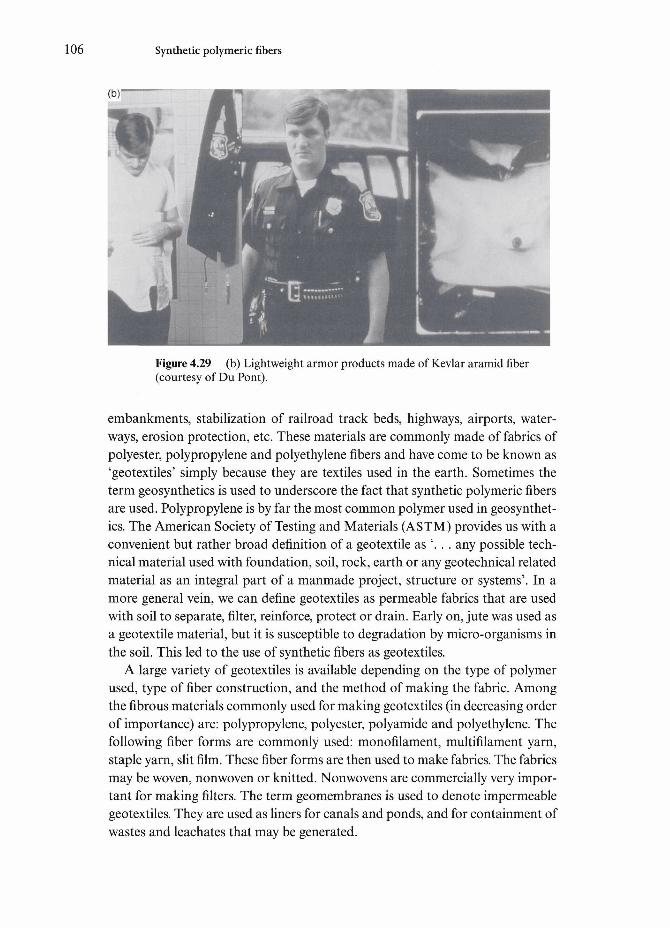
106 Synthetic polymeric fibers
(b)
Figure 4.29 (b) Lightweight armor products made of Kevlar aramid fiber(courtesy of Du Pont).
embankments, stabilization of railroad track beds, highways, airports, water-ways, erosion protection, etc. These materials are commonly made of fabrics ofpolyester, polypropylene and polyethylene fibers and have come to be known as'geotextiles' simply because they are textiles used in the earth. Sometimes theterm geosynthetics is used to underscore the fact that synthetic polymeric fibersare used. Polypropylene is by far the most common polymer used in geosynthet-ics. The American Society of Testing and Materials (ASTM) provides us with aconvenient but rather broad definition of a geotextile as '. . . any possible tech-nical material used with foundation, soil, rock, earth or any geotechnical relatedmaterial as an integral part of a manmade project, structure or systems'. In amore general vein, we can define geotextiles as permeable fabrics that are usedwith soil to separate, filter, reinforce, protect or drain. Early on, jute was used asa geotextile material, but it is susceptible to degradation by micro-organisms inthe soil. This led to the use of synthetic fibers as geotextiles.
A large variety of geotextiles is available depending on the type of polymerused, type of fiber construction, and the method of making the fabric. Amongthe fibrous materials commonly used for making geotextiles (in decreasing orderof importance) are: polypropylene, polyester, polyamide and polyethylene. Thefollowing fiber forms are commonly used: monofilament, multifilament yarn,staple yarn, slit film. These fiber forms are then used to make fabrics. The fabricsmay be woven, nonwoven or knitted. Nonwovens are commercially very impor-tant for making filters. The term geomembranes is used to denote impermeablegeotextiles. They are used as liners for canals and ponds, and for containment ofwastes and leachates that may be generated.

4.7 Applications of synthetic polymeric fibers 107
Geotextiles perform the functions mentioned above for long periods of time,over 50 to 100 years. The number of civil engineering projects all over the worldusing geotextiles, especially projects involving protection of the coast and the seabed from erosion, has grown tremendously. Examples span from parking lots,recreational areas such as tennis courts, streets and highways to airport runways,tunnels and bridge decks. Among the airports, Singapore airport is a very goodexample where geotextiles are indispensable. This airport is built on a formerlagoon and such a construction would not have been conceivable without exten-sive use of geotextiles. Geotextiles also form a critical component in any leachatecollection/leak detection system in hazardous waste management facilities. Inthe United States, the Hazardous and Solid Waste Amendments of 1984 requireall new hazardous waste storage and disposal facilities to be double lined withflexible membrane liners and there must be leak detection between the two liners.
A parameter called permittivity of geotextile (p) describes the ability of a geo-textile to transmit water across the fabric. Permittivity p is given by the follow-ing relationship:
where kn is the cross-plane permeability coefficient and t is the geotextile thick-ness at the normal pressure on the geotextile. The cross-plane permeabilitycoefficient, kn, is given by Darcys law:
q=ktA=kn(MIt)A
where q is the flow rate, A/z is the head loss across the geotextile and A is the areaacross which the flow occurs. Darcy's law, which forms the basis of the workingof geotextiles, is really a general expression for flow through a poms medium,and understandably has applications in many areas.
There are many companies involved in the field of geotextiles. Among theimportant ones are Phillips Fibers, a subsidiary of Phillips Petroleum(Dutch/British) and Polyfelt of Austria. Petrofiber is a polypropylene fiber, madeby Phillips Fibers, suitable for applications in pavement rehabilitation. This is ashort length fiber and can be used by dispersing in the asphalt based matrix toimprove the stability, ductility and fatigue life of the asphalt. It can also be usedfor placement in asphalt cement crack and joint fillers. Polypropylene fibers areinert, water insoluble and fairly stable with regard to moisture. They show goodchemical,weather and abrasion resistance. It bonds well with asphalt bitumen.Petromat, another Phillips product, is a needle punched, nonwoven, polypropy-lene fabric that is heat set on one side.

Chapter 5
Metallic fibers
Metals in bulk form are quite common materials and extensively used in engineer-ing and other applications. Metals can provide an excellent combination ofmechanical and physical properties at a very reasonable cost. One of the importantattributes of metals is their ability to undergo plastic deformation. This allows theuse of plastic deformation as a means to process them into a variety of simple andcomplex shapes and forms, from airplane fuselages to huge oil and gas pipelines tocommonplace aluminum soda pop cans and foil for household use. What is less wellappreciated, however, is the fact that metals in the form of fibers or wire have alsobeen in use for a long time. Examples of the use of metallic filaments include: tung-sten filaments for lamps, copper and aluminum wire for electrical applications, steelwire for tire reinforcement, cables for use in suspension bridges, niobium-based fila-mentary superconductors, and, of course, strings for various musical instrumentssuch as violin, piano, etc. Highly ductile metals such as gold and silver can be drawninto extremely thin filaments. Filaments of such noble metals have long been usedas threads in making Indian women's traditional dress called the saree.
Let us first review some of the important characteristics of metals, in partic-ular, the ones that allow metals and their alloys to be drawn into fine filaments,and then describe the processing, structure, properties and applications of someimportant metallic filaments. Readers already familiar with the basic attributesof metals may turn directly to Section 5.2.
5. l General characteristics of metals
Metals are generally crystalline materials. Under very rapid cooling rates, say,greater than 106Ks"1, one can also produce amorphous metals. Crystallinemetals have the following three common crystal structures:
108

5.1 General characteristics of metals 109
Figure 5.1 Typical struc-tures of metals: (a) facecentered cubic (FCC), (b)body centered cubic(BCC) and, (c) hexagonalclose packed (HCP).
(a) face centered cubic (FCC);(b) body centered cubic (BCC);(c) hexagonal close packed (HCP).
Figure 5.1 shows these structures. Examples of FCC metals are aluminum,copper, gold, silver and y-iron (austenite). They are all very ductile and can bedrawn to less than 100 |xm in diameter. This ability of the FCC and BCC metalsto undergo large-scale plastic deformation stems from the large number of slipsystems in these structures. BCC metals include a-iron (ferrite), tungsten,molybdenum and niobium. HCP metals include beryllium, magnesium, zinc andcadmium. They are not very ductile and it is not very easy to give them a fila-mentary form.
Metals are, of course, characterized by metallic bonding wherein we have asmeared cloud of electrons. This type of nonlocalized bonding results in excep-tional mechanical, thermal, electrical, and magnetic characteristics. Metals canhave a range of elastic modulus and strength values. For example, Young'smodulus can range from a low of 17.5 GPa for lead to a high of 420 GPa for tung-sten. The yield strength and ultimate tensile strength values also vary consider-ably, not only from metal to metal, but also for a given metal depending on theamount of mechanical working, alloying additions, and heat treatments used,which may involve a variety of phase transformations to modify the micro-structure. High strength values can be obtained in filaments of tungsten, highcarbon steels subjected to a heat treatment called patenting, and austenitic stain-less steels after a large amount of plastic deformation.
In general, metals can be worked extensively, either at room temperature or athigh temperatures. This is so mainly because of the availability of a large ofnumber slip systems for plastic deformation. This allows us to use metal drawingtechniques to obtain filamentary metals. Metallic fibers are, generally, not spunfrom a molten state, although this can be done in some cases (see Section 5.2).When metals are cold worked (i.e. below the recrystallization temperature), they
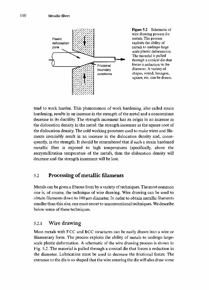
110 Metallic fibers
V//X//////,
Frictionalboundaryconditions
Figure 5.2 Schematic ofwire drawing process formetals. The processexploits the ability ofmetals to undergo largescale plastic deformation.The material is pulledthrough a conical die thatforces a reduction in thediameter. A variety ofshapes, round, hexagon,square, etc. can be drawn.
tend to work harden. This phenomenon of work hardening, also called strainhardening, results in an increase in the strength of the metal and a concomitantdecrease in its ductility. The strength increment has its origin in an increase inthe dislocation density in the metal: the strength increases as the square root ofthe dislocation density. The cold working processes used to make wires and fila-ments invariably result in an increase in the dislocation density and, conse-quently, in the strength. It should be remembered that if such a strain hardenedmetallic fiber is exposed to high temperatures (specifically, above therecrystallization temperature of the metal), then the dislocation density willdecrease and the strength increment will be lost.
5.2 Processing of metallic filaments
Metals can be given a fibrous form by a variety of techniques. The most commonone is, of course, the technique of wire drawing. Wire drawing can be used toobtain filaments down to 100 |mm diameter. In order to obtain metallic filamentssmaller than this size, one must resort to unconventional techniques. We describebelow some of these techniques.
5.2.1 Wire drawingMost metals with FCC and BCC structures can be easily drawn into a wire orfilamentary form. The process exploits the ability of metals to undergo large-scale plastic deformation. A schematic of the wire drawing process is shown inFig. 5.2. The material is pulled through a conical die that forces a reduction inthe diameter. Lubrication must be used to decrease the frictional forces. Theentrance to the die is so shaped that the wire entering the die will also draw some

5.2 Processing of metallic filaments 111
lubricant with it. A variety of cross-sectional shapes, round, hexagon, square, etc.can be drawn. The inner part of the die that comes in contact with the metal beingdrawn is made of hard material such as tungsten carbide or diamond. Almost allrefractory metals are subjected to hot drawing, i.e. working at temperaturesabove their recrystallization temperature. This allows a higher ductility than ispossible during cold working. Non-refractory metals are generally cold drawn,i.e. below their recrystallization temperature. It can be easily appreciated thatproper lubrication is very important in all wire drawing. Graphite and molybde-num disulfide, both possessing a lamellar structure, are used as solid lubricantsin the drawing of refractory metals such as tungsten and molybdenum. Tungstenand molybdenum are drawn at temperatures between 500 and 700°C with drygraphite film as a lubricant. In fact, colloidal graphite in a liquid carrier is usedas lubricant. The carrier volatilizes when the wire is heated for drawing, leavinga solid film of graphite. At room temperature, use of graphite is not commonbecause of the problems of removal. Molybdenum disulfide is used as a lubricantup to about 400°C, mainly because it starts oxidizing at about this temperature.
Work done in wire drawingMechanical work is done when a metal is drawn into a filament. When strainsare large as in the mechanical working of metals, it is convenient to treat this interms of true stress and true strain rather than engineering stress and engineer-ing strain. True stress is load divided by the instantaneous cross-sectional areawhile true strain is the change in length divided by the instantaneous gage length.Engineering stress is the load divided by the original cross-sectional area whileengineering strain is the change in length divided by the original gage length.Mechanical work done per unit volume, W, during deformation processing, canbe written as
= - (a
where Fis the volume, A is the cross-sectional area, € is the length, a-is the truestress and e is the true strain. As can be seen from Eq. (5.1), the work done perunit volume, W, is nothing but the area under the true stress-true strain curve.If we restrict ourselves to plastic deformation between two strain values, say ex
and e2, then the integral in Eq. (5.1) will be evaluated between these limits ofstrain. Another simplification commonly used is to replace o(e) by the meanvalue of flow stress between the strain limits of ex and e2. Thus, Eq. (5.1) becomes
W=a{ex-e2) (5.2)
where a is the average flow stress (a^a^/2. This simplification of taking anaverage value of flow stress is valid in hot working or in severely cold worked

112 Metallic fibers
metals. The reader should realize that in plastic working, one aims at avoidingfracture of the metal, i.e. at all times the maximum tensile stress pulling thematerial through the die should be less than the strength of the drawn materialcoming out of the die. Any friction will increase the drawing force. Frequentbreaking of wire is, of course, highly undesirable from a productivity point ofview, because a wire break means the wire must be pointed again, rethreaded,and the process restarted. This point is discussed further in Section 5.3.
Wire drawing can be carried out cold or hot. Although hot drawing iscommon for refractory metals, cold drawing is more commonly done with non-refractory metals such as steel, copper, gold, silver, etc. Friction, as well as thelarge amount of plastic deformation, can result in a rise of wire temperature ofseveral hundred degrees Celsius. We can take into account the frictional andother non-ideal work during drawing by writing the total work done in wiredrawing as,
W = W.+ Wf+ Wr (5.3)
where W{ is the ideal work, W{ is the frictional work, and Wr is called the redun-dant work. Redundant work is the work that is done in excess of that requiredto produce the desired shape. In practice, it is very difficult to separate the fric-tional and redundant components of work done. One therefore defines a drawingefficiency parameter, 77, as follows:
This drawing efficiency is a function of the die angle, amount of deformationproduced in a pass, lubrication, etc. In general, the value of r\ varies between 0.5and 0.65 (Hosford and Caddell, 1983). In terms of an average stress, one canwrite for the total work done
1 f WW=-\ode=— k (5.4)
VJ VFor many metals, the flow curve, i.e. the true stress versus true plastic straincurve, can be expressed as a power law,
a=K^ (5.5)
where n is called the strain hardening exponent and Kis the strength coefficient.It can be shown that the strain hardening exponent equals the uniform strain(Meyers and Chawla, 1984). Generally, the strain hardening exponent has anupper limit of about 0.5, i.e. the maximum reduction in area will be less than50%. In practice, area reductions are less than 30% and for most metals, 0.1 <n
5.2 Processing of metallic filaments 113
< 0.5. A log-log plot of Eq. (5.5) gives s lopes and K=aat e= 1. Note that thestrain hardening rate is not the same as the strain hardening exponent. In fact,we can write from Eq. (5.5)
_d(logo)_d(lno)_do- ed(loge) d(lne) a de
or the strain hardening rate is
ACT a
For a material obeying power law work hardening (Eq. (5.5)), it can be shownthat
If work hardening is small (e.g. during hot working), one can use an averagestress, a, and obtain the following expression for Wt:
V.where a is the average flow stress over the range Ae. Equation (5.7) is essentiallythe same as Eq. (5.2).
5.2.2 Taylor processConventional wire drawing methods are quite reasonable for producing wires ofAl, Cu, Ti, W, Ta, Mo, steels, etc. with diameters down to 100 (xm. Productioncosts increase tremendously below this diameter. Donald (1987) defines a metal-lic wire less than 100 |mm in diameter as microwire. Metallic wires of diametersdown to 10 |xm or less can be obtained by the Taylor process, so called after theperson who first used it to produce a variety of fine metallic wires (Taylor, 1924).For a detailed review of developments in this process in the former USSR, US A,Europe and Japan, see Donald (1987). The basic process is indicated in theschematic shown in Fig. 5.3. A thick metallic wire is encased in a sheath of asacrificial material (e.g. glass), heated to a temperature where the sheathbecomes quite soft and the core wire melts or softens. This is followed bydrawing in a plastic state down to very fine diameter and removing the sheathmaterial by etching. Production of fine metallic wires is very expensive due tothe cost of the Taylor wire drawing process. It turns out, for example, that forsteel wires of diameters <25 |mm, the cost of wire production becomes constantper unit length and not per unit weight, i.e. the material cost at such fine diam-eters is not very high but the processing costs are. The following requirements

114 Metallic fibers
Glass tube
Heat (induction coil)
Figure 5.3 Schematic ofthe Taylor process.
Glass—encapsulatedmetal filament
must be met in order to produce fine metallic wires by the Taylor method(Donald, 1987):
(a) The glass must not react with metal at the drawing temperature.(b) The working temperature of glass must be greater than the melting point
of the metal and below the temperature at which the vapor pressure ofthe metal is too high.
(c) The viscosity of glass in the processing temperature range should be suchthat easy fiber drawing occurs.
(d) The coefficient of thermal expansion of the glass should be equal to orslightly less than that of the metal. If this condition is not met, then highenough thermal stresses can be generated in the glass to break it and acontinuous fiber will not be obtained.
(e) The glass must become highly viscous before the metal becomes solid-ified. If not, the metallic core will become solid while the glass sheathcontinues to draw, resulting in fracture of the metal.
In practice, the restrictions enumerated above limit the sheath glass material toone of the low thermal expansion, borosilicate (Pyrex-type) glasses or fusedsilica.
5.2.3 Metallic fibers by spinningSpinning fibers from a melt is perhaps the most common technique used to makefibers from polymeric and silica-based glasses. Such a technique, however, is notvery suitable for metallic fibers because molten metals have very low viscosity,

5.3 Microstructure and properties of metallic fibers 115
rather like that of water, and rather high surface energy. These characteristics ofmetals generally preclude the use of casting or extrusion from a molten state tomake metallic fibers. If one were to try such a technique, what would happen isthat as soon as the filamentary jet comes out of the die or spinneret, it breaks upinto droplets because of a fluid instability phenomenon due to surface wavescalled Rayleigh waves. The amplitude of Rayleigh waves increases exponentiallywith the distance from the orifice, making the molten metal jet unstable andbreaking it up into droplets. The sine qua non condition for spinning a fiber fromthe liquid state is that the free-liquid jet must be made stable over a lengthsufficient to allow it to freeze before breaking into droplets. This kind of jetstabilization technique has been used to produce some crystalline ceramic fibers(see Chapter 6). It would thus appear that in order to make metallic fibers bymelt spinning, one must resort to some technique that stabilizes the molten jetas soon as it comes out of the orifice. Such a technique has also been referred toin the literature as 'free-flight melt-spinning into a gaseous environment'. Pond(1961) ejected the molten metal through a nozzle into an inert atmosphere at aspeed high enough to prevent break up into droplets before solidification. Theuse of helium as a high heat transfer coefficient cooling medium promotes rapidsolidification of the melt and helps in maintaining a stable jet. Engelke (1967)ejected molten metal through an orifice into an appropriate liquid that surroundsand flows with the molten metal stream. Alternatively, one can use a method dueto Alber and Smith (1965) which involves the use of an alloy that forms a stableoxide that is insoluble in the molten metal. The molten alloy is ejected into anoxidizing atmosphere and an oxide film forms on the molten jet. Lead has beenmade into filaments by this technique (Kikuchi and Shoji, 1989). The advantageswith lead are that it has a low melting point, which allows a variety of spinneretmaterials to be used, and it tends to oxidize rapidly in air. The rapid formationof a lead oxide layer on the surface tends to stabilize the jet of molten lead againstbreaking into droplets. The important requirement in all fiber spinning processesis that a stable (i.e. laminar rather than turbulent) flow of liquid be maintained.
5.3 Microstructure and properties of metallic fibers
Metals when formed into wires can show rather high strength levels. The highstrength stems from the phenomenon of work hardening that metals undergoduring mechanical working. Work hardening, or strain hardening as it is some-times called, refers to the fact that metals become stronger when they are coldworked (Meyers and Chawla, 1984), i.e. their strength or flow stress increases asa function of strain and correspondingly their ductility or toughness decreases.The phenomenon of work hardening has its origin in the increase in dislocationdensity produced during cold working of the metal. The modulus, however, does

116 Metallic fibers
not change significantly with deformation. Another great advantage of metallicfilaments is that they show very consistent strength values vis-a-vis ceramicfibers. The Weibull modulus of metallic fibers is an order of magnitude higherthan that of ceramic fibers.
Beryllium, steel and tungsten can show good combinations of modulus,strength, and refractoriness. Beryllium, in particular, has a high modulus ofabout 300 GPa and an extremely low density 1.8 g cm"3. Its toxic nature requiresspecial handling, which makes it very expensive. Its strength is relatively low(-1300 MPa). We describe below the processing, microstructure, and propertiesof some important metallic filaments; tungsten, niobium-based superconductingfilaments and steel.
5.3.1 TungstenTungsten wires were originally developed for electric lamps and that still consti-tutes the major use of tungsten. It has a high melting point (3400°C), highmodulus (414GPa), and a very high density (19.3 gcm~3). Tungsten has a BCCstructure and has the somewhat unusual characteristic of being isotropic, evenin the single crystal form. Besides the disadvantage of high density, tungsten oxi-dizes easily and the oxide of tungsten is likely to volatilize at high service tem-peratures. The advantages of tungsten include a high melting point, high elasticmodulus and strength coupled with a high electrical resistivity.
Conceptually, and with a little bit of hindsight, the modern electric lamp is avery simple device: an electrically conducting filament enclosed in an evacuatedglass enclosure. The filament emits light when heated to incandescence by thepassage of an electric current. In 1879, Edison used a carbon filament for thispurpose. Carbon was not very successful, it was replaced by osmium and thentantalum before tungsten filament was used. The success of tungsten filament iscredited to some pioneering work done by Coolidge at GE involving sinteringand drawing of tungsten filament. The tungsten filament works in vacuum orsurrounded by inert gases at about 2600°C. The high melting point of tungsten(3400°C) allows it to be operated at such a high temperature. Generally, the tung-sten filament is wound in the form of a helical coil, see Fig. 5.4a. The coiled fila-ment results in a reduced cooling effect and a compact lamp design. Figure 5.4bshows a higher magnification view of the tungsten filament shown in Fig. 5.4a.Note the rather rough surface markings produced during the drawing process.The characteristic fibrous microstructure of a highly drawn tungsten filament, asseen in TEM, is shown in Fig. 5.5.
When used as an electric lamp filament at high operating temperatures, thetungsten filament creeps under its own weight and most of this creep occurs bygrain boundary sliding. In order to minimize this creep problem, an elongated,bamboo-type grain boundary structure as produced by wire drawing is desir-

5.3 Microstructure and properties of metallic fibers 117
Figure 5.4 (a) Tungsten filament wound in the form of a helical coil, (b) Thefilament drawing process produces rather rough surface markings.
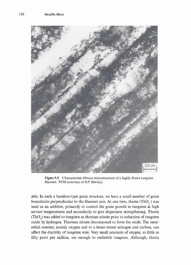
118 Metallic fibers
Figure 5.5 Characteristic fibrous microstructure of a highly drawn tungstenfilament. TEM (courtesy of B.P. Bewlay).
able. In such a bamboo-type grain structure, we have a small number of grainboundaries perpendicular to the filament axis. At one time, thoria (ThO2) wasused as an additive, primarily to control the grain growth in tungsten at highservice temperatures and secondarily to give dispersion strengthening. Thoria(ThO2) was added to tungsten as thorium nitrate prior to reduction of tungstenoxide by hydrogen. Thorium nitrate decomposed to form the oxide. The inter-stitial content, mainly oxygen and to a lesser extent nitrogen and carbon, canaffect the ductility of tungsten wire. Very small amounts of oxygen, as little asfifty parts per million, are enough to embrittle tungsten. Although, thoria

5.3 Microstructure and properties of metallic fibers 119
(ThO2) can be used as an alloying addition for tungsten, for incandescent elec-tric lamp filaments, its use has largely been replaced by tungsten containingminor quantities of aluminum (Al), potassium (K) and silicon (Si). This type oftungsten filament is known as the AKS tungsten filament or non-sag tungstenfilament (Wittenauer et al, 1992). In fact, it is the potassium that is largelyresponsible for the controlled microstructure of tungsten filament as describedbelow. Let us start from the very beginning. Tungsten ore is converted intoammonium paratungstate [5(NH4)20.12 WO3.11 H2O], commonly referred to asAPT. This APT is the starting material for making tungsten powder. APT isreduced to tungsten oxide (WO3), which is doped with potassium disilicate andaluminum chloride (Bewlay et al., 1991). Tungsten oxide is reduced to fine tung-sten powder (< 5 jjim), pressed, and sintered into an ingot. Sintering of dopedtungsten involves passage of an electric current (^5000 A) through the coldpressed ingot. A temperature of 3000°C is reached. At such high temperatures,impurities volatilize and rapid densification occurs and about 75 ppm of ele-mental potassium is left (Bewlay, 1991; Briant and Bewlay, 1995). Tungsten fila-ment is made by drawing this tungsten ingot made via powder metallurgy. Theingot is rolled and/or swaged, followed by drawing down to a diameter less than100 \xm by using a series of dies. A 100 W bulb has a 50 |xm diameter tungstenfilament. The exact diameter of filament depends on the voltage and wattage ofthe lamp.
As noted earlier, creep in tungsten filament occurs by grain boundarysliding. Such a deformation makes the filament sag under its own weight andform a neck where it eventually breaks. Pure, recrystallized tungsten forms abamboo-type grain structure, i.e. the grains occupy the entire diameter of thefilament and the grain boundaries are aligned transverse to the filament axis.Under the service conditions for the tungsten filament, such boundaries willundergo sliding and lead to failure of the filament. The addition of potassiumto tungsten results in an interlocking grain structure, which results in a reducedrate of grain boundary sliding and longer life for the filament than that of theundoped filament. The beneficial effect of potassium comes about because ithelps to control the grain shape. After sintering the doped tungsten ingot haspores that contain elemental potassium. With wire drawing, these pores assumean elongated, tubular structure. When this material is annealed at a high tem-perature, these tubular structures containing potassium vapor become unstableas per Rayleigh waves on the surface of a cylindrical fluid (see Chapter 4). It isimportant that the deformation during drawing should be large enough toproduce potassium cylinders with an aspect ratio >10, otherwise they willspheroidize to a form a single bubble (Briant, 1989; Vukcevich, 1991). Figure5.6 shows an example of such bubbles in a transmission electron micrograph ofa tungsten filament. The objective here is to have a high density of such tinybubbles so that they pin the grain boundaries effectively against sliding, thus

120 Metallic fibers
Figure 5.6 An example of potassium bubbles in a tungsten filament. TEM.(courtesy of B.P. Bewlay).
resulting in a microstructure that is stable at the operating temperature. Non-sag tungsten filament can be regarded as a unique form of dispersion strength-ened alloy in that it has elemental potassium as an alloying element in the formof tiny bubbles in the BCC tungsten lattice. These gas bubbles retard therecrystallization of the wire and give it a very superior creep resistance at thehigh temperatures prevailing in a glowing lamp and thus a longer life than thatof the undoped filament. Figure 5.7 shows the superior creep resistance of thedoped tungsten filament compared to that of an undoped one (Horascek,1989).

5.3 Microstructure and properties of metallic fibers 121
10
CO•*-> D(/)Q.00)
6 4
Fracture
Undoped
Figure 5.7 Creep curvesfor doped and undopedtungsten filaments(0.9 mm diameter) at2800 K, under a tensilestress of 13 MPa (afterHorascek, 1989). Note thelower creep strain in thedoped tungsten vis-a-visthe undoped tungsten.
Doped Fracture
10 15 20Time (h)
30
5.3.2 Niobium-based superconducting filamentsNiobium-based superconducting filaments such as Nb-Ti and Nb3Sn, bothembedded in a copper matrix, are used in making superconducting magnets. Thealloy system Nb-Ti (about 50wt%) is a typical, ductile metallic alloy (BCCstructure) that can be extruded and drawn to very fine filaments when embeddedin a copper matrix. One of its largest uses is in magnetic resonance imaging(MRI) systems (see Section 5.4).
A pertinent question here is why does one need the superconductor in a fila-mentary form? The answer lies in a phenomenon called thermal runaway.Dissipation of energy, associated with flux movement, can cause thermalrunaway in a superconductor. Thermal runaway refers to any rapid build up ofheat in the superconductor leading to a conversion of stored energy in the wire(recall the high current density that is used) into heat. In order to prevent such acatastrophe, the wire is designed such that outflow of heat to the surroundings isalways greater than the rate of heat dissipation. This requirement means that thewire should have a very small diameter and should be arranged inside a highthermal conductivity material such as high purity copper. It also leads to anotherkey requirement of these superconductors, namely that of magnetic flux pinning.This is achieved via proper metallurgical treatments involving a certain amountof cold working (extrusion and wire drawing) followed by an annealing treat-ment. Such a treatment results in a dislocation cell wall structure and precipitates(a-Ti), both of which act as flux pinning agents. A Nb-50% Ti alloy has a f3microstructure with a-phase precipitates which are non-superconducting. Anannealing treatment of 48 h at 375°C will result in about 11% of a-particles.

122 Metallic fibers
More a-particles will reduce the ductility of the alloy. An annealing temperaturegreater than 375°C will result in softening, fewer dislocations, and a lower Jc.Cold work after annealing leads to a refined structure and an increase in the Jc
(Hillman, 1981). An important consideration during the drawing process is toavoid the formation of intermetallic defects from scratches (Hillman, 1981). Ascratch on the surface of the NbTi rod can form a hard ball of oxidized NbTiabout 1 |mm in diameter. During extrusion, there is a snowball-like effect causingmechanical alloying and forming a NbTi+Cu mixture. Annealing treatment cancause the formation of (NbTi)Cu2 and (NbTi)2Cu intermetallic compounds.
Another niobium-based superconductor is Nb3Sn. It has an A-15 crystalstructure and is a very brittle intermetallic, which is not easy to form. It has a7 = 18 K and Hc>l2T. It is extremely brittle, strain to fracture -0.2%, that is,no plasticity. The way around this problem is to initially draw niobium wires ina bronze (Cu-Sn alloy) matrix. Niobium filaments embedded in a (Cu-13 wt %Sn) bronze matrix, with an R ratio=Cu-Sn/Nb>3, are drawn through a seriesof dies. When the desired diameter of wire is obtained, a heat treatment at650-700°C is given to drive out the tin from the bronze matrix, it reacts withniobium to form Nb3Sn leaving behind a copper matrix. Thermal stressesinvolved during a temperature change of AT -1000 to 4.2 K put the Nb3Sn fila-ments in compression (0.4-0.6% strain). The final product has a very fine grainstructure (grain diameter <80nm).
5.3.3 Steel
It is important to take into account the physical metallurgy of a steel in order tounderstand the general structure-property relationships in steels, and especiallyin a filamentary, "eutectoid steel. Steel wire or filaments are obtained by first pro-ducing steel rod and then reducing its diameter to the desired size. The micro-structure of this starting steel rod has a great influence on the final product. Ifthe steel rod is cooled from the high finishing temperature of rolling by letting itstand in air, it will have a rather coarse pearlitic structure. A steel rod having acoarse pearlitic microstructure is not amenable to further cold drawing to a finerdiameter; faster cooling is required for that. The hot rolled steel rod is descaledby mechanical and/or chemical methods, followed by cold drawing through asingle die or a series of dies. Dry, powdered stearate is used for lubrication forcoarse wires while for fine wires (<0.8 mm) a wet lubricant is used. Nonmetallicinclusions, particularly the nondeformable variety, decrease the ductility (this isdiscussed further later in this section).
In its simplest form, steel is an alloy of iron and carbon. In general, there areother alloying elements present. Steel wires can vary in composition enormously,from simple C-Mn steel to alloy steels containing more than ten alloy additions.Control of impurities (mostly nonmetallic inclusions), chemical segregation,

5.3 Microstructure and properties of metallic fibers 123
DL
"5)cCDi _
^—»
CO
700
500
300
o / BFigure 5.8 Inverse squareroot relationship betweenstrength and diameter of apatented, pearlitic steelwire (after Embury andFisher, 1966).
0.5 1.5-1/2, -1/2
d (mm )
surface imperfections, chemical segregation, coupled with a uniformity in grainsize can result in a very high quality product. The carbon content of steel wiremay range from low to high, with the latter generally having carbon contentbetween 0.5 and 0.9 wt%. A eutectoid steel has carbon between 0.8 and 0.9 wt%and consists of a 100% pearlitic microstructure. Steel in the form of wire can bevery strong compared to the bulk steel although its modulus does not change verymuch. The strength of steel wire can span the range 0.8 to 5 GPa. Wires can rangein diameter from coarse (^1.5 mm) to very fine (^O.lmm). Low to mediumcarbon steels will have ferrite+pearlite microstructure. The term pearlite denotesa lamellar structure with the lamellae consisting of hard, orthorhombic cemen-tite (Fe3C) and soft, BCC ferrite (almost pure a-Fe). The high carbon (0.9% C)steel wires, commonly called piano wire and produced by the patenting processdescribed later in this section, can have very high strength levels (~5GPa),although the toughness levels will be rather low at such high strengths. It has apearlitic structure, i.e. it has a lamellar structure with the lamellae consisting ofhard, orthorhombic cementite (Fe3C) and soft, BCC ferrite (almost pure a-Fe).The eutectoid decomposition of austenite (y) phase into a and Fe3C results in astructure consisting of a fine and uniform dispersion of cementite in ferrite. It isthis characteristic structure that allows the wire to be drawn down to 75 |xm anda very fine lamellar structure with interlamellar spacing between 50 and lOOnmis obtained. What is important to realize is that the key here is to understand themicrostructure-property correlations. The strength of such a eutectoid wireincreases as the inverse square root of the interlamellar spacing. The strength, a,of pearlite is given by a relationship similar to the Hall-Petch relationship usedfor grain boundary strengthening of metals (Hall, 1951; Petch, 1953):
where <x0 is a friction stress term, k is a material constant and A is the inter-lamellar spacing. It turns out that one can vary the interfiber spacing, A, easilyby controlling the cooling rate. In more practical terms, Fig. 5.8 shows an inverse

124 Metallic fibers
(0CLO
2
Fine peariite
Coarse peariite
Figure 5.9 Effect ofdrawing or swaging opera-tion on the strength ofpearlitic steel wires. Bothcoarse and fine peariiteshow a linear relationshipbetween yield strength andexp (e/4) where e is thestrain (after Embury andFisher, 1966).
exp(s/4)
square root relationship between yield strength and diameter of a patented,pearlitic steel wire (Embury and Fisher, 1966). It can be shown that the inversesquare root dependence of strength on the diameter translates into strengthbeing proportional to exp (e/4), where e is the true plastic strain. We start bytaking into account the fact that plastic deformation occurs at a constantvolume, i.e., AQl0=Al, where AQ and A are the original and instantaneous cross-sectional areas and /0 and / are the original and instantaneous lengths, respec-tively. The true or logarithmic strain is given by:
If d and d0 are, respectively, the instantaneous and original diameter of the wireor fiber, we can write
6-In (7rd20/4)/(7Td2/4)=2 \ndjd
e/2=ln djdd/do=Qxp(-d2)
d=d0Qxp (-6/2)Vd=Vd0Qxp(-d4)
From the Hall-Petch relationship, we know that af oc(l/V<i), therefore crf
WQ) exp (e/4). Figure 5.9 shows the effect of the drawing or swaging opera-

5.3 Microstructure and properties of metallic fibers 125
tion on pearlitic steel wires. Both coarse and fine pearlite filaments show a linearrelationship between strength and exp {elA).
Processing and microstructureThe strength of steel wire is mainly controlled by its carbon content and itsmicrostructure which depends on processing. The term microstructure in thiscase means ferritic grain size and the interlamellar spacing in the pearliticregions. The microstructure is determined, just as in other steel products, bycomposition and final working conditions. In general, the yield strength and ulti-mate tensile strength increase with carbon content and concomitantly ductilityand toughness decrease. In ferritic/pearlitic steels, the tensile strength of steelincreases with:
(a) decreasing ferritic grain size;(b) fine interlamellar spacing of pearlite;(c) precipitation hardening;(d) carbon content.
The effects (a) and (c) are generally combined by using finely distributed NbCNor VCN precipitates to give a fine grain size and precipitation hardening.
Most steel wire is produced by heavy cold drawing. The drawability of steel isa function of its microstructure, which is a very sensitive function of the coolingrate. For low carbon steels, the natural air cooling of the hot rolled steel resultsin a fine enough microstructure which enables cold drawing down to 95% reduc-tion. For steels with carbon between 0.5 and 0.9 wt%, natural air cooling resultsin a coarse pearlitic structure which can be cold drawn in the 25-50% reductionrange. In this carbon range (0.5-0.9 wt%), a process called patenting is used toproduce steel wire. Very fine steel wires (0.1 mm or less in diameter) containinghigh carbon (0.9% C) can have very high strength levels (~5GPa), althoughunderstandably the toughness levels will be low at such high strengths. Such asteel wire is known as piano wire. Its composition (in wt%) is 0.9 C, 0.37 Mn,0.2 Si, 0.01 P, and 0.03 S. Its structure consists almost entirely of pearlite. Figure5.10 shows a transmission electron micrograph of a fully pearlitic structure. Thespecial processing, patenting, that is used to obtain this high strength wireinvolves drawing the wire down to about 500-750 |xm, and holding at 900°C fora few minutes to transform completely to an FCC phase called austenite (yphase). Austenite has much higher solubility for carbon, and takes all the carboninto solution. The wire is then cooled to 400-500°C in a molten lead or salt bath,which results in the eutectoid decomposition of austenite (y) phase according tothe following reaction

126 Metallic fibers
Figure 5.10 A fully pearlitic structure in a steel consisting of aligned lamellaeof a-Fe (light) and Fe3C (dark). TEM.
i.e. the y phase decomposes into a very fine two-phase mixture, a and Fe3C witha microstructure as shown in Fig. 5.10. The cooling rate is ~30°C/s. This struc-ture, consisting of a fine and uniform dispersion of cementite in ferrite, allowsthe wire to be drawn down to 75 |xm and a very fine lamellar structure. An inter-lamellar spacing between 50 andlOOnm is obtained. The lead patenting processis increasingly being replaced by fluidized bed patenting because of the healthhazards associated with lead.
In more modern wire plants the whole patenting process has been eliminated.A controlled cooling system is used at the exit stands of hot-rolled rod at-950-1100°C. The rod is cooled to a temperature between 750 and 900°C in awater box, followed by forced air cooling at a rate of 5-10°C s"1. This treatmentresults in a microstructural fineness that is intermediate between that producedby air and lead patenting. Such a microstructure allows further reduction by colddrawing to 80%. Microalloy additions in high carbon rod can compensate for thelower tensile strengths achieved due to controlled cooling vis-a-vis the patentingroute. Jaiswal and Mclvor (1989) found the following relationship between thetensile strength, cooling rate and chemical composition:
tensile strength (MPa)=[267(log CR)-293]+1029 (%C)+ 152 (%Si)+210 (% Mn)+442 (% P)0-5
+ 5244(%Nf)
where CR designates the cooling rate in °C/s and the amounts of the differentelements are in weight percentages with Nf being the free nitrogen.
Through a proper control of processing and microstructure of these steel

5.3 Microstructure and properties of metallic fibers 127
0^\
ocCD
*equ
CDO)CD
COCD
-QCD
20
15
10
5
0
Figure 5.11 Effect of sizeof oxide inclusions on wirebreakage (after Takahashiet ah, 1992).
10 20 30 40Inclusion size (|um)
wires, researchers at Nippon Steel (Takahashi et ai, 1992) have been able toproduce steel wires with 2GPa strength for use in suspension bridge cables.Another major application of steel filament is in tire reinforcement. Steel wireused for this purpose is commonly known as cord. It is instructive to understandthe driving force behind the search for still higher strength steel wire for tire rein-forcement. The desire to reduce the weight of an automobile was translated to areduction in tire weight, which in turn led to efforts aimed at increasing thestrength of steel reinforcement wire so that a thinner wire could be used for thesame strengthening effect. This resulted in the addition of alloying elements inthe composition of steel cord for tire reinforcement. Control of nonmetallicinclusions and a reduction in the degree of center segregation have resulted in avast improvement in steel wire used for tire cord and bridge cables. Inclusionssuch as C, Mn, P, etc. tend to segregate to the center of the wire. It is typicallymade by drawing a 5.5 mm rod down to 0.15 mm diameter by a series of patent-ing steps. A key point in regard to the manufacture of steel cord is the numberof breaks per ton of production in the drawing process (Takahashi et al, 1992).Of course, the lower the number of such breaks the better. What is interesting isthat the frequency of wire breaks is a function of the size of nonmetallic inclu-sions in the wire. Figure 5.11 shows the effect of size of oxide inclusions on wirebreakage. Note that the wire break frequency tends to zero for inclusions ofdiameter 5 |xm or less.
The strength of the steel wire is controlled by delaminations that appear alongthe wire axis when it is twisted during the cable strand formation. The genesis ofnonmetallic inclusions in steel wire lies in the process of steel making. Duringsolidification of steel, because of solute redistribution, elements such as C, Mnand P segregate between the dendrites. This inclusion containing molten steelends up in the shrinkage cavities at the center of the bar, solidifies there and resultsin the centerline segregation. Figure 5.12 shows the segregation of manganese in

128 Metallic fibers
Mn segregation • >2% ^>1.5%g >1.0% Figure 5.12 Segregationof manganese in the centerof a rolled rod (afterTakahashi <?*<*/., 1992).Drawing limit strain as afunction of the centersegregation in the startingbillet.
1 2 3 4Center segregation size (mm)
Figure 5.13 Drawinglimit strain as a functionof the center segregationsize in the starting billet.A reduction in segregationsize improves the draw-ability (after Takahashi etal, 1992).
the center of a rolled rod. Any untransformed austenite in the central zone willtransform to martensite (a hard, brittle phase) because of the presence of man-ganese there. Segregation of carbon can lead to cementite film formation ataustenitic grain boundaries. Such segregation can severely limit the drawabilityof steel wire. Figure 5.13 shows the drawing limit strain as a function of the centersegregation in the starting billet. A reduction in segregation size improves draw-ability. This tendency for centerline segregation can be minimized by finely dis-persing the solute-enriched molten steel and pressure welding the shrinkagecavities where this enriched steel accumulates. This can be accomplished by low-ering the pouring temperature of molten steel and electromagnetically stirring themolten steel (Takahashi et al, 1992). After some extensive work at Nippon Steel,researchers came to the conclusion that the delamination cracking failure in steelwire can better be prevented by increasing the strength of the wire rather thanincreasing the total reduction in area during drawing. This can be done byincreasing the carbon and silicon contents of steel and adding another element,chromium. Carbon and chromium add to the strength of the steel wire bydecreasing the interlamellar spacing of pearlite while silicon simply gives solidsolution strengthening. Figure 5.14 shows the effect of carbon and other alloyingelements on the increase in the strength of a patented steel wire (Takahashi et al,1992). Now, silicon does not dissolve in cementite while chromium does. This

5.4 Applications 129
Figure 5.14 Effect ofcarbon and other alloyingelements on the increase inthe strength of a patentedsteel wire (after Takahashietal, 1992).
0 0.5 1
Alloy content (%)
steel is pearlitic and the strength is governed by the interlamellar spacing. Thesteel wire must be subjected to heat treatment, drawing, and galvanizing opera-tions. The galvanizing operation involves immersion of steel wires into a zinc bathat 450°C. This treatment would result in breaking up of the Fe3C lamellae intosmall particles and the strength of the steel wire would be reduced. Takahashi etal. (1992) found that by increasing the amount of silicon in steel, a protective layerwas formed around Fe3C which prevented the break-up into small particles.
Mechanical properties of some commercial metallic wires are summarized inTable 5.1.
5.4 Applications
Although it is not generally appreciated, metallic filaments find a wide range ofapplications in modern day life. We provide below a summary of some impor-tant uses of metals in filamentary form.
CopperExcept for gold and silver, copper is the best metallic electrical conductor andcopper wires are commonly used as electrical conductors. They are also used asmagnet wires in electric motors, transformers, generators, electromagnets, etc.Copper and aluminum are commonly used for magnet wire because of their goodelectrical conductivity. Magnet wires are frequently coated by a variety of poly-mers such as nylon, aramid, polyester, polytetrafluoroethylene, polymide, etc.
AluminumAluminum wires are used as electrical conductors. Although the electricalconductivity of aluminum not as good as that of copper, it is much lighter than

130 Metallic fibers
copper and is therefore used as an electrical conductor. It should be pointed outthat the electrical conductivity of aluminum is about 60% that of copper. Thismeans that replacing a copper wire by aluminum requires a larger cross-sectionand thus a larger design of equipment. Sometimes a bimetallic wire consisting ofaluminum and copper, made by coextrusion, is used as a conductor.
SteelSteel in a wire or filamentary form is commonly used for reinforcement of tiresand pressure hoses. It is also used for reinforcement of concrete, although moreoften than not, for this purpose it is in the form of a rod (diameter greater than1 cm) rather than a wire. Steel wire with 0.8-0.9 wt% carbon (eutectoid steel) isused in pianos and in steel ropes used as cables in suspension bridges and forother structural purposes. We should emphasize the use of fine diameter steel
Table 5.1 Typical properties of some commercial metallic wires.a
Metal
AlBeCuW
Mo0.9% C Steel
(0.1 mmdia.)304 Stainless Steel
(0.05 mm dia).
Density(gcm~3)
2.71.88.9
19.3
10.2
7.9
7.8
Meltingpoint (°C)
660135010833410
2625
1300
1535
Coefficient ofthermalexpansion(10-6K-02412164.5
6.0
11.8
9.0
Young'smodulus(GPa)
70310125350
330
210
198
Tensilestrength(MPa)
3001100450
2890(250 ̂ m)3150
(< 125 jam)3850
2200
4000
2400
Note:a These values are indicative only. Heat treatments (e.g. annealing, aging, etc.) andprocessing can alter the strength properties quite drastically.

5.4 Applications 131
wires in massive engineering structures such as single span suspension bridgeswhich need steel cables whose strength ultimately depends on the strength ofindividual steel filaments composing the cables. Such cables can be one meter ormore in diameter and contain 37 000 strands of steel filament.
An interesting application involves the use of very fine (15 |xm) stainless steelfilament as a conductive filler in a thermoplastic resin for electromagnetic shield-ing. According to Nippon Steel and Nippon Seisen Co., who developed thisproduct called Esbarrier, 4-10 wt% of stainless steel fiber provides an effectiveshielding of 40-50 dB at 100 MHz.
TungstenTungsten filaments are used in electric lamp bulbs. More than 90% of non-sagtungsten is used for incandescent lamps. A small amount is used as defrostingheating wires in automobile windshields. Another use is as heating elements foraluminum evaporation in coating applications. Tungsten fibers have been alsoused to reinforce copper and some nickel and cobalt based superalloys.
LeadHeavy but soft materials such as lead reflect sound waves very efficiently. Becauseof its high density and low modulus, lead is an excellent acoustic insulator. Leadsheets are indeed used for this purpose, but not alone. This is because lead tendsto creep easily under its own weight. A lead sheet is commonly laminatedbetween say plywood or some other material. Toray Co. produced a lead fibernonwoven fabric embedded in soft polyvinyl chloride with excellent sound insu-lating characteristics. Nonwoven lead fiber mat can be used as radiation shield-ing in nuclear installations. A blended product of fine lead short fiber with a resinhas been used for X-ray shielding.
Niobium-based superconducting filamentsThe superconducting magnet is the most important and expensive componentof a magnetic resonance imaging (MRI) system. This is because flux densitiesabove 0.5 T in a volume large enough for patient investigations can only beachieved with superconducting magnets (Oppelt and Grandke, 1993). Typicaloperating conditions for the superconducting magnets in an MRI apparatuswould be a critical current density, Jc > 1000 A mm"2 at a temperature of 4.2 Kand a magnetic field of 7 T. The solenoid coils consist of NbTi filaments embed-ded in a copper matrix.
Filamentary superconductors containing Nb3Sn are used in applications suchas high energy particle confinement in accelerators where very high magneticfields are required. Such superconductors can show a /c=2000 Amm"2, at 4.2Kand 10 T magnetic field.

Chapter 6
Ceramic fibers
In this chapter we provide a description of the processing, structure, and prop-erties of high temperature ceramic fibers, excluding glass and carbon, which aredealt with in separate chapters because of their greater commercial importance.Before we do that, however, we review briefly some fundamental characteristicsof ceramics (crystalline and noncrystalline). Once again, readers already famil-iar with this basic information may choose to go directly to Section 6.5.
6. l Some important ceramics
We provide a summary of the characteristics of some important ceramic materi-als that have been converted into a fibrous form.
6.1.1 Bonding and crystalline structureCeramics are primarily compounds. Ceramics other than glasses generally havea crystalline structure, while silica-based glasses, a subclass of ceramic materials,are noncrystalline. In crystalline ceramic compounds, stoichiometry dictates theratio of one element to another. Nonstoichiometric ceramic compounds,however, occur frequently. Some important ceramic materials are listed in Table6.1. Physical and mechanical characteristics of some ceramic materials are givenin Table 6.2. It should be noted that the values shown in Table 6.2 are moreindicative than absolute.
In terms of bonding, ceramics have mostly ionic bonding and some covalent
132

6.1 Some important ceramics 133
bonding. Ionic bonding means there occurs a transfer of electrons between atomsthat make the compound. Generally, positively charged ions balance the nega-tively charged ions to give an electrically neutral compound, for example, NaCl.In covalent bonding, the electrons are shared between atoms. The characteristichigh strength as well as brittleness of ceramic materials can be traced to thesetypes of bonding which make the Peierls-Nabarro potential very high, i.e. inher-ent lattice resistance to dislocation motion is very high. Also, the number of slipsystems available in ceramics is less than that in metals. Thus, unlike metals, astress concentration at a crack tip in a crystalline ceramic cannot be relieved byplastic deformation, at least not at low and moderate temperatures. This has ledto attempts at toughening ceramics by means other than large scale dislocationmotion, for example, by incorporating fibers or second phases (Chawla, 1993).
6.1.2 Crystalline ceramicsGenerally, metallic cations are smaller than nonmetallic anions. Thus, in crys-talline ceramics, the metallic cations occupy interstitial positions in an array ofnonmetallic ions. Common crystal structures in ceramics, shown in Fig. 6.1, are:
Table 6.1 Some important ceramic materials.
Single oxides Alumina (A12O3)Zirconia (ZrO2)Titania (TiO2)Magnesium oxide (MgO)Silica (SiO2)
Mixed oxides Mullite (3Al2O3-2SiO2)Spinel (MgOAl203)
Carbides Silicon carbide (SiC)Boron carbide (B4C)Titanium carbide (TiC)
Nitrides Boron nitride (BN)Silicon nitride (Si3N4)
Intermetallics Nickel aluminide (NiAl, Ni3Al)Titanium aluminide (TiAl, Ti3Al)Molybdenum disilicide (MoSi2)
Elemental Carbon (C)Boron (B)

134 Ceramic fibers
(a) Figure 6.1 Commoncrystal structures inceramics: (a) Simple cubic(or CsCl) structure ; (b)close-packed cubic (orNaCl), a variant of theface centered cubic (FCC)structure; (c) hexagonalclose-packed (HCP).
Table 6.2 Physical and mechanical characteristics of some ceramic materials.
Material
A12O3
SiC
Si3N4
MgO
Mullite
Density, p
(g/cm3)
3.9
3.2
3.1
3.6
3.2
Melting
point (°C)
2050
—
—
2850
1850
Young's
modulus,
£(GPa)
380
420
310
210
140
Coefficient
of thermal
expansion, a
(10-6/K)
8.5
4.5
3.1
3.6
5.3
Fracture
toughness,
(MPam1/2)
2-A
2.2-3.4
2.5-3.5
—
3.5-3.9

6.1 Some important ceramics 135
(1) Simple cubic. This is also called the cesium chloride structure. Examplesare CsCl, CsBr and Csl. It is not as common as the other structures listedbelow.
(2) Close packed cubic. This is also called the NaCl structure and is really avariant of the face centered cubic (FCC) structure. Examples of thisstructure include CaO, MgO, MnO, NiO, FeO and BaO. Oxygen ionsoccupy the FCC positions while the metal ions occupy the interstices.
(3) Hexagonal close packed. Examples of this structure include ZnS andA12O3.
Next we give a summary of important characteristics of some ceramic materialsthat are available in a fibrous form.
Alpha-alumina (a-Al2O3) is the thermodynamically stable phase of alumina.It has a hexagonal structure with aluminum ions at the octahedral interstitialsites. Each aluminum ion is surrounded by six equidistant oxygen ions. Figure6.2a shows the hexagonal close packed structure of a-alumina. The A and Blayers contain oxygen ions while the C layers contain aluminum ions and vacantsites. The C layers, indicated as Cx and C2, are two-thirds aluminum ions and one-third vacancies. This makes for charge neutrality. Figure 6.2b shows two slipsystems, basal and prismatic, in a hexagonal structure. In alumina, at tempera-tures below 1000°C, slip can occur on these two slip planes. A fine-grainedalumina structure is generally desirable because both low temperature strengthand toughness increase with a decreasing grain size. For most crystalline ceram-ics, at ambient temperatures, the finer the grain size, the smaller will be the flawsize, and the higher the strength. At high temperatures, where creep becomesimportant, the strength of ceramics is mainly determined by the characteristicsof the glassy phase that is frequently present at the grain boundaries. Hence, alarger grain size (i.e. lower grain boundary area) is desirable for high temperaturecreep resistance. Typical properties of monolithic alumina are given in Table 6.2.
Mullite is another important crystalline ceramic that is an oxide. It is a solidsolution of alumina and silica in the compositional range 71-75 wt% alumina.Mullite is represented by the formula, 3Al2O3.2SiO2. It has excellent strength andcreep resistance as well as low thermal expansion and conductivity. For moredetailed information on the structure and properties of mullite the reader isreferred to Schneider et al. (1994). Table 6.2 provides a summary of the proper-ties of mullite.
Among nonoxides, silicon carbide and silicon nitride are two very importantceramics. Both are very hard and abrasive materials, and show excellent resis-tance to erosion and chemical attack in reducing environments. In oxidizingenvironments, any free silicon present in a silicon carbide or silicon nitridecompact will be oxidized readily. Silicon carbide itself can also be oxidized atvery high temperatures, the exact temperatures being a function of purity and

136 Ceramic fibers
(a) O OxygenA • Al
o Vacant
Figure 6.2 (a) The hexag-onal close-packed struc-ture of a-alumina. (b) Twoimportant slip systems,basal (0001) [0001] andprismatic (0110)[2110], ina hexagonal structure.
(b)
\
\
\
\
\
cj
i
\
[0001]
\
\
(0001)//
(C\\\C\\
X2
[2110] [1120]
dwell time. Silicon carbide has two crystalline polymorphs: a-SiC (hexagonal)and /3-SiC (cubic). The hexagonal a-silicon carbide has many polytypes whichdiffer in the stacking sequence. Typical physical and mechanical properties ofsilicon carbide are given in Table 6.2.
There are two forms of silicon nitride, a and j8, and both are hexagonal, with

6.1 Some important ceramics 137
the c-axis of a-Si3N4 being about twice that of /3-Si3N4. Contamination of Si3N4
with oxygen is a perennial problem. Typical physical and mechanical propertiesof silicon nitride are given in Table 6.2.
Boron and nitrogen can form the following BN compounds which are iso-structural polymorphs of carbon.
• a-BN. This has a hexagonal, layered structure similar to graphite with atheoretical density of 3.27 gem"3.
• j8-BN. This variety has a diamond cubic structure and is extremely hardlike diamond. Its theoretical density is 3.48 gcm"3.
• y-BN. This is also hexagonal, but with a higher density of 3.48 gcm"3.
The hexagonal variety of boron nitride shows natural lubricity because of easycleavage along the basal planes. Boron nitride is applied generally as a paint,paste, or aerosol. Because of its structural similarity with lamellar graphite,hexagonal BN is sometimes referred to as white graphite. Graphite, however, isa good electrical conductor while BN is an insulator. Boron nitride shows abetter resistance to oxidation than graphite.
Finally, an important form of boron nitride should be mentioned, pyrolyticboron nitride. It is manufactured by reacting ammonia and a boron halogenideat about 2000°C and depositing the BN vapor on a graphite substrate ormandrel. The characteristic feature of pyrolytic boron nitride is the high degreeof crystal orientation with the hexagonal basal plane parallel to the mold surfaceand the c-direction perpendicular to the substrate.
6.1.3 Noncrystalline ceramicsNoncrystalline or amorphous (i.e. without form) ceramics are supercooledliquids. Liquids flow under their own mass, but they can become very viscous atlow temperatures. Very viscous liquids (for example, honey in the winter time)have solid-like behavior although they maintain a disordered structurecharacteristic of a liquid, i.e. they do not undergo a transformation to a crys-talline structure. Thus, noncrystalline ceramics, i.e. glasses, may behave, in manyrespects, like solids but structurally they are liquids.
When a liquid is cooled, molecular or atomic rearrangement occurs leadingto a closer packing of molecules or atoms. We described the behavior of aliquid on cooling in Chapter 3. In particular, Fig. 3.2 in Chapter 3 shows a plotof specific volume (i.e. volume per unit mass) versus temperature. In the caseof a crystalline material, at the melting point, Tm there occurs a precipitousdrop in the specific volume and, correspondingly, a change in a variety of otherproperties. In the case of glassy materials, a sharp melting point is notobserved. Instead, there occurs a gradual change in the slope of the cooling

138 Ceramic fibers
curve. This change in slope allows us to define a glass transition temperature,T, for glassy materials. At temperatures below the glass transition tempera-ture, T, the supercooled glass becomes rigid and no further rearrangement ofatoms or molecules occurs. Thus, glass, a noncrystalline solid, has a frozen-instructure of a liquid. However, unlike true liquids but like solids, it shows resis-tance to shear forces and shows a Hookean behavior, i.e. strain produced is lin-early proportional to the applied stress. Silica-based glass fibers are describedin Chapter 7.
6.2 Creep in ceramics
Since ceramics are used at very high temperatures, their behavior at high tem-peratures is very important. Inasmuch as ceramic fibers are also meant mainlyfor high temperature applications, it is important to examine their creep behav-ior. In most ceramic materials, the number of operative slip systems is limitedbecause of their ionic/covalent bonding. As a result, they show low ductility orstrain to fracture at low temperatures. At high temperatures, however, ceramicscan show time-dependent phenomena, i.e. creep. A typical creep curve is shownin Fig. 6.3. The curve is divided into three stages: primary (stage I), secondaryor steady state (stage II), and tertiary (stage III) in which accelerated damageleads to fracture.
In polycrystalline ceramics, creep can occur by cavitation and grain bound-ary sliding. This is commonly made worse by the presence of any glassy phase atthe boundaries. Commonly, under creep conditions, cavitation is observed in theintergranular glassy phase. At low stresses and high temperatures diffusionalcreep can occur. The mechanism responsible for this is the operation of vacancycurrents. At high stress levels, power law creep occurs. As the creep mechanismchanges from diffusional to power law, the damage rate increases significantly.At a homologous temperature (the ratio of temperature in kelvin to the melting
Figure 6.3 A typicalcreep curve.
Time (log scale)

6.3 Natural ceramic fibers 139
point in kelvin, TITm) equal to or greater than 0.6, creep in ceramics can occurby dislocation climb.
Steady state creep rate (e) (the creep rate in stage II in Fig. 6.3) is convenientlycharacterized by the following relationship
AGDb(b\p(o\n
e = ^w) \G)where A is a dimensionless constant, G is the shear modulus, D is the diffusivity,b is the Burgers vector of the dislocations taking part in the creep process, d isthe grain size, p is the inverse grain size exponent, n is the stress exponent, k isBoltzmann's constant, and T is the temperature in kelvin. The diffusioncoefficient, D, can be written as
where Do is a frequency-dependent factor and Q is the activation energy.
6.3 Natural ceramic fibers
Although naturally occurring ceramic or mineral fibers are not as common asnatural polymeric fibers, there are two important examples, asbestos and basaltfibers. Asbestos fiber has some health hazards associated with it which havecurbed its use. We provide a summary of these two natural ceramic fibers beforedescribing synthetic ceramic fibers in more detail.
Asbestos fiberThe term asbestos represents several naturally occurring minerals which are sil-icate based and are fibrous in form. This fibrous inorganic material has someunique physical and chemical characteristics (Skinner et al, 1988). They havecrystalline structure and are very resistant to heat, acids, alkalis and other chem-icals. The most common variety is a hydrated magnesium silicate, called chryos-tile with the chemical formula of Mg3(Si2O5)(OH4). Asbestos fibers haverelatively low strength but they are not attacked by insects or micro-organismsas is the case with vegetable fibers. Their tensile strength varies from 0.5 to 3 GPawhile the Young's modulus can vary from 150 to 180 GPa. Aveston (1969) ana-lyzed the strength of various asbestos fibers by considering them to be a fibrouscomposite made up of 100% fibers, but assuming that these fibers contain flawsand that these fibers are held together by friction.
The use of asbestos is being curbed because it has been shown to cause lungcancer if inhaled. A simple explanation for this is that the straight molecules inasbestos cleave easily. The asbestos dust consists of small sized fibrous particles

140 Ceramic fibers
that have a large aspect ratio (length/diameter). The consensus of opinion is thatthese tiny fibers become embedded in the soft tissue of human lungs, causing thetumor. Some respiratory diseases are also caused by inhalation of asbestos fibers.Cooper (1971) summarized the different illnesses associated with occupationalexposure to asbestos such as asbestosis, pleural calcification, and cancers of thepulmonary and gastrointestinal tracts and thoracic cavity. Nonoccupationalexposure to asbestos can also cause illnesses. Asbestos has been used as aninsulation material in homes, schools, brake linings of cars, hair driers, and inmany other products. In most countries, legislation defines the maximum allow-able exposure to asbestos fibers in the workplace.
Since extremely small diameter fibers, diameter between 1 and 3.5 jim, can berespirated by human beings, it would appear that one way to reduce this risk isto increase the fiber diameter. For example, an early process of making refrac-tory fibers for furnace linings involved blowing high pressure air or stream toattenuate the molten drops of alumina-silica. The fiber diameter range obtainedin this operation was from submicrometer to 10 |xm, with an average of about3 |xm (Deren, 1995). Modern techniques involve the spinning of fibers which hasshifted the diameter of fibers to larger sizes (length and diameter). The averagefiber diameter produced by a centrifugal technique that accelerates the fibersaway from the molten stream is about 4 jxm. It should be remembered, however,that both blowing and spinning techniques produce some submicrometer fibersthat are in the respirable range of human beings. There have been attempts toconvert chryostile asbestos into a harmless variety. For example, Mackenzie andMeinhold (1994) developed a process of bonding chryostile asbestos byimpregnation with sodium silicate followed by a thermal treatment to convertthe same chryostile asbestos into crystalline forsterite. The conversion of chryos-tile to forsterite reduced the respirable fiber concentration and destroyed the celltoxicity of raw chryostile. These glass bonded materials showed good resistanceto mechanical abrasion.
Basalt fiberBasalt is an igneous rock found in North America, Eastern Europe, Russia, etc.An approximate chemical composition of basalt (in wt%) is as follows: SiO2 50,A12O3 15, (FeO+Fe2O3) 13, TiO2 3, MnO 0.2, CaO 9, MgO 5, K2O 1, Na2O 3,and P2O5<1. The exact composition depends on the native basalt rock fromwhich the fibers are obtained. Basalt fibers can be obtained by a process similarto that of glass fiber manufacture (see Chapter 7). The basalt rock is melted(1200-1400°C) and fed to electrically heated platinum-rhodium bushings with200 or more holes. The fiber diameter depends on the melt temperature and thespeed of pulling, commonly it is between 10 and 15 |jim. Continuous fibers havebeen drawn through a platinum-rhodium bushing, electrically heated for 2 h at1325°C. Similar to glass fiber, silanes or other sizes are applied to these fibers

6.4 Synthetic ceramic fibers 141
before winding on a drum. Basalt fibers made by drawing have strength andmodulus high enough for reinforcement of polymeric materials (Subramanian etal., 1977; Jang and Subramanian, 1993).
6.4 Synthetic ceramic fibers
The last quarter of the twentieth century saw tremendous advances in the pro-cessing of continuous, fine diameter ceramic fibers. Figure 6.4 provides asummary of some of the important synthetic ceramic fibers that are availablecommercially. We have included in Fig. 6.4 two elemental fibers, carbon andboron, while we have excluded the amorphous, silica-based glasses. Two maincategories of synthetic ceramic fibers are: oxide and nonoxides. A primeexample of oxide fibers is alumina while that of nonoxide fibers is siliconcarbide. An important subclass of oxide fibers are silica-based glass fibers andwe devote a separate chapter to them because of their commercial importance(see chapter 7). There are also some borderline ceramic fibers such as the ele-mental boron and carbon fibers. Boron fiber is described in this chapter whilecarbon fiber is described separately, because of its commercial importance, inChapter 8.
Processing of ceramics into fibrous form requires very high melt temperaturesand the melts generally do not have the rheological characteristics suitable forthe melt drawing process. Thus, to make these fibers, one commonly has to resortto techniques without the melting step, but invariably with a sintering or firingstep. A low firing or sintering temperature will result in a small grain size but isvery likely to lead to an unacceptable level of residual porosity. At higher pro-
Ceramic fibers
SCS Sigma Nicalon Tyranno
Figure 6.4 Some of the important synthetic ceramic fibers that are availablecommercially.

142 Ceramic fibers
cessing temperatures, one can eliminate porosity but excessive grain growth willresult because of the high temperatures involved. One can avoid this dilemma byintroducing a second phase that restricts grain boundary mobility while theporosity is removed at high temperatures. In principle, it is possible to choose thetype and amount of second phase that inhibits grain growth at the service tem-perature.
6.4.1 Oxide fibersCrystalline oxide fibers represent an important class of ceramic fibers mainlybecause of their superior oxidation resistance, being oxides. We describe the pro-cessing, structure, and properties of oxide fibers, mainly alumina and somealumina+silica-type fibers.
Alumina-type oxide fibersAlumina can have y, 8, TJ, and a allotropic forms, a-alumina is the thermo-dynamically stable form. In practice, it is very difficult to obtain the precise timeand temperature conditions to proceed from y to a. Among other problems,internal porosity trapped by grain boundary migration at high processing tem-peratures is difficult to eliminate completely. The reader should note that forhigh creep resistance, one requires a large grain size because grain boundarysliding can lead to a large creep strain in a fine-grained material. It is possibleto use oxides of silicon, phosphorus, boron or zirconium as inhibitors of grainboundary migration in alumina but generally they lower the working tempera-ture.
Many companies have the capability to produce alumina fibers, poly-crystalline or single crystal and in different diameters. Du Pont Co. produced,at one time, a continuous filament, polycrystalline a-alumina yarn, called FP,and later an a-alumina4-15-20% ZrO2 yarn, called PRD-166. 3M Co. makes arange of alumina, alumina+silica, alumina+silica+boria fibers, all under thetrade name of Nextel. Sumitomo Chemical Co. produces a fiber that can havea range of composition: 70-100% A12O3 and 30-0% SiO2. Mitsui Mining Co.produces a polycrystalline, a-alumina fiber called Almax. Continuous, singlecrystal aluminum oxide or sapphire fibers can be produced by drawing frommolten alumina. A commercial fiber produced by this method, called Saphikon,has a hexagonal structure with its c-axis parallel to the fiber axis. The diameteris large, between 75 and 250 jim. ICI produces a staple fiber, called Saffil, thatis 96% S-alumina and 4% silica. Unifrax (formerly Carborundum) produces aseries of staple fibers with a composition that is a mixture of alumina and silicain different proportions. Most of such oxide staple fibers are used for thermalinsulation purposes. We describe below the salient features of some of the oxidefibers.

6.4 Synthetic ceramic fibers 143
a-alumina fiberResearchers at du Pont (Dhingra, 1980) made a continuous a-alumina fiber byspinning a viscous solution. Du Pont Co. does not make these fibers any more.Nevertheless, we give a brief description of this process of making alumina fiberbecause it represents an important technique. The basic fabrication procedureinvolves three steps:
(i) An aqueous slurry mix of selected alumina particles and some additivesto render it spinnable is made. For example, aluminum oxychloride[A12(OH)5C1] can be used to produce a solution containing a high oxide-equivalent in the precursor for alumina fibers. The viscosity of this slurryis controlled by controlling the amount of water present.
(ii) Fibers are dry spun from this spinnable slurry.(iii) The dry-spun yarn is subjected to a two-step firing. This two step firing is
done in order to have controlled shrinkage during the transformation toa crystalline ceramic fiber. The first step of low firing controls the shrink-age, while the second step, called flame firing, improves the density ofa-Al2O3 (98% of theoretical density). A thin silica coating applied to thesurface of this fiber can serve to heal the surface flaws, giving about 50%higher tensile strength than the uncoated fibers.
Figure 6.5a, a TEM micrograph, shows the grains in this continuous a-aluminafiber (trade name FP fiber). A modification of the FP alumina, called PRD-166fiber, was also made by du Pont (Romine, 1987, Nourbakhsh et ai, 1989). PRD-166, an a-alumina fiber, about 20 jxm in diameter, had 15-20wt% yttria-stabi-lized zirconia particles. Figure 6.5b shows the microstructure of the PRD-166fiber as seen in a scanning electron microscope. The fibers had an average grainsize of about 0.5 |mm, with the zirconia particles (about 0.1 |xm in diameter)located mostly at grain boundary triple points. Their function is to inhibit graingrowth in alumina. The small, white particles in Fig. 6.5b are zirconia.
Although oxide fibers have, in general, superior high temperature stability inair vis-a-vis nonoxide fibers, these fibers lose their strength because of graingrowth. A stable grain structure would be desirable for superior creep resistanceat high temperatures. The idea of incorporation of second phase particles is to takecare of this problem. In this regard, a new fiber, Nextel 720, having a two-phasemicrostructure (mullite+a-alumina) has very good creep resistance (see below).
3M alumina fibersAn important polycrystalline a-alumina fiber has been developed by 3M Co.This a-alumina fiber, trade name Nextel 610, is made via a sol-gel route. Thesol-gel process of making fibers involves the following steps common to allsol-gel processing:

144 Ceramic fibers
(a)
Figure 6.5 (a) Microstructure of an alumina fiber. TEM. (b) Microstructure ofan (alumina+zirconia) fiber. SEM. The white particles are zirconia.

6.4 Synthetic ceramic fibers 145
Sol reservoirFigure 6.6 Schematic ofthe 3M process of makingalumina fiber.
Draw wheels
Takeupspool
Pyrolysis furnaceHigh temperature ^
straightening furnace
(a) formulate sol;(b) concentrate to form a viscous gel;(c) spin the precursor fiber;(d) calcine to obtain the oxide fiber.
Specifically, in the case of the 3M process of making A12O3 fiber, the followingsteps are involved:
• Use an organic basic aluminum salt solution as the starting material.m Drive out the organics by decomposing and volatilizing without causing
cracking, blistering, or other defects.• Final firing at 1400°C under carefully controlled conditions.» A low temperature straightening treatment.
Figure 6.6 shows the 3M process schematically.Wilson (1990) has provided some details of the microstructural evolution in
this fiber. A fine-grained a-Al2O3 fiber is obtained by seeding the high tempera-ture a-alumina with a very fine hydrous colloidal iron oxide. The fine iron oxideimproves the nucleation rate of a-Al2O3, with the result that a high density, ultra-fine, homogeneous a-Al2O3 fiber is obtained. The rationale for seeding with ironoxide as follows. Basic salts of aluminum decompose into transition aluminumoxide spinels such as T7-A12O3 above 400°C. These transition cubic spinelsconvert to hexagonal a-Al2O3 on heating to between 1000 and 1200°C. Theproblem is that the nucleation rate of pure a-Al2O3 is too low and results in largegrains. Also, during the transformation to a phase, large shrinkage results in

146 Ceramic fibers
Figure 6.7 Nextel 610alumina fiber. SEM.
large porosity (Sowman, 1988, Birchall et aL, 1985, Saitow et aL, 1992). Seedingof alumina with fine particles would appear to be a solution. a-Fe2O3 is iso-structural with a-Al2O3, with a 6.5% lattice mismatch (Wilson, 1990). 3M uses ahydrous colloidal iron oxide sol as nucleating agent. According to Wilson,without the seeding of iron oxide, the 77-alumina to a-alumina transformationoccurs at about 1100°C. With 1% Fe2O3, the transformation temperature wasdecreased to 1010°C, while with 4% Fe2O3, the transformation temperature camedown to 977°C. Concomitantly, the grain size was refined. The Nextel 610 fiberhas 0.4-0.7% Fe2O3 and about 0.5 wt% SiO2. SiO2 is added to reduce the finalgrain size, although SiO2 inhibits transformation to the a phase. The SiO2 addi-tion also reduces grain growth during soaking at 1400°C. Figure 6.7 shows ascanning electron micrograph of the surface of a Nextel 610 (99.5% a-alumina)fiber fired to 1400°C. Note the smooth fiber surface.
Other aluminosilicate fibersMany other alumina or alumina-silica-type fibers are available. Most of theseare made by the sol-gel process. Sumitomo Chemical company produces a fiberthat is a mixture of alumina and silica. The flow diagram of this process is shownin Fig. 6.8. Starting from an organoaluminum (polyaluminoxanes or a mixtureof polyaluminoxanes and one or more kinds of Si containing compounds), a pre-

6.4 Synthetic ceramic fibers 147
| Organoalumino compound]
Alkyl aluminumor
Alkoxy aluminum(A1R3)
Figure 6.8 Schematic ofthe Sumitomo process formaking an (alumina+silica) fiber.
PolymerizationAIR3 + H2O
r Organic solvent + Si - containingcompound (alkyl silicate)
I Dry spinning |
Precursor fiber(organoaluminum polymer
and alkyl silicate)
I Calcination |
Inorganic fiber
Al2O3:70-100%SiO2: 3 0 - 0 %
cursor fiber is obtained by dry spinning. This precursor fiber is calcined toproduce the final fiber. The structure and properties of the Sumitomoalumina-silica fiber have been studied by Bunsell et al (1988) and Lesniewski etal (1990). Compositionally, this fiber consists of crystalline gammaalumina+amorphous silica. On heating to 1127°C, mullite formed slowly whileat 1400°C, mullite formation occurred rapidly (Lesniewski et al, 1990). Theirobservations showed that the fiber was stable up to 800°C, and the propertiesshowed a distinct decline in the temperature range 800-1127°C, which wasattributed to softening of silica.
The Nextel series of fibers produced by the 3M Company consists of a varietyof aluminosilicate fibers. These contain mainly Al2O3+SiO2 and some B2O3. Thecompositions and properties of Nextel 312, Nextel 440, Nextel 550, Nextel 610,and Nextel 720 fibers are given in Table 6.3. Nextel 610 is, of course, thea-alumina fiber described above. The sol-gel manufacturing process used by 3MCo. has metal alkoxides as the starting materials. Metal alkoxides are M(OR)n-type compounds where M is the metal and n is the metal valence, and R is anorganic compound. Selection of an appropriate organic group is very important.It should provide sufficient stability and volatility to the alkoxide so M-OR

148 Ceramic fibers
bonds are broken and MO-R are obtained to give the desired oxide ceramics.Hydrolysis of metal alkoxides results in sols which are spun and gelled. Thegelled fiber is then densified at relatively low temperatures. The high surface freeenergy available in the pores of the gelled fiber allows for relatively low temper-ature densification. The process provides close control over solution composi-tion and rheology of fiber. The disadvantage is that rather large dimensionalchanges must be accommodated and fiber integrity conserved.
Sowman (1988) has provided details of the process used by 3M Co. formaking the Nextel oxide fibers. Aluminum acetate [A1(OH)2(OOCCH3).1/3H3BO3], e.g. Niaproof, from Niacet Corp., is the starting material. Aluminumacetate having an A12O3/B2O3 ratio of 3 to 1 becomes spinnable after waterremoval from an aqueous solution. In the fabrication of 3M continuous fibers,a 37.5% solution of basic aluminum acetate in water is concentrated in a rotat-ing flask partially immersed in a water bath at 32-36°C. After concentration toan equivalent A12O3 content of 28.5%, a viscous solution with viscosity, 77,between 100 and 150Pas is obtained. This is extruded through a spinnerethaving 130 holes of 100 |xm diameter under a pressure of 800-1000 kPa. Shiny,colorless fibers are obtained on firing to 1000°C. The microstructure shows cube-shaped and lath-shaped crystals. The boria addition lowers the temperaturerequired for mullite formation and retards the transformation of alumina to a-A12O3. One needs boria in an amount equivalent to or greater than a 9 A12O3: 2B2O3 ratio in Al2O3-B2O3-SiO2 compositions to prevent the formation of crys-talline alumina.
An important fiber in this series is Nextel 720. It is also a sol-gel processed fiberwith the composition 85% A12O3-15% SiO2 (Wilson et al., 1995). The distinctivefeature of this fiber is that it has a two-phase crystalline microstructure consist-ing of globular and elongated grains (<100nm) of a-Al2O3 and mullite
Table 6.3 Composition and properties of Nextel series fibers.
Tensile Young'sDiameter Density strength modulus
Fiber type Composition (wt %) (jim) (gcm~3) (MPa) (GPa)
Nextel 312 AUX-62, SiO7-24, B7O,-14 10-12Nextel 440 Al2O3-70, SiO2-28, B2O3-2Nextel 550 Al2O3-73, SiO2-27Nextel 610 Al2O3-99+, SiO2-0.2-0.3,
Fe2O3-0.4~-0.7Nextel 720 Al2O3-85, SiO2-15
10-1210-12
10-12
10-12
10-12
2.73.05
3.03
3.75
3.4
17002000
2000
1900
2130
152186
193
370
260

6.4 Synthetic ceramic fibers 149
Figure 6.9 An 8-harnesssatin weave fabric ofNextel 720 fiber (courtesyofN. Chawla)
(3Al2O3.2SiO2) and large, globular mosaic crystals (0.5 (xm) of mullite anda-alumina. The mosaic structure consists of multiple grains having similar crystalorientations and separated by low angle grain boundaries. The final ceramic fiberis obtained by firing at 1350°C to convert the 85% alumina+15% SiO2 (amor-phous) composition to approximately 59 vol % mullite and 41 vol % A12O3.
The small diameter of all Nextel fibers allows them to be easily woven. As anexample, Fig. 6.9 shows an 8-harness satin weave fabric of Nextel 720 fiber.
Other alumina fibersA S-A12O3 fiber produced by the sol-gel process became commercially availablein the 1970s. This fiber is short in length (3-5 mm) and has a very fine diameter(3 |xm). In textile terminology, such a short fiber is called a staple fiber. Thisstaple fiber carries the trade name 'Saffil'. It contains about 4% SiO2 which servesto stabilize the 5-alumina phase and also inhibits grain growth.
A sol-gel method is used to produce silica-stabilized alumina (Saffil) andcalcia-stabilized zirconia fibers. The flow diagram for Saffil fiber is shown in Fig.6.10. For Saffil alumina fiber, aluminum oxychloride [A12(OH)5C1] is mixed witha medium molecular weight polymer such as 2wt% polyvinyl alcohol. Theaqueous phase contains an oxide sol and an organic polymer. The sol is extrudedas filaments into a coagulating (or precipitating) bath in which the extrudedshape gels. The gelled fiber is then dried and calcined to produce the final oxidefiber. This solution is slowly evaporated in a rotary evaporator until a viscosity

150 Ceramic fibers
lAl2(OH)5Cl + 2wt%PVA|
| Rotary evaporator
| Extrude through a spinneret
| Wind fibers on a drum |
Figure 6.10 Flowdiagram of sol-gel pro-cessed 5-alumina, staplefibers (Saffil).
| Fire t o - 8 0 0 °C | Highly porous, may beI used for filtration
| Heat to 1400-1500 °C | 3 - 4% linear shrinkage
Refractory alumina (8)for reinforcement 2 - 4 cm long fiber, blanket form
of about 80 Pas (800 poise) is attained. This solution is extruded through a spin-neret, and the fibers are wound on a drum and fired to about 800°C. The organicmaterial is burned away and a fine-grained alumina fiber having 5-10% porosityand a diameter of 3-5 |xm is obtained. The fibers produced at this stage are suit-able for filter purposes because of their high porosity. By heating them to1400-1500°C which causes a 3 ^ % linear shrinkage, one obtains a refractoryalumina fiber suitable for reinforcement purposes.
Single crystal oxide fiberA technique called edge-defined film-fed growth (EFG) has been used to makecontinuous, monocrystalline sapphire (A12O3) (LaBelle and Mlavsky, 1971;Labelle, 1971; Pollack, 1972; Hurley and Pollack, 1972). LaBelle and Mlavsky(1971) were the first to grow sapphire (A12O3) single crystal fibers using a mod-ified Czochralski puller and radio frequency heating. In 1971, these authorsdevised a growth method, called the edge-defined, film-fed growth (EFG)method. Figure 6.11 shows a schematic of the EFG method. Growth rates ashigh as 200mm/min have been attained. The die material must be stable at themelting point of alumina. A molybdenum or tungsten die is commonly used. Thetechnique has also been successfully used to make continuous fibers of yttriumaluminum garnet (YAG) and yttria alumina eutectic.
In this technique, a capillary supplies a constant liquid level at the crystal
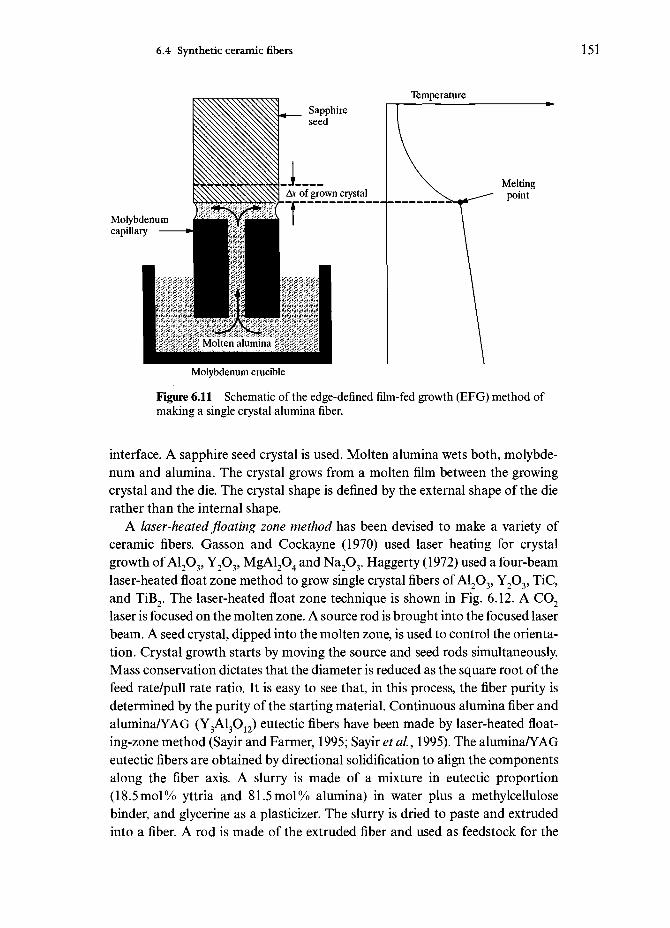
6.4 Synthetic ceramic fibers 151
Temperature
Molybdenumcapillary
Molybdenum crucible
Figure 6.11 Schematic of the edge-defined film-fed growth (EFG) method ofmaking a single crystal alumina fiber.
interface. A sapphire seed crystal is used. Molten alumina wets both, molybde-num and alumina. The crystal grows from a molten film between the growingcrystal and the die. The crystal shape is defined by the external shape of the dierather than the internal shape.
A laser-heated floating zone method has been devised to make a variety ofceramic fibers. Gasson and Cockayne (1970) used laser heating for crystalgrowth of A12O3, Y2O3, MgAl2O4 and Na2O3. Haggerty (1972) used a four-beamlaser-heated float zone method to grow single crystal fibers of A12O3, Y2O3, TiC,and TiB2. The laser-heated float zone technique is shown in Fig. 6.12. A CO2
laser is focused on the molten zone. A source rod is brought into the focused laserbeam. A seed crystal, dipped into the molten zone, is used to control the orienta-tion. Crystal growth starts by moving the source and seed rods simultaneously.Mass conservation dictates that the diameter is reduced as the square root of thefeed rate/pull rate ratio. It is easy to see that, in this process, the fiber purity isdetermined by the purity of the starting material. Continuous alumina fiber andalumina/YAG (Y3A13O12) eutectic fibers have been made by laser-heated float-ing-zone method (Sayir and Farmer, 1995; Sayir et ai, 1995). The alumina/YAGeutectic fibers are obtained by directional solidification to align the componentsalong the fiber axis. A slurry is made of a mixture in eutectic proportion(18.5mol% yttria and 81.5 mol% alumina) in water plus a methylcellulosebinder, and glycerine as a plasticizer. The slurry is dried to paste and extrudedinto a fiber. A rod is made of the extruded fiber and used as feedstock for the
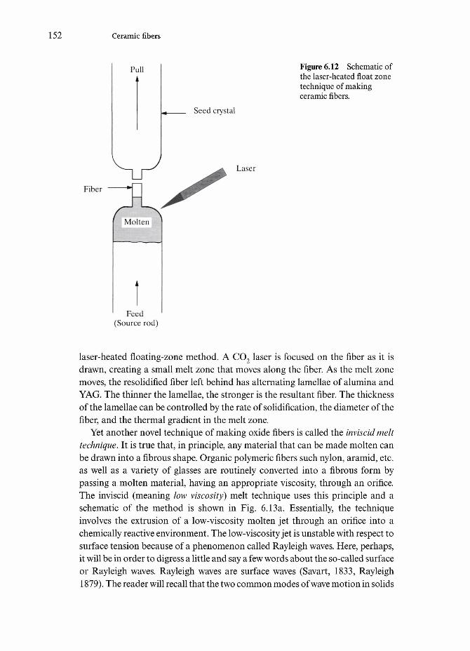
152 Ceramic fibers
Pull Figure 6.12 Schematic ofthe laser-heated float zonetechnique of makingceramic fibers.
Seed crystal
Fiber
Laser
Molten
Feed(Source rod)
laser-heated floating-zone method. A CO2 laser is focused on the fiber as it isdrawn, creating a small melt zone that moves along the fiber. As the melt zonemoves, the resolidified fiber left behind has alternating lamellae of alumina andYAG. The thinner the lamellae, the stronger is the resultant fiber. The thicknessof the lamellae can be controlled by the rate of solidification, the diameter of thefiber, and the thermal gradient in the melt zone.
Yet another novel technique of making oxide fibers is called the inviscid melttechnique. It is true that, in principle, any material that can be made molten canbe drawn into a fibrous shape. Organic polymeric fibers such nylon, aramid, etc.as well as a variety of glasses are routinely converted into a fibrous form bypassing a molten material, having an appropriate viscosity, through an orifice.The inviscid (meaning low viscosity) melt technique uses this principle and aschematic of the method is shown in Fig. 6.13a. Essentially, the techniqueinvolves the extrusion of a low-viscosity molten jet through an orifice into achemically reactive environment. The low-viscosity jet is unstable with respect tosurface tension because of a phenomenon called Rayleigh waves. Here, perhaps,it will be in order to digress a little and say a few words about the so-called surfaceor Rayleigh waves. Rayleigh waves are surface waves (Savart, 1833, Rayleigh1879). The reader will recall that the two common modes of wave motion in solids

6.4 Synthetic ceramic fibers 153
(a) Figure 6.13 (a) Inviscidmelt technique of makingceramic fibers. For (b) and(c) see overleaf.
Propane Propane
Fiber
P i > P 2
are longitudinal and shear waves. In a longitudinal (or compressional wave), theparticle moves parallel to the wave propagation direction while in a shear wave,the particle moves perpendicular to the direction of wave propagation. Surfacewaves are present in a thin surface layer of a solid. There are two types of surfacewaves: Rayleigh and Lamb waves. Surface waves of interest to us here are theRayleigh waves. Rayleigh waves, sometimes referred to as R-waves, are alsoimportant in seismology. They are waves on the surface of the earth with a retro-grade, elliptical motion at the force surface. Rayleigh waves are confined to a thinsurface layer of a solid and the particle trajectories are ellipses in planes normalto the surface and parallel to the direction of wave propagation. These are thesurface waves that form on the surface of the low-viscosity jet stream. The studyof this phenomenon of instability of a liquid jet can be traced to Savart and laterto Rayleigh in the nineteenth century. When a fluid is forced through an orificeunder pressure, Rayleigh or surface waves grow exponentially in amplitude andtend to breakup the jet into a series of droplets. Generally, these droplets will beof random size. If, however, we can apply a regular perturbation of the right fre-quency to the jet, we can impose a standing wave on the fluid cylinder coming outof the orifice (Bogy, 1979). This will result in breakup of the jet in a controlledand periodic manner, and we will have equally spaced droplets whose size is veryuniform and reproducible. The droplet or particle size depends on the original jetdiameter and the wavelength of the imposed mechanical perturbance. In the caseof fiber formation, our objective is to stabilize the molten jet against breakup by

154 Ceramic fibers
100Mm
Figure 6.13 (cont.) (b) A stabilized, round inviscid melt spun fiber (c) An unstable fiberwith Rayleigh waves frozen on its surface, a condition just before breakup (courtesy of F.Wallenberger).
the Rayleigh waves. In the case of glasses and organic polymers, the melts havehigh viscosity (more than 104Pa s or 105 poise), and the high viscosity delays theRayleigh breakup until the molten jet freezes. In the case of a low-viscosity melt,one can avoid breakup of the molten jet by chemically stabilizing it. For example,in a process used at Du Pont Co. to make fibers of alumina+calcia, the low-vis-cosity (1 Pas or 10 poise) jet was chemically stabilized with propane before theRayleigh waves could break the stream into droplets. Figure 6.13b shows a stabi-lized, round inviscid melt spun fiber while Fig. 6.13c shows a fiber with Rayleigh

6.4 Synthetic ceramic fibers 155
waves frozen on its surface, a condition just before breakup (Wallenburger et al,1992). The inviscid jet must be stabilized in about 10~3 seconds or it will break upinto droplets. Yet another point in regard to this process is the fact that smalldiameter fibers are difficult to make. For example, the smallest diameter of analumina-calcia fiber produced by this technique is 105 |xm. These fibers, accord-ing to the authors, have tensile strengths close to 1 GPa.
Properties of oxide fibersThe composition and some of the physical and mechanical characteristics (atroom temperature) of oxide fibers are summarized in Tables 6.3 and 6.4. Oxidefibers, being oxides, are inherently stable in air at high temperatures. They are,however, prone to creep deformation at high temperatures (Gooch and Grover,1973; Jakus and Tulluri, 1989; Johnson et al, 1987; Pysher and Tressler, 1992).The creep rate of fine-grained alumina-based fibers is controlled by grain bound-ary diffusion, characterized by a linear dependence of creep rate on stress. Insingle crystal alumina fibers, creep occurs by dislocation slip or pyramidal slip(see Fig. 6.2), which results in a high stress exponent. A comparison of variouspolycrystalline alumina and aluminosilicate fibers in the Nextel series is shownin Fig. 6.14. Note the superior creep resistance of the Nextel 720 fiber, with thestress exponent n being equal to 3. Nextel 610 fiber also showed n=3. The steadystate creep rate, however, was lower for the 720 fiber. The value of «=3 wouldindicate that the operative creep mechanism is grain boundary or interface con-trolled. Wilson et al (1995) attributed this superior creep resistance to the super-ior creep resistance of mullite compared to alumina and to a two-phase, mosaicmicrostructure consisting of elongated and globular grains, resulting in a bridg-ing effect due to the elongated grains similar to that observed in silicon carbidewhisker reinforced alumina (Chawla, 1993). When fine-grained fibers are held athigh temperatures, their grain size increases and, consequently, their room tem-perature strength decreases. For example, Xu et al (1993) observed loss ofstrength in Nextel 610 alumina fibers upon isothermal exposure due mainly tograin growth. Similar grain size growth was observed in Nextel 720 fibers(Schneider et al., 1996). In the case of Nextel 720, however, we have alumina andmullite grains. Figure 6.15 shows the evolution of microstructure of Nextel 720fiber as a function of isothermal exposure at different temperatures. Quantitativeinformation on the increase in grain size of mullite and alumina with tempera-ture is shown in Fig. 6.16a while the decrease in the residual strength of Nextel720 with increasing annealing temperature (i.e. increasing grain size) is shown inFig, 6.16b. F5 and F100 in Fig. 6.16b refer to the 5 and 100 mm gage lengths usedin tensile testing of these fibers.
Morscher and Sayir (1995) studied the effect of temperature on the bendradius that a c-axis-oriented sapphire fiber can withstand for fibers of variousdiameters. They did this by performing bend stress rupture tests on these fibers

Table 6.4 Composition and properties of some non-Nextel oxide fibers.
CoefficientTensile Tensile of thermal Strain
Composition Diameter Density, p strength, modulus, expansion, a to failureTrade name Manufacturer (wt%) (yjn) (gcm~3) (GPa) £(GPa) (lO^K"1) e(%) Process
Sumica Sumitomo ALCX-85,L2W3
SiO2-153.2
ChemicalSaphikon Saphikon Al2O3-100% 75-225 3.97
Almax
Saffil
Altex
MitsuiMining
ICI
SumitomoChemical
A12O3>99%
Al2O3-96,
Al2O3-95%Si(X-5%
15
3
1015
3.6
2.3
3.3
2600
2.1-3.4
250
386-435 7.9-11.5
lieaxis
1.8
1000
1.8
320
100
210
0.5
0.8
Sol-gel
Meltgrown
Slurryspun
Sol-gel
Sol-gel

6.4 Synthetic ceramic fibers 157
100
Stress (MPa)
1000
Figure 6.14 A comparison of various polycrystalline alumina and aluminosil-icate fibers in the Nextel series. Note the superior creep resistance of the Nextel720 fiber. 3M data.
for times of 1-100 h and temperatures of 300-1700°C. Fibers would show one ofthe following three behaviors: survive the bend test undeformed, fracture ordeform. The radius above which no fibers fractured or deformed for a giventime-temperature treatment was the bend survival radius. The ability of fibers towithstand curvature decreased substantially with time and increasing tempera-ture, and fibers of smaller diameter (40-83 |xm) withstood smaller bend radiithan would be expected from just a difference in fiber diameter when comparedwith the bend results of the fibers of large diameter (144 jim). The authors attrib-uted this to different flaw populations, causing high temperature bend failure forthe tested sapphire fibers of different diameters.
6.4.2 Nonoxide ceramic fibersCeramic fibers of the nonoxide variety such as silicon carbide, silicon oxycarbidesuch as Nicalon, silicon nitride, boron carbide, etc. have become very importantbecause of their attractive combination of high stiffness, high strength and lowdensity. We give brief description of some important nonoxide fibers.
Silicon carbide fibersSilicon carbide fiber must be regarded as a major development in the field ofceramic fibers during the last quarter of the twentieth century. In particular, aprocess developed by the late Professor Yajima in Japan, involving controlled

158 Ceramic fibers
As-received 1300°C
1400°C 1500°C
Figure 6.15 Evolution of microstructure of Nextel 720 fiber as a function ofisothermal exposure at different temperatures (courtesy of H. Schneider and M.Schmucker)
pyrolysis of a polycarbosilane precursor to yield a flexible fiber, must be consid-ered to be the harbinger of the making of ceramic fibers from polymeric pre-cursors. Pyrolysis of a suitable organometallic to produce an inorganic ceramicmaterial must be regarded as one of the greatest success stories of the twentiethcentury. In particular, as we shall see later, polysilane and polycarbosilane areuseful precursors for silicon carbide while polysilazanes are suitable for silicon
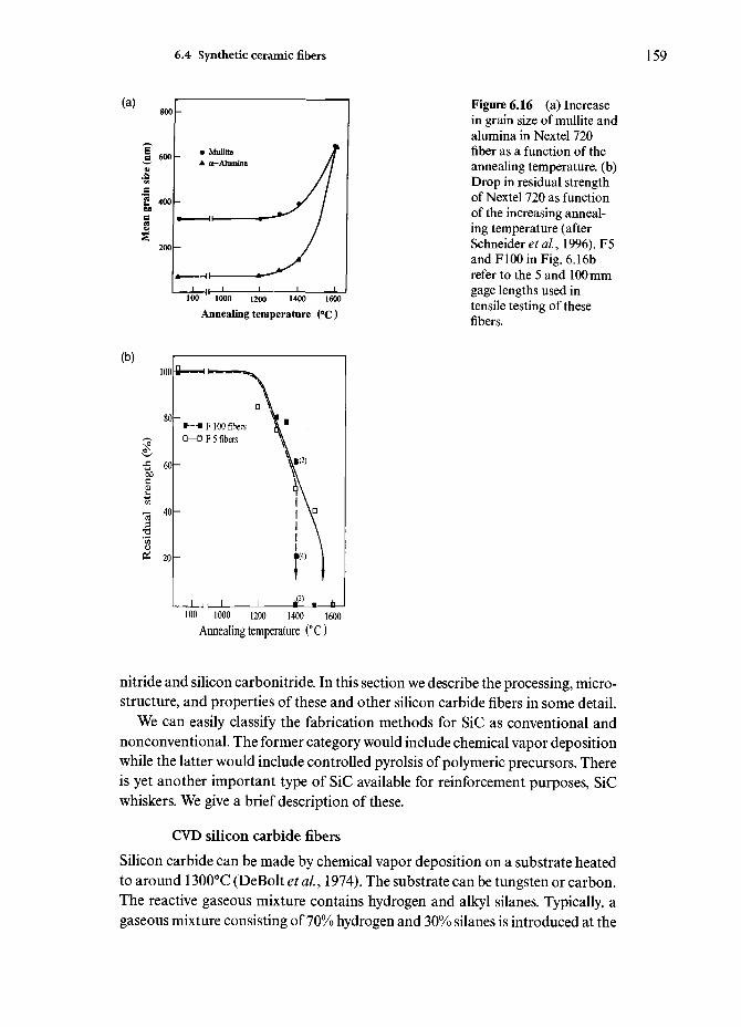
6.4 Synthetic ceramic fibers 159
100 " 1000 1200 1400 1600
Annealing temperature (°C)
Figure 6.16 (a) Increasein grain size of mullite andalumina in Nextel 720fiber as a function of theannealing temperature, (b)Drop in residual strengthof Nextel 720 as functionof the increasing anneal-ing temperature (afterSchneidersal, 1996). F5and F100 in Fig. 6.16brefer to the 5 and 100 mmgage lengths used intensile testing of thesefibers.
1000 1200 1400 1600Annealing temperature (° C)
nitride and silicon carbonitride. In this section we describe the processing, micro-structure, and properties of these and other silicon carbide fibers in some detail.
We can easily classify the fabrication methods for SiC as conventional andnonconventional. The former category would include chemical vapor depositionwhile the latter would include controlled pyrolsis of polymeric precursors. Thereis yet another important type of SiC available for reinforcement purposes, SiCwhiskers. We give a brief description of these.
CVD silicon carbide fibersSilicon carbide can be made by chemical vapor deposition on a substrate heatedto around 1300°C (DeBolt et al, 1974). The substrate can be tungsten or carbon.The reactive gaseous mixture contains hydrogen and alkyl silanes. Typically, agaseous mixture consisting of 70% hydrogen and 30% silanes is introduced at the

160 Ceramic fibers
Carbon monofilamentsubstrate
Gases in(H2 + silane)
Reactor
Figure 6.17 Chemicalvapor deposition (CVD)process of making siliconcarbide fiber.
Gases outfor recycling
SiC
reactor top, Fig. 6.17, where the tungsten substrate (~13|xm diameter) alsoenters the reactor. Mercury seals are used at both ends as contact electrodes forthe filament. The substrate is heated by combined direct current (250 mA) andvery high frequency (VHF-60 MHz) to obtain an optimum temperature profile.To obtain a 100 (xm SiC monofilament, it generally takes about 20s in the reactor.The filament is wound on a spool at the bottom of the reactor. The exhaust gases(95% of the original mixture+HC1) are passed around a condenser to recover theunused silanes. Efficient reclamation of the unused silanes is very important fora cost effective production process. This CVD process of making SiC fiber is verysimilar to that of B fiber. The nodules on the surface of SiC are smaller thanthose seen on B fibers. Such CVD processes result in composite monofilamentswhich have built in residual stresses. The process is, of course, very expensive.Methyltrichlorosilane is an ideal raw material as it contains one silicon and onecarbon atom, i.e. one would expect a stoichiometric SiC to be deposited. Thechemical reaction is:
CH3SiCl3H2
2SiC(s)+3 HCl(g)
An optimum amount of hydrogen is required. If the hydrogen is less thansufficient, chlorosilanes will not be reduced to Si and free carbon will be present

6.4 Synthetic ceramic fibers 161
Diameter— 140 jum
Pyrolytic graphitecoated carbon core
— Inner zone:carbon-rich /?-SiC
— Outer zone:Stoichiometric /?-SiC
— Carbon-rich surfacecoating (0 - 4ju m)
Figure 6.18 Structure ofthe SCS-6 silicon carbidefiber and its characteristicsurface compositionalgradient.
Distance fromthe surface, u.m
in the mixture. If too much hydrogen is present, excess Si will form in the endproduct. Generally, solid (free) carbon and solid or liquid silicon are mixed withSiC. The final monofilament (100-150 fim) consists of a sheath of mainly /3-SiCwith some a-SiC on the tungsten core. The {111} planes in SiC deposit are par-allel to the fiber axis. Figure 6.18 shows schematically the SCS silicon carbidefiber and its characteristic surface compositional gradient.
Another CVD type silicon carbide fiber, available commercially, is calledSigma fiber. Sigma fiber filament is a continuous silicon carbide monofilamentobtained by CVD on a tungsten substrate. Figure 6.19 gives the flow diagram forthe fabrication of this process.
Nonoxide fibers via polymersAs pointed out above, the SiC fiber obtained via CVD is very thick, and it is con-sequently not very flexible. Work on alternative routes for obtaining fine,continuous, and flexible fiber had been in progress for some time when in themid-1970s the late Professor Yajima and his colleagues (Yajima et al.9 1976,Yajima, 1980) in Japan developed a process of making such a fiber by controlledpyrolysis of a polymeric precursor. This method of using silicon-based polymersto produce a family of ceramic fibers having good mechanical properties, goodthermal stability, and oxidation resistance has enormous potential. The varioussteps involved in this polymer route are shown in Fig. 6.20. In any process involv-ing ceramic fiber fabrication via a polymer route, the following are the criticalsteps (Wax, 1985):

162 Ceramic fibers
Exhaust
P1
Scrubber 1
W filament
J L
J L[Refrigeration \+ 1
[Distillation |
Wasteby — products
J L
Gases /for •
recuperation/^^
y
-
>
Hydrogensupply
\Flow
meters
Silanevaporizer
Silanesupply
Photoopticaldiametersensor
Vs^-SiCAV
Figure 6.19 Flowdiagram for fabrication ofthe Sigma fiber.
Polymeric precursorFigure 6.20 Stepsinvolved in the fabricationof ceramic fibers via thepolymer route.
Melt or solutionspinning
Precursor fiber
Curing
Cured or stabilizedfiber
Controlled pyrolysis
Ceramic or glassfiber

6.4 Synthetic ceramic fibers 163
rtM II
-OH3 n —1
- Si C •I I
-CH3 H -1
Polycarbosilane
Polycarbosilanefiber
Polycarbosilane fiberswith molecular cross-linking by oxygen toavoid subsequentmelting
SiC fiberAmorphous or micro-crystalline p-SiC
Figure 6.21 Yajimaprocess of makingNicalon (Si-C-O) fiber.
Dechlorinationwith Na (to NaCI)
Polymerization at470 °C in autoclave
Melt spinning at350 °C (N2)
Curing 190°C inair or RT in ozone
Pyrolisisto1300°Cin vacuum (1000 °Chr1)
(i) polymer characterization (yield, molecular weight, purity, etc.);(ii) melt spin polymer into a precursor fiber;
(iii) cure the precursor fiber to cross-link the molecular chains, making itinfusible during the subsequent pyrolysis. This step may not be requiredunder certain conditions, see below;
(iv) controlled pyrolysis.
Specifically, the Yajima process of making SiC involves the following steps, shownschematically in Fig. 6.21. Polycarbosilane, a high molecular weight polymercontaining Si and C, is synthesized. The starting material is commercially

164 Ceramic fibers
available dimethylchlorosilane. Solid polydimethylsilane is obtained bydechlorination of dimethylchlorosilane by reacting it with sodium.Polycarbosilane is obtained by thermal decomposition and polymerization ofpolydimethylsilane. This is carried out under high pressure in an autoclave at470°C in an argon atmosphere for 8-14 h. A vacuum distillation treatment at upto 280°C follows. The average molecular weight of the resulting polymer is about1500. This is melt spun from a 500-hole nozzle at about 350°C under N2 gas toobtain the so called pre-ceramic continuous, precursor fiber. The precursor fiberis quite weak (tensile strength ~10MPa). This is converted to inorganic SiC bycuring in air, heating to about 1000°C in N2 gas, followed by heating to 1300°C inN2 under tension. This basically is the Nippon Carbon Co. process for the man-ufacture of Nicalon fibers (Simon and Bunsell, 1984; Ishikawa, 1994). Clearly,small variations exist between this and the various laboratory processes. Duringpyrolysis, the first stage of conversion occurs at around 550°C when cross-linkingof polymer chains occurs. Above this temperature, the side chains containinghydrogen and methyl groups decompose. Fiber density and mechanical proper-ties improve sharply. The conversion to SiC occurs above about 850°C.
The multifilament fiber (10-20 |mm diameter) as commercially produced con-sists of a mixture of/3-SiC, free carbon and SiO2. The properties of this fiber aresummarized in Table 6.5. The properties of Nicalon start to degrade at temper-atures above about 600°C because of the thermodynamic instability of composi-tion and microstructure. A ceramic grade of Nicalon, called Hi Nicalon, havinglow oxygen content is also available. Yet another version of a multifilamentsilicon carbide fiber is Tyranno, produced by Ube Industries, Japan. This is madeby pyrolysis of poly (titano carbosilanes) and contains between 1.5 and 4wt%titanium.
Fine-diameter, polymer-derived silicon carbide fibers generally have high
Table 6.5 Properties of two Nicalon-type fibers."
Characteristic
Composition (wt %)
Density (gcm~3)Tensile strength (GPa)Young's modulus (GPa)Coefficient of thermal expansion (10~6K~1)
Nicalon
58 Si, 31 C, H O
2.552.96
1924
Hi-Nicalon
63.7 Si,35.8 C, 0.5 O2.322.80
269—
Note:a Manufacturer's data.

6.4 Synthetic ceramic fibers 165
oxygen content. This results from the curing of the precursor fibers in an oxi-dizing atmosphere to introduce cross-linking. Cross-linking is required to makethe precursor fiber infusible during the subsequent pyrolysis step. One wayaround this is to use electron beam curing. Other techniques involve dry spin-ning of high molecular weight carbosilane polymers (Sacks et ai, 1995). In thiscase, the as spun fiber does not require a curing step because of the high molec-ular weight polycarbosilane polymer used, i.e. it does not melt during pyrolysiswithout requiring curing. Sacks et al (1995) used dopant additions to producelow oxygen, near-stoichiometric, small diameter (10-15 |xm) SiC fibers. Theyreported an average tensile strength for these fibers of about 2.8 GPa.
There is great deal of interest in polymer-derived SiC fibers with improvedthermomechanical stability. An important requirement in making fibers via pre-ceramic polymer processing is to have sufficient spinnability to make the pre-cursor fiber. This route provides small diameter fibers that are flexible. Asdescribed above, two such fine diameter fibers that are commercially available areNicalon and Tyranno. Both are produced by melt spinning. Both of them alsoshow low thermal stability because of their C-rich stoichiometry and high oxygencontent. Such fibers suffer degradation by carbothermal reduction type reac-tions. Volatiles such as CO and SiO are given out and porosity type flaws growand rapid grain growth occurs. By reducing the oxygen content, one can improvethe thermal stability. Hi-Nicalon and Hi-Nicalon type S are improved versionsof Nicalon produced by the Nippon Carbon Co. In order to reduce the oxygencontent, electron beam radiation curing is employed in making these fibers.
Professor Sacks and his colleagues at the University of Florida have produceda C-rich and near stoichiometric SiC, low oxygen content by dry spinning (Sackset aL, 1995; Toreki et al., 1994). They start with polydimethylsilane (PDMS)which has a Si-Si backbone. This is subjected to pressure pyrolysis to obtainpolycarbosilane (PCS) which has a Si-C backbone. The key point in theirprocess is to have a molecular weight of PCS between M W 5000 and 20 000. Thisis a high MW compared to that used in other processes. The spinning dope isobtained by adding suitable spinning aids and a solvent. This dope is dry spunto produce what are called the green fibers, which are heated under controlledconditions to produce SiC fiber.
Let us reconsider the basics of making silicon carbide fiber from poly-carbosilane (PCS), the starting polymer for making silicon carbide fiber. It is avery suitable precursor for making SiC inasmuch as there is one carbon atom foreach silicon atom and thus stoichiometric silicon carbide is easy to obtain in thefinal ceramic fiber. It is, however, not the ideal precursor because it is not quitea linear chain polymer, but has some side groups. The key processing variablehere is the molecular weight, MW of PCS. For MW <5000, it is highly soluble,melts easily, and the ceramic yield is low (60-65%). This melt spinning techniqueis used by Nippon Carbon Co. Thus, the strength of Nicalon green fiber is very

166 Ceramic fibers
low. This makes it difficult to handle. When PCS has a molecular weight>25 000, it does not melt, has low solubility, but the ceramic yield is high. Atsuch high values of MW, it is not very useful for making the precursor fiber.However, for a molecular weight in the 5000-20000 range, the PCS does notmelt, is highly soluble, and results in a high ceramic yield (-80%). Thus, in thisM W range, an appropriate spinning dope can be used to prepare the green fiberwhich will not require the curing step. Sacks et al (1995) took this route. Aproper polymer/solvent ratio in the spinning dope is required. If there is excesssolvent, then not all the solvent will be removed and fibers will stick together. Tocontrol the amount of solvent, a flowing gas in a heated column is used. If thereis less than adequate solvent, then it will be difficult to extrude the dope, and arough fiber surface results. The dope viscosity, r\ should be between 10 and100 Pa s, nearly Newtonian but with a slight shear thinning characteristic but noanisotropy. Certain processing and spinning aids are, invariably, used. Forexample, boron addition enhances densification and controls grain growth. It isvery important to keep the number of fiber breaks/minute/spinneret hole to aminimum. The green fiber obtained in the University of Florida process has astrength between 18 and 21 MPa for a MW of 7000. If the molecular weight isincreased to 16 500, the strength of the green fiber increases to 24 MPa. The finaldiameter of the fiber is between 10 and 15 |xm. The structure of this fiber dependson the final heat treatment temperature. If the heat treatment is between 750 and1000°C, an amorphous structure (very weak crystallinity) results and the frac-ture surface shows a typical glassy appearance. When heat treated at 1600°C,more crystallites form but the crystallite size is less than 10 |xm. After heat treat-ment at 1800°C, /3-SiC (cubic) peaks appear. According to Sacks et al, elementalanalysis shows their fibers to be stoichiometric SiC or slightly C-rich. Theyreport a tensile modulus of 430 GPa, only slightly less than that of 100% /3-SiC.Their density measurements showed a pav =3.15(±0.04)gcm~~3 while the theo-retical density of SiC is ptheo=3.21 gem"3. The fact that Pavg<Ptheo is attributed tothe presence of some porosity (<|xm) in the fiber, plus some free C (in graphiticform) around the grains.
Laine and coworkers (1993,1995) and Zhang et al (1994,1995) at Universityof Michigan have used a polymethylsilane (PMS) (—[CH 3SiH]x—) as the pre-cursor polymer for making a fine diameter, silicon carbide fiber. Spinning aidswere used to stabilize the polymer solution and the precursor fiber was extrudedfrom a 140 jxm orifice extruder into an argon atmosphere. The precursor fiberwas pyrolyzed at 1800°C in Ar. Boron, added as a sintering aid, helped to obtaina dense product. Figure 6.22 shows a schematic of the University of Michiganprocess of making SiC fiber.
Another silicon carbide multifilament fiber, made via a polymeric precursorby Dow Corning Corp., US A, is called Sylramic. According to the manufacturer,this textile grade silicon carbide fiber has a nanocrystalline, stoichiometric

6.4 Synthetic ceramic fibers 167
MeSihh
Catalytic polymerization +spinning aids + boron com-pound
Figure 6.22 Schematic ofthe University ofMichigan process ofmaking SiC fiber (afterLaine etal, 1995)
-(MeSiH)067x
PMS + spinning aids
Solution spinning
Precursor fiber
Pyrolysis in Ar
SiC fiber
silicon carbide (crystallite size of 0.5 |xm). Its density is 3.0gem 3, and it has atensile strength and modulus of 3.15 GPa and 405 GPa, respectively.
Structure and properties of nonoxide fibersTextron Specialty Materials Co. has developed a series of surface-modifiedsilicon carbide fibers, called SCS fibers. These special fibers have a complexthrough-the-thickness gradient structure. SCS-6, for example, is a thick fiber(diameter = 142 |xm) and is produced by chemical vapor deposition of silicon andcarbon-containing compounds onto a pyrolytic graphite coated carbon core, seeFig. 6.18. The pyrolytic graphite coating is applied to a carbon monofilament togive a substrate of 37 |jim thickness. This is then coated with SiC by C VD to givea final monofilament of 142 |xm diameter. The surface modification of the SCSfibers consists of the following: the bulk of the 1 |mm thick surface coating con-sists of C doped Si. Zone I at and near the surface is a carbon rich zone. In zoneII, Si content decreases. This is followed by a zone III in which the Si contentincreases back to the stoichimetric SiC composition. Thus, the SCS siliconcarbide fiber has a surface graded outward to be carbon rich and back to stoi-chiometric SiC at a few |xm from the surface. The properties of a CVD SiCmonofilament, summarized in Table 6.6, are superior to those of Nicalon fiber.
Table 6.6 Properties of CVD SiC monofilament.
Tensile Young's
Composition Diameter (|xm) Density (g cm 3) strength (MPa) modulus (GPa)
/3-SiC 140 3.3 3500 430

168 Ceramic fibers
Figure 6.23 Fracturesurface of an SCS-6 fiberafter high frequencyfatigue. Note the flaking inthe pyrolytic coating onthe carbon core (indicatedby arrow) (courtesy of N.Chawla).
Recall that the properties of Nicalon start degrading above about 600°C becauseof the thermodynamic instability of composition and microstructure. The super-ior properties of CVD SiC fibers stem from the stoichiometric SiC, although thecomposite nature of these fibers can lead to problems. Figure 6.23 shows thefracture surface of an SCS-6 fiber after high frequency fatigue. Note the flakingin the pyrolytic coating on the carbon core (indicated by arrow). Large residualstresses and structural defects can be present at various interfaces in an SCS-6fiber (Lara-Curzio and Sternstein, 1993; Kun et al, 1996). These residual stressesresult from the high processing temperature and the large anisotropy in the pyro-lytic graphite layer.
The structure of Nicalon fiber has been studied by many researchers. Figure6.24 shows a high resolution transmission electron micrograph of Nicalon-typeSiC produced in the laboratory, indicating the amorphous nature of the SiC.Figures 6.25 (a) and (b) show the atomic force microscopy views of the surfaceof Nicalon and Hi-Nicalon fiber, respectively (Chawla et al, 1995). Note thenodular surface in both cases. The commercial variety of Nicalon has an amor-phous structure as shown in Fig. 6.24. A noncommercial variety, processedunder special conditions, showed a microcrystalline structure (SiC grain radiusof 1.7 nm) (Laffon et al, 1989). The microstructural analysis shows that both thefibers contain, in addition to SiC, SiO2 and free carbon. The density of the fiberis about 2.6g/cm3 which is low compared to that of pure /3-SiC. This is not sur-

6.4 Synthetic ceramic fibers 169
Figure 6.24 High resolution transmission electron micrograph of a Nicalonproduced in the laboratory, indicating the amorphous nature of this fiber (cour-tesy of K. Okaumra).
prising in view of the fact that the composition is a mixture of SiC, SiO2 and C.A comparison of Nicalon SiC fiber with CVD SiC fiber shows that the CVDfiber is superior in properties (DiCarlo, 1994; DiCarlo et al, 1995). It turns outthat the continuous phase in these commercial S7C-type fibers (Nicalon andTyranno) is amorphous, and it is this continuous phase that controls the ultimateproperties of these fibers. The elastic moduli, for example, of these fibers aremuch lower than that of the pure, crystalline /3-SiC. These fibers also have lowerdensity than the theoretical density of crystalline /3-SiC and, more importantly,they are not stable at high temperatures (Lipowitz et al.9 1994).
High temperature stability of these nonoxide fibers in air is another criticalproblem. Thermal stability of ceramic fibers derived from polymeric precursorsis of special concern mainly because, as mentioned above, they frequently haveundesirable phases present in them. Polycarbosilane-derived SiC fibers, such asNicalon or Tyranno, involve a thermal oxidation curing process as describedabove and can contain as much as 10 wt % oxygen (Okamura and Seguchi, 1992).Such fibers decompose at temperatures above 1200°C in a nitrogen or argonatmosphere with SiO and CO gas evolution:
S i C O - SiC(s)+SiO(g)+CO (g)

170 Ceramic fibers
(a)
200 T
(nm) 100 -
(b)
200
<nm)100
Figure 6.25 Topographic views of the surface of (a) Nicalon and (b) Hi-Nicalon fiber (courtesy of N. Chawla). Note the nodular surface in both cases.
This reaction is accompanied by a change in morphology and crystal structureof the fiber and a loss of tensile strength. In order to control the oxygen contentof such fibers, Okamura et al (1992) adopted a curing process using radia-tion-chemical reactions and produced oxygen-controlled SiC fibers. Forexample, by radiation curing in an oxygen atmosphere, they could make SiCfibers with a gradient in oxygen content. By electron radiation curing poly-carbosilane in vacuum or helium, SiC fibers with less oxygen were prepared.These low oxygen fibers showed high strength and Young's modulus to temper-

6.4 Synthetic ceramic fibers 171
(a)
£.
treng
th (G
(/>—
Tens
3.0
2.0
1.0
0
-
_
1400
\
\
..-••
\
1 . J1600 1800
Temperature (K)
*&Q.O
mod
ulus
(
1
300
200
100
:
^*^~^^"""
- -— -A""
:.:-•&:;;"'' • • • • • • • • . . . .
• • • • .
-
-
1 , , 11400 1600 1800
Temperature (K)
oxygencontent(mass%)• <0.5O =4.0A = |.9A = 10.8
Figure 6.26 Tensile strength and modulus of Nicalon type fibers as a functionof temperature and oxygen content (after Okamura et al, 1993).
gS 10°Q.Si2Jo
10"1
SCS-6,1300°C-20h— Nicalon, 1300°C-20h
Hl-Nicalon, 1400°C-10h
: / / /
/
Figure 6.27 Comparisonof the creep behavior ofNicalon, Hi-Nicalon andCVD SiC fiber. Note thesuperior performance ofthe CVD fiber, which isattributable to stoichio-metric /3-SiC (afterDicarlo, 1994)
100
Applied stress (MPa)
atures as high as 1500°C and, at a given temperature, the strength and modulusincreased with decreasing oxygen content. Figure 6.26 summarizes their resultson tensile strength and modulus as a function of temperature and oxygencontent. A comparison of the creep behavior of Nicalon, Hi-Nicalon, and CVDSiC fiber is shown in Fig. 6.27. Note the superior performance of the CVD fiber,which is attributable to stoichiometric j8-SiC.
Other nonoxide fibersBesides silicon carbide based ceramic fibers, there are other promising ceramicfibers, e.g. silicon nitride, boron carbide, boron nitride, etc.
172 Ceramic fibers
Silicon nitride (Si3N4) fibers can be prepared by reactive chemical vapordeposition (CVD) using volatile silicon compounds. The reactants are generallySiCl4 and NH3. Si3N4 is deposited on a carbon or tungsten substrate. Again, asin other CVD processes, the resultant fiber has good properties but the diameteris very large and the fiber is expensive. In the polymer route, organosilzane poly-mers with methyl groups on Si and N have been used as silicon nitride precursors.
Polysilazanes have the right elements to give the silicon nitride, however, theyare very reactive to water and tend to incorporate oxygen to form Si-O bondseasily. Polycarbosilanes can be nitrided between 500 and 800°C in a nitrogenousatmosphere such as ammonia. However, such carbon-containing, silicon-nitro-gen precursors on pyrolysis give silicon carbide as well as silicon nitride, i.e. theresulting fiber is not an SiC-free silicon nitride fiber. Wills et al (1983) have dis-cussed the mechanisms involved in the conversion of various organometalliccompounds into ceramics.
A boron nitride fiber can be very competitive commercially with carbon fiber.It has about the same density (2.2g/cm3) as the carbon fiber, but has greateroxidation resistance and excellent dielectric properties. A method of convertingboric oxide precursor fibers into boron nitride fibers has been developed(Economy and Anderson, 1967). Melt spun boric oxide precursor fiber isnitrided with ammonia according to the following reaction:
B2O3+2NH3-* 2 BN+3H2O
This is followed by a high temperature treatment that removes the traces ofoxides and stabilizes the product (Smith, 1977).
The preceramic method has been applied to make BN fibers. The trick againis to synthesize a preceramic fibrous precursor having the same elements as theones desired in the final ceramic fiber. Many derivatives of poly(amino-borazinyls) can be used as precursors for BN fibers (Fazen et al, 1990; Pacioreket al, 1986; Narula et al, 1990) but their spinnability is rather poor. Kimura etal (1994) made a hexagonal boron nitride fiber via a preceramic method basedon a thermoplastic derivative of poly(aminoborazinyl) as the preceramic fiber.The preceramic polymer was made by thermal condensation of B,B,B-tri(methylamino)borazine (M AB) and was melt spun into the preceramic fiber.The preceramic fiber is structurally similar to melt-spinnable carbon pitch. Theprecursor fiber becomes slightly hydrolyzed at the surface during the spinningprocess, and thus becomes infusible. This allows the fiber to be sintered at tem-peratures up to 1000°C in ammonia gas flow without resorting to a thermo-setting step. At this stage there is some contamination with carbon from theorganic residue and the fiber appears black. This is followed by pyrolysis up to1800°C in flowing nitrogen gas, with the color changing to brown at 1200°C andwhite above 1400°C.

6.4 Synthetic ceramic fibers 173
Boron carbide is also a very light and strong material. It can be prepared byreacting carbon yarn with BC13 and H2 at high temperatures, i.e. a CVD process(Economy and Lin, 1977). The chemical reaction involved is
4BCl3+6H2+Cfibers-B4Cfibers+12 HC1
The reaction actually occurs in two steps, namely
2BC13+3H2^2B+6HC1
Much like other CVD processes described earlier, the gaseous mixture BC13, H2,and argon (diluent) enter at one end of a furnace, react in the hot zone, and thereaction products exit at the other end. The second step in the reaction above isthe rate controlling step as the reaction of B and C is slowed by the formation ofa B4C layer.
Another candidate material for high temperature fiber is titanium diboride. Ithas a melting point of around 3000°C. Diefendorf and Mazlout (1994) used agas mixture of titanium tetrachloride, boron trichloride, hydrogen, and hydro-chloride to make titanium diboride fibers by chemical vapor deposition (CVD)in a cold wall reactor at atmospheric pressure.
We make a mention of phosphate fibers, or more appropriately poly-phosphate fibers, that were developed by Monsanto Co. as a replacement forasbestos fibers (Griffith, 1995). Basically, the silicon atoms of asbestos werereplaced by phosphorus atoms. These polyphosphate fibers were supposed to bea kind of 'safe' asbestos fiber. However, Monsanto did not commercialize thesefibers because of a possible vulnerability to lawsuits. The safety feature of poly-phosphate fibers stems from the fact that they are composed of components thatare constituents of the human body and are thus biodegradable. The poly-phosphate fibers developed by Monsanto were similar to asbestos fibers in termsof their insulating and nonflammable characteristics.
Calcium polyphosphate fibers were grown from a water soluble melt. The rawmaterials used were lime (CaO) and phosphoric acid (H3PO4) to give
nCaO+2n H3PO4-* [Ca(PO3)2]n+2nH2O
Calcium polyphosphate fibers were grown as dendritic spherulites. Sodiumcalcium polyphosphates were grown as simple crystals and then milled.
Finally, there are potassium titanate fibers that are produced by heating tita-nium dioxide and potassium carbonate in a furnace to produce whisker-likeshort fibers, about 0.5 |xm in diameter and 50 jxm or more in length. Potassium

174 Ceramic fibers
titanate fibers are quite strong and suitable for reinforcement of polymers. At onetime, Du Pont made them in the US. Their production in the US was dis-continued because of safety reasons. However, these fibers are available com-mercially in Japan.
6.4.3 Boron fibers
Boron fibers are commercially made by chemical vapor deposition of boron ona substrate. Thus, a boron fiber, similar to the SiC CVD fiber described above, isitself a composite fiber. Because of the high temperatures required for thisdeposition process, the choice of substrate material which forms the core of thefinished boron fiber is limited. Generally, a fine tungsten wire is used for thispurpose, but a carbon substrate can also be used. The first boron fibers wereobtained by Weintraub (1911) by reducing a boron halide with hydrogen on ahot wire substrate. These boron fibers were not of high strength. Talley (1959)used the process of halide reduction to obtain amorphous boron fibers of highstrength. This work opened the way for strong but light boron fibers as possiblestructural components.
Fabrication of boron fibersCommercially, boron fibers are obtained by chemical vapor deposition on a sub-strate. The process involves reduction of boron trichloride by hydrogen gasaccording to the following reaction:
2BC€3+3H2->2 B+6HC€
In this process of halide reduction, the temperatures involved are very high, soone needs a refractory material, e.g. high melting point metal such as tungsten,as a substrate. Tungsten being a very heavy metal (its density is 19.3 gcm~3), itsuse as a substrate results in a boron fiber having a density higher than that of ele-mental boron. This process, however, gives boron fibers of high quality.
Boron fiber is produced by chemical vapor deposition on a tungsten wire in amanner similar to that described for the CVD silicon carbide fibers in Fig. 6.17or Fig. 6.19. A fine tungsten wire (10-12 |xm diameter) is pulled into a reactionchamber at one end through a mercury seal and out at the other end throughanother mercury seal. The mercury seals act as electrical contacts for resistanceheating of the substrate wire when gases (BC€3+H2) pass through the reactionchamber where they react on the incandescent tungsten wire substrate. BC€3 isan expensive chemical and only about 10% of it is converted into boron in thisreaction. Thus, efficient recovery of the unused BC€3 can result in a considerablelowering of the boron filament cost.
6.4 Synthetic ceramic fibers 175
There is a critical temperature for obtaining a boron fiber with optimumproperties and structure (van Maaren et al., 1975). The desirable micro-crystalline form of boron with a grain size of about 2-3 nm occurs below thiscritical temperature, while above this temperature crystalline forms of boron alsooccur. Crystalline boron does not have very good mechanical properties. Withthe substrate wire stationary in the reactor, the critical temperature is about1000°C. In a system where the wire is moving, the critical temperature is higherand increases with the speed of the wire. Various combinations of wire temper-ature and wire drawing speed can be used to produce a certain diameter of boronfiber. Boron is deposited in an amorphous state and the more rapidly the wire isdrawn out from the reactor, the higher is the allowed temperature. Of course, ahigher wire drawing speed also results in an increase in production rate andlower costs.
Boron deposition on a carbon monofilament core involves precoating acarbon substrate (-35 |xm diameter) with a 1-2 |xm layer of pyrolytic carbon.The pyrolitic carbon coating is applied by exposing the carbon core to a mixtureof methane, argon and hydrogen at about 2500°C. The pyrolytic carbon coatingaccommodates the growth strains that result during B deposition (Krukonis,1977). The reactor assembly is slightly different from that used to produce boronon a tungsten substrate, as pyrolytic carbon is applied online.
Structure and morphologyThe structure and morphology of boron fibers depend on the conditions ofdeposition: temperature, composition of gases, gas dynamics, etc. Temperaturegradients and trace concentrations of impurity elements inevitably cause processirregularities. Even greater irregularities are caused by fluctuations in electricpower, instability in gas flow or any other operator-induced variables. Theseirregularities can lead to structural defects and morphological irregularitieswhich lower the mechanical properties of boron fiber.
StructureElemental boron can have different crystalline polymorphs, depending on theconditions of deposition. On crystallization from the melt or chemical vapordeposition above 1300°C, one gets /3-rhombohedral. At temperatures below1300°C, the most commonly observed structure is a-rhombohedral.
Boron fibers produced by the CVD method described above have a micro-crystalline structure that is generally called 'amorphous'. This designation isbased on the characteristic X-ray diffraction pattern produced by the filament inthe Debye-Scherrer method, i.e. large and diffuse halos, typical of an amorphousmaterial (Vega-Boggio and Vingsbo, 1978). Electron diffraction studies showthis boron fiber to be nanocrystalline with an average grain size of about 2 nm(Krukonis, 1977). It would thus appear that amorphous boron is really a

176 Ceramic fibers
Figure 6.28 Cross-section of a boron fiber.
nanocrystalline /3-rhombohedral structure. Should any large crystals or groupsof crystals be formed, they will constitute an imperfection in the fiber, andshould be avoided. Such imperfections generally result from exceeding the crit-ical temperature of deposition or due to the presence of impurities in the gases.
When boron fibers are made by deposition on a tungsten substrate, as isgenerally the case, then, depending on the temperature conditions during deposi-tion, the core may consist of, in addition to W, a series of compounds, such asW2B, WB, W2B5 and WB4. A cross-section of such a boron fiber is shown in Fig.6.28, while Fig. 6.29 shows schematically the various subparts of a boron fibercross-section. The tungsten boride phases are formed by diffusion of B into W.Generally the fiber core consists only of WB4 and W2B5. On prolonged heating,the core may completely be converted to WB4. As boron diffuses into the tung-sten substrate to form borides, the core expands from its original 12.5 jim (orig-inal W wire diameter) to 17.5 |mm. When boron fibers are used as reinforcementfor metallic matrices such aluminum or titanium for high temperature use, acoating of SiC or boron carbide is applied to prevent chemical reaction betweenthe matrix and the boron fiber.

6.4 Synthetic ceramic fibers 177
Figure 6.29 Various sub-parts of a boron fibercross-section.
Coating (optional)
MorphologyThe surface of boron fiber shows a corn-cob structure consisting of nodulesseparated by boundaries, Fig. 6.30. The nodule size varies during the course offabrication and has its origin in the very nature of the CVD process. Almost anyfiber-making process via CVD on a substrate results in such a nodular surfacemorphology to some extent. This is particularly exacerbated by a tungsten wiresubstrate because it has longitudinal ridge markings that result from the wiredrawing process. These longitudinal ridges provide preferential nucleation sitesfor the boron nodules, which start as individual nuclei on the substrate and thengrow outward in a conical fashion until a filament diameter of 80-90 |mm isreached, above which the nodules seem to decrease in size. Occasionally, newcones may nucleate in the material, but they always originate at an interface witha foreign particle or inclusion.
Residual stresses in boron fiberBoron fibers, like any CVD fiber, have inherent residual stresses which originatein the process of chemical vapor deposition. Growth stresses in the nodules ofboron, stresses induced due to diffusion of boron into the W core, and stressesgenerated due to the difference in the coefficient of expansion of the depositedboron and the tungsten boride core, all contribute to the residual stresses, andthus can have a considerable influence on the fiber mechanical properties.

178 Ceramic fibers
Figure 6.30 Surface of a boron fiber showing a corn-cob structure consisting ofnodules separated by boundaries (courtesy of Phillips Electronics).
Boron and silicon carbide fibers are produced by CVD on a tungsten wiresubstrate. B(W) has radial cracks due to the fact that the boron fiber consists ofB, W B , and almost no W at the end of the process. Volume changes involved
x y
in the formation of compounds are constrained by the surrounding sheaths ofunreacted material leading to residual stresses (Adler and Hammond, 1969;Vega-Boggio and Vingsbo, 1976a, 1976b; Layden, 1973). SiC(W), on the otherhand, consists of W and SiC, with little or no reaction. One has to contend witha very small amount of differential thermal mismatch, and no compound forma-tion occurs unless exposed to very high temperatures. Radial cracks form inboron fiber from the core outward. Axial extension is considerable, while tan-gential extension is negligible. The final quench results in a compressive surfacelayer and the radial crack stops at the boundary between tensile and compres-sive stress where the tensile stress is zero. A schematic of the residual stresspattern across the transverse section of a boron fiber is shown in Fig. 6.31. Thecompressive stresses on the fiber surface are due to the quenching actioninvolved in pulling the fiber from the chamber.
As pointed out above, boron fiber is also a composite fiber like any otherCVD-type fiber. During fracture, cracks frequently originate at pre-existingdefects located at the boron/core interface or at the surface. Commonly, a radialcrack originates at the boron/core interface and leads to a brittle fracture.
Properties of boron fibersDue to the composite nature of boron fibers, complex internal stresses anddefects such as voids and structural discontinuities result from the presence of a

6.4 Synthetic ceramic fibers 179
0.7... 0.8 kN mm"2
(-)0.3... 0.5kNmm
(-) 1.0... 1.4kNmm-2
Figure 6.31 The residualstress pattern across thetransverse section of aboron fiber (after Vega-Boggio and Vingsbo,1978).
core and the deposition process. Thus, one would not expect boron fiber strengthto equal the intrinsic strength of boron. The average tensile strength of boronfibers is 3-4 GPa while Young's modulus is between 380 and 400 GPa (Wawner,1967).
The intrinsic strength of boron can be estimated in a flexure test. Assumingthat in a flexure test the core and interface are near the neutral axis, criticaltensile stresses would not develop at the core or interface. Flexure tests on boronfibers lightly etched to remove any surface defects yield a strength of 14 GPa(DiCarlo, 1985). Without etching, the strength is about half this value.
Table 6.7 summarizes the properties of boron. The high temperature treat-ment, indicated in this table, improves the fiber properties by putting a perma-nent axial compressive strain in the sheath. Commercially produced 142 |xm
Table 6.7 Properties of boron fibers (after Dicarlo, 1985 ) . a
Diameter (/mi)
142406382
382
Treatment
As-producedAs-producedChemical
polishHeat
treatmentplus polish
Averagestrength (GPa)
3.82.14.6
5.7
COV* (%)
10144
4
Relativefracture energy
1.00.31.4
2.2
Notes:a Gage length=25 mm.b Coefficient of variation=standard deviation/average value.
180 Ceramic fibers
diameter boron fiber shows tensile strengths <3.8 GPa. The tensile strength andfracture energy values of the as-received and some limited-production run largerdiameter fibers show improvement after chemical polishing (DiCarlo, 1985).Fibers showing strengths above 4 GPa have their fracture controlled by the tung-sten boride core while strengths of 4 GPa or less are controlled by fiber surfaceflaws. Chemical polishing improves the strength because it removes some of thedefects from the surface region.
Boron has a density of 2.34 gcm~3 (about 15% less than that of Al). Boronfibers with tungsten core have a density of 2.6gcm"3 for a fiber of 100 jxm diam-eter. Its melting point is 2040°C and it has a thermal expansion coefficient of4.86XlO-6K-1upto315°C.
As mentioned above, commercially produced boron fibers have a large diam-eter, 142 |xm. This makes them rather inflexible (see Chapter 2 for flexibility).Wallenberger and Nordine (1992) have made smaller diameter boron fibers,<25 |mm, by laser assisted chemical vapor deposition (LCVD). This process usesthe focal point of a laser beam rather than a heated tungsten substrate as the heatsource to decompose the gaseous reactants at pressures >lbar. The smallestfiber diameter achievable in this process is limited by the size of the laser focalspot size which in turn is limited by diffraction. The process involves continualadjustment of the hot focal point of the laser to coincide with the tip of thegrowing fiber and to support the continuous growth of the fiber. According tothese authors it is possible to use the LCVD process to make other small diam-eter inorganic fibers such as silicon carbide.
6.5 Ceramic whiskers
Whiskers are monocrystalline, short fibers with extremely high strength.Strength levels approaching the theoretically expected values have been mea-sured in many whiskers (Brenner, 1958, 1962). a-alumina whiskers showed veryhigh strength to very high temperatures (Brenner, 1962). This high strength,approaching the theoretical strength, has its origin in the absence of crystallineimperfections such as dislocations. Being monocrystalline, there are no grainboundaries either. Typically, whiskers have a diameter of a few |xm and a lengthof a few mm. Thus, their aspect ratio (length/diameter) can be very high, varyingfrom 50 to 10 000. This makes it attractive to use these high strength whiskers asreinforcements. Whiskers do not have uniform dimensions or properties. This isperhaps their greatest disadvantage, i.e. the spread in properties is extremelylarge. It should also be recognized that preservation of a defect-free surfaceduring processing of a composite is a very difficult task, i.e. handling and align-ment of whiskers in a matrix to produce a composite are rather difficult.
Whiskers are normally obtained by vapor phase growth. Early in the 1970s, anew process was developed, starting from rice hulls, to produce SiC particles and

6.6 Applications 181
whiskers (Lee and Cutler, 1975; Hollar and Kim, 1991). The SiC particles pro-duced by this process are of a fine size. Rice hulls are a waste by-product of ricemilling. For each 100 kg of rice milled, about 20 kg of rice hull is produced. Ricehulls contain cellulose, silica and other organic and inorganic materials. Silicafrom soil is dissolved and transported in the plant as monosilicic acid. This isdeposited in the cellulosic structure by liquid evaporation. It turns out that mostof the silica ends up in the hull. It is the intimate mixture of silica within the cellu-lose that gives the near ideal amounts of silica and carbon for silicon carbide pro-duction. Raw rice hulls are heated in the absence of oxygen at about 700°C to driveout the volatile compounds. This is called coking. Coked rice hulls, containingabout equal amounts of SiO2 and free C, are heated in an inert or reducing atmos-phere (flowing N2 or NH3 gas) at a temperature between 1500 and 1600°C forabout 1 hour to form silicon carbide in accordance with the following reaction
3C+SiO2^SiC+2CO
Figure 6.32 shows a schematic of the process. When the above reaction is over,the residue is heated to 800°C to remove any free C. Generally, both particles andwhiskers are produced together with some excess free carbon. A wet process isused to separate the particles and the whiskers. Typically, the average aspect ratioof the as-produced whiskers is 75.
A vapor-liquid-solid (VLS) technique (Petrovic et al, 1985; Milewski et al.91985) can be used to grow exceptionally strong and stiff silicon carbide whiskers.The name VLS comes from the fact that the process uses vapor feed gases,a liquid catalyst, and solid crystalline whiskers are the end product. Figure6.33 shows the process schematically. The catalyst forms a liquid solution inter-face with the growing crystalline phase while elements are fed from the vaporphase through the liquid-vapor interface. Whisker growth takes place by pre-cipitation from the supersaturated liquid at the solid/liquid interface. The cata-lyst must take in solution the atomic species of the whisker to be grown. For SiCwhiskers, transition metals and iron alloys meet this requirement. One of themajor drawbacks of whiskers is the extreme variability in their properties. Forexample, the properties of SiC whiskers grown by the VLS technique showedaverage tensile strength and modulus of 8.4 GPa and 581 GPa, respectively.However, the tensile strength values ranged from 1.7 to 23.7 GPa in 40 tests.Whisker lengths were about 10 mm and the equivalent circular diameter aver-aged 5.9 |xm.
6.6 Applications
Refractory or ceramic fibers have low thermal conductivity, low heat capacityand high chemical resistance. These characteristics make them attractive as

182 Ceramic fibers
Rice hull
Carbon tubereactor
Figure 6.32 Schematic ofthe rice hull process ofmaking silicon carbidewhiskers.
Shred and disperse
Whisker/carbon separation
Whisker/hull relict separation
Dry
Carbon oxidation
SiC whiskers
insulation materials in metal processing industries, where they are frequentlyused as insulation in furnaces. The characteristics of chemical inertness tomolten metals and natural gas and low thermal capacity are especially useful.Whenever a furnace is cooled, e.g. during shut down or as part of an operatingcycle, much of the stored heat in the insulating lining is lost. A low thermalcapacity lining will reduce such heat losses. It will also allow rapid cooling andheating. Aluminosihcate fibers, e.g. Fiberfrax, Nextel, etc. have very low thermalconductivity and thus are excellent for insulating purposes. Applications includecommon ones such as various high temperature furnace seals and insulation,and special ones such as insulating catalytic converters and mufflers on vehicles,copying machine components, door seals in stoves, chemical tanks and cylinders,etc. Such fibers are available in a variety of different product forms such asblanket, board, paper, woven fabric, tape, yarn, braided sleeves, rope, etc.Braided thermocouple insulation is a very common application for high tern-

6.6 Applications 183
SiO(g)+C=Si+CO(g)| C P ( g )
Generator
Catalyst
Figure 6.33 Schematic ofthe VLS process ofmaking silicon carbidewhiskers (after Petrovic etal, 1985).
2H2(g)
y
SiC
Si + C-SiC
Whisker
SiO(g) + 2C=SiC(s) + CO(g)
perature measurement. Another application of such fibers is in the making ofhigh temperature filter bags. Special mention should be made of a sprayable formof fiber, coated with a binder, that can be sprayed on to, say, a metal surface,forming an interlocked network of short fibers and highly efiicient insulating airpockets. The spray process is very fast and is used for refits and repairs in thechemical, metallurgical and ceramic industry. Such alumina-silica insulatingfibers are commonly used up to service temperatures of 1250°C while alumina,mullite and zirconia can extend usable temperatures to 1600°C. Mention shouldbe made of insulation boards made of mullite fibers+fillers+inorganic bindersby Rath Co., called Altra Boards, with enhanced thermal shock resistance forkiln furnace linings up to 1800°C (Anon., 1993). This product optimizes diver-gent properties of thermal shrinkage and thermal shock resistance.
Use of ceramic fiber burners with natural gas can result in reduced emissionsof nitrogen oxide. Ceramic fiber burners can lead to a high radiative heat trans-fer and thus a lower flue gas temperature, which in turn results in lower nitrogenmonoxide emission. The nitrogen oxide formation depends on the flue gas tem-perature in a more or less exponential manner. Thus, a reduced flue gas temper-ature results in a reduced NOx production. Ceramic fiber burners can thus leadto less NOx than conventional burners.
High stiffness ceramic fibers such as alumina, alumina-silica, silicon carbide,boron, etc. are used as reinforcement fibers for polymeric, metallic, and ceramicmatrix composites (Chawla, 1987). Silicon carbide whisker reinforced aluminacomposites are used as high speed cutting tools (Chawla, 1993).

Chapter 7
Glass fibers
The term glass or a glassy material represents a rather large family of materialswith the common characteristic that their structure is noncrystalline. Thus,rigorously speaking, one can produce a glassy material from a polymer, metal orceramic. An amorphous structure is fairly common in polymeric materials. It isless so in metals, although metallic glass, generally in the form a ribbon, can beproduced by rapid solidification, i.e. by not giving enough time for crystalliza-tion to occur. In this chapter we describe silica-based inorganic glasses becauseof their great commercial importance, as a reinforcement fiber for polymermatrix composites and as an optical fiber for communications. Communicationvia optical glass fibers is a well established field. Crude optical glass fiber bundleswere used to examine the insides of the human body as far back as 1960. Sincethen tremendous progress has been made in making ultra pure, controlledcomposition fibers with very low optical attenuation. It is estimated that the totalworldwide shipment of optical fibers is over US$5 billion per year. Before wedescribe the processing, structure, and properties of glass fiber, it would beappropriate to digress slightly and describe for the uninitiated, albeit very briefly,the basic physics behind the process of communication via optical glass fibers.
7. l Basic physics of optical communication
Optical glass fiber has many desirable characteristics for communication such as:
H large bandwidth over great distances;• protection against electrical interference and crosstalk;
184

7.1 Basic physics of optical communication 185
• galvanically protected signal transmission;• safety and reliability.
By far the most important and simple phenomenon that is made use of in opticalwave guides is refraction of light. When a ray of light propagates from onemedium to another, it undergoes refraction at the interface such that the ratio ofthe sine of the incident angle and the sine of the refracted angle equals the inverseratio of the relative refractive index of the two media. Thus,
sin flj/sin 62=n2/nl
where Sx is the incident angle, 62 is the refracted angle, and nx and n2 are therefractive indexes of medium 1 and 2, respectively. This is called Snell's law, andit gives the exit angle as
fl^sin"1 (« 2sin 62ln^)
It is easy to see from this expression that for some critical angle and a givenrefractive index ratio, 02 will equal 90° and sin 02 will be unity. For all anglesgreater than the critical angle, 0c, the incident light will be totally reflected, andwe can write
sin 0c = n2/nx
0c = sin
For nx>nv we shall have a critical angle, 01 = 0C called the critical angle for totalinternal reflection such that no refracted ray comes out, i.e. total internal refrac-tion occurs. This condition of total internal reflection is the key for the lightpropagation through a glass fiber and we satisfy this condition when the incidentangle equals or exceeds the critical angle, 0c. If we extend this idea to a situationwhere a ray propagates from a dense medium through successive layers of rarermedium, we can have the ray bend. In an extreme case of a medium having acontinuously varying refractive index, the ray will bend and suffer total internalreflection, i.e. the light will be trapped in such a medium. It is this phenomenonof light trapping that is made use of in optical fiber for light transmission.Fiberoptic glass, thus, consists of a core that conducts the light and a claddingthat has lower refractive index than the core. This enables a light beam toundergo a total internal reflection at the core/cladding interface, that is one hasa light-guiding effect. Figure 7.1 shows this effect schematically. The readershould appreciate the key point here, namely that the light-conducting glasscore should cause as little attenuation of the light signal as possible during its

186 Glass fibers
Coating
Core
ACladding
Cladding
Figure 7.1 A light beamundergoing total internalreflection at thecore/cladding interface.The bottom part shows aperspective view consist-ing of the light conductingcore, the cladding that hasa lower refractive indexthan the core, and the pro-tective coating.
Core
; A/
Coating
transmission over long distances. It is convenient to measure the optical attenua-tion of the glass fiber in decibels per kilometer (dB/km). The symbol dB is usedindicate the logarithmic scale of decibels. The decibel scale is preferred when aquantity can vary over several orders of magnitude. Thus, we can express theoptical power ratio or an index of attenuation of a plane wave A, more conve-niently in the decibel scale as
^(dB)=101og10/0/7
where IQ is the initial energy and /is terminal energy. Up until 1970, optical glassfibers had high losses, -1000 dB/km, and were used mainly for short distanceimaging for medical purposes. In the 1970s low loss glass fibers (as low as0.2 dB/km) became available and the era of optical communications began. Letus see what this 0.2 dB/km translates into in terms of attenuation of the initialenergy. Using the above expression, we can write
o.2=ioiogloy/
so that
Iog10/0//=0.02

7.2 Fabrication 187
and
7^7= 1.05
giving
7=0.95 70
This is a pretty low index of attenuation!For short range optical links, polymeric fibers made of a polystyrene or poly
methyl methacrylate core fiber and low refractive index polymer coating can beused. The best reported attenuation figure for these is 200dB/km. It should berecognized that the capacity of lasers to generate strong and intense opticalsignals has also been helpful in the great progress made in the field ofcommunications via optical fibers. Nevertheless, the so-called photonics revolu-tion could not have come about without the development of optical glass fibersthat can transmit light efficiently over long distances. These optical fibers havetransformed telecommunication and data networks.
7.2 Fabrication
We first describe the characteristic drawability feature of glasses which stemsfrom their viscoelastic nature and then describe the fabrication processes for theglass fiber for insulation and reinforcement of polymers and for opticalcommunication purposes, both of which exploit the ability of glass to be drawninto a very small diameter fiber.
7.2.1 Viscoelastic behavior of glassesViscoelasticity is the phenomenon of time-dependent strain. Often, it is alsorefened to as anelasticity. Glassy materials, above the glass transition tempera-ture T show Newtonian viscosity, i.e. the stress is proportional to the strain rate.This property is exploited in the drawing of fiber and sheet forms. We can write,in terms of normal stresses and strains,
<r=r,e (7.1)
where a is the stress, r\ is the viscosity, and e is the strain rate. The deformationproceeds at a constant volume, i.e. an increase in length is accompanied by adecrease in the cross-sectional area. If an incremental increase in length is d€,and the corresponding decrease in cross-section is — d̂ 4, then

188 Glass fibers
dm=d€=-dA/A
where € and A are the instantaneous values of length and cross-sectional area,respectively. We introduce the strain rate by dividing throughout by incrementaltime, dt. Thus,
i=deldt= -(dA/A)(l/dt)= -(dA/dt)(l/A)= -A/A
Ae=-A (7.2)
If Fis the applied load, then from Eq. (7.1) we have
FIA = (T= 7)6
or, using Eq. (7.2), we can write
-7]A (7.3)
Equation (7.3) states that the rate at which the fiber (or sheet) becomes thinneris proportional to the applied force, not the applied stress. This means thatthinner and thicker regions suffer cross-sectional reduction at an equal rate. Thisexpression also informs us that, for a given load, as the viscosity r\ increases, theaxial strain rate, e, decreases. This has very important implications in fiberdrawing. In order to understand these implications, we need to examine the tem-perature dependence of viscosity. The temperature dependence of viscosity isgiven by the Eyring equation
r]=(hNIVm) exp (Q/RT)=AQXP (Q'RT)
where h is Planck's constant, N is Avogadro's number, Vm is the gram molec-ular volume of the liquid, Q is the molar activation energy, A is a pre-expo-nential constant and R is the universal gas constant. The Eyring equationindicates that the viscosity varies inversely in an exponential manner with thetemperature. As thinner regions of the fiber cool more rapidly, the viscosity ofsuch regions increases resulting in a decrease in the rate at which the thinregion gets thinner. This allows the thicker regions to catch up and the fiber(or the film) extends uniformly without forming a necked region. Thischaracteristic, due to Newtonian behavior, is exploited in the manufacture ofglass fiber involving extension, through platinum orifices, of molten glass asexplained below.

7.2 Fabrication 189
7.2.2 Glass fiber for reinforcementReinforcement of polymer matrix materials is one of the largest markets for glassfiber. A schematic of the conventional fabrication procedure for glass fibers isshown in Fig. 7.2a while a picture of glass fibers being drawn out of holes in abushing is shown in Fig. 7.2b. The raw materials are heated in a hopper and themolten glass is fed into electrically heated, multiholed, platinum orplatinum-rhodium bushings. Typically, each bushing contains 200 holes at itsbase. A constant head of molten glass is kept in the tank. The molten glass flowsby gravity through these holes forming fine continuous filaments which are gath-ered together and passed around a fast rotating collet, followed by drawing at aspeed of l-2km/min. Glass flows out of a platinum bushing (200^400 holes) ata rate given by:
where r is the radius, € is the length, v is the kinematic viscosity (i.e. dynamicviscosity 77 divided by density, p), and h is the hydrostatic pressure generated bythe head of glass in the bushing. The fibers exiting the bushing are cooled, sub-jected to a surface treatment (an organic size such as a starch oil), and given astretching treatment by the take-up spool.
Typically, the glass fibers have a diameter between 5 and 20 |xm. A size, con-sisting of an aqueous polymer emulsion, is applied before winding on a drum.The final glass fiber diameter is a function of the bushing orifice diameter, viscos-ity, which is a function of composition and temperature, and the head of glass inthe hopper. The viscosity is generally around 100Pas for good fiberization. Thebushing diameter (1-2 mm), the head of molten glass, and the viscosity controlthe drawing rate of fibers. The glass fibers undergo a stretching treatment by thetake-up spool. The take-up speed is 50-60 ms"1, which is slightly higher than thedrawing speed, and thus the as-wound glass fiber suffers a stretch.
Glass filaments are easily damaged by the introduction of surface defects. Inorder to minimize this and ease the handling of these fibers, the sizing treatmentprotects as well as binds the filaments into a strand. In almost any fiber drawingprocess from a melt, the melt viscosity is by far the most important processcontrol parameter. If a single glass filament breaks, the glass will drip acrossother filaments and cause a breakdown of the whole drawing process. Filamentbreakage can occur because of undissolved particles in the glass, abrasion, devit-rification, or any instability due to changes in viscosity/winding speed (Proctor,1971).
A very important characteristic of glass fiber is its extreme flexibility, whichof course stems from its fine diameter and low modulus. Textile processes ofweaving, knitting, etc. can be used with fine, flexible glass fibers to produce

190 Glass fibers
Hopper
Furnace
(a)
Filament collectingand size applicator
Strand transversemotion
Figure 7.2 (a) Schematicof the conventionalfabrication procedure forglass fibers (b) Glass fibersbeing drawn out of holesin a bushing (courtesy ofOwen-Corning, Inc.).

7.2 Fabrication 191
fabrics, tapes, sleeves, and ropes. E-glass fiber has a diameter between 3 and20 |xm and is commonly used for insulation purposes as well as for reinforce-ment of polymers. Frequently, glass fibers are chopped to obtain short, staplefibers. Glass wool, used extensively for insulating purposes, is made by a rotaryor spinner process. A vessel containing molten glass is subjected to rapid rota-tion and glass fibers are spun from a series of rotating heads as a result of thecentrifugal force. The emerging horizontal glass streams are impacted by blastsof combustion gases at high speed converting molten glass into short fibers.Binder is sprayed onto these fibers during their downward journey to a conveyorbelt to give them a matted form for insulating material. Finally, the binder iscured in an oven and the glass wool is compressed by rollers to the desired thick-ness.
This characteristic of flexibility can be exploited in some rather innovativeways. For example, Sandtex Co. makes silica fiber from glass fiber by a thermaland chemical digestion process that converts a common glass fiber precursor toessentially pure silica (>98% SiO2). The thermal and chemical leaching processremoves most of the metallic oxides from the precursor glass fiber while main-taining the fibrous form. Thorough washing removes acidic residues and theapplication of proprietary surface finishes gives handleability and abrasion resis-tance. Figure 7.3a shows some forms in which silica glass fiber can be obtainedby this process. A special glass fiber, trade name Miraflex (Owens-Corning) isshown in Fig. 7.3b. Note the different contrast in the two halves of the fiber cross-section. It is a bicomponent fiber and is made by fusing together two glassformulations having different coefficients of expansion. This structure gives thefiber natural, irregular twists.
Sol-gel processing of glass fiberThe conventional processing of glass fibers, as described above, involves directmelting of raw materials, followed by drawing of the molten glass through elec-trically heated platinum bushings. A major problem with any direct meltingprocess is that the temperatures involved are very high. Quite frequently, the meltviscosity at reasonable temperatures is too high to allow proper homogenization.At times the oxides show large differences in volatility and direct melting resultsin large losses of some of the constituents. All these problems, as pointed out inChapter 6, have led to processing of ceramics and glasses via a chemical route.This allows a high degree of homogeneity on a molecular scale and consequentlyhigh purity glasses or ceramics can be obtained. In particular, the sol-gel tech-nique of making glass fibers has become important.
We give a brief description of the general principles of the sol-gel technique,with special emphasis on fiber making via this technique. Essentially the sol-gelroute of making any glass or ceramic involves the formation of the appropriateglass or ceramic structure by chemical polymerization of suitable compounds in

192 Glass fibers
Figure 7.3 (a) Different forms of high silica (>98% SiO2) glass fiber: such afiber is obtained by a thermal and chemical digestion process that converts acommon glass fiber precursor to essentially pure silica (courtesy of Sandtex Co.)(b) A bicomponent glass fiber, Mirafiex (courtesy of Owens-Corning). Note thedifferent contrast in the two halves of the cross-section.

7.2 Fabrication 193
the liquid state (sol) at low temperatures. A sol is a colloidal suspension in whichthe individual particles are so small that no sedimentation occurs. The particlesize in a sol generally varies between 1 and 100 nm. Gel, on the other hand, is asuspension in which the liquid medium is viscous enough to behave more or lesslike a solid. A precursor material in the form of a gel is obtained from the sol.The unwanted residues (water, organic compounds, etc.) are removed from thegel by heating at temperatures much lower than those used in direct melting pro-cesses, and the desired glass or ceramic is obtained in an appropriate form(powder, film, fiber, etc.). As the solvent liquid is lost, the sol viscosity increasesuntil it becomes rigid, i.e. it gels. The gel is the starting material for conversioninto glass or ceramic. Figure 7.4a shows the sol-gel process flow diagram whileFig. 7.4b shows the microstructural changes that occur during the process. Mostsol-gel processing involves the formation of metal oxides (ceramics or glasses)from metal alkoxides. A metal alkoxide has the chemical formula of M(OR)w,where M is a metal or metalloid and R is an alkyl group such as CH3, C2H5, etc.,and n is the valence of the metal atom. Hydrolysis of metal alkoxides provides alow temperature route to produce ceramics. Most metal alkoxides react withwater to yield hydrous metal oxides which give the metal oxide on heating. Twoor more metal alkoxides can be reacted to produce a mixed-metal oxide whichyields binary or ternary oxides on hydrolysis.
The metal alkoxide route has been exploited largely to obtain oxide ceramicsystems. Among nonoxide ceramics, the notable examples are polycarbosilaneand aminosilane methods for SiC and Si3N4 production. Essentially, tetrachloro-silane (SiCl4) when reacted with ethyl alcohol gives the alkoxide tetraethylorthosilicate, also called tetraethoxysilane [Si(OC2H5)J. This alkoxide, acronymTEOS, serves as the starting material for making an inorganic polymer con-taining Si and O via the sol-gel route, i.e. silica glass or ceramic, or even glass-ceramic.
There are two ways of obtaining silica-based gels:
(i) destabilization of silica sol (pure or with metal ions added to aqueoussolutions of salts) to obtain a homogeneous gel. When a sol is destabi-lized, the resultant product can be precipitates, unaggregated particles, ora homogeneous gel. It is the latter that we desire;
(ii) hydrolysis and polycondensation of metalorganic compounds (generallymetal alkoxides) dissolved in alcohols and a small amount of water.
We give a brief description of these two methods:
(i) Destabilization of silica solA sol can be destabilized by increasing its temperature or by adding an elec-trolyte. A temperature increase reduces the quantity of intermicellar liquid byevaporation and increases the thermal agitation. This increases particle collisions

194 Glass fibers
(a)Starting
compound
ISolution
Sol
Wet gel
Dry gel
I densification
Glass orceramic
Figure 7.4 (a) Sol-gelprocess flow diagram, (b)Microstructural changesoccurring during thesol-gel process.
Sol Gel
Liqui(
Aged Gel
-Pore-. ^7 (no liquid)""
Dried Gel PartiallyDensified
Gel
ResidualPorosity
Glassor
Ceramic

7.2 Fabrication 195
Figure 7.5 Strengtheningof the particulate network.
and their linking by condensation of surface hydroxyls occurs. Electrolyte addi-tion modifies the pH of the sol and reduces electric repulsion between particles.Addition of acid diminishes the pH to 5-6 and induces gel formation by aggrega-tion. The sol is converted into gel progressively with microgel aggregates slowlyinvading the whole volume of sol. When about half of the silica has been con-verted to gel, a rapid increase in viscosity is noted.
An aging treatment results in a partial coalescence of particles and a strength-ening of the network occurs. At the neck joining the particles there is a negativeradius of curvature. Thus, local solubility at the neck is less than near the parti-cle surface. Therefore, transport and deposition of silica occur preferentially tothe neck region and neck thickening results. This results in a strengthening of theparticulate network, Fig.7.5 (Zarzycki et al, 1982).
Sol-gel transition occurs only if there are no active forces which promotecoagulation into aggregates of higher silica concentration than the original sol.Metal cations, particularly polyvalent ones, tend to cause precipitation ratherthan gelling.
(ii) Hydrolysis and polycondensation of metalorganic compounds(metal alkoxides) (Zarzycki, 1984; Sakka, 1982).
This method involves three steps:
1. Mix the appropriate metal alkoxides (water-soluble salts if possible) andethanol solutions to yield the desired cation ratio.
2. Hydrolyze the above mixture with a water based acid solution which canbe diluted with alcohol. This polymerizes the mixture and a gel is formedin accordance with the following reaction
M(OR)n+nH2O

196 Glass fibers
where M is the metal and R is an alkyl group such as (C2H5). At thisstage one can choose the conditions to obtain the bulk, powder, or fiberform of the precursor material.
3. Heat the gel slowly to obtain the oxide (glass or ceramic) through thereaction
During the process of gel drying, the solvents (water, any residual organicmaterial) are eliminated. Concomitantly, sintering of the porous oxide takesplace. A well-controlled rate of drying is required because of the large shrinkagethat accompanies the drying process. At an intermediate stage, a solid can beobtained with a very large amount of porosity on a microlevel. This is calledxerogel. The glass or ceramic produced via the sol-gel process has virtually thesame density, thermal expansion, refractive index, and mechanical character-istics as material of the same composition made by direct melting.
Fiber drawingFiber drawing is carried out in the course of sol to gel conversion at viscositiesgreater than 1 Pa s (1 Nm~2s). The gelled fibers are heated to obtain glass fibers.
There are some very general but important points to be considered in gel spin-ning. A high molecular weight (>106) is desirable. Spinning of dilute solutionsinto gels results in a minimum of polymer chain entanglement. Gelled fibers arehighly porous and elastic. They should be stretched by drawing while in a tem-perature gradient. This removes the solvent and decreases the porosity.
When a tetraethoxysilane-water-hydrochloric acid-alcohol solution ofappropriate composition is held at near room temperature, hydrolysis and poly-condensation occur and the solution viscosity increases. Fibers can be drawn ata viscosity about 10 Pas, which occurs during the course of sol to gel transition.It should be pointed out that for an alkoxide solution to be spinnable (Sakka,1982) the solution must have linear polymers and an appropriate ratio of[H2O]/[Si(OC2H5)4], called the r-ratio. An r-ratio <2 gives a spinnable solution.
7.2.3 Optical glass fiberThe conventional method of making glass fiber described above is unsatisfactoryfor making optical grade fibers because of the extremely high purity required.Optical grade glass fiber is generally made by a vapor deposition process(Midwinter, 1979). Figure 7.6 shows two vapor deposition processes. High purityvapors of silicon and germanium are reacted to produce layers of glass, Fig. 7.6a.The composition of the glass can be changed by changing the proportions of Siand Ge, resulting in what is called a graded-index glass fiber. Silicon and ger-

7.1 Fabrication 197
Exhaust Reactantgases
(a)Traversing
heat source
CladdingCore
^
Collapsed rod
(b)1800 °C
Heat source
Figure 7.6 Two vapordeposition processes ofmaking optical glass fiber,(a) High purity vapors ofsilicon and germanium arereacted to produce layersof glass. The compositionof the glass can bechanged by changing theproportions of Si and Geto produce a graded-indexglass fiber, (b) A modifiedchemical vapor deposition(MCVD) technique. Thecladding is deposited onthe inside of a hot silicatube. When sufficientcladding has beenobtained, the reactants arechanged to obtain the coreglass. In the final stage, thetemperature is increasedand the tube is collapsedto form a solid preformrod.
manium are reacted inside a flame and the reaction products deposited on arotating mandrel. Another variation involves reacting the components inside aglass tube. In either case, the preform so produced by the vapor deposition tech-nique is heated and drawn into a fiber.
A modified chemical vapor deposition (MCVD) technique (Nagel et al, 1982)is used to obtain a fiber consisting of a GeO2-SiO2 core and pure SiO2 cladding,see Fig. 7.6b. In this case, first the cladding is deposited on the inside of a hotsilica tube. When sufficient cladding has been obtained, the reactants are changedto obtain the core glass. In the final stage, the temperature is increased and thetube is collapsed to form a solid preform rod. This preform is converted into afine filament by a drawing process and protective polymeric layers are applied.
Direct melting of optical glass fiber of an appropriate composition is also usedunder certain circumstances. Cladding and core rods are melted in a double cru-cible as shown in Fig. 7.7 and wound on a drum. A clean atmosphere must bemaintained throughout all these operations to avoid the introduction of impur-ities. Fibers 5-10 km long (strain to fracture 2-3%) can generally be pulled. Toprotect the glass surface from handling-induced surface flaws, the pristine fiberis immediately coated with polymers. For applications involving communica-tions, the coated fibers are gathered into cables for long haul and rough use suchas in underground ducts, etc.
Optical glass fiber is a thin, flexible, and transparent guide through which light

198 Glass fibers
Core rodCladding rod
Double crucible
Furnace
Furnace windings
Figure 7.7 Direct meltingprocess of making opticalglass fiber. Cladding andcore rods are melted in adouble crucible andwound on a drum.
Fiber
Drum
can be transmitted. Absorption and scattering of light traveling through suchfibers result in signal attenuation. Intrinsic signal attenuation is a function of thewavelength and this component of optical loss is the lowest in GeO2-SiO2
glasses. Extrinsic absorption losses occur from transition metal and OH impur-ities. These are present to a considerable degree in the glass fiber produced bydirect melting. In vapor phase deposited GeO2-SiO2 glasses, transition metal ionimpurities can be reduced to < lppb. OH absorption can be reduced by carefullypreparing dry glass fibers. Complete elimination of OH is difficult.
Sources of strength loss in such fibers are mainly surface damage due tocontamination and, possibly, the presence of microcracks (e.g. bubbles, etc.).Polymer surface coalings are used to minimize the damage. Fibers are also prooftested to breaking strains in the range of 0.5-1%.
Optical cable designOptical fibers give a large bandwidth at small cross-section and should be underas little load as possible because of their brittleness. Essentially, we have an opticalfiber core, a cladding, a buffer coating, and a sheath. The core fiber can vary indiameter from 5 to 1500 |mm. The larger the core diameter, the more light the fibercan carry. Optical fiber fibers can be optimized to carry near IR, IR, UV or visibleradiation. The light source can be traditional spectroscopic light or an intensehigh-power laser. The cladding, as described above, is a thin layer (5-10 |mm) of

7.3 Chemical composition 199
glass or polymer with an index of refraction lower than that of the core so that itreflects the light back into the core. The buffer is also a polymer that protects thecore and cladding from environmental hazards such as moisture, scratches andgeneral handling. The sheath can be metallic or polymeric. Frequently, fiber rein-forced polymers are used to allow for handling during cable manufacture as wellas to allow for the design load. Polymeric composites such as aramid/epoxy or ahybrid of aramid and S glass in an epoxy matrix are frequently used. It givesadded strength, stiffness and general protection from the environmental hazards.
Optical cable needs to be very rugged because of the abuse that it must takeduring a variety of cable forming techniques and rather harsh in-service environ-ments (Gossing and Mahlke, 1987). It should be realized that when used for suchpurposes, optical fiber is exposed to aggressive environments that can cause lossof strength, time-dependent failure and/or premature failure. The mechanicalreliability of optical fiber is thus very important. In particular, failure of glassfiber under the action of a constant stress, less than the initial strength, as a func-tion of time can occur. Frequently, in the literature, this time-dependent failureis referred to as static fatigue.
Cable design must insure that the optical fibers in the cable maintain theiroptical properties (attenuation and dispersion) during service. The design mustalso minimize microbending effects, as explained in the following section. Theterm microbending refers to small-amplitude random bends of the axis of anoptical fiber, with periodic components in the millimeter to centimeter range,which give rise to added transmission losses. It is also desirable to have aminimum differential thermal expansion or contraction during service in orderto minimize microbending. In addition, the cable structure must be such that thefibers carry a load well below the proof test level at all times.
We mentioned above three types of optical fibers: step index single mode, stepindex multimode, and gradient index multimode. The last two types can carry morelight that the step index single mode fiber. Lightness is a very important feature.Among the important features for such a system are the following (Clare, 1995):
• a convenient fiber optic system;• flexible;• small diameter;• low loss;• cheap and reliable.
7.3 Chemical composition
Silica-based glass fiber has been around for a long time. Common glass fiber isreadily available commercially in a variety of different chemical compositions.

200 Glass fibers
Most glass fibers are silica based (-50-60% SiO2) and contain a host of otheroxides of Ca, B, Na, Al, Fe, etc. They are commonly used for reinforcement ofthermosetting and thermoplastic polymers. Table 7.1 gives the compositions ofsome commonly used glass fibers in composites. The designation E stands forelectrical as E glass is a good electrical insulator besides having good strengthand a reasonable Young's modulus; C stands for corrosion as C glass has a betterresistance to chemical corrosion; S stands for higher silica content and S glass isable to withstand higher temperatures than others. It should be pointed out thatmore than 90% of all continuous glass fiber produced is of the E-glass type. Alsoincluded in Table 7.1 is the chemical composition of a special glass fiber calledCemfil.
The most important elements of an optical fiber are the core and the cladding.The refractive index of the core is higher than that of the cladding material suchthat total internal reflection occurs when the light hits the boundary with the lowrefractive index cladding. Optical glass fiber, in its simplest form, consists of acore of silica glass and a cladding of a refractive index lower than that of silica.Such an optical glass fiber is called a step-index fiber, because of the abruptchange in refractive index at the core/cladding boundary. A variety of opticalfiber systems can be obtained. Figure 7.8 shows a schematic of optical guidancein what is called a multimode step-index fiber as well as the refraction indexprofile. There are three common types of optical glass fiber, multimode stepindex, multimode graded index, and single mode. The refractive indexes of thesefiber types are shown in Fig. 7.9. The core fiber diameter can vary between 100and 1500|xm in the case of a step-index fiber, between 5 and 600 |mm for thegraded-index fiber, and between 5 and 10 |mm for the single-mode fiber.
A variety of sources such as bubbles, impurities, density changes, bends, etc.can result in attenuation of the signal in an optical glass fiber as shown in Fig.7.10. There are, however, two important sources that limit the capacity of lighttransmission in any medium: absorption and scattering. In the case of glass
Table 7.1 Chemical composition of some common glass fibers.
Compound
SiO2
A12O3
CaOMgONa2O
K2OLi2O
E-glass
55.2
8.018.7
4.60.30.27.3
C-glass
65.0
4.014.0
3.08.5—5.0
S-glass
65.0
25.0
—10.0
0.3——
Cemfil
71.0
1.0——
Na2O+K2O=11<1.0
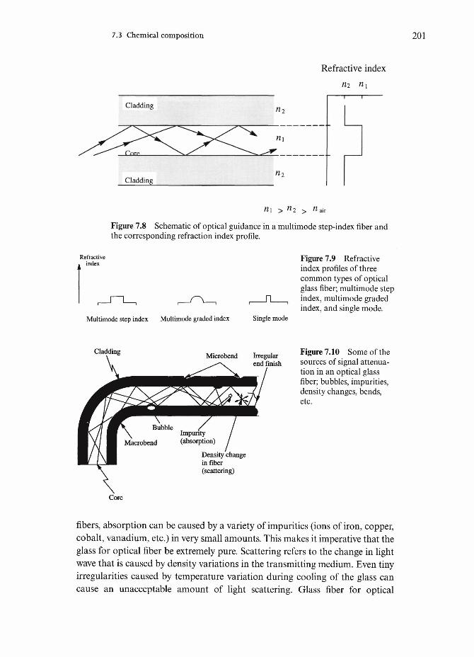
7.3 Chemical composition 201
Refractive indexn2 nx
Refractiveindex
«1 > n2 > ndh
Figure 7.8 Schematic of optical guidance in a multimode step-index fiber andthe corresponding refraction index profile.
Figure 7.9 Refractiveindex profiles of threecommon types of opticalglass fiber; multimode stepindex, multimode gradedindex, and single mode.
Multimode step index Multimode graded index Single mode
Cladding Microbend Irregularend finish
Density changein fiber(scattering)
Figure 7.10 Some of thesources of signal attenua-tion in an optical glassfiber; bubbles, impurities,density changes, bends,etc.
Core
fibers, absorption can be caused by a variety of impurities (ions of iron, copper,cobalt, vanadium, etc.) in very small amounts. This makes it imperative that theglass for optical fiber be extremely pure. Scattering refers to the change in lightwave that is caused by density variations in the transmitting medium. Even tinyirregularities caused by temperature variation during cooling of the glass cancause an unacceptable amount of light scattering. Glass fiber for optical

202 Glass fibers
communication has a very controlled chemical composition. In a step-indexfiber, both core and cladding are silica. Dopants such as GeO2 and P2O5 are putin the silica for the core to increase the refractive index of the core. Dopants suchas B2O3 and F can be used in the cladding to decrease the refractive index.
The core and cladding in an optical glass having different chemical composi-tions can result in an appreciable amount of thermal stresses. Consider, forexample, a germanosilica optical glass fiber with the core and cladding havingdifferent coefficients of thermal expansion. When the glass is cooled below thefictive temperature, Tp the core is put under high tensile stresses due to thethermal mismatch (Scherer, 1980).
7.4 Structure
Silica-based glass is a generic term representing an interesting and versatile classof materials. Glasses of various compositions can be obtained and they showvery different properties. Structurally, however, all silica-based glasses have thesame basic building block: a tetrahedron made up of four large oxygen ions witha silicon ion at the center of the tetrahedron. The composition of a single tetra-hedron is thus SiO4. Each oxygen ion is, however, shared by two tetrahedra,giving the bulk composition of SiO2. It is this basic building block that isrepeated in three dimensions in silica and silica-based materials. Different repeatpatterns can result in different structures for the same composition. Thus, quartzis a crystalline form of pure silica while ordinary glass, which is amorphous, hasa random network of silica tetrahedra. Figure 7.11 shows two different two-dimensional schemes of the network of silica tetrahedra: crystalline and amor-phous. Glass has an amorphous structure, i.e. devoid of any long-range order socharacteristic of a crystalline material. Silicon has a valency of four and bondscovalently to four neighboring atoms placed at the corners of a tetrahedron. Inthe silica tetrahedron, the silicon atom is at the center of the tetrahedron andoxygen atoms occupy the corners of the tetrahedron. Each of the oxygen atomsis shared by another silicon atom. Each polyhedron consists of oxygen atomsbonded covalently to silicon. The addition of other metal oxide types serves toalter the network structure and the bonding, and consequently the properties.The presence of crystalline regions is undesirable in a glass because such regionsact as stress raisers. Glass fibers are quite isotropic; Young's modulus andthermal explosion coefficients are the same along the fiber axis and per-pendicular to it. This, of course, is a result of the amorphous, three-dimensionalnetwork structure of glass, i.e. there is no preferential alignment of any structuralunits such as polymer chains along the fiber axis.
A great advantage of any silica-based glass is its ease of fabrication, whichallows processes such as melt infiltration and compression molding to be used.

7.5 Properties 203
(a)
(b)
Figure 7.11 Two differenttwo-dimensional networkschemes of silica tetra-hedra: (a) crystalline and(b) amorphous. Glass hasan amorphous structure,i.e. devoid of any long-range order so character-istic of a crystallinematerial.
Glass has a low modulus, generally less than that of other common reinforce-ments. It also has a low failure strain.
7.5 Properties
Silica-based glasses generally have a very low density. The strength can be quitehigh, but the elastic modulus is not very high. Thus, while the strength-to-weightratio of glass fibers is quite high, the modulus-to-weight ratio is only moderate.It would be safe to say that it is this low stiffness to weight ratio of glass that wasthe driving force for the development of the so-called advanced fibers, such as B,C, A12O3, SiC, etc. Typical mechanical properties of different glass fibers aresummarized in Table 7.2.
Although resistance to fire and many chemicals are very attractive features ofglass, moisture can decrease the strength of glass fiber. In particular, the adsorp-tion of moisture by freshly made glass fiber results in a drastic decrease in itsstrength. Glass fibers are also susceptible to what is called static fatigue, i.e. theycannot withstand loads for long periods of time.
Common glass fiber such as E-glass becomes severely corroded in an alkaline

204 Glass fibers
atmosphere such as cement or concrete. Some special alkali-resistant glass fibershave been developed. The properties of one such fiber, called cemfil, are given inTable 7.2.
Carding (see Chapter 2) is a process involving mechanically opening,combing, and aligning staple fibers to make nonwoven webs. The main advan-tage of this process is that nonwovens containing quite uniform fiber distributionare obtained. The cardability of a staple fiber depends on its geometry, diameter,length, factional characteristics, crimp, etc. Crimp in a fiber is especially desir-able. Common glass fiber requires the addition of a carrier polymeric fiber to becarded. Without the polymeric fiber, conventional, crimpless glass fiber is toorigid to be carded. A bicomponent glass fiber, called Miraflex glass fiber, has anatural twist which allows it to be carded (Kenney et al, 1995). Miraflex productforms include yarn, staple fiber, fabric, mat and felt. It is soft to touch, feels silky,is highly flexible and form-filling. Table 7.3 summarizes its characteristics.
Table 7.2 Typical properties of some glass fibers.
Glass fiber type Density (g cm"3) Tensile strength (GPa) Young's modulus (GPa)
ESCCemfil
2.542.482.482.70
1.7-3.52.0^.51.7-2.8
69-72857080
Table 7.3 Some important characteristics of Miraflex fiber."
Diameter (|im) 7-8Density (g cm"3) 2.46Fiber length ratio (stretched/relaxed) 2Specific heat (J/gK, at 22°C) 0.825Specific heat (J/gK, at 200°C) 1.04Softening point (°C) 665-690Max. continuous use temperature (°C) 450Thermal conductivity (W/mK) 1Tensile strength/single filament (GPa) 0.7-1Young's modulus (GPa) 67
Note:a Data from Owens-Corning Co.

7.5 Properties 205
Hackle
MirrorMist
Initiation point
Figure 7.12 Schematic of the four regions observed on the surface of aglass fiber.
Fracture of glass fibersMany brittle, amorphous materials show some tell tale markings on their frac-ture surfaces, e.g. many thermosetting polymers and silica-based inorganicglasses. In particular, Mecholsky et al (1977, 1979) and Chandan et al (1994)related fracture surface markings on optical glass fiber to the fiber strength andthe time to failure. Figure 7.12 shows schematically the four distinct regionsobserved on the fracture surface of a glass fiber. These regions surrounding thepoint of fracture origin are indicated in Fig. 7.12 as a smooth mirror region, amist region of small radial ridges, a hackle region consisting of large ridges, andfinally a region of extensive crack branching. Extensive crack branching occursbeyond the hackle region. It turns out that the product of strength, a, and thesquare root of the distance of each of these regions from the origin of fracture,is a constant. One can write
where R the radius of the mirror-mist, mist-hackle, or crack branching bound-aries. These radii can be related to the initial flaw-depth, a, or the half-width, b,through the fracture mechanics analysis:
cIR =Klc Y2I2A]
where c=(ab)°-59 Yis a geometrical constant and Klc is the critical stress intensityfactor or fracture toughness.

206 Glass fibers
Lifetime prediction of glass fibersIt is of interest to be able to predict the life of a glass fiber, say an optical glassfiber in a cable buried under the sea. The starting point is crack growth velocityversus stress intensity factor, K. Generally, we can express crack velocity, v as
v=AK» (7.4)
where KY is the stress intensity factor, A is a constant, and n is the exponent. KYis given by the following expression
KY= Y&Va (7.5)
where a is the far field applied stress, a is the crack size, and Y is a geometricfactor. From Eq. (7.4) we obtain an expression for the lifetime of a componentthat obeys this relationship. For example, a glass fiber component in an opticalcommunication cable. Combining Eqs. (7.4) and (7.5), we can write for the time-to-failure, ti
[a<da 1 fa< da
where a{ is the initial crack size and ac is the critical crack size. Integrating Eq.(7.6), we obtain
where
and ac is the inert strength (strength in the absence of subcritical crack growth)and Klo is the stress intensity factor at the onset of unstable crack extension.
The inert strength, ac, is given by a Weibull distribution (see Chapter 10) withthe cumulative frequency
where <xco and (3 are the Weibull parameters. From Eq. (7.6), it follows that thelifetime (£f) can be described by a Weibull distribution
where tfo=B o£2 a~n.

7.6 Applications 207
Figure 7.13 Failure prob-ability of 1 m and 10mgage length optical glassfibers. The long lengths ofoptical glass fibers havemultiple flaw populations,i.e. there is more than onesource of flaws, thus theydo not follow the simpleWeibull distribution (afterMaurer, 1985).
2 3 4
Strength (GPa)
It should be pointed out that Weibull statistics describe well the distributionof flaws in short lengths (a few centimeters long) of optical glass fibers but forlong lengths (several meters or more), the strength distribution is not welldescribed by a Weibull distribution. Figure 7.13 shows the failure probability of1 m and 10 m gauge length optical glass fibers (Maurer, 1985). The reason for thisis that long lengths of optical glass fibers have multiple flaw populations, i.e.there is more than one source of flaws.
7.6 Applications
Glass fiber is available in a variety of shapes and forms. Some of the importantones include continuous fiber and roving, staple fiber and chopped strand mat.Staple fibers are strands of individual filaments 200 to 400 mm long and areexcellent for providing bulkiness for filling, filtration, etc. Chopped strand glassfibers consist of fibers chopped to various lengths, 3 mm to 50 mm, mainly forthe purpose of mixing with a resin for making composites. Glass fiber matsconsist of randomly dispersed chopped fibers or continuous fiber strands, heldtogether with a resin.
Glass fibers find applications in a vast array of markets.Automotive market. The automobile industry is one of the largest users of glassfiber. Polymer matrix composites containing glass fibers are used to make exter-nal body panels, bumper beams, pultruded body panels and airducts, enginecomponents, etc. Parts made of glass fiber reinforced polymers are much lighterthan metallic ones, making the automobile fuel efficient.Aerospace market. Composites containing glass fibers have been used to make

208 Glass fibers
various aircraft parts. Examples include wings, helicopter rotor blades, engineducts, etc. Glass fiber has a relatively low elastic modulus. Hence, it morecommon to use glass fiber reinforced polymer composites in the interior of anairplane rather than for primary structural parts. The radar transparencycharacteristic of glass has given it some key uses in the radar-evading 'stealth'technologies.Marine market. Sail boats and boats, hulls and decks of commercial fishing boatsand military minehunters are frequently made of glass fiber reinforced polymers.Glass fiber reinforced polyester is commonly used in making boats of all sizes.Civil construction. This is another large market where glass fiber is widely usedin one form or another. Typical applications include the use of glass fibers inpolymeric resins for paneling, bathtubs and shower stalls, doors, windows etc.Glass fibers are also used as a reinforcement in a variety of household items suchas paper, tapes, lamp shades, etc. Teflon coated glass fiber fabrics are used fordomes and building covers of stadia, etc. Denver airport as well as Riyadhairport in Saudi Arabia have made extensive use of such fabrics. Some specialalkali-resistant glass fibers have been developed for reinforcement of cement andconcrete. Commonly, steel bars are used for such purposes. Cement, however, isvery alkaline. An ordinary glass fiber such as E-glass will be severely corroded inan alkaline atmosphere, hence the need for special, alkali-resistant glass fiber(Majumdar, 1970; Hannant, 1978). The bonding between glass fiber and cementis mainly mechanical and has its origin in the shrinkage that occurs when thecement is set.Insulation. Short glass fibers of random lengths, called glass wool, are usedextensively for thermal and acoustical insulation as well as for filtration pur-poses. Air, trapped in the interstices of the pack, provides the insulationcharacteristics. Wall and ceiling panels in buildings and vehicles make use ofsuch characteristics. Glass mat, consisting of shredded silica wool, needlepunched with ordinary fiber glass to give structural integrity, is widely used forthermal insulation. Such a nonwoven mat is lightweight and flexible, it can alsobe conformed to different shapes for insulation purposes. Glass fiber can also bemade into paper. Such a paper consists of silica fibers with about 2% binder toprovide physical integrity. Fabrics made of high silica glass can be used as pro-tective blankets in welding and burning processes. Such fabrics must be resistantto molten metals such as steels and should be usable in high temperatureenvironments without producing smoke or noxious fumes. Woven, braided, orknitted fabrics up to 150 cm wide are available for such purposes.
High temperature textiles consisting of continuous filaments of amorphoussilica in a variety of forms are available commercially. These can be used toreplace asbestos-based high temperature textiles because of the health hazardsassociated with asbestos fiber. These high silica fibers are used for a variety ofhigh temperature thermal insulation products: for example, welding curtains,

7.5 Properties 209
furnace curtains, insulation for pipe and power plant cables, thermocoupleinsulation, fire rescue and smothering blankets. The Sandtex type silica fiber canbe used up to temperatures as high as 1100°C. Knitted fabrics are more compli-ant and can be conformed to flat, curved, or other complex shapes. Knittedfabrics can be cut and sewn to many shapes unlike nonwovens. Ropes (twistedand braided) can also be made. A braided sleeve is easy to apply and fit. Heatinsulation cordage can be braided onto a heating element.Sporting goods. Not surprisingly, the supporting goods industry was one of thefirst to make use of glass fiber reinforced composites. Examples include bicycleframes, tennis rackets, golf shafts, cricket bats, skis, etc. Braided fibers in a resinmatrix give high torsional stiffness to skis.Electrical/electronic market. Glass fibers are used extensively in printed circuitboards, industrial circuit breakers, conduits for power cables, etc.Optical communications. Communication systems that use lightwave transmis-sion via fiberoptic cables are in use in many countries. They are more econom-ical than conventional copper wire, radio, or satellite-based systems. Opticalfibers carry much more information than copper wire of the same diameter. Thereader will gain a good idea of the extent of the importance of glass fiber in thecommunication business if he/she is reminded that by the mid-1990s, more than107km of optical fiber had been installed in the US for long-distancecommunication. Optical fibers are also used in waveguides for long-distancetransmission of digital signals generated by pulsed lasers or photo-diodes.Sensors. Optical fiber sensors can be used to measure a variety of mechanical andphysical parameters such as force, elongation, motion, velocity, rotation, tem-perature, current and voltage. Generally, such a sensor will consist of a lightsource (e.g. a light emitting diode or laser), an optical fiber to transmit the lightto the transducer, a transducer, an optical fiber for the return transmission, anda detector. The transducer has the function of modifying one of the character-istics of light, e.g. intensity, wavelength, phase or polarization.
An unconventional application of optical glass fibers is for temperaturemeasurement. The principle is very simple. A sensor is coupled to a flexibleoptical fiber which conducts light emitted by the target to a photo-detector. Thephoto-detector, a part of an electronics unit, converts the light signal to an elec-trical signal which is then digitized. The digitized electrical signal is converted toa temperature reading.Optical fibers in medical field. Optical glass fibers have become very important inmany medical fields where laser-assisted surgery is required. Laser surgeryrequires a beam directing capability, i.e. one needs a flexible delivery system todirect the energy for surgical purposes at a generally inaccessible place or site.Although generally glass fibers are used for such applications, single crystal andpolycrystal ceramic fibers are used under special circumstances. Glass fiber is easyto fabricate, and one has great flexibility in chemical composition. Silica-based

210 Glass fibers
glass fibers, as described above, are the most common type used in laser surgery.This, of course, follows from its success in the telecommunications where the lowloss is very important (0.1 dB/km).
An important requirement for laser surgery is a beam directing capability,which involves a flexible delivery system. A fiberoptic delivery system is a veryconvenient system for this purpose: it is flexible, low loss, small diameter, andallows deep, invasive laser endoscopy. One should add that there is always thepotentially useful feature of using fibers as biosensors, i.e. one can have a coupledsensing and actuation device.
Chapter 8
Carbon fibers
Carbon fibers have become established engineering materials. In view of theircommercial importance, we devote a separate chapter to them. Carbon is a veryversatile element. It is very light, with a theoretical density of 2.27 gem"3. It canexist in a variety of forms, glassy or amorphous carbon, graphite, and diamond.Carbon in all these forms can be found in nature. Carbon in the graphitic formhas a hexagonal structure and is highly anisotropic. The diamond form ofcarbon has a covalent structure and is an extremely hard material. The latestaddition to the variety of forms of carbon is the Buckminster Fullerene, or theBuckyball with a molecular composition such as C60 or C70. In this chapter, wefollow the same sequence as in previous chapters; processing, structure, proper-ties and applications of carbon fibers. However, in order to understand theseaspects of carbon fiber, it is helpful to review the basic structure and propertiesof graphite.
8. l Structure and properties of graphite
Carbon fiber is a generic name representing a family of fibers. Over the years, ithas become one of the most important reinforcement fibers in many differenttypes of composites, especially in polymer matrix composites. It is an unfortu-nate fact that the terms carbon and graphite are used interchangeably in com-mercial practice as well as in some scientific literature. Rigorously speaking,graphite fiber is a form of carbon fiber that is obtained when we heat the carbonfiber to a temperature greater than 2400°C. This process, called graphitization,
211
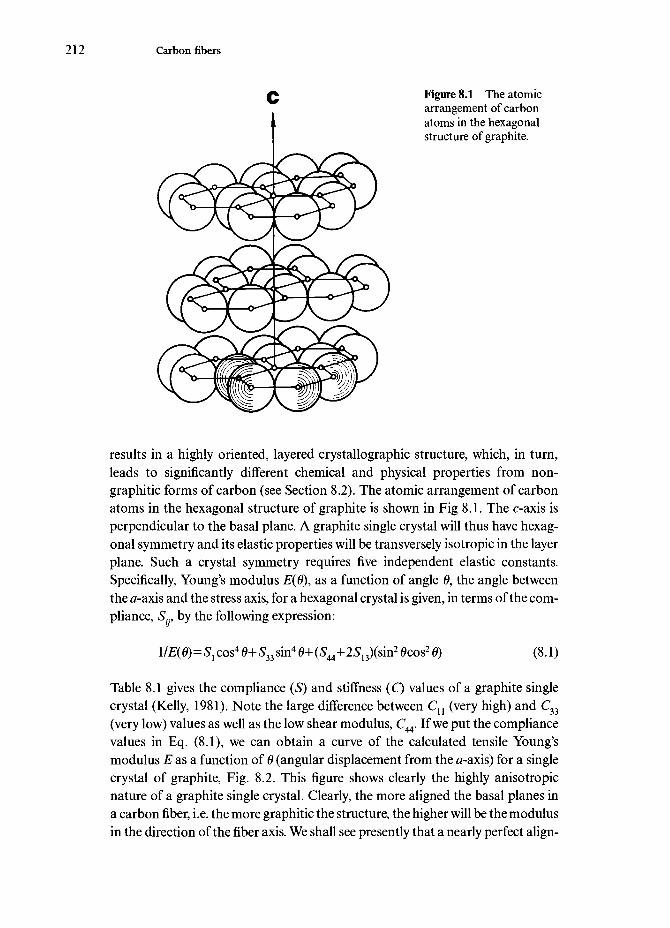
212 Carbon fibers
Figure 8.1 The atomicarrangement of carbonatoms in the hexagonalstructure of graphite.
results in a highly oriented, layered crystallographic structure, which, in turn,leads to significantly different chemical and physical properties from non-graphitic forms of carbon (see Section 8.2). The atomic arrangement of carbonatoms in the hexagonal structure of graphite is shown in Fig 8.1. The oaxis isperpendicular to the basal plane. A graphite single crystal will thus have hexag-onal symmetry and its elastic properties will be transversely isotropic in the layerplane. Such a crystal symmetry requires five independent elastic constants.Specifically, Young's modulus 2?(0), as a function of angle 0, the angle betweenthe a-axis and the stress axis, for a hexagonal crystal is given, in terms of the com-pliance, Sr by the following expression:
IIE(0)=S1 cos4 0+S33 sin4 0+(5f44+2S13)(sin2 0cos2 0) (8.1)
Table 8.1 gives the compliance (S) and stiffness (C) values of a graphite singlecrystal (Kelly, 1981). Note the large difference between Cn (very high) and C33
(very low) values as well as the low shear modulus, C44. If we put the compliancevalues in Eq. (8.1), we can obtain a curve of the calculated tensile Young'smodulus E as a function of 0 (angular displacement from the a-axis) for a singlecrystal of graphite, Fig. 8.2. This figure shows clearly the highly anisotropicnature of a graphite single crystal. Clearly, the more aligned the basal planes ina carbon fiber, i.e. the more graphitic the structure, the higher will be the modulusin the direction of the fiber axis. We shall see presently that a nearly perfect align-

8.1 Structure and properties of graphite 213
COa.o
1200
1000
800
.2 600 -23
o
I400 -
200 -
0 20 40 60
Orientation, e (degree)Figure 8.2 Calculated tensile Young's modulus E as a function of 6 (angulardisplacement from the a-axis) for a single crystal of graphite.
ment of graphitic basal planes can be obtained in mesophase-pitch-based carbonfibers, which in turn results in a Young's modulus in the fiber direction as highas 85% of the theoretical maximum. In contrast, a nonmesophase-pitch-basedcarbon fiber having poor alignment of basal planes can have a Young's modulusas low as 5% of the theoretical value (Edie and Dunham, 1989; Edie, 1990)
Table 8.1 Compliance (S) and stiffness (C) values for a graphite single crystal(after Kelly, 1981).
Sn=0.00098
^3=0.0275
^44=0.25
Sl2= -0.00016
513= -0.00033
C(GPa)
Cn = 1060C33=36.5
C12=180
C13=15

214 Carbon fibers
8.2 Processing of carbon fibers
Carbon fiber is fabricated by controlled pyrolysis of an organic fiber precursor.Some of the commercially important precursors, their chemical structure, andthe carbon fiber yield are given in Table 8.2 (Riggs, 1985). Depending on the pre-cursor and processing, one can obtain a variety of carbon fibers with differentstrength and modulus. Important types are high strength (HS), high modulus(HM), intermediate modulus (IM) and super high modulus (SHM).
Polyacrylonitrile (PAN) precursor fibers are more expensive than rayon.Nevertheless, PAN is more commonly used because the carbon fiber yield isabout double that from rayon. Pitch-based carbon fibers are also important,because, potentially pitch is perhaps the cheapest raw material. Table 8.2 showsthat carbon yield is highest from the mesophase pitch. The reader is cautionedthat this is true only if we exclude the losses during the mesophase conversionstep. If, however, one compares the overall carbon fiber yield from raw pitch tothat from PAN, then the yield from PAN is higher. In any event, the carbon fiberyield or precursor weight loss is a very important factor in the economics of pro-cessing.
There are certain essential steps common to all processes of carbon fiber man-ufacture. These are:
(a) Fiberization. This involves converting the precursor material into afibrous form, i.e. extrusion of a polymer melt or solution into a precursorfiber.
(b) Stabilization. This treatment renders the precursor infusible during thesubsequent high temperature processing. This involves preoxidation orcross-linking of the polymer by thermosetting and is done at relativelylow temperatures (20CM50°C), usually in air.
(c) Carbonization. This step involves conversion of the stabilized precursor
Table 8.2 Some commerciallycarbon fiber yield (after Riggs,
Precursor
RayonPANMesophase pitch
important precursors, their chemical structure,1985).
Structure
(C6H10O5)n
(CH2-CH)n
CN
and the
Yield (wt%)
20-2545-5075-85*
Note:a Excluding the losses in the initial mesophase conversion step before precursorfiber preparation.

8.2 Processing of carbon fibers 215
Figure 8.3 Flow diagramof the fabrication of PAN-based carbon fiber.
Spinning (-30 °C)
PANprecursor
fiber
1 Oxidation (200 - 400 °C)
Stabilized(oxidized)
fiber
Carbonization (1000 - 2000 °C)
Carbonfiber
Graphitization (2000 - 3000 °C)
fiber into a carbon fiber. This is carried out in an inert atmosphere (pureN2 generally) at a temperature between 1000 and 2000°C. At the end ofthis step the fiber has 85-95% carbon content.
(d) Graphitization. This is an optional treatment. It is done in Ar or N2 at atemperature between 2400 and 3000°C. This step increases the carboncontent to more than 99% and imparts a very high degree of preferredorientation to the fiber.
8.2.1 PAN-based carbon fiberPolyacrylonitrile (PAN) is the most common precursor used to make carbonfibers. A flow diagram showing the steps involved in making PAN-based carbonfiber is shown in Fig. 8.3. The PAN precursor has a flexible polymer chain struc-ture like any other polymer, but it has an all carbon backbone chain that con-tains polar nitrile groups, as shown in Fig. 8.4. During the stabilizationtreatment, the PAN precursor fiber is heated to 200-220°C, under tension. Whenthis is done oxygen is absorbed, and it serves to cross-link the chains; the fibersturn black, and a stable ladder structure is formed. A ladder polymer is a rigid

216 Carbon fibers
M Figure 8.4 The flexible' •"• polymer chain structure of
PAN precursor. Note the, f^^r all-carbon backbone
U J N chain.
H
H-" \ ,/Hc:
CH2 CH2 CH2 ^ Figure 8.5 Structuralchanges occurring in PANduring stabilization, (a)The ladder structureobtained when PAN isheated in the absence ofoxygen; (b) the structureobtained when it is heatedin the presence of oxygen.
Q Q Note the oxygen fixed toII || the ladder structure in (b).
CH2 C CH2 C CH2
CH CH CH CH
AN/Wr(b)
and thermally stable structure. This treatment, done under tension, helps inmaintaining the orientation of the ring structure during subsequent processing.Figure 8.5a shows the ladder structure obtained when PAN is heated in theabsence of oxygen, while Fig. 8.5b shows the structure obtained when it is heatedin the presence of oxygen. Note the oxygen fixed to the ladder structure. Duringthe next stage of carbonization, the stabilized precursor fiber is heated between1000 and 1500°C, which results in the formation of well-developed hexagonalnetworks of carbon. A considerable quantity of gases is evolved. This gas evolu-tion is partly responsible for some crack formation in the carbon fiber and, con-sequently, lower tensile strength. Table 8.3 presents the property data for fourdifferent types of commercial PAN-based carbon fibers.

8.2 Processing of carbon fibers 217
Commercially produced carbon fibers, invariably, have a size, i.e. a protectivesurface coating. A size is applied to provide ease of handling and improved adhe-sion between carbon fibers and a polymeric matrix material. The uncoatedcarbon fiber picks up surface charge easily when it comes in contact with rubbingsurfaces such as rollers, pulleys, guides, spools, etc. Handling such fibers(winding, weaving, or braiding) can cause breakages, and these tiny fragmentscan become airborne and short-circuit electrical machinery. The major marketfor carbon fibers is with PMCs. It is, therefore, understandable that a low
Table 8.3 Properties of three different types of commercial PAN-based carbon fibers.a
Manufacturer
High modulus fiberCelaneseHerculesHysol GrafilTorayToray
Trade name
GY-70HM-SHMM50M55J
Intermediate modulus fiberCelaneseHerculesHysol GrafilToho BeslonUnion CarbideToray
High strength fiberCelaneseHerculesHysol GrafrilTorayToray
Celion 1000IM-6Apollo IM 43-600Sta-grade BesfightThornel 300M30
Celion STAS-6Apollo HS 38-750T800T1000
Young'smodulus, E(GPA)
517350370500540
234276300240230294
235241260300294
Tensilestrength, a(GPa)
1.862.212.752.503.63
3.244.404.003.733.103.92
4.344.145.005.707.06
Strain tofailure, e
(%)
0.40.60.70.50.7
1.41.41.31.61.31.3
1.81.71.91.92.4
Note:a All the numbers in these tables are from manufacturer's data.

218 Carbon fibers
molecular weight epoxy-based coating (without the hardener) is commonly usedas a size. An oxidative surface treatment is also given to improve adhesion. Thisproduces a rough etched surface having reactive oxide sides. These aid inmechanical and chemical bonding with a polymeric matrix. Before using carbonfibers in a metal or ceramic matrix, any size on carbon fibers must be removedby burning off.
8.2.2 Pitch-based carbon fibersPitches form an important and low cost raw material for producing carbon fiber.There are three common sources of pitch:
• petroleum asphalt;• coal tar;• polyvinyl chloride (PVC).
Pitches are thermoplastic in nature and are difficult to carbonize without beingfirst stabilized against melting during pyrolysis.
A schematic of the process of making carbon fibers from a pitch is shown inFig. 8.6. It involves the following steps:
• extrude or melt spin pitch into a fibrous form;• stabilize at between 250°C and 400°C;• carbonize;• graphitize.
Spinnability of the pitch and its conversion into a nonfusible state are the mostimportant steps. These properties depend on the chemical composition and mol-ecular weight distribution of the pitch. The pitch composition depends on itssource. In fact, there is a tremendous variability in pitch because it is a mixtureof hundreds of different species, varying with the crude source and the processconditions in the refinery. Indeed, this is one of the main problems in the manu-facture of pitch-based carbon fibers. Generally, pitches are made up of differentorganic compounds containing groups of condensed benzene-ring systemsseparated by and carrying alkyl chains. Petroleum and coal-tar pitches may alsocontain large amounts of sulfur. PVC pitch is also a mixture of several differentorganic compounds—polynuclear aromatic compounds. Polynuclear aromaticcompounds have three or four aromatic nuclei, i.e. consisting of three or fourrings per molecule. One suggested formula is C62H52. PVC pitch is obtained bythermal degradation of PVC at 400°C under nitrogen for 30 minutes, the yieldbeing 20%. The melting range is 150-200°C, and the molecular weight is between700 and 800.
The suitability of pitch for conversion to carbon fiber depends on a number
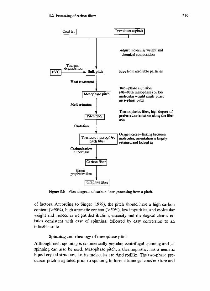
8.2 Processing of carbon fibers 219
Coal tar
T
PVC[ation
- J Bulk pitch
Heat treatment
Mesophase pitch
Melt spinning
Pitch fiber
Oxidation
Petroleum asphalt
Thermoset mesophasepitch fiber
Carbonizationin inert gas
Carbon fiber
Stressgraphitization
I Graphite fiber
Adjust molecular weight andchemical composition
Free from insoluble particles
Two-phase emulsion(40-90% mesophase) or lowmolecular weight single phasemesophase pitch
Thermoplastic fiber; high degree ofpreferred orientation along the fiberaxis
Oxygen cross-linking betweenmolecules; orientation is largelyretained and locked in
Figure 8.6 Flow diagram of carbon fiber processing from a pitch.
of factors. According to Singer (1979), the pitch should have a high carboncontent (>90%), high aromatic content (>50%), low impurities, and molecularweight and molecular weight distribution, viscosity and rheological character-istics consistent with ease of spinning, followed by easy conversion to aninfusible state.
Spinning and rheology of mesophase pitchAlthough melt spinning is commercially popular, centrifugal spinning and jetspinning can also be used. Mesophase pitch, a thermoplastic, has a nematicliquid crystal structure, i.e. its molecules are rigid rodlike. The two-phase pre-cursor pitch is agitated prior to spinning to form a homogeneous mixture and

220 Carbon fibers
spun into filaments in the temperature range where the viscosity varies from 1 to20Pas (Nm~2s). Fibers can be spun at speeds of 3-lOOmmin"1 with diametersof 10-20 |xm and having the same composition as the mesophase pitch. The as-spun mesophase fibers are anisotropic because of the nematic liquid crystalstructure. These fibers have large, elongated, anisotropic domains (about 4 |xmdiameter) aligned along the fiber axis and are thermoplastic in nature. Theanisotropic domains can easily be viewed under polarized light. Fibers drawnfrom isotropic pitches or those drawn from rayon or acrylic (PAN) precursor donot show such anisotropic domains. Oxidation treatment is given to stabilizethermally against internal relaxation and to render the fibers infusible. The restof the process is essentially similar to PAN-based carbon fiber fabrication,except that stress is applied during graphitization.
8.3 Structure of carbon fibers
As we have said above, a very characteristic feature of the structure of carbonfiber is the alignment of the graphitic planes along the fiber axis. The degree ofalignment of these graphitic planes can vary depending on the precursor usedand the processing, especially the heat treatment temperature used. When viewedin a transmission electron microscope, the heterogeneous microstructure ofcarbon fibers becomes clear. In particular, the pronounced irregularity in thepacking of graphitic lamellae from the fiber surface inward can be seen. Thebasal planes are much better aligned in the near surface region of the fiber. Thisregion is called the sheath. The material inside the sheath can have a radial struc-ture or an irregular layer structure, sometimes termed the onion skin structure(Inal et al, 1980). The radial core and well-aligned sheath structure is more com-monly observed in mesophase-pitch-based carbon fibers. A variety of arrange-ment of graphitic layers can be seen. Figure 8.7 shows schematically some ofthese (Herakovich, 1989). In very general terms, the graphitic ribbons are ori-ented more or less parallel to the fiber axis with random interlinking of layers,longitudinally and laterally (Jain and Abhiraman, 1987; Johnson, 1987;Deurbergeu and Oberlin, 1991). Figure 8.8a shows a two-dimensional repre-sentation of this lamellar structure (turbostratic structure), while Fig. 8.8b showslattice fringes in a high resolution transmission electron micrograph of a highmodulus PAN-based carbon fiber (Johnson, 1987). A schematic of the three-dimensional structure of PAN-based carbon fiber is shown in Fig. 8.8c (Bennettet al., 1983). Note the distorted carbon layers and the irregular space filling. Thedegree of alignment of the basal planes increases with the final heat treatmenttemperature. Examination of lattice images of the cross-section of carbon fibershows essentially parallel basal planes in the skin region, but extensive folding oflayer planes can be seen in the core region. It is thought that extensive inter-

8.4 Properties of carbon fibers 221
Figure 8.7 Some ideal-ized cross-sections ofcarbon fibers (afterHerakovich, 1989): (a) cir-cumferentiallyorthotropic; (b) radiallyorthotropic; (c) trans-versely isotropic; (d) cir-cumferentially orthotropicwith transversely isotropiccore; (e) radiallyorthotropic with trans-versely isotropic core.
linking of lattice planes in the longitudinal direction is responsible for the bettercompressive properties of carbon fiber than aramid fibers (see Chapter 4).
In spite of the better alignment of basal planes in the skin region, the surfaceof carbon fibers can show extremely fine-scale roughness. A scanning electronmicrograph of AS4 carbon fibers is shown in Fig. 8.9a, while an atom-forcemicroscope picture of the same fibers is shown in Fig. 8.9b. Note the surfacestriations and the roughness at a microscopic scale.
In general, mesophase-pitch-based carbon fibers have more aligned crystallitesthan PAN-based carbon fiber. Robinson and Edie (1996) studied the effect ofmesophase pitch precursor and capillary entry design on the structure and thermalcharacteristics of ribbon-shaped fibers. They observed that carbon fiber derivedfrom a naphthalene-based mesophase showed a higher degree of crystallinity, pre-ferred orientation, and graphitization, and a lower electrical resistivity than acarbon fiber obtained from a petroleum-based mesophase fiber. An importantfinding of these authors was that the spinneret capillary entry design was veryimportant to the development of a linear transverse structure. It was this linear-ized transverse structure that resulted in very low electrical resistivity.
8.4 Properties of carbon fibers
As described above, a carbon fiber with a perfectly graphitic structure will havea theoretical Young's modulus of slightly over 1000 GPa. In practice, however,
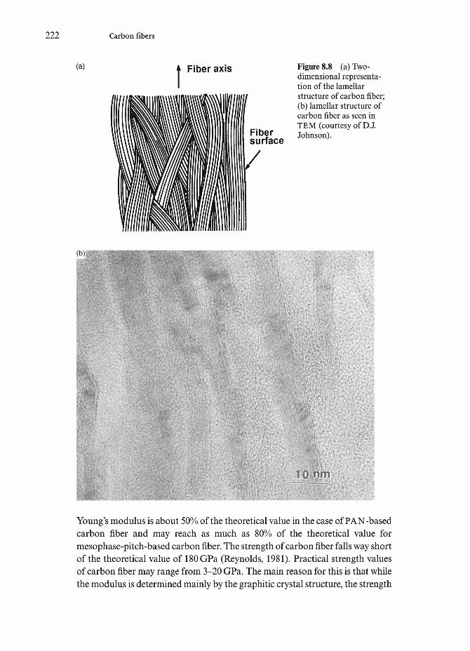
222 Carbon fibers
(a) Fiber axis
Fibersurface
Figure 8.8 (a) Two-dimensional representa-tion of the lamellarstructure of carbon fiber;(b) lamellar structure ofcarbon fiber as seen inTEM (courtesy of DJ.Johnson).
10
Young's modulus is about 50% of the theoretical value in the case of PAN-basedcarbon fiber and may reach as much as 80% of the theoretical value formesophase-pitch-based carbon fiber. The strength of carbon fiber falls way shortof the theoretical value of 180 GPa (Reynolds, 1981). Practical strength valuesof carbon fiber may range from 3-20 GPa. The main reason for this is that whilethe modulus is determined mainly by the graphitic crystal structure, the strength

8.4 Properties of carbon fibers 223
(c) Figure 8.8 (c) three-dimensional structure ofPAN-based carbon fiber(after Bennett et aL, 1983).
50 run
is a very sensitive function of any defects that might be present, for example,voids, impurities, inclusions, etc. The strength of carbon fiber thus depends onthe gage length, decreasing with increasing gage length. This is because the prob-ability of finding a defect in the carbon fiber increases with its gage length.Understandably, it also depends on the purity of the precursor polymer and thespinning conditions. A filtered polymer dope and a clean spinning atmospherewill result in a higher strength carbon fiber for a given gage length.
Following Huttinger (1990), we can correlate the modulus and strength ofcarbon fiber to its diameter. We make use of Weibull statistics to describe themechanical properties of brittle materials (see Chapter 10). Brittle materialsshow a size effect, i.e. the experimental strength decreases with increasing samplesize. This is demonstrated in Fig.8.10 which shows a log-log plot of Young'smodulus as a function of carbon fiber diameter for three different commerciallyavailable carbon fibers. The curves in Fig. 8.10 are based on the following expres-sion:
(8.2)
where E is Young's modulus of the commercial carbon fiber of diameter d whileEo is the theoretical Young's modulus and d0 is the fiber diameter correspondingto EQ. The slope of the straight lines in Fig. 8.10 provides the exponent n. Thevalue of n is about 1.5 and is independent of the fiber type. It would appear thatthese fibers attain their theoretical value of modulus at a diameter of about 3 |xm.We can perform a similar treatment to the tensile strength property of carbonfibers. The corresponding equation will be
(a/ao)=(dQld)n (8.3)

224 Carbon fibers
Figure 8.9 (a) Scanningelectron micrograph ofAS4 carbon fibers. Thefiber diameter is 7|xm; (b)atom-force microscopepicture showing the fibersurface roughness at anextremely fine scale (cour-tesy of R.-K. Eby).
1000 nm(b)
0 nm -J0 nm 1000 nm
Now the theoretical strength of a crystalline solid, <r0 is expected to be aboutO.IEO (Meyers and Chawla, 1984), i.e. in this case o-0=100GPa. For this valueof <70, the exponent n in Eq. (8.3) turns out to be 1.65 and 2 (Huttinger, 1990).This means that in order to obtain a strength of 100 GPa, the diameter of thecarbon fiber must be reduced from d to d^ 1 |xm. Note that this d0 value corre-sponding to theoretical strength is less than the d0 value corresponding to the

8.4 Properties of carbon fibers 225
1.7 1.9 2.1
In fiber diameter (^im)
J_ _L J_6 7Diameter ([Am)
Figure 8.10 Log-log plotof the Young's modulus asa function of carbon fiberdiameter for three differ-ent commercially availablecarbon fibers (afterHuttinger, 1990).
theoretical modulus. The strength corresponding to a 3 |xm diameter carbonfiber from Eq. (8.3) will be between 12 and 18GPa, an extremely high value.This can be understood in terms of the heterogeneous structure of carbon fiber.Recall from our discussion above that the near surface region of a carbon fiberhas more oriented basal planes than the core. As we make the fiber diametersmaller, essentially we are reducing the proportion of the core to the near surfaceregion.
Table 8.4 gives the properties of mesophase-pitch-based carbon fibers. Thereader should note the high density and high modulus of pitch-based fibers com-pared to PAN-based fibers. The very high temperature treatment of graphitiza-tion (to a temperature as high as 3000°C) increases the degree of order in carbonfibers. This is accompanied by a large increase in the elastic modulus of the fiber.The tensile strength of PAN-based fibers when subjected to high temperaturetreatment, however, falls, Fig. 8.11 (Watt, 1970). This is attributed to the pres-ence of discrete flaws on the fiber surface and within it. Most of the volumedefects in carbon fibers originate from the following sources:
(i) inorganic inclusions;(ii) organic inclusions;
(iii) irregular voids from rapid coagulation;(iv) cylindrical voids precipitated by dissolved gases.
These defects are transformed during the high temperature treatment intodiverse imperfections. Basal-plane cracks called Mrozowski cracks are perhaps

226 Carbon fibers
1200 1400 1600 1800 2000 2200 2400 2600
Heat treatment temperature (°C)
Figure 8.11 Tensilestrength and Young'smodulus of PAN-basedfibers as a function of hightemperature treatment(after Watt, 1970).
the most important flaw type that limits the tensile strength of carbon fibers.These occur as a result of anisotropic thermal contractions within the ribbonstructure on cooling down from high temperature treatment (>1500°C). Thesecracks are generally aligned along the fiber axis. Their presence lowers the tensilestrength of the fiber by providing easy crack nucleation sites. The fiber elasticmodulus, however, is unaffected because the elastic strains involved in themodulus measurement are too small. Surface flaws can also limit the tensilestrength of the carbonized fibers. Oxidation treatments tend to remove thesurface defects and thus increase the strength levels of the fiber.
Figure 8.12 shows a comparison of tensile strength and Young's modulus fora variety of carbon fibers. It should be mentioned that the compressive strength
Table 8.4 Tensile properties of mesophase pitch-based carbon fibers.a
Manufacturer
Union Carbide
Osaka Gas
Note:a All the numbers are
Trade name
Thornel P-25P-55P-75P-100P-120DonacarboF-140F-600
Young'smodulus, E(GPA)
140380520700820140
600
from manufacturer's data.
Tensilestrength, a(GPa)
1.402.12.12.12.201.80
3.00
Strain tofailure, e
(%)1.00.50.40.30.21.3
0.5

8.5 High thermal conductivity carbon fibers 227
10%) Figure 8.12 Comparisonof tensile strength andYoung's modulus for avariety of carbon fibers(after Huttinger, 1990).
200 400 600
Young's modulus (GPa)
1100
of carbon fiber is low compared with its tensile strength. The ratio of compres-sive strength to tensile strength for carbon fibers may vary anywhere between 0.2and 1 (Kumar, 1989). High modulus PAN-based carbon fibers buckle oncompression, forming kink bands at the inner surface of the fiber. A crack initi-ates on the tensile side and propagates across the fiber (Johnson, 1990). In con-trast, high modulus mesophase-pitch-based carbon fiber deform by a shearmechanism leading to kink band formation at 45° to the fiber axis.
8.5 High thermal conductivity carbon fibers
Certain types of carbon fibers can have extremely high thermal conductivity.Examples of such carbon fibers include:
(i) A short carbon fiber produced by catalytic chemical vapor deposition(CCVD) (Baker and Harris, 1978). It is also called a vapor grown carbonfiber (VGCF).
(ii) A pitch-based, highly aligned, continuous carbon fiber.
We provide a brief description of these.
Vapor grown carbon fiberThis fiber is made by the decomposition of a suitable hydrocarbon (e.g. naturalgas, acetylene or benzene) on a heated substrate in the presence of a catalyst.The catalyst is a transition metal such as iron, cobalt or nickel and the substratecan be a material such as carbon, silicon or quartz that can withstand a

228 Carbon fibers
Figure 8.13 Formation of vapor grown carbon fibers via catalyzed decomposi-tion of acetylene.
temperature greater than 1000°C. Short filaments, up to several hundred milli-meters long and tens of micrometers in diameter are produced at temperaturesbetween 300 and 2500°C. Figure 8.13 shows, schematically, the catalyzeddecomposition of acetylene to produce vapor grown carbon fibers. A summaryof the process of vapor grown carbon fiber formation is as follows (see Oberlinet aL, 1976; Tibbetts et al9 1986; Tibbetts, 1989). The particles of the transitionmetal catalyst are reduced by hydrogen or their surface is cleaned such thatpolymerization and condensation of hydrocarbons occur, developing a hexag-onal planar network of carbon. This planar network grows normal to the sub-strate surface in the space between the particle and the substrate. The particleis driven upward and the fiber grows. As the particle moves up, a hollow tube isleft behind. Vapor deposition of carbon occurs on this hollow central filamentwhich in turn grows by the catalytic action on the small transition metal parti-cle. Carbon atoms diffuse through the catalyst and precipitate on the growingfilament. The driving force for carbon diffusion is the gradient in the carbonconcentration between the adsorbing surface of the catalyst and its pre-cipitating surface. The filaments are thickened by vapor deposition of carbonon the external surface. An important point is that the carbon deposited in thismanner results in a very high degree of orientation parallel to the plane. Thus,a vapor grown carbon fiber has the graphitic basal planes in a nested, rolied upform. A high temperature heat treatment at 3000°C and above can produce anextremely ordered internal structure which, at times, is reflected in some exter-nal faceting. Because of their dimensions and processing, some people havelikened vapor grown carbon fibers to carbon whiskers. However, that is incor-rect inasmuch as a whisker must be a single crystal and these short carbon fibersare not.
When grown at low temperatures, the VGCF takes a twisted or helical shapeand the structure shows a pleated form, as shown in the SEM micrograph in Fig.8.14. At high temperatures, relatively straight filaments are grown. Vapor growncarbon fibers are characterized by a high tensile strength (7 GPa), high modulus

8.5 High thermal conductivity carbon fibers 229
Figure 8.14 Cross-sectional view of vapor grown carbon fiber showing the foli-ated structure (courtesy of G. Tibbetts).
(400GPa), high density (2gem 3) and exceptionally high thermal conductivity(about four times that of copper) (Piraux et ai, 1984). Not unexpectedly, thestrength and modulus of these fibers decrease with increasing diameter of thefiber.
Pitch-based high thermal conductivity carbon fiberAmoco has developed a family of ultra high modulus continuous graphite fibersand preforms with axial thermal conductivity to HOOW/mK. The extremelyhigh thermal conductivity is a direct result of an extremely high degree ofcrystallinity during carbonization of the mesophase pitch precursor fiber. Table8.5 compares the thermal conductivity of some metals, a variety of carbon fibersand some carbon fiber reinforced unidirectional composites. Also included arespecific thermal conductivity values. Note the extremely high specific thermalconductivity values of K1100X fiber and their composites. These fibers findapplications in the following areas:
• high thermal conductive core materials for aircraft engines;• heatsinks for military electronics;• spacecraft structures requiring high stiffness and high thermal conductiv-
ity.

230 Carbon fibers
8.6 Hollow carbon fibers
There is some interest in obtaining a hollow carbon fiber which is expected tolead to improvements in toughness in carbon fiber reinforced polymer compos-ites (Rhee, 1990). They may also find some applications as high temperaturefilters and in biomedical fields because of the highly selective absorptioncharacteristics of the carbon surfaces. The starting material is anisotropicmesophase pitch. Two specially designed spinnerets have been used: (i) a spin-neret with a C-shaped orifice; (ii) a spinneret with a tiny jet nozzle located at thecenter of the orifice. The wall thickness of the carbon fiber can be varied by con-trolling the draw rate and the pickup or winding speed. Generally, tensilestrength increases with decreasing wall thickness of the carbon fiber.
8.7 Hazards of carbon fibers
Tiny fragments of carbon fiber, if released into the atmosphere, can pose a healthhazard to human beings and can cause problems for electrical and electronicequipment. Some of these human health hazards are, as discussed in Chapter 6with regard to asbestos fiber, common to all very small diameter fibers. They cancause skin and eye irritation and a variety of lung diseases. It turns out that in
Table 8.5 Comparison of thermal conductivity of some metals, carbon fibers andtheir composites.0
Material
Al 6063CopperP-100P-120K1100XK1100X/Al(55v/o)K1100X/epoxy(60v/o)K1100X/Cu(46v/o)
K1100X/C(53v/o)
Longitudinalthermal conductivity(W/mK)
218400520640
1100634540709696
CTE(10-6/K)
2317
-1.6-1.6-1.6
0.5-1.4
1.1-1.0
Density(gem-3)
2.78.92.22.12.22.51.85.9
1.8
Specific thermalconductivity(W/mK/gcm-3)
8145
236305500236344117387
Note:a Data from Amoco Performance Products, Inc.

3.8 Applications of carbon fibers 231
so far as the carcinogenesis potential is concerned, fiber shape, size, and aspectratio are more important factors than chemical composition, although accord-ing to some NASA studies (NASA, 1978, 1979, 1980) it is hard to quantify theeffects because of the paucity of data. Certain precautions are recommendedduring handling and processing of such fine fibers (Kowalska, 1982). Possiblehuman exposure to such fine fibers can occur during fabrication, cutting, grind-ing, etc. Carbon fibers are also good electrical conductors, and if any releasedfibers settle on electrical or electronic equipment, they can cause short-circuit-ing.
8.8 Applications of carbon fibers
Carbon fibers are routinely used to reinforce low modulus polymeric materials.Applications of such composites range from aerospace to sporting goods.Carbon fiber is a highly inert material. This makes it difficult to have strongadhesion between carbon fiber and a polymer matrix. One solution is to makethe fiber surface rough by oxidation or etching in an acid, giving a mechanicalkeying effect at the fiber/matrix interface. Many different grades of carbon fiberare produced by a large number of manufacturers worldwide. Because of itssmall diameter (5-7 |xm), one can use traditional textile processing techniques(e.g. knitting, weaving and braiding) to produce a variety of shapes and forms,fine or heavy fabric, balanced or unbalanced construction, stiff or easy to drapeand conforming to complex shapes!
An unusual application involves the use of carbon fiber to reinforce cement.This results in improved tensile and flexural strength, high impact strength,improved dimensional stability, etc.
Carbon fiber reinforced ceramic composites also find some importantapplications. Carbon is an excellent high temperature material when used in aninert or nonoxidizing atmosphere. In carbon fiber reinforced ceramics, thematrix may be carbon or some other glass or ceramic. Unlike other nonoxideceramics, carbon powder is nonsinterable. Thus, the carbon matrix is generallyobtained from pitch or phenolic resins. Heat treatment decomposes the pitch orphenolic to carbon. Many pores are formed during this conversion from a hydro-carbon to carbon. Thus, a dense and strong pore-free carbon/carbon compositeis not easy to fabricate.
Mesophase-pitch-based carbon fibers can have up to three times the thermalconductivity of copper. This would make them an ideal material for thermalmanagement applications, e.g. brake disks where heat dissipation is of primeconsideration. The extremely high thermal conductivity is a direct result of theextremely high degree of crystallinity obtained during carbonization of themesophase-pitch precursor fiber.
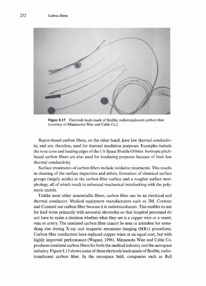
232 Carbon fibers
Figure 8.15 Electrode leads made of flexible, radiotranslucent carbon fiber(courtesy of Minnesotta Wire and Cable Co.).
Rayon-based carbon fibers, on the other hand, have low thermal conductiv-ity and are, therefore, used for thermal insulation purposes. Examples includethe nose cone and leading edges of the US Space Shuttle Orbiter. Isotropic pitch-based carbon fibers are also used for insulating purposes because of their lowthermal conductivity.
Surface treatments of carbon fibers include oxidative treatments. This resultsin cleaning of the surface impurities and debris, formation of chemical surfacegroups (largely acidic) at the carbon fiber surface and a rougher surface mor-phology, all of which result in enhanced mechanical interlocking with the poly-meric matrix.
Unlike most other nonmetallic fibers, carbon fiber can be an electrical andthermal conductor. Medical equipment manufacturers such as 3M, Contourand Conmed use carbon fiber because it is radiotranslucent. This enables its usefor lead wires primarily with neonatal electrodes so that hospital personnel donot have to make a decision whether what they see is a copper wire or a vessel,vein or artery. The insulated carbon fiber cannot be seen or mistaken for some-thing else during X-ray and magnetic resonance imaging (MRI) procedures.Carbon fiber conductors have replaced copper wires at an equal cost, but withhighly improved performance (Wagner, 1996). Minnesota Wire and Cable Co.produces insulated carbon fibers for both the medical industry and the aerospaceindustry. Figure 8.15 shows some of these electrode leads made of flexible, radio-translucent carbon fiber. In the aerospace field, companies such as Ball

3.8 Applications of carbon fibers 233
Aerospace and Technologies Corporation use carbon fiber to improve the weightand size of other more bulky heat transfer devices, while maintaining suitablethermal conductivity. Insulated carbon fiber can also be shaped and bent to fitthe area involved while meeting the heat transfer requirements.

Chapter 9
Experimental determination of fiber properties
Experimental determination of the properties of any material is very important.This is particularly true in the case of fibrous materials because generallyinsufficient data are available for them. Fibers have one very long dimension andthe other two extremely small. This makes determination of their properties,physical and mechanical, far from trivial. In particular, determination of theirtransverse properties, i.e. in the direction of the fiber diameter, can be difficult.In this chapter we describe experimental techniques to determine some physicaland mechanical properties of fibers.
9.1 Physical properties
Many simple physical attributes of fibers can be quite important. We describesome of these attributes and the methods used to measure them.
Weight per unit length. This is also known as the yield and can be measured verysimply by weighing a known length of fiber and expressing the result in gramsper meter. This parameter is useful in comparing the yield of the final fiber fromthe precursor fiber, say carbon fiber from the polyacrylonitrile (PAN) precursorfiber.
Fiber diameter. This a very important parameter in characterizing a fiber. Onecan make a direct measurement of fiber diameter by means of an optical or scan-ning electron microscope. There is an ASTM standard (D 578) for this purpose.
234

9.1 Physical properties 235
The main problem with direct measurement is that fiber diameter may not beuniform along the length. An indirect method that gives an average fiber diam-eter is to weigh a known length of fiber and use the following simple relation-ship:
where dis the fiber diameter, w is the mass of the fiber sample, € is the fiber length,p is the fiber density, and n is the number of filaments per tow, if a tow of fiber isbeing used.
Often fibers have an irregular cross-section. The above method will give anequivalent diameter of a fiber having an irregular cross-section. One can alsotake a photograph of such a fiber and measure the area planimetrically.
Fiber diameter can also be measured by laser beam diffraction (Haege andBunsell, 1988). The technique can be rapid and systematic. The radius of thefiber is given by
r=\sld
where A is the wavelength of the laser beam, s is the distance between the fiberand the projection screen, and <iis the distance between the first intensity minimaof the diffraction pattern.
Fiber density. The density of a fiber can be measured by the same techniques asthe ones used for conventional, bulk materials. The Archimedes method can beused in a straight forward manner to measure this simple but important prop-erty. One weighs the mass of a fiber sample in air and in a liquid of knowndensity, for example, ethanol. Then the following expression gives the density:
where pf is the density of the fiber, ma is the mass of the fiber sample in air, m€ isthe mass of the fiber sample in the liquid and p€ is the density of the liquid.
Swelling. Absorption of moisture can cause swelling of fibers (see Chapter 2).The change in dimensions caused by swelling can be measured by some of thetechniques mentioned above for measuring the diameter of the fiber.Microscopic techniques may be used to measure the diameter of the swollen fiberor the cross-sectional area may be measured by a planimeter. In the case of anirregular cross-sectional fiber, it is better to measure change in area due toswelling than change in diameter. Optical and scanning electron microscopictechniques can be used profitably.

236 Experimental determination of fiber properties
Fabric weave. Fabric weave pattern can influence the properties such as drape-ability, tightness, etc. of a fiber product. The quantities of relevance in this regardare pick count, fabric areal weight, etc.
Thermal analysis. Thermal analysis of fibers is very important. The term thermalanalysis represents a group of techniques in which the property of a sample ismeasured while the sample is subjected to a controlled temperature program.The most common thermal analysis techniques are:
• thermogravimetry (TG) or thermogravimetric analysis (TGA);• differential scanning calorimetry (DSC);• thermomechanical analysis (TMA);• dynamic mechanical analysis (DMA).
Thermogravimetry (TG) or thermogravimetric analysis (TGA). In this tech-nique, the mass of a sample is followed as a function of temperature or time. Theamount and rate of mass change with temperature or time in a controlled atmos-phere are obtained. Such information can tell us about thermal stability as wellas the compositional profile of a variety of elastomers and polymers. It is anexcellent quantitative technique but qualitatively there may be some doubt as towhat material is lost during heating.
Differential scanning calorimetry (DSC). In this case, the heat inflow andoutflow from a sample is measured and information on events that involve achange in the heat content is obtained. For example, melting point, glass transi-tion temperature, heat of fusion, phase transformations, etc.
Thermomechanical analysis (TMA). In this technique, information onchanges in the size of a sample is obtained , e.g. thermal expansion andcoefficient of thermal expansion, cure shrinkage, glass transition, thermalrelaxations, any phase transformation involving volume change in the material.We describe the measurement of the coefficient of thermal expansion in detaillater in this section.
Dynamic mechanical analysis (DMA). This technique is mainly used fordetermining the viscoelastic properties of a sample. The sample is subjected toan oscillating deformation and the amount of energy stored or lost is measured.In a purely elastic material, Hooke's law will be obeyed and the stress and strainwill be in-phase. In a viscoelastic material, the ratio of the viscous (or dissipating)energy to elastic (or storage) energy is obtained as tan 8.
Thermal conductivity. The heat flow in a material is proportional to the temper-ature gradient, and the constant of proportionality is called the thermalconductivity. Thus, in the most general form, using indicial notation, we canwrite

9.1 Physical properties 237
where qt is the heat flux along the xt axis, dT/dx. is the temperature gradientacross a surface that is perpendicular to the x. axis, and k.. is the thermalconductivity. As should be evident from the two indexes, thermal conductivity isalso a second-rank tensor. Although, kv is not a symmetric tensor in the mostgeneral case, it is a symmetric tensor for most crystal systems. For an isotropicmaterial, ktj reduces to a scalar number, k. For a fiber, we have two constants, lon-gitudinal along the axis and transverse along any direction in the cross-sectionalplane, kx and kv or kL and kT, respectively. The same holds true for a transverselyisotropic material such as a unidirectionally reinforced fibrous composite, therewill two constants: thermal conductivity in the axial direction, kd, and that inthe transverse direction, kcV Most thermal conductivity data on fibers areobtained indirectly from measurements made on unidirectionally reinforcedfibrous composites. The thermal conductivity in the axial direction, kd can bepredicted by a rule-of-mixtures or action-in-parallel-type expression
where kn is the thermal conductivity of the fiber in the axial direction and km isthat of the isotropic matrix, and Vf and Vm are the volume fractions of the fiberand the matrix, respectively.
In a transverse direction, the thermal conductivity of a unidirectionallyaligned fiber composite (i.e. transversely isotropic) can be approximated by theaction-in-series model. This would give
Knowing all the parameters except the thermal conductivity of the fiber, we canuse these expressions to obtain thermal conductivity. It should be noted that in realcomposites, it is likely that the thermal contact at the fiber/matrix interface will beless than perfect because of thermal mismatch between the fiber and the matrix.
A laser flash technique can be used for determining the thermal conductivityof fibers (Whittaker et ai, 1990). The laser flash technique provides us thediffusivity, a, which, in turn, is a function of the thermal conductivity, specificheat, and density of the material. Thus,
where C is the specific heat, p is the density, and k is the thermal conductivity.The laser flash technique measures the temperature change with time that givesthe value of diffusivity, a. A small disk-shaped sample is subjected to a burst of

238 Experimental determination of fiber properties
radiant energy. Under the assumption that this energy pulse is absorbedinstantaneously and uniformly, the thermal diffusivity can be calculated fromthe following relationship (Whittaker et ah, 1990).:
a=0.1388rf2/f0>5
where d is the sample thickness and tQ 5 is the half-risetime of the energy pulse.If the specific heat of a single fiber is very small (e.g. carbon fiber), then, the
thermal conductivity measurements should be made on a sample containingmany fibers.
Coefficient of thermal expansion. Much of the data on thermal expansion behav-ior of fibers has been obtained indirectly from oriented fiber reinforced com-posites. In the case of composites such as carbon fibers in a resin matrix, thelongitudinal coefficient of thermal expansion will be dominated by the carbonfibers because the axial coefficient of thermal expansion of carbon fibers isalmost zero. In the transverse direction, however, the matrix contribution tocoefficient of thermal expansion can be quite significant. Sheaffer (1987) used alaser diffraction technique to determine the coefficient of thermal expansion ofcarbon fibers in the transverse direction. The fibers were held under a tension of7 kPa. Not unexpectedly, the transverse expansion coefficient of carbon fibersranged between 6.7X lO^K"1 and 13.1 X lO^K"1. Tsai and Daniels (1994) useda length of fiber fixed at the ends on a plate of titanium silicate (which has a lowcoefficient of thermal expansion of 3xl0~6K"1) inside an oven. The fiber wasloaded at its center by small incremental weights and the deflections wereobtained photographically. From the applied loads and the correspondingdeflections, the authors obtained the elastic stiffness of the fiber. For determin-ing the coefficient of thermal expansion, the authors obtained thermal strainsfrom the deflections at a constant load, but varying temperatures.
Electrical resistivity. Electrical resistivity (or conductivity) of a fiber can be mea-sured by means of simple resistance probe. The fibers are hung by a weight tokeep them taut. Electrical resistance is measured at specific intervals of length.The slope of a plot of electrical resistance against length gives the resistivity. Thefollowing expression gives the electrical resistivity, p:
where dis the fiber diameter, R is the electrical resistance, and € is the fiber length.
Wettability or contact angle. Wettability is a very general term and can be definedas the ability of a liquid to spread on a solid surface. Consider a liquid drop

9.1 Physical properties 239
Liquid
Solid
Complete wetting9 = 0°
LiquidVapor
Solid
No wetting9=180°
Figure 9.1 Contact angleas a measure of wettabil-ity. For 0=0°, we haveperfect wetting and theliquid will spreadspontaneously on thesurface in the form a thinfilm. For 0=180°, theliquid will ball up, andthere will be no wetting.In between these twoextremes, for O°<0<18O°,we have partial wetting.
Liquid
Solid
Partial wetting
resting on a solid substrate and the equilibrium offerees in this system. The threeforces are the three specific energies or surface tensions (i.e. energy per unit area):ysv, the energy of the solid/vapor interface; ys£9 the energy of the liquid/solidinterface; and y€v, the energy of the liquid/vapor interface, see Fig. 9.1. When weput a liquid drop on a solid substrate, we replace a portion of the solid/vaporinterface by a liquid/solid and a liquid/vapor interface. Thermodynamically,spreading of the liquid will occur only if this results in a decrease in the freeenergy of the system, i.e.
The most general situation of partial wetting is shown in Fig. 9.1. From theequilibrium offerees in this figure, we have;
where 6 is the contact angle, so that
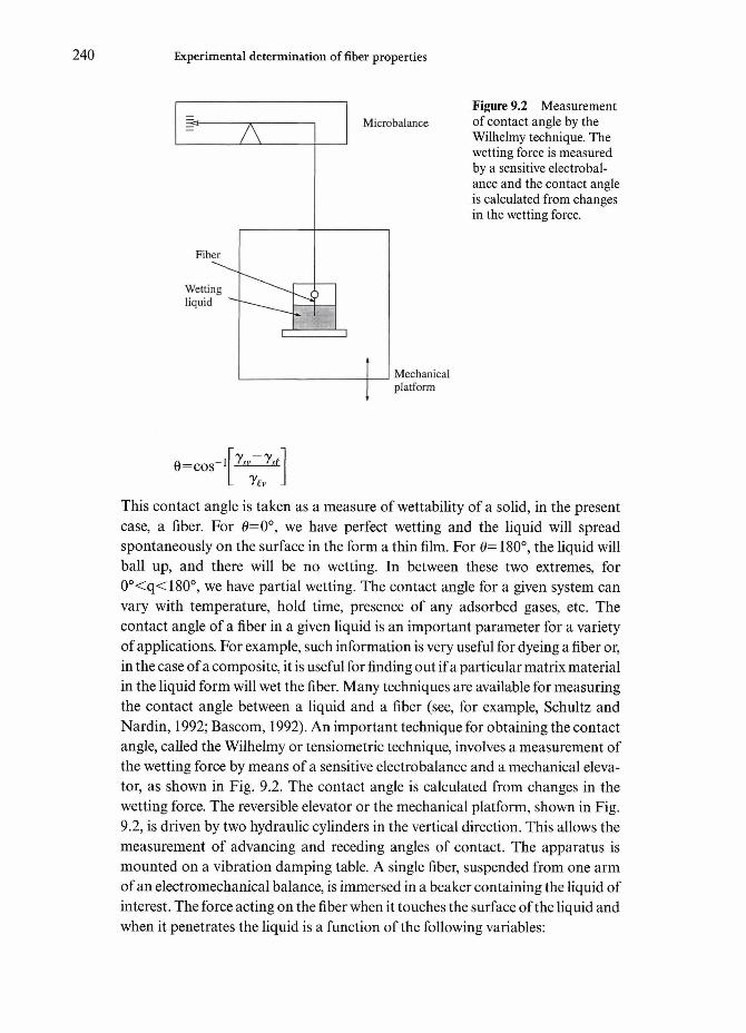
240 Experimental determination of fiber properties
Microbalance
Wettingliquid
Mechanicalplatform
Figure 9.2 Measurementof contact angle by theWilhelmy technique. Thewetting force is measuredby a sensitive electrobal-ance and the contact angleis calculated from changesin the wetting force.
0=cos
This contact angle is taken as a measure of wettability of a solid, in the presentcase, a fiber. For 0=0°, we have perfect wetting and the liquid will spreadspontaneously on the surface in the form a thin film. For 6= 180°, the liquid willball up, and there will be no wetting. In between these two extremes, for0°<q<180°, we have partial wetting. The contact angle for a given system canvary with temperature, hold time, presence of any adsorbed gases, etc. Thecontact angle of a fiber in a given liquid is an important parameter for a varietyof applications. For example, such information is very useful for dyeing a fiber or,in the case of a composite, it is useful for finding out if a particular matrix materialin the liquid form will wet the fiber. Many techniques are available for measuringthe contact angle between a liquid and a fiber (see, for example, Schultz andNardin, 1992; Bascom, 1992). An important technique for obtaining the contactangle, called the Wilhelmy or tensiometric technique, involves a measurement ofthe wetting force by means of a sensitive electrobalance and a mechanical eleva-tor, as shown in Fig. 9.2. The contact angle is calculated from changes in thewetting force. The reversible elevator or the mechanical platform, shown in Fig.9.2, is driven by two hydraulic cylinders in the vertical direction. This allows themeasurement of advancing and receding angles of contact. The apparatus ismounted on a vibration damping table. A single fiber, suspended from one armof an electromechanical balance, is immersed in a beaker containing the liquid ofinterest. The force acting on the fiber when it touches the surface of the liquid andwhen it penetrates the liquid is a function of the following variables:

9.1 Physical properties 241
• fiber surface morphology;• density of the liquid;• depth of immersion;• contact angle of the liquid on the fiber surface.
The following expression relates these parameters (Bascom, 1992)
F=277rylvcos O-pirr2 gh (9.2)
where r is the fiber radius, 6 is the contact angle, ylv is the surface energy of theliquid/vapor interface, p, is the density of the liquid, h is the depth of immersion,and g is the acceleration due to gravity. The first term on the right-hand side ofEq. (9.2) is the capillary force and the second term is the buoyant weight of thesubmerged fiber. Interestingly, for very fine diameter fibers (<50 jxm), the buoy-ancy term becomes negligible because the radius term is squared. Consequently,Eq. (9.2) reduces to
F=27rrylvcos 6 (9.3)
If the force is rng, m being the mass of the fiber, then using 2r=d, the fiber diam-eter and rearranging Eq. (9.2), we get the following expression for the contactangle:
cos 6=mg/7rd yly (9.4)
Note that we need the fiber diameter as input in Eq. (9.4). A quick and conve-nient method to do this is to use a liquid that has a 0=0°, then use the followingrelationship to determine the diameter, d:
Dynamic contact angle. This involves the measurement of contact angle whileimmersing (advancing contact angle) a fiber into a liquid and pulling it out(receding contact angle) from a liquid. The dynamic contact angle is measuredcontinuously while the fiber is immersed or pulled out. The continuous tracesrecorded are the tensiometer weight versus the distance along the fiber; theweight can be converted to contact angle via Eq. (9.4) to obtain a plot of contactangle versus the distance along the fiber. An important phenomenon that is fre-quently observed in such experiments is called contact angle hysteresis, which isa lag in the contact angle of the liquid drop on the solid surface when the fiberis immersed and when the fiber is pulled out of the liquid (Neumann and Good,1979)

242 Experimental determination of fiber properties
Figure 9.3 Elastic con-stants of an anisotropicfiber: the longitudinalYoung's modulus of fiber,En or EL , the transverseYoung's modulus E22 orEJ9 and the principalshear modulus, Gl2 or GLT.Not shown are the twoPoisson's ratios: vl2 or vLT,the longitudinal Poisson'sratio of the fiber and v2l orvTL, the transverse or in-plane Poisson's ratio of thefiber cross-section.
9.2 Mechanical properties
Determining mechanical characteristics of fibrous materials is far from simple,mainly because of their small diameter. In particular, in the case of anisotropicfibers such as carbon or aramid, we need to determine five elastic constants,assuming isotropy in the cross-sectional plane. Figure 9.3 shows three of the fiveelastic constants: the longitudinal Young's modulus of fiber, En or EL, the trans-verse Young's modulus E22 or ET, and the principal shear modulus, Gn or GLT.Not shown are the two Poisson ratios: vLT, the longitudinal Poisson's ratio offiber and vTL, the transverse or in-plane Poisson's ratio of fiber cross-section. Weprovide below some salient features of various techniques to determine suchcharacteristics.
9.2.1 Longitudinal tensile strengthTensile testing of individual filaments is frequently done. It is a tedious processbecause of the fineness of the fibers and, frequently, because of their brittleness.There is an ASTM standard (ASTM-3379-75) for specimen preparation andtesting high modulus (>20 GPa) single filaments. Other ASTM standards avail-able for measuring the strength of fibers include: D3479-76, D3800-79, D3878-87, D4018-81. There are certain critical requirements for testing fibers.

9.2 Mechanical properties 243
Fiber
Cardboard is cutbefore loading
Figure 9.4 The card-board frame technique tomeasure the tensilestrength of a single fila-ment. The single filamentis adhesively bonded to acardboard frame with alongitudinal slot. Thecardboard, with thebonded fiber, is clampedin the grips of a tensiletesting machine. The card-board frame is cut off onthe two sides, leaving thesingle fiber ready to betested.
Alignment of fiber is an obvious one. A serious problem with some of the highstrength and stiffness fibers is the likelihood of breaking in the grips. Clearly, thefiber under test should not be damaged by the gripping mechanism. In order toavoid such premature failure, some kind of facing material, polyethylene or neo-prene, is generally placed between the filament and the metallic grips. This tech-nique is fairly commonly used. As examples, we may cite the work of McMahon(1973); Jain and Abhiraman (1987); and Jain et al (1987) who used this tech-nique to evaluate the properties of carbon fibers while Xu et al. (1993) used thistechnique to study aluminosilicate fibers. The general setup is shown in Fig. 9.4.The single filament is adhesively bonded to a cardboard frame with a longitudi-nal slot. The cardboard, with the bonded fiber, is clamped in the grips of a tensiletesting machine. After all the adjustments and alignment procedures are done,the cardboard frame is cut off on the two sides, leaving the single fiber ready tobe tested. Now when the load is applied, only the fiber experiences the load. Thespecimen is pulled to failure, and a record of load and apparent deformation isobtained. The tensile strength is the maximum load divided by the cross-sec-tional area of the fiber. The precise deformation in the fiber length, however, isnot so easy to obtain. One needs to subtract the machine compliance from thetotal compliance to get the true fiber deformation. But, before we describe thisindirect method of obtaining the strain in the fiber, we should point out thatalthough direct measurement of strain in the gage length of a fiber is not easy, it

244 Experimental determination of fiber properties
can be done. We first describe how direct measurement of strain in the fiber gagelength can be done by laser extensometry and then describe the indirect pro-cedure.
Extensometer is a general term for a device that measures change in length(extension or contraction) of a sample. Commonly, extensometers requiremechanical attachment to the sample being measured. Such a procedure will notwork with very fine fibers. Laser extensometry provides a noncontact measure-ment of elongation. The technique measures axial strain by monitoring surfacedisplacement of two points on the specimen. Two laser beams that differ in fre-quency by a precise amount, say 250 kHz, are brought together at the samplesurface at a fixed angle. The location of any two points on the specimen is definedby the point where recombination of the laser beams occurs. Now, when a speci-men is strained, relative movement of two points on the specimen surface occurs.This results in a phase change in the recombined beam which can be used as ameasure of strain in the specimen. Motion is simultaneously measured at twolocations. Interference fringes form where the two beams overlap. The fringespacing d is given by
d=2sin0
where A is the wavelength of the laser beam and 6 is the half angle between thetwo incident laser beams. Because of the different frequencies of the two beams,the fringes move relative to the stationary sample at a rate equal to the differencefrequency, Av=(vl — v2). Laser extensometry has been used to measure strain ina tungsten filament at 2700°C and in 8 jxm carbon fiber.
An indirect of way of avoiding the measurement of gage length deformationis as follows (Nunes and Klein, 1967). We can write for the total cross-headdeflection, 8t ,as follows:
St=Sn+Sc+Sm (9.5)
where 8n is the deflection due to the nominal gage length of the fiber €n, 8c is thedeflection due to the length of the fiber in the jaws, and 8m is the deflection dueto the load cell and the testing machine. We can reasonably assume that theterms, 8c and 8m are constants at a given load and independent of the nominalgage length. Also, one can use the relationship
St=etn (9.6)
where e represents strain. Equation (9.6) allows one to rewrite Eq. (9.5) as
8t=6€n+c (9.7)

9.2 Mechanical properties 245
where c is a constant. Thus, at a constant load, if we plot 8t against €n, we shouldget a straight line whose slope is the strain, e. If we measure these deflections ofdifferent fiber lengths at a constant load in the elastic regime, we get the true elasticstrain in the fiber at that load, from which we can obtain the elastic modulus.
We should mention that for textile fibers, there is an ASTM D2101 standardwhich allows fibers to be gripped directly because such fibers are generally notdamaged by the clamp pressure. In general, the clamps are lined with rubber orelastomeric pads to reduce the friction.
We make a brief mention of some other problems in testing single filaments.The problem is even more complex for whiskers because of their extremely smalldimensions (Kelsey, 1970). Marsh (1961) used an adhesive cement to mount thewhiskers on quartz rods. Bending moments will be introduced if a fiber of awhisker is not properly aligned. Petrovic et al (1985) describe the complicatedand very careful procedure they developed to test silicon carbide whiskers. Awhisker was glued to the beveled edge of a glass microscope slide with a fastcuring epoxy. Silicon carbide powder was added to the glue to increase itsmodulus. After performing very careful alignment of the whisker, the half gluedwhisker was examined in SEM for any damage, diameter changes, etc. After theSEM examination, the glass slide with the whisker was clamped on to the lineardisplacement device of the tensile tester. A second glass slide was mounted on anX-Y-Z stage and positioned under the free end of the whisker. The whisker wasthen aligned using an optical microscope. The second glue joint was made afterthe alignment. The whisker was then loaded to failure and the load-displace-ment curve recorded.
So far we have discussed the measurement of mechanical properties at roomtemperature. Obtaining mechanical property data at high temperature is evenmore difficult. One needs such data, especially the strength of ceramic fibers atthe high temperatures at which they are likely to be used. A major problemcomes from the thermal gradients involved between the gage length and theportion in the grips. Unal and Lagerlof (1993) tested alumina fibers to 1500°Cby pulling the entire fiber and grips in the hot zone of the furnaces, thus avoid-ing thermal gradients associated with cold grips, i.e. outside the hot zone. Beadsof an alumina adhesive were deposited on the alumina fiber extremities withmuch skill and patience.
9.2.2 Recoil compression testObtaining the compressive strength of a slender fiber is even more difficult thanmeasuring its tensile strength. An indirect technique has been devised to obtaincompressive strength of fibers. It is well known that the recoil of a tensilestress wave generates a compressive wave. This principle is used in the recoilcompression test, which allows one to estimate the compressive strength of fibers.

246 Experimental determination of fiber properties
Figure 9.5 A knot test.De, the loop diameter, isapproximately equal to diewhere d is the fiber diame-ter and e is the failurestrain.
A rigidly held fiber is stretched in tension to a certain stress and cut at the mid-point by a pair of scissors or an electric spark. The tensile wave is reflected at therigid clamps into a compressive wave.
9.2.3 Loop testSinclair (1950) devised this loop test to estimate the strength and elastic modulusof fibers. There are many variants of this test, which is basically a kind of bendtest. Greenwood and Rose (1974), among others, used such a test to evaluateKevlar aramid fiber. Hiittinger (1990) used such a loop or knot test to determinethe deformation characteristics of carbon fibers. Figure 9.5 shows the knot testschematically. If d is the fiber diameter and De is the loop diameter correspond-ing to a tensile strain of e in fiber, then we can write
D~dle=Edlcr
where a is the stress and E is Young's modulus. As in any bending beam test, thestresses will be higher at the fiber surface and decrease toward the axis of thefiber. Clearly, in a fiber having a skin-core structure, such a test will be biasedtoward the characteristics of the skin region. Hillig (1981) used a similar setupto test fibers, see Fig. 9.6. A fiber, lying on a rubber mat base, is bent by a down-ward force applied to a cylindrical tool. Siemers et al (1988) tested SCS-6 siliconcarbide fiber by looping around a series of successively smaller drill bits until thefiber failed. The failure strain e was computed from the relationship,
e=d/D
where d is diameter of the monofilament and D is the diameter of the drill bit.Since the fiber is elastic to fracture, one can compute the failure stress from

9.2 Mechanical properties 247
Cylindrical tool
Fiber
Figure 9.6 A fiber, lyingon a rubber mat base, isbent by a downward forceapplied to a cylindricaltool (after Hillig, 1981).
Hooke's law, a=Ee, where E is the Young's modulus of the fiber. The failurestrain was taken as the average of the strain imposed by the drill bit that causedfiber failure and the one immediately before that.
9.2.4 Dynamic elastic modulusSpeed of sound in a material is related to its Young's modulus and density by thefollowing relationship
c2=Elp
A transducer is used to send a pulse down the fiber while another transducer setat a fixed distance from the first one detects the arriving pulse. Smith (1972) usedsuch an ultrasonic technique to measure the Young's modulus of carbon fibers.
The modulus measured by making an acoustic pulse travel down a fiber axisis called the dynamic modulus to distinguish it from the static modulus measuredin a mechanical testing machine.
9.2.5 Shear modulusFibers are frequently twisted in a variety of operations. Thus, it is important toknow the torsional or shear modulus of a fiber. In Fig. 9.7 a cylindrical fiberbeing twisted under the action of a torque shows the shear modulus corre-sponding to a torsion angle of 6. The shear strain, y, is given by
y=flr/€ (9.8)
while the shear stress, T, is related to shear strain via the shear modulus, G:
T=G0rl€ (9.9)

248 Experimental determination of fiber properties
Figure 9.7 A cylindricalfiber of length € subjectedto torque.
where r is the fiber radius, € is the fiber length, and 6 is the angle of twist. Let usconsider the torsion of the cylindrical fiber, Fig. 9.7. We apply a torque to thefiber by two opposing but equal forces, Fat the two ends. Let da be the area overwhich a small force dFis acting, then
T=dF/da
This elemental area is given by 2urdr, where dr is the thickness of the annulararea on which the force dFis acting. Thus,
T=dF/2irrdr (9.10)
From Eqs. (9.9) and (9.10), we can write
Gdr/e=dF/2vrdr
dF=27rr2 GOdrlt (9.11)
The torque at a radius r from the central axis is rdF. The total torque is obtainedby integrating from 0 to R, the fiber radius. Thus
total torque= I r dF= 8 2TJT3G (01 f) dr=(7rR4G6)/2€ (9.12)J Jo
The quantity TTR4G/2 is called the torsional rigidity which is a combined func-tion of the shear modulus, G and a geometric term containing the fiber radius tothe power four! Thus halving the fiber diameter will result in reducing the tor-sional rigidity by a factor of 16.
One can determine the shear modulus of a fiber from a torque per unit areaversus twist curve. In practice, a simple apparatus called a torsion pendulumis used more commonly. An experimental setup to measure the shear modulusof small fibers is shown in Fig. 9.8 (Mehta, 1996). The torsional pendulum,placed in a vacuum oven, allows the measurement of shear modulus as a func-

9.2 Mechanical properties 249
Air inlet
Vacuum gage
Paper tab(upper half)
Paper tab .;lower half)
Aluminumholder
2 - Clamp
• Fiber
• Torsion disk
Figure 9.8 An experi-mental setup to measureshear modulus of smallfibers (after Mehta, 1996).
To vacuumpump
tion of temperature under vacuum. In this particular example, the fiber samplewas mounted on a cardboard disk. An aluminum fastener was fixed at thecenter of the cardboard to hold the paper tab on which the fiber sample wasmounted. After mounting the paper tab and sample, the top end was fixed ona clamp stand inside the oven. The two sides of mounted paper tab were thencut and only the fiber was freely attached to the torsional pendulum. A smallinitial twist is given to the fiber and the amplitude of the successive oscillationsis determined. The shear modulus of a fiber of a circular cross-section is givenby
where /is the moment of inertia of the torsion pendulum, € is the fiber length, Ris the fiber radius and Tis the period of oscillations. The period of oscillationsis given by
where To is the experimentally measured period of oscillation, A is the logarith-mic decrement=In (AJAY)9 where Ax and A2 are the amplitudes of two succes-sive oscillations. Note that the radius term has an exponent of 4, which meansthat even a very small error in the measurement of fiber radius will introduce asignificant error in the shear modulus value.

250 Experimental determination of fiber properties
9.2.6 Transverse propertiesMany high performance fibers such as aramid, polyethylene, carbon, etc. canhave highly anisotropic properties. For example, the elastic modulus, thestrength, the coefficient of thermal expansion, thermal conductivity, etc. may bequite different along the fiber axis and transverse to the fiber axis. This anisotropystems from the highly oriented chain structure in the case of organic fibers, fromthe layer structure in the case of carbon and boron carbide, or from the orientedstructure obtained by C VD such as is the case for silicon carbide or boron fibers.In the case of pure single crystal fibers such as alumina, the anisotropy will haveorigin in the crystal structure. Hadley et al. (1969) measured the transversemodulus of polyethylene and some other monofilaments in the rod form. Theycompressed the thick rodlike specimen of fibers in the transverse directionbetween two parallel glass plates and measured, with a microscope, the flatten-ing of the contact area of the fiber. The transverse modulus was obtained fromthe force applied and the size of the contact area. This method is suitable for largediameter fiber. Phoenix and Skelton (1974) used an Instron tester fitted with twoparallel steel platens to study the transverse compressive behavior of aramid,nylon, polyester and carbon fibers. Jawad and Ward (1978) performed transversecompression tests on nylon 6.6 and linear polyethylene samples machined fromextruded rods (2.5 mm diameter). Thus, most attempts at measuring the trans-verse modulus of polyethylene and other polymeric fibers have involved com-pressing the single filament between two parallel plates and measuring theamount of flattening of the contact area of the fiber under compression. Eldridgeet al (1993) measured transverse strength of SCS-6 silicon carbide fiber by asimilar technique. Others used the indirect route, namely testing a fibrous com-posite and obtaining an estimate of the transverse modulus of the fiber from thetransverse modulus of a unidirectionally reinforced fiber/matrix composite. Theassumption here is that the in situ behavior of the fiber is the same as that outsidethe composite. Kawabata (1990) devised a technique to measure the transversemodulus of fibers around 10 |mm in diameter by recording compressional forceand diametral change at a constant loading rate. The bottom plane was a mirror-finished, flat steel bed while the top plane was a square plane, mirror-finished. Asingle fiber was placed horizontally on the bottom plane and compressed by thetop plane, which was driven by a rod connected to an electromagnetic driver(load capacity=50 N). A transducer was used to measure the force and a lineardifferential variable transformer (LVDT) was used to measure the deformationof the fiber in the diametral direction (resolution -0.05 |xm). An experimentalload-deflection curve was obtained and compared with the load-deflection curveobtained from a theoretical model, assuming isotropy in the cross-sectionalplane. The change in diameter, u, as a function of compressive force, F, can beobtained from the following relationships:

9.2 Mechanical properties 251
U=(4F/TT) {(UET)-(v2LTIEL)} {
where u is the change in fiber diameter, b is half the contact width between thefiber and the punch face, Fis the compressive force per unit length of fiber, EL isthe longitudinal modulus of the fiber, ET is the transverse modulus of the fiber,R is the radius of the fiber, and vLT is the longitudinal Poisson's ratio of the fiber(defined by the longitudinal strain and the transverse contraction strain whenthe fiber is uniaxially stretched along its axial direction). As can be seen, thetransverse modulus, ET, is an input parameter here. This ET is used as a curvefitting parameter to match the experimental curve. Note also that the Poisson'sratio term, v, enters as a squared term. Poisson's ratio being very small, thesquare of Poisson's ratio will be an insignificant quantity and can be neglectedin most cases. Kawabata's (1990) measurements on carbon and aramid fibersshowed them to be highly anisotropic. He observed a correlation between trans-verse and longitudinal moduli. Carbon and other ceramic fibers failed in a brittlemanner and ET decreased sharply with increasing Ev Aramid and polyethyleneUHMW PE failed in a ductile manner. Organic fibers showed a small increasein ET with increasing EL. Jones et al. (1997) studied the transverse compressiondeformation of a number of commercially available organic and inorganic fibersas well as that of thermally cross-linkable poly(p-l,2-dihydrocyclobutapheny-lene terephthalamide) (PPXTA) fiber. The apparatus used by these authors hada stationary flat-ended punch and a movable table supporting the fiber. A load-displacement curve was obtained was obtained in each case. Carbon andalumina fibers showed a brittle behavior, while organic fibers showed a nonlineardeformation.
9.2.7 Micro-Raman strain measurementA technique called micro-Raman strain measurement, has become quite impor-tant in measuring strain in nonmetallic fibers. Raman spectroscopy deals with thephenomenon of a change in frequency when light is scattered by molecules. Anexchange of energy between the scattering molecule and the photon of the inci-dent radiation gives rise to the Raman effect, named after C.V. Raman who wasawarded the Nobel prize for his discovery of this phenomenon. Raman scatter-ing spectroscopy uses a monochromatic source of radiation, generally obtainedfrom a laser. The Raman frequency (or the wavenumber) depends on the springconstant. The interatomic or intermolecular force being nonlinear, the springconstant will change if we constrain the molecule with a bond length differentfrom that it would have in the unconstrained state. This implies that a shift willoccur in the Raman frequency if we stress the solid. This phenomenon has been

252 Experimental determination of fiber properties
(a) Force transducerRaman spectrometer
Laser
Computer controlling the Mini tensile tester Computer controllingtensile test equipement the Raman spectrometer
(b)
'3
2
a
Figure 9.9 (a) An experi-mental setup to obtain thecharacteristic Ramanspectra from a fiber, (b)The frequency shift for apolyethylene fiber undertension at room tempera-ture. The strain values areindicated. (Courtesy ofBerger and Kausch, 1996.)
1080 1100 1120 1140Wavenumber (cm1)
1160

9.2 Mechanical properties 253
successfully employed to study the deformation behavior of organic as well asinorganic fibers (Cannon and Mendoza, 1991; Kip et ai, 1991; Boogh et al.,1992; Day and Young, 1993;Galiotis, 1991; Wong and Young, 1994; Youngs aL,1990; Young, 1996). Raman spectroscopy is a very powerful technique that canprovide a significant structural information. Equipment involving the use of acharge coupled device (CCD) detector and more computer control has extendedthe Raman microprobe into a Raman microscope in which one can obtain imagesof the Raman scattered light and record the spectra under confocal conditions(Batchelder et a/., 1991; Sudiwala et al., 1992; Williams et al, 1994).
An experimental setup to obtain the characteristic Raman spectra from thesefibers is shown in Fig. 9.9a (Berger et al., 1996). Under tension, the peaks of theRaman bands shift to lower frequencies. Figure 9.9b shows such a frequencyshift for a polyethylene fiber. It turns out that the 1127 cm"1 Raman band inpolyethylene fiber corresponds to symmetric stretching of the C-C bond. Whena polyethylene fiber is strained, this peak would shift to lower frequencies.Similar results have been obtained with aramid fibers. There is an approximatelylinear shift in the peak position, Av with strain, e. The slope of the line, dAv/de,is proportional to the fiber modulus E{ (Young, 1996). This means that one canuse the Raman spectroscopy to investigate molecular stretching, since elasticmodulus is a measure of molecular bonding. In reality, the magnitude of fre-quency shift is a function of the material, Raman band under consideration, andthe Young's modulus of the material. The shift in Raman bands results fromchanges in force constants due to changes in molecular or atomic bond lengths,and bond angles. We can write
where h is Planck's constant, v{ is the frequency of incident radiation, vs is the fre-quency of scattered radiation, and Ex and E2 are the initial and final energies ofthe molecule, respectively. The frequency shift (+ or —) is given by
Av=v§—Vj
A set of Raman frequencies of the scattering species forms the Raman spectrum.Raman frequency shift is commonly expressed in term of a wavenumber (cm"1).Thus
Raman shift=(v-v)/c=(E2-El)/h
where c is the velocity of light. The necessary condition for Raman scattering isthat the incident photon energy hv{ must be greater than the energy differencebetween the final and initial states of actual transition.

Chapter 10
Statistical treatment of fiber strength
Fracture of brittle materials, in general, involves statistical considerations.Materials have randomly distributed defects on their surfaces or in their inte-rior. Fibrous materials, as we saw in Chapter 2, have a large surface area per unitvolume. This makes it more likely for them to have surface defects than bulkmaterials. The presence of defects at random locations can lead to scatter in theexperimentally determined strength values of fibers, which calls for a statisticaltreatment of fiber strength. Clearly, such scatter will be much more pronouncedin brittle fibers than in ductile fibers such as metallic filaments. This is becauseductile metals will yield plastically rather than fracture at a flaw of a critical size.Thus, most high performance fibers, with the exception of ductile metallic fila-ments, shows a rather broad distribution of strength because they are highlyflaw sensitive. Since the distribution of flaws is of statistical nature, the strengthof a fiber must be treated as a statistical variable. To bring home this importantpoint of variation in strength of a fiber as a function of fiber length, we show, inFigs. 10.1-10.3, the variation of tensile strength of some fibers as a function ofgage length: high modulus carbon fiber (Fig. 10.1), boron fiber (Fig. 10.2), andKevlar 49 aramid fiber (Fig. 10.3). Intuitively, one can see that the probabilityof finding a critical flaw (which corresponds to the failure strength) increases asthe volume of brittle material increases. In the case of a fiber, this translates intoan increase in the probability of finding a critical flaw as the fiber lengthincreases. Put more succinctly, the average fiber strength decreases with increas-ing fiber gage length. An increase in fiber diameter can have similar effect. Inthis chapter, we provide a brief review of the statistical variation of fiberstrength.
254
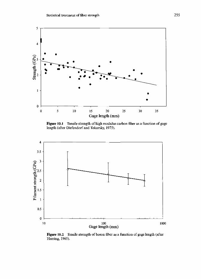
Statistical treatment of fiber strength 255
10 15 20 25Gage length (mm)
30 35
Figure 10.1 Tensile strength of high modulus carbon fiber as a function of gagelength (after Diefendorf and Tokarsky, 1975).
100Gage length (mm)
1000
Figure 10.2 Tensile strength of boron fiber as a function of gage length (afterHerring, 1965).

256 Statistical treatment of fiber strength
10
OHO
I
10 100Gage length (mm)
1000
Figure 10.3 Tensile and failure strain of Kevlar 49 aramid fiber as a function ofgage length (after Zweben, 1977).
10. l Variability of fiber strength
We can regard a fiber as consisting of a chain of links. We assume that fiberfailure occurs when the weakest link fails. This is called the weakest-link assump-tion. It turns out that such a weak-link material is well described by the statisti-cal distribution known as the Weibull distribution (Weibull, 1939,1951). We firstdescribe the general Weibull treatment for brittle materials and then describe itsapplication for fibers.
10.2 Weibull statistics
Let us say that a series of identical samples are tested to failure. From such testswe can obtain the fraction of identical samples, each of volume Fo, that surviveswhen loaded to a given stress, a. Let us call this S(V0). According to the Weibulldistribution, this survival probability is given by
(10.1)
where <r0 and /? are constants. Figure 10.4a shows a general plot of survival prob-ability S(V0) against strength <r. At o-=0, i.e. no load on the sample, all samples

10.2 Weibull statistics 257
(a)
Q
(b)
Figure 10.4 A plot ofsurvival probability, S(Vo)against strength a. At<7-=0, i.e. no load on thesample, all samplessurvive and S( Fo)= 1. As aincreases, more samplesfail and S(Vo) decreases.Eventually, S(Vo)^0, ascr—>o°, i.e. all samples failat very high loads, (b)Survival probability versusstrength for differentvalues of Weibullmodulus, p. As ftincreases, the distributionbecomes less broad.
a
survive and S(V0)=l. As a increases, more samples fail and S(VQ) decreases.Eventually, S(F0)-K), as o-^oo, i.e. all samples fail at very high loads. It is easyto see from Eq. (10.1) that for cr=aQ9
This expression tells us that the constant, cr0 is the stress corresponding to a sur-vival probability of 37%. /3 is called the Weibull modulus and is a measure of theflaw distribution in the sample. The smaller the value of j8, the greater the vari-ability in strength, In other words, the value of Weibull modulus j8 tells us howrapidly the strength falls as we approach a0. Figure 10.4b shows plots of survivalprobability versus strength for different values of Weibull modulus j8. As j8increases, the distribution becomes less broad. For a given material, by using animproved processing technique, one can make a flaw size distribution less broadand thus increase the value of /3. Table 10.1 gives some typical /3 values for bulkmaterials. In general, brittle materials have a lower Weibull modulus than ductilematerials.
If we take logs on both sides of Eq. (10.1), we obtain
In

258 Statistical treatment of fiber strength
Taking logs again,we have
We show in Section 10.5 how the Weibull modulus can be obtained graphically byusing a double log plot of such an equation that gives a straight line of slope /3.
10.3 Weibull distribution of fiber strength
The Weibull distribution is called a parametric distribution, i.e. it is an empiricaldistribution and does not concern itself with the origin of the defects. The Weibulldistribution for the strength (or) of a brittle material takes the following form
/(a)=Laj8a/3"1exp (-Lav?) (10.2)
where L is the fiber length, cris the fiber strength, and a and /3 are statistical para-meters. f(a) is a probability density function.
We define the kth moment, Mk, of a statistical distribution, as
Mk= \akf(a)da (10.3)Jo
Consider a fiber that follows the strength distribution given by Eq. (10.2). Wecan obtain an expression for the mean strength as follows:
a=M{= ( of (a) da (10.4)Jo
= I LaPaP~laGxp(-LaaP) daJo
Knowing d (Laa^)=La fiaP~l da, the above expression becomes
=Jexp (-Laa^{L(^^d(Laa^ (10.5)
Let x denote Laa^. Then Eq. (10.5) becomes
Table 10.1 Typical Weibull modulus (fi) values for bulk materials.
Fiber material Weibull modulus,
Glass <5SiC, A12O3, C 5-10Steel >100

10.3 Weibull distribution of fiber strength 259
oo /• \ o —1
5-= J exp (-x) y^dx (10.6)
Now, letting (/3+l)//3=?2, we can convert Eq. (10.6) to the following simpleform:
r00
a=(La)-l'P exp (-JC) ^ ^ d x (10.7)Jo
The integral part of Eq. (10.7) is called the gamma function of order n and isdenoted by T(n), i.e.
T(n)=Jo
Values of T(n) can be found in mathematical handbook tables. Some importantvalues of T(n) are as follows:
r(2)=iT(3)=2!
Using the gamma function as defined above, we can write the mean or averagestrength of the fiber as
(10.8)
Substituting the value of n=(J3+1)//3, we have the mean strength given by
(10.9)
Now, the standard deviation s of a distribution is given by
s2=[xJ2=M2—a 2
so that
S=VJL2=VM2-M2 (10.10)
We can obtain an expression for s for the Weibull distribution under considera-tion by using the expressions for M2 and Mx involving/(a) as follows:

260 Statistical treatment of fiber strength
(o)-( J o- (10.11)
Let us evaluate the first integral in this expression. The second integral isgiven by Eq. (10.7). Substituting for/(a), we obtain for the first integral in Eq.(10.11)
[= f exp (-JoJo (La)2*
Denoting Lao& by x, we may rewrite the above integral as
jB+2
(X) p "I
Putting this gamma function form for the first integral in Eq. (10.11) and usingthe expression in Eq. (10.7) for the second integral, we obtain the followingexpression for the standard deviation, s:
s=\ J 211/2
From the standard deviation and mean strength, we can arrive at the followingexpression for the coefficient of variation, /JL, for this distribution
(10.12)
(10.13)•
We note from the above expression that fi is an inverse function of the WeibuUmodulus, j8.
We can also find the statistical mode, cr*, the most probable strength value fora given distribution. Consider the mean fiber strength (Eq. 10.8) again

10.3 Weibull distribution of fiber strength 261
For a unit length of fiber, i.e. L= 1, we can rewrite the above expression as
where
For /3>1, we shall have 0.88<A;<1.0. This means that we can regard the quan-tity a~l/P as the reference level strength. To find the statistical mode, <r*, themost probable strength value, we proceed as follows. The Weibull distributionis
f(o)=LaP<jW-V exp (-Lao*5)
At a=o* (mode value), the derivative of/(a) with respect to a will be zero. Wecan write
do-
> exp(-ZW) [-
so that
Putting a=o*, the mode value, we obtain
(10.14)
For large j8, we have
and thus the mode strength can be written as
o*=(aL)-l'P (10.15)

262 Statistical treatment of fiber strength
10.4 Experimental determination of Weibull parametersfor a fiber
A statistical analysis of the fiber tensile strength values determined on a series offiber samples can be easily made by using the two-parameter Weibull distribu-tion described above. Using the form of the Weibull expression given in Eq.(10.2), we can write the probability of failure F{a) of the fiber at a stress a, as
F(a )= l -exp( -a^) (10.16)
where /3 is the Weibull modulus and a is a scale parameter. As we said above, j8is a measure of the scatter in the tensile data. Rearranging Eq. (10.16), we get
=i81ncr+lna (10.17)
From Eq. (10.17), we can easily obtain a and /3 graphically. One generallyarranges the tensile strength values of single filaments in ascending order andassigns a probability of failure using an estimator given by
where F(a) is the probability of failure corresponding to the zth strength valueand TV is the total number of fibers tested. Substituting Eq. (10.18) in Eq. (10.17),we have
Equation (10.19) says then that a plot of In [(N+l)l(N+l—i)] versus a { on alog-log graph would be a straight line if the tensile strength data followed aWeibull distribution. The intercept on the y-axis will then be a and the slope willbe j8. Figure 10.5a shows such a double log plot for the tensile strength of amullite (Nextel 440) fiber, 12mm gage length (Xu et al9 1993), while Fig. 10.5bshows a similar plot for carbon fiber (AS4), 10 mm gage length (Wu et ai91991).Table 10.2 gives the Weibull modulus values for a series of fibers. These valuesshould be taken as indicative values only. Similar use of Weibull two-parameterdistribution has been made for other fibers, see for example Northolt andSikkema (1991), Phani (1988) and Phoenix (1974a, 1974b). Although the two-parameter Weibull distribution is widely used, it does have some drawbacks. Asignificant discrepancy is observed between the values of Weibull modulus, alsocalled the shape parameter, as obtained from a Weibull plot for a single gagelength, L and from a log a versus logL plot. In this regard, it is instructive to
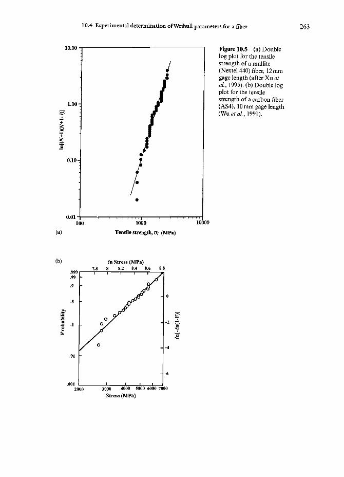
10.4 Experimental determination of WeibuU parameters for a fiber 263
10.00
1.00-
0.10-
0.0110000
Figure 10.5 (a) Doublelog plot for the tensilestrength of a mullite(Nextel 440) fiber, 12 mmgage length (after Xu etal, 1995). (b) Double logplot for the tensilestrength of a carbon fiber(AS4), 10 mm gage length(WuetaL, 1991).
(a) Tensile strength, a, (MPa)
(b)
.001
6n Stress (MPa)7.8 8 8.2 8.4 8.6 8.8
2000
- -6
3000 4000 5000 6000 7000Stress (MPa)

264 Statistical treatment of fiber strength
examine the extensive work of Wagner and colleagues (see Wagner et ai, 1989;Wagner, 1989) on the variability in strength of Kevlar aramid fiber. One of theirconclusions was that Kevlar 49 filaments showed a significant variation in diam-eter within a yarn. This resulted in variabilty of fiber strength, i.e. failure load,but not in fiber tenacity or specific strength at failure. They observe an approxi-mately linear correlation between the failure load and linear density, but no cor-relation was observed between linear density and specific strength or tenacity.This indicates the importance of spool to spool variability in a given fiber. Theirplot of tenacity against gage length for Kevlar 49 showed a stronger fiber atsmaller gage length, but the effect was less than that predicted by the Weibullmodel. The subject of variability in strength of a fiber really involves a complexinterplay of statistical and material effects. For example, Goring et al. (1990)examined the effect of diameter variability in the case of carbon (T800) andNicalon fibers. The statistical effect is that the strength decreases with increasingvolume of fiber tested. The material effect is that fiber structure may vary withdiameter. They eliminated the statistical effect by taking into account a unitvolume of the fiber. Even after this correction, they observed a decrease in fiberstrength with increasing fiber diameter, i.e. this effect was a true material effect.
The Weibull mean tensile strength, a, standard deviation, s, and coefficient ofvariation (CV) can be obtained
(10.20)
(10.21)
where
o
Table 10.2
Fiber
Weibullmodulus,
Typical Weibull modulus ({$) for some fibers.
Glass
10-12
P
Carbon Boron
5-6 3-6
Aramid
10-12
Ceramic^
3-6
Note:a Fibers such as SiC, A12O3, (Al2O3)+SiO2).

10.5 Fiber bundle strength 265
Optical glass fibersThe telecommunication industry requires optical glass fibers with very highstrength (>1 GPa) over very long lengths (>1 km). For example, the True Wavesingle mode fiber of Lucent Technologies is routinely subjected to a proof stressof 0.7 GPa (see below) while the WeibuU modulus is claimed to be 147 (Kummer,1996). There is a variety of standards for measuring the tensile strength of opticalfiber, for example, in the US the EIA/TIA-455-28B is the tensile test standard, dueto the Electronic Industries Association and Telecommunication IndustryAssociation, that is commonly used. It requires the data to be analyzed byWeibuU statistics. As described in Chapter 7, the optical fiber is drawn inextremely clean environments, similar to the clean rooms associated with thesemiconductor industry. Protective coating is applied to freshly drawn fiberwhich protects it from any environmental effects and also introduces compres-sive stresses on the surface. Pristine glass is a very high strength material, with atensile strength greater than 3 GPa. It is the ever present moisture in the air andtiny impurities that lower the strength. Figure 7.13 in Chapter 7 shows theWeibuU plots of optical fibers for two different gage lengths (Maurer, 1985). TheWeibuU modulus for 1 m gage length fiber is >50. The plot for the 10 m gagelength sample, however, shows a bimodal character, indicating a multiple flawpopulation.
Here we should mention the proof testing technique, which is commonly usedwith optical glass fibers. Proof testing is a general technique in which a compo-nent is subjected for a short time to a stress, in excess of that expected in service.The idea is to weed out weak members from a set of components. The danger isthat the proof testing may lead to some subcritical crack growth. In the case ofan optical glass fiber, the fiber is taken off the spool and passed through a seriesof pulleys wherein it is first loaded in tension to a constant stress level muchhigher than that expected in service and then unloaded through another set ofpulleys. All fibers containing flaws exceeding a certain size will fail in a proof test.Thus, this technique allows us to put an upper limit on the flaw size. This trun-cation of the flaw size distribution makes the surviving fibers stronger than theoriginal set of fibers. The higher the proof strength, the more reliable will be thefiber but with the added penalty of a smaller fiber length. Recall that at a higherproof stress level, the fiber will break more often.
10.5 Fiber bundle strength
It is of interest to see how fibers behave when they are tested as a bundle in par-allel. An untwisted yarn is a bundle of parallel fibers. As we shall presently see,it turns out that the strength of a bundle of fibers whose elements do not have a
266 Statistical treatment of fiber strength
uniform strength is less than the average strength of the fibers. The fact that themean strength of a fiber bundle is less than the mean strength of fibers testedindividually can be visualized in a qualitative manner rather easily. When weload an untwisted yarn or bundle of fibers, breaks occur in fibers in a randommanner. As a few fibers break, the load that was supported by them is thrownon to other unbroken fibers. Thus, the stress on the unbroken fibers becomesmore than the average fiber stress. Finally, the bundle fails when the survivingfibers cannot support the applied load. This failure mechanism involvingrandom fiber fracture leading to an overloading of the intact fibers is responsi-ble for the average fiber bundle stress being less than the mean strength of fiberstested individually. Coleman (1958) treated this problem by making the follow-ing simplifying assumptions:
• All fibers are linear elastic;• the fibers have an identical modulus and cross-sectional area;• all individual filament strength is governed by Weibull distribution.
Following Daniels (1945) we use a normal distribution for the fiber bundlestrength, aB. This is reasonable when the number of fibers, N, in a bundle is large.The mean value for a normal distribution is
crB=<Tfu[l-F(o-fu)] (10.22)
where crfu is the maximum fiber strength corresponding to the condition ofmaximum load on the bundle. The maximum fiber strength, crfu, is obtained byequating the derivative of Eq. (10.22) to zero at o-=crfu. Thus,
Normal distribution for the fiber bundle strength is
(10.23)2
where M/'g, the standard deviation, is given by
B ^ (10.24)
and N is the number of fibers in the bundle. Note that as N increases, the stan-dard deviation of the bundle strength, tyB decreases.
Consider the Weibull distribution for the individual fiber Eq. (10.2). Then wecan obtain <rfu from

10.5 Fiber bundle strength 267
where
F(a)= fJo
Thus, we can write
_d_da
l- f LaPoW-»exp(-ZW)doj =0 (10.25)
Let us first evaluate the integral corresponding to F(a) in Eq. (10.25). Let CTP=X,then fkjW~Y)d(T=dx. The new limits of integration are: cr=0, x=0 and a=a,x=xl/?.
J -x rexn^—Lax)]*"
La exp(-Lax)dx=La\ ^0
Jo(10.26)
Inserting Eq. (10.26) into Eq. (10.25), we get
— [o-exp (-Laa^l=<T{u=0
exp (-Laa^)+a-exp (-Lao?) {-
exp (-Laofyi -(oia/3o^-1)]o=ofii=0
(10.28)
Therefore, from Eqs. (10.22) and (10.28), we obtain the mean fiber bundlestrength as
(10.8)
Now, from Eqs (10.27) and (10.29), we get
1-La (Lap)l/P
{ e x p ( - ^ (10.30)

268 Statistical treatment of fiber strength
0 0.1 0.2 0.3 0.4 0.5
Coefficient of variation of fiber strength
Figure 10.6 Fiber bundlestrength/fiber strength as afunction of coefficient ofvariation of fiber strength.The fiber bundle strengthfalls as the coefficient ofvariation of fiber strengthincreases.
Taking the ratio of the mean fiber bundle strength (Eq. (10.30)) and mean indi-vidual fiber strength (Eq. (10.9)), we can write
o-B
- l (10.31)
Here, we have implicitly assumed that the fiber bundle and the individual fibershave the same gage length. This ratio is a function of /3, which, in turn, dependsonly on the coefficient of variation of the fiber. Figure 10.6 shows a plot of theratio of mean fiber bundle strength to mean individual fiber strength as a func-tion of coefficient of variation (/n) of the fiber. As expected, when the fibers showidentical strength, coefficient of variation (//,) being zero, the ratio is unity. Whenthe coefficient of variation of the fiber strength is 10%, the mean fiber bundlestrength drops to 80% of the mean fiber strength. For a coefficient of variationof the fiber strength of 25%, the mean fiber bundle strength drops to 63% of themean fiber strength.

References
Chapter 1
Chawla, K.K. (1987) Composite Materials: Science& Engineering, Springer-Verlag, New York.
Chawla, K.K. (1993) Ceramic Matrix Composites,Chapman & Hall, London.
Chou, T.-W. and F.K. Ko (eds) (1989) TextileStructural Composites, Elsevier, Amsterdam.
Clyne, T.W. and P.J. Withers (1993) An Introductionto Metal Matrix Composites, CambridgeUniversity Press, Cambridge.
Hull, D. and T.W. Clyne (1996) An Introduction toComposite Materials, 2nd edn, CambridgeUniversity Press, Cambridge.
Lyman, D.J. (1991) in High-Tech FibrousMaterials, ACS Symposium Series No. 457,
T.L. Vigo and A.F. Turbak (eds), AmericanChemical Society, Washington, DC.
New York Times (1993, July 13).Piggott, M.R. (1980) Load Bearing Fibre
Reinforced Composites, Pergamon Press, NewYork.
Sharp, A.G. (1995) Invention and Technology, Fall,64.
Suresh, S., A. Needleman and A.M. Mortensen(eds) (1993) Metal Matrix Composites,Butterworth-Heinemann, Boston.
Taya, M. and R. J. Arsenault (1989) Metal MatrixComposites, Pergamon Press, New York.
Chapter 2
Anderson, K.J. (1993) MRS Bull, August, 74.Chawla, K.K. (1987) Composite Materials: Science
& Engineering, Springer-Verlag, New York.Chawla, K.K. (1993) Ceramic Matrix Composites,
Chapman & Hall, London.Chawla, K.K., Xu, Z.R., Hlinak, A. and Chung,
Y.W. (1993) in Advances in Ceramic Matrix
Composites, American Ceramic Society,Westerville, OH, p. 725.
Crook, L. (1993) in Nonwovens: Theory, Process,Performance, and Testing, A. Turbak (ed.),Tappi Press, Atlanta, p. 158.
Dresher, WH. (1969) J. Metals, 21, April,17.
269

270 References
Ko, F.K. (1987) in Engineered MaterialsHandbook, Vol. 1, ASM International, MetalsPark, OH, p. 519.
Lyman, D.J. (1991) in High-Tech FibrousMaterials, T.L. Vigo and A.F. Turbak (eds),American Chemical Society, Washington, DC,p. 116.
Mohamed, M.H. (1990) American Scientist, 78,530.
Perez, G. (1985) in High Speed Fiber Spinning,John Wiley, New York, p.333.
Vassilatos, G , Knox, B.H. and Frankfort, H.R.E.(1985) in High Speed Fiber Spinning, JohnWiley, New York, p. 367.
Chapter 3
Barkakaty, B.C. (1976) Journal of AppliedPolymer Science, 20, 2921.
Batra, S.K. (1985) in Fiber Chemistry, Handbook ofFiber Science and Technology: Volume IV, M.Lewin and E.M. Pearce (eds), Marcel Dekker,New York, p. 727.
Berenbaum, M. (1995) The Sciences, 33(5), 13.Chand, N. and P.K. Rohatgi (1994) Natural Fibers
and Their Composites, Periodical Experts BookAgency, Delhi, India.
Chawla, K.K. (1976) in Proc. Int. Conf MeekBehavior of Materials II, ASM, Metals Park,Ohio, p. 1920.
Chawla, K.K. and A.C. Bastos (1979) in Proc. Int.Conf Mech. Behavior of Materials III,Pergamon Press, Oxford, p. 191.
Datye, K.R. and V.N. Gore (1994) J Geotextilesand Geomembranes, 13, 371.
Feltwell, J. (1990) The Story of Silk, St Martin'sPress, New York.
Gosline, J.M., M.E. Demont and M.W Denny(1986) Endeavour, New Series, 10, January, 37.
Gosline, J.M., C. Nichols, P. Guerette, A. Chengand S. Katz (1995) in Biomimetics-Design andProcessing of Materials, M. Sarikaya and LA.Aksay (eds), Amer. Inst. Physics Press,Woodbury, NY, p. 237.
Hyde, N. (1984) National Geographic, 165,January, 2.
Jefferies, R., D.M Jones, J.K. Roberts, K. Selby,S.C. Simmons and J.O. Warwicker (1969) Cell.Chem. Tech., 3, 255.
Kaniraj, S.R. and G.V. Rao (1994) J. Geotextilesand Geomembrane, 13, 389.
Kaplan, D., W.W. Adams, B. Farmer and C. Viney(eds) (1994) Silk Polymers: Materials Scienceand Biotechnology, American Chemical Society,Washington, DC.
Kerkam, K., C. Viney, D. Kaplan and S. Lombardi(1991) Nature, 349, 596
Li, S.F.Y, A.J. McGhie and S.L. Tang (1994)Biophysical Journal, 66, 1209.
Makinson, K.R. (1972) WoolSci. Rev., 43, 2.Meredith, R. (1970) Contemporary Physics, 11, 43.Robinson, R.M. (1985) in Fiber Chemistry
Handbook of Fiber Science and Technology:Volume IV, M. Lewin and E.M. Pearce (eds),Marcel Dekker, New York, p. 647.
Rohatgi, P.K., K.G Satyanarayana and N. Chand(1992) in International Encylopedia ofComposites, S.M. Lee (ed), VCH, New York, 4,p. 8.
Roe, P.J. and M.P. Ansell (1985) J Mater. Sci, 20,4015.
Segal, L. and PH. Wakelyn (1985) in FiberChemistry, Handbook of Fiber Science andTechnology: Volume IV, M. Lewin and E.M.Pearce (eds), Marcel Dekker, New York, p. 809.
Shear, WA. (1994) American Scientist, 82, 256.Stout, H.P. (1985) in Fiber Chemistry, Handbook of
Fiber Science and Technology: Volume IV, M.Lewin and E.M. Pearce (eds), Marcel Dekker,New York, p. 701.
Thiel, B.L. and C. Viney (1995) MRS Bull, 20,September, 54.
Thompson, J. (1994) National Geographic, June,60.
Vollrath, F(1992) Scientific American, 70, March,266.
Vollrath, F , WJ. Fairbrother, R.J.P. Williams, E.K.Tillinghast, D.T. Bernstein, K.S. Gallagher andM.A. Townley, Nature, 345, 526.
Young, R.J. (1989) in Handbook of Fiber Scienceand Technology, Volume III, High TechnologyFibers, M. Lewin and E.M. Pearce (eds),Marcel Dekker, New York.

References 271
Chapter 4
Allen, S.R. (1987) J. Mater. Sci, 22, 853.Allen, S.R. (1988) Polymer, 29, 1091.Argon, A.S. (1972) in Treatise on Materials
Science and Technology, Academic Press, NewYork, p. 79.
Bhattacharya, S. (1989) Proa Amer. Chem. Soc,Div. Poly. Mater. Sci. & Eng., 60, 512.
Biro, D.A., G. Pleizier and Y. Deslandes (1992) J.Mater. Sci. Lett, 11, 698.
Brown, J.R., P.J.C. Chappell and Z. Mathys (1992)J. Mater. Sci, 21, 3161.
Bunn, C.W. (1939) Trans. Faraday Soc, 35, 482.Capaccio, G , A.G. Gibson and I.M. Ward (1979)
in Ultra-High Modulus Polymers, Elsevier,London, p. 1.
Couper, M. (1985) in High Technology Fibers, PartA, Part B, M. Lewin and J. Preston (eds),Marcel Dekker, New York, p. 113.
DeTeresa, S.J., S.R. Allen, R.J. Farris and R.S.Porter (1984) J. Mater. Sci, 19, 57.
DeTeresa, S.J., R.J. Farris and R.S. Porter (1982)Polymer Composites, 3, 57.
DeTeresa, S.J., R.S. Porter and R.J. Farris (1985) J.Mater. Sci, 20, 1645.
DeTeresa, S.J., R.S. Porter and R.J. Farris (1988) J.Mater. Sci, 23, 1886.
Dobbs, M.G., D.J. Johnson and B.P. Saville (1980)Phil. Trans. R. Soc. Lond, A294, 483.
Flory, P.J.(1956) Proc. Roy. Soc. London, A234,73.
Greszczuk, L.B. (1975) Amer. Inst. Aernautics andAstronautic Journal, 3, 1311.
Hadley, D.W., PR. Pinnock and I.M. Ward (1969)J. Mater. Sci, 4, 152.
Hall, M.E. and A.E. Horrocks (1993) Trends inPoymer Sci, 1, 55.
Hild, D.N. and P. Schwartz (1992a) J. Adhes. Sci.Technol.,6,%19.
Hild, D.N. and P. Schwartz (1992b) J. Adhes. SciTechnol.,6,891.
Hodd, K.A. and D.C. Turley (1978) Chemistry inBritain, 14, 545.
Hokudoh, T, K. Yabuki and Y. Nomura (1995) inProc. Second Int. Conf. on CompositesEngineering, New Orleans, LA, p. 333.
Holme, I. (1994) J. Soc. Dyers. Color., 110, 362.Hounshell, D.A. and J.K. Smith (1988) Science
and Corporate Strategy, Cambridge UniversityPress, Cambridge.
Irwin, R.S. (1997) in Applications of HighTemperature Polymers, R.R. Luise (ed), CRCPress, Boca Raton, FL, p. 149.
Jaffe, M. and R.S. Jones (1985) in Handbook ofFiber Science & Technology, Volume 3, HighTechnology Fibers, Part A, Marcel Dekker,New York, p. 349.
Jiang, H., Damodaran, S., Desai, P., Kumar, S.and Abhiraman, A.S. (1991) Polym. Mater. Sci.Eng., 64, 383.
Kalb, B. and A.J. Pennings (1980) J. Mater. Sci,15, 2584.
Kaplan, S.L., P.W Rose, H.X. Nguyen and H.W.Chang (1988) SAMPE Quarterly, 19, 55.
Kikuchi, T (1982) Surface, 20, 270.Khosravi, N., S.B. Warner, N.S. Murthy and S.
Kumar (1995) / Appl Polym. Set, 57, 781.Kozey, V.V. and S. Kumar (1994) J. Mater. Res., 9,
mi.Kozey, V.V., H. Jiang, V.R. Mehta and S. Kumar
(1994) J. Mater. Sci, 10, 1044.Krassig, H.A., J. Lenz and H.F. Mark (1984)
Fiber Technology: from Film to Fiber, MarcelDekker, New York.
Kumar, S. (1989), SAMPE Quarterly, 20, 3.Kumar, S., (1990a) in International Encyclopedia of
Composites 4, VCH, Weinheim, p. 51.Kumar, S. (1990b), 35th SAMPE Int. Symp, p.
2224.Kumar, S. and WW Adams (1990), Polymer, 31,
15.Kumar, S., WW. Adams and T.E. Heliminiack
(1988) J. Reinf Plast. Compos., 1, 108.Kumar, S. and T.E. Heliminiack (1989a) in The
Materials Science and Engineering of Rigid-Rod Polymers, MRS Symp., Vol. 134,Pittsburgh, p. 580.
Kumar, S. and T.E. Heliminiack (1989b) in TheMaterials Science and Engineering of Rigid-Rod Polymers, MRS Symp., Vol. 134,Pittsburgh, p. 363.
Li, Z.F, A.N. Netravali and W. Sachse (1992) J.Mater. Sci, 27, 4625.
Magat, E. E. (1980) Phil. Trans. Roy. Soc. Lond,A296, 463.
Magat, E.E. and R.E. Morrison (1976) Chemtech,November, 702.

272 References
Mark, H.(1936) Trans. Faraday Soc, 32, 143.Martin, D.C. and E.L. Thomas (1989) in The
Materials Science and Engineering of Rigid-Rod Polymers, MRS Symp., Vol. 134, Mater.Res. Soc, Pittsburgh, p. 415.
McGarry, FJ. and IE . Moalli (1991) Polymer, 32,35.
McGarry, F.I and IE . Moalli (1992) SAMPEQuarterly, July, 35.
Morgan, P. W. (1979) Plastics and Rubber:Materials and Applications, 4, February, 1.
Nakajima, T. (ed.) (1994) Advanced Fiber SpinningTechnology, Woodhead Pub. Co., Singapore.
Northolt, M.G. (1974) Euro. Polymer Journal, 10,799.
Northolt, M.G. (1981) J. Materials Scl, 16, 2025.Ohta, T. (1983) Polymer Eng. Scl, 23, 697.Ozawa, S., Y. Nakagawa, K. Matsuda, T.
Nishihara and H. Yunoki (1978) US patent4,075,172.
Panar, M., P. Avakian, R.C. Blume, K.H. Gardner,T.D. Gierke and H.H. Yang (1983) JournalPolymer Set, Polymer Phys., 21, 1955.
Pennings, A.I, C.J.H. Schouten and A.M. Kiel(1972) J. Polymer ScL, C38, 167 .
Pennings, A.I (1976) Colloid Polymer Set, 253,452.
Polis, D.W., L.R. Dalton and D.I Vachon (1989)Materials Res. Soc. Symp. # 134, Pittsburgh, p.679.
Schuerch, H. (1966) Amer. Inst. Aernautics andAstronautic Journal, 4, 102.
Smith P. and P I Lemstra (1976), Colloid PolymerSci, 15, 258.
Smith P. and P I Lemstra (1980) J. Mater. Sci, 15,505.
Spillman, G.E., L.J. Markoski, K.A. Walker, G ADeeter, D.C. Martin and IS. Moore (1993)Polymeric Mater. Sci. and Eng, 69, 139.
Smook, I and A.I Pennings (1984) / Mater. Sci,19,31.
Swan, PR. (1962) J. Polymer Sci, 56, 403.van Stone, IC. (1985) in Handbook of Dialysis,
AXZO, Wuppertal, Germany, p. 21.Wallenberger, FT., N.E. Weston, K. Motzfeldt and
D.G. Swartzfager (1992) J. Am. Ceram. Soc,75, 629.
Wilson, N. (1967) J Text. Inst., 58, 611.Wilson, N. (1968) J. Text. Inst., 59, 296.Wolfe, I F , B.H. Loo and E.R. Seviller (1981a)
Polymer Preprint, 22 (1), 60 .Wolfe, I F , B.H. Loo and FE. Arnold (1981b)
Macromolecules, 14, 915 .Wynne, K., A.E. Zachariades, T. Inabe and T.I
Marks (1985) Polymer Commun., 26, 162.Young, R.I (1989) in Handbook of Fiber Science
and Technology, Volume 3, High TechnologyFibers, Part A, Marcel Dekker, New York.
Chapter 5
Alber, N.E. and WE. Smith (1965) US Patent 3216 076.
Bewlay, B.P (1991) in Proa 5th Int. TungstenSymp., MPR Pub. Service, Shrewsbury,England, p. 227.
Bewlay, B.P., N. Lewis and K.A. Lou (1991) Met.Trans., 21 A, 2\53>.
Briant, C.L. (1989) Met. Trans., 20A, 243.
Briant, C.L. and B.P. Bewlay (1995) MRS Bulletin,20, 67.
Donald, I.W (1987) J. Mater. Sci, 22, 2661.
Embury, ID . and R.M. Fisher (1966) ActaMetall, 14, Febuary, 147.
Engelke, XL. (1967) US Patent 3 347 959.
Hall, E.O. (1951) Proc. Phys. Soc. London, B64,747.
Hillman, H. (1981) in Superconducting MaterialsScience, S. Foner and B.B. Schwartz (eds),Plenum, New York, 275.
Horascek, O. (1989) The Metallurgy ofDoped/Non-Sag Tungsten, Elsevier AppliedScience, London, 251.
Hosford, W and R.M. Caddell (1983) MetalForming, Prentice-Hall, Englewood Cliffs, NX
Jaiswal, S. and I.D. Mclvor (1989) Ironmaking andSteelmaking, 16, 49.
Kikuchi, Y. and H. Shoji (1989) in HighTechnology Fibers, Part B, M. Lewin and IPreston (eds), Marcel Dekker, New York, 175.

References 273
Meyers, M.A. and K.K Chawla (1984) MechanicalMetallurgy, Prentice-Hall, Englewood Cliffs,NJ, p. 353.
Oppelt, A. and T. Grandke (1993) Supercond. SetTech., 6,3*1.
Petch, NJ . (1953) J. Iron Steel Inst., 174, 25.Pond, R.B. (1961) US Patent 2 976 590.Taylor, G.F. (1924) Phys. Rev., 23, 655.
Takahashi, T., I. Ochiai and H. Satoh (1992)Nippon Steel Tech. Report #55, April, 102.
Vukcevich, N. (1991) in Proc 5th Int. TungstenSymp, MPR Publishing Service Ltd.,Shrewsbury, England, 157.
Wittenauer, I P , T.G. Nieh, and J. Wadsworth(1992) Adv. Mater. & Processes, September,28.
Chapter 6
Adler, R.P.I, and M.L. Hammond (1969) Appl.Phys. Lett., 14, 354.
Anon. (1993) Bull. Am. Ceram. Soc, 72, October42.
Aveston, J. (1969) J. Mater Set, 4, 625.Birchall, J.D., J.A.A. Bradley and J. Dinwoodie
(1985) in Strong Fibres, North-Holland,Amsterdam, 115.
Bogy, D.B. (1979) Ann. Rev. of Fluid Meek, 11,207.
Brenner, S.S. (1958) in Growth and Perfection ofCrystals, John Wiley, New York, p. 157.
Brenner, S.S. (1962) J. Appl. Phys., 33, 33.Bunsell, A.R., G. Simon, Y. Abe and M. Akiyama
(1988) in Fibre Reinforcements for CompositeMaterials, A.R. Bunsell (ed.), Elsevier,Amsterdam, p. 427 .
Chawla, K.K., (1993) Ceramic Matrix Composites,Chapman & Hall, London.
Chawla, N., J.W. Holmes and J.E. Mansfield(1995) Materials Characterization, 35, 199.
Cooper, W.C. (1971) Asbestos: The Need for andFeasibility of Air Pollution Controls,Committee on Biological Effects ofAtmosphere Pollutants, Div. of MedicalSciences/National Research Council,Washington, DC.
DeBolt, H.E. V.J. Krukonis and F.E. Wawner(1974) in Silicon Carbide 1973, University of S.Carolina Press, Columbia, SC, p. 168.
Deren, G. (1995) Bull. Amer. Ceram. Soc, 74, 65.
Dhingra, A.K. (1980) Philos. Trans. R Soc.London, A294, 411.
DiCarlo, J.A. (1985) J. Metals, 37, June, 44.DiCarlo, J.A. (1994) Composites Science and
Technology, 51, 213.
DiCarlo, J.A., H.M. Yun and J.C. Golsby (1995) inHITEMP Review, Vol. Ill, NASA Conf.Publication 10178, NASA Lewis ResearchCenter, Cleveland, OH, p. 53.
Diefendorf, R.J. and L. Mazlout (1994) Compos.Sci. and Technol., 51, 181.
Economy, J. and R.V. Anderson (1967) J. PolymerSci., C19, 283.
Economy, J. and R. Lin (1977) in Boron andRefractory Borides, V.I. Matkovich (ed.),Springer-Verlag, Berlin, p. 552.
Fazen, P.J., J.S. Beck, A.T. Lynch, E.E. Remsenand L.G. Sneddon (1990) Chem. Mater, 2, 96.
Gasson, D.G. and B. Cockayne (1970) J. Mater.Sci., 5, 100.
Gooch, D.J. and G.W. Grover, (1973) J. Mater.Sci, 8,1238.
Griffith, EJ. (1995) Phosphate Fibers, PlenumPress, New York,
Haggerty, J.S. (1972) NASA-CR-120948, NASALewis Res. Center, Cleveland, OH.
Hollar, Jr., WE. and J.J. Kim (1991) Ceram. Eng.Sci. Proc, 12,979.
Hurley, G.F. and J.T.A. Pollack (1972) Met. Trans.,7, 397.
Ishikawa, T. (1994) Compos. Sci. Technol, 51,135.
Jakus, K. and V Tulluri (1989) Ceram. Eng. Sci.Proc, 10, 1338.
Jang, T. and R.V. Subramanian (1993) ScriptaMet. Mater., 28, 527.
Johnson, D.D., A.R. Holz and M.F. Grether(1987) Ceram. Eng. Sci. Proc, 8, 744.
Kimura Y, Y Kubo and N. Hayashi (1994)Compos. Sci. Technol, 51, 173.
Krukonis, K. (1977) in Boron and Refractory

274 References
Borides, V.I. Matkovich (ed.), Springer-Verlag,Berlin, p. 517.
Kun, X, S. Tlali, H.E. Jackson, IE . Webb andR.N. Singh (1996) Appl. Phys. Lett, 68, 2352.
LaBelle, H.E. and A.I. Mlavsky (1971) Mater. Res.Bull., 6, 571.
Laffon, C , A.M. Flank, P. Lagarde, M. Laridjani,R. Hagege, P. Olry, J. Cotteret, J. Dixmier, XL.Niquel, H. Hommel and A.P. Legrand (1989) J.Mater. Sci, 24, 1503.
Laine, R.M. and F. Babonneau, (1993) Chem.Mater., 5, 260.
Laine, R.M., Z.-F. Zhang, K.W. Chew, M.Kannisto and C. Scotto (1995) in CeramicProcessing Science and Technology, Am.Ceram. Soc, Westerville, OH, p. 179.
Lara-Curzio, E. and S. Sternstein (1993) Compos.Set TechnoL, 46, 265.
Layden, XK. (1973) J. Mater. Set, 8, 1581.Lee, X-G. and I.B. Cutler (1975) Am. Ceram. Soc.
Bull., 54, 195Lesniewski C., C. Aubin and A.R. Bunsell (1990)
Compos. Sci. & TechnoL, 37, 63.Lipowitz, X, T. Barnard, D. Bujalski, X Rabe, G.
Zank, A. Zangvil and Y. Xu (1994) Compos.Sci. TechnoL, 51, 167.
van Maaren, A.C., O. Schob and W. Westerveld(1975) Phillips Tech. Rev., 35, 125.
Mackenzie, K.XD. and R.H. Meinhold (1994) J.Mater. Sci, 29,2775.
Milewski, XV, ED. Gac, XX Petrovic and S.R.Skaggs (1985) J. Mater. Sci, 20, 1160.
Morscher, G.N. and H. Sayir (1995) Mater. Sci.and Eng. A, 190, 267.
Narula, C.K., R. Schaffer, A.K. Datye, T.T. Borek,B.M. Rapko and R.T. Paine (1990) Chem.Mater, 2, 394.
Nourbakhsh, S., F.L. Liang and H. Margolin(1989) J. Mater. Sci Lett., 8, 1252.
Okamura, K. and T. Seguchi (1992) J. Inorganicand Organometallic Polymers, 2, 111.
Paciorek, K.XL., Harris, D.H. and Kratzer, R.H.(1986) J. Polym. Sci. Polym. Chem. Edn., 24,173.
Petrovic, XX, XV Milewski, D.L. Rohr and F.D.Gac (1985) J. Mater. Sci, 20, 1167.
Pollack, XT.A. (1972) J. Mater. Sci, 7, 787.Pysher, D.X and R.E. Tressler (1992) J. Mater. Sci,
27, 423.
Romine, XC. (1987) Ceram. Eng. Sci Proc.,%, 755.
Sacks, M.D., G.W. Scheiffele, M. Saleem, G.A.Staab, A.A. Morrone and T.X Williams (1995)Ceramic Matrix Composites: Advanced High-Temperature Structural Materials, MRS,Pittsburgh, PA, p. 3.
Saitow, Y, K. Iwanaga and S. Itou (1992) Proa ofthe SAMPE Annual Meeting, Vol. 37,Anaheim, CA.
Sayir, A. and A.C. Farmer (1995) Ceramic MatrixComposites-Advanced High-TemperatureStructural Materials, MRS, Pittsburgh, PA, p.11.
Sayir, A., A.C. Farmer, P.O. Dickerson and H.M.Yun (1995) Ceramic Matrix Composites -Advanced High-Temperature StructuralMaterials, MRS, Pittsburgh, PA, p. 21.
Schneider, H., K. Okada and X Pask (1994)Mullite and Mullite Ceramics, John Wiley,Chichester.
Schneider, H., X Goring, M. Schmucker and FFlucht (1996) in Ceramic Microstructures '96,A.P. Tomsia and A. Glaeser (eds), PlenumPress, New York, in press.
Simon, G. and A.R. Bunsell (1984) J. Mater. Sci,19, 3649.
Skinner, H.C.W., M. Ross, and C. Frondel (1988)Asbestos and Other Fibrous Materials, OxfordUniversity Press, New York.
Smith, WD. (1977) in Boron and RefractoryBorides, V.I. Matkovich (ed.), Springer-Verlag,Berlin, p. 541.
Sowman, H.G. (1988) in Sol-Gel Technology, L.XKlein (ed.), Noyes Pub., Park Ridge, NJ, p. 162.
Subramanian, R.V, H.F. Austin and T.XY Wang(1977) SAMPE Quarterly, 8, 1.
Talley, C.P. (1959) J. Appl. Phys., 30, 1114.Toreki, W, CD. Batich, M.D. Sacks, M. Saleem,
G.X Choi, and A.A. Morrone (1994) Compos.Sci. TechnoL, 51, 145.
Vega-Boggio, X and O. Vingsbo (1978) in 1978 Int.Conf Composite Materials, ICCM/2, TMS-AIME, New York, p. 909.
Vega-Boggio, X and O. Vingsbo (1976a) J. Mater.Sci, 11, 2242.
Vega-Boggio, X and O. Vingsbo (1976b) J. Mater.Sci, 11,2519.
Wallenberger, FT., N.E. Weston, K. Motzfeldt andD.G Swartzfager (1992) J. Amer. Ceram. Soc,75, 629.
Wallenberger, FT. and PC. Nordine (1992) Mater.Lett., 14,198.

References 275
Wawner, F.W. (1967) in Modern CompositeMaterials, L.J. Broutman and R.H. Krock(eds), Addison-Wesley, Reading MA, p. 244.
Wax, S.G. (1985) Bull. Am. Ceram. Soc, 64, 1096.Weintraub, E. (1911) I Ind. Eng. Chem., 3, 299.Wills, R.R., R.A. Mankle and S.P. Mukherjee
(1983) Am. Ceram. Soc. Bull, 62, 904.Wilson, D.M. (1990) in Proc. 14th Conf. On Metal
Matrix, Carbon, and Ceramic MatrixComposites, NASA Conf. Pub. 3097,Washington, DC, Part 1, p. 105.
Wilson, D.M., S.L. Lieder and D.C. Lueneburg(1995) Ceram. Eng. Sci. Proc, 16, 1005.
Xu, Z.R., K.K. Chawla and X. Li (1993) Mater.Sci. and Eng, Alll, 249.
Yajima, S., K. Okamura, J. Hayashi and M. Omori(1976) J. Am. Ceram. Soc, 59, 324.
Yajima, S. (1980) Phil Trans. R Soc London,A294, 419.
Zarzycki, J. (1984) in Glass: Science andTechnology, Vol. 2, D.R. Uhlmann and N.Kreidl (eds), Academic Press, New York, p.209.
Zarzcyki, X, M. Prassas, and J. Phalippou (1982) J.Mater. Sci., 11, 3311.
Zhang, Z.-K, S. Scotto and R.M. Laine (1994) inCeram. Eng Sci. Proc, 15, 152.
Zhang, Z.-R, S. Scotto and R.M. Laine (1994) inCovalent Ceramics II: Non-oxides, MRS,Pittsburgh. PA, p. 207.
Chapter 7
Clare, A.G. (1995) in Bioceramics: Materials andApplications, Am. Ceram. Soc, Westerville,OH, p. 313.
Chandan, H.C., R.D. Parker and D. Kalish (1994)in Fractography of Glass, R.C. Bradt and R.E.Tressler (eds), Plenum Press, New York, p. 143.
Gossing, P. and G. Mahlke (1987) Fiber OpticCables, John Wiley, New York.
Hannant, D.J. (1978) Fibre Cements and FibreConcretes, John Wiley, New York.
Kenney, M.C., S.K. Barlow and S.L. Eikleberry(1996) Nonwovens Conference, TAPPI,Technology Park, Atlanta, GA, p. 149.
Majumdar, A.J. (1970) Proc Roy. Soc, A319, 69.Maurer, R.D. (1985) in Strength of Inorganic
Glass, C.R. Kurkjian (ed), Plenum, New York,p. 291.
Mecholsky, J.J., S.W Freiman and S.N. Morey(1977) Bull. Amer. Ceramic Soc, 56, 1016.
Mecholsky, J.J., S.W. Freiman and S.N. Morey
(1979) in Fiber Optics: Advances in Researchand Development, B. Bendow and S.S. Mitra(eds), Plenum, New York, p. 187.
Midwinter, J.E. (1979) Optical Fibers forTransmission, John Wiley, New York.
Nagel, S.R., J.B. MacChesney and K.L. Walker(1982) IEEEJ. Quant. Electron., QE-18, 459.
Proctor, B.A. (1971) Composites, 2, 85.Sakka, S. (1982) in Treatise on Materials Science
and Technology, 22, M. Tomozowa and R.H.Doremus (eds), Academic Press, New York, p.129.
Scherer, G W (1980) Applied Optics, 19, 2000.Zarzycki, J. (1984) in Glass: Science and
Technology, Vol. 2, D.R. Uhlmann and N.Kreidl (eds), Academic Press, New York, p.209.
Zarzycki, J., M. Prassas and J. Phalippou (1982) J.Mater. Sci, 11, 3311.
Chapter 8
Baker, R.T.K. and P.S. Harris (1978) in Chemistryand Physics of Carbon, PL. Walker and P. A.Thrower (eds), Vol. 14, Marcel Dekker, NewYork, p. 83.
Bennett, S.C., D.J. Johnson and W. Johnson (1983)J. Mater. Sci., IS, 3331.
Deurbergue, A. and A. Oberlin (1991) Carbon, 29,621.
Edie, D.D. (1990) in Carbon Fibers and Filaments,J.L. Figueiredo, C.A. Bernardo, R.T.K. Bakerand K.J. Huttinger (eds), Kluwer AcademicPublishers, Boston, p. 43.
276 References
Edie, D.D. and M.G. Dunham (1989) Carbon, 27,477.
Herakovich, C.T. (1989) Carbon, 27, 663.Huttinger, K.J. (1990) Adv. Mater., 2, 349Inal, O.T., N. Leca and L. Keller (1980) Phys.
Status Solidi, 62, 681.Jain, M.K. and A.S. Abhiraman (1987), J. Mater.
Sci, 22,278.Johnson, D.J. (1987) in Chemistry and Physics of
Carbon, Vol. 20, P.A. Thrower (ed.), MarcelDekker, New York, p. 1.
Johnson, D.J.(1990) in Carbon Fibers andFilaments, J.L. Figueiredo, C.A. Bernardo,R.T.K. Baker and K.J. Huttinger (eds), KluwerAcademic Publishers, Boston, p. 119.
Kelly, B.T. (1981) Physics of Graphite, AppliedScience Publishers, London.
Kowalska, M. (1982) SAMPE Quarterly, 13, April,2.
Kumar, S. (1989) SAMPE Quarterly, 20, January,3.
Meyers, M.A. and K.K Chawla (1984) MechanicalMetallurgy, Prentice-Hall, Englewood Cliffs,NJ,p. 188.
National Aeronautics and Space Administration
NASA (1978, 1979, 1980) Annual Reports,Washington, DC.
Oberlin, A., M. Endo and T. Koyama (1976) J.Crystal Growth, 32, 335.
Piraux, L., B. Nysten, A. Haquenne, IP. Issi, M.S.Dresselhaus and M. Endo (1984) Solid StateCommun., 50, 697.
Robinson, K.E. and D.D. Edie (1996) Carbon, 34,13.
Reynolds, W.N. (1981) Phil. Trans. Roy. Soc,London, A29, 451.
Rhee, B.S. (1990) High Temperatures-HighPressures, 22, 267.
Riggs, J.P. (1985) in Encyclopedia of PolymerScience and Engineering, 2nd edn, Vol. 2, JohnWiley, New York, p. 640.
Singer, L.S. (1979) in Ultra-High ModulusPolymers, Applied Science Publishers, Essex,UK, p. 251.
Tibbetts, G.G. (1989) Carbon, 27, 745.
Tibbetts, G.G., M. Endo and C. Beetz, Jr. (1986)SAMPE J., 30, 22.
Wagner, F.N. (1996) personal communication.Watt, W. (1970) Proc. Roy. Soc, A319, 5.
Chapter 9
Bascom, W.D. (1992) in Modern Approaches toWettability: Theory and Applications, M.E.Schrader and G. Loeb (eds) Plenum Press, NewYork, p. 73.
Batchelder, D.N, C. Cheng and G.D. Pitt (1991)Adv. Materials, 3, 566.
Berger, L.P., C.G. Plummer and H.H. Kausch, tobe published.
Boogh, L.C.N., R.J. Meier, H.H. Kausch and B.J.Kip (1992) J. Polymer Science, Physics, 30,325.
Cannon, WR and E. Mendoza (1991) inProceedings, of the 4th International.Symposium, on Ceramic Mater, andComponents for Engineers, Gotheberg, Sweden.
Day, R.J. and R.J. Young (1993) J. Microscopy,169, 155.
Galiotis, C. (1991) Compos. Sci. Technol, 42, 125.
Greenwood, J.H. and P.G. Rose (1974) J. Mater.Sci., 9,1809.
Hadley, D.W, PR. Pinnock and I.M. Ward (1969)J. Mater. Sci, 4, 152.
Hagege, R. and A.R. Bunsell (1988) in FibreReinforcement for Composite Materials, A.R.Bunsell (ed.), Elsevier, London, p. 479.
Hillig, WB. (1981) Bull Amer. Ceram. Soc, 66,373.
Huttinger, K.J. (1990) Adv. Mater., 2, 349.
Jain, M.K. and A.S. Abhiraman (1987) J. Mater.Sci., 22, 278.
Jain, M.K., M. Balasubramanian, P. Desai andA.S. Abhiraman (1987) J. Mater. Sci, 22, 301.
Jawad, S.A. and I.M. Ward (1978) J. Mater. Sci,13, 1381.
Jones, M.-C.G, E. Lara-Curzio, A. Kopper andD.C. Martin (1997) J. Mater. Sci, 32, 2855.
Kawabata, S. (1990) J. Text. Inst, 81, 432.Kelsey, R.H. (1970) in Whisker Technology, Wiley-
Interscience, p. 140.

References 277
Kip, B.J., M.CP. van Eijk and RJ. Meier (1991) IPolymer Sci Phy Edn., 29, 99.
Marsh, D.M. (1961) J. Sci. Inst, 38, 229.McMahon, RE. (1973) ASTM Special Technical
Publicatioan 521, ASTM, Philadelphia, p. 357.Mehta, V.R. (1996) PhD Thesis, Georgia Tech,
Atlanta, GA.Neumann A.W. and Good, R.J. (1979) Surface and
Colloid Science, 11,31.Nunes, J. and W. Klein (1967) Trans. ASM, 60,
726.Petrovic, J.J., J.V. Milewski, D.L. Rohr and F.D.
Gac (1985) J. Mater. Sci, 20, 1167.Phoenix, S.L. and J. Skelton (1974) 32, Res.
Journal, 934Schultz, J. and M. Nardin (1992) in Modern
Approaches to Wettability: Theory andApplications, M.E. Schrader and G. Loeb (eds),Plenum Press, New York, 359.
Sheaffer, P.M. (1987) in Extended Abstracts of the18th Biennial Conference on Carbon, Worcester,MA, Amer. Carbon Society, Unviersity Park,PA, p. 20.
Siemers, P.A., R.L. Mehan and H. Moran (1988) J.Mater. Sci., 23, 329.
Sinclair, D. (1950) J. Appl. Phys., 21, 380.
Smith, R.E. (1972) J. Appl. Phys., 43, 255.
Sudiwala, R.V., C. Cheng, E.G. Wilson andD.N. Batchelder (1992) Thin Solid Films, 210,452.
Tsai, C.-L. and I.M. Daniel (1994) Compos. Sci.Techno!. ,50,1.
Unal, D. and K.P. Lagerlof (1993) J. Amer. Ceram.Soc, 16, 3161.
Williams K.P.J., G.D. Pitt, D.N. Batchelder andB.J. Kip (1994) Applied Spectroscopy, 48,232.
Whittaker, A.J., M.L. Allitt, D.G. Onn and J.D.Bolt (1990) in Thermal Conductivity 21, C.J.Cremers and H.A. Fine (eds), Plenum Press,New York, p. 187.
Wong, WF. and R.J. Young (1994) J. Mater. Sci,29, 510.
Xu, Z.R., K.K. Chawla and X. Li (1993), Mater.Sci Eng.,Alll, 249.
Young, R.J., R.J. Day and M. Zakikhani (1990) J.Mater. Sci, 25, 127.
Young, R.J. (1996) in Polymer Spectroscpy,A.H. Fawcett (ed.), John Wiley, New York, p.203.
Chapter 10
Coleman, B.D. (1958) J. of the Mechanics andPhysics of Solids, 7, 60.
Daniels, H.E. (1945) Proc. Roy. Soc, 138A, 405.Diefendorf, R.J. and E. Tokarsky (1975) Polymer
Eng. Sci, 15, 150.Eldridge, J.I., J.P. Wiening, T.S. Davison and M.-J.
Pindera (1993) J. Am. Ceram. Soc, 1, 3151.Goring, J., F. Flucht and G. Ziegler (1990) in 4th
European Conference on Composite Materials,Elsevier, London, p. 543.
Herring, H.W (1965) NASA TN D-3202, NationalAeronautics and Space Administration,Langley, VA.
Kummer, R.B. (1996) personal communication.
Maurer, R.D (1985) in Strength of Inorganic Glass,C.R. Kurkjian (ed.), Plenum Press, New York,p. 291.
Northolt, M.G. and D.J. Sikkema (1991) inAdvances in Polymer Science 98, Springer-Verlag, Berlin, p. 115.
Phani, K.K. (1988) J. Mater. Sci, 23, 1189.Phoenix, S.L. (1974a) Fibre Science and
Technology, 7, 15.Phoenix, S.L. (1974b) in Composite Materials:
Testing and Design, ASTM, Philadelphia, p.130.
Rosen, B.W (1965) in Fiber Composite Materials,ASM, Metals Park, OH, p. 58.
Wagner, H.D. (1989) in Application of FractureMechanics to Composite Materials, Elsevier,Amsterdam, p. 39.
Wagner, H.D., S.L. Phoenix and P. Schwartz.(1989) J. Compos. Mater, 18, 312.
Weibull, W. (1951) J. Appl. Meek, 18, 293.Wu, H.F., G. Biresaw and J.T. Laemmle (1991)
Polymer Compos., 12, 281.Xu, Z.R., K.K. Chawla and X. Li (1993) Mater.
Sci. Eng, AA1\, 249.Zweben, C. (1977) I. Mater. Sci, 1, 1325.

Suggested Further Reading
Chapter 1
Baer, E., LJ. Gathercole and A. Keller (1975) inStructures of Fibrous Proteins, E.D.T. Atkins andA. Keller (eds), Butterworth, London, p. 189.
Bunsell, A.R. (ed.) (1988) Fibre Reinforcements forComposites, Elsevier, Amsterdam.
Hongu, T. and G.O. Phillips (1990) New Fibers,Ellis Horwood, New York.
Kostikov, V.I. (ed.) (1995) Fibre Science
Technology, Chapman & Hall, London.Morton, W.E. and J.W.S. Hearle (1993) Physical
Properties of Textile Fibers, 3rd edn, TheTextile Institute, London.
Warner, S.B. (1995) Fiber Science, Prentice Hall,Englewood Cliffs, NJ.
Watt, W and B.V. Perov (eds) (1985) Strong Fibres,North-Holland, Amsterdam.
Chapter 2
Hongu, T. and G.O. Phillips (1990) New Fibers,Ellis Horwood, New York.
Moncrieff, R.W. (1975) Man-Made Fibres, NewnesButterworths, London.
Morton, W.E. and J.W.S. Hearle (1993) Physical
Properties of Textile Fibers, 3rd edn, TheTextile Institute, London.
Warner, S.B. (1995) Fiber Science, Prentice Hall,Englewood Cliffs, NJ.
Chapter 3
Carter, M.E. (1971) Essential Fiber Chemistry,Marcel Dekker, New York.
Kaplan, D., WW. Adams, B. Farmer and C. Viney(eds) (1994) Silk Polymers: Materials Science
and Biotechnology, Amer. Chem. Soc,Washington, DC.
Kirby, R.H. (1963) Vegetable Fibres, Interscience,NY.
278

Suggested further reading 279
Chapter 4
Adams, W.W., R.K. Eby and D.E. McLemore(eds) (1989) Materials Research Society Symp.134, MRS, Pittsburgh, PA.
Baer, E. and A.Moet (eds) (1991) HighPerformance Polymers, Hanser, Munich.
Carter, M. E. (1971) Essential Fiber Chemistry,Marcel Dekker, New York.
Crist, B. (1995) Annual Rev. Mater. Set, 25, 295.Donald, A.M. and A.H. Windle (1992) Liquid
Crystalline Polymers, Cambridge UniversityPress, Cambridge.
Jiang H., W.W. Adams and R.K. Eby (1993) in
Structure and Properties of Polymers, E.L.Thomas (ed.) VCH, Weinheim, Germany.
Reimschuessel, H. (1985) in Fiber Chemistry,Handbook of Fiber Science and Technology:Volume IV, M. Lewin and E.M. Pearce (eds),Marcel Dekker, New York, p. 73.
Warner, S.B. (1995) Fiber Science, Prentice Hall,Englewood Cliffs, NJ.
Watt, W. and B.V. Perov (eds) (1985) Strong Fibres,North-Holland, Amsterdam.
Yang, H.H. (1993) Kevlar Aramid Fiber, JohnWiley, Chichester, UK.
Chapter 5
Donald, I.W. (1987) Production, properties andapplications of microwire and related products,J. Mater. Set, 22, 2661.
Pink, E. and L. Bartha (eds) (1989) TheMetallurgy of Doped/Non-Sag Tungsten,Elsevier Applied Science, London.
Chapter 6
Brinker, C.J. and G. Scherer (1990) The Sol-GelScience, Academic Press, New York.
Jones, R.W. (1989) Fundamental Principles ofSol-Gel Technology, The Institute of Metals,London.
Kingery, W.D., H.K. Bowen and D.R. Uhlmann(1976) Introduction to Ceramics, 2nd edn, JohnWiley, New York.
Watt, W. and B.V. Perov (eds) (1985 ) StrongFibers, North-Holland, Amsterdam.
Chapter 7
Kao, C.K. (1988) Optical Fibre, Peter Peregrinus,London.
Kao, C.K. (1982) Optical Fiber Systems,Technology, Design and Applications, McGraw-Hill, New York.
Li, T. (ed.) (1985) Fiber Fabrication, Vol. 1 in theseries: Optical Fiber Communications,
Academic Press, Orlando, FL.Murata, H. (1988) Handbook of Optical Fibers and
Cables, Marcel Dekker, New York.Rawson, H. (1990) Glasses and Their Applications,
The Institute of Metals, London.Scholze, H. (1991) Glass, Springer-Verlag, New
York.
Chapter 8
Bunsell, A.R. (ed.) (1988) Fibre Reinforcements forComposite Materials, Elsevier, Amsterdam.
Chung, D.D.L.(1994) Carbon Fiber Composites,Butterworth-Heinemann, Boston.
Donnet, J.-B. and R.C. Bansal (1984) CarbonFibers, 2nd edn, Marcel Dekker, New York.
Dresselhaus, M.S., G. Dresselhaus, K. Sugihara,I.L. Spain and H.A. Goldberg (1988) Graphite

280 Suggested further reading
Fibers and Filaments, Springer Series inMaterials Science, Vol. 5, Springer-Verlag, NewYork.
Figueirdo, J.L., C.A. Bernardo, R.T.K. Baker andK.J. Huttinger (eds) (1990) Carbon Fibers and
Chapter 10
Filaments, Kluwer Academic, Boston.Sittig, M. (1980) Carbon & Graphite Fibers, Noyes
Data Corp., Park Ridge, NJ.Peebles, L. H. (1995) Carbon Fibers, CRC Press,
Boca Raton, FL.
Kittl P. and G. Diaz (1988) Res. Mechanica, 24, 99.Zweben, C. (1977) J. Mater. Set, 7, 1325

Appendix A
Some important units and conversion factors
A. l Unit abbreviations
A=ampereA=angstrom°C=degrees Celsiuscal=caloriecm=centimetereV=electron volt°F=degrees Fahrenheitft=footg=gramGPa=gigapascalin=inchJ= jouleK=kelvinkg=kilogramlb=pound forcelb=pound massm=metermm=millimetermol=moleMPa=megapascalN=newtonnm=nanometer
281
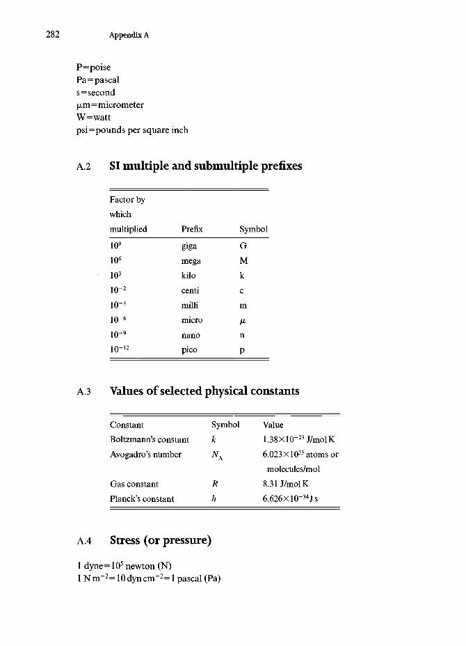
282 Appendix A
P=poisePa=pascals=second\xm=micrometerW=wattpsi=pounds per square inch
A.2 SI multiple and submultiple prefixes
Factor bywhichmultiplied
109
106
103
io-2
10-3
10-6
10-9
10-12
Prefix
gigamegakilocentimillimicronanopico
Symbol
GMkcm
n
P
A3 Values of selected physical constants
ConstantBoltzmann's constantAvogadro's number
Gas constantPlanck's constant
Symbolk
Rh
Value1.38xlO-23J/molK6.023 X1023 atoms ormolecules/mol
8.31 J/molK6.626Xl0~34Js
A.4 Stress (or pressure)
1 dyne= 105 newton (N)1 Nm~2=10dyncm~2=l pascal (Pa)

Appendix A 283
lMPA=106Nm-2=lNmm-2
lbar=105Nm-2=105Pa1 kilobar= 108Nm-2= 109dyn cm"2
lmmHg=ltorr=133.322Pa=133.32Nm-2
1 kgfmm-2=9806.65kNm-2=9806.65kPa=100 atmosphereslkgfcm-2=98.0665kPa=l atmosphere1 lbin-2=6.89476kNm-2=6.89476kPalkgfcm"2= 14.22331b in"2
106psi=106lbin-2=6.89476Gnm-2=6.89476GPalGPa=145000psi
A. 5 Viscosity
1 poise=0.1 Pas=0.1 Nm"2slGNm-2s=1010poise
A.6 Energy per unit area
lergcm~2=lmJm~2=10~3Jm~2=ldyncm~1:=10~3Nm~108ergcnr2=47.68ftlbin-2=572.16psiin
A.7 Fracture toughness
lpsiin1/2=llbfin-3/2=l.llkNm-3/2=l.llkPam-1/2
lksiin1/2=l.llMPam-1/2
lMPam1/2=0.90ksiin1/2
lkgfmm-2mm1/2=3.16Xl04Nm-2m1/2
A. 8 Density
lgcm-3=62.42801bfr3=0.03611b in-lib in-3=27.68gcm"3
lgcm"3=103kgm-3
A.9 Textile units
Linear densitytex=g/kmdenier=g/9 km

284 Appendix A
Specific stress= l(r6Pa/p
where p is density in kg m~3
A. 10 Unit conversions
g/denier g/tex kg/mm2 Pa lb/in2
g/denier 1 9 p 8.995
g/tex 0.111 1 p 80.96
kg/mm2 0.111/lp 0.0124/p 1
Pa (1.138xl0-8)/p (1.260Xl0-9)/p 1.019X10⁻⁸
lb/in2 (7.013Xl0-5)/p (8.681 XlO-6)/p 7.013X10⁻⁴
P8.818X107 pl.28lXlO4
P7.936X108 pl.l52xlO5
9.803X10⁷ 1.281 X10⁴
1 1.451X10⁻⁴
6.889X10³ 1

Author index
Abe, Y. 147Abhiraman, A.S. 93, 220, 243Adams, W.W. 49, 79, 93, 278-9Adler, R.P.L 178Akiyama, M. 147Alber,N.E. 115Allen, S.R. 90, 93, 95Allitt, M.L. 237-8Anderson, R.V. 172Anon 183Ansell, M.R 56Argon, A.S. 94Arnold, RE. 92Arsenault, R.J. 7Aubin, C. 147Austin, H.F. 141Avakian, R 82Aveston, J. 139
Babonneau, F. 168Baer, E. 278-9Baker, R.T.K. 227, 280Balasubramaniam, N. 243Bansal, R.C. 279Barkakaty, B.C. 50Barlow, S.K. 204Barnard, T. 169Bartha, L. 279Bascom, W.D. 240, 241Bastos, A. 56Batchelder, D.N. 253Batich, CD. 165Batra, S.K. 50Beck, A.T. 172Beetz Jr., C. 228-9
Bennett, S.C. 220-3Berenbaum, M. 49Berger, L.R 252-3Bernardo, C.A. 280Bernstein, B.T. 49Bewlay,B.R 118-19, 120Birchall, J.D. 146Biresaw, G. 262-3Biro, D.A. 79Blume, R.C. 82Bogy, D.B. 153Bolt, J.D. 237-8Boogh, L.C.N. 253Borek, T.T. 172Bowen, H.K. 279Bradley, J.A.A. 146Brenner, S.S. 180Briant, C.L. 119Brinker, C.J. 279Brown, J.R. 79Bujalski, D. 169Bunn, C.J. 78Bunsell, A.R. 147, 164, 235, 278-9
Caddell, R.M. 112Cannon, W.R. 253Cappacio, G. 75Carothers, W. 3Carter, M.E. 278Chand, N. 50, 55-6Chandan, H.C. 205Chang, H.W. 79Chappell, P.J.C. 79Chawla, K.K. 7, 23, 28, 56, 112, 115, 133, 155, 168,
183,224,243,262-3
285

286 Author index
Chawla, N. 149, 168, 170Cheng, A. 49Cheng, C. 253Chew, K.W. 166-7Chew, T.-W. 7Choi, G.J. 165Chung, D.D.L. 279Chung, Y.-W. 28Clare, A.G. 199Clyne, T.W. 7Cockayne, B. 151Coleman, B.D. 266Cooper, W.C. 140Cotteret, J. 168Couper, M. 71Crist, B. 279
Dalton, L.R. 98Damodaran, S. 93Daniel, LM. 238Daniels, H.E. 238, 266Datye, A.K. 172Datye, K.R. 57Davison, T.S. 250Day, RJ. 69, 253de Chardonnet, H. 3DeBolt,H.E. 159Demont, M.E. 46, 48-9Denny, M.W. 46, 48-9Deren, G. 140Desai, P. 93, 243DeTeresa, SJ. 90, 93, 95Deurbergue, A. 220Dhingra, A.K. 143Diaz, G. 280DiCarlo,J.A. 169, 171,179, 180Dickerson, P.O. 151,155Diefendorf, R.J. 173, 255Dinwoodie, J. 146Dixmier, XL. 168Dobbs, M.G 88-9Donald, I.W. 113,279Donnet, J.-B. 279Dresher, W.H. 24Dresselhaus, G. 279Dresselhaus, M.S. 229, 279Dunham, M.G. 213
Eby, R.K. 224, 279Economy,! 172-3,181Edie,D.D. 213,221Eikleberry, S.L. 204Eldridge, J.I. 250Embury, J.D. 124Endo, M. 228Engelke,J.L. 115
Fairbrother, WJ. 49Farmer, A.C 151,155Farmer, B. 49, 79, 151,278Farris, R.J. 90, 93, 95Fazen, P.J. 172Feltwell, J. 45
Figueiredo, J.L. 280Fisher, R.M. 124Flank, P. 168Flory,PJ.81Flucht, F. 264Frankfort, H.R.E. 26Freiman, S.W. 205Frondel,C 139
Gac, FD. 181, 183,245Galiotis, C. 253Gallagher, K.S. 49Gardener, K.H. 82Gasson, D.G. 151Gathercole, L.J. 278Gibson, A.G. 75Gierke, T.D. 82Goldberg, H.A. 279Golsby, J.C. 179Gooch,D.J. 155Good, R.J. 241Gore, V.N. 57Goring, J. 264Gosline, J.M. 46, 48-9Gossing, P. 199Greenwood, G.H. 246Greszczuk, L.B. 94Grether, M.F. 155Griffith, E.J. 173Grover, G.W. 155Guerette, P. 49
Hadley, D.W. 64, 250Hagege, R. 168, 235Haggerty, J.S. 151Hall, E.O. 100, 123Hammond, M.L. 178Hannant, D.J. 208Haquenne, A. 229Harris, D.H. 172Harris, PS. 227Hayashi,J. 161,163Hayashi, N. 172Hearle, J.W.S. 278Heliminiack, T.E. 93Herakovich, C.T. 220-1Herring, H.W. 255Hild, D.N. 79Hillig, W.B. 246-7Hillman, H. 122Hilnak, A. 28Hodd, K.A. 82Hokudoh, T. 93Hollar, Jr., WE., 181Holme, I. 100Holmes, J.W 168Holz,A.R. 155Hommel, H. 168Hongu, T. 278Horascek, D. 120-1Horrocks, A.E. 100Hosford,W112Hounshell, D. 58

Author index 287
Hull, D. 7Hurley, G.F. 150Huttinger, KJ. 223, 225, 227, 246, 280Hyde, N. 45
Inabe, T. 98Inal, O.T. 220Irwin, R.S. 99, 100Ishikawa, T. 164Issi, J.R 229Itou, S. 146Iwanaga, K. 146
Jackson, H.E. 168Jaffe, M. 87Jain, M.K. 220, 243Jaiswal, S. 126Jakus,K. 155Jang, T. 141Jawad, S.A. 250Jeffries, R. 52-3Jiang, H. 93, 279Johnson, D.D. 155Johnson, DJ. 88-9, 220, 222-3, 227Johnson, W. 220Jones, D.M. 52-3Jones, M.-C.G. 251Jones, R.S. 87Jones, R.W. 279
Kalb, B. 78Kalish, D. 205Kaniraj, S.R. 57Kannisto, M. 166-7Kao, C.K. 279Kaplan, D. 46, 49, 79, 278Kaplan, S.L. 79Katz, S. 49Kausch, H.H. 252-3Kawabata, S. 250-1Keller, A. 278Keller, L. 220Kelly, B.T. 212-13Kelsey, R.H. 244Kenney, M.C. 204Kerkam, K. 46Khosravi, N. 79Kiel, A.M. 76, 78Kikuchi,T. 83, 115Kim,J. 168, 181Kimura, Y 172Kingery, W. 279Kip, B.J. 253Kirby, R.H. 278Kittl, P. 280Klein, W. 244Knox, B.H. 26Ko,F.K. 7, 18, 19Kopper, A. 251Kostikov, V.I. 278Kowalska, M. 231Koyama, T. 228Kozey, V.V. 90, 93, 97
Krassig, H.A. 63Kratzer, R.H. 172Krukonis, V.J. 159, 175Kubo, Y 172Kumar, S. 79, 90, 93-5, 97, 227Kummer, B. 265Kwolek, S. 80
LaBelle,H.E. 150Laemmle, XT. 262-3Laffon, C. 168Lagarde, P. 168Lagerlof, K.P 245Laine, R.M. 166-7Lara-Curzio, E. 168,251Laridjani, M. 168Layden, J.K. 178Leca, N. 220Legrand,A.P. 168Lemstra, P.J. 76Lenz, J. 63Lesniewski, C. 147Lewis, N. 119Li, T. 279Li, X. 155,243,262-3Li, Z.F. 48, 79Liang, F.L. 143Lieder, S.L. 145-6, 148, 155Lin, R. 173, 181Lipowitz, J. 169Lombardi, S. 46Loo, B.H. 92Lou, N. 119Lueneburg, D.C. 145-6, 148, 155Lyman, D.J. 2, 33Lynch, A.T. 172
MacChesney, IB. 197Mackenzie, K.J.D. 140Magat, E.E. 58, 82Mahlke, G. 199Majumdar, A.J. 208Makinson, K.R. 44Mankle,R.A. 172, 181Mansfield, J.E. 168Margolin, H. 143Mark, H. 75Mark, H.F. 63Marks, T.J. 98Marsh, D.M. 245Martin, D.C. 93, 94, 251Mathys, Z. 79Matsuda, K. 88Maurer, R.D. 207, 265Mazlout, L. 173McGarry, F.J. 95Mclvor, I.D. 126McLemore, D.E. 279McMahon, RE. 243Mecholsky, J.J. 205Mehan, R.L. 246Mehta, V.R. 248-9Meier, R.J. 253

288 Author index
Meinhold, R.H. 140Mendoza, E. 253Meredith, R. 50Meyers, M.A. 112,115,224Midwinter, J.E. 196Milewski,J.V 181, 183,245Mlavsky,A.I. 150Moalli, J.E. 95Moet, A. 279Mohamed, M.H. 16Moncrieff, R.W. 278Moran, H. 277Morey, S.N. 205Morgan, P.W. 82Morrison, R.E. 58Morrone, A.A. 165-6Morscher, G.N.A. 155Mortensen, A. 7Morton, WE. 278Motzfeldt, K. 61, 155Mukherjee, S.P. 172, 181Murata, H. 279Murthy, N.S. 79
Nagel, S.R. 197Nakagawa, K. 88Nakajima, T. 67Nardin, P.C. 240Narula, C.K. 172NASA 231Needleman, A. 7Netravali, A.N. 48, 79Neumann, A.W. 241New York Times 1Nguyen, H.X. 79Nichols, C. 49Nieh,T.G. 119Niquel, J.L. 168Nishihara, T. 88Nomura, Y. 93Nordine,P.C. 180Northolt, M.G. 88, 90, 262Nourbakhsh, S. 143Nunes, J. 244Nysten, B. 229
Oberlin, A. 220, 228Ochiai, I. 127-9Ohta, T. 85Okada, K. 135Okamura, K. 157, 161, 163, 169-71Olry, P. 168Omori, M. 157, 161, 163Onn, D.G. 237-8Ozawa, S. 88
Paciorek, KJ.L. 172Paine, R.T. 172Panar, M. 82Parker, R.D. 205Pask,J.A. 135Peebles, L.H. 280Pennings, A.J. 76, 78
Perez, G. 26Perov, B.V. 278Petch, N.J. 123Petrovic, J.J. 181, 183,245Phalippou, J. 195Phani, K.K. 262Phillips, GO. 278Phoenix, S.L. 250, 262, 264Piggott, M. 7Pindera, M.-J. 250Pink, E. 279Pinnock, PR. 64, 250Piraux, L. 229Pitt, G.D. 253Pleizier, G. 79Plummer, C.G 252-3Polis, D.W. 98Pollack, J.T.A. 150Pond,R.B. 115Porter, R.S. 90, 93, 95Prassas, M. 195Proctor, PA. 189Pysher,D.J. 155
Rabe, J. 169Rao, G.V. 57Rapko,B.M. 172Rawson, H. 279Reimschusssel, H. 279Remsen, E.E. 172Reynolds, W.N. 222Rhee, B.S. 230Riggs, J.P 214Roberts, J.K. 52-3Robinson, K.E. 221Robinson, R.M. 50Roe, P.G. 56Rohatgi, P.K. 50, 55-6Rohr,D.L. 181, 183,245Romine, J.C. 143Rose, P.G. 246Rose, P.W. 79Ross, M. 139
Sachse,W48, 179Sacks, M.D. 165-6Saitow, Y. 146Sakka, S. 146, 195-6Saleem, M. 165-6Satyanarayana, K.G 55Saville, B.P. 88-9Sayir,A151,155Scaggs, S.R. 181Schaffer, R. 172Scheiffle, G.W 165-6Scherer, G.W 202, 279Schlack, P. 3Schmucker, M. 158Schneider, H. 135, 155, 158-9Schob, O. 175Scholze, H. 279Schouten, C.J.H. 76, 78Schuerch, H. 94

Author index 289
Schultz, J. 240Schwartz, P. 79, 264Scotto, C. 166-7Segal, L. 50Seguchi, T. 169Selby, K. 52-3Seviller, E.R. 92Sharp, A.G. 2Sheaffer, P.M. 238Shear, W.A. 46Shoji,H. 115Siemers, PA. 246Sikkema, D.J. 262Simmons, S.C. 52-3Simon, G. 147, 164Sinclair, D. 246Singer, L.S. 219Singh, R.N. 168Sittig, M. 280Skaggs, S.R. 245Skelton, J. 250Skinner, H.C.W. 139Smith, J.K. 58Smith, P. 76Smith, R.E. 247Smith, W.D. 172Smith. WE. 115Smook, J. 78Sneddon, L.G. 172Sowman, H.G. 146, 148Spain, I.L. 279Staab, G.A. 165-6Sternstein, S.S. 168Stout, H.P. 58Subramanian, R.V. 141Sudiwala, R.V. 253Sugihara, K. 279Suresh, S. 7Swan, PR. 78Swartzfager, D.G. 61, 155
Takahashi, T. 127-9Talley, C.P. 174Taya, M. 7Taylor, GF. 113Thiel, B.L. 47Thomas, E.L. 93^1Tibbetts, G.G. 228-9Tillinghast, E.K. 49Tlali, J.S. 168Tokarsky, E. 255Toreki,W. 165Townley, M.A. 49Tressler, R.E. 155Tsai, C.-L. 238Tulluri,V. 155Turley, D.C. 82
Uhlmann, D.R. 279Unal, O. 245
Vachon, D.J. 98van Eijk, M.C.P. 253
van Maaren, A.C. 175van Stone, J.C. 100Vassilatos, G 26Vega-Boggio, J. 175, 178-9Viney, C. 46-7, 49, 79, 278Vingsbo, O. 175, 178-9Vollrath, F. 46, 49Vukcevich,N. 119
Wadsworth,J. 119Wagner, F.N. 232Wagner, H.D. 264Wakelyn, PH. 50Walker, K.L. 197Wallenberger, F.T. 61, 155, 180Wang, T.J.Y. 141Ward, I.M. 64, 75, 250Warner, S.B. 79, 278-9Warwicker, J.O. 52-3Watt, W 225-6, 278Wawner,F.E. 159, 179Wax, S.G. 161Webb, J.E. 168Weibull, W 256-68Wiening, J.P 250Weintraub, E. 174Westerveld, W. 175Weston,N.E.61,155Whittaker, A.J. 237-8Williams, K.P.J. 253Williams, R.J.P 49Williams, TJ. 165-6Wills, R.R. 172, 181Wilson, D.M. 145-6, 148, 155Wilson, E.G. 253Wilson, N. 72-3Windle, A.H. 279Withers, PJ. 7Wittenauer, J.P. 119Wolfe, J.F 92Wong, W E 253Wu, H.F. 262-3Wynne, K. 98
Xu, Y. 169Xu,Z.R. 28, 155,243,262-3
Yabuki, K. 93Yajima, S. 157, 161, 163Yang, H.H. 82, 279Young, R.J. 69, 253Yun,H.M. 151,155, 179Yunoki, H. 88
Zachariades, A.E. 98Zakikhani, N. 69, 253Zangvil,A. 169Zank, G 169Zarzycki, J. 195Zhang, Z.-F. 166-7Ziegler, G 264Zweben, C. 256, 280

Subject index
alumina 4, 7, 8alumina fibers
single crystal 150-2EFG process 150-1
laser heated floating zone process 151-2aluminum 129-30amino acid 44-5aramid 4aramid fibers 79-92, 102-3
structure 88-90properties 90-2processing 80-8
armor 103-6asbestos fiber 139-40aspect ratio 5, 7, 9
basalt fiber 140-1bicomponent fiber 191-2boron 4
fiber 174-80, 254-5processing 174-5properties 178-80strength 254^5structure 175-8
boron carbide fiber 173boron nitride fiber 172braiding 9, 17-19
calcium polyphosphate fiber 173carbon 4, 8, 29carbon fibers 98-9, 211-33, 264
applications 231-3electrodes 232hazards 230-1high thermal conductivity 227-9hollow 230modulus 223-5
PAN-basedprocessing 215-18properties 217, 227
pitch-basedhigh thermal conductivity 229processing 218-20properties 226-7
processing 214-21properties 221-7radiolucent 232strength 254, 256structure 2 2 0 ^VGCFsee vapor grown carbon fibersWeibull plot 263
carding 9, 21cellulose 50-6Cemfil glass fiber 200ceramics 132-9
creep 138-9properties 135structure 134-5
ceramic fibers 204collagen 1,49compressive failure 93-7compressive strength 93-7contact angle 238^1
dynamic 241Wilhemy technique 240
copper 4, 8applications 129, 181-3
cord 9
damping 90-1Darcy's law 107decibel scale 186-7denier 10, 13
290

Subject index 291
density 28-9linear 13
Dyneema 76, 78-9dry-jet wet spinning 85-7
elastic modulus 247-51dynamic 247shear 247-9transverse 250-1
elastomeric fibers 69, 73, 102processing 71properties 71-3structure 71-2
electrical resistivity 238
fabric 16bubble 31-2weave 236
felt 19fibers
alumina 142-6, 150-2aluminosilicate 146-9animal kingdom 43-50applications 31-5bicomponent 9blend 9boron 93bundle strength 265-8card board frame technique 243ceramic 4, 29
applications 181-3chopped strand 9classification 4-5compressive strength 93-7continuous 9crimp 5, 23cross-section 27-8diameter 234-5definition 9density 235from films 63glass 93health hazard(s) 35-6hollow 100metallic 29natural 5, 6, 8, 43-57natural ceramics 139^41nonoxide 157-81nonwoven 5orientation 26-7, 63-5oxide 142-57properties 155-7creep 156-7
polymeric 29conductive 98-9flame retardant 99-100natural 37strong and stiff 73-107
product forms 5properties
experimental determination 234-53roughness 28-9silicon carbide 93, 157-71
silk 44-50staple 5stiff and strong 6-7strength
statistical treatment 254-68boron 254-5carbon 254, 256Kevlar 254-6
strength determination 242-7stretching 26-7, 63-5surface area 21-3surface roughness 27-9swelling 235synthetic 6, 8, 30properties 30
synthetic ceramic 141synthetic polymers 58-107applications 100-7environmental effects 65-6nylon 58-9PAN 59PET 59processing 59-64
vegetable 50-7whiskers 5woven 5yarn 5
fill 10, 12, 15filters 32-3, 34, 39
nylon 34polyester 34stainless steel 35
flaxlflexibility 6, 21, 23-6friction 97-8Fullerene211
gel spinning 76-8geotextiles 9, 57, 105-7
definition 106glass 3glass fibers 7, 20, 184-210
applications 207-10composition 199-202fabrication 187-99failure probability 207for optical communication 196-9for reinforcement 189-96fracture 205lifetime prediction 206-7properties 203-7sol-gel processing 191-6structure 202-3viscoelastic behavior 187-8Weibull statistics 207
glass transition temperature 42-3graphite 211-13
compliance 213modulus 212-13stiffness 213structure 212
hairhuman 24

292 Subject index
handle 10high silica fiber 190-1
insulation 208-9inviscid melt process 152-5
jute fiber 4, 52-6
Kevlar fiber 27, 99, 264see also aramidfibers
energy absorption 92product forms 87-8properties 90-1strength 254-6
kinking 94-5knitting 16-19
lead 131liquid crystal 8 0 ^
lyotropic 81nematic 82-4thermotropic 81
loop test 246-7Lycra 69-73see also elastomeric fibersmat 20metallic fibers 110-31
applications 129-31microstructure 114-15processing 110-13properties 115-30spinning 114-15superconductors 121-2Taylor process 113-15
metalsgeneral characteristics 108-10
microbuckling 94microfiber 101micro-Raman strain
experimental setup 252measurement 251-3
Microflex glass fiber 191-2, 204modulus
function of draw ratio 64moisture absorption 56, 65-6monofilament 10mullite fiber
Weibull plot 263Nextel fiber 146-9, 156-7Nicalon fiber 161-71, 264
elastic modulus 171tensile strength 171
niobium 131Nomex fiber 99see also aramid fibersnonwoven(s) 18-19,31, 106
needle punched 19resin bonded 19thermally bonded 19
nylon 3, 7chemical structure 66
nylon fibers 66-7
optical cable 198-9optical communication 184-7optical glass fibers
attenuation 201medical use 209-10multimode graded index 200-1multimode step index 200-1processingdirect melting 197-8vapor deposition 196-7modified chemical vapor deposition 197
single mode 200-1strength 265Weibull modulus 265
particle 11patenting 125PBZO 9 3 ^Petrofiber 107piano wire 125-8plaitingsee braidingpoly p-phenylene benzobisthiazole (PBT) 92-3poly p-phenylene benzobisoxazole (PBO) 89, 93polydiacetylene fiber 69polyester fibers 67polyethylene 4, 67-8, 101-2
unit cell 78polyethylene fibers 102-3
oriented 75-9processing 75-8properties 78-9structure 78-9surface treatment 79
polymeric fibersenvironmental effects 56
polymersproperties 38^43structure 39^3
polyolefins 101-2polyolefin fibers 67-8polypropylene fibers 107polytetrafluoroethylene 31polyurethane 70-3potassium titanate fiber 173-4proof testing 265
Ramanspectroscopy 79, 253scattering 253strain measurement 251-4
ramie 4Rayleigh waves 60-1, 152-5rayon 3, 55recoil compression test 245-6retting 11rope 20roving 11
Saphikon fiber 150-2SCS-6 fiber 160-1, 167
creep 171sensors 209

Subject index 293
Sigma fiber 161silicon carbide 4, 7silicon carbide fibers
CVD processed 159-61polymer precursor processed 161-71
silicon nitride fiber 172silk 1,3-4silk fiber 44-50
microcomposite structure 48properties 49skin core structure 48stress-strain curve 49structure 47-8types 47
sisal fiber 4size effect 6skin core
structure 25Snell'slawl85Spandex 69-73see also elastomeric fibersSpectra 76, 78-9spider silk 1, 45-7
major ampullate gland silk 47structure 47-8
spinneretspinning 14, 59, 114-15
dry 14, 61dry-jet wet 14, 62gel 62melt 61wet 62, 145
spunbonding 11staple fiber 11static electricity 98-9steel 122-31
effect of drawing 124effect of oxide inclusions 127Hall-Petch relationship 123-4microstructure 125-8processing 125
superconducting filaments 121-2Nb-Ti 121Nb3Sn 122
swelling 65-6, 235
Taylor process 113-15tea bag 2Technora fiberssee also aramidfibers
properties 92tenacity 11tex 10, 13thermal analysis 236thermal conductivity 236-8thermal diffusivity 237thermal expansion 238
coefficient of 238titanium diboride fiber 173total internal reflection 185-7tow 12tungsten 4, 8, 29, 116-21, 131
AKS 119-20creep behavior 120-1fibrous structure 118potassium bubbles 119-20
Twaron fibersee aramid fiberstwist 12-13
S13Z13
Tyvek 101-2
vapor grown carbon fibers 227-9vegetable fibers 50-7
cotton 50, 52-3flex 50, 55hemp 50, 55jute 50-5pina 50sisal 50-3ramie 54-5
viscoelasticity 187-8
warp 12, 15weave(s) 15
basic types 15satin 15
weft 12, 15Weibull modulus 256-64
aramid fiber 264boron fiber 264carbon fiber 264ceramic fiber 264glass fiber 264
Weibull statistics 256-68coefficient of variation 260, 264, 268failure probability 257-63mean 258-60mode 261standard deviation 259-60survival probability 256-7
wettability 238^1whiskers 12, 180-3Wilhelmy technique 240wire drawing 110-13
work done in 111, 113wire 12wool fiber 49woven fabric 12yarn 12-13, 16
denier 113number of fibers 13tex 113twist 113