6x10 galvanized tilt trailer assembly · 12a st1007 screw, 12-14 x 2 tek dek screw 30 32 70095 gas...
TRANSCRIPT

6x10 Galvanized Tilt Trailer Assembly
1 04/19/2013 www.sure-trac.com
1-800-372-1755
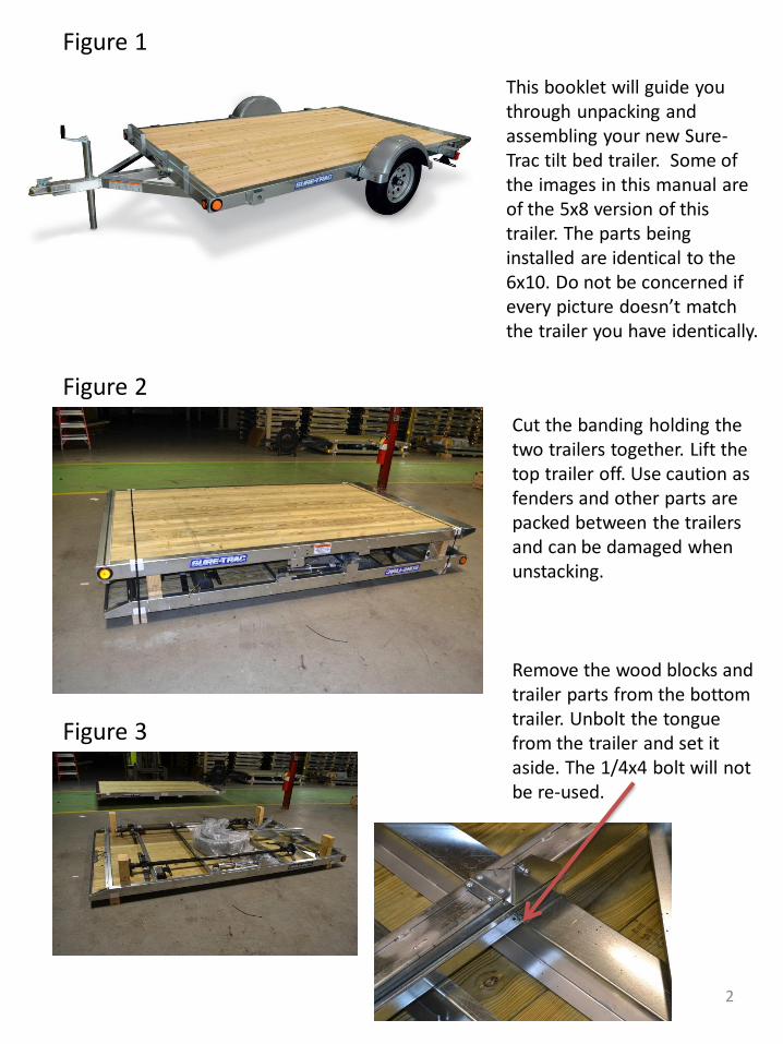
This booklet will guide you through unpacking and assembling your new Sure-Trac tilt bed trailer. Some of the images in this manual are of the 5x8 version of this trailer. The parts being installed are identical to the 6x10. Do not be concerned if every picture doesn’t match the trailer you have identically.
Figure 1
Figure 2
Figure 3
Remove the wood blocks and trailer parts from the bottom trailer. Unbolt the tongue from the trailer and set it aside. The 1/4x4 bolt will not be re-used.
Cut the banding holding the two trailers together. Lift the top trailer off. Use caution as fenders and other parts are packed between the trailers and can be damaged when unstacking.
2

Unbolt the light brackets from their storage positions. (Figure 4) You will not re-use the nut from the light bracket but you will need the bolt.
Insert the tab into the slot on the trailer side frame (Figure 5) and slide the bracket to the rear to fully engage the tab.
Install the bolt you removed from the light bracket. The bolt will tighten into the rivet-nut that is in the side of the trailer. Insert the grommet into the frame hole to protect the wire going through the side frame. Feed the excess wire through the bolt hole that the light bracket was stored in and insert the grommet to protect the folded over wire. (Figure 6) Repeat this process for the other tail light.
Figure 4
Figure 5
Figure 6
3

Place the axle into the shackles on the side frame of the trailer. (Figure 7) The large formed eye on the spring should go to the front of the trailer.
Hammer the large serrated shackle bolt (Figure 8) into the front shackle until the head touches the shackle side (Figure 9). These bolts are shipped in the hardware bag.
Figure 7
Figure 8
Figure 9
4

Install the 5/16 x 3-1/4 bolts and lock nuts over the spring and into the rear shackles. These bolts and nuts are also in the hardware bag. Tighten these bolts to 15 lbf.
Tighten the front shackle bolts using an impact wrench. Be sure to hold the bolt with a wrench so that the bolt does not turn. Spinning this bolt in the shackle will lead to axle mount failure. Tighten the nut until the shackle almost touches the spring sides.
Place the tongue into the tongue channel on the trailer and align the holes. Insert the 9/16 x4 bolt and tighten the nylock nut until the guide starts to push against the tongue. (Figure 12)
Figure 10
Figure 11
Figure 12
5

Pull the wiring harness out of the frame tube so that it can be pushed through the tongue later.
Install the tongue side brace pivot bolts (1 on each side of trailer). Be sure to use the 5/16-18 nylock nuts and the 5/16-18x3/4 flanged bolts. Tighten until the parts are snug together. Feed the trailer wiring harness through the tongue and out the front so that the coupler mounting bolts keep the wire from dropping out the front of the tongue.
Figure 14
Figure 13
Figure 15
6

Snap the gas spring onto the ball stud that is mounted on the trailer, and lift the tongue to snap it onto the ball stud mounted to the tongue. Install the safety clip on both ends of the gas spring. Do not attempt to remove or install the gas spring while the safety clip is in place. Twist the safety clip so that it clicks into the slot on the ball socket. Push the tongue down and install the hitch pin and hair pin to secure it.
Figure 17
Figure 16
Figure 18
7

Flip the trailer and support it on sturdy stands so that you can finish the assembly. Remove the 3 self tapping screws installed in the tongue. Insert the jack through the tongue using caution not to damage the wiring harness. Tighten the 3 self tapping screws into the pre drilled holes in the tongue. Tighten to 10 lbf. Feed the fender light wires through the small hole in the frame between the fender mounting nuts. The amber light should face forward on the trailer. The fenders are “left” and “right” hand versions.
Figure 19
Figure 20
Figure 21
8

Connect the wires to the plugs inside the frame and secure the wires behind the cross member. The lights will work when connected to either color wire, they do not have polarity. Install both fenders by bolting through the fender brackets and into the preplaced nuts in the frame. Use the 5/16-18 x ¾ bolts from the hardware bag. Tighten all 4 bolts on each fender to 15 lbf.
Figure 23
Figure 22
9

Install the tires and tighten the lug nuts (from the hardware bag) to 100 lbf of torque. Be sure and put the coned surface of the nut against the rim. Use a criss cross pattern to tighten the lug nuts working up to the final torque in three stages of tightening. Re-torque the lug nuts after 25, 50 and 100 miles of travel. Install the tire stops on the front of the trailer using the hardware removed earlier. Place a bolt in each corner of the tire stop and use the serrated nuts to secure them. Tighten to 15 lbf of torque. Using the 5/16-18 x ¾ bolts from the hardware bag, install the stake pockets, 2 per side of the trailer; and tighten the bolts to 15 lbf. *Note, if you are installing a factory side board kit, do not install the stake pockets. The sideboard kit instructions are at the end of this manual.
Figure 26
Figure 25
Figure 24
10
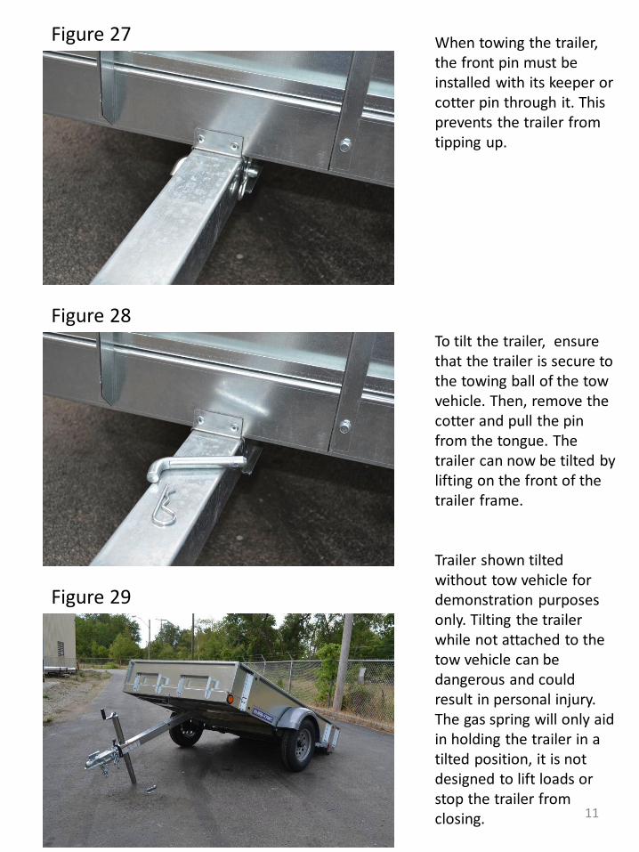
When towing the trailer, the front pin must be installed with its keeper or cotter pin through it. This prevents the trailer from tipping up. To tilt the trailer, ensure that the trailer is secure to the towing ball of the tow vehicle. Then, remove the cotter and pull the pin from the tongue. The trailer can now be tilted by lifting on the front of the trailer frame. Trailer shown tilted without tow vehicle for demonstration purposes only. Tilting the trailer while not attached to the tow vehicle can be dangerous and could result in personal injury. The gas spring will only aid in holding the trailer in a tilted position, it is not designed to lift loads or stop the trailer from closing.
Figure 28
Figure 29
Figure 27
11
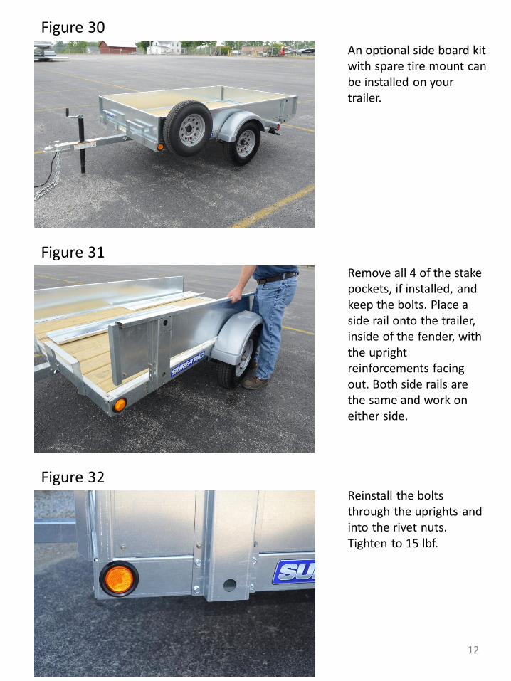
An optional side board kit with spare tire mount can be installed on your trailer. Remove all 4 of the stake pockets, if installed, and keep the bolts. Place a side rail onto the trailer, inside of the fender, with the upright reinforcements facing out. Both side rails are the same and work on either side. Reinstall the bolts through the uprights and into the rivet nuts. Tighten to 15 lbf.
Figure 31
Figure 32
Figure 30
12

Slide an end gate into the front and the back of the side rails. The end gates are identical and can be used in the front or the rear. The end gates can be nested into each other and placed at either the front or the back of the trailer when hauling long items that won’t fit inside the gates. The slot in the upright of the sideboard kit is for mounting a spare tire to the trailer. Slide the included carriage bolt into the slot from the side and pull it away from the trailer to seat the square head into the slot.
Figure 34
Figure 35
Figure 33
13

Place the tire over the bolt and tighten the included lock nut to hold the tire in place against the side of the trailer. The stake pockets are designed to be used as tie down points. Most standard 2” straps have a wire formed hook that fits inside the pocket by twisting it in. Roll the strap hook into place as shown in Figure 37-38. The hook will not fall out when slacked (Figure 39), and it is located correctly when tension is applied (Figure 40).
Figure 37-38
Figure 36
Figure 39-40
14

15

16
ID Part # Description Qty ID Part# Decals Qty
1 70015 Fab, Tire Stop A 2 20 70079 Axle, 2.5k idler 70.5/82 EZ slipper 1
1a 70018 Screw, 5/16-18 x 3/4 HH Serr. Gr 5 zinc 4 21 ST3287 Wheel Assly, 13" Grey 2
1b 30624 Nut, 5/16-18 whiz flange serrated 4 22 70082 Fab, CM tube WA 6W 1
2 70086 Fab, Front Frame 1 23 70084 Fab, Tongue brace mounting brkt 2
3 ST2116 Light, Recessed Refl Rnd 2.5 Amber 12V 2 24 70083R Fab, Side Frame Right 1
3a ST2117 Grommet, 2-1/2 Round Flush W/Wire 1 25 70085R Fab, Tongue brace right 1
4 70003 Fab, Stake Pocket Bolted 4 25a ST1819 Nut, 5/16 Nylon Lock 1
4b 70018 Screw, 5/16-18 x 3/4 HH Serr. Gr 5 zinc 4 25b 70018 Screw, 5/16-18 x 3/4 HH Serr. Gr 5 zinc 1
4c 70020 Rivet nut 5/16-18 .027-.150 Ribbed STL Z 4 26 70040 Tongue W/A 1
5 70083L Fab, Side Frame Left 1 27 70023 Coupler 2 in ball 3 wide CLII 3500 ZN 1
6 70032 L Fender, grey 13inch wheel Left 1 27a 70026 Screw, 1/2-13 x 4 HH GR5 ZN 2
6a 70001L Fab, fender brace left 1 27b 70027 Nut, 1/2-13 Nylon Lock GR5 ZN 2
6b 70099 Fab, fender wire cover 1 28 70108 Harness, wiring 6x10 tilt 1
6c 70001R Fab, fender brace right 1 28 ST1014 Chain, Trailer Safety with Hook 27 2
6d ST1153 Grommet 3/8 OD 1/4 ID 1 28a 1294 Washer, Flat 3/8 Zinc 1
6e 70018 Screw, 5/16-18 x 3/4 HH Serr. Gr 5 zinc 4 28b 102055 Screw, 3/8-16 x 1-1/4 HH GR5 Zinc 1
6f 70020 Rivet nut 5/16-18 .027-.150 Ribbed STL Z 4 28c 70028 Nut, 3/8-16 Nylon Lock GR5 ZN 1
7 70098 Light, 3/4 IN Round Recessed Amber 12V 2 29 ST7089 Jack, A-Fram 5k ZN plated 1
8 31206 Nut, Cone lug 1/2-20 10 29a 70021 Screw, 5/16-18 x 1/2 HH Trilobe 3
9 70016 Fab, Light Bracket B 1 29a ST6686 Foot Plate Small bolt on 1
9a 70018 Screw, 5/16-18 x 3/4 HH Serr. Gr 5 zinc 1 30 70014 Fab, Tilt Tongue Bracket 1
9b 70020 Rivet nut 5/16-18 .027-.150 Ribbed STL Z 1 30a 70022 Screw, 9/16-12 x 4 HH Gr 5 ZN 1
10 ST1538 Light, Tail License Illum Red Ovr 80 12V 1 30a 70024 Nut, 9/16-12 Nylon Lock, Zinc 1
11 ST1173 Hanger, License Plate plastic 1 30a 70025 Pull Pin, 5/8 x 4.5 with Cotter 1
12 70087 Fab, Rear Frame 1 31 70094 Fab, lower gas spring mount 1
12a ST1007 Screw, 12-14 x 2 tek dek screw 30 32 70095 Gas spring tilt trailer 1
13 70088 Fab, CM Z 6W 6 32a 70109 Stud, 13MM ball 2
14 70090 Board, 5/4 x 10 treated 10 32a 70109 Stud, 13MM ball 2
15 ST1537 Light, Surface Mt Red Over 80 12v 1 32a 70110 Safety Clip 13 MM 2
16 70017 Fab, Light Bracket B mir 1 33 70102 Fab, upper gas spring mount 1
16a 70018 Screw, 5/16-18 x 3/4 HH Serr. Gr 5 zinc 1 34 70093 Light, 3/4 IN Round Recessed Red 12V 3
16b 70020 Rivet nut 5/16-18 .027-.150 Ribbed STL Z 1 34a ST2100 Clamp, Wire 3/8in Loop 1/4 Hole 2
17 70005 Fab, Rear Shackle Mount 2 35 70085L Fab, Tongue brace left 1
17a ST1737 Bolt, 5/16-18 x 3-1/4 , HH GR5 1 35a ST1819 Nut, 5/16 Nylon Lock 1
17b ST1819 Nut, 5/16 Nylon Lock 1 35b 70018 Screw, 5/16-18 x 3/4 HH Serr. Gr 5 zinc 1
18 70032 R Fender, grey 13inch wheel Right 1 32154 Decal, Patent Pending 1 x 6 1
18a 70001L Fab, fender brace left 1 ST3637 Label, Final Inspection 1
18b 70099 Fab, fender wire cover 1 ST4069 Label, Sure Trac 15.6 2
18c 70001R Fab, fender brace right 1 ST3527 Label, Bumper Pull Combo 1
18d ST1153 Grommet 3/8 OD 1/4 ID 1 70103 Owners manual, galvanized tilt bed 6W 1
18e 70018 Screw, 5/16-18 x 3/4 HH Serr. Gr 5 zinc 4 ST1273 Label, WWW.sure-trac.com on clear 1
18f 70020 Rivet nut 5/16-18 .027-.150 Ribbed STL Z 4
19 70100 Fab, Front Shackle Mount 2450lb 2 * Rivet Nuts- Part 70020 require installation tool
19a ST1015 Screw, 9/16-18x3 Shackle Bolt Zinc 1
19b ST1016 Nut, 9/16-18 for Shackle Bolt 1
ST7210-GALT PARTS LIST

17