7 crystal structure analysis using the superposition- … · the "superposition"- and...
TRANSCRIPT

7
Crystal Structure Analysis Using the "Superposition"- and
"'Complementary"-Structures
by
Ernst H/Shne and Leo Kutschabsky
This electronic edition may be freely copied and redistributed for educational or research purposes
only.
It may not be sold for profit nor incorporated in any product sold for profit without the express pernfission of The Executive Secretary, International Union of (?rystalk~graphy, 2 Abbey Square, Chester (?111 211U, UK
Copyr ight in this electronic ectition (<.)2001 International [Jnion o f Crys ta l lography
Published for the International Union of Crystallography
by University College Cardiff Press
Cardiff, Wales •

~) 1981 by the International Union of Crystallography. All rights reserved.
Published by the University College Cardiff Press for the International Union of Crystallography with the financial assistance of Unesco Contract No. SC/RP 250.271
This pamphlet is one of a series prepared by the Commission on Crystallographic Teaching of the International Union of Crystallography, under the General Editorship of Professor C. A. Taylor. Copies of this pamphlet and other pamphlets in the series may be ordered direct from the University College Cardiff Press, CF1 1XL, U.K.
ISBN 0 906649 11 1

Series Preface
The long term aim of the Commission on Crystallographic Teaching in establishing this pamphle t p rog ramme is to produce a large collection of short s tatements each dealing with a specific topic at a specific level. The emphasis is on a particular teaching approach and there may well, in time, be pamphlets giving alternative teaching approaches to the same topic. I t is not the function of the Commission to decide on the 'best ' approach but to make all available so that teachers can make their own selection. Similarly, in due course, we hope that the same topics will be covered at more than one level.
The initial selection of ten pamphlets published together represents a sample of the various levels and approaches and it is hoped that it will st imulate many more people to contribute to this scheme. I t does not take very long to write a short pamphlet , but its value to someone teaching a topic for the first t ime can be ve ry great.
Each pamphle t is prefaced by a s ta tement of aims, level, necessary background, etc.
C. A. Taylor Edi tor for the Commission
The financial assistance of UNESCO, ICSU and of the International Union of Crystallog- raphy in publishing the pamphlets is gratefully acknowledged.

Teaching Aims
Broad: To illustrate and illuminate the relation between diffraction pattern and crystal structure, and to draw together direct and vector methods.
Specific: To provide a method for solving structures when standard methods fail.
Level Postgraduate
Background
Sound understanding of the theory, combined with practical experi- ence, of the standard methods of structure solution.
Practical Resources
Computing aid highly desirable.
Time Required
A heavy and demanding course requiring an estimated 8 hours.
Crystal Structure Analysis Using the "Superpositioni'- an d "Complementary"-Structures
E r n s t H 6 h n e a n d L e o K u t s c h a b s k y
Akademie der Wissenschaften der DDR, Zentralinstitut fiir physikalische Chemie, 1199 Berlin-Adlershof, Rudower Chaussee 5, D D R
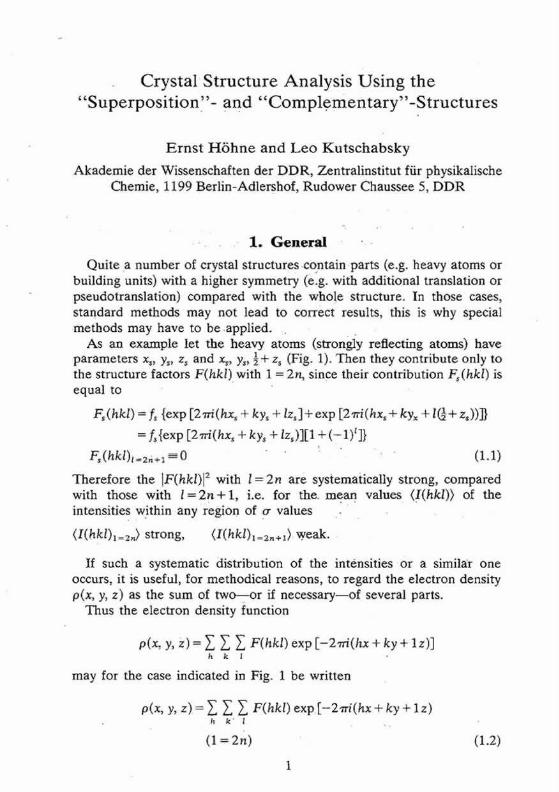
1. Genera l
Quite a number of crystal structures contain par ts (e.g. hea W atoms or building units) with a higher symmetry (e.g. with additional translation or pseudotranslation) compared with the whole structure. In those cases, standard methods may not lead to correct results, this is why special methods may have to be .applied.
As an example let the heavy atoms (strongly reflecting atoms) have parameters xs, ys, z~ and x,, y,, ½+ z s (Fig. 1). Then they contribute only to the structure factors F(hkl)wi th 1 = 2n, since their contribution Fs(hkl) is equal to
F~(hkl) = fs {exp [27r/(hxs + ky~ + lzs]+ exp [2wi(hxs + ky,, + l~+ z~))]}
= f~{exp [27r/(hx~ + ky s +/z,)][1 + ( - 1)z]}
F~(hkl)t=2,+l =-- 0 (1.1)
Therefore the ]F(hkl)[ 2 with l = 2 n are systematically strong, compared with those with l = 2 n + 1 , i.e. for the. mean, values (!(hkl)) of the intensities within any region of ~r values .
(I(hkl)l=2,) strong, (I(hkl)~=2,+1) weak.
If such a systematic distribution of the intensities or a similar one occurs, it is useful, for methodical reasons, to regard the electron density O(x, y, z) as the sum of two- -o r if necessary--of several parts.
Thus the electron density function
p(x, y, Z) = ~', ~ ~ F(hkl) exp [-2-a-/(hx + ky + lz) ] h k l
may for the case indicated in Fig. 1 be written
p(x, y, z) = Y. Y. ~ F(hkl) exp[-2rri(hx + ky + l z ) IT k ' I
(1 = 2 n ) 0.2)

0 C
a
Fig. 1. Crystal structure in Pl.[-'N--symbol for the arrangement of heavy atoms, [ 7 and [] remaining atoms of the structure.
+ ~, ~, ~ F(hkl) exp [-2"tri(hx + ky + lz)] h k l
(1 = 2 n + 1 )
= psup(X, y, Z) "1- lOcom (X, y, Z) (1.2')
where
psup(xyz) = ~ ~ ~ F(hkI) exp [-2"rri(hx+ky+lz)] h k l
( 1 = 2 n )
pcom(xyz) = f.f~ ~. F(hkl) exp [-27r/(hx + k y + lz)] h k |
(1 = 2 n + 1 )
/gsu p (X, y, Z) denotes a hypothetical structure, called the superposition structure, which is related to the real structure in the following way
ps.p(x, y, z)=½[p(x, y, z) + p(x, y, ½+ z)] (1.3)
In Osur~(x, y) (Fig. 2) the two heavy atoms (I--N) appear with correct 0
Fig. 2. Superposition structure.[-'k--heavy atoms [,-'-', []--remaining atoms with half weight.
o c
r - i 2-7 " ' " " • Q t,:
"'" F 7
• " L 2
a
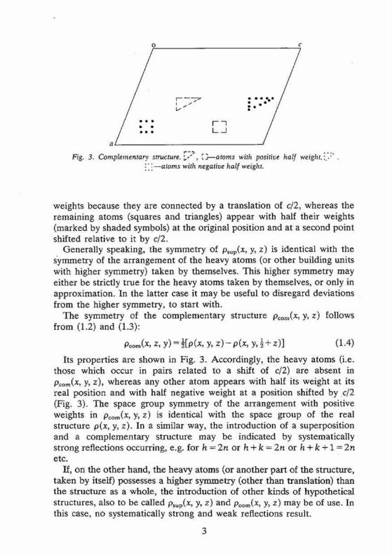
Fig. 3. Complementary structure.' " , [3 - -a toms with positive half weight,~.'.:" o u. S
i l i - a t ° m s with negative hal f weight.
weights because they are connected by a translation of c/2, whereas the remaining atoms (squares and triangles) appear with half their weights (marked by shaded symbols) at the original position and at a second point shifted relative to it by c/2.
Generally speaking, the symmetry of Psup(x, Y, z) is identical with the symmetry of the arrangement of the heavy atoms (or other building units with higher symmetry) taken by themselves. This higher symmetry may either be strictly true for the heavy atoms taken by themselves, or only in approximation. In the latter case it may be useful to disregard deviations from the higher symmetry, to start with.
The symmetry of the complementary structure Pcom(X, y, Z) follows from (1.2) and (1.3):
Pcom(X, Z, y ) = l[Io(X , y, Z ) - - p ( X , y, 1 ,'~- Z)] (1.4)
Its properties are shown in Fig. 3. Accordingly, the heavy atoms (i.e. those which occur in pairs related to a shift of c/2) are absent in p~om(X, y, z), whereas any other atom appears with half its weight at its real position and with half negative weight at a position shifted by c/2 (Fig. 3). The space ~ o u p symmetry of the arrangement with positive weights in pcom(X, y, z) is identical with the space ~ o u p of the real structure O(x, y, z). In a similar way, the introduction of a superposition and a complementary structure may be indicated by systematically strong reflections occurring, e.g. for h = 2n or h + k = 2n or h + k + 1 = 2n etc.
If, on the other hand, the heavy atoms (or another part of the structure, taken by itself) possesses a higher symmetry (other than translation) than the struc~u-e as a whole, the introduction of other kinds of hypothetical structures, also to be called psup(x, y, z) and pcom(x, y, z) may be of use. In this case, no systematically strong and weak reflections result.
3

E
t_.
Fig. 4. Superposition structure ( centrosymmetric ). F~--centrosymmetric arrange- ment of heavy atoms, [2"-', r ?~---remaining atoms with half weights.
As an example, we consider a structure in PI containing two heavy atoms of the same element per unit cell. The heavy atoms considered by themselves are connected by a centre of symmetry. The structure com- puted with phases (signs) taken f rom the heavy a tom contribution is necessarily centrosymmetric and is related to the real structure by its superposition with its centrosymmetric image (Fig. 4). If referred to such a partial centre of symmetry as origin, the electron density distribution of the superposition structure Osup(x, Y, z) may be expressed as
osup(x, y, z) = ~[o(x, y, z ) + o ( ~ , 9, ~)] (1.5)
The real structure or at least part of it may in many cases of this kind be obtained using well established chemical knowledge, such as atomic distances, known stereochemistry of molecules or parts of them as of coordination polyhedra etc.
2. Special Methods
2.1. Linear Structure Factor Equations
In many cases two coordinates (e.g. x i, yj) of any a tom in the real structure are the same as those of the superposition structure. There arises the task of determining the third atomic coordinate (zj). The method of linear structure factor equations (SFE) by Kutschabsky 2 and by Kutschabsky and H6hne 3 allows us to calculate these atomic coordinates (zi) directly, using the reflection of the first level of the reciprocal lattice (F(hkl)).
The basic relation follows directly from the formula for the structure factor
p N
F ( H ) = ~" ~ (f$)(I-l)cos27rl-lrs~.+i/C~(l-1)sin27rltrsj) (2.1) s = l j = l
4

where P is t h e n u m b e r of equipoints in the unit cell, N is the number of symmetrically independent atoms, f,i is the atomic scattering factor and r~i is the radius vector of the centre of atom s, j.
Vector t t is defined by ha* + kb*+ Ie*, where (a, b*, c*) are the basic reciprocal vectors.
Using the symmetry matrices R s and the translation t~ we obtain:
p • N
F(H) = Z ~ f,i(lt)[ cos 2"rrH(Rsrj +t~)+ i sin 27rH(R~ri +t~)] (2.2) s = l j = l
The separation into the components leads to p N
F(/- / )= ~ ~ %j(tt)[cos27r(~,x~+/3~yj+%z~+~,) s = l j = l
+ i sin 27r(mx j +/3,yj ÷ %zj + ~3s)] (2.3) p N
F(H) = wj(la)[cos + ,)'cos s = l / = l
- sin 2 ~r(a~xj +/3,y~ + ~5,)- sin 27r'/sz~
+ i sin 27r(a,x~ +/3~y~ + 3~) -cos 27r%zi
+ i cos 27r(%xj +/3~y i + 3~) sin 27r%zj (2.4)
In the most important cases the factor % depends only on l (not h or k). In those cases we obtain for structure factors P(hkl) with constant L
N N
F(H) = ~ (a t + ibj)C~L~+ ~, (q + idi)s~ L~ (2.5) i = l i = l
where the unknown variables cos 2"rrLz~ and sin 2~Lz i have been denoted by CI z'~ and S~ L>, respectively, and their known coefficients by % hi, cj and
4- ai=aj(h, k,~,x~, Yi) etc. where the exact form of dependence on
h, k, fj, x~ and yj. may be obtained from Table 4 of International Tables for X-ray Crystallography, Vol. 1.
The 2N unknown variables C-~j ~-> and S} L> may be determined by a system of linear equations using Fob~(I-l) for F(I-I).
If the phases of the Fob~(l-l) are unknown the unobserved reflections may be used to obtain a system of homogenous linear equations. Often it is of advantage to use in addition to the homogenous equations one equation belonging to a strong structure factor whose phase may be fixed arbitrarily in centrosymmetrical space groups, and in the non- centrosymmetrical space groups in which the origin may have any posi- tion in the z-direction.
Because the coefficients of these equations are inaccurate and, moreover, the structure factors are zero only approximately a more

accurate solution for the values Ci L) and ~qiL) may be obtained by using V l --1 more equations than there are variables and by minimizing the sum of the squares of the deviations ~ IFobs(]~)-Fcalc(H)] 2, where F~c0FI) stands for the right side Of equation (2.5) and F (H) is to replace by Fobs(I-l) in this relation. The C~ L) and S~ L) f rom the first calculation may be used to determine the phases of further structure factors. Taking these equations in addition to those used already, the number of equations increases and thus the accuracy of CI L) and S) L) is improved.
If the F(hkl) with L = 1 are used, the atomic parameters zi of all atoms resolved in the (x, y)-projection follow from Cl l )=cos 2wzj and S) 1)= sin 2~rzj a n d (C~1))2--t-(S~1)) 2= 1. The accuracy of the values zj may be further improved by using F(hkl) with L larger than one.
2.2. The Application of Direct Methods to Centrosymmetric Structures Containing heavy atoms 4
It is assumed that the positions of the heavy atoms are known and that there is a sufficient number of reflections whose signs are determined by the heavy atoms. These reflections do not obey the probabili ty relation (2.6).
S,,+,,,- S~," Sh, (2.6)
On subtracting the heavy a tom contribution f rom the observed structure factors of these reflections, one obtains the s ign of the light a tom contributions for these reflections. Thereaf ter one can solve the remaining light a tom structure by applying equation (2.6) to obtain the signs of the reflections that do not have contributions from the heavy atoms.
The procedure was used to solve the structure of the complex Au[S2C2(CN)2]2 Au[SaCN(C4Hg)2] 2. The space group was found to be P2flc, with two formula units per unit cell. The reflections hkl (h = 2n, k + 1 = 2n) were all very strong and the gold atoms were placed at the (special) position 000,½00, ~,111 and 0½½. 1337 observed 'strong' reflec- tions (with equal positive contributions f rom the gold atoms) and 538 observed 'weak ' reflections (without any contributions f rom the gold atoms) were used.
The first step was a calculation of the Wilson plot. The following expressions was used:
(I),, = K L ( ~ L f2 exp (--2BL sin 2 0/h2))h + Kz-r(IFHI 2 exp (--2BH sin 2 0/A2)),, (2.7)
where 1 = (KIFobsl~) is the observed intensity on a relative scale, K = Kr. = KH is the scale factor, yL denotes a summation over all light atoms in the unit cell, FH is the heavy a tom contribution to the structure factor and Br_ and Bn are the overall t empera ture factor parameters of the light
6

and heavy atoms respectively. The average is taken over reflections h within a given sin 0 interval.
For the 'weak' reflections (Fn = 0) the second term in equation (2.7) vanishes and a Wilson plot for these reflections gave the scale factor KL (1.29) and the value of BL (3.24 ~2). On substituting these results in equation (2.7) a Wilson plot for the 'strong' reflections gave the scale factor KH (1.26) and the value of Bn (2.91 .&2). A small difference in KL and Kn will not affect the following steps.
The second step is the calculation of the normalized structure factors E. The formulae normally used for the calculation of E values do not make sense for a structure containing heavy atoms. For the corresponding light atom structure the E values, EL, are defined by:
EL =FL(e E~ f i ) - m exp (BL sin 20/)t z) (2.8)
where FL is the light atom contribution to the structure factor and, for space group P21/c, e = 2 for h01 and 0k0 reflections and e = 1 for all other reflections. 6
The 'strong' reflections have positive s t ructure factors and we have Fa = Fobs-FH; the magnitude and the sign of the EL value is obtained by equation (2.8). This resulted in 365 signed EL values, with [Ec]> 1.3. For the 'weak' reflections we have IFLI = ]Fobd and only the magnitude of the EL value is obtained. This resulted in 270 reflections with [EL]> 1.3.
The third step is the application of equation (2.6) to obtain the signs of the 'weak' reflections. When several interactions of the type ( h + h ' ) = (h)+(h') occur for JELl> 1.3, where both S~, and S~,, are known, several predictions of the sign Sa+~,, are obtained by application of (2.6). These predictions should be reasonably consistent before Ss,+a, is considered to be determined and singly occurring interactions should never be trusted. We have followed a procedure similar to the sign correlation procedure. The origin is partly fixed b y the choice of the gold atom positions and further determined by assigning arbitrary signs to two 'weak' reflections: 221 (IELI=4.0) and 348 (lULl=2.9). We define the following sets of reflections, all lULl>2.0:
ha are 'strong' reflections, hkl(h = 2n, k + 1 = 2n). ha are the two origin determining choices. h3 are the reflections hi + h2 and h2+ h~. h4 are the reflections ha + h3, h2 + h3 and h 3-t- h~.
The application of the equation (2.6) on only reflections lh cannot give new signs; together with the reflections h2 probable signs for 36 reflec- tions h3 were calculated. Upon entering h3 in equation (2.6), many reflections take part in the calculations and consequently the sign of one reflection h4 will often be found from several independent sign relations

(2.6). Signs were calculated for 48 reflections hn; of these the signs of 24 reflections were determined by at least five consistent relations (2.6) and accepted to be correct. Although some of the signs for reflections h 3 may be incorrectly determined, it is highly improbable that all reflections h 3
used for the signs determination of one reflection h4 are incorrect. The intermediate results for h 3 and the rest of h a w e r e rejected.
Continued application of equation (2.6) on 365 'strong' reflections, 2 reflections h2 and 24 reflections h4 resulted in the sign determination of 158 more 'weak' reflections with IELI > 1.3. A Fourier synthesis revealed the positions of all of the light atoms, except the hydrogen atoms.
The above described procedure may be generalized for heavy atoms on general positions. In this case there also exist reflections with inter- mediate heavy atom contributions. For these reflections IFLI--IlFobJ ± IFHII and the lowest FL value is taken to avoid incorrect sign indications. In our opinion this procedure is well suited to an automatic solution of structures containing heavy atoms.
3. Steps of Structure Determinat ion
1. Determine the space group and unit cell of the real structure 2. Test for systematically strong intensities 3. Determine the space group of the superposition structure (see
examples) 4. Determine the superposition structure psup(x, y, z) or at least the heavy
atom position(s) in psup(x, y, z) 5. Determine the complementary s t r u c t u r e Pcom(X, y, Z) or the real
structure 5.1. Compute and discuss the Patterson function of the complemen-
tary structure, if this corresponds to the systematically weak reflection
5.2. Apply "Direct methods" (see above) 5.3. Apply the method of "linear structure factor equations" 5.4. Resolve the ambiguity of the superposition structure using chemi-
cal knowledge, such as minimum distance between atoms, know- ledge of groups, coordination polyhedra etc.
4. Examples
A. Demissidine hydroiodide 8
Crystal data: C27H45NO'HI" ~CzHsOH orthorhombic: P212121; a = 23.0 .& b = 7.6 ~, c = 16.0 .&
Z = 4 Observed systematic intensity distribution:
(I(hkl)~=2n} strong; (I(hkl)l=2,+~) weak.

,7. C
,
@ '@ I
a 5
v . 1/4 I/4
Fig. 5. (a) Space group symmetry of (a) real structure-P212~2 ~ ~ 7 building unit in y, I ~ in f, " ~ in l /2-y, .,~ in 112+y; the heavy atoms marked by circles.
According to the chemical formula and number of molecules per unit cell there are 4 heavy atoms per unit cell, i.e. one per asymmetric unit. Thus the 2 heavy atoms related by a shift of c/2 (on account of systematic intensity distribution) must necessarily belong to the same set of equipoints. This results if and only if the atoms lie on screw dyads parallel to c (see Fig. 5), thus the set of equipoints in P212121
x, y, z;½-x, g ~+z;½+x,½- y, ~; ~,~+ ' _ y, ~ - z
specializes to
3 1 (000, 00½)+¼, O, z; ~, ~,
With z ' = 2z this corresponds within the unit cell a ' = a, b ' = b, c' = c/2 of D Z I c']
3
I i i
i @ m
a i n n
(b) superposidon structure--Pmm,h derived from P 2 1 2 1 2 1 ; the reduced weights of all building units in general position (triangles) to a quarter compared with the
weight of the heavy atoms (circles) is symbolized by dashed lines.

the superposition structure, to the equipoints
1 0 , 3 1 f , 4 , , Z ; ~ , 5 ,
Obviously (Fig. 5), any of these two points lies on mirror planes perpendicular to a ' and b' and are related by an n-glide plane perpen- dicular to c'. Thus the space group of the superposition structure is Pmrnn.
The same result could have been obtained by scanning the or thorhom- bic higher symmetry space group for such equipoints. Then the set of special positions (a) 00z, 1 1 025 z would be found for Proton, which corres- ponds to the set found, after a shift of the origin by a'/4.
The space group for the superposition structure thus obtained may now be tested with the usual space group tests, and indeed, the hk0-reflections with h + k = 2 n + 1 are weak (corresponding to the n-glide plane). The superposition structure thus contains for each of 4 symmetry related atoms (x, y, z) etc., of the real structure the following sets of 4 atoms.
(x, y, z), (x, 1 ~_ ( 5 - x, y, z), ' y , , : , z), i ( ~ - x , y , ½+z)
i.e. 4 atoms to any a tom of the real structures. This superposition structure would be obtained, if the usual heavy atom technique could be applied, and would certainly be difficult to interpret.
The Patterson function gave, however, not only the z-coordinate of the heavy a tom but also hinted that it may not lie exactly on the dyad screw, but only approximately so; this was confirmed by the Patterson of the complementary structure, obtained f rom the reflections with 1 = 2n + 1.
This indicated a deviation of x i f rom ¼, and this deviation results in contribution of reflections with high values of h which even determine their phases.
The iodine parameters were refined and with the resulting phases a first Fourier synthesis of the complementary structure was obtained in space group P21212I.
This result was compared with the known part of the model and thus a part of the structure deduced and used as a starting point for the final determination of the real structure.
B. Piper idino-acet-m-bromo-ani l ide 9 Crystal data: C13HlvN2OBr -orthorhombic: Pbca; a = 23.65 ,~, b = 12.66 ,~, c = 9.37 ,~;
Z = 8 Observed systematic intensity distribution: <I(hkl)h=2, ) strong; <I(hkl)h=~,,+l> weak Space group of Osup(x, y, z): Pbcrn with lattice parameters
r a C t = a = 7 ' b'=b, c.
10
o o
o o o
o
o o o
l ° o;
* -t- + o c
+ -t-~- _+
z + t -I- +
+ -I- +
+ +
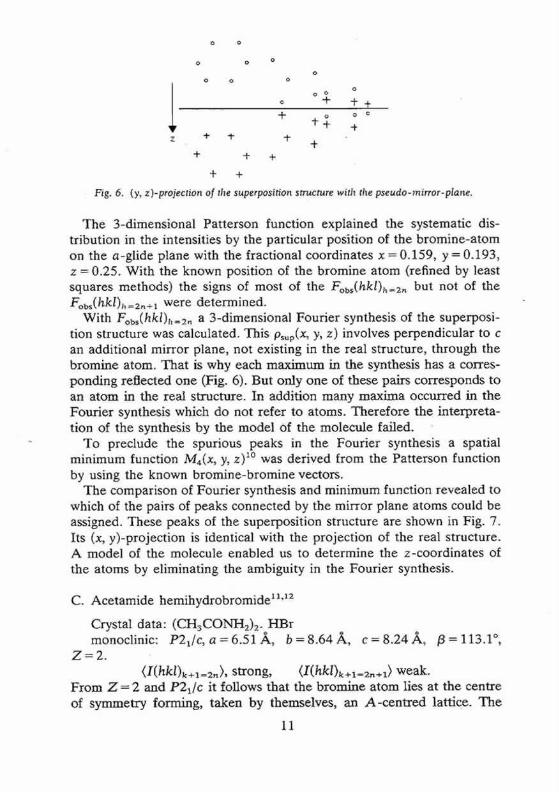
Fig. 6. (y, z )-proi.eclion of tl2e superposition structure ~vith the pseudo-mirror-plane.
The 3-dimensional Patterson function explained the systematic dis- tribution in the intensities by the particular position of the b romine-a tom on the a-glide plane with the fractional coordinates x = 0.159, y = 0.193, z = 0.25. With the known position of the bromine a tom (refined by least squares methods) the signs of most of the Fobs(hkl)~l~2,~ but not of the Fobs(hkI)j,=2,÷l were determined.
With Fobs(hkl)~,=,_~ a 3-dimensional Fourier synthesis of the superposi- tion structure was calculated. This psup(x, y, z) involves perpendicular to c an additional mirror plane, not existing in the real structure, through the bromine atom. Tha t is why each max imum in the synthesis has a corres- ponding reflected one (Fig. 6). But only one of these pairs corresponds to an atom in the real structure. In addition many maxima occurred in the Fourier synthesis which do not refer to atoms. Therefore the interpreta- tion of the synthesis by the model of the molecule failed.
To preclude the spurious peaks in the Fourier synthesis a spatial minimum function M4(x, y, z) ~° was derived from the Patterson function by using the known bromine-bromine vectors.
The comparison of Fourier synthesis and minimum function revealed to which of the pairs of peaks connected by the mirror plane atoms could be assigned. These peaks of the superposition structure are shown in Fig. 7. Its (x, y)-projection is identical with the projection of the real structure. A model of the molecule enabled us to determine the z-coordinates of the atoms by eliminating the ambiguity in the Fourier synthesis.
C. Acetamide hemihydrobromide 11"12
Crystal data: ( C H 3 C O N H 2 ) 2. H B r monoclinic: P21/c,a=6.51.A, b = 8 . 6 4 A , c = 8 . 2 4 , ~ , /3=113.1 ° ,
Z - - 2 . <I(hkl)k+l=2~>, strong, (I(hkl)k÷l=2n÷l> weak.
F rom Z = 2 and P2~/c it follows that the bromine a tom lies at the centre of symmetry forming, taken by themselves, an A-cen t r ed lattice. The
11

• CY o(J
b/2
)~ b-gl ide __ _p_lane _
Br
Fig. 7. Peak coinciding in Fourier synthesis and minimum function.
.Fobs(hkl)k+z=2,, correspond to a superposition structure with the space group A 2/m, which has a mirror plane perpendicular b in addition to the space group of the real structure.
The (x, z)-project ion of the superposition structure is identical to the corresponding projection of the real structure. This projection, calculated with Fobs(h01) revealed the position of all atoms. Although the determi- nation of the real structure in 3 dimensions with the help of a model did not seem feasible, due to the poor data available, it was possible to determine approximate y-coordinates of the atoms by means of two independent systems of linear structure factor equations:
F(h 11)~=2,+1 = K Y,j 4~ cos 2w(hxi + lzi) cos 2-n'yj (4.1)
and
F(h 1 l)z=~_n = - K Y~j 4fj sin 2"n'(hxj + Iz~) sin 2"rryj (4.2)
where K is the scaling factor. The expressions 4~ cos 2"rr(hxj + l z i )=a i and -4[i sin 2~(hx i + Iz~)= b i may be calculated because x i and zj are known, whereas K cos 2,n'y i = C~ and K sin 2-tryj = S~ are the unknown values. From the known position of the h e a w atom (bromine) most of the signs of the F(hll)l=2,+l could be determined and a system of equations (4.1) with a twelvefold overdeterminat ion could be set up
F(hll)l=2.+l = ~ a~(hll)C~. (4.1) i
12
, Z ½
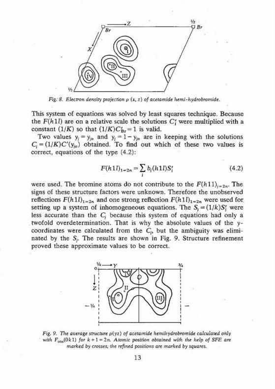
Fig.-8. Electron density projection p (x, z) of acetamide hemi-hydrobromide.
This system of equat ions was solved by least squares technique. Because the F(h 1 I) are on a relat ive scale the solutions C~ were mult ipl ied with a cons tan t ( l / K ) so that (1/K)C~r = 1 is valid.
Two values Yi = YJo and Yi = 1-y~o are in keeping with the solutions C~ = (1/K)C'(yio) obtained. To find out which of these two values is correct, equat ions of the type (4.2):
F(h ll)l=2, = ~, bi(h l l )S ~ (4.2) i
were used. The b romine a toms do not contr ibute to the F(h 11)i=2,. The signs of these s tructure factors were unknown. The re fo re the unobserved reflections F(h 1 l)l=a, and one s t rong reflection F(h 1 l) 1 =a, were used foxz sett ing up a system of in_homogeneous equat ions. The S i = (1/k)Sf were less accurate than the Cj because this system of equat ions had only a twofold overde te rmina t ion . That is why the absolute values of the y- coordinates were calculated f rom the C~, but the ambigui ty was elimi- nated by the S t. The results are shown in Fig. 9. St ructure ref inement 9roved these approx imate values to be correct.
¼ o;
I
1' I zl
- - ¼
i .y ¾
Fig. 9. The average structure p(yz) of acetamide hemihydrobromide calculated only • with Fobs(0kl) for k+ 1 =2n. Atomic position obtained with the help of SFE are
marked by crosses,-the refined positions are marked by squares.
13

D. a -Ca lc iumte t rabora te -hydra te 13
Crystal data: CAB204.4 H 2 0 Monoclinic: Pc or P2/c, a = 5.86 ~ , b = 6.93/~, c = 7.78 ,~,, /3 = 94°;
Z = 2 Observed systematic intensity distribution: (I(hkl)l=2,,) strong, (I(hkl)l=2,,+l) weak
The intensity statistic of Howells, Phillips and Rogers TM using the I(hkl) showed that the real structure has the centrosymmetric space group P2/c.
The Patterson function showed in agreement with Z = 2 and P/2c that the calcium atom occupies a special position on the twofold rotation axis
_ _ 1 with parameters Xca = 0, Zc= - z and Yca approximately zero. This position is near the c-glide plane and thus explains why the reflections I(hkl)~=~_,~+l are systematically weak.
On the other hand the calcium atom determined most of the signs of the F(hk0) . The Fourier projection p(x, y) gave the positions of the oxygen and boron atoms. Because the signs of the F(hkl) with 1 = 2n + 1 were not determined by the contribution of the calcium a tom the z -paramete rs of the a toms could not be derived f rom a Fourier synthesis based on the contributions of the calcium a tom to the sign of the F(hkl). But with the SFE-method the approximate z-coordinates were easily obtained.
From the structure factor formula follows
with F(hkl) = E (a~g'c~ g' + b~L'SJ L' for L = 1, 2 J
a~ l)= -4f~ sin 2rrhx, sin 2rrkyj
b~ 1) = - 4 f / c o s 2~rhx~ sin 2rrkyj
a~ =) = 4f /cos 2rrhx i cos 2rrky,
b~ =) = -4f~ sin 2rrhx, cos 27rkyj
C~ L) = cos 2rrLzi, S~ L) = sin 2~Lz,
Two systems of equations were set up. For the first system F(hkl) and for the second F(hk2) were used. In each case the unobserved structure factors and one strong structure factor with arbitrary sign was used. These systems of equations gave approximate values for C~ L) and S~ r-), by which Fc(hk/) were calculated.
By comparing the Fc(hkl) with the Fo(hkl) the signs of more structure factors could be determined. The corresponding equations were added to the previous systems of equations. In this way the overdeterminat ion of the systems of equations was increased and the accuracy of the results improved. The final results obtained after several cycles are listed in
14
the Table. The last column contains the refined pa ramete r for comparison.
Atom C~fl' S~ I) C} 2) S} 2' zj z i refined
Ca - - 1.00 -1 .000 - - 0.250 0.25 O1 - - 0.20 0.872 - - 0.036 0.0359 02 1.00 0.51 0.703 0.756 0.070 0.0588 O a 0.68 0.44 0.111 0.923 0.106 0.1042 O 4 0.66 -0 .74 -0 .338 0.680 0.842 0.8193
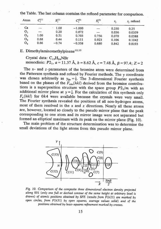
E. Dimethylaminomethylp inene 12.1s
Crystal data: C13H24NBr monoclinic: P21, a = 11.37 ~ , b = 8.62 .&, c = 7 .48/~, /3 = 97.4; Z = 2
The x- and z -parameters of the bromine a tom were determined from the Patterson synthesis and refined by Fourier methods. The y coordinate was chosen arbitrarily as YBr =¼. The 3-dimensional Fourier synthesis based on the phases of the Fobs(hkl) derived f rom the bromine contribu- tions is a superposit ion structure with the space group P21/m with an additional mirror plane at y = ¼. For the calculation of this Synthesis only Fo(hkl) for 0k4 were available because the crystals were very small. The Fourier synthesis revealed the positions of all non-hydrogen atoms, most of them resolved in the x and z directions. Nearly all these atoms are, however, located so closely to the pseudo mirror plane that the peak corresponding to one a tom and its mirror image were not separated but formed an elliptical m a x i m u m with its peak on the mirror plane (Fig. 10).
The main problem of the structure determination was to determine the small deviations of the light atoms f rom this pseudo mirror plane.
YT
- . c(9i
0
(W
J Sin~ x 2
Fig. 10. Comparison of the composite three dimensional electron density projected along 001 (only one full or dashed contour of the same height at arbitrary level is drawn) of atomic positions obtained by SFE (results from F(h21) are marked by open circles, from F(h31) by open squares, average values solid) and of the
positions obtained by. least-squares refinement marked by crosses.
15

• Analysis of the p e a k shape resulted in rather inaccurate values of the deviations from the mirror plane. Better values were obtained by the SFE method: To start with, the positions of all atoms in (x, z)-projection were refined by difference Fourier Synthesis to an R value of 0.16. Using the formulae
and
Ao(h21) = KlY. 2f, cos 2rr(hxj + 1%) cos 2w2yj . i
Ao (h31) = Kz~ - 2f~ sin 27r(hxi-(- i zi) sin 27r3 yi i
w h e re K1 and 1'22 are thescal ing factors, two systems of equations were ob ta ined tak ing Ao(hkl) equal to Fo(hkl). This may be done Without
-creating large errors since the Bo(hkl), to which the bromine i toms do not contribute, are expec ted to be small. In these systems of equations only those Ao(hkl) were used whose signs could be deduced from the contributions F~ir(hkl) of the bromine atoms: : With the abbreviations
a , =.2fi cOS 27r(hx i + lz,) (-7~2), = K1 cos 2rr2y
bj .- =2f~- sin 27r(hxj + 1%) _~.q!3)' = K,_ sin 2rr3 yj.
the systems of .the equations ha~ee the form
Fo(h21) = 2 ,-~2,, ajt~i. i
Fo(h31) = ~ h S (3~' i
The structure factors F0(h21) and Fo(h31) are on a relative scale. The scaling factors K1 and K2 were given such values that (1/K1)CBr(27-- (1/K2)S~ = 1. Four .values f o r . t h e coordinate yj of any atom are in keeping with
C~ 2) = (1/K1)C~2)(y~o) namely 5 = ±Y~o, Yi = ±Yio +½-
Two of these values f o r any atom could be excluded by comparison with the Fourier synthesis of the superposition structure (see above). From the two remaining values one could be precluded for most of the atoms by using a model of the molecule (Fig. 10). The accuracy of the y coordi- nates Obtained from the C~ 2) was improved using the results .obtained f rom .q(3) The coordinates thus obtained were sufficiently accurate for a - - / " .
starting set for a least squares refinement of tile real structure.
16

References
i. K. Dornberger-Schiff, KritaUografija, 6 (1961), 859. 2. L. Kutschabsky, Mber. Dr. Akad. Wiss., 7 (1965), 95, 509. 3. L. Kutschabsky and E. H6hne, Acta Cryst., 19 (1965), 747. 4. P. T. Beurskins and J. H. Noordink, Acta Cryst., A27 (1971), 187. 5. S. Parthasarathy, (1966). Z. Kristallogr. 123, 27. 6. H. Hauptman and J. Karle. Solution of the Phase Problem. I. The Centrosymmetric
Crystal, A.C.A. Monograph No. 3 (1953). 7. P. T. Beurskens, (1963). Technical Report of Sign Correlation by the Sayre Equation.
The Crystallography Laboratory, Univ. of Pittsburgh, Pennsylvania. 8. E. H/Shne, Journ. prakt. Chem., 314 (1972), 371." 9. L. Kutschabsky, P. Leibnitz and J. P. Wenzel, Kristall und Technik, 9 (1974) 605.
10. M. J. Buerger, Vector Space and its application to Crystal Structure Analysis, Wiley, 1959.
11. G. Reck, Mber. Dt. Akad. Wiss. 9, (1967) 505. 12. L. Kutschabsky, S. Kulpe and G. Reck Acta Cryst., A27 (1971), 29. 13. D. Zeigan and L. Kutschabsky M'ber. Dr. Akad. Wiss. 7 (1965), 876. 14. E. R. Howells, D. C. Phillips and D. Rogers, Acta Cryst., 3 (1950), 210. 15. L. Kutschabsky and G. Reck, Journ. prakt. Chem. 312 (1970), 896.
17

International Union of Crystallography Commission on
Crystallographic Teaching
List of booklets in the first series
1 A non-mathematical introduction to X-ray diffraction
by C.A. Taylor 2
An introduction to the scope, potential and applications of X-ray analysis by M. Laing
3 Introduction to the Calculation of Structure Factors
by S.C. Wallwork 4
The Reciprocal Lattice by A. Authier
5 Close-packed structures
by P. Krishna and D. Pandey 6
Pourquoi les groupes de Symetrie en Cristallographie by D. Weigel
7 Solving the phase problem when heavy atoms are in special positions
by L. Hohne and L. Kutchabsky - 8
Anomolous Dispersion of X-rays in Crystallography by S. Caticha-Ellis
9 Rotation Matrices and Translation Vectors in Crystallography
by S. Hovmrller 10
Metric Tensor and Symmetry operations in Crystallography by G. Rigault
Price 95p each Available from
University College Cardiff Press, P.O. Box 78
Cardiff CFI_ 1XL United Kingdom
Cheques should be made payable to University College Cardiff