7 - paper - evgeniy mitev - idc-online · the case, ieee 1584 is used to establish the incident...
TRANSCRIPT

Session Seven: Arc Flash Hazard (AFH) – Rio Tinto Bell Bay Site
Regional Electrical Engineering Forum 2009 – IDC Technologies 1
Session Seven:
Arc Flash Hazard (AFH) – Rio Tinto Bell Bay Site
Evgeniy Mitev and Trung Nguyen
Electrical Engineer: Rio Tinto Aluminium Bell Bay Ltd
Abstract This paper presents the engineering and technical work at Rio Tinto Alcan (Bell Bay), to address Arc Flash Hazards. The driver for this work is Rio Tinto C2 Electrical Safe Work Standard, which stipulates implementation of arc flash protection programme to evaluate arc flash energy levels and define the appropriate PPE and associated procedures to mitigate hazards.
Based on calculated data, labels are being fixed at isolation points across the site, which advise isolation personnel about PPE required for safe local switching. Furthermore, engineering and technical work has been carried out to reduce calculated arc flash incident energy at frequently operated switching devices, so operators and maintainers do not need additional PPE for switching.
I. INTRODUCTION
Circuit overcurrent protection devices (OCPD) constitute first line of defense against the uncontrolled power released during electric arcing fault. Personal protective equipment (PPE), including clothing, is a second line of defense for people working on live electrical infrastructure.
Rio Tinto C2 Electrical Safety Standard regulation 2.4 stipulates:
“There shall be an arc flash protection program in place to determine incident energies and define the appropriate PPE and associated procedures to mitigate the hazard.”
The intent of this provision is to protect personnel from the possibility of being injured by an arc flash. This requires that electrical panels, switchboards, motor control centers, etc., that are likely to be operated, maintained or tested while energised be labeled as to the hazard/risk category and the flash protection approach boundary. The hazard risk category defines the protective clothing and equipment required. The flash protection boundary is the distance at which a person could receive a second degree burn if an electrical flash were to occur.
The C2 guidelines stipulate that for the arc hazard calculation, regional codes shall apply in the first instance and IEEE 1584, and NFPA 70E documents where none exist. In Australia, no specific Australian standard exists for arc flash calculations. As this is the case, IEEE 1584 is used to establish the incident energy and arc flash boundary for electrical equipment installed and operated at RTA Bell Bay site. PPE categories will

Session Seven: Arc Flash Hazard (AFH) – Rio Tinto Bell Bay Site
Regional Electrical Engineering Forum 2009 – IDC Technologies 2
be selected from the calculated incident energy using RTA Arc Protection PPE matrix, NFPA 70E 2009 Table 130.7(C)(10) Protective Clothing and Personal Protective Equipment (PPE), and Table 130.7(C)(11) Protective Clothing Characteristics.
II. COMPLIANCE GUIDELINES
RTA Bell Bay developed a structured action programme to achieve compliance with arc flash protection requirement. The programme comprises following elements:
� An arc flash hazard assessment must be completed based on up-to-date and accurate data.
� A detailed engineering arc flash hazard analysis must be completed on the power distribution system.
� Arc flash hazard labelling corresponding to the flash hazard assessment must be placed on all electrical cabinets that are likely to require examination, adjustment, servicing or maintenance where the potential for an arc flash hazard exists.
� A process must be in place for updating the arc flash hazard analysis and labelling as changes and electrical upgrades occur that might affect the available short circuit current on the system.
� People potentially exposed to arc flash hazards must be trained in the hazards associated with electrical arc flash and the application of wearing appropriate apparel and arc flash personal protective equipment.
� A system must be in place to verify worker’s ability to assess personal protective equipment requirements specific to electrical task hazards.
� Initial management involves PPE but preference should be given to hazard elimination as per hierarchy of controls.
III. ARC FLASH HAZARD ASSESSMENT
1. Definition of an Arc Flash An arc flash is the plasma cloud that develops during and following an electrical fault, whereby the insulating properties of air are overcome through rapid ionisation. “Most arc power is delivered to, and stored in, the plasma cloud as high-temperature plasma enthalpy” [4]. It is characterised by temperatures in excess of 15,000 °C, a cocktail of superheated toxic gases and airborne molten metal from melted conductor and steel, released by the components within an electrical assembly under fault.
As a result of the rapid energy release, a pressure wave also develops of such considerable magnitude such that if contained, may lead to switchboard structural failure and propel missiles such as panel doors. In the absence of appropriate pressure relief, arc flash incidents have been known to collapse entire substation buildings.
Session Seven: Arc Flash Hazard (AFH) – Rio Tinto Bell Bay Site
Regional Electrical Engineering Forum 2009 – IDC Technologies 3
An arc flash is an uncontrolled chaotic event, as opposed to the controlled interruption of electrical arcs that are a normal part of electrical operation to interrupt current within an item of switchgear such as an isolator, circuit breaker or contactor.
2. Consequences of an Arc Flash
The consequences for personnel, if exposed to an arc flash, are often extremely serious including burns, major limb and spinal injuries, loss of sight, respiratory damage, toxic exposure and in some cases, death.
3. Role of Switchgear Standards
Switchgear standards play an important role to produce switchgear components and assemblies that:
a. Reduce the probability of an arc event.
b. Contain the effects of an arcing fault.
Australian electrical standards have been on a path of harmonisation with the International Electro technical Commission (IEC) standards for the last 25 years. Via these standards, the relevant low voltage and high voltage switchgear components and assemblies used in Australia since the early 1980’s have been underpinned by a structured set of requirements that allow engineers and designers to correctly specify equipment to match prevailing conditions of installation and operational duty.
To reduce the probability of an arc event during normal operation and maintenance activities, IEC switchgear component designs have progressively employed higher levels of protection against direct contact by maintaining IP2X (i.e. finger-proof).
Similarly, IEC switchgear assembly standards have defined type-testing requirements, inclusive of arc-fault containment, whereby 3rd party licensed facilities undertake independent testing to quantifiable levels.
4. Role of Safety Standards and Safe Work Practices
Safety standards provide direction on hazard identification and risk assessment for a given installation. Local regulators also place restrictions on work practices known to be high risk, predominantly identified from accident history.
Unlike other States, i.e. QLD or WA, Tasmania does not have Code of Practice explicitly prohibiting LV live electrical work.
RTA (Bell Bay) has used their internal LV Live Electrical Work and Testing standard to align with, for the arc flash hazard assessment. This standard allows live work only in exceptional circumstances, whereby written risk assessments must be completed by the work party, and live work authorised through permit system by equipment owner. Safety Observer is also required for each case of LV live work.
Rio Tinto Health Safety Environment & Quality (HSEQ) Qualitative Risk Assessment process is also used to evaluate the risk associated with arc flash faults. Arc flash faults evaluated in this manner are assigned with Risk Class – High. Those are Risks that exceed the risk acceptance threshold and require proactive management.
5. Role of PPE Standards

Session Seven: Arc Flash Hazard (AFH) – Rio Tinto Bell Bay Site
Regional Electrical Engineering Forum 2009 – IDC Technologies 4
PPE standards specify the minimum safety performance for each category of PPE. There are PPE standards defining requirements for: Head protection; Eye and Face Protection; Gloves; Footwear; Clothing & Apparel.
RTA (Bell Bay) apply following PPE standards:
� Electrical workers exposed to arc flash hazards to wear flame retardant clothing rated 4 cal/cm2 as standard issue PPE
� Non-electrical workers exposed to arc flash hazards must have access to flame retardant clothing
� Cat 2 PPE will be the minimum requirement for switching, testing, or earthing of HV equipment
� Synthetic under garments or garments containing metallic parts should not be worn by persons exposed to arc flash hazards
The outlined hazard assessment process led to development of an Arc Flash Protection Matrix (AFP Matrix), as an interim tool for evaluation of the arc flash hazard and selection of appropriate arc rated PPE. Refer to Appendix A for RTA Arc Protection PPE matrix.
The AFP matrix provides minimum arc protection PPE requirements. Task descriptors are used to identify frequently executed electrical work activities. Each of these activities has been risk assessed and assigned a hazard category based on voltage level, prospective fault current, and working distance from potential arc flash fault.
It is impractical to display the whole variety of activities and their assigned hazard risk categories at each work location. To overcome this, electrical workers are trained to use the matrix for arc hazard assessment, and selection of proper PPE for the intended work.
IV. PERFORMING ARC FLASH HAZARD ANALYSIS
1. Data Collection and Management
Electronic model of the power system is developed using EDSA Paladin Design Base 2.0. This software models and calculates power system fault currents, protection settings, and protection coordination for different system configurations.
For the purpose of modelling, extensive technical information is collected for each piece of equipment, switchgear and cabling building the power distribution system. The process is lengthy and requires continuous concerted effort. The power system model accuracy and calculated variables precision are directly proportional to the accuracy and precision of input data.
2. Arc Flash Calculations
As an overview, to perform arc flash calculations, the following steps are completed:
� Determine the system modes of operation e.g. parallel feeders.
� Calculate 3-phase bolted fault levels at each switchboard of interest using IEC 60909 or AS3851.
� Calculate the arc-currents using IEEE 1584.
Session Seven: Arc Flash Hazard (AFH) – Rio Tinto Bell Bay Site
Regional Electrical Engineering Forum 2009 – IDC Technologies 5
� Find the protective device characteristics and the duration of arcs. The existing protection settings can be obtained from the power supply protection settings database. Where there are no records of protection settings, the settings should be retrieved directly from the relays.
� Determine system voltages and classes of equipment.
� Select the working distance.
� Determine, from calculated arcing currents, the incident energy at working distance.
� Calculate arc flash boundaries.
� Determine the required level of PPE.
� Document calculations and produce labels to be placed on the switchgear doors.
It is also necessary to establish a position whether non type-tested boards will lose their doors during arc flash fault event. It is a very conservative position to assume all non-tested switchboards will fail, however, it should be kept in mind that modern switchgear assemblies are highly optimised to achieve minimum standards and in the past, safety margins were not as refined.
It has been assumed that, due to the service age and technical construction, panels with louvers, door vents or other openings facing the operator will fail in case of arc flash fault. The calculated hazards risk category is applied in full for work activities completed in front of a closed panel.
Whilst this position may devalue type-tested arc fault contained switchgear, some new research [4] suggests that if convective plasma cloud is the key arc flash hazard, then circulating heat flows around front vented switchboards / MCC panels, and knock-type injuries need to be considered.
2.1 Determine the power system modes of operation
The calculation method must take into account separate clearing time of multiple sources feeding an arcing fault. Examples of this include parallel incomers, closed distribution ring mains and the effect of motor contribution. In the absence of any guidance by IEEE 1584, the method of superposition is adopted whereby the fault current contribution of each source is considered separately, complete with clearing time, then simply added together to determine the total arcing fault current and incident energy.
For motor contribution to arcing faults, the presence of the arc voltage reduces the current contribution from the motor.
For manual calculations, IEEE 1584 advises that only motors above 37kW are considered for arc flash calculations. For computer-assisted calculations, it is typical to find motor loads modelled as lumped objects or as individual motors. Either method is valid; however a maximum load case for each bus section must be established. Only where motor contribution is not required for the fault calculation, can it be ignored for the arc flash calculation.
2.2 Calculate 3-phase bolted fault levels

Session Seven: Arc Flash Hazard (AFH) – Rio Tinto Bell Bay Site
Regional Electrical Engineering Forum 2009 – IDC Technologies 6
The calculation of balanced and unbalanced fault currents to IEC 60909 is a standard function within EDSA or a correct network model. This tool also considers the effect of multiple in-feeds and motor contribution as described above.
3.3 Calculate Arc-Fault Current using IEEE 1584
The arc-current will always be less than the prospective fault level for a bolted fault because the arc dissipates energy and can be considered as a resistor.
IEEE 1584 provides calculations to derive the arc current dependent on several factors that feed into empirical equations. These factors are captured within the power system model.
The IEEE standard provides a formula to determine the arc current Ia to feed into the incident energy calculation. In the case of installations � 11,000V, the incident energy is also calculated at 85% of Ia and the larger of the two outcomes used.
3.4 Find protective device characteristics and the duration of arcs
Some basic principles govern the selection of the correct protection device used in the determination of incident energy. If the switchgear enclosure being assessed contains a protective device with line side terminals that are not fully insulated, then an arcing fault can only be cleared by the next upstream device.
This is because an arcing fault in such an enclosure would ionise the air space such that the arc is sustained from the line side after the protection device operates.
Protective devices with extended phase separation barriers, fully insulated cable/busbar connections or fitted with rear mounted spouts, are far less likely to sustain an arc and for such arrangements, the clearing time of the protective device in the enclosure can be applied for the calculation of incident energy.
In the case of standalone Form-1 assemblies (i.e. DB, VSD Panels), the upstream protection response apply. As a general rule, incomers and bus-ties will be separately assessed to the outgoing feeders/cubicles. The duration of the arc includes the trip time and opening time of the protective device.
For certain low-voltage fuses IEEE 1584 provides formulas, which take into account both the current-limiting effect of the fuse and the interruption time [1]. The calculation formulas do not take into account the current-limiting characteristics of circuit breakers though. This fact and research results reported in the literature [3], suggest that MCCB current limiting capabilities significantly reduce incident energy levels, when arcing fault current is in their instantaneous range. This also indicates that IEEE 1584 formulas may be very conservative.
3.5 Determine system voltages and classes of equipment
For systems with operating voltages up to 11kV, the system voltage and class of equipment are used to establish the bus gap. RTA (Bell Bay) have used the IEEE 1584 proposed tables for bus gaps.
3.6 Select the Working Distance For systems with operating voltages up to 11kV, incident energy calculation is based on the distance from the person’s face and body to the potential arc source. For local switching, the operator is usually positioned in front of the switching device at 0.450 m average working distance.
3.7 Determine the Incident Energy at the Working Distance

Session Seven: Arc Flash Hazard (AFH) – Rio Tinto Bell Bay Site
Regional Electrical Engineering Forum 2009 – IDC Technologies 7
To determine incident energy, the following variables are applied to the IEEE 1584 equations:
� Operating voltage
� Working distance
� Arc current
� Protection clearing time
� Busbar gap
3.8 Calculate Arc Flash Boundaries
The arc flash boundary is quantified as that distance where the incident energy is no longer considered a major hazard to unprotected personnel (i.e. wearing minimum PPE). This is taken to be the distance where the incident energy equals 1.2cal/cm2 or 5J/cm2 (threshold for a second degree burn).
IEEE equations are used to establish the arc flash boundary for analysed equipment.
No person is permitted to enter the arc flash boundary during switching, racking, electrical work, testing, cover removal or visual inspection unless they are wearing the appropriate PPE.
3.9 Determine the required level of PPE
The NFPA 70E 2009 Table 130.7(C) (10) and (11) list 5 Hazard Risk Categories and corresponding clothing (PPE) descriptions for each HRC.
HRC-0 = 0.0 to 1.2 cal/cm2
HRC-1 = 1.2 to 4.0 cal/cm2
HRC-2 = 4.0 to 8.0 cal/cm2
HRC-2* = 4.0 to 8.0 cal/cm2
HRC-3 = 8.0 to 25 cal/cm2
HRC-4 = 25 to 40 cal/cm2
RTA (Bell Bay) developed a reference table, based on the NFPA 70E recommendations, which align FR clothing and PPE articles with Hazard Risk Categories. This table forms Section 1 of the Arc Protection PPE Matrix.
Arc Protection PPE Matrix Section 1 - Hazard Risk Categories and required PPE

Session Seven: Arc Flash Hazard (AFH) – Rio Tinto Bell Bay Site
Regional Electrical Engineering Forum 2009 – IDC Technologies 8
Section-1 list only Hazard Risk Categories (HRC) 2, 3, and 4 because:
� Electrical workers exposed to arc flash hazards wear flame retardant clothing rated 4cal/cm2 as standard issue PPE. The standard PPE accounts for HRC 0 and 1.
� Non-electrical workers exposed to arc flash hazards must have access to flame retardant clothing
� Synthetic under garments or garments containing metallic parts should not be worn by persons exposed to arc flash hazards
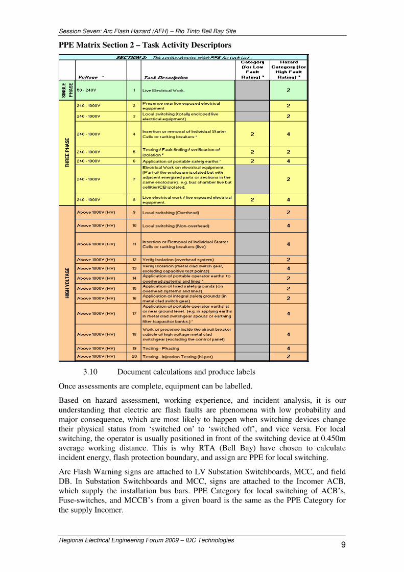
RTA (Bell Bay) developed twenty generic Task Activity Descriptors, to be listed in Section-2 of the Arc Protection PPE Matrix and assigned with Hazard Risk Category, based on voltage level of the operated equipment, and prospective fault current at the working location. The fault current is divided in two rating levels for simplicity. Low Fault Rating for prospective fault current up to 10kA, and High Fault Rating for fault current above 10kA.
Electrical workers select a generic descriptor to match their activity, from the matrix. In the process they verify voltage level, prospective fault current, and obtain Hazard Risk Category for the activity. The activity Hazard Risk Category is then used to select appropriate additional arc clothing and PPE from section 1 of the matrix.
Session Seven: Arc Flash Hazard (AFH) – Rio Tinto Bell Bay Site
Regional Electrical Engineering Forum 2009 – IDC Technologies 9
PPE Matrix Section 2 – Task Activity Descriptors
3.10 Document calculations and produce labels
Once assessments are complete, equipment can be labelled.
Based on hazard assessment, working experience, and incident analysis, it is our understanding that electric arc flash faults are phenomena with low probability and major consequence, which are most likely to happen when switching devices change their physical status from ‘switched on’ to ‘switched off’, and vice versa. For local switching, the operator is usually positioned in front of the switching device at 0.450m average working distance. This is why RTA (Bell Bay) have chosen to calculate incident energy, flash protection boundary, and assign arc PPE for local switching.
Arc Flash Warning signs are attached to LV Substation Switchboards, MCC, and field DB. In Substation Switchboards and MCC, signs are attached to the Incomer ACB, which supply the installation bus bars. PPE Category for local switching of ACB’s, Fuse-switches, and MCCB’s from a given board is the same as the PPE Category for the supply Incomer.
Session Seven: Arc Flash Hazard (AFH) – Rio Tinto Bell Bay Site
Regional Electrical Engineering Forum 2009 – IDC Technologies 10
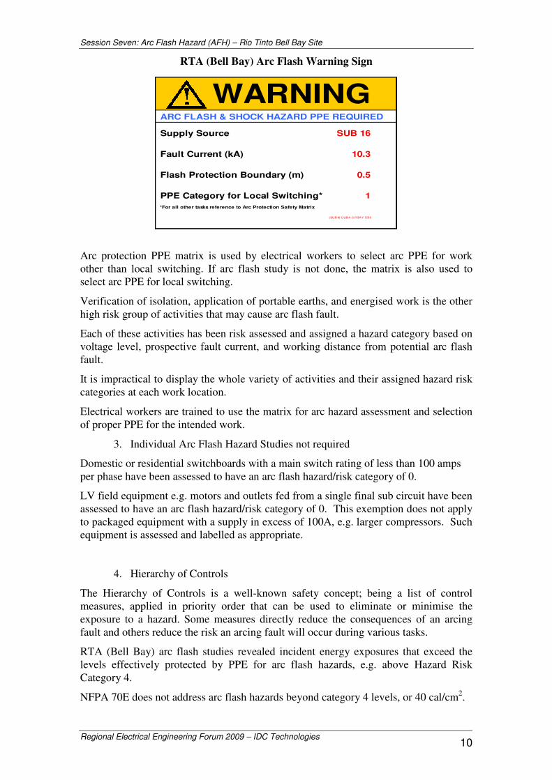
RTA (Bell Bay) Arc Flash Warning Sign
Arc protection PPE matrix is used by electrical workers to select arc PPE for work other than local switching. If arc flash study is not done, the matrix is also used to select arc PPE for local switching.
Verification of isolation, application of portable earths, and energised work is the other high risk group of activities that may cause arc flash fault.
Each of these activities has been risk assessed and assigned a hazard category based on voltage level, prospective fault current, and working distance from potential arc flash fault.
It is impractical to display the whole variety of activities and their assigned hazard risk categories at each work location.
Electrical workers are trained to use the matrix for arc hazard assessment and selection of proper PPE for the intended work.
3. Individual Arc Flash Hazard Studies not required
Domestic or residential switchboards with a main switch rating of less than 100 amps per phase have been assessed to have an arc flash hazard/risk category of 0.
LV field equipment e.g. motors and outlets fed from a single final sub circuit have been assessed to have an arc flash hazard/risk category of 0. This exemption does not apply to packaged equipment with a supply in excess of 100A, e.g. larger compressors. Such equipment is assessed and labelled as appropriate.
4. Hierarchy of Controls
The Hierarchy of Controls is a well-known safety concept; being a list of control measures, applied in priority order that can be used to eliminate or minimise the exposure to a hazard. Some measures directly reduce the consequences of an arcing fault and others reduce the risk an arcing fault will occur during various tasks.
RTA (Bell Bay) arc flash studies revealed incident energy exposures that exceed the levels effectively protected by PPE for arc flash hazards, e.g. above Hazard Risk Category 4.
NFPA 70E does not address arc flash hazards beyond category 4 levels, or 40 cal/cm2.
WARNING ARC FLASH & SHOCK HAZARD PPE REQUIRED
Supply Source SUB 16
Fault Current (kA) 10.3
Flash Protection Boundary (m) 0.5
PPE Category for Local Switching* 1 *For all other tasks reference to Arc Protection Safety Matrix
(SUB16 CUB4-3 FBAY CBI)

Session Seven: Arc Flash Hazard (AFH) – Rio Tinto Bell Bay Site
Regional Electrical Engineering Forum 2009 – IDC Technologies 11
Hierarchy of Control Pyramid
Hierarchy of Control Measures for Switchgear Arc Flash Hazards
Arc Event Triggers
Control Measure
No Activity
Inspection Operational Switching
Electrical Work
Elimination Arc Detection Systems – Light, pressure, heat Faster Protection Schemes – Zone Selective Interlocking Fault Current Limiters – Employ current limiting fuses and circuit breakers
Substitution Remote Switching Remote Racking
Substation design - remote switching, Internal Arc Contained Switchgear,
Engineering
Type-Tested Assemblies. Vermin Proofing
Interlocking Supply Minimum IP2X Internals Viewing Windows
Type-Tested Assemblies. Doors Closed Switching Doors Closed Racking
Minimum IP2X Internals Segregation
Administration Permit to work system, JHA’s, Take 5’s etc.
PPE Appropriate level of PPE for the incident energy
ELIMINATION
SUBSTITUTION
ISOLATION
ENGINEERING
ADMINISTRATIVE
PPE
EF
FEC
TIV
EN
ES
S O
F C
ON
TRO
L O
PTI
ON
S
Level 1 Eliminate the hazard
Level 2 Minimise the risk
Level 3 Back–up controls

Session Seven: Arc Flash Hazard (AFH) – Rio Tinto Bell Bay Site
Regional Electrical Engineering Forum 2009 – IDC Technologies 12
The Hierarchy of Controls method was used to address arc flash hazards beyond category 4 levels. Fault current limiting fuses and circuit breakers were applied as Over Current Protection Devices in a number of cases to eliminate HRC-4 and higher.
V. IMPLEMENTATION AND EXAMPLES
RTA Bell Bay has started investigating arc flash hazards since 2005. All necessary data (cable sizes and lengths, gaps between conductors, big motor loads, protective device information) is collected, input, and updated in software power system model, in order to calculate bolted fault and arc fault currents. Based on the characteristic curves of protective devices, a tripping time for relative arc fault current is defined and used for determining the arc flash energy and necessary personal protection equipment (PPE).
Figure 1: Bell Bay procedure for existing distribution boards
As a result, labels are produced and fixed at panel font doors to advise isolation personnel required PPE for safe switching. More than 500 distribution boards have been evaluated and labelled in this way.
Electrical workers exposed to arc flash hazards wear flame retardant clothing rated 4cal/cm2 as standard issue PPE. The standard PPE accounts for HRC 0 and 1.
As such, it is only necessary to review 20% of all boards, evaluated at Hazard Risk Category 2 or above for isolation. An appropriate engineering solution will be applied, depending on board isolation frequency, and circuit arrangement.
Based on the IEEE 1584 equations [1], the tripping time, distance and fault current are the three dominant factors. As the fault current will not be changed without changing the size and length of cables, in order to reduce the arc flash energy, either Tripping Time or Distance or both need to be adjusted. Tripping times can be reduced by
Session Seven: Arc Flash Hazard (AFH) – Rio Tinto Bell Bay Site
Regional Electrical Engineering Forum 2009 – IDC Technologies 13
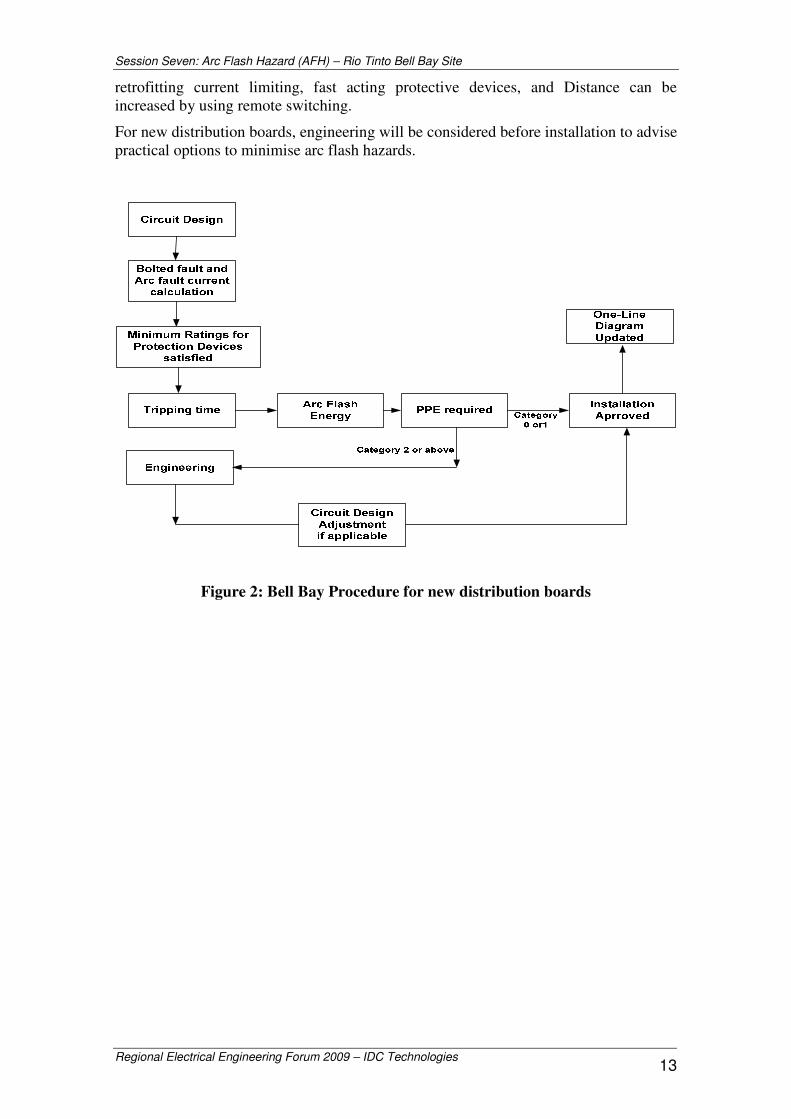
retrofitting current limiting, fast acting protective devices, and Distance can be increased by using remote switching.
For new distribution boards, engineering will be considered before installation to advise practical options to minimise arc flash hazards.
Figure 2: Bell Bay Procedure for new distribution boards

Session Seven: Arc Flash Hazard (AFH) – Rio Tinto Bell Bay Site
Regional Electrical Engineering Forum 2009 – IDC Technologies 14
Case Study 1: Fast Acting Protective Device Replacement
Problem: Crane Collector Rails can be supplied either from substation No21 or No22. Because both supplies are far away from the isolation points, when a fault occurs at these locations, the fuses in both substations cannot react fast enough for the low fault current of 4kA.That’s why in order to isolate at these distribution boards, it requires an electrician with Cat4 PPE.
However, due to the nature of the process and maintenance, these isolators are frequently used by operators and maintainers. In order to isolate safely, operators need to be trained and equipped with Cat4 PPE which creating huge cost in PPE purchases and labours.
Collector Rail
West End DB
Central Passage DB
East End DB
200 meters200 meters
160meters
120meters
Sub 22
Sub 21

Session Seven: Arc Flash Hazard (AFH) – Rio Tinto Bell Bay Site
Regional Electrical Engineering Forum 2009 – IDC Technologies 15
Solution: Fast acting fuses have been chosen to reduce the tripping time and arc flash energy. Three main factors of the new fuse selection were:
+ Similar overload protection
+ Able to handle starting current
+ Acting fast when low current faults occur

Session Seven: Arc Flash Hazard (AFH) – Rio Tinto Bell Bay Site
Regional Electrical Engineering Forum 2009 – IDC Technologies 16
Case Study 2: Remote Switching
Large compressor start/stop buttons were installed in the font door of star/delta contactor panel, which has high fault current rating of 26kA. The starter was designed and installed before arc flash hazard protection was required. Since 2008, when arc flash hazard calculations were done, Cat.4 PPE is required to start/stop the Compressor. This equipment is managed and operated by a mechanical team. The obvious solutions are: either train the whole mechanical team in arc flash hazard evaluation and equip them with arc PPE, or mechanics have to call an electrician in order to start/stop Compressor, which causes process delays etc.
It is technically and economically impractical to replace the existing air circuit breaker with new, current limiting, fast acting ACB, in this case. In order to eliminate operator exposure to arc flash energy, applying IEEE1584 equation, the start/stop station was relocated 4 meters away, out of the arc flash risk zone. Thus, local switching does not require additional arc PPE, while operator still maintains visual control over starting process.

Session Seven: Arc Flash Hazard (AFH) – Rio Tinto Bell Bay Site
Regional Electrical Engineering Forum 2009 – IDC Technologies 17
VI. CONCLUSIONS
Effective Arc Flash Hazard Safety requires a number of key areas to focus on. Structured, step by step, programme can provide a pathway.
The process of Arc Flash hazard Analysis will inevitably reveal protection system weaknesses. These need to be dealt with based on risk assessment and using the Hierarchy of Controls.
Removing the worker from the arc flash hazard zone needs to be always considered with priority.
Conservative risk assumptions lead to imposing higher hazard risk categories and PPE that restricts workers’ ability to carry out the task safely.
VII. REFERENCES
[1] IEEE 1584-2002, “Guide for Performing Arc-Flash Hazard Calculations”
[2] NFPA 70E-2009, “Standard for Electrical Safety in the Workplace”
[3] Kevin J. Lippert, Donald M. Colaberardino, and Clive W. Kimblin, “Understanding Arc Flash Hazards”, IEEE 0-7803-8282-X/04/
[4] A.D. Stokes and D.K. Sweeting, “Electric Arcing Burn Hazards”, IEEE Trans. Ind. Appl., vol.42, no.1, Jan/Feb 2006
[5] D.K. Sweeting, “ELECTROCUTIONS AND ARCS”, Industrial Electrics, Issue 1, Jan/Feb 2009, pp. 31-37