7 pavement drainage strategy 7.1 general - transport for …
TRANSCRIPT
NSW Roads and Traffic Authority Initial Assessment of Drainage Requirements
Camden Valley Way Upgrade – Bringelly Road to Cobbitty Road
CVW_NTH_004_100511.doc Page 29 Lyall & Associates 23 February 2010 Rev. 4.0 Consulting Water Engineers
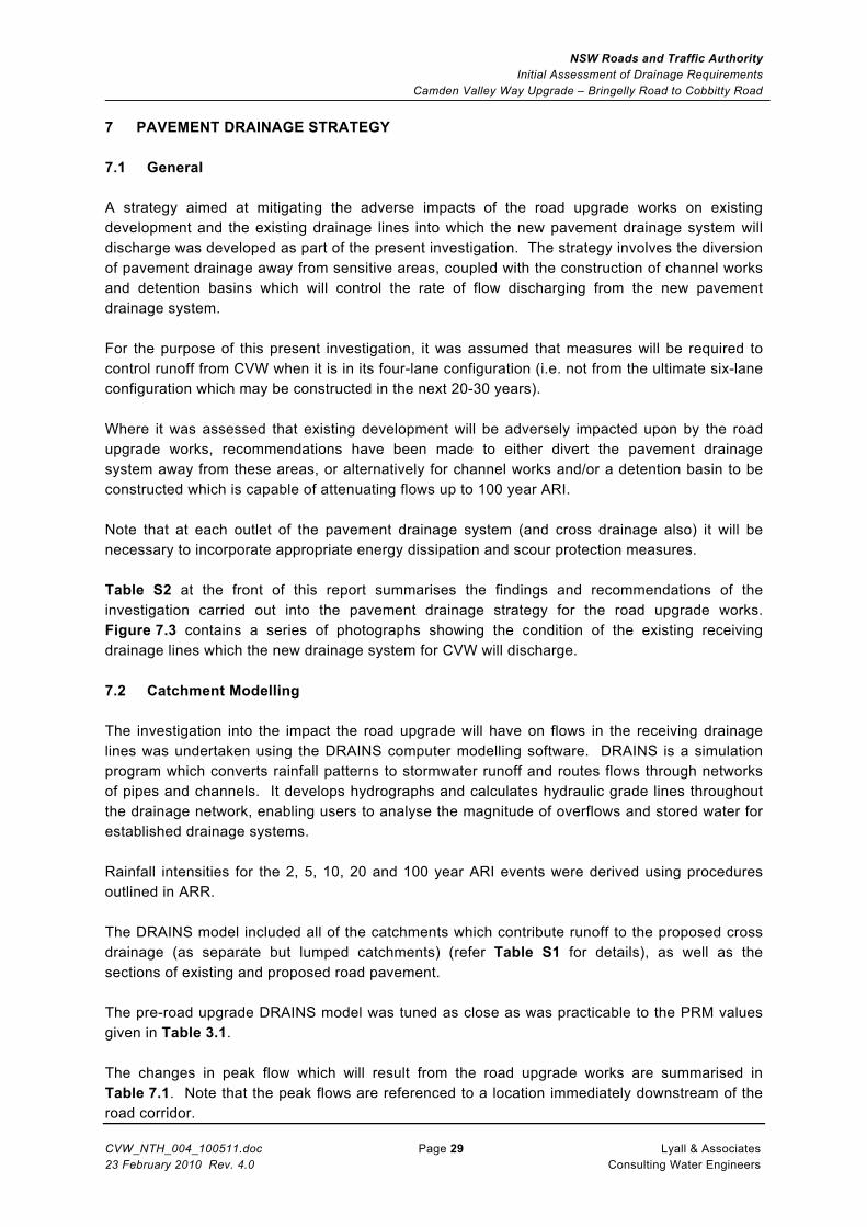
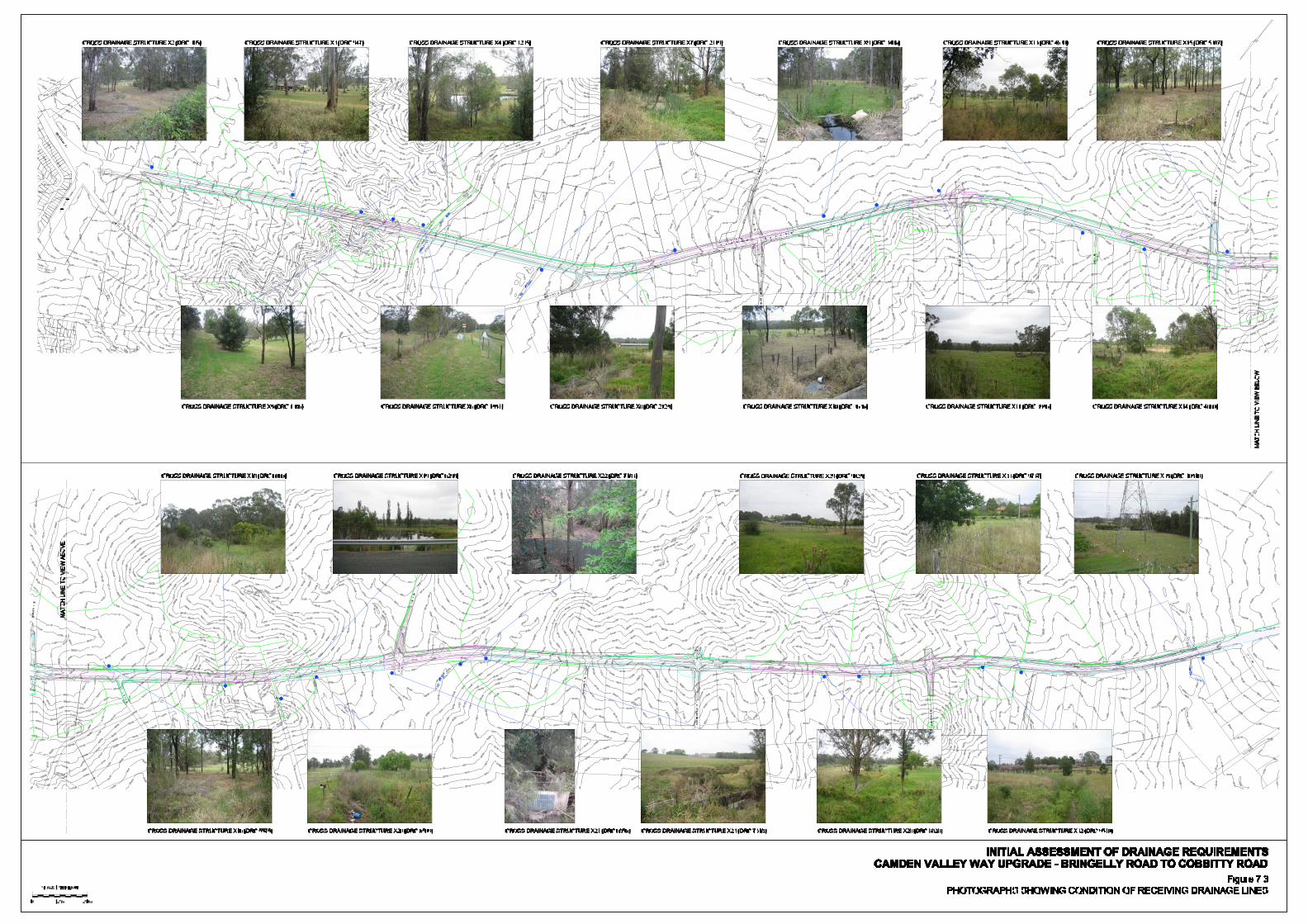
7 PAVEMENT DRAINAGE STRATEGY 7.1 General A strategy aimed at mitigating the adverse impacts of the road upgrade works on existing development and the existing drainage lines into which the new pavement drainage system will discharge was developed as part of the present investigation. The strategy involves the diversion of pavement drainage away from sensitive areas, coupled with the construction of channel works and detention basins which will control the rate of flow discharging from the new pavement drainage system. For the purpose of this present investigation, it was assumed that measures will be required to control runoff from CVW when it is in its four-lane configuration (i.e. not from the ultimate six-lane configuration which may be constructed in the next 20-30 years). Where it was assessed that existing development will be adversely impacted upon by the road upgrade works, recommendations have been made to either divert the pavement drainage system away from these areas, or alternatively for channel works and/or a detention basin to be constructed which is capable of attenuating flows up to 100 year ARI. Note that at each outlet of the pavement drainage system (and cross drainage also) it will be necessary to incorporate appropriate energy dissipation and scour protection measures. Table S2 at the front of this report summarises the findings and recommendations of the investigation carried out into the pavement drainage strategy for the road upgrade works. Figure 7.3 contains a series of photographs showing the condition of the existing receiving drainage lines which the new drainage system for CVW will discharge. 7.2 Catchment Modelling The investigation into the impact the road upgrade will have on flows in the receiving drainage lines was undertaken using the DRAINS computer modelling software. DRAINS is a simulation program which converts rainfall patterns to stormwater runoff and routes flows through networks of pipes and channels. It develops hydrographs and calculates hydraulic grade lines throughout the drainage network, enabling users to analyse the magnitude of overflows and stored water for established drainage systems. Rainfall intensities for the 2, 5, 10, 20 and 100 year ARI events were derived using procedures outlined in ARR. The DRAINS model included all of the catchments which contribute runoff to the proposed cross drainage (as separate but lumped catchments) (refer Table S1 for details), as well as the sections of existing and proposed road pavement. The pre-road upgrade DRAINS model was tuned as close as was practicable to the PRM values given in Table 3.1. The changes in peak flow which will result from the road upgrade works are summarised in Table 7.1. Note that the peak flows are referenced to a location immediately downstream of the road corridor.
NSW Roads and Traffic Authority Initial Assessment of Drainage Requirements
Camden Valley Way Upgrade – Bringelly Road to Cobbitty Road
CVW_NTH_004_100511.doc Page 30 Lyall & Associates 23 February 2010 Rev. 4.0 Consulting Water Engineers
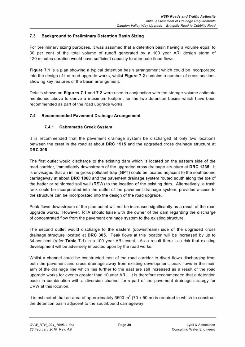
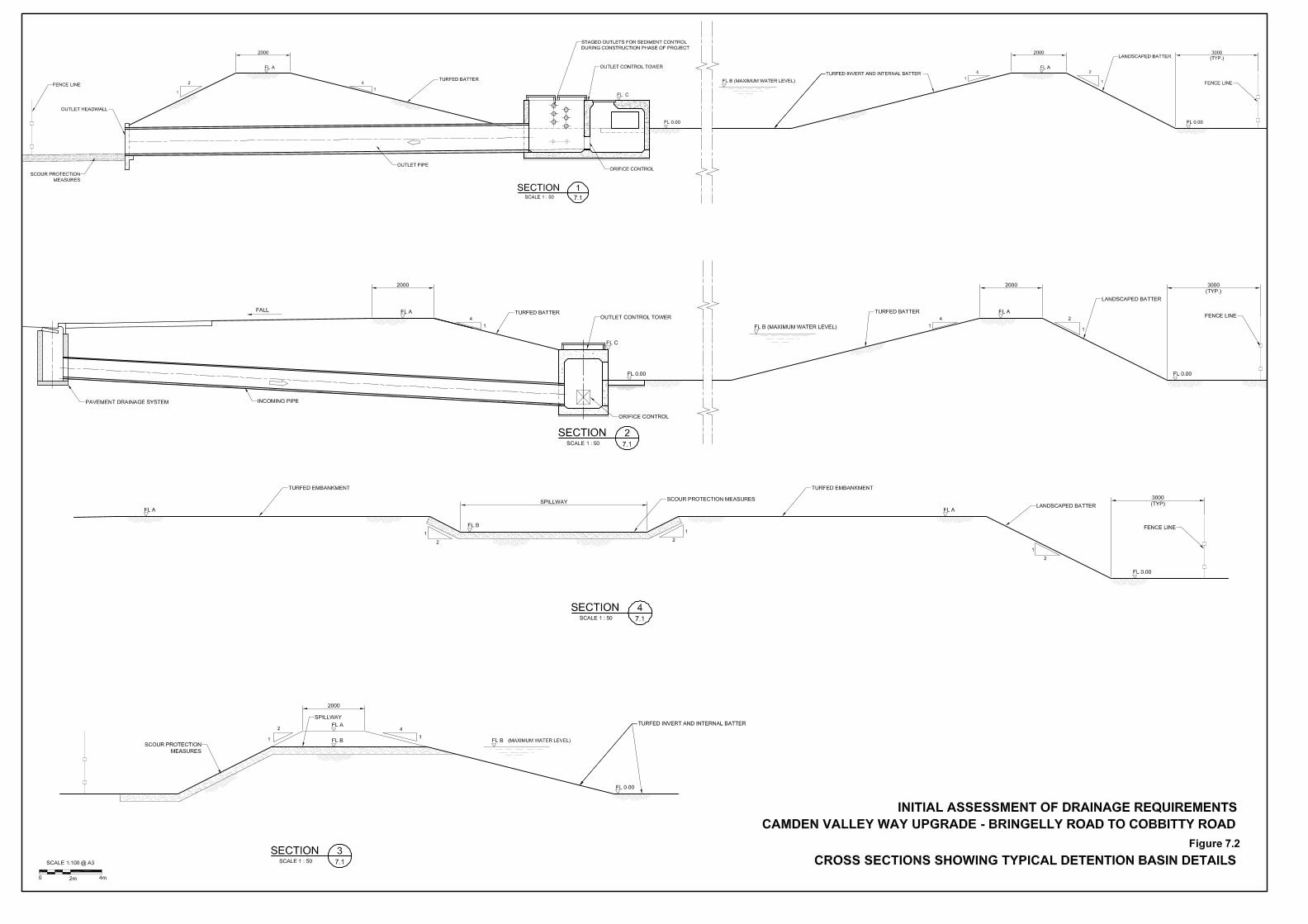
7.3 Background to Preliminary Detention Basin Sizing For preliminary sizing purposes, it was assumed that a detention basin having a volume equal to 30 per cent of the total volume of runoff generated by a 100 year ARI design storm of 120 minutes duration would have sufficient capacity to attenuate flood flows. Figure 7.1 is a plan showing a typical detention basin arrangement which could be incorporated into the design of the road upgrade works, whilst Figure 7.2 contains a number of cross sections showing key features of the basin arrangement. Details shown on Figures 7.1 and 7.2 were used in conjunction with the storage volume estimate mentioned above to derive a maximum footprint for the two detention basins which have been recommended as part of the road upgrade works. 7.4 Recommended Pavement Drainage Arrangement
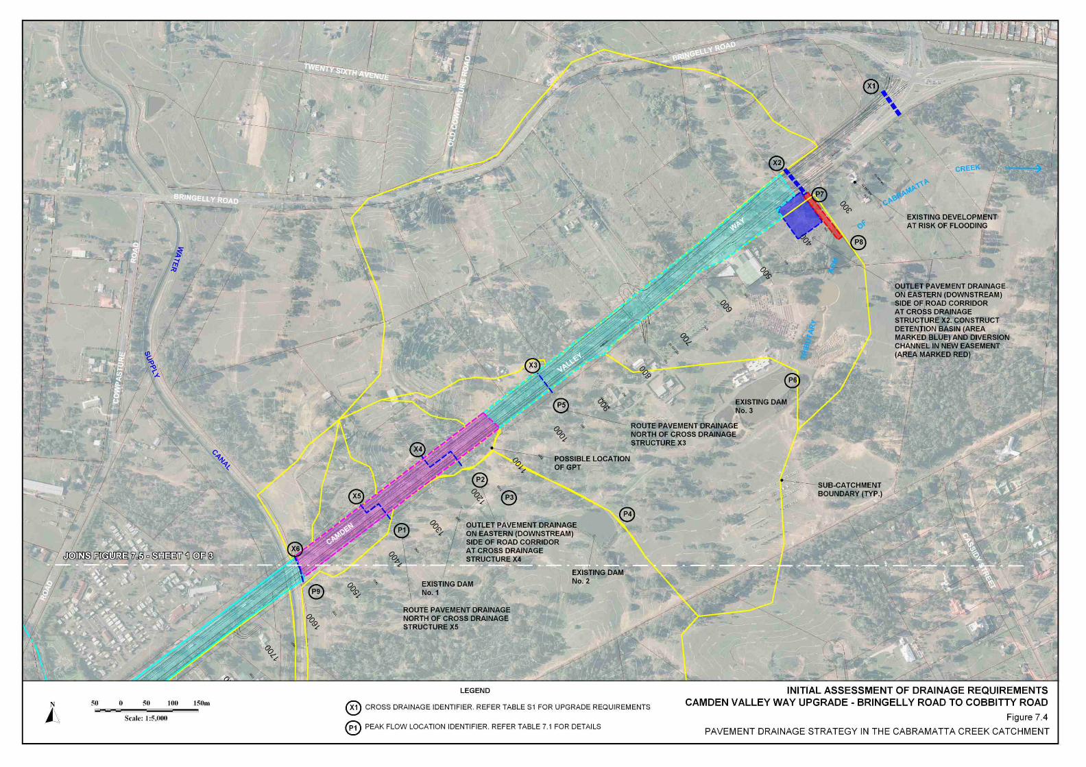
7.4.1 Cabramatta Creek System It is recommended that the pavement drainage system be discharged at only two locations between the crest in the road at about DRC 1515 and the upgraded cross drainage structure at DRC 305. The first outlet would discharge to the existing dam which is located on the eastern side of the road corridor, immediately downstream of the upgraded cross drainage structure at DRC 1235. It is envisaged that an inline gross pollutant trap (GPT) could be located adjacent to the southbound carriageway at about DRC 1060 and the pavement drainage system routed south along the toe of the batter or reinforced soil wall (RSW) to the location of the existing dam. Alternatively, a trash rack could be incorporated into the outlet of the pavement drainage system, provided access to the structure can be incorporated into the design of the road upgrade. Peak flows downstream of the pipe outlet will not be increased significantly as a result of the road upgrade works. However, RTA should liaise with the owner of the dam regarding the discharge of concentrated flow from the pavement drainage system to the existing structure. The second outlet would discharge to the eastern (downstream) side of the upgraded cross drainage structure located at DRC 305. Peak flows at this location will be increased by up to 34 per cent (refer Table 7.1) in a 100 year ARI event. As a result there is a risk that existing development will be adversely impacted upon by the road works. Whilst a channel could be constructed east of the road corridor to divert flows discharging from both the pavement and cross drainage away from existing development, peak flows in the main arm of the drainage line which lies further to the east are still increased as a result of the road upgrade works for events greater than 10 year ARI. It is therefore recommended that a detention basin in combination with a diversion channel form part of the pavement drainage strategy for CVW at this location. It is estimated that an area of approximately 3500 m2 (70 x 50 m) is required in which to construct the detention basin adjacent to the southbound carriageway.

NSW Roads and Traffic Authority Initial Assessment of Drainage Requirements
Camden Valley Way Upgrade – Bringelly Road to Cobbitty Road
CVW_NTH_004_100511.doc Page 31 Lyall & Associates 23 February 2010 Rev. 4.0 Consulting Water Engineers
An easement of approximately 10 m width and 110 m length will be required in which to construct the diversion channel east of the road corridor. Figure 7.4 shows the footprint of the detention basin and easement required for the channel works. It will be necessary to obtain additional ground survey in order to size and configure the detention basin and diversion channel works. Also, at detail design stage it will be necessary to carry out a detailed flood study investigation to demonstrate that the road upgrade works (including the detention basin and channel works) will not have an adverse impact on existing development.
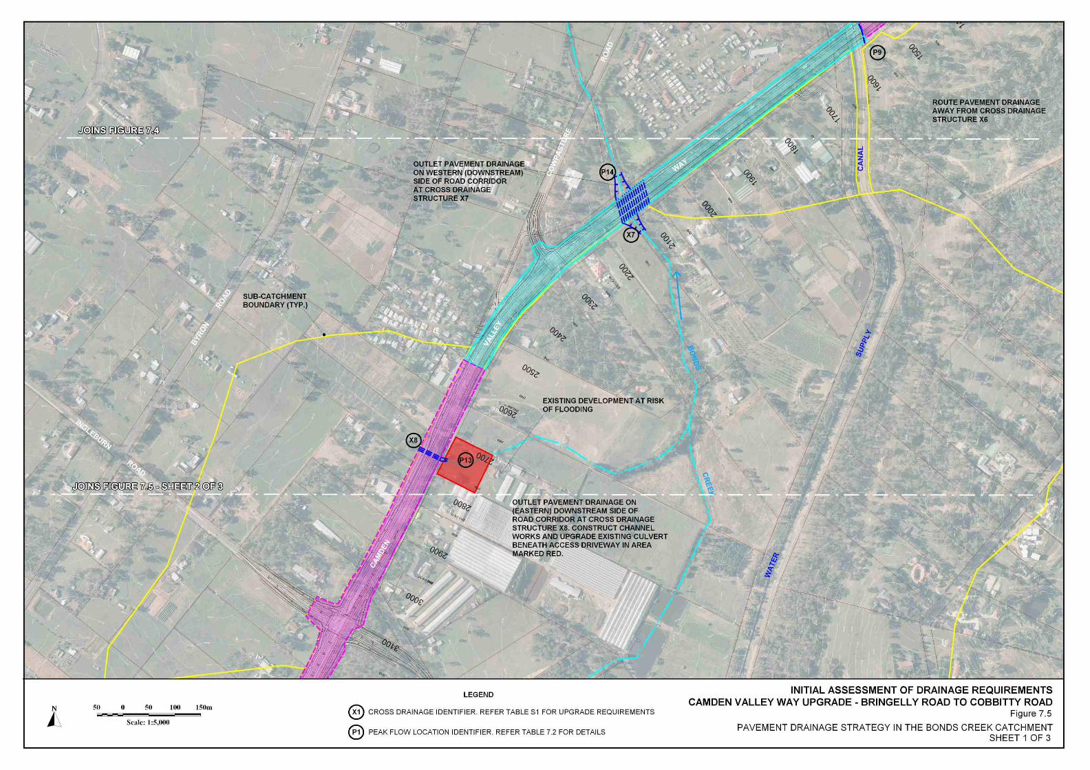
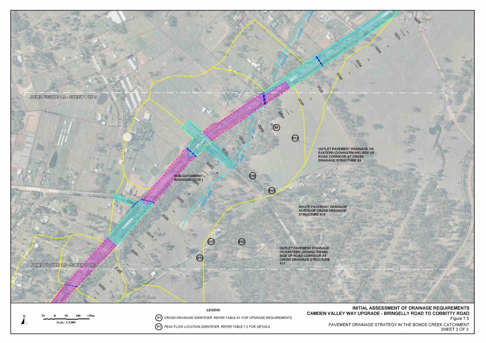
7.4.2 Bonds Creek System It is recommended that the pavement drainage system be discharged at the location of each upgraded cross drainage structure, with the exception of the two cross drainage structures located at DRC 3636 and DRC 5307. In the case of the cross structure at DRC 3636, it is recommended that the pavement drainage system be directed to the outlet of the cross drainage structure located at DRC 3406. In the case of the cross structure at DRC 5307, it is recommended that the pavement drainage system be piped east along St Andrews Road and discharged to the existing drainage line on the downstream side of the local road corridor. Figure 7.5 summarises the pavement drainage strategy where CVW runs through the Bonds Creek catchment. Existing low lying development is at risk of being adversely impacted upon by the road upgrade works downstream of the cross drainage structure located at DRC 2725. Whilst the current analysis indicates that peak flows will only be increased by a small amount, it is recommended that RTA carry out channel works in the downstream property and to also upgrade the existing culvert which is located beneath the access driveway into the property. These works will need to be designed to ensure peak flood levels in the property are not increased as a result of the road upgrade works. RTA advised that the drainage lines into which the pavement drainage system discharges south of Denham Court Road in the Bonds Creek catchment (eastern side only) are likely to undergo change as part of planned development in this area. As a result, it was considered that the minor increase in flows (refer Table 7.2) which will result from the road upgrade works could be managed by the future development. Further to the south, there is a relatively large increase in peak flows discharging to the existing drainage line downstream of the cross drainage structure at DRC 5575. However, the peak flow discharging to the drainage line is only about 1.2 m3/s in a 100 year ARI event. Stormwater discharging to the existing drainage line from the road corridor would tend to spread out and flow at relatively shallow depths across the adjacent grassed area. It is also considered that a flow of this magnitude could be easily catered for in any future development.
NSW Roads and Traffic Authority Initial Assessment of Drainage Requirements
Camden Valley Way Upgrade – Bringelly Road to Cobbitty Road
CVW_NTH_004_100511.doc Page 32 Lyall & Associates 23 February 2010 Rev. 4.0 Consulting Water Engineers
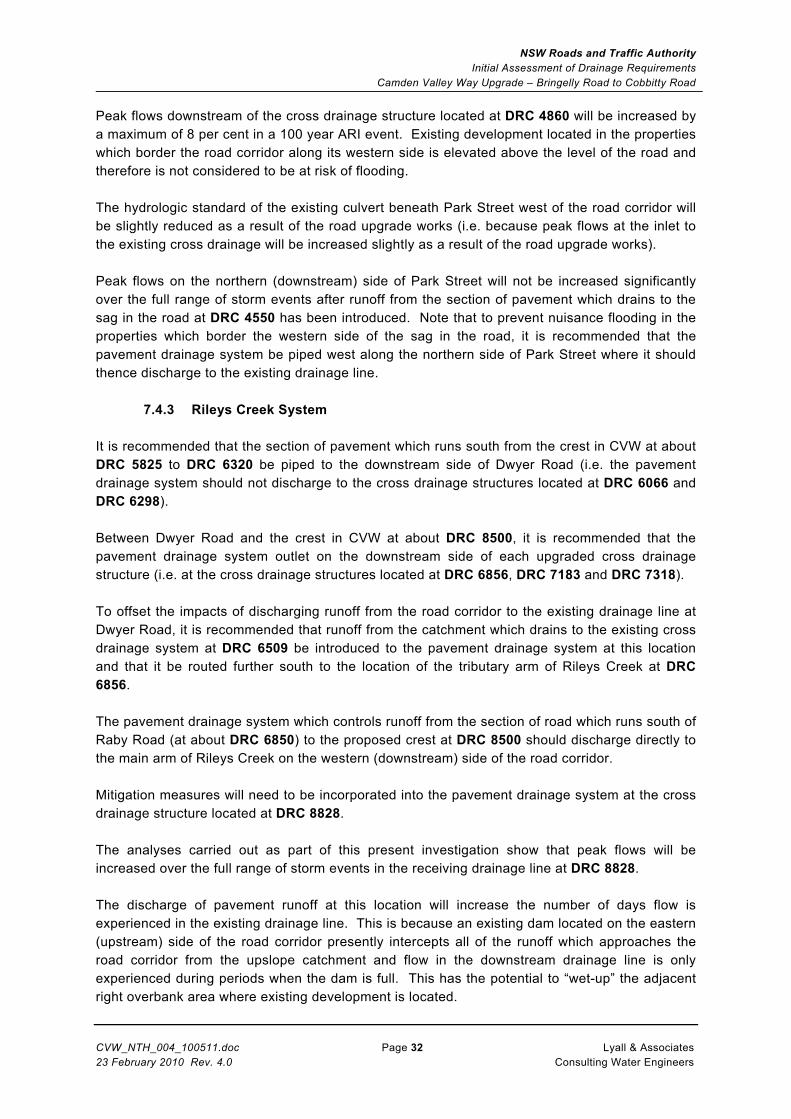
Peak flows downstream of the cross drainage structure located at DRC 4860 will be increased by a maximum of 8 per cent in a 100 year ARI event. Existing development located in the properties which border the road corridor along its western side is elevated above the level of the road and therefore is not considered to be at risk of flooding. The hydrologic standard of the existing culvert beneath Park Street west of the road corridor will be slightly reduced as a result of the road upgrade works (i.e. because peak flows at the inlet to the existing cross drainage will be increased slightly as a result of the road upgrade works). Peak flows on the northern (downstream) side of Park Street will not be increased significantly over the full range of storm events after runoff from the section of pavement which drains to the sag in the road at DRC 4550 has been introduced. Note that to prevent nuisance flooding in the properties which border the western side of the sag in the road, it is recommended that the pavement drainage system be piped west along the northern side of Park Street where it should thence discharge to the existing drainage line.
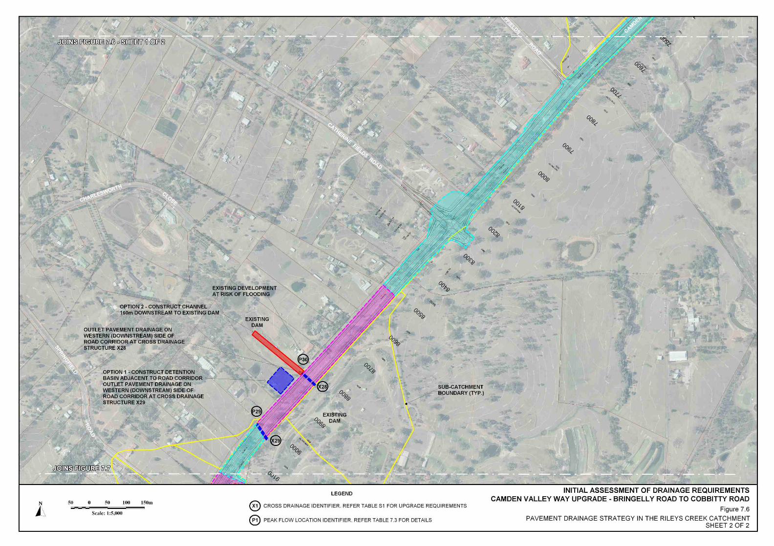
7.4.3 Rileys Creek System It is recommended that the section of pavement which runs south from the crest in CVW at about DRC 5825 to DRC 6320 be piped to the downstream side of Dwyer Road (i.e. the pavement drainage system should not discharge to the cross drainage structures located at DRC 6066 and DRC 6298). Between Dwyer Road and the crest in CVW at about DRC 8500, it is recommended that the pavement drainage system outlet on the downstream side of each upgraded cross drainage structure (i.e. at the cross drainage structures located at DRC 6856, DRC 7183 and DRC 7318). To offset the impacts of discharging runoff from the road corridor to the existing drainage line at Dwyer Road, it is recommended that runoff from the catchment which drains to the existing cross drainage system at DRC 6509 be introduced to the pavement drainage system at this location and that it be routed further south to the location of the tributary arm of Rileys Creek at DRC 6856. The pavement drainage system which controls runoff from the section of road which runs south of Raby Road (at about DRC 6850) to the proposed crest at DRC 8500 should discharge directly to the main arm of Rileys Creek on the western (downstream) side of the road corridor. Mitigation measures will need to be incorporated into the pavement drainage system at the cross drainage structure located at DRC 8828. The analyses carried out as part of this present investigation show that peak flows will be increased over the full range of storm events in the receiving drainage line at DRC 8828. The discharge of pavement runoff at this location will increase the number of days flow is experienced in the existing drainage line. This is because an existing dam located on the eastern (upstream) side of the road corridor presently intercepts all of the runoff which approaches the road corridor from the upslope catchment and flow in the downstream drainage line is only experienced during periods when the dam is full. This has the potential to “wet-up” the adjacent right overbank area where existing development is located.

NSW Roads and Traffic Authority Initial Assessment of Drainage Requirements
Camden Valley Way Upgrade – Bringelly Road to Cobbitty Road
CVW_NTH_004_100511.doc Page 33 Lyall & Associates 23 February 2010 Rev. 4.0 Consulting Water Engineers
The following two options would mitigate, to varying degrees, the adverse impacts of the road upgrade works on the adjacent development:
• Option 1 – Construction of a detention basin adjacent to the northbound carriageway opposite about DRC 8825. It is estimated that an area of approximately 2750 m2 (55 x 50 m) would be required in which to construct a suitably sized detention basin adjacent to the new carriageway.
• Option 2 – Upgrade of the existing drainage line downstream of the cross drainage structure at DRC 8828 to mitigate the impacts of the increase in flow The channel works would need to extend approximately 160 m to the west of the road corridor where the drainage line presently discharges to an existing farm dam.
Option 2 is preferred as the channel works will improve the conveyance capacity of the minor drainage line and prevent the frequent wetting up of the adjacent overbank area. Option 2 would also have less ongoing maintenance costs associated with it. However, RTA would need to gain permission from the landowner to carry out the works on his land. The RTA would also need to check whether an easement is required along the length of the upgraded channel. Figure 7.6 summarises the pavement drainage strategy for CVW where it runs through the Rileys Creek catchment.
7.4.4 South Creek System Existing development which is susceptible to flooding is located on the western (downstream) side of the road corridor between Springfield Road (DRC 9300) and DRC 9900. In order to best manage the discharge of runoff from the road corridor in this area, it is recommended that the pavement drainage system discharge to the outlet of the upgraded cross drainage at DRC 9510, but that runoff from the next downslope section of pavement be diverted further to the south, beyond the cross drainage located at DRC 9737. Note that because of several other constraints further to the south, runoff from this area will need to be piped a distance of approximately 770 m to the main arm of South Creek which is located at DRC 10510. Analyses undertaken as part of this present investigation show that peak flows in the existing drainage line downstream of DRC 9510 will be increased by up to 10 per cent for storms of 10 year ARI and greater. As there is no space available to construct a detention basin immediately adjacent to the road corridor (i.e. because of the close proximity of the existing drainage line to the road corridor), it may be feasible to reconfigure one of the existing dams which have been constructed by the adjacent property owners as a detention basin. However, the reconfigured dam would need to control runoff from not only the road corridor, but also runoff from the relatively large semi-rural catchment which also contributes flow to the existing drainage line. This would mean that the detention basin would need to be much larger than required to control simply the runoff from the road corridor, thus adding to the cost of constructing the basin. Ongoing maintenance of the basin would also be of concern to the RTA. It is recommended that RTA undertake a more detailed flood study investigation to assess the impact the minor increase in peak flow will have on existing development before pursuing a possible upgrade of one of the existing dams as a flow control measure.

NSW Roads and Traffic Authority Initial Assessment of Drainage Requirements
Camden Valley Way Upgrade – Bringelly Road to Cobbitty Road
CVW_NTH_004_100511.doc Page 34 Lyall & Associates 23 February 2010 Rev. 4.0 Consulting Water Engineers
In order to route the pavement drainage system south of the cross drainage at DRC 9737, it will be necessary to either:
a) raise the two new carriageways to allow the pavement drainage system to cross over the upgraded cross drainage. It has been assessed that a maximum 450 mm diameter pipe would be needed to control runoff from the road corridor at the location of the cross-over. Assuming a minimum 300 mm clearance between the top of the upgraded cross drainage and the underside of the new pavement drainage system, as well as a minimum 700 mm cover to gutter level, it would be necessary to raise the two carriageways by 1 m from current design levels. This would require additional selected fill material to be imported to this area given that design road levels are presently generally at grade; or alternatively
b) cross under the upgraded cross drainage via a deep trench. Assuming a minimum 300 mm cover to the underside of a 300 mm thick reinforced culvert base slab, it is estimated that the trench would need to be between 2.5 - 2.75 m deep at the location of the cross drainage structure. If the invert of the pavement drainage system was graded at 0.5 per cent downstream of the crossing, then a deeper than normal trench would need to be excavated over a distance of approximately 140 m south of DRC 9737 (i.e. before RTA’s standard cover of 1 m could be returned to the pavement drainage system). Note that standard RTA pits could still be used in the design and construction of the pavement drainage system should this option be adopted.
On the basis of the above assessment, and in the absence of any critical utilities which may constrain the depth of the pavement drainage system at this location, it is recommended that the latter cross-under option be adopted since it is considered to be the least cost option. Further to the south, a residential home has been constructed across a general low point in the catchment which drains towards the road corridor at about DRC 9950. Whilst there is no existing cross drainage at this location (i.e. because runoff from the relatively large upslope catchment is presently diverted south along the eastern side of the road corridor to the main arm of South Creek), the presence of the existing residential home would prevent the discharge of stormwater at this location. As a result, it will be necessary to route the pavement drainage system further south to the main arm of South Creek at DRC 10510. Further south again, it is recommended that the pavement drainage system from the remaining section of upgraded road (as well as the runoff from the section of upgraded road which extends north to about DRC 9510) be discharged to the main arm of South Creek on the western (downstream) side of the road corridor. Figure 7.7 summarises the pavement drainage strategy for CVW where it runs through the South Creek catchment.

NSW Roads and Traffic Authority Initial Assessment of Drainage Requirements
Camden Valley Way Upgrade – Bringelly Road to Cobbitty Road
CVW_NTH_004_100511.doc Page 35 Lyall & Associates 23 February 2010 Rev. 4.0 Consulting Water Engineers
TABLE 7.1 SUMMARY OF PEAK FLOWS
CABRAMATTA CREEK SYSTEM
2 year ARI 5 year ARI 10 year ARI 20 year ARI 100 year ARI
Present Day
Post CVW
Widening Difference Present
Day Post CVW
Widening Difference Present
Day Post CVW
Widening Difference Present
Day Post CVW
Widening Difference Present
Day Post CVW
WideningDifference Location
Identifier Location Drainage
Outlet Type
(m3/s) (m3/s) (m3/s) (%) (m3/s) (m3/s) (m3/s) (%) (m3/s) (m3/s) (m3/s) (%) (m3/s) (m3/s) (m3/s) (%) (m3/s) (m3/s) (m3/s) (%)
P1 1386 XD Only 0.265 0.179 -0.086 -32.5% 0.579 0.407 -0.172 -29.7% 0.801 0.502 -0.299 -37.3% 1.05 0.631 -0.419 -39.9% 1.33 0.796 -0.534 -40.2%
P2 1235 XD + PD 0.393 0.479 0.086 21.9% 0.862 0.945 0.083 9.6% 1.02 1.12 0.1 9.8% 1.25 1.38 0.13 10.4% 1.71 1.75 0.04 2.3%
P3 Outflow from Existing Dam No. 1 0.644 0.619 -0.025 -3.9% 1.28 1.23 -0.05 -3.9% 1.58 1.51 -0.07 -4.4% 2.1 1.93 -0.17 -8.1% 2.97 2.47 -0.5 -16.8%
P4 Outflow from Existing Dam No. 2 1.97 2.02 0.05 2.5% 4.23 4.32 0.09 2.1% 5.63 5.74 0.11 2.0% 7.87 7.96 0.09 1.1% 12.5 12.5 0 0.0%
P5 947 XD Only 0.173 0.103 -0.07 -40.5% 0.367 0.231 -0.136 -37.1% 0.47 0.304 -0.166 -35.3% 0.631 0.42 -0.211 -33.4% 0.846 0.578 -0.268 -31.7%
P6 Outflow from Existing Dam No. 3 2.97 2.9 -0.07 -2.4% 6.25 6.14 -0.11 -1.8% 8.27 8.05 -0.22 -2.7% 11.3 11 -0.3 -2.7% 17.2 16.8 -0.4 -2.3%
P7 305 XD + PD 1.47 1.59 0.12 8.2% 3.06 3.29 0.23 7.5% 4.53 4.45 -0.08 -1.8% 4.83 5.93 1.1 22.8% 7.1 9.51 2.41 33.9%
P8 Tributary Arm of Cabramatta Creek 4.91 4.89 -0.02 -0.4% 10.2 10.3 0.1 1.0% 13.8 13.5 -0.3 -2.2% 16.6 17.2 0.6 3.6% 24.1 25.7 1.6 6.6%
Note: Refer Figure 7.4 for reference to Location Identifier XD = Cross Drainage PD = Pavement Drainage
TABLE 7.2 SUMMARY OF PEAK FLOWS
BONDS CREEK SYSTEM
2 year ARI 5 year ARI 10 year ARI 20 year ARI 100 year ARI
Present Day
Post CVW
Widening Difference Present
Day Post CVW
Widening Difference Present
Day Post CVW
Widening Difference Present
Day Post CVW
Widening Difference Present
Day Post CVW
WideningDifference Location
Identifier Location Drainage
Outlet Type
(m3/s) (m3/s) (m3/s) (%) (m3/s) (m3/s) (m3/s) (%) (m3/s) (m3/s) (m3/s) (%) (m3/s) (m3/s) (m3/s) (%) (m3/s) (m3/s) (m3/s) (%)
P9 1551 XD + PD 0.147 0.147 0 0.0% 0.323 0.318 -0.005 -1.5% 0.399 0.421 0.022 5.5% 0.42 0.583 0.163 38.8% 0.442 0.801 0.359 81.2%
P10 3956 XD + PD 0.536 0.506 -0.03 -5.6% 1.07 0.959 -0.111 -10.4% 1.3 1.15 -0.15 -11.5% 1.6 1.41 -0.19 -11.9% 2.03 1.78 -0.25 -12.3%
P11 3636 XD Only 0.346 0.263 -0.083 -24.0% 0.755 0.601 -0.154 -20.4% 0.841 0.799 -0.042 -5.0% 0.906 1.01 0.104 11.5% 0.982 1.3 0.318 32.4%
P12 3406 XD + PD 0.725 0.905 0.18 24.8% 1.54 1.8 0.26 16.9% 2.14 2.35 0.21 9.8% 3.08 3.19 0.11 3.6% 4.57 4.69 0.12 2.6%
P13 2725 XD + PD 1.23 1.39 0.16 13.0% 2.53 2.68 0.15 5.9% 3.39 3.5 0.11 3.2% 4.52 4.71 0.19 4.2% 7.31 7.43 0.12 1.6%
P14 2119 XD + PD 9.09 9.13 0.04 0.4% 21.8 21.7 -0.1 -0.5% 31.1 31.1 0 0.0% 43.6 43.6 0 0.0% 74.7 74.6 -0.1 -0.1%
P15 5575 XD + PD 0.324 0.349 0.025 7.7% 0.51 0.644 0.134 26.3% 0.534 0.782 0.248 46.4% 0.569 0.961 0.392 68.9% 0.685 1.22 0.535 78.1%
P16 5307 XD Only 0.576 0.549 -0.027 -4.7% 1.35 1.12 -0.23 -17.0% 1.84 1.49 -0.35 -19.0% 2.66 2.09 -0.57 -21.4% 4 3.01 -0.99 -24.8%
P17 4860 XD + PD 2.45 2.49 0.04 1.6% 4.9 4.99 0.09 1.8% 6.31 6.43 0.12 1.9% 8.09 8.56 0.47 5.8% 12.2 13.2 1 8.2%
P18 Inlet to Park Street Culvert 2.79 2.61 -0.18 -6.5% 5.23 5.3 0.07 1.3% 6.73 6.92 0.19 2.8% 8.41 8.91 0.5 5.9% 12.6 13.6 1 7.9%
P19 4630 XD + PD 0.433 0.596 0.163 37.6% 0.872 1.05 0.178 20.4% 1.13 1.33 0.2 17.7% 1.83 1.74 -0.09 -4.9% 3.25 2.64 -0.61 -18.8%
P20 Downstream of Confluence 3.22 3.08 -0.14 -4.3% 6.04 6.07 0.03 0.5% 7.68 7.94 0.26 3.4% 10 10.2 0.2 2.0% 15.4 15.3 -0.1 -0.6%
Note: Refer Figure 7.5 for reference to Location Identifier XD = Cross Drainage PD = Pavement Drainage
NSW Roads and Traffic Authority Initial Assessment of Drainage Requirements
Camden Valley Way Upgrade – Bringelly Road to Cobbitty Road
CVW_NTH_004_100511.doc Page 36 Lyall & Associates 23 February 2010 Rev. 4.0 Consulting Water Engineers
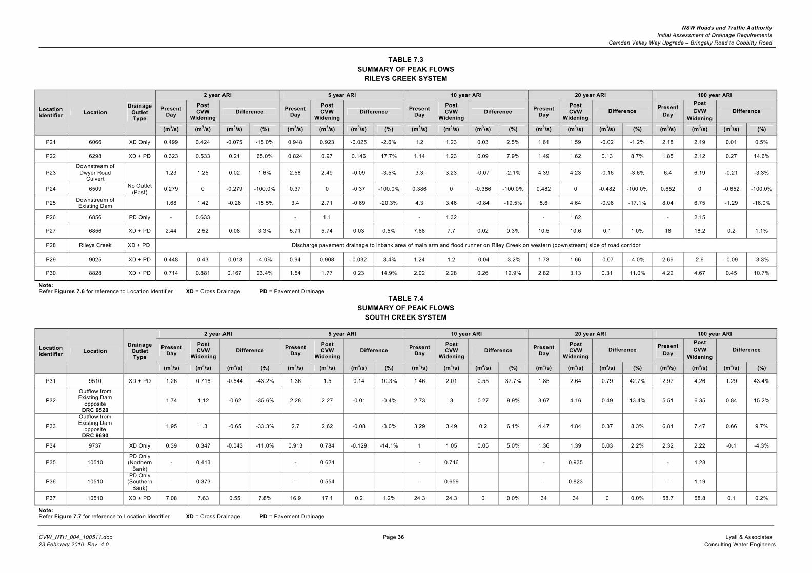
TABLE 7.3 SUMMARY OF PEAK FLOWS
RILEYS CREEK SYSTEM
2 year ARI 5 year ARI 10 year ARI 20 year ARI 100 year ARI
Present Day
Post CVW
Widening Difference Present
Day Post CVW
Widening Difference Present
Day Post CVW
Widening Difference Present
Day Post CVW
Widening Difference Present
Day Post CVW
WideningDifference Location
Identifier Location Drainage
Outlet Type
(m3/s) (m3/s) (m3/s) (%) (m3/s) (m3/s) (m3/s) (%) (m3/s) (m3/s) (m3/s) (%) (m3/s) (m3/s) (m3/s) (%) (m3/s) (m3/s) (m3/s) (%)
P21 6066 XD Only 0.499 0.424 -0.075 -15.0% 0.948 0.923 -0.025 -2.6% 1.2 1.23 0.03 2.5% 1.61 1.59 -0.02 -1.2% 2.18 2.19 0.01 0.5%
P22 6298 XD + PD 0.323 0.533 0.21 65.0% 0.824 0.97 0.146 17.7% 1.14 1.23 0.09 7.9% 1.49 1.62 0.13 8.7% 1.85 2.12 0.27 14.6%
P23 Downstream of
Dwyer Road Culvert
1.23 1.25 0.02 1.6% 2.58 2.49 -0.09 -3.5% 3.3 3.23 -0.07 -2.1% 4.39 4.23 -0.16 -3.6% 6.4 6.19 -0.21 -3.3%
P24 6509 No Outlet (Post) 0.279 0 -0.279 -100.0% 0.37 0 -0.37 -100.0% 0.386 0 -0.386 -100.0% 0.482 0 -0.482 -100.0% 0.652 0 -0.652 -100.0%
P25 Downstream of Existing Dam 1.68 1.42 -0.26 -15.5% 3.4 2.71 -0.69 -20.3% 4.3 3.46 -0.84 -19.5% 5.6 4.64 -0.96 -17.1% 8.04 6.75 -1.29 -16.0%
P26 6856 PD Only - 0.633 - 1.1 - 1.32 - 1.62 - 2.15
P27 6856 XD + PD 2.44 2.52 0.08 3.3% 5.71 5.74 0.03 0.5% 7.68 7.7 0.02 0.3% 10.5 10.6 0.1 1.0% 18 18.2 0.2 1.1%
P28 Rileys Creek XD + PD Discharge pavement drainage to inbank area of main arm and flood runner on Riley Creek on western (downstream) side of road corridor
P29 9025 XD + PD 0.448 0.43 -0.018 -4.0% 0.94 0.908 -0.032 -3.4% 1.24 1.2 -0.04 -3.2% 1.73 1.66 -0.07 -4.0% 2.69 2.6 -0.09 -3.3%
P30 8828 XD + PD 0.714 0.881 0.167 23.4% 1.54 1.77 0.23 14.9% 2.02 2.28 0.26 12.9% 2.82 3.13 0.31 11.0% 4.22 4.67 0.45 10.7%
Note: Refer Figures 7.6 for reference to Location Identifier XD = Cross Drainage PD = Pavement Drainage
TABLE 7.4 SUMMARY OF PEAK FLOWS
SOUTH CREEK SYSTEM
2 year ARI 5 year ARI 10 year ARI 20 year ARI 100 year ARI
Present Day
Post CVW
Widening Difference Present
Day Post CVW
Widening Difference Present
Day Post CVW
Widening Difference Present
Day Post CVW
Widening Difference Present
Day Post CVW
WideningDifference Location
Identifier Location Drainage
Outlet Type
(m3/s) (m3/s) (m3/s) (%) (m3/s) (m3/s) (m3/s) (%) (m3/s) (m3/s) (m3/s) (%) (m3/s) (m3/s) (m3/s) (%) (m3/s) (m3/s) (m3/s) (%)
P31 9510 XD + PD 1.26 0.716 -0.544 -43.2% 1.36 1.5 0.14 10.3% 1.46 2.01 0.55 37.7% 1.85 2.64 0.79 42.7% 2.97 4.26 1.29 43.4%
P32
Outflow from Existing Dam
opposite DRC 9520
1.74 1.12 -0.62 -35.6% 2.28 2.27 -0.01 -0.4% 2.73 3 0.27 9.9% 3.67 4.16 0.49 13.4% 5.51 6.35 0.84 15.2%
P33
Outflow from Existing Dam
opposite DRC 9690
1.95 1.3 -0.65 -33.3% 2.7 2.62 -0.08 -3.0% 3.29 3.49 0.2 6.1% 4.47 4.84 0.37 8.3% 6.81 7.47 0.66 9.7%
P34 9737 XD Only 0.39 0.347 -0.043 -11.0% 0.913 0.784 -0.129 -14.1% 1 1.05 0.05 5.0% 1.36 1.39 0.03 2.2% 2.32 2.22 -0.1 -4.3%
P35 10510 PD Only (Northern
Bank) - 0.413 - 0.624 - 0.746 - 0.935 - 1.28
P36 10510 PD Only
(Southern Bank)
- 0.373 - 0.554 - 0.659 - 0.823 - 1.19
P37 10510 XD + PD 7.08 7.63 0.55 7.8% 16.9 17.1 0.2 1.2% 24.3 24.3 0 0.0% 34 34 0 0.0% 58.7 58.8 0.1 0.2%
Note: Refer Figure 7.7 for reference to Location Identifier XD = Cross Drainage PD = Pavement Drainage


NSW Roads and Traffic Authority Initial Assessment of Drainage Requirements
Camden Valley Way Upgrade – Bringelly Road to Cobbitty Road
CVW_NTH_004_100511.doc Page 37 Lyall & Associates 23 February 2010 Rev. 4.0 Consulting Water Engineers
8 REFERENCES Cardno (2008). “Outcome of Peer Review Assessment of Rileys Creek Hydrology”. Letter addressed to APP Corporation Pty Ltd dated 28 May 2008. DECC (2008). “Managing Urban Stormwater – Soils and Construction” Volume 2 Main Road Construction GHD (2007). “Turner Road Precinct Planning Water Sensitive Urban Design Strategy” Draft Report prepared for Growth Centres Commission. IEAust (1998). “Australian Rainfall and Runoff”. Volumes 1 and 2. Published by the Institution of Engineers, Australia. Landcom (2004). “Managing Urban Stormwater – Soils and Construction” Volume 1 - 4th Edition Lyall & Macoun Consulting Engineers (1996). “Austral Flood Study” Water Resources Commission of New South Wales (1985). “South Creek Flood Study Report”

NSW Roads and Traffic Authority Initial Assessment of Drainage Requirements
Camden Valley Way Upgrade – Bringelly Road to Cobbitty Road
CVW_NTH_004_100511.doc Page 38 Lyall & Associates 23 February 2010 Rev. 4.0 Consulting Water Engineers
[Page Intentionally Left Blank]
APPENDIX A
PLANS SHOWING INDICATIVE LAYOUT OF UPGRADED CROSS DRAINAGE

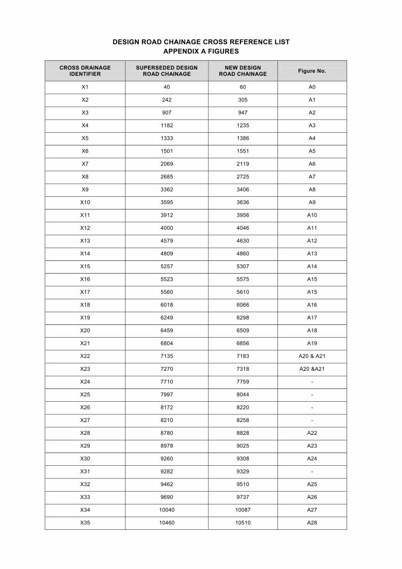
DESIGN ROAD CHAINAGE CROSS REFERENCE LIST APPENDIX A FIGURES
CROSS DRAINAGE IDENTIFIER
SUPERSEDED DESIGN ROAD CHAINAGE
NEW DESIGN ROAD CHAINAGE Figure No.
X1 40 60 A0
X2 242 305 A1
X3 907 947 A2
X4 1182 1235 A3
X5 1333 1386 A4
X6 1501 1551 A5
X7 2069 2119 A6
X8 2685 2725 A7
X9 3362 3406 A8
X10 3595 3636 A9
X11 3912 3956 A10
X12 4000 4046 A11
X13 4579 4630 A12
X14 4809 4860 A13
X15 5257 5307 A14
X16 5523 5575 A15
X17 5560 5610 A15
X18 6018 6066 A16
X19 6249 6298 A17
X20 6459 6509 A18
X21 6804 6856 A19
X22 7135 7183 A20 & A21
X23 7270 7318 A20 &A21
X24 7710 7759 -
X25 7997 8044 -
X26 8172 8220 -
X27 8210 8258 -
X28 8780 8828 A22
X29 8978 9025 A23
X30 9260 9308 A24
X31 9282 9329 -
X32 9462 9510 A25
X33 9690 9737 A26
X34 10040 10087 A27
X35 10460 10510 A28

