7. risk assessment - pangolin laser systems · 7. risk assessment 7.1 introduction the ... and...
TRANSCRIPT

92
7. Risk Assessment
7.1 Introduction
The hazard assessment methodology developed in chapter 6 is not the end of the story. It is necessary to usethis information to assess the risk from the use of lasers, determine control measures to eliminate or reducethe risk, and to manage the residual risk.
There is a legal requirement in the UK for employers to undertake a suitable and sufficient assessment of therisks to which their employees and others are exposed (HMSO 1992). It is important to present theconclusions in a form which is meaningful to the employer, ie assists with risk management, and to others,such as enforcing officers so that informed decisions on the adequacy of control measures and residual riskscan be made. There is currently only a legal requirement to make a record of the significant findings of therisk assessment under the Management of Health and Safety at Work Regulations (MHSWR) (HMSO,1992) if the employer employs at least five employees. It is recognised that many laser display companiescould fall below this threshold. However, enforcing officers may be able to use powers under entertainmentlicensing legislation to require a written record as a reasonable licence condition.
This chapter considers an ideal example of a risk assessment for part of the laser display and a means ofpresenting the data. However, it is accepted that the time constraints may make such assessments unlikely bythe laser companies unless specifically requested by the enforcing authorities or the venue management.Therefore, a more critical risk assessment methodology is presented whereby a decision can be made onwhether the risk can be assessed reasonably, or whether further information is required. Such a processshould allow an enforcing officer to follow a methodology to the limit of their expertise and be confident ofseeking further advice, which will normally be the analysis of information already provided where particularexpertise is required. This approach should provide a means of analysing whether the risk assessment issuitable and sufficient. It is strongly considered that it is more important for the laser display company todemonstrate an understanding of the risk and to be able to present conclusions based on actual data ratherthan to be able to present a microscopically detailed assessment. Such an approach should also meet therequirements of only needing to present the significant findings of a risk assessment.
7.2 Risk Assessment Methodologies
Formal risk assessment methodologies have been developed for industries where the risk is either actuallyhigh, demonstrated by a number of adverse incidents, or perceived to be high. Nuclear power plant operatorsand chemical production companies have developed sophisticated models to evaluate the risk to theiremployees and the public around facilities. Most of this work is carried out at the planning stage of newplants (Kletz 1992). Engineers also use risk assessment techniques to look at failure modes for machinery orprocesses, ie to determine the reliability (Modarres 1993). Here, the risk to personnel may be trivial but thecommercial risk may be important.
When developing a manufacturing process or a power plant, the investment and return is such that significanteffort to determine the risks can be justified. Laser displays are generally provided on a very tight budgetwithin a short timescale. The use of formal techniques such as HAZAN or component failure analyses maynot be justified, except for a major permanent installation which is likely to attract large audiences overseveral months or years. It is also questionable whether the employees of the laser display companies willhave the expertise to carry out such assessments. Concerns had been expressed by employers in otherindustries who had considered that the MHSWR required them to undertake assessments which producednumerical values for risk to different critical groups. These concerns were addressed by the Health and SafetyExecutive producing a practical guide to risk assessment at a level which would be reasonable in manyindustries (HSE 1994). Essentially, the guide suggested that there are five steps to any risk assessment:identify the hazards, decide who may be harmed, evaluate the risks, record the findings, and review and revise

93
the findings. A methodology for completing steps one and two has already been presented in chapter 6. Theanalyses from chapter 5 will provide input to step 3 for the laser radiation.
7.3 Risk Assessment in Practice
Assessing a complete laser display from the planning stage through to disposal will be a time-consumingprocess. However, much of the assessment will be common between installations carried out by a laserdisplay company. This is particularly apparent when the life cycle of the laser display is considered (section6.2). The work carried out at the laser company’s premises is likely to be similar and, generally, will be underthe control of the employer. Transport will also be similar. The major difference is between venues and thedetail of the actual laser display equipment. However, for a touring show, the differences are only related tothe venue.
A significant benefit of a company using the same approach for all of its work is that the enforcingauthorities, promoters and venue managers become familiar with the process and the way the information ispresented. If a common format can be agreed between companies then the net benefits are even greater.
7.3.1 Who is at Risk?
The identification of the hazards in chapter 6 demonstrates that many of these hazards have a risk of deathassociated with them, such as high voltages and working at height. However, it is important to recognise thatthe persons at risk from these hazards are generally either the employees of the laser company or otheremployees associated with the event. The total number of people at risk from these hazards is therefore small.Coming back to the premiss from chapter 1, the average family attending an entertainment event assumes thattheir safety is assured. The audience will generally number far more people than the employees. What is therisk that a member of the audience, or indeed another non-employee, could be injured as a result of theactivities associated with the laser display? The risk of an individual member of the public being injured orkilled will depend on the probability that they will be exposed to the respective hazard.
It is an interesting human characteristic that the number of people injured or killed features highly in thetolerability of risk from an activity to the extent that killing one employee of the laser company is generallymore acceptable then injuring a large number of people in the audience.
The main hazard that the audience are potentially exposed to is from the laser beam paths, ie the laserradiation. If there are secondary optics in the audience area then these may have hazards associated withthem. It is also possible that there may be links between the components of the laser display, such as controlcables, passing through the audience. However, the laser beam path has the greatest potential to affect thelargest number of people. The range of outcomes following exposure to laser radiation is from no effect,through sub-damage-threshold effects, such as distraction and after-images, to actual physical damage. Theresult of any damage will depend on the damage site, even within the target. If the target is the eye thendamage of the macula is likely to result in the loss of central vision. Even damage outside of the macula mayresult in vision degradation, or even blindness if the communication pathways to the optic nerve are damaged.Such damage obviously effects the quality of life of the exposed individual. However, there are also likely tobe other implications. A typical insurance payment for the loss of sight in one eye is about £30,000 in theUK. An insurance claim is likely to result in a critical review of the risks from the industry by the insurancecompanies, which may have far reaching implications for the use of lasers in the entertainment industry.
Recognition of the key risk issues allows the enforcing officer to identify where effort is required to determineif the risk assessment carried out by the laser company is adequate and that the hazards have been adequatelycontrolled and the risks are minimised. It should be possible to codify this taking account of the hazardidentification methodology to permit assessments to be made in a reasonable time. However, this should notdetract from the laser company’s duty to carry out a suitable and sufficient assessment of the risks which

94
cover public, and others’, exposure to hazards.
7.3.2 Example Risk Assessment
An example of the level of detail that is considered appropriate is presented here for a simple primary opticalsystem, as one compartment of the hazard identification methodology (chapter 6). Laser radiation is fed in toone end of the system and the output is through an aperture. An outline of the components of the system is infigure 7.1.
Assume that the input laser beam is from a krypton-argon laser with three wavalengths - 488 nm (blue),514.5 nm (green) and 647.1 nm (red). If these have been balanced for the photopic response of the eye(section 3.1.1) then the input beam will be perceived as white light. The periscope is used to adjust the beamheight between the laser and the optics of the primary optical system. This consists of two planar, frontsurface reflection, mirrors. Adjustment of height and angle of each mirror is possible. All of the remainingoptical components are at a fixed height. All components are mounted on a solid metal base using at least twobolts screwed into tapped holes in the base.
The shutter consists of a solenoid with a black beam stop mounted in the end of the shaft. The default positionis down with the beam stop in the beam path: a drive voltage is needed to pull the beam stop up out of thebeam path. The colour selection consists of three rotary actuators with dichroic mirrors which are matched tothe three wavelengths, ie the 488 nm dichroic will reflect the 488 nm wavelength but transmit the other twowavelengths.
The z-blanking consists of a lens which focuses the nearly parallel beam from the periscope into the mirror ofa galvanometer. The galvanometer and mirror position is set so that the beam is reflected or transmitted, ie theedge of the mirror interrupts the beam under program control. A second lens recollimates the beam after thegalvanometer. The transmitted beam is positioned in the centre of the mirror of the first scanninggalvanometer. The reflected beam from this mirror is then incident on the mirror of the second galvanometer.The beam from this mirror is then output from the primary optical system via an exit aperture.
Beam in
Figure 7.1 Schematic of Example Primary Optical System
Periscope Shutter ColourSelection
Z-BlankingScanningAperture
Beam out

95
It is necessary to identify which parts of the life cycle are relevant to the primary optical system and thepersons likely to be at risk at each stage of the life cycle. An example of such an assessment is presented infigure 7.1, below.
STAGE OF LIFECYCLE
HAZARDS PERSONS AT RISK
Planning None No-one at this stage but consideration ofthe remainder of the life cycle shouldreduce the risk
Manufacture Mechanical (tools, sharp edges,weight of items), electrical, heat(soldering iron), chemical (cleaningfluids)
Employees, visitors (perhaps includingclient)
Testing Mechanical (moving parts),electrical, water, laser radiation
Employees, visitors (perhaps includingclient)
Transport Mechanical (weight, sharp edges) EmployeesInstallation Mechanical (weight, sharp edges),
electricalEmployees, others in the vicinity butgenerally employees of other employers
Alignment Mechanical (moving parts, weight,tools), electrical, water, laserradiation
Employees, others in the vicinity butgenerally employees of other employers.Public, including the audience.
Performance Mechanical (moving parts),electrical, water, laser radiation
Employees, performers, audience, otherstaff
Maintenance Mechanical (moving parts, weight,tools), electrical, laser radiation,heat (soldering iron), chemical(cleaning fluids)
Employees, others in the vicinity butgenerally employees of other employers
Servicing Mechanical (moving parts, weight,tools), electrical, laser radiation,heat (soldering iron), chemical(cleaning fluids), water
Employees, others in the vicinity butgenerally employees of other employers
Modification Mechanical (moving parts, weight,tools), electrical, laser radiation,heat (soldering iron), chemical(cleaning fluids)
Employees, others in the vicinity butgenerally employees of other employers
Dismantle Mechanical (weight, sharp edges),electrical
Employees, others in the vicinity butgenerally employees of other employers
Disposal Mechanical (weight, sharp edges) Employees, any other personTable 7.1 Hazards and Persons at Risk from Primary Optical System
It is now necessary to evaluate the control measures in place to ensure that personnel are not exposed to thehazards. Again, these are likely to be different at different stages of the life cycle.
The hierarchy of control measures should be as follows: prevent exposure to the hazard by eliminating thehazard; substitute the activity for one that presents a reduced hazard; enclose the hazard; reduce the numberof people potentially or actually exposed to the hazard; or provide personal protective equipment. Trainingwill also be an important control measure. However, this may only be effective for employees of the laserdisplay company and, exceptionally, performers. Certainly an audience cannot be expected to be trained or totake notice of safety instructions.

96
7.3.2.1 Manufacture
One of the primary control measures during manufacture is the training of the employee undertaking thework. However, many of the hazards identified at this stage of the life cycle in table 7.1 can be controlled atsource. The use of good quality components, including fixings, with the correct tools should reduce the risk ofinjury. Consideration should be given to appropriate connection techniques, ie whether to solder componentsor dry mount, and whether to crimp or solder leads. If a soldering iron is used, it should be used withextraction and be stored in an appropriate base unit. Where cleaning, or other chemicals are used, theCOSHH assessments (HMSO 1994c) should be undertaken prior to the chemicals being used. If possible,chemicals with a trivial or low risk of ill health should be used.
7.3.2.2 Testing
At the testing stage the primary optical system is likely to be connected to a control system and probably alaser. A number of the components move, or will need adjustment. The minimum laser power necessary toundertake the alignment and testing should be used. It should be recognised that eye exposures at levels belowthe maximum permissible exposure level may cause dazzle, especially when working in reduced ambient lightconditions. With the laser on, and covers removed from the primary optical system, the risk of exposing otherpeople to the laser beam also needs to be recognised. The simplest control measure is to restrict access to thearea where the work is carried out. However, this should be balanced against the risk to the engineer workingalone.
There may be mains voltages within the chassis of the optical system, although most units will operate at 24,12 or 5 V DC maximum. Where there are mains voltages, it would be reasonable to enclose these locally tominimise the risk of accidental contact with live conductors.
At some stage, the primary optical system is likely to be tested with the full power from the laser to be used inthe display. This could identify stray reflections which were not apparent at the lower power. Again, it will beimportant to reduce the number of people at risk and to ramp the power up, where possible, so thatunintended beam paths can be eliminated as soon as they have been identified.
7.3.2.3 Transport
A well engineered system should not have sharp edges. However, there is still the risk of trapped fingers andmanual handling considerations both when the optical system is loaded into the transport case, and when thecase is loaded into the vehicle. Simple control measures include wheels (which can be locked) on the flightcase and a case design which does not require bending over and lowering the optical system into a case. A flatbase unit with a lid integral with the sides may be a suitable solution.

97
7.3.2.4 Installation
The first part of the installation is to unpack the equipment. It then has to be located in position. These bothhave manual handling implications. It is also possible that the installation is at height or in restricted spaces.Planning should have identified any particular issues here and appropriate control measures implemented.
The weather, which may be too hot, cold or wet, may have an impact on the risk to persons at the installationstage. Appropriate clothing, including footwear, hats and gloves, may be required. However, any risk of usingsuch measures should also be considered.
The services to the optical system may present a risk to the installer and others. These will include power andsignal connection cables.
7.3.2.5 Alignment
Most of the alignment of the optical system should have been carried out before the unit was transported.However, there will still be a degree of final alignment. Many of the risks and control measures will be similarto the testing carried out before installation. However, there may be the risk of exposing more people,including non-employees. The hazard likely to present a risk over the greatest distance is the laser radiation.The risk of accidental exposure can be reduced by the use the minimum power necessary to do the alignmentand local shielding. The latter may include a beam stop placed at some distance in front of the beam aperture.This beam stop also assists with the alignment process. The minimum power necessary to undertake thealignment will depend on ambient light conditions. Under extremely bright conditions the input power fromthe laser may need to be of the order of 1 W, especially out of doors when the beam needs to be aligned withsecondary optical components. Under these circumstances it may be necessary to remove all unnecessarypeople from the area while the alignment takes place. This eventuality should be considered at the planningstage, especially for events out of doors.
7.3.2.6 Performance
In order to minimise the risk of exposure to any of the hazards associated with the primary optical systemduring the performance local shielding should be used. This will include shielding over some opticalcomponents, such as the dichroic mirrors to ensure that the reflected beams are suitably dumped. A covershould be placed over the complete optical system so that the only apertures are the input aperture for thelaser and the intended exit apertures.
It should not be possible for non-employees to get access to the primary optical system, and certainly not tothe exit apertures.
The emergent laser beam is a residual hazard which should be controlled by its position in relation toaccessible areas. Engineering controls such as blanking plates should ensure that, even in the event of acomponent or control system failure, the beam cannot access audience areas. It is recognised that someoperators wish to undertake audience scanning and that the blanking would not permit this. However, withreference to the arguments in chapter 5, it would be reasonable to undertake audience scanning only withfurther consideration of control measures. For example, the beam used for audience scanning passes througha separate beam path, ie through a diverging lens, and exits from the primary optical system through adedicated aperture.
7.3.2.7 Maintenance, Servicing and Modification
The control measures for the hazards associated with maintenance, servicing and modification are similar tothose for testing, installation and alignment with due consideration to the location where the work is carried

98
out and the persons likely to be at risk.
7.3.2.8 Dismantle
Dismantling the equipment is essentially the reverse of the installation with two possibly significant factors:the crew are likely to be tired and, if out of doors, it may now be dark,
7.3.2.9 Disposal
The disposal of the optical system should present no more risks than the disposal of any other engineeringcomponents. The most appropriate route of disposal will generally be recycling with the components re-usedon other systems. However, as the components become obsolete they will be disposed of through normaldisposal routes.
7.4 Presenting the Risk Assessment Conclusions
As has already been identified, there are different audiences for the conclusions from the risk assessment. Thecompany will have a legal requirement to record the significant findings from its risk assessments if it hasmore than five employees (HMSO 1992). However, the laser display company may wish to present itsassessment in a written form for any or all of the following reasons:
• compliance with health and safety legislation• compliance with licensing legislation• staff relations• customer relations, including the presentation of a professional image• improved efficiency and effectiveness
The Health and Safety Executive’s (HSE’s) former guidance (HSE 1980) provided a suggested proforma forthe presentation of the basic information in support of a laser display notification to the enforcing authorities.As has already been described in Chapter 3, although these were used by some laser companies, theinformation was generally not adequate to allow a third party to assess the safety of the display.
The Australian code of practice (NHMRC 1995) provides a display safety record proforma which wasdeveloped during the course of this research. The proforma has the following sections:
• Responsible persons• Training• Laser System• Venue• Display Plan• Hazard Assessment• Protective Equipment• Display Maintenance and Routine Checks• Statutory Authority Approvals and Restrictions
Although a good starting point, there is little advice on how this information should be presented.
The revised HSE guidance (HSE 1996a), which the author contributed to, refers to hand-over documentation.This is recognised as being “good practice” rather than to meet a specific requirement. A list of what thehand-over documentation should include is:

99
• calculations and supporting measurements of exposure levels at defined positions within the display area,in keeping with HS(G)95, or otherwise demonstrating the overall safety of the installation;
• clear instructions on the use and effect of display controls;• details of all permissible display effects, their safety implications and the constraints on their use;• information on manual shutdown and surveillance requirements;• information on automatic emergency shutdown systems, their mode of operation, maintenance
requirements and function verification;• details of routine servicing and maintenance procedures, their frequency, who should carry them out, and
details of protective eyewear and/or clothing required;• details of routine adjustment and alignment checks to be carried out by the user, to include frequency,
record keeping and corrective action requirements: external optical component checks are especiallyimportant;
• operator experience and training requirements;• the supplier’s address and telephone number or those of its LSO; and• any special conditions to be observed.
The guidance also recognises the value of scale diagrams and/or photographs and that the information shouldbe presented in a form which is adequate for independent verification of emission safety by the enforcingauthority.
There is no requirement to provide hand-over documentation under this guidance if the installer is also theuser.
The international guidance (IEC 1995), which the author contributed to, refers to a display safety recordwhich should include:
• all relevant safety information relating to the design, installation, alignment and operation of the display;• the names and addresses of designers, installers, modifiers, operators and owner of the laser display
equipment;• any operation and display approvals and restrictions issued by regulatory authorities (both local and
national); and• laser equipment manuals conforming to 6.1 and 6.2 of IEC 60825-1.
It was recognised that the laser display companies would only draft documentation if either there was aspecific legal requirement to do so, or if there was a commercial benefit to them. Therefore, the proposedLaser Display Safety Record tries to address this latter issue while also addressing the general requirementsto record a risk assessment, meet the requirement of national guidance and comply with licensing legislation.
7.4.1 Laser Display Safety Record
The format of the Laser Display Safety Record has evolved from a need to provide a document which can beassessed, and be useful, to persons other than those who draft it. The final format uses a modular approachand is ideally suited to filing in a ring binder. As will be discussed later, this format also supports sub-sets ofthe Record, which can be used for specific purposes.
The laser display company should have a safety policy statement as required under Section 2(6) of the Healthand Safety at Work etc Act 1974 (HMSO 1974). The Laser Display Safety Record could also be consideredpart of that statement.
The outline Laser Display Safety Record presented here only covers the laser display from the time it leavesthe laser company's premises until it returns after a temporary installation. However, it can be seen that the

100
format can be modified to cover permanent installations or, indeed, operations at other stages of the life cycle,including manufacture and testing at the company’s premises. In particular, such a Record should exist forany installed demonstration facilities at the company’s premises.
Suggested section headings for the Laser Display Safety Record are presented in appendix E.
7.4.2 The Laser Display Safety Record in Practice
The Laser Display Safety Record has been used by one of the major UK laser display companies for anumber of events. A number of benefits were identified:
• the format was useful for event managers and enforcing officers• the laser display company manager was able to identify a number of shortcomings with his own
operations and introduced a number of additional control measures to reduce the risks to his staff andothers
• the process of drafting the Record gave the management of the laser display company a betterunderstanding of the problems faced by enforcing officers, who have to assess such displays
• the Record provided a metric against which to carry out internal audits.
The format of the Laser Display Safety Record was not without criticism. Each Record could fill an A4 ring-binder file. Preparation of the file also took significant effort. However, the investment in developing the fileshould mean that subsequent files can be built up from a series of modules. Many parts of each operation arecommon. An example file is presented as Appendix F.
It is also recognised that many enforcing officers will not welcome a large quantity of paperwork to assess.However, this is not the main reason for drafting the file. The value of the effort required to draft the file mustrest primarily with the laser display company. They have the responsibility to ensure that the risks are eithereliminated or reduced to an acceptable level.
It is possible to use a sub-set of the Laser Display Safety Record to provide an indication of the riskassessment carried out for a particular display. Fundamentally, the enforcing officer will want to know whatwill happen, where it will happen and when. They will also want to know the significant findings from therisk assessment. This is essentially Section 1 and Section 5.7 of the file.
The Laser Display Safety Record (LDSR) represents an ideal situation where time and effort are of no object.However, most decisions which need to be made by enforcing officers are made under less than idealconditions with time being the main problem. It was also recognised that they still needed to be reviewed bysomeone with significant knowledge of the subject to make a decision on the bottom line, ie whether the risk isacceptable and the laser display should be permitted to proceed.
The LDSR was adopted in a modified form by the Entertainment Laser Association and used by theirmembers for providing information in compliance with the requirements of HS(G)95. This should be seenagainst a background of a view that notifications were not required under HS(G)95, compounded by someanimosity due to the industry not taking an active part in drafting the guidance. If the methodology wasworking perfectly then it should be possible to assess the laser display from the information provided.
Assessments provided by various companies suggested that they were happy to complete the non-contentioussections, ie details of where and when the laser event was taking place. It appeared that the old PM19appendix 3 information was being re-worked to fit the LDSR format. Even information on the laserequipment was not complete. Risk assessments were included as far as the example presented in appendix F,even if not relevant. This had always been a concern with presenting a worked example since, as stated inchapter 3, the number of PM19 appendix 3s appeared to be small, giving the impression that many enforcing

101
officers were happy to receive some paperwork irrespective of the quality and relevance to the specific event.
The problems with using the LDSR suggested that the whole risk management methodology was not yetmature.
7.5 Assessing the Significant Risks
At the International Laser Display Association annual meeting in Lincoln, Nebraska, in November 1997, theauthor presented the hazard identification methodology and the Laser Display Safety Record to aninternational audience. This was significant because most of those present were from the USA, whereaudience scanning is very restricted and very much the exception. Risk assessment is not generally used in USlegislation but a number of those present could see the benefit of having a methodology for assessing the risksand presenting the significant findings to regulators. They saw this as a means to being able to demonstratethat, under certain well-controlled conditions, it would be acceptable to carry out audience scanning. This, ofcourse, was in marked contrast to UK and European countries where the practice was widespread and it wasconsidered that attempts were being made to restrict an accepted part of most laser displays. At the end of theILDA meeting, the President stated that he wished to see the industry develop an international laser safetyguide. Subsequent to the meeting, an international laser safety forum was formed from the interested parties.
Despite an agreement internationally that the safety issues had to be addressed, there were many views on thelevels of risk to which the audience in particular was exposed. It was considered that different standardsexisted in different countries and many of the misunderstandings regarding audience scanning exposureconditions prevailed. This provided extra justification for a risk assessment methodology which could get tothe heart of the real risk issues and be interpreted throughout the world. In short, the negative attitude of manyELA members had been replaced by an international desire to address the real safety issues to be able todemonstrate that the industry could operate in a safe manner without risk to the audience.
7.5.1 Who is at Risk?
The hazard identification methodology recognises that there are different people at risk from exposure to thehazards. This can be summarised into zones of people:• Laser company employees• Other employees• Performers• Audience• Other peopleNot all laser display events will have people from all categories and, indeed, the life cycle will also beimportant. Using these categories of people, who will generally be in certain specific positions in the venue asa function of time, it is possible to identify where the real risks exist as a function of the hazard identificationmethodology, life cycle and zone. Folded into this the number of people at risk and the outcome will need tobe considered. A three dimensional representation of the risk assessment methodology is shown in figure 7.2.
There are a number of ways of expressing the probability of persons being exposed to a risk, the outcome andthe number of people at risk. For this analysis, a numerical system is used whereby a larger numberrepresents a greater problem. A risk factor can be calculated by multiplying the three parameters. It is likelythat different outcomes will have different risk factors. For this analysis the largest numerical risk factor isused. The parameters are assigned numerical values as follows:Probability: 1 - Improbable
2 - Possible3 - Likely4 - Very likely
Outcome: 1 - No injury

102
2 - Minor injury3 - Major injury4 - Death
Numbers: 0 - None1 - 1 Person2 - 2 to 5 People3 - 6 to 20 People4 - Greater than 20 People
7.5.2 Results
An analysis is presented as a function of the life cycle and the compartments of the hazard identificationmodel, for each of the zones of people considered at risk, for a temporary outdoor display (figures 7.3 to 7.7)and for a permanent indoor installation (figures 7.8 to 7.10). For comparison, the z-scales are identical foreach zone within each event. The number of zones for the permanent installation is less than the temporarydisplay. It is also assumed that intentional audience scanning forms part of the outdoor display, but not theindoor display. The public are also admitted during the alignment of the outdoor display, as was experiencedat event B in appendix B.
The analysis of the risks in the manner presented in figures 7.3 to 7.10 gives a rationale for focusing themanagement of the risks. It is significant that the public are rarely at risk of death from a laser display,whereas the activities of the laser company may put themselves and other employees in the vicinity at suchrisk. Once the laser display reaches the performance part of the life cycle the analysis of the risks is simplifiedand, as suggested from figures 7.3 to 7.10, the main issues are the exposure to the laser radiation and inparticular whether such exposures are intended or reasonably foreseeable. Taking the three-dimensionalpresentation of the risk assessment issues from figure 7.2, this can be redrawn with the key issues aspresented in figure 7.11. In essence there is a bottom line - are the audience at risk from the beam paths eitherthrough intentional or accidental exposure.
People at Risk
CompartmentsLife Cycle
Figure 7.2 - Three Dimensional Representation of Risk Model
for example, risks to performers from the support system during alignment

103
0
10
20
30
40
Lase
r
Bea
m P
aths
Ass
ocia
ted
Equ
ipm
ent
Oth
er S
taff
Ven
ue
Pla
nnin
g
Man
ufac
ture
Test
ing
Tran
spor
t
Inst
alla
tion
Alig
nmen
t
Per
form
ance
Mai
nten
ance
Ser
vici
ng
Mod
ifica
tion
Dis
man
tle
Dis
posa
l
Figure 7.3 Risk Matrix - Laser Company EmployeesTemporary Outdoor Display

104
0
10
20
30
40
Lase
r
Bea
m P
aths
Ass
ocia
ted
Equ
ipm
ent
Oth
er S
taff
Ven
ue
Pla
nnin
g
Man
ufac
ture
Test
ing
Tran
spor
t
Inst
alla
tion
Alig
nmen
t
Per
form
ance
Mai
nten
ance
Ser
vici
ng
Mod
ifica
tion
Dis
man
tle
Dis
posa
l
Figure 7.4 Risk Matrix - Other EmployeesTemporary Outdoor Display
0
10
20
30
40
Lase
r
Prim
ary
Opt
ics
Sec
onda
ry O
ptic
s
Ass
ocia
ted
Equ
ipm
ent
Ope
rato
r
Aud
ienc
e
Ven
ue
Pla
nnin
g
Man
ufac
ture
Test
ing
Tran
spor
t
Inst
alla
tion
Alig
nmen
t
Per
form
ance
Mai
nten
ance
Ser
vici
ng
Mod
ifica
tion
Dis
man
tle
Dis
posa
l
Figure 7.5 Risk Matrix - PerformersTemporary Outdoor Display
0
10
20
30
40
Lase
r
Bea
m P
aths
Ass
ocia
ted
Equ
ipm
ent
Oth
er S
taff
Ven
ue
Pla
nnin
g
Man
ufac
ture
Test
ing
Tran
spor
t
Inst
alla
tion
Alig
nmen
t
Per
form
ance
Mai
nten
ance
Ser
vici
ng
Mod
ifica
tion
Dis
man
tle
Dis
posa
l
Figure 7.6 Risk Matrix - AudienceTemporary Outdoor Display

105
0
10
20
30
40
Lase
r
Prim
ary
Opt
ics
Sec
onda
ry O
ptic
s
Ass
ocia
ted
Equ
ipm
ent
Ope
rato
r
Aud
ienc
e
Ven
ue
Pla
nnin
g
Man
ufac
ture
Test
ing
Tran
spor
t
Inst
alla
tion
Alig
nmen
t
Per
form
ance
Mai
nten
ance
Ser
vici
ng
Mod
ifica
tion
Dis
man
tle
Dis
posa
l
Figure 7.7 Risk Matrix - Other Members of PublicTemporary Outdoor Display
0
5
10
15
20
25
Lase
r
Prim
ary
Opt
ics
Sec
onda
ry O
ptic
s
Ass
ocia
ted
Equ
ipm
ent
Ope
rato
r
Aud
ienc
e
Ven
ue
Pla
nnin
g
Man
ufac
ture
Test
ing
Tran
spor
t
Inst
alla
tion
Alig
nmen
t
Per
form
ance
Mai
nten
ance
Ser
vici
ng
Mod
ifica
tion
Dis
man
tle
Dis
posa
l
Figure 7.8 Risk Matrix - Laser Company EmployeesPermanent Installation
0
5
10
15
20
25
Lase
r
Prim
ary
Opt
ics
Sec
onda
ry O
ptic
s
Ass
ocia
ted
Equ
ipm
ent
Ope
rato
r
Aud
ienc
e
Ven
ue
Pla
nnin
g
Man
ufac
ture
Test
ing
Tran
spor
t
Inst
alla
tion
Alig
nmen
t
Per
form
ance
Mai
nten
ance
Ser
vici
ng
Mod
ifica
tion
Dis
man
tle
Dis
posa
l
Figure 7.9 Risk Matrix - Other EmployeesPermanent Installation

106
Other people
Audience
Operator
Control systemSupport systemBeampaths
Audience Other members of public
Planning
Alignment
Performanc
e
Figure 7.11 Key Risk Assessment Issues
Life Cycle
Hazard Identification Compartments
Persons atRisk
0
5
10
15
20
25
Lase
r
Prim
ary
Opt
ics
Sec
onda
ry O
ptic
s
Ass
ocia
ted
Equ
ipm
ent
Ope
rato
r
Aud
ienc
e
Ven
ue
Pla
nnin
g
Man
ufac
ture
Test
ing
Tran
spor
t
Inst
alla
tion
Alig
nmen
t
Per
form
ance
Mai
nten
ance
Ser
vici
ng
Mod
ifica
tion
Dis
man
tle
Dis
posa
l
Figure 7.10 Risk Matrix - Audience

107
7.5.3 Codifying the Risk Assessment
The former HSE guidance on the safety of laser displays (HSE 1980) attempted to provide a proforma,specifically aimed at the enforcing officer for demonstrating compliance with health and safety requirements.The goal-setting approach of the revised guidance (HSE 1996) requires a risk assessment to be carried out.The feedback from chapter 4 has shown that the enforcing officers were not able to apply formal training onassessing laser displays but were still seeking advice and reassurance each time a laser display took place.Codifying the assessment process should assist the enforcing officer to carry out most, if not all, of theassessment of risk management for a given event. This could be programmed into a decision support softwarepackage. Building on the experience gained with applying the risk assessment methodology developed here,the key issues can be distilled. Generally, the enforcing officer will only be concerned with the stages of thelife cycle which put the public at risk, although it should be appreciated that activities and decisions made atthe other stages of the life cycle may impact on public safety.

108
The primary question will be “does audience scanning form part of the laser display?”. If the answer to this isyes, then the risk assessment needs to concentrate on this issue. If intentional exposure does not form part ofthe display then the failure modes which could result in audience exposure need to be considered. The keyissues for a decision support system simplify to the following.• Whether intentional personnel exposure to laser beams takes place• The reasonably foreseeable incidents which could expose personnel to the laser beams• The integrity of any safety control systems, such as beam blanking• Training and competence of the operator (can be assessed by demonstration of understanding laser display
operation and safety issues)• Whether persons (and particularly the public) are at risk during installation and alignment• The stability of the optical systems which launch both the primary and secondary beams.
It can be seen that the hazards presenting the severest outcome are not necessarily the areas focused on here.If intentional exposure of people is not planned then the whole assessment simplifies further into generalsafety issues with which the enforcing officer is likely to be familiar. However, if intentional exposure, suchas audience scanning, is planned then a full assessment is required, as outlined in chapter 5.
The simplified approach was tested for a number of laser displays both with enforcing officers who hadattended the training courses and with those who had not. Generally, the methodology was applied over thetelephone to minimise the cost to the local authority. Essentially, a series of questions were presented to theenforcing officer to answer each of the bullet points above. A key issue for the enforcing officer asking thequestions of the laser display company was the requirement to not appear foolish in the quality of thequestions asked. This was not as much of an issue for the officers who had attended the training courses.However, for the others it was necessary to present an outline of a laser display. The hazard identificationmethodology provided an excellent basis for this.
The simplified methodology was also applied to a number of overseas laser displays to assist local safetyofficers and included the assessment of the laser displays forming part of the first annual meeting of theInternational Laser Display Association outside of the United States (in Canada), where audience scanningwas less restrictive than in the United States. The methodology was codified as presented in figure 7.12. Thisrecognises the importance of the assessment being carried out, at least initially, at the planning stage. Some ofthe changes resulting from the risk assessment may be fundamental. For example, if the venue manager wantsaudience scanning and the assessment shows that this is not possible with the type of laser installation, it istoo late to find this out once everything has been installed. The author was involved with such a problem.
The key issue is certainly audience scanning. As has already been stressed, the assessment is notstraightforward and an enforcing officer will probably need to seek further advice at this stage. If the scanningis not intended then the beam paths should be reviewed throughout the whole performance. If the display isout of doors there is the potential for persons to be exposed to the laser beams outside of the venue. Again ithas been stressed that the operator competence is a major risk control measure. Careful questioning ratherthan formal assessment may be the only way to judge the competency of an operator. The hazardidentification methodology can form a basis for a range of questions.
The control of the risk of accidental exposure, or intended exposure with un-assessed parameters, may beaffected by the control system. For example, a fully automated playback system is less likely to present a riskof unplanned exposure than a fully computerised system operated manually.
A small movement in the laser display support system can result in beams moving into occupied areas, eventhough blanking may be used. The mechanical stability assessment should be within the capability of theenforcing officer. The stability will be an issue with temporary installations, as described in chapter 3, andalso with new venues where the venue structure may be still settling. This latter point is a particular issue

109
with some entertainment venues which use a floating construction to insulate night clubs, for example, fromcinemas in multi-entertainment complexes.
The hazard assessment methodology provides a final check through all of the safety issues, to ensure thatthese have, at least, been considered. An acceptable conclusion from all of this would result in the risks beingadequately managed and therefore the event may proceed. However, if changes are required then there willneed to an element of judgement on how far back through the decision tree the assessment should re-start.

110
Planning StageCompleted?
Requirement to AssessLaser Display
IntentionalAudienceScanning?
Changes may be difficult to
implement
Seek furtheradvice
Review Beam Paths
Other PeopleExposed to
Beams?
Review OperatorCompetence
Review ControlSystem
Review SupportSystem & Blanking
Run Through HazardMethodology
RiskAcceptable?
Show Proceeds
ChangesPossible?
Show NotPermitted to
Proceed
Yes
Yes
No
Yes
No
OK
OK
OK
Not OK, or ?
Not OK, or ?
Not OK, or ?
Not OK, or ?OK
Yes
No
No
Yes
Figure 7.12 Codified Assessment Process
No

111
In all cases the methodology was found to be effective at quickly getting to the key risk management issues. Itavoided wasting time on some of the detail if it was obvious that some of the key issues would prevent theshow proceeding.
7.5.4 Audience Scanning Control Measures
The UK laser display industry continues to insist that audience scanning is both without risk and that is anaspect of laser displays most attractive to the customer. As such, they continue to consider methods tomaintain this practice in spite of various demonstrations that they cannot provide a suitable and sufficientassessment of the risks from this practice.
Fuelled by the belief that scanning laser beams faster makes them safer, there has been some investment inaudience scanning control measures which terminate the laser scan in the event of a scan-fail condition. Thereis also a requirement in the German draft standard for laser displays to have an automatic shut-downmechanism operating within 100 ms (DIN 1995) if audience scanning is intended.
Since the laser display companies are starting to use scan-fail control systems as a demonstration thataudience scanning can be carried out safely, it is worth considering the practical implications for such devicesand whether they do indeed reduce or manage the risk.
A number of scan-fail devices are commercially available and they all tend to operate with a response timefrom 50 to a few hundred ms. Do such products reduce the risk of intentional audience scanning? Theanalysis presented in chapter 5 demonstrates that the risk is not reduced by scanning the laser beam faster.Therefore, any control measure which is designed only to consider the scan speed will not be an effectivecontrol measure except to control a static beam. However, since the maximum irradiance at the audienceshould already be below the MPE, failure of the scanning system will mean that the MPE will only beexceeded by an order of magnitude, at most, if the beam is static.
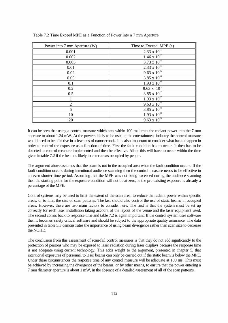
Assuming that the scan-fail system was designed to protect from accidental entry of the laser radiation intothe audience area then it is possible to calculate the time within which it would have to be effective to preventexposure above the MPE. Since this would be an accident situation, the maximum exposure duration wouldbe 0.25 s. The MPE for 0.25 s gives a maximum power into a 7 mm diameter aperture of 1 mW (see chapter5). Assuming a power into a 7 mm aperture (which may be greater than the radiant power of the laser), thenthe time to exceed the MPE can be determined from the following. The area of a 7 mm diameter aperture is3.85 x 10-5 m2. The relevant MPE values are 5 x 10⁻³ J m-2 for t from 1 ns to 18 µs and 18 t0.75 J m-2 from 18µs to 10 s. Converting these into irradiances by dividing by t and into radiant power through a 7 mm apertureby multiplying by 3.85 x 10⁻⁵ m2, this gives 1.925 x 10⁻⁷/t and 6.93 x 10⁻⁴ t-0.25 W, respectively. This data isplotted in figure 5.1 and tabulated in table 7.2.
112
Table 7.2 Time Exceed MPE as a Function of Power into a 7 mm Aperture
Power into 7 mm Aperture (W) Time to Exceed MPE (s)0.001 2.33 x 10⁻¹
0.002 1.46 x 10⁻²
0.005 3.73 x 10⁻⁴
0.01 2.33 x 10⁻⁵
0.02 9.63 x 10⁻⁶
0.05 3.85 x 10⁻⁶
0.1 1.93 x 10⁻⁶
0.2 9.63 x 10⁻⁷
0.5 3.85 x 10⁻⁷
1 1.93 x 10⁻⁷
2 9.63 x 10⁻⁸
5 3.85 x 10⁻⁸
10 1.93 x 10⁻⁸
20 9.63 x 10⁻⁹
It can be seen that using a control measure which acts within 100 ms limits the radiant power into the 7 mmaperture to about 1.24 mW. At the powers likely to be used in the entertainment industry the control measurewould need to be effective in a few tens of nanoseconds. It is also important to consider what has to happen inorder to control the exposure as a function of time. First the fault condition has to occur. It then has to bedetected, a control measure implemented and then be effective. All of this will have to occur within the timegiven in table 7.2 if the beam is likely to enter areas occupied by people.
The argument above assumes that the beam is not in the occupied area when the fault condition occurs. If thefault condition occurs during intentional audience scanning then the control measure needs to be effective inan even shorter time period. Assuming that the MPE was not being exceeded during the audience scanningthen the starting point for the exposure condition will not be at zero, ie the pre-existing exposure is already apercentage of the MPE.
Control systems may be used to limit the extent of the scan area, to reduce the radiant power within specificareas, or to limit the size of scan patterns. The last should also control the use of static beams in occupiedareas. However, there are two main factors to consider here. The first is that the system must be set upcorrectly for each laser installation taking account of the layout of the venue and the laser equipment used.The second comes back to response time and table 7.2 is again important. If the control system uses softwarethen it becomes safety critical software and should be subject to the appropriate quality assurance. The datapresented in table 5.3 demonstrates the importance of using beam divergence rather than scan size to decreasethe NOHD.
The conclusion from this assessment of scan-fail control measures is that they do not add significantly to theprotection of persons who may be exposed to laser radiation during laser displays because the response timeis not adequate using current technology. This adds weight to the argument, presented in chapter 5, thatintentional exposures of personnel to laser beams can only be carried out if the static beam is below the MPE.Under these circumstances the response time of any control measure will be adequate at 100 ms. This mustbe achieved by increasing the divergence of the beams, or by other means, to ensure that the power entering a7 mm diameter aperture is about 1 mW, in the absence of a detailed assessment of all of the scan patterns.

113
7.5.5 The Risk from Audience Scanning
The foregoing sections have highlighted that it is possible to use a simple methodology to assess a laserdisplay if audience scanning does not take place and control measures are implemented to ensure thataccidental exposures to laser radiation are unlikely. If audience scanning does take place then it is unlikelythat the enforcing officers will have the necessary expertise to assess the risk directly or from informationsupplied by the laser company. Indeed, as has been demonstrated from this research it is also unlikely that thelaser company will be able to carry out the assessment themselves.
The analyses presented in chapter 5 showed that the MPE was likely to be exceeded for most laserinstallations undertaking audience scanning. However, how does this translate into risk? The number ofreported eye injuries is extremely low considering the number of people who have been exposed to audiencescanning over the last 25 years. The survey carried out by Murphy (1995) supported the argument that theinjuries are not occurring. This raises a number of issues:• the MPE values may be wrong;• the application of the MPE values to the exposure situation is not appropriate;• the injuries are occurring but are not being reported, but are being attributed to something else; or• the injuries are occuring but are not affecting the quality of vision.
The MPE values have been verified over a number of years. As shown in table 2.1, the MPE values for thevisible part of the spectrum have remained constant since at least 1983. There is approximately a factor of tenbetween the MPE value and the ED50 values, where the ED50 is the radiant exposure required to cause anophthalmologically significant lesion in 50% of cases (Sliney and Wolbarsht 1980). Therefore, based on thisit would be reasonable to expect lesions in 50% of persons exposed at ten times the MPE. The ability of laserradiation at this order of radiant exposure to damage the retina is supported by the radiant exposure levelsused in medical treatment of retinal conditions. The conclusion therefore is that the MPE values are probablycorrect, at least within a factor of ten. It should also be appreciated that the experimental data suggested that,even at the MPE, there was a 3% risk of a lesion.
The quantification of the laser radiation hazard in chapter 5 does make a number of assumptions, but all ofthese are considered to be valid for the exposure situation in the entertainment industry. If anything there areother factors which may need to be taken into account, such as compromised aversion response under theinfluence of drink or drugs. It could be argued that the scanned effects used in audience scanning are neverstationary and even the assumption of a 0.25 s exposure is very restrictive. However, from figure 5.1 andtable 7.2, it can be seen that even a single pass of a laser scan pattern is likely to exceed the MPE unless thepower entering the 7 mm aperture is low. For example, the maximum power for a single 23.2 µs exposure is10 mW. Although eye movement may be a factor for longer exposures, it is unlikely to be significant for thesituation considered here.
Many laser light shows are accompanied by smoke (to make the beams visible) and possibly narcoticsubstances in the environment. A direct laser strike on the macula at a radiant exposure significantly in excessof the MPE is likely to result in a lesion, which is likely to result in complete loss of central, detailed vision.For this to happen, the recipient has to be looking directly at the actual or apparent source of the laserradiation. If the target site is away from the macula then the damage will be to the peripheral vision. Theretina does not contain pain receptor cells and therefore any lesion is unlikely to be accompanied by pain.However, recent reports of laser pointer injuries have included references to pain. Medical assessments havesuggested that the pain has come from bruising or abrading of the corneal surface by repeated rubbing of theeye with the back of the hand. Pain in the eyes may follow extended exposure to the smoke haze or otheragents.
Marshall (1989) has shown that repeated lesions can be placed in the peripheral vision without the recipientbeing aware of them and he suggests that thousands of such lesions will not be perceived, since such damage

114
is routinely carried out during laser treatment for some retinal conditions (Marshall 1997). This would seemto be the best argument for why more laser injuries have not been reported. This then raises a fundamentalquestion. Is it acceptable to cause permanent damage to members of the audience, even though it does notaffect their quality of life? The author’s view is that it is not acceptable. Without a reasonable assessment ofthe irradiance levels to which persons are exposed, it is likely that higher and higher exposure levels will beused, greatly increasing the risk of more recipient observable lesions. It is also recognised that a few highlypublicised incidents could trigger significant requests for eye examinations and potential litigation. Thiswould be a global issue and not restricted to the UK.
To date, the number of reported incidents is small with 28 outdoor eye-related reports (Rockwell, 1997). Themost recent injury report resulted from the use of a laser in a nightclub in Germany (Sachs et al, 1998). Thisfollowed a satisfactory safety inspection, but it is believed that the laser was replaced with one of a higherradiant power after the inspection.
7.6 Summary
This Chapter has shown how the hazard identification model can be used as input to a risk assessment forany laser display operation. It was recognised that detailed system failure assessments were generally notnecessary. The process had to be reasonable and, mainly, relies on common sense.
Carrying out the risk assessment is only part of the task. The laser display industry has to prove to others,including enforcing officers, that the work it carries out is without risk to the public. A Laser Display SafetyRecord has been developed as a means of presenting all of the relevant information about the laser display. Itis encouraging that the managers from laser display companies who have tried the format have found it usefulto themselves, in addition to providing a means of informing others.
The complete Laser Display Safety Record is likely to have more information than an enforcing officer willrequire initially. However, a sub-set of the file can easily be provided. Such assessments should reasonably beprovided for all permanent installations.
The time available to assess a laser display may be limited. Therefore, a more focused risk assessmentmethodology was developed to cover the key issues from any laser display by treating the display in threedimensions: compartments of the hazard identification model; persons at risk; and the life cycle. It is foundthat the significant risks relate to the laser radiation, although the radiation may not result in the most seriousoutcome. This is because, in many cases the public may be at risk and represent a large number of people atrisk. The important sections of the life cycle tend to be the alignment of the laser beams and the actualperformance. By following a simple methodology it is possible to identify the key issues which need to beaddressed by the laser company in order to satisfy the legal requirement to undertake a suitable and sufficientassessment of the risks and to demonstrate this to an enforcing officer. If intentional exposure of people tolaser radiation is not included within the show then the assessment can be straightforward and generallycovers agents which are either familiar to the enforcing officer or can be easily audited such as mechanicalstability, beam blanking and electrical safety. If audience scanning, for example, is an intended part of thelaser display then it is either necessary to analyse each scanned effect, considering the failure conditions, or,simply, to limit the radiant power through a 7 mm aperture at the closest point of access to 1 mW. If this ismeasured, due account will have to be taken of the non-uniformity of many entertainment laser beam profiles:the maximum power through a 7 mm aperture will have to be determined.
Recurrent exposure of people at 1 mW is not without risk. People within the venue may be seated or at least,will not be carrying out safety critical operations. Persons outside of the venue, or who may be workingwithin the venue, may be subject to distraction, dazzle and afterimages at exposure levels considerably belowthe MPE, depending on the ambient light level. If such recipients are driving or piloting vehicles then the riskcould be of death and affect considerable numbers of people. For this reason, any beams which may leave the

115
venue should also be carefully considered.
The assessment has shown that many laser shows are routinely exposing people at irradiance levelsconsiderably in excess of the MPE values. A survey of the number of reported incidents would suggest thatthe practice results in a very small risk, ie a handful of incidents have been reported in the last 25 years. Thesmall number of incident reported does not necessarily mean that injuries are not occurring: they may be inthe peripheral regions of the retina where the recipient may not be aware of any degradation of vision.However, such injuries are still considered unacceptable. Quantification of the laser radiation hazard must becarried out to determine the risk from audience scanning. If the exposure levels cannot be assessed then thepractice should not be permitted.