7. road markings, studs and...
TRANSCRIPT

DEPARTMENT OF THE
ENVIRONMENT
7. ROAD MARKINGS,STUDS AND DELINEATORS
CHAPTER
P7

TRAFFIC SIGNS MANUAL Chapter 7
ENVIRONMENT
Chapter 7 Road Markings, Studs and Delineators
Page
7. I Introduction 7-27.2 Legal 7-37.3 Materials 7-37.4 Transverse Markings 7.37.5 Longitudinal Markings - Lane. Centre and Edge Lines 7-97.6 Longitudinal Markings - Double Line System 7-197.7 Level Crossing 7-247.8 Roundabouts 7-267.9 Worded Markings 7-307.10 Junction Markings 7437.11 Pedestrian Crossings 7-197.12 Chevron Markings 7-547.13 Reflecting Road Studs and Delineators 7-56
0
07.1

TRAFFIC SIGNS MANUAL Chapter 7
ENVIRONMENT
Chapter 7 Road Markings, Studs and Delineators
7.1 Introduction
7.1 . I Road markings may be defined as markings on the surface of theroad for the control, warning, guidance or information of roadusers. They may be used to supplement kethside or overhead signs,or they may be used alone.
7.1.2 Road markings have the limitation that they may be obliteraled bysnow. Their conspicuity is impaired when wei or dirty and theirdurability depends largely on their exposure to traffic wear.Nevertheless, they serve a very important function in conveying todrivers, information and requirements which might not otherwisebe possible by the use of upright signs. They have the advantagethat they can often be seen when an erected sign is obscured, and,unlike such signs, they can provide a continuing message to themoving driver.
7. I .3 The continued increase in the volume of traffic using the roadsmakes extensive use of road markings essential to ensure that fulladvantage is taken of the available road space. In particular,widespread use of lane markings is desirable. Enhancing lanediscipline adds materially to the safety of traffic, besides improvingtraffic flows. In urban areas considerable advantages accrue fromroad markings at junctions.
Classes of Marking
7.1.4 Road markings may be classified as follows:
(a) Transverse markings, which are at right-angles (orthereabouts) to the centre line of the carriageway.
(b) Longitudinal markings:(i) Centre lines(ii) Lane lines(iii) Edge lines.
(c) Markings at level crossings.(d) Markings at roundabouts.(e) Yellow markings for waiting and loading restrictions.
(fl Worded markings, parking bays, box markings, schoolmarkings and bus and cycle tracks.
(g) Junction markings.(h) Markings at pedestrian crossings(i) Hatched markings.
7.1.5 It is strongly recommended that road markings be considered indetail at the design stage of new or improved junctions.The markings for existing junctions are best considered on planbefore the work is undertaken.
7.2

TRAFFIC SIGNS MANUAL Chapter 7
ENVIRONMENT
7.2 Legal
7.2.! Road markings are provided in accordance with signs regulations or
directions of the Minister for the Environment. They may be laid
only by. or on behalf of. the roads authority. Attention is drawn to
the necessity for the Authority to consult with the Commissioner of
the Garda Siochana where regulatory traffic signs or road markings
are being provided.
7.3 Materials
7.3.! Road markings/materials should conform with Lhe guidelines for Qmarkings contained in Thermoplastic Road Markings - Guidelines
and Tender Documentation’, avaiiable from Westmeath County
Council.
7.4 Transverse Markings
Where alternative dimensions for line widths or letter heights are
provided. generaily the smaller dimensions should be used in urban
areas and the larger dimensions in rural areas and at major urban
junctions.
7.4.! The prescribed transverse markings comprise:
(i) Stop Lines(ii) Yield Lines and
(iii) No entry Lines
STOP Line Fig. 7.1 07.4.2 A 200mm (250 mm) wide white line indicates the position beyond
which a driver must not proceed when required to stop by signs, or
by traffic signals. including signals at level crossings.
Note: Special width of 300 mm for stop line at level crossings.
Junction STOP Line
7.4.3 The marking consists of a single continuous white line 200 mm
(250 mm) in width. The edge of the STOP line nearest to the major
road should not be closer than 600 mm to the path normally
followed by the nearest side of the major road vehicles. Only very
rarely should it be sited elsewhere and then it must be sited so as to
halt a driver where visibility is best.
07.3

tj
:- La
CD U) C -a Lf
l
C.) U) C.) U)
I 2l0
0-2
750
C.) t Ct
-I
00
00
No
te:
Gen
eral
lyth
esm
alle
rdi
men
sion
ssh
ould
beus
edin
urba
nar
eas
and
the
larg
erdi
men
sion
sin
rura
lar
eas
and
atm
ajor
urba
nju
nctio
ns.
I100--
-.
(150
)
20m
mmdOS
SST
OP
sign
assh
own
orat
loca
tion
tobe
1600
dete
rmin
edby
sigh
t(2
800)
dist
ance
.
T
V
200(
250)
rV
600
-a

NO
TE
:
A A
Yie
ld-
line
segm
ents
and
gaps
may
bere
duce
dto
500m
mw
here
rest
rict
edla
new
idth
does
not
pem
iit
the
abov
epa
tter
nCo
bepr
oper
lydi
spla
yed
10
0--
--(1
50)
20m 2
A
mm
3750
YIE
LD
Sign
WI, to p In B’
tn-i In 0 0 e In C
C
V
A
-e
200(
250)
2100
-275
0
in z 0 2 m 2 -l
Wtf
r
—-—
1000
1000
II
n Ct
ci, n ‘1 -3
rj
CC
C

TRAFFIC SIGNS MANUAL Chapter 7
ENVIRONMENT
7.4.4 On a two-way road the STOP transverse marking should always be
accompanied by a central continuous longitudinal line extending
back from the junction for a minimum distance of 20m from the
STOP line.
7.4.5 The STOP worded marking, where used, should have letters of
height either 1600mm or 2800mm.
Traffic Signal STOP Linc
7.4.6 The marking consists of a single continuous white line 200mm
(250mm) in width.
7.4.7 At traffic signals, including pedestrian signals, the STOP line is
normally located Im to 2m before the nearside primary signal but
site conditions may necessitate adjustment for this distance.
YIELD Line Fig. 7.2
7.4.8 The recommended marking consists of a broken line 200mm
(250mm) wide comprising 1000mm marks and 1000mm gaps. See
Fig.7.2 for layout of YIELD sign and associated road markings.
Where the width of the approach lane is not sufficient to display the
pattern, segments of 500mm marks and 500mm gaps may be used
instead.
7.1.9 On two-way minor roads, the marking normally extends to the
centre of the carriageway of the minor road; on a one-way mad it
is carried across the whole width of the minor road. The precise
location of the marking nearest to the major road in relation to the
edge of the major road is governed by the same considerations as
the STOP line.
7.4.10 On two-way roads, the YIELD transverse marking should always
be accompanied by a continuous white line extending back from
the junction for a minimum distance of 20m from the YIELD line.
Triangular YIELD Approach Marking Fig. 7.2.
7.4. II The hollow triangular marking may only be used when a transverse
YIELD line is provided and should be accompanied by a YIELD
upright sign. It must not be used elsewhere. The marking should
normally be located with its base 2.Im to 2.75m from the
transverse marking, but exceptionally this distance may be
increased to a maximum of I5m depending on the visibility at the
junction, its layout, and the speed of traffic on the minor road. A
suitable place to locate it would be with the base of the triangle near
the tangent point of the kerbline.
7.6

TRAFFIC SIGNS MANUAL Chapter 7
ENVIRONMENT
7.4.12 \Vhere triangular markings are used they should be positionedapproximately in the centre of the traffic lane, Where the approachto the junction is divided into two or more lanes, then a triangularmarking should be provided in each lane.
NO ENTRY Fig. 7.3
7.4.13 The recommended marking consists of one continuous white lineand one broken line comprising 1000mm marks and 1000mm gaps.The lines are 200mm wide and are spaced 300mm apart. Theprecise location of the marking nearest to the major road isgoverned by the same conditions as the STOP line.
The wording NO ENTRY may accompany the above lines. Thespacing between the broken line and the lettering is 300mm. Theheight of lettering is either 1600mm or 2800mm, depending uponthe width of the road.
7.4.14 The road markings must be accompanied by the appropiateregulatory signs. i.e. the “NO LEFT TURN” and “NO RIGHTTURN” signs on the approaches to the junction on the intersectingroad, and the “NO ENTRY” sign on both sides of the one-way roadat its junction with the intersecting road.
0
07.7

TRAFFIC SIGNS MANUAL Chapter 7
ENVIRONMENT
—100-(150)
FIG. 7.3 Markings for use with NO ENTRY Sign
VA
3750
A
V
2000
— 150
——a 600
V1250
2 100-2750(Max. 12800)
YIELD sign
1600
300
300
V(2800)
NO ENTRY4
_NO
ENTRY_ V
YIELD sign
— NO ENTRY sign
- —
1000 1000
(see also FIG. 7.2)
V
200V
A
‘300A
6000 A
VA200
7.8

TRAFFIC SIGNS MANUAL Chapter 7
ENVIRONMENT
73 Longitudinal Markings : Lane, Centre and Edge ofCarriageway Lines (Figs. 7.4 to 7.12)
7.5.1 The benefits to be gained from the use of lane, centre and edge ofcarriageway lines in both urban and rural areas cannot be stressedtoo strongly. By guiding and confining traffic to its correct lane, thelines have an important bearing on safety, besides ensuring that allthe available carriageway space is used to its maximum capacity.Widespread use of the lines should be made wherever possible androad authorities are strongly recommended to introduce lane, centreand edge lines, where appropriate, on roads in their areas which arenot now so marked. o
7.5.2 Details of the lines and the circumstances in which they should beused are set out in Table 7. I.
7.5.3 The standard edge of carriageway marking is the 2m mark, 2m gapin yellow. A continuous yellow line is used to indicate thattrafficking the shoulder is not permitted (e.g. Motorways).
7.5.4 Where crossing of the centre line is prohibited, the standardlongitudinal marking should be the continuous single tine or doubleline system as appropriate. Section 7.6 indicates circumstanceswhere the double line system is not appropriate and where a solidcontinuous line should be used.
7.5.5 It should be noted that drivers may cross a continuous centre line toenter or leave land or premises on the right hand side of the road. Itis not necessary, therefore, to break the line at such locations.
0
07.9

TRAFFIC SIGNS MANUAL Chapter 7
ENVIRONMENT
TABLE 7.1: LANE, CENTRE AND EDGE OF CARRIAGEWAY LINES
“URBAN” - Restricted to 40m.p.h. (60km/h) or less
Marking Mark Gap Width Stud Spacing Use
(mm) (mm) (mm) (mm)
Lane Lines (a) 4000 8000 100 12000 (a) Dual carriageway
(b) 2000 2000 100 12000 (b) All otherroads andapproaches tojunctions
Centre of 3000 3000 100 12000 Two Lane carriageway
Carriageway Continuous 150 6000 Four or more lanes
Lines
Edge of 2000 2000 100 24000
Carriageway (150) (12000)
Lines
“RURAL - Speed Limit over 40m.p.h. (60km/h)
Marking Mark Gap Width Stud Spacing Use
(mm) (mm) (mm) (mm)
Lane Lines 4000 8000 100 12000 Division ofcarriageway into
traffic lanes
2000 2000 100 12000 Edge of speed
(150) change lane
of approach to
junctions
Centre of 3000 9000 150 12000 Two lane carriageway
Carriageway (100)
Lines Continuous 150 6000 Four or more lanes
Edge of 2000 2000 150 12000
Carriageway 1(100) 12000
Lines
*for use on lower category roads
7.10

TRAFFIC SIGNS MANUAL Chapter 7
ENVIRONMENT
FIG. 7.4 Markings - Two Lane Single Carriageway with Shoulders 0
C
0
0
2m mark/2m gap (150mm) white
Continuous (150mm) yellow’
2m mark/2m gap (150mm) yellow
2m marld2m gap (150mm) yellow
3m mark19m gap (150mm) while
2m mark’2m gap (150mm) yellow
Continuous (150mm) yellow
7.11

TRAFFIC SIGNS MANUAL Chapter 7
ii1thiIjtENVIRONMENT
FIG. 7.5 Markings - Two Lane SingLe Carriageway without Shoulders
3m mark/3m gap(100mm) white
3m mark/9m gap (150mm) white
Note:Dashed yellow edge line may beprovided where paved widthwarrants it, 2m mark 2m gap (100).
Urban Rural
7.12

TRAFFIC SIGNS MANUAL
r=-,’.-•-’— i’rt.L
ENVIRONMENT
Chapter 7
0
450
50150
4(200)
2000
HATCH1NG DETAIL
Continuous (150mm) yellow
4’
Continuous (lSOmm) while
2m mark / 2m gap(150mm) white
NOTE:The double cenn-e line should extend beyond the stan of thetaper at each end for a minimum distance equivalent to thestopping sight distance for the design speed of the road
2m mark !2m gap (150mm) yellow
5
FIG. 7.6 Markings - Single Carriageway with Right-Turn Lane (Not to Scale)
2m mark! 2m gap (150mm) white
500mm
2m mark / 2m gap (150mm) yellow
0
0
CD7.13

TRAFFIC SIGNS MANUAL Chapter 7
ENVIRONMENT
Im mark! Sm aap (150mm) white
Continuous (150mm) white
2m mark! 2m gap (100mm) white
Continuous (150mm) yellow
NOTES1. The taper on the approach to, and at the end of theslow lane should be gradual (mm. 1:25) and shouldapproximate to the natural path of the vehicle.
2. The slow lane marking at the end of the lane shouldbe discontinued when the taper width is 2.Sm.
3. The line on the single lane side of the centre lineshould be dashed or continuous depending on the sightdistance characteristics of the section.
FIG. 7.7 Markings - Two Lane Carriageway with Slow-lane
Shoulder
2m mark! 2m gap (150mm) yellow
Shoulder
7.14

TRAFFIC SIGNS MANUAL Chapter 7
Shoulder
ENVIRONMENT
4m mark / 8m gap (100mm) white
Continuous (150mm) white
2m mark / 2m gap (150mm) white
2m mark / 2m gap (150mm) white
Continuous (150mm) yellow
0
0
0
FIG. 7.8 Markings - Dual Carriageway
Shoulder
2m mark / 2m gap(ISOm) yellow
2m mark / 2m gap (150mm) yellow
715

TRAFFIC SIGNS MANUAL Chapter 7
NOTE:Markings discontinuedwhen taper width is 2.5m
Continuous(150mm) yellow
ENVIRONMENT
Continuous (150mm) Line
4m mark/Sm gap (100mm) white
2000 A 1000 Continuous (lWm) Line
— —.4 -t a White- s—Yellow
:°° flt I50
Seenoici
Verge
Shoulder
FIG. 7.10 Markings at Entry Ramps
p
2m mark/2m gap (150mm) white-4
Shoulder
t —
Mainline carriageway
A
Zn
4m mark / Sm gap Median shoulder(100mm) white
ContinuousMEDIAN(150mm) white
FIG. 7.9 Markings at Exit Ramps
- 15m —
Mainline carriageway
Acceleration Line
Continuous(150mm) yellow
NOTE 1Either or both edge markings of chevronsmay be provided with 25 to 50mm gaps atirregular intervals where ponding occursto promote free surface water drainage
Continuous(150mm)white
150
7.16

TRAFFIC SIGNS MANUAL
ENVIRONMENT
Chapter 7
0
N OTEOn non motorway roadsthis line becomes 2m mark /2m gap (150mm) Yellow
2mmark/2mgap _—
(150mm) white
Continuous line(150mm) yellow
4m mark / 8m gap(100mm) white
Median shoulder
Continuous line(150mm) white
NOTEMarkings discontinuedwhen tapered width is2.5m or less
—2mmark/2mgap(150mm) white
Continuous line(150mm) yellow
4m mark! 8m gap(100mm) white
FIG. 7.11 Markings - Roads to Motorway Standard 0
1Continuous line(150mm) yellow
Continuous line(150mm) white
A
r0
-oZi
/
Continuous line(I 50mm) white
Enuy ramp Exit ramp
7.17

TRAFFIC SIGNS MANUAL Chapter 7
ENVIRON M ENT
150mm continuous—— ycliuw line
-.
10Dm white line4mmañc/8mgap
Marking for Reduction inNumbers ofLanes
dP 500
200m
3 No. warning arrows spacedat 2 and 3 seconds of traveltime for 70 mph design speed
Details of Varning Arrow
FIG. 7.12 Road Markings for Typical Lane Reductions(3 Lanes to 2 Lanes) and (2 Lanes to 1 Lane)
50
- — — 200mm
2000
300m
150r
jDirection
ofTravel
200
150mm continuous - — -—-—— — -- - —
white line150mm Continuouswhite line
Carriageway Lane Rethwtion
300V
9000
— :1050
7.18

TRAFFIC SIGNS MANUAL Chapter 7
ENVIRONMENT
7.6 Longitudinal Markings: Double Line System Fig. 7.13.
7.6.1 The double line system provides a means of prohibiting overtakingon lengths of road where visibility is restricted. The double linesystem permits each direction of travel to be separately markedaccording to the visibility available in that direction. The standardof visibility justifying the use of these lines and hence the lengthsof lines themselves is strictly governed by the speeds of vehicles onthe road. Where visibility is just above the minimum standard, butovertaking may nevertheless present danger, or where it isimpossible to use the double line system (e.g. because of restrictedcarriageway width) a single continuous line is recommended.
7.6.2 It should he borne in mind that where the visibility standards are notsatisfied, it does not automatically follow that double lines must belaid down. Judgement should be exercised in deciding whether.having regard to the topographical and traffic characteristics of theroute, it is reasonable to impose the restrictions.
7.6.3 Road authorities should ensure that all newly laid double linemarkings conform to the criteria set out in the subsequentparagraphs. The emphasis should always be on not using doublelines except where they are clearly justified on these criteria, bothin relation to the length in question and as part of a route as a whole.
TABLE 7.2: DOUBLE LINE SYSTEM
Marking Mark Gap Width Stud
(mm) tmm) (mm) Spacing
Prohihi iorv Coin in u’’u Con) i nous 100 60(X)
( t50)
Warning 1(X))) 50(X) 1(X) 64X)0
(150)
Use
7.6.4 Double line systems consist of a 100 mm wide continuousprohibitory line accompanied either by another continuous line or abroken warning line to provide for the different forward visibilitiesin opposite directions. On improved roads and roads of more thantwo lanes. e.g. where a slow lane or hard shoulder is provided, thelines should be 150mm wide. The continuous prohibitory line isinstalled where the visibility on bends or humps is less than thecriteria set down in Table 7.3, the speed being that which includes85% of drivers and the visibility distance being measured from aneye-height of I .05m to a target of the same height above the roadlevel.
0
07.19
TRAFFIC SIGNS MANUAL Chapter 7
rAITJIfl I: ijrrI,f.t.vII.:rp.
E N V I B 0 N M E N T
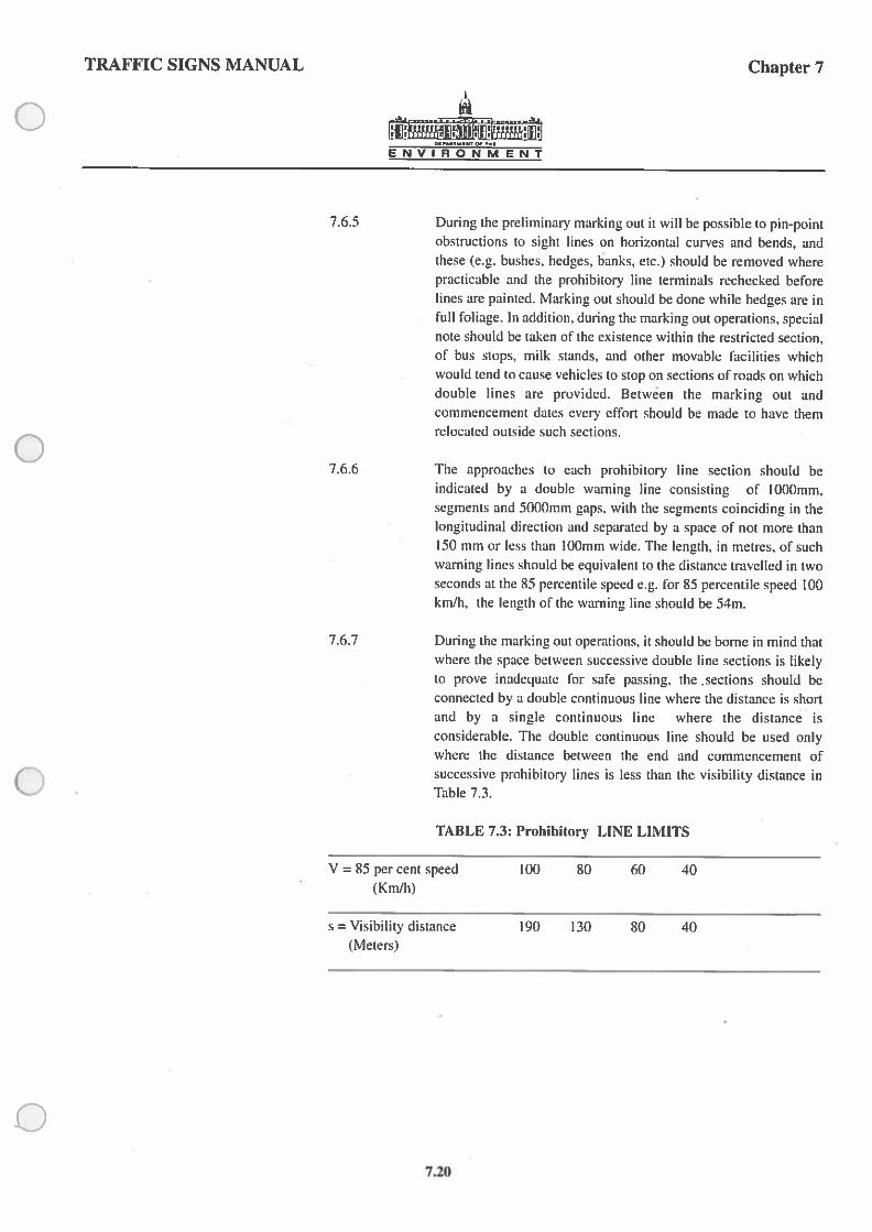
7.6.5 During the preliminary marking out it will be possible to pin-pointobstructions to sight lines on horizontal curves and bends, andthese (e.g. bushes, hedges. banks. etc.) should he removed wherepracticable and the prohibitory line terminals rechecked beforelines are painted. Marking out should be done while hedges are infull foliage. In addition, during the marking out operations, specialnote should be taken of the existence within the restricted section,of bus stops, milk stands, and other movable facilities whichwould tend to cause vehicles to stop on sections of roads on whichdouble lines are provided. Between the marking out andcommencement dates every effort should be made to have themrelocated outside such sections.
7.6.6 The approaches to each prohibitory line section should beindicated by a double warning line consisting of 1000mm,segments and 5000mm gaps. with the segments coinciding in thelongitudinal direction and separated by a space of not more than150mm or less than 100mm wide. The length. in metres. of suchwarning lines should be equivalent to the distance travelled in twoseconds at the 85 percentile speed e.g. for 85 percentile speed 100km/h. the length of the warning line should be 54m.
7.6.7 During the marking out operations, it should be borne in mind thatwhere the space between successive double line sections is likelyto prove inadequate for safe passing, the sections should beconnected by a double continuous line where the distance is shortand by a single continuous line where the distance isconsiderable, The double continuous line should be used onlywhere the distance between the end and commencement ofsuccessive prohibitory lines is less than the visibility distance inTable 7.3.
TABLE 7.3: Prohibitory LINE LIMITS
V = 85 per cent speed 100 80 60 40(Km/h)
s = Visibility distance 190 130 80 40(Nieters)
7.20

TRAFFIC SIGNS MANUAL Chapter 7
ENVIRONMENT
7.6.8 Prohibiton’ line limits may be accurately determined on the road, at
both bends and summits, in the following manner:
I. Use the known spacing of existing studs or mark a
temporary chainage line with 75m or 15m intervals along
the road centre, commencing and ending at points which
are judged to be in advance of the sight line restriction Cs’
Table 7.3). Alternatively, where uniformly spaced road
furniture is not in place, the use of a cord or rope suitably
marked with the visibility distances can be of assistance.
2. Station one person (observer) at chainage 0 and a second
person (leader) at a distance ‘s’ ahead, each being equipped Qwith a l.05m boning rod.
3. Cause both leader and observer to advance, in unison,
along the chainage, and check the intervisibility of the rod
tops at each mark; the observer point where the leader-rod
lirst disappears from view is the commencement of the
prohibitory line and the point where it reappears again the
end, of that section of prohibitory line.
7.6.9 The assumed design speed for each length of road to be marked
should be taken as the 85 percentile speed, determined separately
for each direction of travel, on the approaches to the bend or summit
during off-peak traffic flow.
7.6.10 The prohibitory line should commence at the point where the sight
distance becomes less than that specified in Table 7.3 and ends
where it becomes greater. Prohibitory line terminals should be
located separately for each direction of travel.
7.6.11 All double line sections should be marked with a single row of bi
directional white reflecting studs spaced at 6m intervals. These
should be laid between the lines, except that when the lines are
splayed to form a hatched area, directional studs should be laid
symmetrically in each longitudinal line at 6m intervals arranged so
that only the studs on the line nearest the driver reflect back.
C7.21

TRAFFIC SIGNS MANUAL Chapter 7
ENVIRONMENT
FIG. 7.13 Double Line System for Bends, Humps, & Dips
he51)
100(150)
3050 min.%
1200 max.
Double lines and hatched markings on sharp bends
Deflection not tosharper than I in
100A
(ISO)
1200 31)50 mmmax y 45
p
JUnidirectional studs
6m spacing 3O50 mm
Not more than 3m
175
7.22

TRAFFIC SIGNS MANUAL Chapter 7
N
ENVIRONMENT
7.6. 12 According to the physical characteristics of a bend or hump, thesolid lines for traffic in opposing directions can either overlap orhave a gap between them. If they overlap, there will be a section ofdouble continuous line in the middle. If, however, (hey do not meetand there is a gap. which is less than the visibility distance for theappropriate 85 percentile speed. the two solid lines should beextended to meet in the centre of the gap. If it is greater than thisdistance but less than the warning visibility distance for the samespeed, a single warning line should be used to join the two sectionsof double line; beyond that the normal centre line is appropriate, asat any other site where the visibility distance is greater than thewarning criterion.
7.6.13 The length of a broken line element within a double line systemshould not be less than the visibility distance for the appropriate 85percentile speed. This will prevent overtaking where the distance isinsufficient.
Bends (Fig. 7.13)
7.6.l4 The continuous line of a continuous/broken line combinationshould be located along the centre line of the carriageway, givingthe driver who is restricted by it. his full share of the carriagewaywidth. Double continuous lines should normally be locatedsymmetrically about the centre line of the carriageway.
7.6.15 On sharp bends where double continuous lines are required. theycan be splayed to form a type of central island with a maximumoverall outside width of I .2m. provided there is ample room oneither side to enable vehicles to negotiate the bend reasonablywithout crossing the lines. The area between the lines must behatched with inclined 150mm wide lines at 2.Om spacings.
Humps and Dips (Fig. 7.13)
7.6.16 A hump should be treated in the same way as a horizontal bend asregards visibility criteria and line markings. except thai wheresplayed double continuous lines are required, the lines should beopened out at an inclination not exceeding I in 50 as they approachthe point of minimum visibility (often not the highest point) toattain a maximum overall outside width of I .2m. The lines whichenclose these widened areas should be continuous, and the areabetween the lines must be hatched with the marking shown in Fig.7. I 3. The humps either side of a dip should be treated individually.
,07.23

TRAFFIC SIGNS MANUAL Chapter 7
ENVIRONMENT
Road Widths
7.6.17 Having regard to the road width required by public service andcommercial vehicles, particularly on sharp bends, double linemarkings should not normally be used where the carriageway isless than 6. I m in width. When the road width is less than 6.1 m, asolid centre line should be used as appropriate.
Exceptional Use of Double Centre Lines
7.6.18 In exceptional circumstances double centre lines may be used, eventhough the visibility conditions are not less than those outlined inTable 7.3. Such circumstances might include markings carried outin conjunction with traffic calming measures.
7.6.19 Where a slow lane is provided (Fig 7.7), a double centre line shouldbe laid, with a continuous prohibitory line on the side of the twolanes. The line on the side of the single lane will be eithercontinuous prohibitory or broken warning, dependent on thevisibility conditions in the direction of travel. The width of the linesin this case is 150mm.
7.7 Level Crossings (Fig. 7.14)
7.7.1 The arrangement of carriageway markings, road studs, and othersigns associated with level crossings are set out in detail in theDepartment of Tourism, Transport and Communications“Requirements and Guidelines for the Provision of Automatically
Operated Half-Barriers at Railway Level Crossings”. This
publication should be referred to where new or upgraded level
crossings are contemplated.
NOTE: 300mm width for STOPLINE at level crossings.
7.24

TRAFFIC SIGNS MANUAL
ENVIRONMENT
Chapter 7
C
2m In 2m
7.5m
4220mm — 300mm
S— — 300mm
3m 0Hardshouldcr
FIG. 7.14 Level Crossings 0
<660mm
300mm
900mm
1-3m
IT ardslio ul dc r
3m
I
Note:Centre-line studs and road marking should be carried through the crossing:Discretion should be used in the provision of edge lines so as not to conflict withthe box markings
S// :L-3tu
-4-
- <660mm 2mHdhd‘I
A 2m 2m 2tn 2m— —-I
A
%1.4m3m4 S
7.5m
6odeg
t3rn -
- I/F
/
45 0mm
900mm
0
-3
1-3m
ft- Hardshouider
7.25

TRAFFIC SIGNS MANUAL Chapter 7
ENVIRONMENT
7.8 Roundabouts
7.8.! The most common roundabouts in general use are normal and mini
roundabouts. They are defined as follows:
U) Norma! Roundabout:
A roundabout having a one-way circulatory carriageway,
around a kerbed central island over 4m in diameter and
usually with flared approaches to allow multiple vehicle
entry.
(ii) Mini-Roundabout:
A roundabout having a one-way circulatory carriageway
around a flush or slightly raised circular marking less than
4m in diameter and with or without flared approaches.
7.8.2 At all roundabouts, the appropriate prescribed YIELD line should
be laid &it each entry and should connect the central deflection line
or traffic deflection island to the nearside- kerb ,approximately
following the line of the inscribed circle, in order to maintain
visibility from each approach lane.
7.8.3 It is important to provide adequate vehicular deflections through
the roundabout. Where raised traffic deflection islands are provided
to achieve such deflection, the vertical surfaces may be painted in
alternate black and amber bands 300mm in length to improve their
conspicuity.
Normal Roundabouts Fig7.15
7.8.4 Where the central island is 4m or greater in diameter the
recommended line marking is similar to that for NO ENTRY and
consists of a solid line and a broken line comprising 1000mm
marks and 1000mm gaps. The lines should be 200mm wide and
spaced 300mm apart. The lines should be accompanied by the
triangular YIELD marking.
7.8.5 Where the approach to the junction is divided into two or more
lanes, then a,triangular YIELD marking should be placed in each
lane.
7.26

TRAFFIC SIGNS MANUAL Chapter 7
__
CENVIRONMENT
Mini Roundabouts Fig. 7.16
7.8.6 The recommended YIELD marking is the same as that used atnormal roundabouts but must be accompanied by the following:
(i) A flush or slightly raised. (but capable of being over-run)circular road marking not more than 4m nor less than lmin diameter.
(ii) Three white road arrow markings arranged symmetricallyon the carriageway in the centre of the gyratory area. Twosizes are recommended, Fig. 7.16: Q
(a) The smaller, (3025mm) is used for circular central islandsup to and including 2500mm in diameter.
(b) The larger, (4450mm) is for use with circular centralislands more than 2500mm in diameter up to andincluding 4000mm in diameter.
* 0
07.27

TRAFFIC SIGNS MANUAL Chapter 7
flijiijir;i;;t.JJ
ENVIRONMENT
/flJSee Fig 7.32 for cross hatching details I
.d
See Fig. 7.2 for yieldsign junction layout
100mm broken line2000mm mark 2000mm gap
100 (150) solid line includingdrainage gaps where required
100mm broken line2000mm mark 2000mm gap
200mm broken line1000mm mark / 100Gm gap
200mm solid line
150mm continuous white line
200 solid line
200mm broken linel000mm mark!I000mm gap
300100 (150) solid line
FIG. 7.15 Normal Roundabout
Yield marking as Fig 7.2
N
- -
Internal detail as in Fig 7.32
7.28

TRAFFIC SIGNS MANUAL Chapter 7
ENVIRONMENT
0
3025 (4450)
//
Flush or slightly raised circularisland in white reflectorised material.White reflectorised studs may be usedaround perimeter if required
3500-7000(5000- 10000)diameter
200mm solid line
1250 mill —
200mm broken line1000 mm mark 1000mm gap
100 (150) solid line
— 1000-2400(2500-4000)
Circular road ,narkiigs arrows
0
0
FIG. 7.16 Mini-Roundabout C
I-
See Fig. 7.2 for yield markingjunction layout
100 (150mm) solid line formm. distance of2om
-i-’
See detail above
7.29

TRAFFIC SIGNS MANUAL Chapter 7
ENVIRONMENT
7.9 Worded Markings, Parking Restrictions, Parking Bays, BusStops, Bus Lanes, Yellow Box Markings and Cycle Tracks.
7.9.1 Various worded markings are prescribed. Some augment kerbsidesigns, others indicate areas of the carriageway intended for aparticular function (e.g. Bus), for classes of vehicle (e.g.Ambulances), or to be kept clear (e.g. School Keep Clear). Themarkings are either white or yellow in colour.
7.9.2 The basic characters for the capitals, numerals and the apostrophe
are from the Transport Medium Alphabet, enlarged and increased
in most cases to two standard alphabet sizes. See Figs 7.44 and7.45. Some wnrded markings such as ‘TAXIS, SCHOOL KEEPCLEAR, etc.’ have been enlarged from the Transport MediumAlphabet to give the overall height indicated in the various figures
in the document. Abbreviations may be used to reduce the number
of letters in a worded marking.
SLOW
7.9.3 This marking may be used to supplement a warning sign on the
approach to a hazard or a road junction. Two sizes are prescribed.
(See Table 7.4 below). The larger size is to be used on high speed
approaches.
7.9.4 Discretion should be exercised in the use of the marking to ensure
that its impact is not lost by proliferation. At particularly hazardous
situations e.g. on the approach to a bend at the end of a long straightsection of high speed road, the marking may be repeated to give
added emphasis.
7.9.5 The location of the marking will depend on the nature of the
hazard. In general it should be located sufficiently far back to
enable a driver travelling at the normal speed of the road to reduce
speed in time to negotiate the hazard in safety. In some instances, it
is possible to make use of a change in vertical grade to position the
marking for increased conspicuity.
TABLE 7.4 ‘SLOW’ MARKINGS
Overall Height Overall Width Use
1600mm 2280 mm Normal speed approach2800mm 2280mm High speed approach
7.30

TRAFFIC SIGNS MANUAL Chapter 7
The markings should only be used to supplement a kerbside busstop sign. They indicate the area of a bus stop, within whichvehicles other than buses, are not to be stopped or parked.
The length of the bus stop bay varies between 21m and 41m but 10000
may be extended to cater for stops serving a number of routes
Box Junction Fig. 7.18
General
At a box junction, the carriageway should be marked with yellowlines to form a box enclosing yellow cross hatched diagonal lines.
Box markings are an aid to traffic flow at ajunction where blockingback affecting a cross flow is a significant problem.
Suitable Junctions
Not all junctions are suitable for treatment and it is necessary toapply certain criteria before deciding whether a particular siteshould be marked. It will normally be necessary to carry out atraffic survey to determine whether any other remedial measuresmight be effective (e.g. linking of traffic signals with those atadjacent junctions).
ENVIRONMENT
Bus Stop Fig. 7.17
tooI
7.9.6
7.9.7
7.9.8
7.9.9
7.9.10
BusSlim
1600
j 21m-41m
‘d
0
0
C
FIG. 7.17Markings for use
at Bus Stop
7.31

TRAFFIC SIGNS MANUAL Chapter 7
ICY0 max of breadth10% max of length
NOTESbY0 max I. This drawing shows typical layouts of the markings. Theof breadth overall shape of the marking & the number of oblique lines
should be varied to accord with the circumstances at the site.
2. To set out the markings on the carriageway:
max (A) Set out the ciiagonals at right angles (or as near as possihleto each other
(B) complete the houndan’ lines.
(C) Set out remaining lutes parallel to diagonaLs at gridintenats oJ2000tntn.
3. Half boxes should be set out as for a full box but with onlyhalfthe markings shown. See Fig B
4. Markings at more complicated junctions where varyingwidths of roads produce boundaries which are not rectanglesshould be constructed affollows:
(A) D,-aw transverse lines across the entry arm of the junctionappn’ximatelv at right angles to theJlou’ of traffic.
(B.) complete the peritneter of the box kv following theintervening kerh lines,
(C) Draw a “lain diagonalX— I
(D) By constn,ction draw in the otherdiagonalP— Q.The two diagonals should intersect as nearly as possible at
right angles.
(5) Complete the box in accordance with Note 2.
The method of constructing this type of markings is illustratedinFiguresC&D
5. A full box marking is sometimes required which is muchlongerthan it is wide. Inthis case it should be constructed as forahalfbox as illustrated in Figure E.
ENVIRONMENT
2000 (2500 when the shortest boundary line ofthe box is more than 9000mm in length)
200 —a,I
I
,,
9
60 deg mm150 dej,,mn
3000 mm30000 max
3000 mm 30000 max
Fig A Full Box
Fig D
10% max of length
60 deg mmISO deg max
2000mm10000
Fig B HalfBox
Fig C
. I
I’Fig £
FIG. 7.18 Box Junction Carriageway Markings
7.32

TRAFFIC SIGNS MANUAL Chapter 7
ENVIRONMENT
Half Boxes
7.9.11 The use of half boxes (in which only half the area of thejunction ismarked) is appropriate at “T” junctions and other junctions wheretraffic only blocks back from one direction.
Road Markings
7.9.12 Details of the road markings are given in Fig. 7.18. Two diagonallines join opposite corners, or projected corners, of the box andlines are drawn parallel to each diagonal to form cross hatchedmarking in yellow. The diagonal lines 150mm wide are spaced2000mm apart where the shortest boundary line of the bnx is 9000 Qmm or less, and 2500mm apart where the shortest boundary line ofthe box is greater than 9000mm. Box junctions should usually havefour straight sides transverse to the traffic flow on the approaches,although up to 10% of the length of any side may be cut away asshown in the diagrams to accommodate corner kerbs. The overallshape of the marking and the number of cross hatching lines willvary to accord with the circumstances at the site. Where theintersecting carriageways are of a difterent width, the shortestboundary line of the box is taken as the determining factor for thespacing (x) between the parallel cross hatching lines. Where theshortest boundary line of the box is 9000mm or less in length, x =
2000mm. Where the shortest boundary of the box is more than9000mm in length, x = 2500mm. Width of markings: boundarylines 200mm; cross hatching lines 150mm.
To set out the marking on the carriageway:
1. Complete the boundary lines.
2. Set out the diagonals.
3. Set out remaining lines parallel to diagonals.
Half box markings should be designed in the same way as full boxmarkings but only half of the box marked on the road.
C7.33

TRAFFIC SIGNS MANUAL Chapter 7
50
6000 450
Fig 19 (a) Parking area without buffer zones parallel to kerb
Edge of kerb
A o
-
50
ButTer Area 4800 1200450
Fig 19 (b) Parking area with buffer zones parallel to keith
Edge of kerb
A50
____-
- --2100-2400
—— 100
Fiog. 19 (e) Disc parking area
FIG. 7.19 Markings for Parking Areas
Limit of discparking area
— — 50
ENVIRONMENT
Edge of kerb
A2100-2400
21(10-2400
Edge of kerb
I..
ii.450
Fi 19(c)
— — 33(10 mmI 2(10
4800- 55002500
— — 6002280-2400
Parking area perpendicular to kerb
Edge of kerb
up to 5500
‘ble angle
450
Fig. 19(d) Parking at angle to kerb
7.34

TRAFFIC SIGNS MANUAL Chapter 7
ENVIRON M ENT
Parking Restrictions - Single Yellow Line 2000 - 2700
7.9.13 A continuous yellow line 100mm wide extending along the edge ofa roadway in a built up area and situated approximately 300mmfrom that edge indicates that parking of vehicles is prohibited orrestricted at certain times on that side of the road.
Parking Restrictions - Double Yellow Line
7.9.14 Two parallel continuous yellow lines approximately 100mm apartextending along the edge of a roadway in a built up area, each linebeing approximately 100mm wide and the line nearest the edge ofthe roadway being situated approximately 300mm from that edge, Qindicates that parking is prohibited at any time on that side of theroadway.
Parking Bays (Fig 7.19)
7.9.15 Two patterns of marking are prescribed, one to indicate the limitsfor parallel parking and one for angled parking bays. Both types ofmarking may be used outside or inside controlled parking zones.
Parallel/Perpendicular Parking. (Figs. 7.19a-c)
7.9.16 A double solid terminal marking indicate the limits of the spacereserved for vehicle parking which may also be denoted by “F’signs mounted at the kerbside. A single solid transverse linebetween individual parking spaces is used to denote the buffer zone.
Angled Parking. (Fig 7.19d) jSO
7.9.17 The markings indicate individual parking bays, the angle of whichmay be varied from about 30 to 90 degrees to the kerb according tothe width of road available.
The word LOADING lobe repealed foreach unit length of48Ot) when the length
Disc Parking. (Fig 7.19e) of the loading bay exceeds 9600mm.
FIG. 7.20 Markings for Loading Bay7.9.18 The markings Indicate the boundaries within which disc parking is
permitted.
Loading Bays (Fig. 7.20)
7.9.19 A loading bay is indicated by the word “LOADING” written on theroadway in white lettering. The recommended height of thelettering is 300mm. It should be repeated at least once in eachloading bay and it should be parallel to the kerb and facing towardsthe centre of the roadway. The terminal points of the loading areashould be indicated by solid lines perpendicular to the kerb. Therecommended minimum length is 4.8m.
LJ4°
t0
C.
CC
45()
C
7.35

TRAFFIC SIGNS MANUAL Chapter 7
ENVIRONMENT
School Keep Clear (Fig. 7.21)
The marking consists of the words “SCHOOL KEEP CLEAR”painted on the carriageway in 700 mm yellow letters with a zig-zagpattern of yellow lines the overall length of which should not beless than 25.56m. The overall length of the marking may beincreased by increments of 6m by the addition of a complete zigzag pattern on each side of the marking up to a maximum length of43.56m. A vehicle may not stop or park where this marking isprovided.
The length of the marking needs to be restricted to one whichdrivers will respect. Where an authority desires to lay a markingwith an overall length greater than the maximum 43.56m, e.g.where the marking is to extend across two entrances which are wideapart, then two markings of any of the standard lengths, i.e.25.56m, 31.56m, 37.56m or 43.56m, may be joined togetheromitting the transverse bars at the join to form one continuousmarking.
Where two separate markings (either single or double as describedabove) are required to be laid in close proximity for schoolentrances on the same side of a length of road, a clear space of 7mmust be left between the markings.
The marking should not normally be placed on both sides of theroad but only the side on which the school entrance is situated.
The markings should not be laid in the controlled areas on theapproaches to Zehra crossings, but where waiting restrictions are inforce there is no objection to both the School Keep Clear marking
and the yellow lines denoting the waiting restrictions being used
along the same length of road.
It is not intended that the markings should be used outside all
schools, but only where there is a clear need for them because ofthe hazard to school children due toparked vehicles.
25560 Mm - 43560 Max
FIG. 7.21 Markings for use at school entrance
7.9.20
7.9.21
7.9.22
7.9.23
7.9.24
—— 150
Edge of carriagewayci::
90& 7 -
45 dig 1500 700 5007.9.25
- V--
— — — — 3553000 750 1500
5750
14060
Edge of camageway
I z;, --
L.H zZ -
ii
350 4250 — 1501) — 2500 — 1500 — 3190 350
-—.; /‘
- 12X0
7.36

TRAFFIC SIGNS MANUAL Chapter 7
CENVIRONMENT
Fire and Ambulance Stations
7.9.26 Where problems of obstructions arise at the entrances to Hospitals,
Ambulance Stations or Fire Stations the School Keep Clear
marking (Fig. 7.21) may be adapted by the substitution of the
word SCHOOL by FIRE or AMBULANCE as appropriate. In these
cases the overall minimum size of the marking is reduced to 25.25m
and the maximum size 43.25m. The advice given for School Keep
Clear layouts and suitability is equally applicable.
Taxis (Fig. 7.22)
7.9.27 Two forms of marking are prescribed for approved taxi ranks Qaccording to whether they are at the side or in the centre of thecarriageway. The length of the “box” comprising the marking maybe varied to suit the requirements. The lettering and bordermarkings are white and should be used with the appropriateregulatory signs.
Look Left / Look Right
7.9.28 This marking is generally intended to warn pedestrians of
approaching vehicular traffic on a one-way street. The marking
consists of the words LOOK LEFT or LOOK RIGHT painted on
the carriageway in 300mm white letters is accompanied by a white
arrow pointing in the relevant direction, and is usually provided atsites where pedestrians are encouraged to cross. The provision of
centre medians or refuges allows the provision of this marking ontwo way streets.
0
600
600
V100L
FIG. 7.22 Markings for use at Taxi Rank
Edge of kerb
7.37

TRAFFIC SIGNS MANUAL Chapter 7
ENVIRONMENT
Bus Lanes
7.9.29 The markings prescribed for use in lanes reserved for buseswithout physical separation are shown in Figs. 723, 7.24 and 7.25.The associated signs are shown in chapterS.
7.9.30 Bus lanes may be either (1) With-flow, or (ii) Contra-flow, andtypical arrangements of the markings used in each case areillustrated in Figs. 7.23 and 7.24.
With-Flow Bus Lanes (Fig. 7.23)
7.9.31 The outer edge of the bus lane should be marked by a white line250mm wide, a gap being left in the line adjacent to each side road.
7.9.32 The legend BUS LANA should be marked on the carriagewayacross the lane at its commencement and repeated after eachjunction. Where junctions are more than 300m apart the roadmarkings should be repeated between junctions at approximatelylSOm intervals. Warning arrows should be placed on the nearsidelane l5m and 30m in advance of the commencement of the buslane. A 250mm wide broken line should be laid from the kerb to thestart of the full width lane to deflect other traffic from the bus lane.The taper at which the line should be laid should not normallyexceed 1:10, but in exceptional cases may be reduced to 1:5.
7.9.33 Where a bus lane commences just beyond a junction, adequate
length should be left for the taper to commence at the junction so
that the inclined line does not extend across the junction mouth.
7.9.34 Similarly, to allow traffic to position itself correctly on thecarriageway, the continuous line should end in advance of any
junction with a major left-turning flow. In this case the continuous
line should be replaced by a broken line and should be preceded bythe double headed arrow variant to inform motorists that it ispermissible to enter the bus lane prior to making the left-turn.
7.9.35 Beyond each junction carrying emerging traffic, a curved line(Fig.7.25 (d)) should be provided across the bus lane to continue
the line of a nqrmal left-turn out of the side road and at the end of
a bus lane, the normal double headed arrow (Fig. 7.25 (e)) may be
used.
7.38

TRAFFIC SIGNS MANUAL Chapter 7
250mm wideSee FIG 7.25Angle of Deflectionshould not exceed1:10 —___...
a
ENVIRONMENT
FIG. 7.23 Road Markings for With-Flow Bus Lane
See FIG. 7.25
See FIG. 7.25 —
£74
250mm wideSee FIG. 7.25
See FIG. 7.25
0
0
0
0
See FIG 7.25Swerve arrow at I Sm and30m in advance of bus lane
7.39
TRAFFIC SIGNS MANUAL Chapter 7
ENVIRONMENT
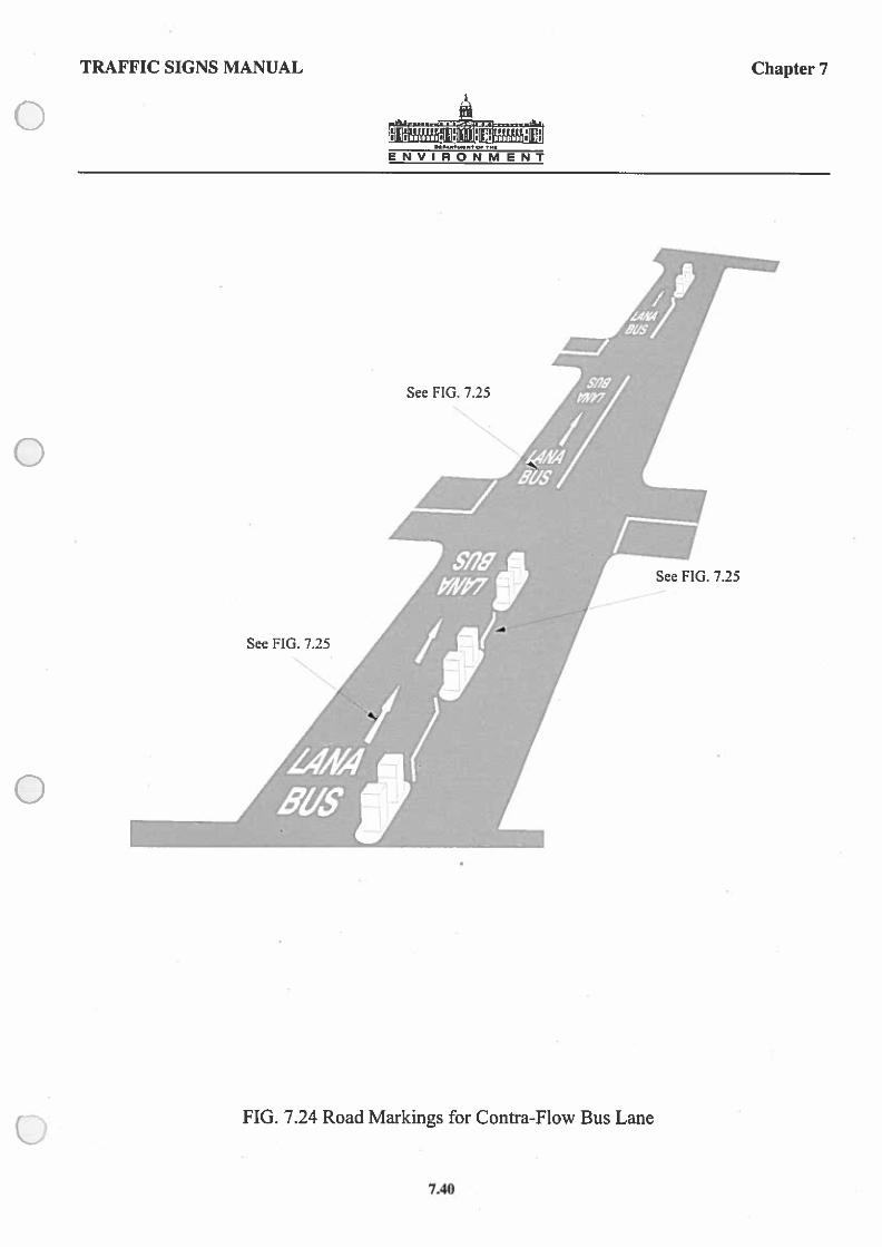
FIG. 7.24 Road Markings for Contra-Flow Bus Lane
See FIG. 7.25
4’
See FIG. 7.25
See FIG. 7.25
7.40

TRAFFIC SIGNS MANUAL Chapter 7
4000 (3000) (6000) 2000(1500)(3000)
1000 1000
FIG. 7.25 Road Markings associated with Bus Lanes
ENVIRONMENT
BUSlANE
200(150)(300) A
250
250
kPERMIHED
VARIANT
(c)
700(525) (1050)
(a)
LANA71000A BUS
(h)
5550- 6550
0
C
C
C.
(d)
2500-4250
(c)
7A 1

TRAFFIC SIGNS MANUAL Chapter 7
1700(1100)
A 2750(1780)
ONE WAY TWO 4AY
A 1000
8 2000
FIG. 7.26 Road Markings for cyclists
7.9.36
7.9.37
7.9.38
7.9.39
7.9.40
7.9.41
7.9.42
7.9.13
7.9.44
ENVIRONMENT
Contra-flow Bus Lanes Fig. 7.24
The road markings are as in Fig. 7.24 with a continuous line
separating the bus lane from other lanes.
Road markings together with an appropriate direction arrow should
be sited so as to be legible to drivers emerging from side roads.
Similarly road markings should be used at known pedestrian
crossing points, to warn pedestrians that traffic is not approaching
from the normal direction.
Normally a basic width of 3m is required for a bus lane. The
distance is measured from the edge of the kerb to the centre of the
continuous white line. A narrower bus lane may be a danger to
pedestrians on the footway and may also force buses to travel
slower than is necessary. At pinch-points, narrower bus lanes may
need to be accepted hut the lane width should never be less than
2.8m.
Cycle Thacks
The markings prescribed for use in cycle tracks and cycle ways are
as outlined in para. 7.9.41 below They may be used in conjunction
with ocher road markings.
The markings are white and are used to advise cyclists of the route
to take where special facilities have been introduced for cyclists.
The outer edge should be marked with a solid white line 100mm
(150) mm wide. The cycle symbol should be marked on the
carriageway across the cycle track at its commencement and
repeated alter each junction. The cycle symbol, which is available
in 2 sizes, should be repeated at inten’als not greater than I OOm and
may be supplemented by a direction arrow. A 100mm (150) mm
wide broken line should be laid from the kerb to the start of the full
width cycle track to deflect other traffic from the cycle track. The
taper at which the line is laid should not normally exceed 1:10.
The termination of a cycle way or track should be indicated by the
sign shown in Fig. 5.32.
Half size triangular Yield markings and 2000mm long direction
arrows may be used where appropriate on cycle tracks.
Cycle tracks crossing minor roads may be indicated on the
carriageways by the special road marking shown on Fig. 7.26. This
marking is informatory and does not give priority to the cyclists.
2000
3000
7.42
TRAFFIC SIGNS MANUAL Chapter 7
ENVIRONMENT
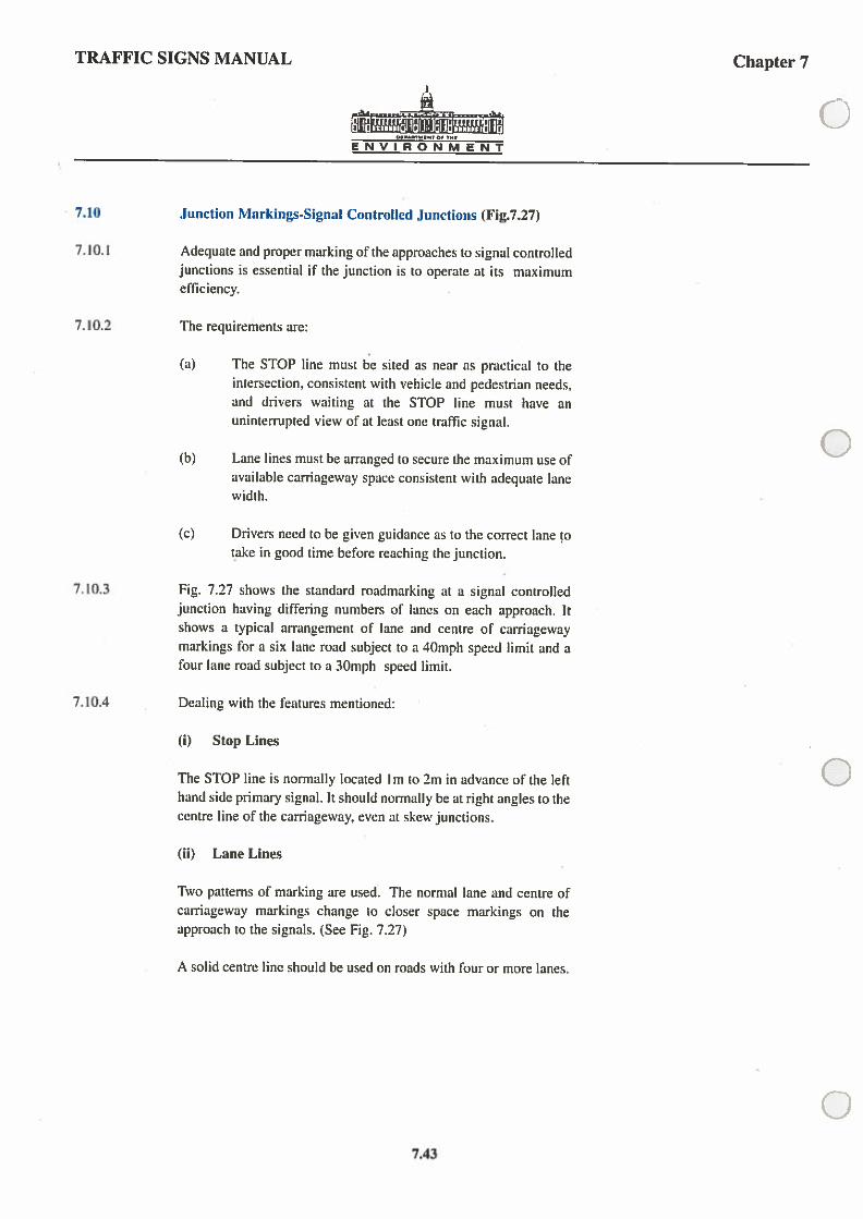
7.10 junction Markings-Signal Controlled Junctions (Fig.7.27)
7.10.1 Adequate and proper marking of the approaches to signal conirolledjunctions is essential if the junction is to operate at its maximumefficiency.
7.10.2 The requirements are:
(a) The STOP line must be sited as near as practical to theintersection, consistent with vehicle and pedestrian needs.and drivers waiting at the STOP line must have anuninterrupted view of at least one traffic signal.
(b) Lane lines must be arranged to secure the maximum use ofavailable carriageway space consistent with adequate lanewidth.
(c) Drivers need to be given guidance as to the correct lane otake in good time before reaching the junction.
7.10.3 Fig. 7.27 shows the standard roadmarking at a signal controlledjunction having differing numbers of lanes on each approach. Itshows a typical arrangement of lane and centre of carriagewaymarkings for a six lane road subject to a 10mph speed limit and afour lane road subject to a 30mph speed limit.
7.10.4 Dealing with the features mentioned:
(i) Stop Lines
The STOP line is normally located I m to 2m in advance of the left Chand side primary signal. It should normally be at right angles to thecentre line of the carriageway, even at skew junctions.
(ii) Lane Lines
Two patterns of marking are used. The normal lane and centre ofcarriageway markings change to closer space markings on theapproach to the signals. (See Fig. 7.27)
A solid centre line should be used on roads with four or more lanes.
07.43

TRAFFIC SIGNS MANUAL Chapter 7
2000-4000 wide
25m
100mm widewarning lines2000 mark2000 gap(mm. 7 marks)
100mm widelane lines4000 mark8000 gap
50m
ENVIRONMENT
Pedestrian crossing lines100mm wide
NOTEIndicates primary signalsIndicates secondary signals
FIG. 7.27 Road Markings at Signal Controlled Junction & Approaches
I I5Omm widesolid line
Subject to 30mph5Okph speed limit
Stop lines200mm widenormally butmay be 250mm V
A
]
j
— I-
15m
I -2m
3Om
2m
100mm lane line.2000 mark2000 gap(mm 5 marks)
100mm wide lane.4000 mark8000 gap
150mm wide solid line
Subject to 40mph6okph speed limit
7.44

TRAFFIC SIGNS MANUAL Chapter 7
ENVIRONMENT
(iii) Lane Widths
The normal width of the lanes should be 3m to 3.75m depending onthe type and speed of traffic and on the width of carriageway.Exceptionally an absolute minimum width of 2.Sm may beaccepted alongside refuges at signals and at the STOP line, but notelsewhere. The aim should be to provide the maximum number oflanes on the approach to the intersection but the number of lanes onthe leaving side may be reduced due to the dedication of lanes toexclusive turning movements on the approach side. The decision onthe number of lanes to adopt will be influenced by safetyrequirements and will depend on road alignment, traffic movementsand the presence of standing vehicles.
(iv) Lane Indication Arrows Figs. 7.2 and 7.29
In addition to the warning lines on the approaches to junctions,direction arrows should be used to give drivers advance indicationof the correct lane to take when approaching busy multi-laneintersections, whether signal conlrolled or not. Traffic must proceedin the direction of the arrow provided. Generally with speeds lessthan 40mph the 3.6m length of arrow (Fig. 7.28) should suffice buton open and faster roads the 5m size (Fig.7.29) should be used.
Normally two arrows should be used in sequence in each lane,occasionally three. The one nearest the junction should be between15m and 25m from the STOP line, or entrance to the junction andthe second should be 30m - 50m further back, the greater distancebeing used on roads subject to higher average speeds. A third arrow,if used, should be 30m to 50m back from the second arrow. Thedirection of each arrow head may be varied to suit thecircumstances but not more than two directions may be shown onany one arrow stalk.
On two lane approaches to a junction the arrangement of arrowsindicating the lanes for straight ahead, left-turn and right turn willdepend on the relative traffic volumes making the movements andon the site conditions. Where for instance, there is a very heavyright turn movement, the straight ahead and left-turn arrows shouldbe combined in the nearside lane. Similarly where there is a leftfilter arrow in the traffic signal installation the filter lane shouldalways be marked by the left arrow marking alone in order toexclude non-filtering traffic.
C7.45

TRAFFIC SIGNS MANUAL
ENVIRONMENT
Chapter 7
375_ 1525_l525__
200750 3050 — 3050 —
225
300
2100 1500
I00
Lane Indication Arrows
FIG. 7.28 Arrow Details
1100
200 I25
1050
1150
1 2100
11008000 1925
2300 —
I
1050
16000
Bifurcation Arrows
2100
3850
200
2007
250
3007
300
250
250
2100 1500
100
310250
7 50 —
______
250
1250
300
300
3600
Derail ofArrow Head
350
250‘I
— 35025Q
750 Detail of—
Arrow Head
7.46

ENVIRONMENT
Chapter 7
FIG. 7.29 Arrow Details (based on A40/ECMT)
C)
TRAFFIC SIGNS MANUAL
5000
2950 2050
710
‘ 350
I50
1000
5000
1600 2050
600
300
A — AiOO
600 ‘
800 500 500
C
0
0
750
750
750
r30()
800
5000
2450
150
1000 —— 1550
600
300
700 500 500 800
2050
2950
L375
—r A375
1300
TA
1300ISO
7.47

TRAFFIC SIGNS MANUAL Chapter 7
ENVIRONMENT
(v) Lane Destination Markings
At heavily trafficked junctions worded lane destinations repeatingthe information shown on advance direction signs may, withadvantage, be marked on (he carriageway on the approaches tojunctions. Besides indicating the correct lane to take, the markingsalso provide drivers with a useful supplementary indication to theadvance direction sign in the event of the latter being obstructed bytall vehicles.
The marking should be normally located at least as far back fromthe junction as the longest peak hour traffic queues, unlessintervening junctions would lead to confusion.
Bifurcation Arrows at Deceleration Lanes Fig. 7.28
7.10.5 These markings should be provided at the commencement ofdeceleration lanes on the approaches to junctions.
7.10.6 Bifurcation arrows serve to guide vehicles into the decelerationlane near its commencement ensuring that the full length of the laneis used to slow down for the junction without impeding throughvehicles on the main carriageway.
7.10.7 Three sizes are prescribed. The 16m is generally used onmotonvays. high speed dual carriageway roads while the 8m is foruse on lesser roads. The 32m arrow (derived by doubling thelongitudinal dimensions only of the l6m arrow) may be used inexceptional circumstances. The arrow marking may be transposedto suit right-hand movements into deceleration lanes in the centralreserve of dual carriageway roads.
7.48

TRAFFIC SIGNS MANUAL Chapter 7
—A
ENVIRONMENT
7.11. Pedestrian Crossings
Zebra Crossings
7.11.1 The markings used to indicate a zebra pedestrian crossing are as
follows:
(i) Pedestrian lines
(ii) Alternate black and white stripesflU) YIELD lines
(I) Pedestrian Lines
7.11.2 Pedestrian lines indicate the limits of the pedestrian crossing area.
They should be arranged in two lines across the carriageway at a
minimum distance of 2.4m apart. The lines are white continuous
and 100mm wide.
(ii) Stripes
7.11.3 The stripes should be laid in an alternate black and white patternacross the full width of the carriageway and positioned centrally
between the two Pedestrian lines.
7.11.4 The stripe immediately adjacent to the kerb on both sides of the
road should be black and should not be less than 500mm wide nor
more than I 300mm wide.
7.11.5 The intermediate black and white stripes should be not less than
500mm wide nor more than 715mm wide and should normally be
of equal width.
7.11.6 Care must be taken to ensure that the skidding resistance of the
striped area does not full below a value of 45.
(iii) Yield Lines
7.11.7 The YIELD line consists of a single white broken line comprising500mm mark and 500mm gaps. The marks are 200mm wide.
7.11.8 The YIELD line is normally sited I m to 2m from and parallel to the
pedestrian line used to indicate the limits of the crossing and shouldextend across the carriageway as indicated in Fig. 7.30.
Pelican Crossings Fig. 7.31
7.11.9 The carriageway markings used to indicate the presence of aPelican pedestrian crossing are as follows: Q
7.49

TRAFFIC SIGNS MANUAL Chapter 7
ENVIRONMENT
FIG. 7.30 Markings at Uncontrolled Pedestrian Crossing (Zebra Crossing)
IILL
ii:: IL — —500-1300A
2400-5000
100V
500I
200
2O00 SNot greater than 250 —
— 500
_
II
II\ II
A150
200
600 — —
7.50

TRAFFIC SIGNS MANUAL Chapter 7
ENVIRONMENT
(I) Pedestrian Lines
7.11.10 Pedestrian lines indicate the limits of the pedestrian crossing area.They should be arranged in two continuous lines 100mm wideacross the carriageway at a minimum distance of 2.4m apart. Thewidth of the crossing is determined by the number of pedestrians.
(ii) STOP Lines
7.11.11 A 200mm (250 mm) wide transverse STOP line is used to indicatewhere traffic should stop when signalled to do so at a Pelicancrossing
.
7.11.12 Where the road carries two-way traffic and the crossing isuninterrupted, the STOP line should extend from the edge to thecentre of the carriageway parallel to the pedestrian line indicatingthe limits of the crossing and placed not less than I .7m nor morethan 2m from the pedestrian line.
7. I I . 13 On a one-way street where the crossing is uninterrupted, the STOPline should extend from one edge of the carriageway to the otheredge parallel to the pedestrian line indicating the Limits of thecrossing and placed not less than I .7m nor more than 2m from thepedestrian line.
0
0731

TRAFFIC SIGNS MANUAL. Chapter 7
100mm wide double yellow lines100mm apart, 300mm from kerb
100,
2400 - 5000
Siqnal Pole
l50910 mm
ENVIRONMENT
200
Signal Pole
FIG. 731 Markings at Pedestrian Operated Signals (Pelican Crossing)
Al
100mm continuouswhite line
7.52

TRAFFIC SIGNS MANUAL Chapter 7
ENVIRONMENT
7.11.14 A pedestrian crossing complex is a section of roadway consisting ofa pedestrian crossing and parts of the roadway on each side of thecrossing.
7.11.15 Within the area of a pedestrian crossing complex, pedestrians areprohibited from crossing the roadway other than on the pedestriancrossing, and the parking or stopping of vehicles is restricted.
7.11.16 This controlled area is marked with the roadway markings toindicate a pedestrian crossing, with the addition of zig-zag lines andterminal lines which indicate the extent of the controlled area.
Zig-Zag and Terminal Lines (J7.11 .17 On carriageways of less than 6m wide, two longitudinal white zig
zag lines should be laid, one on each side of the carriageway with asolid line placed down the centre, On carriageways 6m or more inwidth, three longitudinal zig-zag lines should be laid, one on eachside of the carriageway and the third laid centrally, replacing thehazard line. The “standard” controlled area includes 8 x 2m zig-zagmarks. Where a longer approach warning is required, e.g. due topoor viibility or speed of traffic, the numher of marks may beincreased to 18. The aim should be to lay at least the standardpattern on both sides of the crossing but because of site difficultiesthis will not always be possible. See Fig. 7.30 for standard layoutdetails.
0
07_53

TRAFFIC SIGNS MANUAL Chapter 7
ENVIRONMENT
7.12 Hatched Chevron - Merging and Diverging i\larkings
7.12.1 The immediate approaches to channelising and central medianislands may be marked by either diagonal hatched markings or bychevron markings.
7.12.2 They can be bounded by a broken line where entry’ to the hatchedarea is not prohibited or by a solid line where prohibition isdesirable.
7.12.3 Diagonal hatched markings are appropriate on the approaches to acentral median island and, in certain circumstances, to an islandrefuge on a two-way carriageway, with the angle of the hatchingarranged to deflect drivers. See Fig. 7.32
7.12.4 Chevron markings are used to deflect drivers from the nose of achannelising island where a traffic stream divides. The chevrons areangled to deflect traffic in either stream. See Fig. 7.33.
7.12.5 Similarly, chevron markings may be used to extend the nose of achannelising island where two traffic streams merge. See Fig. 7.33.
7.12.6 Two sets of dimensions for the thickness and spacing of bothdiagonal and chevron markings are prescribed. These are shown inFigs. 7.32 and 7.33.
7.12.7 The less emphatic dimensions are recommended for use on urbanand narrow rural two-lane roads where 100mm wide centre linesare used. The more emphatic bracketed dimensions arerecommended for other roads where 150mm wide centre lines arenormally used.
7.12.8 Exceptionally a width of 500mm hatched lines may be used whereparticular emphasis is required or where it is necessary todiscourage traffic e.g. the left shoulder of a motorway slip lane and
the hatching for a right-turn lane on a high speed road.
7.12.9 On motonvays and high-speed dual cariageways, where trafficmerges or diverges at a slip road, a chevron marking of a differentpattern is used, (Fig. 7.34). The marking is bounded by acontinuous 150mm wide line to indicate to mototists that theyshould not enter the area except in an emergency.
7.12.10 Details of the diagonal hatched road markings, boundary line andwarning arrows used for lane reduction are shown in Fig. 7.12.
7.54

ENVIRONMENT
3000 (2000)
DIRECTION OF TRAFFIC —0.
300
4-
4000 2000
0
FIG. 7.32 Cross Hatchings at Approach to Island
0
0
TRAFFIC SIGNS MANUAL Chapter 7
C
45 4’
dog
100 (150)V
A150(200)
t450 mm
7.55

TRAFFIC SIGNS MANUAL Chapter 7
ENVIRONMENT
90dc1]
FIG. 7.33 Chevron Hatching at Islands(A) Diverging Traffic (B) Merging Traffic
2Mm
4Cm
2.0m
4Dm
(A) (B)
150
100(ISO)
150(200)
7.56

TRAFFIC SIGNS MANUAL Chapter 7
L -
— 150
C
,,Q0deg
F/
Direction ofTraffic
-A15°
‘2000I
‘ 1000
45 deg
8000max
90 deg
1
0
0
Directiofl ofTraffic
1000’
FIG. 7.34 Chevron Hatchings at Islands for Major Routes
7.57

TRAFFIC SIGNS MANUAL Chapter 7
d
E N V I R 0 N M E N T
7.13 Reflecting Road Studs and Delineators
Reflecting Road Studs Figs. 7.35 - 7.42
7.13.1 Road studs should be of a type approved for use by the
NRA/D.O.E. Where alternative products are presented they
should be accompanied by certification from a competent testing
laboratory indicating that the product provides, in use, an equivalent
level of safety and suitability.
7.13.2 Fn the case of rural National roads, all centre lines and lane fines and
lines across the mouths of slip roads should have reflecting road
studs. In urban, or slow speed situations, discretion should be used
as to the amount of studs to be provided, having regard to the traffic
pattern and mix.
Lines
(a) Double White Lines
7.13.3 For the standard double line marking. bi-directional white studs
should he laid between the lines, but where lines are splayed to
form a central island with a huiched marking between them, the
studs should be located in both of the lines and should be of the un
directional type. The stud spacing in all cases should be at óm
centres.
(b) Centre and Lane Lines
White reflecting road studs should be used in those cases as
indicated in the relevant figures. Where road curves of substandard
radius are present, centre line stud spacing should be 6m.
(c) Edge of Carriageway
Where yellow studs are provided at the edge of carriageway with
discontinuous yellow edge markings, they should be bi-directional
and placed in the gap between the dashed lines. The continuous
yellow line at the edge of motorways should have unidirectional
yellow studs at l2m centres.
Delineatom Figs 7.35 7.42
7.13.7 The Department of the Environment Technical Circular of June
1982 permitted the use of timber or synthetic materials in
delineators. Experience has shown that whilst these were effective,
large numbers were either removed or broken by traffic. A number
7.58

TRAFFIC SIGNS MANUAL Chapter 7
CENVIRONMENT
of flexible type delineators are now on the market and, pending theadoption of a European standard. authorilies are free to use theirengineering judgement in choosing from those available. Thedelineator should, however, incorporate a 60mm dia. corner-cubereflector.
7.13.8 Delineators should be located 0.5m from the shoulder edge onimproved roads and l.Om from carriageway edge on unimprovedsections.
7.13.9 On divided roads. delinealors on the median should be 0.5m fromthe carriageway edge or immedialely adjacent to the medianshoulder strip where such exists. The reflective area should be 0.5m (3above the nearest carriageway edge. They should be placed at aconstant distance from the edge of the carriageway and in a smoothalignment.
7.13.10 Delineators are normally single sided reflective white markersspaced at 24m centres (in line with studs) or double sidedgreen/white at 12m centres on the approach to junctions.
0
07.59

TRAFFIC SIGNS MANUAL Chapter 7
ENVIRONMENT
13 No. delineators at 12m centresVhite \ green
VhiteGreen studs at I 2m centres
Green\white studs at 12m centres
13 No. delineatorsat 12m centresGreen! white
Green! white studs at 12m centres
White / green studs at 12m centres
Uni-directional delineator
• Hi-directional delineator
Uni-directional stud
• Hi-directional stud
FIG. 7.35 Studs & Delineators - Two Lane Single Carriageway with Shoulders
White delinealorsat 24m centres
Yellow studs at I2m centres
While delineatorsat 24m centres
Hi-directional whitestuds at I Zm centres
I) No. delineators at 12m centresGreen! white
13 No. delineators at 12m centresWhite! green
White delineatonat 24 m centres
White delineatorsat 24 m centres
7.60

TRAFFIC SIGNS MANUAL
ENVIRONMENT
Chapter 7
C
13 No. delineators at12m centres
White \ green
13 No. delineators at 12mcentres Green / white
0
Urba,,
While delineatorsat 24m centres
FIG. 7.36 Studs & Delineators - Two Lane Single Carriageway without Shou1ders
0
0
C-
> Uni-directional delineator
• 81-directional delineator
Uni-directional stud
i Hi-directional smd3m ma&’3m gap(tOOmm) while
V
Bi directional whitestuds aL 1 2m centres
White delineatorsat 24m centres
Hj
13 No. delinealorsat 12m centres
Green\white
— 13 No. delineators at 12mcentres White / green
J
Rural
7.63

TRAFFIC SIGNS MANUAL Chapter 7
E N V I R 0 N M E N T
Yellow studs at12m centres
While delineatorsat 24m centres
Uni-directional delineator
Ri-directional delineator
i Uni-directional stud
i Bi-directional stud
White studs at6m centres
Bi-directional yellowstuds at 12m centres
White studs at6m centres
13 No. Green I whiteDelineators at 12m Centres
13 Green Studs at l2m Centres
13 No. White I greenDelineators at 12m Centres
13 No. White Studs at l2m Centres
White studs at 12m centres
Yellow studs at 12m Centres
White delineators at 24m Centres
White delineatorsat 24m centres
V
1
Green studs at12m centres —
5 00mm“U
]
I!
FIG. 7.37 Studs & Delineators - Single Carriageway with Right - Turn Lane
7.62

TRAFFIC SIGNS MANUAL Chapter 7
ENVIRONMENT
White studs at 6m centres
white studs at 12m centres
Uni-directional delineator
Bi-directional delineator
Uni-directional stud
Bi-directional stud
C)
0
0
FIG. 7.38 Studs & Delineators - Two Lane Carriageway with Slow-Lane 0
Shoulderii I
— j White delineators at 24m centres
‘r’i— Yellow studs at Urn centres
Shoulder
7.63

TRAFFIC SIGNS MANUAL Chapter 7
31-directional delineator
ENVIRONMENT
White studs at12m centres
White delineatorsat 12m centres
Red delincutorsat O.5m centres
Green delineaiorsat I 2m centres
White delineatorsat 12m centres
13 No. Greendelineators at l2m centres
13 No. Yellow smdsat l2m Centres
13 No. Whitedelineators at l2m centres
FIG. 7.39 Studs & Delineators - Dual CarriageWay
Uni-directional delineator
. Bi-directional stud
Uni-directjonal stud
Shoulder
Yellow studs at 12m centres
White delineators at 24m centres
Yellow studs at 12m centres
Yellow studs at 12m centres
White delineators at 24m centres
Green studsat 12m centres
Shoulder
7.64

TRAFFIC SIGNS MANUAL
ENVIRONMENT
Chapter 7
0
Uni-directional delineator
Ri-directional delineator
Uni-directional stud
. Ri-directional stud
\‘hite delineators at 12m centres
FIG. 7.40 Studs & Delineators at Exit Ramps
0
0
Green delineatorsat 12m centres
4’4
Shoulder
I:9Mainline carriageway
White delineatorsWhite studs at
at 24m centresi 2m centres
0
--
IGreen studs at Median shoulder
12m centres Yellow studs at12m centres
7.65

TRAFFIC SIGNS MANUAL Chapter 7
Uni-directional delineator
• Ri-directional delineator
Uni-directional stud
• 81-directional stud
ENVIRONMENT
White studsat 1 2m centres
White delineators Medianat 24m centres shoulder
Yellow studsat 12m centres
FIG. 7.41 Studs & Delineators at Entry Ramps
Mainline carriageway
ct
- ZZ**ZZZZZ! zr.zzz_.:
—‘:3 —
--—-——----—— 1
__-
Acceleration Line
It
White delineatorsat I 2m centres
Shoulder
7.66

TRAFFIC SIGNS MANUAL Chapter 7
1 J(!JTI. in:r, it. tt.tj.fli.I I I r
ENVIRONMENT
0
White studs at I 2m centres
White delineators at 24m centres
Green studs at 12m centres
White delineators at 1 2m centres
Yellow studs at 12m centres
— White delineators at 12m centres
Uni-directional delineator
0
0
III
\\‘hite delineators at 24m centres
Yellow studs at Urn centres
White studs at 12m centres
Green delineators at l2rn centres
1*
Yellow studs at 12m centres
White studs at Urn centres
ft
White delineators at l2m centres
Yellow studs at 12m centres
Entry ramp
• Hi-directional delineator
Uni-directional stud
• Hi-directional stud
Exit ramp
- Roads to Motorway Standard ()FIG. 7.42 Studs & Delineators
7.67

TRAFFIC SIGNS MANUAL Chapter 7
ENVIRONMENT
•0
A ACC
I IA
. SC
eC C
Cenen en
C’ II Ia A
o o
en en
VV
V V
Single Carriageway Dual Carriageway
FIG. 7.43 Position of Markings Relative to Joints in Pavement Construction
7.68

TRAFFIC SIGNS MANUAL Chapter 7
ENVIRONM EN?
640 292 372
520 664
U436 616 520 756 512 492 376
316 480 508 528 485 504 416 520 512
Dl
544 588
552 425 672
0
0532 I 56
FIG. 7.44 Letters & Numerals l.6rn high CD7.69

TRAFFIC SIGNS MANUAL Chapter 7
544 588 52 676
652 128 736 672
kaIENVIRONMENT
628 476 620 640 292 372
620 520 632 564 648
244Th
flfl2
FIG. 7.45 Letters & Numerals 2.8m high
7.70
