7210 sas m, x os interface configuration guide · 7210 sas m, x os interface configuration guide...
TRANSCRIPT

7210 SAS M, X OSInterface Configuration Guide
Software Version: 7210 SAS OS 3.0 Rev. 05June 2011Document Part Number: 93-0229-03-05
93-0229-03-05

This document is protected by copyright. Except as specifically permitted herein, no portion of the provided information can be reproduced in any form, or by any means, without prior written permission from Alcatel-Lucent.Alcatel, Lucent, Alcatel-Lucent and the Alcatel-Lucent logo are trademarks of Alcatel-Lucent. All other trademarks are the property of their respective owners.The information presented is subject to change without notice.Alcatel-Lucent assumes no responsibility for inaccuracies contained herein.
Copyright 2011 Alcatel-Lucent. All rights reserved.

TABLE OF CONTENTS
Preface. . . . . . . . . . . . . . . . . . . . . . . . . . . . . . . . . . . . . . . . . . . . . . . . . . . . . . . . . . . . . . . . . . . . . . . . . . . . . . .9
Getting Started . . . . . . . . . . . . . . . . . . . . . . . . . . . . . . . . . . . . . . . . . . . . . . . . . . . . . . . . . . . . . . . . . . . . . . . .13Alcatel-Lucent 7210 SAS M-Series Router Configuration Process . . . . . . . . . . . . . . . . . . . . . . . . . . . . . .13
7210 SAS-Series InterfacesConfiguration Overview . . . . . . . . . . . . . . . . . . . . . . . . . . . . . . . . . . . . . . . . . . . . . . . . . . . . . . . . . . . . . . .16
Chassis Slots and Cards . . . . . . . . . . . . . . . . . . . . . . . . . . . . . . . . . . . . . . . . . . . . . . . . . . . . . . . . . . .16MDAs. . . . . . . . . . . . . . . . . . . . . . . . . . . . . . . . . . . . . . . . . . . . . . . . . . . . . . . . . . . . . . . . . . . . . . . . . . .16
Hot Swap Capability . . . . . . . . . . . . . . . . . . . . . . . . . . . . . . . . . . . . . . . . . . . . . . . . . . . . . . . . . . . . .18Digital Diagnostics Monitoring . . . . . . . . . . . . . . . . . . . . . . . . . . . . . . . . . . . . . . . . . . . . . . . . . . . . . . . . . .19
Alcatel-Lucent SFPs and XFPs . . . . . . . . . . . . . . . . . . . . . . . . . . . . . . . . . . . . . . . . . . . . . . . . . . . .22Statistics Collection . . . . . . . . . . . . . . . . . . . . . . . . . . . . . . . . . . . . . . . . . . . . . . . . . . . . . . . . . . . . .22
Ports . . . . . . . . . . . . . . . . . . . . . . . . . . . . . . . . . . . . . . . . . . . . . . . . . . . . . . . . . . . . . . . . . . . . . . . . . . . . . .23Port Types . . . . . . . . . . . . . . . . . . . . . . . . . . . . . . . . . . . . . . . . . . . . . . . . . . . . . . . . . . . . . . . . . . . . . . .23Port Features. . . . . . . . . . . . . . . . . . . . . . . . . . . . . . . . . . . . . . . . . . . . . . . . . . . . . . . . . . . . . . . . . . . . .24Link Layer Discovery Protocol (LLDP). . . . . . . . . . . . . . . . . . . . . . . . . . . . . . . . . . . . . . . . . . . . . . . . . .25
LLDP Protocol Features . . . . . . . . . . . . . . . . . . . . . . . . . . . . . . . . . . . . . . . . . . . . . . . . . . . . . . . . . .28LAG. . . . . . . . . . . . . . . . . . . . . . . . . . . . . . . . . . . . . . . . . . . . . . . . . . . . . . . . . . . . . . . . . . . . . . . . . . . . . . .30
LAG Features . . . . . . . . . . . . . . . . . . . . . . . . . . . . . . . . . . . . . . . . . . . . . . . . . . . . . . . . . . . . . . . . . . . .30Configuring LAGs . . . . . . . . . . . . . . . . . . . . . . . . . . . . . . . . . . . . . . . . . . . . . . . . . . . . . . . . . . . . . . . . .32LAG Hashing . . . . . . . . . . . . . . . . . . . . . . . . . . . . . . . . . . . . . . . . . . . . . . . . . . . . . . . . . . . . . . . . . . . . .33
Lag Hashing Mechanism . . . . . . . . . . . . . . . . . . . . . . . . . . . . . . . . . . . . . . . . . . . . . . . . . . . . . . . . .34LAG on Access. . . . . . . . . . . . . . . . . . . . . . . . . . . . . . . . . . . . . . . . . . . . . . . . . . . . . . . . . . . . . . . . .41LAG and QoS Policies . . . . . . . . . . . . . . . . . . . . . . . . . . . . . . . . . . . . . . . . . . . . . . . . . . . . . . . . . . .42Port Link Damping . . . . . . . . . . . . . . . . . . . . . . . . . . . . . . . . . . . . . . . . . . . . . . . . . . . . . . . . . . . . . .43LACP . . . . . . . . . . . . . . . . . . . . . . . . . . . . . . . . . . . . . . . . . . . . . . . . . . . . . . . . . . . . . . . . . . . . . . . .43LAG Subgroups . . . . . . . . . . . . . . . . . . . . . . . . . . . . . . . . . . . . . . . . . . . . . . . . . . . . . . . . . . . . . . . .44G.8032 Protected Ethernet Rings . . . . . . . . . . . . . . . . . . . . . . . . . . . . . . . . . . . . . . . . . . . . . . . . . .45
802.3ah OAM . . . . . . . . . . . . . . . . . . . . . . . . . . . . . . . . . . . . . . . . . . . . . . . . . . . . . . . . . . . . . . . . . . . . . . .51OAM Events . . . . . . . . . . . . . . . . . . . . . . . . . . . . . . . . . . . . . . . . . . . . . . . . . . . . . . . . . . . . . . . . . . .52Remote Loopback . . . . . . . . . . . . . . . . . . . . . . . . . . . . . . . . . . . . . . . . . . . . . . . . . . . . . . . . . . . . . .53802.3ah OAM PDU Tunneling for Epipe Service . . . . . . . . . . . . . . . . . . . . . . . . . . . . . . . . . . . . . . .53Network Synchronization on Ports . . . . . . . . . . . . . . . . . . . . . . . . . . . . . . . . . . . . . . . . . . . . . . . . . .54MTU Configuration Guidelines . . . . . . . . . . . . . . . . . . . . . . . . . . . . . . . . . . . . . . . . . . . . . . . . . . . . .55
Deploying Preprovisioned Components . . . . . . . . . . . . . . . . . . . . . . . . . . . . . . . . . . . . . . . . . . . . . . . .57Configuration Notes . . . . . . . . . . . . . . . . . . . . . . . . . . . . . . . . . . . . . . . . . . . . . . . . . . . . . . . . . . . . . . . . . .58Configuring Physical Ports with CLI . . . . . . . . . . . . . . . . . . . . . . . . . . . . . . . . . . . . . . . . . . . . . . . . . . . . . .59Preprovisioning Guidelines . . . . . . . . . . . . . . . . . . . . . . . . . . . . . . . . . . . . . . . . . . . . . . . . . . . . . . . . . . . . .60
Predefining Entities . . . . . . . . . . . . . . . . . . . . . . . . . . . . . . . . . . . . . . . . . . . . . . . . . . . . . . . . . . . . . . . .60Preprovisioning a Port . . . . . . . . . . . . . . . . . . . . . . . . . . . . . . . . . . . . . . . . . . . . . . . . . . . . . . . . . . . . . .61
Basic Configuration. . . . . . . . . . . . . . . . . . . . . . . . . . . . . . . . . . . . . . . . . . . . . . . . . . . . . . . . . . . . . . . . . . .62Common Configuration Tasks . . . . . . . . . . . . . . . . . . . . . . . . . . . . . . . . . . . . . . . . . . . . . . . . . . . . . . . . . .63Configuring Ports . . . . . . . . . . . . . . . . . . . . . . . . . . . . . . . . . . . . . . . . . . . . . . . . . . . . . . . . . . . . . . . . . . . .64
Configuring Ethernet Port Parameters . . . . . . . . . . . . . . . . . . . . . . . . . . . . . . . . . . . . . . . . . . . . . . . . .65
7210 SAS M, X Interface Configuration Guide Page 3

Table of Contents
Ethernet Network Port . . . . . . . . . . . . . . . . . . . . . . . . . . . . . . . . . . . . . . . . . . . . . . . . . . . . . . . . . . .65Ethernet Access Port . . . . . . . . . . . . . . . . . . . . . . . . . . . . . . . . . . . . . . . . . . . . . . . . . . . . . . . . . . . .65Configuring 802.1x Authentication Port Parameters . . . . . . . . . . . . . . . . . . . . . . . . . . . . . . . . . . . .65
Configuring LAG Parameters . . . . . . . . . . . . . . . . . . . . . . . . . . . . . . . . . . . . . . . . . . . . . . . . . . . . . . . .66Service Management Tasks . . . . . . . . . . . . . . . . . . . . . . . . . . . . . . . . . . . . . . . . . . . . . . . . . . . . . . . . . . . .67
Modifying a Card Type . . . . . . . . . . . . . . . . . . . . . . . . . . . . . . . . . . . . . . . . . . . . . . . . . . . . . . . . . . . . .68Deleting a Card . . . . . . . . . . . . . . . . . . . . . . . . . . . . . . . . . . . . . . . . . . . . . . . . . . . . . . . . . . . . . . . . . . .69Deleting Port Parameters . . . . . . . . . . . . . . . . . . . . . . . . . . . . . . . . . . . . . . . . . . . . . . . . . . . . . . . . . . .69
Card, MDA, and Port Command Reference . . . . . . . . . . . . . . . . . . . . . . . . . . . . . . . . . . . . . . . . . . . . . . . .71
Standards and Protocol Support . . . . . . . . . . . . . . . . . . . . . . . . . . . . . . . . . . . . . . . . . . . . . . . . . . . . . . . .235
Index . . . . . . . . . . . . . . . . . . . . . . . . . . . . . . . . . . . . . . . . . . . . . . . . . . . . . . . . . . . . . . . . . . . . . . . . . . . . . . .239
Page 4 7210 SAS M, X Interface Configuration Guide
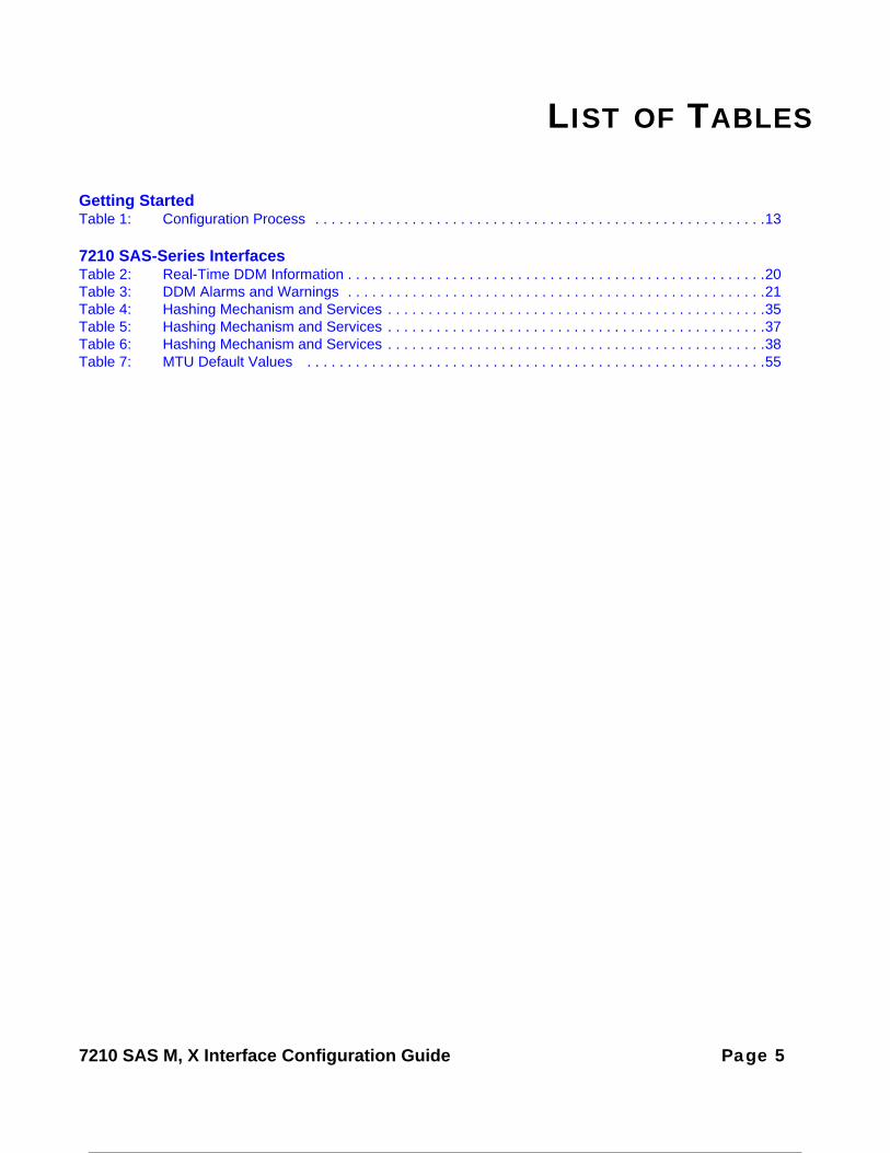
LIST OF TABLES
Getting StartedTable 1: Configuration Process . . . . . . . . . . . . . . . . . . . . . . . . . . . . . . . . . . . . . . . . . . . . . . . . . . . . . . . .13
7210 SAS-Series InterfacesTable 2: Real-Time DDM Information . . . . . . . . . . . . . . . . . . . . . . . . . . . . . . . . . . . . . . . . . . . . . . . . . . . .20Table 3: DDM Alarms and Warnings . . . . . . . . . . . . . . . . . . . . . . . . . . . . . . . . . . . . . . . . . . . . . . . . . . . .21Table 4: Hashing Mechanism and Services . . . . . . . . . . . . . . . . . . . . . . . . . . . . . . . . . . . . . . . . . . . . . . .35Table 5: Hashing Mechanism and Services . . . . . . . . . . . . . . . . . . . . . . . . . . . . . . . . . . . . . . . . . . . . . . .37Table 6: Hashing Mechanism and Services . . . . . . . . . . . . . . . . . . . . . . . . . . . . . . . . . . . . . . . . . . . . . . .38Table 7: MTU Default Values . . . . . . . . . . . . . . . . . . . . . . . . . . . . . . . . . . . . . . . . . . . . . . . . . . . . . . . . .55
7210 SAS M, X Interface Configuration Guide Page 5

List of Tables
Page 6 7210 SAS M, X Interface Configuration Guide

LIST OF FIGURES
7210 SAS-Series InterfacesFigure 1: LAG Configuration . . . . . . . . . . . . . . . . . . . . . . . . . . . . . . . . . . . . . . . . . . . . . . . . . . . . . . . . . . .18Figure 2: 802.1x Architecture . . . . . . . . . . . . . . . . . . . . . . . . . . . . . . . . . . . . . . . . . . . . . . . . . . . . . . . . . .25Figure 3: 802.1x Authentication Scenario . . . . . . . . . . . . . . . . . . . . . . . . . . . . . . . . . . . . . . . . . . . . . . . . .26Figure 4: 802.1x EAPOL Timers (left) and RADIUS Timers (right) . . . . . . . . . . . . . . . . . . . . . . . . . . . . . .28
7210 SAS M, X Interface Configuration Guide Page 7

List of Figures
Page 8 7210 SAS M, X Interface Configuration Guide

Preface
About This Guide
This guide describes system concepts and provides configuration examples to provision input/output modules (IOMs), also referred to as cards, Media Dependent Adapters (MDAs), and ports provided by 7210 SAS-M. All the variants of 7210 SAS-M can be configured in two modes, that is, in network mode and in access-uplink mode. In network mode configuration, 7210 SAS-M uses IP/MPLS to provide service transport. In access-uplink mode configuration, 7210 SAS-M uses Ethernet QinQ technology to provide service transport. The mode can be selected by configuring the BOF appropriately.
Note: In either mode, it is expected that the user will only configure the required CLI parameters appropriate for the mode he intends to use. Unless otherwise noted, most of the configuration is similar in both the Network mode and access uplink mode.
Note : Only 7210 SAS-M supports access-uplink mode. 7210 SAS-X does not support access-uplink mode.
This document is organized into functional chapters and provides concepts and descriptions of the implementation flow, as well as Command Line Interface (CLI) syntax and command usage.
7210 SAS M, X Interface Configuration Guide Page 9

Preface
Audience
This manual is intended for network administrators who are responsible for configuring the 7210 SAS-Series routers. It is assumed that the network administrators have an understanding of networking principles and configurations, routing processes, and protocols and standards, including:
• CLI concepts• MDA, and port configuration• QoS policies• Services
Page 10 7210 SAS M, X Interface Configuration Guide

Preface
List of Technical Publications
The 7210 SAS M, X OS documentation set is composed of the following books:
• 7210 SAS M, X OS Basic System Configuration GuideThis guide describes basic system configurations and operations.
• 7210 SAS M, X OS System Management GuideThis guide describes system security and access configurations as well as event logging and accounting logs.
• 7210 SAS M, X OS Interface Configuration GuideThis guide describes card, Media Dependent Adapter (MDA), and port provisioning.
• 7210 SAS M, X OS OS Router Configuration GuideThis guide describes logical IP routing interfaces and associated attributes such as an IP address, port, link aggregation group (LAG) as well as IP and MAC-based filtering.
• 7210 SAS M Services GuideThis guide describes how to configure service parameters such as customer information and user services.
• 7210 SAS M, X OS OAM and Diagnostic GuideThis guide describes how to configure features such as service mirroring and Operations, Administration and Management (OAM) tools.
• 7210 SAS M Quality of Service GuideThis guide describes how to configure Quality of Service (QoS) policy management.
• 7210 SAS M, X OS MPLS GuideThis guide describes how to configure Multiprotocol Label Switching (MPLS) and Label Distribution Protocol (LDP).
• 7210 SAS M, X OS Routing Protocols GuideThis guide provides an overview of routing concepts and provides configuration examples for RIP, OSPF, IS-IS and route policies.
7210 SAS M, X Interface Configuration Guide Page 11

Preface
Technical Support
If you purchased a service agreement for your 7210 SAS M-series router and related products from a distributor or authorized reseller, contact the technical support staff for that distributor or reseller for assistance. If you purchased an Alcatel-Lucent service agreement, contact your welcome center: Web: http://www1.alcatel-lucent.com/comps/pages/carrier_support.jhtml
Page 12 7210 SAS M, X Interface Configuration Guide

GETTING STARTED
In This Chapter
This chapter provides process flow information to configure cards and ports.
Alcatel-Lucent 7210 SAS M-Series Router Configuration Process
Table 1 lists the tasks necessary to provision cards, Media Dependent Adapters (MDAs), and ports.
This guide is presented in an overall logical configuration flow. Each section describes a software area and provides CLI syntax and command usage to configure parameters for a functional area.
Table 1: Configuration Process
Area Task Chapter
Provisioning Chassis slots and cards Chassis Slots and Cards on page 16
MDAs MDAs on page 16
Ports Ports on page 23
Reference List of IEEE, IETF, and other proprietary entities.
Standards and Protocol Support on page 235
7210 SAS M, X Interface Configuration Guide Page 13

Getting Started
Page 14 7210 SAS M, X Interface Configuration Guide
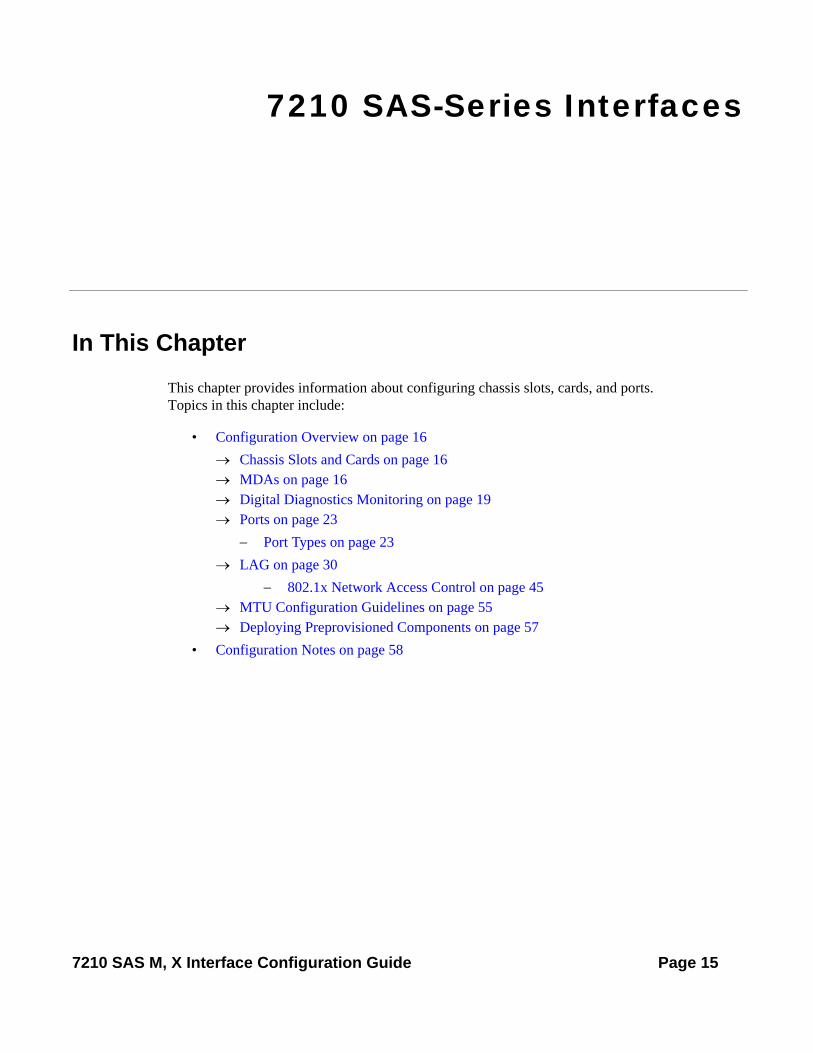
7210 SAS-Series Interfaces
In This Chapter
This chapter provides information about configuring chassis slots, cards, and ports.Topics in this chapter include:
• Configuration Overview on page 16→ Chassis Slots and Cards on page 16→ MDAs on page 16→ Digital Diagnostics Monitoring on page 19→ Ports on page 23
− Port Types on page 23→ LAG on page 30
− 802.1x Network Access Control on page 45→ MTU Configuration Guidelines on page 55→ Deploying Preprovisioned Components on page 57
• Configuration Notes on page 58
7210 SAS M, X Interface Configuration Guide Page 15

Configuration Overview
Configuration Overview
NOTE: This document uses the term preprovisioning in the context of preparing or preconfiguring entities such as chassis slots, media dependent adapters (MDAs), ports, and interfaces, prior to initialization. These entities can be installed but not enabled. When the entity is in a no shutdown state (administratively enabled), then the entity is considered to be provisioned.
Alcatel- Lucent 7210 SAS devices are single chassis (pizza box) devices. The 7210 SAS devices do not accept any IOM cards.
The chassis slot is auto-provisioned at boot time with the appropriate line card type and MDA type.
The following sections are discussed.
• Chassis Slots and Cards on page 16• MDAs on page 16• Ports on page 23
Chassis Slots and Cards
The 7210 SAS-M supports one expansion slot which accepts supported MDAs, and 2*10G MDA. This MDA supports 2 x 10 Gig Ethernet ports with Synchronous Ethernet support (only 10GE LAN option is supported, and synchronous Ethernet is not supported in the current release). All the variants of SAS-M, that is, 7210 SAS-M 24F ,7210 SAS-M 24F 2XFP and 7210 SAS-M 24F 2XFP ETR support the use of 2*10G MDA.
The 7210 SAS-X does not support expansion slots.
MDAs
A chassis slot and card type must be specified and provisioned before an MDA can be preprovisioned. An MDA is provisioned when a type designated from the allowed MDA types is inserted. A preprovisioned MDA slot can remain empty without conflicting with populated slots.
Once installed and enabled, the system verifies that the installed MDA type matches the configured parameters. If the parameters do not match, the MDA remains offline.
An MDA is provisioned when a type designated from the allowed MDA type is inserted. A pre-provisioned MDA slot can remain empty without conflicting with the populated slots.
Page 16 7210 SAS M, X Interface Configuration Guide
Interface Configuration
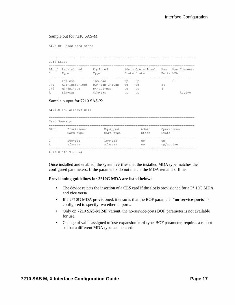
Sample out for 7210 SAS-M:
A:7210# show card state
===============================================================================Card State===============================================================================Slot/ Provisioned Equipped Admin Operational Num Num CommentsId Type Type State State Ports MDA -------------------------------------------------------------------------------1 iom-sas iom-sas up up 2 1/1 m24-1gb+2-10gb m24-1gb+2-10gb up up 24 1/2 m4-ds1-ces m4-ds1-ces up up 4 A sfm-sas sfm-sas up up Active
Sample output for 7210 SAS-X:
A:7210-SAS-X>show# card
===============================================================================Card Summary===============================================================================Slot Provisioned Equipped Admin Operational Card-type Card-type State State-------------------------------------------------------------------------------1 iom-sas iom-sas up upA sfm-sas sfm-sas up up/active===============================================================================A:7210-SAS-X>show#
Once installed and enabled, the system verifies that the installed MDA type matches the configured parameters. If the parameters do not match, the MDA remains offline.
Provisioning guidelines for 2*10G MDA are listed below:
• The device rejects the insertion of a CES card if the slot is provisioned for a 2* 10G MDA and vice versa.
• If a 2*10G MDA provisioned, it ensures that the BOF parameter "no-service-ports" is configured to specify two ethernet ports.
• Only on 7210 SAS-M 24F variant, the no-service-ports BOF parameter is not available for use.
• Change of value assigned to 'use-expansion-card-type' BOF parameter, requires a reboot so that a different MDA type can be used.
7210 SAS M, X Interface Configuration Guide Page 17

Configuration Overview
Hot Swap Capability
For 7210 SAS-M devices currently deployed or new deployements, to insert 2*10 MDA perform the following steps:
1. Configure the BOF parameter "use-expansion-card-type" to m2-xfp. This will provision the system to expect a 2 x 10G MDA for use in the expansion slot.
2. Configure the BOF parameter "no-service-ports", if using a 7210 SAS-M 24F 2XFP and 7210 SAS-M 24F 2XFP ETR variants.
3. Re-boot the device.
Subsequent replacement of 2*10 MDA is hot-swappable and a system re-boot is not required.
Insertion and removal of CES MDA at any point of time into the system is supported, if the BOF parameter configuration is set to default.
In 7210 devices using 2 x 10G MDA, to insert CES MDA perform the following steps:
1. Configure the BOF parameter "use-expansion-card-type" to m4-ds1-ces. This will provision the system to expect a 4 x T1/E1 CES MDA for use in the expansion slot.
2. Configure the BOF parameter "no-service-ports" to default, if using a 7210 SAS-M 24F 2XFP and 7210 SAS-M 24F 2XFP ETR variants.
3. Re-boot the device.
Subsequent replacement of the CES MDA is hot-swappable and a system re-boot is not required.
Page 18 7210 SAS M, X Interface Configuration Guide

Interface Configuration
Digital Diagnostics Monitoring
Some Alcatel-Lucent SFP and XFP transponders have Digital Diagnostics Monitoring (DDM) capability. With DDM the transceiver module maintains information about its working status in device registers, such as:
• Temperature• Supply voltage• Transmit (TX) bias current• TX output power• Received (RX) optical power
The transceiver is also programmed with warning and alarm thresholds for low and high conditions that can generate system events. These thresholds are programmed by the transceiver manufacturer.
There are no CLI commands required for DDM operations, however, the show>port port-id detail command displays DDM information in the Transceiver Digital Diagnostics Monitoring output section.
DDM information is populated into the router’s MIBs, so the DDM data can be retrieved by Network Management using SNMP. Also, RMON threshold monitoring can be configured for the DDM MIB variables to set custom event thresholds if the factory-programmed thresholds are not at the desired levels.
The following are potential uses of the DDM data:
• Optics degradation monitoring — With the information returned by the DDM-capable optics module, degradation in optical performance can be monitored and trigger events based on custom or the factory-programmed warning and alarm thresholds.
• Link/router fault isolation — With the information returned by the DDM-capable optics module, any optical problem affecting a port can be quickly identified or eliminated as the potential problem source.
7210 SAS M, X Interface Configuration Guide Page 19
Digital Diagnostics Monitoring
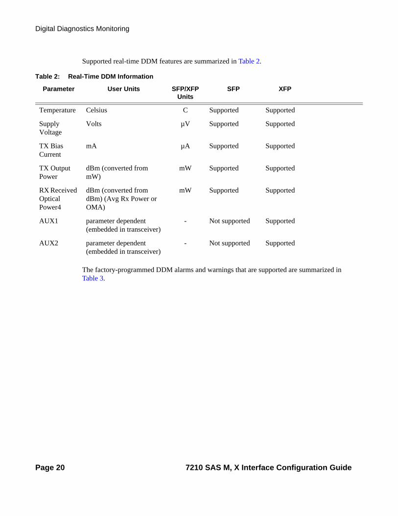
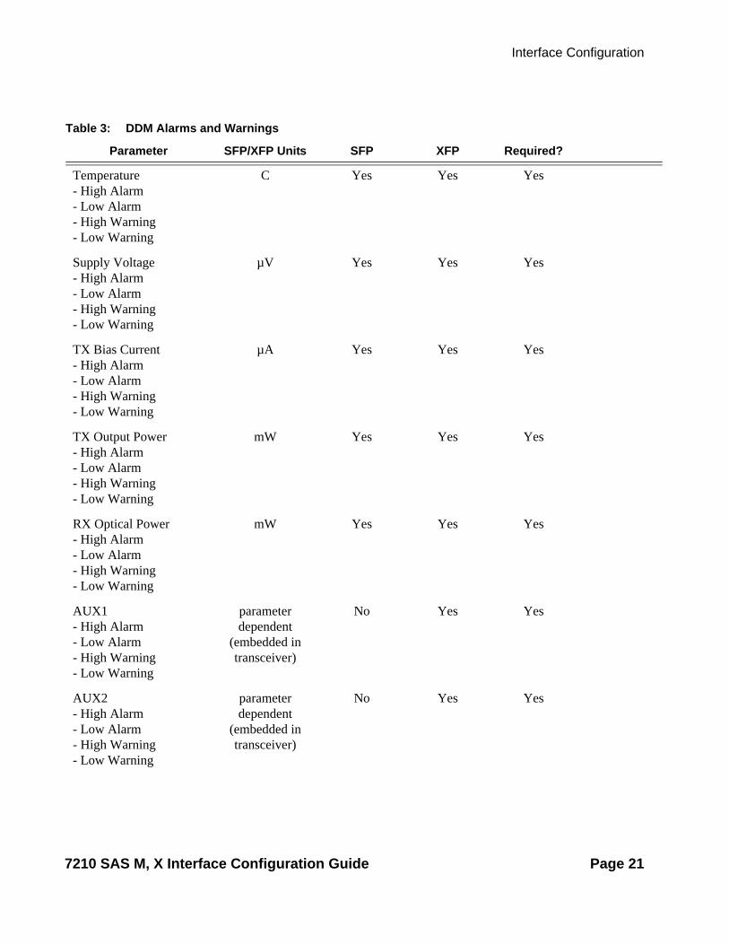
Supported real-time DDM features are summarized in Table 2.
The factory-programmed DDM alarms and warnings that are supported are summarized in Table 3.
Table 2: Real-Time DDM Information
Parameter User Units SFP/XFP Units
SFP XFP
Temperature Celsius C Supported Supported
Supply Voltage
Volts µV Supported Supported
TX Bias Current
mA µA Supported Supported
TX Output Power
dBm (converted from mW)
mW Supported Supported
RX Received Optical Power4
dBm (converted from dBm) (Avg Rx Power or OMA)
mW Supported Supported
AUX1 parameter dependent (embedded in transceiver)
- Not supported Supported
AUX2 parameter dependent (embedded in transceiver)
- Not supported Supported
Page 20 7210 SAS M, X Interface Configuration Guide
Interface Configuration
Table 3: DDM Alarms and Warnings
Parameter SFP/XFP Units SFP XFP Required?
Temperature - High Alarm- Low Alarm- High Warning - Low Warning
C Yes Yes Yes
Supply Voltage- High Alarm- Low Alarm- High Warning- Low Warning
µV Yes Yes Yes
TX Bias Current- High Alarm- Low Alarm- High Warning- Low Warning
µA Yes Yes Yes
TX Output Power- High Alarm- Low Alarm- High Warning- Low Warning
mW Yes Yes Yes
RX Optical Power- High Alarm- Low Alarm- High Warning- Low Warning
mW Yes Yes Yes
AUX1- High Alarm- Low Alarm- High Warning- Low Warning
parameter dependent
(embedded in transceiver)
No Yes Yes
AUX2- High Alarm- Low Alarm- High Warning- Low Warning
parameter dependent
(embedded in transceiver)
No Yes Yes
7210 SAS M, X Interface Configuration Guide Page 21

Digital Diagnostics Monitoring
Alcatel-Lucent SFPs and XFPs
The availability of the DDM real-time information and warning or alarm status is based on the transceiver. It may or may not indicate if DDM is supported, although some Alcatel-Lucent SFPs support DDM. Non-DDM and DDM-supported SFPs are distinguished by a specific ICS value.
For Alcatel-Lucent SFPs that do not indicate DDM support in the ICS value, DDM data is available although the accuracy of the information has not been validated or verified.
For non-Alcatel-Lucent transceivers, DDM information may be displayed, but Alcatel-Lucent is not responsible for formatting, accuracy, etc.
Statistics Collection
The DDM information and warnings/alarms are collected at one minute intervals, so the minimum resolution for any DDM events when correlating with other system events is one minute.
Note that in the Transceiver Digital Diagnostic Monitoring section of the show port port-id detail command output:
• If the present measured value is higher than the either or both High Alarm, High Warn thresholds; an exclamation mark “!” displays along with the threshold value.
• If the present measured value is lower than the either or both Low Alarm, Low Warn thresholds; an exclamation mark “!” displays along with the threshold value.
A:Dut-A# show port 2/1/6 detail
.........
===============================================================================Transceiver Digital Diagnostic Monitoring (DDM), Internally Calibrated=============================================================================== Value High Alarm High Warn Low Warn Low Alarm-------------------------------------------------------------------------------Temperature (C) +39.3 +96.0 +94.0 -7.0 -8.0Supply Voltage (V) 3.27 3.51 3.49 3.12 3.10Tx Bias Current (mA) 18.8 77.0 70.0 5.5 4.5Tx Output Power (dBm) 1.33 5.50 5.00 0.00 -0.50Rx Optical Power (avg dBm) -40.00 -8.50 -9.00 -33.98! -35.23!===============================================================================
Page 22 7210 SAS M, X Interface Configuration Guide

Interface Configuration
Ports
Port Types
The Alcatel-Lucent 7210 SAS routers support the following port types:
• Ethernet — Supported Ethernet port types include:→ Fast Ethernet→ Gigabit→ 10 Gigabit (only on 7210 SAS-M 24F 2XFP, 7210 SAS-M 24F 2XFP ETR, and 7210
SAS-X platforms)7210 SAS M ports must be configured as either access or network. The default is network.→ Access ports — Configured for customer facing traffic on which services are
configured. If a Service Access Port (SAP) is to be configured on the port, it must be configured as an access port. When a port is configured for access mode, the appropriate encapsulation type must be configured to distinguish the services on the port. Once a port has been configured for access mode, one or more services can be configured on the port depending on the encapsulation value.
→ Network ports — Configured for network facing traffic. These ports participate in the service provider transport or infrastructure network. Dot1q is supported on network ports..
• TDM — Supported TDM port types include:→ n*DS-0 inside DS-1/E-1
Only CES services are provided for the T1/E1 ports.
Note: TDM ports are not supported on 7210 SAS-X
7210 SAS M, X Interface Configuration Guide Page 23
Ports
Port Features
• LAG on page 30
• 802.1x Network Access Control on page 45
Page 24 7210 SAS M, X Interface Configuration Guide

Interface Configuration
Link Layer Discovery Protocol (LLDP)
The IEEE 802.1ab Link Layer Discovery Protocol (LLDP) standard defines protocol and management elements suitable for advertising information to stations attached to the same IEEE 802 LAN. The protocol facilitates the identification of stations connected by IEEE 802 LANs or MANs, their points of interconnection, and access points for management protocols.
The LLDP helps the network operators to discover topology information. This information is used to detect and resolve network problems and inconsistencies in the configuration.
Listed below is the information included in the protocol defined by the IEEE 802.1ab standard:
• Connectivity and management information about the local station to adjacent stations on the same IEEE 802 LAN is advertised.
• Network management information from adjacent stations on the same IEEE 802 LAN is received.
• Operates with all IEEE 802 access protocols and network media.• Network management information schema and object definitions that suitable for storing
connection information about adjacent stations is established.• Provides compatibility with a number of MIBs. Refer to Figure 1.
7210 SAS M, X Interface Configuration Guide Page 25

Ports
Figure 1: LLDP Internal Architecture for a Network Node
In order to detect and address network problems and inconsistencies in the configuration, the network operators can discover the topology information using LLDP. The Standard-based tools address the complex network scenarios where multiple devices from different vendors are interconnected using Ethernet interfaces.
The example displayed in Figure 2 depicts a MPLS network that uses Ethernet interfaces in the core or as an access/handoff interfaces to connect to different kind of Ethernet enabled devices such as service gateway/routers, QinQ switches DSLAMs or customer equipment.
The topology information of the network in Figure 2 can be discovered if, IEEE 802.1ab LLDP is running on each of the Ethernet interfaces in network.
OSSG262
OrganizationallyDefined Local DeviceLLDP MIB Extension
(Optional)
LLDP Local SystemMIB
OrganizationallyDefined Remote DeviceLLDP MIB Extensions
(Optional)
LLDP Remote SystemsMIB
PTOPO MIB(Optional)
Entity MIB(Optional)
LLDP/LSAP
Remote Device InformationLocal Device Information
LLDP Frames
Interface MIB(Optional)
Other MIBs(Optional)
LLDP Agent
Page 26 7210 SAS M, X Interface Configuration Guide

Interface Configuration
Figure 2: Generic Customer Use Case For LLDP
OSSG263
Ethernet Links - FE/GE/10GE
MPLS/Native ETHCore
LAG
QinQSWs
DSLAMs
P
PE PE
PE PE
PE PE
P
SG/R
SG/R
7210 SAS M, X Interface Configuration Guide Page 27

Ports
LLDP Protocol Features
The IEEE 802.1ab Link Layer Discovery Protocol (LLDP) is a uni-directional protocol that uses the MAC layer to transmit specific information related to the capabilities and status of the local device. The LLDP can send as well as receive information from a remote device stored in the related MIB(s).
The LLDP does not contain a mechanism to solicit information received from other LLDP agents. The protocol also does not provide means to confirm the receipt of information. LLDP provides the flexibility of enabling a transmitter and receiver separately, therefore the following LLDP configurations are allowed:
• An LLDP agent can only transmit information.• An LLDP agent can only receive information.• An LLDP agent can transmit and receive information.
The information fields in each LLDP frame are contained in an LLDP Data Unit (LLDPDU) as a sequence of variable length information elements. Each information element includes Type, Length, and Value fields (TLVs).
• Type indicates the nature of information being transmitted.• Length indicates the length of the information string in octets.• Value is the actual information that is transmitted. (For example, a binary bit map or an
alphanumeric string that can contain one or more fields).
Each LLDPDU contains four mandatory TLVs and optional TLVs selected by the Network Management. Below is the format of a LLDPDU:
• Chassis ID TLV• Port ID TLV• Time To Live TLV• Zero or more optional TLVs, depending on the maximum size of the LLDPDU allowed.• End Of LLDPDU TLV
An LLDP agent or port is identified by a concatenated string formed by the Chassis ID TLV and the Port ID TLV. This string is used by a recipient to identify an LLDP port or agent. The combination of the Port ID and Chassis ID TLVs remains unchanged until the port or agent is operational.
The TTL (Time To Live) field of an Time-To-Live TLV can be either zero or a non-zero value. A zero value in the TTL field notifies the receiving LLDP agent to immediately discard all information related to the sending LLDP agent. A non-zero value in the TTL field indicates the time duration for which the receiving LLDP agent should retain the sending LLDP agent’s
Page 28 7210 SAS M, X Interface Configuration Guide

Interface Configuration
information. The receiving LLDP agent discards all information related to the sending LLDP agent after the time interval indicated in the TTL field is complete.
Note: A TTL value of zero can be used to signal that the sending LLDP port has initiated a port shutdown procedure.
The End Of LLDPDU TLV indicates the end of the LLDPDU.
7210 SAS M, X Interface Configuration Guide Page 29

LAG
LAG
Based on the IEEE 802.3ax standard (formerly 802.3ad), Link Aggregation Groups (LAGs) can be configured to increase the bandwidth available between two network devices, depending on the number of links installed (from 1 to 16 on iom3-xp/ IMM with chassis-mode D (or) from 1 to 8 on all other IOMs). LAG also provides redundancy in the event that one or more links participating in the LAG fail. All physical links in a given LAG links combine to form one logical interface.
Packet sequencing must be maintained for any given session. The hashing algorithm deployed by Alcatel-Lucent routers is based on the type of traffic transported to ensure that all traffic in a flow remains in sequence while providing effective load sharing across the links in the LAG.
LAGs must be statically configured or formed dynamically with Link Aggregation Control Protocol (LACP). The optional marker protocol described in IEEE 802.3ax is not implemented. LAGs can be configured on network andaccess ports.
LAG Features
Hardware capabilities:
• The LAG load sharing is executed in hardware, which provides line rate forwarding for all port types.
Software capabilities:
• The Alcatel-Lucent solution conforms to the IEEE LAG implementation including dynamic costing and LAG port threshold features. The dynamic cost and LAG port threshold features can be enabled even if the second node is not an Alcatel-Lucent router.→ Dynamic cost
Dynamic cost can be enabled with the config>lag dynamic-cost command or by the action specified in the config>lag>port-threshold command. If dynamic cost is enabled and the number of active links is greater than the port threshold value (0-7 or 0-15), depending on chassis-mode and IOM type), then the path cost is dynamically calculated whenever there is a change in the number of active links regardless of the specified port threshold action. If the port-threshold is met and the action is set to dynamic cost, then the path cost is dynamically recalculated regardless of the global dynamic cost configuration.Enabling dynamic costing causes the physical link metrics used by OSPF to be applied based on the operational or aggregate link bandwidth in the LAG that is available at the time, providing the number of links that are up exceeds the configured
Page 30 7210 SAS M, X Interface Configuration Guide

Interface Configuration
LAG port threshold value. If the number of available links falls below the configured threshold, the configured threshold action determines if and at what cost this LAG will be advertised.For example, assume a single link in OSPF has an associated cost of 100 and the LAG consists of four physical links. The cost associated with the logical link is 25. If one link fails then the cost would automatically be adjusted to 33.If dynamic cost is not configured then costing is applied based on the total number of links configured. The cost would be calculated at 25. This will remain static provided the number of links that are up exceeds the configured LAG threshold.
→ LAG port thresholdThe LAG port threshold feature allows configuration of the behavior, once the number of available links in a LAG falls below or is equal to the specified threshold. Two options are available:
1. If the number of links available (up) in a LAG is less than the configured threshold, then the LAG is regarded as operationally down. For example, assume a LAG consists of four physical links. The threshold is set to twoand dynamic costing is not configured. If the operational links is equal to or drops below two, the link is regarded as operationally down until the number of operational links is two or more.
2. When the number of links available in a LAG is less than the configured threshold, the LAG starts using the dynamic-cost allowing other nodes to adjust their routing tables according to the revised costs. In this case, when the threshold is not crossed, a fixed metric (all links operational) is advertised.
7210 SAS M, X Interface Configuration Guide Page 31

LAG
Configuring LAGs
LAG configuration guidelines include:
• A maximum of 12 LAGs, 4 ports in each, can be configured on a 7210 SAS M. • Ports can be added or removed from the LAG while the LAG and its ports (other than the
port being removed) remain operational. When ports to and/or from the LAG are added or removed, the hashing algorithm is adjusted for the new port count.
• The show commands display physical port statistics on a port-by-port basis or the entire LAG can be displayed.
• LAG is supported on Ethernet ports.• Ports of a particular LAG can be of different types but they must be the same speed and
duplex. To guarantee the same port speed is used for all ports in a LAG, autonegotiation must be disabled or in limited mode to ensure only a specific speed is advertised.
Figure 3 displays traffic routed between ALA-1 and ALA-2 as a LAG consisting of four ports.
Figure 3: LAG Configuration
OSSG011
ALA-1 ALA-4
ALA-2
LAG-1
LAG-2
ALA-3
Page 32 7210 SAS M, X Interface Configuration Guide

Interface Configuration
LAG Hashing
When a requirement exists to increase the available bandwidth for a logical link that exceeds the physical bandwidth or add redundancy for a physical link, typically one of the methods is applied; equal cost multi-path (ECMP) or Link Aggregation (LAG). A 7210 SAS M currently only supports Link Aggregation Groups and supports up to four ports per LAG.
Different types of hashing algorithms can be employed depending whether better loadspreading or consistent per service forwarding is required. The Alcatel-Lucent implementation supports per flow hashing used to achieve uniform loadspreading and per service hashing designed to provide consistent per service forwarding. The following sub-sections describe these two hashing algorithms.
Depending on the type of traffic that needs to be distributed into a LAG, different variables are used as input to the hashing algorithm that determines the next hop selection. There are several traffic types to consider:
• VPLS, VLL traffic: This is hashed based on IP source and destination addresses, TCP or UDP source and destination port information in the hash algorithm, or the MAC source and destination addresses for non-IP traffic.
• The hash used for LAG for VPLS services does not include the VPLS service ID. The MAC SA/DA are hashed and then if the Ethertype is IPv4, the hash is replaced with one based on the IP source address/destination address, TCP or UDP source port and destination port. Packets for the same SAP can be sprayed across different LAG members, if the result of this hash modulo the number of LAG links is different.
• Unicast IP traffic routed by a 7210 SAS M router uses the IP SA/DA and TCP/UDP port information.
• By default, MPLS packet hashing at an LSR is based on the whole label stack, along with the incoming port and system IP address. Note that the EXP/TTL information in each label is not included in the hash algorithm.
7210 SAS M, X Interface Configuration Guide Page 33

LAG
Lag Hashing Mechanism
Figure 4: Hashing Mechanism
In Figure 4, traffic flows from “A” to “B” (A and B represent SAPs). The hashing mechanism sprays packets over different LAG ports.
The following tabels summarize the hashing mechanism for different services
A B
LAG
Page 34 7210 SAS M, X Interface Configuration Guide

Interface Configuration
.
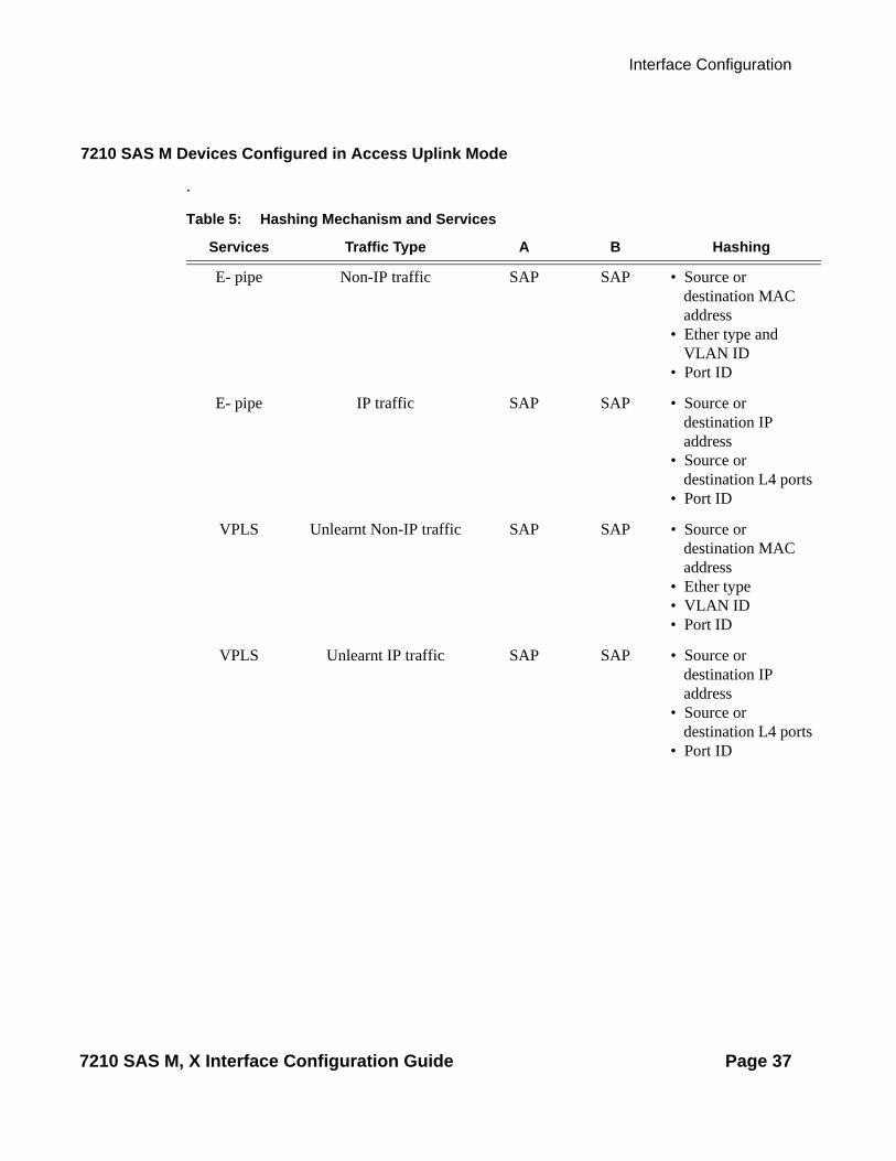
Table 4: Hashing Mechanism and Services
Services Traffic Type A B Hashing
E- pipe Non-IP traffic SAP SAP • Source or destination MAC address
• Ether type • VLAN ID
E- pipe IP traffic SAP SAP • Source or destination IP address
• Source or destination L4 ports
VPLS Unlearned Non-IP traffic SAP SAP • Source or destination MAC address,
• Ether type• VLAN ID • Port ID
VPLS Unlearned Non-IP traffic SAP SAP • Source or destination IP address
• Source or destination L4 ports
• Port ID
VPLS Learned non-IP traffic SAP SAP • Source or destination MAC address
• Ether type• VLAN ID
VPLS Learned non-IP traffic SAP SAP • Source or destination IP address
• Source or destination L4 ports
VPLS Learned IP or non-IP traffic (from SDP to
SAP)
Network SAP • Source or destination MAC address
• Port ID
7210 SAS M, X Interface Configuration Guide Page 35

LAG
Note:
1. For LSR traffic, incoming labels are used for lag hashing.2. For E-pipe service all traffic is treated as learnt traffic.
VPLS Learned IP or non-IP traffic (from SDP to
SAP)
Network SAP • ource or destination MAC address
• Port ID
E- pipe IP or non-IP traffic (from SDP to SAP)
Network SAP • Source or destination MAC address
• Port ID
VPLS or E-pipe
IP traffic (from SAP to SDP)
SAP Network • Source or destination IP address
• Source or destination L4 ports
• Port ID
VPLS or E-pipe
IP traffic (from SAP to SDP)
SAP Network • ource or destination MAC address
• Ether type• VLAN ID • Port ID
H-VPLS IP or Non IP traffic(from SDP to SDP)
Network Network • Source or destination MAC address
• Port ID
IP (For routed traffic)
Unicast traffic Network Network • Source or destination IP address and Source or destination port ID
• Port ID
MPLS LSR traffic Network Network • MPLS label stack (Two labels deep),
• Port ID
Table 4: Hashing Mechanism and Services
Services Traffic Type A B Hashing
Page 36 7210 SAS M, X Interface Configuration Guide
Interface Configuration
7210 SAS M Devices Configured in Access Uplink Mode
.
Table 5: Hashing Mechanism and Services
Services Traffic Type A B Hashing
E- pipe Non-IP traffic SAP SAP • Source or destination MAC address
• Ether type and VLAN ID
• Port ID
E- pipe IP traffic SAP SAP • Source or destination IP address
• Source or destination L4 ports
• Port ID
VPLS Unlearnt Non-IP traffic SAP SAP • Source or destination MAC address
• Ether type• VLAN ID• Port ID
VPLS Unlearnt IP traffic SAP SAP • Source or destination IP address
• Source or destination L4 ports
• Port ID
7210 SAS M, X Interface Configuration Guide Page 37
LAG
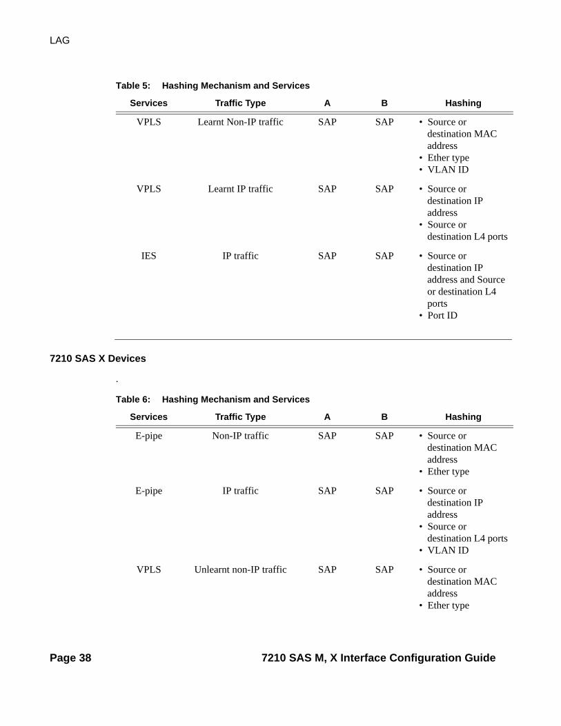
7210 SAS X Devices
.
VPLS Learnt Non-IP traffic SAP SAP • Source or destination MAC address
• Ether type• VLAN ID
VPLS Learnt IP traffic SAP SAP • Source or destination IP address
• Source or destination L4 ports
IES IP traffic SAP SAP • Source or destination IP address and Source or destination L4 ports
• Port ID
Table 5: Hashing Mechanism and Services
Services Traffic Type A B Hashing
Table 6: Hashing Mechanism and Services
Services Traffic Type A B Hashing
E-pipe Non-IP traffic SAP SAP • Source or destination MAC address
• Ether type
E-pipe IP traffic SAP SAP • Source or destination IP address
• Source or destination L4 ports
• VLAN ID
VPLS Unlearnt non-IP traffic SAP SAP • Source or destination MAC address
• Ether type
Page 38 7210 SAS M, X Interface Configuration Guide

Interface Configuration
VPLS Unlearnt IP traffic SAP SAP • Source or destination IP address
• Source or destination L4 ports
• VLAN ID
VPLS Unlearned non-IP traffic SAP SAP • Source or destination MAC address
• Ether type
VPLS Unlearned IP traffic SAP SAP • Source or destination IP address
• Source or destination L4 ports
• VLAN ID
VPLS Learned IP or non-IP traffic
Network SAP • Source or destination MAC address
VPLS Multipoint IP or non-IP traffic (SDP to SAP)
Network SAP • Source or destination MAC address
E-pipe IP or non-IP traffic Network SAP • Source or destination MAC address
VPLS or E-pipe
IP traffic (SAP to SDP) SAP Network • Source or destination IP address
• Source or destination L4 ports
• VLAN ID
VPLS or E-pipe
Non-IP (SAP to SDP) SAP Network • Source or destination MAC address
• Ether type
Table 6: Hashing Mechanism and Services
Services Traffic Type A B Hashing
7210 SAS M, X Interface Configuration Guide Page 39

LAG
Note: For LSR traffic, incoming labels are used for lag hashing.
H-VPLS IP or Non IP traffic(from SDP to SDP)
Network Network • Source or destination MAC address
IP (For routed traffic)
Unicast traffic Network Network • Source or destination IP address and Source or destination L4 ports
MPLS LSR traffic Network Network • MPLS label stack (two labels deep)
Table 6: Hashing Mechanism and Services
Services Traffic Type A B Hashing
Page 40 7210 SAS M, X Interface Configuration Guide

Interface Configuration
LAG on Access
Link Aggregation Groups (LAG) is supported on access ports. This is treated the same as LAG on network ports which provides a standard method to aggregate Ethernet links. The difference lies in how QoS is handled.
7210 SAS M, X Interface Configuration Guide Page 41

LAG
LAG and QoS Policies
In the 7210 SAS M, an ingress QoS policy is applied to the aggregate traffic that enters the traffic through all the ports of the system. For example, if an ingress policy is configured with a policier of PIR 100Mb, for a SAP configured on a LAG with two ports, then the policer limits the traffic entering the system through the two ports to a maximum of 100Mb.
In the 7210 SAS M, egress QoS policy shaper parameters are applied to all the ports that are members of the LAG (all ports get the full SLA). For example, if an egress policy is configured with a policer of PIR 100Mb, each port would get a PIR of 100 Mb. The advantage of this method over a scheme where the PIR is divided equally among all the member ports of the LAG, is that a single flow can consume the entire SLA. The disadvantage is that the overall SLA can be exceeded if the flows span multiple ports.
Page 42 7210 SAS M, X Interface Configuration Guide

Interface Configuration
Port Link Damping
Hold time controls enable port link damping timers that reduce the number of link transitions reported to upper layer protocols.
The 7210 SAS OS port link damping feature guards against excessive port transitions. Any initial port transition is immediately advertised to upper layer protocols, but any subsequent port transitions are not advertised to upper layer protocols until a configured timer has expired.
An “up” timer controls the dampening timer for link up transitions, and a “down” timer controls the dampening timer for link down transitions.
LACP
Generally, link aggregation is used for two purposes: provide an increase in bandwidth and/or provide redundancy. Both aspects are addressed by aggregating several Ethernet links in a single LAG.
Under normal operation, all non-failing links in a given LAG will become active and traffic is load balanced across all active links. In some circumstances, however, this is not desirable. Instead, it desired that only some of the links are active and the other links be kept in stand-by condition.
LACP enhancements allow active lag-member selection based on particular constrains. The mechanism is based on the IEEE 802.3ax standard so interoperability is ensured.
7210 SAS M, X Interface Configuration Guide Page 43

LAG
LAG Subgroups
LACP is used to make selection of active links predictable and compatible with any vendor equipment. Refer to the IEEE STD 802.3-2002, Section 3, Clause 43.6.1 standard which describes how LACP allows stand-by and active signalling.
The 7210 SAS OS implementation of LACP supports the following:
• A given LAG member can be assigned to sub-groups. The selection algorithm then assures that only members of a single sub-group are selected as active links.
• The selection algorithm is effective only if LACP is enabled on a given LAG. At the same time, it is assumed that connected system has also LACP enabled (active or passive mode).
• The algorithm will select active links based on following criteria:→ Depending on selection-criteria setting either the sub-group with the highest number
of eligible links or the sub-group with the highest aggregate weight of all eligible members is selected first.
→ If multiple groups satisfy the selection criteria, the sub-group being currently active remains active. Initially, the sub-group containing the highest priority eligible link is selected.
→ Only links pertaining to a single sub-group are active at any time.→ An eligible member refers to a LAG member link which can potentially become
active. This means it is operationally up, and if the slave-to-partner flag is set, the remote system did not disable its use (by signalling stand-by).
• The selection algorithm works in a reverting mode. This means that every time the configuration or status of any link in a LAG changes, the selection algorithm is re-run. In case of a tie between two groups (one of them being currently active) the active group remains active (no reverting).
Page 44 7210 SAS M, X Interface Configuration Guide

Interface Configuration
G.8032 Protected Ethernet Rings
Ethernet ring protection switching offers ITU-T G.8032 specification compliance to achieve resiliency for Ethernet Layer 2 networks. G.8032 (Eth-ring) is built on Ethernet OAM and often referred to as Ring Automatic Protection Switching (R-APS).
For further information on Ethernet rings, see G.8032 Protected Ethernet Rings section in the Services Guide.
802.1x Network Access Control
The Alcatel-Lucent 7210 SAS supports network access control of client devices (PCs, STBs, etc.) on an Ethernet network using the IEEE. 802.1x standard. 802.1x is known as Extensible Authentication Protocol (EAP) over a LAN network or EAPOL.
802.1x Modes
The Alcatel-Lucent 7210 SAS supports port-based network access control for Ethernet ports only. Every Ethernet port can be configured to operate in one of three different operation modes, controlled by the port-control parameter:
• force-auth — Disables 802.1x authentication and causes the port to transition to the authorized state without requiring any authentication exchange. The port transmits and receives normal traffic without requiring 802.1x-based host authentication. This is the default setting.
• force-unauth — Causes the port to remain in the unauthorized state, ignoring all attempts by the hosts to authenticate. The switch cannot provide authentication services to the host through the interface.
• auto — Enables 802.1x authentication. The port starts in the unauthorized state, allowing only EAPOL frames to be sent and received through the port. Both the router and the host can initiate an authentication procedure as described below. The port will remain in un-authorized state (no traffic except EAPOL frames is allowed) until the first client is authenticated successfully. After this, traffic is allowed on the port for all connected hosts.
7210 SAS M, X Interface Configuration Guide Page 45

LAG
802.1x Basics
Figure 5: 802.1x Architecture
The IEEE 802.1x standard defines three participants in an authentication conversation (see Figure 5).
• The supplicant — This is the end-user device that requests access to the network. • The authenticator — Controls access to the network. Both the supplicant and the
authenticator are referred to as Port Authentication Entities (PAEs). • The authentication server — Performs the actual processing of the user information.
The authentication exchange is carried out between the supplicant and the authentication server, the authenticator acts only as a bridge. The communication between the supplicant and the authenticator is done via the Extended Authentication Protocol (EAP) over LANs (EAPOL). On the back end, the communication between the authenticator and the authentication server is done with the RADIUS protocol. The authenticator is thus a RADIUS client, and the authentication server a RADIUS server.
OSSG038-7210M
Client Alcatel 7210 SAS M RADIUSAuthentication
Server
Supplicant
EAPOL RADIUS
AuthenticatorAuthenticator
Server
Page 46 7210 SAS M, X Interface Configuration Guide

Interface Configuration
Figure 6: 802.1x Authentication Scenario
The messages involved in the authentication procedure are illustrated in Figure 6.The router will initiate the procedure when the Ethernet port becomes operationally up, by sending a special PDU called EAP-Request/ID to the client. The client can also initiate the exchange by sending an EAPOL-start PDU, if it doesn't receive the EAP-Request/ID frame during bootup. The client responds on the EAP-Request/ID with a EAP-Response/ID frame, containing its identity (typically username + password).
After receiving the EAP-Response/ID frame, the router will encapsulate the identity information into a RADIUS AccessRequest packet, and send it off to the configured RADIUS server.
The RADIUS server checks the supplied credentials, and if approved will return an Access Accept message to the router. The router notifies the client with an EAP-Success PDU and puts the port in authorized state.
OSSG039-SAS
Client
EAPOL-Start
Access Request
Access Challenge
Access Request
Access Accept
quiet-period
EAP-Request/ID
EAP-Response/ID
EAP-Request/OTP
EAP-Response/OTP
EAP-Success
EAP-Logoff
EAP-Request/ID
Alcatel 7210 SAS RADIUSAuthentication
Server
Port Unauthorized
Port Unauthorized
Port Authorized
7210 SAS M, X Interface Configuration Guide Page 47
LAG
802.1x Timers
The 802.1x authentication procedure is controlled by a number of configurable timers and scalars. There are two separate sets, one for the EAPOL message exchange and one for the RADIUS message exchange. See Figure 41 for an example of the timers.
EAPOL timers:
• transit-period — Indicates how many seconds the Authenticator will listen for an EAP-Response/ID frame. If the timer expires, a new EAP-Request/ID frame will be sent and the timer restarted. The default value is 60. The range is 1-3600 seconds.
• supplicant-timeout — This timer is started at the beginning of a new authentication procedure (transmission of first EAP-Request/ID frame). If the timer expires before an EAP-Response/ID frame is received, the 802.1x authentication session is considered as having failed. The default value is 30. The range is 1 — 300.
• quiet-period — Indicates number of seconds between authentication sessions It is started after logoff, after sending an EAP-Failure message or after expiry of the supplicant-timeout timer. The default value is 60. The range is 1 — 3600.
RADIUS timer and scaler:
• max-auth-req — Indicates the maximum number of times that the router will send an authentication request to the RADIUS server before the procedure is considered as having failed. The default value is value 2. The range is 1 — 10.
• server-timeout — Indicates how many seconds the authenticator will wait for a RADIUS response message. If the timer expires, the access request message is sent again, up to max-auth-req times. The default value is 60. The range is 1 — 3600 seconds.
Page 48 7210 SAS M, X Interface Configuration Guide

Interface Configuration
Figure 7: 802.1x EAPOL Timers (left) and RADIUS Timers (right)
The router can also be configured to periodically trigger the authentication procedure automatically. This is controlled by the enable re-authentication and reauth-period parameters. Reauth-period indicates the period in seconds (since the last time that the authorization state was confirmed) before a new authentication procedure is started. The range of reauth-period is 1 — 9000 seconds (the default is 3600 seconds, one hour). Note that the port stays in an authorized state during the re-authentication procedure.
Client
quiet-period
supplicant-timeout
transmit-period
EAP-Request/ID
EAP-Request/ID
EAP-Request/ID
EAP-Request/ID
Alcatel 7210 SAS RADIUSAuthentication
Server
Client
Access Request
Access Request
Access Request
quiet-period
server-timeout
max-auth-request
EAP-Request/ID
EAP-Response/ID
EAP-Failure
EAP-Request/ID
Alcatel 7210 SAS RADIUSAuthentication
Server
802.1x EAPOL Timers
802.1x RADIUS Timers
Port Unauthorized
7210 SAS M, X Interface Configuration Guide Page 49

LAG
802.1x Configuration and Limitations
Configuration of 802.1x network access control on the router consists of two parts:
• Generic parameters, which are configured under config>security>dot1x• Port-specific parameters, which are configured under config>port>ethernet>dot1x
801.x authentication:
• Provides access to the port for any device, even if only a single client has been authenticated.
• Can only be used to gain access to a pre-defined Service Access Point (SAP). It is not possible to dynamically select a service (such as a VPLS service) depending on the 802.1x authentication information.
Page 50 7210 SAS M, X Interface Configuration Guide

Interface Configuration
802.3ah OAM
802.3ah Clause 57 (EFM OAM) defines the Operations, Administration, and Maintenance (OAM) sub-layer, which provides mechanisms useful for monitoring link operation such as remote fault indication and remote loopback control. In general, OAM provides network operators the ability to monitor the health of the network and quickly determine the location of failing links or fault conditions. EFM OAM described in this clause provides data link layer mechanisms that complement applications that may reside in higher layers.
OAM information is conveyed in slow protocol frames called OAM protocol data units (OAMPDUs). OAMPDUs contain the appropriate control and status information used to monitor, test and troubleshoot OAM-enabled links. OAMPDUs traverse a single link, being passed between peer OAM entities, and as such, are not forwarded by MAC clients (like bridges or switches).
The following EFM OAM functions are supported:
• EFM OAM capability discovery.• Active and passive modes.• Remote failure indication — Handling of critical link events (for example, link fault,
dying gasp)• Loopback — A mechanism is provided to support a data link layer frame-level loopback
mode. Both remote and local loopback modes are supported.• Dying gasp messages are generated to indicate power failure. The 7210 SAS-M devices
are configured in either Network mode or Access uplink mode. Dying gasp messages are generated on either Network ports or Access uplink ports based on the mode in which the device is configured.
• EFM OAMPDU tunneling.• High resolution timer for EFM OAM in 500ms interval (minimum).
7210 SAS M, X Interface Configuration Guide Page 51

802.3ah OAM
OAM Events
EFM OAM defines a set of events that may impact link operation. The following events are supported:
• Critical link events (defined in 802.3ah clause 57.2.10.1)→ Link fault: the PHY has determined a fault has occurred in the receive direction of the
local DTE.→ Dying gasp: an unrecoverable local failure condition has occurred.→ Critical event: an unspecified critical event has occurred.
These critical link events are signaled to the remote DTE by the flag field in OAM PDUs.
The 7210 does not generate EFM OAM PDUs with these flags except for the dying gasp flag. However, it supports processing of these flags in EFM OAM PDUs received from the peer.
Page 52 7210 SAS M, X Interface Configuration Guide

Interface Configuration
Remote Loopback
EFM OAM provides a link-layer frame loopback mode that can be remotely controlled.
To initiate remote loopback, the local EFM OAM client sends a loopback control OAM PDU by enabling the OAM remote-loopback command. After receiving the loopback control OAM PDU, the remote OAM client puts the remote port into local loopback mode.
To exit remote loopback, the local EFM OAM client sends a loopback control OAM PDU by disabling the OAM remote-loopback command. After receiving the loopback control OAM PDU, the remote OAM client puts the port back into normal forwarding mode.
Note that during remote loopback test operation, all frames except EFM OAM PDUs are dropped at the local port for the receive direction, where remote loopback is enabled. If local loopback is enabled, then all frames except EFM OAM PDUs are dropped at the local port for both the receive and transmit directions. This behavior may result in many protocols (such as STP or LAG) resetting their state machines.
802.3ah OAM PDU Tunneling for Epipe Service
The 7210 SAS routers support 802.3ah. Customers who subscribe to Epipe service treat the Epipe as a wire, so they demand the ability to run 802.3ah between their devices which are located at each end of the Epipe.
Note: This feature only applies to port-based Epipe SAPs because 802.3ah runs at port level not VLAN level. Hence, such ports must be configured as null encapsulated SAPs.
When OAM PDU tunneling is enabled, 802.3ah OAM PDUs received at one end of an Epipe are forwarded through the Epipe. 802.3ah can run between devices that are located at each end of the Epipe. When OAM PDU tunneling is disabled (by default), OAM PDUs are dropped or processed locally according to the efm-oam configuration (shutdown or no shutdown).
Note that by enabling 802.3ah for a specific port and enabling OAM PDU tunneling for the same port are mutually exclusive. Enforcement is performed on the CLI level.
7210 SAS M, X Interface Configuration Guide Page 53

802.3ah OAM
Network Synchronization on Ports
The 7210 SAS supports network synchronization on Ethernet ports.
Network Synchronization on Ethernet Ports
Synchronous Ethernet ports configured for line timing provide the best synchronization performance through a synchronization distribution network. Line timing mode derives the timing information from the Ethernet ports. This mode is immune to any packet delay variation (PDV) occurring on Layer 2 or Layer 3 links.
Synchronous Ethernet is a variant of line timing, supported on the Ethernet SFP ports with SFPs that support Synchronous Ethernet. When synchronous Ethernet is enabled, the operator can select an Ethernet port as a candidate timing reference. The recovered timing from this port is then used to time the system. This ensures that any of the system outputs are locked to a stable, traceable frequency source. In the current release, the recovered timing information is used to time only the Ethernet port output.
Page 54 7210 SAS M, X Interface Configuration Guide

Interface Configuration
MTU Configuration Guidelines
• The 7210 SAS M must contend with MTU limitations at many service points. The physical (access and network) port, service, and SDP MTU values must be individually defined.
• MTU values must conform to both of the following conditions:→ The service MTU must be less than or equal to the SDP path MTU.→ The service MTU must be less than or equal to the access port (SAP) MTU.
Default MTU Values
Table 7 displays the default MTU values which are dependent upon the (sub-) port type, mode, and encapsulation.
*The default MTU for Ethernet ports other than Fast Ethernet is actually the lesser of 9212 and any MTU limitations imposed by hardware which is typically 16K.
Notes:
1. The no service-mtu-check command disables service mtu check. Disabling the service MTU check allows packets to pass to the egress if the packet length is less than or equal to the MTU configured on the port. The length of the packet sent from a SAP is limited only by the access port MTU. In case of a pseudowire, the length of the packet is limited by the network port MTU (including the MPLS encapsulation).
2. In 7210 SAS, length of the SAP tag (or service-delimiting tag, for a packet received over a pseudowire) is included in the computation of the packet length before comparing it with the service-MTU configured for the service.Packet length= Length of IP packet + L2 header + length of SAP tagFor example, if the IP packet received over a dot1q SAP is 1500 and the service-MTU configured is 1514, the service MTU validation check fails as:
Table 7: MTU Default Values
Port Type Mode Encap Type Default (bytes)
Ethernet access null 1514Ethernet access dot1q 1518Fast Ethernet network — 1514Other Ethernet network — 9212*
7210 SAS M, X Interface Configuration Guide Page 55

802.3ah OAM
Packet length=1500 (Length of IP packet) +14 (L2 header) +4 (length of SAP tag) =1518The packet is dropped as packet length is greater than the service MTU configured.
Page 56 7210 SAS M, X Interface Configuration Guide
Interface Configuration
Deploying Preprovisioned Components
Appropriate MDAs are auto-provisioned in 7210 SAS M. User is not required to provisions the slots or MDA.
7210 SAS M, X Interface Configuration Guide Page 57

Configuration Notes
Configuration Notes
The following information describes provisioning caveats:
• Ports can be provisioned without configuration of slot, card and MDA since these components are auto-provisioned.
Page 58 7210 SAS M, X Interface Configuration Guide

Interface Configuration
Configuring Physical Ports with CLI
This section provides information to configure ports.
Topics in this section include:
• Preprovisioning Guidelines on page 60→ Preprovisioning a Port on page 61
• Basic Configuration on page 62• Common Configuration Tasks on page 63
→ Configuring Ports on page 64• Common Configuration Tasks on page 63
→ Configuring Ports on page 64− Configuring Ethernet Port Parameters on page 65
→ Configuring LAG Parameters on page 66• Service Management Tasks on page 67
→ Modifying a Card Type on page 68→ Deleting a Card on page 69→ Deleting Port Parameters on page 69
7210 SAS M, X Interface Configuration Guide Page 59

Preprovisioning Guidelines
Preprovisioning Guidelines
7210 SAS M provides a console port to connect terminals to the device. The Ethernet management port is supported.
Configure parameters from a system console connected to a 7210 SAS M console port, using Telnet to access a 7210 SAS remotely or SSH to open a secure shell connection.
Predefining Entities
In order to initialize a card, the chassis slot, line card type, and MDA type must match the preprovisioned parameters. In this context, preprovisioning means to configure the entity type (such as the line card type, MDA type, port, and interface) that is planned for a chassis slot, line card, or MDA. Preprovisioned entities can be installed but not enabled or the slots can be configured but remain empty until populated. Provisioning means that the preprovisioned entity is installed and enabled.
You can:
• Pre-provision ports and interfaces after the line card and MDA types are specified.• Install line cards in slots with no preconfiguration parameters specified. Once the card is
installed, the card and MDA types must be specified.• Install a line card in a slot provisioned for a different card type (the card will not
initialize). The existing card and MDA configuration must be deleted and replaced with the current information.
Page 60 7210 SAS M, X Interface Configuration Guide

Interface Configuration
Preprovisioning a Port
Some recommendations to configure a port include:
• Ethernet→ Configure an access port for customer facing traffic on which services are configured.
An encapsulation type may be specified in order to distinguish services on the port or channel. Encapsulation types are not required for network ports.To configure an Ethernet access port, refer to on page 65. Configure a network port to participate in the service provider transport or infrastructure network. Accounting policies can only be associated with network ports and Service Access Ports (SAPs). Accounting policies are configured in the config>log> accounting-policy context.To configure an Ethernet network port, refer to on page 65.
Once ports are preprovisioned, Link Aggregation Groups (LAGs) can be configured to increase the bandwidth available between two nodes. Up to four links can be grouped. All physical links in a given LAG combine to form one logical connection. A LAG also provides redundancy in case one or more links that participate in the LAG fail. For command syntax, see Configuring LAG Parameters on page 66.
7210 SAS M, X Interface Configuration Guide Page 61

Basic Configuration
Basic Configuration
Note that cards and MDAs required for operation of the system are auto-provisioned.
Page 62 7210 SAS M, X Interface Configuration Guide

Interface Configuration
Common Configuration Tasks
The following sections are basic system tasks that must be performed.
• Configuring Ports on page 64→ Configuring Ethernet Port Parameters on page 65
• Configuring LAG Parameters on page 66• Service Management Tasks on page 67
7210 SAS M, X Interface Configuration Guide Page 63

Configuring Ports
Configuring Ports
• Configuring Ethernet Port Parameters on page 65
Page 64 7210 SAS M, X Interface Configuration Guide

Interface Configuration
Configuring Ethernet Port Parameters
Ethernet Network Port
A network port is network facing and participates in the service provider transport or infrastructure network processes.
Ethernet Access Port
Services are configured on access ports used for customer-facing traffic. If a Service Access Port (SAP) is to be configured on a port, it must be configured as access mode. When a port is configured for access mode, the appropriate encapsulation type can be specified to distinguish the services on the port. Once a port has been configured for access mode, multiple services may be configured on the port.
Configuring 802.1x Authentication Port Parameters
The following example displays an 802.1x port configuration:
A:ALA-A>config>port>ethernet>dot1x# info detail---------------------------------------------- port-control auto radius-plcy dot1xpolicy re-authentication re-auth-period 3600 max-auth-req 2 transmit-period 30 quiet-period 60 supplicant-timeout 30 server-timeout 30 ----------------------------------------------
7210 SAS M, X Interface Configuration Guide Page 65

Configuring Ports
Configuring LAG Parameters
LAG configurations should include at least two ports. Other considerations include:
• A maximum of four ports can be included in a LAG. All ports in the LAG must share the same characteristics (speed, duplex, hold-timer, etc.). The port characteristics are inherited from the primary port.
• Autonegotiation must be disabled or set limited mode for ports that are part of a LAG to guarantee a specific port speed.
• Ports in a LAG must be configured as full duplex.
The following example displays LAG configuration output:
A:ALA-A>config>lag# info detail---------------------------------------------- description "LAG2" mac 04:68:ff:00:00:01 port 1/1/1 port 1/1/2 port 1/1/3 dynamic-cost port-threshold 2 action down----------------------------------------------A:ALA-A>config>lag#
Page 66 7210 SAS M, X Interface Configuration Guide
Interface Configuration
Service Management Tasks
This section discusses basic procedures of the following service management tasks:
• Modifying a Card Type on page 68• Deleting a Card on page 69• Deleting Port Parameters on page 69
To change an MDA type already provisioned for a specific slot/card, first you must shut down the slot/MDA/port configuration and then delete the MDA from the configuration. Modify and delete operations can be performed only on the MDAs that are not auto equipped or auto provisioned.Use the following CLI syntax to modify an MDA:
CLI Syntax: config> port port-idshutdown
CLI Syntax: config> card slot-numbershutdown
[no] mda mda-number[no] mda-type mda-typeshutdown
7210 SAS M, X Interface Configuration Guide Page 67

Service Management Tasks
Modifying a Card Type
The modify operation cannot be performed on an IOM card that is auto equipped and auto provisioned during bootup and is fixed.
CLI Syntax: config> port port-id[no] shutdown
CLI Syntax: config> card slot-numbermda mda-number
[no] mda-type mda-type[no] shutdown
Page 68 7210 SAS M, X Interface Configuration Guide

Interface Configuration
Deleting a Card
The delete operation cannot be performed on an IOM card that is auto equipped and auto provisioned during bootup and is fixed.
CLI Syntax: config> port port-idshutdown
CLI Syntax: config> card slot-numbercard-type card-typemda mda-number
no mda-type mda-typeno shutdown
Deleting Port Parameters
Use the following CLI syntax to delete a port provisioned for a specific card:
CLI Syntax: config>port port-idshutdownno port port-id
7210 SAS M, X Interface Configuration Guide Page 69

Service Management Tasks
Page 70 7210 SAS M, X Interface Configuration Guide
Command Reference
Card, MDA, and Port Command Reference
Command HierarchiesCard and MDA Configuration Commands
• Hardware Commands on page 72
→ Card Commands on page 72→ MDA Commands on page 72
• Port Configuration Commands on page 73
• Ethernet Commands on page 74
• TDM Commands on page 76 (applicable only for 7210 SAS-M)
• LAG Commands on page 78
• Show Commands on page 80
• Clear Commands on page 81
• Debug Commands on page 81
7210 SAS M, X Interface Configuration Guide Page 71
Card, MDA, and Port Command Reference
Hardware Commands—Card Commands config
— [no] card slot-number — card-type card-type
MDA Commandsconfig
— [no] card slot-number — [no] mda mda-slot
— mda-type mda-type— no mda-type— [no] shutdown— [no] sync-e
— [no] shutdown
Page 72 7210 SAS M, X Interface Configuration Guide

Command Reference
Port Configuration CommandsNote: Listed below are the port configuration commands supported on 7210 SAS M.
config —Port Configuration Commands — port {port-id}
— no port — access
— egress— [no] pool [name]
— slope-policy name— no slope-policy
— uplink— egress
— [no] pool [name]— slope-policy name— no slope-policy
— description long-description-string— no description— ethernet— network
— egress— [no] pool [name]
— slope-policy name— no slope-policy
— [no] shutdown— split-horizon-group group-name— no split-horizon-group— tdm
Port Configuration CommandsNote: Listed below are the port configuration commands supported on 7210 SAS X.
config — port {port-id}— no port
— description long-description-string— no description— ethernet— shutdown
7210 SAS M, X Interface Configuration Guide Page 73

Card, MDA, and Port Command Reference
Ethernet Commandsconfig
— [no] port {port-id}— ethernet
— access— accounting-policy acct-policy-id— no accounting-policy— [no] collect-stats— egress
— qos policy-id (only 7210 SAS M)— no qos— scheduler-mode <fc-based | sap-based> (Supported on 7210
SAS X only)— no scheduler-mode
— uplink— accounting-policy acct-policy-id— no accounting-policy— [no] collect-stats— qos policy-id(only 7210 SAS M)— no qos— queue-policy name— no queue-policy
— autonegotiate [limited]— [no] autonegotiate— dot1x
— max-auth-req max-auth-request— port-control {auto | force-auth | force-unauth}— quiet-period seconds— [no] radius-plcy name— re-auth-period seconds — [no] re-authentication — server-timeout seconds— no server-timeout — supplicant-timeout seconds— no supplicant-timeout — transmit-period seconds— no transmit-period
— down-when-looped— keep-alive timer— no keep-alive— retry-timeout timer— no retry-timeout— [no] shutdown
— duplex {full | half}— efm-oam
— [no] accept-remote-loopback— mode {active | passive}— [no] shutdown— [no] transmit-interval interval [multiplier multiplier]— [no] tunneling
— egress-rate— no egress-rate— egress-scheduler-policy port-scheduler-policy-name
Page 74 7210 SAS M, X Interface Configuration Guide

Command Reference
— no egress-scheduler-policy— encap-type {dot1q | null | qinq}— no encap-type— hold-time {[up hold-time up] [down hold-time down]}— no hold-time— [no] lacp-tunnel — lldp
— dest-mac {nearest-bridge | nearest-non-tpmr | nearest-customer}— admin-status {rx | tx | tx-rx | disabled}— [no] notification— tx-mgmt-address [system]— no tx-mgmt-address— tx-tlvs [port-desc] [sys-name] [sys-desc] [sys-cap]— no tx-tlvs
— mac ieee-address— no mac— mode {access | network} — no mode— mtu mtu-bytes— no mtu— network
— accounting-policy policy-id— no accounting-policy— [no] collect-stats— qos policy-id— no qos— queue-policy name— no queue-policy
— qinq-etype 0x0600..0xffff— [no] report-alarm [signal-fail] [remote] [local] (7210 SAS M, X. Only for 10 G
ports.)— speed {10 | 100 | 1000}— ssm
— [no] shutdown— code-type sonet | sdh— [no] tx-dus
7210 SAS M, X Interface Configuration Guide Page 75

Card, MDA, and Port Command Reference
TDM CommandsNote: TDM commands are applicable only for 7210 SAS-M.
config — [no] port {port-id}
— tdm — buildout short— [no] ds1 ds1-id
— [no] channel-group channel-group— [no] description description-string— [no] encap-type {cem}— idle-cycle-flag {flags | ones}— no idle-cycle-flag— idle-payload-fill {all-ones}— idle-payload-fill pattern pattern— no idle-payload-fill— idle-signal-fill {all-ones}— idle-signal-fill pattern pattern— no idle-signal-fill— [no] mode {access}— [no] shutdown— timeslots timeslots— no timeslots
— clock-source {loop-timed | node-timed | adaptive}— framing (DS-1) {esf | sf | ds1-unframed}— loopback {line | internal| fdl-ansi | fdl-bellcore | payload-ansi}— no loopback— [no] remote-loop-respond— [no] report-alarm [ais] [los] [oof] [rai] [looped]— [no] shutdown— signal-mode {cas}
— [no] e1 [e1-id]— [no] channel-group channel-group-id
— description description-string— no description— [no] encap-type {cem}— idle-payload-fill {all-ones}— idle-payload-fill pattern pattern— no idle-payload-fill— idle-signal-fill {all-ones}— idle-signal-fill pattern pattern— no idle-signal-fill— [no] mode {access}— [no] shutdown— timeslots timeslots— no timeslots
— clock-source {loop-timed | node-timed | adaptive}— framing (E-1) {no-crc-g704 | g704 | e1-unframed}— loopback {line | internal}— no loopback— [no] report-alarm [ais] [los] [oof] [rai] [looped]— [no] shutdown— no signal-mode {cas}
Page 76 7210 SAS M, X Interface Configuration Guide

Command Reference
— lbo [0dB | -7.5dB | -15.0dB | -22.5dB]— length {133 | 266 | 399 | 533 | 655}— line-impedance {75 | 100 | 120}
7210 SAS M, X Interface Configuration Guide Page 77

Card, MDA, and Port Command Reference
LAG Commandsconfig
—LAG Commands — [no] lag [lag-id]— description long-description-string— no description— [no] dynamic-cost— encap-type {dot1q | null | qinq}— no encap-type— hold-time down hold-down-time— no hold-time— lacp [mode] [administrative-key admin-key]— lacp-xmit-interval {slow | fast}— no lacp-xmit-interval— [no] lacp-xmit-stdby— mac ieee-address— no mac— mode — no mode— port port-id [port-id …up to 4 total] [priority priority] [sub-group sub-group-id]— no port port-id [port-id …up to 4 total] — port-threshold value [action {dynamic-cost | down}](Only for 7210 SAS M devices in
Network mode)— selection-criteria [highest-count | highest-weight] [slave-to-partner]— no selection-criteria— [no] shutdown — [no] split-horizon-group group-name (supported only on 7210 SAS-M)
Page 78 7210 SAS M, X Interface Configuration Guide

Command Reference
Ethernet Ring Commandsconfig
— eth-ring ring-id— no eth-ring
— description long-description-string— no description— guard-time time— revert-time time— ccm-hold-time {down down-timeout | up up-timeout}— [no] rpl-node {owner | nbr}— node-id mac— path {a | b} [ { port-id | lag-id } raps-tag qtag[.qtag] ]
— description long-description-string— [no] rpl-end— eth-cfm
— [no] mep mep-id domain md-index association ma-index— [no] ccm-enable— [no] ccm-ltm-priority priority— [no] control-mep— [no] eth-test-enable
— [no] test-pattern {all-zeros | all-ones} [crc-enable]— bit-error-threshold bit-errors
— split-horizon-group {allDef|macRemErrXcon|remErrX-con|errXcon|xcon|noXcon}
— mac-address mac-address— one-way-delay-threshold seconds— [no] shutdown
— [no] shutdown— [no] shutdown
7210 SAS M, X Interface Configuration Guide Page 79

Card, MDA, and Port Command Reference
Show Commandsshow
— chassis [environment] [power-supply]— card [slot-number] [detail]— card state— pools mda-id[/port]— lag [lag-id] [detail] [statistics] — lag lag-id associations— port port-id [detail] — port port-id description — port port-id associations— port port-id dot1x [detail]— port port-id ethernet [efm-oam | detail]— port [A1] [detail] [statistics] [description] — port port-id acr [detail](Not supported on 7210 SAS-X)
— lldp [nearest-bridge | nearest-non-tpmr | nearest-customer] [remote-info] [detail]
Page 80 7210 SAS M, X Interface Configuration Guide

Command Reference
Monitor CommandsMonitor
— port port-id [port-id...(up to 5 max)] [interval seconds] [repeat repeat] [absolute | rate] [multiclass]
Clear Commandsclear
— lag lag-id statistics— mda mda-id [statistics]— port port-id statistics
Debug Commandsdebug
— lag [lag-id lag-id port port-id] [all]— lag [lag-id lag-id port port-id] [sm] [pkt] [cfg] [red] [iom-upd] [port-state] [timers] [sel-logic]— no lag [lag-id lag-id]
7210 SAS M, X Interface Configuration Guide Page 81

Card, MDA, and Port Command Reference
Page 82 7210 SAS M, X Interface Configuration Guide

Interface Configuration
Configuration Commands• Generic Commands on page 83
• MDA Commands on page 86
• Interface QoS Commands on page 88
• General Port Commands on page 91
• Ethernet Port Commands on page 95
• 802.1x Port Commands on page 103
• Port Commands on page 109
• TDM Commands on page 111
• LAG Commands on page 120
Generic Commands
description
Syntax description description-stringno description
Context config>portconfig>lagconfig>port>tdm>e1>channel-groupconfig>port>tdm>ds1>channel-group
Description This command creates a text description for a configuration context to help identify the content in the configuration file.
The no form of this command removes any description string from the context.
Default No description is associated with the configuration context.
Parameters long-description-string — The description character string. Strings can be up to 160 characters long composed of printable, 7-bit ASCII characters. If the string contains special characters (#, $, spaces, etc.), the entire string must be enclosed within double quotes.
shutdown
Syntax [no] shutdown
Context config>cardconfig>card>mda
7210 SAS M, X Interface Configuration Guide Page 83

Generic Commands
config>portconfig>port>ethernetconfig>lagconfig>port>ethernet>efm-oamconfig>port>tdm>ds1>channel-groupconfig>port>tdm>e1>channel-groupconfig>port>ethernet>ssm
Description This command administratively disables an entity. When disabled, an entity does not change, reset, or remove any configuration settings or statistics.
The operational state of the entity is disabled as well as the operational state of any entities contained within.
The no form of this command administratively enables an entity.
card — The default state for a card is no shutdown.
mda — The default state for a mda is no shutdown.
lag — The default state for a Link Aggregation Group (LAG) is shutdown.
port — The default state for a port is shutdown.
path — The default state for a SONET/SDH path is shutdown.
card
Syntax card slot-number
Context config
Description This mandatory command enables access to the chassis card Input/Output Module (IOM), slot, and MDA CLI context.
The no form of this command cannot be used on fixed IOM and MDA cards that are auto equipped and auto provisioned.
Default The IOM card is equipped and provisioned for slot 1.
Parameters slot-number — The slot number of the card in the chassis.
card-type
Syntax card-type card-type
Context config>card
Description This mandatory command adds a to the device configuration for the slot. The card type can be preprovisioned, meaning that the card does not need to be installed in the chassis.
A card must be provisioned before an MDA or port can be configured.
A card can only be provisioned in a slot that is vacant, meaning no other card can be provisioned (configured) for that particular slot.
Page 84 7210 SAS M, X Interface Configuration Guide

Interface Configuration
A card can only be provisioned in a slot if the card type is allowed in the slot. An error message is generated if an attempt is made to provision a card type that is not allowed.
A high severity alarm is raised if an administratively enabled card is removed from the chassis. The alarm is cleared when the correct card type is installed or the configuration is modified. A low severity trap is issued when a card is removed that is administratively disabled.
An appropriate alarm is raised if a partial or complete card failure is detected. The alarm is cleared when the error condition ceases.
The no form of this command cannot be used as the IOM card is fixed.
Default The IOM card is equipped and preprovisioned for slot 1.
Parameters card-type — The type of card to be configured and installed in that slot.
7210 SAS M, X Interface Configuration Guide Page 85

MDA Commands
MDA Commands
mda
Syntax mda mda-slotno mda mda-slot
Context config>card
Description This mandatory command enables access to a card’s MDA CLI context to configure MDAs.
Default No MDA slots are configured by default.
Parameters mda-slot — The MDA slot number to be configured. Fixed ports on the panel of the chassis belong to MDA 1. Cards inserted in expansion slots are numbered 2.
Values 1, 2
mda-type
Syntax mda-type mda-typeno mda-type
Context config>card>mda
Description This mandatory command provisions a specific MDA type to the device configuration for the slot. The MDA can be preprovisioned but an MDA must be provisioned before ports can be configured. Ports can be configured once the MDA is properly provisioned.
A maximum of twothree MDAs can be provisioned on an IOM. Only one MDA can be provisioned per IOM MDA slot. To modify an MDA slot, shut down all port associations.
An alarm is raised if partial or complete MDA failure is detected. The alarm is cleared when the error condition ceases.
MDA 1 does not need to be configured as is provisioned automatically during bootup.
All parameters in the MDA context remain and if non-default values are required then their configuration remains as it is on all existing MDAs.
The no form of this command deletes the MDA from the configuration. The MDA must be administratively shut down before it can be deleted from the configuration. A fixed MDA that is auto equipped and auto provisioned cannot be deleted. An error message is shown in case the no form of command is performed on fixed MDAs.
Default MDA 1 is equipped and provisioned by default during bootup.
Parameters mda-type — The type of MDA selected for the slot postion.
Values m2-xfp (for 7210 SAS M, X)|m4-ds1-ces (only for 7210 SAS M, X)|m24-1gb+2-10Gb
Page 86 7210 SAS M, X Interface Configuration Guide

Interface Configuration
sync-e
Syntax [no] sync-e
Context config>card>mda
Description This command enables Synchronous Ethernet on the Ethernet ports that support Synchronous Ethernet. When Synchronous Ethernet is enabled, the timing information is derived from the Ethernet ports.
Synchronous Ethernet is supported for both Ethernet SFP ports and fixed copper ports. It is highly recommended to use copper port only for distribution of synchronous ethernet and not as a reference.
Refer to the 7210 SAS Basic System Configuration Guide for more information on Synchronous Ethernet.
Default no sync-e
7210 SAS M, X Interface Configuration Guide Page 87
Interface QoS Commands
Interface QoS Commands
access
Syntax access
Context config>port
Description This command enables the access context to configure egress and ingress pool policy parameters.
network
Syntax network
Context config>port
Description This command enables the network context to configure egress and ingress pool policy parameters.
uplink
Syntax uplink
Context config>port>access
Description This command enables the context to configure access pool parameters.
egress
Syntax egress
Context config>port>accessconfig>port>networkconfig>port>uplink
Description This command enables the context to configure egress buffer pool parameters which define the percentage of the pool buffers that are used for CBS calculations and specify the slope policy that is configured in the config>qos>slope-policy context.
Page 88 7210 SAS M, X Interface Configuration Guide

Interface Configuration
ingress
Syntax ingress
Context config>port>access
Description This command enables the context to configure ingress buffer pool parameters which define the percentage of the pool buffers that are used for CBS calculations and specify the slope policy that is configured in the config>qos>slope-policy context.
pool
Syntax [no] pool [name]
Context config>port>access>egressconfig>port>access>ingressconfig>port>network>egressconfig>port>network>ingressconfig>port>access>uplink>egress
Description This command configures pool policies.
On the MDA level, access and network egress and access ingress pools are only allocated on channelized MDAs. On the MDA level, access and network egress and access ingress pools are only allocated on channelized MDAs. Network ingress pools are allocated on the MDA level for non-channelized MDAs.
Default default
Parameters name — Specifies the pool name, a string up to 32 characters long composed of printable, 7-bit ASCII characters. If the string contains special characters (#, $, spaces, etc.), the entire string must be enclosed within double quotes.
slope-policy
Syntax slope-policy nameno slope-policy
Context config>port>access>egress>poolconfig>port>access>uplink>poolconfig>port>network>egress
Description This command specifies an existing slope policy which defines high and low priority RED slope parameters and the time average factor. The policy is defined in the config>qos>slope-policy context.
qos
Note: This command is supported only on 7210 SAS M.
7210 SAS M, X Interface Configuration Guide Page 89

Interface QoS Commands
Syntax qos policy-idno qos
Context config>port>ethernet>access>egress
Description This command associates a QoS policy to the port.
Parameters policy-id — Specifies an existing QoS policy to be assigned to the port.
Values 1 — 65535
scheduler-mode
Note: This command is supported only on 7210 SAS X.
Syntax scheduler-mode <fc-based | sap-based >no scheduler-mode
Context config>port>ethernet>access>egress
Description This command is used to specify the mode of the access egress port scheduler. It operates in the following two modes :
• fc-based
• sap-based
In the "fc-based" mode the priority of all egress queues across all SAPs are considered to determine the next queue to be scheduled.
In the "sap-based" mode the scheduler uses round-robin scheduling mechanism to schedule each of the SAPs configured on a port. The scheduler considers the priority of all the egress queues in a SAP to determine the next queue to be scheduled.
To use the SAP egress aggregate-rate-limit command the port scheduler mode must be set to 'sap-based' using this command. For more information on the aggregate-rate-limit command, see 7210 SAS-X Services guide.
Default fc-based
Page 90 7210 SAS M, X Interface Configuration Guide

Interface Configuration
General Port Commands
port
Syntax port port-idno port port-id
Context config
Description This command enables access to the context to configure ports. Before a port can be configured, the chassis slot must be provisioned with a valid card type and the MDA parameter must be provisioned with a valid MDA type. (See card and mda commands.)
Default No ports are configured. All ports must be explicitly configured and enabled.
Parameters port-id — Specifies the physical port ID in the slot/mda/port format.
egress-scheduler-policy
Syntax egress-scheduler-policy port-scheduler-policy-name no egress-scheduler-policy
Context config>port>ethernet
Description This command enables the provisioning of an existing port-scheduler-policy to a port or channel.
The default scheduling done for a port is strict scheduling. When a port-scheduler-policy is applied to the port, the scheduling behavior changes to the one specified in the policy (Strict, RR, WRR, WDRR, WRR/WDRR + Strict).
The no form of the command removes the policy from the port and makes the scheduling scheme of the port to strict.
The egress-scheduler-override node allows for the definition of the scheduler overrides for a specific port or channel.
When a port scheduler is active on a port or channel, all queues and intermediate service schedulers on the port are subject to receiving bandwidth from the scheduler. Any queues or schedulers with port-parent associations are mapped to the appropriate port priority levels based on the port-parent command parameters. Any queues or schedulers that do not have a port-parent or valid intermediate scheduler parent defined are treated as orphaned and are handled based on the port scheduler policies default or explicit orphan behavior.
The port scheduler maximum rate and priority level rate parameters may be overridden to allow unique values separate from the port-scheduler-policy-name attached to the port or channel. Use the egress-scheduler-override command to specify the port or channel specific scheduling parameters.
The command used to associate an egress scheduler policy on the port is overloaded for HSMDA. HSMDA policies should be associated with HSMDA ports.
7210 SAS M, X Interface Configuration Guide Page 91

General Port Commands
The no form of this command removes a port scheduler policy from an egress port or channel. Once the scheduler policy is removed, all orphaned queues and schedulers revert to a free running state governed only by the local queue or scheduler parameters. This includes any queues or schedulers with a port-parent association.
Parameters port-scheduler-policy-name — Specifies an existing port-scheduler-policy configured in the config>qos context.
mode
Syntax mode {access | network} no mode
Context config>port>ethernetconfig>lag
Description An access port is used for customer facing traffic on which services are configured. A Service Access Point (SAP) can only be configured on an access port. When a port is configured for access mode, the appropriate encap-type must be specified to distinguish the services on the port. Once an Ethernet port has been configured for access mode, multiple services can be configured on the Ethernet port.
An access port or channel is used for customer facing traffic on which services are configured. A Service Access Point (SAP) can only be configured on an access port. When a port is configured for access mode, the appropriate encap-type must be specified to distinguish the services on the port or SONET path. Once an Ethernet port or a SONET path has been configured for access mode, multiple services can be configured on the Ethernet port or SONET path.
The no form of this command restores the default.
Default network — Configures the Ethernet portfor transport network use.
Parameters network — Configures the Ethernet port as service access.
access — Configures the Ethernet port for transport network use.
mac
Syntax mac ieee-addressno mac
Context config>port>ethernetconfig>lagconfig>eth-tunnel
Description This command assigns a specific MAC address to an Ethernet port, Link Aggregation Group (LAG), Ethernet tunnel.
Only one MAC address can be assigned to a port. When multiple mac commands are entered, the last command overwrites the previous command. When the command is issued while the port is operational, IP will issue an ARP, if appropriate, and BPDU’s are sent with the new MAC address.
Page 92 7210 SAS M, X Interface Configuration Guide

Interface Configuration
The no form of this command returns the MAC address to the default value.
Default A default MAC address is assigned by the system from the chassis MAC address pool.
Parameters ieee-address — Specifies the 48-bit MAC address in the form aa:bb:cc:dd:ee:ff or aa-bb-cc-dd-ee-ff where aa, bb, cc, dd, ee and ff are hexadecimal numbers. Allowed values are any non-broadcast, non-multicast MAC and non-IEEE reserved MAC addresses.
mtu
Syntax mtu mtu-bytesno mtu
Context config>port>ethernet
Description This command configures the maximum payload MTU size for an Ethernet port port. The Ethernet port level MTU parameter indirectly defines the largest physical packet the port can transmit or the far-end Ethernet port can receive. Packets received larger than the MTU will be discarded. Packets that cannot be fragmented at egress and exceed the MTU are discarded.
The value specified for the MTU includes the destination MAC address, source MAC address, the Ethertype or Length field and the complete Ethernet payload. The MTU value does not include the preamble, start of frame delimiter or the trailing CRC.
The no form of this command restores the default values.
Default The default MTU value depends on the (sub-)port type, mode and encapsulation and are listed in the following table:
Parameters mtu-bytes — Sets the maximum allowable size of the MTU, expressed as an integer.
Values 512 — 9212
Rangeconfig>port>ethernet 512 — 9212
Type Mode Encap Type Default (Bytes)
10/100, Gig, or 10GigE Access null 1514
10/100, Gig, or 10GigE Access dot1q 1518
10/100, Gig, or 10GigE Access q-in-q 1522
10/100 or 100FX Ethernet Network null 1514
10/100 or 100FX Ethernet Network dot1q 1518
7210 SAS M, X Interface Configuration Guide Page 93
General Port Commands
queue-policy
Syntax queue-policy nameno queue-policy
Context config>card>mda>network>ingress
Description This command specifies the network-queue policy which defines queue parameters such as CBS, high priority only burst size, MBS, CIR and PIR rates, as well as forwarding-class to queue mappings. The network-queue policy is defined in the config>qos>network-queue context.
Default default
Parameters name — Specifies an exisiting network-queue policy name.
Page 94 7210 SAS M, X Interface Configuration Guide

Interface Configuration
Ethernet Port Commands
ethernet
Syntax ethernet
Context config>port
Description This command enables access to the context to configure Ethernet port attributes.
This context can only be used when configuring Fast Ethernet, gigabit, or 10Gig Ethernet LAN ports on an appropriate MDA.
mode
Syntax mode {access | network}no mode
Context config>port>ethernetconfig>port>tdm>ds1>channel-groupconfig>port>tdm>e1>channel-group
Description This command configures an Ethernet port for access, network, or hybrid mode of operation. It also configures a TDM channel or SONET/SDH path (sub-port) for access or network mode operation.
An access port or channel is used for customer facing traffic on which services are configured. A Service Access Point (SAP) can only be configured on an access port or channel. When a port is configured for access mode, the appropriate encap-type must be specified to distinguish the services on the port or SONET path. Once an Ethernet port, a TDM channel or a SONET path has been configured for access mode, multiple services can be configured on the Ethernet port, a TDM channel or SONET path. Note that ATM, Frame Relay, and cHDLC port parameters can only be configured in the access mode.
A network port or channel participates in the service provider transport or infrastructure network when a network mode is selected. When the network option is configured, the encap-type cannot be configured for the port/channel.
When network mode is selected on a SONET/SDH path, the appropriate control protocols are activated when the need arises. For example, configuring an IP interface on the SONET path activates IPCP while the removal of the IP interface causes the IPCP to be removed. The same applies for MPLS, MPLSCP, and OSICP. When configuring a SONET/SDH port, the mode command must be entered in the channel context or an error message is generated.
The no form of this command restores the default.
Default network — for Ethernet ports
access — for TDM channel or SONET paths
Parameters access — Configures the Ethernet port, TDM channel or SONET path as service access.
7210 SAS M, X Interface Configuration Guide Page 95

Ethernet Port Commands
network — Configures the Ethernet port, TDM channel or SONET path for transport network use.
access
Syntax access
Context config>port>ethernet
Description This command configures Ethernet access port parameters.
egress
Syntax egress
Context config>port>ethernet>access
Description This command configures Ethernet access egress port parameters.
ingress
Syntax ingress
Context config>port>ethernet>access
Description This command configures Ethernet access ingress port parameters.
autonegotiate
Syntax autonegotiate [limited][no] autonegotiate
Context config>port>ethernet
Description This command enables speed and duplex autonegotiation on Fast Ethernet ports and enables far-end fault indicator support on gigabit ports.
There are three possible settings for autonegotiation:
• “on” or enabled with full port capabilities advertised
• “off” or disabled where there are no autonegotiation advertisements
• “limited” where a single speed/duplex is advertised.
When autonegotiation is enabled on a port, the link attempts to automatically negotiate the link speed and duplex parameters. If autonegotiation is enabled, the configured duplex and speed parameters are ignored.
Page 96 7210 SAS M, X Interface Configuration Guide

Interface Configuration
When autonegotiation is disabled on a port, the port does not attempt to autonegotiate and will only operate at the speed and duplex settings configured for the port. Note that disabling autonegotiation on gigabit ports is not allowed as the IEEE 802.3 specification for gigabit Ethernet requires autonegotiation be enabled for far end fault indication.
If the autonegotiate limited keyword option is specified the port will autonegotate but will only advertise a specific speed and duplex. The speed and duplex advertised are the speed and duplex settings configured for the port. One use for limited mode is for multispeed gigabit ports to force gigabit operation while keeping autonegotiation enabled for compliance with IEEE 801.3.
7210 SAS requires that autonegotiation be disabled or limited for ports in a Link Aggregation Group to guarantee a specific port speed.
The no form of this command disables autonegotiation on this port.
Default autonegotiate
Parameters limited — The Ethernet interface will automatically negotiate link parameters with the far end, but will only advertise the speed and duplex mode specified by the Ethernet speed and duplex commands.
duplex
Syntax duplex {full | half}
Context config>port>ethernet
Description This command configures the duplex of a Fast Ethernet port when autonegotiation is disabled.
This configuration command allows for the configuration of the duplex mode of a Fast Ethernet port. If the port is configured to autonegotiate this parameter is ignored.
Default full
Parameters full — Sets the link to full duplex mode.
half — Sets the link to half duplex mode.
efm-oam
Syntax efm-oam
Context config>port>ethernet
Description This command configures EFM-OAM attributes.
accept-remote-loopback
Syntax [no] accept-remote-loopback
Context config>port>ethernet>efm-oam
7210 SAS M, X Interface Configuration Guide Page 97

Ethernet Port Commands
Description This command enables reactions to loopback control OAM PDUs from peers.
The no form of this command disables reactions to loopback control OAM PDUs.
Default no accept-remote-loopback
mode
Syntax mode {active | passive}
Context config>port>ethernet>efm-oam
Description This command configures the mode of OAM operation for this Ethernet port. These two modes differ in that active mode causes the port to continually send out efm-oam info PDUs while passive mode waits for the peer to initiate the negotiation process. A passive mode port cannot initiate monitoring activites (such as loopback) with the peer.
Default active
Parameters active — Provides capability to initiate negotiation and monitoring activities.
passive — Relies on peer to initiate negotiation and monitoring activities.
transmit-interval
Syntax [no] transmit-interval interval [multiplier multiplier]
Context config>port>ethernet>efm-oam
Description This command configures the transmit interval of OAM PDUs.
Default transmit-interval 10 multiplier 5
Parameters interval — Specifies the transmit interval.
Values 5 — 600 (in 100 milliseconds)
multiplier multiplier — Specifies the multiplier for transmit-interval to set local link down timer.
Values 2 — 5
tunneling
Syntax [no] tunneling
Context config>port>ethernet>efm-oam
Description This command enables EFM OAM PDU tunneling. Enabling tunneling will allow a port mode Epipe SAP to pass OAM frames through the pipe to the far end.
The no form of the command disables tunneling.
Page 98 7210 SAS M, X Interface Configuration Guide

Interface Configuration
Default no tunneling
egress-rate
Syntax egress-rateno egress-rate
Context config>port>ethernet
Description This command configures the rate of traffic leaving the network.
The no form of this command returns the value to the default.
Default no egress-rate
encap-type
Syntax encap-type {dot1q | null| qinq}no encap-type
Context config>port>ethernet
Description This command configures the encapsulation method used to distinguish customer traffic on an Ethernet access port, or different VLANs on a network port.
The no form of this command restores the default.
Default null
Parameters dot1q — Ingress frames carry 802.1Q tags where each tag signifies a different service.
null — Ingress frames will not use any tags to delineate a service. As a result, only one service can be configured on a port with a null encapsulation type.
qinq — This encapsulation type is specified for QinQ access SAPs.
hold-time
Syntax hold-time {[up hold-time up] [down hold-time down]}no hold-time
Context config>port>ethernet
Description This command configures port link dampening timers which reduce the number of link transitions reported to upper layer protocols. The hold-time value is used to dampen interface transitions.
When an interface transitions from an up state to a down state, it is immediately advertised to the rest of the system if the hold-time down interval is zero, but if the hold-time down interval is greater than zero, interface down transitions are not advertised to upper layers until the hold-time down interval has expired. Likewise, an interface is immediately advertised as up to the rest of the system if the hold-time up interval is
7210 SAS M, X Interface Configuration Guide Page 99

Ethernet Port Commands
zero, but if the hold-time up interval is greater than zero, up transitions are not advertised until the hold-time up interval has expired.
The no form of this command reverts to the default values.
Default down 0 seconds — No port link down dampening is enabled; link down transitions are immediately reported to upper layer protocols.up 0 seconds — No port link up dampening is enabled; link up transitions are immediately reported to upper layer protocols.
Parameters up hold-time up — — The delay, in seconds or centiseconds, to notify the upper layers after an interface transitions from a down state to an up state.
Values 0 — 50
down hold-time down — The delay, in seconds or centiseconds, to notify the upper layers after an interface transitions from an up state to a down state.
Values 0 — 50
lacp-tunnel
Syntax [no] lacp-tunnel
Context config>port>ethernet
Description This command enables LACP packet tunneling for the Ethernet port. When tunneling is enabled, the port will not process any LACP packets but will tunnel them instead. The port cannot be added as a member to a LAG group.
The no form of the command disables LACP packet tunneling for the Ethernet port.
Default no lacp-tunnel
qinq-etype
Syntax qinq-etype 0x0600..0xffffno qinq-etype
Context config>port>ethernet
Description This command configures the Ethertype used for Q-in-Q encapsulation.
The no form of this command reverts the qinq-etype value to the default. The default value is not user configurable.
Parameters 0x0600..0xffff — Specifies the qinq-etype to expect.
Values 1536 — 65535 in decimal or hex formats.
Default 0x8100
Description 0x0600..0xffff — Specifies QinQ etype values.
Page 100 7210 SAS M, X Interface Configuration Guide

Interface Configuration
Values 1536 — 65535, in hexadecimal or decimal notation. Ensure that the values do not match any of the IEEE reserved ethertype values such as 0x8a88, 0x9100, and 0x9200.
report-alarm
Syntax [no] report-alarm [signal-fail]
Context config>port>ethernet
Description This command specifies when and if to generate alarms and alarm clear notifications for this 7210 SAS MX port.
Parameters signal-fail — Reports an Ethernet signal lost alarm.
speed
Syntax speed {10 | 100 | 1000}
Context config>port>ethernet
Description This command configures the port speed of a Fast Ethernet port when autonegotiation is disabled. If the port is configured to autonegotiate this parameter is ignored. Speed cannot be configured for ports that are part of a Link Aggregation Group (LAG).
Default 100
Parameters 10 — Sets the link to 10 mbps speed.
100 — Sets the link to 100 mbps speed.
1000 — Sets the link to 1000 mbps speed.
ssm
Syntax ssm
Context config>port>ethernet
Description This command enables Ethernet Synchronous Status Message (SSM).
code-type
Syntax code-type [sonet | sdh]
Context config>port>ethernet>ssm
7210 SAS M, X Interface Configuration Guide Page 101

Ethernet Port Commands
Description This command configures the encoding of synchronous status messages, that is, to select either SDH or SONET set of values. Configuring the code-type is only applicable to Synchronous Ethernet ports. It is not configurable on TDM ports. For the code-type, SDH refers to ITU-T G.781 Option-1,while SONET refers to G.781 Option 2 (equivalent to Telcordia GR-253-CORE).
Default sdh
Parameters sdh — Specifies the values used on a G.781 Option 1 compliant network.
sonet — Specifies the values used on a G.781 Option 2 compliant network.
tx-dus
Syntax [no] tx-dus
Context config>port>ethernet>ssmconfig>port>sonet-sdh
Description This command forces the QL value transmitted from the SSM channel of the SONET/SDH port or the Synchronous Ethernet port to be set to QL-DUS/QL-DNU. This capability is provided to block the use of the interface from the SR/ESS for timing purposes.
Default no tx-dus
Page 102 7210 SAS M, X Interface Configuration Guide

Interface Configuration
802.1x Port Commands
max-auth-req
Syntax max-auth-req max-auth-request
Context config>port>ethernet>dot1x
Description This command configures the maximum number of times that the 7210 SAS will send an access request RADIUS message to the RADIUS server. If a reply is not received from the RADIUS server after the specified number attempts, the 802.1x authentication procedure is considered to have failed.
The no form of this command returns the value to the default.
Default 2
Parameters max-auth-request — The maximum number of RADIUS retries.
Values 1 — 10
port-control
Syntax port-control [auto | force-auth | force-unauth]
Context config>port>ethernet>dot1x
Description This command configures the 802.1x authentication mode.
The no form of this command returns the value to the default.
Default force-auth
Parameters force-auth — Disables 802.1x authentication and causes the port to transition to the authorized state without requiring any authentication exchange. The port transmits and receives normal traffic without requiring 802.1x-based host authentication.
force-unauth — Causes the port to remain in the unauthorized state, ignoring all attempts by the hosts to authenticate. The switch cannot provide authentication services to the host through the interface.
auto — Enables 802.1x authentication. The port starts in the unauthorized state, allowing only EAPOL frames to be sent and received through the port. Both the 7210 SAS and the host can initiate an authentication procedure. The port will remain in un-authorized state (no traffic except EAPOL frames is allowed) until the first client is authenticated successfully. After this, traffic is allowed on the port for all connected hosts.
7210 SAS M, X Interface Configuration Guide Page 103

802.1x Port Commands
quiet-period
Syntax quiet-period secondsno quiet-period
Context config>port>ethernet>dot1x
Description This command configures the period between two authentication sessions during which no EAPOL frames are sent by the 7210 SAS.
The no form of this command returns the value to the default.
Default 30
Parameters seconds — Specifies the quiet period in seconds.
Values 1 — 3600
radius-plcy
Syntax radius-plcy nameno radius-plcy
Context config>port>ethernet>dot1x
Description This command configures the RADIUS policy to be used for 802.1x authentication. An 802.1x RADIUS policy must be configured (under config>security>dot1x) before it can be associated to a port. If the RADIUS policy-id does not exist, an error is returned. Only one 802.1x RADIUS policy can be associated with a port at a time.
The no form of this command removes the RADIUS policy association.
Default no radius-plcy
Parameters name — Specifies an existing 802.1x RADIUS policy name.
re-auth-period
Syntax re-auth-period secondsno re-auth-period
Context config>port>ethernet>dot1x
Description This command configures the period after which re-authentication is performed. This value is only relevant if re-authentication is enabled.
The no form of this command returns the value to the default.
Default 3600
Parameters seconds — The re-authentication delay period in seconds.
Page 104 7210 SAS M, X Interface Configuration Guide

Interface Configuration
Values 1 — 9000
re-authentication
Syntax [no] re-authentication
Context config>port>ethernet>dot1x
Description This command enables / disables periodic 802.1x re-authentication.
When re-authentication is enabled, the 7210 SAS will re-authenticate clients on the port every re-auth-period seconds.
The no form of the command returns the value to the default.
Default re-authentication
server-timeout
Syntax server-timeout secondsno server-timeout
Context config>port>ethernet>dot1x
Description This command configures the period during which the 7210 SAS waits for the RADIUS server to responds to its access request message. When this timer expires, the 7210 SAS will re-send the access request message, up to the specified number times.
The no form of this command returns the value to the default.
Default 30
Parameters seconds — The server timeout period in seconds.
Values 1 — 300
supplicant-timeout
Syntax supplicant-timeout secondsno supplicant-timeout
Context config>port>ethernet>dot1x
Description This command configures the period during which the 7210 SAS waits for a client to respond to its EAPOL messages. When the supplicant-timeout expires, the 802.1x authentication session is considered to have failed.
The no form of this command returns the value to the default.
Default 30
7210 SAS M, X Interface Configuration Guide Page 105

802.1x Port Commands
Parameters seconds — The server timeout period in seconds.
Values 1 — 300
transmit-period
Syntax transmit-period secondsno transmit-period
Context config>port>ethernet>dot1x
Description This command configures the period after which the 7210 SAS sends a new EAPOL request message.
The no form of this command returns the value to the default.
Default 30
Parameters seconds — The server transmit period in seconds.
Values 1 — 3600
down-when-looped
Syntax down-when-looped
Context config>port>ethernet
Description This command configures Ethernet loop detection attributes.
dot1x
Syntax dot1x
Context config>port>ethernet
Description This command enables access to the context to configure port-specific 802.1x authentication attributes. This context can only be used when configuring a Fast Ethernet, gigabit or 10Gig EthernetFast Ethernet, gigabit or 10Gig EthernetFast Ethernet or gigabit Ethernet LAN ports on an appropriate MDA.
Page 106 7210 SAS M, X Interface Configuration Guide

Interface Configuration
LLDP Ethernet Port Commands
lldp
Syntax lldp
Context config>port>ethernet
Description This command enables the context to configure Link Layer Discovery Protocol (LLDP) parameters on the specified port.
dest-mac
Syntax dest-mac {bridge-mac}
Context config>port>ethernet>lldp
Description This command configures destination MAC address parameters.
Parameters bridge-mac — Specifies destination bridge MAC type to use by LLDP.
Values nearest-bridge — Specifies to use the nearest bridge.nearest-non-tpmr — Specifies to use the nearest non-Two-Port MAC Relay (TPMR) .nearest-customer — Specifies to use the nearest customer.
admin-status
Syntax admin-status {rx | tx | tx-rx | disabled}
Context config>port>ethernet>lldp>dstmac
Description This command specifies the desired administrative status of the local LLDP agent.
Parameters rx — Specifies the LLDP agent will receive, but will not transmit LLDP frames on this port.
tx — Specifies that the LLDP agent will transmit LLDP frames on this port and will not store any information about the remote systems connected.
tx-rx — Specifies that the LLDP agent transmitw and receives LLDP frames on this port.
disabled — Specifies that the LLDP agent does not transmit or receive LLDP frames on this port. If there is remote systems information which is received on this port and stored in other tables, before the port's admin status becomes disabled, then the information will naturally age out.
7210 SAS M, X Interface Configuration Guide Page 107
LLDP Ethernet Port Commands
notification
Syntax [no] notification
Context config>port>ethernet>lldp>dstmac
Description This command enables LLDP notifications.
The no form of the command disables LLDP notifications.
tx-mgmt-address
Syntax tx-mgmt-address [system]no tx-mgmt-address
Context config>port>ethernet>lldp>dstmac
Description This command specifies which management address to transmit.
The no form of the command resets value to the default.
Default no tx-mgmt-address
Parameters system — Specifies to use the system IP address. Note that the system address will only be transmitted once it has been configured if this parameter is specified.
tx-tlvs
Syntax tx-tlvs [port-desc] [sys-name] [sys-desc] [sys-cap]no tx-tlvs
Context config>port>ethernet>lldp>dstmac
Description This command specifies which LLDP TLVs to transmit. The no form of the command resets the value to the default.
no tx-tlvs
Parameters port-desc — Indicates that the LLDP agent should transmit port description TLVs.
sys-name — Indicates that the LLDP agent should transmit system name TLVs.
sys-desc — Indicates that the LLDP agent should transmit system description TLVs.
sys-cap — Indicates that the LLDP agent should transmit system capabilities TLVs.
Page 108 7210 SAS M, X Interface Configuration Guide

Interface Configuration
Port Commands
network
Syntax network
Context config>port>ethernet
Description This command enables access to the context to configure network port parameters.
uplink
Syntax uplink
Context config>port>ethernet>access>uplink
Description This command enables the context to configure access uplink port parameters.
accounting-policy
Syntax accounting-policy policy-idno accounting-policy
Context config>port>ethernet>networkconfig>port>ethernet>access>uplink
Description This command configures an accounting policy that can apply to an interface.
An accounting policy must be configured before it can be associated to an interface. If the accounting policy-id does not exist, an error is returned.
Accounting policies associated with service billing can only be applied to SAPs. Accounting policies associated with network ports can only be associated with interfaces. Only one accounting policy can be associated with an interface at a time.
The no form of this command removes the accounting policy association from the network interface, and the acccounting policy reverts to the default.
Default No accounting policies are specified by default. You must explicitly specify a policy. If configured, the accounting policy configured as the default is used.
Parameters policy-id — The accounting policy-id of an existing policy. Accounting policies record either service (access) or network information. A network accounting policy can only be associated with the network port configurations. Accounting policies are configured in the config>log>accounting-policy context.
Values 1 — 99
7210 SAS M, X Interface Configuration Guide Page 109

Port Commands
collect-stats
Syntax [no] collect-stats
Context config>port>ethernet>networkconfig>port>ethernet>access>uplink
Description This command enables the collection of accounting and statistical data for the network interface. When applying accounting policies, the data, by default, is collected in the appropriate records and written to the designated billing file.
When the no collect-stats command is issued, the statistics are still accumulated by the cards, however, the CPU does not obtain the results and write them to the billing file. If the collect-stats command is issued again (enabled), then the counters written to the billing file will include the traffic collected while the no collect-stats command was in effect.
Default no collect-stats
queue-policy
Syntax queue-policy nameno queue-policy
Context config>port>ethernet>access>uplinkconfig>port>ethernet>access>network
Description This command specifies the existing network queue policy which defines queue parameters such as CIR and PIR rates, as well as forwarding-class to queue mappings. The network-queue policy is defined in the config>qos>network-queue context.
Default default
Parameters name — Specifies an exisiting network-queue policy name.
Page 110 7210 SAS M, X Interface Configuration Guide

Interface Configuration
TDM CommandsNote: TDM commands are applicable only for 7210 SAS-M.
tdm
Syntax tdm
Context config>port
Description This command enables the context to configure DS-1/E-1 parameters for a port on a CES MDA. TDM is a mechanism to divide the bandwidth of a stream into separate channels or time slots by assigning each stream a different time slot in a set. TDM repeatedly transmits a fixed sequence of time slots over a single transmission channel. Each individual data stream is reassembled at the receiving end based on the timing.
Default None
ds1
Syntax [no] ds1
Context config>port>tdm
Description This command enables the context to configure digital signal level 1 (DS-1) frame parameters on a T1/E1 CES MDA. T-1 transmits DS-1-formatted data at 1.544 Mbps through the network. If channel has been con-figured for DS1 on a T1/E1 CES MDA, all ports on that card can be configured for DS1. A combination of DS1 and E1 channels cannot exist on the same card.
The no form of this command disables DS-1 capabilities.
Default None
Parameters ds1-id — Identifies the DS-1 channel being created.
Values DS1: 1 — 28
e1
Syntax e1
Context config>port>tdm
7210 SAS M, X Interface Configuration Guide Page 111

TDM Commands
Description This command enables the context to configure E-1 parameters on a T1/E1 CES MDA. E-1 is a basic time division multiplexing scheme used to carry digital circuits. It is also a standard WAN digital communication format designed to operate over copper facilities at a rate of 2.048 Mbps.
If the channel has been configured for E1 on a T1/E1 CES MDA, all ports on that card can be configured for E1. A combination of DS1 and E1 channels cannot exist on the same card.
The no form of this command disables E-1 capabilities.
Parameters duration — Sets the duration for the BERT test.
Values Up to 24 hours, in seconds or hh:mm:ss format
2e15 — Sends a pseudo-random 2^15 -1 pattern.
2e20 — Sends a pseudo-random 2^20 -1 pattern.
2e23 — Sends a pseudo-random 2^23 -1 pattern.
buildout
Syntax buildout short
Context config>port>tdm
Description This command specifies line buildout (cable length) for physical DS-1 interfaces on the T1/E1 CES MDA.
Default short
Parameters short — Sets the line buildout for length runs up to 655 feet.
lbo
Syntax lbo [0dB | -7.5dB | -15.0dB | -22.5dB]
Context config>port>tdm
Description This command applies only to a DS-1 port configured with a 'long' buildout (see the buildout command). Specify the number of decibels the transmission signal decreases over the line.
For 'short' buildout the following values are valid:
lboNotApplicable — Not applicable
For 'long' buildout the following values are valid:
-> lbo0dB For 0 dB
lboNeg7p5dB For -7.5 dB
lboNeg15p0dB For -15.0 dB
lboNeg22p5dB For -22.5 dB
The default for 'short' build out is 'NotApplicable' while the default for 'long' buildout is 'lbo0dB'.
Page 112 7210 SAS M, X Interface Configuration Guide

Interface Configuration
length
Syntax length {133 | 266 | 399 | 533 | 655}
Context config>port>tdm
Description This command configures the line length for the physical DS1 port on the T1/E1 card.
Default 133
line-impedance
Syntax line-impedance {75 | 100 | 120}
Context config>port>tdm
Description This command configures the line impedance of a port. Line impedance is set on a per-port basis and ports on the same card can have different values. Before changing the line impedance of a port, the port must be shut down.
Default 100 for DS1120 for E1
Parameters 100 for DS1120 or 75 for E1
channel-group
Syntax [no] channel-group channel-group-id
Context config>port>tdm>ds1config>port>tdm>e1
Description This command creates DS0 channel groups in a channelized DS1 or E1 circuit. Channel groups cannot be further subdivided.
The no form of this command deletes the specified DS1 or E1 channel.
Default None
Description channel-group-id — Identifies the channel-group ID number.
Values DS1: 1 — 24E1: 1 — 32
7210 SAS M, X Interface Configuration Guide Page 113

TDM Commands
clock-source
Syntax clock-source {loop-timed | node-timed | adaptive}
Context config>port>tdm>ds1config>port>tdm>e1
Description This command specifies the clock source to be used for the link transmit timing. Adaptive timing is supported only on T1/E1 CES MDA card ports used for TDM pseudowires.
Default looped-timed
Parameters loop-timed — The link recovers the clock from the received data stream.
node-timed — The link uses the internal clock when transmitting data. The internal clock is a free-running clock.
adaptive — The clocking is derived from the incoming pseudowire packets from the MPLS network.
encap-type
Syntax encap-type {cem}
no-encap-type
Context config>port>tdm>ds1>channel-groupconfig>port>tdm>e1>channel-group
Description This command configures the encapsulation method used to on the specified port, path, or channel for the port on the T1/E1 CES MDA. This parameter can be set on access ports. For access mode, only cem encapsulation is supported.
Default cem
Parameters cem — Specifies the encapsulation type as circuit emulation mode for TDM pseudowires on the CES MDA.
framing (DS-1)
Syntax framing {esf | sf | ds1-unframed}
Context config>port>>tdm>ds1
Description This command specifies the DS1 framing to be used for the port. The ds1-unframed parameter allows the configuration of an unstructured DS1 channel on a T1/E1 MDA. If a DS1 unframed channel is shut down, the channel sends an AIS pattern to the far-end DS1. If the far-end DS1 is configured as unframed, it does not react to the AIS pattern. If the far-end DS1 is configured as framed, the far end declares the AIS pattern. The operational status remains up and no alarms are generated when the near end is operationally down. This is normal behavior for unframed G.703 mode.
Default dsl-unframed
Page 114 7210 SAS M, X Interface Configuration Guide

Interface Configuration
Parameters esf — Configures the DS-1 port for extended super frame framing.
sf — Configures the DS-1 port for super frame framing.
ds1-unframed — Specifies the DS1 unframed (G.703) mode for DS1 interfaces. DS1 unframed mode is only applicable if the encapsulation type is set to cem.
framing (E-1)
Syntax framing {no-crc-g704 | g704 | e1-unframed}
Context config>port>tdm>e1
Description This command specifies the E-1 framing to be used for the port.
Default e1-unframed
Parameters g704 — Configure the E-1 port for G.704 framing.
no-crc-g70 — Configures the E-1 for G.704 with no CRC4.
e1-unframed — Specifies E1 unframed (G.703) mode for E1 interfaces. E1 unframed mode is only applicable if the encapsulation type is set to ‘cem’.
idle-cycle-flag
Syntax idle-cycle-flag {flags | ones}
Context config>port>tdm>ds1>channel-groupconfig>port>tdm>ds3config>port>tdm>e1config>port>tdm>e1>channel-groupconfig>port>tdm>e3
Description This command configures the value that the HDLC TDM DS-0, E-1, E-3, DS-1, or DS-3 interface transmits during idle cycles. For ATM ports/channels/channel-groups, the configuration does not apply and only the no form is accepted.
The no form of this command reverts the idle cycle flag to the default value.
Default flags (0x7E)
no flags (ATM)
Parameters flags — Specifies that 0x7E is used as the idle cycle flag.
ones — Specifies that 0xFF is used as the idle cycle flag.
7210 SAS M, X Interface Configuration Guide Page 115

TDM Commands
idle-payload-fill
Syntax idle-payload-fill {all-ones | pattern pattern}
Context config>port>tdm>ds1>channel-groupconfig>port>tdm>e1>channel-group
Description This command defines the data pattern to be transmitted when the circuit emulation service is not operational or temporarily experiences under-run conditions.This command is only valid for cesopsn services.
Note: See the 7210 SAS-M Services guide for more information on CESoPSN services.
Default all-ones
Parameters all-ones — Defines the 8 bit value to be transmitted as 11111111.
pattern — Transmits a user-defined pattern.
Values 0 to 255 (can be entered in decimal, binary, or hexadecimal format)
idle-signal-fill
Syntax idle-signal-fill {all-ones | pattern pattern}no idle-signal-fill
Context config>port>tdm>ds1>channel-groupconfig>port>tdm>e1>channel-group
Description This command defines the signaling pattern to be transmitted (4-bit value) when the circuit emulation service is not operational or temporarily experiences underrun conditions. This command is only valid for CES with CAS.
Note: See the 7210 SAS M Services guide for more information on CESoPSN
Default all-ones
Parameters all-ones — Defines the 4 bit value to be transmitted as 1111.
pattern — Transmits a user-defined pattern.
Values 0 to 15 (can be entered in decimal, binary, or hexadecimal format).
loopback
Syntax loopback {line | internal | fdl-ansi | fdl-bellcore | payload-ansi}no loopback
Context config>port>tdm>ds1
config>port>tdm>e1
Note: Only line and internal options are supported for "e1".
Page 116 7210 SAS M, X Interface Configuration Guide

Interface Configuration
Description This command puts the specified port or channel into a loopback mode. A line loopback, loops frames received on the corresponding port or channel back towards the transmit (egress) direction before reaching the framer. The bit stream is not reframed. The electrical signal is regenerated by the Tx line interface unit (LIU) and the timing is provided by the Rx LIU.
An internal loopback, loops the frames from the local router back to the framer. This is usually referred to as an equipment loopback. The Tx signal is looped back and received by the interface.
Note: The loopback command is not saved to the system configuration.
The no form of this command disables the specified type of loopback.
Note: The fdl-ansi, fdl-bellcore and payload-ansi options can only be configured if DS1 framing is set to ESF.
Default no loopback
Parameters line — Places the associated port or channel into a line loopback mode. A line loopback loops frames received on the corresponding port or channels back to the remote router.
internal — Places the associated port or channel into a internal loopback mode. A internal loopback loops the frames from the local router back at the framer.
fdl-ansi — Requests FDL line loopback according to ANSI T1.403.
fdl-bellcore — Requests FDL line loopback according to Bellcore TR-TSY-000312.
payload-ansi — Requests payload loopback using ANSI signaling.
mode
Syntax mode {access}no mode
Context config>port>tdm>ds1>channel-groupconfig>port>tdm>e1>channel-group
Description This command configures a TDM channel for access mode operation. An access port or channel is used for customer-facing traffic on which services are configured. A Service Access Point (SAP) can only be configured on an access port or channel. When a port is configured for access mode, the encap-type cem must be specified to distinguish the services on the port.
The no form of this command restores the default.
Default access
Parameters access — Configures the port or channel as service access.
remote-loop-respond
Syntax [no] remote-loop-respond
Context config>port>tdm>ds1
7210 SAS M, X Interface Configuration Guide Page 117

TDM Commands
Description This command configures the DS1 channel response to remote loop backs. When enabled, the channel responds to remote loop backs; when disabled, the channel does not respond.
Default no remote-loop-respond
report-alarm
Syntax [no] report-alarm [ais] [los] [oof] [rai] [looped] [ber-sd] [ber-sf]
Context config>port>tdm>ds1config>port>tdm>e1
Description This command enables logging of DS-1 or E-1 alarms for DS-1 or E-1 ports or channels.
The no form of this command disables logging of the specified alarms.
Parameters ais — Reports alarm indication signal errors. When configured, ais alarms are not raised and cleared.
Default ais alarms are issued
los — Reports loss of signal errors. When configured, los traps are not raised and cleared.
Default los traps are issued.
oof — Reports out-of-frame errors. When configured, oof alarms are not raised and cleared.
Default oof alarms are not issued.
rai — Reports resource availability indicator events. When configured, rai events are not raised and cleared.
Default rai alarms are not issued
looped — Reports looped packets errors.
Default looped alarms are not issued
signal-mode
Syntax no signal-mode {cas}
Context config>port>tdm>ds1config>port>tdm>e1
Description This command activates the signal mode on the channel.
When enabled, control signals (such as those for synchronizing and bounding frames) are carried in the same channels as voice and data signals. Configure the signal mode before configuring the Cpipe service to support T1 or E1 with CAS.
Refer to the 7210 SAS Services Guide, “Creating a Cpipe Service”, for information on configuring a Cpipe service.
This command is valid when:
• T1 framing is set to esf or sf
Page 118 7210 SAS M, X Interface Configuration Guide

Interface Configuration
• E1 framing is set to g704 or no-crc-g704.
Note: On the 7210 SAS, CAS is enabled at the port level, rather than at the 64 kb/s channel level. This means that control signals and voice and data signals are all carried in the same channels. However, T1 and E1 links with a mix of voice and data channels cannot be transported directly across a 7210 SAS network. For a workaround, please contact Alcatel-Lucent technical service representatives.
This limitation does not apply to Serial Data Interface card and E&M card traffic transported over MPLS as the signaling is transported in individual pseudowires.
Parameters cas — Specifies channel associated signaling.
timeslots
Syntax timeslots timeslotsno timeslots
Context config>port>tdm>ds1>channel-groupconfig>port>tdm>e1>channel-group
Description This command defines the list of DS-0 timeslots to be used in the DS-1 or E-1 channel-group. The timeslots need not be consecutive.
The no form of this command removes DS-0 timeslots from a channel group.
Default no timeslots — Non-ATM channel groups.
Parameters timeslots — Specifies the timeslot(s) to be associated with the channel group. The value can consist of a list of timeslots. Each member of the list can either be a single timeslot or a range of timeslots.
Values 1 — 24 for DS-1 interfaces2 — 32 for E-1 interfaces
7210 SAS M, X Interface Configuration Guide Page 119

LAG Commands
LAG Commands
lag
Syntax [no] lag [lag-id]
Context config
Description This command creates the context for configuring Link Aggregation Group (LAG) attributes.
A LAG can be used to group up to 4 ports into one logical link. The aggregation of multiple physical links allows for load sharing and offers seamless redundancy. If one of the links fails, traffic will be redistributed over the remaining links. Up to 4 links can be supported in a single LAG, up to 12 LAGs can be configured on a node.
NOTE: All ports in a LAG group must have autonegotiation set to Limited or Disabled.
There are three possible settings for autonegotiation:
• “on” or enabled with full port capabilities advertised
• “off” or disabled where there is no autonegotiation advertisements
• “limited” where a single speed/duplex is advertised.
When autonegotiation is enabled on a port, the link attempts to automatically negotiate the link speed and duplex parameters. If autonegotiation is enabled, the configured duplex and speed parameters are ignored.
When autonegotiation is disabled on a port, the port does not attempt to autonegotiate and will only operate at the speed and duplex settings configured for the port. Note that disabling autonegotiation on gigabit ports is not allowed as the IEEE 802.3 specification for gigabit Ethernet requires autonegotiation be enabled for far end fault indication.
If the autonegotiate limited keyword option is specified the port will autonegotate but will only advertise a specific speed and duplex. The speed and duplex advertised are the speed and duplex settings configured for the port. One use for limited mode is for multispeed gigabit ports to force gigabit operation while keeping autonegotiation is enabled for compliance with IEEE 801.3.
The system requires that autonegotiation be disabled or limited for ports in a LAG to guarantee a specific port speed.
The no form of this command deletes the LAG from the configuration. Deleting a LAG can only be performed while the LAG is administratively shut down. Any dependencies such as IP-Interfaces configurations must be removed from the configuration before issuing the no lag command.
Default No LAGs are defined.
Parameters lag-id — The LAG identifier, expressed as a decimal integer.
Values 1 — 12
Page 120 7210 SAS M, X Interface Configuration Guide

Interface Configuration
dynamic-cost
Syntax [no] dynamic-cost
Context config>lag lag-id
Description This command enables OSPF costing of a Link Aggregation Group (LAG) based on the available aggregated, operational bandwidth.
The path cost is dynamically calculated based on the interface bandwidth. OSPF path cost can be changed through the interface metric or the reference bandwidth.
If dynamic cost is configured, then costing is applied based on the total number of links configured and the cost advertised is inversely proportional to the number of links available at the time. This is provided that the number of links that are up exceeds the configured LAG threshold value at which time the configured threshold action determines if, and at what cost, this LAG will be advertised.
For example:
Assume a physical link in OSPF has a cost associated with it of 100, and the LAG consists of four phys-ical links. The cost associated with the logical link is 25. If one link fails then the cost would automati-cally be adjusted to 33.
If dynamic cost is not configured and OSPF autocost is configured, then costing is applied based on the total number of links configured. This cost will remain static provided the number of links that are up exceeds the configured LAG threshold value at which time the configured threshold action determines if and at what cost this LAG will be advertised.
If dynamic-cost is configured and OSPF autocost is not configured, the cost is determined by the cost configured on the OSPF metric provided the number of links available exceeds the configured LAG threshold value at which time the configured threshold action determines if this LAG will be advertised.
If neither dynamic-cost nor OSPF autocost are configured, the cost advertised is determined by the cost configured on the OSPF metric provided the number of links available exceeds the configured LAG threshold value at which time the configured threshold action determines if this LAG will be advertised.
The no form of this command removes dynamic costing from the LAG.
Default no dynamic-cost
encap-type
Syntax encap-type {dot1q | null | qinq}no encap-type
Context config>lag
Description This command configures the encapsulation method used to distinguish customer traffic on a LAG. The encapsulation type is configurable on a LAG port. The LAG port and the port member encapsulation types must match when adding a port member.
If the encapsulation type of the LAG port is changed, the encapsulation type on all the port members will also change. The encapsulation type can be changed on the LAG port only if there is no interface associated
7210 SAS M, X Interface Configuration Guide Page 121

LAG Commands
with it. If the MTU is set to a non default value, it will be reset to the default value when the encap type is changed.
The no form of this command restores the default.
Default null — All traffic on the port belongs to a single service or VLAN.
Parameters dot1q — Ingress frames carry 802.1Q tags where each tag signifies a different service.
null — Ingress frames will not use any tags to delineate a service. As a result, only one service can be configured on a port with a null encapsulation type.
qinq — This encapsulation type is specified for QinQ access SAPs.
hold-time
Syntax hold-time down hold-down-timeno hold-time
Context config>lag
Description This command specifies the timer, in tenths of seconds, which controls the delay between detecting that a LAG is down (all active ports are down) and reporting it to the higher levels.
A non-zero value can be configured, for example, when active/standby signalling is used in a 1:1 fashion to avoid informing higher levels during the small time interval between detecting that the LAG is down and the time needed to activate the standby link.
Default 0
Parameters down hold-down-time — Specifies the hold-time for event reporting
Values 0 — 2000
lacp
Syntax lacp [mode] [administrative-key admin-key]
Context config>lag
Description This command specifies the LACP mode for aggregated Ethernet interfaces only. This command enables the LACP protocol. Per the IEEE 802.3ax standard (formerly 802.3ad), the Link Aggregation Control Protocol (LACP) provides a standardized means for exchanging information between Partner Systems on a link to allow their Link Aggregation Control instances to reach agreement on the identity of the Link Aggregation Group to which the link belongs, move the link to that Link Aggregation Group, and enable its transmission and reception functions in an orderly manner. LACP can be enabled on a maximum of 12 ports.
Default no lacp
Parameters mode — Specifies the mode in which LACP will operate.
Page 122 7210 SAS M, X Interface Configuration Guide

Interface Configuration
Values passive — Starts transmitting LACP packets only after receiving packets. active — Initiates the transmission of LACP packets.
administrative-key admin-key — Specifies an administrative key value to identify the channel group on each port configured to use LACP. This value should be configured only in exceptional cases. If it is not specified, a random key is assigned.
Values 1 — 65535
lacp-xmit-interval
Syntax lacp-xmit-interval {slow | fast}
Context config>lag
Description This command sepcifies the interval signaled to the peer and tells the peer at which rate it should transmit.
Default fast
Parameters slow — Transmits packets every 30 seconds.
fast — Transmits packets every second.
lacp-xmit-stdby
Syntax [no] lacp-xmit-stdby
Context config>lag
Description This command enables LACP message transmission on standby links.
The no form of this command disables LACP message transmission. This command should be disabled for compatibility when using active/standby groups. This forces a timeout of the standby links by the peer. Use the no form if the peer does not implement the correct behavior regarding the lacp sync bit.
Default lacp-xmit-stdby
port
Syntax port port-id [port-id …up to 4 total] [priority priority] [subgroup sub-group-id]no port port-id [port-id …up to 4 total]
Context config>lag lag-id
Description This command adds ports to a Link Aggregation Group (LAG).
The port configuration of the first port added to the LAG is used as a basis to compare to subsequently added ports. If a discrepancy is found with a newly added port, that port will be not added to the LAG.
Up to 4 (space separated) ports can be added or removed from the LAG link assuming the maximum of 4 ports is not exceeded.
7210 SAS M, X Interface Configuration Guide Page 123

LAG Commands
All ports, when added to a LAG, must share the same characteristics (speed, duplex, etc.). An error message will be displayed when adding ports that do not share the same characteristics. Hold-timers down must be 0. Ports that are part of a LAG must be configured with autonegotiate limited or disabled.
The no form of this command removes ports from the LAG.
Default No ports are defined as members of a LAG.
Parameters port-id — The port ID configured or displayed in the slot/mda/port format.
priority priority — Port priority used by LACP. The port priority is also used to determine the primary port. The port with the lowest priority is the primary port. In the event of a tie, the smallest port ID becomes the primary port.
Values 1 — 65535
subgroup sub-group-id — This parameter identifies a LAG subgroup. When using subgroups in a LAG, they should only be configured on one side of the LAG, not both. Only having one side perform the active/standby selection will guarantee a consistent selection and fast convergence. The active/standby selection will be signalled through LACP to the other side. The hold time should be configured when using subgroups to prevent the LAG going down when switching between active and standby links in case no links are usable for a short time, especially in case a subgroup consists of one member.
Values 1 — 2 identifies a LAG subgroup.
port-threshold
Note: This command is supported only on 7210 SAS M devices operating in Network mode.
Syntax port-threshold value [action {dynamic-cost | down}no port-threshold
Context config>lag lag-id
Description This command configures the behavior for the Link Aggregation Group (LAG) if the number of operational links is equal to or below a threshold level.
The no form of this command reverts to the default values.
Default “0” action down
Parameters value — The decimal integer threshold number of operational links for the LAG at or below which the configured action will be invoked. If the number of operational links exceeds the port-threshold value, any action taken for being below the threshold value will cease.
Values 0 — 3
action {dynamic-cost | down} — Specifies the action to take if the number of active links in the LAG is at or below the threshold value.
When the dynamic-cost action is specified, then dynamic costing will be activated. As a result the LAG will remain operationally up with a cost relative to the number of operational links. The link will only be regarded as operationally down when all links in the LAG are down.
Page 124 7210 SAS M, X Interface Configuration Guide

Interface Configuration
When the down action is specified, then the LAG will be brought operationally down if the number of operational links is equal to or less than the configured threshold value. The LAG will only be regarded as up once the number of operational links exceeds the configured threshold value.
selection-criteria
Syntax selection-criteria [highest-count | highest-weight] [slave-to-partner]no selection-criteria
Context config>lag
Description This command specifies which selection criteria should be used to select the active sub-group.
Default highest-count
Parameters highest-count — Specifies sub-group with the highest number of eligible members.
highest-weight — Specifies sub-group with the highest aggregate weight.
best-port — Selection criteria used with "power-off" mode of operation. The sub-group containing the port with highest priority port. In case of equal port priorities the sub-group containing the port with the lowest port-id is taken
slave-to-partner — The slave-to-partner keyword specifies that it, together with the selection criteria, should be used to select the active sub-group. An eligible member is a lag-member link which can potentially become active. This means it is operationally up (not disabled) for use by the remote side. The slave-to-partner parameter can be used to control whether or not this latter condition is taken into account.
7210 SAS M, X Interface Configuration Guide Page 125

Ethernet Ring Commands
Ethernet Ring Commands
eth-ring
Syntax eth-ring ring-idno eth-ring
Context config
Description This command configures a G.8032 protected Ethernet ring. G.8032 Rings may be configured as major rings with two paths (a&b).
The no form of this command deletes the Ethernet ring specified by the ring-id.
Default no eth-ring
Parameters ring-id — Specifies the ring ID.
Values 1-128
description
Syntax description long-description-stringno description
Context config>eth-ring
Description This command adds a text description for the ring. The no form of this command removes the text description.
Default “Eth ring”
Parameters string — Specifies the text description up to 160 characters in length.
guard-time
Syntax guard-time timeno guard-time
Context config>eth-ring
Description This command configures the guard time for an Eth-Ring. The guard timer is standard and is configurable from “x”ms to 2 seconds
The no form of this command restores the default guard-time.
Default 5 deciseconds
Page 126 7210 SAS M, X Interface Configuration Guide

Interface Configuration
Parameters value — Specifies the guard-time.
Values 1-20 deciseconds
revert-time
Syntax revert-time timeno revert-time
Context config>eth-ring
This command configures the revert time for an Eth-Ring. It ranges from 60 seconds to 720 second by 1 second intervals.
The no form of this command this command means non-revertive mode and revert time essentially is 0 meaning the revert timers are not set.
Default 300 seconds
Parameters value — Specifies the guard-time.
Values 60-720 seconds
ccm-hold-time
Syntax ccm-hold-time {down down-timeout | up up-timeout}no ccm-hold-time
Context config>eth-ring
This command configures eth-ring dampening timers.
The no form of this command set the up and down timer to the default values.
down
Syntax down down-timeout
Context config>eth-ring>ccm-hold-time
This command specifies the timer, which controls the delay between detecting that ring path is down and reporting it to the G.8032 protection module. If a non-zero value is configured, the CPM will wait for the time specified in the value parameter before reporting it to the G.8032 protection module.
Note: This parameter applies only to ring path CCM. It does NOT apply to the ring port link state. To damp ring port link state transitions, use hold-time parameter from the physical member port.
Default 0 - the fault will be reported immediately to the protection module.
Parameters value — Specifies the down timeout.
Values 0-5000 deciseconds
7210 SAS M, X Interface Configuration Guide Page 127

Ethernet Ring Commands
up
Syntax up up-timeout
Context config>eth-ring>ccm-hold-time
This command specifies the timer, which controls the delay between detecting that ring path is up and reporting it to the G.8032 protection module. If a non-zero value is configured, the CPM will wait for the time specified in the value parameter before reporting it to the G.8032 protection module.
Note: This parameter applies only to ring path CCM. It does NOT apply to the member port link state. To damp member port link state transitions, use hold-time parameter from the physical member port.
Default 20 deciseconds
Parameters value — Specifies the hold-time for reporting the recovery.
Values 0-5000 deciseconds
rpl-node
Syntax rpl-node <owner | nbr>no rpl-node
Context config>eth-ring
This command configures the G.8032 ring protection link type as owner or neighbor. The no form of the command means this node is not connected to an RPL link. When RPL owner or neighbor is specified either the a or b path must be configured with the RPL end command. An owner is responsible for operation of the rpl link. Configuring the RPL as neighbor is optional (can be left as no rpl-node) but if the command is used the nbr is mandatory.
The no form of this command removes the RPL link.
Default no rpl-node
node-id
Syntax node-id macno node-id
Context config>eth-ring
This optional command configures the MAC address of the RPL control. The default is to use the chassis MAC for the ring control. This command allows the chassis MAC to be overridden with another MAC address.
The no form of this command removes the RPL link.
Default no node-id
Parameters mac — <xx:xx:xx:xx:xx:xx or xx-xx-xx-xx-xx-xx>
Page 128 7210 SAS M, X Interface Configuration Guide

Interface Configuration
path
Syntax path {a | b} <portid> raps-tag <qtag [.qtag]>[no] path {a | b}
Context config>eth-ring
Description This command assigns the ring (major or sub-ring) path to a port and defines the Ring APS tag. Rings typically have two paths a and b.
The no form of this command removes the path a or b.
Default no path
Parameters raps-tag <qtag [.qtag]> — Specifies the VIDqtag.
Values Dot1q: 1-4094
Values QinQ: 1-4094.1-4094
description
Syntax description long-description-stringno description
Context config>eth-ring>path
Description This command adds a text description for the ring path. The no form of this command removes the text description.
Default “”
Parameters string — Specifies the text description up to 160 characters in length.
rpl-end
Syntax rpl-endno rpl-end
Context config>eth-ring>path
Description This command configures the G.8032 path as a ring protection link end. The ring should be declared as either a RPL owner or RPL neighbor for this command to be allowed. Only path a or path b can be declared an RPL-end.
The no form of this command sets the rpl-end to default no rpl-end.
Default no rpl-end
7210 SAS M, X Interface Configuration Guide Page 129

Ethernet Ring Commands
eth-cfm
Syntax eth-cfm
Context config>eth-ring>path
Description This command enables the context to configure ETH-CFM parameters.
mep
Syntax [no] mep mep-id domain md-index association ma-index
Context config>eth-ring>path>eth-cfm
Description This command provisions an 802.1ag maintenance endpoint (MEP).
The no form of the command reverts to the default values.
Parameters mep-id — Specifies the maintenance association end point identifier.
Values 1 — 81921
md-index — Specifies the maintenance domain (MD) index value.
Values 1 — 4294967295
ma-index — Specifies the MA index value.
Values 1 — 4294967295
ccm-enable
Syntax [no] ccm-enable
Context config>eth-ring>path>eth-cfm>mep
Description This command enables the generation of CCM messages.
The no form of the command disables the generation of CCM messages.
ccm-ltm-priority
Syntax ccm-ltm-priority priorityno ccm-ltm-priority
Context config>eth-ring>path>eth-cfm>mep
Description This command specifies the priority value for CCMs and LTMs transmitted by the MEP.
The no form of the command removes the priority value from the configuration.
Default The highest priority on the bridge-port.
Page 130 7210 SAS M, X Interface Configuration Guide
Interface Configuration
Parameters priority — Specifies the priority of CCM and LTM messages.
Values 0 — 7
control-mep
Syntax no control-mep
Context config>eth-ring>path>eth-cfm>mep
Description This command enables the usage of the CC state by the Ethernet ring for consideration in the protection algorithm. The use of control-mep command is recommended if fast failure detection is required, especially when Link Layer OAM does not provide the required detection time.
The no form of this command disables the use of the CC state by the Ethernet ring.
Default no control-mep
eth-test-enable
Syntax [no] eth-test-enable
Context config>eth-ring>path>eth-cfm>mep
Description This command enables eth-test functionality on MEP. For this test to work, operators need to configure ETH-test parameters on both sender and receiver nodes. The ETH-test then can be done using the following OAM commands:
oam eth-cfm eth-test mac-address mep mep-id domain md-index association ma-index [priority priority] [data-length data-length]
A check is done for both the provisioning and test to ensure the MEP is an Y.1731 MEP (MEP provisioned with domain format none, association format icc-based). If not, the operation fails. An error message in the CLI and SNMP will indicate the problem.
test-pattern
Syntax test-pattern {all-zeros | all-ones} [crc-enable]no test-pattern
Context config>eth-ring>path>eth-cfm>mep>eth-test-enable
Description This command configures the test pattern for eth-test frames.
The no form of the command removes the values from the configuration.
Parameters all-zeros — Specifies to use all zeros in the test pattern.
all-ones — Specifies to use all ones in the test pattern.
crc-enable — Generates a CRC checksum.
7210 SAS M, X Interface Configuration Guide Page 131

Ethernet Ring Commands
Default all-zeros
bit-error-threshold
Syntax bit-error-threshold bit-errors
Context config>eth-ring>path>eth-cfm>mep
Description This command specifies the lowest priority defect that is allowed to generate a fault alarm.
Default 1
Parameters bit-errors — Specifies the lowest priority defect.
Values 0 — 11840
low-priority-defect
Syntax low-priority-defect {allDef | macRemErrXcon | remErrXcon | errXcon | xcon | noXcon}
Context config>eth-tunnel>path>eth-cfm>mep
Description This command specifies the lowest priority defect that is allowed to generate a fault alarm.
Default remErrXcon
Values allDef DefRDICCM, DefMACstatus, DefRemoteCCM, DefErrorCCM, and DefXconCCM
macRemErrXconOnly DefMACstatus, DefRemoteCCM, DefErrorCCM, andDefXconCCM
remErrXcon Only DefRemoteCCM, DefErrorCCM, and DefXconCCMerrXcon Only DefErrorCCM and DefXconCCMxcon Only DefXconCCM; or noXcon No defects DefXcon or lower are to be reported
mac-address
Syntax mac-address mac-addressno mac-address
Context config>eth-ring>path>eth-cfm>mep
Description This command specifies the MAC address of the MEP.
The no form of this command reverts the MAC address of the MEP back to that of the port (if the MEP is on a SAP) or the bridge (if the MEP is on a spoke SDP).
Parameters mac-address — Specifies the MAC address of the MEP.
Page 132 7210 SAS M, X Interface Configuration Guide
Interface Configuration
Values 6-byte unicast mac-address (xx:xx:xx:xx:xx:xx or xx-xx-xx-xx-xx-xx) of the MEP. Using the all zeros address is equivalent to the no form of this command.
one-way-delay-threshold
Syntax one-way-delay-threshold seconds
Context config>eth-ring>path>eth-cfm>mep
Description This command enables one way delay threshold time limit.
Default 3 seconds
Parameters priority — Specifies the value for the threshold in seconds.
Values 0 — 600
shutdown
Syntax [no] shutdown
Context config>eth-ring>path>eth-cfm>mep
Description This command administratively enables or disables the MEP.
The no form of this command disables or enables the MEP.
Default shutdown
shutdown
Syntax [no] shutdown
Context config>eth-ring>pathconfig>eth-ring
Description This command administratively enables or disables the path.
The no form of this command disables or enables the path.
Default shutdown
split-horizon-group
Syntax split-horizon-group group-nameno split-horizon-group
Context config>lag
7210 SAS M, X Interface Configuration Guide Page 133

Ethernet Ring Commands
config>port
Description This command associates a split horizon group to which this port or LAG belongs. For LAGs, all the member ports of the LAG are added to the split horizon group. The split-horizon-group must be configured in the config context.
The no form of this command removes the port or all member ports of the LAG from the split horizon group.
Configuring or removing the association of the port requires the following conditions to be satisfied:
• There are no applications associated with the port/lag (like SAPs on the port, etc.).
• The port or LAG should be administratively shutdown.
• The port should not be part of a LAG.
• To change split horizon group of a port or LAG, the old split horizon group should be first removed from the port or LAG, and then the new split horizon group can be configured.
The no form of this command removes the port or all member ports of the LAG from the split horizon group.
Parameters group-name — Specifies the name of the split horizon group up to 32 characters in length. The string must be composed of printable, 7-bit ASCII characters. If the string contains special characters (#, $, spaces, etc.), the entire string must be enclosed within double quotes.
split-horizon-group
Syntax [no] split-horizon-group name-string
Context config
Description This command creates a split horizon group to be applied on ports and LAGs.
The no form of the command removes the split horizon group. The user can remove a split horizon group only when there are no ports or LAGs associated with this split horizon group.
Default none
Parameters name-string — Creates the name of the split horizon group up to 32 characters in length. The string must be composed of printable, 7-bit ASCII characters. If the string contains special characters (#, $, spaces, etc.), the entire string must be enclosed within double quotes.
Page 134 7210 SAS M, X Interface Configuration Guide

Interface Configuration
Show Commands
Hardware Commands
chassis
Syntax chassis [environment] [power-supply]
Context show
Description This command displays general chassis status information.
Parameters environment — Displays chassis environmental status information.
Default Displays all chassis information.
power-supply — Displays chassis power supply status information.
Default Displays all chassis information.
Output Chassis Output — The following table describes chassis output fields.
Label Description
Name The system name for the router.
Type Displays the model number.
Location The system location for the device.
Coordinates A user-configurable string that indicates the Global Positioning System (GPS) coordinates for the location of the chassis.For example: N 45 58 23, W 34 56 12 N37 37' 00 latitude, W122 22' 00 longitude N36*39.246' W121*40.121'
CLLI Code The Common Language Location Identifier (CLLI) that uniquely iden-tifies the geographic location of places and certain functional catego-ries of equipment unique to the telecommunications industry.
Number of slots The number of slots in this chassis that are available for plug-in cards. The total number includes the IOM/ slot(s) and the CPM/ slots.
Number of ports The total number of ports currently installed in this chassis. This count does not include the Ethernet ports on the CPMs/ that are used for management access.
7210 SAS M, X Interface Configuration Guide Page 135

Hardware Commands
Critical LED state
The current state of the Critical LED in this chassis.
Major LED state The current state of the Major LED in this chassis.
Minor LED state The current state of the Minor LED in this chassis.
Base MAC address The base chassis Ethernet MAC address.
Admin chassis mode
The configured chassis mode.
Oper chassis mode
The current chassis mode.
Part number The CPM’s/ part number.
CLEI code The code used to identify the router.
Serial number The CPM’s/ part number. Not user modifiable.
Manufacture date The chassis manufacture date. Not user modifiable.
Manufacturing string
Factory-inputted manufacturing text string. Not user modifiable.
Administrative state
Up — The card is administratively up.Down — The card is administratively down.
Operational state
Up — The card is operationally up.
Down — The card is operationally down.
Time of last boot
The date and time the most recent boot occurred.
Current alarm state
Displays the alarm conditions for the specific board.
Number of fan trays
The total number of fan trays installed in this chassis.
Number of fans The total number of fans installed in this chassis.
Operational sta-tus
Current status of the fan tray.
Fan speed Half speed — The fans are operating at half speed.
Full speed — The fans are operating at full speed.
Number of power supplies
The number of power supplies installed in the chassis.
Label Description (Continued)
Page 136 7210 SAS M, X Interface Configuration Guide

Interface Configuration
Sample Output
*A:MTU-A# show chassis ===============================================================================Chassis Information=============================================================================== Name : MTU-A Type : 7210 SAS-M-1 Location : Coordinates : CLLI code : Number of slots : 2 Number of ports : 24 Critical LED state : Off Major LED state : Off Minor LED state : Off Over Temperature state : OK Base MAC address : 00:11:00:22:bc:11
Hardware Data Part number : CLEI code : Serial number : MTUSN107210 Manufacture date : Manufacturing string : Manufacturing deviations : Time of last boot : 2001/06/27 11:14:43 Current alarm state : alarm cleared -------------------------------------------------------------------------------Environment Information Number of fan trays : 1 Number of fans : 3
Power supply number
The ID for each power supply installed in the chassis.
AC power Within range — AC voltage is within range.
Out of range — AC voltage is out of range.
DC power Within range — DC voltage is within range.
Out of range — DC voltage is out of range.
Over temp Within range — The current temperature is within the acceptable range.
Out of range — The current temperature is above the acceptable range.
Status Up — The specified power supply is up.
Down — The specified power supply is down
Label Description (Continued)
7210 SAS M, X Interface Configuration Guide Page 137

Hardware Commands
Fan tray number : 1 Status : up Speed : half speed -------------------------------------------------------------------------------Power Supply Information Number of power supplies : 2
Power supply number : 1 Configured power supply type : ac single Status : up AC power : within range
Power supply number : 2 Defaulted power supply type : none Status : not equipped ===============================================================================*A:MTU-A#
*A:MTU-A# show chassis power-supply ===============================================================================Chassis Information===============================================================================Power Supply Information Number of power supplies : 2
Power supply number : 1 Configured power supply type : ac single Status : up AC power : within range
Power supply number : 2 Defaulted power supply type : none Status : not equipped ===============================================================================*A:MTU-A#
Sample output for 7210 SAS-X:
A:7210-SAS-X>show# chassis
===============================================================================Chassis Information=============================================================================== Name : SASX2595 Type : 7210 SAS-X 24F 2XFP-1 Location : Coordinates : CLLI code : Number of slots : 2 Number of ports : 26 Critical LED state : Off Major LED state : Off Minor LED state : Off Over Temperature state : OK Base MAC address : 7c:20:64:ac:ff:8f
Page 138 7210 SAS M, X Interface Configuration Guide

Interface Configuration
Hardware Data Part number : 3HE05171AAAA0501 CLEI code : IPMNX10GRA Serial number : NS1035F0181 Manufacture date : 08242010 Manufacturing string : Manufacturing deviations : D01669 D01696 Time of last boot : 2010/11/10 20:38:27 Current alarm state : alarm cleared-------------------------------------------------------------------------------Environment Information Number of fan trays : 1 Number of fans : 3
Fan tray number : 1 Status : up Speed : half speed-------------------------------------------------------------------------------Power Supply Information Number of power supplies : 2
Power supply number : 1 Configured power supply type : ac single Status : up AC power : within range Over temp : within range Input power : within range Output power : within range
Power supply number : 2 Configured power supply type : ac single Status : up AC power : within range Over temp : within range Input power : within range Output power : within range===============================================================================
*A:7210-SAS-X>show# chassis environment
===============================================================================Chassis Information===============================================================================Environment Information Number of fan trays : 1 Number of fans : 3
Fan tray number : 1 Status : up Speed : half speed===============================================================================*A:7210-SAS-X>show#
*A:7210-SAS-X>show# chassis power-supply
===============================================================================
7210 SAS M, X Interface Configuration Guide Page 139

Hardware Commands
Chassis Information===============================================================================Power Supply Information Number of power supplies : 2
Power supply number : 1 Configured power supply type : ac single Status : up AC power : within range Over temp : within range Input power : within range Output power : within range
Power supply number : 2 Configured power supply type : ac single Status : up AC power : within range Over temp : within range Input power : within range Output power : within range===============================================================================*A:7210-SAS-X>show#
card
Syntax card [slot-number] [detail]card state
Context show
Description This command displays card information.
If no command line parameters are specified, a card summary for all cards is displayed.
Parameters slot-number — Displays information for the specified card slot.
Default Displays all cards.
state — Displays provisioned and equipped card and MDA information.
detail — Displays detailed card information.
Default Displays summary information only.
Output Show Card Output — The following table describes show card output fields.
Label Description
Slot The slot number of the card in the chassis.
Provisioned Card-type
The card type that is configured for the slot.
Page 140 7210 SAS M, X Interface Configuration Guide

Interface Configuration
Sample Output
*A:MTU-A# show card ===============================================================================Card Summary===============================================================================Slot Provisioned Equipped Admin Operational Card-type Card-type State State -------------------------------------------------------------------------------1 iom-24g iom-24g up up A sfm-24g sfm-24g up up/active ===============================================================================*A:MTU-A#
*A:ces-A# show card
===============================================================================Card Summary===============================================================================Slot Provisioned Equipped Admin Operational Card-type Card-type State State -------------------------------------------------------------------------------1 iom-sas iom-sas up up A sfm-sas sfm-sas up up/active ===============================================================================
Sample output for 7210 SAS-X:
A:7210-SAS-X > show card
===============================================================================Card Summary===============================================================================Slot Provisioned Equipped Admin Operational Card-type Card-type State State-------------------------------------------------------------------------------1 iom-sas iom-sas up upA sfm-sas sfm-sas up up/active===============================================================================A:7210-SAS-X >
Equipped Card-type
The card type that is actually populated in the slot.
Admin State Up — The card is administratively up.
Down — The card is administratively down.
Operational State
Up — The card is operationally up.
Down — The card is operationally down.
Label Description (Continued)
7210 SAS M, X Interface Configuration Guide Page 141

Hardware Commands
Show CardState Output — The following table describes show card state output fields.
*A:MTU-A# show card state ===============================================================================Card State===============================================================================Slot/ Provisioned Equipped Admin Operational Num Num CommentsId Type Type State State Ports MDA -------------------------------------------------------------------------------1 iom-24g iom-24g up up 2 1/1 m24-100fx-1gb-s* m24-100fx-1gb-s* up up 24 A sfm-24g sfm-24g up up Active ===============================================================================* indicates that the corresponding row element may have been truncated.
Sample output for 7210 SAS-X:
A:7210-SAS-X> show card state
===============================================================================Card State===============================================================================Slot/ Provisioned Equipped Admin Operational Num Num CommentsId Type Type State State Ports MDA-------------------------------------------------------------------------------1 iom-sas iom-sas up up 21/1 m24-1gb+2-10gb m24-1gb+2-10gb up up 26A sfm-sas sfm-sas up up Active
Label Description
Slot/MDA The slot number of the card in the chassis.
Provisioned Type The card type that is configured for the slot.
Equipped Type The card type that is actually populated in the slot.
Admin State Up — The card is administratively up.
Down — The card is administratively down.
Operational State
Up — The card is operationally up.
provisioned — There is no card in the slot but it has been pre-configured.
Num Ports The number of ports available on the MDA.
Num MDA The number of MDAs installed.
Comments Indicates whether the SF/CPM is the active or standby.
Page 142 7210 SAS M, X Interface Configuration Guide

Interface Configuration
===============================================================================A:7210-SAS-X>
Show Card Detail Output — The following table describes detailed card output fields.
Label Description
Available MDA slots
The number of MDA slots available on the IOM.
Installed MDAs The number of MDAs installed on the IOM
Part number The IOM part number.
CLEI code The Common Language Location Identifier (CLLI) code string for the router.
Serial number The serial number. Not user modifiable.
Manufacture date The chassis manufacture date. Not user modifiable.
Manufacturing string
Factory-inputted manufacturing text string. Not user modifiable.
Manufacturing deviations
Displays a record of changes by manufacturing to the hardware or soft-ware and which is outside the normal revision control process.
Administrative state
Up — The card is administratively up.
Down — The card is administratively down.
Operational state
Up — The card is operationally up.
Down — The card is operationally down.
Temperature Internal chassis temperature.
Temperature threshold
The value above which the internal temperature must rise in order to indicate that the temperature is critical.
Software boot version
The version of the boot image.
Software version The software version number.
Time of last boot
The date and time the most recent boot occurred.
Current alarm state
Displays the alarm conditions for the specific board.
Base MAC address Displays the base MAC address of the hardware component.
7210 SAS M, X Interface Configuration Guide Page 143

Hardware Commands
*A:MTU-A# show card detail ===============================================================================Card 1===============================================================================Slot Provisioned Equipped Admin Operational Card-type Card-type State State -------------------------------------------------------------------------------1 iom-24g iom-24g up up
IOM Card Specific Data Clock source : none Available MDA slots : 2 Installed MDAs : 1
Hardware Data Part number : CLEI code : Serial number : MTUSN107210 Manufacture date : Manufacturing string : Manufacturing deviations : Administrative state : up Operational state : up Temperature : 40C Temperature threshold : 50C Software boot (rom) version : 7 Software version : TiMOS-B-1.1.S29 both/mpc ALCATEL SAS-M 721* Time of last boot : 2001/06/27 11:15:07 Current alarm state : alarm cleared Base MAC address : 00:11:00:22:bc:11 Memory capacity : 1,024 MB ===============================================================================*A:MTU-A#
Sample Output for 7210 SAS-X:
A:7210-SAS-X> show card detail
===============================================================================Card 1===============================================================================Slot Provisioned Equipped Admin Operational Card-type Card-type State State-------------------------------------------------------------------------------1 iom-sas iom-sas up up
IOM Card Specific Data Clock source : none Named Pool Mode : Disabled
Memory Capacity Displays the memory capacity of the card.
Label Description (Continued)
Page 144 7210 SAS M, X Interface Configuration Guide

Interface Configuration
Available MDA slots : 2 Installed MDAs : 1
Hardware Data Part number : 3HE05170AAAA0501 CLEI code : IPMNX10GRA Serial number : NS1034F0924 Manufacture date : 08312010 Manufacturing string : Manufacturing deviations : D01696 D01669 Administrative state : up Operational state : up Temperature : 26C Temperature threshold : 50C Software boot (rom) version : X-0.0.I906 on Tue Nov 9 23:01:33 IST 2010 b* Software version : TiMOS-B-2.0.B1-129 both/hops ALCATEL SAS-X * Time of last boot : 2010/11/10 20:51:20 Current alarm state : alarm cleared Base MAC address : 7c:20:64:ad:00:ef Last bootup reason : hardReboot Memory capacity : 1,024 MB
===============================================================================Card A===============================================================================Slot Provisioned Equipped Admin Operational Card-type Card-type State State-------------------------------------------------------------------------------A sfm-sas sfm-sas up up/active
BOF last modified : N/AConfig file version : TUE NOV 09 20:28:32 2010 UTCConfig file last modified : N/AConfig file last saved : N/AM/S clocking ref state : primary
Flash - cf1: Administrative State : up Operational state : up Serial number : serial-1 Firmware revision : v1.0 Model number : Flash 1 Size : 110,984 KB Free space : 88,548 KB
Hardware Data Part number : 3HE05170AAAA0501 CLEI code : IPMNX10GRA Serial number : NS1034F0924 Manufacture date : 08312010 Manufacturing string : Manufacturing deviations : D01696 D01669 Administrative state : up Operational state : up Temperature : 26C Temperature threshold : 50C Software boot (rom) version : X-0.0.I906 on Tue Nov 9 23:01:33 IST 2010 b* Software version : TiMOS-B-2.0.B1-129 both/hops ALCATEL SAS-X *
7210 SAS M, X Interface Configuration Guide Page 145

Hardware Commands
Time of last boot : 2010/11/10 20:50:25 Current alarm state : alarm cleared Base MAC address : 7c:20:64:ad:00:ef Memory capacity : 1,024 MB===============================================================================A:7210-SAS-X>
*A:ces-A# show card 1 detail
===============================================================================Card 1===============================================================================Slot Provisioned Equipped Admin Operational Card-type Card-type State State -------------------------------------------------------------------------------1 iom-sas iom-sas up up
IOM Card Specific Data Clock source : none Named Pool Mode : Disabled Available MDA slots : 2 Installed MDAs : 2
Hardware Data Part number : 3HE05029AA CLEI code : IPMK410JRA Serial number : NS0950C1606 Manufacture date : 12202009 Manufacturing string : Manufacturing deviations : Administrative state : up Operational state : up Temperature : 41C Temperature threshold : 50C Software boot (rom) version : 9-V-0.0.I771 on Thu Jun 24 21:47:52 IST 201* Software version : TiMOS-B-2.0.S75 both/mpc ALCATEL SAS-M 7210* Time of last boot : 2010/07/06 11:29:53 Current alarm state : alarm cleared Base MAC address : 00:25:ba:01:cc:30 Last bootup reason : hardReboot Memory capacity : 1,024 MB===============================================================================
CPM Output — The following table describes the output fields for a CPM card.
Label Description
Slot The slot of the card in the chassis.
Card Provisioned The SF/CPM type that is configured for the slot.
Card Equipped The SF/CPM type that is actually populated in the slot.
Admin State Up — The SF/CPM is administratively up.
Page 146 7210 SAS M, X Interface Configuration Guide
Interface Configuration
Down — The SF/CPM is administratively down.
Operational State
Up — The SF/CPM is operationally up.
Down — The SF/CPM is operationally down.
BOF last modified The date and time of the most recent BOF modification.
Config file ver-sion
The configuration file version.
Config file last modified
The date and time of the most recent config file modification.
Config file last modified
The date and time of the most recent config file modification.
Config file last saved
The date and time of the most recent config file save.
CPM card status active — The card is acting as the primary (active) CPM in a redundant system.standby — The card is acting as the standby (secondary) CPM in a redundant system.
Administrative state
Up — The CPM is administratively up.Down — The CPM is administratively down.
Operational state
Up — The CPM is operationally up.Down — The CPM is operationally down.
Serial number The compact flash part number. Not user modifiable.
Firmware revi-sion
The firmware version. Not user modifiable.
Model number The compact flash model number. Not user modifiable.
Size The amount of space available on the compact flash card.
Free space The amount of space remaining on the compact flash card.
Part number The SF/CPM part number.
CLEI code The code used to identify the router.
Serial number The SF/CPM part number. Not user modifiable.
Manufacture date The chassis manufacture date. Not user modifiable.
Manufacturing string
Factory-inputted manufacturing text string. Not user modifiable.
Label Description (Continued)
7210 SAS M, X Interface Configuration Guide Page 147

Hardware Commands
Sample Output
*A:MTU-A# show card A detail ===============================================================================Card A===============================================================================Slot Provisioned Equipped Admin Operational Card-type Card-type State State -------------------------------------------------------------------------------A sfm-24g sfm-24g up up/active
BOF last modified : N/A Config file version : WED JUN 27 11:12:21 2008 UTC Config file last modified : 2008/06/27 11:42:06 Config file last saved : N/A M/S clocking ref state : primary
Flash - cf1: Administrative State : up Operational state : up Serial number : serial-1 Firmware revision : v1.0 Model number : Flash 1 Size : 110,984 KB Free space : 103,264 KB
Hardware Data Part number :
Administrative state
Up — The card is administratively up.Down — The card is administratively down.
Operational state
Up — The card is operationally up.
Down — The card is operationally down.
Time of last boot
The date and time the most recent boot occurred.
Current alarm state
Displays the alarm conditions for the specific board.
Status Displays the current status.
Temperature Internal chassis temperature.
Temperature threshold
The value above which the internal temperature must rise in order to indicate that the temperature is critical.
Software boot version
The version of the boot image.
Memory capacity The total amount of memory.
Label Description (Continued)
Page 148 7210 SAS M, X Interface Configuration Guide

Interface Configuration
CLEI code : Serial number : MTUSN107210 Manufacture date : Manufacturing string : Manufacturing deviations : Administrative state : up Operational state : up Temperature : 40C Temperature threshold : 50C Software boot (rom) version : 7 Software version : TiMOS-B-1.1.S29 both/mpc ALCATEL SAS-M 721* Time of last boot : 2008/06/27 11:14:43 Current alarm state : alarm cleared Base MAC address : 00:11:00:22:bc:11 Memory capacity : 1,024 MB ===============================================================================*A:MTU-A#
Sample output for 7210 SAS-X:
A:7210-SAS-X> show card A detail
===============================================================================Card A===============================================================================Slot Provisioned Equipped Admin Operational Card-type Card-type State State-------------------------------------------------------------------------------A sfm-sas sfm-sas up up/active
BOF last modified : N/AConfig file version : TUE NOV 09 20:28:32 2010 UTCConfig file last modified : N/AConfig file last saved : N/AM/S clocking ref state : primary
Flash - cf1: Administrative State : up Operational state : up Serial number : serial-1 Firmware revision : v1.0 Model number : Flash 1 Size : 110,984 KB Free space : 88,548 KB
Hardware Data Part number : 3HE05170AAAA0501 CLEI code : IPMNX10GRA Serial number : NS1034F0924 Manufacture date : 08312010 Manufacturing string : Manufacturing deviations : D01696 D01669 Administrative state : up Operational state : up Temperature : 26C Temperature threshold : 50C
7210 SAS M, X Interface Configuration Guide Page 149

Hardware Commands
Software boot (rom) version : X-0.0.I906 on Tue Nov 9 23:01:33 IST 2010 b* Software version : TiMOS-B-2.0.B1-129 both/hops ALCATEL SAS-X * Time of last boot : 2010/11/10 20:50:25 Current alarm state : alarm cleared Base MAC address : 7c:20:64:ad:00:ef Memory capacity : 1,024 MB===============================================================================A:7210-SAS-X>
mda
Syntax mda [slot [/mda]] [detail]
Context show
Description This command displays MDA information.
If no command line options are specified, a summary output of all MDAs is displayed in table format.
Parameters slot — The slot number for which to display MDA information.
Values 1
mda — The MDA number in the slot for which to display MDA information.
Values 1 — 2 (for 7210 SAS-M)
Values 1 (for 7210 SAS-X)
detail — Displays detailed MDA information.
Output MDA Output — The following table describes MDA output fields.
Sample Output
Label Description
Slot The chassis slot number.
MDA The MDA slot number.
Provisioned MDA-type
The MDA type provisioned.
Equipped MDA-type
The MDA type actually installed.
Admin State Up — Administratively up.
Down — Administratively down.
Ops State Up — Operationally up.
Down — Operationally down.
Page 150 7210 SAS M, X Interface Configuration Guide

Interface Configuration
*A:MTU-A# show mda ===============================================================================MDA Summary===============================================================================Slot Mda Provisioned Equipped Admin Operational Mda-type Mda-type State State -------------------------------------------------------------------------------1 1 m24-100fx-1gb-sfp m24-100fx-1gb-sfp up up ===============================================================================*A:MTU-A#
Sample output for 7210 SAS-X:
A:7210-SAS-X> show mda===============================================================================MDA Summary===============================================================================Slot Mda Provisioned Equipped Admin Operational Mda-type Mda-type State State-------------------------------------------------------------------------------1 1 m24-1gb+2-10gb m24-1gb+2-10gb up up===============================================================================A:7210-SAS-X>
*A:ces-A# show mda ===============================================================================MDA Summary===============================================================================Slot Mda Provisioned Equipped Admin Operational Mda-type Mda-type State State -------------------------------------------------------------------------------1 1 m24-100fx-1gb-sfp m24-100fx-1gb-sfp up up 2 m4-ds1-ces m4-ds1-ces up up ===============================================================================
MDA Detailed Output — The following table describes detailed MDA output fields.
Label Description
Slot The chassis slot number.
Slot The MDA slot number.
Provisioned Pro-visioned-type
The provisioned MDA type.
Equipped Mda-type
The MDA type that is physically inserted into this slot in this chassis.
Admin State Up — The MDA is administratively up.
Down — The MDA is administratively down.
Operational State
Up — The MDA is operationally up.
7210 SAS M, X Interface Configuration Guide Page 151
Hardware Commands
Down — The MDA is operationally down.
Maximum port count
The maximum number of ports that can be equipped on the MDA card.
Number of ports equipped
The number of ports that are actually equipped on the MDA.
Transmit timing selected
Indicates the source for the timing used by the MDA.
Sync interface timing status
Indicates whether the MDA has qualified one of the timing signals from the CPMs.
Transmit timing selected
The transmit timing method which is presently selected and beingused by this MDA.
Sync Interface timing status
Indicates the status of the synchronous equipment timing subsystem.
Network Ingress Queue Policy
Specifies the network queue policy applied to the MDA to define the queueing structure for this object.
Capabilities Specifies the minimum size of the port that can exist on the MDA.
Part number The hardware part number.
CLEI code The code used to identify the MDA.
Serial number The MDA part number. Not user modifiable.
Manufacture date The MDA manufacture date. Not user modifiable.
Manufacturing string
Factory-inputted manufacturing text string. Not user modifiable.
Administrative state
Up — The MDA is administratively up.
Down — The MDA is administratively down.
Operational state
Up — The MDA is operationally up.
Down — The MDA is operationally down.
Time of last boot
The date and time the most recent boot occurred.
Current alarm state
Displays the alarm conditions for the specific MDA.
Base MAC address The base chassis Ethernet MAC address. Special purpose MAC addresses used by the system software are constructed as offsets from this base address.
Label Description (Continued)
Page 152 7210 SAS M, X Interface Configuration Guide

Interface Configuration
Sample Output
*A:MTU-A# show mda 1/1 detail ===============================================================================MDA 1/1 detail===============================================================================Slot Mda Provisioned Equipped Admin Operational Mda-type Mda-type State State -------------------------------------------------------------------------------1 1 m24-100fx-1gb-sfp m24-100fx-1gb-sfp up up
MDA Specific Data Maximum port count : 24 Number of ports equipped : 24 Network ingress queue policy : default Capabilities : Ethernet
Hardware Data Part number : CLEI code : Serial number : MTUSN107210 Manufacture date : Manufacturing string : Manufacturing deviations : Administrative state : up Operational state : up Temperature : 40C Temperature threshold : 50C Time of last boot : 2001/06/27 11:15:10 Current alarm state : alarm cleared Base MAC address : 00:11:00:22:bc:13 ===============================================================================*A:MTU-A#
Sample output for 7210 SAS-X:
A:7210-SAS-X> show mda 1/1 detail===============================================================================MDA 1/1 detail===============================================================================Slot Mda Provisioned Equipped Admin Operational Mda-type Mda-type State State-------------------------------------------------------------------------------1 1 m24-1gb+2-10gb m24-1gb+2-10gb up up
MDA Specific Data Maximum port count : 26 Number of ports equipped : 26 Network ingress queue policy : default Capabilities : Ethernet
Hardware Data Part number : 3HE05170AAAA0501 CLEI code : IPMNX10GRA Serial number : NS1034F0924
7210 SAS M, X Interface Configuration Guide Page 153

Hardware Commands
Manufacture date : 08312010 Manufacturing string : Manufacturing deviations : D01696 D01669 Administrative state : up Operational state : up Temperature : 26C Temperature threshold : 50C Software version : N/A Time of last boot : 2010/11/10 20:51:23 Current alarm state : alarm cleared Base MAC address : 7c:20:64:ad:00:f1
-------------------------------------------------------------------------------QOS Settings-------------------------------------------------------------------------------Ing. Named Pool Policy : NoneEgr. Named Pool Policy : None===============================================================================A:7210-SAS-X>
*A:ces-A# show mda detail ===============================================================================MDA 1/1 detail===============================================================================Slot Mda Provisioned Equipped Admin Operational Mda-type Mda-type State State -------------------------------------------------------------------------------1 1 m24-100fx-1gb-sfp m24-100fx-1gb-sfp up up
MDA Specific Data Maximum port count : 24 Number of ports equipped : 24 Network ingress queue policy : default Capabilities : Ethernet
Hardware Data Part number : 3HE05029AA CLEI code : IPMK410JRA Serial number : NS0950C1606 Manufacture date : 12202009 Manufacturing string : Manufacturing deviations : Administrative state : up Operational state : up Temperature : 36C Temperature threshold : 50C Software version : N/A Time of last boot : 2010/07/06 11:30:00 Current alarm state : alarm cleared Base MAC address : 00:25:ba:01:cc:32-------------------------------------------------------------------------------QOS Settings-------------------------------------------------------------------------------Ing. Named Pool Policy : NoneEgr. Named Pool Policy : None
===============================================================================
Page 154 7210 SAS M, X Interface Configuration Guide

Interface Configuration
MDA 1/2 detail===============================================================================Slot Mda Provisioned Equipped Admin Operational Mda-type Mda-type State State ------------------------------------------------------------------------------- 2 m4-ds1-ces m4-ds1-ces up up
MDA Specific Data Maximum port count : 4 Number of ports equipped : 4 Network ingress queue policy : default Capabilities : TDM, CEM Min channel size : PDH DS0 Group Max channel size : PDH DS1 Max number of channels : 4 Channels in use : 4
CEM MDA Specific Data Clock Mode : adaptive
Hardware Data Part number : 3HE05561AA CLEI code : Serial number : NS102110177 Manufacture date : 06022010 Manufacturing string : Manufacturing deviations : 82-0234-02 rev 1 Administrative state : up Operational state : up Temperature : 41C Temperature threshold : 50C Software version : N/A Time of last boot : 2010/07/06 11:31:37 Current alarm state : alarm cleared Base MAC address : 00:03:fa:1d:7d:d2-------------------------------------------------------------------------------QOS Settings-------------------------------------------------------------------------------Ing. Named Pool Policy : NoneEgr. Named Pool Policy : None===============================================================================
pools
Syntax pools mda-id [/port] [access-app [pool-name | service service-id]] [access-app [pool-name| service service-id]]pools mda-id [/port] [network-app [[pool-name]] [access-uplink-app [pool-name]]
Context show
Description This command displays pool information.
Parameters mda-id[/port] — Displays the pool information of the specified MDA.
7210 SAS M, X Interface Configuration Guide Page 155

Hardware Commands
access-app pool-name — Displays the pool information of the specified QoS policy.
Values access-ingress, access-egress
service service-id — Displays pool information for the specified service.
Values 1 — 2147483647
queue-group queue-group-name — Display information for the specified queue group.
direction — Specifies to display information for the ingress or egress direction.
Values ingress, egress
Output Show Pool Output — The following table describes show pool output fields.
Label Description
Type Specifies the pool type.
ID Specifies the card/mda or card/MDA/port designation.
Application/Type Specifies the nature of usage the pool would be used for. The pools could be used for access or network traffic at either ingress or egress.
Pool Name Specifies the name of the pool being used.
Resv CBS Specifies the percentage of pool size reserved for CBS.
Utilization Specifies the type of the slope policy.
State The administrative status of the port.
Start-AvgThresh-old
Specifies the percentage of the buffer utilized after which the drop probability starts to rise above 0.
Max-Avg Specifies the percentage of the buffer utilized after which the drop probability is 100 percent. This implies that all packets beyond this point will be dropped.
Time Avg Factor Specifies the time average factor the weighting between the previous shared buffer average utilization result and the new shared buffer utili-zation in determining the new shared buffer average utilization.
Actual ResvCBS Specifies the actual percentage of pool size reserved for CBS.
Admin ResvCBS Specifies the percentage of pool size reserved for CBS.
PoolSize Specifies the size in percentage of buffer space. The value '-1' implies that the pool size should be computed as per fair weighting between all other pools.
Pool Total Displays the total pool size.
Pool Shared Displays the amount of the pool which is shared.
Page 156 7210 SAS M, X Interface Configuration Guide

Interface Configuration
*A:MTU-A# show pools 1/1/2 access-egress ===============================================================================Pool Information===============================================================================Port : 1/1/2 Application : Acc-Egr Pool Name : default Resv CBS : Sum -------------------------------------------------------------------------------High Slope--------------------------------------------------------------------------------------------------------------------------------------------------------------QueueId State Start-Avg(%) Max-Avg(%) Max-Prob(%) -------------------------------------------------------------------------------Queue1 Down 70 90 75 Queue2 Down 70 90 75 Queue3 Down 70 90 75 Queue4 Down 70 90 75 Queue5 Down 70 90 75 Queue6 Down 70 90 75 Queue7 Down 70 90 75 Queue8 Down 70 90 75 -------------------------------------------------------------------------------Low Slope--------------------------------------------------------------------------------------------------------------------------------------------------------------QueueId State Start-Avg(%) Max-Avg(%) Max-Prob(%) -------------------------------------------------------------------------------Queue1 Down 50 75 75 Queue2 Down 50 75 75 Queue3 Down 50 75 75 Queue4 Down 50 75 75 Queue5 Down 50 75 75 Queue6 Down 50 75 75 Queue7 Down 50 75 75 Queue8 Down 50 75 75 -------------------------------------------------------------------------------Non Tcp Slope--------------------------------------------------------------------------------------------------------------------------------------------------------------QueueId State Start-Avg(%) Max-Avg(%) Max-Prob(%) -------------------------------------------------------------------------------Queue1 Down 50 75 75
Pool Resv Specifies the percentage of reserved pool size.
Pool Total In Use
Displays the total amount of the pool which is in use.
Pool Shared In Use
Displays the amount of the pool which is shared that is in use.
Label Description (Continued)
7210 SAS M, X Interface Configuration Guide Page 157

Hardware Commands
Queue2 Down 50 75 75 Queue3 Down 50 75 75 Queue4 Down 50 75 75 Queue5 Down 50 75 75 Queue6 Down 50 75 75 Queue7 Down 50 75 75 Queue8 Down 50 75 75 -------------------------------------------------------------------------------Time Avg Factor--------------------------------------------------------------------------------------------------------------------------------------------------------------Queue Id Time Avg Factor-------------------------------------------------------------------------------Queue1 7 Queue2 7 Queue3 7 Queue4 7 Queue5 7 Queue6 7 Queue7 7 Queue8 7 MMU Pool Total In Use: 0 KB MMU Pool Shared In*: 0 KB Pool Total : 163 KB Pool Shared : 95 KB Pool Resv : 68 KB Pool Total In Use : 0 KB Pool Shared In Use : 0 KB Pool Resv In Use : 0 KB -------------------------------------------------------------------------------FC-Maps ID CBS (B) Depth A.CIR A.PIR O.CIR O.PIR-------------------------------------------------------------------------------be 1/1/2 8698 0 0 1000000 0 Max l2 1/1/2 8698 0 0 1000000 0 Max af 1/1/2 8698 0 0 1000000 0 Max l1 1/1/2 8698 0 0 1000000 0 Max h2 1/1/2 8698 0 0 1000000 0 Max ef 1/1/2 8698 0 0 1000000 0 Max h1 1/1/2 8698 0 0 1000000 0 Max nc 1/1/2 8698 0 0 1000000 0 Max ===============================================================================* indicates that the corresponding row element may have been truncated.
*A:MTU-A# show pools 1/1/1 network-egress ===============================================================================Pool Information===============================================================================Port : 1/1/1 (lag-1) Application : Net-Egr Pool Name : default Resv CBS : Sum -------------------------------------------------------------------------------High Slope-------------------------------------------------------------------------------
Page 158 7210 SAS M, X Interface Configuration Guide

Interface Configuration
-------------------------------------------------------------------------------QueueId State Start-Avg(%) Max-Avg(%) Max-Prob(%) -------------------------------------------------------------------------------Queue1 Down 70 90 75 Queue2 Down 70 90 75 Queue3 Down 70 90 75 Queue4 Down 70 90 75 Queue5 Down 70 90 75 Queue6 Down 70 90 75 Queue7 Down 70 90 75 Queue8 Down 70 90 75 -------------------------------------------------------------------------------Low Slope--------------------------------------------------------------------------------------------------------------------------------------------------------------QueueId State Start-Avg(%) Max-Avg(%) Max-Prob(%) -------------------------------------------------------------------------------Queue1 Down 50 75 75 Queue2 Down 50 75 75 Queue3 Down 50 75 75 Queue4 Down 50 75 75 Queue5 Down 50 75 75 Queue6 Down 50 75 75 Queue7 Down 50 75 75 Queue8 Down 50 75 75 -------------------------------------------------------------------------------Non Tcp Slope--------------------------------------------------------------------------------------------------------------------------------------------------------------QueueId State Start-Avg(%) Max-Avg(%) Max-Prob(%) -------------------------------------------------------------------------------Queue1 Down 50 75 75 Queue2 Down 50 75 75 Queue3 Down 50 75 75 Queue4 Down 50 75 75 Queue5 Down 50 75 75 Queue6 Down 50 75 75 Queue7 Down 50 75 75 Queue8 Down 50 75 75 -------------------------------------------------------------------------------Time Avg Factor--------------------------------------------------------------------------------------------------------------------------------------------------------------Queue Id Time Avg Factor-------------------------------------------------------------------------------Queue1 7 Queue2 7 Queue3 7 Queue4 7 Queue5 7 Queue6 7 Queue7 7 Queue8 7 MMU Pool Total In Use: 0 KB MMU Pool Shared In*: 0 KB Pool Total : 163 KB Pool Shared : 95 KB Pool Resv : 68 KB Pool Total In Use : 0 KB Pool Shared In Use : 0 KB Pool Resv In Use : 0 KB -------------------------------------------------------------------------------
7210 SAS M, X Interface Configuration Guide Page 159

Hardware Commands
FC-Maps ID CBS (B) Depth A.CIR A.PIR O.CIR O.PIR-------------------------------------------------------------------------------be 1/1/1 8698 0 0 1000000 0 Max l2 1/1/1 8698 0 250000 1000000 250000 Max af 1/1/1 8698 0 250000 1000000 250000 Max l1 1/1/1 8698 0 250000 1000000 250000 Max h2 1/1/1 8698 0 1000000 1000000 Max Max ef 1/1/1 8698 0 1000000 1000000 Max Max h1 1/1/1 8698 0 100000 1000000 100000 Max nc 1/1/1 8698 0 100000 1000000 100000 Max ===============================================================================* indicates that the corresponding row element may have been truncated.*A:MTU-A#
Page 160 7210 SAS M, X Interface Configuration Guide

Interface Configuration
Port Show Commands
port
Syntax port port-id[detail]port port-id description port port-id associationsport port-id ethernet [efm-oam | detail]port port-id acr [detail] (not supported on 7210 SAS-X)port port-id dot1x [detail]port port-id vport [vport-name] associationsport [A1] [detail] [statistics] [description]
Context show
Description This command displays port information.
If no command line options are specified, the command port displays summary information for all ports on provisioned MDAs.
Parameters port-id — Specifies the physical port ID in the form slot/mda/port.
Syntax port-id slot[/mda[/port]]
MDA Values 1, 2 (for 7210 SAS-M)
MDA Values 1 (for 7210 SAS-X)
Slot Values 1
Port Values 1 — 24 (depending on the MDA type)
associations — Displays a list of current router interfaces to which the port is associated.
description — Displays port description strings.
dot1x — Displays information.about 802.1x status and statistics.
ethernet — Displays ethernet port information.
efm-oam — Displays EFM OAM information.
detail — Displays detailed information about the Ethernet port.
A1 — Displays the out-of-band Ethernet port information.
acr — Displays ACR-capable port information.
Output Port Output — The following tables describe port output fields:
• General Port Output Fields on page 162• Entering port ranges: on page 170• Specific Port Output Fields on page 170
7210 SAS M, X Interface Configuration Guide Page 161

Port Show Commands
• Detailed Port Output Fields on page 176• Ethernet Output Fields on page 187• Ethernet-Like Medium Statistics Output Fields on page 205• Port Associations Output Fields on page 208
General Port Output Fields
Label Description
Port ID The port ID configured or displayed in the slot/mda/port format.
Admin State Up — The administrative state is up.
Down — The administrative state is down.
Phy Link Yes — A physical link is present.
No — A physical link is not present.
Port State Up — The port is physically present and has physical link present.
Down — The port is physically present but does not have a link.
Ghost — A port that is not physically present.
None — The port is in its initial creation state or about to be deleted.
Link Up — A port that is physically present and has physical link present.
Link Down — A port that is physically present but does not have a link.
Cfg MTU The configured MTU.
Oper MTU The negotiated size of the largest packet which can be sent on the port specified in octets.
LAG ID The LAG or multi-link trunk (MLT) that the port is assigned to.
Port Mode network — The port is configured for transport network use.
access — The port is configured for service access.
Port Encap Null — Ingress frames will not use tags or labels to delineate a ser-vice.
dot1q — Ingress frames carry 802.1Q tags where each tag signifies a different service.
QinQ — Encapsulation type specified for QinQ Access SAPs.
Port Type The type of port or optics installed.
Page 162 7210 SAS M, X Interface Configuration Guide

Interface Configuration
Sample Output
A:SR12# show port 3/1/1 atm cp
=================================================================ATM Connection Profiles, Port 3/1/1=================================================================CP Owner Type Ing.TD Egr.TD Adm OAM Opr-----------------------------------------------------------------5 SAP CP 1 1 - - -9 SAP CP 1 1 - - -=================================================================
A:SR12# show port 3/1/1 atm cp detail
=================================================================ATM Connection Profile, Port 3/1/1=================================================================CP Owner Type Ing.TD Egr.TD Adm OAM Opr-----------------------------------------------------------------5 SAP CP 1 1 - - -
========================================================================ATM Connection Profile Statistics======================================================================== Input Output------------------------------------------------------------------------Octets 0 0Cells 0 0Dropped CLP=0 Cells 0 0Dropped Cells (CLP=0+1) 0 Tagged Cells 0 =========================================================================================================================================ATM Connection Profile, Port 3/1/1=================================================================CP Owner Type Ing.TD Egr.TD Adm OAM Opr-----------------------------------------------------------------9 SAP CP 1 1 - - -
========================================================================ATM Connection Profile Statistics======================================================================== Input Output
SFP/MDI MDX GIGE — Indicates the GigE SFP type.
FASTE — Indicates the FastE SFP type.
MDI — Indicates that the Ethernet interface is of type MDI (Media Dependent Interface).
MDX — Indicates that the Ethernet interface is of type MDX (Media Dependent Interface with crossovers).
Label Description (Continued)
7210 SAS M, X Interface Configuration Guide Page 163

Port Show Commands
------------------------------------------------------------------------Octets 0 0Cells 0 0Dropped CLP=0 Cells 0 0Dropped Cells (CLP=0+1) 0 Tagged Cells 0 ========================================================================
A:SR12# show port 3/1/1 atm cp 5
========================================================================ATM Connection Profile========================================================================Port Id : 3/1/1 Connection Profile : 5Owner : SAP Endpoint Type : CPIng. Td Idx : 1 Egr. Td Idx : 1========================================================================
A:SR12# show port 3/1/1 atm cp 5 detail
========================================================================ATM Connection Profile========================================================================Port Id : 3/1/1 Connection Profile : 5Owner : SAP Endpoint Type : CPIng. Td Idx : 1 Egr. Td Idx : 1================================================================================================================================================ATM Connection Profile Statistics======================================================================== Input Output------------------------------------------------------------------------Octets 0 0Cells 0 0Dropped CLP=0 Cells 0 0Dropped Cells (CLP=0+1) 0 Tagged Cells 0 ========================================================================
*B:Dut-A# show port 2/1/4 atm pvc 20/21 detail
======================================================================== ATM PVC======================================================================== Port Id : 2/1/4 VPI/VCI : 20/21Admin State : up Oper state : upOAM State : up Encap Type : n/aOwner : SAP AAL Type : n/aEndpoint Type : PVC Cast Type : P2PIng. Td Idx : 1 Egr. Td Idx : 1Last Changed : 11/01/2010 13:46:16 ILMI Vpi/Vci Range : n/a========================================================================
========================================================================ATM Statistics======================================================================== Input Output------------------------------------------------------------------------Octets 855155 Cells 16135
Page 164 7210 SAS M, X Interface Configuration Guide

Interface Configuration
CLP=0 Cells 16135 Dropped CLP=0 Cells 0 Dropped Cells (CLP=0+1) 0Tagged Cells 0================================================================================================================================================ATM OAM Statistics======================================================================== Input Output------------------------------------------------------------------------AIS 0 28RDI 0 0Loopback 0 0CRC-10 Errors 0Other 0========================================================================
*B:Dut-A# show port 2/1/4 atm cp
=================================================================ATM Connection Profiles, Port 2/1/4=================================================================CP Owner Type Ing.TD Egr.TD Adm OAM Opr-----------------------------------------------------------------10 SAP CP 1 1 - - -20 SAP CP 1 1 - - -================================================================= *B:Dut-A# show port 2/1/4 atm cp 10 ======================================================================== ATM Connection Profile======================================================================== Port Id : 2/1/4 Connection Profile : 10Owner : SAP Endpoint Type : CPIng. Td Idx : 1 Egr. Td Idx : 1========================================================================
*A:ALU-211# show port 1/1/2===============================================================================Ethernet Interface===============================================================================Description : 10/100 Ethernet TXInterface : 1/1/2 Oper Speed : 100 mbpsLink-level : Ethernet Config Speed : 100 mbpsAdmin State : up Oper Duplex : fullOper State : up - Active in LAG 10 Config Duplex : fullPhysical Link : Yes MTU : 1514Single Fiber Mode : NoIfIndex : 35717120 Hold time up : 0 secondsLast State Change : 12/16/2008 19:31:40 Hold time down : 0 secondsLast Cleared Time : 12/16/2008 19:31:48.....===============================================================================*A:ALU-211#
*A:ALU-211# show port 1/1/2===============================================================================
7210 SAS M, X Interface Configuration Guide Page 165

Port Show Commands
Ethernet Interface===============================================================================Description : 10/100 Ethernet TXInterface : 1/1/2 Oper Speed : 100 mbpsLink-level : Ethernet Config Speed : 100 mbpsAdmin State : up Oper Duplex : fullOper State : down - Standby in LAG 10 Config Duplex : fullPhysical Link : Yes MTU : 1514Single Fiber Mode : NoIfIndex : 35717120 Hold time up : 0 secondsLast State Change : 12/16/2008 18:28:52 Hold time down : 0 secondsLast Cleared Time : 12/16/2008 18:28:51...===============================================================================*A:ALU-211#
*A:ces-A# show port ==============================================================================Ports on Slot 1==============================================================================Port Admin Link Port Cfg Oper LAG/ Port Port Port SFP/XFP/ Id State State MTU MTU Bndl Mode Encp Type MDIMDX ------------------------------------------------------------------------------1/1/1 Down No Down 9212 9212 - netw null xcme GIGE-T 1/1/2 Up No Down 1514 1514 - accs null xcme GIGE-T 1/1/3 Down No Down 9212 9212 - netw null xcme GIGE-T 1/1/4 Down No Down 9212 9212 - netw null xcme GIGE-T 1/1/5 Down No Down 9212 9212 - netw null xcme GIGE-T 1/1/6 Down No Down 9212 9212 - netw null xcme GIGE-T 1/1/7 Up Yes Up 1514 1514 - accs null xcme MDI GIGE-SX 1/1/8 Down No Down 9212 9212 - netw null xcme GIGE-T 1/1/9 Up Yes Up 9212 9212 - netw null xcme MDI GIGE-SX 1/1/10 Down No Down 9212 9212 - netw null xcme GIGE-SX 1/1/11 Down No Down 9212 9212 - netw null xcme GIGE-T 1/1/12 Down No Down 9212 9212 - netw null xcme GIGE-T 1/1/13 Down No Down 9212 9212 - netw null xcme GIGE-T 1/1/14 Down No Down 9212 9212 - netw null xcme GIGE-T 1/1/15 Down No Down 9212 9212 - netw null xcme GIGE-T 1/1/16 Up Yes Up 1514 1514 - accs null xcme MDI GIGE-SX 1/1/17 Down No Down 9212 9212 - netw null xcme GIGE-T 1/1/18 Up No Down 9212 9212 1 netw null xcme GIGE-T 1/1/19 Down No Down 9212 9212 - netw null xcme GIGE-T 1/1/20 Down No Down 9212 9212 - netw null xcme GIGE-T 1/1/21 Down No Down 9212 9212 - netw null xcme GIGE-T 1/1/22 Down No Down 9212 9212 - netw null xcme GIGE-T 1/1/23 Down No Down 9212 9212 - netw null xcme GIGE-T 1/1/24 Up Yes Up 9212 9212 - netw null xcme MDX GIGE-T 1/2/1 Up Yes Link Up 1/2/1.1 Up Yes Up 1514 1514 - accs cem tdm 1/2/2 Up Yes Link Up 1/2/2.1 Up Yes Up 1514 1514 - accs cem tdm 1/2/3 Up Yes Link Up 1/2/3.1 Up Yes Up 1514 1514 - accs cem tdm 1/2/4 Up Yes Link Up 1/2/4.1 Up Yes Up 1514 1514 - accs cem tdm
==============================================================================Ports on Slot A==============================================================================
Page 166 7210 SAS M, X Interface Configuration Guide

Interface Configuration
Port Admin Link Port Cfg Oper LAG/ Port Port Port SFP/XFP/ Id State State MTU MTU Bndl Mode Encp Type MDIMDX ------------------------------------------------------------------------------A/1 Up No Down 1514 1514 - netw null faste ==============================================================================
Sample output for SAS-X:A:7210-SAS-X>show# port 1/1/2
===============================================================================Ethernet Interface===============================================================================Description : 10/100/Gig Ethernet SFPInterface : 1/1/2 Oper Speed : N/ALink-level : Ethernet Config Speed : 1 GbpsAdmin State : up Oper Duplex : N/AOper State : down Config Duplex : fullPhysical Link : No MTU : 1514Single Fiber Mode : NoIfIndex : 35717120 Hold time up : 0 secondsLast State Change : 11/11/2010 11:45:40 Hold time down : 0 secondsLast Cleared Time : N/A DDM Events : Enabled
Configured Mode : access Encap Type : nullDot1Q Ethertype : 0x8100 QinQ Ethertype : 0x8100PBB Ethertype : 0x88e7Ing. Pool % Rate : 100 Egr. Pool % Rate : 100Ing. Pool Policy : n/aEgr. Pool Policy : n/aNet. Egr. Queue Pol: default Network Qos Pol : n/aAuto-negotiate : true MDI/MDX : unknownAccounting Policy : None Collect-stats : DisabledEgress Rate : Default Max Burst : DefaultLoad-balance-algo : default LACP Tunnel : DisabledLACP Tunnel : Disabled
Down-when-looped : Disabled Keep-alive : 10Loop Detected : False Retry : 120Use Broadcast Addr : False
Sync. Status Msg. : Disabled Rx Quality Level : N/A
Configured Address : 7c:20:64:ad:00:f2Hardware Address : 7c:20:64:ad:00:f2Cfg Alarm :Alarm Status :
Transceiver Data
Transceiver Type : SFPModel Number : 3HE00062AAAA01 ALA IPUIAEHDAATX Laser Wavelength: 0 nm Diag Capable : noConnector Code : Unknown Vendor OUI : 00:90:65Manufacture date : 2008/03/17 Media : EthernetSerial Number : PDC0C4VPart Number : FCMJ-8521-3-A5Optical Compliance : GIGE-TLink Length support: 100m for copper
7210 SAS M, X Interface Configuration Guide Page 167

Port Show Commands
===============================================================================Traffic Statistics=============================================================================== Input Output-------------------------------------------------------------------------------Octets 0 1408Packets 0 0Errors 0 0===============================================================================
===============================================================================Port Statistics=============================================================================== Input Output-------------------------------------------------------------------------------Unicast Packets 0 0Multicast Packets 0 0Broadcast Packets 0 0Discards 0 0Unknown Proto Discards 0===============================================================================
===============================================================================Ethernet-like Medium Statistics===============================================================================
Alignment Errors : 0 Sngl Collisions : 0FCS Errors : 0 Mult Collisions : 0SQE Test Errors : 0 Late Collisions : 0CSE : 0 Excess Collisns : 0Too long Frames : 0 Int MAC Tx Errs : 0Symbol Errors : 0 Int MAC Rx Errs : 0===============================================================================A:7210-SAS-X>show#*A:SAS-M>show# show port 1/1/1
===============================================================================Ethernet Interface===============================================================================Description : 10/100/Gig Ethernet SFPInterface : 1/1/1 Oper Speed : 1 GbpsLink-level : Ethernet Config Speed : 1 GbpsAdmin State : up Oper Duplex : fullOper State : up Config Duplex : fullPhysical Link : Yes MTU : 1522Single Fiber Mode : NoIfIndex : 35684352 Hold time up : 0 secondsLast State Change : 04/29/2001 06:59:15 Hold time down : 0 secondsLast Cleared Time : 04/28/2001 03:09:37 DDM Events : Enabled
Configured Mode : access Encap Type : QinQDot1Q Ethertype : 0x8100 QinQ Ethertype : 0x8100PBB Ethertype : 0x88e7Ing. Pool % Rate : 100 Egr. Pool % Rate : 100Ing. Pool Policy : n/aEgr. Pool Policy : n/aNet. Egr. Queue Pol: default Network Qos Pol : n/aEgr. Sched. Pol : default Access Egr. Qos *: 1
Page 168 7210 SAS M, X Interface Configuration Guide

Interface Configuration
Auto-negotiate : true MDI/MDX : MDIAccounting Policy : None Collect-stats : DisabledEgress Rate : Default Max Burst : DefaultLACP Tunnel : Disabled
Uplink : NoSplit Horizon Group: (Not Specified)Down-when-looped : Disabled Keep-alive : 10Loop Detected : False Retry : 120Use Broadcast Addr : False
Sync. Status Msg. : Disabled Rx Quality Level : N/A
Configured Address : 00:25:ba:02:ea:02Hardware Address : 00:25:ba:02:ea:02Cfg Alarm :Alarm Status :
Transceiver Data
Transceiver Type : SFPModel Number : 3HE00028AAAA02 ALA IPUIAEMDABTX Laser Wavelength: 1310 nm Diag Capable : yesConnector Code : LC Vendor OUI : 00:06:b5Manufacture date : 2008/09/17 Media : EthernetSerial Number : 8AIT200082Part Number : SPGBLXTDBALOptical Compliance : GIGE-LXLink Length support: 10km for SMF
===============================================================================Transceiver Digital Diagnostic Monitoring (DDM), Externally Calibrated=============================================================================== Value High Alarm High Warn Low Warn Low Alarm-------------------------------------------------------------------------------Temperature (C) +40.5 +98.0 +96.0 -42.0 -43.0Supply Voltage (V) 3.23 4.12 3.60 3.00 2.80Tx Bias Current (mA) 25.5 100.0 85.0 7.5 5.0Tx Output Power (dBm) -5.67 -1.00 -2.00 -10.00 -11.00Rx Optical Power (avg dBm) -1.87 -1.00 -2.00! -23.01 -24.01===============================================================================
===============================================================================Traffic Statistics=============================================================================== Input Output-------------------------------------------------------------------------------Octets 9670292997181 0Packets 142210189554 0Errors 2651 0===============================================================================* indicates that the corresponding row element may have been truncated.
===============================================================================Port Statistics=============================================================================== Input Output-------------------------------------------------------------------------------Unicast Packets 142210189554 0
7210 SAS M, X Interface Configuration Guide Page 169

Port Show Commands
Multicast Packets 0 0Broadcast Packets 0 0Discards 0 0Unknown Proto Discards 0===============================================================================
===============================================================================Ethernet-like Medium Statistics===============================================================================
Alignment Errors : 0 Sngl Collisions : 0FCS Errors : 1095 Mult Collisions : 0SQE Test Errors : 0 Late Collisions : 0CSE : 0 Excess Collisns : 0Too long Frames : 0 Int MAC Tx Errs : 0Symbol Errors : 1509 Int MAC Rx Errs : 0===============================================================================
Entering port ranges:*A:ALU-1# configure port 1/1/[1..3] shut
Specific Port Output Fields Specific Port Output — The following table describes port output fields for a specific port.
Label Description
Description A text description of the port.
Interface The port ID displayed in the slot/mda/port format.
Speed The speed of the interface.
Link-level Ethernet — The port is configured as Ethernet.
MTU The size of the largest packet which can be sent/received on the Ether-net physical interface, specified in octets.
Admin State Up — The port is administratively up.
Down — The port is administratively down.
Oper State Up — The port is operationally up.
Down — The port is operationally down.
Additionally, the lag-id of the LAG it belongs to in addition to the status of the LAG member (active or standby) is specified.
Duplex Full — The link is set to full duplex mode.
Half — The link is set to half duplex mode.
Hold time up The link up dampening time in seconds. The port link dampening timer value which reduces the number of link transitions reported to upper layer protocols.
Page 170 7210 SAS M, X Interface Configuration Guide

Interface Configuration
Hold time down The link down dampening time in seconds. The down timer controls the dampening timer for link down transitions.
Physical Link Yes — A physical link is present.
No — A physical link is not present.
IfIndex Displays the interface's index number which reflects its initialization sequence.
Last State chg Displays the system time moment that the peer is up.
Configured Mode network — The port is configured for transport network use.
access — The port is configured for service access.
Dot1Q Ethertype Indicates the Ethertype expected when the port's encapsulation type is Dot1Q.
QinQ Ethertype Indicates the Ethertype expected when the port's encapsulation type is QinQ.
Net. Egr. Queue Pol
Specifies the network egress queue policy or that the default policy is used.
Access Egr. Qos Specifies the access egress policy or that the default policy 1 is in use
Egr. Sched. Pol Specifies the port scheduler policy or that the default policy default is in use
Encap Type Null — Ingress frames will not use any tags or labels to delineate a service.
dot1q — Ingress frames carry 802.1Q tags where each tag signifies a different service.
QinQ — Encapsulation type specified for QinQ Access SAPs.
Active Alarms The number of alarms outstanding on this port.
Auto-negotiate True — The link attempts to automatically negotiate the link speed and duplex parameters.
False — The duplex and speed values are used for the link.
Alarm State The current alarm state of the port.
Collect Stats Enabled — The collection of accounting and statistical data for the network Ethernet port is enabled. When applying accounting policies the data by default will be collected in the appropriate records and written to the designated billing file.
Label Description (Continued)
7210 SAS M, X Interface Configuration Guide Page 171
Port Show Commands
Disabled — Collection is disabled. Statistics are still accumulated by the IOM cards, however, the CPU will not obtain the results and write them to the billing file.
Egress Buf (Acc) The access-buffer policy for the egress buffer.
Egress Buf (Net) The network-buffer policy for the egress buffer.
Egress Pool Size The amount of egress buffer space, expressed as a percentage of the available buffer space that will be allocated to the port for egress buff-ering.
Ingress Buf (Acc)
The access-buffer policy for the ingress buffer.
Ingress Pool Size
The amount of ingress buffer space, expressed as a percentage of the available buffer space that will be allocated to the port for ingress buffering.
OTU OTU encapsulation status.
Configured Address
The base chassis Ethernet MAC address.
Hardware Address The interface's hardware or system assigned MAC address at itsprotocol sub-layer.
Transceiver Type Type of the transceiver.
Model Number The model number of the transceiver.
Transceiver Code The code for the transmission media.
Laser Wavelength The light wavelength transmitted by the transceiver's laser.
Connector Code The vendor organizationally unique identifier field (OUI)contains the IEEE company identifier for the vendor.
Diag Capable Indicates if the transceiver is capable of doing diagnostics.
Vendor OUI The vendor-specific identifier field (OUI) contains the IEEE company identifier for the vendor.
Manufacture date The manufacturing date of the hardware component in the mmddyyyy ASCII format.
Media The media supported for the SFP.
Serial Number The vendor serial number of the hardware component.
Part Number The vendor part number contains ASCII characters, defining the ven-dor part number or product name.
Label Description (Continued)
Page 172 7210 SAS M, X Interface Configuration Guide

Interface Configuration
Input/Output When the collection of accounting and statistical data is enabled, then octet, packet, and error statistics are displayed.
Description A text description of the port.
Interface The port ID displayed in the slot/mda/port format.
Speed The speed of the interface
Link-level Ethernet — The port is configured as Ethernet.
SONET — The port is configured as SONET-SDH
MTU The size of the largest packet which can be sent/received on the Ether-net physical interface, specified in octets.
Admin State Up — The port is administratively up.
Down — The port is administratively down.
Oper State Up — The port is operationally up.
Down — The port is operationally down.
Duplex Full — The link is set to full duplex mode.
Half — The link is set to half duplex mode.
Hold time up The link up dampening time in seconds. The port link dampening timer value which reduces the number of link transitions reported to upper layer protocols.
Hold time down The link down dampening time in seconds. The down timer controls the dampening timer for link down transitions.
IfIndex Displays the interface's index number which reflects its initialization sequence.
Phy Link Yes — A physical link is present.
No — A physical link is not present.
Configured Mode network — The port is configured for transport network use.
access — The port is configured for service access.
Network Qos Pol The network QoS policy ID applied to the port.
Encap Type Null — Ingress frames will not use any tags or labels to delineate a service.
dot1q — Ingress frames carry 802.1Q tags where each tag signifies a different service.
Label Description (Continued)
7210 SAS M, X Interface Configuration Guide Page 173
Port Show Commands
QinQ — Encapsulation type specified for QinQ Access SAPs.
Active Alarms The number of alarms outstanding on this port.
Auto-negotiate True — The link attempts to automatically negotiate the link speed and duplex parameters.
False — The duplex and speed values are used for the link.
Alarm State The current alarm state of the port.
Collect Stats Enabled — The collection of accounting and statistical data for the network Ethernet port is enabled. When applying accounting policies the data by default will be collected in the appropriate records and written to the designated billing file.
Disabled — Collection is disabled. Statistics are still accumulated by the IOM cards, however, the CPU will not obtain the results and write them to the billing file.
Down-When-Looped Shows whether the feature is enabled or disabled.
Egress Buf (Acc) The access-buffer policy for the egress buffer.
Egress Buf (Net) The network-buffer policy for the egress buffer.
Ingress Buf (Acc)
The access-buffer policy for the ingress buffer.
Ingress Pool Size
The amount of ingress buffer space, expressed as a percentage of the available buffer space, that will be allocated to the port for ingress buffering.
Configured Address
The base chassis Ethernet MAC address.
Hardware Address The interface's hardware or system assigned MAC address at itsprotocol sub-layer.
Errors Input/Output
For packet-oriented interfaces, the number of inbound packets that contained errors preventing them from being deliverable to a higher-layer protocol. For character-oriented or fixed-length interfaces, the number of inbound transmission units that contained errors preventing them from being deliverable to a higher-layer protocol.For packet-oriented interfaces, the number of outbound packets that could not be transmitted because of errors. For character-oriented or fixed-length interfaces, the number of outbound transmission units that could not be transmitted because of errors.
Label Description (Continued)
Page 174 7210 SAS M, X Interface Configuration Guide

Interface Configuration
Unicast Packets Input/Output
The number of packets, delivered by this sub-layer to a higher (sub-) layer, which were not addressed to a multicast or broadcast address at this sub-layer. The total number of packets that higher-level protocols requested be transmitted, and which were not addressed to a multicast or broadcast address at this sub-layer, including those that were dis-carded or not sent.
Multicast Pack-ets Input/Output
The number of packets, delivered by this sub-layer to a higher (sub-) layer, which were addressed to a multicast address at this sub-layer. For a MAC layer protocol, this includes both group and functional addresses. The total number of packets that higher-level protocols requested be transmitted, and which were addressed to a multicast address at this sub-layer, including those that were discarded or not sent. For a MAC layer protocol, this includes both Group and Func-tional addresses.
Broadcast Pack-ets Input/Output
The number of packets, delivered by this sub-layer to a higher (sub-) layer, which were addressed to a broadcast address at this sub-layer. The total number of packets that higher-level protocols requested be transmitted, and which were addressed to a multicast address at this sub-layer, including those that were discarded or not sent. For a MAC layer protocol, this includes both Group and Functional addresses.
Discards Input/Output
The number of inbound packets chosen to be discarded to possibly free up buffer space.
Unknown Proto Discards Input/Output
For packet-oriented interfaces, the number of packets received through the interface which were discarded because of an unknown or unsup-ported protocol. For character-oriented or fixed-length interfaces that support protocol multiplexing the number of transmission units received via the interface which were discarded because of an unknown or unsupported protocol. For any interface that does not sup-port protocol multiplexing, this counter will always be 0.
Errors This field displays the number of cells discarded due to uncorrectable HEC errors. Errors do not show up in the raw cell counts.
Sync. Status Msg Whether synchronization status messages are enabled or disabled.
Tx DUS/DNU Whether the QL value is forcibly set to QL-DUS/QL-DNU.
Rx Quality Level Indicates which QL value has been received from the interface.
Tx Quality Level Indicates which QL value is being transmitted out of the interface.
SSM Code Type Indicates the SSM code type in use on the port.
Label Description (Continued)
7210 SAS M, X Interface Configuration Guide Page 175

Port Show Commands
Detailed Port Output Fields Detailed Port Output — The following table describes detailed port output fields.
Label Description
Description A text description of the port.
Interface The port ID displayed in the slot/mda/port format.
Speed The speed of the interface.
Link-level Ethernet — The port is configured as Ethernet.
MTU The size of the largest packet which can be sent/received on the Ether-net physical interface, specified in octets.
Admin State Up — The port is administratively up.
Down — The port is administratively down.
Oper State Up — The port is operationally up.
Down — The port is operationally down.
Duplex Full — The link is set to full duplex mode.
Half — The link is set to half duplex mode.
Hold time up The link up dampening time in seconds. The port link dampening timer value which reduces the number of link transitions reported to upper layer protocols.
Hold time down The link down dampening time in seconds. The down timer controls the dampening timer for link down transitions.
IfIndex Displays the interface's index number which reflects its initialization sequence.
Phy Link Yes — A physical link is present.
No — A physical link is not present.
Configured Mode network — The port is configured for transport network use.
access — The port is configured for service access.
Network Qos Pol The QoS policy ID applied to the port.
Access Egr. Qos Specifies the access egress policy or that the default policy 1 is in use.
Egr. Sched. Pol Specifies the port scheduler policy or that the default policy default is in use.
Encap Type Null — Ingress frames will not use any tags or labels to delineate a service.
Page 176 7210 SAS M, X Interface Configuration Guide
Interface Configuration
dot1q — Ingress frames carry 802.1Q tags where each tag signifies a different service.
Active Alarms The number of alarms outstanding on this port.
Auto-negotiate True — The link attempts to automatically negotiate the link speed and duplex parameters.
False — The duplex and speed values are used for the link.
Alarm State The current alarm state of the port.
Collect Stats Enabled — The collection of accounting and statistical data for the network Ethernet port is enabled. When applying accounting policies the data by default will be collected in the appropriate records and written to the designated billing file.
Disabled — Collection is disabled. Statistics are still accumulated by the IOM cards, however, the CPU will not obtain the results and write them to the billing file.
Down-When-Looped Shows whether the feature is enabled or disabled.
Egress Rate The maximum amount of egress bandwidth (in kilobits per second) that this Ethernet interface can generate.
Egress Buf (Acc) The access-buffer policy for the egress buffer.
Egress Buf (Net) The network-buffer policy for the egress buffer.
Egress Pool Size The amount of egress buffer space, expressed as a percentage of the available buffer space that will be allocated to the port for egress buff-ering.
Ingress Buf (Acc)
The access-buffer policy for the ingress buffer.
Ingress Pool Size
The amount of ingress buffer space, expressed as a percentage of the available buffer space, that will be allocated to the port for ingress buffering.
Configured Address
The base chassis Ethernet MAC address.
Hardware Address The interface's hardware or system assigned MAC address at itsprotocol sub-layer.
Label Description (Continued)
7210 SAS M, X Interface Configuration Guide Page 177

Port Show Commands
Errors Input/Output
For packet-oriented interfaces, the number of inbound packets that contained errors preventing them from being deliverable to a higher-layer protocol. For character-oriented or fixed-length interfaces, the number of inbound transmission units that contained errors preventing them from being deliverable to a higher-layer protocol.For packet-oriented interfaces, the number of outbound packets that could not be transmitted because of errors. For character-oriented or fixed-length interfaces, the number of outbound transmission units that could not be transmitted because of errors.
Unicast Packets Input/Output
The number of packets, delivered by this sub-layer to a higher (sub-) layer, which were not addressed to a multicast or broadcast address at this sub-layer. The total number of packets that higher-level protocols requested be transmitted, and which were not addressed to a multicast or broadcast address at this sub-layer, including those that were dis-carded or not sent.
Multicast Pack-ets Input/Output
The number of packets, delivered by this sub-layer to a higher (sub-) layer, which were addressed to a multicast address at this sub-layer. For a MAC layer protocol, this includes both Group and Functional addresses. The total number of packets that higher-level protocols requested be transmitted, and which were addressed to a multicast address at this sub-layer, including those that were discarded or not sent. For a MAC layer protocol, this includes both Group and Func-tional addresses.
Broadcast Pack-ets Input/Output
The number of packets, delivered by this sub-layer to a higher (sub-) layer, which were addressed to a broadcast address at this sub-layer. The total number of packets that higher-level protocols requested be transmitted, and which were addressed to a multicast address at this sub-layer, including those that were discarded or not sent. For a MAC layer protocol, this includes both Group and Functional addresses.
Discards Input/Output
The number of inbound packets chosen to be discarded to possibly free up buffer space.
Unknown Proto Discards Input/Output
For packet-oriented interfaces, the number of packets received through the interface which were discarded because of an unknown or unsupported protocol. For character-oriented or fixed-length inter-faces that support protocol multiplexing the number of transmission units received via the interface which were discarded because of an unknown or unsupported protocol. For any interface that does not support protocol multiplexing, this counter will always be 0.
LLF Admin State Displays the Link Loss Forwarding administrative state.
LLF Oper State Displays the Link Loss Forwarding operational state.
Label Description (Continued)
Page 178 7210 SAS M, X Interface Configuration Guide

Interface Configuration
Sample Output
*A:MTU-A# show port 1/1/1 ===============================================================================Ethernet Interface===============================================================================Description : 10/100/Gig Ethernet SFPInterface : 1/1/1 Oper Speed : 1 Gbps Link-level : Ethernet Config Speed : 1 Gbps Admin State : up Oper Duplex : full Oper State : up Config Duplex : full Physical Link : Yes MTU : 1578 IfIndex : 35684352 Hold time up : 0 seconds Last State Change : 06/27/2001 11:15:22 Hold time down : 0 seconds Last Cleared Time : 06/27/2001 11:14:44
Configured Mode : network Encap Type : 802.1q Dot1Q Ethertype : 0x8100 QinQ Ethertype : 0x8100Net. Egr. Queue Pol: default Acc Egr Sch Mode : Fc-BasedEgr. Sched. Pol : default Access Egr. Qos *: n/a Auto-negotiate : limited Network Qos Pol : n/a Accounting Policy : None MDI/MDX : MDI Collect-stats : Disabled
Down-when-looped : Disabled Keep-alive : 10 Loop Detected : False Retry : 120 Configured Address : 00:11:00:22:bc:13Hardware Address : 00:11:00:22:bc:13Cfg Alarm : Alarm Status :
Transceiver Data
Transceiver Type : SFP Model Number : 3HE00027AAAA02 ALA IPUIAELDAB2 TX Laser Wavelength: 850 nm Diag Capable : yes Connector Code : LC Vendor OUI : 00:90:65 Manufacture date : 2008/09/29 Media : Ethernet Serial Number : PEC5184
Rx S1 Byte Displays the received S1 byte and its decoded QL value.
Tx DUS/DNU Displays whether the QL value is forcibly set to QL-DUS/QL-DNU.
Qinq etype Displays the ethertype used for qinq packet encapsulation.
Reason down Indicates the reason for an operation state "Down".
Acc Egr Sch Mode Displays the port egress scheduler mode
Sync. Status Msg. Enabled- If SSM is enabled.
Disabled-If SSM is disabled.
Code-Type Displays the encoding type of SSM messages as SONET or SDH.
Label Description (Continued)
7210 SAS M, X Interface Configuration Guide Page 179
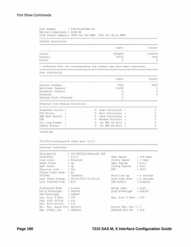
Port Show Commands
Part Number : FTRJ8519P2BNL-A5 Optical Compliance : GIGE-SX Link Length support: 300m for 50u MMF; 150m for 62.5u MMF; ===============================================================================Traffic Statistics=============================================================================== Input Output-------------------------------------------------------------------------------Octets 1556859 1766709Packets 18523 5849Errors 0 0===============================================================================* indicates that the corresponding row element may have been truncated.===============================================================================Port Statistics=============================================================================== Input Output-------------------------------------------------------------------------------Unicast Packets 3324 5847Multicast Packets 15199 0Broadcast Packets 0 2Discards 0 0Unknown Proto Discards 0 ===============================================================================Ethernet-like Medium Statistics===============================================================================Alignment Errors : 0 Sngl Collisions : 0 FCS Errors : 0 Mult Collisions : 0 SQE Test Errors : 0 Late Collisions : 0 CSE : 0 Excess Collisns : 0 Too long Frames : 0 Int MAC Tx Errs : 0 Symbol Errors : 0 Int MAC Rx Errs : 0 ===============================================================================*A:MTU-A#
*A:7210>config>port# /show port 1/1/1 ===============================================================================Ethernet Interface===============================================================================Description : 10/100/Gig Ethernet SFPInterface : 1/1/1 Oper Speed : 100 mbpsLink-level : Ethernet Config Speed : 1 GbpsAdmin State : up Oper Duplex : fullOper State : up Config Duplex : fullPhysical Link : Yes MTU : 9212Single Fiber Mode : No IfIndex : 35684352 Hold time up : 0 secondsLast State Change : 05/31/2010 11:54:16 Hold time down : 0 secondsLast Cleared Time : N/A DDM Events : Enabled
Configured Mode : access Encap Type : nullDot1Q Ethertype : 0x8100 QinQ Ethertype : 0x8100PBB Ethertype : 0x88e7 Ing. Pool % Rate : 100 Egr. Pool % Rate : 100Ing. Pool Policy : n/aEgr. Pool Policy : n/aNet. Egr. Queue Pol: default Access Egr. Qos *: 1Egr. Sched. Pol : default Network Qos Pol : n/a
Page 180 7210 SAS M, X Interface Configuration Guide

Interface Configuration
Auto-negotiate : true MDI/MDX : MDIAccounting Policy : None Collect-stats : DisabledEgress Rate : Default Max Burst : DefaultLACP Tunnel : Enabled
Uplink : No Split Horizon Group: (Not Specified)Down-when-looped : Disabled Keep-alive : 10Loop Detected : False Retry : 120Use Broadcast Addr : False
Sync. Status Msg. : Disabled Rx Quality Level : N/A
Configured Address : 00:25:ba:01:b7:f2Hardware Address : 00:25:ba:01:b7:f2Cfg Alarm : Alarm Status :
Transceiver Data
Transceiver Type : SFPModel Number : 3HE00062AAAA01 ALA IPUIAEHDAATX Laser Wavelength: 0 nm Diag Capable : noConnector Code : Unknown Vendor OUI : 00:90:65Manufacture date : 2008/09/11 Media : EthernetSerial Number : PEB2WPD Part Number : FCMJ-8521-3-A5 Optical Compliance : GIGE-T Link Length support: 100m for copper===============================================================================Traffic Statistics=============================================================================== Input Output-------------------------------------------------------------------------------Octets 72974 20243Packets 482 10Errors 0 0===============================================================================* indicates that the corresponding row element may have been truncated.===============================================================================Port Statistics=============================================================================== Input Output-------------------------------------------------------------------------------Unicast Packets 9 6Multicast Packets 469 2Broadcast Packets 4 2Discards 0 0Unknown Proto Discards 0 ==============================================================================================================================================================Ethernet-like Medium Statistics===============================================================================Alignment Errors : 0 Sngl Collisions : 0FCS Errors : 0 Mult Collisions : 0SQE Test Errors : 0 Late Collisions : 0CSE : 0 Excess Collisns : 0Too long Frames : 0 Int MAC Tx Errs : 0Symbol Errors : 0 Int MAC Rx Errs : 0
7210 SAS M, X Interface Configuration Guide Page 181

Port Show Commands
===============================================================================*A:SAS-M>config>port#
*A:SAS-M>config>port# /show port 1/1/1 detail ===============================================================================Ethernet Interface===============================================================================Description : 10/100/Gig Ethernet SFPInterface : 1/1/1 Oper Speed : 100 mbpsLink-level : Ethernet Config Speed : 1 GbpsAdmin State : up Oper Duplex : fullOper State : up Config Duplex : fullPhysical Link : Yes MTU : 9212Single Fiber Mode : No IfIndex : 35684352 Hold time up : 0 secondsLast State Change : 05/31/2010 11:54:16 Hold time down : 0 secondsLast Cleared Time : N/A DDM Events : Enabled
Configured Mode : access Encap Type : nullDot1Q Ethertype : 0x8100 QinQ Ethertype : 0x8100PBB Ethertype : 0x88e7 Ing. Pool % Rate : 100 Egr. Pool % Rate : 100Ing. Pool Policy : n/aEgr. Pool Policy : n/aNet. Egr. Queue Pol: default Access Egr. Qos *: 1Egr. Sched. Pol : default Network Qos Pol : n/aAuto-negotiate : true MDI/MDX : MDIAccounting Policy : None Collect-stats : DisabledEgress Rate : Default Max Burst : DefaultLACP Tunnel : Enabled
Uplink : No Split Horizon Group: (Not Specified)Down-when-looped : Disabled Keep-alive : 10Loop Detected : False Retry : 120Use Broadcast Addr : False
Sync. Status Msg. : Disabled Rx Quality Level : N/A
Configured Address : 00:25:ba:01:b7:f2Hardware Address : 00:25:ba:01:b7:f2Cfg Alarm : Alarm Status :
Transceiver Data
Transceiver Type : SFPModel Number : 3HE00062AAAA01 ALA IPUIAEHDAATX Laser Wavelength: 0 nm Diag Capable : noConnector Code : Unknown Vendor OUI : 00:90:65Manufacture date : 2008/09/11 Media : EthernetSerial Number : PEB2WPD Part Number : FCMJ-8521-3-A5 Optical Compliance : GIGE-T Link Length support: 100m for copper===============================================================================Traffic Statistics=============================================================================== Input Output
Page 182 7210 SAS M, X Interface Configuration Guide

Interface Configuration
-------------------------------------------------------------------------------Octets 72974 20243Packets 482 10Errors 0 0===============================================================================Ethernet Statistics===============================================================================Broadcast Pckts : 6 Drop Events : 0Multicast Pckts : 471 CRC/Align Errors : 0Undersize Pckts : 0 Fragments : 0Oversize Pckts : 0 Jabbers : 0Collisions : 0
Octets : 93217Packets : 492Packets of 64 Octets : 0Packets of 65 to 127 Octets : 2Packets of 128 to 255 Octets : 567Packets of 256 to 511 Octets : 2Packets of 512 to 1023 Octets : 16Packets of 1024 to 1518 Octets : 7Packets of 1519 or more Octets : 0===============================================================================* indicates that the corresponding row element may have been truncated.===============================================================================Port Statistics=============================================================================== Input Output-------------------------------------------------------------------------------Unicast Packets 9 6Multicast Packets 469 2Broadcast Packets 4 2Discards 0 0Unknown Proto Discards 0 ==============================================================================================================================================================Ethernet-like Medium Statistics===============================================================================Alignment Errors : 0 Sngl Collisions : 0FCS Errors : 0 Mult Collisions : 0SQE Test Errors : 0 Late Collisions : 0CSE : 0 Excess Collisns : 0Too long Frames : 0 Int MAC Tx Errs : 0Symbol Errors : 0 Int MAC Rx Errs : 0==============================================================================================================================================================Queue Statistics=============================================================================== ------------------------------------------------------------------------------- Packets Octets-------------------------------------------------------------------------------Egress Queue 1 (be) Fwd Stats : 112 20243 Drop Stats : 0 0 Egress Queue 2 (l2) Fwd Stats : 0 0 Drop Stats : 0 0 Egress Queue 3 (af)
7210 SAS M, X Interface Configuration Guide Page 183

Port Show Commands
Fwd Stats : 0 0 Drop Stats : 0 0 Egress Queue 4 (l1) Fwd Stats : 0 0 Drop Stats : 0 0 Egress Queue 5 (h2) Fwd Stats : 0 0 Drop Stats : 0 0 Egress Queue 6 (ef) Fwd Stats : 0 0 Drop Stats : 0 0 Egress Queue 7 (h1) Fwd Stats : 0 0 Drop Stats : 0 0 Egress Queue 8 (nc) Fwd Stats : 0 0 Drop Stats : 0 0 ===============================================================================*A:7210>config>port#
*A:7210>config>port# /show port 1/1/1 detail ===============================================================================Ethernet Interface===============================================================================Description : 10/100/Gig Ethernet SFPInterface : 1/1/1 Oper Speed : 100 mbpsLink-level : Ethernet Config Speed : 1 GbpsAdmin State : up Oper Duplex : fullOper State : up Config Duplex : fullPhysical Link : Yes MTU : 9212Single Fiber Mode : No IfIndex : 35684352 Hold time up : 0 secondsLast State Change : 05/31/2010 11:54:16 Hold time down : 0 secondsLast Cleared Time : N/A DDM Events : Enabled
Configured Mode : access Encap Type : nullDot1Q Ethertype : 0x8100 QinQ Ethertype : 0x8100PBB Ethertype : 0x88e7 Ing. Pool % Rate : 100 Egr. Pool % Rate : 100Ing. Pool Policy : n/aEgr. Pool Policy : n/aNet. Egr. Queue Pol: default Access Egr. Qos *: 1Egr. Sched. Pol : default Network Qos Pol : n/aAuto-negotiate : true MDI/MDX : MDIAccounting Policy : None Collect-stats : DisabledEgress Rate : Default Max Burst : DefaultLACP Tunnel : Enabled
Uplink : No Split Horizon Group: (Not Specified)Down-when-looped : Disabled Keep-alive : 10Loop Detected : False Retry : 120Use Broadcast Addr : False
Sync. Status Msg. : Disabled Rx Quality Level : N/A
Configured Address : 00:25:ba:01:b7:f2Hardware Address : 00:25:ba:01:b7:f2
Page 184 7210 SAS M, X Interface Configuration Guide

Interface Configuration
Cfg Alarm : Alarm Status :
Transceiver Data
Transceiver Type : SFPModel Number : 3HE00062AAAA01 ALA IPUIAEHDAATX Laser Wavelength: 0 nm Diag Capable : noConnector Code : Unknown Vendor OUI : 00:90:65Manufacture date : 2008/09/11 Media : EthernetSerial Number : PEB2WPD Part Number : FCMJ-8521-3-A5 Optical Compliance : GIGE-T Link Length support: 100m for copper===============================================================================Traffic Statistics=============================================================================== Input Output-------------------------------------------------------------------------------Octets 72974 20243Packets 482 10Errors 0 0===============================================================================Ethernet Statistics===============================================================================Broadcast Pckts : 6 Drop Events : 0Multicast Pckts : 471 CRC/Align Errors : 0Undersize Pckts : 0 Fragments : 0Oversize Pckts : 0 Jabbers : 0Collisions : 0
Octets : 93217Packets : 492Packets of 64 Octets : 0Packets of 65 to 127 Octets : 2Packets of 128 to 255 Octets : 567Packets of 256 to 511 Octets : 2Packets of 512 to 1023 Octets : 16Packets of 1024 to 1518 Octets : 7Packets of 1519 or more Octets : 0===============================================================================* indicates that the corresponding row element may have been truncated.===============================================================================Port Statistics=============================================================================== Input Output-------------------------------------------------------------------------------Unicast Packets 9 6Multicast Packets 469 2Broadcast Packets 4 2Discards 0 0Unknown Proto Discards 0 ==============================================================================================================================================================Ethernet-like Medium Statistics===============================================================================Alignment Errors : 0 Sngl Collisions : 0FCS Errors : 0 Mult Collisions : 0SQE Test Errors : 0 Late Collisions : 0
7210 SAS M, X Interface Configuration Guide Page 185

Port Show Commands
CSE : 0 Excess Collisns : 0Too long Frames : 0 Int MAC Tx Errs : 0Symbol Errors : 0 Int MAC Rx Errs : 0==============================================================================================================================================================Queue Statistics=============================================================================== ------------------------------------------------------------------------------- Packets Octets-------------------------------------------------------------------------------Egress Queue 1 (be) Fwd Stats : 112 20243 Drop Stats : 0 0 Egress Queue 2 (l2) Fwd Stats : 0 0 Drop Stats : 0 0 Egress Queue 3 (af) Fwd Stats : 0 0 Drop Stats : 0 0 Egress Queue 4 (l1) Fwd Stats : 0 0 Drop Stats : 0 0 Egress Queue 5 (h2) Fwd Stats : 0 0 Drop Stats : 0 0 Egress Queue 6 (ef) Fwd Stats : 0 0 Drop Stats : 0 0 Egress Queue 7 (h1) Fwd Stats : 0 0 Drop Stats : 0 0 Egress Queue 8 (nc) Fwd Stats : 0 0 Drop Stats : 0 0 ===============================================================================*A:MTU-A#*A:MTU-A# show port 1/1/1 ===============================================================================Ethernet Interface===============================================================================Description : 10/100/Gig Ethernet SFPInterface : 1/1/1 Oper Speed : 1 Gbps Link-level : Ethernet Config Speed : 1 Gbps Admin State : up Oper Duplex : full Oper State : up Config Duplex : full Physical Link : Yes MTU : 1578 IfIndex : 35684352 Hold time up : 0 seconds Last State Change : 06/27/2001 11:15:22 Hold time down : 0 seconds Last Cleared Time : 06/27/2001 11:14:44
Configured Mode : network Encap Type : 802.1q Dot1Q Ethertype : 0x8100 QinQ Ethertype : 0x8100 Net. Egr. Queue Pol: default Access Egr. Qos *: n/a Egr. Sched. Pol : default Network Qos Pol : n/a Auto-negotiate : limited MDI/MDX : MDI Accounting Policy : None Collect-stats : Disabled
Down-when-looped : Disabled Keep-alive : 10
Page 186 7210 SAS M, X Interface Configuration Guide

Interface Configuration
Loop Detected : False Retry : 120
Configured Address : 00:11:00:22:bc:13Hardware Address : 00:11:00:22:bc:13Cfg Alarm : Alarm Status :
Transceiver Data
Transceiver Type : SFP Model Number : 3HE00027AAAA02 ALA IPUIAELDAB2 TX Laser Wavelength: 850 nm Diag Capable : yes Connector Code : LC Vendor OUI : 00:90:65 Manufacture date : 2008/09/29 Media : Ethernet Serial Number : PEC5184 Part Number : FTRJ8519P2BNL-A5 Optical Compliance : GIGE-SX Link Length support: 300m for 50u MMF; 150m for 62.5u MMF; ===============================================================================Traffic Statistics=============================================================================== Input Output-------------------------------------------------------------------------------Octets 1556859 1766709Packets 18523 5849Errors 0 0===============================================================================* indicates that the corresponding row element may have been truncated.===============================================================================Port Statistics=============================================================================== Input Output-------------------------------------------------------------------------------Unicast Packets 3324 5847Multicast Packets 15199 0Broadcast Packets 0 2Discards 0 0Unknown Proto Discards 0 ===============================================================================Ethernet-like Medium Statistics===============================================================================Alignment Errors : 0 Sngl Collisions : 0 FCS Errors : 0 Mult Collisions : 0 SQE Test Errors : 0 Late Collisions : 0 CSE : 0 Excess Collisns : 0 Too long Frames : 0 Int MAC Tx Errs : 0 Symbol Errors : 0 Int MAC Rx Errs : 0 ===============================================================================*A:MTU-A#
Ethernet Output Fields
*A:7210-SAS>show# port 1/1/1 detail
===============================================================================Ethernet Interface===============================================================================Description : 10/100/Gig Ethernet SFP
7210 SAS M, X Interface Configuration Guide Page 187

Port Show Commands
Interface : 1/1/1 Oper Speed : N/ALink-level : Ethernet Config Speed : 1 GbpsAdmin State : down Oper Duplex : N/AOper State : down Config Duplex : fullPhysical Link : No MTU : 9212Single Fiber Mode : NoIfIndex : 35684352 Hold time up : 0 secondsLast State Change : 03/03/2011 04:34:26 Hold time down : 0 secondsLast Cleared Time : N/A DDM Events : Enabled
Configured Mode : network Encap Type : nullDot1Q Ethertype : 0x8100 QinQ Ethertype : 0x8100PBB Ethertype : 0x88e7Ing. Pool % Rate : 100 Egr. Pool % Rate : 100Ing. Pool Policy : n/aEgr. Pool Policy : n/aNet. Egr. Queue Pol: default Network Qos Pol : 1Egr. Sched. Pol : default Access Egr. Qos *: n/aAuto-negotiate : true MDI/MDX : unknownAccounting Policy : None Collect-stats : DisabledEgress Rate : Default Max Burst : DefaultLACP Tunnel : Disabled
Split Horizon Group: (Not Specified)Down-when-looped : Disabled Keep-alive : 10Loop Detected : False Retry : 120Use Broadcast Addr : False
Sync. Status Msg. : Disabled Rx Quality Level : N/ACode-Type : SDH Tx Quality Level : N/ATx DUS/DNU : Disabled
Configured Address : 00:25:ba:02:bd:62Hardware Address : 00:25:ba:02:bd:62Cfg Alarm :Alarm Status :
Transceiver Data
Transceiver Type : SFPModel Number : 3HE00062AAAA01 ALA IPUIAEHDAATX Laser Wavelength: 0 nm Diag Capable : noConnector Code : Unknown Vendor OUI : 00:90:65Manufacture date : 2010/01/06 Media : EthernetSerial Number : PH22J35Part Number : FCMJ-8521-3-A5Optical Compliance : GIGE-TLink Length support: 100m for copper
===============================================================================Traffic Statistics=============================================================================== Input Output-------------------------------------------------------------------------------Octets 0 0Packets 0 0Errors 0 0
===============================================================================
Page 188 7210 SAS M, X Interface Configuration Guide

Interface Configuration
Ethernet Statistics===============================================================================
Broadcast Pckts : 0 Drop Events : 0Multicast Pckts : 0 CRC/Align Errors : 0Undersize Pckts : 0 Fragments : 0Oversize Pckts : 0 Jabbers : 0Collisions : 0
Octets : 0Packets : 0Packets of 64 Octets : 0Packets of 65 to 127 Octets : 0Packets of 128 to 255 Octets : 0Packets of 256 to 511 Octets : 0Packets of 512 to 1023 Octets : 0Packets of 1024 to 1518 Octets : 0Packets of 1519 or more Octets : 0===============================================================================* indicates that the corresponding row element may have been truncated.
===============================================================================Port Statistics=============================================================================== Input Output-------------------------------------------------------------------------------Unicast Packets 0 0Multicast Packets 0 0Broadcast Packets 0 0Discards 0 0Unknown Proto Discards 0===============================================================================
===============================================================================Ethernet-like Medium Statistics===============================================================================
Alignment Errors : 0 Sngl Collisions : 0FCS Errors : 0 Mult Collisions : 0SQE Test Errors : 0 Late Collisions : 0CSE : 0 Excess Collisns : 0Too long Frames : 0 Int MAC Tx Errs : 0Symbol Errors : 0 Int MAC Rx Errs : 0===============================================================================
===============================================================================Meter Statistics===============================================================================
------------------------------------------------------------------------------- Packets Octets-------------------------------------------------------------------------------Ingress Meter 1 (Unicast)For. InProf : 0 0For. OutProf : 0 0
-------------------------------------------------------------------------------
===============================================================================
7210 SAS M, X Interface Configuration Guide Page 189

Port Show Commands
Queue Statistics===============================================================================
------------------------------------------------------------------------------- Packets Octets-------------------------------------------------------------------------------Egress Queue 1 (be)Fwd Stats : 0 0Drop Stats : 0 0Egress Queue 2 (l2)Fwd Stats : 0 0Drop Stats : 0 0Egress Queue 3 (af)Fwd Stats : 0 0Drop Stats : 0 0Egress Queue 4 (l1)Fwd Stats : 0 0Drop Stats : 0 0Egress Queue 5 (h2)Fwd Stats : 0 0Drop Stats : 0 0Egress Queue 6 (ef)Fwd Stats : 0 0Drop Stats : 0 0Egress Queue 7 (h1)Fwd Stats : 0 0Drop Stats : 0 0Egress Queue 8 (nc)Fwd Stats : 0 0Drop Stats : 0 0===============================================================================*A:7210-SAS>
*A:ces-A# show port 1/2/1 detail ===============================================================================TDM DS1 Physical Interface===============================================================================Description : DS1/E1Interface : 1/2/1 Port IfIndex : 37781504Admin Status : up Oper Status : upPhysical Link : Yes Line Impedance : 100 Type : ds1 Buildout : shortLength : 133 ==============================================================================================================================================================Port Statistics=============================================================================== Input Output-------------------------------------------------------------------------------Packets 20062480 1887151Discards 0 0Unknown Proto Discards 0 ===============================================================================*A:ces-A# *A:ces-A# show port 1/2/1.ds1 detail ===============================================================================TDM DS1 Interface===============================================================================
Page 190 7210 SAS M, X Interface Configuration Guide
Interface Configuration
Description : DS1Interface : 1/2/1.ds1 Type : ds1 Framing : ds1-unframedAdmin Status : up Oper Status : upPhysical Link : yes Clock Source : adaptiveClock Sync State : normal Last State Change : 07/06/2010 11:31:37 Channel IfIndex : 574652417Loopback : none Remote Loop respond: N/A In Remote Loop : N/ACfg Alarm : ais los Alarm Status : ==============================================================================================================================================================Traffic Statistics=============================================================================== Input Output-------------------------------------------------------------------------------Octets 3853385856 363722496Packets 20069718 1894388Errors 0 0===========================DS1/E1 Line=========================== ---------------------------ES 1 SES 1 SEFS 1 UAS 0 CSS 1 PCV 0 LES 1 BES 0 DM 0 LCV : ==================================================== Transmit:
AIS : 0
Receive:
AIS : 0LOS : 0LOF : 0
Looped : 0=========================================================================================================Port Statistics=============================================================================== Input Output-------------------------------------------------------------------------------Packets 20069718 1894388Discards 0 0Unknown Proto Discards 0 ===============================================================================*A:ces-A#
7210 SAS M, X Interface Configuration Guide Page 191

Port Show Commands
*A:ces-A# show port 1/2/1.1 detail ===============================================================================TDM DS0 Chan Group===============================================================================Description : DS0GRPInterface : 1/2/1.1 TimeSlots : 1-24Speed : 64 Admin Status : up Oper Status : upLast State Change : 07/06/2010 11:31:38 Chan-Grp IfIndex : 574652477
Configured mode : access Encap Type : cemAdmin MTU : 1514 Oper MTU : 1514Scramble : false Physical Link : yes Idle Cycle Flags : n/aPayload Fill Type : all-ones Payload Pattern : N/ASignal Fill Type : n/a Signal Pattern : N/A==============================================================================================================================================================Traffic Statistics=============================================================================== Input Output-------------------------------------------------------------------------------Octets 3854167488 364504128Packets 20073789 1898459Errors 0 0===============================================================================Port Statistics=============================================================================== Input Output-------------------------------------------------------------------------------Packets 20073789 1898459Discards 0 0Unknown Proto Discards 0 ===============================================================================
*A:MTU-T1>show# port 1/1/6
===============================================================================Ethernet Interface===============================================================================Description : 10/100/Gig Ethernet SFPInterface : 1/1/6 Oper Speed : N/ALink-level : Ethernet Config Speed : 1 GbpsAdmin State : down Oper Duplex : N/AOper State : down Config Duplex : fullPhysical Link : No MTU : 9212Single Fiber Mode : NoIfIndex : 35848192 Hold time up : 0 secondsLast State Change : 04/06/2001 07:30:45 Hold time down : 0 secondsLast Cleared Time : N/A DDM Events : Enabled
Configured Mode : network Encap Type : nullDot1Q Ethertype : 0x8100 QinQ Ethertype : 0x8100PBB Ethertype : 0x88e7Ing. Pool % Rate : 100 Egr. Pool % Rate : 100Ing. Pool Policy : n/aEgr. Pool Policy : n/a
Page 192 7210 SAS M, X Interface Configuration Guide

Interface Configuration
Net. Egr. Queue Pol: default Network Qos Pol : 1Egr. Sched. Pol : default Access Egr. Qos *: n/aAuto-negotiate : true MDI/MDX : unknownAccounting Policy : None Collect-stats : DisabledEgress Rate : Default Max Burst : DefaultLACP Tunnel : Disabled
Split Horizon Group: (Not Specified)Down-when-looped : Disabled Keep-alive : 10Loop Detected : False Retry : 120Use Broadcast Addr : False
Sync. Status Msg. : Disabled Rx Quality Level : N/A
Configured Address : 00:25:ba:03:92:77Hardware Address : 00:25:ba:03:92:77Cfg Alarm :Alarm Status :
Transceiver Data
Transceiver Type : SFPModel Number : 3HE00027AAAA02 ALA IPUIAELDABTX Laser Wavelength: 850 nm Diag Capable : yesConnector Code : LC Vendor OUI : 00:90:65Manufacture date : 2010/05/28 Media : EthernetSerial Number : PHN661LPart Number : FTRJ8519P2BNL-A6Optical Compliance : GIGE-SXLink Length support: 550m for 50u MMF; 300m for 62.5u MMF
===============================================================================Transceiver Digital Diagnostic Monitoring (DDM), Internally Calibrated=============================================================================== Value High Alarm High Warn Low Warn Low Alarm-------------------------------------------------------------------------------Temperature (C) +26.2 +95.0 +90.0 -20.0 -25.0Supply Voltage (V) 3.25 3.90 3.70 2.90 2.70Tx Bias Current (mA) 1.0 17.0 14.0 2.0 1.0Tx Output Power (dBm) -23.77 -2.00 -2.00 -11.02 -11.74Rx Optical Power (avg dBm) -35.23 1.00 -1.00 -18.01 -20.00===============================================================================
===============================================================================Traffic Statistics=============================================================================== Input Output-------------------------------------------------------------------------------Octets 128 640Packets 2 10Errors 0 0===============================================================================* indicates that the corresponding row element may have been truncated.
===============================================================================Port Statistics=============================================================================== Input Output-------------------------------------------------------------------------------
7210 SAS M, X Interface Configuration Guide Page 193

Port Show Commands
Unicast Packets 2 10Multicast Packets 0 0Broadcast Packets 0 0Discards 0 0Unknown Proto Discards 0===============================================================================
===============================================================================Ethernet-like Medium Statistics===============================================================================
Alignment Errors : 0 Sngl Collisions : 0FCS Errors : 0 Mult Collisions : 0SQE Test Errors : 0 Late Collisions : 0CSE : 0 Excess Collisns : 0Too long Frames : 0 Int MAC Tx Errs : 0Symbol Errors : 0 Int MAC Rx Errs : 0===============================================================================*A:MTU-T1>show#
*A:MTU-T1>show# port 1/1/6 detail
===============================================================================Ethernet Interface===============================================================================Description : 10/100/Gig Ethernet SFPInterface : 1/1/6 Oper Speed : N/ALink-level : Ethernet Config Speed : 1 GbpsAdmin State : down Oper Duplex : N/AOper State : down Config Duplex : fullPhysical Link : No MTU : 9212Single Fiber Mode : NoIfIndex : 35848192 Hold time up : 0 secondsLast State Change : 04/06/2001 07:30:45 Hold time down : 0 secondsLast Cleared Time : N/A DDM Events : Enabled
Configured Mode : network Encap Type : nullDot1Q Ethertype : 0x8100 QinQ Ethertype : 0x8100PBB Ethertype : 0x88e7Ing. Pool % Rate : 100 Egr. Pool % Rate : 100Ing. Pool Policy : n/aEgr. Pool Policy : n/aNet. Egr. Queue Pol: default Network Qos Pol : 1Egr. Sched. Pol : default Access Egr. Qos *: n/aAuto-negotiate : true MDI/MDX : unknownAccounting Policy : None Collect-stats : DisabledEgress Rate : Default Max Burst : DefaultLACP Tunnel : Disabled
Split Horizon Group: (Not Specified)Down-when-looped : Disabled Keep-alive : 10Loop Detected : False Retry : 120Use Broadcast Addr : False
Sync. Status Msg. : Disabled Rx Quality Level : N/A
Configured Address : 00:25:ba:03:92:77
Page 194 7210 SAS M, X Interface Configuration Guide

Interface Configuration
Hardware Address : 00:25:ba:03:92:77Cfg Alarm :Alarm Status :
Transceiver Data
Transceiver Type : SFPModel Number : 3HE00027AAAA02 ALA IPUIAELDABTX Laser Wavelength: 850 nm Diag Capable : yesConnector Code : LC Vendor OUI : 00:90:65Manufacture date : 2010/05/28 Media : EthernetSerial Number : PHN661LPart Number : FTRJ8519P2BNL-A6Optical Compliance : GIGE-SXLink Length support: 550m for 50u MMF; 300m for 62.5u MMF
===============================================================================Transceiver Digital Diagnostic Monitoring (DDM), Internally Calibrated=============================================================================== Value High Alarm High Warn Low Warn Low Alarm-------------------------------------------------------------------------------Temperature (C) +26.2 +95.0 +90.0 -20.0 -25.0Supply Voltage (V) 3.25 3.90 3.70 2.90 2.70Tx Bias Current (mA) 1.0 17.0 14.0 2.0 1.0Tx Output Power (dBm) -23.77 -2.00 -2.00 -11.02 -11.74Rx Optical Power (avg dBm) -35.23 1.00 -1.00 -18.01 -20.00===============================================================================
===============================================================================Traffic Statistics=============================================================================== Input Output-------------------------------------------------------------------------------Octets 128 640Packets 2 10Errors 0 0
===============================================================================Ethernet Statistics===============================================================================
Broadcast Pckts : 0 Drop Events : 0Multicast Pckts : 0 CRC/Align Errors : 0Undersize Pckts : 0 Fragments : 0Oversize Pckts : 0 Jabbers : 0Collisions : 0
Octets : 768Packets : 12Packets of 64 Octets : 12Packets of 65 to 127 Octets : 0Packets of 128 to 255 Octets : 0Packets of 256 to 511 Octets : 0Packets of 512 to 1023 Octets : 0Packets of 1024 to 1518 Octets : 0Packets of 1519 or more Octets : 0===============================================================================* indicates that the corresponding row element may have been truncated.
7210 SAS M, X Interface Configuration Guide Page 195
Port Show Commands
===============================================================================Port Statistics=============================================================================== Input Output-------------------------------------------------------------------------------Unicast Packets 2 10Multicast Packets 0 0Broadcast Packets 0 0Discards 0 0Unknown Proto Discards 0===============================================================================
===============================================================================Ethernet-like Medium Statistics===============================================================================
Alignment Errors : 0 Sngl Collisions : 0FCS Errors : 0 Mult Collisions : 0SQE Test Errors : 0 Late Collisions : 0CSE : 0 Excess Collisns : 0Too long Frames : 0 Int MAC Tx Errs : 0Symbol Errors : 0 Int MAC Rx Errs : 0===============================================================================
===============================================================================Meter Statistics===============================================================================
------------------------------------------------------------------------------- Packets Octets-------------------------------------------------------------------------------Ingress Meter 1 (Unicast)For. InProf : 0 0For. OutProf : 0 0Ingress Meter 9 (Multipoint)For. InProf : 0 0For. OutProf : 0 0
-------------------------------------------------------------------------------
===============================================================================Queue Statistics===============================================================================
------------------------------------------------------------------------------- Packets Octets-------------------------------------------------------------------------------Egress Queue 1 (be)Fwd Stats : 0 0Drop Stats : 0 0Egress Queue 2 (l2)Fwd Stats : 0 0Drop Stats : 0 0Egress Queue 3 (af)Fwd Stats : 0 0Drop Stats : 0 0Egress Queue 4 (l1)Fwd Stats : 0 0Drop Stats : 0 0
Page 196 7210 SAS M, X Interface Configuration Guide

Interface Configuration
Egress Queue 5 (h2)Fwd Stats : 0 0Drop Stats : 0 0Egress Queue 6 (ef)Fwd Stats : 0 0Drop Stats : 0 0Egress Queue 7 (h1)Fwd Stats : 0 0Drop Stats : 0 0Egress Queue 8 (nc)Fwd Stats : 0 0Drop Stats : 0 0===============================================================================*A:MTU-T1>show#A:7210-SAS># show port 1/1/2 detail
===============================================================================Ethernet Interface===============================================================================Description : 10/100/Gig Ethernet SFPInterface : 1/1/2 Oper Speed : N/ALink-level : Ethernet Config Speed : 1 GbpsAdmin State : down Oper Duplex : N/AOper State : down Config Duplex : fullReason Down : noServicePortPhysical Link : No MTU : 9212Single Fiber Mode : NoIfIndex : 35717120 Hold time up : 0 secondsLast State Change : 12/20/2010 20:51:55 Hold time down : 0 secondsLast Cleared Time : N/A DDM Events : Enabled
Configured Mode : network Encap Type : nullDot1Q Ethertype : 0x8100 QinQ Ethertype : 0x8100PBB Ethertype : 0x88e7Ing. Pool % Rate : 100 Egr. Pool % Rate : 100Ing. Pool Policy : n/aEgr. Pool Policy : n/aNet. Egr. Queue Pol: default Network Qos Pol : 1Egr. Sched. Pol : default Access Egr. Qos *: n/aAuto-negotiate : true MDI/MDX : unknownAccounting Policy : None Collect-stats : DisabledEgress Rate : Default Max Burst : DefaultLACP Tunnel : Disabled
Split Horizon Group: (Not Specified)Down-when-looped : Disabled Keep-alive : 10Loop Detected : False Retry : 120Use Broadcast Addr : False
Sync. Status Msg. : Disabled Rx Quality Level : N/A
Configured Address : 00:25:ba:00:5e:34Hardware Address : 00:25:ba:00:5e:34Cfg Alarm :Alarm Status :
Transceiver Data
Transceiver Type : SFP
7210 SAS M, X Interface Configuration Guide Page 197

Port Show Commands
Model Number : 3HE00867CAAA01 ALA IPUIBD9DAATX Laser Wavelength: 1310 nm Diag Capable : yesConnector Code : LC Vendor OUI : 00:00:5fManufacture date : 2010/03/10 Media : EthernetSerial Number : 9ZT500000163Part Number : SCP6G14-A8-AWEOptical Compliance : GIGE-LXLink Length support: 40km for SMF
===============================================================================Transceiver Digital Diagnostic Monitoring (DDM), Externally Calibrated=============================================================================== Value High Alarm High Warn Low Warn Low Alarm-------------------------------------------------------------------------------Temperature (C) +32.3 +98.0 +88.0 -43.0 -45.0Supply Voltage (V) 3.29 4.12 3.60 3.00 2.80Tx Bias Current (mA) 0.0 70.0 60.0 0.1 0.0Tx Output Power (dBm) -40.00 3.00 1.00 -5.50 -7.50Rx Optical Power (avg dBm) -40.00 0.00 -1.00 -21.49 -22.44===============================================================================
===============================================================================Traffic Statistics=============================================================================== Input Output-------------------------------------------------------------------------------Octets 0 0Packets 0 0Errors 0 0
===============================================================================Ethernet Statistics===============================================================================
Broadcast Pckts : 0 Drop Events : 0Multicast Pckts : 0 CRC/Align Errors : 0Undersize Pckts : 0 Fragments : 0Oversize Pckts : 0 Jabbers : 0Collisions : 0
Octets : 0Packets : 0Packets of 64 Octets : 0Packets of 65 to 127 Octets : 0Packets of 128 to 255 Octets : 0Packets of 256 to 511 Octets : 0Packets of 512 to 1023 Octets : 0Packets of 1024 to 1518 Octets : 0Packets of 1519 or more Octets : 0===============================================================================* indicates that the corresponding row element may have been truncated.
===============================================================================Port Statistics=============================================================================== Input Output-------------------------------------------------------------------------------Unicast Packets 0 0Multicast Packets 0 0
Page 198 7210 SAS M, X Interface Configuration Guide

Interface Configuration
Broadcast Packets 0 0Discards 0 0Unknown Proto Discards 0===============================================================================
===============================================================================Ethernet-like Medium Statistics===============================================================================
Alignment Errors : 0 Sngl Collisions : 0FCS Errors : 0 Mult Collisions : 0SQE Test Errors : 0 Late Collisions : 0CSE : 0 Excess Collisns : 0Too long Frames : 0 Int MAC Tx Errs : 0Symbol Errors : 0 Int MAC Rx Errs : 0===============================================================================
===============================================================================Meter Statistics===============================================================================
------------------------------------------------------------------------------- Packets Octets-------------------------------------------------------------------------------Ingress Meter 1 (Unicast)For. InProf : 0 0For. OutProf : 0 0Ingress Meter 9 (Multipoint)For. InProf : 0 0For. OutProf : 0 0
-------------------------------------------------------------------------------
===============================================================================Queue Statistics===============================================================================
------------------------------------------------------------------------------- Packets Octets-------------------------------------------------------------------------------Egress Queue 1 (be)Fwd Stats : 0 0Drop Stats : 0 0Egress Queue 2 (l2)Fwd Stats : 0 0Drop Stats : 0 0Egress Queue 3 (af)Fwd Stats : 0 0Drop Stats : 0 0Egress Queue 4 (l1)Fwd Stats : 0 0Drop Stats : 0 0Egress Queue 5 (h2)Fwd Stats : 0 0Drop Stats : 0 0Egress Queue 6 (ef)Fwd Stats : 0 0Drop Stats : 0 0Egress Queue 7 (h1)
7210 SAS M, X Interface Configuration Guide Page 199

Port Show Commands
Fwd Stats : 0 0Drop Stats : 0 0Egress Queue 8 (nc)Fwd Stats : 0 0Drop Stats : 0 0===============================================================================
Sample output for 7210 SAS-X
A:7210-SAS-X>show# show port 1/1/2 detail
===============================================================================Ethernet Interface===============================================================================Description : 10/100/Gig Ethernet SFPInterface : 1/1/2 Oper Speed : N/ALink-level : Ethernet Config Speed : 1 GbpsAdmin State : up Oper Duplex : N/AOper State : down Config Duplex : fullPhysical Link : No MTU : 1514Single Fiber Mode : NoIfIndex : 35717120 Hold time up : 0 secondsLast State Change : 11/11/2010 11:45:40 Hold time down : 0 secondsLast Cleared Time : N/A DDM Events : Enabled
Configured Mode : access Encap Type : nullDot1Q Ethertype : 0x8100 QinQ Ethertype : 0x8100PBB Ethertype : 0x88e7Ing. Pool % Rate : 100 Egr. Pool % Rate : 100Ing. Pool Policy : n/aEgr. Pool Policy : n/aNet. Egr. Queue Pol: default Network Qos Pol : n/aAuto-negotiate : true MDI/MDX : unknownAccounting Policy : None Collect-stats : DisabledEgress Rate : Default Max Burst : DefaultLoad-balance-algo : default LACP Tunnel : DisabledLACP Tunnel : Disabled
Down-when-looped : Disabled Keep-alive : 10Loop Detected : False Retry : 120Use Broadcast Addr : False
Sync. Status Msg. : Disabled Rx Quality Level : N/A
Configured Address : 7c:20:64:ad:00:f2Hardware Address : 7c:20:64:ad:00:f2Cfg Alarm :Alarm Status :
Transceiver Data
Transceiver Type : SFPModel Number : 3HE00062AAAA01 ALA IPUIAEHDAATX Laser Wavelength: 0 nm Diag Capable : noConnector Code : Unknown Vendor OUI : 00:90:65Manufacture date : 2008/03/17 Media : EthernetSerial Number : PDC0C4V
Page 200 7210 SAS M, X Interface Configuration Guide
Interface Configuration
Part Number : FCMJ-8521-3-A5Optical Compliance : GIGE-TLink Length support: 100m for copper
===============================================================================Traffic Statistics=============================================================================== Input Output-------------------------------------------------------------------------------Octets 0 1408Packets 0 0Errors 0 0
===============================================================================Ethernet Statistics===============================================================================
Broadcast Pckts : 0 Drop Events : 0Multicast Pckts : 0 CRC/Align Errors : 0Undersize Pckts : 0 Fragments : 0Oversize Pckts : 0 Jabbers : 0Collisions : 0
Octets : 1408Packets : 0Packets of 64 Octets : 22Packets of 65 to 127 Octets : 0Packets of 128 to 255 Octets : 0Packets of 256 to 511 Octets : 0Packets of 512 to 1023 Octets : 0Packets of 1024 to 1518 Octets : 0Packets of 1519 or more Octets : 0===============================================================================
===============================================================================Port Statistics=============================================================================== Input Output-------------------------------------------------------------------------------Unicast Packets 0 0Multicast Packets 0 0Broadcast Packets 0 0Discards 0 0Unknown Proto Discards 0===============================================================================
===============================================================================Ethernet-like Medium Statistics===============================================================================
Alignment Errors : 0 Sngl Collisions : 0FCS Errors : 0 Mult Collisions : 0SQE Test Errors : 0 Late Collisions : 0CSE : 0 Excess Collisns : 0Too long Frames : 0 Int MAC Tx Errs : 0Symbol Errors : 0 Int MAC Rx Errs : 0===============================================================================
A:7210-SAS-X>show#
7210 SAS M, X Interface Configuration Guide Page 201

Port Show Commands
*A:SAS-M>show# show port 1/1/1
===============================================================================Ethernet Interface===============================================================================Description : 10/100/Gig Ethernet SFPInterface : 1/1/1 Oper Speed : 1 GbpsLink-level : Ethernet Config Speed : 1 GbpsAdmin State : up Oper Duplex : fullOper State : up Config Duplex : fullPhysical Link : Yes MTU : 1522Single Fiber Mode : NoIfIndex : 35684352 Hold time up : 0 secondsLast State Change : 04/29/2001 06:59:15 Hold time down : 0 secondsLast Cleared Time : 04/28/2001 03:09:37 DDM Events : Enabled
Configured Mode : access Encap Type : QinQDot1Q Ethertype : 0x8100 QinQ Ethertype : 0x8100PBB Ethertype : 0x88e7Ing. Pool % Rate : 100 Egr. Pool % Rate : 100Ing. Pool Policy : n/aEgr. Pool Policy : n/aNet. Egr. Queue Pol: default Network Qos Pol : n/aEgr. Sched. Pol : default Access Egr. Qos *: 1Auto-negotiate : true MDI/MDX : MDIAccounting Policy : None Collect-stats : DisabledEgress Rate : Default Max Burst : DefaultLACP Tunnel : Disabled
Uplink : NoSplit Horizon Group: (Not Specified)Down-when-looped : Disabled Keep-alive : 10Loop Detected : False Retry : 120Use Broadcast Addr : False
Sync. Status Msg. : Disabled Rx Quality Level : N/A
Configured Address : 00:25:ba:02:ea:02Hardware Address : 00:25:ba:02:ea:02Cfg Alarm :Alarm Status :
Transceiver Data
Transceiver Type : SFPModel Number : 3HE00028AAAA02 ALA IPUIAEMDABTX Laser Wavelength: 1310 nm Diag Capable : yesConnector Code : LC Vendor OUI : 00:06:b5Manufacture date : 2008/09/17 Media : EthernetSerial Number : 8AIT200082Part Number : SPGBLXTDBALOptical Compliance : GIGE-LXLink Length support: 10km for SMF
===============================================================================Transceiver Digital Diagnostic Monitoring (DDM), Externally Calibrated=============================================================================== Value High Alarm High Warn Low Warn Low Alarm-------------------------------------------------------------------------------
Page 202 7210 SAS M, X Interface Configuration Guide
Interface Configuration
Temperature (C) +40.5 +98.0 +96.0 -42.0 -43.0Supply Voltage (V) 3.23 4.12 3.60 3.00 2.80Tx Bias Current (mA) 25.5 100.0 85.0 7.5 5.0Tx Output Power (dBm) -5.67 -1.00 -2.00 -10.00 -11.00Rx Optical Power (avg dBm) -1.87 -1.00 -2.00! -23.01 -24.01===============================================================================
===============================================================================Traffic Statistics=============================================================================== Input Output-------------------------------------------------------------------------------Octets 9670292997181 0Packets 142210189554 0Errors 2651 0===============================================================================* indicates that the corresponding row element may have been truncated.
===============================================================================Port Statistics=============================================================================== Input Output-------------------------------------------------------------------------------Unicast Packets 142210189554 0Multicast Packets 0 0Broadcast Packets 0 0Discards 0 0Unknown Proto Discards 0===============================================================================
===============================================================================Ethernet-like Medium Statistics===============================================================================
Alignment Errors : 0 Sngl Collisions : 0FCS Errors : 1095 Mult Collisions : 0SQE Test Errors : 0 Late Collisions : 0CSE : 0 Excess Collisns : 0Too long Frames : 0 Int MAC Tx Errs : 0Symbol Errors : 1509 Int MAC Rx Errs : 0===============================================================================
7210 SAS M, X Interface Configuration Guide Page 203
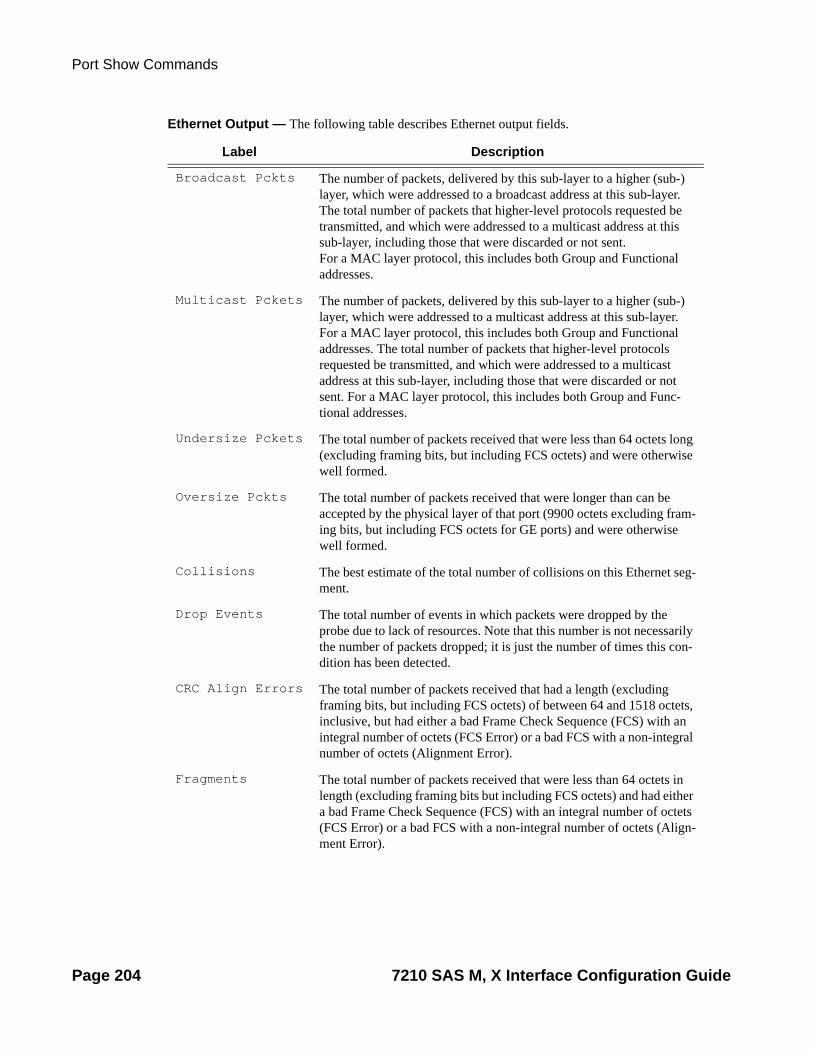
Port Show Commands
Ethernet Output — The following table describes Ethernet output fields.
Label Description
Broadcast Pckts The number of packets, delivered by this sub-layer to a higher (sub-) layer, which were addressed to a broadcast address at this sub-layer. The total number of packets that higher-level protocols requested be transmitted, and which were addressed to a multicast address at this sub-layer, including those that were discarded or not sent. For a MAC layer protocol, this includes both Group and Functional addresses.
Multicast Pckets The number of packets, delivered by this sub-layer to a higher (sub-) layer, which were addressed to a multicast address at this sub-layer. For a MAC layer protocol, this includes both Group and Functional addresses. The total number of packets that higher-level protocols requested be transmitted, and which were addressed to a multicast address at this sub-layer, including those that were discarded or not sent. For a MAC layer protocol, this includes both Group and Func-tional addresses.
Undersize Pckets The total number of packets received that were less than 64 octets long (excluding framing bits, but including FCS octets) and were otherwise well formed.
Oversize Pckts The total number of packets received that were longer than can be accepted by the physical layer of that port (9900 octets excluding fram-ing bits, but including FCS octets for GE ports) and were otherwise well formed.
Collisions The best estimate of the total number of collisions on this Ethernet seg-ment.
Drop Events The total number of events in which packets were dropped by the probe due to lack of resources. Note that this number is not necessarily the number of packets dropped; it is just the number of times this con-dition has been detected.
CRC Align Errors The total number of packets received that had a length (excluding framing bits, but including FCS octets) of between 64 and 1518 octets, inclusive, but had either a bad Frame Check Sequence (FCS) with an integral number of octets (FCS Error) or a bad FCS with a non-integral number of octets (Alignment Error).
Fragments The total number of packets received that were less than 64 octets in length (excluding framing bits but including FCS octets) and had either a bad Frame Check Sequence (FCS) with an integral number of octets (FCS Error) or a bad FCS with a non-integral number of octets (Align-ment Error).
Page 204 7210 SAS M, X Interface Configuration Guide

Interface Configuration
Sample Output
===============================================================================Ethernet Statistics===============================================================================Broadcast Pckts : 2 Drop Events : 0 Multicast Pckts : 15863 CRC/Align Errors : 0 Undersize Pckts : 0 Fragments : 0 Oversize Pckts : 0 Jabbers : 0 Collisions : 0
Octets : 3468749 Packets : 25439 Packets of 64 Octets : 25370 Packets of 65 to 127 Octets : 4987 Packets of 128 to 255 Octets : 10937 Packets of 256 to 511 Octets : 0 Packets of 512 to 1023 Octets : 0 Packets of 1024 to 1518 Octets : 0 Packets of 1519 or more Octets : 0 ===============================================================================
Ethernet-Like Medium Statistics Output Fields Ethernet-like Medium Statistics Output — The following table describes Ethernet-like medium statistics output fields.
Jabbers The total number of packets received that were longer than 1518 octets (excluding framing bits, but including FCS octets), and had either a bad Frame Check Sequence (FCS) with an integral number of octets (FCS Error) or a bad FCS with a non-integral number of octets (Align-ment Error).
Ingress Pool Size
The amount of ingress buffer space, expressed as a percentage of the available buffer space that will be allocated to the port for ingress buff-ering.
Octets The total number of octets received.
Packets The total number of packets received.
Packets to The number of packets received that were equal to or less than the dis-played octet limit.
Label Description (Continued)
Label Description
Alignment Errors The total number of packets received that had a length (excluding framing bits, but including FCS octets) of between 64 and 1518 octets, inclusive, but had either a bad Frame Check Sequence (FCS) with an integral number of octets (FCS Error) or a bad FCS with a non-integral number of octets.
7210 SAS M, X Interface Configuration Guide Page 205

Port Show Commands
Ethernet-like Medium Statistics — the following table describe Ethernet-like Medium Statistics field..
FCS Errors The number of frames received on a particular interface that are an integral number of octets in length but do not pass the FCS check.
SQE Errors The number of times that the SQE TEST ERROR is received on a par-ticular interface.
Label Description
Alignment Errors The total number of packets received that had a length (excluding framing bits, but including FCS octets) of between 64 and 1518 octets, inclusive, but that had either a bad Frame Check Sequence (FCS) with an integral number of octets (FCS Error) or a bad FCS with a non-inte-gral number of octets.
FCS Errors The number of frames received that are an integral number of octets in length but do not pass the FCS check.
SQE Errors The number of times that the SQE TEST ERROR is received.
CSE The number of times that the carrier sense condition was lost or never asserted when attempting to transmit a frame.
Too long Frames The number of frames received that exceed the maximum permitted frame size.
Symbol Errors For an interface operating at 100 Mb/s, the number of times there was an invalid data symbol when a valid carrier was present
Sngl Collisions The number of frames that are involved in a single collision, and are subsequently transmitted successfully.
Mult Collisions The number of frames that are involved in more than one collision and are subsequently transmitted successfully.
Late Collisions The number of times that a collision is detected later than one slot Time into the transmission of a packet.
Excess Colli-sions
The number of frames for which a transmission fails due to excessive collisions.
Int MAC Tx Errs The number of frames for which a transmission fails due to an internal MAC sub-layer transmit error.
Int MAC Rx Errs The number of frames for which a reception fails due to an internal MAC sub-layer receive error.
Label Description (Continued)
Page 206 7210 SAS M, X Interface Configuration Guide

Interface Configuration
Multicast Pckts The number of packets, delivered by this sub-layer to a higher (sub-) layer, which were not addressed to a unicast or broadcast address at this sub-layer. The total number of packets that higher-level protocols requested be transmitted, and which were not addressed to a unicast or broadcast address at this sub-layer, including those that were discarded or not sent.
Undersize Pckts The total number of packets received that were shorter than 64 octets (excluding framing bits, but including FCS octets) but were otherwise well formed.
Oversize Pckts The total number of packets received that were longer than 1518 octets (excluding framing bits, but including FCS octets) but were otherwise well formed.
Collisions The best estimate of the total number of collisions on this Ethernet seg-ment.
Drop Events The total number of times that packets were detected as being dropped due to a lack of resources (not necessarily the total number of packets dropped).
CRC Align Errors The total number of packets received that were between 64 and 1518 octets (excluding framing bits but including FCS octets) that had either a bad Frame Check Sequence (FCS) with an integral number of octets (FCS Error) or a bad FCS with a non-integral number of octets (Align-ment Error).
Fragments The total number of packets received that were shorter than 64 octets (excluding framing bits but including FCS octets) that had either a bad Frame Check Sequence (FCS) with an integral number of octets (FCS Error) or a bad FCS with a non-integral number of octets (Alignment Error).
Jabbers The total number of packets received that were longer than 1518 octets (excluding framing bits but including FCS octets) that had either a bad Frame Check Sequence (FCS) with an integral number of octets (FCS Error) or a bad FCS with a non-integral number of octets (Alignment Error).
Octets Total number of octets received.
Packets The number of packets received, broken down by size Port Statistics.
Unicast packets input/output
The number of packets, delivered by this sub-layer to a higher (sub-) layer, which were not addressed to a multicast or broadcast address at this sub-layer. The total number of packets that higher-level protocols requested be transmitted, and which were not addressed to a multicast or broadcast address at this sub-layer, including those that were dis-carded or not sent.
Label Description
7210 SAS M, X Interface Configuration Guide Page 207

Port Show Commands
Sample Output
*A:MTU-A# ===============================================================================Ethernet-like Medium Statistics===============================================================================
Alignment Errors : 0 Sngl Collisions : 0 FCS Errors : 0 Mult Collisions : 0 SQE Test Errors : 0 Late Collisions : 0 CSE : 0 Excess Collisns : 0 Too long Frames : 0 Int MAC Tx Errs : 0 Symbol Errors : 0 Int MAC Rx Errs : 0 ===============================================================================*A:MTU-A#
Port Associations Output Fields Port Associations Output — The following table describes port associations output fields.
Multicast pack-ets input/output
The number of packets, delivered by this sub-layer to a higher (sub-) layer, which were not addressed to a unicast or broadcast address at this sub-layer. The total number of packets that higher-level protocols requested be transmitted, and which were not addressed to a unicast or broadcast address at this sub-layer,including those that were discarded or not sent.
Broadcast pack-ets input/output
The number of packets, delivered by this sub-layer to a higher (sub-) layer,which were not addressed to a unicast or multicast address at this sub-layer. The total number of packets that higher-level protocols requested be transmitted, and which were not addressed to a unicast or multicast address at this sub-layer, including those that were discarded or not sent.
Discards input/output
The number of inbound packets chosen to be discarded to possibly free up buffer space.
Unknown proto discards input/output
For packet-oriented interfaces, the number of packets received via the interface that were discarded because of an unknown or unsupported protocol. For character-oriented or fixed-length interfaces that support protocol multiplexing, the number of transmission units received via the interface that were discarded because of an unknown or unsup-ported protocol. For any interface that does not support protocol multi-plexing, this counter will always be 0.
Unknown proto Discards do not show up in the packet counts.
Label Description
Label Description
Svc ID The service identifier.
Name The name of the IP interface.
Page 208 7210 SAS M, X Interface Configuration Guide

Interface Configuration
Sample Output
*A:MTU-A>config# show port 1/1/23 associations ===============================================================================Interface Table===============================================================================Router/ServiceId Name Encap Val -------------------------------------------------------------------------------Router: Base one 0 -------------------------------------------------------------------------------Interfaces===============================================================================*A:MTU-A>config#
A1 Detailed Output — The following table describes A1 detailed output fields.
Encap Value The dot1q or qinq encapsulation value on the port for this IP interface
Label Description
Description A text description of the port.
Interface The port ID displayed in the slot/mda/port format.
Oper Speed The operating speed of the interface.
Link-level Ethernet — the port is configured as Ethernet.
Config Speed The configured speed of the interface.
Admin State up — the port is administratively up.down — the port is administratively down.
Oper Duplex The operating duplex mode of the interface.
Oper State up — the port is operationally up.down — the port is operationally down.
Config Duplex full — the link is configured to full duplex mode.half — the link is configured to half duplex mode.
Physical Link Yes — a physical link is present.No — a physical link is not present.
MTU The size of the largest packet that can be sent/received on the Ethernet physical interface, specified in octets.
IfIndex The interface’s index number that reflects its initialization sequence.
Label Description
7210 SAS M, X Interface Configuration Guide Page 209

Port Show Commands
Hold time up The link-up dampening time in seconds. The port link dampening timer value that reduces the number of link transitions reported to upper layer protocols.
Last State Change The last time that the operational status of the port changed state.
Hold time down The link-down dampening time in seconds. The down timer controls the dampening timer for link down transitions.
Configured Mode network — the port is configured for transport. network use access — the port is configured for service access.
Encap Type null — ingress frames will not use any tags or labels to delineate a ser-vice.dot1q — ingress frames carry 802.1Q tags where each tag signifies a different service.
Dot1Q Ethertype The protocol carried in an Ethernet frame.
Net.Egr. Queue Pol.
The number of the associated network egress queue QoS policy, or default if the default policy is used.
Auto-negotiate true — the link attempts to automatically negotiate the link speed and duplex parameters.false — the duplex and speed values are used for the link.
Egress Rate The maximum amount of egress bandwidth (in kilobits per second) that this Ethernet interface can generate.
Loopback The type of loopback configured on the port, either line,internal, or none.
Loopback Time Left The number of seconds left in a timed loopback If there is no loopback configured or the configured loopback is latched, the value is unspecified.
Configured Address
The base chassis Ethernet MAC address.
Hardware Address The interface’s hardware or system assigned MAC address at its protocol sub-layer.
Label Description (Continued)
Page 210 7210 SAS M, X Interface Configuration Guide

Interface Configuration
A:7210>show# port A/1
===============================================================================Ethernet Interface===============================================================================Description : 10/100 Ethernet TXInterface : A/1 Oper Speed : 10 mbpsLink-level : Ethernet Config Speed : 100 mbpsAdmin State : up Oper Duplex : halfOper State : up Config Duplex : fullPhysical Link : Yes MTU : 1514Single Fiber Mode : NoIfIndex : 67141632 Hold time up : 0 secondsLast State Change : 07/12/2010 14:26:43 Hold time down : 0 secondsLast Cleared Time : N/A
Configured Mode : network Encap Type : nullDot1Q Ethertype : 0x8100 QinQ Ethertype : 0x8100PBB Ethertype : 0x88e7Ing. Pool % Rate : 100 Egr. Pool % Rate : 100Ing. Pool Policy : n/aEgr. Pool Policy : n/aNet. Egr. Queue Pol: Access Egr. Qos *: n/a
Traffic Statis-tics
Octets input/output – the total number of octets received and transmitted on the port Packets input/output – the number of packets, delivered by this sub-layer to a higher (sub-) layer, which were not addressed to a multicast or broadcast address at this sublayer. The total number of packets that higher-level protocols requested be transmitted, and which were not addressed to a multicast or broadcast address at this sub-layer, including those that were discarded or not sent.
Errors input/output – for packet-oriented interfaces, the number of inbound packets that contained errors preventing them from being deliverable to a higher-layer protocol. For character-oriented or fixed-length interfaces, the number of inbound transmission units that contained errors preventing them from being deliverable to a higher-layer protocol.
For packet-oriented interfaces, the number of outbound packets that could not be transmitted because of errors. For character-oriented or fixed length interfaces, the number of outbound transmission units that could not be transmitted because of errors.
Ethernet Statis-tics
Broadcast Pckts — the number of packets, delivered by this sub-layer to a higher (sub-) layer, which were not addressed to a unicast or multicast address at this sub-layer. The total number of packets that higher-level protocols requested be transmitted, and which were not addressed to a unicast or multicast address at this sub-layer, including those that were discarded or not sent.
Label Description (Continued)
7210 SAS M, X Interface Configuration Guide Page 211

Port Show Commands
Egr. Sched. Pol : default Network Qos Pol : n/aAuto-negotiate : true MDI/MDX : MDIAccounting Policy : None Collect-stats : DisabledEgress Rate : Default Max Burst : DefaultLACP Tunnel : Disabled
Split Horizon Group: (Not Specified)Down-when-looped : N/A Keep-alive : N/ALoop Detected : N/A Retry : N/AUse Broadcast Addr : N/A
Sync. Status Msg. : Disabled Rx Quality Level : N/A
Configured Address : 00:0a:0b:0a:0d:01Hardware Address : 00:0a:0b:0a:0d:01Cfg Alarm :Alarm Status :
===============================================================================Traffic Statistics=============================================================================== Input Output-------------------------------------------------------------------------------Octets 185674 0Packets 2256 0Errors 0 0===============================================================================* indicates that the corresponding row element may have been truncated.
===============================================================================Port Statistics=============================================================================== Input Output-------------------------------------------------------------------------------Unicast Packets 0 0Multicast Packets 0 0Broadcast Packets 2256 0Discards 0 0Unknown Proto Discards 0===============================================================================
===============================================================================Ethernet-like Medium Statistics===============================================================================
Alignment Errors : 0 Sngl Collisions : 0FCS Errors : 0 Mult Collisions : 0SQE Test Errors : 0 Late Collisions : 0CSE : 0 Excess Collisns : 0Too long Frames : 0 Int MAC Tx Errs : 0Symbol Errors : 0 Int MAC Rx Errs : 0===============================================================================A:7210>show#
Sample output for 7210 SAS-X:
A:7210-SAS-X>show# port A/1
Page 212 7210 SAS M, X Interface Configuration Guide

Interface Configuration
===============================================================================Ethernet Interface===============================================================================Description : 10/100 Ethernet TXInterface : A/1 Oper Speed : 100 mbpsLink-level : Ethernet Config Speed : 100 mbpsAdmin State : up Oper Duplex : fullOper State : up Config Duplex : fullPhysical Link : Yes MTU : 1514Single Fiber Mode : NoIfIndex : 67141632 Hold time up : 0 secondsLast State Change : 11/10/2010 20:50:27 Hold time down : 0 secondsLast Cleared Time : N/A
Configured Mode : network Encap Type : nullDot1Q Ethertype : 0x8100 QinQ Ethertype : 0x8100PBB Ethertype : 0x88e7Ing. Pool % Rate : 100 Egr. Pool % Rate : 100Ing. Pool Policy : n/aEgr. Pool Policy : n/aNet. Egr. Queue Pol: Network Qos Pol : n/aAuto-negotiate : true MDI/MDX : MDIAccounting Policy : None Collect-stats : DisabledEgress Rate : Default Max Burst : DefaultLoad-balance-algo : default LACP Tunnel : DisabledLACP Tunnel : Disabled
Down-when-looped : N/A Keep-alive : N/ALoop Detected : N/A Retry : N/AUse Broadcast Addr : N/A
Sync. Status Msg. : Disabled Rx Quality Level : N/A
Configured Address : 7c:20:64:ad:00:f0Hardware Address : 7c:20:64:ad:00:f0Cfg Alarm :Alarm Status :
===============================================================================Traffic Statistics=============================================================================== Input Output-------------------------------------------------------------------------------Octets 411179 0Packets 5415 0Errors 0 0===============================================================================
===============================================================================Port Statistics=============================================================================== Input Output-------------------------------------------------------------------------------Unicast Packets 0 0Multicast Packets 0 0Broadcast Packets 5415 0Discards 0 0Unknown Proto Discards 0
7210 SAS M, X Interface Configuration Guide Page 213

Port Show Commands
===============================================================================
===============================================================================Ethernet-like Medium Statistics===============================================================================
Alignment Errors : 0 Sngl Collisions : 0FCS Errors : 0 Mult Collisions : 0SQE Test Errors : 0 Late Collisions : 0CSE : 0 Excess Collisns : 0Too long Frames : 0 Int MAC Tx Errs : 0Symbol Errors : 0 Int MAC Rx Errs : 0===============================================================================A:7210-SAS-X>show#
Port ACR Detail Output — The following table describes ACR detail output fields.
Label Description
Clock Master PW The SAP being used by the port for recovering the clock.
Clock Sync State The current state of the ACR adaptive algorithm.
Endpoint The type of endpoint.
Bit-rate The number of DS0s or timeslots in the channel group.
Payload Size The number of octets contained in the payload of a TDM PW packet when the packet is transmitted.
Jitter Buffer The size of the receive jitter buffer, expressed in milliseconds.
Use RTP Header Whether RTP headers are used in CES packets (Yes or No).
CAS Framing The type of CAS framing.
Effective PDVT The peak-to-peak packet delay variation (PDV) used by the circuit emulation service. Since the operating system may adjust the jitter buffer setting in order to ensure no packet loss, the configured jitter buffer value may not be the value used by the system. The effective PDVT provides an indication that the PDV has been adjusted by the operating system.
Cfg Alarm The alarms that have alarm reporting enabled.
Alarm Status The current alarm state (for example, stray, malformed, packet loss, overrun, underrun, remote packet loss, remote fault, or remote RDI).
Page 214 7210 SAS M, X Interface Configuration Guide

Interface Configuration
*A:ces-A# show port 1/2/1.ds1 acr detail
===============================================================================Adaptive Clock Recovery (ACR) Configuration===============================================================================Clock Master PW : 1/2/1.1Clock Sync State : normal-------------------------------------------------------------------------------CEM SAP Configuration Information-------------------------------------------------------------------------------Endpoint Type : Unstruct. T1 Bit-rate : 24Payload Size : 192 Jitter Buffer (ms) : 5Jitter Buffer (packets): 6 Playout Threshold (packets): 4Use RTP Header : No Differential : No
ACR DPLL Statis-tics
Frequency offset mean — The ACR frequency offset mean for the previous 15 sets of 60-second intervals.Frequency offset stddev — The ACR frequency offset standard deviation for the previous 15 sets of 60-second intervals.Phase error mean — The ACR input phase error mean and output DCO mean for the previous 15 sets of 60-second intervals.Phase error stddev — The ACR input phase error standard deviation and output DCO standard deviation for the previous 15 sets of 60-second intervals.
Algorithm State Counts
Normal — The number of 2-second intervals the ACR algorithm was in the normal state.Phase-tracking — The number of 2-second intervals the ACR algorithm was in the phase-tracking state. Freq-tracking — The number of 2-second intervals the ACR algorithm was in the frequency tracking state.Holdover — The number of 2-second intervals the ACR algorithm was in the holdover state.Free-run — The number of 2-second intervals the ACR algorithm was in the free-run state.
Events ACR Calc Out of Range — The number of times the ACR algorithm was internally reset.Prolonged ACR failure — The number of times the ACR algorithm was in the phase-tracking or holdover state for an extended period of time.Excessive Packet Loss — Increments every 2-second interval that ACR is in the phase-tracking state and the tolerated packet loss threshold is exceeded.Excessive Phase Shift — Increments each time the ACR algorithm transitions to the phase-tracking state from normal as a result of a phase shift above the tolerated shift level.
Label Description
7210 SAS M, X Interface Configuration Guide Page 215

Port Show Commands
Timestamp Freq : 0 CAS Framing : No CASEffective PDVT : +/-2.984 ms Cfg Alarm : stray malformed pktloss overrun underrun Alarm Status : -------------------------------------------------------------------------------CEM SAP Statistics------------------------------------------------------------------------------- Packets Seconds EventsEgress Stats Forwarded : 852539 Dropped : 0 Missing : 0 Reordered Forwarded : 0 Underrun : 11119 3 Overrun : 0 0 Misordered Dropped : 0 Malformed Dropped : 0 LBit Dropped : 0 Multiple Dropped : 0 Error : 17 Severely Error : 15 Unavailable : 0 Failure Count : 1 Jitter Buffer Depth : 3
Ingress StatsForwarded : 852590 Dropped : 0 ==============================================================================================================================================================Adaptive Clock Recovery (ACR) - Internal Digital Phase Locked Loop (DPLL) Statistics=============================================================================== frequency frequency phase phase offset offset error error mean stddev mean stddevtime (ppb) (ppb) (ns) (ns)-------------------------------------------------------------------------------07/06/2010 19:25:51 -548 0 1 31 07/06/2010 19:24:51 -548 1 6 38 07/06/2010 19:23:51 -548 1 20 48 07/06/2010 19:22:51 -549 1 -2 49 ~07/06/2010 19:21:51 0 0 0 0 ~07/06/2010 19:20:50 0 0 0 0 07/06/2010 19:19:50 -549 1 -19 31 07/06/2010 19:18:50 -549 1 -4 36 07/06/2010 19:17:50 -548 2 18 139 07/06/2010 19:16:50 -548 1 35 38 07/06/2010 19:15:50 -549 1 28 33 07/06/2010 19:14:50 -549 1 -18 47 07/06/2010 19:13:50 -550 1 -56 38 07/06/2010 19:12:50 -549 0 -36 37 07/06/2010 19:11:50 -548 1 -21 40 -------------------------------------------------------------------------------(~ - indicates an invalid interval) -------------------------------------------------------------------------------Current24 Hour
Page 216 7210 SAS M, X Interface Configuration Guide

Interface Configuration
(105 min) -388 217 ===============================================================================
===============================================================================ACR State Statistics===============================================================================Algorithm State Counts normal : 1386 Phase-tracking : 35 Freq-tracking : 0 Holdover : 12741 Free-run : 64Events ACR Calc Out of Range : 0 Prolonged ACR Failure : 293 Excessive Packet Loss : 0 Excessive Phase Shift : 0===============================================================================
port
PPP Output Fields
lldp
Syntax lldp [nearest-bridge|nearest-non-tpmr|nearest-customer] [remote-info] [detail]
Context show>port>ethernet
Description This command displays Link Layer Discovery Protocol (LLDP) information.
Parameters nearest-bridge — Displays nearest bridge information.
nearest-non-tpmr — Displays nearest Two-Port MAC Relay (TPMR) information.
nearest-customer — Displays nearest customer information.
remote-info — Displays remote information on the bridge MAC.
detail — Shows detailed information.
Sample Output
*A:7210-SAS# show port 1/1/3 ethernet lldp===============================================================================Link Layer Discovery Protocol (LLDP) Port Information===============================================================================
Port 1/1/3 Bridge nearest-bridge-------------------------------------------------------------------------------Admin State : rxOnly Notifications : DisabledTransmit TLVs : None
Management Address Transmit Configuration:Index 1 (system) : Disabled Address : Not Configured
7210 SAS M, X Interface Configuration Guide Page 217

Port Show Commands
Port 1/1/3 Bridge nearest-non-tpmr-------------------------------------------------------------------------------Admin State : rxOnly Notifications : DisabledTransmit TLVs : None
Management Address Transmit Configuration:Index 1 (system) : Disabled Address : Not Configured
Port 1/1/3 Bridge nearest-customer-------------------------------------------------------------------------------Admin State : rxOnly Notifications : DisabledTransmit TLVs : None
Management Address Transmit Configuration:Index 1 (system) : Disabled Address : Not Configured
===============================================================================*A:7210-SAS#
*A:7210-SAS# show port 1/1/3 ethernet lldp nearest-bridge detail===============================================================================Link Layer Discovery Protocol (LLDP) Port Information===============================================================================
Port 1/1/3 Bridge nearest-bridge-------------------------------------------------------------------------------Admin State : rxOnly Notifications : DisabledTransmit TLVs : None
Management Address Transmit Configuration:Index 1 (system) : Disabled Address : Not Configured
Port LLDP Stats:Tx Frames : 0 Tx Length Err Frames : 0Rx Frames : 0 Rx Frame Discard : 0Rx Frame Errors : 0 Rx TLV Discard : 0Rx TLV Unknown : 0 Rx Ageouts : 0===============================================================================*A:7210-SAS#
*A:7210-SAS# show port 1/1/3 ethernet lldp remote-info detail
===============================================================================
Link Layer Discovery Protocol (LLDP) Port Information
===============================================================================
Port 1/1/3 Bridge nearest-bridge Remote Peer Information
-------------------------------------------------------------------------------
No remote peers found
Page 218 7210 SAS M, X Interface Configuration Guide
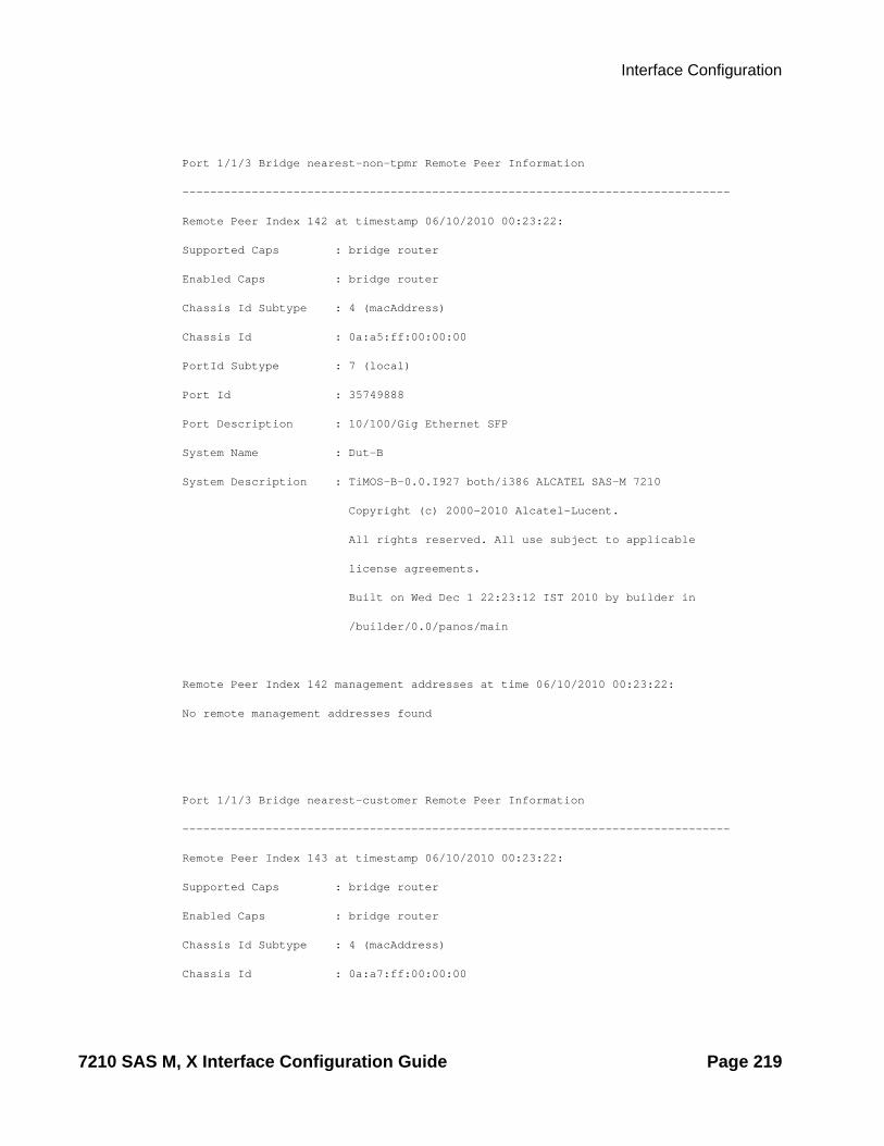
Interface Configuration
Port 1/1/3 Bridge nearest-non-tpmr Remote Peer Information
-------------------------------------------------------------------------------
Remote Peer Index 142 at timestamp 06/10/2010 00:23:22:
Supported Caps : bridge router
Enabled Caps : bridge router
Chassis Id Subtype : 4 (macAddress)
Chassis Id : 0a:a5:ff:00:00:00
PortId Subtype : 7 (local)
Port Id : 35749888
Port Description : 10/100/Gig Ethernet SFP
System Name : Dut-B
System Description : TiMOS-B-0.0.I927 both/i386 ALCATEL SAS-M 7210
Copyright (c) 2000-2010 Alcatel-Lucent.
All rights reserved. All use subject to applicable
license agreements.
Built on Wed Dec 1 22:23:12 IST 2010 by builder in
/builder/0.0/panos/main
Remote Peer Index 142 management addresses at time 06/10/2010 00:23:22:
No remote management addresses found
Port 1/1/3 Bridge nearest-customer Remote Peer Information
-------------------------------------------------------------------------------
Remote Peer Index 143 at timestamp 06/10/2010 00:23:22:
Supported Caps : bridge router
Enabled Caps : bridge router
Chassis Id Subtype : 4 (macAddress)
Chassis Id : 0a:a7:ff:00:00:00
7210 SAS M, X Interface Configuration Guide Page 219
Port Show Commands
PortId Subtype : 7 (local)
Port Id : 35782656
Port Description : 10/100 Ethernet TX
System Name : Dut-G
System Description : TiMOS-B-8.0.R5 both/i386 ALCATEL SR 7750 Copyright (c)
2000-2010 Alcatel-Lucent.
All rights reserved. All use subject to applicable
license agreements.
Built on Tue Sep 28 18:24:07 PDT 2010 by builder in
/rel8.0/b1/R5/panos/main
Remote Peer Index 143 management addresses at time 06/10/2010 00:23:22:
Page 220 7210 SAS M, X Interface Configuration Guide

Interface Configuration
LAG Commands
lag
Syntax lag [lag-id] [detail] [statistics] lag lag-id associations
Context show
Description This command displays Link Aggregation Group (LAG) information.
If no command line options are specified, a summary listing of all LAGs is displayed.
Parameters lag-id — Displays only information on the specified LAG ID.
Default Display information for all LAG IDs.
Values 1 — 12
detail — Displays detailed LAG information.
Default Displays summary information.
statistics — Displays LAG statistics information.
associations — Displays a list of current router interfaces to which the LAG is assigned.
Output LAG Output — The following table describes LAG output fields.
Sample Output
A:ALA-48>config# show lagA:ALA-48# show lag
Label Description
LAG ID The LAG ID that the port is assigned to.
Adm Up — The LAG is administratively up.
Down — The LAG is administratively down.
Opr Up — The LAG is operationally up.
Down — The LAG is operationally down.
Port-Threshold The number of operational links for the LAG at or below which the configured action will be invoked.
Up-Link-Count The number of ports that are physically present and have physical links present.
MC Act/Stdby Member port is selected as active or standby link.
7210 SAS M, X Interface Configuration Guide Page 221
LAG Commands
===============================================================================Lag Data===============================================================================Lag-id Adm Opr Port-Threshold Up-Link-Count MC Act/Stdby -------------------------------------------------------------------------------1 up up 0 2 N/A 2 up up 0 2 N/A 3 up up 0 2 N/A 4 up up 0 2 N/A 5 up up 0 2 N/A 6 up up 0 2 N/A -------------------------------------------------------------------------------Total Lag-ids: 6 Single Chassis: 6 MC Act: 0 MC Stdby: 0===============================================================================A:ALA-48#
Detailed LAG Output — The following table describes detailed LAG output fields. Detailed LAG Output Fields
Label Description
LAG ID The LAG or multi-link trunk (MLT) that the port is assigned to.
Adm Up — The LAG is administratively up.Down — The LAG is administratively down.
Port Threshold If the number of available links is equal or below this number, the threshold action is executed.
Thres. Last Cleared
The last time that keepalive stats were cleared.
Dynamic Cost The OSPF costing of a link aggregation group based on the available aggregated, operational bandwidth.
Configured Address
The base chassis Ethernet MAC address.
Hardware Address The hardware address.
Hold-Time Down The timer, in tenths of seconds, which controls the delay between detecting that a LAG is down and reporting it to the higher levels.
LACP Enabled — LACP is enabled.Down — LACP is disabled.
LACP Transmit Intvl
LACP timeout signalled to peer.
Selection Crite-ria
Configured subgroup selection criteria.
Number of sub-groups
Total subgroups in LAG.
System ID System ID used by actor in LACP messages.
Admin Key Configured LAG key.
Page 222 7210 SAS M, X Interface Configuration Guide

Interface Configuration
*A:dut-c# show lag 1 detail ===============================================================================LAG Details
Oper Key Key used by actor in LACP messages.
System Priority System priority used by actor in LACP messages.
Prtr System ID System ID used by partner in LACP messages.
Prtr Oper Key Key used by partner in LACP messages.
Prtr System Pri-ority
System priority used by partner in LACP messages.
Mode LAG in access or network mode.
Opr Up — The LAG is operationally up.Down — The LAG is operationally down.
Port Threshold Configured port threshold.
Thres. Exceeded Cnt
The number of times that the drop count was reached.
Threshold Action Action to take when the number of available links is equal or below the port threshold.
Encap Type The encapsulation method used to distinguish customer traffic on a LAG.
Lag-IFIndex A box-wide unique number assigned to this interface.
Port ID The specific slot/MDA/port ID.
(LACP) Mode LACP active or passive mode.
LACP xmit standby
LACP transmits on standby links enabled / disabled.
Slave-to-partner Configured enabled/disabled.
Port-id Displays the member port ID.
Adm Displays the member port administrative state.
Active/stdby Indicates that the member port is selected as the active or standby link.
Opr Indicates that the member port operational state.
Primary Indicates that the member port is the primary port of the LAG.
Sub-group Displays the member subgroup where the member port belongs to.
Priority Displays the member port priority.
Label Description (Continued)
7210 SAS M, X Interface Configuration Guide Page 223

LAG Commands
-------------------------------------------------------------------------------Details-------------------------------------------------------------------------------Lag-id : 1 Mode : access Adm : up Opr : up Thres. Exceeded Cnt : 5428 Port Threshold : 0 Thres. Last Cleared : 05/18/2009 11:57:56 Threshold Action : down Dynamic Cost : false Encap Type : dot1q Configured Address : 00:ab:00:5a:01:1c Lag-IfIndex : 1342177281 Hardware Address : 00:ab:00:5a:01:1c Hold-time Down : 0.0 sec Uplink : No LACP : enabled Mode : active LACP Transmit Intvl : fast LACP xmit stdby : enabled Selection Criteria : highest-count Slave-to-partner : disabled Number of sub-groups: 1 Forced : - System Id : 00:ab:00:5a:01:01 System Priority : 32768 Admin Key : 32768 Oper Key : 32768 Prtr System Id : 00:9a:9a:ba:ba:60 Prtr System Priority : 32768 Prtr Oper Key : 32768 -------------------------------------------------------------------------------Port-id Adm Act/Stdby Opr Primary Sub-group Forced Prio-------------------------------------------------------------------------------1/1/3 up active up yes 1 - 32768 1/1/4 up active up 1 - 32768 -------------------------------------------------------------------------------Port-id Role Exp Def Dist Col Syn Aggr Timeout Activity-------------------------------------------------------------------------------1/1/3 actor No No Yes Yes Yes Yes Yes Yes 1/1/3 partner No No Yes Yes Yes Yes Yes Yes 1/1/4 actor No No Yes Yes Yes Yes Yes Yes 1/1/4 partner No No Yes Yes Yes Yes Yes Yes ===============================================================================*A:dut-c#
Page 224 7210 SAS M, X Interface Configuration Guide
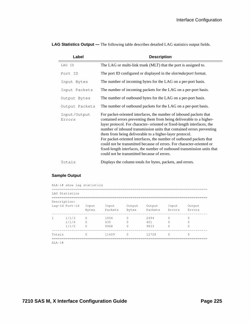
Interface Configuration
LAG Statistics Output — The following table describes detailed LAG statistics output fields.
LAG Statistics Output Fields
Sample Output
ALA-1# show lag statistics===============================================================================LAG Statistics===============================================================================Description: Lag-id Port-id Input Input Output Output Input Output Bytes Packets Bytes Packets Errors Errors-------------------------------------------------------------------------------1 1/1/3 0 1006 0 2494 0 0 1/1/4 0 435 0 401 0 0 1/1/5 0 9968 0 9833 0 0 -------------------------------------------------------------------------------Totals 0 11409 0 12728 0 0 ===============================================================================ALA-1#
Label Description
LAG ID The LAG or multi-link trunk (MLT) that the port is assigned to.
Port ID The port ID configured or displayed in the slot/mda/port format.
Input Bytes The number of incoming bytes for the LAG on a per-port basis.
Input Packets The number of incoming packets for the LAG on a per-port basis.
Output Bytes The number of outbound bytes for the LAG on a per-port basis.
Output Packets The number of outbound packets for the LAG on a per-port basis.
Input/Output Errors
For packet-oriented interfaces, the number of inbound packets that contained errors preventing them from being deliverable to a higher-layer protocol. For character- oriented or fixed-length interfaces, the number of inbound transmission units that contained errors preventing them from being deliverable to a higher-layer protocol.For packet-oriented interfaces, the number of outbound packets that could not be transmitted because of errors. For character-oriented or fixed-length interfaces, the number of outbound transmission units that could not be transmitted because of errors.
Totals Displays the column totals for bytes, packets, and errors.
7210 SAS M, X Interface Configuration Guide Page 225
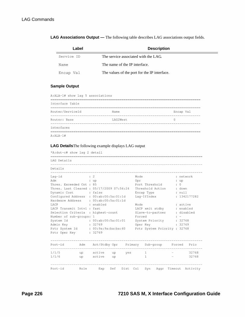
LAG Commands
LAG Associations Output — The following table describes LAG associations output fields.
Sample Output
A:ALA-1# show lag 5 associations==============================================================================Interface Table==============================================================================Router/ServiceId Name Encap Val------------------------------------------------------------------------------Router: Base LAG2West 0------------------------------------------------------------------------------Interfaces==============================================================================A:ALA-1#
LAG DetailsThe following example displays LAG output*A:dut-c# show lag 2 detail ===============================================================================LAG Details-------------------------------------------------------------------------------Details-------------------------------------------------------------------------------Lag-id : 2 Mode : network Adm : up Opr : up Thres. Exceeded Cnt : 85 Port Threshold : 0 Thres. Last Cleared : 05/17/2009 07:56:24 Threshold Action : down Dynamic Cost : false Encap Type : null Configured Address : 00:ab:00:5a:01:1d Lag-IfIndex : 1342177282 Hardware Address : 00:ab:00:5a:01:1dLACP : enabled Mode : active LACP Transmit Intvl : fast LACP xmit stdby : enabled Selection Criteria : highest-count Slave-to-partner : disabled Number of sub-groups: 1 Forced : - System Id : 00:ab:00:5a:01:01 System Priority : 32768 Admin Key : 32769 Oper Key : 32769 Prtr System Id : 00:9a:9a:ba:ba:60 Prtr System Priority : 32768 Prtr Oper Key : 32769 -------------------------------------------------------------------------------Port-id Adm Act/Stdby Opr Primary Sub-group Forced Prio-------------------------------------------------------------------------------1/1/5 up active up yes 1 - 32768 1/1/6 up active up 1 - 32768
-------------------------------------------------------------------------------Port-id Role Exp Def Dist Col Syn Aggr Timeout Activity
Label Description
Service ID The service associated with the LAG.
Name The name of the IP interface.
Encap Val The values of the port for the IP interface.
Page 226 7210 SAS M, X Interface Configuration Guide

Interface Configuration
-------------------------------------------------------------------------------1/1/5 actor No No Yes Yes Yes Yes Yes Yes 1/1/5 partner No No Yes Yes Yes Yes Yes Yes 1/1/6 actor No No Yes Yes Yes Yes Yes Yes 1/1/6 partner No No Yes Yes Yes Yes Yes Yes ===============================================================================*A:dut-c#
7210 SAS M, X Interface Configuration Guide Page 227

Port Monitor Commands
Port Monitor Commands
port
Syntax port port-id [port-id...(up to 5 max)] [interval seconds] [repeat repeat] [absolute | rate] [multiclass]
Context monitor
Description This command enables port traffic monitoring. The specified port(s) statistical information displays at the configured interval until the configured count is reached.
The first screen displays the current statistics related to the specified port(s). The subsequent statistical information listed for each interval is displayed as a delta to the previous display.
When the keyword rate is specified, the "rate per second" for each statistic is displayed instead of the delta.
Monitor commands are similar to show commands but only statistical information displays. Monitor commands display the selected statistics according to the configured number of times at the interval specified.
Parameters port port-id — Specify up to 5 port IDs.
Syntax: port-id slot/mda/portinterval seconds — Configures the interval for each display in seconds.
Default 10 seconds
Values 3 — 60
repeat repeat — Configures how many times the command is repeated.
Default 10
Values 1 — 999
absolute — When the absolute keyword is specified, the raw statistics are displayed, without processing. No calculations are performed on the delta or rate statistics.
rate — When the rate keyword is specified, the rate-per-second for each statistic is displayed instead of the delta.
Sample Output
A:ALA-12>monitor# port /1/4 interval 3 repeat 3 absolute===============================================================================Monitor statistics for Port /1/4=============================================================================== Input Output-------------------------------------------------------------------------------At time t = 0 sec (Base Statistics)-------------------------------------------------------------------------------Octets 0 0Packets 39 175
Page 228 7210 SAS M, X Interface Configuration Guide

Interface Configuration
Errors 0 0-------------------------------------------------------------------------------At time t = 3 sec (Mode: Absolute)-------------------------------------------------------------------------------Octets 0 0Packets 39 175Errors 0 0-------------------------------------------------------------------------------At time t = 6 sec (Mode: Absolute)-------------------------------------------------------------------------------Octets 0 0Packets 39 175Errors 0 0-------------------------------------------------------------------------------At time t = 9 sec (Mode: Absolute)-------------------------------------------------------------------------------Octets 0 0Packets 39 175Errors 0 0===============================================================================A:ALA-12>monitor#
A:ALA-12>monitor# port /1/4 interval 3 repeat 3 rate===============================================================================Monitor statistics for Port /1/4=============================================================================== Input Output-------------------------------------------------------------------------------At time t = 0 sec (Base Statistics)-------------------------------------------------------------------------------Octets 0 0Packets 39 175Errors 0 0-------------------------------------------------------------------------------At time t = 3 sec (Mode: Rate)-------------------------------------------------------------------------------Octets 0 0Packets 0 0Errors 0 0-------------------------------------------------------------------------------At time t = 6 sec (Mode: Rate)-------------------------------------------------------------------------------Octets 0 0Packets 0 0Errors 0 0-------------------------------------------------------------------------------At time t = 9 sec (Mode: Rate)-------------------------------------------------------------------------------Octets 0 0Packets 0 0Errors 0 0===============================================================================A:ALA-12>monitor#
*A:ces-A# monitor port 1/2/1
===============================================================================Monitor statistics for Port 1/2/1
7210 SAS M, X Interface Configuration Guide Page 229

Port Monitor Commands
=============================================================================== Input Output--------------------------------------------------------------------------------------------------------------------------------------------------------------At time t = 0 sec (Base Statistics)-------------------------------------------------------------------------------Octets 3828256704 338593536Packets 19938837 1763508Errors 0 0
-------------------------------------------------------------------------------At time t = 10 sec (Mode: Delta)-------------------------------------------------------------------------------Octets 1929984 1929984Packets 10052 10052Errors 0 0
*A:ces-A# monitor port 1/2/1 rate
===============================================================================Monitor statistics for Port 1/2/1=============================================================================== Input Output--------------------------------------------------------------------------------------------------------------------------------------------------------------At time t = 0 sec (Base Statistics)-------------------------------------------------------------------------------Octets 3831865920 342202752Packets 19957635 1782306Errors 0 0
-------------------------------------------------------------------------------At time t = 10 sec (Mode: Rate)-------------------------------------------------------------------------------Octets 192998 192998Packets 1005 1005Errors 0 0Utilization (% of port capacity) 99.99 99.99
-------------------------------------------------------------------------------At time t = 20 sec (Mode: Rate)-------------------------------------------------------------------------------Octets 192998 192998Packets 1005 1005Errors 0 0Utilization (% of port capacity) 99.99 99.99
^C*A:ces-A# monitor port 1/2/1 absolute
===============================================================================Monitor statistics for Port 1/2/1=============================================================================== Input Output--------------------------------------------------------------------------------------------------------------------------------------------------------------At time t = 0 sec (Base Statistics)-------------------------------------------------------------------------------Octets 3836382144 346718976
Page 230 7210 SAS M, X Interface Configuration Guide

Interface Configuration
Packets 19981157 1805828Errors 0 0
-------------------------------------------------------------------------------At time t = 10 sec (Mode: Absolute)-------------------------------------------------------------------------------Octets 3838312128 348648960Packets 19991209 1815880Errors 0 0
-------------------------------------------------------------------------------At time t = 20 sec (Mode: Absolute)-------------------------------------------------------------------------------Octets 3840242304 350578944Packets 20001262 1825932Errors 0 0
Sample output for 7210 SAS X:A:7210-SAS-X>monitor# port 1/1/2 interval 3 repeat 3 absolute
===============================================================================Monitor statistics for Port 1/1/2=============================================================================== Input Output--------------------------------------------------------------------------------------------------------------------------------------------------------------At time t = 0 sec (Base Statistics)-------------------------------------------------------------------------------Octets 0 1408Packets 0 0Errors 0 0
-------------------------------------------------------------------------------At time t = 3 sec (Mode: Absolute)-------------------------------------------------------------------------------Octets 0 1408Packets 0 0Errors 0 0
-------------------------------------------------------------------------------At time t = 6 sec (Mode: Absolute)-------------------------------------------------------------------------------Octets 0 1408Packets 0 0Errors 0 0
-------------------------------------------------------------------------------At time t = 9 sec (Mode: Absolute)-------------------------------------------------------------------------------Octets 0 1408Packets 0 0Errors 0 0
===============================================================================A:7210-SAS-X>monitor#
7210 SAS M, X Interface Configuration Guide Page 231

Port Monitor Commands
Clear Commands
lag
Syntax lag lag-id statistics
Context clear
Description This command clears statistics for the specified LAG ID.
Parameters lag-id — The LAG ID to clear statistics.
Values 1 — 12
statistics — Specifies to clear statistics for the specified LAG ID.
mda
Syntax mda mda-id
Context clear
Description This command reinitializes the specified MDA in a particular slot.
Parameters mda-id — Clears the specified slot and MDA/CMA.
Values mda-id: slot/mda slot: 1
mda: 1, 2 (for 7210 SAS-M)mda: 1 (for 7210 SAS-X)
port
Syntax port port-id statistics
Context clear
Description This command clears port statistics for the specified port(s).
Parameters port-id — The port identifier.
statistics — Specifies that port statistics will be cleared.
slot — The slot number.
Values 1
Page 232 7210 SAS M, X Interface Configuration Guide
Interface Configuration
mda — The MDA number.
Default All MDAs.
Values 1, 2
7210 SAS M, X Interface Configuration Guide Page 233

Port Monitor Commands
Debug Commands
lag
Syntax lag [lag-id lag-id [port port-id]] [all]lag [lag-id lag-id [port port-id]] [sm] [pkt] [cfg] [red] [iom-upd] [port-state] [timers] [sel-logic]no lag [lag-id lag-id]
Context debug
Description This command enables debugging for LAG.
Parameters lag-id — Specifies the link aggregation group ID.
port-id — Specifies the physical port ID.
sm — Specifies to display trace LACP state machine.
pkt — Specifies to display trace LACP packets.
cfg — Specifies to display trace LAG configuration.
red — Specifies to display trace LAG high availability.
iom-upd — Specifies to display trace LAG IOM updates.
port-state — Specifies to display trace LAG port state transitions.
timers — Specifies to display trace LAG timers.
sel-logic — Specifies to display trace LACP selection logic.
Page 234 7210 SAS M, X Interface Configuration Guide

Standards and Protocol Support
Standards ComplianceIEEE 802.1ab-REV/D3 Station And
Media Access Control Connectivity DiscoveryIEEE 802.1D Bridging
IEEE 802.1p/Q VLAN TaggingIEEE 802.1w Rapid Spanning Tree
ProtocolIEEE 802.1X Port Based Network
Access ControlIEEE 802.1ad Provider BridgesIEEE 802.1ag Service Layer OAMIEEE 802.3ah Ethernet in the First MileIEEE 802.3 10BaseTIEEE 802.3ad Link AggregationIEEE 802.3ae 10Gbps EthernetIEEE 802.3ah Ethernet OAMIEEE 802.3u 100BaseTXIEEE 802.3z 1000BaseSX/LXITU-T Y.1731 OAM functions and
mechanisms for Ethernet based networks
draft-ietf-disman-alarm-mib-04.txtIANA-IFType-MIBIEEE8023-LAG-MIBITU-T G.8032 Ethernet Ring Protection
Switching (version 1)
Protocol Support
OSPFRFC 1765 OSPF Database OverflowRFC 2328 OSPF Version 2RFC 2370 Opaque LSA Support RFC 3101 OSPF NSSA OptionRFC 3137 OSPF Stub Router
AdvertisementRFC 3623 Graceful OSPF Restart – GR
helperRFC 3630 Traffic Engineering (TE)
Extensions to OSPF Version 2
IS-ISRFC 1142 OSI IS-IS Intra-domain
Routing Protocol (ISO 10589)RFC 1195 Use of OSI IS-IS for routing in
TCP/IP & dual environmentsRFC 2763 Dynamic Hostname Exchange
for IS-IS
RFC 2966 Domain-wide Prefix Distribution with Two-Level IS-IS
RFC 2973 IS-IS Mesh GroupsRFC 3373 Three-Way Handshake for
Intermediate System to Intermediate System (IS-IS) Point-to-Point Adjacencies
RFC 3567 Intermediate System to Intermediate System (ISIS) Cryptographic Authentication
RFC 3719 Recommendations for Interoperable Networks using IS-IS
RFC 3784 Intermediate System to Intermediate System (IS-IS) Extensions for Traffic
Engineering (TE)RFC 3787 Recommendations for
Interoperable IP NetworksRFC 3847 Restart Signaling for IS-IS –
GR helper
LDPRFC 3036 LDP SpecificationRFC 3037 LDP ApplicabilityRFC 3478 Graceful Restart Mechanism
for LDP — GR helperRFC 5283 LDP extension for Inter-Area
LSPdraft-jork-ldp-igp-sync-03.txt
MPLSRFC 3031 MPLS ArchitectureRFC 3032 MPLS Label StackEncoding (REV3443))RFC 4379 Detecting Multi-Protocol
Label Switched (MPLS) Data Plane Failures
RFC 4182 Removing a Restriction on the use of MPLS Explicit NULL
draft-ietf-mpls-lsr-mib-06.txtdraft-ietf-mpls-te-mib-04.txtdraft-ietf-mpls-ldp-mib-07.txt
MulticastRFC 1112 Host Extensions for IP
Multicasting (Snooping)RFC 2236 Internet Group Management
Protocol, (Snooping)RFC 3376 Internet Group Management
Protocol, Version 3 (Snooping)!
RSVP-TERFC 2430 A Provider Architecture
DiffServ & TERFC 2702 Requirements for Traffic
Engineering over MPLSRFC 3209 Extensions to RSVP for
TunnelsRFC 4090 Fast reroute Extensions to
RSVP-TE for LSP Tunnelsdraft-ietf-ccamp-mpls-gracefulshutdown-
06 Graceful Shutdown in GMPLS Traffic Engineering Networks
DIFFERENTIATED SERVICESRFC 2474 Definition of the DS Field the
IPv4 and IPv6 Headers (Rev)RFC 2597 Assured Forwarding PHB
Group (rev3260)RFC 2598 An Expedited Forwarding
PHBRFC 2697 A Single Rate Three Color
MarkerRFC 2698 A Two Rate Three Color
MarkerRFC 4115 A Differentiated Service Two-
Rate, Three-Color Marker with Efficient Handling of in-Profile Traffic
TCP/IPRFC 768 UDPRFC 1350 The TFTP Protocol (Rev.RFC 791 IPRFC 792 ICMPRFC 793 TCPRFC 826 ARPRFC 854 TelnetRFC 1519 CIDRRFC 1812 Requirements for IPv4
RoutersRFC 2347 TFTP option ExtensionRFC 2328 TFTP Blocksize OptionRFC 2349 TFTP Timeout Interval and
Transfer Size option
DHCPRFC 2131 Dynamic Host Configuration
Protocol (REV)
Standards and Protocols Page 235

Standards and Protocols
VPLSRFC 4762 Virtual Private LAN Services
Using LDP (previously draft-ietf-l2vpn-vpls-ldp-08.txt)
PSEUDO-WIRERFC 3985 Pseudo Wire Emulation Edge-
to-Edge (PWE3)RFC 4385 Pseudo Wire Emulation Edge-
to-Edge (PWE3) Control Word for Use over an MPLS PSN
RFC 3916 Requirements for Pseudo- Wire Emulation Edge-to-Edge (PWE3)
RFC 4448 Encapsulation Methods for Transport of Ethernet over MPLS Networks (draft-ietf-pwe3-ethernet-encap-11.txt)
RFC 4446 IANA Allocations for PWE3RFC 4447 Pseudowire Setup and
Maintenance Using LDP (draft-ietf-pwe3-control-protocol-17.txt)
RFC 5085, Pseudowire Virtual Circuit Connectivity Verification (VCCV): A Control Channel for Pseudowires
draft-ietf-l2vpn-vpws-iw-oam-02.txtdraft-ietf-pwe3-oam-msg-map-05-txtdraft-ietf-pwe3-ms-pw-arch-02.txtdraft-ietf-pwe3-segmented-pw-05.txtdraft-hart-pwe3-segmented-pw-vccv-
02.txtdraft-muley-dutta-pwe3-redundancy-bit-
02.txtdraft-muley-pwe3-redundancy-02.txt
CIRCUIT EMULATIONRFC 4553 Structure-Agnostic Time
Division Multiplexing (TDM) over Packet (SAToP)
RFC 5086 Structure-Aware Time Division Multiplexed (TDM) Circuit Emulation Service over Packet Switched Network (CESoPSN)
RFC 5287 Control Protocol Extensions for the Setup of Time-Division Multiplexing (TDM) Pseudowires in MPLS Networks
RADIUSRFC 2865 Remote Authentication Dial In
User ServiceRFC 2866 RADIUS Accounting
SSHdraft-ietf-secsh-architecture.txt SSH
Protocol Architecturedraft-ietf-secsh-userauth.txt SSH
Authentication Protocoldraft-ietf-secsh-transport.txt SSH
Transport Layer Protocoldraft-ietf-secsh-connection.txt SSH
Connection Protocoldraft-ietf-secsh- newmodes.txt SSH
Transport Layer Encryption Modes
TACACS+draft-grant-tacacs-02.txt
TimingGR-253-CORE SONET Transport
Systems: Common Generic Criteria. Issue 3, September 2000
ITU-T G.781 Telecommunication Standardization Section of ITU, Synchronization layer functions, issued 09/2008
ITU-T G.813 Telecommunication Standardization Section of ITU, Timing characteristics of SDH equipment slave clocks (SEC), issued 03/2003.
GR-1244-CORE Clocks for the Synchronized Network: Common Generic Criteria, Issue 3,May 2005
ITU-T G.8261 Telecommunication Standardization Section of ITU, Timing and synchronization aspects in packet networks, issued 04/2008.
ITU-T G.8262 Telecommunication Standardization Section of ITU, Timing characteristics of synchronous Ethernet equipment slave clock (EEC), issued 08/2007.
ITU-T G.8264 Telecommunication Standardization Section of ITU, Distribution of timing information through packet networks, issued 10/2008
ITU-T G.8264 Telecommunication Standardization Section of ITU, Distribution of timing information through packet Networks, issued 10/2008.
NETWORK MANAGEMENTITU-T X.721: Information technology-
OSI-Structure of Management Information
ITU-T X.734: Information technology-OSI-Systems Management: Event Report Management Function
M.3100/3120 Equipment and Connection Models
TMF 509/613 Network Connectivity Model
RFC 1157 SNMPv1RFC 1215 A Convention for Defining
Traps for use with the SNMPRFC 1907 SNMPv2-MIBRFC 2011 IP-MIBRFC 2012 TCP-MIBRFC 2013 UDP-MIBRFC 2096 IP-FORWARD-MIBRFC 2138 RADIUSRFC 2206 RSVP-MIBRFC 2571 SNMP-FRAMEWORKMIBRFC 2572 SNMP-MPD-MIBRFC 2573 SNMP-TARGET-&-
NOTIFICATION-MIBRFC 2574 SNMP-USER-
BASEDSMMIBRFC 2575 SNMP-VIEW-BASEDACM-
MIBRFC 2576 SNMP-COMMUNITY-MIBRFC 2665 EtherLike-MIBRFC 2819 RMON-MIBRFC 2863 IF-MIBRFC 2864 INVERTED-STACK-MIBRFC 3014 NOTIFICATION-LOGMIBRFC 3164 SyslogRFC 3273 HCRMON-MIRFC 3411 An Architecture for
Describing Simple Network Management Protocol (SNMP) Management Frameworks
RFC 3412 - Message Processing and Dispatching for the Simple Network Management Protocol (SNMP)
RFC 3413 - Simple Network Management Protocol (SNMP) Applications
RFC 3414 - User-based Security Model (USM) for version 3 of the Simple Network Management Protocol (SNMPv3)
RFC 3418 - SNMP MIBt
Page 236 Standards and Protocols

Standards and Protocols
PROPRIETARY MIBsALCATEL-IGMP-SNOOPING-
MIB.mib TIMETRA-CAPABILITY-7210-SAS-M-
V1v0.mibTIMETRA-CHASSIS-MIB.mibTIMETRA-CLEAR-MIB.mibTIMETRA-DOT3-OAM-MIB.mibTIMETRA-FILTER-MIB.mibTIMETRA-GLOBAL-MIB.mibTIMETRA-IEEE8021-CFM-MIB.mibTIMETRA-LAG-MIB.mibTIMETRA-LOG-MIB.mibTIMETRA-MIRROR-MIB.mibTIMETRA-NTP-MIB.mibTIMETRA-OAM-TEST-MIB.mibTIMETRA-PORT-MIB.mibTIMETRA-QOS-MIB.mibTIMETRA-SAS-ALARM-INPUT-
MIB.mibTIMETRA-SAS-IEEE8021-CFM-
MIB.mibTIMETRA-SAS-GLOBAL-MIB.mibTIMETRA-SAS-PORT-MIB.mibTIMETRA-SAS-QOS-MIB.mibTIMETRA-SAS-SYSTEM-MIB.mibTIMETRA-SAS-SERV-MIB.mibTIMETRA-SAS-VRTR-MIB.mibTIMETRA-SCHEDULER-MIB.mibTIMETRA-SECURITY-MIB.mibTIMETRA-SERV-MIB.mibTIMETRA-SYSTEM-MIB.mibTIMETRA-TC-MIB.mibTIMETRA-ISIS-MIB.mibTIMETRA-ROUTE-POLICY-MIB.mibTIMETRA-MPLS-MIB.mibTIMETRA-RSVP-MIB.mibTIMETRA-LDP-MIB.mibTIMETRA-VRTR-MIB.mib
Note:!Only in access-uplink mode
Standards and Protocols Page 237

Standards and Protocols
Page 238 Standards and Protocols

INDEX
NUMERICS802.1x 45802.3ah OAM 51
CCard, MDA, Port
overview 16chassis slots and cards 16MDAs 16MTU configuration guidelines 55preprovisioning
chassis slots and cards 16configuring
basic 62LAG 66management tasks 67port
Ethernet 65access port 65network port 65
command referencecard commands 72MDA commands 72
port commands 73TDM commands 76
ports 64
DDDM 19
Hhashing 33
LLAG 30
overviewguidelines 32port link damping 43
configuring 66command reference 78
hashing 33
Pport types 23preprovisioning guidelines 60
7210 SAS M, X Interface Configuration Guide Page 239

Page 240 7210 SAS M, X Interface Configuration Guide