722 ieee transactions on computers, vol. 47, …phatak/212/supl/mircea-milos-long-and... · 722...
TRANSCRIPT

722 IEEE TRANSACTIONS ON COMPUTERS, VOL. 47, NO. 7, JULY 1998
Long and Fast Up/Down CountersMircea R. Stan, Member, IEEE, Alexandre F. Tenca,
and Milos D. Ercegovac, Member, IEEE Computer Society
Abstract—This paper presents recent advances in the design of constant-time up/down counters in the general context of fastcounter design. An overview of existing techniques for the design of long and fast counters reveals several methods closely relatedto the design of fast adders, as well as some techniques that are only valid for counter design. The main idea behind the novelup/down counters is to recognize that the only extra difficulty with an up/down (vs. up-only or down-only) counter is when the counterchanges direction from counting up to counting down (and vice-versa). For dealing with this difficulty, the new design uses a“shadow” register for storing the previous counter state. When counting only up or only down, the counter functions like a standardup-only or down-only constant time counter, but, when it changes direction instead of trying to compute the new value (whichtypically requires carry propagation), it simply uses the contents of the shadow register which contains the exact desired previousvalue. An alternative approach for restoring the previous state in constant time is to store the carry bits in a Carry/Borrow register.
Index Terms—Binary counter, constant time counter, serial counter, parallel counter, prescaler, up/down counter.
——————————���F���——————————
1 INTRODUCTION
OUNTING, when viewed as incrementing an integernumber by one, is one of the simplest arithmetic op-
erations, and many design techniques used for speeding upmore complex arithmetic operations, especially addition,can be applied to counters and exemplified with their help.Traditionally, counters have been presented as simple statemachine examples in textbooks on digital logic design andthis has prevented the dissemination of more advanceddesign techniques which have a more natural place in acomputer arithmetic treatise. This paper attempts to presentthe state of the art in fast counter design with special em-phasis on recent results in the design of constant-timeup/down counters [22], [23]. Previously published resultsand patent examples will be analyzed with sometimes sur-prising conclusions relating to the amount of overlap be-tween different techniques and the existence of many recentpatents on textbook-type implementations.
The simplest type of counter is the binary modulo-2N N-bit counter where the value s(t) of the counter is incre-mented by one in each clock cycle:
s(t + 1) = s(t) mod 2N.
Besides this basic behavior, most counter types have severalother features, the most important ones being illustratedwith the help of a “black-box” model as in Fig. 1a:
•� resettable—the counter value is reset to all zeros whenthe RESET input is active,
•� loadable—the counter is loaded with the N-bit value atthe In input lines when the LOAD input is active,
•� reversible—the counter counts “up” (increments) whenthe UP DOWN/ input signal is inactive and counts“down” (decrements) when the UP DOWN/ inputsignal is active,
•� count enable—the counter increments every clock cycleonly when the CNT input is active,
•� terminal count—TC output signal active when thecounter reaches the maximum value (all ones) count-ing up or reaches the minimum value (all zeros) whencounting down,
•� readable on-the-fly—the counter state (Out) can be readreliably without stopping the clock. Ideally, this“sampling rate” should be equal to the clock rate.
Some of the above features can be combined in order toobtain a more complex counter behavior. For example, theterminal count can be used with a loadable modulo-2N coun-ter in order to obtain an arbitrary modulo-P counter (with P £2N) simply by loading the value 2N - P each time TC becomesactive. Alternatively, if the counter has only RESET and noLOAD, a modulo-P counter can be obtained by decoding stateP and resetting the counter to zero at that moment.
In many cases, counters that are both long and fast arenecessary, but speed and size are conflicting qualities forcounters because of the carry propagation from low-orderto high-order bits. One must be careful with the definitionof “speed” though, especially for asynchronous counters.For example, the simple asynchronous ripple-carry counterin Fig. 2a can be considered both very fast, since it can havea very high frequency clock (just one load on the clock line),but also very slow, since the delay of the most significant bitis large and grows linearly with the counter size. For someapplications, like frequency division, the long delay forcarry propagation is not a problem if the clock can still havea high frequency, the simple asynchronous ripple-carrycounter being widely used and one of the fastest available[20]. It should be noted that, for historical reasons, asyn-chronous counters are generally counting down.
²²²²²²²²²²²²²²²²
•� M.R. Stan is with the Department of Electrical Engineering, University ofVirginia, Charlottesville, VA 22903. E-mail: [email protected].
•� A.F. Tenca is with the Department of Electrical and Computer Engineering,Oregon State University, Corvallis, OR 97331, and the University of SaoPaulo, Brazil. E-mail: [email protected].
•� M.D. Ercegovac is with the Computer Science Department, University ofCalifornia, Los Angeles, CA 90024. E-mail: [email protected].
For information on obtaining reprints of this article, please send e-mail to:[email protected], and reference IEEECS Log Number 106607.
0018-9340/98/$10.00 © 1998 IEEE
C

STAN ET AL.: LONG AND FAST UP/DOWN COUNTERS 723
Most counter applications require a synchronous designand the simple ripple-carry synchronous counter in Fig. 2bhas a very large clock period that increases linearly with thesize of the counter, due to the worst case carry propagation,through (N - 1) AND gates. For the rest of the paper, wewill assume the “synchronous paradigm” for which theclock is a perfect broadcast signal, hence, all delays will bedue to combinational logic. It should be clear, though, that,for “real” designs, the delay of the clock also increases withthe number of loads and also becomes a function of thenumber of flip-flops.
The combinational carry-ripple through AND gates rep-resents the simplest circuit for adding a one to the counterbits with a carry-ripple adder [11]. The adder structure canbe clearly revealed if we replace the T-flip-flops tradition-ally used in counter representation with D-flip-flops andhalf-adders (HAs) as in Fig. 2c. The rest of this section willdiscuss several state-of-the-art techniques and a counterclassification, Section 2 will introduce the idea of prescaledcounters, and Section 3 will present two novel up/downconstant time counter structures.
(a) (b) (c)
Fig. 1. (a) “Black-box” generic counter model with the most common control signals, (b) counter with the “exposed” adder structure, (c) “black-box”model for nonloadable counter.
(a)
(b)
(c)
Fig. 2. (a) Asynchronous ripple-carry counter using T-flip-flops, (b) synchronous ripple-carry counter using T-flip-flops, (c) synchronous ripple-carrycounter using D-flip-flops and half-adders.
724 IEEE TRANSACTIONS ON COMPUTERS, VOL. 47, NO. 7, JULY 1998
1.1 Counters as Arithmetic CircuitsRevealing the adder “inside” the black-box counter as inFig. 1b enables the use of all the known techniques for de-signing fast adders [11] to be applied for fast counter de-sign. There are many known techniques for speeding upaddition, and most of them can be also applied to the de-sign of fast counters.
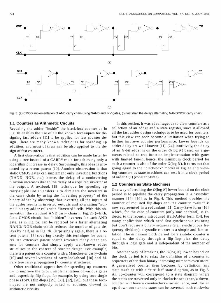
A first observation is that addition can be made faster byusing a tree instead of a CARRY-chain for achieving only alogarithmic increase in delay. Surprisingly, this idea is pro-tected by a recent patent [10]. Another observation is thatstatic CMOS gates can implement only inverting functions(NAND, NOR, etc.), hence, the delay of a noninvertingfunction increases due to the delay of a required inverter atthe output. A textbook [18] technique for speeding upcarry-ripple CMOS adders is to eliminate the inverters inthe carry chain by using the “inverting property” of thebinary adder by observing that inverting all the inputs ofthe adder results in inverted outputs and alternating “nor-mal” binary adder cells with “inverted” cells. With this ob-servation, the standard AND carry chain in Fig. 2b (which,for a CMOS circuit, has “hidden” inverters for each ANDgate, as in Fig. 3a) can be replaced by a faster alternatingNAND/NOR chain which reduces the number of gate de-lays by half, as in Fig. 3b. Surprisingly again, there is a re-cent patent [13] covering exactly this technique for count-ers. An extensive patent search revealed many other pat-ents for counters that simply apply well-known adderstructures in the context of counter design. For example,there is a patent on a counter with a Manchester carry-chain[19] and several versions of carry-lookahead [10] and bi-nary tree carry propagation [7] counter structures.
Other traditional approaches for speeding up counterstry to improve the circuit implementation of various gatesand, especially, flip-flops, for example, by using true-singlephase (TSPC) flip-flops [29], [30], [12], [20], but these tech-niques are not uniquely suited to counters viewed asarithmetic circuits.
In this section, it was advantageous to view counters as acollection of an adder and a state register, since it allowedall the fast adder design techniques to be used for counters,but this view can soon become a limitation when trying tofurther improve counter performance. Lower bounds onadder delay are well-known [11], [24]; intuitively, the delayof an N-bit adder is on the order O(log N) based on argu-ments related to tree function implementation with gateswith limited fan-in, hence, the minimum clock period forsuch a counter is also of the order O(log N). It turns out thatgoing again to the “black-box” model in Fig. 1a and view-ing counters as state machines can result in a clock periodof order O(1) (constant-time).
1.2 Counters as State MachinesOne way of breaking the O(log N) lower bound on the clockperiod is to pipeline the carry propagation in a “systolic”manner [14], [16] as in Fig. 4. This method doubles thenumber of required flip-flops and the counter “value” isnow represented in a redundant [11] Carry-Save form [16],which, for the case of counters (only one operand), is re-duced to the recently introduced Half-Adder form [14]. Formany applications which need fast synchronous countingbut don’t require a binary sequence (e.g., synchronous fre-quency dividers), a systolic counter is a simple and fast so-lution. The minimum clock period for a systolic counter isequal to the delay through a flip-flop plus the delaythrough a logic gate and is independent of the number ofbits.
Another way of breaking the O(log N) lower bound onthe clock period is to relax the definition of a counter tosequences other than binary increasing numbers even more.A generalized counter then becomes, by definition, anystate machine with a “circular” state diagram, as in Fig. 5.An up-counter will correspond to a state diagram wherethe states are traversed only in clockwise sequence, a down-counter will have a counterclockwise sequence, and, for anup/down counter, the states can be traversed both clockwise
(a)
(b)
Fig. 3. (a) CMOS implementation of AND carry chain using NAND and INV gates, (b) fast (half the delay) alternating NAND/NOR carry chain.

STAN ET AL.: LONG AND FAST UP/DOWN COUNTERS 725
and counterclockwise. An arbitrary state can be chosen asthe zero state (ideally encoded as all-zeros) so that the RE-SET signal will bring the state machine into that initialstate. Loading such a generalized counter with meaningfulvalues may be difficult, depending on the state encoding,also, comparing two counter values in order to see whichone is “greater” may become impossible.
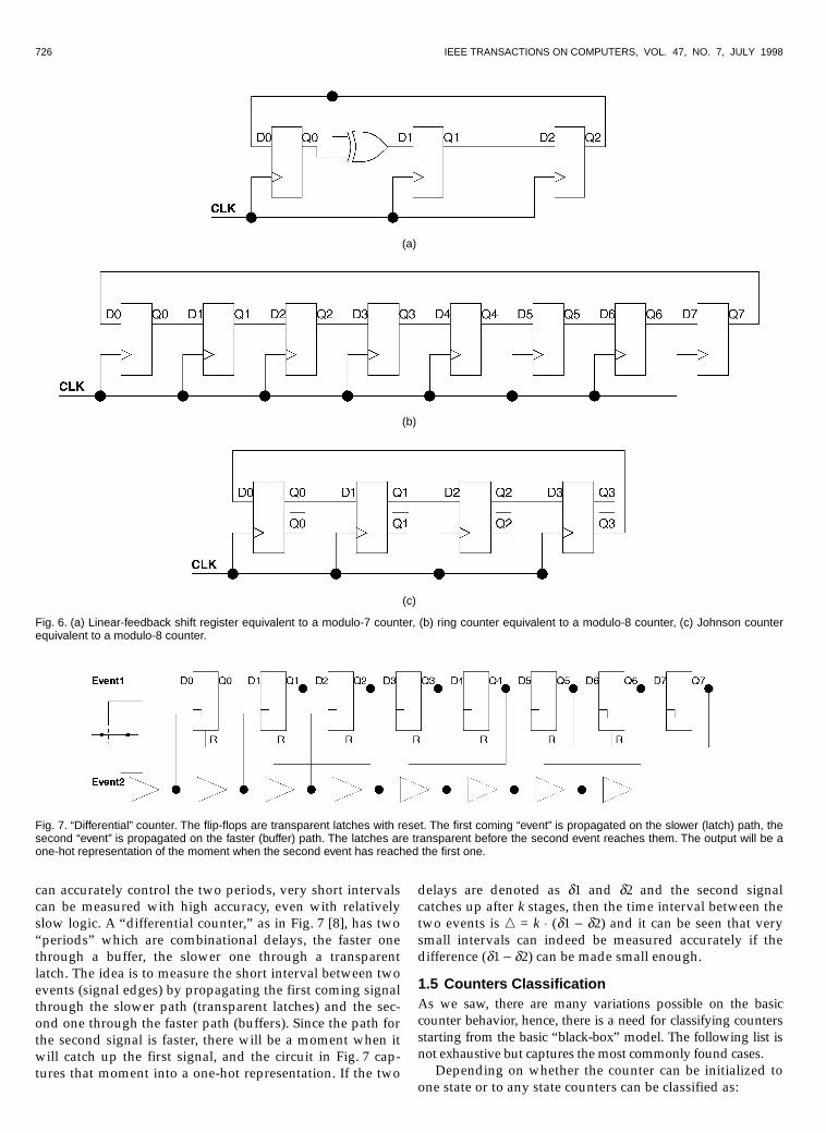
Generalizing the counter definition in this way opens thepossibility of using radically different designs. In principle,any state-encoding and minimization tool can be used forderiving the implementation of such a state machine, butthere are some known structures that implicitly have such acircular state diagram. For example, the linear-feedbackshift register (LFSR) in Fig. 6a [17] has O(1) (constant) clockperiod and O(N) (same as binary counter) space complexity,but has a nonbinary output sequence. LFSRs have the feed-back connections corresponding to a polynomial with bi-nary coefficients and, for a primitive polynomial, the num-ber of states is 2N - 1, hence, an LFSR has a state diagramequivalent to a modulo-(2N - 1) counter (all N-bit patternsexcept the all-zeros state). There are ways to obtain amodulo-2N LFSR (with the all-zeros state) but that may af-fect the clock period. For many applications which needfast counters but don’t require a binary sequence (e.g., ad-
dress pointers to circular FIFOs [21], frequency dividers[15]), the LFSR is a good solution, being simple and fast.The minimum clock period for an LFSR is equal to the de-lay through a flip-flop plus the delay through an XOR andis independent of the number of bits.
1.3 Ring CountersThe shortest theoretical delay for a state machine is obtainedwhen the combinational logic is completely eliminated andthe whole sequential structure becomes a shift-register con-nected in a ring, as in Fig. 6b. The minimum clock periodfor such a ring counter is only limited by the delay througha flip-flop. If the P-bit ring counter is initialized to the“00...001” state, then the state diagram will consist of a cir-cular sequence of P one-hot encoded states. This P-bit one-hot sequence is the longest possible for a ring counter andis easy to decode (need to look only at the “hot” bit). Non-one-hot states are harder to decode and may generate lessthan P distinct states. For example, the “0101...0101” initialstate generates a sequence with only two states(“0101...0101” and “1010...1010”).
A clear disadvantage of ring counters is their exponentialcomplexity compared with binary counters. In order toemulate a simple 8-bit binary counter, a long 256-bit ringcounter is needed; furthermore, although the delay of thering counter is theoretically independent of size (synchro-nous paradigm), for such exponential increases, it is likelythat for a real design a 256-bit ring counter may be slowerthan the much simpler 8-bit binary counterpart. It followsthen that ring counters should be used only when the num-ber of states is relatively small. A well-known technique toreduce the complexity of a ring counter in half is to use atwisted-tail (also known as Johnson or Moebius) counter asin Fig. 6c, which also has the advantage that it can be ini-tialized to the all-zeros state. Decoding any state for atwisted-tail counter needs two bits, hence, it can also bedone in constant time as with the twice longer “standard”ring counter.
1.4 Differential CountersFor applications that need even faster counting, it is possi-ble to derive structures that count differentially with astructure which has some similarities to a ring counter [8].When measuring very short time intervals using a “regu-lar” counter, the accuracy of any time measurement will bedetermined by the clock period, hence, when the interval tobe measured is of the same order of magnitude as the clockperiod, any measurement becomes meaningless. Countingdifferentially allows the accuracy to be determined by thedifference between two different periods. Assuming that weFig. 5. Circular state diagram for generic modulo-P counter.
Fig. 4. Pipelined carry chain for a “systolic” counter.
726 IEEE TRANSACTIONS ON COMPUTERS, VOL. 47, NO. 7, JULY 1998
can accurately control the two periods, very short intervalscan be measured with high accuracy, even with relativelyslow logic. A “differential counter,” as in Fig. 7 [8], has two“periods” which are combinational delays, the faster onethrough a buffer, the slower one through a transparentlatch. The idea is to measure the short interval between twoevents (signal edges) by propagating the first coming signalthrough the slower path (transparent latches) and the sec-ond one through the faster path (buffers). Since the path forthe second signal is faster, there will be a moment when itwill catch up the first signal, and the circuit in Fig. 7 cap-tures that moment into a one-hot representation. If the two
delays are denoted as d1 and d2 and the second signalcatches up after k stages, then the time interval between thetwo events is n = k ◊ (d1 - d2) and it can be seen that verysmall intervals can indeed be measured accurately if thedifference (d1 - d2) can be made small enough.
1.5 Counters ClassificationAs we saw, there are many variations possible on the basiccounter behavior, hence, there is a need for classifying countersstarting from the basic “black-box” model. The following list isnot exhaustive but captures the most commonly found cases.
Depending on whether the counter can be initialized toone state or to any state counters can be classified as:
(a)
(b)
(c)
Fig. 6. (a) Linear-feedback shift register equivalent to a modulo-7 counter, (b) ring counter equivalent to a modulo-8 counter, (c) Johnson counterequivalent to a modulo-8 counter.
Fig. 7. “Differential” counter. The flip-flops are transparent latches with reset. The first coming “event” is propagated on the slower (latch) path, thesecond “event” is propagated on the faster (buffer) path. The latches are transparent before the second event reaches them. The output will be aone-hot representation of the moment when the second event has reached the first one.

STAN ET AL.: LONG AND FAST UP/DOWN COUNTERS 727
•� Noninitializable—The simplest case, it can only beused for specific applications (e.g., frequency divider).
•� Resettable—Necessary for most applications and alsonecessary for testing purposes, without a large pen-alty in performance or area.
•� Loadable—This is a more general case but typically haslower performance and higher complexity.
Depending on whether the counter traverses the circularstate diagram in one direction only or in both, counters can be:
•� Up-only—Most common case, easy to understand.•� Down-only—Equivalent to the up-only case in the
same sense as subtraction is equivalent to addition,sometimes preferred for convenience (e.g., for amodulo-P counter it is more “convenient” to decodezero state and load a down-counter with the value Pthan to load an up-counter with the value -P).
•� Up/down—Most versatile but typically at the cost oflower performance (sometimes called a “reversible”counter).
Depending on whether all the state registers are clockedwith the same signal counters can be:
•� Asynchronous—Simple structure, cannot be read “on-the-fly,” can have registers that are clocked by othersignals than the clock (like the ripple-carry counter inFig. 2a, sometimes called serial counter [3]) or someother nonclocked sequential structure [2].
•� Semisynchronous—A “hybrid” attempt of combiningthe simplicity of asynchronous designs with a syn-chronous behavior on only some of the outputs (e.g.,the terminal count TC [12]).
•� Synchronous—Most robust and can be read on-the-fly,but the routing and loading of the clock can become aperformance bottleneck.
Sometimes it is possible to use “counters” with a statediagram that does not return from the last state to the initialstate. Depending on whether this happens or not, counterscan be classified as:
•� Periodic—This is the normal case with a circular statediagram.
•� Aperiodic—This is the case where the counter does notreturn to the initial state, an example being the differ-ential counter in Section 1.4.
Periodic counters can be classified according to thenumber of states:
•� Modulo-2N—Special case of 2N states, typical for an N-bit binary counter, the counter “wraps-around” fromthe last state by itself, the case of the LFSR with 2N - 1states being similar.
•� Modulo-P—Although apparently a more general casethan the modulo-2N, the modulo-P counter is manytimes obtained from a modulo-2N counter, either bydecoding the state P and resetting to zero, or byloading with P when the counter reaches zero.Modulo-P ring counters are obtained without a needto decode states or explicitly load the counter.
Depending on the state encoding, counters can be classi-fied as:
•� Binary—The most common case in which the se-quence of states is the ascending or descending binarysequence.
•� Quasi-binary—The case where the relation between astate and its binary equivalent can be easily deter-mined (e.g., for the Half-Adder form of systoliccounters in Section 1.2, the binary value can be ob-tained by adding the Sum and Carry parts). A Gray-code encoded counter used for driving decoderswithout glitches [26], [1] can be also considered quasi-binary since the binary state can be easily obtainedwith XORs from the Gray-code state.
•� Nonbinary—The state encoding is not related to thebinary sequence, like in the case of LFSRs and ringcounters.
The nonbinary fast counters described until now areadequate for many applications, but many times it is desir-able to design binary constant-time counters. Prescaledcounters, which are the focus of the rest of the paper, aresynchronous circuits having the following characteristics:
•� Binary counting sequence.•� Clock period independent of counter size.•� Readable on the fly with the sampling rate being
equal to the counting rate.•� Space complexity linear in the number of bits (i.e.,
O(N)).•� Count “up,” “down,” or “up/down”.•� Resettable.
2 CONSTANT-TIME BINARY COUNTERS
Being able to design binary counters with O(1) period isnonintuitive considering that adders have an O(log N) pe-riod and incrementing is a special case of addition, as wesaw in Section 1.1. The following observations give a justifi-cation for why constant time binary counters are feasible:
1)�The binary number system has a special periodicity inthe way the CARRY-in to high order bits is generated,which makes it both predictable and with a low fre-quency [25],
2)�The black-box model of a nonloadable counter (Fig. 1c)has only a limited number of inputs: Clock (CLK),RESET, and Count Enable (CNT). This explains whythe binary tree logic decomposition which leads to theO(log N) delay for an adder or loadable counter canbe circumvented for nonloadable counters.
An ascending sequence of binary numbers has many in-teresting properties, as can be seen in Table 1, which showsa 4-bit counter divided into two 2-bit blocks. The higherorder bits are stable for long periods of time and the termi-nal count (TC1) output from the two least significant bits,which becomes a CARRY-in into the most significant block,is periodic with a lower frequency than the clock signal. Foran M-bit counter block, the terminal count will have a fre-quency 2M lower than the clock, with the moment when theterminal count from low-order bits is active being exactly thetime when higher order bits need to be incremented. Thismeans that the “virtual” frequency at which high-order bits

728 IEEE TRANSACTIONS ON COMPUTERS, VOL. 47, NO. 7, JULY 1998
need to operate is much lower than for the low-order bits andthis is exactly the idea behind prescaled counters. This idea hasbeen in use for a relatively long time, starting with the “old”74160-163 series 4-bit TTL counters [15], but only recently hasbeen formalized in academic publications [4], [25].
2.1 Prescaled CountersPrescaling long counters requires partitioning them into aseries of subblocks of increasing sizes in order to take ad-vantage of the reduced frequency required by high orderbits. The simplest prescaled counters have only two suchblocks, with a small and fast least-significant module calledthe prescaler and a slower large counter for high-order bits[20], like in Fig. 8. We were again surprised to find a recentpatent [3] covering this basic well-known technique.
What makes a prescaled counter work is the fact that,due to the characteristics of the binary number system, theTC from the prescaler to the high order bits (which corre-sponds to the moments when the high order bits have to beincremented) has a low frequency. In this way, the “virtualclock frequency” for the slow high-order block is 2M smallerthan the true clock frequency, and the CARRY propagationinside the high-order partition can take a long time evenwith a fast clock.
A simple reasoning leads to a theoretically unlimitedextension of the counter size, without increasing the clockperiod, by adding more partitions [4], [25]. For higher orderblocks, successive terminal count signals from the previousstages become exponentially farther apart in time, hence,higher order blocks can have exponentially increasing sizes,
and, for all practical purposes, three or four such partitionsare typically enough [25]. In a correctly designed constanttime counter, the clock period is limited only by the speedof the least significant block, hence, the first prescaler istypically very small (one or two bits).
The CARRY propagation inside a partition has to befaster than the “virtual clock” for that block. Generally, it isdesired that the design be as simple (i.e., small) as possible,hence, a ripple CARRY propagation is typically chosen in-side each partition. For such an arrangement, the number ofbits inside a partition is determined by dividing the “virtualclock” period by the gate delay for one bit of carry propa-gation. The size of each subblock must be chosen such thatthe CARRY propagation inside the block is shorter than thedelay between two successive terminal counts from thecorresponding prescaler. In this way, the CARRY propaga-tion inside the block is not on the critical path and does notaffect the clock period.
2.2 Terminal Count GenerationThe prescaled generation of the TC-in to a partition has tobe synchronous with the true clock. Several different ap-proaches have been proposed for the prescaled generationof the TC to high-order partitions. The first proposed solu-tion, by Ercegovac and Lang [4], uses a (relatively ineffi-cient) ring/twisted-tail counter, which practically doublesthe overall complexity of the counter. The ring/twisted-tailcounters are regular and their VLSI implementation maynot be very inefficient. A much simpler TC generation, pro-posed by Vuillemin [25], uses a backward CARRY propa-gation chain [12] that takes the characteristics of the binarynumber system further into account.
2.3 PartitioningDepending on the choice of the prescaled CARRY-in gen-eration method, the partition sizes can be determined:
•� In a top-down manner [4] by first determining the sizeof the most significant block, which is chosen as largeas possible, and then recursively determining the sizesof the lower order blocks. By assuming unit delays forthe combinational gates and a unit delay clock, an N-bitcounter is first partitioned into an (N - Èlog2 N˘) most
significant block and into another Èlog2 N˘ blockwhich is recursively partitioned in the same manner[4]. For example, in the case of a 64-bit counter, a top-down partitioning results in the following block sizes:58, 3, 2, 1 [4]. The top-down procedure reduces thepenalty paid for having ring counter prescalers, buthas the disadvantage that counters of different sizes willrequire different partition sizes, hence, design reuse is
TABLE 1BINARY SEQUENCE COUNTING UP(< 1 REPRESENTS THE CARRY)
number b3b2 TC1 b1b0
0 00 0 001 00 0 012 00 0 103 00 <1 114 01 0 005 01 0 016 01 0 107 01 <1 118 10 0 009 10 0 0110 10 0 1011 10 <1 1112 11 0 0013 11 0 0114 11 0 1015 11 <1 11
Fig. 8. Counter partitioned into a fast prescaler and a slower high-order partition.

STAN ET AL.: LONG AND FAST UP/DOWN COUNTERS 729
difficult to implement. For a 128-bit counter, the top-down partitioning leads to: 121, 4, 2, 1 block sizes.This scheme has recently been refined in [23] as fol-lows: An N-bit counter can be partitioned into an (N- Îlog2 N˚)-bit block and a Îlog2 N˚-bit block, whenever
N N N− ≤log log2 2 23 8 . When the condition does not
apply, the original partitioning method is used.•� In a bottom-up manner [25] by first deciding the size of
the least significant block, then choosing the secondblock as large as possible without affecting the clockperiod, then choosing the third, etc. A bottom-up par-titioning, which assumes unit delays for the combi-national gates, and a unit delay clock, which deter-mines the least significant block with n0 = 1 bit, the
second block with n n1 2 20= = bits, the third block
with n n n2 2 80 1= =+( ) bits, and so on [25]. For the
same example of a 64-bit counter, a bottom-up parti-tioning results in the following block sizes: 53, 8, 2, 1.This bottom-up procedure has the advantage of usinga few “standard size” modules as building blocks forcounters of different lengths with only the most sig-nificant block of a non-standard size. For a 128-bitcounter, the bottom-up partitioning leads to: 117, 8, 2,1 block sizes. This scheme has been recently refined in[31], [28].
3 UP/DOWN BINARY COUNTERS
3.1 Down CountersEach bit of an up counter can be described by the half addi-tion s(t) + cin = 2cout + s(t + 1), while, for a down counter,each bit can be described by the half subtraction s(t) - cin =-2cout + s(t + 1). The truth table of these operations is shownin Table 2. The CARRY-out (or BORROW-out) of one mod-ule becomes TC-out, which is connected to the CARRY-in(or BORROW-in) of the next module in the chain.
As the s output is the same for addition and subtraction,the function that generates s(t + 1) depends on variables s(t)and cin, but not on the operation to be performed. It can beseen that down-counters have very similar characteristics toup-counters, hence, designing a constant time down-counter is almost identical to designing an up-counter, theonly difference being the need for a BORROW chain insteadof the CARRY chain of the up-counter (practically, this canbe accomplished by inverting the inputs to the AND gatesthat compute the chain [27]).
Unlike up-only and down-only counters, loadablecounters and up/down counters do not exhibit the niceperiodicity and predictability of the TC1 (CARRY-in orBORROW-in) to high order blocks [27]. After a load, a load-able counter cannot guarantee enough time for CARRYpropagation inside the subblocks, while an up/downcounter can reverse direction at any moment, as can be seenin Table 3, which again does not guarantee enough time forCARRY (or BORROW) propagation. It is interesting to notethat loadable counters have a large number of input lines(the direct load lines) which grows linearly with the number
of bits, but up/down counters have only a constant numberof inputs (CLK, UP DOWN/ , RESET, and CNT) independ-ent of the counter size, hence, it seems more likely to beable to design a constant time up/down counter than aconstant time loadable counter. In spite of this, constanttime up/down counters have only been recently reported[22], [23], while there have been several reported techniques(e.g., “pulse swallowing” and “state skipping” [27]) thatenable a loadable counter to have a quasi-constant timebehavior by letting the counter output be out of sequencefor a period of time after loading.
3.2 Constant-Time Up/Down CountersThe main idea behind the technique for designing constanttime up/down counters is to realize that it is easy to have aconfigurable counter (configured as an up-counter, it willhave a CARRY chain and, configured as a down-counter, itwill have a BORROW chain) and the only extra difficultyvs. an up-only or down-only counter is when the counterchanges direction. This change of direction is the only mo-ment when the CARRY (or BORROW) chain inside a blockmay not have enough time to propagate until the next TCfrom the corresponding prescaler. The solution proposedhere is to have the desired value prestored and simply loadthis value when necessary, instead of trying to compute it.This can be easily accomplished by using a “shadow” reg-ister that is always loaded with the previous block valuewhenever the block is loaded with a new value.
TABLE 2ADDITION/SUBTRACTION
s(t) cin s(t) + cin s(t) - cin
cout s(t + 1) cout s(t + 1)
0 0 0 0 0 00 1 0 1 1 11 0 0 1 0 11 1 1 0 0 0
TABLE 3BINARY SEQUENCE COUNTING UP/DOWN
(< 1 REPRESENTS A CARRY, > 1 REPRESENTS A BORROW)
number b3b2 TC1 b1b0 dir
0 00 0 00 up1 00 0 01 up2 00 0 10 up3 00 < 1 11 up4 01 0 00 up5 01 0 01 up6 01 0 10 up7 01 < 1 11 up8 10 > 1 00 down7 01 < 1 11 up8 10 0 00 up9 10 0 01 up10 10 0 10 up11 10 < 1 11 up10 11 0 00 down13 11 0 01 up14 11 0 10 up15 11 < 1 11 up

730 IEEE TRANSACTIONS ON COMPUTERS, VOL. 47, NO. 7, JULY 1998
The block diagram of the proposed up/down constanttime counter is shown in Fig. 9. The design is synchronous,with a CLK active on the rising edge, a RESET active HI,and an UP DOWN/ input, which is LO for counting upand HI for counting down. If desired, a separate Count En-able (CNT) can be easily added by gating the CLK, or byAND-ing CNT with the local signals that enable counting ifclock gating is not desirable. The following issues have de-termined the structure of the new counter:
•� The prescaled TC generation must itself be up/down,hence, it can be implemented as an up/down ringcounter similar to the ring counter proposed by Erce-govac and Lang [4]. This also implies that a top-downpartitioning method [4] is needed in order to mini-mize the size of the ring counters. Unfortunately, acombinational chain, as proposed by Vuillemin [25],does not seem to work for an up/down counter be-cause the counter has to be able to change direction inany cycle.
•� Each block needs to be configurable for counting eitherup or down. A separate configuration bit for each blockis needed to keep track of the block configuration.
•� Each subblock has a shadow register that stores theprevious block value (i.e., decremented or incrementedby one block-least-significant bit depending on theconfiguration). When the block configuration is “up,”the shadow stores the present value minus one LSBand, when the configuration is “down,” it stores thepresent value plus one LSB.
The subblocks in this design function practically independ-ently of each other, the ring counter inside each block effec-tively replacing the need for receiving the TC from lower-order blocks. The complexity of the up/down counter is ap-proximately twice as large as that for an up-only counter, as in[4], and four times as large as that in [25], because of the extrashadow register and the configurable CARRY chain.
3.3 Least-Significant Bit CounterA 1-bit counter counts in the same sequence, no matter if itis up-only, down-only, or up/down, hence, the first block(see Fig. 10) can be a simple 1-bit counter which acts both asthe 1-bit least significant bit and as a ring counter for thesecond block. There is no need for a shadow register or con-figuration bit for the first block.
Fig. 9. Block diagram of the constant time up/down counter.

STAN ET AL.: LONG AND FAST UP/DOWN COUNTERS 731
Fig. 10. The least-significant bit block.
3.4 Configuration BitA configuration bit for each higher-order block keeps track ofhow the block is configured (up or down). A CARRY-in canoccur only if the UP DOWN/ input signal is 0 (UP), while aBORROW-in can occur only if the UP DOWN/ input signalis 1 (DOWN). There are four possible situations:
•� The block is configured “up” and a CARRY-in comesfrom the ring counter. The configuration remains thesame (“up”) and the block behaves like a normal up-only constant time counter. The shadow register getsloaded with the present block value, while the blockgets loaded with its next (incremented) value. Sincethe present configuration is “up,” this means that theprevious “event” was also a CARRY-in, hence,enough time has passed for CARRY propagation in-side the Incrementer/Decrementer (which is config-ured as an incrementer).
•� The block is configured “down” and a BORROW-incomes from the ring counter. The configuration re-mains the same (“down”) and the block behaves like anormal down-only constant time counter. The shadowregister gets loaded with the present block value, whilethe block gets loaded with its next (decremented)value. Since the present configuration is “down,” thismeans that the previous “event” was also a BORROW-in, hence, enough time has passed for BORROWpropagation inside the Incrementer/Decrementer(which is configured as an decrementer).
•� The block is configured “up” and a BORROW-in comesfrom the ring counter. The block changes configurationto “down” and it swaps the present value with theshadow register. The Incrementer/Decrementer outputis disabled in this case, hence, there is no need in thiscase to wait for BORROW propagation.
•� The block is configured “down” and a CARRY-incomes from the ring counter. The block changes con-figuration to “up” and it swaps the present value withthe shadow register. The Incrementer/Decrementeroutput is disabled in this case, hence, there is no needin this case to wait for CARRY propagation.
There is a somewhat subtle point in realizing that theconfiguration bits for different blocks can be different attimes. This happens, for example, when, after counting upfor a number of cycles, the counter changes “direction” byonly changing lower order bits. In such a case, the high-order blocks will still remain configured “up” and will onlychange configuration when a BORROW-in comes from the
corresponding ring counter. If the counter changes directionagain, before a BORROW-in, the higher order block willnever “know” that the lower order blocks were in a differ-ent configuration for a period of time.
The configuration register is implemented as a simple Dedge-triggered flip-flop (Fig. 11). The configuration of eachblock can only change when a CARRY-in (or BORROW-in) isreceived from the ring counter. When the configurationchanges (the present configuration is “up” and the next oneis “down,” or vice-versa), the SWAP signal becomes active,which enables swapping the value of the block with theshadow register. When the configuration stays the same, theblock register is loaded from the Incrementer/Decrementerand the shadow register is updated with the previous blockvalue.
The main block register and the shadow register are im-plemented with the same D-type edge-triggered registers asthe configuration bit.
3.5 Clock PeriodFor simplicity, we will assume unit delays for all the com-binational gates in the circuit (including multiplexers andXOR gates). There are several critical paths in the circuitthat determine the minimum clock cycle to be larger thanone unit delay, as in the case of the up-only counter:
•� The least significant bit block has a unit delay, so itdoes not represent the critical path.
•� Incrementing/decrementing the ring counter requirestwo unit delays, since the ring counter is a bidirec-tional shift register.
•� Loading (actually “swapping”) the value of the blockwith the value of the shadow register requires a unitdelay through a multiplexer and, in parallel, the mul-tiplexer control signal requires two unit delays (seeFig. 9). The timing of the UP DOWN/ signal is on thecritical path and the signal needs to be synchronizedwith the clock.
•� By choosing a proper size for each block, the delay ofIncrementer/Decrementer which takes care of CARRY(or BORROW) propagation inside the block can bemasked, and this delay should not be on the criticalpath.
The clock frequency is independent of counter size but islower (by a constant) than for an up-only counter becauseof the extra complexity. Instead of being limited only by thelow order prescaler, the speed is also limited by the extralogic needed for swapping with the shadow register. In a
Fig. 11. The configuration bit inside each block.
732 IEEE TRANSACTIONS ON COMPUTERS, VOL. 47, NO. 7, JULY 1998
real design, the clock period can be larger than two unitdelays due to particular implementation details and fan-outeffects on long lines.
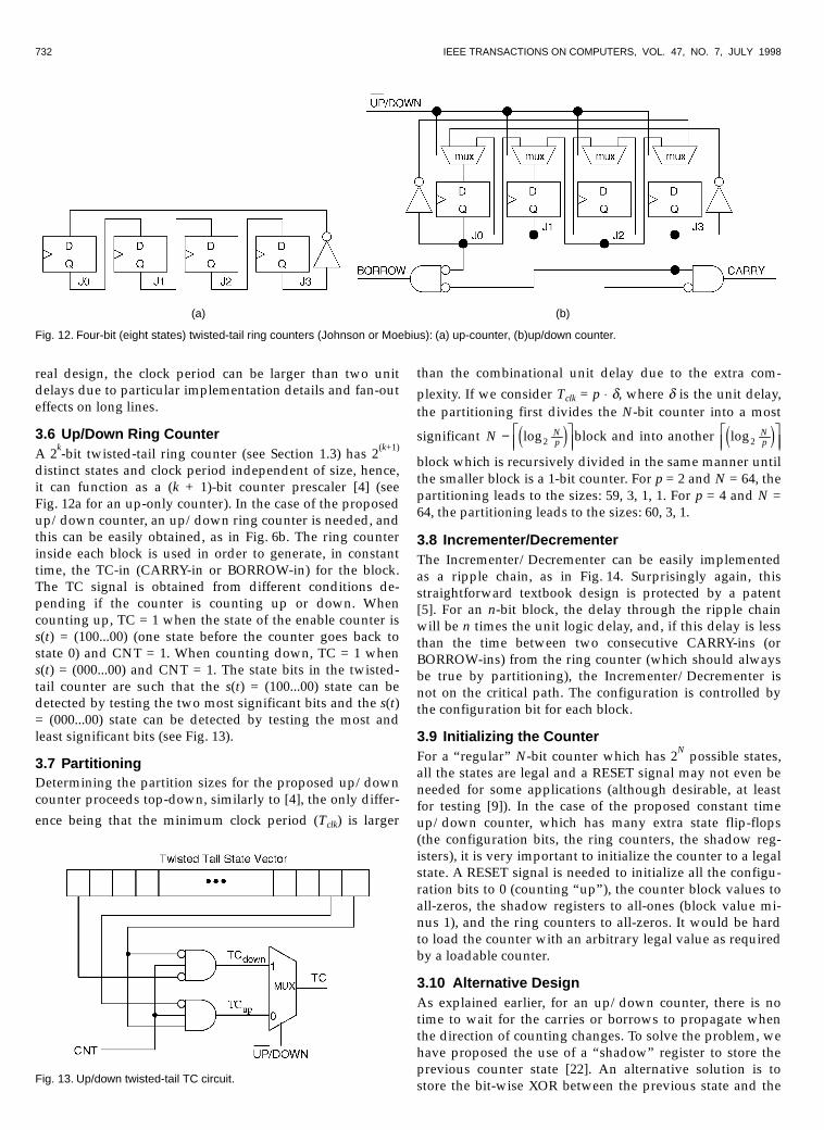
3.6 Up/Down Ring CounterA 2k-bit twisted-tail ring counter (see Section 1.3) has 2(k+1)
distinct states and clock period independent of size, hence,it can function as a (k + 1)-bit counter prescaler [4] (seeFig. 12a for an up-only counter). In the case of the proposedup/down counter, an up/down ring counter is needed, andthis can be easily obtained, as in Fig. 6b. The ring counterinside each block is used in order to generate, in constanttime, the TC-in (CARRY-in or BORROW-in) for the block.The TC signal is obtained from different conditions de-pending if the counter is counting up or down. Whencounting up, TC = 1 when the state of the enable counter iss(t) = (100...00) (one state before the counter goes back tostate 0) and CNT = 1. When counting down, TC = 1 whens(t) = (000...00) and CNT = 1. The state bits in the twisted-tail counter are such that the s(t) = (100...00) state can bedetected by testing the two most significant bits and the s(t)= (000...00) state can be detected by testing the most andleast significant bits (see Fig. 13).
3.7 PartitioningDetermining the partition sizes for the proposed up/downcounter proceeds top-down, similarly to [4], the only differ-
ence being that the minimum clock period (Tclk) is larger
than the combinational unit delay due to the extra com-
plexity. If we consider Tclk = p ◊ d, where d is the unit delay,the partitioning first divides the N-bit counter into a most
significant N Np− � "##log24 9 block and into another log2
Np4 9� "##
block which is recursively divided in the same manner untilthe smaller block is a 1-bit counter. For p = 2 and N = 64, thepartitioning leads to the sizes: 59, 3, 1, 1. For p = 4 and N =64, the partitioning leads to the sizes: 60, 3, 1.
3.8 Incrementer/DecrementerThe Incrementer/Decrementer can be easily implementedas a ripple chain, as in Fig. 14. Surprisingly again, thisstraightforward textbook design is protected by a patent[5]. For an n-bit block, the delay through the ripple chainwill be n times the unit logic delay, and, if this delay is lessthan the time between two consecutive CARRY-ins (orBORROW-ins) from the ring counter (which should alwaysbe true by partitioning), the Incrementer/Decrementer isnot on the critical path. The configuration is controlled bythe configuration bit for each block.
3.9 Initializing the CounterFor a “regular” N-bit counter which has 2N possible states,all the states are legal and a RESET signal may not even beneeded for some applications (although desirable, at leastfor testing [9]). In the case of the proposed constant timeup/down counter, which has many extra state flip-flops(the configuration bits, the ring counters, the shadow reg-isters), it is very important to initialize the counter to a legalstate. A RESET signal is needed to initialize all the configu-ration bits to 0 (counting “up”), the counter block values toall-zeros, the shadow registers to all-ones (block value mi-nus 1), and the ring counters to all-zeros. It would be hardto load the counter with an arbitrary legal value as requiredby a loadable counter.
3.10 Alternative DesignAs explained earlier, for an up/down counter, there is notime to wait for the carries or borrows to propagate whenthe direction of counting changes. To solve the problem, wehave proposed the use of a “shadow” register to store theprevious counter state [22]. An alternative solution is tostore the bit-wise XOR between the previous state and the
(a) (b)
Fig. 12. Four-bit (eight states) twisted-tail ring counters (Johnson or Moebius): (a) up-counter, (b)up/down counter.
Fig. 13. Up/down twisted-tail TC circuit.

STAN ET AL.: LONG AND FAST UP/DOWN COUNTERS 733
current state in a Carry/Borrow Register (CBReg) [23]. Withthis information available, it is possible to restore the de-sired previous state in one gate delay. For comparison, bothsolutions are presented in Fig. 16. In Fig. 16a, the carry bitthat was used in the last transition is stored in CBReg and isused in the place of the carry computed by the incre-menter/decrementer chain [23]. In Fig. 16b, the value of theprevious state is stored in a “shadow” register and can re-place the next state that is being computed by the incre-menter/decrementer [22].
3.11 Experimental ResultsThe up/down counter was implemented for both designsshown in the previous sections in two different technologies.The first design (using the Shadow Register [22]) was imple-mented in an Atmel AT6000 FPGA, while the second design(using the Carry/Borrow Register [23]) was implemented inan Xilinx XC4000 FPGA. The synthesis results were obtainedwithout imposition of constraints on the synthesis tools. Nomanual placements or routings were performed, which leavessome space for optimizations and better performance. Thecounter [23] was also tested in the EVC board with low oper-ating frequency, only to verify the counter operation.
Both designs implement a 64-bit up/down counter par-titioned into three modules with 60, 3, 1 bits that runs at40MHz in the Atmel FPGA and at 47.2MHz in the XilinxFPGA. The partitioning has resulted from the minimumclock period which is p = 4 times the minimum combina-tional delay.
A functional simulation at 40MHz of the 64-bit up/downcounter using the Atmel part is shown in Fig. 15. As can beseen, the counter counts up and down and can change di-rection each cycle.
4 CONCLUSIONS
We have presented the methodology behind designing syn-chronous up/down counters of arbitrary length with pe-riod independent of counter size, which was an openproblem until recently [25], [22], [23]. The main idea is tostore the previous state of the counter for use when thecounter reverses direction [22], [23]. A somewhat relatedidea was proposed by Hendry for storing one bit per stateto speed-up counting [6].
The experimental results for the up/down counters wereobtained using simulation for a 64-bit design and estimatesof the area and delay for other cases. It should be relativelyeasy to migrate this design to a different architecture orcounter size. Since logic synthesis tools are not going to“discover” such a design, it is best to put it in a modulelibrary which can be parameterized by the counter length.Such a design only makes sense when relatively long (morethan 24 bits) up/down counters are needed. For shortcounters, better (faster or simpler) results can be probablyobtained with other approaches which asymptotically areworse but are better for small numbers.
The proposed up/down counters are not loadable, hence,designing a constant-time loadable binary counter is still an
(a)
(b)
(c)
Fig. 14. Ripple chain: (a) incrementer (CARRY chain), (b) decrementer (BORROW chain), (c) incrementer/Decrementer.

734 IEEE TRANSACTIONS ON COMPUTERS, VOL. 47, NO. 7, JULY 1998
open problem. In the context of constant-time state ma-chines (counters being just an example), it would be inter-esting to be able to determine when a state machine canhave period O(1) just by looking at the state transitiongraph and the state encoding. Even more interesting wouldbe to determine a state encoding that enables a O(1) periodfor a given state transition graph (STG) if such an encodingexists.
ACKNOWLEDGMENTS
This research has been supported in part by the U.S. Na-tional Science Foundation Career Grant MIP-9703440 “Ad-vances in Theory, Design Methods and CAD for Low-Power VLSI,” the U.S. National Science Foundation Grant
MIP-9314172 “Arithmetic Algorithms and Structures forLow-Power Systems,” CNPq, Xilinx, and Atmel.
REFERENCES
[1]� S. Amuro, “Adjacent Code System,” U.S. Patent no. 5,329,280, July1994.
[2]� D. Chu and M. Ward, “Data Capture in an Uninterrupted Coun-ter,” U.S. Patent no. 4,519,091, May 1985.
[3]� D.H. Eby, “Synchronous Programmable Two-Stage Serial/ParallelCounter,” U.S. Patent no. 4,905,262, Feb. 1990.
[4]� M.D. Ercegovac and T. Lang, “Binary Counter with CountingPeriod of One Half Adder Independent of Counter Size,” IEEETrans. Circuits and Systems, vol. 36, pp. 924-926, June 1989.
[5]� M.W. Evans, “Minimal Logic Synchronous Up/Down CounterImplemenations for CMOS,” U.S. Patent no. 4,611,337, Sept. 1986.
[6]� D.C. Hendry, “Sequential Lookahead Method for Digital Count-ers,” Electronics Letters, vol. 32, pp. 160-161, Feb. 1996.
Fig. 15. Simulation of the 64-bit up/down counter at 40MHz. Only the six least-significant and the two most-significant bits are shown.
(a) (b)
Fig. 16. Designs of the next state generator: (a) Using carry/borrow from previous state transition, (b) using shadow register to store the previousstate bit.

STAN ET AL.: LONG AND FAST UP/DOWN COUNTERS 735
[7]� T. Iida and T. Ikarashi, “Synchronous Binary Counter,” U.S. Patentno. 4,679,216, July 1987.
[8]� J. Kalisz, R. Szplet, R. Pelka, and A. Poniecki, “Single-Chip Inter-polating Time Counter with 200-ps Resolution and 43-s Range,”IEEE Trans. Instrumentation and Measurement, vol. 46, pp. 851-856,Aug. 1997.
[9]� M. Katoozi and M. Soma, “A Testable CMOS Synchronous Coun-ter,” IEEE J. Solid-State Circuits, vol. 23, pp. 1,241-1,248, Oct. 1988.
[10]� M. Kondo and T. Watnabe, “Synchronous Counter,” U.S. Patentno. 5,526,393, June 1996.
[11]� I. Koren, Computer Arithmetic Algorithms. Englewood Cliffs, N.J.:Prentice Hall, 1993.
[12]� P. Larsson and J.R. Yuan, “Novel Carry Propagation in High-Speed Synchronous Counters and Dividers,” Electronics Letters,vol. 29, pp. 1,457-1,458, Aug. 1993.
[13]� S.-K. Lee, “Binary Counter with Sped-Up Ripple Carry,” U.S.Patent no. 5,559,844, Sept. 1996.
[14]� D.R. Lutz and D.N. Jaysimha, “Programmable Modulo-k Coun-ter,” IEEE Trans. Circuits and Systems, vol. 43, pp. 939-941, Nov.1996.
[15]� B. Norris, Digital Integrated Circuits and Operational-Amplifier andOptoelectronic Circuit Design. New York: McGraw-Hill, 1976.
[16]� K.Z. Pekmestzi and N. Thanasouras, “Systolic Frequency-DividersCounters,” IEEE Trans. Circuits and Systems, vol. 41, pp. 775-776,Nov. 1994.
[17]� W.W. Person, Error Correcting Codes. Cambridge, Mass.: MIT Press,1961.
[18]� J.M. Rabaey, Digital Integrated Circuits. Upper Saddle River, N.J.:Prentice Hall, 1996.
[19]� S.R. Ramirez, “Counter Cell and Counter Circuit,” U.S. Patent no.5,495,513, Feb. 1996.
[20]� R. Rogenmoser, Q. Huang, and F. Piazza, “1.57 GHz Asynchro-nous and 1.4 GHz Dual-Modulus 1.2 mm CMOS Prescalers,” Proc.Custom Integrated Circuits Conf., pp. 387-390, May 1994.
[21]� M.R. Stan, “Shift-Register Generators for Circular FIFOs,” Elec-tronic Eng., pp. 26-27, Feb. 1991.
[22]� M.R. Stan, “Synchronous Up/Down Counter with Period Inde-pendent of Counter Size,” Proc. IEEE Symp. Computer Arithmetic,pp. 274-281, Asilomar, Calif., July 1997.
[23]� A.F. Tenca and M.D. Ercegovac, “Synchronous Up/Down BinaryCounter for LUT FPGAs with Counting Frequency Independentof Counter Size,” Proc. Int’l Symp. FPGAs, pp. 159-165, Monterey,Calif., Feb. 1997.
[24]� J.D. Ullman, Computational Aspects of VLSI. Rockville, Md.: Com-puter Science Press, 1984.
[25]� J.E. Vuillemin, “Constant Time Arbitrary Length SynchronousBinary Counters,” Proc. IEEE Symp. Computer Arithmetic, pp. 180-183, Grenoble, France, June 1991.
[26]� K. Windmiller, “Integrated High Speed Synchronous Counterwith Asynchronous Read-Out,” U.S. Patent no. 5,045,854, Sept.1991.
[27]� Xilinx, The Programmable Logic Data Book. Aug. 1993.[28]� G. Yasar, Y. Tsyrkina, and D. Thygesen, “Fpga Fast Counter De-
sign,” Proc. Canadian Workshop FPDs, pp. 37-43, Toronto, Canada,May 1996.
[29]� J.R. Yuan, “Efficient CMOS Counter Circuits,” Electronics Letters,vol. 24, pp. 1,311-1,313, Oct. 1988.
[30]� J.R. Yuan and C. Svensson, “Fast CMOS Nonbinary Divider andCounter,” Electronics Letters, vol. 29, pp. 1,222-1,223, June 1993.
[31]� Z. Zilic, G. Lemieux, K.L.S. Brown, and Z. Vranesic, “Designingfor High Speed-Performance in cplds and fpgas,” Proc. CanadianWorkshop FPDs, Montreal, Canada, May 1995.
Mircea R. Stan (M-94) received the diploma inelectronics from the Polytechnic Institute of Bu-charest, Romania, in 1984, and the MS and PhDdegrees in electrical and computer engineeringfrom the University of Massachusetts at Amherstin 1994 and 1996, respectively. Since 1996, hehas been an assistant professor in the ElectricalEngineering Department and the Center forSemicustom Integrated Systems at the Univer-sity of Virginia. Dr. Stan is teaching and doingresearch in the areas of low-power VLSI, mixed-
mode analog and digital circuits, computer arithmetic, and embeddedsystems. Before his academic career, he accumulated eight years ofindustrial experience as an R&D engineer in Bucharest, Tokyo, andAtlanta. In 1997, Dr. Stan received the U.S. National Science Founda-tion CAREER Award for investigating low-power design techniques. Heis on the technical committees for the VLSI Design Conference and theInternational Symposium on Low Power Electronics and Design and isa member of the IEEE, the ACM, and Usenix, and also of Phi KappaPhi and Sigma Xi.
Alexandre F. Tenca received the BS and MSdegrees in electrical engineering from the Uni-versity of São Paulo (USP), Brazil, in 1981 and1990, and the MS and PhD degrees from theUniversity of California at Los Angeles, in 1994and 1998, respectively. From 1981 to 1992, heworked as a researcher at USP, developing proj-ects on distributed computer systems, computernetwork protocols, packet-switching networkcommunication nodes, and control systems. In1989, he joined the faculty group of the Com-
puter Engineering and Digital Systems Department of EscolaPolitécnica, USP, where he lectured classes in computer networks andcomputer architecture until the beginning of his doctoral studies in1992. Upon completion of his doctorate, he became an assistant pro-fessor of computer engineering at Oregon State University, Corvallis.His research interests include computer architecture, computer net-works, computer arithmetic, and reconfigurable systems.
Milos D. Ercegovac earned his BS in electricalengineering (1965) from the University of Bel-grade, Yugoslavia, and his MS (1972) and PhD(1975) in computer science from the Universityof Illinois, Urbana-Champaign. He is a professorin the Computer Science Department, School ofEngineering and Applied Science at the Univer-sity of California, Los Angeles. Dr. Ercegovacspecializes in research and teaching in digitalarithmetic, digital design, and computer systemarchitecture. His most recent research is in the
areas of arithmetic design for low power and for field programmablegate arrays (FPGAs). His research contributions have been extensivelypublished in journals and conference proceedings. He is a coauthor ofa textbook on digital design and of a monograph in the area of digitalarithmetic. Dr. Ercegovac has been involved in organizing the IEEESymposia on Computer Arithmetic. He served as an editor of the IEEETransactions on Computers and as a subject area editor for the Journalof Parallel and Distributed Computing. Dr. Ercegovac is a member ofthe ACM and the IEEE Computer Society.