7502.9043 - manual - freedom tool 6300ge software module · all references to “ freedom tool ”...
TRANSCRIPT

FREEDOM Tool
User’s Guide and Reference
for
FREEDOMWare Software Module 10
6300GE DOB Software Module
7502.9043

This is Your Software Security Access Key:
DO NOT LOSE IT !
This security device must be plugged into the notebook computer’s USB port or the spare USB port on your interface box whenever the FREEDOM Tool Software is to be run.

List of Trademarks
• Windows is a trademark / product of Microsoft Corporation. • Microsoft is a registered trademark. • Thyssen is a registered trademark of Thyssen-Krupp Elevator Corp. • WORLD electronics, the WORLD electronics' logo, FREEDOM Tool, and FREEDOMWare are
registered trademarks of WORLD electronics Sales and Service, Inc. • All other trademarks mentioned in this manual are the sole property of their respective manufacturers.
Copyright © 2011 by WORLD electronics®. All rights reserved. Printed in the United States of America. No part of this publication may be reproduced or distributed in any form or by any means, or stored in a database or retrieval system, without the prior written permission of WORLD electronics. Further, this publication and features described herein are subject to change without notice from publisher.
TABLE OF CONTENTS
Introduction .............................................................................................................................................. 1
FREEDOM Tool Features ................................................................................................................ 1
Minimum Hardware and Software Requirements ..................................................................... 1
How to Contact WORLD electronics............................................................................................. 2
Package Contents .............................................................................................................................. 3 FREEDOM Tool Interface for ThyssenKrupp 6300GE (7502.9065)................................................................. 3
Security Key (6015.0014).................................................................................................................................................... 4
Installation CD (6015.0002)................................................................................................................ 4
Instructions............................................................................................................................................... 6
Installing the 6300GE Software Module ...................................................................................... 6
Executing the FREEDOM Tool Shell Program ........................................................................11
The 6300GE Software Module...................................................................................................14
General Description ..........................................................................................................................17
Door Window......................................................................................................................................17
Adjustment Window .........................................................................................................................20
Subsystem I/O Window...................................................................................................................22
Startup Sequence .............................................................................................................................24
Door Parameters ...............................................................................................................................27
Appendix A: Using Device Manager .......................................................................................30
Appendix B: Adjustment List .......................................................................................................34
Appendix C: Subsystem I/O Bit Definitions ........................................................................35
Appendix D: Fault List .....................................................................................................................37

INTRODUCTION
1
Introduction:
The FREEDOM Tool is a sophisticated software tool which allows the operator to service various elevators and elevator control systems. The software allows the operator to simultaneously view independent operations within the elevator system by opening windows to those systems / operations of interest. The selected windows may then be left open during the maintenance / repair session and accessed when desired.
This User’s Guide and Reference, part number 7502.9043, has been written to specifically target the Thyssen 6300GE Door Operator Board control systems. All references to “FREEDOM Tool ” throughout the manual implies that it pertains solely to the 6300GE Software Module.
FREEDOM Tool Features :
The FREEDOM Tool is a Graphical User Interface (GUI) and provides all the functions necessary to service the 6300GE Door Operator Board Control system. The software runs under Microsoft’s Windows operating system and provides the following features:
• A Graphical User Interface, which makes it easy to access various adjustments, I/O, displays, Faults, and setup procedures of the Thyssen 6300GE Door Operator Board to be diagnosed.
• System adjustment parameters for the Door Operator Control System being diagnosed are presented in terms that are the industry standards within the elevator industry.
Minimum Hardware and Software Requirements :
The software is provided as a package by WORLD electronics and is installed on a PC running with Microsoft Windows based Operating systems, which have the following characteristics:
• A Pentium or equivalent microprocessor.
• Windows XP, Windows 2000, Windows Vista, or Windows 7 Operating Systems.
• CD-ROM Drive
• Mouse, Trackball, or other pointing device.
• 1 USB (Universal Serial Bus) Port
The FREEDOM Tool software is not capable of being executed without a sophisticated security key that is to be connected to the USB port of the computer or the spare USB port on the interface box at the time of the FREEDOM Tool execution.
A WORLD electronics “FREEDOM Tool Interface for ThyssenKrupp 6300GE Product” (7502.9065) box is required. This interface box provides a signal level conversion between the computer and the ThyssenKrupp 6300GE Door Operator Board, which allows them to communicate with one another.

INTRODUCTION
2
How to contact WORLD electronics:
If you are having any problems operating the FREEDOM Tool, feel free to contact us at the following location. We value you as a customer and welcome any comments concerning the use of the FREEDOM Tool.
WORLD electronics Phone: 1-800-523-0427 3000 Kutztown Road Phone: (610) 939-9800 Reading, PA 19605-2617 Fax: (610) 939-9895
E-mail:
Elevator Sales: [email protected]
Service: [email protected]
FREEDOM Tool: [email protected]
When calling WORLD electronics for assistance, have your product serial number, the model computer being used, operating system type, and the error description ready.
INTRODUCTION
3
Package Contents (Hardware Components):
FREEDOM Tool Interface for ThyssenKrupp 6300GE (750 2.9065):
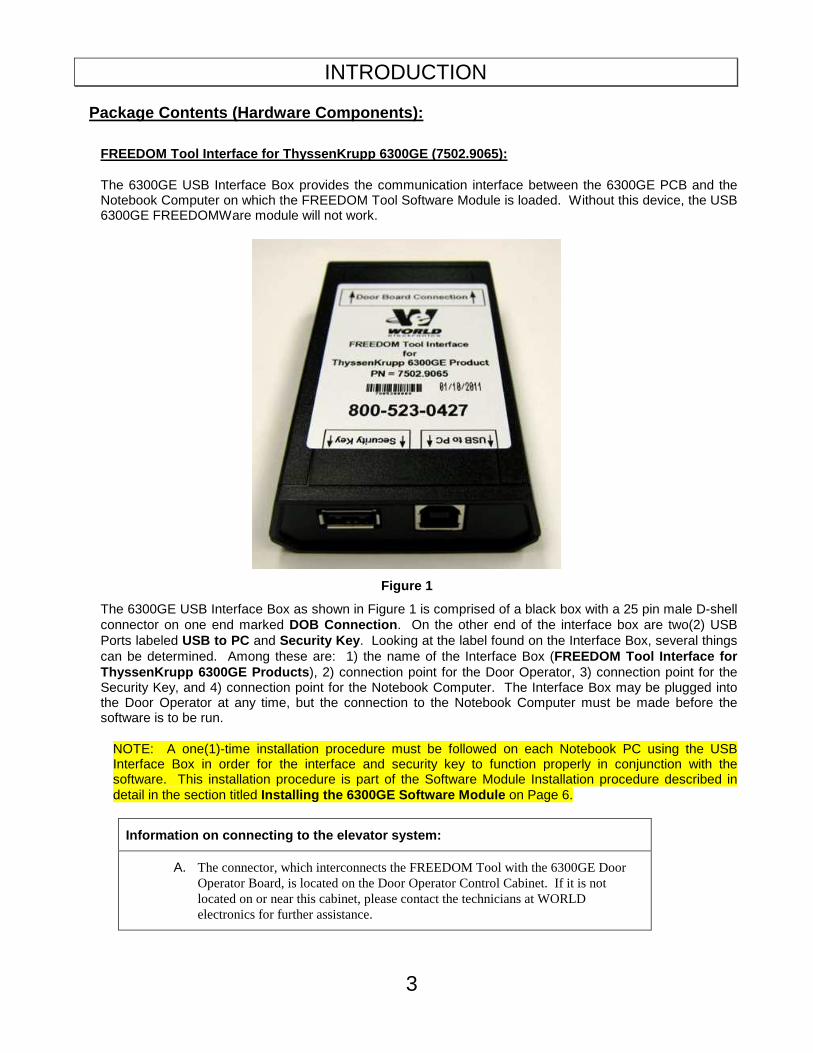
The 6300GE USB Interface Box provides the communication interface between the 6300GE PCB and the Notebook Computer on which the FREEDOM Tool Software Module is loaded. Without this device, the USB 6300GE FREEDOMWare module will not work.
Figure 1
The 6300GE USB Interface Box as shown in Figure 1 is comprised of a black box with a 25 pin male D-shell connector on one end marked DOB Connection . On the other end of the interface box are two(2) USB Ports labeled USB to PC and Security Key . Looking at the label found on the Interface Box, several things can be determined. Among these are: 1) the name of the Interface Box (FREEDOM Tool Interface for ThyssenKrupp 6300GE Products ), 2) connection point for the Door Operator, 3) connection point for the Security Key, and 4) connection point for the Notebook Computer. The Interface Box may be plugged into the Door Operator at any time, but the connection to the Notebook Computer must be made before the software is to be run.
NOTE: A one(1)-time installation procedure must be followed on each Notebook PC using the USB Interface Box in order for the interface and security key to function properly in conjunction with the software. This installation procedure is part of the Software Module Installation procedure described in detail in the section titled Installing the 6300GE Software Module on Page 6.
Information on connecting to the elevator system:
A. The connector, which interconnects the FREEDOM Tool with the 6300GE Door Operator Board, is located on the Door Operator Control Cabinet. If it is not located on or near this cabinet, please contact the technicians at WORLD electronics for further assistance.
INTRODUCTION
4
Security Key (6015.0014):
Figure 2
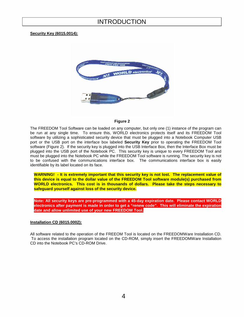
The FREEDOM Tool Software can be loaded on any computer, but only one (1) instance of the program can be run at any single time. To ensure this, WORLD electronics protects itself and its FREEDOM Tool software by utilizing a sophisticated security device that must be plugged into a Notebook Computer USB port or the USB port on the interface box labeled Security Key prior to operating the FREEDOM Tool software (Figure 2). If the security key is plugged into the USB Interface Box, then the Interface Box must be plugged into the USB port of the Notebook PC. This security key is unique to every FREEDOM Tool and must be plugged into the Notebook PC while the FREEDOM Tool software is running. The security key is not to be confused with the communications interface box. The communications interface box is easily identifiable by its label located on its face.
WARNING! - It is extremely important that this sec urity key is not lost. The replacement value of this device is equal to the dollar value of the FRE EDOM Tool software module(s) purchased from WORLD electronics. This cost is in thousands of do llars. Please take the steps necessary to safeguard yourself against loss of the security dev ice.
Note: All security keys are pre-programmed with a 4 5-day expiration date. Please contact WORLD electronics after payment is made in order to get a “renew code”. This will eliminate the expiration date and allow unlimited use of your new FREEDOM To ol.
Installation CD (6015.0002):
All software related to the operation of the FREEOM Tool is located on the FREEDOMWare Installation CD. To access the installation program located on the CD-ROM, simply insert the FREEDOMWare Installation CD into the Notebook PC’s CD-ROM Drive.

INTRODUCTION
5
Figure 3
Upon insertion, the installation program should launch allowing the user access to the installation routines and reference manuals for all available FREEDOM Tool Software Modules (Figure 3). Please refer to the section labeled Installing the 6300GE Software Module for instructions on installing the 6300GE Software Module.

INSTRUCTIONS
6
Instructions:
Installing the 6300GE Software Module:
IMPORTANT: DO NOT PLUG THE 6300GE INTERFACE OR SEC URITY KEY INTO THE NOTEBOOK COMPUTER UNTIL STEP 8 OF THIS INSTALLATION IS REACH ED. STEP 8 WILL GIVE DETAILS ON PROPERLY CONNECTING THE HARDWARE DEVICES AND PROPER LY INSTALLING THEIR RESPECTIVE HARDWARE DRIVERS!
The installation procedure for the 6300GE Software Module is described as follows:
1. Insert the FREEDOMWare Installation CD into the Notebook PC’s CD-ROM Drive. After approximately 10 seconds, a window will appear titled FREEDOMWare – FREEDOM Tool Software Module Installer . Please refer to Figure 4.
Figure 4
If this window does not appear please do the following: a) Select Start . b) Select Run . c) Type the following into the field: d:\startup.exe (Note: substitute “d:” with the Notebook Pc’s desi gnation for the CD-ROM Drive) d. Click OK with the PC’s pointing device and the installation program will run.
2. After selecting the Install pushbutton associated with the 6300GE section of the FREEDOMWare Installer, the Install Shield Wizard will run showing a window similar to the one shown in Figure 5. To continue with the setup of the 6300GE software module simply click the Next pushbutton with the PC’s pointing device.
INSTRUCTIONS
7
Figure 5
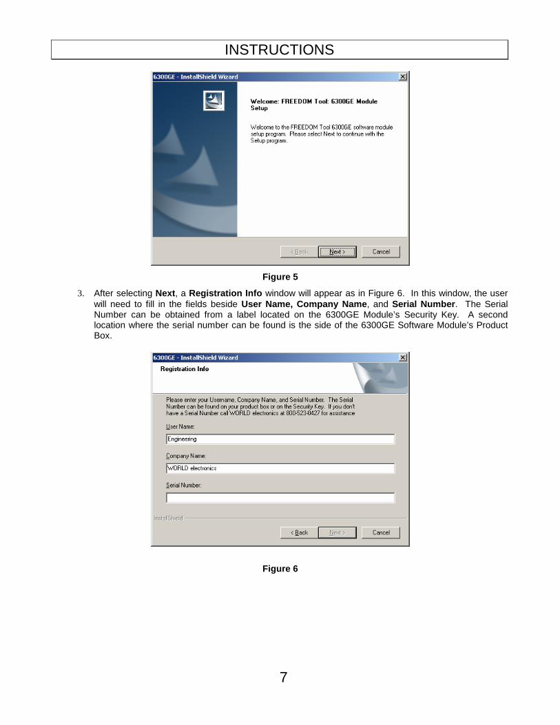
3. After selecting Next , a Registration Info window will appear as in Figure 6. In this window, the user will need to fill in the fields beside User Name, Company Name , and Serial Number . The Serial Number can be obtained from a label located on the 6300GE Module’s Security Key. A second location where the serial number can be found is the side of the 6300GE Software Module’s Product Box.
Figure 6

INSTRUCTIONS
8
4. After entering all the information into the three separate fields, the Next pushbutton will appear allowing the installation to continue (Refer to Figure 7). Select Next to continue with the installation.
Figure 7
5. The Ready to Install the Program window will now appear as in Figure 8. This window informs the user that the installation is ready to begin and instructs the user to select the Install pushbutton to begin the software installation process. At this time select, the Install pushbutton with the PC’s pointing device.
Figure 8
INSTRUCTIONS
9
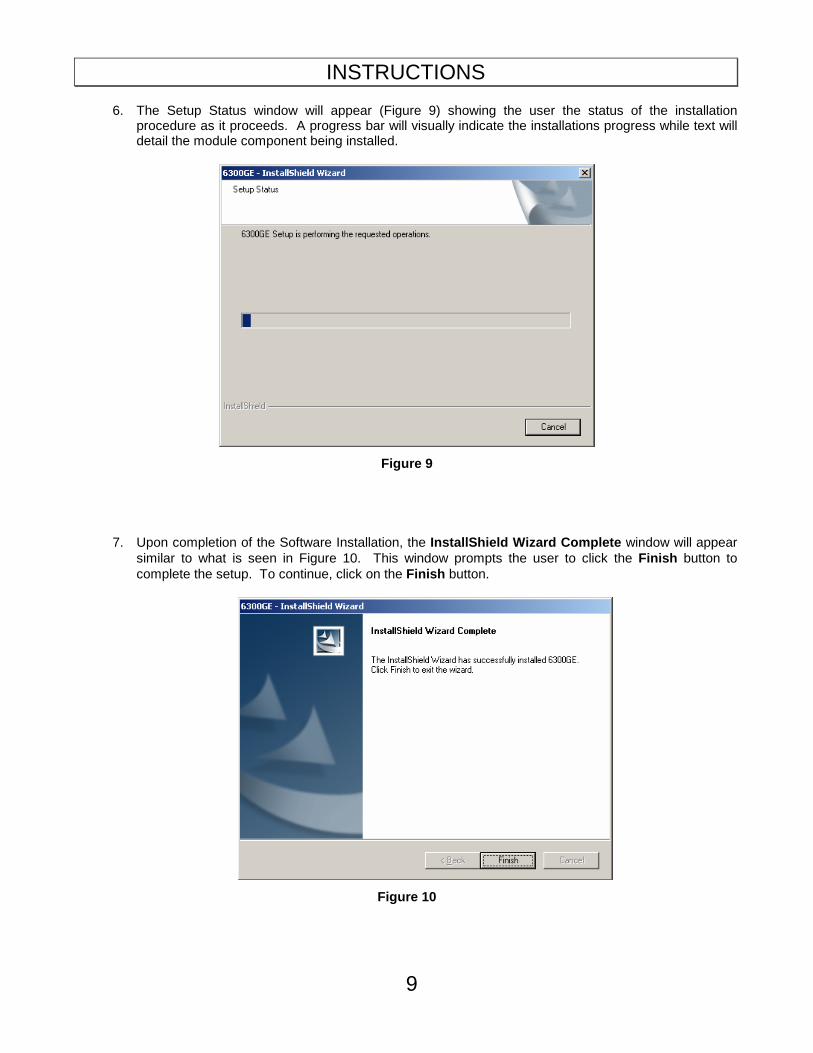
6. The Setup Status window will appear (Figure 9) showing the user the status of the installation procedure as it proceeds. A progress bar will visually indicate the installations progress while text will detail the module component being installed.
Figure 9
7. Upon completion of the Software Installation, the InstallShield Wizard Complete window will appear similar to what is seen in Figure 10. This window prompts the user to click the Finish button to complete the setup. To continue, click on the Finish button.
Figure 10

INSTRUCTIONS
10
8. Upon clicking Finish, the Installation Procedure will continue with the installation of the hardware devices. The first of these required hardware devices is the 6300GE Interface Box. The 6300GE Interface Box utilizes a device manufactured by Silicon Laboratories that requires drivers to be installed onto the FREEDOM Tool laptop. A figure similar to Figure 11 will appear allowing the user to install the drivers for the Silicon Laboratories part.
Figure 11
9. In order to begin the installation of the Silicon Laboratories Drivers select the pushbutton labeled Install . The computer will proceed with the installation of the Silicon Laboratories Device Drivers. Upon completion of the Install, a window will appear informing the user that the computer must be reset for the drivers to take effect. Refer to Figure 12. At this time, select Yes to complete the installation and restart the computer.
Figure 12
If drivers are already installed on the connected computer, a window similar to what is shown in Figure 13 will appear. This window indicates that drivers are already installed, current, and up to date. This means the user does not need to install any further software for the 6300GE Interface box to work properly. Select OK to complete the installation of the drivers for the Silicon Laboratories part.
Figure 13
10. Make sure the BLUE USB Security key with WORLD electronics lanyard IS NOT plugged into the 6300GE Interface box.

INSTRUCTIONS
11
11. Insert the WHITE USB cable of the 6300GE Interface Box into an available USB port on the computer.
12. Upon insertion of the white USB cable, several “balloon” messages will pop up. The first will be a “New Hardware Found” message. It will be followed by a message indicating that the computer is installing drivers for a Silicon Labs USB to UART bridge controller. The final balloon will indicate that the Hardware has been installed and is ready to use. At this point, the 6300GE USB Interface box is ready to be used.
13. Plug the USB Security Key into the available port on the 6300GE Interface Box.
14. Upon insertion of the Blue USB Security key into the available USB port on the 6300GE Interface Box, a balloon message will pop up on the Windows toolbar stating that Device Drivers are being installed. Notice that the LED on the Security Key is flashing green. After a minute or so, the balloon message should update indicating the device drivers have been installed and the device is now ready to be used. The LED on the Security key should now be a Steady Green. If this is the case, all hardware necessary for connecting to the 6300GE Door Operator using the 6300GE Software module has been successfully installed. The user may proceed to Executing the FREEDOM Tool Shell Program section of this manual.
Executing the FREEDOM Tool Shell Program :
The start up procedure of the WORLD electronics’ FREEDOM Tool is described as follows:
1. Make sure the security key is installed on the USB port of the 6300GE Interface Box. If the security key is plugged into the USB port located on the 6300GE4 USB Interface Box, then make sure the interface box is plugged into a USB port on the Notebook PC.
2. From the Microsoft Windows Desktop Screen select the FREEDOM Tool Icon by using the pointing device to position the cursor directly over the FREEDOM Tool Icon and double clicking the pointing device button. Refer to Figure 14.

INSTRUCTIONS
12
Figure 14
3. Double clicking the FREEDOM Tool Icon will run the main FREEDOM Tool Application software. This software allows the user to select the various FREEDOMWare modules that WORLD electronics has available. Refer to Figure 15.
Figure 15
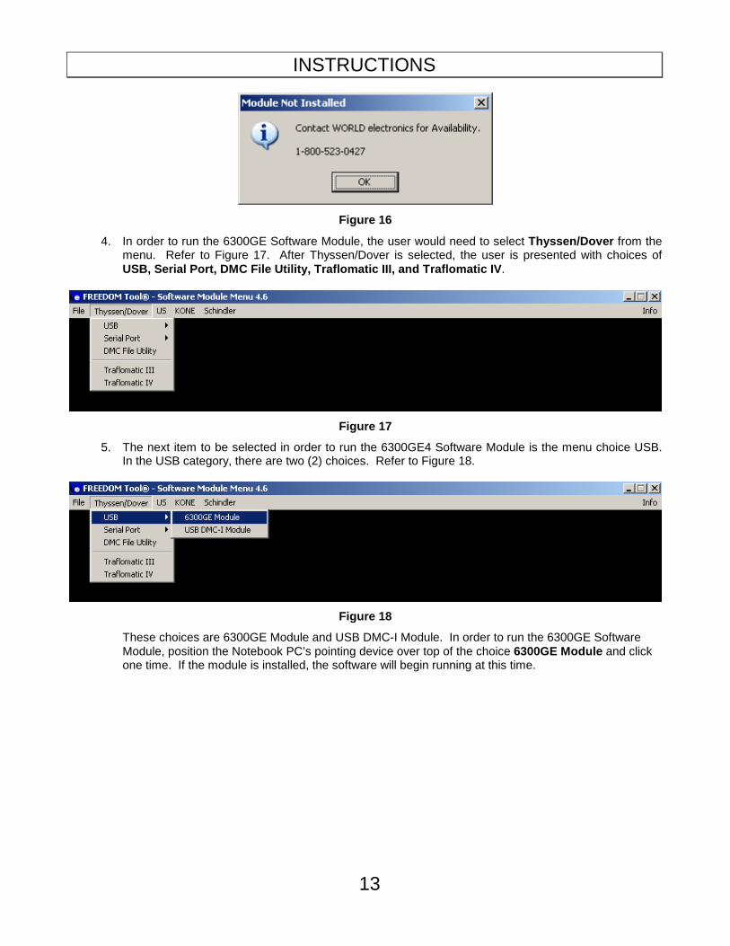
NOTE: Only installed FREEDOMWare software will run. If the module selected is not installed a window will appear as in Figure 16 informing the user that the Module is not installed and to contact WORLD electronics. If this window appears and the software was purchased from WORLD electronics, then contact a member of WORLD electronics’ technical support staff. If the software was not purchased, it can be purchased by contacting WORLD electronics’ Sales Staff. The contact information on both of these departments can be found on Page 2 of this manual.
INSTRUCTIONS
13
Figure 16
4. In order to run the 6300GE Software Module, the user would need to select Thyssen/Dover from the menu. Refer to Figure 17. After Thyssen/Dover is selected, the user is presented with choices of USB, Serial Port, DMC File Utility, Traflomatic III , and Traflomatic IV .
Figure 17
5. The next item to be selected in order to run the 6300GE4 Software Module is the menu choice USB. In the USB category, there are two (2) choices. Refer to Figure 18.
Figure 18
These choices are 6300GE Module and USB DMC-I Module. In order to run the 6300GE Software Module, position the Notebook PC’s pointing device over top of the choice 6300GE Module and click one time. If the module is installed, the software will begin running at this time.
THE 6300GE SOFTWARE MODULE
14
The 6300GE Software Module:
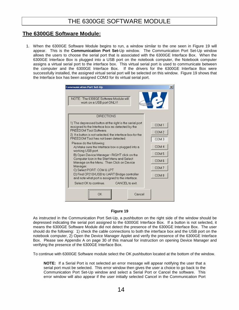
1. When the 6300GE Software Module begins to run, a window similar to the one seen in Figure 19 will appear. This is the Communication Port Set- Up window. The Communication Port Set-Up window allows the users to choose the serial port that is associated with the 6300GE Interface Box. When the 6300GE Interface Box is plugged into a USB port on the notebook computer, the Notebook computer assigns a virtual serial port to the interface box. This virtual serial port is used to communicate between the computer and the 6300GE Interface Box. If the drivers for the 6300GE Interface Box were successfully installed, the assigned virtual serial port will be selected on this window. Figure 19 shows that the Interface box has been assigned COM3 for its virtual serial port.
Figure 19
As instructed in the Communication Port Set-Up, a pushbutton on the right side of the window should be depressed indicating the serial port assigned to the 6300GE Interface Box. If a button is not selected, it means the 6300GE Software Module did not detect the presence of the 6300GE Interface Box. The user should do the following: 1) check the cable connections to both the interface box and the USB port on the notebook computer, 2) Open the Device Manager Applet and verify the presence of the 6300GE Interface Box. Please see Appendix A on page 30 of this manual for instruction on opening Device Manager and verifying the presence of the 6300GE Interface Box.
To continue with 6300GE Software module select the OK pushbutton located at the bottom of the window.
NOTE: If a Serial Port is not selected an error message will appear notifying the user that a serial port must be selected. This error window then gives the user a choice to go back to the Communication Port Set-Up window and select a Serial Port or Cancel the software. This error window will also appear if the user initially selected Cancel in the Communication Port
THE 6300GE SOFTWARE MODULE
15
Set-Up window. Figure 20 shows the error window that appears if a Serial Port is not selected.
Figure 20
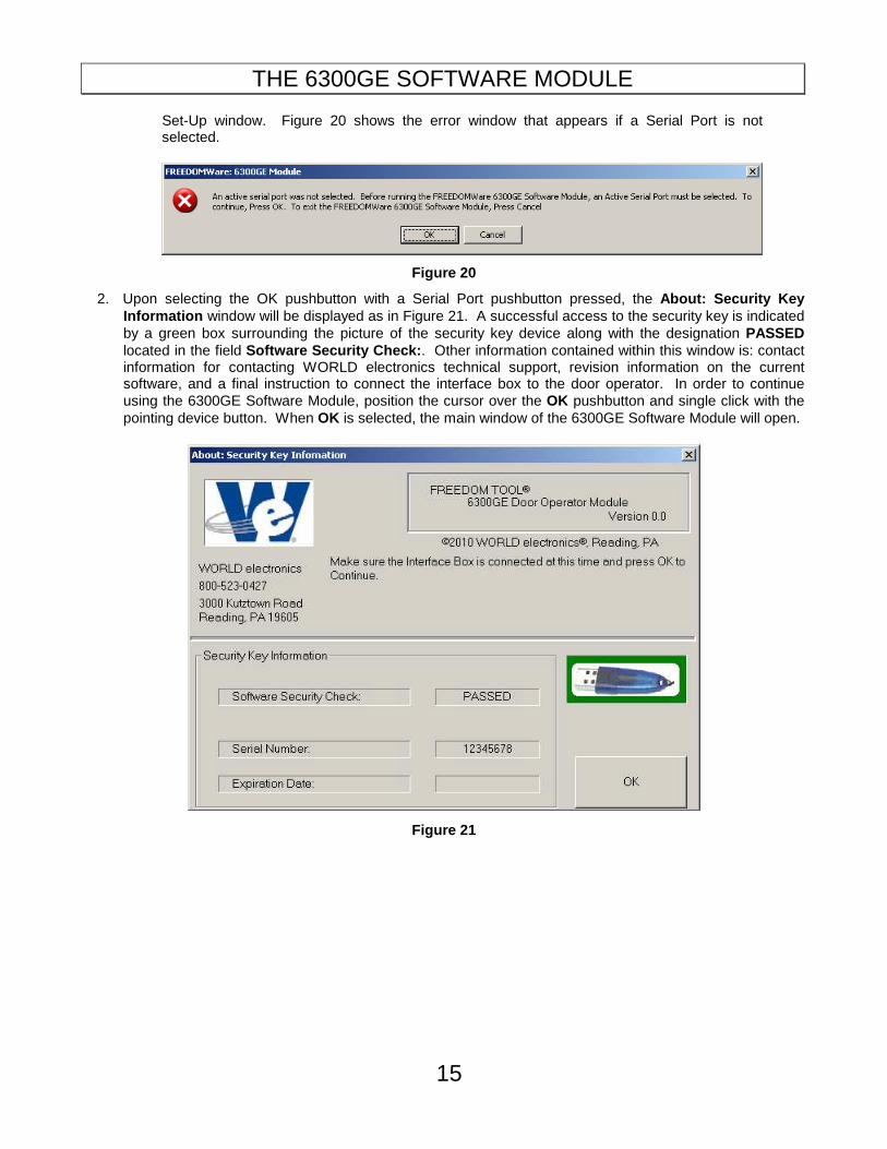
2. Upon selecting the OK pushbutton with a Serial Port pushbutton pressed, the About: Security Key Information window will be displayed as in Figure 21. A successful access to the security key is indicated by a green box surrounding the picture of the security key device along with the designation PASSED located in the field Software Security Check: . Other information contained within this window is: contact information for contacting WORLD electronics technical support, revision information on the current software, and a final instruction to connect the interface box to the door operator. In order to continue using the 6300GE Software Module, position the cursor over the OK pushbutton and single click with the pointing device button. When OK is selected, the main window of the 6300GE Software Module will open.
Figure 21
THE 6300GE SOFTWARE MODULE
16
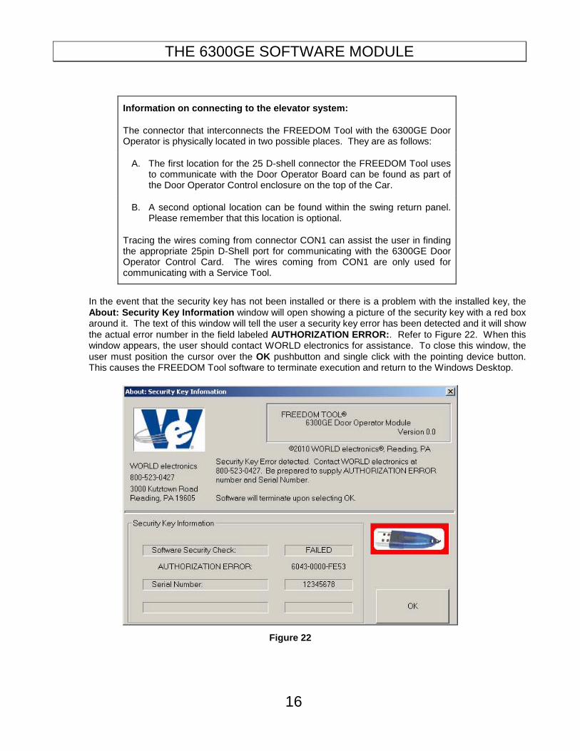
Information on connecting to the elevator system:
The connector that interconnects the FREEDOM Tool with the 6300GE Door Operator is physically located in two possible places. They are as follows:
A. The first location for the 25 D-shell connector the FREEDOM Tool uses to communicate with the Door Operator Board can be found as part of the Door Operator Control enclosure on the top of the Car.
B. A second optional location can be found within the swing return panel. Please remember that this location is optional.
Tracing the wires coming from connector CON1 can assist the user in finding the appropriate 25pin D-Shell port for communicating with the 6300GE Door Operator Control Card. The wires coming from CON1 are only used for communicating with a Service Tool.
In the event that the security key has not been installed or there is a problem with the installed key, the About: Security Key Information window will open showing a picture of the security key with a red box around it. The text of this window will tell the user a security key error has been detected and it will show the actual error number in the field labeled AUTHORIZATION ERROR: . Refer to Figure 22. When this window appears, the user should contact WORLD electronics for assistance. To close this window, the user must position the cursor over the OK pushbutton and single click with the pointing device button. This causes the FREEDOM Tool software to terminate execution and return to the Windows Desktop.
Figure 22
GENERAL DESCRIPTION: Door Window
17
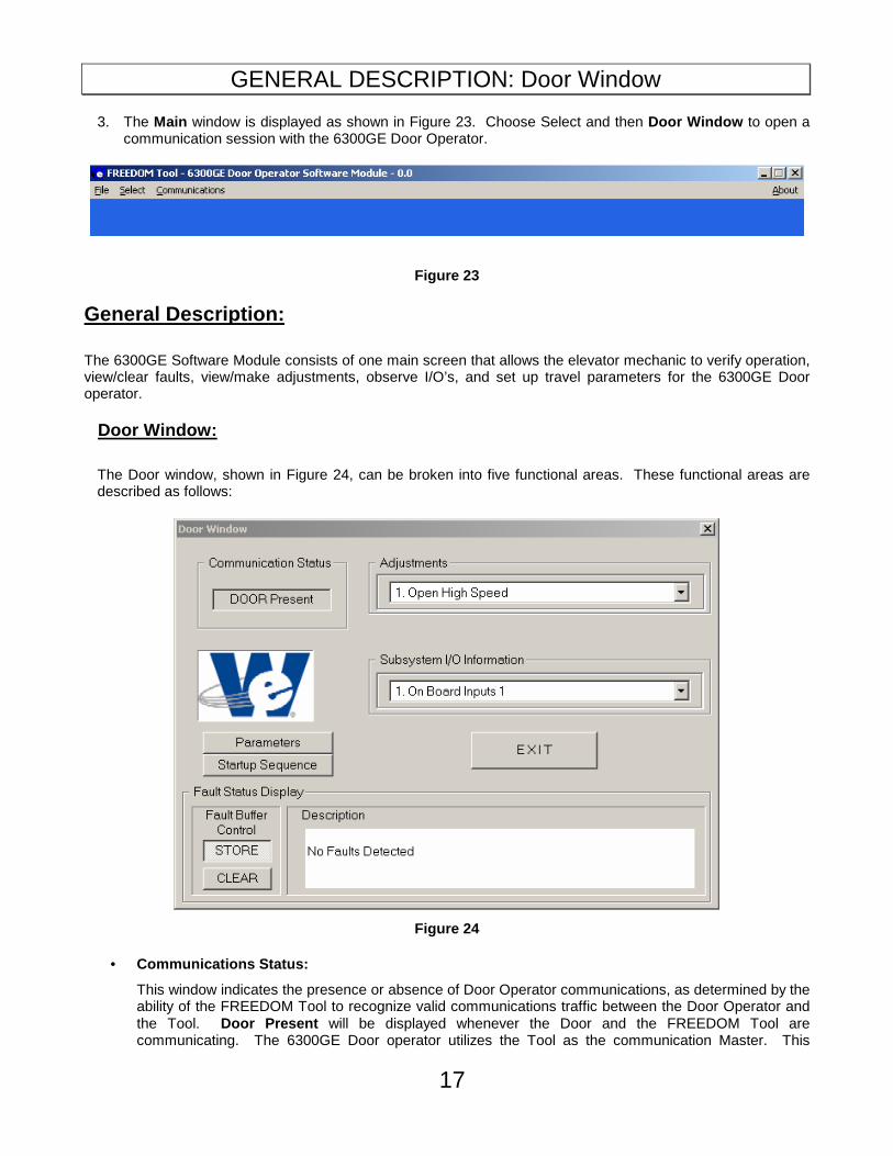
3. The Main window is displayed as shown in Figure 23. Choose Select and then Door Window to open a communication session with the 6300GE Door Operator.
Figure 23
General Description:
The 6300GE Software Module consists of one main screen that allows the elevator mechanic to verify operation, view/clear faults, view/make adjustments, observe I/O’s, and set up travel parameters for the 6300GE Door operator.
Door Window:
The Door window, shown in Figure 24, can be broken into five functional areas. These functional areas are described as follows:
Figure 24
• Communications Status:
This window indicates the presence or absence of Door Operator communications, as determined by the ability of the FREEDOM Tool to recognize valid communications traffic between the Door Operator and the Tool. Door Present will be displayed whenever the Door and the FREEDOM Tool are communicating. The 6300GE Door operator utilizes the Tool as the communication Master. This

GENERAL DESCRIPTION: Door Window
18
means the 6300GE Door Operator Board will not place any communications onto the bus until a tool such as the FREEDOM Tool 6300GE Software Module instructs the 6300GE Door Operator Board. In the event that communications cannot be established or is broken the message displayed in the window will be Door Absent , where appropriate.
• Adjustments:
This window displays a combination drop down box, which gives the user the ability to select one of several adjustments associated with the Door. Please see Appendix B on page 34 for a list of available adjustments used by the FREEDOM Tool 6300GE Software Module. The combo box will drop down a partial listing of adjustments when the cursor is positioned within the combo box or positioned on the down arrow symbol and a single click of the pointing device is performed. The drop down options can be selected by clicking once with the pointing device button while the cursor is positioned on the desired option. Refer to Figure 25.
Figure 25
• Subsystem I/O Information:
The Subsytem I/O Information section of the Door Window contains a combination drop down box, which gives the user the ability to select one of several I/O data ports within the 6300GE Door Operator system in order to examine current I/O statuses. Appendix C on page 35 lists the I/O ports along with corresponding I/O signals used in the 6300GE Software Module. Upon selection with the computer’s pointing device, this combo box will drop down a list of selections. One of these drop down selections can be chosen by clicking once with the pointing device button while the cursor is positioned on the desired option. Refer to Figure 26.

GENERAL DESCRIPTION: Door Window
19
Figure 26
• Fault Status Display:
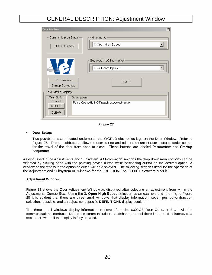
The lower section of the Door Window contains an area titled Fault Status Display . The Fault Status Display as shown in Figure 27 is broken into two (2) sections. The first section, Fault Buffer Control, contains two pushbuttons that control whether the 6300GE Door Operator Board retains faults or immediately dumps them. These pushbuttons are labeled STORE and CLEAR . The second section of the Fault Status display, labeled Description , lists all current faults for the 6300GE Door Operator Board the FREEDOM Tool Software Module is in communication. The most current fault would be at the top of the list. When more faults are in the buffer than can be displayed in the Description window, scroll arrows will appear on the right side of the Description field. Appendix D on Page 37 lists the faults that can appear within the description pane of the Fault Status Display.
GENERAL DESCRIPTION: Adjustment Window
20
Figure 27
• Door Setup:
Two pushbuttons are located underneath the WORLD electronics logo on the Door Window. Refer to Figure 27. These pushbuttons allow the user to see and adjust the current door motor encoder counts for the travel of the door from open to close. These buttons are labeled Parameters and Startup Sequence .
As discussed in the Adjustments and Subsystem I/O Information sections the drop down menu options can be selected by clicking once with the pointing device button while positioning cursor on the desired option. A window associated with the option selected will be displayed. The following sections describe the operation of the Adjustment and Subsystem I/O windows for the FREEDOM Tool 6300GE Software Module.
Adjustment Window:
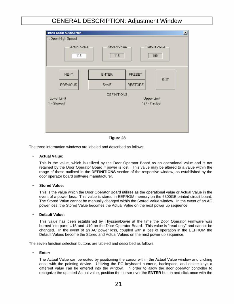
Figure 28 shows the Door Adjustment Window as displayed after selecting an adjustment from within the Adjustments Combo Box. Using the 1. Open High Speed selection as an example and referring to Figure 28 it is evident that there are three small windows that display information, seven pushbutton/function selections possible, and an adjustment specific DEFINITIONS display section.
The three small windows display information retrieved from the 6300GE Door Operator Board via the communications interface. Due to the communications handshake protocol there is a period of latency of a second or two until the display is fully updated.
GENERAL DESCRIPTION: Adjustment Window
21
Figure 28
The three information windows are labeled and described as follows:
• Actual Value:
This is the value, which is utilized by the Door Operator Board as an operational value and is not retained by the Door Operator Board if power is lost. This value may be altered to a value within the range of those outlined in the DEFINITIONS section of the respective window, as established by the door operator board software manufacturer.
• Stored Value:
This is the value which the Door Operator Board utilizes as the operational value or Actual Value in the event of a power loss. This value is stored in EEPROM memory on the 6300GE printed circuit board. The Stored Value cannot be manually changed within the Stored Value window. In the event of an AC power loss, the Stored Value becomes the Actual Value on the next power up sequence.
• Default Value:
This value has been established by Thyssen/Dover at the time the Door Operator Firmware was burned into parts U15 and U19 on the Door Operator Board. This value is “read only” and cannot be changed. In the event of an AC power loss, coupled with a loss of operation in the EEPROM the Default Values become the Stored and Actual Values on the next power up sequence.
The seven function selection buttons are labeled and described as follows:
• Enter:
The Actual Value can be edited by positioning the cursor within the Actual Value window and clicking once with the pointing device. Utilizing the PC keyboard numeric, backspace, and delete keys a different value can be entered into the window. In order to allow the door operator controller to recognize the updated Actual value, position the cursor over the ENTER button and click once with the
GENERAL DESCRIPTION: Subsystem I/O Window
22
pointing device.
• Save:
If it is desired that the Stored Value be updated, whereby the Stored Value is replaced with the Actual Value , position the cursor over the SAVE button and click once with the pointing device.
• Restore:
The function of the RESTORE button is to update the Actual Value with the Stored Value. Simply position the cursor over the RESTORE button and click once with the pointing device.
• Preset:
Positioning the cursor over the PRESET button and clicking once with the pointing device will cause the Actual Value to be replaced with the Default Value.
• Previous:
The PREVIOUS button is used to move backward (n-1, where n is the number associated with the present option viewed) to the previous option without going back to the original selection window. To execute the PREVIOUS function, position the cursor over the PREVIOUS button and click once with the pointing device.
• Next:
The NEXT button is used to move forward (n+1, where n is the number associated with the present option viewed) to the next option without going back to the original selection window. To execute the NEXT function, position the cursor over the NEXT button and click once with the pointing device.
• Exit:
The EXIT button will leave the active window and return to the window detailing the list of the option selections. To execute the EXIT function, position the cursor over the EXIT button and click once with the pointing device.
The DEFINITONS section of the Adjustment Window has the function of providing the user information on the upper and lower limits of the range of value for the selected adjustment along with an indication of the units for the adjustment value. This DEFINITIONS section is located within the bottom half of the Adjustment Window for each adjustment.
Subsystem I/O Information Display Window:
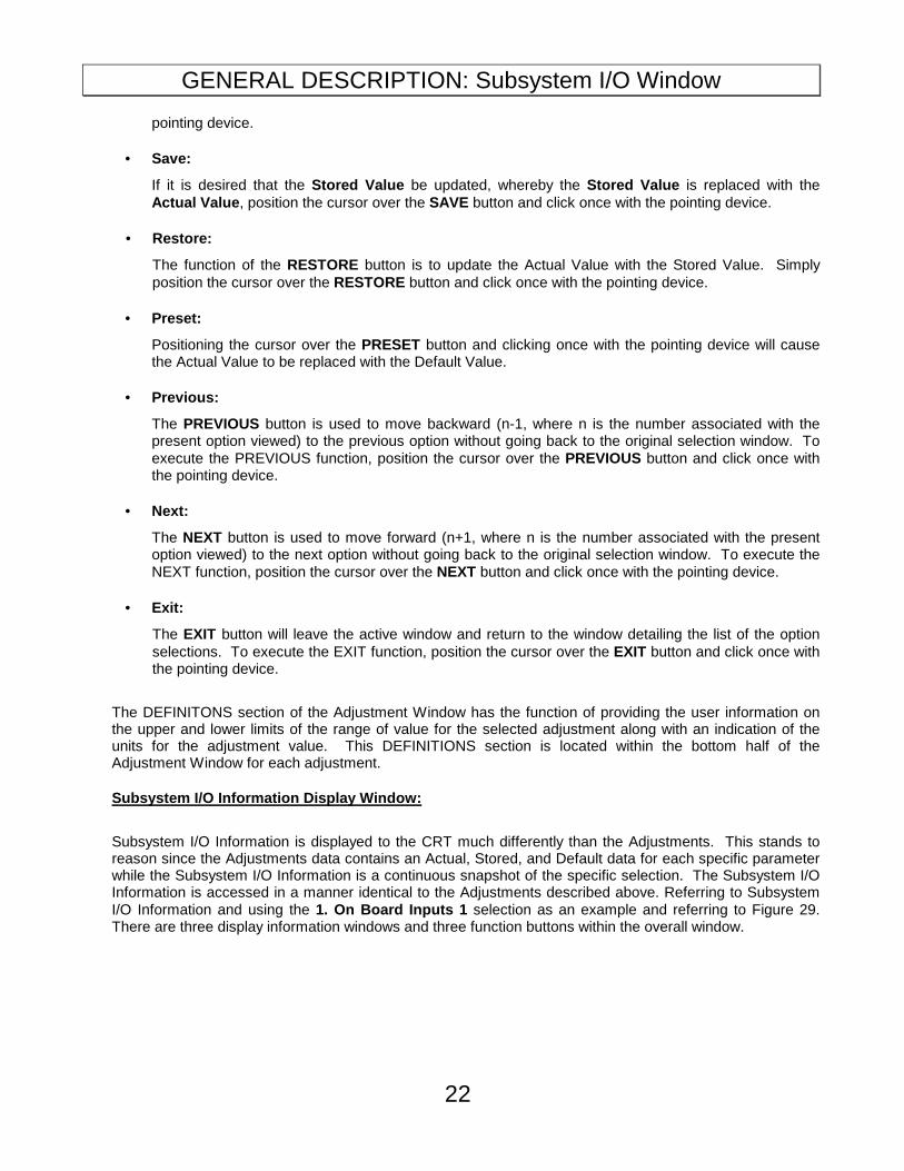
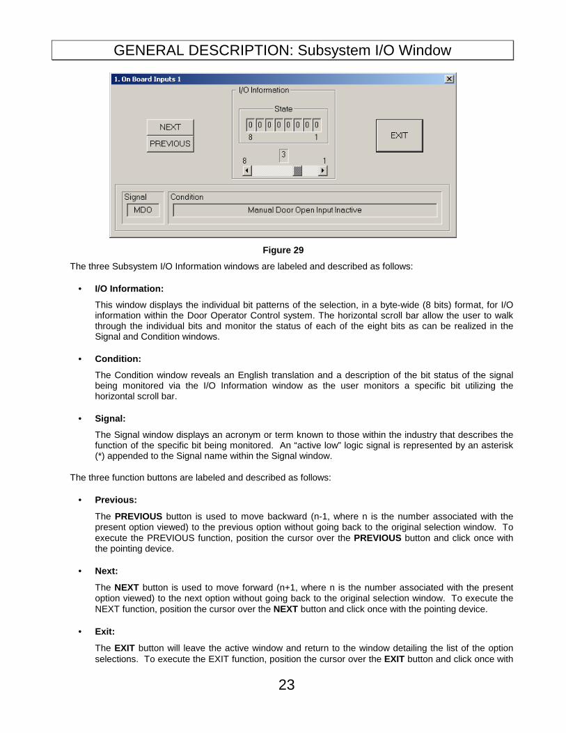
Subsystem I/O Information is displayed to the CRT much differently than the Adjustments. This stands to reason since the Adjustments data contains an Actual, Stored, and Default data for each specific parameter while the Subsystem I/O Information is a continuous snapshot of the specific selection. The Subsystem I/O Information is accessed in a manner identical to the Adjustments described above. Referring to Subsystem I/O Information and using the 1. On Board Inputs 1 selection as an example and referring to Figure 29. There are three display information windows and three function buttons within the overall window.
GENERAL DESCRIPTION: Subsystem I/O Window
23
Figure 29
The three Subsystem I/O Information windows are labeled and described as follows:
• I/O Information:
This window displays the individual bit patterns of the selection, in a byte-wide (8 bits) format, for I/O information within the Door Operator Control system. The horizontal scroll bar allow the user to walk through the individual bits and monitor the status of each of the eight bits as can be realized in the Signal and Condition windows.
• Condition:
The Condition window reveals an English translation and a description of the bit status of the signal being monitored via the I/O Information window as the user monitors a specific bit utilizing the horizontal scroll bar.
• Signal:
The Signal window displays an acronym or term known to those within the industry that describes the function of the specific bit being monitored. An “active low” logic signal is represented by an asterisk (*) appended to the Signal name within the Signal window.
The three function buttons are labeled and described as follows:
• Previous:
The PREVIOUS button is used to move backward (n-1, where n is the number associated with the present option viewed) to the previous option without going back to the original selection window. To execute the PREVIOUS function, position the cursor over the PREVIOUS button and click once with the pointing device.
• Next:
The NEXT button is used to move forward (n+1, where n is the number associated with the present option viewed) to the next option without going back to the original selection window. To execute the NEXT function, position the cursor over the NEXT button and click once with the pointing device.
• Exit:
The EXIT button will leave the active window and return to the window detailing the list of the option selections. To execute the EXIT function, position the cursor over the EXIT button and click once with

GENERAL DESCRIPTION: Startup Sequence
24
the pointing device.
The main Door window also consists of two pushbuttons labeled Parameters and Startup Sequence .
Startup Sequence:
The Door Startup Sequence procedure is used to learn the encoder counts on a complete cycle of the door. The procedure for performing a Door Startup Sequence is described as follows:
Prior to executing the Door Startup Sequence procedure, the following conditions must be met:
1. The car must be placed on inspection. 2. The car must be at any floor level. 3. Make sure the OD and CD signals going to the 6300GE are inactive(Usually done simply by setting
car to Auto)
4. PHV and GHV must be present at Door Board.
1. If the Door module is present and the user positions the cursor on the Startup Sequence pushbutton and clicks one time with the pointing device the Startup Sequence window will be displayed as shown in Figure 30. A prompt is displayed reminding the user that the care needs to be placed on Inspection along with making sure the signals Open Door (OD) and Close Door (CD) are disabled coming from the car controller to the Door Operator. The 1st window in the Door Startup Sequence also reminds the user that power for the Door Motor must be available through the PHV/GHV signals. To continue the Door Startup Sequence the user enables the ENTER function by positioning the cursor on the ENTER button and clicking once with the pointing device. If it is not desirable to continue, but desirable to exit the Door Startup Sequence then position the cursor on the EXIT button and click once with the pointing device.
Figure 30
2. A second Door Startup window replaces the first Door Startup window and prompts the user that the Door Parameters will be cleared on enabling the ENTER function. This is done by positioning the

GENERAL DESCRIPTION: Startup Sequence
25
cursor on the ENTER button and clicking once with the pointing device. If it is not desirable to continue, but desirable to exit the Door Startup Sequence then position the cursor on the EXIT button and click once with the pointing device. Refer to Figure 31.
Figure 31
3. A third Door Startup window replaces the second Door Startup window and prompts the user that the Door Parameters have been reset, that the Door is ready for setup. The third Door Startup window then instructs the user to press and hold both the Manual Door Open and Manual Door Close pushbuttons at the same time. These two (2) pushbuttons are located beside connector CON1. Upon simultaneously pressing these pushbuttons, the door should begin to cycle. The user should allow the door to cycle one complete time.(Usually the Door will cycle 1 – 1.5 times and stop). Once this is done, the user will select the ENTER pushbutton using the computer’s pointing device and button and progress to the next step in the door Startup Sequence procedure. If it is not desirable to continue, but desirable to exit the Door Startup then position the cursor on the EXIT button and click once with the pointing device. Refer to Figure 32.

GENERAL DESCRIPTION: Startup Sequence
26
Figure 32
4. A fourth Door Startup window replaces the third Door Startup window and prompts the user to save pulse counts by enabling the ENTER function by positioning the cursor on the ENTER button and clicking once with the pointing device. If it is not desirable to continue, but desirable to exit the Door Startup then position the cursor on the EXIT button and click once with the pointing device. Refer to Figure 33.
Figure 33
To summarize, the steps required to perform a Door Startup Sequence are as follows:
GENERAL DESCRIPTION: Door Parameters
27
1. Meet startup conditions. 2. A reset Door Parameters via the ENTER function. 3. Allow the doors to cycle one (1) complete time by simultaneously pressing the Manual Door Open and
Manual Door Close buttons located near CON1 on the 6300GE Door Operator Board. Upon completion of one(1) cycle, press ENTER
4. An ENTER function is required to save the pulse counts, complete the Door Startup Sequence operation, and return to the main Door window.
Door Parameters:
The Door Parameters procedure is described as follows:
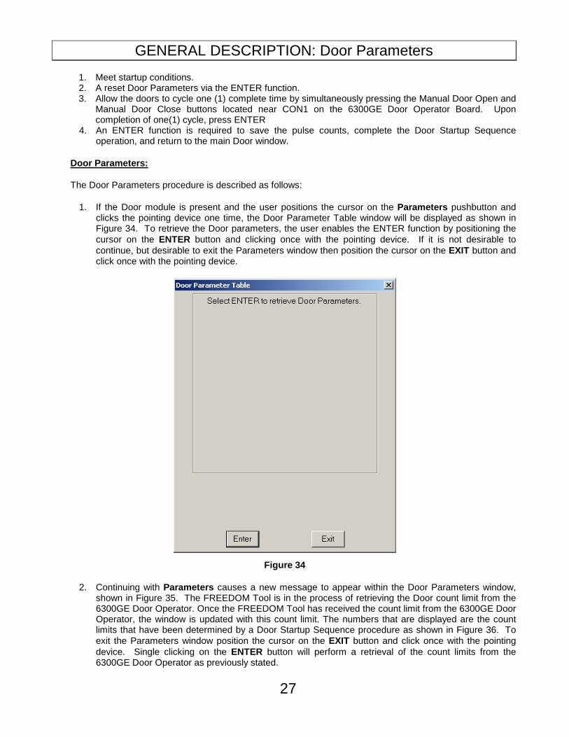
1. If the Door module is present and the user positions the cursor on the Parameters pushbutton and clicks the pointing device one time, the Door Parameter Table window will be displayed as shown in Figure 34. To retrieve the Door parameters, the user enables the ENTER function by positioning the cursor on the ENTER button and clicking once with the pointing device. If it is not desirable to continue, but desirable to exit the Parameters window then position the cursor on the EXIT button and click once with the pointing device.
Figure 34
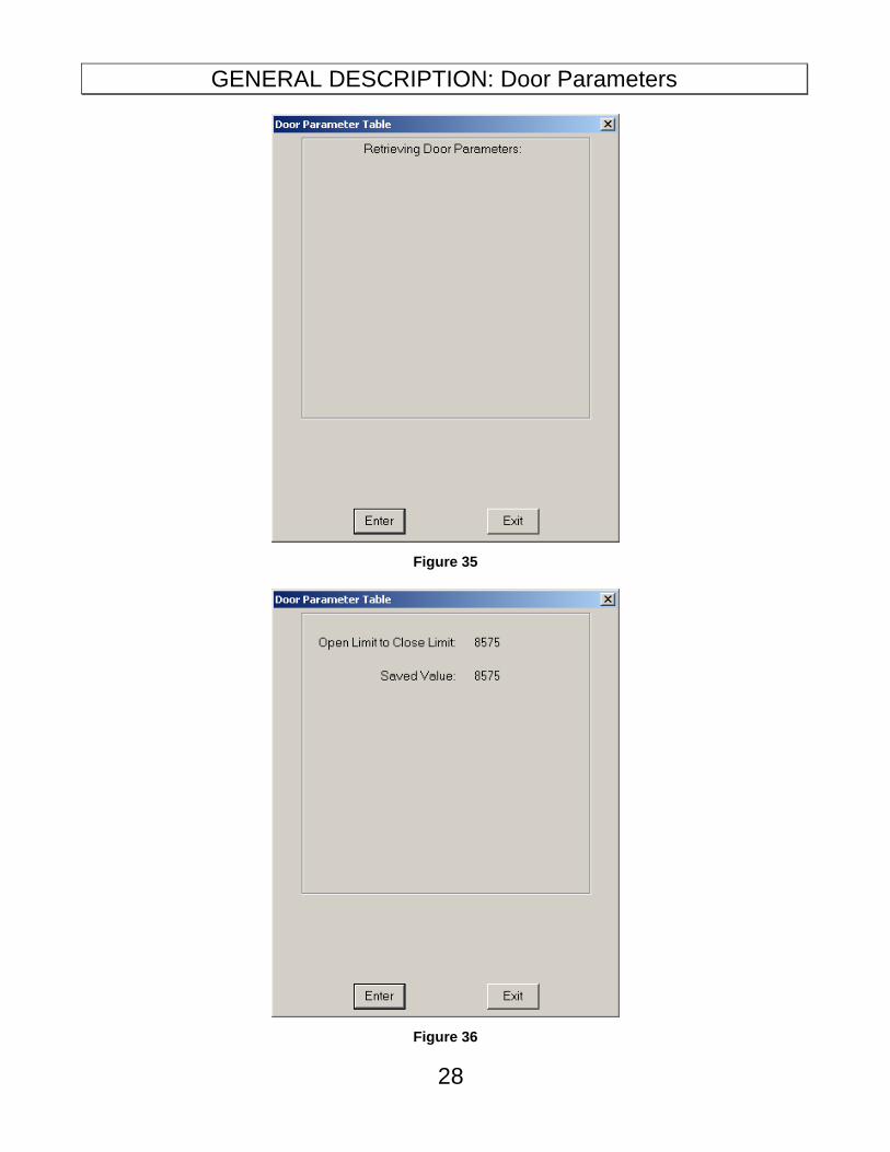
2. Continuing with Parameters causes a new message to appear within the Door Parameters window, shown in Figure 35. The FREEDOM Tool is in the process of retrieving the Door count limit from the 6300GE Door Operator. Once the FREEDOM Tool has received the count limit from the 6300GE Door Operator, the window is updated with this count limit. The numbers that are displayed are the count limits that have been determined by a Door Startup Sequence procedure as shown in Figure 36. To exit the Parameters window position the cursor on the EXIT button and click once with the pointing device. Single clicking on the ENTER button will perform a retrieval of the count limits from the 6300GE Door Operator as previously stated.
GENERAL DESCRIPTION: Door Parameters
28
Figure 35
Figure 36

GENERAL DESCRIPTION: Door Parameters
29
File Menu:
Exit
The Exit function will cause the FREEDOM Tool 6300GE Software Module to close and return to the FREEDOM Tool Shell program. Disconnect the 6300GE USB Interface box prior to performing this EXIT function.

APPENDIX A: Using Device Manager
30
APPENDIX A: Using Device Manager to Determine Seri al Port Assignment
1. Click the Start button on the Windows Toolbar.
2. Find COMPUTER or My Computer on the menu.
3. Right click COMPUTER or My Computer and select Manage from the menu that pops up.
4. A window titled Computer Management will open as in Figure 37. Find Device Manager on the left side of the window and select it using the computer-pointing device’s left button.
Figure 37
5. This will update the Computer Management window to look similar to what is seen in Figure 38. Find Ports (COM & LPT) on the device category list.

APPENDIX A: Using Device Manager
31
Figure 38
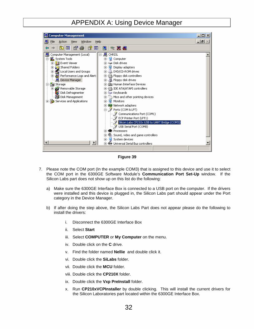
6. Double click the category Ports (COM & LPT) to expand the list of serial and parallel port devices. If the drivers have been installed on the computer and the Interface Box is plugged in, a device named Silicon Labs CP210X USB to UART Bridge should appear similar to what is seen in Figure 39.
APPENDIX A: Using Device Manager
32
Figure 39
7. Please note the COM port (In the example COM3) that is assigned to this device and use it to select the COM port in the 6300GE Software Module’s Communication Port Set-Up window. If the Silicon Labs part does not show up on this list do the following:
a) Make sure the 6300GE Interface Box is connected to a USB port on the computer. If the drivers were installed and this device is plugged in, the Silicon Labs part should appear under the Port category in the Device Manager.
b) If after doing the step above, the Silicon Labs Part does not appear please do the following to install the drivers:
i. Disconnect the 6300GE Interface Box
ii. Select Start
iii. Select COMPUTER or My Computer on the menu.
iv. Double click on the C drive.
v. Find the folder named Nellie and double click it.
vi. Double click the SiLabs folder.
vii. Double click the MCU folder.
viii. Double click the CP210X folder.
ix. Double click the Vxp PreInstall folder.
x. Run CP210xVCPInstaller by double clicking. This will install the current drivers for the Silicon Laboratories part located within the 6300GE Interface Box.

APPENDIX B: Adjustment List
33
xi. Plug the 6300GE Interface Box back into the computer. Go back to Step 1 of Using Device Manager to Determine Serial Port Assignment . If the Silicon Labs part still does not appear, contact FREEDOM Tool Technical Support at WORLD electronics.
APPENDIX C: Subsystem I/O Bit Definitions
34
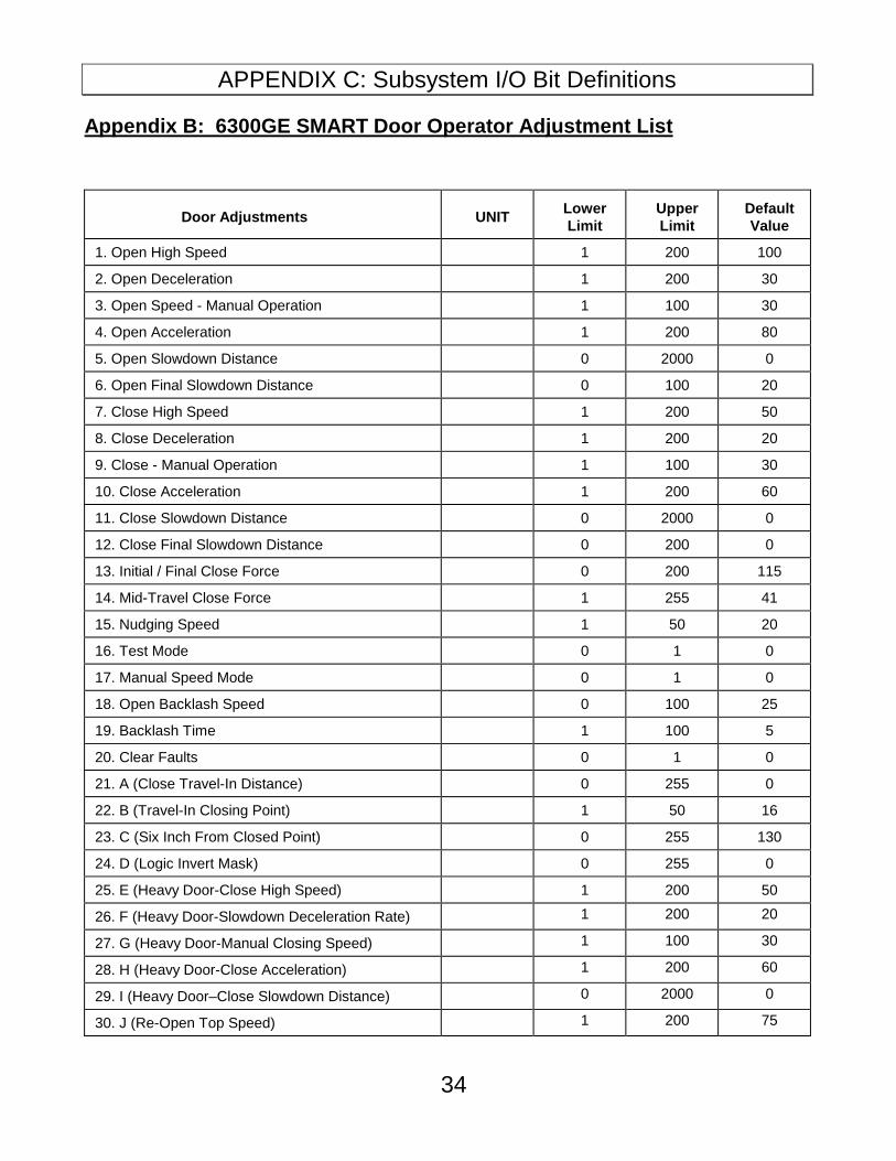
Appendix B: 6300GE SMART Door Operator Adjustment List
Door Adjustments
UNIT
Lower Limit
Upper Limit
Default Value
1. Open High Speed 1 200 100
2. Open Deceleration 1 200 30
3. Open Speed - Manual Operation 1 100 30
4. Open Acceleration 1 200 80
5. Open Slowdown Distance 0 2000 0
6. Open Final Slowdown Distance 0 100 20
7. Close High Speed 1 200 50
8. Close Deceleration 1 200 20
9. Close - Manual Operation 1 100 30
10. Close Acceleration 1 200 60
11. Close Slowdown Distance 0 2000 0
12. Close Final Slowdown Distance 0 200 0
13. Initial / Final Close Force 0 200 115
14. Mid-Travel Close Force 1 255 41
15. Nudging Speed 1 50 20
16. Test Mode 0 1 0
17. Manual Speed Mode 0 1 0
18. Open Backlash Speed 0 100 25
19. Backlash Time 1 100 5
20. Clear Faults 0 1 0
21. A (Close Travel-In Distance) 0 255 0
22. B (Travel-In Closing Point) 1 50 16
23. C (Six Inch From Closed Point) 0 255 130
24. D (Logic Invert Mask) 0 255 0
25. E (Heavy Door-Close High Speed) 1 200 50
26. F (Heavy Door-Slowdown Deceleration Rate) 1 200 20
27. G (Heavy Door-Manual Closing Speed) 1 100 30
28. H (Heavy Door-Close Acceleration) 1 200 60
29. I (Heavy Door–Close Slowdown Distance) 0 2000 0
30. J (Re-Open Top Speed) 1 200 75

APPENDIX C: Subsystem I/O Bit Definitions
35
Door Adjustments
UNIT
Lower Limit
Upper Limit
Default Value
31. K (Acceleration Torque) 0 255 0
32. L (Acceleration Position) 0 255 6
Appendix C: SUBSYSTEM I/O Bit Definitions
1. On Board Inputs 1:
b1 - N/A b2 - MDC, Manual Door Close Input b3 - MDO, Manual Door Open Input b4- N/A b5 - N/A b6 - N/A b7 - N/A b8 - N/A
2. On Board Inputs 2:
b1 - J4, Address Jumper J4 b2 - J3, Address Jumper J3 b3 - J2, Address Jumper J2 b4 - J1, Address Jumper J1 b5 - N/A b6 - DIR, Door Direction b7 – N/A b8 – N/A
3. Door Close Limit:
b1 - N/A b2 - N/A b3 - N/A b4 - N/A b5 - N/A b6 - N/A b7 - N/A b8 - DCL, Door Close Limit
4. Door Open limit:
b1 - N/A b2 - N/A b3 - N/A b4 - N/A b5 - N/A b6 - N/A b7 - N/A b8 - DOL, Door Open Limit

APPENDIX C: Subsystem I/O Bit Definitions
36
5. Adjusted Door Open Limit:
b1 - N/A b2 - N/A b3 - N/A b4 - N/A b5 - N/A b6 - N/A b7 - N/A b8 - DOLX, Door Open Limit
6. Open Door:
b1 - N/A b2 - N/A b3 - N/A b4 - N/A b5 - N/A b6 - N/A b7 - N/A b8 - OD, Open Door
7. Close Door:
b1 - N/A b2 - N/A b3 - N/A b4 - N/A b5 - N/A b6 - N/A b7 - N/A b8 - CD, Close Door
8. Input Flags 1 From Elevator:
b1 - OD, Open Door b2 - CD, Close Door b3 - HDI, Heavy Door Input b4 - NUDG, Nudging b5 – N/A b6 – N/A b7 - SETUP, Door Parameters Found b8 - RERR, Clear Faults
9. Internal Door Flags:
b1 - FLT, Faults b2 - INST, Setup Mode b3 – N/A b4 - NOHS, High Speed Operation b5 - DST, Destination is Door Closed Limit b6 - RDY, Doors Ready b7 - N/A b8 – N/A

APPENDIX D: Fault List
37
10. Port Inputs:
b1 – DOL* – Door Open Limit b2 – DCL – Door Close Limit b3 – N/A b4 – WD – 150 Volts Present b5 – N/A b6 – N/A b7 – N/A b8 – N/A
Appendix D: Fault List
� Defective Components on Door Operator Card
� Internal: EPROM Checksum Bad
� Internal: A to D Converter - Time-out
� Internal: A to D Converter - Offset Error
� 150 Volts NOT Available at Door Operator
� Motor Sensor Fault - Pulse Counts
� Motor Direction Fault
� Motor Sensor Fault - Phase
� Both Manual Push Buttons are enabled
� Limit Fault - DCL/DOL Failed or Belt Slipped
� DR Failed to De-activate
� DR Failed to Activate
� Pulse Count did NOT reach expected value
� 318 - Defective Control Board
� 319 - Defective Control Board
� Defective Control Board (Q1)
� Defective Control Board (Q2)
� Defective Control Board (Q3)
� Defective Control Board (Q4)
� Motor Circuit - Armature Open
� Grounded or Shorted IGBT
� Open Door Speed exceeded Init./Final Door Close Force
� Close Door Speed exceeded Init./Final Door Close Force
� Door operator component bad - EEPROM
� Door operator component bad - EEPROM
� 330 - Door operator component bad
� 331 - Door operator component bad
� 332 - Door operator component bad
� Door operator component bad - Bridge Watchdog
� 334 - Door operator component bad
� Invalid Adjustment Setting