7800 series burner control - 3.imimg.com · 7800 series burner control total burner control 7800...
TRANSCRIPT
83-78-00-011 / 9 8
7800 SeriesBurner Control
TOTAL BURNERCONTROL
7800 SERIES
7800 SERIESThe latest in Flame Safeguard state-of-the-art technologyis the7800SERlES Burner Control. The Honeywell 17800SERIES combines safety, comprehensive diagnostics,communication and networking capabilities into one com-pact and affordable microcomputer burner control. It cando just about anything and everything you would like it todo.
The 7800 SERIES works on a wide range of industrialapplications: burners, boilers, furnaces, ovens, kilns,process heaters and more. The 7800 SERIES replacesmore than 400 Honeywell and competitive control types.It offers you intelligent control anyway you want it: with orwithout communications, with or without an expanded an-nunciator, with or without a keyboard display module.Whatever features you want from a burner control, justask. With the 7800 SERIES, the answer is...yes, it can.
COMMUNICATIONS INTERFACEThe 7800 SERIES can interface with compatible lBM®equivalent personal computers at an onsite or remotelocation through a communications interface.
Primary Relay Modules—Automatic
NOTE: CONTROLS FOR USE IN 7800 SERIES BURNER CONTROL SYSTEMS ARE AVAILABLE ONLY THROUGHAUTHORIZED HONEYWELL 7800 SERIES DISTRIBUTORS.For the name of your nearest authorized Honeywell 7800 SERIES Distributor, please call 1-800-345-6770, ext. 2040.
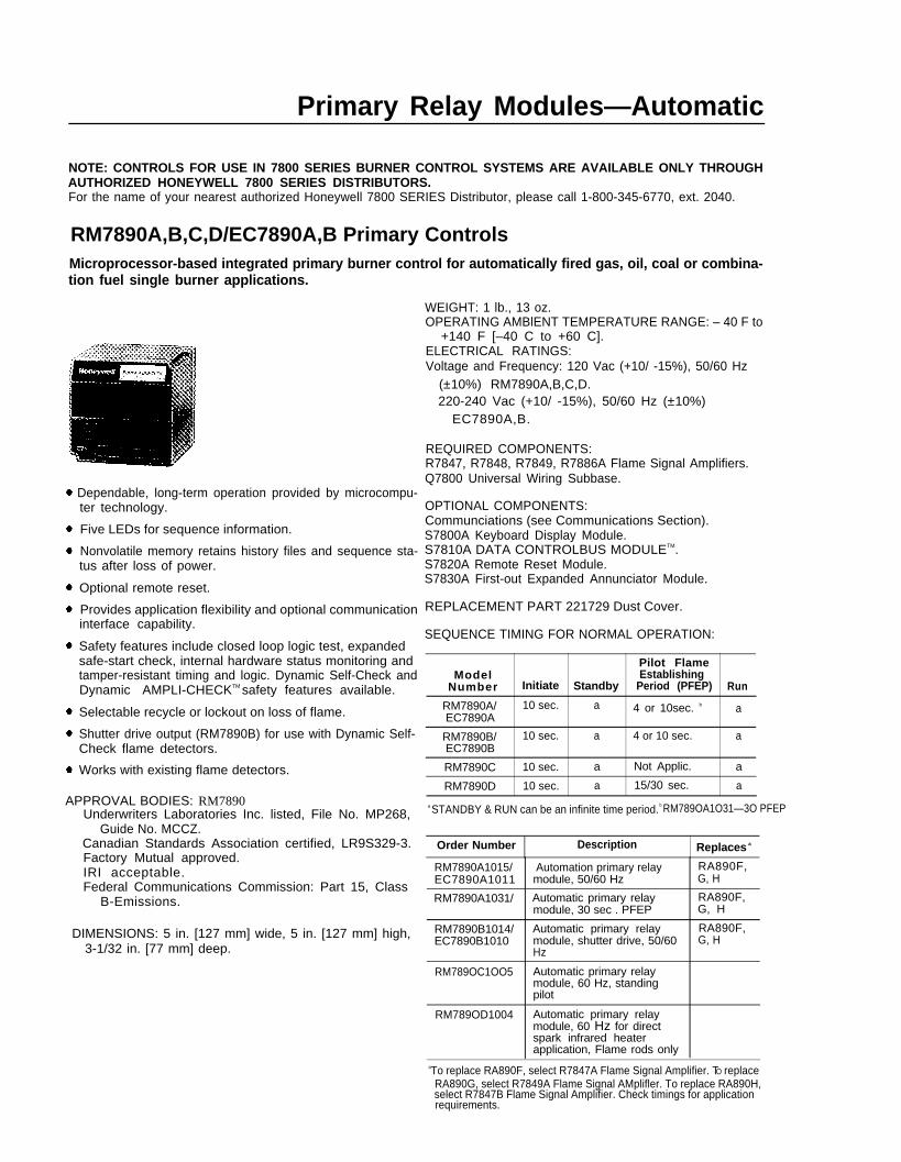
RM7890A,B,C,D/EC7890A,B Primary ControlsMicroprocessor-based integrated primary burner control for automatically fired gas, oil, coal or combina-tion fuel single burner applications.
Dependable, long-term operation provided by microcompu-ter technology.
Five LEDs for sequence information.
Nonvolatile memory retains history files and sequence sta-tus after loss of power.
Optional remote reset.
Provides application flexibility and optional communicationinterface capability.
Safety features include closed loop logic test, expandedsafe-start check, internal hardware status monitoring andtamper-resistant timing and logic. Dynamic Self-Check andDynamic AMPLI-CHECKTM safety features available.
Selectable recycle or lockout on loss of flame.
Shutter drive output (RM7890B) for use with Dynamic Self-Check flame detectors.
Works with existing flame detectors.
APPROVAL BODIES: RM7890Underwriters Laboratories Inc. listed, File No. MP268,
Guide No. MCCZ.Canadian Standards Association certified, LR9S329-3.Factory Mutual approved.IRI acceptable.Federal Communications Commission: Part 15, Class
B-Emissions.
DIMENSIONS: 5 in. [127 mm] wide, 5 in. [127 mm] high,3-1/32 in. [77 mm] deep.
WEIGHT: 1 lb., 13 oz.OPERATING AMBlENT TEMPERATURE RANGE: – 40 F to
+140 F [–40 C to +60 C].ELECTRICAL RATINGS:Voltage and Frequency: 120 Vac (+10/ -15%), 50/60 Hz
(±10%) RM7890A,B,C,D.220-240 Vac (+10/ -15%), 50/60 Hz (±10%)
EC7890A,B.
REQUIRED COMPONENTS:R7847, R7848, R7849, R7886A Flame Signal Amplifiers.Q7800 Universal Wiring Subbase.
OPTIONAL COMPONENTS:Communciations (see Communications Section).S7800A Keyboard Display Module.S7810A DATA CONTROLBUS MODULETM.S7820A Remote Reset Module.S7830A First-out Expanded Annunciator Module.
REPLACEMENT PART 221729 Dust Cover.
SEQUENCE TIMING FOR NORMAL OPERATION:
Pilot FlameModel Establishing
Number Initiate Standby Period (PFEP) Run
RM7890A/ 10 sec. a 4 or 10sec. b aEC7890A
RM7890B/ 10 sec. a 4 or 10 sec. aEC7890B
RM7890C 10 sec. a Not Applic. a
RM7890D 10 sec. a 15/30 sec. a
a STANDBY & RUN can be an infinite time period. b RM789OA1O31—3O PFEP
Order Number Description Replaces a
RM7890A1015/ Automation primary relay RA890F,EC7890A1011 module, 50/60 Hz G, H
RM7890A1031/ Automatic primary relay RA890F,module, 30 sec . PFEP G, H
RM7890B1014/ Automatic primary relay RA890F,EC7890B1010 module, shutter drive, 50/60 G, H
Hz
RM789OC1OO5 Automatic primary relaymodule, 60 Hz, standingpilot
RM789OD1004 Automatic primary relaymodule, 60 Hz for directspark infrared heaterapplication, Flame rods only
aTo replace RA890F, select R7847A Flame Signal Amplifier. TO replaceRA890G, select R7849A Flame Signal AMplifler. To replace RA890H,select R7847B Flame Signal Amplifier. Check timings for applicationrequirements.
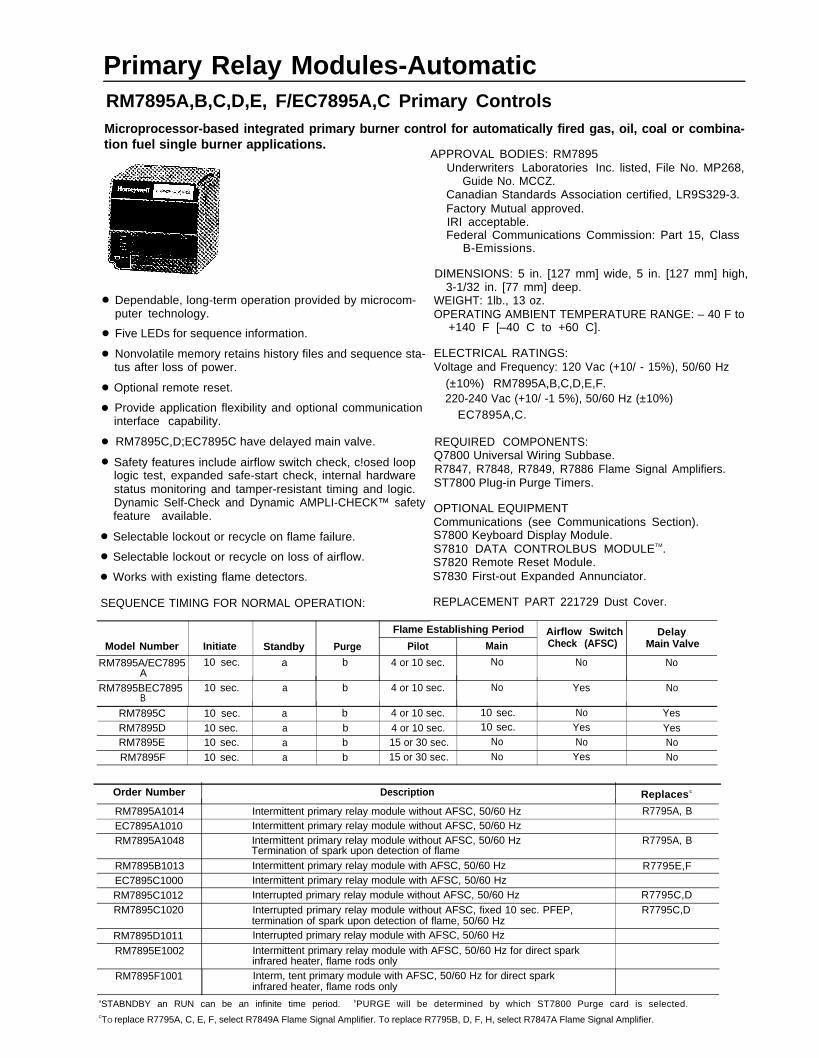
Primary Relay Modules-AutomaticRM7895A,B,C,D,E, F/EC7895A,C Primary ControlsMicroprocessor-based integrated primary burner control for automatically fired gas, oil, coal or combina-tion fuel single burner applications.
●
●
●
●
●
●
●
●
●
●
Dependable, long-term operation provided by microcom-puter technology.
Five LEDs for sequence information.
Nonvolatile memory retains history files and sequence sta-tus after loss of power.
Optional remote reset.
Provide application flexibility and optional communicationinterface capability.
RM7895C,D;EC7895C have delayed main valve.
Safety features include airflow switch check, c!osed looplogic test, expanded safe-start check, internal hardwarestatus monitoring and tamper-resistant timing and logic.Dynamic Self-Check and Dynamic AMPLI-CHECK™ safetyfeature available.
Selectable lockout or recycle on flame failure.
Selectable lockout or recycle on loss of airflow.
Works with existing flame detectors.
SEQUENCE TIMING FOR NORMAL OPERATION:
APPROVAL BODIES: RM7895Underwriters Laboratories Inc. listed, File No. MP268,
Guide No. MCCZ.Canadian Standards Association certified, LR9S329-3.Factory Mutual approved.IRI acceptable.Federal Communications Commission: Part 15, Class
B-Emissions.
DIMENSIONS: 5 in. [127 mm] wide, 5 in. [127 mm] high, 3-1/32 in. [77 mm] deep.
WEIGHT: 1lb., 13 oz.OPERATING AMBIENT TEMPERATURE RANGE: – 40 F to
+140 F [–40 C to +60 C].
ELECTRICAL RATINGS:Voltage and Frequency: 120 Vac (+10/ - 15%), 50/60 Hz
(±10%) RM7895A,B,C,D,E,F.220-240 Vac (+10/ -1 5%), 50/60 Hz (±10%)
EC7895A,C.
REQUIRED COMPONENTS:Q7800 Universal Wiring Subbase.R7847, R7848, R7849, R7886 Flame Signal Amplifiers.ST7800 Plug-in Purge Timers.
OPTIONAL EQUIPMENTCommunications (see Communications Section).S7800 Keyboard Display Module.S7810 DATA CONTROLBUS MODULETM.S7820 Remote Reset Module.S7830 First-out Expanded Annunciator.
REPLACEMENT PART 221729 Dust Cover.
Flame Establishing Period Airflow Switch DelayModel Number Initiate Standby Purge Pilot Main Check (AFSC) Main Valve
RM7895A/EC7895 10 sec. a b 4 or 10 sec. No No NoA
RM7895BEC7895 10 sec. a b 4 or 10 sec. No Yes NoB
RM7895C 10 sec. a b 4 or 10 sec. 10 sec. No YesRM7895D 10 sec. a b 4 or 10 sec. 10 sec. Yes YesRM7895E 10 sec. a b 15 or 30 sec. No No NoRM7895F 10 sec. a b 15 or 30 sec. No Yes No
Order Number Description Replaces c
RM7895A1014 Intermittent primary relay module without AFSC, 50/60 Hz R7795A, BEC7895A1010 Intermittent primary relay module without AFSC, 50/60 HzRM7895A1048 Intermittent primary relay module without AFSC, 50/60 Hz R7795A, B
Termination of spark upon detection of flame
RM7895B1013 Intermittent primary relay module with AFSC, 50/60 Hz R7795E,FEC7895C1000 Intermittent primary relay module with AFSC, 50/60 HzRM7895C1012 Interrupted primary relay module without AFSC, 50/60 Hz R7795C,DRM7895C1020 Interrupted primary relay module without AFSC, fixed 10 sec. PFEP, R7795C,D
termination of spark upon detection of flame, 50/60 HzRM7895D1011 Interrupted primary relay module with AFSC, 50/60 Hz
RM7895E1002 Intermittent primary relay module with AFSC, 50/60 Hz for direct sparkinfrared heater, flame rods only
RM7895F1001 Interm, tent primary module with AFSC, 50/60 Hz for direct sparkinfrared heater, flame rods only
aSTABNDBY an RUN can be an infinite time period. bPURGE will be determined by which ST7800 Purge card is selected.CTO replace R7795A, C, E, F, select R7849A Flame Signal Amplifier. To replace R7795B, D, F, H, select R7847A Flame Signal Amplifier.
Primary Relay Modules—Automatic
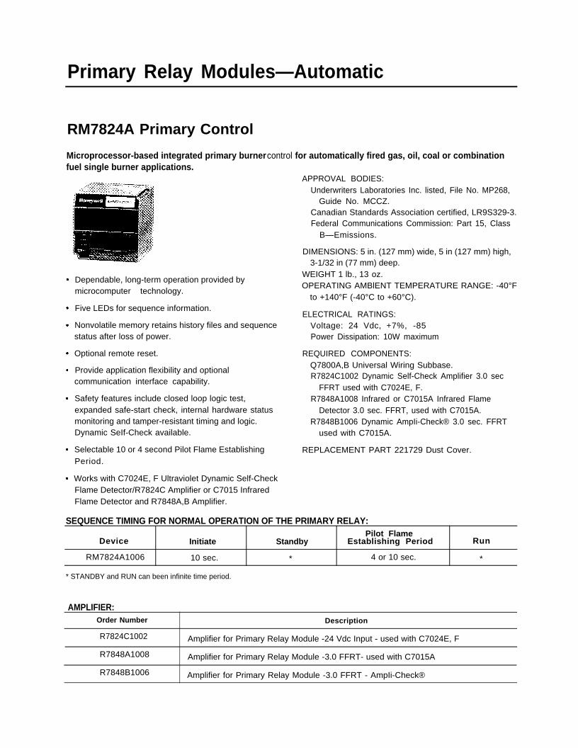
RM7824A Primary Control
Microprocessor-based integrated primary burner control for automatically fired gas, oil, coal or combinationfuel single burner applications.
Dependable, long-term operation provided bymicrocomputer technology.
Five LEDs for sequence information.
Nonvolatile memory retains history files and sequencestatus after loss of power.
Optional remote reset.
Provide application flexibility and optionalcommunication interface capability.
Safety features include closed loop logic test,expanded safe-start check, internal hardware statusmonitoring and tamper-resistant timing and logic.Dynamic SeIf-Check available.
Selectable 10 or 4 second Pilot Flame EstablishingPeriod.
Works with C7024E, F Ultraviolet Dynamic Self-Check
APPROVAL BODIES:Underwriters Laboratories Inc. listed, File No. MP268,
Guide No. MCCZ.Canadian Standards Association certified, LR9S329-3.Federal Communications Commission: Part 15, Class
B—Emissions.
DIMENSIONS: 5 in. (127 mm) wide, 5 in (127 mm) high,3-1/32 in (77 mm) deep.
WEIGHT 1 lb., 13 oz.OPERATING AMBlENT TEMPERATURE RANGE: -40°F
to +140°F (-40°C to +60°C).
ELECTRICAL RATINGS:Voltage: 24 Vdc, +7%, -85Power Dissipation: 10W maximum
REQUIRED COMPONENTS:Q7800A,B Universal Wiring Subbase.R7824C1002 Dynamic Self-Check Amplifier 3.0 sec
FFRT used with C7024E, F.R7848A1008 Infrared or C7015A Infrared Flame
Detector 3.0 sec. FFRT, used with C7015A.R7848B1006 Dynamic AmpIi-Check® 3.0 sec. FFRT
used with C7015A.
REPLACEMENT PART 221729 Dust Cover.
Flame Detector/R7824C Amplifier or C7015 InfraredFlame Detector and R7848A,B Amplifier.
SEQUENCE TIMING FOR NORMAL OPERATION OF THE PRIMARY RELAY:Pilot Flame
Device Initiate Standby Establishing Period Run
RM7824A1006 10 sec. 4 or 10 sec.* *
* STANDBY and RUN can been infinite time period.
AMPLIFIER:Order Number Description
R7824C1002 Amplifier for Primary Relay Module -24 Vdc Input - used with C7024E, F
R7848A1008 Amplifier for Primary Relay Module -3.0 FFRT- used with C7015A
R7848B1006 Amplifier for Primary Relay Module -3.0 FFRT - AmpIi-Check®
Primary Relay Modules—Semi-Automatic
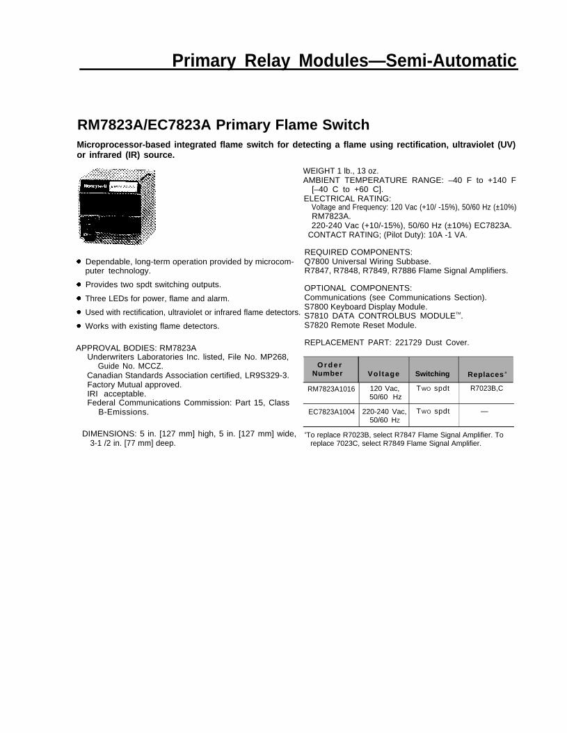
RM7823A/EC7823A Primary Flame SwitchMicroprocessor-based integrated flame switch for detecting a flame using rectification, ultraviolet (UV)or infrared (IR) source.
Dependable, long-term operation provided by microcom-puter technology.
Provides two spdt switching outputs.
Three LEDs for power, flame and alarm.
Used with rectification, ultraviolet or infrared flame detectors.
Works with existing flame detectors.
APPROVAL BODIES: RM7823AUnderwriters Laboratories Inc. listed, File No. MP268,
Guide No. MCCZ.Canadian Standards Association certified, LR9S329-3.Factory Mutual approved.IRI acceptable.Federal Communications Commission: Part 15, Class
B-Emissions.
DIMENSIONS: 5 in. [127 mm] high, 5 in. [127 mm] wide,3-1 /2 in. [77 mm] deep.
WEIGHT 1 lb., 13 oz.AMBIENT TEMPERATURE RANGE: –40 F to +140 F
[–40 C to +60 C].ELECTRICAL RATING:
Voltage and Frequency: 120 Vac (+10/ -15%), 50/60 Hz (±10%)RM7823A.220-240 Vac (+10/-15%), 50/60 Hz (±10%) EC7823A.
CONTACT RATING; (Pilot Duty): 10A -1 VA.
REQUIRED COMPONENTS:Q7800 Universal Wiring Subbase.R7847, R7848, R7849, R7886 Flame Signal Amplifiers.
OPTIONAL COMPONENTS:Communications (see Communications Section).S7800 Keyboard Display Module.S7810 DATA CONTROLBUS MODULETM.S7820 Remote Reset Module.
REPLACEMENT PART: 221729 Dust Cover.
O r d e rNumber Vol tage Switching Replaces a
RM7823A1016 120 Vac, TWO spdt R7023B,C50/60 Hz
EC7823A1004 220-240 Vac, TWO spdt —50/60 HZ
aTo replace R7023B, select R7847 Flame Signal Amplifier. Toreplace 7023C, select R7849 Flame Signal Amplifier.
Primary Relay Modules—Semi-Automatic
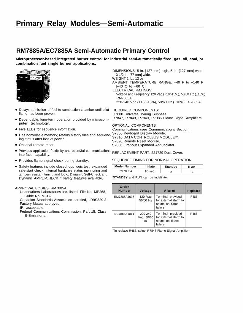
RM7885A/EC7885A Semi-Automatic Primary ControlMicroprocessor-based integrated burner control for industrial semi-automatically fired, gas, oil, coal, orcombination fuel single burner applications.
Delays admission of fuel to combustion chamber until pilotflame has been proven.
Dependable, long-term operation provided by microcom-puter technology.
Five LEDs for sequence information.
Has nonvolatile memory; retains history files and sequenc-ing status after loss of power.
Optional remote reset.
Provides application flexibility and optim3al communicationsinterface capability.
Provides flame signal check during standby.
Safety features include closed loop logic test, expandedsafe-start check, internal hardware status monitoring andtamper-resistant timing and logic. Dynamic Self-Check andDynamic AMPLI-CHECK™ safety features available.
APPROVAL BODIES: RM7885AUnderwriters Laboratories Inc. listed, File No. MP268,
Guide No. MCCZ.Canadian Standards Association certified, LR9S329-3.Factory Mutual approved.IRI acceptable.Federal Communications Commission: Part 15, Class
B-Emissions.
DIMENSIONS: 5 in. [127 mm] high, 5 in. [127 mm] wide,3-1/2 in. [77 mm] wide.
WEIGHT 1 lb., 13 oz.AMBlENT TEMPERATURE RANGE: –40 F to +140 F
[–40 C to +60 C].ELECTRICAL RATINGS:
Voltage and Frequency 120 Vac (+10/-15%), 50/60 Hz (±10%)RM7885A.220-240 Vac (+10/ -15%), 50/60 Hz (±10%) EC7885A.
REQUIRED COMPONENTS:Q7800 Universal Wiring Subbase.R7847, R7848, R7849, R7886 Flame Signal Amplifiers.
OPTIONAL COMPONENTS:Communications (see Communications Section).S7800 Keyboard Display Module.S7810 DATA CONTROLBUS MODULE™.S7820 Remote Reset Module.S7830 First-out Expanded Annunciator.
REPLACEMENT PART: 221729 Dust Cover.
SEQUENCE TIMING FOR NORMAL OPERATION:
Model Number Initiate Standby R u nRM7885A 10 sec. a a
a STANDBY and RUN can be indefinite.
OrderNumber Voltage A l a r m Replacesa
RM7885A1015 120 Vac, Terminal provided R48550/60 Hz for external alarm to
sound on flamefailure.
EC7885A1011 220-240 Terminal provided R485Vac, 50/60 for external alarm to
Hz sound on flamefailure.
aTo replace R485, select R7847 Flame Signal Amplifier.
Primary Relay Modules—Semi-Automatic
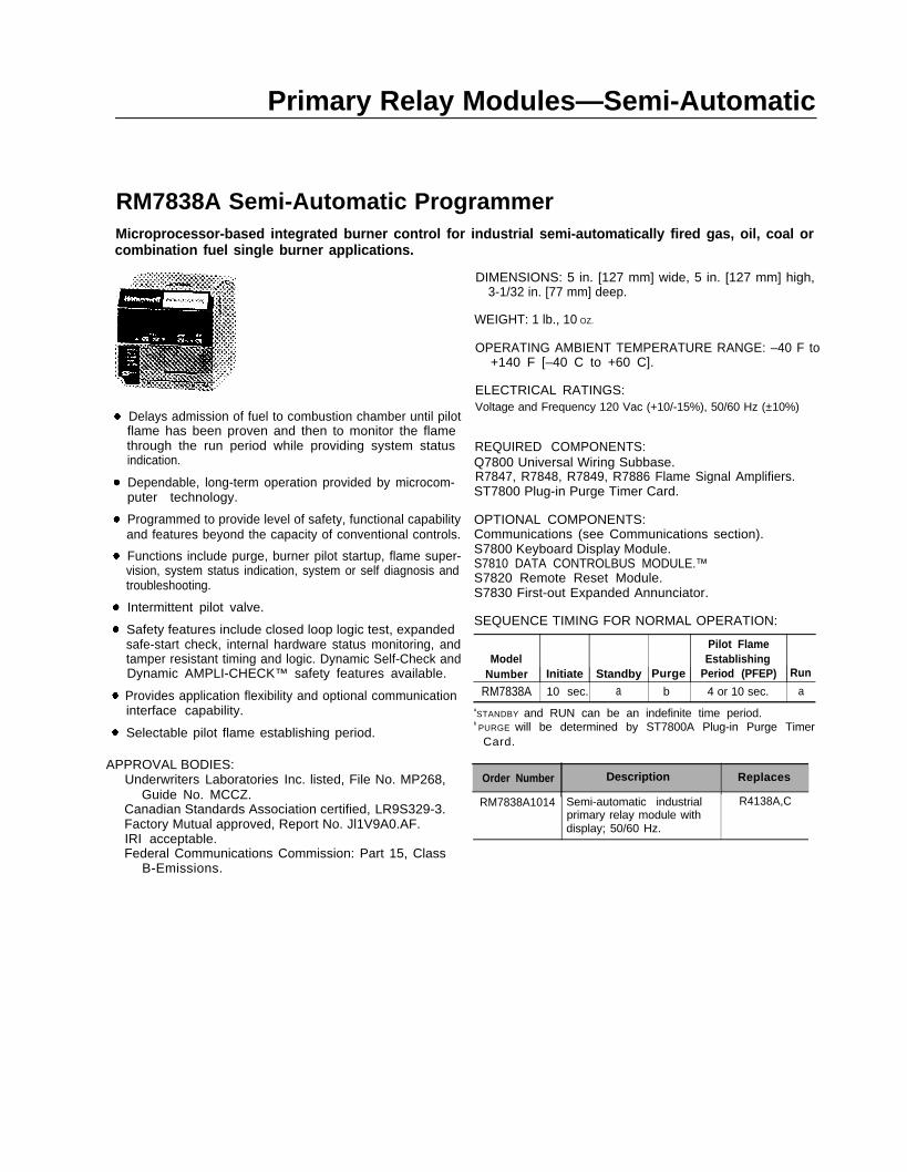
RM7838A Semi-Automatic ProgrammerMicroprocessor-based integrated burner control for industrial semi-automatically fired gas, oil, coal orcombination fuel single burner applications.
Delays admission of fuel to combustion chamber until pilotflame has been proven and then to monitor the flamethrough the run period while providing system statusindication.
Dependable, long-term operation provided by microcom-puter technology.
Programmed to provide level of safety, functional capabilityand features beyond the capacity of conventional controls.
Functions include purge, burner pilot startup, flame super-vision, system status indication, system or self diagnosis andtroubleshooting.
Intermittent pilot valve.
Safety features include closed loop logic test, expandedsafe-start check, internal hardware status monitoring, andtamper resistant timing and logic. Dynamic Self-Check andDynamic AMPLI-CHECK™ safety features available.
Provides application flexibility and optional communicationinterface capability.
Selectable pilot flame establishing period.
APPROVAL BODIES:Underwriters Laboratories Inc. listed, File No. MP268,
Guide No. MCCZ.Canadian Standards Association certified, LR9S329-3.Factory Mutual approved, Report No. Jl1V9A0.AF.IRI acceptable.Federal Communications Commission: Part 15, Class
B-Emissions.
DIMENSIONS: 5 in. [127 mm] wide, 5 in. [127 mm] high,3-1/32 in. [77 mm] deep.
WEIGHT: 1 lb., 10 OZ.
OPERATING AMBIENT TEMPERATURE RANGE: –40 F to+140 F [–40 C to +60 C].
ELECTRICAL RATINGS:Voltage and Frequency 120 Vac (+10/-15%), 50/60 Hz (±10%)
REQUIRED COMPONENTS:Q7800 Universal Wiring Subbase.R7847, R7848, R7849, R7886 Flame Signal Amplifiers.ST7800 Plug-in Purge Timer Card.
OPTIONAL COMPONENTS:Communications (see Communications section).S7800 Keyboard Display Module.S7810 DATA CONTROLBUS MODULE.™S7820 Remote Reset Module.S7830 First-out Expanded Annunciator.
SEQUENCE TIMING FOR NORMAL OPERATION:
Pilot FlameModel Establishing
Number Initiate Standby Purge Period (PFEP) Run
RM7838A 10 sec. a b 4 or 10 sec. aaSTANDBY and RUN can be an indefinite time period.
b PURGE will be determined by ST7800A Plug-in Purge TimerCard.
Order Number Description Replaces
RM7838A1014 Semi-automatic industrial R4138A,Cprimary relay module withdisplay; 50/60 Hz.
Primary Relay Modules—Semi-Automatic
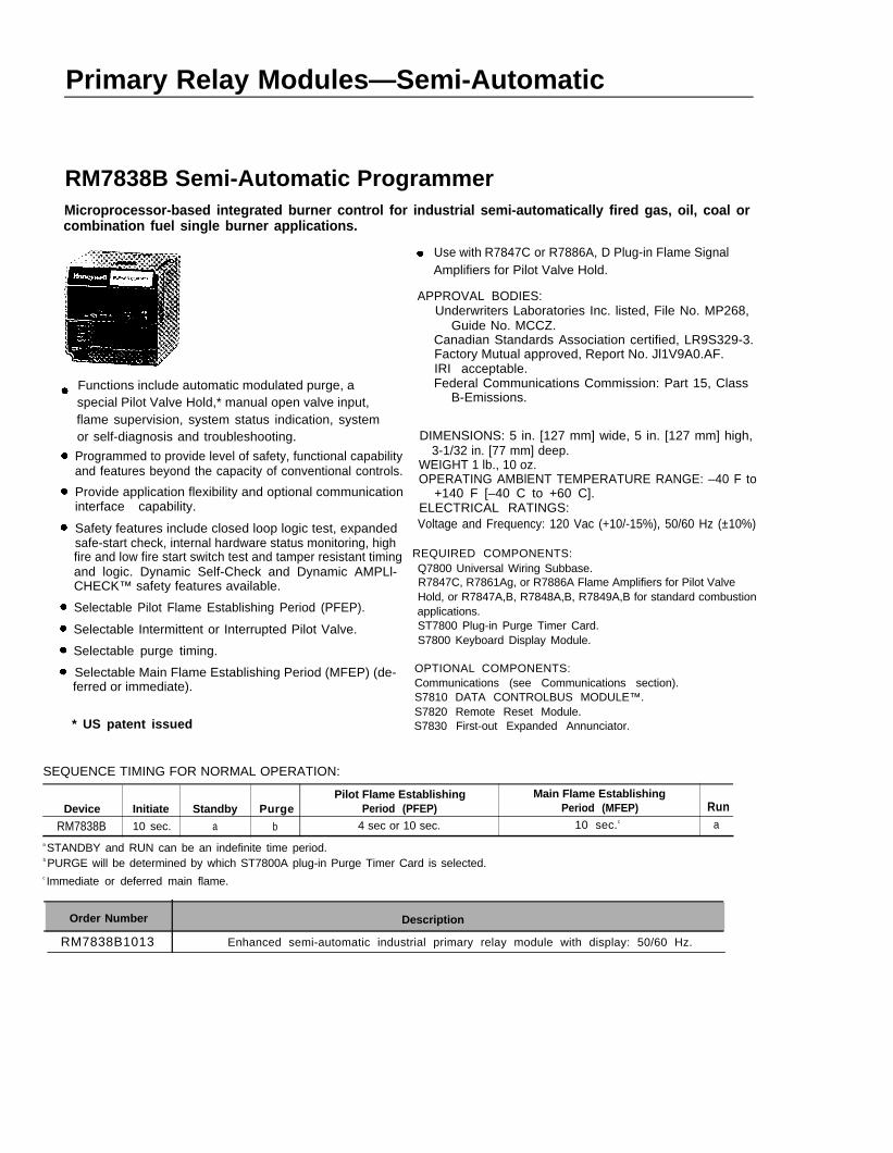
RM7838B Semi-Automatic ProgrammerMicroprocessor-based integrated burner control for industrial semi-automatically fired gas, oil, coal orcombination fuel single burner applications.
Functions include automatic modulated purge, aspecial Pilot Valve Hold,* manual open valve input,flame supervision, system status indication, systemor self-diagnosis and troubleshooting.
Programmed to provide level of safety, functional capabilityand features beyond the capacity of conventional controls.
Provide application flexibility and optional communicationinterface capability.
Safety features include closed loop logic test, expandedsafe-start check, internal hardware status monitoring, highfire and low fire start switch test and tamper resistant timingand logic. Dynamic Self-Check and Dynamic AMPLl-CHECK™ safety features available.
Selectable Pilot Flame Establishing Period (PFEP).
Selectable Intermittent or Interrupted Pilot Valve.
Selectable purge timing.
ferred or immediate).
* US patent issued
Selectable Main Flame Establishing Period (MFEP) (de-
Use with R7847C or R7886A, D Plug-in Flame SignalAmplifiers for Pilot Valve Hold.
APPROVAL BODIES:Underwriters Laboratories Inc. listed, File No. MP268,
Guide No. MCCZ.Canadian Standards Association certified, LR9S329-3.Factory Mutual approved, Report No. Jl1V9A0.AF.IRI acceptable.Federal Communications Commission: Part 15, Class
B-Emissions.
DIMENSIONS: 5 in. [127 mm] wide, 5 in. [127 mm] high,3-1/32 in. [77 mm] deep.
WEIGHT 1 lb., 10 oz.OPERATING AMBlENT TEMPERATURE RANGE: –40 F to
+140 F [–40 C to +60 C].ELECTRICAL RATINGS:Voltage and Frequency: 120 Vac (+10/-15%), 50/60 Hz (±10%)
REQUIRED COMPONENTS:Q7800 Universal Wiring Subbase.R7847C, R7861Ag, or R7886A Flame Amplifiers for Pilot ValveHold, or R7847A,B, R7848A,B, R7849A,B for standard combustionapplications.ST7800 Plug-in Purge Timer Card.S7800 Keyboard Display Module.
OPTIONAL COMPONENTS:Communications (see Communications section).S7810 DATA CONTROLBUS MODULE™.S7820 Remote Reset Module.S7830 First-out Expanded Annunciator.
SEQUENCE TIMING FOR NORMAL OPERATION:
Pilot Flame Establishing Main Flame EstablishingDevice Initiate Standby Purge Period (PFEP) Period (MFEP) Run
RM7838B 10 sec. a b 4 sec or 10 sec. 10 sec.c a
a STANDBY and RUN can be an indefinite time period.b PURGE will be determined by which ST7800A plug-in Purge Timer Card is selected.c Immediate or deferred main flame.
Order Number Description
RM7838B1013 Enhanced semi-automatic industrial primary relay module with display: 50/60 Hz.
Programmers
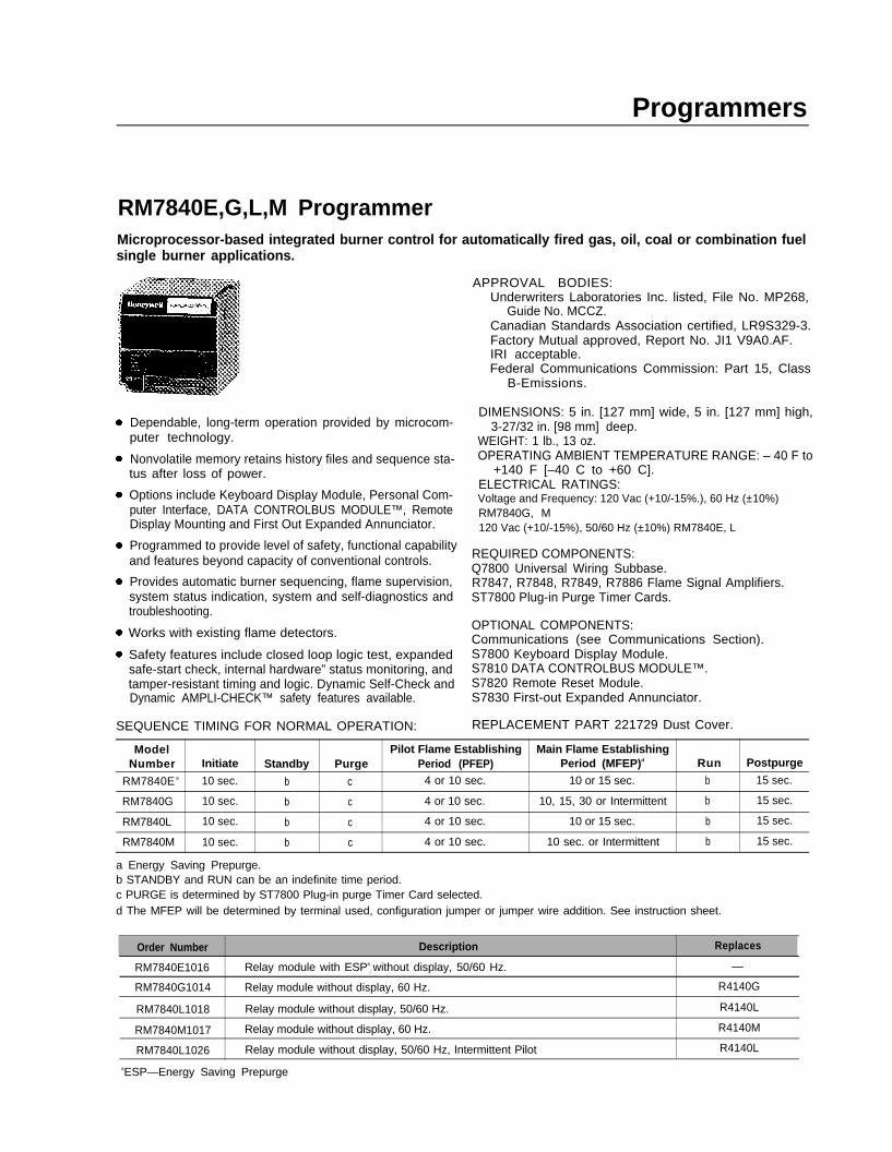
RM7840E,G,L,M ProgrammerMicroprocessor-based integrated burner control for automatically fired gas, oil, coal or combination fuelsingle burner applications.
Dependable, long-term operation provided by microcom-puter technology.
Nonvolatile memory retains history files and sequence sta-tus after loss of power.
Options include Keyboard Display Module, Personal Com-puter Interface, DATA CONTROLBUS MODULE™, RemoteDisplay Mounting and First Out Expanded Annunciator.
Programmed to provide level of safety, functional capabilityand features beyond capacity of conventional controls.
Provides automatic burner sequencing, flame supervision,system status indication, system and self-diagnostics andtroubleshooting.
Works with existing flame detectors.
Safety features include closed loop logic test, expandedsafe-start check, internal hardware” status monitoring, andtamper-resistant timing and logic. Dynamic Self-Check andDynamic AMPLI-CHECK™ safety features available.
SEQUENCE TIMING FOR NORMAL OPERATION:
APPROVAL BODIES:Underwriters Laboratories Inc. listed, File No. MP268,
Guide No. MCCZ.Canadian Standards Association certified, LR9S329-3.Factory Mutual approved, Report No. JI1 V9A0.AF.IRI acceptable.Federal Communications Commission: Part 15, Class
B-Emissions.
DIMENSIONS: 5 in. [127 mm] wide, 5 in. [127 mm] high,3-27/32 in. [98 mm] deep.
WEIGHT: 1 lb., 13 oz.OPERATING AMBlENT TEMPERATURE RANGE: – 40 F to
+140 F [–40 C to +60 C].ELECTRICAL RATINGS:Voltage and Frequency: 120 Vac (+10/-15%.), 60 Hz (±10%)RM7840G, M120 Vac (+10/-15%), 50/60 Hz (±10%) RM7840E, L
REQUIRED COMPONENTS:Q7800 Universal Wiring Subbase.R7847, R7848, R7849, R7886 Flame Signal Amplifiers.ST7800 Plug-in Purge Timer Cards.
OPTIONAL COMPONENTS:Communications (see Communications Section).S7800 Keyboard Display Module.S7810 DATA CONTROLBUS MODULE™.S7820 Remote Reset Module.S7830 First-out Expanded Annunciator.
REPLACEMENT PART 221729 Dust Cover.
Model Pilot Flame Establishing Main Flame EstablishingNumber Initiate Standby Purge Period (PFEP) Period (MFEP)d Run Postpurge
RM7840E a 10 sec. b c 4 or 10 sec. 10 or 15 sec. b 15 sec.
RM7840G 10 sec. b c 4 or 10 sec. 10, 15, 30 or Intermittent b 15 sec.
RM7840L 10 sec. b c 4 or 10 sec. 10 or 15 sec. b 15 sec.
RM7840M 10 sec. b c 4 or 10 sec. 10 sec. or Intermittent b 15 sec.
a Energy Saving Prepurge.b STANDBY and RUN can be an indefinite time period.c PURGE is determined by ST7800 Plug-in purge Timer Card selected.d The MFEP will be determined by terminal used, configuration jumper or jumper wire addition. See instruction sheet.
Order Number Description Replaces
RM7840E1016 Relay module with ESPa
; without display, 50/60 Hz.
RM7840G1014 Relay module without display, 60 Hz. R4140G
RM7840L1018 Relay module without display, 50/60 Hz. R4140L
RM7840M1017 Relay module without display, 60 Hz. R4140M
RM7840L1026 Relay module without display, 50/60 Hz, Intermittent Pilot R4140L
aESP—Energy Saving Prepurge
—
Programmers
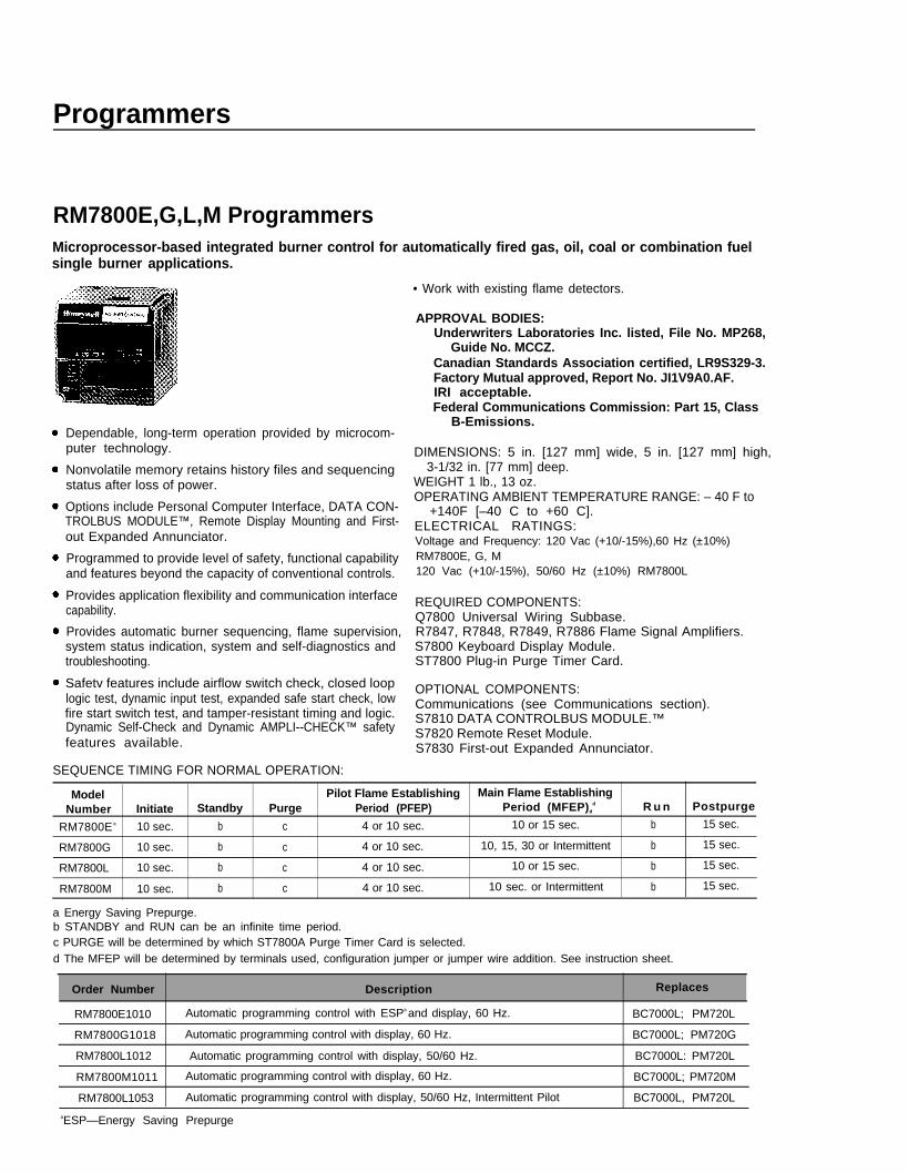
RM7800E,G,L,M ProgrammersMicroprocessor-based integrated burner control for automatically fired gas, oil, coal or combination fuelsingle burner applications.
Dependable, long-term operation provided by microcom-puter technology.
Nonvolatile memory retains history files and sequencingstatus after loss of power.
Options include Personal Computer Interface, DATA CON-TROLBUS MODULE™, Remote Display Mounting and First-out Expanded Annunciator.
Programmed to provide level of safety, functional capabilityand features beyond the capacity of conventional controls.
Provides application flexibility and communication interfacecapability.
Provides automatic burner sequencing, flame supervision,system status indication, system and self-diagnostics and troubleshooting.
Safetv features include airflow switch check, closed looplogic test, dynamic input test, expanded safe start check, lowfire start switch test, and tamper-resistant timing and logic.Dynamic Self-Check and Dynamic AMPLI--CHECK™ safetyfeatures available.
SEQUENCE TIMING FOR NORMAL OPERATION:
• Work with existing flame detectors.
APPROVAL BODIES:Underwriters Laboratories Inc. listed, File No. MP268,
Guide No. MCCZ.Canadian Standards Association certified, LR9S329-3.Factory Mutual approved, Report No. JI1V9A0.AF.IRI acceptable.Federal Communications Commission: Part 15, Class
B-Emissions.
DIMENSIONS: 5 in. [127 mm] wide, 5 in. [127 mm] high,3-1/32 in. [77 mm] deep.
WEIGHT 1 lb., 13 oz.OPERATING AMBlENT TEMPERATURE RANGE: – 40 F to
+140F [–40 C to +60 C].ELECTRICAL RATINGS:Voltage and Frequency: 120 Vac (+10/-15%),60 Hz (±10%)RM7800E, G, M120 Vac (+10/-15%), 50/60 Hz (±10%) RM7800L
REQUIRED COMPONENTS:Q7800 Universal Wiring Subbase.R7847, R7848, R7849, R7886 Flame Signal Amplifiers.S7800 Keyboard Display Module.ST7800 Plug-in Purge Timer Card.
OPTIONAL COMPONENTS:Communications (see Communications section).S7810 DATA CONTROLBUS MODULE.™S7820 Remote Reset Module.S7830 First-out Expanded Annunciator.
Model Pilot Flame Establishing Main Flame EstablishingNumber Initiate Standby Purge Period (PFEP) Period (MFEP)d
d R u n Postpurge
RM7800E a 10 sec. b c 4 or 10 sec. 10 or 15 sec. b 15 sec.
RM7800G 10 sec. b c 4 or 10 sec. 10, 15, 30 or Intermittent b 15 sec.
RM7800L 10 sec. b c 4 or 10 sec. 10 or 15 sec. b 15 sec.
RM7800M 10 sec. b c 4 or 10 sec. 10 sec. or Intermittent b 15 sec.
a Energy Saving Prepurge.b STANDBY and RUN can be an infinite time period.c PURGE will be determined by which ST7800A Purge Timer Card is selected.d The MFEP will be determined by terminals used, configuration jumper or jumper wire addition. See instruction sheet.
Order Number Description Replaces
RM7800E1010 Automatic programming control with ESPa and display, 60 Hz. BC7000L; PM720L
RM7800G1018 Automatic programming control with display, 60 Hz. BC7000L; PM720G
RM7800L1012 Automatic programming control with display, 50/60 Hz. BC7000L: PM720L
RM7800M1011 Automatic programming control with display, 60 Hz. BC7000L; PM720M
RM7800L1053 Automatic programming control with display, 50/60 Hz, Intermittent Pilot BC7000L, PM720L
aESP—Energy Saving Prepurge
7800 SERIES Required Components
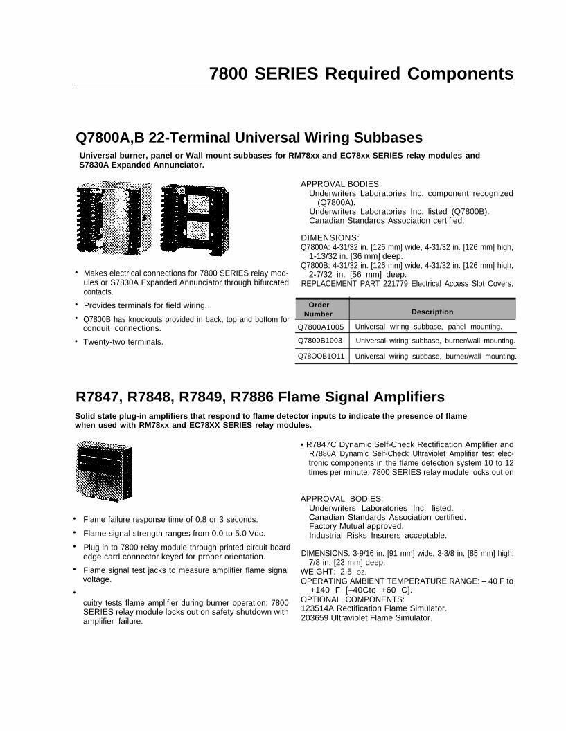
Q7800A,B 22-Terminal Universal Wiring SubbasesUniversal burner, panel or Wall mount subbases for RM78xx and EC78xx SERIES relay modules andS7830A Expanded Annunciator.
APPROVAL BODIES:Underwriters Laboratories Inc. component recognized
(Q7800A).Underwriters Laboratories Inc. listed (Q7800B).Canadian Standards Association certified.
DIMENSIONS:Q7800A: 4-31/32 in. [126 mm] wide, 4-31/32 in. [126 mm] high,
1-13/32 in. [36 mm] deep.
•
•
•
•
Makes electrical connections for 7800 SERIES relay mod-ules or S7830A Expanded Annunciator through bifurcatedcontacts.
Provides terminals for field wiring.
Q7800B has knockouts provided in back, top and bottom forconduit connections.
Twenty-two terminals.
Q7800B: 4-31/32 in. [126 mm] wide, 4-31/32 in. [126 mm] hiqh,2-7/32 in. [56 mm] deep.
REPLACEMENT PART 221779 Electrical Access Slot Covers.
NumberOrder
Description
Q7800A1005 Universal wiring subbase, panel mounting.
Q7800B1003 Universal wiring subbase, burner/wall mounting.
Q78OOB1O11 Universal wiring subbase, burner/wall mounting.
R7847, R7848, R7849, R7886 Flame Signal AmplifiersSolid state plug-in amplifiers that respond to flame detector inputs to indicate the presence of flamewhen used with RM78xx and EC78XX SERIES relay modules.
•
•
•
•
•
Flame failure response time of 0.8 or 3 seconds.
Flame signal strength ranges from 0.0 to 5.0 Vdc.
Plug-in to 7800 relay module through printed circuit boardedge card connector keyed for proper orientation.
Flame signal test jacks to measure amplifier flame signalvoltage.
cuitry tests flame amplifier during burner operation; 7800SERIES relay module locks out on safety shutdown withamplifier failure.
• R7847C Dynamic Self-Check Rectification Amplifier andR7886A Dynamic Self-Check Ultraviolet Amplifier test elec-tronic components in the flame detection system 10 to 12times per minute; 7800 SERIES relay module locks out on
APPROVAL BODIES:Underwriters Laboratories Inc. listed.Canadian Standards Association certified.Factory Mutual approved.Industrial Risks Insurers acceptable.
DIMENSIONS: 3-9/16 in. [91 mm] wide, 3-3/8 in. [85 mm] high,7/8 in. [23 mm] deep.
WEIGHT: 2.5 OZ.
OPERATING AMBlENT TEMPERATURE RANGE: – 40 F to+140 F [–40Cto +60 C].
OPTIONAL COMPONENTS:123514A Rectification Flame Simulator.203659 Ultraviolet Flame Simulator.
7800 SERIES Required Components
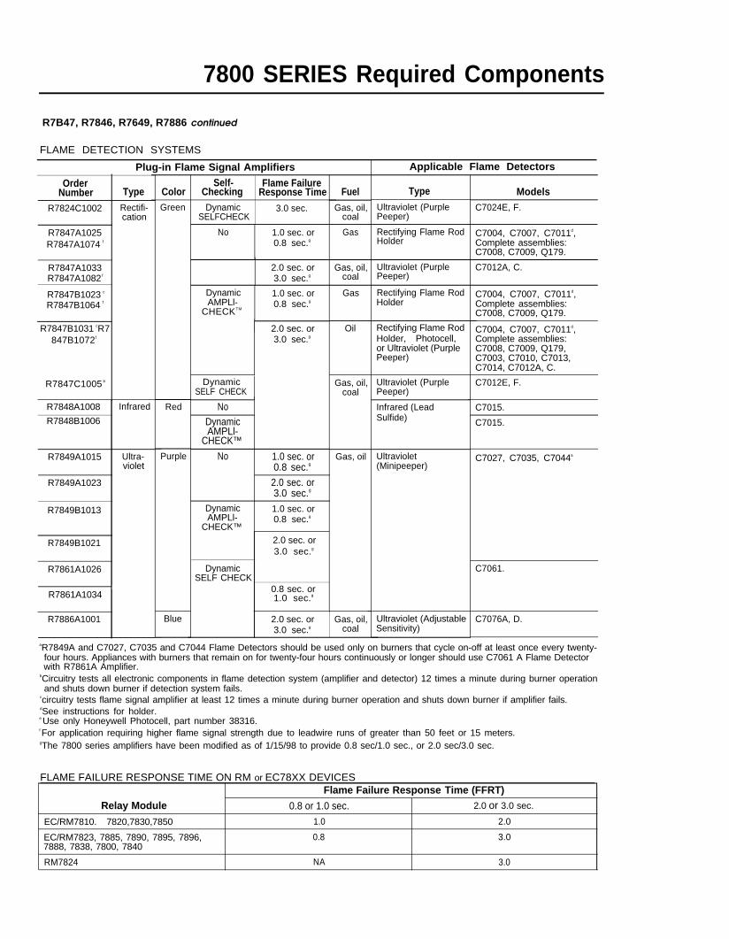
R7B47, R7846, R7649, R7886 continued
FLAME DETECTION SYSTEMS
Plug-in Flame Signal Amplifiers Applicable Flame Detectors
OrderNumber Type
R7824C1002 Rectifi-cation
R7847A1025R7847A1074 f
Self- Flame FailureChecking Response Time Type
Ultraviolet (PurplePeeper)
Color FuelGas, oil,
coal
ModelsC7024E, F.
R7847B1031 cR7847B1072 f
R7848A1008 Infrared
Green
Red
Purple
Blue
Dynamic 3.0 sec.SELFCHECK
Gas Rectifying Flame RodHolder
C7004, C7007, C7011d,Complete assemblies:C7008, C7009, Q179.
C7012A, C.
No 1.0 sec. or0.8 sec.g
2.0 sec. or3.0 sec.g
Gas, oil,coal
Ultraviolet (PurplePeeper)
R7847A1033R7847A1082 f
R7847B1023 c
R7847B1064 f
Dynamic 1.0 sec. orAMPLl-
CHECKTM0.8 sec.g
Gas Rectifying Flame RodHolder
C7004, C7007, C7011d,Complete assemblies:C7008, C7009, Q179.
C7004, C7007, C7011d,Complete assemblies:
2.0 sec. or Oil Rectifying Flame RodHolder, Photocell,or Ultraviolet (PurplePeeper)
3.0 sec.g
C7008, C7009, Q179,C7003, C7010, C7013,
R7847C1005 b
C7014, C7012A, C.
DynamicSELF CHECK
R7848B1006
Gas, oil,coal
Gas, oil
Ultraviolet (PurplePeeper)
Infrared (LeadSulfide)
C7012E, F.
NoDynamicAMPLl-
CHECK™
No 1.0 sec. or0.8 sec.g
2.0 sec. or3.0 sec.g
C7015.
C7015.
C7027, C7035, C7044aUltraviolet(Minipeeper)
R7849A1015 Ultra-violet
R7849A1023
R7849B1013 Dynamic 1.0 sec. orAMPLl-
CHECK™0.8 sec.g
R7849B1021 2.0 sec. or3.0 sec.g
C7061.R7861A1026 DynamicSELF CHECK
R7861A10340.8 sec. or1.0 sec.g
Ultraviolet (AdjustableSensitivity)
R7886A1001 2.0 sec. or Gas, oil,3.0 sec.g coal
C7076A, D.
aR7849A and C7027, C7035 and C7044 Flame Detectors should be used only on burners that cycle on-off at least once every twenty-four hours. Appliances with burners that remain on for twenty-four hours continuously or longer should use C7061 A Flame Detectorwith R7861A Amplifier.
bCircuitry tests all electronic components in flame detection system (amplifier and detector) 12 times a minute during burner operationand shuts down burner if detection system fails.
ccircuitry tests flame signal amplifier at least 12 times a minute during burner operation and shuts down burner if amplifier fails.dSee instructions for holder.
gThe 7800 series amplifiers have been modified as of 1/15/98 to provide 0.8 sec/1.0 sec., or 2.0 sec/3.0 sec.
e Use only Honeywell Photocell, part number 38316.f For application requiring higher flame signal strength due to leadwire runs of greater than 50 feet or 15 meters.
FLAME FAILURE RESPONSE TIME ON RM or EC78XX DEVICESFlame Failure Response Time (FFRT)
Relay Module 0.8 or 1.0 sec. 2.0 or 3.0 sec.
EC/RM7810. 7820,7830,7850 1.0 2.0
EC/RM7823, 7885, 7890, 7895, 7896, 0.8 3.07888, 7838, 7800, 7840
RM7824 NA 3.0
7800 SERIES Required Components
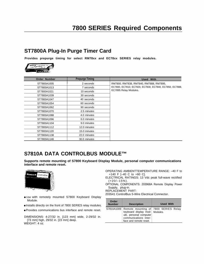
ST7800A Plug-In Purge Timer CardProvides prepurge timing for select RM78xx and EC78xx SERIES relay modules.
Prepurge TimingOrder Number Used With
ST7800A1005 2 seconds RM7800, RM7838, RM7840, RM7888, RM7895,
ST7800A1013 7 seconds EC7800, EC7810, EC7820, EC7830, EC7840, EC7850, EC7888,
ST7800A1021 10 seconds EC7895 Relay Modules.
ST7800A1039 30 seconds
ST7800A1047 40 seconds
ST7800A1054 60 seconds
ST7800A1062 90 seconds
ST7800A1070 2.5 minutes
ST7800A1088 4.0 minutes
ST7800A1096 6.0 minutes
ST7800A1104 9.0 minutes
ST7800A1112 12.0 minutes
ST7800A1120 15.0 minutes
ST7800A1138 22.0 minutes
ST7800A1146 30.0 minutes
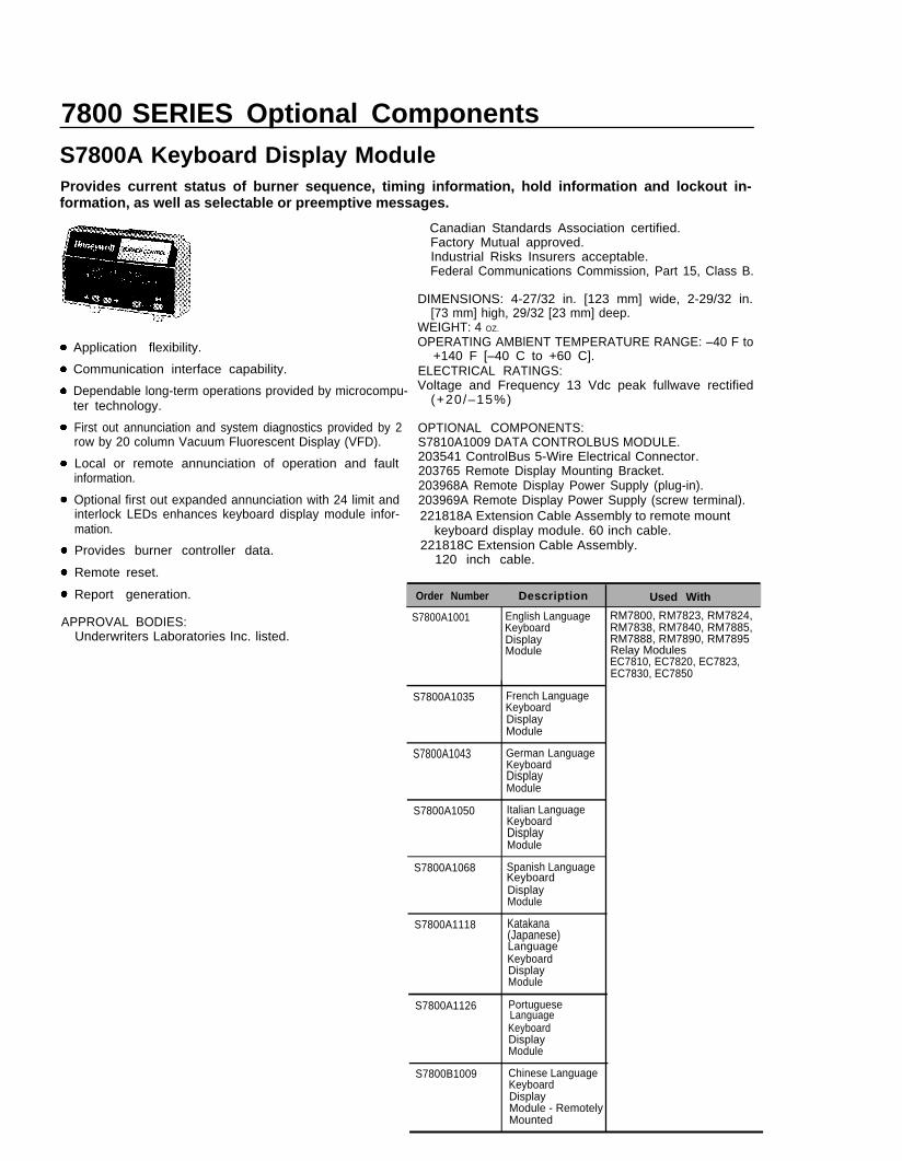
S7810A DATA CONTROLBUS MODULE™Supports remote mounting of S7800 Keyboard Display Module, personal computer communicationsinterface and remote reset.
● Use with remotely mounted S7800 Keyboard Display
OPERATING AMBIENTTEMPERATURE RANGE: –40 F to+140 F [–40 C to +60 C].
ELECTRICAL RATINGS: 13 Vdc peak full-wave rectified(+20/–15%).
OPTIONAL COMPONENTS: 203968A Remote Display PowerSupply, plug-in.
REPLACEMENT PART:203541 ControlBus 5-Wire Electrical Connector.
Module.
● Installs directly on the front of 7800 SERIES relay modules.
● Provides communications bus interface and remote reset.
DIMENSIONS: 4-27/32 in. [123 mm] wide, 2-29/32 in.[73 mm] high, 29/32 in. [23 mm] deep.
WEIGHT: 4 oz.
OrderNumber Description Used With
S7810A1009 Remote mounting of 7800 SERIES Relaykeyboard display mod- Modules.ule, personal computercommunications inter-face and remote reset.
7800 SERIES Optional ComponentsS7800A Keyboard Display ModuleProvides current status of burner sequence, timing information, hold information and lockout in-formation, as well as selectable or preemptive messages.
Application flexibility.
Communication interface capability.
Dependable long-term operations provided by microcompu-ter technology.
First out annunciation and system diagnostics provided by 2row by 20 column Vacuum Fluorescent Display (VFD).
Local or remote annunciation of operation and faultinformation.
Optional first out expanded annunciation with 24 limit andinterlock LEDs enhances keyboard display module infor-mation.
Provides burner controller data.
Remote reset.
Report generation. Order Number Description Used With
APPROVAL BODIES:Underwriters Laboratories Inc. listed.
Canadian Standards Association certified.Factory Mutual approved.Industrial Risks Insurers acceptable.Federal Communications Commission, Part 15, Class B.
DIMENSIONS: 4-27/32 in. [123 mm] wide, 2-29/32 in.[73 mm] high, 29/32 [23 mm] deep.
WEIGHT: 4 OZ.
OPERATING AMBlENT TEMPERATURE RANGE: –40 F to+140 F [–40 C to +60 C].
ELECTRICAL RATINGS:Voltage and Frequency 13 Vdc peak fullwave rectified
(+20/–15%)
OPTIONAL COMPONENTS:S7810A1009 DATA CONTROLBUS MODULE.203541 ControlBus 5-Wire Electrical Connector.203765 Remote Display Mounting Bracket.203968A Remote Display Power Supply (plug-in).203969A Remote Display Power Supply (screw terminal).221818A Extension Cable Assembly to remote mount
keyboard display module. 60 inch cable.221818C Extension Cable Assembly.
120 inch cable.
S7800A1001
S7800A1035
English LanguageKeyboardDisplayModule
French LanguageKeyboardDisplayModule
S7800A1043 German LanguageKeyboardDisplayModule
S7800A1050 Italian LanguageKeyboardDisplayModule
S7800A1068 Spanish Language
DisplayModule
S7800A1118 Katakana(Japanese)
KeyboardDisplayModule
S7800A1126
S7800B1009
Portuguese
KeyboardDisplayModule
Chinese LanguageKeyboardDisplayModule - RemotelyMounted
RM7800, RM7823, RM7824,RM7838, RM7840, RM7885,RM7888, RM7890, RM7895Relay ModulesEC7810, EC7820, EC7823,EC7830, EC7850
Keyboard
Language
Language
7800 SERIES Relay Modules
NEW!
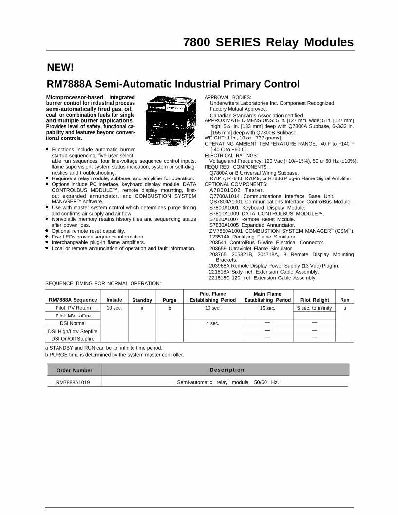
RM7888A Semi-Automatic Industrial Primary ControlMicroprocessor-based integratedburner control for industrial processsemi-automatically fired gas, oil,coal, or combination fuels for singleand multiple burner applications.Provides level of safety, functional ca-pability and features beyond conven-tional controls.
Functions include automatic burnerstartup sequencing, five user select-able run sequences, four line-voltage sequence control inputs,flame supervision, system status indication, system or self-diag-nostics and troubleshooting.Requires a relay module, subbase, and amplifier for operation.Options include PC interface, keyboard display module, DATACONTROLBUS MODULE™, remote display mounting, first-out expanded annunciator, and COMBUSTION SYSTEMMANAGER™ software.Use with master system control which determines purge timingand confirms air supply and air flow.Nonvolatile memory retains history files and sequencing statusafter power loss.Optional remote reset capability.Five LEDs provide sequence information.Interchangeable plug-in flame amplifiers.Local or remote annunciation of operation and fault information.
APPROVAL BODIES:Underwriters Laboratories Inc. Component Recognized.Factory Mutual Approved.Canadian Standards Association certified.
APPROXIMATE DIMENSIONS: 5 in. [127 mm] wide; 5 in. [127 mm]high; 5¼, in. [133 mm] deep with Q7800A Subbase, 6-3/32 in.[155 mm] deep with Q7800B Subbase.
WEIGHT: 1 lb., 10 oz. [737 grams].OPERATING AMBlENT TEMPERATURE RANGE: -40 F to +140 F
[-40 C to +60 C].ELECTRICAL RATINGS:
Voltage and Frequency: 120 Vac (+10/–15%), 50 or 60 Hz (±10%).REQUIRED COMPONENTS:
Q7800A or B Universal Wiring Subbase.R7847, R7848, R7849, or R7886 Plug-in Flame Signal Amplifier.
OPTIONAL COMPONENTS:A78001002 Tester .Q7700A1014 Communications Interface Base Unit.QS7800A1001 Communications Interface ControlBus Module.S7800A1001 Keyboard Display Module.S7810A1009 DATA CONTROLBUS MODULE™.S7820A1007 Remote Reset Module.S7830A1005 Expanded Annunciator.ZM7850A1001 COMBUSTION SYSTEM MANAGERTM (CSMTM).123514A Rectifying Flame Simulator.203541 ControlBus 5-Wire Electrical Connector.203659 Ultraviolet Flame Simulator.203765, 205321B, 204718A, B Remote Display Mounting
Brackets.203968A Remote Display Power Supply (13 Vdc) Plug-in.221818A Sixty-inch Extension Cable Assembly.221818C 120 inch Extension Cable Assembly.
SEQUENCE TIMING FOR NORMAL OPERATION:
Pilot Flame Main FlameRM7888A Sequence Initiate Standby Purge Establishing Period Establishing Period Pilot Relight Run
Pilot: PV Return 10 sec. a b 10 sec. 15 sec. 5 sec. to infinity a
Pilot: MV LoFire —
DSI Normal 4 sec. — —
DSI High/Low Stepfire — —
DSI On/Off Stepfire — —
a STANDBY and RUN can be an infinite time period.b PURGE time is determined by the system master controller.
Order Number Descr ipt ion
RM7888A1019 Semi-automatic relay module, 50/60 Hz.
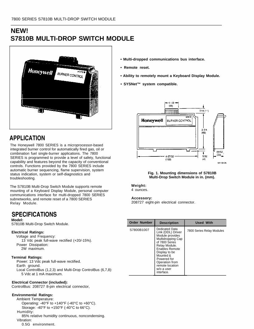
7800 SERIES S7810B MULTI-DROP SWITCH MODULE
NEW!S7810B MULTI-DROP SWITCH MODULE
APPLICATIONThe Honeywell 7800 SERIES is a microprocessor-basedintegrated burner control for automatically fired gas, oil orcombination fuel single-burner applications. The 7800SERIES is programmed to provide a level of safety, functionalcapability and features beyond the capacity of conventionalcontrols. Functions provided by the 7800 SERIES includeautomatic burner sequencing, flame supervision, systemstatus indication, system or self-diagnostics andtroubleshooting.
The S7810B Multi-Drop Switch Module supports remotemounting of a Keyboard Display Module, personal computercommunications interface for multi-dropped 7800 SERIESsubnetworks, and remote reset of a 7800 SERIESRelay Module.
SPECIFICATIONSModel:S7810B Multi-Drop Switch Module. Order Number Description Used With
S7800B1007Electrical Ratings:
Voltage and Frequency:13 Vdc peak full-wave rectified (+20/-15%).
Power Dissipation:2W maximum.
7800 Series Relay Modules
Terminal Ratings:Power: 13 Vdc peak full-wave rectified.Earth ground.Local ControlBus (1,2,3) and Multi-Drop ControlBus (6,7,8):
5 Vdc at 1 mA maximum.
Electrical Connector (included):ControlBus: 208727 8-pin electrical connector,
• Multi-dropped communications bus interface.
• Remote reset.
• Ability to remotely mount a Keyboard Display Module.
• SYSNet™ system compatible.
Fig. 1. Mounting dimensions of S7810BMulti-Drop Switch Module in in. (mm).
Weight:4 ounces.
Accessory:208727 eight-pin electrical connector.
Dedicated DataLink (DDL) DriverModule providesMultidropping Capof 7800 SeriesRelay Module.Enables RemoteDisplay to beMounted &Powered forOperation fromremote locationw/o a userinterface.
Environmental Ratings:Ambient Temperature:
Operating: -40°F to +140°F (-40°C to +60°C).Storage: -40°F to +150°F (-40°C to 66°C).
Humidity:85% relative humidity continuous, noncondensing.
Vibration:0.5G environment.

7800 SERIES Optional Components
S7820A Remote Reset ModuleServes as link between remote reset pushbutton and relay module. Allows RM78xx and EC78xxSERIES relay modules to be reset from a remote location.
●
●
Allows resetting of 7800 SERIES relay module by a remotereset pushbutton up to 1000 feet away.
Installs directly on the front of 7800 SERIES relay module.
DIMENSIONS: 4-27/32 in. [123 mm] wide, 2-29/32 in.[73 mm] high, 29/32 in. [23 mm] deep.
WEIGHT 3 oz.OPERATING AMBlENT TEMPERATURE RANGE: –40 F to
+140 F [–40 C to +60 C].REPLACEMENT PART: 203541 ControlBus 5-Wire Electrical
Connector.
O r d e rNumber Description Used With
S7820A1007 Remote reset module 7800 SERIES relay modulesto reset 7800 SERIESrelay module.
S7830A First-Out Expanded AnnunciatorMicroprocessor-based expanded annunciator to support the RM78xx and EC78XX SERIES relaymodules for first-out annunciation, sequencing, system or self-diagnostics and troubleshooting.
● On/Off status of limits and interlocks.
● RS485 connection to 7800 SERIES relay module.
● Used with Q7800A,B subbases; 7800 SERIES relaymodules.
APPROVAL BODIES:Underwriters Laboratories Inc. listed.Canadian Standards Association certified.
Twenty-six Light Emitting Diodes (LEDs).
Twenty-two LEDs to annunciate Limits and Interlocks.Order Electrical
Number Dimensions Weight InputFour LEDs to annunciate Power, Current Status, First-out S7830A1005 5 in. [127 mm] wide, 1 lb., 13 oz. 120 Vac,Status and System Lockout. 5 in. [127 mm] high, [829 g]. 50/60 Hz
Enhances S7800A Keyboard Display Module sequence3-1/32 in. [77 mm]deep.
hold and lockout messages.
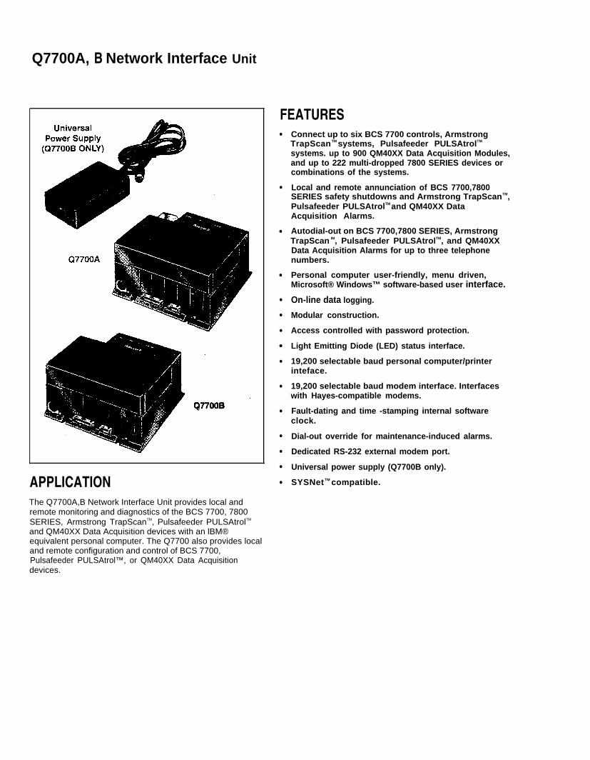
Q7700A, B Network Interface Unit
Q7700B
APPLICATIONThe Q7700A,B Network Interface Unit provides local andremote monitoring and diagnostics of the BCS 7700, 7800SERIES, Armstrong TrapScanTM, Pulsafeeder PULSAtrolTM
and QM40XX Data Acquisition devices with an lBM®
FEATURES●
●
●
●
●
●
●
●
●
●
●
●
●
●
●
Connect up to six BCS 7700 controls, ArmstrongTrapScan TM systems, Pulsafeeder PULSAtrolTM
systems. up to 900 QM40XX Data Acquisition Modules,and up to 222 multi-dropped 7800 SERIES devices orcombinations of the systems.
Local and remote annunciation of BCS 7700,7800SERIES safety shutdowns and Armstrong TrapScanTM,Pulsafeeder PULSAtrolTM and QM40XX DataAcquisition Alarms.
Autodial-out on BCS 7700,7800 SERIES, ArmstrongTrapScan lM, Pulsafeeder PULSAtrolTM, and QM40XXData Acquisition Alarms for up to three telephonenumbers.
Personal computer user-friendly, menu driven,Microsoft® Windows™ software-based user interface.
On-line data logging.
Modular construction.
Access controlled with password protection.
Light Emitting Diode (LED) status interface.
19,200 selectable baud personal computer/printerinteface.
19,200 selectable baud modem interface. Interfaceswith Hayes-compatible modems.
Fault-dating and time -stamping internal softwareclock.
Dial-out override for maintenance-induced alarms.
Dedicated RS-232 external modem port.
Universal power supply (Q7700B only).
SYSNet TM compatible.
equivalent personal computer. The Q7700 also provides localand remote configuration and control of BCS 7700,Pulsafeeder PULSAtrol™, or QM40XX Data Acquisitiondevices.
APPROVAL BODIES:Underwriters Laboratories Inc. component recognized.Canadian Standards Association certified.Factory Mutual approved.Industrial Risk Insurers acceptable.Federal Communications Commission: Part 15, Class A -
Emissions.Canadian Department of Communications certified.
OPERATING AMBlENT TEMPERATURE RANGE: 32 F to130 F [0 C to 54 C].
HUMIDITY: 85% relative humidity continuous, noncondensing.
COMPONENTS:221237 Cover Assembly, Baser Unit.221240 Cover Assembly, Electrical Enclosure.202433 Slot Inserts, ControlBus Slots.200603 ControlBus Module 3-Wire Electrical Connector.203541 ControlBus Module 5-Wire Electrical Connector.QS7700A Communications Interface ControlBus Module
(BCS7700).QS7800A Communications Interface ControlBus Module
(7800 SERIES).
QS7850A General Purpose Interface ControlBus Module.
ACCESSORIES:QM4520A: RS-232C to RS-485 Converter.QS7800B: ControlBus™ Module for multi-drop 7800
Series.QS7800C: ControlBus™ Module for QM40XX Data
Acquisition modules.QS7800D: ControlBus™ Module for Armstrong Trap
Scan™.QS7800E: ControlBus™ Module for Pulsafeeder
PULSAtrol™.ZM7850A: Combustion System Manager® Software for
personal computer.ZM7850B: SYSNet™ Operator Interface Software for
personal computer.200603: ControlBus™ Module Electrical Connector.202433: Slot Inserts, ControlBusTM Slots.221237/1698: Cover Assembly, Base Unit.221240/1698: Cover Assembly, Electrical Enclosure.
Null Modem Adaptor (obtain locally).209164: Power Supply, panel mounting, 85 to 132 Vac
or 170 to 264 Vac input voltage, switchable; 1.4Amaximum input current; 24 Vdc (±10%) outputvoltage; 3A maximum output current.
209162 Power Supply, DIN-Rail mounting, 110 Vacinput voltage; 225mA input current; 24 Vdc (±1%)output voltage; 1A output current.
209163 Power Supply, DIN-Rail mounting, 220 Vacinput voltage; 225mA input current; 24 Vdc (±1%)output voltage; 1A output current.
208670; IEC 120V power cord for universal powersupply (obtain other plug configuration locally).
208289: Universal Power Supply, 100 to 250 Vac,50/60 Hz.
Order Electrical Electrical Signal Direct TerminalNumber Dimensions Weight Ratings Connectors Characteristics Hookup
Q7700A1014 9 in. [229 mm] wide, 4 Ibs., Voltage and Frequency: RS232C Port 25 Selectable baud RS232C Connection,8 in. [203 mm] high, 10 oz. 120 Vac (+10/-15%),60 “D” pin connector; rate up to 19,200 PINS. 1 Ground:4-7/8 in. [123 mm] Hz (±10%) ControlBus Local Protective.deep. Communication: RS485 communications. 2 Transmit Data (TD).
Remote 3 Receive Data (RD).
Q77C0B1004 5 lbs., 100-250 Vac, 50/60 Hz communications 7 Ground: Signal.13 oz. Power Supply (part requires an external
number 208289 included) modem.
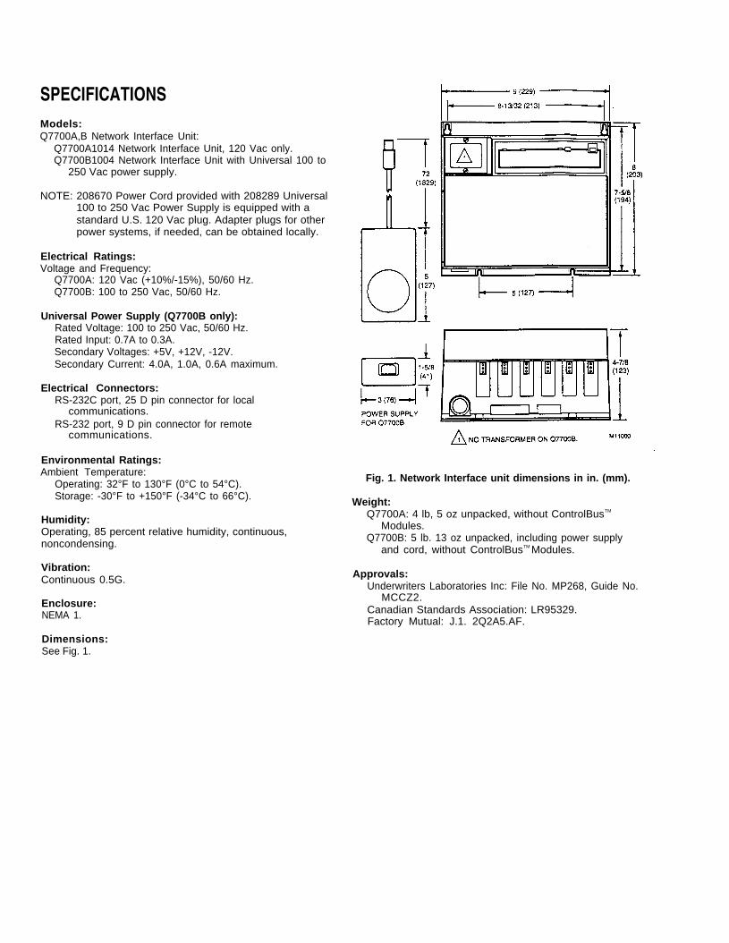
SPECIFICATIONSModels:Q7700A,B Network Interface Unit:
Q7700A1014 Network Interface Unit, 120 Vac only.Q7700B1004 Network Interface Unit with Universal 100 to
250 Vac power supply.
NOTE: 208670 Power Cord provided with 208289 Universal100 to 250 Vac Power Supply is equipped with astandard U.S. 120 Vac plug. Adapter plugs for otherpower systems, if needed, can be obtained locally.
Electrical Ratings:Voltage and Frequency:
Q7700A: 120 Vac (+10%/-15%), 50/60 Hz.Q7700B: 100 to 250 Vac, 50/60 Hz.
Universal Power Supply (Q7700B only):Rated Voltage: 100 to 250 Vac, 50/60 Hz.Rated Input: 0.7A to 0.3A.Secondary Voltages: +5V, +12V, -12V.Secondary Current: 4.0A, 1.0A, 0.6A maximum.
Electrical Connectors:RS-232C port, 25 D pin connector for local
communications.RS-232 port, 9 D pin connector for remote
communications.
Environmental Ratings:Ambient Temperature:
Operating: 32°F to 130°F (0°C to 54°C).Storage: -30°F to +150°F (-34°C to 66°C).
Humidity:Operating, 85 percent relative humidity, continuous,noncondensing.
Vibration:Continuous 0.5G.
Enclosure:NEMA 1.
Fig. 1. Network Interface unit dimensions in in. (mm).
Weight:Q7700A: 4 lb, 5 oz unpacked, without ControlBusTM
Modules.Q7700B: 5 lb. 13 oz unpacked, including power supply
and cord, without ControlBusTM Modules.
Approvals:Underwriters Laboratories Inc: File No. MP268, Guide No.
MCCZ2.Canadian Standards Association: LR95329.Factory Mutual: J.1. 2Q2A5.AF.
Dimensions:See Fig. 1.
7800 SERIES Communications
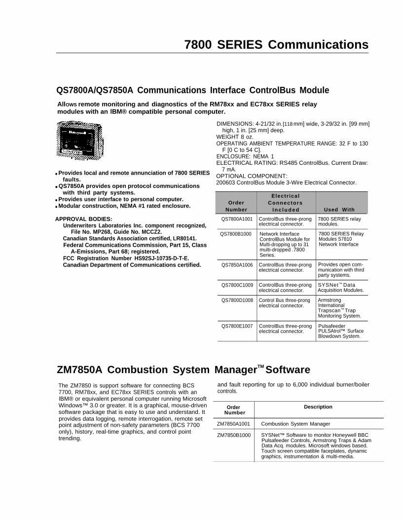
QS7800A/QS7850A Communications Interface ControlBus ModuleAllOWS remote monitoring and diagnostics of the RM78xx and EC78xx SERIES relaymodules with an lBM® compatible personal computer.
● Provides local and remote annunciation of 7800 SERIESfaults.
● QS7850A provides open protocol communicationswith third party systems.
● Provides user interface to personal computer.● Modular construction, NEMA #1 rated enclosure.
Electr icalOrder Connectors
Number I n c l u d e d Used With
APPROVAL BODIES:Underwriters Laboratories Inc. component recognized,
File No. MP268, Guide No. MCCZ2.Canadian Standards Association certified, LR80141.Federal Communications Commission, Part 15, Class
A-Emissions, Part 68; registered.FCC Registration Number HS92SJ-10735-D-T-E.Canadian Department of Communications certified.
DIMENSIONS: 4-21/32 in. [118 mm] wide, 3-29/32 in. [99 mm]high, 1 in. [25 mm] deep.
WEIGHT 8 oz.OPERATING AMBIENT TEMPERATURE RANGE: 32 F to 130
F [0 C to 54 C].ENCLOSURE: NEMA 1ELECTRICAL RATING: RS485 ControlBus. Current Draw:
7 mA.OPTIONAL COMPONENT:200603 ControlBus Module 3-Wire Electrical Connector.
QS7800A1001 ControlBus three-prong 7800 SERlES relayelectrical connector.
QS7800B1000 Network Interface 7800 SERIES RelayControlBus Module for Modules S7810Multi-dropping up to 31 Network Interfacemulti-dropped .7800Series.
QS7850A1006 ControlBus three-prong Provides open com-electrical connector. munication with third
party systems.
QS7800C1009 ControlBus three-prong SYSNet TM Dataelectrical connector. Acquisition Modules.
QS7800D1008 Control Bus three-prong Armstrongelectrical connector. International
TrapscanTM TrapMonitoring System.
QS7800E1007 ControlBus three-prong Pulsafeederelectrical connector. PULSAtrol™ Surface
Blowdown System.
modules.
ZM7850A Combustion System ManagerTM SoftwareThe ZM7850 is support software for connecting BCS7700, RM78xx, and EC78xx SERIES controls with anlBM® or equivalent personal computer running MicrosoftWindows™ 3.0 or greater. It is a graphical, mouse-drivensoftware package that is easy to use and understand. Itprovides data logging, remote interrogation, remote setpoint adjustment of non-safety parameters (BCS 7700only), history, real-time graphics, and control pointtrending.
and fault reporting for up to 6,000 individual burner/boilercontrols.
Order DescriptionNumber
ZM7850A1001 Combustion System Manager
ZM7850B1000 SYSNet™ Software to monitor Honeywell BBCPulsafeeder Controls, Armstrong Traps & AdamData Acq. modules. Microsoft windows based.Touch screen compatible faceplates, dynamicgraphics, instrumentation & multi-media.
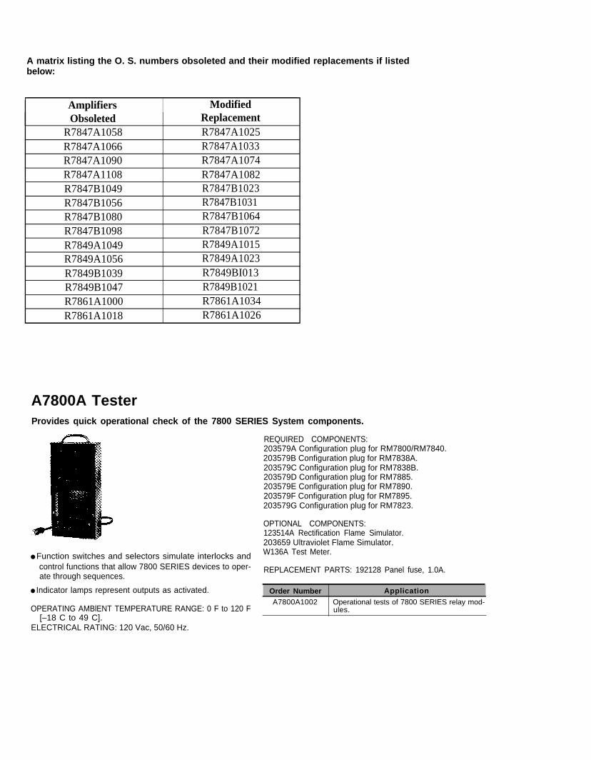
A matrix listing the O. S. numbers obsoleted and their modified replacements if listedbelow:
Amplifiers ModifiedObsoleted Replacement
R7847A1058 R7847A1025R7847A1066 R7847A1033R7847A1090 R7847A1074R7847A1108 R7847A1082R7847B1049 R7847B1023R7847B1056 R7847B1031R7847B1080 R7847B1064R7847B1098 R7847B1072R7849A1049 R7849A1015R7849A1056 R7849A1023R7849B1039 R7849BI013R7849B1047 R7849B1021R7861A1000 R7861A1034R7861A1018 R7861A1026
A7800A TesterProvides quick operational check of the 7800 SERIES System components.
● Function switches and selectors simulate interlocks andcontrol functions that allow 7800 SERIES devices to oper-ate through sequences.
● Indicator lamps represent outputs as activated. Order Number ApplicationA7800A1002 Operational tests of 7800 SERIES relay mod-
OPERATING AMBlENT TEMPERATURE RANGE: 0 F to 120 F[–18 C to 49 C].
ELECTRICAL RATING: 120 Vac, 50/60 Hz.
REQUIRED COMPONENTS:203579A Configuration plug for RM7800/RM7840.203579B Configuration plug for RM7838A.203579C Configuration plug for RM7838B.203579D Configuration plug for RM7885.203579E Configuration plug for RM7890.203579F Configuration plug for RM7895.203579G Configuration plug for RM7823.
OPTIONAL COMPONENTS:123514A Rectification Flame Simulator.203659 Ultraviolet Flame Simulator.W136A Test Meter.
REPLACEMENT PARTS: 192128 Panel fuse, 1.0A.
ules.
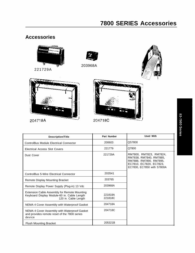
7800 SERIES Accessories
Accessories
203968A221729A
Description/Title Part Number Used With
ControlBus Module Electrical Connector 200603 QS7800
Electrical Access Slot Covers 221779 Q7800
Dust Cover 221729A RM7800, RM7823, RM7824,RM7838, RM7840, RM7885,RM7888, RM7890, RM7895,EC7810, EC7820, EC7823,EC7830, EC7850 with S7800A
ControlBus 5-Wire Electrical Connector 203541
Remote Display Mounting Bracket 203765
Remote Display Power Supply (Plug-in) 13 Vdc 203968A
Extension Cable Assembly for Remote MountingKeyboard Display Module-60 in. Cable Length 221818A
120 in. Cable Length 221818C
NEMA 4 Cover Assembly with Waterproof Gasket 204718A
NEMA 4 Cover Assembly with Waterproof Gasket 204718Cand provides remote reset of the 7800 seriesdevice
Flush Mounting Bracket 205321B
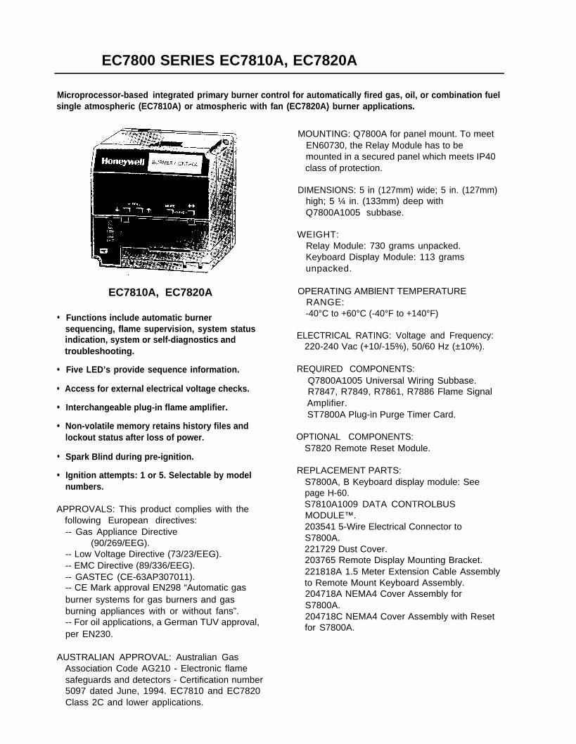
EC7800 SERIES EC7810A, EC7820A
Microprocessor-based integrated primary burner control for automatically fired gas, oil, or combination fuelsingle atmospheric (EC7810A) or atmospheric with fan (EC7820A) burner applications.
●
●
●
●
●
●
●
EC7810A, EC7820A
Functions include automatic burnersequencing, flame supervision, system statusindication, system or self-diagnostics andtroubleshooting.
Five LED’s provide sequence information.
Access for external electrical voltage checks.
Interchangeable plug-in flame amplifier.
Non-volatile memory retains history files andlockout status after loss of power.
Spark Blind during pre-ignition.
Ignition attempts: 1 or 5. Selectable by modelnumbers.
APPROVALS: This product complies with thefollowing European directives:-- Gas Appliance Directive
(90/269/EEG).-- Low Voltage Directive (73/23/EEG).-- EMC Directive (89/336/EEG).-- GASTEC (CE-63AP307011).-- CE Mark approval EN298 “Automatic gasburner systems for gas burners and gasburning appliances with or without fans”.-- For oil applications, a German TUV approval,per EN230.
AUSTRALIAN APPROVAL: Australian GasAssociation Code AG210 - Electronic flamesafeguards and detectors - Certification number5097 dated June, 1994. EC7810 and EC7820Class 2C and lower applications.
MOUNTING: Q7800A for panel mount. To meetEN60730, the Relay Module has to bemounted in a secured panel which meets IP40class of protection.
DIMENSIONS: 5 in (127mm) wide; 5 in. (127mm)high; 5 ¼ in. (133mm) deep withQ7800A1005 subbase.
WEIGHT:Relay Module: 730 grams unpacked.Keyboard Display Module: 113 gramsunpacked.
OPERATING AMBlENT TEMPERATURERANGE:-40°C to +60°C (-40°F to +140°F)
ELECTRICAL RATING: Voltage and Frequency:220-240 Vac (+10/-15%), 50/60 Hz (±10%).
REQUIRED COMPONENTS:Q7800A1005 Universal Wiring Subbase.R7847, R7849, R7861, R7886 Flame SignalAmplifier.ST7800A Plug-in Purge Timer Card.
OPTIONAL COMPONENTS:S7820 Remote Reset Module.
REPLACEMENT PARTS:S7800A, B Keyboard display module: Seepage H-60.S7810A1009 DATA CONTROLBUSMODULE™.203541 5-Wire Electrical Connector toS7800A.221729 Dust Cover.203765 Remote Display Mounting Bracket.221818A 1.5 Meter Extension Cable Assemblyto Remote Mount Keyboard Assembly.204718A NEMA4 Cover Assembly forS7800A.204718C NEMA4 Cover Assembly with Resetfor S7800A.
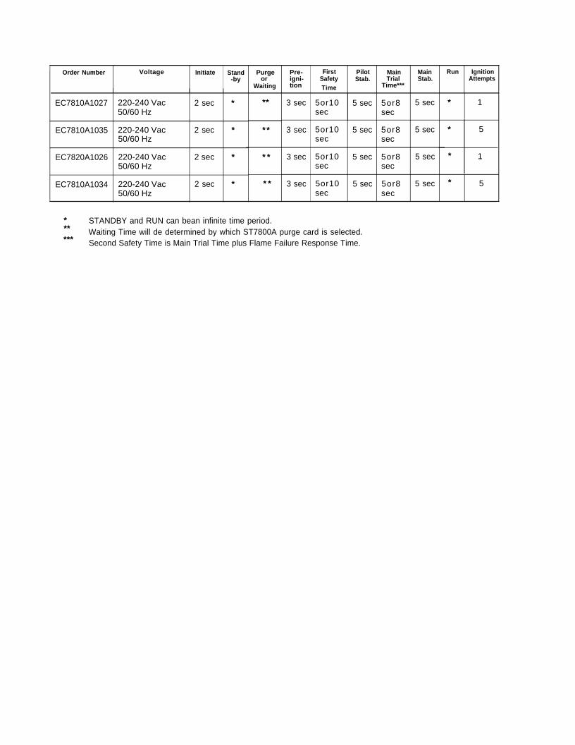
Order Number Voltage Initiate Stand-by or
Time
EC7810A1027 220-240 Vac 2 sec *50/60 Hz
EC7810A1035 220-240 Vac 2 sec *50/60 Hz
EC7820A1026 220-240 Vac 2 sec *50/60 Hz
EC7810A1034 220-240 Vac 2 sec *50/60 Hz
**
Purge
Waiting
* 5
1
*
* *
* *
Pre-igni-tion
3 sec
3 sec
3 sec *
* * 3 sec
First Pilot MainSafety Stab. Trial
Time***
5or10 5 sec 5or8sec sec
5or10 5 sec 5or8sec sec
5or10 5 sec 5or8sec sec
5or10 5 sec 5or8sec sec
*
STANDBY and RUN can bean infinite time period.** Waiting Time will de determined by which ST7800A purge card is selected.*** Second Safety Time is Main Trial Time plus Flame Failure Response Time.
MainStab.
5 sec
5 sec
5 sec
5 sec
Run IgnitionAttempts
1
5
*
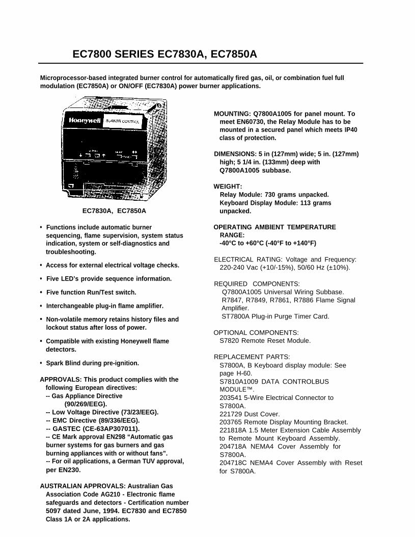
EC7800 SERIES EC7830A, EC7850A
Microprocessor-based integrated burner control for automatically fired gas, oil, or combination fuel fullmodulation (EC7850A) or ON/OFF (EC7830A) power burner applications.
●
●
●
●
●
●
●
●
EC7830A, EC7850A
Functions include automatic burnersequencing, flame supervision, system statusindication, system or self-diagnostics andtroubleshooting.
Access for external electrical voltage checks.
Five LED’s provide sequence information.
Five function Run/Test switch.
Interchangeable plug-in flame amplifier.
Non-volatile memory retains history files andlockout status after loss of power.
Compatible with existing Honeywell flamedetectors.
Spark Blind during pre-ignition.
APPROVALS: This product complies with thefollowing European directives:-- Gas Appliance Directive
(90/269/EEG).-- Low Voltage Directive (73/23/EEG).-- EMC Directive (89/336/EEG).-- GASTEC (CE-63AP307011).-- CE Mark approval EN298 “Automatic gasburner systems for gas burners and gasburning appliances with or without fans”.-- For oil applications, a German TUV approval,per EN230.
AUSTRALIAN APPROVALS: Australian Gas
MOUNTING: Q7800A1005 for panel mount. Tomeet EN60730, the Relay Module has to bemounted in a secured panel which meets IP40class of protection.
DIMENSIONS: 5 in (127mm) wide; 5 in. (127mm)high; 5 1/4 in. (133mm) deep withQ7800A1005 subbase.
WEIGHT:Relay Module: 730 grams unpacked.Keyboard Display Module: 113 gramsunpacked.
OPERATING AMBlENT TEMPERATURERANGE:-40°C to +60°C (-40°F to +140°F)
ELECTRICAL RATING: Voltage and Frequency:220-240 Vac (+10/-15%), 50/60 Hz (±10%).
REQUIRED COMPONENTS:Q7800A1005 Universal Wiring Subbase.R7847, R7849, R7861, R7886 Flame SignalAmplifier.ST7800A Plug-in Purge Timer Card.
OPTIONAL COMPONENTS:S7820 Remote Reset Module.
REPLACEMENT PARTS:S7800A, B Keyboard display module: Seepage H-60.S7810A1009 DATA CONTROLBUSMODULE™.203541 5-Wire Electrical Connector toS7800A.221729 Dust Cover.203765 Remote Display Mounting Bracket.221818A 1.5 Meter Extension Cable Assemblyto Remote Mount Keyboard Assembly.204718A NEMA4 Cover Assembly forS7800A.204718C NEMA4 Cover Assembly with Resetfor S7800A.
Association Code AG210 - Electronic flamesafeguards and detectors - Certification number5097 dated June, 1994. EC7830 and EC7850Class 1A or 2A applications.
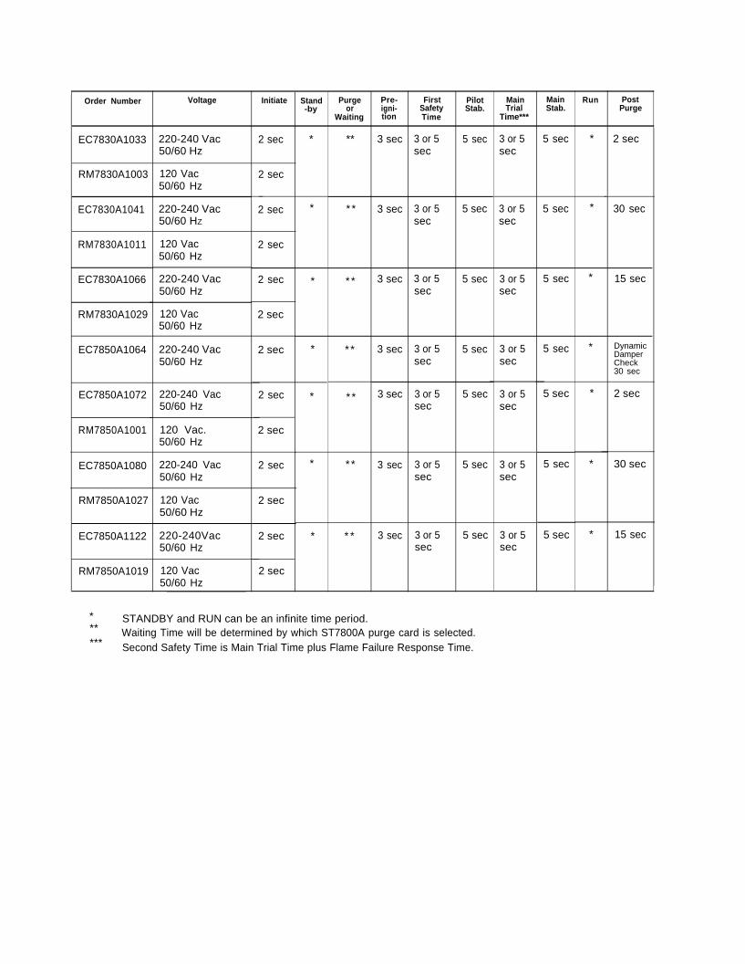
Run PostPurge
Stand-by
Order Numberor
Pre-igni-tion Time
FirstSafety
3 or 5sec
PilotStab.
5 sec
MainTrial
Time***
MainStab.
5 sec
Voltage Initiate Purge
Waiting
EC7830A1033 220-240 Vac50/60 Hz
* ** *
* * *
3 sec
3 sec
3 sec
3 or 5sec
2 sec2 sec
2 secRM7830A1003 120 Vac50/60 Hz
3 or 5sec
5 secEC7830A1041 220-240 Vac50/60 HZ
3 or 5sec
5 sec * 30 sec2 sec
RM7830A1011 120 Vac50/60 Hz
2 sec
* * * 3 or 5sec
5 secEC7830A1066 220-240 Vac50/60 Hz
3 or 5sec
5 sec * 15 sec2 sec
RM7830A1029 120 Vac50/60 Hz
2 sec
* * * 3 or 5sec
3 or 5sec
3 or 5sec
5 secEC7850A1064 * DynamicDamperCheck30 sec
3 sec
3 sec
5 sec220-240 Vac50/60 Hz
2 sec
* * * 5 sec220-240 Vac50/60 Hz
3 or 5sec
5 sec *
* * *
2 secEC7850A1072 2 sec
RM7850A1001 120 Vac.50/60 Hz
220-240 Vac50/60 Hz
120 Vac50/60 Hz
220-240Vac50/60 Hz
2 sec
2 sec
2 sec
2 sec
5 secEC7850A1080 3 or 5sec
5 sec 3 or 5sec
* 30 sec3 sec
RM7850A1027
* * * 5 sec * 15 sec3 or 5sec
EC7850A1122 3 sec 3 or 5sec
5 sec
RM7850A1019 120 Vac50/60 Hz
2 sec
* STANDBY and RUN can be an infinite time period.** Waiting Time will be determined by which ST7800A purge card is selected.*** Second Safety Time is Main Trial Time plus Flame Failure Response Time.