7835/7845/7846/7847 liquid density meter - emerson...micro motion® 7835/7845/7846/7847 technical...
TRANSCRIPT
Micro Motion®
7835/7845/7846/7847Technical Manual 78355080_US, Rev. D December 2008
7835/7845/7846/7847 Liquid Density Meter
Standard and Advanced Electronics

Contents 7835/45/46/47 Technical Manual
Cont-2
Copyright 2008
Micro Motion® pursues a policy of continuous development and product improvement. The specification in this document
may therefore be changed without notice. To the best of our knowledge, the information contained in this document is
accurate and Micro Motion® cannot be held responsible for any errors, omissions or other misinformation contained herein.
No part of this document may be photocopied or reproduced without prior written consent of Micro Motion®.
7835/45/46/47 Technical Manual Contents
Cont-3
IMPORTANT NOTICE
DO NOT drop the meter. Handle with care.
DO NOT use liquids incompatible with the MATERIALS OF CONSTRUCTIONS.
DO NOT position RUPTURE DISC where failure could cause personal injury.
DO NOT allow axial loading from PIPEWORK STRESSES to exceed ½ TONNE.
DO NOT operate the meter above its RATED PRESSURE.
DO NOT PRESSURE TEST above the specified TEST PRESSURE.
DO NOT expose the meter to excessive vibration (of >0.5g continuous).
ENSURE all ELECTRICAL SAFETY requirements are applied.
ENSURE meter and associated pipework are PRESSURE TESTED to 1½ times the maximum operating pressure after installation.
ENSURE meter is not TRANSPORTED when it contains hazardous fluids. This includes fluids that may have leaked into, and are still contained, within the case.Returns Forms are included as Appendix J.
Contents 7835/45/46/47 Technical Manual
Cont-4
Contents
Chapter 1 Introduction
1.1 About this manual ......................................................................................................................1-1 1.2 Product Overview.......................................................................................................................1-2 1.3 Meter Product Range .................................................................................................................1-2 1.4 Electronics Product Range........................................................................................................1-3 1.5 Advanced Electronics................................................................................................................1-4 ---- Part Number Identification tables for 7835, 7845, 7846 and 7847 ..........................................1-5
Chapter 2 Mechanical Installation
2.1 General ........................................................................................................................................2-1 2.2 Planning an installation .............................................................................................................2-2 2.3 Meter mounting and pipework ..................................................................................................2-3 2.4 Pressure drop in the meter........................................................................................................2-6 2.5 Special considerations for hygienic applications ...................................................................2-7 2.6 Post-installation checks ............................................................................................................2-7
Chapter 3 Advanced Unit Electrical Installation and Configuration
3.1 General ........................................................................................................................................3-1 3.2 Planning an electrical installation.............................................................................................3-2 3.3 Electrical installation in safe areas...........................................................................................3-3 3.4 Electrical installation in hazardous areas ................................................................................3-6 3.5 Baseboard configuration ...........................................................................................................3-8 3.6 Baseboard plus HART® option board .......................................................................................3-93.7 Advanced density post-Installation checks ...........................................................................3-10
Chapter 4 Standard Density Unit Electrical Installation
4.1 General ........................................................................................................................................4-1 4.2 Ground connections ..................................................................................................................4-1 4.3 Use with Flow Computers and Signal Converters...................................................................4-1 4.4 Use with customer’s own equipment .......................................................................................4-24.5 Post-installation checks ............................................................................................................4-4
Chapter 5 Entrained Gas Electronics Electrical Installation
5.1 General ........................................................................................................................................5-1 5.2 Ground connections ..................................................................................................................5-1 5.3 Use with Flow Computers and Signal Converters...................................................................5-1 5.4 Use with customer’s own equipment .......................................................................................5-25.5 Post-installation checks ............................................................................................................5-3
Chapter 6 Calibration and Performance
6.1 General ........................................................................................................................................6-1 6.2 Interpretation of calibration certificate .....................................................................................6-1 6.3 Calibration...................................................................................................................................6-7 6.4 Performance .............................................................................................................................6-10
7835/45/46/47 Technical Manual Contents
Cont-5
Contents
Chapter 7 Remote Display and Digital Communications
7.1 Introduction .......................................................................................................................... 7-1 7.2 Mechanical installation of the 7965 Remote Display......................................................... 7-2 7.3 Safe area electrical installation ........................................................................................... 7-3 7.4 Hazardous area electrical installation ................................................................................ 7-37.5 Configuring the baseboard using a Remote Display ........................................................ 7-4 7.6 Multi-drop installation .......................................................................................................... 7-8 7.7 Electrical installation of computer devices........................................................................ 7-9
Chapter 8 General Maintenance
8.1 General .................................................................................................................................. 8-1 8.2 Fault Analysis ....................................................................................................................... 8-1 8.3 General Maintenance Procedure......................................................................................... 8-1
Chapter 9 Using Adview
9.1 What is Adview?................................................................................................................... 9-1 9.2 Installing Adview .................................................................................................................. 9-1 9.3 Starting Adview .................................................................................................................... 9-2 9.4 Using Adview........................................................................................................................ 9-5
Appendix A 7835 Specification
A.1 Performance.........................................................................................................................A-1 A.2 Mechanical ...........................................................................................................................A-1 A.3 The 7835 meter versions .....................................................................................................A-2 A.4 Safety approvals ..................................................................................................................A-2
Appendix B 7845/46/47 Specification
B.1 Performance.........................................................................................................................B-1 B.2 Mechanical ...........................................................................................................................B-2 B.3 7845/46/47 Meter Versions ..................................................................................................B-2 B.4 Safety Approvals..................................................................................................................B-4
Appendix C 7845/47 Entrained Gas Specification
C.1 Performance.........................................................................................................................C-1 C.2 Mechanical ...........................................................................................................................C-2 C.3 7845/47 meter versions .......................................................................................................C-2 C.4 Safety approvals ..................................................................................................................C-2
Appendix D Electronics Specifications
D.1 Standard electronics ...........................................................................................................D-1 D.2 Standard entrained gas electronics ...................................................................................D-1 D.3 Advanced electronics..........................................................................................................D-1 D.4 Environmental performance ...............................................................................................D-2
Contents 7835/45/46/47 Technical Manual
Cont-6
Contents
Appendix E Baseboard Calculations and Configurable Factors
E.1 Baseboard configuration .................................................................................................... E-1 E.2 Baseboard diagnostics ....................................................................................................... E-4 E.3 Baseboard calculations ...................................................................................................... E-5
Appendix F Specimen Calibration Certificates
Appendix G Conversion Tables and Product Data
G.1 Conversion tables...............................................................................................................G-1 G.2 Product data ........................................................................................................................G-4
Appendix H Modbus Communications
H.1 Introduction ......................................................................................................................... H-1 H.2 Outline of Modbus communications ................................................................................. H-1 H.3 Modbus dialect .................................................................................................................... H-2 H.4 Establishing Modbus communications............................................................................. H-3 H.5 Modbus commands............................................................................................................. H-4 H.6 Modbus register assignments ........................................................................................... H-4H.7 Index and enumeration codes............................................................................................ H-7
Appendix I HART® Software
I.1 Introduction.............................................................................................................................I-1 I.2 HART® basics..........................................................................................................................I-1 I.3 Electrical installation..............................................................................................................I-3 I.4 HART® commands ..................................................................................................................I-4 I.5 Transmitter specific command structure .............................................................................I-7 I.6 Summary of HART® functionality ........................................................................................I-10
Appendix J Returns Forms
Appendix K Certified System Drawings
7835/45/46/47 Technical Manual Introduction
Page 1-1
Chapter 1 Introduction
1.1 About this manual
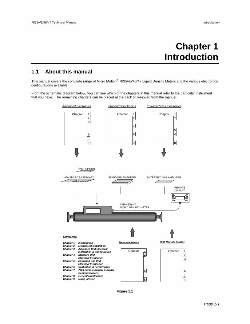
This manual covers the complete range of Micro Motion® 7835/45/46/47 Liquid Density Meters and the various electronics configurations available. From the schematic diagram below, you can see which of the chapters in this manual refer to the particular instrument that you have. The remaining chapters can be placed at the back or removed from the manual.
7835/45/46/47LIQUID DENSITY METER
ENTRAINED GAS AMPLIFIERSTANDARD AMPLIFIERADVANCED BASEBOARD
HART OPTION
CONTENTS
Chapter 1: IntroductionChapter 2: Mechanical InstallationChapter 3: Advanced Unit Electrical
Installation & ConfigurationChapter 4: Standard Unit
Electrical InstallationChapter 5: Entrained Gas Unit
Electrical InstallationChapter 6: Calibration & PerformanceChapter 7: 7965 Remote Display & Digital
Communications Chapter 8: General MaintenanceChapter 9: Using Adview
Standard Electronics Entrained Gas Electronics
Meter Mechanics
Advanced Electronics
7965 Remote Display
REMOTE DISPLAY
Chapter 1
3
8
2
6
Chapter 1
8
2
6
4
Chapter 1
8
2
65
Chapter 1
8
2
6
Chapter 1
3
78
2
6
Figure 1.1
Introduction 7835/45/46/47 Technical Manual
Page 1-2
1.2 Product Overview
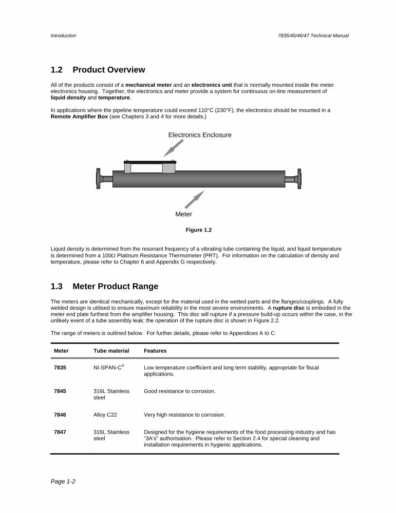
All of the products consist of a mechanical meter and an electronics unit that is normally mounted inside the meter electronics housing. Together, the electronics and meter provide a system for continuous on-line measurement of liquid density and temperature. In applications where the pipeline temperature could exceed 110°C (230°F), the electronics should be mounted in a Remote Amplifier Box (see Chapters 3 and 4 for more details.)
Electronics Enclosure
Meter
transduce rs
Figure 1.2 Liquid density is determined from the resonant frequency of a vibrating tube containing the liquid, and liquid temperature is determined from a 100 Platinum Resistance Thermometer (PRT). For information on the calculation of density and temperature, please refer to Chapter 6 and Appendix G respectively.
1.3 Meter Product Range
The meters are identical mechanically, except for the material used in the wetted parts and the flanges/couplings. A fully welded design is utilised to ensure maximum reliability in the most severe environments. A rupture disc is embodied in the meter end plate furthest from the amplifier housing. This disc will rupture if a pressure build-up occurs within the case, in the unlikely event of a tube assembly leak; the operation of the rupture disc is shown in Figure 2.2. The range of meters is outlined below. For further details, please refer to Appendices A to C.
Meter Tube material Features
7835 NI-SPAN-C® Low temperature coefficient and long term stability, appropriate for fiscal applications.
7845 316L Stainless steel
Good resistance to corrosion.
7846 Alloy C22 Very high resistance to corrosion.
7847 316L Stainless steel
Designed for the hygiene requirements of the food processing industry and has “3A’s” authorisation. Please refer to Section 2.4 for special cleaning and installation requirements in hygienic applications.
7835/45/46/47 Technical Manual Introduction
Page 1-3
1.4 Electronics Product Range
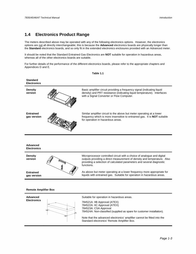
The meters described above may be operated with any of the following electronics options. However, the electronics options are not all directly interchangeable; this is because the Advanced electronics boards are physically longer than the Standard electronics boards, and so only fit in the extended electronics enclosures provided with an Advanced meter. It should be noted that the Standard Entrained Gas Electronics are NOT suitable for operation in hazardous areas, whereas all of the other electronics boards are suitable. For further details of the performance of the different electronics boards, please refer to the appropriate chapters and Appendices D and E.
Table 1.1
Standard Electronics
Density version
Basic amplifier circuit providing a frequency signal (indicating liquid density) and PRT resistance (indicating liquid temperature). Interfaces with a Signal Converter or Flow Computer.
Entrained gas version
Similar amplifier circuit to the above but meter operating at a lower frequency which is more insensitive to entrained gas. It is NOT suitable for operation in hazardous areas.
Advanced Electronics
Density version
Entrained gas version
Microprocessor controlled circuit with a choice of analogue and digital outputs providing a direct measurement of density and temperature. Also providing a selection of calculated parameters and several diagnostic functions.
As above but meter operating at a lower frequency more appropriate for liquids with entrained gas. Suitable for operation in hazardous areas.
Remote Amplifier Box
Advanced Electronics
Suitable for operation in hazardous areas.
784521A: IIB Approval (ATEX) 784522A: IIC Approval (ATEX) 784523A: CSA Approval 784524A: Non-classified (supplied as spare for customer installation). Note that the advanced electronics’ amplifier cannot be fitted into the Standard electronics’ Remote Amplifier Box.
Introduction 7835/45/46/47 Technical Manual
Page 1-4
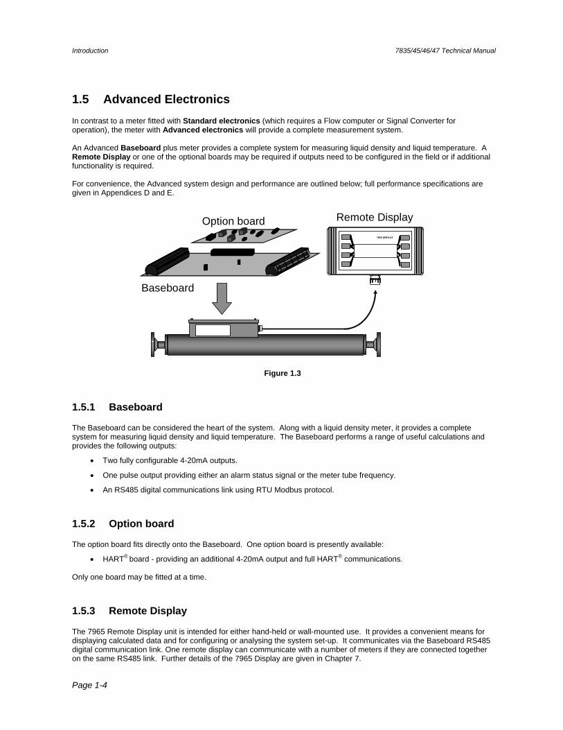
1.5 Advanced Electronics
In contrast to a meter fitted with Standard electronics (which requires a Flow computer or Signal Converter for operation), the meter with Advanced electronics will provide a complete measurement system. An Advanced Baseboard plus meter provides a complete system for measuring liquid density and liquid temperature. A Remote Display or one of the optional boards may be required if outputs need to be configured in the field or if additional functionality is required. For convenience, the Advanced system design and performance are outlined below; full performance specifications are given in Appendices D and E.
Baseboard
Option board Remote Display7965 DISPLAY
Figure 1.3
1.5.1 Baseboard
The Baseboard can be considered the heart of the system. Along with a liquid density meter, it provides a complete system for measuring liquid density and liquid temperature. The Baseboard performs a range of useful calculations and provides the following outputs:
Two fully configurable 4-20mA outputs.
One pulse output providing either an alarm status signal or the meter tube frequency.
An RS485 digital communications link using RTU Modbus protocol.
1.5.2 Option board
The option board fits directly onto the Baseboard. One option board is presently available:
HART® board - providing an additional 4-20mA output and full HART® communications. Only one board may be fitted at a time.
1.5.3 Remote Display
The 7965 Remote Display unit is intended for either hand-held or wall-mounted use. It provides a convenient means for displaying calculated data and for configuring or analysing the system set-up. It communicates via the Baseboard RS485 digital communication link. One remote display can communicate with a number of meters if they are connected together on the same RS485 link. Further details of the 7965 Display are given in Chapter 7.
7835/45/46/47 Technical Manual Introduction
Page 1-5
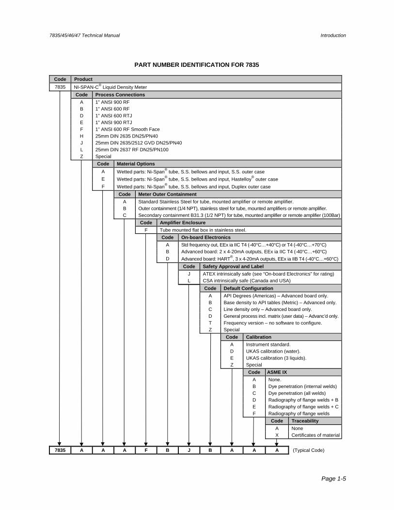
PART NUMBER IDENTIFICATION FOR 7835
Code Product
7835 NI-SPAN-C® Liquid Density Meter Code Process Connections
A 1” ANSI 900 RF B 1” ANSI 600 RF D 1” ANSI 600 RTJ E 1” ANSI 900 RTJ F 1” ANSI 600 RF Smooth Face H 25mm DIN 2635 DN25/PN40 J 25mm DIN 2635/2512 GVD DN25/PN40 L 25mm DIN 2637 RF DN25/PN100 Z Special Code Material Options
A Wetted parts: Ni-Span® tube, S.S. bellows and input, S.S. outer case E Wetted parts: Ni-Span® tube, S.S. bellows and input, Hastelloy® outer case F Wetted parts: Ni-Span® tube, S.S. bellows and input, Duplex outer case Code Meter Outer Containment
A Standard Stainless Steel for tube, mounted amplifier or remote amplifier. B Outer containment (1/4 NPT), stainless steel for tube, mounted amplifiers or remote amplifier. C Secondary containment B31.3 (1/2 NPT) for tube, mounted amplifier or remote amplifier (100Bar) Code Amplifier Enclosure
F Tube mounted flat box in stainless steel. Code On-board Electronics
A Std frequency out, EEx ia IIC T4 (-40°C…+40°C) or T4 (-40°C…+70°C) B Advanced board: 2 x 4-20mA outputs, EEx ia IIC T4 (-40°C…+60°C) D Advanced board: HART®, 3 x 4-20mA outputs, EEx ia IIB T4 (-40°C…+60°C) Code Safety Approval and Label
J ATEX intrinsically safe (see “On-board Electronics” for rating) L CSA intrinsically safe (Canada and USA) Code Default Configuration
A API Degrees (Americas) – Advanced board only. B Base density to API tables (Metric) – Advanced only. C Line density only – Advanced board only. D General process incl. matrix (user data) – Advanc’d only. T Frequency version – no software to configure. Z Special Code Calibration
A Instrument standard. D UKAS calibration (water). E UKAS calibration (3 liquids). Z Special Code ASME IX
A None. B Dye penetration (internal welds) C Dye penetration (all welds) D Radiography of flange welds + B E Radiography of flange welds + C F Radiography of flange welds Code Traceability
A None X Certificates of material
7835 A A A F B J B A A A (Typical Code)
Introduction 7835/45/46/47 Technical Manual
Page 1-6
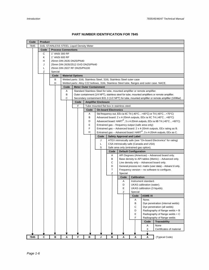
PART NUMBER IDENTIFICATION FOR 7845
Code Product
7845 316L STAINLESS STEEL Liquid Density Meter Code Process Connections
C 1” ANSI 300 RF K 1” ANSI 600 RF H 25mm DIN 2635 DN25/PN40 J 25mm DIN 2635/2512 GVD DN25/PN40 L 25mm DIN 2637 RF DN25/PN100 Z Special Code Material Options
B Wetted parts: 316L Stainless Steel, 316L Stainless Steel outer case D Wetted parts: Alloy C22 bellows, 316L Stainless Steel tube, flanges and outer case. NACE. Code Meter Outer Containment
A Standard Stainless Steel for tube, mounted amplifier or remote amplifier. B Outer containment (1/4 NPT), stainless steel for tube, mounted amplifiers or remote amplifier. C Secondary containment B31.3 (1/2 NPT) for tube, mounted amplifier or remote amplifier (100Bar) Code Amplifier Enclosure
F Tube mounted flat box in stainless steel. Code On-board Electronics
A Std frequency out, EEx ia IIC T4 (-40°C…+40°C) or T4 (-40°C…+70°C) B Advanced board: 2 x 4-20mA outputs, EEx ia IIC T4 (-40°C…+60°C) D Advanced board: HART®, 3 x 4-20mA outputs, EEx ia IIB T4 (-40°C…+60°C) E Entrained gas – frequency output (safe area only) F Entrained gas – Advanced board: 2 x 4-20mA outputs, EEx rating as B. H Entrained gas – Advanced board: HART®, 3 x 4-20mA outputs, EEx as C. Code Safety Approval and Label
J ATEX intrinsically safe (see “On-board Electronics” for rating) L CSA intrinsically safe (Canada and USA) S Safe area only (entrained gas option). Code Default Configuration
A API Degrees (Americas) – Advanced board only. B Base density to API tables (Metric) – Advanced only. C Line density only – Advanced board only. D General process incl. matrix (user data) – Advanc’d only. T Frequency version – no software to configure. Z Special Code Calibration
A Instrument standard. D UKAS calibration (water). E UKAS calibration (3 liquids). Z Special Code ASME IX
A None. B Dye penetration (internal welds) C Dye penetration (all welds) D Radiography of flange welds + B E Radiography of flange welds + C F Radiography of flange welds Code Traceability
A None X Certificates of material
7845 C B A F B J B A A A (Typical Code)
7835/45/46/47 Technical Manual Introduction
Page 1-7
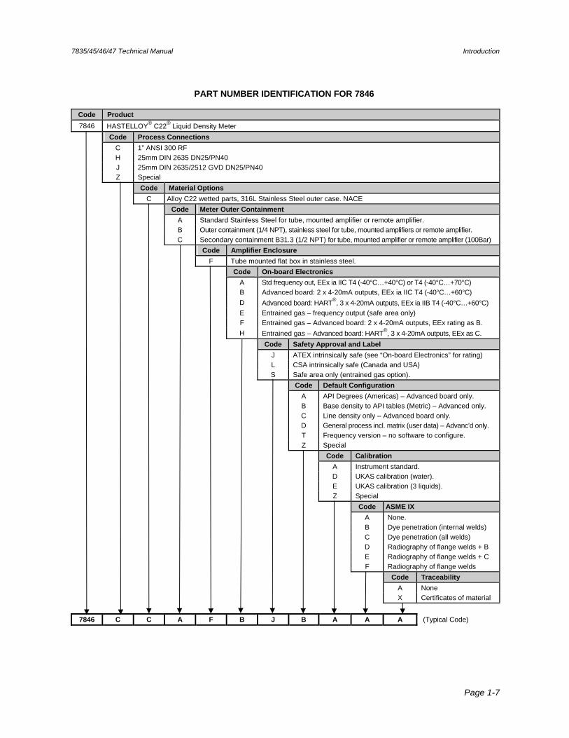
PART NUMBER IDENTIFICATION FOR 7846
Code Product
7846 HASTELLOY® C22® Liquid Density Meter Code Process Connections
C 1” ANSI 300 RF H 25mm DIN 2635 DN25/PN40 J 25mm DIN 2635/2512 GVD DN25/PN40 Z Special Code Material Options
C Alloy C22 wetted parts, 316L Stainless Steel outer case. NACE Code Meter Outer Containment
A Standard Stainless Steel for tube, mounted amplifier or remote amplifier. B Outer containment (1/4 NPT), stainless steel for tube, mounted amplifiers or remote amplifier. C Secondary containment B31.3 (1/2 NPT) for tube, mounted amplifier or remote amplifier (100Bar) Code Amplifier Enclosure
F Tube mounted flat box in stainless steel. Code On-board Electronics
A Std frequency out, EEx ia IIC T4 (-40°C…+40°C) or T4 (-40°C…+70°C) B Advanced board: 2 x 4-20mA outputs, EEx ia IIC T4 (-40°C…+60°C) D Advanced board: HART®, 3 x 4-20mA outputs, EEx ia IIB T4 (-40°C…+60°C) E Entrained gas – frequency output (safe area only) F Entrained gas – Advanced board: 2 x 4-20mA outputs, EEx rating as B. H Entrained gas – Advanced board: HART®, 3 x 4-20mA outputs, EEx as C. Code Safety Approval and Label
J ATEX intrinsically safe (see “On-board Electronics” for rating) L CSA intrinsically safe (Canada and USA) S Safe area only (entrained gas option). Code Default Configuration
A API Degrees (Americas) – Advanced board only. B Base density to API tables (Metric) – Advanced only. C Line density only – Advanced board only. D General process incl. matrix (user data) – Advanc’d only. T Frequency version – no software to configure. Z Special Code Calibration
A Instrument standard. D UKAS calibration (water). E UKAS calibration (3 liquids). Z Special Code ASME IX
A None. B Dye penetration (internal welds) C Dye penetration (all welds) D Radiography of flange welds + B E Radiography of flange welds + C F Radiography of flange welds Code Traceability
A None X Certificates of material
7846 C C A F B J B A A A (Typical Code)
Introduction 7835/45/46/47 Technical Manual
Page 1-8
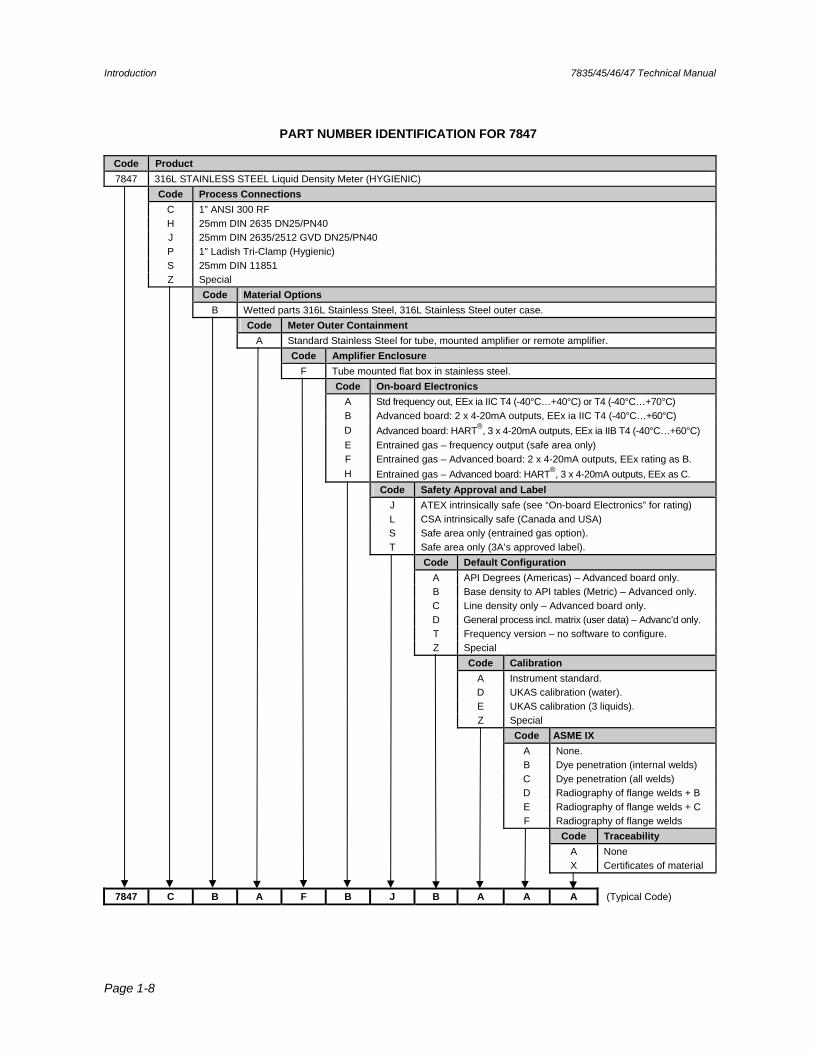
PART NUMBER IDENTIFICATION FOR 7847
Code Product
7847 316L STAINLESS STEEL Liquid Density Meter (HYGIENIC) Code Process Connections
C 1” ANSI 300 RF H 25mm DIN 2635 DN25/PN40 J 25mm DIN 2635/2512 GVD DN25/PN40 P 1” Ladish Tri-Clamp (Hygienic) S 25mm DIN 11851 Z Special Code Material Options
B Wetted parts 316L Stainless Steel, 316L Stainless Steel outer case. Code Meter Outer Containment
A Standard Stainless Steel for tube, mounted amplifier or remote amplifier. Code Amplifier Enclosure
F Tube mounted flat box in stainless steel. Code On-board Electronics
A Std frequency out, EEx ia IIC T4 (-40°C…+40°C) or T4 (-40°C…+70°C) B Advanced board: 2 x 4-20mA outputs, EEx ia IIC T4 (-40°C…+60°C) D Advanced board: HART®, 3 x 4-20mA outputs, EEx ia IIB T4 (-40°C…+60°C) E Entrained gas – frequency output (safe area only) F Entrained gas – Advanced board: 2 x 4-20mA outputs, EEx rating as B. H Entrained gas – Advanced board: HART®, 3 x 4-20mA outputs, EEx as C. Code Safety Approval and Label
J ATEX intrinsically safe (see “On-board Electronics” for rating) L CSA intrinsically safe (Canada and USA) S Safe area only (entrained gas option). T Safe area only (3A’s approved label). Code Default Configuration
A API Degrees (Americas) – Advanced board only. B Base density to API tables (Metric) – Advanced only. C Line density only – Advanced board only. D General process incl. matrix (user data) – Advanc’d only. T Frequency version – no software to configure. Z Special Code Calibration
A Instrument standard. D UKAS calibration (water). E UKAS calibration (3 liquids). Z Special Code ASME IX
A None. B Dye penetration (internal welds) C Dye penetration (all welds) D Radiography of flange welds + B E Radiography of flange welds + C F Radiography of flange welds Code Traceability
A None X Certificates of material
7847 C B A F B J B A A A (Typical Code)
7835/45/46/47 Technical Manual Mechanical Installation
Page 2-1
Chapter 2 Mechanical Installation
2.1 General
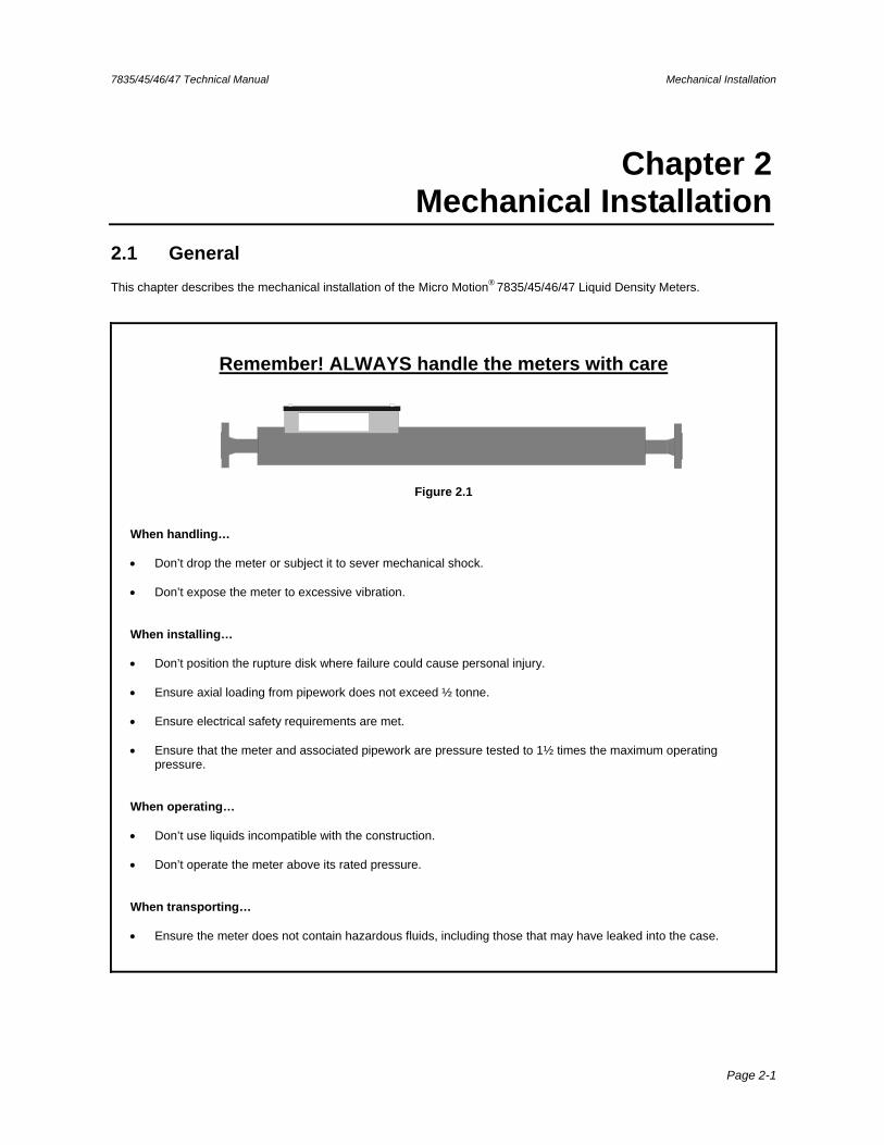
This chapter describes the mechanical installation of the Micro Motion® 7835/45/46/47 Liquid Density Meters.
Remember! ALWAYS handle the meters with care
Figure 2.1
When handling… Don’t drop the meter or subject it to sever mechanical shock. Don’t expose the meter to excessive vibration. When installing… Don’t position the rupture disk where failure could cause personal injury. Ensure axial loading from pipework does not exceed ½ tonne. Ensure electrical safety requirements are met.
Ensure that the meter and associated pipework are pressure tested to 1½ times the maximum operating
pressure. When operating… Don’t use liquids incompatible with the construction. Don’t operate the meter above its rated pressure. When transporting… Ensure the meter does not contain hazardous fluids, including those that may have leaked into the case.
Mechanical Installation 7835/45/46/47 Technical Manual
Page 2-2
2.2 Planning an installation
When planning the installation of a meter it is important to consider the following factors:
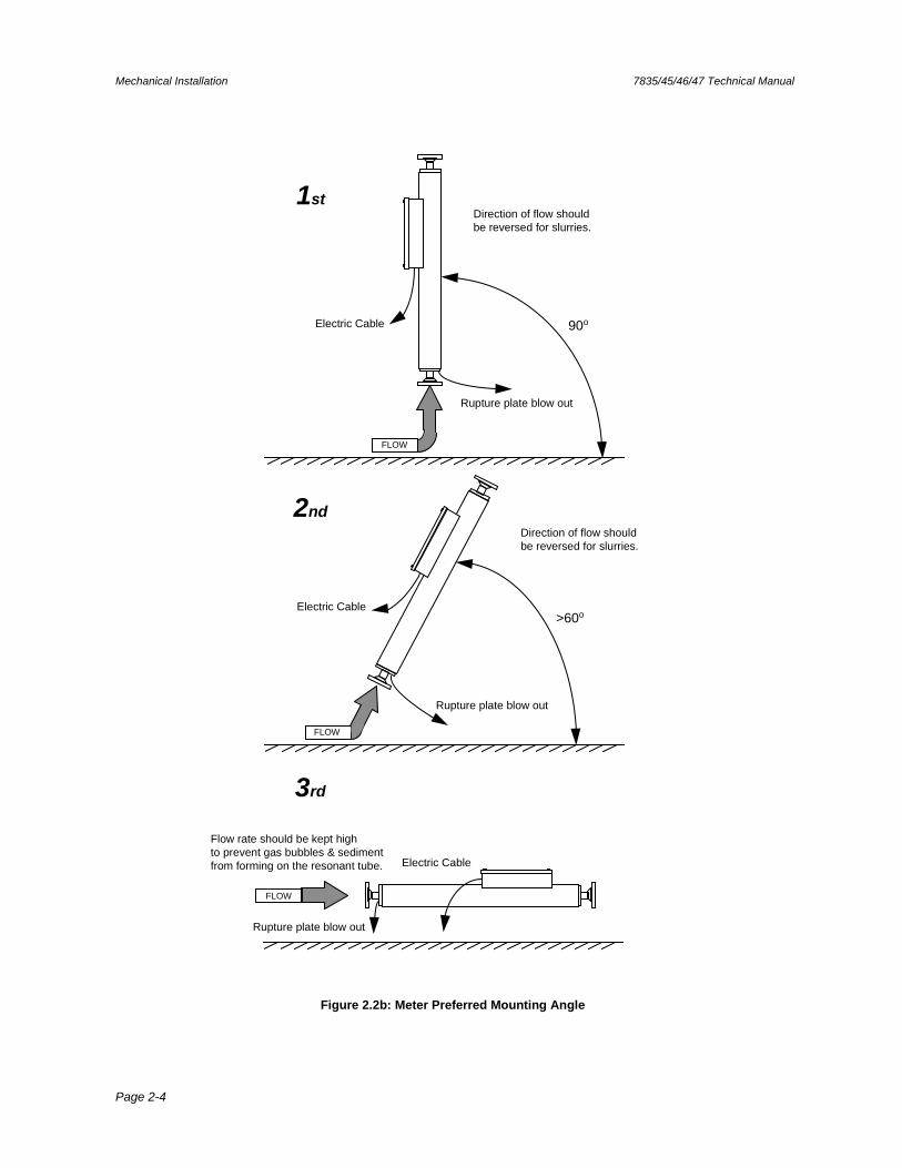
Safety The meter should be orientated such that, if there is a mechanical structure failure within the instrument, the liquid is discharged from the rupture disc in a safe manner. Please refer to figure 2.2b for details.
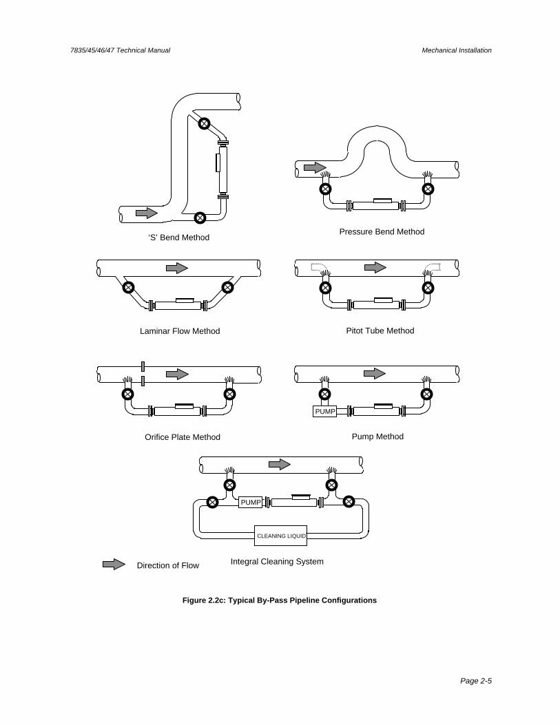
Serviceability Installing the meter in a by-pass configuration allows it to be removed for servicing or calibration without affecting the main pipeline. Possible by-pass configurations are shown in Figure 2.2c
Performance
Pipe stresses and vibration
Axial load should not exceed ½ tonne, so pipework should have a degree of flexibility. Excessive pipe vibration should be avoided.
Gas bubbles The presence of gas bubbles can seriously affect the meter performance and so the following points should be considered:-
The liquid must always be at a pressure substantially above its vapour pressure. All pipework couplings and joints must be air tight. No vortex should be present at the inlet to the meter. Cavitations, caused by pumping, should not generate bubbles from dissolved gases. If a pump is used it is should ‘push’ rather than ‘pull’ the product through the meter.
Note: For entrained gas units where the density of aerated mixtures is to be measured some of the above recommendations may not be applicable.
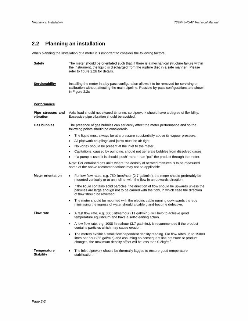
Meter orientation For low flow rates, e.g. 750 litres/hour (2.7 gal/min.), the meter should preferably be mounted vertically or at an incline, with the flow in an upwards direction.
If the liquid contains solid particles, the direction of flow should be upwards unless the particles are large enough not to be carried with the flow, in which case the direction of flow should be reversed.
The meter should be mounted with the electric cable running downwards thereby minimising the ingress of water should a cable gland become defective.
Flow rate A fast flow rate, e.g. 3000 litres/hour (11 gal/min.), will help to achieve good temperature equilibrium and have a self-cleaning action.
A low flow rate, e.g. 1000 litres/hour (3.7 gal/min.), is recommended if the product contains particles which may cause erosion.
The meters exhibit a small flow dependent density reading. For flow rates up to 15000 litres per hour (55 gal/min) and assuming no consequent line pressure or product changes, the maximum density offset will be less than 0.2kg/m3.
Temperature Stability
The inlet pipework should be thermally lagged to ensure good temperature stabilisation.
7835/45/46/47 Technical Manual Mechanical Installation
Page 2-3
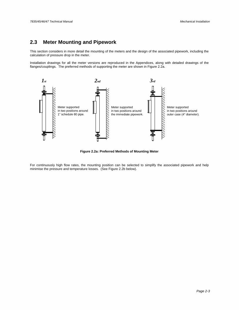
2.3 Meter Mounting and Pipework
This section considers in more detail the mounting of the meters and the design of the associated pipework, including the calculation of pressure drop in the meter. Installation drawings for all the meter versions are reproduced in the Appendices, along with detailed drawings of the flanges/couplings. The preferred methods of supporting the meter are shown in Figure 2.2a.
1st
Meter supportedin two positions around1” schedule 80 pipe.
Meter supportedin two positions aroundouter case (4” diameter).
3rd
Meter supportedin two positions aroundthe immediate pipework.
2nd
Figure 2.2a: Preferred Methods of Mounting Meter
For continuously high flow rates, the mounting position can be selected to simplify the associated pipework and help minimise the pressure and temperature losses. (See Figure 2.2b below).
Mechanical Installation 7835/45/46/47 Technical Manual
Page 2-4
1st
FLOW
90o
Rupture plate blow out
Electric Cable
Direction of flow should be reversed for slurries.
2nd
>60o
Rupture plate blow out
Electric Cable
Direction of flow should be reversed for slurries.
FLOW
Flow rate should be kept high to prevent gas bubbles & sediment from forming on the resonant tube.
3rd
Rupture plate blow out
Electric Cable
FLOW
Figure 2.2b: Meter Preferred Mounting Angle
7835/45/46/47 Technical Manual Mechanical Installation
Page 2-5
‘S’ Bend MethodPressure Bend Method
Pitot Tube MethodLaminar Flow Method
Orifice Plate Method
Direction of Flow
Pump Method
PUMP
PUMP
Integral Cleaning System
CLEANING LIQUID
Figure 2.2c: Typical By-Pass Pipeline Configurations
Mechanical Installation 7835/45/46/47 Technical Manual
Page 2-6
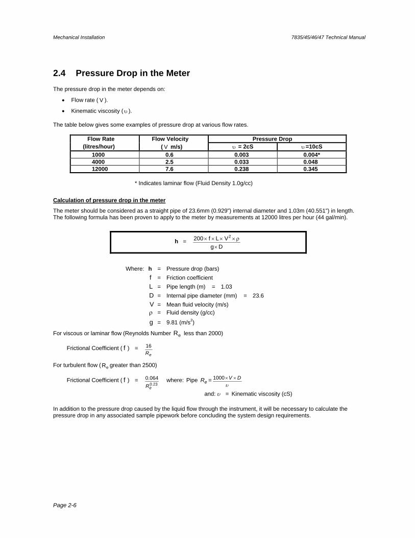
2.4 Pressure Drop in the Meter
The pressure drop in the meter depends on:
Flow rate ( V ).
Kinematic viscosity ( ). The table below gives some examples of pressure drop at various flow rates.
Flow Rate Flow Velocity Pressure Drop (litres/hour) ( V m/s) = 2cS =10cS
1000 0.6 0.003 0.004* 4000 2.5 0.033 0.048 12000 7.6 0.238 0.345
* Indicates laminar flow (Fluid Density 1.0g/cc)
Calculation of pressure drop in the meter
The meter should be considered as a straight pipe of 23.6mm (0.929”) internal diameter and 1.03m (40.551”) in length. The following formula has been proven to apply to the meter by measurements at 12000 litres per hour (44 gal/min).
h = Dg
VLf200 2
Where: h = Pressure drop (bars) f = Friction coefficient L = Pipe length (m) = 1.03 D = Internal pipe diameter (mm) = 23.6 V = Mean fluid velocity (m/s) = Fluid density (g/cc)
g = 9.81 (m/s2)
For viscous or laminar flow (Reynolds Number eR less than 2000)
Frictional Coefficient ( f ) = eR
16
For turbulent flow ( eR greater than 2500)
Frictional Coefficient ( f ) = 23.0
064.0
eR where: Pipe eR =
DV 1000
and: = Kinematic viscosity (cS)
In addition to the pressure drop caused by the liquid flow through the instrument, it will be necessary to calculate the pressure drop in any associated sample pipework before concluding the system design requirements.
7835/45/46/47 Technical Manual Mechanical Installation
Page 2-7
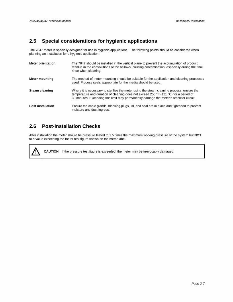
2.5 Special considerations for hygienic applications
The 7847 meter is specially designed for use in hygienic applications. The following points should be considered when planning an installation for a hygienic application.
Meter orientation The 7847 should be installed in the vertical plane to prevent the accumulation of product residue in the convolutions of the bellows, causing contamination, especially during the final rinse when cleaning.
Meter mounting The method of meter mounting should be suitable for the application and cleaning processes used. Process seals appropriate for the media should be used.
Steam cleaning Where it is necessary to sterilise the meter using the steam cleaning process, ensure the temperature and duration of cleaning does not exceed 250 °F (121 °C) for a period of 30 minutes. Exceeding this limit may permanently damage the meter’s amplifier circuit.
Post installation Ensure the cable glands, blanking plugs, lid, and seal are in place and tightened to prevent moisture and dust ingress.
2.6 Post-Installation Checks
After installation the meter should be pressure tested to 1.5 times the maximum working pressure of the system but NOT to a value exceeding the meter test figure shown on the meter label.
CAUTION: If the pressure test figure is exceeded, the meter may be irrevocably damaged.

Mechanical Installation 7835/45/46/47 Technical Manual
Page 2-8
7835/45/46/47 Technical Manual Advanced Unit Electrical Installation and Configuration
Page 3-1
Chapter 3 Advanced Unit Electrical Installation and
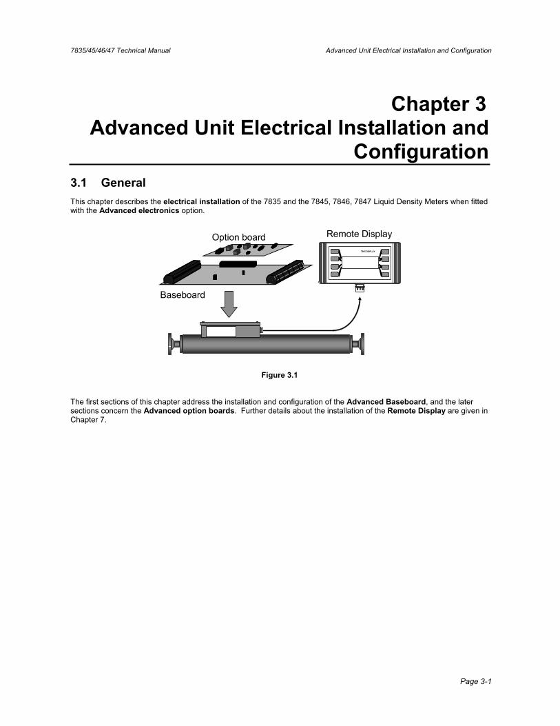
Configuration3.1 General This chapter describes the electrical installation of the 7835 and the 7845, 7846, 7847 Liquid Density Meters when fitted with the Advanced electronics option.
Baseboard
Option board Remote Display7965 DISPLAY
Figure 3.1
The first sections of this chapter address the installation and configuration of the Advanced Baseboard, and the later sections concern the Advanced option boards. Further details about the installation of the Remote Display are given in Chapter 7.
Advanced Unit Electrical Installation and Configuration 7835/45/46/47 Technical Manual
Page 3-2
3.2 Planning an Electrical Installation When planning the electrical installation of an Advanced unit, it is important to consider the points given below.
Safety • Electrical installation in hazardous areas requires strict adherence to local codes of practice.
• For installation of the CSA certified unit in a hazardous area, refer to Appendix K.
• For installation of the ATEX certified unit in a hazardous area, refer to the appropriate safety instructions booklet (78355015/SI, 78355038/SI, or 78355065/SI).
Power supply • The Advanced electronics operate from a nominal 24V supply, but will operate from any supply in the range 9.5V to 28V, measured at the supply terminals on the baseboard.
• The output circuits on the baseboard are all loop-powered and are isolated from the main circuit. If required, the main circuit and the output circuits can be powered from a common power supply.
• When selecting a suitable power supply voltage, you must take into account voltage drops caused by the connecting cable (see below) and in hazardous areas, across zener barriers or galvanic isolators.
Ground connections • The earthing pads on the baseboard (see Figure 3.3a) must make good contact with the meter case via the M3 bolts.
• If a HART® option board is used, the indicated earthing point must make good contact with the baseboard earthing points.
• The 0V power supply lead should be earthed at the supply end, or at the safety barriers if applicable.
Cable parameters • Where long cable lengths are required the cable resistance may be significant. When operating from a 24V supply in safe areas the following limits apply:
Maximum line resistance (Ω) Power supply 260 Remote Display 60 Outputs 500
For further details relating to the maximum line resistance, please refer to Appendix D.
• When calculating the maximum cable lengths please note that the current loop is 2 times the cable length, and so the cable resistance is given by:
2 x (dc resistance per unit length) x (cable length)
• Typical cables would comply with BS5308 Type 1 or 2.
EMC • To meet the EC Directive for EMC (Electromagnetic Compatibility), it is recommended that the meter be connected using a suitable instrumentation cable.
The instrumentation cable should have individual screen(s), foil or braid over each twisted pair and an overall screen to cover all cores. Where permissible, the overall screen should be connected to earth at both ends (360° bonded at both ends). The inner individual screen(s) should be connected at only one end, the controller (e.g. signal converter) end.
• Note that for intrinsic safety, termination of the inner individual screen(s) to earth in the hazardous area is NOT generally permitted.
• Metal cable glands should be used where the cables enter the meter amplifier box. Unused cable ports should be fitted with metal blanking plugs.
• When the 78452 (Advanced Remote Amplifier) is used, the ferrite ring, which is supplied, must be fitted around the connecting cable. For installation in hazardous areas, refer to the certified system drawings in Appendix K, and the safety instruction booklet (78355015/SI or 78355038/SI) that came with the meter.
7835/45/46/47 Technical Manual Advanced Unit Electrical Installation and Configuration
Page 3-3
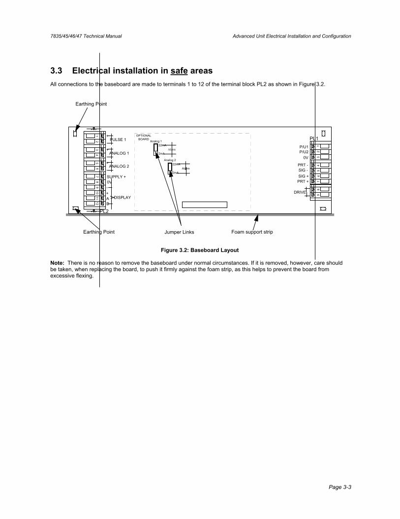
3.3 Electrical installation in safe areas All connections to the baseboard are made to terminals 1 to 12 of the terminal block PL2 as shown in Figure 3.2.
Analog 1
Analog 2
Alarm22mA
2mA
Alarm22mA
2mA
OPTIONALBOARD PL1
PL2
P/U1P/U2
0V
PRT -SIG -SIG +PRT +
DRIVE
PULSE 1+
-
ANALOG 1+
-
SUPPLY + 0V-+AB
DISPLAY
Earthing Point
Earthing Point
ANALOG 2+
-
12
34
56
78
910
1112
12
34
56
78
9
Jumper Links Foam support strip
Figure 3.2: Baseboard Layout
Note: There is no reason to remove the baseboard under normal circumstances. If it is removed, however, care should be taken, when replacing the board, to push it firmly against the foam strip, as this helps to prevent the board from excessive flexing.
Advanced Unit Electrical Installation and Configuration 7835/45/46/47 Technical Manual
Page 3-4
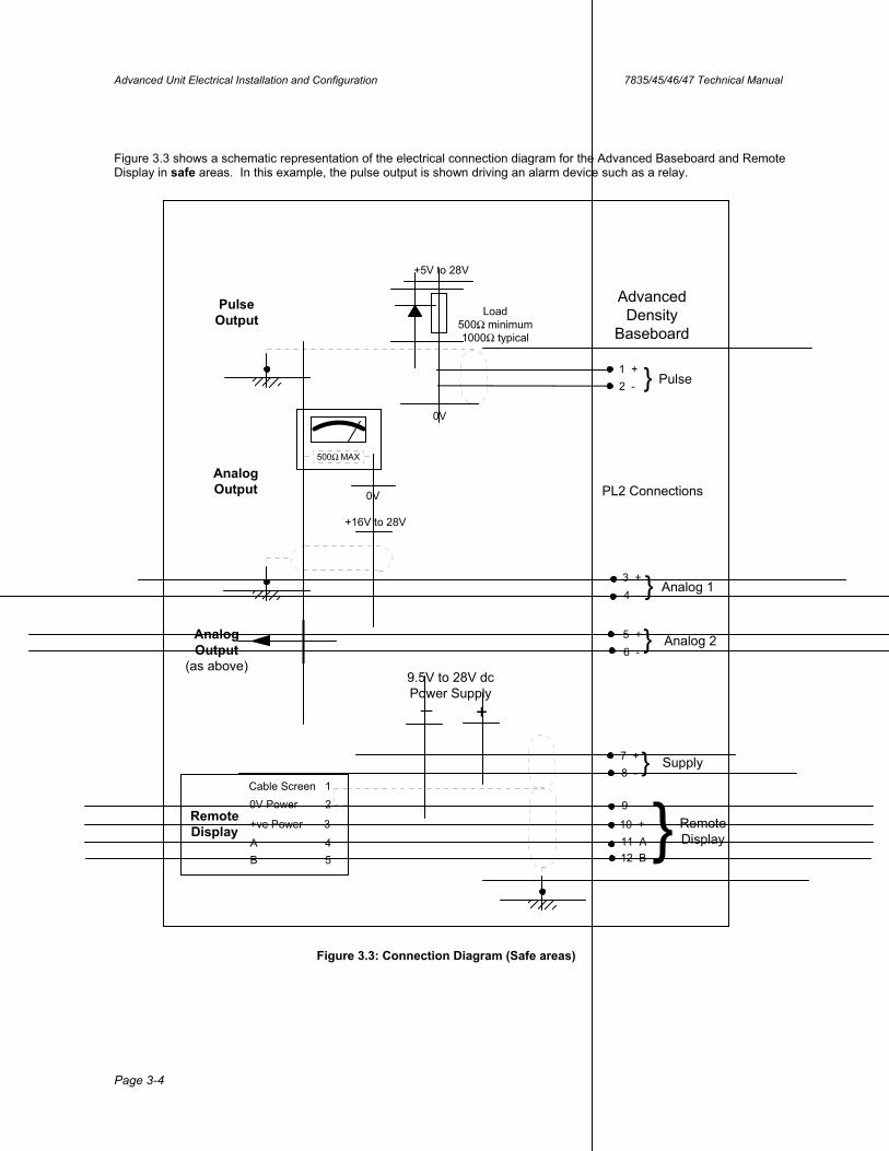
Figure 3.3 shows a schematic representation of the electrical connection diagram for the Advanced Baseboard and Remote Display in safe areas. In this example, the pulse output is shown driving an alarm device such as a relay.
AnalogOutput
+16V to 28V
500Ω MAX
0V
Pulse
Cable Screen 10V Power 2
+ve Power 3
A 4B 5
RemoteDisplay
AnalogOutput
(as above)
1 +2 - }
8 -7 +
9.5V to 28V dcPower Supply
12 B11 A10 +
9 -
+_
}}
4 -3 +
5 +6 -
}
}
RemoteDisplay
Analog 1
Analog 2
Supply
+5V to 28V
PulseOutput
AdvancedDensity
Baseboard
PL2 Connections
0V
Load500Ω minimum1000Ω typical
Figure 3.3: Connection Diagram (Safe areas)
7835/45/46/47 Technical Manual Advanced Unit Electrical Installation and Configuration
Page 3-5
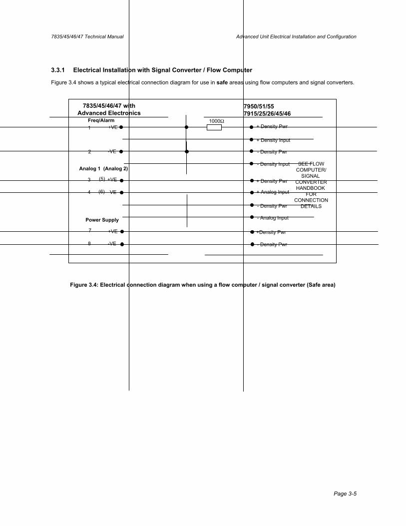
3.3.1 Electrical Installation with Signal Converter / Flow Computer
Figure 3.4 shows a typical electrical connection diagram for use in safe areas using flow computers and signal converters.
7835/45/46/47 withAdvanced Electronics
11000Ω
+ Density Pwr
2
+ Density Input
- Density Pwr
- Density Input
+ Analog Input
7950/51/557915/25/26/45/46
SEE FLOWCOMPUTER/
SIGNAL CONVERTERHANDBOOK
FORCONNECTION
DETAILS
3
4
(5)
(6)
+ Density Pwr
- Density Pwr
- Analog Input
+Density Pwr
- Density Pwr
Power Supply
Analog 1 (Analog 2)
Freq/Alarm+VE
-VE
+VE
-VE
+VE
-VE
7
8
Figure 3.4: Electrical connection diagram when using a flow computer / signal converter (Safe area)
Advanced Unit Electrical Installation and Configuration 7835/45/46/47 Technical Manual
Page 3-6
3.4 Electrical installation in hazardous areas When used in hazardous areas, safety barriers MUST be interposed between the meter and the signal processing equipment. Some of the safety barriers are unsuitable for certain installations, as discussed below.
Note:• For installation of the CSA certified unit in a hazardous area, refer to Appendix K. • For installation of the ATEX certified unit in a hazardous area, refer to the appropriate safety
instructions booklet (78355015/SI, 78355038/SI, or 78355065/SI).
3.4.1 Safety Barrier and Galvanic Isolator Selection
3.4.1.1. Power Supply (PL2 terminals 7 and 8)
As a general rule, the IIB safety barrier should be used where possible as this allows the maximum power to the meter, facilitating a wide range of installations and system configurations.
Where the installation requires the IIC safety barrier, it is important to check that sufficient power is available to power the meter and all of the options. The table below summarises the maximum line resistances allowable for the main system configurations assuming a 24V supply and a minimum of 9.5V available at the supply terminals on the baseboard.
Table 3.1
Advanced System combination Maximum line resistance (Ω) (barrier + cable)
Baseboard 340
Baseboard + remote display 260
Baseboard + locally powered remote display 280
Baseboard + HART® board 270
Baseboard + HART® + display 250
Zener Safety Barriers Power to the main circuit may be obtained through a simple 164Ω barrier or two 300Ω 28V barriers in parallel for IIB applications, or through a single 234Ω 28V barrier in IIC applications.
The main characteristics of the safety barriers are given here. Using this information and the information given in the table above the most suitable barriers for a particular application can be ascertained.
Table 3.2
Type Group Safety Description (Ω) Max. resistance (Ω)MTL 729P IIB 164 184
MTL 728P IIC 234 253
P&F Z728H IIC 240 250
Note: The power supply input is protected internally by an 8.2V±5% clamp diode and a 1Ω resistor. This limits the maximum current that can flow into the device:
Maximum voltage from barrier - Minimum voltage at input I max = Minimum resistance of barrier/input combination
For example, if two 28V, 300Ω barriers are used in parallel, the effective resistance is 150Ω.The maximum current is:
I max =( )
115095.02.828
+×− = 134mA
…and not 185mA, as might be expected if the input protection diode was not present.
7835/45/46/47 Technical Manual Advanced Unit Electrical Installation and Configuration
Page 3-7
Galvanic Isolators Galvanic isolators are suitable for powering the main board in IIB applications, but are NOT suitable for powering the main board in IIC applications. Also, IIC isolators are not suitable for use when Modbus communications are required.
The main characteristics of the galvanic isolators are given here. Using this information and the information given in the table above, the most suitable galvanic isolators for a particular application can be ascertained.
Table 3.3
Type Group Max output impedance (Ω)
MTL 3022 IIB 165
P&F KFD2-SD-Ex1.36 IIB 160
P&F KFD2-SL-Ex1.36 IIB 160
MTL 5022 IIB 143
3.4.1.2. Analogue (4 to 20mA) outputs including HART®
(PL2 terminals 3 & 4, 5 & 6 and HART PL3 3 & 4) Any of the zener safety barriers listed on the system certificates are suitable for operation with the Advanced Density analogue outputs. Some galvanic isolators may not be capable of driving the 2mA and 22mA out-of-range alarm states available on the Advanced Density system; for details please check with the barrier supplier.
3.4.1.3. Pulse output
(PL2 terminals 1 & 2) The pulse output can be configured to output either a status / alarm signal or the resonant frequency of the density meter; the latter requires the safety barrier to have a bandwidth of at least 1 kHz.
The table below indicates which galvanic isolators may be used for frequency configured pulse output; zener barriers may be used for either configuration.
Table 3.4
Isolator type Output description Pulse output configuration
MTL3011 Relay Status / alarm
MTL3012 Solid state (dc to 2kHz) All
MTL4013 Solid state (dc to 5kHz) All
MTL4014 Relay Status / alarm
MTL5011 Relay Status / alarm
MTL5016 Relay Status / alarm
MTL5017 Relay Status / alarm
Advanced Unit Electrical Installation and Configuration 7835/45/46/47 Technical Manual
Page 3-8
3.5 Baseboard Configuration The baseboard is supplied with one of the following two software versions:
• General software version - normally used in the food and process industries.
• Fiscal software version - normally used in Crude oil or refined petroleum applications.
The only difference between the two software versions is the available calculations.
Irrespective of which software version is running, when the unit is received from the factory, it is pre-configured to output the following signals:
Table 3.5
Output Output Parameter
Analog 1 (4-20mA) = Line density (500 to 1500 kg/m³)
Analog 2 (4-20mA) = Temperature (0 to 100°C)
Pulse output = Alarm - normally on
For many applications, the factory default configuration described above will be quite acceptable. However, if any of the additional calculated parameters or different output ranges are required, then a simple Baseboard re-configuration can be performed using a Remote Display, or PC.
For details on the available calculations and other Baseboard configuration factors, please refer to Appendix E.
7835/45/46/47 Technical Manual Advanced Unit Electrical Installation and Configuration
Page 3-9
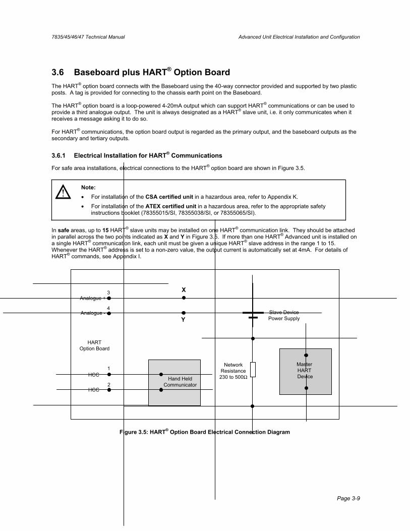
3.6 Baseboard plus HART® Option Board The HART® option board connects with the Baseboard using the 40-way connector provided and supported by two plastic posts. A tag is provided for connecting to the chassis earth point on the Baseboard.
The HART® option board is a loop-powered 4-20mA output which can support HART® communications or can be used to provide a third analogue output. The unit is always designated as a HART® slave unit, i.e. it only communicates when it receives a message asking it to do so.
For HART® communications, the option board output is regarded as the primary output, and the baseboard outputs as the secondary and tertiary outputs.
3.6.1 Electrical Installation for HART® Communications
For safe area installations, electrical connections to the HART® option board are shown in Figure 3.5.
Note:• For installation of the CSA certified unit in a hazardous area, refer to Appendix K.
• For installation of the ATEX certified unit in a hazardous area, refer to the appropriate safety instructions booklet (78355015/SI, 78355038/SI, or 78355065/SI).
In safe areas, up to 15 HART® slave units may be installed on one HART® communication link. They should be attached in parallel across the two points indicated as X and Y in Figure 3.5. If more than one HART® Advanced unit is installed on a single HART® communication link, each unit must be given a unique HART® slave address in the range 1 to 15. Whenever the HART® address is set to a non-zero value, the output current is automatically set at 4mA. For details of HART® commands, see Appendix I.
Hand HeldCommunicator
Analogue +
Analogue -
HCC
HCC
HARTOption Board
Slave DevicePower Supply
Master HART Device
NetworkResistance230 to 500Ω
X
Y
1
2
3
4
Figure 3.5: HART® Option Board Electrical Connection Diagram
Advanced Unit Electrical Installation and Configuration 7835/45/46/47 Technical Manual
Page 3-10
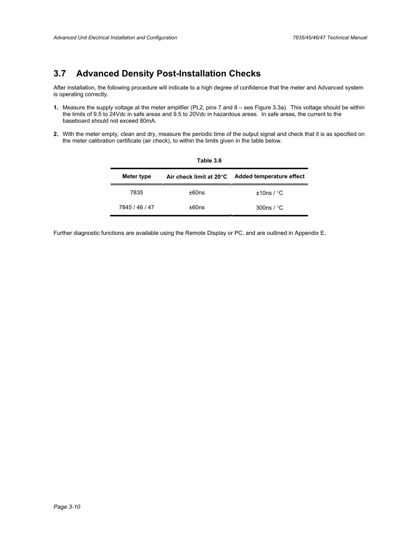
3.7 Advanced Density Post-Installation Checks After installation, the following procedure will indicate to a high degree of confidence that the meter and Advanced system is operating correctly.
1. Measure the supply voltage at the meter amplifier (PL2, pins 7 and 8 – see Figure 3.3a). This voltage should be within the limits of 9.5 to 24Vdc in safe areas and 9.5 to 20Vdc in hazardous areas. In safe areas, the current to the baseboard should not exceed 80mA.
2. With the meter empty, clean and dry, measure the periodic time of the output signal and check that it is as specified on the meter calibration certificate (air check), to within the limits given in the table below.
Table 3.6
Meter type Air check limit at 20°C Added temperature effect
7835 ±60ns ±10ns / °C
7845 / 46 / 47 ±60ns 300ns / °C
Further diagnostic functions are available using the Remote Display or PC, and are outlined in Appendix E.
7835/45/46/47 Technical Manual Standard Density Unit Electrical Installation
Page 4-1
Chapter 4 Standard Density Unit Electrical Installation
4.1 General This chapter describes the electrical installation of the 7835 and the 7845, 7846, 7847 Liquid Density Meters when fitted with the Standard Density electronics option. The units are identical, except where the 7845, 7846, 7847 meters are to be used at temperatures above 110oC (230oF) when the remote amplifier version is recommended - see Appendix B.
4.2 Ground Connections The earthing pads on the mounting face of the amplifier unit MUST make good contact with the meter case by the M3 cage nuts. The meter should be grounded via the pipework.
The external earth bonding point of the meter is located inside the maintaining amplifier housing. The 0V power supply lead should be earthed at the supply end, or at the safety barriers if applicable.
4.3 Use with Flow Computers and Signal Converters
4.3.1 System Connections (Hazardous Area only) When the meter is used in a hazardous area, a safety barrier MUST be interposed between the meter and the signal processing equipment. (See Section 3.4 for information on selecting a safety barrier.)
Note: For installation of the CSA certified unit in a hazardous area, refer to Appendix K. For installation of the ATEX certified unit in a hazardous area, refer to the appropriate safety instructions
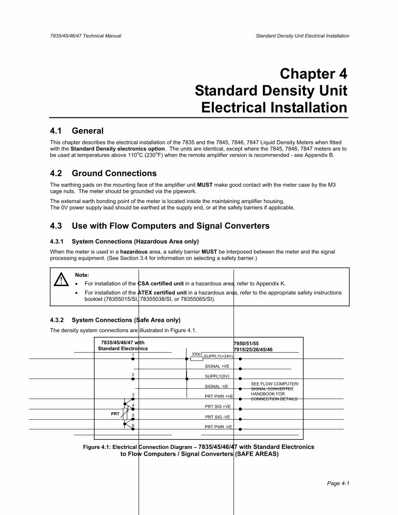
booklet (78355015/SI, 78355038/SI, or 78355065/SI).
4.3.2 System Connections (Safe Area only) The density system connections are illustrated in Figure 4.1.
7835/45/46/47 withStandard Electronics
PRT
1
2
3
4
5
6
330 SUPPLY(+24V)
SIGNAL +VE
SUPPLY(0V)
SIGNAL -VE
PRT PWR +VE
PRT SIG +VE
PRT SIG -VE
PRT PWR -VE
7950/51/557915/25/26/45/46
SEE FLOW COMPUTER/SIGNAL CONVERTERHANDBOOK FORCONNECTION DETAILS
Figure 4.1: Electrical Connection Diagram – 7835/45/46/47 with Standard Electronics to Flow Computers / Signal Converters (SAFE AREAS)
Standard Density Unit Electrical Installation 7835/45/46/47 Technical Manual
Page 4-2
4.4 Use with Customer’s Own Equipment
4.4.1 System Connections (Safe Area only)
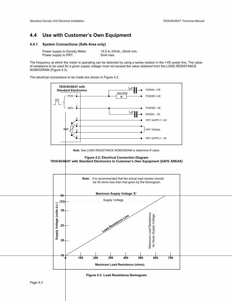
Power supply to Density Meter: 15.5 to 33Vdc, 25mA min. Power supply to PRT: 5mA max.
The frequency at which the meter is operating can be detected by using a series resistor in the +VE power line. The value of resistance to be used for a given supply voltage must not exceed the value obtained from the LOAD RESISTANCE NOMOGRAM (Figure 4.3).
The electrical connections to be made are shown in Figure 4.2.
7835/45/46/47 withStandard Electronics
PRT
1
2
3
4
5
6
See NotePOWER +VE
SIGNAL +VE
POWER VE
SIGNAL VE
PRT SUPPLY +VE
PRT SIGNAL
PRT SUPPLY VE
RPOS +
NEG -
SIG
1 F
1 F
Note: See LOAD RESISTANCE NOMOGRAM to determine R value.
Figure 4.2: Electrical Connection Diagram 7835/45/46/47 with Standard Electronics to Customer’s Own Equipment (SAFE AREAS)
Supp
ly V
olta
ge (v
olts
d.c
.)
15
20
25
30
(33)
35 Maximum Supply Voltage ‘E’
0 100 200 300 400 500 600 700
Load Resistance Line
Supply Voltage
Max
imum
Loa
d R
esis
tanc
efo
r Giv
en S
uppl
y Vo
ltage
Maximum Load Resistance (ohms)
Note: It is recommended that the actual load resistor should be 50 ohms less than that given by the Nomogram.
Figure 4.3: Load Resistance Nomogram
7835/45/46/47 Technical Manual Standard Density Unit Electrical Installation
Page 4-3
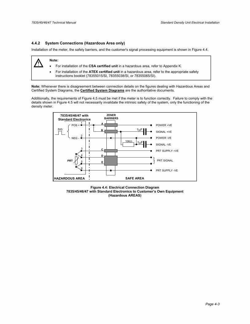
4.4.2 System Connections (Hazardous Area only) Installation of the meter, the safety barriers, and the customer's signal processing equipment is shown in Figure 4.4.
Note: For installation of the CSA certified unit in a hazardous area, refer to Appendix K. For installation of the ATEX certified unit in a hazardous area, refer to the appropriate safety
instructions booklet (78355015/SI, 78355038/SI, or 78355065/SI).
Note: Whenever there is disagreement between connection details on the figures dealing with Hazardous Areas and Certified System Diagrams, the Certified System Diagrams are the authoritative documents.
Additionally, the requirements of Figure 4.5 must be met if the meter is to function correctly. Failure to comply with the details shown in Figure 4.5 will not necessarily invalidate the intrinsic safety of the system, only the functioning of the density meter.
ZENERBARRIERS
7835/45/46/47 withStandard Electronics
PRT
1
2
3
4
5
6
POWER +VE
SIGNAL +VE
POWER -VE
SIGNAL -VE
PRT SUPPLY +VE
PRT SIGNAL
PRT SUPPLY -VE
HAZARDOUS AREA SAFE AREA
POS +
NEG -
SIG
A
B
C
D
E
10K
1 F
1 F
Figure 4.4: Electrical Connection Diagram 7835/45/46/47 with Standard Electronics to Customer’s Own Equipment
(Hazardous AREAS)
Standard Density Unit Electrical Installation 7835/45/46/47 Technical Manual
Page 4-4
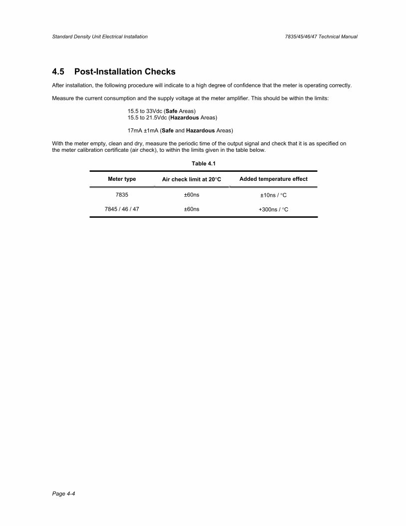
4.5 Post-Installation Checks After installation, the following procedure will indicate to a high degree of confidence that the meter is operating correctly.
Measure the current consumption and the supply voltage at the meter amplifier. This should be within the limits:
15.5 to 33Vdc (Safe Areas) 15.5 to 21.5Vdc (Hazardous Areas)
17mA ±1mA (Safe and Hazardous Areas)
With the meter empty, clean and dry, measure the periodic time of the output signal and check that it is as specified on the meter calibration certificate (air check), to within the limits given in the table below.
Table 4.1
Meter type Air check limit at 20 C Added temperature effect
7835 ±60ns ±10ns / C
7845 / 46 / 47 ±60ns +300ns / C
7835/45/46/47 Technical Manual Entrained Gas Electronics Electrical Installation
Page 5-1
Chapter 5 Entrained Gas Electronics
Electrical Installation
5.1 General This chapter concerns the operation of 7845/47 meters when fitted with the Standard Entrained gas amplifier.
Warning!
7845/47 Entrained Gas Liquid Density Meters with Standard Electronics are NOT intrinsically safe.
5.2 Ground Connections The earthing pads on the mounting face of the amplifier unit MUST make good contact with the meter case by the M3 cage nuts. The external earth bonding point of the meter is located inside the maintaining amplifier housing. The meter should be grounded via the pipework.
The 0V power supply lead should be earthed at the supply end, or at the safety barriers if applicable.
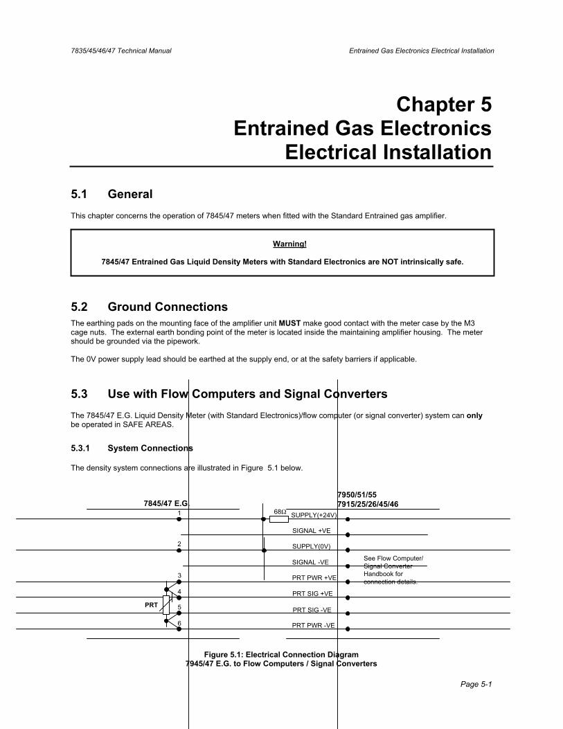
5.3 Use with Flow Computers and Signal Converters The 7845/47 E.G. Liquid Density Meter (with Standard Electronics)/flow computer (or signal converter) system can only be operated in SAFE AREAS.
5.3.1 System Connections
The density system connections are illustrated in Figure 5.1 below.
7845/47 E.G.
PRT
1
2
3
4
5
6
68Ω SUPPLY(+24V)
SIGNAL +VE
SUPPLY(0V)
SIGNAL -VE
PRT PWR +VE
PRT SIG +VE
PRT SIG -VE
PRT PWR -VE
7950/51/557915/25/26/45/46
See Flow Computer/Signal ConverterHandbook forconnection details.
Figure 5.1: Electrical Connection Diagram 7945/47 E.G. to Flow Computers / Signal Converters
Entrained Gas Electronics Electrical Installation 7835/45/46/47 Technical Manual
Page 5-2
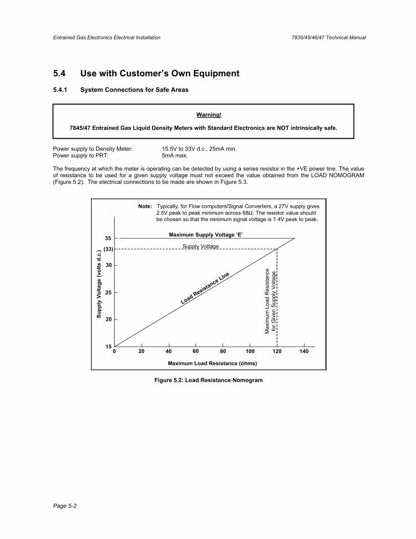
5.4 Use with Customer’s Own Equipment
5.4.1 System Connections for Safe Areas
Warning!
7845/47 Entrained Gas Liquid Density Meters with Standard Electronics are NOT intrinsically safe.
Power supply to Density Meter: 15.5V to 33V d.c., 25mA min. Power supply to PRT: 5mA max.
The frequency at which the meter is operating can be detected by using a series resistor in the +VE power line. The value of resistance to be used for a given supply voltage must not exceed the value obtained from the LOAD NOMOGRAM (Figure 5.2). The electrical connections to be made are shown in Figure 5.3.
Supp
ly V
olta
ge (v
olts
d.c
.)
15
20
25
30
(33)
35 Maximum Supply Voltage ‘E’
0 20 40 60 80 100 120 140
Load Resistance Line
Supply Voltage
Max
imum
Loa
d R
esis
tanc
efo
r Giv
en S
uppl
y V
olta
ge
Maximum Load Resistance (ohms)
Note: Typically, for Flow computers/Signal Converters, a 27V supply gives2.5V peak to peak minimum across 68Ω. The resistor value shouldbe chosen so that the minimum signal voltage is 1.4V peak to peak.
Figure 5.2: Load Resistance Nomogram
7835/45/46/47 Technical Manual Entrained Gas Electronics Electrical Installation
Page 5-3
7845/47 E.G.
PRT
1
2
3
4
5
6
See NotePOWER +VE
SIGNAL +VE
POWER -VE
SIGNAL -VE
PRT SUPPLY +VE
PRT SIGNAL
PRT SUPPLY -VE
RPOS +
NEG -
SIG
Note: See Load Nomogram (Figure 5.2) to determine R value.
1μF
1μF
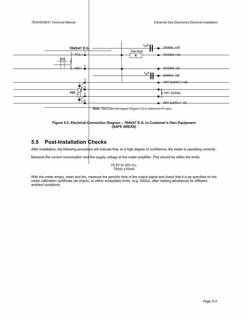
Figure 5.3: Electrical Connection Diagram – 7845/47 E.G. to Customer’s Own Equipment (SAFE AREAS)
5.5 Post-Installation Checks After installation, the following procedure will indicate that, to a high degree of confidence, the meter is operating correctly.
Measure the current consumption and the supply voltage at the meter amplifier. This should be within the limits:
15.5V to 33V d.c. 75mA ±10mA
With the meter empty, clean and dry, measure the periodic time of the output signal and check that it is as specified on the meter calibration certificate (air check), to within acceptable limits (e.g. 500ns), after making allowances for different ambient conditions.

Entrained Gas Electronics Electrical Installation 7835/45/46/47 Technical Manual
Page 5-4

7835/45/46/47 Technical Manual Calibration and Performance
Page 6-1
Chapter 6 Calibration and Performance
6.1 General The 7835, 7845/46/47 Liquid Density Meters and the 7845/47 Entrained Gas Liquid Density Meters are calibrated at the factory, and are supplied with their own test and calibration certificates.
The calibration certificate specifies various calibration constants that allow the user to convert the output periodic timesignal from the meter into a density value. (See Appendix F for specimen calibration certificates.)
Important:If you have a calibration certificate that was issued before 15 February 2007, contact the factory for a new certificate.Pressure coefficient constants are now calculated for sub-sets of the full operating pressure range, and each set is listed on the certificate (See Appendix F for specimen calibration certificates.) No new instrument calibrations should be required. The pressure coefficients are valid for liquids of all densities.
For units with Standard Electronics, the calibration constants will need to be programmed into a signal processing instrument such as a signal converter. Density calculations are performed on the signal processing instrument.
For units with Advanced Electronics, the calibration constants are pre-programmed into the electronics and normally require no further consideration. The calculations in this chapter are performed by the electronics on the meter.
Important:
If you have obtained a replacement calibration certificate for a Advanced Electronics unit, the set of pressure coefficient constants K20A, K20B, K21A and K21B that fall within your operating pressure range can be programmed into the Advanced Electronics using Adview software (downloadable from web sites listed on the back page).
(If your operating pressure range falls between two of the sets of operating pressure ranges on the new certificate, contact the factory for a new calibration certificate.)
The Advanced Electronics keeps a write-protected copy and a working copy of all coefficients. The integrity of the working coefficients is safe, and so for simplicity it is recommended that the working coefficients only be changed. This is achieved by writing to registers 131 and 132. (See Chapter 9 for a guide to using Adview.)
Alternatively, a new FRAM memory chip can be issued which holds the calibration coefficients. However, in replacing the FRAM device some user configured data may be lost (e.g. upper and lower limits on the analog outputs, matrix referral points, special function, user defined line pressure etc.).
Calibration and Performance 7835/45/46/47 Technical Manual
Page 6-2
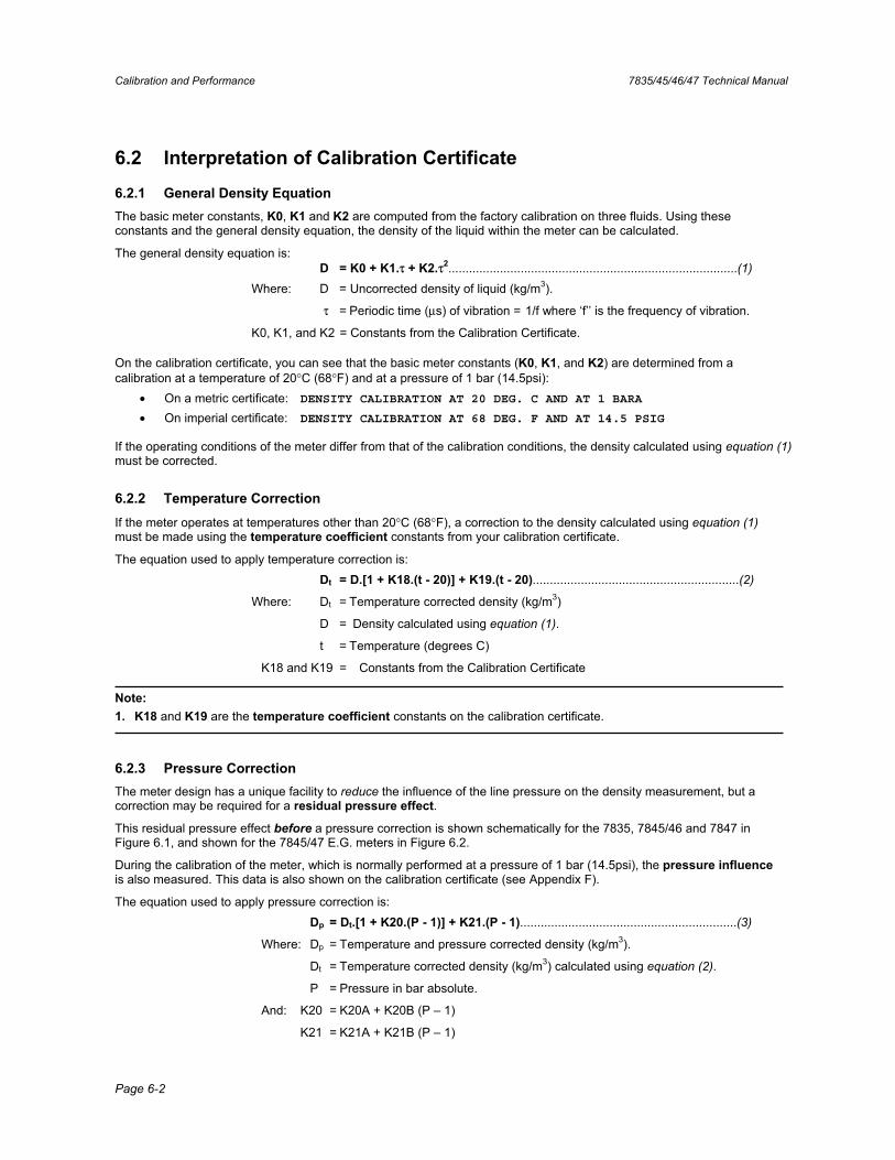
6.2 Interpretation of Calibration Certificate
6.2.1 General Density Equation The basic meter constants, K0, K1 and K2 are computed from the factory calibration on three fluids. Using these constants and the general density equation, the density of the liquid within the meter can be calculated.
The general density equation is: D = K0 + K1.τ + K2.τ2....................................................................................(1)
Where: D = Uncorrected density of liquid (kg/m3).
τ = Periodic time (μs) of vibration = 1/f where ‘f’’ is the frequency of vibration.
K0, K1, and K2 = Constants from the Calibration Certificate.
On the calibration certificate, you can see that the basic meter constants (K0, K1, and K2) are determined from a calibration at a temperature of 20°C (68°F) and at a pressure of 1 bar (14.5psi):
• On a metric certificate: DENSITY CALIBRATION AT 20 DEG. C AND AT 1 BARA
• On imperial certificate: DENSITY CALIBRATION AT 68 DEG. F AND AT 14.5 PSIG
If the operating conditions of the meter differ from that of the calibration conditions, the density calculated using equation (1)must be corrected.
6.2.2 Temperature Correction If the meter operates at temperatures other than 20°C (68°F), a correction to the density calculated using equation (1)must be made using the temperature coefficient constants from your calibration certificate.
The equation used to apply temperature correction is: Dt = D.[1 + K18.(t - 20)] + K19.(t - 20)............................................................(2)
Where: Dt = Temperature corrected density (kg/m3)
D = Density calculated using equation (1).
t = Temperature (degrees C)
K18 and K19 = Constants from the Calibration Certificate
Note:1. K18 and K19 are the temperature coefficient constants on the calibration certificate.
6.2.3 Pressure Correction The meter design has a unique facility to reduce the influence of the line pressure on the density measurement, but a correction may be required for a residual pressure effect.
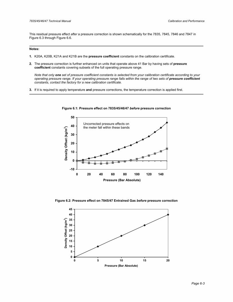
This residual pressure effect before a pressure correction is shown schematically for the 7835, 7845/46 and 7847 in Figure 6.1, and shown for the 7845/47 E.G. meters in Figure 6.2.
During the calibration of the meter, which is normally performed at a pressure of 1 bar (14.5psi), the pressure influenceis also measured. This data is also shown on the calibration certificate (see Appendix F).
The equation used to apply pressure correction is: Dp = Dt.[1 + K20.(P - 1)] + K21.(P - 1)...............................................................(3)
Where: Dp = Temperature and pressure corrected density (kg/m3).
Dt = Temperature corrected density (kg/m3) calculated using equation (2).
P = Pressure in bar absolute.
And: K20 = K20A + K20B (P – 1)
K21 = K21A + K21B (P – 1)
7835/45/46/47 Technical Manual Calibration and Performance
Page 6-3
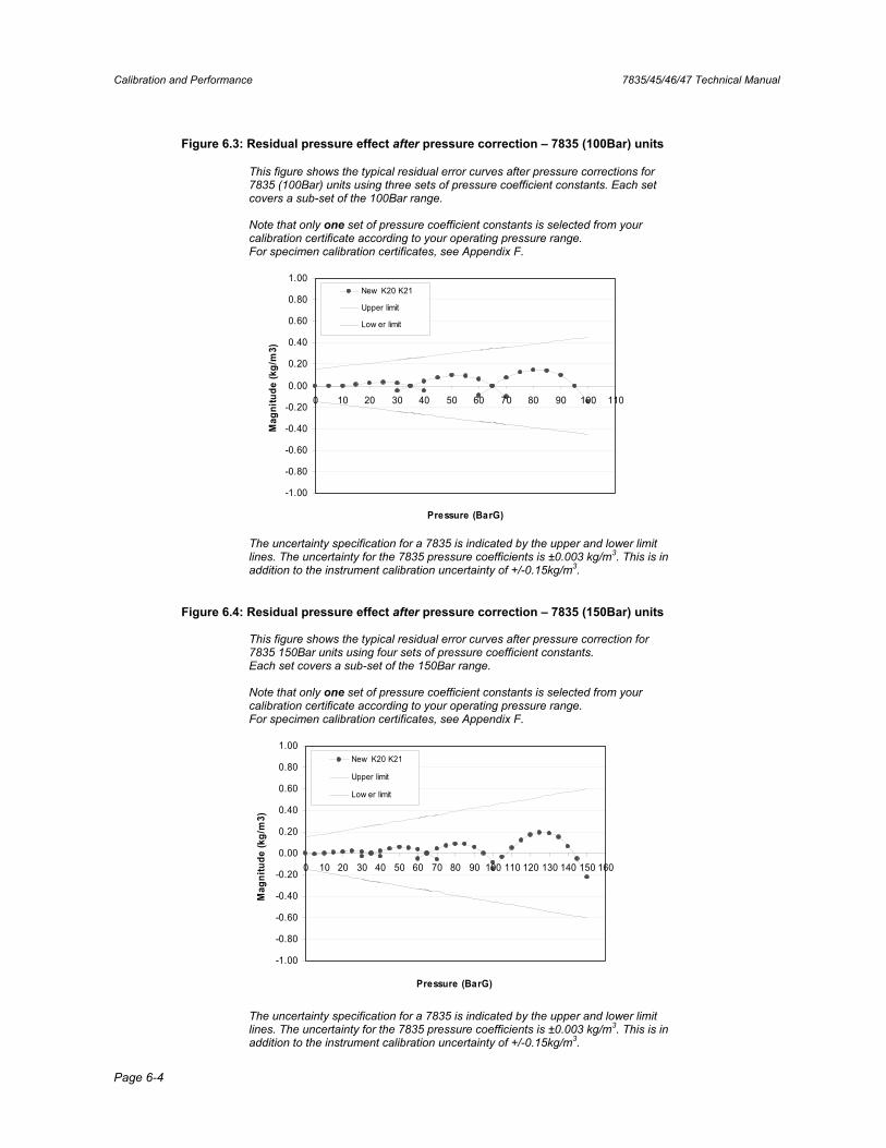
This residual pressure effect after a pressure correction is shown schematically for the 7835, 7845, 7846 and 7847 in Figure 6.3 through Figure 6.6.
Notes:
1. K20A, K20B, K21A and K21B are the pressure coefficient constants on the calibration certificate.
2. The pressure correction is further enhanced on units that operate above 41 Bar by having sets of pressure coefficient constants covering subsets of the full operating pressure range.
Note that only one set of pressure coefficient constants is selected from your calibration certificate according to your operating pressure range. If your operating pressure range falls within the range of two sets of pressure coefficientconstants, contact the factory for a new calibration certificate.
3. If it is required to apply temperature and pressure corrections, the temperature correction is applied first.
Figure 6.1: Pressure effect on 7835/45/46/47 before pressure correction
-10
0
10
20
30
40
50
0 20 40 60 80 100 120 140
Pressure (Bar Absolute)
Den
sity
Offs
et (k
g/m
3 )
Figure 6.2: Pressure effect on 7845/47 Entrained Gas before pressure correction
0
5
10
15
20
25
30
35
40
45
0 5 10 15 20
Pressure (Bar Absolute)
Den
sity
Offs
et (k
g/m
3 )
Uncorrected pressure effects on the meter fall within these bands
Calibration and Performance 7835/45/46/47 Technical Manual
Page 6-4
Figure 6.3: Residual pressure effect after pressure correction – 7835 (100Bar) units
This figure shows the typical residual error curves after pressure corrections for 7835 (100Bar) units using three sets of pressure coefficient constants. Each set covers a sub-set of the 100Bar range.
Note that only one set of pressure coefficient constants is selected from your calibration certificate according to your operating pressure range. For specimen calibration certificates, see Appendix F.
-1.00
-0.80
-0.60
-0.40
-0.20
0.00
0.20
0.40
0.60
0.80
1.00
0 10 20 30 40 50 60 70 80 90 100 110
Pressure (BarG)
Mag
nitu
de (k
g/m
3)
New K20 K21
Upper limit
Low er limit
The uncertainty specification for a 7835 is indicated by the upper and lower limit lines. The uncertainty for the 7835 pressure coefficients is ±0.003 kg/m3. This is in addition to the instrument calibration uncertainty of +/-0.15kg/m3.
Figure 6.4: Residual pressure effect after pressure correction – 7835 (150Bar) units
This figure shows the typical residual error curves after pressure correction for 7835 150Bar units using four sets of pressure coefficient constants. Each set covers a sub-set of the 150Bar range.
Note that only one set of pressure coefficient constants is selected from your calibration certificate according to your operating pressure range. For specimen calibration certificates, see Appendix F.
-1.00
-0.80
-0.60
-0.40
-0.20
0.00
0.20
0.40
0.60
0.80
1.00
0 10 20 30 40 50 60 70 80 90 100 110 120 130 140 150 160
Pressure (BarG)
Mag
nitu
de (k
g/m
3)
New K20 K21
Upper limit
Low er limit
The uncertainty specification for a 7835 is indicated by the upper and lower limit lines. The uncertainty for the 7835 pressure coefficients is ±0.003 kg/m3. This is in addition to the instrument calibration uncertainty of +/-0.15kg/m3.
7835/45/46/47 Technical Manual Calibration and Performance
Page 6-5
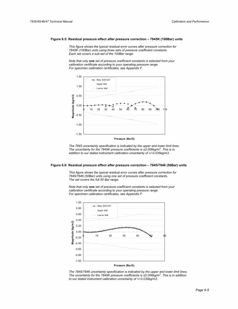
Figure 6.5: Residual pressure effect after pressure correction – 7845K (100Bar) units
This figure shows the typical residual error curves after pressure correction for 7845K (100Bar) units using three sets of pressure coefficient constants. Each set covers a sub-set of the 100Bar range.
Note that only one set of pressure coefficient constants is selected from your calibration certificate according to your operating pressure range. For specimen calibration certificates, see Appendix F.
-1.50
-1.00
-0.50
0.00
0.50
1.00
1.50
0 10 20 30 40 50 60 70 80 90 100 110
Pressure (BarG)
Mag
nitu
de (k
g/m
3)
New K20 K21
Upper limit
Low er limit
The 7845 uncertainty specification is indicated by the upper and lower limit lines. The uncertainty for the 7845K pressure coefficients is ±0.006kg/m3. This is in addition to our stated instrument calibration uncertainty of +/-0.035kg/m3.
Figure 6.6: Residual pressure effect after pressure correction – 7845/7846 (50Bar) units
This figure shows the typical residual error curves after pressure correction for 7845/7846 (50Bar) units using one set of pressure coefficient constants. The set covers the full 50 Bar range.
Note that only one set of pressure coefficient constants is selected from your calibration certificate according to your operating pressure range. For specimen calibration certificates, see Appendix F.
-1.00
-0.80
-0.60
-0.40
-0.20
0.00
0.20
0.40
0.60
0.80
1.00
0 10 20 30 40 50 60
Pressure (BarG)
Mag
nitu
de (k
g/m
3)
New K20 K21
Upper limit
Low er limit
The 7845/7846 uncertainty specification is indicated by the upper and lower limit lines. The uncertainty for the 7845K pressure coefficients is ±0.006kg/m3. This is in addition to our stated instrument calibration uncertainty of +/-0.035kg/m3.
Calibration and Performance 7835/45/46/47 Technical Manual
Page 6-6
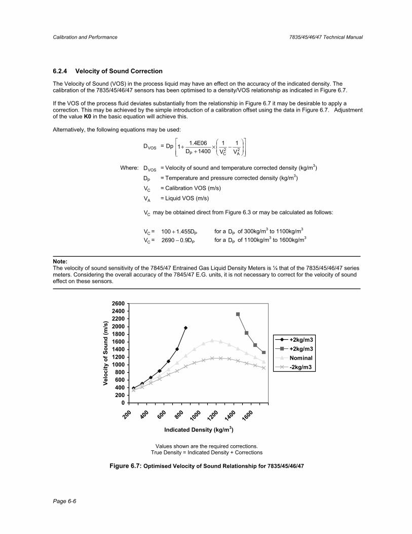
6.2.4 Velocity of Sound Correction
The Velocity of Sound (VOS) in the process liquid may have an effect on the accuracy of the indicated density. The calibration of the 7835/45/46/47 sensors has been optimised to a density/VOS relationship as indicated in Figure 6.7.
If the VOS of the process fluid deviates substantially from the relationship in Figure 6.7 it may be desirable to apply a correction. This may be achieved by the simple introduction of a calibration offset using the data in Figure 6.7. Adjustment of the value K0 in the basic equation will achieve this.
Alternatively, the following equations may be used:
VOSD = Dp −×+
+ 2A
2CP V
1V1
1400D06E4.11
Where: VOSD = Velocity of sound and temperature corrected density (kg/m3)
PD = Temperature and pressure corrected density (kg/m3)
CV = Calibration VOS (m/s)
AV = Liquid VOS (m/s)
CV may be obtained direct from Figure 6.3 or may be calculated as follows:
CV = PD455.1100 + for a PD of 300kg/m3 to 1100kg/m3
CV = PD9.02690 − for a PD of 1100kg/m3 to 1600kg/m3
Note:The velocity of sound sensitivity of the 7845/47 Entrained Gas Liquid Density Meters is ¼ that of the 7835/45/46/47 series meters. Considering the overall accuracy of the 7845/47 E.G. units, it is not necessary to correct for the velocity of sound effect on these sensors.
0200400600800
100012001400160018002000220024002600
200
400
600
800
1000
1200
1400
1600
Indicated Density (kg/m3)
Velo
city
of S
ound
(m/s
)
+2kg/m3+2kg/m3Nominal-2kg/m3
Values shown are the required corrections. True Density = Indicated Density + Corrections
Figure 6.7: Optimised Velocity of Sound Relationship for 7835/45/46/47
7835/45/46/47 Technical Manual Calibration and Performance
Page 6-7
6.3 Calibration
6.3.1 Factory Calibration
The 7835, 7845/6/7 Liquid Density Meters and the 7845/47 Entrained Gas liquid density meters are calibrated prior to leaving the factory against Transfer Standard instruments, traceable to National Standards.
Three fluids are used in the calibration - ambient air whose density is derived from tables, a hydrocarbon oil of about 815kg/m3 density and a high-density fluid in the range 1400 to 1500kg/m3 density. Several of the instruments-under-test are connected in parallel between two Transfer Standard Instruments on a special flow rig at the factory. During a calibration and as the liquid flows through the instruments, readings are only taken when the indicated densities on the two Transfer Standard Instruments agree. In this way, a high integrity of calibration is achieved.
Measurements are also made under conditions of changing temperature and pressure to establish the magnitude of these effects on the instrument. From all this data, a calibration certificate is generated for each instrument.
Samples of the instruments are further tested by the quality assurance team at the factory to verify the calibration.
6.3.2 Calibration of Transfer Standards
The Transfer Standard instruments used in the calibration are selected instruments that are calibrated and certified by the UKAS Certified Calibration Laboratory.
Transfer Standard calibration uses a number of ‘density certified’ liquids. The densities of these certified liquids are obtained using the Primary measurement system, whereby glass sinkers of defined volumes are weighed in samples of the liquids.
Calibration is performed by pumping each certified liquid through the Transfer Standard in a closely controlled manner and recording the output signal in each case. A calibration certificate is issued for each Transfer Standard. Calibrations are repeated, typically every six months, producing a well-documented density standard.
6.3.3 Instrument Calibration Certificate
Each instrument is issued with its own calibration certificate (see Appendix F), containing four important pieces of data:
(a) The instrument serial number.
(b) The output signal/density relationship. This is based on three calibration points - air, medium density and high-density fluids. The air and high density fluid points are offset to achieve the product velocity of sound/density profile described earlier, however, the signal value at Air Density is also given for check purposes.
(c) Temperature coefficient data, describing the correction which should be applied to achieve the best accuracy if the instrument is operating at product temperatures other than 20°C (68°F).
(d) Pressure coefficient data, describing the correction that should be applied to achieve the best accuracy if the instrument is operating at elevated pressures.
A second page of the calibration certificate is retained by the factory, and contains all the calibration measurements.
6.3.4 Pressure Test
A hydrostatic pressure test is carried out to a pressure value specified on the instrument label and on the instrument calibration certificate. This test loads the instrument structure to a pressure which exceeds the maximum permitted operating pressure of the instrument.
Calibration and Performance 7835/45/46/47 Technical Manual
Page 6-8
6.3.5 Insulation Test
To comply with Intrinsic Safety requirements, a 500Vac insulation test is carried out between the electrical terminals and the instrument case.
6.3.6 Calibration Check Methods
There are two methods employed in calibration checks:
(a) Air checkpoint, which is simple and convenient and highlights long term drift, corrosion and deposition.
(b) Liquid calibration verification comprising two choices:
• Drawing off a sample of the liquid being measured and obtaining its density, using a hydrometer (for stable liquids) or pyknometer (for unstable liquids).
• Using a second density meter.
Ambient Air Check
(a) Isolate, drain and if necessary, disconnect the meter from the pipeline.
(b) Clean and dry the wetted parts of the meter and leave them open to the ambient air.
(c) Apply power to the instrument and check that the time period of the output signal agrees with the 'Air Check' figure shown in the calibration certificate, to within acceptable limits (e.g. 60ns or 500ns for the E.G. units).
Some variation between the two figures is to be expected due to changes in ambient air conditions. The density indication if using the K0, K1 and K2 factors will be about -0.9kg/m3 because the basic density equation has been optimised for best performance over the normal operating density range.
This test will indicate whether there has been a calibration offsets due to corrosion, deposition or long term drift. When this test is applied to the 7845/6/7 instruments, their temperature coefficient has a significant effect and must be considered (typically 0.3ms/°C and 0.7ms/°C for the E.G. units).
Reconnect the meter to the pipeline if serviceable or remove it for further servicing.
Liquid Density Check
1. Sample Method
If it is necessary to verify the calibration using liquid at operating conditions, then the following sample methods are recommended:
(a) FOR STABLE LIQUIDS:
Draw off a sample of the liquid into a suitable container, at the same time noting the indicated density, temperature and pressure of the liquid.
Measure the density of the sample under defined laboratory conditions, using a hydrometer or other suitable instrument.
Refer the density measurement under laboratory conditions to that under the line operating conditions of temperature and pressure.
Compare the referred density figure with that indicated by the density meter.
Note: It is essential that a good understanding of the physical properties (temperature coefficient, etc.) of the liquid is acquired when using this method.
7835/45/46/47 Technical Manual Calibration and Performance
Page 6-9
(b) FOR UNSTABLE LIQUIDS:
Couple a pressure pyknometer and its associated pipework to the pipeline so that a sample of the liquid flows through it.
When equilibrium conditions are reached, the meter density reading is noted as the pyknometer is isolated from the sample flow.
Remove the pyknometer for weighing to establish the product density.
Compare the pyknometer registered density with that obtained from the meter.
Sampling Techniques Sampling should comply with the international sampling standards (ISO 3171, ASTM D 4177, API 8.2 and IP 6.2). For further details of these procedures, reference should be made to:
Institute of Petroleum: Petroleum Measurement Manual Part VII Section 1 - Method IP 160 (Hydrometer Method)
(BS2000-160, ISO3675, ASTM 1298)
Institute of Petroleum: Petroleum Measurement Manual Part VII Section 2 - Continuous Density Measurement
American Petroleum Institute: Manual of Petroleum Measurement Standards Chapter 14 - Natural Gas Fluids - Section 6:
Installing and proving density meters used to measure hydrocarbon liquid with densities between 0.3 and 0.7gm/cc at 15.56°C (60°F) and saturation vapour pressure, 1991.
2. Second Density Meter
(a) Connect the second density meter to the pipeline adjacent to meter being checked so that it receives the same sample of fluid under the same conditions of temperature and pressure as the meter under test.
(b) Connect the second meter to its readout equipment, switch on and allow both systems to reach equilibrium conditions.
(c) Compare the two readings, making any necessary corrections.
It is often the practice, especially in fiscal metering applications, to use two or more density meters in a continuous measurement mode as a means of improving the integrity of the measurement system. Any unacceptable discrepancies between the measurements can immediately raise the necessary alarm signals.
This method of automatic checking has proved to be a very successful technique and where there is a facility for two instruments, the practice of exchanging one for a newly calibrated instrument is proving successful. This is sometimes referred to as the "Substitution Method".
It is very important when using one instrument to verify the performance of a second and similar instrument, to ensure there are no unaccounted for systematic errors which would are not highlighted.
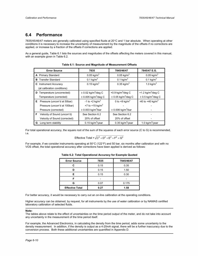
Calibration and Performance 7835/45/46/47 Technical Manual
Page 6-10
6.4 Performance 7835/45/46/47 meters are generally calibrated using specified fluids at 20°C and 1 bar absolute. When operating at other conditions it is necessary to increase the uncertainty of measurement by the magnitude of the offsets if no corrections are applied, or increase by a fraction of the offsets if corrections are applied.
As a general guide, Table 6.1 lists the sources and magnitudes of the offsets affecting the meters covered in this manual, with an example given in Table 6.2.
Table 6.1: Source and Magnitude of Measurement Offsets
Error Source 7835 7845/46/47 7845/47 E.G.
A Primary Standard 0.05 kg/m3 0.05 kg/m3 0.05 kg/m3
B Transfer Standard 0.1 kg/m3 0.1 kg/m3 0.1 kg/m3
C Instrument Accuracy (at calibration conditions)
0.15 kg/m3 0.35 kg/m3 1.0 kg/m3
D Temperature (uncorrected) Temperature (corrected)
± 0.02 kg/m3/deg C ± 0.005 kg/m3/deg C
+0.9 kg/m3/deg C ± 0.05 kg/m3/deg C
+1.2 kg/m3/deg C ± 0.5 kg/m3/deg C
E Pressure (uncorr’d at 50bar) Pressure (uncorr’d at 100bar) Pressure (corrected)
-1 to +2 kg/m3
+7 to +15 kg/m3
± 0.003 kg/m3/bar
0 to +8 kg/m3
-± 0.006 kg/m3/bar
-40 to +40 kg/m3
--
F Velocity of Sound (uncorr’d) Velocity of Sound (corrected)
See Section 6.2 20% of offset
See Section 6.2 20% of offset
--
G Long term stability 0.15 kg/m3/year 0.35 kg/m3/year 1.0 kg/m3/year
For total operational accuracy, the square root of the sum of the squares of each error source (C to G) is recommended, i.e.
Effective Total = 22222 GFEDC ++++
For example, if we consider instruments operating at 50°C (122°F) and 50 bar, six months after calibration and with no VOS offset, the total operational accuracy after corrections have been applied is derived as follows:
Table 6.2: Total Operational Accuracy for Example Quoted
Error Source 7835 7845/46/47
C 0.15 0.35
D 0.15 1.50
E 0.15 0.30
F - -
G 0.07 0.175
Effective Total 0.27 1.58
For better accuracy, it would be necessary to carry out an on-line calibration at the operating conditions.
Higher accuracy can be obtained, by request, for all instruments by the use of water calibration or by NAMAS certified laboratory calibration of selected fluids.
Note:The tables above relate to the effect of uncertainties on the time period output of the meter, and do not take into account any uncertainty in the measurement of the time period itself.
For example, the Advanced Electronics, in calculating the density from the time period, adds some uncertainty to the density measurement. In addition, if the density is output as a 4-20mA signal, there will be a further inaccuracy due to the conversion process. Both these additional uncertainties are quantified in Appendix D.
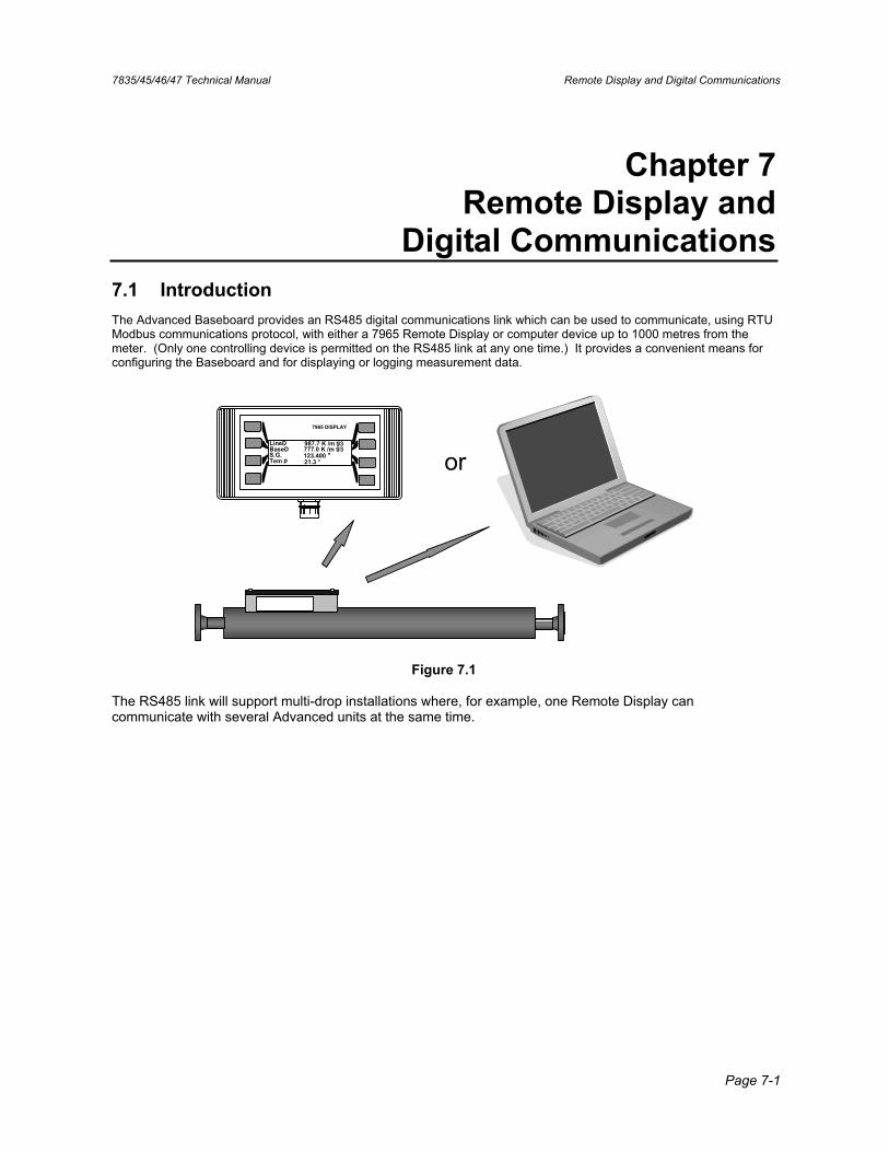
7835/45/46/47 Technical Manual Remote Display and Digital Communications
Page 7-1
Chapter 7 Remote Display and
Digital Communications 7.1 Introduction The Advanced Baseboard provides an RS485 digital communications link which can be used to communicate, using RTU Modbus communications protocol, with either a 7965 Remote Display or computer device up to 1000 metres from the meter. (Only one controlling device is permitted on the RS485 link at any one time.) It provides a convenient means for configuring the Baseboard and for displaying or logging measurement data.
S
7965 DISPLAY
BaseDLineD
S.G.Tem p
987.7 K /m g3
123.400 °777.0 K /m g3
21.3 ° or
Figure 7.1
The RS485 link will support multi-drop installations where, for example, one Remote Display can communicate with several Advanced units at the same time.
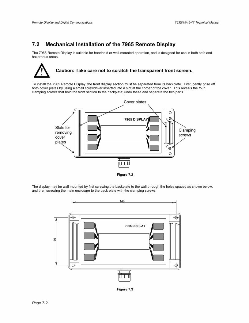
Remote Display and Digital Communications 7835/45/46/47 Technical Manual
Page 7-2
7.2 Mechanical Installation of the 7965 Remote Display The 7965 Remote Display is suitable for handheld or wall-mounted operation, and is designed for use in both safe and hazardous areas.
Caution: Take care not to scratch the transparent front screen.
To install the 7965 Remote Display, the front display section must be separated from its backplate. First, gently prise off both cover plates by using a small screwdriver inserted into a slot at the corner of the cover. This reveals the four clamping screws that hold the front section to the backplate; undo these and separate the two parts.
Cover plates
Clamping screws
Slots for removing cover plates
7965 DISPLAY
Figure 7.2
The display may be wall mounted by first screwing the backplate to the wall through the holes spaced as shown below, and then screwing the main enclosure to the back plate with the clamping screws.
146
66
7965 DISPLAY
Figure 7.3

7835/45/46/47 Technical Manual Remote Display and Digital Communications
Page 7-3
7.3 Safe Area Electrical installation Electrical installation of the Remote Display in a safe area is shown in Chapter 3. The maximum resistance on the power lines between the Baseboard and the Remote Display is 60Ω, which equates to a maximum cable length of 750 metres (2500 ft) for a cable of dc resistance 40Ω/km (12Ω/ 1000ft). If the Remote Display is to be operated at distances of up to 1000 metres from the meter, it should be powered locally with a supply in the range 8 to 28 volts.
7.4 Hazardous Area Electrical installation
When installing in hazardous areas, contact the factory for wiring information. Please also refer to ATEX safety instruction booklet 79655010/SI for information on safety matters.
7.5 Configuring the Baseboard using the Remote Display On either side of the liquid crystal display there are four press-keys, each of which corresponds to one of the four lines of text. These keys are used for entering data and for navigating the menu.
7965 DISPLAY
BaseD 777.0 Kg/mLineD 987.7 Kg/m
S.G. 123.400 °Temp 21.3 °
3
3
Figure 7.4
For security purposes, a connector, located within the enclosure, can be set to disable the keypad so that the Remote Display simply displays measurement data. For additional security, password control may be used to restrict access to certain areas of the menu structure.
7.5.1 Power-up Once the electrical installation is completed, the meter and display can be powered-up. The Remote Display undergoes a sequence of self-checks and should then give a display similar to the one above. If not, it will produce the screen shown below which indicates that communication between the meter and display has not been established.
7965 DISPLAY
No devices replying< Enter demo mode >< Try again >< Change setup >
Figure 7.5
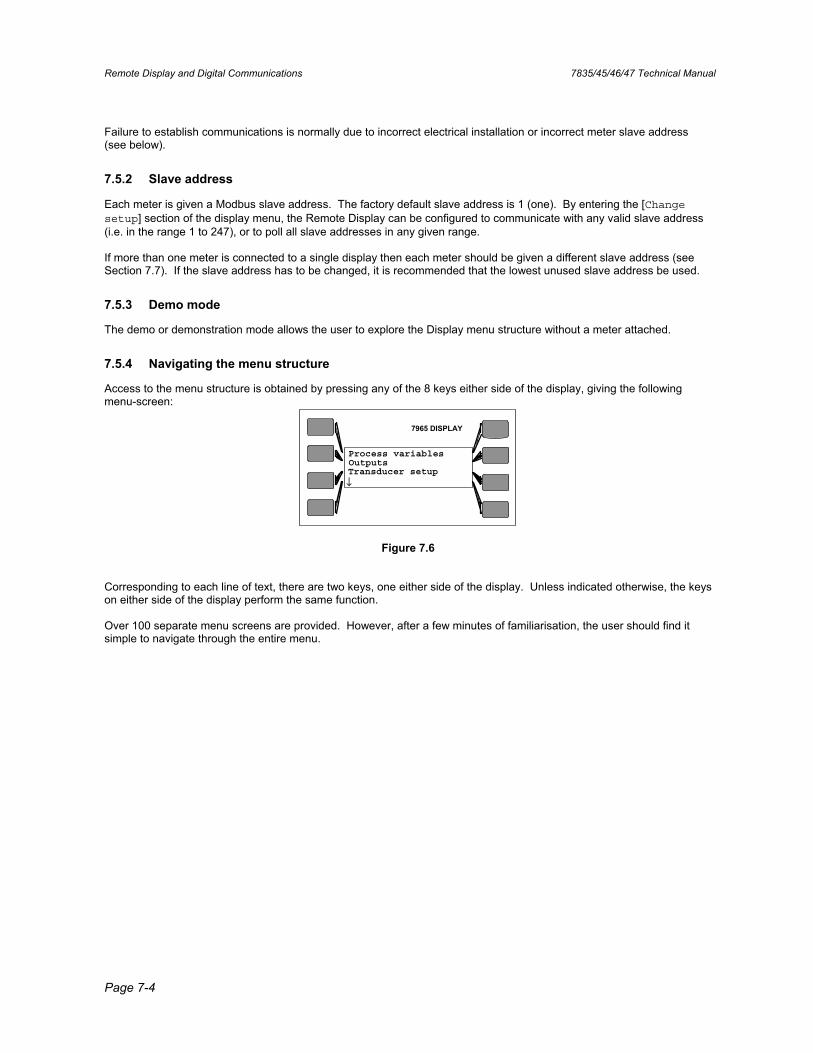
Remote Display and Digital Communications 7835/45/46/47 Technical Manual
Page 7-4
Failure to establish communications is normally due to incorrect electrical installation or incorrect meter slave address (see below).
7.5.2 Slave address
Each meter is given a Modbus slave address. The factory default slave address is 1 (one). By entering the [Changesetup] section of the display menu, the Remote Display can be configured to communicate with any valid slave address (i.e. in the range 1 to 247), or to poll all slave addresses in any given range.
If more than one meter is connected to a single display then each meter should be given a different slave address (see Section 7.7). If the slave address has to be changed, it is recommended that the lowest unused slave address be used.
7.5.3 Demo mode
The demo or demonstration mode allows the user to explore the Display menu structure without a meter attached.
7.5.4 Navigating the menu structure
Access to the menu structure is obtained by pressing any of the 8 keys either side of the display, giving the following menu-screen:
7965 DISPLAY
Process variablesOutputsTransducer setup↓
Figure 7.6
Corresponding to each line of text, there are two keys, one either side of the display. Unless indicated otherwise, the keys on either side of the display perform the same function.
Over 100 separate menu screens are provided. However, after a few minutes of familiarisation, the user should find it simple to navigate through the entire menu.
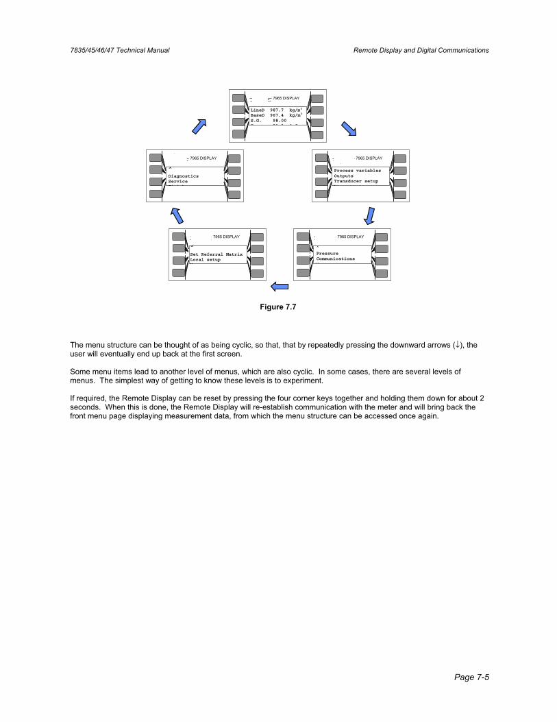
7835/45/46/47 Technical Manual Remote Display and Digital Communications
Page 7-5
7965 DISPLAY
Made in the U.K. by Solartron,Farnborough, Hampshire, England.
solartron
7965 DISPLAY
Made in the U.K. by Solartron,Farnborough, Hampshire, England.
solartron
7965 DISPLAY
Made in the U.K. by Solartron,Farnborough, Hampshire, England.
solartron
7965 DISPLAY
Made in the U.K. by Solartron,Farnborough, Hampshire, England.
solartron
7965 DISPLAY
Made in the U.K. by Solartron,Farnborough, Hampshire, England.
solartron
LineD 987.7 kg/m3
BaseD 967.4 kg/m3
S.G. 98.00 Temp 21 3 ° C
Process variablesOutputs Transducer setup V
^Pressure Communications V
^Set Referral Matrix Local setup V
^Diagnostics Service Finish
Figure 7.7
The menu structure can be thought of as being cyclic, so that, that by repeatedly pressing the downward arrows (↓), the user will eventually end up back at the first screen.
Some menu items lead to another level of menus, which are also cyclic. In some cases, there are several levels of menus. The simplest way of getting to know these levels is to experiment.
If required, the Remote Display can be reset by pressing the four corner keys together and holding them down for about 2 seconds. When this is done, the Remote Display will re-establish communication with the meter and will bring back the front menu page displaying measurement data, from which the menu structure can be accessed once again.
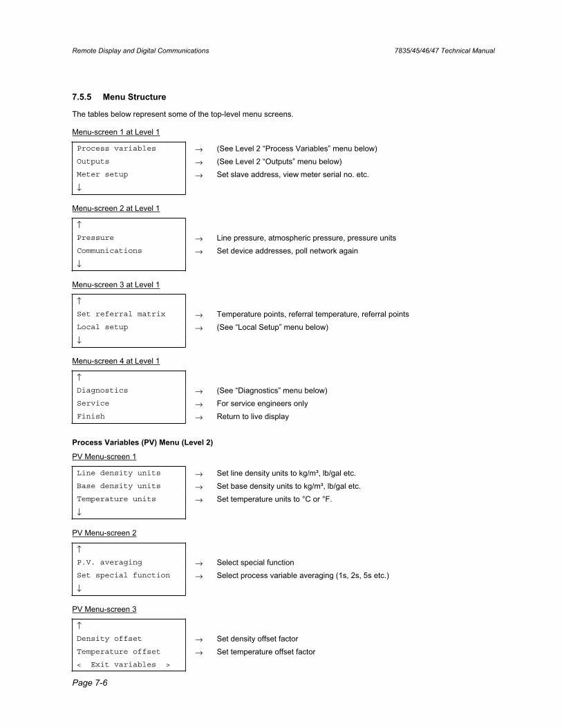
Remote Display and Digital Communications 7835/45/46/47 Technical Manual
Page 7-6
7.5.5 Menu Structure
The tables below represent some of the top-level menu screens.
Menu-screen 1 at Level 1
Process variables → (See Level 2 “Process Variables” menu below) Outputs → (See Level 2 “Outputs” menu below) Meter setup → Set slave address, view meter serial no. etc.
↓
Menu-screen 2 at Level 1
↑Pressure → Line pressure, atmospheric pressure, pressure units Communications → Set device addresses, poll network again
↓
Menu-screen 3 at Level 1
↑Set referral matrix → Temperature points, referral temperature, referral points Local setup → (See “Local Setup” menu below)
↓
Menu-screen 4 at Level 1
↑Diagnostics → (See “Diagnostics” menu below) Service → For service engineers only Finish → Return to live display
Process Variables (PV) Menu (Level 2)
PV Menu-screen 1
Line density units → Set line density units to kg/m³, lb/gal etc. Base density units → Set base density units to kg/m³, lb/gal etc. Temperature units → Set temperature units to °C or °F.
↓
PV Menu-screen 2
↑P.V. averaging → Select special function Set special function → Select process variable averaging (1s, 2s, 5s etc.)
↓
PV Menu-screen 3
↑Density offset → Set density offset factor Temperature offset → Set temperature offset factor < Exit variables >
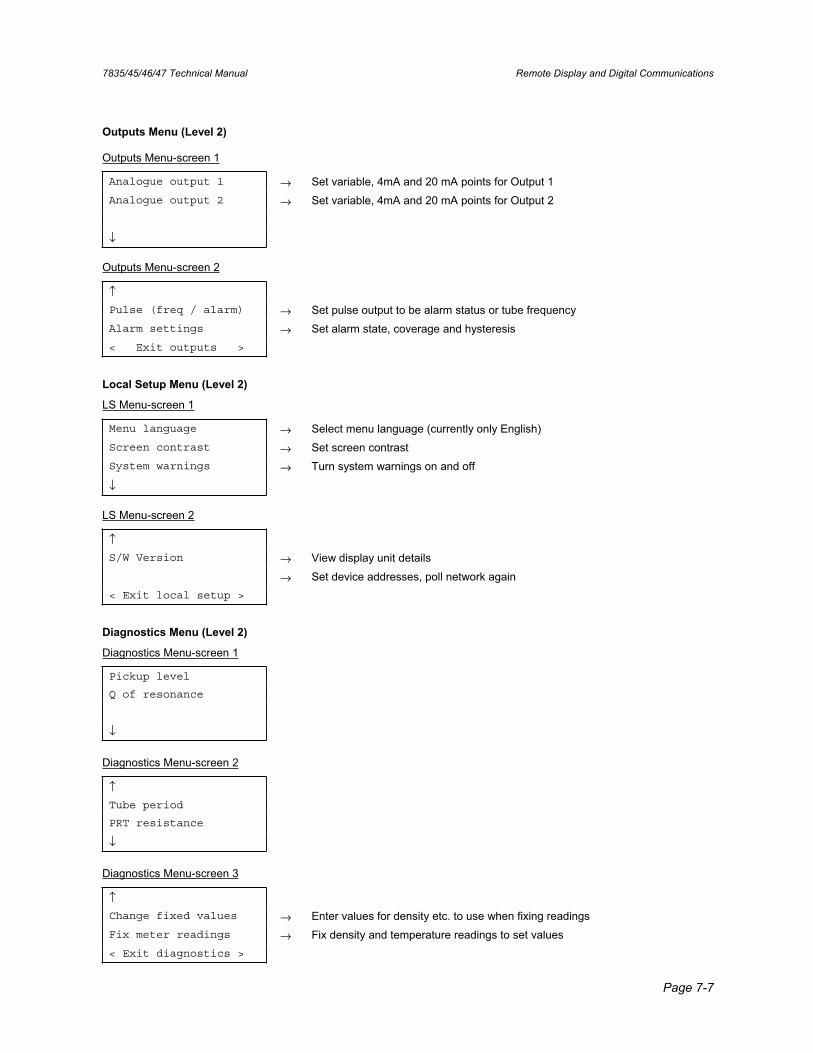
7835/45/46/47 Technical Manual Remote Display and Digital Communications
Page 7-7
Outputs Menu (Level 2)
Outputs Menu-screen 1
Analogue output 1 → Set variable, 4mA and 20 mA points for Output 1 Analogue output 2 → Set variable, 4mA and 20 mA points for Output 2
↓
Outputs Menu-screen 2
↑Pulse (freq / alarm) → Set pulse output to be alarm status or tube frequency Alarm settings → Set alarm state, coverage and hysteresis < Exit outputs >
Local Setup Menu (Level 2)
LS Menu-screen 1
Menu language → Select menu language (currently only English) Screen contrast → Set screen contrast System warnings → Turn system warnings on and off
↓
LS Menu-screen 2
↑S/W Version → View display unit details
→ Set device addresses, poll network again < Exit local setup >
Diagnostics Menu (Level 2)
Diagnostics Menu-screen 1
Pickup level
Q of resonance
↓
Diagnostics Menu-screen 2
↑Tube period
PRT resistance
↓
Diagnostics Menu-screen 3
↑Change fixed values → Enter values for density etc. to use when fixing readings Fix meter readings → Fix density and temperature readings to set values < Exit diagnostics >
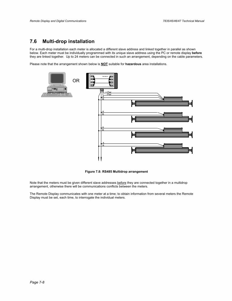
Remote Display and Digital Communications 7835/45/46/47 Technical Manual
Page 7-8
7.6 Multi-drop installation For a multi-drop installation each meter is allocated a different slave address and linked together in parallel as shown below. Each meter must be individually programmed with its unique slave address using the PC or remote display beforethey are linked together. Up to 24 meters can be connected in such an arrangement, depending on the cable parameters.
Please note that the arrangement shown below is NOT suitable for hazardous area installations.
OR
+ Pwr- Pwr
AB
A
A
A
B
B
B
7965 DISPLAY
Figure 7.8: RS485 Multidrop arrangement
Note that the meters must be given different slave addresses before they are connected together in a multidrop arrangement, otherwise there will be communications conflicts between the meters.
The Remote Display communicates with one meter at a time; to obtain information from several meters the Remote Display must be set, each time, to interrogate the individual meters.
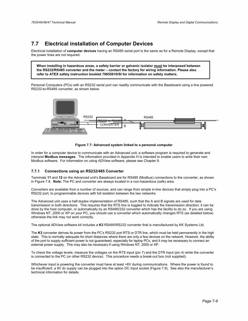
7835/45/46/47 Technical Manual Remote Display and Digital Communications
Page 7-9
7.7 Electrical installation of Computer Devices Electrical installation of computer devices having an RS485 serial port is the same as for a Remote Display, except that the power lines are not required.
When installing in hazardous areas, a safety barrier or galvanic isolator must be interposed between the RS232/RS485 converter and the meter – contact the factory for wiring information. Please also refer to ATEX safety instruction booklet 79655010/SI for information on safety matters.
Personal Computers (PCs) with an RS232 serial port can readily communicate with the Baseboard using a line powered RS232-to-RS485 converter, as shown below.
RS232 to RS485CONVERTER
A
B
RS232 RS485
Figure 7.7: Advanced system linked to a personal computer
In order for a computer device to communicate with an Advanced unit, a software program is required to generate and interpret Modbus messages. The information provided in Appendix H is intended to enable users to write their own Modbus software. For information on using ADView software, please see Chapter 9.
7.7.1 Connections using an RS232/485 Converter Terminals 11 and 12 on the Advanced unit’s Baseboard are for RS485 (Modbus) connections to the converter, as shown in Figure 7.8. Note: The PC and converter are always located in a non-hazardous (safe) area.
Converters are available from a number of sources, and can range from simple in-line devices that simply plug into a PC’s RS232 port, to programmable devices with full isolation between the two networks.
The Advanced unit uses a half-duplex implementation of RS485, such that the A and B signals are used for data transmission in both directions. This requires that the RTS line is toggled to indicate the transmission direction; it can be done by the host computer, or automatically by an RS485/232 converter which has the facility to do so. If you are using Windows NT, 2000 or XP on your PC, you should use a converter which automatically changes RTS (as detailed below) otherwise the link may not work correctly.
The optional ADView software kit includes a K3 RS485/RS232 converter that is manufactured by KK Systems Ltd.
The K3 converter derives its power from the PC’s RS232 port RTS or DTR line, which must be held permanently in the high state. This is normally adequate for short distances where there are only a few devices on the network. However, the ability of the port to supply sufficient power is not guaranteed, especially for laptop PCs, and it may be necessary to connect an external power supply. This may also be necessary if using Windows NT, 2000 or XP.
To check the voltage levels, measure the voltages on the RTS input (pin 7) and the DTR input (pin 4) while the converter is connected to the PC (or other RS232 device). This procedure needs a break-out box (not supplied).
Whichever input is powering the converter must have at least +6V during communications. Where the power is found to be insufficient, a 9V dc supply can be plugged into the option DC Input socket (Figure 7.9). See also the manufacturer’s technical information for details.
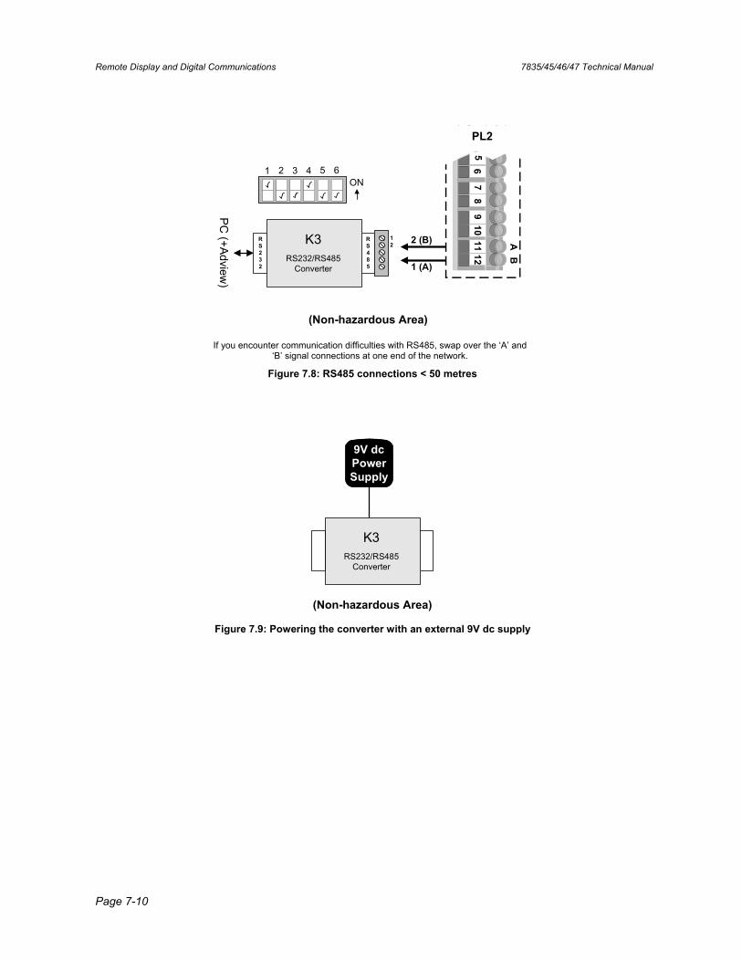
Remote Display and Digital Communications 7835/45/46/47 Technical Manual
Page 7-10
PC (+Adview
)
1 (A)
2 (B)K3RS232/RS485
Converter
1 2 3 4 5 6ON
RS232
RS485
12
78
910
1112
AB
34
56
PL2
(Non-hazardous Area)
If you encounter communication difficulties with RS485, swap over the ‘A’ and ‘B’ signal connections at one end of the network.
Figure 7.8: RS485 connections < 50 metres
K3RS232/RS485
Converter
9V dcPowerSupply
(Non-hazardous Area)
Figure 7.9: Powering the converter with an external 9V dc supply
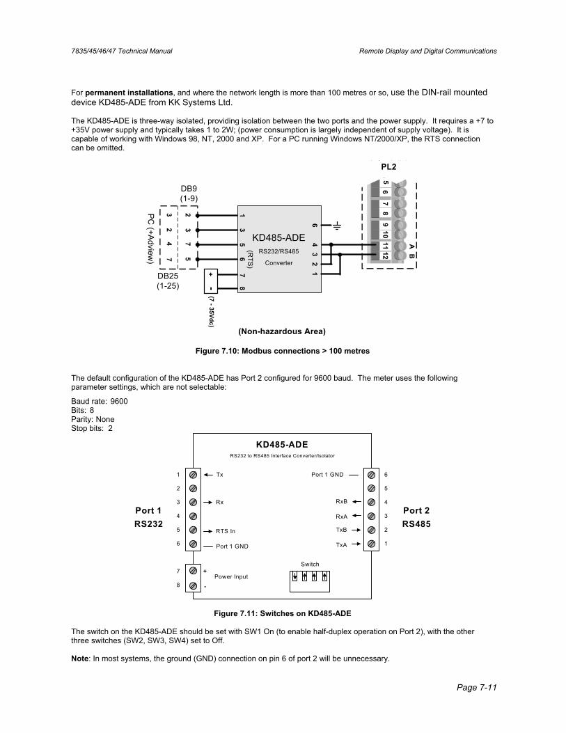
7835/45/46/47 Technical Manual Remote Display and Digital Communications
Page 7-11
For permanent installations, and where the network length is more than 100 metres or so, use the DIN-rail mounted device KD485-ADE from KK Systems Ltd.
The KD485-ADE is three-way isolated, providing isolation between the two ports and the power supply. It requires a +7 to +35V power supply and typically takes 1 to 2W; (power consumption is largely independent of supply voltage). It is capable of working with Windows 98, NT, 2000 and XP. For a PC running Windows NT/2000/XP, the RTS connection can be omitted.
78
910
1112
AB
34
56
PL2
PC (+A
dview)
KD485-ADERS232/RS485
Converter
43
21
6
+-
(7 - 35Vdc)
87
13
56
DB25(1-25)
DB9(1-9)
57
32
74
23
(RTS
)
(Non-hazardous Area)
Figure 7.10: Modbus connections > 100 metres
The default configuration of the KD485-ADE has Port 2 configured for 9600 baud. The meter uses the following parameter settings, which are not selectable:
Baud rate: 9600 Bits: 8 Parity: None Stop bits: 2
Port 1RS232
Port 2RS485
KD485-ADERS232 to RS485 Interface Converter/Isolator
Switch
Tx
Rx
Port 1 GND
RTS In
1
2
3
4
5
6
Power Input+
-
7
8
6
5
4
3
2
1
Port 1 GND
TxB
TxA
RxB
RxA
Figure 7.11: Switches on KD485-ADE
The switch on the KD485-ADE should be set with SW1 On (to enable half-duplex operation on Port 2), with the other three switches (SW2, SW3, SW4) set to Off.
Note: In most systems, the ground (GND) connection on pin 6 of port 2 will be unnecessary.

Remote Display and Digital Communications 7835/45/46/47 Technical Manual
Page 7-12
7835/45/46/47 Technical Manual General Maintenance
Page 8-1
Chapter 8 General Maintenance
8.1 General The 7835/45/6/7 Liquid Density Meters and the 7845/47 Entrained Gas Liquid Density Meters have no moving parts, which reduces the maintenance requirement to simple visual checks for leaks and physical damage.
Check calibrations should be carried out at specified intervals in order to highlight any malfunction or deterioration in meter performance. If a fault or a drop in meter performance is discovered, further tests are required to identify the cause of the fault. Remedial action is limited to cleaning the tube, making good any poor connections and replacing the maintaining amplifier, the temperature probe or, in extreme cases, the entire instrument.
Caution:Extreme care is required in the handling of the meter during transit, its installation into the pipeline and its removal from the pipeline.
8.2 Fault Analysis Faults generally fall into two main categories - erratic readings or readings outside limits.
Erratic Readings: Normally caused by the presence of gas bubbles in the flowing liquid. Severe electrical interference or severe pipeline vibrations can also cause this effect.
Readings Outside Limits: Normally caused by deposition and/or corrosion on the resonating tube.
Since an electrical fault could also cause either fault and since examination for deposition or corrosion requires the removal off-line of the meter, it is recommended that the electrical system be checked first.
8.3 General Maintenance Procedure This procedure is recommended for any periodic maintenance carried out on the system and forms the basis of any faultfinding task.
8.3.1 Physical Checks
(a) Examine the meter and its mounting bracket, pipe couplings and electrical cables for signs of damage and corrosion.
(b) Check the meter for signs of fluid leakage and the state of the rupture plate.
Notes:
1. Any physical damage to the meter case or mounting brackets may have adverse effects on the meter performance and a full calibration would be advisable to verify its accuracy.
2. Any oil leakage, apart from that found in the region of the rupture plate, can generally be remedied by servicing. Any rupture plate leakage requires a meter replacement.
General Maintenance 7835/45/46/47 Technical Manual
Page 8-2
8.3.2 Check Calibration
(a) Carry out a check calibration using methods detailed in Chapter 6.
(b) Compare the results obtained with the current calibration certificate figures to identify any substantial deterioration in the meter's performance or any malfunction.
Notes:
1. A substantial drop in meter performance is likely due to a build-up of deposition on the vibrating tube, which can be removed by the application of a suitable solvent. See 'Remedial Servicing' section below.
2. Malfunctions may be the result of electrical/electronic faults in either the meter circuit or the readout equipment. The readout equipment should be proved before attention is directed to the meter as detailed under 'remedial servicing'.
8.3.3 Remedial Servicing The required servicing falls into two categories - electrical and mechanical.
1. Electrical Servicing
(a) On Advanced units: Check the voltage between terminals 7 and 8 is between 10V and 20V.
(b) On Standard units: Carry out power supply and current consumption tests at the meter terminals. These should give:
• 17mA ±1mA at 15.5V to 33V (7835/45/46/47 Standard units) • 75mA ±2mA at 15.5V to 33V (7845/47 E.G. units)
Remove the power supply to the meter. If current consumption is suspect, replace the meter amplifier.
Identify the drive coils (terminals 8 and 9 on Advanced units, 7 and 8 on Standard units) and disconnect the drive coil wires from the amplifier. Measure the resistance of the drive coils. This should be:
• 95 ±5 ohms at 20°C (68°F).
Reconnect the drive coil wires to the amplifier.
(c) Identify the pick-up coils (terminals 1 and 2 on Advanced units, 9 and 10 on Standard units) and disconnect the pick-up coil wires from the amplifier. Measure the resistance of the pick-up coils. This should be:
• 95 ±5 ohms at 20°C (68°F).
Reconnect the pick-up coil wires to the amplifier.
(d) On Advanced Units: With no power to the unit, check the 100Ω Platinum Resistance Thermometer element across terminals 4 and 7. The
value of the element resistance is temperature dependent. For this data - see Appendix H.
On Standard Units: Check the 100Ω Platinum Resistance Thermometer element across the terminals 11 and 12 (ensure terminals 3 to 6
are disconnected). The value of the element resistance is temperature dependent. For this data, see Appendix H. Check for continuity between terminals 11 and 3, and terminals 11 and 4, also from terminals 12 to 5 and 12 to 6.
(e) Carry out an insulation test by removing all the input connections to the amplifier terminals (1 to 2 inclusive on Advanced units and 1 to 7 inclusive on Standard units) and short circuit the terminals together. Test their insulation resistance to the metal case using a 500V d.c. insulation tester (current limited to 5mA maximum). This resistance must be greater than 2MΩ.
Remove the short circuit and reconnect the input leads, if required.
7835/45/46/47 Technical Manual General Maintenance
Page 8-3
2. Mechanical Servicing
Mechanical servicing comprises mainly of keeping the inner surface of the vibrating tube clear of deposition and corrosion. Deposition may be removed by the use of a suitable solvent. Alternatively, the instrument can be removed from the pipeline and cleaned mechanically. Care is required to prevent damage to the inner surface of the tube during the cleaning.
Caution:Extreme care is required in the handling of the meter during transit, its installation into the pipeline and its removal from the pipeline.
Ensure that the meter is not transported when it contains hazardous fluids. This includes fluids that may have leaked into, and are still contained, within the case.

General Maintenance 7835/45/46/47 Technical Manual
Page 8-4

7835/45/46/47 Technical Manual
Page 9-1
Chapter 9 Using Adview
9.1 WHAT IS ADVIEW? ADView is a software package to: • Configure our density and viscosity transmitters. • View and save data from them. • Check that they are functioning correctly.
ADView is installed on a PC and interacts with the ‘Advanced’ unit through one of the PC’s standard serial (RS-232) ports. The PC must be running one of Microsoft’s Windows operating systems: Windows 3.1, 95, 98, NT, 2000 or XP.
Note: To connect to an RS485 (Modbus) device, such as the ‘Advanced’ unit, you will need an RS232/RS485 converter between the PC and the Advanced unit (see Chapter 3 for details).
ADView provides many useful facilities, such as:
• Setting up serial link to communicate with the ‘Advanced’ unit.
• Configuring the ‘Advanced’ unit.
• Displaying data in real time, or as a graph.
• Logging data to a file.
• Verifying correct operation of the system, and diagnosing faults.
• Loading or storing Modbus register values.
• Read/write to individual Modbus registers.
9.2 INSTALLING ADVIEW Adview software is available for the PC on a variety of media (e.g. CD-ROM) and is freely available to download from the web sites listed on the back page.
Procedure:
1. Identify the media containing the installation files for ADView.
2. Insert the media into an appropriate drive on your PC.
3. If the installation program does not begin automatically, run the set-up ‘.exe’ file that is on the media. (Note:This does vary between different PC operating systems. In general, open the File Manager or Windows Explorer, browse the drive containing the media and double-click on the set-up ‘.exe’.)
4. When the installation program starts, you will be asked to supply your name and organisation name for registration purposes, and supply a directory path into which ADView’s files can be loaded (a default directory path will be suggested).
5. Follow the installation instructions until installation is complete. It will normally only take a few minutes. You can abandon the installation if you need to do so.
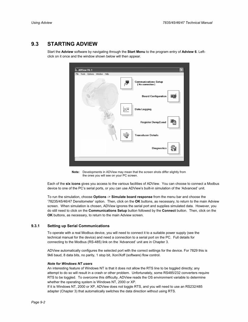
Using Adview 7835/45/46/47 Technical Manual
Page 9-2
9.3 STARTING ADVIEW Start the Adview software by navigating through the Start Menu to the program entry of Adview 6. Left-click on it once and the window shown below will then appear.
Note: Developments in ADView may mean that the screen shots differ slightly from the ones you will see on your PC screen.
Each of the six icons gives you access to the various facilities of ADView. You can choose to connect a Modbus device to one of the PC’s serial ports, or you can use ADView’s built-in simulation of the ‘Advanced’ unit.
To run the simulation, choose Options -> Simulate board response from the menu bar and choose the ‘78235/45/46/47 Densitometer’ option. Then, click on the OK buttons, as necessary, to return to the main Adview screen. When simulation is chosen, ADView ignores the serial port and supplies simulated data. However, you do still need to click on the Communications Setup button followed by the Connect button. Then, click on the OK buttons, as necessary, to return to the main Adview screen.
9.3.1 Setting up Serial Communications
To operate with a real Modbus device, you will need to connect it to a suitable power supply (see the technical manual for the device) and need a connection to a serial port on the PC. Full details for connecting to the Modbus (RS-485) link on the ‘Advanced’ unit are in Chapter 3.
ADView automatically configures the selected port with the correct settings for the device. For 7829 this is 9k6 baud, 8 data bits, no parity, 1 stop bit, Xon/Xoff (software) flow control.
Note for Windows NT usersAn interesting feature of Windows NT is that it does not allow the RTS line to be toggled directly; any attempt to do so will result in a crash or other problem. Unfortunately, some RS485/232 converters require RTS to be toggled. To overcome this difficulty, ADView reads the OS environment variable to determine whether the operating system is Windows NT, 2000 or XP. If it is Windows NT, 2000 or XP, ADView does not toggle RTS, and you will need to use an RS232/485 adapter (Chapter 3) that automatically switches the data direction without using RTS.
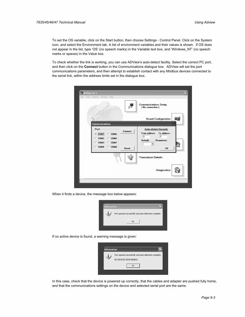
7835/45/46/47 Technical Manual Using Adview
Page 9-3
To set the OS variable, click on the Start button, then choose Settings - Control Panel. Click on the System icon, and select the Environment tab. A list of environment variables and their values is shown. If OS does not appear in the list, type ‘OS’ (no speech marks) in the Variable text box, and ‘Windows_NT’ (no speech marks or spaces) in the Value box.
To check whether the link is working, you can use ADView’s auto-detect facility. Select the correct PC port, and then click on the Connect button in the Communications dialogue box. ADView will set the port communications parameters, and then attempt to establish contact with any Modbus devices connected to the serial link, within the address limits set in the dialogue box.
When it finds a device, the message box below appears:
If no active device is found, a warning message is given:
In this case, check that the device is powered up correctly, that the cables and adapter are pushed fully home, and that the communications settings on the device and selected serial port are the same.
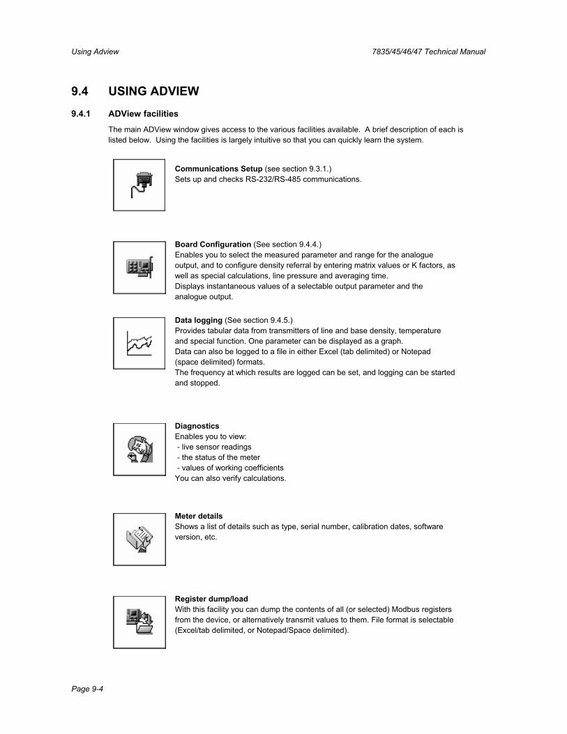
Using Adview 7835/45/46/47 Technical Manual
Page 9-4
9.4 USING ADVIEW
9.4.1 ADView facilities
The main ADView window gives access to the various facilities available. A brief description of each is listed below. Using the facilities is largely intuitive so that you can quickly learn the system.
Communications Setup (see section 9.3.1.) Sets up and checks RS-232/RS-485 communications.
Board Configuration (See section 9.4.4.) Enables you to select the measured parameter and range for the analogue output, and to configure density referral by entering matrix values or K factors, as well as special calculations, line pressure and averaging time. Displays instantaneous values of a selectable output parameter and the analogue output.
Data logging (See section 9.4.5.) Provides tabular data from transmitters of line and base density, temperature and special function. One parameter can be displayed as a graph. Data can also be logged to a file in either Excel (tab delimited) or Notepad (space delimited) formats. The frequency at which results are logged can be set, and logging can be started and stopped.
DiagnosticsEnables you to view: - live sensor readings - the status of the meter - values of working coefficients You can also verify calculations.
Meter detailsShows a list of details such as type, serial number, calibration dates, software version, etc.
Register dump/loadWith this facility you can dump the contents of all (or selected) Modbus registers from the device, or alternatively transmit values to them. File format is selectable (Excel/tab delimited, or Notepad/Space delimited).
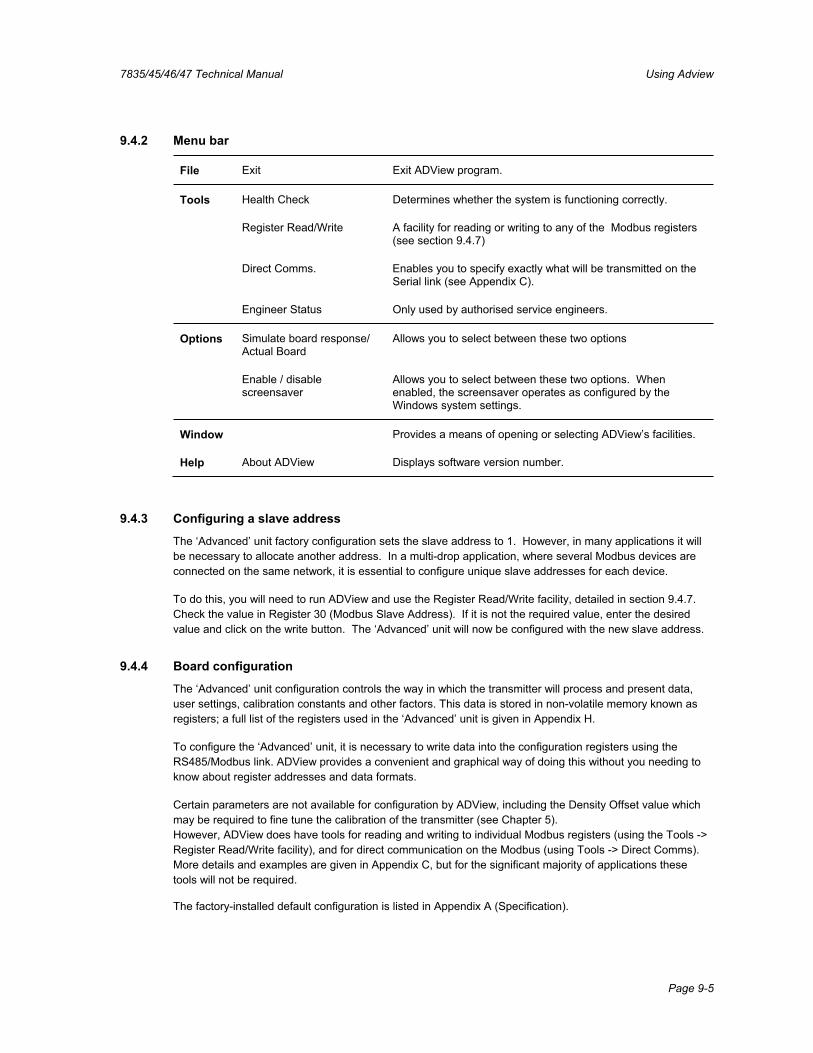
7835/45/46/47 Technical Manual Using Adview
Page 9-5
9.4.2 Menu bar
File Exit Exit ADView program.
Tools Health Check Determines whether the system is functioning correctly.
Register Read/Write A facility for reading or writing to any of the Modbus registers (see section 9.4.7)
Direct Comms. Enables you to specify exactly what will be transmitted on the Serial link (see Appendix C).
Engineer Status Only used by authorised service engineers.
Options Simulate board response/Actual Board
Allows you to select between these two options
Enable / disable screensaver
Allows you to select between these two options. When enabled, the screensaver operates as configured by the Windows system settings.
Window Provides a means of opening or selecting ADView’s facilities.
Help About ADView Displays software version number.
9.4.3 Configuring a slave address
The ‘Advanced’ unit factory configuration sets the slave address to 1. However, in many applications it will be necessary to allocate another address. In a multi-drop application, where several Modbus devices are connected on the same network, it is essential to configure unique slave addresses for each device.
To do this, you will need to run ADView and use the Register Read/Write facility, detailed in section 9.4.7.Check the value in Register 30 (Modbus Slave Address). If it is not the required value, enter the desired value and click on the write button. The ‘Advanced’ unit will now be configured with the new slave address.
9.4.4 Board configuration
The ‘Advanced’ unit configuration controls the way in which the transmitter will process and present data, user settings, calibration constants and other factors. This data is stored in non-volatile memory known as registers; a full list of the registers used in the ‘Advanced’ unit is given in Appendix H.
To configure the ‘Advanced’ unit, it is necessary to write data into the configuration registers using the RS485/Modbus link. ADView provides a convenient and graphical way of doing this without you needing to know about register addresses and data formats.
Certain parameters are not available for configuration by ADView, including the Density Offset value which may be required to fine tune the calibration of the transmitter (see Chapter 5).However, ADView does have tools for reading and writing to individual Modbus registers (using the Tools -> Register Read/Write facility), and for direct communication on the Modbus (using Tools -> Direct Comms). More details and examples are given in Appendix C, but for the significant majority of applications these tools will not be required.
The factory-installed default configuration is listed in Appendix A (Specification).
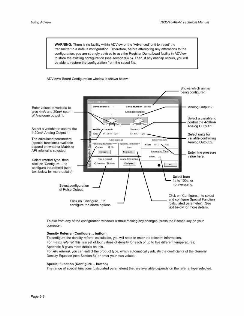
Using Adview 7835/45/46/47 Technical Manual
Page 9-6
WARNING: There is no facility within ADView or the ‘Advanced’ unit to ‘reset’ the transmitter to a default configuration. Therefore, before attempting any alterations to the configuration, you are strongly advised to use the Register Dump/Load facility in ADView to store the existing configuration (see section 9.4.5). Then, if any mishap occurs, you will be able to restore the configuration from the saved file.
ADView’s Board Configuration window is shown below:
To exit from any of the configuration windows without making any changes, press the Escape key on your computer.
Density Referral (Configure… button) To configure the density referral calculation, you will need to enter the relevant information. For matrix referral, this is a set of four values of density for each of up to five different temperatures; Appendix B gives more details on this. For API referral, you can select the product type, which automatically adjusts the coefficients of the General Density Equation (see Section 5), or enter your own values.
Special Function (Configure… button) The range of special functions (calculated parameters) that are available depends on the referral type selected.
Enter line pressure value here.
Select from 1s to 100s, or no averaging.
Select referral type, then click on ‘Configure…’ to configure the referral (see text below for more details).
Click on ‘Configure...’ to select and configure Special Function (calculated parameter). See text below for more details.
Shows which unit is being configured.
Enter values of variable to give 4mA and 20mA span of Analogue output 1.
Select a variable to control the 4-20mA Analog Output 1.
The calculated parameters (special functions) available depend on whether Matrix or API referral is selected.
Select units for variable controlling Analog Output 2.
Analog Output 2.
Select a variable to control the 4-20mA Analog Output 1.
Select configuration of Pulse Output.
Click on ‘Configure...’ to configure the alarm options.
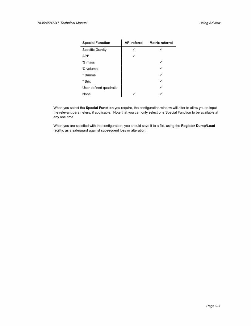
7835/45/46/47 Technical Manual Using Adview
Page 9-7
Special Function API referral Matrix referral
Specific Gravity
API°
% mass
% volume
° Baumé
° Brix
User defined quadratic
None
When you select the Special Function you require, the configuration window will alter to allow you to input the relevant parameters, if applicable. Note that you can only select one Special Function to be available at any one time.
When you are satisfied with the configuration, you should save it to a file, using the Register Dump/Loadfacility, as a safeguard against subsequent loss or alteration.

Using Adview 7835/45/46/47 Technical Manual
Page 9-8
9.4.5 Data logging
ADView’s Data Logging function is a useful tool for checking setups and performing experimental data capture. The diagram below explains some of the features.
For selecting the parameter to be logged.
Graphicalrepresentation of analogue outputs. Select analogue
output of another transmitter.
Tabular display of instantaneousoutput of transmitter.
Use this button to start logging.
Use this button to stop logging
Use this button to close Data Logging window
Use this button to configure and display graph
Use this button to select the transmitter and parameter to be displayed on the graph
For multi-drop configurations(see section 3.4.4), the output of up to three transmitters can be displayed simultaneously.
This button - which is activated when logging has been stopped - enables you to configure the frequency of logging, where the logged data will be filed, and the format of the data.
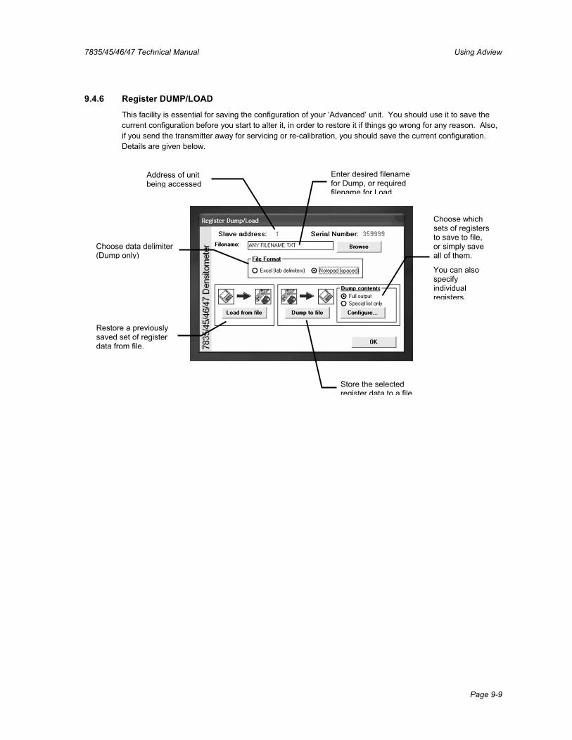
7835/45/46/47 Technical Manual Using Adview
Page 9-9
9.4.6 Register DUMP/LOAD
This facility is essential for saving the configuration of your ‘Advanced’ unit. You should use it to save the current configuration before you start to alter it, in order to restore it if things go wrong for any reason. Also, if you send the transmitter away for servicing or re-calibration, you should save the current configuration.Details are given below.
Address of unit being accessed
Enter desired filename for Dump, or required filename for Load.
Choose data delimiter (Dump only)
Choose which sets of registers to save to file, or simply save all of them.
You can also specify individualregisters.
Restore a previously saved set of register data from file.
Store the selected register data to a file.
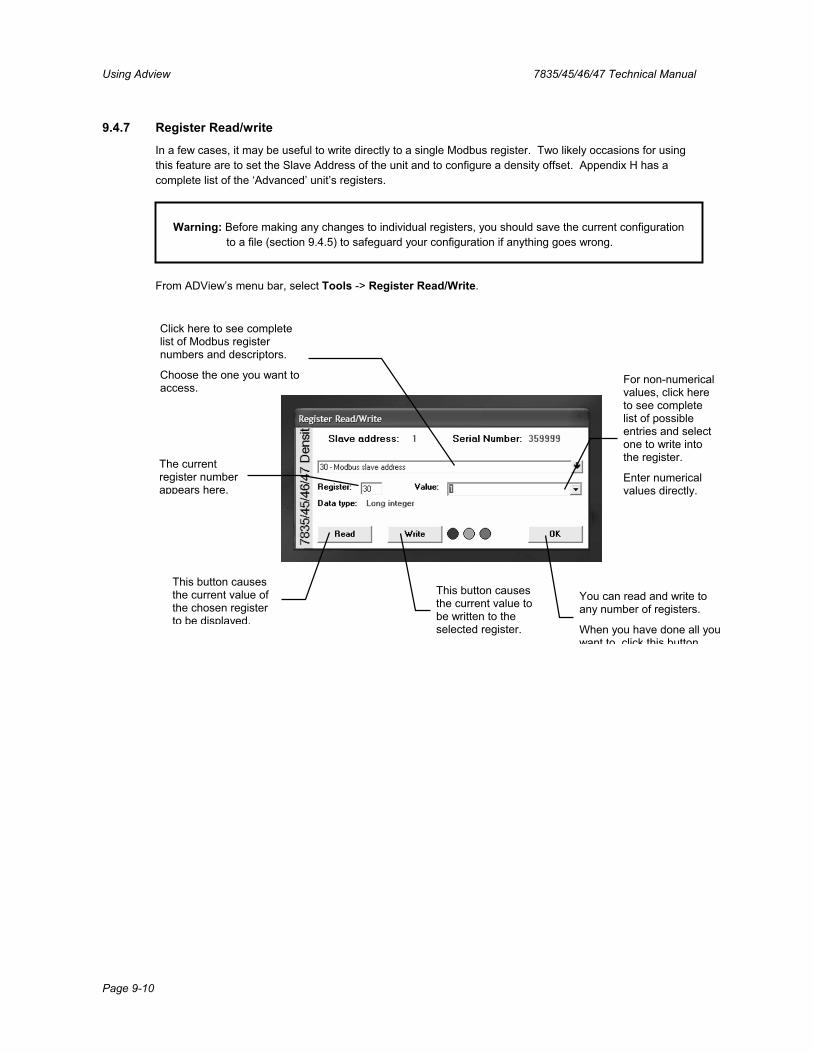
Using Adview 7835/45/46/47 Technical Manual
Page 9-10
9.4.7 Register Read/write
In a few cases, it may be useful to write directly to a single Modbus register. Two likely occasions for using this feature are to set the Slave Address of the unit and to configure a density offset. Appendix H has a complete list of the ‘Advanced’ unit’s registers.
Warning: Before making any changes to individual registers, you should save the current configuration to a file (section 9.4.5) to safeguard your configuration if anything goes wrong.
From ADView’s menu bar, select Tools -> Register Read/Write.
Click here to see complete list of Modbus register numbers and descriptors.
Choose the one you want to access.
For non-numerical values, click here to see complete list of possible entries and select one to write into the register.
Enter numerical values directly.
The current register number appears here.
This button causes the current value of the chosen register to be displayed.
This button causes the current value to be written to the selected register.
You can read and write to any number of registers.
When you have done all you want to click this button
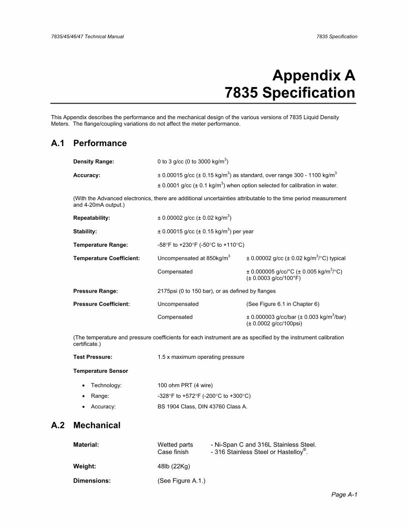
7835/45/46/47 Technical Manual 7835 Specification
Page A-1
Appendix A 7835 Specification
This Appendix describes the performance and the mechanical design of the various versions of 7835 Liquid Density Meters. The flange/coupling variations do not affect the meter performance.
A.1 Performance
Density Range: 0 to 3 g/cc (0 to 3000 kg/m3)
Accuracy: ± 0.00015 g/cc (± 0.15 kg/m3) as standard, over range 300 - 1100 kg/m3
± 0.0001 g/cc (± 0.1 kg/m3) when option selected for calibration in water.
(With the Advanced electronics, there are additional uncertainties attributable to the time period measurement and 4-20mA output.)
Repeatability: ± 0.00002 g/cc (± 0.02 kg/m3)
Stability: ± 0.00015 g/cc (± 0.15 kg/m3) per year
Temperature Range: -58°F to +230°F (-50°C to +110°C)
Temperature Coefficient: Uncompensated at 850kg/m3 ± 0.00002 g/cc (± 0.02 kg/m3/°C) typical
Compensated ± 0.000005 g/cc/°C (± 0.005 kg/m3/°C) (± 0.0003 g/cc/100°F)
Pressure Range: 2175psi (0 to 150 bar), or as defined by flanges
Pressure Coefficient: Uncompensated (See Figure 6.1 in Chapter 6)
Compensated ± 0.000003 g/cc/bar (± 0.003 kg/m3/bar) (± 0.0002 g/cc/100psi)
(The temperature and pressure coefficients for each instrument are as specified by the instrument calibration certificate.)
Test Pressure: 1.5 x maximum operating pressure
Temperature Sensor
• Technology: 100 ohm PRT (4 wire)
• Range: -328°F to +572°F (-200°C to +300°C)
• Accuracy: BS 1904 Class, DIN 43760 Class A.
A.2 Mechanical
Material: Wetted parts - Ni-Span C and 316L Stainless Steel. Case finish - 316 Stainless Steel or Hastelloy®.
Weight: 48lb (22Kg)
Dimensions: (See Figure A.1.)
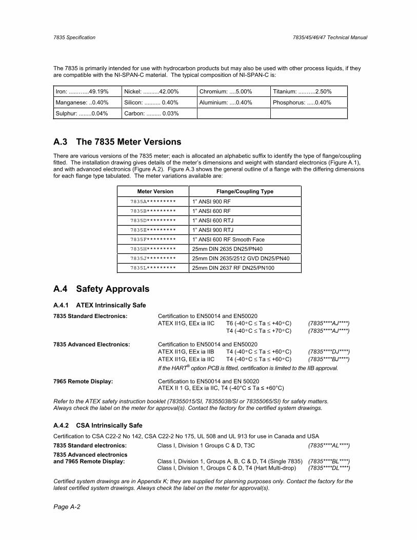
7835 Specification 7835/45/46/47 Technical Manual
Page A-2
The 7835 is primarily intended for use with hydrocarbon products but may also be used with other process liquids, if they are compatible with the NI-SPAN-C material. The typical composition of NI-SPAN-C is:
Iron: .....…....49.19% Nickel: ..........42.00% Chromium: ....5.00% Titanium: ....…...2.50%
Manganese: ..0.40% Silicon: .......... 0.40% Aluminium: ....0.40% Phosphorus: .....0.40%
Sulphur: ........0.04% Carbon: ......... 0.03%
A.3 The 7835 Meter Versions There are various versions of the 7835 meter; each is allocated an alphabetic suffix to identify the type of flange/coupling fitted. The installation drawing gives details of the meter’s dimensions and weight with standard electronics (Figure A.1), and with advanced electronics (Figure A.2). Figure A.3 shows the general outline of a flange with the differing dimensions for each flange type tabulated. The meter variations available are:
Meter Version Flange/Coupling Type
7835A********* 1” ANSI 900 RF 7835B********* 1” ANSI 600 RF 7835D********* 1” ANSI 600 RTJ
7835E********* 1” ANSI 900 RTJ 7835F********* 1” ANSI 600 RF Smooth Face 7835H********* 25mm DIN 2635 DN25/PN40 7835J********* 25mm DIN 2635/2512 GVD DN25/PN40 7835L********* 25mm DIN 2637 RF DN25/PN100
A.4 Safety Approvals
A.4.1 ATEX Intrinsically Safe 7835 Standard Electronics: Certification to EN50014 and EN50020 ATEX II1G, EEx ia IIC T6 (-40°C ≤ Ta ≤ +40°C) (7835****AJ****)
T4 (-40°C ≤ Ta ≤ +70°C) (7835****AJ****)
7835 Advanced Electronics: Certification to EN50014 and EN50020 ATEX II1G, EEx ia IIB T4 (-40°C ≤ Ta ≤ +60°C) (7835****DJ****)
ATEX II1G, EEx ia IIC T4 (-40°C ≤ Ta ≤ +60°C) (7835****BJ****)If the HART® option PCB is fitted, certification is limited to the IIB approval.
7965 Remote Display: Certification to EN50014 and EN 50020 ATEX II 1 G, EEx ia IIC, T4 (-40°C Ta +60°C)
Refer to the ATEX safety instruction booklet (78355015/SI, 78355038/SI or 78355065/SI) for safety matters. Always check the label on the meter for approval(s). Contact the factory for the certified system drawings.
A.4.2 CSA Intrinsically Safe Certification to CSA C22-2 No 142, CSA C22-2 No 175, UL 508 and UL 913 for use in Canada and USA 7835 Standard electronics: Class I, Division 1 Groups C & D, T3C (7835****AL****)7835 Advanced electronics and 7965 Remote Display: Class I, Division 1, Groups A, B, C & D, T4 (Single 7835) (7835****BL****) Class I, Division 1, Groups C & D, T4 (Hart Multi-drop) (7835****DL****)
Certified system drawings are in Appendix K; they are supplied for planning purposes only. Contact the factory for the latest certified system drawings. Always check the label on the meter for approval(s).
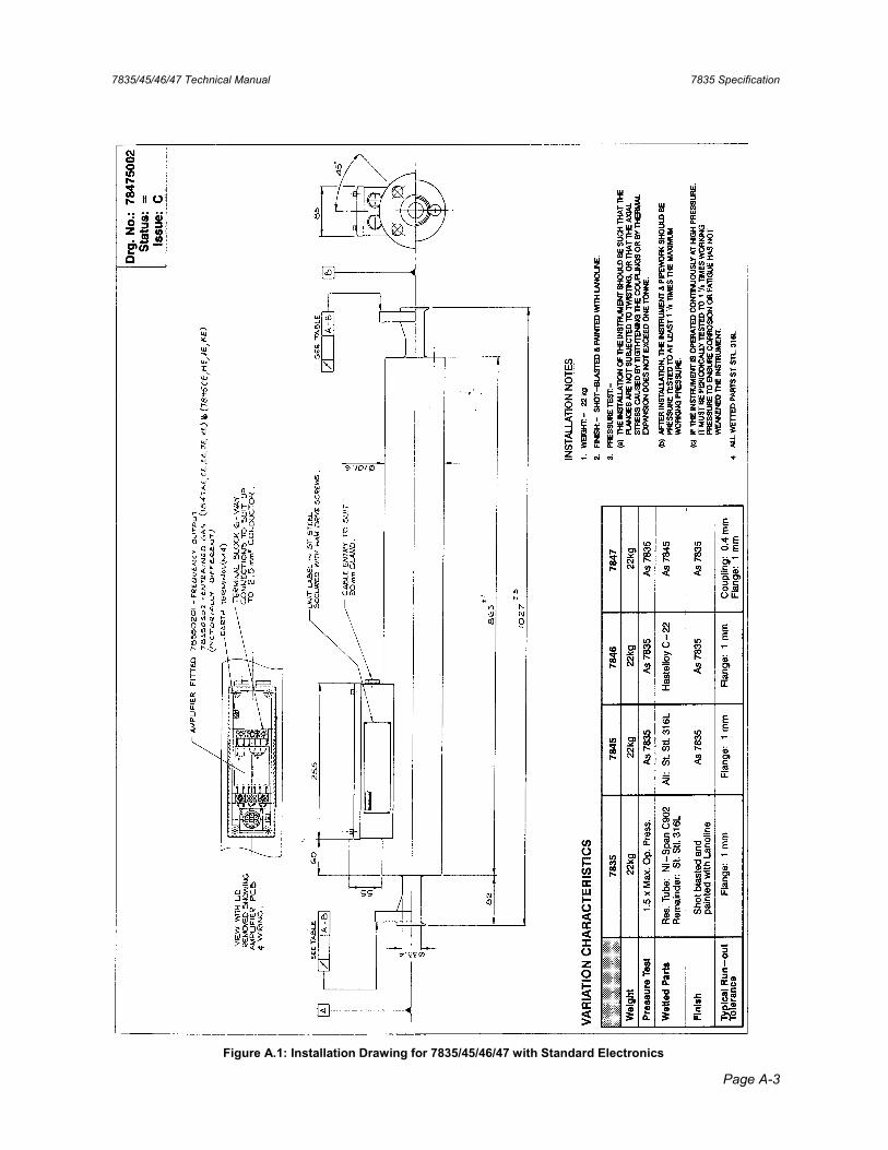
7835/45/46/47 Technical Manual 7835 Specification
Page A-3
Figure A.1: Installation Drawing for 7835/45/46/47 with Standard Electronics
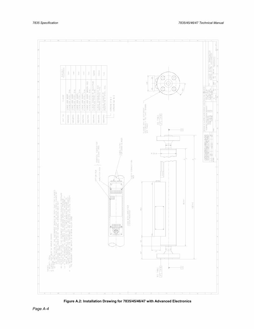
7835 Specification 7835/45/46/47 Technical Manual
Page A-4
Figure A.2: Installation Drawing for 7835/45/46/47 with Advanced Electronics
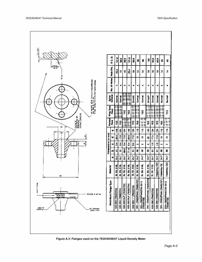
7835/45/46/47 Technical Manual 7835 Specification
Page A-5
Figure A.3: Flanges used on the 7835/45/46/47 Liquid Density Meter

7835 Specification 7835/45/46/47 Technical Manual
Page A-6

7835/45/46/47 Technical Manual 7845/46/47 Specification
Page B-1
Appendix B 7845/46/47 Specification
This Appendix describes the performance and the mechanical design of the various versions of 7845/46/47 Liquid Density Meters including the design of the Remote Amplifier option.
The performance of all of the designs is the same and is summarised below. Please refer to Appendix C for the specification of the 7845/47 Entrained Gas Meters.
B.1 Performance
Density Range: 0 to 3000 kg/m3
Accuracy: 0.35 kg/m3 (over the range 600 - 1200 kg/m3)0.5 kg/m3 (over the range 300 - 1600 kg/m3)0.1 kg/m3 with calibration in water
(With the Advanced electronics, there are additional uncertainties attributable to the time period measurement and 4-20mA output.)
Repeatability: 0.05 kg/m3
Stability: 0.35 kg/m3 per year
Temperature Range: -50°C (122°F) to +160°C (320°F). Above 110°C (230°F) the amplifier must be mounted externally.
Temperature Coefficient: Uncompensated at 850 kg/m3 0.9 kg/m3/°C typical 1.2 kg/m3/°C maximum
Compensated 0.05 kg/m3/°C
Pressure Range: 0 to 100 bar (1450psi) for 7845 0 to 50 bar (725psi) for 7846 or flange limit 0 to 20 bar (290psi) for 7847
Pressure Coefficient: Uncompensated (see Figure 6.2) Compensated 0.006 kg/m3/bar
(The temperature and pressure coefficients for each instrument are as specified by the instrument calibration certificate.)
Test Pressure: 1.5 x maximum operating pressure
Temperature Sensor • Technology: 100Ω PRT (4 wire) • Range: -200°C (-328°F) to 300°C (572°F)• Accuracy: BS 1904 Class, DIN 43760 Class A
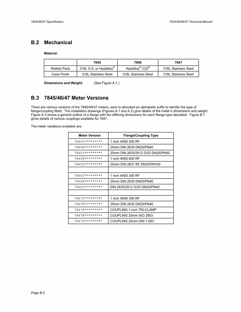
7845/46/47 Specification 7835/45/46/47 Technical Manual
Page B-2
B.2 Mechanical
Material:
7845 7846 7847
Wetted Parts 316L S.S. or Hastelloy® Hastelloy® C22® 316L Stainless Steel
Case Finish 316L Stainless Steel 316L Stainless Steel 316L Stainless Steel
Dimensions and Weight: (See Figure A.1.)
B.3 7845/46/47 Meter Versions There are various versions of the 7845/46/47 meters; each is allocated an alphabetic suffix to identify the type of flange/coupling fitted. The installation drawings (Figures A.1 and A.2) give details of the meter’s dimensions and weight. Figure A.3 shows a general outline of a flange with the differing dimensions for each flange type tabulated. Figure B.1 gives details of various couplings available for 7847.
The meter variations available are:
Meter Version Flange/Coupling Type
7845C********* 1 inch ANSI 300 RF 7845H********* 25mm DIN 2635 DN25/PN40 7845J********* 25mm DIN 2635/2512 GVD DN25/PN40 7845K********* 1 inch ANSI 600 RF 7845L********* 25mm DIN 2637 RF DN25/PN100
7846C********* 1 inch ANSI 300 RF 7846H********* 25mm DIN 2635 DN25/PN40 7846J********* DIN 2635/2512 GVD DN25/PN40
7847C********* 1 inch ANSI 300 RF 7847H********* 25mm DIN 2635 DN25/PN40 7847P********* COUPLING 1 inch TRI-CLAMP 7847R********* COUPLING 25mm ISO 2853 7847S********* COUPLING 25mm DIN 11851
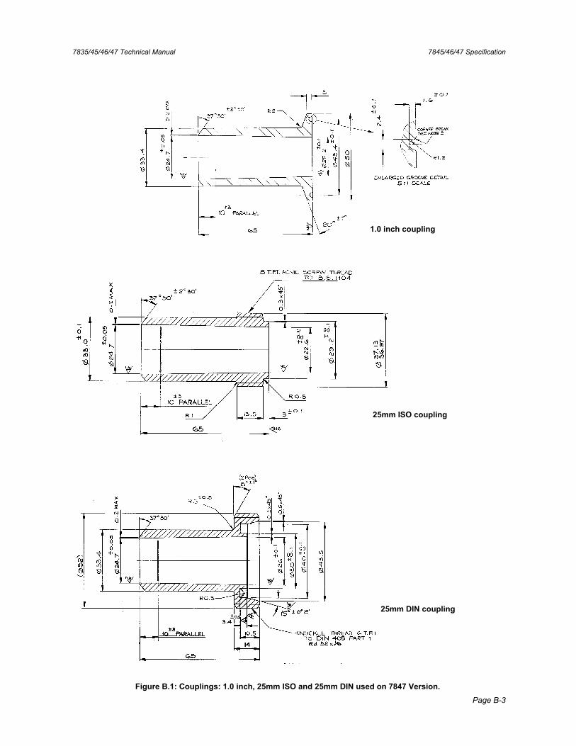
7835/45/46/47 Technical Manual 7845/46/47 Specification
Page B-3
Figure B.1: Couplings: 1.0 inch, 25mm ISO and 25mm DIN used on 7847 Version.
1.0 inch coupling
25mm ISO coupling
25mm DIN coupling

7845/46/47 Specification 7835/45/46/47 Technical Manual
Page B-4
B.3.1 7845/46/47 and 7845/47 Entrained Gas Meters with Remote Amplifier
For operating in product temperatures greater than 110°C (230°F), it is necessary to remove the amplifier unit from direct contact with the meter to a remote position. For this purpose, a flexible PTFE conduit with over-braiding of stainless steel mesh is introduced between the amplifier housing and the new amplifier housing. Three twisted pair cable looms are fed through the conduit to complete the extended meter/amplifier connections.
This high temperature arrangement allows the amplifier unit to be mounted in a more temperate environment and in no way impairs the operational accuracy of the meter.
The maintenance and calibration procedures remain relevant to the re-configured meter assembly. Figure B.2 shows the installation for the 78452 version, which is for Advanced Electronics only.
B.4 Safety Approvals
B.4.1 ATEX Intrinsically Safe
7845/46/47 Standard Electronics: Certification to EN50014 and EN50020 ATEX II1G, EEx ia IIC T6 (-40°C ≤ Ta ≤ +40°C)
T4 (-40°C ≤ Ta ≤ +70°C)
7845/46/47 Advanced Electronics: Certification to EN50014 and EN50020 ATEX II1G, EEx ia IIB T4 (-40°C ≤ Ta ≤ +60°C) [784****(D/F)J***** version] ATEX II1G, EEx ia IIC T4 (-40°C ≤ Ta ≤ +60°C) [784****(B/H)J***** version]
If the HART option PCB is fitted, certification is limited to the IIB approval.
7965 Remote Display: Certification to EN50014 and EN 50020 ATEX II 1 G, EEx ia IIC, T4 (-40°C Ta +60°C)
Refer to the ATEX safety instruction booklet (78355015/SI, 78355038/SI or 78355065/SI) for safety matters. Always check the label on the meter for approval(s). Contact the factory for the latest certified system drawings.
B.4.2 CSA Intrinsically Safe Certification to CSA C22-2 No 142, CSA C22-2 No 175, UL 508 and UL 913 for use in Canada and USA
7845/46/47 Standard electronics: Class I, Division 1 Groups C & D, T3C
7845/46/47 Advanced electronics and 7965 Remote Display: Class I, Division 1, Groups A, B, C & D, T4 (Single instrument) Class I, Division 1, Groups C & D, T4 (Hart Multi-drop)
Certified system drawings are in Appendix K; they are supplied for planning purposes only. Contact the factory for the latest certified system drawings. Always check the label on the meter for approval(s).
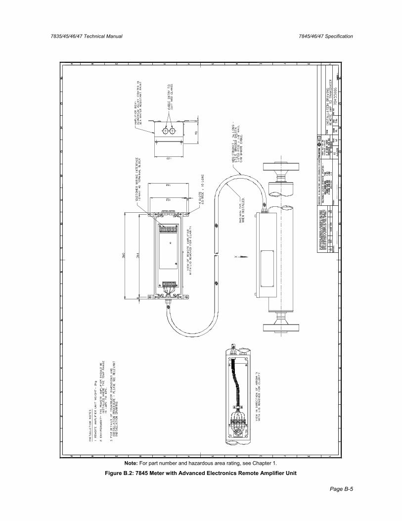
7835/45/46/47 Technical Manual 7845/46/47 Specification
Page B-5
Note: For part number and hazardous area rating, see Chapter 1.
Figure B.2: 7845 Meter with Advanced Electronics Remote Amplifier Unit

7845/46/47 Specification 7835/45/46/47 Technical Manual
Page B-6
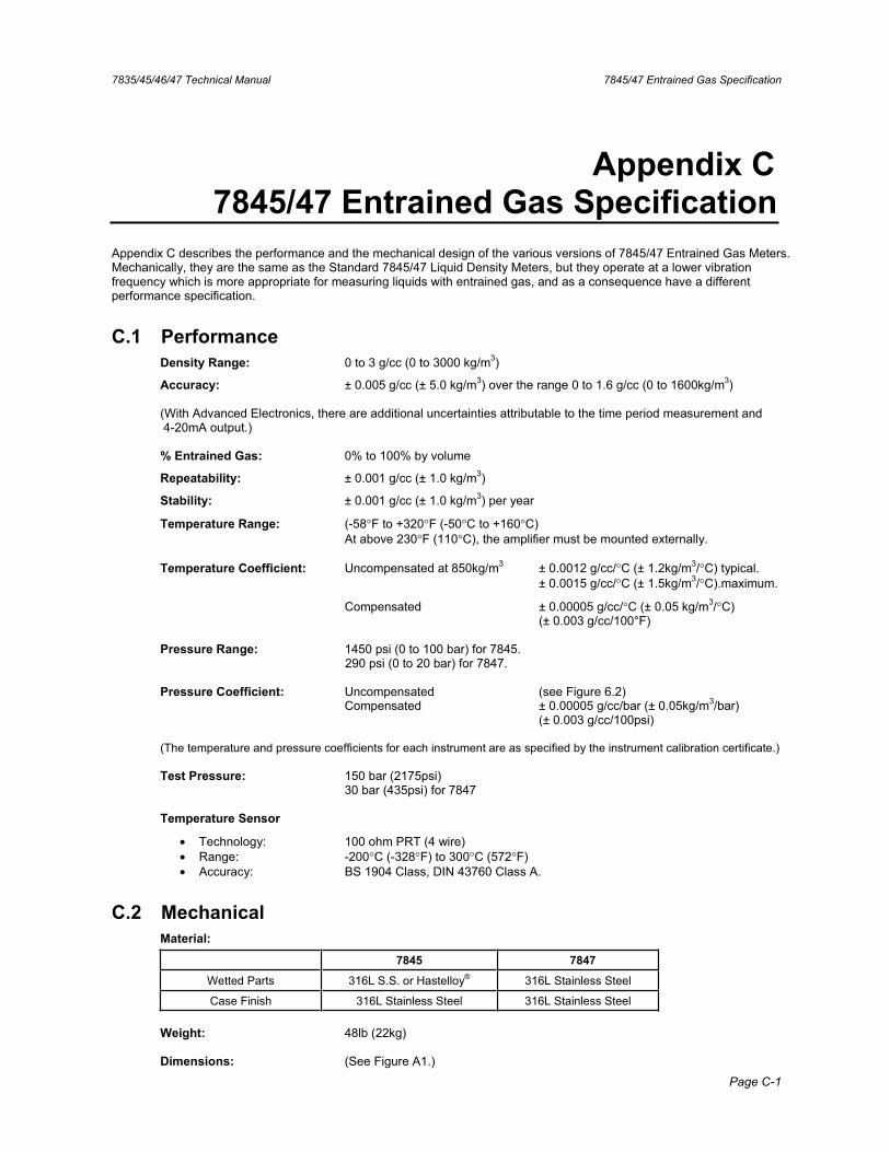
7835/45/46/47 Technical Manual 7845/47 Entrained Gas Specification
Page C-1
Appendix C 7845/47 Entrained Gas Specification
Appendix C describes the performance and the mechanical design of the various versions of 7845/47 Entrained Gas Meters. Mechanically, they are the same as the Standard 7845/47 Liquid Density Meters, but they operate at a lower vibration frequency which is more appropriate for measuring liquids with entrained gas, and as a consequence have a different performance specification.
C.1 Performance Density Range: 0 to 3 g/cc (0 to 3000 kg/m3)
Accuracy: ± 0.005 g/cc (± 5.0 kg/m3) over the range 0 to 1.6 g/cc (0 to 1600kg/m3)
(With Advanced Electronics, there are additional uncertainties attributable to the time period measurement and 4-20mA output.)
% Entrained Gas: 0% to 100% by volume
Repeatability: ± 0.001 g/cc (± 1.0 kg/m3)
Stability: ± 0.001 g/cc (± 1.0 kg/m3) per year
Temperature Range: (-58°F to +320°F (-50°C to +160°C) At above 230°F (110°C), the amplifier must be mounted externally.
Temperature Coefficient: Uncompensated at 850kg/m3 ± 0.0012 g/cc/°C (± 1.2kg/m3/°C) typical. ± 0.0015 g/cc/°C (± 1.5kg/m3/°C).maximum.
Compensated ± 0.00005 g/cc/°C (± 0.05 kg/m3/°C) (± 0.003 g/cc/100°F)
Pressure Range: 1450 psi (0 to 100 bar) for 7845. 290 psi (0 to 20 bar) for 7847.
Pressure Coefficient: Uncompensated (see Figure 6.2) Compensated ± 0.00005 g/cc/bar (± 0.05kg/m3/bar)
(± 0.003 g/cc/100psi)
(The temperature and pressure coefficients for each instrument are as specified by the instrument calibration certificate.)
Test Pressure: 150 bar (2175psi) 30 bar (435psi) for 7847
Temperature Sensor
• Technology: 100 ohm PRT (4 wire) • Range: -200°C (-328°F) to 300°C (572°F)• Accuracy: BS 1904 Class, DIN 43760 Class A.
C.2 Mechanical Material:
7845 7847
Wetted Parts 316L S.S. or Hastelloy® 316L Stainless Steel
Case Finish 316L Stainless Steel 316L Stainless Steel
Weight: 48lb (22kg)
Dimensions: (See Figure A1.)
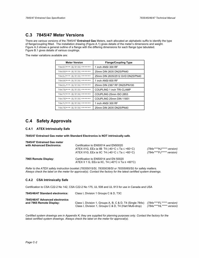
7845/47 Entrained Gas Specification 7835/45/46/47 Technical Manual
Page C-2
C.3 7845/47 Meter Versions There are various versions of the 7845/47 Entrained Gas Meters, each allocated an alphabetic suffix to identify the type of flange/coupling fitted. The installation drawing (Figure A.1) gives details of the meter’s dimensions and weight. Figure A.3 shows a general outline of a flange with the differing dimensions for each flange type tabulated. Figure B.1 gives details of various couplings.
The meter variations available are:
Meter Version Flange/Coupling Type 7845C***(E/F/H)****** 1 inch ANSI 300 RF
7845H***(E/F/H)****** 25mm DIN 2635 DN25/PN40 7845J***(E/F/H)****** 25mm DIN 2635/2512 GVD DN25/PN40 7845K***(E/F/H)****** 1 inch ANSI 600 RF 7845L***(E/F/H)****** 25mm DIN 2367 RF DN25/PN100 7847A***(E/F/H)****** COUPLING 1 inch TRI-CLAMP
7847C***(E/F/H)****** COUPLING 25mm ISO 2853 7847E***(E/F/H)****** COUPLING 25mm DIN 11851 7847J***(E/F/H)****** 1 inch ANSI 300 RF 7847K***(E/F/H)****** 25mm DIN 2635 DN25/PN40
C.4 Safety Approvals
C.4.1 ATEX Intrinsically Safe
7845/47 Entrained Gas meter with Standard Electronics is NOT intrinsically safe.
7845/47 Entrained Gas meter with Advanced Electronics: Certification to EN50014 and EN50020 ATEX II1G, EEx ia IIB T4 (-40°C ≤ Ta ≤ +60°C) (784x****HJ***** version) ATEX II1G, EEx ia IIC T4 (-40°C ≤ Ta ≤ +60°C) (784x****FJ***** version)
7965 Remote Display: Certification to EN50014 and EN 50020 ATEX II 1 G, EEx ia IIC, T4 (-40°C Ta +60°C)
Refer to the ATEX safety instruction booklet (78355015/SI, 78355038/SI or 78355065/SI) for safety matters. Always check the label on the meter for approval(s). Contact the factory for the latest certified system drawings.
C.4.2 CSA Intrinsically Safe
Certification to CSA C22-2 No 142, CSA C22-2 No 175, UL 508 and UL 913 for use in Canada and USA
7845/46/47 Standard electronics: Class I, Division 1 Groups C & D, T3C
7845/46/47 Advanced electronics and 7965 Remote Display: Class I, Division 1, Groups A, B, C & D, T4 (Single 784x) (784x****FL***** version) Class I, Division 1, Groups C & D, T4 (Hart Multi-drop) (784x****HL***** version)
Certified system drawings are in Appendix K; they are supplied for planning purposes only. Contact the factory for the latest certified system drawings. Always check the label on the meter for approval(s).
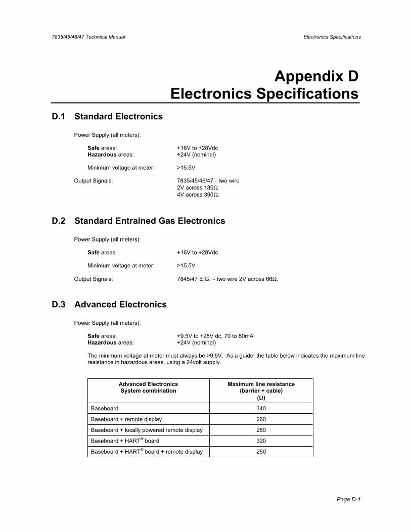
7835/45/46/47 Technical Manual Electronics Specifications
Page D-1
Appendix D Electronics Specifications
D.1 Standard Electronics
Power Supply (all meters):
Safe areas: +16V to +28Vdc Hazardous areas: +24V (nominal)
Minimum voltage at meter: >15.5V
Output Signals: 7835/45/46/47 - two wire 2V across 180Ω 4V across 390Ω.
D.2 Standard Entrained Gas Electronics
Power Supply (all meters):
Safe areas: +16V to +28Vdc
Minimum voltage at meter: >15.5V
Output Signals: 7845/47 E.G. - two wire 2V across 66Ω.
D.3 Advanced Electronics
Power Supply (all meters):
Safe areas: +9.5V to +28V dc, 70 to 80mA Hazardous areas: +24V (nominal)
The minimum voltage at meter must always be >9.5V. As a guide, the table below indicates the maximum line resistance in hazardous areas, using a 24volt supply.
Advanced Electronics System combination
Maximum line resistance (barrier + cable)
(Ω)
Baseboard 340
Baseboard + remote display 260
Baseboard + locally powered remote display 280
Baseboard + HART® board 320
Baseboard + HART® board + remote display 250
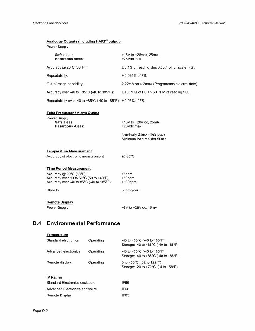
Electronics Specifications 7835/45/46/47 Technical Manual
Page D-2
Analogue Outputs (including HART® output)Power Supply:
Safe areas: +16V to +28Vdc, 25mA Hazardous areas: +28Vdc max.
Accuracy @ 20°C (68°F): ± 0.1% of reading plus 0.05% of full scale (FS).
Repeatability: ± 0.025% of FS.
Out-of-range capability: 2-22mA on 4-20mA (Programmable alarm state)
Accuracy over -40 to +85°C (-40 to 185°F): ± 10 PPM of FS +/- 50 PPM of reading /°C.
Repeatability over -40 to +85°C (-40 to 185°F): ± 0.05% of FS.
Tube Frequency / Alarm OutputPower Supply:
Safe areas +16V to +28V dc, 25mA Hazardous Areas: +28Vdc max.
Nominally 23mA (1kΩ load) Minimum load resistor 500Ω
Temperature MeasurementAccuracy of electronic measurement: ±0.05°C
Time Period MeasurementAccuracy @ 20°C (68°F): ±5ppm Accuracy over 10 to 60°C (50 to 140°F): ±50ppm Accuracy over -40 to 85°C (-40 to 185°F): ±100ppm
Stability 5ppm/year
Remote DisplayPower Supply +8V to +28V dc, 15mA
D.4 Environmental Performance
TemperatureStandard electronics Operating: -40 to +85°C (-40 to 185°F) Storage: -40 to +85°C (-40 to 185°F)
Advanced electronics Operating: -40 to +85°C (-40 to 185°F) Storage: -40 to +85°C (-40 to 185°F)
Remote display Operating: 0 to +50°C (32 to 122°F) Storage: -20 to +70°C (-4 to 158°F)
IP RatingStandard Electronics enclosure IP66
Advanced Electronics enclosure IP66
Remote Display IP65
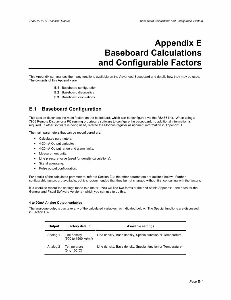
7835/45/46/47 Technical Manual Baseboard Calculations and Configurable Factors
Page E-1
Appendix E Baseboard Calculations
and Configurable Factors This Appendix summarises the many functions available on the Advanced Baseboard and details how they may be used. The contents of this Appendix are:
E.1 Baseboard configurationE.2 Baseboard diagnosticsE.3 Baseboard calculations
E.1 Baseboard Configuration This section describes the main factors on the baseboard, which can be configured via the RS485 link. When using a 7965 Remote Display or a PC running proprietary software to configure the baseboard, no additional information is required. If other software is being used, refer to the Modbus register assignment information in Appendix H.
The main parameters that can be reconfigured are:
• Calculated parameters. • 4-20mA Output variables. • 4-20mA Output range and alarm limits. • Measurement units. • Line pressure value (used for density calculations). • Signal averaging. • Pulse output configuration.
For details of the calculated parameters, refer to Section E.4; the other parameters are outlined below. Further configurable factors are available, but it is recommended that they be not changed without first consulting with the factory.
It is useful to record the settings made to a meter. You will find two forms at the end of this Appendix - one each for the General and Fiscal Software versions - which you can use to do this.
4 to 20mA Analog Output variables
The analogue outputs can give any of the calculated variables, as indicated below. The Special functions are discussed in Section E.4
Output Factory default Available settings
Analog 1 Line density (500 to 1500 kg/m³)
Line density, Base density, Special function or Temperature.
Analog 2 Temperature (0 to 100°C)
Line density, Base density, Special function or Temperature.
Baseboard Calculations and Configurable Factors 7835/45/46/47 Technical Manual
Page E-2
4-20mA Analog Output ranges
The 4-20mA output ranges can be set to any sensible values. The 4mA setting should always represent a smaller measurement value than the 20mA setting.
4-20 mA Out-of-Range Alarms
The operation of these alarms is dependent on the software issue. To find out the software issue, either use the appropriate Modbus command, or examine the label on the baseboard EPROMS.
Software V1, issue 1.00, 1.01 and 1.02 only
If either of the Analog output parameters go outside the selected range settings, then the outputs will give an out-of-range alarm signal to alert the user. These out-of-range alarm signals can be set to either 2mA or 22mA using the jumper connectors on the Baseboard (refer to Figure 3.3b).
The out-of-range alarms trigger if the output signal is outside the range 4mA or 20mA by an amount set by the output hysteresis. The default hysteresis is 1% of the output parameter, but can be configured to be greater if required, (see section E.3).
Example4mA setting = 500kg/m³, 20mA setting = 1000kg/m³, alarm hysteresis = 1%
Out-of-range alarm will trigger if the density falls below 495kg/m³ or rises above 1010kg/m³.
Software V1, issue 1.03 on
The hysteresis facility is not available in these versions of the software. The 4-20mA output signals can actually span the range 3.9mA to 20.8mA; thus, a signal outside the range 4-20mA is considered an alarm signal. In addition, if there is a circuit malfunction within the meter, the output will go to either 2mA or 22mA, in accordance with the setting of the alarm jumper setting.
Measurement Units
Parameter Factory default Available settings
Density units kg/m³ kg/m³, g/cc, lb/ft³,lb/gal (US)
Temperature units °C °C or °F
Pressure units bar bar, Pa, kPa, psi
Signal Averaging
In very noisy situations, it may be desirable to smooth out any short term variations in signals using the Signal Averaging. The available settings are:
no averaging, 1s, 2s, 5s, 10s, 20s, 50s and 100s averaging.
The averaging times are only approximate.
7835/45/46/47 Technical Manual Baseboard Calculations and Configurable Factors
Page E-3
Pressure
Nominal line and atmospheric pressure are set as follows. The values are used in the calculations of liquid density.
Parameter Factory default Available settings
Line Pressure 1.013bar Any value
Atmospheric pressure
1.013 bar Any value
Pulse Output configuration
This output may be set to give either an alarm signal or the meter tube frequency.
The Alarm may be set to signal any combination of:
• System/circuit malfunction. • Analog 1 out-of-range alarm. • Analog 2 out-of-range alarm. • Any user-defined variable.
The alarm can be set to be ‘normally-on’ or ‘normally-off’.
When set to ‘tube frequency’, the pulse output can be coupled to a signal converter to simulate a standard meter.
Density and Temperature Reading Adjustment
If the density or temperature readings given by the Advanced unit do not coincide with the expected density or temperature readings, the user may feel that it is appropriate to add or subtract density or temperature offsets. Normally these would both be set to zero.
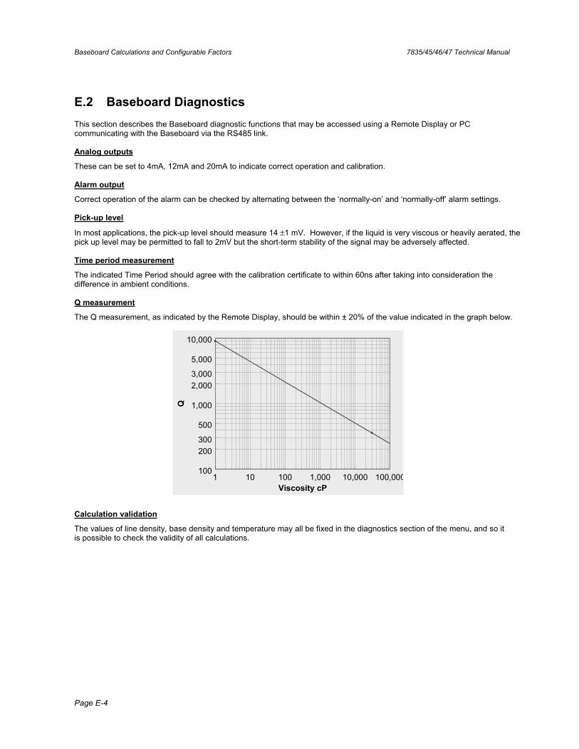
Baseboard Calculations and Configurable Factors 7835/45/46/47 Technical Manual
Page E-4
E.2 Baseboard Diagnostics This section describes the Baseboard diagnostic functions that may be accessed using a Remote Display or PC communicating with the Baseboard via the RS485 link.
Analog outputs
These can be set to 4mA, 12mA and 20mA to indicate correct operation and calibration.
Alarm output
Correct operation of the alarm can be checked by alternating between the ‘normally-on’ and ‘normally-off’ alarm settings.
Pick-up level
In most applications, the pick-up level should measure 14 ±1 mV. However, if the liquid is very viscous or heavily aerated, the pick up level may be permitted to fall to 2mV but the short-term stability of the signal may be adversely affected.
Time period measurement
The indicated Time Period should agree with the calibration certificate to within 60ns after taking into consideration the difference in ambient conditions.
Q measurement
The Q measurement, as indicated by the Remote Display, should be within ± 20% of the value indicated in the graph below.
1 10 100 1,000 10,000 100,000100
200300
500
1,000
2,0003,000
5,000
10,000
Viscosity cP
Q
Calculation validation
The values of line density, base density and temperature may all be fixed in the diagnostics section of the menu, and so it is possible to check the validity of all calculations.
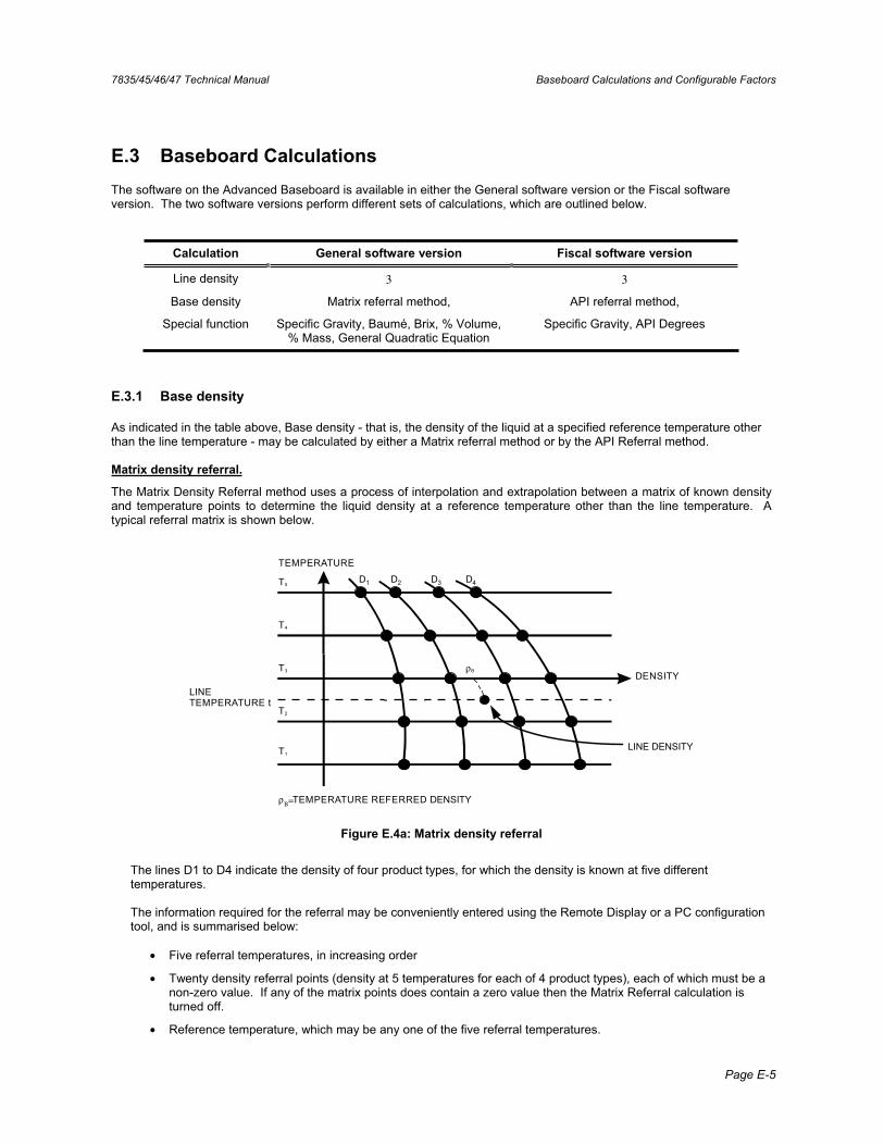
7835/45/46/47 Technical Manual Baseboard Calculations and Configurable Factors
Page E-5
E.3 Baseboard Calculations The software on the Advanced Baseboard is available in either the General software version or the Fiscal software version. The two software versions perform different sets of calculations, which are outlined below.
Calculation General software version Fiscal software version
Line density 3 3
Base density Matrix referral method, API referral method,
Special function Specific Gravity, Baumé, Brix, % Volume, % Mass, General Quadratic Equation
Specific Gravity, API Degrees
E.3.1 Base density
As indicated in the table above, Base density - that is, the density of the liquid at a specified reference temperature other than the line temperature - may be calculated by either a Matrix referral method or by the API Referral method.
Matrix density referral.
The Matrix Density Referral method uses a process of interpolation and extrapolation between a matrix of known density and temperature points to determine the liquid density at a reference temperature other than the line temperature. A typical referral matrix is shown below.
T1
T2
T4
T5
T3
LINETEMPERATURE t
DENSITY
TEMPERATURE
D1 D2 D3 D4
ρΒ=TEMPERATURE REFERRED DENSITY
ρB
LINE DENSITY
Figure E.4a: Matrix density referral
The lines D1 to D4 indicate the density of four product types, for which the density is known at five different temperatures.
The information required for the referral may be conveniently entered using the Remote Display or a PC configuration tool, and is summarised below:
• Five referral temperatures, in increasing order
• Twenty density referral points (density at 5 temperatures for each of 4 product types), each of which must be a non-zero value. If any of the matrix points does contain a zero value then the Matrix Referral calculation is turned off.
• Reference temperature, which may be any one of the five referral temperatures.
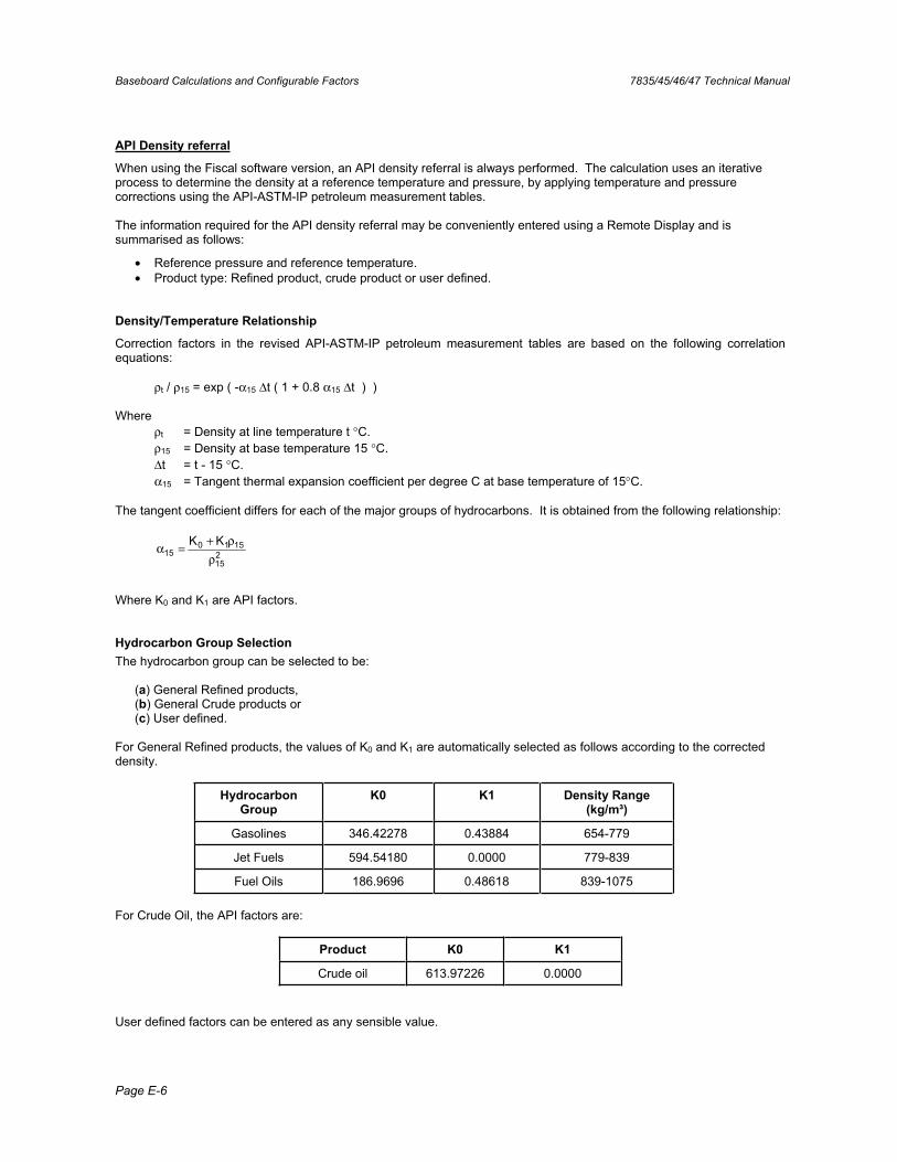
Baseboard Calculations and Configurable Factors 7835/45/46/47 Technical Manual
Page E-6
API Density referral
When using the Fiscal software version, an API density referral is always performed. The calculation uses an iterative process to determine the density at a reference temperature and pressure, by applying temperature and pressure corrections using the API-ASTM-IP petroleum measurement tables.
The information required for the API density referral may be conveniently entered using a Remote Display and is summarised as follows:
• Reference pressure and reference temperature. • Product type: Refined product, crude product or user defined.
Density/Temperature Relationship
Correction factors in the revised API-ASTM-IP petroleum measurement tables are based on the following correlation equations:
ρt / ρ15 = exp ( -α15 Δt ( 1 + 0.8 α15 Δt ) )
Where ρt = Density at line temperature t °C.ρ15 = Density at base temperature 15 °C.Δt = t - 15 °C.α15 = Tangent thermal expansion coefficient per degree C at base temperature of 15°C.
The tangent coefficient differs for each of the major groups of hydrocarbons. It is obtained from the following relationship:
215
151015
KKρ
ρ+=α
Where K0 and K1 are API factors.
Hydrocarbon Group Selection The hydrocarbon group can be selected to be:
(a) General Refined products, (b) General Crude products or (c) User defined.
For General Refined products, the values of K0 and K1 are automatically selected as follows according to the corrected density.
Hydrocarbon Group
K0 K1 Density Range (kg/m³)
Gasolines 346.42278 0.43884 654-779
Jet Fuels 594.54180 0.0000 779-839
Fuel Oils 186.9696 0.48618 839-1075
For Crude Oil, the API factors are:
Product K0 K1
Crude oil 613.97226 0.0000
User defined factors can be entered as any sensible value.
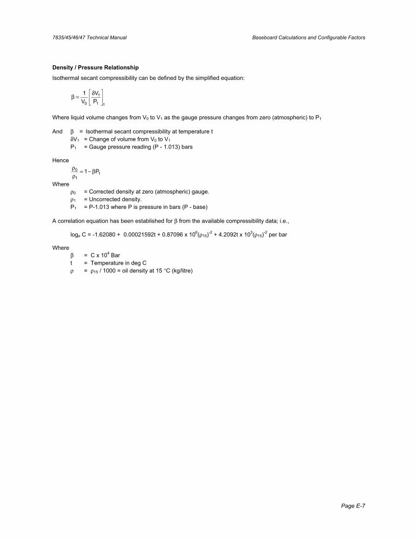
7835/45/46/47 Technical Manual Baseboard Calculations and Configurable Factors
Page E-7
Density / Pressure Relationship
Isothermal secant compressibility can be defined by the simplified equation:
t1
1
0 PV
V1 δ=β
Where liquid volume changes from V0 to V1 as the gauge pressure changes from zero (atmospheric) to P1
And β = Isothermal secant compressibility at temperature t δV1 = Change of volume from V0 to V1
P1 = Gauge pressure reading (P - 1.013) bars
Hence
11
0 P1 β−=ρρ
Where ρ0 = Corrected density at zero (atmospheric) gauge. ρ1 = Uncorrected density. P1 = P-1.013 where P is pressure in bars (P - base)
A correlation equation has been established for β from the available compressibility data; i.e.,
loge C = -1.62080 + 0.00021592t + 0.87096 x 10⁶(ρ15)-2 + 4.2092t x 103(ρ15)-2 per bar
Where β = C x 104 Bar t = Temperature in deg C ρ = ρ15 / 1000 = oil density at 15 °C (kg/litre)
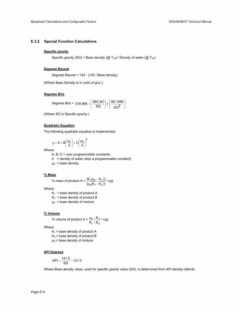
Baseboard Calculations and Configurable Factors 7835/45/46/47 Technical Manual
Page E-8
E.3.2 Special Function Calculations
Specific gravity
Specific gravity (SG) = Base density (@ Tref) / Density of water (@ Tref)
Degrees Baumé
Degrees Baumé = 145 - (145 / Base density)
(Where Base Density is in units of g/cc.)
Degrees Brix
Degrees Brix = +− 2SG
1086.66SG
341.384906.318
(Where SG is Specific gravity.)
Quadratic Equation
The following quadratic equation is implemented:
2BBd
Cd
BAy ρ+ρ+=
Where: A, B, C = user programmable constants. d = density of water (also a programmable constant). ρB = base density.
% Mass
% mass of product A = ( )( )( )( ) 100*
KKKK
21B
2B1−ρ−ρ
Where: K1 = base density of product A K2 = base density of product B ρB = base density of mixture
% Volume
% volume of product A = 100*KKK
21
2B
−−ρ
Where: K1 = base density of product A K2 = base density of product B ρB = base density of mixture
API Degrees
5.131SG
5.141API −=
Where Base density value, used for specific gravity value (SG), is determined from API density referral.

7835/45/46/47 Technical Manual Baseboard Calculations and Configurable Factors
Page E-9
Advanced Density Program Record Sheet - General Software version
Meter Type ................................................................. Meter Serial Number ...............................................
Remote Display Serial Number .................................. Date.........................................................................
Referral MatrixParameter Value
Temp point 1 Temp point 2 Temp point 3 Temp point 4 Temp point 5 T1, Den. point 1 T1, Den. point 2 T1, Den. point 3 T1, Den. point 4 T2, Den. point 1 T2, Den. point 2 T2, Den. point 3 T2, Den. point 4 T3, Den. point 1 T3, Den. point 2 T3, Den. point 3 T3, Den. point 4 T4, Den. point 1 T4, Den. point 2 T4, Den. point 3 T4, Den. point 4 T5, Den. point 1 T5, Den. point 2 T5, Den. point 3 T5, Den. point 4
OutputsParameter Value
Analog O/P 1 4 mA value 20mA value Analog O/P 2 4 mA value 20mA value
Special Function S.G.Parameter Value
Density water Ref. Temp.
Special Function %mass or %volParameter Value
Density A Density B
Special Function °BrixParameter Value
Density Water
Special Function QuadraticParameter Value
Variable abcd
Process VariablesParameter Value
Line density units Base density units Temperature units Averaging Pulse output Line pressure Atm pressure Pressure units
AlarmsParameter Value
Alarm state Normally On / Off System Error On / Off 4-20mA output O/P 1 / 2 / both / none User alarm variable User alrm upper limit User alrm lower limit Alarm hysteresis %
ServiceParameter Value
K0 K1 K2 K18K19K20A K20B K21A K21B Den offset Den scaling Temperature offset
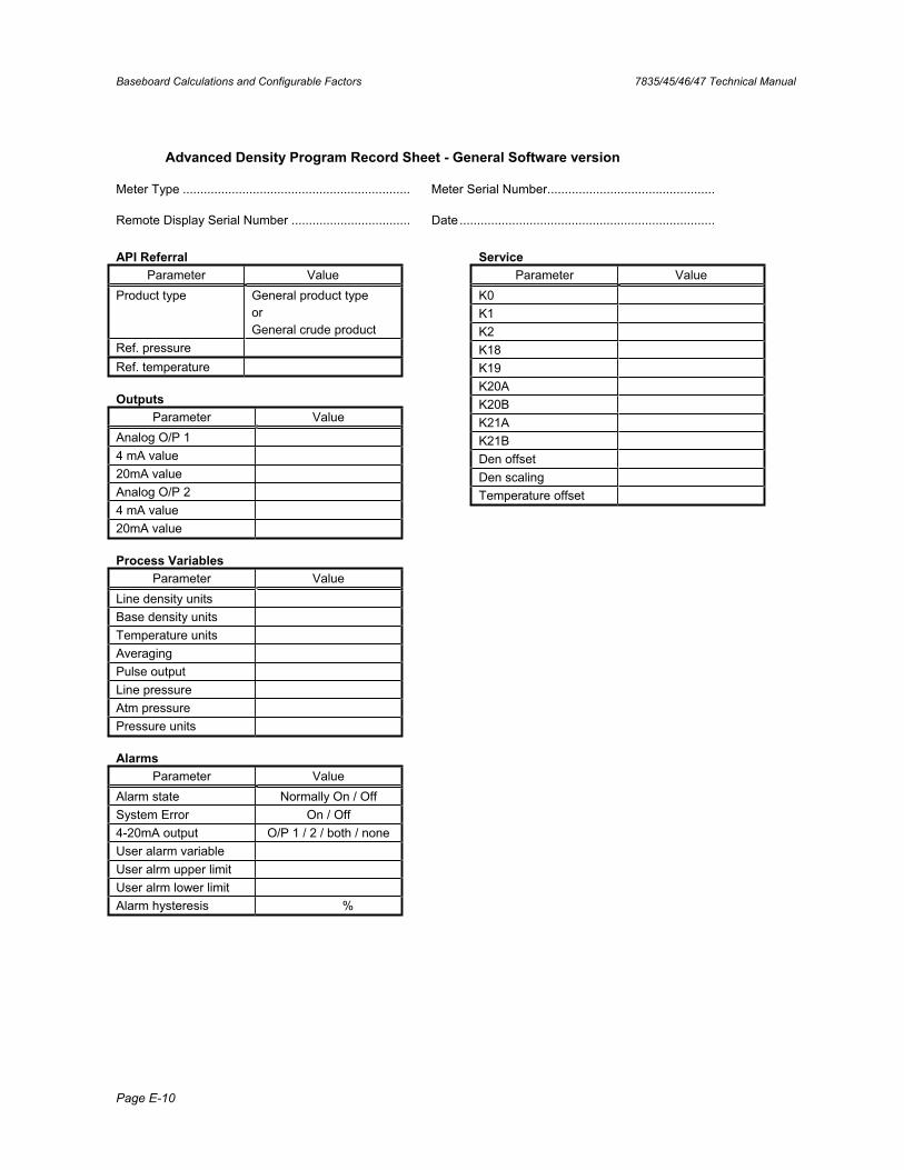
Baseboard Calculations and Configurable Factors 7835/45/46/47 Technical Manual
Page E-10
Advanced Density Program Record Sheet - General Software version
Meter Type ................................................................. Meter Serial Number................................................
Remote Display Serial Number .................................. Date .........................................................................
API ReferralParameter Value
Product type General product type orGeneral crude product
Ref. pressure Ref. temperature
OutputsParameter Value
Analog O/P 1 4 mA value 20mA value Analog O/P 2 4 mA value 20mA value
Process VariablesParameter Value
Line density units Base density units Temperature units Averaging Pulse output Line pressure Atm pressure Pressure units
AlarmsParameter Value
Alarm state Normally On / Off System Error On / Off 4-20mA output O/P 1 / 2 / both / none User alarm variable User alrm upper limit User alrm lower limit Alarm hysteresis %
ServiceParameter Value
K0 K1 K2 K18K19K20A K20B K21A K21B Den offset Den scaling Temperature offset
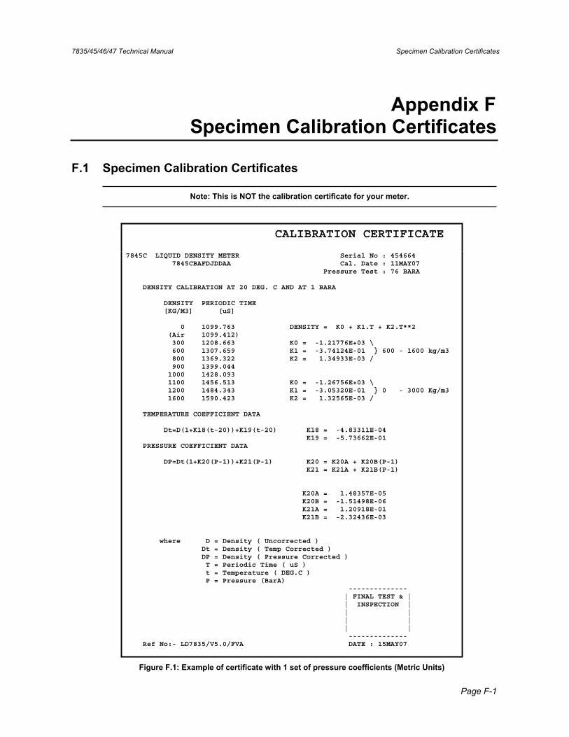
7835/45/46/47 Technical Manual Specimen Calibration Certificates
Page F-1
Appendix F Specimen Calibration Certificates
F.1 Specimen Calibration Certificates
Note: This is NOT the calibration certificate for your meter.
CALIBRATION CERTIFICATE
7845C LIQUID DENSITY METER Serial No : 454664 7845CBAFDJDDAA Cal. Date : 11MAY07 Pressure Test : 76 BARA
DENSITY CALIBRATION AT 20 DEG. C AND AT 1 BARA
DENSITY PERIODIC TIME [KG/M3] [uS]
0 1099.763 DENSITY = K0 + K1.T + K2.T**2 (Air 1099.412) 300 1208.663 K0 = -1.21776E+03 \ 600 1307.659 K1 = -3.74124E-01 } 600 - 1600 kg/m3 800 1369.322 K2 = 1.34933E-03 / 900 1399.044 1000 1428.093 1100 1456.513 K0 = -1.26756E+03 \ 1200 1484.343 K1 = -3.05320E-01 } 0 - 3000 Kg/m3 1600 1590.423 K2 = 1.32565E-03 /
TEMPERATURE COEFFICIENT DATA
Dt=D(1+K18(t-20))+K19(t-20) K18 = -4.83311E-04 K19 = -5.73662E-01 PRESSURE COEFFICIENT DATA
DP=Dt(1+K20(P-1))+K21(P-1) K20 = K20A + K20B(P-1) K21 = K21A + K21B(P-1)
K20A = 1.48357E-05 K20B = -1.51498E-06 K21A = 1.20918E-01 K21B = -2.32436E-03
where D = Density ( Uncorrected ) Dt = Density ( Temp Corrected ) DP = Density ( Pressure Corrected ) T = Periodic Time ( uS ) t = Temperature ( DEG.C ) P = Pressure (BarA) -------------- | FINAL TEST & | | INSPECTION | | | | | | | -------------- Ref No:- LD7835/V5.0/FVA DATE : 15MAY07
Figure F.1: Example of certificate with 1 set of pressure coefficients (Metric Units)
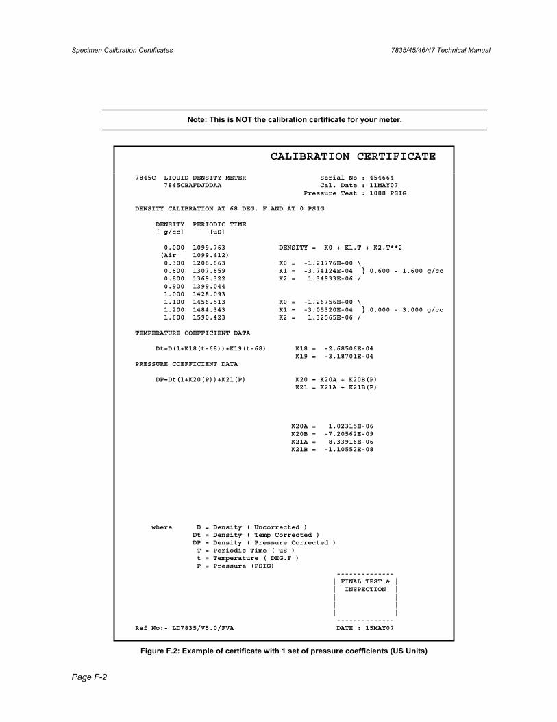
Specimen Calibration Certificates 7835/45/46/47 Technical Manual
Page F-2
Note: This is NOT the calibration certificate for your meter.
CALIBRATION CERTIFICATE
7845C LIQUID DENSITY METER Serial No : 454664 7845CBAFDJDDAA Cal. Date : 11MAY07 Pressure Test : 1088 PSIG
DENSITY CALIBRATION AT 68 DEG. F AND AT 0 PSIG
DENSITY PERIODIC TIME [ g/cc] [uS]
0.000 1099.763 DENSITY = K0 + K1.T + K2.T**2 (Air 1099.412) 0.300 1208.663 K0 = -1.21776E+00 \ 0.600 1307.659 K1 = -3.74124E-04 } 0.600 - 1.600 g/cc 0.800 1369.322 K2 = 1.34933E-06 / 0.900 1399.044 1.000 1428.093 1.100 1456.513 K0 = -1.26756E+00 \ 1.200 1484.343 K1 = -3.05320E-04 } 0.000 - 3.000 g/cc 1.600 1590.423 K2 = 1.32565E-06 /
TEMPERATURE COEFFICIENT DATA
Dt=D(1+K18(t-68))+K19(t-68) K18 = -2.68506E-04 K19 = -3.18701E-04 PRESSURE COEFFICIENT DATA
DP=Dt(1+K20(P))+K21(P) K20 = K20A + K20B(P) K21 = K21A + K21B(P)
K20A = 1.02315E-06 K20B = -7.20562E-09 K21A = 8.33916E-06 K21B = -1.10552E-08
where D = Density ( Uncorrected ) Dt = Density ( Temp Corrected ) DP = Density ( Pressure Corrected ) T = Periodic Time ( uS ) t = Temperature ( DEG.F ) P = Pressure (PSIG) -------------- | FINAL TEST & | | INSPECTION | | | | | | | -------------- Ref No:- LD7835/V5.0/FVA DATE : 15MAY07
Figure F.2: Example of certificate with 1 set of pressure coefficients (US Units)
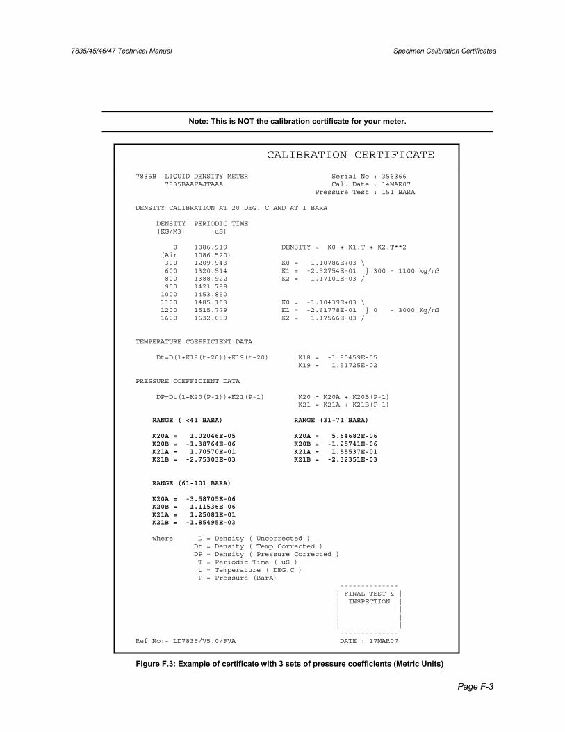
7835/45/46/47 Technical Manual Specimen Calibration Certificates
Page F-3
Note: This is NOT the calibration certificate for your meter.
CALIBRATION CERTIFICATE
7835B LIQUID DENSITY METER Serial No : 356366 7835BAAFAJTAAA Cal. Date : 14MAR07 Pressure Test : 151 BARA
DENSITY CALIBRATION AT 20 DEG. C AND AT 1 BARA
DENSITY PERIODIC TIME [KG/M3] [uS]
0 1086.919 DENSITY = K0 + K1.T + K2.T**2 (Air 1086.520) 300 1209.943 K0 = -1.10786E+03 \ 600 1320.514 K1 = -2.52754E-01 } 300 - 1100 kg/m3 800 1388.922 K2 = 1.17101E-03 / 900 1421.788 1000 1453.850 1100 1485.163 K0 = -1.10439E+03 \ 1200 1515.779 K1 = -2.61778E-01 } 0 - 3000 Kg/m3 1600 1632.089 K2 = 1.17566E-03 /
TEMPERATURE COEFFICIENT DATA
Dt=D(1+K18(t-20))+K19(t-20) K18 = -1.80459E-05 K19 = 1.51725E-02
PRESSURE COEFFICIENT DATA
DP=Dt(1+K20(P-1))+K21(P-1) K20 = K20A + K20B(P-1) K21 = K21A + K21B(P-1)
RANGE ( <41 BARA) RANGE (31-71 BARA)
K20A = 1.02046E-05 K20A = 5.64682E-06 K20B = -1.38764E-06 K20B = -1.25741E-06 K21A = 1.70570E-01 K21A = 1.55537E-01 K21B = -2.75303E-03 K21B = -2.32351E-03
RANGE (61-101 BARA)
K20A = -3.58705E-06 K20B = -1.11536E-06 K21A = 1.25081E-01 K21B = -1.85495E-03
where D = Density ( Uncorrected ) Dt = Density ( Temp Corrected ) DP = Density ( Pressure Corrected ) T = Periodic Time ( uS ) t = Temperature ( DEG.C ) P = Pressure (BarA) -------------- | FINAL TEST & | | INSPECTION | | | | | | | -------------- Ref No:- LD7835/V5.0/FVA DATE : 17MAR07
Figure F.3: Example of certificate with 3 sets of pressure coefficients (Metric Units)
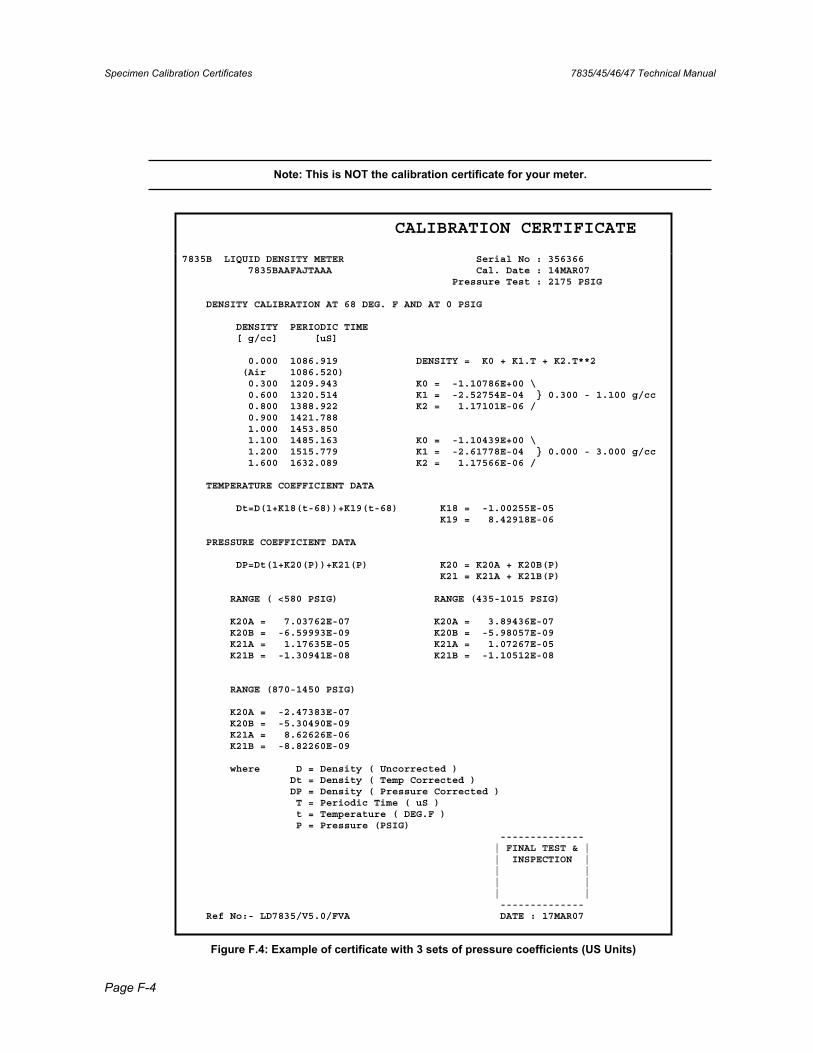
Specimen Calibration Certificates 7835/45/46/47 Technical Manual
Page F-4
Note: This is NOT the calibration certificate for your meter.
CALIBRATION CERTIFICATE
7835B LIQUID DENSITY METER Serial No : 356366 7835BAAFAJTAAA Cal. Date : 14MAR07 Pressure Test : 2175 PSIG
DENSITY CALIBRATION AT 68 DEG. F AND AT 0 PSIG
DENSITY PERIODIC TIME [ g/cc] [uS]
0.000 1086.919 DENSITY = K0 + K1.T + K2.T**2 (Air 1086.520) 0.300 1209.943 K0 = -1.10786E+00 \ 0.600 1320.514 K1 = -2.52754E-04 } 0.300 - 1.100 g/cc 0.800 1388.922 K2 = 1.17101E-06 / 0.900 1421.788 1.000 1453.850 1.100 1485.163 K0 = -1.10439E+00 \ 1.200 1515.779 K1 = -2.61778E-04 } 0.000 - 3.000 g/cc 1.600 1632.089 K2 = 1.17566E-06 /
TEMPERATURE COEFFICIENT DATA
Dt=D(1+K18(t-68))+K19(t-68) K18 = -1.00255E-05 K19 = 8.42918E-06
PRESSURE COEFFICIENT DATA
DP=Dt(1+K20(P))+K21(P) K20 = K20A + K20B(P) K21 = K21A + K21B(P)
RANGE ( <580 PSIG) RANGE (435-1015 PSIG)
K20A = 7.03762E-07 K20A = 3.89436E-07 K20B = -6.59993E-09 K20B = -5.98057E-09 K21A = 1.17635E-05 K21A = 1.07267E-05 K21B = -1.30941E-08 K21B = -1.10512E-08
RANGE (870-1450 PSIG)
K20A = -2.47383E-07 K20B = -5.30490E-09 K21A = 8.62626E-06 K21B = -8.82260E-09
where D = Density ( Uncorrected ) Dt = Density ( Temp Corrected ) DP = Density ( Pressure Corrected ) T = Periodic Time ( uS ) t = Temperature ( DEG.F ) P = Pressure (PSIG) -------------- | FINAL TEST & | | INSPECTION | | | | | | | -------------- Ref No:- LD7835/V5.0/FVA DATE : 17MAR07
Figure F.4: Example of certificate with 3 sets of pressure coefficients (US Units)
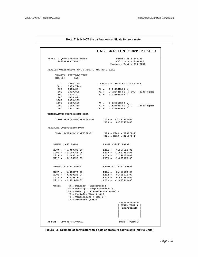
7835/45/46/47 Technical Manual Specimen Calibration Certificates
Page F-5
Note: This is NOT the calibration certificate for your meter.
CALIBRATION CERTIFICATE
7835A LIQUID DENSITY METER Serial No : 356389 7835AAAFAJTAAA Cal. Date : 29MAR07 Pressure Test : 231 BARA
DENSITY CALIBRATION AT 20 DEG. C AND AT 1 BARA
DENSITY PERIODIC TIME [KG/M3] [uS]
0 1084.129 DENSITY = K0 + K1.T + K2.T**2 (Air 1083.744) 300 1202.884 K0 = -1.14114E+03 \ 600 1309.895 K1 = -2.72571E-01 } 300 - 1100 kg/m3 800 1376.201 K2 = 1.22303E-03 / 900 1408.079 1000 1439.191 1100 1469.588 K0 = -1.13720E+03 \ 1200 1499.318 K1 = -2.82458E-01 } 0 - 3000 Kg/m3 1600 1612.345 K2 = 1.22809E-03 /
TEMPERATURE COEFFICIENT DATA
Dt=D(1+K18(t-20))+K19(t-20) K18 = -2.36285E-05 K19 = 8.76969E-03
PRESSURE COEFFICIENT DATA
DP=Dt(1+K20(P-1))+K21(P-1) K20 = K20A + K20B(P-1) K21 = K21A + K21B(P-1)
RANGE ( <41 BARA) RANGE (31-71 BARA)
K20A = -5.04078E-06 K20A = -7.56755E-06 K20B = -1.14004E-06 K20B = -1.06785E-06 K21A = 1.24952E-01 K21A = 1.14822E-01 K21B = -2.11662E-03 K21B = -1.82720E-03
RANGE (61-101 BARA) RANGE (101-151 BARA)
K20A = -1.26867E-05 K20A = -2.46656E-05 K20B = -9.89092E-07 K20B = -8.70957E-07 K21A = 9.42991E-02 K21A = 4.62759E-02 K21B = -1.51146E-03 K21B = -1.03786E-03
where D = Density ( Uncorrected ) Dt = Density ( Temp Corrected ) DP = Density ( Pressure Corrected ) T = Periodic Time ( uS ) t = Temperature ( DEG.C ) P = Pressure (BarA) -------------- | FINAL TEST & | | INSPECTION | | | | | | | -------------- Ref No:- LD7835/V5.0/FVA DATE : 03MAY07
Figure F.5: Example of certificate with 4 sets of pressure coefficients (Metric Units)
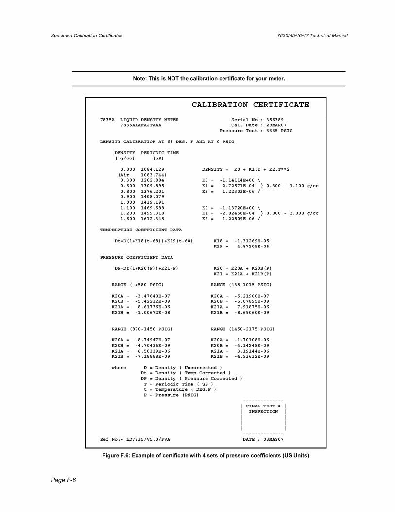
Specimen Calibration Certificates 7835/45/46/47 Technical Manual
Page F-6
Note: This is NOT the calibration certificate for your meter.
CALIBRATION CERTIFICATE
7835A LIQUID DENSITY METER Serial No : 356389 7835AAAFAJTAAA Cal. Date : 29MAR07 Pressure Test : 3335 PSIG
DENSITY CALIBRATION AT 68 DEG. F AND AT 0 PSIG
DENSITY PERIODIC TIME [ g/cc] [uS]
0.000 1084.129 DENSITY = K0 + K1.T + K2.T**2 (Air 1083.744) 0.300 1202.884 K0 = -1.14114E+00 \ 0.600 1309.895 K1 = -2.72571E-04 } 0.300 - 1.100 g/cc 0.800 1376.201 K2 = 1.22303E-06 / 0.900 1408.079 1.000 1439.191 1.100 1469.588 K0 = -1.13720E+00 \ 1.200 1499.318 K1 = -2.82458E-04 } 0.000 - 3.000 g/cc 1.600 1612.345 K2 = 1.22809E-06 /
TEMPERATURE COEFFICIENT DATA
Dt=D(1+K18(t-68))+K19(t-68) K18 = -1.31269E-05 K19 = 4.87205E-06
PRESSURE COEFFICIENT DATA
DP=Dt(1+K20(P))+K21(P) K20 = K20A + K20B(P) K21 = K21A + K21B(P)
RANGE ( <580 PSIG) RANGE (435-1015 PSIG)
K20A = -3.47640E-07 K20A = -5.21900E-07 K20B = -5.42232E-09 K20B = -5.07895E-09 K21A = 8.61736E-06 K21A = 7.91875E-06 K21B = -1.00672E-08 K21B = -8.69060E-09
RANGE (870-1450 PSIG) RANGE (1450-2175 PSIG)
K20A = -8.74947E-07 K20A = -1.70108E-06 K20B = -4.70436E-09 K20B = -4.14248E-09 K21A = 6.50339E-06 K21A = 3.19144E-06 K21B = -7.18888E-09 K21B = -4.93632E-09
where D = Density ( Uncorrected ) Dt = Density ( Temp Corrected ) DP = Density ( Pressure Corrected ) T = Periodic Time ( uS ) t = Temperature ( DEG.F ) P = Pressure (PSIG) -------------- | FINAL TEST & | | INSPECTION | | | | | | | -------------- Ref No:- LD7835/V5.0/FVA DATE : 03MAY07
Figure F.6: Example of certificate with 4 sets of pressure coefficients (US Units)
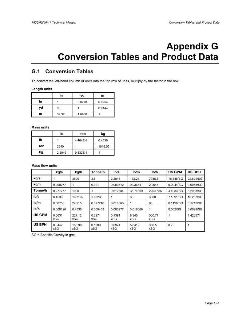
7835/45/46/47 Technical Manual Conversion Tables and Product Data
Page G-1
Appendix G Conversion Tables and Product Data
G.1 Conversion Tables To convert the left-hand column of units into the top row of units, multiply by the factor in the box.
Length units
in yd m
in 1 0.0278 0.0254
yd 36 1 0.9144
m 39.37 1.0936 1
Mass units
lb ton kg
lb 1 4.464E-4 0.4536
ton 2240 1 1016.05
kg 2.2046 9.832E-1 1
Mass flow units
kg/s kg/h Tonne/h lb/s lb/m lb/h US GPM US BPH
kg/s 1 3600 3.6 2.2046 132.28 7936.5 15.848/SG 22.624/SG
kg/h 0.000277 1 0.001 0.000612 0.03674 2.2046 0.0044/SG 0.0063/SG
Tonne/h 0.277777 1000 1 0.612384 36.74309 2204.585 4.4033/SG 6.2933/SG
lb/s 0.4536 1632.92 1.63296 1 60 3600 7.1891/SG 10.267/SG
lb/m 0.00756 27.215 0.027216 0.016666 1 60 0.1198/SG 0.1712/SG
lb/h 0.000126 0.4536 0.000453 0.000277 0.016666 1 0.002/SG 0.0029/SG
US GPM 0.0631xSG
227.12xSG
0.2271xSG
0.1391xSG
8.345xSG
500.71xSG
1 1.428571
US BPH 0.0442xSG
158.98xSG
0.1589xSG
0.0974xSG
5.8419xSG
350.5xSG
0.7 1
SG = Specific Gravity in g/cc
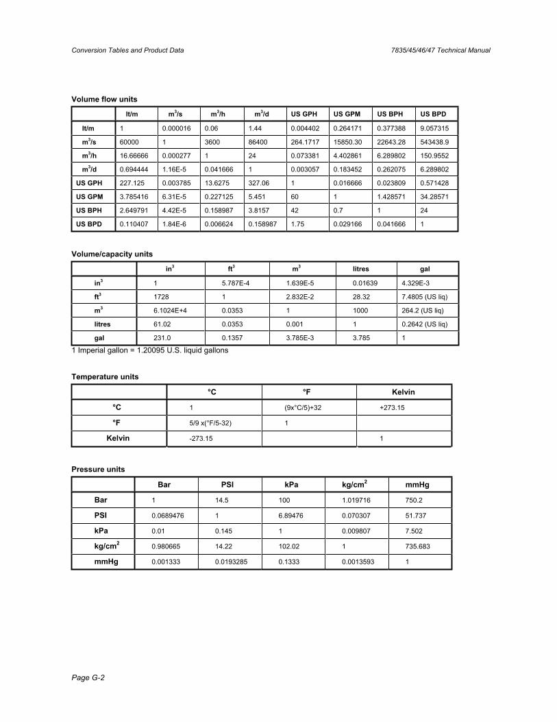
Conversion Tables and Product Data 7835/45/46/47 Technical Manual
Page G-2
Volume flow units
lt/m m3/s m3/h m3/d US GPH US GPM US BPH US BPD
lt/m 1 0.000016 0.06 1.44 0.004402 0.264171 0.377388 9.057315
m3/s 60000 1 3600 86400 264.1717 15850.30 22643.28 543438.9
m3/h 16.66666 0.000277 1 24 0.073381 4.402861 6.289802 150.9552
m3/d 0.694444 1.16E-5 0.041666 1 0.003057 0.183452 0.262075 6.289802
US GPH 227.125 0.003785 13.6275 327.06 1 0.016666 0.023809 0.571428
US GPM 3.785416 6.31E-5 0.227125 5.451 60 1 1.428571 34.28571
US BPH 2.649791 4.42E-5 0.158987 3.8157 42 0.7 1 24
US BPD 0.110407 1.84E-6 0.006624 0.158987 1.75 0.029166 0.041666 1
Volume/capacity units
in3 ft3 m3 litres gal
in3 1 5.787E-4 1.639E-5 0.01639 4.329E-3
ft3 1728 1 2.832E-2 28.32 7.4805 (US liq)
m3 6.1024E+4 0.0353 1 1000 264.2 (US liq)
litres 61.02 0.0353 0.001 1 0.2642 (US liq)
gal 231.0 0.1357 3.785E-3 3.785 1
1 Imperial gallon = 1.20095 U.S. liquid gallons
Temperature units
°C °F Kelvin
°C 1 (9x°C/5)+32 +273.15
°F 5/9 x(°F/5-32) 1
Kelvin -273.15 1
Pressure units
Bar PSI kPa kg/cm2 mmHg
Bar 1 14.5 100 1.019716 750.2
PSI 0.0689476 1 6.89476 0.070307 51.737
kPa 0.01 0.145 1 0.009807 7.502
kg/cm2 0.980665 14.22 102.02 1 735.683
mmHg 0.001333 0.0193285 0.1333 0.0013593 1
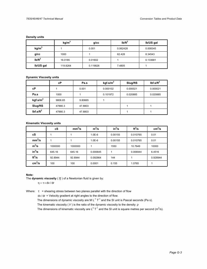
7835/45/46/47 Technical Manual Conversion Tables and Product Data
Page G-3
Density units
kg/m3 g/cc lb/ft3 lb/US gal
kg/m3 1 0.001 0.062428 0.008345
g/cc 1000 1 62.428 8.34543
lb/ft3 16.0185 0.01602 1 0.133681
lb/US gal 119.8264 0.119826 7.4805 1
Dynamic Viscosity units
cP Pa.s kgf.s/m2 Slug/ftS lbf.s/ft2
cP 1 0.001 0.000102 0.000021 0.000021
Pa.s 1000 1 0.101972 0.020885 0.020885
kgf.s/m2 9806.65 9.80665 1
Slug/ftS 47880.3 47.8803 1 1
lbf.s/ft2 47880.3 47.8803 1 1
Kinematic Viscosity units
cS mm2/s m2/s in2/s ft2/s cm2/s
cS 1 1 1.0E-6 0.00155 0.010765 0.01
mm2/s 1 1 1.0E-6 0.00155 0.010765 0.01
m2/s 1000000 1000000 1 1550 10.7649 10000
in2/s 645.16 645.16 0.000645 1 0.006944 6.4516
ft2/s 92.8944 92.8944 0.092864 144 1 0.928944
cm2/s 100 100 0.0001 0.155 1.0765 1
Note:The dynamic viscosity (η ) of a Newtonian fluid is given by:
dr/dv×τ=η
Where: τ = shearing stress between two planes parallel with the direction of flow dr/dv = Velocity gradient at right angles to the direction of flow.
The dimensions of dynamic viscosity are M L-1 T-1 and the SI unit is Pascal seconds (Pa s). The kinematic viscosity (ν ) is the ratio of the dynamic viscosity to the density ρThe dimensions of kinematic viscosity are L2 T-1 and the SI unit is square metres per second (m2/s).
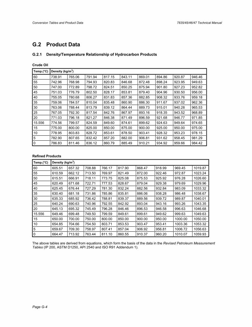
Conversion Tables and Product Data 7835/45/46/47 Technical Manual
Page G-4
G.2 Product Data
G.2.1 Density/Temperature Relationship of Hydrocarbon Products
Crude Oil
Temp.(°C) Density (kg/m3)
60 738.91 765.06 791.94 817.15 843.11 869.01 894.86 920.87 946.46 55 742.96 768.98 794.93 820.83 846.68 872.48 898.24 923.95 949.63 50 747.00 772.89 798.72 824.51 850.25 875.94 901.80 927.23 952.82 45 751.03 776.79 802.50 828.17 853.81 879.40 904.96 930.50 956.00 40 755.05 780.68 806.27 831.83 857.36 882.85 908.32 933.76 959.18 35 759.06 784.57 810.04 835.48 860.90 886.30 911.67 937.02 962.36 30 763.06 788.44 813.79 839.12 864.44 889.73 915.01 940.28 965.53 25 767.05 792.30 817.54 842.76 867.97 893.16 918.35 943.52 968.89 20 771.03 796.18 821.27 846.38 871.49 896.59 921.68 946.77 971.85 15.556 774.56 799.57 824.59 849.60 874.61 899.62 924.63 949.64 974.65 15 775.00 800.00 825.00 850.00 875.00 900.00 925.00 950.00 975.00 10 778.95 803.83 828.72 853.61 878.50 903.41 928.32 953.23 978.15 5 782.90 807.65 832.42 857.20 882.00 906.81 931.62 958.45 981.29 0 786.83 811.46 836.12 860.79 885.49 910.21 934.92 959.66 984.42
Refined Products
Temp.(°C) Density (kg/m3)
60 605.51 657.32 708.88 766.17 817.90 868.47 918.99 969.45 1019.87 55 610.59 662.12 713.50 769.97 821.49 872.00 922.46 972.87 1023.24 50 615.51 666.91 718.11 773.75 825.08 875.53 925.92 976.28 1026.60 45 620.49 671.68 722.71 777.53 828.67 879.04 929.38 979.69 1029.96 40 625.45 676.44 727.29 781.30 832.24 882.56 932.84 983.09 1033.32 35 630.40 681.18 731.86 785.86 835.81 886.06 938.28 986.48 1038.67 30 635.33 685.92 736.42 788.81 839.37 889.56 939.72 989.87 1040.01 25 640.24 690.63 740.96 792.55 842.92 893.04 943.16 993.26 1043.35 20 645.13 695.32 745.49 796.28 846.46 896.53 946.58 996.63 1046.68 15.556 649.46 699.48 749.50 799.59 849.61 899.61 949.62 999.63 1049.63 15 650.00 700.00 750.00 800.00 850.00 900.00 950.00 1000.00 1050.00 10 654.85 704.66 754.50 803.71 853.53 903.47 953.41 1003.36 1053.32 5 659.67 709.30 758.97 807.41 857.04 906.92 956.81 1006.72 1056.63 0 664.47 713.92 763.44 811.10 860.55 910.37 960.20 1010.07 1059.93
The above tables are derived from equations, which form the basis of the data in the Revised Petroleum Measurement Tables (IP 200, ASTM D1250, API 2540 and ISO R91 Addendum 1).
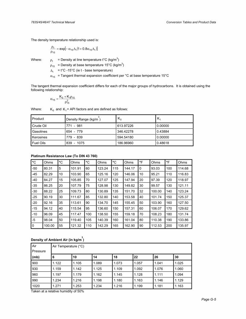
7835/45/46/47 Technical Manual Conversion Tables and Product Data
Page G-5
The density temperature relationship used is:
( )[ ]t15t1515
t 8.01exp Δα+Δα−=ρρ
Where: tρ = Density at line temperature t°C (kg/m3)
15ρ = Density at base temperature 15°C (kg/m3)
tΔ = t°C -15°C (ie t - base temperature)
15α = Tangent thermal expansion coefficient per °C at base temperature 15°C
The tangent thermal expansion coefficient differs for each of the major groups of hydrocarbons. It is obtained using the following relationship:
215
151015
KKρ
ρ+=α
Where: 0K and 1K = API factors and are defined as follows:
Product Density Range (kg/m3) 0K 1K
Crude Oil 771 - 981 613.97226 0.00000
Gasolines 654 - 779 346.42278 0.43884
Kerosines 779 - 839 594.54180 0.00000
Fuel Oils 839 - 1075 186.96960 0.48618
Platinum Resistance Law (To DIN 43 760)
°C Ohms °C Ohms °C Ohms °C Ohms °F Ohms °F Ohms
-50 80.31 5 101.91 60 123.24 115 144.17 0 93.03 100 114.68
-45 82.29 10 103.90 65 125.16 120 146.06 10 95.21 110 116.83
-40 84.27 15 105.85 70 127.07 125 147.94 20 97.39 120 118.97
-35 86.25 20 107.79 75 128.98 130 149.82 30 99.57 130 121.11
-30 88.22 25 109.73 80 130.89 135 151.70 32 100.00 140 123.24
-25 90.19 30 111.67 85 132.80 140 153.58 40 101.74 150 125.37
-20 92.16 35 113.61 90 134.70 145 155.45 50 103.90 160 127.50
-15 94.12 40 115.54 95 136.60 150 157.31 60 106.07 170 129.62
-10 96.09 45 117.47 100 138.50 155 159.18 70 108.23 180 131.74
-5 98.04 50 119.40 105 140.39 160 161.04 80 110.38 190 133.86
0 100.00 55 121.32 110 142.29 165 162.90 90 112.53 200 135.97
Density of Ambient Air (in kg/m3)
AirPressure
Air Temperature (°C)
(mb) 6 10 14 18 22 26 30
900 1.122 1.105 1.089 1.073 1.057 1.041 1.025
930 1.159 1.142 1.125 1.109 1.092 1.076 1.060
960 1.197 1.179 1.162 1.145 1.128 1.111 1.094
990 1.234 1.216 1.198 1.180 1.163 1.146 1.129
1020 1.271 1.253 1.234 1.216 1.199 1.181 1.163 Taken at a relative humidity of 50%
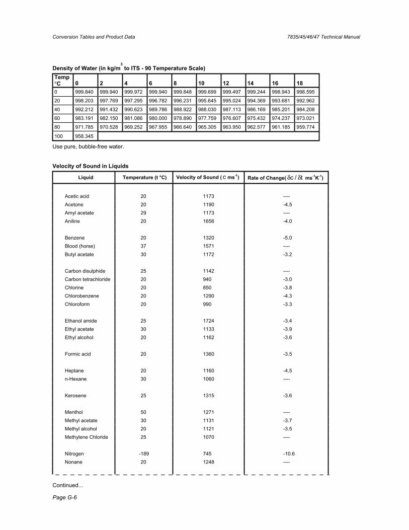
Conversion Tables and Product Data 7835/45/46/47 Technical Manual
Page G-6
Density of Water (in kg/m3
to ITS - 90 Temperature Scale) Temp °C 0 2 4 6 8 10 12 14 16 180 999.840 999.940 999.972 999.940 999.848 999.699 999.497 999.244 998.943 998.595
20 998.203 997.769 997.295 996.782 996.231 995.645 995.024 994.369 993.681 992.962
40 992.212 991.432 990.623 989.786 988.922 988.030 987.113 986.169 985.201 984.208
60 983.191 982.150 981.086 980.000 978.890 977.759 976.607 975.432 974.237 973.021
80 971.785 970.528 969.252 967.955 966.640 965.305 963.950 962.577 961.185 959.774
100 958.345
Use pure, bubble-free water.
Velocity of Sound in Liquids
Liquid Temperature (t °C) Velocity of Sound ( c ms-1) Rate of Change( t/c δδ ms-1K-1)
Acetic acid 20 1173 ---- Acetone 20 1190 -4.5 Amyl acetate 29 1173 ---- Aniline 20 1656 -4.0 Benzene 20 1320 -5.0 Blood (horse) 37 1571 ---- Butyl acetate 30 1172 -3.2 Carbon disulphide 25 1142 ---- Carbon tetrachloride 20 940 -3.0 Chlorine 20 850 -3.8 Chlorobenzene 20 1290 -4.3 Chloroform 20 990 -3.3 Ethanol amide 25 1724 -3.4 Ethyl acetate 30 1133 -3.9 Ethyl alcohol 20 1162 -3.6 Formic acid 20 1360 -3.5 Heptane 20 1160 -4.5 n-Hexane 30 1060 ---- Kerosene 25 1315 -3.6 Menthol 50 1271 ---- Methyl acetate 30 1131 -3.7 Methyl alcohol 20 1121 -3.5 Methylene Chloride 25 1070 ---- Nitrogen -189 745 -10.6 Nonane 20 1248 ----
Continued...
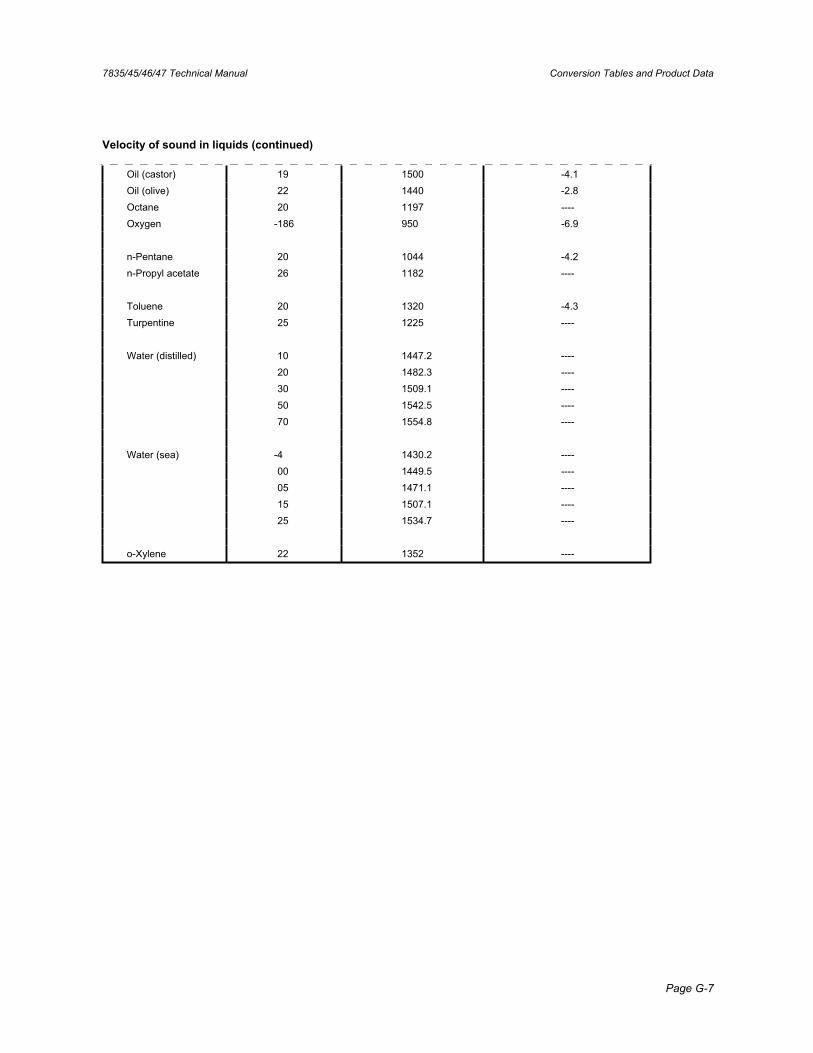
7835/45/46/47 Technical Manual Conversion Tables and Product Data
Page G-7
Velocity of sound in liquids (continued)
Oil (castor) 19 1500 -4.1 Oil (olive) 22 1440 -2.8 Octane 20 1197 ---- Oxygen -186 950 -6.9 n-Pentane 20 1044 -4.2 n-Propyl acetate 26 1182 ---- Toluene 20 1320 -4.3 Turpentine 25 1225 ---- Water (distilled) 10 1447.2 ---- 20 1482.3 ---- 30 1509.1 ---- 50 1542.5 ---- 70 1554.8 ---- Water (sea) -4 1430.2 ---- 00 1449.5 ---- 05 1471.1 ---- 15 1507.1 ---- 25 1534.7 ---- o-Xylene 22 1352 ----

Conversion Tables and Product Data 7835/45/46/47 Technical Manual
Page G-8

7835/45/46/47 Technical Manual Modbus Communications
Page H-1
Appendix H Modbus Communications
H.1 Introduction The Advanced Baseboard provides an RS485 serial communication port, which may be used for communicating with the Remote Display, or any computer device with an RS232 or RS485 serial communications port. Please note that when using an RS232 port, an RS232-to-RS485 converter must be used between the two devices (e.g. KK systems’ K485-99). The communications protocol used is RTU Modbus.
A useful reference on Modbus is the "Modbus Protocol Reference Guide" (PI-MBUS-200 Rev.D) (1992) published by Modicon Industrial Automation Systems Inc., Massachusetts.
When using the Remote Display there should be no need to refer to this Appendix. Users wishing to communicate with a computer device, for example a PC, may download and use proprietary software (from web sites listed on the back page) or may develop their own software package using the information given in this Appendix. For information regarding proprietary software packages, contact the factory.
H.2 Outline of the Modbus communications The Modbus protocol is a well established in many industrial applications. The implementation used on the Advanced system is fully compliant with the Modicon Specification (see reference above).
The Advanced Baseboard can be considered to be a SLAVE device as it only communicates when it receives a request for information from a MASTER device such as a Remote Display or computer device. Up to 24 slave devices can be connected to one master device.
All information is stored in memory locations on the Baseboard referred to as Modbus Registers. The Modbus commands implemented on the Advanced Baseboard are:
• Command 3 - Read Modbus Register.• Command 16 (1016) - Write Modbus Register.
Hence, the Modbus software package can be quite straightforward. Any number of registers can be read with Command 3, but only one register can be written to for each Command 16.
H.2.1 Transmission mode The Advanced system uses the following parameter settings, which are not selectable:
• Baud rate: 9600 • Bits: 8 • Parity: None • Stop bits: 2
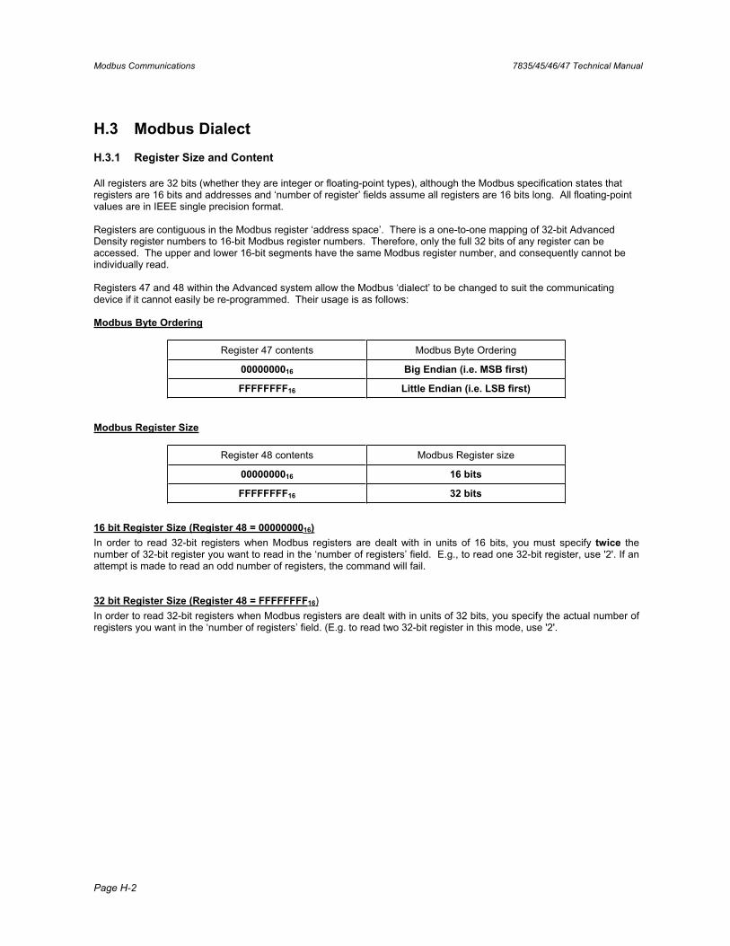
Modbus Communications 7835/45/46/47 Technical Manual
Page H-2
H.3 Modbus Dialect
H.3.1 Register Size and Content
All registers are 32 bits (whether they are integer or floating-point types), although the Modbus specification states that registers are 16 bits and addresses and ‘number of register’ fields assume all registers are 16 bits long. All floating-point values are in IEEE single precision format.
Registers are contiguous in the Modbus register ‘address space’. There is a one-to-one mapping of 32-bit Advanced Density register numbers to 16-bit Modbus register numbers. Therefore, only the full 32 bits of any register can be accessed. The upper and lower 16-bit segments have the same Modbus register number, and consequently cannot be individually read.
Registers 47 and 48 within the Advanced system allow the Modbus ‘dialect’ to be changed to suit the communicating device if it cannot easily be re-programmed. Their usage is as follows:
Modbus Byte Ordering
Register 47 contents Modbus Byte Ordering
0000000016 Big Endian (i.e. MSB first)
FFFFFFFF16 Little Endian (i.e. LSB first)
Modbus Register Size
Register 48 contents Modbus Register size
0000000016 16 bits
FFFFFFFF16 32 bits
16 bit Register Size (Register 48 = 0000000016)In order to read 32-bit registers when Modbus registers are dealt with in units of 16 bits, you must specify twice the number of 32-bit register you want to read in the ‘number of registers’ field. E.g., to read one 32-bit register, use '2'. If anattempt is made to read an odd number of registers, the command will fail.
32 bit Register Size (Register 48 = FFFFFFFF16)In order to read 32-bit registers when Modbus registers are dealt with in units of 32 bits, you specify the actual number of registers you want in the ‘number of registers’ field. (E.g. to read two 32-bit register in this mode, use '2'.
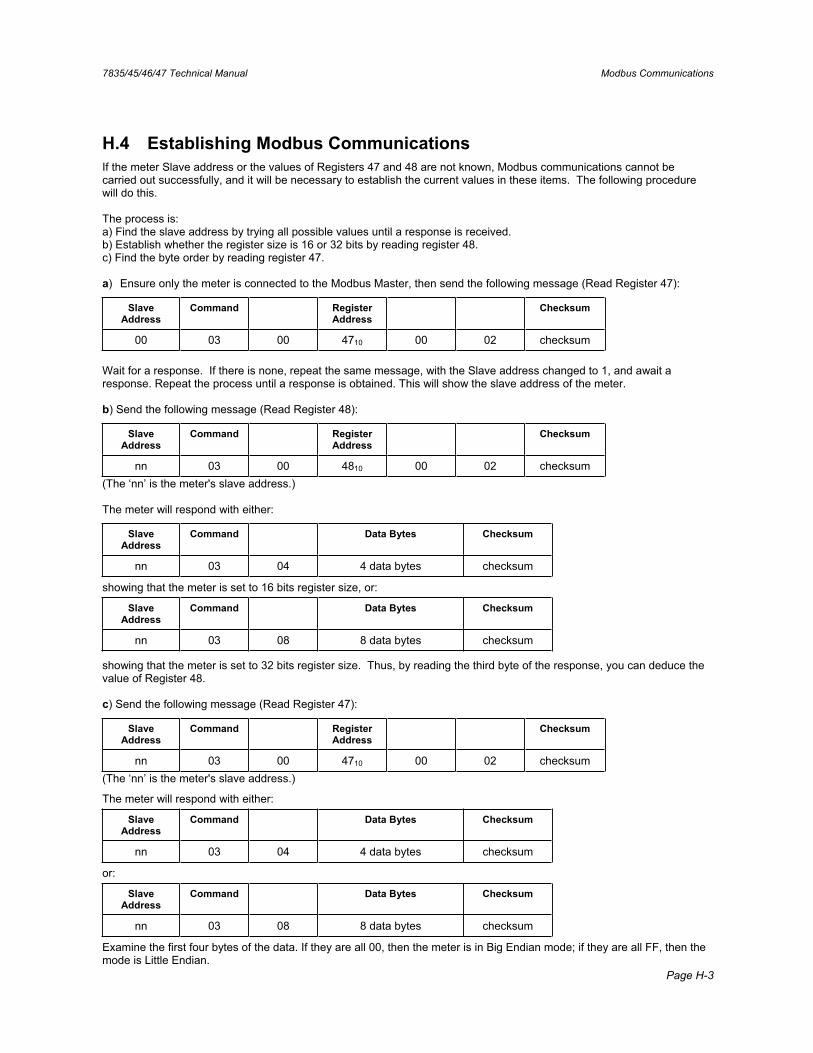
7835/45/46/47 Technical Manual Modbus Communications
Page H-3
H.4 Establishing Modbus Communications If the meter Slave address or the values of Registers 47 and 48 are not known, Modbus communications cannot be carried out successfully, and it will be necessary to establish the current values in these items. The following procedure will do this.
The process is: a) Find the slave address by trying all possible values until a response is received. b) Establish whether the register size is 16 or 32 bits by reading register 48. c) Find the byte order by reading register 47.
a) Ensure only the meter is connected to the Modbus Master, then send the following message (Read Register 47):
Slave Address
Command Register Address
Checksum
00 03 00 4710 00 02 checksum
Wait for a response. If there is none, repeat the same message, with the Slave address changed to 1, and await a response. Repeat the process until a response is obtained. This will show the slave address of the meter.
b) Send the following message (Read Register 48):
Slave Address
Command Register Address
Checksum
nn 03 00 4810 00 02 checksum (The ‘nn’ is the meter's slave address.)
The meter will respond with either:
Slave Address
Command Data Bytes Checksum
nn 03 04 4 data bytes checksum
showing that the meter is set to 16 bits register size, or:
Slave Address
Command Data Bytes Checksum
nn 03 08 8 data bytes checksum
showing that the meter is set to 32 bits register size. Thus, by reading the third byte of the response, you can deduce the value of Register 48.
c) Send the following message (Read Register 47):
Slave Address
Command Register Address
Checksum
nn 03 00 4710 00 02 checksum (The ‘nn’ is the meter's slave address.)
The meter will respond with either:
Slave Address
Command Data Bytes Checksum
nn 03 04 4 data bytes checksum
or:
Slave Address
Command Data Bytes Checksum
nn 03 08 8 data bytes checksum
Examine the first four bytes of the data. If they are all 00, then the meter is in Big Endian mode; if they are all FF, then themode is Little Endian.

Modbus Communications 7835/45/46/47 Technical Manual
Page H-4
H.5 Modbus Commands The only Modbus commands supported by the Advanced Density System are command 3 (Read Holding Registers) and command 16 (Pre-set Multiple Registers). Any number of consecutive registers may be read by one command, but only one may be written to per write command.
This restriction does not limit the performance of the system, since all functions are mapped into the register structure in one way or another.
H.6 Modbus Register Assignments Each register is identified by a unique number, and the list is organised by this number. For each register, the contents are described, along with the data type of the contents.
It also lists the transmitter specific variable tables for the HART® protocol.
Note: The data type is always 32 bits unless stated otherwise. Variable names are given for reference purposes only. They have no other use.
Reg. No. Variable Name Data Type Description 0 API_product_type int index to product type for API referral 1 API_ref_temp float Reference temperature for API referral 2 API_ref_pressure float Reference pressure for API referral 3 density_units int index to density units 4 base_dens_units int index to base density units 5 temperature_units int index to temperature units 6 special_fn int index to special function calculation type 7 spfn_qec_name int index to name for quadratic equation calculation 8 spfn_qec_units int index to units for quadratic equation calculation 9 damping_time int index to output averaging time 10 analogue1_type int index to variable being output on 4 - 20 mA output 1 11 analogue2_type int index to variable being output on 4 - 20 mA output 2 12 analogue3_type int index to variable being output on HART 4 - 20 mA 13 pulse_type int whether pulse output is alarm or frequency 14 analogue1_pcb_offset int PWM value for 4mA on 4 - 20 mA output 1 15 analogue1_pcb_range int PWM value for 20mA on 4 - 20 mA output 1 16 analogue2_pcb_offset int PWM value for 4mA on 4 - 20 mA output 2 17 analogue2_pcb_range int PWM value for 20mA on 4 - 20 mA output 2 18 analogue3_pcb_offset int PWM value for 4mA on HART 4 - 20 mA 19 analogue3_pcb_range int PWM value for 20mA on HART 4 - 20 mA 20 pcb_prt_factor float PRT calibration factor 21 pcb_xtal_factor float Crystal oscillator calibration factor 22 d_flags_long int diagnostics flags 23 dens_override float value for density when fixed by diagnostics 24 ref_dens_override float value for referred density when fixed by diagnostics 25 temp_override float value for temperature when fixed by diagnostics 26 pressure_units int index to pressure units 27 reference_temp int which temperature point to use as the reference
temperature for density referral 28 alarm_norm int index to normal state for alarm output 29 alarm_coverage int index to which errors the alarm output should cover 30 slave_address int Modbus slave address for device 31 alarm_hyst int index to 4 - 20 mA output alarm hysteresis level 32 hart_poll int HART polling address of device 33, 34 hart_tag 6 bytes HART tag 35 - 40 hart_message 24 bytes HART message
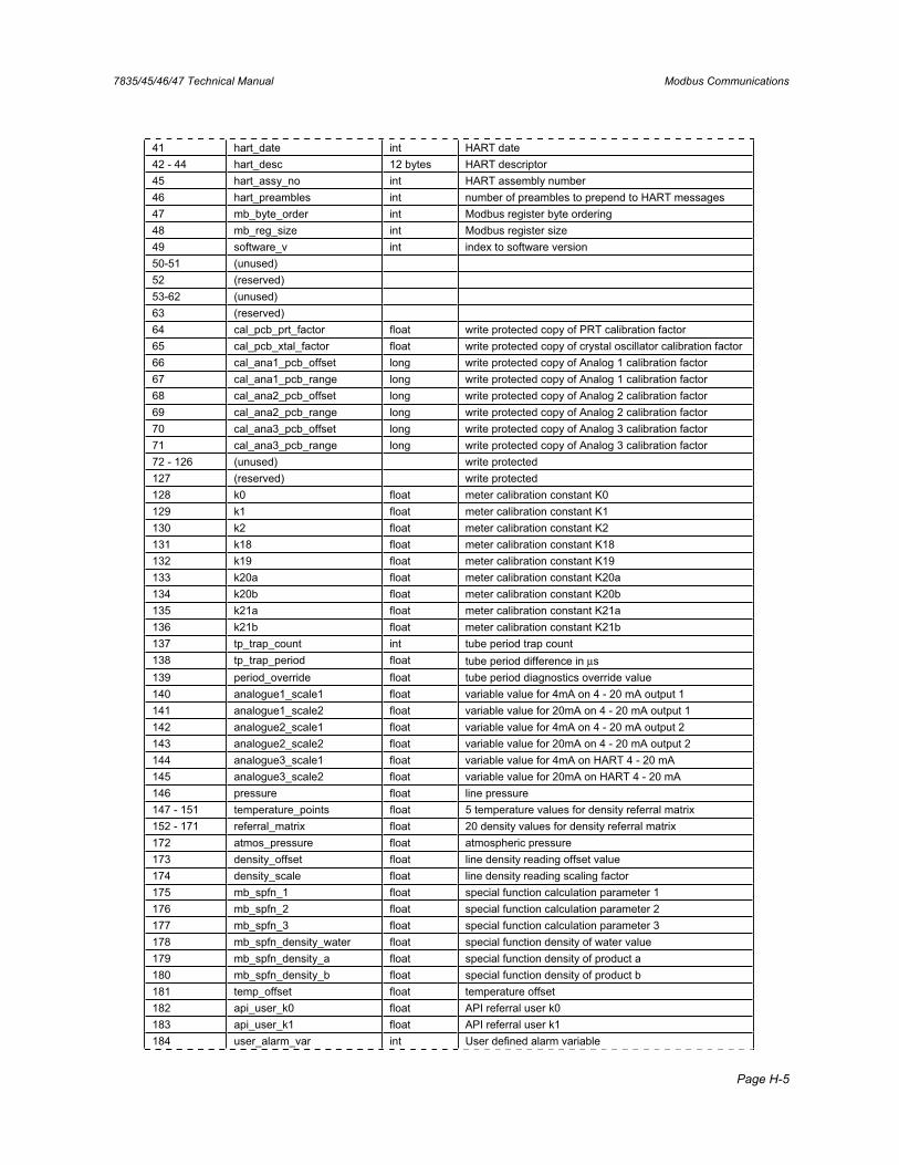
7835/45/46/47 Technical Manual Modbus Communications
Page H-5
41 hart_date int HART date 42 - 44 hart_desc 12 bytes HART descriptor 45 hart_assy_no int HART assembly number 46 hart_preambles int number of preambles to prepend to HART messages 47 mb_byte_order int Modbus register byte ordering 48 mb_reg_size int Modbus register size 49 software_v int index to software version 50-51 (unused) 52 (reserved) 53-62 (unused) 63 (reserved) 64 cal_pcb_prt_factor float write protected copy of PRT calibration factor 65 cal_pcb_xtal_factor float write protected copy of crystal oscillator calibration factor 66 cal_ana1_pcb_offset long write protected copy of Analog 1 calibration factor 67 cal_ana1_pcb_range long write protected copy of Analog 1 calibration factor 68 cal_ana2_pcb_offset long write protected copy of Analog 2 calibration factor 69 cal_ana2_pcb_range long write protected copy of Analog 2 calibration factor 70 cal_ana3_pcb_offset long write protected copy of Analog 3 calibration factor 71 cal_ana3_pcb_range long write protected copy of Analog 3 calibration factor 72 - 126 (unused) write protected 127 (reserved) write protected 128 k0 float meter calibration constant K0 129 k1 float meter calibration constant K1 130 k2 float meter calibration constant K2 131 k18 float meter calibration constant K18 132 k19 float meter calibration constant K19 133 k20a float meter calibration constant K20a 134 k20b float meter calibration constant K20b 135 k21a float meter calibration constant K21a 136 k21b float meter calibration constant K21b 137 tp_trap_count int tube period trap count 138 tp_trap_period float tube period difference in μs139 period_override float tube period diagnostics override value 140 analogue1_scale1 float variable value for 4mA on 4 - 20 mA output 1 141 analogue1_scale2 float variable value for 20mA on 4 - 20 mA output 1 142 analogue2_scale1 float variable value for 4mA on 4 - 20 mA output 2 143 analogue2_scale2 float variable value for 20mA on 4 - 20 mA output 2 144 analogue3_scale1 float variable value for 4mA on HART 4 - 20 mA 145 analogue3_scale2 float variable value for 20mA on HART 4 - 20 mA 146 pressure float line pressure 147 - 151 temperature_points float 5 temperature values for density referral matrix 152 - 171 referral_matrix float 20 density values for density referral matrix 172 atmos_pressure float atmospheric pressure 173 density_offset float line density reading offset value 174 density_scale float line density reading scaling factor 175 mb_spfn_1 float special function calculation parameter 1 176 mb_spfn_2 float special function calculation parameter 2 177 mb_spfn_3 float special function calculation parameter 3 178 mb_spfn_density_water float special function density of water value 179 mb_spfn_density_a float special function density of product a 180 mb_spfn_density_b float special function density of product b 181 temp_offset float temperature offset 182 api_user_k0 float API referral user k0 183 api_user_k1 float API referral user k1 184 user_alarm_var int User defined alarm variable
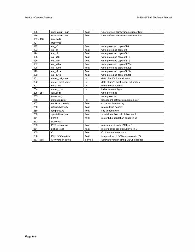
Modbus Communications 7835/45/46/47 Technical Manual
Page H-6
185 user_alarm_high float User defined alarm variable upper limit 186 user_alarm_low float User defined alarm variable lower limit 187 - 190 (unused) 191 (reserved) 192 cal_k0 float write protected copy of k0 193 cal_k1 float write protected copy of k1 194 cal_k2 float write protected copy of k2 195 cal_k18 float write protected copy of k18 196 cal_k19 float write protected copy of k19 197 cal_k20a float write protected copy of k20a 198 cal_k20b float write protected copy of k20b 199 cal_k21a float write protected copy of k21a 200 cal_k21b float write protected copy of k21b 201 meter_cal_date int date of unit’s first calibration 202 meter_recal_date int date of unit’s most recent calibration 203 serial_no int meter serial number 204 meter_type int index to meter type 205 - 254 (unused) write protected 255 (reserved) write protected 256 status register int Baseboard software status register 257 corrected density float corrected line density 258 referred density float referred line density 259 temperature float line temperature 260 special function float special function calculation result 261 period float meter tube oscillation period in μs262 (reserved) 263 PRT resistance float resistance of meter PRT in Ω264 pickup level float meter pickup coil output level in V 265 Q float Q of meter’s resonance 266 PCB temperature float temperature of PCB electronics in °C267 - 268 S/W version string 8 bytes Software version string (ASCII encoded)
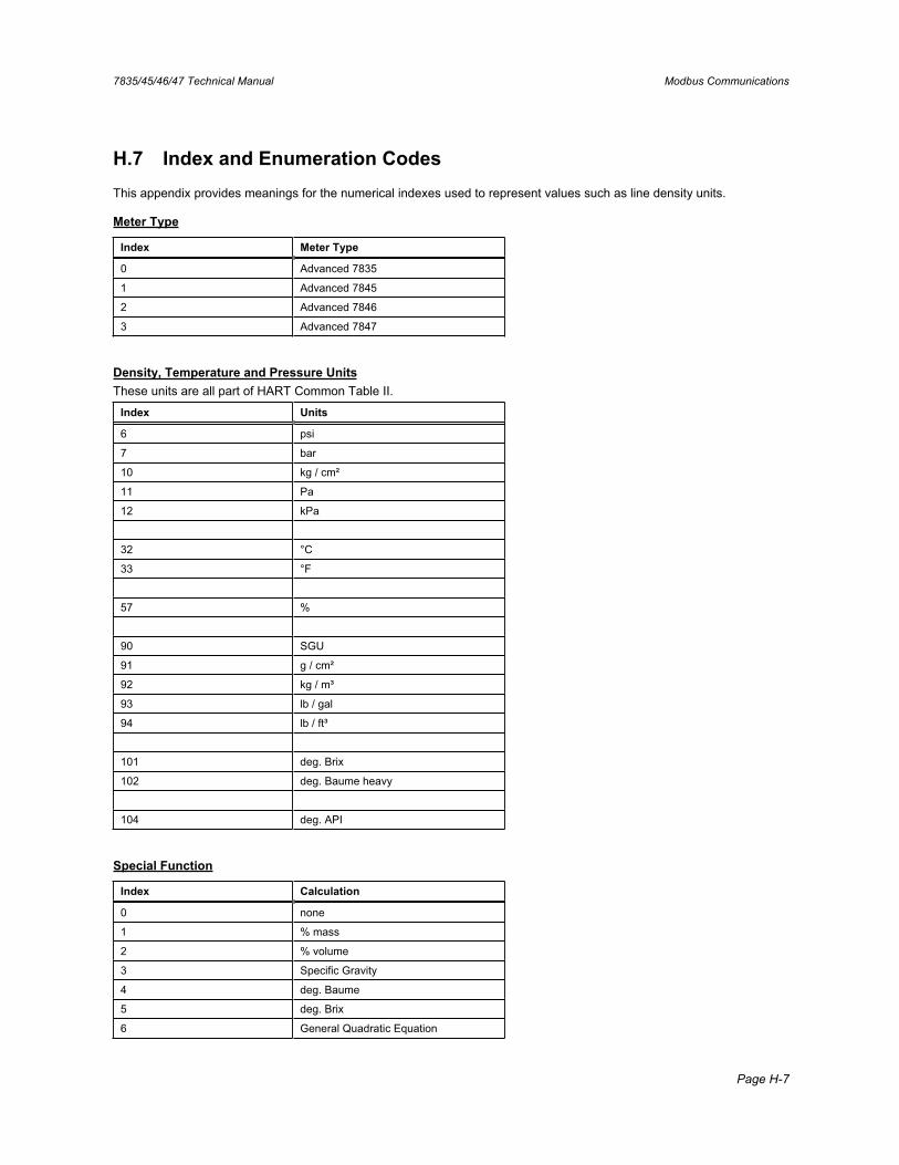
7835/45/46/47 Technical Manual Modbus Communications
Page H-7
H.7 Index and Enumeration Codes This appendix provides meanings for the numerical indexes used to represent values such as line density units.
Meter Type
Index Meter Type
0 Advanced 7835
1 Advanced 7845
2 Advanced 7846
3 Advanced 7847
Density, Temperature and Pressure UnitsThese units are all part of HART Common Table II.
Index Units
6 psi
7 bar
10 kg / cm²
11 Pa
12 kPa
32 °C
33 °F
57 %
90 SGU
91 g / cm²
92 kg / m³
93 lb / gal
94 lb / ft³
101 deg. Brix
102 deg. Baume heavy
104 deg. API
Special Function
Index Calculation
0 none
1 % mass
2 % volume
3 Specific Gravity
4 deg. Baume
5 deg. Brix
6 General Quadratic Equation
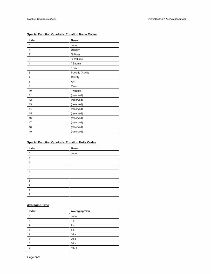
Modbus Communications 7835/45/46/47 Technical Manual
Page H-8
Special Function Quadratic Equation Name Codes
Index Name
0 none
1 Density
2 % Mass
3 % Volume
4 ° Baume
5 ° Brix
6 Specific Gravity
7 Gravity
8 API
9 Plato
10 Twaddle
11 (reserved)
12 (reserved)
13 (reserved)
14 (reserved)
15 (reserved)
16 (reserved)
17 (reserved)
18 (reserved)
19 (reserved)
Special Function Quadratic Equation Units Codes
Index Name
0 none
1
2
3
4
5
6
7
8
9
Averaging Time
Index Averaging Time
0 none
1 1 s
2 2 s
3 5 s
4 10 s
5 20 s
6 50 s
7 100 s
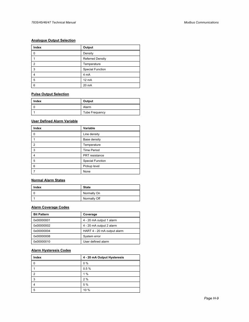
7835/45/46/47 Technical Manual Modbus Communications
Page H-9
Analogue Output Selection
Index Output
0 Density
1 Referred Density
2 Temperature
3 Special Function
4 4 mA
5 12 mA
6 20 mA
Pulse Output Selection
Index Output
0 Alarm
1 Tube Frequency
User Defined Alarm Variable
Index Variable
0 Line density
1 Base density
2 Temperature
3 Time Period
4 PRT resistance
5 Special Function
6 Pickup level
7 None
Normal Alarm States
Index State
0 Normally On
1 Normally Off
Alarm Coverage Codes
Bit Pattern Coverage
0x00000001 4 - 20 mA output 1 alarm
0x00000002 4 - 20 mA output 2 alarm
0x00000004 HART 4 - 20 mA output alarm
0x00000008 System error
0x00000010 User defined alarm
Alarm Hysteresis Codes
Index 4 - 20 mA Output Hysteresis
0 0 %
1 0.5 %
2 1 %
3 2 %
4 5 %
5 10 %
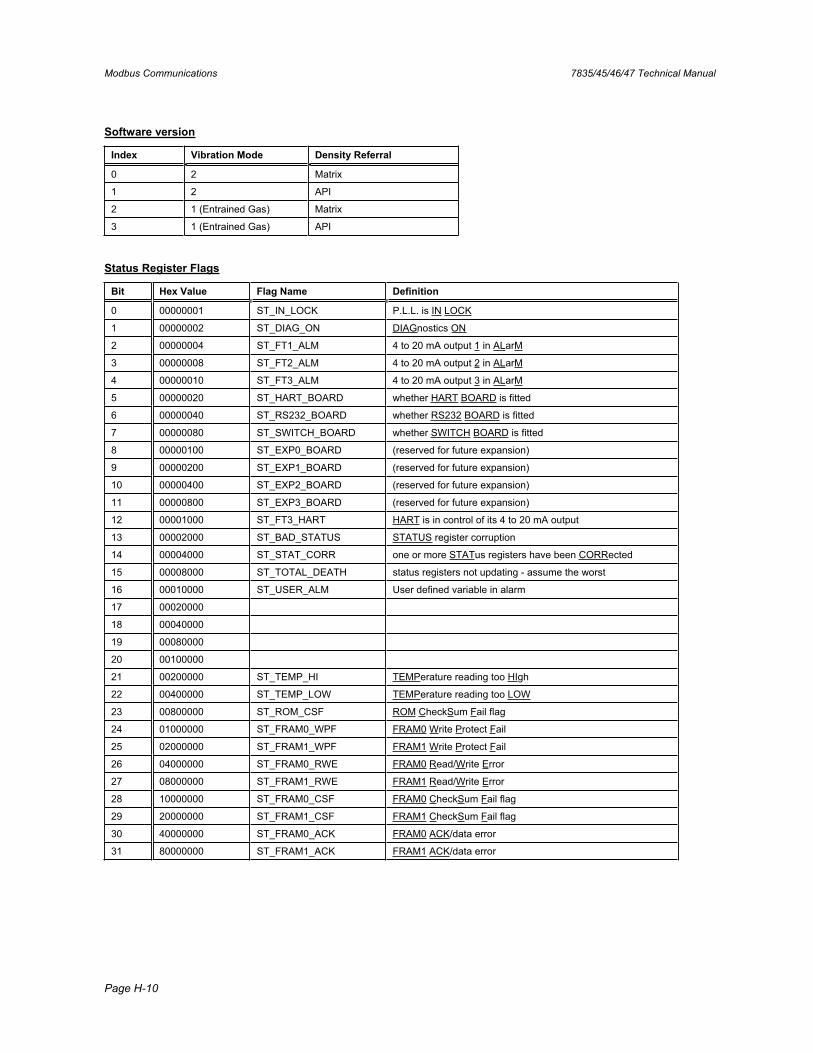
Modbus Communications 7835/45/46/47 Technical Manual
Page H-10
Software version
Index Vibration Mode Density Referral
0 2 Matrix
1 2 API
2 1 (Entrained Gas) Matrix
3 1 (Entrained Gas) API
Status Register Flags
Bit Hex Value Flag Name Definition
0 00000001 ST_IN_LOCK P.L.L. is IN LOCK
1 00000002 ST_DIAG_ON DIAGnostics ON
2 00000004 ST_FT1_ALM 4 to 20 mA output 1 in ALarM
3 00000008 ST_FT2_ALM 4 to 20 mA output 2 in ALarM
4 00000010 ST_FT3_ALM 4 to 20 mA output 3 in ALarM
5 00000020 ST_HART_BOARD whether HART BOARD is fitted
6 00000040 ST_RS232_BOARD whether RS232 BOARD is fitted
7 00000080 ST_SWITCH_BOARD whether SWITCH BOARD is fitted
8 00000100 ST_EXP0_BOARD (reserved for future expansion)
9 00000200 ST_EXP1_BOARD (reserved for future expansion)
10 00000400 ST_EXP2_BOARD (reserved for future expansion)
11 00000800 ST_EXP3_BOARD (reserved for future expansion)
12 00001000 ST_FT3_HART HART is in control of its 4 to 20 mA output
13 00002000 ST_BAD_STATUS STATUS register corruption
14 00004000 ST_STAT_CORR one or more STATus registers have been CORRected
15 00008000 ST_TOTAL_DEATH status registers not updating - assume the worst
16 00010000 ST_USER_ALM User defined variable in alarm
17 00020000
18 00040000
19 00080000
20 00100000
21 00200000 ST_TEMP_HI TEMPerature reading too HIgh
22 00400000 ST_TEMP_LOW TEMPerature reading too LOW
23 00800000 ST_ROM_CSF ROM CheckSum Fail flag
24 01000000 ST_FRAM0_WPF FRAM0 Write Protect Fail
25 02000000 ST_FRAM1_WPF FRAM1 Write Protect Fail
26 04000000 ST_FRAM0_RWE FRAM0 Read/Write Error
27 08000000 ST_FRAM1_RWE FRAM1 Read/Write Error
28 10000000 ST_FRAM0_CSF FRAM0 CheckSum Fail flag
29 20000000 ST_FRAM1_CSF FRAM1 CheckSum Fail flag
30 40000000 ST_FRAM0_ACK FRAM0 ACK/data error
31 80000000 ST_FRAM1_ACK FRAM1 ACK/data error

7835/45/46/47 Technical Manual HART® Software
Page I-1
Appendix I HART® Software
I.1 Introduction This appendix details the specification for the HART® software in the Advanced Density Electronics (known as the Baseboard), and is intended as a guide for interfacing with customer equipment.
The HART® communications provide a means to: • Configure all of the 4-20mA outputs. • Configure the output damping. • Configure the Base density and special function calculations. • Perform diagnostics such as meter time period, Q and pick-up level checks.
Note that the configuration of the base density, special function calculations and diagnostic functions can only be provisioned using the device specific commands 128 and 129.
I.2 HART® basics The HART® specification defines the physical form of transmission, the transaction procedures, the message structure, data formats and a set of commands. These are discussed in outline below.
For more information, consult the following publications:
Bowden, R. "HART: A Technical Description". (1991) Rosemount A.G.
"HART - Smart Communications Protocol Specification (Revision 5.1)". (1991) Rosemount Inc. (Rosemount Document Number: D9000047; Revision A).
Physical form of transmission
HART uses the Bell 202 standard frequency shift keying (f.s.k.) signal to communicate at 1200 baud, superimposed at a low level on the 4-20mA analogue measurement signal. Having an average value of zero, an f.s.k. signal causes no interference with the analogue signal.
1200 Hz "1" 2200 Hz "0"
0mA
+ 0.5mA
- 0.5mA
Transaction protocol
HART® is a master - slave protocol - a field device only replies when it is spoken to. There can be a primary master and a secondary master (e.g. Hand held communicator) on the line. Up to 15 slave devices can be connected to a single multidrop line (safe areas).
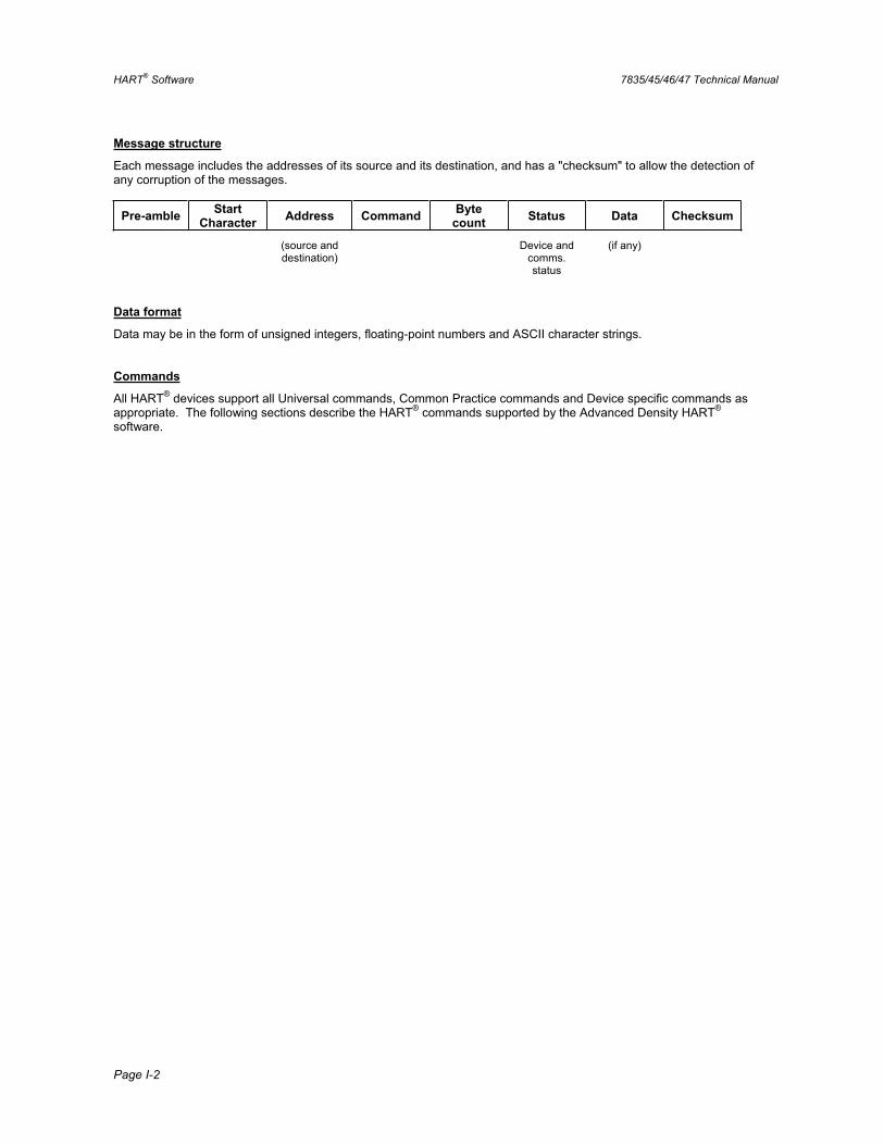
HART® Software 7835/45/46/47 Technical Manual
Page I-2
Message structure
Each message includes the addresses of its source and its destination, and has a "checksum" to allow the detection of any corruption of the messages.
Pre-amble StartCharacter Address Command Byte
count Status Data Checksum
(source and destination)
Device and comms.status
(if any)
Data format
Data may be in the form of unsigned integers, floating-point numbers and ASCII character strings.
Commands
All HART® devices support all Universal commands, Common Practice commands and Device specific commands as appropriate. The following sections describe the HART® commands supported by the Advanced Density HART®
software.
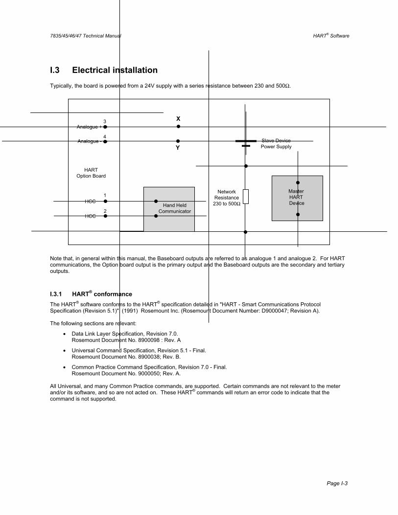
7835/45/46/47 Technical Manual HART® Software
Page I-3
I.3 Electrical installation Typically, the board is powered from a 24V supply with a series resistance between 230 and 500Ω.
Hand HeldCommunicator
Analogue +
Analogue -
HCC
HCC
HARTOption Board
Slave DevicePower Supply
Master HARTDevice
NetworkResistance230 to 500Ω
X
Y
1
2
3
4
Note that, in general within this manual, the Baseboard outputs are referred to as analogue 1 and analogue 2. For HART communications, the Option board output is the primary output and the Baseboard outputs are the secondary and tertiary outputs.
I.3.1 HART® conformance The HART® software conforms to the HART® specification detailed in "HART - Smart Communications Protocol Specification (Revision 5.1)". (1991) Rosemount Inc. (Rosemount Document Number: D9000047; Revision A).
The following sections are relevant:
• Data Link Layer Specification, Revision 7.0. Rosemount Document No. 8900098 : Rev. A
• Universal Command Specification, Revision 5.1 - Final. Rosemount Document No. 8900038; Rev. B.
• Common Practice Command Specification, Revision 7.0 - Final. Rosemount Document No. 9000050; Rev. A.
All Universal, and many Common Practice commands, are supported. Certain commands are not relevant to the meter and/or its software, and so are not acted on. These HART® commands will return an error code to indicate that the command is not supported.

HART® Software 7835/45/46/47 Technical Manual
Page I-4
I.4 HART® Commands
I.4.1 Universal Commands
Command Action Comments / data in reply
0 Read unique identifier Returns:- Byte 0 = 254 expansion Byte 1 = manufacturer id (Table 1) Byte 2 = manufacturer’s device type code (Table 1) Byte 3 = number of preambles (Table 2) Byte 4 = universal command revision Byte 5 = transmitter specific command revision Byte 6 = software revision Byte 7 = hardware revision Byte 8 = device function flags (Table 1) Byte 9 -11 = Meter serial number
1 Read primary variable Refer to Tables 3 and 4
2 Read current and percent of range Refer to Tables 3 and 4
3 Read dynamic variables and P.V. current Refer to Tables 3 and 4
6 Write polling address Any valid address
11 Read identifier associated with tag (Same as for command 0)
12 Read message HART message
13 Read tag, descriptor and date
14 Read primary variable sensor information Returns:- Byte 0-2 Meter s/n Byte 3 Variable units Byte 4 -7 Upper sensor limit (Table 2) Byte 8-11 Lower sensor limit (Table 2) Byte 12-15 Minimum span (Table 2)
15 Read primary variable output information Returns:- Byte 0 Alarm type = special, Byte 1 Transfer function = linear, Byte 3-6 Range upper value, Byte 7-10 Range lower value, Byte 11-14 Damping (s), Byte 15 No write protect, Byte 16 Manufacturer's identity
16 Read final assembly number
17 Write message
18 Write tag, descriptor and date
19 Write final assembly number
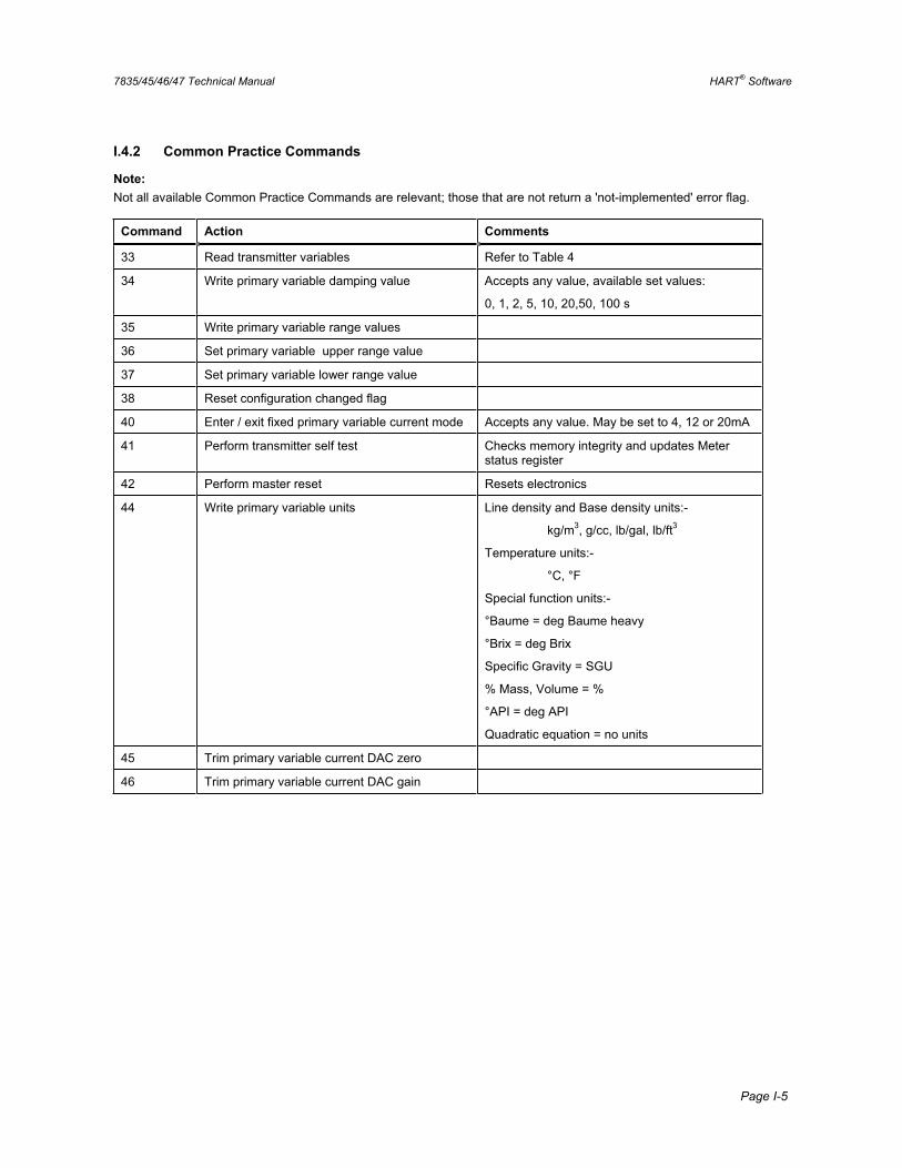
7835/45/46/47 Technical Manual HART® Software
Page I-5
I.4.2 Common Practice Commands
Note:Not all available Common Practice Commands are relevant; those that are not return a 'not-implemented' error flag.
Command Action Comments
33 Read transmitter variables Refer to Table 4
34 Write primary variable damping value Accepts any value, available set values:
0, 1, 2, 5, 10, 20,50, 100 s
35 Write primary variable range values
36 Set primary variable upper range value
37 Set primary variable lower range value
38 Reset configuration changed flag
40 Enter / exit fixed primary variable current mode Accepts any value. May be set to 4, 12 or 20mA
41 Perform transmitter self test Checks memory integrity and updates Meter status register
42 Perform master reset Resets electronics
44 Write primary variable units Line density and Base density units:-
kg/m3, g/cc, lb/gal, lb/ft3
Temperature units:-
°C, °F
Special function units:-
°Baume = deg Baume heavy
°Brix = deg Brix
Specific Gravity = SGU
% Mass, Volume = %
°API = deg API
Quadratic equation = no units
45 Trim primary variable current DAC zero
46 Trim primary variable current DAC gain
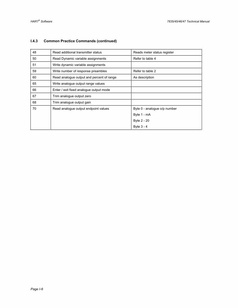
HART® Software 7835/45/46/47 Technical Manual
Page I-6
I.4.3 Common Practice Commands (continued)
48 Read additional transmitter status Reads meter status register
50 Read Dynamic variable assignments Refer to table 4
51 Write dynamic variable assignments
59 Write number of response preambles Refer to table 2
60 Read analogue output and percent of range As description
65 Write analogue output range values
66 Enter / exit fixed analogue output mode
67 Trim analogue output zero
68 Trim analogue output gain
70 Read analogue output endpoint values Byte 0 - analogue o/p number
Byte 1 - mA
Byte 2 - 20
Byte 3 - 4
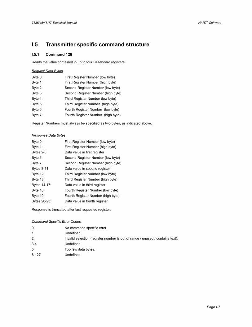
7835/45/46/47 Technical Manual HART® Software
Page I-7
I.5 Transmitter specific command structure
I.5.1 Command 128
Reads the value contained in up to four Baseboard registers.
Request Data Bytes
Byte 0: First Register Number (low byte) Byte 1: First Register Number (high byte) Byte 2: Second Register Number (low byte) Byte 3: Second Register Number (high byte) Byte 4: Third Register Number (low byte) Byte 5: Third Register Number (high byte) Byte 6: Fourth Register Number (low byte) Byte 7: Fourth Register Number (high byte)
Register Numbers must always be specified as two bytes, as indicated above.
Response Data Bytes
Byte 0: First Register Number (low byte) Byte 1: First Register Number (high byte) Bytes 2-5: Data value in first register Byte 6: Second Register Number (low byte) Byte 7: Second Register Number (high byte) Bytes 8-11: Data value in second register Byte 12: Third Register Number (low byte) Byte 13: Third Register Number (high byte) Bytes 14-17: Data value in third register Byte 18: Fourth Register Number (low byte) Byte 19: Fourth Register Number (high byte) Bytes 20-23: Data value in fourth register
Response is truncated after last requested register.
Command Specific Error Codes.
0 No command specific error. 1 Undefined. 2 Invalid selection (register number is out of range / unused / contains text). 3-4 Undefined. 5 Too few data bytes. 6-127 Undefined.
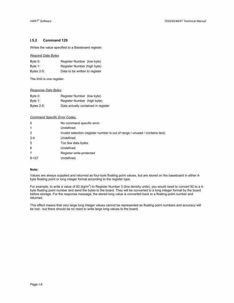
HART® Software 7835/45/46/47 Technical Manual
Page I-8
I.5.2 Command 129
Writes the value specified to a Baseboard register.
Request Data Bytes
Byte 0: Register Number (low byte) Byte 1: Register Number (high byte) Bytes 2-5: Data to be written to register
The limit is one register.
Response Data Bytes
Byte 0: Register Number (low byte) Byte 1: Register Number (high byte) Bytes 2-5: Data actually contained in register
Command Specific Error Codes.
0 No command specific error. 1 Undefined. 2 Invalid selection (register number is out of range / unused / contains text). 3-4 Undefined. 5 Too few data bytes. 6 Undefined. 7 Register write-protected 8-127 Undefined.
Note:
Values are always supplied and returned as four-byte floating point values, but are stored on the baseboard in either 4-byte floating point or long integer format according to the register type.
For example, to write a value of 92 (kg/m3) to Register Number 3 (line density units), you would need to convert 92 to a 4-byte floating point number and send the bytes to the board. They will be converted to a long integer format by the board before storage. For the response message, the stored long value is converted back to a floating-point number and returned.
This effect means that very large long integer values cannot be represented as floating point numbers and accuracy will be lost - but there should be no need to write large long values to the board.
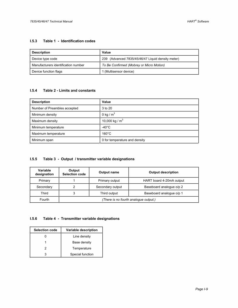
7835/45/46/47 Technical Manual HART® Software
Page I-9
I.5.3 Table 1 - Identification codes
Description Value
Device type code 239 (Advanced 7835/45/46/47 Liquid density meter)
Manufacturers identification number To Be Confirmed (Mobrey or Micro Motion)
Device function flags 1 (Multisensor device)
I.5.4 Table 2 - Limits and constants
Description Value
Number of Preambles accepted 3 to 20
Minimum density 0 kg / m3
Maximum density 10,000 kg / m3
Minimum temperature -40°C
Maximum temperature 160°C
Minimum span 0 for temperature and density
I.5.5 Table 3 - Output / transmitter variable designations
Variabledesignation
Output Selection code Output name Output description
Primary 1 Primary output HART board 4-20mA output
Secondary 2 Secondary output Baseboard analogue o/p 2
Third 3 Third output Baseboard analogue o/p 1
Fourth (There is no fourth analogue output.)
I.5.6 Table 4 - Transmitter variable designations
Selection code Variable description
0
1
2
3
Line density
Base density
Temperature
Special function

HART® Software 7835/45/46/47 Technical Manual
Page I-10
I.6 Summary of HART® functionality The Advanced densitometer’s HART® software gives the HART® user control of the following meter features:
• HART 4-20 mA output:
Analogue to Digital Converter (ADC) offset and gain (i.e. trim the 4mA and 20mA points). Output range limits. Output damping. Fix output current to 4, 12 or 20 mA. Read output current and % of range. Select which dynamic variable to output (line density, referred density, temperature, special function).
• Baseboard 4-20 mA outputs (2 off)
ADC offset and gain. Output range limits. Output damping. Fix output current to 4, 12 or 20 mA. Read output current and % of range. Select which dynamic variable to output.
• Read Baseboard parameters:
K0, K1, K2, K18, K19, K20a, K20b, K21a, K21b. meter PRT (calibration) factor. meter crystal (calibration) factor. special function calculation parameter(s). all analogue output upper and lower range values. line pressure. temperature points and density matrix for density referral calculation. all dynamic variables (line density etc.) Baseboard status register.
• Set Baseboard parameters:
line density, referred density, and temperature units.
• Read and write HART information:
tag (8 character identification label). message (32 character message). descriptor (16 character description). date (day, month, year). final assembly number. sensor serial number. HART polling address.
• Miscellaneous functions:
Self-test.Reset.
7835/45/46/47 Technical Manual Returns Forms
Page J-1
Appendix J Returns Forms
The Returns Forms, contained in this Appendix, must be copied and completed whenever a meter is to be returned to the factory for servicing, calibration or repair. This must be done before the product is shipped.
There are Returns Forms for New/Unused equipment, and for Used equipment. Please select accordingly.
© 2007, Micro Motion, Inc.All rights reservedGI-00381 (5/07)
Micro Motion Return Policy For Use in the U.S.A.With New and Unused Micro Motion Equipment
Definitions
New and unused equipment
Only equipment that has not been removed from the original shipping package will be considered new and unused. New and unused equipment includes sensors, transmitters, or peripheral devices which:
• Were shipped as requested by the customer but are not needed, or
• Were shipped incorrectly by Micro Motion.
Used equipment
All other equipment is considered used. This equipment must be completely decontaminated and cleaned before being returned. Document all foreign substances that have come in contact with the equipment.
Before you begin
This document is for returning new and unused equipment to Micro Motion in the United States.
• For instructions on returning used equipment, our used equipment return policy is available as a separate document.
• For instructions on returning equipment to Emerson offices around the world, our international return policies are available as separate documents.
To obtain any of our return policies, procedures, and forms, contact the Micro Motion Customer Service Department during business hours:
• In the U.S.A., phone 1-800-522-6277 or 1-303-527-5200 between 6:00 a.m. and 5:30 p.m. (Mountain Standard Time), Monday through Friday, except holidays.
• In Europe, phone +31 (0) 318 495 555, or contact your local sales representative.
• In Asia, phone (65) 6777-8211, or contact your local sales representative.
The latest return policies, procedures, and forms are also available from the Micro Motion web site: www.micromotion.com .
Restock fees
Restock fees might apply, depending on the reason for return:
• If you ordered the wrong equipment, a restock fee will be charged.
• If you no longer require the equipment (for example, if your project has been cancelled), a restock fee will be charged.
• If we shipped the wrong equipment, a restock fee will not be charged.
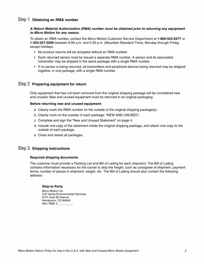
Micro Motion Return Policy for Use in the U.S.A. with New and Unused Micro Motion Equipment 2
Step 1 Obtaining an RMA number
A Return Material Authorization (RMA) number must be obtained prior to returning any equipment to Micro Motion for any reason.
To obtain an RMA number, contact the Micro Motion Customer Service Department at 1-800-522-6277 or 1-303-527-5200 between 6:00 a.m. and 5:30 p.m. (Mountain Standard Time), Monday through Friday, except holidays.
• No product returns will be accepted without an RMA number.
• Each returned sensor must be issued a separate RMA number. A sensor and its associated transmitter may be shipped in the same package with a single RMA number.
• If no sensor is being returned, all transmitters and peripheral devices being returned may be shipped together, in one package, with a single RMA number.
Step 2 Preparing equipment for return
Only equipment that has not been removed from the original shipping package will be considered new and unused. New and unused equipment must be returned in its original packaging.
Before returning new and unused equipment:
a. Clearly mark the RMA number on the outside of the original shipping package(s).
b. Clearly mark on the outside of each package: “NEW AND UNUSED”.
c. Complete and sign the “New and Unused Statement” on page 4.
d. Include one copy of the statement inside the original shipping package, and attach one copy to the outside of each package.
e. Close and reseal all packages.
Step 3 Shipping instructions
Required shipping documents
The customer must provide a Packing List and Bill of Lading for each shipment. The Bill of Lading contains information necessary for the carrier to ship the freight, such as consignee of shipment, payment terms, number of pieces in shipment, weight, etc. The Bill of Lading should also contain the following address:
Ship-to PartyMicro Motion Inc.C/O Veolia Environmental Services9131 East 96 AvenueHenderson, CO 80640Attn: RMA #__________
Micro Motion Return Policy for Use in the U.S.A. with New and Unused Micro Motion Equipment 3
Document submittal
Submit the following shipping documents inside the shipping container:
• One (1) copy of the Packing List.
Submit the following shipping documents to your Micro Motion customer service representative:
• One (1) copy of the Packing List.
• One (1) copy of the Bill of Lading.
Shipping charges
The customer is responsible for all shipping charges.
Veolia has been instructed to refuse any collect shipments.
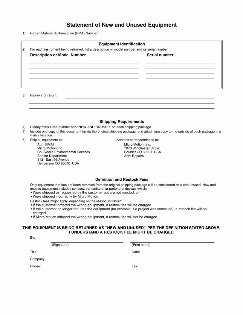
Statement of New and Unused Equipment1) Return Material Authorization (RMA) Number:
Equipment Identification2) For each instrument being returned, list a description or model number and its serial number.
Description or Model Number Serial number
3) Reason for return:
Shipping Requirements4) Clearly mark RMA number and “NEW AND UNUSED” on each shipping package. 5) Include one copy of this document inside the original shipping package, and attach one copy to the outside of each package in a
visible location.6) Ship all equipment to: Address correspondence to:
Attn: RMA# _____________Micro Motion Inc.C/O Veolia Environmental ServicesSensor Department9131 East 96 AvenueHenderson CO 80640 USA
Micro Motion, Inc.7070 Winchester CircleBoulder CO 80301 USAAttn: Repairs
Definition and Restock FeesOnly equipment that has not been removed from the original shipping package will be considered new and unused. New and unused equipment includes sensors, transmitters, or peripheral devices which:• Were shipped as requested by the customer but are not needed, or• Were shipped incorrectly by Micro Motion.Restock fees might apply, depending on the reason for return:• If the customer ordered the wrong equipment, a restock fee will be charged.• If the customer no longer requires the equipment (for example, if a project was cancelled), a restock fee will be
charged.• If Micro Motion shipped the wrong equipment, a restock fee will not be charged.
THIS EQUIPMENT IS BEING RETURNED AS “NEW AND UNUSED,” PER THE DEFINITION STATED ABOVE. I UNDERSTAND A RESTOCK FEE MIGHT BE CHARGED.
By:
(Signature) (Print name)
Title: Date:
Company:
Phone: Fax:
© 2007, Micro Motion, Inc.All rights reservedGI-00381 (5/07)
Micro Motion Return Policy For Use in the U.S.A.With Used Micro Motion Equipment
Definitions
New and unused equipment
Only equipment that has not been removed from the original shipping package will be considered new and unused. New and unused equipment includes sensors, transmitters, or peripheral devices which:
• Were shipped as requested by the customer but are not needed, or
• Were shipped incorrectly by Micro Motion.
Used equipment
All other equipment is considered used. This equipment must be completely decontaminated and cleaned before being returned. Document all foreign substances that have come in contact with the equipment.
Before you begin
This document is for returning used equipment to Micro Motion in the United States.
• For instructions on returning new and unused equipment, our new and unused equipment return policy is available as a separate document.
• For instructions on returning equipment to Emerson offices around the world, our international return policies are available as separate documents.
To obtain any of our return policies, procedures, and forms, contact the Micro Motion Customer Service Department during business hours:
• In the U.S.A., phone 1-800-522-6277 or 1-303-527-5200 between 6:00 a.m. and 5:30 p.m. (Mountain Standard Time), Monday through Friday, except holidays.
• In Europe, phone +31 (0) 318 495 555, or contact your local sales representative.
• In Asia, phone (65) 6777-8211, or contact your local sales representative.
The latest return policies, procedures, and forms are also available from the Micro Motion web site: www.micromotion.com .
These procedures must be followed for you to meet governmental requirements. They also help us provide a safe working environment for our employees. Failure to follow these requirements will result in your equipment being refused delivery.
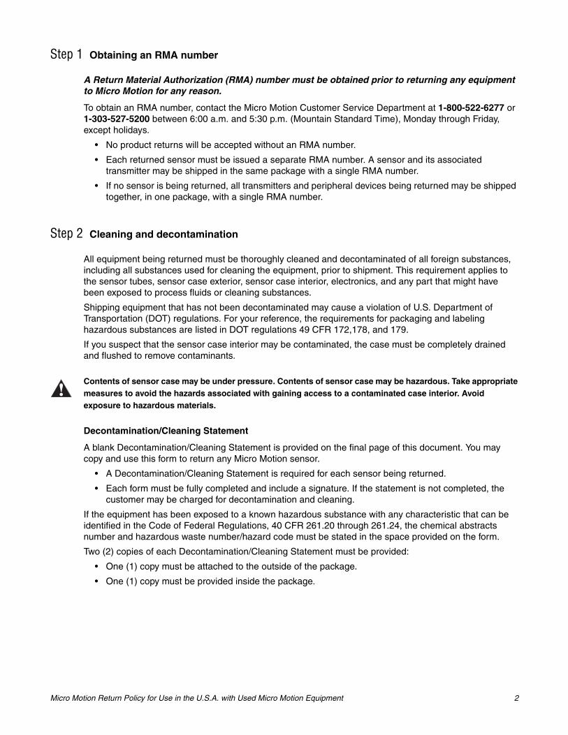
Micro Motion Return Policy for Use in the U.S.A. with Used Micro Motion Equipment 2
Step 1 Obtaining an RMA number
A Return Material Authorization (RMA) number must be obtained prior to returning any equipment to Micro Motion for any reason.
To obtain an RMA number, contact the Micro Motion Customer Service Department at 1-800-522-6277 or 1-303-527-5200 between 6:00 a.m. and 5:30 p.m. (Mountain Standard Time), Monday through Friday, except holidays.
• No product returns will be accepted without an RMA number.
• Each returned sensor must be issued a separate RMA number. A sensor and its associated transmitter may be shipped in the same package with a single RMA number.
• If no sensor is being returned, all transmitters and peripheral devices being returned may be shipped together, in one package, with a single RMA number.
Step 2 Cleaning and decontamination
All equipment being returned must be thoroughly cleaned and decontaminated of all foreign substances, including all substances used for cleaning the equipment, prior to shipment. This requirement applies to the sensor tubes, sensor case exterior, sensor case interior, electronics, and any part that might have been exposed to process fluids or cleaning substances.
Shipping equipment that has not been decontaminated may cause a violation of U.S. Department of Transportation (DOT) regulations. For your reference, the requirements for packaging and labeling hazardous substances are listed in DOT regulations 49 CFR 172,178, and 179.
If you suspect that the sensor case interior may be contaminated, the case must be completely drained and flushed to remove contaminants.
Decontamination/Cleaning Statement
A blank Decontamination/Cleaning Statement is provided on the final page of this document. You may copy and use this form to return any Micro Motion sensor.
• A Decontamination/Cleaning Statement is required for each sensor being returned.
• Each form must be fully completed and include a signature. If the statement is not completed, the customer may be charged for decontamination and cleaning.
If the equipment has been exposed to a known hazardous substance with any characteristic that can be identified in the Code of Federal Regulations, 40 CFR 261.20 through 261.24, the chemical abstracts number and hazardous waste number/hazard code must be stated in the space provided on the form.
Two (2) copies of each Decontamination/Cleaning Statement must be provided:
• One (1) copy must be attached to the outside of the package.
• One (1) copy must be provided inside the package.
Contents of sensor case may be under pressure. Contents of sensor case may be hazardous. Take appropriate measures to avoid the hazards associated with gaining access to a contaminated case interior. Avoid exposure to hazardous materials.
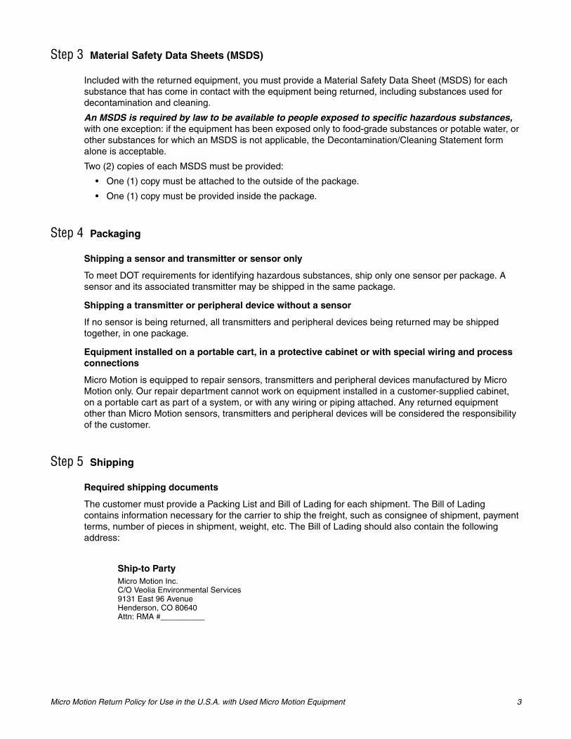
Micro Motion Return Policy for Use in the U.S.A. with Used Micro Motion Equipment 3
Step 3 Material Safety Data Sheets (MSDS)
Included with the returned equipment, you must provide a Material Safety Data Sheet (MSDS) for each substance that has come in contact with the equipment being returned, including substances used for decontamination and cleaning.
An MSDS is required by law to be available to people exposed to specific hazardous substances,with one exception: if the equipment has been exposed only to food-grade substances or potable water, or other substances for which an MSDS is not applicable, the Decontamination/Cleaning Statement form alone is acceptable.
Two (2) copies of each MSDS must be provided:
• One (1) copy must be attached to the outside of the package.
• One (1) copy must be provided inside the package.
Step 4 Packaging
Shipping a sensor and transmitter or sensor only
To meet DOT requirements for identifying hazardous substances, ship only one sensor per package. A sensor and its associated transmitter may be shipped in the same package.
Shipping a transmitter or peripheral device without a sensor
If no sensor is being returned, all transmitters and peripheral devices being returned may be shipped together, in one package.
Equipment installed on a portable cart, in a protective cabinet or with special wiring and process connections
Micro Motion is equipped to repair sensors, transmitters and peripheral devices manufactured by Micro Motion only. Our repair department cannot work on equipment installed in a customer-supplied cabinet, on a portable cart as part of a system, or with any wiring or piping attached. Any returned equipment other than Micro Motion sensors, transmitters and peripheral devices will be considered the responsibility of the customer.
Step 5 Shipping
Required shipping documents
The customer must provide a Packing List and Bill of Lading for each shipment. The Bill of Lading contains information necessary for the carrier to ship the freight, such as consignee of shipment, payment terms, number of pieces in shipment, weight, etc. The Bill of Lading should also contain the following address:
Ship-to PartyMicro Motion Inc.C/O Veolia Environmental Services9131 East 96 AvenueHenderson, CO 80640Attn: RMA #__________
Micro Motion Return Policy for Use in the U.S.A. with Used Micro Motion Equipment 4
Document submittal
Submit the following shipping documents inside the shipping container:
• One (1) copy of the Packing List.
Submit the following shipping documents to your Micro Motion customer service representative:
• One (1) copy of the Packing List.
• One (1) copy of the Bill of Lading.
The address is listed as follows:
Micro Motion, Inc.Attn: (Your customer service representative)7070 Winchester CircleBoulder, CO 80301 USARMA# _________________
Shipping charges
The customer is responsible for all shipping charges.
Veolia has been instructed to refuse any collect shipments.
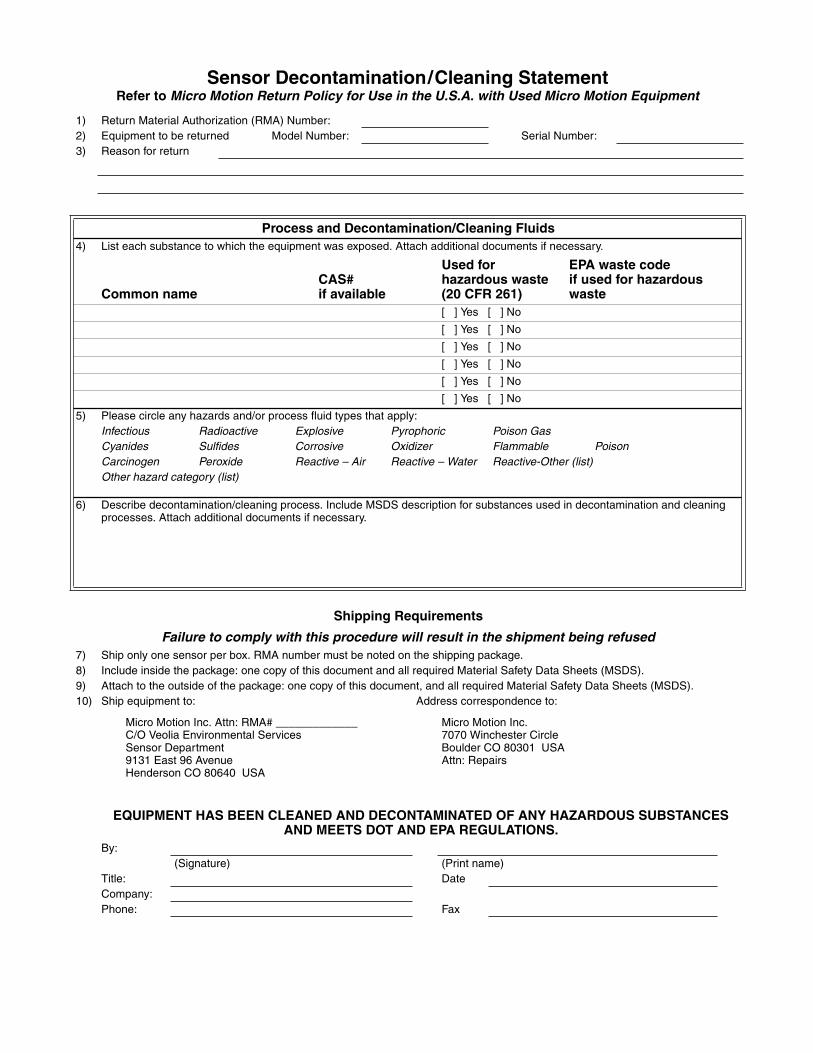
Sensor Decontamination/Cleaning StatementRefer to Micro Motion Return Policy for Use in the U.S.A. with Used Micro Motion Equipment
1) Return Material Authorization (RMA) Number:2) Equipment to be returned Model Number: Serial Number:3) Reason for return
Process and Decontamination/Cleaning Fluids4) List each substance to which the equipment was exposed. Attach additional documents if necessary.
Common nameCAS#if available
Used for hazardous waste (20 CFR 261)
EPA waste codeif used for hazardous waste
[ ] Yes [ ] No
[ ] Yes [ ] No
[ ] Yes [ ] No
[ ] Yes [ ] No
[ ] Yes [ ] No
[ ] Yes [ ] No
5) Please circle any hazards and/or process fluid types that apply:Infectious Radioactive Explosive Pyrophoric Poison GasCyanides Sulfides Corrosive Oxidizer Flammable PoisonCarcinogen Peroxide Reactive – Air Reactive – Water Reactive-Other (list)Other hazard category (list)
6) Describe decontamination/cleaning process. Include MSDS description for substances used in decontamination and cleaning processes. Attach additional documents if necessary.
Shipping Requirements
Failure to comply with this procedure will result in the shipment being refused7) Ship only one sensor per box. RMA number must be noted on the shipping package.8) Include inside the package: one copy of this document and all required Material Safety Data Sheets (MSDS).9) Attach to the outside of the package: one copy of this document, and all required Material Safety Data Sheets (MSDS).10) Ship equipment to: Address correspondence to:
Micro Motion Inc. Attn: RMA# _____________C/O Veolia Environmental ServicesSensor Department9131 East 96 AvenueHenderson CO 80640 USA
Micro Motion Inc.7070 Winchester CircleBoulder CO 80301 USAAttn: Repairs
EQUIPMENT HAS BEEN CLEANED AND DECONTAMINATED OF ANY HAZARDOUS SUBSTANCES AND MEETS DOT AND EPA REGULATIONS.
By:(Signature) (Print name)
Title: DateCompany:Phone: Fax

7835/45/46/47 Technical Manual Certified System Drawings
Page K-1
Appendix K Certified System Drawings
K.1 GENERAL All certified drawings in this manual are given here for planning purposes only. Before commencing with implementation, reference should always be made to the current issue of the certified drawings. Contact the factory for further details.
No. Drawing Reference
Description
1. 78355092ASheet 1 of 1
CSA System Drawing, Gas Groups C and D (Configuration: Standard Electronics)
2. 78355093ASheet 1 of 2
CSA System Drawing, Gas Groups A, B, C and D (Configuration: Advanced Electronics, HART, MODBUS, and Zener Barrier)
3. 78355093ASheet 2 of 2
CSA System Drawing, Gas Groups A, B, C and D (Configuration: Advanced Electronics with HART, MODBUS, Remote Display, Zener Barrier)
4. 78355094ASheet 1 of 3
CSA System Drawing, Gas Groups C and D (Configuration: Advanced Electronics with HART Multi-drop, and Zener Barrier)
5. 78355094ASheet 2 of 3
CSA System Drawing, Gas Groups C and D (Configuration: Advanced Electronics with HART Multi-drop, Remote Display, Zener Barrier)
6. 78355094ASheet 3 of 3
CSA System Drawing, Gas Groups C and D (Configuration: Advanced Electronics with HART Multi-drop, Remote Display, Galvanic Isolator)
Notes: o For installation in CSA applications, refer to appropriate CSA System Drawing.
o For installation in ATEX applications, refer to safety instructions 78355065/SI (Standard Electronics), 78355015/SI (Advanced IIB Electronics), or 78355038/SI (Advanced IIC Electronics).
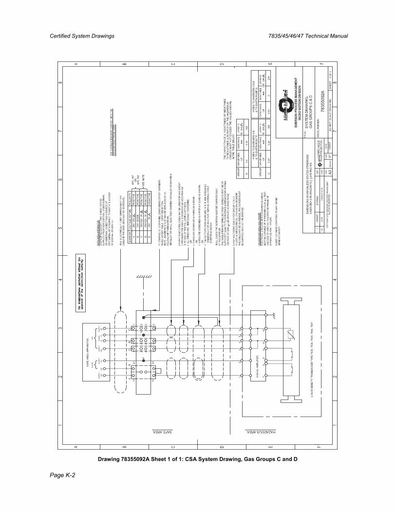
Certified System Drawings 7835/45/46/47 Technical Manual
Page K-2
Drawing 78355092A Sheet 1 of 1: CSA System Drawing, Gas Groups C and D
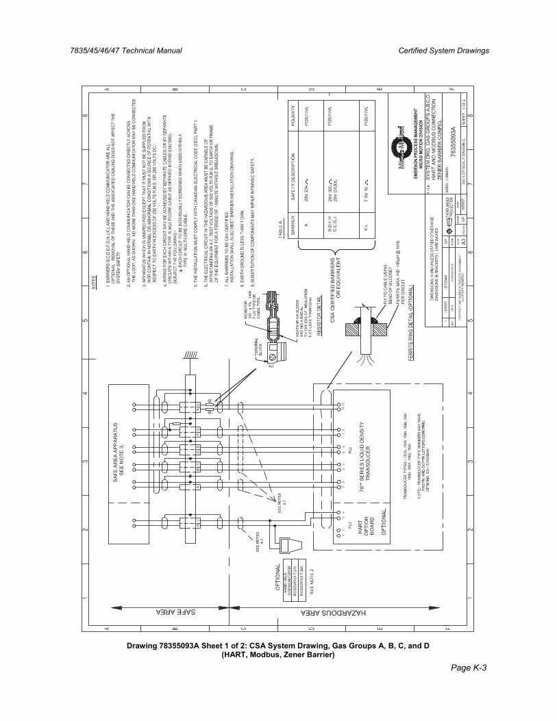
7835/45/46/47 Technical Manual Certified System Drawings
Page K-3
Drawing 78355093A Sheet 1 of 2: CSA System Drawing, Gas Groups A, B, C, and D (HART, Modbus, Zener Barrier)
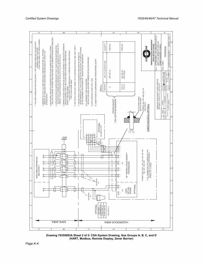
Certified System Drawings 7835/45/46/47 Technical Manual
Page K-4
Drawing 78355093A Sheet 2 of 2: CSA System Drawing, Gas Groups A, B, C, and D (HART, Modbus, Remote Display, Zener Barrier)
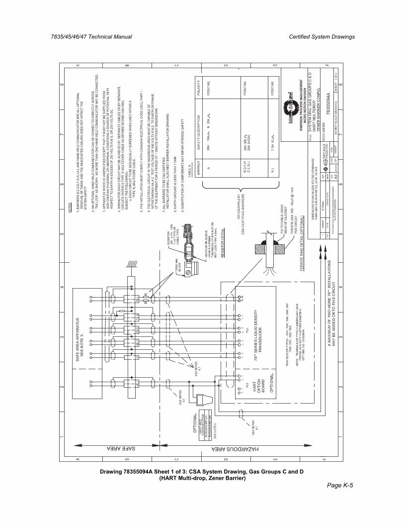
7835/45/46/47 Technical Manual Certified System Drawings
Page K-5
Drawing 78355094A Sheet 1 of 3: CSA System Drawing, Gas Groups C and D (HART Multi-drop, Zener Barrier)
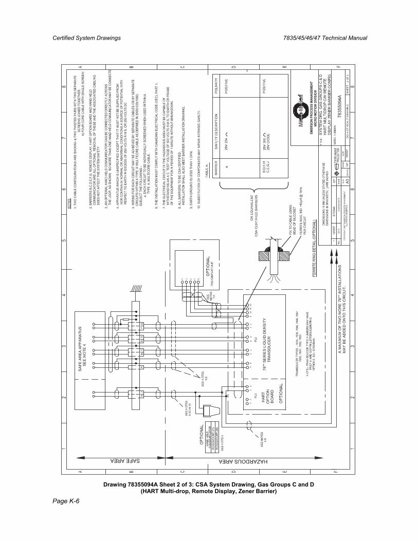
Certified System Drawings 7835/45/46/47 Technical Manual
Page K-6
Drawing 78355094A Sheet 2 of 3: CSA System Drawing, Gas Groups C and D (HART Multi-drop, Remote Display, Zener Barrier)

7835/45/46/47 Technical Manual Certified System Drawings
Page K-7
Drawing 78355094A Sheet 3 of 3: CSA System Drawing, Gas Groups C and D (HART Multi-drop, Remote Display, Galvanic Isolator)

Certified System Drawings 7835/45/46/47 Technical Manual
Page K-8


Micro Motion® 7835/7845/7846/7847
Technical Manual78355080_US, Rev. D
December 2008
The Emerson logo is a trade mark and service mark of Emerson Electric Co. Micro Motion is a registered trademark of Micro Motion, Inc. All other marks are the property of their respective owners. We reserve the right to modify or improve the designs or specifications of product and services at any time without notice USA: International: Emerson Process Management Emerson Process Management Micro Motion, Inc. Mobrey Measurement 7070 Winchester Circle 158 Edinburgh Avenue, Boulder, CO 80301 Slough, Berks, SL1 4UE, UK T +1 303-527-5200 T +44 1753 756600 T +1 800-522-6277 F +44 1753 823589 F +1 303-530-8459 www.mobrey.com www.micromotion.com
ABCDEF