787c gps chartplotter operations manual - busse yachtshop · read this operations manual carefully...
TRANSCRIPT
787c2 GPS Chartplotter Operations Manual
787c2 GPS Chartplotter Operations Manual
531476-1_A
531476-1_A - 787c2_Eng.qxd 11/22/2005 3:20 AM Page 1
www.Busse-Yachtshop.de email: [email protected]
i ii
How Sonar Works 2
DualBeam PLUS™ Sonar . . . . . . . . . . . . . . . . . . . . . . . . . . . . . . . . . . . . . . . . . . . . . . . . . . . . . . . . . . . . . . . 4
QuadraBeam™ Sonar (with optional-purchase QuadraBeam™ transducer) . . . . . . . . . . . . . . . . . . . . . 5
WideSide® Sonar (with optional-purchase WideSide® transducer). . . . . . . . . . . . . . . . . . . . . . . . . . . . . 6
How GPS and Cartography Work 7
Multi-Media Card (MMC)/SD Slot 8
Software Updates . . . . . . . . . . . . . . . . . . . . . . . . . . . . . . . . . . . . . . . . . . . . . . . . . . . . . . . . . . . . . . . . . . . . . 8
What’s On the Display 9
Views 11
Sonar View . . . . . . . . . . . . . . . . . . . . . . . . . . . . . . . . . . . . . . . . . . . . . . . . . . . . . . . . . . . . . . . . . . . . . . . . . . . 12
Understanding Sonar History . . . . . . . . . . . . . . . . . . . . . . . . . . . . . . . . . . . . . . . . . . . . . . . . . . . . . . . . . 13
Real Time Sonar (RTS®) Window . . . . . . . . . . . . . . . . . . . . . . . . . . . . . . . . . . . . . . . . . . . . . . . . . . . . . . 13
Freeze Frame . . . . . . . . . . . . . . . . . . . . . . . . . . . . . . . . . . . . . . . . . . . . . . . . . . . . . . . . . . . . . . . . . . . . . . . . . 14
Bottom Presentation . . . . . . . . . . . . . . . . . . . . . . . . . . . . . . . . . . . . . . . . . . . . . . . . . . . . . . . . . . . . . . . . . 14
Sonar Zoom View . . . . . . . . . . . . . . . . . . . . . . . . . . . . . . . . . . . . . . . . . . . . . . . . . . . . . . . . . . . . . . . . . . . . 16
200/83 kHz Split Sonar View . . . . . . . . . . . . . . . . . . . . . . . . . . . . . . . . . . . . . . . . . . . . . . . . . . . . . . . . . 17
Big Digits View . . . . . . . . . . . . . . . . . . . . . . . . . . . . . . . . . . . . . . . . . . . . . . . . . . . . . . . . . . . . . . . . . . . . . . . 18
Circular Flasher View . . . . . . . . . . . . . . . . . . . . . . . . . . . . . . . . . . . . . . . . . . . . . . . . . . . . . . . . . . . . . . . . . 18
Screen Snapshot View . . . . . . . . . . . . . . . . . . . . . . . . . . . . . . . . . . . . . . . . . . . . . . . . . . . . . . . . . . . . . . . . 19
Side Beam View (with optional-purchase QuadraBeam™ transducer) . . . . . . . . . . . . . . . . . . . . . . . . . 21
WideSide® View (with optional-purchase WideSide® transducer) . . . . . . . . . . . . . . . . . . . . . . . . . . . . . . . . . 22
Bird's Eye View . . . . . . . . . . . . . . . . . . . . . . . . . . . . . . . . . . . . . . . . . . . . . . . . . . . . . . . . . . . . . . . . . . . . . . . 23
Chart View . . . . . . . . . . . . . . . . . . . . . . . . . . . . . . . . . . . . . . . . . . . . . . . . . . . . . . . . . . . . . . . . . . . . . . . . . . . 24
Combo View . . . . . . . . . . . . . . . . . . . . . . . . . . . . . . . . . . . . . . . . . . . . . . . . . . . . . . . . . . . . . . . . . . . . . . . . . 25
View Orientation. . . . . . . . . . . . . . . . . . . . . . . . . . . . . . . . . . . . . . . . . . . . . . . . . . . . . . . . . . . . . . . . . . . . . 25
Viewing Cartography 26
Table of ContentsThank You!Thank you for choosing Humminbird®, America's #1 name in fishfinders. Humminbird®has built its reputation by designing and manufacturing top-quality, thoroughly reliablemarine equipment. Your Humminbird® is designed for trouble-free use in even theharshest marine environment. In the unlikely event that your Humminbird® doesrequire repairs, we offer an exclusive Service Policy - free of charge during the first yearafter purchase, and available at a reasonable rate after the one-year period. For completedetails, see the separate warranty card included with your unit. We encourage you toread this operations manual carefully in order to get full benefit from all the featuresand applications of your Humminbird® product.
Contact our Customer Resource Center at either 1-800-633-1468 or visit our website at www.humminbird.com.
WARNING! This device should not be used as a navigational aid to prevent collision,grounding, boat damage, or personal injury. When the boat is moving, water depth maychange too quickly to allow time for you to react. Always operate the boat at very slow speedsif you suspect shallow water or submerged objects.
WARNING! Disassembly and repair of this electronic unit should only be performed byauthorized service personnel. Any modification of the serial number or attempt to repair theoriginal equipment or accessories by unauthorized individuals will void the warranty.Handling and/or opening this unit may result in exposure to lead, in the form of solder.
WARNING! This product contains lead, a chemical known to the state of California to causecancer, birth defects and other reproductive harm.
DualBeam PLUSTM, Fish ID+TM, Fishing GPS®, Humminbird®, HumminbirdPCTM, QuadraBeamTM, RTS® Window,
Selective Fish ID+TM, WeatherSense®, WhiteLine®, WideSide®, X-PressTM Menu, and Structure ID® are
trademarked by or registered trademarks of Humminbird®.
© 2005 Humminbird®, Eufaula AL, USA. All rights reserved.
531476-1_A - 787c2_Eng.qxd 11/22/2005 3:20 AM Page 2
www.Busse-Yachtshop.de email: [email protected]
iv
Introduction to Navigation 27
Waypoints, Routes and Tracks . . . . . . . . . . . . . . . . . . . . . . . . . . . . . . . . . . . . . . . . . . . . . . . . . . . . . . . . 28
Save, Edit or Delete a Waypoint . . . . . . . . . . . . . . . . . . . . . . . . . . . . . . . . . . . . . . . . . . . . . . . . . . . . . . 29
Navigate to a Waypoint or Position. . . . . . . . . . . . . . . . . . . . . . . . . . . . . . . . . . . . . . . . . . . . . . . . . . . 30
Add a Waypoint Target or Trolling Grid. . . . . . . . . . . . . . . . . . . . . . . . . . . . . . . . . . . . . . . . . . . . . . . . 31
Save, Edit or Delete a Route. . . . . . . . . . . . . . . . . . . . . . . . . . . . . . . . . . . . . . . . . . . . . . . . . . . . . . . . . . . 32
Save or Clear a Current Track. . . . . . . . . . . . . . . . . . . . . . . . . . . . . . . . . . . . . . . . . . . . . . . . . . . . . . . . . . 33
Edit, Delete or Hide Saved Tracks . . . . . . . . . . . . . . . . . . . . . . . . . . . . . . . . . . . . . . . . . . . . . . . . . . . . . 33
Key Functions 34
POWER/LIGHT Key . . . . . . . . . . . . . . . . . . . . . . . . . . . . . . . . . . . . . . . . . . . . . . . . . . . . . . . . . . . . . . . . . . 34
VIEW Key . . . . . . . . . . . . . . . . . . . . . . . . . . . . . . . . . . . . . . . . . . . . . . . . . . . . . . . . . . . . . . . . . . . . . . . . . . . . 34
INFO Key . . . . . . . . . . . . . . . . . . . . . . . . . . . . . . . . . . . . . . . . . . . . . . . . . . . . . . . . . . . . . . . . . . . . . . . . . . . . . 35
MENU Key . . . . . . . . . . . . . . . . . . . . . . . . . . . . . . . . . . . . . . . . . . . . . . . . . . . . . . . . . . . . . . . . . . . . . . . . . . . 35
4-WAY Cursor Control Key . . . . . . . . . . . . . . . . . . . . . . . . . . . . . . . . . . . . . . . . . . . . . . . . . . . . . . . . . . . . 36
MARK Key. . . . . . . . . . . . . . . . . . . . . . . . . . . . . . . . . . . . . . . . . . . . . . . . . . . . . . . . . . . . . . . . . . . . . . . . . . . . 36
GOTO Key . . . . . . . . . . . . . . . . . . . . . . . . . . . . . . . . . . . . . . . . . . . . . . . . . . . . . . . . . . . . . . . . . . . . . . . . . . . . 36
ZOOM (+/-) Key . . . . . . . . . . . . . . . . . . . . . . . . . . . . . . . . . . . . . . . . . . . . . . . . . . . . . . . . . . . . . . . . . . . . . . 37
EXIT Key . . . . . . . . . . . . . . . . . . . . . . . . . . . . . . . . . . . . . . . . . . . . . . . . . . . . . . . . . . . . . . . . . . . . . . . . . . . . . 37
Accessory Bus 37
Powering Up the Unit 38
The Menu System 39
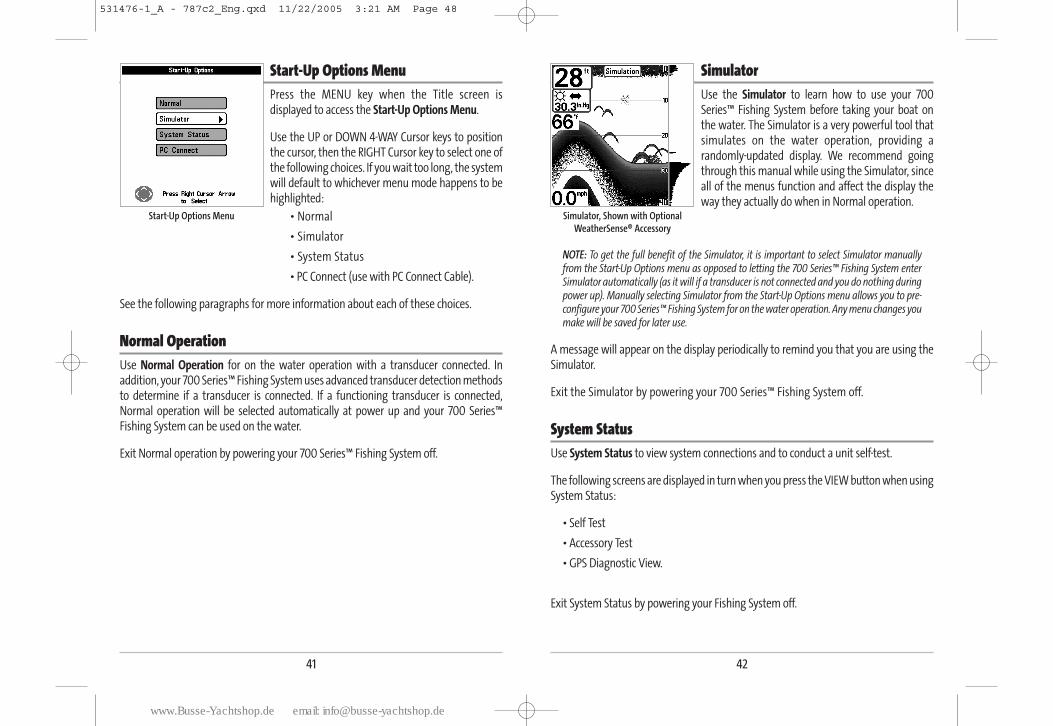
Start-Up Options Menu 41
Normal Operation . . . . . . . . . . . . . . . . . . . . . . . . . . . . . . . . . . . . . . . . . . . . . . . . . . . . . . . . . . . . . . . . . . . . 41
Simulator . . . . . . . . . . . . . . . . . . . . . . . . . . . . . . . . . . . . . . . . . . . . . . . . . . . . . . . . . . . . . . . . . . . . . . . . . . . 42
System Status . . . . . . . . . . . . . . . . . . . . . . . . . . . . . . . . . . . . . . . . . . . . . . . . . . . . . . . . . . . . . . . . . . . . . . . 42
Self Test . . . . . . . . . . . . . . . . . . . . . . . . . . . . . . . . . . . . . . . . . . . . . . . . . . . . . . . . . . . . . . . . . . . . . . . . . . . . . . 43
Accessory Test. . . . . . . . . . . . . . . . . . . . . . . . . . . . . . . . . . . . . . . . . . . . . . . . . . . . . . . . . . . . . . . . . . . . . . . . 43
GPS Diagnostic View . . . . . . . . . . . . . . . . . . . . . . . . . . . . . . . . . . . . . . . . . . . . . . . . . . . . . . . . . . . . . . . . . 44
PC Connect (with PC Connect cable only). . . . . . . . . . . . . . . . . . . . . . . . . . . . . . . . . . . . . . . . . . . . . . . . . . 44
Table of Contents
iii
Sonar X-Press™ Menu (Sonar views only) 45
Side (WideSide® transducer: WideSide® view only) . . . . . . . . . . . . . . . . . . . . . . . . . . . . . . . . . . . . . . . . . . 46
Sensitivity . . . . . . . . . . . . . . . . . . . . . . . . . . . . . . . . . . . . . . . . . . . . . . . . . . . . . . . . . . . . . . . . . . . . . . . . . . . 47
Upper Range (Advanced: Sonar, Split Sonar, Big Digits and Circular Flasher views only) . . . . . . . . . . 48
Lower Range . . . . . . . . . . . . . . . . . . . . . . . . . . . . . . . . . . . . . . . . . . . . . . . . . . . . . . . . . . . . . . . . . . . . . . . . 49
Side Beam Range (WideSide® transducer: WideSide® view only) . . . . . . . . . . . . . . . . . . . . . . . . . . . . . 50
Chart Speed . . . . . . . . . . . . . . . . . . . . . . . . . . . . . . . . . . . . . . . . . . . . . . . . . . . . . . . . . . . . . . . . . . . . . . . . . 50
Bottom Range (Sonar Zoom view only when Bottom Lock is On) . . . . . . . . . . . . . . . . . . . . . . . . . . . . . . 51
Bottom Lock (Sonar Zoom view only) . . . . . . . . . . . . . . . . . . . . . . . . . . . . . . . . . . . . . . . . . . . . . . . . . . . . . 51
Cancel Navigation (only when navigating). . . . . . . . . . . . . . . . . . . . . . . . . . . . . . . . . . . . . . . . . . . . . . . 52
Navigation X-Press™ Menu (Navigation views only) 53
Waypoint [Name] (Only with an active cursor on a waypoint). . . . . . . . . . . . . . . . . . . . . . . . . . . . . . . 54
Cursor To Waypoint (Chart or Combo view only) . . . . . . . . . . . . . . . . . . . . . . . . . . . . . . . . . . . . . . . . . . 55
Save Current Track . . . . . . . . . . . . . . . . . . . . . . . . . . . . . . . . . . . . . . . . . . . . . . . . . . . . . . . . . . . . . . . . . . . 55
Clear Current Track . . . . . . . . . . . . . . . . . . . . . . . . . . . . . . . . . . . . . . . . . . . . . . . . . . . . . . . . . . . . . . . . . . . 56
Save Current Route (only when navigating) . . . . . . . . . . . . . . . . . . . . . . . . . . . . . . . . . . . . . . . . . . . . . . 56
Skip Next Waypoint (only when navigating) . . . . . . . . . . . . . . . . . . . . . . . . . . . . . . . . . . . . . . . . . . . . . 56
Cancel Navigation (only when navigating) . . . . . . . . . . . . . . . . . . . . . . . . . . . . . . . . . . . . . . . . . . . . . . . 57
Remove Target (only if Target is Active) . . . . . . . . . . . . . . . . . . . . . . . . . . . . . . . . . . . . . . . . . . . . . . . . . . 57
Remove Grid (only if Grid is Active) . . . . . . . . . . . . . . . . . . . . . . . . . . . . . . . . . . . . . . . . . . . . . . . . . . . . . . 58
Sonar Window (Combo view only) . . . . . . . . . . . . . . . . . . . . . . . . . . . . . . . . . . . . . . . . . . . . . . . . . . . . . . 58
Waypoint [Name] (Most recently-created waypoint) . . . . . . . . . . . . . . . . . . . . . . . . . . . . . . . . . . . . . . . 59
Screen Snapshot X-Press™ Menu (Screen Snapshot view only) 60
Delete Image (optional-purchase MMC/SD card only) . . . . . . . . . . . . . . . . . . . . . . . . . . . . . . . . . . . . . . 60
Delete All Images (optional-purchase MMC/SD card only) . . . . . . . . . . . . . . . . . . . . . . . . . . . . . . . . . 60
Sonar Menu Tab 61
Beam Select . . . . . . . . . . . . . . . . . . . . . . . . . . . . . . . . . . . . . . . . . . . . . . . . . . . . . . . . . . . . . . . . . . . . . . . . . 62
Fish ID+TM . . . . . . . . . . . . . . . . . . . . . . . . . . . . . . . . . . . . . . . . . . . . . . . . . . . . . . . . . . . . . . . . . . . . . . . . . . . . 63
Fish ID Sensitivity . . . . . . . . . . . . . . . . . . . . . . . . . . . . . . . . . . . . . . . . . . . . . . . . . . . . . . . . . . . . . . . . . . . . 64
Real Time Sonar (RTS®) Window. . . . . . . . . . . . . . . . . . . . . . . . . . . . . . . . . . . . . . . . . . . . . . . . . . . . . . 64
Table of Contents
531476-1_A - 787c2_Eng.qxd 11/22/2005 3:20 AM Page 4
www.Busse-Yachtshop.de email: [email protected]
viv
Bottom View. . . . . . . . . . . . . . . . . . . . . . . . . . . . . . . . . . . . . . . . . . . . . . . . . . . . . . . . . . . . . . . . . . . . . . . . . 65
Zoom Width . . . . . . . . . . . . . . . . . . . . . . . . . . . . . . . . . . . . . . . . . . . . . . . . . . . . . . . . . . . . . . . . . . . . . . . . . 65
83 kHz Sensitivity (Advanced) . . . . . . . . . . . . . . . . . . . . . . . . . . . . . . . . . . . . . . . . . . . . . . . . . . . . . . . . . . 66
455 kHz Balance (Advanced, with QuadraBeamTM transducer) . . . . . . . . . . . . . . . . . . . . . . . . . . . . . . . 67
WideSide® Sensitivity (Advanced, with WideSide® transducer) . . . . . . . . . . . . . . . . . . . . . . . . . . . . . 68
Depth Lines (Advanced) . . . . . . . . . . . . . . . . . . . . . . . . . . . . . . . . . . . . . . . . . . . . . . . . . . . . . . . . . . . . . . . . 69
Surface Clutter (Advanced) . . . . . . . . . . . . . . . . . . . . . . . . . . . . . . . . . . . . . . . . . . . . . . . . . . . . . . . . . . . . . 70
Noise Filter (Advanced) . . . . . . . . . . . . . . . . . . . . . . . . . . . . . . . . . . . . . . . . . . . . . . . . . . . . . . . . . . . . . . . . . 71
Max Depth (Advanced) . . . . . . . . . . . . . . . . . . . . . . . . . . . . . . . . . . . . . . . . . . . . . . . . . . . . . . . . . . . . . . . . . 71
Water Type (Advanced). . . . . . . . . . . . . . . . . . . . . . . . . . . . . . . . . . . . . . . . . . . . . . . . . . . . . . . . . . . . . . . . . 72
Transducer Select. . . . . . . . . . . . . . . . . . . . . . . . . . . . . . . . . . . . . . . . . . . . . . . . . . . . . . . . . . . . . . . . . . . . . 72
Navigation Menu Tab 73
Current Track . . . . . . . . . . . . . . . . . . . . . . . . . . . . . . . . . . . . . . . . . . . . . . . . . . . . . . . . . . . . . . . . . . . . . . . . . 74
Saved Tracks. . . . . . . . . . . . . . . . . . . . . . . . . . . . . . . . . . . . . . . . . . . . . . . . . . . . . . . . . . . . . . . . . . . . . . . . . . 75
Waypoints . . . . . . . . . . . . . . . . . . . . . . . . . . . . . . . . . . . . . . . . . . . . . . . . . . . . . . . . . . . . . . . . . . . . . . . . . . . 76
Routes . . . . . . . . . . . . . . . . . . . . . . . . . . . . . . . . . . . . . . . . . . . . . . . . . . . . . . . . . . . . . . . . . . . . . . . . . . . . . . . 77
Chart Orientation . . . . . . . . . . . . . . . . . . . . . . . . . . . . . . . . . . . . . . . . . . . . . . . . . . . . . . . . . . . . . . . . . . . . 78
North Reference. . . . . . . . . . . . . . . . . . . . . . . . . . . . . . . . . . . . . . . . . . . . . . . . . . . . . . . . . . . . . . . . . . . . . . 78
Grid Rotation. . . . . . . . . . . . . . . . . . . . . . . . . . . . . . . . . . . . . . . . . . . . . . . . . . . . . . . . . . . . . . . . . . . . . . . . . 78
Trackpoint Interval . . . . . . . . . . . . . . . . . . . . . . . . . . . . . . . . . . . . . . . . . . . . . . . . . . . . . . . . . . . . . . . . . . . 79
Track Min Distance (Advanced) . . . . . . . . . . . . . . . . . . . . . . . . . . . . . . . . . . . . . . . . . . . . . . . . . . . . . . . . . 79
Map Datum (Advanced) . . . . . . . . . . . . . . . . . . . . . . . . . . . . . . . . . . . . . . . . . . . . . . . . . . . . . . . . . . . . . . . 80
Course Projection Line. . . . . . . . . . . . . . . . . . . . . . . . . . . . . . . . . . . . . . . . . . . . . . . . . . . . . . . . . . . . . . . . 80
Export All Nav Data (Advanced) . . . . . . . . . . . . . . . . . . . . . . . . . . . . . . . . . . . . . . . . . . . . . . . . . . . . . . . . 81
Delete All Nav Data (Advanced) . . . . . . . . . . . . . . . . . . . . . . . . . . . . . . . . . . . . . . . . . . . . . . . . . . . . . . . . 81
Chart Menu Tab 82
Chart Detail Level . . . . . . . . . . . . . . . . . . . . . . . . . . . . . . . . . . . . . . . . . . . . . . . . . . . . . . . . . . . . . . . . . . . . 83
Map Borders . . . . . . . . . . . . . . . . . . . . . . . . . . . . . . . . . . . . . . . . . . . . . . . . . . . . . . . . . . . . . . . . . . . . . . . . . 83
Lat/Lon Grid . . . . . . . . . . . . . . . . . . . . . . . . . . . . . . . . . . . . . . . . . . . . . . . . . . . . . . . . . . . . . . . . . . . . . . . . . 84
Spot Soundings. . . . . . . . . . . . . . . . . . . . . . . . . . . . . . . . . . . . . . . . . . . . . . . . . . . . . . . . . . . . . . . . . . . . . . . 84
Set Simulation Position (Advanced) . . . . . . . . . . . . . . . . . . . . . . . . . . . . . . . . . . . . . . . . . . . . . . . . . . . . 85
Table of Contents
Set Map Offset (Advanced) . . . . . . . . . . . . . . . . . . . . . . . . . . . . . . . . . . . . . . . . . . . . . . . . . . . . . . . . . . . . 86
Clear Map Offset (Advanced). . . . . . . . . . . . . . . . . . . . . . . . . . . . . . . . . . . . . . . . . . . . . . . . . . . . . . . . . . . 86
Alarms Menu Tab 87
Depth Alarm . . . . . . . . . . . . . . . . . . . . . . . . . . . . . . . . . . . . . . . . . . . . . . . . . . . . . . . . . . . . . . . . . . . . . . . . . 88
Fish ID Alarm . . . . . . . . . . . . . . . . . . . . . . . . . . . . . . . . . . . . . . . . . . . . . . . . . . . . . . . . . . . . . . . . . . . . . . . . 88
Low Battery Alarm . . . . . . . . . . . . . . . . . . . . . . . . . . . . . . . . . . . . . . . . . . . . . . . . . . . . . . . . . . . . . . . . . . . 89
Temp Alarm. . . . . . . . . . . . . . . . . . . . . . . . . . . . . . . . . . . . . . . . . . . . . . . . . . . . . . . . . . . . . . . . . . . . . . . . . . 89
Off Course Alarm . . . . . . . . . . . . . . . . . . . . . . . . . . . . . . . . . . . . . . . . . . . . . . . . . . . . . . . . . . . . . . . . . . . . 90
Arrival Alarm . . . . . . . . . . . . . . . . . . . . . . . . . . . . . . . . . . . . . . . . . . . . . . . . . . . . . . . . . . . . . . . . . . . . . . . . 90
Drift Alarm . . . . . . . . . . . . . . . . . . . . . . . . . . . . . . . . . . . . . . . . . . . . . . . . . . . . . . . . . . . . . . . . . . . . . . . . . . 91
Alarm Tone . . . . . . . . . . . . . . . . . . . . . . . . . . . . . . . . . . . . . . . . . . . . . . . . . . . . . . . . . . . . . . . . . . . . . . . . . . . 91
Setup Menu Tab 92
Units - Depth. . . . . . . . . . . . . . . . . . . . . . . . . . . . . . . . . . . . . . . . . . . . . . . . . . . . . . . . . . . . . . . . . . . . . . . . . 93
Units - Temp (International only) . . . . . . . . . . . . . . . . . . . . . . . . . . . . . . . . . . . . . . . . . . . . . . . . . . . . . . . . 93
Units - Distance . . . . . . . . . . . . . . . . . . . . . . . . . . . . . . . . . . . . . . . . . . . . . . . . . . . . . . . . . . . . . . . . . . . . . . 93
Units - Speed. . . . . . . . . . . . . . . . . . . . . . . . . . . . . . . . . . . . . . . . . . . . . . . . . . . . . . . . . . . . . . . . . . . . . . . . . 94
User Mode . . . . . . . . . . . . . . . . . . . . . . . . . . . . . . . . . . . . . . . . . . . . . . . . . . . . . . . . . . . . . . . . . . . . . . . . . . . 94
Language (International only) . . . . . . . . . . . . . . . . . . . . . . . . . . . . . . . . . . . . . . . . . . . . . . . . . . . . . . . . . . . 94
Triplog Reset . . . . . . . . . . . . . . . . . . . . . . . . . . . . . . . . . . . . . . . . . . . . . . . . . . . . . . . . . . . . . . . . . . . . . . . . . 95
Restore Defaults . . . . . . . . . . . . . . . . . . . . . . . . . . . . . . . . . . . . . . . . . . . . . . . . . . . . . . . . . . . . . . . . . . . . . 95
Select Readouts (Advanced, Sonar view only) . . . . . . . . . . . . . . . . . . . . . . . . . . . . . . . . . . . . . . . . . . . . . 96
Depth Offset (Advanced). . . . . . . . . . . . . . . . . . . . . . . . . . . . . . . . . . . . . . . . . . . . . . . . . . . . . . . . . . . . . . . 97
Temp Offset (Advanced) . . . . . . . . . . . . . . . . . . . . . . . . . . . . . . . . . . . . . . . . . . . . . . . . . . . . . . . . . . . . . . . 97
Speed Calibration (Advanced, with Temp/Speed only) . . . . . . . . . . . . . . . . . . . . . . . . . . . . . . . . . . . . . 98
Local Time Zone (Advanced) . . . . . . . . . . . . . . . . . . . . . . . . . . . . . . . . . . . . . . . . . . . . . . . . . . . . . . . . . . . 98
Daylight Saving Time (Advanced) . . . . . . . . . . . . . . . . . . . . . . . . . . . . . . . . . . . . . . . . . . . . . . . . . . . . . . 99
Position Format (Advanced). . . . . . . . . . . . . . . . . . . . . . . . . . . . . . . . . . . . . . . . . . . . . . . . . . . . . . . . . . . . 99
Time Format (Advanced, International only) . . . . . . . . . . . . . . . . . . . . . . . . . . . . . . . . . . . . . . . . . . . . . 100
Date Format (Advanced, International only) . . . . . . . . . . . . . . . . . . . . . . . . . . . . . . . . . . . . . . . . . . . . . 100
NMEA Output (Advanced) . . . . . . . . . . . . . . . . . . . . . . . . . . . . . . . . . . . . . . . . . . . . . . . . . . . . . . . . . . . . . 101
Sonar . . . . . . . . . . . . . . . . . . . . . . . . . . . . . . . . . . . . . . . . . . . . . . . . . . . . . . . . . . . . . . . . . . . . . . . . . . . . . . . 102
Table of Contents
531476-1_A - 787c2_Eng.qxd 11/22/2005 3:20 AM Page 6
www.Busse-Yachtshop.de email: [email protected]
2
How Sonar WorksSonar technology is based on sound waves. The 700 Series™ Fishing System uses sonar to locate and define structure, bottom contour and composition, as well as depth directly below the transducer.
Your 700 Series™ Fishing System sends a sound wave signal and determines distance bymeasuring the time between the transmission of the sound wave and when the soundwave is reflected off of an object; it then uses the reflected signal to interpret location,size, and composition of an object.
Sonar is very fast. A sound wave can travel from the surface to a depth of 240 ft (70 m) and back again in less than 1/4 of a second. It is unlikely that your boat can"outrun" this sonar signal.
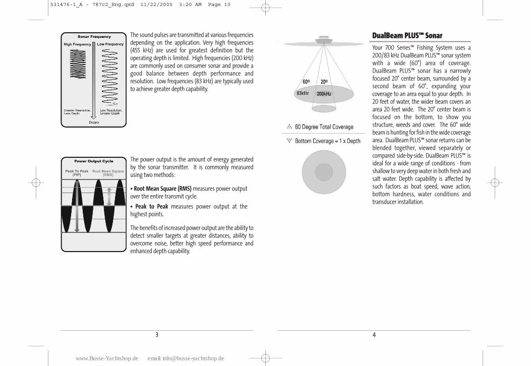
SONAR is an acronym for SOund and NAvigationRanging. Sonar utilizes precision sound pulses or"pings" which are emitted into the water in a teardrop-shaped beam.
The sound pulses "echo" back from objects in the watersuch as the bottom, fish and other submerged objects.The returned echoes are displayed on the LCD screen.Each time a new echo is received, the old echoes aremoved across the LCD, creating a scrolling effect.
When all the echoes are viewed side by side, an easy tointerpret "graph" of the bottom, fish and structureappears.
1
Views Menu Tab 103
Accessories Menu Tab 103
Using Screen Snapshot. . . . . . . . . . . . . . . . . . . . . . . . . . . . . . . . . . . . . . . . . . . . . . . . . . . . . . . . . . . . . . 104
Troubleshooting 105
700 Series™ Doesn’t Power Up . . . . . . . . . . . . . . . . . . . . . . . . . . . . . . . . . . . . . . . . . . . . . . . . . . . . . . 107
700 Series™ Defaults to Simulator with a Transducer Attached . . . . . . . . . . . . . . . . . . . . . . 107
Display Problems . . . . . . . . . . . . . . . . . . . . . . . . . . . . . . . . . . . . . . . . . . . . . . . . . . . . . . . . . . . . . . . . . . . 108
Finding the Cause of Noise . . . . . . . . . . . . . . . . . . . . . . . . . . . . . . . . . . . . . . . . . . . . . . . . . . . . . . . . . . 109
700 Series™ Fishing System Accessories 110
Specifications 111
Glossary 112
Contact Humminbird® 127
NOTE: Entries in this Table of Contents which list (International only) are only availableon products sold outside of the U.S. by our authorized International Distributors. To obtain a list of authorized International Distributors, please visit our website atwww.humminbird.com or contact our Customer Resource Center at 1-800-633-1468 tolocate the distributor nearest you.
NOTE: Entries in this Table of Contents which list (with PC Connect Cable only) or (withOptional-Purchase QuadraBeamTM/WideSide® Transducer) or (with Temp/Speed only)require the purchase of separate accessories. You can visit our website atwww.humminbird.com to order these accessories online or contact our CustomerResource Center at 1-800-633-1468.
531476-1_A - 787c2_Eng.qxd 11/22/2005 3:20 AM Page 8
www.Busse-Yachtshop.de email: [email protected]
3
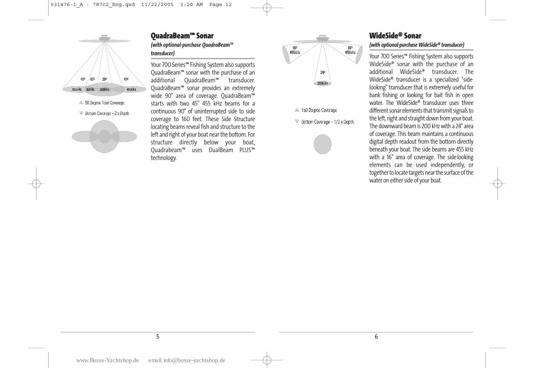
The sound pulses are transmitted at various frequenciesdepending on the application. Very high frequencies(455 kHz) are used for greatest definition but theoperating depth is limited. High frequencies (200 kHz)are commonly used on consumer sonar and provide agood balance between depth performance andresolution. Low frequencies (83 kHz) are typically usedto achieve greater depth capability.
The power output is the amount of energy generated by the sonar transmitter. It is commonly measuredusing two methods:
• Root Mean Square (RMS) measures power outputover the entire transmit cycle.
• Peak to Peak measures power output at thehighest points.
The benefits of increased power output are the ability todetect smaller targets at greater distances, ability toovercome noise, better high speed performance andenhanced depth capability.
DualBeam PLUS™ SonarYour 700 Series™ Fishing System uses a200/83 kHz DualBeam PLUS™ sonar systemwith a wide (60°) area of coverage.DualBeam PLUS™ sonar has a narrowlyfocused 20° center beam, surrounded by asecond beam of 60°, expanding yourcoverage to an area equal to your depth. In20 feet of water, the wider beam covers anarea 20 feet wide. The 20° center beam isfocused on the bottom, to show youstructure, weeds and cover. The 60° widebeam is hunting for fish in the wide coveragearea. DualBeam PLUS™ sonar returns can beblended together, viewed separately orcompared side-by-side. DualBeam PLUS™ isideal for a wide range of conditions - fromshallow to very deep water in both fresh andsalt water. Depth capability is affected bysuch factors as boat speed, wave action,bottom hardness, water conditions andtransducer installation.
4
531476-1_A - 787c2_Eng.qxd 11/22/2005 3:20 AM Page 10
www.Busse-Yachtshop.de email: [email protected]
6
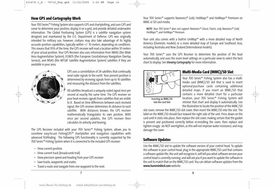
WideSide® Sonar(with optional-purchase WideSide® transducer)
Your 700 Series™ Fishing System also supportsWideSide® sonar with the purchase of anadditional WideSide® transducer. TheWideSide® transducer is a specialized "side-looking" transducer that is extremely useful forbank fishing or looking for bait fish in openwater. The WideSide® transducer uses threedifferent sonar elements that transmit signals tothe left, right and straight down from your boat.The downward beam is 200 kHz with a 24° areaof coverage. This beam maintains a continuousdigital depth readout from the bottom directlybeneath your boat. The side beams are 455 kHzwith a 16° area of coverage. The side-lookingelements can be used independently, ortogether to locate targets near the surface of thewater on either side of your boat.
5
QuadraBeam™ Sonar(with optional-purchase QuadraBeamTM
transducer)
Your 700 Series™ Fishing System also supportsQuadraBeam™ sonar with the purchase of anadditional QuadraBeam™ transducer.QuadraBeam™ sonar provides an extremelywide 90° area of coverage. QuadraBeam™starts with two 45° 455 kHz beams for acontinuous 90° of uninterrupted side to sidecoverage to 160 feet. These Side Structurelocating beams reveal fish and structure to theleft and right of your boat near the bottom. Forstructure directly below your boat,Quadrabeam™ uses DualBeam PLUS™technology.
531476-1_A - 787c2_Eng.qxd 11/22/2005 3:20 AM Page 12
www.Busse-Yachtshop.de email: [email protected]
87
How GPS and Cartography Work Your 700 Series™ Fishing System also supports GPS and chartplotting, and uses GPS andsonar to determine your position, display it on a grid, and provide detailed underwaterinformation. The Global Positioning System (GPS) is a satellite navigation systemdesigned and maintained by the U.S. Department of Defense. GPS was originallyintended for military use; however, civilians may also take advantage of its highlyaccurate position capabilities, typically within +/- 10 meters, depending on conditions.This means that 95% of the time, the GPS receiver will read a location within 10 metersof your actual position. Your GPS Receiver also uses information from WAAS (the WideArea Augmentation System), EGNOS (the European Geostationary Navigation OverlayService), and MSAS (the MTSAT Satellite Augmentation System) satellites if they areavailable in your area.
GPS uses a constellation of 24 satellites that continuallysend radio signals to the earth. Your present position isdetermined by receiving signals from up to 16 satellitesand measuring the distance from the satellites.
All satellites broadcast a uniquely coded signal once persecond at exactly the same time. The GPS receiver onyour boat receives signals from satellites that are visibleto it. Based on time differences between each receivedsignal, the GPS receiver determines its distance to eachsatellite. With distances known, the GPS receivermathematically triangulates its own position. Withonce per second updates, the GPS receiver thencalculates its velocity and bearing.
The GPS Receiver included with your 700 Series™ Fishing System, allows you tocosmbine easy-to-use FishingGPS™ chartplotter and navigation capabilities withadvanced fishfinding. The following GPS functionality is currently supported by the 700 Series™ Fishing System when it is connected to the included GPS receiver:
• View current position
• View current track (breadcrumb trail)
• View precision speed and heading from your GPS receiver
• Save tracks, waypoints and routes
• Travel a route and navigate from one waypoint to the next.
Your 700 Series™ supports Navionics® Gold, HotMaps™ and HotMaps™ Premium onMMC or SD card media.
NOTE: Your 700 Series™ does not support Navionics® Classic Charts, only Navionics® Gold,HotMaps™, and HotMaps™ Premium.
Your unit also comes with a built-in UniMap™ with a more detailed map of NorthAmerica (Domestic models) or a more detailed map of Europe and Southeast Asia,including Australia and New Zealand (International models).
Your 700 Series™ uses the GPS Receiver to determine the position of the boatautomatically, and uses the zoom level settings on a particular view to select the bestchart to display. See Viewing Cartography for more information.
Multi-Media Card (MMC)/SD SlotYour 700 Series™ Fishing System also has a multi-media card (MMC)/SD slot that is used to insertoptional-purchase cards containing additionaldetailed maps. If you insert an MMC/SD thatcontains a more detailed chart for a particularlocation, your 700 Series™ Fishing System willretrieve that chart and display it automatically. Usethe illustration to locate the position of the MMC/SD
slot cover, remove the MMC/SD slot cover, then insert the MMC/SD into the slot. Thelabel on the MMC/SD should face toward the right side of the unit. Press down on thecard until it clicks into place, then replace the slot cover, making certain that the gasketis present and positioned correctly before re-installing the cover, then replace andtighten snugly - do NOT overtighten, as this will not improve water resistance, and maydamage the cover.
Software UpdatesUse the MMC/SD slot to update the software version of your control head. To updatethe software in your control head, plug in the appropriate MMC/SD card that containsa software update file; the unit will recognize it, will tell you what software version yourcontrol head is currently running, and will ask you if you want to update the software inthe unit to match that on the MMC/SD card. You can obtain software updates from thewww.humminbird.com website.
Inserting an MMC/SD into the Card Slot
531476-1_A - 787c2_Eng.qxd 11/22/2005 3:20 AM Page 14
www.Busse-Yachtshop.de email: [email protected]
9 10
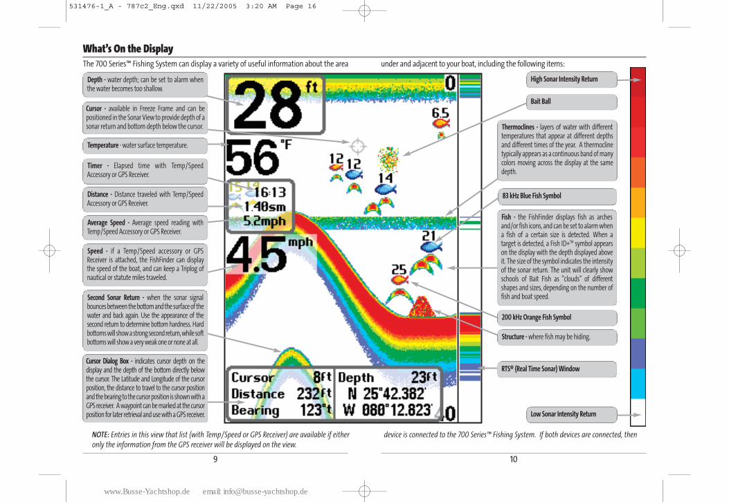
What’s On the DisplayThe 700 Series™ Fishing System can display a variety of useful information about the area under and adjacent to your boat, including the following items:
Depth - water depth; can be set to alarm whenthe water becomes too shallow.
Temperature - water surface temperature.
Timer - Elapsed time with Temp/SpeedAccessory or GPS Receiver.
Distance - Distance traveled with Temp/SpeedAccessory or GPS Receiver.
Average Speed - Average speed reading withTemp/Speed Accessory or GPS Receiver.
Second Sonar Return - when the sonar signalbounces between the bottom and the surface of thewater and back again. Use the appearance of thesecond return to determine bottom hardness. Hardbottoms will show a strong second return, while softbottoms will show a very weak one or none at all.
Speed - if a Temp/Speed accessory or GPSReceiver is attached, the FishFinder can displaythe speed of the boat, and can keep a Triplog ofnautical or statute miles traveled.
RTS® (Real Time Sonar) Window
Structure - where fish may be hiding.
Thermoclines - layers of water with differenttemperatures that appear at different depthsand different times of the year. A thermoclinetypically appears as a continuous band of manycolors moving across the display at the samedepth.
83 kHz Blue Fish Symbol
Bait Ball
Fish - the FishFinder displays fish as archesand/or fish icons, and can be set to alarm whena fish of a certain size is detected. When atarget is detected, a Fish ID+TM symbol appearson the display with the depth displayed aboveit. The size of the symbol indicates the intensityof the sonar return. The unit will clearly showschools of Bait Fish as "clouds" of differentshapes and sizes, depending on the number offish and boat speed.
Low Sonar Intensity Return
High Sonar Intensity Return
NOTE: Entries in this view that list (with Temp/Speed or GPS Receiver) are available if either device is connected to the 700 Series™ Fishing System. If both devices are connected, then
only the information from the GPS receiver will be displayed on the view.
200 kHz Orange Fish Symbol
Cursor - available in Freeze Frame and can bepositioned in the Sonar View to provide depth of asonar return and bottom depth below the cursor.
Cursor Dialog Box - indicates cursor depth on thedisplay and the depth of the bottom directly belowthe cursor. The Latitude and Longitude of the cursorposition, the distance to travel to the cursor positionand the bearing to the cursor position is shown with aGPS receiver. A waypoint can be marked at the cursorposition for later retrieval and use with a GPS receiver.
531476-1_A - 787c2_Eng.qxd 11/22/2005 3:20 AM Page 16
www.Busse-Yachtshop.de email: [email protected]
12
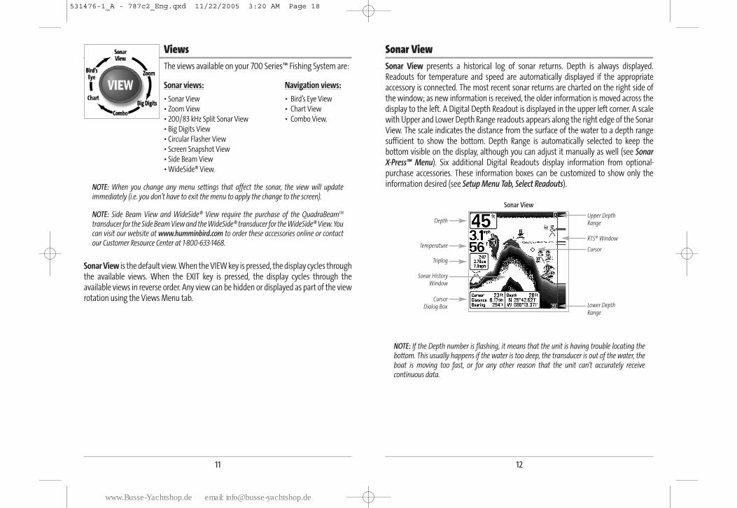
Sonar ViewSonar View presents a historical log of sonar returns. Depth is always displayed.Readouts for temperature and speed are automatically displayed if the appropriateaccessory is connected. The most recent sonar returns are charted on the right side ofthe window; as new information is received, the older information is moved across thedisplay to the left. A Digital Depth Readout is displayed in the upper left corner. A scalewith Upper and Lower Depth Range readouts appears along the right edge of the SonarView. The scale indicates the distance from the surface of the water to a depth rangesufficient to show the bottom. Depth Range is automatically selected to keep thebottom visible on the display, although you can adjust it manually as well (see Sonar X-Press™ Menu). Six additional Digital Readouts display information from optional-purchase accessories. These information boxes can be customized to show only theinformation desired (see Setup Menu Tab, Select Readouts).
NOTE: If the Depth number is flashing, it means that the unit is having trouble locating thebottom. This usually happens if the water is too deep, the transducer is out of the water, theboat is moving too fast, or for any other reason that the unit can’t accurately receivecontinuous data.
Sonar View
Upper DepthRange
Sonar HistoryWindow
Depth
Cursor Dialog Box
Temperature
Triplog
Lower DepthRange
RTS® Window
Cursor
11
ViewsThe views available on your 700 Series™ Fishing System are:
Sonar views: Navigation views:
• Sonar View • Bird’s Eye View
• Zoom View • Chart View
• 200/83 kHz Split Sonar View • Combo View.
• Big Digits View
• Circular Flasher View
• Screen Snapshot View
• Side Beam View
• WideSide® View.
NOTE: When you change any menu settings that affect the sonar, the view will updateimmediately (i.e. you don’t have to exit the menu to apply the change to the screen).
NOTE: Side Beam View and WideSide® View require the purchase of the QuadraBeamTM
transducer for the Side Beam View and the WideSide® transducer for the WideSide® View. Youcan visit our website at www.humminbird.com to order these accessories online or contactour Customer Resource Center at 1-800-633-1468.
Sonar View is the default view. When the VIEW key is pressed, the display cycles throughthe available views. When the EXIT key is pressed, the display cycles through theavailable views in reverse order. Any view can be hidden or displayed as part of the viewrotation using the Views Menu tab.
531476-1_A - 787c2_Eng.qxd 11/22/2005 3:20 AM Page 18
www.Busse-Yachtshop.de email: [email protected]
14
Freeze FrameFreeze Frame - Pressing any arrow on the 4-WAY Cursor Control key will freeze the screenand a cursor will be displayed on the screen. The cursor can be positioned on the displayusingthe 4-WAY Cursor Control key to determine the depth of any sonar return. TheRTS® Window continues to update in Freeze Frame. In addition, see the effects of menusetting changes with Instant Image Update. Pressing EXIT will exit Freeze Frame and thedisplay will start to scroll. Freeze Frame is available in the Sonar, Sonar Zoom, and200/83 kHz Split Sonar Views.
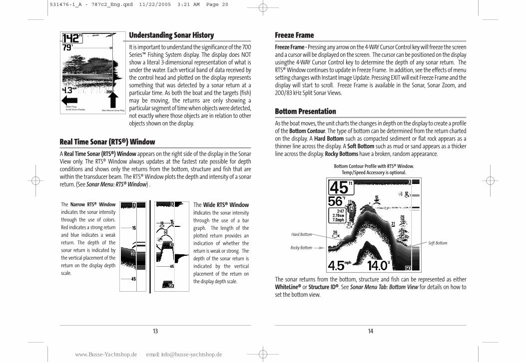
Bottom PresentationAs the boat moves, the unit charts the changes in depth on the display to create a profileof the Bottom Contour. The type of bottom can be determined from the return chartedon the display. A Hard Bottom such as compacted sediment or flat rock appears as athinner line across the display. A Soft Bottom such as mud or sand appears as a thickerline across the display. Rocky Bottoms have a broken, random appearance.
The sonar returns from the bottom, structure and fish can be represented as eitherWhiteLine® or Structure ID®. See Sonar Menu Tab: Bottom View for details on how toset the bottom view.
Bottom Contour Profile with RTS® Window. Temp/Speed Accessory is optional.
Rocky Bottom
Hard Bottom
Soft Bottom
13
Understanding Sonar HistoryIt is important to understand the significance of the 700Series™ Fishing System display. The display does NOTshow a literal 3-dimensional representation of what isunder the water. Each vertical band of data received bythe control head and plotted on the display representssomething that was detected by a sonar return at aparticular time. As both the boat and the targets (fish)may be moving, the returns are only showing aparticular segment of time when objects were detected,not exactly where those objects are in relation to otherobjects shown on the display.
Real Time Sonar (RTS®) WindowA Real Time Sonar (RTS®) Window appears on the right side of the display in the SonarView only. The RTS® Window always updates at the fastest rate possible for depthconditions and shows only the returns from the bottom, structure and fish that arewithin the transducer beam. The RTS® Window plots the depth and intensity of a sonarreturn. (See Sonar Menu: RTS® Window) .
The Narrow RTS® Window
indicates the sonar intensity
through the use of colors.
Red indicates a strong return
and blue indicates a weak
return. The depth of the
sonar return is indicated by
the vertical placement of the
return on the display depth
scale.
The Wide RTS® Windowindicates the sonar intensity
through the use of a bar
graph. The length of the
plotted return provides an
indication of whether the
return is weak or strong. The
depth of the sonar return is
indicated by the vertical
placement of the return on
the display depth scale.
531476-1_A - 787c2_Eng.qxd 11/22/2005 3:21 AM Page 20
www.Busse-Yachtshop.de email: [email protected]
16
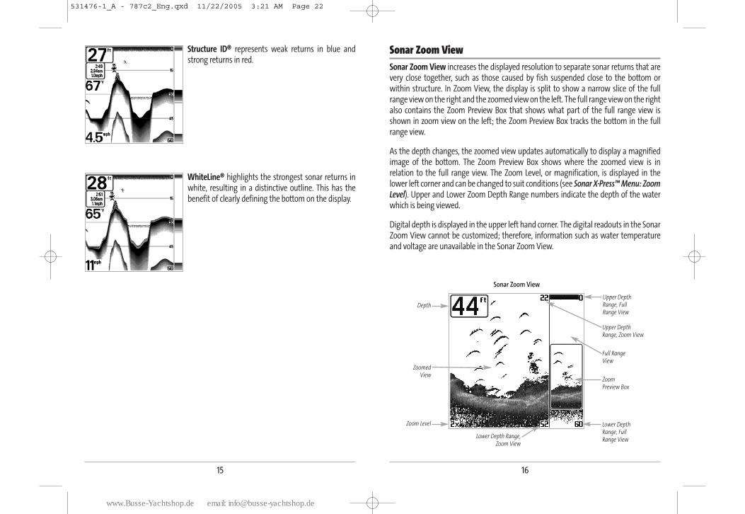
Sonar Zoom ViewSonar Zoom View increases the displayed resolution to separate sonar returns that arevery close together, such as those caused by fish suspended close to the bottom orwithin structure. In Zoom View, the display is split to show a narrow slice of the fullrange view on the right and the zoomed view on the left. The full range view on the rightalso contains the Zoom Preview Box that shows what part of the full range view isshown in zoom view on the left; the Zoom Preview Box tracks the bottom in the fullrange view.
As the depth changes, the zoomed view updates automatically to display a magnifiedimage of the bottom. The Zoom Preview Box shows where the zoomed view is inrelation to the full range view. The Zoom Level, or magnification, is displayed in thelower left corner and can be changed to suit conditions (see Sonar X-Press™ Menu: ZoomLevel). Upper and Lower Zoom Depth Range numbers indicate the depth of the waterwhich is being viewed.
Digital depth is displayed in the upper left hand corner. The digital readouts in the SonarZoom View cannot be customized; therefore, information such as water temperatureand voltage are unavailable in the Sonar Zoom View.
Sonar Zoom View
Upper DepthRange, Zoom View
Upper DepthRange, FullRange View
Full Range View
Zoom Preview Box
Lower DepthRange, FullRange View
ZoomedView
Zoom Level
Depth
Lower Depth Range,Zoom View
15
Structure ID® represents weak returns in blue andstrong returns in red.
WhiteLine® highlights the strongest sonar returns inwhite, resulting in a distinctive outline. This has thebenefit of clearly defining the bottom on the display.
531476-1_A - 787c2_Eng.qxd 11/22/2005 3:21 AM Page 22
www.Busse-Yachtshop.de email: [email protected]
18
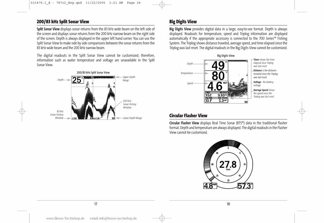
Big Digits ViewBig Digits View provides digital data in a large, easy-to-see format. Depth is alwaysdisplayed. Readouts for temperature, speed and Triplog information are displayedautomatically if the appropriate accessory is connected to the 700 Series™ FishingSystem. The Triplog shows distance traveled, average speed, and time elapsed since theTriplog was last reset. The digital readouts in the Big Digits View cannot be customized.
Circular Flasher ViewCircular Flasher View displays Real Time Sonar (RTS®) data in the traditional flasherformat. Depth and temperature are always displayed. The digital readouts in the FlasherView cannot be customized.
Big Digits View
Depth
Temperature
Speed
Timer shows the timeelapsed since Triplog was last reset
Distance is the distance
traveled since the Triplog
was last reset
Voltage - the batteryvoltage.
Average Speed shows the speed since the Triplog was last reset
17
200/83 kHz Split Sonar ViewSplit Sonar View displays sonar returns from the 83 kHz wide beam on the left side ofthe screen and displays sonar returns from the 200 kHz narrow beam on the right sideof the screen. Depth is always displayed in the upper left hand corner. You can use theSplit Sonar View to make side by side comparisons between the sonar returns from the83 kHz wide beam and the 200 kHz narrow beam.
The digital readouts in the Split Sonar View cannot be customized; therefore,information such as water temperature and voltage are unavailable in the Split Sonar View.
200/83 kHz Split Sonar View
Depth
83 kHz Sonar History
Window
200 kHz Sonar History Window
Lower Depth Range
Upper DepthRange
531476-1_A - 787c2_Eng.qxd 11/22/2005 3:21 AM Page 24
www.Busse-Yachtshop.de email: [email protected]
20
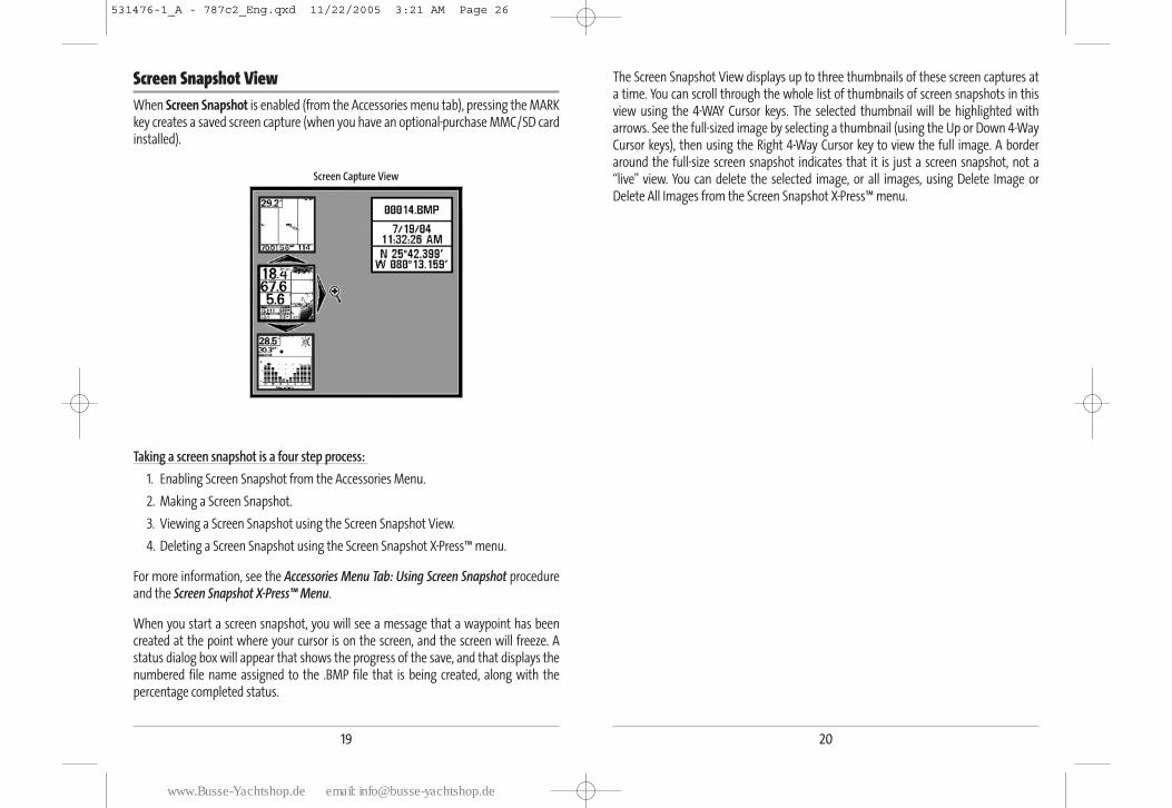
The Screen Snapshot View displays up to three thumbnails of these screen captures ata time. You can scroll through the whole list of thumbnails of screen snapshots in thisview using the 4-WAY Cursor keys. The selected thumbnail will be highlighted witharrows. See the full-sized image by selecting a thumbnail (using the Up or Down 4-WayCursor keys), then using the Right 4-Way Cursor key to view the full image. A borderaround the full-size screen snapshot indicates that it is just a screen snapshot, not a“live” view. You can delete the selected image, or all images, using Delete Image orDelete All Images from the Screen Snapshot X-Press™ menu.
19
Screen Snapshot ViewWhen Screen Snapshot is enabled (from the Accessories menu tab), pressing the MARKkey creates a saved screen capture (when you have an optional-purchase MMC/SD cardinstalled).
Taking a screen snapshot is a four step process:
1. Enabling Screen Snapshot from the Accessories Menu.
2. Making a Screen Snapshot.
3. Viewing a Screen Snapshot using the Screen Snapshot View.
4. Deleting a Screen Snapshot using the Screen Snapshot X-Press™ menu.
For more information, see the Accessories Menu Tab: Using Screen Snapshot procedureand the Screen Snapshot X-Press™ Menu.
When you start a screen snapshot, you will see a message that a waypoint has beencreated at the point where your cursor is on the screen, and the screen will freeze. Astatus dialog box will appear that shows the progress of the save, and that displays thenumbered file name assigned to the .BMP file that is being created, along with thepercentage completed status.
Screen Capture View
531476-1_A - 787c2_Eng.qxd 11/22/2005 3:21 AM Page 26
www.Busse-Yachtshop.de email: [email protected]
22
WideSide® View (with optional-purchase WideSide® transducer)
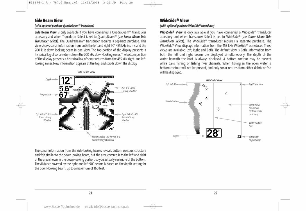
WideSide® View is only available if you have connected a WideSide® transduceraccessory and when Transducer Select is set to WideSide® (see Sonar Menu Tab:Transducer Select). The WideSide® transducer requires a separate purchase. TheWideSide® View displays information from the 455 kHz WideSide® transducer. Threeviews are available: Left, Right and Both. The default view is Both. Information from both the left and right beams are displayed simultaneously. The depth of the water beneath the boat is always displayed. A bottom contour may be present while bank fishing or fishing river channels. When fishing in the open water, a bottom contour will not be present, and only sonar returns from either debris or fish will be displayed.
WideSide ViewLeft Side View
Bank Contour
Water SurfaceLine
Depth
Right Side View
Open Water (no bottomcontour visible on-screen)
Side BeamDepth Range
21
Side Beam View(with optional-purchase QuadraBeam™ transducer)
Side Beam View is only available if you have connected a QuadraBeamTM transduceraccessory and when Transducer Select is set to QuadraBeam™ (see Sonar Menu Tab:Transducer Select). The QuadraBeam™ transducer requires a separate purchase. Thisview shows sonar information from both the left and right 90° 455 kHz beams and the200 kHz down-looking beam in one view. The top portion of the display presents ahistorical log of sonar returns from the 200 kHz down-looking sonar. The bottom portionof the display presents a historical log of sonar returns from the 455 kHz right- and left-looking sonar. New information appears at the top, and scrolls down the display
The sonar information from the side-looking beams reveals bottom contour, structureand fish similar to the down-looking beam, but the area covered is to the left and rightof the area shown in the down-looking portion, so you actually see more of the bottom.The distance covered by the right and left 90° beams is based on the depth setting forthe down-looking beam, up to a maximum of 160 feet.
Side Beam View
Depth
Temperature
Left Side 455 kHzSonar History
Window
Right Side 455 kHzSonar HistoryWindow
200 kHz SonarHistory Window
Water Surface Line for 455 kHz Sonar History Windows
531476-1_A - 787c2_Eng.qxd 11/22/2005 3:21 AM Page 28
www.Busse-Yachtshop.de email: [email protected]
24
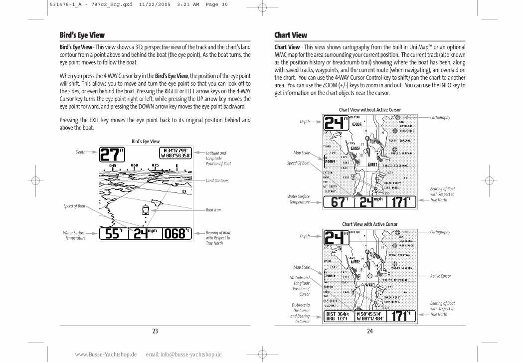
Chart ViewChart View - This view shows cartography from the built-in Uni-Map™ or an optionalMMC map for the area surrounding your current position. The current track (also knownas the position history or breadcrumb trail) showing where the boat has been, alongwith saved tracks, waypoints, and the current route (when navigating), are overlaid onthe chart. You can use the 4-WAY Cursor Control key to shift/pan the chart to anotherarea. You can use the ZOOM (+/-) keys to zoom in and out. You can use the INFO key toget information on the chart objects near the cursor.
Chart View with Active Cursor
DepthCartography
Latitude and
Longitude
Position of
Cursor
Bearing of Boat
with Respect to
True North
Distance to
the Cursor
and Bearing
to Cursor
Map Scale
Active Cursor
Chart View without Active Cursor
DepthCartography
Speed Of Boat
Bearing of Boat
with Respect to
True NorthWater Surface
Temperature
Map Scale
23
Bird’s Eye ViewBird's Eye View - This view shows a 3-D, perspective view of the track and the chart’s landcontour from a point above and behind the boat (the eye point). As the boat turns, theeye point moves to follow the boat.
When you press the 4-WAY Cursor key in the Bird’s Eye View, the position of the eye pointwill shift. This allows you to move and turn the eye point so that you can look off to the sides, or even behind the boat. Pressing the RIGHT or LEFT arrow keys on the 4-WAYCursor key turns the eye point right or left, while pressing the UP arrow key moves theeye point forward, and pressing the DOWN arrow key moves the eye point backward.
Pressing the EXIT key moves the eye point back to its original position behind and above the boat.
Bird’s Eye View
Depth
Land Contours
Boat Icon
Water SurfaceTemperature
Latitude andLongitudePosition of Boat
Speed of Boat
Bearing of Boatwith Respect toTrue North
531476-1_A - 787c2_Eng.qxd 11/22/2005 3:21 AM Page 30
www.Busse-Yachtshop.de email: [email protected]
26
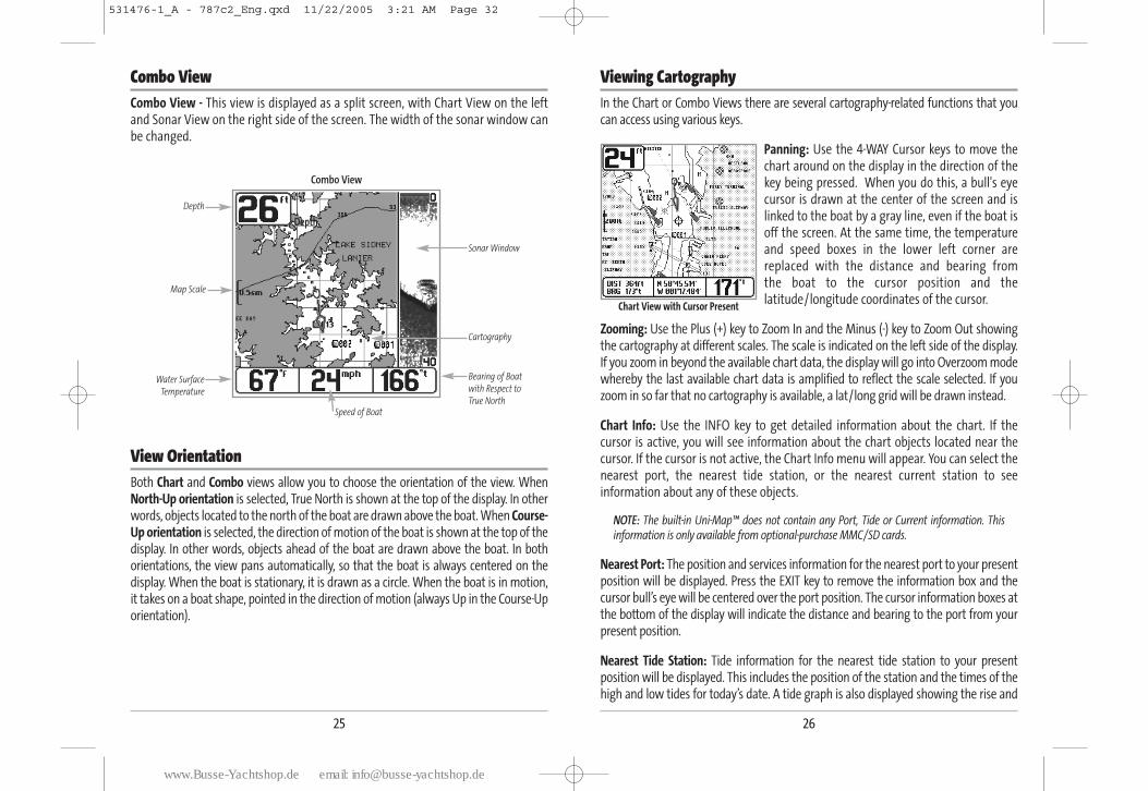
Viewing CartographyIn the Chart or Combo Views there are several cartography-related functions that youcan access using various keys.
Panning: Use the 4-WAY Cursor keys to move thechart around on the display in the direction of thekey being pressed. When you do this, a bull's eyecursor is drawn at the center of the screen and islinked to the boat by a gray line, even if the boat isoff the screen. At the same time, the temperatureand speed boxes in the lower left corner arereplaced with the distance and bearing fromthe boat to the cursor position and thelatitude/longitude coordinates of the cursor.
Zooming: Use the Plus (+) key to Zoom In and the Minus (-) key to Zoom Out showingthe cartography at different scales. The scale is indicated on the left side of the display.If you zoom in beyond the available chart data, the display will go into Overzoom modewhereby the last available chart data is amplified to reflect the scale selected. If youzoom in so far that no cartography is available, a lat/long grid will be drawn instead.
Chart Info: Use the INFO key to get detailed information about the chart. If thecursor is active, you will see information about the chart objects located near thecursor. If the cursor is not active, the Chart Info menu will appear. You can select thenearest port, the nearest tide station, or the nearest current station to seeinformation about any of these objects.
NOTE: The built-in Uni-Map™ does not contain any Port, Tide or Current information. Thisinformation is only available from optional-purchase MMC/SD cards.
Nearest Port: The position and services information for the nearest port to your presentposition will be displayed. Press the EXIT key to remove the information box and thecursor bull’s eye will be centered over the port position. The cursor information boxes atthe bottom of the display will indicate the distance and bearing to the port from yourpresent position.
Nearest Tide Station: Tide information for the nearest tide station to your presentposition will be displayed. This includes the position of the station and the times of thehigh and low tides for today’s date. A tide graph is also displayed showing the rise and
Chart View with Cursor Present
Combo ViewCombo View - This view is displayed as a split screen, with Chart View on the leftand Sonar View on the right side of the screen. The width of the sonar window canbe changed.
View OrientationBoth Chart and Combo views allow you to choose the orientation of the view. WhenNorth-Up orientation is selected, True North is shown at the top of the display. In otherwords, objects located to the north of the boat are drawn above the boat. When Course-Up orientation is selected, the direction of motion of the boat is shown at the top of thedisplay. In other words, objects ahead of the boat are drawn above the boat. In bothorientations, the view pans automatically, so that the boat is always centered on thedisplay. When the boat is stationary, it is drawn as a circle. When the boat is in motion,it takes on a boat shape, pointed in the direction of motion (always Up in the Course-Uporientation).
Combo View
Depth
Depth
Cartography
Sonar Window
Bearing of Boat
with Respect to
True North
Water Surface
Temperature
Speed of Boat
Map Scale
25
531476-1_A - 787c2_Eng.qxd 11/22/2005 3:21 AM Page 32
www.Busse-Yachtshop.de email: [email protected]
28
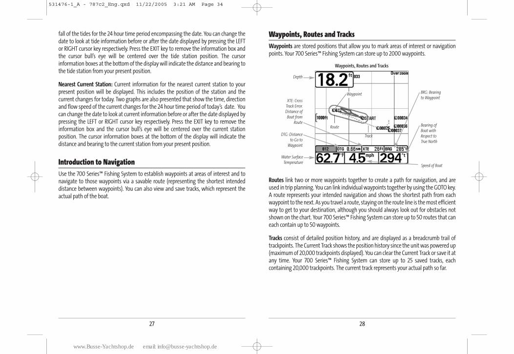
Waypoints, Routes and TracksWaypoints are stored positions that allow you to mark areas of interest or navigationpoints. Your 700 Series™ Fishing System can store up to 2000 waypoints.
Routes link two or more waypoints together to create a path for navigation, and areused in trip planning. You can link individual waypoints together by using the GOTO key.A route represents your intended navigation and shows the shortest path from eachwaypoint to the next. As you travel a route, staying on the route line is the most efficientway to get to your destination, although you should always look out for obstacles notshown on the chart. Your 700 Series™ Fishing System can store up to 50 routes that caneach contain up to 50 waypoints.
Tracks consist of detailed position history, and are displayed as a breadcrumb trail oftrackpoints. The Current Track shows the position history since the unit was powered up(maximum of 20,000 trackpoints displayed). You can clear the Current Track or save it atany time. Your 700 Series™ Fishing System can store up to 25 saved tracks, eachcontaining 20,000 trackpoints. The current track represents your actual path so far.
Waypoints, Routes and Tracks
Route
Track
Waypoint
Depth
Water Surface
Temperature
DTG: Distance
to Go to
Waypoint
Speed of Boat
XTE: Cross
Track Error.
Distance of
Boat from
RouteBearing of
Boat with
Respect to
True North
BRG: Bearing
to Waypoint
27
fall of the tides for the 24 hour time period encompassing the date. You can change thedate to look at tide information before or after the date displayed by pressing the LEFTor RIGHT cursor key respectively. Press the EXIT key to remove the information box andthe cursor bull’s eye will be centered over the tide station position. The cursorinformation boxes at the bottom of the display will indicate the distance and bearing tothe tide station from your present position.
Nearest Current Station: Current information for the nearest current station to yourpresent position will be displayed. This includes the position of the station and thecurrent changes for today. Two graphs are also presented that show the time, directionand flow speed of the current changes for the 24 hour time period of today’s date. Youcan change the date to look at current information before or after the date displayed bypressing the LEFT or RIGHT cursor key respectively. Press the EXIT key to remove theinformation box and the cursor bull’s eye will be centered over the current stationposition. The cursor information boxes at the bottom of the display will indicate thedistance and bearing to the current station from your present position.
Introduction to NavigationUse the 700 Series™ Fishing System to establish waypoints at areas of interest and tonavigate to those waypoints via a savable route (representing the shortest intendeddistance between waypoints). You can also view and save tracks, which represent theactual path of the boat.
531476-1_A - 787c2_Eng.qxd 11/22/2005 3:21 AM Page 34
www.Busse-Yachtshop.de email: [email protected]
30
To make it easier to select a waypoint, select Sort By and press the RIGHT or LEFT Cursorkeys to select a sort order:
• Name shows the waypoints alphabetically
• Time shows the most recently-created waypoint first
• Distance shows the closest waypoint first.
Delete a waypoint: From the Waypoints submenu, select Delete and press the RIGHTCursor key to display a list of waypoints. Select the waypoint you want to delete, thenpress the RIGHT Cursor key. You will be asked to confirm deletion before the waypoint isactually deleted.
Navigate to a Waypoint or PositionNavigate to the cursor position: From the Chart or Combo view, use the Cursor key toselect a position or waypoint to which you want to navigate. Press the GOTO key.Navigation will begin immediately.
Navigate to a specified waypoint: Press the GOTO key, then choose the waypoint towhich you would like to navigate from the waypoint list and press the RIGHT Cursor keyto select it.
NOTE: By repeating the previous instructions, you can add more waypoints to create alonger multi-segment route.
Skipping a waypoint: From the Navigation X-Press™ menu, select Skip Next Waypointand press the RIGHT Cursor key. If there is not another waypoint to skip to, navigationwill be cancelled.
Cancel navigation: From the Navigation X-Press™ menu, select Cancel Navigation andpress the RIGHT Cursor key. Canceling navigation removes the route and any waypointscreated using the GOTO key, but does not remove any saved routes from memory. Youwill be prompted to save the current route when you cancel navigation.
29
Save, Edit, or Delete a WaypointSave your current position as a waypoint: On any view, press the MARK key to save thecurrent position of the boat as a waypoint.
Save the cursor position as a waypoint: On the Chart or Combo view, use the Cursor keyto designate the position you want to save as a waypoint. Then press the MARK key tosave the marked position as a waypoint.
Save a position from the sonar history: On any Sonar view, use the Cursor key to pointto a feature in the sonar history (also called the Sonar Saver feature). Press the MARK keyto create a waypoint at the location where that sonar reading was taken. The newwaypoint will also record the depth at that location.
NOTE: When you save a waypoint by any of these methods, a numerical waypoint name isautomatically assigned. You can edit the waypoint information later to give it a differentname and select an icon to represent it (see Waypoint submenu on the Navigation MainMenu Tab).
Display the Waypoints Submenu: From any view, press the MENU key twice to displaythe Main Menu System, then use the RIGHT Cursor key to select the Navigation tab.Select Waypoints and press the RIGHT Cursor key to display the Waypoints submenu.
Program a specific position as a waypoint: To create a waypoint that is NOT your currentposition, from the Waypoints submenu, select the Create option and press the RIGHTCursor key. Use the Cursor keys to program a waypoint name, latitude, longitude, andicon before selecting Save.
Edit a waypoint: From the Waypoints submenu, select Edit and press the RIGHT Cursorkey to display a list of saved waypoints. Select the waypoint you want to edit and pressthe RIGHT Cursor key. Use the 4-WAY Cursor Control key to move from field to field, andthe UP and DOWN Cursor keys to changes values once you are in a field. In the WaypointName, Latitude and Longitude fields, use the UP and DOWN Cursor keys to change theletter or number. All upper and lower case letters are available, as well as digits 0-9 andsome punctuation characters. In the Waypoint Icon field, use the UP and DOWN Cursorkeys to change the icon used to represent the waypoint on the Combo and Chart Views.You can exit these fields with the LEFT and RIGHT Cursor keys or by pressing the EXIT key.Select Save and press the RIGHT Cursor key to save your changes.
531476-1_A - 787c2_Eng.qxd 11/22/2005 3:21 AM Page 36
www.Busse-Yachtshop.de email: [email protected]
32
Save, Edit or Delete a RouteSave the current route: While you are navigating, the current route can be saved. Fromthe Navigation X-PressTM menu, select Save Current Route and press the RIGHT Cursorkey. Navigation will continue.
Display the Routes submenu: From any view, press the MENU key twice to display theMain Menu System, then use the RIGHT Cursor key to select the Navigation tab. SelectRoutes and press the RIGHT Cursor key to display the Routes submenu.
Create a route: From the Routes submenu, select Create and press the RIGHT Cursor key.A Route Edit screen will be displayed with an empty route. You can name the route, addwaypoints to the route from the list of all waypoints, and order the waypoints in theroute using the Cursor keys.
Edit a saved route: From the Routes submenu, select Edit and press the RIGHT Cursorkey. A Route Edit screen will be displayed. Select the route you wish to edit and press theRIGHT Cursor key. Re-name the route or change, delete or re-order the waypoints used inthe route.
Delete a saved route: From the Routes submenu, select Delete and press the RIGHTCursor key. Select the route you wish to delete and press the RIGHT Cursor key. You willbe asked to confirm your choice by pressing the RIGHT Cursor key again before the routeis deleted.
Travel a saved route: From the Routes submenu, select Travel and press the RIGHTCursor key. A list of saved routes will appear. Select the route you wish to travel and pressthe RIGHT Cursor key to make this route the current route and begin navigation. Youmay also travel the route in either forward or reverse order.
Route Info: From the Routes submenu, select Info and press the RIGHT Cursor key. A listof saved routes will appear. Select the route for which you want information, and pressthe RIGHT Cursor key. The list of waypoints in the route will be shown, with the distanceand bearing from each waypoint to the next, as well as the distance and bearing fromthe current position to the first waypoint in the route.
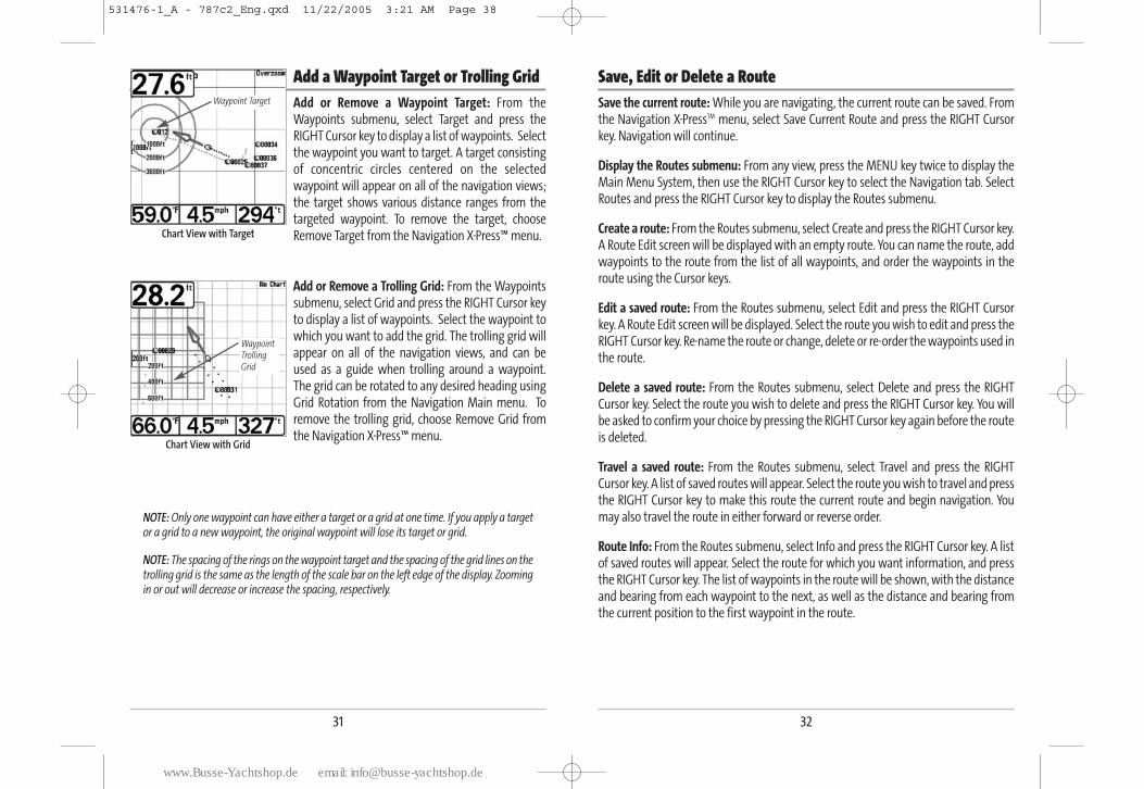
Add a Waypoint Target or Trolling GridAdd or Remove a Waypoint Target: From theWaypoints submenu, select Target and press theRIGHT Cursor key to display a list of waypoints. Selectthe waypoint you want to target. A target consistingof concentric circles centered on the selectedwaypoint will appear on all of the navigation views;the target shows various distance ranges from thetargeted waypoint. To remove the target, chooseRemove Target from the Navigation X-Press™ menu.
Add or Remove a Trolling Grid: From the Waypointssubmenu, select Grid and press the RIGHT Cursor keyto display a list of waypoints. Select the waypoint towhich you want to add the grid. The trolling grid willappear on all of the navigation views, and can beused as a guide when trolling around a waypoint.The grid can be rotated to any desired heading usingGrid Rotation from the Navigation Main menu. Toremove the trolling grid, choose Remove Grid fromthe Navigation X-Press™ menu.
NOTE: Only one waypoint can have either a target or a grid at one time. If you apply a targetor a grid to a new waypoint, the original waypoint will lose its target or grid.
NOTE: The spacing of the rings on the waypoint target and the spacing of the grid lines on thetrolling grid is the same as the length of the scale bar on the left edge of the display. Zoomingin or out will decrease or increase the spacing, respectively.
Chart View with Grid
WaypointTrollingGrid
Chart View with Target
Waypoint Target
31
531476-1_A - 787c2_Eng.qxd 11/22/2005 3:21 AM Page 38
www.Busse-Yachtshop.de email: [email protected]
34
Key FunctionsYour 700 Series™ Fishing System user interface consists of a set of easy-to-use keys thatwork with various on-screen views and menus to give you flexibility and control overyour fishing experience.
POWER/LIGHT Key The POWER/LIGHT key is used to turn the 700 Series™ Fishing System onand off, and also to adjust the backlight and contrast of the display. Pressthe POWER/LIGHT key to turn the unit on. The Title screen is thendisplayed until the 700 Series™ Fishing System begins sonar operation.
To adjust the backlight, or to adjust the display backgroundcolor, press the LIGHT key to access the Light and Backgroundmenu. Use the 4-WAY Cursor key to select Light or Backgroundand then use the LEFT or RIGHT Cursor key to change thesettings. Press EXIT to exit the Light and Background menu. -
Press and hold the POWER/LIGHT key for 3 seconds to turn the unit off. A message willappear telling you how many seconds there are until shutdown occurs. Your 700 Series™Fishing System should always be turned off using the POWER/LIGHT key. This willensure that shutdown occurs properly and any menu settings will be saved.
VIEW Key The VIEW key is used to cycle through all available views. Press the VIEWkey to advance to the next view. Repeatedly pressing VIEW cyclesthrough all views available. Views can be hidden to optimize the systemto your fishing requirements (see Views Menu Tab).
Save or Clear a Current TrackSave the current track: From the Navigation X-PressTM menu, select Save Current Trackand press the RIGHT Cursor key. The track will remain on the display, but will changefrom black to gray. To remove the track completely from the display, see Edit, Delete orHide Saved Tracks.
NOTE: When you save a track, a name is automatically assigned. The track name consists ofa date/time stamp, but can be re-named later (see Edit a Saved Track).
Clear the current track: From the Navigation X-PressTM menu, select Clear Current Trackand press the RIGHT Cursor key. The track will be removed from the display and discarded.
Edit, Delete or Hide Saved TracksDisplay the Tracks Submenu: From any view, press the MENU key twice to display theMain Menu System, then use the RIGHT Cursor key to select the Navigation tab. SelectTracks and press the RIGHT Cursor key to display the Tracks submenu.
Edit a saved track: From the Tracks submenu, select Edit and press the RIGHT Cursor keyto display the list of saved tracks. Select the track you want to edit and press the RIGHTCursor key. When the Edit Track dialog box appears, use the Cursor keys to move betweenfields. In the Track Name field, the UP and DOWN Cursor keys change the letter or number.All upper and lower case letters are available, as well as digits 0-9 and some punctuationcharacters. You can exit the Track Name field with the LEFT and RIGHT Cursor keys or bypressing the EXIT key. Select Save and press the RIGHT Cursor key to save your changes.
Delete a saved track: From the Tracks submenu, select Delete and press the RIGHTCursor key to display the list of saved tracks. Select the track you want to delete and pressthe RIGHT Cursor key. You will be asked to confirm deletion before the track is actuallydeleted.
Hide or display a saved track: From the Tracks submenu, select Visibility and press theRIGHT Cursor key to display the list of saved tracks. Select the track you want to hide ordisplay and use the Cursor keys to select Hidden or Visible. Press the EXIT key to returnto the Tracks submenu.
33
531476-1_A - 787c2_Eng.qxd 11/22/2005 3:21 AM Page 40
www.Busse-Yachtshop.de email: [email protected]
36
4-WAY Cursor Control Key The 4-Way Cursor Control Key has multiple functions, depending on thesituation:
• Use the DOWN or UP arrow keys to select a menu choice from the menu list,then use the LEFT or RIGHT arrow keys to change a menu setting.
NOTE: Menu choices are implemented and saved immediately - no further action is required.
• In all Sonar views but the Big Digits view, pressing any 4-WAY Cursor Control keywill activate Freeze Frame and will then allow you to position the cursor on thedisplay.
MARK KeyPress the MARK key while in any view to mark the position of a waypoint,either at the current boat location, or, if the Cursor is active, at the currentCursor location.
The MARK key only functions if you have the GPS receiver connected, or if you haveenabled Screen Snapshot from the Accessories menu tab. If you have enabled the ScreenSnapshot feature, pressing the MARK key still creates a waypoint, but it also captures thescreen image to the optional-purchase MMC/SD card.
NOTE: You must have an optional-purchase MMC/SD card installed for the screensnapshot feature to work.
Navigation is not affected by the Screen Snapshot feature. Also, if Screen Snapshot isenabled but there is no GPS receiver connected, pressing the MARK key will capture thescreen image and display an error saying that a GPS position fix is required to create awaypoint.
GOTO KeyIf the Cursor is active, pressing the GOTO key while in any view creates awaypoint and starts navigation towards that waypoint. If the Cursor isnot active, pressing the GOTO key displays the list of waypoints, so thatyou can select the waypoint towards which you want to navigate.
INFO KeyInfo - Press the INFO key while in Bird's Eye, Chart or Combo View todisplay information about objects that are nearest to an active cursor.
If the cursor is not active, the following menu will be displayed.Use the 4-WAY Cursor key to select Nearest Port, Nearest TideStation or Nearest Current Station, then use the RIGHT Cursorkey to display the requested information.
NOTE: The built-in UniMap™ does not contain Port, Tide or Currentinformation. This information is only available from optionalpurchase MMC/SD cards.
MENU Key The MENU key is used to access the menu system.
Start-Up Options Menu - Press the MENU key during the power up sequence to view theStart-Up Options menu.
X-PressTM Menu - Press the MENU key once for the X-PressTM Menu. The X-PressTM menuallows you to access frequently-used settings without having to navigate through thewhole menu system. When the X-PressTM menu is displayed, you can use the UP orDOWN Cursor keys to move to a particular menu choice. As soon as you alter aparameter (using the RIGHT or LEFT Cursor keys) the X-PressTM menu will collapsetemporarily, and the screen will update if it is affected by your menu setting change,allowing you to see the effects of your action immediately. Reactivate the X-PressTM
Menu by using the UP or DOWN Cursor keys.
Main Menu - Press the MENU key twice for the tabbed Main Menu System. The MainMenu System is organized under tabbed headings to help you find a specific menu itemquickly: Alarms, Sonar, Navigation, Chart, Setup, Views and Accessories tabs are part ofyour tabbed Main Menu System. Use the LEFT or RIGHT 4-WAY Cursor Control key toselect a tab; then use the DOWN or UP key to select the menu item, and the LEFT orRIGHT key to alter a menu setting.
35
531476-1_A - 787c2_Eng.qxd 11/22/2005 3:21 AM Page 42
www.Busse-Yachtshop.de email: [email protected]
38
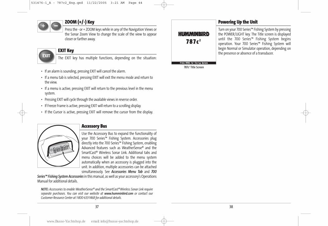
Powering Up the UnitTurn on your 700 Series™ Fishing System by pressingthe POWER/LIGHT key. The Title screen is displayeduntil the 700 Series™ Fishing System beginsoperation. Your 700 Series™ Fishing System willbegin Normal or Simulator operation, depending onthe presence or absence of a transducer.
787c2 Title Screen
37
ZOOM (+/-) KeyPress the - or + ZOOM keys while in any of the Navigation Views orthe Sonar Zoom View to change the scale of the view to appearcloser or farther away.
EXIT Key The EXIT key has multiple functions, depending on the situation:
• If an alarm is sounding, pressing EXIT will cancel the alarm.
• If a menu tab is selected, pressing EXIT will exit the menu mode and return tothe view.
• If a menu is active, pressing EXIT will return to the previous level in the menusystem.
• Pressing EXIT will cycle through the available views in reverse order.
• If Freeze Frame is active, pressing EXIT will return to a scrolling display.
• If the Cursor is active, pressing EXIT will remove the cursor from the display.
Accessory BusUse the Accessory Bus to expand the functionality ofyour 700 Series™ Fishing System. Accessories plugdirectly into the 700 Series™ Fishing System, enablingAdvanced features such as WeatherSense® and theSmartCast® Wireless Sonar Link. Additional tabs andmenu choices will be added to the menu systemautomatically when an accessory is plugged into theunit. In addition, multiple accessories can be attachedsimultaneously. See Accessories Menu Tab and 700
Series™ Fishing System Accessories in this manual, as well as your accessory's OperationsManual for additional details.
NOTE: Accessories to enable WeatherSense® and the SmartCast®Wireless Sonar Link requireseparate purchases. You can visit our website at www.humminbird.com or contact ourCustomer Resource Center at 1-800-633-1468 for additional details.
7 8 7 c 2
531476-1_A - 787c2_Eng.qxd 11/22/2005 3:21 AM Page 44
www.Busse-Yachtshop.de email: [email protected]
40
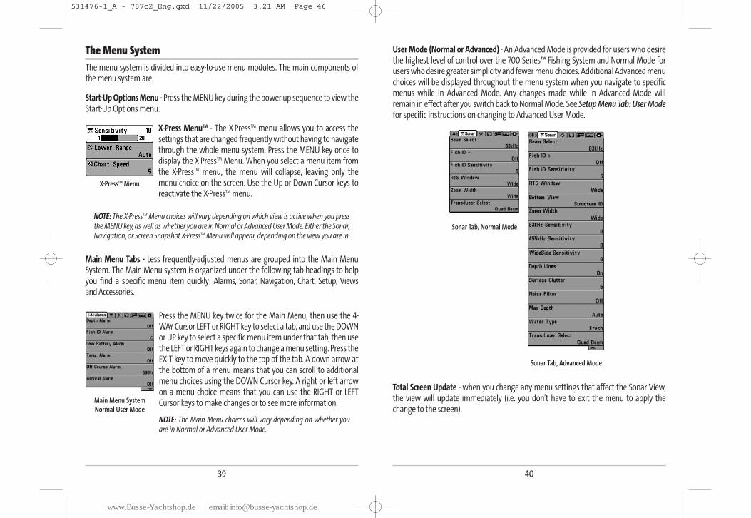
User Mode (Normal or Advanced) - An Advanced Mode is provided for users who desirethe highest level of control over the 700 Series™ Fishing System and Normal Mode forusers who desire greater simplicity and fewer menu choices. Additional Advanced menuchoices will be displayed throughout the menu system when you navigate to specificmenus while in Advanced Mode. Any changes made while in Advanced Mode willremain in effect after you switch back to Normal Mode. See Setup Menu Tab: User Modefor specific instructions on changing to Advanced User Mode.
Total Screen Update - when you change any menu settings that affect the Sonar View,the view will update immediately (i.e. you don’t have to exit the menu to apply thechange to the screen).
Sonar Tab, Normal Mode
Sonar Tab, Advanced Mode
39
The Menu SystemThe menu system is divided into easy-to-use menu modules. The main components ofthe menu system are:
Start-Up Options Menu - Press the MENU key during the power up sequence to view theStart-Up Options menu.
X-Press MenuTM - The X-PressTM menu allows you to access thesettings that are changed frequently without having to navigatethrough the whole menu system. Press the MENU key once todisplay the X-PressTM Menu. When you select a menu item fromthe X-PressTM menu, the menu will collapse, leaving only themenu choice on the screen. Use the Up or Down Cursor keys toreactivate the X-PressTM menu.
NOTE: The X-PressTM Menu choices will vary depending on which view is active when you pressthe MENU key, as well as whether you are in Normal or Advanced User Mode. Either the Sonar,Navigation, or Screen Snapshot X-PressTM Menu will appear, depending on the view you are in.
Main Menu Tabs - Less frequently-adjusted menus are grouped into the Main MenuSystem. The Main Menu system is organized under the following tab headings to helpyou find a specific menu item quickly: Alarms, Sonar, Navigation, Chart, Setup, Views and Accessories.
Press the MENU key twice for the Main Menu, then use the 4-WAY Cursor LEFT or RIGHT key to select a tab, and use the DOWNor UP key to select a specific menu item under that tab, then usethe LEFT or RIGHT keys again to change a menu setting. Press theEXIT key to move quickly to the top of the tab. A down arrow atthe bottom of a menu means that you can scroll to additionalmenu choices using the DOWN Cursor key. A right or left arrowon a menu choice means that you can use the RIGHT or LEFTCursor keys to make changes or to see more information.
NOTE: The Main Menu choices will vary depending on whether youare in Normal or Advanced User Mode.
Main Menu SystemNormal User Mode
X-PressTM Menu
531476-1_A - 787c2_Eng.qxd 11/22/2005 3:21 AM Page 46
www.Busse-Yachtshop.de email: [email protected]
42
SimulatorUse the Simulator to learn how to use your 700Series™ Fishing System before taking your boat onthe water. The Simulator is a very powerful tool thatsimulates on the water operation, providing arandomly-updated display. We recommend goingthrough this manual while using the Simulator, sinceall of the menus function and affect the display theway they actually do when in Normal operation.
NOTE: To get the full benefit of the Simulator, it is important to select Simulator manuallyfrom the Start-Up Options menu as opposed to letting the 700 Series™ Fishing System enterSimulator automatically (as it will if a transducer is not connected and you do nothing duringpower up). Manually selecting Simulator from the Start-Up Options menu allows you to pre-configure your 700 Series™ Fishing System for on the water operation. Any menu changes youmake will be saved for later use.
A message will appear on the display periodically to remind you that you are using theSimulator.
Exit the Simulator by powering your 700 Series™ Fishing System off.
System Status Use System Status to view system connections and to conduct a unit self-test.
The following screens are displayed in turn when you press the VIEW button when usingSystem Status:
• Self Test
• Accessory Test
• GPS Diagnostic View.
Exit System Status by powering your Fishing System off.
Simulator, Shown with OptionalWeatherSense® Accessory
Start-Up Options MenuPress the MENU key when the Title screen isdisplayed to access the Start-Up Options Menu.
Use the UP or DOWN 4-WAY Cursor keys to positionthe cursor, then the RIGHT Cursor key to select one ofthe following choices. If you wait too long, the systemwill default to whichever menu mode happens to behighlighted:
• Normal
• Simulator
• System Status
• PC Connect (use with PC Connect Cable).
See the following paragraphs for more information about each of these choices.
Normal OperationUse Normal Operation for on the water operation with a transducer connected. Inaddition, your 700 Series™ Fishing System uses advanced transducer detection methodsto determine if a transducer is connected. If a functioning transducer is connected,Normal operation will be selected automatically at power up and your 700 Series™Fishing System can be used on the water.
Exit Normal operation by powering your 700 Series™ Fishing System off.
Start-Up Options Menu
41
531476-1_A - 787c2_Eng.qxd 11/22/2005 3:21 AM Page 48
www.Busse-Yachtshop.de email: [email protected]
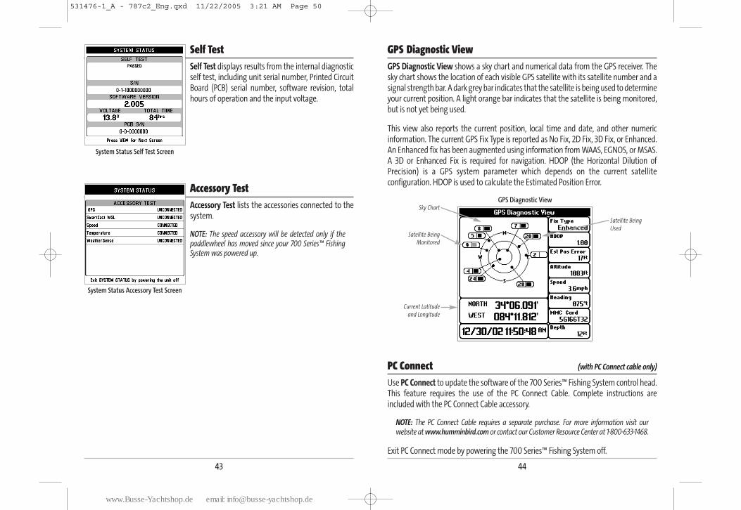
44
GPS Diagnostic View GPS Diagnostic View shows a sky chart and numerical data from the GPS receiver. Thesky chart shows the location of each visible GPS satellite with its satellite number and asignal strength bar. A dark grey bar indicates that the satellite is being used to determineyour current position. A light orange bar indicates that the satellite is being monitored,but is not yet being used.
This view also reports the current position, local time and date, and other numericinformation. The current GPS Fix Type is reported as No Fix, 2D Fix, 3D Fix, or Enhanced.An Enhanced fix has been augmented using information from WAAS, EGNOS, or MSAS.A 3D or Enhanced Fix is required for navigation. HDOP (the Horizontal Dilution ofPrecision) is a GPS system parameter which depends on the current satelliteconfiguration. HDOP is used to calculate the Estimated Position Error.
PC Connect (with PC Connect cable only)
Use PC Connect to update the software of the 700 Series™ Fishing System control head.This feature requires the use of the PC Connect Cable. Complete instructions areincluded with the PC Connect Cable accessory.
NOTE: The PC Connect Cable requires a separate purchase. For more information visit ourwebsite at www.humminbird.com or contact our Customer Resource Center at 1-800-633-1468.
Exit PC Connect mode by powering the 700 Series™ Fishing System off.
GPS Diagnostic View
Satellite Being
Monitored
Satellite Being
Used
Current Latitude
and Longitude
Sky Chart
43
Self TestSelf Test displays results from the internal diagnosticself test, including unit serial number, Printed CircuitBoard (PCB) serial number, software revision, totalhours of operation and the input voltage.
Accessory TestAccessory Test lists the accessories connected to thesystem.
NOTE: The speed accessory will be detected only if thepaddlewheel has moved since your 700 Series™ FishingSystem was powered up.
System Status Accessory Test Screen
System Status Self Test Screen
531476-1_A - 787c2_Eng.qxd 11/22/2005 3:21 AM Page 50
www.Busse-Yachtshop.de email: [email protected]
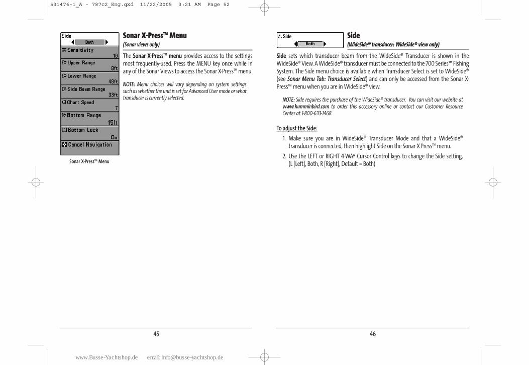
46
Side (WideSide® transducer: WideSide® view only)
Side sets which transducer beam from the WideSide® Transducer is shown in theWideSide® View. A WideSide® transducer must be connected to the 700 Series™ FishingSystem. The Side menu choice is available when Transducer Select is set to WideSide®(see Sonar Menu Tab: Transducer Select) and can only be accessed from the Sonar X-PressTM menu when you are in WideSide® view.
NOTE: Side requires the purchase of the WideSide® transducer. You can visit our website atwww.humminbird.com to order this accessory online or contact our Customer ResourceCenter at 1-800-633-1468.
To adjust the Side:
1. Make sure you are in WideSide® Transducer Mode and that a WideSide®transducer is connected, then highlight Side on the Sonar X-PressTM menu.
2. Use the LEFT or RIGHT 4-WAY Cursor Control keys to change the Side setting. (L [Left], Both, R [Right], Default = Both)
45
Sonar X-PressTM Menu (Sonar views only)
The Sonar X-PressTM menu provides access to the settingsmost frequently-used. Press the MENU key once while inany of the Sonar Views to access the Sonar X-PressTM menu.
NOTE: Menu choices will vary depending on system settingssuch as whether the unit is set for Advanced User mode or whattransducer is currently selected.
Sonar X-PressTM Menu
531476-1_A - 787c2_Eng.qxd 11/22/2005 3:21 AM Page 52
www.Busse-Yachtshop.de email: [email protected]
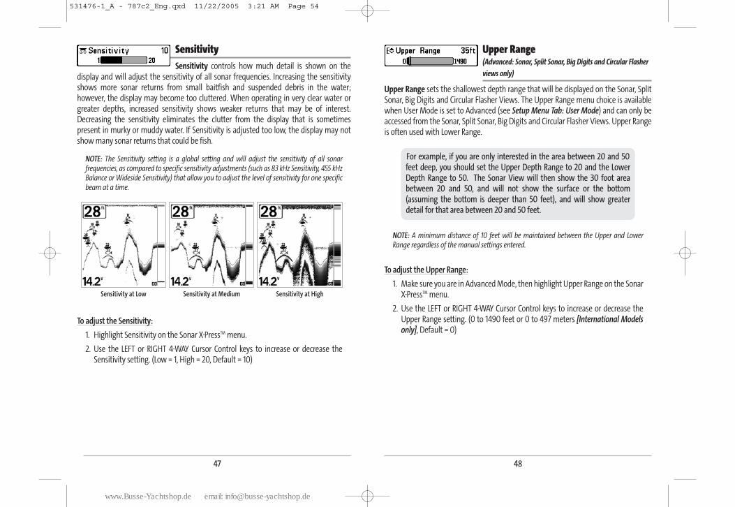
48
Upper Range (Advanced: Sonar, Split Sonar, Big Digits and Circular Flasher
views only)
Upper Range sets the shallowest depth range that will be displayed on the Sonar, SplitSonar, Big Digits and Circular Flasher Views. The Upper Range menu choice is availablewhen User Mode is set to Advanced (see Setup Menu Tab: User Mode) and can only beaccessed from the Sonar, Split Sonar, Big Digits and Circular Flasher Views. Upper Rangeis often used with Lower Range.
NOTE: A minimum distance of 10 feet will be maintained between the Upper and LowerRange regardless of the manual settings entered.
To adjust the Upper Range:
1. Make sure you are in Advanced Mode, then highlight Upper Range on the SonarX-PressTM menu.
2. Use the LEFT or RIGHT 4-WAY Cursor Control keys to increase or decrease the Upper Range setting. (0 to 1490 feet or 0 to 497 meters [International Modelsonly], Default = 0)
For example, if you are only interested in the area between 20 and 50feet deep, you should set the Upper Depth Range to 20 and the LowerDepth Range to 50. The Sonar View will then show the 30 foot areabetween 20 and 50, and will not show the surface or the bottom(assuming the bottom is deeper than 50 feet), and will show greaterdetail for that area between 20 and 50 feet.
47
SensitivitySensitivity controls how much detail is shown on the
display and will adjust the sensitivity of all sonar frequencies. Increasing the sensitivityshows more sonar returns from small baitfish and suspended debris in the water;however, the display may become too cluttered. When operating in very clear water orgreater depths, increased sensitivity shows weaker returns that may be of interest.Decreasing the sensitivity eliminates the clutter from the display that is sometimespresent in murky or muddy water. If Sensitivity is adjusted too low, the display may notshow many sonar returns that could be fish.
NOTE: The Sensitivity setting is a global setting and will adjust the sensitivity of all sonarfrequencies, as compared to specific sensitivity adjustments (such as 83 kHz Sensitivity, 455 kHzBalance or Wideside Sensitivity) that allow you to adjust the level of sensitivity for one specificbeam at a time.
To adjust the Sensitivity:
1. Highlight Sensitivity on the Sonar X-PressTM menu.
2. Use the LEFT or RIGHT 4-WAY Cursor Control keys to increase or decrease theSensitivity setting. (Low = 1, High = 20, Default = 10)
Sensitivity at Low Sensitivity at Medium Sensitivity at High
531476-1_A - 787c2_Eng.qxd 11/22/2005 3:21 AM Page 54
www.Busse-Yachtshop.de email: [email protected]
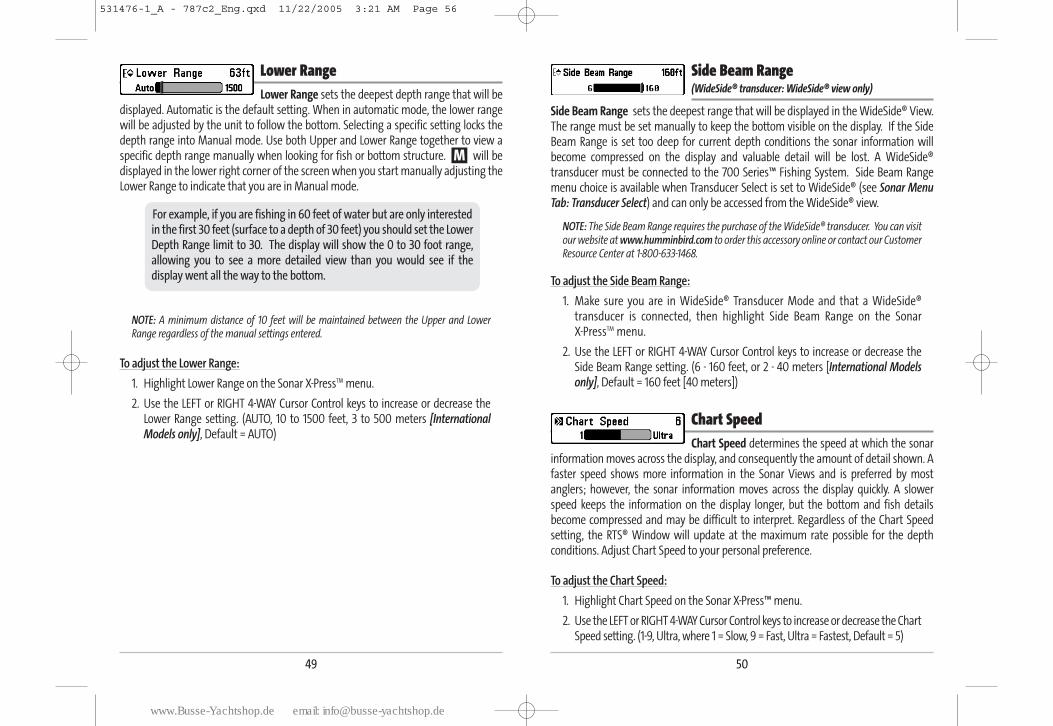
50
Side Beam Range (WideSide® transducer: WideSide® view only)
Side Beam Range sets the deepest range that will be displayed in the WideSide® View.The range must be set manually to keep the bottom visible on the display. If the SideBeam Range is set too deep for current depth conditions the sonar information willbecome compressed on the display and valuable detail will be lost. A WideSide®transducer must be connected to the 700 Series™ Fishing System. Side Beam Rangemenu choice is available when Transducer Select is set to WideSide® (see Sonar MenuTab: Transducer Select) and can only be accessed from the WideSide® view.
NOTE: The Side Beam Range requires the purchase of the WideSide® transducer. You can visitour website at www.humminbird.com to order this accessory online or contact our CustomerResource Center at 1-800-633-1468.
To adjust the Side Beam Range:
1. Make sure you are in WideSide® Transducer Mode and that a WideSide®transducer is connected, then highlight Side Beam Range on the Sonar X-PressTM menu.
2. Use the LEFT or RIGHT 4-WAY Cursor Control keys to increase or decrease theSide Beam Range setting. (6 - 160 feet, or 2 - 40 meters [International Modelsonly], Default = 160 feet [40 meters])
Chart Speed Chart Speed determines the speed at which the sonar
information moves across the display, and consequently the amount of detail shown. Afaster speed shows more information in the Sonar Views and is preferred by mostanglers; however, the sonar information moves across the display quickly. A slowerspeed keeps the information on the display longer, but the bottom and fish detailsbecome compressed and may be difficult to interpret. Regardless of the Chart Speedsetting, the RTS® Window will update at the maximum rate possible for the depthconditions. Adjust Chart Speed to your personal preference.
To adjust the Chart Speed:
1. Highlight Chart Speed on the Sonar X-Press™ menu.
2. Use the LEFT or RIGHT 4-WAY Cursor Control keys to increase or decrease the ChartSpeed setting. (1-9, Ultra, where 1 = Slow, 9 = Fast, Ultra = Fastest, Default = 5)
49
Lower RangeLower Range sets the deepest depth range that will be
displayed. Automatic is the default setting. When in automatic mode, the lower rangewill be adjusted by the unit to follow the bottom. Selecting a specific setting locks thedepth range into Manual mode. Use both Upper and Lower Range together to view aspecific depth range manually when looking for fish or bottom structure. will bedisplayed in the lower right corner of the screen when you start manually adjusting theLower Range to indicate that you are in Manual mode.
NOTE: A minimum distance of 10 feet will be maintained between the Upper and LowerRange regardless of the manual settings entered.
To adjust the Lower Range:
1. Highlight Lower Range on the Sonar X-PressTM menu.
2. Use the LEFT or RIGHT 4-WAY Cursor Control keys to increase or decrease theLower Range setting. (AUTO, 10 to 1500 feet, 3 to 500 meters [InternationalModels only], Default = AUTO)
For example, if you are fishing in 60 feet of water but are only interestedin the first 30 feet (surface to a depth of 30 feet) you should set the LowerDepth Range limit to 30. The display will show the 0 to 30 foot range,allowing you to see a more detailed view than you would see if thedisplay went all the way to the bottom.
M
531476-1_A - 787c2_Eng.qxd 11/22/2005 3:21 AM Page 56
www.Busse-Yachtshop.de email: [email protected]
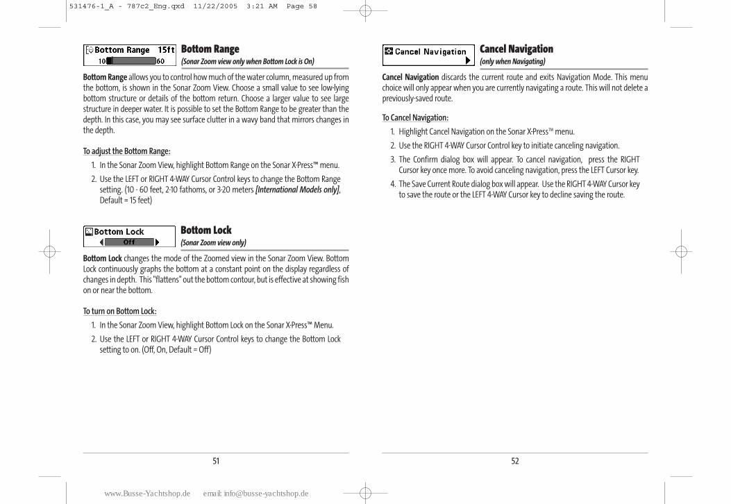
52
Cancel Navigation (only when Navigating)
Cancel Navigation discards the current route and exits Navigation Mode. This menuchoice will only appear when you are currently navigating a route. This will not delete apreviously-saved route.
To Cancel Navigation:
1. Highlight Cancel Navigation on the Sonar X-PressTM menu.
2. Use the RIGHT 4-WAY Cursor Control key to initiate canceling navigation.
3. The Confirm dialog box will appear. To cancel navigation, press the RIGHTCursor key once more. To avoid canceling navigation, press the LEFT Cursor key.
4. The Save Current Route dialog box will appear. Use the RIGHT 4-WAY Cursor keyto save the route or the LEFT 4-WAY Cursor key to decline saving the route.
51
Bottom Range (Sonar Zoom view only when Bottom Lock is On)
Bottom Range allows you to control how much of the water column, measured up fromthe bottom, is shown in the Sonar Zoom View. Choose a small value to see low-lyingbottom structure or details of the bottom return. Choose a larger value to see largestructure in deeper water. It is possible to set the Bottom Range to be greater than thedepth. In this case, you may see surface clutter in a wavy band that mirrors changes inthe depth.
To adjust the Bottom Range:
1. In the Sonar Zoom View, highlight Bottom Range on the Sonar X-Press™ menu.
2. Use the LEFT or RIGHT 4-WAY Cursor Control keys to change the Bottom Rangesetting. (10 - 60 feet, 2-10 fathoms, or 3-20 meters [International Models only],Default = 15 feet)
Bottom Lock (Sonar Zoom view only)
Bottom Lock changes the mode of the Zoomed view in the Sonar Zoom View. BottomLock continuously graphs the bottom at a constant point on the display regardless ofchanges in depth. This "flattens" out the bottom contour, but is effective at showing fishon or near the bottom.
To turn on Bottom Lock:
1. In the Sonar Zoom View, highlight Bottom Lock on the Sonar X-Press™ Menu.
2. Use the LEFT or RIGHT 4-WAY Cursor Control keys to change the Bottom Locksetting to on. (Off, On, Default = Off)
531476-1_A - 787c2_Eng.qxd 11/22/2005 3:21 AM Page 58
www.Busse-Yachtshop.de email: [email protected]
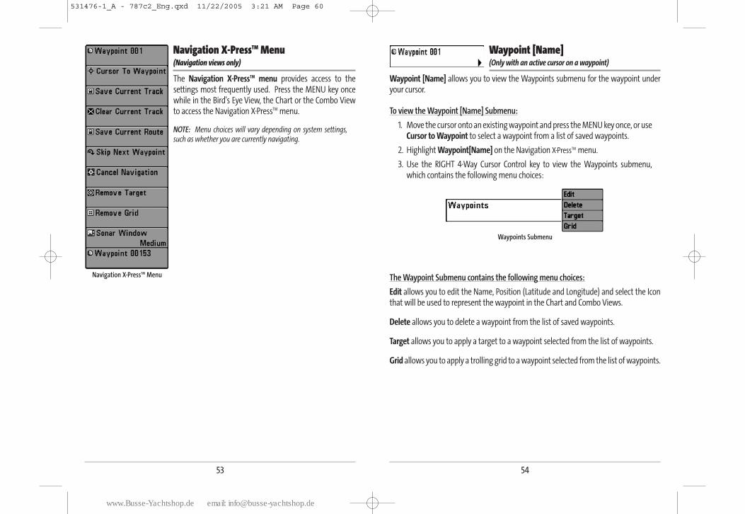
54
Waypoint [Name] (Only with an active cursor on a waypoint)
Waypoint [Name] allows you to view the Waypoints submenu for the waypoint underyour cursor.
To view the Waypoint [Name] Submenu:
1. Move the cursor onto an existing waypoint and press the MENU key once, or useCursor to Waypoint to select a waypoint from a list of saved waypoints.
2. Highlight Waypoint[Name] on the Navigation X-PressTM menu.
3. Use the RIGHT 4-Way Cursor Control key to view the Waypoints submenu,which contains the following menu choices:
The Waypoint Submenu contains the following menu choices:
Edit allows you to edit the Name, Position (Latitude and Longitude) and select the Iconthat will be used to represent the waypoint in the Chart and Combo Views.
Delete allows you to delete a waypoint from the list of saved waypoints.
Target allows you to apply a target to a waypoint selected from the list of waypoints.
Grid allows you to apply a trolling grid to a waypoint selected from the list of waypoints.
Waypoints Submenu
53
Navigation X-PressTM Menu (Navigation views only)
The Navigation X-PressTM menu provides access to thesettings most frequently used. Press the MENU key oncewhile in the Bird's Eye View, the Chart or the Combo Viewto access the Navigation X-PressTM menu.
NOTE: Menu choices will vary depending on system settings,such as whether you are currently navigating.
Navigation X-PressTM Menu
531476-1_A - 787c2_Eng.qxd 11/22/2005 3:21 AM Page 60
www.Busse-Yachtshop.de email: [email protected]
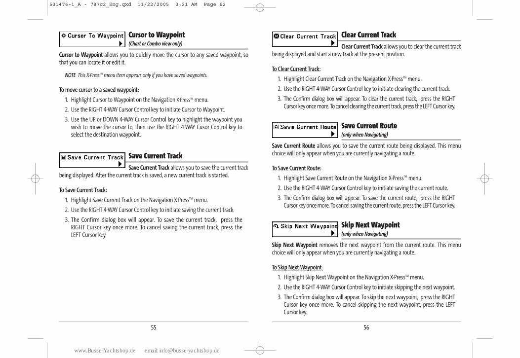
56
Clear Current TrackClear Current Track allows you to clear the current track
being displayed and start a new track at the present position.
To Clear Current Track:
1. Highlight Clear Current Track on the Navigation X-PressTM menu.
2. Use the RIGHT 4-WAY Cursor Control key to initiate clearing the current track.
3. The Confirm dialog box will appear. To clear the current track, press the RIGHTCursor key once more. To cancel clearing the current track, press the LEFT Cursor key.
Save Current Route (only when Navigating)
Save Current Route allows you to save the current route being displayed. This menuchoice will only appear when you are currently navigating a route.
To Save Current Route:
1. Highlight Save Current Route on the Navigation X-PressTM menu.
2. Use the RIGHT 4-WAY Cursor Control key to initiate saving the current route.
3. The Confirm dialog box will appear. To save the current route, press the RIGHTCursor key once more. To cancel saving the current route, press the LEFT Cursor key.
Skip Next Waypoint (only when Navigating)
Skip Next Waypoint removes the next waypoint from the current route. This menuchoice will only appear when you are currently navigating a route.
To Skip Next Waypoint:
1. Highlight Skip Next Waypoint on the Navigation X-PressTM menu.
2. Use the RIGHT 4-WAY Cursor Control key to initiate skipping the next waypoint.
3. The Confirm dialog box will appear. To skip the next waypoint, press the RIGHTCursor key once more. To cancel skipping the next waypoint, press the LEFTCursor key.
55
Cursor to Waypoint (Chart or Combo view only)
Cursor to Waypoint allows you to quickly move the cursor to any saved waypoint, sothat you can locate it or edit it.
NOTE This X-PressTM menu item appears only if you have saved waypoints.
To move cursor to a saved waypoint:
1. Highlight Cursor to Waypoint on the Navigation X-PressTM menu.
2. Use the RIGHT 4-WAY Cursor Control key to initiate Cursor to Waypoint.
3. Use the UP or DOWN 4-WAY Cursor Control key to highlight the waypoint youwish to move the cursor to, then use the RIGHT 4-WAY Cusor Control key toselect the destination waypoint.
Save Current TrackSave Current Track allows you to save the current track
being displayed. After the current track is saved, a new current track is started.
To Save Current Track:
1. Highlight Save Current Track on the Navigation X-PressTM menu.
2. Use the RIGHT 4-WAY Cursor Control key to initiate saving the current track.
3. The Confirm dialog box will appear. To save the current track, press theRIGHT Cursor key once more. To cancel saving the current track, press theLEFT Cursor key.
531476-1_A - 787c2_Eng.qxd 11/22/2005 3:21 AM Page 62
www.Busse-Yachtshop.de email: [email protected]
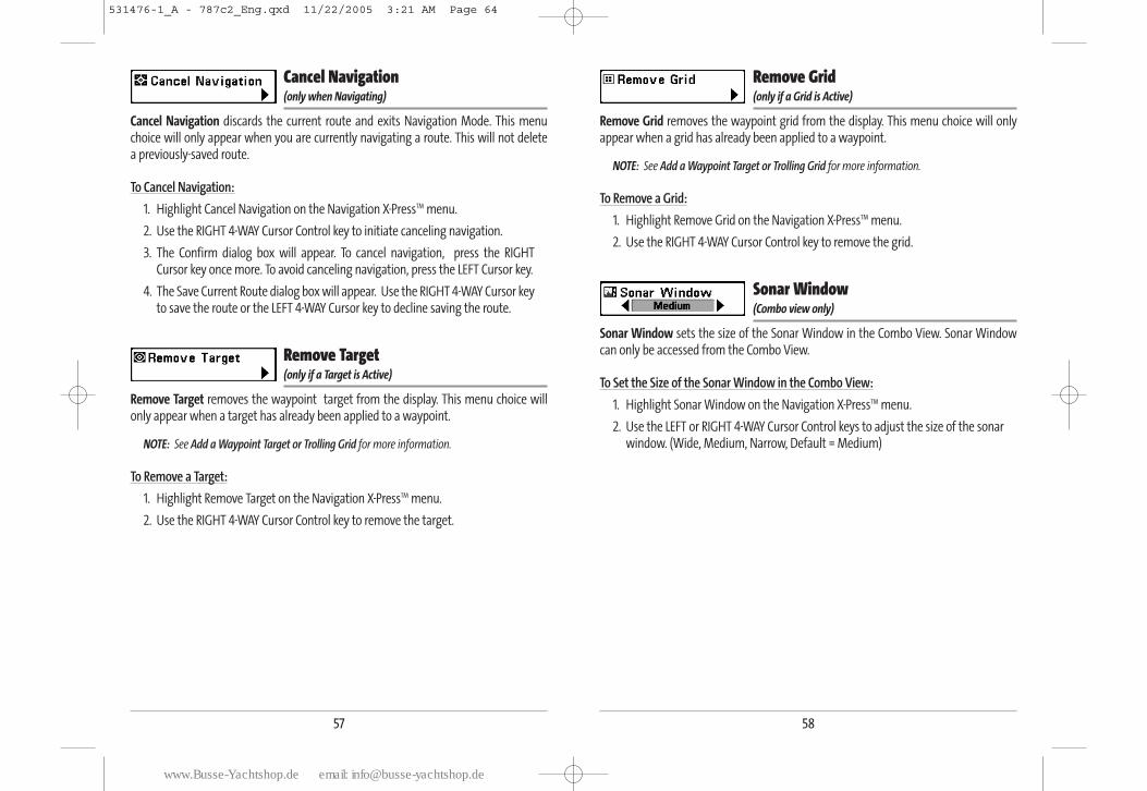
58
Remove Grid (only if a Grid is Active)
Remove Grid removes the waypoint grid from the display. This menu choice will onlyappear when a grid has already been applied to a waypoint.
NOTE: See Add a Waypoint Target or Trolling Grid for more information.
To Remove a Grid:
1. Highlight Remove Grid on the Navigation X-PressTM menu.
2. Use the RIGHT 4-WAY Cursor Control key to remove the grid.
Sonar Window (Combo view only)
Sonar Window sets the size of the Sonar Window in the Combo View. Sonar Windowcan only be accessed from the Combo View.
To Set the Size of the Sonar Window in the Combo View:
1. Highlight Sonar Window on the Navigation X-PressTM menu.
2. Use the LEFT or RIGHT 4-WAY Cursor Control keys to adjust the size of the sonarwindow. (Wide, Medium, Narrow, Default = Medium)
57
Cancel Navigation (only when Navigating)
Cancel Navigation discards the current route and exits Navigation Mode. This menuchoice will only appear when you are currently navigating a route. This will not delete a previously-saved route.
To Cancel Navigation:
1. Highlight Cancel Navigation on the Navigation X-PressTM menu.
2. Use the RIGHT 4-WAY Cursor Control key to initiate canceling navigation.
3. The Confirm dialog box will appear. To cancel navigation, press the RIGHTCursor key once more. To avoid canceling navigation, press the LEFT Cursor key.
4. The Save Current Route dialog box will appear. Use the RIGHT 4-WAY Cursor keyto save the route or the LEFT 4-WAY Cursor key to decline saving the route.
Remove Target (only if a Target is Active)
Remove Target removes the waypoint target from the display. This menu choice willonly appear when a target has already been applied to a waypoint.
NOTE: See Add a Waypoint Target or Trolling Grid for more information.
To Remove a Target:
1. Highlight Remove Target on the Navigation X-PressTM menu.
2. Use the RIGHT 4-WAY Cursor Control key to remove the target.
531476-1_A - 787c2_Eng.qxd 11/22/2005 3:21 AM Page 64
www.Busse-Yachtshop.de email: [email protected]
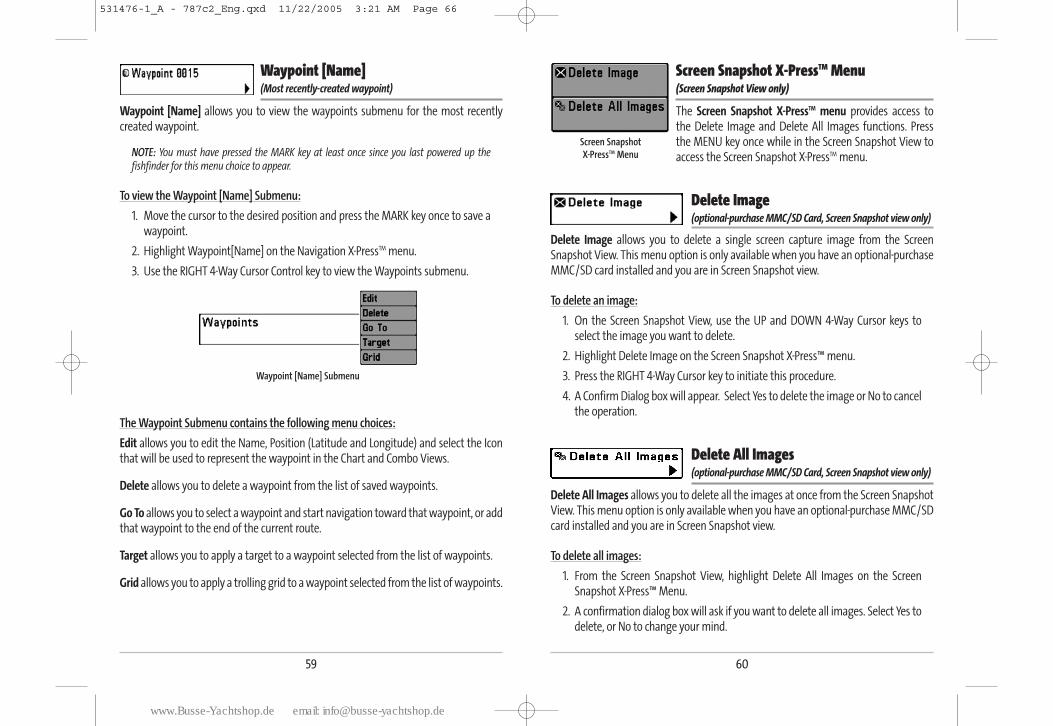
60
Screen Snapshot X-PressTM Menu (Screen Snapshot View only)
The Screen Snapshot X-PressTM menu provides access to the Delete Image and Delete All Images functions. Pressthe MENU key once while in the Screen Snapshot View toaccess the Screen Snapshot X-PressTM menu.
Delete Image (optional-purchase MMC/SD Card, Screen Snapshot view only)
Delete Image allows you to delete a single screen capture image from the ScreenSnapshot View. This menu option is only available when you have an optional-purchaseMMC/SD card installed and you are in Screen Snapshot view.
To delete an image:
1. On the Screen Snapshot View, use the UP and DOWN 4-Way Cursor keys toselect the image you want to delete.
2. Highlight Delete Image on the Screen Snapshot X-Press™ menu.
3. Press the RIGHT 4-Way Cursor key to initiate this procedure.
4. A Confirm Dialog box will appear. Select Yes to delete the image or No to cancelthe operation.
Delete All Images (optional-purchase MMC/SD Card, Screen Snapshot view only)
Delete All Images allows you to delete all the images at once from the Screen SnapshotView. This menu option is only available when you have an optional-purchase MMC/SDcard installed and you are in Screen Snapshot view.
To delete all images:
1. From the Screen Snapshot View, highlight Delete All Images on the ScreenSnapshot X-Press™ Menu.
2. A confirmation dialog box will ask if you want to delete all images. Select Yes todelete, or No to change your mind.
Screen Snapshot X-PressTM Menu
59
Waypoint [Name] (Most recently-created waypoint)
Waypoint [Name] allows you to view the waypoints submenu for the most recentlycreated waypoint.
NOTE: You must have pressed the MARK key at least once since you last powered up thefishfinder for this menu choice to appear.
To view the Waypoint [Name] Submenu:
1. Move the cursor to the desired position and press the MARK key once to save awaypoint.
2. Highlight Waypoint[Name] on the Navigation X-PressTM menu.
3. Use the RIGHT 4-Way Cursor Control key to view the Waypoints submenu.
The Waypoint Submenu contains the following menu choices:
Edit allows you to edit the Name, Position (Latitude and Longitude) and select the Iconthat will be used to represent the waypoint in the Chart and Combo Views.
Delete allows you to delete a waypoint from the list of saved waypoints.
Go To allows you to select a waypoint and start navigation toward that waypoint, or addthat waypoint to the end of the current route.
Target allows you to apply a target to a waypoint selected from the list of waypoints.
Grid allows you to apply a trolling grid to a waypoint selected from the list of waypoints.
Waypoint [Name] Submenu
531476-1_A - 787c2_Eng.qxd 11/22/2005 3:21 AM Page 66
www.Busse-Yachtshop.de email: [email protected]
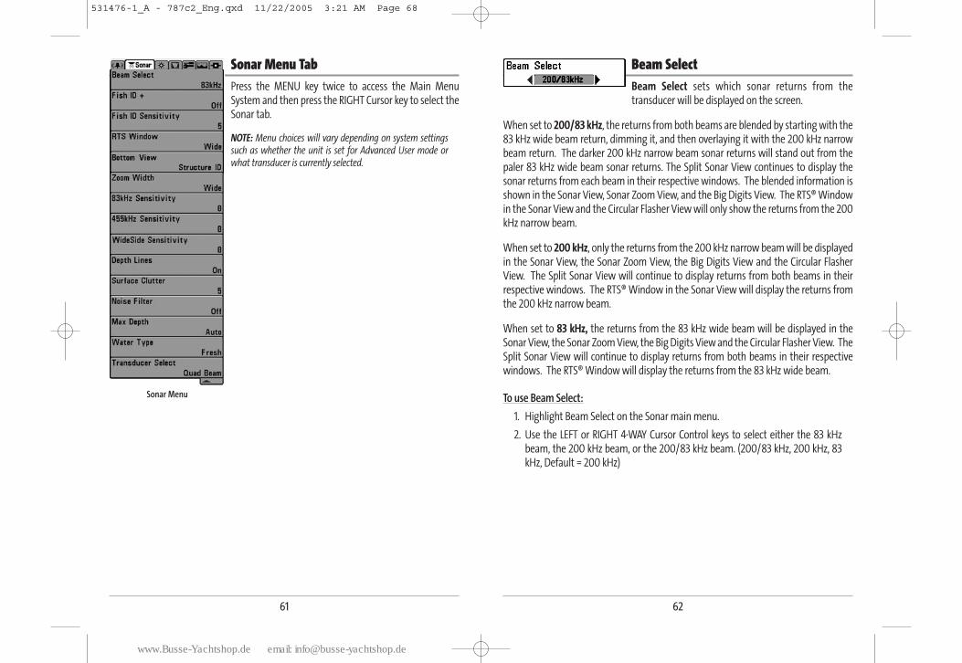
62
Beam Select Beam Select sets which sonar returns from thetransducer will be displayed on the screen.
When set to 200/83 kHz, the returns from both beams are blended by starting with the83 kHz wide beam return, dimming it, and then overlaying it with the 200 kHz narrowbeam return. The darker 200 kHz narrow beam sonar returns will stand out from thepaler 83 kHz wide beam sonar returns. The Split Sonar View continues to display thesonar returns from each beam in their respective windows. The blended information isshown in the Sonar View, Sonar Zoom View, and the Big Digits View. The RTS® Windowin the Sonar View and the Circular Flasher View will only show the returns from the 200kHz narrow beam.
When set to 200 kHz, only the returns from the 200 kHz narrow beam will be displayedin the Sonar View, the Sonar Zoom View, the Big Digits View and the Circular FlasherView. The Split Sonar View will continue to display returns from both beams in theirrespective windows. The RTS® Window in the Sonar View will display the returns fromthe 200 kHz narrow beam.
When set to 83 kHz, the returns from the 83 kHz wide beam will be displayed in theSonar View, the Sonar Zoom View, the Big Digits View and the Circular Flasher View. TheSplit Sonar View will continue to display returns from both beams in their respectivewindows. The RTS® Window will display the returns from the 83 kHz wide beam.
To use Beam Select:
1. Highlight Beam Select on the Sonar main menu.
2. Use the LEFT or RIGHT 4-WAY Cursor Control keys to select either the 83 kHz beam, the 200 kHz beam, or the 200/83 kHz beam. (200/83 kHz, 200 kHz, 83kHz, Default = 200 kHz)
61
Sonar Menu TabPress the MENU key twice to access the Main MenuSystem and then press the RIGHT Cursor key to select theSonar tab.
NOTE: Menu choices will vary depending on system settingssuch as whether the unit is set for Advanced User mode orwhat transducer is currently selected.
Sonar Menu
531476-1_A - 787c2_Eng.qxd 11/22/2005 3:21 AM Page 68
www.Busse-Yachtshop.de email: [email protected]
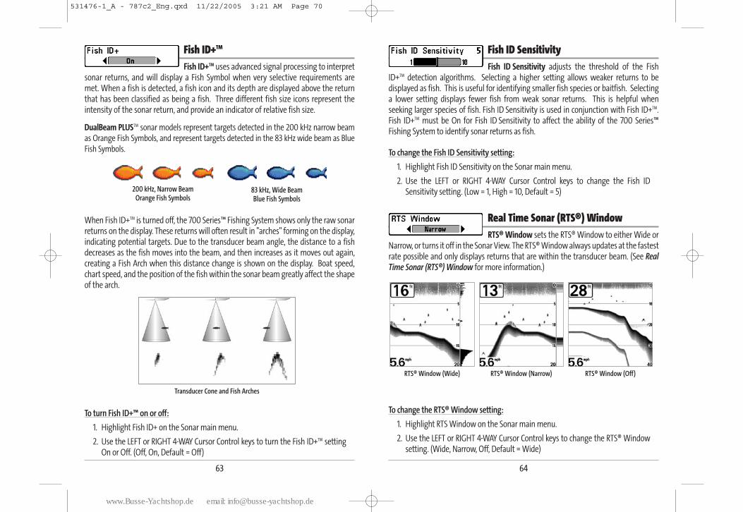
64
Fish ID SensitivityFish ID Sensitivity adjusts the threshold of the Fish
ID+TM detection algorithms. Selecting a higher setting allows weaker returns to bedisplayed as fish. This is useful for identifying smaller fish species or baitfish. Selectinga lower setting displays fewer fish from weak sonar returns. This is helpful whenseeking larger species of fish. Fish ID Sensitivity is used in conjunction with Fish ID+TM.Fish ID+TM must be On for Fish ID Sensitivity to affect the ability of the 700 Series™Fishing System to identify sonar returns as fish.
To change the Fish ID Sensitivity setting:
1. Highlight Fish ID Sensitivity on the Sonar main menu.
2. Use the LEFT or RIGHT 4-WAY Cursor Control keys to change the Fish IDSensitivity setting. (Low = 1, High = 10, Default = 5)
Real Time Sonar (RTS®) Window RTS® Window sets the RTS® Window to either Wide or
Narrow, or turns it off in the Sonar View. The RTS® Window always updates at the fastestrate possible and only displays returns that are within the transducer beam. (See RealTime Sonar (RTS®) Window for more information.)
To change the RTS® Window setting:
1. Highlight RTS Window on the Sonar main menu.
2. Use the LEFT or RIGHT 4-WAY Cursor Control keys to change the RTS® Windowsetting. (Wide, Narrow, Off, Default = Wide)
RTS® Window (Narrow) RTS® Window (Off)RTS® Window (Wide)
63
Fish ID+TM
Fish ID+TM uses advanced signal processing to interpretsonar returns, and will display a Fish Symbol when very selective requirements aremet. When a fish is detected, a fish icon and its depth are displayed above the returnthat has been classified as being a fish. Three different fish size icons represent theintensity of the sonar return, and provide an indicator of relative fish size.
DualBeam PLUSTM sonar models represent targets detected in the 200 kHz narrow beamas Orange Fish Symbols, and represent targets detected in the 83 kHz wide beam as BlueFish Symbols.
When Fish ID+TM is turned off, the 700 Series™ Fishing System shows only the raw sonarreturns on the display. These returns will often result in "arches" forming on the display,indicating potential targets. Due to the transducer beam angle, the distance to a fishdecreases as the fish moves into the beam, and then increases as it moves out again,creating a Fish Arch when this distance change is shown on the display. Boat speed,chart speed, and the position of the fish within the sonar beam greatly affect the shapeof the arch.
To turn Fish ID+™ on or off:
1. Highlight Fish ID+ on the Sonar main menu.
2. Use the LEFT or RIGHT 4-WAY Cursor Control keys to turn the Fish ID+TM settingOn or Off. (Off, On, Default = Off)
Transducer Cone and Fish Arches
200 kHz, Narrow Beam Orange Fish Symbols
83 kHz, Wide Beam Blue Fish Symbols
531476-1_A - 787c2_Eng.qxd 11/22/2005 3:21 AM Page 70
www.Busse-Yachtshop.de email: [email protected]
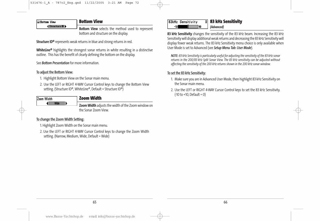
66
83 kHz Sensitivity (Advanced)
83 kHz Sensitivity changes the sensitivity of the 83 kHz beam. Increasing the 83 kHzSensitivity will display additional weak returns and decreasing the 83 kHz Sensitivity willdisplay fewer weak returns. The 83 kHz Sensitivity menu choice is only available whenUser Mode is set to Advanced (see Setup Menu Tab: User Mode).
NOTE: 83 kHz Sensitivity is particularly useful for adjusting the sensitivity of the 83 kHz sonarreturns in the 200/83 kHz Split Sonar View. The 83 kHz sensitivity can be adjusted withoutaffecting the sensitivity of the 200 kHz returns shown in the 200 kHz sonar window.
To set the 83 kHz Sensitivity:
1. Make sure you are in Advanced User Mode, then highlight 83 kHz Sensitivity onthe Sonar main menu.
2. Use the LEFT or RIGHT 4-WAY Cursor Control keys to set the 83 kHz Sensitivity. (-10 to +10, Default = 0)
65
Bottom ViewBottom View selects the method used to representbottom and structure on the display.
Structure ID® represents weak returns in blue and strong returns in red.
WhiteLine® highlights the strongest sonar returns in white resulting in a distinctiveoutline. This has the benefit of clearly defining the bottom on the display.
See Bottom Presentation for more information.
To adjust the Bottom View:
1. Highlight Bottom View on the Sonar main menu.
2. Use the LEFT or RIGHT 4-WAY Cursor Control keys to change the Bottom Viewsetting. (Structure ID®, WhiteLine®, Default = Structure ID®)
Zoom WidthZoom Width adjusts the width of the Zoom window onthe Sonar Zoom View.
To change the Zoom Width Setting:
1. Highlight Zoom Width on the Sonar main menu.
2. Use the LEFT or RIGHT 4-WAY Cursor Control keys to change the Zoom Widthsetting. (Narrow, Medium, Wide, Default = Wide)
531476-1_A - 787c2_Eng.qxd 11/22/2005 3:21 AM Page 72
www.Busse-Yachtshop.de email: [email protected]
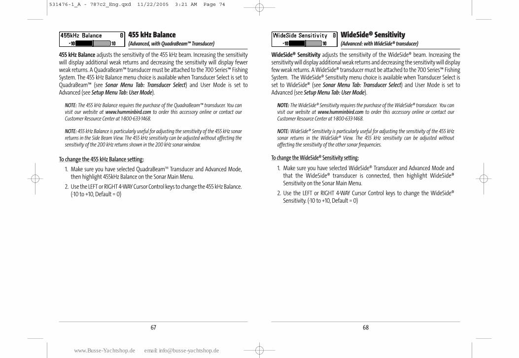
68
WideSide® Sensitivity (Advanced: with WideSide® transducer)
WideSide® Sensitivity adjusts the sensitivity of the WideSide® beam. Increasing thesensitivity will display additional weak returns and decreasing the sensitivity will displayfew weak returns. A WideSide® transducer must be attached to the 700 Series™ FishingSystem. The WideSide® Sensitivity menu choice is available when Transducer Select isset to WideSide® (see Sonar Menu Tab: Transducer Select) and User Mode is set toAdvanced (see Setup Menu Tab: User Mode).
NOTE: The WideSide® Sensitivity requires the purchase of the WideSide® transducer. You canvisit our website at www.humminbird.com to order this accessory online or contact ourCustomer Resource Center at 1-800-633-1468.
NOTE: WideSide® Sensitivity is particularly useful for adjusting the sensitivity of the 455 kHzsonar returns in the WideSide® View. The 455 kHz sensitivity can be adjusted withoutaffecting the sensitivity of the other sonar frequencies.
To change the WideSide® Sensitivity setting:
1. Make sure you have selected WideSide® Transducer and Advanced Mode andthat the WideSide® transducer is connected, then highlight WideSide®Sensitivity on the Sonar Main Menu.
2. Use the LEFT or RIGHT 4-WAY Cursor Control keys to change the WideSide®Sensitivity. (-10 to +10, Default = 0)
67
455 kHz Balance (Advanced, with QuadraBeam™ Transducer)
455 kHz Balance adjusts the sensitivity of the 455 kHz beam. Increasing the sensitivitywill display additional weak returns and decreasing the sensitivity will display fewerweak returns. A QuadraBeam™ transducer must be attached to the 700 Series™ FishingSystem. The 455 kHz Balance menu choice is available when Transducer Select is set toQuadraBeam™ (see Sonar Menu Tab: Transducer Select) and User Mode is set toAdvanced (see Setup Menu Tab: User Mode).
NOTE: The 455 kHz Balance requires the purchase of the QuadraBeam™ transducer. You canvisit our website at www.humminbird.com to order this accessory online or contact ourCustomer Resource Center at 1-800-633-1468.
NOTE: 455 kHz Balance is particularly useful for adjusting the sensitivity of the 455 kHz sonarreturns in the Side Beam View. The 455 kHz sensitivity can be adjusted without affecting thesensitivity of the 200 kHz returns shown in the 200 kHz sonar window.
To change the 455 kHz Balance setting:
1. Make sure you have selected QuadraBeamTM Transducer and Advanced Mode,then highlight 455kHz Balance on the Sonar Main Menu.
2. Use the LEFT or RIGHT 4-WAY Cursor Control keys to change the 455 kHz Balance. (-10 to +10, Default = 0)
531476-1_A - 787c2_Eng.qxd 11/22/2005 3:21 AM Page 74
www.Busse-Yachtshop.de email: [email protected]
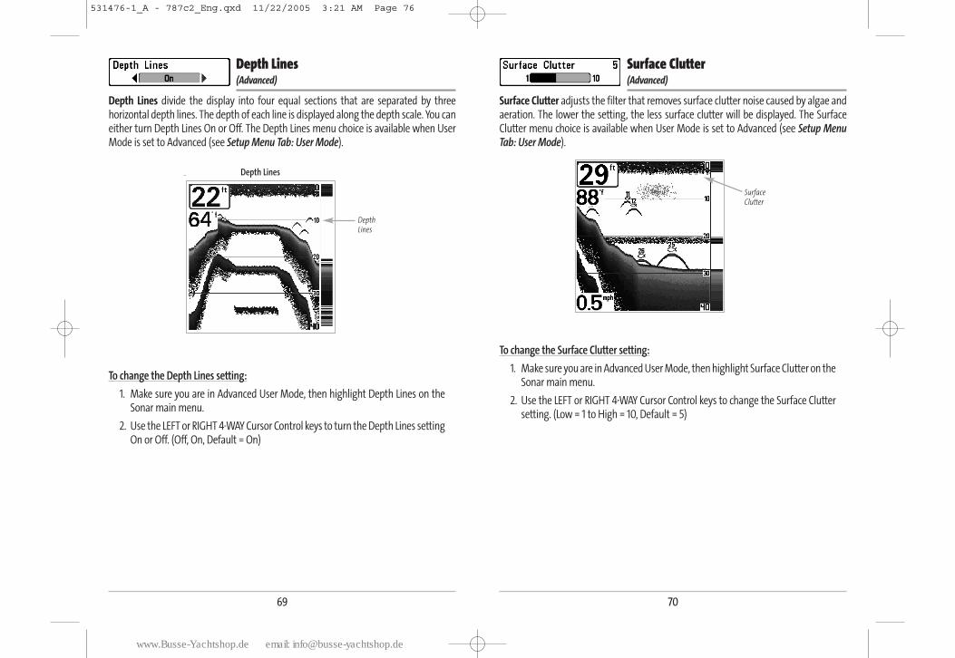
70
Surface Clutter (Advanced)
Surface Clutter adjusts the filter that removes surface clutter noise caused by algae andaeration. The lower the setting, the less surface clutter will be displayed. The SurfaceClutter menu choice is available when User Mode is set to Advanced (see Setup MenuTab: User Mode).
To change the Surface Clutter setting:
1. Make sure you are in Advanced User Mode, then highlight Surface Clutter on theSonar main menu.
2. Use the LEFT or RIGHT 4-WAY Cursor Control keys to change the Surface Cluttersetting. (Low = 1 to High = 10, Default = 5)
Surface Clutter
69
Depth Lines (Advanced)
Depth Lines divide the display into four equal sections that are separated by threehorizontal depth lines. The depth of each line is displayed along the depth scale. You caneither turn Depth Lines On or Off. The Depth Lines menu choice is available when UserMode is set to Advanced (see Setup Menu Tab: User Mode).
To change the Depth Lines setting:
1. Make sure you are in Advanced User Mode, then highlight Depth Lines on theSonar main menu.
2. Use the LEFT or RIGHT 4-WAY Cursor Control keys to turn the Depth Lines settingOn or Off. (Off, On, Default = On)
DepthLines
Depth Lines
531476-1_A - 787c2_Eng.qxd 11/22/2005 3:21 AM Page 76
www.Busse-Yachtshop.de email: [email protected]
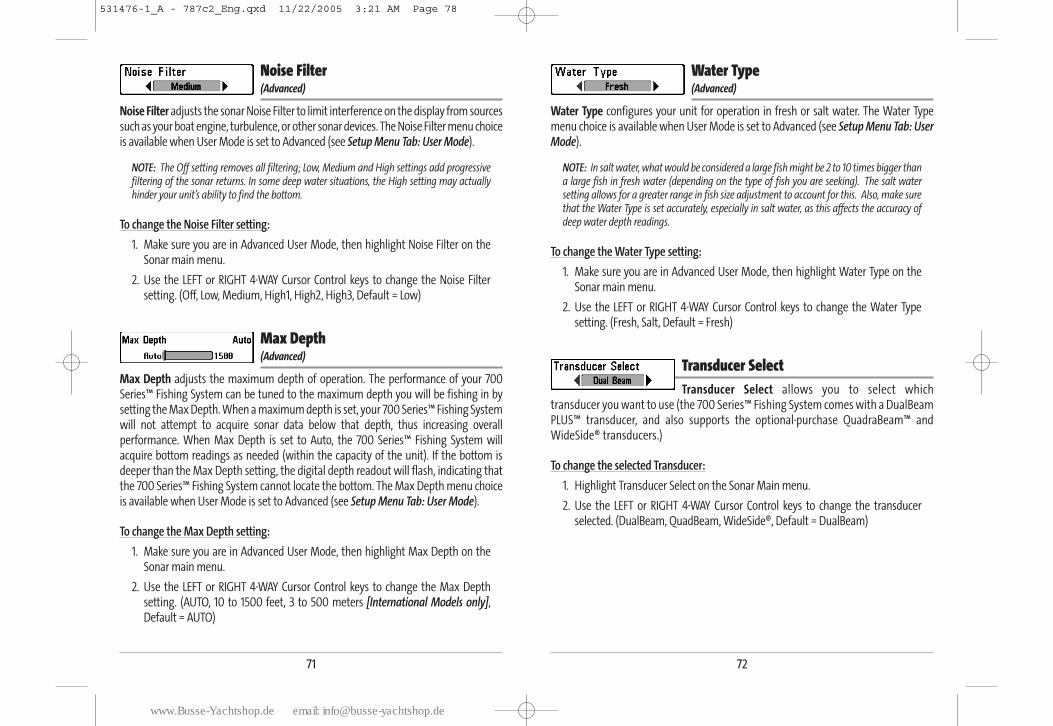
72
Water Type (Advanced)
Water Type configures your unit for operation in fresh or salt water. The Water Typemenu choice is available when User Mode is set to Advanced (see Setup Menu Tab: UserMode).
NOTE: In salt water, what would be considered a large fish might be 2 to 10 times bigger thana large fish in fresh water (depending on the type of fish you are seeking). The salt watersetting allows for a greater range in fish size adjustment to account for this. Also, make surethat the Water Type is set accurately, especially in salt water, as this affects the accuracy ofdeep water depth readings.
To change the Water Type setting:
1. Make sure you are in Advanced User Mode, then highlight Water Type on theSonar main menu.
2. Use the LEFT or RIGHT 4-WAY Cursor Control keys to change the Water Typesetting. (Fresh, Salt, Default = Fresh)
Transducer Select Transducer Select allows you to select which
transducer you want to use (the 700 Series™ Fishing System comes with a DualBeamPLUS™ transducer, and also supports the optional-purchase QuadraBeam™ andWideSide® transducers.)
To change the selected Transducer:
1. Highlight Transducer Select on the Sonar Main menu.
2. Use the LEFT or RIGHT 4-WAY Cursor Control keys to change the transducerselected. (DualBeam, QuadBeam, WideSide®, Default = DualBeam)
71
Noise Filter (Advanced)
Noise Filter adjusts the sonar Noise Filter to limit interference on the display from sourcessuch as your boat engine, turbulence, or other sonar devices. The Noise Filter menu choiceis available when User Mode is set to Advanced (see Setup Menu Tab: User Mode).
NOTE: The Off setting removes all filtering; Low, Medium and High settings add progressivefiltering of the sonar returns. In some deep water situations, the High setting may actuallyhinder your unit’s ability to find the bottom.
To change the Noise Filter setting:
1. Make sure you are in Advanced User Mode, then highlight Noise Filter on theSonar main menu.
2. Use the LEFT or RIGHT 4-WAY Cursor Control keys to change the Noise Filtersetting. (Off, Low, Medium, High1, High2, High3, Default = Low)
Max Depth (Advanced)
Max Depth adjusts the maximum depth of operation. The performance of your 700Series™ Fishing System can be tuned to the maximum depth you will be fishing in bysetting the Max Depth. When a maximum depth is set, your 700 Series™ Fishing Systemwill not attempt to acquire sonar data below that depth, thus increasing overallperformance. When Max Depth is set to Auto, the 700 Series™ Fishing System willacquire bottom readings as needed (within the capacity of the unit). If the bottom isdeeper than the Max Depth setting, the digital depth readout will flash, indicating thatthe 700 Series™ Fishing System cannot locate the bottom. The Max Depth menu choiceis available when User Mode is set to Advanced (see Setup Menu Tab: User Mode).
To change the Max Depth setting:
1. Make sure you are in Advanced User Mode, then highlight Max Depth on theSonar main menu.
2. Use the LEFT or RIGHT 4-WAY Cursor Control keys to change the Max Depthsetting. (AUTO, 10 to 1500 feet, 3 to 500 meters [International Models only],Default = AUTO)
531476-1_A - 787c2_Eng.qxd 11/22/2005 3:21 AM Page 78
www.Busse-Yachtshop.de email: [email protected]
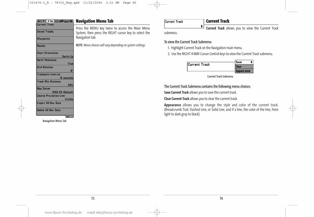
74
Current TrackCurrent Track allows you to view the Current Track
submenu.
To view the Current Track Submenu:
1. Highlight Current Track on the Navigation main menu.
2. Use the RIGHT 4-WAY Cursor Control keys to view the Current Track submenu.
The Current Track Submenu contains the following menu choices:
Save Current Track allows you to save the current track.
Clear Current Track allows you to clear the current track.
Appearance allows you to change the style and color of the current track.(Breadcrumb Trail, Dashed Line, or Solid Line, and if a line, the color of the line, fromlight to dark gray to black).
Current Track Submenu
73
Navigation Menu TabPress the MENU key twice to access the Main MenuSystem, then press the RIGHT cursor key to select theNavigation tab.
NOTE: Menu choices will vary depending on system settings.
Navigation Menu Tab
531476-1_A - 787c2_Eng.qxd 11/22/2005 3:21 AM Page 80
www.Busse-Yachtshop.de email: [email protected]
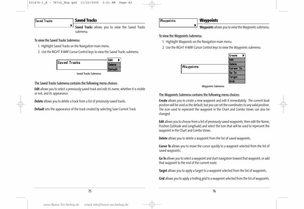
76
WaypointsWaypoints allows you to view the Waypoints submenu.
To view the Waypoints Submenu:
1. Highlight Waypoints on the Navigation main menu.
2. Use the RIGHT 4-WAY Cursor Control keys to view the Waypoints submenu.
The Waypoints Submenu contains the following menu choices:
Create allows you to create a new waypoint and edit it immediately. The current boatposition will be used as the default, but you can set the coordinates to any valid position.The Icon used to represent the waypoint in the Chart and Combo Views can also bechanged.
Edit allows you to choose from a list of previously-saved waypoints, then edit the Name,Position (Latitude and Longitude) and select the Icon that will be used to represent thewaypoint in the Chart and Combo Views.
Delete allows you to delete a waypoint from the list of saved waypoints.
Cursor To allows you to move the cursor quickly to a waypoint selected from the list ofsaved waypoints.
Go To allows you to select a waypoint and start navigation toward that waypoint, or addthat waypoint to the end of the current route.
Target allows you to apply a target to a waypoint selected from the list of waypoints.
Grid allows you to apply a trolling grid to a waypoint selected from the list of waypoints.
Waypoints Submenu
75
Saved TracksSaved Tracks allows you to view the Saved Trackssubmenu.
To view the Saved Tracks Submenu:
1. Highlight Saved Tracks on the Navigation main menu.
2. Use the RIGHT 4-WAY Cursor Control keys to view the Saved Tracks submenu.
The Saved Tracks Submenu contains the following menu choices:
Edit allows you to select a previously-saved track and edit its name, whether it is visibleor not, and its appearance.
Delete allows you to delete a track from a list of previously-saved tracks.
Default sets the appearance of the track created by selecting Save Current Track.
Saved Tracks Submenu
531476-1_A - 787c2_Eng.qxd 11/22/2005 3:21 AM Page 82
www.Busse-Yachtshop.de email: [email protected]
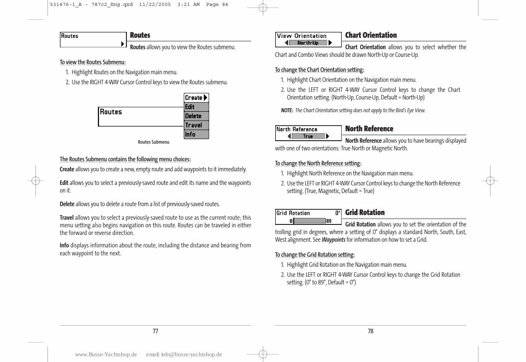
78
Chart OrientationChart Orientation allows you to select whether the
Chart and Combo Views should be drawn North-Up or Course-Up.
To change the Chart Orientation setting:
1. Highlight Chart Orientation on the Navigation main menu.
2. Use the LEFT or RIGHT 4-WAY Cursor Control keys to change the ChartOrientation setting. (North-Up, Course-Up, Default = North-Up)
NOTE: The Chart Orientation setting does not apply to the Bird's Eye View.
North ReferenceNorth Reference allows you to have bearings displayed
with one of two orientations: True North or Magnetic North.
To change the North Reference setting:
1. Highlight North Reference on the Navigation main menu.
2. Use the LEFT or RIGHT 4-WAY Cursor Control keys to change the North Referencesetting. (True, Magnetic, Default = True)
Grid RotationGrid Rotation allows you to set the orientation of the
trolling grid in degrees, where a setting of 0° displays a standard North, South, East,West alignment. See Waypoints for information on how to set a Grid.
To change the Grid Rotation setting:
1. Highlight Grid Rotation on the Navigation main menu.
2. Use the LEFT or RIGHT 4-WAY Cursor Control keys to change the Grid Rotationsetting. (0° to 89°, Default = 0°)
77
RoutesRoutes allows you to view the Routes submenu.
To view the Routes Submenu:
1. Highlight Routes on the Navigation main menu.
2. Use the RIGHT 4-WAY Cursor Control keys to view the Routes submenu.
The Routes Submenu contains the following menu choices:
Create allows you to create a new, empty route and add waypoints to it immediately.
Edit allows you to select a previously-saved route and edit its name and the waypointson it.
Delete allows you to delete a route from a list of previously-saved routes.
Travel allows you to select a previously-saved route to use as the current route; thismenu setting also begins navigation on this route. Routes can be traveled in eitherthe forward or reverse direction.
Info displays information about the route, including the distance and bearing from
each waypoint to the next.
Routes Submenu
531476-1_A - 787c2_Eng.qxd 11/22/2005 3:21 AM Page 84
www.Busse-Yachtshop.de email: [email protected]
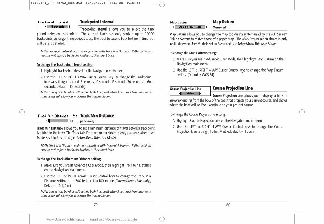
80
Map Datum (Advanced)
Map Datum allows you to change the map coordinate system used by the 700 Series™Fishing System to match those of a paper map. The Map Datum menu choice is onlyavailable when User Mode is set to Advanced (see Setup Menu Tab: User Mode).
To change the Map Datum setting:
1. Make sure you are in Advanced User Mode, then highlight Map Datum on theNavigation main menu.
2. Use the LEFT or RIGHT 4-WAY Cursor Control keys to change the Map Datumsetting. (Default = WGS 84)
Course Projection Line Course Projection Line allows you to display or hide an
arrow extending from the bow of the boat that projects your current course, and showswhere the boat will go if you continue on your present course.
To change the Course Project Line setting:
1. Highlight Course Projection Line on the Navigation main menu.
2. Use the LEFT or RIGHT 4-WAY Cursor Control keys to change the CourseProjection Line setting (Hidden, Visible, Default = Hidden)
79
Trackpoint IntervalTrackpoint Interval allows you to select the time
period between trackpoints. The current track can only contain up to 20000trackpoints, so longer time periods cause the track to extend back further in time, butwill be less detailed.
NOTE: Trackpoint Interval works in conjunction with Track Min Distance. Both conditionsmust be met before a trackpoint is added to the current track.
To change the Trackpoint Interval setting:
1. Highlight Trackpoint Interval on the Navigation main menu.
2. Use the LEFT or RIGHT 4-WAY Cursor Control keys to change the TrackpointInterval setting. (1 second, 5 seconds, 10 seconds, 15 seconds, 30 seconds or 60seconds, Default = 15 seconds)
NOTE: During slow travel or drift, setting both Trackpoint Interval and Track Min Distance tosmall values will allow you to increase the track resolution.
Track Min Distance (Advanced)
Track Min Distance allows you to set a minimum distance of travel before a trackpointis added to the track. The Track Min Distance menu choice is only available when UserMode is set to Advanced (see Setup Menu Tab: User Mode).
NOTE: Track Min Distance works in conjunction with Trackpoint Interval. Both conditionsmust be met before a trackpoint is added to the current track.
To change the Track Minimum Distance setting:
1. Make sure you are in Advanced User Mode, then highlight Track Min Distanceon the Navigation main menu.
2. Use the LEFT or RIGHT 4-WAY Cursor Control keys to change the Track MinDistance setting. (1 to 300 feet or 1 to 100 meters [International Units only],Default = 16 ft, 5 m)
NOTE: During slow travel or drift, setting both Trackpoint Interval and Track Min Distance tosmall values will allow you to increase the track resolution.
531476-1_A - 787c2_Eng.qxd 11/22/2005 3:21 AM Page 86
www.Busse-Yachtshop.de email: [email protected]
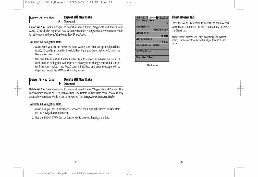
82
Chart Menu TabPress the MENU key twice to access the Main MenuSystem and then press the RIGHT Cursor key to selectthe Chart tab.
NOTE: Menu choices will vary depending on systemsettings such as whether the unit is set for Advanced Usermode.
Chart Menu
81
Export All Nav Data (Advanced)
Export All Nav Data allows you to export all saved Tracks, Waypoints and Routes to anMMC/SD card. The Export All Nav Data menu choice is only available when User Modeis set to Advanced (see Setup Menu Tab: User Mode).
To Export All Navigation Data:
1. Make sure you are in Advanced User Mode, and that an optional-purchaseMMC/SD card is installed in the slot, then highlight Export All Nav Data on theNavigation main menu.
2. Use the RIGHT 4-WAY Cursor Control key to export all navigation data. Aconfirmation dialog box will appear to allow you to change your mind, and toconfirm your choice. If no MMC card is installed, and error message will bedisplayed. Insert the MMC card and try again.
Delete All Nav Data (Advanced)
Delete All Nav Data allows you to delete all saved Tracks, Waypoints and Routes. Thismenu choice should be used with caution. The Delete All Nav Data menu choice is onlyavailable when User Mode is set to Advanced (see Setup Menu Tab: User Mode).
To Delete All Navigation Data:
1. Make sure you are in Advanced User Mode, then highlight Delete All Nav Dataon the Navigation main menu.
2. Use the RIGHT 4-WAY Cursor Control key to delete all navigation data.
531476-1_A - 787c2_Eng.qxd 11/22/2005 3:21 AM Page 88
www.Busse-Yachtshop.de email: [email protected]
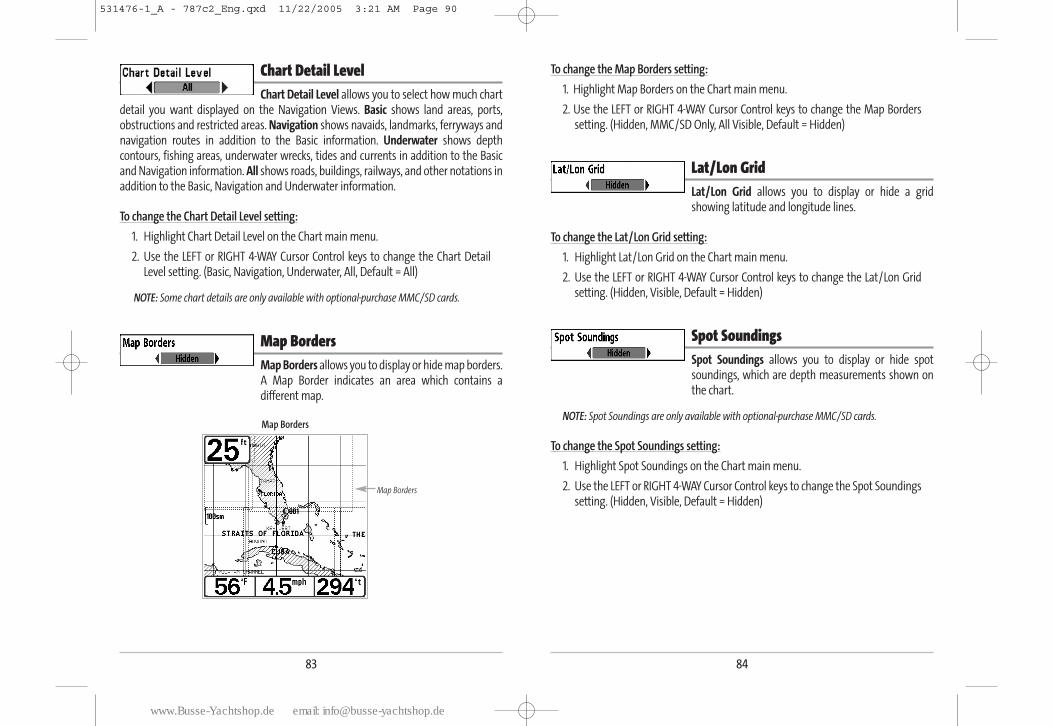
84
To change the Map Borders setting:
1. Highlight Map Borders on the Chart main menu.
2. Use the LEFT or RIGHT 4-WAY Cursor Control keys to change the Map Borderssetting. (Hidden, MMC/SD Only, All Visible, Default = Hidden)
Lat/Lon GridLat/Lon Grid allows you to display or hide a gridshowing latitude and longitude lines.
To change the Lat/Lon Grid setting:
1. Highlight Lat/Lon Grid on the Chart main menu.
2. Use the LEFT or RIGHT 4-WAY Cursor Control keys to change the Lat/Lon Gridsetting. (Hidden, Visible, Default = Hidden)
Spot SoundingsSpot Soundings allows you to display or hide spotsoundings, which are depth measurements shown onthe chart.
NOTE: Spot Soundings are only available with optional-purchase MMC/SD cards.
To change the Spot Soundings setting:
1. Highlight Spot Soundings on the Chart main menu.
2. Use the LEFT or RIGHT 4-WAY Cursor Control keys to change the Spot Soundingssetting. (Hidden, Visible, Default = Hidden)
83
Chart Detail LevelChart Detail Level allows you to select how much chart
detail you want displayed on the Navigation Views. Basic shows land areas, ports,obstructions and restricted areas. Navigation shows navaids, landmarks, ferryways andnavigation routes in addition to the Basic information. Underwater shows depthcontours, fishing areas, underwater wrecks, tides and currents in addition to the Basicand Navigation information. All shows roads, buildings, railways, and other notations inaddition to the Basic, Navigation and Underwater information.
To change the Chart Detail Level setting:
1. Highlight Chart Detail Level on the Chart main menu.
2. Use the LEFT or RIGHT 4-WAY Cursor Control keys to change the Chart DetailLevel setting. (Basic, Navigation, Underwater, All, Default = All)
NOTE: Some chart details are only available with optional-purchase MMC/SD cards.
Map BordersMap Borders allows you to display or hide map borders.A Map Border indicates an area which contains adifferent map.
Map Borders
Map Borders
531476-1_A - 787c2_Eng.qxd 11/22/2005 3:21 AM Page 90
www.Busse-Yachtshop.de email: [email protected]
86
Set Map Offset (Advanced)
Set Map Offset allows you to change the map offset used by the 700 Series™. The SetMap Offset menu choice is only available when User Mode is set to Advanced (see SetupMenu Tab: User Mode).
NOTE: The Map Offset will be applied to all maps and not just the map that requires thecorrection. The Map Offset should be cleared if a different map is to be used.
To change the Map Offset setting:
1. Activate the cursor and move it to the location where the Map Offset will be applied.
NOTE: The cursor must be active in order for this procedure to work.
2. Make sure you are in Advanced User Mode, then highlight Set Map Offset onthe Chart main menu.
3. Use the RIGHT 4-WAY Cursor Control key to set the Map Offset. A confirmationdialog box will appear to allow you to change your mind, or to confirm yourchoice. If the cursor was not active before you began this procedure, you will seean error message. Exit the menu, set the cursor, then try again.
Clear Map Offset (Advanced)
Clear Map Offset allows you to clear the Map Offset. The Clear map Offset menu choiceis only available when User Mode is set to Advanced (see Setup Menu Tab: User Mode)and a Map Offset is currently active.
To Clear Map Offset:
1. Make sure you are in Advanced User Mode, then highlight Clear Map Offset onthe Chart main menu.
2. Use the RIGHT 4-WAY Cursor Control key to clear the Map Offset.
85
Set Simulation Position (Advanced)
Set Simulation Position allows you to set the position of the boat used in the Simulator.The Set Simulation Position menu choice is only available when User Mode is set toAdvanced (see Setup Menu Tab: User Mode).
To set the Simulation Position:
1. Activate the cursor and move it to the coordinates from where you want thesimulation to start.
NOTE: The cursor must be active in order for this procedure to work.
2. Make sure you are in Advanced User Mode, then highlight Set SimulationPosition on the Chart main menu.
3. Use the RIGHT 4-WAY Cursor Control key to change the Simulation Positionsetting. A confirmation dialog box will appear to allow you to change yourmind, or to confirm your choice. If the cursor was not active before you beganthis procedure, you will see an error message. Exit the menu, set the cursor, thentry again.
531476-1_A - 787c2_Eng.qxd 11/22/2005 3:21 AM Page 92
www.Busse-Yachtshop.de email: [email protected]
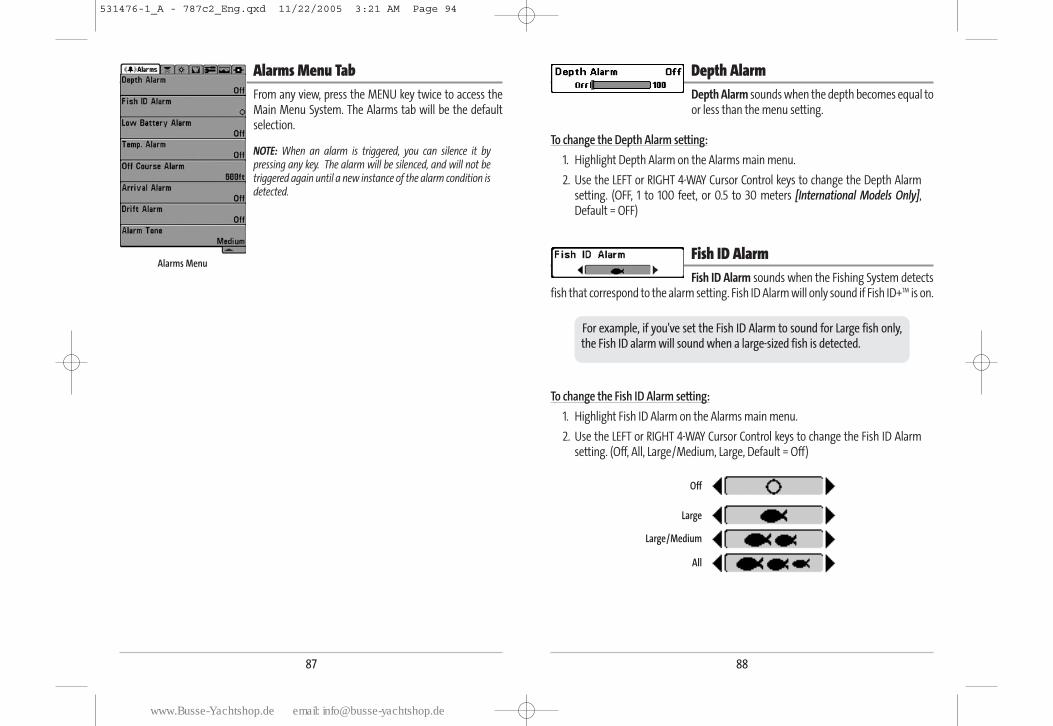
88
Depth AlarmDepth Alarm sounds when the depth becomes equal toor less than the menu setting.
To change the Depth Alarm setting:
1. Highlight Depth Alarm on the Alarms main menu.
2. Use the LEFT or RIGHT 4-WAY Cursor Control keys to change the Depth Alarmsetting. (OFF, 1 to 100 feet, or 0.5 to 30 meters [International Models Only],Default = OFF)
Fish ID AlarmFish ID Alarm sounds when the Fishing System detects
fish that correspond to the alarm setting. Fish ID Alarm will only sound if Fish ID+TM is on.
To change the Fish ID Alarm setting:
1. Highlight Fish ID Alarm on the Alarms main menu.
2. Use the LEFT or RIGHT 4-WAY Cursor Control keys to change the Fish ID Alarmsetting. (Off, All, Large/Medium, Large, Default = Off)
All
Large/Medium
Large
Off
For example, if you've set the Fish ID Alarm to sound for Large fish only,the Fish ID alarm will sound when a large-sized fish is detected.
87
Alarms Menu TabFrom any view, press the MENU key twice to access theMain Menu System. The Alarms tab will be the defaultselection.
NOTE: When an alarm is triggered, you can silence it bypressing any key. The alarm will be silenced, and will not betriggered again until a new instance of the alarm condition isdetected.
Alarms Menu
531476-1_A - 787c2_Eng.qxd 11/22/2005 3:21 AM Page 94
www.Busse-Yachtshop.de email: [email protected]
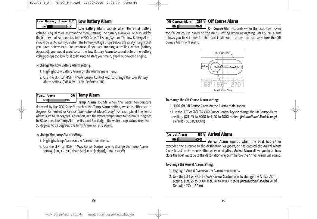
90
Off Course AlarmOff Course Alarm sounds when the boat has moved
too far off course based on the menu setting when navigating. Off Course Alarmallows you to set how far the boat is allowed to move off course before the OffCourse Alarm will sound.
To change the Off Course Alarm setting:
1. Highlight Off Course Alarm on the Alarms main menu.
2. Use the LEFT or RIGHT 4-WAY Cursor Control keys to change the Off Course Alarmsetting. (Off, 25 to 3000 feet, 10 to 1000 meters [International Models only],Default = 300 ft, 100 m)
Arrival Alarm Arrival Alarm sounds when the boat has either
exceeded the distance to the destination waypoint, or has entered the Arrival AlarmCircle, based on the menu setting when navigating. Arrival Alarm allows you to set howclose the boat must be to the destination waypoint before the Arrival Alarm will sound.
To change the Arrival Alarm setting:
1. Highlight Arrival Alarm on the Alarms main menu.
2. Use the LEFT or RIGHT 4-WAY Cursor Control keys to change the Arrival Alarmsetting. (Off, 25 to 3000 feet, 10 to 1000 meters [International Models only],Default = 150 ft, 50 m)
Arrival Alarm Circle
Off Course Limits
89
Low Battery AlarmLow Battery Alarm sounds when the input battery
voltage is equal to or less than the menu setting. The battery alarm will only sound forthe battery that is connected to the 700 Series™ Fishing System. The Low Battery Alarmshould be set to warn you when the battery voltage drops below the safety margin thatyou have determined. For instance, if you are running a trolling motor (batteryoperated), you would want to set the Low Battery Alarm to sound before the batteryvoltage drops too low for it to be used to start your main, gasoline-powered engine.
To change the Low Battery Alarm setting:
1. Highlight Low Battery Alarm on the Alarms main menu.
2. Use the LEFT or RIGHT 4-WAY Cursor Control keys to change the Low BatteryAlarm setting. (Off, 8.5V - 13.5V, Default = Off)
Temp AlarmTemp Alarm sounds when the water temperature
detected by the 700 Series™ reaches the Temp Alarm setting, which is either set indegrees Fahrenheit or Celsius [International Models only]. For example, if the TempAlarm is set to 58 degrees Fahrenheit, and the water temperature falls from 60 degreesto 58 degrees, the Temp Alarm will sound. Similarly, if the water temperature rises from56 degrees to 58 degrees, the Temp Alarm will also sound.
To change the Temp Alarm setting:
1. Highlight Temp Alarm on the Alarms main menu.
2. Use the LEFT or RIGHT 4-Way Cursor Control keys to change the Temp Alarmsetting. (Off, 33-120 [Fahrenheit], 0-50 [Celsius], Default = Off)
531476-1_A - 787c2_Eng.qxd 11/22/2005 3:21 AM Page 96
www.Busse-Yachtshop.de email: [email protected]
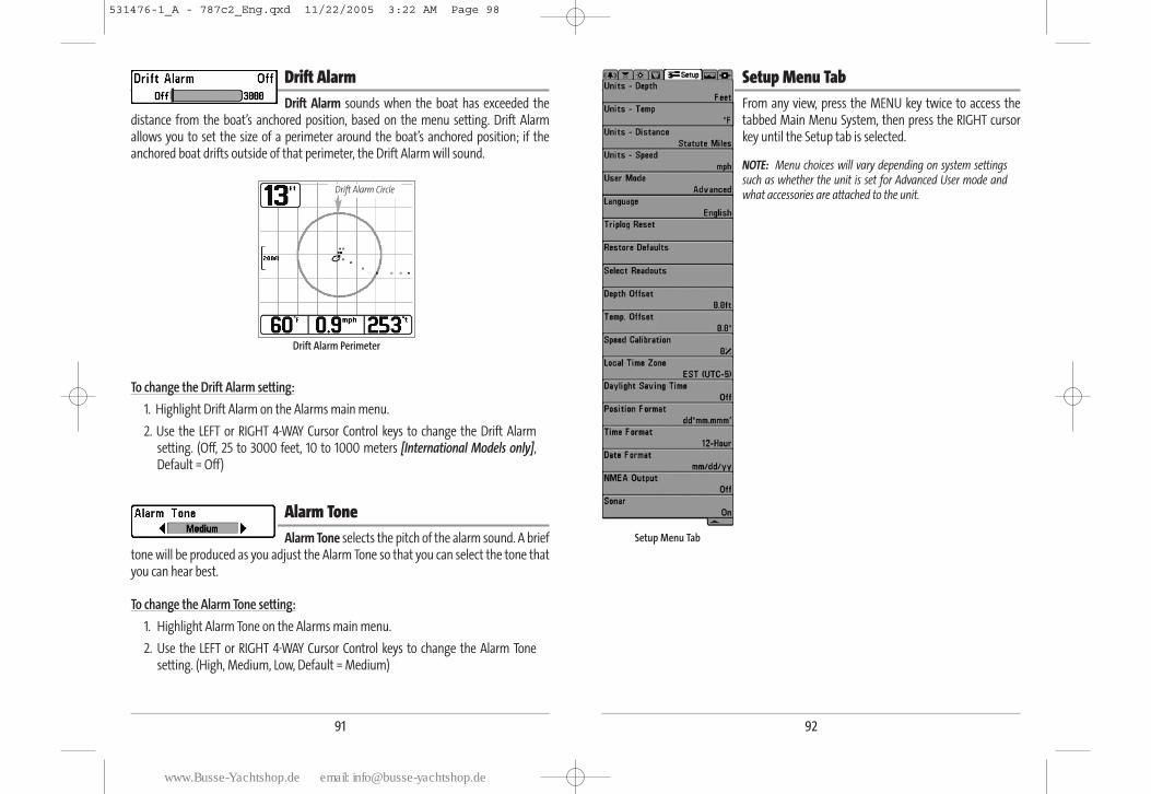
92
Setup Menu TabFrom any view, press the MENU key twice to access thetabbed Main Menu System, then press the RIGHT cursorkey until the Setup tab is selected.
NOTE: Menu choices will vary depending on system settingssuch as whether the unit is set for Advanced User mode andwhat accessories are attached to the unit.
Setup Menu Tab
91
Drift Alarm Drift Alarm sounds when the boat has exceeded the
distance from the boat’s anchored position, based on the menu setting. Drift Alarmallows you to set the size of a perimeter around the boat’s anchored position; if theanchored boat drifts outside of that perimeter, the Drift Alarm will sound.
To change the Drift Alarm setting:
1. Highlight Drift Alarm on the Alarms main menu.
2. Use the LEFT or RIGHT 4-WAY Cursor Control keys to change the Drift Alarmsetting. (Off, 25 to 3000 feet, 10 to 1000 meters [International Models only],Default = Off)
Alarm ToneAlarm Tone selects the pitch of the alarm sound. A brief
tone will be produced as you adjust the Alarm Tone so that you can select the tone thatyou can hear best.
To change the Alarm Tone setting:
1. Highlight Alarm Tone on the Alarms main menu.
2. Use the LEFT or RIGHT 4-WAY Cursor Control keys to change the Alarm Tonesetting. (High, Medium, Low, Default = Medium)
Drift Alarm Perimeter
Drift Alarm Circle
531476-1_A - 787c2_Eng.qxd 11/22/2005 3:22 AM Page 98
www.Busse-Yachtshop.de email: [email protected]
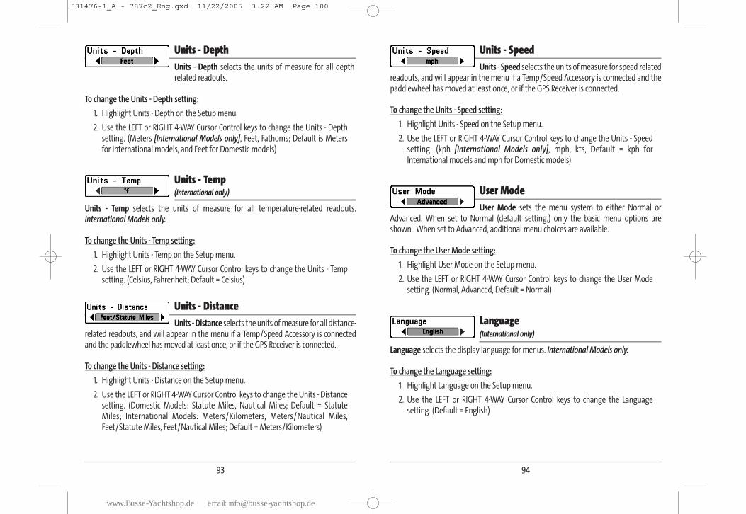
94
Units - Speed Units - Speed selects the units of measure for speed-related
readouts, and will appear in the menu if a Temp/Speed Accessory is connected and thepaddlewheel has moved at least once, or if the GPS Receiver is connected.
To change the Units - Speed setting:
1. Highlight Units - Speed on the Setup menu.
2. Use the LEFT or RIGHT 4-WAY Cursor Control keys to change the Units - Speedsetting. (kph [International Models only], mph, kts, Default = kph forInternational models and mph for Domestic models)
User Mode User Mode sets the menu system to either Normal or
Advanced. When set to Normal (default setting,) only the basic menu options areshown. When set to Advanced, additional menu choices are available.
To change the User Mode setting:
1. Highlight User Mode on the Setup menu.
2. Use the LEFT or RIGHT 4-WAY Cursor Control keys to change the User Modesetting. (Normal, Advanced, Default = Normal)
Language(International only)
Language selects the display language for menus. International Models only.
To change the Language setting:
1. Highlight Language on the Setup menu.
2. Use the LEFT or RIGHT 4-WAY Cursor Control keys to change the Languagesetting. (Default = English)
93
Units - Depth Units - Depth selects the units of measure for all depth-related readouts.
To change the Units - Depth setting:
1. Highlight Units - Depth on the Setup menu.
2. Use the LEFT or RIGHT 4-WAY Cursor Control keys to change the Units - Depthsetting. (Meters [International Models only], Feet, Fathoms; Default is Metersfor International models, and Feet for Domestic models)
Units - Temp (International only)
Units - Temp selects the units of measure for all temperature-related readouts.International Models only.
To change the Units - Temp setting:
1. Highlight Units - Temp on the Setup menu.
2. Use the LEFT or RIGHT 4-WAY Cursor Control keys to change the Units - Tempsetting. (Celsius, Fahrenheit; Default = Celsius)
Units - Distance Units - Distance selects the units of measure for all distance-
related readouts, and will appear in the menu if a Temp/Speed Accessory is connectedand the paddlewheel has moved at least once, or if the GPS Receiver is connected.
To change the Units - Distance setting:
1. Highlight Units - Distance on the Setup menu.
2. Use the LEFT or RIGHT 4-WAY Cursor Control keys to change the Units - Distancesetting. (Domestic Models: Statute Miles, Nautical Miles; Default = StatuteMiles; International Models: Meters/Kilometers, Meters/Nautical Miles,Feet/Statute Miles, Feet/Nautical Miles; Default = Meters/Kilometers)
531476-1_A - 787c2_Eng.qxd 11/22/2005 3:22 AM Page 100
www.Busse-Yachtshop.de email: [email protected]
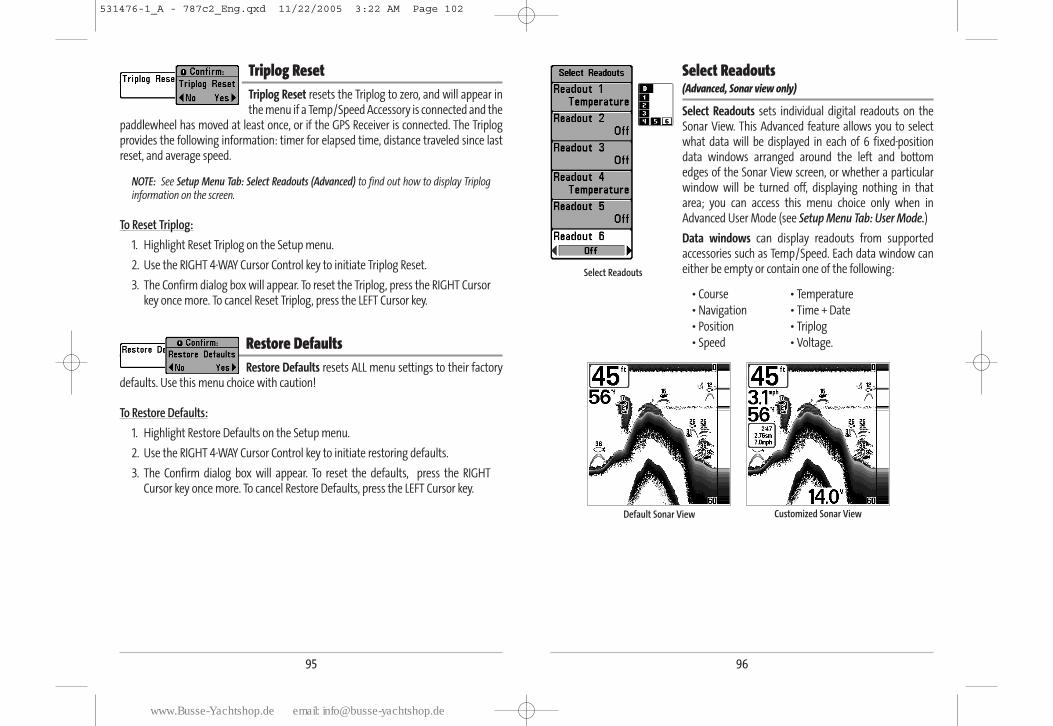
96
Select Readouts (Advanced, Sonar view only)
Select Readouts sets individual digital readouts on theSonar View. This Advanced feature allows you to selectwhat data will be displayed in each of 6 fixed-positiondata windows arranged around the left and bottomedges of the Sonar View screen, or whether a particularwindow will be turned off, displaying nothing in thatarea; you can access this menu choice only when inAdvanced User Mode (see Setup Menu Tab: User Mode.)
Data windows can display readouts from supportedaccessories such as Temp/Speed. Each data window caneither be empty or contain one of the following:
• Course • Temperature
• Navigation • Time + Date
• Position • Triplog
• Speed • Voltage.
Default Sonar View Customized Sonar View
Select Readouts
95
Triplog Reset Triplog Reset resets the Triplog to zero, and will appear inthe menu if a Temp/Speed Accessory is connected and the
paddlewheel has moved at least once, or if the GPS Receiver is connected. The Triplogprovides the following information: timer for elapsed time, distance traveled since lastreset, and average speed.
NOTE: See Setup Menu Tab: Select Readouts (Advanced) to find out how to display Triploginformation on the screen.
To Reset Triplog:
1. Highlight Reset Triplog on the Setup menu.
2. Use the RIGHT 4-WAY Cursor Control key to initiate Triplog Reset.
3. The Confirm dialog box will appear. To reset the Triplog, press the RIGHT Cursorkey once more. To cancel Reset Triplog, press the LEFT Cursor key.
Restore Defaults Restore Defaults resets ALL menu settings to their factory
defaults. Use this menu choice with caution!
To Restore Defaults:
1. Highlight Restore Defaults on the Setup menu.
2. Use the RIGHT 4-WAY Cursor Control key to initiate restoring defaults.
3. The Confirm dialog box will appear. To reset the defaults, press the RIGHTCursor key once more. To cancel Restore Defaults, press the LEFT Cursor key.
531476-1_A - 787c2_Eng.qxd 11/22/2005 3:22 AM Page 102
www.Busse-Yachtshop.de email: [email protected]
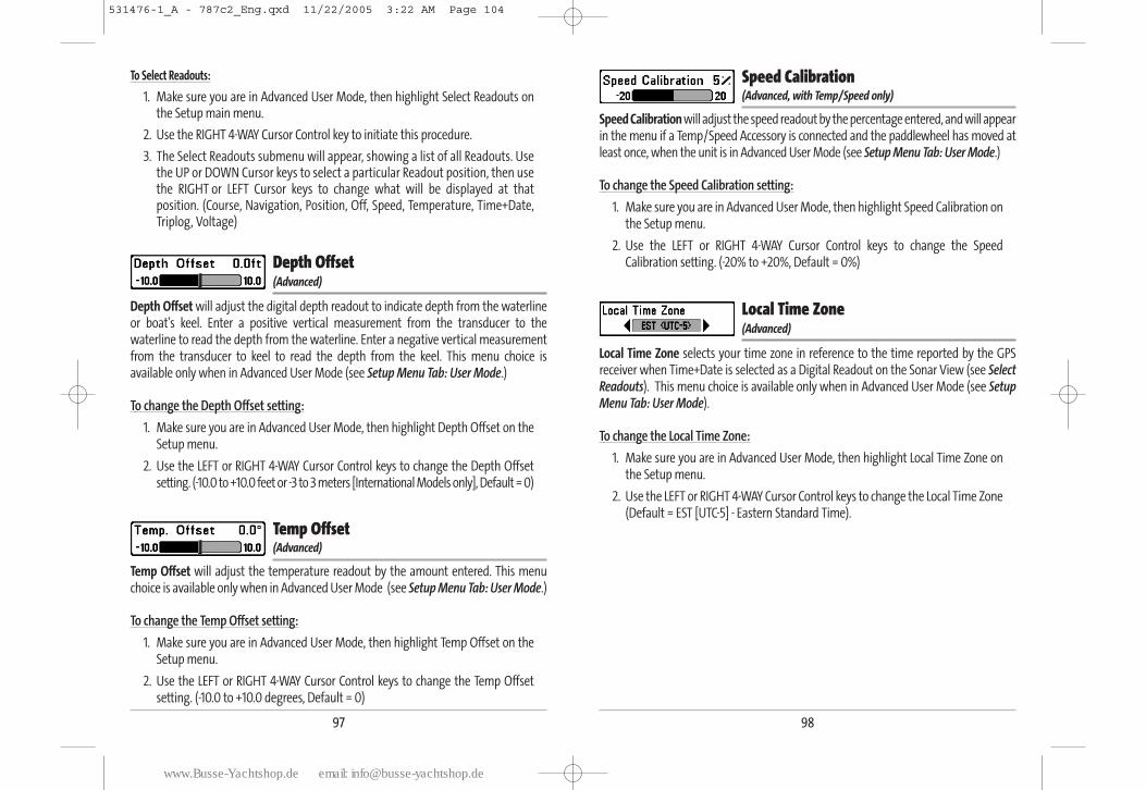
98
Speed Calibration (Advanced, with Temp/Speed only)
Speed Calibration will adjust the speed readout by the percentage entered, and will appearin the menu if a Temp/Speed Accessory is connected and the paddlewheel has moved atleast once, when the unit is in Advanced User Mode (see Setup Menu Tab: User Mode.)
To change the Speed Calibration setting:
1. Make sure you are in Advanced User Mode, then highlight Speed Calibration onthe Setup menu.
2. Use the LEFT or RIGHT 4-WAY Cursor Control keys to change the SpeedCalibration setting. (-20% to +20%, Default = 0%)
Local Time Zone (Advanced)
Local Time Zone selects your time zone in reference to the time reported by the GPSreceiver when Time+Date is selected as a Digital Readout on the Sonar View (see SelectReadouts). This menu choice is available only when in Advanced User Mode (see SetupMenu Tab: User Mode).
To change the Local Time Zone:
1. Make sure you are in Advanced User Mode, then highlight Local Time Zone onthe Setup menu.
2. Use the LEFT or RIGHT 4-WAY Cursor Control keys to change the Local Time Zone (Default = EST [UTC-5] - Eastern Standard Time).
97
To Select Readouts:
1. Make sure you are in Advanced User Mode, then highlight Select Readouts onthe Setup main menu.
2. Use the RIGHT 4-WAY Cursor Control key to initiate this procedure.
3. The Select Readouts submenu will appear, showing a list of all Readouts. Usethe UP or DOWN Cursor keys to select a particular Readout position, then usethe RIGHT or LEFT Cursor keys to change what will be displayed at thatposition. (Course, Navigation, Position, Off, Speed, Temperature, Time+Date,Triplog, Voltage)
Depth Offset (Advanced)
Depth Offset will adjust the digital depth readout to indicate depth from the waterlineor boat's keel. Enter a positive vertical measurement from the transducer to thewaterline to read the depth from the waterline. Enter a negative vertical measurementfrom the transducer to keel to read the depth from the keel. This menu choice isavailable only when in Advanced User Mode (see Setup Menu Tab: User Mode.)
To change the Depth Offset setting:
1. Make sure you are in Advanced User Mode, then highlight Depth Offset on theSetup menu.
2. Use the LEFT or RIGHT 4-WAY Cursor Control keys to change the Depth Offsetsetting. (-10.0 to +10.0 feet or -3 to 3 meters [International Models only], Default = 0)
Temp Offset (Advanced)
Temp Offset will adjust the temperature readout by the amount entered. This menuchoice is available only when in Advanced User Mode (see Setup Menu Tab: User Mode.)
To change the Temp Offset setting:
1. Make sure you are in Advanced User Mode, then highlight Temp Offset on theSetup menu.
2. Use the LEFT or RIGHT 4-WAY Cursor Control keys to change the Temp Offsetsetting. (-10.0 to +10.0 degrees, Default = 0)
531476-1_A - 787c2_Eng.qxd 11/22/2005 3:22 AM Page 104
www.Busse-Yachtshop.de email: [email protected]
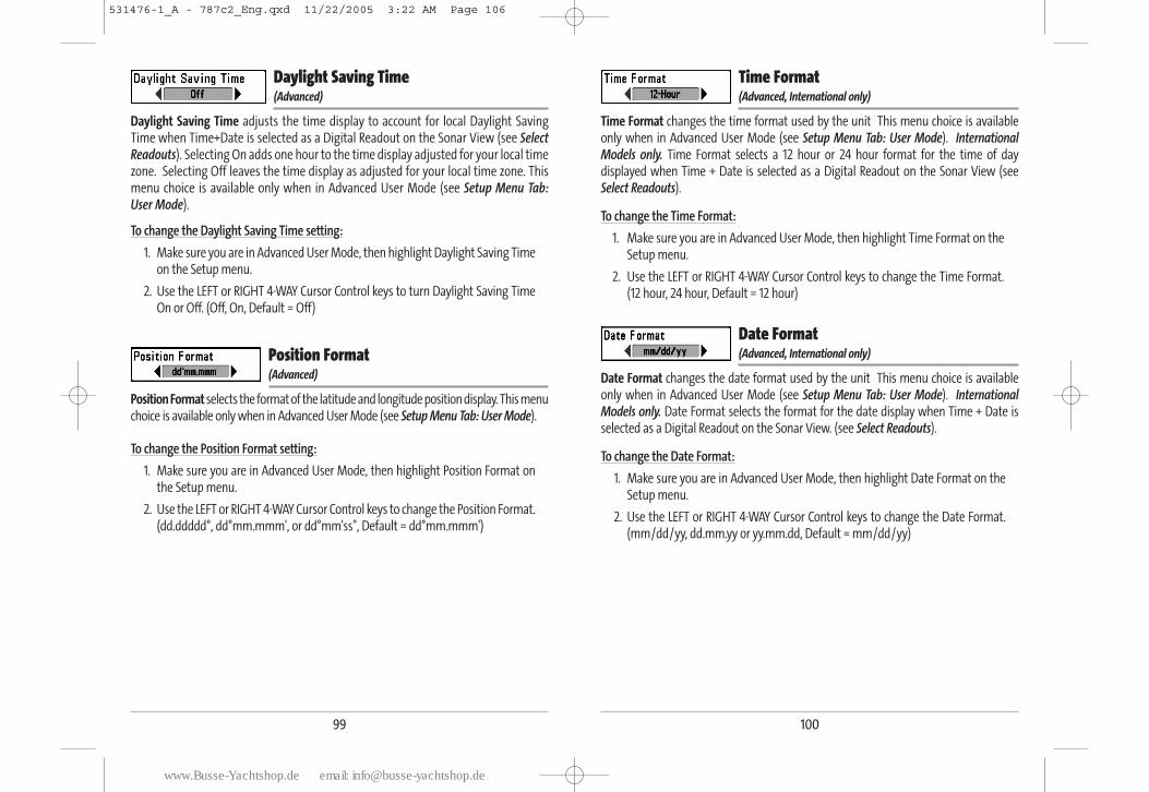
100
Time Format (Advanced, International only)
Time Format changes the time format used by the unit This menu choice is availableonly when in Advanced User Mode (see Setup Menu Tab: User Mode). InternationalModels only. Time Format selects a 12 hour or 24 hour format for the time of daydisplayed when Time + Date is selected as a Digital Readout on the Sonar View (seeSelect Readouts).
To change the Time Format:
1. Make sure you are in Advanced User Mode, then highlight Time Format on theSetup menu.
2. Use the LEFT or RIGHT 4-WAY Cursor Control keys to change the Time Format. (12 hour, 24 hour, Default = 12 hour)
Date Format (Advanced, International only)
Date Format changes the date format used by the unit This menu choice is availableonly when in Advanced User Mode (see Setup Menu Tab: User Mode). InternationalModels only. Date Format selects the format for the date display when Time + Date isselected as a Digital Readout on the Sonar View. (see Select Readouts).
To change the Date Format:
1. Make sure you are in Advanced User Mode, then highlight Date Format on theSetup menu.
2. Use the LEFT or RIGHT 4-WAY Cursor Control keys to change the Date Format.(mm/dd/yy, dd.mm.yy or yy.mm.dd, Default = mm/dd/yy)
99
Daylight Saving Time (Advanced)
Daylight Saving Time adjusts the time display to account for local Daylight SavingTime when Time+Date is selected as a Digital Readout on the Sonar View (see SelectReadouts). Selecting On adds one hour to the time display adjusted for your local timezone. Selecting Off leaves the time display as adjusted for your local time zone. Thismenu choice is available only when in Advanced User Mode (see Setup Menu Tab:User Mode).
To change the Daylight Saving Time setting:
1. Make sure you are in Advanced User Mode, then highlight Daylight Saving Timeon the Setup menu.
2. Use the LEFT or RIGHT 4-WAY Cursor Control keys to turn Daylight Saving TimeOn or Off. (Off, On, Default = Off)
Position Format (Advanced)
Position Format selects the format of the latitude and longitude position display. This menuchoice is available only when in Advanced User Mode (see Setup Menu Tab: User Mode).
To change the Position Format setting:
1. Make sure you are in Advanced User Mode, then highlight Position Format onthe Setup menu.
2. Use the LEFT or RIGHT 4-WAY Cursor Control keys to change the Position Format.(dd.ddddd°, dd°mm.mmm', or dd°mm'ss", Default = dd°mm.mmm')
531476-1_A - 787c2_Eng.qxd 11/22/2005 3:22 AM Page 106
www.Busse-Yachtshop.de email: [email protected]
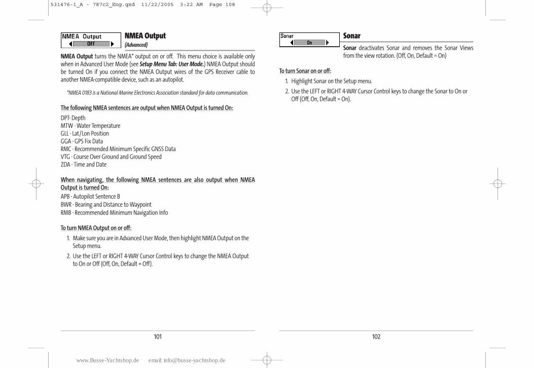
102
SonarSonar deactivates Sonar and removes the Sonar Viewsfrom the view rotation. (Off, On, Default = On)
To turn Sonar on or off:
1. Highlight Sonar on the Setup menu.
2. Use the LEFT or RIGHT 4-WAY Cursor Control keys to change the Sonar to On orOff (Off, On, Default = On).
101
NMEA Output (Advanced)
NMEA Output turns the NMEA* output on or off. This menu choice is available onlywhen in Advanced User Mode (see Setup Menu Tab: User Mode.) NMEA Output shouldbe turned On if you connect the NMEA Output wires of the GPS Receiver cable toanother NMEA-compatible device, such as an autopilot.
*NMEA 0183 is a National Marine Electronics Association standard for data communication.
The following NMEA sentences are output when NMEA Output is turned On:
DPT- DepthMTW - Water TemperatureGLL - Lat/Lon PositionGGA - GPS Fix DataRMC - Recommended Minimum Specific GNSS DataVTG - Course Over Ground and Ground SpeedZDA - Time and Date
When navigating, the following NMEA sentences are also output when NMEAOutput is turned On:APB - Autopilot Sentence B
BWR - Bearing and Distance to Waypoint
RMB - Recommended Minimum Navigation Info
To turn NMEA Output on or off:
1. Make sure you are in Advanced User Mode, then highlight NMEA Output on theSetup menu.
2. Use the LEFT or RIGHT 4-WAY Cursor Control keys to change the NMEA Outputto On or Off (Off, On, Default = Off).
531476-1_A - 787c2_Eng.qxd 11/22/2005 3:22 AM Page 108
www.Busse-Yachtshop.de email: [email protected]
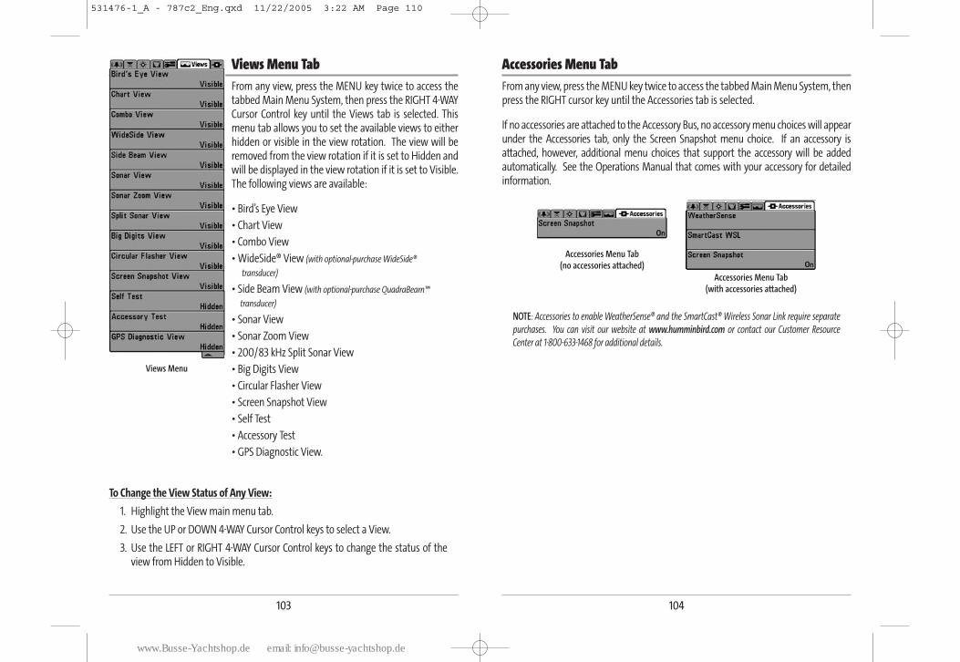
104
Accessories Menu TabFrom any view, press the MENU key twice to access the tabbed Main Menu System, thenpress the RIGHT cursor key until the Accessories tab is selected.
If no accessories are attached to the Accessory Bus, no accessory menu choices will appearunder the Accessories tab, only the Screen Snapshot menu choice. If an accessory isattached, however, additional menu choices that support the accessory will be addedautomatically. See the Operations Manual that comes with your accessory for detailedinformation.
NOTE: Accessories to enable WeatherSense® and the SmartCast® Wireless Sonar Link require separate
purchases. You can visit our website at www.humminbird.com or contact our Customer Resource
Center at 1-800-633-1468 for additional details.
Accessories Menu Tab (no accessories attached)
Accessories Menu Tab (with accessories attached)
103
Views Menu Tab From any view, press the MENU key twice to access thetabbed Main Menu System, then press the RIGHT 4-WAYCursor Control key until the Views tab is selected. Thismenu tab allows you to set the available views to eitherhidden or visible in the view rotation. The view will beremoved from the view rotation if it is set to Hidden andwill be displayed in the view rotation if it is set to Visible.The following views are available:
• Bird’s Eye View
• Chart View
• Combo View
• WideSide® View (with optional-purchase WideSide®
transducer)
• Side Beam View (with optional-purchase QuadraBeam™
transducer)
• Sonar View
• Sonar Zoom View
• 200/83 kHz Split Sonar View
• Big Digits View
• Circular Flasher View
• Screen Snapshot View
• Self Test
• Accessory Test
• GPS Diagnostic View.
To Change the View Status of Any View:
1. Highlight the View main menu tab.
2. Use the UP or DOWN 4-WAY Cursor Control keys to select a View.
3. Use the LEFT or RIGHT 4-WAY Cursor Control keys to change the status of theview from Hidden to Visible.
Views Menu
531476-1_A - 787c2_Eng.qxd 11/22/2005 3:22 AM Page 110
www.Busse-Yachtshop.de email: [email protected]
106
To view screen snapshots:
1. Make sure that the optional-purchase MMC/SD card used to capture thescreens is installed in your card slot.
2. Press the VIEW key until you see the Screen Snapshot View.
3. The Screen Snapshot View displays up to three thumbnails of these screencaptures at a time. You can scroll through the whole list of thumbnails of screencaptures in this view using the 4-WAY Cursor keys. The selected thumbnail willbe highlighted with arrows. See the full-sized image by selecting a thumbnail(using the Up or Down 4-Way Cursor keys), then using the Right 4-Way Cursorkey to view the full image. A border around the full-size screen capture indicatesthat it is just a screen capture, not a “live” view. You can delete the selectedimage, or all captured images, using Delete Image or Delete All Images from theScreen Snapshot X-Press™ menu. (See Screen Snapshot X-Press™ menu: DeleteImage and Delete All Images for more information).
NOTE: You may view data files associated with each screen snapshot by removing theMMC/SD card from your unit and installing it in your optional-purchase MMC/SD card readerconnected to a PC. Use Windows Explorer to see the contents of your MMC/SD card; you willnotice that a .DAT (may show up as .TXT) file is created for every .BMP screen capture; thisdata file includes the thumbnail view, and is required in order to be able to view the screensnapshot from your 700 series unit, so don’t delete these files.
105
Using Screen SnapshotScreen Snapshot activates the screen snapshot
function. When Screen Snapshot is enabled, pressing the MARK key creates a savedscreen capture on the optional-purchase MMC/SD card installed in your unit’s card slot.All menus, dialog boxes, warnings and messages are captured and saved automatically.You can view these captures on the Screen Snapshot View, which shows thumbnails ofthe screen captures, three at a time.
NOTE: You must have an optional-purchase MMC/SD card installed for the screen snapshotfeature to work.
To turn Screen Snapshot on or off:
1. Highlight Screen Snapshot on the Accessories main menu.
2. Use the LEFT or RIGHT 4-WAY Cursor Control keys to turn Screen Snapshot On orOff (Off, On, Default = Off).
To make a screen snapshot (Screen Snapshot must be enabled):
1. Make sure you have installed an optional-purchase MMC/SD card into yourcard slot.
2. From any view you want to capture, press the MARK key. When you start ascreen capture, you will see a message that a waypoint has been created at thepoint where your cursor is on the screen, and the screen will freeze. A statusdialog box will appear that shows the progress of the save, and that displays thenumbered filename assigned to the .BMP file that is being created, along withthe percentage completed status.
NOTE: Navigation is not affected by the Screen Snapshot feature. Also, if Screen Sanpshot isenabled but there is no GPS receiver connected, pressing the MARK key will capture the screenimage and display an error saying that a GPS position fix is required to create a waypoint.
NOTE: The speed of the capture depends on the type of card you use; in general, SD cardscapture the screen faster than MMC cards do.
531476-1_A - 787c2_Eng.qxd 11/22/2005 3:22 AM Page 112
www.Busse-Yachtshop.de email: [email protected]
108
Display ProblemsThere are several main conditions or sources of possible interference that may causeproblems with the quality of the information displayed on the control head. Look in thefollowing table for some symptoms of display problems and possible solutions:
Problem Possible Cause
The control head loses powerat high speeds.
When the boat moves athigher speeds, the bottomdisappears or suddenlyweakens, or the displaycontains gaps.
There are no fish detected,even when you know theyare in the water under theboat, or sonar readings seemweak or faulty.
If the power output of your boat’s engine isunregulated, the control head may be protectingitself using its over-voltage protection feature. Makesure the input voltage does not exceed 20 Volts.
The transducer position may need to be adjusted. Amix of air and water flowing around the transducer(cavitation) may be interfering with theinterpretation of sonar data. See your InstallationGuide for suggestions on adjusting the transducerposition.
Electrical noise from the boat’s engine may beinterfering with sonar reception. See Finding theCause of Noise for more information.
Sonar readings may be affected if the transducer isnot positioned correctly (i.e. mounted at an angle,not straight down), or there is some kind ofmechanical interference, either because it ismounted inside a hull that is too thick for propersonar transmission, the bond between thetransducer and the hull is not airtight, or because thetransducer is dirty. Check with your Installation Guidefor guidance on re-positioning the transducer, andmake sure the transducer is clean.
Low battery voltage may be affecting the power ofsignal transmission.
Electrical noise from the boat’s engine may beinterfering with sonar reception. See Finding theCause of Noise for more information.
107
TroubleshootingBefore contacting the Humminbird® Customer Resource Center, please read thefollowing section. Taking the time to review these troubleshooting guidelines may allowyou to solve a performance problem yourself, and therefore avoid sending your unitback for repair.
700 Series™ Doesn’t Power Up
If your 700 Series™ Fishing System doesn’t power up, use the Installation Guide that also
comes with it for specific confirmation details, making sure that:
• The power cable is properly connected to the 700 Series™ Fishing Systemcontrol head.
• The power cable is wired correctly, with red to positive battery terminal andblack to negative terminal or ground.
• The fuse is operational.
• The battery voltage of the power connector is at least 10 Volts.
Correct any known problems, including removing corrosion from the battery terminals
or wiring, or actually replacing the battery if necessary.
700 Series™ Defaults to Simulator with a Transducer Attached
A connected and functioning transducer will cause the newly-started 700 Series™Fishing System to go into Normal operating mode automatically. If, when you power upthe 700 Series™ Fishing System, it goes into Simulator mode automatically, even thougha transducer is already connected, this means that the control head is not detecting thetransducer. Perform the following troubleshooting tasks:
• Using the Installation Guide that also comes with your 700 Series™ FishingSystem, check to make sure that the transducer cable is securely connected tothe 700 Series™ Fishing System. Reconnect if necessary, and power up the 700Series™ Fishing System again to see if this fixes the problem.
• Replace the non-functioning transducer with a known good transducer ifavailable and power up the control head again.
• Check the transducer cable. Replace the transducer if the cable is damagedor corroded.
531476-1_A - 787c2_Eng.qxd 11/22/2005 3:22 AM Page 114
www.Busse-Yachtshop.de email: [email protected]
110
700 Series™ Fishing System AccessoriesAccessories customize the 700 Series™ Fishing System to your needs and enable you to stayon the edge of new technology. When an accessory is connected to the 700 Series™ FishingSystem, additional menus and readouts are added automatically to the Main Menu System.Accessories available today that are supported by your Fishing System include:
WideSide® transducer: purchase and connect the WideSide® transducer to your 700 Series™ Fishing System to access specialized "side looking" functions that areextremely useful for bank fishing or looking for bait fish in open water.
QuadraBeam™ transducer: purchase and connect the QuadraBeam™ transducer toyour 700 Series™ Fishing System to access specialized QuadraBeam™ functions suchas two 45° 455 kHz beams for a continuous 90° of uninterrupted side to sidecoverage to 160 feet. These Side Structure locating beams reveal fish and structureto the left and right of your boat near the bottom.
WeatherSense® Fishing Condition Monitor: purchase and plug in the WeatherSense®accessory to your 700 Series™ Fishing System to obtain barometric pressurereadouts and trend data in real time.
GPS Connection Cable: purchase the GPS Connection Cable in order to connect ahandheld or other NMEA* GPS-compatible device that you may already own to your 700 Series™ Fishing System.
*NMEA 0183 is a National Marine Electronics Association standard for data communication.
Wireless Sonar Link (WSL): Purchase the Wireless Sonar Link (WSL) accessory to receiveremote sonar signals from a SmartCast® Remote Sonar Sensor (RSS). Radio signals fromthe RSS are received by the WSL and are transmitted over the Accessory Bus to the 700Series™ Fishing System.
PC Connect Cable: Purchase the PC Connect Cable to connect the 700 Series™ FishingSystem to a PC in order to upload product software updates and new features obtainedfrom www.humminbird.com. This accessory requires the MSWindows-compatibleHumminbirdPC™ software downloaded from our website to your PC in order tocommunicate with the 700 Series™ Fishing System.
Be sure to check out our website www.humminbird.com for additional new andexciting accessories to grow your 700 Series™ Fishing System!
NOTE: Each accessory requires a separate purchase. You can visit our website atwww.humminbird.com or contact our Customer Resource Center at 1-800-633-1468 foradditional details.
109
Finding the Cause of NoiseElectrical noise usually affects the display with many black dots at high speeds, and highsensitivity readings. One or more of the following sources can cause noise orinterference:
Possible Source of Noise Isolation
Other electronic devices
The boat’s engine
Cavitation from the boat’spropeller
Turn off any nearby electronic devices to see if theproblem goes away, then turn them on one at atime to see if the noise re-appears.
To determine whether the boat’s engine is thesource of the noise, increase the RPMs while theboat is in neutral and stationary to see if the noiseincreases proportionately; if noise appears whenyou rev the engine, the problem could be the sparkplugs, alternator, or tachometer wiring. Replace thespark plugs with resistor plugs, install an alternatorfilter, or route the control head power andtransducer cables away from the engine wiring.
Turbulence created by the propeller can causenoise; make sure the transducer is mounted at least15” (38 cm) from the propeller, and that the waterflows smoothly over the face of the transducer at alltimes.
531476-1_A - 787c2_Eng.qxd 11/22/2005 3:22 AM Page 116
www.Busse-Yachtshop.de email: [email protected]
112
Specifications
Depth Capability.......................................................................................... 1500 ft (500 m)
Power Output ........................................ 500 Watts (RMS), 4000 Watts (Peak to Peak)
Operating Frequency........................................ 200 kHz and 83 kHz DualBeam PLUSTM
Area of Coverage ............................................................................ 60° @ -10 dB in 83 kHz
20° @ -10 dB in 200 kHz
Target Separation .......................................................................... 2 1/2 Inches (63.5 mm)
Power Requirement .............................................................................................. 10-20 VDC
LCD .................................................................................................................... 640 V x 480 H
Transducer .............................................................................................................. XHS-9-20-T
Transducer Cable Length .................................................................................... 20 ft (6 m)
Current Draw ............................................................................................................0.7 Amps
NOTE: Humminbird® verifies maximum stated depth in saltwater conditions, but actualdepth performance may vary due to transducer installation, water type, thermal layers,bottom composition and slope.
NOTE: Product specifications and features are subject to change without notice.
Glossary
Sonar Terms:
Alarm, Depth: Depth Alarm is a user-controllable, audible alert that sounds when depthis less than or equal to the setting.
Alarm, Temperature: Temperature Alarm is a user-controllable, audible alert that soundswhen the water surface temperature equals the setting.
Backlight: Backlight is a user-controllable illumination for the LCD for night and low lightuse.
Beam (Sonar Beam): A sonar beam is the wide, cone-shaped projection of sound wavesformed as sound travels underwater. See Cone Angle.
Big Digits View: Big Digits View is a Humminbird® feature that displays the sonar graphand enlarged digital readouts for easy reading from a distance. This is a great tool whenmonitoring the digital depth is important - such as with higher boat speeds, or whenviewing the unit from a distance. When speed input is available, the Big Digits View alsoshows the TripLog. See TripLog.
Bottom Black: Bottom Black is a Humminbird® feature that "fills in" the area of thedisplay below the bottom contour. Bottom Black is preferred by some anglers because ofits high contrast and easy readability, even though it can obscure bottom hardnessinformation.
Bottom Contour: Bottom Contour is the profile of the bottom graphed to the displayas the depth changes.
Bottom Hardness: Bottom Hardness is the density (or composition) of the bottom,which can often be determined by interpreting the main sonar return. Varying levels ofhardness can be determined by interpreting the "thickness" of the sonar return. Hardreturns appear thin and black, softer returns appear thicker and less black. It is importantto note that a sonar return from a sloping bottom can have the appearance of a softerbottom.
Cavitation: Cavitation is the effect of air bubbles created as the propeller rotates and theboat moves through the water.
111
531476-1_A - 787c2_Eng.qxd 11/22/2005 3:22 AM Page 118
www.Busse-Yachtshop.de email: [email protected]
114113
Chart Speed: Chart Speed is a user-controllable feature that sets the speed at whichsonar information moves across the display. A faster setting displays sonar informationfrom more pings and shows more detail, but the information moves quickly across thedisplay: a slower setting permits viewing of more sonar history, but does not display asmuch detail. The best setting is often the user's personal choice.
Cone Angle: The cone angle is the angular measurement of the sonar beam at a specificdB down point (i.e. -10 dB). See dB Down Point.
Customizable Digital Readouts: Customizable Digital Readouts is a Humminbird®feature that permits the user to select the specific digital information that appears inthe main Sonar view (i.e. Speed, Temperature, Barometric Pressure, TripLog, etc.)
Dead Zone: The dead zone is the area of the sonar beam that receives the sonar signalafter the main bottom return. Fish and other objects close to the bottom that fall withinthe dead zone will probably not be visible in the sonar beam. Precision sonar beams,such as the Humminbird® 20° beam, have a smaller dead zone than wider sonar beams.
Decibel: A Decibel is the measurement for sound pressure level, or "intensity" of thesonar return. See dB Down Point.
dB Down Point: The dB Down Point is the standard decibel level at which the sonar coneangle is measured, and is written as "@ -10 dB" or "@ -3 dB". Measurements at smallerdown points (bigger negative numbers) indicate that the less intensive sonar signals arebeing used for the measurement.
Display, FSTN: FSTN is an acronym for Film Super-Twist Nematic. FSTN is a monochromedisplay technology characterized by black, high-contrast pixels. All monochrome fixedmount Humminbird® products use FSTN technology.
DualBeam PLUS™: DualBeam PLUS™ is a Humminbird® sonar configuration that usestwo sonar beams simultaneously, and combines the information from both beams intoone view by overlapping the data on-screen, or shows each beam individually side byside, or permits each beam to be viewed individually full screen.
Feature Memory: Feature Memory is a Humminbird® feature that retains the user'smenu settings in permanent memory. Settings are retained even when the unit ispowered off indefinitely.
Fish Arch: A Fish Arch is the apparent "arch" that appears on the display when any objectmoves through the sonar cone. The arch results from a gradual decrease in distance toan object as it moves into the sonar cone. The distance to an object changes due to theconical shape of the sonar beam, which causes the distance to be greater at the edgesof the beam than at the center of the beam. When this distance change is graphed onthe display, an arch appears.
Fish ID+™: Fish ID+™ is a Humminbird® feature that uses advanced sonar processingalgorithms to determine if a detected object is likely to be a fish. When the sonar signalfrom an object meets strict parameters, the unit draws a Fish Symbol (or icon) and thedigital depth of the target. On DualBeam and DualBeam PLUS™ units, fish detected inthe narrow center beam are shown as shaded symbols, and fish detected in the widerbeam are shown as hollow symbols.
Fish Symbol: A Fish Symbol is the graphic that is displayed on the screen when Fish ID+determines that a sonar return is likely to be a fish. See Fish ID+.
Freeze Frame: Freeze Frame is a Humminbird® feature that pauses the sonar scrollingso that the image on screen can be studied with greater detail. See Instant ImageUpdate.
Frequency: Frequency is a measure of the number of sound wave cycles per second of asound impulse transmitted underwater. A typical frequency for fishfinders is 200 kHz,which offers a good balance of performance under many conditions. Lower frequencies,such as 50 kHz, are capable of penetrating to greater depths, but with less resolution.Higher frequencies, such as 455 kHz, offer greater resolution, but are limited in depthperformance. Humminbird® uses a variety of frequencies that are optimized for specificapplications.
Grayscale: Grayscale is the use of varying shades of gray to represent the strength of thesonar signal on the display , and is a very intuitive method of presenting information.Traditionally, the strongest sonar signals are represented in black, and progressivelyweaker signals are represented in progressively lighter shades of gray.
Grayscale, Inverse: Inverse Grayscale is a Humminbird® feature that reverses thecorrelation of sonar signal strength and the shade of gray typically used to represent it.The strongest sonar signals are represented by "white", and progressively weakersignals are represented in progressively darker shades of gray. While somewhat counter-intuitive, this method makes the sonar images crisper, and has the benefit of enhancing
531476-1_A - 787c2_Eng.qxd 11/22/2005 3:22 AM Page 120
www.Busse-Yachtshop.de email: [email protected]
116115
the apparent sensitivity because the weaker signals appear bolder. Inverse grayscaleworks well in very clear water. Debris-laden water often appears as a lot of clutteron the screen.
Instant Image Update: Instant Image Update is a Humminbird® feature that updates allthe sonar information on the display when Sensitivity and a variety of sonar settings(Bottom View, Range, etc.) are modified. This differs from the traditional functionalitythat only updates the new sonar information collected after the setting change. InstantImage Update permits more accurate fine-tuning of the display because the user can seethe results on the complete sonar graph. When combined with the Freeze Framefeature, the user can adjust and understand the effects of many different sonar settingsquickly and easily.
Maximum Depth Menu: The Maximum Depth Menu is a Humminbird® feature thatoptimizes performance based on the maximum operational depth set by the user. ManyHumminbird® units can operate across a very broad depth range (up to 2500 feet) whichcauses the unit to "look" up to that full depth under some circumstances. Due to the speedof sound in water, this can result in less responsiveness because the unit has to wait for alonger period of time to receive the sonar signal. When the Maximum Depth menu is setto a lower value, the unit only looks up to the setting, which increases the responsivenessof the unit. This is an important feature for anyone operating in shallower depths!
Noise: Noise is unintentional, external sound waves that interfere with the optimaloperation of sonar. Noise appears as random "dots" on the display, and is caused by avariety of sources. Electrical noise (from trolling motors, bilge pumps, VHF radios)typically manifests as a consistent dot pattern. Electrical noise can be isolated byselectively turning on and off other electrical devices to determine the source. Often re-routing the power cable, or connecting to an alternative power supply (second battery)can help overcome electrical noise. Hydrodynamic noise (from propeller and/or hullcavitation) has a more random appearance and is generally related to boat speed, sothat faster operation results in more noise. Hydrodynamic noise can be overcome byproper transducer installation. Many Humminbird® products have a Noise Filter menusetting that allows the user to clear the screen of noise that is difficult to eliminate.
Pixels: Pixels are the "picture elements", or small square blocks, that make up the imageon the LCD. Measured as a vertical by horizontal number (i.e. 640V x 320H), this keyspecification typically indicates the quality of resolution. In fishfinders, the totalresolution (vertical multiplied by horizontal) is often less important than the "VerticalPixel" resolution. See Pixels, Vertical.
Pixels, Vertical: Vertical Pixels are a number of vertical picture elements in a singlecolumn on an LCD display. A greater number of vertical pixels provide finer resolution oftargets detected by sonar. Essentially, a vertical distance (the depth), when divided by alarger number, breaks that distance into smaller samples, each representing a smallerarea and thus providing more detail. In fishfinders, vertical pixels are more critical thanhorizontal pixels because the horizontal axis of the display represents time, or history.Sonar information on the horizontal axis can vary greatly, depending on boat speed andthe Chart Speed setting. A greater number of horizontal pixels show more sonar historythat the boat has passed through. On many models, Humminbird® provides the mostvertical pixels to provide a better display resolution. See Chart Speed and Pixels.
Power Output: Power output is the amount of sound energy emitted into the water bythe sonar transmitter. Power output is measured using either RMS (Root Mean Square)or P-T-P (Peak-to-Peak) measurement systems. Either method is acceptable, but it isimportant, when comparing power outputs, to make sure that the same measurementsystem is being used for both outputs, because P-T-P numbers are 8 times higher thanRMS numbers. Greater power output allows the sonar signal to penetrate throughweeds and thermoclines, reach deeper depths and operate more effectively in noisyenvironments, such as when the boat is running at high speed.
Pulse Width (Pulse Length): Pulse Width is the length of time that a sonar sound burstis transmitted into the water. Shorter pulse widths provide better target separation, butcannot travel to great depths. Longer pulse widths provide better depth penetration, butresult in poorer target separation. Humminbird® varies pulse width based on depth tooptimize both target separation and depth performance. See Target Separation.
QuadraBeam™: QuadraBeam™ is a Humminbird® sonar configuration that uses foursonar beams for a more detailed bottom image. QuadraBeam™ uses the DualBeamPLUS™ configuration for downlooking, and also adds two additional beams to look tothe left and right. The sonar beams pointing to the left and right provide the ability tospot fish and structure over a wide 90° area, and to identify on which side of the boatthey are located. See DualBeam PLUS™.
Quick Disconnect Mount: The Quick Disconnect Mounting system is an exclusiveHumminbird® feature that permits the unit to be easily removed from the mountingbase by pressing a release button, and re-installed by simply snapping it back intoplace. All cable connections are made when installing, so that no separate wiringconnections are required. Additionally, the mount offers 90° tilt and 360° swivelcapability to adjust the viewing angle of the unit as you move about the boat.
531476-1_A - 787c2_Eng.qxd 11/22/2005 3:22 AM Page 122
www.Busse-Yachtshop.de email: [email protected]
118117
Real Time Sonar: Real Time Sonar is a Humminbird® technology that delivers ultra-fastsonar transmitter/receiver operation and results in a more detailed instantaneous viewof what is under the boat. The Real Time Sonar window is a vertical band at the right sideof the display that shows the instantaneous sonar return from the transducer at aparticular instant. The RTS® Window menu option permits the user to adjust thewindow to show the full sonar signal return, or just a narrower band that indicatesintensity using grayscale. Real Time Sonar relies on very fast Sonar Update Rate (PingSpeed). See Sonar Update Rate.
Receiver: See Transmitter.
Second Return: The Second Return is a term that describes the appearance of a secondsonar return below the primary sonar return (bottom contour) at exactly twice the truedepth. The second return is caused by the same sonar energy bouncing off the bottomonce, rebounding to the water surface and then traveling back down to the bottom tobe reflected again. Second returns are more common in shallow water and over hardbottoms; it is actually possible to see a third sonar return under some circumstances.The second return provides useful information to help determine bottom hardness, asareas with harder bottoms will generally create a second return. The second return canbe used as a guide to set Sensitivity when in shallower water.
Sensitivity: Sensitivity is a user feature that adjusts the sensitivity of the sonar systemto show more or less detail in the water. Higher sensitivities are often preferred,however, when the water contains debris (silt, storm debris, etc.) and it can be difficultto pick out targets. Conversely, if sensitivity is set too low, relevant targets may bemissed.
SONAR: SONAR is the acronym for SOund and NAvigation Ranging. Sonar technologyuses precision sound bursts transmitted underwater to determine the distance andother attributes of objects in the water. Distance can be determined because the speedof sound in water is constant, and the time for the signal to return is measured. Soundalso travels very quickly underwater, making sonar a responsive, cost-effective tool.Sonar is the basic technology behind all recreational and commercial fishfinding anddepthfinding devices.
Sonar Echo Enhancement: Sonar Echo Enhancement is a Humminbird® feature thatdescribes the high degree of sonar sensitivity achieved through a combination oftransmitter/receiver and software algorithms. The result of Sonar Echo Enhancement isto display virtually everything in the water that is of interest to the angler, including bait
fish, game fish, thermoclines, weed beds, subtle structure, and more.
Sonar Update Rate: Sonar Update Rate is the number of times per second that thetransmitter/receiver sends and receives sonar signals. A very fast sonar update ratecollects more information and provides a more detailed image of the bottom, fish andstructure. Many Humminbird® units operate at up to 40 times per second when insingle frequency operation. Due to the limitation of the speed of sound in water, theupdate rate begins to slow as depth increases to deeper than 50 feet. In very shallowwater (less than 10 feet), however, update rates as much as 60 times per second can be achieved.
Speed: Speed is the rate at which the boat moves through the water. Boat speed can bemeasured as Speed Over Ground or Speed Through Water. Speed Over Ground isprovided by GPS, and is the measurement of the boats progress across a given distance.Speed Through Water is provided by a speed paddlewheel, and is the measurement ofthe flow past the boat, which may vary depending on current speed and direction.Speed Through Water is most critical for anglers using downriggers, as it impacts therunning depth of the down riggers. Speed Over Ground is optimal for navigation, asaccurate destination times can be derived from this measurement. Humminbird®products allow for input and display of both sources.
Structure: Structure is a general term for objects on the bottom that present adiscontinuity and are a likely attractor for fish. This includes bottom contour features(drop-offs, humps, and holes), standing structure (stumps, timbers, brush piles) and awide range of other potential objects (sunken boats, reefs). Humminbird® units excel atshowing structure with great detail over a wider area due to unique sonarconfigurations developed for the angler.
Structure ID®: Structure ID® is a Humminbird® feature that describes the traditionalgrayscale method of presenting sonar information. See Grayscale.
Surface Clutter: Surface Clutter is a phenomenon where sonar returns are reflected offof tiny objects near the surface of the water, including algae and even air bubbles.Typically, saltwater environments have significantly greater surface clutter thanfreshwater due to continuous wind and wave action that causes aeration at the surface.The Surface Clutter menu provides manual control to bias the default settings underextreme conditions.
531476-1_A - 787c2_Eng.qxd 11/22/2005 3:22 AM Page 124
www.Busse-Yachtshop.de email: [email protected]
120119
Target Separation: Target Separation is the measurement of minimum distance that afishfinder needs to be able to recognize two very close objects as two distinct targets (i.e.two fish hanging very close, or a fish hanging very close to structure). Humminbird®findfinders provide a very good 2 1/2 inches of target separation in shallower than 100feet of depth. Target separation decreases as depth increases due to the need for longerPulse Width to achieve greater depth. See Pulse Width.
Thermoclines: Thermoclines are water layer(s) of distinctly different temperatures thatcreate a sonar reflection due to the density of the differing water temperatures. Typicallya thermocline will appear as a continuous band across the display at some distanceabove the bottom contour. Thermoclines are of interest to anglers because fish willsuspend above or below the thermocline as they seek the optimum temperature andoxygen levels.
Time Variable Gain: Time Variable Gain is a processing step applied to the sonar returnto "normalize" the data so that objects of equal size (i.e. fish) appear to be the same size,even if they are separated by a good distance. Time Variable Gain is a fundamentalattribute of good sonar, but is often promoted as a feature.
Total Screen Update®: A Humminbird® feature that refreshes and updates all the sonarinformation on the display when a range change occurs. Without Total Screen Update®,only the most recent sonar information would be drawn to the new range, and the oldsonar information would continue to scroll off the screen at the old range.
Transducer: The transducer is part of the sonar system, which mounts on the boat andis in contact with the water, that converts the electrical energy from the transmitter intosound energy, and that forms the sonar beam in turn. Internally, the transducer consistsof one or more piezo electric disks that expand by very minute amounts to create thesound wave. This element also works in reverse, converting the returned sound energyback into an electrical signal that the receiver interprets. Transducers are available formany specific mounting applications for the boat, such as a transom mount, trollingmotor mount, etc. Humminbird® offers many sophisticated transducers, often withmultiple piezo electric elements designed to form specifically-shaped sonar beams,providing the angler with superior tools for finding and catching fish. See Transmitterand SONAR.
Transmitter: The transmitter and receiver are matched parts of the sonar system thatsend (transmit) and listen to (receive) the sonar signals, and work in conjunction withthe transducer. Humminbird® transmitters have an extremely fast cycling design that
can send signals up to 60 times per second, as well as produce the varying levels ofpower output needed for different depths and conditions. Additionally, the transmitterhas the capability to create very precise sonar pulses needed for a high degree of targetseparation. Humminbird® receivers are extremely sensitive, but within a narrow"bandwidth" to discriminate against noise from external sources. Additionally, thereceiver offers a wide "dynamic range" which provides the ability to receive very strongsignals alternating with very weak signals, without the strong signal overwhelming theweak signal. See Transducer and Noise.
TripLog: TripLog is a Humminbird® feature that provides an on-screen counter forElapsed Time, Average Speed and Total Distance traveled, and requires a speed input toactivate the feature. TripLog appears on the Big Digits View, and can be reset to zerothrough the TripLog menu.
TrueArch®: TrueArch® is a Humminbird® feature that provides true fish arches, notartificial arches or symbols. Humminbird® units are capable of producing fish arches dueto the wide 60° sonar beam of DualBeam PLUS™, an extremely sensitive sonar receiver.See Fish Arch.
Viewing Angle: Viewing Angle is an attribute of an LCD that characterizes visibility of thedisplay when viewing from off the central access, such as when standing to the side ofthe fishfinder. Wider viewing angles are better because the information remains visibleeven when viewing from the side.
WhiteLine®: WhiteLine® is a Humminbird® feature that highlights the strongest sonarreturn on the display using a very light gray band. This is preferred by some anglers whohave grown accustomed to the feature on paper graph chart recorders.
WideSide®: WideSide® is a Humminbird® sonar configuration used in an optionaltransducer. WideSide® uses three sonar beams pointing to the left, right and down.Beams pointing to the left and right are effective for spotting fish and structure near thesurface or on the bank. The downlooking beam provides depth information directlybelow the boat.
X-Press™ Menu: X-Press™ Menus are a Humminbird® feature that make the mostcommonly-used menu selections available with one press of the MENU key. Items thatappear on the X-Press™ Menu are related to the current view, and present the most logicalchoices for that view. Sonar View X-Press™ menus will differ from Chart View X-Press™ menus, etc. X-Press™ menus are one of the principal reasons that Humminbird®products are easier to use.
531476-1_A - 787c2_Eng.qxd 11/22/2005 3:22 AM Page 126
www.Busse-Yachtshop.de email: [email protected]
122121
Zoom: Zoom is a feature that focuses in on a smaller area of the bottom to provideenhanced resolution. With enhanced resolution, the angler can more easily see fishhanging in structure or multiple fish hanging close together. Split screen zoom dividesthe display into the full range view on the right, and the zoomed view on the left.Humminbird® offers One-Touch® Zoom which allows the zoom feature to be easilyaccessed from the regular sonar view with just one key press, eliminating the need touse menus to access the feature.
Zoom, Bottom Lock: Bottom Lock Zoom is a feature that focuses on a smaller area justabove the bottom to provide enhanced resolution. Unlike regular zoom, it continuouslygraphs the bottom at a constant point on the display regardless of changes in depth.This "flattens" out the bottom contour, but is effective at showing fish on or near thebottom, and is preferred by many saltwater anglers.
GPS & Navigation Terms:
Acquisition Time: The length of time that a GPS receiver typically takes to determine aposition from at least three satellites. Humminbird® GPS receivers provide very fastacquisition times (under one minute), permitting users to get out on the water faster.
Alarm, Arrival: The audible alert that sounds when the boat is equal to or less than thealarm setting (25 feet–3000 feet) from the location of the destination waypoint.
Alarm, Drift: Drift Alarm is an audible alert that sounds when the boat is equal to or overthe alarm setting (25 feet–3000 feet) from the location where the alarm was turned on.
Alarm, Off-Course: Off-Course Alarm is an audible alert that sounds when the boat’sdistance from the intended Track, (Cross Track Error), is equal to or over the alarm setting(25 feet – 3000 feet). See Track and Cross Track Error.
Altitude: Altitude measures height above sea level. Altitude is a measurement that canbe provided by GPS.
Bearing (BRG): Bearing is the direction to a destination waypoint measured in degreesfrom North (i.e. 321°, where 000° is North, 090° East, 180° is South, 270° is West).
Chartplotter: Chartplotter describes a navigation device that shows Present Position ona Map, along with Tracks, Waypoints, and Routes. All Chartplotters are also consideredTrackplotters. All Humminbird® GPS Combo units are Chartplotters. See Trackplotter.
Cold Start: Cold Start refers to the procedure that a GPS receiver must perform when itdoes not have historical information regarding its current location. This proceduretypically lasts for several minutes, and may be experienced upon first power up of thereceiver, or if the receiver has been moved a great distance.
Course Over Ground (COG): Course Over Ground is the current direction the boat istraveling measured in degrees from North (i.e. 321°, where 000° is North, 090° East, 180°is South, 270° is West). When the Course Over Ground is equal to Bearing, the boat issaid to be “On Course” and will arrive at the destination in the most efficient manner.COG is often confused with Heading. See Heading.
Cross Track Error (XTE): Cross Track Error is the straight-line distance of the boat fromthe intended Track. XTE measures how far the boat is off course, and also triggers theOff Course Alarm. See Track.
Differential GPS (DGPS): Differential GPS is a system to improve the position accuracyof the Department of Defense GPS through the use of secondary “correction signals”broadcast from ground stations around the coastal United States and on some inlandwaterways. These correction signals are provided by the USCG and received by anauxiliary Differential Beacon Receiver (DBR) that connects to the GPS receiver. Theadvent of WAAS has largely negated the need for the added expense of a DBR in theUnited States.
Distance To Go: Distance To Go is the straight-line distance between Present Positionand the Destination Waypoint. DTG and SOG (Speed Over Ground) are used to calculateTime To Go. See Time to Go and Speed Over Ground.
Estimated Position Error (EPE): Estimated Position Error is a calculation that indicates thepotential position inaccuracy the user may experience due to a variety of GPS factorswhich include satellite position in the sky, signal strength and others factors.
Fix Type: Fix Type indicates whether the GPS receiver is providing 2D fix or 3D fix. A 2Dfix requires only three satellites and provides only latitude and longitude. A 3D fixrequires four or more satellites, and provides latitude, longitude and altitude.
GPS: GPS is an acronym for Global Positioning System. GPS provides accurate position(latitude, longitude, altitude) information virtually anywhere on the earth throughsatellite technology and personal receivers on the ground. A series of geosynchronoussatellites broadcast a unique signal toward the earth once per second. A GPS receiver,
531476-1_A - 787c2_Eng.qxd 11/22/2005 3:22 AM Page 128
www.Busse-Yachtshop.de email: [email protected]
124123
such as that included with many Humminbird® products, receives the signals fromthese satellites and is able to determine position based on very slight differences in thetime each signal is received and the receiver’s knowledge of the location of each of thesatellites.
Heading: Heading describes the direction the boat is pointing and is measured indegrees (i.e. 321°, where 000° is North, 090° East, 180° is South, 270° is West). Due towind and waves, the boat is often traveling in a slightly different direction than it isheading, and therefore Heading is often confused with Course Over Ground. See CourseOver Ground.
Map Datum: A Map Datum refers to a particular survey of the earth’s surface that wasreferenced when creating a chart (i.e. WGS84). Since the earth is not flat, and not evenconsistently round, a mathematical model must be used to translate coordinates fromthe sphere of the earth to the flat surface of a chart. This mathematical model is theMap Datum. Historically, many different Map Datums have been used around the worldto create maps; often a reference to the Map Datum can be found in the legend of apaper map. It is important to select the correct Map Datum setting in your fishfinderwhen comparing GPS position to a paper chart to avoid slight position inaccuracies.Almost all electronic charts use the WGS84 Map Datum and therefore, they do notrequire setting changes.
MMC: MMC is an acronym for Multi Media Card. An MMC is a postage stamp-sizedmemory device used to store electronic data such a maps, waypoints, routes and otherinformation. MMC is a very rugged format suitable for the marine environment, but it isnot waterproof. The MMC is removable from Humminbird® products, and can be usedin a PC that is equipped with an appropriate card reader. MMC is the same format thatmany digital cameras use. See SD.
North, Magnetic: North is the principle reference point of the compass (i.e. North is000°). Magnetic North relies on the earth’s magnetic field to align a metal pointergenerally towards True North. However, due to local variations in the earth’s magneticfield around the globe, the difference between True North and Magnetic North can begreater than 10°. See True North.
North, True: North is the principle reference point of the compass (i.e. North is 000°).True North uses the axis of the rotation of the earth as the reference for North and isconstant for all points on the earth. Most GPS units default to True North as the setting.The GPS heading may vary from the boat compass heading because the compass uses
Magnetic North. Humminbird® GPS units provide the option of selecting True orMagnetic readouts by using the North Reference menu. See Magnetic North.
Present Position: Present Position is the current location (latitude, longitude)determined by GPS. The Present Position is indicated on-screen by a directional boat iconif the boat is moving, or a round symbol if the boat is stationary.
Route: A Route is series of waypoints linked together in a specific sequence to define anavigation path between two points, and saved in the fishfinder’s memory. Routes areoften used when frequently traveling between two or more locations because it is afaster and more accurate method than repeatedly selecting individual waypoints eachtime one travels through the same area. Routes consist of a Start Waypoint, an EndWaypoint, and a series of waypoints in between. Users can begin navigation at thebeginning, the end (to run the route in reverse) or at any waypoint in between. SeeWaypoint.
SD: SD is an acronym for Secure Digital. An SD card is virtually identical in function to anMMC; however, the speed at which information can be accessed is generally faster, thestorage capacity is generally larger, and the card has security features which can be usedto prevent extracting the data from the card. SD is the same format that many digitalcameras use. See MMC.
Selective Availability: Selective Availability (SA) is a GPS system “feature” that can beimplemented by the U.S. Department of Defense (DoD) to degrade the accuracy of GPSpositioning information. With SA active, the GPS is accurate to within 100 meters 95%of the time. With SA inactive, the GPS is accurate to within 45 meters 95% of the time.Currently, SA is inactive and the consumer can enjoy the greater precision GPS provides;however, the DoD reserves the right to activate SA at any time.
Speed Over Ground (SOG): Speed Over Ground is the measurement of the boat’sprogress across a given distance, and is the speed measurement provided by GPS. Analternate, Speed Through Water, is provided by a speed paddlewheel, and is themeasurement of the flow past the boat, which may vary depending on current speedand direction. Speed Over Ground is optimal for navigation because accuratedestination times can be derived from this measurement. Humminbird® products allowfor input and display of both speed measurements.
Time To Go (TTG): Time To Go is the estimated time required to reach the destinationwaypoint. TTG is calculated using the SOG and DTG. See SOG and DTG.
531476-1_A - 787c2_Eng.qxd 11/22/2005 3:22 AM Page 130
www.Busse-Yachtshop.de email: [email protected]
126125
Track: A Track is a series of saved points that define the past path of the boat. These TrackPoints are saved at regular time intervals. Tracks are a useful and quick method to seewhere you’ve been, and an easy guide to follow to get you back to the starting point.Generally, all GPS units have a limited number of Track Points that can be saved beforethe unit runs out of memory and begins erasing the first track points saved. Because ofthis, the user can adjust the Track Point Interval menu to increase the amount of timebetween when points are saved, and thus extend the distance covered by a track. Trackscan also be permanently saved to memory, and re-displayed at the user’s option.
Track Line (TRK): The Track Line is the desired line of travel between two waypoints, andrepresents the most efficient path between the two points because it is a straight line.The TRK is measured in degrees (i.e. 321°, where 000° is North, 090° East, 180° is South,270° is West). See Cross Track Error, Course Over Ground.
Trackplotter: Trackplotter describes a navigation device that shows Present Position,along with Track, Waypoint, and Routes, but NO MAP in the background. SeeChartplotter.
Trolling Grid: Trolling Grid is a Humminbird® feature that displays a precise referencegrid around a waypoint. This grid is used as a guide pattern for trolling around a specificarea to assure a more efficient and complete coverage of that area. Trolling Gridresolution be changed by zooming in or out on the chart. The Trolling Grid can also berotated on the display to orient it for optimal boat course for wave and wind conditions.
UTC: UTC is an acronym for Universal Time Constant. UTC is the “standard time” used innavigation, and is the local time in Greenwich England. (UTC is equivalent to GreenwichMean Time (GMT)). To display the correct Local Time in a Humminbird® GPS unit, theuser must use the Local Time Zone menu and select the time zone (i.e. EST, CST).
WAAS: WAAS is an acronym for Wide Area Augmentation System. WAAS iscomplementary technology to GPS that provides enhanced accuracy through correctionsignals broadcast from Federal Aviation Administration WAAS satellites stationed overthe USA. These secondary signals are automatically received by the standardHumminbird® GPS Receiver. With WAAS signal, GPS accuracy is improved to within 3meters 95% of the time. Outside the United States, regional governmental coalitionshave created similar systems such as EGNOS (Europe) and MSAS (Japan).
Waypoint: A Waypoint is the saved location (latitude, longitude) of a point of interestthat is stored in a GPS receiver’s memory. This can include a marker buoy, dock, fishinghole or anywhere else the user may want to return to. Humminbird® products offer theability to name and assign a symbol to the saved location. Depth, Date and Time of Daywhen the waypoint was created is also saved.
Waypoint Target: Waypoint Target is a Humminbird® feature that displays a precise“bull’s eye” around a selected waypoint. This bull’s eye is used to easily monitor boatposition relative to a waypoint, and is useful for fishing over submerged structure. WithWaypoint Targets, a quick look at the screen lets you know how far off the waypoint theboat has drifted.
531476-1_A - 787c2_Eng.qxd 11/22/2005 3:22 AM Page 132
www.Busse-Yachtshop.de email: [email protected]
127
Contact Humminbird®
Contact the Humminbird® Customer Resource Center
in any of the following ways:
By Telephone:
(Monday - Friday 8:00 a.m. to 4:30 p.m. Central Standard Time):
1-800-633-1468
By e-mail:
(typically we respond to your e-mail within three business days):
For direct shipping, our address is:
Humminbird
Service Department
678 Humminbird Lane
Eufaula, AL 36027 USA
531476-1_A - 787c2_Eng.qxd 11/22/2005 3:22 AM Page 134
www.Busse-Yachtshop.de email: [email protected]