789 ' # '6& *#7 & 0cdn.intechopen.com/pdfs-wm/827.pdfand redundantly-actuated...
TRANSCRIPT

3,350+OPEN ACCESS BOOKS
108,000+INTERNATIONAL
AUTHORS AND EDITORS115+ MILLION
DOWNLOADS
BOOKSDELIVERED TO
151 COUNTRIES
AUTHORS AMONG
TOP 1%MOST CITED SCIENTIST
12.2%AUTHORS AND EDITORS
FROM TOP 500 UNIVERSITIES
Selection of our books indexed in theBook Citation Index in Web of Science™
Core Collection (BKCI)
Chapter from the book Parallel Manipulators , towards New ApplicationsDownloaded from:http://www.intechopen.com/books/parallel_manipulators_towards_new_applications
PUBLISHED BY
World's largest Science,Technology & Medicine
Open Access book publisher
Interested in publishing with IntechOpen?Contact us at [email protected]

7
Robust, Fast and Accurate Solution of the Direct Position Analysis of Parallel Manipulators
by Using Extra-Sensors
Rocco Vertechy and Vincenzo Parenti-Castelli University of Bologna
Italy
1. Introduction
Parallel manipulators (PMs) are closed kinematic chains with one or more loops where only some pairs are actuated while the remaining are passive. In particular, they feature a fixed link (base) and an output moving link (platform) interconnected by at least two independent kinematic chains (legs) to form one loop. The most well known and commonly employed PMs (hereafter called UPS-PMs) feature n variable-length legs of type UPS (where U, P and S are for universal, spherical and prismatic pairs respectively). Equivalently, a revolute pair R could be used instead of the prismatic pair P in order to make the leg length variable (in this case the leg would be of type URS). These leg topologies provide the platform with six degrees of freedom with respect to the base.
Although the definition of UPS-PMs requires n ≥ 2, in practice, neglecting overconstrained
and redundantly-actuated manipulators, performance issues recommend 3 ≤ n ≤ 6. Indeed, UPS-PMs with only two UPS legs might exhibit a low stiffness against torques acting along the line joining the centers of the two spherical pairs, and their control would require the in-series placement of at least three actuators/sensors (one of them placed to control/measure at least one out of the three degrees of freedom of the spherical pairs) which reduces the overall manipulator dynamic and accuracy capabilities. On the other side, the use of more than six legs reduces the exploitable manipulator workspace for the increase of leg interference. Different sub-classes of manipulator architectures can be obtained according to the location of the centers of the U and S pairs in the base and in the platform respectively (Innocenti & Parenti-Castelli, 1994; Faugere & Lazard, 1995). General UPS-PM architectures feature distinct joint centers. Special architectures can be devised by setting some of the joint centers to be coincident. A schematic of a 6-DOF UPS-PM having six legs (n = 6) and general architecture is shown in Fig. 1. In the figure, the U pairs (connecting the legs to the base) and S pairs (connecting the legs to the platform) are depicted as grey and white dots respectively. Points Bi and Pi represent the centers of the U and S pairs of the i-th leg on the base and on the platform respectively. The six legs of type UPS are represented by the telescopic rods BiPi (i = 1, …,
6). Accordingly, the length of the i-th leg is defined as the distance li = ⎪Pi - Bi⎪. Source: Parallel Manipulators, Towards New Applications, Book edited by: Huapeng Wu, ISBN 978-3-902613-40-0, pp. 506, April 2008,
I-Tech Education and Publishing, Vienna, Austria
Ope
n A
cces
s D
atab
ase
ww
w.in
tehw
eb.c
om
www.intechopen.com

Parallel Manipulators, Towards New Applications
134
Fig. 1. Parallel manipulator with six legs of type UPS
Manipulators with less than six DOF can be obtained from UPS-PMs by suitably eliminating or locking some of the leg kinematic pairs. For instance, considering a 6-DOF UPS-PM having six legs, elimination of four P pairs yields a 2-DOF PM having two legs of type UPS and four legs of type US. Well-known examples of UPS-PMs are as follows: 1) the 6-DOF UPS-PMs (Gough & Whitehall, 1962; Stewart, 1965; Cappel, 1967); 2) the 3-DOF spherical PMs (Innocenti & Parenti-Castelli, 1993); 3) the 2-DOF spherical PMs (Vertechy & Parenti-Castelli, 2006); and 4) the 1-DOF helicoidal PMs (Jacobsen, 1975). Because of their parallel architecture, UPS-PMs exhibit large payload-to-weight ratio, high accuracy, high structural rigidity and high dynamic capabilities, which make them excel as: a) fast and high precision robots in vehicle simulators (Gough & Whitehall, 1962; Stewart, 1965; Cappel, 1967), machine tools (Charles, 1995) and positioning systems (Schmidt-Kaler, 1992); b) passive Cartesian input devices in joysticks, master-slave teleoperation systems (Daniel et al., 1993) and other tracking devices (Geng & Haynes, 1994); c) force/torque sensors and generators in multi-axis sensors and motors (Gaillet & Reboulet, 1983; Nguyen et al., 1991; Lewis et al., 2002); d) mechanical transmissions in motion converters (Jacobsen, 1975); and e) orthopedic devices in fixations systems (Taylor & Taylor, 2000; Di Gregorio & Parenti-Castelli, 2002). Practical use of UPS-PMs requires solving the manipulator direct position analysis (DPA)
robustly, quickly and accurately. By definition, the DPA of PMs consists in finding the
relative pose (position and orientation) of platform and base when the readouts of an
adequate number of joint-sensors (hereafter also referred to as “input variables”), which
equip some of the leg kinematic pairs, are given. Usually, this problem involves the solution
of a system of kinematic constraint equations (SKCE) that are implicit and non-linear. That
is, in general, the DPA of UPS-PMs is very complicated and admits multiple real solutions,
each corresponding to a different mode of assembly of the manipulator. The existing
methods for the solution of the DPA of UPS-PMs fall into three categories: 1) echelon-form
approaches (Griffis & Duffy, 1989; Innocenti & Parenti-Castelli, 1990; Nanua et al., 1990;
Merlet, 1992; Innocenti, 2001; Lee & Shim, 2001); 2) iterative approaches (McCallion &
Truong, 1979; Reboulet, 1988; Innocenti & Parenti-Castelli, 1991; Merlet, 1993a; Parenti-
www.intechopen.com

Robust, Fast and Accurate Solution of the Direct Position Analysis of Parallel Manipulators by Using Extra-Sensors
135
Castelli & Di Gregorio, 1995; McAree & Daniel, 1996); and 3) extra-sensor approaches. Both
echelon-form methods and iterative methods are based on the use of a number of input
variables (that is the joint-sensor number) which equals the number of manipulator DOFs.
They differ, however, in the way the SKCE is solved. In particular, in echelon-form
approaches, the SKCE is possibly reduced to one univariate polynomial equation, from
which all the possible modes of assembly of the manipulator are determined by means of
standard root finding techniques. Though of great theoretical significance, echelon-form
methods are not suited for real-time applications where the fast and unambiguous
identification of the actual pose of the platform is sought for. In iterative approaches, the
SKCE is solved monolithically by iterative techniques, mostly based on the Newton-
Raphson method. These approaches require a guess solution and aim at determining the
actual pose of the platform in real-time. Unfortunately, iterative approaches require both the
UPS-PM to be sufficiently far away from a singular configuration and a good initial guess of
the actual pose of the platform, two conditions which cannot always be satisfied and can
seriously affect the robustness of these approaches. Unlike the first two methods, extra-
sensor approaches use a number of input variables which is greater than the number of
manipulator DOFs. The extra-sensors are added for at least one of the following reasons:
1) to render the SKCE an explicit problem, which makes it possible to find closed form
solutions of the DPA; 2) to render the SKCE a linear problem, which makes it possible to
find the actual pose of the platform unambiguously; 3) to speed-up the computation of the
DPA solution; 4) to make the method robust against UPS-PM special configurations (i.e.
platform poses for which the DPA problem becomes undetermined); and 5) to improve the
accuracy of the solution by reducing the influence of the errors affecting the joint-sensor
readouts on the errors affecting the computed actual pose of the platform.
A proper choice of the number, type and location of the sensors makes it possible to devise extra-sensor methods possessing all the abovementioned features. The possibility of determining the actual configuration of the UPS-PM (i.e. the actual platform pose) unambiguously, robustly, quickly and accurately makes such extra-sensor approaches superior to the echelon-form and the iterative ones in practical real-time applications. In this chapter, a detailed overview of the extra-sensor approaches, presented in the literature, is first provided. Then a novel very robust, fast and accurate general method based on extra-sensors is presented which makes it possible to unambiguously find the actual pose of the platform of UPS-PMs having general architecture. The method readily applies also to the DPA of both UPS-PMs with special geometry and PMs with less than six DOF that can be obtained from the 6-DOF UPS-PMs by suitably eliminating or locking some of the leg kinematic pairs. Finally, discussions are reported to highlight the advantages of the presented method.
2. Measurement of the input variables for the DPA of UPS-PMs
The manipulator DPA requires the knowledge of a number of input variables at least equal to the number of manipulator DOF. The manipulator variables which are frequently chosen as input for the solution of the DPA of UPS-PMs are presented in this section along with the possible methods for their measurement. Considering UPS-PMs having n legs, possible choice (which practically the most used) of the input variables are the followings:
www.intechopen.com
Parallel Manipulators, Towards New Applications
136
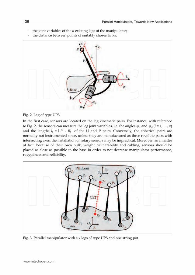
- the joint variables of the n existing legs of the manipulator; - the distance between points of suitably chosen links.
Fig. 2. Leg of type UPS
In the first case, sensors are located on the leg kinematic pairs. For instance, with reference
to Fig. 2, the sensors can measure the leg joint variables, i.e. the angles ϕi1 and ϕi2 (i = 1, …, n)
and the lengths li = ⎪Pi - Bi⎪ of the U and P pairs. Conversely, the spherical pairs are
normally not instrumented since, unless they are manufactured as three revolute pairs with
intersecting axes, the installation of rotary sensors may be impractical. Moreover, as a matter
of fact, because of their own bulk, weight, vulnerability and cabling, sensors should be
placed as close as possible to the base in order to not decrease manipulator performance,
ruggedness and reliability.
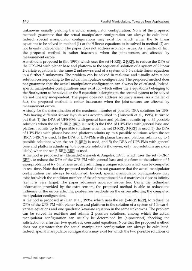
Fig. 3. Parallel manipulator with six legs of type UPS and one string pot
www.intechopen.com

Robust, Fast and Accurate Solution of the Direct Position Analysis of Parallel Manipulators by Using Extra-Sensors
137
Fig. 4. Leg of type UPS instrumented with string pots
In the second case, additional external sensors are used. The most common way is to use: a) cable extension transducers (CET, also known as “string pots”); b) passive chains of type UPS with a sensor embedded in the P pair.
By means of these sensors, the distance between points of the base and the platform can be measured (see Fig. 3, points B7 and P7) or also the distance of points of suitably chosen links of the UPS legs can be measured, which may provide additional information on the joint leg variables. For instance, (see Fig. 4) the measure of ⎪Ci - Di⎪ and ⎪Ei - Fi⎪, with Di and Fi points of the platform, and Ci and Ei points of the second movable link of the UPS leg, indirectly provides the values of the joint angles ϕi2 and ϕi1. It is worth noting, however, that the direct measuring of angles ϕi1 and ϕi2 by rotary sensors (placed locally on the revolute pairs) is normally preferable since it would lead to a unique position of point Pi, while the use of the lengths of the segments CiDi and EiFi would provide two positions for Pi (two symmetric positions with respect to the plane defined by points Bi, Di and Fi). The choice of the UPS joint variables is, in general, the most suitable. Indeed, the addition of CETs or additional UPS measurement legs can both reduce the exploitable manipulator workspace (because of increased possibility of leg interference) and slow-down the manipulator dynamic performance (due to the inertia of the additional UPS legs and to the limited mechanical response of CETs). Moreover, CET sensor accuracy is poor for many practical applications and the implementation of accurate extra UPS measurement legs is rather expensive. An overview of extra-sensor based methods that have been proposed in the literature for the DPA of 6-DOF UPS-PMs having general architecture is presented in the following section. Of course, all these methods readily apply to the DPA of both UPS-PMs with special geometry and PMs with less than six DOF that can be obtained from the 6-DOF UPS-PMs by suitably eliminating or locking some of the leg kinematic pairs.
3. Literature overview of extra-sensor based methods for the DPA of UPS-PMs
This section provides an overview of extra-sensor based methods that are available for the solution of the DPA of 6-DOF UPS-PMs. The methods are sorted in chronological order
www.intechopen.com

Parallel Manipulators, Towards New Applications
138
(according to the publication date of the author’s most relevant work). For each method, the employed sensor layouts are first described, and the major features and drawbacks of the resulting DPA methods are then highlighted. To describe the sensor layout of each leg of type UPS, the sequence RRP is used to indicate the cascade of joints which are serially connected from base to platform (referring to Fig. 2, RR indicates the two revolute pairs with intersecting axes the U pair is featured by; the spherical pair S is ignored since it is not supposed to be instrumented) and the underline is used to highlight the joint whose position is measured. For instance, the leg sensor layout RRP indicates that 1 rotary position sensor and 1 linear position sensor are installed on the leg. The sensor layout of a given manipulator is described by a list (set) of sensor layouts of the legs belonging to the manipulator. That is, the set {2-RRP, RRP, 4-RRP} indicates that 8 sensors are mounted on the manipulator; in particular, it features 2 legs each having 1 rotary position sensor, 1 leg having 1 rotary position sensor and 1 linear position sensor, and 4 legs each having 1 linear position sensor. The first DPA solution of UPS-PMs via extra-sensors was firstly proposed in 1991, when, following the studies on the pose and twist estimation from three collinear measured points (Fenton & Shi, 1989), Shi and Fenton (Shi & Fenton, 1991) employed the set {3-RRP} to devise a method that reduces the DPA of UPS-PMs having general base and platform to an explicit problem which can be readily solved in real-time. Irrespective of the manipulator configuration, the method always makes it possible to find the actual platform pose. However, the method does not account for the measurement errors, which in practice always affect the sensor readouts. As a matter of fact, the proposed method is rather inaccurate when measurement errors are present. Several sensor layouts are studied in (Stoughton & Arai, 1991) in order to devise fast and accurate methods for the solution of the DPA of the UPS-PM with general base and platform. Note that results similar to those presented by Stoughton and Arai have also been reported lately in (Hesselbach et al., 2005). In particular: 1) using the set {3-RRP} the DPA is reduced to an explicit problem readily yielding the actual manipulator configuration; 2) using both the set {2-RRP, RRP} and the set {2-RRP, RRP} the DPA is reduced to the solution of a system of 2 uni-variate quadratic equations in the same unknown usually yielding the actual manipulator configuration; 3) using both the set {2-RRP, RRP} and the set {2-RRP, RRP} the DPA is reduced to the solution of a system of 2 quadratic and 1 linear 3-variate equations in the same 3 unknowns usually yielding 2 possible manipulator configurations from which the actual platform pose cannot be detected; 4) using one of the sets {RRP, 2-RRP}, {RRP, 2-RRP} or {RRP, RRP, RRP}, the DPA is reduced to the solution of 2 uni-variate quadratic equations in 2 different unknowns usually yielding four possible manipulator configurations (although it is not stated in the paper, the actual manipulator configuration may be detected among those 4 possibilities by checking the satisfaction of a further constraint equation); and 5) using the set {RRP, RRP, RRP} the DPA is reduced to the sequential solution of a system of 2 quadratic and 1 linear 3-variate equations in the same 3 unknowns, and of a uni-variate quadratic equation in a different unknown usually yielding 4 possible manipulator configurations among which the actual platform pose cannot be detected. All the aforementioned solutions can be computed in real-time. Only the method based on the set {3-RRP} guarantees that the actual manipulator configuration can always be calculated (manipulator configurations may exist for which the methods based on the other sensor layouts cannot find a unique DPA solution). The paper also addresses accuracy
www.intechopen.com

Robust, Fast and Accurate Solution of the Direct Position Analysis of Parallel Manipulators by Using Extra-Sensors
139
issues. In particular, the ratios between the magnitudes of the errors affecting the computed manipulator configuration and the measurement errors affecting the joint-sensor readouts are determined for all the abovementioned sensor layouts. This makes it possible to select the required sensor precision which provides the desired accuracy of the calculated platform pose. Moreover, it is shown that the solution of the DPA based on the set {3-RRP} is less sensitive to the measurement errors affecting the joint-sensors than the solution which can readily be computed if the measurement of the 6 joints parameters of one single leg are available (in this latter case the leg sensor layout would be RRP plus 3 additional rotary position sensors measuring the rotations allowed by the S pair of the same leg). Two sensor layouts are proposed in (Cheok et al, 1992) to devise methods that make it possible to find the actual solution of the DPA of the UPS-PM with general base and platform in real-time. In particular: 1) using the set {3-RRP} the DPA is reduced to an explicit problem readily yielding the actual manipulator configuration; and 2) using the set {6-RRP, RRP} the DPA is reduced to the solution of a system of 6 linear 6-variate equations in the same 6 unknowns usually yielding the actual manipulator configuration. Only the method based on the set {3-RRP} guarantees that the actual manipulator configuration can always be calculated. Indeed, special manipulator configurations may exist for which the 6 linear equations to be solved in method (2) are not linearly independent. The paper does not address accuracy issues. As a matter of fact, the proposed method is rather inaccurate when the joint-sensors are affected by measurement errors. Two sensor layouts are proposed in (Merlet, 1993b) to devise methods that make it possible to find the solution of the DPA of UPS-PMs in real-time. In particular: 1) the set {2-RRP, 2-RRP} is used to reduce the DPA of the UPS-PM with general base and platform to the solution of a system of 2 uni-variate quadratic equations in the same unknown usually yielding the actual manipulator configuration; 2) the set {RRP, RRP, 2-RRP} is used to reduce the DPA of the UPS-PM with general base and platform to the sequential solution of a system of 2 uni-variate quadratic equations in the same unknown and of a uni-variate quadratic equation in a further different unknown usually yielding 2 possible manipulator configurations from which the actual platform pose cannot be detected; and 3) the set {RRP, 6-RRP} is used to reduce the DPA of the UPS-PM with planar base and platform to the solution of a system of 9 9-variate linear equations in the same 9 unknowns usually yielding the actual manipulator configuration. Note that the proposed methods do not guarantee that the actual manipulator configuration can always be calculated. Indeed, special manipulator configurations may exist for which either the two pairs of solutions of the two quadratic equations to be solved in method (1) are identical or the 9 linear equations to be solved in method (3) are not linearly independent. Accuracy issues related to the {2-RRP, 4-RRP} sensor layout are addressed in a later paper (Tancredi and Merlet, 1994) in which the pose dependent ratios between the magnitudes of the errors affecting the computed manipulator configuration and the errors affecting the joint-sensor readouts are evaluated and mapped. Two sensor layouts are proposed in (Nair & Maddocks, 1994) to devise methods that make it possible to reduce the solution of the DPA of UPS-PMs to an explicit problem which can be solved in real-time. In particular: 1) the set {16-RRP} is used to reduce the DPA of manipulators with general base and platform to the solution of a system of 16 16-variate linear equations in the same 16 unknowns usually yielding the actual manipulator configuration; and 2) the set {9-RRP} is used to reduce the DPA of manipulators with planar base/platform to the solution of a system of 9 9-variate linear equations in the same 9
www.intechopen.com
Parallel Manipulators, Towards New Applications
140
unknowns usually yielding the actual manipulator configuration. None of the proposed methods guarantee that the actual manipulator configuration can always be calculated. Indeed, special manipulator configurations may exist for which either the 16 linear equations to be solved in method (1) or the 9 linear equations to be solved in method (2) are not linearly independent. The paper does not address accuracy issues. As a matter of fact, the proposed method is rather inaccurate when the joint-sensors are affected by measurement errors. A method is proposed in (Jin, 1994), which uses the set {4-RRP, 2-RRP}, to reduce the DPA of the UPS-PM with planar base and platform to the sequential solution of a system of 2 linear 2-variate equations in the same 2 unknowns and of a system of 5 5-variate linear equations in a further 5 unknowns. The problem can be solved in real-time and usually admits one solution corresponding to the actual manipulator configuration. The proposed method does not guarantee that the actual manipulator configuration can always be calculated. Indeed, special manipulator configurations may exist for which either the 2 equations belonging to the first system to be solved or the 5 equations belonging to the second system to be solved are not linearly independent. The paper does not address accuracy issues. As a matter of fact, the proposed method is rather inaccurate when the joint-sensors are affected by measurement errors. A study for the determination of the maximum number of possible DPA solutions for UPS-PMs having different sensor layouts was accomplished in (Tancredi et al., 1995). It turned out that: 1) the DPA of UPS-PMs with general base and platform admits up to 35 possible solutions when the set {5-RRP, RRP} is used; 2) the DPA of UPS-PMs with general base and platform admits up to 8 possible solutions when the set {3-RRP, 3-RRP} is used; 3) the DPA of UPS-PMs with planar base and platform admits up to 6 possible solutions when the set {RRP, 5-RRP} is used; 4) the DPA of UPS-PMs with planar base and platform admits up to 4 possible solutions when the set {6-RRP} is used; and 5) the DPA of UPS-PMs with general base and platform admits up to 8 possible solutions (however, only two solutions are more likely) when the set {5-RRP, RRP} is used. A method is proposed in (Etemadi-Zanganeh & Angeles, 1995), which uses the set {5-RRP, RRP}, to reduce the DPA of the UPS-PM with general base and platform to the solution of 5
eigenproblems of 6 × 6 matrices usually admitting a unique solution which can be computed in real-time. Note that the proposed method does not guarantee that the actual manipulator configuration can always be calculated. Indeed, special manipulator configurations may
exist for which the condition number of the aforementioned 6 × 6 matrices is close to infinity (i.e. it is very large). The paper addresses accuracy issues too. Using the redundant information provided by the extra-sensors, the proposed method is able to reduce the influence of the errors affecting joint-sensor readouts on the errors affecting the computed manipulator configuration. A method is proposed in (Han et al., 1996), which uses the set {5-RRP, RRP}, to reduce the DPA of the UPS-PM with planar base and platform to the solution of a system of 5 linear 6-variate equations and one quadratic 3-variate equation in the same unknowns. The problem can be solved in real-time and admits 2 possible solutions, among which the actual manipulator configuration can usually be determined by (a-posteriori) checking the satisfaction of a further two quadratic constraint equations. Note that the proposed method does not guarantee that the actual manipulator configuration can always be calculated. Indeed, special manipulator configurations may exist for which the two possible solutions of
www.intechopen.com
Robust, Fast and Accurate Solution of the Direct Position Analysis of Parallel Manipulators by Using Extra-Sensors
141
the system of equations both satisfy the additional constraint equations. The paper does not address accuracy issues. As a matter of fact, the proposed method is rather inaccurate when the joint-sensors are affected by measurement errors. A method is proposed in (Jin & Hai-Rong, 1996), which uses the set {5-RRP, RRP}, to reduce the DPA of the UPS-PM with planar base and platform to the sequential solution of two systems of equations, the first one of 20 linear 20-variate equations in the same 20 unknowns and the second one of 3 3-variate linear equations in another 3 different unknowns, and then to the solution of a quadratic equation in a further unknown. The problem can be solved in real-time and usually admits two solutions (that are symmetric with respect to the planar manipulator base) one of which corresponds to the actual manipulator configuration. Note that the proposed method does not guarantee that the two aforementioned solutions (and, thus, the actual manipulator configuration) can always be calculated. Indeed, special manipulator configurations may exist for which the 20 equations belonging to the first system to be solved are not linearly independent. The paper does not address accuracy issues. As a matter of fact, the proposed method is rather inaccurate when the joint-sensors are affected by measurement errors. A method based on either the set {7-RRP} or the set {5-RRP, RRP} is proposed in (Innocenti, 1998), which reduces the DPA of the UPS-PM with general base and platform to the solution of a system of 146 146-variate linear equations in the same 146 unknowns usually yielding the actual manipulator configuration. Note that the proposed method does not guarantee that the actual manipulator configuration can always be calculated. Indeed, special manipulator configurations may exist for which the 146 equations to be solved are not linearly independent. Due to the large number of equations, the solution of the system of equations requires a rather large computational burden. However, since the system of 146 equations has a sparse coefficient matrix, rather efficient sparse solvers may be used to find the solution in real-time. The paper does not address accuracy issues. As a matter of fact, the proposed method is rather inaccurate when the joint-sensors are affected by measurement errors. Two sensor layouts are used in (Parenti Castelli & Di Gregorio, 1998) to devise methods which make it possible to reduce the DPA of UPS-PMs to an explicit problem that can be solved in real-time. In particular: 1) the set {4-RRP, RRP} is used to reduce the DPA of manipulators with general base and platform to the solution of a system of 15 15-variate linear equations in the same 15 unknowns usually yielding the actual manipulator configuration; and 2) the set {5-RRP, RRP} is used to reduce the DPA of manipulators with general base and platform to the solution of a system of two 6-degree polynomial uni-variate equations in the same unknown usually yielding the actual manipulator configuration. Note that the proposed methods do not guarantee that the actual manipulator configuration can always be calculated. Indeed, special manipulator configurations may exist for which either the 15 equations to be solved in method (1) are not linearly independent or the two 6-degree polynomials involved in method (2) have more than one common root. The paper does not address accuracy issues. As a matter of fact, the proposed method is rather inaccurate when the joint-sensors are affected by measurement errors. A method based on the set {5-RRP, RRP} is used in (Parenti Castelli & Di Gregorio, 1999) to reduce the DPA of UPS-PMs with general base and platform to the solution of two 48-degree uni-variate polynomial equations in the same unknown usually having a unique common root, corresponding to the actual manipulator configuration. Note that the
www.intechopen.com

Parallel Manipulators, Towards New Applications
142
proposed method does not guarantee that the actual manipulator configuration can always be calculated. Indeed, special manipulator configurations may exist for which the two 48-degree polynomials have more than one common root. The solution of the reduced problem requires a large computational burden and, thus, cannot be computed in real-time. The paper does not address accuracy issues. As a matter of fact, the proposed method is rather inaccurate when the joint-sensors are affected by measurement errors. A method based on the set {9-RRP} is used in (Bonev & Ryu, 1999) to reduce the DPA of UPS-PMs with general base and planar platform to the solution of two sets of three quadratic 3-variate equations in the same 3 unknowns usually having a unique common solution, corresponding to the actual manipulator configuration. The proposed method does not guarantee that the actual manipulator configuration can always be calculated. Indeed, special manipulator configurations may exist for which the two sets of quadratic equations have more than one common solution. The calculations involved in the determination of manipulator configuration require a large computational burden and, thus, cannot be computed in real time. The paper addresses accuracy issues. In particular it is shown that the errors in the calculated platform pose are of the same magnitude of the measurement errors affecting the sensor readouts. A method based on the set {4-RRP, RRP} is proposed in (Parenti Castelli & Di Gregorio, 2000) to reduce the DPA of manipulators with general base and platform to the sequential solution of a 6-degree uni-variate polynomial equation and of a system of two linear bi-variate equations in two further unknowns. The problem can be solved in real-time and admits up to six possible solutions, among which the actual manipulator configuration can usually be determined by (a-posteriori) checking the satisfaction of a further additional quadratic constraint equation. Note that the proposed method does not guarantee that the actual manipulator configuration can always be calculated. Indeed, special manipulator configurations may exist for which more than one solution (among the abovementioned six possible solutions) satisfy the additional quadratic constraint equation. The paper does not address accuracy issues. As a matter of fact, the proposed method is rather inaccurate when the joint-sensors are affected by measurement errors. As a result of several investigations (Angeles, 1990; Baron & Angeles, 1994; Baron & Angeles, 1995) a very general method based on at least nine measurements, obtained from the sensors placed on n legs according to the following sensor layouts RRP, RRP and RRP, is proposed in (Baron & Angeles, 2000a; Baron & Angeles, 2000b) which reduces the DPA of UPS-PMs with general base and platform to the evaluation of the orthogonal polar factor of a 3 × 3 matrix whose components are obtained from the least-square-solution of a system of 3n 9-variate linear equations in the same nine unknowns. The reduced problem can be solved in real-time and usually admits a unique solution, corresponding to the actual manipulator configuration. However, in general, the uniqueness of the solution is not guaranteed. Indeed, special manipulator configurations may exist for which 9 linearly independent equations cannot be found among the 3n equations cited above. The method accounts for the measurement errors, which always affect the joint-sensor readouts. In particular, the redundant information provided by the extra-sensors is also used to reduce the influence of the measurement errors on the errors affecting the computed platform pose (that is, the computed manipulator configuration is the solution which most closely satisfies all the aforementioned 3n equations). Among all the possible sets of leg sensor layouts, the sets {n-RRP} (for n ≥ 3) are shown to be very effective since they guarantee that both a unique (the actual) DPA solution can always be found and the matrix from which to extract
www.intechopen.com

Robust, Fast and Accurate Solution of the Direct Position Analysis of Parallel Manipulators by Using Extra-Sensors
143
the orthogonal polar factor is simply obtained by the matrix multiplication of two matrices having dimensions 3 × n and n × 3. In practice, the set {3-RRP} is very interesting since it provides a very fast and accurate unique solution of the DPA by using the minimum number of sensors (among the sensor layouts this method is based on). As compared to other methods (Shi & Fenton, 1991; Stoughton & Arai, 1991; Cheok et al, 1992) using the set {3-RRP}, the method proposed by Baron and Angeles is the most accurate and only slightly more expensive in terms of computational cost. A method based on the set {9-RRP} is proposed in (Bonev et al., 2001) to reduce the DPA of the UPS-PM with planar base and platform to the solution of a system of six linear 6-variate equations in the same 6 unknowns usually admitting a unique solution, corresponding to the actual manipulator cofiguration, which can be computed in real time. Note that the proposed method does not guarantee that the actual manipulator configuration can always be found. Indeed, special manipulator configurations may exist for which the 6 equations to be solved are not linearly independent. The paper addresses accuracy issues too. In particular a procedure is proposed for the determination of the optimal extra-sensor location, which makes it possible to minimize (throughout the desired manipulator workspace) the ratio between the magnitudes of the errors affecting the computed manipulator configuration and of the errors affecting the joint-sensor readouts. A method based on the set {6-RRP, RRP} is proposed in (Chiu & Perng, 2001) to reduce the DPA of the UPS-PM with general base and platform to the solution of two quadratic uni-variate equations in two different unknowns. The problem can be solved in real-time and admits four possible solutions, among which the actual manipulator configuration can usually be determined by (a-posteriori) checking the satisfaction of a further three quadratic constraint equations. The proposed method does not guarantee that the actual manipulator configuration can always be calculated. Indeed, special manipulator configurations may exist for which more than one solution (among the four possible solutions cited above) satisfies the three additional quadratic constraint equations. The paper addresses accuracy issues too. In particular a procedure is proposed for the determination of the optimal extra-sensor location, which makes it possible to minimize (throughout the desired manipulator workspace) the ratio between the magnitudes of the errors affecting the computed manipulator configuration and of the errors affecting the joint-sensor readouts. Focusing on the popular measurement set {3-RRP}, which is the only one guaranteeing that a unique DPA solution can always be found irrespective of the manipulator configuration, and accounting for the measurement errors, which always affect the sensor readouts, a method is proposed in (Vertechy & Parenti Caselli, 2007; Vertechy et al., 2002) which, following an approach similar to that of Baron and Angeles (Baron & Angeles, 2000a; Baron & Angeles, 2000b), reduces the DPA of the UPS-PM with general base and platform to the solution of one simple trigonometric equation in a single unknown. The method always provides the actual platform pose in real-time, it is insensitive to singular configurations, it has the same accuracy as the method by Baron and Angeles (Baron & Angeles, 2000a; Baron & Angeles, 2000b) but it requires a reduced computational burden (it is three times more efficient).
4. A robust, fast and accurate novel method for the DPA of UPS-PMs by using extra-sensors
In this section, a novel extra-sensor-based method for the solution of the DPA of 6-DOF UPS-PMs having general geometry is presented (the method readily applies also to the DPA of both UPS-PMs with special geometry and PMs with less than six DOF). The method is
www.intechopen.com

Parallel Manipulators, Towards New Applications
144
based on the sensor layout {n-RRP} (n ≥ 3) and is: robust since it always provide the actual platform pose; fast since the calculation of the actual platform pose can be performed in real-time; and accurate since the redundant information provided by the extra-sensors is used to reduce the influence of the measurement errors on the errors affecting the computed platform pose. The method is based on the DPA algorithms developed in (Baron & Angeles, 2000a; Baron & Angeles, 2000b) but it improves both the accuracy and the computational efficiency. In the following, in sub-section 4.1 the fundamentals of the method are introduced. In sub-section 4.2 a general method is presented which makes it possible to solve the DPA of UPS-PMs having general architecture, general sensor layout and noisy sensors, but which cannot guarantee the uniqueness of the DPA solution. In section 4.3 the novel method is presented. Finally, in sub-section 4.4 results are reported which show that the novel method is more accurate and computationally more efficient than other methods available in the literature.
4.1 Fundamentals of the method: general sensor layout without measurement errors
For a UPS-PM two reference frames Sb, centered at Ob, and Sp, centered at Op, are attached to the manipulator base and platform respectively. With reference to Fig. 1, the platform pose is described by the vector c = (Op – Ob), which gives the origin of Sp with respect to Sb, and
by the proper orthogonal matrix R (i.e. det(R) = +1, RTR = 1 where 1 is the 3 × 3 identity matrix) which describes the orientation of Sp with respect to Sb. In some applications, R is
defined equivalently as R = [r1 r2 r3]T, where the ri’s (i = 1,…, 3) are the 3 × 1 orthonormal
vectors (i.e. ri ⋅ rj = 0 if i ≠ j and ri ⋅ rj = 1 if i = j) indicating the components of the unit vectors
of the frame Sb in the frame Sp. With reference to Fig. 2, consider the leg variables ϕi1, ϕi2 and li which define the position of points Pi with respect to Sb (without losing in generality, in the following it is assumed that the leg geometry is such that the leg unit vector vi, vi = BiPi/|BiPi|, is orthogonal to the axis ui of the revolute pair Ri2 and that the unit vector ui
is orthogonal to the axis ii of the revolute pair Ri1; thus, ϕi1 indicates the angle between axes
ui and ji, ϕi2 indicates the angle between the vector PiBi and the axis ii, and li indicates the distance between points Pi and Bi). By definition, the DPA of 6-DOF UPS-PMs having n legs consists in finding c and R once the magnitude of at least 6 leg variables (among the 3n
possible variables ϕi1, ϕi1 and li, for i = 1, …, n) are known by measurement. In practice, c and R are found as the solution of a system of kinematic constraint equations (SKCE) of the type
( )ϕ ϕ1 2, ; , ,i i i il =Rf c 0 , i = 1, …, n. (1)
For the class of manipulators under study, the kinematic constraint equations (1) can be derived by considering the analytical expressions of vectors BiPi (i = 1, …, n). Indeed, by referring to Fig. 1, the position vector qi = (Pi − Bi)b expressed in Sb can be written as
= + −i i iRq c p b , (2)
where pi = (Pi − C)p and bi = (Bi − O)b are known (at the outset) position vectors expressed in Sp and Sb respectively. Besides, with reference to Fig. 2, the position vector qi can also be written as
qi i i= l v , (3.1)
www.intechopen.com

Robust, Fast and Accurate Solution of the Direct Position Analysis of Parallel Manipulators by Using Extra-Sensors
145
ϕ ϕ+ ×2 2cos sini i i i i i=v i u i , (3.2)
ϕ ϕcos sini i i1 i i1=u j k− , (3.3)
where, of course, in Eqs. (3) vectors ii, ji, ki, ui and vi are assumed to be expressed in Sb. Starting from Eqs. (2) and (3), different sets of rather simple linear kinematic constraint equations (KCE) can be derived for each of the sensor layouts RRP, RRP and RRP. Indeed, if
the i-th leg is equipped with one sensor according to the layout RRP, then the angle ϕi1 (and the vector ui) are fully known. Therefore, from equations (2), (3.1) and (3.2) the following KCE can be written:
( )+ − =Ti i iiu u Rc p b 0 , (4)
which indicates that the distance of the platform point Pi from the plane passing through Bi and having the measured vector ui as normal (i.e. the plane defined by ii and vi) is zero. Note that Eq. (4) consists of three equations among which only one is independent of the others. If the leg is equipped with two sensors according to the layout RRP, then the angles ϕi1 and ϕi2 (and the vector vi) are fully known. Therefore, from equations (2) and (3.1) the following KCE can be written:
( )( )− + − =Ti i i i1 v v Rc p b 0 , (5)
which indicates that the distance of the platform point Pi from the line passing through Bi and directed along the measured vector vi is zero. Note that Eq. (5) consists of three equations among which only two are independent of the others. If the leg is equipped with
three sensors according to the layout RRP, then the angles ϕi1 and ϕi2, and the length li (and the vector qi) are fully known. Therefore, from equations (2) and (3.1) the following KCE can be written:
( )+ − − =i i i ilR vc p b 0 , (6)
which indicates that the distance of the platform point Pi from the corresponding measured point lying on the leg is zero. Note that Eq. (6) consists of three independent equations. Equations (4)-(6) are of the type described by Eq. (1). Considering all the instrumented legs of the manipulator and by resorting to a unified formulation, the SKCE of Eq. (1) can be written as
( ) δ+ − − =i i i i iW R vc p b 0 , i =1, …, n (7)
where Wi = uiuiT and δi = 0, Wi = 1 - viviT and δi = 0, or Wi = 1 and δi = li if the i-th leg is instrumented according to the sensor layout RRP, RRP or RRP respectively. The SKCE of Eq. (7) consists of 3n equations. If the manipulator is equipped with at least nine sensors, then nine linearly independent equations can usually be extracted from Eq. (7) to find the actual manipulator configuration. Indeed, such nine equations can be used to determine the three components of c and six of the nine components of R (for instance the components of the orthonormal vectors r1 and r2); the remaining three components of R (the components of the orthonormal vector r3) can be determined afterwards by using a further three linear
www.intechopen.com

Parallel Manipulators, Towards New Applications
146
equations coming from the proper orthogonality conditions (the three equations r1 ⋅ r3 = 0, r2 ⋅ r3 = 0 and det(R) = +1). Among all the possible sensor layouts, the sets {n-RRP} (n ≥ 3) guarantee that a unique DPA solution can always be found. For other sensor layouts, manipulator configurations may exist for which the set of measurement data is singular and, thus, nine linearly independent equations cannot be extracted from Eq. (7).
4.2 The general method: general sensor layout with measurement errors The equalities described by Eq. (7) hold in ideal situations only. Indeed, whenever finite precision arithmetic is used to perform the required calculation and whenever joint-sensor readouts are affected by measurement errors, the following relations
( ) δ+ − − =i i i i i iW R vc p b e , i =1, …, n, (8)
hold instead of Eqs. (7), where the ei’s are error vectors whose magnitude should be as small as possible. In such real situations, the DPA can be recast to the solution of the following constrained least-squares (CLS) problem
( )[ ]21
,min
n
i i i i i
i
δ=
+ − −∑R
W R vc
c p b ,
subject to RTR = 1 and det(R) = +1.
(9)
By observing the quadratic nature of the function to be minimized, the solution of Eq. (9) is reduced to first solving the following CLS problem in R only
2
1
1 1
min
n n
i i j j i i
i j
−= =
′ ′− − −⎡ ⎤⎡ ⎤⎞⎛⎢ ⎥⎟⎢⎜ ⎥⎜ ⎟⎢ ⎥⎢ ⎥⎝ ⎠⎣ ⎦⎣ ⎦∑ ∑R
W R W W Rp p b v ,
subject to RTR = 1 and det(R) = +1,
(10.1)
and then to computing c as
( )1
1
n
j j j j j j
j
δ−=
= − − −⎡ ⎤⎣ ⎦∑W W R W vc p b , (10.2)
where the 3 × 3 matrix W, and the 3 × 1 vectors b′i and v′i are
1
n
j
j==∑W W , (10.3)
1
1
n
i i j j
j
−=
′ −= ∑W Wb b b , (10.4)
1
1
n
i i i j j
j
δδ −=
′ −= ∑W vvv , (10.5)
www.intechopen.com

Robust, Fast and Accurate Solution of the Direct Position Analysis of Parallel Manipulators by Using Extra-Sensors
147
and depend on the given manipulator geometry and on the measured joint variables. In general, the closed-form solution of the CLS problem described by Eq. (10.1) is difficult to compute. In practice, an acceptable minimizer R of Eq. (10.1) can be obtained by evaluating the orthogonal polar factor (OPF) of the solution of the corresponding unconstrained least-square (ULS) problem, which is given in the following
− −⎡ ⎤⎢ ⎥⎢ ⎥⎢ ⎥⎣ ⎦
b v1 2 3
1
2, ,
3
min W W Wr r r
r
P r
r
, (11.1)
n n
′=
′⎡ ⎤⎢ ⎥⎢ ⎥⎢ ⎥⎣ ⎦
1 1
...W
W
W
b
b
b
, (11.2)
n
′=
′⎡ ⎤⎢ ⎥⎢ ⎥⎢ ⎥⎣ ⎦
1
...W
v
v
v
, (11.3)
1
1
...
j
j
−=
−=
−=
−
⎡ ⎤⎞⎛ ⎟⎢ ⎜ ⎥⎜ ⎟⎢ ⎥⎝ ⎠⎢ ⎥⎢ ⎥⎢ ⎥⎞⎛⎢ ⎥⎟⎜⎢ ⎥⎜ ⎟⎝ ⎠⎣ ⎦
∑∑
11 1
1
n
j j
n
n n j j
W
W P W W P
P
W P W W P
, (11.4)
=⎡ ⎤⎢ ⎥⎢ ⎥⎢ ⎥⎢ ⎥⎣ ⎦
p 0 0
0 p 0
0 0 p
T T Ti
T T Ti i
T T Ti
P , (11.5)
where PW is a 3n × 9 matrix, Pi (i =1, …, n) is a 3 × 9 matrix, and bW and vW are 3n × 1 vectors. Hence, an acceptable minimizer of Eq. (10.1) is
( )ˆOPF=R R , (12.1)
[ ]ˆ ˆ ˆ ˆ1 2 3=R r r r
T, (12.2)
( ) ( )ˆ
ˆ
ˆ
11
2
3
T T−= +
⎡ ⎤⎢ ⎥⎢ ⎥⎢ ⎥⎣ ⎦W W W W W
r
r P P P
r
b v , (12.3)
www.intechopen.com

Parallel Manipulators, Towards New Applications
148
where the vectors 1̂r , 2̂r and ˆ3r are estimates of the orthonormal vectors r1, r2 and r3.
Regarding the meaning of the orthogonal polar factor, note that given a 3 × 3 matrix A
whose polar decomposition is A = QM, where Q is an orthogonal 3 × 3 matrix and M is a
symmetric and positive definite 3 × 3 matrix, then OPF(A) = Q. Providing that matrix TWWP P
is well conditioned (i.e. if rank(PW) = 9), then Eqs. (12) admit a unique solution corresponding to the actual orientation of the manipulator platform.
4.2.1 Uniqueness of the solution and computational issues According to Eqs. (12), the actual platform orientation can be found if rank(PW) = 9. In order for PW to have full rank, a minimum of nine leg variables need to be measured. However, this may not be sufficient. Indeed, due to matrices Wi and Pi (i = 1, …, 6), matrix PW is dependent on the given manipulator geometry and on the configuration (which is known by measurements). As a matter of fact, special manipulator configurations may exist for which rank(PW) < 9. In practice, for given manipulator geometry and for selected sensor layout, a-priori study of the rank of PW is required in order to prevent the method to fail. In cases where the drop of rank (which may be caused not only by special configurations and a special manipulator geometry, but also by the availability of less than nine joint-sensor measurements) is not too drastic, a number of remedies that rely on the mutual dependency of the components of R exist, which make it possible to find the actual manipulator orientation. A first trick (trick 1) consists in circumventing the rank deficiency by solving Eqs. (11) for a reduced number of unknowns only (whose number cannot be greater than the rank of PW) and by calculating the remaining ones via the proper orthogonality conditions.
As an example, note that the solution of Eqs. (11) for the components of 1̂r and 2̂r only, and
the a-posteriori evaluation of the components of ˆ3r via the three linear equations ˆ ˆ1 3 0⋅ =r r ,
ˆ ˆ2 3 0⋅ =r r and ˆdet( )R = +1, requires rank(PW) ≥ 6 only. A second trick (trick 2) consists in
restoring the rank of PW by considering, in addition to the points Pi (i = 1, …, n) of the instrumented legs, additional virtual points Pk (k > n) depending on the Pi’s themselves such that pk = pi × pj and (b′k + v′k) = (b′i + v′i) × (b′j + v′j), (i ≠ j; for i,j = 1, …, n). As an example note that whenever the third components of the vectors pi’s are zero for all points Pi (i = 1, …, n), then rank(PW) ≤ 6. In this case, the rank of PW can be restored to 9 by adding an appropriate number of virtual points as defined above. A third last trick (trick 3) consists in circumventing the rank drop of PW by solving the rank deficient least-squares problem given by Eqs. (11) via a method based on the singular value decomposition (SVD) of PW (Golub & Van Loan, 1983). Among the three remedies, trick (3) is the most general (it does not require a-priori knowledge of the structure of PW), rather accurate, but it is also the most computationally intensive; trick (2) is quite general (it requires some a-priori knowledge of the structure of PW) and quite computationally efficient, but it is the most inaccurate; trick (1) is the less general (it requires a-priori knowledge of the full structure of PW), it is quite accurate and quite computationally efficient.
4.3 A novel method for the manipulator actual configuration determination As described in sub-section 4.2.1, the effectiveness of the general method relies upon the good conditioning of PW. A very practical sensor layout which both guarantees that the rank of PW is independent of manipulator configuration and greatly simplifies the solution of the DPA is the set {n-RRP} (n ≥ 3). With this sensor layout, the DPA problem described by Eqs. (10) is reduced to
www.intechopen.com

Robust, Fast and Accurate Solution of the Direct Position Analysis of Parallel Manipulators by Using Extra-Sensors
149
Fmin − −
RRP B V ,
subject to RTR = 1 and det(R) = +1, (13.1)
and
= + − Rc b v p , (13.2)
where p, b and v are the following 3 × 1 mean vectors
1
1n
j
jn =
= ∑p p , (13.3)
1
1n
j
jn =
= ∑b b , (13.4)
1
1n
j j
j
ln =
= ∑v v , (13.5)
and P, B and V are the following 3 × n matrices
[ ]...1 n′ ′=P p p , (13.6)
[ ]...1 n′ ′=B b b , (13.7)
[ ]...1 n′ ′=V v v , (13.8)
which are formed, respectively, by the 3 × 1 vectors p′i = (pi – p), b′i = (bi – b) and v′i = (vi – v). It is worth highlighting that the quantities p, b, P and B depend only on the manipulator geometry, while v and V depend also on the manipulator configuration. As usual, the notation ║A║F appearing in Eq. (13.1) is used to indicate the Frobenius norm of matrix A. Equations (13) show that if the center Op of the mobile frame Sp is chosen as the centroid of points Pi (i = 1, …, n), i.e. p = 0, then the orientation and the position problems are decoupled, i.e. c = (b + v). Following the procedure based on the ULS estimate which was described in section 4.2, an acceptable minimizer R of the CLS problem described by Eq. (13.1) is
( )ˆOPF=R R , (14.1)
( ) ( )ˆ1
T T−= +R B V P PP . (14.2)
However, for the set {n-RRP} (n ≥ 3), the optimal solution of Eq. (13.1) can be found in closed-form. Indeed, the CLS problem described in Eq. (13.1) is well known in computer vision (Umeyama, 1991) and admits the following solution
www.intechopen.com

Parallel Manipulators, Towards New Applications
150
( )( )= ⎡ ⎤⎣ ⎦diag 1,1,det TR U US S , (15.1)
where U and V are the 3 × 3 matrices coming from the SVD of the cross-covariance matrix
( ) T= +C B V P . (15.2)
That is, C = UDST (UUT = SST = 1 and D = diag(d1, d2, d3), d1 ≥ d2 ≥ d3 ≥ 0). The unique solution given by Eq. (15) does not require the full rank of C (Umeyama, 1991). As a matter of fact, the actual platform orientation can be computed whenever rank (C) ≥ 2. The solution given in Eq. (15) is different from that proposed in (Baron and Angeles, 2000)
( )OPF=R C , (16)
which is the solution of the orthogonal Procrustes problem (Golub & Van Loan, 1983) obtained from the CLS problem of Eq. (13.1) by relaxing the constraint det(R) = +1.
4.4 Comparison of different DPA methods in terms of accuracy and computational efficiency Among the different solution methods represented by equations (14), (15) and (16), only Eqs. (15) always provides the exact minimum of the CLS problem given by Eq. (13). Thus, only the solution given by Eqs. (15) always corresponds to the actual platform orientation and is the most accurate. Indeed, the solutions given by Eqs. (14) and Eq. (16) do not guarantee the proper orthogonality (det(R) = +1) of matrix R. This is rather risky since Eqs. (14) and Eq. (16) may fail to give the correct rotation matrix (corresponding to the actual manipulator configuration) and may give a reflection instead when the sensor readouts are affected by measurement errors (this drawback is more severe the larger the measurement errors are). Between the solutions given by Eqs. (14) and Eq. (16), the former is the least accurate. Indeed, Eqs. (14) do not even minimize Eq. (13.1) (Eqs. (14) can be a viable good estimate of the solution in cases where measurement errors are rather small only). Moreover, due to the matrix inversion operation, note that Eqs. (14.2) requires matrix P to have full rank. This is not the case whenever points Pi’s (i = 1, …, n) are coplanar. In such instances, as already described in section 4.2.1, to obtain the solution of Eq. (14.2) it is necessary to resort to either trick (2), which however leads to a rather inaccurate solution, or trick (3), which however implies a large computational effort. In terms of computational efficiency, it is worth highlighting that the solution represented by Eqs. (15) requires the calculation of the SVD of a 3 × 3 matrix, while the solutions represented by equations (14) and (16) require the calculation of the polar decomposition (PD) of a 3 × 3 matrix. In general the algorithms available for the computation of the PD are more efficient than those available for the computation of the SVD. However, when 3 × 3 matrices are of concern, fast and robust solutions of the SVD exist which require fewer calculations than those required by the PD of 3 × 3 matrices. As a matter of fact, the SVD of a 3 × 3 matrix can be obtained via non-iterative algorithms. As an example, an improved version of the algorithm presented in (Vertechy & Parenti-Castelli, 2004), which is based on the analytical solution of the cubic equation, requires only 150 multiplications/divisions, 88 sums/subtractions, 5 square root evaluations and 4 trigonometric evaluations to obtain the full SVD. Conversely, the algorithms available for the PD are iterative. In particular, considering the most well known and adopted algorithms, the PD of 3 × 3 matrices via the routine proposed in (Dubrulle, 1999) requires (87 + kD⋅78) multiplications/divisions,
www.intechopen.com

Robust, Fast and Accurate Solution of the Direct Position Analysis of Parallel Manipulators by Using Extra-Sensors
151
(47 + kD⋅39) sums/subtractions and (4 + kD⋅3) square root evaluations, where kD is the number of iterations required by the Dubrulle’s routine to converge; and the PD of 3 × 3 matrices via the routine proposed in (Higham, 1986) requires (48 + kH⋅63) multiplications/divisions, (38 + kH⋅62) sums/subtractions and (kH⋅3) square root evaluations, where kH is the number of iterations required by Higham’s routine to converge. In practice, simulations of the DPA solution of UPS-PMs employing both Dubrulle’s and Higham’s routines show that kD > 3 and kH > 2 when solving Eq. (14.1), and that kD > 5 and kH > 5 when solving Eq. (16). Note that the solution of Eq. (16) requires more iterations than those
of Eq. (14.1) since matrix R̂ is closer to orthogonality than matrix C. Finally, it is worth mentioning that both Dubrulle’s and Higham’s routines involve the
matrix inversion operation of either R̂ or C and, thus, both Eq. (14.1) and Eq. (16) require such matrices to have full rank. Again, this is not the case whenever points Pi‘s (i = 1, …, n) are coplanar, and this requires resorting to either trick (2), which leads to a rather inaccurate
solution, or trick (3). In this latter case, once the SVD of either C or R̂ is calculated (i.e.
either C = UDVT or ˆ T=R UDV ), the solution of Eq. (14.1) and Eq. (16) is found as R = UVT. Hence, generally, in order to find a unique and accurate solution of the DPA, the
computation of the SVD of either C or R̂ is anyway required.
5. Conclusions
This chapter addresses the solution of the direct position analysis (DPA) of parallel manipulators. More specifically, it focuses on the determination of the actual configuration of parallel manipulators, which have legs of type UPS (where U, S and P are for universal, spherical and prismatic pairs respectively), by using extra-sensor data, that is a number of sensor data which is greater than the number of manipulator degrees of freedom. First, an extensive overview of the extra-sensor approaches that are available in the literature for the solution of the manipulator direct position analysis is provided. Second, a general method is described which makes it possible to solve accurately and in real-time the DPA of manipulators having general architecture, general sensor layouts and sensor data affected by measurement errors. The method, however, may suffer from singularities of the set of sensor data. Third, a novel method is presented which, by exploiting a suitable sensor layout, makes it possible to solve robustly, accurately and in real-time the direct position analysis of manipulators having general architecture and sensor data affected by measurement errors. A comparison with other methods based on mathematical proofs is provided that shows the accuracy and the computational efficiency of the proposed novel method.
6. References
Angeles, J. (1990). Rigid-body pose and twist estimation in the presence of noisy redundant measurements, Proc. Eighth CISM-IFToMM Symposium on Theory and Practice of Robots and Manipulators, pp. 69-78, Cracow, July 2-6 1990
Baron, L. & Angeles, J. (1994). The measurement subspaces of parallel manipulators under sensor redundancy, ASME Design Automation Conf., pp. 467-474, Minneapolis, 11-14 September 1994
Baron, L. & Angeles, J. (1995). The isotropic decoupling of the direct kinematic of parallel manipulators under sensor redundancy, IEEE Int. Conf. on Robotics and Automation, pp. 1541-1546, Nagoya, 25-27 May 1995
www.intechopen.com
Parallel Manipulators, Towards New Applications
152
Baron, L. & Angeles, J. (2000a). The direct kinematics of parallel manipulators under joint-sensor redundancy. IEEE Trans. on Robotics and Automation, Vol. 16, No. 1, 12-19
Baron, L. & Angeles, J. (2000b). The kinematic decoupling of parallel manipulators using joint-sensor data. IEEE Trans. on Robotics and Automation, Vol. 16, No. 6, 644-651
Bonev, I.A. & Ryu J. (2000). A new method for solving the direct kinematics of general 6-6 Stewart platforms using three linear extra sensors. Mechanism and Machine Theory, Vol. 35, No. 3, 423-436
Bonev, I.A.; Ryu, J.; Kim, S.-G. & Lee, S.-K. (2001). A closed-form solution to the direct kinematics of nearly general parallel manipulators with optimally located three linear extra sensors. IEEE Transactions on Robotics and Automation, Vol. 17, No. 2, 148-156
Cappel, K.L (1967). Motion simulator. US Patent #3295224 Charles, P.A.-S. (1995). Octahedral machine tool frame. US Patent #5392663 Cheok, K.C.; Overholt, J.L. & Beck, R.R. (1993). Exact Method for Determining the
Kinematics of a Stewart Platform Using Additional Displacement Sensors. Journal of Robotic Systems, Vol. 10, No. 5, 689-707
Chiu, Y.J. & Perng, M.-H. (2001). Forward kinematics of a general fully parallel manipulator with auxiliary sensors. Int. J. of Robotics Research, Vol. 20, No. 5, 401-414
Daniel, R.W.; Fischer, P.J. & Hunter, B. (1993). A High Performance Parallel Input Device. Proc. SPIE Vol. 2057, Telemanipulator Technology and Space Telerobotics, pp. 272-281, Boston, December 1993
Di Gregorio, R. & Parenti-Castelli, V. (2002). Fixation devices for long bone fracture reduction: an overview and new suggestions. Journal of Intelligent and Robotic Systems, Vol. 34, No. 3, 265-278
Dubrulle, A.A. (1999). An optimum Iteration for the Matrix Polar Decomposition. Electronic Transactions on Numerical Analysis, Vol. 8, 21-25
Etemadi-Zanganeh, K. & Angeles, J. (1995). Real time direct kinematics of general six-degree-of-freedom parallel manipulators with minimum sensor data. Journal of Robotics Systems, Vol. 12, No. 12, 833-844
Faugere, J.C. & Lazard, D. (1995). The combinatorial classes of parallel manipulators. Mechanism and Machine Theory, Vol. 30, No. 6, 765-776
Fenton, R.G. & Shi, X. (1989). Comparison of methods for determining screw parameters of finite rigid body motions from initial positions and final position data, in Advances in Design Automation, Vol. 3, 433-439
Gaillet, A. & Reboulet, C. (1983). An Isostatic Six Component Force and Torque Sensor. Proc. 13th Int. Symposium on Industrial Robotics, pp. 102-111, Chicago, 18-21 April 1983
Geng, Z. & Haynes, L.S. (1994). A 3-2-1 kinematic configuration of a Stewart platform and its application to six degree of freedom pose measurements. Robotics & Computer-Integrated Manufacturing, Vol. 11, No. 1, 23-34
Golub, G.H. & Van Loan, C.F. (1983). Matrix Computations, The Johns Hopkins University Press, ISBN 0-946536-00-7, Baltimore
Gough, V.E. & Whitehall, S.G. (1962). Universal Tire Test Machine. Proceedings 9th Int. Technical Congress F.I.S.I.T.A, Vol. 117, pp. 117-135, London, 30 April – 5 May 1962
Griffis, M. & Duffy, J. (1989). A Forward Displacement Analysis of a Class of Stewart Platform. Journal of Robotics Systems, Vol. 6, No. 6, 703-720
Han, H.; Chung, W. & Youm, Y. (1996). New Resolution Scheme of the Forward Kinematics of Parallel Manipulators Using Extra Sensors. ASME Journal of Mechanical Design, Vol. 118, No. 2, 214-219
Hesselbach, J.; Bier, C.; Pietsch, I.; Plitea, N.; Büttgenbach, S.; Wogersien, A. & Güttler, J. (2005). Passive-joint sensors for parallel robots. Mechatronics, Vol. 15, 43-65
www.intechopen.com

Robust, Fast and Accurate Solution of the Direct Position Analysis of Parallel Manipulators by Using Extra-Sensors
153
Higham, N.J. (1986). Computing the Polar Decomposition – with Applications. SIAM Sci. Stat. Comput., Vol. 7, No. 4, 1160-1174
Innocenti, C. & Parenti-Castelli, V. (1990). Direct Position Analysis of the Stewart Platform Mechanism. Mechanism and Machine Theory, Vol. 25, No. 6, 611-621
Innocenti, C. & Parenti-Castelli, V. (1991). A Novel Numerical Approach to the Closure of the 6-6 Stewart Platform Mechanism. ICAR’91, Fifth Int. Conf. on Advance Robotics, pp. 851-855, Pisa, 19-22 June
Innocenti, C. & Parenti-Castelli, V. (1993). Echelon Form Solution of Direct Kinematics for the General Fully-Parallel Spherical Wrist. Mechanism and Machine Theory, Vol. 28, No. 4, 553–561.
Innocenti, C. & Parenti-Castelli, V. (1994). Exhaustive Enumeration of Fully Parallel Kinematic Chains, ASME International Winter Annual Meeting DSC-55-2, pp. 1135-1141, Chicago, November 1994.
Innocenti, C. (1998). Closed-Form Determination of the Location of a Rigid Body by Seven In-Parallel Linear Transducers. ASME Journal of Mechanical Design, Vol. 120, 293-298
Innocenti, C. (2001). Forward Kinematics in Polynomial Form of the General Stewart Platform. ASME Journal of Mechanical Design, Vol. 123, 254-260
Jacobsen, S.C. (1975). Rotary-to-Linear and Linear-to-Rotary Motion Converters. US Patent #3864983
Jin Y. (1994). Exact solution for the forward kinematics of the general stewart platform using two additional displacement sensors. Proc. of the 23rd ASME Mechanism Conference, DE-Vol. 72, pp. 491-495, Minneapolis, 11-14 September 1994
Jin, Y. & Hai-rong, F. (1996). Explicit Solution for the Forward Displacement Analysis of the Stewart Platform Manipulator. Proc. ASME DETC 1996, Irvine, 18-22 August 1996
Lee, T.-Y. & Shim, J.-K. (2001). Forward kinematics of the general 6-6 Stewart platform using algebraic elimination. Mechanism and Machine Theory, Vol. 36, No. 9, 1073-1085
Lewis, J.L.; Carroll, M.B.; Morales, R.H. & Le, T.D. (2002). Androgynous, reconfigurable closed loop feedback controlled low impact docking system with load sensing electromagnetic capture ring. US Patent #6354540
McAree, P.R. & Daniel, R.W. (1996). A Fast, Robust Solution to the Stewart Platform Forward Kinematics. Journal of Robotics Systems, Vol. 13, No. 7, 407-427
McCallion, H. & Truong, P.D. (1979). The Analysis of a Six-Degree-of-Freedom Work Station for Mechanised Assembly. Proceedings of the Fifth World Congress on Theory of Machines and Mechanisms, 611-617, Montreal, July 1979.
Merlet, J-P. (1992). Direct Kinematics and Assembly Modes of Parallel Manipulators. The International Journal of Robotics Research, Vol. 11, No. 2, 150-162
Merlet, J-P. (1993a). Direct Kinematics of Parallel Manipulators. IEEE Transactions on Robotics and Automation, Vol. 9, No. 6, 842-845
Merlet, J-P. (1993b). Closed-Form Resolution of the Direct Kinematics of Parallel Manipulators Using Extra Sensors Data. Proc. IEEE Int. Robotics and Automation Conf., pp. 200-204, Atlanta, 2-7 May 1993.
Nair, R. & Maddocks, J.H. (1994). On the Forward Kinematics of Parallel Manipulators. The Int. Journal of Robotics Research, Vol. 13, No. 2, 171-188
Nanua, P.; Waldron, K.J. & Murty, V. (1990). Direct Solution of a Stewart Platform. IEEE Transaction on Robotics and Automation, Vol. 6, No. 4, 438-443
Nguyen, C.C.; Antrazi, S.S. & Zhou, Z.L. (1991). Analysis and Implementation of a 6 DOF Stewart Platform-Based Force Sensor for Passive Compliant Robotic Assembly. IEEE Proc. of the Southeast Conf'91, pp. 880-884, Williamsburg, 7-10 April 1991
Parenti-Castelli, V. & Di Gregorio, R. (1995). A Three Equations Numerical Method for the Direct Kinematics of the Generalized Gough-Stewart Platform. 9th World Congress
www.intechopen.com

Parallel Manipulators, Towards New Applications
154
on the Theory of Machines and Mechanisms, pp. 837-841, Milan, 30 August – 2 September 1995.
Parenti-Castelli, V. & Di Gregorio, R. (1998). Real-Time Computation of the Actual Posture of the General Geometry 6-6 Fully-Parallel Mechanism using Two Extra Rotary Sensors. Journal of Mechanical Design, Vol. 120, No. 4, 549-554
Parenti-Castelli, V. & Di Gregorio, R. (1999). Determination of the Actual Configuration of the General Stewart Platform Using Only One Additional Sensor. Journal of Mechanical Design, Vol. 121, No. 1. 21-25
Parenti-Castelli, V. & Di Gregorio, R. (2000). A new algorithm based on two extra sensors for real-time computation of the actual configuration of the generalized Stewart-Gough manipulator. ASME J. of Mechanical Design, Vol. 122, No. 3, 294-298
Reboulet, C. (1988). Robot parallèles. Technique de la Robotique, Hermes (Ed.), Paris Schmidt-Kaler, T. (1992). The Hexapod Telescope: A New Way to Very Large Telescopes.
Progress in Telescope and Instrumentation Technologies, ESO Conference and Workshop Proceedings, ESO Conference on Progress in Telescope and Instrumentation Technologies, p. 117, European Southern Observatory (ESO), Garching, 27-30 April 1992.
Shi, X. & Fenton, R.G. (1991). Forward Kinematic Solution of a General 6 DOF Stewart Platform Based on Three Point Position Data. Eight World Cong. on the Theory of Machines and Mechanism, 1015-1018, Prague, 26-31 August 1991.
Stewart, D. (1965). A Platform with Six Degree of Freedom. Proc. of the Institution of Mechanical Engineers, vol. 180, No. 15, 371-386
Stoughton, R. & Arai, T. (1991). Optimal sensor placement for forward kinematics evaluation of a 6-dof parallel link manipulator. IEEE Int. Conf. on Intelligent Robots and Systems, IROS’91, pp. 785-790, Osaka, 3-5 November 1991.
Taylor, H.S. & Taylor, J.C. (2000). Six axis external fixator strut. US Patent#6030386 Tancredi, L. & Merlet, J.-P. (1994). Evaluation of the errors when solving the direct
kinematics of parallel manipulators with extra sensors, In: Advances in Robot Kinematics and Computational Geometry, Lenarcic J. and Ravani B., (Ed), 439-448, Springer, ISBN:978-0-7923-2983-1
Tancredi, L.; Teillaud, M. & Merlet, J.-P. (1995). Extra sensors data for solving the forward kinematics problem of parallel manipulators. 9th IFToMM World Congress on the Theory of Machines and Mechanisms, pp. 2122-2126, Milan, 30 August-2 September 1995
Umeyama, S. (1991). Least-Squares Estimation of Transformation Parameters Between Two point Patterns. IEEE Transactions on Pattern Analysis and Machine Intelligence, Vol. 13, No. 4, 376-380
Vertechy, R.; Dunlop, G.R. & Parenti-Castelli ,V. (2002). An accurate algorithm for the real-time solution of the direct kinematics of 6-3 Stewart platform manipulators, In: Advances in Robot Kinematics: Theory and Applications, Lenarcic J. & Thomas F., (Ed.), 369-378, Springer, ISBN: 978-1-4020-0696-8
Vertechy, R. & Parenti-Castelli, V. (2004). A fast and Accurate Method for the Singular Value Decomposition of 3x3 Matrices, In: On Advances in Robot Kinematics, Lenarcic J. and Galletti C., (Ed.), 3-12, Springer, ISBN: 978-1-4020-2248-7
Vertechy, R. & Parenti-Castelli, V. (2006). Synthesis of 2-DOF Spherical US Parallel Mechanisms, In: Advances in Robots Kinematics: Mechanisms and Motion, Lenarcic J. and Roth B., (Ed.), 385-394, Springer, ISBN: 978-1-4020-4940-8
Vertechy, R. & Parenti-Castelli, V. (2007). Accurate and Fast Body Pose Estimation by Three Point Position Data. Mechanism and Machine Theory, Vol. 42, No. 9, 1170-1183
www.intechopen.com
Parallel Manipulators, towards New ApplicationsEdited by Huapeng Wu
ISBN 978-3-902613-40-0Hard cover, 506 pagesPublisher I-Tech Education and PublishingPublished online 01, April, 2008Published in print edition April, 2008
InTech EuropeUniversity Campus STeP Ri Slavka Krautzeka 83/A 51000 Rijeka, Croatia Phone: +385 (51) 770 447 Fax: +385 (51) 686 166www.intechopen.com
InTech ChinaUnit 405, Office Block, Hotel Equatorial Shanghai No.65, Yan An Road (West), Shanghai, 200040, China
Phone: +86-21-62489820 Fax: +86-21-62489821
In recent years, parallel kinematics mechanisms have attracted a lot of attention from the academic andindustrial communities due to potential applications not only as robot manipulators but also as machine tools.Generally, the criteria used to compare the performance of traditional serial robots and parallel robots are theworkspace, the ratio between the payload and the robot mass, accuracy, and dynamic behaviour. In additionto the reduced coupling effect between joints, parallel robots bring the benefits of much higher payload-robotmass ratios, superior accuracy and greater stiffness; qualities which lead to better dynamic performance. Themain drawback with parallel robots is the relatively small workspace. A great deal of research on parallelrobots has been carried out worldwide, and a large number of parallel mechanism systems have been built forvarious applications, such as remote handling, machine tools, medical robots, simulators, micro-robots, andhumanoid robots. This book opens a window to exceptional research and development work on parallelmechanisms contributed by authors from around the world. Through this window the reader can get a goodview of current parallel robot research and applications.
How to referenceIn order to correctly reference this scholarly work, feel free to copy and paste the following:
Rocco Vertechy and Vincenzo Parenti-Castelli (2008). Robust, Fast and Accurate Solution of the DirectPosition Analysis of Parallel Manipulators by Using Extra-Sensors, Parallel Manipulators, towards NewApplications, Huapeng Wu (Ed.), ISBN: 978-3-902613-40-0, InTech, Available from:http://www.intechopen.com/books/parallel_manipulators_towards_new_applications/robust__fast_and_accurate_solution_of_the_direct_position_analysis_of_parallel_manipulators_by_using