7hfkqlfdofdwdorjxh - kolektor etra · factor. double helical winding with effects of continuously...
TRANSCRIPT

Technical catalogue
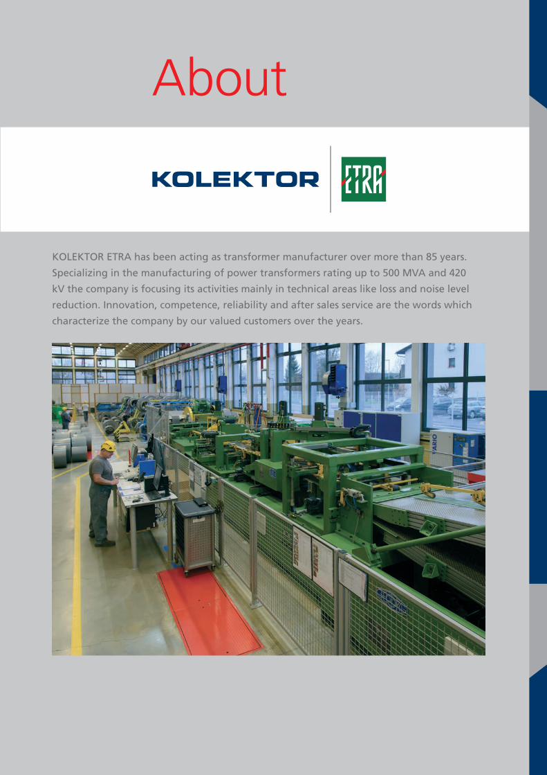
KOLEKTOR ETRA has been acting as transformer manufacturer over more than 85 years.
Specializing in the manufacturing of power transformers rating up to 500 MVA and 420
kV the company is focusing its activities mainly in technical areas like loss and noise level
reduction. Innovation, competence, reliability and after sales service are the words which
characterize the company by our valued customers over the years.
About
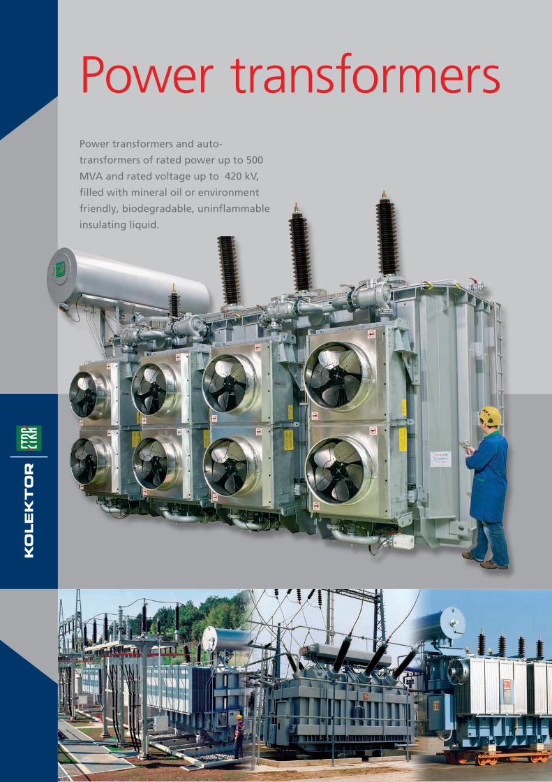
Power transformersPower transformers and auto-
transformers of rated power up to 500
MVA and rated voltage up to 420 kV,
filled with mineral oil or environment
friendly, biodegradable, uninflammable
insulating liquid.

• Furnace transformers with on-load tap-changing used for arc furnaces.
• Furnace transformers with off-load tap-changing used for induction furnaces.
• Rectifier transformers.
• Grounding transformers for the neutral point earthing.
Special transformers

In our archives we preserve more than
4000 different designs. Most of them are
currently used for the performance of our
servicing activities, but taken as a whole,
they are a unique source of tradition,
experience and excellence. With modern
and approved computer techniques, use
of new materials and technologies, we are
constantly developing new products.
KnowledgeAll our products are result of our own design
Magnetic field between conductors and ferrous beam

Our aim is to supply
our customers with
reliable, environment-
friendly products.
Thus, transformers
manufactured in
KOLEKTOR ETRA have
low losses and low
noise levels.
Numerical simulation of mechanical stresses
in transformer tank

• Our special attention is paid to reduction of noise level of the transformer.
Noise levels, achieved for transformers are low enough to decrease substantially the costs
for the construction of anti-noise barriers in transformer stations.
• Our special contribution to preservation of the environment is safe and environmental
friendly decommission of transformers after their life cycle expiration.
In modern society human beings and
machines often share their common life
and working space. Operation of each
machine or appliance is felt by human
beings and the nature as a disturbance.
In our factory we do our best that the
operation of our transformers is safe,
long-lasting, economic and with least
possible effects upon environment.
EnvironmentOur contributions to the protectionof environment
• Mineral oils used for oil immersed transformers do not contain
PCBs or other harmful substances.
• In transformers located in fire-resistant and water conservation areas we use synthetic
oils, i.e. environment-friendly liquids. Main characteristics of these liquids are:
higher flash point and biodegradability.
• We are qualified for repair works, reconstructions, different reworks of transformers,
their constituent parts and equipment.
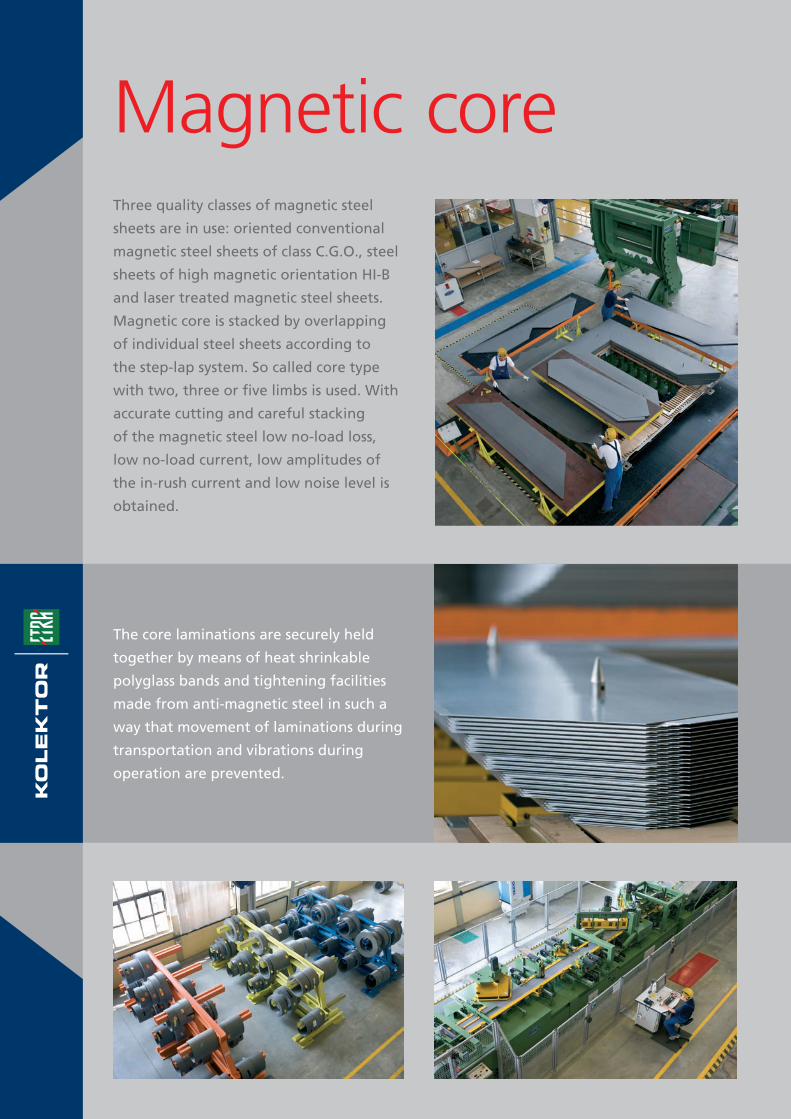
Three quality classes of magnetic steel
sheets are in use: oriented conventional
magnetic steel sheets of class C.G.O., steel
sheets of high magnetic orientation HI-B
and laser treated magnetic steel sheets.
Magnetic core is stacked by overlapping
of individual steel sheets according to
the step-lap system. So called core type
with two, three or five limbs is used. With
accurate cutting and careful stacking
of the magnetic steel low no-load loss,
low no-load current, low amplitudes of
the in-rush current and low noise level is
obtained.
Magnetic core
The core laminations are securely held
together by means of heat shrinkable
polyglass bands and tightening facilities
made from anti-magnetic steel in such a
way that movement of laminations during
transportation and vibrations during
operation are prevented.
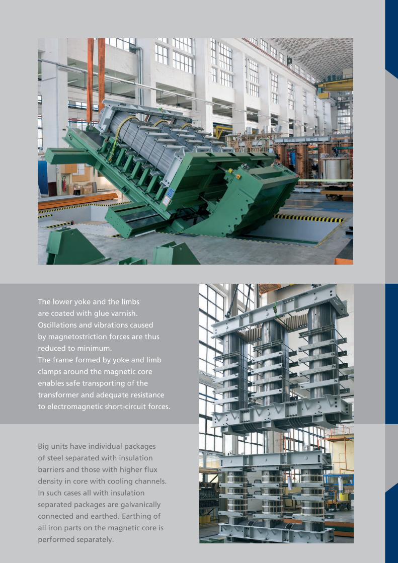
The lower yoke and the limbs
are coated with glue varnish.
Oscillations and vibrations caused
by magnetostriction forces are thus
reduced to minimum.
The frame formed by yoke and limb
clamps around the magnetic core
enables safe transporting of the
transformer and adequate resistance
to electromagnetic short-circuit forces.
Big units have individual packages
of steel separated with insulation
barriers and those with higher flux
density in core with cooling channels.
In such cases all with insulation
separated packages are galvanically
connected and earthed. Earthing of
all iron parts on the magnetic core is
performed separately.

Three thermal classes of insulation are in
use:
• enamel insulation (PVA), thermal class E
(120°C), in compliance with standard
IEC 60317-0-2.
• Paper insulation 5A2-1M3, thermal class A
(105°C), in compliance with standard
IEC 554-3-5.
• Thermal upgraded paper insulation
5B1-2M3, thermal class E (120°C),
in compliance with standard IEC 554-3-5.
WindingsThe windings are made from
electrolytic copper of high purity,
Cu-ETP signed. Specific electric
conductivity is 58 Sm/mm2.
Conductors are in strength by RP0,2
from 90 to 160 N/mm2. For higher
currents are used foil and rectangular
conductors insulated with paper or
enamel. For the highest powers and
currents is used transposed cable.
The windings are manufactured
in different variants.
Single-layer or multy-layer windings
are used for phase currents up to 1000 A
and rated voltages up to 72,5 kV.
For higher and the highest voltage classes
disc windings are used: helical, continuous
disc or interleaved.
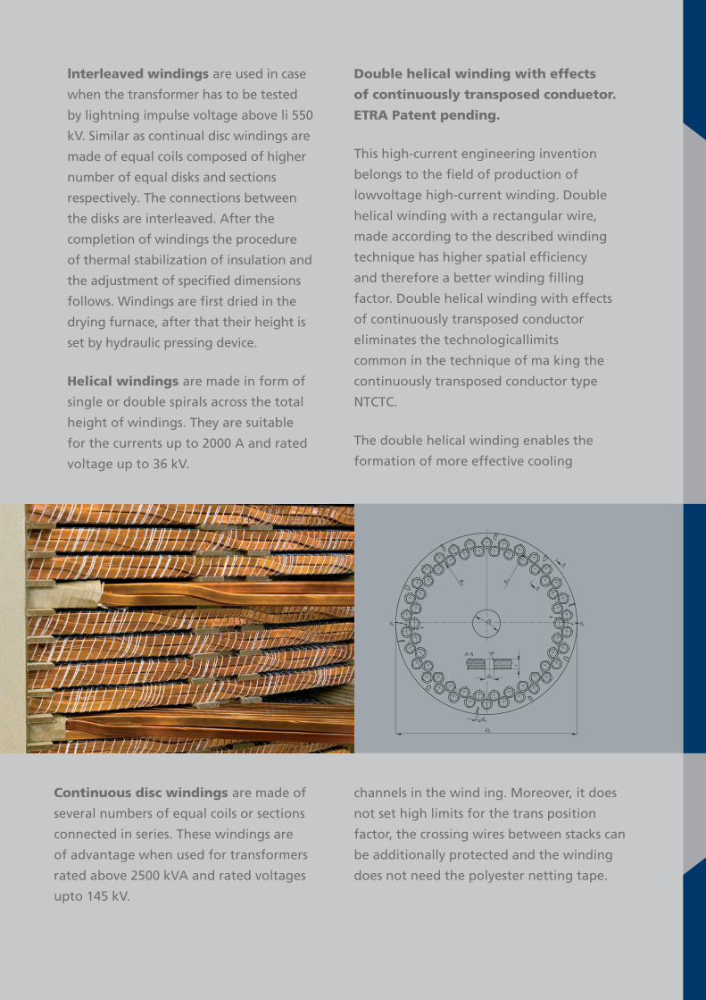
Double helical winding with effects
of continuously transposed conduetor.
ETRA Patent pending.
This high-current engineering invention
belongs to the field of production of
lowvoltage high-current winding. Double
helical winding with a rectangular wire,
made according to the described winding
technique has higher spatial efficiency
and therefore a better winding filling
factor. Double helical winding with effects
of continuously transposed conductor
eliminates the technologicallimits
common in the technique of ma king the
continuously transposed conductor type
NTCTC.
The double helical winding enables the
formation of more effective cooling
lnterleaved windings are used in case
when the transformer has to be tested
by lightning impulse voltage above li 550
kV. Similar as continual disc windings are
made of equal coils composed of higher
number of equal disks and sections
respectively. The connections between
the disks are interleaved. After the
completion of windings the procedure
of thermal stabilization of insulation and
the adjustment of specified dimensions
follows. Windings are first dried in the
drying furnace, after that their height is
set by hydraulic pressing device.
Helical windings are made in form of
single or double spirals across the total
height of windings. They are suitable
for the currents up to 2000 A and rated
voltage up to 36 kV.
Continuous disc windings are made of
several numbers of equal coils or sections
connected in series. These windings are
of advantage when used for transformers
rated above 2500 kVA and rated voltages
upto 145 kV.
channels in the wind ing. Moreover, it does
not set high limits for the trans position
factor, the crossing wires between stacks can
be additionally protected and the winding
does not need the polyester netting tape.
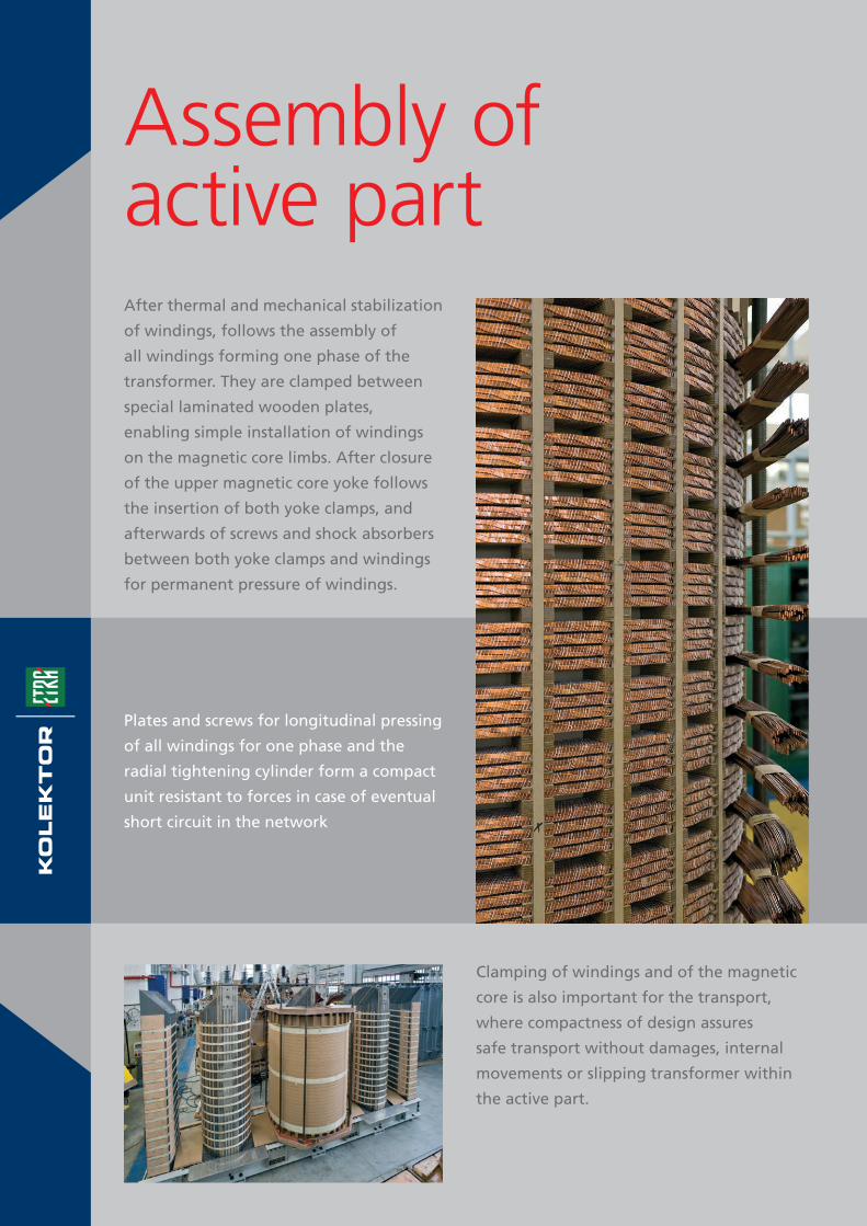
After thermal and mechanical stabilization
of windings, follows the assembly of
all windings forming one phase of the
transformer. They are clamped between
special laminated wooden plates,
enabling simple installation of windings
on the magnetic core limbs. After closure
of the upper magnetic core yoke follows
the insertion of both yoke clamps, and
afterwards of screws and shock absorbers
between both yoke clamps and windings
for permanent pressure of windings.
Assembly of active part
Clamping of windings and of the magnetic
core is also important for the transport,
where compactness of design assures
safe transport without damages, internal
movements or slipping transformer within
the active part.
Plates and screws for longitudinal pressing
of all windings for one phase and the
radial tightening cylinder form a compact
unit resistant to forces in case of eventual
short circuit in the network
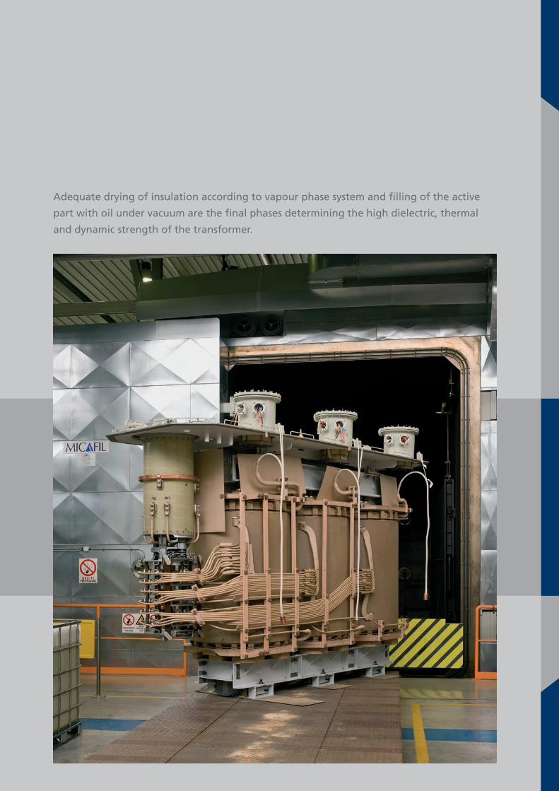
Adequate drying of insulation according to vapour phase system and filling of the active
part with oil under vacuum are the final phases determining the high dielectric, thermal
and dynamic strength of the transformer.

The insulation system in oil-immersed
transformers is made of hard insulation
and liquid dielectric. The liquid dielectric
is usually mineral or synthetic oil. Hard
insulation is made of concentric cylinders
or barriers from special high-pressure
cardboard. We use only high-quality,
stabilized insulation produced by renown
producers.
Insulation systemCalculations of dielectric insulation loads are
performed according to modern methods
based on computer aided design. This
enables a fast and more accurate calculation
and optimum design of insulation,
especially for highvoltage transformers.

The standard corrosion protection is
often adapted to the requirements of
our customers, thus they can choose
the thickness of individual layers, their
combination and the top coat shade.
Parts of equipment for large transformers
and radiators are often protected with
the hot-zincking procedure enabling
transformers to operate under hardest
TankTanks are designed with reinforced plane
walls to withstand full vacuum and 70
kPa overpressure. We manufacture two
types of tanks: the classic tank and the
tank in the shape of a bell. The active part
in the classic tank is lifted together with
the cover while in the bell-shaped tank
only the bell is lifted without the bottom
and active part. Corrosion protection of
the tank and equipment is standardized
and is defined in dependence on climatic
conditions in which the transformer
shall be in operation or according to the
customer’s requirements.
climatic conditions. Materials used for
the production of tanks are classified into
the category of construction steels. The
required strength calculations for the tank
are performed in accordance with modern
methods. With the help of computer aided
engineering work and numerical strength
tests we assure optimal construction
design, perfect safety and safe transport
of the transformer to the location of its
installation.
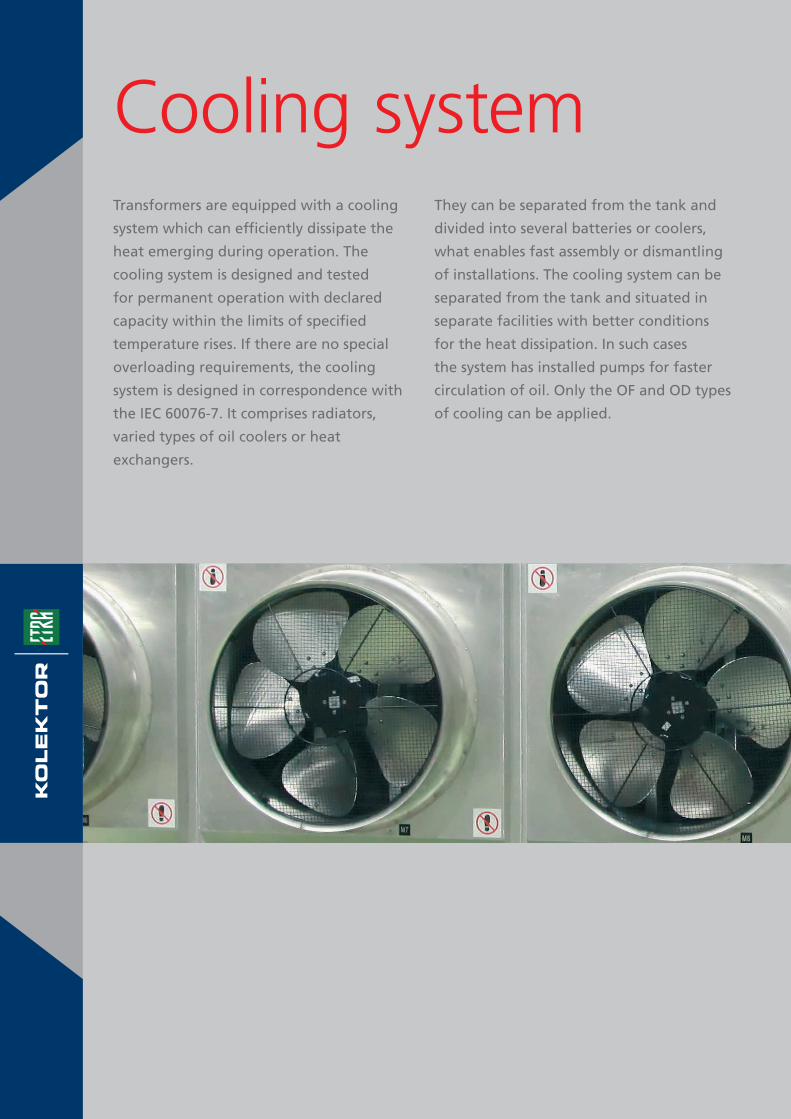
Transformers are equipped with a cooling
system which can efficiently dissipate the
heat emerging during operation. The
cooling system is designed and tested
for permanent operation with declared
capacity within the limits of specified
temperature rises. If there are no special
overloading requirements, the cooling
system is designed in correspondence with
the IEC 60076-7. It comprises radiators,
varied types of oil coolers or heat
exchangers.
Cooling systemThey can be separated from the tank and
divided into several batteries or coolers,
what enables fast assembly or dismantling
of installations. The cooling system can be
separated from the tank and situated in
separate facilities with better conditions
for the heat dissipation. In such cases
the system has installed pumps for faster
circulation of oil. Only the OF and OD types
of cooling can be applied.

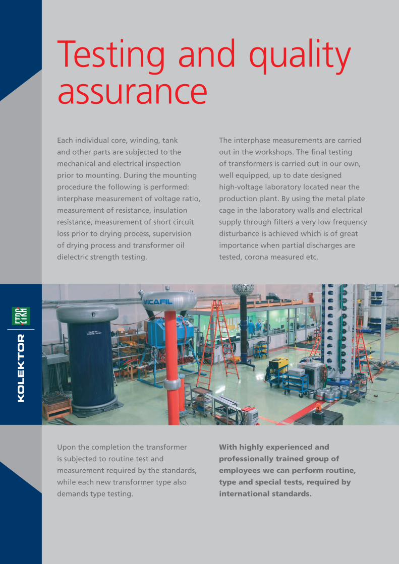
Testing and quality assurance
With highly experienced and
professionally trained group of
employees we can perform routine,
type and special tests, required by
international standards.
The interphase measurements are carried
out in the workshops. The final testing
of transformers is carried out in our own,
well equipped, up to date designed
high-voltage laboratory located near the
production plant. By using the metal plate
cage in the laboratory walls and electrical
supply through filters a very low frequency
disturbance is achieved which is of great
importance when partial discharges are
tested, corona measured etc.
Upon the completion the transformer
is subjected to routine test and
measurement required by the standards,
while each new transformer type also
demands type testing.
Each individual core, winding, tank
and other parts are subjected to the
mechanical and electrical inspection
prior to mounting. During the mounting
procedure the following is performed:
interphase measurement of voltage ratio,
measurement of resistance, insulation
resistance, measurement of short circuit
loss prior to drying process, supervision
of drying process and transformer oil
dielectric strength testing.

The main equipment of the high-voltage laboratory is:
• Motor-generator group 3500/1200/500 kVA, 12/6/6 kV, 50/200/300 Hz.
• Test transformer 500 kV, with a regulation transformer, compensating reactor, capacity
divider and control panel with digital measuring instrument.
• Computer controlled impulse voltage generator 2000 kV, 200 kJ provided with a RC
divider and chopped wave device.
• Mobile equipment for measurement of resistance and temperature rise test with
automatic temperature readings.
• Digital partial discharge measuring system.
• Equipment for measuring tgδ and the transformer capacitance.
• Precision wide band power analyser.
• Frequency response analyser (FRA).
• Three phase transformer turns ratio meter
• Noise source identifikation system with automated microphone positioning system,
• Sound intensity analyser
• Sound level meter.
• Automated test unit for testing of transformer oil dielectrical strength.
• Testing unit for dissolved gas analyses.
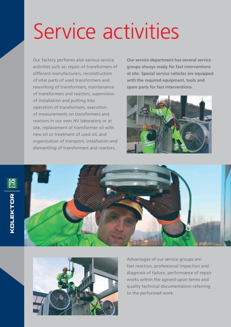
Service activitiesOur factory performs also various service
activities such as: repair of transformers of
different manufacturers, reconstruction
of vital parts of used transformers and
reworking of transformers, maintenance
of transformers and reactors, supervision
of installation and putting into
operation of transformers, execution
of measurements on transformers and
reactors in our own HV laboratory or at
site, replacement of transformer oil with
new oil or treatment of used oil, and
organization of transport, installation and
dismantling of transformers and reactors.
Our service department has several service
groups always ready for fast interventions
at site. Special service vehicles are equipped
with the required equipment, tools and
spare parts for fast interventions.
Advantages of our service groups are:
fast reaction, professional inspection and
diagnosis of failure, performance of repair
works within the agreed-upon terms and
quality technical documentation referring
to the performed work.
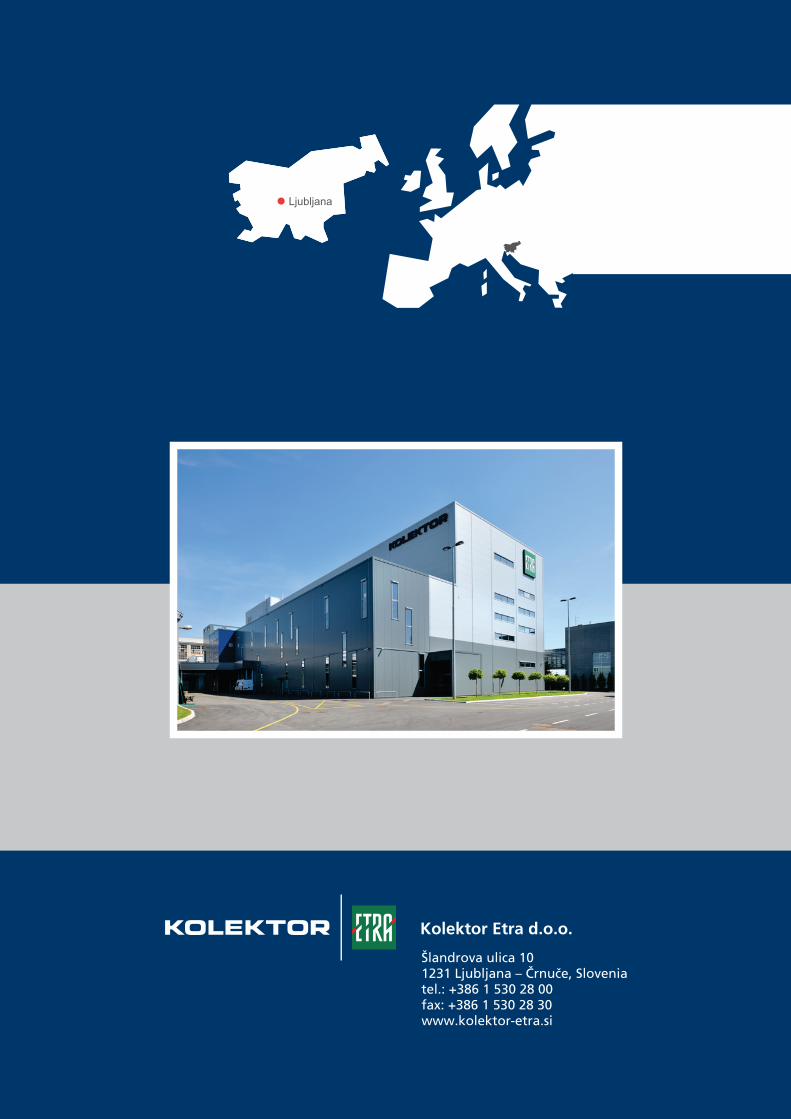
Šlandrova ulica 101231 Ljubljana – Črnuče, Sloveniatel.: +386 1 530 28 00fax: +386 1 530 28 30www.kolektor-etra.si
Kolektor Etra d.o.o.