7sr242 - duobias technical manual chapter 06 commissioning
TRANSCRIPT

8/13/2019 7SR242 - Duobias Technical Manual Chapter 06 Commissioning
http://slidepdf.com/reader/full/7sr242-duobias-technical-manual-chapter-06-commissioning 1/57
7SR242 Duobias Commissioning & Maintenance Guide
The copyright and other intellectual property rights in this document, and in any model or article produced from it(and including any registered or unregistered design rights) are the property of Siemens Protection DevicesLimited. No part of this document shall be reproduced or modified or stored in another form, in any data retrievalsystem, without the permission of Siemens Protection Devices Limited, nor shall any model or article bereproduced from this document unless Siemens Protection Devices Limited consent.
While the information and guidance given in this document is believed to be correct, no liability shall be acceptedfor any loss or damage caused by any error or omission, whether such error or omission is the result ofnegligence or any other cause. Any and all such liability is disclaimed.
©2010 Siemens Protection Devices Limited
7SR242 DuobiasMulti-Function 2-Winding Transformer Protection Relay
Document Release History
This document is issue 2010/02. The list of revisions up to and including this issue is:
2010/06 Defect Report Form revised
2010/02 Document reformat due to rebrand
2010/02 Third issue. Software revision 2662H80001 R4c-3
2008/07 Second issue. Software revision 2662H80001R3d-2c.
2008/05 First issue
Software Revision History
2010/02 2662H80001 R4c-3 Revisions to: VT ratio settings, 87BD 1st bias slope limit setting
increments, CB fail function, LED CONFIG menu, DATA STORAGEmenu.
Added: Open circuit detection (46BC), CONTROL MODE menu,Close circuit supervision (74CCS), Measured earth fault undercurrent(37G), Pulsed output contacts.
2008/07 2662H80001R3d-2c. Demand metering. Optional DNP3.0 data comms.
2008/05 2662H80001R3-2b First Release

8/13/2019 7SR242 - Duobias Technical Manual Chapter 06 Commissioning
http://slidepdf.com/reader/full/7sr242-duobias-technical-manual-chapter-06-commissioning 2/57
7SR242 Duobias Commissioning & Maintenance Guide
©2010 Siemens Protection Devices Limited Chapter 6 Page 2 of 57
Contents
Document Release History ....................................................................................................................1
Software Revision History .....................................................................................................................1
Contents ..................................................................................................................................................2
Section 1: Common Functions .............................................................................................................5
1.1 Overview...................................................................................................................................5
1.2 Before Testing...........................................................................................................................5 1.2.1 Safety ...........................................................................................................................5 1.2.2 Sequence of Tests .......................................................................................................5 1.2.3 Test Equipment ............................................................................................................6 1.2.4 Precautions ..................................................................................................................6 1.2.5 Applying Settings .........................................................................................................7
1.3 Tests .........................................................................................................................................8 1.3.1 Inspection.....................................................................................................................8 1.3.2 Secondary Injection Tests............................................................................................8 1.3.3 Primary Injection Tests.................................................................................................8 1.3.4 Putting into Service ......................................................................................................8
1.4 AC Energising Quantities..........................................................................................................9
1.5 Binary Inputs...........................................................................................................................10
1.6 Binary Outputs ........................................................................................................................11
1.7 Relay Case Shorting Contacts................................................................................................11
Section 2: Protection Funct ions .........................................................................................................12
2.1 Biased Differential (87BD, 87HS) ...........................................................................................14 2.1.1 Secondary Injection Testing.......................................................................................14 2.1.2 Primary Injection Testing............................................................................................17 2.1.3 Phase Overcurrent (50, 51)........................................................................................18 2.1.4 Definite Time Overcurrent (50) ...............................................................................19 2.1.5 Inverse Time Overcurrent (51).................................................................................19
2.2 Derived Earth fault (50N,51N).................................................................................................21 2.2.1 Definite Time Overcurrent (50N).............................................................................22 2.2.2 Inverse Time Overcurrent (51N) ..............................................................................22 2.2.3 ANSI Reset.................................................................................................................23
2.3 Measured Earth fault (50G, 51G)............................................................................................24 2.3.1 Definite Time Overcurrent (50G).............................................................................25 2.3.2 Inverse Time Overcurrent (51G)..............................................................................25 2.3.3 ANSI Reset.................................................................................................................26
2.4 Restricted Earth fault (64H) ..................................................................................................27
2.5 Open Circuit (46BC)..............................................................................................................29
2.6 Negative Phase Sequence Overcurrent (46NPS) ..................................................................31 2.6.1 Definite Time NPS Overcurrent (46DT) ..................................................................32 2.6.2 Inverse Time NPS Overcurrent (46IT) .....................................................................32
2.7 Undercurrent (37, 37G).........................................................................................................34 2.7.1 37-n Elements ............................................................................................................34 2.7.2 37G-n Elements .........................................................................................................35
2.8 Thermal Overload (49)............................................................................................................36
2.9 Under/Over Voltage (27/59)...................................................................................................38 2.9.2 Undervoltage Guard (27/59UVG) ..............................................................................40
2.10 Neutral Over Voltage (59N) ..................................................................................................41 2.10.1 Definite Time (59NDT) ...............................................................................................42 2.10.2 Inverse Time (59NIT) .................................................................................................42

8/13/2019 7SR242 - Duobias Technical Manual Chapter 06 Commissioning
http://slidepdf.com/reader/full/7sr242-duobias-technical-manual-chapter-06-commissioning 3/57
7SR242 Duobias Commissioning & Maintenance Guide
©2010 Siemens Protection Devices Limited Chapter 6 Page 3 of 57
2.11 Under/Over Frequency (81) ....................................................................................................43
2.12 Overfluxing (24) ......................................................................................................................45 2.12.1 definite time (24DT)....................................................................................................45 2.12.2 inverse time (24IT) .....................................................................................................46
Section 3: Supervision Functions ......................................................................................................47
3.1 CB Fail (50BF) ........................................................................................................................47 3.2 Trip/Close Circuit Supervision (74TCS, 74CCS) ..................................................................49
3.3 Magnetising Inrush Detector (81HBL2) ................................................................................50
3.4 Overfluxing Detector (81HBL5).............................................................................................52
Section 4: Control & Logic Functions ................................................................................................53
4.1 Quick Logic .............................................................................................................................53
Section 5: Testing and Maintenance ..................................................................................................54
5.1 Periodic Tests .........................................................................................................................54
5.2 Maintenance............................................................................................................................54
5.3 Troubleshooting ......................................................................................................................54
5.4 Defect Report Form ................................................................................................................56
8/13/2019 7SR242 - Duobias Technical Manual Chapter 06 Commissioning
http://slidepdf.com/reader/full/7sr242-duobias-technical-manual-chapter-06-commissioning 4/57
7SR242 Duobias Commissioning & Maintenance Guide
©2010 Siemens Protection Devices Limited Chapter 6 Page 4 of 57
List of Figures
Figure 2-1 Biased Differential ...........................................................................................................14 Figure 2-2 Secondary Injection using a Variac ...............................................................................15 Figure 2-3 Phase Overcurrent ...........................................................................................................18 Figure 2-4 Measured Earth Fault........................................................................................................21
Figure 2-5 Measured Earth Fault........................................................................................................24 Figure 2-6 Restricted Earth Fault .......................................................................................................27 Figure 2-7 Open Circuit ........................................................................................................................29 Figure 2-8 Negative Phase Sequence Overcurrent ...........................................................................31 Figure 2-9 Undercurrent ......................................................................................................................34 Figure 2-10 Thermal Overload.............................................................................................................36 Figure 2-11 Phase Under/Over Voltage ..............................................................................................38 Figure 2-12 Neutral Overvol tage .........................................................................................................41 Figure 2-13 Under/Over Frequency ....................................................................................................43 Figure 2-14 Under/Over Frequency ....................................................................................................45 Figure 3-1 CB Fail .................................................................................................................................47 Figure 3-2 Trip Circuit Supervision ....................................................................................................49 Figure 3-3 Magnetis ing Inrush Detector ............................................................................................50 Figure 3-4 Magnetis ing Inrush Detector ............................................................................................52
8/13/2019 7SR242 - Duobias Technical Manual Chapter 06 Commissioning
http://slidepdf.com/reader/full/7sr242-duobias-technical-manual-chapter-06-commissioning 5/57
7SR242 Duobias Commissioning & Maintenance Guide
©2010 Siemens Protection Devices Limited Chapter 6 Page 5 of 57
Section 1: Common Functions
1.1 Overview
Commissioning tests are carried out to prove:
a) Equipment has not been damaged in transit.b) Equipment has been correctly connected and installed.
c) Prove characteristics of the protection and settings which are based on calculations.
d) Confirm that settings have been correctly applied.
e) To obtain a set of test results for future reference.
1.2 Before Testing
1.2.1 Safety
The commissioning and maintenance of this equipment should only be carried out by skilled personnel trained inprotective relay maintenance and capable of observing all the safety precautions and regulations appropriate tothis type of equipment and also the associated primary plant.
Ensure that all test equipment and leads have been correctly maintained and are in good condition. It isrecommended that all power supplies to test equipment be connected via a Residual Current Device (RCD),which should be located as close to the supply source as possible.
The choice of test instrument and test leads must be appropriate to the application. Fused instrument leadsshould be used when measurements of power sources are involved, since the selection of an inappropriate rangeon a multi-range instrument could lead to a dangerous flashover. Fused test leads should not be used where themeasurement of a current transformer (C.T.) secondary current is involved, the failure or blowing of an instrumentfuse or the operation of an instrument cut-out could cause the secondary winding of the C.T. to become an opencircuit.
Open circuit secondary windings on energised current transformers are a hazard that can produce high voltagesdangerous to personnel and damaging to equipment, test procedures must be devised so as to eliminate this risk.
1.2.2 Sequence of Tests
If other equipment is to be tested at the same time, then such testing must be co-ordinated to avoid danger topersonnel and/or equipment.
When all cabling and wiring is completed, a comprehensive check of all terminations for tightness and compliancewith the approved diagrams must be carried out. This can then be followed by the insulation resistance testswhich, if satisfactory allows the wiring to be energised by either the appropriate station supply or test supply.
When primary injection tests are completed satisfactorily, all remaining systems can be functionally tested beforethe primary circuit is energised. Some circuits may require further tests before being put on load.
Protection relay testing will require access to the protection system wiring diagrams, relay configurationinformation and protection settings. The following sequence of tests is loosely based on the arrangement of therelay menu structure. A test log based on the actual tests completed should be recorded for each relay tested. Atypical example of this Site Test Sheet is included.
The ‘Description of Operation’ section of this manual provides detailed information regarding the operation ofeach function of the relay.
8/13/2019 7SR242 - Duobias Technical Manual Chapter 06 Commissioning
http://slidepdf.com/reader/full/7sr242-duobias-technical-manual-chapter-06-commissioning 6/57
7SR242 Duobias Commissioning & Maintenance Guide
©2010 Siemens Protection Devices Limited Chapter 6 Page 6 of 57
1.2.3 Test Equipment
Required test equipment is:
Secondary injection equipment with integral time interval meter
Primary injection equipment
A d.c. supply with nominal voltage within the working range of the relay's d.c. auxiliary supply rating
A d.c. supply with nominal voltage within the working range of the relay’s d.c. binary input rating
Other equipment as appropriate to the protection being commissioned – this will be specified in the productspecific documentation.
The secondary injection equipment should be appropriate to the protection functions to be tested. Additionalequipment for general tests and for testing the communications channel is:
• Portable PC with appropriate interface equipment.
• Printer to operate from the above PC (Optional).
Use of PC to facilitate testing
The functions of ReyDisp Evolution (see Section 2: Settings and Instruments) can be used during thecommissioning tests to assist with test procedures or to provide documentation recording the test and testparameters. One method is to clear both the waveform and event records before each test is started, then, afterthe test upload from the relay the settings, events and waveform files generated as a result of application of thetest. These can then be saved off to retain a comprehensive record of that test.
Relay settings files can be prepared on the PC (offline) or on the relay before testing commences. These settingsshould be saved for reference and compared with the settings at the end of testing to check that errors have notbeen introduced during testing and that any temporary changes to settings to suit the test process are returned tothe required service state.
A copy of the Relay Settings as a Rich Text Format (.rtf) file suitable for printing or for record purposes can beproduced from ReyDisp as follows. From the File menu select Save As, change the file type to ExportDefault/Actual Setting (.RTF) and input a suitable filename.
When testing is completed the event and waveform records should be cleared and the settings file checked toensure that the required in-service settings are being applied.
1.2.4 Precautions
Before electrical testing commences the equipment should be isolated from the current and voltage transformers.The current transformers should be short-circuited in line with the local site procedure. The tripping and alarmcircuits should also be isolated where practical. The provision and use of secondary injection test sockets on thepanel simplifies the isolation and test procedure.
Ensure that the correct auxiliary supply voltage and polarity is applied. See the relevant scheme diagrams for therelay connections.
Check that the nominal secondary current rating of the current and voltage transformers has been correctly set in
the System Config menu of the relay.
8/13/2019 7SR242 - Duobias Technical Manual Chapter 06 Commissioning
http://slidepdf.com/reader/full/7sr242-duobias-technical-manual-chapter-06-commissioning 7/57
7SR242 Duobias Commissioning & Maintenance Guide
©2010 Siemens Protection Devices Limited Chapter 6 Page 7 of 57
1.2.5 Applying Settings
The relay settings for the particular application should be applied before any secondary testing occurs. If they arenot available then the relay has default settings that can be used for pre-commissioning tests. See the RelaySettings section of this manual for the default settings.
Note that the tripping and alarm contacts for any function must be programmed correctly before any scheme tests
are carried out.
The relay features multiple settings groups, only one of which is active at a time. In applications where more thanone settings group is to be used it may be necessary to test the relay in more than one configuration.
Note. One group may be used as a ‘Test’ group to hold test-only settings that can be used for regularmaintenance testing, eliminating the need for the Test Engineer to interfere with the actual in-service settings inthe normally active group. This Test group may also be used for functional testing where it is necessary to disableor change settings to facilitate testing.
When using settings groups it is important to remember that the relay need not necessarily be operatingaccording to the settings that are currently being displayed. There is an ‘active settings group’ on which the relayoperates and an ‘edit/view settings group’ which is visible on the display and which can be altered. This allows thesettings in one group to be altered from the relay fascia while the protection continues to operate on a differentunaffected group. The ‘Active Settings Group’ and the ‘Edit Settings Group’ are selected in the ‘SystemConfiguration Menu’.
The currently Active Group and the group currently Viewed are shown at the top of the display in the Settingsdisplay screen. If the View Group is not shown at the top of the display, this indicates that the setting is commonto all groups. CT/VT ratio, I/O mapping and other settings which are directly related to hardware are common toall groups.
If the relay is allowed to trip during testing then the instruments display will be interrupted and replaced by the‘Trip Alert’ screen which displays fault data information. If this normal operation interferes with testing then thisfunction can be temporarily disabled for the duration of testing by use of the Trip Alert Enabled/Disabled setting inthe System Config Menu.
After applying a settings change to the relay, which may involve a change to the indication and output contacts,the TEST/RESET key should be pressed to ensure any existing indication and output is correctly cleared.

8/13/2019 7SR242 - Duobias Technical Manual Chapter 06 Commissioning
http://slidepdf.com/reader/full/7sr242-duobias-technical-manual-chapter-06-commissioning 8/57
7SR242 Duobias Commissioning & Maintenance Guide
©2010 Siemens Protection Devices Limited Chapter 6 Page 8 of 57
1.3 Tests
1.3.1 Inspection
Ensure that all connections are tight and correct to the relay wiring diagram and the scheme diagram. Record anydeviations. Check that the relay is correctly programmed and that it is fully inserted into the case. Refer to
‘Section 2: Settings and Instruments’ for information on programming the relay.
1.3.2 Secondary Injection Tests
Select the required relay configuration and settings for the application.
Isolate the auxiliary D.C. supplies for alarm and tripping from the relay and remove the trip and intertrip links.
Carry out injection tests for each relay function, as described in this document
For all high current tests it must be ensured that the test equipment has the required rating and stability and thatthe relay is not stressed beyond its thermal limit.
1.3.3 Primary Injection TestsPrimary injection tests are essential to check the ratio and polarity of the current transformers as well as thesecondary wiring. Primary injection testing of the 87BD Biased Differential protection is recommended to avoidrelay operation during first energisation of the transformer if incorrect values are applied to the ICT Connection protection setting.
Note. If the current transformers associated with the protection are located in power transformer bushings it maynot be possible to apply test connections between the current transformer and the power transformer windings.Primary injection is needed however, to verify the polarity of the CTs. In these circumstances primary currentmust be injected through the associated power transformer winding. It may be necessary to short circuit anotherwinding in order to allow current to flow. During these primary injection tests the injected current is likely to besmall due to the impedance of the transformer.
Phase current transformer polarities and connections can be checked by examination of the relay Current Metersand Differential Meters in the Instruments Menu when the protected plant is carrying load but Earth Fault CT
polarity can only be checked during primary injection.
1.3.4 Putting into Service
After tests have been performed satisfactorily the relay should be put back into service as follows:-
Remove all test connections.
Replace all secondary circuit fuses and links, or close m.c.b.
Ensure the Protection Healthy LED is on, steady, and that all LED indications are correct. If necessary pressCANCEL until the Relay Identifier screen is displayed, then press TEST/RESET to reset the indication LEDs.
The relay meters should be checked in Instruments Mode with the relay on load
The relay settings should be downloaded to a computer and a printout of the settings produced. The installedsettings should then be compared against the required settings supplied before testing began. Automated settingcomparison can be carried out by ReyDisp using the Compare Settings Groups function in the Edit menu. Anymodified settings will be clearly highlighted.

8/13/2019 7SR242 - Duobias Technical Manual Chapter 06 Commissioning
http://slidepdf.com/reader/full/7sr242-duobias-technical-manual-chapter-06-commissioning 9/57
7SR242 Duobias Commissioning & Maintenance Guide
©2010 Siemens Protection Devices Limited Chapter 6 Page 9 of 57
1.4 AC Energising QuantitiesVoltage and current measurement for each input channel is displayed in the Instrumentation Mode sub-menus,each input should be checked for correct connection and measurement accuracy by single phase secondaryinjection at nominal levels. Ensure that the correct instrument displays the applied signal within limits of thePerformance Specification.
Applied Current AppliedVoltage
W1-I A W1-IB W1-IC IG1 W2-I A W2-IB W2-IC IG2 V1(VX)
Secondary
Primary
Apply 3P balanced Current at nominal levels and ensure that the measured Zero Phase Sequence and NegativePhase Sequence quantities are approximately zero.
ZPS NPS
Current
8/13/2019 7SR242 - Duobias Technical Manual Chapter 06 Commissioning
http://slidepdf.com/reader/full/7sr242-duobias-technical-manual-chapter-06-commissioning 10/57
7SR242 Duobias Commissioning & Maintenance Guide
©2010 Siemens Protection Devices Limited Chapter 6 Page 10 of 57
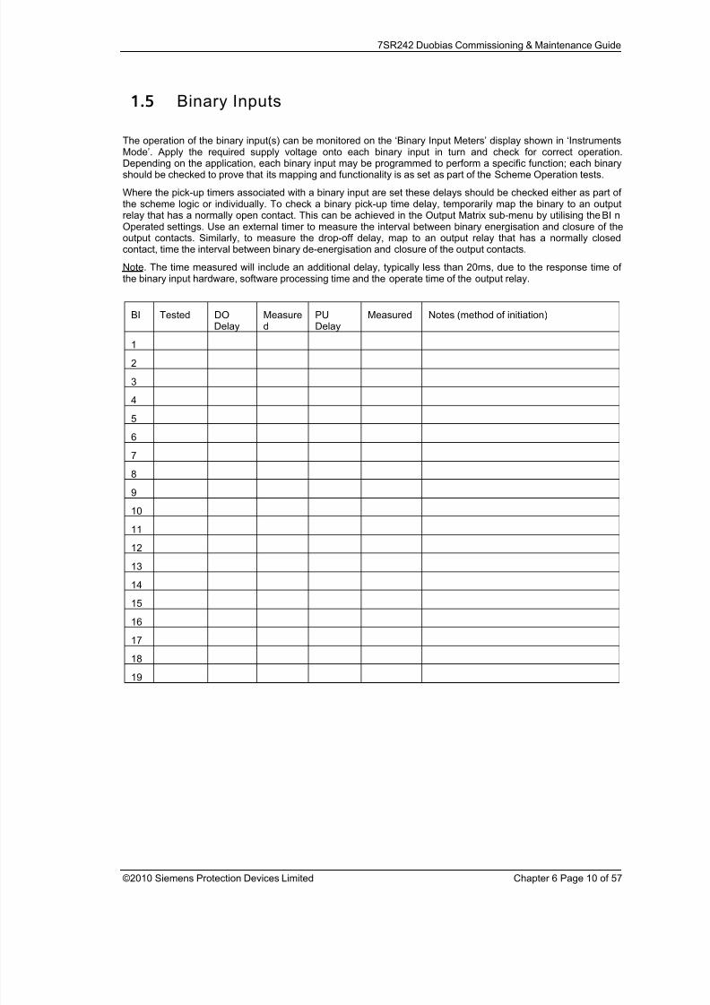
1.5 Binary Inputs
The operation of the binary input(s) can be monitored on the ‘Binary Input Meters’ display shown in ‘InstrumentsMode’. Apply the required supply voltage onto each binary input in turn and check for correct operation.
Depending on the application, each binary input may be programmed to perform a specific function; each binaryshould be checked to prove that its mapping and functionality is as set as part of the Scheme Operation tests.
Where the pick-up timers associated with a binary input are set these delays should be checked either as part ofthe scheme logic or individually. To check a binary pick-up time delay, temporarily map the binary to an outputrelay that has a normally open contact. This can be achieved in the Output Matrix sub-menu by utilising the BI nOperated settings. Use an external timer to measure the interval between binary energisation and closure of theoutput contacts. Similarly, to measure the drop-off delay, map to an output relay that has a normally closedcontact, time the interval between binary de-energisation and closure of the output contacts.
Note. The time measured will include an additional delay, typically less than 20ms, due to the response time ofthe binary input hardware, software processing time and the operate time of the output relay.
BI Tested DO
Delay
Measure
d
PU
Delay
Measured Notes (method of initiation)
1
2
3
4
5
6
7
8
9
10
11
12
13
14
15
16
17
18
19

8/13/2019 7SR242 - Duobias Technical Manual Chapter 06 Commissioning
http://slidepdf.com/reader/full/7sr242-duobias-technical-manual-chapter-06-commissioning 11/57
7SR242 Duobias Commissioning & Maintenance Guide
©2010 Siemens Protection Devices Limited Chapter 6 Page 11 of 57
1.6 Binary Outputs A minimum of six output relays are provided. Two of these have change over contacts, BO2 & BO3, one has anormally closed contact, BO1 and the remainder have normally open contacts.
Care should be observed with regard to connected devices when forcing contacts to operate for test purposes.
Short duration energisation can cause contact failure due to exceeding the break capacity when connected toinductive load such as electrically reset trip relays.
Close each output relay in turn from the ReyDisp Evolution PC programme, Relay – Control - Close output relay.This function will energise the output for its minimum operate time. This time is specified in the Output Config -Binary Output Config menu for each output relay and may be too short to measure with a continuity tester.
An alternative method of energising an output permanently so that wiring can be checked is to temporarily mapthe relay being tested to the ‘Protection Healthy’ signal in the Output Matrix, as this signal is permanentlyenergised the mapped relay will be held energised, normally open contacts will be closed and vice versa.
BO Checked Notes (method of test)
1NC
2NO
2NC
3NO
3NC
4
5
6
7
8
9
10
11
12
13
14
1.7 Relay Case Shorting ContactsCT inputs and terminals C25-C26 (Relay Withdrawn Alarm) are fitted with case mounted shorting contacts whichprovide a closed contact when the relay is withdrawn from the case. The operation of these contacts should bechecked.
CT Shorting contacts checked
Relay Withdrawn Alarm Checked

8/13/2019 7SR242 - Duobias Technical Manual Chapter 06 Commissioning
http://slidepdf.com/reader/full/7sr242-duobias-technical-manual-chapter-06-commissioning 12/57
7SR242 Duobias Commissioning & Maintenance Guide
©2010 Siemens Protection Devices Limited Chapter 6 Page 12 of 57
Section 2: Protection Functions
This section details the procedures for testing each protection function of the 7SR24 relay. These tests are carriedout to verify the accuracy of the protection pick-ups and time delays at setting and to confirm correct operation ofany associated input and output functionality.
Guidance for calculating test input quantities is given in the relevant test description where required. In many
cases it may be necessary to disable some functions during the testing of other functions, this prevents anyambiguity caused by the operation of multiple functions from one set of input quantities. The ‘Function Config’Menu provides a convenient high level point at which all elements of a particular function can beEnabled/Disabled to suit testing. The ‘Config’ tab in ‘ReyDisp Evolution’ can be used to ‘Enable/Disable’ individualelements. Note that this screen disables functions by applying setting changes to the relay and that any changesmust be sent to the relay to take effect and settings must be returned to their correct value after testing.
The table below indicates functions where function conflicts may occur during testing, consideration should begiven to disabling functions to avoid interference.
Function
Under
Test B i a s e
d D i f f e r e n
t i a l
D i f f e r e n
t i a l H i g h s e
t
P h a s e
O v e r c u r
r e n
t
D e r i v e
d E / F
M e a s u r e
d E / F
R e s
t r i c t e d E / F
O p e n
C i r c u i t
N P S O v e r c u r r
e n
t
U n
d e r c u r r e n
t
T h e r m a l
U / O
v o
l t a g e
N e u
t r a l O v e r v o
l t a g e
U / O
F r e q u e n
c y
O v e r f l u x
i n g
C B F a
i l
T r i p c c
t S u p e r v
i s i o n
I n r u s
h D e
t e c t o r
O v e r f l u x
i n g
D e t e c
t o r
Biased Diff. O O O O O O O O O O
Diff. Highset O O O O O O O O
Phase OC O O O O O O O O O
Derived E/F O O O O O O O O O O
Measured E/F O O O O O O O O O O
Restricted E/F O O O O O O O O O O
Open Circuit O O O O O O O
NPS OC O O O O O O O O
Undercurrent O O O O O O O O
Thermal O O O O O O O O
U/O voltage O O O O
Neutral OV O O O
U/O Frequency O O
Overfluxing O O O
CB Fail O O O O O O O O O O O O O O
74TCS/74CCS
Inrush Detector
O/fluxing Detector
The General Pickup LED can be used to assess operation of functions during testing if other functions are
disabled or if the setting allocating General Pickup is temporarily modified.
Particular care should be taken when testing overcurrent functions that the thermal rating of the current inputs isnot exceeded.
8/13/2019 7SR242 - Duobias Technical Manual Chapter 06 Commissioning
http://slidepdf.com/reader/full/7sr242-duobias-technical-manual-chapter-06-commissioning 13/57
7SR242 Duobias Commissioning & Maintenance Guide
©2010 Siemens Protection Devices Limited Chapter 6 Page 13 of 57
It should be considered that where several overlapping elements are used simultaneously, the overall protectionoperate time may be dependent on the operation of different individual elements at the various levels of appliedcurrent or voltage. The resulting composite characteristic may be tested by enabling all of the relevant applicableelements or the element operations can be separated or disabled and tested individually.
All relay settings should be checked before testing begins. It is recommended that the relay settings are extractedfrom the relay using ReyDisp Evolution software and a copy of these settings is stored for reference during and
after testing. It may be necessary to disable some protection functions during the testing of other functions toallow unambiguous results to be obtained.
Care must be taken to reset or re-enable any settings that have been temporarily altered during the testing beforethe relay can be put into service. At the end of testing the relay settings should be compared to the file extractedat the start to ensure that errors have not been introduced.
An example ‘Test Sheet’ summary document is included at the end of this Guide.

8/13/2019 7SR242 - Duobias Technical Manual Chapter 06 Commissioning
http://slidepdf.com/reader/full/7sr242-duobias-technical-manual-chapter-06-commissioning 14/57
7SR242 Duobias Commissioning & Maintenance Guide
©2010 Siemens Protection Devices Limited Chapter 6 Page 14 of 57
2.1 Biased Differential (87BD, 87HS)
Figure 2-1 Biased Differential
Voltage Inputs: None
Current Inputs: W1-IL1 (I A),W1-IL2 (IB),W1-IL3 (IC), and W2-IL1 (I A),W2-IL2 (IB),W2-IL3 (IC),
Disable: 46, 49, 50, 51, 50N, 51N, 50BF,
Map Pickup LED: 87BD, 87HS - Self Reset
The differential elements are subjected to CT multipliers, Vector Group Compensation and Zero Sequence filterswhen applied to power transformers. The complexity of these features can cause confusion during testing andlead to incorrect relay settings being applied. It is recommended that the accuracy of the differential elements aretested by secondary injection with simplified differential settings applied to avoid ambiguity before reinstating therequired site settings which can be tested more thoroughly by primary injection followed by final checking with theprotected transformer on load.
2.1.1 Secondary Injection Testing
The settings used for Secondary Injection test purposes should be:
W1 ICT Multiplier 1x W1 ICT
Connection Yy0,0deg W2 ICTMultiplier 1x W2 ICTConnection Yy0,0deg
8/13/2019 7SR242 - Duobias Technical Manual Chapter 06 Commissioning
http://slidepdf.com/reader/full/7sr242-duobias-technical-manual-chapter-06-commissioning 15/57
7SR242 Duobias Commissioning & Maintenance Guide
©2010 Siemens Protection Devices Limited Chapter 6 Page 15 of 57
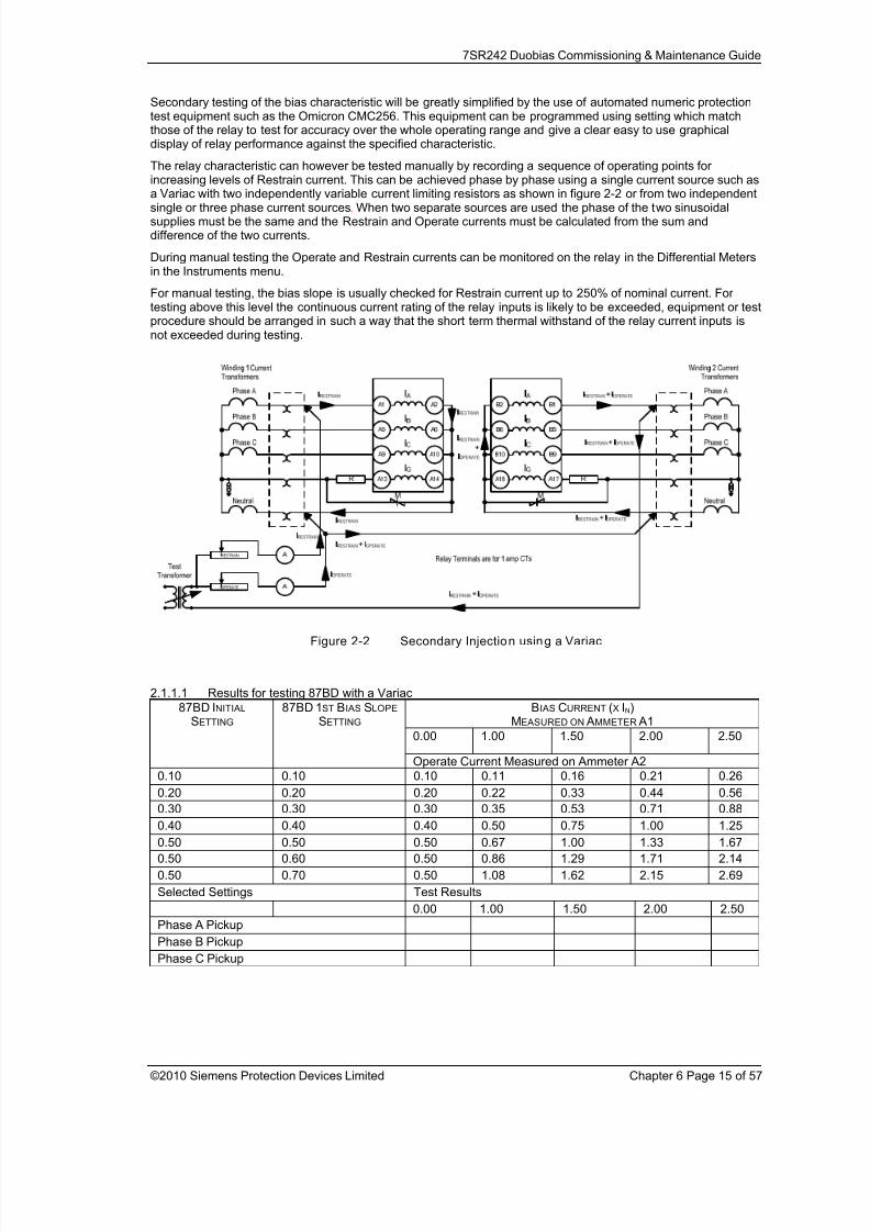
Secondary testing of the bias characteristic will be greatly simplified by the use of automated numeric protectiontest equipment such as the Omicron CMC256. This equipment can be programmed using setting which matchthose of the relay to test for accuracy over the whole operating range and give a clear easy to use graphicaldisplay of relay performance against the specified characteristic.
The relay characteristic can however be tested manually by recording a sequence of operating points forincreasing levels of Restrain current. This can be achieved phase by phase using a single current source such as
a Variac with two independently variable current limiting resistors as shown in figure 2-2 or from two independentsingle or three phase current sources. When two separate sources are used the phase of the two sinusoidalsupplies must be the same and the Restrain and Operate currents must be calculated from the sum anddifference of the two currents.
During manual testing the Operate and Restrain currents can be monitored on the relay in the Differential Metersin the Instruments menu.
For manual testing, the bias slope is usually checked for Restrain current up to 250% of nominal current. Fortesting above this level the continuous current rating of the relay inputs is likely to be exceeded, equipment or testprocedure should be arranged in such a way that the short term thermal withstand of the relay current inputs isnot exceeded during testing.
Figure 2-2 Secondary Injection using a Variac
2.1.1.1 Results for testing 87BD with a Variac
BIAS CURRENT (X IN)MEASURED ON AMMETER A1
0.00 1.00 1.50 2.00 2.50
87BD INITIAL
SETTING 87BD 1ST BIAS SLOPE
SETTING
Operate Current Measured on Ammeter A2
0.10 0.10 0.10 0.11 0.16 0.21 0.26
0.20 0.20 0.20 0.22 0.33 0.44 0.560.30 0.30 0.30 0.35 0.53 0.71 0.88
0.40 0.40 0.40 0.50 0.75 1.00 1.25
0.50 0.50 0.50 0.67 1.00 1.33 1.67
0.50 0.60 0.50 0.86 1.29 1.71 2.14
0.50 0.70 0.50 1.08 1.62 2.15 2.69
Selected Settings Test Results
0.00 1.00 1.50 2.00 2.50
Phase A Pickup
Phase B Pickup
Phase C Pickup
8/13/2019 7SR242 - Duobias Technical Manual Chapter 06 Commissioning
http://slidepdf.com/reader/full/7sr242-duobias-technical-manual-chapter-06-commissioning 16/57
7SR242 Duobias Commissioning & Maintenance Guide
©2010 Siemens Protection Devices Limited Chapter 6 Page 16 of 57
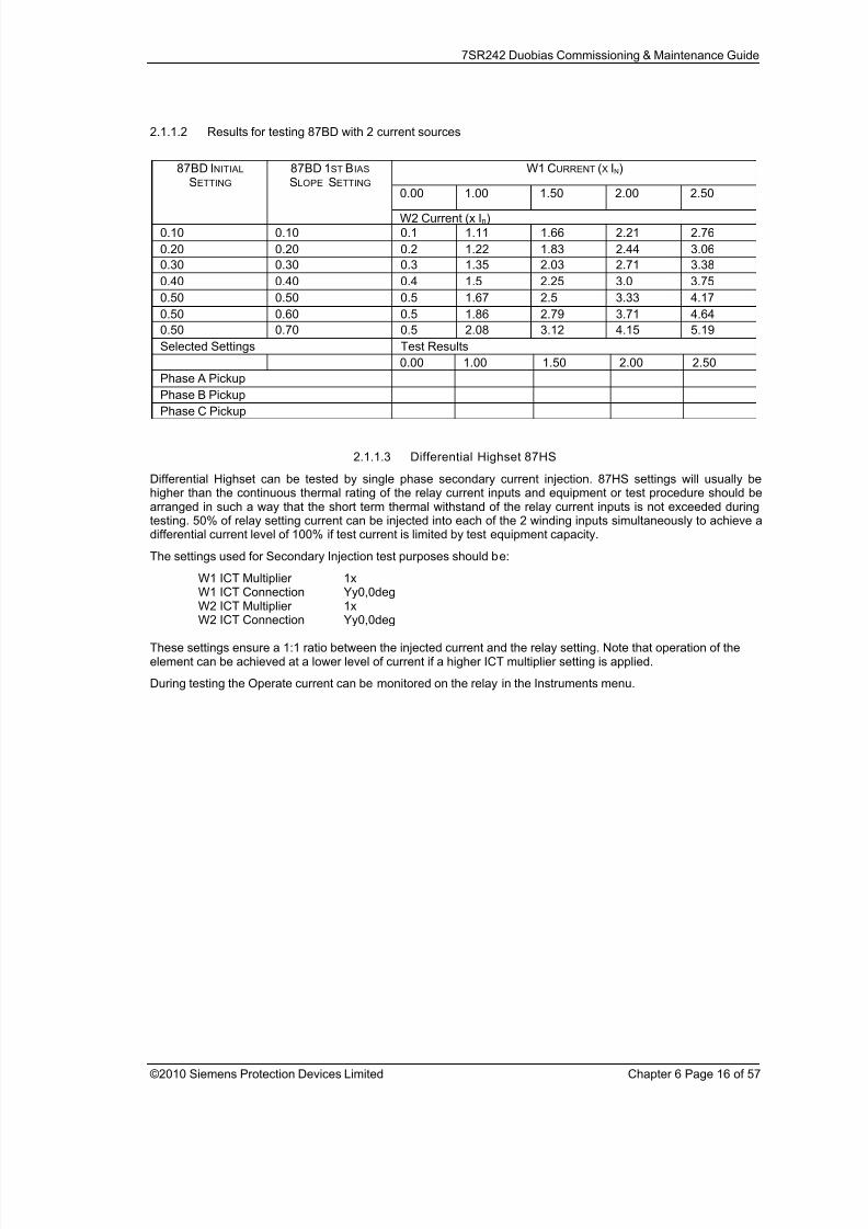
2.1.1.2 Results for testing 87BD with 2 current sources
W1 CURRENT (X IN)
0.00 1.00 1.50 2.00 2.50
87BD INITIAL
SETTING 87BD 1ST BIAS
SLOPE SETTING
W2 Current (x In)
0.10 0.10 0.1 1.11 1.66 2.21 2.76
0.20 0.20 0.2 1.22 1.83 2.44 3.06
0.30 0.30 0.3 1.35 2.03 2.71 3.38
0.40 0.40 0.4 1.5 2.25 3.0 3.75
0.50 0.50 0.5 1.67 2.5 3.33 4.17
0.50 0.60 0.5 1.86 2.79 3.71 4.64
0.50 0.70 0.5 2.08 3.12 4.15 5.19
Selected Settings Test Results
0.00 1.00 1.50 2.00 2.50
Phase A Pickup
Phase B PickupPhase C Pickup
2.1.1.3 Differential Highset 87HS
Differential Highset can be tested by single phase secondary current injection. 87HS settings will usually behigher than the continuous thermal rating of the relay current inputs and equipment or test procedure should bearranged in such a way that the short term thermal withstand of the relay current inputs is not exceeded duringtesting. 50% of relay setting current can be injected into each of the 2 winding inputs simultaneously to achieve adifferential current level of 100% if test current is limited by test equipment capacity.
The settings used for Secondary Injection test purposes should be:
W1 ICT Multiplier 1x
W1 ICT Connection Yy0,0degW2 ICT Multiplier 1xW2 ICT Connection Yy0,0deg
These settings ensure a 1:1 ratio between the injected current and the relay setting. Note that operation of theelement can be achieved at a lower level of current if a higher ICT multiplier setting is applied.
During testing the Operate current can be monitored on the relay in the Instruments menu.

8/13/2019 7SR242 - Duobias Technical Manual Chapter 06 Commissioning
http://slidepdf.com/reader/full/7sr242-duobias-technical-manual-chapter-06-commissioning 17/57
7SR242 Duobias Commissioning & Maintenance Guide
©2010 Siemens Protection Devices Limited Chapter 6 Page 17 of 57
2.1.2 Primary Injection Testing
Primary injection is recommended to prove the relay connections, CT polarity and settings before putting theprotection scheme into service. Primary injection is essential to fully prove the connections of the BiasedDifferential and REF protections. To provide a useful test the relay should have the final site specific settingsapplied for primary injection tests.
WARNING!
It is important before carrying out any primary injection to ensure appropriate CTs are shorted to avoid operationof mesh corner or busbar type unit protection. If the injected primary current is large enough, the bus zonesprotection may operate.
Sufficient primary current to prove the connections and settings is required so that a minimum secondary currentof about 10mA rms circulates in the relay inputs. This is difficult to achieve using high current primary injectionequipment due to the relatively high impedance of the transformer windings. An alternative method is to apply 415LVAC to one side of the transformer with a short circuit applied to the other side. The external three-phaseprimary short is usually applied to the HV side so that the LVAC supply is connected to the winding with lowest
impedance which will result in a higher current level. The test current that will be produced can be predictedbased on the impedance of the transformer and the applied test voltage. The primary test current is injectedthrough all of the biased differential CT’s on the LV side.
Injection of 3 phase current in this way will simulate balanced load conditions, or through fault. During injection,check that the W1 and W2 relay currents are in anti-phase by examination of the relay ‘Differential Meters’ in‘Instruments Mode’. Check each phase in turn, ensuring that the phase angle for ‘W1 Relay’ is in anti-phase with‘W2 Relay’.
When the transformer is eventually energised and carrying load current, the above examination of the W1 and W2relay current phase angle should be re-checked for anti-phase to ensure that the correct ICT Connection settingsare applied to the differential protection.
It should be noted that checking of Vector Grouping by phase alignment between W1 and W2 by 3 phase primaryinjection or on-load will highlight phase cross-over or connection polarity but will not show incorrect application ofzero sequence filters.
8/13/2019 7SR242 - Duobias Technical Manual Chapter 06 Commissioning
http://slidepdf.com/reader/full/7sr242-duobias-technical-manual-chapter-06-commissioning 18/57
7SR242 Duobias Commissioning & Maintenance Guide
©2010 Siemens Protection Devices Limited Chapter 6 Page 18 of 57
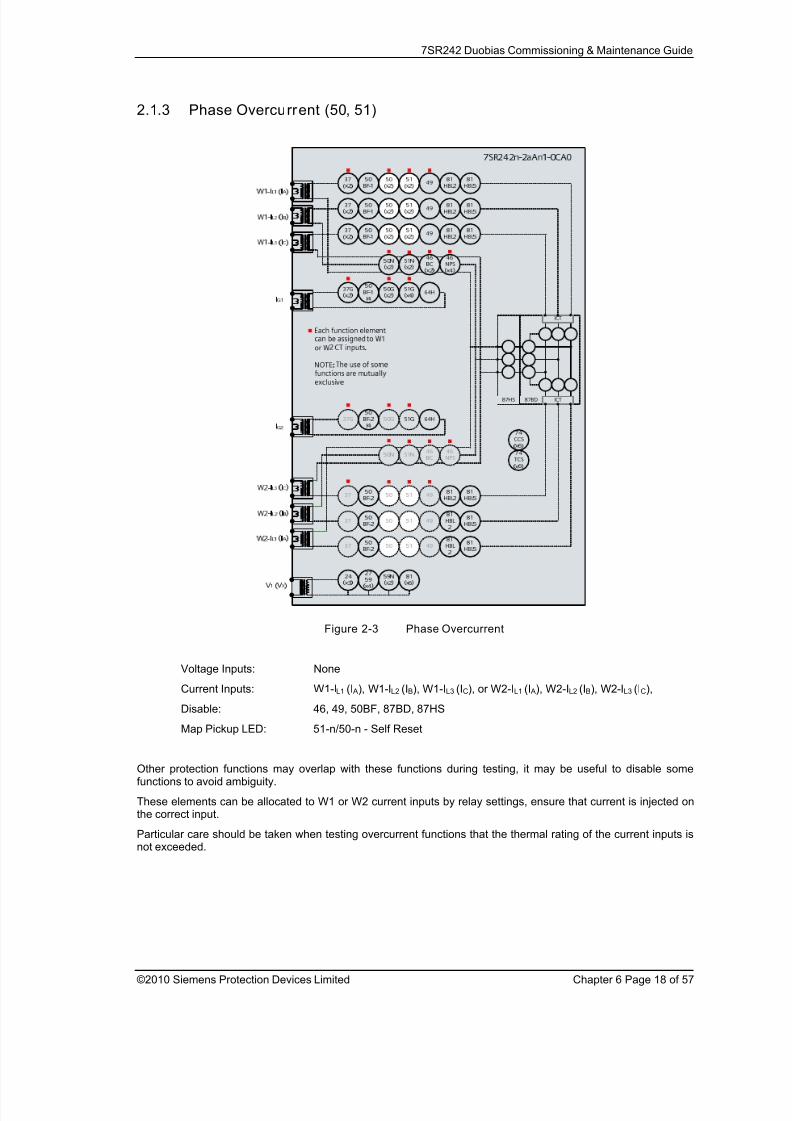
2.1.3 Phase Overcurrent (50, 51)
Figure 2-3 Phase Overcurrent
Voltage Inputs: None
Current Inputs: W1-IL1 (I A), W1-IL2 (IB), W1-IL3 (IC), or W2-IL1 (I A), W2-IL2 (IB), W2-IL3 (IC),
Disable: 46, 49, 50BF, 87BD, 87HS
Map Pickup LED: 51-n/50-n - Self Reset
Other protection functions may overlap with these functions during testing, it may be useful to disable somefunctions to avoid ambiguity.
These elements can be allocated to W1 or W2 current inputs by relay settings, ensure that current is injected onthe correct input.
Particular care should be taken when testing overcurrent functions that the thermal rating of the current inputs isnot exceeded.

8/13/2019 7SR242 - Duobias Technical Manual Chapter 06 Commissioning
http://slidepdf.com/reader/full/7sr242-duobias-technical-manual-chapter-06-commissioning 19/57
7SR242 Duobias Commissioning & Maintenance Guide
©2010 Siemens Protection Devices Limited Chapter 6 Page 19 of 57
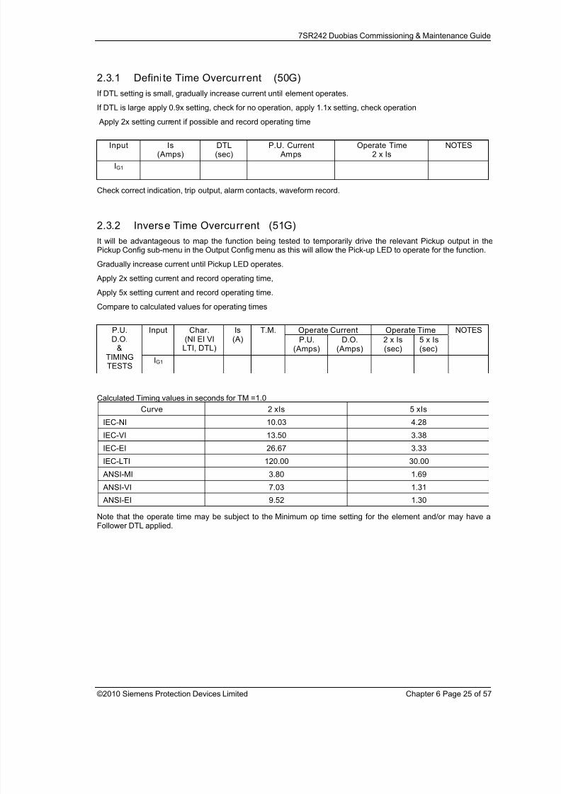
2.1.4 Defini te Time Overcurrent (50)
If DTL setting is small, gradually increase current until element operates.
If DTL is large apply 0.9x setting, check for no operation, apply 1.1x setting, check operation
Apply 2x setting current if possible and record operating time
Phase
Dir. Is(Amps)
DTL(sec)
P.U. Current Amps
Operate Time2 x Is
NOTES
IL1(I A)
IL2(IB)
IL3(IC)
Check correct indication, trip output, alarm contacts, waveform record.
2.1.5 Inverse Time Overcurrent (51)
It will be advantageous to map the function being tested to temporarily drive the relevant Pickup output in thePickup Config sub-menu in the Output Config menu as this will allow the Pick-up LED to operate for the function.
Gradually increase current until Pickup LED operates.
Apply 2x setting current and record operating time,
Apply 5x setting current and record operating time.
Compare to calculated values for operating times
Operate Current Operate TimePh. Dir Char.(NI EI VI
LTI, DTL)
Is(A)
TM
P.U.
(Amps)
D.O.
(Amps)
2 x Is
(sec)
5 x Is
(sec)
NOTES
IL1(I A)
IL2(IB)
P.U.
D.O.&TIMIN
GTESTS IL3(IC)
Calculated Timing values in seconds for TM =1.0
Curve 2 xIs 5 xIs
IEC-NI 10.03 4.28
IEC-VI 13.50 3.38
IEC-EI 26.67 3.33
IEC-LTI 120.00 30.00
ANSI-MI 3.80 1.69
ANSI-VI 7.03 1.31
ANSI-EI 9.52 1.30
Note that the operate time may be subject to the Minimum op time setting for the element and/or may have aFollower DTL applied.
8/13/2019 7SR242 - Duobias Technical Manual Chapter 06 Commissioning
http://slidepdf.com/reader/full/7sr242-duobias-technical-manual-chapter-06-commissioning 20/57
7SR242 Duobias Commissioning & Maintenance Guide
©2010 Siemens Protection Devices Limited Chapter 6 Page 20 of 57
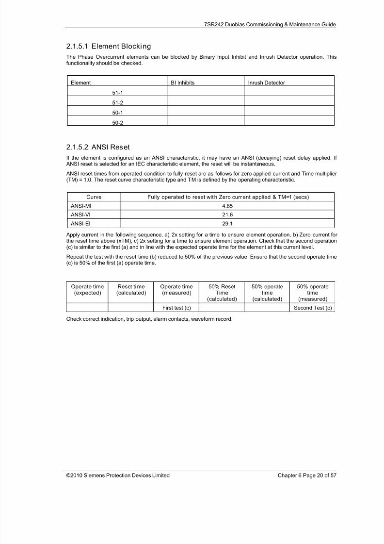
2.1.5.1 Element Blocking
The Phase Overcurrent elements can be blocked by Binary Input Inhibit and Inrush Detector operation. Thisfunctionality should be checked.
Element BI Inhibits Inrush Detector
51-1
51-2
50-1
50-2
2.1.5.2 ANSI Reset
If the element is configured as an ANSI characteristic, it may have an ANSI (decaying) reset delay applied. If ANSI reset is selected for an IEC characteristic element, the reset will be instantaneous.
ANSI reset times from operated condition to fully reset are as follows for zero applied current and Time multiplier(TM) = 1.0. The reset curve characteristic type and TM is defined by the operating characteristic.
Curve Fully operated to reset with Zero current applied & TM=1 (secs)
ANSI-MI 4.85
ANSI-VI 21.6
ANSI-EI 29.1
Apply current in the following sequence, a) 2x setting for a time to ensure element operation, b) Zero current forthe reset time above (xTM), c) 2x setting for a time to ensure element operation. Check that the second operation(c) is similar to the first (a) and in line with the expected operate time for the element at this current level.
Repeat the test with the reset time (b) reduced to 50% of the previous value. Ensure that the second operate time
(c) is 50% of the first (a) operate time.
Check correct indication, trip output, alarm contacts, waveform record.
Operate time(expected)
Reset time(calculated)
Operate time(measured)
50% ResetTime
(calculated)
50% operatetime
(calculated)
50% operatetime
(measured)
First test (c) Second Test (c)

8/13/2019 7SR242 - Duobias Technical Manual Chapter 06 Commissioning
http://slidepdf.com/reader/full/7sr242-duobias-technical-manual-chapter-06-commissioning 21/57
7SR242 Duobias Commissioning & Maintenance Guide
©2010 Siemens Protection Devices Limited Chapter 6 Page 21 of 57
2.2 Derived Earth fault (50N,51N)
Figure 2-4 Measured Earth Fault
Voltage Inputs: None
Current Inputs: W1-IL1 (I A), W1-IL2 (IB), W1-IL3 (IC), or W2-IL1 (I A), W2-IL2 (IB), W2-IL3 (IC),
Disable: 50BF, 50, 51, 49, 37
Map Pickup LED: 51N-n/50N-n - Self Reset
Other protection functions may overlap with these functions during testing, it may be useful to disable somefunctions to avoid ambiguity. Measured EF & Restricted EF protections can be Enabled/Disabled individually oras groups in the ‘Function Config’ menu.
These elements can be allocated to W1 or W2 current inputs by relay settings, ensure that current is injected onthe correct input.
Derived EF elements can be separated from Measured EF by secondary injection of current through the phaseinput circuit only.
8/13/2019 7SR242 - Duobias Technical Manual Chapter 06 Commissioning
http://slidepdf.com/reader/full/7sr242-duobias-technical-manual-chapter-06-commissioning 22/57
7SR242 Duobias Commissioning & Maintenance Guide
©2010 Siemens Protection Devices Limited Chapter 6 Page 22 of 57
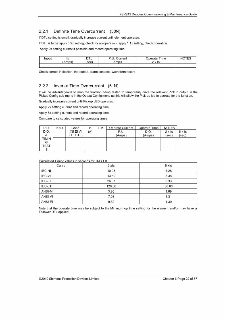
2.2.1 Defini te Time Overcurrent (50N)
If DTL setting is small, gradually increase current until element operates.
If DTL is large apply 0.9x setting, check for no operation, apply 1.1x setting, check operation
Apply 2x setting current if possible and record operating time
Input Is(Amps)
DTL(sec)
P.U. Current Amps
Operate Time2 x Is
NOTES
Check correct indication, trip output, alarm contacts, waveform record.
2.2.2 Inverse Time Overcurrent (51N)
It will be advantageous to map the function being tested to temporarily drive the relevant Pickup output in thePickup Config sub-menu in the Output Config menu as this will allow the Pick-up led to operate for the function.
Gradually increase current until Pickup LED operates.
Apply 2x setting current and record operating time,
Apply 5x setting current and record operating time.
Compare to calculated values for operating times
Operate Current Operate Time NOTESInput Char.(NI EI VI
LTI, DTL)
Is(A)
T.M.
P.U.(Amps)
D.O.(Amps)
2 x Is(sec)
5 x Is(sec)
P.U.D.O.
&TIMIN
GTEST
S
Calculated Timing values in seconds for TM =1.0
Curve 2 xIs 5 xIs
IEC-NI 10.03 4.28
IEC-VI 13.50 3.38
IEC-EI 26.67 3.33
IEC-LTI 120.00 30.00
ANSI-MI 3.80 1.69
ANSI-VI 7.03 1.31
ANSI-EI 9.52 1.30
Note that the operate time may be subject to the Minimum op time setting for the element and/or may have aFollower DTL applied.
8/13/2019 7SR242 - Duobias Technical Manual Chapter 06 Commissioning
http://slidepdf.com/reader/full/7sr242-duobias-technical-manual-chapter-06-commissioning 23/57
7SR242 Duobias Commissioning & Maintenance Guide
©2010 Siemens Protection Devices Limited Chapter 6 Page 23 of 57
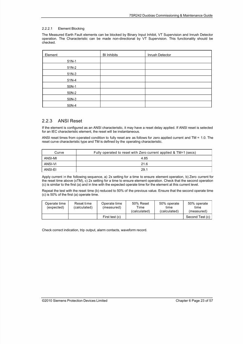
2.2.2.1 Element Blocking
The Measured Earth Fault elements can be blocked by Binary Input Inhibit, VT Supervision and Inrush Detectoroperation. The Characteristic can be made non-directional by VT Supervision. This functionality should bechecked.
Element BI Inhibits Inrush Detector
51N-1
51N-2
51N-3
51N-4
50N-1
50N-2
50N-3
50N-4
2.2.3 ANSI Reset
If the element is configured as an ANSI characteristic, it may have a reset delay applied. If ANSI reset is selectedfor an IEC characteristic element, the reset will be instantaneous.
ANSI reset times from operated condition to fully reset are as follows for zero applied current and TM = 1.0. Thereset curve characteristic type and TM is defined by the operating characteristic.
Curve Fully operated to reset with Zero current applied & TM=1 (secs)
ANSI-MI 4.85
ANSI-VI 21.6
ANSI-EI 29.1
Apply current in the following sequence, a) 2x setting for a time to ensure element operation, b) Zero current forthe reset time above (xTM), c) 2x setting for a time to ensure element operation. Check that the second operation(c) is similar to the first (a) and in line with the expected operate time for the element at this current level.
Repeat the test with the reset time (b) reduced to 50% of the previous value. Ensure that the second operate time(c) is 50% of the first (a) operate time.
Check correct indication, trip output, alarm contacts, waveform record.
Operate time(expected)
Reset time(calculated)
Operate time(measured)
50% ResetTime
(calculated)
50% operatetime
(calculated)
50% operatetime
(measured)
First test (c) Second Test (c)

8/13/2019 7SR242 - Duobias Technical Manual Chapter 06 Commissioning
http://slidepdf.com/reader/full/7sr242-duobias-technical-manual-chapter-06-commissioning 24/57
7SR242 Duobias Commissioning & Maintenance Guide
©2010 Siemens Protection Devices Limited Chapter 6 Page 24 of 57
2.3 Measured Earth fault (50G, 51G)
Figure 2-5 Measured Earth Fault
Voltage Inputs: None
Current Inputs: IG1 , IG2
Disable: 50BF, 64H
Map Pickup LED: 51G-n/50G-n - Self Reset
Other protection functions may overlap with these functions during testing, it may be useful to disable somefunctions to avoid ambiguity. Derived EF, Measured EF & Restricted EF protections can be Enabled/Disabledindividually or as groups in the ‘Function Config’ menu.
These elements can be allocated to IG1 or IG2 current inputs by relay settings, ensure that current is injected onthe correct input.
Measured EF elements can be separated from Derived EF by secondary injection of current through the IG1 or IG2 input circuit only.
8/13/2019 7SR242 - Duobias Technical Manual Chapter 06 Commissioning
http://slidepdf.com/reader/full/7sr242-duobias-technical-manual-chapter-06-commissioning 25/57
7SR242 Duobias Commissioning & Maintenance Guide
©2010 Siemens Protection Devices Limited Chapter 6 Page 25 of 57
2.3.1 Defini te Time Overcurrent (50G)
If DTL setting is small, gradually increase current until element operates.
If DTL is large apply 0.9x setting, check for no operation, apply 1.1x setting, check operation
Apply 2x setting current if possible and record operating time
Input Is(Amps)
DTL(sec)
P.U. Current Amps
Operate Time2 x Is
NOTES
IG1
Check correct indication, trip output, alarm contacts, waveform record.
2.3.2 Inverse Time Overcurrent (51G)
It will be advantageous to map the function being tested to temporarily drive the relevant Pickup output in thePickup Config sub-menu in the Output Config menu as this will allow the Pick-up LED to operate for the function.
Gradually increase current until Pickup LED operates.
Apply 2x setting current and record operating time,
Apply 5x setting current and record operating time.
Compare to calculated values for operating times
Operate Current Operate TimeInput Char.(NI EI VI
LTI, DTL)
Is(A)
T.M.
P.U.(Amps)
D.O.(Amps)
2 x Is(sec)
5 x Is(sec)
NOTESP.U.D.O.
&TIMINGTESTS
IG1
Calculated Timing values in seconds for TM =1.0
Curve 2 xIs 5 xIs
IEC-NI 10.03 4.28
IEC-VI 13.50 3.38
IEC-EI 26.67 3.33
IEC-LTI 120.00 30.00
ANSI-MI 3.80 1.69
ANSI-VI 7.03 1.31
ANSI-EI 9.52 1.30
Note that the operate time may be subject to the Minimum op time setting for the element and/or may have aFollower DTL applied.
8/13/2019 7SR242 - Duobias Technical Manual Chapter 06 Commissioning
http://slidepdf.com/reader/full/7sr242-duobias-technical-manual-chapter-06-commissioning 26/57
7SR242 Duobias Commissioning & Maintenance Guide
©2010 Siemens Protection Devices Limited Chapter 6 Page 26 of 57
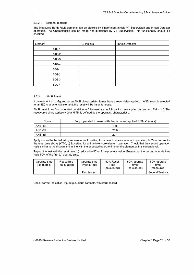
2.3.2.1 Element Blocking
The Measured Earth Fault elements can be blocked by Binary Input Inhibit, VT Supervision and Inrush Detectoroperation. The Characteristic can be made non-directional by VT Supervision. This functionality should bechecked.
Element BI Inhibits Inrush Detector
51G-1
51G-2
51G-3
51G-4
50G-1
50G-2
50G-3
50G-4
2.3.3 ANSI Reset
If the element is configured as an ANSI characteristic, it may have a reset delay applied. If ANSI reset is selectedfor an IEC characteristic element, the reset will be instantaneous.
ANSI reset times from operated condition to fully reset are as follows for zero applied current and TM = 1.0. Thereset curve characteristic type and TM is defined by the operating characteristic.
Curve Fully operated to reset with Zero current applied & TM=1 (secs)
ANSI-MI 4.85
ANSI-VI 21.6
ANSI-EI 29.1
Apply current in the following sequence, a) 2x setting for a time to ensure element operation, b) Zero current forthe reset time above (xTM), c) 2x setting for a time to ensure element operation. Check that the second operation(c) is similar to the first (a) and in line with the expected operate time for the element at this current level.
Repeat the test with the reset time (b) reduced to 50% of the previous value. Ensure that the second operate time(c) is 50% of the first (a) operate time.
Check correct indication, trip output, alarm contacts, waveform record.
Operate time(expected)
Reset time(calculated)
Operate time(measured)
50% ResetTime
(calculated)
50% operatetime
(calculated)
50% operatetime
(measured)
First test (c) Second Test (c)

8/13/2019 7SR242 - Duobias Technical Manual Chapter 06 Commissioning
http://slidepdf.com/reader/full/7sr242-duobias-technical-manual-chapter-06-commissioning 27/57
7SR242 Duobias Commissioning & Maintenance Guide
©2010 Siemens Protection Devices Limited Chapter 6 Page 27 of 57
2.4 Restricted Earth fault (64H)
Figure 2-6 Restricted Earth Fault
Voltage Inputs: n/a
Current Inputs: IG1 , IG2
Disable: 50G, 51G, 50BF
Map Pickup LED: 64H-n - Self Reset
The external stabilising resistor value should be measured and compared to that specified in the settings data.Both values should be recorded.
Element Settings Data: RSTAB Value RSTAB Measured
64H-1
64H-2
The relatively high value of stabilising resistance RSTAB will often interfere with secondary current injection when
using a digital test set. It is normal practice in these cases to short circuit the resistor to allow testing, the shortinglink should be removed after testing.

8/13/2019 7SR242 - Duobias Technical Manual Chapter 06 Commissioning
http://slidepdf.com/reader/full/7sr242-duobias-technical-manual-chapter-06-commissioning 28/57
7SR242 Duobias Commissioning & Maintenance Guide
©2010 Siemens Protection Devices Limited Chapter 6 Page 28 of 57
These elements can be enabled for the IG1 or IG2 current inputs by relay settings, ensure that current is injected onthe correct input.
Since the DTL setting is generally small the pick-up setting can be tested by gradually increasing current untilelement operates. The relay should be disconnected from the current transformers for this test.
Apply 2x setting current if possible and record operating time
Is(Amps)
DTL(sec)
P.U. Current Amps
Operate Time2 x Is
NOTES
64H-1
64H-2
It is also desirable to check the operating voltage achieved with the setting resistor and all parallel CTs connectedbut de-energised. A higher capacity test set will be required for this test. Adequate current must be supplied toprovide the magnetising current of all connected CTs. Precautions should be taken to ensure that no personnelare at risk of contact with any of the energised secondary wiring during the test.
Settings Data:
Voltage Setting (VS)
VS Measured Settings Data:
Operate Current (IOP)
IOP Measured
64H-1
64H-2
To complete testing of the REF requires primary injection through the phase and residual (REF) CT in series tosimulate an out of zone fault and ensure stability of the relay. The test can then be repeated with the REF CTsecondary connections reversed to prove operation.
2.4.1.1 Element Blocking
The Restricted Earth Fault element can be blocked by Binary Input Inhibit. Where applied this functionality shouldbe checked.
Element BI Inhibi ts Checked
64H-1
64H-2
Check correct indication, trip output, alarm contacts, waveform record.
Check that any shorting links are removed after testing.

8/13/2019 7SR242 - Duobias Technical Manual Chapter 06 Commissioning
http://slidepdf.com/reader/full/7sr242-duobias-technical-manual-chapter-06-commissioning 29/57
7SR242 Duobias Commissioning & Maintenance Guide
©2010 Siemens Protection Devices Limited Chapter 6 Page 29 of 57
2.5 Open Circuit (46BC)
Figure 2-7 Open Circui t
Voltage Inputs: n/a
Current Inputs: W1-IL1 (I A), W1-IL2 (IB), W1-IL3 (IC), or W2-IL1 (I A), W2-IL2 (IB), W2-IL3 (IC),
Disable: 51N, 46IT, 46DT
Map Pickup LED: 46BC - Self Reset
This function uses the ratio of NPS current to PPS current to detect an open circuit . These quantities can beproduced directly from many advanced test sets but with limited equipment the following approach can beapplied.
Apply 3P balanced current with normal phase rotation direction. This current will consist of PPS alone, no NPS orZPS.
Increase 1 phase current magnitude in isolation to produce NPS. The single phase unbalance current will containequal quantities of ZPS, NPS and PPS. The NPS component will be 1/3 of the unbalance current and the totalPPS component will be value of the original balanced 3P current plus 1/3 of the additional unbalance current. i.e.as the single phase unbalance current increases, the ratio of NPS to PPS will also increase. The levels of eachsequence component current can be monitored in the Current Meters in Instruments Mode.
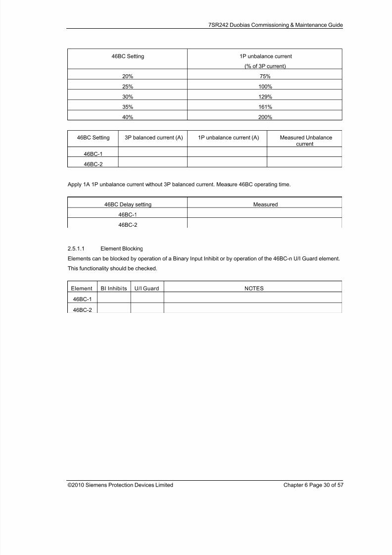
Inject 1A of balanced current. Gradually increase imbalance current, operating level should be as follows:
8/13/2019 7SR242 - Duobias Technical Manual Chapter 06 Commissioning
http://slidepdf.com/reader/full/7sr242-duobias-technical-manual-chapter-06-commissioning 30/57
7SR242 Duobias Commissioning & Maintenance Guide
©2010 Siemens Protection Devices Limited Chapter 6 Page 30 of 57
46BC Setting 1P unbalance current
(% of 3P current)
20% 75%
25% 100%
30% 129%
35% 161%
40% 200%
46BC Setting 3P balanced current (A) 1P unbalance current (A) Measured Unbalancecurrent
46BC-1
46BC-2
Apply 1A 1P unbalance current without 3P balanced current. Measure 46BC operating time.
46BC Delay setting Measured
46BC-1
46BC-2
2.5.1.1 Element Blocking
Elements can be blocked by operation of a Binary Input Inhibit or by operation of the 46BC-n U/I Guard element.
This functionality should be checked.
Element BI Inhibi ts U/I Guard NOTES
46BC-1
46BC-2
8/13/2019 7SR242 - Duobias Technical Manual Chapter 06 Commissioning
http://slidepdf.com/reader/full/7sr242-duobias-technical-manual-chapter-06-commissioning 31/57
7SR242 Duobias Commissioning & Maintenance Guide
©2010 Siemens Protection Devices Limited Chapter 6 Page 31 of 57
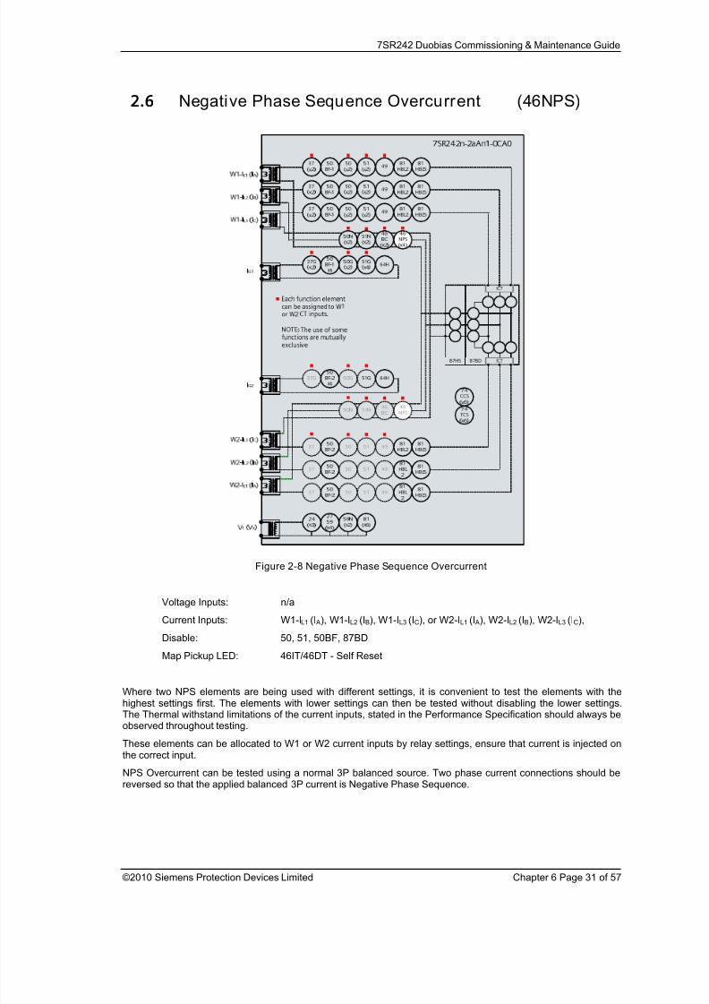
2.6 Negative Phase Sequence Overcurrent (46NPS)
Figure 2-8 Negative Phase Sequence Overcurrent
Voltage Inputs: n/a
Current Inputs: W1-IL1 (I A), W1-IL2 (IB), W1-IL3 (IC), or W2-IL1 (I A), W2-IL2 (IB), W2-IL3 (IC),
Disable: 50, 51, 50BF, 87BD
Map Pickup LED: 46IT/46DT - Self Reset
Where two NPS elements are being used with different settings, it is convenient to test the elements with thehighest settings first. The elements with lower settings can then be tested without disabling the lower settings.The Thermal withstand limitations of the current inputs, stated in the Performance Specification should always beobserved throughout testing.
These elements can be allocated to W1 or W2 current inputs by relay settings, ensure that current is injected onthe correct input.
NPS Overcurrent can be tested using a normal 3P balanced source. Two phase current connections should bereversed so that the applied balanced 3P current is Negative Phase Sequence.
8/13/2019 7SR242 - Duobias Technical Manual Chapter 06 Commissioning
http://slidepdf.com/reader/full/7sr242-duobias-technical-manual-chapter-06-commissioning 32/57
7SR242 Duobias Commissioning & Maintenance Guide
©2010 Siemens Protection Devices Limited Chapter 6 Page 32 of 57
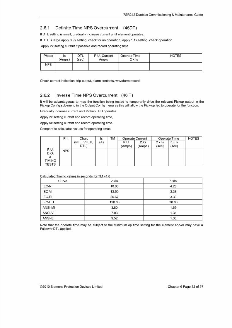
2.6.1 Defini te Time NPS Overcurrent (46DT)
If DTL setting is small, gradually increase current until element operates.
If DTL is large apply 0.9x setting, check for no operation, apply 1.1x setting, check operation
Apply 2x setting current if possible and record operating time
Phase Is(Amps)
DTL(sec)
P.U. Current Amps
Operate Time2 x Is
NOTES
NPS
Check correct indication, trip output, alarm contacts, waveform record.
2.6.2 Inverse Time NPS Overcurrent (46IT)
It will be advantageous to map the function being tested to temporarily drive the relevant Pickup output in the
Pickup Config sub-menu in the Output Config menu as this will allow the Pick-up led to operate for the function.Gradually increase current until Pickup LED operates.
Apply 2x setting current and record operating time,
Apply 5x setting current and record operating time.
Compare to calculated values for operating times
Operate Current Operate TimePh. Char.(NI EI VI LTI,
DTL)
Is(A)
TM
P.U.(Amps)
D.O.(Amps)
2 x Is(sec)
5 x Is(sec)
NOTES
P.U.D.O.
&TIMINGTESTS
NPS
Calculated Timing values in seconds for TM =1.0
Curve 2 xIs 5 xIs
IEC-NI 10.03 4.28
IEC-VI 13.50 3.38
IEC-EI 26.67 3.33
IEC-LTI 120.00 30.00
ANSI-MI 3.80 1.69
ANSI-VI 7.03 1.31
ANSI-EI 9.52 1.30
Note that the operate time may be subject to the Minimum op time setting for the element and/or may have aFollower DTL applied.
8/13/2019 7SR242 - Duobias Technical Manual Chapter 06 Commissioning
http://slidepdf.com/reader/full/7sr242-duobias-technical-manual-chapter-06-commissioning 33/57
7SR242 Duobias Commissioning & Maintenance Guide
©2010 Siemens Protection Devices Limited Chapter 6 Page 33 of 57
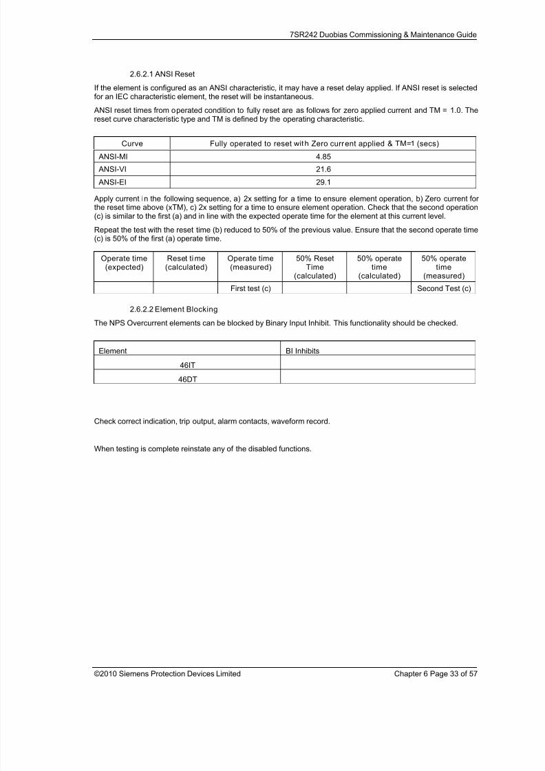
2.6.2.1 ANSI Reset
If the element is configured as an ANSI characteristic, it may have a reset delay applied. If ANSI reset is selectedfor an IEC characteristic element, the reset will be instantaneous.
ANSI reset times from operated condition to fully reset are as follows for zero applied current and TM = 1.0. Thereset curve characteristic type and TM is defined by the operating characteristic.
Curve Fully operated to reset with Zero current applied & TM=1 (secs)
ANSI-MI 4.85
ANSI-VI 21.6
ANSI-EI 29.1
Apply current in the following sequence, a) 2x setting for a time to ensure element operation, b) Zero current forthe reset time above (xTM), c) 2x setting for a time to ensure element operation. Check that the second operation(c) is similar to the first (a) and in line with the expected operate time for the element at this current level.
Repeat the test with the reset time (b) reduced to 50% of the previous value. Ensure that the second operate time(c) is 50% of the first (a) operate time.
2.6.2.2 Element Blocking
The NPS Overcurrent elements can be blocked by Binary Input Inhibit. This functionality should be checked.
Element BI Inhibits
46IT
46DT
Check correct indication, trip output, alarm contacts, waveform record.
When testing is complete reinstate any of the disabled functions.
Operate time(expected)
Reset time(calculated)
Operate time(measured)
50% ResetTime
(calculated)
50% operatetime
(calculated)
50% operatetime
(measured)
First test (c) Second Test (c)

8/13/2019 7SR242 - Duobias Technical Manual Chapter 06 Commissioning
http://slidepdf.com/reader/full/7sr242-duobias-technical-manual-chapter-06-commissioning 34/57
7SR242 Duobias Commissioning & Maintenance Guide
©2010 Siemens Protection Devices Limited Chapter 6 Page 34 of 57
2.7 Undercurrent (37, 37G)
Figure 2-9 Undercurrent
Voltage Inputs: n/a
Current Inputs: W1-IL1 (I A), W1-IL2 (IB), W1-IL3 (IC), IG1 or W2-IL1 (I A), W2-IL2 (IB), W2-IL3 (IC), IG2
Disable: 50N, 51N, 51G, 46, 87BD
Map Pickup LED: 37-n, 37G-n - Self Reset
2.7.1 37-n Elements
If two Undercurrent 37 elements are used with different settings, it is convenient to test the element with thelowest setting first. The higher setting element can then be tested without interference from the other element.
These elements can be allocated to W1 or W2 current inputs by relay settings, ensure that current is injected onthe correct input.
Apply 3P balanced current at a level above the 37-n setting until the element resets.
If DTL setting is small, gradually reduce any each phase current in turn until element operates.
If DTL is large apply 1.1x setting, check for no operation, apply 0.9x setting, check operationTesting of these elements phase by phase may cause inadvertent operation of the 46 NPS Overcurrent elements.
8/13/2019 7SR242 - Duobias Technical Manual Chapter 06 Commissioning
http://slidepdf.com/reader/full/7sr242-duobias-technical-manual-chapter-06-commissioning 35/57
7SR242 Duobias Commissioning & Maintenance Guide
©2010 Siemens Protection Devices Limited Chapter 6 Page 35 of 57
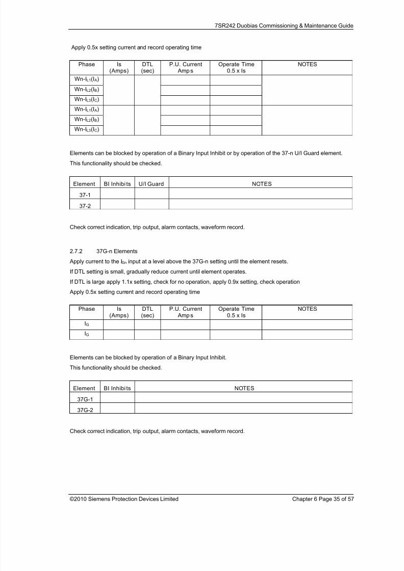
Apply 0.5x setting current and record operating time
Phase Is(Amps)
DTL(sec)
P.U. Current Amps
Operate Time0.5 x Is
NOTES
Wn-IL1(I A)
Wn-IL2(IB)
Wn-IL3(IC)
Wn-IL1(I A)
Wn-IL2(IB)
Wn-IL3(IC)
Elements can be blocked by operation of a Binary Input Inhibit or by operation of the 37-n U/I Guard element.
This functionality should be checked.
Element BI Inhibi ts U/I Guard NOTES
37-1
37-2
Check correct indication, trip output, alarm contacts, waveform record.
2.7.2 37G-n Elements
Apply current to the IGn input at a level above the 37G-n setting until the element resets.
If DTL setting is small, gradually reduce current until element operates.
If DTL is large apply 1.1x setting, check for no operation, apply 0.9x setting, check operation
Apply 0.5x setting current and record operating time
Phase Is(Amps)
DTL(sec)
P.U. Current Amps
Operate Time0.5 x Is
NOTES
IG
IG
Elements can be blocked by operation of a Binary Input Inhibit.
This functionality should be checked.
Element BI Inhibi ts NOTES
37G-1
37G-2
Check correct indication, trip output, alarm contacts, waveform record.

8/13/2019 7SR242 - Duobias Technical Manual Chapter 06 Commissioning
http://slidepdf.com/reader/full/7sr242-duobias-technical-manual-chapter-06-commissioning 36/57
7SR242 Duobias Commissioning & Maintenance Guide
©2010 Siemens Protection Devices Limited Chapter 6 Page 36 of 57
2.8 Thermal Overload (49)
Figure 2-10 Thermal Overload
Voltage Inputs: n/a
Current Inputs: W1-IL1 (I A), W1-IL2 (IB), W1-IL3 (IC), or W2-IL1 (I A), W2-IL2 (IB), W2-IL3 (IC),
Disable: 51, 50, 37, 46NPS, 50CBF, 87BD
Map Pickup LED: 49 Alarm
The current can be applied from a 3P balanced supply or phase by phase from a 1P supply. Alternatively the 3phase current inputs can be connected in series and injected simultaneously from a single 1P source.
This elements can be allocated to W1 or W2 current inputs by relay settings, ensure that current is injected on thecorrect input.
The Thermal Overload Setting and Time Constant Setting can be considered together to calculate the operatingtime for a particular applied current.
The following table lists operate times for a range of Time Constant Settings for an applied current of 2x theThermal Overload setting. Ensure that the thermal rating of the relay is not exceeded during this test.

8/13/2019 7SR242 - Duobias Technical Manual Chapter 06 Commissioning
http://slidepdf.com/reader/full/7sr242-duobias-technical-manual-chapter-06-commissioning 37/57
7SR242 Duobias Commissioning & Maintenance Guide
©2010 Siemens Protection Devices Limited Chapter 6 Page 37 of 57
Time Constant (mins) Operate Time (sec)
1 17.3
2 34.5
3 51.8
4 69
5 86.3
10 173
15 259
20 345
25 432
30 51.8
50 863
100 1726
The Thermal State must be in the fully reset condition in order to measure the operate time correctly. This can beachieved by setting change in the Thermal protection settings menu or by pressing the Test/Reset button whenthe Thermal Meter is shown in the Instruments Mode.Reset the thermal State then apply 2x the Overload Setting current.
Calculated Operate Time (s) Measured Operate Time (s)
If the Thermal Overload Capacity Alarm is used, this can be tested by monitoring the Thermal Capacity in theinstruments menu. If the Thermal time constant is longer than a few minutes, this can be assessed during thetiming test above. If the Time Constant is less than a few minutes, a lower multiple of current will be required suchthat the rate of capacity increase is slowed to allow monitoring of the instrument to be accurate.
Capacity Alarm Setting Measured
2.8.1.1 Element Blocking
The Thermal element can be blocked by Binary Input Inhibit. This functionality should be checked.
Element BI Inhibits
49

8/13/2019 7SR242 - Duobias Technical Manual Chapter 06 Commissioning
http://slidepdf.com/reader/full/7sr242-duobias-technical-manual-chapter-06-commissioning 38/57
7SR242 Duobias Commissioning & Maintenance Guide
©2010 Siemens Protection Devices Limited Chapter 6 Page 38 of 57
2.9 Under/Over Voltage (27/59)
Figure 2-11 Phase Under/Over Voltage
Voltage Inputs: V1 (VX)
Current Inputs: n/a apply zero current to stabilize other functions
Disable: 59N
Map Pickup LED: 27/59-n - Self Reset
Where more than one Undervoltage (27) elements are being used with different settings, it is convenient to testthe elements with the lowest settings first. The elements with higher settings can then be tested without disablingthe lower settings.
Note that if the voltage is reduced below the 27UVG setting, the function may be blocked. Current inputs are notrequired to stabilise the relay during voltage element testing.
If the DTL is short, starting from nominal voltage, slowly decrease the applied test voltage until the Pickup LED(temporarily mapped) is lit. Record the operate voltage. The LED should light at setting Volts +/-5%. Slowlyincrease the input voltage until the LED extinguishes. Record the reset voltage to check the ‘Hysteresis’ setting. Ifthe DTL is long, the operate level should be checked by applying a voltage of 90% of setting voltage. CheckHysteresis by resetting element to the operate level setting plus the hysteresis setting.
Connect the relevant output contact(s) to stop the test set. Step the applied voltage to a level below the setting.The test set should be stopped at the operate time setting +/-5%

8/13/2019 7SR242 - Duobias Technical Manual Chapter 06 Commissioning
http://slidepdf.com/reader/full/7sr242-duobias-technical-manual-chapter-06-commissioning 39/57
7SR242 Duobias Commissioning & Maintenance Guide
©2010 Siemens Protection Devices Limited Chapter 6 Page 39 of 57
When testing is complete reinstate any of the disabled functions.
Where more than one Overvoltage (59) elements are being used with different settings, it is convenient to test theelements with the highest settings first. The elements with lower settings can then be tested without disabling thehigher settings.
If the ‘O/P Phases’ is set to ‘All’, the voltage on all phases must be increased simultaneously. Otherwise the 3phases should be tested individually. If the DTL setting is short, starting from nominal voltage, slowly increase the
applied 3P or VL1 test voltage until the Pickup LED (temporarily mapped) is lit. The LED should light at settingVolts +/-5% Decrease the input voltage to nominal Volts and the LED will extinguish. Record the reset voltage tocheck the ‘Hysteresis’ setting. If the DTL setting is long, the operate level can be checked by applying 100% ofsetting to cause operation followed by setting minus the Hysteresis setting to cause reset.
Connect the relevant output contact(s) to stop the test set. Step the applied voltage to a level above the setting.The test set should be stopped at the operate time setting +/-5%
Test inputs VL2 and VL3 by repeating the above if necessary.
Phase 27/59setting(Volts)
U/O
DTL(sec)
Hyst. D.O.(calculated)
P.U.Volts
D.OVolts
Op. Time2x Vs (OV)
0.5x Vs(UV)
UVGuard
NOTES
V1(VX)
2.9.1.1 Element Blocking
The NPS Overcurrent elements can be blocked by Binary Input Inhibit and VT Supervision. This functionalityshould be checked.
Element BI Inhibits
27/59-1
27/59-2
27/59-3
27/59-4
When testing is complete reinstate any of the disabled functions.

8/13/2019 7SR242 - Duobias Technical Manual Chapter 06 Commissioning
http://slidepdf.com/reader/full/7sr242-duobias-technical-manual-chapter-06-commissioning 40/57
7SR242 Duobias Commissioning & Maintenance Guide
©2010 Siemens Protection Devices Limited Chapter 6 Page 40 of 57
2.9.2 Undervoltage Guard (27/59UVG)
If any 27 Undervoltage element is set to be inhibited by the 27 Undervoltage Guard element, this function shouldbe tested.
Connect the test voltage inputs to suit the installation wiring diagram utilising any test socket facilities available. Itmay be useful to temporarily map an LED as ‘General Pickup’ to assist during testing. 27UVG operation will resetthe General Pickup if no other element is operated. This LED should not be set as ‘Hand Reset’ in the Outputmatrix.
Starting from nominal voltage, apply a step decrease to the applied voltage to a level below the 27 Undervoltagesetting but above the 27UVG setting such that an Undervoltage element operation occurs. Slowly reduce theapplied voltage until the 27 Undervoltage element resets, this can be detected by the General Pickup LED reset ifno other element is operated (this includes any Undervoltage element which is not UV Guarded).
Phase Vs(Volts)
V elementUsed for test
BlockedVolts
NOTES
UVG
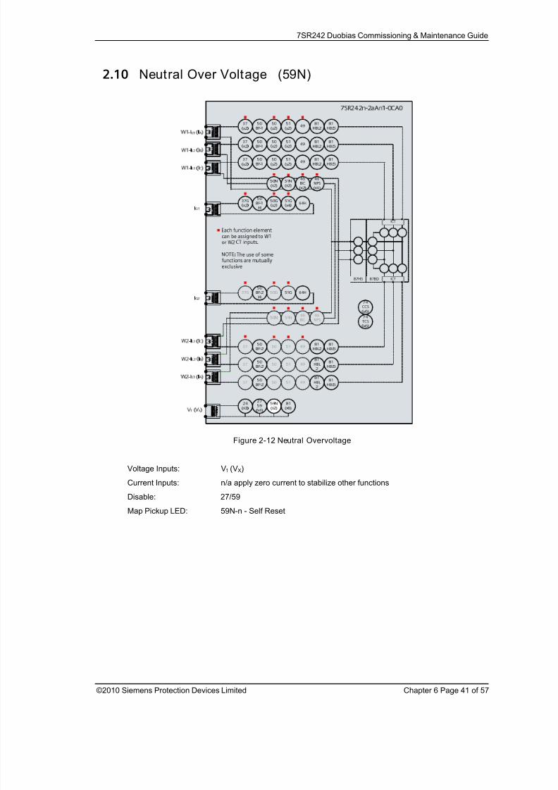
8/13/2019 7SR242 - Duobias Technical Manual Chapter 06 Commissioning
http://slidepdf.com/reader/full/7sr242-duobias-technical-manual-chapter-06-commissioning 41/57
7SR242 Duobias Commissioning & Maintenance Guide
©2010 Siemens Protection Devices Limited Chapter 6 Page 41 of 57
2.10 Neutral Over Voltage (59N)
Figure 2-12 Neutral Overvoltage
Voltage Inputs: V1 (VX)
Current Inputs: n/a apply zero current to stabilize other functions
Disable: 27/59
Map Pickup LED: 59N-n - Self Reset
8/13/2019 7SR242 - Duobias Technical Manual Chapter 06 Commissioning
http://slidepdf.com/reader/full/7sr242-duobias-technical-manual-chapter-06-commissioning 42/57
7SR242 Duobias Commissioning & Maintenance Guide
©2010 Siemens Protection Devices Limited Chapter 6 Page 42 of 57
2.10.1 Defin ite Time (59NDT)
If DTL setting is small, gradually increase single phase voltage until element operates.
If DTL is large apply 0.9x setting, check for no operation, apply 1.1x setting, check operation
Apply 2x setting voltage if possible and record operating time
Phase Vs(Volts)
DTL(sec)
P.U. CurrentVolts
Operate Time2 x Vs
NOTES
V1(VX)
Check correct indication, trip output, alarm contacts, waveform record.
2.10.2 Inverse Time (59NIT)
It will be advantageous to map the function being tested to temporarily drive the relevant Pickup output in thePickup Config sub-menu in the Output Config menu as this will allow the Pick-up LED to operate for the function.
Gradually increase voltage until Pickup LED operates.
Apply 2x setting voltage and record operating time,
Apply a higher multiple of setting voltage and record operating time.
Compare to calculated values for operating times from:
( )[ ] ⎥
⎦
⎤⎢⎣
⎡
−=
1
1)sec
Vs
Vnop M ondst
Where M = Time multiplier and Vn/Vs = multiple of setting.
Operate Voltage Operate TimePh. Vs(V)
TM
P.U.(Volts)
D.O.(Volts)
2 x Vs(sec)
x Vs(sec)
NOTES
V1(V
X)
2.10.2.1 Element Blocking
The Neutral Overvoltage elements can be blocked by Binary Input Inhibit. This functionality should be checked.
Element BI Inhibits
59NIT
59NDT
Check correct indication, trip output, alarm contacts, waveform record.
When testing is complete reinstate any of the disabled functions.

8/13/2019 7SR242 - Duobias Technical Manual Chapter 06 Commissioning
http://slidepdf.com/reader/full/7sr242-duobias-technical-manual-chapter-06-commissioning 43/57
7SR242 Duobias Commissioning & Maintenance Guide
©2010 Siemens Protection Devices Limited Chapter 6 Page 43 of 57
2.11 Under/Over Frequency (81)
Figure 2-13 Under/Over Frequency
Voltage Inputs: V1 (VX)
Current Inputs: n/a apply zero current to stabilize other functions
Disable:
Map Pickup LED: 81-n - Self Reset
For Over-frequency, the elements with the highest setting should be tested first and for Under-frequency theelements with the lowest settings should be tested first. The elements with other settings can then be testedwithout need to disable the elements already tested. Note that the relay is designed to track the gradual changesin power system frequency and that sudden step changes in frequency during testing do not reflect normalsystem operation. Normal ‘instantaneous’ operation of the frequency element is 140-175ms in line with thePerformance Specification. Application of sudden step changes to frequency can add additional delay which canproduce misleading test results.
Gradually increase/decrease applied voltage frequency until 81-n operation occurs. Elements set for moreextreme frequency fluctuation should be tested first with lesser elements disabled.
If the 81-n Delay setting is long it will be advantageous to map the function to temporarily drive the relevant
Pickup output in the Pickup Config sub-menu in the Output Config menu as this will allow the Pick-up LED tooperate for the function. If the delay setting is short the operation of the element can be easily checked directly.

8/13/2019 7SR242 - Duobias Technical Manual Chapter 06 Commissioning
http://slidepdf.com/reader/full/7sr242-duobias-technical-manual-chapter-06-commissioning 44/57
7SR242 Duobias Commissioning & Maintenance Guide
©2010 Siemens Protection Devices Limited Chapter 6 Page 44 of 57
The frequency should then be gradually decreased/increased until the element resets. The reset frequency canbe used to check the Hysteresis setting.
If the element is set as 81-n U/V Guarded, The applied voltage must be above the 81 UV Guard Setting in theU/O Frequency menu.
Apply setting frequency +0.5Hz for Over-frequency or -0.5Hz for Under-frequency and record operating time.Starting with the element in the operated condition, gradually increase or decrease the applied voltage until theelement resets. Measure the reset voltage level to check the 81 Hysteresis setting.
F(Hertz)
U/O DTL(sec)
Hyst. D.O.(calc.)
P.U.FreqHertz
D.O.Freq.Hertz
OperateTime
+/- 0.5Hz
UVGuard
NOTES
If the element is set as 81-nU/V Guarded, this setting can be tested by applying the test voltage at a level belowthe 81 U/V Guard Setting at a frequency in the operate range. Increase the voltage until the relay operates.
UVG UVG Setting(Volts)
Freq elementUsed for test
BlockedVolts (D.O.)
Unblocked Volts (P.U.) NOTES
U/O Freq
2.11.1.1 Element Blocking
The U/O Frequency elements can be blocked by Binary Input Inhibit. This functionality should be checked.
Element BI Inhibits
81-1
81-2
81-3
81-4
81-5
81-6
Check correct indication, trip output, alarm contacts, waveform record.When testing is complete reinstate any of the disabled functions.
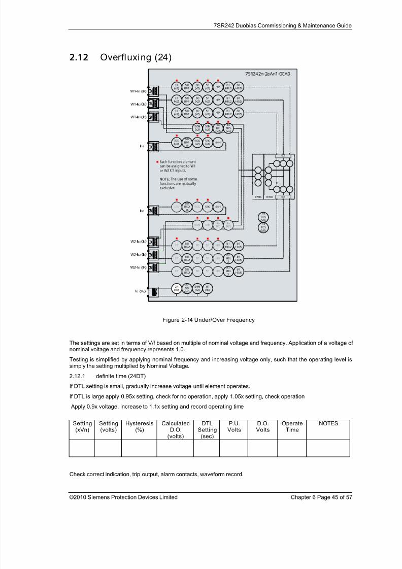
8/13/2019 7SR242 - Duobias Technical Manual Chapter 06 Commissioning
http://slidepdf.com/reader/full/7sr242-duobias-technical-manual-chapter-06-commissioning 45/57
7SR242 Duobias Commissioning & Maintenance Guide
©2010 Siemens Protection Devices Limited Chapter 6 Page 45 of 57
2.12 Overfluxing (24)
Figure 2-14 Under/Over Frequency
The settings are set in terms of V/f based on multiple of nominal voltage and frequency. Application of a voltage ofnominal voltage and frequency represents 1.0.
Testing is simplified by applying nominal frequency and increasing voltage only, such that the operating level is
simply the setting multiplied by Nominal Voltage.2.12.1 definite time (24DT)
If DTL setting is small, gradually increase voltage until element operates.
If DTL is large apply 0.95x setting, check for no operation, apply 1.05x setting, check operation
Apply 0.9x voltage, increase to 1.1x setting and record operating time
Setting(xVn)
Setting(volts)
Hysteresis(%)
CalculatedD.O.
(volts)
DTLSetting(sec)
P.U.Volts
D.O.Volts
OperateTime
NOTES
Check correct indication, trip output, alarm contacts, waveform record.
8/13/2019 7SR242 - Duobias Technical Manual Chapter 06 Commissioning
http://slidepdf.com/reader/full/7sr242-duobias-technical-manual-chapter-06-commissioning 46/57
7SR242 Duobias Commissioning & Maintenance Guide
©2010 Siemens Protection Devices Limited Chapter 6 Page 46 of 57
2.12.2 inverse time (24IT)The inverse V/f element should be tested at each of the points specified by settings that constitute the overallinverse characteristics.
Setting
(xVn)
Setting
(volts)
Hysteresis
(%)
Calculated
D.O.(volts)
DTL
Setting(sec)
P.U.
Volts
D.O.
Volts
Operate
Time
NOTES
X0 Y0
Setting(xVn)
Setting(volts)
DTLSetting(sec)
OperateTime
NOTES
X1 Y1
X2 Y2
X3 Y3
X4 Y4
X5 Y5
X6 Y6
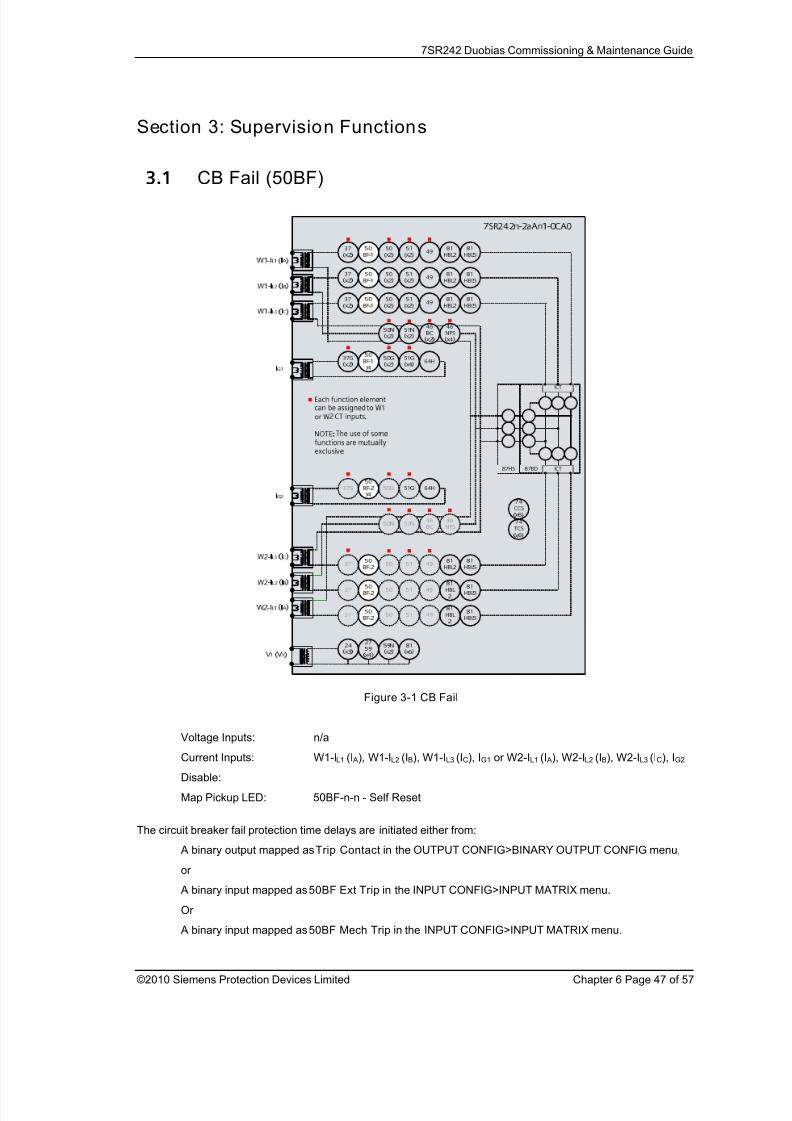
8/13/2019 7SR242 - Duobias Technical Manual Chapter 06 Commissioning
http://slidepdf.com/reader/full/7sr242-duobias-technical-manual-chapter-06-commissioning 47/57
7SR242 Duobias Commissioning & Maintenance Guide
©2010 Siemens Protection Devices Limited Chapter 6 Page 47 of 57
Section 3: Supervision Functions
3.1 CB Fail (50BF)
Figure 3-1 CB Fail
Voltage Inputs: n/a
Current Inputs: W1-IL1 (I A), W1-IL2 (IB), W1-IL3 (IC), IG1 or W2-IL1 (I A), W2-IL2 (IB), W2-IL3 (IC), IG2
Disable:
Map Pickup LED: 50BF-n-n - Self Reset
The circuit breaker fail protection time delays are initiated either from:
A binary output mapped as Trip Contact in the OUTPUT CONFIG>BINARY OUTPUT CONFIG menu,
or
A binary input mapped as 50BF Ext Trip in the INPUT CONFIG>INPUT MATRIX menu.
Or
A binary input mapped as 50BF Mech Trip in the INPUT CONFIG>INPUT MATRIX menu.
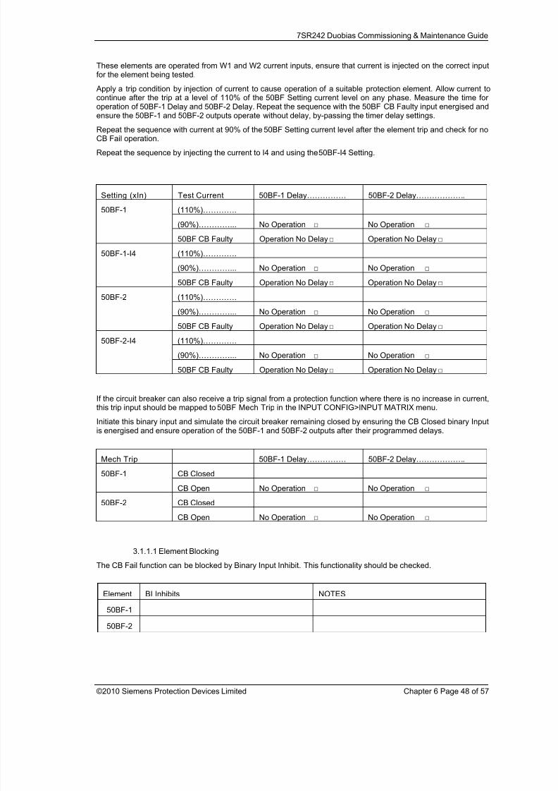
8/13/2019 7SR242 - Duobias Technical Manual Chapter 06 Commissioning
http://slidepdf.com/reader/full/7sr242-duobias-technical-manual-chapter-06-commissioning 48/57
7SR242 Duobias Commissioning & Maintenance Guide
©2010 Siemens Protection Devices Limited Chapter 6 Page 48 of 57
These elements are operated from W1 and W2 current inputs, ensure that current is injected on the correct inputfor the element being tested.
Apply a trip condition by injection of current to cause operation of a suitable protection element. Allow current tocontinue after the trip at a level of 110% of the 50BF Setting current level on any phase. Measure the time foroperation of 50BF-1 Delay and 50BF-2 Delay. Repeat the sequence with the 50BF CB Faulty input energised andensure the 50BF-1 and 50BF-2 outputs operate without delay, by-passing the timer delay settings.
Repeat the sequence with current at 90% of the 50BF Setting current level after the element trip and check for noCB Fail operation.
Repeat the sequence by injecting the current to I4 and using the 50BF-I4 Setting.
Setting (xIn) Test Current 50BF-1 Delay…………… 50BF-2 Delay……………….
(110%)………….
(90%)…………... No Operation □ No Operation □
50BF-1
50BF CB Faulty Operation No Delay □ Operation No Delay □
(110%)………….(90%)…………... No Operation □ No Operation □
50BF-1-I4
50BF CB Faulty Operation No Delay □ Operation No Delay □
(110%)………….
(90%)…………... No Operation □ No Operation □
50BF-2
50BF CB Faulty Operation No Delay □ Operation No Delay □
(110%)………….
(90%)…………... No Operation □ No Operation □
50BF-2-I4
50BF CB Faulty Operation No Delay □ Operation No Delay □
If the circuit breaker can also receive a trip signal from a protection function where there is no increase in current,this trip input should be mapped to 50BF Mech Trip in the INPUT CONFIG>INPUT MATRIX menu.
Initiate this binary input and simulate the circuit breaker remaining closed by ensuring the CB Closed binary Inputis energised and ensure operation of the 50BF-1 and 50BF-2 outputs after their programmed delays.
Mech Trip 50BF-1 Delay…………… 50BF-2 Delay……………….
CB Closed50BF-1
CB Open No Operation □ No Operation □
CB Closed50BF-2
CB Open No Operation □ No Operation □
3.1.1.1 Element Blocking
The CB Fail function can be blocked by Binary Input Inhibit. This functionality should be checked.
Element BI Inhibits NOTES
50BF-1
50BF-2
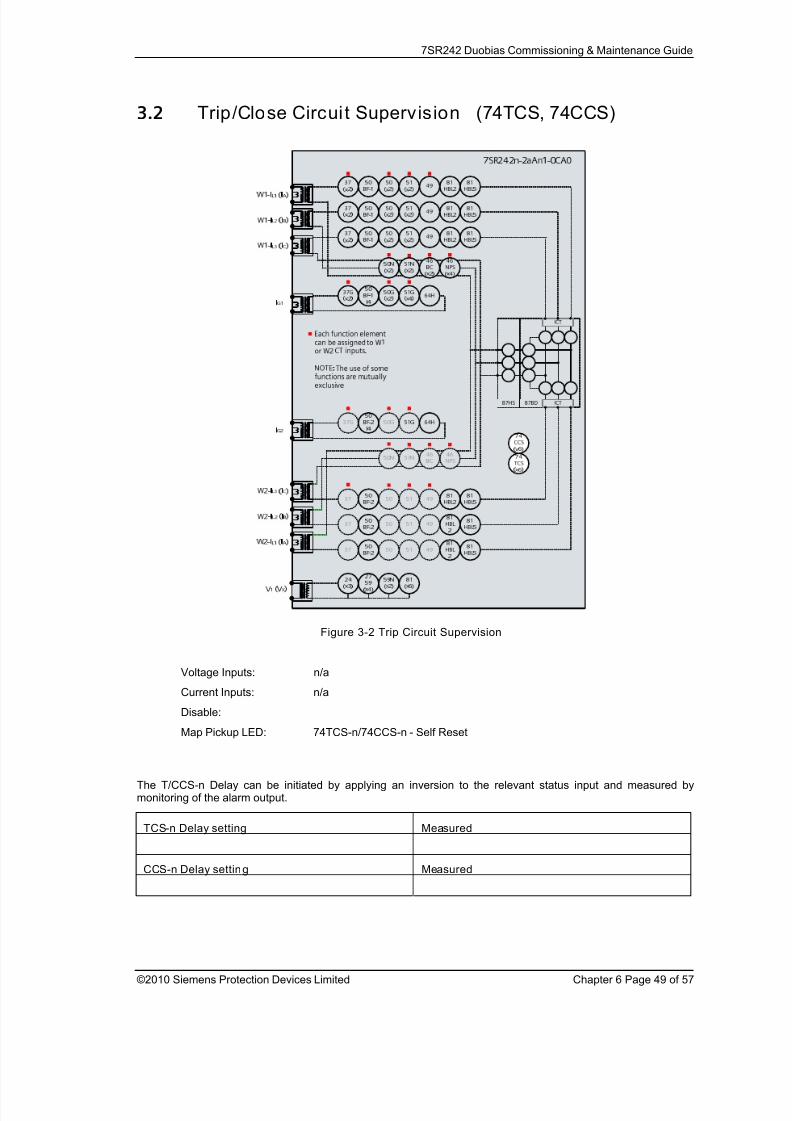
8/13/2019 7SR242 - Duobias Technical Manual Chapter 06 Commissioning
http://slidepdf.com/reader/full/7sr242-duobias-technical-manual-chapter-06-commissioning 49/57
7SR242 Duobias Commissioning & Maintenance Guide
©2010 Siemens Protection Devices Limited Chapter 6 Page 49 of 57
3.2 Trip/Close Circuit Supervision (74TCS, 74CCS)
Figure 3-2 Trip Circuit Supervision
Voltage Inputs: n/a
Current Inputs: n/a
Disable:
Map Pickup LED: 74TCS-n/74CCS-n - Self Reset
The T/CCS-n Delay can be initiated by applying an inversion to the relevant status input and measured bymonitoring of the alarm output.
TCS-n Delay setting Measured
CCS-n Delay setting Measured

8/13/2019 7SR242 - Duobias Technical Manual Chapter 06 Commissioning
http://slidepdf.com/reader/full/7sr242-duobias-technical-manual-chapter-06-commissioning 50/57
7SR242 Duobias Commissioning & Maintenance Guide
©2010 Siemens Protection Devices Limited Chapter 6 Page 50 of 57
3.3 Magnetising Inrush Detector (81HBL2)
Figure 3-3 Magnetising Inrush Detector
Voltage Inputs: n/a
Current Inputs: W1-IL1 (I A), W1-IL2 (IB), W1-IL3 (IC), or W2-IL1 (I A), W2-IL2 (IB), W2-IL3 (IC)
Disable:
Map Pickup LED:
Logical operation of the harmonic blocking can be tested by injection of 2nd
harmonic current (at 100Hz for 50Hzrelay) to cause operation of the blocking signals. Note that injection of any level of 2
nd harmonic alone on a
current input will cause the block to be raised if the Cross or Phase blocking method is used since the harmoniccontent on this input is 100%, i.e. greater than setting. Full wave rectified current contains mostly 2
nd harmonic
and is the traditional method to generate it without advanced equipment.
If the Cross or Sum Blocking methods are used, fundamental frequency current can be injected into the otherwinding simultaneously to operate protection elements if required to test the blocking operation. Care should betaken that the thermal limits of the relay are not exceeded during these tests.
More advanced test equipment is required, with the facility to combine harmonic and fundamental frequencies ofcurrent, to test the accuracy of setting for current level of the blocking element. Note that the 81HBL2 Setting is
set as a fraction of the total current. e.g. 0.25A at 100Hz combined with 1A at 50Hz gives a 2nd
harmonic contentof 0.2 i.e. (0.25/(0.25+1.0)).
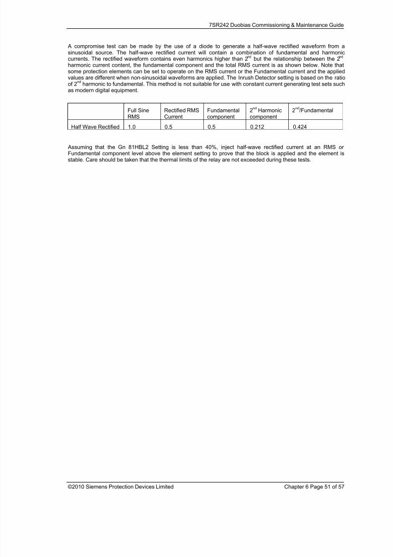
8/13/2019 7SR242 - Duobias Technical Manual Chapter 06 Commissioning
http://slidepdf.com/reader/full/7sr242-duobias-technical-manual-chapter-06-commissioning 51/57
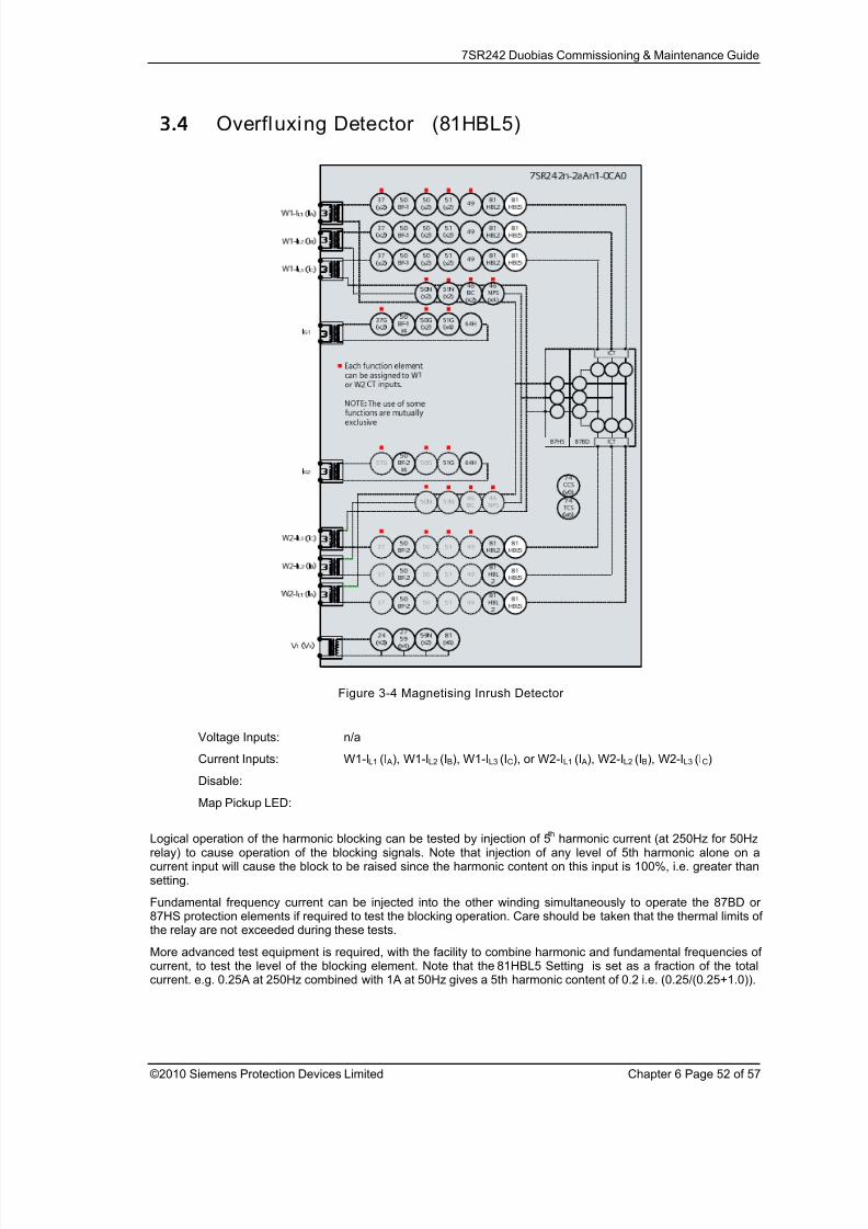
8/13/2019 7SR242 - Duobias Technical Manual Chapter 06 Commissioning
http://slidepdf.com/reader/full/7sr242-duobias-technical-manual-chapter-06-commissioning 52/57
8/13/2019 7SR242 - Duobias Technical Manual Chapter 06 Commissioning
http://slidepdf.com/reader/full/7sr242-duobias-technical-manual-chapter-06-commissioning 53/57
7SR242 Duobias Commissioning & Maintenance Guide
©2010 Siemens Protection Devices Limited Chapter 6 Page 53 of 57
Section 4: Control & Logic Functions
4.1 Quick LogicIf this functionality is used, the logic equations may interfere with testing of other protection functions in the relay.The function of the Quick Logic equations should be tested conjunctively with connected plant or by simulation toassess suitability and check for correct operation on an individual basis with tests specifically devised to suit theparticular application.
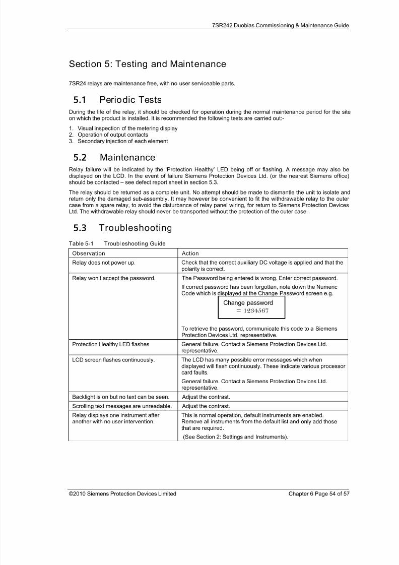
8/13/2019 7SR242 - Duobias Technical Manual Chapter 06 Commissioning
http://slidepdf.com/reader/full/7sr242-duobias-technical-manual-chapter-06-commissioning 54/57
7SR242 Duobias Commissioning & Maintenance Guide
©2010 Siemens Protection Devices Limited Chapter 6 Page 54 of 57
Section 5: Testing and Maintenance
7SR24 relays are maintenance free, with no user serviceable parts.
5.1 Periodic Tests
During the life of the relay, it should be checked for operation during the normal maintenance period for the siteon which the product is installed. It is recommended the following tests are carried out:-
1. Visual inspection of the metering display2. Operation of output contacts3. Secondary injection of each element
5.2 MaintenanceRelay failure will be indicated by the ‘Protection Healthy’ LED being off or flashing. A message may also bedisplayed on the LCD. In the event of failure Siemens Protection Devices Ltd. (or the nearest Siemens office)
should be contacted – see defect report sheet in section 5.3.
The relay should be returned as a complete unit. No attempt should be made to dismantle the unit to isolate andreturn only the damaged sub-assembly. It may however be convenient to fit the withdrawable relay to the outercase from a spare relay, to avoid the disturbance of relay panel wiring, for return to Siemens Protection DevicesLtd. The withdrawable relay should never be transported without the protection of the outer case.
5.3 Troubleshooting
Table 5-1 Troubleshooting Guide
Observation Action
Relay does not power up. Check that the correct auxiliary DC voltage is applied and that thepolarity is correct.
Relay won’t accept the password. The Password being entered is wrong. Enter correct password.
If correct password has been forgotten, note down the NumericCode which is displayed at the Change Password screen e.g.
To retrieve the password, communicate this code to a SiemensProtection Devices Ltd. representative.
Protection Healthy LED flashes General failure. Contact a Siemens Protection Devices Ltd.representative.
LCD screen flashes continuously. The LCD has many possible error messages which when
displayed will flash continuously. These indicate various processorcard faults.
General failure. Contact a Siemens Protection Devices Ltd.representative.
Backlight is on but no text can be seen. Adjust the contrast.
Scrolling text messages are unreadable. Adjust the contrast.
Relay displays one instrument afteranother with no user intervention.
This is normal operation, default instruments are enabled.Remove all instruments from the default list and only add thosethat are required.
(See Section 2: Settings and Instruments).
Change password
= 1234567

8/13/2019 7SR242 - Duobias Technical Manual Chapter 06 Commissioning
http://slidepdf.com/reader/full/7sr242-duobias-technical-manual-chapter-06-commissioning 55/57
7SR242 Duobias Commissioning & Maintenance Guide
©2010 Siemens Protection Devices Limited Chapter 6 Page 55 of 57
Observation Action
Cannot communicate with the relay. Check that all of the communications settings match those usedby ReyDisp Evolution.
Check that the Tx and Rx fibre-optic cables are connectedcorrectly. ( Tx –> Rx and Rx –> Tx ).
Check that all cables, modems and fibre-optic cables workcorrectly.
Ensure that IEC 60870-5-103 is specified for the connected port(COM1, COM2, COM3 or COM4).
Relays will not communicate in a ringnetwork.
Check that the Data Echo setting on all relays is set to ON.
Check that all relays are powered up.
Check that all relays have unique addresses.
Status inputs do not work. Check that the correct DC voltage is applied and that the polarityis correct.
Check that the status input settings such as the pick-up and drop-off timers and the status inversion function are correctly set.
Relay instrument displays show small
currents or voltages even though thesystem is dead.
This is normal. The relay is displaying calculation noise. This will
not affect any accuracy claims for the relay.
If the above checklist does not help in correcting the problem please contact the local Siemens office or contactPTD 24hr Customer Support,
Tel: +49 180 5247000,
Fax: +49 180 524 2471,
e-mail: [email protected].

8/13/2019 7SR242 - Duobias Technical Manual Chapter 06 Commissioning
http://slidepdf.com/reader/full/7sr242-duobias-technical-manual-chapter-06-commissioning 56/57
7SR242 Duobias Commissioning & Maintenance Guide
©2010 Siemens Protection Devices Limited Chapter 6 Page 56 of 57
Sender:
* Name, first n ame: Complete phone number (incl. country code): Complete fax number (incl. country code):
Email address: * Org-ID and GBK reference: * AWV:
* Order-/ reference-no (choosing at least 1 optio n):
Order-no for repair: order-/ delivery note-no for return of commission
failure:
Beginning order-no for credit note demand:
Information concerning the product and its use:
* Order Code (MLFB): Firmware version:
V
* Serial number:
* Customer: Product was in use approximately since: Station/project: Hotline Input no.:
Customer original purchase order number: Delivery note number with position number: Manufacturer:
* Type of order (choos ing at least 1 option):
Repair Return of commission failure Credit Note
Upgrade / Modification to … Warranty repair Quotation (not repair V4 and current
For collection products! See prices in PMD)
Type of failure:
Device or module does not start up Mechanical problem Overload
Sporadic failure Knock sensitive Transport damage
Permanent failure Temperature caused failure Failure after ca hrs in use
Repeated breakdown Failure after firmware update
Error description:Display message:
(use separated sheet for more info)
Active LED messages:
Faulty Interface(s), which? Wrong measured value(s), which? Faulty input(s)/output(s), which?
*Detail ed error description (please refer to other error reports or documentation i f possible):
* Shall a firmware update be m ade dur ing repair or mechanical upgrade of protective relays? (choosi ng at least 1 optio n)
Yes, to most recent version No Yes, actual parameters must be reusable
repair report:
Yes, standard report (free of charge) Yes, detailed report (charge : 400EUR)
Shipping address of the repaired/upgraded product:
Company, department
Name, first name
Street, number
Postcode, city, country
Date, Signature
E
D E
A
M
F T C C
6
r e l e a s e
f r o m
1 1 / 2 0
0 9
5.4 Defect Report Form
Form sheet for repairs and returned goods (fields marked with * are mandatory fields)
8/13/2019 7SR242 - Duobias Technical Manual Chapter 06 Commissioning
http://slidepdf.com/reader/full/7sr242-duobias-technical-manual-chapter-06-commissioning 57/57
7SR242 Duobias Commissioning & Maintenance Guide
Siemens Protection Devices Ltd.PO Box 8HebburnTyne & WearNE31 1TZEnglandTelephone: (0191) 401 5555
Fax: (0191) 401 5575