8 channel push button module for velbus system · vmb1ts protocol – edition 1 _ rev4 ... 0xxx1xxx...
TRANSCRIPT
VMB1TS PROTOCOL – edition 1 _ rev4
1
VMB1TS
Temperature Sensor Module PROTOCOL

VMB1TS PROTOCOL – edition 1 _ rev4
2
Binary format
<SOF-SID10...SID0-RTR-IDE-r0-DLC3...0-DATABYTE1...DATABYTEn-CRC15...CRC1-CRCDEL-ACK-ACKDEL-EOF7...EOF1-IFS3...IFS1>
bits Description
SOF Start Of Frame (always 0)
SID10 & SID9 Priority (00: highest … 11: lowest priority)
SID8…SID1 Address
SID0 Always 0
RTR Remote Transmit Request
IDE Identifier Extension (always 0)
r0 reserved (always 0)
DLC3…DLC0 Data Length Code (0…8)
Databyte1 Command
Databyte2 Parameter
Databyte3 Parameter
Databyte4 Parameter
Databyte5 Parameter
Databyte6 Parameter
Databyte7 Parameter
Databyte8 Parameter
CRC15…CRC1 Cyclic Redundancy Checksum
CRCDEL CRC Delimiter (always 1)
ACK Acknowledge slot (transmit 1 readback 0 if received correctly)
ACKDEL Acknowledge Delimiter (always 1)
EOF7...EOF1 End Of Frame (always 1111111)
IFS3...IFS1 InterFrame Space (always 111)
The temperature sensor module can transmit the following messages:
Sensor output status
Manual push buttons status
Sensor status
Sensor temperature (incl. minimum and maximum)
Time statistics (heater/cooler operation time)
First, second and third part of the sensor settings
Sensor configuration data
Module type
Bus error counter status
First, second and third part of the sensor name
Memory data
Memory data block (4 bytes) The temperature sensor module can transmit the following commands:
Updates LEDs on a push button module
Clears LEDs on a push button module
Sets LEDs on a push button module
Blinks LEDs slowly on a push button module
Blinks LEDs very fast on a push button module
Set target temperature of the differential sensor The temperature sensor module can receive the following message:
Push button status

VMB1TS PROTOCOL – edition 1 _ rev4
3
The temperature sensor module can receive the following commands:
Update output LED
Clear output LED
Set output LED
Blink output LED slowly
Blink output LED fast
Blink output LED very fast
Clear Push button Led
Module type request
Bus error counter status request
Sensor temperature request
Reset min/max temperature
Sensor status request
Sensor settings request
Sensor configuration data request
Sensor name request
Time statistics request
Enable/disable anti block heating valve and pump
Reset time statistics
Lock local control
Unlock local control
Sensor zone number
Set heating mode
Set cooling mode
Set temperature
Switch to comfort mode
Switch to day mode
Switch to night mode
Switch to safe temperature mode
Set default sleep time
Read memory data
Read memory data block (4 bytes)
Memory dump request
Write memory data
Write memory data block (4 bytes)
Program availability

VMB1TS PROTOCOL – edition 1 _ rev4
4
Transmits the sensor output status: SID10-SID9 = 00 (highest priority) SID8...SID1 = Module address RTR = 0 DLC3...DLC0 = 4 databytes to send DATABYTE1 = COMMAND_OUTPUT_STATUS (H’00’) DATABYTE2 = Output channel just activated (1 = just activated)
Contents Output channel 0xx1xxx1 Heater just activated 0xxxxx1x Turbo heater/cooler just activated 0xxxx1xx Comfort or day mode just activated 0xxx1xxx Cooler just activated 0x1xxxxx Low temperature alarm activated 01xxxxxx High temperature alarm activated
DATABYTE3 = Outputs just deactivated (1 = just deactivated)
Contents Output channel 0xx1xxx1 Heater just deactivated 0xxxxx1x Turbo heater/cooler just deactivated 0xxxx1xx Comfort or day mode just deactivated 0xxx1xxx Cooler just deactivated 0x0xxxxx Low temperature alarm deactivated 00xxxxxx High temperature alarm deactivated
DATABYTE4 = always zero Transmits the manual push button status:
SID10-SID9 = 00 (highest priority) SID8...SID1 = Module address RTR = 0 DLC3...DLC0 = 4 databytes to send DATABYTE1 = COMMAND_PUSHBUTTON_STATUS (H’00’) DATABYTE2 = Push buttons just pressed (1 = just pressed)
Contents Manual push button channel xxxxxxx1 Heater push button just pressed xxxxxx1x Turbo heater/cooler push button just pressed xxxxx1xx Day mode push button just pressed xxxx1xxx Cooler push button just pressed xxx1xxxx Mode & heater (pump) button just pressed xx1xxxxx Mode & turbo (low alarm) button just pressed x1xxxxxx Mode & day (high alarm) button just pressed
DATABYTE3 = Push buttons just released (1 = just released)
Contents Manual push button channel xxxxxxx1 Heater push button just released xxxxxx1x Turbo heater/cooler push button just released xxxxx1xx Day mode push button just released Xxxx1xxx Cooler push button just released xxx1xxxx Mode & heater (pump) button just released xx1xxxxx Mode & turbo (low alarm) button just released x1xxxxxx Mode & day (high alarm) button just released
DATABYTE4 = Push buttons long pressed (1 = longer than 0.85s pressed)
Contents Manual push button channel xxxxxxx1 Heater push button long pressed xxxxxx1x Turbo heater/cooler push button long pressed xxxxx1xx Day mode push button long pressed Xxxx1xxx Cooler push button long pressed xxx1xxxx Mode & heater (pump) button long pressed xx1xxxxx Mode & turbo (low alarm) button long pressed x1xxxxxx Mode & day (high alarm) button long pressed

VMB1TS PROTOCOL – edition 1 _ rev4
5
Transmit the sensor status (Build 0949): SID10-SID9 = 11 (lowest priority) SID8...SID1 = Module address RTR = 0 DLC3...DLC0 = 8 databytes to send DATABYTE1 = COMMAND_TEMP_SENSOR_STATUS (H’EA’) DATABYTE2 = Operating mode
Contents Operating mode xxxxxxx1 Mode push button locked xxxxxxx0 Mode push button unlocked Xxxxx11x Disable mode xxxxx01x Manual mode xxxxx10x Sleep timer mode xxxxx00x Run mode xxxx1xxx Auto send sensor temperature enabled xxxx0xxx Auto send sensor temperature disabled x100xxxx Comfort mode x010xxxx Day mode x001xxxx Night mode x000xxxx Safe temp mode (anti frost) 1000xxxx Cooler mode 0xxxxxxx Heater mode
DATABYTE3 = Program step mode
Contents Program step mode xxxxx0xx No sensor program xxxxx1xx Sensor program available xxxx0xxx No zone program xxxx1xxx Zone program available 0xxxxxxx No all rooms program 1xxxxxxx All rooms program available x100xxxx Comfort program step received x010xxxx Day program step received x001xxxx Night program step received X000xxxx Safe temperature program step received xxxxxx1x Enable unjamming heater valve xxxxxx0x Disable unjamming heater valve xxxxxxx1 Enable unjamming pump xxxxxxx0 Disable unjamming pump
DATABYTE4 = Output status (1 = activated)
Contents Output channel 0xx0xxx0 Heater/pump off 0xx1xxx1 Heater/pump on 0xxxxx0x Boost heater/cooler off 0xxxxx1x Boost heater/cooler on 0xxxx0xx Comfort and day mode off 0xxxx1xx Comfort or day mode on 0xxx0xxx Cooler off 0xxx1xxx Cooler on 0x0xxxxx Low alarm off 0x1xxxxx Low alarm on 00xxxxxx High alarm off 01xxxxxx High alarm on
DATABYTE5 = Current sensor temperature into two’s complement format (resolution 0.5°)
Contents Current sensor temperature 01111111 63.5°C 00000001 0.5°C 00000000 0°C 11111111 -0.5°C 10010010 -55°C

VMB1TS PROTOCOL – edition 1 _ rev4
6
DATABYTE6 = Current temperature set (resolution 0.5°)
Contents Current temperature set 01101100 54°C 00101000 20°C 00000010 1°C 00000001 0.5°C 00000000 0°C 11111111 -0.5°C 11000000 -32°C
DATABYTE7 = High byte of the sleep timer DATABYTE8 = Low byte of the sleep timer into minutes Remark: [DATABYTE7][DATABYTE8] contains a 16-bit sleep timer into minutes (1 to 65.279min). If the sleep timer contains H’0000’, the sleep timer is deactivated. If the sleep timer contains a value between H’0001’ and H’FEFF’ (1 to 65.279min), the sleep timer is running for that time. If the sleep timer contains H’FFFF’, the sensor is in manual mode.
Transmit the sensor temperature: SID10-SID9 = 11 (lowest priority) SID8...SID1 = Module address RTR = 0 DLC3...DLC0 = 7 databytes to send DATABYTE1 = COMMAND_SENSOR_TEMPERATURE (H’E6’) DATABYTE2 = High byte current sensor temperature DATABYTE3 = Low byte current sensor temperature into two’s complement format (resolution 0.0625°) DATABYTE4 = High byte minimum sensor temperature DATABYTE5 = Low byte minimum sensor temperature into two’s complement format (resolution 0.0625°) DATABYTE6 = High byte maximum sensor temperature DATABYTE7 = Low byte maximum sensor temperature into two’s complement format (resolution 0.0625°)
High byte Low byte Current sensor temperature 01111111 11100000 63.5°C 00000001 00000000 0.5°C 00000000 10000000 0.25°C 00000000 01000000 0.125°C 00000000 00100000 0.0625°C 00000000 00000000 0°C 11111111 11100000 -0.0625°C 11111111 11000000 -0.125°C 11111111 10000000 -0.25°C 11111110 00000000 -0.5°C 10010010 00000000 -55°C
Remark: The 5 least significant bits of the low byte are always zero. The low order bytes are not sending with the data length of 4 bytes (resolution 0.5°C)
VMB1TS PROTOCOL – edition 1 _ rev4
7
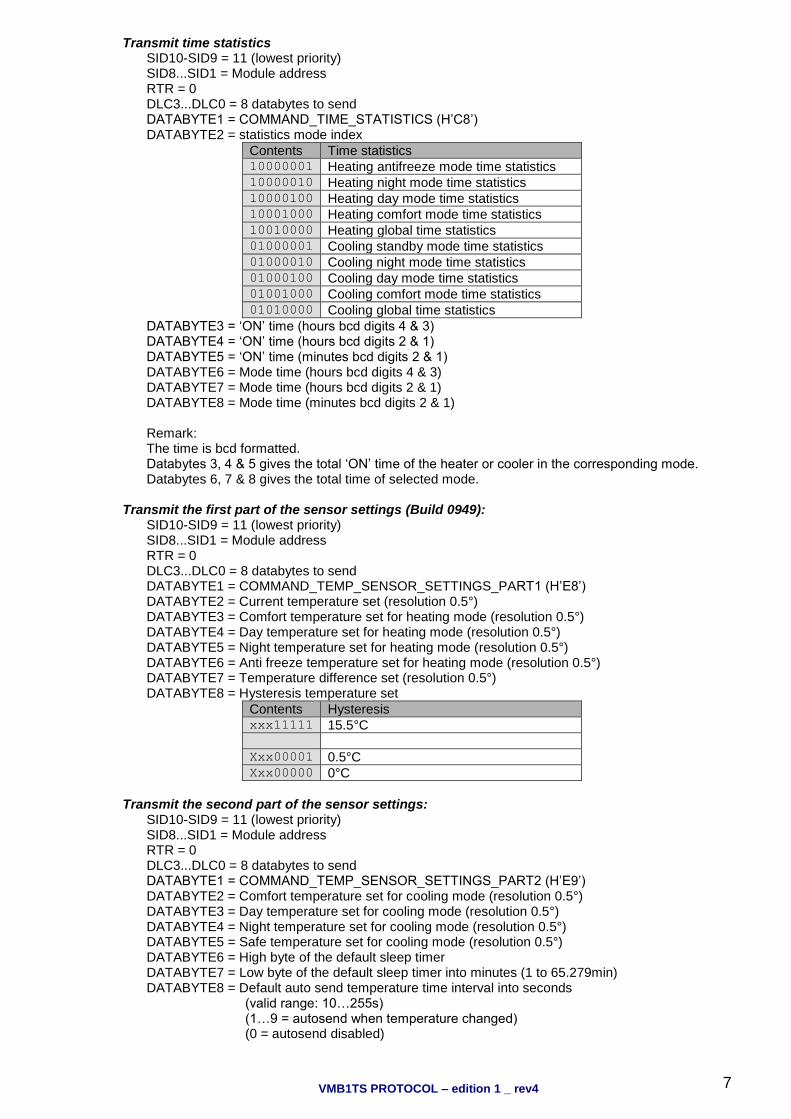
Transmit time statistics SID10-SID9 = 11 (lowest priority) SID8...SID1 = Module address RTR = 0 DLC3...DLC0 = 8 databytes to send DATABYTE1 = COMMAND_TIME_STATISTICS (H’C8’) DATABYTE2 = statistics mode index
Contents Time statistics 10000001 Heating antifreeze mode time statistics 10000010 Heating night mode time statistics 10000100 Heating day mode time statistics 10001000 Heating comfort mode time statistics 10010000 Heating global time statistics 01000001 Cooling standby mode time statistics 01000010 Cooling night mode time statistics 01000100 Cooling day mode time statistics 01001000 Cooling comfort mode time statistics 01010000 Cooling global time statistics
DATABYTE3 = ‘ON’ time (hours bcd digits 4 & 3) DATABYTE4 = ‘ON’ time (hours bcd digits 2 & 1) DATABYTE5 = ‘ON’ time (minutes bcd digits 2 & 1) DATABYTE6 = Mode time (hours bcd digits 4 & 3) DATABYTE7 = Mode time (hours bcd digits 2 & 1) DATABYTE8 = Mode time (minutes bcd digits 2 & 1) Remark: The time is bcd formatted. Databytes 3, 4 & 5 gives the total ‘ON’ time of the heater or cooler in the corresponding mode. Databytes 6, 7 & 8 gives the total time of selected mode.
Transmit the first part of the sensor settings (Build 0949): SID10-SID9 = 11 (lowest priority) SID8...SID1 = Module address RTR = 0 DLC3...DLC0 = 8 databytes to send DATABYTE1 = COMMAND_TEMP_SENSOR_SETTINGS_PART1 (H’E8’) DATABYTE2 = Current temperature set (resolution 0.5°) DATABYTE3 = Comfort temperature set for heating mode (resolution 0.5°) DATABYTE4 = Day temperature set for heating mode (resolution 0.5°) DATABYTE5 = Night temperature set for heating mode (resolution 0.5°) DATABYTE6 = Anti freeze temperature set for heating mode (resolution 0.5°) DATABYTE7 = Temperature difference set (resolution 0.5°) DATABYTE8 = Hysteresis temperature set
Contents Hysteresis xxx11111 15.5°C Xxx00001 0.5°C Xxx00000 0°C
Transmit the second part of the sensor settings:
SID10-SID9 = 11 (lowest priority) SID8...SID1 = Module address RTR = 0 DLC3...DLC0 = 8 databytes to send DATABYTE1 = COMMAND_TEMP_SENSOR_SETTINGS_PART2 (H’E9’) DATABYTE2 = Comfort temperature set for cooling mode (resolution 0.5°) DATABYTE3 = Day temperature set for cooling mode (resolution 0.5°) DATABYTE4 = Night temperature set for cooling mode (resolution 0.5°) DATABYTE5 = Safe temperature set for cooling mode (resolution 0.5°) DATABYTE6 = High byte of the default sleep timer DATABYTE7 = Low byte of the default sleep timer into minutes (1 to 65.279min) DATABYTE8 = Default auto send temperature time interval into seconds (valid range: 10…255s) (1…9 = autosend when temperature changed) (0 = autosend disabled)
VMB1TS PROTOCOL – edition 1 _ rev4
8
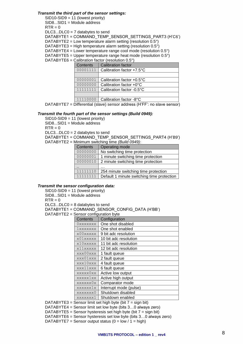
Transmit the third part of the sensor settings: SID10-SID9 = 11 (lowest priority) SID8...SID1 = Module address RTR = 0 DLC3...DLC0 = 7 databytes to send DATABYTE1 = COMMAND_TEMP_SENSOR_SETTINGS_PART3 (H’C6’) DATABYTE2 = Low temperature alarm setting (resolution 0.5°) DATABYTE3 = High temperature alarm setting (resolution 0.5°) DATABYTE4 = Lower temperature range cool mode (resolution 0.5°) DATABYTE5 = Upper temperature range heat mode (resolution 0.5°) DATABYTE6 = Calibration factor (resolution 0.5°)
Contents Calibration factor 00001111 Calibration factor +7.5°C 00000001 Calibration factor +0.5°C 00000000 Calibration factor +0°C 11111111 Calibration factor -0.5°C 11110000 Calibration factor -8°C
DATABYTE7 = Differential (slave) sensor address (H’FF’: no slave sensor)
Transmit the fourth part of the sensor settings (Build 0949): SID10-SID9 = 11 (lowest priority) SID8...SID1 = Module address RTR = 0 DLC3...DLC0 = 2 databytes to send DATABYTE1 = COMMAND_TEMP_SENSOR_SETTINGS_PART4 (H’B9’) DATABYTE2 = Minimum switching time (Build 0949):
Contents Operating mode 00000000 No switching time protection 00000001 1 minute switching time protection 00000010 2 minute switching time protection … … 11111110 254 minute switching time protection 11111111 Default 1 minute switching time protection
Transmit the sensor configuration data:
SID10-SID9 = 11 (lowest priority) SID8...SID1 = Module address RTR = 0 DLC3...DLC0 = 8 databytes to send DATABYTE1 = COMMAND_SENSOR_CONFIG_DATA (H’BB’) DATABYTE2 = Sensor configuration byte
Contents Configuration 0xxxxxxx One shot disabled 1xxxxxxx One shot enabled x00xxxxx 9 bit adc resolution x01xxxxx 10 bit adc resolution x10xxxxx 11 bit adc resolution x11xxxxx 12 bit adc resolution xxx00xxx 1 fault queue xxx01xxx 2 fault queue xxx10xxx 4 fault queue xxx11xxx 6 fault queue xxxxx0xx Active low output xxxxx1xx Active high output xxxxxx0x Comparator mode xxxxxx1x Interrupt mode (pulse) xxxxxxx0 Shutdown disabled xxxxxxx1 Shutdown enabled
DATABYTE3 = Sensor limit set high byte (bit 7 = sign bit) DATABYTE4 = Sensor limit set low byte (bits 3…0 always zero) DATABYTE5 = Sensor hysteresis set high byte (bit 7 = sign bit) DATABYTE6 = Sensor hysteresis set low byte (bits 3…0 always zero) DATABYTE7 = Sensor output status (0 = low / 1 = high)
VMB1TS PROTOCOL – edition 1 _ rev4
9
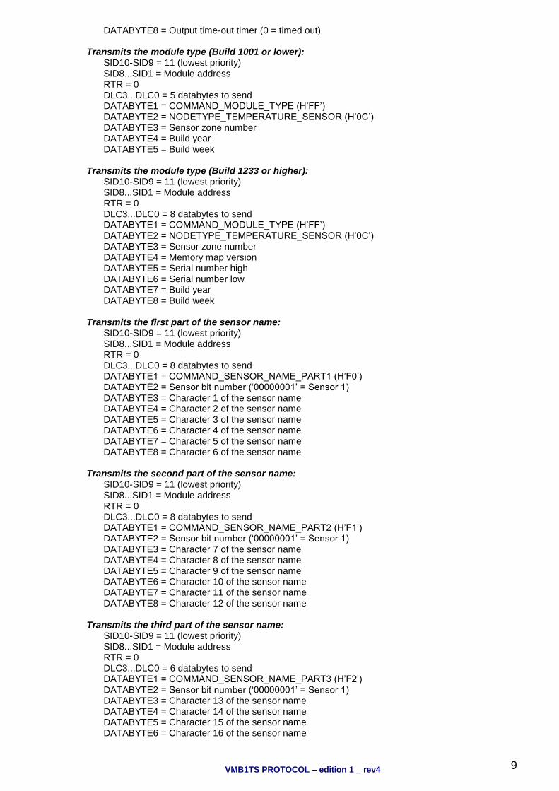
DATABYTE8 = Output time-out timer (0 = timed out) Transmits the module type (Build 1001 or lower):
SID10-SID9 = 11 (lowest priority) SID8...SID1 = Module address RTR = 0 DLC3...DLC0 = 5 databytes to send DATABYTE1 = COMMAND_MODULE_TYPE (H’FF’) DATABYTE2 = NODETYPE_TEMPERATURE_SENSOR (H’0C’) DATABYTE3 = Sensor zone number DATABYTE4 = Build year DATABYTE5 = Build week
Transmits the module type (Build 1233 or higher): SID10-SID9 = 11 (lowest priority) SID8...SID1 = Module address RTR = 0 DLC3...DLC0 = 8 databytes to send DATABYTE1 = COMMAND_MODULE_TYPE (H’FF’) DATABYTE2 = NODETYPE_TEMPERATURE_SENSOR (H’0C’) DATABYTE3 = Sensor zone number DATABYTE4 = Memory map version DATABYTE5 = Serial number high DATABYTE6 = Serial number low DATABYTE7 = Build year DATABYTE8 = Build week
Transmits the first part of the sensor name: SID10-SID9 = 11 (lowest priority) SID8...SID1 = Module address RTR = 0 DLC3...DLC0 = 8 databytes to send DATABYTE1 = COMMAND_SENSOR_NAME_PART1 (H’F0’) DATABYTE2 = Sensor bit number (‘00000001’ = Sensor 1) DATABYTE3 = Character 1 of the sensor name DATABYTE4 = Character 2 of the sensor name DATABYTE5 = Character 3 of the sensor name DATABYTE6 = Character 4 of the sensor name DATABYTE7 = Character 5 of the sensor name DATABYTE8 = Character 6 of the sensor name
Transmits the second part of the sensor name:
SID10-SID9 = 11 (lowest priority) SID8...SID1 = Module address RTR = 0 DLC3...DLC0 = 8 databytes to send DATABYTE1 = COMMAND_SENSOR_NAME_PART2 (H’F1’) DATABYTE2 = Sensor bit number (‘00000001’ = Sensor 1) DATABYTE3 = Character 7 of the sensor name DATABYTE4 = Character 8 of the sensor name DATABYTE5 = Character 9 of the sensor name DATABYTE6 = Character 10 of the sensor name DATABYTE7 = Character 11 of the sensor name DATABYTE8 = Character 12 of the sensor name
Transmits the third part of the sensor name:
SID10-SID9 = 11 (lowest priority) SID8...SID1 = Module address RTR = 0 DLC3...DLC0 = 6 databytes to send DATABYTE1 = COMMAND_SENSOR_NAME_PART3 (H’F2’) DATABYTE2 = Sensor bit number (‘00000001’ = Sensor 1) DATABYTE3 = Character 13 of the sensor name DATABYTE4 = Character 14 of the sensor name DATABYTE5 = Character 15 of the sensor name DATABYTE6 = Character 16 of the sensor name
VMB1TS PROTOCOL – edition 1 _ rev4
10
Remarks: Unused characters contain H’FF’.
Transmits the memory data:
SID10-SID9 = 11 (lowest priority) SID8...SID1 = Module address RTR = 0 DLC3...DLC0 = 4 databytes to send DATABYTE1 = COMMAND_MEMORY_DATA (H’FE’) DATABYTE2 = High memory address (must be H’00’) DATABYTE3 = LOW memory address (H’00’...H’7F’) DATABYTE4 = memory data

VMB1TS PROTOCOL – edition 1 _ rev4
11
Transmits memory data block (4 bytes): SID10-SID9 = 11 (lowest priority) SID8...SID1 = Address of the module RTR = 0 DLC3...DLC0 = 7 databytes to send DATABYTE1 = COMMAND_MEMORY_DATA_BLOCK (H’CC’) DATABYTE2 = High start address of memory block (must be H’00’) DATABYTE3 = LOW start address of memory block (H’00’...H’FF’) DATABYTE4 = memory data1 DATABYTE5 = memory data2 DATABYTE6 = memory data3 DATABYTE7 = memory data4
Transmit: Updates LEDs on a push button module:
SID10-SID9 = 11 (lowest priority) SID8...SID1 = Address of the push button module for updating the LEDs RTR = 0 DLC3...DLC0 = 4 databytes to send DATABYTE1 = COMMAND_UPDATE_LED (H’F4’) DATABYTE2 = LED continuous on status (1 = LED on) DATABYTE3 = LED slow blinking status (1 = LED slow blinking) DATABYTE4 = LED fast blinking status (1 = LED fast blinking) Remarks: The continuous on bit overrides the blinking modes. If the slow and fast blinking bits for a LED are both on, the LED blinks very fast.
Transmit: Clears LEDs on a push button module:
SID10-SID9 = 11 (lowest priority) SID8...SID1 = Address of the push button module for clearing LEDs RTR = 0 DLC3...DLC0 = 2 databytes to send DATABYTE1 = COMMAND_CLEAR_LED (H’F5’) DATABYTE2 = LED bit numbers (1 = clear LED)
Transmit: Sets LEDs on a push button module:
SID10-SID9 = 11 (lowest priority) SID8...SID1 = Address of the push button module for setting LEDs on RTR = 0 DLC3...DLC0 = 2 databytes to send DATABYTE1 = COMMAND_SET_LED (H’F6’) DATABYTE2 = LED bit numbers (1 = set LED)
Transmit: Blinks LEDs slowly on a push button module:
SID10-SID9 = 11 (lowest priority) SID8...SID1 = Address of the push button module for slowly blinking LEDs RTR = 0 DLC3...DLC0 = 2 databytes to send DATABYTE1 = COMMAND_SLOW_BLINKING_LED (H’F7’) DATABYTE2 = LED bit numbers (1 = slow blink LED)
Transmit: Blinks LEDs very fast on a push button module:
SID10-SID9 = 11 (lowest priority) SID8...SID1 = Address of the push button module for very fast blinking LEDs RTR = 0 DLC3...DLC0 = 2 databytes to send DATABYTE1 = COMMAND_VERYFAST_BLINKING_LED (H’F9’) DATABYTE2 = LED bit numbers (1 = very fast blink LED)
Transmit: Bus error counter status
SID10-SID9 = 11 (lowest priority) SID8...SID1 = Module address RTR = 0 DLC3...DLC0 = 4 databytes to send DATABYTE1 = COMMAND_BUSERROR_COUNTER_STATUS (H’DA’) DATABYTE2 = Transmit error counter DATABYTE3 = Receive error counter DATABYTE4 = Bus off counter
VMB1TS PROTOCOL – edition 1 _ rev4
12
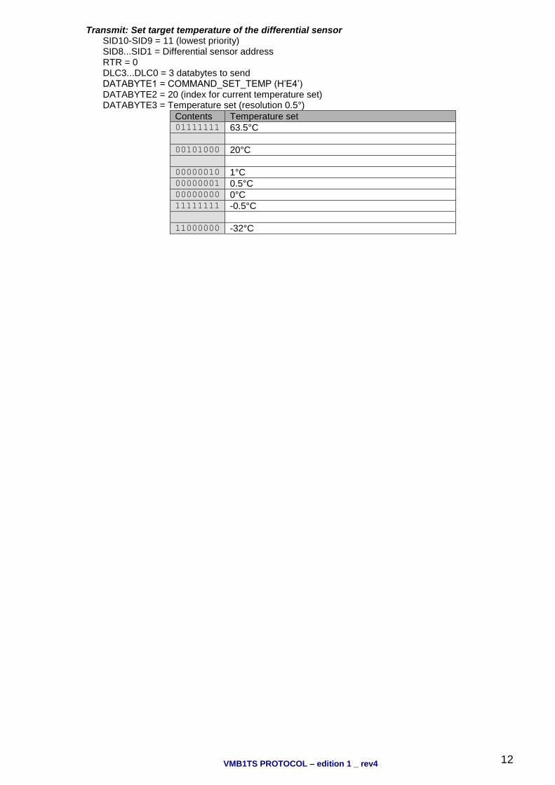
Transmit: Set target temperature of the differential sensor SID10-SID9 = 11 (lowest priority) SID8...SID1 = Differential sensor address RTR = 0 DLC3...DLC0 = 3 databytes to send DATABYTE1 = COMMAND_SET_TEMP (H’E4’) DATABYTE2 = 20 (index for current temperature set) DATABYTE3 = Temperature set (resolution 0.5°)
Contents Temperature set 01111111 63.5°C 00101000 20°C 00000010 1°C 00000001 0.5°C 00000000 0°C 11111111 -0.5°C 11000000 -32°C
VMB1TS PROTOCOL – edition 1 _ rev4
13
‘Push button status’ received: SID10-SID9 = 00 (highest priority) SID8...SID1 = Address of the push button module RTR = 0 DLC3...DLC0 = 4 databytes received DATABYTE1 = COMMAND_PUSH_BUTTON_STATUS (H’00’) DATABYTE2 = Push buttons just pressed (1 = just pressed) DATABYTE3 = Push buttons just released (1 = just released) DATABYTE4 = Push buttons long pressed (1 = longer than 0.85s pressed)
‘Clear Push button LED’ command received:
SID10-SID9 = 11 (lowest priority) SID8...SID1 = Address of the push button module RTR = 0 DLC3...DLC0 = 2 databytes received DATABYTE1 = COMMAND_CLEAR_LED (H’F5’) DATABYTE2 = LEDs to clear (a one clears the corresponding LED)
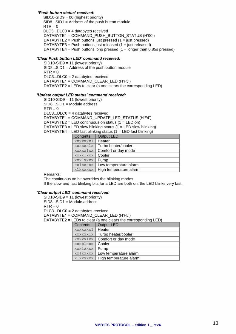
‘Update output LED status’ command received:
SID10-SID9 = 11 (lowest priority) SID8...SID1 = Module address RTR = 0 DLC3...DLC0 = 4 databytes received DATABYTE1 = COMMAND_UPDATE_LED_STATUS (H’F4’) DATABYTE2 = LED continuous on status (1 = LED on) DATABYTE3 = LED slow blinking status (1 = LED slow blinking) DATABYTE4 = LED fast blinking status (1 = LED fast blinking)
Contents Output LED xxxxxxx1 Heater xxxxxx1x Turbo heater/cooler xxxxx1xx Comfort or day mode xxxx1xxx Cooler xxx1xxxx Pump xx1xxxxx Low temperature alarm x1xxxxxx High temperature alarm
Remarks: The continuous on bit overrides the blinking modes. If the slow and fast blinking bits for a LED are both on, the LED blinks very fast.
‘Clear output LED’ command received:
SID10-SID9 = 11 (lowest priority) SID8...SID1 = Module address RTR = 0 DLC3...DLC0 = 2 databytes received DATABYTE1 = COMMAND_CLEAR_LED (H’F5’) DATABYTE2 = LEDs to clear (a one clears the corresponding LED)
Contents Output LED xxxxxxx1 Heater xxxxxx1x Turbo heater/cooler xxxxx1xx Comfort or day mode xxxx1xxx Cooler xxx1xxxx Pump xx1xxxxx Low temperature alarm x1xxxxxx High temperature alarm

VMB1TS PROTOCOL – edition 1 _ rev4
14
‘Set output LED’ command received: SID10-SID9 = 11 (lowest priority) SID8...SID1 = Module address RTR = 0 DLC3...DLC0 = 2 databytes received DATABYTE1 = COMMAND_SET_LED (H’F6’) DATABYTE2 = LEDs to set (a one sets the corresponding LED)
Contents Output LED xxxxxxx1 Heater xxxxxx1x Turbo heater/cooler xxxxx1xx Comfort or day mode xxxx1xxx Cooler xxx1xxxx Pump xx1xxxxx Low temperature alarm x1xxxxxx High temperature alarm
‘Slow blinking output LED’ command received:
SID10-SID9 = 11 (lowest priority) SID8...SID1 = Module address RTR = 0 DLC3...DLC0 = 2 databytes received DATABYTE1 = COMMAND_SLOW_BLINKING_LED (H’F7’) DATABYTE2 = LEDs to blink slow (1 = slow blinking)
Contents Output LED xxxxxxx1 Heater xxxxxx1x Turbo heater/cooler xxxxx1xx Comfort or day mode xxxx1xxx Cooler xxx1xxxx Pump xx1xxxxx Low temperature alarm x1xxxxxx High temperature alarm
‘Fast blinking output LED’ command received:
SID10-SID9 = 11 (lowest priority) SID8...SID1 = Module address RTR = 0 DLC3...DLC0 = 2 databytes received DATABYTE1 = COMMAND_FAST_BLINKING_LED (H’F8’) DATABYTE2 = LEDs to blink fast (1 = fast blinking)
Contents Output LED xxxxxxx1 Heater xxxxxx1x Turbo heater/cooler xxxxx1xx Comfort or day mode xxxx1xxx Cooler xxx1xxxx Pump xx1xxxxx Low temperature alarm x1xxxxxx High temperature alarm
‘Very fast blinking output LED’ command received:
SID10-SID9 = 11 (lowest priority) SID8...SID1 = Module address RTR = 0 DLC3...DLC0 = 2 databytes received DATABYTE1 = COMMAND_VERYFAST_BLINKING_LED (H’F9’) DATABYTE2 = LEDs to clear (1 = very fast blinking)
Contents Output LED xxxxxxx1 Heater xxxxxx1x Turbo heater/cooler xxxxx1xx Comfort or day mode xxxx1xxx Cooler xxx1xxxx Pump xx1xxxxx Low temperature alarm x1xxxxxx High temperature alarm
VMB1TS PROTOCOL – edition 1 _ rev4
15
‘Module type request’ command received: SID10-SID9 = 11 (lowest priority) SID8...SID1 = Module address RTR = 1 DLC3...DLC0 = 0 databytes received
‘Bus error counter status request’ command received:
SID10-SID9 = 11 (lowest priority) SID8...SID1 = Module address RTR = 0 DLC3...DLC0 = 1 databytes to send DATABYTE1 = COMMAND_BUS_ERROR_CONTER_STATUS_REQUEST (H’D9’)
‘Sensor temperature request’ command received:
SID10-SID9 = 11 (lowest priority) SID8...SID1 = Module address RTR = 0 DLC3...DLC0 = 2 databytes to send DATABYTE1 = COMMAND_SENSOR_TEMP_REQUEST (H’E5’) DATABYTE2 = Autosend time interval into seconds (valid range: 10…255s) (1…9 = autosend when temperature changed) (0 = autosend disabled)
‘Sensor status request’ command received:
SID10-SID9 = 11 (lowest priority) SID8...SID1 = Module address RTR = 0 DLC3...DLC0 = 2 databytes to send DATABYTE1 = COMMAND_MODULE_STATUS_REQUEST (H’FA’) DATABYTE2 = don’t care
‘Sensor settings request’ command received:
SID10-SID9 = 11 (lowest priority) SID8...SID1 = Module address RTR = 0 DLC3...DLC0 = 2 databytes to send DATABYTE1 = COMMAND_TEMP_SENSOR_SETTINGS_REQUEST (H’E7’) DATABYTE2 = don’t care
‘Sensor configuration data request’ command received:
SID10-SID9 = 11 (lowest priority) SID8...SID1 = Module address RTR = 0 DLC3...DLC0 = 2 databytes to send DATABYTE1 = COMMAND_SENSOR_CONFIG_DATA _REQUEST (H’BA’) DATABYTE2 = don’t care
‘Sensor name request’ command received:
SID10-SID9 = 11 (lowest priority) SID8...SID1 = Module address RTR = 0 DLC3...DLC0 = 2 databytes received DATABYTE1 = COMMAND_SENSOR_NAME_REQUEST (H’EF’) DATABYTE2 = don’t care

VMB1TS PROTOCOL – edition 1 _ rev4
16
‘Time statistics request’ command received: SID10-SID9 = 11 (lowest priority) SID8...SID1 = Module address RTR = 0 DLC3...DLC0 = 2 databytes to send DATABYTE1 = COMMAND_TIME_STATISTICS_REQUEST (H’C7’) DATABYTE2 = statistics mode index
Contents Time statistics request 10000001 Heating antifreeze mode time statistics 10000010 Heating night mode time statistics 10000100 Heating day mode time statistics 10001000 Heating comfort mode time statistics 10010000 Heating global time statistics 01000001 Cooling standby mode time statistics 01000010 Cooling night mode time statistics 01000100 Cooling day mode time statistics 01001000 Cooling comfort mode time statistics 01010000 Cooling global time statistics
‘Lock local control’ command received:
SID10-SID9 = 11 (lowest priority) SID8...SID1 = Module address RTR = 0 DLC3...DLC0 = 2 databytes received DATABYTE1 = COMMAND_LOCK_LOCAL_CONTROL (H’E1’) DATABYTE2 = don’t care
‘Unlock local control’ command received:
SID10-SID9 = 11 (lowest priority) SID8...SID1 = Module address RTR = 0 DLC3...DLC0 = 2 databytes received DATABYTE1 = COMMAND_UNLOCK_LOCAL_CONTROL (H’E2’) DATABYTE2 = don’t care
‘Set heating mode’ command received:
SID10-SID9 = 11 (lowest priority) SID8...SID1 = Module address RTR = 0 DLC3...DLC0 = 2 databytes received DATABYTE1 = COMMAND_SET_HEATING_MODE (H’E0’) DATABYTE2 = don’t care
‘Set cooling mode’ command received:
SID10-SID9 = 11 (lowest priority) SID8...SID1 = Module address RTR = 0 DLC3...DLC0 = 2 databytes received DATABYTE1 = COMMAND_SET_COOLING_MODE (H’DF’) DATABYTE2 = don’t care
‘Read data from memory’ command received:
SID10-SID9 = 11 (lowest priority) SID8...SID1 = Module address RTR = 0 DLC3...DLC0 = 3 databytes received DATABYTE1 = COMMAND_READ_DATA_FROM_MEMORY (H’FD’) DATABYTE2 = High memory address (must be H’00’) DATABYTE3 = LOW memory address (H’00’...H’7F’)
VMB1TS PROTOCOL – edition 1 _ rev4
17
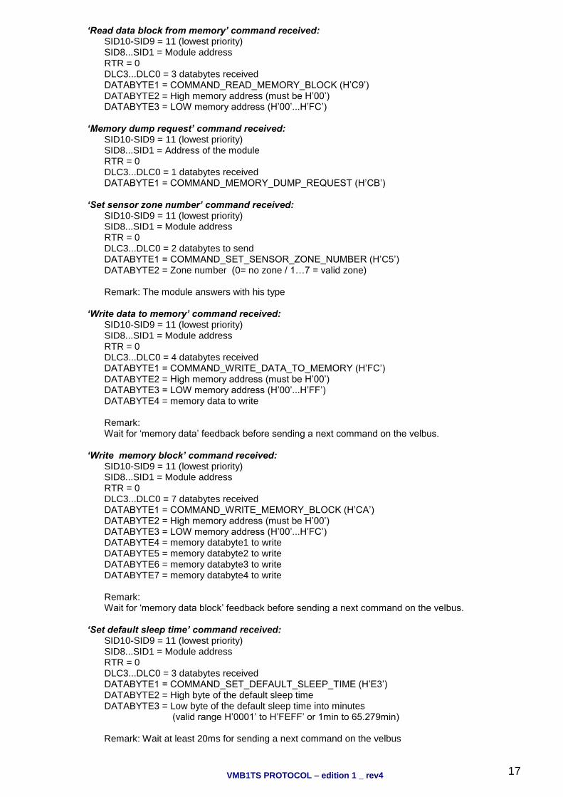
‘Read data block from memory’ command received: SID10-SID9 = 11 (lowest priority) SID8...SID1 = Module address RTR = 0 DLC3...DLC0 = 3 databytes received DATABYTE1 = COMMAND_READ_MEMORY_BLOCK (H’C9’) DATABYTE2 = High memory address (must be H’00’) DATABYTE3 = LOW memory address (H’00’...H’FC’)
‘Memory dump request’ command received:
SID10-SID9 = 11 (lowest priority) SID8...SID1 = Address of the module RTR = 0 DLC3...DLC0 = 1 databytes received DATABYTE1 = COMMAND_MEMORY_DUMP_REQUEST (H’CB’)
‘Set sensor zone number’ command received:
SID10-SID9 = 11 (lowest priority) SID8...SID1 = Module address RTR = 0 DLC3...DLC0 = 2 databytes to send DATABYTE1 = COMMAND_SET_SENSOR_ZONE_NUMBER (H’C5’) DATABYTE2 = Zone number (0= no zone / 1…7 = valid zone) Remark: The module answers with his type
‘Write data to memory’ command received:
SID10-SID9 = 11 (lowest priority) SID8...SID1 = Module address RTR = 0 DLC3...DLC0 = 4 databytes received DATABYTE1 = COMMAND_WRITE_DATA_TO_MEMORY (H’FC’) DATABYTE2 = High memory address (must be H’00’) DATABYTE3 = LOW memory address (H’00’...H’FF’) DATABYTE4 = memory data to write Remark: Wait for ‘memory data’ feedback before sending a next command on the velbus.
‘Write memory block’ command received:
SID10-SID9 = 11 (lowest priority) SID8...SID1 = Module address RTR = 0 DLC3...DLC0 = 7 databytes received DATABYTE1 = COMMAND_WRITE_MEMORY_BLOCK (H’CA’) DATABYTE2 = High memory address (must be H’00’) DATABYTE3 = LOW memory address (H’00’...H’FC’) DATABYTE4 = memory databyte1 to write DATABYTE5 = memory databyte2 to write DATABYTE6 = memory databyte3 to write DATABYTE7 = memory databyte4 to write Remark: Wait for ‘memory data block’ feedback before sending a next command on the velbus.
‘Set default sleep time’ command received:
SID10-SID9 = 11 (lowest priority) SID8...SID1 = Module address RTR = 0 DLC3...DLC0 = 3 databytes received DATABYTE1 = COMMAND_SET_DEFAULT_SLEEP_TIME (H’E3’) DATABYTE2 = High byte of the default sleep time DATABYTE3 = Low byte of the default sleep time into minutes (valid range H’0001’ to H’FEFF’ or 1min to 65.279min)
Remark: Wait at least 20ms for sending a next command on the velbus

VMB1TS PROTOCOL – edition 1 _ rev4
18
‘Set temperature’ command received (Build 0949): SID10-SID9 = 11 (lowest priority) SID8...SID1 = Module address RTR = 0 DLC3...DLC0 = 3 databytes received DATABYTE1 = COMMAND_SET_TEMP (H’E4’) DATABYTE2 = Pointer to temperature variable (0…20)
Contents Temperature variable
0 Current temperature set
1 Comfort temperature set for heating
2 Day temperature set for heating
3 Night temperature set for heating
4 Safe temperature set for heating
5 Temperature difference for turbo output
6 Hysteresis (0°…15.5°C)
7 Comfort temperature set for cooling
8 Day temperature set for cooling
9 Night temperature set for cooling
10 Safe temperature set for cooling
11 Calibration factor (-8°…+7.5°C)
12 Reset minimum/maximum temperature
13 Reset time statistics
14 enable/disable anti-block valve/pump
15 Low temperature alarm set
16 High temperature alarm set
17 Lower temperature range cool mode
18 Upper temperature range heat mode
19 Differential sensor address (H’FF’ = no diff. sensor)
20 Target temperature set for the differential sensor
21 Minimum switching time
DATABYTE3 = Temperature set (resolution 0.5°)
Contents Temperature set 01111111 63.5°C 00101000 20°C 00000010 1°C 00000001 0.5°C 00000000 0°C 11111111 -0.5°C 10010010 -55°C
DATABYTE3 = Reset minimum/maximum temperature
Contents Reset temperature 00000001 Reset minimum temperature 00000010 Reset maximum temperature
DATABYTE3 = Reset time statistics mode index
Contents Reset time statistics 10000001 Reset heating antifreeze mode time statistics 10000010 Reset heating night mode time statistics 10000100 Reset heating day mode time statistics 10001000 Reset heating comfort mode time statistics 10010000 Reset heating global time statistics 01000001 Reset cooling standby mode time statistics 01000010 Reset cooling night mode time statistics 01000100 Reset cooling day mode time statistics 01001000 Reset cooling comfort mode time statistics 01010000 Reset cooling global time statistics
DATABYTE3 = Enable/disable unjamming heater valve & pump
Contents Enable/disable unjamming valve and pump 00000000 Disable unjamming heater valve & pump 00000001 Disable unjamming heater valve & enable unjamming pump 00000010 Enable unjamming heater valve & disable unjamming pump 00000011 Enable unjamming heater valve & pump

VMB1TS PROTOCOL – edition 1 _ rev4
19
DATABYTE3 = Minimum switching time (Build 0949):
Contents Operating mode 00000000 No switching time protection 00000001 1 minute switching time protection 00000010 2 minute switching time protection … … 11111110 254 minute switching time protection 11111111 Default 1 minute switching time protection
Remark: Valid hysteresis range = 0 …15.5°C Valid calibration factor range = -8 …7.5°C Wait at least 10ms for sending a next command on the velbus.
‘Switch to comfort mode’ command received:
SID10-SID9 = 11 (lowest priority) SID8...SID1 = Module address RTR = 0 DLC3...DLC0 = 3 databytes received DATABYTE1 = COMMAND_SWITCH_TO_COMFORT_MODE (H’DB’) DATABYTE2 = High byte of the sleep time DATABYTE3 = Low byte of the sleep time into minutes Remark: If the sleep time contains H’FF00’, the command is a program step. A sleep time between H’0001’ and H’FEFF’ (1 to 65.279min) starts the sleep timer for that time and program steps will not be executed during that time. A sleep time of H’FFFF’ puts the sensor into manual mode. Program steps will not be executed any more and local control is disabled. A value of zero for the sleep time cancels the manual mode or sleep timer.
‘Switch to day mode’ command received:
SID10-SID9 = 11 (lowest priority) SID8...SID1 = Module address RTR = 0 DLC3...DLC0 = 3 databytes received DATABYTE1 = COMMAND_SWITCH_TO_DAY_MODE (H’DC’) DATABYTE2 = High byte of the sleep time DATABYTE3 = Low byte of the sleep time into minutes Remark: If the sleep time contains H’FF00’, the command is a program step. A sleep time between H’0001’ and H’FEFF’ (1 to 65.279min) starts the sleep timer for that time and program steps will not be executed during that time. A sleep time of H’FFFF’ puts the sensor into manual mode. Program steps will not be executed any more and local control is disabled. A value of zero for the sleep time cancels the manual mode or sleep timer.
‘Switch to night mode’ command received:
SID10-SID9 = 11 (lowest priority) SID8...SID1 = Module address RTR = 0 DLC3...DLC0 = 3 databytes received DATABYTE1 = COMMAND_SWITCH_TO_NIGHT_MODE (H’DD’) DATABYTE2 = High byte of the sleep time DATABYTE3 = Low byte of the sleep time into minutes Remark: If the sleep time contains H’FF00’, the command is a program step. A sleep time between H’0001’ and H’FEFF’ (1 to 65.279min) starts the sleep timer for that time and program steps will not be executed during that time. A sleep time of H’FFFF’ puts the sensor into manual mode. Program steps will not be executed anymore and local control is disabled. A value of zero for the sleep time cancels the manual mode or sleep timer.

VMB1TS PROTOCOL – edition 1 _ rev4
20
‘Switch to safe temperature mode’ command received: SID10-SID9 = 11 (lowest priority) SID8...SID1 = Module address RTR = 0 DLC3...DLC0 = 3 databytes received DATABYTE1 = COMMAND_SWITCH_TO_SAFE_MODE (H’DE’) DATABYTE7 = High byte of the sleep time DATABYTE8 = Low byte of the sleep time into minutes Remark: If the sleep time contains H’FF00’, the command is a program step. A sleep time between H’0001’ and H’FEFF’ (1 to 65.279min) starts the sleep timer for that time and program steps will not be executed during that time. A sleep time of H’FFFF’ puts the sensor into manual mode. Program steps will not be executed anymore and local control is disabled. A value of zero for the sleep time cancels the manual mode or sleep timer.
’Program availability’ command received:
SID10-SID9 = 11 (lowest priority) SID8...SID1 = H’00’ RTR = 0 DLC3...DLC0 = 4 databytes to send DATABYTE1 = COMMAND_SENSOR_PROGRAM_AVAILABILITY (H’BC’) DATABYTE2 = Program availabitlity (0 = no program ; 1 = program available) DATABYTE3 = Program type
Contents Day
0…32 Sensor program
33 All rooms program
34 Zone 1 program
35 Zone 2 program
36 Zone 3 program
37 Zone 4 program
38 Zone 5 program
39 Zone 6 program
40 Zone 7 program
40…255 Not valid
DATABYTE4 = Sensor address
Remark: This command will be received every time a program step is added, modified or deleted by the temperature controller VMB1TC.

VMB1TS PROTOCOL – edition 1 _ rev4
21
Memory map Build 0927 or 0947:
Address Contents Address
Contents
H’0000’ Push button module address H’0001’ Comfort mode push button 1 bit numbers
... ... ... ...
H’0018’ Push button module address H’0019’ Comfort mode push button 13 bit numbers
H’001A’ Push button module address H’001B’ Day mode push button 1 bit numbers
... ... ... ...
H’0032’ Push button module address H’0033’ Day mode push button 13 bit numbers
H’0034’ Push button module address H’0035’ Night mode push button 1 bit numbers
... ... ... ...
H’004C’ Push button module address H’004D’ Night mode push button 13 bit numbers
H’004E’ Push button module address H’004F’ Safe mode push button 1 bit numbers
... ... ... ...
H’0066’ Push button module address H’0067’ Safe mode push button 13 bit numbers
H’0068’ Push button module address H’0069’ Heating mode push button 1 bit numbers
... ... ... ...
H’0080’ Push button module address H’0081’ Heating mode push button 13 bit numbers
H’0082’ Push button module address H’0083’ Cooling mode push button 1 bit numbers
... ... ... ...
H’009A’ Push button module address H’009B’ Cooling mode push button 13 bit numbers
H’009C’ Push button module address H’009D’ Lock local control push button 1 bit numbers
... ... ... ...
H’00B4’ Push button module address H’00B5’ Lock local control push button 13 bit numbers
H’00B6’ Push button module address H’00B7’ Unlock local control push button 1 bit numbers
... ... ... ...
H’00CE’ Push button module address H’00CF’ Unlock local control push button 13 bit numbers
H’00D0’ Not used H’00D1’ Not used
… …
H’00D8’ Not used H’00D9’ Differential sensor address
H’00DA’ Calibration factor H’00DB’ Lower temperature range cool mode
H’00DC’ Upper temp range heat mode H’00DD’ Sensor zone number
H’00DE’ Low temperature alarm H’00DF’ High temperature alarm
H’00E0’ Current program mode H’00E1’ Current mode
H’00E2’ Current temperature set H’00E3’ Comfort temp set for heating
H’00E4’ Day temp set for heating H’00E5’ Night temp set for heating
H’00E6’ Safe temp set for heating H’00E7’ Temp. difference for boost output or diff. sensor
H’00E8’ Hysteresis H’00E9’ Comfort temp set for cooling
H’00EA’ Day temp set for cooling H’00EB’ Night temp set for cooling
H’00EC’ Safe temp set for cooling H’00ED’ Default sleep time high byte
H’00EE’ Default sleep time low byte H’00EF’ Auto send time interval
H’00F0’ Sensor name character 1 H’00F1’ Sensor name character 2
... ... ... ...
H’00FE’ Sensor name character 15 H’00FF’ Sensor name character 16
Remark: Unused locations in the push button location contain H’FF’. Unused characters for the sensor name contain H’FF’.
VMB1TS PROTOCOL – edition 1 _ rev4
22
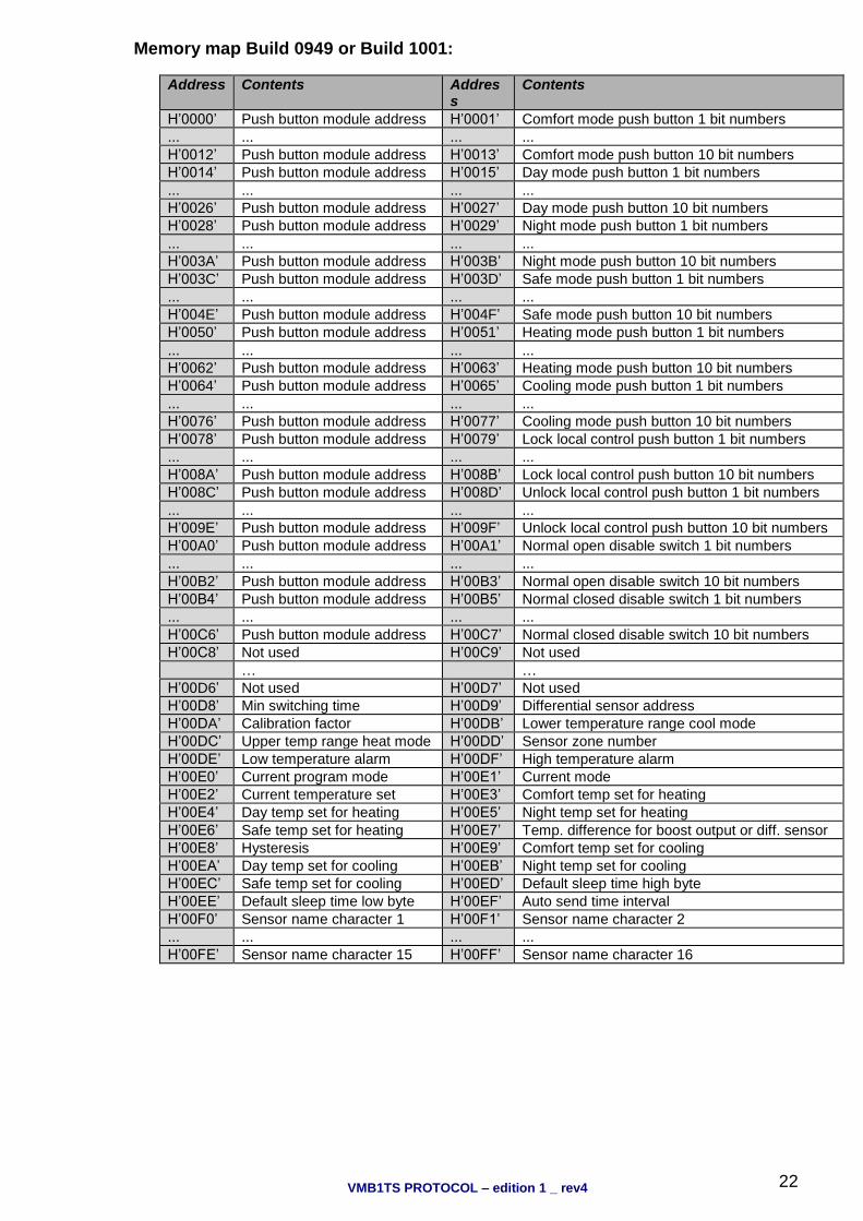
Memory map Build 0949 or Build 1001:
Address Contents Address
Contents
H’0000’ Push button module address H’0001’ Comfort mode push button 1 bit numbers
... ... ... ...
H’0012’ Push button module address H’0013’ Comfort mode push button 10 bit numbers
H’0014’ Push button module address H’0015’ Day mode push button 1 bit numbers
... ... ... ...
H’0026’ Push button module address H’0027’ Day mode push button 10 bit numbers
H’0028’ Push button module address H’0029’ Night mode push button 1 bit numbers
... ... ... ...
H’003A’ Push button module address H’003B’ Night mode push button 10 bit numbers
H’003C’ Push button module address H’003D’ Safe mode push button 1 bit numbers
... ... ... ...
H’004E’ Push button module address H’004F’ Safe mode push button 10 bit numbers
H’0050’ Push button module address H’0051’ Heating mode push button 1 bit numbers
... ... ... ...
H’0062’ Push button module address H’0063’ Heating mode push button 10 bit numbers
H’0064’ Push button module address H’0065’ Cooling mode push button 1 bit numbers
... ... ... ...
H’0076’ Push button module address H’0077’ Cooling mode push button 10 bit numbers
H’0078’ Push button module address H’0079’ Lock local control push button 1 bit numbers
... ... ... ...
H’008A’ Push button module address H’008B’ Lock local control push button 10 bit numbers
H’008C’ Push button module address H’008D’ Unlock local control push button 1 bit numbers
... ... ... ...
H’009E’ Push button module address H’009F’ Unlock local control push button 10 bit numbers
H’00A0’ Push button module address H’00A1’ Normal open disable switch 1 bit numbers
... ... ... ...
H’00B2’ Push button module address H’00B3’ Normal open disable switch 10 bit numbers
H’00B4’ Push button module address H’00B5’ Normal closed disable switch 1 bit numbers
... ... ... ...
H’00C6’ Push button module address H’00C7’ Normal closed disable switch 10 bit numbers
H’00C8’ Not used H’00C9’ Not used
… …
H’00D6’ Not used H’00D7’ Not used
H’00D8’ Min switching time H’00D9’ Differential sensor address
H’00DA’ Calibration factor H’00DB’ Lower temperature range cool mode
H’00DC’ Upper temp range heat mode H’00DD’ Sensor zone number
H’00DE’ Low temperature alarm H’00DF’ High temperature alarm
H’00E0’ Current program mode H’00E1’ Current mode
H’00E2’ Current temperature set H’00E3’ Comfort temp set for heating
H’00E4’ Day temp set for heating H’00E5’ Night temp set for heating
H’00E6’ Safe temp set for heating H’00E7’ Temp. difference for boost output or diff. sensor
H’00E8’ Hysteresis H’00E9’ Comfort temp set for cooling
H’00EA’ Day temp set for cooling H’00EB’ Night temp set for cooling
H’00EC’ Safe temp set for cooling H’00ED’ Default sleep time high byte
H’00EE’ Default sleep time low byte H’00EF’ Auto send time interval
H’00F0’ Sensor name character 1 H’00F1’ Sensor name character 2
... ... ... ...
H’00FE’ Sensor name character 15 H’00FF’ Sensor name character 16

VMB1TS PROTOCOL – edition 1 _ rev4
23
Memory map Build 1233 & 1234:
Address Contents Address
Contents
H’0000’ Push button module address H’0001’ Comfort mode push button 1 bit numbers
... ... ... ...
H’0012’ Push button module address H’0013’ Comfort mode push button 10 bit numbers
H’0014’ Push button module address H’0015’ Day mode push button 1 bit numbers
... ... ... ...
H’0026’ Push button module address H’0027’ Day mode push button 10 bit numbers
H’0028’ Push button module address H’0029’ Night mode push button 1 bit numbers
... ... ... ...
H’003A’ Push button module address H’003B’ Night mode push button 10 bit numbers
H’003C’ Push button module address H’003D’ Safe mode push button 1 bit numbers
... ... ... ...
H’004E’ Push button module address H’004F’ Safe mode push button 10 bit numbers
H’0050’ Push button module address H’0051’ Heating mode push button 1 bit numbers
... ... ... ...
H’0062’ Push button module address H’0063’ Heating mode push button 10 bit numbers
H’0064’ Push button module address H’0065’ Cooling mode push button 1 bit numbers
... ... ... ...
H’0076’ Push button module address H’0077’ Cooling mode push button 10 bit numbers
H’0078’ Push button module address H’0079’ Lock local control push button 1 bit numbers
... ... ... ...
H’008A’ Push button module address H’008B’ Lock local control push button 10 bit numbers
H’008C’ Push button module address H’008D’ Unlock local control push button 1 bit numbers
... ... ... ...
H’009E’ Push button module address H’009F’ Unlock local control push button 10 bit numbers
H’00A0’ Push button module address H’00A1’ Normal open disable switch 1 bit numbers
... ... ... ...
H’00B2’ Push button module address H’00B3’ Normal open disable switch 10 bit numbers
H’00B4’ Push button module address H’00B5’ Normal closed disable switch 1 bit numbers
... ... ... ...
H’00C6’ Push button module address H’00C7’ Normal closed disable switch 10 bit numbers
H’00C8’ Not used H’00C9’ Not used
H’00CA’ Not used H’00CB’ Not used
H’00CC’ Zone address H’00CD’ Module address
H’00CE’ Serial number high H’00CF’ Serial number low
H’00D0’ Not used H’00D1’ Not used
… …
H’00D6’ Not used H’00D7’ Not used
H’00D8’ Min switching time H’00D9’ Differential sensor address
H’00DA’ Calibration factor H’00DB’ Lower temperature range cool mode
H’00DC’ Upper temp range heat mode H’00DD’ Sensor zone number
H’00DE’ Low temperature alarm H’00DF’ High temperature alarm
H’00E0’ Current program mode H’00E1’ Current mode
H’00E2’ Current temperature set H’00E3’ Comfort temp set for heating
H’00E4’ Day temp set for heating H’00E5’ Night temp set for heating
H’00E6’ Safe temp set for heating H’00E7’ Temp. difference for boost output or diff. sensor
H’00E8’ Hysteresis H’00E9’ Comfort temp set for cooling
H’00EA’ Day temp set for cooling H’00EB’ Night temp set for cooling
H’00EC’ Safe temp set for cooling H’00ED’ Default sleep time high byte
H’00EE’ Default sleep time low byte H’00EF’ Auto send time interval
H’00F0’ Sensor name character 1 H’00F1’ Sensor name character 2
... ... ... ...
H’00FE’ Sensor name character 15 H’00FF’ Sensor name character 16
Remark: Addresses 0xCC … 0xCF are write protected Unused locations in the push button location contain H’FF’. Unused characters for the sensor name contain H’FF’.
VMB1TS PROTOCOL – edition 1 _ rev4
24
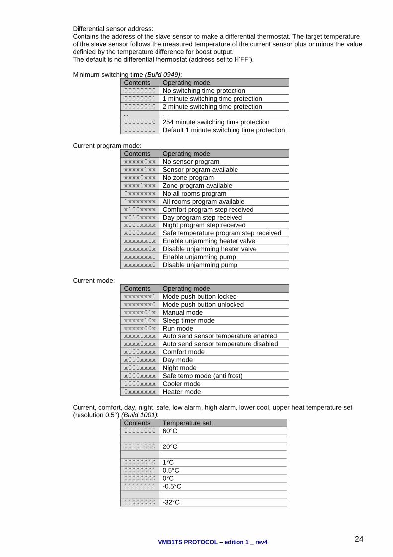
Differential sensor address: Contains the address of the slave sensor to make a differential thermostat. The target temperature of the slave sensor follows the measured temperature of the current sensor plus or minus the value definied by the temperature difference for boost output. The default is no differential thermostat (address set to H’FF’). Minimum switching time (Build 0949):
Contents Operating mode 00000000 No switching time protection 00000001 1 minute switching time protection 00000010 2 minute switching time protection … … 11111110 254 minute switching time protection 11111111 Default 1 minute switching time protection
Current program mode:
Contents Operating mode xxxxx0xx No sensor program xxxxx1xx Sensor program available xxxx0xxx No zone program xxxx1xxx Zone program available 0xxxxxxx No all rooms program 1xxxxxxx All rooms program available x100xxxx Comfort program step received x010xxxx Day program step received x001xxxx Night program step received X000xxxx Safe temperature program step received xxxxxx1x Enable unjamming heater valve xxxxxx0x Disable unjamming heater valve xxxxxxx1 Enable unjamming pump xxxxxxx0 Disable unjamming pump
Current mode:
Contents Operating mode xxxxxxx1 Mode push button locked xxxxxxx0 Mode push button unlocked xxxxx01x Manual mode xxxxx10x Sleep timer mode xxxxx00x Run mode xxxx1xxx Auto send sensor temperature enabled xxxx0xxx Auto send sensor temperature disabled x100xxxx Comfort mode x010xxxx Day mode x001xxxx Night mode x000xxxx Safe temp mode (anti frost) 1000xxxx Cooler mode 0xxxxxxx Heater mode
Current, comfort, day, night, safe, low alarm, high alarm, lower cool, upper heat temperature set (resolution 0.5°) (Build 1001):
Contents Temperature set 01111000 60°C 00101000 20°C 00000010 1°C 00000001 0.5°C 00000000 0°C 11111111 -0.5°C 11000000 -32°C
VMB1TS PROTOCOL – edition 1 _ rev4
25
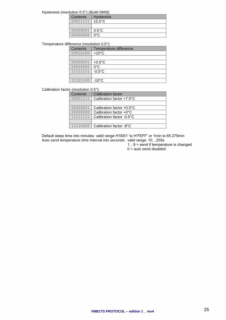
Hysteresis (resolution 0.5°) (Build 0949):
Contents Hysteresis 00011111 15.5°C 00000001 0.5°C 00000000 0°C
Temperature difference (resolution 0.5°):
Contents Temperature difference 00010100 +10°C 00000001 +0.5°C 00000000 0°C 11111111 -0.5°C 11101100 -10°C
Calibration factor (resolution 0.5°):
Contents Calibration factor 00001111 Calibration factor +7.5°C 00000001 Calibration factor +0.5°C 00000000 Calibration factor +0°C 11111111 Calibration factor -0.5°C 11110000 Calibration factor -8°C
Default sleep time into minutes: valid range H’0001’ to H’FEFF’ or 1min to 65.279min Auto send temperature time interval into seconds: valid range: 10…255s 1…9 = send if temperature is changed 0 = auto send disabled