8. combined cycle power plants fluid techniques in plants 8. combined cycle power plants 9 / 80 gas...
TRANSCRIPT

8. Combined Cycle Power Plants 1 / 80Thermal Fluid Techniques in Plants
8. Combined Cycle Power Plants

8. Combined Cycle Power Plants 2 / 80Thermal Fluid Techniques in Plants
Cost of Electricity 193
Wide Use of Gas Turbine 735
Introduction to Combined Cycle Power Plants 21
Electricity Demand and Supply 112
Characteristics of Combined Cycle Power Plants 274

8. Combined Cycle Power Plants 3 / 80Thermal Fluid Techniques in Plants
Combined Cycle Power Plants
Compressor
Fuel
Combustor
Turbine
Inlet
Air
Steam
Turbine
G
G
Condenser
Deaerator
Condensate
PumpHP Boiler
Feed Pump
LP Boiler
Feed Pump
HP Superheater
HP Evaporator
HP Economizer
LP Superheater
LP Evaporator
LP Economizer
HP
Drum
LP
Drum
Exhaust
Gas
HRSG
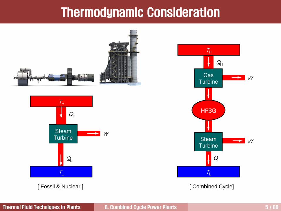
In simple cycle mode, the gas turbine is operated alone, without the benefit of recovering any of energy
in the hot exhaust gases. The exhaust gases are sent directly to the atmosphere.
In combined cycle mode, the gas turbine exhaust gases are sent into HRSG. The HRSG generates
steam that is normally used to power a steam turbine.

8. Combined Cycle Power Plants 4 / 80Thermal Fluid Techniques in Plants
T
s
Topping Cycle
(Brayton Cycle)
Bottoming Cycle
(Rankine Cycle)
T-s Diagram for a Typical CCPP
8. Combined Cycle Power Plants 5 / 80Thermal Fluid Techniques in Plants
TH
TL
QL
W
QH
SteamTurbine
TH
TL
QL
W
QH
Gas Turbine
WSteamTurbine
HRSG
[ Fossil & Nuclear ] [ Combined Cycle]
Thermodynamic Consideration

8. Combined Cycle Power Plants 6 / 80Thermal Fluid Techniques in Plants
Gas Turbine Combined Cycle
구분 Topping Cycle Bottoming Cycle
Main Components GT ST/HRSG
Working Fluid Air Water/Steam
Temperature High Medium/Low
Thermodynamic Cycle Brayton Rankine
Coupling Two Cycles Heat Exchanger
Topping Cycle Coupling Bottoming Cycle

8. Combined Cycle Power Plants 7 / 80Thermal Fluid Techniques in Plants
CCPP System Options
Items Options Remarks
Steam Cycle
• Single pressure / Two pressure /Three pressure *
• Reheat *
• Non-reheat
• Non-reheat for rated EGT less than
1000°F/538°C
• Reheat for rated EGT higher than
1050°F/566°C and fuel heating
• Heat recovery feedwater heating
Fuel
• Natural gas */ Distillate oil / Ash bearing oil
• Low BTU coal and oil-derived gas
• Multiple fuel systems
NOx Control
• Water injection / Steam injection
• SCR (NOx and/or CO)
• Dry Low NOx combustion *
Condenser• Water cooled (once-through system) *
• Cooling tower /Air-cooled condenser
Deaeration• Deaerating condenser *
• Deaerator/evaporator integral with HRSG
HRSG Design
• Natural circulation evaporators *
• Forced circulation evaporators
• Unfired *
• Supplementary fired
* Base Configuration for Combined Cycle Power Plants

8. Combined Cycle Power Plants 8 / 80Thermal Fluid Techniques in Plants
Unfired, 3-pressure steam cycle
• Non-reheat for rated EGT less than 1000°F/538°C
• Reheat for rated EGT higher than 1050°F/566°C and fuel heating
• Heat recovery feedwater heating
• Feedwater dearation on condenser
• Natural circulation HRSG evaporators
GT with DLN combustors
Once-through condenser cooling water system
Multi-shaft systems (2-on-1, or 3-on-1)
Single-shaft systems
• Integrated equipment and control system
Base Configurations for CCPP

8. Combined Cycle Power Plants 9 / 80Thermal Fluid Techniques in Plants
Gas Turbine Steam Turbine
Combustion Internal External
Thermodynamic cycle Brayton Rankine
Cycle type Closed (Open) Closed
Working fluid Air Water/Steam
Max. pressure, bar 23 (40 for Aviation) 350 (5050 psig)
Max. temperature, C(F) 1350 (2462) 630 (1166)
Blade cooling Yes No
Shaft cooling No Yes (USC)
Max. cycle efficiency, % 40 49 (USC)
Max. number of reheat 1 2
Power density High Low
Steam conditions of the steam turbines for combined cycle applications are lower than those for
USC steam turbines.
GT vs. ST
8. Combined Cycle Power Plants 10 / 80Thermal Fluid Techniques in Plants
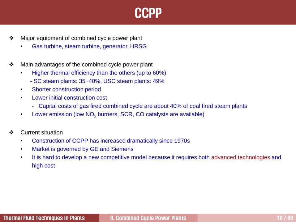
Major equipment of combined cycle power plant
• Gas turbine, steam turbine, generator, HRSG
Main advantages of the combined cycle power plant
• Higher thermal efficiency than the others (up to 60%)
- SC steam plants: 35~40%, USC steam plants: 49%
• Shorter construction period
• Lower initial construction cost
- Capital costs of gas fired combined cycle are about 40% of coal fired steam plants
• Lower emission (low NOx burners, SCR, CO catalysts are available)
Current situation
• Construction of CCPP has increased dramatically since 1970s
• Market is governed by GE and Siemens
• It is hard to develop a new competitive model because it requires both advanced technologies and
high cost
CCPP

8. Combined Cycle Power Plants 11 / 80Thermal Fluid Techniques in Plants
Cost of Electricity 3
Wide Use of Gas Turbine 5
Introduction to Combined Cycle Power Plants1
Electricity Demand and Supply2
Characteristics of Combined Cycle Power Plants 4

8. Combined Cycle Power Plants 12 / 80Thermal Fluid Techniques in Plants
국내 복합발전 설치 현황 - 민자
회사 Site 제작사 GT model MW/Unit GT대수 GT용량 ST용량 총용량 비고
GS EPS 당진 SiemensV84.3A
SGT6-8000H
179.0
276.0
4
1
716.0
276.0
382.0
140.0
1,098
416
2-on-1
1-on-1
GS 파워부천 WH 501D5 105.2 3 315.6 150.0 466 3-on-1 (CHP)
안양 ABB GT11N 79.4 4 317.6 150.0 468 4-on-1 (CHP)
GS 에너지 인천 GE 6F 70.0 2 140.0 60.0 200 (구)인천종합에너지
SK E&S
광양 GE 7FA+e 171.7 4 686.8 394.0 1,081 K-Power
오성 GE 7FA+e 183.0 3 549.0 285.0 834 3-on-1
장문 Siemens SGT6-8000H 274.0 4 1096.0 704.0 1,800 2-on-1 2 (2017 완공)
하남 두중/MHI M501GAC 267.3 1 267.3 131.6 399 CHP
POSCO광양 GE 7FA+e 168.8 2 337.6 165.0 502
포항 GE 7FA+e 168.8 2 337.6 165.0 502
POSCO에너지 인천
WH
Siemens
Siemens
W501D5
SGT6-5000F
SGT6-8000H
102.0
203.0
274.0
12
4
3
1,200.0
812.0
822.0
600.0
440.0
438.0
1,800
1,252
1,260
3-on-1 4
2-on-1 2
1-on-1 3
MPC순천
Siemens
MHI
W501FD2
M501J
185.0
317.0
2
2
370.0
634.0
208.0
312.0
578
946
2-on-1
2-on-1
대산 WH W501D5 102.0 4 408.0 100.0 508 현대중공업 인수
한국지역난방공사판교 GE 7EA 88.0 1 88.0 88
파주 MHI M501F 153.0 2 306.0 175.0 481
동두천드림파워 동두천 MHI M501J 317.0 4 1,268.0 610.0 1,878 2015년 3월완공
대구그린파워 대구 Siemens SGT6-8000H 276.0 1 276.0 144.0 420
포천파워 포천 두중/MHI M501GAC 267.5 4 1,070.0 530.0 1600
S-Power(안산복합) 안산 Siemens SGT6-8000H 274.0 2 548.0 272.0 820
대륜발전(한진중) 양주 두중/MHI M501F 185.0 2 670.0 200.0 870 CHP
합 계 73 13,511.5 6,755.6 20,267

8. Combined Cycle Power Plants 13 / 80Thermal Fluid Techniques in Plants
국내 복합발전 설치 현황 - 한전
발전소 Site 제작사 GT model MW/Unit GT 대수 GT용량 ST용량 총용량 비고
남부발전
신인천 GE 7FA+e 165.0 8 1320.0 600.0 1,920 2-on-1
부산 GE 7FA 165.0 8 1320.0 640.0 1,960 2-on-1
한림 GE 6B 38.0 2 76.0 29.0 105
영월 두중/MHI M501F 183.0 3 549.0 299.4 848 3-on-1
안동 Siemens SGT6-8000H 277.0 1 277.0 140.0 417 1-on-1
중부발전
보령 ABB GT24AB 163.0 6 978.0 546.0 1,524 2-on-1
인천
Siemens
Siemens
ABB
V84.3A
V84.3A
GT24AB
179.0
184.0
163.0
2
2
2
358.0
368.0
326.0
195.0
193.0
182.0
553
561
508
2-on-1
2-on-1
2-on-1
세종 두중/MHI M501F 186.5 2 373.0 204.0 577 2-on-1 (CHP)
서부발전
서인천 GE 7FA+e 165.0 8 1320.0 712.0 2,032 1-on-1
평택GE 7EA 87.9 4 351.6 183.0 535 4-on-1
MHI M501J 317.5 2 635.0 311.0 946 2-on-1
군산 MHI M501G 254.0 2 508.0 263.0 771 2-on-1
남동발전 분당 ABB GT11N 79.4 8 635.2 300.0 935
동서발전
일산 WH 501D5 105.2 6 631.2 300.0 931 4-on-1, 2-on-1
울산
WH 501D5 105.2 2 210.4 100.0 310 2-on-1
WH 501F (150) 150 4 600.0 300.0 900 2-on-1
MHI M501J 287.0 2 574.0 299.0 873 2-on-1
합 계 74 11,410.4 5,796.4 17,206

8. Combined Cycle Power Plants 14 / 80Thermal Fluid Techniques in Plants
복합화력 4,300 MW (7FA+e x 16 Units)
신인천/서인천복합발전단지

8. Combined Cycle Power Plants 15 / 80Thermal Fluid Techniques in Plants
부산복합 (2,000 MW) 분당복합 (960 MW) 일산복합 (900 MW)
보령복합 (1,800 MW) POSCO 광양복합 (500 MW) POSCO 포항복합 (500 MW)
POSCO파워 (3,000 MW) GS EPS (1,000 MW) 현대중대산 (500 MW) 메이야율촌 (500 MW) K-Power(1,074 MW)
울산 (1,200 MW)
담수설비
GS 파워 (1,000 MW)
국내 복합화력발전소 [1/2]
8. Combined Cycle Power Plants 16 / 80Thermal Fluid Techniques in Plants
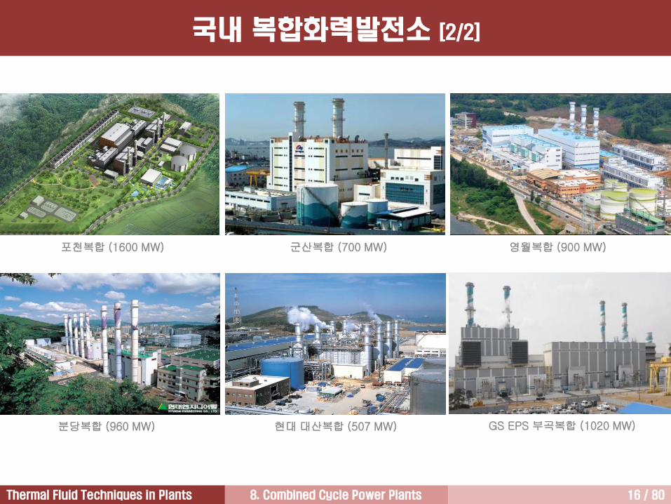
포천복합 (1600 MW) 군산복합 (700 MW) 영월복합 (900 MW)
현대대산복합 (507 MW)분당복합 (960 MW) GS EPS 부곡복합 (1020 MW)
국내 복합화력발전소 [2/2]

8. Combined Cycle Power Plants 17 / 80Thermal Fluid Techniques in Plants
2004 2006 2008 2010
Bill
ions
of
Dolla
rs (
2007)
3
6
9
12
15
18
Commercial Aviation
Electrical Generation
Military Aviation
Mechanical Drive
Marine Propulsion
Gas Turbine Production by Sector
Source: Davis Franus, Forecast International
8. Combined Cycle Power Plants 18 / 80Thermal Fluid Techniques in Plants
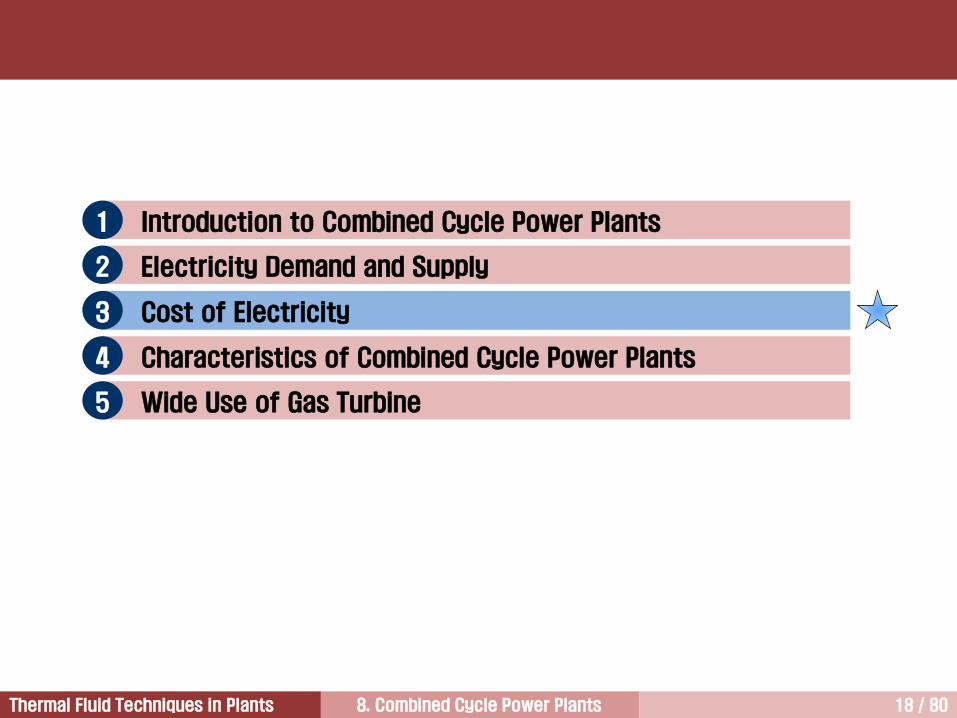
Cost of Electricity 3
Wide Use of Gas Turbine 5
Introduction to Combined Cycle Power Plants1
Electricity Demand and Supply2
Characteristics of Combined Cycle Power Plants4

8. Combined Cycle Power Plants 19 / 80Thermal Fluid Techniques in Plants
2015년 기준
• 석탄: 탄소배출권비용을감안하면발전원가 27.2원상승
• 원자력: 핵폐기물처리비용미반영
원자력
55
단위: 원/kWh
석탄 중유 LNG 풍력 태양광
66
117.0
156
?
?
국내 발전원가 비교

8. Combined Cycle Power Plants 20 / 80Thermal Fluid Techniques in Plants
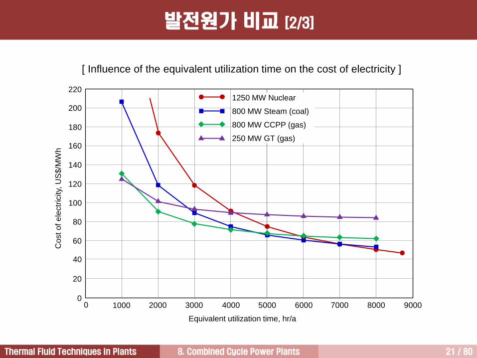
Source: Power Plant Engineering (Black & Veatch)
발전원가 비교 [1/3]
8. Combined Cycle Power Plants 21 / 80Thermal Fluid Techniques in Plants
발전원가 비교 [2/3]
[ Influence of the equivalent utilization time on the cost of electricity ]
1000 2000 3000 4000 5000 6000 7000 8000 9000
220
200
180
160
140
120
100
80
60
40
20
0
Equivalent utilization time, hr/a
Cost o
f e
lectr
icity,
US
$/M
Wh
1250 MW Nuclear
800 MW Steam (coal)
800 MW CCPP (gas)
250 MW GT (gas)
0
8. Combined Cycle Power Plants 22 / 80Thermal Fluid Techniques in Plants
In contrast to steam turbine-generators, the manufacturers of gas turbines have a defined product line,
allowing for substantial standardization and assembly line manufacturing.
The modular concept of the package power plants made gas turbines relatively quick and easy to install.
Standardization and modularization combine to provide the product benefits of relatively low capital cost
and fast installation.
The benefits of low capital cost and fast installation were initially offset by higher operating costs when
compared to other installed capacity. Therefore, early utility applications of gas turbine generator were
strictly for peak load operation for a few hundred hours per year.
Improvements in efficiency and reliability and the application of combined cycles have added to the
economic benefits of the technology and now give gas turbine based power plants a wider range of
application on electric systems.
발전원가 비교 [3/3]

8. Combined Cycle Power Plants 23 / 80Thermal Fluid Techniques in Plants
Type of PlantOutput,
MW
Descripti
on
Investment
cost, US$/kW
Average
efficiency
(LHV), %
Fuel price,
US$/MBTu
(LHV)
감가상각
Combined Cycle
Power Plant800
2 x GT
1 x ST750 56.5 8.0 25
Gas Turbine
Plant (gas)250 1 x GT 413 37.5 8.0 25
Steam Power
Plant (coal)800 1 x ST 1716 44.0 3.5 25
Nuclear Power
Plant1250 1 x ST 3500 34.5 0.5 40
< Inputs for the evaluation of the cost of electricity >
No cost for CO2 emissions were included.
Cost of Electricity

8. Combined Cycle Power Plants 24 / 80Thermal Fluid Techniques in Plants
Co
st o
f E
lectr
icity (
US
$/M
Wh
)
800 MW
CCPP
(gas)
20
40
60
80
100Capital
O&M
Fuel
Intermediate LoadBase Load
800 MW
Steam
(coal)
250 MW
GT PP
(gas)
1250 MW
Nuclear PP
800 MW
CCPP
(gas)
800 MW
Steam
(coal)
250 MW
GT PP
(gas)
1250 MW
Nuclear PP
Cost of Electricity

8. Combined Cycle Power Plants 25 / 80Thermal Fluid Techniques in Plants
GE S109H
: Dry Low NOx Combustors(H System™)
: Combined cycle
: 14 Can-annular lean pre-mix DLN-2.5combustors
: Output 480 MW (Gas turbine power 300 MW)
: Heat rate 6000 kJ/kWh
: $153,500,000 ($320/kW) F15-K : $1억
복합화력발전 가격
8. Combined Cycle Power Plants 26 / 80Thermal Fluid Techniques in Plants
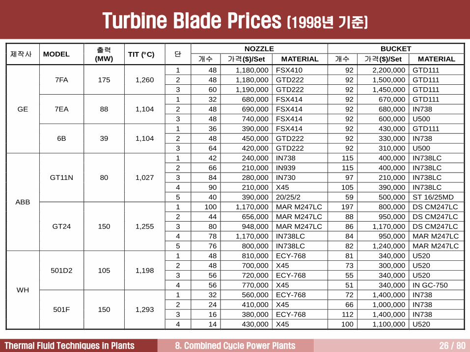
NOZZLE BUCKET제작사 MODEL
출력(MW)
TIT (C) 단개수 가격($)/Set MATERIAL 개수 가격($)/Set MATERIAL
1 48 1,180,000 FSX410 92 2,200,000 GTD111
2 48 1,180,000 GTD222 92 1,500,000 GTD1117FA 175 1,260
3 60 1,190,000 GTD222 92 1,450,000 GTD111
1 32 680,000 FSX414 92 670,000 GTD111
2 48 690,000 FSX414 92 680,000 IN7387EA 88 1,104
3 48 740,000 FSX414 92 600,000 U500
1 36 390,000 FSX414 92 430,000 GTD111
2 48 450,000 GTD222 92 330,000 IN738
GE
6B 39 1,104
3 64 420,000 GTD222 92 310,000 U500
1 42 240,000 IN738 115 400,000 IN738LC
2 66 210,000 IN939 115 400,000 IN738LC
3 84 280,000 IN730 97 210,000 IN738LC
4 90 210,000 X45 105 390,000 IN738LC
GT11N 80 1,027
5 40 390,000 20/25/2 59 500,000 ST 16/25MD
1 100 1,170,000 MAR M247LC 197 800,000 DS CM247LC
2 44 656,000 MAR M247LC 88 950,000 DS CM247LC
3 80 948,000 MAR M247LC 86 1,170,000 DS CM247LC
4 78 1,170,000 IN738LC 84 950,000 MAR M247LC
ABB
GT24 150 1,255
5 76 800,000 IN738LC 82 1,240,000 MAR M247LC
1 48 810,000 ECY-768 81 340,000 U520
2 48 700,000 X45 73 300,000 U520
3 56 720,000 ECY-768 55 340,000 U520501D2 105 1,198
4 56 770,000 X45 51 340,000 IN GC-750
1 32 560,000 ECY-768 72 1,400,000 IN738
2 24 410,000 X45 66 1,000,000 IN738
3 16 380,000 ECY-768 112 1,400,000 IN738
WH
501F 150 1,293
4 14 430,000 X45 100 1,100,000 U520
Turbine Blade Prices (1998년기준)
8. Combined Cycle Power Plants 27 / 80Thermal Fluid Techniques in Plants
Cost of Electricity 3
Wide Use of Gas Turbine 5
Introduction to Combined Cycle Power Plants1
Electricity Demand and Supply2
Characteristics of Combined Cycle Power Plants 4

8. Combined Cycle Power Plants 28 / 80Thermal Fluid Techniques in Plants
Advantages Disadvantages
1. High thermal efficiency
2. Low initial investment
3. Short construction time
4. Fuel flexibility
Wide range of gas and liquid fuels
5. High reliability and availability
6. Low operation and maintenance cost
7. High efficiency in small capacity increments
Various gas turbine models
8. Operating flexibility
Base, intermediate, peak load
9. Environmental friendliness
10. Reduced plant space
1. Higher fuel costs
2. Uncertain long-term fuel supply
3. Output more dependent on ambient
temperatures
System Features of CCPP
8. Combined Cycle Power Plants 29 / 80Thermal Fluid Techniques in Plants
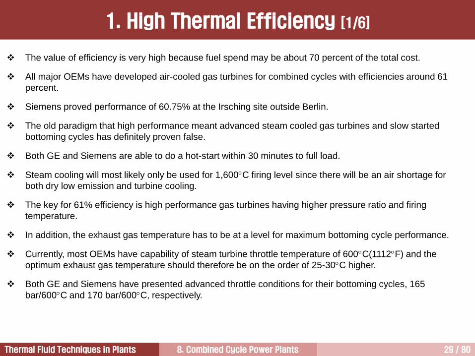
1. High Thermal Efficiency [1/6]
The value of efficiency is very high because fuel spend may be about 70 percent of the total cost.
All major OEMs have developed air-cooled gas turbines for combined cycles with efficiencies around 61
percent.
Siemens proved performance of 60.75% at the Irsching site outside Berlin.
The old paradigm that high performance meant advanced steam cooled gas turbines and slow started
bottoming cycles has definitely proven false.
Both GE and Siemens are able to do a hot-start within 30 minutes to full load.
Steam cooling will most likely only be used for 1,600C firing level since there will be an air shortage for
both dry low emission and turbine cooling.
The key for 61% efficiency is high performance gas turbines having higher pressure ratio and firing
temperature.
In addition, the exhaust gas temperature has to be at a level for maximum bottoming cycle performance.
Currently, most OEMs have capability of steam turbine throttle temperature of 600C(1112F) and the
optimum exhaust gas temperature should therefore be on the order of 25-30C higher.
Both GE and Siemens have presented advanced throttle conditions for their bottoming cycles, 165
bar/600C and 170 bar/600C, respectively.

8. Combined Cycle Power Plants 30 / 80Thermal Fluid Techniques in Plants
Fuel Energy
100%
GT 37.6%
ST 21.7%
Co
nd
ense
r
31.0%
Stack8.6%
Loss in HRSG0.3%
Loss
0.5%
Loss
0.3%
Three Pressure
Reheat Cycle T
s
Topping Cycle
(Brayton Cycle)
Bottoming Cycle
(Rankine Cycle)
Combined cycle power plants have a higher thermal efficiency because of the application of two
complementary thermodynamic cycles
[ Heat balance in a typical combined cycle plant ]
1. High Thermal Efficiency [2/6]
8. Combined Cycle Power Plants 31 / 80Thermal Fluid Techniques in Plants
10
원자력
열효율
, %
60
50
40
30
20
IGCC가스터빈(SIMPLE)
화력(SC)
화력(USC)
가스터빈(복합)
35
38
49
40
48
60발전유형별성능비교
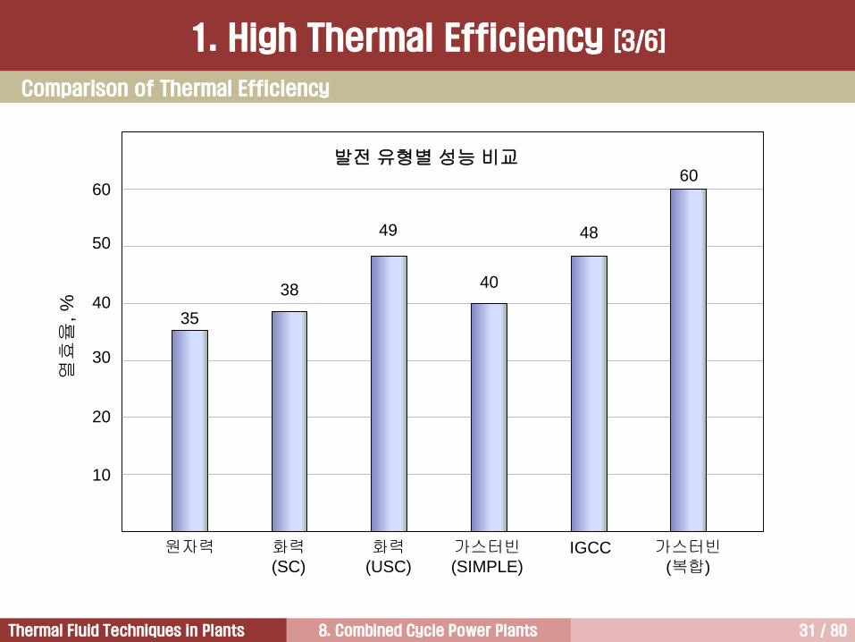
Comparison of Thermal Efficiency
1. High Thermal Efficiency [3/6]
8. Combined Cycle Power Plants 32 / 80Thermal Fluid Techniques in Plants
1967 1972 1979 1990 2000 2008 2012
TIT, C (F) 900 (1650) 1010 (1850) 1120 (2050) 1260 (2300)1426
(2600)
1426
(2600)1500
Press. Ratio 10.5 11 14 14.5 19-23 20-23 20-23
EGT, C (F) 427 (800) 482 (900) 530 (986) 582 (1080) 593 (1100) 623
Cooling 1 vane1&2 vane
1 blade
1&2 vane
1&2 blade
1,2,3 vane
1,2,3 blade
1,2,3 vane
1,2,3
blade
SC Power, MW 50-60 60-80 70-105 165-240 165-280400-480
(CC)
SC Heat Rate,
Btu/kWh11,600 11,180 10,250 9,500 8,850
CC Heat Rate,
Btu/kWh8,000 7,350 7,000 6,400 5,880 5,690
SC Effi., % 29.4 30.5 33.3 35.9 38.6 40
CC Effi., % 42.7 46.4 48.7 53.3 58.0 60 61
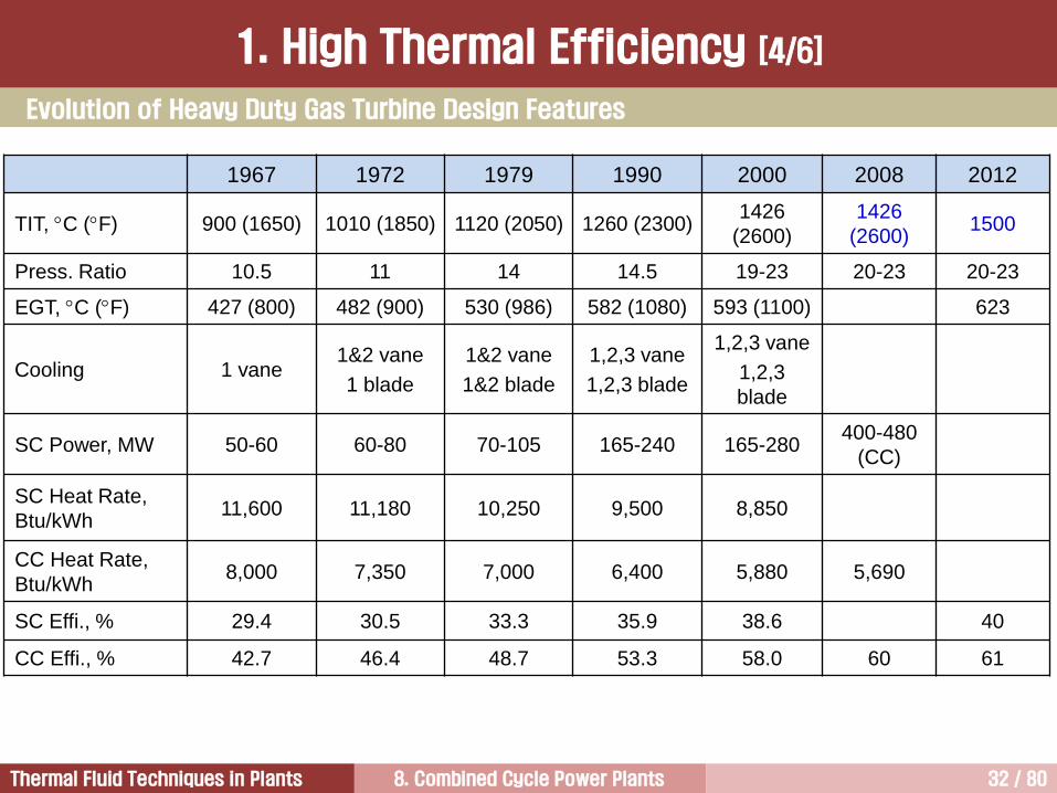
Evolution of Heavy Duty Gas Turbine Design Features
1. High Thermal Efficiency [4/6]

8. Combined Cycle Power Plants 33 / 80Thermal Fluid Techniques in Plants
Load, %
30 40 50 60 70 80 90 100
65
60
75
70
85
80
95
90
100 The gas turbine equipped with
VIGV or several rows of variable
stator vanes keeps the efficiency
of the combined cycle plant
almost constant down to
approximately 80 to 85% load.
This is because a high exhaust
gas temperature can be
maintained as the air mass flow is
reduced.
Below that level, the turbine inlet
temperature must be reduced,
leading to an increasingly fast
reduction of efficiencies.
The steam turbine is operated with sliding pressure mode down to 50% load. Below that point, the live-
steam pressure is held constant, resulting in throttling losses.
Part Load Efficiency
1. High Thermal Efficiency [5/6]
8. Combined Cycle Power Plants 34 / 80Thermal Fluid Techniques in Plants
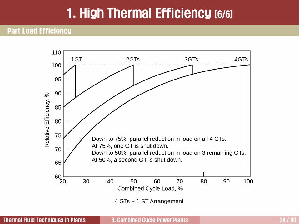
4 GTs + 1 ST Arrangement
Combined Cycle Load, %
30 40 50 60 70 80 90 100
65
60
75
70
85
80
95
90
100
110
20
4GTs3GTs2GTs1GT
Down to 75%, parallel reduction in load on all 4 GTs.
At 75%, one GT is shut down.
Down to 50%, parallel reduction in load on 3 remaining GTs.
At 50%, a second GT is shut down.
Part Load Efficiency
1. High Thermal Efficiency [6/6]

8. Combined Cycle Power Plants 35 / 80Thermal Fluid Techniques in Plants
Type of Plant Output (MW)Specific Price
(US$/kW)
Combined Cycle Power Plant 800 550 - 650
Combined Cycle Power Plant 60 700 - 800
Gas Turbine Plant 250 300 - 400
Gas Turbine Plant 60 500 - 600
Steam Power Plant (coal) 800 1,200 – 1,400
Steam Power Plant (coal) 60 1,000 – 1,200
Nuclear Power Plant 1,250 2,000 – 3,000
Biomass Power Plant 30 2,000 – 2,500
These prices are valid for 2007.
Interest during construction is not included.
Capital costs of gas-fired combined cycle are about 45% of coal-fired steam plants
Comparison of Initial Construction Cost
2. Low Initial Construction Cost [1/4]
8. Combined Cycle Power Plants 36 / 80Thermal Fluid Techniques in Plants
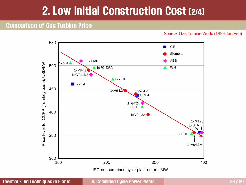
Source: Gas Turbine World (1999 Jan/Feb)
Comparison of Gas Turbine Price
2. Low Initial Construction Cost [2/4]
1401
17EA
17FA
19FA
1GT11N2
1V84.2
1GT13D
1GT24
1GT26
1501D5A
1701D
1501F
1701F
1V94.2 1V84.3
1V94.3A
GE
Siemens
ABB
WH
100 200 300 400
ISO net combined cycle plant output, MW
Price
le
ve
l fo
r C
CP
P (
Tu
rnke
y b
ase
), U
SD
/kW
550
500
450
400
350
300
1V94.2A

8. Combined Cycle Power Plants 37 / 80Thermal Fluid Techniques in Plants
Basis: 350~700MW CC plant with a V94.3A Gas Turbine
Items Portion % CCPP
Integrated
Services15%
4 Project management / Subcontracting
2 Plant and project engineering / Software
8 Plant erection / Commissions / Training
1 Transport / Insurance
Lots 85%
15 Civil works
32 Gas turbine / Steam turbine / Generator set
16 Balance of plants
7 Electrical systems
4 Instrumental and control
11 HRSG island
As a rule of thumb, a 1% increase in the efficiency could mean that 3.3% more capital can be invested.
Cost Breakdown for CCPP
2. Low Initial Construction Cost [3/4]

8. Combined Cycle Power Plants 38 / 80Thermal Fluid Techniques in Plants
Steam Turbine Set
8%
Power Island
Mechanical System
9%
Heat Recovery
Steam Generator
10%
Gas Turbine Set
32%
Electrical (without high
voltage switchyard)
9%
Control 3%
Mechanical
Systems Outside
Power Island
8%
Civil, Arrangement,
Building Facilities
18%
Site
Infrastructure
3%
Cost Breakdown for a 400 MW CCPP
2. Low Initial Construction Cost [4/4]
8. Combined Cycle Power Plants 39 / 80Thermal Fluid Techniques in Plants
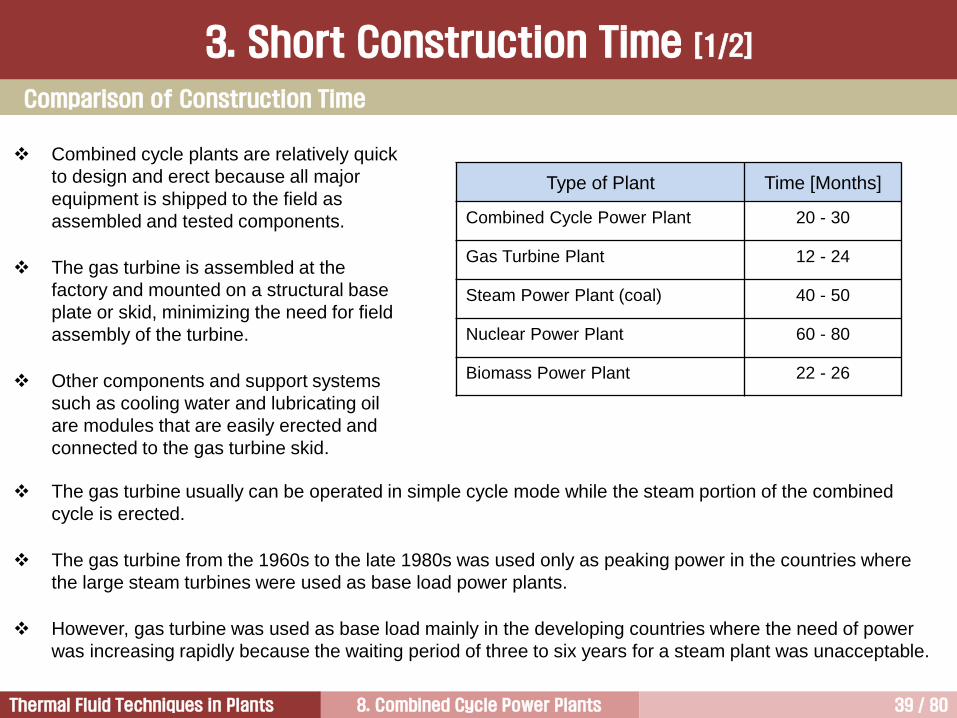
Type of Plant Time [Months]
Combined Cycle Power Plant 20 - 30
Gas Turbine Plant 12 - 24
Steam Power Plant (coal) 40 - 50
Nuclear Power Plant 60 - 80
Biomass Power Plant 22 - 26
The gas turbine usually can be operated in simple cycle mode while the steam portion of the combined
cycle is erected.
The gas turbine from the 1960s to the late 1980s was used only as peaking power in the countries where
the large steam turbines were used as base load power plants.
However, gas turbine was used as base load mainly in the developing countries where the need of power
was increasing rapidly because the waiting period of three to six years for a steam plant was unacceptable.
Combined cycle plants are relatively quick
to design and erect because all major
equipment is shipped to the field as
assembled and tested components.
The gas turbine is assembled at the
factory and mounted on a structural base
plate or skid, minimizing the need for field
assembly of the turbine.
Other components and support systems
such as cooling water and lubricating oil
are modules that are easily erected and
connected to the gas turbine skid.
Comparison of Construction Time
3. Short Construction Time [1/2]
8. Combined Cycle Power Plants 40 / 80Thermal Fluid Techniques in Plants
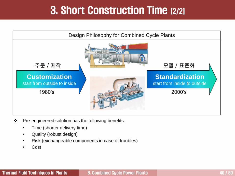
Pre-engineered solution has the following benefits:
• Time (shorter delivery time)
• Quality (robust design)
• Risk (exchangeable components in case of troubles)
• Cost
Customizationstart from outside to inside
Standardizationstart from inside to outside
1980’s 2000’s
Design Philosophy for Combined Cycle Plants
주문 / 제작 모델 / 표준화
3. Short Construction Time [2/2]

8. Combined Cycle Power Plants 41 / 80Thermal Fluid Techniques in Plants
Most gas turbine applications rely on natural gas or No. 2 distillate
oil.
Because of the availability and economics of natural gas, the
majority of new power plants prefer natural gas as a fuel.
Fuel affects CC performance in a variety of ways.
Natural gas containing high hydrogen content has a higher heat
content and therefore output and efficiency increase when the
natural gas is used as a fuel.
Plant output and efficiency can be reduced when the ash bearing
fuels (crude oil, residual oil, blends, or heavy distillate) are used
because of fouling occurred in gas turbine and HRSG.
Plant output and efficiency can be reduced when the fuels
containing higher sulfur content are used. This is because higher
stack gas temperature is required to prevent condensation of
corrosive sulfuric acid.
Heavy fuels normally cannot be ignited for gas turbine startup;
therefore a startup and shutdown fuel, usually light distillate, is
needed with its own storage, forwarding system, and fuel
changeover equipment.
Fuel Units
Natural Gas
Process Gas
Dual Gas
Distillate
Naphtha
Kerosene
Distillate or Gas
Distillate and Gas
Crude
Crude and Distillate
Residual
Residual or Gas
Residual/Distillate/Gas
1408
13
60
783
14
30
964
82
59
32
120
4
1
Total 3570
[Table] GE heavy-duty GT
shipped for fuels (by 1983)
4. Fuel Flexibility

8. Combined Cycle Power Plants 42 / 80Thermal Fluid Techniques in Plants
The probability that a unit, which is classified as available, and in ready service, can be started, and
be brought to synchronization within a specific period time is defined as above. An inability to start
within the specified period and synchronize is considered a failure to start. However, repeated
attempts to start without attempting corrective action are not considered additional failures to start.
Starting Reliability =No. of Successful Starts
No. of Attempted Starts
MTBF =Fired Hours
Trips from a state of operation
P = period hours (normally one year, 8,760h)
F = total forced outage hours for unplanned outages and repairs
S = scheduled maintenance hours
Reliability = Availability =P F
P
P S F
P
Definition of Reliability and Availability
5. High Reliability and Availability [1/4]
8. Combined Cycle Power Plants 43 / 80Thermal Fluid Techniques in Plants
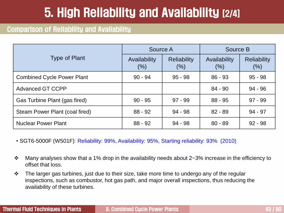
• SGT6-5000F (W501F): Reliability: 99%, Availability: 95%, Starting reliability: 93% (2010)
Type of Plant
Source A Source B
Availability
(%)
Reliability
(%)
Availability
(%)
Reliability
(%)
Combined Cycle Power Plant 90 - 94 95 - 98 86 - 93 95 - 98
Advanced GT CCPP 84 - 90 94 - 96
Gas Turbine Plant (gas fired) 90 - 95 97 - 99 88 - 95 97 - 99
Steam Power Plant (coal fired) 88 - 92 94 - 98 82 - 89 94 - 97
Nuclear Power Plant 88 - 92 94 - 98 80 - 89 92 - 98
Many analyses show that a 1% drop in the availability needs about 2~3% increase in the efficiency to
offset that loss.
The larger gas turbines, just due to their size, take more time to undergo any of the regular
inspections, such as combustor, hot gas path, and major overall inspections, thus reducing the
availability of these turbines.
Comparison of Reliability and Availability
5. High Reliability and Availability [2/4]

8. Combined Cycle Power Plants 44 / 80Thermal Fluid Techniques in Plants
Source: EPRI CS-3344 pp.1-3
Gas
clean up
Fans (0.6%) Boiler tubes (4.2%) Fouling/slagging (2.8%) Pulverizers (0.6%) Bearings (2.0%)
Pumps (1.7%) Condenser (3.8%) Turbine blades (2.7%) Generator (3.8%)
Stack
Air
heater
Pulverizer
Coal
prepCoal
HP
heater
LP
heater
Water
treatment
Condenser
Water
HP Turbine IP Turbine
LP Turbines
Econ
S.H.R.H.
AshAsh
I.D. fan
F.D. fan
Generator
Availability Reduction in Coal-Fired Power Plant
5. High Reliability and Availability [3/4]

8. Combined Cycle Power Plants 45 / 80Thermal Fluid Techniques in Plants
Reliability is the percentage of the time between planned overhauls where the plant is generating or is
ready to generate electricity, whereas the availability is the percentage of the total time where power could
be produced.
Availability and reliability are very important in terms of plant economy because the power station’s fixed
costs are constant whether the plant is running or not.
A high availability has a positive impact on the cost of electricity.
The major factors affecting plant availability and reliability are:
• Design of the major components
• Engineering of the plant as whole, especially of the interfaces between the systems
• Mode of operation (whether base, intermediate, or peak-load duty)
• Type of fuel
• Qualifications and skill of the operating and maintenance staff
• Adherence to manufacturer’s operating and maintenance instructions (preventive maintenance)
5. High Reliability and Availability [4/4]

8. Combined Cycle Power Plants 46 / 80Thermal Fluid Techniques in Plants
Type of Plant Output (MW)Fixed (Million
US$/year)
Variable
(US$/MWh)
Combined Cycle Power Plant 800 6~8 2~3
Combined Cycle Power Plant 60 3~4 3~4
Gas Turbine Plant 250 2~2.5 3~4
Gas Turbine Plant 60 1~1.5 4~5
Steam Power Plant (coal) 800 12~15 2.5~3.5
Nuclear Power Plant 1250 40~60 2.0
Biomass Power Plant 30 3~4 5~8
Fixed O&M: personnel and insurance costs.
Variable O&M: cost depending upon the operation regime of the plant. Included items are:
• Inspection and overhauls, including labor, parts, and rentals
• Water treatment expenses
• Catalyst replacement
• Major overhaul expences
• Air filter replacements
Comparison of Operating and Maintenance Cost
6. Low O&M Cost [1/4]

8. Combined Cycle Power Plants 47 / 80Thermal Fluid Techniques in Plants
ItemsSimple
cycle
Combined
cycleSteam coal IGCC
Fuel type NG NG Coal Coal
Fuel cost ($/MBtu) 2.65 2.65 1.5 1.5
Fixed O&M cost ($/kW/year) 0.7 3.7 28.1 38.8
Variable O&M cost ($/MWh) 7.3 3.3 2.7 3.7
Normalized plant cost 1.14 1 4.40 6.07
Source: GE (1991)
Some estimate that burning residual or crude oil will increase maintenance costs by a factor of 3,
(summing a base of 1 for natural gas, and by a factor of 1.5 for distillate) and that those costs will
be three times higher for the same number of fired hours if the unit is started every fired hour,
instead of once every 1000 fired hours.
Comparison of Operating and Maintenance Cost
6. Low O&M Cost [2/4]
8. Combined Cycle Power Plants 48 / 80Thermal Fluid Techniques in Plants
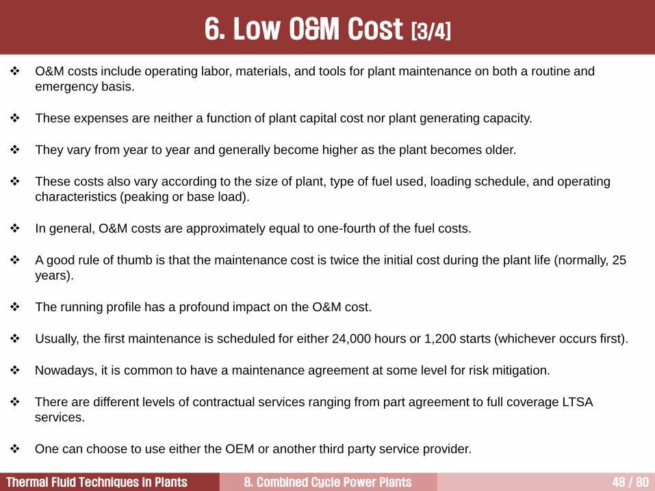
O&M costs include operating labor, materials, and tools for plant maintenance on both a routine and
emergency basis.
These expenses are neither a function of plant capital cost nor plant generating capacity.
They vary from year to year and generally become higher as the plant becomes older.
These costs also vary according to the size of plant, type of fuel used, loading schedule, and operating
characteristics (peaking or base load).
In general, O&M costs are approximately equal to one-fourth of the fuel costs.
A good rule of thumb is that the maintenance cost is twice the initial cost during the plant life (normally, 25
years).
The running profile has a profound impact on the O&M cost.
Usually, the first maintenance is scheduled for either 24,000 hours or 1,200 starts (whichever occurs first).
Nowadays, it is common to have a maintenance agreement at some level for risk mitigation.
There are different levels of contractual services ranging from part agreement to full coverage LTSA
services.
One can choose to use either the OEM or another third party service provider.
6. Low O&M Cost [3/4]
8. Combined Cycle Power Plants 49 / 80Thermal Fluid Techniques in Plants
In many cases, financing organs or insurer requires and LTSA (or better) for risk mitigation to level the
insurance cost at a reasonable level.
There are ways of potentially reducing the maintenance cost and one should always lumped methods with
equivalent hours.
The word lumped is used in a sense that the two different ageing mechanisms, such as creep, oxidation,
regular wear and tear and stresses related to thermal gradients during start and stop, are evaluated as
equivalent time by e.g. assuming that a start consumes time rather being a low cycle.
The total number of gas turbine operated in the world is about 47,000 units and the total value of the gas
turbine after market was 19.3 billion USD in 2009.
The after market is valuable greatly to the manufacturers since all 47,000 units requires maintenance on a
regular basis.
Certain in-house produced parts may be offered with several hundred percent margin. In contrast, the
margin of a complete new turn-key power plant is about 10 percent.
The reward for the user, by having a LTSA, is discounted parts and prioritized treatment by the supplier.
6. Low O&M Cost [4/4]

8. Combined Cycle Power Plants 50 / 80Thermal Fluid Techniques in Plants
Mode Baseload Plant (1990s)SCC5-4000F cycling plant
(Siemens)
Hot start (8 h) 90 min 45-55 min
Warm start (64 h) 200 min 120 min
Cold start (>120 h) 250 min 150 min
7. Operating Flexibility [1/11]
Operational flexibility is essential in combined cycle power plants for frequency control.
Most OEMs are capable of 30 min hot-start and steep (35-50 MW/minute) ramp-rates.
The steam cooled gas turbine gas a longer start-up time. Thus, is has less flexibility in terms of DSS.
8. Combined Cycle Power Plants 51 / 80Thermal Fluid Techniques in Plants
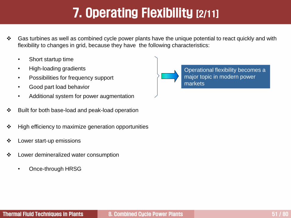
Gas turbines as well as combined cycle power plants have the unique potential to react quickly and with
flexibility to changes in grid, because they have the following characteristics:
• Short startup time
• High-loading gradients
• Possibilities for frequency support
• Good part load behavior
• Additional system for power augmentation
Built for both base-load and peak-load operation
High efficiency to maximize generation opportunities
Lower start-up emissions
Lower demineralized water consumption
• Once-through HRSG
Operational flexibility becomes a
major topic in modern power
markets
7. Operating Flexibility [2/11]
8. Combined Cycle Power Plants 52 / 80Thermal Fluid Techniques in Plants
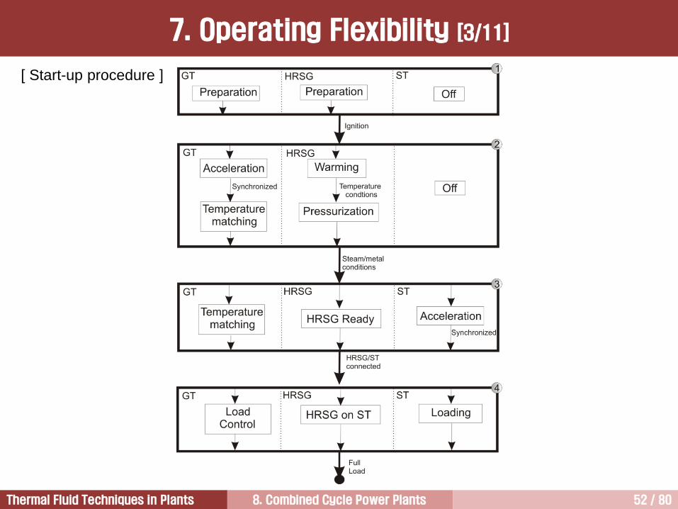
[ Start-up procedure ]
7. Operating Flexibility [3/11]

8. Combined Cycle Power Plants 53 / 80Thermal Fluid Techniques in Plants
Hot start (start after an 8-hour shutdown) of a 400 MW CCPP with optimized steam turbine start-up
technology (Siemens)
7. Operating Flexibility [4/11]

8. Combined Cycle Power Plants 54 / 80Thermal Fluid Techniques in Plants
Improvement of SGT6-5000F (W501F) Starting Capability
30 MW/min 5 additional minutes to 150 MW
5 minutes to accelerate
30 min. to baseload
13.5 minutes to accelerate
Improved
7. Operating Flexibility [5/11]

8. Combined Cycle Power Plants 55 / 80Thermal Fluid Techniques in Plants
7. Operating Flexibility [6/11]

8. Combined Cycle Power Plants 56 / 80Thermal Fluid Techniques in Plants
Gas turbines are capable of relatively quick starts.
Heavy duty gas turbines can achieve starting times as low as 10 minutes but usually no higher than 30
minutes from cold start to 100% load.
Aeroderivative gas turbines can achieve 100% load in 3 minutes or less.
If equipped with bypass systems, the startup of the steam cycle portion of the combined cycle can be
separated from the gas turbine.
The gas turbine can be operated at full load while the steam turbine is warming up.
The HRSG can be warmed up nearly as quickly as the gas turbine, with excess steam produced being
bypassed to the condenser.
The startup time of the gas turbine and the combined cycle plant is significantly less than the time required
for a comparably sized coal-fired power plant.
Supercritical plants require feedwater purity so that tube side deposition will not cause overheating damage.
Condensate polishing with oxygenated water treatment is required to achieve excellent water purity.
Even many natural circulation (drum type) units now use oxygenated water treatment.
The deposition has been greatly reduced so that the requirement for frequent chemical cleaning is almost
eliminated.
7. Operating Flexibility [7/11]

8. Combined Cycle Power Plants 57 / 80Thermal Fluid Techniques in Plants
Turbine start/stop cycle – firing temperature changes Transient temperature distribution (1st
stage bucket)
For rapid changes in gas temperature, the edges of the bucket or nozzle respond more quickly than
the thicker bulk section.
These gradients, in turn, produce thermal stress that, when cycled, can eventually lead cracking.
7. Operating Flexibility [8/11]
8. Combined Cycle Power Plants 58 / 80Thermal Fluid Techniques in Plants
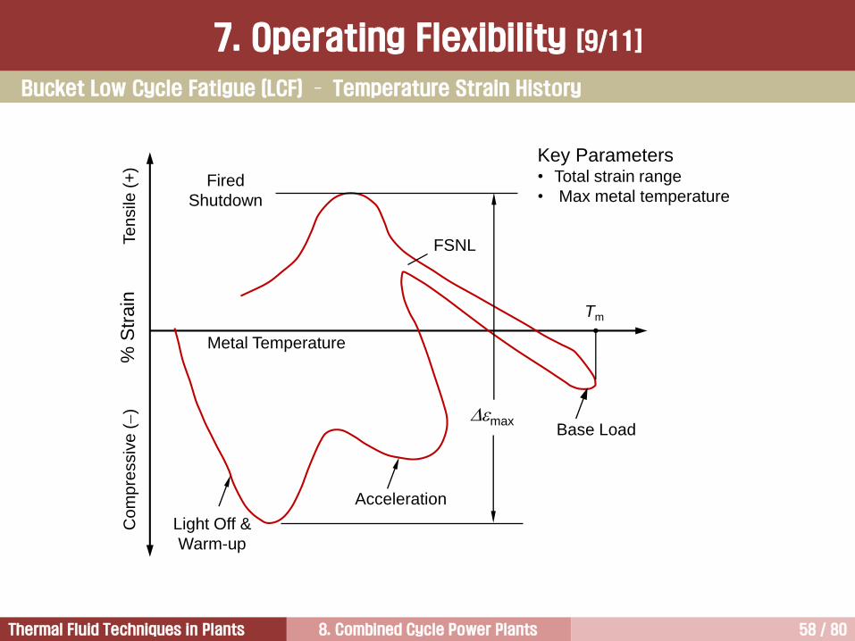
Light Off &
Warm-up
maxBase Load
Metal Temperature
Tm
FSNL
Fired
Shutdown
Acceleration
% S
train
Te
nsile
(+
)C
om
pre
ssiv
e ()
Key Parameters• Total strain range
• Max metal temperature
Bucket Low Cycle Fatigue (LCF) – Temperature Strain History
7. Operating Flexibility [9/11]

8. Combined Cycle Power Plants 59 / 80Thermal Fluid Techniques in Plants
Currently, short start-up and shutdown times are emphasized by customers because of high fuel price.
Especially, fast start-up is important for intermediate load application.
The important parameters should be considered for fast start-up are as follows:
• HRSG ramp capability
• Steam turbine ramp capability
• Piping warm up times
• Steam chemistry
• Steam turbine back-pressure limitations
7. Operating Flexibility [10/11]

8. Combined Cycle Power Plants 60 / 80Thermal Fluid Techniques in Plants
HRSG
There has also been a debate over the years whether the once-through HRSG technology should be better off
than drum boilers in terms of cycling.
GE
• Detailed transient analysis showed that the majority of fatigue life consumption occurs at
the hottest high pressure superheater and reheater during fast gas turbine loading,
regardless of whether the HRSG uses high pressure drum or once through technology.
• The HRSG stack is equipped with an automatic damper that closes upon plant shutdown to
reduce HRSG heat loss and the time required for next plant start-up, as well as reduce the
cyclic stress of the start.
Siemens
• Once-through HRSG eliminates the thick wall HP drum and allows an unrestricted gas
turbine start-up.
a. gas turbine start-up produces rapid boiling in the evaporator
b. if water level in the drum rises to the separators, water carry over into the superheater
may occur
c. the typical response to this is to either trip or slow gas turbine load ramp
It is hard to conclude that which one is better in terms of operating flexibility.
7. Operating Flexibility [11/11]
8. Combined Cycle Power Plants 61 / 80Thermal Fluid Techniques in Plants
8. Lower Emissions [1/3]
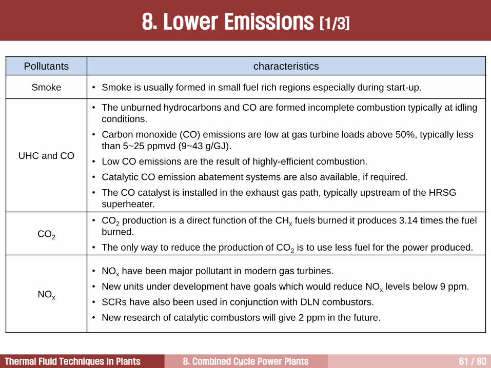
Pollutants characteristics
Smoke • Smoke is usually formed in small fuel rich regions especially during start-up.
UHC and CO
• The unburned hydrocarbons and CO are formed incomplete combustion typically at idling
conditions.
• Carbon monoxide (CO) emissions are low at gas turbine loads above 50%, typically less
than 5~25 ppmvd (9~43 g/GJ).
• Low CO emissions are the result of highly-efficient combustion.
• Catalytic CO emission abatement systems are also available, if required.
• The CO catalyst is installed in the exhaust gas path, typically upstream of the HRSG
superheater.
CO2
• CO2 production is a direct function of the CHx fuels burned it produces 3.14 times the fuel
burned.
• The only way to reduce the production of CO2 is to use less fuel for the power produced.
NOx
• NOx have been major pollutant in modern gas turbines.
• New units under development have goals which would reduce NOx levels below 9 ppm.
• SCRs have also been used in conjunction with DLN combustors.
• New research of catalytic combustors will give 2 ppm in the future.
8. Combined Cycle Power Plants 62 / 80Thermal Fluid Techniques in Plants
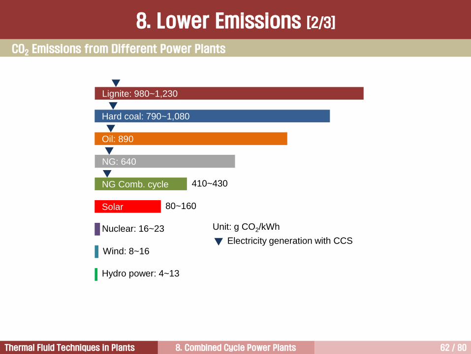
Lignite: 980~1,230
Hard coal: 790~1,080
Oil: 890
NG: 640
NG Comb. cycle
Unit: g CO2/kWh
410~430
Solar 80~160
Nuclear: 16~23
Wind: 8~16
Hydro power: 4~13
Electricity generation with CCS
CO2 Emissions from Different Power Plants
8. Lower Emissions [2/3]

8. Combined Cycle Power Plants 63 / 80Thermal Fluid Techniques in Plants
The CO2 emissions of the plant are having a more direct impact on the economics of a plant due to the
effort to globally limit these kinds of emissions.
The combined cycle plant emits about 40% of the CO2 of a coal-fired plant. This is driven by the higher
efficiency and the higher hydrogen content in natural gas.
Unfortunately, however, the relative lower CO2 content in the flue gas makes the separation process more
difficult, and may render in high separation tower heights to provide for sufficient residence time.
Another issue is the flue gas flow which is on the order of 1.5 kg/MW, compared to 0.95 kg/MW for than
advanced steam plants.
The cross section of the separation tower should provide for a velocity around 5 m/s. Therefore, a combined
cycle plant requires a higher and wider tower for CO2 capture plant compared to a coal fired plant.
No commercial full-scale technology for CO2 capture exists today and the road-maps towards feasible
solution are still not clear.
It has been expected that the efficiency of combined cycle power plant with CO2 capture plant will drop 8
percent for a GE 9FB.03 with a 3-pressure HRSG. This is because a lot of LP steam is required for solvent
regeneration.
Lower CO2 Emissions
8. Lower Emissions [3/3]
8. Combined Cycle Power Plants 64 / 80Thermal Fluid Techniques in Plants
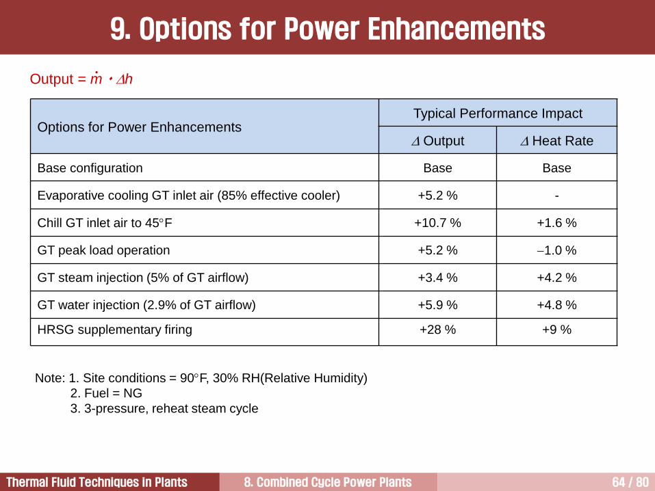
Options for Power EnhancementsTypical Performance Impact
Output Heat Rate
Base configuration Base Base
Evaporative cooling GT inlet air (85% effective cooler) +5.2 % -
Chill GT inlet air to 45F +10.7 % +1.6 %
GT peak load operation +5.2 % 1.0 %
GT steam injection (5% of GT airflow) +3.4 % +4.2 %
GT water injection (2.9% of GT airflow) +5.9 % +4.8 %
HRSG supplementary firing +28 % +9 %
Note: 1. Site conditions = 90F, 30% RH(Relative Humidity)
2. Fuel = NG
3. 3-pressure, reheat steam cycle
Output = m h•
9. Options for Power Enhancements

8. Combined Cycle Power Plants 65 / 80Thermal Fluid Techniques in Plants
BoilerFeedwater
Pump
Steam
Turbine
10 Meters
Comparison with Coal-Fired Power Plants
10. Compactness [1/8]
8. Combined Cycle Power Plants 66 / 80Thermal Fluid Techniques in Plants
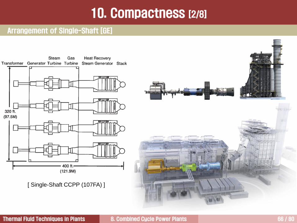
[ Single-Shaft CCPP (107FA) ]
Arrangement of Single-Shaft [GE]
10. Compactness [2/8]

8. Combined Cycle Power Plants 67 / 80Thermal Fluid Techniques in Plants
Arrangement of Multi-Shaft [207FA – GE]
10. Compactness [3/8]

8. Combined Cycle Power Plants 68 / 80Thermal Fluid Techniques in Plants
Single Shaft (1-on-1 configuration) Multiple Shaft (2-on-1 configuration)
ComponentsLess generator required
One compact lube oil system
One large ST instead of 2 smaller STs
Less auxiliaries (pumps etc) required
Civil Smaller plant area Higher flexibility in plant layout
Costs
Lower capital cost of plant because one
generator and one step-up transformer is
eliminated
Performance Same level in larger plantsSteam turbine has higher efficiency because
of larger steam volume flow
Operating
Flexibility
Suitable for daily start and stop (DSS)
operationSuitable for base load operation
Availability Higher (less complexity)
Operation limit
Operation is limited to concurrent operation of
the gas turbine and steam turbine, unless the
steam turbine can be decoupled from the
generator through a clutch
The gas turbine can be decoupled from the
operation of the steam turbine, allowing for
steam turbine shutdown with continued gas
turbine operation
10. Compactness [4/8]

8. Combined Cycle Power Plants 69 / 80Thermal Fluid Techniques in Plants
Arrangement of Single-Shaft [Siemens]
10. Compactness [5/8]

8. Combined Cycle Power Plants 70 / 80Thermal Fluid Techniques in Plants
Single-shaft with generator between gas turbine and steam turbine enables installation of a clutch between
steam turbine and generator.
One problem of a Jaw clutch, which was used previously, is that it can only be engaged when the gas turbine
is at rest. This means that in the event of a failed gas turbine start, the operator must wait until the gas
turbine is stationary before engaging the jaw clutch to re-start.
Currently, SSS(Synchronous Self-Shifting) clutch has been employed popularly. The SSS clutch engages in
that moment when the steam turbine speed tries to overrun the rigidly coupled gas turbine generator and
disengages if the torque transmitted from the steam turbine to the generator becomes zero.
The clutch allows startup and operation of gas turbine without driving the steam turbine.
This results in a lower starting power and eliminates certain safety measures for the steam turbine, such as
cooling steam or sealing steam.
The clutch also provides design opportunities for accommodating axial thermal expansion.
However, the clutch is an additional component with a potential impact on availability. Additionally, the
generator located at the end of the line of shafting has advantages during generator overhaul.
Single-shaft units without a clutch definitely need auxiliary steam supply to cool the steam turbine during
startup. This is not necessary in units with a clutch.
Single-Shaft
10. Compactness [6/8]
8. Combined Cycle Power Plants 71 / 80Thermal Fluid Techniques in Plants
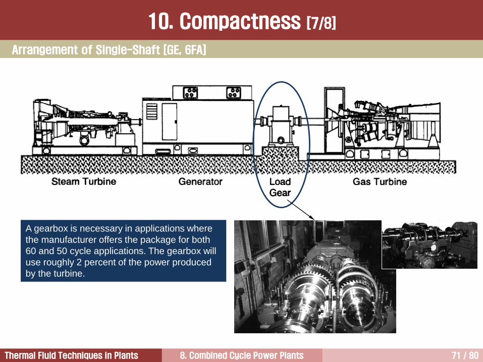
A gearbox is necessary in applications where
the manufacturer offers the package for both
60 and 50 cycle applications. The gearbox will
use roughly 2 percent of the power produced
by the turbine.
Arrangement of Single-Shaft [GE, 6FA]
10. Compactness [7/8]
8. Combined Cycle Power Plants 72 / 80Thermal Fluid Techniques in Plants
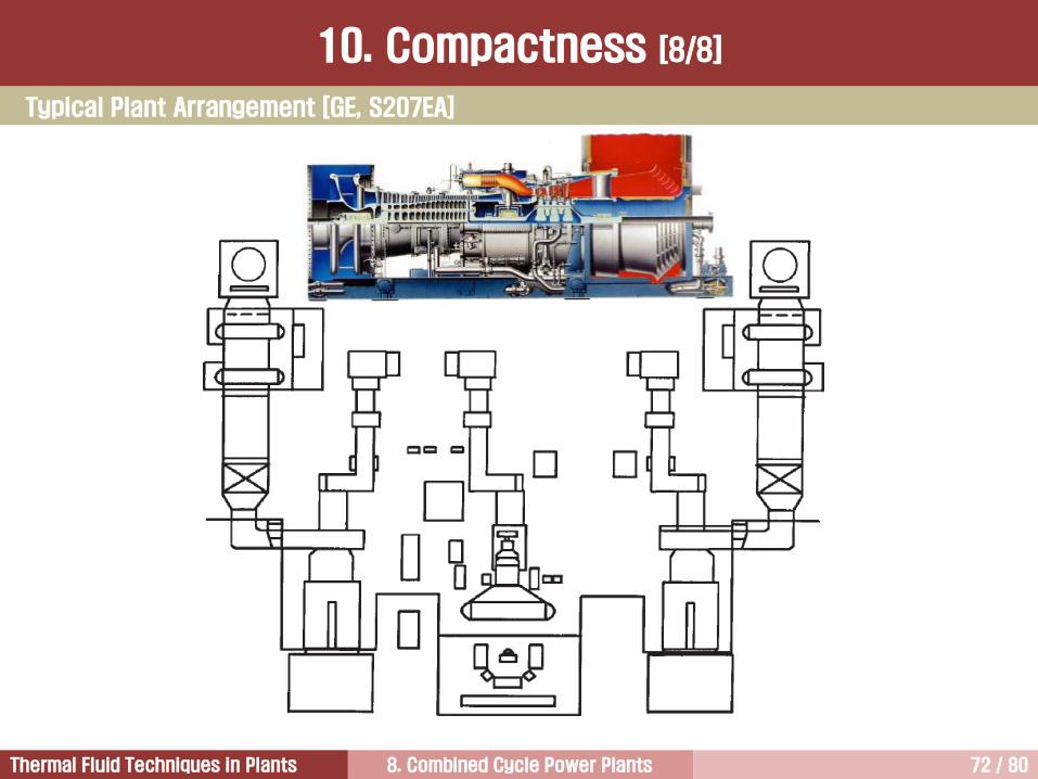
Typical Plant Arrangement [GE, S207EA]
10. Compactness [8/8]

8. Combined Cycle Power Plants 73 / 80Thermal Fluid Techniques in Plants
Cost of Electricity 3
Wide Use of Gas Turbine 5
Introduction to Combined Cycle Power Plants1
Electricity Demand and Supply2
Characteristics of Combined Cycle Power Plants 4

8. Combined Cycle Power Plants 74 / 80Thermal Fluid Techniques in Plants
Cogeneration means the simultaneous production of electricity and thermal energy in the same plants.
The thermal energy is usually steam or hot water.
The types of cogeneration plants:
① Industrial power stations supplying heat to an industrial process
② District heating power plants
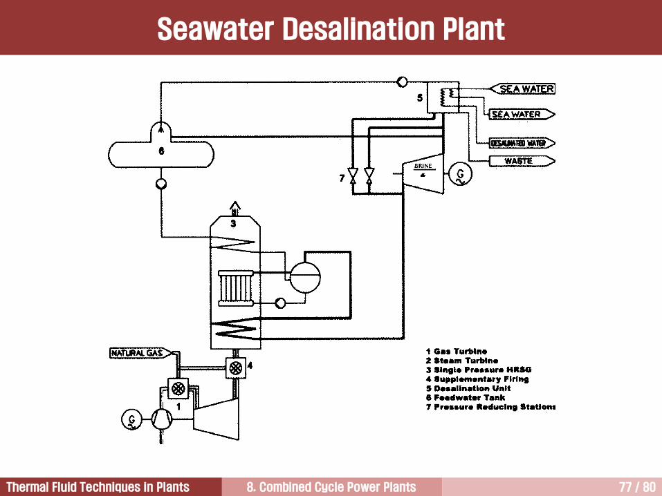
③ Power plants coupled to seawater desalination plants
The supplementary firing in the HRSG gives greater design and operating flexibility, but the cycle efficiency
is normally lower if supplementary firing is used.
Thermal energy in the form of steam can be extracted from HRSG, or from an extraction in the steam
turbine.
The power coefficient (also called the alpha-value) is defined as the ratio between the electrical and the
thermal output.
Fuel utilization is a measure of how much of the fuel supplied is usefully used in the plant. It is equal to the
sum of electrical output and thermal output divided by the fuel input.
Cogeneration [1/3]

8. Combined Cycle Power Plants 75 / 80Thermal Fluid Techniques in Plants
Single Pressure
Supplementary Firing
Backpressure Turbine
Heat Balance
Cogeneration [2/3]

8. Combined Cycle Power Plants 76 / 80Thermal Fluid Techniques in Plants
In the simplest arrangements, the
gas turbine waste heat is used
directly in an industrial process,
such as for drying in a paper mill,
or cement works.
Adding an HRSG converting
waste heat into steam, gives
greater flexibilities in the process
for chemical industries, or district
heating
CHP; Combined Heat and Power
Cogeneration [3/3]
8. Combined Cycle Power Plants 77 / 80Thermal Fluid Techniques in Plants
Seawater Desalination Plant

8. Combined Cycle Power Plants 78 / 80Thermal Fluid Techniques in Plants
IGCC

8. Combined Cycle Power Plants 79 / 80Thermal Fluid Techniques in Plants
Combined cycle plants are very well suited to rapid load changes because gas turbine react extremely
quickly to frequency variations.
As soon as fuel valve opens, more added power becomes available on the shaft and gas turbine load jumps
of up to 35% are possible, but this is detrimental to the life expectancy of the turbine blades.
To perform a plant load jump while the frequency is falling, it is essential that gas turbine is operating below
the maximum output level.
For frequency support gas turbines are typically operated between 50 and 95% load.
The electrical output of the combined cycle power plants is controlled by means of gas turbine only. This is
because the gas turbine generates two-thirds of the total power output, a solution without control for the
steam turbine power output is generally preferred.
The gas turbine output is controlled by a combination of VIGV and TIT control.
The TIT is controlled by a combination of the fuel flow into the combustor and VIGV setting.
VIGVs allows a high gas turbine exhaust temperature down to approximately 40% GT load. Below this level,
TIT is further reduced because the airflow cannot be further reduced.
The steam turbine will always follow the gas turbine by generating power with whatever steam is available.
Load Control & Frequency Response

8. Combined Cycle Power Plants 80 / 80Thermal Fluid Techniques in Plants
질의 및 응답
작성자: 이 병 은 (공학박사)작성일: 2016.02.15 (Ver.1)연락처: [email protected]
Mobile: 010-3122-2262저서: 실무 발전설비 열역학/증기터빈 열유체기술