8: nonlinear components - imperial college london diode 8: nonlinear components •ideal diode...
TRANSCRIPT

8: Nonlinear Components
8: Nonlinear Components
• Ideal Diode
• Operating modes
• Switching Point
• Bridge Rectifier
• Non-Ideal Diode
• Halfwave Rectifier• Precision HalfwaveRectifier
• Summary
E1.1 Analysis of Circuits (2017-10117) Nonlinear Components: 8 – 1 / 9
Ideal Diode
8: Nonlinear Components
• Ideal Diode
• Operating modes
• Switching Point
• Bridge Rectifier
• Non-Ideal Diode
• Halfwave Rectifier• Precision HalfwaveRectifier
• Summary
E1.1 Analysis of Circuits (2017-10117) Nonlinear Components: 8 – 2 / 9
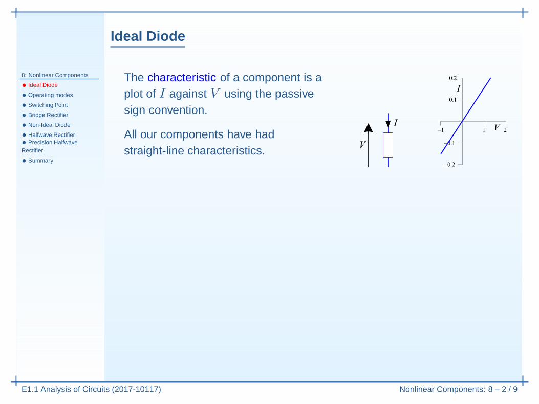
The characteristic of a component is aplot of I against V using the passivesign convention.
All our components have hadstraight-line characteristics.

Ideal Diode
8: Nonlinear Components
• Ideal Diode
• Operating modes
• Switching Point
• Bridge Rectifier
• Non-Ideal Diode
• Halfwave Rectifier• Precision HalfwaveRectifier
• Summary
E1.1 Analysis of Circuits (2017-10117) Nonlinear Components: 8 – 2 / 9
The characteristic of a component is aplot of I against V using the passivesign convention.
All our components have hadstraight-line characteristics.
An ideal diode allows current to flow in onedirection only.
Its characteristic is not a straight line, but ismade from two straight line segments:piecewise-linear .

Ideal Diode
8: Nonlinear Components
• Ideal Diode
• Operating modes
• Switching Point
• Bridge Rectifier
• Non-Ideal Diode
• Halfwave Rectifier• Precision HalfwaveRectifier
• Summary
E1.1 Analysis of Circuits (2017-10117) Nonlinear Components: 8 – 2 / 9
The characteristic of a component is aplot of I against V using the passivesign convention.
All our components have hadstraight-line characteristics.
An ideal diode allows current to flow in onedirection only.
Its characteristic is not a straight line, but ismade from two straight line segments:piecewise-linear . Each segment is a mode ofoperation.
Each mode applies only when a particular condition is true:
Mode Condition EquationConducting (or “forward bias” or “on”) I > 0 V = 0
Non-conducting (or “reverse bias” or “off”) V < 0 I = 0

Operating modes
8: Nonlinear Components
• Ideal Diode
• Operating modes
• Switching Point
• Bridge Rectifier
• Non-Ideal Diode
• Halfwave Rectifier• Precision HalfwaveRectifier
• Summary
E1.1 Analysis of Circuits (2017-10117) Nonlinear Components: 8 – 3 / 9
To analyse a circuit with a diode in it, you first guess which mode it isoperating in, solve the circuit and then check the condition.If you guessed wrongly, the condition will not be met.
Mode Condition Equation
Conducting I > 0 VD = 0
Non-conducting VD < 0 I = 0
Voltage across diode is VD = U −X .Current through diode is I = X
2mA.
Assume Conducting Mode ⇒ VD = 0

Operating modes
8: Nonlinear Components
• Ideal Diode
• Operating modes
• Switching Point
• Bridge Rectifier
• Non-Ideal Diode
• Halfwave Rectifier• Precision HalfwaveRectifier
• Summary
E1.1 Analysis of Circuits (2017-10117) Nonlinear Components: 8 – 3 / 9
To analyse a circuit with a diode in it, you first guess which mode it isoperating in, solve the circuit and then check the condition.If you guessed wrongly, the condition will not be met.
Mode Condition Equation
Conducting I > 0 VD = 0
Non-conducting VD < 0 I = 0
Voltage across diode is VD = U −X .Current through diode is I = X
2mA.
Assume Conducting Mode ⇒ VD = 0VD = 0

Operating modes
8: Nonlinear Components
• Ideal Diode
• Operating modes
• Switching Point
• Bridge Rectifier
• Non-Ideal Diode
• Halfwave Rectifier• Precision HalfwaveRectifier
• Summary
E1.1 Analysis of Circuits (2017-10117) Nonlinear Components: 8 – 3 / 9
To analyse a circuit with a diode in it, you first guess which mode it isoperating in, solve the circuit and then check the condition.If you guessed wrongly, the condition will not be met.
Mode Condition Equation
Conducting I > 0 VD = 0
Non-conducting VD < 0 I = 0
Voltage across diode is VD = U −X .Current through diode is I = X
2mA.
Assume Conducting Mode ⇒ VD = 0VD = 0⇒ X = U = −6

Operating modes
8: Nonlinear Components
• Ideal Diode
• Operating modes
• Switching Point
• Bridge Rectifier
• Non-Ideal Diode
• Halfwave Rectifier• Precision HalfwaveRectifier
• Summary
E1.1 Analysis of Circuits (2017-10117) Nonlinear Components: 8 – 3 / 9
To analyse a circuit with a diode in it, you first guess which mode it isoperating in, solve the circuit and then check the condition.If you guessed wrongly, the condition will not be met.
Mode Condition Equation
Conducting I > 0 VD = 0
Non-conducting VD < 0 I = 0
Voltage across diode is VD = U −X .Current through diode is I = X
2mA.
Assume Conducting Mode ⇒ VD = 0VD = 0⇒ X = U = −6⇒ I = −3

Operating modes
8: Nonlinear Components
• Ideal Diode
• Operating modes
• Switching Point
• Bridge Rectifier
• Non-Ideal Diode
• Halfwave Rectifier• Precision HalfwaveRectifier
• Summary
E1.1 Analysis of Circuits (2017-10117) Nonlinear Components: 8 – 3 / 9
To analyse a circuit with a diode in it, you first guess which mode it isoperating in, solve the circuit and then check the condition.If you guessed wrongly, the condition will not be met.
Mode Condition Equation
Conducting I > 0 VD = 0
Non-conducting VD < 0 I = 0
Voltage across diode is VD = U −X .Current through diode is I = X
2mA.
Assume Conducting Mode ⇒ VD = 0VD = 0⇒ X = U = −6⇒ I = −3but condition is I > 0 so bad guess
Assume Non-conducting Mode ⇒ I = 0

Operating modes
8: Nonlinear Components
• Ideal Diode
• Operating modes
• Switching Point
• Bridge Rectifier
• Non-Ideal Diode
• Halfwave Rectifier• Precision HalfwaveRectifier
• Summary
E1.1 Analysis of Circuits (2017-10117) Nonlinear Components: 8 – 3 / 9
To analyse a circuit with a diode in it, you first guess which mode it isoperating in, solve the circuit and then check the condition.If you guessed wrongly, the condition will not be met.
Mode Condition Equation
Conducting I > 0 VD = 0
Non-conducting VD < 0 I = 0
Voltage across diode is VD = U −X .Current through diode is I = X
2mA.
Assume Conducting Mode ⇒ VD = 0VD = 0⇒ X = U = −6⇒ I = −3but condition is I > 0 so bad guess
Assume Non-conducting Mode ⇒ I = 0I = 0

Operating modes
8: Nonlinear Components
• Ideal Diode
• Operating modes
• Switching Point
• Bridge Rectifier
• Non-Ideal Diode
• Halfwave Rectifier• Precision HalfwaveRectifier
• Summary
E1.1 Analysis of Circuits (2017-10117) Nonlinear Components: 8 – 3 / 9
To analyse a circuit with a diode in it, you first guess which mode it isoperating in, solve the circuit and then check the condition.If you guessed wrongly, the condition will not be met.
Mode Condition Equation
Conducting I > 0 VD = 0
Non-conducting VD < 0 I = 0
Voltage across diode is VD = U −X .Current through diode is I = X
2mA.
Assume Conducting Mode ⇒ VD = 0VD = 0⇒ X = U = −6⇒ I = −3but condition is I > 0 so bad guess
Assume Non-conducting Mode ⇒ I = 0I = 0⇒ X = 2I = 0

Operating modes
8: Nonlinear Components
• Ideal Diode
• Operating modes
• Switching Point
• Bridge Rectifier
• Non-Ideal Diode
• Halfwave Rectifier• Precision HalfwaveRectifier
• Summary
E1.1 Analysis of Circuits (2017-10117) Nonlinear Components: 8 – 3 / 9
To analyse a circuit with a diode in it, you first guess which mode it isoperating in, solve the circuit and then check the condition.If you guessed wrongly, the condition will not be met.
Mode Condition Equation
Conducting I > 0 VD = 0
Non-conducting VD < 0 I = 0
Voltage across diode is VD = U −X .Current through diode is I = X
2mA.
Assume Conducting Mode ⇒ VD = 0VD = 0⇒ X = U = −6⇒ I = −3but condition is I > 0 so bad guess
Assume Non-conducting Mode ⇒ I = 0I = 0⇒ X = 2I = 0⇒ VD = U −X = −6

Operating modes
8: Nonlinear Components
• Ideal Diode
• Operating modes
• Switching Point
• Bridge Rectifier
• Non-Ideal Diode
• Halfwave Rectifier• Precision HalfwaveRectifier
• Summary
E1.1 Analysis of Circuits (2017-10117) Nonlinear Components: 8 – 3 / 9
To analyse a circuit with a diode in it, you first guess which mode it isoperating in, solve the circuit and then check the condition.If you guessed wrongly, the condition will not be met.
Mode Condition Equation
Conducting I > 0 VD = 0
Non-conducting VD < 0 I = 0
Voltage across diode is VD = U −X .Current through diode is I = X
2mA.
Assume Conducting Mode ⇒ VD = 0VD = 0⇒ X = U = −6⇒ I = −3but condition is I > 0 so bad guess
Assume Non-conducting Mode ⇒ I = 0I = 0⇒ X = 2I = 0⇒ VD = U −X = −6condition is VD < 0 so good guess
Current flows from anode to cathode.

Switching Point
8: Nonlinear Components
• Ideal Diode
• Operating modes
• Switching Point
• Bridge Rectifier
• Non-Ideal Diode
• Halfwave Rectifier• Precision HalfwaveRectifier
• Summary
E1.1 Analysis of Circuits (2017-10117) Nonlinear Components: 8 – 4 / 9
How does X change with U ?

Switching Point
8: Nonlinear Components
• Ideal Diode
• Operating modes
• Switching Point
• Bridge Rectifier
• Non-Ideal Diode
• Halfwave Rectifier• Precision HalfwaveRectifier
• Summary
E1.1 Analysis of Circuits (2017-10117) Nonlinear Components: 8 – 4 / 9
How does X change with U ?
Voltage across diode is VD = Y − 3.Current through diode is ID = X−Y
1mA.
Assume Conducting Mode ⇒ Y = 3
KCL: X−U4
+ X−3
1+ X
4= 0
⇒ X = 1
6U + 2
0 5 10
0
2
4
U (Volts)

Switching Point
8: Nonlinear Components
• Ideal Diode
• Operating modes
• Switching Point
• Bridge Rectifier
• Non-Ideal Diode
• Halfwave Rectifier• Precision HalfwaveRectifier
• Summary
E1.1 Analysis of Circuits (2017-10117) Nonlinear Components: 8 – 4 / 9
How does X change with U ?
Voltage across diode is VD = Y − 3.Current through diode is ID = X−Y
1mA.
Assume Conducting Mode ⇒ Y = 3
KCL: X−U4
+ X−3
1+ X
4= 0
⇒ X = 1
6U + 2
ID = X−3
1= 1
6U − 1
ID > 0 ⇔ U > 6
Assume Non-conducting Mode⇒ ID = 0
Potential Div: X = Y = 1
2U
VD = Y − 3 = 1
2U − 3
VD < 0 ⇔ U < 60 5 10
0
2
4
U (Volts)
Diode switches between regions where the graphs intersect (U = 6).At this point both the diode equations, VD = 0 and ID = 0, are true.

Bridge Rectifier
8: Nonlinear Components
• Ideal Diode
• Operating modes
• Switching Point
• Bridge Rectifier
• Non-Ideal Diode
• Halfwave Rectifier• Precision HalfwaveRectifier
• Summary
E1.1 Analysis of Circuits (2017-10117) Nonlinear Components: 8 – 5 / 9
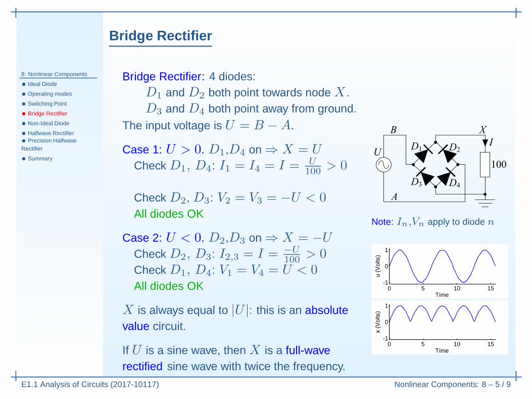
Bridge Rectifier: 4 diodes:D1 and D2 both point towards node X .D3 and D4 both point away from ground.
The input voltage is U = B −A.

Bridge Rectifier
8: Nonlinear Components
• Ideal Diode
• Operating modes
• Switching Point
• Bridge Rectifier
• Non-Ideal Diode
• Halfwave Rectifier• Precision HalfwaveRectifier
• Summary
E1.1 Analysis of Circuits (2017-10117) Nonlinear Components: 8 – 5 / 9
Bridge Rectifier: 4 diodes:D1 and D2 both point towards node X .D3 and D4 both point away from ground.
The input voltage is U = B −A.
Case 1: U > 0.

Bridge Rectifier
8: Nonlinear Components
• Ideal Diode
• Operating modes
• Switching Point
• Bridge Rectifier
• Non-Ideal Diode
• Halfwave Rectifier• Precision HalfwaveRectifier
• Summary
E1.1 Analysis of Circuits (2017-10117) Nonlinear Components: 8 – 5 / 9
Bridge Rectifier: 4 diodes:D1 and D2 both point towards node X .D3 and D4 both point away from ground.
The input voltage is U = B −A.
Case 1: U > 0. D1,D4 on ⇒ X = U
Check D1, D4: I1 = I4 = I = U100
> 0
Note: In,Vn apply to diode n

Bridge Rectifier
8: Nonlinear Components
• Ideal Diode
• Operating modes
• Switching Point
• Bridge Rectifier
• Non-Ideal Diode
• Halfwave Rectifier• Precision HalfwaveRectifier
• Summary
E1.1 Analysis of Circuits (2017-10117) Nonlinear Components: 8 – 5 / 9
Bridge Rectifier: 4 diodes:D1 and D2 both point towards node X .D3 and D4 both point away from ground.
The input voltage is U = B −A.
Case 1: U > 0. D1,D4 on ⇒ X = U
Check D1, D4: I1 = I4 = I = U100
> 0
Check D2, D3: V2 = V3 = −U < 0
Note: In,Vn apply to diode n

Bridge Rectifier
8: Nonlinear Components
• Ideal Diode
• Operating modes
• Switching Point
• Bridge Rectifier
• Non-Ideal Diode
• Halfwave Rectifier• Precision HalfwaveRectifier
• Summary
E1.1 Analysis of Circuits (2017-10117) Nonlinear Components: 8 – 5 / 9
Bridge Rectifier: 4 diodes:D1 and D2 both point towards node X .D3 and D4 both point away from ground.
The input voltage is U = B −A.
Case 1: U > 0. D1,D4 on ⇒ X = U
Check D1, D4: I1 = I4 = I = U100
> 0
Check D2, D3: V2 = V3 = −U < 0All diodes OK
Case 2: U < 0.
Note: In,Vn apply to diode n

Bridge Rectifier
8: Nonlinear Components
• Ideal Diode
• Operating modes
• Switching Point
• Bridge Rectifier
• Non-Ideal Diode
• Halfwave Rectifier• Precision HalfwaveRectifier
• Summary
E1.1 Analysis of Circuits (2017-10117) Nonlinear Components: 8 – 5 / 9
Bridge Rectifier: 4 diodes:D1 and D2 both point towards node X .D3 and D4 both point away from ground.
The input voltage is U = B −A.
Case 1: U > 0. D1,D4 on ⇒ X = U
Check D1, D4: I1 = I4 = I = U100
> 0
Check D2, D3: V2 = V3 = −U < 0All diodes OK
Case 2: U < 0. D2,D3 on ⇒ X = −U
Check D2, D3: I2,3 = I = −U100
> 0
Note: In,Vn apply to diode n

Bridge Rectifier
8: Nonlinear Components
• Ideal Diode
• Operating modes
• Switching Point
• Bridge Rectifier
• Non-Ideal Diode
• Halfwave Rectifier• Precision HalfwaveRectifier
• Summary
E1.1 Analysis of Circuits (2017-10117) Nonlinear Components: 8 – 5 / 9
Bridge Rectifier: 4 diodes:D1 and D2 both point towards node X .D3 and D4 both point away from ground.
The input voltage is U = B −A.
Case 1: U > 0. D1,D4 on ⇒ X = U
Check D1, D4: I1 = I4 = I = U100
> 0
Check D2, D3: V2 = V3 = −U < 0All diodes OK
Case 2: U < 0. D2,D3 on ⇒ X = −U
Check D2, D3: I2,3 = I = −U100
> 0Check D1, D4: V1 = V4 = U < 0
Note: In,Vn apply to diode n

Bridge Rectifier
8: Nonlinear Components
• Ideal Diode
• Operating modes
• Switching Point
• Bridge Rectifier
• Non-Ideal Diode
• Halfwave Rectifier• Precision HalfwaveRectifier
• Summary
E1.1 Analysis of Circuits (2017-10117) Nonlinear Components: 8 – 5 / 9
Bridge Rectifier: 4 diodes:D1 and D2 both point towards node X .D3 and D4 both point away from ground.
The input voltage is U = B −A.
Case 1: U > 0. D1,D4 on ⇒ X = U
Check D1, D4: I1 = I4 = I = U100
> 0
Check D2, D3: V2 = V3 = −U < 0All diodes OK
Case 2: U < 0. D2,D3 on ⇒ X = −U
Check D2, D3: I2,3 = I = −U100
> 0Check D1, D4: V1 = V4 = U < 0All diodes OK
X is always equal to |U |: this is an absolutevalue circuit.
If U is a sine wave,
Note: In,Vn apply to diode n
0 5 10 15-1
0
1
Time
Bridge Rectifier
8: Nonlinear Components
• Ideal Diode
• Operating modes
• Switching Point
• Bridge Rectifier
• Non-Ideal Diode
• Halfwave Rectifier• Precision HalfwaveRectifier
• Summary
E1.1 Analysis of Circuits (2017-10117) Nonlinear Components: 8 – 5 / 9
Bridge Rectifier: 4 diodes:D1 and D2 both point towards node X .D3 and D4 both point away from ground.
The input voltage is U = B −A.
Case 1: U > 0. D1,D4 on ⇒ X = U
Check D1, D4: I1 = I4 = I = U100
> 0
Check D2, D3: V2 = V3 = −U < 0All diodes OK
Case 2: U < 0. D2,D3 on ⇒ X = −U
Check D2, D3: I2,3 = I = −U100
> 0Check D1, D4: V1 = V4 = U < 0All diodes OK
X is always equal to |U |: this is an absolutevalue circuit.
If U is a sine wave, then X is a full-waverectified sine wave with twice the frequency.
Note: In,Vn apply to diode n
0 5 10 15-1
0
1
Time
0 5 10 15-1
0
1
Time

Non-Ideal Diode
8: Nonlinear Components
• Ideal Diode
• Operating modes
• Switching Point
• Bridge Rectifier
• Non-Ideal Diode
• Halfwave Rectifier• Precision HalfwaveRectifier
• Summary
E1.1 Analysis of Circuits (2017-10117) Nonlinear Components: 8 – 6 / 9
An ideal diode allows hasV = 0 whenever it is “on”.
A real diode has a voltage drop that depends approximately logarithmicallyon the current: it increases by about 0.1V for every 50-fold increase incurrent.
For a wide range of currents we can treat V as almost constant:

Non-Ideal Diode
8: Nonlinear Components
• Ideal Diode
• Operating modes
• Switching Point
• Bridge Rectifier
• Non-Ideal Diode
• Halfwave Rectifier• Precision HalfwaveRectifier
• Summary
E1.1 Analysis of Circuits (2017-10117) Nonlinear Components: 8 – 6 / 9
An ideal diode allows hasV = 0 whenever it is “on”.
A real diode has a voltage drop that depends approximately logarithmicallyon the current: it increases by about 0.1V for every 50-fold increase incurrent.
For a wide range of currents we can treat V as almost constant:(a) For low-current circuits (e.g I < 20mA): V ≃ 0.7V.

Non-Ideal Diode
8: Nonlinear Components
• Ideal Diode
• Operating modes
• Switching Point
• Bridge Rectifier
• Non-Ideal Diode
• Halfwave Rectifier• Precision HalfwaveRectifier
• Summary
E1.1 Analysis of Circuits (2017-10117) Nonlinear Components: 8 – 6 / 9
An ideal diode allows hasV = 0 whenever it is “on”.
A real diode has a voltage drop that depends approximately logarithmicallyon the current: it increases by about 0.1V for every 50-fold increase incurrent.
For a wide range of currents we can treat V as almost constant:(a) For low-current circuits (e.g I < 20mA): V ≃ 0.7V.(b) For high-current circuits: V ≃ 1.0V.
The two regions of operation are now:
Region Condition EquationConducting Mode (“on”) I > 0 V = 0.7
Non-conducting Mode (“off”) V < 0.7 I = 0

Halfwave Rectifier
8: Nonlinear Components
• Ideal Diode
• Operating modes
• Switching Point
• Bridge Rectifier
• Non-Ideal Diode
• Halfwave Rectifier• Precision HalfwaveRectifier
• Summary
E1.1 Analysis of Circuits (2017-10117) Nonlinear Components: 8 – 7 / 9
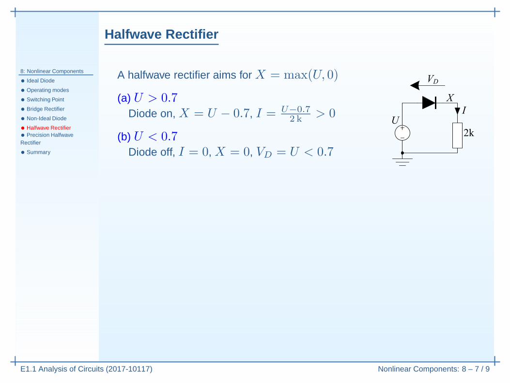
A halfwave rectifier aims for X = max(U, 0)

Halfwave Rectifier
8: Nonlinear Components
• Ideal Diode
• Operating modes
• Switching Point
• Bridge Rectifier
• Non-Ideal Diode
• Halfwave Rectifier• Precision HalfwaveRectifier
• Summary
E1.1 Analysis of Circuits (2017-10117) Nonlinear Components: 8 – 7 / 9
A halfwave rectifier aims for X = max(U, 0)
(a) U > 0.7Diode on, X = U − 0.7, I = U−0.7
2 k> 0
(b) U < 0.7Diode off, I = 0, X = 0, VD = U < 0.7
We actually have X = max(U − 0.7, 0)
(1) u(t) = 20 sinωtThe 0.7V drop makes littledifference.
0 5 10 15 20-20
0
20
Time

Halfwave Rectifier
8: Nonlinear Components
• Ideal Diode
• Operating modes
• Switching Point
• Bridge Rectifier
• Non-Ideal Diode
• Halfwave Rectifier• Precision HalfwaveRectifier
• Summary
E1.1 Analysis of Circuits (2017-10117) Nonlinear Components: 8 – 7 / 9
A halfwave rectifier aims for X = max(U, 0)
(a) U > 0.7Diode on, X = U − 0.7, I = U−0.7
2 k> 0
(b) U < 0.7Diode off, I = 0, X = 0, VD = U < 0.7
We actually have X = max(U − 0.7, 0)
(1) u(t) = 20 sinωtThe 0.7V drop makes littledifference.
(2) u(t) = sinωtThe 0.7V drop makes a bigdifference.
0 5 10 15 20-20
0
20
Time
0 5 10 15 20-1
0
1
Time

Precision Halfwave Rectifier
8: Nonlinear Components
• Ideal Diode
• Operating modes
• Switching Point
• Bridge Rectifier
• Non-Ideal Diode
• Halfwave Rectifier• Precision HalfwaveRectifier
• Summary
E1.1 Analysis of Circuits (2017-10117) Nonlinear Components: 8 – 8 / 9
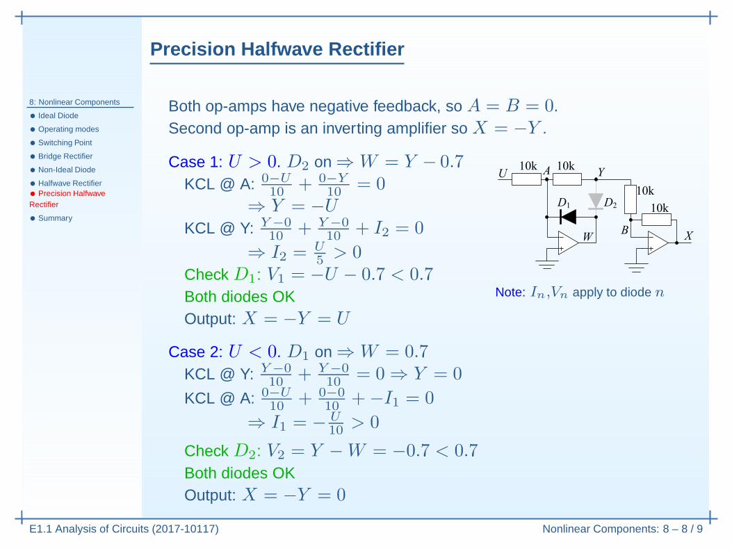
Both op-amps have negative feedback, so A = B = 0.Second op-amp is an inverting amplifier so X = −Y .

Precision Halfwave Rectifier
8: Nonlinear Components
• Ideal Diode
• Operating modes
• Switching Point
• Bridge Rectifier
• Non-Ideal Diode
• Halfwave Rectifier• Precision HalfwaveRectifier
• Summary
E1.1 Analysis of Circuits (2017-10117) Nonlinear Components: 8 – 8 / 9
Both op-amps have negative feedback, so A = B = 0.Second op-amp is an inverting amplifier so X = −Y .
Case 1: U > 0.

Precision Halfwave Rectifier
8: Nonlinear Components
• Ideal Diode
• Operating modes
• Switching Point
• Bridge Rectifier
• Non-Ideal Diode
• Halfwave Rectifier• Precision HalfwaveRectifier
• Summary
E1.1 Analysis of Circuits (2017-10117) Nonlinear Components: 8 – 8 / 9
Both op-amps have negative feedback, so A = B = 0.Second op-amp is an inverting amplifier so X = −Y .
Case 1: U > 0. D2 on ⇒ W = Y − 0.7

Precision Halfwave Rectifier
8: Nonlinear Components
• Ideal Diode
• Operating modes
• Switching Point
• Bridge Rectifier
• Non-Ideal Diode
• Halfwave Rectifier• Precision HalfwaveRectifier
• Summary
E1.1 Analysis of Circuits (2017-10117) Nonlinear Components: 8 – 8 / 9
Both op-amps have negative feedback, so A = B = 0.Second op-amp is an inverting amplifier so X = −Y .
Case 1: U > 0. D2 on ⇒ W = Y − 0.7KCL @ A: 0−U
10+ 0−Y
10= 0
⇒ Y = −U
KCL @ Y: Y−0
10+ Y−0
10+ I2 = 0
⇒ I2 = U5> 0
Note: In,Vn apply to diode n

Precision Halfwave Rectifier
8: Nonlinear Components
• Ideal Diode
• Operating modes
• Switching Point
• Bridge Rectifier
• Non-Ideal Diode
• Halfwave Rectifier• Precision HalfwaveRectifier
• Summary
E1.1 Analysis of Circuits (2017-10117) Nonlinear Components: 8 – 8 / 9
Both op-amps have negative feedback, so A = B = 0.Second op-amp is an inverting amplifier so X = −Y .
Case 1: U > 0. D2 on ⇒ W = Y − 0.7KCL @ A: 0−U
10+ 0−Y
10= 0
⇒ Y = −U
KCL @ Y: Y−0
10+ Y−0
10+ I2 = 0
⇒ I2 = U5> 0
Check D1: V1 = −U − 0.7 < 0.7Note: In,Vn apply to diode n

Precision Halfwave Rectifier
8: Nonlinear Components
• Ideal Diode
• Operating modes
• Switching Point
• Bridge Rectifier
• Non-Ideal Diode
• Halfwave Rectifier• Precision HalfwaveRectifier
• Summary
E1.1 Analysis of Circuits (2017-10117) Nonlinear Components: 8 – 8 / 9
Both op-amps have negative feedback, so A = B = 0.Second op-amp is an inverting amplifier so X = −Y .
Case 1: U > 0. D2 on ⇒ W = Y − 0.7KCL @ A: 0−U
10+ 0−Y
10= 0
⇒ Y = −U
KCL @ Y: Y−0
10+ Y−0
10+ I2 = 0
⇒ I2 = U5> 0
Check D1: V1 = −U − 0.7 < 0.7Both diodes OK Note: In,Vn apply to diode n

Precision Halfwave Rectifier
8: Nonlinear Components
• Ideal Diode
• Operating modes
• Switching Point
• Bridge Rectifier
• Non-Ideal Diode
• Halfwave Rectifier• Precision HalfwaveRectifier
• Summary
E1.1 Analysis of Circuits (2017-10117) Nonlinear Components: 8 – 8 / 9
Both op-amps have negative feedback, so A = B = 0.Second op-amp is an inverting amplifier so X = −Y .
Case 1: U > 0. D2 on ⇒ W = Y − 0.7KCL @ A: 0−U
10+ 0−Y
10= 0
⇒ Y = −U
KCL @ Y: Y−0
10+ Y−0
10+ I2 = 0
⇒ I2 = U5> 0
Check D1: V1 = −U − 0.7 < 0.7Both diodes OKOutput: X = −Y = U
Note: In,Vn apply to diode n

Precision Halfwave Rectifier
8: Nonlinear Components
• Ideal Diode
• Operating modes
• Switching Point
• Bridge Rectifier
• Non-Ideal Diode
• Halfwave Rectifier• Precision HalfwaveRectifier
• Summary
E1.1 Analysis of Circuits (2017-10117) Nonlinear Components: 8 – 8 / 9
Both op-amps have negative feedback, so A = B = 0.Second op-amp is an inverting amplifier so X = −Y .
Case 1: U > 0. D2 on ⇒ W = Y − 0.7KCL @ A: 0−U
10+ 0−Y
10= 0
⇒ Y = −U
KCL @ Y: Y−0
10+ Y−0
10+ I2 = 0
⇒ I2 = U5> 0
Check D1: V1 = −U − 0.7 < 0.7Both diodes OKOutput: X = −Y = U
Case 2: U < 0.
Note: In,Vn apply to diode n

Precision Halfwave Rectifier
8: Nonlinear Components
• Ideal Diode
• Operating modes
• Switching Point
• Bridge Rectifier
• Non-Ideal Diode
• Halfwave Rectifier• Precision HalfwaveRectifier
• Summary
E1.1 Analysis of Circuits (2017-10117) Nonlinear Components: 8 – 8 / 9
Both op-amps have negative feedback, so A = B = 0.Second op-amp is an inverting amplifier so X = −Y .
Case 1: U > 0. D2 on ⇒ W = Y − 0.7KCL @ A: 0−U
10+ 0−Y
10= 0
⇒ Y = −U
KCL @ Y: Y−0
10+ Y−0
10+ I2 = 0
⇒ I2 = U5> 0
Check D1: V1 = −U − 0.7 < 0.7Both diodes OKOutput: X = −Y = U
Case 2: U < 0. D1 on ⇒ W = 0.7
Note: In,Vn apply to diode n

Precision Halfwave Rectifier
8: Nonlinear Components
• Ideal Diode
• Operating modes
• Switching Point
• Bridge Rectifier
• Non-Ideal Diode
• Halfwave Rectifier• Precision HalfwaveRectifier
• Summary
E1.1 Analysis of Circuits (2017-10117) Nonlinear Components: 8 – 8 / 9
Both op-amps have negative feedback, so A = B = 0.Second op-amp is an inverting amplifier so X = −Y .
Case 1: U > 0. D2 on ⇒ W = Y − 0.7KCL @ A: 0−U
10+ 0−Y
10= 0
⇒ Y = −U
KCL @ Y: Y−0
10+ Y−0
10+ I2 = 0
⇒ I2 = U5> 0
Check D1: V1 = −U − 0.7 < 0.7Both diodes OKOutput: X = −Y = U
Case 2: U < 0. D1 on ⇒ W = 0.7KCL @ Y: Y−0
10+ Y−0
10= 0 ⇒ Y = 0
KCL @ A: 0−U10
+ 0−0
10+−I1 = 0
⇒ I1 = − U10
> 0
Note: In,Vn apply to diode n
Check D2: V2 = Y −W = −0.7 < 0.7

Precision Halfwave Rectifier
8: Nonlinear Components
• Ideal Diode
• Operating modes
• Switching Point
• Bridge Rectifier
• Non-Ideal Diode
• Halfwave Rectifier• Precision HalfwaveRectifier
• Summary
E1.1 Analysis of Circuits (2017-10117) Nonlinear Components: 8 – 8 / 9
Both op-amps have negative feedback, so A = B = 0.Second op-amp is an inverting amplifier so X = −Y .
Case 1: U > 0. D2 on ⇒ W = Y − 0.7KCL @ A: 0−U
10+ 0−Y
10= 0
⇒ Y = −U
KCL @ Y: Y−0
10+ Y−0
10+ I2 = 0
⇒ I2 = U5> 0
Check D1: V1 = −U − 0.7 < 0.7Both diodes OKOutput: X = −Y = U
Case 2: U < 0. D1 on ⇒ W = 0.7KCL @ Y: Y−0
10+ Y−0
10= 0 ⇒ Y = 0
KCL @ A: 0−U10
+ 0−0
10+−I1 = 0
⇒ I1 = − U10
> 0
Note: In,Vn apply to diode n
Check D2: V2 = Y −W = −0.7 < 0.7Both diodes OK
Precision Halfwave Rectifier
8: Nonlinear Components
• Ideal Diode
• Operating modes
• Switching Point
• Bridge Rectifier
• Non-Ideal Diode
• Halfwave Rectifier• Precision HalfwaveRectifier
• Summary
E1.1 Analysis of Circuits (2017-10117) Nonlinear Components: 8 – 8 / 9
Both op-amps have negative feedback, so A = B = 0.Second op-amp is an inverting amplifier so X = −Y .
Case 1: U > 0. D2 on ⇒ W = Y − 0.7KCL @ A: 0−U
10+ 0−Y
10= 0
⇒ Y = −U
KCL @ Y: Y−0
10+ Y−0
10+ I2 = 0
⇒ I2 = U5> 0
Check D1: V1 = −U − 0.7 < 0.7Both diodes OKOutput: X = −Y = U
Case 2: U < 0. D1 on ⇒ W = 0.7KCL @ Y: Y−0
10+ Y−0
10= 0 ⇒ Y = 0
KCL @ A: 0−U10
+ 0−0
10+−I1 = 0
⇒ I1 = − U10
> 0
Note: In,Vn apply to diode n
Check D2: V2 = Y −W = −0.7 < 0.7Both diodes OKOutput: X = −Y = 0

Precision Halfwave Rectifier
8: Nonlinear Components
• Ideal Diode
• Operating modes
• Switching Point
• Bridge Rectifier
• Non-Ideal Diode
• Halfwave Rectifier• Precision HalfwaveRectifier
• Summary
E1.1 Analysis of Circuits (2017-10117) Nonlinear Components: 8 – 8 / 9
Both op-amps have negative feedback, so A = B = 0.Second op-amp is an inverting amplifier so X = −Y .
Case 1: U > 0. D2 on ⇒ W = Y − 0.7KCL @ A: 0−U
10+ 0−Y
10= 0
⇒ Y = −U
KCL @ Y: Y−0
10+ Y−0
10+ I2 = 0
⇒ I2 = U5> 0
Check D1: V1 = −U − 0.7 < 0.7Both diodes OKOutput: X = −Y = U
Case 2: U < 0. D1 on ⇒ W = 0.7KCL @ Y: Y−0
10+ Y−0
10= 0 ⇒ Y = 0
KCL @ A: 0−U10
+ 0−0
10+−I1 = 0
⇒ I1 = − U10
> 0
Note: In,Vn apply to diode n
So X = max(U, 0)
Putting diodes in a feedbackloop allows their voltagedrops to be eliminated.
Check D2: V2 = Y −W = −0.7 < 0.7Both diodes OKOutput: X = −Y = 0

Summary
8: Nonlinear Components
• Ideal Diode
• Operating modes
• Switching Point
• Bridge Rectifier
• Non-Ideal Diode
• Halfwave Rectifier• Precision HalfwaveRectifier
• Summary
E1.1 Analysis of Circuits (2017-10117) Nonlinear Components: 8 – 9 / 9
• Beware: a nonlinear circuit does not obey superposition
• Ideal diode:◦ Two regions of operation:
⊲ Conducting Mode ( = “on”): V = 0 and I > 0

Summary
8: Nonlinear Components
• Ideal Diode
• Operating modes
• Switching Point
• Bridge Rectifier
• Non-Ideal Diode
• Halfwave Rectifier• Precision HalfwaveRectifier
• Summary
E1.1 Analysis of Circuits (2017-10117) Nonlinear Components: 8 – 9 / 9
• Beware: a nonlinear circuit does not obey superposition
• Ideal diode:◦ Two regions of operation:
⊲ Conducting Mode ( = “on”): V = 0 and I > 0⊲ Non-conducting Mode ( = “off”): I = 0 and V < 0
• Solving a diode circuit:◦ (a) Guess region◦ (b) Solve circuit: assuming V = 0 or I = 0◦ (c) Check condition: either I > 0 or V < 0
• Real diode: V ≃ 0.7 in Conducting Mode (≃ 1.0 for high currents)
Summary
8: Nonlinear Components
• Ideal Diode
• Operating modes
• Switching Point
• Bridge Rectifier
• Non-Ideal Diode
• Halfwave Rectifier• Precision HalfwaveRectifier
• Summary
E1.1 Analysis of Circuits (2017-10117) Nonlinear Components: 8 – 9 / 9
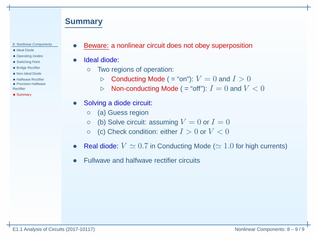
• Beware: a nonlinear circuit does not obey superposition
• Ideal diode:◦ Two regions of operation:
⊲ Conducting Mode ( = “on”): V = 0 and I > 0⊲ Non-conducting Mode ( = “off”): I = 0 and V < 0
• Solving a diode circuit:◦ (a) Guess region◦ (b) Solve circuit: assuming V = 0 or I = 0◦ (c) Check condition: either I > 0 or V < 0
• Real diode: V ≃ 0.7 in Conducting Mode (≃ 1.0 for high currents)
• Fullwave and halfwave rectifier circuits

Summary
8: Nonlinear Components
• Ideal Diode
• Operating modes
• Switching Point
• Bridge Rectifier
• Non-Ideal Diode
• Halfwave Rectifier• Precision HalfwaveRectifier
• Summary
E1.1 Analysis of Circuits (2017-10117) Nonlinear Components: 8 – 9 / 9
• Beware: a nonlinear circuit does not obey superposition
• Ideal diode:◦ Two regions of operation:
⊲ Conducting Mode ( = “on”): V = 0 and I > 0⊲ Non-conducting Mode ( = “off”): I = 0 and V < 0
• Solving a diode circuit:◦ (a) Guess region◦ (b) Solve circuit: assuming V = 0 or I = 0◦ (c) Check condition: either I > 0 or V < 0
• Real diode: V ≃ 0.7 in Conducting Mode (≃ 1.0 for high currents)
• Fullwave and halfwave rectifier circuits
• Precision Rectifier Circuit◦ Use an opamp to eliminate the 0.7V diode drop.
For further details see Irwin Ch 17.