8 - ohm_s law and kirchhoff_s circuit rules.v1.4!10!06
TRANSCRIPT

7/31/2019 8 - Ohm_s Law and Kirchhoff_s Circuit Rules.v1.4!10!06
http://slidepdf.com/reader/full/8-ohms-law-and-kirchhoffs-circuit-rulesv141006 1/22
Ohm’s Law and Kirchhoff’s Circuit Rules 71July 13
Name ___________________________ Date ____________ Partners__________________________________
OHM'S LAW ANDKIRCHHOFF’S CIRCUIT RULES
AMPS
VOLTS
+
-
OBJECTIVES
• To learn to apply the concept of potential difference (voltage) toexplain the action of a battery in a circuit.
• To understand how potential difference (voltage) is distributed indifferent parts of series and parallel circuits.
• To understand the quantitative relationship between potentialdifference and current for a resistor (Ohm's law).
• To examine Kirchhoff's circuit rules.
OVERVIEW
In a previous lab you explored currents at different points in series and parallel circuits. You saw that in a series circuit, the current is the
same through all elements. You also saw that in a parallel circuit, the
current divides among the branches so that the total current through
the battery equals the sum of the currents in each branch .
You have also observed that when two or more parallel branches areconnected directly across a battery, making a change in one branchdoes not affect the current in the other branch(es), while changing one part of a series circuit changes the current in all parts of that series
circuit.
In carrying out these observations of series and parallel circuits, youhave seen that connecting light bulbs in series results in a larger resistance to current and therefore a smaller current, while a parallelconnection results in a smaller resistance and larger current.
University of Virginia Physics Department Modified from P. Laws, D. Sokoloff, R. ThorntonPHYS 636, Summer 2006 Supported by National Science Foundation
and the U.S. Dept. of Education (FIPSE), 1993-2000

7/31/2019 8 - Ohm_s Law and Kirchhoff_s Circuit Rules.v1.4!10!06
http://slidepdf.com/reader/full/8-ohms-law-and-kirchhoffs-circuit-rulesv141006 2/22
72 Ohm’s Law & Kirchhoff's Circuit RulesJuly 13
In this lab, you will first examine the role of the battery in causing acurrent in a circuit. You will then compare the potential differences(voltages) across different parts of series and parallel circuits.
Based on your previous observations, you probably associate a larger resistance connected to a battery with a smaller current, and a smaller
resistance with a larger current. You will explore the quantitativerelationship between the current through a resistor and the potentialdifference (voltage) across the resistor. This relationship is known asOhm's law. You will then use Kirchhoff's circuit rules to completelysolve a DC circuit.
INVESTIGATION 1: BATTERIES AND VOLTAGES IN SERIES CIRCUITS
So far you have developed a current model and the concept of resistance to explain the relative brightness of bulbs in simple circuits.Your model says that when a battery is connected to a complete
circuit, there is a current. For a given battery, the magnitude of thecurrent depends on the total resistance of the circuit. In thisinvestigation you will explore batteries and the potential differences(voltages) between various points in circuits.
In order to do this you will need the following items:
• two voltage probes
• two 1.5 volt D batteries (must be very fresh, alkaline) andholders
• 6 wires with alligator clip leads
• two #14 bulbs in sockets
• contact switch
You have already seen what happens to the brightness of the bulb incircuit 1-1(a) if you add a second bulb in series as shown in circuit 1-1(b). The two bulbs are not as bright as the original bulb. Weconcluded that the resistance of the circuit is larger, resulting in lesscurrent through the bulbs.
AB
C
Figure 1-1: Series circuits with (a) one battery and one bulb, (b) one battery and two bulbs and (c) two batteries and two bulbs. (All batteries and all bulbs are identical.)
University of Virginia Physics Department Modified from P. Laws, D. Sokoloff, R. ThorntonPHYS 636, Summer 2006 Supported by National Science Foundation
and the U.S. Dept. of Education (FIPSE), 1993-2000

7/31/2019 8 - Ohm_s Law and Kirchhoff_s Circuit Rules.v1.4!10!06
http://slidepdf.com/reader/full/8-ohms-law-and-kirchhoffs-circuit-rulesv141006 3/22
7/31/2019 8 - Ohm_s Law and Kirchhoff_s Circuit Rules.v1.4!10!06
http://slidepdf.com/reader/full/8-ohms-law-and-kirchhoffs-circuit-rulesv141006 4/22
74 Ohm’s Law & Kirchhoff's Circuit RulesJuly 13
Question 1-2: How does increasing the number of batteries connectedin series affect the current in a series circuit?
Let's eExplore the potential differences of batteries and bulbs in series and parallel circuits to see if we can come up with rules for them as we didearlier for currents.
When a battery is fresh, the voltage marked on it is actually ameasure of the emf (electromotive force) or electric potential
difference between its terminals. Voltage is an informal term for emf or potential difference. We will use the three termsinterchangeably.
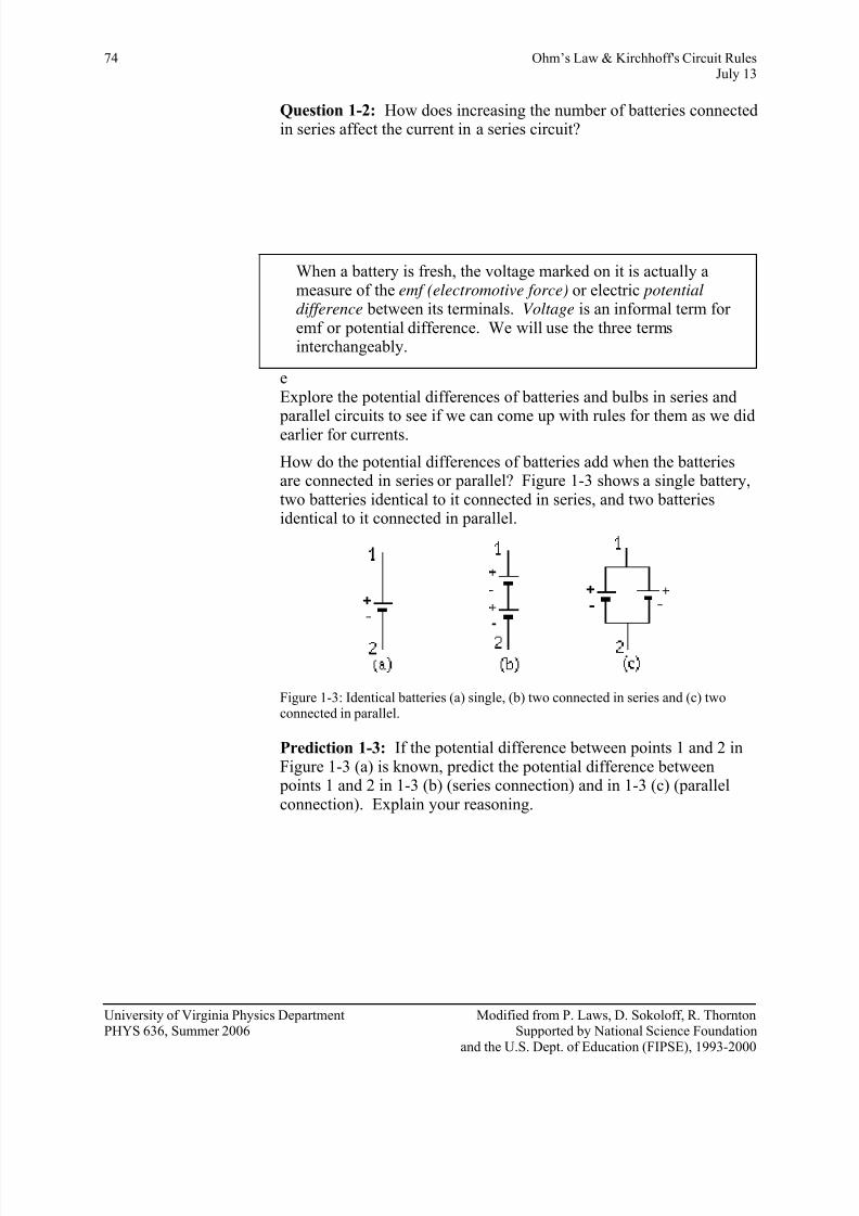
How do the potential differences of batteries add when the batteriesare connected in series or parallel? Figure 1-3 shows a single battery,two batteries identical to it connected in series, and two batteriesidentical to it connected in parallel.
Figure 1-3: Identical batteries (a) single, (b) two connected in series and (c) twoconnected in parallel.
Prediction 1-3: If the potential difference between points 1 and 2 inFigure 1-3 (a) is known, predict the potential difference between points 1 and 2 in 1-3 (b) (series connection) and in 1-3 (c) (parallelconnection). Explain your reasoning.
University of Virginia Physics Department Modified from P. Laws, D. Sokoloff, R. ThorntonPHYS 636, Summer 2006 Supported by National Science Foundation
and the U.S. Dept. of Education (FIPSE), 1993-2000

7/31/2019 8 - Ohm_s Law and Kirchhoff_s Circuit Rules.v1.4!10!06
http://slidepdf.com/reader/full/8-ohms-law-and-kirchhoffs-circuit-rulesv141006 5/22
Ohm’s Law and Kirchhoff’s Circuit Rules 75July 13
Activity 1-2: Batteries in Series and Parallel
You can measure potential differences with voltage probes connectedas shown in Figure 1-4.
+
-
+
-VPBVPA
(a)
VPA
+-
+- VPB
(b) (c)
VPB
+
-B
A
BA B
VPA
+
-A
+ +
+ ++
+
- - -
-
-
-
Figure 1-4: Voltage probes connected to measure the potential difference across (a) two single batteries,(b) a single battery and two batteries connected in series, and (c) a single battery and two batteriesconnected in parallel.
1. Open the experiment file Batteries.
2. Connect voltage probe VPA across a single battery (as inFigure 1-4(a)), and voltage probe VPB across the other identical battery.
3. Record the voltage measured for each battery below.
Voltage of battery A:______ Voltage of battery B: ______
4. Now connect the batteries in series as in Figure 1-4(b), andconnect probe VPA to measure the potential difference across battery A and probe VPB to measure the potential difference across
the series combination of the two batteries. Record your measuredvalues below.
Voltage of battery A:_____
Voltage of A and B in series:_____
Question 1-3: Do your measured values agree with your predictions?Explain any differences.
5. Now connect the batteries in parallel as in Figure 1-4(c), andconnect probe VPA to measure the potential difference across battery A and probe VPB to measure the potential difference acrossthe parallel combination of the two batteries. Record your measured values below.
University of Virginia Physics Department Modified from P. Laws, D. Sokoloff, R. ThorntonPHYS 636, Summer 2006 Supported by National Science Foundation
and the U.S. Dept. of Education (FIPSE), 1993-2000

7/31/2019 8 - Ohm_s Law and Kirchhoff_s Circuit Rules.v1.4!10!06
http://slidepdf.com/reader/full/8-ohms-law-and-kirchhoffs-circuit-rulesv141006 6/22
76 Ohm’s Law & Kirchhoff's Circuit RulesJuly 13
Voltage of battery A:______
Voltage of A and B in parallel:______
Question 1-4: Do your measured values agree with your predictions?Explain any differences.
Question 1-5: Make up a rule for finding the combined voltage of anumber of batteries connected in series.
Question 1-6: Make up a rule for finding the combined voltage of anumber of identical batteries connected in parallel.
What would happen if you wired two batteries of unequal voltage in parallel (don’t do it)? In attempting to equalize the voltages, thestronger (higher-voltage) battery would charge up the weaker battery. This would severely drain the stronger battery, reducing itsvoltage, and temporarily add charge to the weaker battery, increasingits voltage. This could cause both batteries to overheat, and could bedangerous.
You can now explore the potential difference across different parts of a simple series circuit. Consider the circuit shown in Figure 1-5.
University of Virginia Physics Department Modified from P. Laws, D. Sokoloff, R. ThorntonPHYS 636, Summer 2006 Supported by National Science Foundation
and the U.S. Dept. of Education (FIPSE), 1993-2000

7/31/2019 8 - Ohm_s Law and Kirchhoff_s Circuit Rules.v1.4!10!06
http://slidepdf.com/reader/full/8-ohms-law-and-kirchhoffs-circuit-rulesv141006 7/22
Ohm’s Law and Kirchhoff’s Circuit Rules 77July 13
VPB
VP1+
+
-
-
VPA
S1
Figure 1-5: A series circuit with one battery and two bulbs.
IMPORTANT NOTE: The switch (S1) should remain open except
when you are making a measurement. It is in the circuit to save thebattery.
Prediction 1-4: If bulbs A and B are identical, predict how the potential difference (voltage) across bulb A in Figure 1-5 will compare
to the potential difference across the battery. How about bulb B?
Activity 1-3: Voltages in Series Circuits
1. Open the experiment file Batteries, if it is not already open.
2. Connect the circuit shown in Figure 1-5.
3. Connect the voltage probes as in Figure 1-5 to measure the potentialdifference across bulb A and across bulb B. Record your measurements below.
Potential difference across bulb A:______
Potential difference across bulb B:______
Question 1-7: Formulate a rule for how potential differences acrossindividual bulbs in a series connection combine to give the total potential difference across the series combination of the bulbs. How isthis related to the potential difference of the battery?
University of Virginia Physics Department Modified from P. Laws, D. Sokoloff, R. ThorntonPHYS 636, Summer 2006 Supported by National Science Foundation
and the U.S. Dept. of Education (FIPSE), 1993-2000

7/31/2019 8 - Ohm_s Law and Kirchhoff_s Circuit Rules.v1.4!10!06
http://slidepdf.com/reader/full/8-ohms-law-and-kirchhoffs-circuit-rulesv141006 8/22
78 Ohm’s Law & Kirchhoff's Circuit RulesJuly 13
INVESTIGATION 2: VOLTAGES IN PARALLEL CIRCUITS
Now you will explore the potential differences across different parts of a simple parallel circuit.
You will need the following material:
• 2 voltage probes
• 1.5 V D cell battery (must be very fresh, alkaline) with holder
• 8 alligator clip leads
• two #14 bulbs with holders
• knife switch
• contact switch
Activity 2-1: Voltages in a Parallel Circuit
1. The experiment file Batteries should still be open showing twovoltage graphs as a function of time.
2. Connect the circuit shown in Figure 2-1.
VPB VP1
S2S1
+ +
- -VPA
Figure 2-1: Voltage probes connected to measure the potential differencesacross bulbs A and B.
3. Begin graphing, and then close and open the switch S2 a couple of times. Remember to open switch S1 when not taking data.
4. Print out one set of graphs for your group.
5. Record your measurements using the Digit Display.
Switch S2 open
Voltage across bulb A:______Voltage across bulb B:______
Switch S2 closed
Voltage across bulb A:______Voltage across bulb B:______
Question 2-1: Did closing and opening switch S2 significantly affectthe voltage across bulb A (by more than several %)?
University of Virginia Physics Department Modified from P. Laws, D. Sokoloff, R. ThorntonPHYS 636, Summer 2006 Supported by National Science Foundation
and the U.S. Dept. of Education (FIPSE), 1993-2000

7/31/2019 8 - Ohm_s Law and Kirchhoff_s Circuit Rules.v1.4!10!06
http://slidepdf.com/reader/full/8-ohms-law-and-kirchhoffs-circuit-rulesv141006 9/22
Ohm’s Law and Kirchhoff’s Circuit Rules 79July 13
Question 2-2: Did closing and opening switch S2 significantly affectthe voltage across bulb B (by more than several %)?
Question 2-3: Based on your observations, formulate a rule for the potential differences across the different branches of a parallel circuit.How are these related to the voltage across the battery?
You have now observed that the voltage across a real battery doesn'tchange much no matter what is connected to it (i.e., no matter howmuch current flows in the circuit). An ideal battery would be onewhose voltage did not change at all, no matter what the currentflowing through it. No battery is truly ideal (this is especially true for a less than fresh battery), so the voltage usually drops somewhat whenthe load on the battery is increased.
INVESTIGATION 3: MEASURING CURRENT, VOLTAGE AND RESISTANCE
OFF ON
V
A
COM A 10AV, Ω
Ω
.245 AC DC
A
V
Ω
(a) (b)
Figure 3-1 (a) Multimeter with voltage, current and resistance modes, and (b)
symbols that will be used to indicate a multimeter used as an ammeter, voltmeter andohmmeter respectively.
The multimeters available to you can be used to measure current,voltage or resistance. All you need to do is choose the correct dialsetting, connect the wire leads to the correct terminals on the meter and connect the meter correctly in the circuit. Figure 3-1 shows a
University of Virginia Physics Department Modified from P. Laws, D. Sokoloff, R. ThorntonPHYS 636, Summer 2006 Supported by National Science Foundation
and the U.S. Dept. of Education (FIPSE), 1993-2000

7/31/2019 8 - Ohm_s Law and Kirchhoff_s Circuit Rules.v1.4!10!06
http://slidepdf.com/reader/full/8-ohms-law-and-kirchhoffs-circuit-rulesv141006 10/22
80 Ohm’s Law & Kirchhoff's Circuit RulesJuly 13
simplified diagram of a multimeter. We will be using the multimeter to make DC (direct current) measurements, so make sure themultimeter is set to DC mode.
A current probe or a multimeter used to measure current (an ammeter)are both connected in a circuit in the same way. Likewise, a voltage probe or a multimeter used to measure voltage (a voltmeter) are bothconnected in a circuit in the same way. The next two activities willremind you how to connect them. The activities will also show youthat when meters are connected correctly, they don’t interfere with thecurrents or voltages being measured.
You will need:
• digital multimeter
• two 1.5 V D batteries (must be very fresh alkaline) with holder
• 6 alligator clip leads
• two #14 bulbs and sockets• 22 Ω and 75 Ω resistors
Activity 3-1: Measuring Current with a Multimeter
A
Figure 3-2: Connections to use a multimeter as an ammeter.
1. Set up the basic circuit in Figure 3-2, but without the ammeter (connect the bulb directly to the battery). Observe the brightness of the bulb.
2. Set the multimeter to measure current. Important: Use the 20-amp
setting and connect the leads to the 20-amp terminals on themultimeter. When the multimeter is ready, connect it to the circuit
as shown in Figure 3-2.
Question 3-1: Was the brightness of the bulb significantly affected?
What current do you measure? _________
University of Virginia Physics Department Modified from P. Laws, D. Sokoloff, R. ThorntonPHYS 636, Summer 2006 Supported by National Science Foundation
and the U.S. Dept. of Education (FIPSE), 1993-2000

7/31/2019 8 - Ohm_s Law and Kirchhoff_s Circuit Rules.v1.4!10!06
http://slidepdf.com/reader/full/8-ohms-law-and-kirchhoffs-circuit-rulesv141006 11/22
Ohm’s Law and Kirchhoff’s Circuit Rules 81July 13
Question 3-2: When used correctly as an ammeter, the multimeter should measure the current through the bulb without significantlyaffecting that current. Does this ammeter appear to behave as if it is alarge or small resistor? Explain based on your observations. Whatwould be the resistance of a perfect ammeter?
Activity 3-2: Measuring Voltage with a Multimeter
V
S
Figure 3-3: Connections to use a multimeter as a voltmeter.
1.
Set up the basic circuit in Figure 3-3, but without the voltmeter.Observe the brightness of the bulb.
2. Set the multimeter to measure voltage. Important: Use the volts setting and connect the leads to the voltage terminals on themultimeter. When the multimeter is ready, connect it to the circuitas shown in Figure 3-3.
Question 3-3: Was the brightness of the bulb significantly affected?
What voltage do you measure? ___________
Note: The multimeters we are using have two attachments. One is thealligator clip-on probe and the other is a needle-like probe. You canscrew off the clip-on probe to reveal the needle-like probe. Usewhichever one you prefer, but make sure you screw the clip-on probe back on when finished.
University of Virginia Physics Department Modified from P. Laws, D. Sokoloff, R. ThorntonPHYS 636, Summer 2006 Supported by National Science Foundation
and the U.S. Dept. of Education (FIPSE), 1993-2000

7/31/2019 8 - Ohm_s Law and Kirchhoff_s Circuit Rules.v1.4!10!06
http://slidepdf.com/reader/full/8-ohms-law-and-kirchhoffs-circuit-rulesv141006 12/22
82 Ohm’s Law & Kirchhoff's Circuit RulesJuly 13
Question 3-4: When used correctly as a voltmeter, the multimeter should measure the voltage across the bulb without significantlyaffecting that voltage. Does this voltmeter appear to behave as if it is alarge or small resistor? Explain based on your observations. Whatwould be the resistance of an ideal voltmeter?
Activity 3-3: Measuring Resistance with a Multimeter
Next we will investigate how you measure resistance with amultimeter. In earlier labs, you may have observed that light bulbsexhibit resistance that increases with the current through the bulb (i.e.with the temperature of the filament). To make the design andanalysis of circuits as simple as possible, it is desirable to have circuitelements with resistances that do not change. For that reason,resistors are used in electric circuits. The resistance of a well-designed resistor doesn't vary with the amount of current passingthrough it (or with the temperature), and they are inexpensive tomanufacture.
One type of resistor is a carbon resistor, and uses graphite suspendedin a hard glue binder. It is usually surrounded by a plastic case with acolor code painted on it.
Cutaway view of acarbon resistor showingthe cross sectional area
of the graphite material
Figure 3-4: A Cutaway View of a Carbon Resistor
The color code on the resistor tells you the value of the resistance andthe tolerance (guaranteed accuracy) of this value.
The first two stripes indicate the two digits of the resistance value.The third stripe indicates the power-of-ten multiplier. The followingkey shows the corresponding values:
University of Virginia Physics Department Modified from P. Laws, D. Sokoloff, R. ThorntonPHYS 636, Summer 2006 Supported by National Science Foundation
and the U.S. Dept. of Education (FIPSE), 1993-2000

7/31/2019 8 - Ohm_s Law and Kirchhoff_s Circuit Rules.v1.4!10!06
http://slidepdf.com/reader/full/8-ohms-law-and-kirchhoffs-circuit-rulesv141006 13/22
Ohm’s Law and Kirchhoff’s Circuit Rules 83July 13
black = 0 yellow = 4 grey = 8 brown = 1 green = 5 white = 9red = 2 blue = 6orange = 3 violet = 7
The fourth stripe tells the tolerance according to the following key:
As an example, look at the resistor in Figure 3-5. Its two digits are 1
and 2 and the multiplier is 103, so its value is 12 x 103, or 12,000 Ω.
The tolerance is ± 20%, so the value might actually be as large as14,400 Ω or as small as 9,600 Ω.
Brown
Red
Orange
one
Figure 3-5: An example of a color-coded carbon resistor. The resistance of this
resistor is 12 x 103 Ω ± 20%.
The connection of the multimeter to measure resistance is shown inFigure 3-6. When the multimeter is in its ohmmeter mode, it connectsa known voltage across the resistor, and measures the current throughthe resistor. Then resistance is calculated by the meter from R = V/I(Ohm’s law).
Note: Resistors must be isolated by disconnecting them from the
circuit before measuring their resistances. This also prevents damageto the multimeter that may occur if a voltage is connected across itsterminals while in the resistance mode.
red or none = ± 20% gold = ± 5%silver = = ± 10% brown = ± 1%
University of Virginia Physics Department Modified from P. Laws, D. Sokoloff, R. ThorntonPHYS 636, Summer 2006 Supported by National Science Foundation
and the U.S. Dept. of Education (FIPSE), 1993-2000

7/31/2019 8 - Ohm_s Law and Kirchhoff_s Circuit Rules.v1.4!10!06
http://slidepdf.com/reader/full/8-ohms-law-and-kirchhoffs-circuit-rulesv141006 14/22
84 Ohm’s Law & Kirchhoff's Circuit RulesJuly 13
Figure 3-6: Connection of an ohmmeter to measure resistance.
1. Choose two different resistors and read their codes. Write downthe resistances and tolerances.
2. Use the multimeter as an ohmmeter and measure each.
Question 3-5: Comment on the agreement.
3. Measure the equivalent resistance of the two resistors in series.Use alligator clip wires to connect the resistors. Calculate what theequivalent total resistance should be and compare with your measurement. (Look up in textbook if you don’t know how to findequivalent resistance in series and parallel)
Question 3-6: Comment on the agreement.
4. Do the same thing as in step 3 for the two resistors in parallel.
Question 3-7: Comment on the agreement.
University of Virginia Physics Department Modified from P. Laws, D. Sokoloff, R. ThorntonPHYS 636, Summer 2006 Supported by National Science Foundation
and the U.S. Dept. of Education (FIPSE), 1993-2000

7/31/2019 8 - Ohm_s Law and Kirchhoff_s Circuit Rules.v1.4!10!06
http://slidepdf.com/reader/full/8-ohms-law-and-kirchhoffs-circuit-rulesv141006 15/22
Ohm’s Law and Kirchhoff’s Circuit Rules 85July 13
INVESTIGATION 4: OHM’S LAW
What is the relationship between current and potential difference?You have already seen that there is only a potential difference across a bulb or resistor when there is a current through the circuit element.The next question is how does the potential difference depend on thecurrent? In order to explore this, you will need the following:
• current and voltage probes
• Hewlett Packard 6213A variable regulated DC power supply
• 10 alligator clip leads• 10 Ω and 22 Ω resistors
• #14 bulb in a socket
Examine the circuit shown below. A variable DC power supply is likea variable battery. When you turn the dial, you change the voltage(potential difference) between its terminals. Therefore, this circuitallows you to measure the current through the resistor when differentvoltages are across it.
VPB CPA
+ -
+DC
Power Supply
-
+
-
Figure 4-1: Circuit with a variable power supply to explore the relationship betweencurrent and potential difference for a resistor.
Prediction 4-1: What will happen to the current through the resistor
as you turn the dial on the power supply and increase the appliedvoltage from zero? What about the voltage across the resistor?
University of Virginia Physics Department Modified from P. Laws, D. Sokoloff, R. ThorntonPHYS 636, Summer 2006 Supported by National Science Foundation
and the U.S. Dept. of Education (FIPSE), 1993-2000

7/31/2019 8 - Ohm_s Law and Kirchhoff_s Circuit Rules.v1.4!10!06
http://slidepdf.com/reader/full/8-ohms-law-and-kirchhoffs-circuit-rulesv141006 16/22

7/31/2019 8 - Ohm_s Law and Kirchhoff_s Circuit Rules.v1.4!10!06
http://slidepdf.com/reader/full/8-ohms-law-and-kirchhoffs-circuit-rulesv141006 17/22
Ohm’s Law and Kirchhoff’s Circuit Rules 87July 13
Measured R = ____________ Percentage Difference = ____________
Comment on the agreement:
5. On the same graph, repeat steps 2 and 3 for: (a) a resistor 22 Ω and(b) a light bulb. Be sure to increase the voltage very slowly for thelight bulb, especially in the beginning. There should now be threesets of data on the I vs. V graph.
6. Print out one set of graphs for your group.
Question 4-3: For the second resistor, use the fit routine or the slopetool to find:
Slope = ______________
Calculated R = ________________
7. Measure R directly with the multimeter, and find the percentagedifference.
R measured: _________________
Percentage difference in two values of R: ________________
The relationship between potential difference and current that youhave observed for a resistor is known as Ohm's law. To put this law inits normal form, we must now define the quantity known as resistance.Resistance is defined as the slope of a voltage vs. current graph.(Recall that we have graphed current vs. voltage instead.)
Question 4-4: Based on your data for the light bulb, does it have alarger resistance for low current (cooler bulb) or high current (hotter bulb)? Use Data Studio to find the slope (and calculate R) for a lowcurrent and a high current.
Low current: slope = ___________ R =_____________
High current: slope = ___________ R =_____________
Question 4-5: Does a proportional or linear fit seem more reasonablefor the resistor? Explain.
University of Virginia Physics Department Modified from P. Laws, D. Sokoloff, R. ThorntonPHYS 636, Summer 2006 Supported by National Science Foundation
and the U.S. Dept. of Education (FIPSE), 1993-2000
7/31/2019 8 - Ohm_s Law and Kirchhoff_s Circuit Rules.v1.4!10!06
http://slidepdf.com/reader/full/8-ohms-law-and-kirchhoffs-circuit-rulesv141006 18/22
88 Ohm’s Law & Kirchhoff's Circuit RulesJuly 13
Question 4-6: What about for the light bulb? Explain.
INVESTIGATION 5: KIRCHHOFF’S CIRCUIT RULES
Suppose you want to calculate the currents in various branches of acircuit that has many components wired together in a complex array.The rules for combining resistors are very convenient in circuits madeup only of resistors that are connected in series or parallel. But, whileit may be possible in some cases to simplify parts of a circuit with theseries and parallel rules, complete simplification to an equivalentresistance is often impossible, especially when components other than
resistors are included. The application of Kirchhoff's Circuit Rulescan help you to understand the most complex circuits.
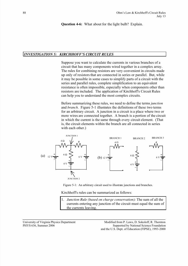
Before summarizing these rules, we need to define the terms junction and branch. Figure 5-1 illustrates the definitions of these two termsfor an arbitrary circuit. A junction in a circuit is a place where two or more wires are connected together. A branch is a portion of the circuitin which the current is the same through every circuit element. (Thatis, the circuit elements within the branch are all connected in serieswith each other.)
JUNCTION 1
JUNCTION 2
4 Ω
12 V6 Ω
4 V
6 V
R
BRANCH 1 BRANCH 2
BRANCH 3
4 Ω
6 Ω 12 V
4 V
R
(a)(b)6 V
+
–
+
–
+
– +
–
+
–
+
–
Figure 5-1: An arbitrary circuit used to illustrate junctions and branches.
Kirchhoff's rules can be summarized as follows:
1. Junction Rule (based on charge conservation): The sum of all thecurrents entering any junction of the circuit must equal the sum of the currents leaving.
University of Virginia Physics Department Modified from P. Laws, D. Sokoloff, R. ThorntonPHYS 636, Summer 2006 Supported by National Science Foundation
and the U.S. Dept. of Education (FIPSE), 1993-2000

7/31/2019 8 - Ohm_s Law and Kirchhoff_s Circuit Rules.v1.4!10!06
http://slidepdf.com/reader/full/8-ohms-law-and-kirchhoffs-circuit-rulesv141006 19/22
Ohm’s Law and Kirchhoff’s Circuit Rules 89July 13
2. Loop Rule (based on energy conservation): Around any closedloop in a circuit, the sum of all changes in potential (emfs and potential drops across resistors and other circuit elements) mustequal zero.
You have probably already learned how to apply Kirchhoff’s rules inclass, but if not, here is a quick summary:
1. Assign a current symbol to each branch of the circuit, and label thecurrent in each branch (I1, I2, I3, etc.).
2. Assign a direction to each current. The direction chosen for thecurrent in each branch is arbitrary. If you chose the right direction,the current will come out positive. If you chose the wrongdirection, the current will eventually come out negative, indicatingthat you originally chose the wrong direction. Remember that thecurrent is the same everywhere in a branch.
3. Apply the Loop Rule to each of the loops.
(a) Let the voltage drop across each resistor be the product of theresistance and the net current through the resistor (Ohm’s law).Remember to make the sign negative if you are traversing aresistor in the direction of the current and positive if you aretraversing the resistor in the direction opposite to that of thecurrent.
(b) Assign a positive potential difference when the loop traverses fromthe “–“ to the “+” terminal of a battery. If you are going across a battery in the opposite direction, assign a negative potential
difference.
4. Find each of the junctions and apply the Junction Rule to it.
Consider the circuit in Figure 5-2:
+ –
+ – Loop 1 Loop 2
I1
I1
R 2
I3
I3
R 3
R 1Junction 2
Junction
ε1 ε2
Arbitrarily assigned loopdirection for keeping
track of currents and
potential differences.
Current directionthrough battery often
chosen as in direction
of – to +
I2
Figure 5-2: A complex circuit in which loops 1 and 2 share the resistor R 2.
University of Virginia Physics Department Modified from P. Laws, D. Sokoloff, R. ThorntonPHYS 636, Summer 2006 Supported by National Science Foundation
and the U.S. Dept. of Education (FIPSE), 1993-2000

7/31/2019 8 - Ohm_s Law and Kirchhoff_s Circuit Rules.v1.4!10!06
http://slidepdf.com/reader/full/8-ohms-law-and-kirchhoffs-circuit-rulesv141006 20/22
90 Ohm’s Law & Kirchhoff's Circuit RulesJuly 13
In Figure 5-2 the directions for the loops through the circuits and for the three currents are assigned arbitrarily. If we assume that theinternal resistances of the batteries are negligible (i.e. that the batteriesare ideal), then by applying the Loop Rule we find that
Loop 1 ε1 –I2 R 2 – I1 R 1 = 0 (1)
Loop 2 – ε 2 + I2 R 2 – I3 R 3 = 0 (2)
By applying the Junction Rule to junction 1 or 2, we find that
I1 = I2 + I3 (3)
It may trouble you that the current directions and directions that theloops are traversed have been chosen arbitrarily. You can explore thisassertion by changing these choices, and analyzing the circuit again.
In order to do the following activity you'll need a couple of resistorsand a multimeter as follows:
• 2 resistors (rated values of 39 Ω and 75 Ω, both + 5%)
• digital multimeter
• 6 V battery
• 1.5 V D battery (very fresh, alkaline) and holder
• 200 Ω potentiometer (to be set to 100 Ω)
• 8 alligator clip lead wires
1. Measure the actual values of the two fixed resistors and the two battery voltages with your multimeter. List the results below.
Measured voltage (emf) of the 6 V battery ε1:_______
Measured voltage (emf) of the 1.5 V battery ε2:_______
Measured resistance of the 75 Ω resistor R 1:_______
Measured resistance of the 39 Ω resistor R 3:_______
2. Carefully rewrite Equations (1), (2) and (3) with the appropriatemeasured (not rated) values for emf and resistances substituted
into them. Use 100 Ω for the value of R 2 in your equations. You
will be setting a variable resistor to that value soon.
3. In the pre-lab assignment you solved these three equations for thethree unknown currents, I1, I2 and I3.
Calculated values: I1 _________ I2 _________ I3 _________
University of Virginia Physics Department Modified from P. Laws, D. Sokoloff, R. ThorntonPHYS 636, Summer 2006 Supported by National Science Foundation
and the U.S. Dept. of Education (FIPSE), 1993-2000

7/31/2019 8 - Ohm_s Law and Kirchhoff_s Circuit Rules.v1.4!10!06
http://slidepdf.com/reader/full/8-ohms-law-and-kirchhoffs-circuit-rulesv141006 21/22
Ohm’s Law and Kirchhoff’s Circuit Rules 91July 13
Figure 5-3: Schematic of a potentiometer. As the dial is rotated, the amount of resistive material between terminals 1 and 2, and between 2 and 3, changes. Thus itis a variable resistor.
Activity 5-1: Testing Kirchhoff's Rules with a Real Circuit
1. Using the resistance mode of the multimeter measure the resistance between the center wire on the variable resistor (see Figure 5-3)and one of the other wires.
Question 5-1: What happens to the resistance reading as you rotatethe dial on the variable resistor clockwise? Counterclockwise?
2. Set the variable resistor so that there is 100 Ω between the center wire and one of the other wires.
3.
Wire up the circuit pictured in Figure 5-2 using the variableresistor set at 100 Ω as R 2. Spread the wires and circuit elements
out on the table so that the circuit looks as much like Figure 5-2 as possible. It will be a big mess!
4. Use the multimeter to measure the current in each branch of thecircuit (you will actually measure voltages; see Note below), andenter your data in Table 5-1. Compare the measured values tothose calculated in the pre-lab by computing the % difference ineach case.
Note: The most accurate and easiest way to measure the currents withthe digital multimeter is to measure the voltage across a resistor of known value, and then use Ohm's Law to calculate I from V and R.
Pay careful attention to the “+” and “-“ connections of the voltmeter,so that you are checking not only the magnitude of the current, butalso its direction.
University of Virginia Physics Department Modified from P. Laws, D. Sokoloff, R. ThorntonPHYS 636, Summer 2006 Supported by National Science Foundation
and the U.S. Dept. of Education (FIPSE), 1993-2000

7/31/2019 8 - Ohm_s Law and Kirchhoff_s Circuit Rules.v1.4!10!06
http://slidepdf.com/reader/full/8-ohms-law-and-kirchhoffs-circuit-rulesv141006 22/22
92 Ohm’s Law & Kirchhoff's Circuit RulesJuly 13
Table 5-1 Results from test of Kirchhoff's Circuit Rules
R measured w/multimeter
(ohms)
V measuredw/multimeter
(volts)
Calculated I=V/R (amps)
Theoretical I (amps)
(pre-lab)
% Difference
R 1
R 2
R 3
Question 5-2: How well do your measured currents agree with the
theoretical values? Discuss possible errors in both your theoreticaland measured currents. Were the directions of the currents confirmed?
Question 5-3: If the currents were less than expected, could this beexplained by the conditions under which you measured the batteryvoltages?
University of Virginia Physics Department Modified from P. Laws, D. Sokoloff, R. ThorntonPHYS 636 Summer 2006 Supported by National Science Foundation