8 performance metrics - hgi€¦ · 10 and “online” versions of existing services such as...
TRANSCRIPT

Page 1 of 20 © Home Gateway Initiative – 2008 – All rights reserved
1 2
3
4
5
6
7
Performance Metrics 8
9
Version 1.0 10
11
05/06/2008 12
Performance metrics
Page 2 of 20 © Home Gateway Initiative – 2008 – All rights reserved
1 2 3 4 5 6 7 8 9 10 11 12 13 14 15 16 17 18 19 20 21 22 23 24
PAGE LEFT INTENTIONALLY BLANK 25

Performance metrics
Page 3 of 20 © Home Gateway Initiative – 2008 – All rights reserved
Table of Contents 1 2 1 Important notice, IPR statement, disclaimer and copyright....................................... 4 3 2 Acronyms................................................................................................................... 5 4 3 Definitions and Terminology...................................................................................... 6 5 4 Introduction and scope of the Home Gateway Initiative (HGI).................................. 7 6
4.1 Cooperation with other bodies and initiatives............................................................ 7 7 5 Introduction................................................................................................................ 8 8 6 Methodology.............................................................................................................. 9 9
6.1 Configuration Profile.................................................................................................. 9 10 6.2 Test Setup ............................................................................................................... 10 11
6.2.1 HG ........................................................................................................................... 11 12 6.2.2 WAN I/F................................................................................................................... 11 13 6.2.3 WAN/LAN Switch .................................................................................................... 12 14 6.2.4 Wi-Fi/HAN Test Setup ............................................................................................. 12 15 6.2.5 Test Equipment: IGMP Tester, Voice Tester, Traffic Generator/Sink..................... 13 16 6.2.6 Interference with Test Setup ................................................................................... 13 17
6.3 Test Procedure........................................................................................................ 13 18 6.3.1 Flooding Test........................................................................................................... 13 19 6.3.2 Headroom Test........................................................................................................ 15 20
7 References .............................................................................................................. 17 21 Appendix 18 22
23
Performance metrics
Page 4 of 20 © Home Gateway Initiative – 2008 – All rights reserved
1 Important notice, IPR statement, disclaimer and 1
copyright 2
The Home Gateway Initiative (HGI) is a non-profit making organization created to define 3 guidelines and specifications for broadband Home Gateways. 4
This document is the output of the Working Groups of the HGI and its members as of the 5 date of release. Readers of this document must be aware that it can be revised, edited or have its 6 status changed according to the HGI working procedures. 7
The HGI makes no representation or warranty on the contents, completeness and accuracy 8 of this publication. 9
This document, though formally approved by the HGI member companies, is not binding in 10 any part on the HGI members. 11
IPRs essential or potentially essential to the present document may have been declared in 12 conformance to the HGI IPR Policy and Statutes available at the HGI website 13 www.homegateway.org . 14
Any parts of this document may be freely reproduced (for example in RFPs and ITTs) by 15 HGI and non-HGI members subject only to the following: 16
• HGI Requirement numbers not being changed 17
• an acknowledgement to the HGI being given in the resulting document. 18
Trademarks and copyrights mentioned in this document are the property of their respective 19 owners. 20
21 The HGI membership list as of the date of the formal review of this document is: 2 Wire, Inc., 22 Alcatel-Lucent, Atheros, AVM ,Belgacom, BeWAN, Broadcom, BT, Deutsche Telekom, DS2, DSP 23 Group, Echelon EMEA, ,Ericsson AB, Fastweb SpA, France Telecom, Freescale Semiconductor, 24 Gigle Semiconductor, Huawei, InAccess Networks, Infineon Technologies AG, Intel, Intellon, ITRI, 25 JDSU, Jungo Software Technologies, KDDI, KPN, LG-Nortel Co Ltd, Linksys/Cisco, Marvell 26 Semiconductors, Microsoft, Motorola, Netgear, NTT, Philips, Pirelli Broadband Solutions, Portugal 27 Telecom, Sagem, Siemens, Sphairon Access Systems, Spidcom, Supportsoft, Swisscom AG, 28 Telecom Italia, Telefonica, Telekom Slovenije, Telekomunikacja Polska, Telenor, TeliaSonera, 29 Telkom ZA, Telstra, Texas Instruments, Thomson, Tilgin AB, TNO ICT, U4EA Technologies 30 Limited, Ubicom Inc., Vtech, ZTE, Zarlink, ZyXEL. 31 32
Performance metrics
Page 5 of 20 © Home Gateway Initiative – 2008 – All rights reserved
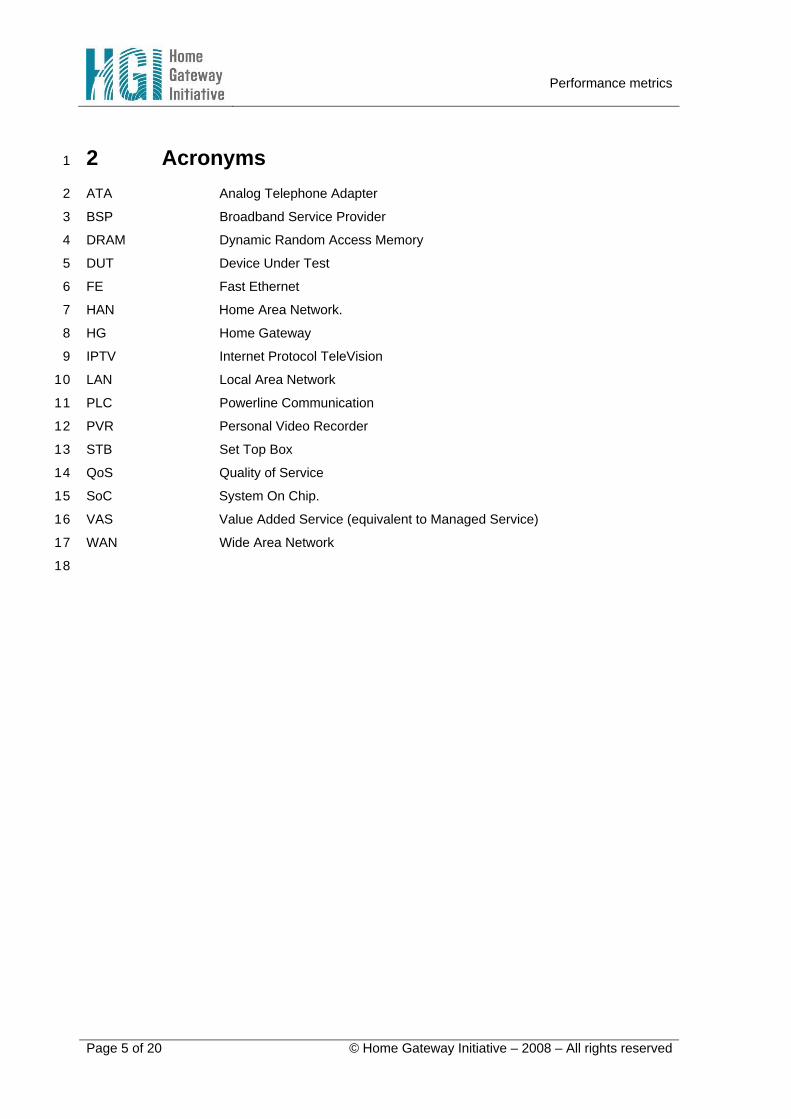
2 Acronyms 1
ATA Analog Telephone Adapter 2
BSP Broadband Service Provider 3
DRAM Dynamic Random Access Memory 4
DUT Device Under Test 5
FE Fast Ethernet 6
HAN Home Area Network. 7
HG Home Gateway 8
IPTV Internet Protocol TeleVision 9
LAN Local Area Network 10
PLC Powerline Communication 11
PVR Personal Video Recorder 12
STB Set Top Box 13
QoS Quality of Service 14
SoC System On Chip. 15
VAS Value Added Service (equivalent to Managed Service) 16
WAN Wide Area Network 17
18

Performance metrics
Page 6 of 20 © Home Gateway Initiative – 2008 – All rights reserved
3 Definitions and Terminology 1
• Flooding: A number of flows and functions applied to the HG that is in addition to the 2 normal usage model of flows and functions. The flooding is applied under a test 3 environment to determine the HG’s ability to retain QoS of VAS. 4
• Headroom: Capacity of the solution that exists beyond what is required to transport and 5 enable a predefined set of VAS captured in a profile. 6
• Value Added Service: A service for which the BSP provides preferential treatment (that 7 can include QoS...) for the customer. The service can be a service offered by the BSP or 8 operated by the BSP on behalf of a third party. A managed service can also be local: 9 watching a video on a PC recorded on the IPTV STB; as explained in the IPTV PVR use 10 case. Managed services do not necessarily involve use of the remote management system; 11 management only means that the operator has taken some responsibility for the service 12 (e.g. its QoS treatment) in order to provide the appropriate quality of experience. 13
• Profile: A set of VAS, represented in terms of functions and traffic flows, applied to a 14 specified HG hardware configuration. 15
• System-on-Chip: A silicon chip composed of one or more processors with various 16 LAN/WAN interfaces, DRAM all interconnected with an internal bus. 17
18

Performance metrics
Page 7 of 20 © Home Gateway Initiative – 2008 – All rights reserved
4 Introduction and scope of the Home Gateway 1
Initiative (HGI) 2
Home connectivity has evolved dramatically over recent times. From the initial simple voice 3 service, home services evolved in the 80s to include things such as fax and video text, with the 90s 4 seeing the advent of mass-market Internet access via dial-up modems. At the start of the 21st 5 century, the world has entered the broadband era. Network operators have deployed technology 6 that offers much larger bandwidths, such as DSL, cable or fibre-based access systems. 7
The Internet has been a major driver for the evolution to broadband, creating a new 8 experience for the customer and offering him new services such as email and Internet browsing, 9 and “online” versions of existing services such as digital photo labs, ticket booking etc. 10
The next generation of broadband services (triple or even “multiple-play”) has created a set 11 of new requirements for the Home Gateway, namely: 12
• the need to manage the Home Gateway, and to a lesser extent, the home network and the 13 devices beyond the Home Gateway 14
• allowing the right device or application to connect to the right service platform with the right 15 service class / Quality of Service 16
• unifying device capabilities in order to offer customers a better “integrated home 17 environment”. 18
19 Due to the lack of suitable off-the-shelf and standardized products to support this new, end-20
to-end network and service model, several major Telecom Operators have recently worked 21 separately with a very small number of Home Gateway vendors to specify and develop suitable 22 Gateways. However, such custom development is not cost-effective for either operators or vendors. 23
It became apparent that many operators had similar service aspirations, and so were asking 24 for similar equipment. Therefore in December 2004, nine Telecom Operators founded the Home 25 Gateway Initiative to agree on a common Gateway specification. The intention was to involve the 26 relevant vendor community (i.e. vendors of gateways, chipsets, software, devices and transmission 27 systems) so that the specifications would also be pragmatic and could be realized in a cost-28 effective manner. 29
The aim of HGI is therefore to specify a small range of low cost, high capability Gateways 30 which will provide multi-service communication support for the residential and SOHO environments. 31 While an end-to-end network view has been taken, the specifications mainly focus on the Home 32 Gateway device which sits between the access network and service platforms on one side, and the 33 in-home networked devices and applications on the other. 34
4.1 Cooperation with other bodies and initiatives 35
The Home Gateway Initiative does not wish to become a new, long-term de facto 36 standardization body. Its task is to agree a set of functional requirements for a Home Gateway, 37 wherever possible re-using or referring out to existing specifications. An important aspect of the 38 work is to identify gaps and inconsistencies in or between existing specifications. The HGI will 39 publish its own specifications, but will work alongside other SDOs to ensure that issues are 40 addressed in the most appropriate body, that there is no unnecessary duplication of effort, and that 41 the HGI specifications are downstreamed in the most appropriate way. 42
Performance metrics
Page 8 of 20 © Home Gateway Initiative – 2008 – All rights reserved
5 Introduction 1
This document gives an overview of the HGI performance metrics, capturing the objectives, 2 and defining the process, methodology, test setup and resulting graphs that represent a HG 3 performance capability. 4
The objective of the performance metrics is to define a way of evaluating the performance 5 capabilities of the HG in an environment that closely represents what is found in a real deployment. 6
A HG typically has a SoC device that performs most of the HG functions. Within the SoC is a 7 processor. Historically, a common way of communicating the capability of the processor was to 8 either identify the clock frequency (MHz), or the instructions per second (MIPS) or some calculation 9 metric (e.g. Dhrystone). All these metrics have no association to the functions and flows that a HG 10 has to process. 11
Assessment of processors has evolved and a group called EEMBC [2] have developed 12 many application specific tests such as NAT, IP packet processing, and QoS. These tests require 13 specific code to be applied to enable comparison of processor technologies. However, these tests 14 represent a small subset of the overall HG functions [1], and the algorithms specified in the tests 15 are not 100% applicable to the functions found in a HG [1]. Thus, the EEMBC metrics are 16 unsuitable for HGI performance metrics. 17
The performance metrics outlined in this document answer the question of whether a HG is 18 able to meet the minimum service requirements, including any QoS metrics, whilst being under 19 duress. Once the HG meets the minimum requirements, the next goal of the performance metric is 20 to ascertain how much processing capacity remains. This additional capacity represents the 21 headroom that could be applied to future flows or functions yet to be defined by the BSP. 22
The performance metric must be measured in an environment that represents real world 23 situations. 24
The process and methodology must be defined such as it is specific to neither LAN/WAN 25 technology, nor services. This is to ensure that the performance metric can be applied to as many 26 different HG profile configurations as possible. 27
The resulting outputs must be informative and capture key behaviours of the HG. It is 28 expected that a single performance number is insufficient. 29
It is not the intent of the HGI’s performance metric to ascertain the throughput capacity of 30 interconnected technologies, such as 802.11, PLC, and xDSL. This is left to the defining bodies of 31 such technologies such as Wi-Fi alliance and DSL Forum. 32
33
Performance metrics
Page 9 of 20 © Home Gateway Initiative – 2008 – All rights reserved
6 Methodology 1
6.1 Configuration Profile 2
It is recognized that there are many LAN and WAN technologies, in addition to the number of 3 flows applied to the HG as well as the number of different functions required by the HG. It is 4 impossible to capture all combinations in a single test environment. The concept of a profile is 5 adopted. A profile defines a single set of VAS, represented in terms of functions and traffic flows, 6 applied to a single and specified HG hardware configuration. The performance metric is applied to 7 this profile. Multiple profiles will have to be created to capture all the different HG definitions as 8 specified in [1]. 9
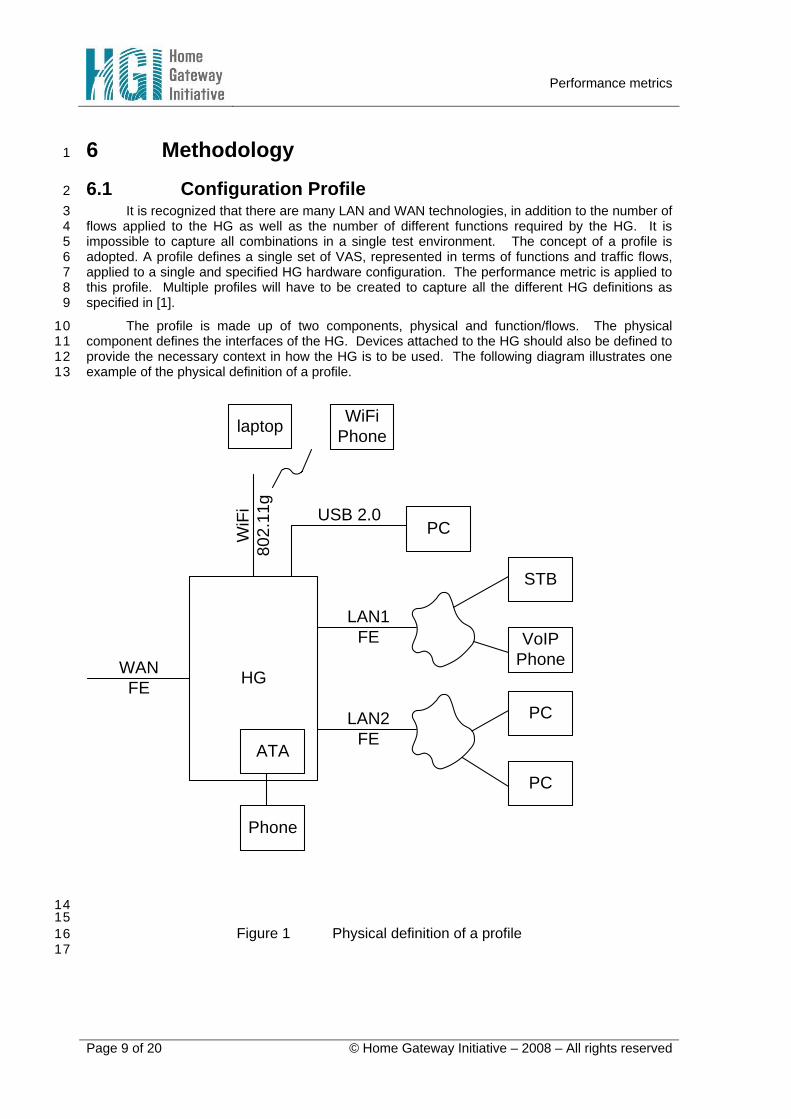
The profile is made up of two components, physical and function/flows. The physical 10 component defines the interfaces of the HG. Devices attached to the HG should also be defined to 11 provide the necessary context in how the HG is to be used. The following diagram illustrates one 12 example of the physical definition of a profile. 13
HGWANFE
LAN1FE
LAN2FE
WiF
i80
2.11
g
laptop
STB
WiFi Phone
PC
PC
VoIP Phone
PCUSB 2.0
Phone
ATA
14 15
Figure 1 Physical definition of a profile 16 17

Performance metrics
Page 10 of 20 © Home Gateway Initiative – 2008 – All rights reserved
The function/flow component of the profile is a detailed list of functions and flows that the HG 1 has to perform and transport respectively. Examples of a flow include video, voice, and best effort. 2 Details of each flow are to be provided, such as packet rate/size, source/destination, initial DSCP 3 markings, required QoS metrics (acceptable loss rate, latency, jitter). In addition, transit functions 4 that impact performance must be captured. Examples of transit functions include DSCP 5 remapping, PPP termination, and NAPT/bridging. 6
Functions that have no association with a flow may be specified if that function is considered 7 to have impact on the performance of the HG. Not all flows or functions need to be captured in the 8 profile; only those functions/flows that impact the performance of the HG should be specified. An 9 example of a function/flow component of a configuration profile is included in the Appendix. 10
6.2 Test Setup 11
It is expected that many of the profiles will have multiple divergent flows. At the time of 12 writing, no single test equipment is known to be capable of generating/sinking/analysing all the 13 flows simultaneously; hence it is expected that multiple test equipment needs to be simultaneously 14 connected to the HG to realize the test. 15
The diagram below outlines the basic setup that enables the connection of various test 16 equipment that would provide the necessary stimulus and analysis to the HG. The basis of the test 17 assumes that the underlying L2 PHY technology is Ethernet. The motivation is to leverage the 18 widely available Ethernet based test equipment. 19
To maintain clarity in the diagram, not all flows are represented, such as those flows 20 terminated in the HG. 21
The motivation and function of each block within the test setup is described in the following 22 sections. 23

Performance metrics
Page 11 of 20 © Home Gateway Initiative – 2008 – All rights reserved
WANI/F HGWAN
SwitchLAN
Switch
Traffic Gen/Sink
IGMP Tester
WiFi / HAN
Voice Tester
Ethernet
xDSLEthernetGPON
1 2
Figure 2 Example of test setup 3 4
6.2.1 HG 5
This is the HG as defined in HGI Residential profile v1 [1], and is the DUT. 6
7
6.2.2 WAN I/F 8
The WAN interface block found in the diagram represents the layer 1 bridging required 9 between the Ethernet based test equipment and the specific WAN interface configuration of the 10 HG. For HG, where the WAN interface is Ethernet, this block is a NULL function. For WAN I/F that 11 is Ethernet/ATM/DSL, this block is an IP DSLAM with an Ethernet uplink. In the case of GPON, the 12 WAN I/F is an OLT with an Ethernet uplink. In the case where Ethernet does not exist on the WAN 13 I/F, such as PPPoA/DSL, the WAN I/F consists of an ATM based DSLAM with a PPPoA termination 14 box (with appropriate PPP authentication) that has an Ethernet backend. 15

Performance metrics
Page 12 of 20 © Home Gateway Initiative – 2008 – All rights reserved
1 Figure 3 Example of PPPoA test setup 2
3 Common to all these WAN I/F devices is that Ethernet must be the L2 protocol to facilitate 4
connectivity to the Ethernet based test equipment. 5
6
6.2.3 WAN/LAN Switch 7
The WAN/LAN Ethernet switches are components used to converge/distribute the Ethernet 8 based flows to/from the various test equipment. Both switches must be capable of non-blocking 9 switching across the range of packet sizes and rates utilised in the tests. In order to test the HG 10 across a full range, the test setup must be capable of offering traffic into the HG at as close as 11 possible to line rate. The LAN switch in this test setup may be the switch found in the HG. Should 12 a switch not exist in the HG, then an external LAN switch may be required. 13
14
6.2.4 Wi-Fi/HAN Test Setup 15
To achieve reproducible and comparable test results, it is important that the Test Setup for 16 the Wi-Fi/HAN part follows strict definitions. In addition to the definition of the common and well 17 known Wi-Fi parameters the Test Setup must take into account the test environment as well. The 18 following bullets describe the general setup: 19
• The distance between HG and Wi-Fi/HAN-Adapter must be 1m. This distance is short 20 enough so that the antenna orientation or HAN medium should not have any impact on the system 21 performance. Shorter distances might cause receiver blocking or overloading. 22
• There must be no obstacles in-between. 23
• QoS must be switched on. 24
• It must be verified that the environment is “clean”, that means there should be no 25 interferers operating on the actual or neighbouring channels. Alternatively the Wi-Fi/HAN part of the 26 setup can be placed in a shielded room. 27
Performance metrics
Page 13 of 20 © Home Gateway Initiative – 2008 – All rights reserved
• Specific to Wi-Fi: 1
• For the Test Setup HG and Wi-Fi Adapter must be configured to channel 4 (should 2 be supported in every country) 3
4
6.2.5 Test Equipment: IGMP Tester, Voice Tester, Traffic Generator/Sink 5
There can be one or more test equipment that is simultaneously required in the test setup. 6 Specialized test equipment such as the IGMP or voice tester may be required in the profile. Such 7 equipment is connected to the DUT via the LAN and WAN switches. 8
9
6.2.6 Interference with Test Setup 10
Given that the test equipment is typically NOT connected directly to the HG, care must be 11 taken that any device/component that sits between the HG and the tester are as transparent as 12 possible. 13
In the case of the switch, it is the convergence/distribution point for the majority of the flows 14 originating/destined for the testers. The switches output scheduler on the interface connected 15 directly to the HG will impact the latency/jitter QoS parameters for traffic, such as voice. The 16 overall buffer capacity of the switch will certainly impact transient responses of traffic coming 17 simultaneously from the testers. If the buffer is insufficient to withstand the transient bursts, 18 packets will be discarded in the switch. Hence the behaviour of the switch must be acknowledged 19 and the actual test procedure should attempt to eliminate interference of the switch’s behaviour. In 20 addition, in-test monitoring of switch performance, such as packet discards, must be performed. 21
For layer 1 technologies that are susceptible to interference, such as the DSL, Wi-Fi and 22 HAN, care must be taken to eliminate all possible agitators that could change the outcome of the 23 test. Ideal layer 1 environments must be created to ensure that the performance of the HG is 24 measured, and not impacted by any layer 1 interference outside of the HG. 25
26
6.3 Test Procedure 27
The performance metrics has two distinct tests. The first test is called the flooding test, and 28 its objective is to capture the QoS behaviour of the HG under duress. This test establishes how 29 well a HG can maintain QoS of the VAS as defined in a profile, under a variety of conditions. 30
The second test is called the headroom test. Its objective is to quantify how much 31 processing capacity and throughput above and beyond what is required to be delivered to the VAS 32 as defined in a profile. 33
34
6.3.1 Flooding Test 35
Within the profile, the flows fall into one of two categories. There are the basic flows and the 36 flooding flows. The basic flows represent the bulk of the flows within the profile. These are the 37 flows that the HG must process and they define the minimum capability required by the HG. The 38 flooding flows are the aggregate upstream and downstream flows that put the HG under duress 39 The packet size of all flooding flows is set to 64B. 40
The procedure of the flooding test is as follows. 41
1. The basic flows are applied to the HG. 42
Performance metrics
Page 14 of 20 © Home Gateway Initiative – 2008 – All rights reserved
2. QoS metrics as specified in the profile are checked and confirmed that they have been 1 met. 2
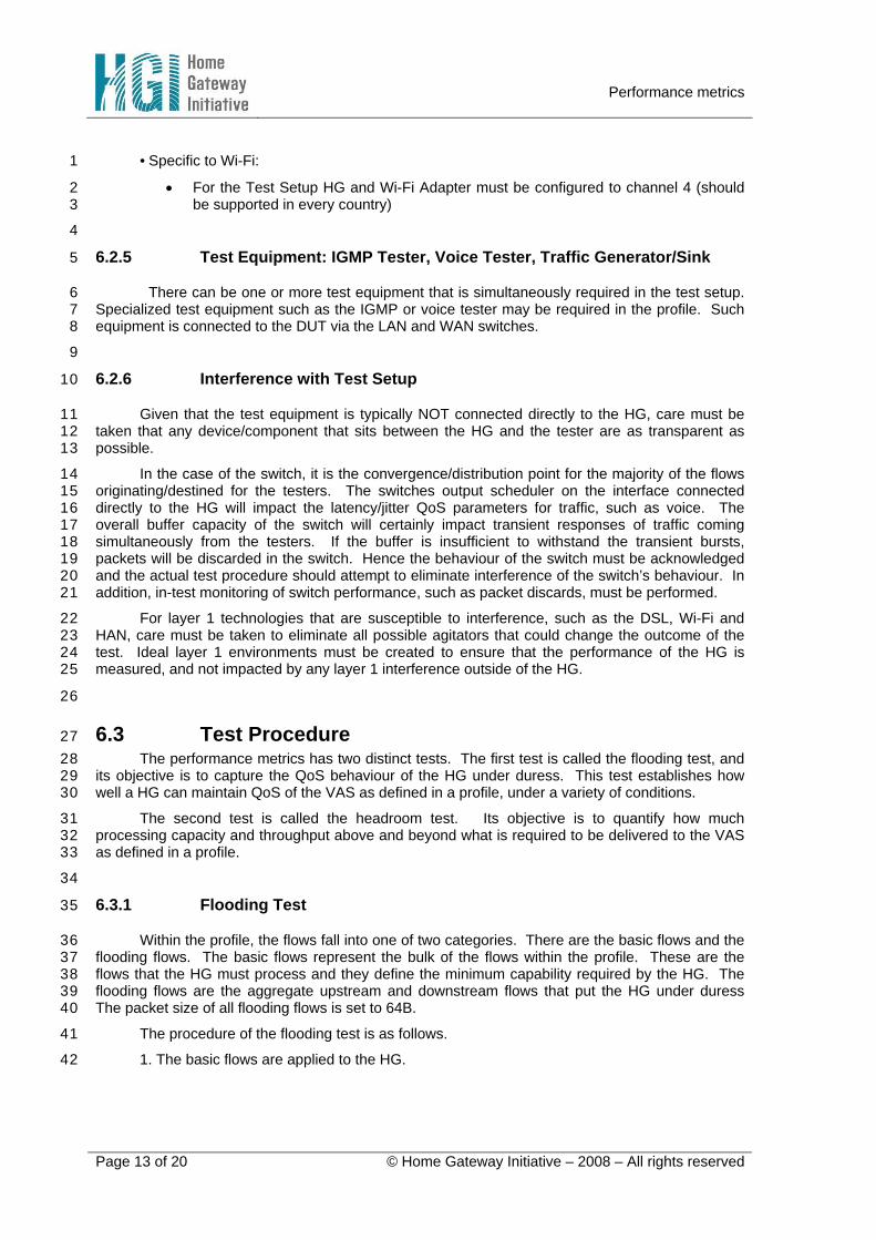
3. The flooding flows are applied in addition to the basic flows. The ingress flood rate is 3 increased. There are four points of interest: when there is zero flooding, ingress flood rate at the 4 point of first discard, ingress flood rate at the point of maximum throughput and finally the ingress 5 flood rate when line rate is achieved. 6
4. At each point of interest, the test is run for one minute. During this time, minimum, 7 average and maximum latency values for flows that have latency QoS metrics are measured. In 8 addition, the average data rate for each flow is measured. 9
5. A graph is plotted, the X-axis records the ingress flood rate. The positive Y-axis plots the 10 average output data rate of each flow. The negative Y-axis captures the min/avg/max latency of 11 the latency sensitive flows. The x-axis only indicates the increase of ingress flood rate and the 12 basic flow rates are constant (ingress and egress). 13
Performance metrics
Page 15 of 20 © Home Gateway Initiative – 2008 – All rights reserved
Egress Data Rate
Ingress Flood Rate
Basic flow 0
Basic flow 2
Line Rate
Flooding flows
Max. throughputFirst discard
QoS Flow Latency
Basic flow 1
1 Figure 4 Example of graphical output from flooding test 2
3 4
6.3.2 Headroom Test 5
Within the profile, the flows fall into one of two categories. There are the basic flows and the 6 headroom flows. The basic flows represent the bulk of the flows within the profile. These are the 7 flows that the HG must process and they define the minimum capability required of the HG. The 8 headroom flows are the flows used to quantify the headroom capacity of the HG. 9
The procedure of the headroom test is as follows. 10

Performance metrics
Page 16 of 20 © Home Gateway Initiative – 2008 – All rights reserved
1. The basic flows are applied to the HG. 1
2. QoS metrics as specified in the profile are checked and confirmed that they have been 2 met. 3
3. Starting with 64B packet size, the headroom flows are applied in addition to the basic 4 flows. The ingress headroom flow data rate is increased until either line rate is achieved, or until a 5 QoS metric is violated, or the first packet from any flow is dropped. The test is run for one minute. 6
4. The ingress headroom data rate is recorded. The packet size of the headroom flow is 7 increased, and step 3 is repeated. Possible headroom packet sizes to be exercised are 64B, 128B, 8 256B, 512B, 1024B, 1500B. 9
5. A headroom graph is created. The X-axis captures the headroom packet size. The Y-10 axis represents the aggregate output data rate of all the flows, which is the sum of the basic flow 11 and the ingress headroom data rate. 12
overall throughput(Mbps)
Headroom flowPkt Size (Byte)
Basic flow throughput
Headroom flow throughput
64 512 1024 1500
13 Figure 5 Example of graphical output from headroom test 14
15
Performance metrics
Page 17 of 20 © Home Gateway Initiative – 2008 – All rights reserved
7 References 1
[1] Home Gateway Technical Requirement, Residential Profile Version 1.0.1; 2
http://www.homegateway.org/publis/HGI_V1.01_Residential.pdf 3
[2] Embedded Microprocessor Benchmark Consortium, http://www.eembc.org 4
5
6
7
8
9
Performance metrics
Page 18 of 20 © Home Gateway Initiative – 2008 – All rights reserved
Appendix 1
2
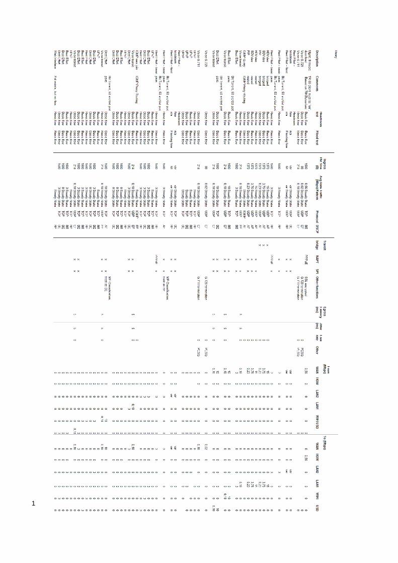
The following table shows an example of a function/flow component of a configuration profile as 3 described in Chapter 6. It is constructed from a library containing a large set of flow definitions. This 4 library is given on the next page. 5
The library of flows is provided for convenience and can be used to develop configuration 6 profiles that accommodate a variety of application scenarios. For example, a configuration profile 7 could use High Definition (HD) or Standards Definition (SD) video flows, G.729 voice, IGMP, and 8 other flows as appropriate given the application context. For each flow within the library, packet 9 size, average bit rate, traffic pattern, protocol, and several other parameters are provided. Some 10 flows are used for flooding, some for headroom, and some for both. Some flows are basic, and 11 some are specific headroom flows or flooding flows. 12
A profile can be developed by selecting a number of flows from the library. The test 13 equipment used for this profile should be configured to provide each of the selected flows according 14 to the parameters shown in the flow library. 15
The example configuration profile (“profile 1”) provides flows for a triple play scenario. In this 16 particular profile, flows include: 17
• several WAN to HG flows 18
o SD video 19
o voice 20
• several WAN to LAN flows 21
o IGMP 22
o best effort basic 23
o best effort headroom 24
o best effort flooding 25
o best effort (Bit Torrent) basic 26
• Several WAN to WIFI flows 27
o Best effort (Bit Torrent) basic 28
o Voice transit basic 29
• Several WIFI to WAN flows 30
o Best effort (Bit Torrent) basic 31
o Voice transit basic 32
• Web interface function33
1

1
2