8. powder mixing and blending; fluid flow through …...fig_mpe_8 dr. w. hintz + prof. dr. tomas...
TRANSCRIPT
Fig. 8.1
Prof. Dr. J. Tomas, chair of Mechanical Process Engineering
Fig_MPE_8 Dr. W. Hintz + Prof. Dr. Tomas Mechanical Process Engineering - Particle Technology Powder mixing and blending 30.06.2014 Figure 8.1
8. Powder mixing and blending;
Fluid flow through
particle beds
8. Product tailoring by particle mixing,
8.1 Microprocesses and mixing efficiency of particles 8.1.1 Model of stochastic homogeneity 8.1.2 Mixing kinetics
8.2 Rotating vessels, kneaders and agitators 8.3 Pneumatic mixing
8.3.1 Permeation of particle beds 8.3.2 Fluidized bed mixer

Fig. 8.2
Prof. Dr. J. Tomas, chair of Mechanical Process Engineering
Fig_MPE_8 Dr. W. Hintz + Prof. Dr. Tomas Mechanical Process Engineering - Particle Technology Powder mixing and blending 30.06.2014 Figure 8.2
Processes or unit operations of mechanical process engineering according to RUMPF
separation
combination
without
change
of
particle size
mechanical
separation (filters,
separators,
screens, sifters)
powder mixing
and
blending
particle
size
analysis with change
of
particle size
size reduction
(crushing and
grinding)
size enlargement
(agglomeration)
transport and storage of bulk materials

Fig. 8.3
Prof. Dr. J. Tomas, chair of Mechanical Process Engineering
Fig_MPE_8 Dr. W. Hintz + Prof. Dr. Tomas Mechanical Process Engineering - Particle Technology Powder mixing and blending 30.06.2014 Figure 8.3
Characterisation of particle mixtures
1. characterisation of mixing states of a granular material or
particle system
a) completely separated
b) ideal mixture
(regular distribution)
c) random mixture
c)
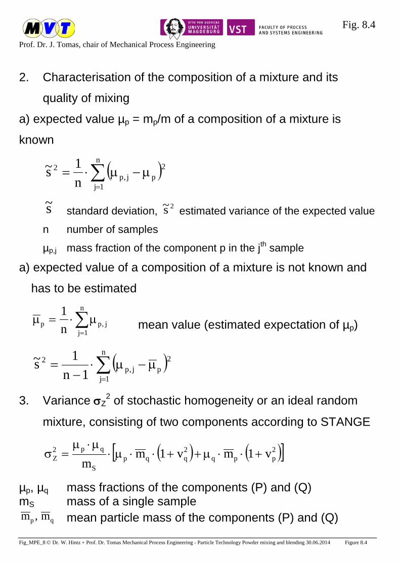
Fig. 8.4
Prof. Dr. J. Tomas, chair of Mechanical Process Engineering
Fig_MPE_8 Dr. W. Hintz + Prof. Dr. Tomas Mechanical Process Engineering - Particle Technology Powder mixing and blending 30.06.2014 Figure 8.4
2. Characterisation of the composition of a mixture and its
quality of mixing
a) expected value µp = mp/m of a composition of a mixture is
known
( )∑=
µ−µ⋅=n
1j
2pj,p
2
n1s~
s~ standard deviation, 2s~ estimated variance of the expected value
n number of samples
µp,j mass fraction of the component p in the jth sample
a) expected value of a composition of a mixture is not known and
has to be estimated
∑=
µ⋅=µn
1jj,pp n
1 mean value (estimated expectation of µp)
( )∑=
µ−µ⋅−
=n
1j
2pj,p
2
1n1s~
3. Variance σZ2 of stochastic homogeneity or an ideal random
mixture, consisting of two components according to STANGE
( ) ( )[ ]2ppq
2qqp
S
qp2Z v1mv1m
m+⋅⋅µ++⋅⋅µ⋅
µ⋅µ=σ
µp, µq mass fractions of the components (P) and (Q) mS mass of a single sample
qp m,m mean particle mass of the components (P) and (Q)

Fig. 8.5
Prof. Dr. J. Tomas, chair of Mechanical Process Engineering
Fig_MPE_8 Dr. W. Hintz + Prof. Dr. Tomas Mechanical Process Engineering - Particle Technology Powder mixing and blending 30.06.2014 Figure 8.5
q
p
pp m
v,m
vσ
=σ
= variation coefficients of the particle mass (size)
distributions of the components (P) and (Q) 4. Special cases:
a) narrow size distributions of both components vp → 0, vq → 0,
average particle number in one sample pSp m/mN =
pqp2Z N/µ⋅µ≈σ
b) nearly equivalent size distributions qp mm ≈ , vp ≈ vq
( )2qq
S
qp2Z v1m
m+⋅⋅
µ⋅µ≈σ
c) large mass fraction of component (P) µp > 0.9 and qp mm ≈
( )2qq
S
qp2Z v1m
m+⋅⋅
µ⋅µ≈σ
d) component (P) is very coarse qp mm >>
( )2pp
S
qp2Z v1m
m+⋅⋅
µ⋅µ≈σ
5. Mixing efficiency ME = 1 – SE segregation index:
s~/ME Z1 σ= ⇒ ( ) 1...0...s~/ ZmaxZ =σσ=σ
( ) qppp2max 1 µ⋅µ=µ−⋅µ=σ
max3 /s~1ME σ−= ⇒ ( ) 1...0/...s~1 maxZmax =σσσ=−

Fig. 8.6
Prof. Dr. J. Tomas, chair of Mechanical Process Engineering
Fig_MPE_8 Dr. W. Hintz + Prof. Dr. Tomas Mechanical Process Engineering - Particle Technology Powder mixing and blending 30.06.2014 Figure 8.6
Process principles for input of mechanical energy into particulate systems
Process principle schematic sketch example
rotating process
chambers or vessels
drum mixer drum mill
drum dryer
agitated systems
mechanical silo
discharging forced mixing
impact mill
flow of fluids
through granular
beds
pneumatic silo
discharging pneumatic
homogenisation fluidised beds
vibrations
vibration systems for charging and
discharging screen machine
vibration mill
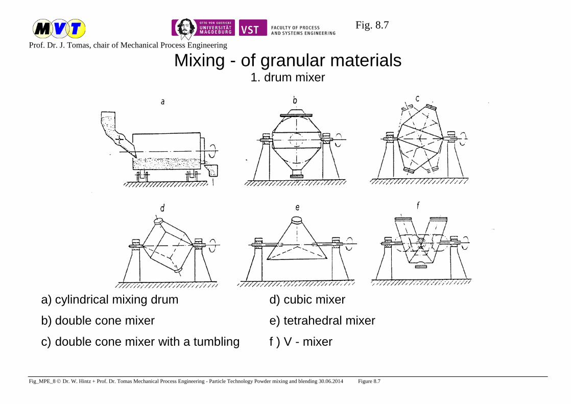
Fig. 8.7
Prof. Dr. J. Tomas, chair of Mechanical Process Engineering
Fig_MPE_8 Dr. W. Hintz + Prof. Dr. Tomas Mechanical Process Engineering - Particle Technology Powder mixing and blending 30.06.2014 Figure 8.7
Mixing - of granular materials 1. drum mixer
a) cylindrical mixing drum d) cubic mixer
b) double cone mixer e) tetrahedral mixer
c) double cone mixer with a tumbling f ) V - mixer
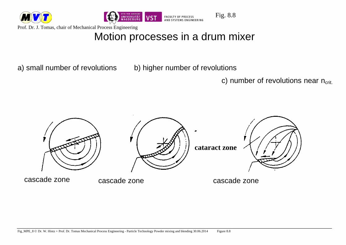
Fig. 8.8
Prof. Dr. J. Tomas, chair of Mechanical Process Engineering
Fig_MPE_8 Dr. W. Hintz + Prof. Dr. Tomas Mechanical Process Engineering - Particle Technology Powder mixing and blending 30.06.2014 Figure 8.8
Motion processes in a drum mixer
a) small number of revolutions b) higher number of revolutions
c) number of revolutions near ncrit.
cascade zone cascade zone cascade zone
cataract zone

Fig. 8.9
Prof. Dr. J. Tomas, chair of Mechanical Process Engineering
Fig_MPE_8 Dr. W. Hintz + Prof. Dr. Tomas Mechanical Process Engineering - Particle Technology Powder mixing and blending 30.06.2014 Figure 8.9
Mixing processes in a drum mixer
a) before mixing b) after mixing c) composition of samples taken from different
heights of the mixing bulk materials, before mixing
(t = 0), while mixing, and after mixing (t > tM)

Fig. 8.10
Prof. Dr. J. Tomas, chair of Mechanical Process Engineering
Fig_MPE_8 Dr. W. Hintz + Prof. Dr. Tomas Mechanical Process Engineering - Particle Technology Powder mixing and blending 30.06.2014 Figure 8.10
s2 = f (t) for different mixing processes a) without segregation processes
b) with segregation processes in the
beginning, components of higher
density are above those of lower
density
c) with segregation processes in the
beginning, components of higher
density are under those of lower
density

Fig. 8.11
Prof. Dr. J. Tomas, chair of Mechanical Process Engineering
Fig_MPE_8 Dr. W. Hintz + Prof. Dr. Tomas Mechanical Process Engineering - Particle Technology Powder mixing and blending 30.06.2014 Figure 8.11
Mixing - of granular materials
2. kneader, pan mixer
a) double-shaft kneader or pan mixer b) fast running paddle mixer
1 rotating mixing tool A feed
2 repel share, ploughshare M mixed product

Fig. 8.12
Prof. Dr. J. Tomas, chair of Mechanical Process Engineering
Fig_MPE_8 Dr. W. Hintz + Prof. Dr. Tomas Mechanical Process Engineering - Particle Technology Powder mixing and blending 30.06.2014 Figure 8.12
Mixing - of granular materials
3. Pneumatic mixer
a) fluidised bed mixer b) air jet mixer
LE air inlet
LA air outlet
A feed material for mixing
S1 – S4 separate aeration segments

Fig. 8.13
Prof. Dr. J. Tomas, chair of Mechanical Process Engineering
Fig_MPE_8 Dr. W. Hintz + Prof. Dr. Tomas Mechanical Process Engineering - Particle Technology Powder mixing and blending 30.06.2014 Figure 8.13

Fig. 8.14
Prof. Dr. J. Tomas, chair of Mechanical Process Engineering
Fig_MPE_8 Dr. W. Hintz + Prof. Dr. Tomas Mechanical Process Engineering - Particle Technology Powder mixing and blending 30.06.2014 Figure 8.14
Flow of fluids through granular beds - important mechanical
micro processes
1. schematic flow of fluids through a granular bed
entrance streaming profile of fluid exit streaming profile of fluid P2 - P1 pressure drop across the bed
u average velocity of flow of the fluid
uε average velocity of flow of the fluid in the pores
ε porosity of the bed
A total cross sectional area of the bed
I thickness of the bed
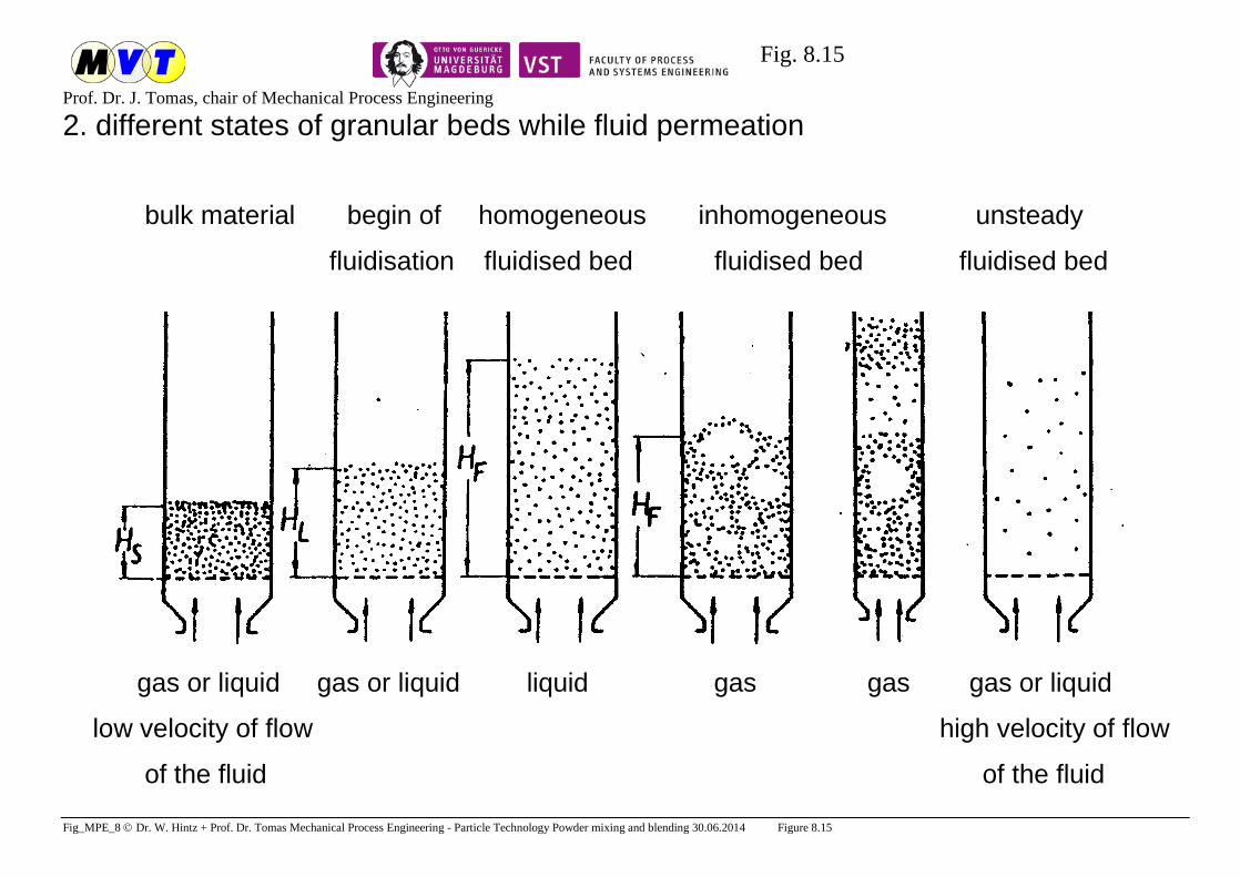
Fig. 8.15
Prof. Dr. J. Tomas, chair of Mechanical Process Engineering
Fig_MPE_8 Dr. W. Hintz + Prof. Dr. Tomas Mechanical Process Engineering - Particle Technology Powder mixing and blending 30.06.2014 Figure 8.15
2. different states of granular beds while fluid permeation
bulk material begin of homogeneous inhomogeneous unsteady
fluidisation fluidised bed fluidised bed fluidised bed
gas or liquid gas or liquid liquid gas gas gas or liquid
low velocity of flow high velocity of flow
of the fluid of the fluid

Fig. 8.16
Prof. Dr. J. Tomas, chair of Mechanical Process Engineering
Fig_MPE_8 Dr. W. Hintz + Prof. Dr. Tomas Mechanical Process Engineering - Particle Technology Powder mixing and blending 30.06.2014 Figure 8.16
3. pressure drop in the granular bed dependent on the fluid flow rate

Fig. 8.17
Prof. Dr. J. Tomas, chair of Mechanical Process Engineering
Fig_MPE_8 Dr. W. Hintz + Prof. Dr. Tomas Mechanical Process Engineering - Particle Technology Powder mixing and blending 30.06.2014 Figure 8.17
Fluid Flow through Particle Beds – Permeation Models a) Fixed particle bed
Valid for Model of Remarks
No Author Equation
Lam
inar
flow
-aro
und
Re
< 0.
5 tr
ansi
tion
Re
= 0.
5 - 1
000
Tur
bule
nt fl
ow-a
roun
d
Re
> 10
00
Poro
sity
ε
Pore
syst
em
Ran
dom
pac
king
mon
odis
pers
e sp
here
s
Part
icle
shap
e
1 Darcy uKukh
p
B⋅η⋅=⋅=
∆, K = Darcy constant
+ - - - + - - - Homoge-neous pore system
2 Carman, Kozeny
( )CK
2V,S3
2
B
KuA1h
p⋅⋅η⋅⋅
εε−
=∆
, KCK = Car-
man Kozeny constant, KCK = 5 for spheres of equal size with small deviation
+ - -
≈ 0.
4
+ - + - parallel bended, cylindrical pores
3 Gupte 5.5
B
K2
f Re6.5
hd
up
ε⋅=⋅
⋅ρ∆
+ - - + - + + - Dimension
analysis 4 Molerus,
Pahl, Rumpf
( ) 55.4B
K2
f Re6.514
hd
up
ε⋅⋅ε−⋅=⋅
⋅ρ∆
+ - -
0.35
– 0
.7 - + + - Basing on
results of Gupte

Fig. 8.18
Prof. Dr. J. Tomas, chair of Mechanical Process Engineering
Fig_MPE_8 Dr. W. Hintz + Prof. Dr. Tomas Mechanical Process Engineering - Particle Technology Powder mixing and blending 30.06.2014 Figure 8.18
5 Pärnt ( )3
2
2ST
2R
2F
hB
1d
uReh
pεε−
⋅⋅ψ⋅ψ
⋅η⋅⋅ξ=
∆,
ε−=
1ReReh
Reh = hydraulic Reynolds number ψF = shape factor, ψR = roundness factor ξ = fluid drag coefficient
+ - - + - + - + Experiments with fine disperse particle beds
6 Burke, Plummer 3
B
K2
f
175.1hd
up
εε−
⋅=⋅⋅ρ∆
- - + + - - - - Experiments
7 Ergun ( )3
B
K2
f
1hd
up
εε−
⋅λ=⋅⋅ρ∆
, 75.1Re
1150 +ε−
⋅=λ + + + + - - - - Experiments
8 Molerus
1.095.0
5.1
95.0
95.0
2
B
Re891.0
ad4.0
ad12.01
Re4
ad
21
ad692.01
Re24Eu
⋅
++
⋅+⋅+
+
⋅+⋅+⋅=
Euler number of fixed bed:
ε−ε
⋅ρ∆⋅
=1h
du3p4Eu
2
B2
fB
Re < 104
0.1
- 1
+ + + + η
ρ⋅⋅ε= fd)/u(
Re
Surface separation ratio
3
3
95.0 195.01
ad
ε−−ε−
=
d+a
d
a
d
d+a
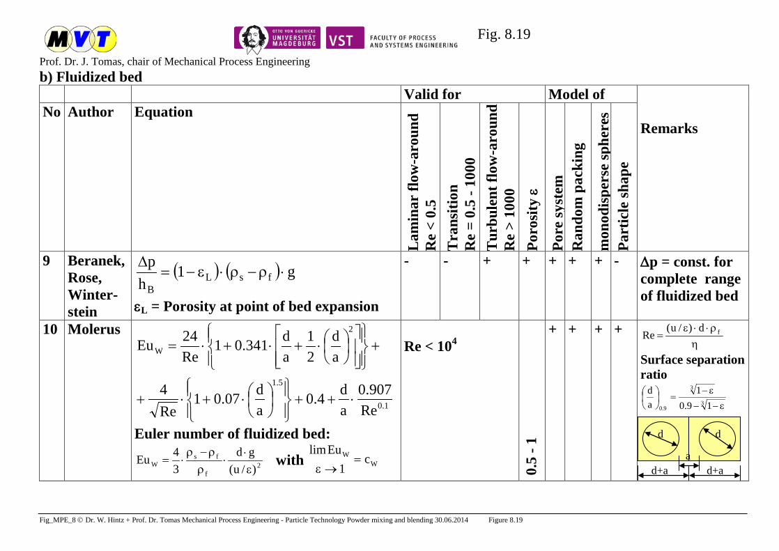
Fig. 8.19
Prof. Dr. J. Tomas, chair of Mechanical Process Engineering
Fig_MPE_8 Dr. W. Hintz + Prof. Dr. Tomas Mechanical Process Engineering - Particle Technology Powder mixing and blending 30.06.2014 Figure 8.19
b) Fluidized bed Valid for Model of
Remarks
No Author Equation
Lam
inar
flow
-aro
und
Re
< 0.
5 T
rans
ition
R
e =
0.5
- 100
0 T
urbu
lent
flow
-aro
und
R
e >
1000
Po
rosi
ty ε
Pore
syst
em
Ran
dom
pac
king
mon
odis
pers
e sp
here
s Pa
rtic
le sh
ape
9 Beranek, Rose, Winter-stein
( ) ( ) g1h
pfsL
B⋅ρ−ρ⋅ε−=
∆
εL = Porosity at point of bed expansion
- - + + + + + - ∆p = const. for complete range of fluidized bed
10 Molerus
1.0
5.1
2
W
Re907.0
ad4.0
ad07.01
Re4
ad
21
ad341.01
Re24Eu
⋅++
⋅+⋅+
+
⋅+⋅+⋅=
Euler number of fluidized bed:
2f
fsW )/u(
gd34Eu
ε⋅
⋅ρρ−ρ
⋅= with WW c
1Eulim
=→ε
Re < 104
0.5
- 1
+ + + + η
ρ⋅⋅ε= fd)/u(
Re
Surface separation ratio
3
3
9.0 19.01
ad
ε−−
ε−=
d
d+a d+a a
d
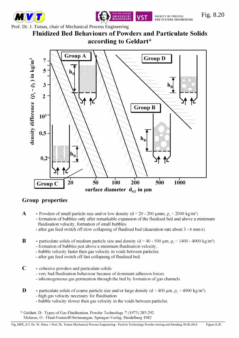
Fig. 8.20
Prof. Dr. J. Tomas, chair of Mechanical Process Engineering
Fig_MPE_8 Dr. W. Hintz + Prof. Dr. Tomas Mechanical Process Engineering - Particle Technology Powder mixing and blending 30.06.2014 Figure 8.20

Fig. 8.21
Prof. Dr. J. Tomas, chair of Mechanical Process Engineering
Fig_MPE_8 Dr. W. Hintz + Prof. Dr. Tomas Mechanical Process Engineering - Particle Technology Powder mixing and blending 30.06.2014 Figure 8.21
Survey of constitutive functions, processing and handling problems of cohesive powders. Property, problems
Physical principle
Physical assessment of product quality Particle size
d in µm Physical law Assessment
characteristic Value range
Evaluation
Large adhesion potential1) FG
FH0
2s
20
sls,H
G
0H
dag2C
FF
⋅ρ⋅⋅π= 2
2
d)µm100(
WeightAdhesion
≈ 1 - 100
100 - 104 104 - 108
slightly adhesive adhesive
very adhesive
10 - 100 1 - 10
0.01 - 1 Large intensifi-cation of adhesion2)
FN
FH(FN)FN
FH(FN)
pA
p
κ−κκ
=κ Contact consolidation
coefficient κ by flattening
0.1 – 0.3 0.3 – 0.77
> 0.77
soft very soft
extreme soft
< 10 < 1
< 0.1
Poor flowablity2)
σ1 σc
c
1cff
σσ
= Flow function ffc 2 - 4
1 - 2 < 1
cohesive very cohesive non-flowing
< 100 < 10 < 0.1
Large compres-sibility2)
σ1
∆h
n
0
st,M
0,b
b 1
σσ
+=ρρ
Compressibility index
n 0.05 – 0.1
0.1 - 1 compressible
very compressible < 100 < 10
Small permea-bility3,4)
∆hW
∆hb
u b
Wf h
hku∆∆⋅=
Permeability kf in m/s
< 10-9 10-9 - 10-7 10-7 - 10-5
non-permeable very low
low
< 1 1 - 10
10 - 100
Poor fluidi-sation5,6)
( ))d(ufp P=∆ Channelling Group C, non-fluidising
< 10
1) Rumpf, H.: Die Wissenschaft des Agglomerierens. Chem.-Ing.-Technik, 46 (1974) 1-11. 2) Tomas, J.: Product Design of Cohesive Powders - Mechanical Properties, Compression and Flow Behavior. Chem. Engng. & Techn., 27 (2004) 605-618. 3)Förster, W.: Bodenmechanik - Mechanische Eigenschaften der Lockergesteine, 4. Lehrbrief, Bergakademie Freiberg 1986. 4) Terzaghi, K., Peck, R. B., Mesri, G.: Soil mechanics in engineering practice, Wiley, New York 1996.
5) Geldart, D.: Types of Gas Fluidization, Powder Techn. 7 (1973) 285-292. 6) Molerus, O.: Fluid-Feststoff-Strömungen, Springer, Heidelberg 1982.