contents 80 series... · 1.9.2 – automatic thrust restoration (atr) ... the primary flight...
TRANSCRIPT
Contents
1.0.0 – Foreword
1.1.0 – Airplane General
1.2.0 – Flying Tips
1.2.1 – General
1.2.2 – Takeoff
1.2.3 – Inflight
1.2.4 – Descent
1.2.5 – Approach
1.2.6 – Landing
1.3.0 – Flight Guidance
1.3.1 – Basic System Layout
1.3.2 – Flight Guidance Panel
1.3.3 – Flight Mode Annunciator
1.3.4 - Auto Throttle System
1.3.5 – FGS Flight Mode Annunciator Examples
1.3.6 – FGS Reminders / Notes
1.3.7 – Thrust Rating Panel
1.4.0 – Ground Operations
1.4.1 – Powerback
1.4.2 – Ground Movement
1.5.0 – Crosswind Guidelines
1.5.1 – Takeoff
1.5.2 – Approach & Landing
1.6.0 - Auto Brake System
1.6.1 – Takeoff
1.6.2 – Landing
1.6.3 – General
1.7.0 – Air
1.7.1 – Anti-Ice & Bleed Config
1.7.2 – Air Conditioning
1.7.3 – A/C Packs OFF Departure
1.7.4 – Abnormal Bleed Configuration
1.8.0 – EOAP
1.9.0 – Engine Thrust Recovery
1.9.1 – Automatic Reserve Thrust (ART)
1.9.2 – Automatic Thrust Restoration (ATR)

1.0.0 First and foremost
The aim of this document is to provide dedicated users of the Fly The Maddog X simulation a
pocket guide for advanced flying techniques and aircraft operation. Except for a few elements
which were considered necessary for quick reference, in-depth system descriptions were left out to
cut the size of the document and make essential information as easy to access as possible.
For detailed information about basic aircraft systems please refer to the AOM which is provided
with the add-on. This guide purely focuses on giving pilots a guideline for questions and
challenges encountered in everyday operation.
We hope you will find yourself as excited flying the Maddog as we were while developing and
testing it.
Sincerely,
The Fly The Maddog X Development Team
1.1.0 Airplane General
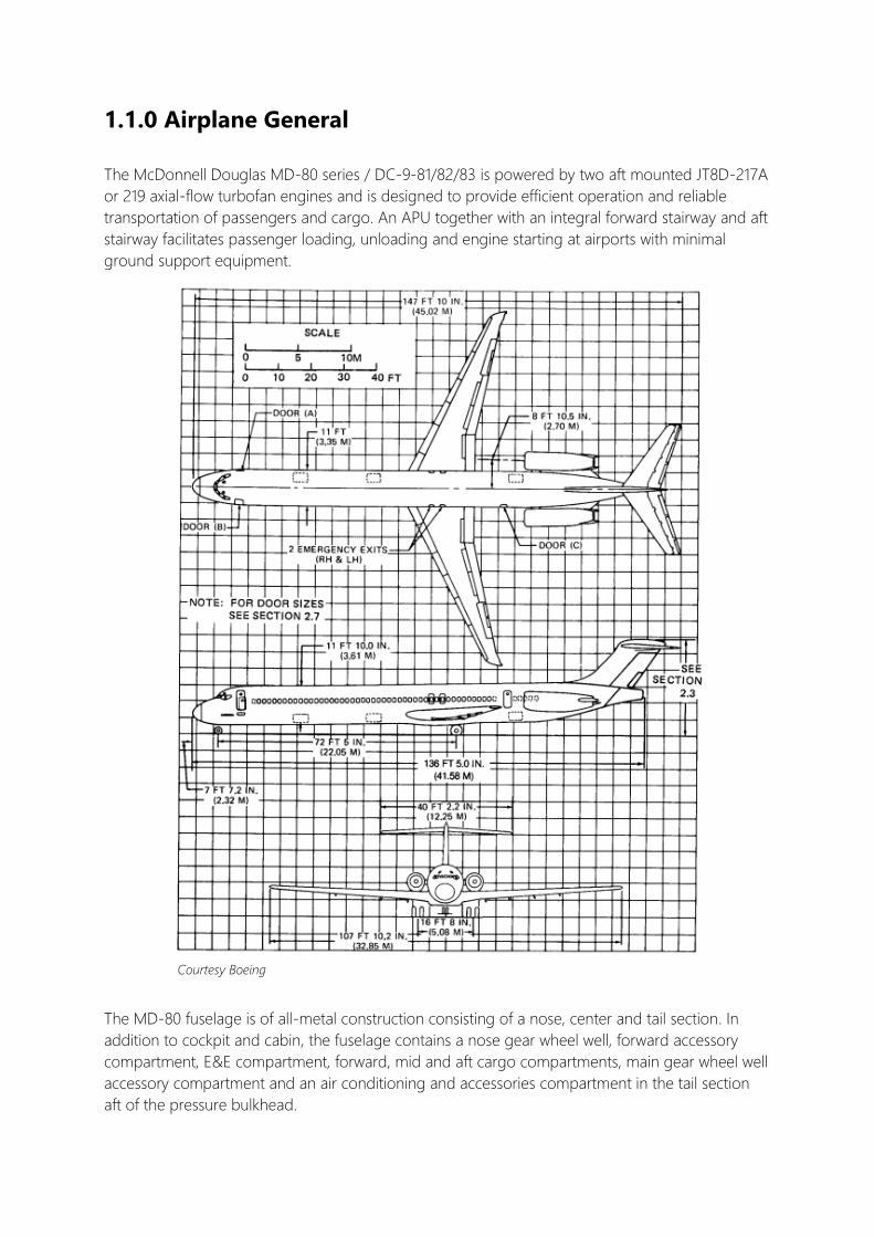
The McDonnell Douglas MD-80 series / DC-9-81/82/83 is powered by two aft mounted JT8D-217A
or 219 axial-flow turbofan engines and is designed to provide efficient operation and reliable
transportation of passengers and cargo. An APU together with an integral forward stairway and aft
stairway facilitates passenger loading, unloading and engine starting at airports with minimal
ground support equipment.
The MD-80 fuselage is of all-metal construction consisting of a nose, center and tail section. In
addition to cockpit and cabin, the fuselage contains a nose gear wheel well, forward accessory
compartment, E&E compartment, forward, mid and aft cargo compartments, main gear wheel well
accessory compartment and an air conditioning and accessories compartment in the tail section
aft of the pressure bulkhead.
Courtesy Boeing

All external doors and emergency exits, with exception of the forward stair well door, are plug-type
and pressure sealed.
The tailcone is the aft end of the aircraft´s fuselage and may be jettisoned by actuation of either an
interior or exterior control as long as the airplane is on the ground to provide an emergency exit.
Compared to many current aircraft types in service, the MD-80 (like other aircraft of the DC-9
series) has quite a different approach in terms of the flight control system. Primary flight controls
consist of conventional aileron, rudder and elevator control surfaces. Secondary flight controls
consist of lift-augmenting leading-edge slats, spoilers, inboard and outboard flaps and horizontal
stabilizer.
The flaps may be positioned in six different permanent detents from 0 to 40 degree range.
A specific MD-80 feature is called “Dial-A-Flap” and allows free flap selection from 0 to 13 degrees
and 15 to 25 degrees for takeoff. The specific setting can be selected with the takeoff flap selector
thumbwheel on the right side of the pedestal.
The primary flight controls are cable connected to the control surfaces and are aerodynamically
actuated via control tabs. Therefore, the pilot does not have direct control over the control
surfaces, but over small tabs on the trailing edge of the ailerons and elevator with exception of the
rudder. To move the whole control surface, it is necessary to have some airflow along the aircraft.
By moving the yoke, the control tabs move into the opposite direction than commanded by the
pilot and thus push the actual control surface into the correct position. On the elevator, alongside
the control tabs, there are geared tabs which are not directly controlled but assist the control tabs
in moving the elevator into position. The elevator also features a third kind of tab – the anti-float
tab – which counters the tendency of the elevator to float upwards on approach. The ailerons also
have a second type of tab – the trim tab – which is not geared and allows for aileron trim. During
normal operation the rudder is hydraulically operated. A control tab on the trailing edge is locked
and only becomes active if hydraulic pressure is lost.
1.2.0 Flying Tips
1.2.1 GENERAL
The slower the aircraft flies, the softer the controls get. This results in small yoke movements
necessary to control the MD-80 at high speed and greater control inputs required as speed
decreases. It is known that the aircraft might feel slightly sluggish especially on approach.
1.2.2 TAKEOFF
To allow for constant and equal engine spool up, set throttles slightly ahead of the idle detent. By
doing this, engine RPM can be aligned without applying a high thrust setting. Once engines are
stable and spool up has been checked, bring the throttles forward to 1.4 EPR in a smooth but
steady manner. If AT is used for takeoff, set the AT switch to ON once engines have reached 1.4
EPR.
- CLMP will engage at 60kts
f
After lift-off speed is reached, rotate the aircraft with a constant steady rate smoothly to a
maximum of 20° nose up attitude. Avoid large elevator control inputs.
Reaching the desired height for noise abatement (e.g. 3000ft), accelerate towards FLAP/SLAT
retract speed by selecting half of the current climb rate (VERT SPD) via the pitch wheel on the
FGCP. Once acceleration process is complete continue climb-out with IAS/MACH, EPR LIM or
VNAV.
1.2.3 INFLIGHT
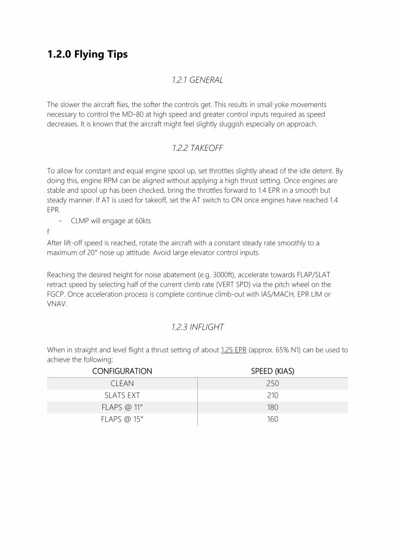
When in straight and level flight a thrust setting of about 1.25 EPR (approx. 65% N1) can be used to
achieve the following:
CONFIGURATION SPEED (KIAS)
CLEAN 250
SLATS EXT 210
FLAPS @ 11° 180
FLAPS @ 15° 160
1.2.4 DESCENT
Planning – The common method (Height x 3 = Descent distance required) can be used for
descent planning. Descent speed should either equal cruise speed / the provided company value
until reaching 10,000ft or other speed restrictions. Around 6nm are required to slow down 10kts
without the use of drag devices (Based on zero wind condition, add 1nm per 10kts of wind)
Monitor the descent by applying the procedure mentioned above regularly, check V/S roughly
equals ground speed x 5.
Note: There are many ways to descent from cruise level, one that’s particularly special to the MD-
80 though, is the IAS/MACH descent in conjunction with CLMP.
Once a descent is initiated with VERT SPD, select IAS/MACH on the Pitch Control Panel. Throttles
will be clamped, the FMA displays – CLMP (AT) and IAS or MACH (Pitch). From here on, the
airplane will maintain descent speed by pitch. The throttles, although clamped, can still be
manually set to a different position. This allows the pilot to increase or decrease vertical speed by
alternating engine thrust. The aircraft will hold the selected speed independent of throttle position.
ATTENTION
Throttles should not be set to the true idle position trying to reduce descent speed. Once
the autopilot levels the airplane off at a certain altitude, the engines can´t spool up fast
enough from this position. In order to hold the selected IAS the AT will push the engines to
almost full thrust resulting in an abrupt and uncomfortable acceleration.
Reselecting VERT SPD or any other vertical mode will deactivate CLMP if required.
1.2.5 APPROACH
Normal flap settings for landing are 28° or 40°. If the airplane should be very light, Flaps 40°
should be used in order to reduce approach speed.
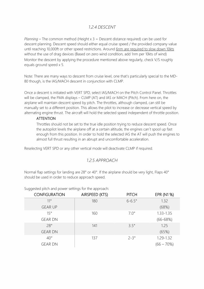
Suggested pitch and power settings for the approach:
CONFIGURATION AIRSPEED (KTS) PITCH EPR (N1 %)
11°
GEAR UP
180 6-6.5° 1.32
(68%)
15°
GEAR DN
160 7.0° 1.33-1.35
(66-68%)
28°
GEAR DN
141 3.5° 1.25
(65%)
40°
GEAR DN
137 2-3° 1.29-1.32
(66 – 70%)

1.2.6 LANDING
Vref calculation:
The airplane will automatically calculate approach speeds for different flap settings and will display
these on the FMS APPR page.
Wind additives should either equal half of the current steady wind or the difference between
steady wind and gust value. Should both calculations be possible use the greater additive.
- Add a minimum 5 kts / maximum 20kts
- AUTOLAND: Vref + 5 regardless of gust / steady wind
If conditions require greater additives than 10kts (gust) / 15 (steady) discontinue
autoland operation
FLAPS 28 / 40 reference
Target speed
Flaps 11 / 15 maneuver
Slats Extended, Flaps 0 maneuver
Clean maneuver

1.3.0 Flight Guidance System – FGS
FGS consists of:
1.3.1 Basic System Layout
LEFT RIGHT
Autopilot DFGC (1/2) selector also determines which DFGC supplies command to:
-Autopilot (AP)
-Auto Throttle (AT)
-Flight Director (F/D)
-Lateral / Vertical Navigation
-Altitude Alert
-Speed Control
-EPR Selection
-Auto Thrust Restoration (ATR)
-Auto Reserve Thrust (ART)
-Engine Sync
-Yaw Damper
-Mach Trim Compensation
AIRCRAFT SENSORS
-CADC 1 & 2
-Flap/Slat/Spoiler sensors
-Stab/Elevator sensors
DFGC 2 DFGC 1
F/D 1 F/D 2
F/D Command Bars
Fast / Slow Indicator
AUTOPILOT
-Commands Roll, Pitch, Yaw control (dual servos)
-Powered by either DFGC -> one active / one “hot spare”
Auto Throttle
-Commands Throttle servos
-Controls speed, Mach number, engine thrust
-EPR/TRP panel
-FMS
-
-Altitude Alert
-EPR Sync
-ART
-ATR
-Yaw Damper Actuator
-Mach Trim Actuator

VHF NAV 1 Auto Throttle
Panel
Directional
Control Panel
Pitch Control
Panel
Altitude Selector
VHF NAV 2
Auto Throttle Panel
SPD/MACH knob – adjust SPD
->1st detent - fast change
->PUSH SPD <-> MACH
SPD/MACH SEL – activates SPD / MACH mode
EPR LIM – Auto Throttle to MAX EPR set
FMS OVRD – manipulate FMS speed
Directional Control Panel
NAV – AP follows FMS LNAV course
VOR LOC – AP follows NAV course / localizer
ILS – arm AP ILS function (G/S, LOC)
AUTO LAND – arm automatic landing function
HDG SEL knob – adjust HDG
->PUSH to engage HDG HOLD
->PULL to engage HDG SEL
Pitch Control Panel
Pitch Select Wheel – set VERT SPD / IAS, MACH / PITCH
->ANU = Up / AND = Down
VNAV – AP follows FMS vertical profile
ALT HOLD – AP will maintain altitude at engagement
->engages if VERT SPD is > 100 fpm
ALT preselect – preselect an altitude (for level-off)
->PUSH – 100ft / NORM – 1000ft / PULL – Arm ALT
->automatically arms if new ALT is set
->arms altitude alert
TURB – engages TURB mode
->AP holds pitch attitude (can be selected) / WINGS LVL
ATTENTION
-Activating TURB mode disengages Auto Throttle
-Dampens DFGC pitch/roll commands
1.3.2 Flight Guidance Control Panel (FGCP)

The easiest way to get into how the FMA works in conjunction with the Autopilot system is to it
compare with the FGCP. After a short look it should appear that, from left to right, the FMA is quite
similar to the layout of the FGCP.
On the outer left side the current Auto Throttle mode is displayed. (Example: IAS, MACH, CLMP)
Next to it is the “Arm” section which shows the armed AP modes. (For example, if an altitude is set
on the FGCP the “Arm” section shows ALT to remind you that the aircraft, if controlled by the AP,
will level-off once the altitude set is reached.)
The center right “Roll” part shows the currently active lateral navigation mode. (Example: HDG,
NAV TRK, VOR TRK). In addition, all lateral captures will be announced with CAP once e.g. a VOR
or LOCalizer signal has been recognized and the AP is capturing the radial set.
The outer right side displays the vertical/pitch mode that is currently active. It will, as the “Roll”
panel, also announce capture of a specific setting. For example once a set altitude is in the process
of being captured, the display will show ALT CAP before switching to ALT HOLD.
To remember the layout just keep the word TARP in mind.
Regardless of F/D switch position, the FMA will always display active modes if AP is ON.
Above these four display is the FMA Warning Lights section which can alert the pilot about the
following failures:
AP TRIM – Autopilot command / horizontal trim disagree
NO AUTOLAND – FGS detected condition which doesn´t permit an automatic landing
Four of these warning lights are referred to as “Comparator Monitor Lights”, in short, they indicate
a difference between either of the Capitan´s/FO´s:
- ILS indication
- Attitude indication
- Compass direction
In case the Comparator system itself should fail, the “MONITOR” warning will be illuminated.
1.3.3 Flight Mode Annunciator (FMA)

The Comparator lights will, in addition to indicating a system failure, also show which side has
failed. The warning light on the failed side will flash continuously while the light on the non-failed
side will be steady.
Above the FMA Warning Lights two red bars will flash continuously if either AP or AT is
disconnected. These warnings can be reset by pressing either AP / AT disconnect button(s).
On the right edge the FMA will also show which AP (DFGC) is active and if the panels
corresponding F/D is set ON.
1.3.4 Auto Throttle (AT) System (ATS)
Auto Thrust will disengage due:
- Manual deactivation
- ATS monitor detects failure
- ATS in EPR mode -> airspeed exceeds FLAP/SLAT limit or Vmo/Mmo
- Power interrupted for 1/5 sec
- DFGC unit switched
- Reverse thrust is applied
DFGC signals to Auto Throttle control:
- Throttle lever servos
- F/S indication
- F/D command bars
The Auto Throttle System can CLMP (Clamp) the throttles to a specific setting by removing
electrical power from the servos. This is common during Take-Off or if AP/AT modes are
incompatible.
The Auto Throttle System is bound to following restrictions:
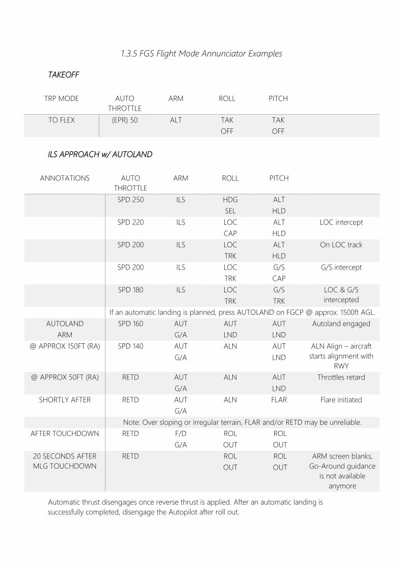
1.3.5 FGS Flight Mode Annunciator Examples
TAKEOFF
TRP MODE AUTO
THROTTLE
ARM ROLL PITCH
TO FLEX (EPR) 50 ALT TAK
OFF
TAK
OFF
ILS APPROACH w/ AUTOLAND
ANNOTATIONS AUTO
THROTTLE
ARM ROLL PITCH
SPD 250
ILS HDG
SEL
ALT
HLD
SPD 220 ILS LOC
CAP
ALT
HLD
LOC intercept
SPD 200 ILS LOC
TRK
ALT
HLD
On LOC track
SPD 200 ILS LOC
TRK
G/S
CAP
G/S intercept
SPD 180 ILS LOC
TRK
G/S
TRK
LOC & G/S
intercepted
If an automatic landing is planned, press AUTOLAND on FGCP @ approx. 1500ft AGL.
AUTOLAND
ARM
SPD 160 AUT
G/A
AUT
LND
AUT
LND
Autoland engaged
@ APPROX 150FT (RA) SPD 140 AUT
G/A
ALN AUT
LND
ALN Align – aircraft
starts alignment with
RWY
@ APPROX 50FT (RA) RETD AUT
G/A
ALN AUT
LND
Throttles retard
SHORTLY AFTER RETD AUT
G/A
ALN FLAR Flare initiated
Note: Over sloping or irregular terrain, FLAR and/or RETD may be unreliable.
AFTER TOUCHDOWN RETD F/D
G/A
ROL
OUT
ROL
OUT
20 SECONDS AFTER
MLG TOUCHDOWN
RETD ROL
OUT
ROL
OUT
ARM screen blanks,
Go-Around guidance
is not available
anymore
Automatic thrust disengages once reverse thrust is applied. After an automatic landing is
successfully completed, disengage the Autopilot after roll out.
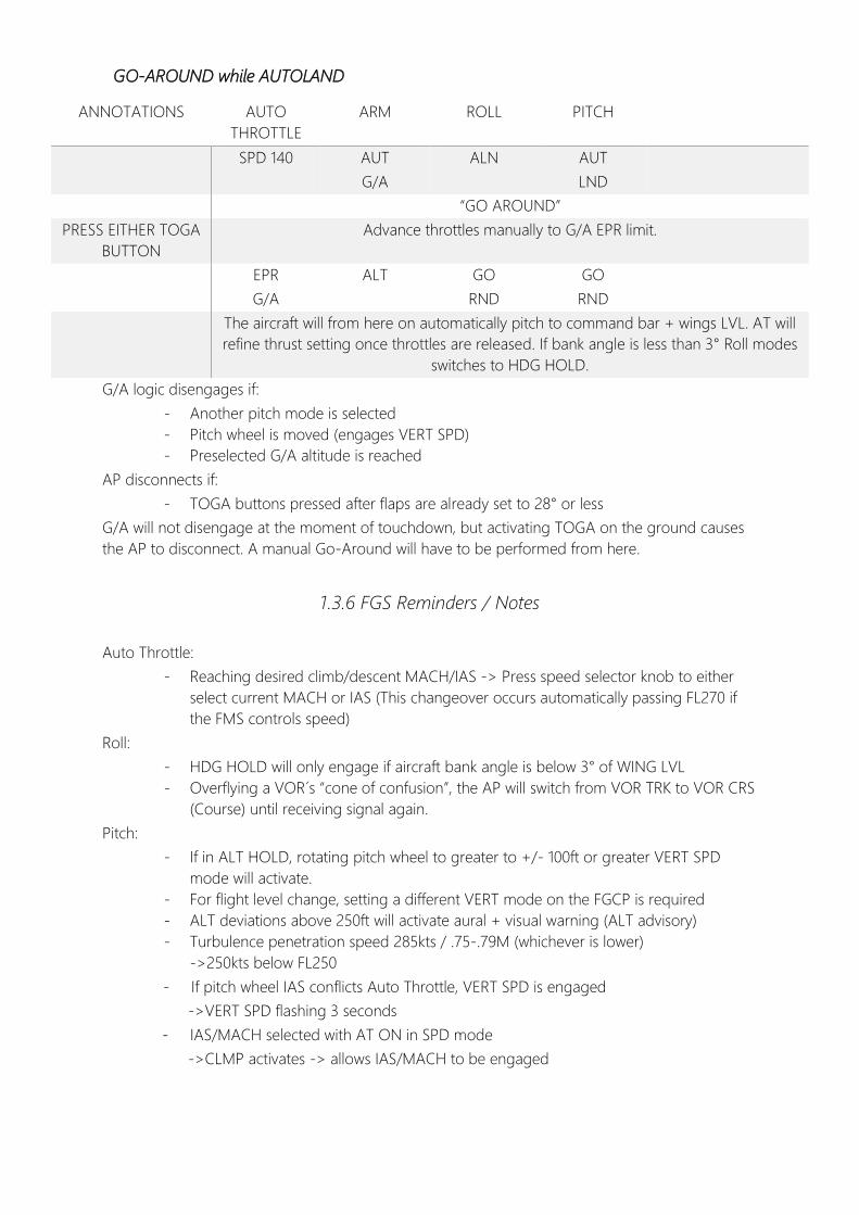
ANNOTATIONS AUTO
THROTTLE
ARM ROLL PITCH
SPD 140 AUT
G/A
ALN
AUT
LND
“GO AROUND”
PRESS EITHER TOGA
BUTTON
Advance throttles manually to G/A EPR limit.
EPR
G/A
ALT GO
RND
GO
RND
The aircraft will from here on automatically pitch to command bar + wings LVL. AT will
refine thrust setting once throttles are released. If bank angle is less than 3° Roll modes
switches to HDG HOLD.
G/A logic disengages if:
- Another pitch mode is selected
- Pitch wheel is moved (engages VERT SPD)
- Preselected G/A altitude is reached
AP disconnects if:
- TOGA buttons pressed after flaps are already set to 28° or less
G/A will not disengage at the moment of touchdown, but activating TOGA on the ground causes
the AP to disconnect. A manual Go-Around will have to be performed from here.
1.3.6 FGS Reminders / Notes
Auto Throttle:
- Reaching desired climb/descent MACH/IAS -> Press speed selector knob to either
select current MACH or IAS (This changeover occurs automatically passing FL270 if
the FMS controls speed)
Roll:
- HDG HOLD will only engage if aircraft bank angle is below 3° of WING LVL
- Overflying a VOR´s “cone of confusion”, the AP will switch from VOR TRK to VOR CRS
(Course) until receiving signal again.
Pitch:
- If in ALT HOLD, rotating pitch wheel to greater to +/- 100ft or greater VERT SPD
mode will activate.
- For flight level change, setting a different VERT mode on the FGCP is required
- ALT deviations above 250ft will activate aural + visual warning (ALT advisory)
- Turbulence penetration speed 285kts / .75-.79M (whichever is lower)
->250kts below FL250
- If pitch wheel IAS conflicts Auto Throttle, VERT SPD is engaged
->VERT SPD flashing 3 seconds
- IAS/MACH selected with AT ON in SPD mode
->CLMP activates -> allows IAS/MACH to be engaged
GO-AROUND while AUTOLAND
Climbing less than 2000ft it is advisable to use SPD SEL and VS 1000fpm. If a climb of more than
2000ft is required use IAS with EPR LIM.
When climbing watch out for SPD/MACH ATL indications on the FMA, this indicates that the
engines are running at maximum EPR. Ignoring the change from a normal AT mode to SPD or
MACH LIM may result in a stall condition as the airplane can no longer maintain speed.
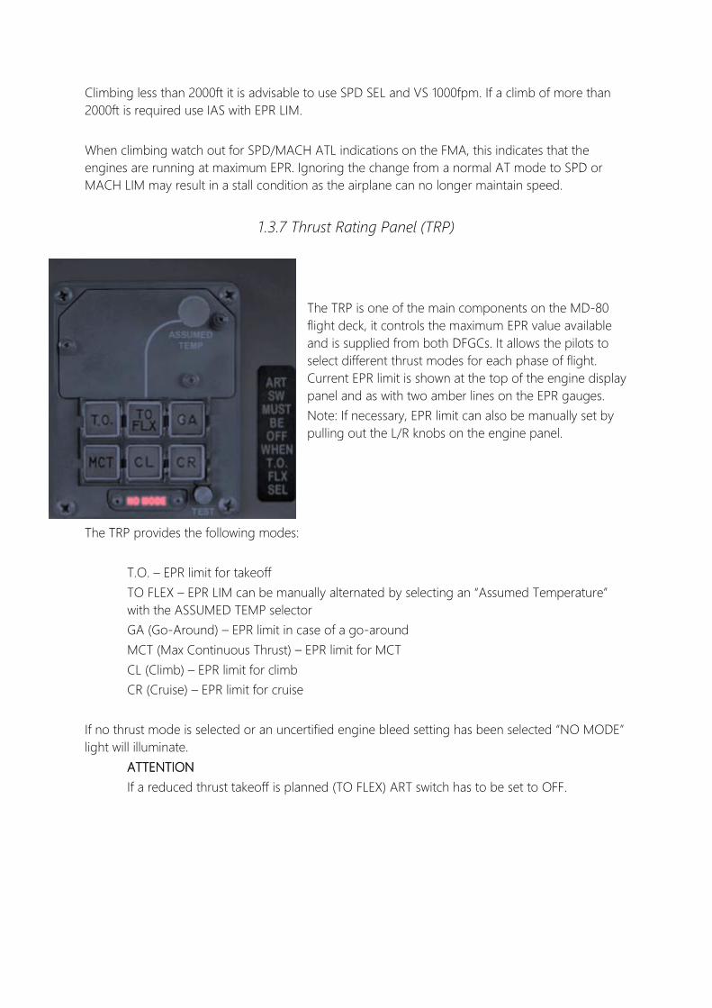
1.3.7 Thrust Rating Panel (TRP)
The TRP is one of the main components on the MD-80
flight deck, it controls the maximum EPR value available
and is supplied from both DFGCs. It allows the pilots to
select different thrust modes for each phase of flight.
Current EPR limit is shown at the top of the engine display
panel and as with two amber lines on the EPR gauges.
Note: If necessary, EPR limit can also be manually set by
pulling out the L/R knobs on the engine panel.
The TRP provides the following modes:
T.O. – EPR limit for takeoff
TO FLEX – EPR LIM can be manually alternated by selecting an “Assumed Temperature”
with the ASSUMED TEMP selector
GA (Go-Around) – EPR limit in case of a go-around
MCT (Max Continuous Thrust) – EPR limit for MCT
CL (Climb) – EPR limit for climb
CR (Cruise) – EPR limit for cruise
If no thrust mode is selected or an uncertified engine bleed setting has been selected “NO MODE”
light will illuminate.
ATTENTION
If a reduced thrust takeoff is planned (TO FLEX) ART switch has to be set to OFF.

1.4.0 Ground Operation
1.4.1 Powerback
1.4.2 Ground Movement
- Use 1.1 EPR MAX momentarily to begin rolling unless aircraft is very heavily loaded
- Idle power may cause acceleration once aircraft is moving
- Maximum steering 82° from center to L/R
-> Single HYD system operative: 55° towards operating system / 82° towards inoperative
side
- Aircraft reacts very sensitive to nose gear steering input
-> To allow smooth turns assist entry with rudder pedal steering (approx. 17° L/R)
- Avoid braking while turning, if still required brake outside wheels first
- If additional thrust is required while turning increase outside engine power
- Overshooting the centerline will be required in all turns due to gear position
CHECK
-Both thrust reversers operative
-Ramp clear of personnel / ground
equipment
-Precipitation not above medium
-Do not apply brakes when rolling
backwards
-Max. 1.3 EPR
PROCEDURE
FLAP/SLAT handle………..UP/RET
Thrust levers……………….…IDLE reverse
Engine panel…………………Check reverse operation
Thrust setting………………..MAX 1.3 EPR
Once reverse taxi complete:
Thrust levers…………………Forward IDLE
To stop the backward movement apply slight
amount of forward thrust.

1.5.0 Crosswind Guidelines
1.5.1 TAKEOFF
Dry runway……………………………………………………..30 kts
Wet runway…………………………………………………….20 kts
Icy runway……………………………………………………….12 kts
Preapply slight amount of aileron input into the wind and use rudder for directional control. Avoid
use of wheel throw above 5° -> drag producing spoilers engage at 5° or more. Rotate normally
holding crossed controls, increase if required. After lift-off focus on transition to coordinated
aileron and rudder while maintaining wings level.
1. Swept wing, high-tail aircraft have a tendency to turn into the wind, heel over at rotation.
2. Forward pressure on the yoke assists in maintaining control.
1.5.2 APPROACH & LANDING:
Manual rudder…………………………………………………25 kts
Autoland system limit:
- Headwinds < 25 kts
- Tailwinds < 10 kts
- Crosswinds < 15 kts
Crosswind correction with the autoland system engaged begins at about 150ft radio altitude.
Restricted rudder……..……………………………………….12 kts
Instrument approach at or below 2400 RVR…..10 kts
On final establish a crab angle into the wind, maintain this angle until just before touchdown on
the runway. Keep wings as level as possible to avoid excessive bank (8° to either side) otherwise
they will make contact with the ground. Use as little aileron as possible on roll-out, excessive use
can lead to spoiler yaw.
ATTENTION
Use of ailerons with spoilers extended causes spoilers to retract partially on one wing which
in return can cause one-sided lifting of the aircraft.
1.6.0 Automatic Brake System
1.6.1 TAKEOFF
The ABS takeoff mode is selected by setting the AUTO BRAKE selector to T.O. and AUTO BRAKE
ARM/DISARM switch to ARM. The spoilers must be retracted and armed, flaps set to less than 26°.
In case of a rejected takeoff the auto brake system will apply MIN braking if below 70kts. At speeds
above 70kts the ABS will apply maximum available dual-system automatic braking without any
time delay.
-Takeoff aural warning will sound if either spoilers or ABS aren´t armed
1.6.2 LANDING
ABS landing mode is armed prior to landing by selecting an appropriate setting and placing the
AUTOBRAKE ARM/DISARM switch to ARM. Anti-skid must be armed & operational for the ABS to
work.
ABS automatically activates as landing spoilers are deployed or manually by retarding the throttles
below 22°, above this setting system operation is inhibited.
-ABS activates after 1 second (MAX) 3 seconds (MIN/MED)
1.6.3 GENERAL
The system is disarmed if one of either or both brake pedals are pressed, by selecting the
AUTOBRAKE ARM /DISARM switch to DISARM, throttles are advanced beyond 22° or if flaps are
set to less than 26° while aircraft speed is above 70kts during landing. Retracting the ground
spoilers will relief brake pressure but does not disarm the automatic brake system.
-ABS disarm lights on glareshield will illuminate if auto brake is disarmed
-ABS will automatically disarm if malfunction occurs
->AUTO BRAKE FAIL on EOAP
->ABS & MASTER CAUTION lights illuminate
If the fault is cleared, to re-arm the system set AUTO BRAKE selector to OFF and then back to an
appropriate setting and resetting the AUTO BRAKE ARM/ DISARM switch to ARM.
Note: If both ABS and spoilers aren’t armed for TO/Landing, no warning will become active. The
unarmed system warning only activates if either of both systems is armed and the other is not.
1.7.0 Air 1.7.1 Anti-Ice
If icing conditions are present (RAT below +10°C and visible moisture):
Anti-Ice procedure:
Ignition………………….……...A or B
Engine Anti-Ice …...……..ON (One by one)
PNEU Cross Feeds……….OPEN
Air Foil Anti-Ice……………..ON
Anti-Ice Shutdown procedure:
TAIL button………………….Pressed
Wait until TAIL AI complete & reverse procedure described above.
1.7.2 Air Conditioning
Heated air from the pneumatic system is mixed with cold air from the air conditioning system to
provide temperature control for cockpit and cabin. The aircraft is fitted with two air conditioning
packs (L&R) operating independent as well as parallel. Normally the right pack is fed by right
engine bleed air and controls cabin temperature. The left pack is fed by left engine bleed air and
controls cockpit temperature. If one system should fail, the remaining one is capable of supplying
the requirements for both areas. Air conditioning can be set on the according overhead panel.
The Air Conditioning Supply switches allow the system to operate in two different modes, HP BLD
OFF and AUTO.
HP BLD OFF (High-Pressure Bleed) should be selected on the ground as long as pressuriziation of
the aircraft is NOT required. The augmentation valve stays closed, therefore pressure control is not
provided. HP BLD OFF also has direct influence on bleed air supplied from the engines, if HP BLD
OFF is selected the 13th stage high-pressure manifold will stay shut. Thus, only LP bleed air from
the 8th stage manifold will be used.
AUTO should be selected once one or both engines are started, the augmentation valve then
opens and allows the aircraft to be pressurized.
1.7.3 A/C Packs OFF departure
In case of hot & high operations switching OFF the air conditioning packs may be necessary to
comply with takeoff performance.
Therefore, prior to takeoff:
Air Conditioning Supply switches………………OFF
After takeoff passing 400ft,
Air Conditioning Supply switches………………AUTO
ATTENTION
Air Conditioning Supply switches must be set to AUTO before selecting climb power to
prevent NO MODE light from illuminating.
1.7.4 Abnormal Bleed Configuration
Following is a chart of abnormal bleed configs which cause the “NO MODE” light to illuminate.
TRP MODE SELECTED BLEED CONFIGURATION
T.O., T.O. FLEX, GA, MCT, CL or CR - Air Foil Ice Protection ON
- One or both PNEU CROSS FEEDS OPEN
- Engine AI OFF
T.O. or T.O. FLEX - Engine AI ON
- RAT greater than 10°C
GA - Engine AI ON
- RAT greater than 14°C
MCT - Air Foil Ice Protection ON
- Both PNEU CROSS FEEDS OPEN
CL -Air Foil Ice Protection ON
-One PNEU CROSS FEED CLOSED
MCT, CL or CR -Both A/C Packs OFF
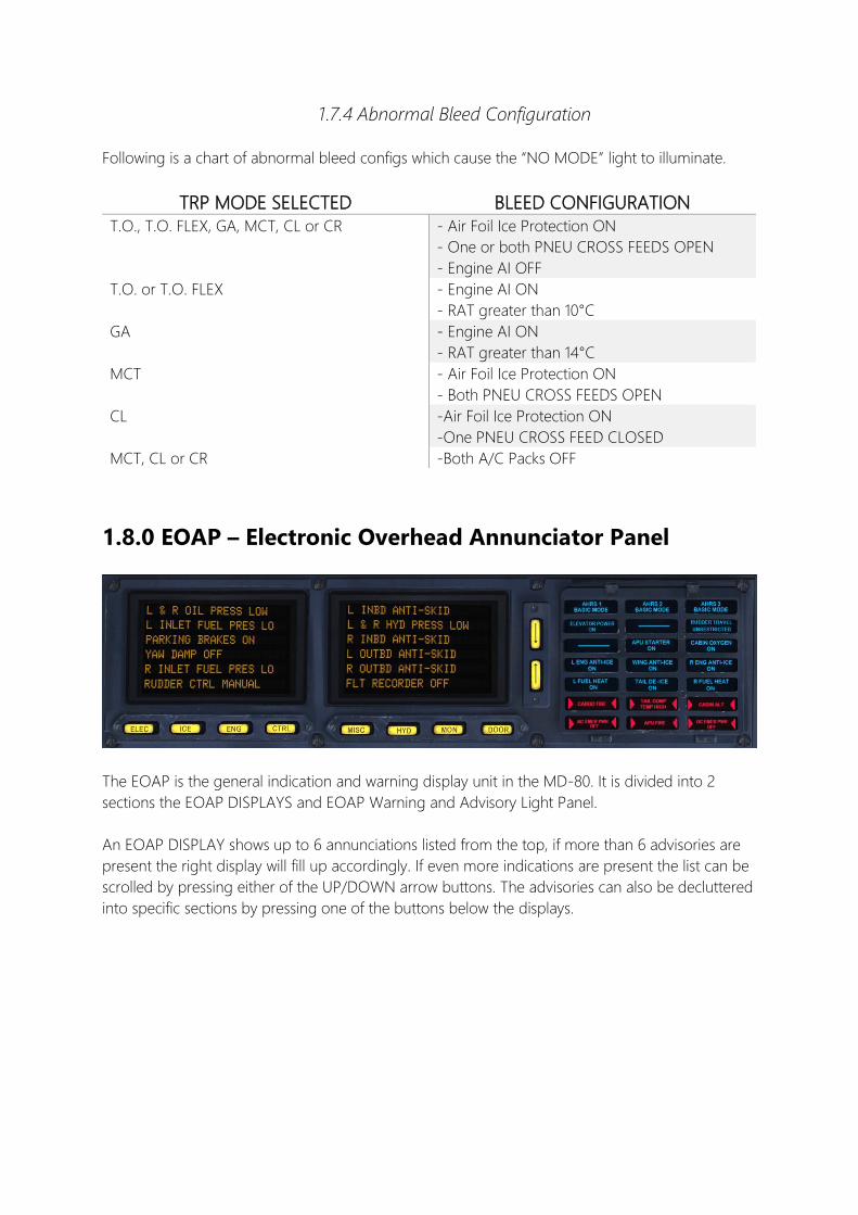
1.8.0 EOAP – Electronic Overhead Annunciator Panel
The EOAP is the general indication and warning display unit in the MD-80. It is divided into 2
sections the EOAP DISPLAYS and EOAP Warning and Advisory Light Panel.
An EOAP DISPLAY shows up to 6 annunciations listed from the top, if more than 6 advisories are
present the right display will fill up accordingly. If even more indications are present the list can be
scrolled by pressing either of the UP/DOWN arrow buttons. The advisories can also be decluttered
into specific sections by pressing one of the buttons below the displays.

1.9.0 Engine Thrust Recovery (ART / ATR)
1.9.1 Automatic Reserve Thrust (ART)
In case of a one-sided engine failure, the ART system automatically provides maximum rated
thrust to the operative engine, when:
- a N1 difference of approx. 30 % is noticed by the DFGC
- invalid N1 readout
- DFGC failure
- ELEC power lost
- Manual DFGC switch
The ATR system is armed once both engines have reached 64% N1. ART will increase TO EPR to
maximum TO EPR and can only be deactivated when the ART switch is set to OFF.
1.9.2 Automatic Thrust Restoration (ATR)
ATR is a separate and independent feature from ART which increases thrust under certain
conditions during an engine failure on takeoff.
If the AT is engaged, the ATR system will disengage CLMP mode and move both throttles until
one engines go-around EPR limit is reached.
ATR is armed if:
- F/D pitch axis in TO mode
- Airplane is above 350ft RA
- Both engine EPRs below G/A EPR
If ART is armed and ATR activates, the EPR limit will be the maximum inflight takeoff rating
reduced by the amount that ART is designed to provide. This is to prevent the engine from
overboosting.
Good luck and always happy landings!
Guide compiled by Felix Leverenz
Sources:
- Fly The Maddog X Beta Team
- Boeing MD-80 Series FCOM Volume 2 & 3
- Boeing MD-80 Series Airplane Characteristics for Airport Planning
- Continental MD-80 Flight Manual
- David Hingtgen´s excellent DC-9/MD-80 Guide