80 ust lifting capacity rough terrain cranes … · standard asme b30.5 outriggers retracted 9 ft...
TRANSCRIPT
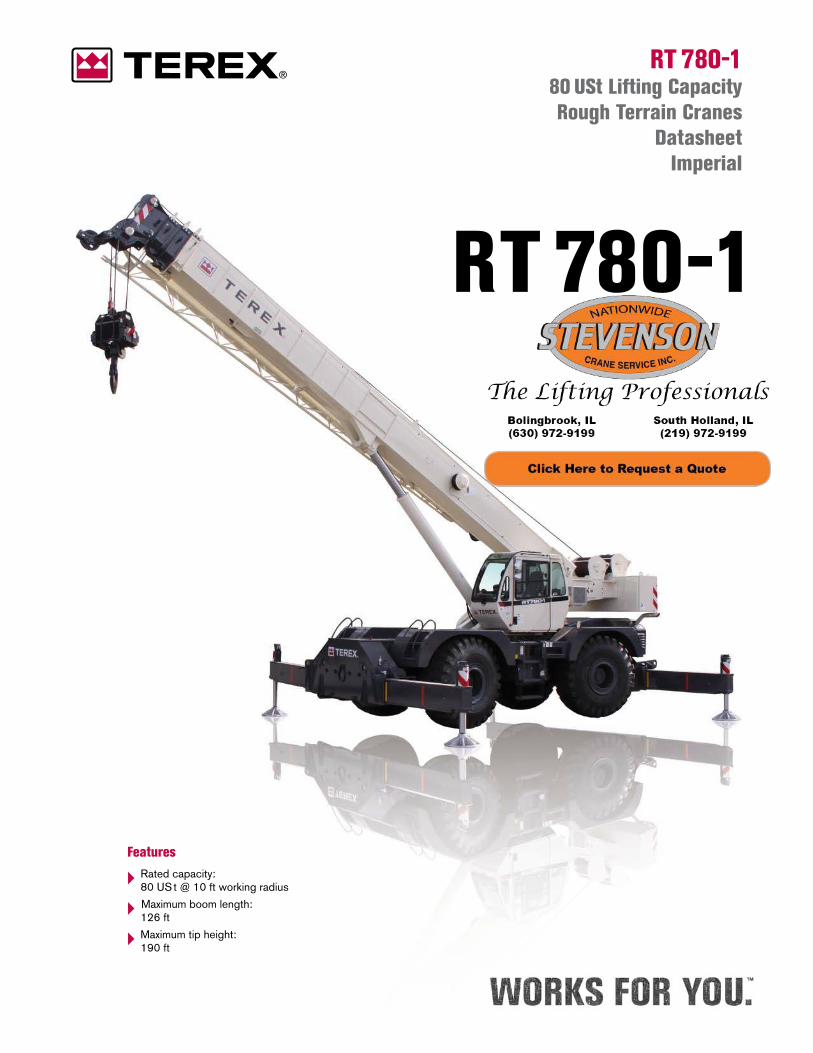
RT 780-1 80 USt Lifting Capacity Rough Terrain Cranes
DatasheetImperial
RT 780-1
Features
‣ Rated capacity: 80 US t @ 10 ft working radius
‣ Maximum boom length: 126 ft
‣ Maximum tip height: 190 ft
2
RT 780-1CONTENTS
Key
. . . . . . . . . . . . . . . . . . . . . . . . . . . . . . . . . . . . . . . . . . . . . . . . . . . . . . . . . . . . . . . . . . . . . . . . . . . . . . . . . . . . . . . . . . . 3
DimensionsCrane dimensions . . . . . . . . . . . . . . . . . . . . . . . . . . . . . . . . . . . . . . . . . . . . . . . . . . . . . . . . . . . . . . . . . . . . . . . . . . . 4
Crane weights . . . . . . . . . . . . . . . . . . . . . . . . . . . . . . . . . . . . . . . . . . . . . . . . . . . . . . . . . . . . . . . . . . . . . . . . . . . . . . 5
Load chartsRange Diagram – Main Boom – Outriggers fully extended (100%) . . . . . . . . . . . . . . . . . . . . . . . . . . . . . . . . . 6
Load Chart – Main Boom – Outriggers fully extended (100%) . . . . . . . . . . . . . . . . . . . . . . . . . . . . . . . . . . . . . 7
Range Diagram – Main Boom – Outriggers fully retracted (0%) . . . . . . . . . . . . . . . . . . . . . . . . . . . . . . . . . . . . 8
Load Chart – Main Boom – Outriggers fully retracted (0% . . . . . . . . . . . . . . . . . . . . . . . . . . . . . . . . . . . . . . . . 9
Range Diagram – Main Boom – 33 ft offsettable jib . . . . . . . . . . . . . . . . . . . . . . . . . . . . . . . . . . . . . . . . . . . . . 10
Load Chart – Main Boom – 33 ft offsettable jib . . . . . . . . . . . . . . . . . . . . . . . . . . . . . . . . . . . . . . . . . . . . . . . . . 11
Range Diagram – Main Boom – 57 ft offsettable jib . . . . . . . . . . . . . . . . . . . . . . . . . . . . . . . . . . . . . . . . . . . . . 12
Load Chart – Main Boom – 57 ft offsettable jib . . . . . . . . . . . . . . . . . . . . . . . . . . . . . . . . . . . . . . . . . . . . . . . . . 13
Range Diagram – Main Boom – On tires . . . . . . . . . . . . . . . . . . . . . . . . . . . . . . . . . . . . . . . . . . . . . . . . . . . . . . . 14
Load Chart – Main Boom – On tires . . . . . . . . . . . . . . . . . . . . . . . . . . . . . . . . . . . . . . . . . . . . . . . . . . . . . . . . . . . 15
Technical descriptionBoom . . . . . . . . . . . . . . . . . . . . . . . . . . . . . . . . . . . . . . . . . . . . . . . . . . . . . . . . . . . . . . . . . . . . . . . . . . . . . . . . . . . . . 16
Hoist, rope and hook. . . . . . . . . . . . . . . . . . . . . . . . . . . . . . . . . . . . . . . . . . . . . . . . . . . . . . . . . . . . . . . . . . . . . 16, 17
Superstructure . . . . . . . . . . . . . . . . . . . . . . . . . . . . . . . . . . . . . . . . . . . . . . . . . . . . . . . . . . . . . . . . . . . . . . . . . . . . . 17
Cab, controls, operator aids and load limiter / load indicator . . . . . . . . . . . . . . . . . . . . . . . . . . . . . . . . . . . . 18
Carrier, engine, drive-line and hydraulic system . . . . . . . . . . . . . . . . . . . . . . . . . . . . . . . . . . . . . . . . . . . . . 18, 19
Vehicle performance . . . . . . . . . . . . . . . . . . . . . . . . . . . . . . . . . . . . . . . . . . . . . . . . . . . . . . . . . . . . . . . . . . . . . . . . 19
Tires . . . . . . . . . . . . . . . . . . . . . . . . . . . . . . . . . . . . . . . . . . . . . . . . . . . . . . . . . . . . . . . . . . . . . . . . . . . . . . . . . . . . . . 19
Page:
3
RT 780-1KEYKEY
General performance
Telescoping mode
Boom luffing angle
Working radius
Max. boom length with extension
Distance from the hook to the head sheave pin
Slewing locked / Slewing locked at specified position
Slewing gears
Lifting on wheels / Pick & Carry
Auxiliary hoist
Rope length
Max. line pull
Tire
Controls
Engine
Steering
Speed
Heating / Air conditioning
Gradeability
Gross vehicle weight
Weight on front axle
Weight on rear axle
Counterweight
Main boom
Boom length
Tip height
Boom with extension
Main boom with aux head
Slewing / Allowable slewing range
Slewing brake
Outriggers / Lifting on outriggers
(100/50/0% extended)
Main hoist
Hoist speed
Rope – Standard / Optional
Rope diameter
Hook block
Cab
Operator aids / Load limiter / Load indicator
Mechanical transmission
Hydraulics
Working temperature
Lights
Crane / Crane in standard configuration
Crane without counterweight
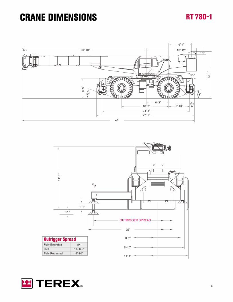
Outrigger Spread Fully Extended 24'
Half 16'-6.5"
Fully Retracted 9'-10"
OUTRIGGER SPREAD
13'-2" 5'-10"
24'-4"
1'-5
"
27'-1"
26'
8'-7"
9'-10"
11'-4"
19°
1'-1"
11"
11
'-8
"
18°
13
'-1
"
10"
6'-3"
13'-12"33'-10" 9"
48'
6'-4"
5'-6
"
4
RT 780-1CRANE DIMENSIONS
5
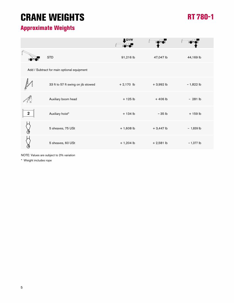
RT 780-1CRANE WEIGHTSApproximate Weights
NOTE: Values are subject to 2% variation
* Weight includes rope
STD 91,216 lb 47,047 lb 44,169 lb
Add / Subtract for main optional equipment
33 ft to 57 ft swing on jib stowed + 2,170 lb + 3,992 lb – 1,822 lb
Auxiliary boom head + 125 lb + 406 lb – 281 lb
Auxiliary hoist* + 134 lb – 35 lb + 159 lb
5 sheaves, 75 USt + 1,608 lb + 3,447 lb – 1,839 lb
5 sheaves, 60 USt + 1,204 lb + 2,581 lb – 1,377 lb
120 ft110 ft100 ft90 ft80 ft70 ft60 ft50 ft40 ft30 ft20 ft10 ftft
150 ft
140 ft
130 ft
120 ft
110 ft
100 ft
90 ft
80 ft
70 ft
60 ft
50 ft
40 ft
30 ft
20 ft
10 ft
40 f t
90 f t
102 f t
114 f t
126 f t
54 f t
66 f t
78 f t
70°
78°
60°
50°
40°
30°
20°
10°
6
RT 780-1
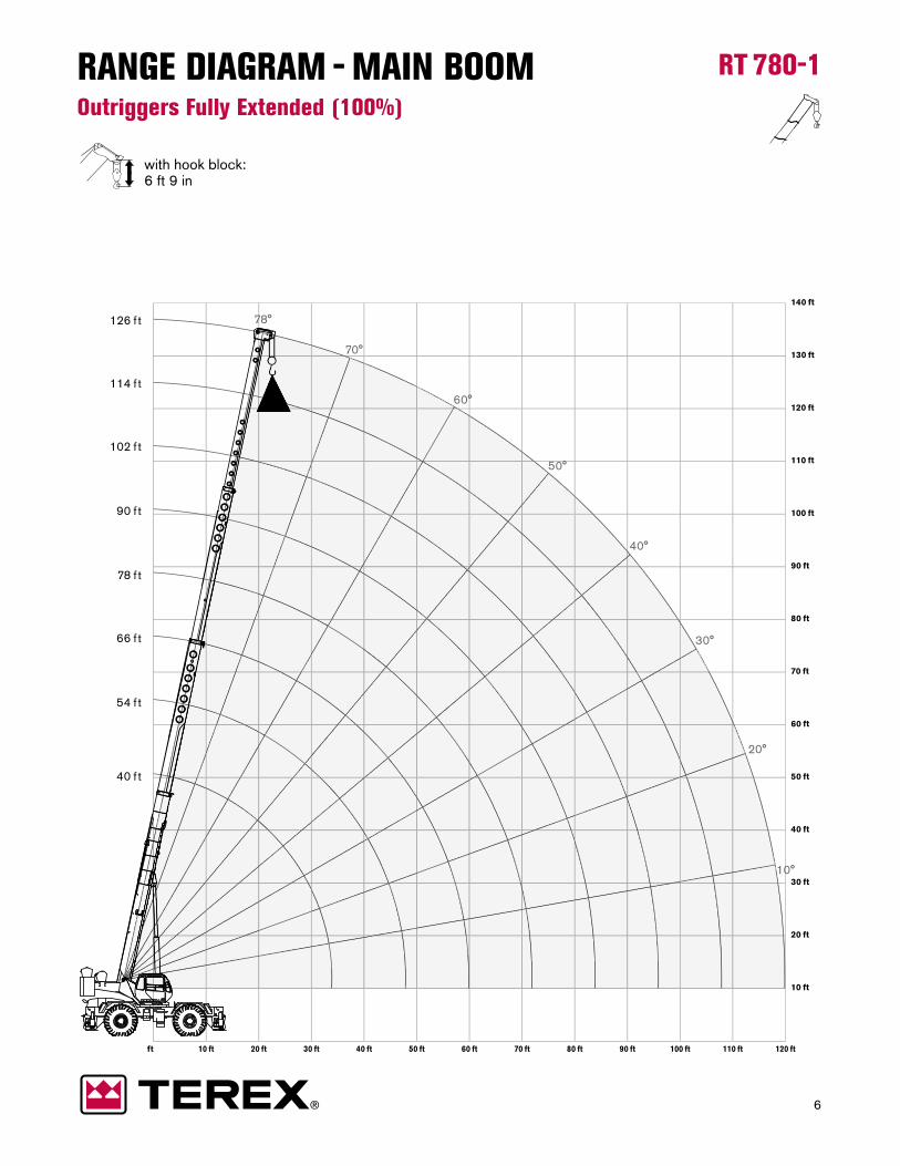
with hook block:6 ft 9 in
RANGE DIAGRAM - MAIN BOOMOutriggers Fully Extended (100%)
7
RT 780-1
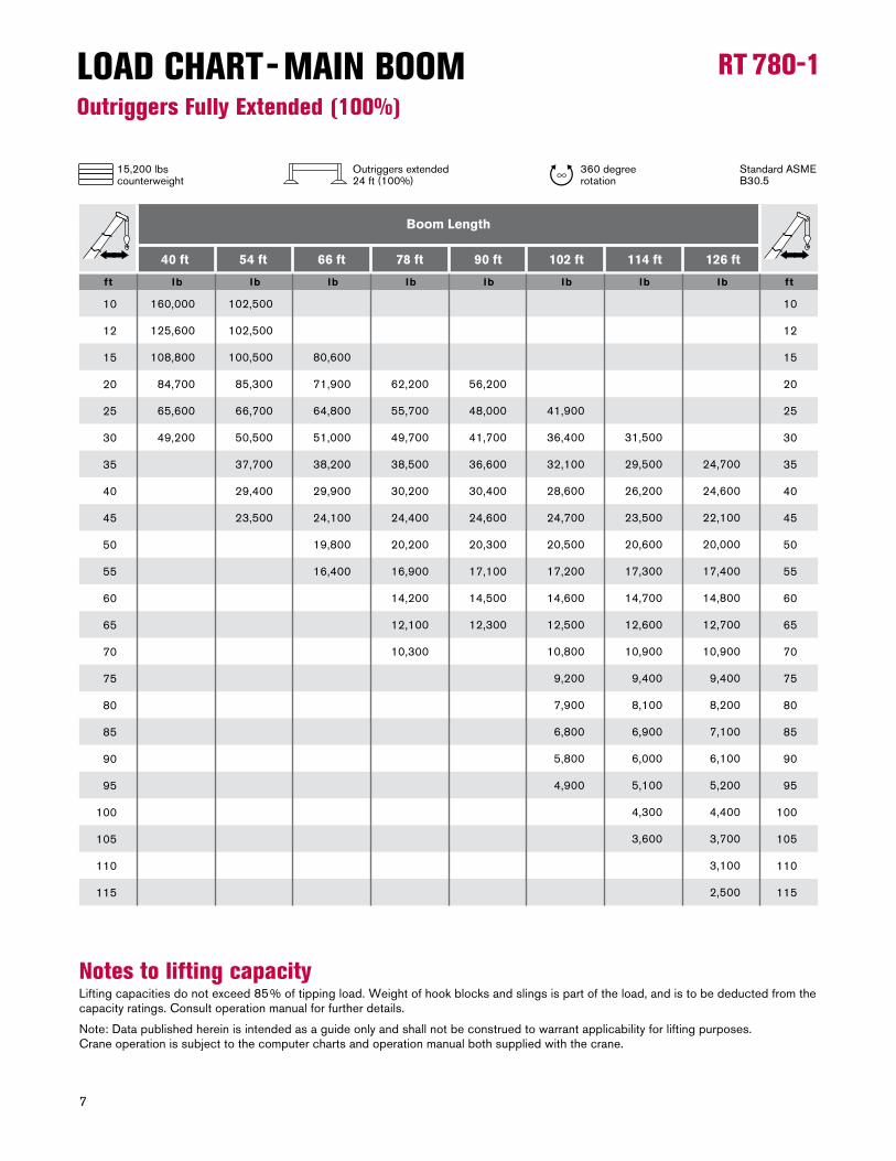
Notes to lifting capacity Lifting capacities do not exceed 85% of tipping load. Weight of hook blocks and slings is part of the load, and is to be deducted from the capacity ratings. Consult operation manual for further details.
Note: Data published herein is intended as a guide only and shall not be construed to warrant applicability for lifting purposes. Crane operation is subject to the computer charts and operation manual both supplied with the crane.
LOAD CHART - MAIN BOOMOutriggers Fully Extended (100%)
ftft lb lb lb lb lb lb lb lb
40 ft 54 ft 66 ft 78 ft 90 ft 102 ft 114 ft 126 ft
Boom Length
10
12
15
20
25
30
35
40
45
50
55
60
65
70
75
80
85
90
95
100
105
110
115
10
12
15
20
25
30
35
40
45
50
55
60
65
70
75
80
85
90
95
100
105
110
115
160,000
125,600
108,800
84,700
65,600
49,200
102,500
102,500
100,500
85,300
66,700
50,500
37,700
29,400
23,500
80,600
71,900
64,800
51,000
38,200
29,900
24,100
19,800
16,400
62,200
55,700
49,700
38,500
30,200
24,400
20,200
16,900
14,200
12,100
10,300
56,200
48,000
41,700
36,600
30,400
24,600
20,300
17,100
14,500
12,300
41,900
36,400
32,100
28,600
24,700
20,500
17,200
14,600
12,500
10,800
9,200
7,900
6,800
5,800
4,900
31,500
29,500
26,200
23,500
20,600
17,300
14,700
12,600
10,900
9,400
8,100
6,900
6,000
5,100
4,300
3,600
24,700
24,600
22,100
20,000
17,400
14,800
12,700
10,900
9,400
8,200
7,100
6,100
5,200
4,400
3,700
3,100
2,500
15,200 lbscounterweight
360 degree rotation
Standard ASME B30.5
Outriggers extended24 ft (100%)
120 ft110 ft100 ft90 ft80 ft70 ft60 ft50 ft40 ft30 ft20 ft10 ftft
150 ft
140 ft
130 ft
120 ft
110 ft
100 ft
90 ft
80 ft
70 ft
60 ft
50 ft
40 ft
30 ft
20 ft
10 ft
40 f t
90 f t
102 f t
114 f t
126 f t
54 f t
66 f t
78 f t
70°
78°
60°
50°
40°
30°
20°
10°
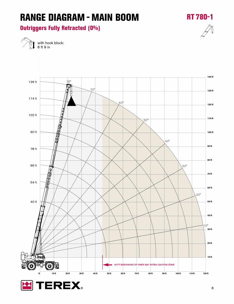
45 FT BEGINNING OF OVER 360º EXTRA-CAUTION ZONE
8
RT 780-1
with hook block:6 ft 9 in
RANGE DIAGRAM - MAIN BOOMOutriggers Fully Retracted (0%)
9
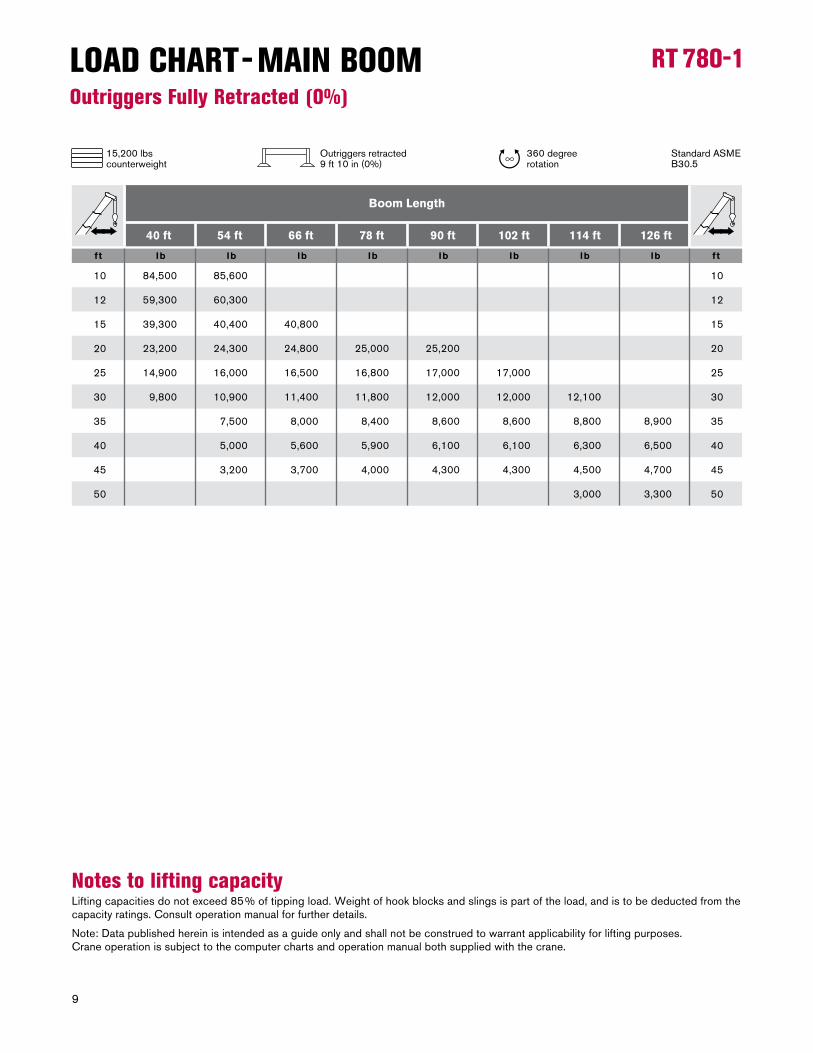
RT 780-1LOAD CHART - MAIN BOOMOutriggers Fully Retracted (0%)
Notes to lifting capacity Lifting capacities do not exceed 85% of tipping load. Weight of hook blocks and slings is part of the load, and is to be deducted from the capacity ratings. Consult operation manual for further details.
Note: Data published herein is intended as a guide only and shall not be construed to warrant applicability for lifting purposes. Crane operation is subject to the computer charts and operation manual both supplied with the crane.
ftft lb lb lb lb lb lb lb lb
40 ft 54 ft 66 ft 78 ft 90 ft 102 ft 114 ft 126 ft
Boom Length
10
12
15
20
25
30
35
40
45
50
10
12
15
20
25
30
35
40
45
50
84,500
59,300
39,300
23,200
14,900
9,800
85,600
60,300
40,400
24,300
16,000
10,900
7,500
5,000
3,200
40,800
24,800
16,500
11,400
8,000
5,600
3,700
25,000
16,800
11,800
8,400
5,900
4,000
25,200
17,000
12,000
8,600
6,100
4,300
17,000
12,000
8,600
6,100
4,300
12,100
8,800
6,300
4,500
3,000
8,900
6,500
4,700
3,300
15,200 lbscounterweight
360 degree rotation
Standard ASME B30.5
Outriggers retracted9 ft 10 in (0%)
160 ft150 ft140 ft130 ft120 ft110 ft100 ft90 ft80 ft70 ft60 ft50 ft40 ft30 ft20 ft10 ftft
170 ft
160 ft
150 ft
140 ft
130 ft
120 ft
110 ft
100 ft
90 ft
80 ft
180 ft
70 ft
60 ft
50 ft
40 ft
30 ft
20 ft
10 ft
40 f t
90 f t
102 f t
114 f t
126 f t
54 f t
66 f t
78 f t
159 f t
70°
78°
60°
50°
40°
30°
20°
10°
30°15°
BEGINNING OF OVER FRONT EXTRA-CAUTION ZONE 135 FT
BEGINNING OF OVER 360º EXTRA-CAUTION ZONE 132 FT
10
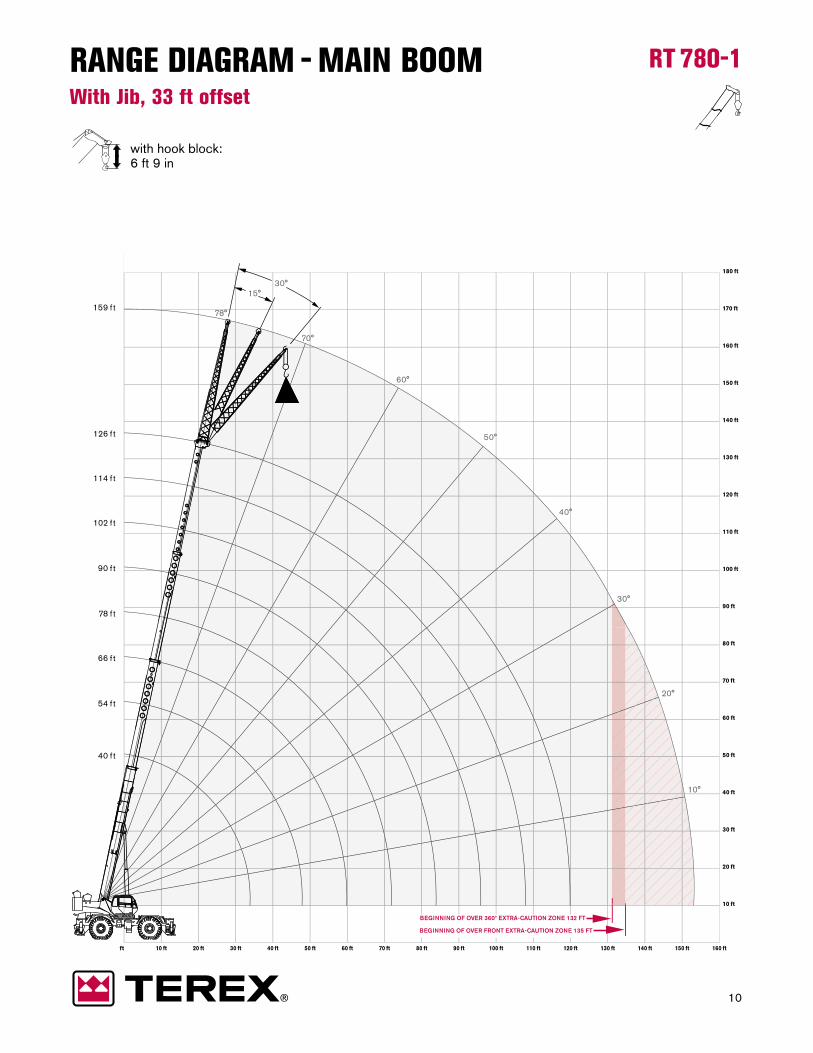
RT 780-1
with hook block:6 ft 9 in
RANGE DIAGRAM - MAIN BOOMWith Jib, 33 ft offset

11
RT 780-1LOAD CHART - MAIN BOOMWith Jib, 33 ft offset
Notes to lifting capacity Lifting capacities do not exceed 85% of tipping load. Weight of hook blocks and slings is part of the load, and is to be deducted from the capacity ratings. Consult operation manual for further details.
Note: Data published herein is intended as a guide only and shall not be construed to warrant applicability for lifting purposes. Crane operation is subject to the computer charts and operation manual both supplied with the crane.
lbs lbs lbs
0° Offset 30° Offset15° Offset
Radius (ft)
Radius (ft)
Radius (ft)
33 ft Offsettable Jib
41
47
52
58
66
74
81
88
97
105
113
120
127
135
50
56
61
67
74
81
88
95
103
111
117
124
131
138
57
62
67
72
79
86
93
99
107
114
120
126
132
138
12,500
12,000
11,500
10,900
9,900
9,200
8,600
7,300
5,700
4,500
3,600
2,900
2,200
1,600
8,500
8,100
7,800
7,500
7,100
6,700
6,400
6,200
5,200
4,200
3,400
2,700
2,000
1,400
6,400
6,200
6,100
5,900
5,900
5,600
5,400
5,300
5,200
4,300
3,500
2,800
1,900
1,100
15,200 lbscounterweight
360 degree rotation
Standard ASME B30.5
Outriggers extended24 ft (100%)
170 ft160 ft150 ft140 ft130 ft120 ft110 ft100 ft90 ft80 ft70 ft60 ft50 ft40 ft30 ft20 ft10 ftft 180 ft
170 ft
160 ft
150 ft
140 ft
130 ft
120 ft
110 ft
100 ft
90 ft
80 ft
200 ft
190 ft
180 ft
70 ft
60 ft
50 ft
40 ft
30 ft
20 ft
10 ft
40 f t
90 f t
102 f t
114 f t
126 f t
54 f t
66 f t
78 f t
182 f t
BEGINNING OF OVER 360º EXTRA-CAUTION ZONE 148 FT
BEGINNING OF OVER FRONT EXTRA-CAUTION ZONE 151 FT
78°
70°
60°
50°
40°
30°
20°
15°
10°
12
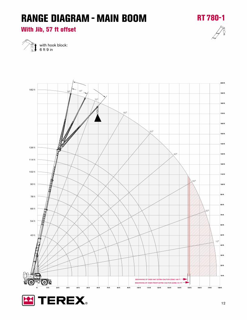
RT 780-1
with hook block:6 ft 9 in
RANGE DIAGRAM - MAIN BOOMWith Jib, 57 ft offset

13
RT 780-1LOAD CHART - MAIN BOOMWith Jib, 57 ft offset
Notes to lifting capacity Lifting capacities do not exceed 85% of tipping load. Weight of hook blocks and slings is part of the load, and is to be deducted from the capacity ratings. Consult operation manual for further details.
Note: Data published herein is intended as a guide only and shall not be construed to warrant applicability for lifting purposes. Crane operation is subject to the computer charts and operation manual both supplied with the crane.
lbs lbs lbs
0° Offset 30° Offset15° Offset
Radius (ft)
Radius (ft)
Radius (ft)
57 ft Offsettable Jib
48
56
63
70
80
90
98
106
116
125
133
140
148
157
66
72
77
83
91
99
106
114
123
132
140
147
154
161
75
81
87
92
100
108
115
121
129
137
143
149
155
162
6,500
6,400
6,200
6,000
5,400
4,900
4,500
4,200
3,800
3,500
2,800
2,200
1,600
1,000
4,500
4,300
4,100
3,900
3,700
3,500
3,300
3,100
2,900
2,800
2,600
2,100
1,500
1,000
3,300
3,200
3,100
3,000
2,900
2,800
2,700
2,600
2,500
2,500
2,400
2,000
1,500
1,000
15,200 lbscounterweight
360 degree rotation
Standard ASME B30.5
Outriggers extended24 ft (100%)
90 ft80 ft70 ft60 ft50 ft40 ft30 ft20 ft10 ftft
110 ft
100 ft
90 ft
80 ft
70 ft
60 ft
50 ft
40 ft
30 ft
20 ft
10 ft
40 f t
54 f t
66 f t
78 f t
90 f t70°
78°
60°
50°
40°
30°
20°
10°0°10°1
0°20°2202
30°30
0°060°0
4
6
0°40°
0°50°5
0°70°7
78°78
0°10
0°202
0°30
0°4
0°5
0°06
70°7
878
14
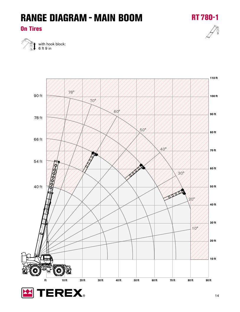
RT 780-1
with hook block:6 ft 9 in
RANGE DIAGRAM - MAIN BOOMOn Tires
15
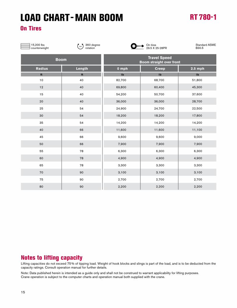
RT 780-1LOAD CHART - MAIN BOOMOn Tires
Notes to lifting capacity Lifting capacities do not exceed 75% of tipping load. Weight of hook blocks and slings is part of the load, and is to be deducted from the capacity ratings. Consult operation manual for further details.
Note: Data published herein is intended as a guide only and shall not be construed to warrant applicability for lifting purposes. Crane operation is subject to the computer charts and operation manual both supplied with the crane.
0 mph Creep 2.5 mph
BoomTravel Speed
Boom straight over front
Radius Length
ft ft lb lb lb
40
40
40
40
54
54
54
66
66
66
78
78
78
90
90
90
10
12
15
20
25
30
35
40
45
50
55
60
65
70
75
80
82,700
69,800
54,200
36,000
24,900
18,200
14,200
11,600
9,600
7,900
6,300
4,900
3,300
3,100
2,700
2,200
68,700
60,400
50,700
36,000
24,700
18,200
14,200
11,600
9,600
7,900
6,300
4,900
3,300
3,100
2,700
2,200
51,800
45,300
37,600
28,700
22,500
17,800
14,200
11,100
9,000
7,900
6,300
4,900
3,300
3,100
2,700
2,200
On tires29.5 X 25-28PR
15,200 lbscounterweight
360 degree rotation
Standard ASME B30.5
16
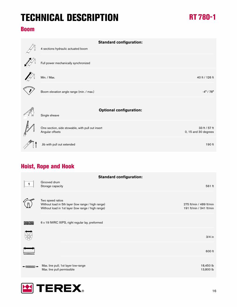
RT 780-1TECHNICAL DESCRIPTIONBoom
Standard configuration:
4 sections hydraulic actuated boom
Full power mechanically synchronized
Min. / Max. 40 ft / 126 ft
Boom elevation angle range (min. / max.) -4° / 78°
Optional configuration:
Single sheave
One section, side stowable, with pull out insert 33 ft / 57 ft
Angular offsets 0, 15 and 30 degrees
Jib with pull out extended 190 ft
Hoist, Rope and Hook
Standard configuration:
Grooved drum
Storage capacity 561 ft
Two speed ratios
Without load in 5th layer (low range / high range) 275 ft/min / 489 ft/min
Without load in 1st layer (low range / high range) 191 ft/min / 341 ft/min
6 x 19 IWRC XIPS, right regular lay, preformed
3/4 in
600 ft
Max. line pull; 1st layer low-range 18,450 lb
Max. line pull permissible 13,800 lb
17
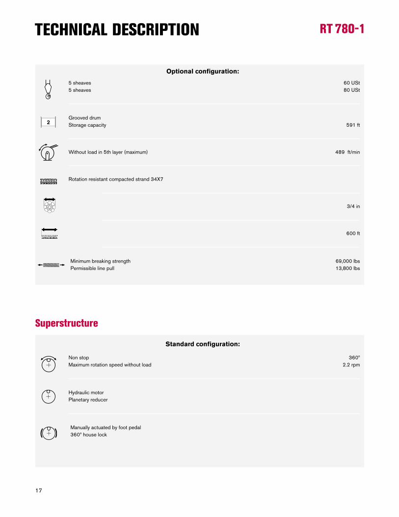
RT 780-1TECHNICAL DESCRIPTION
Optional configuration:
5 sheaves 60 USt
5 sheaves 80 USt
Grooved drum
Storage capacity 591 ft
Without load in 5th layer (maximum) 489 ft/min
Rotation resistant compacted strand 34X7
3/4 in
600 ft
Minimum breaking strength 69,000 lbs
Permissible line pull 13,800 lbs
Superstructure
Standard configuration:
Non stop 360º
Maximum rotation speed without load 2.2 rpm
Hydraulic motor
Planetary reducer
Manually actuated by foot pedal
360º house lock
18
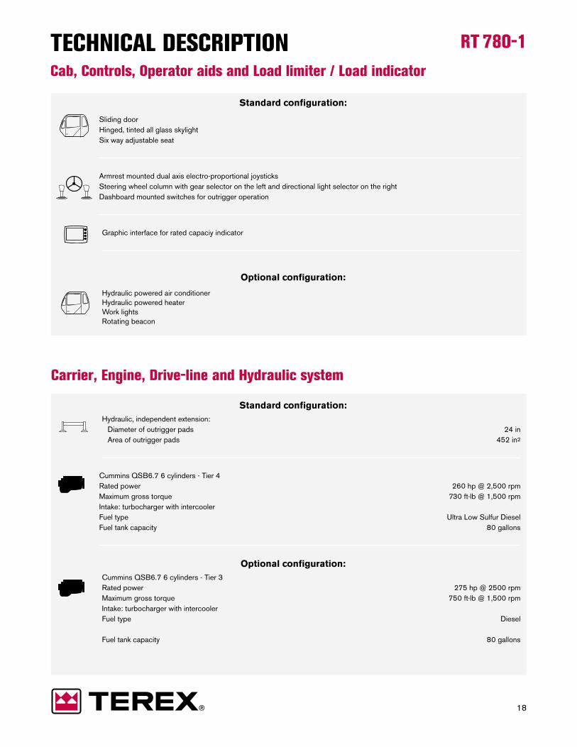
RT 780-1TECHNICAL DESCRIPTIONCab, Controls, Operator aids and Load limiter / Load indicator
Standard configuration:
Sliding door
Hinged, tinted all glass skylight
Six way adjustable seat
Armrest mounted dual axis electro-proportional joysticks
Steering wheel column with gear selector on the left and directional light selector on the right
Dashboard mounted switches for outrigger operation
Graphic interface for rated capaciy indicator
Optional configuration:
Hydraulic powered air conditioner
Hydraulic powered heater
Work lights
Rotating beacon
Carrier, Engine, Drive-line and Hydraulic system
Standard configuration:
Hydraulic, independent extension:
Diameter of outrigger pads 24 in
Area of outrigger pads 452 in2
Cummins QSB6.7 6 cylinders - Tier 4
Rated power 260 hp @ 2,500 rpm
Maximum gross torque 730 ft·lb @ 1,500 rpm
Intake: turbocharger with intercooler
Fuel type Ultra Low Sulfur Diesel
Fuel tank capacity 80 gallons
Optional configuration:
Cummins QSB6.7 6 cylinders - Tier 3
Rated power 275 hp @ 2500 rpm
Maximum gross torque 750 ft·lb @ 1,500 rpm
Intake: turbocharger with intercooler
Fuel type Diesel
Fuel tank capacity 80 gallons
19
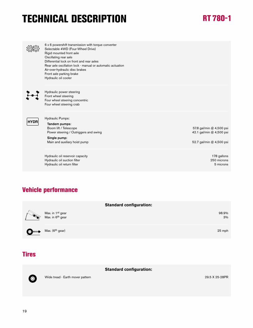
RT 780-1TECHNICAL DESCRIPTION
6 x 6 powershift transmission with torque converter
Selectable 4WD (Four-Wheel Drive)
Rigid mounted front axle
Oscillating rear axle
Differential lock on front and rear axles
Rear axle oscillation lock - manual or automatic actuation
Air-over-hydraulic disc brakes
Front axle parking brake
Hydraulic oil cooler
Hydraulic power steering
Front wheel steering
Four wheel steering concentric
Four wheel steering crab
Hydraulic Pumps:
Tandem pumps:
Boom lift / Telescope 57.8 gal/min @ 4,500 psi
Power steering / Outriggers and swing 42.1 gal/min @ 4,500 psi
Single pump:
Main and auxiliary hoist pump 52.7 gal/min @ 4,500 psi
Hydraulic oil reservoir capacity 178 gallons
Hydraulic oil suction filter 250 microns
Hydraulic oil return filter 5 microns
Vehicle performance
Standard configuration:
Max. in 1st gear 98.9%
Max. in 6th gear 3%
Max. (6th gear) 25 mph
Tires
Standard configuration:
Wide tread - Earth mover pattern 29.5 X 25-28PR
20
RT 780-1
Effective Date: July 2012. Product specifications and prices are subject to change without notice or obligation. The photographs and/or drawings in this document are for illustrative purposes only. Refer to the appropriate Operator’s Manual for instructions on the proper use of this equipment. Failure to follow the appropriate Operator’s Manual when using our equipment or to otherwise act irresponsibly may result in serious injury or death. The only warranty applicable to our equipment is the standard written warranty applicable to the particular product and sale and Terex makes no other warranty, express or implied. Products and services listed may be trademarks, service marks or trade-names of Terex Corporation and/or its subsidiaries in the USA and other countries. All rights are reserved. Terex® is a registered trademark of Terex Corporation in the USA and many other countries.
Copyright 2012 Terex Corporation.
Terex Cranes, Global Marketing, Dinglerstraße 24, 66482 Zweibrücken, GermanyTel. +49 (0) 6332 830, Email: [email protected], www.terexcranes.com
www.terexcranes.com Brochure Reference: TC-DS-I-E-RT780-1-07/12