800-09618v1-a v128fbpt v250fbpt-pg · feature vista-128fbpt vista-250fbpt number of zones 128 250...
TRANSCRIPT

VVVVVVVVIIIIIIIISSSSSSSSTTTTTTTTAAAAAAAA--------111111112222222288888888FFFFFFFFBBBBBBBBPPPPPPPPTTTTTTTT
VVVVVVVVIIIIIIIISSSSSSSSTTTTTTTTAAAAAAAA--------222222225555555500000000FFFFFFFFBBBBBBBBPPPPPPPPTTTTTTTT Commercial Fire and BurglaryCommercial Fire and BurglaryCommercial Fire and BurglaryCommercial Fire and Burglary
Partitioned Security System with SchedulingPartitioned Security System with SchedulingPartitioned Security System with SchedulingPartitioned Security System with Scheduling
Programming GuideProgramming GuideProgramming GuideProgramming Guide
800-09618V1 11/12 Rev. A

–2–
Table of Contents
Programming Field Settings for UL864 Compliance ......... 2
Programming Field Settings for ULC304 Compliance ....... 4
Recommended Programming Procedure .......................... 6
Program Field Index .......................................................... 7
VISTA-128FBPT/VISTA-250FBPT Programming ............. 8
Programming With #93 Menu Mode ................................ 26
Zone Programming.......................................................... 27
Zone Number Designations ............................................. 27
Zone Response Type Definitions .................................... 30
Zone Input Type Definitions ............................................ 31
5800 Series Transmitters Loop Designations .................. 37
Expert Mode Zone Programming .................................... 38
Report Code Programming ............................................. 40
Alpha Descriptors Programming ..................................... 44
Alpha Descriptor Vocabulary ........................................... 47
Device Programming ....................................................... 48
Output Programming ....................................................... 51
Relay Voice Descriptors .................................................. 56
System Layout Worksheets ............................................ 58
Output Devices Worksheets ............................................ 74
Scheduling ...................................................................... 80
Scheduling Menu Mode .................................................. 83
Programming Field Settings for UL864 Compliance
NOTICE TO USERS, INSTALLERS, AUTHORITIES HAVING JURISDICTION, AND OTHER INVOLVED PARTIES
This product incorporates field-programmable software. In order for the product to comply with the requirements in the Standard for Control Units and Accessories for Fire Alarm Systems, UL 864, certain programming features or options must be limited to specific values or not used at all as indicated below. Program feature or option Permitted in
UL864? Y/N Possible settings Settings permitted in UL 864
∗08 TEMPORAL SIREN PULSE N 0 = disable
1 = enable
Not used at this time. Must be set to
“0” (disable).
∗13 BELL 1 TIMEOUT Y Enter 01-15 multiplied by 2 minutes.
00 = no timeout.
Must be set to “3” (Minimum of 6
minutes).
∗14 RS232 comm. N 0 = no
1 = yes
Must be set to “0”.
∗17 AC LOSS KEYPAD
SOUNDING
N 0 = disable
1 = enable
Must be set to “1” (enabled).
∗19 RANDOMIZE AC LOSS
REPORT
Y 0 = within 2 minutes
1 = 10-40 minutes
2 = 1-3 hours
3 = 6-12 hours without Type 13, 1-3
hours with Type 13
Must be set to “2”.
∗20 TELEPHONE MODULE
PHONE CODE N 1-9 = first digit of access code
∗∗∗∗ or # = second digit of access code
(enter # +11 for “∗”, or # +12 for “#”)
To disable enter 00 for the 1st digit
Not Used. Must be set to “00”.
∗22 KEYPAD PANIC ENABLES
(PARTITION SPECIFIC)
N 0 = disable
1 = enable
Must be set to “000” for partition 1
in fire systems.
∗23 MULTIPLE ALARMS
(PARTITION SPECIFIC)
N 0 = disable
1 = enable
Must be set to “1” (enabled).
∗24 IGNORE EXPANSION
ZONE TAMPER N 0 = disable (tamper detection)
1 = enable (no tamper detection)
Must be set to “0” (enabled).
∗26 INTELLIGENT TEST
REPORTING
N 0 = disable
1 = enable
Must be set to “0” (disable).
∗27 TEST REPORT INTERVAL Y Enter 0001-9999 for the test report
interval in hours.
Enter 0000 for test reporting.
Must be set to “0024” (Maximum 24
hours)
∗28 POWER-UP IN PREV.
STATE Y 0 = disable
1 = enable
Must be set to “1” (enable).
∗37 DOWNLOAD COMMAND
ENABLES N 0 = disable
1 = enable
Must be set to “0” for all entries
(disable).
∗41 NORMALLY CLOSED OR
EOLR (ZONES 3-8) N 0 = EOLR supervision
1 = N.C. loops
Must be set to “0” (EOLR
Supervision).
∗42 DIAL TONE PAUSE Y Enter the wait time for dial tone
detection:
0 = 5 seconds; 1 = 11 seconds; 2 = 30
seconds.
Must be set to “0” (5 seconds).

–3–
Program feature or option Permitted in UL864? Y/N
Possible settings Settings permitted in UL 864
∗44 RING DETECTION COUNT N Enter 00 to disable ring detection.
Enter 01-14 for ring counts of 1-14.
Enter 15 to select Answering Machine
Defeat Mode
Must be set to “00” (disable).
∗56 DYNAMIC SIGNAL DELAY Y Enter 00-15 times 15 seconds.
Must be set to “6” (90 seconds).
∗77 AUTO TRBL RSTR Y 0 = disable
1 = enable
Must be set to “1” (enable).
∗80 ZONE TYPE 9 -10, 14
RESTORE
N 0 = disable
1 = enable
Must be set to “1” (enable) for zone
type 9.
∗84 SWINGER SUPPRESS.
(PARTITION – SPECIFIC)
N Enter 01-14,
Enter 00 for unlimited reports
Must be set to “00” (disable).
1∗12 PROGRAM
NOTIFICATION Y 0 = no
1 = yes
Must be set to “1” (yes).
1∗13 SYS. SENSOR REV.
RELAY
N 0=use neither Zone 1 or Zone 2 inputs
1=use Zone 1 input;
2=use Zone 2 input;
3=use Zone 1 and Zone 2 inputs.
Not Used. Must be set to “0”.
1∗18 AFFECTS LOBBY
(PARTITION – SPECIFIC)
N 0 = disable
1 = enable
Must be set to “0” (disabled) for
partition 1.
1∗19 ARMS LOBBY
(PARTITION – SPECIFIC)
N 0 = disable
1 = enable
Must be set to “0” (disabled) for
partition 1.
1∗22 thru 1∗25 CROSS-ZONING
PAIRS (1 – 4)
N Enter 001-250
Enter 000,000 to disable
Must be set to “000,000” (disabled)
for fire zones.
1∗28 RF TX LOW BATTERY
SOUND
N 0 = disarmed state only
1 = both armed and disarmed states
Must be set to “1” (both armed and
disarmed states).
1∗29 RF TX LOW BATTERY
REPORTING
N 0 = disable
1 = enable
Must be set to “1” (enable).
1∗30 RF RCVR CHECK-IN
INTERVAL
N Enter 02–15 times 2 hours (4–30
hours)
Enter 00 to disable receiver
supervision
Maximum is 02 (4 hours) for fire
installations.
1∗31 RF TX CHECK-IN
INTERVAL
N Enter 02–15 times 2 hours (4–30
hours)
Enter 00 to disable transmitter
supervision
Maximum is 02 (4 hours) for fire
installations.
1∗35 ACS DLR ENABLES N 0 = disable
1 = enable
Not used. Must be set to “0”.
1∗44 RF KEYPAD TAMPER
DETECTION
N 0 = disable
1 = enable
Not used. Must be set to “0”.
1∗45 EXIT DELAY SOUNDING
(PARTITION SPECIFIC)
N 0 = disable
1 = enable
Must be set to “0” (disable) for
partition 1.
1∗48 RF KEYPAD ASSIGN 1-
8=PART. 0=NO
N 0 = none
1-8 = partition number
Not used. Must be set to “0”.
1∗49 SUPPRESS TX SUPERV.
SOUND
N 0 = disable
1 = enable
Must be set to “0” (disable).
1∗53 DOWNLOAD CALLBACK N 0 = callback required
1 = no callback required
Must be set to “0” (callback
required).
1∗57 ENABLE 5800 RF
BUTTON GLOBAL ARM
N 0 = disable
1 = enable
Must be set to “0” (disable).
1∗58 ENABLE 5800 RF FORCE
ARM
N 0 = disable
1 = enable
Must be set to “0” (disable).
1∗60 ZONE 5/AUDIO ALARM
VER.
N 0 = disable
1 = enable
Must be set to “0” (disable).
1∗72 PRINTER ON-LINE MODE N 0 = disable
1 = enable
Not used. Must be set to “0”.
1∗76 ACCESS RELAY #
(PARTITION SPECIFIC)
N 01-96 = relay number
00 = relay not used.
Must be set to “00” (relay not used)
for partition 1.
1∗78 EXT. HOME CONTROL
EVT
N 1 = extended
0 = limited
Not used. Must be set to “0”.
1∗79 HOME CONTROL
EVENTS
N 0 = disable
1 = enable
Not used. Must be set to “0” in each
entry.
1∗80 LOG-FAULTS &
RESTORES
N 0 = disable
1 = enable
Not used. Must be set to “0”.

–4–
Program feature or option Permitted in UL864? Y/N
Possible settings Settings permitted in UL 864
2∗07 AUTO-DISARM DELAY
(PARTITION SPECIFIC)
N 00 = no delay.
01-14 times 4 minutes (04-56) delay.
15 = no auto disarming.
Must be set to “15” (no auto
disarming) for partition 1.
2∗18 ENABLE GOTO FOR
PARTITION (PARTITION
SPECIFIC)
N 0 = disable
1 = enable
Must be set to “0” (disable) for
partition 1.
2*21 SUPERVISION PULSES FOR
COMMUNICATIONS DEVICE
N 0 = disable
1 = enable
Not Used. Must be set to “00000”
(disable).
2∗22 DISPLAY OTHER FIRE
ALARMS (PARTITION SPECIFIC)
N 0 = disable
1 = enable
Must be set to “0” (disable) for
partition 1.
2∗23 DISPLAY OTHER BURG &
PANIC (INCLUDING CO ALARMS)
(PARTITION SPECIFIC)
N 0 = disable
1 = enable
Must be set to “0” (disable) for
partition 1.
2∗24 DISPLAY TROUBLES OF
OTHER PARTITIONS (PARTITION
SPECIFIC)
N 0 = disable
1 = enable
Must be set to “0” (disable) for
partition 1.
3∗01 EVENT DISPLAY LOCK N 0 = disable
1 = enable
Must be set to “1” (enable).
3∗12 ZN TYPE 18 DELAY USE N 0 = disable
1 = enable
Must be set to “0” (disable).
3∗13 “SUPV” ON OPEN AND
SHORT (APPLIES TO ZONE TYPE
18
N 0 = Trouble on open/Supv on short
1 = Supv on open/Supv on short
Must be set to “0”.
3∗14 W.F. ALARM SILENCE OPT. N 0 = Silenced by User Code + OFF
1 = Silenced when zone restores
Must be set to “0” (Silenced by User
Code + OFF).
3∗16 ZONE TYP 17/18 DLY N Enter 01-15 times 2 seconds
Enter 00 for no delay
Must be set to 00 (no delay).
3∗18 EXTENDED DLY FOR TYP
17/18
N 0 = no extended delay
1 = multiply delay by 4
Must be set to 0 (no extended delay).
3∗20 TRIG OUTS FUNC SEL
(ONLY APPLIES TO VISTA-
128FBPT)
N 0 = remote keypad sounder
1 = keyswitch LEDs
Must be set to 0 (remote keypad
sounder).
3∗21 MAX ATEMPTS Y 1-8 Must be set at 3, 4 or 5.
3∗50 ZONE TYPES 16-18 REST. N 0 = disable
1 = enable
Must be set to “1” (enable).
3∗55 RESET ON 2ND OFF FOR
BELL 1
N 0 = disable
1 = enable
Must be set to “0” (disable).
3∗56 RESET ON 2ND OFF FOR
BELL 2
N 0 = disable
1 = enable
Must be set to “0” (disable).
3∗57 CONFIRM ARM BELL 2, AUX N 0 = disable
1 = enable
Must be set to “0, 0” (disable).
3∗59 CHIME ON BELL 2, AUX N 0 = disable
1 = enable
Must be set to “0” (disable) if Bell 2
or Aux Relay is used for Fire.
3∗60 BELL 2, AUX RLY TIMEOUT Y Enter 01-15 multiplied by 2 minutes.
00 = no timeout.
Must be set to “3” (Minimum of 6
minutes).
3∗82 BURG FEATURES ENABLED N 0 = disable
1 = enable
Must be set to “0” (disable).
RESTRICTION FOR FIRE RELAYS Y Yes
No
Restriction for # 70 must be set to
Yes when programming fire relays.
Programming Field Settings for ULC304 Compliance
NOTICE TO USERS, INSTALLERS, AUTHORITIES HAVING JURISDICTION, AND OTHER INVOLVED PARTIES
This product incorporates field-programmable software. In order for the product to comply with the requirements in the Standard for Signal Receiving Centre and Premise Burglar Alarm Control Units, ULC S304, certain programming features or options must be limited to specific values or not used at all as indicated below. Program feature or option Possible settings Settings permitted in ULC S304
∗38 PREVENT ZONE XXX BYPASS (PARTITION SPECIFIC)
Enter a zone number (001-250).
Enter 000 if all zones can be bypassed.
Must be set to “000” (all zones can be
bypassed).
1∗58 ENABLE 5800 RF FORCE ARM 0 = disable, 1 = enable Must be set to “0” (disable).
2∗03 ULC S304 ENABLE 0 = disable, 1 = enable Must be set to “1” (enabled).
2∗08 FORCE-ARM ENABLE
(PARTITION SPECIFIC)
0 = disable, 1 = enable Must be set to “0” (disable).

–5–
NOTE: All references in this manual for number of zones, number of user codes, number of access cards, and the event log capacity, use the VISTA-250FBPT’s features. The following table lists the differences between the VISTA-128FBPT and the VISTA-250FBPT control panels. All other features are identical.
Feature VISTA-128FBPT VISTA-250FBPT
Number of Zones 128 250
Number of User Codes 150 250
Event Log Capacity 512 1000
Vistakey Modules 8 15
Number of Access Cards 250 500
The purpose of this document is to provide a quick and easy way to program your entire system. A recommended programming procedure is included, followed by a list of program fields with the corresponding program group they belong to (system-wide, partition-specific, scheduling, etc.). Two program forms are included. One contains all the programming fields, and the other contains the partition-specific fields. If you are setting up a single-partition system, the partition-specific fields become system-wide fields.
Following the program forms are system layout worksheets. We recommend that you use these sheets to plan your system before programming is performed. If you need further information about specific programming options, see the VISTA-128FBPT/VISTA-250FBPT Installation and Setup Guide.
Make sure that one two-line alpha keypad is connected to the control and is set to device address "00."
Single-Partition System
The system default is for a single-partition system. Use the VISTA-128FBPT/VISTA-250FBPT SINGLE PARTITION PROGRAMMING FORM when programming for single-partition usage. Follow the steps outlined in RECOMMENDED PROGRAMMING PROCEDURE of this document for proper programming procedure.
Multiple-Partition System
You must enter the number of partitions you are using in data field 2∗00 to set the system for multiple partitions. Use the VISTA-128FBPT/VISTA-250FBPT SINGLE PARTITION and the PARTITION-SPECIFIC PROGRAM FORMS when programming the system for multiple partitions. Follow the steps outlined in RECOMMENDED PROGRAMMING PROCEDURE of this document for proper programming procedure.
SUMMARY OF PROGRAMMING COMMANDS
• To enter program mode, enter installer code + [8] + [0] + [0] + [0]
• To set standard defaults, press ∗97
• To change to next page of program fields, press ∗94
• To return to previous set of fields, press ∗99
• To erase account and phone number field entries, press [∗] + field number + [∗]
• To assign zone descriptors, press #93 + follow menu prompts
• To add custom words, press #93 + follow menu prompts
• To enter Installer's Message, press #93 + follow menu prompts
• To exit program mode, enter ∗99 OR ∗98: ∗99 allows re-access to programming mode by installer code.
∗98 prevents re-access to programming mode by installer code. The only way to re-access programming mode
is by depressing both the [∗] and [#] keys at the same time within 30 seconds of power-up.
Standard default (∗97) values are shown in brackets [ ], otherwise default = 0.
–6–
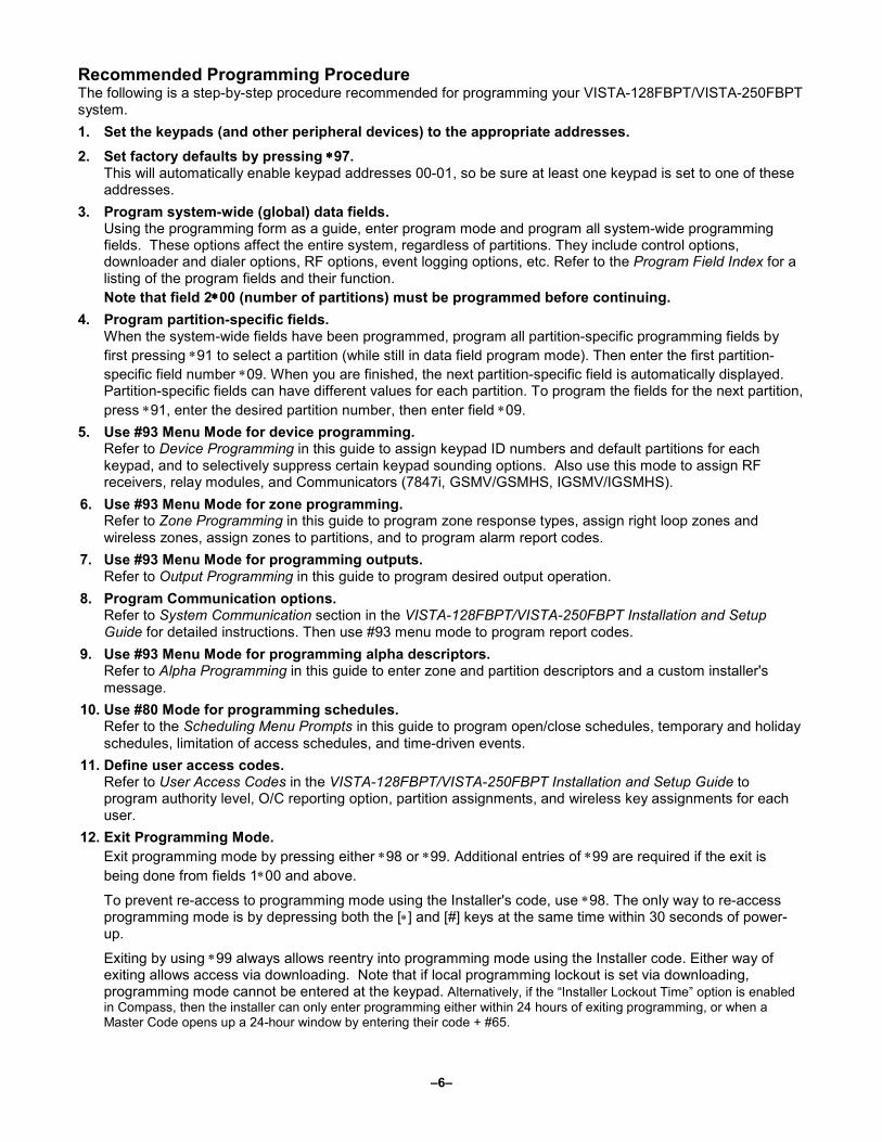
Recommended Programming Procedure The following is a step-by-step procedure recommended for programming your VISTA-128FBPT/VISTA-250FBPT system.
1. Set the keypads (and other peripheral devices) to the appropriate addresses.
2. Set factory defaults by pressing ∗∗∗∗97. This will automatically enable keypad addresses 00-01, so be sure at least one keypad is set to one of these addresses.
3. Program system-wide (global) data fields. Using the programming form as a guide, enter program mode and program all system-wide programming fields. These options affect the entire system, regardless of partitions. They include control options, downloader and dialer options, RF options, event logging options, etc. Refer to the Program Field Index for a listing of the program fields and their function.
Note that field 2∗∗∗∗00 (number of partitions) must be programmed before continuing.
4. Program partition-specific fields. When the system-wide fields have been programmed, program all partition-specific programming fields by
first pressing ∗91 to select a partition (while still in data field program mode). Then enter the first partition-
specific field number ∗09. When you are finished, the next partition-specific field is automatically displayed. Partition-specific fields can have different values for each partition. To program the fields for the next partition,
press ∗91, enter the desired partition number, then enter field ∗09.
5. Use #93 Menu Mode for device programming. Refer to Device Programming in this guide to assign keypad ID numbers and default partitions for each keypad, and to selectively suppress certain keypad sounding options. Also use this mode to assign RF receivers, relay modules, and Communicators (7847i, GSMV/GSMHS, IGSMV/IGSMHS).
6. Use #93 Menu Mode for zone programming. Refer to Zone Programming in this guide to program zone response types, assign right loop zones and wireless zones, assign zones to partitions, and to program alarm report codes.
7. Use #93 Menu Mode for programming outputs. Refer to Output Programming in this guide to program desired output operation.
8. Program Communication options. Refer to System Communication section in the VISTA-128FBPT/VISTA-250FBPT Installation and Setup Guide for detailed instructions. Then use #93 menu mode to program report codes.
9. Use #93 Menu Mode for programming alpha descriptors. Refer to Alpha Programming in this guide to enter zone and partition descriptors and a custom installer's message.
10. Use #80 Mode for programming schedules. Refer to the Scheduling Menu Prompts in this guide to program open/close schedules, temporary and holiday schedules, limitation of access schedules, and time-driven events.
11. Define user access codes. Refer to User Access Codes in the VISTA-128FBPT/VISTA-250FBPT Installation and Setup Guide to program authority level, O/C reporting option, partition assignments, and wireless key assignments for each user.
12. Exit Programming Mode.
Exit programming mode by pressing either ∗98 or ∗99. Additional entries of ∗99 are required if the exit is
being done from fields 1∗00 and above.
To prevent re-access to programming mode using the Installer's code, use ∗98. The only way to re-access programming mode is by depressing both the [∗] and [#] keys at the same time within 30 seconds of power-up.
Exiting by using ∗99 always allows reentry into programming mode using the Installer code. Either way of exiting allows access via downloading. Note that if local programming lockout is set via downloading, programming mode cannot be entered at the keypad. Alternatively, if the “Installer Lockout Time” option is enabled in Compass, then the installer can only enter programming either within 24 hours of exiting programming, or when a Master Code opens up a 24-hour window by entering their code + #65.

–7–
Program Field Index On the following pages, the programming fields have been arranged in numerical order. Use this index to cross-reference the fields on the programming form.
Field Group Field Group Field Group
∗00 System-Wide
∗04 System-Wide
∗05 System-Wide
∗06 Partition-Specific
∗08 System-Wide
∗09 Partition-Specific
∗10 Partition-Specific
∗11 Partition-Specific
∗12 Partition-Specific
∗13 Partition-Specific
∗14 System-Wide
∗15 System-Wide
∗16 Partition-Specific
∗17 System-Wide
∗19 System-Wide
∗20 System-Wide
∗22 Partition-Specific
∗23 Partition-Specific
∗24 System-Wide
∗25 System-Wide
∗26 Communications
∗27 Communications
∗28 System-Wide
∗29 Partition-Specific
∗31 Communications
∗32 Partition-Specific
∗33 Communications
∗34 Communications
∗35 System-Wide
∗36 System-Wide
∗37 System-Wide
∗38 Partition-Specific
∗39 Partition-Specific
∗40 Communications
∗41 System-Wide
∗42 Communications
∗44 Communications
∗45 Communications
∗47 Communications
∗51 Communications
∗56 Communications
∗57 Communications
∗58 Communications
∗59 Communications
∗77 Communications
∗79 Communications
∗80 Communications
∗83 Communications
∗84 Partition-Specific
∗85 Partition-Specific
∗88 Partition-Specific
∗89 Communications
∗90 Partition-Specific
1∗11 System-Wide
1∗12 System-Wide
1∗13 System-Wide
1∗15 Communications
1∗17 System-Wide
1∗18 Partition-Specific
1∗19 Partition-Specific
1∗20 System-Wide
1∗21 System-Wide
1∗22 System-Wide
1∗23 System-Wide
1∗24 System-Wide
1∗25 System-Wide
1∗26 Partition-Specific
1∗28 System-Wide
1∗29 System-Wide
1∗30 System-Wide
1∗31 System-Wide
1∗34 Communications
1∗35 Communications
1∗42 Communications
1∗43 Partition-Specific
1∗44 System-Wide
1∗45 Partition-Specific
1∗47 Partition-Specific
1∗48 System-Wide
1∗49 System-Wide
1∗50 System-Wide
1∗51 System-Wide
1∗52 Partition-Specific
1∗53 System-Wide
1∗54 System-Wide
1∗55 System-Wide
1∗56 System-Wide
1∗57 System-Wide
1∗58 System-Wide
1∗60 System-Wide
1∗70 System-Wide
1∗71 System-Wide
1∗72 System-Wide
1∗74 System-Wide
1∗75 System-Wide
1∗76 Partition-Specific
1∗77 System-Wide
1∗78 System-Wide
1∗79 System-Wide
1∗80 System-Wide
2∗00 System-Wide
2∗01 System-Wide
2∗02 System-Wide
2∗03 System-Wide
2∗05 Partition-Specific
2∗06 Partition-Specific
2∗07 Partition-Specific
2∗08 Partition-Specific
2∗09 Partition-Specific
2∗10 Partition-Specific
2∗11 System-Wide
2∗18 Partition-Specific
2∗19 Partitioning
2∗22 Partition-Specific
2∗23 Partition-Specific
2∗24 Partition-Specific
3∗00 System-Wide
3∗01 System-Wide
3∗12 System-Wide
3∗13 System-Wide
3∗14 System-Wide
3∗16 System-Wide
3∗17 System-Wide
3∗18 System-Wide
3∗20 System-Wide
3∗21 System-Wide
3∗30 System-Wide
3∗50 System-Wide
3∗55 System-Wide
3∗56 System-Wide
3∗57 Partition-Specific
3∗59 Partition-Specific
3∗60 Partition-Specific
3∗61 System-Wide
3∗82 System-Wide
3∗85 System-Wide

– 8 –
VISTA-128FBPT/VISTA-250FBPT Programming Some fields are programmed for each partition (shown as shaded fields). If you are programming a multiple-partition system,
see the Partition-Specific Fields section for programming these fields. Standard default (∗97) values are shown in brackets [ ]; otherwise, default = 0.
Data field programming involves making the appropriate entries for each of the data fields. Start Data Field programming by entering the installer code + 8 + 0 + 0 + 0.
All Fire zones should be assigned to partition 1.
∗∗∗∗00 Installer Code Enter 4 digits, 0-9
[5140]
The Installer Code is a 4-digit code reserved for installation company use.
This is the only code that can be used to enter the Program Mode from the keypad. This code cannot be used to disarm the system if it isn’t used to arm the system. This code cannot be used to re-enter Program Mode if Program
Mode is exited by the ∗98 command.
∗∗∗∗04 Enable Random Timers (for partitions 1-8) 0 = disable 1 = enable
1
2
3
4
5
6
7
8
Enter 1 to make available the randomizing of pre-programmed time driven events for each partition. [0=disable].
If enabled, the activation time of the window is randomized up to 30 minutes and is initialized by either of two methods:
User Code + [#] + [41] Initiates the random schedule for all devices in the partition.
User Code + [#] + [42] Initiates the random schedule for all devices in the partition with a time window within 6 PM and 5 AM.
NOTES: Must be “0” for Commercial Burglary installations.
∗∗∗∗05 System Events Notify 0 = disable 1 = enable
[0]
If enabled the system sends notification messages via the RS232 port to interface with Home Control type software.
1=enable, (messages sent via the RS232 port).
0=disable, (no messages sent).
NOTES:
While in a communication session with Compass, system events will not operate.
If enabled, the system also sends fault and restore messages via the RS232 port.
∗∗∗∗06 Quick Exit (partition-specific) 0 = disable 1 = enable
[1]
If enabled, allows users to exit the armed partition without disarming and then rearming the partition.
Quick Exit is initiated by entering [#] + [9]. This restarts the exit delay. All rules of exit apply, including exit error logic.
∗∗∗∗08 Temporal Siren Pulse
Not used at this time.
∗∗∗∗09 Entry Delay 1 (partition-specific) Enter 02-15 multiplied by 15 seconds. 00 = no delay.
[02]
Entry delay defines the delay time that allows users to re-enter the premises through a door that has been programmed as an entry delay door and disarm the system without sounding an alarm. The system must be disarmed within this period or an alarm will occur.
NOTE: The delay may not exceed 45 seconds (“03”) for Commercial Burglary installations.

– 9 –
∗∗∗∗10 Exit Delay 1 (partition-specific) Enter 03-15 multiplied by 15 seconds. 00 = no delay.
[04]
Exit delay defines the delay period that allows users to leave the premises through a door that has been programmed as an entry/exit delay door after arming the system without setting off the alarm.
NOTE: The delay may not exceed 1 minute ("04") for Commercial Burglary installations.
∗∗∗∗11 Entry Delay 2 (partition-specific) Enter 02-15 multiplied by 15 seconds. 00 = no delay. (Must be longer than Entry Delay #1.)
[02]
Entry Delay #2 is used for a secondary door requiring a longer delay than those assigned to Entry Delay #1.
NOTE: The delay may not exceed 45 seconds (“03”) for Commercial Burglary installations.
∗∗∗∗12 Exit Delay 2 (partition-specific) Enter 03-15 multiplied by 15 seconds. 00 = no delay. (Must be longer than Exit Delay #1).
[08]
Exit Delay #2 is used for a secondary door requiring a longer delay than those assigned to Exit Delay #1.
NOTE: The delay may not exceed 1 minute ("04") for Commercial Burglary installations.
∗∗∗∗13 Bell 1 Timeout Enter 01-15 multiplied by 2 minutes. 00 = no timeout.
[03]
Defines the length of time the Bell 1 Output and the keypad’s sounder will sound for all audible alarms.
NOTES:
Must be minimum 16 minutes for Commercial Burglary installations.
Must be minimum 6 minutes for Commercial Fire installations.
∗∗∗∗14 RS232 comm. 0 = No 1 = Yes
[0]
Enter 1 to enable (9600 baud).
Enter 0 to disable.
NOTE: Must be set to “0” for Commercial Fire installations.
∗∗∗∗15 Keyswitch 1-8 = Ptn 9 = Bell 0 = no Enter 1-8 partition keyswitch is being used. Enter 9 if the keyswitch is being used to silence fire Notification Appliance Circuits in the event of a fire alarm. Enter 0 if the keyswitch is not used.
[0]
Enter partition in which keyswitch used, 1-8; 9=silences Notification Appliance Circuit if fire present; 0=disable
The keyswitch requires the use of zone 7 wired loop (zone 7 is no longer available as protection zone). The fire and panic alarm voltage triggers (J2) can become ARMING and READY status outputs for the Keyswitch LEDs if programmed in 3∗20.
Openings/closing report as user “0” if enabled in field ∗40.
∗∗∗∗16 Bell 1 Confirm Arm (partition-specific) 0 = disable 1 = enable
[1]
If enabled, produces ½-second external alarm sounding (“ding”) at the end of exit delay (or after kissoff from the central station, if sending closing reports).
NOTES:
If using a keyfob, when the button is pressed for arming, the bell will ding indicating that the button is working.
Must be 1 for UL Commercial Burglary installations.
∗∗∗∗17 AC Loss Keypad Sounding 0 = disable 1 = enable
[1]
If enabled, sounding at the keypad (rapid beeping) occurs when AC power is lost (sounding occurs about 2 minutes after actual AC loss).
NOTE: Must be “1” for Commercial Fire installations.

– 10 –
∗∗∗∗19 Randomize AC Loss Report 0 = within 2 minutes 1 = 10-40 minutes 2 = 1-3 hours 3 = 6-12 hours without Type 13, 1-3 hours with Type 13
[2]
If enabled, randomizes AC loss reporting within the selected time after an actual AC loss.
If disabled (0), AC loss reporting about 2 minutes after actual AC loss.
Selecting this option helps prevent an overload of AC loss messages at the central station during a community blackout.
NOTE: Must be 2 for Commercial Fire installations.
∗∗∗∗20 Telephone Module Phone Code 1-9 = first digit of access code ∗∗∗∗ or # = second digit of access code (enter
11 for “∗”, or 12 for “#”) To disable enter 00 for the 1st digit
[00] [00]
NOT USED.
Must be set to “00, 00” for Commercial Fire and Commercial Burglary installations.
∗∗∗∗22 Keypad Panic Enables (partition-specific) 0 = disable 1 = enable
[001]
995 996 999
If enabled, the keypad panics (zones 995, 996, and 999) may be used in this partition. There are three entries in this field, one for each panic.
NOTES:
Use for Burglary panic types only.
Do not use on partition 1 on fire systems.
∗∗∗∗23 Multiple Alarms (partition-specific) 0 = disable 1 = enable
[1]
If enabled, allows more than one alarm sounding for a given zone during an armed period. Pertains to Burglary zones.
NOTES:
Multiple alarm soundings will not occur more frequently than allowed by the programmed alarm sounder duration. This has no impact on the number of communication messages transmitted.
Must be “1” for Commercial Fire and UL Commercial Burglary installations.
∗∗∗∗24 Ignore Expansion Zone Tamper 0 = disable (tamper detection) 1 = enable (no tamper detection)
[0]
If disabled, the system monitors the tampers on expansion zones for RF and V-plex device.
NOTES:
Only applicable to certain polling loop sensors with tamper switches or 5800 Series transmitters.
Must be "0" for Commercial Burglary and Commercial Fire installations if using these devices.
∗∗∗∗25 LRR Burg. Trigger for type 8 0 = disable
1 = enable
[1]
If enabled, allows triggering of Output 3 (pin 3) of the J2 header to include zone response type 8 (24-hr. auxiliary).
∗∗∗∗26 Intelligent Test Report 0 = disable 1 = enable
If enabled, no test report is sent if any other type of report was sent since the last test report.
If disabled, test reports are sent at the programmed intervals (field ∗27), regardless of whether or not any other report has been sent.
NOTE: Must be “0” for Commercial Fire and UL Commercial Burglary installations.
∗∗∗∗27 Test Report Interval Enter 0001-9999 for the test report interval in hours. Enter 0000 for no test reporting.
[0024]
If a test report is desired, enter a test code in Report Code Programming in
#93 Menu Mode. Set first test report time in field ∗83.
NOTE: Maximum Test report interval is “0024” for Commercial Fire and Commercial Burglary installations.

– 11 –
∗∗∗∗28 Power-Up in Prev. State 0 = disable 1 = enable
[1]
If enabled, the system, upon power-up, reverts to its status prior to a complete power loss.
If disabled, the system always powers up in a disarmed state.
NOTES:
Neither authority level 0 nor 5 can be used to disarm the system if the control powers up armed.
When Power Up in Previous State is enabled, if the panel powers up armed, it may take up to 3 minutes before an alarm is recognized and initiated.
Must be "1" for Commercial Burglary and Commercial Fire installations.
∗∗∗∗29 Quick Arm (partition-specific) 0 = disable 1 = enable
[1]
If enabled, allows arming of the burglary system in AWAY, STAY, INSTANT, or MAXIMUM mode by using the [#] key instead of the user code.
NOTES:
When armed, the system reports closing as User 0 if Open/Close reporting for User #2 (typically a Master level user) was enabled for a given partition.
If Quick Arm is used, the Installer Code and Authority Level 5 codes cannot disarm the system.
∗∗∗∗31 PABX (Access Code) Enter 00-09; B-F (11-15)
[00] [00] [00] [00]
This field is used to enter up to four 2-digit numbers representing the prefix needed to obtain an outside telco line. If not required, enter nothing and proceed to next field.
∗∗∗∗32 Prim. Sub. Acc # (partition-specific) Enter 00-09; B-F (11-15)
[15] [15] [15] [15] [15]
[15] [15] [15] [15] [15]
Enter a 4- or 10-digit (depending on report format) primary subscriber account number. Each number requires a 2-digit entry so as to allow entry of hexadecimal digits (B-F). If a 4-digit account number is to be used, enter data only in the first four locations, and enter * in the fifth location.
∗∗∗∗33 Primary Phone
Enter 0-9; #11 for ∗, #12 for #, #13 for a 2-second pause.
Enter the primary central station phone number, up to 17 digits. This is the phone number the control will use to transmit Alarm and status messages to the central station. Do not fill unused spaces.
NOTE: Backup reporting is automatic only if a secondary phone number is entered.
NOTE: Ensure that the phone number entered is to the Central Station, not a Police Station, as the call will not go through to the Police Station.
∗∗∗∗34 Secondary Phone
Enter 0-9; #11 for ∗, #12 for #, #13 for a 2-second pause.
Enter the secondary phone number, up to 17 digits. The secondary phone number is used if communication on the primary number is unsuccessful, or if split/dual reporting is desired. Do not fill unused spaces.
NOTE: If this field is programmed, a secondary subscriber account number (field ∗90) must also be programmed.
NOTE: Ensure that the phone number entered is to the Central Station, not a Police Station, as the call will not go through to the Police Station.
∗∗∗∗35 Download Phone
Enter 0-9; #11 for ∗, #12 for #, #13 for a 2-second pause.
Enter the downloading phone number, up to 17 digits. Do not fill unused spaces.
NOTE: This field is applicable only if downloading is utilized.
∗∗∗∗36 Download ID No. Make entries as 2-digit numbers as follows: 00=0 01=1 02=2 03=3 04=4 05=5 06=6 07=7 08=8 09=9 10=A 11=B 12=C 13=D 14=E 15=F
[15] [15] [15] [15] [15]
[15] [15] [15]
Enter eight digits.
NOTE: This field is applicable only if downloading is utilized.

– 12 –
∗∗∗∗37 Download Command Enables 0 = disable 1 = enable
[1] [1] [1] [1] [1] [1] [1] [1]
Dir Shtdwn Sys Shtdwn Not Used Rmt Byp Rmt Disarm Rmt Arm Upld Pgm Dwnld Pgm
Enabling a function means that you are able to perform that function via the
Honeywell Compass Downloading software. See field 1∗53 for Callback disable function.
Functions are as follows: Dialer Shutdown; System Shutdown; Not Used; Remote Bypass; Remote Disarm; Remote Arm; Upload Program; Download Program.
NOTE: For Commercial Burglary and Fire installations, all entries must be 0.
∗∗∗∗38 Prevent Zone XXX Bypass (partition-specific) Enter a zone number (001-250). Enter 000 if all zones can be bypassed.
[000]
Enter three digits for zone that cannot be bypassed by the user.
NOTES:
The actions manual bypass, group bypass, auto-stay, and STAY/INSTANT arming modes cannot bypass any zone programmed in this field.
The system will not arm if the zone is programmed with the vent zone or force arm fault attributes.
ULC Force Arming is not a ULC Listed feature and must be disabled for ULC installations.
∗∗∗∗39 Open/Close Rep. Installer (partition-specific) 0 = disable 1 = enable
[1]
If enabled, whenever the Installer Code is used to arm or disarm the partition, an open/close report is sent to the central station.
∗∗∗∗40 Enable Open/Close report for Keyswitch 0 = disable 1 = enable
[0]
If enabled, whenever the keyswitch is used to arm or disarm the partition, an open/close report is sent to the central station.
∗∗∗∗41 Normally Closed or EOLR (Zones 3-8) 0 = EOLR supervision 1 = N.C. loops
[0]
If EOLR supervision is selected, end-of-line resistors must be used on zones 3-8.
If N.C. loops is selected, end-of-line resistors cannot be used and only normally closed devices must be used.
NOTE: Must be “0” for Commercial Fire and Burglary installations.
∗∗∗∗42 Dial Tone Pause
Enter the wait time for dial tone detection: 0 = 5 seconds; 1 = 11 seconds; 2 = 30 seconds.
[0]
Enter the time the system waits for dial tone before dialing.
NOTE: Must be “0” for Commercial Fire and Burglary installations.
∗∗∗∗44 Ring Detection Count Enter 00 to disable ring detection. Enter 01-14 for ring counts of 1-14. Enter 15 to select Answering Machine Defeat Mode
[00]
Only applicable if station-initiated downloading will be used.
NOTES:
In the Answering Machine Mode, the caller should let the phone ring once, then hang up, and call again within 30 seconds. The system, upon hearing one ring followed by nothing, does not answer the first call, but readies itself to pick up on the first ring of the next incoming call that is received within 30 seconds (i.e., the downloader calling again).
Must be set to “00” for Commercial Fire and Burglary installations.
∗∗∗∗45 Primary Format 1 = Contact ID; 2 = 10-Digit Contact ID;
3 = 4 + 2 Express
[1]
Enter the reporting format for the primary telephone number.
∗∗∗∗47 Secondary Format 1 = Contact ID; 2 = 10-Digit Contact ID;
3 = 4 + 2 Express
[1]
Enter the reporting format for the secondary telephone number.

– 13 –
∗∗∗∗51 Dual Reporting 0 = disable 1 = enable
[0]
If enabled, all reports are to be sent to both primary and secondary phone numbers.
NOTES:
If used with Spilt Reporting "1" option (1∗34), alarms and alarm restores go to both primary and secondary numbers, while all other reports go to secondary only. If used with Split Reporting "2" option, alarms and alarm restores go to both, open/close and test messages go to secondary only, while all other reports go to primary. If used with Split Reporting “3” option, fire alarms and fire restore signals go to both, all other reports go to secondary only.
For Remote Station Applications, where separate transmission circuits are required for Fire, Supervisory (when applicable), and Trouble signals, option 3 must be enabled.
∗∗∗∗56 Dynamic Signal Delay Enter 00-15 times 15 seconds.
[03]
Select the time the panel should wait for acknowledgment from the first reporting destination before it attempts to send a message to the second
destination (first and second destinations are determined in field ∗57).
NOTES:
A minimum of 45 seconds is recommended when the Communicator is set to be the primary report path. If the delay is short (30 seconds or less), the communications device does not have enough time to sent the acknowledgement back to the panel, therefore the report would be sent out via the dialer.
When a Communicator is used as a backup to the dialer, the Dynamic
Signaling Delay (∗56) should be set to a minimum of 1 minute.
If the acknowledgment is received before the delay time expires, no message is sent to the second destination.
∗∗∗∗57 Dynamic Signal Priority 0 = Primary Dialer 1 = Communicator
[0]
Select the initial reporting path for central station messages.
∗∗∗∗58 LRR CS #1 Category En. 0 = disable 1 = enable
[000000]
Alarm Trbl Byp O/C Syst Test
This field has six entries as follows: Alarm, Trouble, Bypass, Open/Close, System, and Test. If enabled, the reports are sent to the primary subscriber ID of the Communicator.
∗∗∗∗59 LRR CS #2 Category En. 0 = disable 1 = enable
[000000]
Alarm Trbl Byp O/C Syst Test
This field has six entries as follows: Alarm, Trouble, Bypass, Open/Close, System, and Test. If enabled, the reports are sent to the secondary subscriber ID of the Communicator.
∗∗∗∗77 Auto Trbl Rstr 0 = disable 1 = enable
[1]
If enabled, each trouble and supervisory condition automatically clears the keypad display and stops the keypad beeping when the zone returns to a “ready/normal” state. This applies to ALL trouble and supervisory types. The system also sends the Trouble/Supervisory Restore report to the central station, if programmed.
If a partition has more than one trouble/supervisory condition present at the same time, the system automatically clears the keypad display of each zone as it restores, but the keypad continues to beep until all the zones restore.
NOTES:
If this option is set to 0 (disable) then the operation is that restore reports will be sent to the CS when the actual restoral on the zone occurs, however the keypad display will remain showing the condition until a valid code is entered.
Must be “1” for Commercial Fire installations.
– 14 –
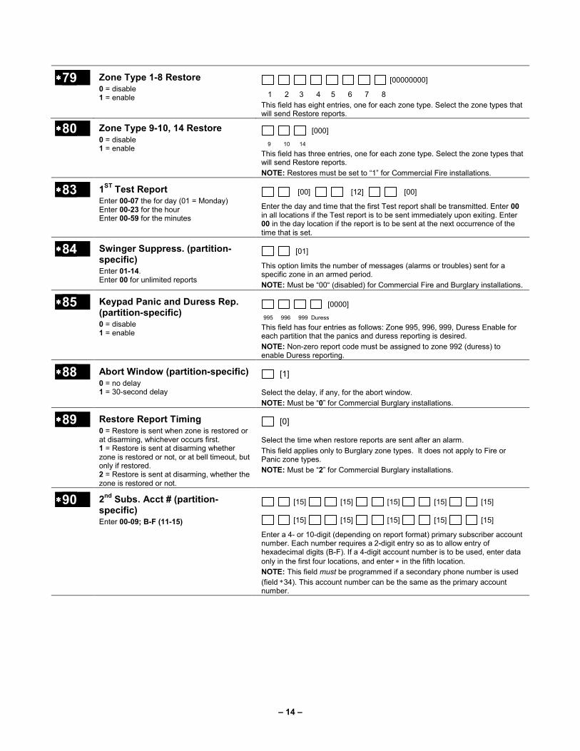
∗∗∗∗79 Zone Type 1-8 Restore 0 = disable 1 = enable
[00000000]
1 2 3 4 5 6 7 8
This field has eight entries, one for each zone type. Select the zone types that will send Restore reports.
∗∗∗∗80 Zone Type 9-10, 14 Restore 0 = disable 1 = enable
[000]
9 10 14
This field has three entries, one for each zone type. Select the zone types that will send Restore reports.
NOTE: Restores must be set to “1” for Commercial Fire installations.
∗∗∗∗83 1ST
Test Report Enter 00-07 the for day (01 = Monday) Enter 00-23 for the hour Enter 00-59 for the minutes
[00] [12] [00]
Enter the day and time that the first Test report shall be transmitted. Enter 00 in all locations if the Test report is to be sent immediately upon exiting. Enter 00 in the day location if the report is to be sent at the next occurrence of the time that is set.
∗∗∗∗84 Swinger Suppress. (partition-specific) Enter 01-14. Enter 00 for unlimited reports
[01]
This option limits the number of messages (alarms or troubles) sent for a specific zone in an armed period.
NOTE: Must be “00“ (disabled) for Commercial Fire and Burglary installations.
∗∗∗∗85 Keypad Panic and Duress Rep. (partition-specific) 0 = disable 1 = enable
[0000]
995 996 999 Duress
This field has four entries as follows: Zone 995, 996, 999, Duress Enable for each partition that the panics and duress reporting is desired.
NOTE: Non-zero report code must be assigned to zone 992 (duress) to enable Duress reporting.
∗∗∗∗88 Abort Window (partition-specific) 0 = no delay 1 = 30-second delay
[1]
Select the delay, if any, for the abort window.
NOTE: Must be “0” for Commercial Burglary installations.
∗∗∗∗89 Restore Report Timing 0 = Restore is sent when zone is restored or at disarming, whichever occurs first. 1 = Restore is sent at disarming whether zone is restored or not, or at bell timeout, but only if restored. 2 = Restore is sent at disarming, whether the zone is restored or not.
[0]
Select the time when restore reports are sent after an alarm.
This field applies only to Burglary zone types. It does not apply to Fire or Panic zone types.
NOTE: Must be “2” for Commercial Burglary installations.
∗∗∗∗90 2nd
Subs. Acct # (partition-specific) Enter 00-09; B-F (11-15)
[15] [15] [15] [15] [15]
[15] [15] [15] [15] [15]
Enter a 4- or 10-digit (depending on report format) primary subscriber account number. Each number requires a 2-digit entry so as to allow entry of hexadecimal digits (B-F). If a 4-digit account number is to be used, enter data only in the first four locations, and enter ∗ in the fifth location.
NOTE: This field must be programmed if a secondary phone number is used
(field ∗34). This account number can be the same as the primary account number.

– 15 –
2nd
Page Programming Fields (press ∗94)
1∗∗∗∗11 Zone Bypass after Disarm 0 = disable 1 = enable
[00000000]
1 2 3 4 5 6 7 8
Enter 1 for each partition in which zones will remain bypassed after disarm.
NOTES:
For each partition in which field 1∗11 is enabled, the USER CODE + OFF will no longer unbypass zones. To unbypass ALL zones, you must enter USER CODE + # + 64. To unbypass zones INDIVIDUALLY, you must enter USER CODE + 6 + zone number.
Any zone that was automatically bypassed by the system will be unbypassed upon disarming of the system (e.g., STAY mode, Auto-STAY, etc.).
Vent zones and zones bypassed by a programmed Auto-Bypass schedule (Timed Driven Event) are considered “manual bypasses” and will not be unbypassed upon disarming the system.
Zones that were in a bypassed state at the time a System Shutdown is sent from the Compass Downloading software will be unbypassed when the System Shutdown is removed.
1∗∗∗∗12 Program Notification 0 = no 1 = yes
[1]
If enabled, sends signal to central station indicating the system has been put in programming mode.
NOTE: Must be “1” for Commercial Fire installations.
1∗∗∗∗13 Sys. Sensor Rev. Relay 0 =use neither Zone 1 or Zone 2 inputs
1=use Zone 1 input;
2=use Zone 2 input;
3=use Zone 1 and Zone 2 inputs
[0]
Selects zones for system sensor reversing relay.
NOTE: When code + #69 fire Drill test is active, these zones if programmed, will be disabled.
Not Used for Commercial Fire installations.
1∗∗∗∗15 Cancel Verify 0 = disable 1 = enable alarm output pulse upon kissoff of Cancel report.
[1]
NOTES:
Field 1∗52 must be enabled to send a Cancel report to the central station.
Cancel reports must be enabled in system group 1.
1∗∗∗∗17 Lobby Partition 0 = none; 1-8 = partition number
[0]
Select the Common Lobby Partition.
1∗∗∗∗18 Affects Lobby (partition-specific) 1 = if this partition affects the common lobby (enable)
0 = if it does not (disable)
[0]
If enabled, causes lobby partition to disarm when this partition disarms.
NOTES:
This partition must be armed before lobby can be armed.
Must be “0” for Commercial Burglary and Commercial Fire installations.
1∗∗∗∗19 Arms Lobby (partition-specific) 0 = disable 1 = enable
[0]
If enabled, arming this partition causes the system to attempt to arm the lobby
partition. Field 1∗18 must also be enabled (partition-specific).
NOTES:
The lobby cannot be armed unless all partitions programmed for “affect” (field 1*18) is already armed.
If this field is enabled, Field 1∗18 for this partition must also be enabled.
Must be “0” for Commercial Burglary and Commercial Fire installations.

– 16 –
1∗∗∗∗20 Exit Error Logic Enable 0 = disable 1 = enable
[1]
Exit Error Logic functions as follows: the system at the end of the exit delay, if a door is left open or an interior zone is faulted, starts the entry delay period, and sounds the bell(s), siren(s), and keypad sounders for the duration of entry delay. This gives the user time to re-enter the premises and disarm the system before exit error occurs.
If the user does not re-enter the premises and disarm the system, the system bypasses the faulted entry/exit and/or interior zone(s). The rest of the system is armed. In addition, the following dialer reports are sent to the central station if programmed:
Exit Error by Zone
Entry/Exit or Interior Alarm with the zone number
Bypass reports
UL
Exit Error Logic is not suitable for use in a UL installation.
NOTE: Exit Error only affects Bell #1 regardless of the zone's bell assignment.
NOTE: Must be “0” for Commercial Burglary installations.
1∗∗∗∗21 Exit Delay Reset 0 = disable 1 = enable
[1]
If enabled, when the panel is armed, the normal exit delay begins. After the user exits, closes the door and then re-enters the premises, the exit delay time is reset to the programmed value.
Exit Delay Reset is designed to allow an operator to re-enter the premises to retrieve a forgotten item without triggering an alarm. This feature may only be activated once after arming.
UL
Exit Delay Reset is not suitable for use in a UL installation.
NOTE: Must be “0” for Commercial Burglary installations.
Cross-Zoning
UL Cross Zoning is not suitable for use in a UL installation.
Cross Zoning is designed so that a combination of two zones must be faulted within a 5-minute period of each other (once
the first zone trips, the cross zoning window begins, and when the 2nd zone trips within that window, the alarm for both
zones will occur). This prevents momentary faults from one of the zones from causing an alarm condition. You can
select four "sets" of cross-zones (programmed in data fields 1∗22, 1∗23, 1∗24 and 1∗25), keeping in mind the following:
• Both zones in each set must protect the same area.
• Both zones in each set must be in the same partition.
Conditions That Affect Cross-Zone Operation
• Fire zones can not be cross-zoned.
• In the event of a continuous fault (lasting at least 5 minutes) on one of the paired zones, a fault on the second zone
causes an alarm immediately.
• If one of the zones in a pair is bypassed or has a zone response type set to 0, the cross-zoning feature does not apply.
• If an entry/exit zone is paired with an interior follower zone, be sure to enter the entry/exit zone as the first zone of
the pair. This ensures that the entry delay time is started before the follower zone is processed.
• If a relay is programmed to activate on a fault of one of the zones, the relay activates without the other zone being
faulted.
• If a relay is programmed to activate on an alarm or trouble, both zones must trip before the relay activates, and both
zones must restore for the relay to deactivate (if relay is programmed to deactivate on a Zone List Restore).
If the one of the zones trips and the second zone does not trip within the 5-minute period, an “error” message is reported to the central station. The Contact ID event code is 378.
1∗∗∗∗22 Cross-Zoning Pair 1 Enter 001-250 Enter 000,000 to disable
[000] [000]
Select the first pair of cross zones, which must both be faulted within a 5-minute period to cause an alarm.
NOTE: Must be set to “000,000 “for Commercial Fire and Burglary installations.

– 17 –
1∗∗∗∗23 Cross-Zoning Pair 2 Enter 001-250 Enter 000,000 to disable
[000] [000]
Select the second pair of cross zones, which must both be faulted within a 5-minute period to cause an alarm.
NOTE: Must be set to “000,000” for Commercial Fire and Burglary installations.
1∗∗∗∗24 Cross-Zoning Pair 3 Enter 001-250 Enter 000,000 to disable
[000] [000]
Select the third pair of cross zones, which must both be faulted within a 5-minute period to cause an alarm.
NOTE: Must be set to “000,000” for Commercial Fire and Burglary installations.
1∗∗∗∗25 Cross-Zoning Pair 4 Enter 001-250 Enter 000,000 to disable
[000] [000]
Select the fourth pair of cross zones, which must both be faulted within a 5-minute period to cause an alarm.
NOTE: Must be set to “000,000” for Commercial Fire and Burglary installations.
1∗∗∗∗26 Panic Button or Speedkey For A, B, C keys: 00 = panic function; 01-32 = macro number
For D key: 00 = to select a macro to execute when key is pressed; 01-32 = macro number
[00] [00] [00] [00]
A B C D
Select for the A, B, and C keys whether the system performs a panic or a speedkey function when the key is pressed.
Select for the D key whether the system performs a specific macro or if the user will select a macro when the key is pressed.
1∗∗∗∗28 RF Tx LowBattery Sound 0 = when disarmed 1 = immediate
[0]
Select when the RF transmitter low-battery condition should display and audible beep annunciate on the keypad.
NOTE: Must be “1” for Commercial Fire and UL Commercial Burglary installations.
1∗∗∗∗29 RF Tx LowBattery Reporting 0 = disable 1 = enable
[0]
If enabled, the system sends a Trouble message for RF transmitter low-battery condition to the central station.
NOTES:
The Trouble message will be sent for a transmitter supervision failure, independent of this selection.
Must be “1” for Commercial Fire and UL Commercial Burglary installations.
1∗∗∗∗30 RF Rcvr Check-in Interval Enter 02-15 times 2 hours (4-30 hours). 00 = disable receiver supervision.
[02]
Select the check-in monitoring interval for the RF receiver(s).
Failure of a receiver to receive any RF signal within the time entered results in the activation of the response type programmed for zone 990 for the first receiver and zone 988 for the second receiver and their related communication reports.
NOTE: Maximum is “2” (4 hr) for Commercial Fire and UL Commercial Burglary installations.
1∗∗∗∗31 RF Tx Check-in Interval Enter 02-15 times 2 hours (4-30 hours). 00 = disable transmitter supervision.
[02]
Select the check-in monitoring interval for the RF transmitters.
Failure of an individual transmitter to send a supervision signal within the time entered will result in a trouble response and related communication report.
NOTE: Maximum is 2 (4 hr) for Commercial Fire and UL Commercial Burglary installations.

– 18 –
1∗∗∗∗34 Comm. Split Reporting (Dialer only) 0 = Split Reporting disabled
1 = Alarm, Alarm Restore, and Cancel reports to primary, all others to secondary
2 = Open/Close and Test reports to secondary, all other reports to primary
3 = Fire Alarms and Fire Restores to primary and secondary, all others to secondary
[0]
Select the type of split reporting for system communication.
NOTES:
See ∗51 for split/dual reporting combinations.
Split reporting should not be used with Dynamic Signaling.
1∗∗∗∗35 ACS Dlr Enables (Access Control) 0 = disable 1 = enable
[000000]
Trace Trbl Byp Not Used Syst Alm
There are six entries for this field as follows: Trace, Trouble, Not Used, Bypass, System, and Alarm.
If Trace is enabled, access grant/denial events sent to the central station.
For the other events, if enabled, a report is sent to the central station.
NOTE: Not Used. Must be set to “0”.
1∗∗∗∗42 Call Waiting Defeat 0 = disable 1 = enable
[0]
If enabled, the system defeats Call Waiting on the first outgoing call attempt to both the primary and secondary numbers.
After the panel's initial call to report the alarm, the panel may attempt to make an additional call, perhaps for a cancel or a zone restoral. If Call Waiting is not defeated, an operator at the central station attempting to contact the premises (to verify whether the alarm is valid) hears the phone ringing indefinitely and must dispatch on the call.
NOTE: DO NOT enable this feature unless Call Waiting is being used.
1∗∗∗∗43 Permanent Keypad Backlight (partition-specific) 0 = disable 1 = enable
[0]
If enabled, backlighting for the keypad display remains on at all times. Otherwise the backlighting comes on when a key is pressed.
NOTES:
When a key is pressed, display backlighting turns on for all keypads in that partition.
This field affects only standard keypads, not graphic/touch-screen keypads.
1∗∗∗∗44 RF Keypad Tamper Detection 0 = disable 1 = enable
[0]
If enabled, when more than 40 key depressions are received without a valid sequence (arm, disarm, etc.), the control panel disables the wireless keypad. This inhibit is removed once a valid key sequence is received from a wired keypad.
NOTE: Not Used. Must be set to “0”.
1∗∗∗∗45 Exit Delay Sounding (partition-specific) 0 = disable 1 = enable
[1]
If enabled, the system produces slow beeping from the keypads during exit delay and reverts to rapid beeping during the last 10 seconds of the exit delay.
NOTES:
Must be “1” for UL/ULC installations.
The duration of the beeping is the programmed value of field ∗10 regardless of which entry/exit zone is used to exit the premises.
See “SOUND OPTION” prompt in this guide for disabling the entry/exit beeps on individual keypads.
1∗∗∗∗47 Chime on Bell 1 (partition-specific) 0 = disable 1 = enable
[0]
If enabled, the system produces chime annunciation on the Bell 1 output.
1∗∗∗∗48 RF Keypad Assign 1-8=Part. 0=NO
0 = none 1-8 = partition number
[0]
Select the partition in which RF keypad is used.
NOTE: Not Used. Must be set to “0”.

– 19 –
1∗∗∗∗49 Suppress Tx Superv. Sound 0 = disable 1 = enable
[1]
If enabled, no trouble soundings occur on the keypad for transmitter check-in failures.
NOTE: Must be “0” for Commercial Burglary and Commercial Fire installations.
1∗∗∗∗50 Seconds Added per day
Enter 00-60 [00]
Enter the number of seconds that will be added per day to correct the real-time clock, if internal crystal sync is selected in 1∗54.
NOTES:
NOT FOR DOMESTIC USE. For use in Asia Pacific applications only.
Time adjustment should only be set in 1∗50 or 1∗51. Do Not Set Both.
1∗∗∗∗51 Seconds Removed per day
Enter 00-60 [00]
Enter the number of seconds that will be subtracted per day to correct the real-time clock, if internal crystal sync is selected in 1∗54.
NOTES:
NOT FOR DOMESTIC USE. For use in Asia Pacific applications only.
Time adjustment should only be set in 1∗50 or 1∗51. Do Not Set Both.
1∗∗∗∗52 Send Cancel If Alarm + OFF (partition-specific) 0 = within bell timeout period only.
1 = no restriction
[1]
If set to “1” (no restrictions), Cancel reports are sent when the system is disarmed after an alarm, regardless of how much time has gone by.
If set to “0” (within bell timeout period only), Cancel reports are sent within Bell Timeout period only.
NOTE: This option must be enabled so Cancel reports are always sent.
1∗∗∗∗53 Download Callback 0 = callback required 1 = no callback required
[0]
Select whether a callback from the control panel is required for downloading.
NOTE: Must be set to “0” for Commercial Burglary and Commercial Fire installations.
1∗∗∗∗54 Internal Clock Sync. 0 = use AC sync for clock
1 = use internal crystal for clock
[0]
Select the sync method for the real-time clock. If “Use Internal Crystal for Clock” is selected, refer to 1∗50 and 1∗51 settings.
NOTE: NOT FOR DOMESTIC USE. For use in Asia Pacific applications only.
1∗∗∗∗55 European Date Format 0 = disable (mm/dd/yy)
1 = enable (dd/mm/yy)
[0]
Select the date format for display in the event log.
1∗∗∗∗56 AC 60Hz or 50Hz 0 = 60Hz 1 = 50Hz
[0]
Select the frequency for the AC.
NOTE: Must be “0” for U.S. and Canadian installations.
1∗∗∗∗57 Enable 5800 RF Button Global Arm 0 = disable 1 = enable
[0]
If enabled, the system arms/disarms in accordance with the button’s user’s global arming settings.
NOTE: Must be “0” for Commercial Burglary and Commercial Fire installations.

– 20 –
1∗∗∗∗58 Enable 5800 RF Force Arm 0 = disable 1 = enable
[0]
If enabled, allows the RF button user to force a bypass of all faulted zones when arming the system.
NOTES:
When attempting to arm the system, the keypad beeps once after the button is pressed if any faulted zones are present. The user should then press the button again within 4 seconds to force-bypass those zones and arm the system.
Must be set to “0” for Commercial Burglary and Commercial Fire installations.
ULC Force Arming is not a ULC Listed feature and must be disabled for ULC installations.
1∗∗∗∗60 Zone 5/Audio Alarm Ver. 0 = disable 1 = enable
[0]
If enabled, zone 5 is used for 2-way audio (AAV).
NOTES:
Must be set to “0” for Commercial Burglary and Commercial Fire installations.
Zone 5 cannot be used as protection zone.
1∗∗∗∗70 Event Log Types 0 = disable 1 = enable
[100010]
Alarm Chk Byp O/C Syst Test
This field has six entries as follows: Alarm, Check, Bypass, Open/Close, System and Test. If enabled, the system logs those events into the event log.
1∗∗∗∗71 12/24 Hour Time Stamp Format 0 = 12-hour
1 = 24-hour
[0]
Select the type of time stamping for the event log.
1∗∗∗∗72 Printer On-Line Mode 0 = disable 1 = enable
[0]
If enabled, the system prints the events as they occur.
If disabled, the system prints the log only upon request.
NOTE: Not Used. Must be set to “0”.
1∗∗∗∗74 Relay Timeout XXX Minutes Enter 000-127 times 2 minutes (000-254).
[000]
Enter relay timeout, 0-127 in multiples of 2 minutes, desired for #80 Menu Mode Time-Driven event relay command numbers “04/09” and Output Programming in the #93 Menu Mode Programming output command “56.”
1∗∗∗∗75 Relay Timeout YYY Seconds Enter 000-127 seconds.
[000]
Enter relay timeout, 0-127 seconds, desired for #80 Menu Mode Time-Driven event relay command numbers “05/10” and Output Programming in the #93 Menu Mode Programming output command “57.”
1∗∗∗∗76 Access Relay # (partition-specific) 01-96 = relay number 00 = relay not used.
[00]
If enabled, the assigned relay closes for 2 seconds when the user enters his code and presses 0.
NOTES:
Must be set to “00” for Commercial Burglary and Commercial Fire installations.
1∗∗∗∗77 Log 1st
Maint. Signal 0 = disable 1 = enable
[0]
If enabled, the system logs the first maintenance signal from each smoke detector. If disabled, no logging occurs.
1∗∗∗∗78 Ext. Home Control Evt 0 = limited
1 = extended
[1]
If extended, there are 255 commands to the home control command set. If limited, there are 32 commands to the home control command set.
NOTE: Not Used for Commercial Fire installations. Must be set to “0”.

– 21 –
1∗∗∗∗79 Home Control Events 0 = disable
1 = enable
[000000]
Alarm Trbl Byp O/C Syst Test
Select the type of events (status reports) transmitted via the RS232 output.
NOTE: Not Used for Commercial Fire installations. Must be set to “0” in each Entry.
1∗∗∗∗80 Log Faults & Restores 0 = disable
1 = enable
[1]
When enabled automatically transfers zone fault/restore data of the RS232 output.
NOTE: Not Used for Commercial Fire installations. Must be set to “0”.
3rd
Page Programming Fields (press ∗94)
2∗∗∗∗00 # of Partitions (1-8) Enter 1-8.
[1]
Enter the number of partitions used in the system.
2∗∗∗∗01 Daylight: Start & End Month 0 = disable 1 = enable
[03] [11]
Start End
Enter the months (00-12) in which daylight saving time starts and ends.
Enter 00, 00 if daylight saving time does not apply to the user’s region. Standard setting for U.S. is 03, 11.
2∗∗∗∗02 Daylight: Start & End Weekend 0 = disable 1 = enable
[21]
Start End
Enter the start and end weekends for daylight saving time as follows: 1=first; 2=second; 3=third; 4=fourth; 5=last; 6=next to last; 7=third from last. Standard setting for U.S. is 2, 1.
2∗∗∗∗03 ULC S304 Enable 0 = disable 1 = enable
[0]
If enable is selected, the following will happen: A 2-minute stabilization upon power up – (zones scanning will be disabled when the panel is powered up for 2 minutes). Previous reporting will be enabled. Attempting to arm when there is a faulted burglary zone will cause a 4-second long tone.
ULC The ULC S304 Enable must be set to “1” (enabled) for ULC installations.
2∗∗∗∗05 Auto-arm Delay (partition-specific) 00 = no delay. 01-14 times 4 minutes (04-56) delay. 15 = no auto arming.
[15]
Enter the time between the end of the arming window and the start of the auto-arming warning period, in values of 1 – 14 times 4 minutes. When this
delay expires, the Auto-Arm Warning Period (field 2∗06) begins.
NOTE: This field must be set to “00” for UL installations.
2∗∗∗∗06 Auto-arm Warning Period (partition-specific) 01-15 times 1-minute warning. 00 = no warning period.
[15]
This is the time during which the user is warned to exit the premises prior to the auto-arming of the system (beeps every 15 seconds; “ALERT” displayed at keypad). Enter 1 to 15 minutes. 00 = instant at end of arming delay.
NOTE: This field must be set to “00” for UL installations.
2∗∗∗∗07 Auto-disarm Delay (partition-specific) 00 = no delay. 01-14 times 4 minutes (04-56) delay. 15 = no auto disarming.
[15]
This is the time between the end of the disarming window and the start of auto disarming of the system. Enter 01 – 14 times 4 minutes; 00 = instant at end of window; 15 = no auto disarm.
NOTE: Must be “15” for Commercial Burglary and Commercial Fire installations.

– 22 –
2∗∗∗∗08 Force-Arm Enable (partition-specific) 0 = disable 1 = enable
[0]
If enabled, the system automatically bypasses any faulted zones when it attempts to auto-arm.
If disabled, the system will not auto-arm.
NOTE: This field must be set to “0” for UL installations.
ULC Force Arming is not a ULC Listed feature and must be disabled for ULC installations.
2∗∗∗∗09 Open/Close by Exception (partition-specific) 0 = disable 1 = enable
[0]
If enabled, Open/Close reports are sent only if the openings/closings occur outside the arm and disarm windows.
Open reports are also suppressed during the closing window in order to prevent false alarms if the user arms the system, then re-enters the premises, for example to retrieve a forgotten item.
NOTES:
Openings and closings are still recorded in the event log.
This field must be set to “1” if No Opening and No Closing reports are to be sent.
2∗∗∗∗10 Disarm During arm/disarm (partition-specific) 0 = disable 1 = enable
[0]
If enabled, disarming of the system is allowed only during the
arming/disarming windows, or if the system is in alarm (if 2∗11 is set to 1).
NOTE: This applies only to Operator-level users. Installer, Master, and Manager-level users can disarm the system at any time.
2∗∗∗∗11 Allow Disarm Outside Alarm 0 = disable 1 = enable
[0]
Use only if field 2∗10 is set to “1”. If enabled, allows the system to be disarmed outside the programmed disarm (opening) window if an alarm has occurred. Otherwise disarming is allowed only during the disarm window. If
field 2∗10 is set to “0” for a partition, this field has no effect for that partition.
NOTE: Used only if field 2∗10 is enabled.
2∗∗∗∗18 Enable GOTO for Partition (partition-specific) 0 = disable 1 = enable (Allow log-on from other partitions)
[0]
If enabled, this partition can be accessed from another partition’s keypad using the GOTO command.
NOTE: Must be disabled “0” for partition 1 in Commercial Fire installations.
2∗∗∗∗19 Use Partition Descriptor 0 = disable 1 = enable
[0]
If enabled, the normal keypad display will include a partition number and 4-digit descriptor.
2*21 Supervision Pulses for Communicator
0 = disable
1 = enable
[00000]
Silent Panic Duress Supv Trbl
Not Used.
If enabled, causes the control to send periodic short pulses on the J2 communicator triggers to the communications device. The communications device uses these pulses to determine that its connection to the control is still intact.
Must be set to “00000” for UL commercial fire and burglary installations.
2∗∗∗∗22 Display other Fire Alarm (partition-specific) 0 = disable 1 = enable
[0]
If enabled, allows fire alarms that occur on other partitions to be displayed at this partition’s keypad(s).
NOTE: Must be disabled “0” for partition 1 in Commercial Fire installations.
2∗∗∗∗23 Display other Burg & Panic (including CO alarms) (partition-specific) 0 = disable 1 = enable
[0]
If enabled, allows burglary, panic and CO alarms that occur on other partitions to be displayed at this partition’s keypad(s).
NOTE: Must be disabled “0” for partition 1 in Commercial Fire installations.

– 23 –
2∗∗∗∗24 Display Troubles of Other Partitions (partition-specific) 0 = disable 1 = enable
[0]
If enabled, allows troubles that occur on other partitions to be displayed at this partition’s keypad(s).
NOTE: Must be disabled “0” for partition 1 in Commercial Fire installations.
4th
Page Programming Fields (press ∗94)
3∗∗∗∗00 CHECK or TRBL 0 = CHECK 1 = TRBL
[0]
Select whether the system should display CHECK or TRBL when a trouble condition occurs.
3∗∗∗∗01 Event Display Lock 0 = disable 1 = enable
[1]
If enabled, the system locks the display on the first fire alarm. Press ∗ to display the next fire alarm in the system. If disabled, the system scrolls all alarms automatically.
When 3∗01 is Enabled, the following priorities go into effect: The First event to occur is locked on the display; subsequent events will be displayed in priority order: Priority 1: Life Safety: ZT 06, 07, 09, 16, 17, and Duress override all others below Priority 2: Property Safety: ZT 01, 02, 03, 04, 05, 10 override all others below Priority 3: Supervisory: ZT 14, 18, 19 and Fire Trouble override all others below Priority 4: System: AC Loss, Low Bat, Line Cut, etc. do not override any other events
NOTE: Must be set to “1” for Commercial Fire installations.
3∗∗∗∗12 ZN Type 18 Delay Use 0 = disable 1 = enable
[1]
If enabled, use the delay time programmed in field 3∗16.
NOTE: Must be set to “0” for Commercial Fire installations.
3∗∗∗∗13 “Supv” on Open and Short (Applies to Zone Type 18) 0 = disable 1 = enable
[0]
If “0” is selected, the system will respond with a trouble on open, and a supervisory on short.
If “1” is selected, the system will respond with a supervisory on open, and a supervisory on short.
NOTE: Must be set to “0” for Commercial Fire installations.
3∗∗∗∗14 W.F. Alarm Silence Opt. 0 = silenced by User Code + OFF 1 = silenced when zone restores
[0]
Select how the Waterflow zone type will be silenced.
NOTES:
This feature may be set to 1 only by permission of the local authority.
For an output of a 4204CF to be silenced when 3∗14=1, all Type 17 (Waterflow) zones activating the output must be put into a Zone List, and that Zone List must be the STP condition of the 4204CF fire output. In addition to the STP ZL, you also need an STP ZT of 22 in order to silence via code + off in the event the zone does not restore.
Since a Type 17 zone is processed as a FIRE alarm, it will activate outputs programmed for STT ZT 17, 16, 09, and 39. The only way to have individual output activations (e.g. ZT17 versus ZT09) is to use zone lists.
NOTE: Must be set to “0” for Commercial Fire installations.
3∗∗∗∗16 ZN Typ 17/18 Dly Enter 01-15 times 2 seconds Enter 00 for no delay
[00]
Select the delay time for zone types 17 and 18. The zone must be faulted for entire delay time before an alarm or supervisory condition occurs. This may prevent alarms due to minor fluctuations in waterflow.
Maximum combined delay of3∗16 and 3∗18 cannot exceed 90 seconds for UL installations.
NOTES:
For zone types 17 and 18 a fault must be programmed in the event type.
Must be set to “00” for Commercial Fire installations.

– 24 –
3∗∗∗∗17 ZN 6 Alt Func En 0 = disable 1 = enable
[0]
If enabled, zone 6 may be used as a tamper zone (bell and cabinet tampers). If used, the zone will annunciate in accordance with response type, rather than a ground fault when a ground fault is detected.
3∗∗∗∗18 Extended Dly For Typ 17/18 0 = no extended delay 1 = multiply delay by 4
[0]
This option allows the delay programmed in field 3∗16 for Waterflow and Supervisory zones to be extended by 4 times.
NOTE: Must be set to “0” for Commercial Fire installations.
3∗∗∗∗20 Trig Outs Func Sel (0nly applies to Vista-128FBPT panel) 0 = remote keypad sounder 1 = keyswitch LEDs
[0]
Select the function of the J2 trigger outputs. See chart below.
J2 Pin Field3∗∗∗∗20 = 0 Field3∗∗∗∗20 = 1
1 Panic Alarm Panic Alarm
2 Trouble Trouble
3 Burglary Alarm Burglary Alarm
4 Fire Supervisory Fire Supervisory
5 Fire Alarm Fire Alarm
6 Remote Console
Sounder Keyswitch Ready LED
7 Open/Close Keyswitch Armed LED
8 Ground Ground
9 Communicator Xmit Okay Communicator Xmit Okay
3∗∗∗∗21 Max Attempts Enter the number of dialing attempts 1-8.
[8]
Select the maximum number of dialer attempts for the system.
NOTE: Must be 3, 4, or 5 for NFPA 72 compliant systems if a secondary phone number is programmed.
3∗∗∗∗30 Dialer Sel 0 = disable 1 = enable
[10]
Main Backup
This field has two entries, one for each dialer (main and backup). Enter 1 if the dialer is being used.
NOTE: If 3∗30 is disabled (0, 0), the panel does not report at all via communications device.
3∗∗∗∗50 Zone Types 16-18 Rest. 0 = disable 1 = enable
16 17 18
This field has three entries, one for each zone type. Select the zone types that will send Restore reports.
NOTE: Must be “1” for Commercial Fire installations
3∗∗∗∗55 Reset on 2nd
OFF for Bell 1 0 = disable 1 = enable
[0]
If enabled, the system silences bell 1 output when the second User Code + OFF Code is entered after a fire alarm. If disabled, the system silences bell 1 output after the first User Code + OFF.
NOTE: Must be “0” for Commercial Fire installations
3∗∗∗∗56 Reset on 2nd
OFF for Bell 2 0 = disable 1 = enable
[0]
If enabled, the system silences the bell 2 output when the second User Code + OFF Code is entered after a fire alarm. If disabled, the system silences bell 2 output after the first User Code + OFF.
NOTE: Must be “0” for Commercial Fire installations

– 25 –
3∗∗∗∗57 Confirm Arm Bell 2, Aux 0 = disable 1 = enable
[00]
Bell 2 Aux
This field has two entries, one for bell 2 and one for the auxiliary relay. If enabled, produces ½-second external alarm sounding (“ding”) at the end of exit delay (or after kissoff from the central station, if sending closing reports).
NOTES:
If using a keyfob, when the button is pressed, either for arming or disarming, the bell will ding indicating that the button is working.
Must be “1” for Commercial Burglary installations.
3∗∗∗∗59 Chime on Bell 2, Aux 0 = disable 1 = enable
[00]
Bell 2 Aux
This field has two entries, one for bell 2 and one for the auxiliary relay. If enabled, the system produces chime annunciation on the output.
NOTE: Must be set to “00” if Bell 2 or Aux. Relay is used for Fire.
3∗∗∗∗60 Bell 2, Aux Rly Timeout Enter 01-15 multiplied by 2 minutes. 00 = no timeout.
[00] [00]
Bell 2 Aux
This field has two entries, one for bell 2 and one for the auxiliary relay. Defines the length of time the output and the keypad’s sounder will sound for all audible alarms.
NOTE: Must be a minimum of 16 minutes for Commercial Burglary installations and a minimum 6 minutes for Commercial Fire installations.
3∗∗∗∗61 Aux Rly Func Sel 0 = trouble/supervisory 1 = alarm, silenced by User Code + OFF 2 = smoke detector reset 3 = battery save 4 = alarm, silenced by User Code + # + 67
[1]
Select the condition that will trigger the auxiliary relay.
NOTES:
Select “4” for applications requiring independent resetting of the relay.
Smoke detector reset triggers the relay momentarily (approximately 6 seconds) on the second User Code + OFF entry.
Battery save is used to disconnect power from non-critical loads 4 hours after AC loss.
3∗∗∗∗82 Burg Features Enabled 0 = disable 1 = enable
[1]
If enabled, arming, test and chime modes can be used on partition 1.
NOTES:
These features are automatically enabled on all other partitions.
Must be set to “0” in Commercial Fire installations.
3∗∗∗∗85 System Zone Byp Inhibit 0 = prevent bypass 1 = allow only installer to bypass 2 = allow only installer and master codes to bypass
[1]
Select which codes, if any, can bypass fire zones CO zones and systems zones.
NOTES:
This applies to fire zones programmed with zone types 9, 16, 17, and 18 and system zones 970-977.
The bypassing can only be done from partition 1.
SUMMARY OF PROGRAMMING COMMANDS
• To enter program mode, enter installer code + [8] + [0] + [0] + [0]
• To set standard defaults, press ∗97
• To change to next page of program fields, press ∗94
• To return to previous set of fields, press ∗99
• To erase account and phone number field entries, press [∗] + field number + [∗]
• To assign zone descriptors, press #93 + follow menu prompts
• To add custom words, press #93 + follow menu prompts
• To enter Installer's Message, press #93 + follow menu prompts
• To exit program mode, enter ∗99 OR ∗98: ∗99 allows re-access to programming mode by installer code. ∗98 prevents re-access to programming mode by installer code.

– 26 –
Programming With #93 Menu Mode NOTE: The following field should be preset before beginning: 2∗∗∗∗00 Number of Partitions. In addition, receivers should be programmed via Device programming.
After programming all system related programming fields in the usual way, press #93 while still in programming mode to display the first choice of the menu driven programming functions. Press 0 (NO) or 1 (YES) in response to the displayed menu selection. Pressing 0 will display the next choice in sequence.
NOTE: All references in this manual for number of zones, number of user codes, and the event log capacity, use the VISTA-250FBPT’s features. See page 5 of this manual for the table listing the differences between the VISTA-128FBPT and the VISTA-250FBPT control panels.
#93 MENU MODE KEY COMMANDS
The following is a list of commands used while in the menu mode.
#93 Enters Menu mode
[∗] Serves as ENTER key. Press to have keypad accept entry.
[#] Backs up to previous screen. 0 Press to answer NO
1 Press to answer YES 001-009 All data entries are either 2-digit or 3-digit entries.
000 Exits menu mode and goes back to Data Field Programming Mode if entered at first prompt of each main menu option.
Menu selections are as follows:
PROMPT EXPLANATION
ZONE PROG?
1 = YES 0 = NO 0
For programming the following:
• Zone Number
• Zone Response Type
• Partition Number for Zone
• Dialer report code for zone
• Input Device Type for zone (whether RF, polling loop, etc.)
• Enrolling serial numbers of 5800 Series transmitters & serial polling loop devices into the system.
• Zone Attributes (e.g., Arm w/Fault, Silent, etc.)
EXPERT MODE?
1 = YES 0 = NO 0
Same as Zone Programming except:
• Done with a minimum number of keystrokes.
• Can program wireless keys using pre-defined templates.
NOTE: Be aware some of the zone attributes cannot be programmed in the Expert Mode. These can only be done in Zone Programming.
REPORT CODE PROG?
1 = YES 0 = NO 0
For programming the following:
• Alarm report codes for zones
• Restore & supervisory codes
• All other system report codes
ALPHA PROG?
1 = YES 0 = NO 0
For entering alpha descriptors for the following:
• Zone Descriptors
• Default Screen
• Custom Words
• Partition Descriptors
DEVICE PROG?
1 = YES 0 = NO 0
For defining the following device characteristics for addressable devices, including keypads, RF receivers (5881ENHC), output relay modules (4204/4204CF), and Communicators (7847i, GSMV/GSMHS, IGSMV/IGSMHS, etc.).
• Device Address
• Device Type
• Keypad Options (incl. partition assignment)
• RF House ID
• Communicator Options (incl. programming communicators)
OUTPUT PGM?
1 = YES 0 = NO 0
For defining output relay functions.

– 27 –
PROMPT EXPLANATION
RLY VOICE DESCR?
1 = YES 0 = NO 0
Not Used.
Must be set to “0” for Commercial Fire Installations.
CUSTOM INDEX?
1 = YES 0 = NO 0
Not Used.
Must be set to “0” for Commercial Fire Installations.
ACCESS POINT PGM
1 = YES 0 = NO 0
For defining the parameters for each of the VistaKey access points, including which group(s) have access through an access point (door). See the VistaKey-SK Installation and Setup Guide for the detailed programming instructions.
ACCESS GRP PGM
1 = YES 0 = NO 0
For defining the capabilities (privileges) for each group of users. See the VistaKey-SK Installation and Setup Guide for the detailed programming instructions.
EVENT/ACTION PGM
1 = YES 0 = NO 0
For defining events and time windows for an access group. See the VistaKey-SK Installation and Setup Guide for the detailed programming instructions.
Zone Programming
Zone Number Designations The VISTA-128FBPT supports up to 128 zones, the VISTA-250FBPT supports up to 250 zones, of hardwire, polling loop and/or wireless protection, distributed among up to 8 partitions. The following table lists the zone numbers and the types of sensors that can be used with each, and some alternate functions of the zones.
Zone Function
1 & 2 2-wire Smoke Detectors (if used) 6 Cabinet Tamper/Ground Fault (if used) 7 Keyswitch (if used) 1-8 Traditional Hardwired Zones 1-250 5800 Series Wireless Devices
9-250 Polling Loop Devices
995 ∗ + 1 Panic (Do not use in Fire Alarm applications) 996 # + 3 Panic (Do not use in Fire Alarm applications) 999 ∗ + # Panic (Do not use in Fire Alarm applications)
Zone Defaults Zone # Zone Type Zone # Zone Type
001 09 800-830 00 002 09 970 19 003 03 971-974 19 004 03 975 00 005 03 988 & 990 00 006 03 992* N/A 007 03 995 09 008 03 996 08
009–250 00 997 19 601-632 00 999 06
NOTES: * Zone 992 is the Duress zone. Programming of the zone response type is not applicable. This zone requires only the report code
programming.

– 28 –
Zone Index
The zones are designated as follows: ZONE # RANGE
ZONE FUNCTION ACTUAL ZONE
001 – 250 Protection zones As indicated
601 – 632 Relay Supervision Zones
6 + 2-digit Relay Number; e.g., Relay Number 03, if supervised, is zone 603.
NOTE: Relay supervision should be used only for relays on 4204CF modules.
800 – 830 ECP Device Supervision Zones
8 + 2-digit Device Address; e.g., Device Address 01, if supervised, is zone 801.
970-977, 988, 990, & 997
System Supervision Zones
970: Bell 1Output
971: Bell 2 Output
972: Earth Ground
973: J2 Input 1 (communications device)
974: Dialer 1
975: Dialer 2
976: Auxiliary Relay
977: J2 Trigger Outputs
988: 2nd Wireless Receiver – +not receiving signals
990: 1st Wireless Receiver – not receiving signals
997: Polling Loop (short circuit)
992, 995 – 999
Duress and Keypad Panics
992: Duress
995: 1 + ∗ panic (A key)
996: 3 + # panic (C key)
999: ∗ + # panic (B key) Supervision zones should be given a response type of either 05 (Trouble by Day, Alarm by Night) or 19 (24-Hour Trouble).

– 29 –
Communication Defaults for Zones ZONE # 1st 2nd ZONE # 1st 2nd ZONE # 1st 2nd ZONE # 1st 2nd
1 01 00 69 09 00 137 02 00 205 10 00
2 02 00 70 10 00 138 03 00 206 11 00
3 03 00 71 11 00 139 04 00 207 12 00
4 04 00 72 12 00 140 05 00 208 13 00
5 05 00 73 13 00 141 06 00 209 14 00
6 06 00 74 14 00 142 07 00 210 15 00
7 07 00 75 15 00 143 08 00 211 01 00
8 08 00 76 01 00 144 09 00 212 02 00
9 09 00 77 02 00 145 10 00 213 03 00
10 10 00 78 03 00 146 11 00 214 04 00
11 11 00 79 04 00 147 12 00 215 05 00
12 12 00 80 05 00 148 13 00 216 06 00
13 13 00 81 06 00 149 14 00 217 07 00
14 14 00 82 07 00 150 15 00 218 08 00
15 15 00 83 08 00 151 01 00 219 09 00
16 01 00 84 09 00 152 02 00 220 10 00
17 02 00 85 10 00 153 03 00 221 11 00
18 03 00 86 11 00 154 04 00 222 12 00
19 04 00 87 12 00 155 05 00 223 13 00
20 05 00 88 13 00 156 06 00 224 14 00
21 06 00 89 14 00 157 07 00 225 15 00
22 07 00 90 15 00 158 08 00 226 01 00
23 08 00 91 01 00 159 09 00 227 02 00
24 09 00 92 02 00 160 10 00 228 03 00
25 10 00 93 03 00 161 11 00 229 04 00
26 11 00 94 04 00 162 12 00 230 05 00
27 12 00 95 05 00 163 13 00 231 06 00
28 13 00 96 06 00 164 14 00 232 07 00
29 14 00 97 07 00 165 15 00 233 08 00
30 15 00 98 08 00 166 01 00 234 09 00
31 01 00 99 09 00 167 02 00 235 10 00
32 02 00 100 10 00 168 03 00 236 11 00
33 03 00 101 11 00 169 04 00 237 12 00
34 04 00 102 12 00 170 05 00 238 13 00
35 05 00 103 13 00 171 06 00 239 14 00
36 06 00 104 14 00 172 07 00 240 15 00
37 07 00 105 15 00 173 08 00 241 01 00
38 08 00 106 01 00 174 09 00 242 02 00
39 09 00 107 02 00 175 10 00 243 03 00
40 10 00 108 03 00 176 11 00 244 04 00
41 11 00 109 04 00 177 12 00 245 05 00
42 12 00 110 05 00 178 13 00 246 06 00
43 13 00 111 06 00 179 14 00 247 07 00
44 14 00 112 07 00 180 15 00 248 08 00
45 15 00 113 08 00 181 01 00 249 09 00
46 01 00 114 09 00 182 02 00 250 10 00
47 02 00 115 10 00 183 03 00 601-632 00 00
48 03 00 116 11 00 184 04 00 800-830 00 00
49 04 00 117 12 00 185 05 00 970 00 00
50 05 00 118 13 00 186 06 00 988 00 00
51 06 00 119 14 00 187 07 00 990 00 00
52 07 00 120 15 00 188 08 00 992 (DURESS) 11 00
53 08 00 121 01 00 189 09 00
54 09 00 122 02 00 190 10 00 995 01 00
55 10 00 123 03 00 191 11 00 996 02 00
56 11 00 124 04 00 192 12 00 997 06 00
57 12 00 125 05 00 193 13 00 999 03 00
58 13 00 126 06 00 194 14 00 ALARM RST. 01 00
59 14 00 127 07 00 195 15 00 TROUBLE 01 00
60 15 00 128 08 00 196 01 00 TRBLE. RST 01 00
61 01 00 129 09 00 197 02 00 BYPASS 01 00
62 02 00 130 10 00 198 03 00 BYP. RST. 01 00
63 03 00 131 11 00 199 04 00
64 04 00 132 12 00 200 05 00
65 05 00 133 13 00 201 06 00
66 06 00 134 14 00 202 07 00
67 07 00 135 15 00 203 08 00
68 08 00 136 01 00 204 09 00

– 30 –
Zone Response Type Definitions Each zone must be assigned a zone type, which defines the way in which the system responds to faults in that zone. There are three keypad-activated zones (panic keys; see note) for each partition, a polling loop supervision zone, and four RF supervisory zones, two for each RF receiver installed. Zone types are defined below. Type 00: Zone Not Used
Program with this zone type if the zone is not used. Type 01: Entry/Exit #1 Burglary
Provides entry delay whenever the zone is faulted and the system is armed in the AWAY or STAY mode. When the panel is armed in the INSTANT or MAXIMUM mode, no entry delay is provided. Exit delay begins whenever the control is armed, regardless of the arming mode selected. These delays are programmable. Assign this zone type to zones that are used for primary entry to and exit from the facility. Type 02: Entry/Exit #2 Burglary
Provides a secondary entry delay, if the system is armed in the AWAY or STAY modes and the zone is faulted. When the panel is armed in the INSTANT or MAXIMUM mode, no entry delay is provided. Secondary exit delay begins whenever the control is armed, regardless of the arming mode selected. These delays are programmable. Assign this zone type to zones that are used for entry and exit of the facility and require more time than the primary entry and exit point. Delay times for this zone type must be greater than those for zone type 01 (e.g., a garage, loading dock, or basement door). Type 03: Perimeter Burglary
Provides an instant alarm if the zone is faulted and the system is armed in the AWAY, STAY, INSTANT, or MAXIMUM mode. Assign this zone type to all exterior doors and windows. Type 04: Interior, Follower
Provides a delayed alarm (using the programmed entry delay time) if an entry/exit zone is faulted first. Otherwise it produces an instant alarm. It is active when the system is armed in the AWAY or MAXIMUM mode, but the MAXIMUM mode eliminates the entry delay.
If the Interior Follower zone is programmed for one of the STAY modes (default is STAY mode 1), it is automatically bypassed when the panel is armed in the STAY or INSTANT mode.
Assign this zone type to a zone covering an area such as a foyer, lobby, or hallway through which one must pass upon entry or exit (to and from the keypad). Type 05: Trouble by Day/Alarm by Night
Provides an instant alarm if the zone is faulted and the system is armed in the AWAY, STAY, INSTANT, or MAXIMUM mode. During the disarmed state (day), the system annunciates a latched trouble sounding from the keypad (and a central station report, if desired). Assign this zone type to a zone that contains a foil-protected door or window (such as in a store), or to a zone covering a sensitive area such as a stock room or drug supply room. It can also be used on a zone in an area where immediate notification of an entry is desired. Type 06: 24-Hour Silent Alarm
Sends a report to the central station but provides no keypad display or sounding. Assign this zone type to a zone containing an Emergency button. Type 07: 24-Hour Audible Alarm
Sends a report to the central station and provides an alarm sound at the keypad and an audible external alarm. Assign this zone type to a zone containing an Emergency button. Type 08: 24-Hour Auxiliary Alarm
Sends a report to central station and provides an alarm sound at the keypad only. (No other Notification Appliance Circuit is activated.) Assign this zone type to a zone an Emergency button or one containing monitoring devices such as water sensors or temperature sensors. Type 09: Supervised Fire (Without Verification)
Provides a fire alarm on a short circuit and a trouble condition on open circuit. A fire alarm produces a pulsing of the Notification Appliance Circuit if a Sync Module is used. This type is always active and can only be bypassed by the Installer
code or the Master code, (field 3∗85). Type 10: Interior with Delay
Provides entry and exit delays (using the programmed entry and exit delay times) when armed in the AWAY mode. Provides only exit delay when armed in the MAXIMUM mode (no entry delay).
If the Interior with Delay zone is programmed for one of the STAY modes (default is STAY mode 1), it is automatically bypassed when the panel is armed in the STAY or INSTANT mode. Delay begins whenever sensors in this zone are violated, regardless of whether or not an entry/exit delay zone was tripped first.
Assign this zone type to a zone covering an area such as a foyer, lobby, or hallway through which one must pass upon entry or exit (to and from the keypad). Type 13: Remote P/S
Sends a report to the central station upon detection of an AC power loss on a power supply following the parameters selected
in ∗19 (Randomize AC Loss Report). The exception is that if option 3 is selected for ∗19, 6- 12 hour reporting will not be used. Instead if option 3 is selected, reporting will be 1-3 hours, the same as if option 2 were selected.

– 31 –
Type 14: CO Detector Alarm
Sends a report to the central station and displays a CO text message at the keyboard. Upon a CO alarm only the keypad’s sounder will annunciate. The external bell will not sound at all.
Type 16: Fire with Verification
Provides a fire alarm when there is a short circuit and a trouble condition when there is an open circuit. An initial short results in a 7-second smoke detector power reset. Any subsequent short within 90 seconds causes a fire alarm. This type is always
active and can only be bypassed by the Installer code or the Master code, (field 3∗85). Type 17: Fire Waterflow
Provides a trouble condition on open circuit and an alarm on a short circuit that remains longer than the programmed time
delay (fields 3∗16 and 3∗18). The alarm can be silenced by either an entry of User Code + OFF or when the zone restores
(field 3∗14). This type is always active and can only be bypassed by the Installer code or the Master code, (field 3∗85). For zone type 17 a "fault" programmed in the event type. Type 18: Fire Supervisory
Provides a supervisory response on a short circuit. Open circuit can be programmed for either a trouble or supervisory
response (field 3∗13). This type is always active and can only be bypassed by the Installer code or the Master code, (field
3∗85). For zone type 18 a "fault" programmed in the event type. Type 19: 24-Hour Trouble
Provides a trouble response on a short or open circuit. No alarm sounders are activated. Type 20: Arm-STAY (5800 Series devices only)
Causes the system to arm in the STAY mode when the zone is activated. Type 21: Arm-AWAY (5800 Series devices only)
Causes the system to arm in the AWAY mode when the zone is activated. Type 22: Disarm (5800 Series devices only)
Causes the system to disarm when the zone is activated. Type 23: No Alarm Response
Used on a zone when an output relay action is desired, but with no accompanying alarm (e.g., for lobby door access). Type 27: Access Point
Assign this zone type to an input device (hardwired zone, wireless zone, keypad, access control relay, etc.) that controls an access entry point (e.g., a door). The access point entry relay can be assigned to an access control relay (controlled by the VISTA-128FBPT/ VISTA-250FBPT), ECP relay (4204), or to the access control system independent of the VISTA-128FBPT/ VISTA-250FBPT. Type 29: Momentary Exit
Used to cause an access point programmed for entry to revert to an exit point for 15 seconds. After the 15 seconds, it automatically reverts to an entry point. Use this zone type only with VistaKey modules.
NOTE FOR PANIC KEYS: Keypad panic zones share the same zone response type for all 8 partitions, but panics may be individually enabled for each partition.
IMPORTANT! FAULT ANNUNCIATION Polling loop and RF troubles (zones 988, 990, and 997) report as trouble conditions only, and as such, should be assigned zone type 19 if annunciation is desired. See Polling Loop Supervision and RF System Operation and Supervision in SECTION 3: Installing the Control for more information.
Zone Input Type Definitions Each zone must be assigned an input type, which defines the where the system will “look” for status of the zone (RF receiver, polling loop, etc.). Zone input types are defined below.
Type 01 Hardwired (HW)
Reserved for built-in hardwired zones 1 through 8.
Type 02 RF Motion (RM)
Select for 5800 Series transmitters. Sends periodic check-in signals, fault and low-battery signals. The control panel automatically restores the zone to “ready” after a few seconds. This type is designed for facilities with multiple motion detectors that may fault and restore simultaneously. The transmitter must remain within the receiver’s range. NOTE: If using RF Motion with a door/window type transmitter, only loop 1 may be used.
Type 03 Supervised RF (RF)
Select for 5800 Series transmitters that will be supervised for check-in signals. The transmitter must remain within the receiver’s range.
Type 04 Unsupervised RF (UR)
Select for 5800 Series transmitters that will not be supervised for check-in signals. The transmitter may therefore be carried off-premises.
Type 05 Unsupervised Button RF (BR)
Select for 5800 Series transmitters specifically designed for this input type. These transmitters send only fault signals. They do not send low-battery signals until they are activated. The transmitter may be carried off-premises.

– 32 –
Type 06 Serial Number Polling Loop (SL)
Use for V-Plex devices with a built-in serial number.
For VistaKey, select this type for Door Status Monitor Backup DSMB. If local power to the VistaKey is lost, a V-Plex SIM, located on the VistaKey board, is powered directly from the polling loop and reports the state of the DSM via the standard V-Plex polling system. NOTE: To obtain the DSMB function, the Input Type must be defined as 06 and the next prompt in Zone Programming (Access Point) must contain the Access Point number (01-15) (address of the VistaKey module). Type 07 DIP Switch Loop (DP)
Select for polling loop devices that use DIP switches for programming the zone number of the device. Type 08 Dip Switch Polling Loop Right Loop (PS)
Select for the second loop of two-zone polling loop devices. Type 09 Console Input (CS)
Select when this zone is to be controlled by a keypad input (user code + [#] + [7] + [3]) for access control. Type11 VistaKey Door Status Monitor (DSM)
Select this input type when using a VistaKey module connected to a door. This must be programmed for each VistaKey module to provide the DSM zone mapping a panel zone. If this is not programmed the panel will not “see” the VistaKey module.
It is also used to determine the door is opened after a card swipe or if the door is being held open. The device is normally a magnetic switch mounted on the door. The status of the switch is different when the door is in an open position. Type 12 VistaKey Request to Exit (RTE) Use this input type to map an uncommitted RTE zone to an alarm panel zone. This input type is not normally used if the zone is used for a request-to-exit function. Type 13 VistaKey General Purpose (GP) This input type operates in the same manner as other alarm panel zones and is provided so that a zone in the proximity of the VistaKey can be wired without having to run additional wiring from the control panel.
Using a Relay to Unlock a Door
This control can be programmed so that a user can trigger a relay for 2 seconds (e.g., to unlock a door) by entering the User Code + [ 0 ].
To program a relay for this purpose, perform the following steps:
Step Action
1 Enter Output Programming in the #93 Menu Mode.
2 Program the output type as 1 or 2.
3 For type 1, program the ECP address and relay number.
4 For type 2, program the house and unit codes.
5 Program the relay number in field 1∗76 (partition-specific). NOTE: Cannot be used on partition 1 in Commercial Fire installations.
• All Fire zones should be assigned to partition 1.
• If using 5800 Series transmitters, do not the install batteries until you are ready to enroll them. After enrolling the transmitter, the battery need not be removed. This is to prevent enrolling the wrong serial number.
PROMPT EXPLANATION
ZONE PROG?
1 = YES 0 = NO 0
Press 1 to enter ZONE PROGRAMMING mode. The following screens appear. Press [∗] to display the next screen. Press # to display a previous screen.
SET TO CONFIRM?
1 = YES 0 = NO 0
This prompt appears once upon entering Zone Programming Mode.
If “Yes,” Confirmation prompts will be displayed after the device’s Serial and Loop numbers have been entered later.
ENTER ZONE NO.
000 = QUIT 010
Zone 010 entered ↑
Enter the 3-digit zone number to be programmed, as follows:
Protection Zones = 001–250
Relay Zones = 601–632 (use for relays on 4204CF modules only).
ECP Device Supervisory Zones = 800–830
System Supervisory Zones = 988, 990, 992 (duress), 997
Keypad Panic Zones = 995 (Do not use in Fire Alarm applications), 996, 999
Press [∗] to continue.
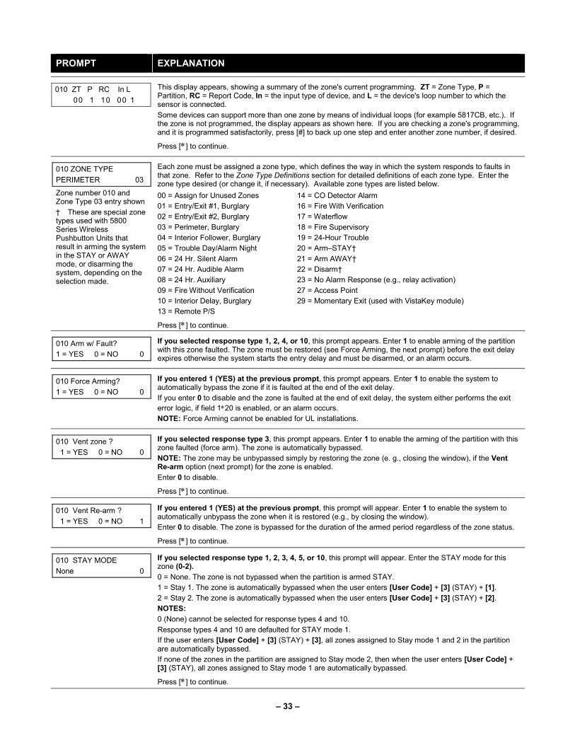
– 33 –
PROMPT EXPLANATION
010 ZT P RC In L
00 1 10 00 1
This display appears, showing a summary of the zone's current programming. ZT = Zone Type, P = Partition, RC = Report Code, In = the input type of device, and L = the device's loop number to which the sensor is connected.
Some devices can support more than one zone by means of individual loops (for example 5817CB, etc.). If the zone is not programmed, the display appears as shown here. If you are checking a zone's programming, and it is programmed satisfactorily, press [#] to back up one step and enter another zone number, if desired.
Press [∗] to continue.
010 ZONE TYPE
PERIMETER 03
Zone number 010 and Zone Type 03 entry shown
† These are special zone types used with 5800 Series Wireless Pushbutton Units that result in arming the system in the STAY or AWAY mode, or disarming the system, depending on the selection made.
Each zone must be assigned a zone type, which defines the way in which the system responds to faults in that zone. Refer to the Zone Type Definitions section for detailed definitions of each zone type. Enter the zone type desired (or change it, if necessary). Available zone types are listed below.
00 = Assign for Unused Zones 14 = CO Detector Alarm
01 = Entry/Exit #1, Burglary 16 = Fire With Verification
02 = Entry/Exit #2, Burglary 17 = Waterflow
03 = Perimeter, Burglary 18 = Fire Supervisory
04 = Interior Follower, Burglary 19 = 24-Hour Trouble
05 = Trouble Day/Alarm Night 20 = Arm–STAY†
06 = 24 Hr. Silent Alarm 21 = Arm AWAY†
07 = 24 Hr. Audible Alarm 22 = Disarm†
08 = 24 Hr. Auxiliary 23 = No Alarm Response (e.g., relay activation)
09 = Fire Without Verification 27 = Access Point
10 = Interior Delay, Burglary 29 = Momentary Exit (used with VistaKey module)
13 = Remote P/S
Press [∗] to continue.
010 Arm w/ Fault?
1 = YES 0 = NO 0
If you selected response type 1, 2, 4, or 10, this prompt appears. Enter 1 to enable arming of the partition with this zone faulted. The zone must be restored (see Force Arming, the next prompt) before the exit delay expires otherwise the system starts the entry delay and must be disarmed, or an alarm occurs.
010 Force Arming?
1 = YES 0 = NO 0
If you entered 1 (YES) at the previous prompt, this prompt appears. Enter 1 to enable the system to automatically bypass the zone if it is faulted at the end of the exit delay.
If you enter 0 to disable and the zone is faulted at the end of exit delay, the system either performs the exit
error logic, if field 1∗20 is enabled, or an alarm occurs.
NOTE: Force Arming cannot be enabled for UL installations.
010 Vent zone ?
1 = YES 0 = NO 0
If you selected response type 3, this prompt appears. Enter 1 to enable the arming of the partition with this zone faulted (force arm). The zone is automatically bypassed.
NOTE: The zone may be unbypassed simply by restoring the zone (e. g., closing the window), if the Vent Re-arm option (next prompt) for the zone is enabled.
Enter 0 to disable.
Press [∗] to continue.
010 Vent Re-arm ?
1 = YES 0 = NO 1
If you entered 1 (YES) at the previous prompt, this prompt will appear. Enter 1 to enable the system to automatically unbypass the zone when it is restored (e.g., by closing the window).
Enter 0 to disable. The zone is bypassed for the duration of the armed period regardless of the zone status.
Press [∗] to continue.
010 STAY MODE
None 0
If you selected response type 1, 2, 3, 4, 5, or 10, this prompt will appear. Enter the STAY mode for this zone (0-2).
0 = None. The zone is not bypassed when the partition is armed STAY.
1 = Stay 1. The zone is automatically bypassed when the user enters [User Code] + [3] (STAY) + [1].
2 = Stay 2. The zone is automatically bypassed when the user enters [User Code] + [3] (STAY) + [2].
NOTES:
0 (None) cannot be selected for response types 4 and 10.
Response types 4 and 10 are defaulted for STAY mode 1.
If the user enters [User Code] + [3] (STAY) + [3], all zones assigned to Stay mode 1 and 2 in the partition are automatically bypassed.
If none of the zones in the partition are assigned to Stay mode 2, then when the user enters [User Code] + [3] (STAY), all zones assigned to Stay mode 1 are automatically bypassed.
Press [∗] to continue.
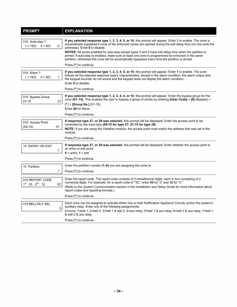
– 34 –
PROMPT EXPLANATION
010 Auto-stay ?
1 = YES 0 = NO 0
If you selected response type 1, 2, 3, 4, 5, or 10, this prompt will appear. Enter 1 to enable. The zone is automatically bypassed if none of the entry/exit zones are opened during the exit delay time (no one exits the premises). Enter 0 to disable.
NOTES: All zones enabled for auto-stay except types 3 and 5 have exit delay time when the partition is armed. If auto-stay is enabled, make sure at least one zone is programmed for entry/exit in the same partition, otherwise this zone will be automatically bypassed every time the partition is armed.
Press [∗] to continue.
010 Silent ?
1 = YES 0 = NO 1
If you selected response type 1, 2, 3, 4, 5, or 10, this prompt will appear. Enter 1 to enable. The zone follows all the selected response type’s characteristics, except in the alarm condition, the alarm output and the keypad sounder do not sound and the keypad does not display the alarm condition.
Enter 0 to disable.
Press [∗] to continue.
010 Bypass Group
01-15 01
If you selected response type 1, 2, 3, 4, 5, or 10, this prompt will appear. Enter the bypass group for the zone (01–15). This enables the user to bypass a group of zones by entering [User Code] + [6] (Bypass) +
[∗] + [Group No.] (01-15).
Enter 00 for None.
Press [∗] to continue.
010 Access Point
(00-15) 01
If response type 27, or 29 was selected, this prompt will be displayed. Enter the access point to be controlled by the input type (00-15 for type 27; 01-15 for type 29).
NOTE: If you are using the VistaKey module, the access point must match the address that was set in the module.
Press [∗] to continue.
10 ENTRY OR EXIT
1
If response type 27, or 29 was selected, this prompt will be displayed. Enter whether the access point is an entry or exit point.
0 = entry; 1 = exit
Press [∗] to continue.
10 Partition
1
Enter the partition number (1–8) you are assigning this zone to.
Press [∗] to continue.
010 REPORT CODE
1st 03 2nd 12 3C
Enter the report code. The report code consists of 2 hexadecimal digits, each in turn consisting of 2 numerical digits. For example, for a report code of “3C,” enter 03 for “3” and 12 for “C.”
(Refer to the System Communication section in the Installation and Setup Guide for more information about report codes and reporting formats.)
Press [∗] to continue.
010 BELL/RLY SEL
0
Each zone can be assigned to activate either one or both Notification Appliance Circuits and/or the system’s auxiliary relay. Enter one of the following assignments:
0=none; 1=bell 1; 2=bell 2; 3=bell 1 & bell 2; 4=aux relay; 5=bell 1 & aux relay; 6=bell 2 & aux relay; 7=bell 1 & bell 2 & aux relay.
Press [∗] to continue.

– 35 –
PROMPT EXPLANATION
(01-�) INPUT TYPE
RF Xmitter 3
Input types 4 & 5 are valid for certain 5800 Series transmitters only
If using input type 02 with a door/window type transmitter, only loop 1 may be used.
If you selected response type 12, 28, or 29 the input type MUST be 00.
Enter the input device type as follows:
00 = not used
01 = hardwired
02 = RF motion (RM type)
03 = supervised RF transmitter (RF type)
04 = unsupervised RF transmitter (UR type)
05 = RF button-type transmitter (BR type)
06 = serial number polling loop device (SL type)
07 = DIP switch-type polling loop device
08 = right loop of DIP switch type device
09 = keypad input (code + #73)
10 = Not Used
11 = VistaKey Door Status Monitor (DM)
12 = VistaKey Request to Exit (RE)
13 = VistaKey General Purpose (GP)
Right loops refer to the use of the right loop on a device, which allow hardwired devices to be monitored by the polling loop.
If you are programming hardwired or DIP switch polling loop devices, the summary display appears after completing this entry.
NOTE: After programming, refer to the Installation and Setup Guide test section for testing of the RF devices.
NOTE: Input types 11 (DM), 12 (RE), and 13 (GP) should only be used with VistaKey modules.
Press [∗] to continue.
010 SMART CONTACT
1 = YES 0 = NO
If input type 3 or 6 was selected, this prompt will be displayed. Enter 1 for devices that monitor maintenance signals (ex. 5193SD, 5193SDT) or can be used to limit fault signals in the disarmed state (ex. DT7500SN or IS2500SN). Otherwise, enter 0.
NOTES:
1. The Smart Contact option must ONLY be selected for devices that support the feature, otherwise unpredictable results may occur.
2. If using the 5193SD/SDT V-Plex smoke detectors the “Smart” option must be selected in zone programming or when they enroll unpredictable results may occur if the smoke goes into a High Sens or Low Sens condition.
010 ANTI MASK
1 = YES 0 = NO 0
If zone type is 04 (interior) or 10 (interior with delay) and input type 06 (serial poll) is selected, this prompt will be displayed. Enable for PIRs that support anti-mask (e.g., DT7500SN). The trouble report code will be used to report the masked condition.
001 Tamper Option
none 0
If you selected input type 1, 6, 7, or 8, this prompt displays. If the zone has a tamper switch wired in the loop in addition to a sensor contact, enter the tamper option.
Enter 1 if the tamper switch is normally closed (wired in series) with the EOL resistor.
Enter 2 if the tamper switch is normally open (wired in parallel) with the EOL resistor.
Enter 0 if a tamper switch is not being used in the loop.
NOTE: For zone response types 9 or 16 (Fire), the tamper selection must be “0” none.
010 V-PLEX RELAY?
1 = YES 0 = NO
If you selected input type 6, this prompt is displayed. Enter 1 if using a 4101SN Relay Module for this zone. Otherwise enter 0.
Press [∗] to continue.
010 CONS ECP ADDR
(00-30) 01
If you selected input type 09, this prompt is displayed. Enter the ECP address of the keypad that is being used for entry/exit for this access point (00-30).
Press [∗] to continue.
010 ACCESS POINT
(01-15) 01
If you selected input types 06, 11 - 13 this prompt is displayed. Enter the access point (01-15) to be controlled by the input type.
NOTE: For input type 06, the selected address must be 00 if VistaKey is not selected. If you are using the VistaKey module, the access point must match the address that was set in the module.
Press [∗] to continue.

– 36 –
PROMPT EXPLANATION
010 INPUT S/N: L
AXXX-XXXX 1
For Serial Number entry and Loop Number entry, do one of the following:
a. Transmit two open and close (or close and open) sequences. For a button-type transmitter, press and release the button, wait approximately 4 seconds, then press and release the button a second time.
OR
b. Manually enter the 7-digit serial number printed on a label on the transmitter, using the Alpha keypad.
Then press the [∗] key, the cursor moves to the “L” position. You can edit the loop number, if necessary.
When the loop number is acceptable, press [∗].
OR
c. Press key [C] to copy the last serial number enrolled (used when programming a transmitter with several input loops).
Press [∗] to accept.
010 INPUT S/N: L
A022-4064 1
The cursor will then move to the Loop column (L) with the previously entered/transmitted serial number displayed.
Enter the loop number (refer to 5800 Series Transmitters Loop Designations below).
To Delete an Existing Serial Number, enter “0“ in the loop number field. The serial number will change to “0”s.
If “0” was entered in error, simply re-enter the loop number or press [#], and the serial number will return to the display.
Press [∗] to accept.
010 INPUT S/N: L
A022-4064 1
The system will then check for a duplicate serial/loop number combination.
If a duplicate serial/loop number combination is found, the keypad will emit a single long beep, and display the serial number along with a “?” for the loop number, allowing you to re-enter the correct loop number.
If the serial/loop number combination is not a duplicate in the system, a display appears showing the serial number and loop number entry.
Press [∗] to continue.

– 37 –
5800 Series Transmitters Loop Designations
PROMPT EXPLANATION
XMIT TO CONFIRM
PRESS ∗ TO SKIP
Confirmation Option: This prompt only appears if you answered “Yes” at the first prompt. The system enters a confirmation mode so that the operation of the actual programmed input can be confirmed. Activate
the loop input or button that corresponds to this zone. At any time during this step, you may press the [∗] key on the keypad to save the serial and loop number combination without confirming.
Entd A022-4063 1
Rcvd A022-4064
If the serial number transmitted does not match the serial number entered, a display similar to the one at the left appears. If the loop number does not match, it is also displayed.
If so, activate the loop input or button on the transmitter once again. If a match is not obtained (i.e., summary display does not appear), press the [#] key twice and then enter or transmit the correct serial number.
010 ZT P RC In L
03 1 3C RF 1s
If the serial number transmitted does match the serial number entered, the system beeps 3 times and a summary display appears, showing that zone’s programming. Note that an “s” indicates that a transmitter’s serial number has been enrolled.
Press [∗] to accept the zone information.
ENTER ZONE NO.
000 = QUIT 011
The system now returns to the “ENTER ZONE NO.” prompt for the next zone.
When all zones have been programmed, enter “000” to quit.
After you have enrolled each wireless device, remove ONE of the serial number labels from that device and affix it in the appropriate column on the worksheets provided later in this Programming Guide; then enter the other information (zone number, zone type, etc.) relevant to that device.
When you have finished programming all zones, test each using the system's Test Mode. Do not use the Transmitter ID Sniffer Mode. The system checks only for transmission of one zone on a particular transmitter, NOT the zones assigned to each additional loop, and also does not verify polling loop type zones.

– 38 –
Expert Mode Zone Programming Expert mode allows you to program zones using the minimum number of screens and keystrokes.
Expert Mode Zone Programming does not provide the capability to program some of the zone’s attributes, such as Arm w/Fault, Vent Zone, STAY mode, Auto-STAY, Bypass Group, etc. If you want to program a zone for any of these attributes, you must use Zone Programming.
Enter the Programming mode with [Installer Code] + 8 0 0 0
Before programming your zones, do the following:
1. Program field 2∗00: Number of Partitions.
2. Enable your RF Receiver in Device Programming menu mode.
To program your zones, press ∗93 to display the "ZONE PROG?" prompt. Enter “0” (NO) to each prompt until the “EXPERT MODE?” prompt appears.
PROMPT EXPLANATION
EXPERT MODE?
1 = YES 0 = NO 0
Press 1 to enter Expert mode.
SET TO CONFIRM?
0 = NO 1 = YES 0
This prompt appears once upon entering Expert Mode.
If you select “Yes,” Confirmation prompts will be displayed after the device’s Serial and Loop numbers have been entered later.
Zn ZT P RC In L
001 03 1 10 HW -
A summary display appears, showing zone 1’s current programming or default values.
Zn ZT P RC In L
010 03 1 10 RF 1s
Enter the desired 3-digit zone number and press [∗].
NOTE: If you want to exit the Expert mode, enter “000” + [∗].
If an “s” appears after the loop number, it indicates that the transmitter’s serial number has been enrolled.
Use the [D] key to enter and duplicate wireless keys (see “Entering Wireless Keys” later)
Zn ZT P RC In L
010 03 1 10 RF -
Enter all zone information except for Loop number, or press “C” to copy the zone information on this screen from the last saved zone (including Loop).
ZT = Zone Type
P = Partition
RC = Report Code
In = Input Device Type
L = Loop number to which the sensor is connected.
NOTE: Pressing the [C] copies the zone information from the last saved zone, which includes the input type. Verify this information is correct for this zone.
On this screen:
• Use the [A] key to move to the right.
• Use the [B] key to move to left and to back up to “ZT” field.
Press [∗] to accept the existing or newly-entered zone information.

– 39 –
PROMPT EXPLANATION
ZN B M V A C E AD
010 2 1 1 0 1 1 01
Enter the remainder of the zone’s information, or press the [C] key to copy the zone attributes on this screen from the last saved zone.
B = Bell/Relay Assignment
M = Maintenance (only used if “In” = 3 or 6)
V = Do Not Use. Must be set to “0”.
AC = Access Point (only used if ZT = 27, 29 or In = 6, 11, 12, 13)
E = Entry or Exit? (only used if ZT = 27)
AD = Address (only used if “In” = 9)
If “In” = 9, enter the Device Address
NOTE: Pressing the [C] copies the zone attributes from the last saved zone. Verify the attributes for this zone are correct.
On this screen:
• Use the [A] key to move to the right.
• Use the [B] key to move to left and to back up to “V” field.
Press [∗] to accept existing information.
010 INPUT S/N: L
A XXX-XXXX -
If you entered RM, RF, BR, UR or SL for the Input Type, this screen displays. Otherwise the summary screen for the next zone displays.
Enter the 7-digit serial number, using one of the following methods:
a. Transmit two open and close (or close and open) sequences. For a button-type transmitter, press and release the button, wait approximately 4 seconds, then press and release the button a second time.
OR
b. Manually enter the 7-digit serial number printed on a label on the transmitter, using the alpha keypad.
Then press the [∗] key, the cursor will move to the “L” position. You can edit the loop number, if
necessary. When the loop number is acceptable, press [∗].
OR
c. Press key [C] to copy the last serial number enrolled (used when programming a transmitter with several input loops).
Remember, you can use the [A] key to move to the right or the [B] key to move to the left.
You can also use the [#] key to back up without saving.
010 INPUT S/N: L
A022-4064 1
Press [∗] to accept the serial number and advance to the “L” position (if method “a” or “c” was used), then enter the loop number. If necessary, press the [#] key to back up without saving, and re-enter or edit the
serial number before pressing [∗] to save
The system checks for a duplicate. If a duplicate serial/loop number combination is found, the keypad will emit a single long beep, and display the serial number along with a “?” for the loop number, allowing you to re-enter the correct loop number.
010 INPUT S/N: L
A000-0000 1
To Delete an Existing Serial Number, enter “0“ in the loop number field. The serial number will change to “0”s.
If “0” was entered in error, simply re-enter the loop number or press [#], and the serial number will return to the display.
XMIT TO CONFIRM
PRESS ∗ TO SKIP
The prompt to confirm appears. This prompt only appears if you answered “Yes” at the “SET TO CONFIRM?” prompt.
The system enters a confirmation mode so that the operation of the actual programmed input can be confirmed. Activate the loop input or button that corresponds to this zone. At any time during this step, you
may press the [∗] key on the keypad to save the serial and loop number combination without confirming.
Entd A022-4063 1
Rcvd A022-4064
If the serial number transmitted does not match the serial number entered, a display similar to the one at the left appears. If the loop number does not match, it also is displayed.
If so, activate the loop input or button on the transmitter once again. If a match is not obtained (i.e., summary display for the next zone does not appear), press the [#] key twice and then enter or transmit the correct serial number.
Activate the button on the wireless key again after re-entering the serial number.
Zn ZT P RC In L
011 00 1 10 00 1
If the serial number transmitted matches the serial number entered, the system beeps 3 times and advances to the summary display for the next zone's programming.
After all the zones have been programmed, enter 000 for the zone number to quit.
After you have enrolled each wireless device, remove ONE of the serial number labels from that device and affix it in the appropriate column on the worksheets provided later in this Programming Guide; then enter the other information (zone number, zone type, etc.) relevant to that device.

– 40 –
Report Code Programming All report codes are entered using #93 Menu Mode Programming, either through Report Code Programming, or through Zone Programming while entering other zone information. In the VISTA-128FBPT/VISTA-250FBPT, reports are divided into six categories. These categories represent the main menu options in Report Code Programming. Reports and the categories in which they are found are as follows:
ALARM CODES RESTR, SUPV. CODES (for groups of 16 zones)
SYSTEM GROUP #1
Zone Alarm Reports Alarm Restore Trouble Trouble Restore Bypass Bypass Restore
Closing (arm AWAY) Opening (disarm) System Low Battery Low Battery Restore AC Loss AC Restore Periodic Test Power Cancel Program Tamper
SYSTEM GROUP #2 SYSTEM GROUP #3 SYSTEM GROUP #4
Arm STAY Time Set, Log Reset Dialer Queue Overflow Exit Error by Zone Recent Close
Early Open Early Close Late Open Late Close Failed to Open Failed to Close Auto-Arm Failed Schedule Change
Fire Walk-Test Start Fire Walk-Test End Off-Normal
The programming sequence that follows assumes that you will be entering all reports for the system at one time. In actuality, you may skip from one main menu option to another by pressing 0 (No) at each main menu option. Main menu options are highlighted in bold text. To enter report codes, do the following:
Enter Program Mode: [Installer Code] + 8 0 0 0. Then press #93. Enter 0 (No) at each main menu option until the Report Code Programming option is displayed.
PROMPT EXPLANATION
REPORT CODE PROG
1 = YES 0 = NO 0
Press 1 (Yes) to enter to Report Code Programming.
Zone Alarm Reports
PROMPT EXPLANATION
ALARM, ID DIGIT?
1 = YES 0 = NO 0
Press [1] (Yes) to enter Alarm Report Codes for zones. Press [0] (No) to skip to the next main menu option.
ENTER ZONE NO.
000 = QUIT 001
Enter the zone number for which you are entering the report code.
Press [∗] to continue.
001 REPORT CODE
1st 00 2nd 00 00
Enter the first digit of the Alarm report code (double-digit entry) and press [∗]. Enter the 2nd digit of the Alarm Report code.
Press [∗] to continue.
ENTER ZONE NO.
000 = QUIT 001
Enter the zone number for which you are entering the report code. When all zone Alarm Codes have been programmed, enter 000 to Quit.
Press [∗] to continue.
QUIT REPORT MENU
1 = YES 0 = NO 0
If you have completely finished entering report codes, press [1] (Yes) to quit Report Code Programming. If you wish to enter other system report codes, enter 0 (No).
Press [∗] to continue.

– 41 –
Restore/Supervisory Codes
PROMPT EXPLANATION
RESTR, SUPV. CODE
1 = YES 0 = NO 0
Press [1] (Yes) to enter Restore and Supervisory Codes for zones.
ENTER ZN FOR GRP
000 = QUIT 001
Enter one zone for each group of 16 zones (001-016, 017-032, etc.).
ALARM RESTORE
GRP 001-016 00
Enter the first digit of the Alarm Restore Report Code for this group of zones (double-digit entry). The second digit (for two-digit reporting formats) is automatically the ID (second) digit of the Alarm Report Code for each zone (if programmed).
Press [∗] to continue.
TROUBLE
GRP 001-016 00
Enter the first digit of the Trouble Report Code for this group of zones (double-digit entry). The second digit (for two-digit reporting formats) is automatically the ID (second) digit of the Alarm Report Code for each zone (if programmed).
Press [∗] to continue.
TROUBLE RESTORE
GRP 001-016 00
Enter the first digit of the trouble restore code (single-digit entry) and press [∗]. The second digit (for two-digit reporting formats) is automatically the ID (second) digit of the alarm report code for each zone (if programmed).
Press [∗] to continue.
BYPASS
GRP 001-016 00
Enter the first digit of the Bypass Report Code (double-digit entry) and press [∗]. The second digit (for two-digit reporting formats) is automatically the ID (second) digit of the Alarm Report Code for each zone (if programmed).
Press [∗] to continue.
BYPASS RESTORE
GRP 001-016 00
Enter the first digit of the Bypass Restore Report Code (double-digit entry) and press [∗]. The second digit (for two-digit reporting formats) is automatically the ID (second) digit of the Alarm Report Code for each zone (if programmed).
Press [∗] to continue.
ENTER ZN FOR GRP
000 = QUIT 017
Enter one zone for each group of 16 zones. When you are finished entering Restore and Supervisory Codes for all zone groups, enter 000.
Press [∗] to continue.
QUIT REPORT MENU
1 = YES 0 = NO 0
If you have completely finished entering report codes, press [1] (Yes) to quit Report Code Programming. If you wish to enter other system report codes, enter 0 (No).
Press [∗] to continue.

– 42 –
System Group #1 Codes
PROMPT EXPLANATION
SYSTEM GROUP #1?
1 = YES 0 = NO 0
To enter System Group #1 codes, press 1 (Yes).
CLOSE
1st 00 2nd 00
Enter the first digit of the Closing (Arm-AWAY) report. Press [∗]. Enter the second digit of the report. If the user number is desired as the second digit, enter 01 (not necessary for Contact ID).
Press [∗] to continue.
Enter the rest of the codes in the same manner. Other report codes in System Group #1 are:
• Opening (Disarm) Also, enable this if you desire Callback Requested reports (the panel answers a phone call from the downloader).
• System Low Battery
• Low Battery Restore
• AC Loss
• AC Restore
• Periodic Test
• Power
• Cancel
• Program Tamper
Once you have entered these report codes, the system prompts you with the Quit menu.
QUIT REPORT MENU
1 = YES 0 = NO 0
If you have completely finished entering report codes, press 1 (Yes) to quit Report Code Programming. If you wish to enter other system report codes, enter 0 (No).
Press [∗] to continue.
System Group #2 Codes
PROMPT EXPLANATION
SYSTEM GROUP #2 ?
1 = YES 0 = NO 0
To enter System Group #2 codes, press [1] (Yes).
STAY
1st 00 2nd 00
Enter the first digit of the Arm-STAY report. Press [∗]. Enter the second digit of the report. If the user number is desired as the second digit, enter 01 (not necessary for Contact ID).
Press [∗] to continue.
Enter the rest of the codes in the same manner. Other codes in System Group #2 are:
• Time Set, Log Reset
• Dialer Queue Overflow
• Exit Error by Zone
• Recent Close
Once you have entered these report codes, the system prompts you with the Quit menu.
QUIT REPORT MENU
1 = YES 0 = NO 0
If you have completely finished entering report codes, press [1] (Yes) to quit Report Code Programming. If you wish to enter other system report codes, enter 0 (No).
Press [∗] to continue.

– 43 –
System Group #3 Codes
PROMPT EXPLANATION
SYSTEM GROUP #3 ?
1 = YES 0 = NO 0
To enter System Group #3 codes, press [1] (Yes).
EARLY OPEN
1st 00 2nd 00
Enter the first digit of the Early Opening Report Code. Press [∗]. Enter the second digit of the report code. If the user number is desired as the second digit, enter 01 (not necessary for Contact ID).
Press [∗] to continue.
Enter the rest of the codes in the same manner. Other codes in System Group #3 are:
• Early Close
• Late Open
• Late Close
• Failed to Open
• Failed to Close
• Auto-Arm Failed
• Schedule Change
Once you have entered these report codes, the system prompts you with the Quit menu.
QUIT REPORT MENU
1 = YES 0 = NO 0
If you have completely finished entering report codes, press [1] (Yes) to quit Report Code Programming. If you wish to enter other system report codes, enter 0 (No)
Press [∗] to continue.
System Group #4 Codes
PROMPT EXPLANATION
SYSTEM GROUP #4 ?
1 = YES 0 = NO 0
To enter System Group #4 codes, press [1] (Yes).
WALK TEST START
1st 00 2nd 00
Enter the first digit of the Fire Walk Test Start Report Code. Press [∗]. Enter the second digit of the report code.
Press [∗] to continue.
Enter the rest of the codes in the same manner. Other codes in System Group #4 are:
• Fire Walk-Test End.
• Off-Normal.
Once you have entered these report codes, the system prompts you with the Quit menu.
QUIT MENU MODE?
1 = YES 0 = NO 0
Enter 1 to exit back to normal Programming mode. Enter 0 to stay in Menu mode.
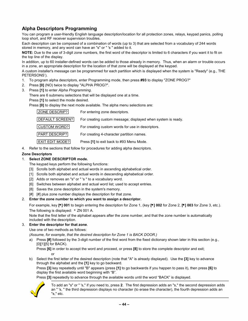
– 44 –
Alpha Descriptors Programming You can program a user-friendly English language description/location for all protection zones, relays, keypad panics, polling loop short, and RF receiver supervision troubles.
Each description can be composed of a combination of words (up to 3) that are selected from a vocabulary of 244 words stored in memory, and any word can have an "s" or " 's " added to it.
NOTE: Due to the use of 3-digit zone numbers, the first word of the descriptor is limited to 6 characters if you want it to fit on the top line of the display.
In addition, up to 60 installer-defined words can be added to those already in memory. Thus, when an alarm or trouble occurs in a zone, an appropriate description for the location of that zone will be displayed at the keypad.
A custom installer's message can be programmed for each partition which is displayed when the system is "Ready" (e.g., THE PETERSONS’).
1. To program alpha descriptors, enter Programming mode, then press #93 to display "ZONE PROG?"
2. Press [0] (NO) twice to display "ALPHA PROG?".
3. Press [1] to enter Alpha Programming.
There are 6 submenu selections that will be displayed one at a time.
Press [1] to select the mode desired.
Press [0] to display the next mode available. The alpha menu selections are:
ZONE DESCRIP? For entering zone descriptors.
DEFAULT SCREEN? For creating custom message; displayed when system is ready.
CUSTOM WORD? For creating custom words for use in descriptors.
PART DESCRIP? For creating 4-character partition names.
EXIT EDIT MODE? Press [1] to exit back to #93 Menu Mode.
4. Refer to the sections that follow for procedures for adding alpha descriptors.
Zone Descriptors
1. Select ZONE DESCRIPTOR mode.
The keypad keys perform the following functions:
[3] Scrolls both alphabet and actual words in ascending alphabetical order.
[1] Scrolls both alphabet and actual words in descending alphabetical order.
[2] Adds or removes an "s" or " 's " to a vocabulary word.
[6] Switches between alphabet and actual word list; used to accept entries.
[8] Saves the zone description in the system's memory.
[#] [#] plus zone number displays the description for that zone.
2. Enter the zone number to which you want to assign a descriptor.
For example, key [∗∗∗∗] 001 to begin entering the description for Zone 1, (key [∗∗∗∗] 002 for Zone 2, [∗∗∗∗] 003 for Zone 3, etc.).
The following is displayed: ∗ ZN 001 A.
Note that the first letter of the alphabet appears after the zone number, and that the zone number is automatically included with the description.
3. Enter the descriptor for that zone.
Use one of two methods as follows:
(Assume, for example, that the desired description for Zone 1 is BACK DOOR.)
a) Press [#] followed by the 3-digit number of the first word from the fixed dictionary shown later in this section (e.g., [0][1][5] for BACK).
Press [6] in order to accept the word and proceed, or press [8] to store the complete descriptor and exit;
or
b) Select the first letter of the desired description (note that "A" is already displayed). Use the [3] key to advance through the alphabet and the [1] key to go backward.
Press [3] key repeatedly until "B" appears (press [1] to go backwards if you happen to pass it), then press [6] to display the first available word beginning with “B”.
Press [3] repeatedly to advance through the available words until the word “BACK” is displayed.
To add an "s" or " 's," if you need to, press 2. The first depression adds an "s," the second depression adds an " 's, " the third depression displays no character (to erase the character), the fourth depression adds an "s," etc.

– 45 –
4. Accept the word.
To accept the word, press [6], which switches back to the alphabet list for the next word, or press [8] to store the complete descriptor and then exit.
5. Select the next word.
For selection of the next word (DOOR), repeat step 3a (word #063) or 3b, but selecting the word "DOOR.”
To accept the word, press [6], which again switches back to alphabet list.
6. Store the descriptor.
When all desired words have been entered, press [8] to store the description in memory.
To review the zone descriptors, key [#] plus zone number (e.g., #001).
To edit zone descriptors, key [∗] plus zone number (e.g., ∗001)
7. Exit Zone Description Mode: enter 000.
Default Screen (Custom Message Display)
Normally, when the system is in the disarmed state, the following display is present on the keypad.
****DISARMED****
READY TO ARM
Part or the entire above message can be modified to create a custom installer message for each partition. For example, “****DISARMED****” on the first line or “READY TO ARM” on the second line could be replaced by the installation company name or phone number for service.
NOTE: There are only 16 character spaces on each of the two lines.
To create a custom display message, proceed as follows:
1. Select Default Screen mode.
The keypad asks for the partition number for this message.
Enter the partition number. Press [∗] to accept entry.
The following display appears:
****DISARMED****
READY TO ARM
A cursor is present at the extreme left of the first line (over the first "star"). Press [6] to move the cursor to the right and [4] to move the cursor to the left. Press [7] to insert spaces or erase existing characters.
2. Create the message.
For example, to replace “READY TO ARM” with the message “SERVICE 424-0177,” proceed as follows:
Press [6] to move the cursor to the right, and continue until the cursor is positioned over the first location on the second line.
Press [3] to advance through the alphabet to the first desired character (in this case, "S"). Press [1] to go backward, when necessary. When the desired character is reached, press [6].
The cursor then moves to the next position, ready for entry of the next character (in this example, "E"). When the cursor reaches a position over an existing character, press [3] or [1] to advance or back up from that character in the alphabet.
Proceed in this manner until all characters in the message have been entered.
3. Save the message.
Store the new display message in memory by pressing [8].
4. The system asks for a new partition number.
Enter 0 to quit or 1-8 for a new partition number.
Custom Words
Up to 60 installer-defined words can be added to the built-in vocabulary. Each of the 60 "words" can actually consist of several words, but bear in mind that a maximum of 10 characters can be used for each word string.
1. Select CUSTOM WORD Mode.
The keys perform the following functions:
[3] Advances through alphabet in ascending order.
[1] Advances through alphabet in descending order.
[6] Selects desired letter; moves the cursor 1 space to the right.
[4] Moves the cursor one space to the left.
[7] Inserts a space at the cursor location, erasing any character at that location.
[8] Saves the new word in the system's memory.
[∗] Returns to Description Entry Mode.
2. Enter the custom word number (01-60) you want to create.
For example, if you are creating the first word (or word string), enter 01; when creating the second word, enter 02, and so on. A cursor now appears at the beginning of the second line.

– 46 –
3. Type the word using one of two methods as follows:
a) Press [#], followed by the 2-digit entry for the first letter you would like to display (e.g., 65 for "A").
When the desired character appears, press [6] to select it. The cursor will then move to the right, in position for the next character. Press [#] plus the 2-digit entry for the next letter of the word.
or b) Press 3 to advance through the list of symbols, numbers, and letters.
Press 1 to move back through the list.
When you have reached the desired character, press [6] to select it. The cursor then moves to the right, in position for the next character.
4. Repeat step 3 to create the desired custom word (or words).
Press [4] to move the cursor to the left if necessary.
Press [7] to enter a blank (or to erase an existing character).
Each word or word string cannot exceed 10 characters.
5. Save the word by pressing [8].
This returns you to the “CUSTOM WORD?” display. The custom word (or string of words) is automatically added to the built-in vocabulary at the end of the group of words beginning with the same letter.
Custom words are retrieved as word numbers 255 to 314 for words 1 to 60, respectively, when using method 3a to enter alpha descriptors.
When using method 3b to enter alpha descriptors, each word appears at the end of the group of words that begin with the same letter as it does.
6. Repeat steps 2 through 6 to create up to a maximum of 60 custom words (or word strings).
7. Exit Custom Word Mode by entering 00 at the “CUSTOM WORD” prompt.
Partition Descriptors 1. Select "Part DESCRIPT." Mode.
The system asks for the partition number desired. Enter the number as a single-key entry 1-8.
2. Follow the same procedure as for custom words.
NOTE: The partition descriptors are limited to 4 characters (e.g., WHSE for warehouse).
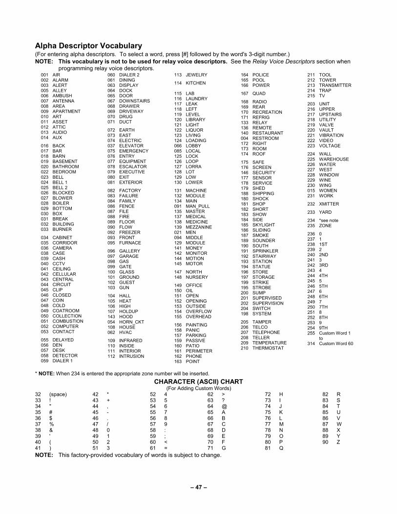
– 47 –
Alpha Descriptor Vocabulary (For entering alpha descriptors. To select a word, press [#] followed by the word's 3-digit number.)
NOTE: This vocabulary is not to be used for relay voice descriptors. See the Relay Voice Descriptors section when programming relay voice descriptors.
001 AIR 002 ALARM 003 ALERT 005 ALLEY 006 AMBUSH 007 ANTENNA 008 AREA 009 APARTMENT 010 ART 011 ASSET 012 ATTIC 013 AUDIO 014 AUX
016 BACK 017 BAR 018 BARN 019 BASEMENT 020 BATHROOM 022 BEDROOM 023 BELL 024 BELL 1 025 BELL 2 026 BLOCKED 027 BLOWER 028 BOILER 029 BOTTOM 030 BOX 031 BREAK 032 BUILDING 033 BURNER
034 CABINET 035 CORRIDOR 036 CAMERA 038 CASE 039 CASH 040 CCTV 041 CEILING 042 CELLULAR 043 CENTRAL 044 CIRCUIT 045 CLIP 046 CLOSED 047 COIN 048 COLD 049 COATROOM 050 COLLECTION 051 COMBUSTION 052 COMPUTER 053 CONTACT
055 DELAYED 056 DEN 057 DESK 058 DETECTOR 059 DIALER 1
060 DIALER 2 061 DINING 063 DISPLAY 064 DOCK 065 DOOR 067 DOWNSTAIRS 068 DRAWER 069 DRIVEWAY 070 DRUG 071 DUCT
072 EARTH 073 EAST 074 ELECTRIC 037 ELEVATOR 075 EMERGENCY 076 ENTRY 077 EQUIPMENT 078 ESCALATOR 079 EXECUTIVE 080 EXIT 081 EXTERIOR
082 FACTORY 083 FAILURE 084 FAMILY 086 FENCE 087 FILE 088 FIRE 089 FLOOR 090 FLOW 092 FREEZER 093 FRONT 095 FURNACE
096 GALLERY 097 GARAGE 098 GAS 099 GATE 100 GLASS 101 GROUND 102 GUEST 103 GUN
104 HALL 105 HEAT 106 HIGH 107 HOLDUP 143 HOOD 054 HORN_CKT 108 HOUSE 062 HVAC
109 INFRARED 110 INSIDE 111 INTERIOR 112 INTRUSION
113 JEWELRY
114 KITCHEN 115 LAB
116 LAUNDRY 117 LEAK 118 LEFT 119 LEVEL 120 LIBRARY 121 LIGHT 122 LIQUOR 123 LIVING 124 LOADING 066 LOBBY 085 LOCAL 125 LOCK 126 LOOP 127 LORRA 128 LOT 129 LOW 130 LOWER
131 MACHINE 132 MODULE 134 MAIN 091 MAN_PULL 135 MASTER 137 MEDICAL 138 MEDICINE 139 MEZZANINE 021 MEN 094 MIDDLE 129 MODULE 141 MONEY 142 MONITOR 144 MOTION 145 MOTOR
147 NORTH 148 NURSERY
149 OFFICE 150 OIL 151 OPEN 152 OPENING 153 OUTSIDE 154 OVERFLOW 155 OVERHEAD
156 PAINTING 158 PANIC 157 PARKING 159 PASSIVE 160 PATIO 161 PERIMETER 162 PHONE 163 POINT
164 POLICE 165 POOL 166 POWER
167 QUAD
168 RADIO 169 REAR 170 RECREATION 171 REFRIG 133 RELAY 136 REMOTE 140 RESTAURANT 004 RESTROOM 172 RIGHT 173 ROOM 174 ROOF
175 SAFE 176 SCREEN 146 SECURITY 177 SENSOR 178 SERVICE 179 SHED 188 SHIPPING 180 SHOCK 181 SHOP 182 SHORT 183 SHOW 184 SIDE 185 SKYLIGHT 186 SLIDING 187 SMOKE 189 SOUNDER 190 SOUTH 191 SPRINKLER 192 STAIRWAY 193 STATION 194 STATUE 196 STORE 197 STORAGE 199 STRIKE 195 STROBE 200 SUMP 201 SUPERVISED 202 SUPERVISION 204 SWITCH 198 SYSTEM
205 TAMPER 206 TELCO 207 TELEPHONE 208 TELLER 209 TEMPERATURE 210 THERMOSTAT
211 TOOL 212 TOWER 213 TRANSMITTER 214 TRAP 215 TV
203 UNIT 216 UPPER 217 UPSTAIRS 218 UTILITY 219 VALVE 220 VAULT 221 VIBRATION 222 VIDEO 223 VOLTAGE
224 WALL 225 WAREHOUSE 226 WATER 227 WEST 228 WINDOW 229 WINE 230 WING 015 WOMEN 231 WORK
232 XMITTER
233 YARD
234 *see note 235 ZONE
236 0 237 1 238 1ST 239 2 240 2ND 241 3 242 3RD 243 4 244 4TH 245 5 246 5TH 247 6 248 6TH 249 7 250 7TH 251 8 252 8TH 253 9 254 9TH 255 Custom Word 1 to 314 Custom Word 60
* NOTE: When 234 is entered the appropriate zone number will be inserted.
CHARACTER (ASCII) CHART (For Adding Custom Words)
32 (space) 33 ! 34 " 35 # 36 $ 37 % 38 & 39 ' 40 ( 41 )
42 * 43 + 44 , 45 - 46 . 47 / 48 0 49 1 50 2 51 3
52 4 53 5 54 6 55 7 56 8 57 9 58 : 59 ; 60 < 61 =
62 > 63 ? 64 @ 65 A 66 B 67 C 68 D 69 E 70 F 71 G
72 H 73 I 74 J 75 K 76 L 77 M 78 N 79 O 80 P 81 Q
82 R 83 S 84 T 85 U 86 V 87 W 88 X 89 Y 90 Z
NOTE: This factory-provided vocabulary of words is subject to change.

– 48 –
Device Programming This menu is used to program keypads, receivers, and relay modules, etc.
Device Address 00 is always set as an alpha keypad assigned to Partition 1 with no sounder suppression options, and these settings cannot be changed.
From Data Field Programming mode, press #93 to display "ZONE PROG?" Press [0] repeatedly to display "DEVICE PROG?"
PROMPT EXPLANATION
DEVICE PROG?
1=YES 0=NO 0
Press [1] to enter Device Programming.
DEVICE ADDRESS
01-30, 00=QUIT 01
The device address identifies the device to the control. Enter the 2-digit device address number to match the device's physical address setting (01-30).
Press [∗] to accept entry.
DEVICE TYPE
00
Select the type of addressable device as follows:
00 = device not used 04 = output relay module (4204)
01 = alpha keypad (6160/6160CR-2, GUI) 06 = communicator
03 = RF receiver (5881ENHC) 12 = Remote Interactive Services (RIS)
Press [∗] to accept entry.
Alpha Keypad
PROMPT EXPLANATION
01 CONSOLE PART.
1
If you selected device type 01 (alpha keypad), this prompt appears. Enter the addressable device's default
partition number (1 to maximum number of partitions programmed for system in field 2∗00). This is the primary partition for the device. Enter 9 to make this keypad a "Master" keypad for the system.
Press [∗] to accept entry.
01 SOUND OPTION
00
If you entered device type 01 (alpha keypad), this prompt appears. Keypads can be individually programmed to suppress arm/disarm beeps, entry/exit beeps and chime mode beeps. This helps prevent unwanted sounds from disturbing users in other areas of the premises.
Enter a number 00-03 for the keypad sounding suppression options desired for the keypad as follows:
00 = no suppression
01 = suppress arm/disarm & entry/exit beeps
02 = suppress chime mode beeps only
03 = suppress arm/disarm, entry/exit and chime mode beeps
Press [∗] to accept entry.
01 KEYPAD GLBL?
0
If you entered device type 01 (alpha keypad), this prompt appears. Each keypad can give users with access to multiple partitions the ability to arm and disarm those partitions from it. To enable this keypad for global arming/disarming, enter 1. To prevent the ability to use this keypad for global arming/disarming, enter 0.
Press [∗] to accept entry.
01 AUTO-STAY ARM DISABLED? 0
0 = No, 1 = Yes. If enabled (1=yes), Auto-Stay Arming is turned off for the selected keypad address (system does not automatically revert to Auto-Stay Arm mode if armed Away and no entry/exit doors are opened). Default is No.
Press [∗] to accept entry.
01 AUI ?
1 = YES 0 = NO 0
If you selected device type 01 (alpha keypad), this prompt appears. Enter 1 (YES) if the device is a graphic/touch-screen keypad and/or a virtual keypad used for RIS.
Must be set to “0”for Commercial Fire Installations.
Press [∗] to accept entry.

– 49 –
RF Expander
PROMPT EXPLANATION
01 RF EXPANDER
HOUSE ID 00
If you selected device type 03 (RF receiver), this prompt appears. Enter the 2-digit House ID (00-31).
Press [∗] to accept entry.
Output Relay Module
PROMPT EXPLANATION
01 SUPERVISED CF?
0
If you selected device type 04 (relay module), this prompt appears. Enter 1 if the unit is a 4204CF. If not, enter 0. If you enter 1, only Relay 1 (Output A) and Relay 3 (Output B) on each module may be programmed for functions.
NOTE: For Commercial Fire installations, only one notification appliance module may be used, and only one notification appliance output (A or B) may be used on that module.
Press [∗] to accept entry.
Communicator If you selected device type 6, the 6160/6160CR-2 Keypad functions similarly to the 7720P Programming Tool. See Figure 1 for the functions of the keys on the 6160CR-2.
1 OFF
4 MAX
7 INSTANT
READY
2 AWAY
5 TEST
8 CODE
0
3 STAY
6 BYPASS
9 CHIME
#
SILENCED
TROUBLE
ALARM
SUPV
POWER
6160C
R2-0
01-V
1
ARMED
READY
(B)
A
D
S
ENTER
SHIFT
N / Y
BS/ESC
SPACE
B
E
T
C
F
XSHIFT
FUNCTION
WHEN LIT
/
(C)
(D)
(A)
Figure 1: 6160CR-2 Key Functions for Programming the Communicator
Each key has two possible functions: a normal function and a SHIFT function. To perform a normal key function, simply press the desired key. To perform a SHIFT key function, press SHIFT key, then press desired function key.
Normal and SHIFT key Functions:
Key Normal Key Function SHIFT Key Function BS/ESC [BS]: Press to delete entry [ESC]: Press to quit Program Mode Also, can reset EEPROM defaults *
↓/↑ [↓]: Scroll down programming [↑]: Scroll up programming N/Y [N]: Press for "NO" answer [Y]: Press SHIFT-Y for "YES" answer SHIFT
Press before pressing a SHIFT key function. Will light READY LED. LED goes out once a key is pressed. Press again for each SHIFT function desired.
1/A [1]: For entering the number 1 [A]: Used for entering C.S. ID number 2/B [2]: For entering the number 2 [B]: Used for entering C.S. ID number 3/C [3]: For entering the number 3 [C]: Used for entering C.S. ID number 4/D [4]: For entering the number 4 [D]: Used for entering C.S. ID number 5/E [5]: For entering the number 5 [E]: Used for entering C.S. ID number 6/F [6]: For entering the number 6 [F]: Used for C.S. ID & FAST Mode 7/S [7]: For entering the number 7 [S]: Press to display diagnostic status 8/T [8]: For entering the number 8 [T]: Press to send TEST messages 9/X [9]: For entering the number 9 [X]: Press to reset the 7847i
∗/SPACE [∗]: Not used with 7847i [SPACE]: Not used with 7847i
0 [0]: For entering the number 0 No SHIFT function #/ENTER [#/ENTER]: Press to accept entries No SHIFT function
* Active only when the "REVIEW?" prompt is displayed.

– 50 –
The 6160/6160CR-2 Keypad displays the following prompts, which are sent by the Communicator to the control. NOTE: These prompts are for the 7847i Communicator only. If you are using a different communicator, refer to the communicator’s instructions for the correct prompts.
PROMPT EXPLANATION
DEVICE ADDRESS
Enter the device address of the Communicator. The default address is 3.
ID #
(1234)
Enter the 4-digit customer account number, 0001-9999. This ID number will appear in the messages generated by the Communicator. Messages generated by the panel and transmitted by the Communicator will contain the ID number programmed into the panel. The Communicator and the panel should have the same ID number, if possible.
If a different 4-digit customer account number is used in the Communicator that is programmed into the alarm control, the Communicator will transmit Communicator-specific messages (power-on reset, AC fail, etc.) using the Communicator customer number, and alarm messages using the control panel’s customer number. If these numbers are different, you will be billed for two AlarmNet Communicator accounts.
PROMPT EXPLANATION
ODD [Y/N]
(N)
Enter Y for odd system flag; N for even system flag.
Alarmnet (Y/N)
(Y)
Enter Y if this is an AlarmNet installation. Enter N if this is a private system and skip to Question 7.
CS ID
(11)
Enter the primary central station’s system ID number 1-7F (will not be displayed for private system users).
BAT PRESENT [Y/N]
(N)
Enter Y if optional battery will be used. Must be Y for UL installations (a battery must be installed).
USE RADIO # [Y/N]
(N)
If you selected Y, the Communicator ID number replaces the panel Subscriber ID in panel-generated messages.
If you selected N, the Communicator sends panel-generated messages with the panel Subscriber ID number.
2ND CS ID
(12)
This must be programmed with a value, even if it is the same as the primary central station. The alarm panel has the option of sending a selected message to the second central station.
REVIEW (Y/N)
(N)
Enter Y to review the programming options and to ensure that the correct responses have been made. Parameters can be changed during review.
Enter N to end programming session.

– 51 –
Output Programming The system supports up to 96 outputs. Outputs can be used to perform many different functions and actions. Each output must be programmed to begin one of four types of ACTIONS at a designated START event, and end that ACTION at a designated STOP event. The options used to start and stop these devices are described below, followed by the actual screen prompts and available entries.
NOTE: If you are using outputs on the polling loop (e.g., 4101SN) no more than 20 of the polling loop outputs may be programmed for the same START or STOP condition. Also, if you are using ZONE # for the START of a polling loop output and want that output to stop when the same zone restores, the STOP programming MUST BE BLANK.
If you are using Zone Type 17 (Waterflow) or 18 (Fire Supervisory) to trigger an output, you must program an Event for the START (alarm, trouble, etc.). All other Zone Type/System Operations do not require an Event.
The letter(s) in parentheses after each function described below, such as (A) after ACTION, are those that appear in the various summary displays of programmed data during programming.
ACTION (A) The "ACTION" of the device is how the device will respond when it is activated by the "START" programming. You may want the device to activate momentarily, to pulse on and off continuously, or to remain activated until some other event occurs to stop it. There are five different action choices:
• ACTIVATE for 2 SECONDS and then reset. If selected, it is not necessary to program a stop parameter.
• ACTIVATE and REMAIN ACTIVATED until stopped by some other event.
• PULSE ON and OFF until stopped by some other event.
• NO RESPONSE when the device is not used.
• TOGGLE on and off alternately with each activation of event. Do not program a stop parameter as this may cause unpredictable results.
START (STT) The "START" programming determines when and under what conditions the device is activated. The following START options are available:
1) EVENT (EV) is the condition (alarm, fault, trouble) that must occur to a zone or group of zones (zone list) in order to activate the device. These conditions apply only when a zone list is used. The different choices for "EVENT" are listed below and in “Programming Relays” later in this section.
• ALARM Action begins upon any alarm in an assigned zone in the zone list.
• FAULT Action begins upon any opening of an assigned zone in the zone list.
• TROUBLE Action begins upon any trouble condition in an assigned zone in the zone list.
• NOT USED Action is not dependent upon one of the above events.
ZONE LIST (ZL) is a group of zones to which the “EVENT” applies in order to activate a particular device. Note that there are a total of 15 zone lists that can be programmed; when the selected EVENT (alarm, fault or trouble) occurs in any zone in the selected “Start” ZONE LIST (01-15), activation of the selected device will START.
2) ZONE # A specific zone going into alarm, fault, trouble, or restore (Event programming) can be used to start the relay action. Enter the 3-digit zone number (000-250).
3) ZONE TYPE/SYSTEM OPERATION (ZT). If all zones to be used to start the device have the same response type, and there are no other zones of this type that are not to activate this device, then “ZONE TYPE” may be used instead of a "ZONE LIST" and "EVENT” to activate the device.
If a system operation, such as “DISARMING” or “ANY FIRE ALARM,” is to activate the device, enter the appropriate choice under the “ZONE TYPE” option.
The “ZONE TYPE/SYSTEM OPERATION” option functions independently of the “EVENT/ZONE LIST” combination.
If a specific "ZONE TYPE" is chosen, any zone of that response type going into alarm, trouble, or fault will cause the device to activate as selected in "ACTION.” If the same “ZONE TYPE” is also chosen for the STOP programming, any zone of that type that restores will de-activate the device.
If a "SYSTEM OPERATION" is chosen, that operation will cause the device to activate as selected in "ACTION.” The different choices for "ZONE TYPE" and "SYSTEM OPERATION" are listed in “Programming Relays” later in this section, and on the Programming Form.
4) PARTITION NO. (P). The device's "Start" ZONE TYPE/SYSTEM OPERATION may be limited to an occurrence on one partition (1-8), or any partition (0).

– 52 –
STOP (STP): The "STOP" programming determines when and under what conditions the device is de-activated. The following options are available:
1). RESTORE ZONE LIST (ZL). If a "ZONE LIST" is used as the “Stop” event, the device de-activates when all the zones in that list restore from a previous fault, trouble, or alarm condition. This occurs regardless of what is programmed to "START" the device; therefore, a "RESTORE ZONE LIST" is normally only used when a "ZONE LIST" is used to start the device.
2). ZONE TYPE/SYSTEM OPERATION (ZT). Instead of using a "RESTORE ZONE LIST," you can select a specific zone (response) type or system operation action to de-activate the device.
If you choose a specific "ZONE TYPE," any zone of that response type that restores from a previous alarm, trouble, or fault condition will cause the device to de-activate.
If you choose a "SYSTEM OPERATION," that operation causes the device to de-activate. The different choices for "ZONE TYPE" and "SYSTEM OPERATION" are listed in “Programming Relays” later in this section, and in the Programming Form.
3) PARTITION NO. (P). The device's "Stop" Zone Type/System Operation may be limited to an occurrence on one partition (1-8), or on any partition (0).
The “ZONE TYPE/SYSTEM OPERATION” option functions independently of the “RESTORE/ZONE LIST” combination.
Output Devices Programming
From Data Field Programming Mode, press #93 to display the "ZONE PROG?" prompt. Press [0] (NO) to each menu option until the "OUTPUT PGM?" prompt appears. Press [1] (YES).
While in this mode, press [∗] to advance to next screen. Press [#] to back up to the previous screen.
PROMPT EXPLANATION
ENTER RELAY #
(00=QUIT) 01
Enter the relay (output device) identification number 01-96. This is a reference number only, used for identification purposes. The actual module address and relay number on the module are programmed in the last two prompts.
Press [∗] to continue.
02 A EV ZL ZT P
STT 0 0 00 00 0
Press [∗] to continue.
02 A ZL ZT P
STOP 0 00 00 0
The keypad displays a summary STOP screen.
Press [∗] to continue.
02 RELAY ACTION
NO RESPONSE 0
The Relay Action is the way in which the relay will respond when activated by the "start" event. Enter the desired action for this relay as follows:
0=not used; 1=close for 2 seconds.; 2=stay closed; 3=pulse on/off; 4= toggle on and off alternately
NOTE: For options 1 and 4, do not program a “Stop” parameter.
02 START EVENT
NOT USED 0
An output may be activated by an Event/Zone List combination, and/or by a Zone Type/System Operation. For an Event/Zone List or Event Zone Number combination, enter the event code as follows:
0=not used; 1=alarm; 2=fault; 3=trouble
NOTE: An Event is required for Zone List, Zone Number and Zone Types 17 and 18.
If you are not using a Zone List or Zone Number to activate the relay, enter 0.
Press [∗] to continue.
02 START: ZN LIST
00
A zone list is a set of zones that can be used to initiate the start or stop relay action. If a zone list is being used to start this relay action, enter the zone list number, 1-15. If a zone list is not being used, enter 0.
Press [∗] to continue.
02 START: ZONE #
000
A specific zone can be used instead of or in addition to an Event/Zone List or Zone Type/System Operation combination to start the relay action. Enter the 3-digit zone number.
Press [∗] to continue.
02 START: ZN TYPE
NO RESPONSE 00
A Zone Type/System Operation can be used instead of or in addition to an Event/Zone List combination or a specific zone to start the relay action. If a Zone Type/System Operation is being used, enter the 2-digit code as listed in the table that follows.
Press [∗] to continue.

– 53 –
Output Programming Notes when using with a Burglary/Panic Zone Type: 1. When using a START EVENT OF FAULT on a ZONE # and no other start or stop entries, the Output assigned to the relay will follow the zone (tripped Relay on, restored Relay off) on FAULT/ALARM/TROUBLE, armed and disarmed. 2. When using a START EVENT OF FAULT on a ZONE # and a STOP ZONE/TYPE of 22, the Output assigned to the relay will START on FAULT/ALARM/TROUBLE, but will not Stop until code and off is entered. 3. When using a START EVENT OF ALARM on a ZONE # and no other start or stop entries, the Output assigned to the relay will follow the zone (on after an ALARM only) and off when zone restores. 4. When using a START EVENT OF ALARM on a ZONE # and a STOP ZONE/TYPE of 22, the Output assigned to the relay will START only on ALARM of the zone and will not Stop until code and off is entered.
NOTE: BYPASSING A ZONE WILL PREVENT IT FROM STARTING AN OUTPUT.
Choices for Start/Stop Zone Types and System Operations: 00 = No Response (Not Used) 22 = Disarming (Code + Off) 44 = RF Low Battery 01 = Entry/Exit #1 23 = No Alarm Response 45 = Polling Loop Failure 02 = Entry/exit #2 27 = Access Point (allows more than one
relay to be controlled by activation if access point request)
47 = Console Failure 03 = Perimeter 51 = RF Receiver Failure 04 = Interior Follower 52 = Kissoff 05 = Trouble Day/Alarm Night 29 = Momentary Exit (use w/Vistakey only) 54 = Smoke Detector Reset 06 = 24-Hr. Silent 30 = On Second Code + Off 55 = Disarm + 1 Minute 07 = 24-Hr. Audible 31 = End of Exit Time 56 = XX Minutes (enter XX in field 1∗74) * 08 = 24-Hr. Auxiliary 32 = Start of Entry Time 57 = YY Seconds (enter YY in field 1∗75) * 09 = Fire Alarm or Trouble 33 = Any Burglary Alarm 58 = Duress 10 = Interior W/Delay 34 = Code + [#] + 71 Key Entry 12 = Not Used 35 = Code + [#] + 72 Key Entry 13 = Remote P/S 36 = At Bell 1 Timeout ** 14 = CO Detector Alarm 37 = 2x Bell 1 Timeout ** 60 = Audio Alarm Verification (must be
selected for both START and STOP operation)
16 = Fire With Verification 38 = Chime 17 = Waterflow***** 39 = Fire Alarm 18 = Fire Supervisory 40 = Bypassing 61 = Code + [#] + 67 19 = 24-Hour Trouble 41 = AC Power Fail 62 = Bell 2 Timeout 20 = Arming-STAY*** 42 = System Battery Low 63 = Auxiliary Relay Timeout 21 = Arming-AWAY**** 43 = Communication failure
* Stop condition only ** Or at disarming, whichever occurs earlier *** The output also activates when the partition is armed in the INSTANT mode **** The output also activates when the partition is armed in the MAXIMUM mode ***** Use an event of fault or alarm as the START option
If you are using options 56 and/or 57 (usually as the STOP Zone Type), you must program data fields 1∗74
and 1∗75 for the respective relay timeouts for minutes and seconds.
PROMPT EXPLANATION
02 START: ACS PT
(00-15) 00
If the start zone type you selected was 27 (access point), this prompt is displayed. Enter the access point (00-15) that will start the relay action.
Press [∗] to continue.
02 START: PARTN
ANY PARTITION 0
If the starting event will be limited to occurring on a specific partition, enter the partition number (1-8) in which the start event will occur. Enter 0 for any partition.
Press [∗] to continue.
Do not use a zone programmed with an RF Button (Input Type BR) to STOP a relay. The system will not de-activate the relay.

– 54 –
PROMPT EXPLANATION
02 STOP: ZN LIST
00
If a zone list is being used to stop this relay action, enter the zone list number, 1-15. The restore of a zone on the zone list stops the relay. If a zone list is not being used, enter 0.
Press [∗] to continue.
02 STOP: ZN TYPE
NO RESPONSE 00
If a Zone Type/System Operation is being used to stop the relay action, enter the 2-digit code listed in the Choices for Start/Stop System Operation chart. The restore of the Zone Type or System Operation stops the relay.
NOTE: If a 4204CF is being used, the stop action for a NAC must be programmed as zone type 62, Bell 2 Timeout. Only one relay of the 4204CF may be used for this function.
Press [∗] to continue.
02 STOP: ACS PT
(00-15) 00
If the stop zone type you selected was 27 (access point), this prompt is displayed. Enter the access point (00-15) which will stop the relay action.
Press [∗] to continue.
02 STOP: PARTN
ANY PARTITION 0
This is the partition to which the stop condition will be limited. Enter 0 for any partition. Enter 1-8 for specific partition number.
Press [∗] to continue.
02 RELAY GROUP
00
Relays may be grouped for common activation by time-driven events (commands 06-10). Enter 00 (no group) or 01-15 for a specific group number.
Press [∗] to continue.
02 FIRE BELL
1=YES 0=NO 0
Enter 1 only if this output is to be used to activate a fire alarm sounder.
Press [∗] to continue.
02 RESTRICTION
1=YES 0=NO 0
The system may have some devices that are not intended to be under end user control, such as relays activating fire doors or machinery.
NOTE: #70 must be set to yes for Commercial Fire installations.
Enter 1 if the end user will be restricted from accessing this relay group.
Press [∗] to continue.
02 RELAY TYPE
V-PLEX 0
Enter 0 for V-Plex (polling loop) devices. Enter 1 for (ECP) relay modules (4204/4204CF).
Press [∗] to continue.
02 V-PLEX ZONE #
000
For polling loop trigger outputs (4101SN), enter the protection zone number (009-250) linked to each output, if used. Be sure to enroll the module’s serial number (see Zone Programming).
Press [∗] to continue.
02 ECP ADDRESS
00
If you selected 1 or 3 for (4204/4204CF), enter the actual module's address (01-32 – 4204/4204CF) as set by its DIP switches. Up to 8 4204/4204CF modules can be installed in a system.
Press [∗] to continue.
02 MODULE RELAY#
0
For 4204 Relay Outputs, enter the specific relay number on that module (1-4). For 4204CF outputs, enter only module relay number 1 (Output A) or relay number 3 (Output B). These are the only two programmable relays on the 4204CF Module.
Press [∗] to continue.
The keypad will display the Start and Stop summary screens again.
Press [∗] to continue.
When all relays have been programmed, enter 00 at the "ENTER RELAY NO." prompt.
If you are defining a zone list, continue to the next section. If not, enter 00 + [∗] at the next two prompts. You will then be
asked "Quit Menu Mode?" Enter 1 for "Yes," 0 for "No." Then enter ∗99 to exit programming completely.
If supervision of the 4204CF Relay Output is desired, enter a response type for that output's corresponding supervisory zone. This is equal to 600 + [Relay ID No.]. For example, if you are programming Relay ID No. 1, the relay's supervisory zone is 601. Program this zone with response type 05 (Day/Night) in Zone Programming.

– 55 –
Zone List Programming After all relays have been programmed, upon entering 00 at the "ENTER RELAY NO." prompt, you are asked to enter a zone list. If a zone list number was used to start or stop a relay, you must define the zones belonging to that list as follows:
PROMPT EXPLANATION
ENTER Zn LIST ?
00=QUIT 00
Enter the zone list number 01-15. Enter 00 to quit.
01 ADD ZONE #
000=QUIT 000
Using 3-digit entries enter each zone to be included in this zone list. Press [∗] after you enter each zone number.
When you have entered all zones, enter 000.
Press [∗] to continue.
01 Del Zn LIST ?
1=YES 0=NO 0
Enter 0 to save this zone list. Enter 1 to delete it.
01 DEL ZONES ?
1=YES 0=NO 0
Enter 1 to delete one or more zones in that zone list. Enter 0 if no changes are necessary. If you enter 1, the following screen appears; otherwise, the "Enter Zone LIST" prompt reappears.
01 Zn to DELETE ?
000=QUIT 000
Enter each zone number to be deleted from the zone list, pressing [∗] after each number.
VIEW Zn LIST ?
00=QUIT 00
This display appears if you pressed 00 at the “Enter Zone LIST” prompt. Enter the zone list number that you wish to view.
Press [∗] to continue.
01 ASSIGNED ZONE
000=QUIT 000
Press [∗] to scroll through all zones in that list. Enter 000 + [∗] to quit.
Press [1] to exit Menu Mode.
Press ∗99 to exit Program Mode.

– 56 –
Relay Voice Descriptors Each voice descriptor can consist of up to 3 words selected from the Relay Voice Descriptors and Custom Word Substitutes Vocabulary list (later in this section).
The index numbers from this vocabulary list are to be used for relay voice descriptors only. For normal system voice annunciation (e.g., alarms, troubles, status), use the highlighted words in the alpha vocabulary list in the Alpha Programming part of this guide.
To enter relay voice descriptors, do the following:
1. From Data Field Programming mode, press #93 to display the "ZONE PROG?" prompt.
2. Press [0] (NO) to each menu option until the "RLY VOICE DESCR?" prompt is displayed. Follow the instructions below.
While in this mode, press [∗] to advance to next screen. Press [#] to back up to previous screen.
PROMPT EXPLANATION
RLY VOICE DESCR?
1=YES 0=NO 0
Press [1] to program voice descriptors for relays.
ENTER RELAY NO.
00=QUIT 01
Enter the 2-digit relay number (01-32) for the relay desired, or enter 00 to quit Relay Voice Descriptor Programming Mode.
Press [∗]
01 ENTER DESC d1
From the Relay Voice Descriptors and Custom Word Substitutes Vocabulary list, enter the 3-digit index number for the first word of the relay descriptor phrase.
Press [∗] to accept entry.
01 ENTER DESC d2
From the Relay Voice Descriptors and Custom Word Substitutes Vocabulary list, enter the 3-digit index number for the second word of the relay descriptor phrase. If second word is not desired, press [000].
Press [∗] to accept entry.
01 ENTER DESC d3
From the Relay Voice Descriptors and Custom Word Substitutes Vocabulary list, enter the 3-digit index number for the third word of the relay descriptor phrase. If third word is not desired, press [000].
Press [∗] to accept entry. The “ENTER RELAY NO.” prompt appears. Enter the next relay number to be programmed. When you have programmed all output devices, enter 00 to quit.
Enter ∗99 to exit Program Mode.

– 57 –
Relay Voice Descriptors and Custom Word Substitutes Vocabulary
Word Index Air ............................. 116 Alarm ........................ 255 And ........................... 067 Apartment ................. 117 Appliances ................ 161 Area ......................... 118 Attic .......................... 119 Back ......................... 121 Bar ........................... 122 Basement ................. 021 Bathroom .................. 051 Battery ...................... 053 Bedroom ................... 015 Blower ...................... 123 Boiler ........................ 124 Bright ........................ 162 Building .................... 125 Burglary .................... 039 Central...................... 089 Chime ....................... 054 Closed ...................... 126 Computer ................. 127 Console .................... 066 Den .......................... 052 Detector .................... 128
Word Index Device ...................... 060 Dim .......................... 163 Dining....................... 031 Door ......................... 016 Down........................ 008 Downstairs ............... 184 Driveway .................. 130 Duct ......................... 131 East ......................... 132 Eight ........................ 077 Eighth....................... 221 Equipment ................ 133 Exit ........................... 004 Factory ..................... 134 Fence ....................... 135 Fifth .......................... 218 Fire .......................... 040 First ......................... 136 Five .......................... 074 Floor ........................ 029 Four ......................... 073 Fourth ...................... 217 Foyer........................ 137 Front ........................ 087 Garage ..................... 023
Word Index Gas ........................... 138 Glass ........................ 139 Hall ........................... 050 Heat .......................... 010 Inside ........................ 209 Kitchen ..................... 022 Laundry .................... 140 Left ........................... 027 Library ...................... 141 Light ......................... 019 Living ........................ 030 Loading ..................... 142 Lower........................ 094 Machine .................... 143 Master ...................... 144 Medical ..................... 014 Motion ....................... 145 Nine .......................... 078 Ninth ......................... 222 No ............................. 165 North......................... 146 Not ............................ 012
Word Index Off ............................ 011 Office ........................ 147 On ............................ 058 One .......................... 070 Open ........................ 148 Outside ..................... 210 Panic ........................ 013 Partition .................... 090 Patio ......................... 149 Phone ....................... 061 Power ....................... 063 Pump ........................ 166 Rear ........................ 088 Right......................... 028 Room ....................... 018 's .............................. 007 Second ..................... 056 Service ..................... 150 Seven ....................... 076 Seventh .................... 220 Shed......................... 151 Shop......................... 152 Side ......................... 153 Six ........................... 075 Sixth ........................ 219
Word Index Smoke ..................... 024 South ....................... 155 Stairs ....................... 006 Station ..................... 156 Storage .................... 157 Sun .......................... 154 System ..................... 062 Temperature ............ 158 Third ........................ 159 Three ....................... 072 Tool.......................... 213 Two .......................... 071 Up ............................ 025 Upper ....................... 187 Upstairs ................... 183 Utility ........................ 185 West ........................ 215 Window .................... 017 Wing ........................ 216 Zero ......................... 069 Zone ........................ 002

– 58 –
System Layout Worksheets Before programming any security system, you should first define the installation. To help you lay out a partitioned system, use the following worksheets. This will further simplify the programming process.
NOTE: All references in this manual for number of zones, number of user codes, number of access cards, and the event log capacity, use the VISTA-250FBPT’s features. See page 2 of this manual for the table listing the differences between the VISTA-128FBPT and the VISTA-250FBPT control panels. All other features are identical.
PARTITIONS
Partition # Descriptor (4-char max) Prim. Sub. # Sec. Sub. # Alpha Default Message (32-character maximum)
Partition 1
Partition 2
Partition 3
Partition 4
Partition 5
Partition 6
Partition 7
Partition 8
Keyswitch Arming Partition Assignment (1-8):
Wireless Keypad Partition Assignment (1-8):
Use Partition Descriptor (yes/no)?
Common Lobby Partition Assignment (1-8):
COMMUNICATION OPTIONS BY PARTITION
Option Part. 1 Part. 2 Part. 3 Part. 4 Part. 5 Part. 6 Part. 7 Part. 8
Swinger Suppression Count 00-15; 00=no suppression
Cancel Report After Disarm
Dialer Reports for Panic (∗ + 1)
Dialer Reports for Panic (# + 3)
Dialer Reports for Panic (∗ + #)
Dialer Reports for Duress
Burglary Alarm Communications Delay (30 sec.)
SYSTEM DEFINITIONS BY PARTITION (enter values or yes/no)
Option Part. 1 Part. 2 Part. 3 Part. 4 Part. 5 Part. 6 Part. 7 Part. 8
Entry Delay #1 (00, 30-225 seconds):
Exit Delay #1 (00, 45-225 seconds):
Entry Delay #2 (00, 30-225 seconds):
Exit Delay #2 (00, 45-225 seconds):
Quick Arming
Multiple Alarms per Arming
Console Panic for Zone 995 (∗ + 1)
Console Panic for Zone 996 (# + 3)
Console Panic for Zone 999 (∗ + #)
Allow Sign-on (GOTO function)
Non-Bypassable Zone (001-250)
Bell 1Sounder Duration (2 min. increments)
Bell 2 and Aux Relay Sounder Duration for (2 min. incr.)
Console Annunciation During Entry
Console Annunciation During Exit
Bell 1Confirmation of Arming Ding
Bell 2 and Aux Relay 1Confirmation of Arming Ding
Chime on Bell 1
Chime on Bell 2 and Aux Relay
Access Control Relay (field 1∗76)
Affects Lobby (check partitions that apply)
Arms Lobby (check partitions that apply)
Display Fire Alarms of Other Partitions
Display Burg and Panic Alarms of Other Partitions
Display Troubles of Other Partitions

– 59 –
PRINTER OPTIONS
Serial printer
12- or 24-hour Time format
Printer On-Line (yes/no)
EVENT LOG TYPES
Option No Yes
Alarm
Trouble
Bypass
Open/Close
System
Test
DEVICES (keypads, 4204, rf receivers, communicator)
Addr Type Part Sound
Opt Supv CF?
House ID
Kypd Glbal
Graphic/Touch-Screen
Panel ID
00. Device Types:
00 = Device Not Used
01 = Alpha Console
03 = RF Receiver
04 = Output Relay Module
06 = Communicator
12 = Remote Interactive Services (RIS)
Console Sounder Options:
0 = No Suppression
1 = Suppress Arm/Disarm and Entry/Exit Beeps
2 = Suppress Chime Mode Beeps Only
3 = Suppress Arm/Disarm, Entry/Exit and Chime Mode Beeps
Defaults:
Address 00 = Alpha Keypad; No Suppression
Address 01 = Alpha Keypad; No Suppression
01.
02.
03.
04.
05.
06.
07.
08.
09.
10.
11.
12.
13.
14.
15.
16.
17.
18.
19.
20.
21.
22.
23.
24.
25.
26.
27.
28.
29.
30.
ACCESS CODES and USER DEFINITIONS FOR PARTITIONS 1 and 2
4-digit Security
Code
Access Group 0; 1-8
Partition 1 Partition 2 3-Digit User #
Auth. Level
Open/ Close
Group Bypass
RF Key
Global Arm
3-Digit User #
Auth. Level
Open/Close
Group Bypass
RF Key
Global Arm
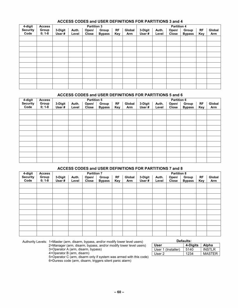
– 60 –
ACCESS CODES and USER DEFINITIONS FOR PARTITIONS 3 and 4
4-digit Security
Code
Access Group 0; 1-8
Partition 3 Partition 4 3-Digit User #
Auth. Level
Open/ Close
Group Bypass
RF Key
Global Arm
3-Digit User #
Auth. Level
Open/Close
Group Bypass
RF Key
Global Arm
ACCESS CODES and USER DEFINITIONS FOR PARTITIONS 5 and 6
4-digit Security
Code
Access Group 0; 1-8
Partition 5 Partition 6 3-Digit User #
Auth. Level
Open/ Close
Group Bypass
RF Key
Global Arm
3-Digit User #
Auth. Level
Open/Close
Group Bypass
RF Key
Global Arm
ACCESS CODES and USER DEFINITIONS FOR PARTITIONS 7 and 8
4-digit Security
Code
Access Group 0; 1-8
Partition 7 Partition 8 3-Digit User #
Auth. Level
Open/ Close
Group Bypass
RF Key
Global Arm
3-Digit User #
Auth. Level
Open/Close
Group Bypass
RF Key
Global Arm
Authority Levels: 1=Master (arm, disarm, bypass, and/or modify lower level users) 2=Manager (arm, disarm, bypass, and/or modify lower level users) 3=Operator A (arm, disarm, bypass) 4=Operator B (arm, disarm) 5=Operator C (arm, disarm only if system was armed with this code) 6=Duress code (arm, disarm, triggers silent panic alarm)
Defaults:
User 4-Digits Alpha
User 1 (Installer) 5140 INSTLR User 2 1234 MASTER

– 61 –
ZO
NE
DE
FIN
ITIO
N F
OR
ZO
NE
S 0
01-0
25
Zo
ne
In
fo (
part
no
s.)
& A
lph
a
Descri
pto
r (3
wo
rds m
ax.)
An
ti
Mas
k
Sm
art
Zo
ne
Rp
t.
Co
de
Seri
al
# /
Lo
op
Tam
per
Acce
ss
Po
int
Byp
as
s
Gro
up
Silen
t
Au
to-
ST
AY
ST
AY
Mo
de
Ven
t
Zo
ne
Arm
w/F
au
lt
Inp
ut
Ty
pe
Part
1-8
Zo
ne
Ty
pe
Zo
ne
No
.
1
2
3
4
5
6
7
8
9
10
11
12
13
14
15
16
17
18
19
20
21
22
23
24
25

– 62 –
Z
ON
E D
EF
INIT
ION
FO
R Z
ON
ES
026-0
50
Zo
ne
In
fo (
part
no
s.)
& A
lph
a
Descri
pto
r (3
wo
rds m
ax.)
An
ti
Mas
k
Sm
art
Zo
ne
Rp
t.
Co
de
Seri
al
# /
Lo
op
Tam
per
Acce
ss
Po
int
Byp
as
s
Gro
up
Silen
t
Au
to-
ST
AY
ST
AY
Mo
de
Ven
t
Zo
ne
Arm
w/F
au
lt
Inp
ut
Ty
pe
Part
1-8
Zo
ne
Ty
pe
Zo
ne
No
.
26
27
28
29
30
31
32
33
34
35
36
37
38
39
40
41
42
43
44
45
46
47
48
49
50

– 63 –
Z
ON
E D
EF
INIT
ION
FO
R Z
ON
ES
051-0
75
Zo
ne
In
fo (
part
no
s.)
& A
lph
a
Descri
pto
r (3
wo
rds m
ax.)
An
ti
Mas
k
Sm
art
Zo
ne
Rp
t.
Co
de
Seri
al
# /
Lo
op
Tam
per
Acce
ss
Po
int
Byp
as
s
Gro
up
Silen
t
Au
to-
ST
AY
ST
AY
Mo
de
Ven
t
Zo
ne
Arm
w/F
au
lt
Inp
ut
Ty
pe
Part
1-8
Zo
ne
Ty
pe
Zo
ne
No
.
51
52
53
54
55
56
57
58
59
60
61
62
63
64
65
66
67
68
69
70
71
72
73
74
75

– 64 –
Z
ON
E D
EF
INIT
ION
FO
R Z
ON
ES
076-1
00
Zo
ne
In
fo (
part
no
s.)
& A
lph
a
Descri
pto
r (3
wo
rds m
ax.)
An
ti
Mas
k
Sm
art
Zo
ne
Rp
t.
Co
de
Seri
al
# /
Lo
op
Tam
per
Acce
ss
Po
int
Byp
as
s
Gro
up
Silen
t
Au
to-
ST
AY
ST
AY
Mo
de
Ven
t
Zo
ne
Arm
w/F
au
lt
Inp
ut
Ty
pe
Part
1-8
Zo
ne
Ty
pe
Zo
ne
No
.
76
77
78
79
80
81
82
83
84
85
86
87
88
89
90
91
92
93
94
95
96
97
98
99
10
0

– 65 –
Z
ON
E D
EF
INIT
ION
FO
R Z
ON
ES
101-1
25
Zo
ne
In
fo (
part
no
s.)
& A
lph
a
Descri
pto
r (3
wo
rds m
ax.)
An
ti
Mas
k
Sm
art
Zo
ne
Rp
t.
Co
de
Seri
al
# /
Lo
op
Tam
per
Acce
ss
Po
int
Byp
as
s
Gro
up
Silen
t
Au
to-
ST
AY
ST
AY
Mo
de
Ven
t
Zo
ne
Arm
w/F
au
lt
Inp
ut
Ty
pe
Part
1-8
Zo
ne
Ty
pe
Zo
ne
No
.
10
1
10
2
10
3
10
4
10
5
10
6
10
7
10
8
10
9
11
0
11
1
11
2
11
3
11
4
11
5
11
6
11
7
11
8
11
9
12
0
12
1
12
2
12
3
12
4
12
5

– 66 –
Z
ON
E D
EF
INIT
ION
FO
R Z
ON
ES
126-1
50
Zo
ne
In
fo (
part
no
s.)
& A
lph
a
Descri
pto
r (3
wo
rds m
ax.)
An
ti
Mas
k
Sm
art
Zo
ne
Rp
t.
Co
de
Seri
al
# /
Lo
op
Tam
per
Acce
ss
Po
int
Byp
as
s
Gro
up
Silen
t
Au
to-
ST
AY
ST
AY
Mo
de
Ven
t
Zo
ne
Arm
w/F
au
lt
Inp
ut
Ty
pe
Part
1-8
Zo
ne
Ty
pe
Zo
ne
No
.
12
6
12
7
12
8
12
9
13
0
13
1
13
2
13
3
13
4
13
5
13
6
13
7
13
8
13
9
14
0
14
1
14
2
14
3
14
4
14
5
14
6
14
7
14
8
14
9
15
0

– 67 –
Z
ON
E D
EF
INIT
ION
FO
R Z
ON
ES
151-1
75
Zo
ne
In
fo (
part
no
s.)
& A
lph
a
Descri
pto
r (3
wo
rds m
ax.)
An
ti
Mas
k
Sm
art
Zo
ne
Rp
t.
Co
de
Seri
al
# /
Lo
op
Tam
per
Acce
ss
Po
int
Byp
as
s
Gro
up
Silen
t
Au
to-
ST
AY
ST
AY
Mo
de
Ven
t
Zo
ne
Arm
w/F
au
lt
Inp
ut
Ty
pe
Part
1-8
Zo
ne
Ty
pe
Zo
ne
No
.
15
1
15
2
15
3
15
4
15
5
15
6
15
7
15
8
15
9
16
0
16
1
16
2
16
3
16
4
16
5
16
6
16
7
16
8
16
9
17
0
17
1
17
2
17
3
17
4
17
5

– 68 –
6 Z
ON
E D
EF
INIT
ION
FO
R Z
ON
ES
176-2
00
Zo
ne
In
fo (
part
no
s.)
& A
lph
a
Descri
pto
r (3
wo
rds m
ax.)
An
ti
Mas
k
Sm
art
Zo
ne
Rp
t.
Co
de
Seri
al
# /
Lo
op
Tam
per
Acce
ss
Po
int
Byp
as
s
Gro
up
Silen
t
Au
to-
ST
AY
ST
AY
Mo
de
Ven
t
Zo
ne
Arm
w/F
au
lt
Inp
ut
Ty
pe
Part
1-8
Zo
ne
Ty
pe
Zo
ne
No
.
17
6
17
7
17
8
17
9
18
0
18
1
18
2
18
3
18
4
18
5
18
6
18
7
18
8
18
9
19
0
19
1
19
2
19
3
19
4
19
5
19
6
19
7
19
8
19
9
20
0

– 69 –
Z
ON
E D
EF
INIT
ION
FO
R Z
ON
ES
201-2
25
Zo
ne
In
fo (
part
no
s.)
& A
lph
a
Descri
pto
r (3
wo
rds m
ax.)
An
ti
Mas
k
Sm
art
Zo
ne
Rp
t.
Co
de
Seri
al
# /
Lo
op
Tam
per
Acce
ss
Po
int
Byp
as
s
Gro
up
Silen
t
Au
to-
ST
AY
ST
AY
Mo
de
Ven
t
Zo
ne
Arm
w/F
au
lt
Inp
ut
Ty
pe
Part
1-8
Zo
ne
Ty
pe
Zo
ne
No
.
20
1
20
2
20
3
20
4
20
5
20
6
20
7
20
8
20
9
21
0
21
1
21
2
21
3
21
4
21
5
21
6
21
7
21
8
21
9
22
0
22
1
22
2
22
3
22
4
22
5

– 70 –
Z
ON
E D
EF
INIT
ION
FO
R Z
ON
ES
226-2
50
Zo
ne
In
fo (
part
no
s.)
& A
lph
a
Descri
pto
r (3
wo
rds m
ax.)
An
ti
Mas
k
Sm
art
Zo
ne
Rp
t.
Co
de
Seri
al
# /
Lo
op
Tam
per
Acce
ss
Po
int
Byp
as
s
Gro
up
Silen
t
Au
to-
ST
AY
ST
AY
Mo
de
Ven
t
Zo
ne
Arm
w/F
au
lt
Inp
ut
Ty
pe
Part
1-8
Zo
ne
Ty
pe
Zo
ne
No
.
22
6
22
7
22
8
22
9
23
0
23
1
23
2
23
3
23
4
23
5
23
6
23
7
23
8
23
9
24
0
24
1
24
2
24
3
24
4
24
5
24
6
24
7
24
8
24
9
25
0

— 71 —
ZONE DEFINITIONS FOR KEYPAD PANIC ZONES 995, 996, and 999 Enter yes/no for each partition-field ∗∗∗∗22
Zone No.
Zone Type
1
2
3
4
5
6
7
8
Bell/Relay Activation
Report Code
Zone Information and Alpha Descriptor (3 words max.)
995 (see note below)
996
999
NOTE: Do Not Use Zone No. 995 in a Fire Alarm application.
ZONE DEFINITIONS FOR SYSTEM ZONES; 970 −−−− 975, 988; 990 and 997
Zone
No.
Zone
Type
Bell/Relay Activation
Report
Code
Zone Information
and
Alpha Descriptor (three words max.)
970
971
972
973
974
975
988
990
997

— 72 —
ZONE DEFINITIONS FOR RELAY SUPERVISORY ZONES 601-632
Zone No.
Zone Type
Report Code
Zone Information and
Alpha Descriptor (3 words max.)
Zone No.
Zone Type
Report Code
Zone Information and
Alpha Descriptor (3 words max.)
601
617
602
618
603
619
604
620
605
621
606
622
607
623
608
624
609
625
610
626
611
627
612
628
613
629
614
630
615
631
616
632
NOTE: Only the relays on 4204CF modules may be supervised. If supervision is programmed for other types of Output Devices, unpredictable results may occur.

— 73 —
ZONE DEFINITIONS FOR SUPERVISORY OF ECP DEVICE ZONES 800-830
Zone No.
Zone Type
Report Code
Zone Information and
Alpha Descriptor (3 words max.)
Zone No.
Zone Type
Report Code
Zone Information and
Alpha Descriptor (3 words max.)
800
816
801
817
802
818
803
819
804
820
805
821
806
822
807
823
808
824
809
825
810
826
811
827
812
828
813
829
814
830
815
Zone Types
00=zone not used 07=24-hour audible 16=fire w/verification 23=no alarm response
01=entry/exit 1 08=24-hour auxiliary 17=waterflow 27=access control
02=entry/exit 2 09=supervised fire 18=supervisory 29=momentary on exit
03=perimeter 10=interior (delay) 19=24-hour trouble
04=interior (follower) 12=Not Used 20=arm stay
05=day/night burglary 13=Remote P/S 21=arm away
06=24-hour silent 14=CO Detector alarm 22=disarm
Input Types Bells/Auxiliary Relay Activation
00=not used 07=Dip switch-type polling loop 0=none 4=auxiliary relay
01=hardwired 08=right loop dip switch poll loop 1=bell 1 5=bell 1 and auxiliary relay
02=RF motion transmitter 09=keypad input 2=bell2 6=bell 2 and auxiliary relay
03=supervised RF transmitter 10=Not Used 3=bells 1 and 2 7=bells 1 and 2 and auxiliary relay
04=unsupervised RF transmitter 11=VistaKey door status monitor
05=RF button transmitter 12=VistaKey request to exit
06=serial number polling loop 13=VistaKey general purpose

— 74 —
Output Devices Worksheets Applicable only if relays (4204/4204CF) or V-Plex are used. Output Devices – Programmed in the #93 Menu Mode in the Output Programming Section. Fill in the required data on
the worksheet below and follow the procedure in the installation instructions as you enter the data during the displays and prompts that appear in sequence.
NOTES: 1. For 4204/4204CF, the Device Programming section must be programmed for the device address. Set the DIP switches on the device for that address.
2. For V-Plex, devices must be programmed in the Zone Programming section
3. If you are using outputs on V-Plex (e.g., 4101SN) no more than 20 of the V-Plex outputs may be programmed for the same START or STOP condition. Also, if you are using ZONE # for the START of a V-Plex output and want that output to stop when the same zone restores, the STOP programming MUST BE BLANK.
OUTPUT DEV #
A
S T A R T S T O P
Relay Group
Restrict
0=V-Plex 1=4204/ 4204CF
V-Plex Zone # or
Dev Add 4204/4204CF
Relay # for 4204/
4204CF EV/ZL Zone ZT / P ZL ZT / P
1
2
3
4
5
6
7
8
9
10
11
12
13
14
15
16
17
18
19
20

— 75 —
OUTPUT DEVICES WORKSHEET (cont’d)
OUTPUT DEV #
A
S T A R T S T O P
Relay Group
Restrict
0=V-Plex 1=4204/ 4204CF
V-Plex Zone # or
Dev Add 4204/4204CF
Relay # for 4204/
4204CF EV/ZL Zone ZT / P ZL ZT / P
21
22
23
24
25
26
27
28
29
30
31
32
33
34
35
36
37
38
39
40
41
42
43
44
45

— 76 —
OUTPUT DEVICES WORKSHEET (cont’d)
OUTPUT DEV #
A
S T A R T S T O P
Relay Group
Restrict
0=V-Plex 1=4204/ 4204CF
V-Plex Zone # or
Dev Add 4204/4204CF
Relay # for 4204/
4204CF EV/ZL Zone ZT / P ZL ZT / P
46
47
48
49
50
51
52
53
54
55
56
57
58
59
60
61
62
63
64
65
66
67
68
69
70

— 77 —
OUTPUT DEVICES WORKSHEET (cont’d)
OUTPUT DEV #
A
S T A R T S T O P
Relay Group
Restrict
0=V-Plex 1=4204/ 4204CF
V-Plex Zone # or
Dev Add 4204/4204CF
Relay # for 4204/
4204CF EV/ZL Zone ZT / P ZL ZT / P
71
72
73
74
75
76
77
78
79
80
81
82
83
84
85
86
87
88
89
90
91
92
93
94
95
96

— 78 —
A = DEVICE ACTION 0 = No Response; 1 = Close for 2 sec; 2 = Close and stay closed; 3 = Pulse on and off; 4 = Toggle alternately between START and STOP events
EV = EVENT 0 = Not used; 1 = Alarm; 2 = Fault; 3 = Trouble; 4 = Restore
ZL = ZONE LIST 01-15, 00 = Not Used
"START" ZONE LIST: Upon alarm, fault, trouble or restore of ANY zone in this list, device action will START.
"STOP" ZONE LIST: Upon restore of ALL zones on this list, device action will STOP. It need not be same list as used for START.
ZT = ZONE TYPE/SYSTEM OPERATION
Choices for Zone Type/System Operation are:
00 = No Response (Not Used) 21 = Arming-AWAY**** 42 = System Battery Low 01 = Entry/Exit #1 22 = Disarming (Code + Off) 43 = Communication failure 02 = Entry/exit #2 23 = No Alarm Response 44 = RF Low Battery 03 = Perimeter 27 = Access Point (allows more than one
relay to be controlled by activation if access point request)
45 = Polling Loop Failure 04 = Interior Follower 47 = Console Failure 05 = Trouble Day/Alarm Night 51 = RF Receiver Failure 06 = 24-Hr. Silent 29 = Momentary Exit 52 = Kissoff 07 = 24-Hr. Audible 30 = On Second Code + Off 54 = Fire Zone Reset 08 = 24-Hr. Auxiliary 31 = End of Exit Time 55 = Disarm + 1 Minute 09 = Fire Alarm or Trouble 32 = Start of Entry Time 56 = XX Minutes (enter XX in field 1∗74) * 10 = Interior W/Delay 33 = Any Burglary Alarm 57 = YY Seconds (enter YY in field 1∗75) * 12 = Not Used 34 = Code + [#] + 71 58 = Duress 13 = Remote P/S 35 = Code + [#] + 72 14 = CO Detector Alarm 36 = At Bell Timeout ** 60 = Audio Alarm Verification (must be
selected for both START and STOP operation)
16 = Fire With Verification 37 = 2 Times Bell Timeout ** 17 = Waterflow***** 38 = Chime 18 = Fire Supervisory 39 = Fire Alarm 61 = Code + [#] + 67 19 = 24-Hour Trouble 40 = Bypassing 62 = Bell 2 Timeout 20 = Arming-STAY*** 41 = AC Power Fail 63 = Auxiliary Relay Timeout
* Stop condition only ** Or at disarming, whichever occurs earlier *** The output also activates when the partition is armed in the INSTANT mode **** The output also activates when the partition is armed in the MAXIMUM mode ***** Use an event of fault or alarm as the START option
P = PARTITION No. 1-8, 0 = Any
ZONE LISTS FOR OUTPUT DEVICES – Programmed in the #93 Menu Mode in the Output Programming Section. Fill in the required data on the worksheet below and follow the procedure shown earlier in this Programming Guide as you enter the data during the displays and prompts that appear in sequence. Up to 15 zone lists may be created
NOTE: Record desired zone numbers below. More or fewer boxes than shown may be needed, as any list may include any or all of system's zone numbers.
Zone List 1: Started or stopped by zone numbers (enter 000 to end entries).
Zone List 2: Started or stopped by zone numbers (enter 000 to end entries).
Zone List 3: Started or stopped by zone numbers (enter 000 to end entries).
Zone List 4: Started or stopped by zone numbers (enter 000 to end entries).

— 79 —
Zone List 5: Started or stopped by zone numbers (enter 000 to end entries).
Zone List 6: Started or stopped by zone numbers (enter 000 to end entries).
Zone List 7: Started or stopped by zone numbers (enter 000 to end entries).
Zone List 8: Started or stopped by zone numbers (enter 000 to end entries).
Zone List 9: Started or stopped by zone numbers (enter 000 to end entries).
Zone List 10: Started or stopped by zone numbers (enter 000 to end entries).
Zone List 11: Started or stopped by zone numbers (enter 000 to end entries).
Zone List 12: Started or stopped by zone numbers (enter 000 to end entries).
Zone List 13: Started or stopped by zone numbers (enter 000 to end entries).
Zone List 14: Started or stopped by zone numbers (enter 000 to end entries).
Zone List 15: Started or stopped by zone numbers (enter 000 to end entries).

— 80 —
Scheduling
ULC Scheduling is currently not approved for ULC applications.
UL • You must program Bypass and Auto-Arm Fail reports for UL installations.
• Auto-disarming is not permitted in UL installations.
• You must not program Random Scheduling of Time Driven Events for UL installations.
General
The scheduling features allow certain operations to be automated, such as arming, disarming, bypassing of zones, and activating relay outputs.
The system uses time windows (a programmed period of time with a start and stop time) for defining open/close schedules, holiday schedules, user-defined temporary schedules, and access schedules for users.
Scheduled events are programmed by user-friendly menu modes of programming (#80, #81, #83, and #93 modes), explained in detail in this section. These menus take you step by step through the options.
Auto Arming
ULC Auto Arming is not a ULC Listed feature.
The system can automatically arm (AWAY Mode) a partition at the end of a pre-determined closing (arming) time window.
Auto Arming can be delayed three ways: by use of the Auto-Arm Delay, the Auto-Arm Warning, or by manually extending the closing (arming) time window with a keypad command.
The system can also automatically bypass any open zones when auto arming.
Auto-Arm Delay
Auto-Arm Delay provides a delay (grace period) before auto arming. It starts at the end of the closing time window.
The delay is set in 4-minute increments, up to 56 minutes in partition-specific program field 2∗05. At the expiration of this delay, the Auto-Arm Warning will start.
Auto-Arm Warning
The Auto-Arm Warning causes the keypad sounder to warn the user of an impending Auto-Arm.
The warning can be set from 1 to 15 minutes prior to the arming in partition-specific program field 2∗06. During this period the keypad beeps every 15 seconds and displays “AUTO ARM ALERT.” During the last 60 seconds, the keypads beep every 5 seconds.
The panel arms at the conclusion of the Auto-Arm Warning period.
Extend Closing Window
A user can manually delay the arm (closing) time window by 1 or 2 hours. This is done by entering a keypad command (User Code + #82), which then prompts the user to enter the desired extension time of 1 or 2. This feature is useful if a user must stay on the premises later than usual. The Auto-Arm delay and warning periods begin at the end of the extension.
Force Arm
The Force Arm option causes the panel to attempt to bypass any faulted zones prior to auto arming (panel performs a force-arm).
ULC Force Arming is not a ULC Listed feature and must be disabled for ULC installations.
This option is set in partition-specific program field 2∗08.
Auto Disarming
The system can automatically disarm a partition at the end of a pre-determined opening (disarm) time window. The disarming time can be delayed by using the Auto-Disarm Delay feature.
Disarm Delay
Auto-Disarm Delay provides a delay before auto disarming. This delay is added to the end of the disarm time window.
The delay is set in 4-minute increments, up to 56 minutes, in partition-specific program field 2∗07.
Restrict Disarming
This option allows disarming by users only during the disarm time window and during the arming time window (in case user needs to re-enter premises after manually arming the partition).
This option is set in partition-specific field 2∗10. If field 2∗10 is set, we highly recommend setting field 2∗11, as well. This field allows the partition to be disarmed outside the arm/disarm time windows only if the partition is in alarm.

— 81 —
Exception Reports
This option allows the reporting of openings and closings to the central station only if the arming and disarming occurs outside
of the predetermined opening and closing time windows. It is set in partition-specific field 2∗09. The system can be programmed to send Failed to Open and Failed to Close reports if the partition is not armed or disarmed by the end of the corresponding time window.
Limitation of Access of Users by Time
A user’s access to the system can be limited to a certain time period. Outside this time, that user’s code is inactive. The system provides up to eight access schedules, each consisting of two time windows (typically one for opening, one for closing) for each day of the week and two time windows for holidays. The access schedules are programmed in the #80 Menu Mode, and enabled when a user’s access code is added to the system. If a user tries to operate the system outside the schedule, the alpha keypad displays “Access Denied.”
Time-Driven Events
The system can automatically activate and de-activate relays at predetermined times to turn lights or other devices on and off. The Time-Driven events can be activated at different times in relation to a time window:
• At the beginning of a time window
• At the end of a time window
• During a time window (on at beginning of window, off at end)
• At both the beginning and end of the time window (e.g., to sound a buzzer at the beginning and end of a coffee break)
• Random time at the start of the time window (occurs within 30 minutes after the start of the time window)
• Random time at the end of the time window (occurs within 30 minutes after the end of the time window)
• Random during the time window (begins within 30 minutes after the start of the time window and ends within 30 minutes after the end of the time window)
The system can perform the same actions on a daily basis, or can perform an action only once (e.g., turn on the porch light this Wednesday at 8:00 PM). The system also provides up to 20 programmable “timers” available to the end user for the purpose of activating output devices at preset times and days.
Time Window Definitions Scheduled events are based on time windows, (periods of time) during which an event may take place. The system supports up to 20 time windows, each defined by a “Start” time and a “Stop” time.
The windows are shared by all 8 partitions, and are used when programming the various schedules (open/close, limitation of access), as well as for Time-Driven event control.
Scheduling Example
A store that has the following hours:
Monday to Friday 9am to 6pm
Saturday 10am to 4pm
Sunday Closed
Holidays Closed
The owner desires the following time windows to allow time for employees to arm or disarm the system:
Monday to Friday Open (disarm) 8am to 9am
Close (arm) 6pm to 6:30pm
Saturday Open (disarm) 9am to 10am
Close (arm) 4pm to 4:30pm
Sunday & Holidays Closed
For this schedule, the four time windows need to be programmed: Window Start Stop Purpose
1 8am 9am Monday-Friday open window
2 9am 10am Saturday open window
3 4pm 4:30pm Saturday close window
4 6pm 6:30pm Monday-Fri. close window
Using the #80 Menu Mode, the installer can program open/close schedules by assigning a time window to a day of the week (windows are entered as 2-digit entries)
Mon Tue Wed Thu Fri Sat Sun Hol
Op/Cl Op/Cl Op/Cl Op/Cl Op/Cl Op/Cl Op/Cl Op/Cl
01/04 01/04 01/04 01/04 01/05 02/03 00/00 00/00
NOTE: 00 is entered for those days on which the store is closed.
Employees can arm and disarm the system, when programmed, within the open and close time windows without causing a report to be sent to the central station (reporting by exception, field 2∗09). The system can be programmed to automatically arm/disarm in case an employee fails to arm/disarm manually (auto-arm/auto-disarm).

— 82 —
Open/Close Schedules Definitions
General
The open/close scheduling is controlled by one of three schedules. Each schedule consists of one time window for openings and one time window for closings. There are three types of schedules available: Daily, Holiday, and Temporary.
Daily Schedule
Each partition can have one daily schedule consisting of one opening window and one closing window per day.
Holiday Schedule
A holiday schedule overrides the regular daily schedule on selected holidays throughout the year.
The opening and closing windows are programmed in the daily schedule, but the holidays themselves are defined in Holiday Schedule Programming in the #80 Menu Mode.
Temporary Schedule
The temporary schedule provides a method for the end user to override the daily and holiday schedules. It consists of one opening window and one closing window for each day of the week. The schedule takes effect for up to one week, after which it is automatically deactivated.
This schedule is programmed using the #81 Temporary Schedule Menu Mode.
Additional Schedules
Additional opening and closing schedules can be programmed using the Time-Driven Event Programming. For example, a schedule for normal store openings/closings can be programmed with a daily open/close schedule, and another open/close schedule for a lunch hour can be programmed using the Time-Driven event schedule programming.
Refer to “Time-Driven Events” later in this section for detailed information.
Open/Close Reports by Exception
The system can help reduce communication traffic to the central station by using the Open/Close Reports by Exception feature. The Open/Close by Exception option suppresses these reports from being sent to the central station if an arm or disarm is done within the expected time window. Reports are only sent if the arm or disarm occurs outside the assigned time window.
The system keeps a record of all openings/closings in its event log.
If a disarming occurs during a closing window (for example, a person who arms the system forgets something and has to re-enter), the Opening report (although outside of the opening window) will not be sent (as long as that disarming occurs within the closing window).
This option is programmed in partition-specific program field 2∗09.
Example of Open/Close Exception Reporting & Scheduling
The following chart gives an example of how the Open/Close by Exception reporting works. 6:01PM 5:59AM 6AM 9AM 9:01AM 3:59PM 4PM 6PM 6:01PM 5:59AM Early Opening reports are sent if system is manually disarmed before opening window begins. Early and Late Opening and Closing reports are programmable options in Report Code Programming in the Programming Guide. They are not dependent on the programming of the Exception Reporting option.
Opening Window
No reports are sent if system is disarmed during this time window. If an arming occurs, a Closing report is sent to the central station regardless of how the Exception Reporting option is set.
Auto-disarm delay begins. Auto-disarm occurs after delay (if auto-disarm is enabled). Missed Opening reports are sent if manual disarming has not occurred at expiration of opening window. Late Opening reports are sent if disarm occurs after the opening window expires.
Early Closing reports are sent if manual arming occurs before the closing window begins. Missed Opening/Closing type reports are programmed in Report Code Programming in the Programming Guide. The Exception Reporting option must be set for these to be sent.
Closing Window
No reports are sent if system is armed* during this time window. * or disarmed if user needs to re-enter premises.
Auto-arm delay begins. Auto-arm warning begins. Auto-arm occurs after warning expires (if auto-arm is enabled). Missed Closing reports are sent if manual arming has not occurred at expiration of closing window. Late Closing reports are sent if system is manually armed after the closing window expires.

— 83 —
Scheduling Menu Mode The #80 Scheduling Menu Mode is used to program most of the scheduling and timed-event options. Enter Installer Code + [#] + [8] + [0] from the normal operating mode. NOTE: Only users with an Installer or Master level user code may enter the #80 mode. The following can be programmed while in this mode:
• time windows
• open/close schedules to each partition
• holiday schedules
• Time-Driven events (for system functions and relay activation)
• limitation of access schedules Some scheduling features are programmed in Data Field Programming Mode (Installer Code + 8 0 0 0). Some features are programmed in the #93 Menu Mode. The programming scheduling fields are listed below.
System-Wide Fields:
∗04 Enable Random Timers
1∗74 –1∗75 Relay timeout values
2∗01-2∗02 Daylight saving time options
2∗11 Allow disarming outside window if alarm occurs
Partition-Specific fields:
1∗76 Access control relay for this partition
2∗05 Auto-arm delay value
2∗06 Auto-arm warning time
2∗07 Auto-disarm delay value
2∗08 Force-arm enable
2∗09 Open/Close Reporting by Exception
2∗10 Restrict disarm only during windows
#93 Menu Mode (System Group #3)
Scheduling related report codes
Event-driven options are programmed using Output Programming in #93 Menu Mode. Relay activation can also be Time-Driven and that those are programmed using the #80 Menu Mode. Refer to the Time-Driven Event Programming later in this section for the procedure.
Steps to Program Scheduling Options
This section contains examples of the worksheets only. For complete worksheets, see the Programming Guide accompanying this Installation and Setup Guide.
In order to use #80 Scheduling Menu Mode, use the worksheets to do the following:
1. Define time windows (up to 20)
2. Define the daily open/close schedules (one schedule per day, per partition)
3. Define the holidays to be used by the system (up to 16)
4. Define limitation of access times (up to eight schedules)
5. Define the Time-Driven events (up to 20)
NOTE: Temporary schedules are programmed using #81 Menu Mode. Use #80 Scheduling Menu Mode to perform the following functions:
6. Program the time windows
7. Program the open/close schedules
8. Program the Time-Driven events
9. Program the access schedules
Scheduling Menu Structure
To program schedules, enter Scheduling Program Mode: Installer Code + [#] + [80]. (Installer or Master level user code.)
Scheduling Program Mode can be entered only when all partitions are disarmed.
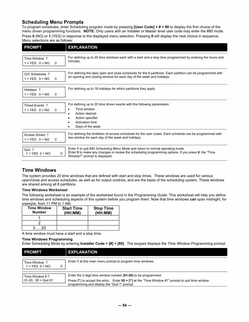
— 84 —
Scheduling Menu Prompts To program schedules, enter Scheduling program mode by pressing [User Code] + # + 80 to display the first choice of the menu driven programming functions. NOTE: Only users with an Installer or Master level user code may enter the #80 mode.
Press 0 (NO) or 1 (YES) in response to the displayed menu selection. Pressing 0 will display the next choice in sequence. Menu selections are as follows:
PROMPT EXPLANATION
Time Window ?
1 = YES 0 = NO 0
For defining up to 20 time windows each with a start and a stop time programmed by entering the hours and minutes.
O/C Schedules ?
1 = YES 0 = NO 0
For defining the daily open and close schedules for the 8 partitions. Each partition can be programmed with an opening and closing window for each day of the week and holidays.
Holidays ?
1 = YES 0 = NO 0
For defining up to 16 holidays for which partitions they apply.
Timed Events ?
1 = YES 0 = NO 0
For defining up to 20 time driven events with the following parameters:
• Time window
• Action desired
• Action specifier
• Activation time
• Days of the week
Access Sched. ?
1 = YES 0 = NO 0
For defining the limitation of access schedules for the user codes. Each schedule can be programmed with two window for each day of the week and holidays
Quit ? 1 = YES 0 = NO 0
Enter 1 to quit #80 Scheduling Menu Mode and return to normal operating mode. Enter 0 to make any changes or review the scheduling programming options. If you press 0, the “Time Window?” prompt is displayed.
Time Windows The system provides 20 time windows that are defined with start and stop times. These windows are used for various open/close and access schedules, as well as for output controls, and are the basis of the scheduling system. These windows are shared among all 8 partitions.
Time Windows Worksheet
The following worksheet is an example of the worksheet found in the Programming Guide. This worksheet will help you define time windows and scheduling aspects of this system before you program them. Note that time windows can span midnight; for example, from 11 PM to 1 AM.
Time Window Number
Start Time (HH:MM)
Stop Time (HH:MM)
1
2
3…..20
A time window must have a start and a stop time.
Time Windows Programming Enter Scheduling Mode by entering Installer Code + [#] + [80]. The keypad displays the Time Window Programming prompt.
PROMPT EXPLANATION
Time Window ? 1 = YES 0 = NO 0
Enter 1 at this main menu prompt to program time windows.
Time Window # ? 01-20, 00 = Quit 01
Enter the 2-digit time window number (01-20) to be programmed.
Press [∗] to accept the entry. Enter 00 + [∗] at the “Time Window #?” prompt to quit time window programming and display the “Quit ?” prompt.

— 85 —
PROMPT EXPLANATION
01 TIME WINDOW 00:00AM 00:00AM
If you entered a time window number, the cursor is now positioned on the tens of hours digit of the start of window entry.
Enter the desired start of window hour and press [∗]. The cursor moves to the minutes position. Enter the
desired minutes and press [∗]. Toggle the AM/PM indication by pressing any key 0-9 while the cursor is
under the A/P position and then press [∗]. Repeat this to program the stop of window entry.
When the entry is completed, the “Time Window #?” prompt is displayed again.
Enter the next time window number to be programmed and repeat the procedure.
Quit ? 1 = YES 0 = NO 0
Enter 0 at the Quit ? prompt to return to the main menu choices and continue programming. Enter 1 to quit Scheduling Menu Mode.
Because the time windows are shared among all partitions, it is important to make sure that changing a time window does not adversely affect desired actions in other partitions.
Daily Open/Close Schedules Each partition can be assigned one daily open/close schedule, plus a holiday schedule. Temporary schedules are programmed separately, using the #81 Temporary Schedule Menu Mode. To program additional open/close schedules, see Time-Driven Events Programming later in this section for the procedure.
Open/Close Schedule Worksheet
The following worksheet is an example of the worksheet found in the Programming Guide. Write the previously defined time window numbers for open and close for each partition.
Part Mon Tues Wed Thur Fri Sat Sun Hol Op Cl Op Cl Op Cl Op Cl Op Cl Op Cl Op Cl Op Cl
1
2
3…8
Open/Close Schedule Programming After entering Scheduling Menu Mode, press [0] until the “O/C Schedules?” prompt appears.
PROMPT EXPLANATION
O/C Schedules ? 1 = YES 0 = NO 0
Enter 1 to program opening and closing schedules.
Partition # ? 01-08, 00 = Quit 01
Enter the appropriate partition number for which the following open/close schedules will apply.
Enter 00 + [∗] at the “Partition #?” prompt to quit open/close schedules programming and display the “Quit ?” prompt.
Mon P1 OP WIND.? 00:00 00:00 00
Enter the time window number 01-20 for the displayed day’s opening schedule beginning with Monday.
Enter 00 if no schedule is desired for a particular day. As the number is keyed in, the actual time that has been stored for that window number is displayed as a programming aid.
Press [∗] to accept the entry.
Mon P1 CL WIND.? 00:00 00:00 00
Enter the time window number for the displayed day’s closing schedule. As the number is keyed in, the actual time that has been stored for the window number is displayed.
Press the [∗] key to accept the entry.
Tue P1 OP WIND.? 00:00 00:00 00
The keypad now prompts for Tuesday’s open/close schedule. Follow the procedure for Monday’s prompts. When the last day of the week has been programmed, the holiday opening and closing window prompts are displayed.
Hol P1 OP WIND.? 00:00 00:00 00
Repeat the procedure for the holiday opening and closing time windows.
Press the [∗] key to accept the entry. When the entries are completed, the “Partition #?” prompt is displayed again. Repeat this procedure for each partition in the system.
Quit ? 1 = YES 0 = NO 0
Enter 0 at the “Quit ?” prompt to return to the main menu choices and continue programming. Enter 1 to quit Scheduling Menu Mode.

— 86 —
Holiday Schedules A holiday schedule overrides the regular daily open/close schedule on the programmed holidays throughout the year.
The system provides up to 16 holidays that can be assigned for the system. Each holiday can be assigned to any combination of partitions. List the desired holidays in a Month/Day format on the worksheet. Check the partitions for which these holidays apply.
Holiday Schedule Worksheet
The following worksheet is an example of the worksheet found in the Programming Guide.
HOL Partition
Month/Day 1 2 3 4 5 6 7 8
1 /
2 /
3…16
Holiday Schedule Programming After entering Scheduling Menu Mode, press [0] until the “Holidays ?” prompt appears.
PROMPT EXPLANATION
Holidays ? 1 = YES 0 = NO 0
Enter 1 to program holiday schedules.
HOLIDAY NUMBER ? 01-16,00=Quit 01
Enter the 2-digit holiday number (01-16) to be programmed and press [∗] to accept entry.
Enter 00 + [∗∗∗∗] at the “Holiday Number?” prompt to quit the holiday menus and display the “Quit ?” prompt.
01 ENTER DATE 00/00
The cursor is now positioned on the tens of months digit. Enter the appropriate month, then press [∗] to proceed to the day field. Enter the appropriate day for the holiday.
Press [∗] to accept the entry.
Part ? 12345678 Hit 0-8 x x
Holidays can be set for any partition, as follows. Press [0] to turn all partitions on or off, or use keys 1-8 to toggle the letter “x” under the partition to which this holiday will apply.
Press the [∗] key when all desired partitions have been assigned.
The “Holiday Number?” prompt is displayed again. Repeat the procedure for each holiday to be programmed.
Quit ? 1 = YES 0 = NO 0
Enter 0 at the “Quit ?” prompt to return to the main menu choices and continue programming. Enter 1 to quit Scheduling Menu Mode.
Time-Driven Events These schedules are used to activate outputs, bypass zones, etc. based on time. There are 20 of these schedules that may be programmed for the system, each governed by the previously defined time windows.
The actions that can be programmed to automatically activate at set times are: relay commands, arm/disarm commands, zone bypassing commands, and open/close access conditions.
Time-Driven Events Worksheet
The following worksheet is an example of the worksheet found in the Programming Guide. Fill out the worksheet using the steps outlined below.
Automatic Refresh Feature
The system automatically updates the status of all Time-Driven Events upon any of the following occurrences:
• Changing of the time or date via #63 mode
• Exiting #80 Scheduling Menu mode
• Exiting Program mode
• After a disconnect from the downloader
• On a power-up
• At Daylight Saving Time adjustment.
Sched Time Days Action Action Activation Num. Window M T W T F S S H Desired Specifier Time
1
2
3…20

— 87 —
1. Enter the schedule number (01-20) and time window number (01-20), and note the day of the week the action is desired.
2. Enter the code for the desired action and action specifier. The action codes represent the events that are to take place when the scheduled time is reached. Each action also requires an action specifier, which defines what the action will affect (relay, relay group, partition, zone list, user group). The action specifier varies, depending on the type of action selected.
The following is a list of the Action Codes (desired actions) used when programming Time-Driven events. Note that these codes are independent of the relay codes programmed during Output Programming in the #93 Menu Mode.
Relay Commands Action Code Action Action Specifier
01 Relay On Relay #
02 Relay Off Relay #
03 Relay Close for 2 seconds Relay #
04 Relay Close XX minutes (set in field 1∗74) Relay #
05 Relay Close YY seconds (set in field 1∗75) Relay #
06 Relay Group On Relay Group #
07 Relay Group Off Relay Group #
08 Relay Group Close for 2 seconds Relay Group #
09 Relay Group Close XX minutes (set in field 1∗74) Relay Group #
10 Relay Group Close YY seconds (set in field 1∗75) Relay Group #
Arm/Disarm Commands Action Code Action Action Specifier
20 Arm-STAY Partition(s)
21 Arm AWAY Partition(s)
22 Disarm Partition(s)
23 Force Arm STAY (Auto-bypass faulted zns) Partition(s)
24 Force Arm AWAY (Auto-bypass faulted zns) Partition(s)
25 Arm INSTANT Partition(s)
26 Arm MAXIMUM Partition(s)
• The auto-arm warning (field 2∗06) applies when using Time-Driven events to auto-arm.
• Temporary schedules do not override an auto-arming or auto-disarming programmed in Time-Driven events.
• The auto-arming window cannot be extended using the Installer Code + #82 Mode.
Bypass Commands Action Code Action Action Specifier
30 Auto bypass – Zone list Zone list #
31 Auto unbypass – Zone list Zone list #
Open/Close Windows Action Code Action Action Specifier
40 Enable Opening Window by partition Partition(s)
41 Enable Closing Window by partition Partition(s)
42 Enable Access Window for access group Access Group
50 Off-Normal Reminder
(starts local keypad beeping if fire or system trouble condition exists)
None

— 88 —
Access Control Commands 55-78 Not Used
3. Enter the desired activation time (when the action is to take place). Select from:
Activation Time Description
1 Beginning of time window. 2 End of time window. 3 During time window active period only (on at beginning of window, off at end).
For example, if bypass is selected to activate during the window, zones in a zone list are bypassed at the beginning of the window and unbypassed at the end of the window.
4 Beginning and end of time window (e.g., a coffee break buzzer). In this example, if relay pulse is selected, the relay pulses for 2 seconds at the beginning of the window, signaling the beginning of the coffee break. At the end of the window it pulses again, signaling the end of coffee break.
5 Random time at the start of the time window (occurs within 30 minutes after the start of the time window). NOTE: Since the randomization for choice “5” occurs within 30 minutes after the start of the window, the time window duration must be at least 30 minutes.
6 Random time at the end of the time window (occurs within 30 minutes after the end of the time window). 7 Random during the time window (begins within 30 minutes after the start of the time window and ends within 30
minutes after the end of the time window). NOTE: Since the randomization for choice “7” occurs within 30 minutes after the start of the window, the time window duration must be at least 30 minutes.
Field ∗04 must be enabled for randomization. A user must initiate a random schedule by entering one of the following sequences:
• [User Code] + [#] + [41]. This will randomize, up to 30 minutes, the activation time of all devices, programmed for randomization, assigned to the partition the sequence is entered in. Enter the sequence again to turn off the random schedule.
• [User Code] + [#] + [42]. This is the same as the method above, except the randomization occurs only on devices with activation times within 6 PM and 5 AM. Enter the same sequence again to turn off the random schedule.
UL You must not program Random Scheduling of Time Driven Events for UL installations.
Time-Driven Event Programming
The following menu items must first be programmed in Output Programming in the #93 Menu Mode:
Enter Relay No. (reference identification number)
Output Group (if applicable)
Restriction (#70) (Restriction must be set to yes for Commercial Fire installations.)
Output Type (V-Plex or 4204/4204CF)
Zone No. (V-Plex)
ECP Address (4204/4204CF)
Relay No. (4204/4204CF)
After entering Scheduling Menu Mode, press [0] until the “Timed Events ?” prompt appears.
PROMPT EXPLANATION
Timed Events ? 1 = YES 0 = NO 0
Enter 1 to program timed events.
TIMED EVENT # ? 01-20, 00=Quit 01
Enter the timed event number to be programmed (01-20).
Press [∗]. The system then prompts the user to enter the desired action to be taken. Enter 00 at the “TIMED EVENT #?” prompt to quit the timed event menus and display the “Quit ?” prompt.
01 ACTION ? none 00
Enter the action code for this timed-event number from the list at the left. This could be an output command, an arming command, or any other Time-Driven event.
Press [∗] to accept the entry. The prompt for the action specifier appears.

— 89 —
ACTION CODES EXPLANATION ACTION SPECIFIER
01=Relay On 02=Relay Off
03=Relay Close for 2 seconds
04=Relay Close XX minutes 05=Relay Close YY seconds
Actions 01-05 If you selected actions 01-05, the prompt at the right appears. Enter the relay number.
Press [∗] to accept entry. The “Time Window ?” prompt appears.
01 RELAY # ? 00
06=Relay Group On 07=Relay Group Off 08=Relay Group Close for 2
seconds 09=Relay Group Close XX
minutes 10=Relay Group Close YY
seconds
Actions 06-10 If you selected actions 06-10, the prompt at the right appears. Enter the relay group number.
Press [∗] to accept entry. The “Time Window ?” prompt appears.
01 RELAY GRP # ? 00
20=Arm-STAY 21=Arm AWAY 22=Disarm 23=Force Arm STAY 24=Force Arm AWAY 25=Arm INSTANT 26=Arm MAXIMUM 40=Enable Open Window by
Part. 41=Enable Close Window by
Part.
Actions 21-26 and 40-41 If you selected actions 21-26 or 40-41, the prompt at the right appears. Enter the partition to which the action applies. Enter 0 to select all partitions. Enter a partition number again to deselect it.
Press [∗] to accept entry. The “Time Window ?” prompt appears.
PART? 12345678 HIT 0-8 X X
30=Auto bypass – Zone list 31=Auto unbypass – Zone list
Actions 30-31 If you selected actions 30-31, the prompt at the right appears. Enter the zone list number that contains the zones to be bypassed or unbypassed.
Press [∗] to accept entry. The “Time Window ?” prompt appears.
01 ZONE LIST ? ENTER 01-15 01
42=Enable Access Window for Access group(s)
Action 42 If you selected action 42, the prompt at the right appears. Enter the group number to which the time window will apply.
Press [∗] to accept entry. The “Time Window ?” prompt appears.
GROUP ? 12345678 HIT 0-8 X
50=Off-Normal Reminder Action 50
No action specifier is required for this action since the condition that this occurs for are system-wide.
PROMPT EXPLANATION
01 Time Window ? 00:00 00:00 01
Enter the time window number (01-20) for which this timed event is to occur. As the number is keyed in, the actual time that has been stored for the time window number is displayed.
Press [∗] to accept entry.
01 Active time ? 0
Enter the activation time from 1-10 (listed below). As the number is keyed in, the activation time is displayed. The choices are: 1: Trigger at the start of the window. 2: Trigger at the end of the window. 3: Take effect only for the duration of the window. 4: Trigger at both the start and the end of the window. Example: coffee break buzzer. 5: Random trigger, up to 30 minutes, after the start of the window. 6: Random trigger, up to 30 minutes, after the end of the window. 7: Take effect only for the duration of the window, but random start and end the window up to 30 minutes.
Press [∗] to accept entry.
Days ? MTWTFSSH Hit 0-8 x x
The system then asks for which days the event is to be activated. Press 0 to toggle all days on or off; or press keys 1-8 to toggle the letter “x” under the day on or off (Monday = 1, Holiday = H = 8).
When all entries have been made, the “TIMED EVENT #?” prompt is displayed again.
Repeat the procedure for each timed event for the installation.
Quit ? 1 = YES 0 = NO 0
Enter 0 at the “Quit ?” prompt to return to the main menu choices and continue programming. Enter 1 to quit Scheduling Menu Mode.

— 90 —
Limitation of Access Schedules Limitation of Access is a means by which a user’s access code is limited to working during a certain period of time. The system provides eight Access Schedules, each of which consists of two time windows for each day of the week and two time windows for holidays (typically, one for an opening time window and the second for a closing time window). A user, required to follow a schedule, would be assigned to an access group of the same number (e.g., schedule 1= group 1). The user’s access code is assigned to a group when that user is added to the system. If no limitations apply, enter 0.
Limitation of Access Schedule Worksheet
Enter the appropriate time window numbers for each access schedule.
Acc Mon Tues Wed Thurs Fri Sat Sun Hol Sch W1 W2 W1 W2 W1 W2 W1 W2 W1 W2 W1 W2 W1 W2 W1 W2
1
2
3…8
NOTE: The holidays used for the access groups are the same as those defined in the holiday schedule.
Limitation of Access Schedules Programming
To program access schedules enter Scheduling Menu Mode Installer Code + # 80. After entering Scheduling Menu Mode, press [0] until the “Access Sched. ?” prompt appears.
PROMPT EXPLANATION
Access Sched. ? 1 = YES 0 = NO 0
Enter 1 to program access schedules.
ACCESS SCHED # ? 01-08, 00 = Quit 01
Enter the access control schedule number between 01 and 08.
Press [∗] to accept entry. Enter 00 at the “Access Sched #?” prompt to quit the access control menus and display the Quit ? prompt.
MON A1 Window 1? 00:00 00:00 00
Enter the first time-window number (01-20) for this access schedule for the displayed day. As the number is keyed in, the actual time that has been stored for the window is displayed.
Press [∗] to continue.
MON A1 Window 2 ? 00:00 00:00 00
Enter the second time-window number from 01-20 for this access schedule for the displayed day. As the number is keyed in, the actual time that has been stored for the window is displayed.
Press [∗] to continue.
TUE A1 Window 1? 00:00 00:00 00
Repeat the procedure for the other days of the week. When the last day of the week has been programmed, the windows for holidays may be entered.
Hol A1 Window 1 ? 00:00 00:00 00
Enter the first time-window number for holidays for this access schedule. As the number is keyed in, the actual time that has been stored for the window is displayed.
Press [∗] to continue.
Hol A1 Window 2 ? 00:00 00:00 00
Enter the second time-window number for holidays for this access schedule. As the number is keyed in, the actual time that has been stored for the window is displayed.
Press [∗] to continue.
Quit ? 1 = YES 0 = NO 0
Enter 0 at the “Quit ?” prompt to return to the main menu choices and continue programming. Enter 1 to quit Scheduling Menu Mode.

— 91 —
Temporary Schedules Each partition can be assigned a temporary schedule, which overrides the regular open/close schedule (and the holiday schedule). This schedule takes effect as soon as it is programmed, and remains active for up to one week.
Only users with the authority level of manager or higher can program temporary schedules.
A temporary schedule affects only the partition from which it is entered. Temporary schedules can also be reused at later dates simply by scrolling (pressing [#]) to the “DAYS?” prompt and activating the appropriate days. This should be considered when defining daily time windows.
Temporary Schedule Worksheet
Partition/Windows Mon Tue Wed Thu Fri Sat Sun
1 Disarm Window
Start Time HH:MM
Stop Time HH:MM
Arm Window
Start Time HH:MM
Stop Time HH:MM
2…8 Disarm Window
Start Time HH:MM
Stop Time HH:MM
Arm Window
Start Time HH:MM
Stop Time HH:MM
Temporary Schedules Programming Enter User Code + [#] + 81 to enter this mode.
PROMPT EXPLANATION
Mon DISARM WIND. 00:00AM 00:00AM
This prompt is for entering the start and end times of the disarm (opening) window for Monday. Upon entry of this mode, the cursor is positioned on the tens of hours digit of the start time of the disarm window. Enter the desired hour.
Press [∗] to move to the minutes field. The minutes are entered in the same manner.
Press [∗] to move to the AM/PM position. Pressing any key in the 0-9 range toggles the AM/PM indication.
Repeat the procedure for the stop time entry.
Press [∗] to store the entries and move to the arming (closing) window for Monday. Pressing [#] scrolls you through the prompts without making any changes.
Mon ARM WINDOW 00:00AM 00:00AM
This prompt is for entering the start and end times of the arm (closing) window for Monday.
The cursor is positioned on the tens of hours digit of the start time of the arm window. Enter the hour.
Press [∗] to move to the minutes field. The minutes are entered in the same manner.
Press [∗] to move to the AM/PM position. Pressing any key in the 0-9 range toggles the AM/PM indication.
Repeat the procedure for the stop time entry.
After the windows for that day have been completed, the system prompts for disarm and arm time windows for the next day. Press [#] if no changes are desired.
Tue DISARM WIND. 00:00AM 00:00AM
Repeat the procedure described above for all days of the week. When all the windows for all the days have been completed, the system prompts for which days of the schedule are to be activated.
Days ? MTWTFSS Hit 0-7 x x
This is the prompt that actually activates the temporary schedule. To select the days to be activated, enter 1-7 (Monday = 1). An “X” appears under that day, indicating the temporary schedule for that day is active. Entering a day’s number again deactivates that day. Pressing 0 toggles all days on/off. The temporary schedule is in effect only for the days highlighted with the letter “x” under them. As the week progresses, the selected days are reset to the inactive state, but all other entries for the temporary schedule remain programmed.
Press [∗] to store the entries or press [#] to exit the Temporary Schedule Entry Mode without making any changes.

— 92 —
User Scheduling Menu Mode The system provides up to 20 “timers” available to the end user to control output devices. The output devices themselves are programmed into the system by the installer during Output Programming in the #93 Menu Mode. The end user needs only to know the output device number and its alpha descriptor. The installer may set certain outputs to be “restricted” during Output Programming (this prevents the end user from controlling doors, pumps, Notification Appliance Circuits, etc.) To enter this mode, the user enters User Code + [#] + 83.
PROMPT EXPLANATION
Output Timer # ? 01-20, 00=Quit 01
Enter the output timer number to be programmed (01-20). Press [∗] to accept entry and move to the next prompt. Enter 00 to quit and return to normal operating mode.
06 07:00P 11:45P PORCH LITE 04
If that timer number has already been programmed, a summary screen appears. In this example: 06 = Timer # 07:00PM = Start Time 11:45PM = Stop Time
PORCH LITE = Descriptor for Output Device # 4
04 = Output Device # affected by this timer
Press [∗] to continue.
06 ENTER OUTPUT# PORCH LITE 04
Enter the desired output number (01-96). As the number is entered, the descriptor for that output device is displayed.
Press [∗] to continue.
Entering 00 as the output number deletes the timer (Timer 06, in this example) and displays an output descriptor of “None.” Output devices are programmed via #93 Menu Mode.
06 ON TIME ? 07:00 PM
The cursor is positioned on the tens of hours digit of the ON time. Enter the desired hour. Press [∗] to move to the minutes field. The minutes are entered in the same manner. The AM/PM indication is toggled by hitting any key from 0-9 while the cursor is under the AM/PM position.
Press [∗] to continue.
06 OFF TIME ? 11:45 PM
The cursor positioned on the tens of hours digit of the OFF time. Enter the desired hour. Press [∗] to move to the minutes field. The minutes are entered in the same manner. The AM/PM indication is toggled by hitting any key in the 0-9 range while the cursor is under the AM/PM position.
Press [∗] to continue.
06 DAYS? MTWTFSS HIT 0-7 x x
To select the days to be activated, enter 1-7 (Monday = 1). An “x” appears under that day, indicating the output for that day is active. Entering a day’s number again deactivates that day. Pressing 0 toggles all days on/off. The outputs are in effect only for the days highlighted with the letter “x” under them. As the week progresses, the selected days are reset to the inactive state, unless the permanent option is selected (next screen prompt).
When completed, press [∗] to continue.
06 Permanent ? 0 = NO,1 = YES 0
Selecting “Permanent” (1) means that this schedule will be in effect on a continuous basis. Selecting 0 means that this schedule will be in effect for one week only. The letter “x” under the day is then cleared, but all other entries for the output device remain programmed.
Press [∗] to accept entry.
The system quits User Scheduling Mode and returns to normal operating mode.
#80 and #81 MENU MODE KEY COMMANDS
The following is a list of commands used while in the Menu mode.
#80 or #81 Enters Menu mode
[∗] Serves as ENTER key. Press to have keypad accept entry.
[#] Backs up to previous screen.
0 Press to answer NO.
1 Press to answer YES.
01-09 All data entries are either 2-digit entries.
00 Exits Menu mode, returns to normal operation mode when entered at the first question for each category.

— 93 —
Scheduling Worksheets
Time Windows Definitions Worksheet. The system provides 20 time windows that are defined with start and stop times. They are programmed in the #80 Menu Mode. Fill in the required data on the worksheet below and follow the procedure in the installation instructions as you enter the data during the displays and prompts that appear in sequence.
Time Window Number
Start Time (HH:MM)
Stop Time (HH:MM)
1
2
3
4
5
6
7
8
9
10
11
12
13
14
15
16
17
18
19
20
(Keep this worksheet handy, as you will be asked for a given time window number later in this section).
Because the time windows are shared among all partitions, it is important to make sure that changing a time window does not adversely affect desired actions in other partitions.
Daily Open/Close Schedule Worksheet: Using the time windows previously defined, fill in the required data on the worksheet below and follow the procedure in the installation instructions as you enter the data during the displays and prompts that appear in sequence.
Part Mon Tues Wed Thur Fri Sat Sun Hol
Op Cl Op Cl Op Cl Op Cl Op Cl Op Cl Op Cl Op Cl
1
2
3
4
5
6
7
8

— 94 —
Holiday Schedule Worksheet: The system provides up to 16 holidays that can be assigned for the system. Each holiday can be assigned to any combination of partitions. Fill in the required data on the worksheet below and follow the procedure in the installation instructions as you enter the data during the displays and prompts that appear in sequence.
HOL Partition
Month/Day 1 2 3 4 5 6 7 8
1 /
2 /
3 /
4 /
5 /
6 /
7 /
8 /
9 /
10 /
11 /
12 /
13 /
14 /
15 /
16 /
Time-Driven Event Worksheet: The system provides up to 20 time-driven events that can be programmed for the system. Fill in the required data on the worksheet below and follow the procedure in the installation instructions as you enter the data during the displays and prompts that appear in sequence.
Sched Time Day(s) Action Action Activation
Num. Window M T W T F S S H Desired Specifier Time
1
2
3
4
5
6
7
8
9
10
11
12
13
14
15
16
17
18
19
20

— 95 —
Automatic Refresh: The system automatically updates the status of all Time-Driven Events upon any of the following occurrences:
• Changing of the time or date via #63 mode • Exiting #80 Scheduling Menu mode • Exiting Program mode • After a disconnect from the downloader • On a power-up • At Daylight Saving Time adjustment.
Below is a list of the "Action" codes (desired actions) used when programming time-driven events. Note that these codes are independent of the "relay codes" programmed during the #93 Menu Mode–Output Programming mode. If using Time Driven Events, the following menu items must first be programmed using #93 Menu Mode - Output Programming:
Enter Relay No. (reference identification number) Relay Group (if applicable) Restriction Relay Type (V-Plex or 4204/4204CF)
Zone No. (V-Plex) ECP Address (4204/4204CF) Relay No. (4204/4204CF)
Relay commands:
Action Specifier for commands 01-05 is Relay No.; Action Specifier for commands 06-10 is Relay Group No.
01 = Relay On 02 = Relay Off
03 = Relay Close for 2 seconds 04 = Relay Close XX minutes (field 1∗74)
05 = Relay Close YY seconds (field 1∗75) 06 = Relay Group On 07 = Relay Group Off 08 = Relay Group Close for 2 seconds
09 = Relay Group Close XX minutes (field 1∗74) 10 = Relay Group Close YY seconds (field 1∗75)
Arm/Disarm commands:
Action Specifier for commands 20-24 is Partition(s). Activation times 1 (Beginning), 2 (End), 3 (During), 5 (Random Start), 6 (Random End), 7 (Random During) are the only valid choices for auto-arming and disarming functions.
20 = Arm-Stay 21 = Arm Away 22 = Disarm 23 = Force Arm Stay (Auto-bypass faulted zones) 24 = Force Arm Away (Auto-bypass faulted zones) 25 = Arm Instant 26 = Arm Maximum
Bypass commands:
Action Specifier for commands 30-31 is Zone List #, Activation times 1 (Beginning), 2 (End), 3 (During), 5 (Random Start), 6 (Random End), 7 (Random During) are the only valid choices for bypass commands.
30 = Auto bypass - Zone list 31 = Auto unbypass - Zone list
Open/Close Windows:
Action Specifier for commands 40-41 is Partition(s), for 42 is Access Group and for 50 no specifier is programmed.
Activation time 3 (During), 7 (Random During) are the only valid choices for these commands.
40 = Enable Opening Window 41 = Enable Closing Window 42 = Enable Access Window 50 = Off-Normal Reminder (Starts local keypad beeping if off-normal condition exists)
Access Control Commands
Action Specifier for commands 55-60 is Access Point, for 61-66 is Group, for 67-72 is Partition, and for 73-74 is Trigger.
55 = Access Point Grant 56 = Access Point Grant with Override 57 = Access Point Protect 58 = Access Point Bypass 59 = Access Point Lock 60 = Access Point Exit 61 = Access Point Group Grant 62 = Access Point Group Grant with Override 63 = Access Point Group Protect 64 = Access Point Group Bypass 65 = Access Point Group Lock 66 = Access Point Group Exit 67 = Access Point Partition Grant 68 = Access Point Partition Grant with Override 69 = Access Point Protect by Partition 70 = Access Point Bypass by Partition 71 = Access Point Lock by Partition 72 = Access Point Exit by Partition 73 = Access Point Trigger On 74 = Access Point Trigger Off
Additional Commands
Action Specifier for command 78 is Group.
78 = Access Point Group Disable

— 96 —
Activation time:
Refers to when the action is to take place relative to the time window. 1 = Beginning of time window
2 = End of time window
3 = During time window active period only (On at beginning of window, off at end).
4 = Beginning and end of time window
5 = Random Start of the time window *
6 = Random End of the time window *
7 = Random During the time window *
* The activation time of the window is randomized up to 30 minutes and is initialized by either of two methods: a. [User Code] + [#] + [41] − Initiates the random schedule for all devices in the partition. b. [User Code] + [#] + [42] − Initiates the random schedule for all devices in the partition with a time window within 6
PM and 5 AM.
Limitation of Access Worksheet The system provides up to 8 Access Schedules that can be programmed for the system. Fill in the required data on the worksheet below and follow the procedure in the installation instructions as you enter the data during the displays and prompts that appear in sequence.
Acc Mon Tues Wed Thurs Fri Sat Sun Hol
Sch W1 W2 W1 W2 W1 W2 W1 W2 W1 W2 W1 W2 W1 W2 W1 W2
1
2
3
4
5
6
7
8
Temporary Schedule #81 Menu Mode. The system provides a Temporary Schedule for each partition. Enter the temporary scheduling mode by pressing [Installer Code] + [#] + [81]. Fill in the required data on the worksheet below and follow the procedure in the installation instructions as you enter the data during the displays and prompts that appear in sequence.
Partition/Windows Mon Tue Wed Thu Fri Sat Sun
1 Disarm Window
Start Time HH:MM
Stop Time HH:MM
Arm Window
Start Time HH:MM
Stop Time HH:MM
2 Disarm Window
Start Time HH:MM
Stop Time HH:MM
Arm Window
Start Time HH:MM
Stop Time HH:MM

— 97 —
Partition/Windows Mon Tue Wed Thu Fri Sat Sun
3 Disarm Window
Start Time HH:MM
Stop Time HH:MM
Arm Window
Start Time HH:MM
Stop Time HH:MM
4 Disarm Window
Start Time HH:MM
Stop Time HH:MM
Arm Window
Start Time HH:MM
Stop Time HH:MM
5 Disarm Window
Start Time HH:MM
Stop Time HH:MM
Arm Window
Start Time HH:MM
Stop Time HH:MM
6 Disarm Window
Start Time HH:MM
Stop Time HH:MM
Arm Window
Start Time HH:MM
Stop Time HH:MM
7 Disarm Window
Start Time HH:MM
Stop Time HH:MM
Arm Window
Start Time HH:MM
Stop Time HH:MM
8 Disarm Window
Start Time HH:MM
Stop Time HH:MM
Arm Window
Start Time HH:MM
Stop Time HH:MM

— 98 —
NOTES

— 99 —
NOTES

— 100 —
NOTES

— 101 —
NOTES

— 102 —
NOTES

— 103 —
V1
28
FB
PT
-SO
C-V
1
VIS
TA
-128F
BP
T / V
ISTA
-250F
BP
T
SU
MM
AR
Y O
F C
ON
NE
CT
ION
S
TR
AN
SF
OR
ME
RW
/EN
CL
OS
UR
EA
DE
MC
O N
o.1
451
(supplie
d)
INP
UT
: 120V
AC
, 6
0H
Z,
1
.0A
max. C
onnect to
a
dedic
ate
d c
ircuit.
See instr
uctions for
pro
per
eart
h g
round
connections
PROGRAMMABLEAS KEYSWITCH LOOP
PROGRAMMABLEAS TAMPER LOOP
2k (
no
te 6
)
+Data in
Data out
+
BA
CK
-UP
LIN
E S
EIZ
ELE
D (
GR
EE
N)
Connect to
main
PC
Bheader
J3 u
sin
g r
ibbon
cable
(supplie
d)
BA
CK
-UP
TLM
ON
HO
OK
VO
LT
AG
E T
HR
ES
HO
LD
(B
LU
E)
INT
AC
T: 25V
CU
T: 13V
OP
TIO
NA
L 5
140D
LM
BA
CK
-UP
DIA
LE
R M
OD
UL
E
MA
IN P
CB
SH
IEL
D
BA
CK
-UP
PH
ON
E J
AC
KS
EE
TE
LC
O
JA
CK
SH
OC
K
WA
RN
ING
B
ELO
W
J2
Make c
onnections u
sin
g 4
142T
R c
able
VO
LT
AG
E
TR
IGG
ER
S(n
ot superv
ised)
1
2
3
4
5
6
7
8
9J4
Ma
ke
co
nn
ectio
ns u
sin
g
41
42
TR
ca
ble
(su
pp
lied
)
KE
YP
AD
PO
RT
#2
BE
LL 1
W1
(WH
ITE
)
BE
LL 2
W4
(WH
ITE
)
BLK
+
R
ED
BE
LL
HO
RN
BE
LL
HO
RN
N.C
.
N.O
.
N.C
.
N.O
.
TO
OT
HE
R D
EV
ICE
S
2k
2k
2k
2k
ZO
NE
4
2k
(NO
TE
5)
2k
AC
WIR
ING
IS
S
UP
ER
VIS
ED
BE
LL 1
BE
LL 2
++
ALA
RM
PO
LA
RIT
Y S
HO
WN
N.O.
POLE
N.C.
AU
X R
ELA
Y (
FO
RM
C)
pro
gra
mm
able
response
(not superv
ised)
Conta
ct R
ating:
28V
AC
/VD
C, 2.8
Are
sis
tive loads
SPARE AUX
POWR #1
Connect to
12V
, 12A
H m
in/3
4.4
AH
max
lead a
cid
batteries u
sin
g c
able
s s
upplie
d.
See instr
uctions for
required c
apacity.
Flo
at charg
ing v
oltage: 13.7
VD
C. B
attery
norm
ally
need n
ot be r
epla
ced for
at le
ast 3 y
rs.
J4 K
EY
PA
D P
OR
T #
2S
ee instr
. re
gard
ing p
ort
#2 u
se
1. G
RO
UN
D (
to k
eypad b
lack w
ire)
4. D
AT
A IN
2 (
to k
eypad g
reen w
ire)
5. A
UX
PW
R #
2 (
to k
eypad r
ed w
ire)
R
ating: 10 -
14 V
DC
, 400m
A m
ax. S
ee n
ote
1
7. D
AT
A O
UT
2 (
to k
eypad y
ello
w w
ire)
�
BA
CK
-UP
DIA
LE
R E
AR
TH
G
RO
UN
D S
CR
EW
(w
ire to m
ain
PC
Bte
rmin
al #30)
J2 V
OL
TA
GE
TR
IGG
ER
SS
ee instr
uctions for
trig
ger
use a
nd p
rogra
mm
ing
(d
efa
ult functions s
how
n)
1. O
UT
4 (
SIL
EN
T P
AN
IC/D
UR
ES
S)
2. O
UT
7 (
TR
OU
BLE
)3. O
UT
3 (
BU
RG
LA
RY
/AU
DIB
LE
PA
NIC
)4. O
UT
6 (
SU
PE
RV
ISO
RY
)5. O
UT
2 (
FIR
E)
6. O
UT
5 (
RE
MO
TE
KE
YP
AD
SO
UN
DE
R)
7. O
UT
1 (
OP
EN
/CLO
SE
)8. G
RO
UN
D9. IN
1 (
N.O
. LO
OP
)R
AT
ING
S: O
UT
1, 5, 7:
LO
W: 2K
TO
GR
OU
ND
H
IGH
: 10 -
14V
DC
, 20m
A M
AX
OT
HE
R O
UT
S: LO
W: 1K
TO
GR
OU
ND
HIG
H: 10 -
14V
DC
TH
RU
5K
Attach 5
140D
LM
module
to m
ain
PC
B s
hie
ld u
sin
g
4 s
tandoffs (
supplie
d)
1
2
3
4
5
6
7
8
9
BA
TT
ER
Y T
AB
S
PIN
S 2
, 3, 6, 8 &
9 N
OT
US
ED
RJ31X
MA
IN
PH
ON
E J
AC
K
INP
UT
OU
TP
UT
CO
NN
EC
TIO
N O
F T
HE
F
IRE
ALA
RM
SIG
NA
L T
O A
FIR
E A
LA
RM
HE
AD
-Q
UA
RT
ER
S O
R A
CE
NT
RA
L S
TA
TIO
NS
HA
LL B
E P
ER
MIT
TE
D O
NLY
WIT
HT
HE
AP
PR
OV
AL O
F T
HE
LO
CA
LA
UT
HO
RIT
Y H
AV
ING
JU
RIS
DIC
TIO
N.
TH
E B
UR
GLA
RY
ALA
RM
SIG
NA
L
SH
ALL N
OT
BE
CO
NN
EC
TE
D T
O A
P
OLIC
E E
ME
RG
EN
CY
NU
MB
ER
.
PO
LL
ING
L
OO
P
Co
nn
ect
RJ3
1X
usin
g
ca
ble
su
pp
lied
. S
up
erv
isio
n is
pro
gra
mm
ab
le
OU
TP
UT
: 18V
AC
7
2V
A
BL
BL
BL
AC
KW
H
RJ31X
(connect usin
g s
upplie
d c
able
)S
uperv
isio
n is p
rogra
mm
able
EA
RT
H G
RO
UN
D
• R
atin
gs f
or
zo
ne
s 1
,2:
-
2m
A m
ax f
or
all
sm
oke
de
t.
(
up
to
16
de
tecto
rs o
f th
e t
yp
e
s
pe
cifie
d in
th
e in
str
uctio
ns c
an
be
use
d)
-
UL
co
mp
atib
ility
ID
: A
TE
ST
BU
RG
LA
RY
SY
ST
EM
WE
EK
LY
The 5
140D
LM
Dia
ler
Com
plie
s w
ith F
CC
Rule
s, P
art
68
FC
C R
eg. N
o.: A
C398U
-68628-M
O-N
Rin
ger
Equiv
ale
nce
: 0.7
B
5193
SD
SM
OK
E
42
08
SN
F
42
08
U
The M
ain
Dia
ler
Com
plie
s w
ith
FC
C R
ule
s, P
art
68
FC
C R
eg. N
o.: A
C3-U
SA
-68192-A
L-E
Rin
ger
Equiv
ale
nce: 0.7
B
FO
R D
RY
, IN
DO
OR
US
E O
NL
Y
Th
e im
pe
da
nce
at
wh
ich
a g
rou
nd
fault
is a
nnunci
ate
d is
1,0
00 o
hm
s
Sp
ecia
l A
pp
lica
tio
n C
ircu
itC
on
ne
ct
On
ly F
ire
Ke
yp
ad
s t
oA
UX
PW
R #
2.
• Z
on
e r
esis
tan
ce
(e
xclu
din
g E
OL
R):
-
Zo
ne
s 1
, 2
, 8
: 1
00
oh
ms
ma
x
- O
the
r zo
ne
s:
30
0 o
hm
s
ma
x•
Zo
ne
re
sp
on
se
: 3
50
- 5
00
mS
(a
ll zo
ne
s)
This
unit inclu
des a
Fire A
larm
Veri
fication featu
re that w
ill r
esult in a
dela
y o
fth
e S
yste
m A
larm
Sig
nal fr
om
the indic
ate
d F
ire A
larm
circuits. T
he tota
l dela
y(C
ontr
ol U
nit p
lus S
moke
Dete
cto
rs)
shall
not exceed 3
0 s
econds. N
o o
ther
Sm
oke
Dete
cto
r shall
be c
onnecte
d to these c
ircuits u
nle
ss a
ppro
ved b
y the
local auth
ori
ty h
avin
g juri
sdic
tion.
WA
RN
ING
:
TY
PE
S O
F F
IRE
SIG
NA
LL
ING
SE
RV
ICE
:
Ma
nu
al fire
ala
rm,
au
tom
atic f
ire
ala
rm,
sp
rin
kle
r su
pe
rvis
ory
an
d w
ate
rflo
w a
larm
, D
AC
T,
Ra
dio
Fre
qu
en
cy (
RF
) a
nd
Mu
ltip
lex.
UL
Lis
t ed
lo
ca
l co
ntr
ol (n
on
-co
de
d).
UL
Lis
ted
ce
ntr
al sta
tio
n a
nd
re
mo
te s
tatio
n p
rote
cte
d p
rem
ise
s u
nit w
he
n u
se
d w
ith
51
40
DL
M b
ack-u
p d
iale
r m
od
ule
. In
sta
llatio
n lim
its u
nd
er
jurisd
ictio
n o
f lo
ca
l a
uth
ority
.
2k
2-WIRE SMOKEDETECTOR LOOP
N.C
.
N.O
.
SM
OK
E
2-WIRE SMOKEDETECTOR LOOP
N.C
.
N.O
.
+
SM
OK
E
RE
MO
TE
KE
YP
AD
S:
61
60
, 6
16
0C
R-2
,
SE
E N
OT
E 2
Re
dB
lkG
rnY
el
N.C
.
N.O
.
N.C
.
N.O
.
N.C
.
N.O
.
N.C
.
N.O
.
2k
2k
FO
R I
NS
TR
UC
TIO
NS
SE
E 8
00
-09
61
7,
DA
TE
D 1
/12
AN
D Q
UIC
K R
EF
ER
EN
CE
80
0-0
96
17
QR
DA
TE
D 1
/12
• A
ll Z
on
es a
re C
lass B
an
d p
rovid
e
Sty
le B
su
pe
rvis
ion
.
• V
olta
ge
ra
tin
g,
all
zo
ne
s -
12
VD
C.
• D
o n
ot
mix
fire
an
d b
urg
. se
nso
rs o
n o
ne
lo
op
.
N.C
. co
nta
cts
fo
r b
urg
. u
sa
ge
on
ly.
ZO
NE
1-8
NO
TE
S
Polli
ng L
oop: C
lass B
, S
tyle
3.
Polli
ng L
oop R
atings:
(
superv
ised)
128m
A m
ax. S
ee n
ote
1.
8
-11 V
DC
2
0 O
hm
s M
ax. Im
pedance
See instr
uctions for
com
patible
devic
es a
nd
for
max w
ire r
un length
. F
ire a
nd B
urg
lary
devic
es o
n the p
olli
ng loop m
ust be isola
ted
by u
se o
f a 4
297 o
r V
SI m
odule
.R
efe
r to
instr
uctions for
specific
exam
ple
s.
- M
axim
um
fire loop c
apacitance
is 1
00 u
f.
Sm
oke
De
tecto
rC
on
tro
l U
nit D
ela
y, S
eco
nd
sC
ircu
it (
zo
ne
)
Mo
de
lD
ela
y, S
eco
nd
s
TH
E D
EL
AY
TIM
E M
AR
KE
D O
N T
HE
IN
ST
AL
LE
D D
ET
EC
TO
R(S
) IS
TO
BE
US
ED
.
8 S
eco
nd
s
8 S
eco
nd
s
8 S
eco
nd
s
Zo
ne
2
Au
x R
ela
y
Zo
ne
1
BE
LL
CIR
CU
IT S
UP
ER
VIS
ION
JU
MP
ER
SD
O N
OT
CU
T
AU
XIL
IAR
Y P
OW
ER
#1
1.0
A M
AX
(S
TA
ND
BY
) (F
or
Ca
na
da
65
0m
A)
1.7
A M
AX
(A
LA
RM
) (S
ee
No
te 1
.)M
ax.
Imp
ed
an
ce
: 0
.6 O
hm
sS
pe
cia
l A
pp
lica
tio
n C
ircu
it.
Fire
& B
urg
lary
De
vic
es o
n t
he
EC
P B
us
mu
st
be
iso
late
d u
sin
g a
n E
CP
Iso
lato
r.R
efe
r to
In
str
uctio
ns f
or
sp
ecific
exa
mp
les.
EC
P B
us:
Ma
x.
Lin
e I
mp
ed
an
ce
: 5
0 O
hm
sS
pe
cia
l A
pp
lica
tio
n C
ircu
it.
(SE
E N
OT
E 7
)
This
equip
ment should
be insta
lled in a
ccord
ance w
ith the N
ational F
ire A
larm
Code, A
NS
I/N
FP
A 7
2(N
ational F
ire P
rote
ction A
ssoc., B
attery
marc
h P
ark
, Q
uin
cy, M
A. 02169).
Printe
d info
rmation d
escribin
gpro
per
insta
llation, opera
tion, te
sting, m
ain
tenance a
nd re
pair s
erv
ice is to b
e p
rovid
ed w
ith this
equip
ment.
Maxim
um
Loop Im
pedance is 1
.17 o
hm
s.
NO
TE
S
Use o
nly
14-2
2 A
WG
wire.
5.
2k E
OLR
is A
dem
co M
odel E
OL20.
6.
No m
ore
than o
ne (
1)
wire p
er
term
inal m
ay
be c
onnecte
d.
4.
See instr
uctions o
n s
ettin
g a
ddre
sses &
for
max #
of keypads a
nd w
ire r
un length
restr
ictions.
3.
2.
1.
Th
e c
om
bin
ed
sta
nd
by c
urr
en
t d
raw
n f
rom
au
xp
wr
#1
, a
ux p
wr
#2
an
d p
olli
ng
lo
op
ca
nn
ot
exce
ed
1.0
A (
for
Ca
na
da
, 6
50
mA
).T
he
co
mb
ine
da
larm
cu
rre
nt
dra
wn
fro
m a
ux p
wr
#1
, a
ux p
wr
#2
,p
olli
ng
lo
op
, b
ell
1 a
nd
be
ll 2
ca
nn
ot
exce
ed
2.3
A(f
or
Ca
na
da
, 1
.95
A).
If s
up
erv
isio
n o
f th
e b
att
erie
s is r
eq
uire
d,
the
ysh
ou
ld b
e c
on
ne
cte
d t
o t
he
Ba
tte
ry S
en
se
Mo
du
le.
Th
e B
att
ery
Se
nse
Mo
du
le is t
he
nco
nn
ecte
d t
o t
he
pa
ne
l. R
efe
r to
th
e B
att
ery
Se
nse
Mo
du
le in
str
uctio
ns f
or
co
nn
ectio
ns.
Th
e c
on
tro
l u
nit is t
o b
e c
he
cke
d b
y a
qu
alif
ied
tech
nic
ian
at
lea
st
eve
ry 3
ye
ars
.
7.
8.
Additio
nally
, th
is e
quip
ment should
be insta
lled in a
ccord
ance w
ith U
L1641 -
Insta
llation a
nd C
lassific
ation o
fR
esid
ential B
urg
lar
Ala
rms S
yste
ms.
PC
PR
N
J13
TX
DR
XD
RT
S/D
TR
CT
S/D
SR
GN
D
J3
W6
(BL
UE
)
INT
ER
FA
CE
TO
5140D
LM
MA
IN D
IAL
ER
ON
HO
OK
VO
LT
AG
E T
HR
ES
HO
LD
IN
TA
CT
:25
V C
UT
: 1
3V
12
34
56
78
91
0O
PT
ION
AL
RE
MO
VA
BL
ET
ER
MIN
AL
BL
OC
K K
IT:
AD
EM
CO
NO
. 4142B
LK
BE
LL
OU
TP
UT
SA
UX
. R
EL
AY
TR
NS
FM
R
18
19
17
ZO
NE
1Z
ON
E 2
15
11
12
13
14
16
KE
YP
AD
PO
RT
#1
20
ZO
NE
3
30
28
29
21
22
23
24
25
27
27
26
ZO
NE
7Z
ON
E 8
ZO
NE
5Z
ON
E 6
Each o
utp
ut is
Cla
ss B
with S
tyle
Y s
uperv
isio
n.
FIR
E C
KT
S: R
ate
d 1
.7A
when u
tiliz
ed a
s S
pecia
l A
pplic
ation
NA
C (
see Insta
llation a
nd S
etu
p G
uid
e for
com
patible
devic
es).
Rate
d 1
.4A
when u
tiliz
ed a
s R
egula
ted 1
2V
DC
NA
C.
Superv
ise u
sin
g 2
k E
OLR
. U
se p
ola
rized s
oundin
g d
evic
es a
nd
backup b
atteries.
BU
RG
CK
TS
: S
uperv
isio
n is r
equired. M
ay u
se n
on p
ola
rized
devic
es. 1.7
A m
ax. S
ee n
ote
1, see instr
uctions for
com
patible
devic
es.
ALL C
IRC
UIT
S A
RE
PO
WE
R L
IMIT
ED
EX
CE
PT
TH
E O
UT
PU
TO
F T
HE
1451 T
RA
NS
FO
RM
ER
AN
D B
AC
KU
P B
AT
TE
RIE
S.
ALL P
OW
ER
-LIM
ITE
D W
IRIN
G M
US
T B
E S
EP
AR
AT
ED
FR
OM
NO
N-P
OW
ER
LIM
ITE
D A
ND
HIG
H V
OLT
AG
EW
IRIN
G B
Y 1
/4 IN
CH
(6.4
mm
)
For
com
merc
ial fire
, bell
tim
eout m
ust be a
min
imum
of
6 m
inute
s.
Can u
se N
o. 702 S
iren, or
12V
Bell.
NO
TE
: J2 K
eysw
itch V
olta
ge triggers
can o
nly
be u
sed w
ith the 4
146 k
eysw
itch
for
fire a
pplic
atio
ns. T
rigger
Wirin
g m
ust
be r
un in
conduit
with
in 2
0ft o
f th
eC
ontr
ol P
anel.
Make c
onnectio
ns fro
m J
13 u
sin
gN
o. V
T-S
ER
CB
L C
able
. C
onnect to
a P
C u
sin
g a
sta
ndard
Str
aig
ht th
rough
Serial C
able
with
a 9
-PIN
Connecto
ron the p
anel e
nd a
nd the a
ppro
priate
connecto
r fo
r th
e P
C o
n the o
ther
end.
TO
PR
EV
EN
T R
ISK
OF
EL
EC
TR
ICA
LS
HO
CK
, D
ISC
ON
NE
CT
TE
LC
O J
AC
KB
EF
OR
E S
ER
VIC
ING
TH
IS P
AN
EL
WA
RN
ING
:
TO
RE
DU
CE
TH
E R
ISK
OF
FIR
E,
US
E O
NL
Y N
o.
26
AW
G O
R L
AR
GE
RT
EL
EC
OM
MU
NIC
AT
ION
LIN
E C
OR
DO
R E
QU
IVA
LE
NT
CA
UT
ION
:
Co
mm
erc
ial/
Re
sid
en
tia
l F
ire
an
d B
urg
lary
, M
erc
an
tile
/Ba
nk
Sa
fe a
nd
Va
ult
, L
oc
al
an
d P
oli
ce
Sta
tio
n, C
en
tra
l S
tati
on
an
d P
rop
rie
tary
Pro
tec
ted
Pre
mis
es
Co
ntr
ol
Un
it w
ith
DA
CT

Ê800-09618V1kŠ 800-09618V1 11/12 Rev. A
2 Corporate Center Drive, Suite 100
P.O. Box 9040, Melville, NY 11747Copyright © 2011 Honeywell International Inc.