802dsl datos maquina interfase sigñals
TRANSCRIPT

7/23/2019 802Dsl Datos Maquina Interfase Sigñals
http://slidepdf.com/reader/full/802dsl-datos-maquina-interfase-signals 1/646
SINUMERIK
SINUMERIK 802D sl,
SINAMICS S120
Machine data and interface signals
Parameter Manual
Valid for:SINUMERIK 802D sl Version 1.4 SP7
11/2012
6FC5397-5CP10-4BA0
Preface
Explanation of the machine/
setting data
1
Machine data
2
NC setting data
3
Interface signals - overview
4
Interface signals - detailed
description
5
SINAMICS parameters
6
Appendix A
A

7/23/2019 802Dsl Datos Maquina Interfase Sigñals
http://slidepdf.com/reader/full/802dsl-datos-maquina-interfase-signals 2/646
Legal information - Warningnotice system
Legal information
Warning notice system
This manual contains notices you have to observe in order to ensure your personal safety, as well as to preventdamage to property. The notices referring to your personal safety are highlighted in the manual by a safety alertsymbol, notices referring only to property damage have no safety alert symbol. These notices shown below aregraded according to the degree of danger.
If more than one degree of danger is present, the warning notice representing the highest degree of danger will be
used. A notice warning of injury to persons with a safety alert symbol may also include a warning relating to propertydamage.
Qualified Personnel
The product/system described in this documentation may be operated only by personnel qualified for the specifictask in accordance with the relevant documentation for the specific task, in particular its warning notices and safetyinstructions. Qualified personnel are those who, based on their training and experience, are capable of identifyingrisks and avoiding potential hazards when working with these products/systems.
Proper use of Siemens products
Note the following:
Trademarks
All names identified by ® are registered trademarks of the Siemens AG. The remaining trademarks in thispublication may be trademarks whose use by third parties for their own purposes could violate the rights of theowner.
Disclaimer of Liability
We have reviewed the contents of this publication to ensure consistency with the hardware and software described.Since variance cannot be precluded entirely, we cannot guarantee full consistency. However, the information in this
publication is reviewed regularly and any necessary corrections are included in subsequent editions.
DANGER
indicates that death or severe personal injurywill
result if proper precautions are not taken.
WARNING
indicates that death or severe personal injury may result if proper precautions are not taken.
CAUTION
with a safety alert symbol, indicates that minor personal injury can result if proper precautions are not taken.
CAUTION
without a safety alert symbol, indicates that property damage can result if proper precautions are not taken.
NOTICE
indicates that an unintended result or situation can occur if the corresponding information is not taken into account.
WARNING
Siemens products may only be used for the applications described in the catalog and in the relevant technicaldocumentation. If products and components from other manufacturers are used, these must be recommended orapproved by Siemens. Proper transport, storage, installation, assembly, commissioning, operation andmaintenance are required to ensure that the products operate safely and without any problems. The permissibleambient conditions must be adhered to. The information in the relevant documentation must be observed.
Siemens AGIndustry Sector Postfach 48 4890026 NÜRNBERGGERMANY
order number: 6FC5397-5CP10-4BA0Ⓟ 11.2012
Copyright © Siemens AG2012.Technical data subject to change

7/23/2019 802Dsl Datos Maquina Interfase Sigñals
http://slidepdf.com/reader/full/802dsl-datos-maquina-interfase-signals 3/646
Machine data and interface signals
Parameter Manual 11/2012, 6FC5397-5CP10-4BA0 3
Preface
SINUMERIK documentation
The SINUMERIK documentation is organized in the following categories:
• General documentation
• User documentation
• Manufacturer/service documentation
Additional information
You can find information on the following topics at www.siemens.com/motioncontrol/docu:
• Ordering documentation/overview of documentation
• Additional links to download documents
• Using documentation online (find and search in manuals/information)
Please send any questions about the technical documentation (e.g. suggestions forimprovement, corrections) to the following address:
My Documentation Manager (MDM)
Under the following link you will find information to individually compile OEM-specific machine
documentation based on the Siemens content:www.siemens.com/mdm
Training
For information about the range of training courses, refer under:
• www.siemens.com/sitrain
SITRAIN - Siemens training for products, systems and solutions in automation technology• www.siemens.com/sinutrain
SinuTrain - training software for SINUMERIK
FAQs
You can find Frequently Asked Questions in the Service&Support pages under ProductSupport. http://support.automation.siemens.com

7/23/2019 802Dsl Datos Maquina Interfase Sigñals
http://slidepdf.com/reader/full/802dsl-datos-maquina-interfase-signals 4/646
Preface
Machine data and interface signals
4 Parameter Manual, 11/2012, 6FC5397-5CP10-4BA0
SINUMERIK
You can find information on SINUMERIK under the following link:
www.siemens.com/sinumerik
Target group
This publication is intended for project engineers, commissioning engineers, machineoperators and service and maintenance personnel.
Benefits
The Parameter Manual provides information on parameters and their effects on the system.
The Parameter Manual enables the intended target group to evaluate fault displays and torespond accordingly.
Standard scope
This Parameter Manual only describes the functionality of the standard version. Additions orchanges made by the machine manufacturer are documented by the machine manufacturer.
Other functions not described in this documentation might be executable in the control.However, no claim can be made regarding the availability of these functions when theequipment is first supplied or in the event of servicing.
Furthermore, for the sake of clarity, this documentation does not contain all detailedinformation about all types of the product and cannot cover every conceivable case ofinstallation, operation or maintenance.
Technical Support
You will find telephone numbers for other countries for technical support in the Internet underhttp://www.siemens.com/automation/service&support
EC Declaration of Conformity
The EC Declaration of Conformity for the EMC Directive can be found on the Internet at:
http://support.automation.siemens.com
Here, enter the number 15257461 as the search term or contact your local Siemens office.

7/23/2019 802Dsl Datos Maquina Interfase Sigñals
http://slidepdf.com/reader/full/802dsl-datos-maquina-interfase-signals 5/646
Machine data and interface signals
Parameter Manual 11/2012, 6FC5397-5CP10-4BA0 5
Table of contents
Preface................................................................................................................................................... ......3
1 Explanation of the machine/setting data .....................................................................................................9
1.1 Structure of the data tables ......................................................................................................... 9
1.2 Meaning of table fields............................................................................................................... 10
1.3 Overview of the data.................................................................................................................. 15
2 Machine data ............................................................................................................................................17
2.1 Display machine data ................................................................................................................ 17
2.2 General machine data ............................................................................................................... 33
2.2.1 System settings ......................................................................................................................... 332.2.2 Override switch settings .......................................................................................................... 1342.2.3 System specific memory settings ............................................................................................ 156
2.3 Channel-specific machine data ............................................................................................... 1962.3.1 Basic channel machine data .................................................................................................... 1962.3.2 Machine data for grinding function .......................................................................................... 2532.3.3 Channel auxiliary function settings .......................................................................................... 2562.3.4 Transformation definitions in channel ...................................................................................... 2782.3.5 Punching and nibbling ............................................................................................................. 3222.3.6 Channel-specific memory settings ........................................................................................... 335
2.4 Axis-specific machine data ...................................................................................................... 3482.4.1 Configuration ........................................................................................................................... 348
2.4.2 Encoder matching .................................................................................................................... 3612.4.3 Closed-loop control .................................................................................................................. 3662.4.4 Reference point approach ....................................................................................................... 4012.4.5 Spindles ................................................................................................................................... 4122.4.6 Monitoring functions ................................................................................................................ 4292.4.7 Travel to fixed stop .................................................................................................................. 4432.4.8 Axis-specific memory settings ................................................................................................. 463
3 NC setting data .......................................................................................................................................465
3.1 Setting data ............................................................................................................................. 4653.1.1 General setting data ................................................................................................................ 4653.1.2 Channel-specific setting data .................................................................................................. 473
3.1.3 Axis specific setting data ......................................................................................................... 4984 Interface signals - overview ................................................................................................................ ....511
4.1 Adressranges .......................................................................................................................... 511
4.2 User data ................................................................................................................................. 5134.2.1 User data 1 .............................................................................................................................. 5134.2.2 User data 2 .............................................................................................................................. 5134.2.3 Signals from MCP (connected to the MCPA module) ............................................................. 5134.2.4 Signals to MCP (connected to the MCPA module) .................................................................. 5144.2.5 Reading/writing NC data: Job [F20.6] ...................................................................................... 514

7/23/2019 802Dsl Datos Maquina Interfase Sigñals
http://slidepdf.com/reader/full/802dsl-datos-maquina-interfase-signals 6/646
Table of contents
Machine data and interface signals
6 Parameter Manual, 11/2012, 6FC5397-5CP10-4BA0
4.2.6 Read/write NC data: Result [F20.6] ......................................................................................... 514
4.3 Retentive data area ................................................................................................................. 515
4.4 User alarm ............................................................................................................................... 5154.4.1 User alarm: Activation .............................................................................................................. 515
4.4.2 Variable for alarm .................................................................................................................... 5164.4.3 Active alarm reaction ............................................................................................................... 516
4.5 Signals from/to HMI................................................................................................................. 5174.5.1 Program control signals from HMI (retentive area) .................................................................. 5174.5.2 Program selection from PLC (retentive area) .......................................................................... 5174.5.3 Checkback signal Program selection from HMI (retentive area) ............................................. 5174.5.4 Signals from HMI ..................................................................................................................... 5184.5.5 Signals from PLC ..................................................................................................................... 5184.5.6 Signals from operator panel (retentive area) ........................................................................... 5184.5.7 General selection/status signals from HMI (retentive area) ..................................................... 5194.5.8 General selection/status signals to HMI (retentive area) ......................................................... 519
4.6 Auxiliary function transfer from NC channel ............................................................................ 5204.6.1 Decoded M signals: (M0 - M99) ..........................................................................................................5204.6.2 Transferred T functions ............................................................................................................ 5214.6.3 Transferred M functions ........................................................................................................... 5214.6.4 Transferred S functions ........................................................................................................... 5214.6.5 Transferred D functions ........................................................................................................... 5224.6.6 Transferred H functions ........................................................................................................... 522
4.7 NCK signals ............................................................................................................................. 5224.7.1 General signals to NCK ........................................................................................................... 5224.7.2 General signals from NCK ....................................................................................................... 5234.7.3 Signals to fast inputs and outputs ............................................................................................ 5244.7.4 Signal from fast inputs and outputs ......................................................................................... 525
4.7.5 Operating mode signals ........................................................................................................... 5254.8 Channel Signals....................................................................................................................... 5264.8.1 Signals to NC channel ............................................................................................................. 5264.8.2 Signals from NC channel ......................................................................................................... 529
4.9 Axis/spindle signals ................................................................................................................. 5324.9.1 Transferred M/S functions, axis-specific .................................................................................. 5324.9.2 Signals to axis/spindle ............................................................................................................. 5324.9.3 Signals from axis/spindle ......................................................................................................... 536
4.10 PLC machine data ................................................................................................................... 5404.10.1 INT values (MD 14510 USER_DATA_INT) .............................................................................. 5404.10.2 HEX values (MD 14512 USER_DATA_HEX) .......................................................................... 540
4.10.3 FLOAT values (MD 14514 USER_DATA_FLOAT) .................................................................. 5404.10.4 User alarm: Configuration (MD 14516 USER_DATA_PLC_ALARM) ...................................... 5414.10.5 Reading and writing PLC variables .......................................................................................... 541
4.11 Tool management functions from NC channel ........................................................................ 542
5 Interface signals - detailed description ....................................................................................................543
5.1 General .................................................................................................................................... 543
5.2 Signals from/to HMI................................................................................................................. 5445.2.1 Program-control signals from HMI ........................................................................................... 544

7/23/2019 802Dsl Datos Maquina Interfase Sigñals
http://slidepdf.com/reader/full/802dsl-datos-maquina-interfase-signals 7/646
Machine data and interface signals
Parameter Manual, 11/2012, 6FC5397-5CP10-4BA0 7
Table of contents
5.2.2 Signals from HMI ..................................................................................................................... 5465.2.3 Signals from operator panel .................................................................................................... 5475.2.4 General selection/status signals from HMI .............................................................................. 5485.2.5 General selection/status signals to HMI .................................................................................. 549
5.3 Auxiliary function transfer from NC channel ............................................................................ 550
5.4 NC signals ............................................................................................................................... 5535.4.1 General signals to NC ............................................................................................................. 5535.4.2 General signals from NC ......................................................................................................... 554
5.5 Mode signals ........................................................................................................................... 556
5.6 Channel-specific signals.......................................................................................................... 5605.6.1 Signals to channel ................................................................................................................... 5605.6.2 Signals from the channel ......................................................................................................... 575
5.7 Axis-/spindle-specific signals.................................................................................................. 5855.7.1 Transferred axis-specific M and S functions ............................................................................ 5855.7.2 Signals to axis/spindle ............................................................................................................. 587
5.7.3 Signals from axis/spindle ......................................................................................................... 6025.8 Tool management functions from NC channel ........................................................................ 613
6 SINAMICS parameters ...........................................................................................................................615
6.1 List of parameters.................................................................................................................... 615
A Appendix A ..............................................................................................................................................617
A.1 Abbreviations 802D sl.............................................................................................................. 617
A.2 Document tree 802D sl ............................................................................................................ 619

7/23/2019 802Dsl Datos Maquina Interfase Sigñals
http://slidepdf.com/reader/full/802dsl-datos-maquina-interfase-signals 8/646
Table of contents
Machine data and interface signals
8 Parameter Manual, 11/2012, 6FC5397-5CP10-4BA0

7/23/2019 802Dsl Datos Maquina Interfase Sigñals
http://slidepdf.com/reader/full/802dsl-datos-maquina-interfase-signals 9/646
1
Machine data and interface signals
Parameter Manual, 11/2012, 6FC5397-5CP10-4BA0 9
Explanation of the machine/setting data
1.1 Structure of the data tables
Standard table
The standard table contains all the important information about the data.
Expanded table
The expanded table includes data from the standard table plus additional rows with system-specific values.
A minus sign "-" in a field means that the same value as for <System 1> applies for thespecified system.
The entry "-/-" in the "Protection" field means that the machine data is not available for thespecified system.
Example:
MD number Identifier Display filter Reference
Units Name Data type Activation
Attributes
System Dimension Default value Minimum value Maximum value Protection
MD number Identifier Display filter Reference
Units Name Data type Activation
Attributes
- Dimension Default value Minimum value Maximum value Protection
<System 1> - Default value - - -/-<System 2> - - - - -1/-
10470 SW_CAM_ASSIGN_FASTOUT_1 N09 N3
- Hardware assignment fљ output of cams 1-8 to NCK IO DWORD POWER ON
-802d-cu3 - 0 - - 2/2
802d-ng2 - 0 - - 2/2
802d-ng3 - 0 - - 2/2
802d-tm1 - 0 - - 0/0
802d-tm2 - 0 - - 0/0
802d-tm3 - 0 - - 0/0

7/23/2019 802Dsl Datos Maquina Interfase Sigñals
http://slidepdf.com/reader/full/802dsl-datos-maquina-interfase-signals 10/646
Explanation of the machine/setting data
1.2 Meaning of table fields
Machine data and interface signals
10 Parameter Manual, 11/2012, 6FC5397-5CP10-4BA0
1.2 Meaning of table fields
MD number
The "MD number" field contains the machine data number. This number is displayed in thedata lists on the user interface of the control.
Identifier
The "Identifier" field contains the unique alphanumeric identifier of the machine data. Themachine data is, for example, addressed by means of this identifier (with an additional label)for programming in the part program.
This identifier is displayed in the data lists on the user interface of the control.
Reference
The data is described in detail in the specified description of functions or instructions.
Example: [F-S1] Description of Functions 802D sl, chapter spindle
Units/system of units
Depending on MD10240 $MN_SCALING_SYSTEM_IS_METRIC, the physical units differ asfollows:
If the MD is not based on any physical unit, the field is marked with "-".
Name
The "Name" field contains the name of the data in plain text.
MD10240=1 MD10240=0
mm inch
mm/min inch/min
m/sec2 inch/sec2
m/sec3 Inch/sec3
mm/rev. inch/rev.
Note
The default setting is MD10240 $MN_SCALING_SYSTEM_IS_METRIC = 1 (metric)

7/23/2019 802Dsl Datos Maquina Interfase Sigñals
http://slidepdf.com/reader/full/802dsl-datos-maquina-interfase-signals 11/646
Machine data and interface signals
Parameter Manual, 11/2012, 6FC5397-5CP10-4BA0 11
Explanation of the machine/setting data
1.2 Meaning of table fields
Activation
The "Activation" field contains the action that must be performed by the user in order for achange to take effect.
The activation levels are listed according to their priority.• po = highest priority
• so = lowest priority
Protection
The "Protection" field contains the protection level for reading or writing to the data in theform: Read/write.
The SINUMERIK 802D sl provides a concept of protection levels for enabling data areas.Protection levels 0 to 7 are available, where 0 represents the highest protection level and 7the lowest protection level. The protection levels can be set for certain function areas (e.g.
program editor) using the display machine data (USER_CLASS...). The control system isdelivered with default passwords for the protection levels 1 to 3; if necessary, thesepasswords can be changed by the person authorized to do so.
The protection level for user data (GUD) is defined with the numbers 10 to 17.
Activation User action
po POWER ON Otherwise:
•
"Reset(po)" softkey
•
Switch voltage off/on
cf NEW_CONF•
"RESET" button at PLC interface (V3000 0000.7)
•
Changes in program operation at block limits possible
re RESET Otherwise:
•
"RESET" button at PLC interface (V3000 0000.7)
•
Program end reset (M02/M30)
so IMMEDIATELY After entering a value
Value Protection level
0 or 10 System
1 or 11 Manufacturer
2 or 12 Service
3 or 13 User
4 or 14 Key-operated switch position 3
5 or 15 Key-operated switch position 26 or 16 Key-operated switch position 1
7 or 17 Key-operated switch position 0

7/23/2019 802Dsl Datos Maquina Interfase Sigñals
http://slidepdf.com/reader/full/802dsl-datos-maquina-interfase-signals 12/646
Explanation of the machine/setting data
1.2 Meaning of table fields
Machine data and interface signals
12 Parameter Manual, 11/2012, 6FC5397-5CP10-4BA0
Display filter
The "Display filter" field contains the identifier of the data filter setting that enables the data tobe seen. Using the filter setting, the exact data areas required at a given time can be selectedfor display.
ID Data area
EXP Expert mode
General machine data
N01 Configuration/scaling
N02 Memory configuration
N03 PLC machine data
N04 Drive control
N05 Status data/diagnostics
N06 Monitoring/limiting functions
N07 Auxiliary functions
N08 Corrections/compensations
N09 Technological functions
N10 I/O configuration
N11 Standard machine
A12 NC language, ISO dialect
Channel-specific machine data
C01 Configuration
C02 Memory configuration
C03 Initial states
C04 Auxiliary functionsC05 Velocities
C06 Monitoring/limiting functions
C07 Transformations
C08 Corrections/compensations
C09 Technological functions
C10 Standard machine
C11 NC language, ISO dialect
Axis-specific machine data
A01 Configuration (including memory)
A02 Measuring systemA03 Machine geometry
A04 Velocities / accelerations
A05 Monitoring/limiting functions
A06 Spindle
A07 Controller data
A08 Status data
A09 Corrections/compensations

7/23/2019 802Dsl Datos Maquina Interfase Sigñals
http://slidepdf.com/reader/full/802dsl-datos-maquina-interfase-signals 13/646
Machine data and interface signals
Parameter Manual, 11/2012, 6FC5397-5CP10-4BA0 13
Explanation of the machine/setting data
1.2 Meaning of table fields
Default value
The "Default value" field contains the value that is used to preset the machine data. If defaultvalues for the channels differ, this is indicated by "/".
System
In the "System" field, the control system is specified for which the data with thecorrespondingly entered values applies.
The following entries are possible: ·
•
Default:
The entered values apply to all SINUMERIK 802D sl.
• Deviations in the value range are entered in the following lines of the table, sortedaccording to the control versions listed:
If this field is empty, the data is valid for all systems.
Dimension
The "Dimension" field contains the number of elements of a data field.
Range of values
The "Minimum value" and "Maximum value" fields contain the lower limit and upper limit,
respectively, of the permissible range of the data.If the "Minimum value" and "Maximum value" fields contain the string " *** ", an explicit rangeis not defined for this data. In this case, the range is determined by the specified data type.
A10 Technological functions
A11 Standard machine
A12 NC language, ISO dialect
ID Data area
802d-cu3 Customer-specific pro
802d-ng2 Nibbling / grinding plus
802d-ng3 Nibbling / grinding per
802d-tm1 Turning / milling value
802d-tm2 Turning / milling plus
802d-tm3 Turning / milling pro

7/23/2019 802Dsl Datos Maquina Interfase Sigñals
http://slidepdf.com/reader/full/802dsl-datos-maquina-interfase-signals 14/646
Explanation of the machine/setting data
1.2 Meaning of table fields
Machine data and interface signals
14 Parameter Manual, 11/2012, 6FC5397-5CP10-4BA0
SINUMERIK data types
The "Data type" field contains the following data types:
Attributes
The "Attributes" field contains additional attributes of the data:
Data type Range of values
BOOLEAN Machine data bit (1 or 0)BYTE Integer values ( -128 to 127 )
DOUBLE Real values ( ± ( 2.2 * 10-308 to 1.8 * 10+308 ) )
DWORD Integer values ( -2147483648 to +2147483647 )
DWORD Hex values ( 0 to FFFF FFFF )
STRING Character string (max. 16 characters) consisting of upper-case letterswith digits and underscore
UNSIGNED WORD Integer values ( 0 to 65536 )
SIGNED WORD Integer values ( -32768 to 32767 )
UNSIGNED DWORD Integer values ( 0 to 4294967300 )
SIGNED DWORD Integer values ( -2147483650 to 2147483649 )WORD Hex values ( 0000 to FFFF )
FLOAT DWORD Real values ( ± ( 8.43 x 10-37 to "3.37 x 1038 )
UBYTE Integer values ( 0 to 255 )
LONG Integer values ( 4294967296 to 4294967295 )
Attribute Meaning
NBUP No Back UP: The data is not backed up as part of the data backup.
ODLD Only DownLoaD: The data can only be written to via an INI file, archive,or from the part program.
NDLD No DownLoaD: The data can only be written to via the HMI userinterface.
SFCO SaFety COnfiguration: Component of the "Safety Integrated" function
SCAL SCaling ALarm: Scaling data; when changed, alarm 4070 is displayed
LINK LINK description: The data describes a link cluster, component of the"NCU Link" function
CTEQ ConTainer EQual: The data must be the same for all axes in an axis
container, component of the "Axis container" functionCTDE ConTainer DEscription: The data describes an axis container,
component of the "Axis container" function

7/23/2019 802Dsl Datos Maquina Interfase Sigñals
http://slidepdf.com/reader/full/802dsl-datos-maquina-interfase-signals 15/646
Machine data and interface signals
Parameter Manual, 11/2012, 6FC5397-5CP10-4BA0 15
Explanation of the machine/setting data
1.3 Overview of the data
1.3 Overview of the data
Machine and setting data (SINUMERIK)
The machine and setting data are divided into the following areas:
Data Identifiers
The identifier specified in the data description is displayed on the HMI user interface.However, if the data is addressed in the parts program, for example, the identifier of therelevant data area must precede the data identifier (designator).
Range Designation
from 200 to 1200 Displaying machine data
from 10000 to 18999 General NC machine data
from 19000 to 19999 Reserved
from 20000 to 28999 Channel-specific machine data
from 29000 to 29999 Reserved
from 30000 to 38999 Axis-specific machine data
from 39000 to 39999 Reserved
from 41000 to 41999 General setting datafrom 42000 to 42999 Channel-specific setting data
from 43000 to 43999 Axis-specific setting data
from 51000 to 51299 General configuration machine data
from 51300 to 51999 General cycle machine data
from 52000 to 52299 Channel-specific configuration machine data
from 52300 to 52999 Channel-specific cycle machine data
from 53000 to 53299 Axis-specific configuration machine data
from 53300 to 53999 Axis-specific cycle machine data
Identifier Data area
$MM_ Displaying machine data
$MN_/ $SN_
$MNS_/ $SNS_
General machine/setting data
$MC_/ $SC_
$MCS_/ $SCS_
Channel-specific machine/setting data
$MA_/ $SA_
$MAS_/ $SAS_
Axis-specific machine/setting data

7/23/2019 802Dsl Datos Maquina Interfase Sigñals
http://slidepdf.com/reader/full/802dsl-datos-maquina-interfase-signals 16/646
Explanation of the machine/setting data
1.3 Overview of the data
Machine data and interface signals
16 Parameter Manual, 11/2012, 6FC5397-5CP10-4BA0
Example: $MA_JOG_VELO[Y1]=2000
The JOG velocity of axis Y1 is 2000 mm/min.
If the content of a machine data is a STRING (e.g., X1) or a hexadecimal value (e.g., H41),the content must be enclosed in single quotation marks (e.g., 'X1' or 'H41').
Example: $MA_FIX_POINT_POS[0,X1]=500.000
The value 500 is assigned to the first fixed point position on axis 1.
Examples:
$MN_AUXFU_GROUP_SPEC[2]='H41'
Output instant in time of the auxiliary functions of the 3rd auxiliary function group.
$MN_AXCONF_MACHAX_NAME_TAB[0]='X1'String "X1" is assigned as name for the first machine axis.
$MA_REFP_SET_POS[0,X1]=100.00000
A value of 100 mm is assigned to the first reference point of axis X1.
Examples:
Assignment to channel-specific machine data:
Characters Meanings
$ System variables
M Machine data (first letter)
S Setting data (first letter)
M, N, C, A, D Subarea (second letter)
S Siemens data (third letter)
Note
Axis-specific data can also be addressed with the axis name as an index. The internal axisidentifier (AX1, AX2, AX3, etc.) or the identifier specified in MD10000$MA_AX_CONF_NAME_TAB can be used as the axis name.
CHANDATA(1) ; Selection of the first channel
$MC_CHAN_NAME='CHAN1' ; Name of the first channel
$MC_AXCONF_GEOAX_NAME_TAB[1]='Y' ; Name of the 2nd geometry axis; of the first channel 'Y'
R10=33.75 ; R10 of the first channel

7/23/2019 802Dsl Datos Maquina Interfase Sigñals
http://slidepdf.com/reader/full/802dsl-datos-maquina-interfase-signals 17/646
Machine data and interface signals
Parameter Manual 11/2012, 6FC5397-5CP10-4BA0 17
2
achine data
2.1 Display machine data
Description:
Description: With 802S contrast of the b/w display.
Description: Not assigned
Description: Internal assignment
Description: This MD is used to define the number of decimal places of the position dis-play, for linear axes in metric systems, in general for rotary axes.
Spindle positions are treated like rotary axis positions.
The position display is displayed with a max. of 10 characters includingsigns and decimal places. A positive sign is not displayed.
By default 3 digits are displayed after the decimal point.
MD value=3: display resolution = 10-3 [mm] or [degree],Related to:
MD 10200: INT_INCR_PER_MM bzw. MD 10210: INT_INCR_PER_DEG
Number Identifier Display filters Reference
Unit Name Data type Active
Attributes
System Dimension Default value Minimum value Maximum value Protection
200 LCD_CONTRAST - -
- Foreground language BYTE PowerOn
-
- 0 7 0 15 0/0
201 LCD_INVERSE - -
- Foreground language BYTE PowerOn
-
- 0 0 0 1 0/0
202 FIRST_LANGUAGE - -
- Foreground language BYTE PowerOn
-
- 0 2 1 2 0/0
203 DISPLAY_RESOLUTION - -
- BYTE Immediately
-
- 0 3 0 5 3/2

7/23/2019 802Dsl Datos Maquina Interfase Sigñals
http://slidepdf.com/reader/full/802dsl-datos-maquina-interfase-signals 18/646
Machine data
2.1 Display machine data
Machine data and interface signals
18 Parameter Manual, 11/2012, 6FC5397-5CP10-4BA0
Description: This MD is used to define the number of decimal places of the position dis-play for linear axes in the inch system of measurement.
The position display is displayed with a max. of 10 characters includingsigns and decimal places. A positive sign is not displayed.
By default 4 digits are displayed after the decimal point.
MD value=4: display resolution = 10-4 [mm]
For rotary axes and spindle positions the display is maintained as in MD 203.
Related to:
MD 10200: INT_INCR_PER_MM, MD 203: DISPLAY_RESOLUTION
Description: This MD is used to define the number of decimal places for spindle speed dis-play.
The values are displayed with a max. of 10 characters including sign and dec-imal point. A positive sign is not displayed.
By default 1 digit is displayed after the decimal point.
MD value=1: display resolution = 10-1
Description: Protection level of the tool offsets, general
Description: Protection level for tool offsets (geometry) for writing
Description: Protection level of tool offsets (wear) for writing
Description: Protection level Settable work offset for writing
204 DISPLAY_RESOLUTION_INCH - -
- Display resolution for inch system of measurement BYTE Immediately
-
- 0 4 0 5 3/2
205 DISPLAY_RESOLUTION_SPINDLE - -
- Display resolution for spindle values BYTE Immediately
-
- 0 1 0 5 3/2
207 USER_CLASS_READ_TOA - -
- Read tool offsets protection level, general BYTE Immediately
-
- 0 3 0 7 3/3
208 USER_CLASS_WRITE_TOA_GEO - -
- Write tool geometry protection level BYTE Immediately
-
- 0 3 0 7 3/3
209 USER_CLASS_WRITE_TOA_WEAR - -
- Write tool wear data protection level BYTE Immediately
-
- 0 3 0 7 3/3
210 USER_CLASS_WRITE_ZOA - -
- Write settable work offset protection level BYTE Immediately
-
- 0 3 0 7 3/3

7/23/2019 802Dsl Datos Maquina Interfase Sigñals
http://slidepdf.com/reader/full/802dsl-datos-maquina-interfase-signals 19/646
Machine data
2.1 Display machine data
Machine data and interface signals
Parameter Manual, 11/2012, 6FC5397-5CP10-4BA0 19
Description: Protection level Setting data for writing
Description: Read protection level of part program
Description: Enter part program protection level
Description: Protection level program selection
Description: Not assigned
Description: Protection level write R variables
Description: Protection level Change parameters for RS-232 interface
Description: Directory access protection level
212 USER_CLASS_WRITE_SEA - -
- Protection level write setting data BYTE Immediately
-
- 0 7 0 7 3/3
213 USER_CLASS_READ_PROGRAM - -
- Read protection level of part program BYTE Immediately
-
- 0 7 0 7 3/3
214 USER_CLASS_WRITE_PROGRAM - -
- Enter part program protection level BYTE Immediately
-
- 0 3 0 7 3/3
215 USER_CLASS_SELECT_PROGRAM - -
- Program selection protection level BYTE Immediately
-
- 0 3 0 7 3/3
217 USER_CLASS_WRITE_CYCLES - -
- Write cycles protection level BYTE Immediately
-
- 0 3 0 7 0/0
218 USER_CLASS_WRITE_RPA - -
- Protection level write R variables BYTE Immediately
-
- 0 3 0 7 3/3
219 USER_CLASS_SET_V24 - -
- Set RS-232 protection level BYTE Immediately
-
- 0 3 0 7 3/3
221 USER_CLASS_DIR_ACCESS - -
- Directory access protection level BYTE Immediately
-
- 0 3 0 7 3/3

7/23/2019 802Dsl Datos Maquina Interfase Sigñals
http://slidepdf.com/reader/full/802dsl-datos-maquina-interfase-signals 20/646
Machine data
2.1 Display machine data
Machine data and interface signals
20 Parameter Manual, 11/2012, 6FC5397-5CP10-4BA0
Description: PLC project protection level
Description: Protected work area protection level
Description: Baudrate for programming tool (9600,19200,38400,57600,115200)
Description: PLC station address
Description: NCK station address
Description: Use this MD to define the time intervals in which the simulation graphic isupdated on the current machine tool machining.
Value = 0 means no update
222 USER_CLASS_PLC_ACCESS - -
- PLC project protection level BYTE Immediately
-
- 0 3 0 7 2/2
223 USER_CLASS_WRITE_PWA - -
- Protected work area protection level BYTE Immediately
-
- 0 7 0 7 3/2
247 V24_PG_PC_BAUD - -
- PG: baud rate (300, 600, 1200, 2400, 4800, 9600, 19200,38400)
BYTE Immediately
-
- 0 7 5 9 3/3
280 V24_PPI_ADDR_PLC - -
- PLC station address BYTE PowerOn
-
- - 2 0 126 3/3
281 V24_PPI_ADDR_NCK - -
- NCK station address BYTE PowerOn
-
- - 3 0 126 3/3
289 CTM_SIMULATION_TIME_NEW_POS - -
- Simulation of actual value update rate BOOLEAN Immediately
-
- 0 100 0 4000 4/3

7/23/2019 802Dsl Datos Maquina Interfase Sigñals
http://slidepdf.com/reader/full/802dsl-datos-maquina-interfase-signals 21/646
Machine data
2.1 Display machine data
Machine data and interface signals
Parameter Manual, 11/2012, 6FC5397-5CP10-4BA0 21
Description: The position of the coordinate system can be changed as follows:
290 CTM_POS_COORDINATE_SYSTEM - -
- Coordinate system position
MD290 = 0 X-axis behind the rotation center
MD290 = 2 X-axis before the rotation center
BYTE PO
-- 0 2 0 7 3/3
Value G02 direction of
rotation left
Coordinate system Operations
0 0 no operationno operation
1 1 mirroring Yno operation
2 1 mirroring Xno operation
3 0 mirroring Xmirroring Y
4 1 rotation 270o mirroring Y
5 0 rotation 270o no operation
6 0 rotation 90o no operation
7 1 rotation 90o mirroring Y

7/23/2019 802Dsl Datos Maquina Interfase Sigñals
http://slidepdf.com/reader/full/802dsl-datos-maquina-interfase-signals 22/646
Machine data
2.1 Display machine data
Machine data and interface signals
22 Parameter Manual, 11/2012, 6FC5397-5CP10-4BA0
Description: 0: Input of absolute values as radius valueWork offsets always in radius
Tool lengths always in radius
Tool wear always in radius
1: Position display in diameter
Distance to go in diameter
Absolute paths in diameter
Description: 0: Input in radius
1: Input in diameter
Description: User-oriented G group for position display
Description: User-oriented G group for position display
Description: User-oriented G group for position display
Description: User-oriented G group for position display
Description: User-oriented G group for position display
291 CTM_CROSS_AX_DIAMETER_ON - -
- Diameter display active for transv. axes BYTE Immediately
-
- 0 1 0 1 4/3
292 CTM_G91_DIAMETER_ON - -
- Incremental infeed BYTE Immediately
-
- 0 1 0 1 7/3
305 G_GROUP1 - -
- User-oriented G group for position display BOOLEAN Immediately
-
- 0 1 1 1000 7/3
306 G_GROUP2 - -
- User-oriented G group for position display BOOLEAN Immediately
-
- 0 2 1 1000 7/3
307 G_GROUP3 - -
- User-oriented G group for position display BOOLEAN Immediately
-
- 0 8 1 1000 7/3
308 G_GROUP4 - -
- User-oriented G group for position display BOOLEAN Immediately
-
- 0 9 1 1000 7/3
309 G_GROUP5 - -
- User-oriented G group for position display BOOLEAN Immediately
-
- 0 10 1 1000 7/3

7/23/2019 802Dsl Datos Maquina Interfase Sigñals
http://slidepdf.com/reader/full/802dsl-datos-maquina-interfase-signals 23/646
Machine data
2.1 Display machine data
Machine data and interface signals
Parameter Manual, 11/2012, 6FC5397-5CP10-4BA0 23
Description: User-oriented G group for position display (ext. language)
Description: User-oriented G group for position display (ext. language)
Description: User-oriented G group for position display (ext. language)
Description: User-oriented G group for position display (ext. language)
Description: User-oriented G group for position display (ext. language)
Description: Coordinate position of the machine
Description: Enable 802 contour definition programming
310 FG_GROUP1 - -
- User-oriented G group for position display (externallanguage)
BOOLEAN Immediately
-
- 0 1 1 1000 7/3
311 FG_GROUP2 - -
- User-oriented G group for position display (externallanguage)
BOOLEAN Immediately
-
- 0 2 1 1000 7/3
312 FG_GROUP3 - -
- User-oriented G group for position display (externallanguage)
BOOLEAN Immediately
-
- 0 8 1 1000 7/3
313 FG_GROUP4 - -
- User-oriented G group for position display (externallanguage)
BOOLEAN Immediately
-
- 0 9 1 1000 7/3
314 FG_GROUP5 - -
- User-oriented G group for position display (externallanguage)
BOOLEAN Immediately
-
- 0 19 1 1000 7/3
330 CMM_POS_COORDINATE_SYSTEM - -
- Coordinate position of the machine axis BYTE Immediately
-
- 0 0 0 7 7/3
331 CONTOUR_MASK - -- Enable 802 contour definition programming BYTE Immediately
-
- 0 1 0 1 7/3

7/23/2019 802Dsl Datos Maquina Interfase Sigñals
http://slidepdf.com/reader/full/802dsl-datos-maquina-interfase-signals 24/646
Machine data
2.1 Display machine data
Machine data and interface signals
24 Parameter Manual, 11/2012, 6FC5397-5CP10-4BA0
Description: Enable the location number in the tool list
Description: HMI station address
Description: Enable modem function
Description: Baud rate for modem connection
Description: Parity for modem connection
Description: Color setting Title line Focus window Foreground
Description: Color setting Title line Focus window Background
Description: Switch on spindle 1 utilization display
332 TOOL_LIST_PLACE_NO - -
- Enable the location number in the tool list BOOLEAN Immediately
-
- 0 0 0 1 3/3
343 V24_PPI_ADDR_MMC - -
- . BOOLEAN PowerOn
-
- 0 4 0 126 3/3
344 V24_PPI_MODEM_ACTIVE - -
- . BYTE Immediately
-
- 0 0 0 1 3/3
345 V24_PPI_MODEM_BAUD - -
- Baud rate for modem connection BYTE Immediately
-
- 0 7 5 9 3/3
346 V24_PPI_MODEM_PARITY - -
- Parity for modem connection BYTE Immediately
-
- 0 0 0 2 3/3
356 HMI_COLE_TITLE_FOCUS_FOR - -
- Color setting Title line Focus window Foreground BYTE Immediately
-
- - 15 0 15 2/3
357 HMI_COLE_TITLE_FOCUS_BACK - -
- Color setting Title line Focus window Background BYTE Immediately
-
- - 2 0 15 2/3
360 SPINDEL_LOAD_DISPLE1 - -
- Switch on spindle 1 utilization display BOOLEAN Immediately
-
- - 0 0 1 3/3

7/23/2019 802Dsl Datos Maquina Interfase Sigñals
http://slidepdf.com/reader/full/802dsl-datos-maquina-interfase-signals 25/646
Machine data
2.1 Display machine data
Machine data and interface signals
Parameter Manual, 11/2012, 6FC5397-5CP10-4BA0 25
Description: 0: Input of T/D no. disabled1: Input of T/D no. enabled
Description: Switch on spindle 2 utilization display
Description: Utilization display spindle limit value 2
Description: Utilization display spindle limit value 3
Description: Utilization display spindle maximum
Description: Color utilization display spindle area 1
Description: Color utilization display spindle area 2
Description: Color utilization display spindle area 3
361 USER_MEAS_TOOL_CHANGE - -
- Input enable for T/D no. in tool measuring window BYTE Immediately
-
- - 0 0 1 3/3
362 SPINDLE_LOAD_DISPLE2 - -
- Switch on spindle 2 utilization display BOOLEAN Immediately
-
- - 1 0 1 3/3
363 SPINDLE_LOAD_BAR_LIM2 - -
- Utilization display spindle limit value 2 BOOLEAN Immediately
-
- - 100 0 9999999 2/2
364 SPINDLE_LOAD_BAR_LIM3 - -
- Utilization display spindle limit value 3 BOOLEAN Immediately
-
- - 100 0 9999999 2/2
365 SPINDEL_LOAD_BAR_MAX - -
- Utilization display spindle maximum BOOLEAN Immediately
-
- - 120 0 120 2/2
366 SPINDEL_LOAD_BAR_COL1 - -
- Color utilization display spindle area 1 BYTE Immediately
-
- - 10 0 15 3/3
367 SPINDLE_LOAD_BAR_COL2 - -
- Color utilization display spindle area 2 BYTE Immediately
-
- - 9 0 15 3/3
368 SPINDLE_LOAD_BAR_COL3 - -
- Color utilization display area 3 BYTE Immediately
-
- - 9 0 15 3/3

7/23/2019 802Dsl Datos Maquina Interfase Sigñals
http://slidepdf.com/reader/full/802dsl-datos-maquina-interfase-signals 26/646
Machine data
2.1 Display machine data
Machine data and interface signals
26 Parameter Manual, 11/2012, 6FC5397-5CP10-4BA0
Description: Type of measuring system: 1: probe, 2: opt. measuring procedure
Description: Absolute position probe X
Description: Absolute position probe Y
Description: Absolute position probe Z
Description: Controls softkey 'Save Pos' for the function 'Measure tool manually':
0: SK 'Save Pos' is only active when measuring length 1
1: SK 'Save Pos' is active in general
Description: Limit value wear control on input
Description: Protection level User cycles for reading
Description: Protection level User cycles for writing
369 PROBE_MODE - -
- Type of measuring system: 1: probe, 2: opt. measuringprocedure
BOOLEAN Immediately
-
- - 1 0 2 3/3
370 TOOL_REF_PROBE_AXIS1 - -
- Absolute position probe X DOUBLE Immediately
-
- - 0 -999999.999 999999.999 2/2
371 TOOL_REF_PROBE_AXIS2 - -
- Absolute position probe Y DOUBLE Immediately
-
- - 0 -999999.999 999999.999 2/2
372 TOOL_REF_PROBE_AXIS3 - -
- Absolute position probe 3 DOUBLE Immediately
-
- - 9 -999999.999 999999.999 2/2
373 MEAS_SAVE_POS_LENGTH2 - -
- Switch on Measure tool SK "Save Pos" for all values BYTE Immediately
-
- - 0 0 1 2/2
374 TOOL_WEAR_LIMIT_VALUE - -
- Limit value wear control on input DOUBLE Immediately
-
- - 9.999 0 9.999 2/2
375 USER_CLASS_READ_CUSS_DIR - -
- Read user cycles protection level BYTE Immediately
-
- 0 7 0 7 0/0
376 USER_CLASS_WRITE_CUS_DIR - -
- Write user cycles protection level BYTE Immediately
-
- 0 2 0 7 3/3

7/23/2019 802Dsl Datos Maquina Interfase Sigñals
http://slidepdf.com/reader/full/802dsl-datos-maquina-interfase-signals 27/646
Machine data
2.1 Display machine data
Machine data and interface signals
Parameter Manual, 11/2012, 6FC5397-5CP10-4BA0 27
Description: Tool monitoring protection level
Description: Select User Ladder View protection level
Description: 0: Standard Mode; spindle speed display
1: Constant cutting speed display when G96 is set
2: Mixed display
Description: Station address Drives
Description: Configuration of selectable wheel types
Bit0: free contour
Bit1: straight without relief cut
Bit2: straight with relief cut
Bit3: bevelled left
Bit4: bevelled right
Bit5: straight profile roller table
Bit6: straight profile roller head
Description: Defines the number of dressers. Bit0 = dresser1; bit1 = dresser2; bit3 =dresser3
377 USER_CLASS_WRITE_TO_MON_DAT - -
- Tool monitoring protection level BYTE Immediately
-
- 0 3 0 7 3/2
378 USER_CLASS_LADDER_VIEW - -
- Select User Ladder View protection level BYTE Immediately
-
- 0 2 0 7 2/2
379 SPINDLE_DISP_MODE - -
- 0: Standard Mode; spindle speed display
1: Constant cutting speed
BYTE Immediately
-
- 0 0 0 2 3/3
383 V24_PPI_ADDR_DRV1 - -
- Station address Drives BYTE PowerOn
-
- 0 5 0 126 3/3
384 WHEEL_TYPE_MASK - -
- Foreground language DWORD Immediately-
- 0 0xFFFF 1 0xFFFF 2/2
385 DRESSER_FUNCTION_MASK - -
- -- DWORD Immediately
-
- - 7 1 7 2/2

7/23/2019 802Dsl Datos Maquina Interfase Sigñals
http://slidepdf.com/reader/full/802dsl-datos-maquina-interfase-signals 28/646
Machine data
2.1 Display machine data
Machine data and interface signals
28 Parameter Manual, 11/2012, 6FC5397-5CP10-4BA0
Description: Defines the access level for the CMA directory in the NCK
Description: MM Plus
Description: MM Plus
Description: MM Plus
Description: MM Plus
Description: Defines the display format of an indexing axis. 0 = indexing position; 1 =type-spec. actual value
Description: Defines the access authorization for writing the location number in the toollist
Description: Controls the display of the H number in the tool list
386 USER_CLASS_WRITE_CMA_DIR - -
- -- BYTE Immediately
-
- - 7 1 7 2/2
387 GRAPHIC_MIN_X - -
mm -- DOUBLE Immediately
-
- - -999.999000 -99999999.999 99999999.999 7/2
388 GRAPHIC_MAX_X - -
mm -- DOUBLE Immediately
-
- - 999.999000 -99999999.999 99999999.999 7/2
389 GRAPHIC_MIN_Y - -
mm -- DOUBLE Immediately
-
- - -999.999000 -99999999.999 99999999.999 7/2
390 GRAPHIC_MAX_Y - -
mm -- DOUBLE Immediately
-
- - 999.999000 -99999999.999 99999999.999 7/2
391 DISPLAY_MODE_INDEXING_AXIS - -
- -- DWORD Immediately
-
- - 0 0 1 7/2
392 USER_CLASS_WRITE_LOC_NO - -
- -- BYTE Immediately
-
- - 3 0 7 3/2
393 DISPLAY_TOLI_H_NO - -
- -- BOOLEAN Immediately
-
- - 0 0 1 3/3

7/23/2019 802Dsl Datos Maquina Interfase Sigñals
http://slidepdf.com/reader/full/802dsl-datos-maquina-interfase-signals 29/646
Machine data
2.1 Display machine data
Machine data and interface signals
Parameter Manual, 11/2012, 6FC5397-5CP10-4BA0 29
Description: Controls the display of the replacement tool in the tool list
Description: Check box in tool list
Description: -
Description: MM Plus
Description: MM Plus
Description: MM Plus
Description: Assignment of a spindle number to the 1st tool spindle in the display of themachine main screen
Description: Assignment of a spindle number to the 2nd tool spindle in the display of themachine main screen
394 DISPLAY_TOLI_SISTER_TOOL - -
- -- BOOLEAN Immediately
-
- - 0 0 1 3/3
395 COL_OVERSIZE_TYPE_CHECKBOX - -
- -- BOOLEAN Immediately
-
- - 1 0 1 3/2
398 CUTEDGE_PARAM_CHECK_ON - -
- -- BOOLEAN Immediately
-
- - 0 0 1 3/3
399 SUBPRESS_STOPPER_ALARM - -
- -- BOOLEAN Immediately
-
- - 0 0 1 3/2
400 USER_MANUAL_MA_TOOL_CHANGE - -
- -- BOOLEAN Immediately
-
- - 0 0 1 3/2
401 USER_MANUAL_MA_SHOW_PAGE_NO - -
- -- BOOLEAN Immediately
-
- - 1 0 1 3/2
1088 ASSIGN_SPIN_TO_WP_SPIN1 - -
- -- DWORD Immediately
-
- - 1 0 3 3/3
1089 ASSIGN_SPIN_TO_WP_SPIN2 - -
- -- DWORD Immediately
-
- - 2 0 3 3/3

7/23/2019 802Dsl Datos Maquina Interfase Sigñals
http://slidepdf.com/reader/full/802dsl-datos-maquina-interfase-signals 30/646
Machine data
2.1 Display machine data
Machine data and interface signals
30 Parameter Manual, 11/2012, 6FC5397-5CP10-4BA0
Description: Mask for oscillator functionBit0: no function
Bit1: infeed X axis no oscillation
Bit2: infeed Y axis no oscillation
Bit3: infeed Z axis no oscillation
Bit4: infeed X axis oscillation Y/Z axes
Bit5: infeed Y axis oscillation X axis
Bit6: infeed Z axis oscillation X axis
Bit7: infeed X axis oscillation Y axis
Bit8: infeed Y axis oscillation X/Z axis
Bit9: infeed Z axis oscillation Y axis
Bit10: infeed X axis oscillation Z axis
Bit11: infeed Y axis oscillation Z axisBit12: infeed Z axis oscillation X/Y axis
Description: Defines the wait time on read-in of the parameters for all SINAMICS devicesduring commissioning
Description: Input limit spindle speed MM+
Description: Input limit cutting meter MM+
Description: Input limit time feed MM+
Description: Input limit rotation feed MM+
1090 OSCILATE_FUNCTION_MASK - -
- -- DWORD Immediately
-
- - 4095 0 0xFFFF 2/2
1091 SINAMICS_IBN_TIMEOUT_VALUE - -
- -- DWORD Immediately
-
- - 230 0 1000 2/2
1092 MAX_SPINDEL_SPEED_MANUAL_MA - -
- -- DOUBLE Immediately
-
- - 99999.00000 0 99999.00000 3/3
1093 MAX_SPEED_G96_MANUAL_MA - -
- -- DOUBLE Immediately
-
- - 99999.00000 0 99999.00000 3/3
1094 MAX_SPEED_G94_MANUAL_MA - -
- -- DOUBLE Immediately
-
- - 99999.00000 0 99999.00000 3/3
1095 MAX_SPEED_G95_MANUAL_MA - -
- -- DOUBLE Immediately
-
- - 99999.00000 0 99999.00000 3/3

7/23/2019 802Dsl Datos Maquina Interfase Sigñals
http://slidepdf.com/reader/full/802dsl-datos-maquina-interfase-signals 31/646
Machine data
2.1 Display machine data
Machine data and interface signals
Parameter Manual, 11/2012, 6FC5397-5CP10-4BA0 31
Description: Number of managed masks per cycle in manual mode of MM+
Description: Number of managed cutting edges in MM+
Description: The direction of spindle rotation is displayed inverted.
Description: Tool change increment MM+:
The selection field for fixed-point approach is selected or deselected bydefault
Description: If the value is 1, the tool offset data can be measured in the X directionwith rotating spindle.
Description: Tool change increment MM+:
If the value is 1, input of a tool or cutting edge number is permissible.
Description: Input mode T no. in the cycle masks MM+:
0: No T no. input by the operator. T no. is automatically created fromSGUD.
>=1: T no. input by the operator
1096 MAX_NUM_CYCLE_MANUAL_MA - -
- -- DWORD Immediately
-
- - 9 1 9 3/3
1097 MAX_NUM_CUTT_EDGE_MANUAL_MA - -
- -- DWORD Immediately
-
- - 9 1 9 3/3
1098 INVERT_SPIN_ICON_MANUAL_MA - -
- -- BOOLEAN Immediately
-
- - 1 0 1 3/2
1099 USE_FIXPOINT_MANUAL_MA - -
- -- BOOLEAN Immediately
-
- - 1 0 1 3/3
1100 MEAS_SPIN_ACTIV_MANUAL_MA - -
- -- BOOLEAN Immediately
-- - 1 0 1 3/2
1101 USER_TOOL_CHG_MANUAL_MA - -
- -- BOOLEAN Immediately
-
- - 1 0 1 3/3
1102 CYC_TOOLNO_EDTMOD_MANUAL_MA - -
- -- BOOLEAN Immediately
-
- - 1 0 1 3/3

7/23/2019 802Dsl Datos Maquina Interfase Sigñals
http://slidepdf.com/reader/full/802dsl-datos-maquina-interfase-signals 32/646
Machine data
2.1 Display machine data
Machine data and interface signals
32 Parameter Manual, 11/2012, 6FC5397-5CP10-4BA0
Description: Preselection of cycle type on tapping MM+: With compensating chuck without compensating chuck
0 CYCLE840 CYCLE840
1 CYCLE840 CYCLE84
>=2 CYCLE840 not possible
Description: Tool change enable in the JOG function of the MM+
Description: Automatic start of MM+ after power ON
Description: Text on the softkeys is justified
Description: Activate axis utilization display
1103 TAPPINGCYCLE_MODE_MANUAL_MA - -
- -- BOOLEAN Immediately
-
- - 1 0 1 3/3
1104 TOOL_CHG_MANUALMODE_MA - -
- -- BOOLEAN Immediately
-
- - 1 0 1 3/3
1105 STARTUP_WITH_MMP - -
- -- BOOLEAN PowerOn
-
- - 1 0 1 3/3
1106 SOFTKEY_CENTRE_ADJ - -
- -- BOOLEAN PowerOn
-
- - 1 0 1 3/3
1107 AX_LOAD_DISPL - -
- -- BOOLEAN Immediately
-
- - 1 0 1 3/3

7/23/2019 802Dsl Datos Maquina Interfase Sigñals
http://slidepdf.com/reader/full/802dsl-datos-maquina-interfase-signals 33/646
Machine data
2.2 General machine data
Machine data and interface signals
Parameter Manual, 11/2012, 6FC5397-5CP10-4BA0 33
2.2 General machine data
2.2.1 System settings
Description: The name of the machine axis is entered in this MD.
The use of an axis identifier consisting of a valid address letter (A, B, C,Q, U, V, W, X, Y, Z), followed by an optional numerical extension (1-99)should be used with priority.
- The selected machine axis identifier must have a different name from thegeometry axes (X, Y, Z) and further channel axes (MD 20080:
AXCONF_CHANAX_NAME_TAB) - as long as a transformation (e.g.:
TRANSMITT) is scheduled.
Note: Transformations are not available with SINUMERIK 802D in the SW versionP1.
- A "free" entered machine axis identifier (axis name) must not have thename,
address, key word or predefined identifier that has already been used in thecontrol or has been reserved for some other functionality
(e.g.: SPOS, DIAMON,...).
Note: Not all the functionalities of the control system
SINUMERIK have been documented under the 802D. A free axis name can, there-fore, be used only conditionally.
Related to:
MD20060 $MC_AXCONF_GEOAX_NAME_TAB (geometry axis name)
MD20080 $MC_AXCONF_CHANAX_NAME_TAB (channel axis name)
10000 AXCONF_MACHAX_NAME_TAB N01, N11 K2,F1,G2,F2,K5,M1
- Machine axis name STRING PowerOn
-
802d-cu3 6 X1,Y1,Z1,SP,A1,PLCX1...
- - 2/2
802d-ng2 6 X1,Z1,C1,A1,B1,PLCX1...
- - 2/2
802d-ng3 6 X1,Z1,C1,A1,B1,PLCX1...
- - 2/2
802d-tm1 4 X1,Y1,Z1,SP - - 2/2
802d-tm2 6 X1,Y1,Z1,SP,A1,PLCX1...
- - 2/2
802d-tm3 6 X1,Y1,Z1,SP,A1,PLCX1...
- - 2/2

7/23/2019 802Dsl Datos Maquina Interfase Sigñals
http://slidepdf.com/reader/full/802dsl-datos-maquina-interfase-signals 34/646
Machine data
2.2 General machine data
Machine data and interface signals
34 Parameter Manual, 11/2012, 6FC5397-5CP10-4BA0
Description: This MD assigns the channel to a mode group
Entry value 1 => Assigned to 1st mode group
Entry value 2 => Assigned to 2nd mode group
etc.
From software version 4, it is permissible not to assign a mode group numberto individual channels.
Channel gaps are allowed, in order to favor uniform configuration in similartypes of machines. In this case, the number 0 is assigned to the channelinstead of assigning a mode group number equal to or greater than 1. Thechannel is not activated, however it is handled like an active channel whencounting the channels.
E.g.
ASSIGN_CHAN_TO_MODE_GROUP[0] = 1 ASSIGN_CHAN_TO_MODE_GROUP[1] = 1
ASSIGN_CHAN_TO_MODE_GROUP[2] = 0 ; gap
ASSIGN_CHAN_TO_MODE_GROUP[3] = 1
Application example:
Select desired channel via HMI and enter with MD10010$MN_ASSIGN_CHAN_TO_MODE_GROUP = 1.
Note:
This MD must still be entered even when only one mode group is present.
Description: Basic cycle time of the system software
The cycle times settings of cyclical tasks (position controller/IPO ) aremultiples of this basic cycle. Apart from special applications in whichPOSCTRL_SYSCLOCK_TIME_RATIO is set greater than 1, the basic cycle corre-sponds to the position controller cycle.
For PROFIBUS/PROFINET:
In the case of systems with a PROFIBUS DP connection, this MD corresponds tothe PROFIBUS DP cycle time. This time is read from the configuration file(SDB-Type-2000) during startup and written to the MD.
This MD can only be changed via the configuration file.
Note:
Reducing this MD can result in an automatic correction ofPOSCTRL_CYCLE_DELAY that cannot be undone by a subsequent increase!
10010 ASSIGN_CHAN_TO_MODE_GROUP N01, N02, N11 K1,K5
- Channel valid in mode group DWORD PowerOn
-
- 1 1,0,0,0,0,0,0,0,0,0,0,0,
0,0,0,0
0 1 0/0
10050 SYSCLOCK_CYCLE_TIME N01, N05, N11, - G3,G2,R1
s System clock cycle DOUBLE PowerOn
SFCO
- - 0.0015 0.0005 0.032 0/0

7/23/2019 802Dsl Datos Maquina Interfase Sigñals
http://slidepdf.com/reader/full/802dsl-datos-maquina-interfase-signals 35/646
Machine data
2.2 General machine data
Machine data and interface signals
Parameter Manual, 11/2012, 6FC5397-5CP10-4BA0 35
Details:
The basic cycle is incremented in multiples ( SYSCLOCK_SAMPL_TIME_RATIO )of units of the measured value sampling cycle. During system startup, theentered value is automatically rounded up to a multiple of this incremen-tation.
Note:Discrete timer division ratios can give rise to the entered value produc-ing a value that is not an integer after a Power OFF/ON.
For example:
Input = 0.005s
after Power OFF/ON =0.00499840
or
Input = 0.006s
after Power OFF/ON =0.0060032
Description: PROFIBUS/PROFINET alarm flag:
In this machine data, alarm requests for the PROFIBUS/PROFINET layer arestored beyond a reboot.
If conflicts arise between machine data 10050, 10060, 10070 and the data inthe SDB on startup, the machine data are matched according to SDB, and analarm is output on the next start up. These alarm requests are stored here.
Related to:
MD10050 $MN_SYSCLOCK_CYCLE_TIME,
MD10080 $MN_SYSCLOCK_SAMPL_TIME_RATIO
Description: The position-control cycle is stated as a multiple of the time units of thesystem basic cycle SYSCLOCK_CYCLE_TIME.
The regular setting is 1. The position-control cycle then corresponds to thesystem basic cycle SYSCLOCK_CYCLE_TIME.
Setting values > 1 costs computing time for the operating system to calculatethe additional timer interrupts, and should therefore only be used in thosecases in which there is a task in the system that is to run faster than theposition-control cycle.
For PROFIBUS/PROFINET:
In the case of systems with a PROFIBUS DP connection, this MD represents theratio between the PROFIBUS DP cycle and the position controller cycle.
Description: Position controller cycle time:
Display of the position controller cycle time (not modifiable !).
It is compiled internally from the machine data SYSCLOCK_CYCLE_TIME andPOSCTRL_SYSCLOCK_TIME_RATIO.
10059 PROFIBUS_ALARM_MARKER N05 G3
- PROFIBUS/PROFINET alarm flag (internal only) BYTE PowerOn
NBUP, NDLD
- - 0 - - 0/0
10060 POSCTRL_SYSCLOCK_TIME_RATIO N01, N05 G3
- Factor for position control cycle DWORD PowerOn
SFCO
- - 2 1 31 0/0
10061 POSCTRL_CYCLE_TIME N01, N05 G3
- Position control cycle DOUBLE PowerOn
-
- - 0.0 - - 0/0

7/23/2019 802Dsl Datos Maquina Interfase Sigñals
http://slidepdf.com/reader/full/802dsl-datos-maquina-interfase-signals 36/646
Machine data
2.2 General machine data
Machine data and interface signals
36 Parameter Manual, 11/2012, 6FC5397-5CP10-4BA0
Description: For PROFIdrive only:Only relevant to operation with PROFIBUS drives.
Position controller cycle offset in relation to the PROFIBUS DP cycle.
Offsets that exceed the set DP cycle or are smaller than the maximum Tdx, areautomatically corrected to a substitute value half the size of the DP cycle.
MD10062 $MN_POSCTRL_CYCLE_DELAY > 0:Default for position controller offset
MD10062 $MN_POSCTRL_CYCLE_DELAY = 0:Automatic determination of the positioncontroller offset with max. Tdx from STEP7 project
Tdx_max is determined through all equidistant buses.
The actually active offset value is displayed in MD 10063[1].
Note:
MD10062 $MN_POSCTRL_CYCLE_DELAY > 0 can reduce MD10050
$MN_SYSCLOCK_CYCLE_TIME to the automatic correction of this MD that cannotbe undone by a subsequent increase.
Recommendation:
In this case set the original value or default value once again.
Description: Diagnostic data related to the PROFIBUS/PROFINET cycle.
[0]: Latest date at which the actual values must be available (Tdx)
[1]: Actually active position controller cycle offset (Tm)
[2]: Latest date at which the setpoints were output by the position control-ler
Diagnostic data are initialized with ZERO with each NCK power up
Description: The interpolator cycle is stated as a multiple of the time units of the sys-tem basic cycle SYSCLOCK_CYCLE_TIME.
Only integer multiples of the position control cycle can be set (set inPOSCTRL_SYSCLOCK_TIME_RATIO). Values that are not an integer multiple of theposition control cycle are automatically increased to the next integer multi-ple of the position control cycle before they become active (on next powerup).
This is accompanied by alarm 4102 "IPO cycle increased to [ ] ms".
10062 POSCTRL_CYCLE_DELAY N01, N05 G3
s Position control cycle offset DOUBLE PowerOn
-
- - 0.0 0.000 0.008 0/0
10063 POSCTRL_CYCLE_DIAGNOSIS EXP, N01, N05 -
s Active timing DOUBLE PowerOn
-
- 3 0.0,0.0,0.0 - - 0/RO
10070 IPO_SYSCLOCK_TIME_RATIO N01, N05, N11, - G3,R1
- Factor for interpolation cycle DWORD PowerOn
SFCO
802d-cu3 - 6 1 100 0/0
802d-ng2 - 6 1 100 0/0
802d-ng3 - 6 1 100 0/0
802d-tm1 - 8 1 100 0/0
802d-tm2 - 6 1 100 0/0
802d-tm3 - 6 1 100 0/0

7/23/2019 802Dsl Datos Maquina Interfase Sigñals
http://slidepdf.com/reader/full/802dsl-datos-maquina-interfase-signals 37/646
Machine data
2.2 General machine data
Machine data and interface signals
Parameter Manual, 11/2012, 6FC5397-5CP10-4BA0 37
Description: Interpolation timeDisplay of the interpolator cycle time (not modifiable !).
It is compiled internally from the machine data SYSCLOCK_CYCLE_TIME andIPO_SYSCLOCK_TIME_RATIO.
Description: The call frequency of the communication task can be controlled by MD10072$MN_COM_IPO_TIME_RATIO.
The communication tasks are activated cyclically. That has some advantages
and disadvantages: Advantages:
The communication behavior of the NCK is deterministic in relation to thecommunication task.
Disadvantages:
• The communication task can lead to level overflows.• In an unloaded NCK system, the speed of communication is determined by
MD10072 $MN_COM_IPO_TIME_RATIO. As this machine data is power ON, it can-not adapt to the current NCK operating mode. A typical problem is thatuploading a part program can take a very long time on an unloaded NCK. Inthis case, the bottleneck is the communication task that only progressesin the relation defined by machine data COM_IPO_TIME_RATIO.
This machine data has been introduced to eliminate the above-mentioned disad-
vantages. It makes the times at which the communication software is activatedcontrollable. The machine data is bit-coded. The bits have the followingmeanings:
Bit 0:
The communication software is calculated cyclically
Bit 1:
The level time overflow monitoring is switched off for the cyclical commu-nication task. This bit is only practical if bit zero is set. The task isimplemented in a non-cyclical level that has a higher priority than thepreparation/communication level. The communication task makes a delay ofthe time defined in COM_IPO_TIME_RATIO after each cycle.
Bit 2:
The communication software is calculated at the start of the task which
the domain services accept.Bit 3:
The communication software is calculated at the end of the task which thedomain services accept.
Bit 4:
The communication software is calculated at the start of the task whichthe domain services accept if a PDU upload has arrived. This bit is onlyuseful if bit 2 is set.
10071 IPO_CYCLE_TIME N01, N05, N11, - G3
- Interpolator cycle DOUBLE PowerOn
-
- - 0.0 - - 0/0
10073 COM_IPO_STRATEGY EXP -
- Strategy for activation of communication. DWORD PowerOn
-
- - 0x0F 1 0x7F 0/0

7/23/2019 802Dsl Datos Maquina Interfase Sigñals
http://slidepdf.com/reader/full/802dsl-datos-maquina-interfase-signals 38/646
Machine data
2.2 General machine data
Machine data and interface signals
38 Parameter Manual, 11/2012, 6FC5397-5CP10-4BA0
Bit 5:
The communication software is calculated at the end of the task which thedomain services accept if a PDU upload has arrived. This bit is only use-ful if bit 3 is set.
This machine data is only active in systems containing the Softbus communica-
tion software. This is in P6 the 840Di with MCI2 software and the solutionline systems for P7.
The default value is 0x0F. This means that the COS is calculated prior to andafter communiction in order to minimize latencies.
Description: Division ratio between IPO and PLC tasks.
A value of 2 means, e. g. that the PLC task is only processed in every secondIPO cycle. The PLC cycle time is then 2 IPO cycle times. This makes more run-time available for the other tasks.
The PLC run time must not exceed this PLC cycle time, otherwise an alarm withPLC STOP is triggered.
Description: Display of the PLC cycle time (not modifiable !)
It is compiled internally from MD10071 $MN_IPO_CYCLE_TIME and MD10074$MN_PLC_IPO_TIME_RATIO.
Description: For SIMODRIVE611D only:
SYSCLOCK_SAMPL_TIME_RATIO sets the division factor of a cycle divider
that is arranged as hardware between the cycle of the measured value sampling
and the interrupt controller.
• The sampler cycle (upstream of the divider) taps the actual value inputsand triggers the digital analog converter.
• The output of the divider generates a timer interrupt as the basic cycleof the
operating system ( SYSCLOCK_CYCLE_TIME ).
A value greater than 1 may only be entered in SYSCLOCK_SAMPL_TIME_RATIO inexceptional cases:
Values > 1 increase the size of the increments in which the basic cycle canbe set. ( see SYSCLOCK_CYCLE_TIME )
10074 PLC_IPO_TIME_RATIO N01, N05 -
- Factor of PLC task for the main run. DWORD PowerOn
-
- - 1 1 50 2/2
10075 PLC_CYCLE_TIME N01, N05 -
- PLC cycle time DOUBLE PowerOn
-
- - 0.0 - - 1/RO
10080 SYSCLOCK_SAMPL_TIME_RATIO EXP, N01 G3
- Division ratio for actual value recording cycle time DWORD PowerOn-
- - 1 1 31 -1/0

7/23/2019 802Dsl Datos Maquina Interfase Sigñals
http://slidepdf.com/reader/full/802dsl-datos-maquina-interfase-signals 39/646
Machine data
2.2 General machine data
Machine data and interface signals
Parameter Manual, 11/2012, 6FC5397-5CP10-4BA0 39
Special cases:
1. When using the conventional drive interface ( analog speed interface ),the divider is set according to the following criteria:
It is advantageous for the control to keep the dead time between readingin the current axis actual positions and outputting the corresponding set-
point values as short as possible. The delay time of the position control-ler output can be set in fractions of the position control cycle time bysetting SYSCLOCK_SAMPL_TIME_RATIO to values > 1. The difficulty with thisis reliably determining the time after which the position controllerdelivers valid results. Multiple triggering of the input/output hardwareduring one position controller cycle could also be achieved by settingPOSCTRL_SYSCLOCK_TIME_RATIO to values > 1. However, the disdvantage withthis is the unnecessarily high rate of generating timer interrupts for theoperating system. This procedure is not recommended.
2. When using the digital drive controller the division factor is set auto-matically. The sample cycle time is then set as the 1, 2, 3, ... 8-fold of125µs.
Description: The reboot following PI "_N_IBN_SS" is delayed by the time MD10088$MN_REBOOT_DELAY_TIME.
The suppressable NOREADY alarm 2900 is triggered immediately by PI"_N_IBN_SS".
If MD10088 $MN_REBOOT_DELAY_TIME falls below the MD36620$MA_SERVO_DISABLE_DELAY_TIME value of an axis, the axis is decelerated duringMD10088 $MN_REBOOT_DELAY_TIME. The servo enable is then disabled. That is,the full MD36620 $MA_SERVO_DISABLE_DELAY_TIME is NOT waited.
Alarm 2900 does not become active if MD10088 $MN_REBOOT_DELAY_TIME = 0.0, and
there is no reboot delay.The NCK waits beyond the stated delay time until the PI has been able to beacknowledged to the HMI. The total delay time may be as much as 2 s.
Description: Cyclical PLC monitoring time.
This machine data specifies the maximum monitoring time after which the PLCmust have incremented its sign of life. Incrementing takes place within theinterpolation cycles.
10088 REBOOT_DELAY_TIME EXP K3
s Reboot delay DOUBLE Immediately
-
- - 0.2 0.0 1.0 2/2
10100 PLC_CYCLIC_TIMEOUT EXP, N01, N06 P3
s Maximum PLC cycle time DOUBLE PowerOn
-
- - 0.1 - - 0/0

7/23/2019 802Dsl Datos Maquina Interfase Sigñals
http://slidepdf.com/reader/full/802dsl-datos-maquina-interfase-signals 40/646
Machine data
2.2 General machine data
Machine data and interface signals
40 Parameter Manual, 11/2012, 6FC5397-5CP10-4BA0
Description: Time information for the CNC about the OB1 cycle time. During this cycletime, it is guaranteed that the auxiliary functions will be acknowledged.
By means of the MD, the status transitions:
"channel operates/ channel in RESET/ channel failure --> channel interrupted"can be delayed for the PLC in case of a RESET. With the output "channelinterrupted", the NCK waits at least the time indicated in the MD + 1 IPOcycle.
With the time indication, the path feedrate during path control operation incase of an auxiliary function output during motion is controlled in a way toensure that the minimum travel time corresponds to the time information. Thisensures a uniform velocity behavior which is not disturbed by waiting for thePLC acknowledgement. The internal incrementation is performed in the interpo-lation cycle.
For the auxiliary function output in the continuous-path mode, the MD is alsorelevant for the FM357 and 802/802s systems. With SW 5.1 and higher, theother systems are parameterized directly via the PLC.
Description: Power up PLC monitoring time
This machine data specifies the maximum monitoring time within which the PLCmust report its first sign of life to the NCK. During the power up routine,the monitoring function has the task of verifying that the PLC has properlyassumed cyclic operation. If the PLC does not issue a message within thistime, the NC issues an alarm message when it powers up; NC-READY is not set.The incrementing takes place within the interpolation cycles.
Description: Net runtime limit of the communication sub-task
Preprocessing and the communications task share the time that is not used upby the cyclical tasks. Of this remaining time, communication uses the settime at the expense of preprocessing time; in other words, the net blockcycle time is increased by the set value. This machine data serves the pur-pose of optimizing the block cycle time with the function "Reloading partprograms block-by-block".
10110 PLC_CYCLE_TIME_AVERAGE N01, N07 B1
s Average PLC acknowledgement time DOUBLE PowerOn
-
802d-cu3 - 0.018 - - 0/0
802d-ng2 - 0.018 - - 0/0802d-ng3 - 0.018 - - 0/0
802d-tm1 - 0.024 - - 0/0
802d-tm2 - 0.018 - - 0/0
802d-tm3 - 0.018 - - 0/0
10120 PLC_RUNNINGUP_TIMEOUT EXP, N01, N06 H2
s Monitoring time for PLC power up DOUBLE PowerOn
-
- - 5.0 - - 0/0
10130 TIME_LIMIT_NETTO_COM_TASK EXP, N01 OEM
s Runtime limitation of communication to HMI DOUBLE PowerOn
-
- - 0.005 .001 0.100 0/0

7/23/2019 802Dsl Datos Maquina Interfase Sigñals
http://slidepdf.com/reader/full/802dsl-datos-maquina-interfase-signals 41/646
Machine data
2.2 General machine data
Machine data and interface signals
Parameter Manual, 11/2012, 6FC5397-5CP10-4BA0 41
Description: There are part programs in which the main run (HL) has to wait until the pre-processing (VL) makes new blocks available.
The pre-processing and display update compete for NC computing time. The MDdefines how the NC is to respond when the pre-processing is too slow.
0: When the VL of a channel is too slow, the updating of the display issuppressed in all channels.
1: When the VL of a channel is too slow, the updating of the display issuppressed only in the time-critical channels in order to gain time for thepre-processing.
2: The updating of the display is never suppressed.
Description: Possible number of simultaneous HMI communication partners with which the NCUcan exchange data.
This value affects the number of communication orders that the NCK can man-age. The higher the value, the more HMIs that can be simultaneously connectedto the NCK without leading to communication problems.
DRAM is made available for this function in the NCU corresponding to theinput in the machine data. The inputs for changing the memory areas have tobe taken into account.
The unit of MD10134 $MN_MM_NUM_MMC_UNITS is a "resource unit".
A standard OP030 needs 1 resource unit, an HMI100/103 needs 2. OEM variantsmay need more or less resources.
• If the value is set lower than would be needed for the number of con-nected HMIs, this is not inevitably problematical. Actions may not func-tion sporadically during multiple, simultaneous, communication-intensiveoperations (e.g. loading a program): Alarm 5000 is displayed. The opera-tion then has to be repeated.
• If the value is set higher, more dynamic memory is occupied than neces-sary. The value should be reduced appropriately if the memory is requiredfor other purposes.
References: /FB/, S7, "Memory Configuration"
10131 SUPPRESS_SCREEN_REFRESH EXP A2
- Screen refresh response under overload BYTE PowerOn
-
- - 2 0 2 1/1
10134 MM_NUM_MMC_UNITS EXP, N01, N02 B3
- Possible number of simultaneous HMI communication
partners
DWORD PowerOn
-
- - 6 1 10 0/0

7/23/2019 802Dsl Datos Maquina Interfase Sigñals
http://slidepdf.com/reader/full/802dsl-datos-maquina-interfase-signals 42/646
Machine data
2.2 General machine data
Machine data and interface signals
42 Parameter Manual, 11/2012, 6FC5397-5CP10-4BA0
Description: Defines how the position and the distance to go are displayed in the WCS.0: Display as in software version 5 and earlier
1: At end of block, the actual value display is in principle the same asthe programmed end point, irrespective of where the machine actually is (e.g.as a result of the tool radius compensation). The distance to go is the sameas the actual distance to be traversed. This means that the displayed actualpostion has to be the same as the displayed end position minus the distanceto go, irrespective of the actual machine position. If the block end pointsare changed by chamfers, radii, contour definitions, splines or SAR in com-parison to the NC programm, then these changes are reflected in the displayas if thay had been programmed. This does not apply to changes resulting fromtool radius compensation or smoothing.
Description: This machine data specifies the division ratio used for activating the commu-nication task in the non-cyclic time level. This allows the time share ofpreparation in the non-cyclic time level to be increased, which reduces blockcycle times. External communication (file transfer) is slowed down in partic-ular during program execution (block reload).
Description: Values 1-3 define the maximum number of PDUs that are accepted in one pass.
Value 0 stands for infinite, i.e. all present jobs are executed immediately.These three values become active after PowerOn.
1st value: max. number of variable job PDUs executed per pass.
2nd value: max. number of PI job PDUs executed per pass.
3rd value: max. number of domain job PDUs executed per pass.
Values 4-8 define the credit assignment for optimized download.
4th value: number of PDUs that are assigned as credit at the begin ofacknowledgement under opt. domain service (here, the file header and there-fore the file on NCK are still unknown)
5th value: number of PDUs that will be requested by default under opt.
domain service, if there is no explicit memory limit for the file6th value: min. number of PDUs that are requested with the data request mes-sage (so that data request messages are not displayed again and again)
7th value: max. number of PDUs that are requested with the data request mes-sage (max. value is 255, as the log cannot handle more than that!)
8th value: max. number of PDUs that may be present in total
10136 DISPLAY_MODE_POSITION N01 -
- Display mode for actual position in the WCS DWORD Reset
-
- - 0 0 1 1/1
10160 PREP_COM_TASK_CYCLE_RATIO EXP, N01 ECO- Factor for communication with HMI DWORD PowerOn
-
- - 3 1 50 0/0
10161 COM_CONFIGURATION EXP, N01 -
- Configuration of communication DWORD PowerOn
-
- 8 5, 5,18, 1,16, 8,18,18 - - 0/0

7/23/2019 802Dsl Datos Maquina Interfase Sigñals
http://slidepdf.com/reader/full/802dsl-datos-maquina-interfase-signals 43/646
Machine data
2.2 General machine data
Machine data and interface signals
Parameter Manual, 11/2012, 6FC5397-5CP10-4BA0 43
Description: This machine data specifies the division ratio used for activation of thebackground task of the software PLC2xx in the non-cyclic time level.
As this cycle should be executed as often as possible (once in each PLCcycle), a ratio to the PREP task of 1:1 should be set. The frequency of acti-vation depends on the computing time of the cyclic tasks (SERVO, IPO, COM,PLC) and the settings for the other subtasks (ratio to PREP, net runtime) orthe utilization of the non-cyclic tasks PREP, EXCOM, DRIVE.
Description: Net runtime limit of the Soft PLC2xx background subtask
The machine data determines the minimum computing time assigned to the SWPLC2xx
background task, if activated, as a whole (interrupted by the cyclic tasks
and Linux)
If the task does not give up control on its own (as there is nothing to do),
it will disable both the feed and the other subtasks for this period of time.
If there is only few computing time left, relatively long periods of time maybe created this way.
Description: A cyclic task of software PLC2xx, which is implemented on the servo level ofthe PLC, is started in a ratio synchronously with the servo task. A ratio of1 must be set in order to achieve a quick reaction to external events.
Description: Runtime limit of the servosynchronous soft PLC2xx interrupt task
This machine data defines the maximum amount of computing time given at any
one time to the servosynchronous task of the softeware PLC2xx to execute thePLC user program on the PLC servo interrupt level.
10170 PREP_PLCBG_TASK_CYCLE_RATIO EXP, N01 ECO
- Factor for communication with SW PLC2xx DWORD PowerOn
-
- - 1 1 50 0/0
10171 TIME_LIMIT_NETTO_PLCBG_TASK EXP, N01 ECO
s Runtime limitation of communication to SW PLC2xx DOUBLE PowerOn
-
- - 0.005 .001 0.100 0/0
10172 PLCINT_POSCTRL_TIME_RATIO EXP, N01 ECO
- Division ratio between servosynch. task of softwarePLC2xx and servotask
DWORD PowerOn
-- - 1 1 10 0/0
10173 TIME_LIMIT_PLCINT_TASK EXP, N01 ECO
s Runtime limitation of servosynch. task of software PLC2xx DOUBLE PowerOn
-
- - 0.00005 0.00001 0.0001 0/0

7/23/2019 802Dsl Datos Maquina Interfase Sigñals
http://slidepdf.com/reader/full/802dsl-datos-maquina-interfase-signals 44/646
Machine data
2.2 General machine data
Machine data and interface signals
44 Parameter Manual, 11/2012, 6FC5397-5CP10-4BA0
Description: Diagnostic data of the runtimes of the servosynchronous task of the SW-PLC2xxin the case of a time-out.
[0]: Current runtime that has led to a time-out
[1]: Minimum runtime so far measured
[2]: Maximum runtime so far measured
Diagnostic data are initialized with ZERO at each NCK power up
Description: This machine data defines the maximum proportion of CPU time given to the NCKin a PC-based system. The division specified by the user is implemented aswell as possible.
When implementing the specification, the system takes into account limitingvalues for the absolute proportion of CPU time that must not be over orundershot.
Adaptations are made without generating an alarm.
Description: External events which trigger reorganization, wait for the end of a gear
stage change. GEAR_CHANGE_WAIT_TIME now determines the waiting time for thegear stage change. Time unit in seconds.
When this time expires without the gear stage change having been terminated,the NCK reacts with an alarm.
Among others, the following events will cause reorganization:
User ASUB
Mode change
Delete distance-to-go
Axis replacement
Activate user data
10174 TIME_LIMIT_PLCINT_TASK_DIAG EXP, N01, N05 -
s Runtimes of the servosynch. task of software PLC2xx withtimeout
DOUBLE PowerOn
-
- 3 0.0,0.0,0.0 - - 0/RO
10185 NCK_PCOS_TIME_RATIO EXP, N01 -
- Processing time share NCK DWORD PowerOn
-
- - 65 10 90 0/0
10192 GEAR_CHANGE_WAIT_TIME N01 S1
s Gear stage change waiting time DOUBLE PowerOn
-
- - 10.0 0.0 1.0e5 1/1

7/23/2019 802Dsl Datos Maquina Interfase Sigñals
http://slidepdf.com/reader/full/802dsl-datos-maquina-interfase-signals 45/646
Machine data
2.2 General machine data
Machine data and interface signals
Parameter Manual, 11/2012, 6FC5397-5CP10-4BA0 45
Description: This MD defines the number of internal increments per millimeter.
The accuracy of the input of linear positions is limited to the calculationaccuracy by rounding the product of the programmed value and the calculationaccuracy to an integer.
In order to keep the executed rounding easily understandable it is useful touse powers of 10 for the calculation accuracy.
Description: This MD defines the number of internal increments per degree.
The accuracy of the input of angular positions is limited to the calculationaccuracy by rounding the product of the programmed value and the calculation
accuracy to an integer.In order to keep the executed rounding easily understandable it is useful touse powers of 10 for the calculation accuracy.
Description: Bit mask for selecting the base values for the data (e.g. machine and settingdata) that have a physical unit, they are interpreted in the default unitsshown below according to the basic system (metric/inch). If other input/out-put units are to be selected for individual physical units then these areactivated with the scale factors associated with this machine data (enteredin MD10230 $MN_SCALING_FACTORS_USER_DEF[n]).
This does not affect the programming of geometry and feed values.
10200 INT_INCR_PER_MM N01 G2,K3
- Calculation resolution for linear positions DOUBLE PowerOn
-
802d-cu3 - 1000. 1.0 1.0e9 2/2
802d-ng2 - 100000. 1.0 1.0e9 2/2802d-ng3 - 100000. 1.0 1.0e9 2/2
802d-tm1 - 1000. 1.0 1.0e9 2/2
802d-tm2 - 1000. 1.0 1.0e9 2/2
802d-tm3 - 1000. 1.0 1.0e9 2/2
10210 INT_INCR_PER_DEG N01 G2,K3,R2
- Calculation resolution for angular positions DOUBLE PowerOn
-
802d-cu3 - 1000.0 1.0 1.0e9 2/2
802d-ng2 - 100000. 1.0 1.0e9 2/2
802d-ng3 - 100000. 1.0 1.0e9 2/2
802d-tm1 - 1000.0 1.0 1.0e9 2/2
802d-tm2 - 1000.0 1.0 1.0e9 2/2
802d-tm3 - 1000.0 1.0 1.0e9 2/2
10220 SCALING_USER_DEF_MASK EXP, N01 G2
- Activation of scaling factors DWORD PowerOn
SCAL
- - 0x200 0 0x3FFF 0/0

7/23/2019 802Dsl Datos Maquina Interfase Sigñals
http://slidepdf.com/reader/full/802dsl-datos-maquina-interfase-signals 46/646
Machine data
2.2 General machine data
Machine data and interface signals
46 Parameter Manual, 11/2012, 6FC5397-5CP10-4BA0
Bit set:
Data of the assigned physical variable (see list) are scaled to the unitdefined by MD10230 $MN_SCALING_FACTORS_USER_DEF[n].
Bit not set:
Data of the assigned physical variable are scaled to the default unit shown
below. Assigned physical variable Default units for:
MD10240 $MN_SCALING_SYSTEM_IS_METRIC
Bit no. 1 = METRIC 0 = INCH
(Stated as hex value)
0 Linear position 1 mm 1 inch
1 Angular position 1 degree 1 degree
2 Linear velocity 1 mm/min 1 inch/min
3 Angular speed 1 rpm 1 rpm
4 Linear acceleration 1 m/s² 1 inch/s²
5 Angular acceleration 1 rev/s² 1 rev/s²
6 Linear jerk 1 m/s³ 1 inch/s³
7 Angular jerk 1 rev/s³ 1 rev/s³
8 Time 1 s 1 s
9 Position-controller servo gain 1/s 1/s
10 Revolutional feedrate 1 mm/rev 1 mm/rev
11 Compensation value linear pos. 1 mm 1 mm
12 Compensation value angular pos. 1 degree 1 degree
13 Cutting rate 1 m/min 1 feet/min
Example:
SCALING_USER_DEF_MASK =?H3?; (Bit nos. 0 and 1 as hex values)
The scale factor defined in the associated MD10230$MN_SCALING_FACTORS_USER_DEF[n] is activated for linear and angular posi-tions.
If this machine data is changed, a startup is required as otherwise the asso-
ciated machine data that have physical units would be incorrectly scaled.Proceed as follows:
• MD changed manually
First start up and then enter the associated machine data with physicalunits.
• MD changed via machine data file
First start up and then reload the machine data file so that the new phys-ical units are taken into account.
If the machine data are altered, alarm 4070 "Scaling machine data altered" isoutput.
Application example: Input/output of linear velocities is to be in cm/min:
SCALING_USER_DEF_MASK = 0x4 (bit no. 2 as hex value)
SCALING_FACTORS_USER_DEF[2] = 0.1666666667 (10/60)
[Related to:
MD10230 $MN_SCALING_FACTORS_USER_DEF[n] (scaling factors of the physicalvariables)

7/23/2019 802Dsl Datos Maquina Interfase Sigñals
http://slidepdf.com/reader/full/802dsl-datos-maquina-interfase-signals 47/646
Machine data
2.2 General machine data
Machine data and interface signals
Parameter Manual, 11/2012, 6FC5397-5CP10-4BA0 47
Description: The scaling factor of a physical variable that has a unit other than thedefault unit setting (set bit in MD10220 $MN_SCALING_USER_DEF_MASK) isentered in this MD. The factor must refer to the unit used internally for thephysical variable in question.
Index [n] Assigned physical variable Internal unit
0 Linear position 1 mm
1 Angular position 1 degree
2 Linear velocity 1 mm/s
3 Angular speed 1 degree/s
4 Linear acceleration 1 mm/s²
5 Angular acceleration 1 degree/s²
6 Linear jerk 1 mm/s³
7 Angular jerk 1 degree/s³
8 Time 1 s
9 Position-controller servo gain 1/s
10 Revolutional feedrate 1 mm/degree
11 Compensation value linear position 1 mm
12 Compensation value angular position 1 degree
13 Cutting rate 1 mm/s
The scaling factor is assigned to the physical variable using the index[0...12]. If this machine data is changed, a startup is required because oth-erwise the associated machine data that have physical units would be incor-rectly scaled.
Proceed as follows:
• MD changed manuallyFirst start up and then enter the associated machine data with physicalunits.
• MD changed via machine data file
First start up and then reload the machine data file so that the new phys-ical units are taken into account.
If the machine data are altered, alarm 4070 "Scaling machine data altered" isoutput.
Application example(s):
Input/output of angular speeds is to be in new degree/min:$MN_SCALING_USER_DEF_MASK = 'H8'; (bit no. 3 as hex value)$MN_SCALING_FACTORS_USER_DEF[3] = 0.01851852; (400/360/60)
[3]: Index for angular speed.
Related to:
MD10220 $MN_SCALING_USER_DEF_MASK (activation of scaling factors).
10230 SCALING_FACTORS_USER_DEF EXP, N01 G2
- Scaling factors of physical variables DOUBLE PowerOn
SCAL
- 15 1.0,1.0,1.0,1.0,1.0,1.0,
1.0,1.0,1.0...
1e-9 - 0/0

7/23/2019 802Dsl Datos Maquina Interfase Sigñals
http://slidepdf.com/reader/full/802dsl-datos-maquina-interfase-signals 48/646
Machine data
2.2 General machine data
Machine data and interface signals
48 Parameter Manual, 11/2012, 6FC5397-5CP10-4BA0
Description: The MD defines the basic system used by the control for scaling length-depen-dent physical variables for data input/output.
All corresponding data are stored internally in the basic units of 1 mm, 1degree and 1 sec.
In the case of access from the interpreter ( part program and download ),from the operator panel ( variable service ) or through external communica-tion, scaling takes place in the following units:
MD10240 $MN_SCALING_SYSTEM_IS_METRIC = 1: scaled in:
mm, mm/min, m/s2 , m/s3, mm/rev.
MD10240 $MN_SCALING_SYSTEM_IS_METRIC = 0: scaled in:
inch, inch/min, inch/s2, inch/s3, inch/rev.
The selection of the basic system also defines the interpretation of the pro-grammed F value for linear axes:
metric inch
G94 mm/min inch/min
G95 mm/rev. inch/rev.
If this machine data is changed, a startup is required because otherwise theassociated machine data that have physical units would be incorrectly scaled.
Proceed as follows:
• MD changed manually
First start up and then enter the associated machine data with physicalunits.
• MD changed via machine data file
First start up and then reload the machine data file so that the new physicalunits are taken into account.
If the machine data are altered, alarm 4070 "Scaling machine data altered" isoutput.
Application example(s):
Startup in the metric system and then change to inch system.
Special cases, errors:
The factor used for changing from 1 mm to 1 inch can be changed with MD10250$MN_SCALING_VALUE_INCH.
10240 SCALING_SYSTEM_IS_METRIC N01 G2,K3,A3,S1
- Basic system metric BOOLEAN PowerOn
SCAL
- - TRUE - - 2/2

7/23/2019 802Dsl Datos Maquina Interfase Sigñals
http://slidepdf.com/reader/full/802dsl-datos-maquina-interfase-signals 49/646
Machine data
2.2 General machine data
Machine data and interface signals
Parameter Manual, 11/2012, 6FC5397-5CP10-4BA0 49
Description: The MD contains the conversion factor from metric to inch.This factor is only active with the selection of the non-metric basic system(MD10240 $MN_SCALING_SYSTEM_IS_METRIC = 0) in the following conversions:
• Programmed F values for linear axes• Input/output of lengths and length-dependent data (e.g. when uploading
machine data, work offsets)
Programmed geometry axis positions are converted by this factor when the mea-suring system programmed with G70/G71 is different from the selected basicsystem (SCAL-ING_ SYSTEM_IS_METRIC).
Programmed synchronous axis positions are converted by the correspondingaxial factors (MD31200 $MA_SCALING_FAKTOR_G70_G71) when the measuring systemprogrammed with G70/G71 is different from the selected basic system (MD10240$MN_SCALING_SYSTEM_IS_METRIC). Settings other than the default 25.4 should
only be made in exceptional cases as the correct display of the unit on theoperator interface depends on this value.
If this machine data is changed, a startup is required because otherwise theassociated machine data that have physical units would be incorrectly scaled.
Proceed as follows:
• MD changed manually
--> Start up and then enter the associated machine data with physicalunits.
• MD changed via machine data file
-->Start up and then reload the machine data file so that the new physicalunits are taken into account.
If the machine data are altered, alarm 4070 "Scaling machine data altered" isoutput.
Application example(s):
This conversion factor is used if a changeover is made from metric to inch ora customized measuring system after startup. Then all the input machine data,among other things, are converted by this factor. The converted values arethen given at the next read out and on the operator panel.
Related to:
MD10240 $MN_SCALING_SYSTEM_IS_METRIC
10250 SCALING_VALUE_INCH EXP G2
- Conversion factor for INCH DOUBLE PowerOn
SCAL
- - 25.4 1e-9 - 0/0

7/23/2019 802Dsl Datos Maquina Interfase Sigñals
http://slidepdf.com/reader/full/802dsl-datos-maquina-interfase-signals 50/646
Machine data
2.2 General machine data
Machine data and interface signals
50 Parameter Manual, 11/2012, 6FC5397-5CP10-4BA0
Description: Determines the handling of MD10240 $MN_SCALING_SYSTEM_IS_METRIC.0: Inch/metric behavior conforms to SW1-SW4
1: Inch/metric behavior from SW5
Inch/metric functionality of SW5:
1. Switch over the systems of units with HMI softkey
2. New G codes G700/G710
3. Data backup with system of unit recognition INCH/METRIC
4. Automatic data conversion on change of system of units
• All zero point offsets• Compensation data (EEC, QEC)• Tool offsets• etc.
The change from MD10260 $MN_CONVERT_SCALING_SYSTEM leads to alarm 4070!
This alarm is designed to indicate that data which remain active after aPOWERON are not subjected to automatic conversion from SW1-SW4 and SW5 for-mats.
Description: Defines the measuring system for the positional data for the followingmachine data
MD10910 $MN_INDEX_AX_POS_TAB_1
MD10930 $MN_INDEX_AX_POS_TAB_2
SD41500 $SN_SW_CAM_MINUS_POS_TAB_1SD41501 $SN_SW_CAM_PLUS_POS_TAB_1
0: metric
1: inch
This machine data is only evaluated for MD10260 $MN_CONVERT_SCALING_SYSTEM =1.
Related to:
MD10260 $MN_CONVERT_SCALING_SYSTEM
MD10910 $MN_INDEX_AX_POS_TAB_1
MD10930 $MN_INDEX_AX_POS_TAB_2
SD41500 $SN_SW_CAM_MINUS_POS_TAB_1
SD41501 $SN_SW_CAM_PLUS_POS_TAB_1
10260 CONVERT_SCALING_SYSTEM EXP -
- Enable basic system conversion BOOLEAN PowerOn
LINK
- - TRUE - - 1/1
10270 POS_TAB_SCALING_SYSTEM N01, N09 T1,N3,G2
- System of units of position tables BYTE Reset
-
- - 0 0 1 0/0

7/23/2019 802Dsl Datos Maquina Interfase Sigñals
http://slidepdf.com/reader/full/802dsl-datos-maquina-interfase-signals 51/646
Machine data
2.2 General machine data
Machine data and interface signals
Parameter Manual, 11/2012, 6FC5397-5CP10-4BA0 51
Description: Bit mask for parameterizing various sub-program commandsBit Hexadec.Meaning with bit set
value
0: 0x1Comparison commands ">" and "<" are processed as for SW 6.3 and ear-lier:
Sub-program data of the type REAL are mapped internally in the IEEE 64bit format. This mode maps decimal numbers inaccurately if this format's52-bit wide mantissa is inadequate to map the number in binary notation.To solve this problem, all comparison commands ( ==, <>, >=, <=, > and < )are checked for relative equality of 1E-12.
This procedure is switched off for greater than (>) and less than ( < )comparisons by setting bit 0. (Compatibility setting for software releasesearlier than SW 6.4)
1: 0x2Programming the channel names from machine data MD20000 $MC_CHAN_NAME
By setting bit 1, the channel name stored in machine data MD20000$MC_CHAN_NAME can be programmed in the part program. The channel name canthus also be programmed instead of a numerical value for the channel num-ber in programming coordination commands such as (START(), INIT(), WAIT()etc.
2: 0x4reserved
Description: Bit mask for parameterizing various display variables:BitNo. Hexadec. Meaning with bit set
value
Bit0: 0x1
Parameters are assigned to the OPI variable lastBlockNoStr in the SPARPand SPARPP blocks.
Bit1: 0x2
Concerns the OPI variable cmdSpeed in the SPARPP block. If the bit is set,the variable returns the programmed speed even if the spindle is at astandstill or in another mode (positioning mode, axis mode).
Bit2 0x4
Concerns the OPI variable cmdSpeed in the SPARPP block. (reserved for con-
stant cutting speed)Bit8: 0x100
Servotrace manages larger numerical values internally. Overruns in dataformat are avoided. The accuracy may be reduced with large numerical val-ues.
10280 PROG_FUNCTION_MASK EXP, N01 K1
- Comparing (> and <) compatible with SW6.3 DWORD PowerOn
-
- - 0x0 0 0x7 0/0
10284 DISPLAY_FUNCTION_MASK EXP, N01 -
- BTSS-variable lastBlockNoStr active DWORD PowerOn
-
- - 0x0 - - 0/0

7/23/2019 802Dsl Datos Maquina Interfase Sigñals
http://slidepdf.com/reader/full/802dsl-datos-maquina-interfase-signals 52/646
Machine data
2.2 General machine data
Machine data and interface signals
52 Parameter Manual, 11/2012, 6FC5397-5CP10-4BA0
Description: Physical units for the user-defined tool-specific data:0 ;No unit
1 ;Linear position [ mm ; inch ]
2 ;Angular position [ degree ; degree ]
3 ;Linear velocity [ mm/min ; inch/min ]
4 ;Angular speed [ rpm ; rpm ]
5 ;Linear acceleration [ m/s² ; inch/s² ]
6 ;Angular acceleration. [ rev/s ² ; rev/s ² ]
7 ;Linear jerk [ m/s ³ ; inch/s ³ ]
8 ;Angular jerk [ rev/s ³ ; rev/s ³ ]
9 ;Revolutional feedrate [ mm/rev ; inch/rev ]
Only available if bit 2 (0x4) is set in MD18080 $MN_MM_TOOL_MANAGEMENT_MASK
Description: Physical units for application-specific tool-specific data:
0: No unit
1: Linear position [ mm; inch ]
2: Angular position [ degree ; degree ]
3: Linear velocity [ mm/min ; inch/min ]
4: Angular speed [ rpm ; rpm ]
5: Linear acceleration [ m/s² ; inch/s² ]
6: Angular acceleration [ rev/s² ; rev/s² ]7: Linear jerk [ m/s³ ; inch/s³ ]
8: Angular jerk [ rev/s³ ; rev/s³ ]
9: Feedrate per revolution [ mm/rev; inch/rev]
Only available if Bit 2 (0x4) is set in MD18080 $MN_MM_TOOL_MANAGEMENT_MASK.
Related to:
MD18204 $MN_MM_NUM_CCS_TDA_PARAM
10290 CC_TDA_PARAM_UNIT N09 G2
- Physical units of tool data for compile cycles DWORD PowerOn
-
- 1 0,0,0,0,0,0,0,0,0,0 0 9 0/0
10291 CCS_TDA_PARAM_UNIT N09 -
- physical units of SIEMENS-OEM tool data DWORD PowerOn
-
- 1 0,0,0,0,0,0,0,0,0,0 0 9 0/0

7/23/2019 802Dsl Datos Maquina Interfase Sigñals
http://slidepdf.com/reader/full/802dsl-datos-maquina-interfase-signals 53/646
Machine data
2.2 General machine data
Machine data and interface signals
Parameter Manual, 11/2012, 6FC5397-5CP10-4BA0 53
Description: Physical units for the user-defined cutting edge data:0 ;No unit
1 ;Linear position [ mm ; inch ]
2 ;Angular position [ degree ; degree ]
3 ;Linear velocity [ mm/min ; inch/min ]
4 ;Angular speed [ rpm ; rpm ]
5 ;Linear acceleration [ m/s² ; inch/s² ]
6 ;Angular acceleration. [ rev/s ² ; rev/s ² ]
7 ;Linear jerk [ m/s ³ ; inch/s ³ ]
8 ;Angular jerk [ rev/s ³ ; rev/s ³ ]
9 ;Revolutional feedrate [ mm/rev ; inch/rev ]
Only available if bit 2 (0x4) is set in MD18080 $MN_MM_TOOL_MANAGEMENT_MASK
Description: Physical units for application-specific cutting data:
0 : No unit
1 : Linear position [ mm ; inch ]
2 : Angular position [ degree ; degree ]
3 : Linear velocity [ mm/min ; inch/min ]
4 : Angular speed [ rpm ; rpm ]
5 : Linear acceleration [ m/s² ; inch/s² ]
6 : Angular acceleration [ rev/s² ; rev/s² ]7 : Linear jerk [ m/s³ ; inch/s³ ]
8 : Angular jerk [ rev/s³ ; rev/s³ ]
9 : Feedrate per revolution [ mm/rev; inch/rev]
Only available if Bit 2 (0x4) is set in MD18080 $MN_MM_TOOL_MANAGEMENT_MASK.
Related to:
MD18206 $MN_MM_NUM_CCS_TOA_PARAM
Description: This machine data defines the number of usable analog NCK inputs on the con-trol.
Only these analog NCK inputs can be addressed by the NC part program orassigned by NC functions.
If more analog NCK inputs are defined with the machine data than are avail-able in the hardware of the control, the binary analog actual value is set tozero in the control for the inputs that do not exist in the hardware. The NCKvalue can be altered by the PLC.
10292 CC_TOA_PARAM_UNIT N09 G2
- Physical units of cutting edge data for compile cycles DWORD PowerOn
-
- 1 0,0,0,0,0,0,0,0,0,0 0 9 0/0
10293 CCS_TOA_PARAM_UNIT N09 -
- Physical units of SIEMENS-OEM cutting edge data DWORD PowerOn
-
- 1 0,0,0,0,0,0,0,0,0,0 0 9 0/0
10300 FASTIO_ANA_NUM_INPUTS N10 A4,TE1
- Number of active analog NCK inputs BYTE PowerOn
-
- - 0 0 8 0/0

7/23/2019 802Dsl Datos Maquina Interfase Sigñals
http://slidepdf.com/reader/full/802dsl-datos-maquina-interfase-signals 54/646
Machine data
2.2 General machine data
Machine data and interface signals
54 Parameter Manual, 11/2012, 6FC5397-5CP10-4BA0
Note:
CPU computing time on the interpolation level is required for processingthe digital and analog NCK I/Os. The number of active NCK I/Os shouldtherefore be limited to the demands of the machine so that the interpola-tion cycle time is not unnecessarily loaded.
Description: This machine data defines the number of usable analog NCK outputs on the con-trol.
Only these analog NCK outputs can be addressed by the NC part program orassigned by NC functions.
If more analog NCK outputs are defined with the machine data than are avail-able in the hardware of the control, no alarm is triggered. The analog valuesspecified by the part program can be read by the PLC.
Note:
CPU computing time on the interpolation level is required for processingthe digital and analog NCK I/Os. The number of active NCK I/Os shouldtherefore be limited to the demands of the machine so that the interpola-tion cycle time is not unnecessarily loaded.
Description: The number of bytes of the digital NCK inputs that can be used on the controlare defined in this machine data.
These digital NCK inputs can be read directly by the part program. Moreover,
the signal state at the HW inputs can also be changed by the PLC.If more digital NCK inputs are defined in the machine data than are availablein the control hardware, a signal status of 0 is set in the control for theinputs that do not exist in the hardware. The NCK value can be altered by thePLC.
Related to:
NC/PLC interface signal V2800 0000 (Disable the digital NCK inputs 1-8)
NC/PLC interface signal VB2800 1000 (Disable the external digital inputs9-40)
NC/PLC interface signal V2800 0001(PLC setting for digital NCK inputs 1-9)
NC/PLC interface signal VB2800 1001 (PLC values for external digitalinputs 9-40)
NC/PLC interface signal V2900 0000,1000 (Actual value for digital NCKinputs)
10310 FASTIO_ANA_NUM_OUTPUTS N10 A4
- Number of active analog NCK outputs BYTE PowerOn
-
- - 0 0 8 0/0
10350 FASTIO_DIG_NUM_INPUTS N10 A4,TE1
- Number of active digital NCK input bytes BYTE PowerOn
-
- - 2 1 5 2/2

7/23/2019 802Dsl Datos Maquina Interfase Sigñals
http://slidepdf.com/reader/full/802dsl-datos-maquina-interfase-signals 55/646
Machine data
2.2 General machine data
Machine data and interface signals
Parameter Manual, 11/2012, 6FC5397-5CP10-4BA0 55
Description: The number of bytes for digital NCK outputs that can be used on the controlare defined in this machine data.
These digital NCK outputs can be set directly by the part program. From thePLC can
• the digital outputs with the NC/PLC interface signal V2800 0004,1008(Disable the digital NCK outputs).
• with the NC/PLC interface signal V2800 0005,1009 (Overwrite mask for dig-ital NCK outputs).
• with the NC/PLC interface signal V2800 0007,1011 (Setting mask for digi-tal NCK outputs).
If more digital NCK outputs are defined in the machine data than are avail-able in the control hardware, no alarm is triggered. The signal states spec-ified by the part program can be read by the PLC.
Special cases:Digital NCK outputs 5 to 8 can be processed only by the PLC (no hardware out-puts).
Related to:
NC/PLC interface signal V2800 0004,1008 (Disable the digital NCK outputs)
NC/PLC interface signal V2800 0005,1009 (Overwrite mask for digital NCKoutputs)
NC/PLC interface signal V2800 0006,1001 (PLC setting value for digital NCKoutputs)
NC/PLC interface signal V2800 0007,1011 (Setting mask for digital NCK out-puts)
NC/PLC interface signal V2900 0004,1004 (Setpoint for digital NCK outputs)
Description: Defined short circuits between digital output and input signals of the high-speed NCK I/Os are realized by linking the signals read in from the high-speed NCK I/Os or the PLC interface to defined output signals.
The output signals always remain unchanged by the link, the inputs that haveto be taken into account internally arise from the read inputs and the link.If a plurality of output bits are specified for one input bit in overwritemode, the last defined assignment in the list determines the result.
The definition of non-existent or non-activated inputs/outputs is ignored
without an alarm.Bits 0-7:Number of the input byte to be written ( 1 - 5 )
Bits 8-15:Bit number within the input byte ( 1 - 8 )
Link:
The type of link is selected by adding a hexadecimal number to the input bitnumber:
00 Overwrite input identically to output
A0 Input is AND-gated to the read input with the status of the stated output
10360 FASTIO_DIG_NUM_OUTPUTS N10 A4,TE8
- Number of active digital NCK output bytes BYTE PowerOn
-
- - 2 0 5 2/2
10361 FASTIO_DIG_SHORT_CIRCUIT N10 A4
- Short circuit of digital inputs and outputs DWORD PowerOn
-
- 10 0,0,0,0,0,0,0,0,0,0 - - 1/1

7/23/2019 802Dsl Datos Maquina Interfase Sigñals
http://slidepdf.com/reader/full/802dsl-datos-maquina-interfase-signals 56/646
Machine data
2.2 General machine data
Machine data and interface signals
56 Parameter Manual, 11/2012, 6FC5397-5CP10-4BA0
B0 Input is OR-gated to the read input with the status of the statedoutput
Bits 16-23:Number of the output byte to be used ( 1 - 5 )
Bits 24-31:Bit number within the output byte ( 1 - 8 )
Example:
$MN_FASTIO_DIG_SHORT_CIRCUIT[ 0 ] = 0x04010302Input: 3rd bit of the 2nd byte
Output: 4th bit of the 1st byte ( = 4th onboard NCU output )
The input status is overwritten by the specified output
$MN_FASTIO_DIG_SHORT_CIRCUIT[ 1 ] = 0x0705A201
Input: 2nd bit of the 1st byte ( = 2nd onboard NCU input )
Output: 7th bit of the 5th byte
The input status is AND-gated with the specified output
$MN_FASTIO_DIG_SHORT_CIRCUIT[ 2 ] = 0x0103B502
Input: 5th bit of the 2nd byte
Output: 1st bit of the 3rd byte
The input status is OR-gated with the specified output
Related to:
MD10350 $MN_FASTIO_DIG_NUM_INPUTS,
MD10360 $MN_FASTIO_DIG_NUM_OUTPUTS.
References: /FB/, A4, "Digital and Analog NCK I/Os"
Description: For PROFIBUS/PROFINET:
1st + 2nd byte indicate the logical start address of the I/O slot on thePROFIBUS/PROFINET:
Value 0000 means NO active slot
Values 0001..0100 are reserved for the PLC process image (the value of inputslots can be read by the NCK without errors, but output slots are forbiddenin this range, and cause an alarm on power up)
1st byte = LowByte of the logical start address
2nd byte = HighByte of the logical start address
3nd byte = 0 = without meaning
4th byte = 5 = segment no. for PROFIBUS/PROFINET
The individual bytes are explained in MD10366 $MN_HW_ASSIGN_DIG_FASTIN.
[hw] = Index (0 to 7) for addressing the external analog inputs
Related to:
MD10366 $MN_HW_ASSIGN_DIG_FASTINMD10368 $MN_HW_ASSIGN_DIG_FASTOUT
MD10364 $MN_HW_ASSIGN_ANA_FASTOUT
10362 HW_ASSIGN_ANA_FASTIN N10 A4,TE1
- Hardware assignment of the fast analog NCK inputs DWORD PowerOn
-
- 1 0x01000000,0x01000000,0x01000000...
0x01000000 0x060003FF 0/0

7/23/2019 802Dsl Datos Maquina Interfase Sigñals
http://slidepdf.com/reader/full/802dsl-datos-maquina-interfase-signals 57/646
Machine data
2.2 General machine data
Machine data and interface signals
Parameter Manual, 11/2012, 6FC5397-5CP10-4BA0 57
Description: For PROFIBUS/PROFINET:
1st + 2nd byte indicate the logical start address of the I/O slot on thePROFIBUS/PROFINET:
Value 0000 means NO active slot
Values 0001..0100 are reserved for the PLC process image (the value of inputslots can be read by the NCK without errors; however, output slots are for-bidden in this range, and cause an alarm on power up)
1st byte = LowByte of the logical start address
2nd byte = HighByte of the logical start address
3rd byte = 0 = without meaning
4th byte = 5 = segment no. for PROFIBUS/PROFINET
The individual bytes are explained in MD10366 $MN_HW_ASSIGN_DIG_FASTIN.
Related to:
MD10366 $MN_HW_ASSIGN_DIG_FASTIN
MD10368 $MN_HW_ASSIGN_DIG_FASTOUT
MD10362 $MN_HW_ASSIGN_ANA_FASTIN
Description: For SIMODRIVE611D (terminal block):
The following 4 bytes assign the external digital NCK I/Os to the hardware:
1st byte: I/O no.
2nd byte: Submodule no.
3rd byte: Module no.
4th byte: Segment no.
As soon as value 0 is entered in byte 3 (module no.), the output byte con-cerned is not processed by the control.
I/O no.:
Number of the I/O byte on the DP compact module (range: 1 to 2; always 1with analog inputs/outputs)
Submodule no.:
Submodule slot on the terminal block into which the DP compact module isinserted (range: 1 to 8)
Module no.:
Number of the logical slot into which the terminal block with the externalI/Os is inserted. The logical slot is assigned to a physical slot byMD13010 $MN_DRIVE_LOGIC_NR (logical drive number). Each module occupies aphysical slot.
10364 HW_ASSIGN_ANA_FASTOUT N10 A4,TE3
- Hardware assignment of external analog NCK outputs DWORD PowerOn
-
- 1 0x01000000,0x01000
000,0x01000000...
0x01000000 0x060003FF 0/0
10366 HW_ASSIGN_DIG_FASTIN N10 A4,TE1
- Hardware assignment of external digital NCK inputs DWORD PowerOn
-
802d-cu3 1 0x0 0x0 0x00010101 2/2
802d-ng2 1 0x00010101 0x0 0x00010101 2/2
802d-ng3 1 0x00010101 0x0 0x00010101 2/2
802d-tm1 1 0x0 0x0 0x00010101 2/2
802d-tm2 1 0x0 0x0 0x00010101 2/2
802d-tm3 1 0x0 0x0 0x00010101 2/2

7/23/2019 802Dsl Datos Maquina Interfase Sigñals
http://slidepdf.com/reader/full/802dsl-datos-maquina-interfase-signals 58/646
Machine data
2.2 General machine data
Machine data and interface signals
58 Parameter Manual, 11/2012, 6FC5397-5CP10-4BA0
Segment no.:
Always 1 for 840D (ID for SIMODRIVE611D bus)
Example:
HW_ASSIGN_DIGITAL_FASTIN[3] = 01 04 03 02
1st byte: 02 = 2nd input byte of a 16 bit input module
2nd byte: 03 = Input module inserted in slot 3 of the terminal block 3rd byte: 04 = Terminal block inserted at logical drive number 4
4th byte: 01 = ID for 611D bus
For PROFIBUS/PROFINET:
1st + 2nd byte indicate the logical start address of the I/O slot on thePROFIBUS/PROFINET:
Value 0000 means NO active slot
Values 0001..0100 are reserved for the PLC process image (the value of inputslots can be read by the NCK without errors; however, output slots are for-bidden in this range, and cause an alarm on power up)
1st byte = LowByte of the logical start address
2nd byte = HighByte of the logical start address
3rd byte = 0 = without meaning
4th byte = 5 = segment no. for PROFIBUS/PROFINET
Module no.: 1 ... MD_MAXNUM_SIMO611D_AXES:
Number of the logical slot in which the terminal block with the externalI/Os is inserted. The logical slot is assigned to a physical slot byMD13010 $MN_DRIVE_LOGIC_NR, it is activated by MD13000$MN_DRIVE_IS_ACTIVE.
1st + 2nd bytes give the logical start address of the I/O slot on the PROFI-BUS
1st byte = low byte
2nd byte = high byte
Value 0000 means NO active slots
Values 0001..007F are reserved for the PLC (NCK can also read the value for
input slots without error, but output slots are forbidden in this range andlead to an alarm during startup)
Values 0080..02FF are valid
Values > 02FF are invalid
Example:
HW_ASSIGN_DIGITAL_FASTIN[3] = '05000302'
1st + 2nd byte: 0302 (hex) = logical start address 770 (decimal)
3rd byte: 00 = no significance
4th byte: 05 = ID for PROFIBUS/PROFINET
Related to:
MD10368 $MN_HW_ASSIGN_DIG_FASTOUT
MD10362 $MN_HW_ASSIGN_ANA_FASTIN
MD10364 $MN_HW_ASSIGN_ANA_FASTOUT

7/23/2019 802Dsl Datos Maquina Interfase Sigñals
http://slidepdf.com/reader/full/802dsl-datos-maquina-interfase-signals 59/646
Machine data
2.2 General machine data
Machine data and interface signals
Parameter Manual, 11/2012, 6FC5397-5CP10-4BA0 59
Description: For PROFIBUS/PROFINET:
1st + 2nd byte indicate the logical start address of the I/O slot on thePROFIBUS/PROFINET:
Value 0000 means NO active slot
Values 0001..0100 are reserved for the PLC process image (the value of inputslots can be read by the NCK without errors; however, output slots are for-bidden in this range, and cause an alarm on power up)
1st byte = LowByte of the logical start address 2nd byte = HighByte of the logical start address
3rd byte = 0 = without meaning
4th byte = 5 = segment no. for PROFIBUS/PROFINET
The individual bytes are explained under MD10366 $MN_HW_ASSIGN_DIG_FASTIN.
[hw] = Index (0 to 3) for addressing the external digital output bytes
Related to:
MD10366 $MN_HW_ASSIGN_DIG_FASTIN
MD10362 $MN_HW_ASSIGN_ANA_FASTIN
MD10364 $MN_HW_ASSIGN_ANA_FASTOUT
Description: Setting of special responses to peripheral HW interfaces for NCK debug
For practical debugging of NCK software, among other things, the response ofperipheral units to the loss of the NCK sign of life must be suppressed whenthe NCK software has run to a breakpoint.
Bit 0(LSB)-3:
For practical debugging of NCK software, among other things, the responseof peripheral units to the loss of the NCK sign of life must be suppressedwhen the NCK software has run to a breakpoint.
Meaning of set bits:
Bit 0:
Drive modules ignore the loss of the NCK sign of life
Bit 1:
Terminal blocks ignore the loss of the NCK sign of life
Bit 3:
PLC ignores the loss of the NCK sign of life
Bit 4:
Recording of internal and external control commands. Recording the controlsequences and storing them in a file in the passive file system. One cantrace the exact sequence between the incoming harware signals of the PLCinterface and the internal sequences with the aid of the recording file.
10368 HW_ASSIGN_DIG_FASTOUT N10 A4
- Hardware assignment of external digital NCK outputs DWORD PowerOn
-
802d-cu3 1 0x0 0x0 0x00010101 2/2
802d-ng2 1 0x00010101 0x0 0x00010101 2/2802d-ng3 1 0x00010101 0x0 0x00010101 2/2
802d-tm1 1 0x0 0x0 0x00010101 2/2
802d-tm2 1 0x0 0x0 0x00010101 2/2
802d-tm3 1 0x0 0x0 0x00010101 2/2
10430 CC_HW_DEBUG_MASK EXP OEM
- Hardware debug mask for compile cycles DWORD PowerOn
NBUP, NDLD
- - 0 0 0x7fffffff 0/0

7/23/2019 802Dsl Datos Maquina Interfase Sigñals
http://slidepdf.com/reader/full/802dsl-datos-maquina-interfase-signals 60/646
Machine data
2.2 General machine data
Machine data and interface signals
60 Parameter Manual, 11/2012, 6FC5397-5CP10-4BA0
Bit 5:
Servotrace: Enable physical addresses without access control
Bit10:
Test for measuring function. If this bit is set, one can use the GUD Vari-ables CHAN INT MEA_TASK and CHAN INT MEA_COUNTER to transfer the inverse
transformation of the measured values into cyclical and non-cyclicaltasks.
Bit11:
No EMERGENCY STOP alarm on loss of PLC sign of life. If the PLC sign oflife is not obtained within the time defined in MD10100$MN_PLC_CYCLIC_TIMEOUT, an alarm is not issued, merely the axis releasewithdrawn. (Application case: debugging the PLC user program)
Bit15:
Reserved for gantry startup help.
Description: This machine data allows one machine axis to be assigned to each of the 8possible cam pairs (each is comprised of one minus and one plus cam).
If a "0" is entered, the corresponding cam is not processed.
The cam signal output is activated via the axial NC/PLC interface signalV380x 0002.0 (Cam activation).
Index [n] of the machine data addresses the cam pair: n = 0, 1, ... , 15 cor-respond to cam pairs 1, 2, ... , 8
Example:
Cam pair 1 is to be assigned to machine axis 3, and cam pair 3 to machineaxis 4. Cam pair 2 is not to be assigned to an axis.
MD10450 $MN_SW_CAM_ASSIGN_TAB[0]= 3
MD10450 $MN_SW_CAM_ASSIGN_TAB[1]= 0
MD10450 $MN_SW_CAM_ASSIGN_TAB[2]= 4
10450 SW_CAM_ASSIGN_TAB N09 N3
- Assignment of software cams to machine axes BYTE PowerOn
-
802d-cu3 8 0,0,0,0,0,0,0,0,0,0,0,0,0,0,0,0,0,0,0,0,0,0,0,0,0,0...
0 31 2/2
802d-ng2 8 0,0,0,0,0,0,0,0,0,0,0,0,0,0,0,0,0,0,0,0,0,0,0,0,0,0...
0 31 2/2
802d-ng3 8 0,0,0,0,0,0,0,0,0,0,0,0,0,0,0,0,0,0,0,0,0,0,0,0,0,0...
0 31 2/2
802d-tm1 1 0,0,0,0,0,0,0,0,0,0,0,0,0,0,0,0,0,0,0,0,0,0,0,0,0,0...
0 31 0/0
802d-tm2 1 0,0,0,0,0,0,0,0,0,0,0,0,
0,0,0,0,0,0,0,0,0,0,0,0,0,0...
0 31 0/0
802d-tm3 1 0,0,0,0,0,0,0,0,0,0,0,0,0,0,0,0,0,0,0,0,0,0,0,0,0,0...
0 31 0/0

7/23/2019 802Dsl Datos Maquina Interfase Sigñals
http://slidepdf.com/reader/full/802dsl-datos-maquina-interfase-signals 61/646
Machine data
2.2 General machine data
Machine data and interface signals
Parameter Manual, 11/2012, 6FC5397-5CP10-4BA0 61
Description: A lead or delay time can be assigned in this machine data to each minus cam1-8 to compensate for delay times.
The switching edge of the associated cam signal is advanced or delayed by thetime value entered.
Positive value: --> Lead time
Negative value: --> Delay time
Serves to compensate for the constant proportion of the internal delay time
between actual value acquisition and signal output.
Index [n] of the machine data addresses the cam pair:
n = 0, 1, ... , 8 correspond to cam pairs 1, 2, ... , 8
This machine data is added to the setting data SD41520$SN_SW_CAM_MINUS_TIME_TAB_1[n].
Related to:
SD41520 $SN_SW_CAM_MINUS_TIME_TAB_1[n] (lead or delay time on minus cams 1- 8)
Description: A lead or delay time can be assigned in this machine data to each plus cam 1-8 to compensate for delay times.
The switching edge of the associated cam signal is advanced or delayed by thetime value entered.
Positive value: --> Lead time
10460 SW_CAM_MINUS_LEAD_TIME N09 N3
s Lead or delay time at minus cams 1-16 DOUBLE PowerOn
-
802d-cu3 8 0.0,0.0,0.0,0.0,0.0,0.0,
0.0,0.0,0.0...
- - 3/3
802d-ng2 8 0.0,0.0,0.0,0.0,0.0,0.0,0.0,0.0,0.0...
- - 3/3
802d-ng3 8 0.0,0.0,0.0,0.0,0.0,0.0,0.0,0.0,0.0...
- - 3/3
802d-tm1 1 0.0,0.0,0.0,0.0,0.0,0.0,0.0,0.0,0.0...
- - 0/0
802d-tm2 1 0.0,0.0,0.0,0.0,0.0,0.0,0.0,0.0,0.0...
- - 0/0
802d-tm3 1 0.0,0.0,0.0,0.0,0.0,0.0,0.0,0.0,0.0...
- - 0/0
10461 SW_CAM_PLUS_LEAD_TIME N09 N3
s Lead or delay time at plus cams 1-16 DOUBLE PowerOn
-
802d-cu3 8 0.0,0.0,0.0,0.0,0.0,0.0,0.0,0.0,0.0...
- - 3/3
802d-ng2 8 0.0,0.0,0.0,0.0,0.0,0.0,0.0,0.0,0.0...
- - 3/3
802d-ng3 8 0.0,0.0,0.0,0.0,0.0,0.0,0.0,0.0,0.0...
- - 3/3
802d-tm1 1 0.0,0.0,0.0,0.0,0.0,0.0,0.0,0.0,0.0...
- - 0/0
802d-tm2 1 0.0,0.0,0.0,0.0,0.0,0.0,0.0,0.0,0.0...
- - 0/0
802d-tm3 1 0.0,0.0,0.0,0.0,0.0,0.0,0.0,0.0,0.0...
- - 0/0

7/23/2019 802Dsl Datos Maquina Interfase Sigñals
http://slidepdf.com/reader/full/802dsl-datos-maquina-interfase-signals 62/646
Machine data
2.2 General machine data
Machine data and interface signals
62 Parameter Manual, 11/2012, 6FC5397-5CP10-4BA0
Negative value: --> Delay time
Serves to compensate for the constant proportion of the internal delay time
between actual value acquisition and signal output.
Index [n] of the machine data addresses the cam pair:
n = 0, 1, ... , 7 correspond to cam pairs 1, 2, ... , 8
This machine data is added to the setting data SD41521$SN_SW_CAM_PLUS_TIME_TAB_1[n].
Related to:
SD41521 $SN_SW_CAM_PLUS_TIME_TAB_1[n] (lead or delay time on plus cams 1 -8)
Description: The cam signal status can be output to the NCK I/Os as well as to the PLC.
The hardware assignment of the minus and plus cam signals to the digital out-put bytes used for the NCK I/Os is made in this machine data for cam pairs 1- 8.
The assigned output signals can also be inverted with this machine data.
The MD is coded as follows:
Bits 0-7: No. of 1st HW byte used with digital outputs
Bits 8-15: No. of 2nd HW byte used with digital outputs
Bits 16-23: Inversion mask for writing 1st HW byte used
Bits 24-31: Inversion mask for writing 2nd HW byte used Bit=0: Do not invert
Bit=1: Invert
If both HW bytes are specified, the 1st byte contains the minus cam signalsand the 2nd byte the plus cam signals.
If the 2nd byte is not specified (= "0"), then the 8 cams are output as an AND operation of the minus and plus cam signals via the 1st HW byte using the1st inversion mask.
The status of the non-inverted output signal for linear axes and for rotaryaxes with "plus cam - minus cam < 180 degrees" is:
"1" between minus and plus cams
"0" outside this range
The status of the non-inverted output signal for rotary axes with "plus cam -
minus cam >= 180 degrees" is: "0" between minus and plus cams
"1" outside this range
The following must be specified as the byte address for the digital outputs:
1: for on-board byte
2 - 5: for external bytes
10470 SW_CAM_ASSIGN_FASTOUT_1 N09 N3
- Hardware assignment for output of cams 1-8 to NCK I/Os DWORD PowerOn
-
802d-cu3 - 0 - - 2/2
802d-ng2 - 0 - - 2/2
802d-ng3 - 0 - - 2/2
802d-tm1 - 0 - - 0/0802d-tm2 - 0 - - 0/0
802d-tm3 - 0 - - 0/0

7/23/2019 802Dsl Datos Maquina Interfase Sigñals
http://slidepdf.com/reader/full/802dsl-datos-maquina-interfase-signals 63/646
Machine data
2.2 General machine data
Machine data and interface signals
Parameter Manual, 11/2012, 6FC5397-5CP10-4BA0 63
Description: A timer-controlled output to the 4 on-board outputs of the NCK I/Os can beselected in this machine data for 4 cam pairs.
In this case, the minus and plus signals of a cam pair are "EXCLUSIVE OR'd"for output as one signal.
Meaning for set bit:
Associated cam (minus and plus cam signals "EXCLUSIVE OR'd") is output via atimer interrupt at one of the 4 on-board outputs of the NCU.
The on-board outputs are assigned in order of increasing machine axis numbers(with assigned cam pairs).
Example:
Machine axis 3 = cam pair 1 --> on-board output 3
Machine axis 1 = cam pair 2 --> on-board output 1
Machine axis 7 = cam pair 3 --> on-board output 4
Machine axis 2 = cam pair 4 --> on-board output 2
If a plurality of cam pairs are set for one machine axis, then this axis isassigned in ascending order of the cam pairs.
Example:
Machine axis 3 = cam pair 1 --> on-board output 2
Machine axis 3 = cam pair 2 --> on-board output 3
Machine axis 7 = cam pair 3 --> on-board output 4
Machine axis 2 = cam pair 4 --> on-board output 1
This function works independently of the assignment set in MD10470$MN_SW_CAM_ASSIGN_FASTOUT_1 or MD10471 $MN_SW_CAM_ASSIGN_FASTOUT_2.
Note:
The on-board byte must not be used more than once.
If there is more than one signal change in the IPO cycle for the cam pairsspecified in the MD, then the cam pair with the lowest number determines theinstant of output. The other signals change at the same time.
10480 SW_CAM_TIMER_FASTOUT_MASK N09 N3
- Mask for output of cam signals via timer interr. to NCU DWORD PowerOn
-
802d-cu3 - 0 - - 2/2
802d-ng2 - 0 - - 2/2802d-ng3 - 0 - - 2/2
802d-tm1 - 0 - - 0/0
802d-tm2 - 0 - - 0/0
802d-tm3 - 0 - - 0/0

7/23/2019 802Dsl Datos Maquina Interfase Sigñals
http://slidepdf.com/reader/full/802dsl-datos-maquina-interfase-signals 64/646
Machine data
2.2 General machine data
Machine data and interface signals
64 Parameter Manual, 11/2012, 6FC5397-5CP10-4BA0
Description: Meaning of the individual bits:
Bit 0(LSB) = 0:
If more than 1 signal change per interpolation cycle is due for the camsspecified in MD10480 $MN_SW_CAM_TIMER_FASTOUT_MASK, the cam having thelowest number will determine the output instant. The other signals changeat the same instant. That is, a maximum of one interrupt-controlled outputis effected per interpolation cycle.
Bit 0(LSB) = 1:Each cam specified in MD10480 $MN_SW_CAM_TIMER_FASTOUT_MASK will be outputprecisely at the time of the interpolation cycle. There is no output pri-ority of the cams. A maximum of 8 interrupt-controlled outputs can be per-formed per interpolation cycle.
Bit 1 = 0:
Inversion of signal behavior from plus cam, where plus cam - minus cam >=180 degr.
Bit 1 = 1:
No inversion of signal behavior from plus cam, where plus cam - minus cam>= 180 degr.
Signal behavior on-board output:
Overtravelling:Minus cam plus cam
Traversing direction:
positive 0->1 1->0
negative 1->0 0->1
Bit 2 = 0:
No path-time cam
Bit 2 = 1:
Path-time cam for cams where minus position = plus position. The lead/delay time applied is independent of:
• velocity of the axis• position of the axis
• reversal of traversing directionThe cam is only activated on overtravelling of the cam position. A lead/delay time applied to the minus cam is active and leads to a shift of thewhole cam.
Bit 3 = 0:
No alignment signal in case of measurement area selection.
Bit 3 = 1:
Output of an alignment signal for measurement area selection (FM only).On-board output 8 is used permanently.
On-board output 8 = 1: Measurement possible (active range enabled)
10485 SW_CAM_MODE N09 N3
- Behavior of SW cams DWORD PowerOn
-
802d-cu3 - 0 - - 2/2
802d-ng2 - 0 - - 2/2802d-ng3 - 0 - - 2/2
802d-tm1 - 0 - - 0/0
802d-tm2 - 0 - - 0/0
802d-tm3 - 0 - - 0/0

7/23/2019 802Dsl Datos Maquina Interfase Sigñals
http://slidepdf.com/reader/full/802dsl-datos-maquina-interfase-signals 65/646
Machine data
2.2 General machine data
Machine data and interface signals
Parameter Manual, 11/2012, 6FC5397-5CP10-4BA0 65
On-board output 8 = 0: Measurement not possible
Bit 4 = 0:
and following free
Description: The compensation value reduces system-related time inaccuracies during outputof highly precise cam signals. The default time encumbers the cyclic timelevel of the control, and should therefore be selected as short as possible.It is recommended to return a cam signal to a measuring input of the controland to increase the compensation value until the scatter of the measuredpositions cannot be reduced any further.
Currently only active when MD10485 $MN_SW_CAM_MODE Bit0 = 0.
Description: Logical slot address of the PROFIBUS/PROFINET I/Os usable by the NCK.
Description: Length of the PROFIBUS/PROFINET I/O range consistently usable for the NCK.This range must be defined in STEP 7, hardware configuration.
0: only the first data slot is used. x: length of the consistent PROFIBUS/PROFINET I/O range
Note: in PROFINET it is not possible to combine several slots in onearea.
Description: Attributes of the PROFIBUS/PROFINET I/Os
Bit 0: Little/Big Endian format of the system variable $A_DPx_IN[n,m]
0: Little Endian format 1: Big Endian format
10490 SW_CAM_COMP_NCK_JITTER N09 -
s Cam jitter compensation DOUBLE NEW CONF-
- - 0 0.0 0.0001 0/0
10500 DPIO_LOGIC_ADDRESS_IN N10 A4
- Logical slot address of the PROFIBUS/PROFINET I/Os DWORD PowerOn
-
- 16 0,0,0,0,0,0,0,0,0,0,0,0,0,0,0,0
0 8191 -1/2
10501 DPIO_RANGE_LENGTH_IN N10 A4
- Length of the PROFIBUS/PROFINET I/O range DWORD PowerOn
-
- 16 0,0,0,0,0,0,0,0,0,0,0,0,0,0,0,0
0 128 -1/2
10502 DPIO_RANGE_ATTRIBUTE_IN N10 A4
- Attributes of the PROFIBUS/PROFINET I/Os DWORD PowerOn
-
- 16 0x01,0x01,0x01,0x01,0x01,0x01,0x01...
0x00 0x0F -1/2

7/23/2019 802Dsl Datos Maquina Interfase Sigñals
http://slidepdf.com/reader/full/802dsl-datos-maquina-interfase-signals 66/646
Machine data
2.2 General machine data
Machine data and interface signals
66 Parameter Manual, 11/2012, 6FC5397-5CP10-4BA0
Bit 1: (reserved)
Bit 2: Read input data
0: Read possible through system variable and CC binding (increasedperformance requirements)
1: Read only possible for CC binding (low performance requirements)
Bit 3: Slot sign-of-life alarm 0: Slot sign-of-life alarms are output
1: Slot sign-of-life alarms are suppressed
Description: Logical slot address of the PROFIBUS/PROFINET I/Os usable by the NCK.
Description: Length of the PROFIBUS I/O range consistently usable for the NCK. This rangemust be defined in STEP 7, hardware configuration.
0: only the first data slot is used.
x: length of the consistent PROFIBUS I/O range
Note: in PROFINET it is not possible to combine several slots in onearea.
Description: Attributes of the PROFIBUS/PROFINET I/Os
Bit 0: Little/Big Endian format of system variable $A_DPx_OUT[n,m]
0: Little Endian format
1: Big Endian format
Bit 1: Write output data
0: Write only through system variable
1: Write only through CC binding
Bit 2: (reserved)
Bit 3: Slot sign-of-life alarm
0: Slot sign-of-life alarms are output 1: Slot sign-of-life alarms are suppressed
10510 DPIO_LOGIC_ADDRESS_OUT N10 A4
- Logical slot address of the PROFIBUS/PROFINET I/Os DWORD PowerOn
-
- 16 0,0,0,0,0,0,0,0,0,0,0,0,0,0,0,0
0 8191 -1/2
10511 DPIO_RANGE_LENGTH_OUT N10 A4
- Length of the PROFIBUS I/O range DWORD PowerOn
-
- 16 0,0,0,0,0,0,0,0,0,0,0,0,0,0,0,0
0 128 -1/2
10512 DPIO_RANGE_ATTRIBUTE_OUT N10 A4
- Attributes of the PROFIBUS/PROFINET I/Os DWORD PowerOn
-- 16 0x01,0x01,0x01,0x01,
0x01,0x01,0x01...0x00 0x0F -1/2

7/23/2019 802Dsl Datos Maquina Interfase Sigñals
http://slidepdf.com/reader/full/802dsl-datos-maquina-interfase-signals 67/646
Machine data
2.2 General machine data
Machine data and interface signals
Parameter Manual, 11/2012, 6FC5397-5CP10-4BA0 67
Description: This MD assigns analog inputs 1 to 8 to a bit number of comparator byte 1.This input bit of the comparator is set to "1" if the comparison between theapplied analog value and the associated threshold value (SD41600$SN_COMPAR_THRESHOLD_1 fulfills the condition parameterized in (MD10540$MN_COMPAR_TYPE_1).
An analog input can be assigned to a plurality of comparator input bits.
The following generally applies to comparator byte 1:
COMPAR_ASSIGN_ANA_INPUT_1 [b] = n
with index: b = number of comparator input bit (0 to 7)
n = number of analog input (1 to 8)
Example:
COMPAR_ASSIGN_ANA_INPUT_1[0] = 1 COMPAR_ASSIGN_ANA_INPUT_1[1] = 2
COMPAR_ASSIGN_ANA_INPUT_1[2] = 1
COMPAR_ASSIGN_ANA_INPUT_1[3] = 3
COMPAR_ASSIGN_ANA_INPUT_1[4] = 3
COMPAR_ASSIGN_ANA_INPUT_1[5] = 1
COMPAR_ASSIGN_ANA_INPUT_1[6] = 1
COMPAR_ASSIGN_ANA_INPUT_1[7] = 1
Analog input 1 affects input bits 0, 2 , 5, 6 and 7 of comparator byte 1
Analog input 2 affects input bit 1 of comparator byte 1
Analog input 3 affects input bits 3 and 4 of comparator byte 1
Related to:
MD10540 $MN_COMPAR_TYPE_1
MD10541 $MN_COMPAR_TYPE_2
Description: This MD assigns analog inputs 1 to 8 to a bit number of comparator byte 2.This input bit of the comparator is set to "1" if the comparison between theapplied analog value and the associated threshold value (SD41601$SN_COMPAR_THRESHOLD_2 fulfills the condition parameterized in (MD10541$MN_COMPAR_TYPE_2).
An analog input can be assigned to a plurality of comparator input bits.The following generally applies to comparator byte 2:
COMPAR_ASSIGN_ANA_INPUT_2 [b] = n
with index:b = number of comparator input bit (0 to 7)
n = number of analog input (1 to 8)
10530 COMPAR_ASSIGN_ANA_INPUT_1 N10 A4
- Hardware assignment of analog inputs for comparator byte1
BYTE PowerOn
-
- 1 0,0,0,0,0,0,0,0 - - 0/0
10531 COMPAR_ASSIGN_ANA_INPUT_2 N10 A4
- Hardware assignment of analog inputs for comparator byte2
BYTE PowerOn
-
- 1 0,0,0,0,0,0,0,0 - - 0/0

7/23/2019 802Dsl Datos Maquina Interfase Sigñals
http://slidepdf.com/reader/full/802dsl-datos-maquina-interfase-signals 68/646
Machine data
2.2 General machine data
Machine data and interface signals
68 Parameter Manual, 11/2012, 6FC5397-5CP10-4BA0
Example:
COMPAR_ASSIGN_ANA_INPUT_2[0] = 1
COMPAR_ASSIGN_ANA_INPUT_2[1] = 2
COMPAR_ASSIGN_ANA_INPUT_2[2] = 1
COMPAR_ASSIGN_ANA_INPUT_2[3] = 3
COMPAR_ASSIGN_ANA_INPUT_2[4] = 3
COMPAR_ASSIGN_ANA_INPUT_2[5] = 1
COMPAR_ASSIGN_ANA_INPUT_2[6] = 1
COMPAR_ASSIGN_ANA_INPUT_2[7] = 1
Analog input 1 affects input bits 0, 2 , 5, 6 and 7 of comparator byte 2
Analog input 2 affects input bit 1 of comparator byte 2
Analog input 3 affects input bits 3 and 4 of comparator byte 2
Related to:
MD10540 $MN_COMPAR_TYPE_1
MD10541 $MN_COMPAR_TYPE_2
Description: This MD can be used to make the following settings for the individual outputbits (0 to 7) of comparator byte 1:
• Bits 0 to 7: Comparison type mask (for comparator output bits 0 to 7)
Bit = 1: output bit = 1 if analog value >= threshold value
Bit = 0: output bit = 1 if analog value < threshold value
(Threshold value defined by SD41600 $SN_COMPAR_THRESHOLD_1)
• Bits 8 to 15: Not used (defined to be set to 0)• Bits 16 to 23: Assignment of a HW output byte for outputting
the comparator states (statement of the byte address)
Byte = 0: No output via digital NCK outputs Byte = 1: Output via digital onboard NCK outputs (1 to 4)
Byte = 2: Output via external digital NCK outputs 9 to 16
Byte = 3: Output via external digital NCK outputs 17 to 24
Byte = 4: Output via external digital NCK outputs 25 to 32
Byte = 5: Output via external digital NCK outputs 33 to 40
• Bits 24 to 31: Inversion mask for the output of the comparator states(bits 0 to 7)
Bit = 0: Output bit is not inverted
Bit = 1: Output bit is inverted
Related to:
MD10530 $MN_COMPAR_ASSIGN_ANA_INPUT_1
MD10531 $MN_COMPAR_ASSIGN_ANA_INPUT_2SD41600 $SN_COMPAR_THRESHOLD_1
SD41601 $SN_COMPAR_THRESHOLD_2
MD10360 $MN_FASTIO_DIG_NUM_OUTPUTS
10540 COMPAR_TYPE_1 N10 A4
- Parameterization for comparator byte 1 DWORD PowerOn
-
- - 0 - - 0/0

7/23/2019 802Dsl Datos Maquina Interfase Sigñals
http://slidepdf.com/reader/full/802dsl-datos-maquina-interfase-signals 69/646
Machine data
2.2 General machine data
Machine data and interface signals
Parameter Manual, 11/2012, 6FC5397-5CP10-4BA0 69
Description: This MD can be used to make the following settings for the individual outputbits (0 to 7) of comparator byte 2:
• Bits 0 to 7: Comparison type mask (for comparator output bits 0 to 7)
Bit = 1: output bit = 1 if analog value >= threshold value
Bit = 0: output bit = 1 if analog value < threshold value
(Threshold value defined by SD41601 $SN_COMPAR_THRESHOLD_2)
• Bits 8 to 15: not used (defined to be set to 0)• Bits 16 to 23: Assignment of a HW output byte for outputting the compara-
tor states (statement of the byte address)• Byte = 0: no output via digital NCK outputs
Byte = 1: output via digital onboard NCK outputs (1 to 4)
Byte = 2: output via external digital NCK outputs 9 to 16
Byte = 3: output via external digital NCK outputs 17 to 24
Byte = 4: output via external digital NCK outputs 25 to 32
Byte = 5: output via external digital NCK outputs 33 to 40
• Bits 24 to 31: Inversion mask for the output of the comparator states(bits 0 to 7)
Bit = 0: Output bit is not inverted
Bit = 1: Output bit is inverted
Related to:
MD10530 $MN_COMPAR_ASSIGN_ANA_INPUT_1
MD10531 $MN_COMPAR_ASSIGN_ANA_INPUT_2
SD41600 $SN_COMPAR_THRESHOLD_1
SD41601 $SN_COMPAR_THRESHOLD_2
MD10360 $MN_FASTIO_DIG_NUM_OUTPUTS
Description: FRAME_ANGLE_INPUT_MODE sets how the rotations (ROT and AROT) around the threegeometry axes are defined if more than one rotation is programmed in a block.The order in which these rotations are programmed within the block is irrel-evant.
The rotations can be set to be calculated according to:
• Euler angle with FRAME_ANGLE_INPUT_MODE = 2
The rotations are calculated according to the Euler angle in the following
order:1. Rotation around Z
2. Rotation around X
3. Rotation around Y
• RPY with FRAME_ANGLE_INPUT_MODE = 1
The rotations are calculated according to the Euler angle in the followingorder:
1. Rotation around Z
2. Rotation around Y
3. Rotation around X
10541 COMPAR_TYPE_2 N10 A4
- Parameterization of comparator byte 2 DWORD PowerOn
-
- - 0 - - 0/0
10600 FRAME_ANGLE_INPUT_MODE EXP, N01, N09 K2
- Sequence of rotation in FRAME BYTE PowerOn
-
- - 1 1 2 0/0

7/23/2019 802Dsl Datos Maquina Interfase Sigñals
http://slidepdf.com/reader/full/802dsl-datos-maquina-interfase-signals 70/646
Machine data
2.2 General machine data
Machine data and interface signals
70 Parameter Manual, 11/2012, 6FC5397-5CP10-4BA0
Description: Geometry axes can be switched over in the following states:• Selection and deselection of transformations• Switchable geometry axes GEOAX()
The current total frame is then defined as follows:
0: The current total frame is canceled.
1: The current total frame is recalculated when geometry axes are switchedover. Translations, scaling and mirroring for the new geometry axes becomeactive. The rotations of the old geometry axes still apply.
2: The current total frame is recalculated when geometry axes are switchedover. Translations, scaling and mirroring for the new geometry axes becomeactive. If rotations were active before switching over to the current baseframes, current settable frame or programmable frame, switchover is abortedwith an alarm.
3: The current total frame is deleted when selecting and deselecting trans-formations.When the GEOAX() command is entered, the frame is recalculated andtransaction, scaling and mirroring for the new geometry axes become active.The rotations of the old geometry axes still apply.
Description: This machine data specifies whether a potentially active working area limi-tation will remain active after geo axis replacement, or whether it will bedeactivated.
Meaning of the MD values:= 0 Working area limitation will be deactivated when replacing geo axis.
= 1 Working area limitation will remain activated when replacing geo axis.
Description: 0: Mirroring always takes place in the stated axis, without scaling.
The mirroring of a geometry axis can always be related to a defined
reference axis.
1: x is the reference axis
Mirroring of the x axis is unique.
Mirroring of the y axis is mapped on:
a mirroring of the x axis and
a rotation of the z axis through 180 degrees.
Mirroring of the z axis is mapped on:
a mirroring of the x axis and
a rotation of the x axis through 180 degrees and
a rotation of the z axis through 180 degrees
10602 FRAME_GEOAX_CHANGE_MODE EXP, N01, N09 K2
- Frames when changing geometry axes BYTE PowerOn
-
- - 0 0 5 0/0
10604 WALIM_GEOAX_CHANGE_MODE EXP, N01, N09 A3
- Working area limitation by changing geometry axes BYTE PowerOn
-
- - 0 0 1 0/0
10610 MIRROR_REF_AX EXP, N01, N09 K2
- Reference axis for mirroring BYTE PowerOn
-
- - 0 0 3 0/0

7/23/2019 802Dsl Datos Maquina Interfase Sigñals
http://slidepdf.com/reader/full/802dsl-datos-maquina-interfase-signals 71/646
Machine data
2.2 General machine data
Machine data and interface signals
Parameter Manual, 11/2012, 6FC5397-5CP10-4BA0 71
2: y is the reference axis
Mirroring of the x axis is mapped on:
a mirroring of the y axis and
a rotation of the z axis through 180 degrees.
Mirroring of the y axis is unique.
Mirroring of the z axis is mapped on:
a mirroring of the y axis and
a rotation of the x axis through 180 degrees
3: z is the reference axis
Mirroring of the x axis is mapped on:
a mirroring of the z axis and
a rotation of the z axis through 180 degrees and
a rotation of the x axis through 180 degrees
Mirroring of the y axis is mapped on:
a mirroring of the z axis and
a rotation of the x axis through 180 degrees.
Mirroring of the z axis is unique.
Description: Mirror toggle function.
1: Programmed axis values are not evaluated. Toggle switching behavior.
0: Programmed axis values are evaluated.
The axes are mirrored in the case of values not equal to 0 if they are notalready mirrored. Mirroring is disabled if the value is 0.
Description: Bit mask for the reset setting of the NCU global base frames which areincluded in the channel.
The following applies:
When MD20110 $MC_RESET_MODE_MASK bit0 = 1 and bit14 = 1
The entire base frame is derived on reset from the linking of the NCUglobal base frame field elements whose bit in the bit mask is 1.
When MD20110 $MC_RESET_MODE_MASK bit0 = 1 and bit14 = 0
The entire base frame is deselected on reset.
10612 MIRROR_TOGGLE EXP, N01, N09 K2
- Mirror toggle BYTE PowerOn
-
- - 1 0 1 0/0
10613 NCBFRAME_RESET_MASK EXP K2
- Active NCU global base frames after reset DWORD Reset
-
- - 0xFFFF 0 0xFFFF 0/0

7/23/2019 802Dsl Datos Maquina Interfase Sigñals
http://slidepdf.com/reader/full/802dsl-datos-maquina-interfase-signals 72/646
Machine data
2.2 General machine data
Machine data and interface signals
72 Parameter Manual, 11/2012, 6FC5397-5CP10-4BA0
Description: This machine data defines whether global base frames are reset in the datamanagement on Power On.
That is
• Offsets are set to 0,• Scalings are set to 1.• Mirroring is disabled.
The individual base frames can be selected separately.
Bit 0 means base frame 0, bit 1 base frame 1 etc.
Value=0: Base frame is retained on Power On
Value=1: Base frame is reset in the data management on Power On.
Related to:
MD24004 $MC_CHBFRAME_POWERON_MASK
Description: This machine data is used to define which frames are restored with SAVEattribute at return from a subprogram.
Bit 0: Settable frames G54 through G599
Value = 0:
If the same G code is active at subprogram return and subprogram call, theactive settable frame is maintained. If not, the settable frame is reacti-vated when the subprogram is called.
Value = 1:
At subprogram return, the settable frame is reactivated when the subprogramis called.
Bit 1: Basic frame
Value = 0:
The active basic frame is not changed at subprogram return. This is also thecase, if a basic frame change is carried out in the subprogram by an opera-tion or by an implicit frame deselection (possibly through TRAFOOF).
Value = 1:
At subprogram return, the basic frame is reactivated when the subprogram iscalled.
10615 NCBFRAME_POWERON_MASK EXP, N12 K2
- Reset global base frames after power on DWORD PowerOn
-
- - 0 0 0xFFFF 0/0
10617 FRAME_SAVE_MASK EXP K2
- Behavior of frames in SAVE subroutines DWORD PowerOn
-
- - 0 0 0x3 0/0

7/23/2019 802Dsl Datos Maquina Interfase Sigñals
http://slidepdf.com/reader/full/802dsl-datos-maquina-interfase-signals 73/646
Machine data
2.2 General machine data
Machine data and interface signals
Parameter Manual, 11/2012, 6FC5397-5CP10-4BA0 73
Description: This machine data is used to define whether any active protection zones willremain active after a transformation change or geo axis replacement, orwhether they will be deactivated.
The machine data is bit-coded with the following meanings:
Bit 0 = 0
Protection zones deactivated on transformation change.
Bit 0 = 1
Active protection zones remain active after transformation change.
Bit 1 = 0
Protection zones deactivated on geo axis replacement.
Bit 1 = 1
Active protection zones remain active after geo axis replacement.
Description: List of identifiers for the interpolation parameters
The rules for axis identifiers described in MD20080$MC_AXCONF_CHANAX_NAME_TAB apply to the selection of identifiers.
The identifiers must be selected so that they do not cause any conflicts withother identifiers (axes, Euler angles, normal vectors, direction vectors,intermediate point coordinates).
Related to:
MD10660 $MN_INTERMEDIATE_POINT_NAME_TAB
References: /PA/, Programming Guide: Fundamentals
Description: Identifier for contour angleThe identifier must be selected so that no conflict arises with other identi-fiers (e.g. axes, Euler angles, normal vectors, direction vectors, interpola-tion point coordinates).
10618 PROTAREA_GEOAX_CHANGE_MODE EXP, N01, N09 A3
- Protection range on change of geometry axes BYTE PowerOn
-
802d-cu3 - 0 0 3 1/1
802d-ng2 - 0 0 3 1/1802d-ng3 - 0 0 3 1/1
802d-tm1 - 0 0 3 -1/2
802d-tm2 - 0 0 3 -1/2
802d-tm3 - 0 0 3 -1/2
10650 IPO_PARAM_NAME_TAB EXP, N01 K2
- Name of interpolation parameters STRING PowerOn
-
- 3 I,J,K - - 0/0
10652 CONTOUR_DEF_ANGLE_NAME EXP, N01, N12 FBFA
- Name of angle for contour definitions STRING PowerOn
-
- - ANG - - 0/0

7/23/2019 802Dsl Datos Maquina Interfase Sigñals
http://slidepdf.com/reader/full/802dsl-datos-maquina-interfase-signals 74/646
Machine data
2.2 General machine data
Machine data and interface signals
74 Parameter Manual, 11/2012, 6FC5397-5CP10-4BA0
Description: Identifier for contour radiusThe identifier must be selected so that no conflict arises with other identi-fiers (e.g. axes, Euler angles, normal vectors, direction vectors, intermedi-ate point coordinates).
Description: Identifier for contour chamfer
The identifier must be selected so that no conflict arises with other identi-fiers (e.g. axes, Euler angles, normal vectors, direction vectors, intermedi-
ate point coordinates).
Description: List of identifiers for the intermediate point coordinates
The rules for axis identifiers described in MD20080$MC_AXCONF_CHANAX_NAME_TAB apply to the selection of identifiers. The identi-fiers must be selected so that they do not cause any conflicts with otheridentifiers (axes, Euler angles, normal vectors, direction vectors, interme-diate point coordinates).
Related to:
MD10650 $MN_IPO_PARAM_NAME_TABReferences: /PG/, Programming Guide: Fundamentals
Description: Identifier for position information for solving ambiguities in
Cartesian PTP travel.
An identifier must be chosen that does not conflict with other identifiers(e.g. axes, Euler angles, normal vectors, direction vectors, intermediatepoint coordinates).
Description: Identifier for position information of axes for solving ambiguities in
Cartesian PTP travel.
An identifier must be chosen that does not conflict with other identifiers(e.g. axes, Euler angles, normal vectors, direction vectors, intermediatepoint coordinates).
10654 RADIUS_NAME EXP, N01, N12 FBFA
- Name of radius for contour definitions STRING PowerOn
-
- - RND - - 0/0
10656 CHAMFER_NAME EXP, N01, N12 FBFA
- Name of chamfer for contour definitions STRING PowerOn
-
- - CHR - - 0/0
10660 INTERMEDIATE_POINT_NAME_TAB EXP, N01 K2
- Name of interpolation point coordinates for G2/G3 STRING PowerOn
-
- 3 I1,J1,K1 - - 0/0
10670 STAT_NAME N01, N09 F2
- Name of state information STRING PowerOn
-
- - STAT - - 0/0
10672 TU_NAME N01, N09 F2
- Name of state information of axes STRING PowerOn
-
- - TU - - 0/0

7/23/2019 802Dsl Datos Maquina Interfase Sigñals
http://slidepdf.com/reader/full/802dsl-datos-maquina-interfase-signals 75/646
Machine data
2.2 General machine data
Machine data and interface signals
Parameter Manual, 11/2012, 6FC5397-5CP10-4BA0 75
Description: Min. possible contour sampling time in seconds. This MD is used to limit thevalue that can be entered with MD10682 $MN_CONTOUR_SAMPLING_FACTOR, indepen-dently of the current interpolation cycle of the control.
Description: This factor defines the maximum time interval at which a curved contour issampled in the interpolator.
The maximum sampling time results from the set interpolation cycle (seeMD10071 $MN_IPO_CYCLE_TIME) and the factor set with this data and the toler-ance set for the geometry axes in MD33100 $MA_COMPRESS_POS_TOL[].
The minimum sampling time cannot be shorter than the time set in MD10680$MN_MIN_CONTOUR_SAMPLING_TIME.
Description: Bit 0= 0:
No preprocessing
Bit 0= 1:
The call description of the cycles is formed during control power on. Allthe programs in the directories _N_CUS_DIR, _N_CMA_DIR and _N_CST_DIR canbe called in the part program without EXTERNAL declaration. If the parame-ter interface of a cycle is changed in the control, then this change doesnot become active until after Power On.
Bit 1=1:
During control power on, all cycles in the directories _N_CUS_DIR,_N_CMA_DIR and _N_CST_DIR are preprocessed to form a process-optimizingcompilation. These cycles are then processed more quickly. Changes to thecycle programs do not become active until after the next Power On.
Bit 2=1:
During control power on, the Siemens cycles in the directory _N_CST_DIRare preprocessed to form a process-optimizing compilation (from SW 3.5).
Bit 3=1:
During control power on, the user cycles in the directory _N_CUS_DIR arepreprocessed to form a process-optimizing compilation (from SW 3.5).
Bit 4=1:
Preprocessing the user cycles in the directory _N_CMA_DIR
Bit 5=1:
All files marked with PREPRO in the PROG statement line are preprocessed(from SW 6.4)
10680 MIN_CONTOUR_SAMPLING_TIME N01, EXP -
s Minimum contour sampling time DOUBLE Reset
-
- - 0.008 - - 0/0
10682 CONTOUR_SAMPLING_FACTOR N01, EXP -
- Contour sampling factor DOUBLE Reset
-
- - 1.0 - - 1/1
10700 PREPROCESSING_LEVEL N01, N02 V2,K1
- Program preprocessing level BYTE PowerOn
-
- - 0x01 - - 1/1

7/23/2019 802Dsl Datos Maquina Interfase Sigñals
http://slidepdf.com/reader/full/802dsl-datos-maquina-interfase-signals 76/646
Machine data
2.2 General machine data
Machine data and interface signals
76 Parameter Manual, 11/2012, 6FC5397-5CP10-4BA0
Bit 5=0:
During control power on, all cycles in the directories activated by bits 1to 4 are preprocessed. This also applies to programs that are not markedwith PREPRO.
Bit 6=1:
The compilation is stored in SRAM if there is inadequate space in DRAM(from SW 7.1).
Memory space is required for preprocessing cycles. Better utilization ofmemory can be achieved by selective setting of the preprocessing:
The runtime-critical cycles are brought together in one directory. Theremaining cycles are in the other directory.
References:
/PG/, "Programming Guide Fundamentals" (EXTERNAL declaration)
Description: This machine data prevents stopping at certain blocks with
single block.
Single block stop can be prevented with the following bits of the mask:
Bit0 = 1
Means that there is no stop in any internal ASUB block. Exception: thesingle block stop has been explicitly activated by the SBLON command.
There are three different internal ASUBs that are triggered by differentevents.
- Repos: In the case of the events: change of operating mode to a manualmode (JOG, JOGREF,...) unless MODESWITCH_MASK is not set, switch skipblock on and off, activate machine data, switch-on overstore, axisreplacement, subroutine level abort, switch-on single block, switch dryrun feedrate on and off, alarm with compensation block.
- Return: Delete distance-to-go, switchover after TEACH-IN, or deselectionof MDI with corresponding MODESWITCH_MASK.
- _N_PROG_EVENT_SPF: Parameterizing MD 20108 $MC_PROG_EVENT_MASK parame-terizes the events whereby _N_PROG_EVENT_SPF is executed.
Bit1 = 1
Means that there is no stop in any user ASUB block. Exception: The singleblock stop has been explicitly activated via the SBLON command.
User ASUBs are linked to an interrupt channel by the part program commandSETINT or via the PI- _N_ASUP__. The interrupt channel is then activatedvia PLC or the high-speed inputs, and the user ASUBs are retracted.
This disables machine data MD20117 $MC_IGNORE_SINGLEBLOCK_ASUP. The NCK
behavior corresponds to the machine data assignment MD20117$MC_IGNORE_SINGLEBLOCK_ASUP= FFFFFFFF.
Bit2 = 1
Means that there is no stop in any intermediate block. Intermediate blocksare generated at, among other events, tool change, ADIS and complicatedgeometry.
10702 IGNORE_SINGLEBLOCK_MASK N01 K1,Z1
- Prevents stopping at specific blocks in single block mode DWORD PowerOn
-
- - 0 0 0xFFFF 1/1

7/23/2019 802Dsl Datos Maquina Interfase Sigñals
http://slidepdf.com/reader/full/802dsl-datos-maquina-interfase-signals 77/646
Machine data
2.2 General machine data
Machine data and interface signals
Parameter Manual, 11/2012, 6FC5397-5CP10-4BA0 77
Bit3 = 1
Means that there is no stop in the block search pickup block. The blocksearch pickup block is the 1st block that is loaded into the main run atthe start after the search target has been found in the program.
Bit4 = 1
Means that there is no stop in the INIT blocks. INIT blocks are generatedfrom reset immediately after a part program start.
Bit5 = 1
Means that there is no stop in any subprogram block with the parameterDISPLOF.
Bit6 = 1
Means that there is no stop in any block in which the NCK cannot reorga-nize.
Reorganize is an internal procedure that is needed for mode change afterJOG/JOGREF..., switch skip block on and off, activate machine data, axisreplacement, switch on overstore, switch on single block, switch dry runfeedrate on and off, subroutine level abort, user ASUBs delete distance-to-go, switchover after TEACH-IN. Reorganize is never needed in Resetstate.
Example blocks in which reorganize is impossible:
• Tool change• 1st block after the Repos procedure• Block after an ASUB from JOG/aborted
Bit7 = 1
Means that there cannot be a stop in any block in which repositioning isimpossible.
Reposition is an internal procedure that is needed for mode change afterJOG/JOGREF..., switch skip block on and off, activate machine data, axisreplacement, switch on overstore, switch on single block, switch dry runfeedrate on and off, subroutine level abort, and possibly user ASUBs.
Reposition is never needed in Reset state.Example blocks in which reposition is impossible:
- G33 + blocks in which reorganize is impossible.
Bit8 = 1
Means that there is no stop in a residual block that does not contain tra-versing information.
Bit9 = 1
Means that there is no stop in a run in/main run synchronization block(e.g.STOPRE, $Variable) that is repeated because of an interruption withReorg (e.g. mode change).
Bit10= 1
Means that there is no stop in a "tool selection block". "Tool selection
block" only occurs with tool management (magazine management or TMMG)active. This block gives the corresponding tool change command to the PLC.
This block is generally generated by T programming from the part program.
Example block "N1010 T="Drill" M6 D1"
Depending on machine data, the "tool selection block" can be held in theinterpolator until the PLC has acknowledged the corresponding tool change(see MD20310 $MC_TOOL_MANAGEMENT_MASK). However the program status remainsin "run".

7/23/2019 802Dsl Datos Maquina Interfase Sigñals
http://slidepdf.com/reader/full/802dsl-datos-maquina-interfase-signals 78/646
Machine data
2.2 General machine data
Machine data and interface signals
78 Parameter Manual, 11/2012, 6FC5397-5CP10-4BA0
Bit11= 1
The control has to automatically generate implicit GET blocks for the axisreplacement function (axis replacement: 2 or more channels control oneaxis alternately) if no explicit GET(D) has been programmed and the fol-lowing block wants to traverse the axis. (The other channel had previously
used this axis). An explicitly programmed GET may appear as follows "getd(x1,y1,z1) orget(x1,y1,z1)".
There is no stop at explicit or implicit GET blocks in the single blockwith this bit 11.
Bit12= 1
There is no stop in the single block type 2 in the SBLON block.
Bit13= 1
If an axis is pulled out in the middle of a block and possibly assigned toanother channel, then there is no stop at the PREMATURE end of thisblock. This block follows a REPOSA in order to traverse it to the end,there is no stop until this end has been reached.
Bit14=1
In a part program line, in which a substitution subroutine is called dueto NC language replacement, only one stop is performed under the conditionthat the subroutine includes PROC attribute SBLOF. It is irrelevantwhether the subroutine is called at block start and/or end or whether itis exited with M17 or RET.
Bit15=1
Means that there is no stop in any user ASUB block. Exception: The singleblock stop has been explicitly activated via the SBLON command.
There are three different internal ASUBs that are triggered by differentevents.
- Repos: In the case of the events: change of operating mode to a manualmode (JOG, JOGREF,...) unless MODESWITCH_MASK is not set, switch skip
block on and off, activate machine data, switch-on overstore, axisreplacement, subroutine level abort, switch-on single block, switch dryrun feedrate on and off, alarm with compensation block.
- Return: Delete distance-to-go, switchover after TEACH-IN, or deselectionof MDI with corresponding MODESWITCH_MASK.
Related to:
MD20117 $MC_IGNORE_SINGLEBLOCK_ASUP
Description: DRYRUN_MASK == 0Dryrun can only be switched on or off at the end of the block.
When DRYRUN_MASK = 1 is set, the dry run feedrate can also be activated dur-ing program execution (in the part program block).
NOTICE!
After activating dry run feedrate, the axes are stopped for the durationof the reorganization process.
DRYRUN_MASK == 2
Dryrun can be switched on or off in every phase and the axes are not stopped.
10704 DRYRUN_MASK N01 V1
- Dry run feedrate activation BYTE PowerOn
-
- - 0 0 2 1/1

7/23/2019 802Dsl Datos Maquina Interfase Sigñals
http://slidepdf.com/reader/full/802dsl-datos-maquina-interfase-signals 79/646
Machine data
2.2 General machine data
Machine data and interface signals
Parameter Manual, 11/2012, 6FC5397-5CP10-4BA0 79
NOTICE:
However, the function does not become active until a "later" block in theprogram execution and this is with the next (implicit) StopRe block.
Related to:
SD42100 $SC_DRY_RUN_FEED
Description: If SLASH_MASK = 0, skip block can only be activated when stopped at the endof the block
If SLASH_MASK = 1, skip block can also be activated during program execution.
NOTICE!
After activating skip block, the axes are stopped for the duration of thereorganization process.
If SLASH_MASK = 2 ,skip block can be activated in every phase.
Notice!However, the function does not become active until a "later" block in theprogram execution, and this is with the next (implicit) StopRe block.
Description: Bit-coded mask for program test
Bit 0 == 1 Program test cannot be deselected in 'Stopped' program status.
Bits 1..31 Still unused.
Description: Bit-coded mask for block search via program test (abbr. SERUPRO).
SERUPRO block search is activated by the PI service _N_FINDBL mode paramter== 5.
SERUPRO means SEarchRUn by PROgram test, that is proceed under program testfrom start of program to search target. Note: Program test does not move anyaxis.
Bit 0 == 0
There is a stop at M0 during the search phase
Bit 0 == 1There is no stop at M0 during the search phase
Bit 1 == 0
Alarm 16942 aborts the search phase upon the part programm command START.
Bit 1 == 1
Alarm 16942 is switched off.
NOTICE:
A start program command may really start the other channel!
10706 SLASH_MASK N01 PG,A2
- Activation of block skip BYTE PowerOn
-
- - 0 0 2 1/1
10707 PROG_TEST_MASK N01 K1
- Program test mode DWORD PowerOn
-
- - 1 0 1 1/1
10708 SERUPRO_MASK N01 K1
- Seach run modes DWORD PowerOn
-
- - 0 0 15 1/1

7/23/2019 802Dsl Datos Maquina Interfase Sigñals
http://slidepdf.com/reader/full/802dsl-datos-maquina-interfase-signals 80/646
Machine data
2.2 General machine data
Machine data and interface signals
80 Parameter Manual, 11/2012, 6FC5397-5CP10-4BA0
Bit 2 == 0
Switches the function "Group Serupro" off
Bit 2 == 1
Switches the function "Group Serupro" on.
"Group-Serupro" enables a search routine in which the start part program
command is changed into a search routine for the other channel.Bit 3 == 0
Compels all channels that have started Serupro to end Serupro simultane-ously unless they are aborted via Reset or the channel reaches M30 withoutfinding the search taget. In other words, all channels that find thesearch target (including self-acting Serupro) terminate SERUPRO simultane-ously.
Bit 3 == 1
Switches this function off
Bits 4 .. 31
Still unused.
Description: Setting data to be initialized:
The values of the programmable SD indicated in this MD are set to their ini-tial values on control power up.
Programmable setting data are: (GCODE)
SD42000 $SC_THREAD_START_ANGLE SF
SD42010 $SC_THREAD_RAMP_DISP DITS/DITE
SD42400 $SC_PUNCH_DWELLTIME PDELAYON
SD42800 $SC_SPIND_ASSIGN_TAB SETMS
SD43200 $SA_SPIND_S S wih G94,G95,G97,G971,G972
SD43202 $SA_SPIND_CONSTCUT_S S with G96,G961,G962
SD43210 $SA_SPIND_MIN_VELO_G25 G25 S
SD43220 $SA_SPIND_MAX_VELO_G26 G26 S
SD43230 $SA_SPIND_MAX_VELO_LIMS LIMS
SD43300 $SA_ASSIGN_FEED_PER_REV_SOURCE FPRAON
SD43420 $SA_WORKAREA_LIMIT_PLUS G26SD43430 $SA_WORKAREA_LIMIT_MINUS G25
SD43700 $SA_OSCILL_REVERSE_POS1 OSP1
SD43710 $SA_OSCILL_REVERSE_POS2 OSP2
SD43720 $SA_OSCILL_DWELL_TIME1 OST1
SD43730 $SA_OSCILL_DWELL_TIME2 OST2
SD43740 $SA_OSCILL_VELO FA
SD43750 $SA_OSCILL_NUM_SPARK_CYCLES OSNSC
SD43760 $SA_OSCILL_END_POS OSE
SD43770 $SA_OSCILL_CTRL_MASK OSCTRL
SD43780 $SA_OSCILL_IS_ACTIVE OS
10709 PROG_SD_POWERON_INIT_TAB EXP, N01 K1- Setting data to be initialized DWORD PowerOn
-
802d-cu3 30 43200,43202 - - 2/2
802d-ng2 30 43200,43202 - - 2/2
802d-ng3 30 43200,43202 - - 2/2
802d-tm1 30 43200,43202 - - 1/1
802d-tm2 30 43200,43202 - - 2/2
802d-tm3 30 43200,43202 - - 2/2

7/23/2019 802Dsl Datos Maquina Interfase Sigñals
http://slidepdf.com/reader/full/802dsl-datos-maquina-interfase-signals 81/646
Machine data
2.2 General machine data
Machine data and interface signals
Parameter Manual, 11/2012, 6FC5397-5CP10-4BA0 81
Description: Setting data to be backed up
The values of the SDs listed in this table are stored in non-volatile memory,i.e. they remain valid after power ON. The setting data whose HMI numberswere entered in the backup list are written into the (buffered) active filesystem after the description of the part program on reset.
Programmable setting data are:
(GCODE)
SD 42000 $SC_THREAD_START_ANGLE SF
SD 42010: $SC_THREAD_RAMP_DISP DITS/DITE
SD 42400 $SC_PUNCH_DWELLTIME PDELAYON
SD 42800 $SC_SPIND_ASSIGN_TAB SETMS
SD 43200: $SA_SPIND_S S with G94,G95,G97,G971,G972
SD 43202: $SA_SPIND_CONSTCUT_S S with G96,G961,G962
SD 43210 $SA_SPIND_MIN_VELO_G25 G25S
SD 43220 $SA_SPIND_MAX_VELO_G26 G26 S
SD 43230 $SA_SPIND_MAX_VELO_LIMS LIMS
SD 43300 $SA_ASSIGN_FEED_PER_REV_SOURCE FPRAON
SD 43420 $SA_WORKAREA_LIMIT_PLUS G26
SD 43430 $SA_WORKAREA_LIMIT_MINUS G25
SD 43700 $SA_OSCILL_REVERSE_POS1 OSP1
SD 43710 $SA_OSCILL_REVERSE_POS2 OSP2
SD 43720 $SA_OSCILL_DWELL_TIME1 OST1
SD 43730 $SA_OSCILL_DWELL_TIME2 OST2SD 43740 $SA_OSCILL_VELO FA
SD 43750 $SA_OSCILL_NUM_SPARK_CYCLES OSNSC
SD 43760 $SA_OSCILL_END_POS OSE
SD 43770 $SA_OSCILL_CTRL_MASK OSCTRL
SD 43780 $SA_OSCILL_IS_ACTIVE OS
The values of D43420 $SA_WORKAREA_LIMIT_PLUS (working area limitation plus)and SD43430 $SA_WORKAREA_LIMIT_MINUS (working area limitation minus) are tobe stored in the buffered RAM after every RESET, M02, M30 or M17.
--> PROG_SD_RESET_SAVE_TAB[0] = 43420
10710 PROG_SD_RESET_SAVE_TAB EXP, N01 A3, V1
- Setting data to be updated DWORD PowerOn
-
802d-cu3 30 0,0,0,0,0,0,0,0,0,0,0,0,
0,0,0,0,0,0,0,0,0,0,0,0,0,0...
- - 2/2
802d-ng2 30 0,0,0,0,0,0,0,0,0,0,0,0,0,0,0,0,0,0,0,0,0,0,0,0,0,0...
- - 2/2
802d-ng3 30 0,0,0,0,0,0,0,0,0,0,0,0,0,0,0,0,0,0,0,0,0,0,0,0,0,0...
- - 2/2
802d-tm1 30 0,0,0,0,0,0,0,0,0,0,0,0,0,0,0,0,0,0,0,0,0,0,0,0,0,0...
- - 1/1
802d-tm2 30 0,0,0,0,0,0,0,0,0,0,0,0,0,0,0,0,0,0,0,0,0,0,0,0,0,0...
- - 2/2
802d-tm3 30 0,0,0,0,0,0,0,0,0,0,0,0,0,0,0,0,0,0,0,0,0,0,0,0,0,0...
- - 2/2

7/23/2019 802Dsl Datos Maquina Interfase Sigñals
http://slidepdf.com/reader/full/802dsl-datos-maquina-interfase-signals 82/646
Machine data
2.2 General machine data
Machine data and interface signals
82 Parameter Manual, 11/2012, 6FC5397-5CP10-4BA0
--> PROG_SD_RESET_SAVE_TAB[1] = 43430
See also: 'REDEF: change attributes of NC language elements', setting data/PRLOC
Description: Manner of handling language commands whose associated option or function hasnot been activated.
All programmable commands in an NC program or cycle program are language com-mands. Detailed information is available in the description of the language
command STRINGIS.ValueMeaning
--------------------------------------------------------------
0: All language commands are known - especially those whose function hasnot been activated. That means that all language commands are programmable.Whether the required function is active is not detected until execution. Ifnot, then a specific alarm is generated.
Option approved / not approved (for functions without options "Optionapproved" applies implicitly):
-------------------------------------------------------------------------------------------------------
1: All language commands are known. Language commands with options thathave not been approved, are recognized at the beginning of the program inter-
pretation and rejected with alarm 12553 "Option/function inactive".Example:
If the option data for cylinder transformation has not been set, pro-gramming of TRACYL will be rejected with alarm 12553.
2: Only those language commands are known that correspond to the currentscope of approved NCK software options. This means that options that are notapproved are rejected with 12550 "Name not defined or option/function notavailable". In this case it is not possible to decide whether the relevantcommand is not known in Siemens NC language in general or whether it is sim-ply not available on this system.
Example:
If the option data for cylinder transformation has not been set, pro-gramming of TRACYL will be rejected with alarm 12550.
Function active/inactive:
----------------------------
3: All language commands are known. Language commands with inactive func-tions are recognized at the beginning of the program interpretation andrejected with alarm 12553 "Option/function inactive".
Example:
If the option data for cylinder transformation has been set, but trans-formation has not been activated with MD24100 $MC_TRAFO_TYPE_1, program-ming of TRACYL will be rejected with alarm 12553.
10711 NC_LANGUAGE_CONFIGURATION EXP, N01 K1
- NC language commands of inactive options / functions DWORD PowerOn-
802d-cu3 - 0 0 4 0/0
802d-ng2 - 1 0 4 0/0
802d-ng3 - 1 0 4 0/0
802d-tm1 - 2 0 4 0/0
802d-tm2 - 1 0 4 0/0
802d-tm3 - 1 0 4 0/0

7/23/2019 802Dsl Datos Maquina Interfase Sigñals
http://slidepdf.com/reader/full/802dsl-datos-maquina-interfase-signals 83/646
Machine data
2.2 General machine data
Machine data and interface signals
Parameter Manual, 11/2012, 6FC5397-5CP10-4BA0 83
4: Only those language commands are known that correspond to the currentscope of active NCK software functions. This means that any command regardinginactive functions are rejected with alarm 12550 "Name not defined or option/function not available". In this case it cannot be decided whether the rele-vant command is not known in the Siemens NC language in general or whether itis simply not available on this system.
Example:
If the option data for cylinder transformation has been set, but trans-formation has not been activated with MD24100 $MC_TRAFO_TYPE_1, program-ming of TRACYL will be rejected with alarm 12550.
Example:
See description for the STRINGIS language command.
Description: List of identifiers of the NC codes reconfigured by the user.The list is to be structured as follows:
Even address: Identifier to be changed
Subsequent odd address: New identifier
The following three types of NC codes can reconfigured:
1. G codes e.g.: G02, G64, ASPLINE...
2. NC addresses e.g.: RND, CHF, ...
3. Pre-defined subprograms e.g.: CONTPRON, ...
Description: The M functions defined by MD10713 $MN_M_NO_FCT_STOPRE perform an implicitpreprocessing stop.
That is, the interpretation of the next part program line will be stoppeduntil the block with the M function defined in that way has been processedcompletely
(PLC acknowledgement, motion, etc.).
Description: For spindles where a '2' is configured in MD35040$MA_SPIND_ACTIVE_AFTER_RESET, no spindle reset is enabled with this M func-tion when the part program is terminated. The spindle therefore remainsactive after the end of the part program.
Proposal: M32
Restrictions: see MD10715 $MN_M_NO_FCT_CYCLE
10712 NC_USER_CODE_CONF_NAME_TAB EXP, N01, N12 TE1,B1
- List of reconfigured NC codes STRING PowerOn
-
- 60 G58,G59,G505,G58,G506...
- - 0/0
10713 M_NO_FCT_STOPRE EXP, N12, N07 H2
- M function with preprocessing stop DWORD PowerOn
-
- 15 -1,-1,-1,-1,-1,-1,-1,-1,-1,-1,-1,-1,-1... - - 2/2
10714 M_NO_FCT_EOP EXP, N07 K1,H2
- M function for spindle active after reset DWORD PowerOn
-
- - -1 - - 2/2

7/23/2019 802Dsl Datos Maquina Interfase Sigñals
http://slidepdf.com/reader/full/802dsl-datos-maquina-interfase-signals 84/646
Machine data
2.2 General machine data
Machine data and interface signals
84 Parameter Manual, 11/2012, 6FC5397-5CP10-4BA0
Related to:
MD35040 $MA_SPIND_ACTIVE_AFTER_RESET
MD10714 $MN_M_NO_FCT_EOP,
MD10715 $MN_M_NO_FCT_CYCLE,
MD20094 $MC_SPIND_RIGID_TAPPING_M_NR,
MD22254 $MC_AUXFU_ASSOC_M0_VALUEFor external language mode:
MD10814 $MN_EXTERN_M_NO_MAC_CYCLE,
MD10804 $MN_EXTERN_M_NO_SET_INT
MD10806 $MN_EXTERN_M_NO_DISABLE_INT,
MD10800 $MN_EXTERN_CHAN_SYNC_M_NO_MIN,
MD10802 $MN_EXTERN_CHAN_SYNC_M_NO_MAX
MD20095 $MC_EXTERN_RIGID_TAPPING_M_NR
For nibbling:
MD26008 $MC_NIBBLE_PUNCH_CODE
Description: M number with which a subprogram is called.
The name of the subprogram is stated in MD10716 $MN_M_NO_FCT_CYCLE_NAME[n].If the M function defined with MD10715 $MN_M_NO_FCT_CYCLE[n] is programmed ina part program block, the subprogram defined in MD10716$MNM_NO_FCT_CYCLE_NAME[n] is started at the end of the block. If the M func-tion is programmed again in the subprogram, there is no longer substitutionby a subprogram call. MD10715 $MN_M_NO_FCT_CYCLE[n] acts both in Siemens modeG290 and in external language mode G291.
The subprograms configured with MD10716 $MN_M_NO_FCT_CYCLE_NAME[n] and
MD10717 $MN_T_NO_FCT_CYCLE_NAME must not be active simultaneously in oneblock (line of a part program). This means that no more than one M/T functionreplacement can be active in any one block. Neither an M98 nor a modal sub-program call can be programmed in a block with the M function replacement.
Subprogram return and end of part program are also not permitted. Alarm 14016is output in the event of a conflict.
Restrictions:
M functions with a fixed meaning and configurable M functions are checked forconflicting settings. A conflict is reported with an alarm.
The following M functions are checked:
• M0 to M5,• M17, M30,• M19,
• M40 to M45,• M function for spindle/axis mode switchover according to MD20094$MC_SPIND_RIGID_TAPPING_M_NR (default: M70),
• M functions for nibbling/punching as configured in MD26008$MC_NIBBLE_PUNCH_CODE if activated by MD26012 $MC_PUNCHNIB_ACTIVATION.
• M19, M96-M99 for applied external language (MD18800$MN_MM_EXTERN_LANGUAGE).
Exception: The M function for the tool change defined by MD22560$MC_TOOL_CHANGE_M_CODE.
10715 M_NO_FCT_CYCLE EXP, N12, N07 H2,K1
- M function to be replaced by a subroutine DWORD PowerOn
-
- 10 -1,-1,-1,-1,-1,-1,-1,-1,-1,-1
- - 2/2

7/23/2019 802Dsl Datos Maquina Interfase Sigñals
http://slidepdf.com/reader/full/802dsl-datos-maquina-interfase-signals 85/646
Machine data
2.2 General machine data
Machine data and interface signals
Parameter Manual, 11/2012, 6FC5397-5CP10-4BA0 85
Description: The machine data contains the name of the cycle. This cycle is called if theM function has been programmed from MD10715 $MN_M_NO_FCT_CYCLE.
If the M function is programmed in a motion block, the cycle is executedafter the motion.
MD10715 $MN_M_NO_FCT_CYCLE is active in both Siemens mode G290 and in exter-nal language mode G291.
If a T number is programmed in the call block, then the programmed T numbercan be polled in the cycle under the variable $P_TOOL.
M and T function replacements must not be programmed simultaneously in oneblock. This means that not more than one M or T function replacement may beactive in any one block.
Neither an M98 nor a modal subprogram call may be programmed in a block withM function replacement.
Moreover, neither subprogram return nor part program end are allowed. Alarm 14016 is issued if there is a conflict.
Related to:
MD10715 $MN_M_NO_FCT_CYCLE,
MD10717 $MN_T_NO_FCT_CYCLE_NAME
Description: Cycle name for tool change routine on call-up with a T function.
If a T function is programmed in a part program block, the subprogram defined
in T_NO_FCT_CYCLE_NAME is called at the end of the block.The T number programmed can be polled in the cycle via system variables $C_T/ $C_T_PROG as a decimal value and via $C_TS / $C_TS_PROG as a string (onlywith tool management). MD10717 $MN_T_NO_FCT_CYCLE_NAME is active both in Sie-mens mode G290 and in external language mode G291.
MD10716 $MN_M_NO_FCT_CYCLE_NAME and MD10717 $MN_T_NO_FCT_CYCLE_NAME must notbe active in one block at the same time, i.e. no more than one M/T functionreplacement can be active per block. Neither an M98 nor a modal subprogramcall can be programmed in a block with a T function replacement. Furthermore,neither subprogram return nor part program end are allowed.
Alarm 14016 is output in the event of a conflict.
Related to:
MD10715 $MN_M_NO_FCT_CYCLE,
MD10716 $MN_M_NO_FCT_CYCLE_NAME
10716 M_NO_FCT_CYCLE_NAME EXP, N12, N07 K1
- Subroutine name for M function replacement STRING PowerOn
-
- 10 - - 2/2
10717 T_NO_FCT_CYCLE_NAME EXP, N12, N07 K1
- Name of tool-changing cycle for T function replacement STRING PowerOn
-
- - - - 2/2

7/23/2019 802Dsl Datos Maquina Interfase Sigñals
http://slidepdf.com/reader/full/802dsl-datos-maquina-interfase-signals 86/646
Machine data
2.2 General machine data
Machine data and interface signals
86 Parameter Manual, 11/2012, 6FC5397-5CP10-4BA0
Description: If an M function replacement was configured with MD10715$MN_M_NO_FCT_CYCLE[n] / MD10716 $MN_M_NO_FCT_CYCLE_NAME[n], a parametertransfer via system variable can be specified for one of these M functionsusing MD10718 $MN_M_NO_FCT_CYCLE_PAR, in the same way as T function replace-ment. The parameters stored in the system variables always refer to the partprogram line where the M function to be replaced was programmed.
The following system variables are available:
$C_ME : Address extension of the replaced M function
$C_T_PROG : TRUE if address T was programmed
$C_T : Value of address T ( Integer )
$C_TE : Address extension of address T
$C_TS_PROG : TRUE if address TS was programmed
$C_TS : Value of address TS (string, only with tool management )
$C_D_PROG : TRUE if address D was programmed
$C_D : Value of address D
$C_DL_PROG : TRUE if address DL was programmed
$C_DL : Value of address DL
Description: This machine data parameterizes the execution of the replacement subprogramfor the tool and tool offset selection.
Bit 0 = 0:
D or DL number is transferred to the replacement subprogram (defaultvalue)
Bit 0 = 1:
The D or DL number is not transferred to the replacement subprogram if thefollowing conditions are fulfilled: $MC_TOOL_CHANGE_MODE = 1 ProgrammingD/DL with T or M function with which the tool change cycle is called, in apart program line.
Bit 1 = 0
Execution of the replacement subprogram at end of block (default value)
Bit 1 = 1
Execution of the replacement subprogram at block start
Bit 2 = 0:
Execution of the replacement subprogram according to the settin of bit 1Bit 2 = 1:
Execution of the replacement subprogram at block start and at end ofblock.
10718 M_NO_FCT_CYCLE_PAR EXP, N12, N07 K1
- M function replacement with parameters DWORD PowerOn
-
- - -1 - - 2/2
10719 T_NO_FCT_CYCLE_MODE EXP, N12, N07 K1
- Setting of T function substitution DWORD PowerOn
-
- - 0 0 7 2/2

7/23/2019 802Dsl Datos Maquina Interfase Sigñals
http://slidepdf.com/reader/full/802dsl-datos-maquina-interfase-signals 87/646
Machine data
2.2 General machine data
Machine data and interface signals
Parameter Manual, 11/2012, 6FC5397-5CP10-4BA0 87
Description: Default modes of the mode groups after power ON.If no mode is selected by the PLC, all the channels associated with modegroup n are in the mode preset by OPERATING_MODE_DEFAULT[ n -1 ] after powerON:
0 = Automatic mode
1 = Automatic mode, submode REPOS
2 = MDI mode
3 = MDI mode, submode REPOS
4 = MDI mode, submode Teach In
5 = MDI mode, submode Reference point approach
6 = JOG mode
7 = JOG mode, submode Reference point approach
8 = AUTO mode, submode Teach In9 = AUTO mode, submode Teach In, submode Reference point approach
10 = AUTO mode, submode Teach In, submode Repos
11 = MDI mode, submode Teach In, submode Reference point approach
12 = MDI mode, submode Teach In, submode Repos
Description: The axis replacement behavior can be changed with this
machine data.
Bit0 = 1
Means that there is an automatic axis replacement via channels even if theaxis has been brought into a neutral state by Waitp.
Bit1 = 1
Means that an AXCTSWE fetches all the axis container axes that can beassigned to the channel by means of implicit GET or GETD, and an axisreplacement is not permitted again until after the axis container rota-tion.
Bit2 = 1
Means that, in the case of a GET, an intermediate block without prepro-cessing stop is generated, and whether a reorganization is needed is notchecked until main run.
Bit3 = 1 means, that the NC carries out an axis replacement request for the
VDI interface only for: - an axis exclusively controlled by the PLC ($MA_BASE_FUNCTION_MASKBit 4 == 1)
- a permanently assigned PLC axis ($MA_BASE_FUNCTION_MASK Bit 5 == 1)
For such axes, the VDI interface signal 'Axis replacement possible'is always 1.
For all other axes, the VDI interface signal 'Axis replacementpossible' is always 0.
For permanently assigned PLC axes, an axis replacement is possible only from neutral axis to PLC axis or from PLC axis to neutral axis.
10720 OPERATING_MODE_DEFAULT N01 H2
- Setting of mode after power ON BYTE PowerOn
-
- 1 7,7,7,7,7,7,7,7,7,7 0 12 1/1
10722 AXCHANGE_MASK EXP, N01 K5
- Paramameters for axis replacement behavior DWORD PowerOn
-
- - 0x08 0 0xFFFF 0/0

7/23/2019 802Dsl Datos Maquina Interfase Sigñals
http://slidepdf.com/reader/full/802dsl-datos-maquina-interfase-signals 88/646
Machine data
2.2 General machine data
Machine data and interface signals
88 Parameter Manual, 11/2012, 6FC5397-5CP10-4BA0
Bit3 = 0 means that an axis replacement can be requested by the PLC for eachaxis.
For permanently assigned PLC axes, an axis replacement is only possible fromneutral axis to PLC axis
or from PLC axis to neutral axis.
Description: This data determines whether the signals of the VDI interface, which set theJOG mode (progressive INC10000, ... INC1), work as switches (level triggered)or as push buttons (edge triggered). In the latter case, a setting is made inthe NCK to retain the function of the key last pressed.
Description: Bit 0:
Enables JOG in automatic.
JOG is enabled in automatic when all channels in the mode group are in theRESET state and no channel of the DRF mode group has been selected. Themode group changes internally to JOG with the +/- key and the handwheel,and the axis moves. After the JOG motion has ended, a change back to AUTOis also made internally.
Bit 1:
Position with AxFrame.
The function 'JOG to position' considers all axial frames and, in the caseof an axis configured as geometry axis, the tool length offset.
Bit 2:
Travel in opposite direction.
The functions 'JOG to position' and 'Approach machine fixed point manu-ally' allow travel in opposite direction, i.e. away from the specifiedposition.
Bit 3:
Tool radius offset.
MD21020 $MC_WORKAREA_WITH_TOOL_RADIUS is active with JOG motions of thegeometry axes.
Bit 4:
Alarm suppression operating range limit in the basic coordinate system inJOG.
Alarms that would be output in JOG when an operating range limit isreached in the basic coordinate system, are suppressed.
Bit 5:
Alarm suppression operating range limit in the workpiece coordinate systemin JOG.
Alarms that would be output in JOG when an operating range limit isreached in the workpiece coordinate system, are suppressed.
10731 JOG_MODE_KEYS_EDGETRIGGRD EXP, N01 IAF
- Functioning of the JOG keys BOOLEAN PowerOn
-
- - TRUE - - 0/0
10735 JOG_MODE_MASK EXP, N01 K1
- Settings for JOG mode DWORD PowerOn
-
- - 0 0 0xff 2/2

7/23/2019 802Dsl Datos Maquina Interfase Sigñals
http://slidepdf.com/reader/full/802dsl-datos-maquina-interfase-signals 89/646
Machine data
2.2 General machine data
Machine data and interface signals
Parameter Manual, 11/2012, 6FC5397-5CP10-4BA0 89
Bit 6, 7:
JOG of circles:
Bit 7 and bit 6 = 0: traversing the 2nd geometry axis of the active planeto PLUS for radius increase, traversing to MINUS for radius decrease inde-pendently of inner or outer machining being active.
Bit 7 = 1 and bit 6 = 0: traversing the 2nd geometry axis of the activeplane to PLUS always travels in the direction of the limiting circle. Thismeans that the radius is increased on inner machining and decreased onouter machining.
Bit 7 = 1 and bit 6 = 1: traversing the 2nd geometry axis of the activeplane to MINUS always travels in the direction of the limiting circle.This means that the radius is increased on inner machining and decreasedon outer machining.
Bits 8-31:
Currently unassigned.
Description: With this MD you define whether tool length offset and tool radius offset arealso to be suppressed with language commands G53, G153 and SUPA
The machine data is bit-coded.
Bit 0 = 0: G53, G153 and SUPA cause block-by-block suppression of work off-sets. The active tool length offset and tool radius offset remain active.
Bit 0 = 1: G53, G153 and SUPA cause block-by-block suppression of work off-sets, active tool length offset and tool radius offset. The tool lengthbehavior can be modified with bit 1.
Bit 1 is only evaluated, if the value of bit 0 is 1.
Bit1 = 0: with bit 0 set, the tool length is always suppressed with G53, G153
and SUPA.Bit1 = 1: with bit 0 set the tool length is only suppressed with G53, G153and SUPA, if a cutting edge is not selected in the same block (this can alsobe the cutting edge that is already active).
Description: To avoid inconsistent states, a start disable is forced in Teach In mode whena part program is edited.
This start disable during editing can be canceled together with the operatingalgorithms of the individual MMCs by an NC reset or a mode group change.
0: Start disable when editing is also canceled with NC Reset
1: Start disable when editing is also canceled on a mode group change.
10760 G53_TOOLCORR N12 FBFA
- Method of operation of G53, G153 and SUPA DWORD NEW CONF
-
- - 0 0 3 2/2
10780 UNLOCK_EDIT_MODESWITCH EXP, N01 -
- Cancel start disable when editing a part program BOOLEAN PowerOn
-
- - TRUE - - 0/0

7/23/2019 802Dsl Datos Maquina Interfase Sigñals
http://slidepdf.com/reader/full/802dsl-datos-maquina-interfase-signals 90/646
Machine data
2.2 General machine data
Machine data and interface signals
90 Parameter Manual, 11/2012, 6FC5397-5CP10-4BA0
Description: M number of the first M function which can be used to perform a channel (pro-gram) synchronization in ISO2/3 mode.
To avoid conflicts with standard M functions the lowest permissible value is100. If you enter a value between 0 and 99, alarm 4170 will be issued.
Description: M number of the last M function which can be used to perform a channel (pro-gram) synchronization in ISO2/3 mode.
In combination with MD10800 $MN_EXTERN_CHAN_SYNC_M_NO_MIN, the machine data
defines an M number range reserved for channel synchronization. This rangemay be a maximum of 10 times the number of channels as only 10 WAIT marks maybe set for each channel.
Alarm 4170 is output if a value is entered between 0 and 99 or less thanMD10800 $MN_EXTERN_CHAN_SYNC_M_NO_MIN.
Description: M function number used to activate an interrupt program (ASUB) in ISO2/3mode. The interrupt program is always started by the 1st high-speed input ofthe numerical control.
The M number defined in the machine data replaces M96 in external languagemode.
Restrictions: Refer to MD10715 $MN_M_NO_FCT_CYCLE
Related to:
MD10714 $MN_M_NO_FCT_EOP,
MD10715 $MN_M_NO_FCT_CYCLE,
MD20094 $MC_SPIND_RIGID_TAPPING_M_NR,
MD22254 $MC_AUXFU_ASSOC_M0_VALUE
For external language mode:
MD10814 $MN_EXTERN_M_NO_MAC_CYCLE,
MD10804 $MN_EXTERN_M_NO_SET_INT
MD10806 $MN_EXTERN_M_NO_DISABLE_INT,
MD10800 $MN_EXTERN_CHAN_SYNC_M_NO_MIN,
MD10802 $MN_EXTERN_CHAN_SYNC_M_NO_MAX
MD20095 $MC_EXTERN_RIGID_TAPPING_M_NR
10800 EXTERN_CHAN_SYNC_M_NO_MIN EXP, N12 H2
- 1st M function for channel synchronization DWORD PowerOn
-
- - -1 - - 0/0
10802 EXTERN_CHAN_SYNC_M_NO_MAX EXP, N12 H2
- Last M function for channel synchronization DWORD PowerOn
-
- - -1 - - 0/0
10804 EXTERN_M_NO_SET_INT EXP, N12 H2,K1
- M function to activate ASUB DWORD PowerOn
-
802d-cu3 - 96 - - 1/1
802d-ng2 - 96 - - -1/2
802d-ng3 - 96 - - -1/2
802d-tm1 - 96 - - 1/1
802d-tm2 - 96 - - 1/1
802d-tm3 - 96 - - 1/1

7/23/2019 802Dsl Datos Maquina Interfase Sigñals
http://slidepdf.com/reader/full/802dsl-datos-maquina-interfase-signals 91/646
Machine data
2.2 General machine data
Machine data and interface signals
Parameter Manual, 11/2012, 6FC5397-5CP10-4BA0 91
For nibbling:
$MC_NIBBLE_PUNCH_CODE
Description: M function number used to deactivate an interrupt program (ASUB) in ISO2/3mode.
The M number defined in the machine data replaces M97 in external languagemode.
Restrictions: refer to MD10715 $MN_M_NO_FCT_CYCLE
MD10714 $MN_M_NO_FCT_EOP,
MD10715 $MN_M_NO_FCT_CYCLE,
MD20094 $MC_SPIND_RIGID_TAPPING_M_NR,
MD22254 $MC_AUXFU_ASSOC_M0_VALUE
For external language mode:
MD10814 $MN_EXTERN_M_NO_MAC_CYCLE,
MD10804 $MN_EXTERN_M_NO_SET_INT
MD10806 $MN_EXTERN_M_NO_DISABLE_INT,
MD10800 $MN_EXTERN_CHAN_SYNC_M_NO_MIN,
MD10802 $MN_EXTERN_CHAN_SYNC_M_NO_MAX
MD20095 $MC_EXTERN_RIGID_TAPPING_M_NR
For nibbling:MD26008 $MC_NIBBLE_PUNCH_CODE
Description: Setting the various bits can influence the processing of the interrupt rou-tine activated by M96 P...
Bit 0 = 0,
No interrupt program possible, M96/M97 are normal M functions
Bit 0 = 1,
Using M96/M97 to activate an interrupt program is allowed
10806 EXTERN_M_NO_DISABLE_INT EXP, N12 H2,K1
- M function to deactivate ASUB DWORD PowerOn
-802d-cu3 - 97 - - 1/1
802d-ng2 - 97 - - -1/2
802d-ng3 - 97 - - -1/2
802d-tm1 - 97 - - 1/1
802d-tm2 - 97 - - 1/1
802d-tm3 - 97 - - 1/1
10808 EXTERN_INTERRUPT_BITS_M96 EXP, N12 FBFA
- Activate interrupt program (ASUB) DWORD PowerOn
-
802d-cu3 - 0 - - 1/1
802d-ng2 - 0 - - -1/2
802d-ng3 - 0 - - -1/2
802d-tm1 - 0 - - 1/1
802d-tm2 - 0 - - 1/1
802d-tm3 - 0 - - 1/1

7/23/2019 802Dsl Datos Maquina Interfase Sigñals
http://slidepdf.com/reader/full/802dsl-datos-maquina-interfase-signals 92/646
Machine data
2.2 General machine data
Machine data and interface signals
92 Parameter Manual, 11/2012, 6FC5397-5CP10-4BA0
Bit 1 = 0,
Continue processing part program at the final position of the next blockafter the interrupt block
Bit 1 = 1,
Continue processing part program from interrupt position
Bit 2 = 0,The interrupt signal immediately interrupts the current block and startsthe interrupt routine
Bit 2 = 1,
The interrupt routine will not be started until the end of the block
Bit 3 = 0,
Interrupt machining cycle at an interupt signal
Bit 3 = 1,
Do not start interrupt program until the end of a machining cycle.
Description: This machine data defines the assignment of measurement inputs 1 and 2 to theP numbers programmed with G31 P1 ( - P4). The machine data is bit-coded. Onlybits 0 and 1 are evaluated. For example, if bit 0 = 1 in MD10810$MN_EXTERN_MEAS_G31_P_SIGNAL[1], the 1st measurement input is activated withG31 P2. If MD10810 $MN_EXTERN_MEAS_G31_P_SIGNAL[3]=2, the 2nd measurement
input is activated with G31 P4.Bit 0: = 0, Do not evaluate measurement input 1 with G31 P1 (- P4)
Bit 0: = 1, Activate measurement input 1 with G31 P1 (- P4)
Bit 1: = 0, Do not evaluate measurement input 2 with G31 P1 (- P4)
Bit 1: = 1, Activate measurement input 2 with G31 P1 (- P4)
Description: This machine data is used to determine whether double-slide machining (chan-nel synchronization for 1st and 2nd channel) is to be started using G68 orwhether the second tool of a double turret (= two closely-linked tools at adistance defined in the MD42162 SC_EXTERN_DOUBLE_TURRET_DIST) is to be acti-vated.
FALSE:
Channel synchronization for double-slide machining
10810 EXTERN_MEAS_G31_P_SIGNAL EXP, N12 FBFA
- Config. of measuring inputs for G31 P.. BYTE PowerOn
-
802d-cu3 4 1,1,1,1 0 3 2/2
802d-ng2 4 1,1,1,1 0 3 -1/2
802d-ng3 4 1,1,1,1 0 3 -1/2
802d-tm1 4 1,1,1,1 0 3 2/2
802d-tm2 4 1,1,1,1 0 3 2/2
802d-tm3 4 1,1,1,1 0 3 2/2
10812 EXTERN_DOUBLE_TURRET_ON EXP, N12 FBFA
- Double turret with G68 BOOLEAN PowerOn
-
802d-cu3 - FALSE - - 2/2
802d-ng2 - FALSE - - -1/2
802d-ng3 - FALSE - - -1/2
802d-tm1 - FALSE - - 2/2802d-tm2 - FALSE - - 2/2
802d-tm3 - FALSE - - 2/2

7/23/2019 802Dsl Datos Maquina Interfase Sigñals
http://slidepdf.com/reader/full/802dsl-datos-maquina-interfase-signals 93/646
Machine data
2.2 General machine data
Machine data and interface signals
Parameter Manual, 11/2012, 6FC5397-5CP10-4BA0 93
TRUE:
Load 2nd tool of a double turret (that is, activate$SC_EXTERN_DOUBLE_TURRET_DISTANCE as additive zero offset and mirroringaround Z axis)
Description: A macro is called with this M number.
The name of the subprogram is stated in MD10815$MN_EXTERN_M_NO_MAC_CYCLE_NAME[n].
If the M function specified with MD10814 $MN_EXTERN_M_NO_MAC_CYCLE[n] is pro-grammed in a part program block, the subprogram defined in MD10815$MN_EXTERN_M_NO_MAC_CYCLE_NAME[n] is started. All addresses programmed inthe block are written into the corresponding variables.
If the M function is programmed again in the subprogram, there is no longer areplacement by a subprogram call.
MD10814 $MN_EXTERN_M_NO_MAC_CYCLE[n] is only active in the external languagemode G291.
The subprograms configured with MD10815 $MN_EXTERN_M_NO_MAC_CYCLE_NAME[n]must not be active simultaneously in a block (part program line), i.e. onlyone M function replacement can become active in any one block. Neither an M98nor a modal subprogram call may be programmed in the block with the M func-tion replacement.
Subprogram return and the part program end are also not permitted. Alarm14016 is issued in case of a conflict. Restrictions: see MD10715$MN_M_NO_FCT_CYCLE
Related to:
MD10714 $MN_M_NO_FCT_EOP,
MD10715 $MN_M_NO_FCT_CYCLE,
MD20094 $MC_SPIND_RIGID_TAPPING_M_NR,
MD22254 $MC_AUXFU_ASSOC_M0_VALUEFor external language mode:
MD10814 $MN_EXTERN_M_NO_MAC_CYCLE,
MD10804 $MN_EXTERN_M_NO_SET_INT
MD10806 $MN_EXTERN_M_NO_DISABLE_INT,
MD10800 $MN_EXTERN_CHAN_SYNC_M_NO_MIN,
MD10802 $MN_EXTERN_CHAN_SYNC_M_NO_MAX
MD20095 $MC_EXTERN_RIGID_TAPPING_M_NR
For nibbling:
MD26008 $MC_NIBBLE_PUNCH_CODE
10814 EXTERN_M_NO_MAC_CYCLE EXP, N12 H2,K1
- Macro call via M function DWORD PowerOn
-
802d-cu3 10 -1,-1,-1,-1,-1,-1,-1,-1,-1,-1
- - 2/2
802d-ng2 10 -1,-1,-1,-1,-1,-1,-1,-1,-1,-1
- - -1/2
802d-ng3 10 -1,-1,-1,-1,-1,-1,-1,-1,-1,-1
- - -1/2
802d-tm1 10 -1,-1,-1,-1,-1,-1,-1,-1,-1,-1
- - 2/2
802d-tm2 10 -1,-1,-1,-1,-1,-1,-1,-1,-1,-1
- - 2/2
802d-tm3 10 -1,-1,-1,-1,-1,-1,-1,-1,-1,-1
- - 2/2

7/23/2019 802Dsl Datos Maquina Interfase Sigñals
http://slidepdf.com/reader/full/802dsl-datos-maquina-interfase-signals 94/646
Machine data
2.2 General machine data
Machine data and interface signals
94 Parameter Manual, 11/2012, 6FC5397-5CP10-4BA0
Description: Name of the subprogram started by a call via the M function defined byMD10814 $MN_EXTERN_M_NO_MAC_CYCLE[n].
Description: G number for calling a macro.
The name of the subprogram is stated in MD10817
$MN_EXTERN_G_NO_MAC_CYCLE_NAME[n].If the G function specified with MD10816 $MN_EXTERN_G_NO_MAC_CYCLE[n] is pro-grammed in a part program block, the subprogram defined in MD10817$MN_EXTERN_M_NO_MAC_CYCLE_NAME[n] is started. All addresses programmed inthe block are written in the corresponding $C_xx variables.
No subprogram call is executed if a subprogram call is already active via anM/G macro or an M replacement. If a standard G function is programmed in thiscase, this code is executed. Otherwise, alarm 12470 is issued.
MD10816 $MN_EXTERN_G_NO_MAC_CYCLE[n] is only active in the external languagemode G291.
Only a single subprogram call may be included in any one block. This meansthat only a single M/G function replacement may be programmed in a block, andno additional subprogram (M98) or cycle call may be included in the block.
Furthermore, a subprogram return and a part program end are not permitted inthe same block.
Alarm 14016 is issued in case of a conflict.
10815 EXTERN_M_NO_MAC_CYCLE_NAME EXP, N12 H2
- Name of subroutine for M function macro call STRING PowerOn
-
802d-cu3 10 - - 2/2
802d-ng2 10 - - -1/2802d-ng3 10 - - -1/2
802d-tm1 10 - - 2/2
802d-tm2 10 - - 2/2
802d-tm3 10 - - 2/2
10816 EXTERN_G_NO_MAC_CYCLE EXP, N12 FBFA
- Macro call via G function DOUBLE PowerOn
-
802d-cu3 50 -1.,-1.,-1.,-1.,-1.,-1.,-
1.,-1.,-1....
- - 2/2
802d-ng2 50 -1.,-1.,-1.,-1.,-1.,-1.,-1.,-1.,-1....
- - -1/2
802d-ng3 50 -1.,-1.,-1.,-1.,-1.,-1.,-1.,-1.,-1....
- - -1/2
802d-tm1 50 -1.,-1.,-1.,-1.,-1.,-1.,-1.,-1.,-1....
- - 2/2
802d-tm2 50 -1.,-1.,-1.,-1.,-1.,-1.,-1.,-1.,-1....
- - 2/2
802d-tm3 50 -1.,-1.,-1.,-1.,-1.,-1.,-1.,-1.,-1....
- - 2/2

7/23/2019 802Dsl Datos Maquina Interfase Sigñals
http://slidepdf.com/reader/full/802dsl-datos-maquina-interfase-signals 95/646
Machine data
2.2 General machine data
Machine data and interface signals
Parameter Manual, 11/2012, 6FC5397-5CP10-4BA0 95
Description: Name of the subprogram started by call via the G function defined by MD10816$MN_EXTERN_G_NO_MAC_CYCLE[n].
Description: Number of the interrupt input starting an asynchronous subprogram activatedin ISO mode. (M96 <program number>)
Description: Number of the interrupt input triggering rapid retraction to the positionprogrammed with G10.6 in ISO mode.
Description: Definition of the external CNC system whose part programs are to be executedon the SINUMERIK control in addition to SINUMERIK code (ISO_1):
1: ISO_21: System Fanuc0 milling (5.1 and higher)
10817 EXTERN_G_NO_MAC_CYCLE_NAME EXP, N12 FBFA
- Name of subroutine for G function macro call STRING PowerOn
-
802d-cu3 50 - - 2/2
802d-ng2 50 - - -1/2802d-ng3 50 - - -1/2
802d-tm1 50 - - 2/2
802d-tm2 50 - - 2/2
802d-tm3 50 - - 2/2
10818 EXTERN_INTERRUPT_NUM_ASUP EXP, N12 FBFA
- Interrupt number for ASUB start (M96) BYTE PowerOn
-
802d-cu3 - 1 1 8 1/1
802d-ng2 - 1 1 8 -1/2
802d-ng3 - 1 1 8 -1/2
802d-tm1 - 1 1 8 1/1
802d-tm2 - 1 1 8 1/1
802d-tm3 - 1 1 8 1/1
10820 EXTERN_INTERRUPT_NUM_RETRAC EXP, N12 FBFA
- Interrupt number for rapid retraction (G10.6) BYTE PowerOn
-
802d-cu3 - 2 1 8 2/2
802d-ng2 - 2 1 8 -1/2
802d-ng3 - 2 1 8 -1/2
802d-tm1 - 2 1 8 2/2
802d-tm2 - 2 1 8 2/2
802d-tm3 - 2 1 8 2/2
10880 MM_EXTERN_CNC_SYSTEM N01, N12 FBFA
- Definition of the control system to be adapted DWORD PowerOn
-
802d-cu3 - 1 1 5 2/2
802d-ng2 - 1 1 5 -1/2
802d-ng3 - 1 1 5 -1/2
802d-tm1 - 1 1 5 2/2
802d-tm2 - 1 1 5 2/2
802d-tm3 - 1 1 5 2/2

7/23/2019 802Dsl Datos Maquina Interfase Sigñals
http://slidepdf.com/reader/full/802dsl-datos-maquina-interfase-signals 96/646
Machine data
2.2 General machine data
Machine data and interface signals
96 Parameter Manual, 11/2012, 6FC5397-5CP10-4BA0
2: ISO_31: System Fanuc0 turning (P5.2 and higher)
3: External language via OEM application (P6.2 and higher)
4: ISO_22: System Fanuc0 Milling (P7 and higher)
5: ISO_32: System Fanuc0 Turning (P7 and higher)
Description: Definition of the GCodeSystem to be actively executed in ISO_3 Mod (turning):
Value = 0 : ISO_3: Code system B
Value = 1 : ISO_3: Code system A
Value = 2 : ISO_3: Code system C
Description: List of G commands of external NC languages which have been reconfigured bythe user.
The implemented G commands are to be taken from the current Siemens documen-tation for this programming language.
The list is structured as follows:
Even address: G command to be changed
Subsequent odd address: New G command
Only G codes can be reconfigured, e.g.: G20, G71.
Description: This MD defines how programmed values without a decimal point are evaluated:
0: Values without a decimal point are interpreted in internal units. Forexample, X1000 = 1 mm (for 0.001 mm input resolution) X1000.0 = 1000 mm
10881 MM_EXTERN_GCODE_SYSTEM N01, N12 FBFA
- ISO_3 Mode: GCodeSystem DWORD PowerOn
-
802d-cu3 - 0 0 2 2/2
802d-ng2 - 0 0 2 -1/2
802d-ng3 - 0 0 2 -1/2
802d-tm1 - 0 0 2 2/2
802d-tm2 - 0 0 2 2/2
802d-tm3 - 0 0 2 2/2
10882 NC_USER_EXTERN_GCODES_TAB N12 FBFA
- List of user-specific G commands of an external NClanguage
STRING PowerOn
-
802d-cu3 60 - - 2/2
802d-ng2 60 - - -1/2
802d-ng3 60 - - -1/2
802d-tm1 60 - - 2/2
802d-tm2 60 - - 2/2
802d-tm3 60 - - 2/2
10884 EXTERN_FLOATINGPOINT_PROG N12 FBFA
- Evaluation of programmed values without decimal point BOOLEAN PowerOn
-
802d-cu3 - TRUE - - 2/2
802d-ng2 - TRUE - - -1/2
802d-ng3 - TRUE - - -1/2
802d-tm1 - TRUE - - 2/2
802d-tm2 - TRUE - - 2/2
802d-tm3 - TRUE - - 2/2

7/23/2019 802Dsl Datos Maquina Interfase Sigñals
http://slidepdf.com/reader/full/802dsl-datos-maquina-interfase-signals 97/646
Machine data
2.2 General machine data
Machine data and interface signals
Parameter Manual, 11/2012, 6FC5397-5CP10-4BA0 97
1: Values without decimal point are interpreted as mm, inch or degrees. Forexample, X1000 = 1000 mm X1000.0 = 1000 mm
Related to:
MD10886 $MN_EXTERN_INCREMENT_SYSTEM
Description: This machine data is active for external programming languages, that is ifMD18800 $MN_MM_EXTERN_LANGUAGE = 1.
This machine data specifies which incremental system is active:
0: Incremental system IS-B = 0.001 mm/degree= 0.0001 inch
1: Incremental system IS-C = 0.0001 mm/degree
= 0.00001 inch
Related to:
MD10884 $MN_EXTERN_FLOATINGPOINT_PROG
Description: This machine data is only active when MD10880 $MN_MM_EXTERN_CNC_SYSTEM == 2.
Number of digits of the tool number in the programmed T word.
From the programmed T word, the number of leading digits specified in MD10888$MN_EXTERN_DIGITS_TOOL_NO are interpreted as the tool number.
The following digits address the offset memory.
Description: Configuration for programming the tool change in an external programming lan-guage:
10886 EXTERN_INCREMENT_SYSTEM N12 FBFA- Incremental system in external language mode BOOLEAN PowerOn
-
802d-cu3 - FALSE - - 2/2
802d-ng2 - FALSE - - -1/2
802d-ng3 - FALSE - - -1/2
802d-tm1 - FALSE - - 2/2
802d-tm2 - FALSE - - 2/2
802d-tm3 - FALSE - - 2/2
10888 EXTERN_DIGITS_TOOL_NO N12 FBFA
- Digits for T number in ISO mode BYTE PowerOn
-
802d-cu3 - 2 0 8 2/2
802d-ng2 - 2 0 8 -1/2
802d-ng3 - 2 0 8 -1/2802d-tm1 - 2 0 8 2/2
802d-tm2 - 2 0 8 2/2
802d-tm3 - 2 0 8 2/2
10890 EXTERN_TOOLPROG_MODE N12 FBFA
- Tool change programming for external language DWORD PowerOn
-802d-cu3 - 0x0 - - 2/2
802d-ng2 - 0x0 - - -1/2
802d-ng3 - 0x0 - - -1/2
802d-tm1 - 0x0 - - 2/2
802d-tm2 - 0x0 - - 2/2
802d-tm3 - 0x0 - - 2/2

7/23/2019 802Dsl Datos Maquina Interfase Sigñals
http://slidepdf.com/reader/full/802dsl-datos-maquina-interfase-signals 98/646
Machine data
2.2 General machine data
Machine data and interface signals
98 Parameter Manual, 11/2012, 6FC5397-5CP10-4BA0
Bit0=0:
Only active if MD10880 $MN_MM_EXTERN_CNC_SYSTEM =2: The tool number andoffset number are programmed in the T word. $MN_DIGITS_TOOLNO defines thenumber of leading digits that form the tool number.
Example:
$MN_DIGITS_TOOLNO = 2T=1234 ; Tool number 12,
; Offset number 34
Bit0=1:
Only active if MD10880 $MN_MM_EXTERN_CNC_SYSTEM =2: Only the tool numberis programmed in the T word. Offset number = Tool number.$MN_DIGITS_TOOLNO is irrelevant.
Example:
T=12 ; Tool number 12
; Offset number 12
Bit1=0:
Only active if MD10880 $MN_MM_EXTERN_CNC_SYSTEM =2: A leading 0 is added
if the number of digits programmed in the T word is the same as that inMD10888 $MN_EXTERN_DIGITS_TOOL_NO.
Bit1=1:
Only active if MD10880 $MN_MM_EXTERN_CNC_SYSTEM =2: If the number of dig-its programmed in the T word is equal to the number of digits defined inMD10888 $MN_EXTERN_DIGITS_TOOL_NO, the programmed number is both the off-set number and the tool number
Bit2=0:
Only active if $MN_MM_EXTERN_CNC_LANGUAGE =2: ISO T offset selection onlywith D (Siemens cutting edge number)
Bit2=1:
Only active if $MN_MM_EXTERN_CNC_LANGUAGE =2: ISO T offset selection only
with H ($TC_DPH[t,d]) Bit6=0:
The offset memories for the tool length and tool radius arelinked so that tool length and tool radius are always selected when either Hor D is programmed.
Bit6=1:
The offset memories for the tool length and tool radius are notlinked, so that the number of the tool length value is selected when H isprogrammed, and the number of the tool radius value is selected when D isprogrammed.

7/23/2019 802Dsl Datos Maquina Interfase Sigñals
http://slidepdf.com/reader/full/802dsl-datos-maquina-interfase-signals 99/646
Machine data
2.2 General machine data
Machine data and interface signals
Parameter Manual, 11/2012, 6FC5397-5CP10-4BA0 99
Description: The indexing position table is used to assign the axis positions in the validunit of measurement (mm, inches or degrees) to the indexing positions [n] onthe indexing axis. The number of indexing positions used in table 1 isdefined by MD10900 $MN_INDEX_AX_LENGTH_POS_TAB_1.
These indexing positions must be assigned valid values in table 1. Any index-ing positions in the table above the number specified in the machine data areignored. Up to 60 indexing positions (0 to 59) can be entered in the table.
Table length = 0 means that the table is not evaluated. If the length is notequal to 0, then the table must be assigned to an axis with MD30500$MA_INDEX_AX_ASSIGN_POS_TAB.
If the indexing axis is defined as a rotary axis (MD30300 $MA_IS_ROT_AX ="1") with modulo 360° (MD30310 $MA_ROT_IS_MODULO = "1"), the machine datadefines the last indexing position after which, with a further traversingmovement in the positive direction, the indexing positions begin again at 1.
Special cases:
Alarm 17090 "Value violates upper limit" if values over 60 are entered inMD10900 $MN_INDEX_AX_LENGTH_POS_TAB_1.
Related to:
MD30500 $MA_INDEX_AX_ASSIGN_POS_TAB (axis is an indexing axis)
MD10910 $MN_INDEX_AX_POS_TAB_1 (indexing position table 1)
MD30300 $MA_IS_ROT_AX(rotary axis)
MD30310 $MA_ROT_IS_MODULO (modulo conversion for rotary axis)
Description: The indexing position table is used to assign the axis positions in the validunit of measurement (mm, inches or degrees) to the indexing positions [n] onthe indexing axis.
10900 INDEX_AX_LENGTH_POS_TAB_1 N09 T1
- Number of positions for indexing axis table 1 DWORD Reset
-
802d-cu3 - 0 0 60 2/2
802d-ng2 - 0 0 60 2/2802d-ng3 - 0 0 60 2/2
802d-tm1 - 0 0 60 0/0
802d-tm2 - 0 0 60 2/2
802d-tm3 - 0 0 60 2/2
10910 INDEX_AX_POS_TAB_1 N09 T1
mm/inch, degrees Indexing position table 1 DOUBLE Reset
-
802d-cu3 60 0.,0.,0.,0.,0.,0.,0.,0.,0.,0.,0.,0.,0....
- - 2/2
802d-ng2 60 0.,0.,0.,0.,0.,0.,0.,0.,0.,0.,0.,0.,0....
- - 2/2
802d-ng3 60 0.,0.,0.,0.,0.,0.,0.,0.,0.,0.,0.,0.,0....
- - 2/2
802d-tm1 1 0.,0.,0.,0.,0.,0.,0.,0.,0.,0.,0.,0.,0.... - - 0/0
802d-tm2 60 0.,0.,0.,0.,0.,0.,0.,0.,0.,0.,0.,0.,0....
- - 2/2
802d-tm3 60 0.,0.,0.,0.,0.,0.,0.,0.,0.,0.,0.,0.,0....
- - 2/2

7/23/2019 802Dsl Datos Maquina Interfase Sigñals
http://slidepdf.com/reader/full/802dsl-datos-maquina-interfase-signals 100/646
Machine data
2.2 General machine data
Machine data and interface signals
100 Parameter Manual, 11/2012, 6FC5397-5CP10-4BA0
[n] = indexing for the entry of the indexing positions in the indexingposition table.
Range: 0 y n x 59, where 0 corresponds to the 1st indexing position and 59 tothe 60th indexing position.
Note.
Programming with the absolute indexing position (e.g. CAC) starts withindexing position 1. This corresponds to the indexing position with index-ing n = 0 in the indexing position table.
The following should be noted when entering the indexing positions:
• Up to 60 different indexing positions can be stored in the table.• The 1st entry in the table corresponds to indexing position 1; the nth
entry corresponds to indexing position n.• The indexing positions must be entered in the table in ascending order
(starting with the negative and going to the positive traversing range)with no gaps between the entries. Consecutive position values must not beidentical.
• If the indexing axis is defined as a rotary axis (MD30300 $MA_IS_ROT_AX ="1") with modulo 360° (MD30310 $MA_ROT_IS_MODULO = "1"), then the posi-
tion values are limited to a range of 0° x pos. < 360°.The number of indexing positions used in the table is defined by MD10900$MN_INDEX_AX_LENGTH_POS_TAB_1.
Entering the value 1 in axial MD30500 $MA_INDEX_AX_ASSIGN_POS_TAB assignsindexing position table 1 to the current axis.
Special cases:
Alarm 17020 "Illegal array index" if over 60 positions are entered in thetable.
Related to:
MD30500 $MA_INDEX_AX_ASSIGN_POS_TAB (axis is an indexing axis)
MD10900 $MN_INDEX_AX_LENGTH_POS_TAB_1 (number of indexing positions usedin table 1)
MD30300 $MA_IS_ROT_AX(rotary axis)
MD30310 $MA_ROT_IS_MODULO (modulo conversion for rotary axis)
Description: The indexing position table is used to assign the axis positions in the validunit of measurement (mm, inches or degrees) to the indexing positions [n] onthe indexing axis. The number of indexing positions used in table 2 isdefined by MD10920 $MN_INDEX_AX_LENGTH_POS_TAB_2.
These indexing positions in table 2 must be assigned valid values. Any index-ing positions in the table above the number specified in the machine data areignored.
Up to 60 indexing positions (0 to 59) can be entered in the table.
Table length = 0 means that the table is not evaluated. If the length is notequal to 0, the table must be assigned to an axis with MD30500$MA_INDEX_AX_ASSIGN_POS_TAB.
10920 INDEX_AX_LENGTH_POS_TAB_2 N09 T1
- Number of positions for indexing axis table 2 DWORD Reset
-
802d-cu3 - 0 0 60 2/2
802d-ng2 - 0 0 60 2/2
802d-ng3 - 0 0 60 2/2
802d-tm1 - 0 0 60 0/0
802d-tm2 - 0 0 60 2/2
802d-tm3 - 0 0 60 2/2

7/23/2019 802Dsl Datos Maquina Interfase Sigñals
http://slidepdf.com/reader/full/802dsl-datos-maquina-interfase-signals 101/646
Machine data
2.2 General machine data
Machine data and interface signals
Parameter Manual, 11/2012, 6FC5397-5CP10-4BA0 101
If the indexing axis is defined as a rotary axis (MD30300 $MA_IS_ROT_AX ="1") with modulo 360° (MD30310 $MA_ROT_IS_MODULO = "1"), the machine datadefines the last indexing position after which, with a further traversingmovement in the positive direction, the indexing positions begin again at 1.
Not relevant for tool magazines (revolvers, chain magazines)
Special cases: Alarm 17090 "Value violates upper limit" if a value over 60 is entered inMD10920 $MN_INDEX_AX_LENGTH_POS_TAB_2.
Related to:
MD30500 $MA_INDEX_AX_ASSIGN_POS_TAB (axis is an indexing axis)
MD10930 $MN_INDEX_AX_POS_TAB_2 (indexing position table 2)
MD30300 $MA_IS_ROT_AX(rotary axis)
MD30310 $MA_ROT_IS_MODULO (modulo conversion for rotary axis)
Description: The indexing position table is used to assign the axis positions in the valid
unit of measurement (mm, inches or degrees) to the indexing positions [n] onthe indexing axis.
[n] = indexing for the entry of the indexing positions in the indexingposition table.
Range: 0 y n x 59, where 0 corresponds to the 1st indexing position and 59 tothe 60th indexing position.
Note:
Programming with the absolute indexing position (e.g. CAC) starts withindexing position 1. This corresponds to the indexing position with index-ing n = 0 in the table.
The following should be noted when entering the indexing positions:
• Up to 60 different indexing positions can be stored in the table.• The 1st entry in the table corresponds to indexing position 1; the nth
entry corresponds to indexing position n.• The indexing positions should be entered in the table in ascending order
(starting with the negative and going to the positive traversing range)with no gaps between the entries. Consecutive position values must not beidentical.
• If the indexing axis is defined as a rotary axis (MD30300 $MA_IS_ROT_AX= "1") with modulo 360° (MD30310 $MA_ROT_IS_MODULO = "1"), then the posi-tion values are limited to a range of 0° x pos. < 360°.
10930 INDEX_AX_POS_TAB_2 N09 T1
mm/inch, degrees Indexing position table 2 DOUBLE Reset
-
802d-cu3 60 0.,0.,0.,0.,0.,0.,0.,0.,0.,0.,0.,0.,0.... - - 2/2
802d-ng2 60 0.,0.,0.,0.,0.,0.,0.,0.,0.,0.,0.,0.,0....
- - 2/2
802d-ng3 60 0.,0.,0.,0.,0.,0.,0.,0.,0.,0.,0.,0.,0....
- - 2/2
802d-tm1 1 0.,0.,0.,0.,0.,0.,0.,0.,0.,0.,0.,0.,0....
- - 0/0
802d-tm2 60 0.,0.,0.,0.,0.,0.,0.,0.,0.,0.,0.,0.,0....
- - 2/2
802d-tm3 60 0.,0.,0.,0.,0.,0.,0.,0.,0.,0.,0.,0.,0....
- - 2/2

7/23/2019 802Dsl Datos Maquina Interfase Sigñals
http://slidepdf.com/reader/full/802dsl-datos-maquina-interfase-signals 102/646
Machine data
2.2 General machine data
Machine data and interface signals
102 Parameter Manual, 11/2012, 6FC5397-5CP10-4BA0
The number of indexing positions used in the table is defined by MD10920$MN_INDEX_AX_LENGTH_POS_TAB_2.
Entering the value 1 in axial MD30500 $MA_INDEX_AX_ASSIGN_POS_TAB assignsindexing position table 1 to the current axis.
Special cases:
Alarm 17020 "Illegal array index" if over 60 positions are entered in thetable.
Related to:
MD30500 $MA_INDEX_AX_ASSIGN_POS_TAB (axis is an indexing axis)
MD10920 $MN_INDEX_AX_LENGTH_POS_TAB_2 (num ber of indexing positions usedin table 2)
MD30300 $MA_IS_ROT_AX(rotary axis)
MD30310 $MA_ROT_IS_MODULO (modulo conversion for rotary axis)
Description: Affects the display of indexing positions (AA_ACT_INDEX_AX_POS_NO andaaActIndexAxPosNo).
Bit 0 = 0:
Indexing position display changes on reaching/passing the indexing posi-tion (indexing range lies between the indexing positions, compatiblebehavior).
Bit 0 = 1:Indexing position display changes on passing the half indexing axis posi-tion (indexing range lies quasi symmetrically round the indexing position)
Description: The maximum number of auxiliary functions that can be assigned to a group by
AUXFU_ASSIGN_TYPE,
AUXFU_ASSIGN_EXTENTION,
AUXFU_ASSIGN_VALUE and AUXFU_ASSIGN_GROUP.
This number includes only the user-defined auxiliary functions, not the pre-defined auxiliary functions.
Related to:
MD22010 $MC_AUXFU_ASSIGN_TYPE[n].
10940 INDEX_AX_MODE EXP T1
- Settings for indexing position DWORD PowerOn
-
802d-cu3 - 1 0 1 1/1802d-ng2 - 1 0 1 1/1
802d-ng3 - 1 0 1 1/1
802d-tm1 - 1 0 1 0/0
802d-tm2 - 1 0 1 1/1
802d-tm3 - 1 0 1 1/1
11100 AUXFU_MAXNUM_GROUP_ASSIGN N01, N07, N02 H2
- Number of auxiliary functions distr. amongst aux. fct.groups
DWORD PowerOn
-
- - 1 1 255 2/2

7/23/2019 802Dsl Datos Maquina Interfase Sigñals
http://slidepdf.com/reader/full/802dsl-datos-maquina-interfase-signals 103/646
Machine data
2.2 General machine data
Machine data and interface signals
Parameter Manual, 11/2012, 6FC5397-5CP10-4BA0 103
Description: Defines the output options for the auxiliary functions belonging to a group.
However, the output option of an auxiliary function configured by MD22080$MC_AUXFU_PREDEF_SPEC[ preIndex ] or MD22035 $MC_AUXFU_ASSIGN_SPEC[ auxIndex] has a higher priority.
Bit 0=1"Normal" acknowledgement after an OB1 cycle
Bit 1=1"Quick" acknowledgement with OB40
Bit 2=1No predefined auxiliary function
Bit 3=1No output to PLC
Bit 4=1Spindle response after acknowledgement by the PLC
Bit 5=1Output prior to motion
Bit 6=1Output during motion
Bit 7=1Output at end of block
Bit 8=1No output after block search types 1, 2, 4
Bit 9=1Collection during block search type 5 (SERUPRO)
Bit 10 = 1 No output during block search type 5 (SERUPRO)
Bit 11 = 1Cross-channel auxiliary function (SERUPRO)
Bit 12 = 1Output via synchronized action
Bit 13 = 1 Implicit auxiliary function
Bit 14 = 1 Active M01
Bit 15 = 1 No output during running-in test
Bit 16 = 1 Nibbling off
Bit 17 = 1 Nibbling on
Bit 18 = 1 Nibbling
The MD must be defined for each existing auxiliary function group.
The index [n] corresponds to the auxiliary function group: 0...63The assignment of individual auxiliary functions to specific groups isdefined in channel-specific machine data ( AUXFU_PREDEF_TYPE, AUXFU_PREDEF_EXTENTION, AUXFU_PREDEF_VALUE, AUXFU_PREDEF_GROUP, AUXFU_ASSIGN_TYPE, AUXFU_ASSIGN_EXTENTION, AUXFU_ASSIGN_VALUE, AUXFU_ASSIGN_GROUP ).
M0, M1, M2, M17 and M30 are assigned to group 1 by default.
The specification of this group ( 0x81: output duration 1 OB1 pass, output atend of block ) must not be changed.
All spindle-specific auxiliary functions ( M3, M4, M5, M19, M70 ) areassigned to group 2 by default.
If several auxiliary functions with different output types ( before / during/ at end of motion ) are programmed in one motion block, then the output of
the individual auxiliary functions occurs in accordance with their outputtypes.
All auxiliary functions are output simultaneously in a block without motion.
Default setting:
AUXFU_GROUP_SPEC[0]=81H
AUXFU_GROUP_SPEC[1]=21H
AUXFU_GROUP_SPEC[2]=41H
...
AUXFU_GROUP_SPEC[n]=41H
11110 AUXFU_GROUP_SPEC N07 H2
- Auxiliary function group specification DWORD PowerOn
-
- 128 0x81,0x21,0x41,0x41,
0x41,0x41,0x41...
- - 1/1

7/23/2019 802Dsl Datos Maquina Interfase Sigñals
http://slidepdf.com/reader/full/802dsl-datos-maquina-interfase-signals 104/646
Machine data
2.2 General machine data
Machine data and interface signals
104 Parameter Manual, 11/2012, 6FC5397-5CP10-4BA0
Description: Activate function "Program-global user data (PUD)":MD = 0: User data of the main program level are only active on this level.
MD = 1: User data of the main program level are also visible in the subpro-gram levels.
Description: This data indicates in which area the contents of the GUD module are alsosaved.
MD11140 $MN_GUD_AREA_SAVE_TAB[0] : SGUD_DEF
MD11140 $MN_GUD_AREA_SAVE_TAB[1] : MGUD_DEFMD11140 $MN_GUD_AREA_SAVE_TAB[2] : UGUD_DEF
MD11140 $MN_GUD_AREA_SAVE_TAB[3] : GUD4_DEF
MD11140 $MN_GUD_AREA_SAVE_TAB[4] : GUD5_DEF
MD11140 $MN_GUD_AREA_SAVE_TAB[5] : GUD6_DEF
MD11140 $MN_GUD_AREA_SAVE_TAB[6] : GUD7_DEF
MD11140 $MN_GUD_AREA_SAVE_TAB[7] : GUD8_DEF
MD11140 $MN_GUD_AREA_SAVE_TAB[8] : GUD9_DEF
BitNo. Hexadec. Meaning when bit is set
Value
0 (LSB) 0x00000001 TOA area
Description: Execution right assigned to the program stored in directory /_N_CST_DIR :
Value 0: Siemens password
Value 1: Machine OEM password
Value 2: Password of startup engineer, service
Value 3: End user password
Value 4: Keyswitch position 3
Value 5: Keyswitch position 2
Value 6: Keyswitch position 1
Value 7: Keyswitch position 0
Machine data can only be written with values 0 and 1, and with the corre-sponding password also active.
11120 LUD_EXTENDED_SCOPE N01 PG
- Function "program global user data (PUD)" is active BOOLEAN PowerOn
-
- - FALSE - - 0/0
11140 GUD_AREA_SAVE_TAB N01 -
- Additional saving for GUD modules DWORD Immediately
-
- 9 0,0,0,0,0,0,0,0,0 - - 0/0
11160 ACCESS_EXEC_CST N01 -
- Execution right for /_N_CST_DIR BYTE PowerOn
-
- - 7 - - 2/2

7/23/2019 802Dsl Datos Maquina Interfase Sigñals
http://slidepdf.com/reader/full/802dsl-datos-maquina-interfase-signals 105/646
Machine data
2.2 General machine data
Machine data and interface signals
Parameter Manual, 11/2012, 6FC5397-5CP10-4BA0 105
Description: Execution right assigned to the programs stored in directory /_N_CMA_DIR : Value 0: Siemens password
Value 1: Machine OEM password
Value 2: Password of startup engineer, service
Value 3: End user password
Value 4: Keyswitch position 3
Value 5: Keyswitch position 2
Value 6: Keyswitch position 1
Value 7: Keyswitch position 0
Machine data can only be written with values 0 and 1, and with the corre-sponding password also active.
Description: Execution right assigned to the programs stored in directory /_N_CUS_DIR :
Value 0: Siemens password
Value 1: Machine OEM password
Value 2: Password of startup engineer, service
Value 3: End user password
Value 4: Keyswitch position 3
Value 5: Keyswitch position 2
Value 6: Keyswitch position 1
Value 7: Keyswitch position 0
Machine data can only be written with values 0, 1 and 2, and with the corre-sponding password also active.
Description: Set write protection for cycle directory /_N_CST_DIR:
Assigned to the programs:
Value -1: Keep the value currently set
Value 0: Siemens password
Value 1: Machine OEM password
Value 2: Password of startup engineer, service Value 3: End user password
Value 4: Keyswitch position 3
Value 5: Keyswitch position 2
Value 6: Keyswitch position 1
Value 7: Keyswitch position 0
The machine data can only be written with values 0 and 1, and with the cor-responding password also active.
11161 ACCESS_EXEC_CMA N01 -
- Execution right for /_N_CMA_DIR BYTE PowerOn
-
- - 7 - - 2/2
11162 ACCESS_EXEC_CUS N01 -
- Execution right for /_N_CUS_DIR BYTE PowerOn
-
- - 7 - - 3/3
11165 ACCESS_WRITE_CST N01 -
- Write protection for directory /_N_CST_DIR DWORD PowerOn
-
- - -1 - - 2/2

7/23/2019 802Dsl Datos Maquina Interfase Sigñals
http://slidepdf.com/reader/full/802dsl-datos-maquina-interfase-signals 106/646
Machine data
2.2 General machine data
Machine data and interface signals
106 Parameter Manual, 11/2012, 6FC5397-5CP10-4BA0
Description: Set write protection for cycle directory /_N_CMA_DIR: Assigned to the programs:
Value -1: Keep the value currently set
Value 0: Siemens password
Value 1: Machine OEM password
Value 2: Password of startup engineer, service
Value 3: End user password
Value 4: Keyswitch position 3
Value 5: Keyswitch position 2
Value 6: Keyswitch position 1
Value 7: Keyswitch position 0
The machine data can only be written with values 0 and 1, and with the cor-
responding password also active.
Description: Set write protection for cycle directory /_N_CUS_DIR:
Assigned to the programs: Value -1: Keep the value currently set
Value 0: Siemens password
Value 1: Machine OEM password
Value 2: Password of startup engineer, service
Value 3: End user password
Value 4: Keyswitch position 3
Value 5: Keyswitch position 2
Value 6: Keyswitch position 1
Value 7: Keyswitch position 0
The machine data can only be written with values 0, 1 and 2, and with thecorresponding password also active.
11166 ACCESS_WRITE_CMA N01 -
- Write protection for directory /_N_CMA_DIR DWORD PowerOn
-
- - -1 - - 2/2
11167 ACCESS_WRITE_CUS N01 -
- Write protection for directory /_N_CUS_DIR DWORD PowerOn
-
802d-cu3 - -1 - - 2/2
802d-ng2 - -1 - - 2/2
802d-ng3 - -1 - - 2/2
802d-tm1 - -1 - - 3/3
802d-tm2 - -1 - - 3/3
802d-tm3 - -1 - - 3/3

7/23/2019 802Dsl Datos Maquina Interfase Sigñals
http://slidepdf.com/reader/full/802dsl-datos-maquina-interfase-signals 107/646

7/23/2019 802Dsl Datos Maquina Interfase Sigñals
http://slidepdf.com/reader/full/802dsl-datos-maquina-interfase-signals 108/646
Machine data
2.2 General machine data
Machine data and interface signals
108 Parameter Manual, 11/2012, 6FC5397-5CP10-4BA0
Description: A power on must be triggered after setting MD11200 $MN_INIT_MD. The functionis executed and the MD reset to "0" at power on.
Meaning of the input:
Bit 0 set:
All machine data (with the exception of the memory-configuring data) willbe overwritten with the compiled values at the next NCK power on.
Bit 1 set:
All memory-configuring machine data will be overwritten with the compiledvalues at the next NCK power on.
Bit 2 set:
The OEM machine data brought in by compile cycles will be deleted from thebuffered memory at the next power on.
Bit 3 set: All setting data will be overwritten with the compiled values at the nextpower on.
Bit 4 set: All option data will be overwritten with the compiled
values at the next power on.
INIT_MD is automatically set to 0 at power on.
Memory configuring MDs are described in:
References: /IAD/, Installation and Startup Guide, Memory Configuration
• MD10010 $MN_ASSIGN_CHAN_TO_MODE_GROUP• All machine data starting with "MM_"
MD 18000 - 18999 (general MD)
MD 28000 - 28999 (channel-specific MD)
MD 38000 - 38999 (axis-specific MD)
Description:
Select differential MD upload:
Bit0(LSB) Effectiveness of the differential upload with TEA files (machinefiles)
0: All data are output
1: Only those MDs which have changed in comparison to the compiled values areoutput
Bit1 efficiency of differential upload for INI files
0: all data are output
1: only MDs changed from the value compiled in are output
Bit2 Change to an array element
0: Complete array is output
1: Only those elements of an array which have changed are output
Bit3 R parameters (only for INI files)
0: All R parameters are output
1: Only those R parameters not equal to '0' are output
11200 INIT_MD EXP, N01 IAF,IAD,IA
- Standard machine data loaded at next Power On BYTE PowerOn
-
- - 0 - - 0/0
11210 UPLOAD_MD_CHANGES_ONLY N01, N05 IAD
- Machine data backup of changed machine data only BYTE Immediately
-
- - 0x0F - - 2/2

7/23/2019 802Dsl Datos Maquina Interfase Sigñals
http://slidepdf.com/reader/full/802dsl-datos-maquina-interfase-signals 109/646

7/23/2019 802Dsl Datos Maquina Interfase Sigñals
http://slidepdf.com/reader/full/802dsl-datos-maquina-interfase-signals 110/646
Machine data
2.2 General machine data
Machine data and interface signals
110 Parameter Manual, 11/2012, 6FC5397-5CP10-4BA0
Description: Only for PROFIBUS/PROFINET with selection option of autonomous SDB data man-agement (802d, 828d):
Number of the system data block (SDB) used for configuring the I/Os.
Description: Only for PROFIBUS/PROFINET with selection option of autonomous SDB data man-agement (802d, 828d):
If MD11240 $MN_PROFIBUS_SDB_NUMBER > 0, SDBs are loaded directly from thedirectory:
MD11241 $MN_PROFIBUS_SDB_SELECT = 0: /siemens/sinumerik/sdb/...MD11241 $MN_PROFIBUS_SDB_SELECT = 1: /addon/sinumerik/sdb/...
MD11241 $MN_PROFIBUS_SDB_SELECT = 2: /oem/sinumerik/sdb/...
MD11241 $MN_PROFIBUS_SDB_SELECT = 3: /user/sinumerik/sdb/...
Description: For PROFIBUS/PROFINET only:
Handling of PROFIBUS/PROFINET when shutting down NCK (NCK reset)
Value 0:
The bus is shut down directly from cyclic operation, without 'prewarning'Value 1:
When shutting down NCK, the bus is changed to the CLEAR state for at least20 cycles. Then, it is shut down. If this is not possible on the hardwareside, the procedure described for value 2 is used instead.
Value 2:
When shutting down NCK, the bus is changed to a state where all drives aresent a zero word as control word1 and control word2 (pseudoclear) for atleast 20 cycles. The bus itself remains in the Operate status.
Description: Activation of the function 'Memory for initialization values of
NC language elements'
Bit Hex. Meaning
value
-------------------------------
0: (LSB) 0x1 default values GUD
Meaning of the individual bits:
Bit 0 = 0:
The default values stated for the definition are not stored
11240 PROFIBUS_SDB_NUMBER N01, N05 K4,FBU
- SDB number DWORD PowerOn
-
- 4 0,-1,0 -1 7 2/2
11241 PROFIBUS_SDB_SELECT N01, N05 -
- SDB source selection DWORD PowerOn
-
- - 0 0 3 2/2
11250 PROFIBUS_SHUTDOWN_TYPE EXP, N01 G3,FBU
- PROFIBUS/PROFINET shutdown handling BYTE PowerOn
-
- - 0 0 2 2/2
11270 DEFAULT_VALUES_MEM_MASK N01 A2
- Activation of default values for NC language elements DWORD PowerOn
-
- - 1 - - 7/2

7/23/2019 802Dsl Datos Maquina Interfase Sigñals
http://slidepdf.com/reader/full/802dsl-datos-maquina-interfase-signals 111/646

7/23/2019 802Dsl Datos Maquina Interfase Sigñals
http://slidepdf.com/reader/full/802dsl-datos-maquina-interfase-signals 112/646
Machine data
2.2 General machine data
Machine data and interface signals
112 Parameter Manual, 11/2012, 6FC5397-5CP10-4BA0
Description: Bit0-n = 0:No backup is performed. The files stored on NCK are lost if the control isswitched off.
1:
Backup in the FFS of the NC card takes place if the files are located inDRAM.
Bit0 CST directory (Siemens cycles)
Bit1 CMA directory (machine manufacturer cycles)
Bit2 CUS directory (user cycles)
Bit3 MPF directory (main programs)
Bit4 SPF directory (subprograms)
Bit5 WPD directory (workpieces)
Description: Configuration of the DRAM file system.
It is not permitted to change the default value!
Bit0/1:
Background memory for the DRAM file system
Bit4/5:
Memory for a fast backup during editing of DRAM files.
Description: Configuration of the tracefiles SIEM*
Bit0:
Additional information about the PDUs sent is to be entered in_N_SIEMDOMAINSEQ_MPF for download
Bit1:
Additional information about the PDUs received is to be entered in_N_SIEMDOMAINSEQ_MPF for download
Description: Setting whether an overflow of the time level is to be prevented during therecording of data in the time level of the IPO.
If applicable, data sets are discarded when the function is active, and arenot entered in the log file in order to prevent an impending overflow of theIPO time level.
This may mean that data sets are also then lost if a level overflow would notyet have occurred with the function inactive.
11291 DRAM_FILESYST_SAVE_MASK N01 S7
- Back up of directories in DRAM DWORD PowerOn
-
- - 0x3f - - 0/0
11292 DRAM_FILESYST_CONFIG EXP -
- Configuration of the DRAM file system BYTE PowerOn
-
- - 0x22 - - 0/0
11294 SIEM_TRACEFILES_CONFIG EXP -- Configuration of the SIEM* trace file DWORD PowerOn
-
- - 0 - - 1/1
11297 PROTOC_IPOCYCLE_CONTROL N01 -- Prevent overrun of IPO time level BYTE PowerOn
-
- 10 1,1,1,1,1,1,1,1,1,1 0 1 1/1

7/23/2019 802Dsl Datos Maquina Interfase Sigñals
http://slidepdf.com/reader/full/802dsl-datos-maquina-interfase-signals 113/646
Machine data
2.2 General machine data
Machine data and interface signals
Parameter Manual, 11/2012, 6FC5397-5CP10-4BA0 113
Description: Time in seconds, for which the prep time level may be blocked. If the PREPdoes not manage to pass through within the set time, the cyclic events arenot logged. It is thus ensured that operation cannot be completely blockedby data recording.
Description: 1: Jog mode for JOG-INC and reference point approach
JOG-INC:
When the traversing key is pressed in the required direction (e.g. +), theaxis begins to traverse the set increment. If the key is released beforethe increment has been completely the traversed, the movement is inter-rupted and the axis stops. If the same key is pressed again, the axis com-pletes the remaining distance-to-go until this is 0.
0: Continuous operation for JOG-INC and reference point approach
JOG-INC:
When the traversing key is pressed (first rising edge) the axis travelsthe whole set increment. If the same key is pressed again (second risingedge) before the axis has completed traversing the increment, the movementis aborted, i.e. not completed.
The differences in axis travel behavior between the jog mode and continuousoperation in incremental traversing are described in detail in the relevant
chapters.For travel behavior in reference point approach see
References: /FB/, R1, "Reference Point Approach"
MD irrelevant for:
Continuous traversing (JOG continuous)
Description: Handwheel travel:
Value = 0: no immediate traversing in the opposite direction
Value > 0: immediate traversing in the opposite direction if the handwheel isturned in the opposite direction by at least the indicated number of pulses
11298 PROTOC_PREPTIME_CONTROL N01 -
- Interruption time prep time level in seconds. DOUBLE PowerOn
-
- 10 1.0,1.0,1.0,1.0,1.0,1.0,
1.0,1.0,1.0...
- - 0/0
11300 JOG_INC_MODE_LEVELTRIGGRD N01 H1,R1
- INC and REF in jog mode BOOLEAN PowerOn
-
- - TRUE - - 1/1
11310 HANDWH_REVERSE N09 H1
- Threshold for direction change handwheel BYTE PowerOn
-
- - 2 - - 2/2

7/23/2019 802Dsl Datos Maquina Interfase Sigñals
http://slidepdf.com/reader/full/802dsl-datos-maquina-interfase-signals 114/646
Machine data
2.2 General machine data
Machine data and interface signals
114 Parameter Manual, 11/2012, 6FC5397-5CP10-4BA0
Description: The connected handwheels are adapted to the control in MD11320$MN_HANDWH_IMP_PER_LATCH.
The number of pulses generated by the handwheel for each handwheel detentposition has to be entered. The handwheel pulse weighting must be definedseparately for each connected handwheel (1 to 3). With this adaptation, eachhandwheel detent position has the same effect as one press of the traversingkey in incremental traversal.
Entering a negative value reverses the direction of rotation of the hand-wheel.
Description: Adaptation factor to the hardware of the contour handwheel:
Enter the number of pulses issued per detent position by the contour
handwheel.
Because of this normalization, a detent position of the contour handwheel
corresponds to one press of a key with incremental jog processes.
Sign reversal reverses the direction of evaluation.
Description: The number of the handwheel is displayed in the channel/axis-specific signalsof the
VDI interface:
Value = 0 :
Bit coded (1 of 3, only 3 handwheels can be displayed)
Value = 1 :
Binary coded (6 handwheels can be displayed)
11320 HANDWH_IMP_PER_LATCH N09 H1
- Handwheel pulses per detent position DOUBLE PowerOn
-
- 6 1.,1.,1.,1.,1.,1. - - 2/2
11322 CONTOURHANDWH_IMP_PER_LATCH N09 H1
- Contour handwheel pulses per detent position DOUBLE PowerOn
-
802d-cu3 6 1.,1.,1.,1.,1.,1. - - 2/2
802d-ng2 6 1.,1.,1.,1.,1.,1. - - 0/0
802d-ng3 6 1.,1.,1.,1.,1.,1. - - 0/0
802d-tm1 6 1.,1.,1.,1.,1.,1. - - 0/0
802d-tm2 6 1.,1.,1.,1.,1.,1. - - 0/0
802d-tm3 6 1.,1.,1.,1.,1.,1. - - 0/0
11324 HANDWH_VDI_REPRESENTATION N01 OEM
- Display of handwheel number in VDI Interface DWORD PowerOn
-
- - 0 0 1 0/0

7/23/2019 802Dsl Datos Maquina Interfase Sigñals
http://slidepdf.com/reader/full/802dsl-datos-maquina-interfase-signals 115/646

7/23/2019 802Dsl Datos Maquina Interfase Sigñals
http://slidepdf.com/reader/full/802dsl-datos-maquina-interfase-signals 116/646
Machine data
2.2 General machine data
Machine data and interface signals
116 Parameter Manual, 11/2012, 6FC5397-5CP10-4BA0
Description: Machine data defines which
hardware segment the handwheel is connected to:
0 = SEGMENT_EMPTY ;no handwheel
1 = SEGMENT_840D_HW ;handwheel at 840D HW
2 = SEGMENT_802DSL_HW ;handwheel at 802DSL HW
5 = SEGMENT_PROFIBUS ;handwheel at PROFIBUS 7 = SEGMENT_ETHERNET ;handwheel at Ethernet
Description: Machine data specifies the hardware module to whichthe handwheel is connected.
(Content dependent on MD11350 $MN_HANDWHEEL_SEGMENT):
0 = no handwheel configured
$MN_HANDWHEEL_MODUL =
1 ;SEGMENT_840D_HW
1 ;SEGMENT_802DSL_HW
1..6 ;SEGMENT_PROFIBUS/PROFINET ;index for MD11353$MN_HANDWHEEL_LOGIC_ADDRESS[(x-1)]
1 ;SEGMENT_ETHERNET
Description: Machine data which is intended to select
the handwheels connected to
a hardware module:
0 = No handwheel configured
1..6 = Handwheel connection to HW module/Ethernet interface
Description: For PROFIBUS/PROFINET only:
Logical start address of the hand wheel slots if handwheels are connected byPROFIBUS/PROFINET ($MN_HANDWHEEL_SEGMENT = 5)
11351 HANDWHEEL_MODULE N09 H1
- Handwheel module BYTE PowerOn
-
802d-cu3 3 1,1,0,0,0,0 0 6 1/1
802d-ng2 2 1,1,0,0,0,0 0 6 1/1
802d-ng3 2 1,1,0,0,0,0 0 6 1/1
802d-tm1 2 1,1,0,0,0,0 0 6 1/1
802d-tm2 2 1,1,0,0,0,0 0 6 1/1
802d-tm3 2 1,1,0,0,0,0 0 6 1/1
11352 HANDWHEEL_INPUT N09 H1
- Handwheel connection BYTE PowerOn
-
802d-cu3 3 1,2,0,0,0,0 0 6 1/1
802d-ng2 2 1,2,0,0,0,0 0 6 1/1
802d-ng3 2 1,2,0,0,0,0 0 6 1/1
802d-tm1 2 1,2,0,0,0,0 0 6 1/1
802d-tm2 2 1,2,0,0,0,0 0 6 1/1
802d-tm3 2 1,2,0,0,0,0 0 6 1/1
11353 HANDWHEEL_LOGIC_ADDRESS N04, N10 H1
- Logical handwheel slot addresses DWORD PowerOn
-
- 6 0,0,0,0,0,0 0 8191 1/1

7/23/2019 802Dsl Datos Maquina Interfase Sigñals
http://slidepdf.com/reader/full/802dsl-datos-maquina-interfase-signals 117/646
Machine data
2.2 General machine data
Machine data and interface signals
Parameter Manual, 11/2012, 6FC5397-5CP10-4BA0 117
Description: Address of an NCU memory location whose content is displayed in the MD11382$MN_MONITOR_DISPLAY_INT and 11384 $MN_MONITOR_DISPLAY_REAL.
There are no protective measures incorporated to prevent unauthorized access.That is the input address points to a memory area protected by the system orunoccupied, so refreshing the MD values MONITOR_DISPLAY_INT andMONITOR_DISPLAY_REAL causes a time-out and the NCU remains at a standstill(watchdog LED lights up)!
There is a list of permisible addresses for the test, which depends on thesoftware version.
A restart resets the address to its starting value.
It then points to any writable and readable memory location that is not usedby any other system function.
Description: INTEGER display of the addressed location SW3.2
This MD displays the content of the NCU memory location that is defined inMD11380 $MN_MONITOR_ADDRESS. The displayed values contains the four consecu-tive bytes from the stated address, whereby the first byte is on the extremeright and the fourth on the extreme left.
This MD is a display MD whose content is read anew on every display refresh.Writing to this MD is ignored (without alarm).
Description: REAL display of the addressed location SW3.2
This MD displays the content of the NCU memory location that is defined inMDMD11380 $MN_MONITOR_ADDRESS. The displayed value interprets the eight con-secutive memory locations from the stated address as a floating point numberwith double accuracy (64 bit IEEE format). 0.0 is displayed if this valuedoes not correspond to a valid floating point number.
This MD is a display MD whose content is read anew on every display refresh.Writing to this MD is ignored (without alarm).
11380 MONITOR_ADDRESS EXP, N06 STZ
- Test MD for changing the NCK code or data for SafetyIntegrated
DWORD Immediately
NBUP, NDLD
- - 0 - - 0/0
11382 MONITOR_DISPLAY_INT EXP, N06 STZ
- INTEGER display of the addressed location DWORD Immediately
NBUP, NDLD
- - 0 - - 0/0
11384 MONITOR_DISPLAY_REAL EXP, N06 STZ
- REAL display of the addressed location DOUBLE Immediately
NBUP, NDLD
- - 0.0 - - 0/0

7/23/2019 802Dsl Datos Maquina Interfase Sigñals
http://slidepdf.com/reader/full/802dsl-datos-maquina-interfase-signals 118/646
Machine data
2.2 General machine data
Machine data and interface signals
118 Parameter Manual, 11/2012, 6FC5397-5CP10-4BA0
Description: INTEGER input for addressed location, SW3.2The value is written with the aid of MD11390 $MN_MONITOR_INPUT_STROBE intothe address selected with MD11380 $MN_MONITOR_ADDRESS. The 4 bytes from thestated address are taken over by writing the value 1 in the MD11390$MN_MONITOR_INPUT_STROBE.
In so doing, the byte moves to the extreme right of the memory locationMONITOR_ADDRESS, the byte to its left into the memory locationMONITOR_ADDRESS+1, etc.
Description: REAL input for addressed location, SW3.2
The value is written with the aid of MD11390 $MN_MONITOR_INPUT_STROBE intothe address selected with MD11380 $MN_MONITOR_ADDRESS. The 8 bytes from thestated address are taken over by writing the value 2 in the MD11390$MN_MONITOR_INPUT_STROBE.
In so doing, the input floating point number is converted into 64 bit IEEEformat.
Description: Overwriting the addressed location with MD11386 $MN_MONITOR_INPUT_INT/REALor MD11388$MN_MONITOR_INPUT_REAL SW3.2
An input into this MD takes over the content of the MD11386$MN_MONITOR_INPUT_INT or the MD11388 $MN_MONITOR_INPUT_REAL. The input valuedecides which data is taken over:
0: No action
1: Content of MD11386 $MN_MONITOR_INPUT_INT is written in four NCU bytes fromMD11380 $MN_MONITOR_ADDRESS.
2: Content of MD11388 $MN_MONITOR_INPUT_REAL is written in eight NCU bytesfrom MD11380 $MN_MONITOR_ADDRESS.
The content of MONITOR_INPUT_STROBE is reset to 0 after the takeover (noaction). A new input can therefore be made immediately.
In order to familiarize oneself with this function, one should first leaveMD11380 $MN_MONITOR_ADDRESS at its default value. One can then write datawithout causing damage.
Examples:
MONITOR_INPUT_INT = 55AA
MONITOR_INPUT_STROBE = 1
=> in MONITOR_DISPLAY_INT appears 55AA
MONITOR_INPUT_REAL = 1.234
MONITOR_INPUT_STROBE = 2
=> in MONITOR_DISPLAY_REAL appears 1.234
11386 MONITOR_INPUT_INT EXP, N06 STZ
- INTEGER input for the addressed location DWORD Immediately
NBUP, NDLD
- - 0 - - 0/0
11388 MONITOR_INPUT_REAL EXP, N06 STZ
- REAL input for addressed location DOUBLE Immediately
NBUP, NDLD
- - 0.0 - - 0/0
11390 MONITOR_INPUT_STROBE EXP, N06 STZ
- Overwrite the addressed location with MONITOR_INT/REAL
BYTE Immediately
NBUP, NDLD
- - 0 0 2 0/0

7/23/2019 802Dsl Datos Maquina Interfase Sigñals
http://slidepdf.com/reader/full/802dsl-datos-maquina-interfase-signals 119/646

7/23/2019 802Dsl Datos Maquina Interfase Sigñals
http://slidepdf.com/reader/full/802dsl-datos-maquina-interfase-signals 120/646
Machine data
2.2 General machine data
Machine data and interface signals
120 Parameter Manual, 11/2012, 6FC5397-5CP10-4BA0
Bit 3:
Alarm 22010 "Channel %1 spindle %2 block %3. Actual gear stage does notcorrespond to the set gear stage"
Bit 4:
Alarm 17188 "Channel %1 D number %2 with tool T nos. %3 and %4 defined"
Alarm 17189 "Channel %1 D number %2 of the tools at magazine/ magazinelocations %3 and %4 defined". The two alarms are of equal status and onlymessage alarms.
Bit 5:
Alarm 22071 "TO unit %1 tool %2 duplo no. %3 is active but not in theactive wear grouping." The alarm is only a message alarm.
Bit 6:
Alarm 4027 "NOTICE! MD %1 was also changed for the other axes of the axiscontainer %2 "
Alarm 4028 "NOTICE! The axial MDs in the axis container will be aligned onthe next runup "
Bit 7:
Alarm 22070 "TO unit %1 please change tool T= %2 into magazine. Repeatdata backup". The alarm is only a message alarm.
Bit 8:
Alarm 6411 "Channel %1 tool %2 with duplo no. %3 has reached tool prewarn-ing limit"
Alarm 6413 "Channel %1 tool %2 with duplo no. %3 has reached tool monitor-ing limit."
The two alarms are only message alarms. They occur during the program exe-cution.
Bit 9:
Alarm 6410 "TO unit %1 tool %2 with duplo no. %3 has reached tool prewarn-ing limit ."
Alarm 6412 "TO unit %1 tool %2 with duplo no. %3 has reached tool monitor-ing limit ".
The two alarms are only message alarms. They occur as a result of an oper-ator action.
Bit10:
Alarm 10604 "channel %1 block %2 "Thread lead increase too high"
Alarm 10605 "channel %1 block %2 "Thread lead decrease too high"
Bit 11:
Alarm 14088 "Channel 51 block %2 axis %3 doubtful position".
Bit 12:
Alarm 10607 "Channel %1 block %2 tapping cannot be executed with frame."
Bit13:
Alarm 10704 " channel %1 block %2 Protection area monitoring is not guar-anteed."
Bit14:
Alarm 21701 "Measuring reactivated too soon (<2 IPO cycles)"
Bit15:
Alarm 5000 "Communication order cannot be executed"
Bit16:
Alarm 21600 "Monitoring active for ESR"
Bit17:
Alarm 16945 "Channel %1 action %2<ALNX> is delayed until block end"

7/23/2019 802Dsl Datos Maquina Interfase Sigñals
http://slidepdf.com/reader/full/802dsl-datos-maquina-interfase-signals 121/646
Machine data
2.2 General machine data
Machine data and interface signals
Parameter Manual, 11/2012, 6FC5397-5CP10-4BA0 121
Note: The alarm is only a message alarm.
Bit18:
Alarm 10750 "Channel %1 block %2 Activation of the tool radius compensa-tion without tool number"
Bit19: Alarm 17193 "Channel %1 block %2 The active tool ist no longer at
tool holder no./spindle no. %3, program %4"Bit20:
Alarm 2900 "Reboot is delayed"
Bit21:
Alarm 22012 "Channel %1 block %2. Leading axis %3 is in simulation mode"
Alarm 22013 "Channel %1 block %2. Following axis %3 is in simulation mode"
Alarm 22014 "Channel %1 block %2. The dynamics of leading axis %3 and fol-lowing axis %4 are very different"
Alarm 22040 "Channel%1 Block %3 Spindle %2 not referenced with zero mark"is no longer checked (cyclically) with
Bit21 set after power ON of the closed loop position control.
Bit22:
Alarm 26080 "Channel %1 retraction position of axis %2 not programmed orinvalid"
Alarm 26081 "Channel %1 single axis trigger axis %2 is triggered, but axisis not PLC controlled"
Bit23:
Alarm 16949 "Correspondence between marks of channel %1 and channel %2 isinvalid"
Bit24:
Alarm 16950 "Channel %1 search run with holding block"
Bit25:
Alarm 22016 "Channel %1 block %2 following spindle %3 in range of reducedacceleration capacity"
Bit26: Alarm 22015 "Channel %1 block %2 following spindle %3 no dynamic for addi-tional motion"
Bit27:
Alarms 16112 and 22030 "Channel %1 block %2 following spindle %3 imper-missible programming"
Bit28:
Alarm 26083 "Channel %1 ESR for PLC controlled axis %2 was triggered"
Bit29:
Alarm 16772 "Channel %1 block %2 axis %3 is following axis, coupling isopened"
Bit30:
Alarm 16600 "Channel %1 block %2 spindle %3 gear stage change not possi-ble"
Bit31:
Alarm 16774 "Channel %1 axis %2 synchronizsation aborted"

7/23/2019 802Dsl Datos Maquina Interfase Sigñals
http://slidepdf.com/reader/full/802dsl-datos-maquina-interfase-signals 122/646
Machine data
2.2 General machine data
Machine data and interface signals
122 Parameter Manual, 11/2012, 6FC5397-5CP10-4BA0
Description: Mask for generating alarms that are normally suppressed.Bit set:Alarms of this alarm group are output.
Bit not set:Alarms of this alarm group are not output.
Bit Hex.Meaning
value
============================================================================
0: 0x1Alarms that have SHOWALARMAUTO as the alarm response are output.
1: 0x2Alarms that have SHOWWARNING as the alarm response are output.
2: 0x4Alarm 22280 "Thread power up path too short" is output.
3: 0x8Alarms that are triggered by the NCU LINK MODULE are switched on.
4: 0x10Alarm 10883 "Chamfer or rounding must be shortened" allowed.
5: 0x20Alarm 20096 "Brake test aborted" is output.
6: 0x40Alarm 16956 "Program cannot be started because of global start dis-able" is output.
Alarm14005 "Program cannot be started because of program-specific startdisable" is output. Alarm can only be switched on in channel status RESET,in all other channel states it is output without conditions.
7: 0x80Alarm 16957 "Stop delay range is suppressed" is output.
8: 0x100Alarm 1011 fine coding150019 or 150020 "Incorrect axis number inthe LINK".
9: 0x200Alarm 22033 Diagnostics 1 to 6 for "Track synchronism" (linkages).
10: 0x400Alarm 15122 "PowerOn after Powerfail: %1 data were restored,thereof %2 machine data, %3 errors" is output.
11: 0x800Alarms 10722, 10723, 10732 or 10733 are output instead of alarms10720, 10721, 10730 or 10731.
12: 0x1000Alarm 22033 diagnostics greater than or equal to 7 for "Track syn-chronism" (linkages)
Description: This MD is used for compatibility with the PLC systems older than SW4.1.
If this MD is not set, the behavior implemented before SW4.1 (configuredalarm reaction) is set
With SW 4.1 and higher, it is possible to set signal CHANNEL_NOREADY on thePLC in response to alarms.
If this MD is not set, then the alarm handler internally re-configuresBAG_NOREADY into CHAN_NOREADY.
Description: If the MD is set, texts can be output as alarm parameters instead of numbers.
11411 ENABLE_ALARM_MASK EXP D1,K1
- Activation of warnings DWORD Reset
-
- - 0 - - 0/0
11412 ALARM_REACTION_CHAN_NOREADY EXP, N01 D1
- Alarm response CHAN_NOREADY permitted BOOLEAN PowerOn
-
- - FALSE - - 0/0
11413 ALARM_PAR_DISPLAY_TEXT EXP, N01 D1
- Alarm parameter as text output BOOLEAN PowerOn
-
- - FALSE - - 0/0

7/23/2019 802Dsl Datos Maquina Interfase Sigñals
http://slidepdf.com/reader/full/802dsl-datos-maquina-interfase-signals 123/646

7/23/2019 802Dsl Datos Maquina Interfase Sigñals
http://slidepdf.com/reader/full/802dsl-datos-maquina-interfase-signals 124/646
Machine data
2.2 General machine data
Machine data and interface signals
124 Parameter Manual, 11/2012, 6FC5397-5CP10-4BA0
Description: The behavior during the action blocks after search run can be affected by thefollowing bits:
Bit 0 = 0:
Machining is stopped after loading of the last action block after searchrun, the NC/PLC interface signal V3300 0000.6 (last action block active)and alarm 10208 is output.
Bit 0 = 1:
Machining is stopped with the loading of the last action block aftersearch run, and the NC/PLC interface signal V3300 0000.6 (last actionblock active) is set. Alarm 10208 is not output until the PLC requests itby setting the NC/PLC interface signal V3200 0001.6 (PLC action finished).
Usage:
Starting an ASUB from the PLC after search run.The message to the operator that another NC start is required in order tocontinue with the program is not to be displayed until after the end ofthe ASUB.
Bit1 = 1
Automatic ASUB start after output of the action blocks (see also MD11620$MN_PROG_EVENT_NAME). Alarm 10208 is not output until the ASUB has fin-ished.
Bit2 = 0:
Spindle: The auxiliary functions are output in the action blocks
Bit2 = 1:
The output of the auxiliary functions in the action blocks is suppressed.The spindle programming collected by search run can be output at a laterpoint in time (e.g. in an ASUB).
The program data for this are stored in the following system variables:
$P_SEARCH_S,
$P_SEARCH_SDIR,
$P_SEARCH_SGEAR,
$P_SEARCH_SPOS,
$P_SEARCH_SPOSMODE.
Bit 3 = 1:
The cascaded search run is disabled (default setting: release).
Cascaded search run means that the search run is restarted immediatelyafter finding a search target.
Bit 4:ReservedBit 5 = 0:
During block search on a nibbling block the 1st nibbling stroke is notexecuted.
Bit 5 = 1:
During block search on a nibbling block a punching stroke is triggered atblock start (1st nibbling stroke).
11450 SEARCH_RUN_MODE EXP, N01 K1,TE3,N4,H2,Z1
- Parameterization for search run DWORD PowerOn
-
- - 0 0 0x3F 1/1

7/23/2019 802Dsl Datos Maquina Interfase Sigñals
http://slidepdf.com/reader/full/802dsl-datos-maquina-interfase-signals 125/646

7/23/2019 802Dsl Datos Maquina Interfase Sigñals
http://slidepdf.com/reader/full/802dsl-datos-maquina-interfase-signals 126/646

7/23/2019 802Dsl Datos Maquina Interfase Sigñals
http://slidepdf.com/reader/full/802dsl-datos-maquina-interfase-signals 127/646
Machine data
2.2 General machine data
Machine data and interface signals
Parameter Manual, 11/2012, 6FC5397-5CP10-4BA0 127
Description: Buffer depth of PLC trace data at OB40.Multiple values of PLC data are buffered, between the time of collection inthe PLC and the time of inspection in NCK. Variables traced at "OB40" arecollected just when the PLC receives the special, programmably initiated OB40interrupt from NCK, but can only be inspected once per IPO cycle.
The buffer size must accomodate at least one more value than the number ofbuffered values to be inspected. This is to prevent NCK from inspecting avalue that the PLC is in the process of collecting.
If the OB40 interrupt is issued less frequently than once per IPO cycle, thenthe OB40 buffer depth should be 2. Otherwise it should be one more than thelargest number of interrupts expected during any one IPO cycle.
The larger the buffer depth, the fewer PLC variables that can be traced,because there is a single, small, fixed pool of data slots for sending data
samples from the PLC to NCK (64 data slots). Every PLC variable being tracedis allocated as many data slots from the pool as the value of the bufferdepth.
The single pool of data slots is shared by data collected at OB1, OB35, andOB40 (even though the buffer depths of OB1, OB35, and OB40 can be configuredto be different from each other). It is also shared by all concurrent usersof trace, even though the users might have no knowledge of one another.
Description: This MD describes the stop behavior of the NCK under certain conditions:
Bit no. Meaning
Bit 0 == 0 :=
No stop if G codes G331/G332 are active and a path motion or G4 has alsobeen programmed.
Bit 0 == 1 :=
Same behavior as until SW version 6.4, i.e. a stop is possible duringG331/G332.
Bits 1.....15
Not assigned
Description: This MD describes the effect of the VDI signals on the channels of a modegroup in respect of ASUBs and interrupt routines.
Bit no. Hexadec. Meaning when bit set
value
Bit0: 0x0 Normal response to mode group signals in all channels of the mode group (as SW 3. All channels switch into a program
operating mode on interrupt.
11482 PLC_OB40_TRACE_DEPTH EXP, N03, N09 -
- Buffer depth of PLC trace data at OB40 DWORD PowerOn
-
- - 2 2 8 0/0
11550 STOP_MODE_MASK N01 V1
- Defines the stop behavior. DWORD PowerOn
-
- - 0 0 0x1 0/0
11600 BAG_MASK N01 K1,Z1
- Defines the mode group behavior DWORD PowerOn
-
- - 0 0 0x3 0/0

7/23/2019 802Dsl Datos Maquina Interfase Sigñals
http://slidepdf.com/reader/full/802dsl-datos-maquina-interfase-signals 128/646
Machine data
2.2 General machine data
Machine data and interface signals
128 Parameter Manual, 11/2012, 6FC5397-5CP10-4BA0
Bit0: 0x1 No response to other mode group VDI signale in the channel in which an interrupt handling (ASUB) is running.
BAG-RESET, BAG-STOP. individual types A and B, mode selection)
Bit1: 0x1 There is an operating mode changeover only in those channels
which have received an interrupt request.
(Only when bit 0 is set!)
Description: This machine data defines which stop reasons are to be ignored at an ASUBstart. The ASUB is started, or the following stop reasons are ignored:
Bit 0 :
STOP reason: STOP key , M0 or M01
An ASUB is started immediately if NCK is in RESET state (or JOG mode)(no ASUB can be started in RESET/JOG without this bit).
NOTICE:- This bit is set implicitly if MD20108 $MC_PROG_EVENT_MASK deviates fromzero in a channel!
- This bit is set implicitly if BIT 1 is set in MD11450$MN_SEARCH_RUN_MODE!
Bit 1 :
Start allowed even if not all axes have yet been referenced.
Bit 2:
Start allowed even if a read-in disable is active,that is the blocks ofthe ASUB program are loaded and executed immediately. This disablesmachine data IGNORE_INHIBIT_ASUP. The NCK behavior corresponds to themachine data contents of IGNORE_INHIBIT_ASUP== FFFFFFFF.
If the bit is not set:
then the ASUB is internally selected, but not processed until the read-indisable is canceled.
The assignment of the machine data IGNORE_INHIBIT_ASUP is evaluated.
If IGNORE_INHIBIT_ASUP = 0 also applies, then an ASUB is triggered immedi-ately internally, but the blocks of the ASUB program are not loaded untilthe read-in disable is canceled.
The path is immediately decelerated when the ASUB is triggered (exceptwith option BLSYNC).
The read-in disable is set once more in the ASUB program.
Bit 3:
Notice:
The following function can always be activated in single-channel systems.Multi-channel system require bit1 in MD11600 $MN_BAG_MASK in addition. Thefunction is active o_n_l_y for those ASUBs that were activated from pro-gram status Abort (channel status Reset). The function is not active inmulti-channel systems without MD11600 $MN_BAG_MASK Bit1.
If an ASUB is started automatically from JOG, the user may stop in themiddle of the ASUB program. The JOG mode is continuously displayed for theuser. With bit 3 set, the user may jog in this situation. This is not pos-sible without bit 3. In this case mode change is locked with alarm 16927.By pressing the Start key, the user can continue the ASUB program. As longas the ASUB program is running, the user is naturally not able to jog. After ASUB program end the user may jog again.
11602 ASUP_START_MASK N01, - K1,M3,TE3,TE7
- Ignore stop conditions for ASUB DWORD PowerOn
-
- - 0 0 0xf 2/2

7/23/2019 802Dsl Datos Maquina Interfase Sigñals
http://slidepdf.com/reader/full/802dsl-datos-maquina-interfase-signals 129/646
Machine data
2.2 General machine data
Machine data and interface signals
Parameter Manual, 11/2012, 6FC5397-5CP10-4BA0 129
Bits 4 to 15:Reserved
Related to:
MD11604 $MN_ASUP_START_PRIO_LEVEL
Description: This machine data defines the ASUB priority from which MD11602$MN_ASUP_START_MASK is to be applied. MD11602 $MN_ASUP_START_MASK is appliedfrom the level specified here up to the highest ASUB priority level 1.
Related to:
MD11602 $MN_ASUP_START_MASK
Description: This MD determines whether user-specific routine: _N_ASUP_SPF stored indirectory _N_CUS_DIR/ _N_CMA_DIR is to be used to process RET and REPOS. Theuser ASUB is searched for first in _N_CUS_DIR.
Value: Meaning:
0 Routine _N_ASUP_SPF is not activated for either RET or REPOS.
Bit0 = 1User-specific routine _N_ASUP_SPF is executed for RET, the routinesupplied by the system is executed for REPOS.
Bit1 = 1User-specific routine _N_ASUP_SPF is executed for REPOS, the routinesupplied by the system is executed for RET
Bit0= + bit1 = 3User-specific routine _N_ASUP_SPF is executed for both RETand REPOS
Bit2 = 1User ASUB _N_ASUP_SPF is searched for first in _N_CMA_DIR
Related to:
MD11612 $MN_ASUP_EDIT_PROTECTION_LEVEL
References:
/IAD/ "Installation and Start-Up Guide"
Description: Protection level of the user-specific ASUB program for RET and/or REPOS
The data is active only if MD11610 $MN_ASUP_EDITABLE is set to a value otherthan 0.
This machine data defines the protection level of the program _N_ASU_CUS.
MD irrelevant for:
MD11610 $MN_ASUP_EDITABLE set to 0
Related to:
MD11610 $MN_ASUP_EDITABLE
11604 ASUP_START_PRIO_LEVEL N01, - K1,TE3,TE7
- Priorities from which 'ASUP_START_MASK' is effective DWORD PowerOn-
- - 0 0 128 2/2
11610 ASUP_EDITABLE N01 K1
- Activation of a user-specific ASUB program DWORD PowerOn
-
- - 0 0 0x7 2/2
11612 ASUP_EDIT_PROTECTION_LEVEL N01 K1
- Protection level of the user-specific ASUB program DWORD PowerOn
-
- - 2 0 7 2/2

7/23/2019 802Dsl Datos Maquina Interfase Sigñals
http://slidepdf.com/reader/full/802dsl-datos-maquina-interfase-signals 130/646

7/23/2019 802Dsl Datos Maquina Interfase Sigñals
http://slidepdf.com/reader/full/802dsl-datos-maquina-interfase-signals 131/646
Machine data
2.2 General machine data
Machine data and interface signals
Parameter Manual, 11/2012, 6FC5397-5CP10-4BA0 131
Description: Normally, the NCK knows the program algorithms for writing on the flash ofthe PCMCIA card, however, if "new" cards with another ManufactorCode and/orDeviceCode are used, then these values can be entered here. Whereby, the Man-ufactorCode must be entered in the first line, and the DeviceCode in the fol-lowing line.
Description: Cycle name for replacement routine of the D function.
If a D function is programmed in a part program block, then, depending onmachine data MD10717 $MN_T_NO_FCT_CYCLE_NAME, MD10719$MN_T_NO_FCT_CYCLE_MODE and MD10718 $MN_M_NO_FCT_CYCLE_PAR, the MD subpro-gram defined in MD11717 $MN_D_NO_FCT_CYCLE_NAME is called.
The programmed D number can be polled in the cycle via system variable $C_D /$C_D_PROG.
MD11717 $MN_D_NO_FCT_CYCLE_NAME is only active in Siemens mode (G290).
No more than one M/T/D function replacement can be active per part programline.
A modal subprogram call must not be programmed in the block with the D func-tion replacement. Furthermore, neither subprogram return nor part program endare allowed.
In the event of a conflict alarm 14016 is output.
Description: Special functions of the master value coupling are set with this MD.
The MD is bit-coded, the following bits are assigned:
Bits 0-3:
reserved
Bit 4 == 0:
the following axis of a master value coupling decelerates independently onNC or mode group stop or channel-specific feed disable
Bit 4 == 1:
the following axis of a master value coupling does not decelerate indepen-dently on NC or mode group stop or channel-specific feed disable
Bits 5-31:
reserved
11700 PERMISSIVE_FLASH_TAB EXP, N01 IAD
- Codes for NC card DWORD PowerOn
-
- 6 0,0,0,0,0,0,0,0 - - 1/1
11717 D_NO_FCT_CYCLE_NAME EXP, N12, N07 K1
- Subroutine name for D function replacement STRING PowerOn
-
- - - - 2/2
11750 NCK_LEAD_FUNCTION_MASK N09 -
- Functions for master value coupling DWORD NEW CONF
-
- - 0x00 0 0x10 1/1

7/23/2019 802Dsl Datos Maquina Interfase Sigñals
http://slidepdf.com/reader/full/802dsl-datos-maquina-interfase-signals 132/646
Machine data
2.2 General machine data
Machine data and interface signals
132 Parameter Manual, 11/2012, 6FC5397-5CP10-4BA0
Description: Special functions for coupled motions are set with this MD.The MD is bit-coded; the following bits are assigned:
Bits 0-3:
reserved
Bit 4 = 0:
the following axis of a coupled axis grouping activated by a synchronizedaction decelerates independently on NC or mode group stop or channel-spe-cific feed disable
Bit 4 = 1:
the following axis of a coupled axis grouping activated by a synchronizedaction does not decelerate independently on NC or mode group stop or chan-nel-specific feed disable
Bit 5-31:reserved
Description: This machine data defines which predefined procedures for axis-spindle cou-pling are replaced by machining cycles.
This MD is bit-coded; the following bits have been assigned:
Bit 0 == 0:
The predefined procedures EGDEL, EGOFC, EGOFS, EGON, EGONSYN and EGONSYNEare executed
Bit 0 == 1:
The predefined procedures EGDEL, EGOFC, EGOFS, EGON, EGONSYN and EGONSYNEare replaced by calling machining cycles
Bit 1 == 0:
The predefined procedures LEADON and LEADOF are executed
Bit 1 == 1:
The predefined procedures LEADON and LEADOF are replaced by callingmachining cycles
Bit 2 == 0:
The predefined procedures TRAILON and TRAILOF are executed
Bit 2 == 1:The predefined procedures TRAILON and TRAILOF are replaced by callingmachining cycles
Bit 3 == 0:
The predefined procedures COUPDEF, COUPDEL, COUPOF, COUPOFS, COUPON, COU-PONC and COUPRES are executed
Bit 3 ==1:
The predefined procedures COUPDEF, COUPDEL, COUPOF, COUPOFS, COUPON, COU-PONC and COUPRES are replaced by calling machining cycles
11752 NCK_TRAIL_FUNCTION_MASK N09 -
- Functions for coupled motion DWORD NEW CONF
-
- - 0x200 0 0x210 1/1
11754 COUPLE_CYCLE_MASK EXP, N09 -
- Replacement of coupling language commands bymachining cycles
DWORD PowerOn
-
- - 0x0 0 0x3F 1/1

7/23/2019 802Dsl Datos Maquina Interfase Sigñals
http://slidepdf.com/reader/full/802dsl-datos-maquina-interfase-signals 133/646
Machine data
2.2 General machine data
Machine data and interface signals
Parameter Manual, 11/2012, 6FC5397-5CP10-4BA0 133
Bit 4 == 0:
The predefined procedures LEADON and LEADOF are executed in synchronizedactions
Bit 4 == 1:
The predefined procedures LEADON and LEADOF are replaced in synchronized
actions by calling machining cycles as technology cyclesBit 5 == 0:
The predefined procedures TRAILON and TRAILOF are executed in synchronizedactions
Bit 5 == 1:
The predefined procedures TRAILON and TRAILOF are replaced in synchronizedactions by calling machining cycles as technology cycles
Description: This MD is used to set special functions of Electronic Gear (EG).The MD is bit-coded, the following bits are occupied:
Bit 0 - 4:
reserved
Bit 5 = 0:
Positions indicated in EGONSYN and EGONSYNE are evaluated according tosetting G700 or G710 inch or metric that is valid in the currentlymachined part program block.
Bit 5 = 1
Positions indicated in EGONSYN and EGONSYNE are evaluated in the basicsystem involved.
Bit 6 - 31:
reserved
11756 NCK_EG_FUNCTION_MASK N09 -
- Functions for Electronic Gear DWORD NEW CONF
-
- - 0x0 0 0x2F 1/1

7/23/2019 802Dsl Datos Maquina Interfase Sigñals
http://slidepdf.com/reader/full/802dsl-datos-maquina-interfase-signals 134/646
Machine data
2.2 General machine data
Machine data and interface signals
134 Parameter Manual, 11/2012, 6FC5397-5CP10-4BA0
2.2.2 Override switch settings
Description: lThis machine data is used to adapt the axis feed override switch to theinterface coding of the PLC interface.
1: The 5 low-order bits of the PLC interface signal V380x 0000 (Feed over-ride A-H) are interpreted as a Gray code. The value which is read correspondsto a switch setting. It is used as an index for selecting the correct over-ride factor from the table of MD12010 $MN_OVR_FACTOR_AX_SPEED [n].
0: The feed override byte of the PLC interface is interpreted as a binaryrepresentation of the override value in percent (limit 200 percent).
Related to:
NC/PLC interface signal V380x 0000 (Feed override A-H), (axis-specific)
MD12010 $MN_OVR_FACTOR_AX_SPEED [n](Evaluation of the axis feed override switch)
Description: Evaluation of the axis velocity override switch with gray-coded interface.
Not relevant with:
MD12000 $MN_OVR_AX_IS_GRAY_CODE = 0
Related to:
NC/PLC interface signal V380x 0000 (Feed override A-H), (axis-specific)
Description: This machine data is used to adapt the path feed override switch to theinterface coding of the PLC interface.
1: The 5 low-order bits of the NC/PLC interface signal V380x 0000 (Feedoverride A-H) are interpreted as a Gray code. The value which is read corre-sponds to a switch setting. It is used as an index for selecting the correctoverride factor from the table of MD12030 $MN_OVR_FACTOR_FEEDRATE [n].
0: The feed override byte of the PLC interface is interpreted as a binaryrepresentation of the override value in percent (limit 200 percent).
Related to:
NC/PLC interface signal V380x 0000 (Feed override A-H)
MD12030 $MN_OVR_FACTOR_FEEDRATE [n]
(Evaluation of the path feed override switch)
12000 OVR_AX_IS_GRAY_CODE EXP, N10 V1,Z1
- Axis feedrate override switch Gray-coded BOOLEAN PowerOn
-
- - TRUE - - 1/1
12010 OVR_FACTOR_AX_SPEED EXP, N10 V1,Z1
- Evaluation of axis feedrate override switch DOUBLE PowerOn
-
- 31 0.00,0.01,0.02,0.04,0.06,0.08,0.10...
0.00 2.00 1/1
12020 OVR_FEED_IS_GRAY_CODE EXP, N10 V1,Z1
- Path feedrate override switch Gray-coded BOOLEAN PowerOn
-
- - TRUE - - 1/1

7/23/2019 802Dsl Datos Maquina Interfase Sigñals
http://slidepdf.com/reader/full/802dsl-datos-maquina-interfase-signals 135/646
Machine data
2.2 General machine data
Machine data and interface signals
Parameter Manual, 11/2012, 6FC5397-5CP10-4BA0 135
Description: Evaluation of the feedrate override switch with gray-coded interface.
Special function of the 31st value for the velocity control:
The setting of the 31st override value defines the dynamic reserves whichtake the velocity control to be an excessive increase in the path feed. Thesetting should correspond to the highest override factor actually used.
The function of the 31st value is thus identical to the effect of MD12100$MN_OVR_FACTOR_LIMIT_BIN when using the binary-coded interface.
Not relevant with:
MD12020 $MN_OVR_FEED_IS_GRAY_CODE = 0
Related to:
NC/PLC interface signal V380x 0000 (Feed override A-H)
Description: This machine data is used to adapt the rapid traverse override switch to theinterface coding of the PLC interface.
1: The 5 low-order bits of the PLC interface signal V3200 0005 (Rapid tra-verse override A-H) are interpreted as a Gray code. The value which is readcorresponds to a switch setting.
It is used as an index for selecting the correct override factor from thetable of MD12050 $MN_OVR_FACTOR_RAPID_TRA[n].
0: The rapid traverse override byte of the PLC interface is interpreted as
a binary representation of the override value in percent (limit 200 percent).Related to:
NC/PLC interface signal V3200 0005 (Rapid traverse override A-H)
MD12050 $MN_OVR_FACTOR_RAPID_TRA[n]
(Evaluation of the rapid traverse override switch)
Description: Evaluation of the rapid traverse override switch with gray-coded interface.
Not relevant with:
MD12040 $MN_OVR_RAPID_IS_GRAY_CODE = 0
Related to:
NC/PLC interface signal V3200 0005 (Rapid traverse override A-H)
12030 OVR_FACTOR_FEEDRATE EXP, N10 V1,B1,Z1
- Evaluation of path feedrate override switch DOUBLE PowerOn
-
- 31 0.00,0.01,0.02,0.04,0.
06,0.08,0.10...
0.00 2.00 1/1
12040 OVR_RAPID_IS_GRAY_CODE EXP, N10 V1,Z1
- Rapid traverse override switch Gray-coded BOOLEAN PowerOn
-
- - TRUE - - 1/1
12050 OVR_FACTOR_RAPID_TRA EXP, N10 V1,Z1
- Evaluation of rapid traverse override switch DOUBLE PowerOn
-
- 31 0.00,0.01,0.02,0.04,0.06,0.08,0.10...
0.00 1.00 1/1

7/23/2019 802Dsl Datos Maquina Interfase Sigñals
http://slidepdf.com/reader/full/802dsl-datos-maquina-interfase-signals 136/646

7/23/2019 802Dsl Datos Maquina Interfase Sigñals
http://slidepdf.com/reader/full/802dsl-datos-maquina-interfase-signals 137/646
Machine data
2.2 General machine data
Machine data and interface signals
Parameter Manual, 11/2012, 6FC5397-5CP10-4BA0 137
SD43230 $SA_SPIND_MAX_VELO_LIMS Spindle speed limitation with G96
Description: The reference speed for the path feed override specified via the machine con-trol panel can be set differently from the standard.
0: Standard:
The override is relative to the programmed feed.
1: Special case:
The override is relative to the programmed feed or to the path feed limit,depending on which resulting value is lower. In this way, even for a greatfeed reduction (due to the permissible axis dynamics), the effect of theoverride value (in the range 0 to 100%) is always visible.
Description: The functionality of the override switches can be affected by the bits.
Bit 0: = 0,
Standard: Spindle override active with G331/G332
= 1,
Path override is active instead of spindle override with G331/G332
(Tapping without compensating chuck)
Description: This machine data can be used as an additional limit for the override factorwhen using the binary-coded interface for path, axis and spindle feeds.
In this case, the maximum values
• 200% for channel-specific feed override• 100% for channel-specific rapid traverse override• 200% for axis-specific feed override• 200% for spindle override
are replaced with the limit value entered in MD: OVR_FACTOR_LIMIT_BIN whenthis value is lower.
Example: OVR_FACTOR_LIMIT_BIN = 1.20
--> maximum override factor for
• channel-specific feed override =120%• channel-specific rapid traverse override =100%• axis-specific feed override =120%• spindle override =120%
This value also defines the dynamic reserves maintained by the speed controlfor increasing the path and spindle feedrates.
References:
/FB/, B1, "Continuous Path Mode, Exact Stop and Look Ahead"
12082 OVR_REFERENCE_IS_MIN_FEED N10, N09 V1
- Specification of the reference of the path override BOOLEAN PowerOn
-
- - FALSE - - 0/0
12090 OVR_FUNCTION_MASK N01, N10, N09 -
- Selection of override specifications DWORD Reset
-
- - 0 0 0x01 0/0
12100 OVR_FACTOR_LIMIT_BIN EXP, N10 V1,B1,Z1
- Limitation for binary-coded override switch DOUBLE PowerOn
-- - 2.0 0.0 2.0 0/0

7/23/2019 802Dsl Datos Maquina Interfase Sigñals
http://slidepdf.com/reader/full/802dsl-datos-maquina-interfase-signals 138/646

7/23/2019 802Dsl Datos Maquina Interfase Sigñals
http://slidepdf.com/reader/full/802dsl-datos-maquina-interfase-signals 139/646
Machine data
2.2 General machine data
Machine data and interface signals
Parameter Manual, 11/2012, 6FC5397-5CP10-4BA0 139
Note: PERMANENT_ROT_AX_FEED is used instead of PERMANENT_FEED for the pathmotion if all synchronously traversed axes in the current block are rotaryaxes. PERMANENT_FEED applies if linear and rotary axes are to be synchro-nously traversed together.
The fixed feedrate is also evaluated in continuous-path mode in order to
optimize the overhead for the Look Ahead calculation. Unnecessarily high val-ues should therefore be avoided. Enter zero if a fixed feedrate is not wanted
In JOG mode:
After activating a fixed feedrate via an interface signal, and traversing therotary axis with a traversing key, traversing proceeds in the selected direc-tion with the fixed feedrate.
n = 0, 1, 2, 3 mean fixed feedrates 1, 2, 3, 4.
Special cases, errors, ......
The maximum velocity defined by MD32000 $MA_MAX_AX_VELO is active. Anoverride setting of 100 % is assumed. MD12200 $MN_RUN_OVERRIDE_0 is activeif the override is 0.
Related to:
MD12200 $MN_RUN_OVERRIDE_0
Description: Fixed feedrate values:
JOG: A spindle is traversed with a fixed feedrate by activating the travers-ing keys and activating the appropriate signals in the PLC interface.
The override is not active.
Depending upon MD12200 $MN_RUN_OVERRIDE_0, traversing also takes place withoverride 0.
The value defined by MD32000 $MA_MAX_AX_VELO is taken as the upper limit. If
the fixed feedrate has a larger value, the aforementioned limiting valueapplies.
Description: When a settable axial path has been exceeded, the axial VDI signals request alubrication pulse from the PLC (compare MD33050 $MA_LUBRICATION_DIST). Theseaxial pulses act (by default) independently of each other.
If the machine construction requires a central lubrication, i.e. the lubrica-tion pulse of any axis is acting on all axes, the corresponding path monitor-ing of all axes must be restarted after lubrication pulse output. This start
synchronization of the monitoring is executed via MD12300$MN_CENTRAL_LUBRICATION=TRUE.
Description: Logical start address of the digital input addresses of the PLC
Related to:
MD12971 $MN_PLC_DIG_IN_NUM
12205 PERMANENT_SPINDLE_FEED N01, N09 FBMA
rev/min Fixed feedrates for spindles DOUBLE Reset
-
- 4 0.,0.,0.,0. - - 0/0
12300 CENTRAL_LUBRICATION N01, N09 -
- Central lubrication active BOOLEAN PowerOn
-
- - FALSE - - 0/0
12970 PLC_DIG_IN_LOGIC_ADDRESS N10 -
- Logical start address of the digital PLC input address DWORD PowerOn
-
- - 0 0 1023 0/0

7/23/2019 802Dsl Datos Maquina Interfase Sigñals
http://slidepdf.com/reader/full/802dsl-datos-maquina-interfase-signals 140/646
Machine data
2.2 General machine data
Machine data and interface signals
140 Parameter Manual, 11/2012, 6FC5397-5CP10-4BA0
Description: Number of digital input addresses as from the start addressRelated to:
MD12970 $MN_PLC_DIG_IN_LOGIC_ADDRESS
Description: Logical start address of the digital output addresses of the PLC
Related to:
MD12975 $MN_PLC_DIG_OUT_NUM
Description: Number of digital output addresses as from the start address
Description: Logical start address of the analog input addresses of the PLC
Related to:
MD12979 $MN_PLC_ANA_IN_NUM
Description: Number of analog input addresses as from the start address
Related to:
MD12978 $MN_PLC_ANA_IN_LOGIC_ADDRESS
Description: Logical start address of the analog output addresses of the PLC
Related to:
MD12983 $MN_PLC_ANA_OUT_NUM
12971 PLC_DIG_IN_NUM N10 -
- Number of digital input addresses DWORD PowerOn
-
- - 256 1 256 0/0
12974 PLC_DIG_OUT_LOGIC_ADDRESS N10 -
- Logical start address of the digital PLC output addresses DWORD PowerOn
-
- - 0 0 1023 0/0
12975 PLC_DIG_OUT_NUM N10 -- Number of digital output addresses DWORD PowerOn
-
- - 256 1 256 0/0
12978 PLC_ANA_IN_LOGIC_ADDRESS N10 -
- Logical start address of the analog PLC input addresses DWORD PowerOn
-
- - 0 0 1023 0/0
12979 PLC_ANA_IN_NUM N10 -
- Number of analog input addresses DWORD PowerOn
-
- - 0 0 1023 0/0
12982 PLC_ANA_OUT_LOGIC_ADDRESS N10 -
- Logical start address of the analog PLC output addresses DWORD PowerOn
-
- - 0 0 1023 0/0

7/23/2019 802Dsl Datos Maquina Interfase Sigñals
http://slidepdf.com/reader/full/802dsl-datos-maquina-interfase-signals 141/646
Machine data
2.2 General machine data
Machine data and interface signals
Parameter Manual, 11/2012, 6FC5397-5CP10-4BA0 141
Description: Number of analog output addresses as from the start addressRelated to:
MD12982 $MN_PLC_ANA_OUT_LOGIC_ADDRESS
Description: The PLC input/output image of the stations with these logical addresses
is not connected to the real I/Os
Description: The PLC input/output image of the stations with these logical addresses
is not connected to the real I/Os
Description: For PROFIdrive only:Logical I/O addresses of the PROFIdrive drives on the PROFIBUS/PROFINET. Anaddress is assigned to a drive.
This MD is the link to the description of the PROFIBUS/PROFINET configurationin SDB.
The MD value is the address index of the logical I/O drive address assignedwith HW-Config (SIMATIC Manager S7).
Example:
DRIVE_LOGIC_ADDRESS[1] = 272 (The start address 272 is assigned to drive 1.)
The SDB defines the logical I/O address of the drives on the PROFIBUS/PROFI-NET. An address is assigned to a drive or to a slave.
The address index is used for actual-value and setpoint-value assignment
(MD30220 $MA_ENC_MODULE_NR[n], MD30110 $MA_CTRLOUT_MODULE_NR[n]).
Note:The same drive (I/O address) must be assigned to the MD30220$MA_ENC_MODULE_NR[0] and MD30110 $MA_CTRLOUT_MODULE_NR[0]
of a machine axis.
Each drive or slave must be assigned to a single logical address index.
The index [n] of the machine data has the following coding: [Drive index]:
Drive 1 -->n-=0
Drive 2 -->n-=1,
12983 PLC_ANA_OUT_NUM N10 -
- Number of analog output addresses DWORD PowerOn
-
- - 0 0 1023 0/0
12986 PLC_DEACT_IMAGE_LADDR_IN N10 -
- Deactivation of I/O connection to the PLC image DWORD PowerOn
-
- 8 0,9,18,27,36,96,112,-1
-1 255 1/1
12987 PLC_DEACT_IMAGE_LADDR_OUT N10 -
- Deactivation of I/O connection to the PLC image DWORD PowerOn
-
- 8 -1,-1,-1,-1,-1,-1,-1,-1 -1 255 1/1
13050 DRIVE_LOGIC_ADDRESS N04, N10 G2
- Logical drive addresses DWORD PowerOn
-
- 31 4100,4140,4180,4220,4260,4300,450...
258 8191 0/0

7/23/2019 802Dsl Datos Maquina Interfase Sigñals
http://slidepdf.com/reader/full/802dsl-datos-maquina-interfase-signals 142/646
Machine data
2.2 General machine data
Machine data and interface signals
142 Parameter Manual, 11/2012, 6FC5397-5CP10-4BA0
Description: Telegram type has to be indicated for every drive:
102:
10: - spindle with direct measuring system
Machine date index [n] has the following coding: [drive index]:
n=0: drive number 1
n=1: drive number 2 etc.
Description: For PROFIdrive only:
Bit-coded mask for skipping the scope of available functions for PROFIdriveaxes expected by the NCK.
Meaning of set bits:
Bit 0:Deactivation of axial drive alarm display
Note: the effect of this bit may be hidden, depending on the
value in MD13140 $MN_PROFIBUS_ALARM_ACCESS.
Bit 1:Deactivation of 611U description file intermediate storage in the NCK
Bit 2:Deactivation of axial encoder driver parameter accesses
Bit 3:Deactivation of axial output driver parameter accesses
Bit 4:Reserved, free (previously activation of DSC bits)
Bit 5:Deactivation of the 611U-specific drive parking (STW2.7/STA2.7)
Bit 6:Deactivation of the 611U-specific travel to fixed stop (STW2.8/STA2.8)
Bit 7:Deactivation of the 611U-specific motor switching int. (STW2.9 to 2.11)
Bit 8:Deactivation of the 611U-specific ramp block (STW1.11+13)
Bit 9:Deactivation of the 611U-specific function generator bits (STW1.8/STA1.13)
Bit 10:Deactivation of the control of the holding brake (STW1.12 / STA2.5)
Bit 11:Deactivation of the effect of OFF2/OFF3 on V390x 4001.5 (Drive Ready)
Bit 12:Deactivation of the error/warning class SINAMICS (STA1.11 to STA1.12)
Bit 13:Drive parking simulation (STA2.7 = STW2.7)
Bit 14:Selection of non-cyclical communication 0 = DPT 1 = DPV1
Bit 15: Deactivation of the consistency check of the PROFIdrive message frameconfiguration
Configuration of bits 5 - 10, which is new for SW 6.3 and higher, allowsadaptation of certain control or status bits that are not standardized in thePROFIdrive profile. The bits may have a different significance and effect inthe default setting of third-party drives.
13060 DRIVE_TELEGRAM_TYPE N04, N10 G2
- Standard message frame type for PROFIdrive DWORD PowerOn
-
- 31 116,116,116,116,116,
116,102,102,102...
- - 2/2
13070 DRIVE_FUNCTION_MASK N04, N10 G2
- PROFIdrive expansion functions DWORD PowerOn
-
- 31 2,2,2,2,2,2,0,0,0,0,0,0 - - 2/2

7/23/2019 802Dsl Datos Maquina Interfase Sigñals
http://slidepdf.com/reader/full/802dsl-datos-maquina-interfase-signals 143/646

7/23/2019 802Dsl Datos Maquina Interfase Sigñals
http://slidepdf.com/reader/full/802dsl-datos-maquina-interfase-signals 144/646
Machine data
2.2 General machine data
Machine data and interface signals
144 Parameter Manual, 11/2012, 6FC5397-5CP10-4BA0
Description: For PROFIBUS/PROFINET only:0: Trace off
1: Trace on
MD13112 $MN_PROFIBUS_TRACE_FILE_SIZE > 0: Trace is automatically disabledwhen the file size is reached.
Description: For PROFIBUS/PROFINET only:
The trigger frequency is configured bit-by-bitBits 0-15: 0x0001-0xffff: bit mask
Bits 16-23: 0x01-0x14: process data number (a maximum of 20 words are permis-sible)
Bits 24-27:0x01: status change 0->1
0x00: status change 1->0
Bits 28-31:0x10: send slot
0x00: receive slot
When MD13113=1 and MD13114=0x0 Recording starts immediately
When MD13113=1 and MD13114=0x1 Recording starts on control power on
When MD13113=1 and MD13114=0x2 Recording starts on loss of the sign of life
Description: For PROFIBUS/PROFINET, SINAMICS:
Logical I/O address of a SINAMICS-CU (Control Unit) on the PROFIBUS/PROFINET.
The cyclic DP communication with SINAMICS-CU is activated by taking over theassociated slot address from the STEP7 project. The onboard I/Os cannot beaccessed until after configuration.
Description: For PROFIBUS/PROFINET only:
Specifies the time of activation for evaluation/transmission of
PROFIBUS/PROFINET node alarms or warnings
(fine diagnostics messages) on the NCK.
Affects drive alarms or warnings 380500, 380501
(or alarms 200000ff etc. created from these in the HMI)
as well as drive safety alarms 27900.
13113 PROFIBUS_TRACE_START EXP -
- Activation of PROFIBUS/PROFINET trace DWORD Immediately
-
- - 0 0 1 1/1
13114 PROFIBUS_TRACE_START_EVENT EXP -
- Trigger conditions for PROFIBUS/PROFINET trace DWORD NEW CONF
-
- 14 0,0,0,0,0,0,0,0,0,0,0,0,0,0
0x00000000 0x111fffff 1/1
13120 CONTROL_UNIT_LOGIC_ADDRESS N04, N10 -
- Logical address of SINAMICS CU DWORD PowerOn-
- 7 6500,0,0,0,0,0,0 0 8191 2/2
13140 PROFIBUS_ALARM_ACCESS N04, N10 -
- Alarm response of PROFIBUS/PROFINET drives onpower up
DWORD Immediately
-
- - 1 0 2 1/7

7/23/2019 802Dsl Datos Maquina Interfase Sigñals
http://slidepdf.com/reader/full/802dsl-datos-maquina-interfase-signals 145/646
Machine data
2.2 General machine data
Machine data and interface signals
Parameter Manual, 11/2012, 6FC5397-5CP10-4BA0 145
Meaning of the MD values:
0 = alarms/warnings are evaluated immediately
1 = alarms/warnings are not evaluated
2 = alarms are evaluated only after power up, i.e.
as soon as HMI has set value 2 active again (NCK automatically
resets the MD value to 1 at every power up; HMI must explicitely articulate its readiness for message processing
by setting value 2)
Note: the MD restricts the range or effectiveness
of MD13150 $MN_SINAMICS_ALARM_MASK
Default: the display default behavior of the mentioned drive
alarms changes with the introduction of this MD.
Now the alarms are not transported and displayed
by default.
The previous default behavior can be restored
with MD13140 $MN_PROFIBUS_ALARM_ACCESS=0.
Description: For PROFIBUS/PROFINET only, especially SINAMICS:
Relevant to SINAMICS diagnostics:
Note: the effect of this MD may be hidden independently of
the value of $MN_PROFIBUS_ALARM_ACCESS.
Mask for displaying the SINAMICS DOS fault and warning buffers
Bit set:Alarms in this DO group are output
Bit not set:Alarms in this DO group are not output
Bit Hex. Meaning
value
====================================================================================
0: 0x1 Output faults of the Control Units
1: 0x2 Reserved
2: 0x4 Output faults of the Drive Controls
3: 0x8 Output faults of the Line Modules
4: 0x10 Output faults of the Terminal Boards
5: 0x20 Output faults of the Terminal Modules
8: 0x100 Output warnings of the Control Units
9: 0x200 Output warnings of the Communication Objects
10: 0x400 Output warnings of the Drive Controls
11: 0x800 Output warnings of the Line Modules
12: 0x1000 Ouptut warnings of the Terminal Boards13: 0x2000 Output warnings of the Terminal Modules
13150 SINAMICS_ALARM_MASK N04, N05 -
- Activate fault and warning buffer output for Sinamics DWORD Immediately
-
- - 0x0909 - - 1/1

7/23/2019 802Dsl Datos Maquina Interfase Sigñals
http://slidepdf.com/reader/full/802dsl-datos-maquina-interfase-signals 146/646

7/23/2019 802Dsl Datos Maquina Interfase Sigñals
http://slidepdf.com/reader/full/802dsl-datos-maquina-interfase-signals 147/646

7/23/2019 802Dsl Datos Maquina Interfase Sigñals
http://slidepdf.com/reader/full/802dsl-datos-maquina-interfase-signals 148/646
Machine data
2.2 General machine data
Machine data and interface signals
148 Parameter Manual, 11/2012, 6FC5397-5CP10-4BA0
Description: Number of NC/PLC user data (HEX)
Description: Number of NC/PLC user data of type FLOAT
Description: Machine user data, evaluation in PLC (display as an integer, decimal).
Description: Machine user data, evaluation in PLC (display in HEX format).
Description: Machine user data, evaluation in PLC (floating point format, in PLCrestricted to 32-bit IEEE format).
Description: User data is stored in the NCK-PLC interface and can be evaluated by the PLCbasic system (currently for software PLC 2xx).
14506 MAXNUM_USER_DATA_HEX N03 P3
- Number of user data (HEX) DWORD PowerOn
-
- - 32 0 256 0/0
14508 MAXNUM_USER_DATA_FLOAT N03 P3
- Number of user data (FLOAT) DWORD PowerOn
-
- - 8 0 32 0/0
14510 USER_DATA_INT N03 P3
- User data (INT) DWORD PowerOn
-
- 32 0,0,0,0,0,0,0,0,0,0,0,0,
0,0,0,0,0,0,0,0,0,0,0,0,0,0...
-32768 32767 7/3
14512 USER_DATA_HEX N03 P3
- User data (HEX) DWORD PowerOn
-
- 32 0,0,0,0,0,0,0,0,0,0,0,0,0,0,0,0,0,0,0,0,0,0,0,0,0,0...
0 0x0FF 7/3
14514 USER_DATA_FLOAT N03 P3
- User data (FLOAT) DOUBLE PowerOn-
- 8 0.0,0.0,0.0,0.0,0.0,0.0,0.0,0.0,0.0...
-3.40e38 3.40e38 7/3
14516 USER_DATA_PLC_ALARM N03 A2,P3
- User data (HEX) BYTE PowerOn
-
- 64 0,0,0,0,0,0,0,0,0,0,0,0,0,0,0,0,0,0,0,0,0,0,0,0,0,0...
- - 7/3

7/23/2019 802Dsl Datos Maquina Interfase Sigñals
http://slidepdf.com/reader/full/802dsl-datos-maquina-interfase-signals 149/646
Machine data
2.2 General machine data
Machine data and interface signals
Parameter Manual, 11/2012, 6FC5397-5CP10-4BA0 149
Description: Name of the user program called on the basis of a substitution configured byMD30465 $MA_AXIS_LANG_SUB_MASK.
The user program is called with the path configured by MD15702$MN_LANG_SUB_PATH.
Description: Path with which the user program set by MD15700 $MN_LANG_SUB_NAME is calledon the basis of a substitution configured by MD30465 $MA_AXIS_LANG_SUB_MASK:
0: /_N_CMA_DIR (default)
1: /_N_CUS_DIR2: /_N_CST_DIR
Description: The HMI stores the global display machine data
• $MM_DISPLAY_RESOLTION• $MM_DISPLAY_RESOLTION_INCH• $MM_SPIND_DISPLAY_RESOLUTION• $MM_MA_COORDINATE_SYSTEM
in the NCK machine data from MD17200 $MN_GMMC_INFO_NO_UNIT[0] to MD17200$MN_GMMC_INFO_NO_UNIT[3]. This enables these display machine data to beaccessed from the NCK.
Description: Value 0: input not assigned
Value 1: input assigned
Description: A version information freely available to the user
(is indicated in the version screen)
15700 LANG_SUB_NAME N01 K1
- Name for substitution subroutine STRING PowerOn
-
- - - - 2/2
15702 LANG_SUB_PATH N01 K1
- Call path for substitution subroutine BYTE PowerOn
-
- - 0 0 2 2/2
17200 GMMC_INFO_NO_UNIT EXP K1
- Global HMI information (without physical unit) DOUBLE PowerOn
-
- 16 3.,4.,3.,1.,0.,0.,0.,0.,0.,0.,0.,0.,0....
- - 0/0
17201 GMMC_INFO_NO_UNIT_STATUS EXP K1
- Global HMI status info (without physical unit) BYTE PowerOn
-
- 16 1,1,1,1,0,0,0,0,0,0,0,0,0,0,0,0
- - 0/0
17400 OEM_GLOBAL_INFO A01, A11 -
- OEM version information STRING PowerOn
-
- 5 - - 2/2

7/23/2019 802Dsl Datos Maquina Interfase Sigñals
http://slidepdf.com/reader/full/802dsl-datos-maquina-interfase-signals 150/646
Machine data
2.2 General machine data
Machine data and interface signals
150 Parameter Manual, 11/2012, 6FC5397-5CP10-4BA0
Description: Only relevant if the tool management function is active.Only relevant if the tool management (TMMA) function or the tool monitoringfunction (TMMO) is active.
0: The number of replacement tools is not monitored.
1: Exactly one replacement tool may be assigned to an identifier.
The data does not influence the memory requirement. It is solely for monitor-ing purposes.
Related to:
MD18080 $MN_MM_TOOL_MANAGEMENT_MASK,
MD20310 $MC_TOOL_MANAGEMENT_MASK
Description: The 5th parameter of the RESETMON command defines which tool status is to bereset. If the 5th parameter is omitted, it is replaced by the value in thisMD. With the PI service "_N_TRESMON", work is always done with this value.
In that case, the bits are always assigned as the bits in the tool status$TC_TP8[x].
Bit no.: 0 Bit value: 0 hex value: -
Meaning: Tool status "active" remains unchanged
Bit no.: 0 Bit value: 1 hex value: 'H1'
Meaning: Tool status "active" is deleted
Bit no.: 1 Bit value: 0 hex value: -
Meaning: Tool status "released" remains unchangedBit no.: 1 Bit value: 1 hex value: 'H2'
Meaning: Tool status "released" is set
Bit no.: 2 Bit value: 0 hex value: -
Meaning: Tool status "locked" remains unchanged
Bit no.: 2 Bit value: 1 hex value: 'H4'
Meaning: Tool status "locked" is deleted, if this is permitted by the moni-toring data and the 4th parameter is set correspondingly.
Bit no.: 3 Bit value: 0 hex value: -
Meaning: Tool status "measure" remains unchanged
Bit no.: 3 Bit value: 1 hex value: 'H8'
Meaning: Tool status "measure" is set.
Bit no.: 4 Bit value: 0 hex value: -Meaning: Tool status "prewarning limit" remains unchanged
Bit no.: 4 Bit value: 1 hex value: 'H10'
Meaning: Tool status "prewarning limit" is deleted, if this is permitted bythe monitoring data and the 4th parameter is set.
Bit no.: 5 Not permitted (tool status "tool is being changed")
Bit no.: 6 Not permitted (tool status "tool is fixed-location-coded")
Bit no.: 7 Bit value: 0 hex value: -
Meaning: Tool status "was in use" remains unchanged
Bit no.: 7 Bit value: 1 hex value: 'H80'
Meaning: Tool status "was in use" is deleted
17500 MAXNUM_REPLACEMENT_TOOLS N09 FBW
- Maximal number of replacement tools. DWORD PowerOn
-
- - 1 0 32 0/0
17515 TOOL_RESETMON_MASK N09 -
- Tool data behavior with RESETMON DWORD PowerOn
-
- - 0x14 0 0x49F 0/0

7/23/2019 802Dsl Datos Maquina Interfase Sigñals
http://slidepdf.com/reader/full/802dsl-datos-maquina-interfase-signals 151/646
Machine data
2.2 General machine data
Machine data and interface signals
Parameter Manual, 11/2012, 6FC5397-5CP10-4BA0 151
Bit no.: 8 Bit value: 0 Not permitted (tool status "is in retract")
Bit no.: 9 Bit value: 0 hex value: -
Meaning: Tool status "locked is ignored" remains unchanged
Bit no.: 9 Bit value: 1 hex value: 'H200'
Meaning: Tool status "locked is ignored" is deleted
Bit no.: 10 Bit value: 0 hex value: -Meaning: Tool status "to unload" remains unchanged
Bit no.: 10 Bit value: 1 hex value: 'H400'
Meaning: Tool status "to unload" is deleted
Bit no.: 11 Not permitted (tool status "to load")
Bit no.: 12 Bit value: 0 Not permitted (tool status "master tool")
Bit no.: 13 Not permitted (reserved)
The default setting corresponds to the previous behavior.
Impermissible bits are filtered and not displayed in the limit mask.
Bits not defined here are ignored when writing the machine data.
Description: When defining a tool for the first time, certain data of the tool can be setto fixed default values. This can prevent simple applications from dealingwith data which do not necessarily have to be assigned individual values.
Bit no.: 0 Bit value: 0 Hex value: -
Meaning: Default value of tool status ($TC_TP8), bit1=0 = 'not released'
Bit no.: 0 Bit value: 1 Hex value: 'H1'
Meaning: Default value of tool status ($TC_TP8), bit1=1 = 'released'
Bit no.: 1 Bit value: 0 Hex value: -
Meaning: Default value of tool status ($TC_TP8), bit6=0 = 'not fixed-loca-tion-coded'
Bit no.: 1 Bit value: 1 Hex value: 'H2'Meaning: Default value of tool status ($TC_TP8), bit6=1 = 'fixed-location-coded'
Bit no.: 2 Bit value: 0 Hex value: -
Meaning: The tool is only accepted in the tool group when the explicit writecommand is used for the tool name. Only then can it be loaded via program-ming.
Bit no.: 2 Bit value: 1 Hex value: 'H4'
Meaning: The tool is automatically accepted in the tool group correspondingto the tool name when it is defined for the first time. The tool can then bechanged using the default name ("t" = t-No.).
The term 'tool name' ($TC_TP2) can be hidden from the user. (This only makessense if you do not use replacement tools or if the tool name is not written
explicitly, as this may give rise to data consistency problems.)Bit no.: 3 Bit value: 0 Only with TMMG: Default value of location type($TC_TP7) = 9999 =not defined
Bit no.: 3 Bit value: 1 Hex value: 'H8'
Meaning: Only with TMMG: Default value of location type ($TC_TP7) = 1 andconsequently the default value of magazine location type ($TC_MPP2) = 1. Thismeans that all magazine locations can accept all tools.
Bit no.: 4 Bit value: 0 Hex value: -
Meaning: Only with TMMG + active consider adjacent location: With SET/RESETof the magazine location status 'disabled', the magazine location status'Overlapping allowed' remains unchanged.
17520 TOOL_DEFAULT_DATA_MASK N09 FBW
- Create new tool: default settings DWORD PowerOn
-
- - 0x5 0 0x1F 1/1

7/23/2019 802Dsl Datos Maquina Interfase Sigñals
http://slidepdf.com/reader/full/802dsl-datos-maquina-interfase-signals 152/646
Machine data
2.2 General machine data
Machine data and interface signals
152 Parameter Manual, 11/2012, 6FC5397-5CP10-4BA0
Bit no.: 4 Bit value: 1 Hex value: 'H10'
Meaning: Only with TMMG + active consider adjacent location: With SET/RESETof the magazine location status 'disabled' the magazine location status'Overlapping allowed' occurs automatically with SET/RESET.
Description: HMI display support. This data enables individual data to be explicitly takeninto account or not taken into account in the OPI variables (block C/S) tool-Counter, toolCounterC, toolCounterM.
Bit no.: 0 Bit value: 0 Hex value: -
Meaning: Changes to the values of the tool status ($TC_TP8) are not takeninto account in toolCounterC
Bit no.: 0 Bit value: 1 Hex value: 'H1'
Meaning: Changes to the values of the tool status ($TC_TP8) are taken intoaccount in toolCounterC
Bit no.: 1 Bit value: 0 Hex value: -Meaning: Changes to the values of the remaining number of tools ($TC_MOP4)are not taken into account in toolCounterC
Bit no.: 1 Bit value: 1 Hex value: 'H2'
Meaning: Changes to the values of the remaining number of tools ($TC_MOP4)are taken into account in toolCounterC
Bit no.: 2 Bit value: 0 Hex value: -
Meaning: Changes to the values of the tool data are not taken into account inthe tool data update service
Bit no.: 2 Bit value: 1 Hex value: 'H4'
Meaning: Changes to the values of the tool data are taken into account in thetool data update service
Bit no.: 3 Bit value: 0 Hex value: -
Meaning: Changes to the values of the magazine data are not taken intoaccount in the tool data update service
Bit no.: 3 Bit value: 1 Hex value: 'H8'
Meaning: Changes to the values of the magazine data are taken into account inthe tool data update service.
Bit no.: 4 Bit value: 0 Hex value: -
Meaning: Changes to the values of the ISO tool offset data are not taken intoaccount in the tool data update service
Bit no.: 4 Bit value: 1 Hex value: 'H10' Meaning: Changes to the values ofthe ISO tool offset data are taken into account in the tool data update ser-vice
The statements "Changes to the values of the tool status" and "Changes to
the values of the remaining number of tools" refer not only to value changeseffected by internal processes in the NC but also to value changes producedby writing the corresponding system variables.
17530 TOOL_DATA_CHANGE_COUNTER EXP, N01 FBW
- Mark tool data change for HMI DWORD PowerOn
-
- - 0 0 0x1F 2/2

7/23/2019 802Dsl Datos Maquina Interfase Sigñals
http://slidepdf.com/reader/full/802dsl-datos-maquina-interfase-signals 153/646

7/23/2019 802Dsl Datos Maquina Interfase Sigñals
http://slidepdf.com/reader/full/802dsl-datos-maquina-interfase-signals 154/646
Machine data
2.2 General machine data
Machine data and interface signals
154 Parameter Manual, 11/2012, 6FC5397-5CP10-4BA0
Example:
MD17600 $MN_DEPTH_OF_LOGFILE_OPT is assumed to be 5 and the following wouldbe a typical program sequence:
x10 ; Executable NC block
r1=1 ; The first write command since x10
; -> Save old value in log file. 1st entryr2=1 ; Determine that r2 is not yet included
; -> Save old value in log file. 2nd entry
r3=1 ; Determine that r3 is not yet included
; -> Save old value in log file. 3rd entry
r4=1 ; Determine that r4 is not yet included
; -> Save old value in log file. 4th entry
r5=1 ; Determine that r5 is not yet included
; -> Save old value in log file. 5th entry
r6=1 ; Determine that r6 is not yet included
; -> Save old value in log file. 6th entry
r2=1 ; Determine that r2 is already included
; (5th oldest entry) -> no renewed saving
r3=1 ; Determine that r3 is already included
; (4th oldest entry) -> no renewed saving
r1=2 ; As MD17600 $MN_DEPTH_OF_LOGFILE_OPT = 5 it is not detected that
; r1 is already included
; (6th oldest entry) -> save old value in log file.
; 7th entry
x20 ; Executable NC block
r1=3 ; The first write command since x20
; -> Save old value in log file. 1st entry
r1=4 ; Determine that r1 is already included
; (Only one entry) -> no renewed saving
The setting of the MD is particularly useful if a small number of verious
parameters are written frequently (e.g. in a loop) and if alarm 15110 occursfor this reason.
Description: Depth of the memory optimization in the PowerFail log file (=search depth, tofind out
whether a parameter to be written is already included in the PowerFail logfile).
It is possible to increase the value of the machine data if
alarm 15120 occurs during program processing and if you wish to avoid it.(Alternatively, you can increase the size of the PowerFail log file itself
by means of MD18232 $MN_MM_ACTFILESYS_LOG_FILE_MEM, if you have the necessaryaccess right
and if the required memory is available.
Value
0 = same effect as value 1.
Writing of a variable value is therefore very time-efficient at the cost of the required memory. 0< n <= Maximum value
17610 DEPTH_OF_LOGFILE_OPT_PF EXP, N01 -
- Depth of the PowerFail log memory optimization DWORD Reset
-
- 3 10,0,0 0 300 1/1

7/23/2019 802Dsl Datos Maquina Interfase Sigñals
http://slidepdf.com/reader/full/802dsl-datos-maquina-interfase-signals 155/646

7/23/2019 802Dsl Datos Maquina Interfase Sigñals
http://slidepdf.com/reader/full/802dsl-datos-maquina-interfase-signals 156/646

7/23/2019 802Dsl Datos Maquina Interfase Sigñals
http://slidepdf.com/reader/full/802dsl-datos-maquina-interfase-signals 157/646

7/23/2019 802Dsl Datos Maquina Interfase Sigñals
http://slidepdf.com/reader/full/802dsl-datos-maquina-interfase-signals 158/646
Machine data
2.2 General machine data
Machine data and interface signals
158 Parameter Manual, 11/2012, 6FC5397-5CP10-4BA0
Description: Output of the available memory in the Dual Port RAM (Bytes).
The data cannot be written.
Description: Max. number of definable tool holders per TO range.
The address extension e of commands Te=t, Me=6 (*) is the number of the toolholder.
t=T number/tool name - depending on the function activated in the NCK.
(*) if: MD22550 $MC_TOOL_CHANGE_MODE=1 and MD22560 $MC_TOOL_CHANGE_M_CODE=6applies
Normally the tool holder of milling machines is a spindle.
Also see MD20090 $MC_SPIND_DEF_MASTER_SPIND.
For turning machines the tool holder normally is not a spindle axis.
Also see MD20124 $MC_TOOL_MANAGEMENT_TOOLHOLDER.In this case it should reasonably apply that MD18075 $MN_MM_NUM_TOOLHOLDERSis larger or equal to MD20090 $MC_SPIND_DEF_MASTER_SPIND/MD20124$MC_TOOL_MANAGEMENT_TOOLHOLDER.
If bit 0 = 1 in MD18080 $MN_MM_TOOL_MANAGEMENT_MASK and MD20310$MC_TOOL_MANAGEMENT_MASK is set (=magazine management (TOOLMAN))
it will apply for reasonable values that MD18075 $MN_MM_NUM_TOOLHOLDERS issmaller or equal to MD18076 $MN_MM_NUM_LOCS_WITH_DISTANCE.
A maximum of MD18075 $MN_MM_NUM_TOOLHOLDERS intermediate memory locations ofthe type spindle
($TC_MPP1[9998,x]=2) can then be defined.
Example: TOOLMAN inactive
MD20090 $MC_SPIND_DEF_MASTER_SPIND shall be =3, MD18075$MN_MM_NUM_TOOLHOLDERS shall be =3.Then T1=t, T2=t, T3=t, T=t can be programmed.
Example: TOOLMAN active, milling machine with Me=6 as tool change command
MD18075 $MN_MM_NUM_TOOLHOLDERS shall be = 14, MD18076$MN_MM_NUM_LOCS_WITH_DISTANCE=20,
10 channels shall be active, all channels have TOOLMAN active and have thesame tool and magazine data
(=one TO range for all channels). MD20090$MC_SPIND_DEF_MASTER_SPIND=1,.....10 for the channels.
Then up to 14 locations of the kind 'tool holder'/'spindle' can be defined inthe intermediate magazine memory.
18070 INFO_FREE_MEM_DPR EXP, N01, N02,N05
S7
- Display data of free memory in DUAL PORT RAM DWORD PowerOn
-
- - 0 - - -1/RO
18075 MM_NUM_TOOLHOLDERS N02, N09 /FBW/,"Description ofFunctions, ToolManagement"
- Max. number of tool holders per TOA DWORD PowerOn
-
802d-cu3 - 3 1 5 -1/1
802d-ng2 - 3 1 5 -1/1
802d-ng3 - 3 1 5 -1/1
802d-tm1 - 1 1 4 -1/1
802d-tm2 - 2 1 5 -1/1
802d-tm3 - 2 1 5 -1/1

7/23/2019 802Dsl Datos Maquina Interfase Sigñals
http://slidepdf.com/reader/full/802dsl-datos-maquina-interfase-signals 159/646
Machine data
2.2 General machine data
Machine data and interface signals
Parameter Manual, 11/2012, 6FC5397-5CP10-4BA0 159
Additional 6 grippers or others can be defined.
These 20 locations max. can be linked to magazines.
In the channels T1=t, .... T14=t and Tt, or M1=6,....M14=6 and M6 can be pro-grammed.
The PLC version used can limit the maximum number of tool holders.
Description: Value = 0: no memory reserved, no tool monitoring possible
Value = 0x2: monitoring data / memory available
(only possible if option "Tool monitoring" is available)
Related to: MD20310 $MC_TOOL_MANAGEMENT_MASK
Description: The NC cannot manage more tools than the number entered in the MD. A tool hasat least one cutting edge.
Buffered user memory is used.
The maximum possible number of tools is equal to the number of cutting edges.The MD must also be set when TOOLMAN is not used.
The buffered data are lost when the machine data is changed.
Related to:
MD18100 $MN_MM_NUM_CUTTING_EDGES_IN_TOA
Description: Maximum number of definable toolholders for orientable tools in the TO area.The value is divided by the number of active TO units. The integer resultstates how many toolholders can be defined for each TO unit. The data fordefining a toolholder are set with the system variables $TC_CARR1, ...$TC_CARR14.
The data are stored in battery-backed memory.
Application example(s):
-
18080 MM_TOOL_MANAGEMENT_MASK N02, N09 FBW
- Reserved memory for the tool management (SRAM) DWORD POWER ON
802d-cu3 - 0x0 0 0xFFFF 2/2
802d-ng2 - 0x0 0 0xFFFF 2/2
802d-ng3 - 0x0 0 0xFFFF 2/2
802d-tm1 - 0x0 0 0xFFFF 0/0
802d-tm2 - 0x0 0 0xFFFF 2/2
802d-tm3 - 0x0 0 0xFFFF 2/2
18082 MM_NUM_TOOL N02, N09 FBW,S7
- Number of tools the NCK can manage (SRAM) DWORD PowerOn
-
802d-cu3 - 128 0 200 0/0
802d-ng2 - 64 0 200 0/0
802d-ng3 - 128 0 200 0/0
802d-tm1 - 32 0 64 0/0
802d-tm2 - 64 0 200 0/0
802d-tm3 - 128 0 200 0/0
18088 MM_NUM_TOOL_CARRIER N02, N09 W1
- Maximum number of definable tool holders DWORD PowerOn
-
- - 0 0 600 0/0

7/23/2019 802Dsl Datos Maquina Interfase Sigñals
http://slidepdf.com/reader/full/802dsl-datos-maquina-interfase-signals 160/646
Machine data
2.2 General machine data
Machine data and interface signals
160 Parameter Manual, 11/2012, 6FC5397-5CP10-4BA0
Description: Number of tool-specific data (of type Integer) which can be created per tool,and which are available to the user or the compile cycle.
This machine data increases the buffered memory requirement by sizeof(dou-ble)*max. number of tools.
Related to:
MD18080 $MN_MM_TOOL_MANAGEMENT_MASK
MD18082 $MN_MM_NUM_TOOL
Description: Work may only be done with the default setting.
Individual types can be assigned to the parameters in this way. The array
index n can accept values from 0 to the value of MD18094$MN_MM_NUM_CC_TDA_PARAM.
The possible values of the MD = 1, 2, 3, 4, 5 and 6 represent the NC languagetypes
1 BOOL,
2 CHAR,
3 INT,
4 REAL,
5 STRING and
6 AXIS.
The type FRAME cannot be defined here. The type STRING can be up to 31 char-acters long.
Example:
MD18094 $MN_MM_NUM_CC_TDA_PARAM=1
MD18095 $MN_MM_TYPE_CC_TDA_PARAM=5
"UserCuttingEdge" can then be programmed for parameter $TC_TPC1.
Buffered working memory is used. A value change can - but need not - lead toreconfiguration of the buffered memory.
Related to:
MD18094 $MN_MM_NUM_CC_TDA_PARAM
MD18082 $MN_MM_NUM_TOOL
18094 MM_NUM_CC_TDA_PARAM N02, N09 H2
- Number of OEM tool data (SRAM) DWORD PowerOn
-
802d-cu3 - 10 0 10 1/1
802d-ng2 - 10 0 10 1/1802d-ng3 - 10 0 10 1/1
802d-tm1 - 0 0 10 0/0
802d-tm2 - 0 0 10 0/0
802d-tm3 - 0 0 10 0/0
18095 MM_TYPE_CC_TDA_PARAM N02, N09 -
- Type of OEM tool data (SRAM) DWORD PowerOn
-
802d-cu3 10 4,4,4,4,4,4,4,4,4,4 1 6 1/1
802d-ng2 10 4,4,4,4,4,4,4,4,4,4 1 6 1/1
802d-ng3 10 4,4,4,4,4,4,4,4,4,4 1 6 1/1
802d-tm1 10 4,4,4,4,4,4,4,4,4,4 1 6 -1/2
802d-tm2 10 4,4,4,4,4,4,4,4,4,4 1 6 -1/2
802d-tm3 10 4,4,4,4,4,4,4,4,4,4 1 6 -1/2

7/23/2019 802Dsl Datos Maquina Interfase Sigñals
http://slidepdf.com/reader/full/802dsl-datos-maquina-interfase-signals 161/646
Machine data
2.2 General machine data
Machine data and interface signals
Parameter Manual, 11/2012, 6FC5397-5CP10-4BA0 161
Description: Number of TOA data (of type Real) which can be created per tool, and whichare available to the user or the compile cycle.
This MD increases the buffered memory requirement by sizeof(double)*max. num-ber of cutting edges.
Related to:
MD18080 $MN_MM_TOOL_MANAGEMENT_MASK
MD18100 $MN_MM_NUM_CUTTING_EDGES_IN_TOA
Description: Work may only be done with the default setting.
Individual types can be assigned to the parameters in this way. The array
index n can accept values from 0 to the value of MD18096$MN_MM_NUM_CC_TOA_PARAM.
The possible values of the MD = 1, 2, 3, 4 and 6 represent the NC languagetypes
1 BOOL,
2 CHAR,
3 INT,
4 REAL and
6 AXIS.
The type STRING is explicitly not possible here. The value 5 is treated likevalue 2).
The type FRAME cannot be defined here.
Example:
MD18096 $MN_MM_NUM_CC_TOA_PARAM=1
MD18097 $MN_MM_TYPE_CC_TOA_PARAM=2
"A" can then be programmed for parameter $TC_DPC1.
Buffered working memory is used. A value change can - but need not - lead toreconfiguration of the buffered memory.
Related to:
MD18096 $MN_MM_NUM_CC_TOA_PARAM
MD18100 $MN_MM_NUM_CUTTING_EDGES_IN_TOA
18096 MM_NUM_CC_TOA_PARAM N02, N09 G2
- Number of data per tool edge for compile cycles (SRAM) DWORD PowerOn
-
802d-cu3 - 10 0 10 1/1
802d-ng2 - 10 0 10 1/1802d-ng3 - 10 0 10 1/1
802d-tm1 - 0 0 10 0/0
802d-tm2 - 0 0 10 0/0
802d-tm3 - 0 0 10 0/0
18097 MM_TYPE_CC_TOA_PARAM N02, N09 -
- Type of OEM data per cutting edge (SRAM) DWORD PowerOn
-
802d-cu3 10 4,4,4,4,4,4,4,4,4,4 1 6 1/1
802d-ng2 10 4,4,4,4,4,4,4,4,4,4 1 6 1/1
802d-ng3 10 4,4,4,4,4,4,4,4,4,4 1 6 1/1
802d-tm1 10 4,4,4,4,4,4,4,4,4,4 1 6 -1/2
802d-tm2 10 4,4,4,4,4,4,4,4,4,4 1 6 -1/2
802d-tm3 10 4,4,4,4,4,4,4,4,4,4 1 6 -1/2

7/23/2019 802Dsl Datos Maquina Interfase Sigñals
http://slidepdf.com/reader/full/802dsl-datos-maquina-interfase-signals 162/646
Machine data
2.2 General machine data
Machine data and interface signals
162 Parameter Manual, 11/2012, 6FC5397-5CP10-4BA0
Description: Number of monitoring data (of type Integer) which can be created per tool,and which are available to the user or the compile cycle.
This MD increases the buffered memory requirement by sizeof(int)*max. numberof cutting edges.
Related to:
MD18080 $MN_MM_TOOL_MANAGEMENT_MASK
MD18100 $MN_MM_NUM_CUTTING_EDGES_IN_TOA
Description: Work may only be done with the default setting.Individual types can be assigned to the parameters in this way. The arrayindex n can accept values from 0 to the value of MD18098$MN_MM_NUM_CC_MON_PARAM.
Possible values of the MD = 1, 2, 3, 4 and 6 represent the NC language types
1 BOOL,
2 CHAR,
3 INT,
4 REAL and
6 AXIS.
The FRAME type cannot be defined here.
(The type STRING is explicitly not possible here. The value 5 is treated likevalue 2.)
Example:MD18098 $MN_MM_NUM_CC_MON_PARAM=1
MD18099 $MN_MM_TYPE_CC_MON_PARAM=2
"UserCuttingEdge" can then be programmed for the parameter $TC_MOPC1.
Buffered working memory is used. A value change can - but need not - lead toreconfiguration of the buffered memory.
Related to:
MD18100 $MN_MM_NUM_CUTTING_EDGES_IN_TOA
MD18098 $MN_MM_NUM_CC_MON_PARAM
18098 MM_NUM_CC_MON_PARAM N02, N09 FBW
- Number of monitoring data per tool for compile cycles DWORD PowerOn
-
- - 0 0 10 0/0
18099 MM_TYPE_CC_MON_PARAM N02, N09 FBW
- Type of OEM monitor data (SRAM) DWORD PowerOn
-
- 10 3,3,3,3,3,3,3,3,3,3 1 6 -1/2

7/23/2019 802Dsl Datos Maquina Interfase Sigñals
http://slidepdf.com/reader/full/802dsl-datos-maquina-interfase-signals 163/646

7/23/2019 802Dsl Datos Maquina Interfase Sigñals
http://slidepdf.com/reader/full/802dsl-datos-maquina-interfase-signals 164/646
Machine data
2.2 General machine data
Machine data and interface signals
164 Parameter Manual, 11/2012, 6FC5397-5CP10-4BA0
Description: Maximum value of the D number.This does not affect the maximum number of D numbers per cutting edge.
The monitoring of the D number assignment associated with this value is onlyactive when the D numbers are redefined. This means that existing data blocksare not subsequently checked if the MD is changed.
The following settings are advantageus:
MD18105 $MN_MM_MAX_CUTTING_EDGE_NO is equal to
MD18106 $MN_MM_MAX_CUTTING_EDGE_PER_TOOL.
If MD18105 $MN_MM_MAX_CUTTING_EDGE_NO is selected > MD18106$MN_MM_MAX_CUTTING_EDGE_PER_TOOL, then the difference between offset numberD and cutting-edge number CE should be known.
See also language commands CHKDNO, CHKDM, GETDNO, SETDNO, DZERO.
The machine data is not evaluated with the function "flat D number", andtherefore has no significance there.
The MD can affect the memory requirement:
If the relation between the two, above-mentioned MDs changes from "less thanor equal to" to "greater than" or vice versa, then this affects the non-buff-ered memory requirement.
Related to:
MD18106 $MN_MM_MAX_CUTTING_EDGE_PER_TOOL
Description: Maximum number of cutting edges (D offsets) per tool (per T number).This enables more safety to be achieved in the data definition. The value canbe set to 1 if only tools with one cutting edge are used. This prevents morethan one cutting edge being assigned to a tool in the data definition.
The following settings are advantageus: MD18105 $MN_MM_MAX_CUTTING_EDGE_NOis equal to MD18106 $MN_MM_MAX_CUTTING_EDGE_PER_TOOL. If MD18105$MN_MM_MAX_CUTTING_EDGE_NO is selected > MD18106$MN_MM_MAX_CUTTING_EDGE_PER_TOOL, then the difference between offset numberD and cutting-edge number CE should be known.
See also language commands CHKDNO, CHKDM, GETDNO, SETDNO, DZERO.
The machine data is not evaluated with the function "flat D number", andtherefore has no significance there.
The data can affect the memory requirement.
The MD can affect the memory requirement.If the relation between the two, above-mentioned MDs changes from "less thanor equal to" to "greater than" or vice versa, then this affects the non-buff-ered memory requirement.
Related to:
MD19105 $MN_MM_MAX_CUTTING_EDGE_NO
18105 MM_MAX_CUTTING_EDGE_NO N02, N09 W1
- maximum value of D number DWORD PowerOn
-
- - 9 1 32000 0/0
18106 MM_MAX_CUTTING_EDGE_PERTOOL N02, N09 W1
- maximum number of D numbers per tool DWORD PowerOn
-
- - 9 1 12 0/0

7/23/2019 802Dsl Datos Maquina Interfase Sigñals
http://slidepdf.com/reader/full/802dsl-datos-maquina-interfase-signals 165/646
Machine data
2.2 General machine data
Machine data and interface signals
Parameter Manual, 11/2012, 6FC5397-5CP10-4BA0 165
Description: Total number of resulting offsets in the NCK.The value = -1 means that the number of resulting offsets is equal to thenumber of cutting edges multiplied by the number of resulting offsets percutting edge.
A value > 0 and < "number of cutting edges multiplied by the number ofresulting offsets per cutting edge" means that a maximum "number of resultingoffsets per cutting edge" can be defined per cutting edge but do not have tobe. This means that buffered memory can be used economically. Only those cut-ting edges for which expliicit data have been defined have a resulting offsetdata block.
Buffered memory is reserved. The memory requirement for a resulting offsetdoubles if "setup offset active" has also been configured, see MD18112$MN_MM_KIND_OF_SUMCORR.
See also:MD18100 $MN_MM_NUM_CUTTING_EDGES_IN_TOA,
MD18110 $MN_MM_MAX_SUMCORR_PER_CUTTEDGE
Description: Maximum number of resulting offsets per cutting edge.
If MD18108 $MN_MM_NUM_SUMCORR > 0 then:
The data is not memory defining, but is only used for monitoring.
If MD18108 $MN_MM_NUM_SUMCORR = -1 then:
The data is memory defining.See also
MD18108 $MN_MM_NUM_SUMCORR,
MD18100 $MN_MM_NUM_CUTTING_EDGES_IN_TOA.
Description: Properties of the resulting offsets in NCK.
Bit 0=0 "Resulting offsets fine" are backed up when the tool data are backedup.
Bit 0=1 "Resulting offsets fine" are backed up when the tool data are backedup.
Bit 1=0 Set-up offsets are backed up when the tool data are backed up.
Bit 1=1 Set-up offsets are not backed up when the tool data are backed up.
Bit 2=0 If work is done with the function tool management (TOOLMAN) and/ortool monitoring (TMMO), existing "resulting offsets fine/setup offsets" arenot affected when the tool status is set to "active".
Bit 2 =1 Existing resulting offsets are set to zero when the tool status isset to "active".
18108 MM_NUM_SUMCORR N02, N09 W1
- Resulting offsets in TO area (SRAM) DWORD PowerOn
-
- - -1 -1 9000 0/0
18110 MM_MAX_SUMCORR_PER_CUTTEDGE N02, N09 S7
- Max. number of additive offsets per edge (SRAM) DWORD PowerOn
-
- - 1 1 6 0/0
18112 MM_KIND_OF_SUMCORR N02, N09 W1
- Properties of resulting offsets in TO area (SRAM) DWORD PowerOn
-
- - 0 0 0x1F 0/0

7/23/2019 802Dsl Datos Maquina Interfase Sigñals
http://slidepdf.com/reader/full/802dsl-datos-maquina-interfase-signals 166/646
Machine data
2.2 General machine data
Machine data and interface signals
166 Parameter Manual, 11/2012, 6FC5397-5CP10-4BA0
Bit 3=0 If work is done with the function "TOOLMAN" +"adapter", the "result-ing offsets fine"/setup offsets are transformed.
Bit 3=1 No transformation of the "resulting offsets fine"/setup offsets
Bit 4=0 No set-up offset data blocks
Bit 4=1 Set-up offset data blocks are additionally created. Whereby the
resulting offset is composed of the sum of the set-up offset + "resultingoffset fine"
Changing the status of bits 0, 1, 2, 3 does not change the memory structure.
Changing the status of bit 4 triggers restructuring of the buffered memoryafter the next PowerOn.
See also
MD18100 $MN_MM_NUM_CUTTING_EDGES_IN_TOA
MD18108 $MN_MM_NUM_SUMCORR
MD18110 $MN_MM_MAX_SUMCORR_PER_CUTTEDGE
MD18080 $MN_MM_TOOL_MANAGEMENT_MASK,
MD20310 $MC_TOOL_MANAGEMENT_MASK,
MD18086 $MN_MM_NUM_MAGAZINE_LOCATION,
MD18104 $MN_MM_NUM_TOOL_ADAPTER
Description: The function allows an orientation deviating from the default value to beassigned to each tool cutting edge.
Value = 0:
The tool orientation function is inactive.
Value = 1:
The system parameter $TC_DPV[n, m] is assigned to each tool cutting edgeD=m of the tool T=n, with the aid of which one of 6 possible tool orienta-
tions in positive or negative coordinate direction can be defined.Value = 2:
Not only the system parameter $TC_DPV[n, m] but also the additional threesystem parameters $TC_DPV3[n, m], $TC_DPV4[n, m] and $TC_DPV5[n, m] areassigned to each tool cutting edge D=m of the tool T=n, with the aid ofwhich any spatial tool orientation can be defined
T, D are the NC addresses T and D with which the tool change or the toolselection and the offset selection are programmed.
Value = 3:
Not only the system parameters $TC_DPV[n, m] and $TC_DPV3 - $TC_DPV5 butalso the additional three system parameters $TC_DPVN3[n, m], $TC_DPVN4[n,m] and $TC_DPVN5[n, m] are assigned to each tool cutting edge D=m of thetool T=n, with the aid of which a vector (normal vector) can be definedthat is preferably perpendicular to the tool orientation. The normal vec-tor may be modified so that it lies in the plane formed by the orientationand the programmed normal vector but perpendicular to the orientation
The orientation and the possibly modified normal vector together define acomplete orientation coordinate system. The machine data affects therequirement for battery-backed memory.
18114 MM_ENABLE_TOOL_ORIENT N02, N09 W1, F2
- Assign tool cutting edge orientation DWORD PowerOn
-
- - 0 0 3 0/0

7/23/2019 802Dsl Datos Maquina Interfase Sigñals
http://slidepdf.com/reader/full/802dsl-datos-maquina-interfase-signals 167/646
Machine data
2.2 General machine data
Machine data and interface signals
Parameter Manual, 11/2012, 6FC5397-5CP10-4BA0 167
Description: Total number of tool environments in the NCK.Battery-backed memory is reserved.
Description: A GUD block corresponds to a file in which user-defined data can be stored. 9GUD blocks are available of which 3 are already assigned to specific users/applications.
UGUD_DEF_USER (block for user)
SGUD_DEF_USER (block for SIEMENS)
MGUD_DEF_USER (block for machine manufacturer)Special cases:
The number of GUD modules is determined by the GUD module with the highestnumber entered.
Example:
If the following GUD modules are defined,
UGUD
MGUD
GUD5
GUD8
then the machine data must be set to a value of 8, signifying a memoryrequirement of 8 x 120 bytes = 960 bytes.
It is therefore advisable to selected the "lowest" possible GUD module. IfGUD modules UGUD and MGUD have not been assigned elsewhere, then they may beused for this purpose.
Related to:
MD18150 $MN_MM_GUD_VALUES_MEM
(Memory space for user variables)
Description: Defines the number of user variables for NCK global user data (GUD). Approx-
imately 80 bytes of memory per variable are reserved in the SRAM for thenames of the variables. The additional memory required for the value of thevariable depends on the data type of the variable. The number of availableNCK global user data is exhausted on reaching the limit value set in MD18120$MN_MM_NUM_GUD_NAMES_NCK or MD18150 $MN_MM_GUD_VALUES_MEM (memory space foruser variables).
Buffered user memory is used.
Special cases:
The battery-backed data are lost if this machine data is altered.
18116 MM_NUM_TOOL_ENV N02, N09 W1
- Number of tool environments in the TO area (SRAM) DWORD PowerOn
-
- - 0 0 600 0/0
18118 MM_NUM_GUD_MODULES N02 S7
- Number of GUD files in active file system (SRAM) DWORD PowerOn
-
- - 7 1 9 0/0
18120 MM_NUM_GUD_NAMES_NCK N02 S7
- Number of global user variable names (SRAM) DWORD PowerOn
-
- - 50 0 32000 2/2

7/23/2019 802Dsl Datos Maquina Interfase Sigñals
http://slidepdf.com/reader/full/802dsl-datos-maquina-interfase-signals 168/646
Machine data
2.2 General machine data
Machine data and interface signals
168 Parameter Manual, 11/2012, 6FC5397-5CP10-4BA0
Related to:
MD18150 $MN_MM_GUD_VALUES_MEM
(Memory space for user variables)
Description: Defines the number of user variable names for channel-specific global userdata (GUD). Approximately 80 bytes of memory are reserved in the SRAM foreach variable name. The additional memory required for the value of the vari-able is equal to the size of the data type of the variable multiplied by thenumber of channels. This means that each channel has its own memory availablefor the variable values. The number of available channel-specific global userdata is exhausted on reaching the limit value set in MD18130$MN_MM_NUM_GUD_NAMES_CHAN or MD18150 $MN_MM_GUD_VALUES_MEM (memory space foruser variables).
The name created with the DEF statement is valid for all channels.
The memory requirement for the variable value is equal to the size of thedata type multiplied by the number of channels.
Buffered user memory is used.
Special cases:
The battery-backed data are lost if this machine data is altered.
Related to:
MD18150 $MN_MM_GUD_VALUES_MEM
(Memory space for user variables)
Description: The specified value reserves memory space for the variable values of theglobal user data (GUD). The dimensioning of the memory depends to a largeextent on the data types used for the variables.
Overview of the memory requirements of the data types:
Data type Memory requirement
REAL 8 bytes
INT 4 bytes
BOOL 1 byte
CHAR 1 byte
STRING 1 byte per character, 100 characters permitted per string
AXIS 4 bytes
FRAME up to 1KB depending on control model
18130 MM_NUM_GUD_NAMES_CHAN N02 S7
- Number of channel-specific user variable names (SRAM) DWORD PowerOn-
- - 150 0 32000 2/2
18150 MM_GUD_VALUES_MEM N02 A2
- Memory location for global user variable values (SRAM) DWORD PowerOn
-
802d-cu3 - 48 0 32000 2/2
802d-ng2 - 48 0 32000 2/2
802d-ng3 - 48 0 32000 2/2
802d-tm1 - 32 0 32000 2/2
802d-tm2 - 32 0 32000 2/2
802d-tm3 - 32 0 32000 2/2

7/23/2019 802Dsl Datos Maquina Interfase Sigñals
http://slidepdf.com/reader/full/802dsl-datos-maquina-interfase-signals 169/646
Machine data
2.2 General machine data
Machine data and interface signals
Parameter Manual, 11/2012, 6FC5397-5CP10-4BA0 169
The total memory required by a channel or axis-specific global user variableis the memory requirement of the variables multiplied by the number of chan-nels or axes. The number of global user variables available is given when thelimit defined in MD18120 $MN_MM_NUM_GUD_NAMES_NCK, MD18130$MN_MM_NUM_GUD_NAMES_CHAN, MD18140 $MN_MM_NUM_GUD_NAMES_AXIS or MD18150$MN_MM_GUD_VALUES_MEM is reached.
Buffered user memory is used.
Special cases:
The buffered data are lost if this machine data is altered!
Related to:
MD18118 $MN_MM_NUM_GUD_MODULES
(Number of GUD blocks)
MD18120 $MN_MM_NUM_GUD_NAMES_NCK
(Number of global user variables)
MD18130 $MN_MM_NUM_GUD_NAMES_CHAN
(Number of channel-specific user variables)
Description: Defines the number of macros that can be stored in the files _N_SMAC_DEF,_N_MMAC_DEF und _N_UMAC_DEF. Each of these files which is opened occupies atleast one kbyte memory space for the file code in the part program memory.
Another kbyte of memory is reserved for the file when the one kbyte file codelimit is exceeded.
The dynamic user memory is used. For the stated number of macros, approxi-mately 375 bytes are reserved per macro for management tasks.
Description: The data limits the maximum number of special functions over and above thepredefined functions (such as sine, cosine, etc.) which can be used in
• cycle programs• compile cycle software.
The function names are entered in the global NCK dictionary and must not con-flict with the names that already exist.
The SIEMENS cycle package contains special functions that are taken intoaccount by the default setting of the MD.
The data are stored in unbuffered memory. Approximately 150 bytes arerequired for each special function for management purposes.
Related to:
MD18180 $MN_MM_NUM_MAX_FUNC_PARAM
(Number. of additional parameters)
18160 MM_NUM_USER_MACROS N02 S7
- Number of macros (DRAM) DWORD PowerOn
-
802d-cu3 - 70 0 32000 1/1
802d-ng2 - 70 0 32000 1/1
802d-ng3 - 70 0 32000 1/1
802d-tm1 - 50 0 32000 1/1
802d-tm2 - 50 0 32000 1/1
802d-tm3 - 50 0 32000 1/1
18170 MM_NUM_MAX_FUNC_NAMES N02 V2,A2
- Number of miscellaneous functions (cycles, DRAM) DWORD PowerOn
-
- - 100 0 32000 0/0

7/23/2019 802Dsl Datos Maquina Interfase Sigñals
http://slidepdf.com/reader/full/802dsl-datos-maquina-interfase-signals 170/646
Machine data
2.2 General machine data
Machine data and interface signals
170 Parameter Manual, 11/2012, 6FC5397-5CP10-4BA0
Description: Defines the maximum number of parameters required for the special functionsin
• cycle programs• compile cycle software.
50 parameters are required for the special functions of the SIEMENS cyclepackage, software version 1.
The data are stored in unbuffered memory. 72 bytes of memory are reserved foreach parameter.
Related to:
MD18170 $MN_MM_NUM_MAX_FUNC_NAMES
(Number of special functions)
Description: This machine data defines how many blocks are created for the protectionzones available in the NCK.
Buffered memory is used.
Special cases:
The battery-backed data are lost if this machine data is altered.
References:
/FB/, A3, "Axis Monitoring, Protection Zones"
Description: Only when MD18080 $MN_MM_TOOL_MANAGEMENT_MASK, bit 2=1 ('H4'), is set:
User or OEM data of the tools.
Number of Siemens OEM TDA (=tool-specific) data (standard format Int).
See also: MD18094 $MN_MM_NUM_CC_TDA_PARAM, MD18082 $MN_MM_NUM_TOOL
Buffered user memory is used
18180 MM_NUM_MAX_FUNC_PARAM N02 V2
- Number of additional parameters for cycles according toMD 18170
DWORD PowerOn
-
- - 1000 0 32000 0/0
18190 MM_NUM_PROTECT_AREA_NCK N12, N02, N06,N09
A3
- Number of files for machine-related protection zones(SRAM)
DWORD PowerOn
-
802d-cu3 - 0 0 10 1/1
802d-ng2 - 0 0 10 1/1
802d-ng3 - 0 0 10 1/1
802d-tm1 - 0 0 10 -1/2
802d-tm2 - 0 0 10 -1/2
802d-tm3 - 0 0 10 -1/2
18204 MM_NUM_CCS_TDA_PARAM N02, N09 FBW
- Number of Siemens OEM tool data (SRAM) DWORD PowerOn
-
- - 0 0 10 0/0

7/23/2019 802Dsl Datos Maquina Interfase Sigñals
http://slidepdf.com/reader/full/802dsl-datos-maquina-interfase-signals 171/646
Machine data
2.2 General machine data
Machine data and interface signals
Parameter Manual, 11/2012, 6FC5397-5CP10-4BA0 171
Description: Only when MD18080 $MN_MM_TOOL_MANAGEMENT_MASK, bit 2=1 ('H4'), is set:User or OEM data in the tool management.
Type of tool-specific Siemens user data configured by MD18204$MN_MM_NUM_CCS_TDA_PARAM.
Each parameter can be assigned its own type. The permissible types are
Type Value of the machine data
(See types of theNC language)
----------------------------------------------------------------
BOOL 1
CHAR 2
INT 3
REAL 4STRING 5 (permits identifiers up to 31 characters long)
AXIS 6
FRAME not defined
See also: MD18204 $MN_MM_NUM_CCS_TDA_PARAM, MD18082 $MN_MM_NUM_TOOL
Buffered user memory is used
Description: Only when MD18080 $MN_MM_TOOL_MANAGEMENT_MASK, bit 2=1 ('H4'), is set:
User or OEM data of the tools.
Number of Siemens OEM TOA data (standard format IN_Real).
See also: MD18096 $MN_MM_NUM_CC_TOA_PARAM, MD18100$MN_MM_NUM_CUTTING_EDGES_IN_TOA
Buffered user memory is used
Description: Only when MD18080 $MN_MM_TOOL_MANAGEMENT_MASK, bit 2=1 ('H4'), is set:
User or OEM data in the tool management.
Type of cutting-edge-specific Siemens user data configured by MD18206
$MN_MM_NUM_CCS_TOA_PARAM.
18205 MM_TYPE_CCS_TDA_PARAM N02, N09 FBW
- Type of Siemens OEM tool data (SRAM) DWORD PowerOn
-
- 10 4,4,4,4,4,4,4,4,4,4 1 6 0/0
18206 MM_NUM_CCS_TOA_PARAM N02, N09 FBW
- No. of Siemens OEM data per cutting edge (SRAM) DWORD PowerOn
-
- - 0 0 10 0/0
18207 MM_TYPE_CCS_TOA_PARAM N02, N09 FBW
- Type of Siemens OEM data per cutting edge (SRAM) DWORD PowerOn
-
- 10 4,4,4,4,4,4,4,4,4,4 1 6 0/0

7/23/2019 802Dsl Datos Maquina Interfase Sigñals
http://slidepdf.com/reader/full/802dsl-datos-maquina-interfase-signals 172/646

7/23/2019 802Dsl Datos Maquina Interfase Sigñals
http://slidepdf.com/reader/full/802dsl-datos-maquina-interfase-signals 173/646

7/23/2019 802Dsl Datos Maquina Interfase Sigñals
http://slidepdf.com/reader/full/802dsl-datos-maquina-interfase-signals 174/646
Machine data
2.2 General machine data
Machine data and interface signals
174 Parameter Manual, 11/2012, 6FC5397-5CP10-4BA0
Note:
During power on, the system software compares the sum of all requests fordynamic memory with the value in MD18210 $MN_MM_USER_MEM_DYNAMIC. Alarm6000 "Memory allocated with standard machine data" is output if the memoryrequired exceeds the memory capacity set with the MD. Alarm 6030 "User
memory limit has been adapted" is output if the control detects during thepower on that the memory capacity required by MD18210$MN_MM_USER_MEM_DYNAMIC is larger than the physical memory.
Related to:
The available dynamic memory can be taken from MD18050$MN_INFO_FREE_MEM_DYNAMIC (display data of the free dynamic memory).
Description: The functionality is not available in previous software versions.
Description: Battery-backed user memory (in kbyte).
Various types of user data are stored in this memory area.
For example:• NC part programs• R parameters• Global user data (GUD)• Definitions of the protection zones• Correction tables EEC, CEC, QEC• Tool / magazine data
...
This data is retained after control power off.
(Provided the data backup (battery,...) is in good working order and the Initswitch is correctly set on the control).
This means that they are available unchanged after restart.
In the case of control models without a backup battery (e.g. 802S,...) there
is, as a rule, an option of , specifically backing up the data by operation,so that they are available again after the next power on process.
The settable values depend on the hardware and software configurations.
The set values are designed for the minimum memory configuration of the par-ticular control model.
256, 512 and 2000, 4000KB of battery-backed memory are available on the hard-ware.
18220 MM_USER_MEM_DPR EXP, N02 -
- User memory in DUAL PORT RAM (DPR) DWORD PowerOn
-
- - 0 - - -1/0
18230 MM_USER_MEM_BUFFERED N02 S7
- User memory in SRAM DWORD PowerOn
-
802d-cu3 - 0 0 10240 0/0
802d-ng2 - 0 0 9216 0/0
802d-ng3 - 0 0 10240 0/0
802d-tm1 - 0 0 6144 0/0
802d-tm2 - 0 0 9216 0/0
802d-tm3 - 0 0 10240 0/0

7/23/2019 802Dsl Datos Maquina Interfase Sigñals
http://slidepdf.com/reader/full/802dsl-datos-maquina-interfase-signals 175/646
Machine data
2.2 General machine data
Machine data and interface signals
Parameter Manual, 11/2012, 6FC5397-5CP10-4BA0 175
Approximately 30KB of this physically present memory is used for internalpurposes. This means that approximately 226, 482, 1970, 3970KB of user memorycan be set.
After all the NCK functions have taken 'their' memory corresponding to therelevant machine data values, the rest of the memory is added to the part
program memory. As a rule, the user will thus have more part program memoryavailable than that guaranteed in the sales brochure. This 'more' may howevervary from version to version.
If there are various memory configuration options for a control model thenthe data may have to be increased correspondingly when using the larger mem-ory variants.
In this respect, see the meaning of MD18060 $MN_INFO_FREE_MEM_STATIC
Special cases:
The battery-backed data are lost if this machine data is altered.
Description: Type of technology used for data back-up
Value = 0 SRAM memory only
Value = 1 SRAM and flash/disk memory
If the value = 1 then see also MD18232 $MN_MM_ACTFILESYS_LOG_FILE_MEM
Index 0 = Reserved
Index 1 = Definition for the battery-backed data of the active file system(incl. machine data).
Index 2 = Definition for the battery-backed data of the passive file system(part programs, cycles, ...).
This value is in each case automatically derived during power on
from MD11292 $MN_DRAM_FILESYST_CONFIG.
Description: Buffered log file for buffered data of the active file system ( in kbytes )
Systems with slow data buffer media store changed buffered data in the inter-nal system SRAM. When the buffer is full, all data of the active file systemare made persistent. The buffer backs up the data persistence of the lastpersistence operation until the next power fail. After a power fail (powerfailure or power OFF), data that had not yet been made persistent at the timeof the power fail can be restored from this buffer.
The log file serves to minimize or totally avoid data loss in the event of
power fail.1000 entries require approximately 70 kB.
A value greater than 0 is only practicable if MD18231$MN_MM_USER_MEM_BUFFERED_TYPEOF[1] = 1.
A value equal to 0 means that the buffered data are not voltage loss safe
if MD18231 $MN_MM_USER_MEM_BUFFERED_TYPEOF[1] = 1 (typical for SINUMERIKsolution line)
18231 MM_USER_MEM_BUFFERED_TYPEOF N02 -
- Technology for data buffering DWORD PowerOn
-
- 3 1,1,1 0 1 0/0
18232 MM_ACTFILESYS_LOG_FILE_MEM N02 -
- System: logfile size in SRAM [KB] DWORD PowerOn
-
- 3 200,5,30 0 32000 0/0

7/23/2019 802Dsl Datos Maquina Interfase Sigñals
http://slidepdf.com/reader/full/802dsl-datos-maquina-interfase-signals 176/646
Machine data
2.2 General machine data
Machine data and interface signals
176 Parameter Manual, 11/2012, 6FC5397-5CP10-4BA0
Example:
With MD18232 $MN_MM_ACTFILESYS_LOG_FILE_MEM[2] = 0, data changes from syn-chronized actions can be excluded from the power fail data backup.
An improved time response of the synchronized actions would be advantageous.This should only be set if the buffered data that are changed by the synchro-
nized action are not safety-relevant.Index Meaning
0 Preprocessing buffer
1 Buffer for data changes within the range of the tool change
2 Buffer for data changes of the main processing (especially synchronizedactions)
See also MD17610 $MN_DEPTH_OF_LOGFILE_OPT_PF, which can be used to optimizethe behavior.
Description: The machine data is relevant only if MD18231 $MN_MM_USER_MEM_BUFFERED_TYPEOF= 1.
The default value should be changed only if the system is operated in anenvironment,
Value = 0 : Continuous saving of persistent data on disk/flash/etc. is deac-tivated.
The dynamic response of the software on systems of the SolutionLinerange can thus be improved.
Value = 1 : Continuous automatic saving of persistent data on disk/flash/etc.is active.
Index 0 = Reserved
Index 1 = Definition for the buffered data of the active file system (incl.machine data).
Index 2 = Definition for the buffered data of the passive file system (partprograms, cycles, ....).
The default value should be changed only for diagnostic purposes or for opti-mizing the dynamic response.
The default value should be changed only if the system is operated in anenvironment,
where no spontaneous shutdown of the system / spontaneous power failureoccurs.
Otherwise, persistent data can be lost.
Description: On cold restart of the control system, the default value of MD18235$MN_MM_INCOA_MEM_SIZE specifies
the DRAM memory range that is available for INCOA applications in total.
This MD can only be read. With the diagnostics function "Read current actualvalue" the
memory space actually occupied by the INCOA applications can be determined.
18233 IS_CONTINOUS_DATA_SAVE_ON EXP, N02 -
- System: Automatic saving of persistent data BOOLEAN PowerOn
-
- 3 TRUE,TRUE,TRUE - - 0/0
18235 MM_INCOA_MEM_SIZE EXP -
- Size of the DRAM memory for INCOA applications [Kbyte] DWORD PowerOn
-
- - 0 0 25600 -1/2

7/23/2019 802Dsl Datos Maquina Interfase Sigñals
http://slidepdf.com/reader/full/802dsl-datos-maquina-interfase-signals 177/646
Machine data
2.2 General machine data
Machine data and interface signals
Parameter Manual, 11/2012, 6FC5397-5CP10-4BA0 177
Description: Size of the buffered memory for 'Setting data for cycles and display' [kB]
Description: Defines the size of the hash table for local user data (LUD). The valueentered must be a primary number. The setting allows the optimization of
• the interpreter execution time (low value = longer execution time) and• memory requirements (low value = less memory).
A larger table requires a smaller number of decoding operations for inter-nally decoding the variables and consequently a shorter interpreter execution
time. The value of this machine data affects the amount of dynamic memoryrequired for managing the blocks for local user variables with REORG, seeMD28010 $MC_MM_NUM_REORG_LUD_MODULES (Number of blocks for local user vari-ables with REORG (DRAM)).
Note:
This machine data is assigned internally by the control and must not bealtered by the user.
Description: Defines the net memory array size for LUD/GUD variables. Each NC program thatdefines at least one LUD/GUD variable or has call parameters then occupies atleast one memory array of this size.
The LUD/GUD variables of a program may occupy the complete LUD/GUD value mem-ory set for the channel. However, then there is no memory available for otherprogramms.
The memory for the LUD/GUD variables (that is defined for LUD by the channel-specific MD28040 $MC_MM_LUD_VALUES_MEM and for GUD by the NCK-specificMD18150 $MN_MM_GUD_VALUES_MEM) is divided into equally sized arrays of thesize MD18242 $MN_MM_MAX_SIZE_OF_LUD_VALUE.
Example:
MM_LUD_VALUES_MEM = 12 (kbytes gross)
MM_MAX_SIZE_OF_LUD_VALUE = 660 (bytes net)
+ 16 (bytes management data per array) --------------------------------------
676 (bytes gross)
One then obtains 12*1024 / 676 = 18 memory arrays each of 660 bytes.
This means that 12 NC programs can either each occupy one array or one NCprogram can define, for example, 18 variables of type Frame (whose size isapproximately 660 bytes.
18237 MM_CYC_DATA_MEM_SIZE EXP, N02 -
- Cycle/display setting data in SRAM [kB] DWORD PowerOn
-
- - 0 0 96 1/RO
18240 MM_LUD_HASH_TABLE_SIZE EXP, N02 S7
- Hash table size for LUD (DRAM) DWORD PowerOn
-
- - 37 11 107 0/0
18242 MM_MAX_SIZE_OF_LUD_VALUE N02 V2
- Maximum memory block size for LUD/GUD values DWORD PowerOn
-
- - 920 920 SLMAXVARBYTES
0/0

7/23/2019 802Dsl Datos Maquina Interfase Sigñals
http://slidepdf.com/reader/full/802dsl-datos-maquina-interfase-signals 178/646
Machine data
2.2 General machine data
Machine data and interface signals
178 Parameter Manual, 11/2012, 6FC5397-5CP10-4BA0
Data type Memory requirement
REAL 8 bytes
INT 4 bytes
BOOL 1 byte
CHAR 1 byte
STRING 1 byte per character, 100 characters are possible per string
AXIS 4 bytes
FRAME up to 1 kbyte (depending on control model)
Related to:
MD28040 $MC_MM_LUD_VALUES_MEM
(Memory size for local user variables (DRAM))
Warning:
The battery-backed data are lost when this machine data is changed!
The size of the NC language type Frame depends on the maximum number ofchannel axes generated by the NCK.
There are NCK systems with a maximum number of channel axes from 4 to 20.
In the case of 20 axes, the type Frame then has a size of 660 bytes.
Description: Defines the size of the hash table for channel-specific names. The valueentered must be a primary number. The setting allows the optimization of
• the interpreter execution time (low value = longer execution time) and• memory requirements (low value = less dynamic memory).
A larger table requires a smaller number of decoding operations for inter-nally decoding the variables and consequently a shorter interpreter executiontime. The value of this machine data affects the amount of dynamic memoryrequired.
The memory required per channel in bytes is equal to the value entered multi-plied by 68.
Note:
This machine data is assigned internally by the control and must not bealtered by the user.
Warning:
The battery-backed data are lost if this machine data is altered!
Description: Defines the size of the NCK-specific names. The value entered must be a pri-mary number. The setting allows the optimization of
• the interpreter execution time (low value = longer execution time) and• memory requirements (low value = less dynamic memory).
A larger table requires a smaller number of decoding operations for inter-nally decoding the variables and consequently a shorter interpreter executiontime. The value of this machine data affects the amount of dynamic memoryrequired. The memory required in bytes is equal to the value entered multi-plied by 68.
18250 MM_CHAN_HASH_TABLE_SIZE EXP, N02 S7
- Hash table size for channel-specific data (DRAM) DWORD PowerOn
-
- - 23 3 193 0/0
18260 MM_NCK_HASH_TABLE_SIZE EXP, N02 S7
- Hash table size for global data (DRAM) DWORD PowerOn
-
- - 4001 537 4327 0/0

7/23/2019 802Dsl Datos Maquina Interfase Sigñals
http://slidepdf.com/reader/full/802dsl-datos-maquina-interfase-signals 179/646

7/23/2019 802Dsl Datos Maquina Interfase Sigñals
http://slidepdf.com/reader/full/802dsl-datos-maquina-interfase-signals 180/646
Machine data
2.2 General machine data
Machine data and interface signals
180 Parameter Manual, 11/2012, 6FC5397-5CP10-4BA0
The value of this machine data affects the amount of static memory requiredfor the management of directories, see MD18310 $MN_MM_NUM_DIR_IN_FILESYSTEM(number of directories in the passive file system).
Buffered user memory is used.
Note:
This machine data is assigned internally by the control and must not bealtered by the user.
Special cases:
The battery-backed data are lost if this machine data is altered!
Description: This machine data limits the number of directories in the passive file sys-tem.
It can be used to reserve memory in the SRAM for the management of the direc-tories. The directories and subdirectories of the passive file system set upby the system are included in this machine data. The memory required for themanagement of the directories can be calculated as follows:
Memory required = a (440+28 (b+c)) bytes
a = Input value of MD18310 $MN_MM_NUM_DIR_IN_FILESYSTEM
(no. of directories in passive file system)
b = Input value of MD19300 $MN_MM_DIR_HASH_TABLE_SIZE
(HASH table size for subdirectories)
c = Input value of MD18290 $MN_MM_FILE_HASH_TABLE_SIZE
(hash table size for the files of a directory)
Buffered user memory is used.
Special cases:
The battery-backed data are lost if this machine data is altered.
Related to:
MD18270 $MN_MM_NUM_SUBDIR_PER_DIR
(Number of subdirectories)
18310 MM_NUM_DIR_IN_FILESYSTEM N02 S7
- Number of directories in passive file system (SRAM) DWORD PowerOn
-
802d-cu3 - 30 30 256 0/0
802d-ng2 - 30 30 256 0/0
802d-ng3 - 30 30 256 0/0
802d-tm1 - 30 30 50 0/0
802d-tm2 - 30 30 256 0/0802d-tm3 - 30 30 256 0/0

7/23/2019 802Dsl Datos Maquina Interfase Sigñals
http://slidepdf.com/reader/full/802dsl-datos-maquina-interfase-signals 181/646

7/23/2019 802Dsl Datos Maquina Interfase Sigñals
http://slidepdf.com/reader/full/802dsl-datos-maquina-interfase-signals 182/646
Machine data
2.2 General machine data
Machine data and interface signals
182 Parameter Manual, 11/2012, 6FC5397-5CP10-4BA0
If the flash file system is used as a backup memory for the DRAM file system,then MD18332 $MN_MM_FLASH_FILE_SYSTEM_SIZE must be at least 3 times the sizeof the largest file in the DRAM file system larger than MD18351$MN_MM_DRAM_FILE_MEM_SIZE.
Additional memory space is needed in the DRAM file system for log files if
this has been configured by MD11295 $PROTOC_FILE_MEM.
Description: The MD defines the memory space available for the compensation tables.
When MD18342 $MN_MM_CEC_MAX_POINTS = 0, no memory is set up for the table.The sag compensation function cannot then be used.
Caution!If MD18342 $MN_MM_CEC_MAX_POINTS[t] is changed, when the system is poweredup, the buffered NC user memory is automatically reset. This deletes all userdata in the buffered user memory (e.g. drive and HMI machine data, tool off-sets, part programs etc.).
Related to:
SD41300 $SN_CEC_TABLE_ENABLE[t]
Evaluation of the sag compensation table (t) enabled.
References:
/FB/, S7, "Memory Configuration"
18342 MM_CEC_MAX_POINTS N01, N02 K3
- max. number of interpolation points on sag compensation(SRAM)
DWORD PowerOn
-
802d-cu3 2 0,0,0,0,0,0,0,0,0,0,0,0,0,0,0,0,0,0,0,0,0,0,0,0,0,0...
0 120 1/1
802d-ng2 2 0,0,0,0,0,0,0,0,0,0,0,0,0,0,0,0,0,0,0,0,0,0,0,0,0,0...
0 120 1/1
802d-ng3 2 0,0,0,0,0,0,0,0,0,0,0,0,0,0,0,0,0,0,0,0,0,0,0,0,
0,0...
0 120 1/1
802d-tm1 2 0,0,0,0,0,0,0,0,0,0,0,0,0,0,0,0,0,0,0,0,0,0,0,0,0,0...
0 0 -1/2
802d-tm2 2 0,0,0,0,0,0,0,0,0,0,0,0,0,0,0,0,0,0,0,0,0,0,0,0,0,0...
0 120 1/1
802d-tm3 2 0,0,0,0,0,0,0,0,0,0,0,0,0,0,0,0,0,0,0,0,0,0,0,0,0,0...
0 120 1/1

7/23/2019 802Dsl Datos Maquina Interfase Sigñals
http://slidepdf.com/reader/full/802dsl-datos-maquina-interfase-signals 183/646
Machine data
2.2 General machine data
Machine data and interface signals
Parameter Manual, 11/2012, 6FC5397-5CP10-4BA0 183
Description: Valid only for PowerLine control models.Minimum user memory for files in the passive file system ( in kbyte )
There are various types of user data in this memory area.
Defines the minimum remaining battery-backed memory area for the files of thepassive file system (in kbyte). The settable value depends on the hardwareand software configurations (memory allocation SRAM) and on MD18230$MN_MM_USER_MEM_BUFFERED (user memory in the SRAM). During the memory alloca-tion of the SRAM, the files of the passive file system are assigned to theend of the remaining memory.
The remaining memory must have at least the memory space stated in MD18350$MN_MM_USER_FILE_MEM_MINIMUM available for the file system to be able towork. If this is not ensured, the control assigns the pre-assigned data tothe memory during power on, as a consequence of which all the battery-backed
data entered by the user is lost. Alarm 6000 "Memory allocation with standardmachine data" is also output.
The available part program memory can be taken from the MD18060$MN_INFO_FREE_MEM_STATIC (display data of the free static memory).
Special cases:
The battery-backed data are lost if this machine data is changed and theremaining memory is less than the value of MD18350$MN_MM_USER_FILE_MEM_MINIMUM.
Description: Size of memory for files in the DRAM of the passive file system (in kbyte).
If the flash file system is used as a background memory for the DRAM filesystem then MD18332 $MN_MM_FLASH_FILE_SYSTEM_SIZE must be at least 3 timesthe size of the largest file in the DRAM file system and be larger thanMD18351 $MN_MM_DRAM_FILE_MEM_SIZE.
18350 MM_USER_FILE_MEM_MINIMUM EXP, N02 S7
- minimum part program memory (SRAM) DWORD PowerOn
-
- - 0 0 0 0/0
18351 MM_DRAM_FILE_MEM_SIZE EXP, N02 TE7,V2,M5,S7
- Size of part program memory (DRAM) DWORD PowerOn
-
- - 0 0 32768 0/0

7/23/2019 802Dsl Datos Maquina Interfase Sigñals
http://slidepdf.com/reader/full/802dsl-datos-maquina-interfase-signals 184/646
Machine data
2.2 General machine data
Machine data and interface signals
184 Parameter Manual, 11/2012, 6FC5397-5CP10-4BA0
Description: The machine data is not available or not defined for PowerLine control mod-els.
End user memory for files in the passive file system ( in kbyte ).
There are various types of user data in this memory area.
E.g.: NC part programs, cycle programs of the end user, diagnostic files,....
The settable values depend on the hardware and software configurations.
The settable size of the part program memory is, apart from the upper limitvalue,
determined by the MD18230 $MN_MM_USER_MEM_BUFFERED and can also
be determined by a software option.
Index 0 = Size of the battery-backed part program / cycle program memory
Index 1 = Reserved
Index 2 = Reserved
Description: The machine data is not available or not defined for PowerLine control mod-els.
Memory for machine manufacturer files in the passive file system ( in kbyte).
The machine manufacturer's files are in this memory area of the passive filesystem.
E.g.: cycle programs
The settable values depend on the hardware and software configurations.
The settable size of the memory is, apart from the upper limit value,
determined by the MD18230 $MN_MM_USER_MEM_BUFFERED.
Index 0 = Minimum size of the battery-backed (persistent) part program /cycle program memory
Index 1 = Reserved
Index 2 = Reserved
18352 MM_U_FILE_MEM_SIZE EXP, N02 S7
- End user memory for part programs/cycles/files DWORD PowerOn
-
802d-cu3 3 3136,0,0 0 3200 0/0
802d-ng2 3 1088,0,0 0 1152 0/0802d-ng3 3 3136,0,0 0 3200 0/0
802d-tm1 3 576,0,0 0 640 0/0
802d-tm2 3 1088,0,0 0 1152 0/0
802d-tm3 3 3136,0,0 0 3200 0/0
18353 MM_M_FILE_MEM_SIZE EXP, N02 S7
- Memory capacity for machine manufacturer's cycles/files DWORD PowerOn
-
802d-cu3 3 0,0,0 0 512 0/0
802d-ng2 3 0,0,0 0 512 0/0
802d-ng3 3 0,0,0 0 512 0/0
802d-tm1 3 0,0,0 0 256 0/0
802d-tm2 3 0,0,0 0 512 0/0
802d-tm3 3 0,0,0 0 512 0/0

7/23/2019 802Dsl Datos Maquina Interfase Sigñals
http://slidepdf.com/reader/full/802dsl-datos-maquina-interfase-signals 185/646
Machine data
2.2 General machine data
Machine data and interface signals
Parameter Manual, 11/2012, 6FC5397-5CP10-4BA0 185
Description: The machine data is not available or not defined for PowerLine control mod-els.
Memory for the control manufacturer's files in the passive file system ( inkbyte ).
The control manufacturer's files are in this memory area of the passive filesystem.
E.g.: cycle programs, system files
The settable values depend on the hardware and software configurations.
The settable size of the memory is, apart from the upper limit value,
for index = 0 determined by MD18230 $MN_MM_USER_MEM_BUFFERED.
For index 1 = Reserved.
For index 2 = limited by the size of the internally availble battery-backedmemory (SRAM).
Index 0 = Size of the battery-backed cycle program memory
Index 1 = Reserved
Index 2 = Size of the battery-backed memory for system files
Description: The machine data is not available or not defined for PowerLine control mod-els.
Memory for temporary files in the passive file system ( in kbyte )
For example: Compilate of cycles (preprocessing), system traces
Description: For PowerLine control models the machine data is not available or has notbeen defined.
Memory for the clipboard of external files in the passive file system (in kB)
The settable values depend on the hardware and software configuration.
The settable memory size is limited, except for the upper limit value,
for index = 0 by MD18230 $MN_MM_USER_MEM_BUFFERED.
for index = 1 reserved
for index = 2 reserved
Index 0 = size of the buffered clipboard
Index 1 = reserved
Index 2 = reserved
18354 MM_S_FILE_MEM_SIZE EXP, N02 -
- Memory capacity for NC manufacturer's cycles/files DWORD PowerOn
-
- 3 384,0,128 0 768 0/0
18355 MM_T_FILE_MEM_SIZE EXP, N02 -
- Memory size for temporary files DWORD PowerOn
-
- - 1000 0 - 0/0
18356 MM_E_FILE_MEM_SIZE EXP, N02 -
- Memory size for the clipboard of external files DWORD PowerOn
-
802d-cu3 3 512,0,0 0 3200 0/0
802d-ng2 3 512,0,0 0 1152 0/0
802d-ng3 3 512,0,0 0 3200 0/0
802d-tm1 3 256,0,0 0 640 0/0
802d-tm2 3 512,0,0 0 1152 0/0
802d-tm3 3 512,0,0 0 3200 0/0

7/23/2019 802Dsl Datos Maquina Interfase Sigñals
http://slidepdf.com/reader/full/802dsl-datos-maquina-interfase-signals 186/646
Machine data
2.2 General machine data
Machine data and interface signals
186 Parameter Manual, 11/2012, 6FC5397-5CP10-4BA0
Description: Setting for the compression methods to be supported.
Description: Defines the maximum number of curve tables that can be stored in the SRAM ofthe entire system. A curve table consists of a number of curve segments.
Related to:
MD18402 $MN_MM_NUM_CURVE_SEGMENTS
Description: Defines the maximum number of curve segments that can be stored in the SRAMof the entire system. The curve segments are a component of a curve table.
Related to
MD18400 $MN_MM_NUM_CURVE_TABS
Description: Number of linear curve segments in the SRAM available throughout the NCK. A curve table may consist of "normal" curve segments and linear segments. Thenumber of "normal" curve segments in the SRAM is defined by MD18402$MN_MM_NUM_CURVE_SEGMENTS, these curve segments can accommodate polynomials.
Linear curve segments can only accommodate straight lines.
These linear curve segments are stored in battery-backed memory.
Description: Defines the maximum total number of polynomials for curve tables that can be
stored in the SRAM of the entire system. The polynomials are a component of acurve segment. A maximum of 3 polynomials are required for a curve segment. As a rule, only 2 polynomials are used for each curve segment.
Related to
MD18400 $MN_MM_NUM_CURVE_TABS
MD18402 $MN_MM_NUM_CURVE_SEGMENTS
18390 MM_COM_COMPRESS_METHOD EXP, N01, N02 -
- Supported compression methods. DWORD PowerOn
-
- - 0x01 - - 0/0
18400 MM_NUM_CURVE_TABS N02, N09 M3
- Number of curve tables (SRAM) DWORD PowerOn
-
- - 0 0 INT_MAX -1/1
18402 MM_NUM_CURVE_SEGMENTS N02, N09 M3,B3
- Number of curve segments (SRAM) DWORD PowerOn-
- - 0 0 INT_MAX -1/1
18403 MM_NUM_CURVE_SEG_LIN N02, N09 M3
- Number of linear curve segments (SRAM) DWORD PowerOn
-
- - 0 0 INT_MAX -1/1
18404 MM_NUM_CURVE_POLYNOMS N02, N09 M3,B3
- Number of curve table polynomials (SRAM) DWORD PowerOn
-
- - 0 0 INT_MAX -1/1

7/23/2019 802Dsl Datos Maquina Interfase Sigñals
http://slidepdf.com/reader/full/802dsl-datos-maquina-interfase-signals 187/646
Machine data
2.2 General machine data
Machine data and interface signals
Parameter Manual, 11/2012, 6FC5397-5CP10-4BA0 187
Description: Number of curve tables in the DRAM available throughout the NCK.The curve tables are stored either in the buffer memory or in the dynamicmemory.
This MD is used to set the number of curve tables in the dynamic memory(DRAM).
Description: Number of polynomial curve segments in the DRAM available throughout the NCK.
The curve segments are stored either in the buffer memory or in the dynamic
memory.This MD is used to set the number of segments in the dynamic memory (DRAM).
Description: Number of linear curve segments in the DRAM available throughout the NCK.
A curve table may consist of "normal" curve segments and linear segments. Thenumber of "normal" curve segments in the DRAM is defined by MD18408$MN_MM_NUM_CURVE_SEGMENTS_DRAM, these curve segments can accommodate polyno-mials. Linear curve segments can only accommodate straight lines.
The curve segments are stored either in the buffer memory or in the dynamic
memory. This MD defines the number of curve segments in the dynamic memory(DRAM).
Description: Number of polynomials for curve tables in the DRAM available throughout theNCK.
The polynomials for curve tables are stored in the buffer memory or in thedynamic memory.
This MD is used to set the number of polynomials for curve tables in the
dynamic memory (DRAM).
Description: Number of CP coupling modules available within the NCK
The MD defines the max. permissible number of CP couplings and reserves therequired dynamic memory (DRAM).
18406 MM_NUM_CURVE_TABS_DRAM N02, N09 M3
- Number of curve tables (DRAM) DWORD PowerOn
-
- - 0 0 INT_MAX -1/1
18408 MM_NUM_CURVE_SEGMENTS_DRAM N02, N09 M3
- Number of curve segments (DRAM) DWORD PowerOn
-
- - 0 0 INT_MAX -1/1
18409 MM_NUM_CURVE_SEG_LIN_DRAM N02, N09 M3
- Number of linear curve segments (DRAM) DWORD PowerOn
-
- - 0 0 INT_MAX -1/1
18410 MM_NUM_CURVE_POLYNOMS_DRAM N02, N09 M3
- Number of curve table polynomials (DRAM) DWORD PowerOn
-
- - 0 0 INT_MAX -1/1
18450 MM_NUM_CP_MODULES N02, N09 -
- Max. number of CP modules DWORD PowerOn
-
- - 4 0 48 -1/1

7/23/2019 802Dsl Datos Maquina Interfase Sigñals
http://slidepdf.com/reader/full/802dsl-datos-maquina-interfase-signals 188/646
Machine data
2.2 General machine data
Machine data and interface signals
188 Parameter Manual, 11/2012, 6FC5397-5CP10-4BA0
Description: Number of NCK-wide available CP master values.This MD defines the max. permissible number of CP master values and reservesthe required dynamic memory (DRAM).
Description: Defines the size (KB) of the stack for external communication. The dynamicmemory area is used.
Note:
This machine data is assigned internally by the control and must not be
altered by the user.
Description: Defines the stack size for the SERVO task. The dynamic memory is used forthis purpose.
Note:
This machine data is assigned internally by the control and must not bealtered by the user.
Description: Size of the IPO task stack in kbyte.
The dynamic memory is used.
Description: Size of the stack of the PLC task in kbyte.
Dynamic memory is used.
Description: Size of the stacks for the PLC background task in Kbyte.
The dynamic memory is used.
18452 MM_NUM_CP_MODUL_LEAD N02, N09 -
- Maximum number of CP master values DWORD PowerOn
-
- - 4 0 99 -1/1
18500 MM_EXTCOM_TASK_STACK_SIZE EXP, N02 S7
- Stack size for external communications task (DRAM) DWORD PowerOn
-
- - 30 30 60 0/0
18510 MM_SERVO_TASK_STACK_SIZE EXP, N02 S7
- Stack size of servo task (DRAM) DWORD PowerOn
-
- - 20 20 40 0/0
18512 MM_IPO_TASK_STACK_SIZE EXP, C02 -
- Stack size of IPO task (DRAM) DWORD PowerOn
-
- - 30 30 40 0/0
18540 MM_PLC_TASK_STACK_SIZE EXP, N02 -
- Stack size of the PLC task (DRAM) DWORD PowerOn
-
- - 30 30 60 0/0
18541 MM_PLCBG_TASK_STACK_SIZE EXP, N02 -
- Stack size of the PLC background task (DRAM) DWORD PowerOn
-
- - 30 30 60 0/0

7/23/2019 802Dsl Datos Maquina Interfase Sigñals
http://slidepdf.com/reader/full/802dsl-datos-maquina-interfase-signals 189/646
Machine data
2.2 General machine data
Machine data and interface signals
Parameter Manual, 11/2012, 6FC5397-5CP10-4BA0 189
Description: Size of the stack of the servosynchronous PLC task in KB.Dynamic memory is used.
Description: The MD18660 $MN_MM_NUM_SYNACT_GUD_REAL[ ] can be used to extend individualGUD blocks by additional channel-specific parameter areas of type REAL. TheGUD blocks are differentiated by the field index:
$MN_MM_NUM_SYNACT_GUD_REAL[0] = <value> -> extension of the SGUD block
$MN_MM_NUM_SYNACT_GUD_REAL[1] = <value> -> extension of the MGUD block$MN_MM_NUM_SYNACT_GUD_REAL[2] = <value> -> extension of the UGUD block
$MN_MM_NUM_SYNACT_GUD_REAL[3] = <value> -> extension of the GUD4 block
$MN_MM_NUM_SYNACT_GUD_REAL[8] = <value> -> extension of the GUD9 block
In each case, fields with the following properties are created:
Data type REAL
Field size corresponding to <value> of the relevant machine data
Predefined names:
SYG_RS[ ] -> Synact parameter of type REAL in the SGUD block
SYG_RM[ ] -> Synact parameter of type REAL in the MGUD block
SYG_RU[ ] -> Synact parameter of type REAL in the UGUD block
SYG_R4[ ] -> Synact parameter of type REAL in the GUD4 block
....SYG_R9[ ] -> Synact parameter of type REAL in the GUD9 block
The parameters can be read and written both by the part program and also viasynchronous actions.
Description: The MD18661 $MN_MM_NUM_SYNACT_GUD_INT[ ] can be used to extend individual GUDblocks by additional channel-specific parameter areas of type INTEGER. TheGUD blocks are differentiated by the field index:
$MN_MM_NUM_SYNACT_GUD_INT[0] = <value> -> extension of the SGUD block
$MN_MM_NUM_SYNACT_GUD_INT[1] = <value> -> extension of the MGUD block
$MN_MM_NUM_SYNACT_GUD_INT[2] = <value> -> extension of the UGUD block
$MN_MM_NUM_SYNACT_GUD_INT[3] = <value> -> extension of the GUD4 block
$MN_MM_NUM_SYNACT_GUD_INT[8] = <value> -> extension of the GUD9 block
In each case, fields with the following properties are created:
Data type BOOL
18542 MM_PLCINT_TASK_STACK_SIZE EXP, N02 -
- Stack size of the servosynch. PLC task (DRAM) DWORD PowerOn
-
- - 30 30 60 0/0
18660 MM_NUM_SYNACT_GUD_REAL N02 -
- Number of configurable GUD variables of type REAL DWORD PowerOn
-
- 9 0,0,0,0,0,0,0,0,0 0 32767 0/0
18661 MM_NUM_SYNACT_GUD_INT N02 -
- Number of configurable GUD variables of type integer DWORD PowerOn
-
- 9 0,0,0,0,0,0,0,0,0 0 32767 0/0

7/23/2019 802Dsl Datos Maquina Interfase Sigñals
http://slidepdf.com/reader/full/802dsl-datos-maquina-interfase-signals 190/646
Machine data
2.2 General machine data
Machine data and interface signals
190 Parameter Manual, 11/2012, 6FC5397-5CP10-4BA0
Field size corresponding to <value> of the relevant machine data
Predefined names:
SYG_IS[ ] -> Synact parameter of type INT in the SGUD block
SYG_IM[ ] -> Synact parameter of type INT in the MGUD block
SYG_IU[ ] -> Synact parameter of type INT in the UGUD block
SYG_I4[ ] -> Synact parameter of type INT in the GUD4 block
....
SYG_I9[ ] -> Synact parameter of type INT in the GUD9 block
The parameters can be read and written both by the part program and also viasynchronous actions.
Description: The MD18662 $MN_MM_NUM_SYNACT_GUD_BOOL[ ] can be used to extend individualGUD blocks by additional channel-specific parameter areas of type Boolean.
The GUD blocks are differentiated by the field index:$MN_MM_NUM_SYNACT_GUD_BOOL[0] = <value> -> extension of the SGUD block
$MN_MM_NUM_SYNACT_GUD_BOOL[1] = <value> -> extension of the MGUD block
$MN_MM_NUM_SYNACT_GUD_BOOL[2] = <value> -> extension of the UGUD block
$MN_MM_NUM_SYNACT_GUD_BOOL[3] = <value> -> extension of the GUD4 block
$MN_MM_NUM_SYNACT_GUD_BOOL[8] = <value> -> extension of the GUD9 block
In each case, fields with the following properties are created:
Data type BOOL
Field size corresponding to <value> of the relevant machine data
Predefined names:
SYG_BS[ ] -> Synact parameter of type Boolean in the SGUD block
SYG_BM[ ] -> Synact parameter of type Boolean in the MGUD block
SYG_BU[ ] -> Synact parameter of type Boolean in the UGUD blockSYG_B4[ ] -> Synact parameter of type Boolean in the GUD4 block
....
SYG_B9[ ] -> Synact parameter of type Boolean in the GUD9 block
The parameters can be read and written both by the part program and also viasynchronous actions.
Description: The MD18663 $MN_MM_NUM_SYNACT_GUD_AXIS[ ] can be used to extend individual
GUD blocks by additional channel-specific parameter areas of type AXIS. TheGUD blocks are differentiated by the field index:
$MN_MM_NUM_SYNACT_GUD_AXIS[0] = <value> -> extension of the SGUD block
$MN_MM_NUM_SYNACT_GUD_AXIS[1] = <value> -> extension of the MGUD block
$MN_MM_NUM_SYNACT_GUD_AXIS[2] = <value> -> extension of the UGUD block
$MN_MM_NUM_SYNACT_GUD_AXIS[3] = <value> -> extension of the GUD4 block
$MN_MM_NUM_SYNACT_GUD_AXIS[8] = <value> -> extension of the GUD9 block
In each case, fields with the following properties are created:
Data type AXIS
18662 MM_NUM_SYNACT_GUD_BOOL N02 -
- Number of configurable GUD variables of type Boolean DWORD PowerOn
-
- 9 0,0,0,0,0,0,0,0,0 0 32767 0/0
18663 MM_NUM_SYNACT_GUD_AXIS N02 -
- Number of configurable GUD variables of type Axis DWORD PowerOn
-
- 9 0,0,0,0,0,0,0,0,0 0 32767 0/0

7/23/2019 802Dsl Datos Maquina Interfase Sigñals
http://slidepdf.com/reader/full/802dsl-datos-maquina-interfase-signals 191/646
Machine data
2.2 General machine data
Machine data and interface signals
Parameter Manual, 11/2012, 6FC5397-5CP10-4BA0 191
Field size corresponding to <value> of the relevant machine data
Predefined names:
SYG_AS[ ] -> Synact parameter of type AXIS in the SGUD block
SYG_AM[ ] -> Synact parameter of type AXIS in the MGUD block
SYG_AU[ ] -> Synact parameter of type AXIS in the UGUD block
SYG_A4[ ] -> Synact parameter of type AXIS in the GUD4 block
....
SYG_A9[ ] -> Synact parameter of type AXIS in the GUD9 block
The parameters can be read and written both by the part program and also viasynchronous actions.
Description: The MD18664 $MN_MM_NUM_SYNACT_GUD_CHAR[ ]
can be used to extend individual GUD blocks by additional
channel-specific parameter areas of type CHAR.The GUD blocks are differentiated by the field index:
$MN_MM_NUM_SYNACT_GUD_CHAR[0] = <value> -> extension of the SGUD block
$MN_MM_NUM_SYNACT_GUD_CHAR[1] = <value> -> extension of the MGUD block
$MN_MM_NUM_SYNACT_GUD_CHAR[2] = <value> -> extension of the UGUD block
$MN_MM_NUM_SYNACT_GUD_CHAR[3] = <value> -> extension of the GUD4 block
$MN_MM_NUM_SYNACT_GUD_CHAR[8] = <value> -> extension of the GUD9 block
In each case, fields with the following properties are created:
Data type CHAR
Field size corresponding to <value> of the relevant machine data
Predefined names:
SYG_CS[ ] -> Synact parameter of type CHAR in the SGUD block
SYG_CM[ ] -> Synact parameter of type CHAR in the MGUD block SYG_CU[ ] -> Synact parameter of type CHAR in the UGUD block
SYG_C4[ ] -> Synact parameter of type CHAR in the GUD4 block
....
SYG_C9[ ] -> Synact parameter of type CHAR in the GUD9 block
The parameters can be read and written both by the part program
and also via synchronous actions.
Description: The MD18665 $MN_MM_NUM_SYNACT_GUD_STRING[ ] can beused to extend individual GUD blocks by additional channel-specific
parameter areas of type STRING.
The GUD blocks are differentiated by the field index:
$MN_MM_NUM_SYNACT_GUD_STRING[0] = <value> -> extension of the SGUD block
$MN_MM_NUM_SYNACT_GUD_STRING[1] = <value> -> extension of the MGUD block
$MN_MM_NUM_SYNACT_GUD_STRING[2] = <value> -> extension of the UGUD block
$MN_MM_NUM_SYNACT_GUD_STRING[3] = <value> -> extension of the GUD4 block
$MN_MM_NUM_SYNACT_GUD_STRING[8] = <value> -> extension of the GUD9 block
18664 MM_NUM_SYNACT_GUD_CHAR N02 -
- Configurable GUD variable of type Char DWORD PowerOn
-
- 9 0,0,0,0,0,0,0,0,0 0 32767 0/0
18665 MM_NUM_SYNACT_GUD_STRING N02 -
- Configurable GUD variable of type STRING DWORD PowerOn
-
- 9 0,0,0,0,0,0,0,0,0 0 25 0/0

7/23/2019 802Dsl Datos Maquina Interfase Sigñals
http://slidepdf.com/reader/full/802dsl-datos-maquina-interfase-signals 192/646
Machine data
2.2 General machine data
Machine data and interface signals
192 Parameter Manual, 11/2012, 6FC5397-5CP10-4BA0
In each case, fields with the following properties are created:
Data type STRING
Field size corresponding to <value> of the relevant machine data
The maximum length of a string is 31 characters.
Predefined names:
SYG_SS[ ] -> Synact parameter of type STRING in the SGUD block SYG_SM[ ] -> Synact parameter of type STRING in the MGUD block
SYG_SU[ ] -> Synact parameter of type STRING in the UGUD block
SYG_S4[ ] -> Synact parameter of type STRING in the GUD4 block
....
SYG_S9[ ] -> Synact parameter of type STRING in the GUD9 block
The parameters can be read and written both by the part program
and also via synchronous actions.
Description: Number of global time variables for motion-synchronous actions (DRAM)
Description: The machine data determines the size of the setpoint value buffer betweeninterpolator and position control, and has a direct effect on the dynamicuser memory requirement.
That is normally 2. If several NCUs are connected via NCU link for e.g.rotary indexing machines, the value should be set to 3 on all NCUs. This willbalance the transmission rates of the setpoint values via the link.
In a master value application (e.g. line shaft), the value should be set to4, but only on the NCU that generates the master value. For all the otherNCUs, the preset value should be maintained at 2.
Note:
In control loops that are connected via interpolator, every increase of thevalue generates a further dead-time.
When the IPO cycles of the NCUs within an NCU group are set to different val-ues, the link communication will only run in the slowest IPO cycle. The MDmust be increased in the ratio of the NCU IPO cycle to the slowest IPO cyclein the NCU group, in order to achieve a synchronized output of the setpointvalues on the drive interface. The formula for this is as follows:
MM_SERVO_FIFO_SIZE = 2 * IPO cycle ratio + 1
Example:
In an IPO cycle ratio of 4:1, the value on the fast NCU should be set to 9instead of 3. On the slow NCU, the value must be set to 3.
18710 MM_NUM_AN_TIMER N02 -
- Number of global time variable for synchronized actions DWORD PowerOn
-
802d-cu3 - 0 0 10000 2/2
802d-ng2 - 0 0 10000 0/0
802d-ng3 - 0 0 10000 0/0
802d-tm1 - 0 0 10000 0/0
802d-tm2 - 0 0 10000 0/0
802d-tm3 - 0 0 10000 0/0
18720 MM_SERVO_FIFO_SIZE EXP, N01 B3
- Setpoint value for buffer size between IPO and positioncontrol
DWORD PowerOn
-
- - 2 2 35 0/0

7/23/2019 802Dsl Datos Maquina Interfase Sigñals
http://slidepdf.com/reader/full/802dsl-datos-maquina-interfase-signals 193/646

7/23/2019 802Dsl Datos Maquina Interfase Sigñals
http://slidepdf.com/reader/full/802dsl-datos-maquina-interfase-signals 194/646
Machine data
2.2 General machine data
Machine data and interface signals
194 Parameter Manual, 11/2012, 6FC5397-5CP10-4BA0
Description: Maximum number of transformation objects in NCK.This machine data defines the maximum number of transformation objects in NCKwhich can be created by transformations that are defined by kinematic chains.
Description: System response to floating point unit arithmetic errors
Bit 0 = 0: (LSB)
The response to an FPU arithmetic error takes place during a stationchange by the station controller polling the FPU status word. (For CPUs
without exception handling)Bit 0 = 1:
There is an immediate branch into an exception when an FPU arithmeticerror occurs:
The address at which the arithmetic error occurred can be exactly local-ized in the alarm output
Description: The basic initialization of the FPU control word enables the FPU mode of
operation (e.g. rounding mode) to be changed.Significance of the bit: see manual of the FPU used.
Description: The exception mask for FPU calculation errors enables selection of the FPUerror for which an exception was issued.
Significance of the bits for Intel 486:
Bit 0 (LSB):
invalid operation
Bit 1:denormalized operand: | operand | < as the smallest 2nd power
Bit 2:
zero divide
Bit 3:
overflow: result is larger than the largest displayable number
Bit 4:
underflow: result is smaller than the smallest displayable number
18866 MM_NUM_KIN_TRAFOS N02, N09 W1
- Maximum number of transformation objects in NCK DWORD PowerOn
-
- - 0 0 200 0/0
18900 FPU_ERROR_MODE EXP -
- System reaction to FPU calculation error DWORD PowerOn
NBUP, NDLD
- - 0x1 - - 0/0
18910 FPU_CTRLWORD_INIT EXP -
- Basic initialization of FPU control word DWORD PowerOn
NBUP, NDLD
- - 0x37F - - 0/0
18920 FPU_EXEPTION_MASK EXP -
- Exception mask for FPU calculation errors DWORD PowerOn
NBUP, NDLD
- - 0xD - - 0/0

7/23/2019 802Dsl Datos Maquina Interfase Sigñals
http://slidepdf.com/reader/full/802dsl-datos-maquina-interfase-signals 195/646
Machine data
2.2 General machine data
Machine data and interface signals
Parameter Manual, 11/2012, 6FC5397-5CP10-4BA0 195
Bit 5:
precision: result cannot be displayed exactly (e.g. 1/3)
Significance of the bits for Intel 960:
Bit 12:
integer overflow
Bit 24:
floating overflow
Bit 25:
floating underflow
Bit 26:
invalid operation
Bit 27:
zero divide
Bit 28:
floating inexact (precision): result cannot be displayed exactly
Bit 29:
denormalized operand
Description: File name with path name under which a core file is created in the case of acontrol crash.
The core file is used for problem analysis by NCK development.
A core file will be created, if a valid file name is entered in this MD.
18930 COREFILE_NAME EXP -
- Path for core file creation STRING PowerOn
-
- - - - 0/0

7/23/2019 802Dsl Datos Maquina Interfase Sigñals
http://slidepdf.com/reader/full/802dsl-datos-maquina-interfase-signals 196/646
Machine data
2.3 Channel-specific machine data
Machine data and interface signals
196 Parameter Manual, 11/2012, 6FC5397-5CP10-4BA0
2.3 Channel-specific machine data
Description: Description
2.3.1 Basic channel machine data
Description: The channel name can be defined in this MD. The channel name is only used forthe display on the HMI.
Description: This MD assigns a geometry axis to a channel axis.
The assignment has to apply to all three geometry axes (X, Y, Z). If noassignment has been made for one geometry axis, then enter value 0. The geom-etry axis is thus not available and cannot be programmed. For example, in thecase of the "Turning" technology the second geometry axis Y -> entry: value 0(see default setting for turning) is missing.
Number Identifier Display filters Reference
Unit Name Data type Active
Attributes
System Dimension Default value Minimum value Maximum value Protection
20000 CHAN_NAME C01, C10 B3,K1
- Channel name STRING PowerOn
-
- - CHAN1,CHAN2,CHA
N3,CHAN4...
- - 0/0
20050 AXCONF_GEOAX_ASSIGN_TAB C01, C10 TE7,TE8,M1,R2,K1,K2
- Assignment of geometry axis to channel axis BYTE PowerOn
-
802d-cu3 3 1, 2, 3,0, 0, 0,0, 0, 0,0,0, 0...
0 20 2/2
802d-ng2 3 1, 0, 2 0 20 2/2
802d-ng3 3 1, 0, 2 0 20 2/2
802d-tm1 3 1, 2, 3,0, 0, 0,0, 0, 0,0,0, 0...
0 20 2/2
802d-tm2 3 1, 2, 3,0, 0, 0,0, 0, 0,0,0, 0...
0 20 2/2
802d-tm3 3 1, 2, 3,0, 0, 0,0, 0, 0,0,0, 0...
0 20 2/2

7/23/2019 802Dsl Datos Maquina Interfase Sigñals
http://slidepdf.com/reader/full/802dsl-datos-maquina-interfase-signals 197/646
Machine data
2.3 Channel-specific machine data
Machine data and interface signals
Parameter Manual, 11/2012, 6FC5397-5CP10-4BA0 197
Description: This MD is used to enter the names of the geometry axes separately for eachchannel. Geometry axes can be programmed in the part program using the namesspecified here.
Special cases:
• The geometry axis name entered must not conflict with the designationsand assignments of the machine and channel axis names.
• The machine axis names entered must not be the same as the names entered
for Euler angles (MD10620 $MN_EULER_ANGLE_NAME_TAB), names specified fordirectional vectors (MD10640 $MN_DIR_VECTOR_NAME_TAB), names given tointermediate point coordinates in the case of CIP (MD10660$MN_INTERMEDIATE_POINT_NAME_TAB) or the names of interpolation parameters(MD10650 $MN_IPO_PARAM_NAME_TAB).
• The geometry axis name entered must not include any of the followingreserved address letters:
- D Tool offset (D function) - E Reserved
- F Feedrate (F function) - G Preparatory function
- H Auxiliary function (H function) - L Subroutine call
- M Miscellaneous function (M function) - N Subblock
- P Subroutine number of passes - R Arithmetic parameters
- S Spindle speed (S function) - T Tool (T function)
• The name must not include any keywords (e.g. DEF, SPOS etc.) or pre-defined identifiers (e.g. ASPLINE, SOFT).
• The use of an axis identifier consisting of a valid address letter (A, B,C, I, J, K, Q, U, V, W, X, Y, Z) followed by an optional numerical exten-sion (1-99) gives slightly better block cycle times than a general iden-tifier.
• Identical names may be given to geometry axes assigned to different chan-nels.
Related to:
MD10000 $MN_AXCONF_MACHAX_NAME_TAB
(machine axis name [axis no.])
MD20080 $MC_AXCONF_CHANAX_NAME_TAB
(channel axis name in the channel [channel axis no.])
20060 AXCONF_GEOAX_NAME_TAB C01, C11, C10 F2,V2,M1,K2
- Geometry axis name in channel STRING PowerOn
-
802d-cu3 3 X, Y, Z,X, Y, Z... - - 1/1
802d-ng2 3 X, , Z - - 1/1802d-ng3 3 X, , Z - - 1/1
802d-tm1 3 X, Y, Z,X, Y, Z... - - 1/1
802d-tm2 3 X, Y, Z,X, Y, Z... - - 1/1
802d-tm3 3 X, Y, Z,X, Y, Z... - - 1/1

7/23/2019 802Dsl Datos Maquina Interfase Sigñals
http://slidepdf.com/reader/full/802dsl-datos-maquina-interfase-signals 198/646
Machine data
2.3 Channel-specific machine data
Machine data and interface signals
198 Parameter Manual, 11/2012, 6FC5397-5CP10-4BA0
Description: This MD assigns a channel axis to a machine axis.
The SINUMERIK 802D has five channel axes.
For the axes activated in the channel, the channel axis identifiers must beset by default in MD20080 $MC_AXCONF_CHANAX_NAME_TAB. These axes can be pro-grammed.
A machine axis not assigned to a channel axis is not active, i.e. no axiscontrol, no display on the screen.
Description: This MD is used to set the name of the channel axis. The channel axis in thework (workpiece coordinate system) is displayed under this name. The samename is also written in the program.
Generally, the first two or three channel axes are used as geometry axes (seealso MD20050 $MC_AXCONF_GEOAX_ASSIGN_TAB). The remaining channel axes arecalled additional axes.
The SINUMERIK 802D has five channel axes.
20070 AXCONF_MACHAX_USED C01, C10 TE3,B3,K5,M1,K1,K2,P3 pl,P3 sl,S1
- Machine axis number valid in channel BYTE PowerOn
-
802d-cu3 6 1, 2, 3, 4, 5, 0 0 31 2/2802d-ng2 6 1, 2, 3, 4, 5, 0 0 31 2/2
802d-ng3 6 1, 2, 3, 4, 5, 0 0 31 2/2
802d-tm1 4 1, 2, 3, 4 0 31 2/2
802d-tm2 6 1, 2, 3, 4, 5, 0 0 31 2/2
802d-tm3 6 1, 2, 3, 4, 5, 0 0 31 2/2
20080 AXCONF_CHANAX_NAME_TAB C01, C11, C10 F2,V2,M1,K2,V1
- Channel axis name in channel STRING PowerOn
-
802d-cu3 6 X, Y, Z, SP, A, PLCX - - 2/2
802d-ng2 6 X, Z, C, A, B, PLCX - - 2/2
802d-ng3 6 X, Z, C, A, B, PLCX - - 2/2
802d-tm1 4 X, Y, Z, SP - - 2/2
802d-tm2 6 X, Y, Z, SP, A, PLCX - - 2/2
802d-tm3 6 X, Y, Z, SP, A, PLCX - - 2/2

7/23/2019 802Dsl Datos Maquina Interfase Sigñals
http://slidepdf.com/reader/full/802dsl-datos-maquina-interfase-signals 199/646
Machine data
2.3 Channel-specific machine data
Machine data and interface signals
Parameter Manual, 11/2012, 6FC5397-5CP10-4BA0 199
Description: Variables or parameters of type Axis which have not been initialized are ini-tialized with a default axis identifier. The identifier can be configured viathe machine data MD20082 $MC_AXCONF_CHANAX_DEFAULT_NAME. If this machine datais set with an empty string, the 1st geometry axis is used, as previously.
MD20082 $MC_AXCONF_CHANAX_DEFAULT_NAME can be set by default with all avail-able, valid axis identifiers. The value of this machine data should generallyalways correspond to a value of $MD20060 $MC_AXCONF_GEOAX_NAME_TAB, MD20080$MC_AXCONF_CHANAX_NAME_TAB or MD10000 $MN_AXCONF_MACHAX_NAME_TAB.
If an invalid axis name is entered as a value or if this name has beenchanged, for example, in MD20080 $MC_AXCONF_CHANAX_NAME_TAB but not inMD20082 $MC_AXCONF_CHANAX_DEFAULT_NAME, then this is indicated with alarm4041 channel %1 block %2 axis identifier %3 is invalid".
Only valid axis identifiers, empty string and "NO_AXIS" may be entered in
MD20082 $MC_AXCONF_CHANAX_DEFAULT_NAME. "NO_AXIS" is used to indicate a non-initialized axis variable, empty string means previous behavior, i.e. eachvariable is initialized with the 1st geometry axis.
Description: Definition of the default setting for the master spindle (in the channel).
The number of the spindle is entered.
A number of functions are linked to the master spindle, which are not possi-ble with any other spindle.
Note:
The language command SETMS(n) can declare the spindle number as the masterspindle.The spindle defined in this MD is declared once again as the master spindlewith SETMS.
The spindle defined in this MD is also declared as the master spindle at pro-gram end and program abort.
20082 AXCONF_CHANAX_DEFAULT_NAME C01, C11, C10 -
- Default axis name for axis variables in the channel STRING PowerOn
-
- - - - 0/0
20090 SPIND_DEF_MASTER_SPIND C01, C03 H2,K1,K2,P3pl,P3 sl,S1,W1
- Initial setting of master spindle in channel BYTE PowerOn
-
802d-cu3 - 1,1,1,1,1,1,1,1,1,1,1,1,1,1,1,1
1 2 2/2
802d-ng2 - 1,1,1,1,1,1,1,1,1,1,1,1,1,1,1,1
1 2 1/1
802d-ng3 - 1,1,1,1,1,1,1,1,1,1,1,1,
1,1,1,1
1 2 1/1
802d-tm1 - 1,1,1,1,1,1,1,1,1,1,1,1,1,1,1,1
1 1 1/1
802d-tm2 - 1,1,1,1,1,1,1,1,1,1,1,1,1,1,1,1
1 2 2/2
802d-tm3 - 1,1,1,1,1,1,1,1,1,1,1,1,1,1,1,1
1 2 2/2

7/23/2019 802Dsl Datos Maquina Interfase Sigñals
http://slidepdf.com/reader/full/802dsl-datos-maquina-interfase-signals 200/646
Machine data
2.3 Channel-specific machine data
Machine data and interface signals
200 Parameter Manual, 11/2012, 6FC5397-5CP10-4BA0
Description: This machine data defines the M auxiliary function number with which thespindle is switched into axis mode.
The M number defined in the machine data replaces M70 in Siemens languagemode.
Note:
On the VDI interface, M70 is always output with the corresponding addressextension to indicate the switch to axis mode.
Restrictions: Refer to machine data MD10715 $MN_M_NO_FCT_CYCLE
Related to:
MD10714 $MN_M_NO_FCT_EOP,
MD10715 $MN_M_NO_FCT_CYCLE,
MD20094 $MC_SPIND_RIGID_TAPPING_M_NR,
MD22254 $MC_AUXFU_ASSOC_M0_VALUE
For external language mode:
MD10814 $MN_EXTERN_M_NO_MAC_CYCLE,
MD10804 $MN_EXTERN_M_NO_SET_INT
MD10806 $MN_EXTERN_M_NO_DISABLE_INT,
MD10800 $MN_EXTERN_CHAN_SYNC_M_NO_MIN,
MD10802 $MN_EXTERN_CHAN_SYNC_M_NO_MAX
MD20095 $MC_EXTERN_RIGID_TAPPING_M_NR
For nibbling:
$MD26008 $MC_NIBBLE_PUNCH_CODE
20094 SPIND_RIGID_TAPPING_M_NR C01, C03, C10 H2,K1,S1
- M function for switching into controlled axis mode DWORD PowerOn
-
802d-cu3 - 70,70,70,70,70,70,70,
70,70,70,70,70,70...
- - 2/2
802d-ng2 - 70,70,70,70,70,70,70,70,70,70,70,70,70...
- - 1/1
802d-ng3 - 70,70,70,70,70,70,70,70,70,70,70,70,70...
- - 1/1
802d-tm1 - 70,70,70,70,70,70,70,70,70,70,70,70,70...
- - 0/0
802d-tm2 - 70,70,70,70,70,70,70,70,70,70,70,70,70...
- - 2/2
802d-tm3 - 70,70,70,70,70,70,70,70,70,70,70,70,70...
- - 2/2

7/23/2019 802Dsl Datos Maquina Interfase Sigñals
http://slidepdf.com/reader/full/802dsl-datos-maquina-interfase-signals 201/646
Machine data
2.3 Channel-specific machine data
Machine data and interface signals
Parameter Manual, 11/2012, 6FC5397-5CP10-4BA0 201
Description: This machine data defines the M function number with which the switchover tocontrolled spindle/axis mode is to be carried out.
The M number defined in the machine data replaces M29 in external languagemode.
Pre-defined M numbers, such as M00,M1,M2,M3, etc., are not allowed as M num-bers.
Restrictions: See machine data MD10715 $MN_M_NO_FCT_CYCLE
Related to:
MD10714 $MN_M_NO_FCT_EOP,
MD10715 $MN_M_NO_FCT_CYCLE,
MD20094 $MC_SPIND_RIGID_TAPPING_M_NR,
MD22254 $MC_AUXFU_ASSOC_M0_VALUE
For external language mode:MD10814 $MN_EXTERN_M_NO_MAC_CYCLE,
MD10804 $MN_EXTERN_M_NO_SET_INT
MD10806 $MN_EXTERN_M_NO_DISABLE_INT,
MD10800 $MN_EXTERN_CHAN_SYNC_M_NO_MIN,
MD10802 $MN_EXTERN_CHAN_SYNC_M_NO_MAX
MD20095 $MC_EXTERN_RIGID_TAPPING_M_NR
For nibbling:
MD26008 $MC_NIBBLE_PUNCH_CODE
20095 EXTERN_RIGID_TAPPING_M_NR C01, C11, C03,C10
H2,K1
- M function for switching to controlled axis mode(externalmode)
DWORD PowerOn
-
802d-cu3 - 29,29,29,29,29,29,29,29,29,29,29,29,29...
- - 2/2
802d-ng2 - 29,29,29,29,29,29,29,29,29,29,29,29,29...
- - -1/2
802d-ng3 - 29,29,29,29,29,29,29,29,29,29,29,29,29...
- - -1/2
802d-tm1 - 29,29,29,29,29,29,29,29,29,29,29,29,29...
- - 0/0
802d-tm2 - 29,29,29,29,29,29,29,29,29,29,29,29,29...
- - 2/2
802d-tm3 - 29,29,29,29,29,29,29,29,29,29,29,29,29...
- - 2/2

7/23/2019 802Dsl Datos Maquina Interfase Sigñals
http://slidepdf.com/reader/full/802dsl-datos-maquina-interfase-signals 202/646
Machine data
2.3 Channel-specific machine data
Machine data and interface signals
202 Parameter Manual, 11/2012, 6FC5397-5CP10-4BA0
Description: This MD is only significant if the functions 'Tool management'/'flat D num-bers' are inactive.
FALSE
The contents of the address extensions of the NC addresses T and M 'toolchange command number' are not evaluated by the NCK. The PLC decides on thesignificance of the programmed extension.
TRUE
The address extensions of the NC addresses T and M 'tool change command num-ber' - 'tool change command number'=TOOL_CHANGE_M_CODE with 6 as the defaultvalue - are interpreted as spindle numbers.
NCK treats the extension in the same way as the active functions 'tool man-
agement' and 'flat D number management'.That is, the programmed D number always refers to the T number of the pro-grammed main spindle number.
See also:
MD20090 $MC_SPIND_DEF_MASTER_SPIND,
MD22550 $MC_TOOL_CHANGE_MODE,
MD22560 $MC_TOOL_CHANGE_M_CODE
Description: This MD is used to define a geometry axis as a transverse axis. Only onetransverse axis can be defined here for each channel.
The axis identifier of an active geometry axis that has been defined in thechannel-specific MD20050 $MC_AXCONF_GEOAX_ASSIGN_TAB[n] or MD24120$MC_TRAFO_AX_GEOAX_ASSIGN_TAB_1[n] (from SW 4) and MD20060$MC_AXCONF_GEOAX_NAME_TAB[n] must be specified.
If space characters are entered or if an axis identifier is specified for an
axis which is not defined as a geometry axis, this leads to the followingalarms:
• during runup, to alarm 4032 "Channel %1 wrong identifier for transverseaxis in %2", if the "Diameter programming" function (DIAMON) or constantcutting velocity G96/G961/G962 is the switch-on setting.
• when the "Diameter programming (DIAMON)" function is activated, to alarm16510 "Channel %1 block %2 No transverse axis available for diameter pro-gramming", if no axis has been permitted via DIAMCHANA[AX] for channel-specific diameter programming.
20096 T_M_ADDRESS_EXT_IS_SPINO C01, C04, C09 H2,W1
- Meaning of address extension at T, M tool change BOOLEAN PowerOn
-
- - FALSE,FALSE,FALS
E,FALSE,FALSE,FALSE...
- - 1/1
20100 DIAMETER_AX_DEF C01, C10 P1
- Geometry axis with transverse axis function STRING PowerOn
-
802d-cu3 - - - 1/1
802d-ng2 - X - - 1/1802d-ng3 - X - - 1/1
802d-tm1 - - - 1/1
802d-tm2 - - - 1/1
802d-tm3 - - - 1/1

7/23/2019 802Dsl Datos Maquina Interfase Sigñals
http://slidepdf.com/reader/full/802dsl-datos-maquina-interfase-signals 203/646
Machine data
2.3 Channel-specific machine data
Machine data and interface signals
Parameter Manual, 11/2012, 6FC5397-5CP10-4BA0 203
• when G96/G961/G962 has been programmed, to alarm 10870 "Channel %1 block%2 No transverse axis defined as reference axis for G96/G961/G962", if nogeometry axis has been defined as the reference axis for G96/G961/G962 bythe instruction SCC[ax].
Related to:
MD20050 $MC_AXCONF_GEOAX_ASSIGN_TAB[n](assignment of geometry axis to channel axis)
MD20060 $MC_AXCONF_GEOAX_NAME_TAB[n]
(geometry axis name in the channel)
MD24120 $MC_TRAFO_AX_GEOAX_ASSIGN_TAB_1[n]
(assignment of GEO axis to channel axis for transformation 1)
Description: Event-controlled programm calls (Prog-Events) can be set regarding their sin-gle block behavior.
Bit 0 = 1 :
Prog-Event after part program start causes block change without restart
Bit 1 = 1 :
Prog-Event after part program end causes block change without restart
Bit 2 = 1 :
Prog-Event after OP reset causes block change without restart
Bit 3 = 1 :
Prog-Event after runup causes block change without restart
Bit 4 = 1 :
Prog-Event after 1st start after search run causes block change without
restart
Description: Event-controlled programm calls (Prog-Events) can be set regarding theirread-in disable behavior.
Bit 0 = 1 :
Prog-Event after part program start causes block change despite read-indisable
Bit 1 = 1 :Prog-Event after part program end causes block change despite read-in dis-able
Bit 2 = 1 :
Prog-Event after OP reset causes block change despite read-in disable
Bit 3 = 1 :
Prog-Event after runup causes block change despite read-in disable
Bit 4 = 1 :
Prog-Event after 1st start after search run causes block change despiteread-in disable
20106 PROG_EVENT_IGN_SINGLEBLOCK N01 K1,Z1
- Prog-Events ignore single block DWORD PowerOn
-
- - 0x0,0x0,0x0,0x0,0x0,0x0,0x0,0x0,0x0...
0 0x1F 2/2
20107 PROG_EVENT_IGN_INHIBIT N01 K1,Z1
- Prog-Events ignore read-in disable DWORD PowerOn
-
- - 0x0,0x0,0x0,0x0,0x0,0x0,0x0,0x0,0x0...
0 0x1F 2/2

7/23/2019 802Dsl Datos Maquina Interfase Sigñals
http://slidepdf.com/reader/full/802dsl-datos-maquina-interfase-signals 204/646
Machine data
2.3 Channel-specific machine data
Machine data and interface signals
204 Parameter Manual, 11/2012, 6FC5397-5CP10-4BA0
Description: Parameterization of the events, at which the user program set with MD11620$MN_PROG_EVENT_NAME (default: _N_PROG_EVENT_SPF) is called implicitly:
Bit 0 = 1 : Part program start
Bit 1 = 1 : Part program end
Bit 2 = 1 : Operator panel reset
Bit 3 = 1 : Runup
The user program is called via the following search path:
1. /_N_CUS_DIR/_N_PROG_EVENT_SPF
2. /_N_CMA_DIR/_N_PROG_EVENT_SPF
3. /_N_CST_DIR/_N_PROG_EVENT_SPF
Description: Parameterization of additional properties of the event-controlled programcalls (in short, Prog-Event), that is, the MD20108 $MC_PROG_EVENT_MASK isfurther parameterized.
Bit 0 = 1 :
An ASUB started from channel status RESET does not result in a Prog-Event.
Description: The initial setting of the control after runup and on reset / part programend with regard to the G codes (in particular the active plane and the setta-ble zero offset), tool length compensation and transformation is defined bysetting the following bits:
Bit 0: Reset mode
Bit 1: Suppress auxiliary function output on tool selection
Bit 2: Select reset response after POWER ON; e.g. tool offset
Bit 3: Select reset response after end of test mode with reference to activetool offsets. This bit is only relevant when bits 0 and 6 are set.
It defines what "Current setting for active tool length compensation" refersto:
• the program which was active at the end of test mode• the program which was active before test mode was switched on
Bit 4: Reserved! Setting now via MD20152 $MC_GCODE_RESET_MODE[..]
Bit 5: Reserved! Setting now via MD20152 $MC_GCODE_RESET_MODE[..]
Bit 6: Reset response "Active tool length compensation"
20108 PROG_EVENT_MASK N01, - TE3,K1
- Setting of event-driven programm calls DWORD PowerOn
-
- - 0x0,0x0,0x0,0x0,0x0,0
x0,0x0,0x0,0x0...
0 0xF 2/2
20109 PROG_EVENT_MASK_PROPERTIES N01 K1
- Properties of Prog-Events DWORD PowerOn
-
- - 0x0,0x0,0x0,0x0,0x0,0x0,0x0,0x0,0x0...
0 0x1 2/2
20110 RESET_MODE_MASK C11, C03 F2,K6,M3,TE4,W5,B3,K5,M1,G2,K1,
K2,P1,S1,W1,2.4,2.7
- Definition of basic control settings after reset/PP end DWORD Reset
-
- - 0x4045,0x4045,0x4045,0x4045,0x4045...
0 0x7FFFF 1/1

7/23/2019 802Dsl Datos Maquina Interfase Sigñals
http://slidepdf.com/reader/full/802dsl-datos-maquina-interfase-signals 205/646
Machine data
2.3 Channel-specific machine data
Machine data and interface signals
Parameter Manual, 11/2012, 6FC5397-5CP10-4BA0 205
Bit 7: Reset response "Active kinematic transformation"
Bit 8: Reset response "Coupled-motion axes"
Bit 9: Reset response "Tangential follow-up"
Bit 10: Reset response "Synchronous spindle"
Bit 11: Reset response "Revolutional feedrate"
Bit 12: Reset response "Geo-axis replacement"Bit 13: Reset response "Master value coupling"
Bit 14: Reset response "Basic frame"
Bits 4 to 11 are only evaluated when bit 0 = 1.
Bit 15: Function for "electronic gearbox", not relevant for tool management.
Bit 16=0: The spindle number defined by MD20090 $MC_SPIND_DEF_MASTER_SPIND isthe number of the master spindle after programm end/reset.
Bit 16=1: The programmed value of SETMS is retained after programm end/reset.
Bit 17=0: The tool holder number defined by MD20124$MC_TOOL_MANAGEMENT_TOOLHOLDER is the number of the master tool holder afterprogramm end/reset.
Bit 17=1 The programmed value of SETMS is retained after programm end/reset.
These two bits are only relevant if bit 0=1 is also set. The bit value=0 is
selected so that the previous response with bit 0=1 is retained. (Retentionof the programmed values of SETMTH/SETMS after programm end already appliedto bit 0=0.)
Bit 18=0 Reference axis for G96/G961/G962 according to MD20100$MC_DIAMETER_AX_DEF. Bit 18 = 1 is recommended when using SCC with its ownspindle reset (see also MD20112 $MC_START_MODE_MASK, Bit 18).
Bit 18=1 Reference axis for G96/G961/G962 is retained.
Related to:
MD20120 $MC_TOOL_RESET_VALUE
MD20130 $MC_CUTTING_EDGE_RESET_VALUE
MD20150 $MC_GCODE_RESET_VALUES
MD20152 $MC_GCODE_RESET_MODE
MD20140 $MC_TRAFO_RESET_VALUE
MD20112 $MC_START_MODE_MASK
MD20121 $MC_TOOL_PRESEL_RESET_VALUE
MD20118 $MC_GEOAX_CHANGE_RESET
Description: The initial setting of the control at the start of the part program withrespect to G codes (in particular, current plane and active settable zero
offset), active tool length compensation, transformation and axis couplingsis defined by setting the following bits:
Bit 0: Not assigned: MD20112 $MC_START_MODE_MASK is evaluated every time apart program is started.
Bit 1: Suppression of auxiliary function output on tool selection.
Bit 4: Start response for G code "Current plane"
Bit 5: Start response for G code "Settable zero offset"
Bit 6: Start response for "Active tool length compensation"
20112 START_MODE_MASK C03 K6,M3,K5,M1,K1,K2,P1,S1,W1
- Definition of basic setting of control after part program start DWORD Reset
-
- - 0x400,0x400,0x400,0x400,0x400,0x400...
0 0x7FFFF 1/1

7/23/2019 802Dsl Datos Maquina Interfase Sigñals
http://slidepdf.com/reader/full/802dsl-datos-maquina-interfase-signals 206/646
Machine data
2.3 Channel-specific machine data
Machine data and interface signals
206 Parameter Manual, 11/2012, 6FC5397-5CP10-4BA0
Bit 7: Start response for "Active kinematic transformation"
Bit 8: Start response for "Coupled-motion axes"
Bit 9: Start response for "Tangential follow-up"
Bit 10: Start response for "Synchronous spindle"
Bit 11: Reserved
Bit 12: Start response for "Geometry axis replacement"Bit 13: Start response for "Master value coupling"
Bit 14: Start response for "Basic frame".
Bit 15: Function for electronic gearboxes (irrelevant to tool management)
Bit 16=0: The current value of SETMS is retained (it is a function of thesettings in MD20110 $MC_RESET_MODE_MASK).
Bit 16=1: At program start, the spindle defined by MD20090$MC_SPIND_DEF_MASTER_SPIND is the master spindle.
Bit 17=0: The current value of SETMH is retained (it is a function of thesettings in MD20110 $MC_RESET_MODE_MASK).
Bit 17=1: At program start, the number allocated by MD20124$MC_TOOL_MANAGEMENT_TOOLHOLDER is the number of the master tool holder.
Bit 18=0: Reference axis for G96/G961/G962 according to MD20100
$MC_DIAMETER_AX_DEF. Bit 18=1 is recommended when using SCC with its ownspindle reset (see also MD20110 $MC_RESET_MODE_MASK, bit 18).
Bit 18=1: Reference axis for G96/G961/G962 is retained.
Related to:
MD20120 $MC_TOOL_RESET_VALUE
MD20130 $MC_CUTTING_EDGE_RESET_VALUE
MD20150 $MC_GCODE_RESET_VALUES
MD20152 $MC_GCODE_RESET_MODE
MD20140 $MC_TRAFO_RESET_VALUE
MD20110 $MC_RESET_MODE_MASK
MD20121 $MC_TOOL_PRESEL_RESET_VALUE
MD20118 $MC_GEOAX_CHANGE_RESET
Description: After program interruption in MDI mode (e.g. in order to carry out a measure-ment on the workpiece and to correct the tool wear values or after toolbreakage) the tool can be manually withdrawn from the contour by changinginto JOG mode.
In this case, the control stores the coordinates of the position of theinterruption and indicates the path differences traversed by the axes in JOGmode as "Repos offset". When MDI mode is selected again, the axis is reposi-
tioned on the contour. This response can be canceled by means of this machinedata.
Bit 0 (LSB)= 0:
When MDI (JOG, JOGREF, JOGREPOS, MDIREF and MDIREPOS) are deselected instopped status, the system ASUB Repos is selected.
Bit 0 (LSB) = 1:
When MDI (JOG, JOGREF, JOGREPOS, MDIREF and MDIREPOS) are deselected instopped status, the system ASUB Repos is not selected.
20114 MODESWITCH_MASK C03 K1
- Interruption MDA by mode change DWORD Reset
-
- - 0x0,0x0,0x0,0x0,0x0,0x0,0x0,0x0,0x0...
0 0xFFFF 1/1

7/23/2019 802Dsl Datos Maquina Interfase Sigñals
http://slidepdf.com/reader/full/802dsl-datos-maquina-interfase-signals 207/646
Machine data
2.3 Channel-specific machine data
Machine data and interface signals
Parameter Manual, 11/2012, 6FC5397-5CP10-4BA0 207
Bit 1 (LSB) = 0:
If the NCK stops at a part program block in the program execution in whichrepositioning is not possible, alarm 16916 is generated if an attempt ismade to switch to manual mode.
Bit 1 (LSB) = 1:
If the NCK stops at a part program block in the program execution in whichrepositioning is not possible, no alarm is generated if an attempt is madeto switch to manual mode.
Description: In spite of the set read-in disable, an assigned user ASUB is completely exe-cuted for the interrupt channel with the set bit.
Bit 0 is assigned to interrupt channel 1.
Bit 1 is assigned to interrupt channel 2, etc.
Related to:
MD20117 $MC_IGNORE_SINGLEBLOCK_ASUP
Description: In spite of the set single-block processing mode, an assigned user ASUB iscompletely executed for the relevant channel with the set bit.
Bit 0 is assigned to interrupt channel 1.
Bit 1 is assigned to interrupt channel 2, etc.
The MD is only active with single block type 1.Related to:
MD20116 $MC_IGNORE_INHIBIT_ASUP
Description: 0: The current configuration of the geometry axes remains unchanged onreset and part program start. With this setting, the response is identical to
that with older software versions without geometry axis replacement.1: The configuration of the geometry axes remains unchanged on reset orpart program end, depending on MD20110 $MC_RESET_MODE_MASK and, on part pro-gram start, depending on MD20112 $MC_START_MODE_MASK, or is switched to theinitial state defined by MD20050 $MC_AXCONF_GEOAX_ASSIGN_TAB.
Related to:
MD20050 $MC_AXCONF_GEOAX_ASSIGN_TAB
MD20110 $MC_RESET_MODE_MASK
MD20112 $MC_START_MODE_MASK
20116 IGNORE_INHIBIT_ASUP C01 K1,Z1
- Execuite interrupt program despite read-in disable DWORD NEW CONF
-
- - 0,0,0,0,0,0,0,0,0,0,0,0,0,0,0,0
- - 2/2
20117 IGNORE_SINGLEBLOCK_ASUP C01 K1,Z1
- Execute interrupt program completely despite single block DWORD NEW CONF
-
- - 0,0,0,0,0,0,0,0,0,0,0,0,0,0,0,0
- - 2/2
20118 GEOAX_CHANGE_RESET C03 M1,K1,Z1
- Enable automatic geometry axis change BOOLEAN Reset
-
- - FALSE,FALSE,FALSE,FALSE,FALSE,FALSE...
- - 0/0

7/23/2019 802Dsl Datos Maquina Interfase Sigñals
http://slidepdf.com/reader/full/802dsl-datos-maquina-interfase-signals 208/646
Machine data
2.3 Channel-specific machine data
Machine data and interface signals
208 Parameter Manual, 11/2012, 6FC5397-5CP10-4BA0
Description: Definition of the tool for which tool length compensation is selected duringrunup or on reset or part program end as a function of MD20110$MC_RESET_MODE_MASK, and on part program start as a function of MD20112$MC_START_MODE_MASK
Related to:
MD20110 $MC_RESET_MODE_MASK
MD20112 $MC_START_MODE_MASK
Description: Definition of the preselected tool in MD20310 $MC_TOOL_MANAGEMENT_MASK=1. Atool is selected after runup, or on reset or part program end as a functionof MD20110 $MC_RESET_MODE_MASK, and on part program start as a function ofMD20112 $MC_START_MODE_MASK.
This MD is valid only without tool management.
Related to:
MD20110 $MC_RESET_MODE_MASK
MD20112 $MC_START_MODE_MASK
Description: The system variable $P_USEKT is set with the value of this MD:
• after run-up:
As a function of MD20112 $MC_START_MODE_MASK
• after RESET or part program end:
As a function of MD20110 $MC_RESET_MODE_MASK
Related to:
MD20110 $MC_RESET_MODE_MASK
MD20112 $MC_START_MODE_MASK
20120 TOOL_RESET_VALUE C03 K1,W1
- Tool with length compens. during runup (reset/partprogram end).
DWORD Reset
-
- - 0,0,0,0,0,0,0,0,0,0,0,0,0,0,0,0 0 32000 1/1
20121 TOOL_PRESEL_RESET_VALUE C03 K1,W1
- Preselected tool on RESET DWORD Reset
-
- - 0,0,0,0,0,0,0,0,0,0,0,0,0,0,0,0
0 32000 1/1
20123 USEKT_RESET_VALUE C03 -
- Preselected value of $P_USEKT on RESET DWORD Reset
-
- - 0,0,0,0,0,0,0,0,0,0,0,0,0,0,0,0
0 0xF 0/0

7/23/2019 802Dsl Datos Maquina Interfase Sigñals
http://slidepdf.com/reader/full/802dsl-datos-maquina-interfase-signals 209/646
Machine data
2.3 Channel-specific machine data
Machine data and interface signals
Parameter Manual, 11/2012, 6FC5397-5CP10-4BA0 209
Description: Definition of the tool holder for which tool length compensation is selectedduring runup or on reset or part program end as a function of MD20110$MC_RESET_MODE_MASK and as a function of MD20112 $MC_START_MODE_MASK on partprogram start.
This data is valid without tool management.
Related to:
MD20110 $MC_RESET_MODE_MASK
MD20112 $MC_START_MODE_MASK
Description: The value programmable with NC command CUTMOD is initialized automatically onpower ON with the value stored in this machine data. If the value of themachine data equals -2, CUTMOD will be set to the value included in MD20126$MC_TOOL_CARRIER_VALUE.
Description: Definition of the cutting edge for which tool length compensation is selectedduring runup or on reset or part program end as a function of MD20110$MC_RESET_MODE_MASK, and as a function of MD20112 $MC_START_MODE_MASK on partprogram start.
With active tool management and with bit 0 and bit 6 set in MD20110$MC_RESET_MODE_MASK at selection, the last offset of the tool active at powerOFF - as a rule the tool on the spindle - is effective after runup.
Related to:
MD20110 $MC_RESET_MODE_MASK
MD20112 $MC_START_MODE_MASK
Description: Definition of the total offset with which the tool length compensation isselected in the runup and on reset or part program end as a function ofMD20110 $MC_RESET_MODE_MASK and as a function of MD20112 $MC_START_MODE_MASKon part program start.
MD18110 $MN_MM_MAX_SUMCORR_PER_CUTTEDGE determines the maximum useful valuewhich can be entered.
20126 TOOL_CARRIER_RESET_VALUE C03 W1
- Active tool holder on RESET DWORD Reset
-
- - 0,0,0,0,0,0,0,0,0,0,0,0,
0,0,0,0
- - 0/0
20127 CUTMOD_INIT C08 K1,W1
- Initialize CUTMOD after power ON DWORD PowerOn
-
- - 0,0,0,0,0,0,0,0,0,0,0,0,0,0,0,0
-2 999999999 0/0
20130 CUTTING_EDGE_RESET_VALUE C03 -
- Tool edge with length compens. during runup (reset/end ofpp)
DWORD Reset
-
- - 1,1,1,1,1,1,1,1,1,1 0 32000 1/1
20132 SUMCORR_RESET_VALUE C03 -
- Effective resulting offset on RESET DWORD Reset
-- - 0,0,0,0,0,0,0,0,0,0,0,0,
0,0,0,00 6 0/0

7/23/2019 802Dsl Datos Maquina Interfase Sigñals
http://slidepdf.com/reader/full/802dsl-datos-maquina-interfase-signals 210/646
Machine data
2.3 Channel-specific machine data
Machine data and interface signals
210 Parameter Manual, 11/2012, 6FC5397-5CP10-4BA0
Description: Definition of the transformation data block which is selected during runup
and on reset or part program end as a function ofMD20110 $MC_RESET_MODE_MASK, and as a function ofMD20112 $MC_START_MODE_MASK on part program start.
Number of the transformation data block (1...n) corresponding with MD24100$MC_TRAFO_TYPE_1 bis TRAFO_TYPE_n.
Not relevant MD20110 $MC_RESET_MODE_MASK:
MD20110 $MC_RESET_MODE_MASK, Bit 0 = 0
MD20112 $MC_START_MODE_MASK
Description: Specifies the name of a transformation ($NT_NAME[n]) defined with the aid ofkinematic chains, which is selected during power on or on reset or part pro-gram end as a function of MD20110 $MC_RESET_MODE_MASK and, on part programstart, as a function of MD20112 $MC_START_MODE_MASK.
If this machine data is not empty, machine data 20140: TRAFO_RESET_VALUE isignored. This means that TRAFO_RESET_NAME has priority over TRAFO_RESET_VALUE
MD irrelevant:
MD20110 $MC_RESET_MODE_MASK, bit 0 = 0
20140 TRAFO_RESET_VALUE C03 F2,TE4,M1
- Transformation data block selected during runup (reset/ppend)
BYTE Reset
-
802d-cu3 - 0,0,0,0,0,0,0,0,0,0,0,0,0,0,0,0 0 20 2/2
802d-ng2 - 0,0,0,0,0,0,0,0,0,0,0,0,0,0,0,0
0 20 2/2
802d-ng3 - 0,0,0,0,0,0,0,0,0,0,0,0,0,0,0,0
0 20 2/2
802d-tm1 - 0,0,0,0,0,0,0,0,0,0,0,0,0,0,0,0
0 20 0/0
802d-tm2 - 0,0,0,0,0,0,0,0,0,0,0,0,0,0,0,0
0 20 2/2
802d-tm3 - 0,0,0,0,0,0,0,0,0,0,0,0,0,0,0,0
0 20 2/2
20142 TRAFO_RESET_NAME C03 K1
- Transformation during power up (reset/part program end ) STRING Reset
-
802d-cu3 - - - 2/2
802d-ng2 - - - 2/2
802d-ng3 - - - 2/2
802d-tm1 - - - 0/0
802d-tm2 - - - 2/2
802d-tm3 - - - 2/2

7/23/2019 802Dsl Datos Maquina Interfase Sigñals
http://slidepdf.com/reader/full/802dsl-datos-maquina-interfase-signals 211/646
Machine data
2.3 Channel-specific machine data
Machine data and interface signals
Parameter Manual, 11/2012, 6FC5397-5CP10-4BA0 211
Description: The specific functionality of the kinematic transformation is selected bysetting the following bits:
Bit 0 = 0:Default behavior.
Bit 0 = 1:
The transformation as defined in MD20140 $MC_TRAFO_RESET_VALUE is persis-tent. That is, it is also selected with TRAFOOF and not shown in the dis-play. This requires that the transformation defined in MD20140$MC_TRAFO_RESET_VALUE is selected automatically after RESET and START viaMD20110 $MC_RESET_MODE_MASK and MD20112 $MC_START_MODE_MASK. This meansthat:
MD20110 $MC_RESET_MODE_MASK bit 0 = 1 and bit 7 = 0,
MD20112 $MC_START_MODE_MASK bit 7 = 1
MD20118 $MC_GEOAX_CHANGE_RESET = TRUE
Bit 1 = 0:Default behavior.
Bit 1 = 1:
The last active transformation is selected again after control power on.MD20110 $MC_RESET_MODE_MASK Bit 0 = 1 and Bit 7 = 1 also have to be set.
20144 TRAFO_MODE_MASK C07 M1
- Function selection of kinematic transformation BYTE Reset
-
802d-cu3 - 0x0,0x0,0x0,0x0,0x0,0
x0,0x0,0x0,0x0...
0 0x03 1/1
802d-ng2 - 0x0,0x0,0x0,0x0,0x0,0x0,0x0,0x0,0x0...
0 0x03 7/2
802d-ng3 - 0x0,0x0,0x0,0x0,0x0,0x0,0x0,0x0,0x0...
0 0x03 7/2
802d-tm1 - 0x0,0x0,0x0,0x0,0x0,0x0,0x0,0x0,0x0...
0 0x03 7/2
802d-tm2 - 0x0,0x0,0x0,0x0,0x0,0x0,0x0,0x0,0x0...
0 0x03 7/2
802d-tm3 - 0x0,0x0,0x0,0x0,0x0,0x0,0x0,0x0,0x0...
0 0x03 7/2

7/23/2019 802Dsl Datos Maquina Interfase Sigñals
http://slidepdf.com/reader/full/802dsl-datos-maquina-interfase-signals 212/646
Machine data
2.3 Channel-specific machine data
Machine data and interface signals
212 Parameter Manual, 11/2012, 6FC5397-5CP10-4BA0
Description: Definition of the G codes which become active on runup and reset or at partprogram end depending on MD20110 $MC_RESET_MODE_MASK (up to software version4) and MD20152 $MC_GCODE_RESET_MODE (from software version 5) and at partprogram start depending on MD20112 $MC_START_MODE_MASK.
The index of the G codes in the respective groups must be programmed as thedefault value.
For a list of the G groups and their G functions, please refer to References:
Programming Manual, Fundamentals
TitleGroupDefault setting on 840D/810D
GCODE_RESET_VALUES[0] 12 (G1)
GCODE_RESET_VALUES[1] 20 (inactive)GCODE_RESET_VALUES[2] 30 (inactive)
GCODE_RESET_VALUES[3] 42 (STARTFIFO)
GCODE_RESET_VALUES[4] 50 (inactive)
GCODE_RESET_VALUES[5] 61 (G17)
GCODE_RESET_VALUES[6] 71 (G40)
GCODE_RESET_VALUES[7] 81 (G500)
GCODE_RESET_VALUES[8] 90 (inactive)
GCODE_RESET_VALUES[9] 101 (G60)
GCODE_RESET_VALUES[10] 110 (inactive)
GCODE_RESET_VALUES[11] 121 (G601)
GCODE_RESET_VALUES[12] 132 (G71)
GCODE_RESET_VALUES[13] 141 (G90)
GCODE_RESET_VALUES[14] 151 (G94)GCODE_RESET_VALUES[15] 161 (CFC)
GCODE_RESET_VALUES[16] 171 (NORM)
GCODE_RESET_VALUES[17] 181 (G450)
GCODE_RESET_VALUES[18] 191 (BNAT)
GCODE_RESET_VALUES[19] 101 (ENAT)
GCODE_RESET_VALUES[20] 211 (BRISK)
GCODE_RESET_VALUES[21] 221 (CUT2D)
GCODE_RESET_VALUES[22] 231 (CDOF)
20150 GCODE_RESET_VALUES C11, C03 F2,TE4,K3,M1,M5,K1,K2,P1,V1
- Initial setting of G groups BYTE Reset
-
802d-cu3 70 2, 0, 0, 1, 0, 1, 1, 1, 0,1, 0, 1, 2, 1, 2, 1, 1, 1,1, 1, 1...
- - 1/1
802d-ng2 70 2, 0, 0, 1, 0, 2, 1, 2, 0,1, 0, 1, 2, 1...
- - 1/1
802d-ng3 70 2, 0, 0, 1, 0, 2, 1, 2, 0,1, 0, 1, 2, 1...
- - 1/1
802d-tm1 70 2, 0, 0, 1, 0, 1, 1, 1, 0,1, 0, 1, 2, 1, 2, 1, 1, 1,1, 1, 1...
- - 1/1
802d-tm2 70 2, 0, 0, 1, 0, 1, 1, 1, 0,1, 0, 1, 2, 1, 2, 1, 1, 1,1, 1, 1...
- - 1/1
802d-tm3 70 2, 0, 0, 1, 0, 1, 1, 1, 0,
1, 0, 1, 2, 1, 2, 1, 1, 1,1, 1, 1...
- - 1/1

7/23/2019 802Dsl Datos Maquina Interfase Sigñals
http://slidepdf.com/reader/full/802dsl-datos-maquina-interfase-signals 213/646
Machine data
2.3 Channel-specific machine data
Machine data and interface signals
Parameter Manual, 11/2012, 6FC5397-5CP10-4BA0 213
GCODE_RESET_VALUES[23] 241 (FFWOF)
GCODE_RESET_VALUES[24] 251 (ORIWKS)
GCODE_RESET_VALUES[25] 262 (RMI)
GCODE_RESET_VALUES[26] 271 (ORIC)
GCODE_RESET_VALUES[27] 281 (WALIMON)
GCODE_RESET_VALUES[28] 291 (DIAMOF)GCODE_RESET_VALUES[29] 301 (COMPOF)
GCODE_RESET_VALUES[30] 311 (inactive)
GCODE_RESET_VALUES[31] 321 (inactive)
GCODE_RESET_VALUES[32] 331 (FTOCOF)
GCODE_RESET_VALUES[33] 341 (OSOF)
GCODE_RESET_VALUES[34] 351 (SPOF)
GCODE_RESET_VALUES[35] 361 (PDELAYON)
GCODE_RESET_VALUES[36] 371 (FNORM)
)GCODE_RESET_VALUES[37] 381 (SPIF1)
GCODE_RESET_VALUES[38] 391 (CPRECOF)
GCODE_RESET_VALUES[39] 401 (CUTCONOF)
GCODE_RESET_VALUES[40] 411 (LFOF)GCODE_RESET_VALUES[41] 421 (TCOABS)
GCODE_RESET_VALUES[42] 431 (G140)
GCODE_RESET_VALUES[43] 441 (G340)
GCODE_RESET_VALUES[44] 451 (SPATH)
GCODE_RESET_VALUES[45] 461 (LFTXT)
GCODE_RESET_VALUES[46] 471 (G290 SINUMERIK mode)
GCODE_RESET_VALUES[47] 483 (G460)
GCODE_RESET_VALUES[48] 491 (CP)
GCODE_RESET_VALUES[49] 501 (ORIEULER)
GCODE_RESET_VALUES[50] 511 (ORIVECT)
GCODE_RESET_VALUES[51] 521 (PAROTOF)
GCODE_RESET_VALUES[52] 531 (TOROTOF)
GCODE_RESET_VALUES[53] 541 (ORIROTA)GCODE_RESET_VALUES[54] 551 (RTLION)
GCODE_RESET_VALUES[55] 561 (TOWSTD)
GCODE_RESET_VALUES[56] 571 (FENDNORM)
GCODE_RESET_VALUES[57] 581 (RELIEVEON)
GCODE_RESET_VALUES[58] 591 (DYNNORM)
GCODE_RESET_VALUES[59] 601 (WALCS0)
GCODE_RESET_VALUES[60] 611 (ORISOF)
: ::
GCODE_RESET_VALUES[69] 701 (not defined)

7/23/2019 802Dsl Datos Maquina Interfase Sigñals
http://slidepdf.com/reader/full/802dsl-datos-maquina-interfase-signals 214/646
Machine data
2.3 Channel-specific machine data
Machine data and interface signals
214 Parameter Manual, 11/2012, 6FC5397-5CP10-4BA0
Description: This MD is only evaluated if bit 0 is set in MD20110 $MC_RESET_MODE_MASK.
For each entry in MD20150 $MC_GCODE_RESET_VALUES (that is for each G group),this MD is used to determine whether, on reset/part program end, the settingin MD20150 $MC_GCODE_RESET_VALUES is used again (MD = 0) or the current set-ting is retained (MD = 1).
Example:
Here, the basic setting for the 6th G group (current plane) is read fromMD20150 $MC_GCODE_RESET_VALUES at each reset / part program end:
$MC_GCODE_RESET_VALUES[5]=1 ; reset value of the 6th G group is M17
$MC_GCODE_RESET_MODE[5]=0 ; basic setting for 6th G group corresponds, after
;reset / part program end
;to MD20150 $MC_GCODE_RESET_VALUES[5]However, if the current setting for the 6th G group (current plane) is to beretained after reset / part program end, then the following setting results:
$MC_GCODE_RESET_VALUES[5]=1 ; reset value of the 6th G group is M17
$MC_GCODE_RESET_MODE[5]=1 ; current setting for 6th G group
;is retained even after reset / part program end.
Related to:
MD20110 $MC_RESET_MODE_MASK
MD20112 $MC_START_MODE_MASK
Description: When an external NC programming language is used, the G codes which becomeactive on runup and reset or at part program end are defined as a function ofMD20110 $MC_RESET_MODE_MASK and at part program start as a function ofMD20112 $MC_START_MODE_MASK.
20152 GCODE_RESET_MODE C03 M1,K1,K2,P1
- Reset response of G groups BYTE Reset
-
- 70 0, 0, 0, 0, 0, 0, 0, 0, 0,
0, 0, 0, 0, 0, 0, 0, 0, 0,0, 0, 0...
0 1 1/1
20154 EXTERN_GCODE_RESET_VALUES C11, C03 -
- Initial setting of G groups in ISO mode BYTE Reset
-
802d-cu3 31 1, 1, 1, 2, 1, 1, 1, 3, 4,1, 1, 2, 2, 1, 3, 2, 1, 0,1, 1, 1...
- - 1/1
802d-ng2 31 1, 1, 1, 2, 1, 1, 1, 3, 4,1, 1, 2, 2, 1, 3, 2, 1, 0,1, 1, 1...
- - -1/2
802d-ng3 31 1, 1, 1, 2, 1, 1, 1, 3, 4,1, 1, 2, 2, 1, 3, 2, 1, 0,1, 1, 1...
- - -1/2
802d-tm1 31 1, 1, 1, 2, 1, 1, 1, 3, 4,1, 1, 2, 2, 1, 3, 2, 1, 0,1, 1, 1...
- - 1/1
802d-tm2 31 1, 1, 1, 2, 1, 1, 1, 3, 4,
1, 1, 2, 2, 1, 3, 2, 1, 0,1, 1, 1...
- - 1/1
802d-tm3 31 1, 1, 1, 2, 1, 1, 1, 3, 4,1, 1, 2, 2, 1, 3, 2, 1, 0,1, 1, 1...
- - 1/1

7/23/2019 802Dsl Datos Maquina Interfase Sigñals
http://slidepdf.com/reader/full/802dsl-datos-maquina-interfase-signals 215/646
Machine data
2.3 Channel-specific machine data
Machine data and interface signals
Parameter Manual, 11/2012, 6FC5397-5CP10-4BA0 215
The following external programming languages are possible:
ISO2 dialect Milling
ISO3 dialect Turning
The G group division that is to be used is stated in the current SINUMERIKdocumentation.
The following groups within MD20154 $MC_EXTERN_GCODE_RESET_VALUES can bewritten:
ISO2 dialect M:
G group 2: G17/G18/G19
G group 3: G90/G91
G group 5: G94/G95
G group 6: G20/G21
G group 13: G96/G97
G group 14: G54-G59
ISO3 dialect T:
G group 2: G96/G97
G group 3: G90/G91
G group 5: G94/G95
G group 6: G20/G21
G group 16: G17/G18/G19
Description:This MD is evaluated only if bit0 is set in MD20110 $MC_RESET_MODE_MASK (seethere).
For each entry in MD20154 $MC_EXTERN_GCODE_RESET_VALUES (that is for each Ggroup), this MD is used to determine whether, on reset/part program end, thesetting in MD20154 $MC_EXTERN_GCODE_RESET_VALUES is used again (MD = 0) orthe current setting is retained (MD = 1).
20156 EXTERN_GCODE_RESET_MODE C03 -
- Reset response of external G groups BYTE Reset
-
802d-cu3 31 0, 0, 0, 0, 0, 0, 0, 0, 0,0, 0, 0, 0, 0, 0, 0, 0, 0,0, 0, 0...
0 1 1/1
802d-ng2 31 0, 0, 0, 0, 0, 0, 0, 0, 0,0, 0, 0, 0, 0, 0, 0, 0, 0,
0, 0, 0...
0 1 -1/2
802d-ng3 31 0, 0, 0, 0, 0, 0, 0, 0, 0,0, 0, 0, 0, 0, 0, 0, 0, 0,0, 0, 0...
0 1 -1/2
802d-tm1 31 0, 0, 0, 0, 0, 0, 0, 0, 0,0, 0, 0, 0, 0, 0, 0, 0, 0,0, 0, 0...
0 1 1/1
802d-tm2 31 0, 0, 0, 0, 0, 0, 0, 0, 0,0, 0, 0, 0, 0, 0, 0, 0, 0,0, 0, 0...
0 1 1/1
802d-tm3 31 0, 0, 0, 0, 0, 0, 0, 0, 0,0, 0, 0, 0, 0, 0, 0, 0, 0,0, 0, 0...
0 1 1/1

7/23/2019 802Dsl Datos Maquina Interfase Sigñals
http://slidepdf.com/reader/full/802dsl-datos-maquina-interfase-signals 216/646
Machine data
2.3 Channel-specific machine data
Machine data and interface signals
216 Parameter Manual, 11/2012, 6FC5397-5CP10-4BA0
Example for ISO dialect M:
Here, the basic setting for the 14th G group (settable zero offset) is readfrom MD20154 $MC_EXTERN_GCODE_RESET_VALUES at each reset / part program end:
MD20154 $MC_EXTERN_GCODE_RESET_VALUES[13]=1 ; the reset value for the 14th Ggroup
;is G54MD20156 $MC_EXTERN_GCODE_RESET_MODE[13]=0 ; the basic setting for the 14th Ggroup
;after reset / part program endis defined by
;MD20154$MC_EXTERN_GCODE_RESET_VALUES[13]
;
However, if the current setting for the 14th G group is to be retained beyondreset / part program end, this results in the following setting:
MD20154 $MC_EXTERN_GCODE_RESET_VALUES[13]=1 ;reset value for the 14th G group
;is G54
MD20156 $MC_EXTERN_GCODE_RESET_MODE[13]=1 ;current setting for the 14th
;G group is retained even after ;reset / part program end
Description: For orientable tool carriers, this machine data defines the size of the min-imum increment (in degrees) by which the first or second orientation axis canbe changed (e.g. for Hirth tooth systems).
A programmed or calculated angle is rounded to the nearest value resultingfrom
phi = s + n * d
with integer n.
In which:
s = MD20180 $MC_TOCARR_ROT_ANGLE_INCR[i]
d = MD20182 $MC_TOCARR_ROT_ANGLE_OFFSET[i]
and i is 0 for the 1st and 1 for the 2nd axis.
There is no rounding if this machine data is equal to zero.
Description: This machine data defines the offset of the rotary axis for an orientabletool holder if its position cannot be continuously changed.
It is only evaluated if MD20180 $MC_TOCARR_ROT_ANGLE_INCR is not equal tozero.
For the precise meaning of this machine data, see the description of MD20180$MC_TOCARR_ROT_ANGLE_INCR.
20180 TOCARR_ROT_ANGLE_INCR C08 W1
- Rotary axis increment of orientable tool holder DOUBLE NEW CONF
-
- 2 0.0, 0.0,0.0, 0.0,0.0,0.0,0.0, 0.0...
- - 0/0
20182 TOCARR_ROT_ANGLE_OFFSET C08 -
- Rotary axis offset of orientable tool holder DOUBLE NEW CONF
-
- 2 0.0, 0.0,0.0, 0.0,0.0,
0.0,0.0, 0.0...
- - 0/0

7/23/2019 802Dsl Datos Maquina Interfase Sigñals
http://slidepdf.com/reader/full/802dsl-datos-maquina-interfase-signals 217/646
Machine data
2.3 Channel-specific machine data
Machine data and interface signals
Parameter Manual, 11/2012, 6FC5397-5CP10-4BA0 217
Description: This machine data indicates into which channel-specific base frame the tableoffset of an orientable tool holder with a rotary table is written.
This machine data must refer to a valid base frame.
If its content is less than 0 or greater than or equal to the maximum numberof base frames set in MD28081 $MC_MM_NUM_BASE_FRAMES, selection of a corre-sponding tool holder causes an alarm.
Description: Indicates for each channel the input limit for the linear fine offset valuesof an orientable tool holder.
Description: Indicates for each channel the input limit for the rotary fine offset valuesof an orientable tool holder.
Description: If the ASUB is started, OPI variables
progStatus and chanStatus do not change, i.e. the HMI does not see this nor-mally short program execution.
Bit 0 is assigned to interrupt channel 1.
Bit 1 is assigned to interrupt channel 2, etc.
Korrespondiert mit:
MD20192 $MC_PROG_EVENT_IGN_PROG_STATE
20184 TOCARR_BASE_FRAME_NUMBER C08 K2,W1
- Base frame number for holding machine table offset DWORD NEW CONF
-
- - -1,-1,-1,-1,-1,-1,-1,-1,-
1,-1,-1,-1,-1...
-1 15 0/0
20188 TOCARR_FINE_LIM_LIN C07 W1
mm Limit of linear fine offset TCARR DOUBLE Immediately
-
- - 1.0,1.0,1.0,1.0,1.0,1.0,1.0,1.0,1.0...
- - 0/0
20190 TOCARR_FINE_LIM_ROT C07 W1
degrees Limit of rotary fine offset TCARR DOUBLE Immediately
-
- - 1.0,1.0,1.0,1.0,1.0,1.0,1.0,1.0,1.0...
- - 0/0
20191 IGN_PROG_STATE_ASUP EXP K1
- Do not display interrupt program execution on OPI DWORD NEW CONF
-
- - 0,0,0,0,0,0,0,0,0,0,0,0,0,0,0,0
- - 0/0

7/23/2019 802Dsl Datos Maquina Interfase Sigñals
http://slidepdf.com/reader/full/802dsl-datos-maquina-interfase-signals 218/646
Machine data
2.3 Channel-specific machine data
Machine data and interface signals
218 Parameter Manual, 11/2012, 6FC5397-5CP10-4BA0
Description: Event-controlled program calls (Prog-Events) can be influenced with regard totheir behavior on the OPI interface.
In this case, the progStatus and chanStatus variables are not influenceddespite active Prog-Event execution and remain in the old value. Thus, theProg-Event execution can be hidden from the HMI.
Bit 0 = 1 :
Reserved bit without effect
Bit 1 = 1 :
Prog-Event after part program end does not change progStatus and chanSta-tus
Bit 2 = 1 :
Prog-Event after operator panel reset does not change progStatus andchanStatus.
Bit 3 = 1 :
Prog-Event after power up does not change progStatus and chanStatus.
Description: Event-controlled program calls (Prog-Events) can be influenced with regard totheir behavior after pressing of the stop key.
The Stop, StopAll and StopAtEnd key of the PLC is ignored, if required.
Bit 0 = 1 :
Prog-Event after part program start delays the stop until the part programstarts, i.e. the stop only becomes active in the part program, not beforeits start. If the part program starts with a traversing block, it is pos-sible that it starts briefly, i.e. a short motion occurs, although Stophas already been pressed in the Start-Prog-Event.
Bit 1 = 1 :
Prog-Event after part program end ignores the stop
Bit 2 = 1 :
Prog-Event after operator panel reset ignores the stop
Bit 3 = 1 :
Prog-Event after power up ignores the stop
20192 PROG_EVENT_IGN_PROG_STATE EXP -
- Do not display the Prog-Event on OPI DWORD PowerOn
-
- - 0x0,0x0,0x0,0x0,0x0,0
x0,0x0,0x0,0x0...
0 0xF 2/2
20193 PROG_EVENT_IGN_STOP EXP -
- Prog-Events ignore the stop key DWORD PowerOn
-
- - 0x0,0x0,0x0,0x0,0x0,0x0,0x0,0x0,0x0...
0 0xF 2/2

7/23/2019 802Dsl Datos Maquina Interfase Sigñals
http://slidepdf.com/reader/full/802dsl-datos-maquina-interfase-signals 219/646
Machine data
2.3 Channel-specific machine data
Machine data and interface signals
Parameter Manual, 11/2012, 6FC5397-5CP10-4BA0 219
Description: The MD is bit-coded. Bit 0 applies to orientable tool holders with one axis,bit 1 for those with 2 axes.
When the axis positions of an orientable tool holder are determined from aspecified frame, it might happen that the required orientation is achieved atany position of a rotary axis.
This MD specifies how the rotary axis position is defined in these cases:
If the relevant bit is 0, the position of the rotary axis will be 0; a pos-sibly necessary rotation is performed through the specified frame.
If the relevant bit is 1, the rotation is performed by means of the rotaryaxis of the orientable tool holder. The resulting frame will no longerinclude a rotation.
Example: A tool in its basic position points into the Z direction, and an axis of theorientable tool holder rotates the workpiece around Z (C_Axis). If the toolshall be oriented in parallel with the Z axis of a rotating frame, and if theframe only rotates around the Z axis, the tool orientation will not bechanged, if the C axis is rotated. The condition saying that the tool is topoint in the direction of the Z axis defined by the frame is therefore ful-filled for any position of the Z axis.
Description: Indicates the maximum number of blocks without traversing information in the
compensation plane (dummy blocks) that can be programmed between two blockswith traversing information when chamfer/rounding are active.
20196 TOCARR_ROTAX_MODE C07 W1
- ToolCarrier: rotary axis setting with axis positions notdefined
DWORD Immediately
-
- - 2,2,2,2,2,2,2,2,2,2,2,2,2,2,2,2 0 3 0/0
20200 CHFRND_MAXNUM_DUMMY_BLOCKS EXP, C02, C06,C09
V1
- Empty blocks with chamfer/radii BYTE PowerOn
-
802d-cu3 - 3,3,3,3,3,3,3,3,3,3,3,3,3,3,3,3 0 15 1/1
802d-ng2 - 3,3,3,3,3,3,3,3,3,3,3,3,3,3,3,3
0 15 0/0
802d-ng3 - 3,3,3,3,3,3,3,3,3,3,3,3,3,3,3,3
0 15 0/0
802d-tm1 - 3,3,3,3,3,3,3,3,3,3,3,3,3,3,3,3
0 15 0/0
802d-tm2 - 3,3,3,3,3,3,3,3,3,3,3,3,3,3,3,3
0 15 0/0
802d-tm3 - 3,3,3,3,3,3,3,3,3,3,3,3,3,3,3,3
0 15 1/1

7/23/2019 802Dsl Datos Maquina Interfase Sigñals
http://slidepdf.com/reader/full/802dsl-datos-maquina-interfase-signals 220/646

7/23/2019 802Dsl Datos Maquina Interfase Sigñals
http://slidepdf.com/reader/full/802dsl-datos-maquina-interfase-signals 221/646
Machine data
2.3 Channel-specific machine data
Machine data and interface signals
Parameter Manual, 11/2012, 6FC5397-5CP10-4BA0 221
Description: In the case of smooth approach and retraction, the point defined with DISCL,from which, in the case of infeed from the initial plane, traversing is car-ried out at lower speed (G341) or the point in which the actual approachmovement begins (G 340), must lie between the initial plane and the approachplane.
If this point lies outside this interval and the deviation is less than orequal to this machine data, it is assumed that the point lies in the approachor retraction plane.
If the deviation is greater, then alarm 10741 is output.
Example:
An approach is made from position Z = 20. The SAR plane is at Z = 0. The pointdefined by DISCL must therefore lie between these two values. If it lies
between 20.000 and 20.010 or between 0 and -0.010, it is assumed that thevalue 20.0 or 0.0 was programmed (under the condition that the MD has thevalue 0.010). The alarm is output if the position is greater than 20.010 orless than -0.010.
Description: Where outer corners are very pointed, G451 can result in long idle paths. Thesystem therefore switches automatically from G451 (intersection) to G450(transition circle, with DISC where appropriate) when the outer corners arevery pointed. The contour angle which can be traversed following this auto-matic switchover (intersection ---> transition circle) can be defined in
CUTCOM_CORNER_LIMIT.
20204 WAB_CLEARANCE_TOLERANCE C06 W1
mm Change of direction with SAR DOUBLE PowerOn
-
- - 0.01,0.01,0.01,0.01,0.
01,0.01,0.01...
- - 2/2
20210 CUTCOM_CORNER_LIMIT C08, C06 W1
degrees Maximum angle f. compensation blocks in tool radiuscompensation
DOUBLE Reset
-
802d-cu3 - 100.,100.,100.,100.,100.,100.,100....
0.0 150. 1/1
802d-ng2 - 100.,100.,100.,100.,100.,100.,100....
0.0 150. 0/0
802d-ng3 - 100.,100.,100.,100.,100.,100.,100....
0.0 150. 0/0
802d-tm1 - 100.,100.,100.,100.,100.,100.,100....
0.0 150. 0/0
802d-tm2 - 100.,100.,100.,100.,100.,100.,100....
0.0 150. 0/0
802d-tm3 - 100.,100.,100.,100.,100.,100.,100....
0.0 150. 1/1

7/23/2019 802Dsl Datos Maquina Interfase Sigñals
http://slidepdf.com/reader/full/802dsl-datos-maquina-interfase-signals 222/646
Machine data
2.3 Channel-specific machine data
Machine data and interface signals
222 Parameter Manual, 11/2012, 6FC5397-5CP10-4BA0
Description: The G450 transition circle cannot produce sharp outer contour corners,because the path of the tool center point through the transition circle is
controlled so that the cutting edge stops at the outer corner (programmedposition).
Where sharp outer corners are to be machined with G450, the DISC instructioncan be used in the program to program an overshoot. This transforms the tran-sition circle into a conic section and the cutting edge lifts off from theouter corner.
The value range of the DISC instruction extends from 0 to theoretically 100in steps of 1.
DISC = 0 ...Overshoot disabled, transition circle active
DISC = 100 ...Overshoot large enough to theoretically produce a
response similar to intersection (G451).
Programmed values of DISC which are higher than those stored inCUTCOM_MAX_DISC are limited to this maximum value without output of a mes-
sage. A severely non-linear alteration in the path speed can thus be avoided.Special cases:
It is not generally meaningful to enter values higher than 50 in DISC.
It is therefore not possible to enter values > 75.
20220 CUTCOM_MAX_DISC C08, C06 W1
- Maximum value for DISC DOUBLE Reset
-
802d-cu3 - 0.0,0.0,0.0,0.0,0.0,0.0,
0.0,0.0,0.0...
0.0 75.0 1/1
802d-ng2 - 0.0,0.0,0.0,0.0,0.0,0.0,0.0,0.0,0.0...
0.0 75.0 0/0
802d-ng3 - 0.0,0.0,0.0,0.0,0.0,0.0,0.0,0.0,0.0...
0.0 75.0 0/0
802d-tm1 - 0.0,0.0,0.0,0.0,0.0,0.0,0.0,0.0,0.0...
0.0 75.0 0/0
802d-tm2 - 0.0,0.0,0.0,0.0,0.0,0.0,0.0,0.0,0.0...
0.0 75.0 0/0
802d-tm3 - 0.0,0.0,0.0,0.0,0.0,0.0,0.0,0.0,0.0...
0.0 75.0 1/1

7/23/2019 802Dsl Datos Maquina Interfase Sigñals
http://slidepdf.com/reader/full/802dsl-datos-maquina-interfase-signals 223/646
Machine data
2.3 Channel-specific machine data
Machine data and interface signals
Parameter Manual, 11/2012, 6FC5397-5CP10-4BA0 223
Description: Where outer corners are very flat, G450 (transition circle) and G451 (inter-section) approximate each other more and more. In such a case, it is no lon-
ger useful to insert a transition circle. Especially with 5-axis machining,it is not allowed to insert a transition circle at these outer corners, asthis might lead to losses in velocity during continuous-path mode (G64).
That is why the system switches automatically from G450 (transition circle,possibly with DISC) to G451 (intersection) in the case of very flat outercorners. The contour angle (in degrees), as of which the automatic switchover(transition circle ---> intersection) is to be carried out, can be specifiedin CUTCOM_CURVE_INSERT_LIMIT.
Description: Indicates the maximum number of blocks with traversing information at theoffset plane that are considered simultaneously for collision detection with
active radius compensation.
20230 CUTCOM_CURVE_INSERT_LIMIT C08, C06 W1
- Maximum angle for calculation of intersection with TRC DOUBLE Reset
-
802d-cu3 - 10.,10.,10.,10.,10.,10.,
10.,10.,10....
0.0 150. 1/1
802d-ng2 - 10.,10.,10.,10.,10.,10.,10.,10.,10....
0.0 150. 0/0
802d-ng3 - 10.,10.,10.,10.,10.,10.,10.,10.,10....
0.0 150. 0/0
802d-tm1 - 10.,10.,10.,10.,10.,10.,10.,10.,10....
0.0 150. 0/0
802d-tm2 - 10.,10.,10.,10.,10.,10.,10.,10.,10....
0.0 150. 0/0
802d-tm3 - 10.,10.,10.,10.,10.,10.,10.,10.,10....
0.0 150. 1/1
20240 CUTCOM_MAXNUM_CHECK_BLOCKS C08, C02 W1
- Blocks for look-ahead contour calculation with TRC DWORD PowerOn
-
802d-cu3 - 4,4,4,4,4,4,4,4,4,4,4,4,
4,4,4,4
2 10000 1/1
802d-ng2 - 4,4,4,4,4,4,4,4,4,4,4,4,4,4,4,4
2 10000 0/0
802d-ng3 - 4,4,4,4,4,4,4,4,4,4,4,4,4,4,4,4
2 10000 0/0
802d-tm1 - 4,4,4,4,4,4,4,4,4,4,4,4,4,4,4,4
2 10000 0/0
802d-tm2 - 4,4,4,4,4,4,4,4,4,4,4,4,4,4,4,4
2 10000 0/0
802d-tm3 - 4,4,4,4,4,4,4,4,4,4,4,4,4,4,4,4
2 10000 1/1

7/23/2019 802Dsl Datos Maquina Interfase Sigñals
http://slidepdf.com/reader/full/802dsl-datos-maquina-interfase-signals 224/646
Machine data
2.3 Channel-specific machine data
Machine data and interface signals
224 Parameter Manual, 11/2012, 6FC5397-5CP10-4BA0
Description: During active TRC only program blocks with movements of geometry axes perpen-dicular to the current tool orientation are normally programmed. Neverthe-less, individual intermediate blocks that do not contain such pathinformation may also be programmed during active TRC. For example:
• Movements in the direction of tool orientation• Movements in axes that are not geometry axes
• Auxiliary functions• In general: Blocks that are taken over into the main run and executedthere
The maximum number of intermediate blocks is defined with this MD. If thevalue is exceeded, alarm 10762 "Too many empty blocks between 2 traversingblocks during active tool radius compensation" is output.
Note:
Comment blocks, arithmetic blocks and empty blocks are not intermediateblocks in the sense of this MD and can therefore be programmed in any num-ber (without an alarm being triggered).
Description: Indicates the maximum number of blocks for active tool radius compensation,in which the function "Keep radius offset constant" (CUTCONON or reprogram-ming of G41 / G42 during active TRC) may be active.
Note:
The restriction of the number of blocks with active CUTONON is necessaryin order to carry out repositioning in this situation too. Increasing thisvalue for the machine data can lead to an increased memory requirement forNC blocks.
Description: For SW-internal function optimization.
20250 CUTCOM_MAXNUM_DUMMY_BLOCKS C08, C02 W1
- maximum number of blocks without traversing motion inTRC
DWORD PowerOn
-
802d-cu3 - 5 0 1000 1/1802d-ng2 - 5 0 1000 0/0
802d-ng3 - 5 0 1000 0/0
802d-tm1 - 5 0 1000 0/0
802d-tm2 - 5 0 1000 0/0
802d-tm3 - 5 0 1000 1/1
20252 CUTCOM_MAXNUM_SUPPR_BLOCKS EXP, C01, C08,C02
W1
- Maximum number of blocks with compensation
suppression
DWORD PowerOn
-
- - 5,5,5,5,5,5,5,5,5,5,5,5,5,5,5,5
0 1000 0/0
20260 PATH_IPO_IS_ON_TCP EXP, C09, C05 -
- Velocity control with spline BOOLEAN PowerOn
-
- - FALSE,FALSE,FALSE,FALSE,FALSE,FALSE...
- - 0/0

7/23/2019 802Dsl Datos Maquina Interfase Sigñals
http://slidepdf.com/reader/full/802dsl-datos-maquina-interfase-signals 225/646
Machine data
2.3 Channel-specific machine data
Machine data and interface signals
Parameter Manual, 11/2012, 6FC5397-5CP10-4BA0 225
Description: This machine data is evaluated only if MD28540 $MC_MM_ARCLENGTH_SEGMENTS isgreater than 0.
The factor indicates how large the relative error of the path velocity may befor splines, compressor and polynomial interpolation. The smaller the factorthe more computing time is required for preprocessing.
Furthermore, more memory is required to display the arc length function (see28540 $MC_MM_ARCLENGTH_SEGMENTS).
Example:
SPLINE_FEED_PRECISION=0.1, programmed path velocity=1000 mm/min.
The actual path velocity for polynomial and spline interpolations may thenvary within the range between 900 and 1100 mm/min.
Description: Default cutting edge after tool change
If no cutting edge has been programmed after a tool change, the default cut-ting edge number set in MD20270 $MC_CUTTING_EDGE_DEFAULT is used.
Value
:= 0
Initially, no cutting edge is active after a tool change.
The cutting edge is not selected until D programming.
:= 1MD_SLMAXCUTTINGEDGENUMBER
No. of cutting edge (MD_SLMAXCUTTINGEDGENUMBER=9 is valid up to P4)
:= -1
Cutting edge number of old tool also applies to new tool.
:= -2
Cutting edge (correction) of old tool remains active until D is pro-grammed. This means that the old tool remains the active tool until D isprogrammed. In other words, the tool on the spindle remains the programmedtool until D is programmed.
Example:
MD20270 $MC_CUTTING_EDGE_DEFAULT = 1;
After a tool change, the first cutting edge is active if no other cuttingedge has been programmed.
20262 SPLINE_FEED_PRECISION EXP, C09, C05 -
- Permissible rel. error of path velocity for spline DOUBLE PowerOn
-
- - 0.001,0.001,0.001,0.0
01,0.001,0.001...
0.000001 1.0 0/0
20270 CUTTING_EDGE_DEFAULT C11, C03 H2,W1- Initial position of tool cutting edge without programming DWORD PowerOn
-
- - 1,1,1,1,1,1,1,1,1,1,1,1,1,1,1,1
-2 32000 1/1

7/23/2019 802Dsl Datos Maquina Interfase Sigñals
http://slidepdf.com/reader/full/802dsl-datos-maquina-interfase-signals 226/646
Machine data
2.3 Channel-specific machine data
Machine data and interface signals
226 Parameter Manual, 11/2012, 6FC5397-5CP10-4BA0
Description: The number of the total offset of the cutting edge which becomes active whena new cutting edge compensation is activated without a programmed DL valuebeing available.
MD18110 $MN_MM_MAX_SUMCORR_PER_CUTTEDGE
defines the maximum useful value which can be entered.
Value Meaning
> 0 Number of the total offset
= 0 No total offset active with D programming
= 1 The total offset number for the previously programmed D is used.
Related to:
MD20270 $MC_CUTTING_EDGE_DEFAULT.
Description: Value = 0: no tool monitoring
Value = 0x2: tool monitoring activated (possible only if "Tool monitoring"option is available)
Related to:
MD18080 $MN_MM_TOOL_MANAGEMENT_MASK
20272 SUMCORR_DEFAULT C03 H2,W1
- Initial position resulting offset without program DWORD PowerOn
-
- - 0,0,0,0,0,0,0,0,0,0,0,0,
0,0,0,0
-1 6 0/0
20310 TOOL_MANAGEMENT_MASK C09 P3 pl,P3 sl
- Activation of tool management functions DWORD PowerOn
-
802d-cu3 - 0x0,0x0,0x0,0x0,0x0,0x0,0x0,0x0,0x0...
0 0xFFFFFFF 2/2
802d-ng2 - 0x0,0x0,0x0,0x0,0x0,0x0,0x0,0x0,0x0...
0 0xFFFFFFF 2/2
802d-ng3 - 0x0,0x0,0x0,0x0,0x0,0x0,0x0,0x0,0x0...
0 0xFFFFFFF 2/2
802d-tm1 - 0x0,0x0,0x0,0x0,0x0,0x0,0x0,0x0,0x0...
0 0xFFFFFFF 0/0
802d-tm2 - 0x0,0x0,0x0,0x0,0x0,0x0,0x0,0x0,0x0...
0 0xFFFFFFF 2/2
802d-tm3 - 0x0,0x0,0x0,0x0,0x0,0x0,0x0,0x0,0x0...
0 0xFFFFFFF 2/2

7/23/2019 802Dsl Datos Maquina Interfase Sigñals
http://slidepdf.com/reader/full/802dsl-datos-maquina-interfase-signals 227/646
Machine data
2.3 Channel-specific machine data
Machine data and interface signals
Parameter Manual, 11/2012, 6FC5397-5CP10-4BA0 227
Description: Activation of the tool time monitoring for the tool holders and spindles1..x.
As soon as the path axes have been traversed (not with G00, always with G63),the tool time monitoring data of the active D compensation are updated forthe tool in the selected tool holder, which is also the master tool holder.
Bit 0...x-1: Monitoring of the tool in tool holder 1...x
Description: This MD is used to define whether tool monitoring is switched on automati-cally if tool length compensation for a grinding tool with monitoring isselected (odd type number types 401 - 499).
TOOL_GRIND_AUTO_TMON = 1 : Automatic monitoring switched on
TOOL_GRIND_AUTO_TMON = 0 : Automatic monitoring switched off
Description: Bit 0=0:For turning tools the wear parameter of the transverse axis X is cal-culated as a radius value.
Bit 0=1:For turning tools the wear parameter of the transverse axis X is cal-culated as a diameter value.
20320 TOOL_TIME_MONITOR_MASK C06, C09 -
- Time monitoring for tool in tool holder DWORD PowerOn
-
802d-cu3 - 0x1 - - 2/2
802d-ng2 - 0x1 - - 2/2802d-ng3 - 0x1 - - 2/2
802d-tm1 - 0x0 - - 2/2
802d-tm2 - 0x1 - - 2/2
802d-tm3 - 0x1 - - 2/2
20350 TOOL_GRIND_AUTO_TMON C06, C09 -
- Activation of tool monitoring. 0/1: Monitoring off/on BYTE PowerOn
-
802d-cu3 - 0,0,0,0,0,0,0,0,0,0,0,0,0,0,0,0
0 1 1/1
802d-ng2 - 0,0,0,0,0,0,0,0,0,0,0,0,0,0,0,0
0 1 1/1
802d-ng3 - 0,0,0,0,0,0,0,0,0,0,0,0,0,0,0,0
0 1 1/1
802d-tm1 - 0,0,0,0,0,0,0,0,0,0,0,0,0,0,0,0
0 1 0/0
802d-tm2 - 0,0,0,0,0,0,0,0,0,0,0,0,0,0,0,0
0 1 0/0
802d-tm3 - 0,0,0,0,0,0,0,0,0,0,0,0,0,0,0,0
0 1 0/0
20360 TOOL_PARAMETER_DEF_MASK C09 M5,P1,W1
- Definition of tool parameters DWORD PowerOn
-
- - 0x0,0x0,0x0,0x0,0x0,0x0,0x0,0x0,0x0...
0 0xFFFF 2/2

7/23/2019 802Dsl Datos Maquina Interfase Sigñals
http://slidepdf.com/reader/full/802dsl-datos-maquina-interfase-signals 228/646
Machine data
2.3 Channel-specific machine data
Machine data and interface signals
228 Parameter Manual, 11/2012, 6FC5397-5CP10-4BA0
Description: Indicates for each channel max. two number ranges for tool types that aretreated as forming tools. Therefore individual ranges are possible both forgrinding and for turning tools.
The first range is specified by the first and the second number, the secondrange by the third and fourth number.
If the first number is not smaller than the second one (the same applies forthe third and fourth number), no range will be defined, but two individualnumbers will be specified instead.
The numbers 400 through 599 are permissible (tool type numbers for turningand grinding tools), and also value 0 (no tool type number defined).
Examples:
400 405 590 596 : Tool types 400-405 and 590-596 are contour tools
410 400 590 596 : tool types 400, 410 and 590-596 are contour tools450 0 420 430 : Tool types 450 and 420-430 are contour tools
Description: Indicates for each channel whether for completion of the contour tool defini-tion an edge must be available that includes the negative sums of tool lengthcomponents and tool radius of the previous edges.
Description: This machine data determines in ISO dialect M (G43 / G44) the way in whichlength compensations programmed with H are processed.
0: Mode A
Tool length H always acts on the third geometry axis (usually Z)
20370 SHAPED_TOOL_TYPE_NO C01, C08 -
- Tool type number for contour tools DWORD Immediately
-
- 4 0, 0, 0, 0,0, 0, 0, 0,0,
0, 0, 0...
- - 0/0
20372 SHAPED_TOOL_CHECKSUM C01, C08 -
- Checksum test for contour tools BOOLEAN Immediately
-
- - FALSE,FALSE,FALSE,FALSE,FALSE,FALSE...
- - 0/0
20380 TOOL_CORR_MODE_G43G44 C01, C08, C11 -
- Treatment of tool length compensation with G43 / G44 BYTE Reset
-
802d-cu3 - 0,0,0,0,0,0,0,0,0,0,0,0,0,0,0,0
0 2 2/2
802d-ng2 - 0,0,0,0,0,0,0,0,0,0,0,0,0,0,0,0
0 2 -1/2
802d-ng3 - 0,0,0,0,0,0,0,0,0,0,0,0,0,0,0,0
0 2 -1/2
802d-tm1 - 0,0,0,0,0,0,0,0,0,0,0,0,0,0,0,0
0 2 2/2
802d-tm2 - 0,0,0,0,0,0,0,0,0,0,0,0,0,0,0,0
0 2 2/2
802d-tm3 - 0,0,0,0,0,0,0,0,0,0,0,0,0,0,0,0
0 2 2/2

7/23/2019 802Dsl Datos Maquina Interfase Sigñals
http://slidepdf.com/reader/full/802dsl-datos-maquina-interfase-signals 229/646
Machine data
2.3 Channel-specific machine data
Machine data and interface signals
Parameter Manual, 11/2012, 6FC5397-5CP10-4BA0 229
1: Mode B
Tool length H acts, depending on the active plane, on one of the threegeometry axes. This means with
G17 on the 3rd geometry axis (usually Z)
G18 on the 2nd geometry axis (usually Y)
G19 on the 1st geometry axis (usually X)In this mode, compensations in all three geometry axes can be configuredthrough multiple programming, i.e. through the activation of one compo-nent, the length compensation possibly active in another axis is notdeleted.
2: Mode C
The tool length acts, independent of the active plane, on the axis thathas simultaneously been programmed with H. Otherwise, the response is thesame as with mode B.
Description: This machine data determines how the tool length compensations are traversed.
0: A tool length compensation is only traversed if the associated axis hasbeen programmed (behavior as in previous software versions)
1: Tool lengths are always traversed independently of whether the associ-ated axes are programmed or not.
Description: This machine data determines for tool length compensation in ISO dialect M(ISO2) (G43 / G44), whether the compensation shall be allowed in mode C(selection of the axis on which the compensation is acting by specifying thecorresponding axis letter) to act on several axes simultaneously.
If this machine data is 1, this type of programming is allowed; otherwise itis rejected with an alarm.
20382 TOOL_CORR_MOVE_MODE C01, C08 -
- Traversing of tool length compensation BOOLEAN Reset
-
- - FALSE,FALSE,FALSE,FALSE,FALSE,FALSE...
- - 1/1
20384 TOOL_CORR_MULTIPLE_AXES C01, C08, C11 -
- Tool length compensation in several axes simultaneously BOOLEAN Reset
-
802d-cu3 - TRUE,TRUE,TRUE,TRUE,TRUE,TRUE,TRUE...
- - 1/1
802d-ng2 - TRUE,TRUE,TRUE,TRUE,TRUE,TRUE,TRUE...
- - -1/2
802d-ng3 - TRUE,TRUE,TRUE,TRUE,TRUE,TRUE,TRUE...
- - -1/2
802d-tm1 - TRUE,TRUE,TRUE,TRUE,TRUE,TRUE,TRUE...
- - 1/1
802d-tm2 - TRUE,TRUE,TRUE,TRUE,TRUE,TRUE,TR
UE...
- - 1/1
802d-tm3 - TRUE,TRUE,TRUE,TRUE,TRUE,TRUE,TRUE...
- - 1/1

7/23/2019 802Dsl Datos Maquina Interfase Sigñals
http://slidepdf.com/reader/full/802dsl-datos-maquina-interfase-signals 230/646
Machine data
2.3 Channel-specific machine data
Machine data and interface signals
230 Parameter Manual, 11/2012, 6FC5397-5CP10-4BA0
Description: This machine data activates the temperature compensation in tool direction(see also SD42960 $SC_TOOL_TEMP_COMP)
Description: With temperature compensation, this machine data indicates the maximum per-missible value for the tool length for each geometry axis.
If a temperature compensation value larger than this limit value is entered,
it will be limited without an alarm.
Description: This machine data activates the handwheel override in tool direction.
When this machine data is set, a handwheel override is active in the axisthat is assigned to length L1 of the active tool, in the direction defined bytool orientation.
Example:
G17 is active; the tool is a milling tool; tool length L1 is thereforeassigned to the Z axis (the 3rd geometry axis).
When the tool (e.g. with active 5-axis transformation) is turned around the Yaxis by 90 degrees, so that it shows in X direction, a handwheel overridebecomes active in the 3rd axis in the X axis.
20390 TOOL_TEMP_COMP_ON C01, C08 K3,W1
- Activation of temperature compensation for tool length BOOLEAN Reset
-
- - FALSE,FALSE,FALS
E,FALSE,FALSE,FALSE...
- - 1/1
20392 TOOL_TEMP_COMP_LIMIT C01, C08 W1
mm Max. temperature compensation for tool length DOUBLE Reset
-
- 3 1.0, 1.0 , 1.0,1.0, 1.0 ,1.0...
- - 1/1
20396 TOOL_OFFSET_DRF_ON C01, C08 -
- Handwheel override in tool direction BOOLEAN Reset
-
- - FALSE,FALSE,FALSE,FALSE,FALSE,FALSE...
- - -1/2

7/23/2019 802Dsl Datos Maquina Interfase Sigñals
http://slidepdf.com/reader/full/802dsl-datos-maquina-interfase-signals 231/646
Machine data
2.3 Channel-specific machine data
Machine data and interface signals
Parameter Manual, 11/2012, 6FC5397-5CP10-4BA0 231
Description: For SW-internal function optimization.
Description: For SW-internal function optimization.
20400 LOOKAH_USE_VELO_NEXT_BLOCK EXP, C05 B1
- LookAhead following block velocity BOOLEAN PowerOn
-
802d-cu3 - TRUE,TRUE,TRUE,T
RUE,TRUE,TRUE,TRUE...
- - 1/1
802d-ng2 - TRUE,TRUE,TRUE,TRUE,TRUE,TRUE,TRUE...
- - 0/0
802d-ng3 - TRUE,TRUE,TRUE,TRUE,TRUE,TRUE,TRUE...
- - 0/0
802d-tm1 - TRUE,TRUE,TRUE,TRUE,TRUE,TRUE,TRUE...
- - 0/0
802d-tm2 - TRUE,TRUE,TRUE,TRUE,TRUE,TRUE,TRUE...
- - 0/0
802d-tm3 - TRUE,TRUE,TRUE,TRUE,TRUE,TRUE,TRUE...
- - 1/1
20430 LOOKAH_NUM_OVR_POINTS EXP, C02, C05 B1
- Number of override characteristics for LookAhead DWORD PowerOn
-
802d-cu3 - 1,1,1,1,1,1,1,1,1,1,1,1,1,1,1,1
0 2 1/1
802d-ng2 - 1,1,1,1,1,1,1,1,1,1,1,1,1,1,1,1
0 2 0/0
802d-ng3 - 1,1,1,1,1,1,1,1,1,1,1,1,1,1,1,1
0 2 0/0
802d-tm1 - 1,1,1,1,1,1,1,1,1,1,1,1,1,1,1,1
0 2 0/0
802d-tm2 - 1,1,1,1,1,1,1,1,1,1,1,1,1,1,1,1
0 2 0/0
802d-tm3 - 1,1,1,1,1,1,1,1,1,1,1,1,1,1,1,1
0 2 1/1

7/23/2019 802Dsl Datos Maquina Interfase Sigñals
http://slidepdf.com/reader/full/802dsl-datos-maquina-interfase-signals 232/646
Machine data
2.3 Channel-specific machine data
Machine data and interface signals
232 Parameter Manual, 11/2012, 6FC5397-5CP10-4BA0
Description: For SW-internal function optimization.
Description: System parameter for extended LookAhead.
Description: The MD specifies for which technology group the extended LookAhead is active.Value 0: default LookAhead; value 1: extended LookAhead
e.g. MD20443 $MC_LOOKAH_FFORM[4]=1; i.e. activation for DYNFINISH.
Entry for all dynamic G code groups.
When changing between the default LookAhead and the extended LookAhead orvice versa the continuous-path mode is interrupted by an interpolatory stop.
Description: Block cycle problems occur for the following reason:The traversing length of the NC blocks to be processed is so short that theLook Ahead function must reduce the machine velocity to provide enough timefor block preparation. In this situation, constant deceleration and acceler-ation of the path motion can occur.
This machine data defines the extent to which such velocity fluctuations areto be smoothed.
Special cases:
Values up to approx. 1.0 are appropriate.
The value 0.0 means that the function is deactivated.
20440 LOOKAH_OVR_POINTS EXP, C05 B1
- Override switch points for Look Ahead DOUBLE PowerOn
-
802d-cu3 2 1.0, 0.2,1.0, 0.2,1.0,
0.2,1.0, 0.2...
0.2 2.0 1/1
802d-ng2 2 1.0, 0.2,1.0, 0.2,1.0,0.2,1.0, 0.2...
0.2 2.0 0/0
802d-ng3 2 1.0, 0.2,1.0, 0.2,1.0,0.2,1.0, 0.2...
0.2 2.0 0/0
802d-tm1 2 1.0, 0.2,1.0, 0.2,1.0,0.2,1.0, 0.2...
0.2 2.0 0/0
802d-tm2 2 1.0, 0.2,1.0, 0.2,1.0,0.2,1.0, 0.2...
0.2 2.0 0/0
802d-tm3 2 1.0, 0.2,1.0, 0.2,1.0,0.2,1.0, 0.2...
0.2 2.0 1/1
20442 LOOKAH_SYSTEM_PARAM EXP -- System parameter for extended LookAhead DOUBLE NEW CONF
-
- 20 0., 0., 0., 0., 0., 0., 0.,0., 0., 0., 0., 0., 0., 0.,0., 0....
- - 0/0
20443 LOOKAH_FFORM EXP, C05 -
- Activate extended LookAhead BYTE NEW CONF
-
- 5 0, 0, 0, 0, 0,0, 0, 0, 0,0...
0 5 0/0
20450 LOOKAH_RELIEVE_BLOCK_CYCLE EXP, C05 B1
- Relief factor for block cycle time DOUBLE PowerOn
-
- - 0.0,0.0,0.0,0.0,0.0,0.0,0.0,0.0,0.0...
- - 2/2

7/23/2019 802Dsl Datos Maquina Interfase Sigñals
http://slidepdf.com/reader/full/802dsl-datos-maquina-interfase-signals 233/646
Machine data
2.3 Channel-specific machine data
Machine data and interface signals
Parameter Manual, 11/2012, 6FC5397-5CP10-4BA0 233
Description: Look Ahead special functions:
Bit 0 = 1:
The Safety Integrated setpoint limitation is already taken into account inLook Ahead.
Description: A smoothing factor can be defined to give a more stable path velocity con-
trol.It defines the maximum permitted productivity loss.
Acceleration procedures which contribute less than this factor to a shorterprogram run time are then not executed.
In this case, only those acceleration procedures whose frequency lies abovethe frequency parameterized in MD32440 $MA_LOOKAH_FREQUENCY are taken intoaccount.
The entry of 0.0 deactivates the function.
Description: The MD defines whether the programmed feed is also taken into account forsmoothing the path velocity. In these cases, the factor defined in MD20460$MC_LOOKAH_SMOOTH_FACTOR can be better maintained when the override is set to100%.
Related to:
MD32440 $MA_LOOKAH_FREQUENCY,
MD20460 $MC_LOOKAH_SMOOTH_FACTOR
20455 LOOKAH_FUNCTION_MASK EXP, C05 -
- Look Ahead special functions BYTE NEW CONF
-
- - 1,1,1,1,1,1,1,1,1,1,1,1,
1,1,1,1
0 1 0/0
20460 LOOKAH_SMOOTH_FACTOR EXP, C05 B1
% Smoothing factor for Look Ahead DOUBLE NEW CONF
-
- - 0.0,0.0,0.0,0.0,0.0,0.0,0.0,0.0,0.0...
0. 500.0 2/2
20462 LOOKAH_SMOOTH_WITH_FEED EXP, C05 B1
- Path velocity smoothing with programmed feed BOOLEAN NEW CONF
-
802d-cu3 - TRUE,TRUE,TRUE,T
RUE,TRUE,TRUE,TRUE...
- - 1/1
802d-ng2 - TRUE,TRUE,TRUE,TRUE,TRUE,TRUE,TRUE...
- - 0/0
802d-ng3 - TRUE,TRUE,TRUE,TRUE,TRUE,TRUE,TRUE...
- - 0/0
802d-tm1 - TRUE,TRUE,TRUE,TRUE,TRUE,TRUE,TRUE...
- - 0/0
802d-tm2 - TRUE,TRUE,TRUE,TRUE,TRUE,TRUE,TRUE...
- - 0/0
802d-tm3 - TRUE,TRUE,TRUE,TRUE,TRUE,TRUE,TRUE...
- - 1/1

7/23/2019 802Dsl Datos Maquina Interfase Sigñals
http://slidepdf.com/reader/full/802dsl-datos-maquina-interfase-signals 234/646
Machine data
2.3 Channel-specific machine data
Machine data and interface signals
234 Parameter Manual, 11/2012, 6FC5397-5CP10-4BA0
Description: This machine data is used to influence the path action
Bit0:
If only rotary axes are traversed in the block as path axes with activeG700, the programmed rotary axis velocity corresponds to
0: [degrees/min]
1: [25.4*degrees/min]
Description: This adaptation factor can be used to reduce the dynamics of changes in toolpath velocity.
ADAPT_PATH_DYNAMIC[0] is effective with Brisk, reducing the permissibleacceleration
ADAPT_PATH_DYNAMIC[1] is effective with Soft, reducing the permissible jerk
Considering only acceleration processes using a frequency above the frequencyparameterized in MD32440 $MA_LOOKAH_FREQUENCY.
To disable this function, enter 1.0.
Description: This machine data defines the behavior of the programmable function CPRECONin conjunction with feedforward control.
FALSE: The CPRECON function is inactive when feedforward control is activatedsimultaneously.
TRUE: CPRECON is also active with feedforward control.
Related to:
SD42450 $SC_CONTPREC, SD42460 $SC_MINFEED
Description: Smoothing of the programmed block end points with compressor type COMPCAD.Value 0: no smoothing. Value 1: maximum smoothing.
Entry for all dynamic G code groups.
20464 PATH_MODE_MASK EXP, C05 -
- Path behavior DWORD Reset
-
- - 0,0,0,0,0,0,0,0,0,0,0,0,
0,0,0,0
0 0xffff 0/0
20465 ADAPT_PATH_DYNAMIC EXP, C05 B1
- Adaptation of path dynamic response DOUBLE NEW CONF
-
- 2 1.0, 1.0,1.0, 1.0,1.0,1.0,1.0, 1.0...
1.0 100.0 0/0
20470 CPREC_WITH_FFW EXP, C06, C05 K6
- Programmable contour accuracy BOOLEAN PowerOn
-
- - FALSE,FALSE,FALSE,FALSE,FALSE,FALSE...
- - 0/0
20485 COMPRESS_SMOOTH_FACTOR EXP, C05 B1
- Smoothing by compressor DOUBLE NEW CONF
-
- 5 0., 0., 0., 0., 0.,0., 0.,0., 0., 0....
0. 1. 1/1

7/23/2019 802Dsl Datos Maquina Interfase Sigñals
http://slidepdf.com/reader/full/802dsl-datos-maquina-interfase-signals 235/646
Machine data
2.3 Channel-specific machine data
Machine data and interface signals
Parameter Manual, 11/2012, 6FC5397-5CP10-4BA0 235
Description: Spline degree for compressor type COMPCAD. Value 3 is recommended; value 5may be possible for roughing, if soft and rapid movements are more importantthan accuracy
Entry for all dynamic G code groups.
Description: A block transition is normally only smoothed with G641 and G642 when the pathvelocity at block transition is reduced by the overload factor set in MD32310$MA_MAX_ACCEL_OVL_FACTOR. When SOFT is active, the maximum jerk occurring atblock transitions is also limited by MD32432 $MA_PATH_TRANS_JERK_LIM. Thismeans that the effect of smoothing with G641 and G642 depends on the valuesset for the overload factor and possibly for the maximum jerk.
By setting MD20490 $MC_IGNORE_OVL_FACTOR_FOR_ADIS = TRUE a block transitioncan be smoothed with G641 and G642, irrespectively of the values set for theoverload factor.
Description: Defines the minimum time for constant velocity during transition from accel-eration to deceleration in short blocks in which the set velocity cannot bereached. Entering a time of at least several IPO cycles prevents a directtransition from the acceleration to the deceleration phase and thus reducesthe acceleration jump to half. This acceleration limitation is only activewith the acceleration profile BRISK.
MD irrelevant for:
Look Ahead does not take account of this function.
20486 COMPRESS_SPLINE_DEGREE EXP, C05 B1
- Compressor spline degree BYTE NEW CONF
-
- 5 3, 3, 3, 3, 3,3, 3, 3, 3,
3...
3 5 0/0
20490 IGNORE_OVL_FACTOR_FOR_ADIS EXP B1
- G641/G642 independent of overload factor BOOLEAN NEW CONF
-
802d-cu3 - FALSE,FALSE,FALSE,FALSE,FALSE,FALSE...
- - 1/1
802d-ng2 - FALSE,FALSE,FALS
E,FALSE,FALSE,FALSE...
- - 1/1
802d-ng3 - FALSE,FALSE,FALSE,FALSE,FALSE,FALSE...
- - 1/1
802d-tm1 - FALSE,FALSE,FALSE,FALSE,FALSE,FALSE...
- - 0/0
802d-tm2 - FALSE,FALSE,FALSE,FALSE,FALSE,FALSE...
- - 1/1
802d-tm3 - FALSE,FALSE,FALSE,FALSE,FALSE,FALSE...
- - 1/1
20500 CONST_VELO_MIN_TIME EXP, C05 B2
s Minimum time with constant velocity DOUBLE PowerOn
-
- - 0.0,0.0,0.0,0.0,0.0,0.0,0.0,0.0,0.0...
0.0 0.1 2/2

7/23/2019 802Dsl Datos Maquina Interfase Sigñals
http://slidepdf.com/reader/full/802dsl-datos-maquina-interfase-signals 236/646
Machine data
2.3 Channel-specific machine data
Machine data and interface signals
236 Parameter Manual, 11/2012, 6FC5397-5CP10-4BA0
Description: Configuration of the exact stop conditions for G00 and other G codes of the1st G code group.
The MD is decimal-coded. The units digits define the behavior at G00 (infeedmotion) and the tens digits the behavior of all the other G codes of the 1stgroup ("machining G codes").
x0: At G00, the relevant programmed exact stop conditions become active.
x1: At G00, G601 (fine positioning window) becomes active independent of theprogrammed exact stop condition.
x2: At G00, G602 (coarse positioning window) becomes active independent ofthe programmed exact stop condition.
x3: At G00, G603 (setpoint value reached) becomes active independent of theprogrammed exact stop condition.
0x: At the machining G codes, the relevant programmed exact stop conditionsbecome active.
1x: At the machining G codes, G601 (fine positioning window) becomes activeindependent of the programmed exact stop condition.
2x: At the machining G codes, G602 (coarse positioning window) becomesactive independent of the programmed exact stop condition.
3x: At the machining G codes, G603 (setpoint value reached) becomes activeindependent of the programmed exact stop condition.
The values of the units digits and tens digits are added.
For example, the value of EXACT_POS_MODE = 2 means that the exact stop condi-tion G602 is always activated automatically at G00, independently of whichexact stop condition was programmed. At all other G codes of group 1, theprogrammed exact stop condition becomes active.
Description: Configuration of a stop at transition from G00 to a different G code of the1st G code group, and also vice versa, at transition from non-G00 to G00 incontinuous-path mode.
In exact-stop mode, the positioning window programmed or set in MD20550$MC_EXACT_POS_MODE is used.
The following applies:
0: No additional stop, no control of exact stop
1: Behavior active as with G601 (positioning window, fine).
2: Behavior active as with G602 (positioning window, coarse).
3: Behavior active as with G603 (setpoint reached).
4: As 0,
in addition, the override of the subsequent non-G00 block is taken intoaccount in the G00 block via LookAhead in the case of a change from G00 tonon-G00.
20550 EXACT_POS_MODE EXP B1
- Exact stop conditions on G00/G01. BYTE NEW CONF
-
- - 0,0,0,0,0,0,0,0,0,0,0,0,
0,0,0,0
0 33 2/2
20552 EXACT_POS_MODE_G0_TO_G1 EXP B1
- Exact stop condition at G00-G01 transition BYTE NEW CONF
-
- - 0,0,0,0,0,0,0,0,0,0,0,0,0,0,0,0
0 5 2/2

7/23/2019 802Dsl Datos Maquina Interfase Sigñals
http://slidepdf.com/reader/full/802dsl-datos-maquina-interfase-signals 237/646
Machine data
2.3 Channel-specific machine data
Machine data and interface signals
Parameter Manual, 11/2012, 6FC5397-5CP10-4BA0 237
5: As 0,
in addition, the override of the subsequent block is taken into accountvia LookAhead in the case of a change from G00 to non-G00 and non-G00 toG00.
Description: The jerk limitation restricts the path acceleration change in SOFT mode. Thepath acceleration divided by the jerk limitation value produces a time inwhich the acceleration change takes place.
The jerk limitation is activated on the path by the NC command SOFT, anddeactivated by BRISK.
MD irrelevant for:
Error states that lead to a rapid stop. In addition, the limitation isalso inactive for positioning axes.
There is an entry for each dynamic G code group.
Description: This MD is used to determine whether the reaction of path curvature on pathacceleration and path velocity is taken into account.
0:
Not taken into account
> 0:
If required, the path velocity and path acceleration are reduced in orderto keep a sufficient reserve on the machine axes for centripetal accelera-tion.
0.75: Recommended setting.
MD20602 $MC_CURV_EFFECT_ON_PATH_ACCEL defines the proportion of the axisaccelerations (see MD32300 $MA_MAX_AX_ACCEL[..]) that can be used for cen-tripetal acceleration. The remainder is used for changing the path velocity.
Centripetal acceleration is not required for linear blocks; the full axisacceleration is therefore available for the path acceleration. On slightlycurved contours or with a sufficiently low maximum path feedrate$MC_CURV_EFFECT_ON_PATH_ACCEL has only a partial or no effect. Accordingly,the path acceleration is higher than that specified by (1. - MD20602$MC_CURV_EFFECT_ON_PATH_ACCEL) * MD32300 $MA_MAX_AX_ACCEL[..].
There is an entry for each dynamic G code group.
20600 MAX_PATH_JERK C05 B1,B2
m/s³ Path-related maximum jerk DOUBLE NEW CONF
-
802d-cu3 5 1.e6, 1.e6, 1.e6, 1.e6,1.e6
1.e-9 - 1/1
802d-ng2 5 1.e6, 1.e6, 1.e6, 1.e6,1.e6
1.e-9 - 0/0
802d-ng3 5 1.e6, 1.e6, 1.e6, 1.e6,1.e6
1.e-9 - 1/1
802d-tm1 5 1.e6, 1.e6, 1.e6, 1.e6,1.e6
1.e-9 - 0/0
802d-tm2 5 1.e6, 1.e6, 1.e6, 1.e6,1.e6
1.e-9 - 0/0
802d-tm3 5 1.e6, 1.e6, 1.e6, 1.e6,1.e6
1.e-9 - 1/1
20602 CURV_EFFECT_ON_PATH_ACCEL EXP, C05 B1,B2
- Effect of path curvature on path dynamic DOUBLE NEW CONF
-
- 5 0., 0., 0., 0., 0.,0., 0.,0., 0., 0....
0. 0.95 1/1

7/23/2019 802Dsl Datos Maquina Interfase Sigñals
http://slidepdf.com/reader/full/802dsl-datos-maquina-interfase-signals 238/646
Machine data
2.3 Channel-specific machine data
Machine data and interface signals
238 Parameter Manual, 11/2012, 6FC5397-5CP10-4BA0
Description: Allows the reaction of the path curvature on the path jerk to be taken intoaccount on especially jerk-sensitive machines.
Entry for each dynamic G code group.
Description: Factor to determine the degree of smoothing and torsion.
A larger value of this MD causes a stronger smoothing and thus a more homog-enous curvature/torsion and resulting path velocity.
With this factor being zero no smoothing is performed.
There is an entry for all dynamic G code groups.
Description: Switch on of curve and torsion smoothing.
Smoothing of the curve or torsion causes a homogenous path velocity.
Smoothing is only performed, when the relevant factor is MD 20605$MC_PREPDYN_SMOOTHING_FACTOR > 0.
There is an entry for all dynamic G code groups.
Description: Maximum filter length for curve and torsion smoothing of the geometry axes.
There is an entry for all dynamic G code groups.
Description: Maximum filter length for curve and torsion smoothing of the rotary axes.
There is an entry for all dynamic G code groups.
20603 CURV_EFFECT_ON_PATH_JERK EXP, C05 B1
- Effect of path curvature on path jerk DOUBLE NEW CONF
-
- 5 0., 0., 0., 0., 0.,0., 0.,
0., 0., 0....
0. 1000. 1/1
20605 PREPDYN_SMOOTHING_FACTOR EXP, C05 B1
- Factor for curve smoothing DOUBLE NEW CONF
-
- 5 1., 1., 1., 1., 1.,1., 1.,1., 1., 1....
- - 1/1
20606 PREPDYN_SMOOTHING_ON EXP, C05 B1
- Activation of curve smoothing BOOLEAN NEW CONF
-
- 5 0, 0, 0, 0, 0,0, 0, 0, 0,0...
- - 7/7
20607 PREPDYN_MAX_FILT_LENGTH_GEO EXP, C05 B1
mm, degrees Maximum filter length for geometry axes DOUBLE NEW CONF
-
- 5 2., 2., 2., 2., 2.,2., 2.,2., 2., 2....
- - 1/1
20608 PREPDYN_MAX_FILT_LENGTH_RD EXP, C05 B1
mm, degrees Maximum filter length for rotary axes DOUBLE NEW CONF
-
- 5 5., 5., 5., 5., 5.,5., 5.,5., 5., 5....
- - 1/1

7/23/2019 802Dsl Datos Maquina Interfase Sigñals
http://slidepdf.com/reader/full/802dsl-datos-maquina-interfase-signals 239/646
Machine data
2.3 Channel-specific machine data
Machine data and interface signals
Parameter Manual, 11/2012, 6FC5397-5CP10-4BA0 239
Description: This machine data contains the factor which defines the acceleration marginwhich is not used by a path movement in order to provide sufficient acceler-
ation reserves for an overlaid movement for the velocity control. A factor of 0.2 means that the path axes utilize 80% of the path accelerationin normal operation. Only when a request for overlaid movement is made, can100% of the path acceleration be utilized.
MD irrelevant for:
Error states that lead to a rapid stop. In addition, the limitation isalso ineffective for positioning axes.
Special cases:
At the moment the machine data is only taken into account if the function"Fast retraction" is first activated.
Related to:
MD32300 $MA_MAX_AX_ACCEL (axis acceleration)
Description: > 0: Limitation of the size of the selected increment for geometry axes
$MN_JOG_INCR_SIZE0[<increment/VDI signal>] or
SD41010 $SN_JOG_VAR_INCR_SIZE for geometry axes
0: No limitation on geometry axes
20610 ADD_MOVE_ACCEL_RESERVE C05 F2,B2,K1
- Acceleration margin for overlaid movements DOUBLE PowerOn
-
802d-cu3 - .2,.2,.2,.2,.2,.2,.2,.2,.2,
.2,.2,.2,.2...
0. 0.9 2/2
802d-ng2 - .2,.2,.2,.2,.2,.2,.2,.2,.2,.2,.2,.2,.2...
0. 0.9 2/2
802d-ng3 - .2,.2,.2,.2,.2,.2,.2,.2,.2,.2,.2,.2,.2...
0. 0.9 2/2
802d-tm1 - .2,.2,.2,.2,.2,.2,.2,.2,.2,.2,.2,.2,.2...
0. 0.9 0/0
802d-tm2 - .2,.2,.2,.2,.2,.2,.2,.2,.2,.2,.2,.2,.2...
0. 0.9 0/0
802d-tm3 - .2,.2,.2,.2,.2,.2,.2,.2,.2,.2,.2,.2,.2...
0. 0.9 0/0
20620 HANDWH_GEOAX_MAX_INCR_SIZE C08, C06 H1
mm Limitation handwheel increment for geometry axes DOUBLE PowerOn
-
- - 0.0,0.0,0.0,0.0,0.0,0.0,0.0,0.0,0.0...
- - 1/1

7/23/2019 802Dsl Datos Maquina Interfase Sigñals
http://slidepdf.com/reader/full/802dsl-datos-maquina-interfase-signals 240/646
Machine data
2.3 Channel-specific machine data
Machine data and interface signals
240 Parameter Manual, 11/2012, 6FC5397-5CP10-4BA0
Description: The following applies to the velocity override of the path:
> 0: Limitation of the size of the selected increment
($MN_JOG_INCR_SIZE_[<increment/VDI signal>] or
SD41010 $SN_JOG_VAR_INCR_SIZE) / 1000*IPO sampling time
= 0: No limitation
Description: Definition of the behavior for handwheel travel to channel-specific VDIinterface signals (bit 0 to bit 7) or the context-sensitive interpolator stop(bit 7):
Bit = 0:
Interruption or collection of the displacements entered via the handwheel.
Bit = 1:Traversing aborted and no collecting
Bit assignment:
Bit 0: Mode group stop
Bit 1: Mode group stop, axes plus spindle
Bit 2: NC stop
Bit 3: NC stop, axes plus spindles
Bit 4: Feed disable
Bit 5: Feedrate override
20622 HANDWH_GEOAX_MAX_INCR_VSIZE C08, C06, C05 -
mm/min Path velocity override DOUBLE PowerOn
-
802d-cu3 - 500.,500.,500.,500.,50
0.,500.,500....
- - 1/1
802d-ng2 - 500.,500.,500.,500.,500.,500.,500....
- - 0/0
802d-ng3 - 500.,500.,500.,500.,500.,500.,500....
- - 1/1
802d-tm1 - 500.,500.,500.,500.,500.,500.,500....
- - 0/0
802d-tm2 - 500.,500.,500.,500.,500.,500.,500....
- - 0/0
802d-tm3 - 500.,500.,500.,500.,500.,500.,500....
- - 1/1
20624 HANDWH_CHAN_STOP_COND EXP, C09 H1,P1
- Definition of response of handwheel travel, channel-specific
DWORD PowerOn
-
802d-cu3 - 0x13FF,0x13FF,0x13FF,0x13FF,0x13FF...
0 0xFFFF 2/2
802d-ng2 - 0x13FF,0x13FF,0x13FF,0x13FF,0x13FF...
0 0xFFFF 1/1
802d-ng3 - 0x13FF,0x13FF,0x13FF,0x13FF,0x13FF...
0 0xFFFF 2/2
802d-tm1 - 0x13FF,0x13FF,0x13FF,0x13FF,0x13FF...
0 0xFFFF 0/0
802d-tm2 - 0x13FF,0x13FF,0x13FF,0x13FF,0x13FF...
0 0xFFFF 0/0
802d-tm3 - 0x13FF,0x13FF,0x13FF,0x13FF,0x13FF...
0 0xFFFF 0/0

7/23/2019 802Dsl Datos Maquina Interfase Sigñals
http://slidepdf.com/reader/full/802dsl-datos-maquina-interfase-signals 241/646
Machine data
2.3 Channel-specific machine data
Machine data and interface signals
Parameter Manual, 11/2012, 6FC5397-5CP10-4BA0 241
Bit 6: Rapid traverse override
Bit 7: Feed stop, geometry axis or context-sensitive interpolator stop
Bit 8 = 0:
The maximum feedrate for handwheel travel of geometry axes is that speci-fied in machine data JOG_AX_VELO for the corresponding machine axis/axes.
Bit 8 == 1:The maximum feedrate for handwheel travel of geometry axes is that speci-fied in machine data MAX_AX_VELO for the corresponding machine axis/axes.
Bit 9 = 0:
The override is active during handwheel travel of geometry axes
Bit 9 = 1:
During handwheel travel of geometry axes, the override is assumed to be100% irrespective of the position of the override switch.
Exception: override 0, which is always active.
Bit 10 = 0:
MD11310 $MN_HANDWH_REVERSE is not active for DRF, i.e. handwheel travelwith DRF is carried out as if MD11310 $MN_HANDWH_REVERSE = 0.
Bit 10 = 1:MD11310 $MN_HANDWH_REVERSE is active for DRF.
Bit 11 = 0:
When the contour handwheel is deselected, program processing is continuedautomatically.
Bit 11 = 1:
When the contour handwheel is deselected, an NCSTOP is triggered auto-matically. Program processing is not continued until NCSTART is entered.
Bit 12 = 0
NC start has no effect on handwheel travel.
Bit 12 = 1:
The previously collected paths are rejected at NC start.
Bit 13 = 0:
For DRF, bits 0 - 3 and bit 12: bit = 0 / bit = 1 are active (see above).
Bit 13 = 1:
For DRF, bits 0 - 3 and bit 12 are NOT active: the DRF motion is not inter-rupted by a stop, and a DRF motion can take place even in "Automaticinterrupted" state (achieved by NC Stop).
Note:
If an alarm leads to an axis stop and if such an alarm is pending, noDRF motion can take place.
Bit 14 = 0:
The maximum feedrate for handwheel travel of geometry axes is that speci-fied in SD41120 $SN_JOG_REV_SET_VELO or in MD32050 $MA_JOG_REV_VELO (for
revolutional feedrate) or in MD32040 $MA_JOG_REV_VELO_RAPID (for rapidtraverse) for the corresponding machine axis, the spindle or rotary axisfeedrate is included in the calculation.
Bit 14 = 1:
The maximum rotational feedrate for handwheel travel of geometry axes isthe feedrate specified in MD32000 $MA_MAX_AX_VELO for the correspondingmachine axis (see also bit 6).
Bit 15 = 0:
If an axis with active diameter programming is traversed in the channel,only half the distance of the specified increment is traveled during hand-wheel travel ($MN_HANDWH_TRUE_DISTANCE = 1 or 3).

7/23/2019 802Dsl Datos Maquina Interfase Sigñals
http://slidepdf.com/reader/full/802dsl-datos-maquina-interfase-signals 242/646
Machine data
2.3 Channel-specific machine data
Machine data and interface signals
242 Parameter Manual, 11/2012, 6FC5397-5CP10-4BA0
Bit 15 = 1:
If an axis with active diameter programming is traversed in the channel,the specified increment is fully traveled during handwheel travel($MN_HANDWH_TRUE_DISTANCE = 1 or 3).
Description: 0: The NC/PLC interface signal V3200 0007.1 (NC Start) for starting of partprograms or part program blocks (MDI and overstore) is active even if one orall axes of the channel has/have not yet been referenced.
To ensure that the axes nevertheless reach the correct position after NCStart, the workpiece coordinate system (WCS) must be set to the correctvalue by means of other methods (scratch method, automatic zero offsetdetermination etc.).
1: Those axes, for which the axial MD34110 $MA_REFP_CYCLE_NR specifies thata reference point is obligate (value > -1), must have been referenced beforeNC Start is allowed.
Description: This machine data defines the interpolation behavior of G0:
0: Non-linear interpolation (RTLIOF): Each path axis interpolates as anindividual axis (positioning axis), independently of the other axes, at therapid traverse velocity of the axis (MD32000 $MA_MAX_AX_VELO).
1: Linear interpolation (RTLION): The path axes are interpolated jointly.
Related to:
MD20732 $MC_EXTERN_G0_LINEAR_MODE
20700 REFP_NC_START_LOCK C01, C03 D1,R1,Z1
- NC start disable without reference point BOOLEAN Reset
-
- - TRUE,TRUE,TRUE,TRUE,TRUE,TRUE,TRUE...
- - 2/2
20730 G0_LINEAR_MODE C09 P2
- G0 interpolation mode BOOLEAN PowerOn
-
- - TRUE,TRUE,TRUE,TRUE,TRUE,TRUE,TRUE...
- - 2/2

7/23/2019 802Dsl Datos Maquina Interfase Sigñals
http://slidepdf.com/reader/full/802dsl-datos-maquina-interfase-signals 243/646
Machine data
2.3 Channel-specific machine data
Machine data and interface signals
Parameter Manual, 11/2012, 6FC5397-5CP10-4BA0 243
Description: This machine data defines the interpolation behavior of G00:
0: Axes are traversed as positioning axes
1: Axes interpolate with each other
Related to:
MD10886 $MN_EXTERN_INCREMENT_SYSTEM
Description: This machine data is used to influence functions in ISO mode.
Bit0: 0:ISO mode T: "A" and "C" are interpreted as axes. If contour definition hasbeen programmed, "A" or "C" must be preceded by a comma.
1:
"A" and "C" in the part program are always interpreted as a contour defi-nition. An axis "A" or "C" is not allowed.
20732 EXTERN_G0_LINEAR_MODE N12 P2
- G00 interpolation mode BOOLEAN PowerOn
-
802d-cu3 - TRUE,TRUE,TRUE,T
RUE,TRUE,TRUE,TRUE...
- - 2/2
802d-ng2 - TRUE,TRUE,TRUE,TRUE,TRUE,TRUE,TRUE...
- - -1/2
802d-ng3 - TRUE,TRUE,TRUE,TRUE,TRUE,TRUE,TRUE...
- - -1/2
802d-tm1 - TRUE,TRUE,TRUE,TRUE,TRUE,TRUE,TRUE...
- - 2/2
802d-tm2 - TRUE,TRUE,TRUE,TRUE,TRUE,TRUE,TRUE...
- - 2/2
802d-tm3 - TRUE,TRUE,TRUE,TRUE,TRUE,TRUE,TRUE...
- - 2/2
20734 EXTERN_FUNCTION_MASK N12 -
- Function mask for external language DWORD Reset
-
802d-cu3 - 0,0,0,0,0,0,0,0,0,0,0,0,0,0,0,0
0 0xFFFF 2/2
802d-ng2 - 0,0,0,0,0,0,0,0,0,0,0,0,0,0,0,0
0 0xFFFF -1/2
802d-ng3 - 0,0,0,0,0,0,0,0,0,0,0,0,0,0,0,0
0 0xFFFF -1/2
802d-tm1 - 0,0,0,0,0,0,0,0,0,0,0,0,0,0,0,0
0 0xFFFF 2/2
802d-tm2 - 0,0,0,0,0,0,0,0,0,0,0,0,0,0,0,0
0 0xFFFF 2/2
802d-tm3 - 0,0,0,0,0,0,0,0,0,0,0,0,0,0,0,0
0 0xFFFF 2/2

7/23/2019 802Dsl Datos Maquina Interfase Sigñals
http://slidepdf.com/reader/full/802dsl-datos-maquina-interfase-signals 244/646
Machine data
2.3 Channel-specific machine data
Machine data and interface signals
244 Parameter Manual, 11/2012, 6FC5397-5CP10-4BA0
Bit1: 0:
ISO mode T: G10 P < 100 tool geometry
P > 100 tool wear
1:
G10 P < 10000 tool geometry
P > 10000 tool wear
Bit2: 0:
G04 dwell time: always [s] or [ms]
1:
If G95 is active, in spindle revolutions
Bit3: 0:
Errors in ISO scanner lead to an alarm
1:
Errors in ISO scannner are not output, the block is transferred to theSiemens translator.
Bit4: 0:
G00 is traversed with the current exact stop - continuous-path mode G code 1:
G00 is always traversed with G09
Bit5: 0:
Modulo rotary axis is positioned at the shortest possible distance
1:
Direction of rotation of modulo rotary axis depends on sign
Bit6: 0:
Only 4-digit program number allowed.
1:
8-digit program number allowed. If the program number has less than 4 dig-its, it is expanded to 4 digits with 0.
Bit7: 0: Axis programming for geometry axis exchange/parallel axes is compatiblewith ISO mode.
1:
Axis programming for geometry axis exchange/parallel axes in ISO mode iscompatible with Siemens mode.
Bit8: 0:
With cycles, the F value transferred is always interpreted as a feedrate.
1:
With threading cycles, the F value transferred is interpreted as a pitch.
Bit9: 0:
Multiplication with 0.01mm / 0.0001inch is carried out in ISO mode T forG84, G88 and in standard mode F for G95.
1:
Multiplication with 0.001mm / 0.00001inch is carried out in ISO mode T forG84, G88 and in standard mode F for G95.
Bit10: 0:
With M96 Pxx, the program programmed with Pxx is always called in the caseof an interrupt
1:
With M96 Pxx, CYCLE396.spf is always called in the case of an interrupt

7/23/2019 802Dsl Datos Maquina Interfase Sigñals
http://slidepdf.com/reader/full/802dsl-datos-maquina-interfase-signals 245/646
Machine data
2.3 Channel-specific machine data
Machine data and interface signals
Parameter Manual, 11/2012, 6FC5397-5CP10-4BA0 245
Bit11: 0:
With G54 Pxx, only G54.1 is displayed
1:
With G54 Pxx, the programmed program is displayed after the point, e.g.G54.48
Bit12: 0:When the subroutine defined with M96 Pxx is called, $P_ISO_STACK is notmodified
1:
When the subroutine defined with M96 Pxx is called, $P_ISO_STACK is incre-mented
Bit13: 0:
G10 is executed without internal STOPRE
1:
G10 is executed with internal STOPRE
Bit14: 0:
ISO_mode T: No alarm if a cutting edge has been programmed in the T com-mand.
1:
ISO mode T: Alarm 14185 if a cutting edge has not been pro-grammed in the T command.
Description: This machine data defines the speed regulation characteristic of the spindle
in G0 blocks with constant cutting rate (G96, G961) selected .1: In a G0 block, the spindle speed is kept constant at the last value ofthe previous block that was unequal G0.
Prior to a subsequent block that does not contain G0, the spindle speed isincreased to a value that belongs to the transverse axis position of thesubsequent block.
0: In a G0 block, the spindle speed changes against the transverse axisposition.
Description: Bit 0 = 1:
The M functions for subroutine end (M17 and/or M2/M30) are transferred tothe PLC interface.
Bit 0 = 0:
The M functions for subroutine end (M17 and/or M2/M30) are not transferredto the PLC interface.
20750 ALLOW_G0_IN_G96 C09, C05 P2,V1
- G0 logic with G96, G961 BOOLEAN PowerOn
-
- - TRUE,TRUE,TRUE,TRUE,TRUE,TRUE,TRUE...
- - 1/1
20800 SPF_END_TO_VDI C04, C03 H2,K1
- End of subroutine to PLC BYTE PowerOn
-
- - 1,1,1,1,1,1,1,1,1,1,1,1,
1,1,1,1
- - 1/1

7/23/2019 802Dsl Datos Maquina Interfase Sigñals
http://slidepdf.com/reader/full/802dsl-datos-maquina-interfase-signals 246/646
Machine data
2.3 Channel-specific machine data
Machine data and interface signals
246 Parameter Manual, 11/2012, 6FC5397-5CP10-4BA0
Note:
To prevent stopping in continuous-path mode, M17 must not be programmedalone in a block.
Example of a subroutine: G64 F2000 G91 Y10 X10
X10 Z10 M17
Bit 1 = 0:M01:
conditional program stop is always output to PLC, irrespective of whetherthe M01 signal is active or not.
Fast auxiliary function output M=QU(1) is inactive because M01 is assignedto the 1st M function group and thus is always output at block end.
Bit 1 = 1:
M01:
conditional program stop is only output to PLC, if M01 is also active.
This thus enables optimal run-time processing of the part program.
With fast auxiliary function output M=QU(1), M1 is output during the move-ment; thus it is possible to traverse blocks in continuous-path mode with
programmed M01 as long as M01 is not active.The request of the M01 signal with M=QU(1) no longer occurs at block endbut during the movement.
Description: Bit 0 = 0:
When bit 19 is also set to '0' in MD35035 $MA_SPIND_FUNCTION_MASK, auxil-iary function M19 is not generated with SPOS and SPOSA. This also elimi-
nates the acknowledgement time for the auxiliary function, which can causefaults wiith very short blocks.
Bit 0 = 1:
When SPOS and SPOSA are programmed in the part program, auxiliary functionM19 is generated and output to the PLC. The address extension correspondsto the spindle number.
Related to:
SPIND_FUNCTION_MASK
Description: This MD is used to configure the way jumps of the slave axis are processed incurve tables. A jump of the slave axis results from the presence of a move-ment of the slave axis in a segment of the curve table with no correspondingmovement of the master axis.
The jumps of the slave axis may be programmed directly, or they are createdinternally in the control.
These segments may be created especially if a curve table with active toolradius compensation is generated.
20850 SPOS_TO_VDI C04, C03 S1
- Output of M19 to PLC on SPOS/SPOSA BYTE PowerOn
-
- - 0,0,0,0,0,0,0,0,0,0,0,0,0,0,0,0
- - 1/1
20900 CTAB_ENABLE_NO_LEADMOTION EXP M3
- Curve tables with jump of slave axis BYTE Reset
-
- - 0,0,0,0,0,0,0,0,0,0,0,0,
0,0,0,0
0 2 0/0

7/23/2019 802Dsl Datos Maquina Interfase Sigñals
http://slidepdf.com/reader/full/802dsl-datos-maquina-interfase-signals 247/646
Machine data
2.3 Channel-specific machine data
Machine data and interface signals
Parameter Manual, 11/2012, 6FC5397-5CP10-4BA0 247
The following configurations are possible:
0: No curve tables are created that contain a jump of the slave axis. If ajump of the slave axis occurs, alarm 10949 (CTAB_NO_LEADMOTION) is issued andprogram processing is terminated. This setting is compatible with previoussoftware versions.
1: Curve tables containing a jump of the slave axis may be implemented. Ifa jump of the slave axis occurs, alarm 10955 (CTAB_NO_LEADMOTIONWARNING) isissued without terminating program processing.
2: Curve tables with jumps of the slave axis are implemented without issu-ing an alarm or a note.
Description: This machine data defines the memory (SRAM or DRAM) in which the curve tablesare created by default.
This MD is only relevant if no memory type was specified when defining acurve table using CTABDEF().
The following settings can be selected:
0: By default, curve tables are created in the SRAM.
1: By default, curve tables are created in the DRAM.
Description: This machine data is used to specify the permissible absolute circle error[mm].
When a circle is programmed, the radii from the programmed center point tothe start and end points are usually not equal (the circle is "overdefined").
The maximum permissible difference between these two radii that is acceptedwithout an alarm is defined by the larger value in the following data:
• MD21000 $MC_CIRCLE_ERROR_CONST• Start radius multiplied by MD21010 $MC_CIRCLE_ERROR_FACTOR
This means that for small circles the tolerance is a fixed value (MD21000$MC_CIRCLE_ERROR_CONST), and for large circles it is proportional to thestart radius.
Related to:
MD21010 $MC_CIRCLE_ERROR_FACTOR
(circle end point monitoring factor)
Description: Factor for permissible radius difference.
Defines the factor for large circles by which the starting radius and endradius may deviate from each other
(see also MD21000 $MC_CIRCLE_ERROR_CONST (circle end point monitoring con-stant).
20905 CTAB_DEFAULT_MEMORY_TYPE EXP M3
- Default memory type for curve tables BYTE Reset
-
- - 0,0,0,0,0,0,0,0,0,0,0,0,0,0,0,0
0 1 0/0
21000 CIRCLE_ERROR_CONST C06 -
mm Circle end point monitoring constant DOUBLE PowerOn
-
- - 0.01,0.01,0.01,0.01,0.01,0.01,0.01...
- - 2/2
21010 CIRCLE_ERROR_FACTOR C06 -
- Circle end point monitoring factor DOUBLE PowerOn
-
- - 0.001,0.001,0.001,0.001,0.001,0.001...
- - 2/2

7/23/2019 802Dsl Datos Maquina Interfase Sigñals
http://slidepdf.com/reader/full/802dsl-datos-maquina-interfase-signals 248/646

7/23/2019 802Dsl Datos Maquina Interfase Sigñals
http://slidepdf.com/reader/full/802dsl-datos-maquina-interfase-signals 249/646
Machine data
2.3 Channel-specific machine data
Machine data and interface signals
Parameter Manual, 11/2012, 6FC5397-5CP10-4BA0 249
Description: Maximum permissible value of the tilt angle in degrees.
Description: This data is only active for MD21102 $MC_ORI_DEF_WITH_G_CODE = 0
MD = 0 (FALSE):
The values programmed with A2, B2, C2 during orientation programming areinterpreted as an RPY angle (in degrees).
The orientation vector is produced by rotating a vector in direction Zfirst by C2 around the Z axis, then by B2 around the new Y axis and finallyby A2 around the new X axis. In contrast to Euler angle programming, allthree values influence the orientation vector in this case.
MD = 1 (TRUE):
The values programmed with A2, B2, C2 during orientation programming areinterpreted as Euler angles (in degrees).
The orientation vector is produced by rotating a vector in direction Zfirst by A2 around the Z axis, then by B2 around the new X axis and finallyby C2 around the new Z axis. This means that the value of C2 is meaning-less.
Description: 1 = With automatic definition of a frame (TOFRAME), the Z direction of whichequals the current tool orientation, the new coordinate system is addition-ally rotated around the new Z axis so that the new X axis is in the old Z-Xplane.
0 = With automatic definition of a frame (TOFRAME), the Z direction of whichequals the current tool orientation, the new coordinate system is maintained
as it results from the kinematics of the machine, i.e. it is assumed that thecoordinate system is fixed to the tool and rotates with the tool (orienta-tion).
From SW 5.3:
This machine data is only effective when the three lowest value decimal posi-tions (units, tens, hundreds) of SD42980 $SC_TOFRAME_MODE) equal zero. Other-wise the frame definition is specified by SD42980 $SC_TOFRAME_MODE.
21092 MAX_TILT_ANGLE C08, C09 M1
degrees Maximum value of permitted side angle for orientationprogr.
DOUBLE NEW CONF
-
- - 180.,180.,180.,180.,180.,180.,180.... -180. 180. 0/0
21100 ORIENTATION_IS_EULER C01, C09 F2,TE4,M1
- Angle definition for orientation programming BOOLEAN NEW CONF
-
- - TRUE,TRUE,TRUE,TRUE,TRUE,TRUE,TRUE...
- - 0/0
21110 X_AXIS_IN_OLD_X_Z_PLANE EXP, C01, C09 M1,K2
- Coordinate system for automatic frame definition BOOLEAN PowerOn
-
- - TRUE,TRUE,TRUE,TRUE,TRUE,TRUE,TRUE...
- - 1/1

7/23/2019 802Dsl Datos Maquina Interfase Sigñals
http://slidepdf.com/reader/full/802dsl-datos-maquina-interfase-signals 250/646
Machine data
2.3 Channel-specific machine data
Machine data and interface signals
250 Parameter Manual, 11/2012, 6FC5397-5CP10-4BA0
MD irrelevant for:
No orientation programming
Related to:
MD21100 $MC_ORIENTATION_IS_EULER
Further references:
/PG/, Programming Guide, Fundamentals
Description: Velocity in JOG mode with rapid traverse override for geometry axes in thechannel (mm/min)
Description: JOG velocity for geometry axes in the channel (mm/min)
21160 JOG_VELO_RAPID_GEO C07 F2
mm/min JOG rapid traverse for geometry axes DOUBLE Reset
-
802d-cu3 3 10000., 10000.0,10000.,10000.,10000.0, 10000....
- - 1/1
802d-ng2 3 10000., 10000.0,10000.,10000.,10000.0, 10000....
- - 0/0
802d-ng3 3 10000., 10000.0,10000.,10000.,
10000.0, 10000....
- - 0/0
802d-tm1 3 10000., 10000.0,10000.,10000.,10000.0, 10000....
- - 0/0
802d-tm2 3 10000., 10000.0,10000.,10000.,10000.0, 10000....
- - 0/0
802d-tm3 3 10000., 10000.0,10000.,10000.,10000.0, 10000....
- - 0/0
21165 JOG_VELO_GEO C07 F2mm/min Jog feedrate for geometry axes DOUBLE Reset
-
802d-cu3 3 1000., 1000.,1000.,1000., 1000.,1000....
- - 1/1
802d-ng2 3 1000., 1000.,1000.,1000., 1000.,1000....
- - 0/0
802d-ng3 3 1000., 1000.,1000.,1000., 1000.,1000....
- - 0/0
802d-tm1 3 1000., 1000.,
1000.,1000., 1000.,1000....
- - 0/0
802d-tm2 3 1000., 1000.,1000.,1000., 1000.,1000....
- - 0/0
802d-tm3 3 1000., 1000.,1000.,1000., 1000.,1000....
- - 0/0

7/23/2019 802Dsl Datos Maquina Interfase Sigñals
http://slidepdf.com/reader/full/802dsl-datos-maquina-interfase-signals 251/646
Machine data
2.3 Channel-specific machine data
Machine data and interface signals
Parameter Manual, 11/2012, 6FC5397-5CP10-4BA0 251
Description: Rotary axes offset for the orientable tool holder is automatically acceptedfrom the work offset activated on activation of the orientable tool holderfor the rotary axes.
Description: The realtime dynamic limitation is activated if the effective tool length inan orientation transformation differs from the value taken into account in
the preprocessing by more than the value defined in this machine data, forexample as a result of overlaid motions or activation of the online toollength compensation.
Description: The machine data determines the absolute value of the traverse movement forrapid lift. The direction of the traverse movement is defined in the partprogram by the command ALF.
References:
/PA/, Programming Guide: Fundamentals
Description: 1: When determining the retraction direction, if mirroring of the contouris active then the retraction direction is also mirrored. Mirroring of theretraction direction only refers to the directional components vertical tothe tool direction.
0: Mirroring of the contour is NOT taken into account when determining theretraction direction.
21186 TOCARR_ROT_OFFSET_FROM_FR C01, C07 F2
- Offset of TOCARR rotary axes from WO BOOLEAN Immediately
-
- - FALSE,FALSE,FALS
E,FALSE,FALSE,FALSE...
- - 0/0
21198 ORI_TRAFO_ONLINE_CHECK_LIM C07 F2
mm Activation limit of the realtime dynamic monitoring DOUBLE NEW CONF
-
- - 1.0,1.0,1.0,1.0,1.0,1.0,1.0,1.0,1.0...
- - 1/1
21200 LIFTFAST_DIST C09 K1,V1,2.6,6.1
mm Traversing distance on rapid lift from contour DOUBLE PowerOn
-
- - 0.1,0.1,0.1,0.1,0.1,0.1,0.1,0.1,0.1...
- - 1/1
21202 LIFTFAST_WITH_MIRROR C09 K1
- Rapid retract with mirrorring BOOLEAN PowerOn
-
- - FALSE,FALSE,FALSE,FALSE,FALSE,FALSE...
- - 1/1

7/23/2019 802Dsl Datos Maquina Interfase Sigñals
http://slidepdf.com/reader/full/802dsl-datos-maquina-interfase-signals 252/646

7/23/2019 802Dsl Datos Maquina Interfase Sigñals
http://slidepdf.com/reader/full/802dsl-datos-maquina-interfase-signals 253/646
Machine data
2.3 Channel-specific machine data
Machine data and interface signals
Parameter Manual, 11/2012, 6FC5397-5CP10-4BA0 253
Description: When time MD21380 $MC_ESR_DELAY_TIME1 has expired, the time (MD21381$MC_ESR_DELAY_TIME2) specified for interpolatory braking is still available.
When time MD21381 $MC_ESR_DELAY_TIME2 has expired, rapid deceleration withfollowing tracking is initiated.
2.3.2 Machine data for grinding function
Description: The vertical offset of the grinding axis is specified in this MD.
Description: Horizontal position offset of the grinding axis in centerless grinding.
The setting in this MD is significant only when MD: TRAFO_AXES_IN_n[0] = 0,i.e. no axis is programmed for the grinding wheel.
Description: The vertical offset for the regulating axis is specified in this MD.
Description: Y offset for work blade
Rule: X(0) = Y(offset) + Q1 <Y(direction vectorQ1) + Q2 < Y(direction vectorQ2)
21381 ESR_DELAY_TIME2 EXP, N09 M3
s ESR time for IPO controlled braking DOUBLE NEW CONF
-
- - 0.0,0.0,0.0,0.0,0.0,0.0,
0.0,0.0,0.0...
- - 1/1
21500 TRACLG_GRINDSPI_VERT_OFFSET C07 -
mm Vertical position offset of grinding axis in centerlessgrinding
DOUBLE PowerOn
-
- - 0.,0.,0.,0.,0.,0.,0.,0.,0.,0.,0.,0.,0....
- - 0/0
21501 TRACLG_GRINDSPI_HOR_OFFSET C07 -
mm Horiz. position offset of grinding axis in centerless grinding DOUBLE PowerOn
-
- - 0.,0.,0.,0.,0.,0.,0.,0.,0.,0.,0.,0.,0....
- - 0/0
21502 TRACLG_CTRLSPI_VERT_OFFSET C07 -
mm vert. position offset of regulating axis in centerless grinding DOUBLE PowerOn
-
- - 0.,0.,0.,0.,0.,0.,0.,0.,0.,0.,0.,0.,0....
- - 0/0
21504 TRACLG_SUPPORT_VERT_OFFSET C07 -
mm Vertical offset of work blade in centerless grinding DOUBLE PowerOn
-
- - 0.,0.,0.,0.,0.,0.,0.,0.,0.,0.,0.,0.,0....
- - 0/0

7/23/2019 802Dsl Datos Maquina Interfase Sigñals
http://slidepdf.com/reader/full/802dsl-datos-maquina-interfase-signals 254/646
Machine data
2.3 Channel-specific machine data
Machine data and interface signals
254 Parameter Manual, 11/2012, 6FC5397-5CP10-4BA0
Description: X offset for work blade
Rule: X(0) = X(offset) + Q1 <X(direction vector Q1) + Q2 < X(direction vectorQ2)
Description: Y component of blade direction vector for Q1
Rule: Y0 = Y(offset) + Q1 <Y(direction vectorQ1) + Q2 < Y(direction vectorQ2)
Description: X component of blade direction vector for Q1
Rule: X(0) = X(offset) + Q1 <X(direction vector Q1) + Q2 < X(direction vectorQ2)
Description: Y component of blade direction vector for Q2
Rule: Y(0) = Y(offset) + Q1 <Y(direction vectorQ1) + Q2 < Y(direction vectorQ2)
Description: X component of blade direction vector for Q2Rule: X(0) = X(offset) + Q1 <X(direction vector Q1) + Q2 < X(direction vectorQ2)
Description: The angle of lead of the work blade (a) is entered here.
21506 TRACLG_SUPPORT_HOR_OFFSET C07 S8
mm Horizontal offset of work blade in centerless grinding DOUBLE PowerOn
-
- - 0.,0.,0.,0.,0.,0.,0.,0.,0.,
0.,0.,0.,0....
- - 0/0
21508 TRACLG_VERT_DIR_SUPPORTAX_1 C07 -
- Vertical component of work blade direction vector for Q1 DOUBLE PowerOn
-
- - 1.,1.,1.,1.,1.,1.,1.,1.,1.,1.,1.,1.,1....
- - 0/0
21510 TRACLG_HOR_DIR_SUPPORTAX_1 C07 -
- Horizontal component of work blade direction vector for Q1 DOUBLE PowerOn
-
- - 0.,0.,0.,0.,0.,0.,0.,0.,0.,0.,0.,0.,0....
- - 0/0
21512 TRACLG_VERT_DIR_SUPPORTAX_2 C07 -
- Vertical component of work blade direction vector for Q2 DOUBLE PowerOn
-- - 0.,0.,0.,0.,0.,0.,0.,0.,0.,
0.,0.,0.,0....- - 0/0
21514 TRACLG_HOR_DIR_SUPPORTAX_2 C07 -
- Horizontal component of work blade direction vector for Q2 DOUBLE PowerOn
-
- - 1.,1.,1.,1.,1.,1.,1.,1.,1.,1.,1.,1.,1....
- - 0/0
21516 TRACLG_SUPPORT_LEAD_ANGLE C07 -
degrees Lead angle of work blade in centerless grinding DOUBLE PowerOn
-
- - 0.,0.,0.,0.,0.,0.,0.,0.,0.,0.,0.,0.,0....
-90. 90. 0/0

7/23/2019 802Dsl Datos Maquina Interfase Sigñals
http://slidepdf.com/reader/full/802dsl-datos-maquina-interfase-signals 255/646
Machine data
2.3 Channel-specific machine data
Machine data and interface signals
Parameter Manual, 11/2012, 6FC5397-5CP10-4BA0 255
Description: It is necessary to specify the upper contact limit of the blade with the partto be ground (d1) for the purpose of monitoring the support range limits.
Related to:
MD21520 $MC_TRACLG_CONTACT_LOWER_LIMIT
Description: It is necessary to specify the lower contact limit of the blade with the partto be ground (d2) for the purpose of monitoring the support range limits.
Related to:
MD: TRACLG_CONTACT_UPPER_LIMIT
Description: The number of the grinding spindle is specified in this MD.
Description: The number of the regulating spindle is specified in this MD.
21518 TRACLG_CONTACT_UPPER_LIMIT C07 -
mm Upper contact limit of work blade with work in centerl.grinding
DOUBLE PowerOn
-
- - 0.,0.,0.,0.,0.,0.,0.,0.,0.,0.,0.,0.,0.... - - 0/0
21520 TRACLG_CONTACT_LOWER_LIMIT C07 -
mm Lower contact limit of work blade with work in centerl.grinding
DOUBLE PowerOn
-
- - 0.,0.,0.,0.,0.,0.,0.,0.,0.,0.,0.,0.,0....
- - 0/0
21522 TRACLG_GRINDSPI_NR C07 -
- Definition of grinding spindle for centerless grinding BYTE PowerOn
-
- - 2,2,2,2,2,2,2,2,2,2,2,2,2,2,2,2
1 20 0/0
21524 TRACLG_CTRLSPI_NR C07 -- Definition of regulating spindle for centerless grinding BYTE PowerOn
-
- - 1,1,1,1,1,1,1,1,1,1,1,1,1,1,1,1
1 20 0/0

7/23/2019 802Dsl Datos Maquina Interfase Sigñals
http://slidepdf.com/reader/full/802dsl-datos-maquina-interfase-signals 256/646
Machine data
2.3 Channel-specific machine data
Machine data and interface signals
256 Parameter Manual, 11/2012, 6FC5397-5CP10-4BA0
Description: This MD can be used to define how the speed of the regulating wheel mustrespond in the case of transitions from motion blocks with G0 and without G0(see table).
TRACLG_G0_IS_SPECIAL = 1:
On transition from a motion block with G0 to one without G0, the speed of theregulating wheel is increased during the G0 block to the desired initialspeed in the block without G0.
TRACLG_G0_IS_SPECIAL = 0:
The speed of the regulating wheel is controlled only for motion blocks with-out G0 (the transitions from a motion block with G0 to one without G0 are nottaken into account).
2.3.3 Channel auxiliary function settings
Description: See MD22010 $MC_AUXFU_ASSIGN_TYPE [n] (auxiliary function type)
Description: Machine data
AUXFU_ASSIGN_TYPE[n] (auxiliary function type),
AUXFU_ASSIGN_EXTENSION[n] (auxiliary function extension),
AUXFU_ASSIGN_VALUE[n] (auxiliary function value) and
AUXFU_ASSIGN_GROUP[n] (auxiliary function group)
assign an auxiliary function type (M,S,H,T,F,D,DL), the associated extensionand the auxiliary function value to an auxiliary function group.
Example:
M0 = 100 => Group 5 (corr. M100)
Auxiliary function typeM
Auxiliary function extension 0
Auxiliary function value 100
Auxiliary function group 5
MD22010 $MC_AUXFU_ASSIGN_TYPE[0] = "M"
MD22020 $MC_AUXFU_ASSIGN_EXTENSION[0] = 0
21526 TRACLG_G0_IS_SPECIAL C07 -
- Special logic for G0 in centerless grinding BOOLEAN PowerOn
-
- - TRUE,TRUE,TRUE,T
RUE,TRUE,TRUE,TRUE...
- - 0/0
22000 AUXFU_ASSIGN_GROUP C04 H2,S1
- Auxiliary function group BYTE PowerOn
-
- 64 1, 1, 1, 1, 1, 1, 1, 1, 1,1, 1, 1, 1, 1, 1, 1, 1, 1,1, 1,1, 1...
1 127 2/2
22010 AUXFU_ASSIGN_TYPE C04 H2,S1
- Auxiliary function type STRING PowerOn
-
- 64 "", "", "", "", "", "", "", "","", "", "", "", "", "", "",""...
- - 2/2

7/23/2019 802Dsl Datos Maquina Interfase Sigñals
http://slidepdf.com/reader/full/802dsl-datos-maquina-interfase-signals 257/646
Machine data
2.3 Channel-specific machine data
Machine data and interface signals
Parameter Manual, 11/2012, 6FC5397-5CP10-4BA0 257
MD22030 $MC_AUXFU_ASSIGN_VALUE[0] = 100
MD22040 $MC_AUXFU_ASSIGN_GROUP[0] = 5 ; (5th group)
M00, M01, M02, M17 and M30 are assigned to group 1 as default.
M3, M4, M5 and M70 of the master spindle are assigned to group 2 as default.
The S functions of the master spindle are assigned to group 3 as default.
The four machine data for assigning an auxiliary function to an auxiliaryfunction group must always be given the same index [n].
Special cases:
If the value of an auxiliary function is less than 0, all auxiliary func-tions of this type and extension are assigned to one group.
Example:
S2 = -1 => group 9
(all S values of the 2nd spindle are assigned to group 9)
Related to:
MD11100 $MN_AUXFU_MAXNUM_GROUP_ASSIGN
Description: See MD22010 $MC_AUXFU_ASSIGN_TYPE[n] (auxiliary function type)
Special cases:
With the spindle functions M3, M4, M5, M19, M70, M40, M41, M42, M43, M44,M45 and S,
the spindle number is output to the PLC in the auxiliary function exten-sion.
Description: If the value in this MD is smaller than 0, all help functions of this typeand of this address expansion are assigned to this group.
(see MD22010 $MC_AUXFU_ASSIGN_TYPE[n] (help function type)
Description: Specification of the output behavior of the user-defined auxiliary functions.
Bit 0 = 1Acknowledgment "normal" after an OB1 cycle
Bit 1 = 1Acknowledgment "quick" with OB40
Bit 2 = 1No predefined auxiliary function
Bit 3 = 1No output to the PLC
Bit 4 = 1Spindle reaction after acknowledgment by the PLC
22020 AUXFU_ASSIGN_EXTENSION C04 H2,S1
- Auxiliary function extension DWORD PowerOn
-
- 64 0, 0, 0, 0, 0, 0, 0, 0, 0,0, 0, 0, 0, 0, 0, 0, 0, 0,0, 0, 0...
-1 99 2/2
22030 AUXFU_ASSIGN_VALUE C04 H2,S1
- Auxiliary function value DWORD PowerOn
-
- 64 0, 0, 0, 0, 0, 0, 0, 0, 0,0, 0, 0, 0, 0, 0, 0, 0, 0,0, 0, 0...
- - 2/2
22035 AUXFU_ASSIGN_SPEC C04 H2
- Output specification DWORD PowerOn
-- 64 0, 0, 0, 0, 0, 0, 0, 0, 0,
0, 0, 0, 0, 0, 0, 0, 0, 0,0, 0, 0...
- - 2/2

7/23/2019 802Dsl Datos Maquina Interfase Sigñals
http://slidepdf.com/reader/full/802dsl-datos-maquina-interfase-signals 258/646

7/23/2019 802Dsl Datos Maquina Interfase Sigñals
http://slidepdf.com/reader/full/802dsl-datos-maquina-interfase-signals 259/646
Machine data
2.3 Channel-specific machine data
Machine data and interface signals
Parameter Manual, 11/2012, 6FC5397-5CP10-4BA0 259
Description: Specification of the output behavior of the predefined auxiliary functions.
Bit 0 = 1Acknowledgment "normal" after an OB1 cycle
Bit 1 = 1Acknowledgment "quick" with OB40
Bit 2 = 1No predefined auxiliary function
Bit 3 = 1No output to the PLC
Bit 4 = 1Spindle reaction after acknowledgment by the PLC
Bit 5 = 1Output before the motion
Bit 6 = 1Output during the motion
Bit 7 = 1Output at block end
Bit 8 = 1No output after block search types 1, 2, 4
Bit 9 = 1 Collection during block search type 5 (SERUPRO)Bit 10 = 1No output during block search type 5 (SERUPRO)
Bit 11 = 1Cross-channel auxiliary function (SERUPRO)
Bit 12 = 1Output via synchronized action
Bit 13 = 1 Implicit auxiliary function
Bit 14 = 1 Active M01
Bit 15 = 1 No output during running-in test
Bit 16 = 1 Nibbling off
Bit 17 = 1 Nibbling on
Bit 18 = 1 Nibbling
Description: Block change is not delayed with quick auxiliary functions.
0: With the quick auxiliary function output the block change is delayeduntil acknowledgement by the PLC (OB40).
1: With the quick auxiliary function output to the PLC the block change isnot delayed.
MD irrelevant for:
Auxiliary functions with normal acknowledgement
References:
/FBSY/, Synchronized Actions
22080 AUXFU_PREDEF_SPEC C04 H2,K1
- Output specification DWORD PowerOn
-
- 261 0x81, 0x81, 0x81,
0x81, 0x81, 0x21,0x21, 0x21, 0x21,0x21...
- - 1/1
22100 AUXFU_QUICK_BLOCKCHANGE C04 H2
- Block change delay with quick auxiliary functions. DWORD PowerOn
-
802d-cu3 - 0,0,0,0,0,0,0,0,0,0,0,0,0,0,0,0
0 1 1/1
802d-ng2 - 0,0,0,0,0,0,0,0,0,0,0,0,0,0,0,0
0 1 0/0
802d-ng3 - 0,0,0,0,0,0,0,0,0,0,0,0,0,0,0,0
0 1 1/1
802d-tm1 - 0,0,0,0,0,0,0,0,0,0,0,0,0,0,0,0
0 1 0/0
802d-tm2 - 0,0,0,0,0,0,0,0,0,0,0,0,0,0,0,0
0 1 0/0
802d-tm3 - 0,0,0,0,0,0,0,0,0,0,0,0,
0,0,0,0
0 1 0/0

7/23/2019 802Dsl Datos Maquina Interfase Sigñals
http://slidepdf.com/reader/full/802dsl-datos-maquina-interfase-signals 260/646
Machine data
2.3 Channel-specific machine data
Machine data and interface signals
260 Parameter Manual, 11/2012, 6FC5397-5CP10-4BA0
Description: 0: The values of H auxiliary functions are present in floating point for-mat.
The maximum value range is +/-3.4028 ex 38.
1: The value of H auxiliary functions is rounded and changed to an integer.
The basic program in the PLC must interpret the value as an integer.
The maximum value range is -2147483648 to 2147483647.
Description: Synchronization of the M auxiliary functions with regard to a simultaneouslyprogrammed axis motion.
0 = Output before motion
1 = Output during motion
2 = Output at block end
3 = No output to the PLC (therefore no block change delay)
Notice:
An auxiliary function output specification configured by MD22080$MC_AUXFU_PREDEF_SPEC[ preIndex ], MD22035 $MC_AUXFU_ASSIGN_SPEC[ auxIndex] or
A group output specification configured by MD11110 $MN_AUXFU_GROUP_SPEC[groupIndex ], which has a higher priority.
Description: Synchronization of the S auxiliary functions with regard to a simultaneouslyprogrammed axis motion.
0 = Output before motion
1 = Output during motion
2 = Output at block end
3 = No output to the PLC (therefore no block change delay)
4 = Output in accordance with the predefined output specification
Notice:
An auxiliary function output specification configured by MD22080$MC_AUXFU_PREDEF_SPEC[ preIndex ], MD22035 $MC_AUXFU_ASSIGN_SPEC[ auxIndex] or
A group output specification configured by MD11110 $MN_AUXFU_GROUP_SPEC[groupIndex ], which has a higher priority.
22110 AUXFU_H_TYPE_INT C11, C04 H2,K1
- Data format of H auxiliary functions (integer/real) DWORD PowerOn
-
- - 0,0,0,0,0,0,0,0,0,0,0,0,
0,0,0,0
0 1 0/0
22200 AUXFU_M_SYNC_TYPE C04 H2,K1,2.4
- Output time of M functions BYTE PowerOn
-
- - 1 0 3 0/0
22210 AUXFU_S_SYNC_TYPE C04 H2,2.4
- Output time of S functions (see MD22200 for values) BYTE PowerOn
-
- - 1 0 4 0/0

7/23/2019 802Dsl Datos Maquina Interfase Sigñals
http://slidepdf.com/reader/full/802dsl-datos-maquina-interfase-signals 261/646
Machine data
2.3 Channel-specific machine data
Machine data and interface signals
Parameter Manual, 11/2012, 6FC5397-5CP10-4BA0 261
Description: Synchronization of the T auxiliary functions with regard to a simultaneouslyprogrammed axis motion.
0 = Output before motion
1 = Output during motion
2 = Output at block end
3 = No output to the PLC (therefore no block change delay)
4 = Output in accordance with the predefined output specification
Notice:
An auxiliary function output specification configured by MD22080$MC_AUXFU_PREDEF_SPEC[ preIndex ], MD22035 $MC_AUXFU_ASSIGN_SPEC[ auxIndex] or
A group output specification configured by MD11110 $MN_AUXFU_GROUP_SPEC[
groupIndex ], which has a higher priority.
Description: Synchronization of the D auxiliary functions with regard to a simultaneouslyprogrammed axis motion.
0 = Output before motion
1 = Output during motion
2 = Output at block end
3 = No output to the PLC (therefore no block change delay)
4 = Output in accordance with the predefined output specification
Notice:
An auxiliary function output specification configured by MD22080$MC_AUXFU_PREDEF_SPEC[ preIndex ], MD22035 $MC_AUXFU_ASSIGN_SPEC[ auxIndex] or
A group output specification configured by MD11110 $MN_AUXFU_GROUP_SPEC[groupIndex ], which has a higher priority.
Description: Synchronization of the auxiliary function with regard to a simultaneously
programmed motion.0 = Output before motion
1 = Output during motion
2 = Output at block end
3 = No output to the PLC (therefore no block change delay)
4 = Output in accordance with the predefined output specification
22220 AUXFU_T_SYNC_TYPE C11, C04 H2,2.4
- Output time for T functions (see MD22200 for values) BYTE PowerOn
-
- - 1 0 4 0/0
22250 AUXFU_D_SYNC_TYPE C04 H2
- Output time for D functions (see MD22200 for values) BYTE PowerOn
-
- - 1 0 4 0/0
22252 AUXFU_DL_SYNC_TYPE C04 H2
- Output time of DL functions BYTE PowerOn
-
- - 1 0 4 0/0

7/23/2019 802Dsl Datos Maquina Interfase Sigñals
http://slidepdf.com/reader/full/802dsl-datos-maquina-interfase-signals 262/646
Machine data
2.3 Channel-specific machine data
Machine data and interface signals
262 Parameter Manual, 11/2012, 6FC5397-5CP10-4BA0
Notice:
An auxiliary function output specification configured by MD22080$MC_AUXFU_PREDEF_SPEC[ preIndex ], MD22035 $MC_AUXFU_ASSIGN_SPEC[ auxIndex] or
A group output specification configured by MD11110 $MN_AUXFU_GROUP_SPEC[
groupIndex ], which has a higher priority.
Description: This machine data defines an additional, predefined M function, which behavesin the same way as M0. The value of the machine data corresponds to the num-ber of the auxiliary M function.
Predefined M numbers, such as M0, M1, M2, M3, etc., are not allowed.
Restriction:
See MD10715 $MN_M_NO_FCT_CYCLE
Related to:
MD10714 $MN_M_NO_FCT_EOP,
MD10715 $MN_M_NO_FCT_CYCLE,
MD20094 $MC_SPIND_RIGID_TAPPING_M_NR,
MD22254 $MC_AUXFU_ASSOC_M0_VALUE
For external language mode:
MD10814 $MN_EXTERN_M_NO_MAC_CYCLE,
MD10804 $MN_EXTERN_M_NO_SET_INT
MD10806 $MN_EXTERN_M_NO_DISABLE_INT,
MD10800 $MN_EXTERN_CHAN_SYNC_M_NO_MIN,
MD10802 $MN_EXTERN_CHAN_SYNC_M_NO_MAX
MD20095 $MC_EXTERN_RIGID_TAPPING_M_NRFor nibbling:
MD26008 $MC_NIBBLE_PUNCH_CODE
Description: This machine data defines an additional, predefined M function, which behavesin the same way as M1. The value of the machine data corresponds to the num-ber of the auxiliary M function.
Predefined M numbers, such as M0, M1, M2, M3, etc., are not allowed.Restriction:
See MD10715 $MN_M_NO_FCT_CYCLE
Related to:
MD10714 $MN_M_NO_FCT_EOP,
MD10715 $MN_M_NO_FCT_CYCLE,
MD20094 $MC_SPIND_RIGID_TAPPING_M_NR,
MD22254 $MC_AUXFU_ASSOC_M0_VALUE
22254 AUXFU_ASSOC_M0_VALUE C01, C03, C10 H2,K1
- Additional M function to stop a program DWORD PowerOn
-
- - -1,-1,-1,-1,-1,-1,-1,-1,-1,-1,-1,-1,-1...
- - 2/2
22256 AUXFU_ASSOC_M1_VALUE C01, C03, C10 H2
- Additional M function for conditional stop DWORD PowerOn
-
- - -1,-1,-1,-1,-1,-1,-1,-1,-1,-1,-1,-1,-1...
- - 2/2

7/23/2019 802Dsl Datos Maquina Interfase Sigñals
http://slidepdf.com/reader/full/802dsl-datos-maquina-interfase-signals 263/646
Machine data
2.3 Channel-specific machine data
Machine data and interface signals
Parameter Manual, 11/2012, 6FC5397-5CP10-4BA0 263
For external language mode:
MD10814 $MN_EXTERN_M_NO_MAC_CYCLE,
MD10804 $MN_EXTERN_M_NO_SET_INT
MD10806 $MN_EXTERN_M_NO_DISABLE_INT,
MD10800 $MN_EXTERN_CHAN_SYNC_M_NO_MIN,
MD10802 $MN_EXTERN_CHAN_SYNC_M_NO_MAX
MD20095 $MC_EXTERN_RIGID_TAPPING_M_NR
For nibbling:
MD26008 $MC_NIBBLE_PUNCH_CODE
Description: 1: The last S values set in the main run are still active after a RESET.
0: The various S values are equal to 0 after a RESET and must therefore bereprogrammed.
Description: 1: The last programmed F, FA, OVR and OVRA values are still active afterRESET.
0: The various values are set to their default values after reset.
Related to:
MD22240 $MC_AUXFU_F_SYNC_TYPE Output time of the F functions
Description: Default setting for FGROUP command. You can specify up to 8 channel axeswhose resulting velocity is equivalent to the programmed path feed.
If all eight values are zero (default), the geo axis entered in MD20050$MC_AXCONF_GEOAX_ASSIGN_TAB are active as the default setting for the FGROUPcommand as previously.
Description: Specification of the G code group, the G codes of which are output to theNCK/PLC interface in case of block change/ reset.
The interface is updated after each block change and reset.
22400 S_VALUES_ACTIVE_AFTER_RESET C04, C03, C05 -
- S function active beyond RESET BOOLEAN PowerOn
-
- - FALSE,FALSE,FALSE,FALSE,FALSE,FALSE...
- - 2/2
22410 F_VALUES_ACTIVE_AFTER_RESET C04, C03, C05 M3,V1
- F function active beyond RESET BOOLEAN PowerOn
-
- - FALSE,FALSE,FALSE,FALSE,FALSE,FALSE...
- - 2/2
22420 FGROUP_DEFAULT_AXES C11 -
- Default setting for FGROUP command BYTE PowerOn
-
- 8 0, 0, 0, 0, 0, 0, 0, 0,0,0, 0, 0, 0, 0, 0, 0...
- - 0/0
22510 GCODE_GROUPS_TO_PLC C04 K1,P3 pl,P3 sl
- G codes output at NCK-PLC interface on block change/RESET
BYTE PowerOn
-
- 8 2, 0, 0, 0, 0, 0, 0, 0 - - 1/1

7/23/2019 802Dsl Datos Maquina Interfase Sigñals
http://slidepdf.com/reader/full/802dsl-datos-maquina-interfase-signals 264/646
Machine data
2.3 Channel-specific machine data
Machine data and interface signals
264 Parameter Manual, 11/2012, 6FC5397-5CP10-4BA0
Notice:
It is not guaranteed that a PLC user program has at all times a block-syn-chronous relation between the active NC block and the G codes present.
Example: Path mode with very short blocks
Description: Specification of the G code group of external languages, the G codes of which
are output at the NCK interface on block change/reset.The interface is updated at each block change and after RESET.
Notice:
It is not guaranteed that a PLC user program has at all times a block-syn-chronous relation between the active NC block and the G codes present.(Example: Path mode with very short blocks).
Description:For setting the behavior, i.e. how the G groups are to be interpreted in thePLC with regard to data.
With the current behavior (bit 0 = 0), the G group is the array index of a64-byte field (DBB 208 - DBB 271).
Maximally the 64th G group can be reached in this way.
With the new behavior (bit 0 = 1), the data storage in the PLC consists ofmax. 8 bytes (DBB 208 - DBB 215).
With this procedure, the array index of this byte array is identical with theindex of the MD22510 $MC_GCODE_GROUPS_TO_PLC[Index] and MD22512$MC_EXTERN_GCODE_GROUPS_TO_PLC[Index].
Each index (0 - 7) may only be set for one of the two machine data; the value0 must be entered for the other MD.
Bit 0(LSB) = 0:
Behavior as before, the 64-byte field is used for displaying the G codesBit 0(LSB) = 1:
The user specifies for which G groups the first 8 bytes are to be used
22512 EXTERN_GCODE_GROUPS_TO_PLC C11, C04 -- Send G codes of an external NC language to PLC BYTE PowerOn
-
802d-cu3 8 18, 0, 0, 0, 0, 0, 0, 0 - - 1/1
802d-ng2 8 0, 0, 0, 0, 0, 0, 0, 0,0,0, 0, 0, 0, 0, 0, 0...
- - -1/1
802d-ng3 8 0, 0, 0, 0, 0, 0, 0, 0,0,0, 0, 0, 0, 0, 0, 0...
- - -1/1
802d-tm1 8 18, 0, 0, 0, 0, 0, 0, 0 - - 1/1
802d-tm2 8 18, 0, 0, 0, 0, 0, 0, 0 - - 1/1
802d-tm3 8 18, 0, 0, 0, 0, 0, 0, 0 - - 1/1
22515 GCODE_GROUPS_TO_PLC_MODE C04 -
- Behavior of G group transfer to PLC DWORD PowerOn
-
- - 0,0,0,0,0,0,0,0,0,0,0,0,0,0,0,0
0 1 1/1

7/23/2019 802Dsl Datos Maquina Interfase Sigñals
http://slidepdf.com/reader/full/802dsl-datos-maquina-interfase-signals 265/646
Machine data
2.3 Channel-specific machine data
Machine data and interface signals
Parameter Manual, 11/2012, 6FC5397-5CP10-4BA0 265
Description: The absolute value of this machine data indicates the number of the M code,which is output at the VDI interface when a tool holder is activated.
• If the MD is positive, the unchanged M code is always output.• If the MD is negative, the number of the tool holder is added to the abso-
lute value of the machine data and the number is output.
Special cases:
N M code is output, if the number of the M code to be output or the abso-lute value of this MD is set to one of the values 0 to 6, 17 or 30. It isnot monitored whether an M code created in this way will conflict withother functions.
References:
/FB/, H2, Auxiliary Function Output to PLC
Description: Number of the M code, which is output at the VDI interface in the case of aswitchover of the geometry axes.
No M code is output if this MD is set to one of the values 0 to 6, 17 or 30.
It is not monitored whether an M code created in this way will conflict withother functions.
Description: Number of the M code that is output at the VDI interface in the case of atransformation changeover of the geometry axes.
No M code is output if this MD is set to one of the values 0 to 6, 17 or 30.
It is not monitored whether an M code created in this way will conflict withother functions.
Description: The T function is used to select a tool in the program. The setting in thismachine data determines whether the new tool is loaded immediately on execu-tion of the T function:
MD22550 $MC_TOOL_CHANGE_MODE = 0
22530 TOCARR_CHANGE_M_CODE C04 H2,W1
- M code at change of tool holder DWORD PowerOn
-
- - 0,0,0,0,0,0,0,0,0,0,0,0,
0,0,0,0
-99999999 99999999 0/0
22532 GEOAX_CHANGE_M_CODE C04 H2,K2
- M code at change of geo axes DWORD PowerOn
-
- - 0,0,0,0,0,0,0,0,0,0,0,0,0,0,0,0
0 99999999 0/0
22534 TRAFO_CHANGE_M_CODE C04 M1,H2
- M code at change of transformation DWORD PowerOn
-
- - 0,0,0,0,0,0,0,0,0,0,0,0,0,0,0,0
0 99999999 2/2
22550 TOOL_CHANGE_MODE C01, C11, C04,C09
W3,K1,W1
- New tool compensation for M function BYTE PowerOn-
- - 0,0,0,0,0,0,0,0,0,0,0,0,0,0,0,0
0 1 2/2

7/23/2019 802Dsl Datos Maquina Interfase Sigñals
http://slidepdf.com/reader/full/802dsl-datos-maquina-interfase-signals 266/646
Machine data
2.3 Channel-specific machine data
Machine data and interface signals
266 Parameter Manual, 11/2012, 6FC5397-5CP10-4BA0
The new tool is loaded directly with the programming of T or D. This settingis mainly used on lathes. If a D is not programmed in the block by T, thenthe tool offset defined in MD20270 $MC_CUTTING_EDGE_DEFAULT is active.
In this case, the function "Manual tools" is not enabled.
MD22550 $MC_TOOL_CHANGE_MODE = 1
The new tool is prepared for loading on execution of the T function. Thissetting is used mainly on milling machines with a tool magazine in order tobring the new tool into the tool change position without interrupting themachining process. The M function entered in MD22560 $MC_ TOOL_CHANGE_M_CODEis used to remove the old tool from the spindle and load the new tool ontothe spindle. According to DIN 66025, this tool change has to be programmedwith M function M06.
Related to:
MD22560 $MC_TOOL_CHANGE_M_CODE
Description: If the T function is only used to prepare a new tool for a tool change (thissetting is used mainly on milling machines with a tool magazine, in order tobring the new tool into the tool change position without interrupting themachining process), another M function must be used to trigger the toolchange.
The M function entered in TOOL_CHANGE_M_CODE triggers the tool change (removeold tool from the spindle and load new tool into the spindle). This toolchange is required to be programmed with M function M06, in accordance withDIN 66025.
Related to:
MD22550 $MC_TOOL_CHANGE_MODE
Description: Behavior if faults/problems occur during programmed tool change.
Bit 0=0: Standard behavior: Stop on the faulty NC block
Bit 0=1: If a fault is detected in the block with the tool change prepara-tion, the alarm relevant to the preparation command T is delayed until thecorresponding tool change command (M06) has been interpreted in the programsequence. Until then, the alarm triggered by the preparation command is notoutput. The operator can take corrective actions in this block. When the pro-gram continues, the faulty NC block is re-interpreted, and the preparationcommand is automatically executed again internally.
The value = 1 is relevant only if the setting MD22550 $MC_TOOL_CHANGE_MODE =1 is used.
Bit 1 Only relevant with active tool management:
Bit 1=0: Standard behavior: Only tools with data assigned to a magazine aredetected during tool change preparation.
Bit 1=1: Manual tools can be loaded.
22560 TOOL_CHANGE_M_CODE C01, C04, C09 H2,K1,W1
- M function for tool change DWORD PowerOn
-
- - 6,6,6,6,6,6,6,6,6,6,6,6,6,6,6,6 0 99999999 1/1
22562 TOOL_CHANGE_ERROR_MODE C09 W1
- Response to tool change errors DWORD PowerOn
-
- - 0x0,0x0,0x0,0x0,0x0,0x0,0x0,0x0,0x0...
0 0xFF 1/1

7/23/2019 802Dsl Datos Maquina Interfase Sigñals
http://slidepdf.com/reader/full/802dsl-datos-maquina-interfase-signals 267/646

7/23/2019 802Dsl Datos Maquina Interfase Sigñals
http://slidepdf.com/reader/full/802dsl-datos-maquina-interfase-signals 268/646
Machine data
2.3 Channel-specific machine data
Machine data and interface signals
268 Parameter Manual, 11/2012, 6FC5397-5CP10-4BA0
a) Tx Dy --> T0:
With T0, D0 or D0 DL=0 is automatically programmed in the NCK; i.e. values inMD20270 $MC_CUTTING_EDGE_DEFAULT and $MC_SUMCORR_DEFAULT unequal to zero aretreated as values equal to zero.
b) Tx Dy --> T0 Dy, or T0 DL=z, or T0 Dy DL=z, or T0 D0 DL=z, explicitly pro-
grammed values of D, DL are not influenced.c) Dy DL=z --> D0
With D0, DL=0 is automatically programmed in the NCK; i.e. values in MD20272$MC_SUMCORR_DEFAULT unequal to zero are treated as values equal to zero.
d) Dy DL=z --> D0 DL=z
Explicitly programmed values of DL are not influenced.
If bit 2 is also set:
Only T0 / D0 have to be programmed for tool/offset deselection, and this doesnot generate an alarm.
The statements relating to MD20272 $MC_SUMCORR_DEFAULT or DL are valid onlyif the total offset function is active (see MD18080$MN_MM_TOOL_MANAGEMENT_MASK, bit 8).
Bit 7=0: When Tx is programmed, a check is made to see whether a tool with T
number x is known in the TO unit of the channel. If not, the program isstopped in this block with alarm 17190
Bit 7=1: Only if tool basic functionality is active (MD20310$MC_TOOL_MANAGEMENT_MASK, bit 0,1=0) and (MD18102$MN_MM_TYPE_OF_CUTTING_EDGE=0):
When Tx is programmed, an unknown Tx is intially be ignored, and the alarmrelating to the preparation command (Tx) is also ignored until the D selec-tion is interpreted in the program sequence. Only then is alarm 17191, whichhas been triggered by the preparation command, output. This means that theoperator can take corrective actions with the D selection in this block. Whenthe program is continued, the incorrect NC block is re-interpreted, and thepreparation command is automatically executed again internally.
(This is of interest for Cutting-Edge-Default=0 or =-2 and D0 programming,
otherwise the D of Cutting-Edge-Default is deselected on tool change.)This variant is justified for programming "Tool number=Location" (revolver astool holder) without tool management. The revolver can now positioned on alocation for which a tool has not (yet) been defined.
This bit has no meaning if bit 0=1 is set.
Description: This machine data specifies the search run mode: SERUPRO in more detail.
SERUPRO search run is activated with PI service _N_FINDBL mode parameter = 5.
SERUPRO means SEarchRUn by PROgram test, i.e. traversing under program testfrom beginning of program to search target.
22600 SERUPRO_SPEED_MODE EXP K1
- Speed for block search run type 5 DWORD Immediately
-
- - 1,1,1,1,1,1,1,1,1,1,1,1,1,1,1,1
- - 1/1

7/23/2019 802Dsl Datos Maquina Interfase Sigñals
http://slidepdf.com/reader/full/802dsl-datos-maquina-interfase-signals 269/646
Machine data
2.3 Channel-specific machine data
Machine data and interface signals
Parameter Manual, 11/2012, 6FC5397-5CP10-4BA0 269
Note:
Program test does not move any axes/spindles.
Bit0 and Bit1:
==========
0: Under program test, the axes/spindles are traversed at the following
speeds: Axes: MD22601 $MC_SERUPRO_SPEED_FACTOR*dry run feed.
Spindles: MD22601 $MC_SERUPRO_SPEED_FACTOR*programmed speed.
Dynamic axis / spindle limitations are not taken into account.
1: Under program test, the axes/spindles are traversed at the followingspeeds:
Axes: at the same velocity as dry run feed.
Spindles: at the programmed speed.
Dynamic axis / spindle limitations are taken into account.
2: Under program test, the axes/spindles are traversed at the programmedvelocity/speed.
Dynamic axis /spindle limitations are taken into account.
3: Not assigned.
Related to:
SD42100 $SC_DRY_RUN_FEED, MD22601 $MC_SERUPRO_SPEED_FACTOR
Description: SERUPRO means SEarch RUn by PROgram test, i.e. traversing under program testfrom beginning of program to search target.
Note:
Program test does not move any axes / spindles.The machine data is relevant only if the first two bits of MD22600$MC_SERUPRO_SPEED_MODE are 0. The machine data has the following meaning:
Axes: MD specifies the factor by which the test run feedrate is multiplied.
Spindles: MD specifies the factor by which the programmed speed is multi-plied.
Dynamic limitations of axes / spindles are always ignored.
Related to:
SD42100 $SC_DRY_RUN_FEED, MD22600 $MC_SERUPRO_SPEED_MODE
Description: This machine data is activated via MD22621 $MC_ENABLE_START_MODE_MASK_PRT.
If MD22621 $MC_ENABLE_START_MODE_MASK_PRT is in its initial setting, MD22620$MC_START_MODE_MASK_PRT is inactive.
22601 SERUPRO_SPEED_FACTOR EXP K1
- Speed factor for search run type 5 DOUBLE Immediately
-
- - 10.0,10.0,10.0,10.0,10.0,10.0,10.0...
1.0 - 1/1
22620 START_MODE_MASK_PRT EXP, C03 M3,K1
- Initial setting on special starts DWORD Reset
-- - 0x400,0x400,0x400,0
x400,0x400,0x400...0 0xFFFF 1/1

7/23/2019 802Dsl Datos Maquina Interfase Sigñals
http://slidepdf.com/reader/full/802dsl-datos-maquina-interfase-signals 270/646
Machine data
2.3 Channel-specific machine data
Machine data and interface signals
270 Parameter Manual, 11/2012, 6FC5397-5CP10-4BA0
If MD22620 $MC_START_MODE_MASK_PRT is activated for "search via program test"(abbr. SERUPRO), then MD22620 $MC_START_MODE_MASK_PRT replaces MD20112$MC_START_MODE_MASK when "search via program test" is started.
This enables a behavior deviating from PLC start to be set at the start ofthe search. The meaning of the bit-by-bit assignment of MD22620
$MC_START_MODE_MASK_PRT is the same as that in MD20112 $MC_START_MODE_MASK.
Description: MD22620 $MC_START_MODE_MASK_PRT is activated via MD22621$MC_ENABLE_START_MODE_MASK_PRT.
If MD22621 $MC_ENABLE_START_MODE_MASK_PRT is in its initial setting, MD22620$MC_START_MODE_MASK_PRT is inactive.
Bit0 = 1:
If a "search via program test" (English abbr. SERUPRO) is started from
RESET (PI service _N_FINDBL mode paramter == 5), MD22620$MC_START_MODE_MASK_PRT replaces MD20112 $MC_START_MODE_MASK.
This method can be used to set a start behavior differing from PLC start whenthe search
is started.
Description: Allow part program start via PLC.
This machine data will ONLY be evaluated, if "Group-Serupro" mode is switchedon.
"Group-Serupro" is switched on by means of "$MC_SERUPRO_MODE BIT2".
BIT0 = 0
A part program can be started in this channel only via the PLC. Startingvia the part program command "START" is interlocked.
BIT0 = 1
A part program can be started in this channel only by means of the partprogram command "START" from another channel. Starting via the PLC isinterlocked.
Description: With MD22680 $MC_AUTO_IPTR_LOCK program areas are defined in which the indi-vidually indicated coupling types are active. If a program abort is executedin a program range that is defined as such, it will not be the currently exe-cuted part program block that is stored in the interrupt pointer (OPI moduleInterruptionSearch),but the last block prior to activation of the coupling.
22621 ENABLE_START_MODE_MASK_PRT EXP, C03 M3,K1
- Enables MD22620 $MC_START_MODE_MASK_PRT DWORD Reset
-
- - 0x0,0x0,0x0,0x0,0x0,0x0,0x0,0x0,0x0...
0 0x1 1/1
22622 DISABLE_PLC_START EXP -
- Enable part program start via PLC DWORD PowerOn
-
- - 0x0,0x0,0x0,0x0,0x0,0x0,0x0,0x0,0x0...
- - 1/1
22680 AUTO_IPTR_LOCK EXP, C03 K1
- Disable interrupt pointer DWORD Reset
-
- - 0x0,0x0,0x0,0x0,0x0,0x0,0x0,0x0,0x0...
0 0x3 0/0

7/23/2019 802Dsl Datos Maquina Interfase Sigñals
http://slidepdf.com/reader/full/802dsl-datos-maquina-interfase-signals 271/646
Machine data
2.3 Channel-specific machine data
Machine data and interface signals
Parameter Manual, 11/2012, 6FC5397-5CP10-4BA0 271
Description: This MD defines whether protection zone 3 is a protection zone inside or out-side.
Meaning:
0: Protection zone 3 is a protection zone inside, i.e. the protection zonemust not entered inwardly.
1: Protection zone 3 is a protection zone outside
Description: Definition of the unit for the scaling factor P and for the axial scalingfactors I, J, K.
Meaning:
0 Scale factor in 0.001
1 Scale factor in 0.00001
22900 STROKE_CHECK_INSIDE EXP, C01, C11 -
- Direction (inside/outside) in which prot. zone 3 is effective BOOLEAN PowerOn
-
802d-cu3 - FALSE,FALSE,FALS
E,FALSE,FALSE,FALSE...
- - 1/1
802d-ng2 - FALSE,FALSE,FALSE,FALSE,FALSE,FALSE...
- - 0/0
802d-ng3 - FALSE,FALSE,FALSE,FALSE,FALSE,FALSE...
- - 0/0
802d-tm1 - FALSE,FALSE,FALSE,FALSE,FALSE,FALSE...
- - 0/0
802d-tm2 - FALSE,FALSE,FALSE,FALSE,FALSE,FALSE...
- - 0/0
802d-tm3 - FALSE,FALSE,FALSE,FALSE,FALSE,FALSE...
- - 0/0
22910 WEIGHTING_FACTOR_FOR_SCALE EXP, C01, C11 -
- Input resolution for scaling factor BOOLEAN PowerOn
-
802d-cu3 - FALSE,FALSE,FALSE,FALSE,FALSE,FALSE...
- - 2/2
802d-ng2 - FALSE,FALSE,FALSE,FALSE,FALSE,FALSE...
- - 0/0
802d-ng3 - FALSE,FALSE,FALSE,FALSE,FALSE,FALSE...
- - 0/0
802d-tm1 - FALSE,FALSE,FALSE,FALSE,FALSE,FALSE...
- - 2/2
802d-tm2 - FALSE,FALSE,FALS
E,FALSE,FALSE,FALSE...
- - 2/2
802d-tm3 - FALSE,FALSE,FALSE,FALSE,FALSE,FALSE...
- - 2/2

7/23/2019 802Dsl Datos Maquina Interfase Sigñals
http://slidepdf.com/reader/full/802dsl-datos-maquina-interfase-signals 272/646
Machine data
2.3 Channel-specific machine data
Machine data and interface signals
272 Parameter Manual, 11/2012, 6FC5397-5CP10-4BA0
Related to:
SD43120 $SA_DEFAULT_SCALE_FACTOR_AXIS,
SD42140 $SC_DEFAULT_SCALE_FACTOR_P
Description: This MD enables axial scaling.
Meaning:
0: Axial scaling not possible
1: Axial scaling possible -> MD DEFAULT_SCALE_FACTOR_AXIS is active
Related to:
SD43120 $SA_DEFAULT_SCALE_FACTOR_AXIS
Description: This MD is used to activate the fixed feedrates set in SD42160$SC_EXTERN_FIXED_FEEDRATE_F1_F9[].
Meaning:
0: no fixed feedrates with F1 - F9
1: the feedrates set in SD42160 $SC_EXTERN_FIXED_FEEDRATE_F1_F9[] becomeactive when F1 - F9 are programmed.
22914 AXES_SCALE_ENABLE EXP, C01, C11 -
- Activation for axial scaling factor ( G51 ) BOOLEAN PowerOn-
802d-cu3 - FALSE,FALSE,FALSE,FALSE,FALSE,FALSE...
- - 2/2
802d-ng2 - FALSE,FALSE,FALSE,FALSE,FALSE,FALSE...
- - 0/0
802d-ng3 - FALSE,FALSE,FALSE,FALSE,FALSE,FALSE...
- - 0/0
802d-tm1 - FALSE,FALSE,FALSE,FALSE,FALSE,FALSE...
- - 2/2
802d-tm2 - FALSE,FALSE,FALSE,FALSE,FALSE,FALSE...
- - 2/2
802d-tm3 - FALSE,FALSE,FALSE,FALSE,FALSE,FALSE...
- - 2/2
22920 EXTERN_FIXED_FEEDRATE_F1_ON EXP, C01, C11 -
- Activation of fixed feedrates F1 - F9 BOOLEAN PowerOn
-
802d-cu3 - FALSE,FALSE,FALSE,FALSE,FALSE,FALSE...
- - 2/2
802d-ng2 - FALSE,FALSE,FALSE,FALSE,FALSE,FALSE...
- - 0/0
802d-ng3 - FALSE,FALSE,FALSE,FALSE,FALSE,FALSE...
- - 0/0
802d-tm1 - FALSE,FALSE,FALSE,FALSE,FALSE,FALSE...
- - 2/2
802d-tm2 - FALSE,FALSE,FALSE,FALSE
,FALSE,FALSE...
- - 2/2
802d-tm3 - FALSE,FALSE,FALSE,FALSE,FALSE,FALSE...
- - 2/2

7/23/2019 802Dsl Datos Maquina Interfase Sigñals
http://slidepdf.com/reader/full/802dsl-datos-maquina-interfase-signals 273/646
Machine data
2.3 Channel-specific machine data
Machine data and interface signals
Parameter Manual, 11/2012, 6FC5397-5CP10-4BA0 273
Description: Assignment table of the axes positioned parallel to the geometry axes.
This table can be used to assign channel axes positioned parallel to the
geometry axes. The parallel axes can then be activated as geometry axes inISO mode using the G functions of plane selection (G17 - G19) and the axisname of the parallel axis. The axis is then replaced by the axis defined viaMD20050 $MC_AXCONF_GEOAX_ASSIGN_TAB[].
Prerequisite:
The channel axes used must be active. ( list position assigned in AXCONF_MACHAX_USED ). Entering zero deactivates the corresponding parallelgeometry axis:
Description: Additive programmable frame components can be separately programmed and mod-ified.
0: Additive translations which have been programmed with ATRANS are storedin the frame together with the absolute translation (prog. with TRANS).
G58 and G59 are not possible.
1: The sum of the additive translations are stored in the fine offset ofthe programmable frame. The absolute and the additive translations can bechanged independently of one another.
G58 and G59 are possible.
22930 EXTERN_PARALLEL_GEOAX EXP, C01, C11 -
- Assignment of a parallel channel axis to the geometry axis BYTE PowerOn
-
802d-cu3 3 0, 0, 0,0, 0, 0,0, 0, 0,0,
0, 0...
0 20 2/2
802d-ng2 3 0, 0, 0,0, 0, 0,0, 0, 0,0,0, 0...
0 20 -1/2
802d-ng3 3 0, 0, 0,0, 0, 0,0, 0, 0,0,0, 0...
0 20 -1/2
802d-tm1 3 0, 0, 0,0, 0, 0,0, 0, 0,0,0, 0...
0 20 2/2
802d-tm2 3 0, 0, 0,0, 0, 0,0, 0, 0,0,0, 0...
0 20 2/2
802d-tm3 3 0, 0, 0,0, 0, 0,0, 0, 0,0,0, 0...
0 20 2/2
24000 FRAME_ADD_COMPONENTS C03 K2
- Frame components for G58 and G59 BOOLEAN PowerOn
-
- - FALSE,FALSE,FALS
E,FALSE,FALSE,FALSE...
- - 0/0

7/23/2019 802Dsl Datos Maquina Interfase Sigñals
http://slidepdf.com/reader/full/802dsl-datos-maquina-interfase-signals 274/646
Machine data
2.3 Channel-specific machine data
Machine data and interface signals
274 Parameter Manual, 11/2012, 6FC5397-5CP10-4BA0
Description: Bit mask for the reset setting of the channel-specific base frames which areincluded in the channel.
The following apply:
If MD20110 $MC_RESET_MODE_MASK bit0 = 1 and BIT14 = 1
the entire base frame is determined on reset by chaining the base framefield elements, whose bit is 1 in the bit mask.
If MD20110 $MC_RESET_MODE_MASK bit0 = 1 and BIT14 = 0
the entire base frame is deselected on reset.
Description: This machine data defines whether channel-specific base frames are reset inthe data management on Power On.
That is
• Offsets and rotations are set to 0,• Scalings are set to 1.• Mirror image machining is disabled.
The selection can be made separately for individual base frames.
Bit 0 means base frame 0, bit 1 base frame 1 etc.
Value=0: Base frame is retained on Power On
Value=1: Base frame is reset in the data management on Power On.
Related to:MD10615 $MN_NCBFRAME_POWERON_MASK
Description: Bit mask used for the reset setting of the channel-specific system framesincluded in the channel.
Bit 0: System frame for actual value setting and scratching is active afterreset.
Bit 1: System frame for external work offset is active after reset.Bit 2: Reserved, for TCARR and PAROT see MD20150 $MC_GCODE_RESET_VALUES[].
Bit 3: Reserved, for TOROT and TOFRAME see MD20150 $MC_GCODE_RESET_VALUES[].
Bit 4: System frame for workpiece reference points is active after reset.
Bit 5: System frame for cycles is active after reset.
Bit 6: Reserved; reset behavior dependent on MD20110 $MC_RESET_MODE_MASK.
Bit 7:System frame $P_ISO1FR (ISO G51.1 Mirror) is active after reset.
Bit 8:System frame $P_ISO2FR (ISO G68 2DROT) is active after reset.
24002 CHBFRAME_RESET_MASK C03 K2
- Active channel-specific base frames after reset DWORD Reset
-
- - 0xFFFF,0xFFFF,0xFF
FF,0xFFFF,0xFFFF...
0 0xFFFF 0/0
24004 CHBFRAME_POWERON_MASK C03 K2
- Reset channel-specific base frames after power on DWORD PowerOn
-
- - 0x0,0x0,0x0,0x0,0x0,0x0,0x0,0x0,0x0...
0 0xFFFF 0/0
24006 CHSFRAME_RESET_MASK C03 K2
- Active system frames after reset DWORD Reset
-
- - 0x1,0x1,0x1,0x1,0x1,0x1,0x1,0x1,0x1...
0 0x00000FFF 0/0

7/23/2019 802Dsl Datos Maquina Interfase Sigñals
http://slidepdf.com/reader/full/802dsl-datos-maquina-interfase-signals 275/646
Machine data
2.3 Channel-specific machine data
Machine data and interface signals
Parameter Manual, 11/2012, 6FC5397-5CP10-4BA0 275
Bit 9:System frame $P_ISO3FR (ISO G68 3DROT) is active after reset.
Bit 10:System frame $P_ISO4FR (ISO G51 Scale) is active after reset.
Bit 11: System frame $P_RELFR is active after reset.
Related to:
MD28082 $MC_MM_SYSTEM_FRAME_MASK
Description: Bit mask used to delete channel-specific system frames from the data manage-ment on reset.
Bit 0: System frame for actual value setting and scratching is deleted onreset.
Bit 1: System frame for exernal work offset is deleted on reset.
Bit 2: Reserved, for TCARR and PAROT, see MD20150 $MC_GCODE_RESET_VALUES[].
Bit 3: Reserved, for TOROT and TOFRAME, see MD20150 $MC_GCODE_RESET_VALUES[].
Bit 4: System frame for workpiece reference points is deleted on reset.
Bit 5: System frame for cycles is deleted on reset.
Bit 6: Reserved; reset behavior depends on MD20110 $MC_RESET_MODE_MASK.Bit 7:System frame $P_ISO1FR (ISO G51.1 Mirror) is deleted on reset.
Bit 8:System frame $P_ISO2FR (ISO G68 2DROT) is deleted on reset.
Bit 9:System frame $P_ISO3FR (ISO G68 3DROT) is deleted on reset.
Bit 10:System frame $P_ISO4FR (ISO G51 Scale) is deleted on reset.
Bit 11: System frame $P_RELFR is deleted on reset.
24007 CHSFRAME_RESET_CLEAR_MASK C03 K2
- Deletion of system frames after reset DWORD Reset
-
802d-cu3 - 0x0,0x0,0x0,0x0,0x0,0x0,0x0,0x0,0x0...
0 0x00000FFF 1/1
802d-ng2 - 0x0,0x0,0x0,0x0,0x0,0x0,0x0,0x0,0x0...
0 0x00000FFF 1/1
802d-ng3 - 0x0,0x0,0x0,0x0,0x0,0x0,0x0,0x0,0x0...
0 0x00000FFF 1/1
802d-tm1 - 0x0,0x0,0x0,0x0,0x0,0x0,0x0,0x0,0x0...
0 0x00000FFF 0/0
802d-tm2 - 0x0,0x0,0x0,0x0,0x0,0
x0,0x0,0x0,0x0...
0 0x00000FFF 0/0
802d-tm3 - 0x0,0x0,0x0,0x0,0x0,0x0,0x0,0x0,0x0...
0 0x00000FFF 0/0

7/23/2019 802Dsl Datos Maquina Interfase Sigñals
http://slidepdf.com/reader/full/802dsl-datos-maquina-interfase-signals 276/646
Machine data
2.3 Channel-specific machine data
Machine data and interface signals
276 Parameter Manual, 11/2012, 6FC5397-5CP10-4BA0
Description: This machine data defines whether channel-specific system frames are reset inthe data management on Power On. That is offsets and rotations are set to 0,
scalings to 1. Mirroring is disabled.The selection can be made separately for individual system frames.
Bit 0:System frame for set actual value and scratching is deleted after PowerOn.
Bit 1:System frame for external work offset is deleted after Power On.
Bit 2:System frame for TCARR and PAROT is deleted after Power On.
Bit 3:System frame for TOROT and TOFRAME is deleted after Power On.
Bit 4:System frame for work piece reference points deleted after Power On.
Bit 5:System frame for cycles retained after Power On.
Bit 6:System frame for transformations deleted after Power On.
Bit 7:System frame $P_ISO1FR (ISO G51.1 Mirror) is deleted after power ON.
Bit 8:System frame $P_ISO2FR (ISO G68 2DROT) is deleted after power ON.
Bit 9:System frame $P_ISO3FR (ISO G68 3DROT) is deleted after power ON.
Bit 10:System frame $P_ISO4FR (ISO G51 Scale) is deleted after power ON.
Bit 11:System frame $P_RELFR is deleted after power ON.
Related to:
MD28082 $MC_MM_SYSTEM_FRAME_MASK
Description: 0: Programmable frame is deleted at reset.
1: Programmable frame remains active at reset.
24008 CHSFRAME_POWERON_MASK C03 K2
- Reset channel system frames after power on DWORD PowerOn
-
802d-cu3 - 0x0,0x0,0x0,0x0,0x0,0
x0,0x0,0x0,0x0...
0 0x00000FFF 1/1
802d-ng2 - 0x0,0x0,0x0,0x0,0x0,0x0,0x0,0x0,0x0...
0 0x00000FFF 1/1
802d-ng3 - 0x0,0x0,0x0,0x0,0x0,0x0,0x0,0x0,0x0...
0 0x00000FFF 1/1
802d-tm1 - 0x0,0x0,0x0,0x0,0x0,0x0,0x0,0x0,0x0...
0 0x00000FFF 0/0
802d-tm2 - 0x0,0x0,0x0,0x0,0x0,0x0,0x0,0x0,0x0...
0 0x00000FFF 0/0
802d-tm3 - 0x0,0x0,0x0,0x0,0x0,0x0,0x0,0x0,0x0...
0 0x00000FFF 0/0
24010 PFRAME_RESET_MODE C03 K2
- Reset mode for programmable frame DWORD PowerOn
-
802d-cu3 - 0,0,0,0,0,0,0,0,0,0,0,0,0,0,0,0
0 1 1/1
802d-ng2 - 0,0,0,0,0,0,0,0,0,0,0,0,0,0,0,0
0 1 1/1
802d-ng3 - 0,0,0,0,0,0,0,0,0,0,0,0,0,0,0,0
0 1 1/1
802d-tm1 - 0,0,0,0,0,0,0,0,0,0,0,0,0,0,0,0
0 1 0/0
802d-tm2 - 0,0,0,0,0,0,0,0,0,0,0,0,0,0,0,0
0 1 0/0
802d-tm3 - 0,0,0,0,0,0,0,0,0,0,0,0,0,0,0,0
0 1 0/0

7/23/2019 802Dsl Datos Maquina Interfase Sigñals
http://slidepdf.com/reader/full/802dsl-datos-maquina-interfase-signals 277/646
Machine data
2.3 Channel-specific machine data
Machine data and interface signals
Parameter Manual, 11/2012, 6FC5397-5CP10-4BA0 277
Description: Bit mask for configuring the positions for frame suppressions (SUPA, G153,G53).
The following rule applies:
Bit 0: Positions for display (OPI) without frame suppression
Bit 1: Position variables without frame suppression
Description: Bit mask for adapting the active frames or axis configuration
The following applies:
Bit 0:
Rotations in active frames that rotate coordinate axes for which there areno geometry axes are deleted from the active frames.
Bit 1:
Shear angles in active frames are orthogonalized.
Bit 2:
Scalings of all geometry axes in the active frames are set to value 1.
Description: Bit mask for saving and activating data handling frames.
The following applies:
Bit 0:
Data handling frames are only activated by programming the bit masks$P_CHBFRMASK, $P_NCBFRMASK and $P_CHSFRMASK. G500..G599 only activate therelevant settable frame. The reset behavior is independent of this.
Bit 1:
Data handling frames are not written implicitly by system functions suchas TOROT, PAROT, ext. work offset, transformations.
24020 FRAME_SUPPRESS_MODE C03 K2
- Positions for frame suppression DWORD PowerOn
-
- - 0x0,0x0,0x0,0x0,0x0,0
x0,0x0,0x0,0x0...
0 0x0000003 2/2
24040 FRAME_ADAPT_MODE C03 K2
- Adaptation of active frames DWORD PowerOn
-
- - 0x0,0x0,0x0,0x0,0x0,0x0,0x0,0x0,0x0...
0 0x0000007 1/1
24050 FRAME_SAA_MODE C03 -
- Saving and activating of data management frames DWORD PowerOn
-
- - 0x0,0x0,0x0,0x0,0x0,0x0,0x0,0x0,0x0...
0 0x0000003 1/1

7/23/2019 802Dsl Datos Maquina Interfase Sigñals
http://slidepdf.com/reader/full/802dsl-datos-maquina-interfase-signals 278/646
Machine data
2.3 Channel-specific machine data
Machine data and interface signals
278 Parameter Manual, 11/2012, 6FC5397-5CP10-4BA0
Description: Setting the following bits activates certain properties of the settableframe:
Bit 0 = 0: default behavior.
Bit 0 = 1: if MD20152 $MC_GCODE_RESET_MODE[7] = 1, the last active settableframe is selected again according to G code group 8 after power up of thecontrol.
2.3.4 Transformation definitions in channel
Description: This MD specifies the first available transformation in each channel.
The 4 low-value bits identify the specific transformation of a specifictransformation group. The transformation group is identified by a numberstarting with the 5th bit.
Meaning:
0 No transformation
16 and higher
5-axis transformation with turnable tool
32 and higher
5-axis transformation with turnable workpiece
48 and higher5-axis transformation with turnable tool and turnable workpiece
72
Generic 5-axis transformation. Type and kinematic data are determined byan associated, orientable tool carrier, see MD24582 $MC_TRAFO5_TCARR_NO_1and MD24682 $MC_TRAFO5_TCARR_NO_2
24080 USER_FRAME_POWERON_MASK N01 -
- Parameterize properties for settable frame DWORD PowerOn
-
- - 0x0,0x0,0x0,0x0,0x0,0
x0,0x0,0x0,0x0...
0 0x1 7/2
24100 TRAFO_TYPE_1 C07 F2,TE4,M1,K1,W1
- Definition of transformation 1 in channel DWORD NEW CONF
-
802d-cu3 - 0,0,0,0,0,0,0,0,0,0,0,0,0,0,0,0
- - 2/2
802d-ng2 - 0,0,0,0,0,0,0,0,0,0,0,0,0,0,0,0
- - 2/2
802d-ng3 - 0,0,0,0,0,0,0,0,0,0,0,0,0,0,0,0
- - 2/2
802d-tm1 - 0,0,0,0,0,0,0,0,0,0,0,0,0,0,0,0
- - 0/0
802d-tm2 - 0,0,0,0,0,0,0,0,0,0,0,0,0,0,0,0
- - 2/2
802d-tm3 - 0,0,0,0,0,0,0,0,0,0,0,0,0,0,0,0
- - 2/2

7/23/2019 802Dsl Datos Maquina Interfase Sigñals
http://slidepdf.com/reader/full/802dsl-datos-maquina-interfase-signals 279/646
Machine data
2.3 Channel-specific machine data
Machine data and interface signals
Parameter Manual, 11/2012, 6FC5397-5CP10-4BA0 279
The 4 low-value bits have the following meaning for a 5-axis transforma-tion:
0 Axis sequence AB
1 Axis sequence AC
2 Axis sequence BA
3 Axis sequence BC4 Axis sequence CA
5 Axis sequence CB
8 Generic orientation transformation (3- 5 axes)
256 and higher
TRANSMIT transformation
512 and higher
TRACYL transformation
1024 and higher
TRAANG transformation
2048
TRACLG: centerless transformationFrom 4096 to 4098
OEM transformation
8192 and higher
TRACON: cascaded transformations
Example:
A 5-axis transformation with turnable tool and axis sequence CA (i.e. Caxis turns A axis) has number 20 ( = 16 + 4 )
Notice:
Not all combinations of group numbers and axis sequence numbers areallowed. An error message is output if a number for a non-existent trans-formation is entered.
Related to:MD24200 $MC_TRAFO_TYPE_2, MD24300 $MC_TRAFO_TYPE_3, ... MD24460$MC_TRAFO_TYPE_8
References:
/FB/, F2, "5-Axis Transformation"

7/23/2019 802Dsl Datos Maquina Interfase Sigñals
http://slidepdf.com/reader/full/802dsl-datos-maquina-interfase-signals 280/646
Machine data
2.3 Channel-specific machine data
Machine data and interface signals
280 Parameter Manual, 11/2012, 6FC5397-5CP10-4BA0
Description: Axis assignment at input point of 1st transformation
Example for Transmit:
Index i adopts the values 0, 1, 2 with TRANSMIT.
$MC_TRAFO_AXES_IN_1[0]= channel axis number of the axis vertical to rotaryaxis
$MC_TRAFO_AXES_IN_1[1]=channel axis number of rotary axis
$MC_TRAFO_AXES_IN_1[2]=channel axis number of the axis parallel to rotaryaxis
Example for TRACYL: see TRACYL Section
Not relevant:
no transformation
Releated to:
MD24200 $MC_TRAFO_TYPE_2
24110 TRAFO_AXES_IN_1 C07 F2,TE4,M1,K1,W1
- Axis assignment for the 1st transformation in the channel BYTE NEW CONF
-
802d-cu3 6 1, 2, 3, 4, 5, 0, 0, 0, 0,
0, 0, 0, 0, 0, 0, 0, 0, 0,0, 0, 0...
0 20 2/2
802d-ng2 6 1, 2, 3, 4, 5, 0, 0, 0, 0,0, 0, 0, 0, 0, 0, 0, 0, 0,0, 0, 0...
0 20 2/2
802d-ng3 6 1, 2, 3, 4, 5, 0, 0, 0, 0,0, 0, 0, 0, 0, 0, 0, 0, 0,0, 0, 0...
0 20 2/2
802d-tm1 4 1, 2, 3, 4, 5, 0, 0, 0, 0,0, 0, 0, 0, 0, 0, 0, 0, 0,0, 0, 0...
0 20 0/0
802d-tm2 6 1, 2, 3, 4, 5, 0, 0, 0, 0,0, 0, 0, 0, 0, 0, 0, 0, 0,0, 0, 0...
0 20 2/2
802d-tm3 6 1, 2, 3, 4, 5, 0, 0, 0, 0,0, 0, 0, 0, 0, 0, 0, 0, 0,0, 0, 0...
0 20 2/2
24120 TRAFO_GEOAX_ASSIGN_TAB_1 C07 F2,TE4,TE4,M1,K1,W1
- Assignment of the geometry axes to channel axes fortransformation 1
BYTE NEW CONF
-
802d-cu3 3 0, 0, 0,0, 0, 0,0, 0, 0,0,0, 0...
0 20 2/2
802d-ng2 3 0, 0, 0,0, 0, 0,0, 0, 0,0,0, 0...
0 20 2/2
802d-ng3 3 0, 0, 0,0, 0, 0,0, 0, 0,0,0, 0...
0 20 2/2
802d-tm1 3 0, 0, 0,0, 0, 0,0, 0, 0,0,0, 0...
0 20 0/0
802d-tm2 3 0, 0, 0,0, 0, 0,0, 0, 0,0,0, 0...
0 20 2/2
802d-tm3 3 0, 0, 0,0, 0, 0,0, 0, 0,0,0, 0...
0 20 2/2

7/23/2019 802Dsl Datos Maquina Interfase Sigñals
http://slidepdf.com/reader/full/802dsl-datos-maquina-interfase-signals 281/646
Machine data
2.3 Channel-specific machine data
Machine data and interface signals
Parameter Manual, 11/2012, 6FC5397-5CP10-4BA0 281
Description: This MD states the channel axes on which the axes of the cartesian coordinatesystem are mapped for active transformation 1.
Index i adopts the values 0, 1, 2 for TRANSMIT. It refers to the first, sec-ond and third geometry axis.
Not relevant:
No transformation Application example:
MD20050 $MC_TRAFO_GEOAX_ASSIGN_TAB_1[0]= 2 ; 2nd channel axis
Related to:
MD20050 $MC_AXCONF_GEOAX_ASSIGN_TAB, if no transformation is active.
Description: This machine data states for each channel whether the tool is handled duringthe 1st transformation or externally.
This machine data is evaluated only with specific transformations.
It is evaluated on the condition that the orientation of the tool with refer-ence to the Basic Coordinate System cannot be changed by the transformation.In standard transformations, only the "inclined-axis transformation" ful-fills this condition.
If this machine data is set, the Basic Coordinate System (BCS) refers to thetool reference point even with active transformations. Otherwise, it refersto the tool tip (Tool Center Point - TCP).
The method of operation of protection zones and working area limitations var-ies correspondingly.
24130 TRAFO_INCLUDES_TOOL_1 C07 -
- Tool handling with 1st active transformation BOOLEAN NEW CONF
-
802d-cu3 - TRUE,TRUE,TRUE,TRUE,TRUE,TRUE,TRUE...
- - 2/2
802d-ng2 - TRUE,TRUE,TRUE,TRUE,TRUE,TRUE,TRUE...
- - 2/2
802d-ng3 - TRUE,TRUE,TRUE,TRUE,TRUE,TRUE,TRUE...
- - 2/2
802d-tm1 - TRUE,TRUE,TRUE,TRUE,TRUE,TRUE,TRUE...
- - 0/0
802d-tm2 - TRUE,TRUE,TRUE,TRUE,TRUE,TRUE,TRUE...
- - 2/2
802d-tm3 - TRUE,TRUE,TRUE,TRUE,TRUE,TRUE,TR
UE...
- - 2/2

7/23/2019 802Dsl Datos Maquina Interfase Sigñals
http://slidepdf.com/reader/full/802dsl-datos-maquina-interfase-signals 282/646
Machine data
2.3 Channel-specific machine data
Machine data and interface signals
282 Parameter Manual, 11/2012, 6FC5397-5CP10-4BA0
Description: This MD states the second available transformation in each channel.
Same as TRAFO_TYPE_1, but for the second available transformation in the
channel.References:
/FB/, F2, "5-Axis Transformation"
Description: TRAFO_AXES_IN_2(n)
Axis assignment at input of 2nd to 8th transformation.Same meaning as for TRAFO_AXES_IN_1.
24200 TRAFO_TYPE_2 C07 F2,M1
- Definition of the 2nd transformation in the channel DWORD NEW CONF
-
802d-cu3 - 0,0,0,0,0,0,0,0,0,0,0,0,
0,0,0,0
- - 2/2
802d-ng2 - 0,0,0,0,0,0,0,0,0,0,0,0,0,0,0,0
- - 2/2
802d-ng3 - 0,0,0,0,0,0,0,0,0,0,0,0,0,0,0,0
- - 2/2
802d-tm1 - 0,0,0,0,0,0,0,0,0,0,0,0,0,0,0,0
- - 0/0
802d-tm2 - 0,0,0,0,0,0,0,0,0,0,0,0,0,0,0,0
- - 2/2
802d-tm3 - 0,0,0,0,0,0,0,0,0,0,0,0,0,0,0,0
- - 2/2
24210 TRAFO_AXES_IN_2 C07 F2,M1
- Axis assignment for transformation 2 BYTE NEW CONF
-
802d-cu3 6 1, 2, 3, 4, 5, 0, 0, 0, 0,0, 0, 0, 0, 0, 0, 0, 0, 0,0, 0, 0...
0 20 2/2
802d-ng2 6 1, 2, 3, 4, 5, 0, 0, 0, 0,0, 0, 0, 0, 0, 0, 0, 0, 0,0, 0, 0...
0 20 2/2
802d-ng3 6 1, 2, 3, 4, 5, 0, 0, 0, 0,0, 0, 0, 0, 0, 0, 0, 0, 0,0, 0, 0...
0 20 2/2
802d-tm1 4 1, 2, 3, 4, 5, 0, 0, 0, 0,0, 0, 0, 0, 0, 0, 0, 0, 0,0, 0, 0...
0 20 0/0
802d-tm2 6 1, 2, 3, 4, 5, 0, 0, 0, 0,0, 0, 0, 0, 0, 0, 0, 0, 0,0, 0, 0...
0 20 2/2
802d-tm3 6 1, 2, 3, 4, 5, 0, 0, 0, 0,0, 0, 0, 0, 0, 0, 0, 0, 0,0, 0, 0...
0 20 2/2

7/23/2019 802Dsl Datos Maquina Interfase Sigñals
http://slidepdf.com/reader/full/802dsl-datos-maquina-interfase-signals 283/646
Machine data
2.3 Channel-specific machine data
Machine data and interface signals
Parameter Manual, 11/2012, 6FC5397-5CP10-4BA0 283
Description: This MD states the channel axes on which the axes of the cartesian coordinate
system are mapped for active transformation 2.Otherwise the meaning corresponds to TRAFO_GEOAX_ASSIGN_TAB_1.
Description: This machine data states for each channel whether the tool is handled duringthe 2nd transformation or externally.
This machine data is evaluated only with specific transformations.It is evaluated on the condition that the orientation of the tool with refer-ence to the Basic Coordinate System cannot be changed by the transformation.In standard transformations, only "inclined-axis transformation" fulfillsthis condition.
If this machine data is set, the Basic Coordinate System (BCS) refers to thetool reference point even with active transformations. Otherwise, it refersto the tool tip (Tool Center Point - TCP).
The method of operation of protection zones and working area limitations var-ies correspondingly.
24220 TRAFO_GEOAX_ASSIGN_TAB_2 C07 F2,M1
- Assignment of geometry axes to channel axes fortransformation 2
BYTE NEW CONF
-
802d-cu3 3 0, 0, 0,0, 0, 0,0, 0, 0,0,0, 0... 0 20 2/2
802d-ng2 3 0, 0, 0,0, 0, 0,0, 0, 0,0,0, 0...
0 20 2/2
802d-ng3 3 0, 0, 0,0, 0, 0,0, 0, 0,0,0, 0...
0 20 2/2
802d-tm1 3 0, 0, 0,0, 0, 0,0, 0, 0,0,0, 0...
0 20 0/0
802d-tm2 3 0, 0, 0,0, 0, 0,0, 0, 0,0,0, 0...
0 20 2/2
802d-tm3 3 0, 0, 0,0, 0, 0,0, 0, 0,0,0, 0...
0 20 2/2
24230 TRAFO_INCLUDES_TOOL_2 C07 -
- Tool handling with active 2nd transformation BOOLEAN NEW CONF
-
802d-cu3 - TRUE,TRUE,TRUE,TRUE,TRUE,TRUE,TRUE...
- - 2/2
802d-ng2 - TRUE,TRUE,TRUE,TRUE,TRUE,TRUE,TRUE...
- - 2/2
802d-ng3 - TRUE,TRUE,TRUE,T
RUE,TRUE,TRUE,TRUE...
- - 2/2
802d-tm1 - TRUE,TRUE,TRUE,TRUE,TRUE,TRUE,TRUE...
- - 0/0
802d-tm2 - TRUE,TRUE,TRUE,TRUE,TRUE,TRUE,TRUE...
- - 2/2
802d-tm3 - TRUE,TRUE,TRUE,TRUE,TRUE,TRUE,TRUE...
- - 2/2

7/23/2019 802Dsl Datos Maquina Interfase Sigñals
http://slidepdf.com/reader/full/802dsl-datos-maquina-interfase-signals 284/646
Machine data
2.3 Channel-specific machine data
Machine data and interface signals
284 Parameter Manual, 11/2012, 6FC5397-5CP10-4BA0
Description: This MD states the third available transformation in each channel.
Same as TRAFO_TYPE_1, but for the third available transformation in the chan-nel.
References:
/FB/, F2, "5-Axis Transformation"
Description: Axis assignment at the input point of the 3rd transformation in the channel.
Meaning is the same as TRAFO_AXES_IN_1, but for the third available transfor-mation in the channel.
Description: This MD states the channel axes on which the axes of the cartesian coordinate
system are mapped for active transformation 3.Otherwise the meaning corresponds to TRAFO_GEOAX_ASSIGN_TAB_1.
24300 TRAFO_TYPE_3 C07 M1
- Definition of the 3rd transformation in the channel DWORD NEW CONF
-
- - 0,0,0,0,0,0,0,0,0,0,0,0,
0,0,0,0
- - -1/7
24310 TRAFO_AXES_IN_3 C07 M1
- Axis assignment for transformation 3 BYTE NEW CONF
-
802d-cu3 6 1, 2, 3, 4, 5, 0, 0, 0, 0,0, 0, 0, 0, 0, 0, 0, 0, 0,0, 0, 0...
0 20 -1/7
802d-ng2 6 1, 2, 3, 4, 5, 0, 0, 0, 0,0, 0, 0, 0, 0, 0, 0, 0, 0,0, 0, 0...
0 20 -1/7
802d-ng3 6 1, 2, 3, 4, 5, 0, 0, 0, 0,0, 0, 0, 0, 0, 0, 0, 0, 0,0, 0, 0...
0 20 -1/7
802d-tm1 4 1, 2, 3, 4, 5, 0, 0, 0, 0,0, 0, 0, 0, 0, 0, 0, 0, 0,0, 0, 0...
0 20 -1/7
802d-tm2 6 1, 2, 3, 4, 5, 0, 0, 0, 0,0, 0, 0, 0, 0, 0, 0, 0, 0,0, 0, 0...
0 20 -1/7
802d-tm3 6 1, 2, 3, 4, 5, 0, 0, 0, 0,
0, 0, 0, 0, 0, 0, 0, 0, 0,0, 0, 0...
0 20 -1/7
24320 TRAFO_GEOAX_ASSIGN_TAB_3 C07 M1
- Assignment of geometry axes to channel axes fortransformation 3
BYTE NEW CONF
-
- 3 0, 0, 0,0, 0, 0,0, 0, 0,0,0, 0...
0 20 -1/7

7/23/2019 802Dsl Datos Maquina Interfase Sigñals
http://slidepdf.com/reader/full/802dsl-datos-maquina-interfase-signals 285/646
Machine data
2.3 Channel-specific machine data
Machine data and interface signals
Parameter Manual, 11/2012, 6FC5397-5CP10-4BA0 285
Description: This machine data states for each channel whether the tool is handled duringthe 3rd transformation or externally.
This machine data is evaluated only with specific transformations.
It is evaluated on the condition that the orientation of the tool with refer-ence to to the Basic Coordinate System cannot be changed by the transforma-tion. In standard transformations, only "inclined-axis transformation"fulfills this condition.
If this machine data is set, the Basic Coordinate System (BCS) refers to thetool reference point even with active transformations. Otherwise, it refersto the tool tip (Tool Center Point - TCP).
The method of operation of protection zones and working area limitations var-
ies correspondingly.
Description: This MD states the fourth available transformation in each channel.
Same as TRAFO_TYPE_1, but for the fourth available transformation in thechannel.
References:
/FB/, F2, "5-Axis Transformation"
Description: Axis assignment at the input point of the 4th transformation in the channel.
Meaning is the same as TRAFO_AXES_IN_1, but for the fourth available trans-formation in the channel.
24330 TRAFO_INCLUDES_TOOL_3 C07 -
- Tool handling with active 3rd transformation BOOLEAN NEW CONF
-
- - TRUE,TRUE,TRUE,T
RUE,TRUE,TRUE,TRUE...
- - -1/7
24400 TRAFO_TYPE_4 C07 M1
- Definition of the 4th transformation in the channel DWORD NEW CONF
-
- - 0,0,0,0,0,0,0,0,0,0,0,0,0,0,0,0
- - -1/7
24410 TRAFO_AXES_IN_4 C07 F2,M1
- Axis assignment for the 4th transformation in the channel BYTE NEW CONF
-
802d-cu3 6 1, 2, 3, 4, 5, 0, 0, 0, 0,0, 0, 0, 0, 0, 0, 0, 0, 0,0, 0, 0...
0 20 -1/7
802d-ng2 6 1, 2, 3, 4, 5, 0, 0, 0, 0,0, 0, 0, 0, 0, 0, 0, 0, 0,0, 0, 0...
0 20 -1/7
802d-ng3 6 1, 2, 3, 4, 5, 0, 0, 0, 0,0, 0, 0, 0, 0, 0, 0, 0, 0,0, 0, 0...
0 20 -1/7
802d-tm1 4 1, 2, 3, 4, 5, 0, 0, 0, 0,
0, 0, 0, 0, 0, 0, 0, 0, 0,0, 0, 0...
0 20 -1/7
802d-tm2 6 1, 2, 3, 4, 5, 0, 0, 0, 0,0, 0, 0, 0, 0, 0, 0, 0, 0,0, 0, 0...
0 20 -1/7
802d-tm3 6 1, 2, 3, 4, 5, 0, 0, 0, 0,0, 0, 0, 0, 0, 0, 0, 0, 0,0, 0, 0...
0 20 -1/7

7/23/2019 802Dsl Datos Maquina Interfase Sigñals
http://slidepdf.com/reader/full/802dsl-datos-maquina-interfase-signals 286/646
Machine data
2.3 Channel-specific machine data
Machine data and interface signals
286 Parameter Manual, 11/2012, 6FC5397-5CP10-4BA0
Description: This MD states the channel axes on which the axes of the cartesian coordinatesystem are mapped for active transformation 4.
Otherwise the meaning corresponds to TRAFO_GEOAX_ASSIGN_TAB_1.
Description: This machine data states for each channel whether the tool is handled during
the 4th transformation or externally.This machine data is evaluated only with specific transformations.
It is evaluated on the condition that the orientation of the tool with refer-ence to to the Basic Coordinate System cannot be changed by the transforma-tion. In standard transformations, only "inclined-axis transformation"fulfills this condition.
If this machine data is set, the Basic Coordinate System (BCS) refers to thetool reference point even with active transformations. Otherwise, it refersto the tool tip (Tool Center Point - TCP).
The method of operation of protection zones and working area limitations var-ies correspondingly.
Description: Type of transformation available as the fifth in the channel. See MD24100$MC_TRAFO_TYPE_1 for explanation.
24420 TRAFO_GEOAX_ASSIGN_TAB_4 C07 M1
- Assignment of geometry axes to channel axes fortransformation 4
BYTE NEW CONF
-
- 3 0, 0, 0,0, 0, 0,0, 0, 0,0,0, 0... 0 20 -1/7
24426 TRAFO_INCLUDES_TOOL_4 C07 -
- Tool handling with active 4th transformation BOOLEAN NEW CONF
-
- - TRUE,TRUE,TRUE,TRUE,TRUE,TRUE,TRUE...
- - -1/7
24430 TRAFO_TYPE_5 C07 M1
- Type of transformation 5 in the channel DWORD NEW CONF-
- - 0,0,0,0,0,0,0,0,0,0,0,0,0,0,0,0
- - -1/7

7/23/2019 802Dsl Datos Maquina Interfase Sigñals
http://slidepdf.com/reader/full/802dsl-datos-maquina-interfase-signals 287/646
Machine data
2.3 Channel-specific machine data
Machine data and interface signals
Parameter Manual, 11/2012, 6FC5397-5CP10-4BA0 287
Description: Axis assignment at the input point of the 5th transformation. SeeTRAFO_AXES_IN_1 for explanation.
Description:This MD states the channel axes on which the axes of the cartesian coordinatesystem are mapped for active transformation 5.
Otherwise the meaning corresponds to TRAFO_GEOAX_ASSIGN_TAB_1.
Description: This machine data states for each channel whether the tool is handled duringthe 5th transformation or externally.
This machine data is evaluated only with specific transformations.
It is evaluated on the condition that the orientation of the tool with refer-ence to the Basic Coordinate System cannot be changed by the transformation.In standard transformations, only "inclined-axis transformation" fulfillsthis condition.
If this machine data is set, the Basic Coordinate System (BCS) refers to thetool reference point even with active transformations. Otherwise, it refersto the tool tip (Tool Center Point - TCP).
The method of operation of protection zones and working area limitations var-ies correspondingly.
24432 TRAFO_AXES_IN_5 C07 F2
- Axis assignment for transformation 5 BYTE NEW CONF
-
802d-cu3 6 1, 2, 3, 4, 5, 0, 0, 0, 0,
0, 0, 0, 0, 0, 0, 0, 0, 0,0, 0, 0...
0 20 -1/7
802d-ng2 6 1, 2, 3, 4, 5, 0, 0, 0, 0,0, 0, 0, 0, 0, 0, 0, 0, 0,0, 0, 0...
0 20 -1/7
802d-ng3 6 1, 2, 3, 4, 5, 0, 0, 0, 0,0, 0, 0, 0, 0, 0, 0, 0, 0,0, 0, 0...
0 20 -1/7
802d-tm1 4 1, 2, 3, 4, 5, 0, 0, 0, 0,0, 0, 0, 0, 0, 0, 0, 0, 0,0, 0, 0...
0 20 -1/7
802d-tm2 6 1, 2, 3, 4, 5, 0, 0, 0, 0,0, 0, 0, 0, 0, 0, 0, 0, 0,0, 0, 0...
0 20 -1/7
802d-tm3 6 1, 2, 3, 4, 5, 0, 0, 0, 0,0, 0, 0, 0, 0, 0, 0, 0, 0,0, 0, 0...
0 20 -1/7
24434 TRAFO_GEOAX_ASSIGN_TAB_5 C07 M1
- Assignment of geometry axes to channel axes fortransformation 5
BYTE NEW CONF
-
- 3 0, 0, 0,0, 0, 0,0, 0, 0,0,0, 0...
0 20 -1/7
24436 TRAFO_INCLUDES_TOOL_5 C07 -
- Tool handling with active 5th transformation BOOLEAN NEW CONF
-
- - TRUE,TRUE,TRUE,TRUE,TRUE,TRUE,TRUE...
- - -1/7

7/23/2019 802Dsl Datos Maquina Interfase Sigñals
http://slidepdf.com/reader/full/802dsl-datos-maquina-interfase-signals 288/646
Machine data
2.3 Channel-specific machine data
Machine data and interface signals
288 Parameter Manual, 11/2012, 6FC5397-5CP10-4BA0
Description: Type of transformation available as the sixth in the channel. See MD24100$MC_TRAFO_TYPE_1 for explanation.
Description: Axis assignment at the input point of the 6th transformation. See
TRAFO_AXES_IN_1 for explanation.
Description: This MD states the channel axes on which the axes of the cartesian coordinatesystem are mapped for active transformation 6.
Otherwise the meaning corresponds to TRAFO_GEOAX_ASSIGN_TAB_1.
24440 TRAFO_TYPE_6 C07 -
- Type of transformation 6 in the channel DWORD NEW CONF
-
- - 0,0,0,0,0,0,0,0,0,0,0,0,
0,0,0,0
- - -1/7
24442 TRAFO_AXES_IN_6 C07 -
- Axis assignment for transformation 6 BYTE NEW CONF
-
802d-cu3 6 1, 2, 3, 4, 5, 0, 0, 0, 0,0, 0, 0, 0, 0, 0, 0, 0, 0,0, 0, 0...
0 20 -1/7
802d-ng2 6 1, 2, 3, 4, 5, 0, 0, 0, 0,0, 0, 0, 0, 0, 0, 0, 0, 0,0, 0, 0...
0 20 -1/7
802d-ng3 6 1, 2, 3, 4, 5, 0, 0, 0, 0,0, 0, 0, 0, 0, 0, 0, 0, 0,0, 0, 0...
0 20 -1/7
802d-tm1 4 1, 2, 3, 4, 5, 0, 0, 0, 0,0, 0, 0, 0, 0, 0, 0, 0, 0,0, 0, 0...
0 20 -1/7
802d-tm2 6 1, 2, 3, 4, 5, 0, 0, 0, 0,0, 0, 0, 0, 0, 0, 0, 0, 0,0, 0, 0...
0 20 -1/7
802d-tm3 6 1, 2, 3, 4, 5, 0, 0, 0, 0,0, 0, 0, 0, 0, 0, 0, 0, 0,0, 0, 0...
0 20 -1/7
24444 TRAFO_GEOAX_ASSIGN_TAB_6 C07 -
- Assignment of geometry axes to channel axes fortransformation 6
BYTE NEW CONF
-
- 3 0, 0, 0,0, 0, 0,0, 0, 0,0,0, 0...
0 20 -1/7

7/23/2019 802Dsl Datos Maquina Interfase Sigñals
http://slidepdf.com/reader/full/802dsl-datos-maquina-interfase-signals 289/646
Machine data
2.3 Channel-specific machine data
Machine data and interface signals
Parameter Manual, 11/2012, 6FC5397-5CP10-4BA0 289
Description: This machine data states for each channel whether the tool is handled duringthe 6th transformation or externally.
This machine data is evaluated only with specific transformations.
It is evaluated on the condition that the orientation of the tool with refer-ence to the Basic Coordinate System cannot be changed by the transformation.In standard transformations, only "inclined-axis transformation" fulfillsthis condition.
If this machine data is set, the Basic Coordinate System (BCS) refers to thetool reference point even with active transformations. Otherwise, it refersto the tool tip (Tool Center Point - TCP).
The method of operation of protection zones and working area limitations var-
ies correspondingly.
Description: Type of transformation available as the seventh in the channel. See MD24100$MC_TRAFO_TYPE_1 for explanation.
Description: Axis assignment at the input point of the 7th transformation. SeeTRAFO_AXES_IN_1 for explanation.
24446 TRAFO_INCLUDES_TOOL_6 C07 -
- Tool handling with active 6th transformation BOOLEAN NEW CONF
-
- - TRUE,TRUE,TRUE,T
RUE,TRUE,TRUE,TRUE...
- - -1/7
24450 TRAFO_TYPE_7 C07 -
- Type of transformation 7 in the channel DWORD NEW CONF
-
- - 0,0,0,0,0,0,0,0,0,0,0,0,0,0,0,0
- - -1/7
24452 TRAFO_AXES_IN_7 C07 -
- Axis assignment for transformation 7 BYTE NEW CONF
-
802d-cu3 6 1, 2, 3, 4, 5, 0, 0, 0, 0,0, 0, 0, 0, 0, 0, 0, 0, 0,0, 0, 0...
0 20 -1/7
802d-ng2 6 1, 2, 3, 4, 5, 0, 0, 0, 0,0, 0, 0, 0, 0, 0, 0, 0, 0,0, 0, 0...
0 20 -1/7
802d-ng3 6 1, 2, 3, 4, 5, 0, 0, 0, 0,0, 0, 0, 0, 0, 0, 0, 0, 0,0, 0, 0...
0 20 -1/7
802d-tm1 4 1, 2, 3, 4, 5, 0, 0, 0, 0,0, 0, 0, 0, 0, 0, 0, 0, 0,0, 0, 0...
0 20 -1/7
802d-tm2 6 1, 2, 3, 4, 5, 0, 0, 0, 0,
0, 0, 0, 0, 0, 0, 0, 0, 0,0, 0, 0...
0 20 -1/7
802d-tm3 6 1, 2, 3, 4, 5, 0, 0, 0, 0,0, 0, 0, 0, 0, 0, 0, 0, 0,0, 0, 0...
0 20 -1/7

7/23/2019 802Dsl Datos Maquina Interfase Sigñals
http://slidepdf.com/reader/full/802dsl-datos-maquina-interfase-signals 290/646
Machine data
2.3 Channel-specific machine data
Machine data and interface signals
290 Parameter Manual, 11/2012, 6FC5397-5CP10-4BA0
Description: This MD states the channel axes on which the axes of the cartesian coordinatesystem are mapped for active transformation 7.
Otherwise the meaning corresponds to TRAFO_GEOAX_ASSIGN_TAB_1.
Description: This machine data states for each channel whether the tool is handled during
the 7th transformation or externally.This machine data is evaluated only with specific transformations.
It is evaluated on the condition that the orientation of the tool with refer-ence to the Basic Coordinate System cannot be changed by the transformation.In standard transformations, only "inclined-axis transformation" fulfillsthis condition.
If this machine data is set, the Basic Coordinate System (BCS) refers to thetool reference point even with active transformations. Otherwise, it refersto the tool tip (Tool Center Point - TCP).
The method of operation of protection zones and working area limitations var-ies correspondingly.
Description: Type of transformation available as the eighth in the channel. See MD24100$MC_TRAFO_TYPE_1 for explanation.
24454 TRAFO_GEOAX_ASSIGN_TAB_7 C07 -
- Assignment of geometry axes to channel axes fortransformation 7
BYTE NEW CONF
-
- 3 0, 0, 0,0, 0, 0,0, 0, 0,0,0, 0... 0 20 -1/7
24456 TRAFO_INCLUDES_TOOL_7 C07 -
- Tool handling with active 7th transformation BOOLEAN NEW CONF
-
- - TRUE,TRUE,TRUE,TRUE,TRUE,TRUE,TRUE...
- - -1/7
24460 TRAFO_TYPE_8 C07 F2,TE4,M1
- Type of transformation 8 in the channel DWORD NEW CONF-
- - 0,0,0,0,0,0,0,0,0,0,0,0,0,0,0,0
- - -1/7

7/23/2019 802Dsl Datos Maquina Interfase Sigñals
http://slidepdf.com/reader/full/802dsl-datos-maquina-interfase-signals 291/646
Machine data
2.3 Channel-specific machine data
Machine data and interface signals
Parameter Manual, 11/2012, 6FC5397-5CP10-4BA0 291
Description: Axis assignment at the input point of the 8th transformation. SeeTRAFO_AXES_IN_1 for explanation.
Description:This MD states the channel axes on which the axes of the cartesian coordinatesystem are mapped for active transformation 8.
Otherwise the meaning corresponds to TRAFO_GEOAX_ASSIGN_TAB_1.
Description: This machine data states for each channel whether the tool is handled duringthe 8th transformation or externally.
This machine data is evaluated only with specific transformations.
It is evaluated on the condition that the orientation of the tool with refer-ence to the Basic Coordinate System cannot be changed by the transformation.In standard transformations, only "inclined-axis transformation" fulfillsthis condition.
If this machine data is set, the Basic Coordinate System (BCS) refers to thetool reference point even with active transformations. Otherwise, it refersto the tool tip (Tool Center Point - TCP).
The method of operation of protection zones and working area limitations var-ies correspondingly.
24462 TRAFO_AXES_IN_8 C07 F2
- Axis assignment for transformation 8 BYTE NEW CONF
-
802d-cu3 6 1, 2, 3, 4, 5, 0, 0, 0, 0,
0, 0, 0, 0, 0, 0, 0, 0, 0,0, 0, 0...
0 20 -1/7
802d-ng2 6 1, 2, 3, 4, 5, 0, 0, 0, 0,0, 0, 0, 0, 0, 0, 0, 0, 0,0, 0, 0...
0 20 -1/7
802d-ng3 6 1, 2, 3, 4, 5, 0, 0, 0, 0,0, 0, 0, 0, 0, 0, 0, 0, 0,0, 0, 0...
0 20 -1/7
802d-tm1 4 1, 2, 3, 4, 5, 0, 0, 0, 0,0, 0, 0, 0, 0, 0, 0, 0, 0,0, 0, 0...
0 20 -1/7
802d-tm2 6 1, 2, 3, 4, 5, 0, 0, 0, 0,0, 0, 0, 0, 0, 0, 0, 0, 0,0, 0, 0...
0 20 -1/7
802d-tm3 6 1, 2, 3, 4, 5, 0, 0, 0, 0,0, 0, 0, 0, 0, 0, 0, 0, 0,0, 0, 0...
0 20 -1/7
24464 TRAFO_GEOAX_ASSIGN_TAB_8 C07 -
- Assignment of geometry axes to channel axes fortransformation 8
BYTE NEW CONF
-
- 3 0, 0, 0,0, 0, 0,0, 0, 0,0,0, 0...
0 20 -1/7
24466 TRAFO_INCLUDES_TOOL_8 C07 -
- Tool handling with 8th active transformation BOOLEAN NEW CONF
-
- - TRUE,TRUE,TRUE,TRUE,TRUE,TRUE,TRUE...
- - -1/7

7/23/2019 802Dsl Datos Maquina Interfase Sigñals
http://slidepdf.com/reader/full/802dsl-datos-maquina-interfase-signals 292/646
Machine data
2.3 Channel-specific machine data
Machine data and interface signals
292 Parameter Manual, 11/2012, 6FC5397-5CP10-4BA0
Description: Type of transformation available as the ninth in the channel. See MD24100$MC_TRAFO_TYPE_1 for explanation.
Description: Axis assignment at the input point of the 9th transformation. See
TRAFO_AXES_IN_1 for explanation.
Description: This MD states the channel axes on which the axes of the cartesian coordinatesystem are mapped for active transformation 9.
Description: Same as TRAFO_INCLUDES_TOOL_1, but for the 9th transformation.
24470 TRAFO_TYPE_9 C07 M1
- Type of transformation 9 in the channel DWORD NEW CONF
-
- - 0,0,0,0,0,0,0,0,0,0,0,0,
0,0,0,0
- - -1/7
24472 TRAFO_AXES_IN_9 C07 -
- Axis assignment for transformation 9 BYTE NEW CONF
-
802d-cu3 6 1, 2, 3, 4, 5, 0, 0, 0, 0,0, 0, 0, 0, 0, 0, 0, 0, 0,0, 0, 0...
0 20 -1/7
802d-ng2 6 1, 2, 3, 4, 5, 0, 0, 0, 0,0, 0, 0, 0, 0, 0, 0, 0, 0,0, 0, 0...
0 20 -1/7
802d-ng3 6 1, 2, 3, 4, 5, 0, 0, 0, 0,0, 0, 0, 0, 0, 0, 0, 0, 0,0, 0, 0...
0 20 -1/7
802d-tm1 4 1, 2, 3, 4, 5, 0, 0, 0, 0,0, 0, 0, 0, 0, 0, 0, 0, 0,0, 0, 0...
0 20 -1/7
802d-tm2 6 1, 2, 3, 4, 5, 0, 0, 0, 0,0, 0, 0, 0, 0, 0, 0, 0, 0,0, 0, 0...
0 20 -1/7
802d-tm3 6 1, 2, 3, 4, 5, 0, 0, 0, 0,0, 0, 0, 0, 0, 0, 0, 0, 0,0, 0, 0...
0 20 -1/7
24474 TRAFO_GEOAX_ASSIGN_TAB_9 C07 -
- Assignment of geometry axes to channel axes fortransformation 9
BYTE NEW CONF
-
- 3 0, 0, 0,0, 0, 0,0, 0, 0,0,0, 0...
0 20 -1/7
24476 TRAFO_INCLUDES_TOOL_9 C07 -
- Treatment of tool with active 9th transformation BOOLEAN NEW CONF
-- - TRUE,TRUE,TRUE,T
RUE,TRUE,TRUE,TRUE...
- - -1/7

7/23/2019 802Dsl Datos Maquina Interfase Sigñals
http://slidepdf.com/reader/full/802dsl-datos-maquina-interfase-signals 293/646

7/23/2019 802Dsl Datos Maquina Interfase Sigñals
http://slidepdf.com/reader/full/802dsl-datos-maquina-interfase-signals 294/646
Machine data
2.3 Channel-specific machine data
Machine data and interface signals
294 Parameter Manual, 11/2012, 6FC5397-5CP10-4BA0
Description: In the case of 6-axis transformations, defines the offset between the 2nd andthird rotary axes for the 1st transformation of each channel.
Description: Indicates the vector which defines the direction of the third rotary axis inthe case of the general 6-axis transformation (TRAFO_TYPE_* = 24, 40, 56,57).
The vector may have any value except zero.
Example:
The same axis is defined with both (0, 1, 0) and (0, 7.21, 0) (in the direc-tion of the 2nd geometry axis, that is as a rule Y).
Valid for the first orientation transformation of a channel.
Description: Indicates a vector that is perpendicular to the tool orientation(TRAFO5_BASE_ORIENTATION_1) in the case of the general 6-axis transformation
(TRAFO_TYPE_* = 24, 40, 56, 57).If TRAFO6_BASE_ORIENT_NORMAL_1 and TRAFO5_BASE_ORIENTATION_1 are neitherorthogonal nor parallel, then the two vectors are orthogonalized by modifyingthe normal vector.The two vectors must not be parallel.
The vector may have any value other than zero.
Valid for the first orientation transformation of a channel.
Description: As TRAFO6_JOINT_OFFSET_2_3_1 but for the second transformation.
Description: As TRAFO5_AXIS3_1 but for the second orientation transformation of a channel.
24561 TRAFO6_JOINT_OFFSET_2_3_1 C07 F2
mm Vector of kinematic offset DOUBLE NEW CONF
-
- 3 0.0, 0.0 , 0.0,0.0, 0.0 ,
0.0...
- - -1/7
24573 TRAFO5_AXIS3_1 C07 F2
- Direction of the 3rd rotary axis DOUBLE NEW CONF
-
- 3 0.0, 0.0 , 0.0,0.0, 0.0 ,0.0...
- - -1/7
24576 TRAFO6_BASE_ORIENT_NORMAL_1 C07 F2
- Normal tool vector in 6-axis transformation DOUBLE NEW CONF
-
- 3 0.0, 1.0 , 0.0,0.0, 1.0 ,0.0...
- - -1/7
24661 TRAFO6_JOINT_OFFSET_2_3_2 C07 -
mm Vector of kinematic offset DOUBLE NEW CONF
-
- 3 0.0, 0.0 , 0.0,0.0, 0.0 ,0.0...
- - -1/7
24673 TRAFO5_AXIS3_2 C07 -
- Direction of the 3rd rotary axis DOUBLE NEW CONF
-
- 3 0.0, 0.0 , 0.0,0.0, 0.0 ,0.0...
- - -1/7

7/23/2019 802Dsl Datos Maquina Interfase Sigñals
http://slidepdf.com/reader/full/802dsl-datos-maquina-interfase-signals 295/646
Machine data
2.3 Channel-specific machine data
Machine data and interface signals
Parameter Manual, 11/2012, 6FC5397-5CP10-4BA0 295
Description: As TRAFO6_BASE_ORIENT_NORMAL_1 but for the second orientation transformation
Description: Indicates for the first agreed TRAANG transformation of the channel the angleof the inclined axis in degrees between the 1st machine axis and the 1stbasic axis while TRAANG is active. The angle is measured positively clock-wise.
Related to:
MD24750 $MC_TRAANG_ANGLE_2
Description: Indicates a basic offset of the tools zero for the 1st TRAANG transformation.The offset is referenced to the geometry axes valid when TRAANG is active.The basic offset is included with and without selection of the tool lengthcompensation. Programmed length corrections have an additive effect withrespect to the basic tool.
The index i takes the values 0, 1, 2 for the 1st to 3rd geometry axes.
Related to:
MD24760 $MC_TRAANG_BASE_TOOL_2
24676 TRAFO6_BASE_ORIENT_NORMAL_2 C07 -
- Normal tool vector DOUBLE NEW CONF
-
- 3 0.0, 1.0 , 0.0,0.0, 1.0 ,
0.0...
- - -1/7
24700 TRAANG_ANGLE_1 C07 M1
degrees Angle between Cartesian axis and real (inclined) axis DOUBLE NEW CONF
-
802d-cu3 - 0.0,0.0,0.0,0.0,0.0,0.0,0.0,0.0,0.0...
- - 2/2
802d-ng2 - 0.0,0.0,0.0,0.0,0.0,0.0,0.0,0.0,0.0...
- - 2/2
802d-ng3 - 0.0,0.0,0.0,0.0,0.0,0.0,0.0,0.0,0.0...
- - 2/2
802d-tm1 - 0.0,0.0,0.0,0.0,0.0,0.0,
0.0,0.0,0.0...
- - -1/7
802d-tm2 - 0.0,0.0,0.0,0.0,0.0,0.0,0.0,0.0,0.0...
- - -1/7
802d-tm3 - 0.0,0.0,0.0,0.0,0.0,0.0,0.0,0.0,0.0...
- - -1/7
24710 TRAANG_BASE_TOOL_1 C07 M1
mm Vector of base tool for 1st TRAANG transformation DOUBLE NEW CONF
-
802d-cu3 3 0.0, 0.0 , 0.0,0.0, 0.0 ,0.0...
- - 2/2
802d-ng2 3 0.0, 0.0 , 0.0,0.0, 0.0 ,0.0...
- - 2/2
802d-ng3 3 0.0, 0.0 , 0.0,0.0, 0.0 ,0.0...
- - 2/2
802d-tm1 3 0.0, 0.0 , 0.0,0.0, 0.0 ,0.0...
- - -1/7
802d-tm2 3 0.0, 0.0 , 0.0,0.0, 0.0 ,0.0...
- - -1/7
802d-tm3 3 0.0, 0.0 , 0.0,0.0, 0.0 ,0.0...
- - -1/7

7/23/2019 802Dsl Datos Maquina Interfase Sigñals
http://slidepdf.com/reader/full/802dsl-datos-maquina-interfase-signals 296/646
Machine data
2.3 Channel-specific machine data
Machine data and interface signals
296 Parameter Manual, 11/2012, 6FC5397-5CP10-4BA0
Description: Indicates the axis velocity reserve for jog, positioning and oscillatingmovements for each channel for the first TRAANG transformation which is held
ready on the parallel axis (see MD2.... $MC_TRAFO_AXES_IN_...[1]) for thecompensating movement.
Velocity reserve to be provided for jog, positioning and oscillating move-ments on the parallel axis to handle the compensating movement as a conse-quence of the inclined axis.
0.0 means that the control or the transformation itself determines thereserve according to the angle of the inclined axis and the velocity capacityof the inclined and parallel axes. - The criterion for this is that the samevelocity limit has to be maintained in the direction of the parallel axis andthe (virtual) axis at right-angles to it.
>0.0 means that a fixed reserve has been set (MD24720$MC_TRAANG_PARALLEL_VELO_RES_1 * MD32000 $MA_MAX_AX_VELO of the parallelaxis). The velocity capacity in the virtual axis is determined by this. The
lower MD24720 $MC_TRAANG_PARALLEL_VELO_RES_1 has been set, the lower it isRelated to:
MD24771 $MC_TRAANG_PARALLEL_ACCEL_RES_2
24720 TRAANG_PARALLEL_VELO_RES_1 C07 M1
- Velocity margin for 1st TRAANG transformation DOUBLE NEW CONF
-
802d-cu3 - 0.0,0.0,0.0,0.0,0.0,0.0,
0.0,0.0,0.0...
0.0 1.0 2/2
802d-ng2 - 0.0,0.0,0.0,0.0,0.0,0.0,0.0,0.0,0.0...
0.0 1.0 2/2
802d-ng3 - 0.0,0.0,0.0,0.0,0.0,0.0,0.0,0.0,0.0...
0.0 1.0 2/2
802d-tm1 - 0.0,0.0,0.0,0.0,0.0,0.0,0.0,0.0,0.0...
0.0 1.0 -1/7
802d-tm2 - 0.0,0.0,0.0,0.0,0.0,0.0,0.0,0.0,0.0...
0.0 1.0 -1/7
802d-tm3 - 0.0,0.0,0.0,0.0,0.0,0.0,0.0,0.0,0.0...
0.0 1.0 -1/7

7/23/2019 802Dsl Datos Maquina Interfase Sigñals
http://slidepdf.com/reader/full/802dsl-datos-maquina-interfase-signals 297/646
Machine data
2.3 Channel-specific machine data
Machine data and interface signals
Parameter Manual, 11/2012, 6FC5397-5CP10-4BA0 297
Description: Indicates the acceleration margin for jog, positioning and oscillating move-
ments for each channel for the first TRAANG transformation which is heldready on the parallel axis (see MD2.... $MC_TRAFO_AXES_IN_...[1]) for thecompensating movement.
Related to:
MD24720 $MC_TRAANG_PARALLEL_VELO_RES_1
Description: Indicates for the second agreed TRAANG transformation of the channel theangle of the inclined axis in degrees between the 1st machine axis and the1st basic axis while TRAANG is active. The angle is measured positivelyclockwise.
Related to:
MD24700 $MC_TRAANG_ANGLE_1
24721 TRAANG_PARALLEL_ACCEL_RES_1 C07 M1
- Acceleration margin of parallel axis for the 1st TRAANGtransf.
DOUBLE NEW CONF
-
802d-cu3 - 0.0,0.0,0.0,0.0,0.0,0.0,0.0,0.0,0.0... 0.0 1.0 2/2
802d-ng2 - 0.0,0.0,0.0,0.0,0.0,0.0,0.0,0.0,0.0...
0.0 1.0 2/2
802d-ng3 - 0.0,0.0,0.0,0.0,0.0,0.0,0.0,0.0,0.0...
0.0 1.0 2/2
802d-tm1 - 0.0,0.0,0.0,0.0,0.0,0.0,0.0,0.0,0.0...
0.0 1.0 -1/7
802d-tm2 - 0.0,0.0,0.0,0.0,0.0,0.0,0.0,0.0,0.0...
0.0 1.0 -1/7
802d-tm3 - 0.0,0.0,0.0,0.0,0.0,0.0,0.0,0.0,0.0...
0.0 1.0 -1/7
24750 TRAANG_ANGLE_2 C07 M1
degrees Angle between Cartesian axis and real (inclined) axis DOUBLE NEW CONF
-
802d-cu3 - 0.0,0.0,0.0,0.0,0.0,0.0,0.0,0.0,0.0...
- - 2/2
802d-ng2 - 0.0,0.0,0.0,0.0,0.0,0.0,0.0,0.0,0.0...
- - 2/2
802d-ng3 - 0.0,0.0,0.0,0.0,0.0,0.0,0.0,0.0,0.0...
- - 2/2
802d-tm1 - 0.0,0.0,0.0,0.0,0.0,0.0,0.0,0.0,0.0...
- - -1/7
802d-tm2 - 0.0,0.0,0.0,0.0,0.0,0.0,0.0,0.0,0.0...
- - -1/7
802d-tm3 - 0.0,0.0,0.0,0.0,0.0,0.0,0.0,0.0,0.0...
- - -1/7

7/23/2019 802Dsl Datos Maquina Interfase Sigñals
http://slidepdf.com/reader/full/802dsl-datos-maquina-interfase-signals 298/646
Machine data
2.3 Channel-specific machine data
Machine data and interface signals
298 Parameter Manual, 11/2012, 6FC5397-5CP10-4BA0
Description: Indicates a basic offset of the tools zero for the 2nd TRAANG transformation.The offset is referenced to the geometry axes valid when TRAANG is active.
The basic offset is included with and without selection of the tool lengthcompensation. Programmed length corrections have an additive effect withrespect to the basic tool.
The index i takes the values 0, 1, 2 for the 1st to 3rd geometry axes.
Related to:
MD24710 $MC_TRAANG_BASE_TOOL_1
Description: Indicates the axis velocity reserve for jog, positioning and oscillatingmovements for each channel for the second TRAANG transformation which is heldready on the parallel axis (see MD2.... $MC_TRAFO_AXES_IN_...[1]) for the
compensating movement.Related to:
MD24771 $MC_TRAANG_PARALLEL_ACCEL_RES_2
24760 TRAANG_BASE_TOOL_2 C07 M1
mm Vector of base tool for 2nd TRAANG transformation DOUBLE NEW CONF
-
802d-cu3 3 0.0, 0.0 , 0.0,0.0, 0.0 ,
0.0...
- - 2/2
802d-ng2 3 0.0, 0.0 , 0.0,0.0, 0.0 ,0.0...
- - 2/2
802d-ng3 3 0.0, 0.0 , 0.0,0.0, 0.0 ,0.0...
- - 2/2
802d-tm1 3 0.0, 0.0 , 0.0,0.0, 0.0 ,0.0...
- - -1/7
802d-tm2 3 0.0, 0.0 , 0.0,0.0, 0.0 ,0.0...
- - -1/7
802d-tm3 3 0.0, 0.0 , 0.0,0.0, 0.0 ,0.0...
- - -1/7
24770 TRAANG_PARALLEL_VELO_RES_2 C07 M1
- Velocity margin for 2nd TRAANG transformation DOUBLE NEW CONF
-
802d-cu3 - 0.0,0.0,0.0,0.0,0.0,0.0,0.0,0.0,0.0...
0.0 1.0 2/2
802d-ng2 - 0.0,0.0,0.0,0.0,0.0,0.0,
0.0,0.0,0.0...
0.0 1.0 2/2
802d-ng3 - 0.0,0.0,0.0,0.0,0.0,0.0,0.0,0.0,0.0...
0.0 1.0 2/2
802d-tm1 - 0.0,0.0,0.0,0.0,0.0,0.0,0.0,0.0,0.0...
0.0 1.0 -1/7
802d-tm2 - 0.0,0.0,0.0,0.0,0.0,0.0,0.0,0.0,0.0...
0.0 1.0 -1/7
802d-tm3 - 0.0,0.0,0.0,0.0,0.0,0.0,0.0,0.0,0.0...
0.0 1.0 -1/7

7/23/2019 802Dsl Datos Maquina Interfase Sigñals
http://slidepdf.com/reader/full/802dsl-datos-maquina-interfase-signals 299/646
Machine data
2.3 Channel-specific machine data
Machine data and interface signals
Parameter Manual, 11/2012, 6FC5397-5CP10-4BA0 299
Description: Indicates the axis acceleration margin for jog, positioning and oscillating
movements which is held ready on the parallel axis (see MD2....$MC_TRAFO_AXES_IN_...[1]) for the compensatory movement; MD setting appliesto the second TRAANG transformation for each channel.
Related to:
$MC_TRAANG_PARALLEL_RES_1
Description: Indicates the offset of the rotary axis for the first agreed TRACYL transfor-mation in degrees in relation to the neutral position while TRACYL is active.
Related to:
MD24850 $MC_TRACYL_ROT_AX_OFFSET_2
24771 TRAANG_PARALLEL_ACCEL_RES_2 C07 M1
- Acceler. margin of parallel axis for the 2nd TRAANGtransform.
DOUBLE NEW CONF
-
802d-cu3 - 0.0,0.0,0.0,0.0,0.0,0.0,0.0,0.0,0.0... 0.0 1.0 2/2
802d-ng2 - 0.0,0.0,0.0,0.0,0.0,0.0,0.0,0.0,0.0...
0.0 1.0 2/2
802d-ng3 - 0.0,0.0,0.0,0.0,0.0,0.0,0.0,0.0,0.0...
0.0 1.0 2/2
802d-tm1 - 0.0,0.0,0.0,0.0,0.0,0.0,0.0,0.0,0.0...
0.0 1.0 -1/7
802d-tm2 - 0.0,0.0,0.0,0.0,0.0,0.0,0.0,0.0,0.0...
0.0 1.0 -1/7
802d-tm3 - 0.0,0.0,0.0,0.0,0.0,0.0,0.0,0.0,0.0...
0.0 1.0 -1/7
24800 TRACYL_ROT_AX_OFFSET_1 C07 M1,K2
degrees Offset of rotary axis for the 1st TRACYL transformation DOUBLE NEW CONF
-
802d-cu3 - 0.0,0.0,0.0,0.0,0.0,0.0,0.0,0.0,0.0...
- - 2/2
802d-ng2 - 0.0,0.0,0.0,0.0,0.0,0.0,0.0,0.0,0.0...
- - -1/7
802d-ng3 - 0.0,0.0,0.0,0.0,0.0,0.0,0.0,0.0,0.0...
- - -1/7
802d-tm1 - 0.0,0.0,0.0,0.0,0.0,0.0,0.0,0.0,0.0...
- - 0/0
802d-tm2 - 0.0,0.0,0.0,0.0,0.0,0.0,0.0,0.0,0.0...
- - 2/2
802d-tm3 - 0.0,0.0,0.0,0.0,0.0,0.0,0.0,0.0,0.0...
- - 2/2

7/23/2019 802Dsl Datos Maquina Interfase Sigñals
http://slidepdf.com/reader/full/802dsl-datos-maquina-interfase-signals 300/646
Machine data
2.3 Channel-specific machine data
Machine data and interface signals
300 Parameter Manual, 11/2012, 6FC5397-5CP10-4BA0
Description: 0: axial rotary axis offset is not considered.
1: axial rotary axis offset is considered.
2: axial rotary axis offset is considered until SZS.SZS frames include transformed axial rotary axis offsets.
Description: Default setting of TRACYL type 514:
0: without groove side offset (i.e. TRACYL type 514 - equals 512)
1: with groove side offset (i.e. TRACYL type 514 - equals 513)
MD2.... $MC_TRAFO_TYPE_... = 514 can be used to decide, via the selectionparameters, whether calculation is made with or without groove side offset.The parameter defines the variable to be selected if no selection is made inthe call parameters.
If MD24808 $MC_TRACYL_DEFAULT_MODE_1 = 1, it is sufficient to program TRA-CYL(30) in the part program instead of TRACYL(30,1,1).
24805 TRACYL_ROT_AX_FRAME_1 C07 M1
- Rotary axis offset TRACYL 1 BYTE NEW CONF
-
802d-cu3 - 0,0,0,0,0,0,0,0,0,0,0,0,
0,0,0,0
0 2 2/2
802d-ng2 - 0,0,0,0,0,0,0,0,0,0,0,0,0,0,0,0
0 2 -1/7
802d-ng3 - 0,0,0,0,0,0,0,0,0,0,0,0,0,0,0,0
0 2 -1/7
802d-tm1 - 0,0,0,0,0,0,0,0,0,0,0,0,0,0,0,0
0 2 0/0
802d-tm2 - 0,0,0,0,0,0,0,0,0,0,0,0,0,0,0,0
0 2 2/2
802d-tm3 - 0,0,0,0,0,0,0,0,0,0,0,0,0,0,0,0
0 2 2/2
24808 TRACYL_DEFAULT_MODE_1 C07 M1
- TRACYL mode selection BYTE NEW CONF
-
802d-cu3 - 0,0,0,0,0,0,0,0,0,0,0,0,0,0,0,0
0 1 2/2
802d-ng2 - 0,0,0,0,0,0,0,0,0,0,0,0,0,0,0,0
0 1 -1/7
802d-ng3 - 0,0,0,0,0,0,0,0,0,0,0,0,0,0,0,0
0 1 -1/7
802d-tm1 - 0,0,0,0,0,0,0,0,0,0,0,0,0,0,0,0
0 1 0/0
802d-tm2 - 0,0,0,0,0,0,0,0,0,0,0,0,0,0,0,0
0 1 2/2
802d-tm3 - 0,0,0,0,0,0,0,0,0,0,0,0,0,0,0,0
0 1 2/2

7/23/2019 802Dsl Datos Maquina Interfase Sigñals
http://slidepdf.com/reader/full/802dsl-datos-maquina-interfase-signals 301/646
Machine data
2.3 Channel-specific machine data
Machine data and interface signals
Parameter Manual, 11/2012, 6FC5397-5CP10-4BA0 301
Description: Indicates the sign with which the rotary axis is taken into account in theTRACYL transformation for the first agreed TRACYL transformation.
Related to:
MD24860 $MC_TRACYL_ROT_SIGN_IS_PLUS_2
Description: Indicates a basic offset of the tools zero for the 1st TRACYL transformation.The offset is referenced to the geometry axes valid when TRACYL is active.
The basic offset is included with and without selection of the tool lengthcompensation. Programmed length corrections have an additive effect withrespect to the basic tool.
The index i takes the values 0, 1, 2 for the 1st to 3rd geometry axes.
Related to:
MD24870 $MC_TRACYL_BASE_TOOL_2
24810 TRACYL_ROT_SIGN_IS_PLUS_1 C07 M1
- Sign of rotary axis for 1st TRACYL transformation BOOLEAN NEW CONF
-
802d-cu3 - TRUE,TRUE,TRUE,T
RUE,TRUE,TRUE,TRUE...
- - 2/2
802d-ng2 - TRUE,TRUE,TRUE,TRUE,TRUE,TRUE,TRUE...
- - -1/7
802d-ng3 - TRUE,TRUE,TRUE,TRUE,TRUE,TRUE,TRUE...
- - -1/7
802d-tm1 - TRUE,TRUE,TRUE,TRUE,TRUE,TRUE,TRUE...
- - 0/0
802d-tm2 - TRUE,TRUE,TRUE,TRUE,TRUE,TRUE,TRUE...
- - 2/2
802d-tm3 - TRUE,TRUE,TRUE,TRUE,TRUE,TRUE,TRUE...
- - 2/2
24820 TRACYL_BASE_TOOL_1 C07 M1
mm Vector of base tool for 1st TRACYL transformation DOUBLE NEW CONF
-
802d-cu3 3 0.0, 0.0 , 0.0,0.0, 0.0 ,0.0...
- - 2/2
802d-ng2 3 0.0, 0.0 , 0.0,0.0, 0.0 ,0.0...
- - -1/7
802d-ng3 3 0.0, 0.0 , 0.0,0.0, 0.0 ,0.0...
- - -1/7
802d-tm1 3 0.0, 0.0 , 0.0,0.0, 0.0 ,0.0...
- - 0/0
802d-tm2 3 0.0, 0.0 , 0.0,0.0, 0.0 ,0.0...
- - 2/2
802d-tm3 3 0.0, 0.0 , 0.0,0.0, 0.0 ,0.0...
- - 2/2

7/23/2019 802Dsl Datos Maquina Interfase Sigñals
http://slidepdf.com/reader/full/802dsl-datos-maquina-interfase-signals 302/646
Machine data
2.3 Channel-specific machine data
Machine data and interface signals
302 Parameter Manual, 11/2012, 6FC5397-5CP10-4BA0
Description: Indicates the offset of the rotary axis in degrees in relation to the neutralposition for the 2nd agreed TRACYL transformation for each channel.
MD irrelevant:If no TRACYL is active
Related to:
MD24800 $MC_TRACYL_ROT_AX_OFFSET_1
Description: 0: axial rotary axis offset is not considered.
1: axial rotary axis offset is considered.
2: axial rotary axis offset is considered until SZS.
SZS frames include transformed axial rotary axis offsets.
24850 TRACYL_ROT_AX_OFFSET_2 C07 M1
degrees Offset of rotary axis for the 2nd TRACYL transformation DOUBLE NEW CONF
-
802d-cu3 - 0.0,0.0,0.0,0.0,0.0,0.0,
0.0,0.0,0.0...
- - 2/2
802d-ng2 - 0.0,0.0,0.0,0.0,0.0,0.0,0.0,0.0,0.0...
- - -1/7
802d-ng3 - 0.0,0.0,0.0,0.0,0.0,0.0,0.0,0.0,0.0...
- - -1/7
802d-tm1 - 0.0,0.0,0.0,0.0,0.0,0.0,0.0,0.0,0.0...
- - 0/0
802d-tm2 - 0.0,0.0,0.0,0.0,0.0,0.0,0.0,0.0,0.0...
- - 2/2
802d-tm3 - 0.0,0.0,0.0,0.0,0.0,0.0,0.0,0.0,0.0...
- - 2/2
24855 TRACYL_ROT_AX_FRAME_2 C07 M1,K2
- Rotary axis offset TRACYL 2 BYTE NEW CONF
-
802d-cu3 - 0,0,0,0,0,0,0,0,0,0,0,0,0,0,0,0
0 2 2/2
802d-ng2 - 0,0,0,0,0,0,0,0,0,0,0,0,0,0,0,0
0 2 -1/7
802d-ng3 - 0,0,0,0,0,0,0,0,0,0,0,0,0,0,0,0 0 2 -1/7
802d-tm1 - 0,0,0,0,0,0,0,0,0,0,0,0,0,0,0,0
0 2 0/0
802d-tm2 - 0,0,0,0,0,0,0,0,0,0,0,0,0,0,0,0
0 2 2/2
802d-tm3 - 0,0,0,0,0,0,0,0,0,0,0,0,0,0,0,0
0 2 2/2

7/23/2019 802Dsl Datos Maquina Interfase Sigñals
http://slidepdf.com/reader/full/802dsl-datos-maquina-interfase-signals 303/646
Machine data
2.3 Channel-specific machine data
Machine data and interface signals
Parameter Manual, 11/2012, 6FC5397-5CP10-4BA0 303
Description: Default setting of TRACYL type 514 for the 2nd TRACYL:
0: without groove side offset (i.e. TRACYL type 514 - equals 512)
1: with groove side offset (i.e. TRACYL type 514 - equals 513)MD2.... $MC_TRAFO_TYPE_... = 514 can be used to decide, via the selectionparameters, whether calculation is made with or without groove side offset.The parameter defines the variable to be selected if no selection is made inthe call parameters.
If MD24858 $MC_TRACYL_DEFAULT_MODE_2 = 1, it is sufficient to program TRA-CYL(30,2) in the part program instead of TRACYL(30,2,1).
Description: Indicates the sign with which the rotary axis is taken into account in theTRACYL transformation for the 2nd agreed TRACYL transformation for each chan-nel.
Related to:
MD24810 $MC_TRACYL_ROT_SIGN_IS_PLUS_1
24858 TRACYL_DEFAULT_MODE_2 C07 M1
- TRACYL mode selection BYTE NEW CONF
-
802d-cu3 - 0,0,0,0,0,0,0,0,0,0,0,0,
0,0,0,0
0 1 2/2
802d-ng2 - 0,0,0,0,0,0,0,0,0,0,0,0,0,0,0,0
0 1 -1/7
802d-ng3 - 0,0,0,0,0,0,0,0,0,0,0,0,0,0,0,0
0 1 -1/7
802d-tm1 - 0,0,0,0,0,0,0,0,0,0,0,0,0,0,0,0
0 1 0/0
802d-tm2 - 0,0,0,0,0,0,0,0,0,0,0,0,0,0,0,0
0 1 2/2
802d-tm3 - 0,0,0,0,0,0,0,0,0,0,0,0,0,0,0,0
0 1 2/2
24860 TRACYL_ROT_SIGN_IS_PLUS_2 C07 -
- Sign of rotary axis for 2nd TRACYL transformation BOOLEAN NEW CONF
-
802d-cu3 - TRUE,TRUE,TRUE,TRUE,TRUE,TRUE,TR
UE...
- - 2/2
802d-ng2 - TRUE,TRUE,TRUE,TRUE,TRUE,TRUE,TRUE...
- - -1/7
802d-ng3 - TRUE,TRUE,TRUE,TRUE,TRUE,TRUE,TRUE...
- - -1/7
802d-tm1 - TRUE,TRUE,TRUE,TRUE,TRUE,TRUE,TRUE...
- - 0/0
802d-tm2 - TRUE,TRUE,TRUE,TRUE,TRUE,TRUE,TRUE...
- - 2/2
802d-tm3 - TRUE,TRUE,TRUE,TRUE,TRUE,TRUE,TRUE...
- - 2/2

7/23/2019 802Dsl Datos Maquina Interfase Sigñals
http://slidepdf.com/reader/full/802dsl-datos-maquina-interfase-signals 304/646
Machine data
2.3 Channel-specific machine data
Machine data and interface signals
304 Parameter Manual, 11/2012, 6FC5397-5CP10-4BA0
Description: Indicates a basic offset of the tools zero for the 2ndTRACYL transformation.The offset is referenced to the geometry axes valid when TRACYL is active.
The basic offset is included with and without selection of the tool lengthcompensation. Programmed length corrections have an additive effect withrespect to the basic tool.
The index i takes the values 0, 1, 2 for the 1st to 3rd geometry axes.
Related to:
MD24820 $MC_TRACYL_BASE_TOOL_1
Description: Indicates the offset of the rotary axis for the first agreed TRANSMIT trans-formation in degrees in relation to the neutral position while TRANSMIT isactive.
Related to:MD24950 $MC_TRANSMIT_ROT_AX_OFFSET_2
24870 TRACYL_BASE_TOOL_2 C07 M1
mm Vector of base tool for 2nd TRACYL transformation DOUBLE NEW CONF
-
802d-cu3 3 0.0, 0.0 , 0.0,0.0, 0.0 ,
0.0...
- - 2/2
802d-ng2 3 0.0, 0.0 , 0.0,0.0, 0.0 ,0.0...
- - -1/7
802d-ng3 3 0.0, 0.0 , 0.0,0.0, 0.0 ,0.0...
- - -1/7
802d-tm1 3 0.0, 0.0 , 0.0,0.0, 0.0 ,0.0...
- - 0/0
802d-tm2 3 0.0, 0.0 , 0.0,0.0, 0.0 ,0.0...
- - 2/2
802d-tm3 3 0.0, 0.0 , 0.0,0.0, 0.0 ,0.0...
- - 2/2
24900 TRANSMIT_ROT_AX_OFFSET_1 C07 M1
degrees Offset of rotary axis for the 1st TRANSMIT transformation DOUBLE NEW CONF
-
802d-cu3 - 0.0,0.0,0.0,0.0,0.0,0.0,0.0,0.0,0.0...
- - 2/2
802d-ng2 - 0.0,0.0,0.0,0.0,0.0,0.0,
0.0,0.0,0.0...
- - 0/0
802d-ng3 - 0.0,0.0,0.0,0.0,0.0,0.0,0.0,0.0,0.0...
- - 0/0
802d-tm1 - 0.0,0.0,0.0,0.0,0.0,0.0,0.0,0.0,0.0...
- - 0/0
802d-tm2 - 0.0,0.0,0.0,0.0,0.0,0.0,0.0,0.0,0.0...
- - 2/2
802d-tm3 - 0.0,0.0,0.0,0.0,0.0,0.0,0.0,0.0,0.0...
- - 2/2

7/23/2019 802Dsl Datos Maquina Interfase Sigñals
http://slidepdf.com/reader/full/802dsl-datos-maquina-interfase-signals 305/646
Machine data
2.3 Channel-specific machine data
Machine data and interface signals
Parameter Manual, 11/2012, 6FC5397-5CP10-4BA0 305
Description: 0: axial rotary axis offset is not considered.
1: axial rotary axis offset is considered.
2: axial rotary axis offset is considered until SZS.SZS frames include transformed rotations around the rotary axis.
Description: Indicates the sign with which the rotary axis is taken into account in theTRANSMIT transformation for the first agreed TRANSMIT transformation for each
channel.Related to:
MD24960 $MC_TRANSMIT_ROT_SIGN_IS_PLUS_2
24905 TRANSMIT_ROT_AX_FRAME_1 C07 M1,K2
- Rotary axis offset TRANSMIT 1 BYTE NEW CONF
-
802d-cu3 - 0,0,0,0,0,0,0,0,0,0,0,0,
0,0,0,0
0 2 2/2
802d-ng2 - 0,0,0,0,0,0,0,0,0,0,0,0,0,0,0,0
0 2 0/0
802d-ng3 - 0,0,0,0,0,0,0,0,0,0,0,0,0,0,0,0
0 2 0/0
802d-tm1 - 0,0,0,0,0,0,0,0,0,0,0,0,0,0,0,0
0 2 0/0
802d-tm2 - 0,0,0,0,0,0,0,0,0,0,0,0,0,0,0,0
0 2 2/2
802d-tm3 - 0,0,0,0,0,0,0,0,0,0,0,0,0,0,0,0
0 2 2/2
24910 TRANSMIT_ROT_SIGN_IS_PLUS_1 C07 M1
- Sign of rotary axis for 1st TRANSMIT transformation BOOLEAN NEW CONF
-
802d-cu3 - TRUE,TRUE,TRUE,TRUE,TRUE,TRUE,TRUE...
- - 2/2
802d-ng2 - TRUE,TRUE,TRUE,TRUE,TRUE,TRUE,TRUE...
- - 0/0
802d-ng3 - TRUE,TRUE,TRUE,T
RUE,TRUE,TRUE,TRUE...
- - 0/0
802d-tm1 - TRUE,TRUE,TRUE,TRUE,TRUE,TRUE,TRUE...
- - 0/0
802d-tm2 - TRUE,TRUE,TRUE,TRUE,TRUE,TRUE,TRUE...
- - 2/2
802d-tm3 - TRUE,TRUE,TRUE,TRUE,TRUE,TRUE,TRUE...
- - 2/2

7/23/2019 802Dsl Datos Maquina Interfase Sigñals
http://slidepdf.com/reader/full/802dsl-datos-maquina-interfase-signals 306/646
Machine data
2.3 Channel-specific machine data
Machine data and interface signals
306 Parameter Manual, 11/2012, 6FC5397-5CP10-4BA0
Description: Restriction of the working area in front of/behind pole or no restriction,
i.e. traversal through the pole.The assigned values have the following meanings:
1: Working area of linear axis for positions >=0,
(if tool length compensation parallel to linear axis equals 0)
2: Working area of linear axis for positions <=0,
(if tool length compensation parallel to linear axis equals 0)
0: No restriction of working area. Traversal through pole.
Description: Indicates a basic offset of the tools zero for the 1st TRANSMIT transforma-tion. The offset is referenced to the geometry axes valid when TRANSMIT is
active. The basic offset is included with and without selection of the toollength compensation. Programmed length corrections have an additive effectwith respect to the basic tool.
The index i takes the values 0, 1, 2 for the 1st to 3rd geometry axes.
Related to:
MD24970 $MC_TRANSMIT_BASE_TOOL_2
24911 TRANSMIT_POLE_SIDE_FIX_1 C07 M1
- Restr. working range before/behind the pole, 1.TRANSMIT
BYTE NEW CONF
-
802d-cu3 - 0,0,0,0,0,0,0,0,0,0,0,0,0,0,0,0 0 2 2/2
802d-ng2 - 0,0,0,0,0,0,0,0,0,0,0,0,0,0,0,0
0 2 0/0
802d-ng3 - 0,0,0,0,0,0,0,0,0,0,0,0,0,0,0,0
0 2 0/0
802d-tm1 - 0,0,0,0,0,0,0,0,0,0,0,0,0,0,0,0
0 2 0/0
802d-tm2 - 0,0,0,0,0,0,0,0,0,0,0,0,0,0,0,0
0 2 2/2
802d-tm3 - 0,0,0,0,0,0,0,0,0,0,0,0,0,0,0,0
0 2 2/2
24920 TRANSMIT_BASE_TOOL_1 C07 M1
mm Vector of base tool for 1st TRANSMIT transformation DOUBLE NEW CONF
-
802d-cu3 3 0.0, 0.0 , 0.0,0.0, 0.0 ,0.0...
- - 2/2
802d-ng2 3 0.0, 0.0 , 0.0,0.0, 0.0 ,0.0...
- - 0/0
802d-ng3 3 0.0, 0.0 , 0.0,0.0, 0.0 ,0.0...
- - 0/0
802d-tm1 3 0.0, 0.0 , 0.0,0.0, 0.0 ,0.0...
- - 0/0
802d-tm2 3 0.0, 0.0 , 0.0,0.0, 0.0 ,0.0...
- - 2/2
802d-tm3 3 0.0, 0.0 , 0.0,0.0, 0.0 ,0.0...
- - 2/2

7/23/2019 802Dsl Datos Maquina Interfase Sigñals
http://slidepdf.com/reader/full/802dsl-datos-maquina-interfase-signals 307/646
Machine data
2.3 Channel-specific machine data
Machine data and interface signals
Parameter Manual, 11/2012, 6FC5397-5CP10-4BA0 307
Description: Indicates the offset of the rotary axis for the second agreed TRANSMIT trans-formation in degrees in relation to the neutral position while TRANSMIT is
active.Related to:
MD24900 $MC_TRANSMIT_ROT_AX_OFFSET_1
Description: 0: axial rotary axis offset is not considered.
1: axial rotary axis offset is considered.
2: axial rotary axis offset is considered until SZS.
SZS frames include transformed rotations around the rotary axis.
24950 TRANSMIT_ROT_AX_OFFSET_2 C07 M1
degrees Offset of rotary axis for the 2nd TRANSMIT transformation DOUBLE NEW CONF
-
802d-cu3 - 0.0,0.0,0.0,0.0,0.0,0.0,
0.0,0.0,0.0...
- - 2/2
802d-ng2 - 0.0,0.0,0.0,0.0,0.0,0.0,0.0,0.0,0.0...
- - 0/0
802d-ng3 - 0.0,0.0,0.0,0.0,0.0,0.0,0.0,0.0,0.0...
- - 0/0
802d-tm1 - 0.0,0.0,0.0,0.0,0.0,0.0,0.0,0.0,0.0...
- - 0/0
802d-tm2 - 0.0,0.0,0.0,0.0,0.0,0.0,0.0,0.0,0.0...
- - 2/2
802d-tm3 - 0.0,0.0,0.0,0.0,0.0,0.0,0.0,0.0,0.0...
- - 2/2
24955 TRANSMIT_ROT_AX_FRAME_2 C07 M1
- Rotary axis offset TRANSMIT 2 BYTE NEW CONF
-
802d-cu3 - 0,0,0,0,0,0,0,0,0,0,0,0,0,0,0,0
0 2 2/2
802d-ng2 - 0,0,0,0,0,0,0,0,0,0,0,0,0,0,0,0
0 2 0/0
802d-ng3 - 0,0,0,0,0,0,0,0,0,0,0,0,0,0,0,0
0 2 0/0
802d-tm1 - 0,0,0,0,0,0,0,0,0,0,0,0,0,0,0,0
0 2 0/0
802d-tm2 - 0,0,0,0,0,0,0,0,0,0,0,0,0,0,0,0
0 2 2/2
802d-tm3 - 0,0,0,0,0,0,0,0,0,0,0,0,0,0,0,0
0 2 2/2

7/23/2019 802Dsl Datos Maquina Interfase Sigñals
http://slidepdf.com/reader/full/802dsl-datos-maquina-interfase-signals 308/646
Machine data
2.3 Channel-specific machine data
Machine data and interface signals
308 Parameter Manual, 11/2012, 6FC5397-5CP10-4BA0
Description: Indicates the sign with which the rotary axis is taken into account in theTRANSMIT transformation for the second agreed TRANSMIT transformation foreach channel.
Related to:
MD24910 $MC_TRANSMIT_ROT_SIGN_IS_PLUS_1
Description: Restriction of working area in front of/behind pole or no restriction, i.e.traversal through pole.
The assigned values have the following meanings:
1: Working area of linear axis for positions >=0,
(if tool length compensation parallel to linear axis equals 0)
2: Working area of linear axis for positions <=0,
(if tool length compensation parallel to linear axis equals 0)
0: No restriction of working area. Traversal through pole.
24960 TRANSMIT_ROT_SIGN_IS_PLUS_2 C07 M1
- Sign of rotary axis for 2nd TRANSMIT transformation BOOLEAN NEW CONF
-
802d-cu3 - TRUE,TRUE,TRUE,T
RUE,TRUE,TRUE,TRUE...
- - 2/2
802d-ng2 - TRUE,TRUE,TRUE,TRUE,TRUE,TRUE,TRUE...
- - 0/0
802d-ng3 - TRUE,TRUE,TRUE,TRUE,TRUE,TRUE,TRUE...
- - 0/0
802d-tm1 - TRUE,TRUE,TRUE,TRUE,TRUE,TRUE,TRUE...
- - 0/0
802d-tm2 - TRUE,TRUE,TRUE,TRUE,TRUE,TRUE,TRUE...
- - 2/2
802d-tm3 - TRUE,TRUE,TRUE,TRUE,TRUE,TRUE,TRUE...
- - 2/2
24961 TRANSMIT_POLE_SIDE_FIX_2 C07 M1
- Restr. of working range before/behind the pole, 2.TRANSMIT
BYTE NEW CONF
-
802d-cu3 - 0,0,0,0,0,0,0,0,0,0,0,0,0,0,0,0
0 2 2/2
802d-ng2 - 0,0,0,0,0,0,0,0,0,0,0,0,0,0,0,0
0 2 0/0
802d-ng3 - 0,0,0,0,0,0,0,0,0,0,0,0,0,0,0,0
0 2 0/0
802d-tm1 - 0,0,0,0,0,0,0,0,0,0,0,0,0,0,0,0
0 2 0/0
802d-tm2 - 0,0,0,0,0,0,0,0,0,0,0,0,0,0,0,0
0 2 2/2
802d-tm3 - 0,0,0,0,0,0,0,0,0,0,0,0,0,0,0,0
0 2 2/2

7/23/2019 802Dsl Datos Maquina Interfase Sigñals
http://slidepdf.com/reader/full/802dsl-datos-maquina-interfase-signals 309/646
Machine data
2.3 Channel-specific machine data
Machine data and interface signals
Parameter Manual, 11/2012, 6FC5397-5CP10-4BA0 309
Description: Indicates a basic offset of the tools zero for the 2nd TRANSMIT transforma-tion. The offset is referenced to the geometry axes valid when TRANSMIT is
active. The basic offset is included with and without selection of the toollength compensation. Programmed length corrections have an additive effectwith respect to the basic tool.
The index i takes the values 0, 1, 2 for the 1st to 3rd geometry axes.
Related to:
MD24920 $MC_TRANSMIT_BASE_TOOL_1
Description: Transformation chain of the third concatenated transformation.See TRACON_CHAIN_1 for documentation.
Description: Transformation chain of the fourth concatenated transformation.
See TRACON_CHAIN_1 for documentation.
Description: This MD defines for each channel, which transformation is available as 11thtransformation in the channel.
Other than that it has the same meaning as TRAFO_TYPE_1.
24970 TRANSMIT_BASE_TOOL_2 C07 M1
mm Vector of base tool for 2nd TRANSMIT transformation DOUBLE NEW CONF
-
802d-cu3 3 0.0, 0.0 , 0.0,0.0, 0.0 ,
0.0...
- - 2/2
802d-ng2 3 0.0, 0.0 , 0.0,0.0, 0.0 ,0.0...
- - 0/0
802d-ng3 3 0.0, 0.0 , 0.0,0.0, 0.0 ,0.0...
- - 0/0
802d-tm1 3 0.0, 0.0 , 0.0,0.0, 0.0 ,0.0...
- - 0/0
802d-tm2 3 0.0, 0.0 , 0.0,0.0, 0.0 ,0.0...
- - 2/2
802d-tm3 3 0.0, 0.0 , 0.0,0.0, 0.0 ,0.0...
- - 2/2
24997 TRACON_CHAIN_3 C07 M1
- Transformation grouping DWORD NEW CONF
-
- 4 0, 0, 0 ,0,0, 0, 0, 0,0,0, 0, 0...
0 20 -1/7
24998 TRACON_CHAIN_4 C07 M1
- Transformation grouping DWORD NEW CONF
-
- 4 0, 0, 0 ,0,0, 0, 0, 0,0,0, 0, 0...
0 20 -1/7
25100 TRAFO_TYPE_11 C07 F2
- Definition of the 11th transformation in the channel DWORD NEW CONF
-
- - 0,0,0,0,0,0,0,0,0,0,0,0,0,0,0,0
- - -1/7

7/23/2019 802Dsl Datos Maquina Interfase Sigñals
http://slidepdf.com/reader/full/802dsl-datos-maquina-interfase-signals 310/646
Machine data
2.3 Channel-specific machine data
Machine data and interface signals
310 Parameter Manual, 11/2012, 6FC5397-5CP10-4BA0
Description: Axis assignment at the input of the 11th transformation.
See TRAFO_AXES_IN_1 for explanation.
Description: This MD states the channel axes on which the axes of the cartesian coordinatesystem are mapped for active transformation 11.
Otherwise the meaning corresponds to TRAFO_GEOAX_ASSIGN_TAB_1.
Description: This MD defines for each channel, whether the tool is treated in the 11thtransformation or externally.
Other than that it has the same meaning as TRAFO_INCLUDES_TOOL_1.
Description: This MD defines for each channel, which transformation is available as 12thtransformation in the channel.
Other than that it has the same meaning as TRAFO_TYPE_1.
25102 TRAFO_AXES_IN_11 C07 F2
- Axis assignment for transformation 11 BYTE NEW CONF
-
802d-cu3 6 1, 2, 3, 4, 5, 0, 0, 0, 0,
0, 0, 0, 0, 0, 0, 0, 0, 0,0, 0, 0...
0 20 -1/7
802d-ng2 6 1, 2, 3, 4, 5, 0, 0, 0, 0,0, 0, 0, 0, 0, 0, 0, 0, 0,0, 0, 0...
0 20 -1/7
802d-ng3 6 1, 2, 3, 4, 5, 0, 0, 0, 0,0, 0, 0, 0, 0, 0, 0, 0, 0,0, 0, 0...
0 20 -1/7
802d-tm1 4 1, 2, 3, 4, 5, 0, 0, 0, 0,0, 0, 0, 0, 0, 0, 0, 0, 0,0, 0, 0...
0 20 -1/7
802d-tm2 6 1, 2, 3, 4, 5, 0, 0, 0, 0,0, 0, 0, 0, 0, 0, 0, 0, 0,0, 0, 0...
0 20 -1/7
802d-tm3 6 1, 2, 3, 4, 5, 0, 0, 0, 0,0, 0, 0, 0, 0, 0, 0, 0, 0,0, 0, 0...
0 20 -1/7
25104 TRAFO_GEOAX_ASSIGN_TAB_11 C07 F2
- Assignment of geometry axes to channel axes fortransformation 11
BYTE NEW CONF
-
- 3 0, 0, 0,0, 0, 0,0, 0, 0,0,0, 0...
0 20 -1/7
25106 TRAFO_INCLUDES_TOOL_11 C07 M1,F2
- Tool handling with 11th active transformation BOOLEAN NEW CONF
-
- - TRUE,TRUE,TRUE,TRUE,TRUE,TRUE,TRUE...
- - -1/7
25110 TRAFO_TYPE_12 C07 F2
- Definition of transformation 12 in channel DWORD NEW CONF
-
- - 0,0,0,0,0,0,0,0,0,0,0,0,0,0,0,0
- - -1/7

7/23/2019 802Dsl Datos Maquina Interfase Sigñals
http://slidepdf.com/reader/full/802dsl-datos-maquina-interfase-signals 311/646
Machine data
2.3 Channel-specific machine data
Machine data and interface signals
Parameter Manual, 11/2012, 6FC5397-5CP10-4BA0 311
Description: Axis assignment at the input of the 12th transformation.
See TRAFO_AXES_IN_1 for explanation.
Description: This MD states the channel axes on which the axes of the cartesian coordinatesystem are mapped for active transformation 12.
Otherwise the meaning corresponds to TRAFO_GEOAX_ASSIGN_TAB_1.
Description: This MD defines for each channel, whether the tool is treated in the 12thtransformation or externally.
Other than that it has the same meaning as TRAFO_INCLUDES_TOOL_1.
Description: This MD defines for each channel, which transformation is available as 13thtransformation in the channel.
Other than that it has the same meaning as TRAFO_TYPE_1.
25112 TRAFO_AXES_IN_12 C07 F2
- Axis assignment for transformation 12 BYTE NEW CONF
-
802d-cu3 6 1, 2, 3, 4, 5, 0, 0, 0, 0,
0, 0, 0, 0, 0, 0, 0, 0, 0,0, 0, 0...
0 20 -1/7
802d-ng2 6 1, 2, 3, 4, 5, 0, 0, 0, 0,0, 0, 0, 0, 0, 0, 0, 0, 0,0, 0, 0...
0 20 -1/7
802d-ng3 6 1, 2, 3, 4, 5, 0, 0, 0, 0,0, 0, 0, 0, 0, 0, 0, 0, 0,0, 0, 0...
0 20 -1/7
802d-tm1 4 1, 2, 3, 4, 5, 0, 0, 0, 0,0, 0, 0, 0, 0, 0, 0, 0, 0,0, 0, 0...
0 20 -1/7
802d-tm2 6 1, 2, 3, 4, 5, 0, 0, 0, 0,0, 0, 0, 0, 0, 0, 0, 0, 0,0, 0, 0...
0 20 -1/7
802d-tm3 6 1, 2, 3, 4, 5, 0, 0, 0, 0,0, 0, 0, 0, 0, 0, 0, 0, 0,0, 0, 0...
0 20 -1/7
25114 TRAFO_GEOAX_ASSIGN_TAB_12 C07 F2
- Assignment of geometry axes to channel axes fortransformation 12
BYTE NEW CONF
-
- 3 0, 0, 0,0, 0, 0,0, 0, 0,0,0, 0...
0 20 -1/7
25116 TRAFO_INCLUDES_TOOL_12 C07 M1,F2
- Tool handling with 12th active transformation BOOLEAN NEW CONF
-
- - TRUE,TRUE,TRUE,TRUE,TRUE,TRUE,TRUE...
- - -1/7
25120 TRAFO_TYPE_13 C07 F2
- Definition of transformation 13 in channel DWORD NEW CONF
-
- - 0,0,0,0,0,0,0,0,0,0,0,0,0,0,0,0
- - -1/7

7/23/2019 802Dsl Datos Maquina Interfase Sigñals
http://slidepdf.com/reader/full/802dsl-datos-maquina-interfase-signals 312/646
Machine data
2.3 Channel-specific machine data
Machine data and interface signals
312 Parameter Manual, 11/2012, 6FC5397-5CP10-4BA0
Description: Axis assignment at the input of the 13th transformation.
See TRAFO_AXES_IN_1 for explanation.
Description: This MD states the channel axes on which the axes of the cartesian coordinatesystem are mapped for active transformation 13.
Otherwise the meaning corresponds to TRAFO_GEOAX_ASSIGN_TAB_1.
Description: This MD defines for each channel, whether the tool is treated in the 13thtransformation or externally.
Other than that it has the same meaning as TRAFO_INCLUDES_TOOL_1.
Description: This MD defines for each channel, which transformation is available as 14thtransformation in the channel.
Other than that it has the same meaning as TRAFO_TYPE_1.
25122 TRAFO_AXES_IN_13 C07 F2
- Axis assignment for transformation 13 BYTE NEW CONF
-
802d-cu3 6 1, 2, 3, 4, 5, 0, 0, 0, 0,
0, 0, 0, 0, 0, 0, 0, 0, 0,0, 0, 0...
0 20 -1/7
802d-ng2 6 1, 2, 3, 4, 5, 0, 0, 0, 0,0, 0, 0, 0, 0, 0, 0, 0, 0,0, 0, 0...
0 20 -1/7
802d-ng3 6 1, 2, 3, 4, 5, 0, 0, 0, 0,0, 0, 0, 0, 0, 0, 0, 0, 0,0, 0, 0...
0 20 -1/7
802d-tm1 4 1, 2, 3, 4, 5, 0, 0, 0, 0,0, 0, 0, 0, 0, 0, 0, 0, 0,0, 0, 0...
0 20 -1/7
802d-tm2 6 1, 2, 3, 4, 5, 0, 0, 0, 0,0, 0, 0, 0, 0, 0, 0, 0, 0,0, 0, 0...
0 20 -1/7
802d-tm3 6 1, 2, 3, 4, 5, 0, 0, 0, 0,0, 0, 0, 0, 0, 0, 0, 0, 0,0, 0, 0...
0 20 -1/7
25124 TRAFO_GEOAX_ASSIGN_TAB_13 C07 F2
- Assignment of geometry axes to channel axes fortransformation 13
BYTE NEW CONF
-
- 3 0, 0, 0,0, 0, 0,0, 0, 0,0,0, 0...
0 20 -1/7
25126 TRAFO_INCLUDES_TOOL_13 C07 M1,F2
- Tool handling with 13th active transformation BOOLEAN NEW CONF
-
- - TRUE,TRUE,TRUE,TRUE,TRUE,TRUE,TRUE...
- - -1/7
25130 TRAFO_TYPE_14 C07 F2
- Definition of transformation 14 in channel DWORD NEW CONF
-
- - 0,0,0,0,0,0,0,0,0,0,0,0,0,0,0,0
- - -1/7

7/23/2019 802Dsl Datos Maquina Interfase Sigñals
http://slidepdf.com/reader/full/802dsl-datos-maquina-interfase-signals 313/646
Machine data
2.3 Channel-specific machine data
Machine data and interface signals
Parameter Manual, 11/2012, 6FC5397-5CP10-4BA0 313
Description: Axis assignment at the input of the 14th transformation.
See TRAFO_AXES_IN_1 for explanation.
Description: This MD states the channel axes on which the axes of the cartesian coordinatesystem are mapped for active transformation 14.
Otherwise the meaning corresponds to TRAFO_GEOAX_ASSIGN_TAB_1.
Description: This MD defines for each channel, whether the tool is treated in the 14thtransformation or externally.
Other than that it has the same meaning as TRAFO_INCLUDES_TOOL_1.
Description: This MD defines for each channel, which transformation is available as 15thtransformation in the channel.
Other than that it has the same meaning as TRAFO_TYPE_1.
25132 TRAFO_AXES_IN_14 C07 F2
- Axis assignment for transformation 14 BYTE NEW CONF
-
802d-cu3 6 1, 2, 3, 4, 5, 0, 0, 0, 0,
0, 0, 0, 0, 0, 0, 0, 0, 0,0, 0, 0...
0 20 -1/7
802d-ng2 6 1, 2, 3, 4, 5, 0, 0, 0, 0,0, 0, 0, 0, 0, 0, 0, 0, 0,0, 0, 0...
0 20 -1/7
802d-ng3 6 1, 2, 3, 4, 5, 0, 0, 0, 0,0, 0, 0, 0, 0, 0, 0, 0, 0,0, 0, 0...
0 20 -1/7
802d-tm1 4 1, 2, 3, 4, 5, 0, 0, 0, 0,0, 0, 0, 0, 0, 0, 0, 0, 0,0, 0, 0...
0 20 -1/7
802d-tm2 6 1, 2, 3, 4, 5, 0, 0, 0, 0,0, 0, 0, 0, 0, 0, 0, 0, 0,0, 0, 0...
0 20 -1/7
802d-tm3 6 1, 2, 3, 4, 5, 0, 0, 0, 0,0, 0, 0, 0, 0, 0, 0, 0, 0,0, 0, 0...
0 20 -1/7
25134 TRAFO_GEOAX_ASSIGN_TAB_14 C07 F2
- Assignment of geometry axes to channel axes fortransformation 14
BYTE NEW CONF
-
- 3 0, 0, 0,0, 0, 0,0, 0, 0,0,0, 0...
0 20 -1/7
25136 TRAFO_INCLUDES_TOOL_14 C07 M1,F2
- Tool handling with 14th active transformation BOOLEAN NEW CONF
-
- - TRUE,TRUE,TRUE,TRUE,TRUE,TRUE,TRUE...
- - -1/7
25140 TRAFO_TYPE_15 C07 F2
- Definition of transformation 15 in channel DWORD NEW CONF
-
- - 0,0,0,0,0,0,0,0,0,0,0,0,0,0,0,0
- - -1/7

7/23/2019 802Dsl Datos Maquina Interfase Sigñals
http://slidepdf.com/reader/full/802dsl-datos-maquina-interfase-signals 314/646
Machine data
2.3 Channel-specific machine data
Machine data and interface signals
314 Parameter Manual, 11/2012, 6FC5397-5CP10-4BA0
Description: Axis assignment at the input of the 15th transformation.
See TRAFO_AXES_IN_1 for explanation.
Description: This MD states the channel axes on which the axes of the cartesian coordinatesystem are mapped for active transformation 15.
Otherwise the meaning corresponds to TRAFO_GEOAX_ASSIGN_TAB_1.
Description: This MD defines for each channel, whether the tool is treated in the 15thtransformation or externally.
Other than that it has the same meaning as TRAFO_INCLUDES_TOOL_1.
Description: This MD defines for each channel, which transformation is available as 16thtransformation in the channel.
Other than that it has the same meaning as TRAFO_TYPE_1.
25142 TRAFO_AXES_IN_15 C07 F2
- Axis assignment for transformation 15 BYTE NEW CONF
-
802d-cu3 6 1, 2, 3, 4, 5, 0, 0, 0, 0,
0, 0, 0, 0, 0, 0, 0, 0, 0,0, 0, 0...
0 20 -1/7
802d-ng2 6 1, 2, 3, 4, 5, 0, 0, 0, 0,0, 0, 0, 0, 0, 0, 0, 0, 0,0, 0, 0...
0 20 -1/7
802d-ng3 6 1, 2, 3, 4, 5, 0, 0, 0, 0,0, 0, 0, 0, 0, 0, 0, 0, 0,0, 0, 0...
0 20 -1/7
802d-tm1 4 1, 2, 3, 4, 5, 0, 0, 0, 0,0, 0, 0, 0, 0, 0, 0, 0, 0,0, 0, 0...
0 20 -1/7
802d-tm2 6 1, 2, 3, 4, 5, 0, 0, 0, 0,0, 0, 0, 0, 0, 0, 0, 0, 0,0, 0, 0...
0 20 -1/7
802d-tm3 6 1, 2, 3, 4, 5, 0, 0, 0, 0,0, 0, 0, 0, 0, 0, 0, 0, 0,0, 0, 0...
0 20 -1/7
25144 TRAFO_GEOAX_ASSIGN_TAB_15 C07 F2
- Assignment of geometry axes to channel axes fortransformation 15
BYTE NEW CONF
-
- 3 0, 0, 0,0, 0, 0,0, 0, 0,0,0, 0...
0 20 -1/7
25146 TRAFO_INCLUDES_TOOL_15 C07 M1,F2
- Tool handling with 15th active transformation BOOLEAN NEW CONF
-
- - TRUE,TRUE,TRUE,TRUE,TRUE,TRUE,TRUE...
- - -1/7
25150 TRAFO_TYPE_16 C07 F2
- Definition of transformation 16 in channel DWORD NEW CONF
-
- - 0,0,0,0,0,0,0,0,0,0,0,0,0,0,0,0
- - -1/7

7/23/2019 802Dsl Datos Maquina Interfase Sigñals
http://slidepdf.com/reader/full/802dsl-datos-maquina-interfase-signals 315/646
Machine data
2.3 Channel-specific machine data
Machine data and interface signals
Parameter Manual, 11/2012, 6FC5397-5CP10-4BA0 315
Description: Axis assignment at the input of the 16th transformation.
See TRAFO_AXES_IN_1 for explanation.
Description: This MD states the channel axes on which the axes of the cartesian coordinatesystem are mapped for active transformation 16.
Otherwise the meaning corresponds to TRAFO_GEOAX_ASSIGN_TAB_1.
Description: This MD defines for each channel, whether the tool is treated in the 16thtransformation or externally.
Other than that it has the same meaning as TRAFO_INCLUDES_TOOL_1.
Description: This MD defines for each channel, which transformation is available as 17thtransformation in the channel.
Other than that it has the same meaning as TRAFO_TYPE_1.
25152 TRAFO_AXES_IN_16 C07 F2
- Axis assignment for transformation 16 BYTE NEW CONF
-
802d-cu3 6 1, 2, 3, 4, 5, 0, 0, 0, 0,
0, 0, 0, 0, 0, 0, 0, 0, 0,0, 0, 0...
0 20 -1/7
802d-ng2 6 1, 2, 3, 4, 5, 0, 0, 0, 0,0, 0, 0, 0, 0, 0, 0, 0, 0,0, 0, 0...
0 20 -1/7
802d-ng3 6 1, 2, 3, 4, 5, 0, 0, 0, 0,0, 0, 0, 0, 0, 0, 0, 0, 0,0, 0, 0...
0 20 -1/7
802d-tm1 4 1, 2, 3, 4, 5, 0, 0, 0, 0,0, 0, 0, 0, 0, 0, 0, 0, 0,0, 0, 0...
0 20 -1/7
802d-tm2 6 1, 2, 3, 4, 5, 0, 0, 0, 0,0, 0, 0, 0, 0, 0, 0, 0, 0,0, 0, 0...
0 20 -1/7
802d-tm3 6 1, 2, 3, 4, 5, 0, 0, 0, 0,0, 0, 0, 0, 0, 0, 0, 0, 0,0, 0, 0...
0 20 -1/7
25154 TRAFO_GEOAX_ASSIGN_TAB_16 C07 F2
- Assignment of geometry axes to channel axes fortransformation 16
BYTE NEW CONF
-
- 3 0, 0, 0,0, 0, 0,0, 0, 0,0,0, 0...
0 20 -1/7
25156 TRAFO_INCLUDES_TOOL_16 C07 M1,F2
- Tool handling with 16th active transformation BOOLEAN NEW CONF
-
- - TRUE,TRUE,TRUE,TRUE,TRUE,TRUE,TRUE...
- - -1/7
25160 TRAFO_TYPE_17 C07 F2
- Definition of transformation 17 in channel DWORD NEW CONF
-
- - 0,0,0,0,0,0,0,0,0,0,0,0,0,0,0,0
- - -1/7

7/23/2019 802Dsl Datos Maquina Interfase Sigñals
http://slidepdf.com/reader/full/802dsl-datos-maquina-interfase-signals 316/646
Machine data
2.3 Channel-specific machine data
Machine data and interface signals
316 Parameter Manual, 11/2012, 6FC5397-5CP10-4BA0
Description: Axis assignment at the input of the 17th transformation.
See TRAFO_AXES_IN_1 for explanation.
Description: This MD states the channel axes on which the axes of the cartesian coordinatesystem are mapped for active transformation 17.
Otherwise the meaning corresponds to TRAFO_GEOAX_ASSIGN_TAB_1.
Description: This MD defines for each channel, whether the tool is treated in the 17thtransformation or externally.
Other than that it has the same meaning as TRAFO_INCLUDES_TOOL_1.
Description: This MD defines for each channel, which transformation is available as 18thtransformation in the channel.
Other than that it has the same meaning as TRAFO_TYPE_1.
25162 TRAFO_AXES_IN_17 C07 F2
- Axis assignment for transformation 17 BYTE NEW CONF
-
802d-cu3 6 1, 2, 3, 4, 5, 0, 0, 0, 0,
0, 0, 0, 0, 0, 0, 0, 0, 0,0, 0, 0...
0 20 -1/7
802d-ng2 6 1, 2, 3, 4, 5, 0, 0, 0, 0,0, 0, 0, 0, 0, 0, 0, 0, 0,0, 0, 0...
0 20 -1/7
802d-ng3 6 1, 2, 3, 4, 5, 0, 0, 0, 0,0, 0, 0, 0, 0, 0, 0, 0, 0,0, 0, 0...
0 20 -1/7
802d-tm1 4 1, 2, 3, 4, 5, 0, 0, 0, 0,0, 0, 0, 0, 0, 0, 0, 0, 0,0, 0, 0...
0 20 -1/7
802d-tm2 6 1, 2, 3, 4, 5, 0, 0, 0, 0,0, 0, 0, 0, 0, 0, 0, 0, 0,0, 0, 0...
0 20 -1/7
802d-tm3 6 1, 2, 3, 4, 5, 0, 0, 0, 0,0, 0, 0, 0, 0, 0, 0, 0, 0,0, 0, 0...
0 20 -1/7
25164 TRAFO_GEOAX_ASSIGN_TAB_17 C07 F2
- Assignment of geometry axes to channel axes fortransformation 17
BYTE NEW CONF
-
- 3 0, 0, 0,0, 0, 0,0, 0, 0,0,0, 0...
0 20 -1/7
25166 TRAFO_INCLUDES_TOOL_17 C07 M1,F2
- Tool handling with 17th active transformation BOOLEAN NEW CONF
-
- - TRUE,TRUE,TRUE,TRUE,TRUE,TRUE,TRUE...
- - -1/7
25170 TRAFO_TYPE_18 C07 F2
- Definition of transformation 18 in channel DWORD NEW CONF
-
- - 0,0,0,0,0,0,0,0,0,0,0,0,0,0,0,0
- - -1/7

7/23/2019 802Dsl Datos Maquina Interfase Sigñals
http://slidepdf.com/reader/full/802dsl-datos-maquina-interfase-signals 317/646
Machine data
2.3 Channel-specific machine data
Machine data and interface signals
Parameter Manual, 11/2012, 6FC5397-5CP10-4BA0 317
Description: Axis assignment at the input of the 18th transformation.
See TRAFO_AXES_IN_1 for explanation.
Description: This MD states the channel axes on which the axes of the cartesian coordinatesystem are mapped for active transformation 18.
Otherwise the meaning corresponds to TRAFO_GEOAX_ASSIGN_TAB_1.
Description: This MD defines for each channel, whether the tool is treated in the 18thtransformation or externally.
Other than that it has the same meaning as TRAFO_INCLUDES_TOOL_1.
Description: This MD defines for each channel, which transformation is available as 19thtransformation in the channel.
Other than that it has the same meaning as TRAFO_TYPE_1.
25172 TRAFO_AXES_IN_18 C07 F2
- Axis assignment for transformation 18 BYTE NEW CONF
-
802d-cu3 6 1, 2, 3, 4, 5, 0, 0, 0, 0,
0, 0, 0, 0, 0, 0, 0, 0, 0,0, 0, 0...
0 20 -1/7
802d-ng2 6 1, 2, 3, 4, 5, 0, 0, 0, 0,0, 0, 0, 0, 0, 0, 0, 0, 0,0, 0, 0...
0 20 -1/7
802d-ng3 6 1, 2, 3, 4, 5, 0, 0, 0, 0,0, 0, 0, 0, 0, 0, 0, 0, 0,0, 0, 0...
0 20 -1/7
802d-tm1 4 1, 2, 3, 4, 5, 0, 0, 0, 0,0, 0, 0, 0, 0, 0, 0, 0, 0,0, 0, 0...
0 20 -1/7
802d-tm2 6 1, 2, 3, 4, 5, 0, 0, 0, 0,0, 0, 0, 0, 0, 0, 0, 0, 0,0, 0, 0...
0 20 -1/7
802d-tm3 6 1, 2, 3, 4, 5, 0, 0, 0, 0,0, 0, 0, 0, 0, 0, 0, 0, 0,0, 0, 0...
0 20 -1/7
25174 TRAFO_GEOAX_ASSIGN_TAB_18 C07 F2
- Assignment of geometry axes to channel axes fortransformation 18
BYTE NEW CONF
-
- 3 0, 0, 0,0, 0, 0,0, 0, 0,0,0, 0...
0 20 -1/7
25176 TRAFO_INCLUDES_TOOL_18 C07 M1,F2
- Tool handling with 18th active transformation BOOLEAN NEW CONF
-
- - TRUE,TRUE,TRUE,TRUE,TRUE,TRUE,TRUE...
- - -1/7
25180 TRAFO_TYPE_19 C07 F2
- Definition of transformation 19 in channel DWORD NEW CONF
-
- - 0,0,0,0,0,0,0,0,0,0,0,0,0,0,0,0
- - -1/7

7/23/2019 802Dsl Datos Maquina Interfase Sigñals
http://slidepdf.com/reader/full/802dsl-datos-maquina-interfase-signals 318/646
Machine data
2.3 Channel-specific machine data
Machine data and interface signals
318 Parameter Manual, 11/2012, 6FC5397-5CP10-4BA0
Description: Axis assignment at the input of the 19th transformation.
See TRAFO_AXES_IN_1 for explanation.
Description: This MD states the channel axes on which the axes of the cartesian coordinatesystem are mapped for active transformation 19.
Otherwise the meaning corresponds to TRAFO_GEOAX_ASSIGN_TAB_1.
Description: This MD defines for each channel, whether the tool is treated in the 19thtransformation or externally.
Other than that it has the same meaning as TRAFO_INCLUDES_TOOL_1.
Description: This MD defines for each channel, which transformation is available as 20thtransformation in the channel.
Other than that it has the same meaning as TRAFO_TYPE_1.
25182 TRAFO_AXES_IN_19 C07 F2
- Axis assignment for transformation 19 BYTE NEW CONF
-
802d-cu3 6 1, 2, 3, 4, 5, 0, 0, 0, 0,
0, 0, 0, 0, 0, 0, 0, 0, 0,0, 0, 0...
0 20 -1/7
802d-ng2 6 1, 2, 3, 4, 5, 0, 0, 0, 0,0, 0, 0, 0, 0, 0, 0, 0, 0,0, 0, 0...
0 20 -1/7
802d-ng3 6 1, 2, 3, 4, 5, 0, 0, 0, 0,0, 0, 0, 0, 0, 0, 0, 0, 0,0, 0, 0...
0 20 -1/7
802d-tm1 4 1, 2, 3, 4, 5, 0, 0, 0, 0,0, 0, 0, 0, 0, 0, 0, 0, 0,0, 0, 0...
0 20 -1/7
802d-tm2 6 1, 2, 3, 4, 5, 0, 0, 0, 0,0, 0, 0, 0, 0, 0, 0, 0, 0,0, 0, 0...
0 20 -1/7
802d-tm3 6 1, 2, 3, 4, 5, 0, 0, 0, 0,0, 0, 0, 0, 0, 0, 0, 0, 0,0, 0, 0...
0 20 -1/7
25184 TRAFO_GEOAX_ASSIGN_TAB_19 C07 F2
- Assignment of geometry axes to channel axes fortransformation 19
BYTE NEW CONF
-
- 3 0, 0, 0,0, 0, 0,0, 0, 0,0,0, 0...
0 20 -1/7
25186 TRAFO_INCLUDES_TOOL_19 C07 M1,F2
- Tool handling with 19th active transformation BOOLEAN NEW CONF
-
- - TRUE,TRUE,TRUE,TRUE,TRUE,TRUE,TRUE...
- - -1/7
25190 TRAFO_TYPE_20 C07 F2
- Definition of transformation 20 in channel DWORD NEW CONF
-
- - 0,0,0,0,0,0,0,0,0,0,0,0,0,0,0,0
- - -1/7

7/23/2019 802Dsl Datos Maquina Interfase Sigñals
http://slidepdf.com/reader/full/802dsl-datos-maquina-interfase-signals 319/646
Machine data
2.3 Channel-specific machine data
Machine data and interface signals
Parameter Manual, 11/2012, 6FC5397-5CP10-4BA0 319
Description: Axis assignment at the input of the 20th transformation.
See TRAFO_AXES_IN_1 for explanation.
Description: This MD states the channel axes on which the axes of the cartesian coordinatesystem are mapped for active transformation 20.
Otherwise the meaning corresponds to TRAFO_GEOAX_ASSIGN_TAB_1.
Description: This MD defines for each channel, whether the tool is treated in the 20thtransformation or externally.
Other than that it has the same meaning as TRAFO_INCLUDES_TOOL_1.
Description: In the case of 6-axis transformations, defines the offset between the 2nd andthird rotary axes for the 3rd transformation of each channel.
25192 TRAFO_AXES_IN_20 C07 F2
- Axis assignment for transformation 20 BYTE NEW CONF
-
802d-cu3 6 1, 2, 3, 4, 5, 0, 0, 0, 0,
0, 0, 0, 0, 0, 0, 0, 0, 0,0, 0, 0...
0 20 -1/7
802d-ng2 6 1, 2, 3, 4, 5, 0, 0, 0, 0,0, 0, 0, 0, 0, 0, 0, 0, 0,0, 0, 0...
0 20 -1/7
802d-ng3 6 1, 2, 3, 4, 5, 0, 0, 0, 0,0, 0, 0, 0, 0, 0, 0, 0, 0,0, 0, 0...
0 20 -1/7
802d-tm1 4 1, 2, 3, 4, 5, 0, 0, 0, 0,0, 0, 0, 0, 0, 0, 0, 0, 0,0, 0, 0...
0 20 -1/7
802d-tm2 6 1, 2, 3, 4, 5, 0, 0, 0, 0,0, 0, 0, 0, 0, 0, 0, 0, 0,0, 0, 0...
0 20 -1/7
802d-tm3 6 1, 2, 3, 4, 5, 0, 0, 0, 0,0, 0, 0, 0, 0, 0, 0, 0, 0,0, 0, 0...
0 20 -1/7
25194 TRAFO_GEOAX_ASSIGN_TAB_20 C07 F2
- Assignment of geometry axes to channel axes fortransformation 20
BYTE NEW CONF
-
- 3 0, 0, 0,0, 0, 0,0, 0, 0,0,0, 0...
0 20 -1/7
25196 TRAFO_INCLUDES_TOOL_20 C07 M1,F2
- Tool handling with 20th active transformation BOOLEAN NEW CONF
-
- - TRUE,TRUE,TRUE,TRUE,TRUE,TRUE,TRUE...
- - -1/7
25261 TRAFO6_JOINT_OFFSET_2_3_3 C07 -
mm Vector of kinematic offset DOUBLE NEW CONF
-
- 3 0.0, 0.0 , 0.0,0.0, 0.0 ,0.0...
- - -1/7

7/23/2019 802Dsl Datos Maquina Interfase Sigñals
http://slidepdf.com/reader/full/802dsl-datos-maquina-interfase-signals 320/646
Machine data
2.3 Channel-specific machine data
Machine data and interface signals
320 Parameter Manual, 11/2012, 6FC5397-5CP10-4BA0
Description: The MD designates the vector that describes the direction of the third rotaryaxis with the general 6-axis transformation (TRAFO_TYPE_* = 24, 40, 56, 57).
Other than that it has the same meaning as TRAFO5_AXIS3_1.
Description: Indicates the vector that stands vertically on the tool orientation(TRAFO5_BASE_ORIENTATION_1) in general 6-axis transformation (TRAFO_TYPE_*= 24, 40, 56, 57).
Other than that it has the same meaning as TRAFO6_BASE_ORIENT_NORMAL_1.
Description: In the case of 6-axis transformations, defines the offset between the 2nd andthird rotary axes for the 4th transformation of each channel.
Description: The MD designates the vector that describes the direction of the third rotaryaxis with the general 6-axis transformation (TRAFO_TYPE_* = 24, 40, 56, 57).
Other than that it has the same meaning as TRAFO5_AXIS3_1.
Description: Indicates the vector that stands vertically on the tool orientation(TRAFO5_BASE_ORIENTATION_1) in general 6-axis transformation (TRAFO_TYPE_*= 24, 40, 56, 57).
Other than that it has the same meaning as TRAFO6_BASE_ORIENT_NORMAL_1.
25273 TRAFO5_AXIS3_3 C07 -
- Direction of the 3rd rotary axis DOUBLE NEW CONF
-
- 3 0.0, 0.0 , 0.0,0.0, 0.0 ,
0.0...
- - -1/7
25276 TRAFO6_BASE_ORIENT_NORMAL_3 C07 -
- Normal tool vector in 6-axis transformation DOUBLE NEW CONF
-
- 3 0.0, 1.0 , 0.0,0.0, 1.0 ,0.0...
- - -1/7
25361 TRAFO6_JOINT_OFFSET_2_3_4 C07 -
mm Vector of kinematic offset DOUBLE NEW CONF
-
- 3 0.0, 0.0 , 0.0,0.0, 0.0 ,0.0...
- - -1/7
25373 TRAFO5_AXIS3_4 C07 -
- Direction of the 3rd rotary axis DOUBLE NEW CONF
-- 3 0.0, 0.0 , 0.0,0.0, 0.0 ,
0.0...- - -1/7
25376 TRAFO6_BASE_ORIENT_NORMAL_4 C07 -
- Normal tool vector in 6-axis transformation DOUBLE NEW CONF
-
- 3 0.0, 1.0 , 0.0,0.0, 1.0 ,0.0...
- - -1/7

7/23/2019 802Dsl Datos Maquina Interfase Sigñals
http://slidepdf.com/reader/full/802dsl-datos-maquina-interfase-signals 321/646
Machine data
2.3 Channel-specific machine data
Machine data and interface signals
Parameter Manual, 11/2012, 6FC5397-5CP10-4BA0 321
Description: Transformation chain of the 5th concatenated transformation.
See TRACON_CHAIN_1 for documentation.
Description: Transformation chain of the 6th concatenated transformation.
See TRACON_CHAIN_1 for documentation.
Description: Transformation chain of the 7th concatenated transformation.
See TRACON_CHAIN_1 for documentation.
Description: Transformation chain of the 8th concatenated transformation.See TRACON_CHAIN_1 for documentation.
25495 TRACON_CHAIN_5 C07 M1
- Transformation grouping DWORD NEW CONF
-
- 4 0, 0, 0 ,0,0, 0, 0, 0,0,
0, 0, 0...
0 20 -1/7
25496 TRACON_CHAIN_6 C07 M1
- Transformation grouping DWORD NEW CONF
-
- 4 0, 0, 0 ,0,0, 0, 0, 0,0,0, 0, 0...
0 20 -1/7
25497 TRACON_CHAIN_7 C07 M1
- Transformation grouping DWORD NEW CONF
-
- 4 0, 0, 0 ,0,0, 0, 0, 0,0,0, 0, 0...
0 20 -1/7
25498 TRACON_CHAIN_8 C07 M1
- Transformation grouping DWORD NEW CONF
-
- 4 0, 0, 0 ,0,0, 0, 0, 0,0,0, 0, 0...
0 20 -1/7

7/23/2019 802Dsl Datos Maquina Interfase Sigñals
http://slidepdf.com/reader/full/802dsl-datos-maquina-interfase-signals 322/646
Machine data
2.3 Channel-specific machine data
Machine data and interface signals
322 Parameter Manual, 11/2012, 6FC5397-5CP10-4BA0
2.3.5 Punching and nibbling
Description: Assignment of the high-speed input byte for "punching and nibbling"Bit 0-7: Number of the input byte used
Bit 8-15: Free
Bit 16-23: Inversion mask for writing the hardware byte
Bit 24-31: Free
This data defines which input byte is to be used for the signal "travelactive".
= 1:
On-board inputs (4 high-speed NCK outputs) are used.
2, 3, 4, 5
The external digital NCK inputs are used
128-129:
Comparator byte (results from high-speed analog inputs or VDI specifica-tion)
Related to:
MD26006 $MC_NIBBLE_PUNCH_INMASK[n]
References:
/FB/, A4, Digital and Analog NCK I/Os
The signal is high active as default from software 3.2. That is there is wirebreak monitoring. If the signal is low active then, e.g., the MD must be setto the value MD ="H 0001 0001" for the outboard inputs.
26000 PUNCHNIB_ASSIGN_FASTIN C01, C09 N4
- Hardware assignment for input byte for stroke control DWORD PowerOn
-
802d-cu3 - 0,0,0,0,0,0,0,0,0,0,0,0,0,0,0,0
- - 2/2
802d-ng2 - 0,0,0,0,0,0,0,0,0,0,0,0,0,0,0,0
- - 2/2
802d-ng3 - 0,0,0,0,0,0,0,0,0,0,0,0,0,0,0,0
- - 2/2
802d-tm1 - 0,0,0,0,0,0,0,0,0,0,0,0,0,0,0,0
- - -1/2
802d-tm2 - 0,0,0,0,0,0,0,0,0,0,0,0,0,0,0,0
- - -1/2
802d-tm3 - 0,0,0,0,0,0,0,0,0,0,0,0,0,0,0,0
- - -1/2

7/23/2019 802Dsl Datos Maquina Interfase Sigñals
http://slidepdf.com/reader/full/802dsl-datos-maquina-interfase-signals 323/646
Machine data
2.3 Channel-specific machine data
Machine data and interface signals
Parameter Manual, 11/2012, 6FC5397-5CP10-4BA0 323
Description: This data defines which output byte is to be used for the stroke control.
Number of the high-speed output byte for "punching and nibbling"
Bit 0-7: Number of the output byte usedBit 8-15: Free
Bit 16-23: Inversion mask for writing the hardware byte
Bit 24-31: Free
Possible inputs:
1:
840D on-board outputs (4 high-speed + 4 bits via VDI specification)
2, 3, 4, 5
External digital outputs (high-speed NCK O/I or VDI specification)
Related to:
MD26004 $MC_NIBBLE_PUNCH_OUTMASK[n]
References:
/FB/, A4, Digital and Analog NCK I/Os
Description: Mask for high-speed output bits for punching and nibbling.
Byte 1: Contains the bit for stroke release
Bytes 2-8: Currently free
26002 PUNCHNIB_ASSIGN_FASTOUT C01, C09 N4
- Hardware assignment for output byte for stroke control DWORD PowerOn
-
802d-cu3 - 0,0,0,0,0,0,0,0,0,0,0,0,
0,0,0,0
- - 2/2
802d-ng2 - 0,0,0,0,0,0,0,0,0,0,0,0,0,0,0,0
- - 2/2
802d-ng3 - 0,0,0,0,0,0,0,0,0,0,0,0,0,0,0,0
- - 2/2
802d-tm1 - 0,0,0,0,0,0,0,0,0,0,0,0,0,0,0,0
- - -1/2
802d-tm2 - 0,0,0,0,0,0,0,0,0,0,0,0,0,0,0,0
- - -1/2
802d-tm3 - 0,0,0,0,0,0,0,0,0,0,0,0,0,0,0,0
- - -1/2
26004 NIBBLE_PUNCH_OUTMASK C01, C09 N4
- Mask for fast output bits BYTE PowerOn
-
802d-cu3 8 1, 0, 0, 0, 0, 0, 0, 0,0,0, 0, 0, 0, 0, 0, 0...
- - 2/2
802d-ng2 8 1, 0, 0, 0, 0, 0, 0, 0,0,0, 0, 0, 0, 0, 0, 0...
- - 2/2
802d-ng3 8 1, 0, 0, 0, 0, 0, 0, 0,0,0, 0, 0, 0, 0, 0, 0...
- - 2/2
802d-tm1 8 1, 0, 0, 0, 0, 0, 0, 0,0,0, 0, 0, 0, 0, 0, 0...
- - -1/2
802d-tm2 8 1, 0, 0, 0, 0, 0, 0, 0,0,0, 0, 0, 0, 0, 0, 0...
- - -1/2
802d-tm3 8 1, 0, 0, 0, 0, 0, 0, 0,0,0, 0, 0, 0, 0, 0, 0...
- - -1/2

7/23/2019 802Dsl Datos Maquina Interfase Sigñals
http://slidepdf.com/reader/full/802dsl-datos-maquina-interfase-signals 324/646
Machine data
2.3 Channel-specific machine data
Machine data and interface signals
324 Parameter Manual, 11/2012, 6FC5397-5CP10-4BA0
Special cases:
Only NIBBLE_PUNCH_OUTMASK[0] is significant.
This is used to define the output bit for the signal "Release stroke".
Related to:
MD26002 $MC_PUNCHNIB_ASSIGN_FASTOUT
Description: This data can define up to 8 byte masks for the output of the high-speedbits.
The standard assignment of this data is as follows:
NIBBLE_PUNCH_INMASK[0]=1:
2° = first bit for the first punch interface (SPIF1)
NIBBLE_PUNCH_INMASK[1]=4:
Second punch interface (SPIF2), not available as standard
NIBBLE_PUNCH_INMASK[2]=0
...
NIBBLE_PUNCH_INMASK[7]=0Note:
-
Special cases:
Only NIBBLE_PUNCH_INMASK[0] is relevant. This is used to define the inputbit for the signal "Stroke active".
Related to:
MD26000 $MC_PUNCHNIB_ASSIGN_FASTIN
26006 NIBBLE_PUNCH_INMASK C01, C09 N4
- Mask for fast input bits BYTE PowerOn
-
802d-cu3 8 1, 0, 0, 0, 0, 0, 0, 0,0,0, 0, 0, 0, 0, 0, 0...
- - 2/2
802d-ng2 8 1, 0, 0, 0, 0, 0, 0, 0,0,0, 0, 0, 0, 0, 0, 0...
- - 2/2
802d-ng3 8 1, 0, 0, 0, 0, 0, 0, 0,0,0, 0, 0, 0, 0, 0, 0...
- - 2/2
802d-tm1 8 1, 0, 0, 0, 0, 0, 0, 0,0,0, 0, 0, 0, 0, 0, 0...
- - -1/2
802d-tm2 8 1, 0, 0, 0, 0, 0, 0, 0,0,0, 0, 0, 0, 0, 0, 0...
- - -1/2
802d-tm3 8 1, 0, 0, 0, 0, 0, 0, 0,0,0, 0, 0, 0, 0, 0, 0...
- - -1/2

7/23/2019 802Dsl Datos Maquina Interfase Sigñals
http://slidepdf.com/reader/full/802dsl-datos-maquina-interfase-signals 325/646
Machine data
2.3 Channel-specific machine data
Machine data and interface signals
Parameter Manual, 11/2012, 6FC5397-5CP10-4BA0 325
Description: This data defines the special M functions for punching and nibbling.
Standard value Example
NIBBLE_PUNCH_CODE[0] = 0 20 End punching, nibbling with M20NIBBLE_PUNCH_CODE[1] = 23 23 End punching, nibbling with M23
NIBBLE_PUNCH_CODE[2] = 22 22 Start nibbling
NIBBLE_PUNCH_CODE[3] = 25 25 Start punching
NIBBLE_PUNCH_CODE[4] = 26 26 Activate dwell time
NIBBLE_PUNCH_CODE[5] =122 122 Start nibbling with pretension,
stroke control at servo level
NIBBLE_PUNCH_CODE[6] =125 125 Start punching with pretension,
stroke control at servo level
NIBBLE_PUNCH_CODE[7] = 0 0 Not used
(in preparation)
Special cases:
If MD26012 $MC_PUNCHNIB_ACTIVATION = 2 (M functions are interpreted directlyby the software), then MD26008 $MC_NIBBLE_PUNCH_CODE[0] =20 has to be set.
Related to:
MD26012 $MC_PUNCHNIB_ACTIVATION
26008 NIBBLE_PUNCH_CODE C09 H2,K1
- Definition of M functions DWORD PowerOn
-
802d-cu3 8 0,23,22, 25, 26, 0, 0,
0,0, 0, 0, 0, 0, 0, 0, 0...
- - 2/2
802d-ng2 8 0,23,22, 25, 26, 0, 0,0,0, 0, 0, 0, 0, 0, 0, 0...
- - 2/2
802d-ng3 8 0,23,22, 25, 26, 0, 0,0,0, 0, 0, 0, 0, 0, 0, 0...
- - 2/2
802d-tm1 8 0,23,22, 25, 26, 0, 0,0,0, 0, 0, 0, 0, 0, 0, 0...
- - -1/2
802d-tm2 8 0,23,22, 25, 26, 0, 0,0,0, 0, 0, 0, 0, 0, 0, 0...
- - -1/2
802d-tm3 8 0,23,22, 25, 26, 0, 0,0,0, 0, 0, 0, 0, 0, 0, 0...
- - -1/2

7/23/2019 802Dsl Datos Maquina Interfase Sigñals
http://slidepdf.com/reader/full/802dsl-datos-maquina-interfase-signals 326/646
Machine data
2.3 Channel-specific machine data
Machine data and interface signals
326 Parameter Manual, 11/2012, 6FC5397-5CP10-4BA0
Description: Defines the axes involved in punching and nibbling. That is all the axesdefined here must be at rest during punching and nibbling.
Related to:MD26016 $MC_PUNCH_PARTITION_TYPE
Description: This MD defines the ways in which punching and nibbling functions can beactivated:
PUNCHNIB_ACTIVATION = 0
None of the punching or nibbling functions can be activated. The automaticpath segmentation is the only exception - if it is enabled via MD26014$MC_PUNCH_PATH_SPLITTING.
PUNCHNIB_ACTIVATION = 1
The functions are activated via language commands. If M functions are to beused, then they must be programmed using macros.
PUNCHNIB_ACTIVATION = 2
The M functions are interpreted directly by the software. Language commandscan still be used.
Note:
This option is intended only as a temporary solution.
Related to:
MD26014 $MC_PUNCH_PATH_SPLITTING
MD26008 $MC_NIBBLE_PUNCH_CODE[n]
26010 PUNCHNIB_AXIS_MASK C09 N4
- Definition of punching and nibbling axes DWORD PowerOn
-
802d-cu3 - 7,0,0,0,0,0,0,0,0,0,0,0,
0,0,0,0
- - 2/2
802d-ng2 - 7,0,0,0,0,0,0,0,0,0,0,0,0,0,0,0
- - 2/2
802d-ng3 - 7,0,0,0,0,0,0,0,0,0,0,0,0,0,0,0
- - 2/2
802d-tm1 - 7,0,0,0,0,0,0,0,0,0,0,0,0,0,0,0
- - -1/2
802d-tm2 - 7,0,0,0,0,0,0,0,0,0,0,0,0,0,0,0
- - -1/2
802d-tm3 - 7,0,0,0,0,0,0,0,0,0,0,0,0,0,0,0
- - -1/2
26012 PUNCHNIB_ACTIVATION C09 K1
- Activation of punching and nibbling functions DWORD PowerOn
-
802d-cu3 - 0,0,0,0,0,0,0,0,0,0,0,0,0,0,0,0
- - 2/2
802d-ng2 - 0,0,0,0,0,0,0,0,0,0,0,0,0,0,0,0
- - 2/2
802d-ng3 - 0,0,0,0,0,0,0,0,0,0,0,0,0,0,0,0
- - 2/2
802d-tm1 - 0,0,0,0,0,0,0,0,0,0,0,0,0,0,0,0
- - -1/2
802d-tm2 - 0,0,0,0,0,0,0,0,0,0,0,0,0,0,0,0
- - -1/2
802d-tm3 - 0,0,0,0,0,0,0,0,0,0,0,0,0,0,0,0
- - -1/2

7/23/2019 802Dsl Datos Maquina Interfase Sigñals
http://slidepdf.com/reader/full/802dsl-datos-maquina-interfase-signals 327/646
Machine data
2.3 Channel-specific machine data
Machine data and interface signals
Parameter Manual, 11/2012, 6FC5397-5CP10-4BA0 327
Description: Activation data for automatic path segmentation.
Value Significance
------------------------------------------------------------------0 =
Automatic path segmentation only active with punching and nibbling.
1 =
Automatic path segmentation can also be activated without punching andnibbling functions;
that is, it is programmable and be used NC internally
2 =
Automatic path segmentation can only be used NC internally;
that is it cannot be programmed.
Description: This machine data defines how single axes that are also nibbling axes withinthe meaning of MD26010 $MC_PUNCHNIB_AXIS_MASK are to behave.
In this case, there are the following options for the behavior of the singleaxes during automatic path segmentation and stroke control:
26014 PUNCH_PATH_SPLITTING C09 N4
- Activation of automatic path segmentation DWORD PowerOn
-
802d-cu3 - 2,2,2,2,2,2,2,2,2,2,2,2,
2,2,2,2
- - 2/2
802d-ng2 - 2,2,2,2,2,2,2,2,2,2,2,2,2,2,2,2
- - 2/2
802d-ng3 - 2,2,2,2,2,2,2,2,2,2,2,2,2,2,2,2
- - 2/2
802d-tm1 - 2,2,2,2,2,2,2,2,2,2,2,2,2,2,2,2
- - -1/2
802d-tm2 - 2,2,2,2,2,2,2,2,2,2,2,2,2,2,2,2
- - -1/2
802d-tm3 - 2,2,2,2,2,2,2,2,2,2,2,2,2,2,2,2
- - -1/2
26016 PUNCH_PARTITION_TYPE C09 N4
- Behavior of individual axes with automatic pathsegmentation
DWORD PowerOn
-
802d-cu3 - 1,0,0,0,0,0,0,0,0,0,0,0,0,0,0,0
- - 2/2
802d-ng2 - 1,0,0,0,0,0,0,0,0,0,0,0,0,0,0,0
- - 2/2
802d-ng3 - 1,0,0,0,0,0,0,0,0,0,0,0,0,0,0,0
- - 2/2
802d-tm1 - 1,0,0,0,0,0,0,0,0,0,0,0,0,0,0,0
- - -1/2
802d-tm2 - 1,0,0,0,0,0,0,0,0,0,0,0,0,0,0,0
- - -1/2
802d-tm3 - 1,0,0,0,0,0,0,0,0,0,0,0,0,0,0,0
- - -1/2

7/23/2019 802Dsl Datos Maquina Interfase Sigñals
http://slidepdf.com/reader/full/802dsl-datos-maquina-interfase-signals 328/646
Machine data
2.3 Channel-specific machine data
Machine data and interface signals
328 Parameter Manual, 11/2012, 6FC5397-5CP10-4BA0
PUNCH_PARTITION_TYPE = 0
No special behavior during automatic path segmentation. If the single axesare programmed together with path axes in one block, then their total tra-versing path is split up corresponding to the path axes. That is the puregeometric relationship between the single axes and path axes is identical to
the undivided motion. If the single axes are programmed without the path axesbut with SPN=<value>, then the path is divided accordng to the programmed SPNvalue.
PUNCH_PARTITION_TYPE = 1
In this case, the path of the single axes, if they are programmed togetherwith path axes, are generally traversed in the first section (that is inde-pendently of the currently active type of interpolation).
PUNCH_PARTITION_TYPE = 2
In this case, the single axes behave with linear interpolation in the sameway as with PUNCH_PARTITION_TYPE = 1, and with all other types of interpola-tion in the same way as with PUNCH_PARTITION_TYPE = 0.
Related to:
MD26010 $MC_PUNCHNIB_AXIS_MASK
Description: To minimize any dead times due to the reaction time of the punching unit, itis possible to release the stroke before reaching the in-position window ofthe axes. The reference time for this is the interpolation end. Since thereis normally a delay of some interpolation cycles after reaching the interpo-lation end (depending on the machine dynamics) until the axes actually comeinto position, the prestart time is a delay time with respect to reaching theinterpolation end.
The function is therefore coupled to G603 (block change at the end of inter-polation).
The time can be set via the machine data NIBBLE_PRE_START_TIME).
Example:With an interpolation cycle of 5 ms, a stroke shall be released 2 cyclesafter reaching the interpolation end. In this case, the value 0.010 s mustbe selected for NIBBLE_PRE_START_TIME. If a value that is not integrallydivisible by the set interpolation time is selected, then the stroke isinitiated in the interpolation cycle following the set time.
26018 NIBBLE_PRE_START_TIME C09 N4
s Delay time for nibbling/punching with G603 DOUBLE PowerOn
-
802d-cu3 - 0.,0.,0.,0.,0.,0.,0.,0.,0.,0.,0.,0.,0....
- - 2/2
802d-ng2 - 0.,0.,0.,0.,0.,0.,0.,0.,0.,0.,0.,0.,0....
- - 2/2
802d-ng3 - 0.,0.,0.,0.,0.,0.,0.,0.,0.,0.,0.,0.,0....
- - 2/2
802d-tm1 - 0.,0.,0.,0.,0.,0.,0.,0.,0.,0.,0.,0.,0....
- - -1/2
802d-tm2 - 0.,0.,0.,0.,0.,0.,0.,0.,0.,
0.,0.,0.,0....
- - -1/2
802d-tm3 - 0.,0.,0.,0.,0.,0.,0.,0.,0.,0.,0.,0.,0....
- - -1/2

7/23/2019 802Dsl Datos Maquina Interfase Sigñals
http://slidepdf.com/reader/full/802dsl-datos-maquina-interfase-signals 329/646
Machine data
2.3 Channel-specific machine data
Machine data and interface signals
Parameter Manual, 11/2012, 6FC5397-5CP10-4BA0 329
Description: When stroke active signal is set, for example by punch overshoots between thestrokes, then the interpolation is stopped. It is also possible to generate
the message "unclean punch signal" as a function of machine dataNIBBLE_SIGNAL_CHECK.
0: No error message when the punching signal is irregular
1: Alarm, when the punching signal is irregular between strokes
Description: Parameterization of the "block display with absolute values" function
Bit 0 = 1 :
The position values of the transverse axis are always displayed as diame-ter values.
Description: -
26020 NIBBLE_SIGNAL_CHECK C09 N4
- Alarm on chattering punching signal DWORD PowerOn
-
802d-cu3 - 0,0,0,0,0,0,0,0,0,0,0,0,
0,0,0,0
- - 2/2
802d-ng2 - 0,0,0,0,0,0,0,0,0,0,0,0,0,0,0,0
- - 2/2
802d-ng3 - 0,0,0,0,0,0,0,0,0,0,0,0,0,0,0,0
- - 2/2
802d-tm1 - 0,0,0,0,0,0,0,0,0,0,0,0,0,0,0,0
- - -1/2
802d-tm2 - 0,0,0,0,0,0,0,0,0,0,0,0,0,0,0,0
- - -1/2
802d-tm3 - 0,0,0,0,0,0,0,0,0,0,0,0,0,0,0,0
- - -1/2
27100 ABSBLOCK_FUNCTION_MASK N01 K1,P1
- Parameterize the block display with absolute values DWORD PowerOn
-
802d-cu3 - 0x0,0x0,0x0,0x0,0x0,0x0,0x0,0x0,0x0...
0 0x1 2/2
802d-ng2 - 0x0,0x0,0x0,0x0,0x0,0x0,0x0,0x0,0x0...
0 0x1 2/2
802d-ng3 - 0x0,0x0,0x0,0x0,0x0,0
x0,0x0,0x0,0x0...
0 0x1 2/2
802d-tm1 - 0x0,0x0,0x0,0x0,0x0,0x0,0x0,0x0,0x0...
0 0x1 0/0
802d-tm2 - 0x0,0x0,0x0,0x0,0x0,0x0,0x0,0x0,0x0...
0 0x1 2/2
802d-tm3 - 0x0,0x0,0x0,0x0,0x0,0x0,0x0,0x0,0x0...
0 0x1 2/2
27200 MMC_INFO_NO_UNIT EXP, - -
- HMI info (without physical unit) DOUBLE PowerOn
-
- 80 45., 2., 0., 1., 0., -1.,0., 1., 100., 1., 1., 0.,0., 0., 0....
- - -1/2

7/23/2019 802Dsl Datos Maquina Interfase Sigñals
http://slidepdf.com/reader/full/802dsl-datos-maquina-interfase-signals 330/646
Machine data
2.3 Channel-specific machine data
Machine data and interface signals
330 Parameter Manual, 11/2012, 6FC5397-5CP10-4BA0
Description: -
Description: -
Description: -
Description: -
Description: -
Description: -
Description: -
27201 MMC_INFO_NO_UNIT_STATUS EXP, - -
- HMI status info (without physical unit) BYTE PowerOn
-
- 80 1, 1, 1, 1, 1, 1, 1, 1, 1,
1, 1, 1, 1, 1, 1, 1, 1, 1,1, 1, 1...
- - -1/2
27202 MMC_INFO_POSN_LIN EXP, - -
mm HMI info (linear positions) DOUBLE PowerOn
-
- 50 0., 0., 1., 1., 0., 0.,100., 0., 0., 1000.,1., 1....
- - -1/2
27203 MMC_INFO_POSN_LIN_STATUS EXP, - -
- HMI status info (linear positions) BYTE PowerOn-
- 50 1, 1, 1, 1, 1, 1, 1, 1, 1,1, 1, 1, 1, 1, 1, 1, 1, 1,1, 1, 1...
- - -1/2
27204 MMC_INFO_VELO_LIN EXP, - -
mm/min HMI info (linear velocities) DOUBLE PowerOn
-
- 16 10., 10., 2000.,10000., 300., 1000.,1000., 10., 0.,0.,0.,0....
- - -1/2
27205 MMC_INFO_VELO_LIN_STATUS EXP, - -
- HMI status info (linear velocities) BYTE PowerOn
-
- 16 1,1,1,1,1,1,1,1,0,0,0,0,0,0,0,0...
- - -1/2
27206 MMC_INFO_CUT_SPEED EXP, - -
m/min HMI info (cutting speed) DOUBLE PowerOn
-
- 5 100.,0.,0.,0.,0.,100.,0.,0.,0.,0....
- - -1/2
27207 MMC_INFO_CUT_SPEED_STATUS EXP, - -
- HMI status info (cutting speed) BYTE PowerOn
-
- 5 1,0,0,0,0,1,0,0,0,0,1,0,0,0,0...
- - -1/2

7/23/2019 802Dsl Datos Maquina Interfase Sigñals
http://slidepdf.com/reader/full/802dsl-datos-maquina-interfase-signals 331/646
Machine data
2.3 Channel-specific machine data
Machine data and interface signals
Parameter Manual, 11/2012, 6FC5397-5CP10-4BA0 331
Description: -
Description: -
Description: A version information freely available to the user
(is indicated in the version screen)
Description: Technology selection for display and operational purposes (HMI)
This information is used, among other things, for evaluating HMI.
Meaning:
MD = 0:Milling
MD = 1:Turning
MD = 2:Grinding
21:Cylindrical grinding
22:Surface grindingMD = 3:Nibbling
Technology-related screens and softkeys are supplied in the HMI.
27208 MMC_INFO_REV_FEED EXP, - -
mm/rev HMI info (feed) DOUBLE PowerOn
-
- 10 1.,0.100,1.,1.,0.,0.,0.,0
.,0.,0....
- - -1/2
27209 MMC_INFO_REV_FEED_STATUS EXP, - -
- HMI status info (feed) BYTE PowerOn
-
- 10 1,1,1,1,0,0,0,0,0,0,1,1,1,1,0,0,0,0,0,0...
- - -1/2
27400 OEM_CHAN_INFO A01, A11 -
- OEM version information STRING PowerOn
-
- 3 , , ,, , ,, , ... - - 2/2
27800 TECHNOLOGY_MODE C09 A2,K1
- Mode of technology in channel BYTE NEW CONF
-
802d-cu3 - 0,0,0,0,0,0,0,0,0,0,0,0,0,0,0,0
- - 2/2
802d-ng2 - 21 - - 2/2
802d-ng3 - 21 - - 2/2
802d-tm1 - 0,0,0,0,0,0,0,0,0,0,0,0,
0,0,0,0
- - 2/2
802d-tm2 - 0,0,0,0,0,0,0,0,0,0,0,0,0,0,0,0
- - 2/2
802d-tm3 - 0,0,0,0,0,0,0,0,0,0,0,0,0,0,0,0
- - 2/2

7/23/2019 802Dsl Datos Maquina Interfase Sigñals
http://slidepdf.com/reader/full/802dsl-datos-maquina-interfase-signals 332/646
Machine data
2.3 Channel-specific machine data
Machine data and interface signals
332 Parameter Manual, 11/2012, 6FC5397-5CP10-4BA0
Description: Timers are provided as system variables under the function program runtime.While the NCK-specific timers are always activated (for time measurementssince the last control power on), the channel-specific timers have to bestarted via this machine data.
Meaning:
Bit 0 = 0
No measurement of total operating time for any part program
Bit 0 = 1
Measurement of total operating time is active for all part programs($AC_OPERATING_TIME)
Bit 1 = 0
No measurement of current program runtime
Bit 1 = 1Measurement of current program runtime is active ($AC_CYCLE_TIME)
Bit 2 = 0
No measurement of tool operating time
Bit 2 = 1
Measurement of tool operating time is active ($AC_CUTTING_TIME)
Bit 3
Reserved
Bits 4,5 only when bit 0, 1, 2 = 1:
Bit 4 = 0 No measurement with active dry run feed
Bit 4 = 1 Measurement also with active dry run feed
Bit 5 = 0 No measurement with program test
Bit 5 = 1 Measurement also with program testBit 6 only when Bit 1 = 1:
Bit 6 = 0
Delete $AC_CYCLE_TIME also with start by ASUB and PROG_EVENTs
Bit 6 = 1
$AC_CYCLE_TIME is not deleted on start by ASUB and PROG_EVENTs.
Bit 7 only when bit 2 = 1:
Bit 7 = 0 $AC_CUTTING_TIME counts only with active tool
Bit 7 = 1 $AC_CUTTING_TIME counts irrespective of tool
Bits 8 only when bit 1 = 1
Bit 8 = 0
$AC_CYCLE_TIME is not deleted on jumping to program start with GOTOS
Bit 8 = 1$AC_CYCLE_TIME is deleted on jumping to program start with GOTOS.
Bit 9 only when bits 0, 1 = 1:
Bit 9 = 0
$AC_OPERATING_TIME, $AC_CYCLE_TIME: No measurement with override = 0.
Bit 9 = 1
$AC_OPERATING_TIME, $AC_CYCLE_TIME: Measurement also with override = 0.
Bits 10 to 31
Reserved
27860 PROCESSTIMER_MODE C09 K1
- Activation of program runtime measurement DWORD Reset
-
- - 0x07 0 0x3FF 2/2

7/23/2019 802Dsl Datos Maquina Interfase Sigñals
http://slidepdf.com/reader/full/802dsl-datos-maquina-interfase-signals 333/646
Machine data
2.3 Channel-specific machine data
Machine data and interface signals
Parameter Manual, 11/2012, 6FC5397-5CP10-4BA0 333
Description: The part counters can be configured with this machine data.
Note: with bit 0 = 1 and $AC_REQUIRED_PARTS smaller than 0 all workpiececounts
activated in this MD are frozen at the status reached.
Meaning of the individual bits:
Bits 0 - 3:Activating $AC_REQUIRED_PARTS
------------------------------------------------------------------------
Bit 0 = 1:Counter $AC_REQUIRED_PARTS is activated
Further significance of bits 1-3 only when bit 0 =1 and $AC_REQUIRED_PARTS >0:
Bit 1 = 0:Alarm/VDI output if $AC_ACTUAL_PARTS corresponds to$AC_REQUIRED_PARTS
Bit 1 = 1:Alarm/VDI output if $AC_SPECIAL_PARTS corresponds to$AC_REQUIRED_PARTS
Bit 2Reserved!
Bit 3Reserved!
Bits 4 - 7:Activating $AC_TOTAL_PARTS
-------------------------------------------------------------------------
Bit 4 = 1:Counter $AC_TOTAL_PARTS is active
Further meaning of bits 5-7 only when bit 4 =1 and $AC_REQUIRED_PARTS > 0:
Bit 5 = 0:Counter $AC_TOTAL_PARTS is incremented by 1 with a VDI output ofM02/M30
Bit 5 = 1:Counter $AC_TOTAL_PARTS is incremented by 1 with output of the Mcommand from MD PART_COUNTER_MCODE[0]
Bit 6 = 0:$AC_TOTAL_PARTS also active with program test/block searchBit 7 = 1:counter $AC_TOTAL_PARTS is incremented by 1 when jumping back withGOTOS
Bits 8 - 11:Activating $AC_ACTUAL_PARTS
-------------------------------------------------------------------------
Bit 8 = 1:Counter $AC_ACTUAL_PARTS is active
Further significance of bits 9-11 only when bit 8 =1 and $AC_REQUIRED_PARTS >0:
Bit 9 = 0:Counter $AC_ACTUAL_PARTS is incremented by 1 with a VDI output ofM02/M30
Bit 9 = 1:Counter $AC_ACTUAL_PARTS is incremented by 1 with output of the Mcommand from MD PART_COUNTER_MCODE[1]
Bit 10 = 0:$AC_ACTUAL_PARTS also active with program test/block search
Bit 10 = 1:No machining $AC_ACTUAL_PARTS with program test/block searchBit 11 = 1:counter $AC_ACTUAL_PARTS is incremented by 1 when jumping bakcwith GOTOS
Bit 12 - 15:Activating $AC_SPECIAL_PARTS
-------------------------------------------------------------------------
Bit 12 = 1:Counter $AC_SPECIAL_PARTS is active
Further significance of bits 13-15 only when bit 12 =1 and $AC_REQUIRED_PARTS> 0:
Bit 13 = 0:Counter $AC_SPECIAL_PARTS is incremented by 1 with a VDI outputof M02/M30
Bit 13 = 1:Counter $AC_SPECIAL_PARTS is incremented by 1 with output of the
27880 PART_COUNTER C09 K1
- Activation of workpiece counter DWORD Reset
-
- - 0x0,0x0,0x0,0x0,0x0,0
x0,0x0,0x0,0x0...
0 0x0FFFF 3/2

7/23/2019 802Dsl Datos Maquina Interfase Sigñals
http://slidepdf.com/reader/full/802dsl-datos-maquina-interfase-signals 334/646
Machine data
2.3 Channel-specific machine data
Machine data and interface signals
334 Parameter Manual, 11/2012, 6FC5397-5CP10-4BA0
M command from MD PART_COUNTER_MCODE[2]
Bit 14 = 0:$AC_SPECIAL_PARTS also active with program test/block search
Bit 14 = 1:No machining $AC_SPECIAL_PARTS with program test/block search
Bit 15 = 1:counter $AC_SPECIAL_PARTS is incremented by 1 when jumping backwith GOTOS
Related to:MD27882 $MC_PART_COUNTER_MCODE
Description: If part counting is activated via MD27880 $MC_PART_COUNTER, the count pulsecan be triggered by a special M command.
Only then are the values defined here taken into account:
Meaning:
The part counters are incremented by 1 in the NST signal output of the M com-mand described, where:
MD27882 $MC_PART_COUNTER_MCODE[0] for $AC_TOTAL_PARTS
MD27882 $MC_PART_COUNTER_MCODE[1] for $AC_ACTUAL_PARTS
MD27882 $MC_PART_COUNTER_MCODE[2] for $AC_SPECIAL_PARTS
Description: The machine data defines the percentage of the IPO buffer above which data inthe REORG LOG memory can be released in stages, if the block preparation has
been interrupted due to an overflow of the REORG LOG data memory.The released data are no longer available to the REORG function (References:/FB /, K1, "Mode Groups, Channels, Program Operation Mode").
A consequence of this status is that a further REORG command is cancelledwith an error message.
If the status of "non-reorganizability" occurs, warning 15110 is output. Theoutput of the warning can be suppressed by enabling the highest significantbit. The bit is set by adding the value 128 to the input value inREORG_LOG_LIMIT.
In addition to the instructions of the NC blocks, the size of the IPO bufferand the REORG data memory also affect the frequency of data release.
Related to:
MD28000 $MC_MM_REORG_LOG_FILE_MEM
(memory size for REORG)
MD28060 $MC_MM_IPO_BUFFER_SIZE
(number of blocks in the IPO buffer)
27882 PART_COUNTER_MCODE C09 K1
- Workpiece counting with user-defined M command BYTE PowerOn
-
- 3 2, 2, 2,2, 2, 2,2, 2, 2,2,2, 2...
0 99 3/2
27900 REORG_LOG_LIMIT EXP, C02 -
- Percentage of IPO buffer for enabling log file BYTE PowerOn
-
- - 1,1,1,1,1,1,1,1,1,1,1,1,1,1,1,1
- - 0/0

7/23/2019 802Dsl Datos Maquina Interfase Sigñals
http://slidepdf.com/reader/full/802dsl-datos-maquina-interfase-signals 335/646
Machine data
2.3 Channel-specific machine data
Machine data and interface signals
Parameter Manual, 11/2012, 6FC5397-5CP10-4BA0 335
Description: With MD27920 $MC_TIME_LIMIT_NETTO_INT_TASK, the maximum runtime of the inter-preter subtask is set. The interpreter subtask is started from the prepro-cessing task. If the interpreter task does not end on its own within the timeset with MD27920 $MC_TIME_LIMIT_NETTO_INT_TASK, it will be stopped and con-tinued after a preprocessing cycle.
2.3.6 Channel-specific memory settings
Description: Definition of the size (in kbyte) of the dynamic memory for the REORG-LOGdata. The size of the memory determines the quantity of the data availablefor the function REORG.
References:
/FB/, K1, "Mode Groups, Channel, Program Operation"
Description: Defines the number of additional LUD data blocks available for the functionREORG (see Description of Functions, Channels, Mode Groups, Program Operation(K1)).
This value can be 0 if the function REORG is not used. The CNC always opens12 LUD data blocks, of which 8 are used for NC programs and 4 for the ASUBs.
An LUD data block is needed for each NC program and ASUB in which a localuser variable is defined. This value may have to be increased for the func-tion REORG if a large IPO buffer is present and a large number of short NCprograms in which LUD variables are defined are active (prepared NC blocks of
the programs are located in the IPO buffer). An LUD data block is needed for each of these programs. The size of thereserved memory is affected by the number of LUDs per NC program and theirindividual memory requirements. The LUD data blocks are stored in the dynamicmemory.
The memory requirement for managing the blocks for local user variables withREORG can be determined as follows:
The size of the LUD blocks depends on the number of active LUDs and theirdata type. The memory for the LUD blocks is limited by the MD28000$MC_MM_REORG_LOG_FILE_MEM (memory size for REORG).
27920 TIME_LIMIT_NETTO_INT_TASK EXP, C01 -
s Runtime limit of interpreter subtask DOUBLE PowerOn
-
- - 0.005,0.005,0.005,0.0
05,0.005,0.005...
0.001 0.100 7/0
28000 MM_REORG_LOG_FILE_MEM EXP, C02 V2,K1
- Memory space for REORG (DRAM) DWORD PowerOn
-
- - 100,100,100,100,100,100,100,100,100...
1 500 0/0
28010 MM_NUM_REORG_LUD_MODULES EXP, C02 V2,K1
- Number of blocks for local user variables in REORG(DRAM)
DWORD PowerOn
-
- - 8,8,8,8,8,8,8,8,8,8,8,8,8,8,8,8
0 SLMAXNUMBEROF_USERMODULES
1/1

7/23/2019 802Dsl Datos Maquina Interfase Sigñals
http://slidepdf.com/reader/full/802dsl-datos-maquina-interfase-signals 336/646
Machine data
2.3 Channel-specific machine data
Machine data and interface signals
336 Parameter Manual, 11/2012, 6FC5397-5CP10-4BA0
Description: Defines the number of variables for the local user data (LUD) which are per-mitted to exist in the active sections of the program. Approximately 150bytes of memory per variable are reserved for the names of the variables andthe variable values. The memory required for the variable value is equal tothe size of the data type. If the total of the local user variables from theactive main program and the related subprograms is larger than the definedlimit, the variables which are over the limit are not accepted during execu-tion of the program. Dynamic memory is used for the variable names and vari-able values.
Overview of the memory used by the data types:
Data type Memory used
REAL 8 bytes
INT 4 bytesBOOL 1 byte
CHAR 1 byte
STRING 1 byte per character, 200 characters per string are pos-sible
AXIS 4 bytes
FRAME 400 bytes
Description: This MD defines the amount of memory space available for LUD variables.
The maximum number of available LUDs is given by one of the limit values ofMD28020 $MC_MM_NUM_LUD_NAMES_TOTAL or MD28040 $MC_MM_LUD_VALUES_MEM.
The memory defined here is subdivided into (MD28040 $MC_MM_LUD_VALUES_MEM *1024) / MD18242 $MN_MM_MAX_SIZE_OF_LUD_VALUE blocks, and allocated to partprograms which request memory. Each part program that contains at least onedefinition of an LUD variable or call parameters uses at least one suchblock.
It should be remembered that several part programs requiring memory can beopen simultaneously in the NCK. The number depends on the type of program-ming, the program length, and the size of the internal NCK block memoryupwards of (MD28060 $MC_MM_IPO_BUFFER_SIZE, MD28070$MC_MM_NUM_BLOCKS_IN_PREP).
Related to:
MD28020 $MC_MM_NUM_LUD_NAMES_TOTAL
(number of local user variables (DRAM))
28020 MM_NUM_LUD_NAMES_TOTAL C02 V2,K1
- Number of local user variables (DRAM) DWORD PowerOn
-
- - 400,400,400,400,400,
400,400,400,400...
0 32000 1/1
28040 MM_LUD_VALUES_MEM C02 V2,K1
- Memory space for local user variables (DRAM) DWORD PowerOn
-
- - 50,50,50,50,50,50,50,50,50,50,50,50,50...
0 32000 1/1

7/23/2019 802Dsl Datos Maquina Interfase Sigñals
http://slidepdf.com/reader/full/802dsl-datos-maquina-interfase-signals 337/646
Machine data
2.3 Channel-specific machine data
Machine data and interface signals
Parameter Manual, 11/2012, 6FC5397-5CP10-4BA0 337
Description: Defines the number of R parameters available in the channel. A maximum of32535 R parameters are available per channel. This machine data reserves 8bytes of buffered user memory per R parameter.
R parameters have a considerably lower management overhead in comparison toLUD and GUD variables.
Attention:
The buffered data are lost when this machine data is changed!
Description: Defines the number of blocks for the interpolation buffer. This buffer con-tains prepared NC blocks available for the interpolation. A number of kbytesof the dynamic user memory are reserved for each NC block. The data also lim-its the number of blocks for look ahead consideration of speed limitation forthe LookAhead function.
MD28060 $MC_MM_IPO_BUFFER_SIZE is set by the system.
Related to:
MD28070 $MC_MM_NUM_BLOCKS_IN_PREP(number of blocks for block preparation)
Description: Defines the number of NC blocks available for NC block preparation. This fig-ure is determined mainly by the system software and is used largely for opti-mization. Approximately 10 Kbytes of dynamic memory is reserved per NC block.
Related to:
MD28060 $MC_MM_IPO_BUFFER_SIZE
(number of NC blocks with IPO buffer)
28050 MM_NUM_R_PARAM C02 K1
- Number of channel-specific R parameters (SRAM) DWORD PowerOn
-
- - 300 0 32535 0/0
28060 MM_IPO_BUFFER_SIZE C02 B1,K1
- Number of NC blocks in IPO buffer (DRAM) DWORD PowerOn
-
802d-cu3 - 100 2 100 0/0
802d-ng2 - 50 2 50 0/0802d-ng3 - 100 2 100 0/0
802d-tm1 - 20 2 20 0/0
802d-tm2 - 50 2 50 0/0
802d-tm3 - 100 2 100 0/0
28070 MM_NUM_BLOCKS_IN_PREP EXP, C02 B1,K1
- Number of blocks for block preparation (DRAM) DWORD PowerOn
-
802d-cu3 - 65 50 500 1/1
802d-ng2 - 50,50,50,50,50,50,50,50,50,50,50,50,50...
20 500 0/0
802d-ng3 - 50,50,50,50,50,50,50,50,50,50,50,50,50...
20 500 0/0
802d-tm1 - 50,50,50,50,50,50,50,50,50,50,50,50,50...
20 500 0/0
802d-tm2 - 50,50,50,50,50,50,50,50,50,50,50,50,50...
20 500 0/0
802d-tm3 - 65 50 500 1/1
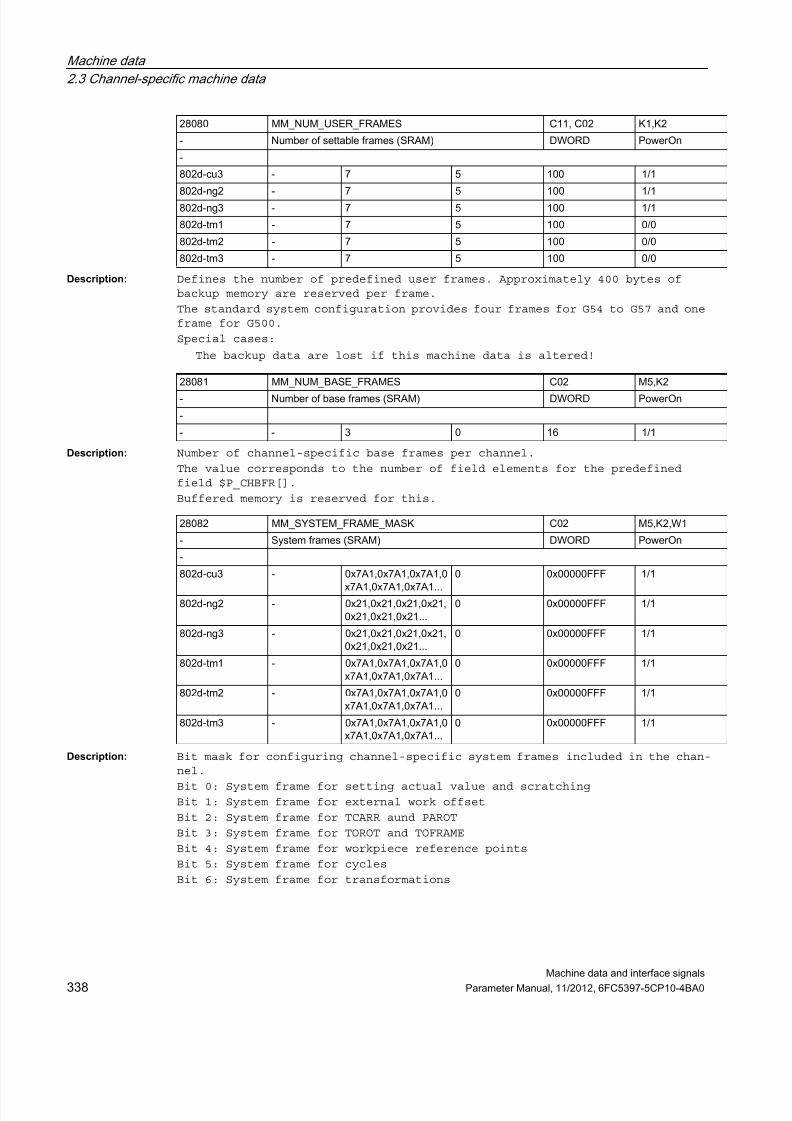
7/23/2019 802Dsl Datos Maquina Interfase Sigñals
http://slidepdf.com/reader/full/802dsl-datos-maquina-interfase-signals 338/646
Machine data
2.3 Channel-specific machine data
Machine data and interface signals
338 Parameter Manual, 11/2012, 6FC5397-5CP10-4BA0
Description: Defines the number of predefined user frames. Approximately 400 bytes ofbackup memory are reserved per frame.
The standard system configuration provides four frames for G54 to G57 and oneframe for G500.
Special cases:
The backup data are lost if this machine data is altered!
Description: Number of channel-specific base frames per channel.
The value corresponds to the number of field elements for the predefinedfield $P_CHBFR[].
Buffered memory is reserved for this.
Description: Bit mask for configuring channel-specific system frames included in the chan-
nel.Bit 0: System frame for setting actual value and scratching
Bit 1: System frame for external work offset
Bit 2: System frame for TCARR aund PAROT
Bit 3: System frame for TOROT and TOFRAME
Bit 4: System frame for workpiece reference points
Bit 5: System frame for cycles
Bit 6: System frame for transformations
28080 MM_NUM_USER_FRAMES C11, C02 K1,K2
- Number of settable frames (SRAM) DWORD PowerOn
-
802d-cu3 - 7 5 100 1/1
802d-ng2 - 7 5 100 1/1802d-ng3 - 7 5 100 1/1
802d-tm1 - 7 5 100 0/0
802d-tm2 - 7 5 100 0/0
802d-tm3 - 7 5 100 0/0
28081 MM_NUM_BASE_FRAMES C02 M5,K2- Number of base frames (SRAM) DWORD PowerOn
-
- - 3 0 16 1/1
28082 MM_SYSTEM_FRAME_MASK C02 M5,K2,W1
- System frames (SRAM) DWORD PowerOn
-
802d-cu3 - 0x7A1,0x7A1,0x7A1,0x7A1,0x7A1,0x7A1...
0 0x00000FFF 1/1
802d-ng2 - 0x21,0x21,0x21,0x21,0x21,0x21,0x21...
0 0x00000FFF 1/1
802d-ng3 - 0x21,0x21,0x21,0x21,0x21,0x21,0x21...
0 0x00000FFF 1/1
802d-tm1 - 0x7A1,0x7A1,0x7A1,0x7A1,0x7A1,0x7A1...
0 0x00000FFF 1/1
802d-tm2 - 0x7A1,0x7A1,0x7A1,0x7A1,0x7A1,0x7A1...
0 0x00000FFF 1/1
802d-tm3 - 0x7A1,0x7A1,0x7A1,0x7A1,0x7A1,0x7A1...
0 0x00000FFF 1/1

7/23/2019 802Dsl Datos Maquina Interfase Sigñals
http://slidepdf.com/reader/full/802dsl-datos-maquina-interfase-signals 339/646
Machine data
2.3 Channel-specific machine data
Machine data and interface signals
Parameter Manual, 11/2012, 6FC5397-5CP10-4BA0 339
Bit 7:System frame $P_ISO1FR for ISO G51.1 Mirror
Bit 8:System frame $P_ISO2FR for ISO G68 2DROT
Bit 9:System frame $P_ISO3FR for ISO G68 3DROT
Bit 10:System frame $P_ISO4FR for ISO G51 Scale
Bit 11: System frame $P_RELFR for relative coordinate systems
Description: Bit mask for configuring channel-specific system frames in the data storage(SRAM).
Bit 0: System frame for setting actual value and scratching
Bit 1: System frame for external work offset
Bit 2: System frame for TCARR aund PAROT
Bit 3: System frame for TOROT and TOFRAME
Bit 4: System frame for workpiece reference points
Bit 5: System frame for cycles
Bit 6: System frame for transformations
Bit 7:System frame $P_ISO1FR for ISO G51.1 Mirror
Bit 8:System frame $P_ISO2FR for ISO G68 2DROT
Bit 9:System frame $P_ISO3FR for ISO G68 3DROT
Bit 10:System frame $P_ISO4FR for ISO G51 Scale
Bit 11: System frame $P_RELFR for relative coordinate systems
Description: The MD defines the number of elements which the user has available for writ-ing PLC variables ($A_DBx=...). This number also applies to block search, butnot to synchronized actions.
The memory requirement is ca. 24 bytes per element.
One element is needed for each write action when writing PLC variables inquick succession.
If more writing actions are to be performed than elements are available,block transport must be guaranteed (trigger preprocessing stop, if required)
However, the number of elements can be reduced if the accessing actions aremade separately (block transport has already been accomplished). Writingaccesses (var=$A_DBx) are unlimited.
28083 MM_SYSTEM_DATAFRAME_MASK C02 -
- System frames (SRAM) DWORD PowerOn
-
- - 0xF9F,0xF9F,0xF9F,0xF9F,0xF9F,0xF9F...
0 0x00000FFF 1/1
28150 MM_NUM_VDIVAR_ELEMENTS C02 A2,P3 pl,P3 sl
- Number of elements for writing PLC variables DWORD PowerOn
-
- - 3 0 32000 0/0

7/23/2019 802Dsl Datos Maquina Interfase Sigñals
http://slidepdf.com/reader/full/802dsl-datos-maquina-interfase-signals 340/646
Machine data
2.3 Channel-specific machine data
Machine data and interface signals
340 Parameter Manual, 11/2012, 6FC5397-5CP10-4BA0
Description: This machine data defines how many blocks are set up for channel-specific
protection zones.Related to:
MD28210 $MC_MM_NUM_PROTECT_AREA_ACTIVE
(number of simultaneously active protection zones)
MD18190 $MN_MM_NUM_PROTECT_AREA_NCK
(number of files for machine-related protection zones (SRAM))
References:
/FB/, A3, "Axis/Contour Tunnel Monitoring, Protection Zones"
Description: This machine data defines the number of protection zones that may be acti-vated simultaneously for each channel.
It is not practical to enter a numerical value higher than MD18190$MN_MM_NUM_PROTECT_AREA_NCK + MD28200 $MC_MM_NUM_PROTECT_AREA_CHAN.
28200 MM_NUM_PROTECT_AREA_CHAN C02, C06, C09 A3
- Number of files for channel-specific protection zones(SRAM)
DWORD PowerOn
-
802d-cu3 - 0,0,0,0,0,0,0,0,0,0,0,0,0,0,0,0 0 10 1/1
802d-ng2 - 0,0,0,0,0,0,0,0,0,0,0,0,0,0,0,0
0 10 1/1
802d-ng3 - 0,0,0,0,0,0,0,0,0,0,0,0,0,0,0,0
0 10 1/1
802d-tm1 - 0,0,0,0,0,0,0,0,0,0,0,0,0,0,0,0
0 10 -1/2
802d-tm2 - 0,0,0,0,0,0,0,0,0,0,0,0,0,0,0,0
0 10 -1/2
802d-tm3 - 0,0,0,0,0,0,0,0,0,0,0,0,0,0,0,0
0 10 -1/2
28210 MM_NUM_PROTECT_AREA_ACTIVE C11, C02, C06,C09
A3
- Number of simultaneously active protection zones in onechannel
DWORD PowerOn
-
802d-cu3 - 0,0,0,0,0,0,0,0,0,0,0,0,0,0,0,0
0 10 1/1
802d-ng2 - 0,0,0,0,0,0,0,0,0,0,0,0,0,0,0,0
0 10 1/1
802d-ng3 - 0,0,0,0,0,0,0,0,0,0,0,0,0,0,0,0
0 10 1/1
802d-tm1 - 0,0,0,0,0,0,0,0,0,0,0,0,0,0,0,0
0 10 -1/2
802d-tm2 - 0,0,0,0,0,0,0,0,0,0,0,0,0,0,0,0
0 10 -1/2
802d-tm3 - 0,0,0,0,0,0,0,0,0,0,0,0,
0,0,0,0
0 10 -1/2

7/23/2019 802Dsl Datos Maquina Interfase Sigñals
http://slidepdf.com/reader/full/802dsl-datos-maquina-interfase-signals 341/646
Machine data
2.3 Channel-specific machine data
Machine data and interface signals
Parameter Manual, 11/2012, 6FC5397-5CP10-4BA0 341
Related to:
MD28200 $MC_MM_NUM_PROTECT_AREA_CHAN
(Number of blocks for channel-specific protection zones)
MD18190 $MN_MM_NUM_PROTECT_AREA_NCK
(Number of files for machine-related protection zones (SRAM))
References:
/FB1/ Function Manual Basic Functions; Axis Monitoring, Protection Zones (A3)
Description: This machine data defines for each channel how many internal contour elementsin total are held available for active protection zones.
Dynamic memory is used.
The MD affects the memory requirements for the activated protection zones.
This machine data is active only if MD28210 $MC_MM_NUM_PROTECT_AREA_ACTIVE isnot equal to 0.
Description: Panel size of $AC_PARAM.
28212 MM_NUM_PROTECT_AREA_CONTOUR C11, C02, C06,C09
A3
- Elements for active protection zones (DRAM) DWORD PowerOn
-
802d-cu3 - 30,30,30,30,30,30,30,30,30,30,30,30,30...
0 50 1/1
802d-ng2 - 30,30,30,30,30,30,30,30,30,30,30,30,30...
0 50 1/1
802d-ng3 - 30,30,30,30,30,30,30,30,30,30,30,30,30...
0 50 1/1
802d-tm1 - 30,30,30,30,30,30,30,30,30,30,30,30,30...
0 50 -1/2
802d-tm2 - 30,30,30,30,30,30,30,30,30,30,30,30,30...
0 50 -1/2
802d-tm3 - 30,30,30,30,30,30,30,30,30,30,30,30,30...
0 50 -1/2
28254 MM_NUM_AC_PARAM C02 -
- Dimension of $AC_PARAM. DWORD PowerOn
-
802d-cu3 - 50,50,50,50,50,50,50,50,50,50,50,50,50...
0 20000 2/2
802d-ng2 - 50,50,50,50,50,50,50,50,50,50,50,50,50...
0 20000 1/1
802d-ng3 - 50,50,50,50,50,50,50,50,50,50,50,50,50...
0 20000 1/1
802d-tm1 - 0,0,0,0,0,0,0,0,0,0 0 20000 0/0
802d-tm2 - 0,0,0,0,0,0,0,0,0,0 0 20000 0/0
802d-tm3 - 0,0,0,0,0,0,0,0,0,0 0 20000 0/0

7/23/2019 802Dsl Datos Maquina Interfase Sigñals
http://slidepdf.com/reader/full/802dsl-datos-maquina-interfase-signals 342/646
Machine data
2.3 Channel-specific machine data
Machine data and interface signals
342 Parameter Manual, 11/2012, 6FC5397-5CP10-4BA0
Description: $AC_PARAM[] is stored in SRAM.
Description: Number of channel-specific markers $AC_MARKER for motion-synchronousactions.
DRAM or SRAM is required depending on MD28257 $MC_MM_BUFFERED_AC_MARKER.
Description: $AC_MARKER[] is stored in SRAM.
28255 MM_BUFFERED_AC_PARAM C02 2.3,6.1
- $AC_PARAM[] is stored in SRAM. DWORD PowerOn
-
802d-cu3 - 0,0,0,0,0,0,0,0,0,0,0,0,
0,0,0,0
0 1 2/2
802d-ng2 - 0,0,0,0,0,0,0,0,0,0,0,0,0,0,0,0
0 1 1/1
802d-ng3 - 0,0,0,0,0,0,0,0,0,0,0,0,0,0,0,0
0 1 1/1
802d-tm1 - 0,0,0,0,0,0,0,0,0,0,0,0,0,0,0,0
0 1 0/0
802d-tm2 - 0,0,0,0,0,0,0,0,0,0,0,0,0,0,0,0
0 1 0/0
802d-tm3 - 0,0,0,0,0,0,0,0,0,0,0,0,0,0,0,0
0 1 0/0
28256 MM_NUM_AC_MARKER C02 2.3,6.1- Dimension of $AC_MARKER DWORD PowerOn
-
802d-cu3 - 8,8,8,8,8,8,8,8,8,8,8,8,8,8,8,8
0 20000 2/2
802d-ng2 - 8,8,8,8,8,8,8,8,8,8,8,8,8,8,8,8
0 20000 1/1
802d-ng3 - 8,8,8,8,8,8,8,8,8,8,8,8,8,8,8,8
0 20000 1/1
802d-tm1 - 0,0,0,0,0,0,0,0,0,0 0 20000 0/0
802d-tm2 - 0,0,0,0,0,0,0,0,0,0 0 20000 0/0
802d-tm3 - 0,0,0,0,0,0,0,0,0,0 0 20000 0/0
28257 MM_BUFFERED_AC_MARKER C02 2.3,6.1
- $AC_MARKER[] is stored in SRAM. DWORD PowerOn
-
802d-cu3 - 0,0,0,0,0,0,0,0,0,0,0,0,0,0,0,0
0 1 2/2
802d-ng2 - 0,0,0,0,0,0,0,0,0,0,0,0,0,0,0,0
0 1 1/1
802d-ng3 - 0,0,0,0,0,0,0,0,0,0,0,0,0,0,0,0
0 1 1/1
802d-tm1 - 0,0,0,0,0,0,0,0,0,0,0,0,0,0,0,0
0 1 0/0
802d-tm2 - 0,0,0,0,0,0,0,0,0,0,0,0,0,0,0,0
0 1 0/0
802d-tm3 - 0,0,0,0,0,0,0,0,0,0,0,0,0,0,0,0
0 1 0/0

7/23/2019 802Dsl Datos Maquina Interfase Sigñals
http://slidepdf.com/reader/full/802dsl-datos-maquina-interfase-signals 343/646
Machine data
2.3 Channel-specific machine data
Machine data and interface signals
Parameter Manual, 11/2012, 6FC5397-5CP10-4BA0 343
Description: Number of $AC_SYSTEM_ PARAM parameters for motion-synchronous actions.
Depending on MD28255 $MC_MM_BUFFERED_AC_PARAM, DRAM or SRAM is required.Reserved for SIEMENS applications.
Description: Number of $AC_SYSTEM_MARKER markers for motion-synchronous actions.
Depending on MD28257 $MC_MM_BUFFERED_AC_MARKER, DRAM or SRAM is required.
Reserved for SIEMENS applications.
Description: The function "Tool radius compensation for contour tools" is enabled withthis tool.
Modification of this machine data will cause a reconfiguration of the memory.
28274 MM_NUM_AC_SYSTEM_PARAM EXP, C02 -
- Number of $AC_SYSTEM_ PARAM for motion-synchronous actions
DWORD PowerOn
-
802d-cu3 - 0,0,0,0,0,0,0,0,0,0,0,0,0,0,0,0 0 20000 2/2
802d-ng2 - 0,0,0,0,0,0,0,0,0,0,0,0,0,0,0,0
0 20000 1/1
802d-ng3 - 0,0,0,0,0,0,0,0,0,0,0,0,0,0,0,0
0 20000 1/1
802d-tm1 - 0,0,0,0,0,0,0,0,0,0,0,0,0,0,0,0
0 20000 0/0
802d-tm2 - 0,0,0,0,0,0,0,0,0,0,0,0,0,0,0,0
0 20000 0/0
802d-tm3 - 0,0,0,0,0,0,0,0,0,0,0,0,0,0,0,0
0 20000 0/0
28276 MM_NUM_AC_SYSTEM_MARKER EXP, C02 -
- Number of $AC_SYSTEM_MARKER for motion-synchronous actions
DWORD PowerOn
-
802d-cu3 - 0,0,0,0,0,0,0,0,0,0,0,0,0,0,0,0
0 20000 2/2
802d-ng2 - 0,0,0,0,0,0,0,0,0,0,0,0,0,0,0,0
0 20000 1/1
802d-ng3 - 0,0,0,0,0,0,0,0,0,0,0,0,0,0,0,0
0 20000 1/1
802d-tm1 - 0,0,0,0,0,0,0,0,0,0,0,0,0,0,0,0
0 20000 0/0
802d-tm2 - 0,0,0,0,0,0,0,0,0,0,0,0,0,0,0,0
0 20000 0/0
802d-tm3 - 0,0,0,0,0,0,0,0,0,0,0,0,0,0,0,0
0 20000 0/0
28290 MM_SHAPED_TOOLS_ENABLE C01, C08, C02 -
- Enable tool radius compensation for contour tools BOOLEAN PowerOn
-
- - FALSE,FALSE,FALSE,FALSE,FALSE,FALSE...
- - 0/0

7/23/2019 802Dsl Datos Maquina Interfase Sigñals
http://slidepdf.com/reader/full/802dsl-datos-maquina-interfase-signals 344/646
Machine data
2.3 Channel-specific machine data
Machine data and interface signals
344 Parameter Manual, 11/2012, 6FC5397-5CP10-4BA0
Description: Value:0: Block display with absolute values deactivated
1: Block display with absolute values activated;
A display buffer of the following size is created:
(MD28257 $MC_MM_BUFFERED_AC_MARKER + MD28070 $MC_MM_NUM_BLOCKS_IN_PREP) *256 bytes
>= 128:Block display with absolute values activated;
A display buffer of the following size is created:
(MD28060 $MC_MM_IPO_BUFFER_SIZE + MD28070 $MC_MM_NUM_BLOCKS_IN_PREP) *<value>
Description: Dimensioning the size of the upload buffer:
MD28402 $MC_MM_ABSBLOCK_BUFFER_CONF[0] : Number of blocks before the currentblock
MD28402 $MC_MM_ABSBLOCK_BUFFER_CONF[1] : Number of blocks after the currentblock
The machine data is tested for the following upper / lower limits duringstartup:
0 <= MD28402 $MC_MM_ABSBLOCK_BUFFER_CONF[0] <= 8
0 <= MD28402 $MC_MM_ABSBLOCK_BUFFER_CONF[1] <= (MD28060$MC_MM_IPO_BUFFER_SIZE + MD28070 $MC_MM_NUM_BLOCKS_IN_PREP)
Alarm 4152 is issued when the limits are violated.
Description: Defines the stack size in kbytes for the preparation task. The stack isstored in the dynamic memory.
Note:
This machine data is assigned internally by the control and must not be
altered by the user.
Description: Definition of the stack size (kByte) for the interpreter subtask.
28400 MM_ABSBLOCK EXP, C02 K1
- activate block display w. absolute values DWORD PowerOn
-
- - 0,0,0,0,0,0,0,0,0,0 0 512 2/2
28402 MM_ABSBLOCK_BUFFER_CONF EXP, C02 K1
- Setting of upload buffer size DWORD PowerOn-
- 2 0, 0,0, 0,0, 0,0, 0,0,0,0, 0,0, 0,0, 0,0, 0...
0 32000 2/2
28500 MM_PREP_TASK_STACK_SIZE EXP, C02 K1
- Stack size of preparation task (DRAM) DWORD PowerOn
-
- - 70,70,70,70,70,70,70,70,70,70,70,70,70...
70 500 0/0
28502 MM_INT_TASK_STACK_SIZE EXP, C02 -
- Stack size for interpreter subtask (kB). DWORD PowerOn
-
- - 20,20,20,20,20,20,20,20,20,20,20,20,20...
20 40 0/0

7/23/2019 802Dsl Datos Maquina Interfase Sigñals
http://slidepdf.com/reader/full/802dsl-datos-maquina-interfase-signals 345/646
Machine data
2.3 Channel-specific machine data
Machine data and interface signals
Parameter Manual, 11/2012, 6FC5397-5CP10-4BA0 345
Description: Maximum number of axis polynomials which can be contained in a block.In the standard case, each block only contains one polynomial per axis, i.e.this data can immediately be set to one.
Currently, more polynomials are only needed for the new ADIS function withG643.
In this case, this data must have a minimum value of three.
Description: Number of memory elements available for limiting the path velocity and chang-ing it in the block.
0 : Each block is limited by a maximum path velocity.
> 0 : If required, a profile of the permissible path velocity ; and its modification options is generated and monitored
; in the block.
; This results in a smoother axis velocity progression and
; a shorter travel time.
; MD28530 $MC_MM_PATH_VELO_SEGMENTS defines the average
; number of segments available in the block.
; The necessary setting essentially depends
; on the requirements.
The following values are recommended:
3: for G643, if only geometry axes are traversed
5: for G643, if geometry and rotary axes are traversed
5: for COMPCAD
5: for dyn. transformation
A value that is too low this may lead to additional velocity limitations if asufficient number of blocks cannot be made available for interpolation.
MD28530 $MC_MM_PATH_VELO_SEGMENTS additionally increases the memory require-ment of dyn. Look Ahead. Values higher than 5 are only practical in excep-tional cases.
3 ... 5 : Recommended setting.
28520 MM_MAX_AXISPOLY_PER_BLOCK C02 B1
- maximal number of axial polynomials per block DWORD PowerOn
-
- - 1,1,1,1,1,1,1,1,1,1 1 5 0/0
28530 MM_PATH_VELO_SEGMENTS C02 A2,B1
- Number of memory elements for path velocity limitation DWORD PowerOn
-
802d-cu3 - 0,0,0,0,0,0,0,0,0,0,0,0,0,0,0,0
0 100 1/1
802d-ng2 - 0,0,0,0,0,0,0,0,0,0,0,0,
0,0,0,0
0 100 0/0
802d-ng3 - 0,0,0,0,0,0,0,0,0,0,0,0,0,0,0,0
0 100 0/0
802d-tm1 - 0,0,0,0,0,0,0,0,0,0,0,0,0,0,0,0
0 100 0/0
802d-tm2 - 0,0,0,0,0,0,0,0,0,0,0,0,0,0,0,0
0 100 0/0
802d-tm3 - 0,0,0,0,0,0,0,0,0,0,0,0,0,0,0,0
0 100 1/1

7/23/2019 802Dsl Datos Maquina Interfase Sigñals
http://slidepdf.com/reader/full/802dsl-datos-maquina-interfase-signals 346/646
Machine data
2.3 Channel-specific machine data
Machine data and interface signals
346 Parameter Manual, 11/2012, 6FC5397-5CP10-4BA0
Description: The machine data is used to configure the work memory for extended LookAhead.
The MD scales the value defined internally through MD28060$MC_MM_IPO_BUFFER_SIZE, MD28520 $MC_MM_MAX_AXISPOLY_PER_BLOCK, MD28530$MC_MM_PATH_VELO_SEGMENTS, MD28535 $MC_MM_FEED_PROFILE_SEGMENTS, MD28540$MC_MM_ARCLENGTH_SEGMENTS).
Its practical size depends on the part program, the block lengths, the axisdynamics, and an active kinematic transformation.
The MD should only be set for those channels in which free-form surfaces arealso machined.
0 : default LookAhead is active.
> 0 : extended LookAhead is active if switched on by MD20443$MC_LOOKAH_FFORM.
The guide value for free-form surface applications is: 18..20
Description: Number of memory elements available for the arc length function for parame-terizing polynomials.
If this machine data is equal to zero, a fixed interval division is used torepresent the arc length function. In this case, the calculated function isonly tangent-continuous. This can lead to discontinuities in the axis accel-erations.
If the function G643 is used for smoothing and/or COMPCAD, this MD should beassigned a value of at least 10. In this case, the calculated function alsohas a constant curvature which results in a smoother progression of the pathvelocity, as well as the axis velocities and accelerations.
Values substantially larger than 10 are only practical in exceptional cases.
Not only the value of MD28540 $MC_MM_ARCLENGTH_SEGMENTS but also that ofMD20262 $MC_SPLINE_FEED_PRECISION are crucial for the accuracy.
28533 MM_LOOKAH_FFORM_UNITS C02 -
- Memory for extended LookAhead DWORD PowerOn
-
- - 0,0,0,0,0,0,0,0,0,0,0,0,
0,0,0,0
0 100000 0/0
28540 MM_ARCLENGTH_SEGMENTS C02 B1
- Number of memory elements for arc length functionrepresentation
DWORD PowerOn
-
802d-cu3 - 0,0,0,0,0,0,0,0,0,0,0,0,0,0,0,0
0 100 1/1
802d-ng2 - 0,0,0,0,0,0,0,0,0,0,0,0,0,0,0,0
0 100 0/0
802d-ng3 - 0,0,0,0,0,0,0,0,0,0,0,0,0,0,0,0
0 100 0/0
802d-tm1 - 0,0,0,0,0,0,0,0,0,0,0,0,
0,0,0,0
0 100 0/0
802d-tm2 - 0,0,0,0,0,0,0,0,0,0,0,0,0,0,0,0
0 100 0/0
802d-tm3 - 0,0,0,0,0,0,0,0,0,0,0,0,0,0,0,0
0 100 1/1

7/23/2019 802Dsl Datos Maquina Interfase Sigñals
http://slidepdf.com/reader/full/802dsl-datos-maquina-interfase-signals 347/646
Machine data
2.3 Channel-specific machine data
Machine data and interface signals
Parameter Manual, 11/2012, 6FC5397-5CP10-4BA0 347
Description: Bit mask to restore data after abort of a simulated program execution. Thefollowing applies:
Bit 0: All frames in the data storage are restored.
Description: Number of data blocks in the channel that are created for coordinate system-specific operating range limits.
It indicates the maximum value of the 1st index of system variable$P_WORKAREA_CS...[WALimNo, Ax]. It furthermore defines the number of the pro-grammable G functions "WALCS1, WALCS2, ... WALCS10" as well as the maximumvalue in system variable $AC_WORKAREA_CS_GROUP".
= 0: Function "Monitoring of coordinate system-specific operating range lim-its" cannot be activated.
28560 MM_SEARCH_RUN_RESTORE_MODE C02 K2
- Data restore after simulation DWORD PowerOn
-
- - 0x0,0x0,0x0,0x0,0x0,0
x0,0x0,0x0,0x0...
0 0x00000001 1/1
28600 MM_NUM_WORKAREA_CS_GROUPS C02 -
- Number of coordinate system-specific operating rangelimits
DWORD PowerOn
-
- - 0,0,0,0,0,0,0,0,0,0,0,0,0,0,0,0
0 10 0/0

7/23/2019 802Dsl Datos Maquina Interfase Sigñals
http://slidepdf.com/reader/full/802dsl-datos-maquina-interfase-signals 348/646
Machine data
2.4 Axis-specific machine data
Machine data and interface signals
348 Parameter Manual, 11/2012, 6FC5397-5CP10-4BA0
2.4 Axis-specific machine data
Description: Description
2.4.1 Configuration
Description: In this MD enter the number of the bus segment through which the output isaddressed.
0: Local bus (for 802D MCPA)
1: SIMODRIVE611D drive bus for SINUMERIK 840D/810D (1st DCM)
2: reserved (previously local P bus)
3: reserved (previously 611D bus, 2nd DCM)
4: reserved (virtual buses)
5: PROFIBUS/PROFINET (e.g. SINUMERIK 840Di)
6: reserved (same effect as 5)
Description: Enter in this MD the number of the module within a bus segment through whichthe output is addressed.
For axes on the PROFIBUS/PROFINET, the number of the drive assigned with
MD13050 $MN_DRIVE_LOGIC_ADDRESS must be entered here (MD30110$MA_CTRLOUT_MODULE_NR=n consequently points to MD13050$MN_DRIVE_LOGIC_ADDRESS[n]).
Number Identifier Display filters Reference
Unit Name Data type Active
Attributes
System Dimension Default value Minimum value Maximum value Protection
30100 CTRLOUT_SEGMENT_NR EXP, A01 G2,S9
- Setpoint assignment: bus segment number BYTE PowerOn
-
- 1 5 0 5 2/2
30110 CTRLOUT_MODULE_NR A01, A11, - G2,S9
- Setpoint assignment: module number BYTE PowerOn
-802d-cu3 1 1,2,3,4,5,6,7,8,9,10,11
,12,13,14,15,16,17,18...
1 31 2/2
802d-ng2 1 3,2,4,1 1 31 2/2
802d-ng3 1 3,2,4,1 1 31 2/2
802d-tm1 1 2,3,4,1 1 31 2/2
802d-tm2 1 2,3,4,1 1 31 2/2
802d-tm3 1 2,3,4,1 1 31 2/2

7/23/2019 802Dsl Datos Maquina Interfase Sigñals
http://slidepdf.com/reader/full/802dsl-datos-maquina-interfase-signals 349/646
Machine data
2.4 Axis-specific machine data
Machine data and interface signals
Parameter Manual, 11/2012, 6FC5397-5CP10-4BA0 349
Description: Number of the output on a module, through which the setpoint output isaddressed.
Index [n] of the machine date has the following coding: [setpoint branch]: 0
Description: The type of speed setpoint output is entered in this MD:
0: Simulation (no hardware required)
1: Setpoint output active (differentiated by hardware configuration)
Index [n] of the machine date has the following coding: [setpoint branch]: 0.
Description: Virtual axis. An axis that is also interpolated in follow-up mode. (Elec-tronic transfer technology; virtual and real master values.)
This MD is the successor to MD30130 $MA_CTRLOUT_TYPE=4. MD30130$MA_CTRLOUT_TYPE=0 and MD30132 $MA_IS_VIRTUAL_AX=1 must now be used insteadof MD30130 $MA_CTRLOUT_TYPE=4.
Related to:
MD30130 $MA_CTRLOUT_TYPE
Description: Only for PROFIdrive, special application of analog additional drives:
Unipolar output driver (for unipolar analog drive actuator):
Only positive set speeds are supplied to the drive, the sign of the set speedis separately output in its own digital control signal.
Input value "0":
Bipolar output with pos./neg. set speed (this is the normal case)
Input value "1":
0. Digital bit = servo enable1. Digital bit = neg. direction of travel
Input value "2": (linking of enable and direction of travel signals):
0. Digital bit = servo enable pos. direction of travel
1. Digital bit = servo enable neg. direction of travel
30120 CTRLOUT_NR EXP, A01, - G2
- Setpoint assignment: Setpoint output on drive submodule/module
BYTE PowerOn
-
- 1 1 1 3 2/2
30130 CTRLOUT_TYPE A01, A11 G2,M3,S9
- Output type of setpoint BYTE PowerOn
-
- 1 0 0 3 2/2
30132 IS_VIRTUAL_AX A01 M3,TE1,TE3
- Axis is a virtual axis BOOLEAN PowerOn
CTEQ
- 1 FALSE - - 1/1
30134 IS_UNIPOLAR_OUTPUT A01 G2
- Setpoint output is unipolar BYTE PowerOn
-
- 1 0 0 2 2/2

7/23/2019 802Dsl Datos Maquina Interfase Sigñals
http://slidepdf.com/reader/full/802dsl-datos-maquina-interfase-signals 350/646
Machine data
2.4 Axis-specific machine data
Machine data and interface signals
350 Parameter Manual, 11/2012, 6FC5397-5CP10-4BA0
Description: 0: without measuring system (possible with spindle)1: spindle / axis with measuring system (in motor or directly)
Description: Number of the bus segment, through which the encoder is addressed.
The bus segments must be firmly assigned to the control systems.
0: reserved (previously local bus)
1: SIMODRIVE611D drive bus for SINUMERIK 840D/810D (1st DCM)
2: reserved (previously local P bus)
3: reserved (previously 611D bus, 2nd DCM)4: reserved (virtual buses)
5: PROFIBUS/PROFINET (e.g. SINUMERIK 840Di)
6: reserved (same effect as 5)
Index [n] has the following coding [Encodernr.]: 0 or 1
Description: The number of the module within a bus segment (MD30210 $MA_ENC_SEGMENT_NR[n])through which the encoder is addressed must be entered in the MD.
For axes on PROFIBUS/PROFINET, the number of the drive assigned via MD13050$MN_DRIVE_LOGIC_ADDRESS must be entered here (MD30220 $MA_ENC_MODULE_NR=nconsequently points to MD13050 $MN_DRIVE_LOGIC_ADDRESS[n]).
The index[n] of the machine data has the following coding:
[Encoder no.]: 0 or 1
Related to:
MD30110 $MA_CTRLOUT_MODULE_NR[n]
(setpoint assignment: drive number/module number)
30200 NUM_ENCS A01, A02, - G2,R1,Z1
- Number of encoders BYTE PowerOn
-
- - 1 0 1 2/2
30210 ENC_SEGMENT_NR EXP, A01, A02 G2
- Actual value assignment: bus segment number. BYTE PowerOn
-
- 1 5, 5 5 5 -1/2
30220 ENC_MODULE_NR A01, A02, A11 G2
- Actual value assignment: Drive number/measuring circuitnumber
BYTE PowerOn
-
802d-cu3 1 1, 1,2, 2,3, 3,4, 4,5,5,6, 6,7, 7...
1 31 2/2
802d-ng2 1 3, 3,2, 2,4, 4,1, 1 1 31 2/2
802d-ng3 1 3, 3,2, 2,4, 4,1, 1 1 31 2/2
802d-tm1 1 2, 2,3, 3,4, 4,1, 1 1 31 2/2
802d-tm2 1 2, 2,3, 3,4, 4,1, 1 1 31 2/2
802d-tm3 1 2, 2,3, 3,4, 4,1, 1 1 31 2/2

7/23/2019 802Dsl Datos Maquina Interfase Sigñals
http://slidepdf.com/reader/full/802dsl-datos-maquina-interfase-signals 351/646
Machine data
2.4 Axis-specific machine data
Machine data and interface signals
Parameter Manual, 11/2012, 6FC5397-5CP10-4BA0 351
Description: For PROFIdrive:
Number of the encoder within the PROFIdrive message frame through which theencoder is addressed.
For example telegram 103: 1 (=G1_ZSW etc.) or 2 (=G2_ZSW etc.).
The index[n] of the machine data has the following coding:
[Encodernr.]: 0 or 1
If an input is selected, to which no encoder is connected, alarm 300008 "Mea-suring circuit not available on drive" is output.
Description: Encoder type:
0: simulation
1: raw signal generator (high resolution)
2, 3, 5: reserved
Index [n] of the machine date has the following coding: [encoder number]: 0
4: general absolute encoder (e.g. with EnDat interface)
Description: If actual value corrections performed by the NC on the encoder selected forposition control are not to influence the actual value of any other encoderdefined in the same axis, then the position control encoder must be declaredto be "independent".
Actual value corrections include the following:
• Modulo treatment,• Reference point approach,• Measuring system calibration,• PRESET
Example:
MD30200 $MA_NUM_ENCS[ AX1 ] = 2
MD30242 $MA_ENC_IS_INDEPENDENT[ 0, AX1 ] = 0
MD30242 $MA_ENC_IS_INDEPENDENT[ 1, AX1 ] = 1
When the VDI interface has selected the first encoder for position control,the above mentioned actual value corrections will be executed on this encoderonly.
When the VDI interface has selected the second encoder for position control,the above mentioned actual value corrections will be executed on both encod-ers.
The machine data is therefore only valid for encoders that have not beenselected by the VDI interface for positon control (passive encoders).
30230 ENC_INPUT_NR A01, A02, A11, - G2,S9
- Actual value assignm.: Input on drive module/meas. circuitboard
BYTE PowerOn
-
- 1 1, 2 1 2 2/2
30240 ENC_TYPE A01, A02, A11, - A3,,G2,R1
- Encoder type of actual value sensing (actual positionvalue).
BYTE PowerOn
-
- 1 0, 0 0 5 2/2
30242 ENC_IS_INDEPENDENT A02, A11, - G2,R1
- Encoder is independent BYTE NEW CONF
-
- 1 0, 0 0 3 1/1

7/23/2019 802Dsl Datos Maquina Interfase Sigñals
http://slidepdf.com/reader/full/802dsl-datos-maquina-interfase-signals 352/646
Machine data
2.4 Axis-specific machine data
Machine data and interface signals
352 Parameter Manual, 11/2012, 6FC5397-5CP10-4BA0
As from SW5, the scope of functions has been extended:
MD30242 $MA_ENC_IS_INDEPENDENT = 2
The passive encoder is dependent. The active encoder changes the actualencoder value. In combination with MD35102 $MA_REFP_SYNC_ENCS = 1, the pas-sive encoder is adjusted to the active encoder during reference point
approach, but is NOT referenced.In reference mode MD34200 $MA_ENC_REFP_MODE = 3 (distance-coded referencemarks), the passive encoder is automatically referenced with the next tra-versing movement after zero mark distance overtravel. This is done indepen-dently of the current mode setting.
MD30242 $MA_ENC_IS_INDEPENDENT = 3
In contrast to MD30242 $MA_ENC_IS_INDEPENDENT = 1, modulo actual value cor-rections are executed in the passive encoder of modulo rotary axes.
Description: For PROFIdrive only:In combination with the MD13210 $MN_MEAS_TYPE = 1 (decentralized measure-ment), this MD can be used to set the type of axial measuring function fordrives.
Encoder measurement type:
0: encoder measurement type central (global) measurement
1: encoder measurement type decentral (local) measurement
MEAS_TYPE ENC_MEAS_TYPE measuring sensor input used
0 0 central
0 1 central
1 0 central
1 1 decentralized
Description: The actual position (hardware counter status only without machine reference)is stored (in internal format display) in this MD.
At power ON (or encoder activation), it acts with:
• Absolute encoders:
To restore the current position (in combination with the position, possi-bly with several meanings, buffered in the encoder).
• Incremental encoders:
To buffer the actual value beyond power OFF when the functionality isactivated MD34210 $MA_ENC_REFP_STATE = 1 or. 2 (i.e. as a reference pointreplacement).
To buffer the actual value beyond power OFF when the functionality isactivated MD34210 $MA_ENC_REFP_STATE = 3 (i.e. as a restored positionvalue).
30244 ENC_MEAS_TYPE A01, A02, A11 -
- Encoder measurement type BYTE PowerOn
-
- 1 1, 1 0 1 0/0
30250 ACT_POS_ABS EXP, A02, A08 R1
- Internal encoder position DOUBLE PowerOn
ODLD, -, -
- 1 0.0, 0.0 - - 1/1

7/23/2019 802Dsl Datos Maquina Interfase Sigñals
http://slidepdf.com/reader/full/802dsl-datos-maquina-interfase-signals 353/646
Machine data
2.4 Axis-specific machine data
Machine data and interface signals
Parameter Manual, 11/2012, 6FC5397-5CP10-4BA0 353
Note:
This MD is changed internally by the control during traversing movements.Loading a previously saved MD data block can therefore destroy the encodercalibration (machine position reference) of absolute encoders.
For software conversions, we recommend removing the MD data block from the
old software release prior to conversion and reloading it into the newsoftware release without moving any axis in the meantime. Protection level1 should be set for SW 3.6; protection level 2 suffices for SW 4 andhigher. The encoder calibration must be explicitly verified (controlled,calibrated) after the software conversion.
Description: Absolute track resolution in relation to the incremental signal resolution.
This MD only applies for absolute encoders:
- PROFIBUS drives:
Absolute information XIST2 related to incremental information XIST1.
With plausible drive parameters (e.g. for SIMODRIVE 611U: P1042/P1043 orP1044/P1045 or the relevant entries in PROFIdrive parameter p979) thevalue of this MD is automatically calculated and updated from drive param-eters (if parameter read-out has not been deactivated by$MN_DRIVE_FUNCTION_MASK, bit2).
With plausible drive parameters (e.g. for SIMODRIVE 611U: P1042/P1043 orP1044/P1045 or the relevant entries in PROFIdrive parameter p979) the valueof this MD is calculated and updated automatically from the drive parameters(provided that parameter read-out has not been disabled by MD13070$MN_DRIVE_FUNCTION_MASK, bit2).
Unplausible drive parameters (e.g. multiplication of absolute track higherthan that of the incremental signal) are rejected and replaced by the valueentered in the current MD.
Unplausible input values in the current MD (e.g. value=0) are reset to thedefault value. In addition, alarm 26025 or 26002 is output in order to informthe user.
Description: This MD defines the way in which the absolute encoder position is buffered,and whether a traversing range extension is active on software side (exceed-
ing the limits of the absolute value encoder range that can be displayed onthe hardware).
"0" = standard = traversing range extension (compare ACT_POS_ABS) is active.
"1" = traversing range extension on software side is inactive.
When using an absolute linear scale, there will not be a traversing rangeoverflow for mechanical reasons. This MD is therefore only valid for rotaryabsolute value encoders.
30260 ABS_INC_RATIO EXP, A01, A02 -
- Absolute encoder: Ratio of absolute to incrementalresolution
DWORD PowerOn
-
- 1 4, 4 - - 1/1
30270 ENC_ABS_BUFFERING EXP, A01, A02 R1
- Absolute encoder: Traversing range extension BYTE PowerOn
-
- 1 0, 0 0 1 2/2

7/23/2019 802Dsl Datos Maquina Interfase Sigñals
http://slidepdf.com/reader/full/802dsl-datos-maquina-interfase-signals 354/646
Machine data
2.4 Axis-specific machine data
Machine data and interface signals
354 Parameter Manual, 11/2012, 6FC5397-5CP10-4BA0
For rotary absolute value encoders, the traversing range that can be clearlydisplayed on the encoder side, is stored in MD34220 $MA_ENC_ABS_TURNS_MODULO.You can do without a traversing range extension without any problems (a hard-ware counter overflow that might be within the traversing range is concealedin the software via shortest-path decision):
a. in linear axes or limited rotary axes, if the actual traversing range onthe load side is smaller than the traversing range on the load side that cor-responds to MD34220 $MA_ENC_ABS_TURNS_MODULO.
b. in endlessly turning rotary axes (ROT_IS_MODULO = TRUE), if the absoluteencoder is connected on the load side (no gear to be considered) or if "with-out remainder" can be calculated:
Number of rotations on the load side = ENC_ABS_TURNS_MODULO * gear ratio
(Example: ENC_ABS_TURNS_MODULO = 4096 encoder rotations, gear 25:32, i.e.number of rotations on load side = 4096*(25/32)=3200).
Notice:
If you do not meet the conditions under a. or b., you run the risk of get-ting a wrong absolute encoder position at next Power ON or encoder activa-tion after parking without prewarning if the traversing range extension is
not working. Therefore, the traversing range extension remains active inthe standard version.
Related to:
MD30240 $MA_ENC_TYPE
MD30300 $MA_IS_ROT_AX
MD30310 $MA_ROT_IS_MODULO
MD30250 $MA_ACT_POS_ABS
MD34220 $MA_ENC_ABS_TURNS_MODULO
MD34090 $MA_REFP_MOVE_DIST_CORR
Description: 1: Axis: The axis is defined as a "rotary axis".
• The special functions of the rotary axis are active or can be activatedby means of additional machine data according to the type of machinerequired (see below).
• The unit of measurement is degrees.• The units of the axis-specific machine and setting data are interpreted
as follows with the standard control setting:
- Positions in "degrees"
- Speedsin "rev/minute"- Accelerationin "rev/second²"
- Jerk limitationin "rev/second³"
30300 IS_ROT_AX A01, A06, A11, - G1,K3,R2,T1,G2,K2,R1,S1,V1
- Rotary axis / spindle BOOLEAN PowerOn
SCAL, CTEQ
- - FALSE,FALSE,FALSE,FALSE,FALSE,FALSE...
- - 2/2
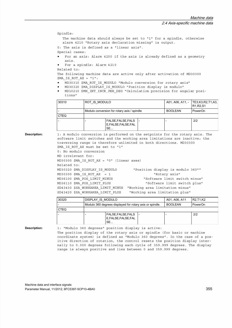
7/23/2019 802Dsl Datos Maquina Interfase Sigñals
http://slidepdf.com/reader/full/802dsl-datos-maquina-interfase-signals 355/646
Machine data
2.4 Axis-specific machine data
Machine data and interface signals
Parameter Manual, 11/2012, 6FC5397-5CP10-4BA0 355
Spindle:
The machine data should always be set to "1" for a spindle, otherwisealarm 4210 "Rotary axis declaration missing" is output.
0: The axis is defined as a "linear axis".
Special cases:
• For an axis: Alarm 4200 if the axis is already defined as a geometryaxis.
• For a spindle: Alarm 4210
Related to:
The following machine data are active only after activation of MD30300$MA_IS_ROT_AX = "1":
• MD30310 $MA_ROT_IS_MODULO "Modulo conversion for rotary axis"• MD30320 $MA_DISPLAY_IS_MODULO "Position display is modulo"• MD10210 $MN_INT_INCR_PER_DEG "Calculation precision for angular posi-
tions"
Description: 1: A modulo conversion is performed on the setpoints for the rotary axis. Thesoftware limit switches and the working area limitations are inactive; thetraversing range is therefore unlimited in both directions. MD30300$MA_IS_ROT_AX must be set to "1"
0: No modulo conversion
MD irrelevant for:
MD30300 $MA_IS_ROT_AX = "0" (linear axes)
Related to:
MD30320 $MA_DISPLAY_IS_MODULO "Position display is modulo 360°"MD30300 $MA_IS_ROT_AX = 1 "Rotary axis"
MD36100 $MA_POS_LIMIT_MINUS "Software limit switch minus"
MD36110 $MA_POS_LIMIT_PLUS "Software limit switch plus"
SD43430 $SA_WORKAREA_LIMIT_MINUS "Working area limitation minus"
SD43420 $SA_WORKAREA_LIMIT_PLUS "Working area limitation plus"
Description: 1: "Modulo 360 degrees" position display is active:
The position display of the rotary axis or spindle (for basic or machinecoordinate system) is defined as "Modulo 360 degrees". In the case of a pos-itive direction of rotation, the control resets the position display inter-nally to 0.000 degrees following each cycle of 359.999 degrees. The displayrange is always positive and lies between 0 and 359.999 degrees.
30310 ROT_IS_MODULO A01, A06, A11, - TE3,K3,R2,T1,A3,R1,R2,S1
- Modulo conversion for rotary axis / spindle BOOLEAN PowerOn
CTEQ
- - FALSE,FALSE,FALSE,FALSE,FALSE,FALSE...
- - 2/2
30320 DISPLAY_IS_MODULO A01, A06, A11 R2,T1,K2
- Modulo 360 degrees displayed for rotary axis or spindle. BOOLEAN PowerOn
CTEQ
- - FALSE,FALSE,FALSE,FALSE,FALSE,FALSE...
- - 2/2

7/23/2019 802Dsl Datos Maquina Interfase Sigñals
http://slidepdf.com/reader/full/802dsl-datos-maquina-interfase-signals 356/646
Machine data
2.4 Axis-specific machine data
Machine data and interface signals
356 Parameter Manual, 11/2012, 6FC5397-5CP10-4BA0
0: Absolute position display is active:
In contrast to the modulo 360 degrees position display, absolute positionsare indicated by the absolute position display, e.g. +360 degrees after 1rotation, and +720 degrees after 2 rotations, etc in the positive direction.In this case, the display range is limited by the control in accordance with
the linear axes.MD irrelevant for:
Linear axes MD30300 $MA_IS_ROT_AX = "0"
Related to:
MD30300 $MA_IS_ROT_AX = 1 "Axis is rotary axis"
Description: Defines the size of the modulo range. Default positions are accepted and dis-played within this range. Useful modulo ranges are n * 360 degrees with inte-ger n. Other settings are equally possible in principle. Attention should be
paid to having a useful relationship between the positions in the NC and themechanics (ambiguity). Velocity definitions are not affected by settings inthis MD.
Description: Defines the start position for the modulo range.
Example:
Start = 0 degree -> modulo range 0 <->360 degrees
Start = 180 degrees -> modulo range 180 <->540 degrees
Start = -180 degrees -> modulo range -180 <->180 degrees
Description: This machine data defines whether axis-specific interface signals are outputto the PLC during simulation of an axis.
1: The axis-specific interface signals of a simulated axis are output to thePLC.
In this way the user PLC program can be tested without the drives.
0: The axis-specific interface signals of a simulated axis are not output tothe PLC.
All axis-specific interface signals are set to "0".
MD irrelevant for:
MD30130 $MA_CTRLOUT_TYPE (output type of setpoint value) = 1
30330 MODULO_RANGE EXP, A01, - R2,T1,R1
degrees Size of modulo range. DOUBLE Reset
CTEQ
- - 360.0 1.0 360000000.0 1/1
30340 MODULO_RANGE_START EXP, A01 R1,R2
degrees Modulo range start position DOUBLE Reset
CTEQ
- - 0.0 - - 1/1
30350 SIMU_AX_VDI_OUTPUT A01, A06 A2,G2,Z1
- Axis signals output for simulation axes BOOLEAN PowerOn
CTEQ
- - FALSE - - 2/2

7/23/2019 802Dsl Datos Maquina Interfase Sigñals
http://slidepdf.com/reader/full/802dsl-datos-maquina-interfase-signals 357/646
Machine data
2.4 Axis-specific machine data
Machine data and interface signals
Parameter Manual, 11/2012, 6FC5397-5CP10-4BA0 357
Description: For SW4.3:
If FALSE: On RESET, a neutral axis is reassigned to the NC program.
If TRUE: On RESET, a neutral axis remains in the neutral axis state and anaxis assigned to the NC program becomes a neutral axis
Description: MD30465 $MA_AXIS_LANG_SUB_MASK defines for the leading spindle(s) of a cou-pling (synchronous spindle coupling, ELG, tangential tracking, coupledmotion, master value coupling, master/slave) which language constructs/func-tions are to be substituted by the user program set by MD15700$MN_LANG_SUB_NAME / MD15702 $MN_LANG_SUB_PATH (default: /_N_CMA_DIR/_N_LANG_SUB_SPF).
The substitution is executed only if a coupling is active for the relevantspindle and, in the case of a gear stage change, only if a gear stage changeis actually pending.
Bit 0 = 1:
Automatic (M40) and direct (M41-M45) gear stage change
Bit 1 = 1:
Spindle positioning with SPOS/SPOSA/M19
Description: The axis is declared as an indexing axis by assignment of indexing positiontable 1 or 2.
0: The axis is not declared as an indexing axis
1: The axis is an indexing axis. The associated indexing positions arestored in table 1 (MD10910 $MN_INDEX_AX_POS_TAB_1).
2: The axis is an indexing axis. The associated indexing positions arestored in table 2 (MD10930 $MN_INDEX_AX_POS_TAB_2).
30450 IS_CONCURRENT_POS_AX EXP, A01 G1
- Default for reset: neutral/channel axis BOOLEAN Reset
CTEQ
802d-cu3 - FALSE - - 1/1
802d-ng2 - FALSE - - 1/1802d-ng3 - FALSE - - 1/1
802d-tm1 - FALSE - - 0/0
802d-tm2 - FALSE - - 1/1
802d-tm3 - FALSE - - 1/1
30465 AXIS_LANG_SUB_MASK N01 K1
- Substitution of NC language commands DWORD PowerOn
-- - 0x0 0x0 0x3 2/2
30500 INDEX_AX_ASSIGN_POS_TAB A01, A10 T1,H1
- Axis is an indexing axis BYTE Reset
-
802d-cu3 - 0 0 3 2/2
802d-ng2 - 0 0 3 2/2
802d-ng3 - 0 0 3 2/2
802d-tm1 - 0 0 3 -1/2
802d-tm2 - 0 0 3 2/2
802d-tm3 - 0 0 3 2/2

7/23/2019 802Dsl Datos Maquina Interfase Sigñals
http://slidepdf.com/reader/full/802dsl-datos-maquina-interfase-signals 358/646
Machine data
2.4 Axis-specific machine data
Machine data and interface signals
358 Parameter Manual, 11/2012, 6FC5397-5CP10-4BA0
3: Equidistant indexing with SW 4.3 and higher (840D) and SW 2.3 and higher(810D)
>3: Alarm 17090 "Value violates upper limit"
Special cases:
Several axes can be assigned to an indexing position table on the condi-
tion that all these indexing axes are of the same type (linear axis,rotary axis, modulo 360° function). If they are not, alarm 4000 is outputduring power-up.
Alarm 17500 "Axis is not an indexing axis"
Alarm 17090 "Value violates upper limit"
Related to:
MD10910 $MN_INDEX_AX_POS_TAB_1 (indexing position table 1)
MD10900 $MN_INDEX_AX_LENGTH_POS_TAB_1
(no. of indexing positions used in table 1)
MD10930 $MN_INDEX_AX_POS_TAB_2 (indexing position table 2)
MD10920 $MN_INDEX_AX_LENGTH_POS_TAB_2
(no. of indexing positions used in table 2)
For equidistant indexings with value 3:MD30501 $MA_INDEX_AX_NUMERATOR Numerator
MD30502 $MA_INDEX_AX_DENOMINATOR Denominator
MD30503 $MA_INDEX_AX_OFFSET First indexing position
MD30505 $MA_HIRTH_IS_ACTIVE Hirth tooth system
Description: Defines the value of the numerator for calculating the distances between twoindexing positions when the positions are equidistant. Modulo axes ignorethis value and use MD30330 $MA_MODULO_RANGE instead.
MD irrelevant for non-equidistant indexes in accordance with tables.
Related to:
MD30502 $MA_INDEX_AX_DENOMINATOR,
MD30503 $MA_INDEX_AX_OFFSET;
MD30500 $MA_INDEX_AX_ASSIGN_POS_TAB
30501 INDEX_AX_NUMERATOR A01, A10 T1
mm, degrees Indexing axis equidistant positions numerator DOUBLE Reset
-
802d-cu3 - 0.0 - - 1/1
802d-ng2 - 0.0 - - 1/1
802d-ng3 - 0.0 - - 1/1
802d-tm1 - 0.0 - - -1/2
802d-tm2 - 0.0 - - 1/1
802d-tm3 - 0.0 - - 1/1

7/23/2019 802Dsl Datos Maquina Interfase Sigñals
http://slidepdf.com/reader/full/802dsl-datos-maquina-interfase-signals 359/646
Machine data
2.4 Axis-specific machine data
Machine data and interface signals
Parameter Manual, 11/2012, 6FC5397-5CP10-4BA0 359
Description: Defines the value of the denominator for calculating the distances betweentwo indexing positions when the positions are equidistant. For modulo axes ittherefore specifies the number of indexing positions.
MD irrelevant for non-equidistant indexes in accordance with tables.
Related to:
MD30501 $MA_INDEX_AX_NUMERATOR,
MD30503 $MA_INDEX_AX_OFFSET,
MD30500 $MA_INDEX_AX_ASSIGN_POS_TAB
Description:Defines the position of the first indexing position from zero for an indexingaxis with equidistant positions.
MD irrelevant for non-equidistant indexes in accordance with tables.
Related to:
MD30501 $MA_INDEX_AX_NUMERATOR, MD30502 $MA_INDEX_AX_DENOMINATOR, MD30500$MA_INDEX_AX_ASSIGN_POS_TAB
Description: Hirth tooth system is active when value 1 is set.
MD irrelevant if axis is not an indexing axis.
Related to:
MD30500 $MA_INDEX_AX_ASSIGN_POS_TAB, MD30501 $MA_INDEX_AX_NUMERATOR,MD30502 $MA_INDEX_AX_DENOMINATOR, MD30503 $MA_INDEX_AX_OFFSET
30502 INDEX_AX_DENOMINATOR A01, A10 T1
- Indexing axis equidistant positions denominator DWORD Reset
-
802d-cu3 - 1 1 - 1/1
802d-ng2 - 1 1 - 1/1802d-ng3 - 1 1 - 1/1
802d-tm1 - 1 1 - -1/2
802d-tm2 - 1 1 - 1/1
802d-tm3 - 1 1 - 1/1
30503 INDEX_AX_OFFSET A01, A10 T1,R2
mm, degrees Indexing axis with equidistant positions first index position DOUBLE Reset
-
802d-cu3 - 0.0 - - 1/1
802d-ng2 - 0.0 - - 1/1
802d-ng3 - 0.0 - - 1/1
802d-tm1 - 0.0 - - -1/2
802d-tm2 - 0.0 - - 1/1
802d-tm3 - 0.0 - - 1/1
30505 HIRTH_IS_ACTIVE A01, A10 T1
- Axis is an indexing axis with Hirth tooth system BOOLEAN Reset
CTEQ
802d-cu3 - FALSE - - 1/1
802d-ng2 - FALSE - - 1/1
802d-ng3 - FALSE - - 1/1
802d-tm1 - FALSE - - -1/2
802d-tm2 - FALSE - - 1/1
802d-tm3 - FALSE - - 1/1

7/23/2019 802Dsl Datos Maquina Interfase Sigñals
http://slidepdf.com/reader/full/802dsl-datos-maquina-interfase-signals 360/646
Machine data
2.4 Axis-specific machine data
Machine data and interface signals
360 Parameter Manual, 11/2012, 6FC5397-5CP10-4BA0
Description: Definition of the channel to which the axis is assigned after Power ON.
Related to:
MD20070 $MC_AXCONF_MACHAX_USED
Description: 0 = No automatically created GET -> Alarm in response to incorrect program-ming.
1 = GET is output when GET is generated automatically.2 = GETD is output when GET is generated automatically.
Description: The fixed-point positions (4 max.) for each axis which can be approached whenG75 is programmed or via JOG are entered in these machine data.
References:
/PA/, "Programming Guide: Fundamentals"
Description: Number of fixed point positions set, i.e. the number of valid entries inMD30600 $MA_FIX_POINT_POS.
For G75, two (2) fixed point positions are assumed in MD30600$MA_FIX_POINT_POS for reasons of compatibility, even if '0' has been enteredin this machine data.
Description: With this machine data you can specify whether only the working area limita-tions of traversing axes are to be checked (0)
or
whether the stationary axes in a traversing block are also to be checked(1).
The value 0 corresponds to the behavior up to SW5.
30550 AXCONF_ASSIGN_MASTER_CHAN A01, A06, A10 K5,TE3,B3,S3,K1,R1
- Initial setting of channel for change of axis BYTE PowerOn
-
- - 0 0 10 0/0
30552 AUTO_GET_TYPE EXP, A06, A10 K5,M3,TE6,P2,P5,2.4
- Automatic GET for get axis BYTE PowerOn
-
- - 1 0 2 0/0
30600 FIX_POINT_POS A03, A10 K1,W3
mm, degrees Fixed-value positions of axis with G75 DOUBLE PowerOn
-
- 4 0.0, 0.0, 0.0, 0.0 - - 2/2
30610 NUM_FIX_POINT_POS A03, A10 K1
- Number of fixed-value positions of an axis DWORD PowerOn
-
- - 0 0 4 2/2
30800 WORKAREA_CHECK_TYPE - A3
- Type of check of working area limitations. BOOLEAN NEW CONF
CTEQ
- - FALSE - - 0/0

7/23/2019 802Dsl Datos Maquina Interfase Sigñals
http://slidepdf.com/reader/full/802dsl-datos-maquina-interfase-signals 361/646
Machine data
2.4 Axis-specific machine data
Machine data and interface signals
Parameter Manual, 11/2012, 6FC5397-5CP10-4BA0 361
2.4.2 Encoder matching
Description: MD = 1: Encoder for position actual-value acquisition is linear (linearscale).
MD = 0: Encoder for position actual-value acquisition is rotary.
The index [n] of the machine data has the following coding:
[encoder no.]: 0 or 1
Description: For linear measuring system only:
The distance between the reference marks on the linear scale must be enteredin this MD.
Index [n] of the machine data has the following coding:
[encoder no.]: 0 or 1
Description: For rotary measuring system only:
The number of encoder lines per encoder revolution must be entered in thisMD.
Index [n] of the machine data has the following coding:[encoder no.]: 0
Description: For PROFIdrive only:
This MD describes the measuring system multiplication on PROFIBUS/PROFINET.
Default value 2048 means: changing by just one encoder line can be seen inbit11 of the actual PROFIdrive value XIST1, that is, the actual encoder valueis multiplied by 2 to the power of 11= 2048.
Description: The ball screw lead must be entered in the MD (see data sheet: mm/rev orinch/rev).
Special meaning for hydraulic linear drives:
If a hydraulic linear drive (HLA) is configured as rotary axis, it must bespecified in this MD, which drive feedrate in mm corresponds to a programmedrevolution (360 degrees).
31000 ENC_IS_LINEAR A02, A11, - G2
- Linear scale BOOLEAN PowerOn
-
- 1 FALSE, FALSE - - 2/2
31010 ENC_GRID_POINT_DIST A02, A11, - G2
mm Division period for linear scales DOUBLE PowerOn
-
- 1 0.01, 0.01 - - 2/2
31020 ENC_RESOL A02, A11, - G2,R1
- Encoder lines per revolution DWORD PowerOn
-
- 1 2048, 2048 - - 2/2
31025 ENC_PULSE_MULT EXP, A01, A02 -
- Encoder multiplication (high-resolution) DWORD PowerOn
-
- 1 2048, 2048 - - 2/2
31030 LEADSCREW_PITCH A02, A11, - G2,A3
mm Pitch of leadscrew DOUBLE PowerOn
-
- - 10.0 - - 2/2

7/23/2019 802Dsl Datos Maquina Interfase Sigñals
http://slidepdf.com/reader/full/802dsl-datos-maquina-interfase-signals 362/646
Machine data
2.4 Axis-specific machine data
Machine data and interface signals
362 Parameter Manual, 11/2012, 6FC5397-5CP10-4BA0
Description: MD = 1:Encoder for actual position value sensing is attached directly to the machine(without an intermediate gear unit).
MD = 0:
Encoder for actual position value sensing is attached to the motor(MD31060 $MA_DRIVE_AX_RATIO_NUMERA and MD31050 $MA_DRIVE_AX_RATIO_DENOMare included in the encoder valuation).
The index[n] of the machine data has the following coding:
[encoder no.]: 0 or 1
Special cases:
An incorrect entry may result in an incorrect encoder resolution, as, forexample, the gear ratios would be calculated incorrectly.
Description: When using a load intermediate gearbox (for example for rotating tools, com-pare MD31066 $MA_DRIVE_AX_RATIO2_NUMERA and MD31064$MA_DRIVE_AX_RATIO2_DENOM), the encoder installation location can be definedas "on the output" of this load intermediate gearbox:
Encoder installation "on the output of the load intermediate gearbox" is con-figured by MD31040 $MA_ENC_IS_DIRECT=1 and MD31044 $MA_ENC_IS_DIRECT2=1 atthe same time.
Encoder installation "on the input of the load intermediate gearbox" is con-
figured by MD31040 $MA_ENC_IS_DIRECT=1 together with MD31044$MA_ENC_IS_DIRECT2=0.
A parameterization alarm will be output if MD31044 $MA_ENC_IS_DIRECT2=1 isset without MD31040 $MA_ENC_IS_DIRECT=1 (this combination has not beendefined).
Description: The load gearbox denominator is entered in this MD.
The index [n] of the machine data has the following coding:
[control parameter set no.]: 0-5
Description: The load gearbox numerator is entered in this MD.
The index [n] of the machine data has the following coding:
[control parameter set no.]: 0-5
31040 ENC_IS_DIRECT A02, A11, - G2,S1
- Direct measuring system (no compilation to load position) BOOLEAN PowerOn
-
- 1 FALSE, FALSE - - 2/2
31044 ENC_IS_DIRECT2 A02, - G2,S1
- Encoder mounted on the additional gearbox BOOLEAN NEW CONF
-
- 1 FALSE, FALSE - - 2/2
31050 DRIVE_AX_RATIO_DENOM A02, A11, - A2,A3,G2,S1,V1
- Denominator load gearbox DWORD PowerOn
-
- 6 1, 1, 1, 1, 1, 1 1 2147000000 2/2
31060 DRIVE_AX_RATIO_NUMERA A02, A11, - A2,A3,G2,S1,V1
- Numerator load gearbox DWORD PowerOn
-
- 6 1, 1, 1, 1, 1, 1 -2147000000 2147000000 2/2

7/23/2019 802Dsl Datos Maquina Interfase Sigñals
http://slidepdf.com/reader/full/802dsl-datos-maquina-interfase-signals 363/646
Machine data
2.4 Axis-specific machine data
Machine data and interface signals
Parameter Manual, 11/2012, 6FC5397-5CP10-4BA0 363
Description: Intermediate gearbox denominatorThis MD together with MD31066 $MA_DRIVE_AX_RATIO2_NUMERA defines an interme-diate gearbox that acts as a multiplier to the motor/load gearbox (describedby MD31060 $MA_DRIVE_AX_RATIO_NUMERA and MD31050 $MA_DRIVE_AX_RATIO_DENOM).
The load intermediate gearbox is inactive with the default values 1:1.
Please consider MD31044 $MA_ENC_IS_DIRECT2 for encoder installation.
When the Safety Integrated functionality (see MD36901$MA_SAFE_FUNCTION_ENABLE) is active, the intermediate gearbox can be used, if
• the effectively active gear ratio from the motor to the tool is consid-ered in the safety-relevant machine data and if
• the safety-relevant supplementary conditions for gear ratios are consid-ered.
For more detailed information see the Safety Integrated Description of Func-
tions.
Description: Intermediate gearbox numerator
Related to:
MD31064 $MA_DRIVE_AX_RATIO2_DENOM
Description: The measuring gearbox denominator is entered in this MD.
The index [n] of the machine data has the following coding:
[encoder no.]: 0
Description: The measuring gearbox numerator is entered in this MD.
The index [n] of the machine data has the following coding:
[encoder no.]: 0
31064 DRIVE_AX_RATIO2_DENOM A02, - G2,S1
- Denominator additional gearbox DWORD NEW CONF
-
- - 1 1 2147000000 2/2
31066 DRIVE_AX_RATIO2_NUMERA A02, - G2,S1
- Numerator additional gearbox DWORD NEW CONF
-
- - 1 -2147000000 2147000000 2/2
31070 DRIVE_ENC_RATIO_DENOM A02, A11, - A3,G2,S1
- Denominator measuring gearbox DWORD PowerOn
-- 1 1, 1 1 2147000000 2/2
31080 DRIVE_ENC_RATIO_NUMERA A02, A11, - A3,G2,S1
- Numerator measuring gearbox DWORD PowerOn
-
- 1 1, 1 1 2147000000 2/2

7/23/2019 802Dsl Datos Maquina Interfase Sigñals
http://slidepdf.com/reader/full/802dsl-datos-maquina-interfase-signals 364/646
Machine data
2.4 Axis-specific machine data
Machine data and interface signals
364 Parameter Manual, 11/2012, 6FC5397-5CP10-4BA0
Description: The value entered in this MD defines the path of an increment which applieswhen an axis is traversed with the JOG keys in incremental mode or with thehandwheel.
The path traveled by the axis on each increment each time the traversing keyis pressed or for each handwheel detent position is defined by the followingparameters:
• MD31090 $MA_JOG_INCR_WEIGHT
(Weighting of an increment of a machine axis for INC/handwheel)
• Selected increment size (INC1, ..., INCvar)
The possible increment stages are defined globally for all axes in MD11330$MN_JOG_INCR_SIZE_TAB [n] and in SD41010 $SN_JOG_VAR_INCR_SIZE.
Entering a negative value reverses the direction of evaluation of the tra-verse keys and the handwheel rotation.
Related to:
MD11330 $MN_JOG_INCR_SIZE_TAB
SD41010 $SN_JOG_VAR_INCR_SIZE
Description: This machine data in combination with the setting in MD34200$MA_ENC_REFP_MODE (referencing mode) = 7 causes a signal runtime compensationin the positive direction of movement at a position determined by a BERO(zero mark).
The typical total delay time of the BERO message path for overtravel in thepositive direction of movement is entered.
This time includes:
• the BERO edge delay time• the time for digitizing the signal• the time for processing the measured value, etc.
The periods of time depend on the hardware used. The default value is typicalfor SIEMENS products. Adjustment by the customer is only required in excep-tional cases.
Input of the minimum value "0.0" deactivates the compensation (only active incombination with MD34200 $MA_ENC_REFP_MODE = 7).
The machine data is available for all encoders.
Related to:
MD34200 $MA_ENC_REFP_MODE (referencing mode)
MD34040 $MA_REFP_VELO_SEARCH_MARKER[n]
(reference point creep velocity [Enc. no.])
31090 JOG_INCR_WEIGHT A01, A12 H1,G2
mm, degrees Evaluation of an increment with INC/handwheel DOUBLE Reset
CTEQ
- 2 0.001, 0.00254 - - 2/2
31122 BERO_DELAY_TIME_PLUS A02, A06 S1,R1
s BERO delay time Plus DOUBLE NEW CONF
-
- 1 0.000110, 0.000110 - - 2/2

7/23/2019 802Dsl Datos Maquina Interfase Sigñals
http://slidepdf.com/reader/full/802dsl-datos-maquina-interfase-signals 365/646
Machine data
2.4 Axis-specific machine data
Machine data and interface signals
Parameter Manual, 11/2012, 6FC5397-5CP10-4BA0 365
Description: This machine data in combination with the setting in MD34200$MA_ENC_REFP_MODE (referencing mode) = 7 causes a signal runtime compensationin the negative direction of movement at a position determined by a BERO(zero mark).
The typical total delay time of the BERO message path for overtravel in thenegative direction of movement is entered.
The time includes:
• the BERO edge delay time• the time for digitizing the signal• the time for processing the measured value, etc.
The periods of time depend on the hardware used. The default value is typicalfor SIEMENS products. Adjustment by the customer is only required in excep-tional cases.
Input of the minimum value "0.0" deactivates the compensation (only active incombination with MD34200 $MA_ENC_REFP_MODE = 7).
The machine data is available for all encoders.
Related to:
MD34200 $MA_ENC_REFP_MODE (referencing mode)
MD34040 $MA_REFP_VELO_SEARCH_MARKER[n]
(creep velocity [Enc. no.])
Description: The inch/metric conversion factor by which the programmed geometry of an axis(position, polynomial coefficients, radius for circular programming,...) ismultiplied when the programmed value for G code group G70/G71 differs fromthe initial setting value (set in MD20150 $MC_GCODE_RESET_VALUES[n]) isentered in this MD.
The factor can be set for each axis individually, so that pure positioningaxes are not dependent on G70/G71. The factors within the three geometry axesshould not be different.
The data influenced by G70/G71 are described in the Programming Guide.
Related to:
MD20150 $MC_GCODE_RESET_VALUES[n] (G group initial setting).
31123 BERO_DELAY_TIME_MINUS A02, A06 S1,R1
s BERO delay time minus DOUBLE NEW CONF
-
- 1 0.000078, 0.000078 - - 2/2
31200 SCALING_FACTOR_G70_G71 EXP, A01 G2
- Factor for converting values while G70/G71 is active DOUBLE PowerOn
CTEQ
- - 25.4 1.e-9 - 0/0

7/23/2019 802Dsl Datos Maquina Interfase Sigñals
http://slidepdf.com/reader/full/802dsl-datos-maquina-interfase-signals 366/646
Machine data
2.4 Axis-specific machine data
Machine data and interface signals
366 Parameter Manual, 11/2012, 6FC5397-5CP10-4BA0
2.4.3 Closed-loop control
Description: Maximum velocity at which the axis can permanently travel. The value limitsboth the positive and the negative axis velocity. The axis traverses at thisvelocity, if rapid traverse has been programmed.
Depending on the MD30300 $MA_IS_ROT_AX, the maximum rotary or linear axisvelocity has to be entered.
In the machine data, the dynamic behavior of the machine and drive and thelimit frequency of the actual value acquisition must be taken into account.
Description: The axis velocity entered applies when the rapid traverse override key ispressed in JOG mode and when the axial feedrate override is set to 100%.
The value entered must not exceed the maximum permissible axis velocity(MD32000 $MA_MAX_AX_VELO).
This machine data is not used for the programmed rapid traverse G0.
MD irrelevant to:
Operating modes AUTOMATIC and MDI
Related to: MD32000 $MA_MAX_AX_VELO (maximum axis velocity)
MD32040 $MA_JOG_REV_VELO_RAPID
(revolutional feedrate for JOG with rapid traverse override)
NC/PLC interface signal V3200 1000.5,1004.5,1008.5 (Rapid traverseoverride)
NC/PLC interface signal V3200 0004 (Feedrate override A-H)
Description: The velocity entered applies to traversing in JOG mode when the axial fee-drate override switch position is 100%.
This velocity is only used when general SD41110 $SN_JOG_SET_VELO = 0 forlinear axes, and linear feedrate is selected (SD41100 $SN_JOG_REV_IS_ACTIVE =0) or SD41130 $SN_JOG_ROT_AX_SET_VELO = 0 for rotary axes.
32000 MAX_AX_VELO A11, A04 M3,TE1,TE3,W6,Z3,H1,K3,M1,P2, A3,B2,G2,H2,S1,
V1,W1mm/min, rev/min maximum axis velocity DOUBLE NEW CONF
CTEQ
- - 10000.,10000.,10000.,10000.,10000....
1.e-9 - 7/2
32010 JOG_VELO_RAPID A11, A04, - H1
mm/min, rev/min Rapid traverse in jog mode DOUBLE Reset
CTEQ
- - 10000.,10000.,10000.,10000.,10000....
- - 7/2
32020 JOG_VELO A11, A04, - H1
mm/min, rev/min Jog axis velocity DOUBLE Reset
CTEQ
- - 2000.,2000.,2000.,2000.,2000.,2000....
- - 7/2

7/23/2019 802Dsl Datos Maquina Interfase Sigñals
http://slidepdf.com/reader/full/802dsl-datos-maquina-interfase-signals 367/646
Machine data
2.4 Axis-specific machine data
Machine data and interface signals
Parameter Manual, 11/2012, 6FC5397-5CP10-4BA0 367
If this is the case, the axis velocity is active for
• continuous jogging• incremental jogging (INC1, ... INCvar)• handwheel jogging
The value entered must not exceed the maximum permissible axis velocity
(MD32000 $MA_MAX_AX_VELO).If DRF is active, the axis velocity for JOG must be reduced with MD32090$MA_HANDWH_VELO_OVERLAY_FACTOR.
Spindles in JOG mode:
This machine data can also be used to define the JOG mode speed for specificspindles (if SD41200 $SN_JOG_SPIND_SET_VELO = 0). However, the speed can bemodified with the spindle override switch.
Related to:
MD32000 $MA_MAX_AX_VELO
(maximum axis velocity)
MD32050 $MA_JOG_REV_VELO
(revolutional feedrate for JOG)
MD32090 $MA_HANDWH_VELO_OVERLAY_FACTOR
(ratio of JOG velocity to handwheel velocity (DRF))SD41110 $SN_JOG_SET_VELO
(JOG velocity for G94)
SD41130 $SN_JOG_ROT_AX_SET_VELO
(JOG velocity for rotary axes)
NC/PLC interface signal V3200 0004 (Feedrate override A-H)
Description: The value entered defines the revolutional feedrate of the axis in JOG modewith rapid traverse override in relation to the revolutions of the masterspindle. This feedrate is active when SD41100 $SN_JOG_REV_IS_ACTIVE = 1.(Revolutional feedrate active with JOG)
MD irrelevant for:
SD41100 $SN_JOG_REV_IS_ACTIVE = "0"
Related to:
SD41100 $SN_JOG_REV_IS_ACTIVE (revolutional feedrate with JOG active)
MD32050 $MA_JOG_REV_VELO (revolutional feedrate with JOG)
Description: The value entered defines the revolutional feedrate of the axis in JOG modein relation to the revolutions of the master spindle.
This feedrate is active when SD41100 $SN_JOG_REV_IS_ACTIVE= 1 (revolutionalfeedrate active with JOG).
32040 JOG_REV_VELO_RAPID A11, A04 H1,P2,R2,T1,V1,Z1
mm/rev Revolutional feedrate in JOG with rapid traverse overr ide DOUBLE Reset
CTEQ
- - 2.5,2.5,2.5,2.5,2.5,2.5,2.5,2.5,2.5...
- - 1/1
32050 JOG_REV_VELO A11, A04 H1,P2,R2,T1,V1,Z1
mm/rev Revolutional feedrate in JOG DOUBLE Reset
CTEQ
- - 0.5,0.5,0.5,0.5,0.5,0.5,0.5,0.5,0.5...
- - 1/1

7/23/2019 802Dsl Datos Maquina Interfase Sigñals
http://slidepdf.com/reader/full/802dsl-datos-maquina-interfase-signals 368/646
Machine data
2.4 Axis-specific machine data
Machine data and interface signals
368 Parameter Manual, 11/2012, 6FC5397-5CP10-4BA0
MD irrelevant for:
Linear feedrate; i.e. SD41100 $SN_JOG_REV_IS_ACTIVE = 0
Related to:
SD41100 $SN_JOG_REV_IS_ACTIVE
(revolutional feedrate for JOG active)
MD32040 $MA_JOG_REV_VELO_RAPID
(JOG revolutional feedrate with rapid traverse override)
Description: If a positioning axis is programmed in the part program without specifyingthe axis-specific feedrate, the feedrate entered in MD32060 $MA_POS_AX_VELOis automatically used for this axis. The feedrate in MD32060 $MA_POS_AX_VELO
applies until an axis-specific feedrate is programmed in the part program forthis positioning axis.
MD irrelevant for:
MD32060 $MA_POS_AX_VELO is irrelevant for all axis types other than posi-tioning axis.
Special cases:
If a ZERO velocity is entered in MD32060 $MA_POS_AX_VELO, the positioningaxis does not traverse if it is programmed without feed. If a velocity isentered in MD32060 $MA_POS_AX_VELO that is higher than the maximum veloc-ity of the axis (MD32000 $MA_MAX_AX_VELO), the velocity is automaticallyrestricted to the maximum rate.
Description: Limitation of axis velocity for handwheel override, external zero offset,continuous dressing, distance control $AA_OFF via synchronized actionsrelated to the JOG velocity
MD32020 $MA_JOG_VELO,
MD32010 $MA_JOG_VELO_RAPID,MD32050 $MA_JOG_REV_VELO,
MD32040 $MA_JOG_REV_VELO_RAPID.
The maximum permissible velocity is the maximum velocity in MD32000$MA_MAX_AX_VELO. Velocity is limited to this value.
The conversion into linear or rotary axis velocity is made according toMD30300 $MA_IS_ROT_AX.
32060 POS_AX_VELO A12, A04 H1,P2,K1,V1,2.4,6.2
mm/min, rev/min Initial setting for positioning axis velocity DOUBLE Reset
CTEQ
- - 10000.,10000.,10000.,10000.,10000....
- - 1/1
32070 CORR_VELO A04 2.4,6.2
% Axis velocity for override DOUBLE ResetCTEQ
802d-cu3 - 50.0 - - 2/2
802d-ng2 - 50.0 - - 1/1
802d-ng3 - 50.0 - - 1/1
802d-tm1 - 50.0 - - 0/0
802d-tm2 - 50.0 - - 0/0
802d-tm3 - 50.0 - - 0/0

7/23/2019 802Dsl Datos Maquina Interfase Sigñals
http://slidepdf.com/reader/full/802dsl-datos-maquina-interfase-signals 369/646
Machine data
2.4 Axis-specific machine data
Machine data and interface signals
Parameter Manual, 11/2012, 6FC5397-5CP10-4BA0 369
Description: This machine data is used to define the effectiveness of the frames and toollength compensations for indexing axes, PLC axes and command axes startedfrom synchronized actions.
Bit assignment:
Bit 0 = 0:
Programmable zero offset (TRANS) allowed for indexing axis
Bit 0 = 1:
Programmable zero offset (TRANS) forbidden for indexing axis
Bit 1 = 0:
Scale modification (SCALE) allowed for indexing axis
Bit 1 = 1:
Scale modification (SCALE) forbidden for indexing axis
Bit 2 = 0:
Direction change (MIRROR) allowed for indexing axis
Bit 2 = 1:
Direction change (MIRROR) forbidden for indexing axis
Bit 3 = 0:
DRF offset allowed for axis
Bit 3 = 1:DRF offset forbidden for axis
Bit 4 = 0:
External zero offset allowed for axis
Bit 4 = 1:
External zero offset forbidden for axis
Bit 5 = 0:
Online tool compensation allowed for axis
Bit 5 = 1:
Online tool compensation forbidden for axis
Bit 6 = 0:
Synchronized action offset allowed for axis
Bit 6 = 1:
Synchronized action offset forbidden for axis
Bit 7 = 0:
Compile cycles offset allowed for axis
Bit 7 = 1:
Compile cycles offset forbidden for axis
Bit 8 = 0:
Axial frames and tool length compensation are NOT considered for PLC axes(bit evaluation so for compatibility reasons)
32074 FRAME_OR_CORRPOS_NOTALLOWED A01 K5,K2,2.4,6.2
- Frame or tool length compensation are not permissible DWORD PowerOn
CTEQ
802d-cu3 - 0 0 0xFFF 1/1
802d-ng2 - 0 0 0xFFF 1/1802d-ng3 - 0 0 0xFFF 1/1
802d-tm1 - 0 0 0xFFF 0/0
802d-tm2 - 0 0 0xFFF 1/1
802d-tm3 - 0 0 0xFFF 1/1

7/23/2019 802Dsl Datos Maquina Interfase Sigñals
http://slidepdf.com/reader/full/802dsl-datos-maquina-interfase-signals 370/646
Machine data
2.4 Axis-specific machine data
Machine data and interface signals
370 Parameter Manual, 11/2012, 6FC5397-5CP10-4BA0
Bit 8 = 1:
Axial frames are considered for PLC axes, and the tool length compensationis considered for PLC axes which are geometry axes.
Bit 9 = 0:
Axial frames are considered for command axes, and the tool length compen-
sation is considered for command axes which are geometry axes.Bit 9 = 1:
Axial frames and tool length compensation are NOT considered for commandaxes
Bit 10 = 0:
In JOG mode, too, traversing of a geometry axis as a PLC or command axis isNOT allowed with active rotation.
Bit 10 = 1:
In JOG mode, traversing of a geometry axis as a PLC axis or command axis(static synchronized action ) is allowed with active rotation (ROT frame).Traversing must be terminated prior to returning to AUTOMATIC mode (neu-tral axis state), as otherwise alarm16908 would be output when the mode is
changed.Bit 11 = 0:
In the 'Program interrupted' status, repositioning to the interrupt posi-tion (AUTO - JOG) takes place when changing from JOG to AUTO.
Bit 11 = 1:
Prerequisite: Bit 10 == 1 (PLC or command axis motion with active rotationin JOG mode).
In the 'Program interrupted' status, the end point of the PLC or commandaxis motion is taken over when changing from JOG to AUTOMATIC and thegeometry axes are positioned according to the rotation
Description: > 0: Limitation of size of selected increment $MN_JOG_INCR_SIZE <Increment/VDI signal>Ü or SD41010 $SN_JOG_VAR_INCR_SIZE for the associated machine axis
0: No limitation
32080 HANDWH_MAX_INCR_SIZE A05, A10 H1
mm, degrees Limitation of selected increment DOUBLE Reset
CTEQ
- - 0.0 - - 1/1

7/23/2019 802Dsl Datos Maquina Interfase Sigñals
http://slidepdf.com/reader/full/802dsl-datos-maquina-interfase-signals 371/646
Machine data
2.4 Axis-specific machine data
Machine data and interface signals
Parameter Manual, 11/2012, 6FC5397-5CP10-4BA0 371
Description: For the velocity override of positioning axes:
>0: Limitation of size of selected increment $MN_JOG_INCR_SIZEL<Increment/
VDI signal> 0 or SD41010 $SN_JOG_VAR_INCR_SIZE for the associated machineaxis
0: No limitation
Description: Definition of the response of the handwheel travel to axis-specific VDIinterface signals or a context-sensitive interpolator stop:
Bit = 0:
Interruption or collection of the distances preset via the handwheel.
Bit = 1:
Cancellation of the traversing motion or no collection.
Bit assignment:
Bit 0: feedrate override
Bit 1: spindle speed override
Bit 2: feedrate stop/spindle stop or context-sensitive interpolator stop
Bit 3: clamping procedure running (= 0 no effect)
Bit 4: servo enableBit 5: pulse enable
For machine axis:
Bit 6 = 0
For handwheel travel, the maximum velocity at which the relevant machineaxis can be traversed is the feedrate set in MD32020 $MA_JOG_VELO.
Bit 6 = 1
For handwheel travel, the maximum velocity at which the relevant machineaxis can be traversed is the feedrate set in MD32000 $MA_MAX_AX_VELO.
32082 HANDWH_MAX_INCR_VELO_SIZE A05, A10, A04 -
mm/min, rev/min Limitation for velocity override DOUBLE Reset
CTEQ
802d-cu3 - 500.0,500.0,500.0,500
.0,500.0,500.0...
- - 2/2
802d-ng2 - 500.0,500.0,500.0,500.0,500.0,500.0...
- - 1/1
802d-ng3 - 500.0,500.0,500.0,500.0,500.0,500.0...
- - 1/1
802d-tm1 - 500.0,500.0,500.0,500.0,500.0,500.0...
- - 1/1
802d-tm2 - 500.0,500.0,500.0,500.0,500.0,500.0...
- - 1/1
802d-tm3 - 500.0,500.0,500.0,500.0,500.0,500.0...
- - 1/1
32084 HANDWH_STOP_COND EXP, A10 H1
- Handwheel travel behavior DWORD Reset
CTEQ
802d-cu3 - 0xFF 0 0x7FF 2/2
802d-ng2 - 0xFF 0 0x7FF 1/1
802d-ng3 - 0xFF 0 0x7FF 1/1
802d-tm1 - 0xFF 0 0x7FF 1/1
802d-tm2 - 0xFF 0 0x7FF 1/1
802d-tm3 - 0xFF 0 0x7FF 1/1

7/23/2019 802Dsl Datos Maquina Interfase Sigñals
http://slidepdf.com/reader/full/802dsl-datos-maquina-interfase-signals 372/646
Machine data
2.4 Axis-specific machine data
Machine data and interface signals
372 Parameter Manual, 11/2012, 6FC5397-5CP10-4BA0
Bit 7 = 0
The override is active in handwheel travel.
Bit 7 = 1
The override is always assumed to be 100% for handwheel travel, regardlessof how the override switch is set.
Exception: override 0% is always active.Bit 8 = 0
The override is active with DRF
Bit 8 = 1
The override is always assumed to be 100% for DRF, regardless of how theoverride switch is set.
Exception: override 0% is always active.
Bit 9 = 0
For handwheel travel, the maximum possible velocity with revolutional fee-drate is
- with the feedrate in SD41120 $SN_JOG_REV_SET_VELO or
- the feedrate in MD32050 $MA_JOG_REV_VELO or
- in the case of rapid traverse with MD32040 $MA_JOG_REV_VELO_RAPID
of the relevant machine axis calculated with the spindle or rotary axisfeedrate.
Bit 9 = 1
For handwheel travel, the maximum possible velocity is with the revolu-tional feedrate in MD32000 $MA_MAX_AX_VELO of the relevant machine axis.(see also bit 6)
Bit 10 = 0
For overlaid motions, $AA_OVR is not active.
Bit 10 = 1
For overlaid motions (DRF, $AA_OFF, external work offset, online tool off-set), the override $AA_OVR settable via synchronized actions is active.
Bit 11 = 0
With the VDI interface signal "driveReady" (= 0) missing, paths defined bythe handwheel are not collected, but a traversing request is displayed.Start of a continuous JOG motion in continuous mode($SN_JOG_CONT_MODE_LEVELTRIGGRD 41050 = 0) or an incremental JOG motion incontinuous mode ($MN_JOG_INC_MODE_LEVELTRIGGRD 11300 = 0) is displayed asa traversing request. With "driveReady" = 1, however, the tool is not tra-versed, but the procedure is aborted and must be started again.
Bit 11 = 1
With the VDI interface "driveReady" missing, the paths defined by thehandwheel are collected. Start of a continuous JOG motion in continuousmode ($SN_JOG_CONT_MODE_LEVELTRIGGRD 41050 = 0) or an incremental JOGmotion in continuous mode ($MN_JOG_INC_MODE_LEVELTRIGGRD 11300 = 0) isdisplayed and saved as a traversing request. With "driveReady" = 1 thetraversing motion is started. |

7/23/2019 802Dsl Datos Maquina Interfase Sigñals
http://slidepdf.com/reader/full/802dsl-datos-maquina-interfase-signals 373/646
Machine data
2.4 Axis-specific machine data
Machine data and interface signals
Parameter Manual, 11/2012, 6FC5397-5CP10-4BA0 373
Description: The velocity active with the handwheel in DRF can be reduced from the JOGvelocity with this machine data.
The following applies to linear axes for the velocity active with DRF:
vDRF = SD41110 $SN_JOG_SET_VELO * MD32090 $MA_HANDWH_VELO_OVERLAY_FACTOR
or when SD41110 $SN_JOG_SET_VELO = 0:
vDRF = MD32020 $MA_JOG_VELO * MD32090 $MA_HANDWH_VELO_OVERLAY_FACTOR
The velocity setting in SD41130 $SN_JOG_ROT_AX_SET_VELO applies for DRF onrotary axes instead of the value in SD41110 $SN_JOG_SET_VELO.
MD irrelevant for:
JOG handwheel
Related to:
MD32020 $MA_JOG_VELO (JOG axis velocity)
SD41110 $SN_JOG_SET_VELO (JOG velocity for G94)
SD41130 $SN_JOG_ROT_AX_SET_VELO (JOG velocity for rotary axes)
Description: The direction of movement of the machine can be reversed with this MD.
The control direction is, however, not destroyed, i.e. closed-loop controlremains stable.
-1: direction reversed
0, 1: direction not reversed
Description: The evalution direction of the shaft encoder signals is entered into the MD.
-1: actual value is reversed
0, 1: actual value is not reversed
The index[n] of the machine data has the following coding:
[Encoder no.]: 0 or 1
Special cases:
When an incorrect control direction is entered, the axis can run off.
Depending on the setting of the corresponding limit values, one of thefollowing alarms is displayed:
Alarm 25040 "Standstill monitoring"
32090 HANDWH_VELO_OVERLAY_FACTOR A10, A04 H1
- Ratio of JOG velocity to handwheel velocity (DRF) DOUBLE Reset
CTEQ
802d-cu3 - 0.5 - - 2/2
802d-ng2 - 0.5 - - 1/1802d-ng3 - 0.5 - - 1/1
802d-tm1 - 0.5 - - 1/1
802d-tm2 - 0.5 - - 1/1
802d-tm3 - 0.5 - - 1/1
32100 AX_MOTION_DIR A07, A03, A11, - G1,TE3,G2
- Traversing direction (not control direction) DWORD PowerOn
-
- - 1 -1 1 2/2
32110 ENC_FEEDBACK_POL A07, A02, A11 G2
- Sign actual value (control direction) DWORD PowerOn
-
- 1 1, 1 -1 1 2/2

7/23/2019 802Dsl Datos Maquina Interfase Sigñals
http://slidepdf.com/reader/full/802dsl-datos-maquina-interfase-signals 374/646
Machine data
2.4 Axis-specific machine data
Machine data and interface signals
374 Parameter Manual, 11/2012, 6FC5397-5CP10-4BA0
Alarm 25050 "Contour monitoring"
Alarm 25060 "Speed setpoint limitation"
If an uncontrolled setpoint leap occurs on connection of a drive, the con-trol direction might be incorrect.
Description: Position controller gain, or servo gain factor.
The input/output unit for the user is [ (m/min)/mm].
I.e. MD32200 $MA_POSCTRL_GAIN[n] = 1 corresponds to a 1 mm following error at
V = 1m/min.The following machine data have default settings for adapting the standardselected input/output unit to the internal unit [rev/s].
• MD10230 $MN_SCALING_FACTORS_USER_DEF[9] = 16.666667S• MD10220 $MN_SCALING_USER_DEF_MASK = 0x200; (bit no 9 as hex value).
If the value "0" is entered the position controller is opened.
When entering the servo gain factor it is important to take into account thatthe gain factor of the whole position control loop is still dependent onother parameters of the controlled system. A distinction should be madebetween a "desired servo gain factor" (MD32200 $MA_POSCTRL_GAIN) and an"actual servo gain factor" (produced by the machine). Only when all theparameters of the control loop are matched will these servo gain factors bethe same.
Other factors are:• Speed setpoint adjustment (MD32260 $MA_RATED_VELO, MD32250
$MA_RATED_OUTVAL)
or automatic speed setpoint interface adjustment (with MD32250$MA_RATED_OUTVAL = 0 etc.)
• Correct actual value recording of the position encoder (no. of encodermarks, high resolution, encoder mounting location, gear etc.)
• Correct actual speed recording on the drive (standardization, possiblytacho compensation, tacho generator)
Note:
Axes which interpolate together and are to perform a machining operation,must either have the same gain setting (i.e. have the identical followingerror = 45° slope at the same velocity) or they must be matched via MD32910
$MA_DYN_MATCH_TIME.The actual servo gain factor can be checked by means of the following error(in the service display). However, note that the drift compensation must bechecked first.
In the case of analog axes, a drift compensation must be performed prior tothe control.
The index [n] of the machine data has the following coding:
[control parameter set no.]: 0-5
32200 POSCTRL_GAIN A07, A11 G1,TE1,TE9,K3,S3,A2,A3,D1,G2,S1,V1
1000/min Servo gain factor DOUBLE NEW CONF
CTEQ
- 6 16.66666667,16.66666667,16.66666667,16.66666667,16.66666667...
0 2000. 7/2

7/23/2019 802Dsl Datos Maquina Interfase Sigñals
http://slidepdf.com/reader/full/802dsl-datos-maquina-interfase-signals 375/646
Machine data
2.4 Axis-specific machine data
Machine data and interface signals
Parameter Manual, 11/2012, 6FC5397-5CP10-4BA0 375
Description: Position controller integral action time for the integral component in sThe MD is only active if MD32220 $MA_POSCTRL_INTEGR_ENABLE = TRUE.
A value of the MD less than 0.001 disables the integral component of the PIcontroller. The controller is then a P controller, which works with disabledmanipulated variable clamping (see also MD32230 $MA_POSCTRL_CONFIG, bit0 =1).
Description: Enable of the integral component position controller; the position controller
is then a PI controller in which the manipulated variable clamping is dis-abled (s.a. MD32230 $MA_POSCTRL_CONFIG, bit0 = 1).
Position overshoots may occur if the integral component is used. For thisreason, this functionality may only be used in special cases.
Description: Configuration of the position controller structure:
Bit0 = 1: Manipulated variable clamping inactive
Bit4 = 1: Accelerated exact stop signal active
Description: a.)
Scaling of the manipulated variable with analog drives:
The value of the speed setpoint in percent is to be entered in this MD, inrelation to the maximum speed setpoint at which the motor speed specified inMD32260 $MA_RATED_VELO[n] is reached.
Related to:
MD32250 $MA_RATED_OUTVAL[n] only makes sense in combination with MD32260$MA_RATED_VELO[n].
Example:1. At a voltage of 5V, the drive reaches a speed of
1875 rev/min ==> RATED_OUTVAL = 50%, RATED_VELO = 11250 [degrees/s]
2. At a voltage of 8V, the drive reaches a speed of
3000 rev/min ==> RATED_OUTVAL = 80%, RATED_VELO = 18000 [degrees/s]
3. At a voltage of 1.5V, the drive reaches a speed of
562.5 rev/min ==> RATED_OUTVAL = 15%, RATED_VELO = 3375 [degrees/s]
32210 POSCTRL_INTEGR_TIME A07 G2
s Position controller integral time DOUBLE NEW CONF
-
- - 1.0 0 10000.0 2/2
32220 POSCTRL_INTEGR_ENABLE A07 G2
- Enable integral component position controller BOOLEAN PowerOn
-
- - FALSE - - 2/2
32230 POSCTRL_CONFIG A07 TE1
- Configuration of the position controller structure BYTE PowerOn
-
- - 0 0 17 7/2
32250 RATED_OUTVAL A01, A11 A3,D1,G2% Rated output voltage DOUBLE NEW CONF
CTEQ
- 1 0.0 0.0 200 1/1

7/23/2019 802Dsl Datos Maquina Interfase Sigñals
http://slidepdf.com/reader/full/802dsl-datos-maquina-interfase-signals 376/646
Machine data
2.4 Axis-specific machine data
Machine data and interface signals
376 Parameter Manual, 11/2012, 6FC5397-5CP10-4BA0
All three examples are possible for one and the same drive/converter. Theratio of the two values is decisive; it is the same in all three examples.
MD32250 $MA_RATED_OUTVAL and MD32260 $MA_RATED_VELO describe physical char-acteristics of converter and drive; they can therefore only be determined bymeans of measurement or start-up instructions (converter, drive).
b.)Scaling of the manipulated variable with digital PROFIdrive drives:
Default value "0" declares MD32250 $MA_RATED_OUTVAL and MD32260$MA_RATED_VELO as invalid. Scaling of the manipulated variable is automati-cally determined and adjusted from the drive parameters instead.
Otherwise (MD32250 $MA_RATED_OUTVAL unequal to zero), the scaling of themanipulated variable is not determined from the drive (for example non-Sie-mens PROFIdrive drives), but set with RATED_VELO and RATED_OUTVAL, even inthe case of these, irrespective of the scaling active on the drive side. Inthis case, the following applies:
Scaling of the manipulated variable on the drive = RATED_VELO / RATED_OUTVAL
In the case of simultaneous operation of analog and PROFIdrive drives, thesettings for the analog axes must be adjusted as described in a.).
Description: Only applies when:
MD32250 $MA_RATED_OUTVAL is set greater than 0.
The drive speed (scaled on the drive) that is reached with the percentualspeed setpoint specified in MD32250 $MA_RATED_OUTVAL[n] must be entered inthe MD.
Related to:
MD32260 $MA_RATED_VELO[n] only makes sense in combination with MD32250$MA_RATED_OUTVAL[n].
Description: Maximum acceleration, i.e. change in setpoint velocity, which is to act uponthe axis. The value limits both the positive and negative axis acceleration.
Depending on machine data MD30300 $MA_IS_ROT_AX, the maximum angular or lin-
ear axis acceleration must be entered.If axes are interpolated linearly in a grouping, the grouping is limited insuch a way that no axis is overloaded. With regard to contour accuracy, thecontrol dynamic behavior has to be taken into account.
MD irrelevant for error states that lead to rapid stop.
Related to:
MD32210 $MA_MAX_ACCEL_OVL_FACTOR
MD32434 $MA_G00_ACCEL_FACTOR
MD32433 $MA_SOFT_ACCEL_FACTOR
MD20610 $MC_ADD_MOVE_ACCEL_RESERVE
MD20602 $MC_CURV_EFFECT_ON_PATH_ACCEL
32260 RATED_VELO A01, A11 A3,D1,G2
rev/min Rated motor speed DOUBLE NEW CONF
CTEQ
- 1 3000.0 - - 1/1
32300 MAX_AX_ACCEL A11, A04, - M3,TE6,Z3,H1,K3,M1,A3,B1,B2,K1,V1,2.4
m/s², rev/s² maximum axis acceleration DOUBLE NEW CONF
CTEQ
- 5 1.0, 1.0, 1.0, 1.0,1.0,1.0, 1.0, 1.0, 1.0,1.0...
1.0e-3 - 7/2

7/23/2019 802Dsl Datos Maquina Interfase Sigñals
http://slidepdf.com/reader/full/802dsl-datos-maquina-interfase-signals 377/646
Machine data
2.4 Axis-specific machine data
Machine data and interface signals
Parameter Manual, 11/2012, 6FC5397-5CP10-4BA0 377
Description: MD32301 $MA_JOG_MAX_ACCEL is effective only in JOG mode.It ensures that the acceleration set in the MD is not exceeded when the axis/spindle is in JOG mode.
MD32301 $MA_JOG_MAX_ACCEL = 0 disables the limit. The actual accelerationvalue of the axis/spindle is then effective.
Related to:
MD32300 $MA_MAX_AX_ACCEL (axis acceleration)
MD35200 $MA_GEAR_STEP_SPEEDCTRL_ACCEL (acceleration of spindle in speedcontrol mode)
MD35210 $MA_GEAR_STEP_POSCTRL_ACCEL (acceleration of spindle in positioncontrol mode)
MD35212 $MA_GEAR_STEP_POSCTRL_ACCEL2 (acceleration of spindle in position
control mode, tapping)
Description: The overload factor limits the velocity jump of the machine axis on blocktransition. The value entered is related to the value of MD32300$MA_MAX_AX_ACCEL (axis acceleration) and states by how much the maximumacceleration can be exceeded for one IPO cycle.
Related to:
MD32300 $MA_MAX_AX_ACCEL (axis acceleration)
MD10070 $MN_IPO_SYSCLOCK_TIME_RATIO (interpolator clock)
There is an entry for each dynamic G code group.
Description: With MD32320 $MA_DYN_LIMIT_RESET_MASK, the reset behavior of functions limit-ing the dynamic response can be set.
The MD is bit-coded; currently only bit 0 (LSB) is assigned.
Bit 0 == 0:
Channel reset/M30 resets the programmed ACC to 100%. (compatibility: sameresponse as before)
Bit 0 == 1:
Programmed ACC is maintained beyond channel reset/M30.
32301 JOG_MAX_ACCEL A11, A04, - -
m/s², rev/s² Maximum acceleration in JOG mode DOUBLE NEW CONF
CTEQ
- - 0.0 - - 0/0
32310 MAX_ACCEL_OVL_FACTOR A04 B1
- Overload factor for axial velocity steps DOUBLE NEW CONF
CTEQ
- 5 1.26, 1.26, 1.26, 1.26,1.26
- - 1/1
32320 DYN_LIMIT_RESET_MASK A05, A06, A10, A04
-
- Reset behavior of dynamic response limitation. DWORD Reset
CTEQ
- - 0 0 0x01 2/2

7/23/2019 802Dsl Datos Maquina Interfase Sigñals
http://slidepdf.com/reader/full/802dsl-datos-maquina-interfase-signals 378/646
Machine data
2.4 Axis-specific machine data
Machine data and interface signals
378 Parameter Manual, 11/2012, 6FC5397-5CP10-4BA0
Description: Enables the function of an axial jerk limitation.The limitation is set via a time constant; it is always active.
The limitation works independently of the limitations "path-related maximumjerk", "knee-shaped acceleration characteristic" and the axial jerk limita-tion of the axes that are operated in JOG mode or positioning axis mode.
Related to:
MD32410 $MA_AX_JERK_TIME (time constant for axial jerk limitation)
Description: Filter type for axial jerk limitation:1: 2nd order filter (as in SW 1 through 4)
2: Moving averaging (SW 5 and higher)
3: Bandstop filter (SW 6 and higher)
Type 2 requires more computing time, but causes smaller contour errors forthe same smoothing effect, or smoother movements at the same accuracy.
Type 2 is recommended; type 1 is set as a default value for reasons of com-patibility.
The maximum jerk is set in the time constant MD32410 $MA_AX_JERK_TIME.
Recommended values for type 1:
Min. 0.03 s; max. 0.06s.
Recommended values for type 2:
Min. 1 position-control cycle; max. 16 position-control cycles At a position-control cycle of 2ms, this corresponds to 0.002 to 0.032seconds.
Type 3 requires the setting of MD32410 $MA_AX_JERK_TIME, MD32412$MA_AX_JERK_FREQ and MD32414 $MA_AX_JERK_DAMP.
To parameterize a simple bandstop filter, we recommend setting MD32410$MA_AX_JERK_TIME=0, which automatically sets "denominator frequency = numer-ator frequency = blocking frequency = MD32412 $MA_AX_JERK_FREQ".
However, MD32410 $MA_AX_JERK_TIME>0 is used to set a specific denominatorfrequency, which makes it possible to implement a bandstop filter with ampli-tude increase for frequencies beyond the blocking frequency.
MD32402 $MA_AX_JERK_MODE is only active if MD32400 $MA_AX_JERK_ENABLE hasbeen set to 1.
Special cases, errors:The machine data must be same for all axes of an axis container.
Related to:
MD32400 $MA_AX_JERK_ENABLE
MD32410 $MA_AX_JERK_TIME
and for type 3: MD32412 $MA_AX_JERK_FREQ and MD32414 $MA_AX_JERK_DAMP
32400 AX_JERK_ENABLE A07, A04, - B2
- Axial jerk limitation BOOLEAN NEW CONF
CTEQ
- - FALSE - - 1/1
32402 AX_JERK_MODE A07, A04 B2,G2,B3
- Filter type for axial jerk limitation BYTE PowerOn
CTEQ
- - 1 1 3 1/1

7/23/2019 802Dsl Datos Maquina Interfase Sigñals
http://slidepdf.com/reader/full/802dsl-datos-maquina-interfase-signals 379/646
Machine data
2.4 Axis-specific machine data
Machine data and interface signals
Parameter Manual, 11/2012, 6FC5397-5CP10-4BA0 379
Description: Time constant of the axial jerk filter which causes a smoother axis setpointcharacteristic. The jerk filter will only be active, if the time constant ishigher than a position control cycle.
Not active in case of errors that cause a change in follow-up mode (for exam-ple EMERGENCY STOP99:
Special cases:
Machine axes that are supposed to be interpolating with one another, musthave the same effective jerk filtering (for example the same time constantfor tapping without compensating chuck).
Related to:
MD32400 $MA_AX_JERK_ENABLE (axial jerk limitation)
Description: Blocking frequency of axial jerk filter bandstop MD is only active if MD32402$MA_AX_JERK_MODE = 3
Description: Damping of axial jerk filter bandstop:
Input value 0 means complete blocking with MD32412 $MA_AX_JERK_FREQ, inputvalues >0 can attenuate the blocking effect.
MD is only active if MD32402 $MA_AX_JERK_MODE = 3
Description: Enables the function of the axis-specific jerk limitation for the operatingmodes JOG, REF and positioning axis mode.
1: Axial jerk limitation for JOG mode and positioning axis mode
0: No jerk limitation for JOG mode and positioning axis mode
The maximum jerk occurring is defined in MD32430 $MA_JOG_AND_POS_MAX_JERK.
Related to:MD32430 $MA_JOG_AND_POS_MAX_JERK (axial jerk)
32410 AX_JERK_TIME A07, A04 G1,TE1,S3,B2,G2
s Time constant for axial jerk filter DOUBLE NEW CONF
-
- - 0.001 - - 1/1
32412 AX_JERK_FREQ A07, A04 -
- Blocking frequency of axial jerk filter DOUBLE NEW CONF
-
- - 10.0 - - 1/1
32414 AX_JERK_DAMP A07, A04 -
- Damping of axial jerk filter DOUBLE NEW CONF
-
- - 0.0 - - 1/1
32420 JOG_AND_POS_JERK_ENABLE A04 G1,H1,P2,S3,B2
- Default setting of axis jerk limitation BOOLEAN Reset
CTEQ
- - FALSE - - 2/2

7/23/2019 802Dsl Datos Maquina Interfase Sigñals
http://slidepdf.com/reader/full/802dsl-datos-maquina-interfase-signals 380/646
Machine data
2.4 Axis-specific machine data
Machine data and interface signals
380 Parameter Manual, 11/2012, 6FC5397-5CP10-4BA0
Description: The jerk limit value limits the rate of change of axis acceleration in JOG,REF and positioning axis modes.
The setting and time calculation are made as for MD20600 $MC_MAX_PATH_JERK(path-related maximum jerk).
MD irrelevant for:
• Path interpolation• Error states that lead to rapid stop.
Related to:
MD32420 $MA_JOG_AND_POS_JERK_ENABLE (initial setting of axial jerk limita-tion)
Description: Maximum axial jerk for path motion
There is an entry for each G code except for the 59th G code group (dynamic Gcode group).
Description: The control limits the jerk (acceleration jump) at a block transition betweencontour sections of different curvature to the value set.
MD irrelevant for:
Exact stop
Related to:
Continuous-path mode, SOFT type of acceleration
Description: Scaling of the acceleration limitation with SOFT.
Relevant axial acceleration limitation for SOFT =:
(MD32433 $MA_SOFT_ACCEL_FACTOR[..] * MD32300 $MA_MAX_AX_ACCEL[..])
There is an entry for each dynamic G code group.
32430 JOG_AND_POS_MAX_JERK A04 G1,P2,S3,B2
m/s³, rev/s³ Axial jerk DOUBLE NEW CONF
CTEQ
- - 1000.0,1000.0,1000.0,
1000.0,1000.0...
1.e-9 - 2/2
32431 MAX_AX_JERK A04 B1,B2
m/s³, rev/s³ maximum axial jerk for path movement DOUBLE NEW CONF-
- 5 1.e6, 1.e6, 1.e6, 1.e6,1.e6...
1.e-9 - 3/3
32432 PATH_TRANS_JERK_LIM A04 B1,B2
m/s³, rev/s³ maximum axial jerk at block transition in continuous-pathmode
DOUBLE NEW CONF
CTEQ
- 5 1.e6, 1.e6, 1.e6, 1.e6,1.e6...
- - 3/3
32433 SOFT_ACCEL_FACTOR A04, - TE9,B1,B2
- Scaling of acceleration limitation with SOFT DOUBLE NEW CONF
-
- 5 1., 1., 1., 1., 1. 1e-9 - 1/1

7/23/2019 802Dsl Datos Maquina Interfase Sigñals
http://slidepdf.com/reader/full/802dsl-datos-maquina-interfase-signals 381/646
Machine data
2.4 Axis-specific machine data
Machine data and interface signals
Parameter Manual, 11/2012, 6FC5397-5CP10-4BA0 381
Description: Scaling of the acceleration limitation with G00.Relevant axial acceleration limitation for G00 =:
(MD32433 $MA_G00_ACCEL_FACTOR[..] * MD32300 $MA_MAX_AX_ACCEL[..])
Description: Scaling of the jerk limitation with G00.
Relevant axial jerk limitation for G00 =:
(MD32435 $MA_G00_JERK_FACTOR[..] * MD32431 $MA_MAX_AX_JERK[..])
Description: The jerk limit value limits the change of axis acceleration in JOG mode only.
The behavior of the MD is analog to:
MD32430 $MA_JOG_AND_POS_MAX_JERK
It therefore also communicates with:
MD32420 $MA_JOG_AND_POS_JERK_ENABLE
(default of the axial jerk limitation)
Description: Acceleration procedures in continuous-path mode with Look Ahead which executewith a higher frequency than that parameterized in this MD are smoothed as afunction of the parameterization in MD20460 $MC_LOOKAH_SMOOTH_FACTOR.
It is always the minimum of all the axes participating in the path which isdetermined.
If vibrations are aroused in the mechanics of this axis and if their fre-quency is known, then this MD should be set to a lower value than this fre-quency.
32434 G00_ACCEL_FACTOR A04, - TE9,B1,B2
- Scaling of acceleration limitation with G00. DOUBLE NEW CONF
-
- - 1. 1e-9 - 1/1
32435 G00_JERK_FACTOR A04 B1,B2
- Scaling of jerk limitation with G00. DOUBLE NEW CONF
-
- - 1. 1e-9 - 1/1
32436 JOG_MAX_JERK A04 -
m/s³, rev/s³ Maximum axial jerk during JOG motion DOUBLE NEW CONF
CTEQ
- - 0.0 - - 0/0
32440 LOOKAH_FREQUENCY EXP, A04 B1- Smoothing frequency for Look Ahead DOUBLE NEW CONF
-
- - 10. - - 2/2

7/23/2019 802Dsl Datos Maquina Interfase Sigñals
http://slidepdf.com/reader/full/802dsl-datos-maquina-interfase-signals 382/646
Machine data
2.4 Axis-specific machine data
Machine data and interface signals
382 Parameter Manual, 11/2012, 6FC5397-5CP10-4BA0
Description: Backlash on reversal between positive and negative travel directions.Input of the compensation value is
• positive, if the encoder is leading the machine part (normal situation)• negative, if the encoder is behind the machine part.
Backlash compensation is not active when 0 is entered.
Backlash compensation is always active after reference point approach in alloperating modes.
Special cases:
A specific backlash on reversal must be entered for each measuring system.
Related to:
MD30200 $MA_NUM_ENCS (number of measuring systems)
MD36500 $MA_ENC_CHANGE_TOL
(Maximum tolerance at actual position value change)
Description: Evaluation factor for backlash.
The machine data enables the backlash defined in MD32450 $MA_BACKLASH to bechanged as a function of the parameter set, in order to take a gear stagedependent backlash into account, for example.
Related to:
MD32450 $MA_BACKLASH[n]
Description: 0: No friction compensation
1: Friction compensation with constant injection value or adaptive charac-teristic
2: Friction compensation with learned characteristic via neural network
32450 BACKLASH A09 K3,G2
mm, degrees Backlash DOUBLE NEW CONF
-
- 1 0.0, 0.0 - - 2/2
32452 BACKLASH_FACTOR A09 K3,G2,S1,V1
- Evaluation factor for backlash DOUBLE NEW CONF
-
- 6 1.0, 1.0, 1.0, 1.0, 1.0,1.0
0.01 100.0 1/1
32490 FRICT_COMP_MODE A09 K3
- Type of friction compensation BYTE PowerOn
-
- 1 1 0 2 2/2

7/23/2019 802Dsl Datos Maquina Interfase Sigñals
http://slidepdf.com/reader/full/802dsl-datos-maquina-interfase-signals 383/646
Machine data
2.4 Axis-specific machine data
Machine data and interface signals
Parameter Manual, 11/2012, 6FC5397-5CP10-4BA0 383
Description: 1: Friction compensation is enabled for this axis.Depending on the setting of MD32490 $MA_FRICT_COMP_MODE, either "frictioncompensation with constant modulation factor" or "QEC with neural net-works" becomes active.
In the case of neural QEC, the machine data should not be set to "1" untila valid characteristic has been "learnt".
During the learning stage, the compensation values are added on indepen-dently of the contents of this machine data.
0: Friction compensation is not enabled for this axis.
Thus, no friction compensation values are entered.
Related to:
MD32490 $MA_FRICT_COMP_MODE
Friction compensation typeMD32510 $MA_FRICT_COMP_ADAPT_ENABLE
Friction compensation adaptation active
MD32520 $MA_FRICT_COMP_CONST_MAX
Maximum friction compensation value
MD32540 $MA_FRICT_COMP_TIME
Friction compensation time constant
MD38010 $MA_MM_QEC_MAX_POINTS
Number of interpolation points for QEC with neural networks
Description: 1: Friction compensation with amplitude adaptation is enabled for the axis.Quadrant errors on circular contours can be compensated with friction compen-sation.
The amplitude of the friction compensation value required to be added onis frequently not constant over the entire acceleration range. That is, alower compensation value needs to be entered for optimum friction compen-sation for higher accelerations than for lower accelerations.
The parameters of the adaptation curve have to be determined, and enteredin the machine data.
0: Friction compensation with amplitude adaptation is not enabled for the
axis.MD irrelevant for:
MD32500 $MA_FRICT_COMP_ENABLE = 0
MD32490 $MA_FRICT_COMP_MODE = 2
32500 FRICT_COMP_ENABLE A09 K3,G2
- Friction compensation active BOOLEAN NEW CONF
-
- - FALSE - - 2/2
32510 FRICT_COMP_ADAPT_ENABLE EXP, A09 K3
- Adaptation friction compensation active BOOLEAN NEW CONF
-
- 1 FALSE - - 2/2

7/23/2019 802Dsl Datos Maquina Interfase Sigñals
http://slidepdf.com/reader/full/802dsl-datos-maquina-interfase-signals 384/646
Machine data
2.4 Axis-specific machine data
Machine data and interface signals
384 Parameter Manual, 11/2012, 6FC5397-5CP10-4BA0
Related to:
MD32500 $MA_FRICT_COMP_ENABLE
Friction compensation active
MD32520 $MA_FRICT_COMP_CONST_MAX
Maximum friction compensation value
MD32530 $MA_FRICT_COMP_CONST_MIN
Minimum friction compensation value
MD32550 $MA_FRICT_COMP_ACCEL1
Adaptation acceleration value 1
MD32560 $MA_FRICT_COMP_ACCEL2
Adaptation acceleration value 2
MD32570 $MA_FRICT_COMP_ACCEL3
Adaptation acceleration value 3
MD32540 $MA_FRICT_COMP_TIME
Friction compensation time constant
Description: If adaptation is inactive (MD32510=0), the maximum friction compensation isadded throughout the entire acceleration range.
If adaptation is active (MD32510=1), the maximum friction compensation isentered in accordance with the adaptation curve.
In the 1st acceleration range ( a < MD32550), the add-on amplitude= MD32520 * (a/MD32550)
In the 2nd acceleration range (MD32550 <= a <= MD32560), the add-on amplitude= MD32520
In the 3rd acceleration range (MD32560 < a < MD32570), the add-on amplitude
= MD32520 * (1-(a-MD32560)/(MD32570-MD32560))In the 4th acceleration range (MD32570 <= a ), the add-on amplitude= MD32530
MD irrelevant for:
MD32500 $MA_FRICT_COMP_ENABLE = 0
MD32490 $MA_FRICT_COMP_MODE = 2 (neural QEC)
Related to:
MD32500 $MA_FRICT_COMP_ENABLE
Friction compensation active
MD32510 $MA_FRICT_COMP_ADAPT_ENABLE
Friction compensation adaptation active
MD32530 $MA_FRICT_COMP_CONST_MIN
Minimum friction compensation value
MD32550 $MA_FRICT_COMP_ACCEL1
Adaptation acceleration value 1
MD32560 $MA_FRICT_COMP_ACCEL2
Adaptation acceleration value 2
MD32570 $MA_FRICT_COMP_ACCEL3
Adaptation acceleration value 3
MD32540 $MA_FRICT_COMP_TIME
Friction compensation time constant
32520 FRICT_COMP_CONST_MAX EXP, A09 K3
mm/min, rev/min Maximum friction compensation value DOUBLE NEW CONF
-
- 1 0.0 - - 2/2

7/23/2019 802Dsl Datos Maquina Interfase Sigñals
http://slidepdf.com/reader/full/802dsl-datos-maquina-interfase-signals 385/646
Machine data
2.4 Axis-specific machine data
Machine data and interface signals
Parameter Manual, 11/2012, 6FC5397-5CP10-4BA0 385
Description: The minimum friction compensation value is active only if "Friction compensa-tion with adaptation" (MD32510 $MA_FRICT_COMP_ADAPT_ENABLE=1) is active.
The amplitude of the friction compensation value is entered in the 4th accel-eration range (MD32570 $MA_FRICT_COMP_ACCEL3 <= a).
MD irrelevant for:
MD32510 $MA_FRICT_COMP_ADAPT_ENABLE = 0
MD32490 $MA_FRICT_COMP_MODE = 2 (neural QEC)
Special cases:
In special cases, the value for FRICT_COMP_CONST_MIN may be even higherthan for MD32520 $MA_FRICT_COMP_CONST_MAX.
Related to:
MD32500 $MA_FRICT_COMP_ENABLE
Friction compensation activeMD32510 $MA_FRICT_COMP_ADAPT_ENABLE
Friction compensation adaptation active
MD32520 $MA_FRICT_COMP_CONST_MAX
Maximum friction compensation value
MD32550 $MA_FRICT_COMP_ACCEL1
Adaptation acceleration value 1
MD32560 $MA_FRICT_COMP_ACCEL2
Adaptation acceleration value 2
MD32570 $MA_FRICT_COMP_ACCEL3
Adaptation acceleration value 3
MD32540 $MA_FRICT_COMP_TIMEFriction compensation time constant
Description: The friction compensation value is entered via a DT1 filter.
The add-on amplitude decays in accordance with the time constant.
MD irrelevant for:
MD32500 $MA_FRICT_COMP_ENABLE = 0
Related to:
MD32500 $MA_FRICT_COMP_ENABLEFriction compensation active
MD32520 $MA_FRICT_COMP_CONST_MAX
Maximum friction compensation value
32530 FRICT_COMP_CONST_MIN EXP, A09 K3
mm/min, rev/min Minimum friction compensation value DOUBLE NEW CONF
-
- 1 0.0 - - 2/2
32540 FRICT_COMP_TIME EXP, A09 K3
s Friction compensation time constant DOUBLE NEW CONF
-
- 1 0.015 - - 2/2

7/23/2019 802Dsl Datos Maquina Interfase Sigñals
http://slidepdf.com/reader/full/802dsl-datos-maquina-interfase-signals 386/646
Machine data
2.4 Axis-specific machine data
Machine data and interface signals
386 Parameter Manual, 11/2012, 6FC5397-5CP10-4BA0
Description: The adaptation acceleration value is only required if "Friction compensationwith adaptation" (MD32510=1) is active.
The adaptation acceleration values 1 to 3 are interpolation points for defin-ing the adaptation curve. The adaptation curve is subdivided into 4 ranges,in each of which a different friction compensation value applies.
For the 1st range (a < MD32550), the add-on amplitude = a * MD32520/ MD32550
MD irrelevant for:
MD32510 $MA_FRICT_COMP_ADAPT_ENABLE = 0MD32490 $MA_FRICT_COMP_MODE = 2
Related to:
MD32500 $MA_FRICT_COMP_ENABLE
Friction compensation active
MD32510 $MA_FRICT_COMP_ADAPT_ENABLE
Friction compensation adaptation active
MD32520 $MA_FRICT_COMP_CONST_MAX
Maximum friction compensation value
MD32530 $MA_FRICT_COMP_CONST_MIN
Minimum friction compensation value
MD32560 $MA_FRICT_COMP_ACCEL2
Adaptation acceleration value 2
MD32570 $MA_FRICT_COMP_ACCEL3
Adaptation acceleration value 3
MD32540 $MA_FRICT_COMP_TIME
Friction compensation time constant
32550 FRICT_COMP_ACCEL1 EXP, A09 K3
m/s², rev/s² Adaptation acceleration value 1 DOUBLE NEW CONF
-
802d-cu3 1 0.0 - - 1/1
802d-ng2 1 0.0 - - 0/0802d-ng3 1 0.0 - - 1/1
802d-tm1 1 0.0 - - 0/0
802d-tm2 1 0.0 - - 0/0
802d-tm3 1 0.0 - - 1/1

7/23/2019 802Dsl Datos Maquina Interfase Sigñals
http://slidepdf.com/reader/full/802dsl-datos-maquina-interfase-signals 387/646
Machine data
2.4 Axis-specific machine data
Machine data and interface signals
Parameter Manual, 11/2012, 6FC5397-5CP10-4BA0 387
Description: The adaptation acceleration value is only required if "Friction compensationwith adaptation" (MD32510=1) is active.
The adaptation acceleration values 1 to 3 are interpolation points for defin-ing the adaptation curve. The adaptation curve is subdivided into 4 ranges,in each of which a different friction compensation value applies.
In the 1st acceleration range ( a < MD32550), the add-on amplitude= MD32520 * (a/MD32550)
In the 2nd acceleration range (MD32550 <= a <= MD32560), the add-on amplitude= MD32520
In the 3rd acceleration range (MD32560 < a < MD32570), the add-on amplitude= MD32520 * (1-(a-MD32560)/(MD32570-MD32560))
In the 4th acceleration range (MD32570 <= a ), the add-on amplitude= MD32530
MD irrelevant for:
MD32510 $MA_FRICT_COMP_ADAPT_ENABLE = 0
MD32490 $MA_FRICT_COMP_MODE = 2
Related to:
MD32500 $MA_FRICT_COMP_ENABLE
Friction compensation active
MD32510 $MA_FRICT_COMP_ADAPT_ENABLEFriction compensation adaptation active
MD32520 $MA_FRICT_COMP_CONST_MAX
Maximum friction compensation value
MD32530 $MA_FRICT_COMP_CONST_MIN
Minimum friction compensation value
MD32550 $MA_FRICT_COMP_ACCEL1
Adaptation acceleration value 1
MD32570 $MA_FRICT_COMP_ACCEL3
Adaptation acceleration value 3
MD32540 $MA_FRICT_COMP_TIME
Friction compensation time constant
32560 FRICT_COMP_ACCEL2 EXP, A09 K3
m/s², rev/s² Adaptation acceleration value 2 DOUBLE NEW CONF
-
802d-cu3 1 0.0 - - 1/1
802d-ng2 1 0.0 - - 0/0802d-ng3 1 0.0 - - 1/1
802d-tm1 1 0.0 - - 0/0
802d-tm2 1 0.0 - - 0/0
802d-tm3 1 0.0 - - 1/1

7/23/2019 802Dsl Datos Maquina Interfase Sigñals
http://slidepdf.com/reader/full/802dsl-datos-maquina-interfase-signals 388/646
Machine data
2.4 Axis-specific machine data
Machine data and interface signals
388 Parameter Manual, 11/2012, 6FC5397-5CP10-4BA0
Description: The adaptation acceleration value is only required if "Friction compensationwith adaptation" (MD32510=1) is active.
The adaptation acceleration values 1 to 3 are interpolation points for defin-ing the adaptation curve. The adaptation curve is subdivided into 4 ranges,in each of which a different friction compensation value applies.
In the 1st acceleration range ( a < MD32550), the add-on amplitude= MD32520 * (a/MD32550)
In the 2nd acceleration range (MD32550 <= a <= MD32560), the add-on amplitude= MD32520
In the 3rd acceleration range (MD32560 < a < MD32570), the add-on amplitude= MD32520 * (1-(a-MD32560)/(MD32570-MD32560))
In the 4th acceleration range (MD32570 <= a ), the add-on amplitude= MD32530
MD irrelevant for:
MD32510 $MA_FRICT_COMP_ADAPT_ENABLE = 0
MD32490 $MA_FRICT_COMP_MODE = 2
Related to:
MD32500 $MA_FRICT_COMP_ENABLE
Friction compensation active
MD32510 $MA_FRICT_COMP_ADAPT_ENABLEFriction compensation adaptation active
MD32520 $MA_FRICT_COMP_CONST_MAX
Maximum friction compensation value
MD32530 $MA_FRICT_COMP_CONST_MIN
Minimum friction compensation value
MD32550 $MA_FRICT_COMP_ACCEL1
Adaptation acceleration value 1
MD32560 $MA_FRICT_COMP_ACCEL2
Adaptation acceleration value 2
MD32540 $MA_FRICT_COMP_TIME
Friction compensation time constant
32570 FRICT_COMP_ACCEL3 EXP, A09 K3
m/s², rev/s² Adaptation acceleration value 3 DOUBLE NEW CONF
-
802d-cu3 1 0.0 - - 1/1
802d-ng2 1 0.0 - - 0/0802d-ng3 1 0.0 - - 1/1
802d-tm1 1 0.0 - - 0/0
802d-tm2 1 0.0 - - 0/0
802d-tm3 1 0.0 - - 1/1

7/23/2019 802Dsl Datos Maquina Interfase Sigñals
http://slidepdf.com/reader/full/802dsl-datos-maquina-interfase-signals 389/646
Machine data
2.4 Axis-specific machine data
Machine data and interface signals
Parameter Manual, 11/2012, 6FC5397-5CP10-4BA0 389
Description: The optimum friction compensation value determined by the circularity testcan cause overcompensation of this axis if compensation is activated andaxial positioning movements are short.
In such cases, a better setting can be achieved by reducing the amplitude ofthe friction compensation value and acts on all positioning blocks that aremade within an interpolation cycle of the control.
The factor that has to be entered can be determined empirically and can bedifferent from axis to axis because of the different friction conditions. Theinput range is between 0 and 100% of the value determined by the circularitytest.
The default setting is 0; so that no compensation is performed for short tra-versing movements.
Related to:
MD32500 $MA_FRICT_COMP_ENABLE Friction compensation active
Description: Weighting factor for feedforward control. Is normally = 1.0 on digitaldrives, since these keep the setpoint speed exactly .
On analog drives, this factor can be used to compensate the gain error of thedrive actuator, so that the actual speed becomes exactly equal to the set-point speed (this reduces the following error with feedforward control).
On both drive types, the effect of the feedforward control can be continu-ously reduced with a factor of < 1.0, if the machine moves too abruptly andother measures (e.g. jerk limitation) are not to be used. This also reducespossibly existing overshoots; however, the error increases on curved con-tours, e.g. on a circle. With 0.0, you have a pure position controller with-out feedforward control.
32580 FRICT_COMP_INC_FACTOR A09 K3
% Weighting factor of friction comp. value w/ short trav.movem.
DOUBLE NEW CONF
-
802d-cu3 1 0.0 0 100.0 1/1802d-ng2 1 0.0 0 100.0 0/0
802d-ng3 1 0.0 0 100.0 1/1
802d-tm1 1 0.0 0 100.0 0/0
802d-tm2 1 0.0 0 100.0 0/0
802d-tm3 1 0.0 0 100.0 1/1
32610 VELO_FFW_WEIGHT A07, A09 G1,TE1,K3,S3,A3,G2,S1,V1
- Feedforward control factor f. velocity/speed feedforwardcontrol
DOUBLE NEW CONF
-
802d-cu3 6 1.0, 1.0, 1.0, 1.0, 1.0,1.0
- - 2/2
802d-ng2 6 1.0, 1.0, 1.0, 1.0, 1.0,1.0
- - 0/0
802d-ng3 6 1.0, 1.0, 1.0, 1.0, 1.0,1.0
- - 2/2
802d-tm1 6 1.0, 1.0, 1.0, 1.0, 1.0,1.0
- - 0/0
802d-tm2 6 1.0, 1.0, 1.0, 1.0, 1.0,1.0
- - 0/0
802d-tm3 6 1.0, 1.0, 1.0, 1.0, 1.0,1.0
- - 2/2

7/23/2019 802Dsl Datos Maquina Interfase Sigñals
http://slidepdf.com/reader/full/802dsl-datos-maquina-interfase-signals 390/646

7/23/2019 802Dsl Datos Maquina Interfase Sigñals
http://slidepdf.com/reader/full/802dsl-datos-maquina-interfase-signals 391/646
Machine data
2.4 Axis-specific machine data
Machine data and interface signals
Parameter Manual, 11/2012, 6FC5397-5CP10-4BA0 391
2 = The feedforward control can be switched on and off by the part programwith FFWON and FFWOF respectively.
The instruction FFWON/FFWOF does not become active until the next axisstandstill
The default setting is specified by the channel-specific MD20150
$MC_GCODE_RESET_VALUES. This setting is valid even before the first NC blockis executed.
Notes:
The last valid state continues to be active even after Reset (and thereforealso with JOG).
As the feedforward control of all axes of the channel is switched on and offby FFWON and FFWOF respectively, MD32630 $MA_FFW_ACTIVATION_MODE should beset identically for axes interpolating with one naother.
Switching feedforward control on or off while the axis/spindle is traversingmay cause compensation operations in the control loop. Interpolating axes aretherefore stopped by the part program if such switching operations occur(internal stop Stop G09 is triggered).
Related to:
MD32620 $MA_FFW_MODEMD20150 $MC_GCODE_RESET_VALUES
Description: Dynamic stiffness control is active when the bit is set.
Higher servo gain factors are possible if stiffness control is active(MD32200 $MA_POSCTRL_GAIN).
Precondition: The drive supports the DSC function (see SIMODRIVE611D and PRO-FIdrive).
Note on PROFIdrive drives:
Alarm 26017 refers to this machine data, if
a. The PROFIdrive telegramm used (see $MN_DRIVE_TELEGRAM_TYPE) does not sup-port the DSC function. Remedy: Use a sufficiently powerful telegram (e.g.tel. 106, 116).
b. Specifically for SINAMICS drives, if inversion of the encoder signal isparameterized in $MA_ENC_FEEDBACK_POL=-1 for active DSC. Remedy: Removeinversion of the encoder signal from $MA_ENC_FEEDBACK_POL, and enter it inSINAMICS parameter p410 instead.
Description: Configuration of dynamic stiffness control (DSC):
0: DSC in drive works with indirect measuring system, i.e. motor measuringsystem (standard case)
1: DSC in drive works with direct measuring system
Notes:
Availability of this function depends on the drive used (the drive mustsupport function DSC).
With SIMODRIVE611D (without independent parameterization on the drive) orSINAMICS (P1193 unequal to 0) the value of this machine data must be setto 0.
32640 STIFFNESS_CONTROL_ENABLE A01, A07 TE3,G2
- Dynamic stiffness control BOOLEAN NEW CONF
CTEQ
- 1 FALSE - - 2/2
32642 STIFFNESS_CONTROL_CONFIG A01, A07 -
- Dynamic stiffness control configuration (DSC) BYTE NEW CONF
CTEQ
- 1 0 0 1 2/2

7/23/2019 802Dsl Datos Maquina Interfase Sigñals
http://slidepdf.com/reader/full/802dsl-datos-maquina-interfase-signals 392/646
Machine data
2.4 Axis-specific machine data
Machine data and interface signals
392 Parameter Manual, 11/2012, 6FC5397-5CP10-4BA0
Description: Configuration of compensation dead time of the dynamic stiffness control(DSC) with optimized PROFIBUS/PROFINET cycle, unit: seconds
Description: 1: LEC (leadscrew error compensation) is activated for the measuring system.
This enables leadscrew and measuring system errors to be compensated.
The function is not enabled internally until the relevant measuring systemhas been referenced (NC/PLC interface signal V390x 0000.4 / .5 (Referenced/synchronized 1 or 2) = 1).
write protect function (compensation values) active.0: LEC is not active for the axis/measuring system.
Related to:
MD38000 $MA_MM_ENC_COMP_MAX_POINTS number of interpolation points with LEC
NC/PLC interface signal V390x 0000.4 (Referenced/synchronized 1)
NC/PLC interface signal V390x 0000.5 (Referenced/synchronized 2)
Description: 1: Sag compensation is enabled for this axis.
Inter-axis machine geometry errors (e.g. sag and angularity errors) can becompensated with sag compensation.
The function is not activated until the following conditions have been ful-filled:
• The "Interpolatory compensation" option is set• The associated compensation tables have been loaded into the NC user mem-
ory and enabled (SD41300 $SN_CEC_TABLE_ENABLE[t] = 1)• The relevant position measuring system is referenced (NC/PLC interface
signal V390x 0000.4 / .5 = 1 (Referenced/synchronized 1 or 2))0: Sag compensation is not enabled for the compensation axis.
Related to:
MD18342 $MN_MM_CEC_MAX_POINTS[t]
Number of interpolation points for sag compensation
SD41300 $SN_CEC_TABLE_ENABLE[t]
Enable evaluation of sag compensation table t
NC/PLC interface signal V390x 0000.4 / .5
(referenced/synchronized 1 or 2)
32644 STIFFNESS_DELAY_TIME A01, A07 -
s dynamic stiffness control: Delay DOUBLE PowerOn
CTEQ
- 1 -0.0015 -0.02 0.02 2/2
32700 ENC_COMP_ENABLE A09 K3
- Encoder/spindle error compensation. BOOLEAN NEW CONF
-
- 1 FALSE, FALSE - - 2/2
32710 CEC_ENABLE A09 K3
- Enable of sag compensation BOOLEAN NEW CONF
-
802d-cu3 - FALSE - - 1/1
802d-ng2 - FALSE - - 1/1
802d-ng3 - FALSE - - 1/1
802d-tm1 - FALSE - - -1/2
802d-tm2 - FALSE - - 1/1
802d-tm3 - FALSE - - 1/1
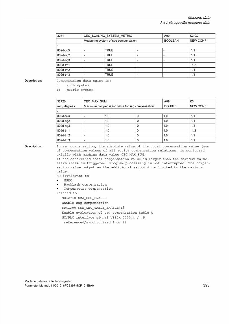
7/23/2019 802Dsl Datos Maquina Interfase Sigñals
http://slidepdf.com/reader/full/802dsl-datos-maquina-interfase-signals 393/646
Machine data
2.4 Axis-specific machine data
Machine data and interface signals
Parameter Manual, 11/2012, 6FC5397-5CP10-4BA0 393
Description: Compensation data exist in:
0: inch system
1: metric system
Description: In sag compensation, the absolute value of the total compensation value (sumof compensation values of all active compensation relations) is monitoredaxially with machine data value CEC_MAX_SUM.
If the determined total compensation value is larger than the maximum value,alarm 20124 is triggered. Program processing is not interrupted. The compen-
sation value output as the additional setpoint is limited to the maximumvalue.
MD irrelevant to:
• MSEC• Backlash compensation• Temperature compensation
Related to:
MD32710 $MA_CEC_ENABLE
Enable sag compensation
SD41300 $SN_CEC_TABLE_ENABLE[t]
Enable evaluation of sag compensation table t
NC/PLC interface signal V390x 0000.4 / .5
(referenced/synchronized 1 or 2)
32711 CEC_SCALING_SYSTEM_METRIC A09 K3,G2
- Measuring system of sag compensation BOOLEAN NEW CONF
-
802d-cu3 - TRUE - - 1/1
802d-ng2 - TRUE - - 1/1802d-ng3 - TRUE - - 1/1
802d-tm1 - TRUE - - -1/2
802d-tm2 - TRUE - - 1/1
802d-tm3 - TRUE - - 1/1
32720 CEC_MAX_SUM A09 K3
mm, degrees Maximum compensation value for sag compensation DOUBLE NEW CONF
-802d-cu3 - 1.0 0 1.0 1/1
802d-ng2 - 1.0 0 1.0 1/1
802d-ng3 - 1.0 0 1.0 1/1
802d-tm1 - 1.0 0 1.0 -1/2
802d-tm2 - 1.0 0 1.0 1/1
802d-tm3 - 1.0 0 1.0 1/1

7/23/2019 802Dsl Datos Maquina Interfase Sigñals
http://slidepdf.com/reader/full/802dsl-datos-maquina-interfase-signals 394/646
Machine data
2.4 Axis-specific machine data
Machine data and interface signals
394 Parameter Manual, 11/2012, 6FC5397-5CP10-4BA0
Description: In sag compensation, modification of the total compensation value (sum of thecompensation values of all active compensation relations) is limited axially.The maximum change value is defined in this machine data as a percentage ofMD32000 $MA_MAX_AX_VELO (maximum axis velocity).
If the change in the total compensation value is greater than the maximumvalue, alarm 20125 is output. Program processing is however continued. Thepath not covered because of the limitation is made up as soon as the compen-
sation value is no longer subject to limitation.MD irrelevant to:
• MSEC• Backlash compensation• Temperature compensation
Related to:
MD32710 $MA_CEC_ENABLE
Enable sag compensation
MD32000 $MA_MAX_AX_VELO
Maximum axis velocity
SD41300 $SN_CEC_TABLE_ENABLE[t]
Enable evaluation of sag compensation table t
NC/PLC interface signal V390x 0000.4 / .5(referenced/synchronized 1 or 2)
Description: The type of temperature compensation applicable to the machine axis is acti-vated in MD32750 $MA_TEMP_COMP_TYPE.
A distinction is made between the following types:
0: No temperature compensation active
1: Position-independent temperature compensation active
(compensation value with SD43900 $SA_TEMP_COMP_ABS_VALUE)2: Position-dependent temperature compensation active
(compensation value with SD43910 $SA_TEMP_COMP_SLOPE and SD43920TEMP_COMP_REF_POSITION)
3: Position-dependent and position-independent temperature compensationactive
(compensation values with SD according to types 1 and 2)
Temperature compensation is an option that must be enabled.
32730 CEC_MAX_VELO EXP, A09, A04 K3
% Change in velocity at CEC DOUBLE NEW CONF
-
802d-cu3 - 10.0 0 100.0 1/1
802d-ng2 - 10.0 0 100.0 1/1802d-ng3 - 10.0 0 100.0 1/1
802d-tm1 - 10.0 0 100.0 -1/2
802d-tm2 - 10.0 0 100.0 1/1
802d-tm3 - 10.0 0 100.0 1/1
32750 TEMP_COMP_TYPE A09 K3,W1
- Temperature compensation type BYTE PowerOn
CTEQ
- - 0 0 7 0/0

7/23/2019 802Dsl Datos Maquina Interfase Sigñals
http://slidepdf.com/reader/full/802dsl-datos-maquina-interfase-signals 395/646
Machine data
2.4 Axis-specific machine data
Machine data and interface signals
Parameter Manual, 11/2012, 6FC5397-5CP10-4BA0 395
Related to:
SD43900 $SA_TEMP_COMP_ABS_VALUE
Position-dependent temperature compensation value
SD43920 $SA_TEMP_COMP_REF_POSITION
Reference point for position-dependent temperature compensation
SD43910 $SA_TEMP_COMP_SLOPE
Gradient for position-dependent temperature compensation
MD32760 $MA_COMP_ADD_VELO_FACTOR
Excessive velocity due to compensation
Description: The maximum distance that can be traversed because of temperature compensa-tion in one IPO cycle can be limited by the axial MD32760$MA_COMP_ADD_VELO_FACTOR.
If the resulting temperature compensation value is above this maximum, it istraversed over several IPO cycles. There is no alarm.
The maximum compensation value per IPO cycle is specified as a factor refer-ring to the maximum axis velocity (MD32000 $MA_MAX_AX_VELO).
The maximum gradient of the temperature compensation tanbmax is also limitedwith this machine data.
Example of calculation of the maximum gradient tanb(max):
1. Calculation of the interpolator cycle time (see Description of FunctionsVelocities, Setpoint/Actual Value Systems, Cycle Times (G2))
Interpolator cycle time = Basic system clock rate * factor for interpola-tion cycle
Interpolator cycle time = MD10050 $MN_SYSCLOCK_CYCLE_TIME ^ MD10070
$MN_IPO_SYSCLOCK_TIME_RATIOExample:
MD10050 $MN_SYSCLOCK_CYCLE_TIME = 0.004 [s]
MD10070 $MN_IPO_SYSCLOCK_TIME_RATIO = 3
-> Interpolator cycle time = 0.004 * 3 = 0.012 [s]
2. Calculation of the maximum velocity increase resulting from a changemade to the temperature compensation parameter DvTmax
DvTmax = MD32000 $MA_MAX_AX_VELO * MD32760 $MA_COMP_ADD_VELO_FACTOR
Example: MD32000 $MA_MAX_AX_VELO = 10 000 [mm/min]
MD32760 $MA_COMP_ADD_VELO_FACTOR = 0.01
-> DvTmax = 10 000 * 0.01 = 100 [mm/min]
3. Calculation of the traverse distances per interpolator cycle
0.012 S1 (at vmax) = 10 000 x --------- = 2.0 [mm]
60
0.012
ST (at DvTmax) = 100 x --------- = 0.02 [mm]
60
32760 COMP_ADD_VELO_FACTOR EXP, A09, A04 K3
- Excessive velocity due to compensation DOUBLE NEW CONF
CTEQ
- - 0.01 0. 0.10 0/0

7/23/2019 802Dsl Datos Maquina Interfase Sigñals
http://slidepdf.com/reader/full/802dsl-datos-maquina-interfase-signals 396/646
Machine data
2.4 Axis-specific machine data
Machine data and interface signals
396 Parameter Manual, 11/2012, 6FC5397-5CP10-4BA0
4. Calculation of tanbmax
ST 0.02
tanbmax = ---- = ------ = 0.01 (corresponds to value for
S1 2 COMP_ADD_VELO_FACTOR)
-> bmax = arc tan 0.01 = 0.57 degrees
With larger values of SD43910 $SA_TEMP_COMP_SLOPE, the maximum gradient(here 0.57 degrees) for the position-dependent temperature compensationvalue is used internally. There is no alarm.
Note:
Any additional excessive velocity resulting from temperature compensationmust be taken into account when defining the limit value for velocity mon-itoring (MD36200 $MA_AX_VELO_LIMIT).
MD irrelevant for:
MD32750 $MA_TEMP_COMP_TYPE = 0, sag compensation, LEC, backlash compensa-tion
Related to:
MD32750 $MA_TEMP_COMP_TYPE
Temperature compensation typeSD43900 $SA_TEMP_COMP_ABS_VALUE
Position-independent temperature compensation value
SD43910 $SA_TEMP_COMP_SLOPE
Gradient for position-dependent temperature compensation
MD32000 $MA_MAX_AX_VELO
Maximum axis velocity
MD36200 $MA_AX_VELO_LIMIT
Threshold value for velocity monitoring
MD10070 $MN_IPO_SYSCLOCK_TIME_RATIO
Ratio of basic system clock rate to IPO cycle
MD10050 $MN_SYSCLOCK_CYCLE_TIME
Basic system clock rate
Description: The time constant is used for parameterizing the torque feedforward controland for calculating the dynamic following error model (contour monitoring).
In order to set the torque feedforward control correctly, the equivalent timeconstant of the current control loop must be determined exactly by measuringthe step response of the current control loop.
Closed-loop control free of following errors can be set by inputting negativevalues when MD32620 $MA_FFW_MODE=4 (but positioning overshoots may thenoccur).
Delay values taken into account automatically by the software internally arethus compensated again until the actually active minimum symmetrizing time"0" is reached.
32800 EQUIV_CURRCTRL_TIME EXP, A07, A09 G1,K3,S3,A2,A3,G2,S1,V1
s Equiv. time const. current control loop for feedforwardcontrol
DOUBLE NEW CONF
-
- 6 0.0005, 0.0005,0.0005, 0.0005,0.0005, 0.0005
- - 0/0

7/23/2019 802Dsl Datos Maquina Interfase Sigñals
http://slidepdf.com/reader/full/802dsl-datos-maquina-interfase-signals 397/646
Machine data
2.4 Axis-specific machine data
Machine data and interface signals
Parameter Manual, 11/2012, 6FC5397-5CP10-4BA0 397
Any other negative input values have no further effect.
Negative values input when MD32620 $MA_FFW_MODE=2 are automatically convertedinternally to the input value "0", which means that they are not active inthis case.
Related to:
MD32620 $MA_FFW_MODEType of feedfoward control
MD32650 $MA_AX_INERTIA
Moment of inertia for torque feedforward control
or MD32652 $MA_AX_MASS
Axis mass for torque feedforward control
MD36400 $MA_CONTOUR_TOL
Tolerance band contour monitoring
Description: This time constant must be equal to the equivalent time constant of theclosed current control loop.
It is used for parameterizing the speed feedforward control and for calculat-ing the dynamic following error model (contour monitoring).
In addition, this MD determines the time behavior of the closed-loop speedcontrol circuit for simulated drives (MD30130 $MA_CTRLOUT_TYPE 0).
In order to set the speed feedforward control correctly, the equivalent timeconstant of the current control loop must be determined exactly by measuringthe step response of the current control loop.
Closed-loop control free of following errors can be set by inputting negativevalues when MD32620 $MA_FFW_MODE=3 (but positioning overshoots may thenoccur).
Delay values taken into account automatically by the software internally arethus compensated again until the actually active minimum symmetrizing time"0" is reached.
Any other negative input values have no further effect.
Negative values input when MD32620 $MA_FFW_MODE=1 are automatically convertedinternally to the input value "0", which means that they are not active inthis case.
Related to:
MD32620 $MA_FFW_MODE (type of feedfoward control)
MD32610 $MA_VELO_FFW_WEIGHT (moment of inertia for speed feedforward control)
MD36400 $MA_CONTOUR_TOL (tolerance band contour monitoring)
32810 EQUIV_SPEEDCTRL_TIME A07, A09 G1,K3,S3,A2,A3,G2,S1,V1
s Equiv. time constant speed control loop for feedforwardcontrol
DOUBLE NEW CONF
-
- 6 0.003, 0.003, 0.003,0.003, 0.003...
- - 2/2

7/23/2019 802Dsl Datos Maquina Interfase Sigñals
http://slidepdf.com/reader/full/802dsl-datos-maquina-interfase-signals 398/646
Machine data
2.4 Axis-specific machine data
Machine data and interface signals
398 Parameter Manual, 11/2012, 6FC5397-5CP10-4BA0
Description: With dynamic response adaptation, axes with different servo gain factors canbe set to the same following error with MD32910 $MA_DYN_MATCH_TIME.
1: Dynamic response adaptation active.
0: Dynamic response adaptation inactive.
Related to:
MD32910 $MA_DYN_MATCH_TIME[n]
(time constant of dyamic response adaptation)
Description: The time constant of the dynamic response adaptation of an axis has to beentered in this MD.
Axes interpolating with each other but having different dynamic responses canbe adapted to the "slowest" control loop by means of this value.
The difference of the equivalent time constant of the "slowest" control loopto the individual axis has to be entered here as the time constant of thedynamic response adaptation.
The MD is only active if MD32900 $MA_DYN_MATCH_ENABLE = 1.
Related to:
MD32900 $MA_DYN_MATCH_ENABLE (dynamic response adaptation)
Description: For SIMODRIVE611D (as well as for PROFIdrive drives, provided that theytransport the following actual drive values in the PROFIdrive message frame,e.g. MD13060 $MN_DRIVE_TELEGRAM_TYPE = 116):
With the main run variables $AA_LOAD, $AA_POWER, $AA_TORQUE and $AA_CURR, thefollowing drive actual values can be measured:
• Drive utilization• Drive active power• Drive torque setpoint value• Current actual value of the axis or spindle
To compensate any peaks, the measured values can be smoothed with a PT1 fil-ter. The filter time constant is defined via MD32920 $MA_AC_FILTER_TIME (fil-ter smoothing time constant for adaptive control).
When measuring the drive torque setpoint value or the current actual value,the filter is active in addition to the filters available in the drive. Thetwo filters are connected in series, if both strongly and slightly smoothedvalues are required in the system. The filter is switched off when a smooth-ing time of 0 seconds is entered.
32900 DYN_MATCH_ENABLE A07 G21,S3,G2
- Dynamic response adaptation BOOLEAN NEW CONF
CTEQ
- - FALSE - - 1/1
32910 DYN_MATCH_TIME A07 G1,K3,S3,A2,A3,G2,S1,V1
s Time constant of dynamic response adaptation DOUBLE NEW CONF
-
- 6 0.0, 0.0, 0.0, 0.0, 0.0,0.0 - - 1/1
32920 AC_FILTER_TIME A10 -s Smoothing filter time constant for adaptive control DOUBLE PowerOn
-
- - 0.0 - - 0/0

7/23/2019 802Dsl Datos Maquina Interfase Sigñals
http://slidepdf.com/reader/full/802dsl-datos-maquina-interfase-signals 399/646
Machine data
2.4 Axis-specific machine data
Machine data and interface signals
Parameter Manual, 11/2012, 6FC5397-5CP10-4BA0 399
Description: Activation of low-pass filter at position controller output. Activation of the low-pass filter is only enabled when the dynamic stiffnesscontrol is inactive MD32640=0.
Description: Time constant of low-pass filter at position controller output
Related to:
MD32640 $MA_STIFFNESS_CONTROL_ENABLE (dynamic stiffness control)
Description: Application:
Attenuation of an oscillating axis through additional activation of a rota-tional speed difference, which is determined from the difference of the twomeasuring systems.
Condition: the axis must have two measuring systems, while one encoder mustbe connected directly, the other indirectly.
Explanation of normalization by means of SIMODRIVE611D:
An input value of "100%" means: An additional torque is activated in accor-dance with drive MD 1725, if
• a positional deviation of 1mm exists on linear motors• a load-side positional deviation of 360 degrees exists on rotary axes• a positional deviation corresponding to MD31030 $MA_LEADSCREW_PITCH (e.g.
10mm as a standard) exists on linear axes (rot. drive).
Description: The type of the fine interpolator has to be entered in this MD:
1: differential FIPO
2: cubic FIPO
3: cubic FIPO, optimized for operation with feedforward control
32930 POSCTRL_OUT_FILTER_ENABLE A07 G2
- Activation of low-pass filter at position controller output BOOLEAN NEW CONF
CTEQ
- - FALSE - - 0/0
32940 POSCTRL_OUT_FILTER_TIME A07 G2
s Time constant of low-pass filter at position controller output DOUBLE NEW CONF
-
- - 0.0 - - 0/0
32950 POSCTRL_DAMPING EXP, A07 G2% Damping of the speed control circuit. DOUBLE NEW CONF
-
- - 0.0 - - 0/0
33000 FIPO_TYPE EXP, A07 G1,G3,S3,G2
- Fine interpolator type BYTE PowerOn
CTEQ
802d-cu3 - 2 1 3 0/0
802d-ng2 - 1 1 3 0/0
802d-ng3 - 2 1 3 0/0
802d-tm1 - 1 1 3 0/0
802d-tm2 - 1 1 3 0/0802d-tm3 - 2 1 3 0/0

7/23/2019 802Dsl Datos Maquina Interfase Sigñals
http://slidepdf.com/reader/full/802dsl-datos-maquina-interfase-signals 400/646
Machine data
2.4 Axis-specific machine data
Machine data and interface signals
400 Parameter Manual, 11/2012, 6FC5397-5CP10-4BA0
Calculation time required and contour quality increase with increasing typeof FIPO.
• The default setting is the cubic FIPO.• If no feedforward control is used in the position control loop, the use
of the differential FIPO reduces the calculation time while slightly
increasing the contour error.• If the position control cycle and the interpolation cycle are identical,fine interpolation does not take place, i.e. the different types of fineinterpolator do not have different effects.
Description: After the traversing path defined in the MD has been covered, the state ofthe axial interface signal "Lubrication pulse" is inverted, this can activatean automatic lubrication device.
The traversing path is summated after Power on.
The "Lubrication pulse" can be used with axes and spindles. Application example(s):
The machine bed lubrication can be carried out as a function of the relevanttraversed path.
Note:
When 0 is entered, the NC/PLC interface signal V390x 1002.0 (Lubricationpulse) is set in every cycle.
Related to:
NC/PLC interface signal V390x 1002.0 (Lubrication pulse)
Description: Configuration of axis maintenance data recording:
Bit 0:
Recording the entire traversing path, entire traversing time and number ofaxis traversing procedures
Bit 1:
Recording the entire traversing path, entire traversing time and number oftraversing procedures at high axis speed
Bit 2:
Recording the total sum of axis jerks, the time in which the axis is tra-versed with jerk, and the number of traversing procedures with jerk.
33050 LUBRICATION_DIST A03, A10 A2,Z1
mm, degrees Traversing path for lubrication from PLC DOUBLE NEW CONF
-
- - 1.0e8 - - 3/3
33060 MAINTENANCE_DATA A10 W6,2.4,6.2
- Configuration of maintenance data recording DWORD Reset
-
- - 1 - - 1/1

7/23/2019 802Dsl Datos Maquina Interfase Sigñals
http://slidepdf.com/reader/full/802dsl-datos-maquina-interfase-signals 401/646
Machine data
2.4 Axis-specific machine data
Machine data and interface signals
Parameter Manual, 11/2012, 6FC5397-5CP10-4BA0 401
2.4.4 Reference point approach
Description: 1: There is at least one reference point cam for this axis
0: This axis does not have a reference point cam (e.g. rotary axis)
The referencing cycle starts immediately with phase 2 (see documentation)
Machine axes that have only one zero mark over the whole travel range orrotary axes that have only one zero mark per revolution do not require anadditional reference cam that selects the zero mark (select MD34000$MA_REFP_CAM_IS_ACTIVE = 0).
The machine axis marked this way accelerates to the velocity specified inMD34040 $MA_REFP_VELO_SEARCH_MARKER (reference point creep velocity) whenthe plus/minus traversing key is pressed, and synchronizes with the next zeromark.
Description: 0: MD34010 $MA_REFP_CAM_DIR_IS_MINUS Reference point approach in plus direc-tion
1: MD34010 $MA_REFP_CAM_DIR_IS_MINUS Reference point approach in minus direc-tion
For incremental measuring systems:
If the machine axis is positioned in front of the reference cam, it acceler-ates, depending on the plus/minus traversing key pressed, to the velocityspecified in MD34020 $MA_REFP_VELO_SEARCH_CAM (reference point approachvelocity) in the direction specified in MD34010 $MA_REFP_CAM_DIR_IS_MINUS. Ifthe wrong traversing key is pressed, reference point approach is not started.
If the machine axis is positioned on the reference cam, it accelerates to thevelocity specified in MD34020 $MA_REFP_VELO_SEARCH_CAM and travels in thedirection opposite to that specified in MD34010 $MA_REFP_CAM_DIR_IS_MINUS.
Note on absolute encoders:
The direction of the traverse key is also important for adjusting the abso-lute encoder: approach direction for fixed position and updating the valuesin MD34090 $MA_REFP_MOVE_DIST_CORR und MD34210 $MA_ENC_REFP_STATE.
Description: The reference point approach velocity is the velocity at which the machineaxis travels in the direction of the reference cam after the traversing keyhas been pressed (phase 1). This value should be set at a magnitude largeenough for the axis to be stopped to 0 before it reaches a hardware limitswitch.
MD irrelevant for:
Linear measuring systems with distance-coded reference marks
34000 REFP_CAM_IS_ACTIVE A03, A11 G1,R1
- Axis with reference point cam BOOLEAN Reset
-
- - TRUE - - 2/2
34010 REFP_CAM_DIR_IS_MINUS A03, A11 G1,R1
- Approach reference point in minus direction BOOLEAN Reset
-
- - FALSE - - 2/2
34020 REFP_VELO_SEARCH_CAM A03, A11, A04 G1,R1
mm/min, rev/min Reference point approach velocity DOUBLE Reset
-
- - 5000.00,5000.00,5000.00,5000.00...
- - 2/2

7/23/2019 802Dsl Datos Maquina Interfase Sigñals
http://slidepdf.com/reader/full/802dsl-datos-maquina-interfase-signals 402/646
Machine data
2.4 Axis-specific machine data
Machine data and interface signals
402 Parameter Manual, 11/2012, 6FC5397-5CP10-4BA0
Description: If the machine axis travels a maximum distance defined in MD34030$MA_REFP_MAX_CAM_DIST from the starting position in the direction of the ref-erence cam, without reaching the reference cam (NC/PLC interface signalV380x1000.7 (Reference point approach delay) is reset), the axis stops andalarm 20000 "Reference cam not reached" is output.
Irrelevant to:
Linear measuring systems with distance-coded reference marks
Description: 1) For incremental measuring systems:
This is the velocity at which the axis travels during the time between ini-tial detection of the reference cam and synchronization with the first zeromark (phase 2).
Traversing direction: Opposite to the direction specified for the cam search(MD34010 $MA_REFP_CAM_DIR_IS_MINUS)
If MD34050 $MA_REFP_SEARCH_MARKER_REVERSE (direction reversal on referencecam) is enabled, then if the axis is synchronized with a rising reference camsignal edge on the cam, the axis traverses at the velocity defined in MD34020$MA_REFP_VELO_SEARCH_CAM.
2) Indirect measuring system with BERO on the load-side (preferred for spin-dles):
At this velocity, a search is made for the zero mark associated with the BERO(zero mark selection per VDI signal). The zero mark is accepted if the actualvelocity lies within the tolerance range defined in MD35150$MA_SPIND_DES_VELO_TOL as a deviation from the velocity specified in MD34040$MA_REFP_VELO_SEARCH_MARKER[n].
3) For linear measuring systems with distance-coded reference marks:
The axis crosses the two reference marks at this velocity. The maximum veloc-ity must be low enough to ensure that the time required to travel the small-est possible reference mark distance [(x(minimum)] on the linear measuringsystem is longer than one position controller cycle.
The formula
Basic dist. Meas.length
[x(minimum)] [mm] = ----------- * Grad.cycle - -------------- 2 Basic dist.
with Basic distance [multiple of graduation cycle]
Graduation cycle [mm]
Measuring length [mm] yields:
x(minimum) [mm]
max. velocity [m/s] = ---------------------------------
Position controller cycle [ms]
34030 REFP_MAX_CAM_DIST A03, A11 G1,R1
mm, degrees Maximum distance to reference cam DOUBLE Reset
-
- - 10000.0 - - 2/2
34040 REFP_VELO_SEARCH_MARKER A03, A11, A04 G1,R1,S1
mm/min, rev/min Creep velocity DOUBLE Reset
-
- 1 300.00,300.00,300.00,
300.00...
- - 2/2

7/23/2019 802Dsl Datos Maquina Interfase Sigñals
http://slidepdf.com/reader/full/802dsl-datos-maquina-interfase-signals 403/646
Machine data
2.4 Axis-specific machine data
Machine data and interface signals
Parameter Manual, 11/2012, 6FC5397-5CP10-4BA0 403
This limiting value consideration also applies to the other measuring sys-tems.
Traversing direction:
• as defined in MD34010 $MA_REFP_CAM_DIR_IS_MINUS;• if the axis is already positioned on the cam, the axis is traversed in
the opposite direction
Description: This MD can be used to set the direction of search for the zero mark:
MD34050 $MA_REFP_SEARCH_MARKER_REVERSE = 0
Synchronization with falling reference cam signal edge
The machine axis accelerates to the velocity specified in MD34040$MA_REFP_VELO_SEARCH_MARKER (reference point creep velocity) in the oppositedirection to that specified in MD34010 $MA_REFP_CAM_DIR_IS_MINUS (referencepoint approach in minus direction).
If the axis leaves the reference cam (NC/PLC interface signal V380x1000.7(Reference point approach delay) is reset) the control is synchronized withthe first zero mark.
MD34050 $MA_REFP_SEARCH_MARKER_REVERSE = 1
Synchronization with rising reference cam signal edge
The machine axis accelerates to the velocity defined in MD34020$MA_REFP_VELO_SEARCH_CAM (reference point creep velocity) in the oppositedirection to that specified in the MD34010 $MA_REFP_CAM_DIR_IS_MINUS. If theaxis leaves the reference cam (NC/PLC interface signal V380x1000.7 (Referencepoint approach delay) is reset), the machine axis decelerates to a halt andaccelerates in the opposite direction towards the reference cam at the veloc-ity specified in MD34040: $MA_REFP_VELO_SEARCH_MARKER. When the reference camis reached (NC/PLC interface signal V380x1000.7 (Reference point approach
delay) is enabled) the control is synchronized with the first zero mark.MD irrelevant to:
Linear measuring systems with distance-coded reference marks
Description: For incremental measuring systems:
If, after leaving the reference cam (NC/PLC interface signal V380x1000.7(Reference point approach delay) is reset), the machine axis travels a dis-
tance defined in MD34060: $MA_REFP_MAX_MARKER_DIST without detecting the zeromark, the axis stops and alarm 20002 "Zero mark missing" is output.
For linear measuring systems with distance-coded reference marks:
If the machine axis travels a distance defined in MD34060$MA_REFP_MAX_MARKER_DIST from the starting position without crossing two zeromarks, the axis stops and alarm 20004 "Reference mark missing" is output.
34050 REFP_SEARCH_MARKER_REVERSE A03, A11 G1,R1
- Direction reversal to reference cam BOOLEAN Reset
-
- 1 FALSE, FALSE - - 2/2
34060 REFP_MAX_MARKER_DIST A03, A11 G1,R1,S1
mm, degrees maximum distance to reference mark DOUBLE Reset
-
- 1 20.0, 20.0,20.0,20.0,20.0, 20.0...
- - 2/2

7/23/2019 802Dsl Datos Maquina Interfase Sigñals
http://slidepdf.com/reader/full/802dsl-datos-maquina-interfase-signals 404/646
Machine data
2.4 Axis-specific machine data
Machine data and interface signals
404 Parameter Manual, 11/2012, 6FC5397-5CP10-4BA0
Description: For incremental measuring systems:
The axis travels at this velocity between the time of synchronization withthe first zero mark and arrival at the reference point.
For linear measuring systems with distance-coded reference marks:
The axis travels at this velocity between the time of synchronization(crossing two zero marks) and arrival at the target point.
Description: 1. Standard measuring system (incremental with equidistant zero marks)Reference point positioning movement: 3rd phase of the reference pointapproach:
The axis traverses from the position at which the zero mark is detected withthe velocity REFP_AX_VELO_POS along the path REFP_MOVE_DIST +REFP_MOVE_DIST_CORR (relative to the marker).
REFP_SET_POS is set as the current axis position at the target point.
2. Irrelevant for distance-coded measuring system.
Override switch and selection jog/continuous mode ( MD JOG_INC_MODE_IS_CONT) are active.
Description: • Incremental encoder with zero mark(s):
After detection of the zero mark, the axis is positioned away from the zeromark by the distance specified in MD34080 $MA_REFP_MOVE_DIST + MD34090$MA_REFP_MOVE_DIST_CORR. After traversing this distance, the axis has reachedthe reference point. MD34100 $MA_REFP_SET_POS is transferred into the actualvalue.
During traversing by MD34080 $MA_REFP_MOVE_DIST + MD34090$MA_REFP_MOVE_DIST_CORR, the override switch and MD11300$MN_JOG_INC_MODE_LEVELTRIGGRD (jog/continuous mode) are active.
• Distance-coded measuring system:
MD34090 $MA_REFP_MOVE_DIST_CORR acts as an absolute offset. It describes theoffset between the machine zero and the first reference mark of the measuringsystem.
• Absolute encoder:
MD34090 $MA_REFP_MOVE_DIST_CORR acts as an absolute offset.
It describes the offset between the machine zero and the zero point of theabsolute measuring system.
34070 REFP_VELO_POS A03, A11, A04 G1,R1
mm/min, rev/min Reference point positioning velocity DOUBLE Reset
-
- - 10000.00,10000.00,10
000.00,10000.00...
- - 2/2
34080 REFP_MOVE_DIST A03, A11 G1,R1,S1,S3,G2
mm, degrees Reference point distance DOUBLE NEW CONF
-
- 1 -2.0, -2.0 -1e15 1e15 2/2
34090 REFP_MOVE_DIST_CORR A03, A02, A08, A11
G1,R1,S1,S3,G2
mm, degrees Reference point offset/absolute offset DOUBLE NEW CONF-, -
- 1 0.0, 0.0 -1e12 1e12 2/2

7/23/2019 802Dsl Datos Maquina Interfase Sigñals
http://slidepdf.com/reader/full/802dsl-datos-maquina-interfase-signals 405/646
Machine data
2.4 Axis-specific machine data
Machine data and interface signals
Parameter Manual, 11/2012, 6FC5397-5CP10-4BA0 405
Note:
In conjunction with absolute encoders, this MD is modified by the controlduring calibration processes and modulo offset.
With rotary absolute encoders (on linear and rotary axes), the modificationfrequency also depends on the setting of MD34220 $MA_ENC_ABS_TURNS_MODULO.
Manual input or modification of this MD via the part program should thereforebe followed by a Power ON Reset to activate the new value and prevent it frombeing lost.
The following applies to an NCU-LINK:
If a link axis uses an absolute encoder, every modification of MD34090$MA_REFP_MOVE_DIST_CORR on the home NCU (servo physically available) isupdated only locally and not beyond the limits of the NCU. The modificationis therefore not visible to the link axis. Writing MD34090$MA_REFP_MOVE_DIST_CORR through the link axis is rejected with alarm 17070.
Description: Electronic cam offset for incremental measuring systems with equidistant zeromarks.
When the reference cam signal occurs, the zero mark search does not startimmediately but is delayed until after the distance from REFP_CAM_SHIFT.
This ensures the reproducibility of the zero mark search through a definedselection of a zero mark, even with temperature-dependent expansion of thereference cam.
Because the reference cam offset is calculated by the control in the interpo-lation cycle, the actual cam offset is at least REFP_CAM_SHIFT and at mostREFP_CAM_SHIFT+(MD34040 $MA_REFP_VELO_SEARCH_MARKER*interpolation cycle)
The reference cam offset is effective in the search direction of the zeromark.
The reference cam offset is only active if existing cam MD34000$MA_REFP_CAM_IS_ACTIVE=1.
Description: The value displayed corresponds to the distance between exiting the referencecam and the occurrence of the reference mark. If the values are too small,there is a risk of not being able to determine the reference point due totemperature reasons or varying operating times of the cam signal. The dis-tance travelled may serve as a clue for setting the electronic reference camoffset.
This machine data is a display data and can therefore not be changed.
34092 REFP_CAM_SHIFT A03, A11 G1,R1
mm, degrees electronic cam offset for incremental measuring systems DOUBLE Reset
-
- 1 0.0, 0.0 - - 2/2
34093 REFP_CAM_MARKER_DIST A03, A11 R1
mm, degrees Reference cam/reference mark distance DOUBLE PowerOn
-
- 1 0.0, 0.0 - - 2/2

7/23/2019 802Dsl Datos Maquina Interfase Sigñals
http://slidepdf.com/reader/full/802dsl-datos-maquina-interfase-signals 406/646
Machine data
2.4 Axis-specific machine data
Machine data and interface signals
406 Parameter Manual, 11/2012, 6FC5397-5CP10-4BA0
Description: • Incremental encoder with zero mark(s):The position value which is set as the current axis position after detec-tion of the zero mark and traversal of the distance REFP_MOVE_DIST +REFP_MOVE_DIST_CORR (relative to zero mark). REFP_SET_POS of the referencepoint number, which is set as the instant that the edge of the referencecam signal rises (NC/PLC interface signal V380x 0002.4 - .7 (Referencepoint value 1 to 4)), is set as the axis position.
• Distance-coded measuring system:
Target position which is approached when MD34330 $MA_REFP_STOP_AT_ABS_MARKERis set to 0 (FALSE) and two zero marks have been crossed.
• Absolute encoder:
MD34100 $MA_REFP_SET_POS corresponds to the correct actual value at the cal-ibration position.
The reaction on the machine depends on the status of MD34210$MA_ENC_REFP_STATE: When MD34210 $MA_ENC_REFP_STATE = 1, the value of MD34100$MA_REFP_SET_POS is transferred as the absolute value.
When MD34210 $MA_ENC_REFP_STATE = 2 and MD34330 $MA_REFP_STOP_AT_ABS_MARKER =0 (FALSE), the axis approaches the target position stored in MD34100$MA_REFP_SET_POS.
The value of MD34100 $MA_REFP_SET_POS that has been set via NC/PLC interfacesignal V380x 0002.4 - .7 (Reference point value 1 to 4) is used.
Related to:
NC/PLC interface signal V380x 0002.4 - .7 (Reference point value 1 to 4)
Description: Calibrating the measuring system to the reference measuring system can beactivated for all measuring systems of this axis with this machine data.
The calibration procedure is made during reference point approach or whencalibrated absolute encoders selected for the closed-loop control areswitched on.
Values:
0: No measuring system calibration, measuring systems must be referencedindividually
1: Calibration of all measuring systems of the axis to the position of thereference measuring system
In combination with MD30242 $MA_ENC_IS_INDEPENDENT = 2, the passive encoderis calibrated to the active encoder but NOT referenced.
Description: An axis can also be referenced in the follow-up mode under JOG+REF mode bymeans of an external motion.
34100 REFP_SET_POS A03, A11 G1,S3,G2,R1,S1
mm, degrees Reference point for incremental system DOUBLE Reset
-
- 4 0., 0., 0., 0. -45000000 45000000 2/2
34102 REFP_SYNC_ENCS A03, A02 R1,Z1
- Calibration of measuring systems BYTE Reset
-
- - 0 0 1 0/0
34104 REFP_PERMITTED_IN_FOLLOWUP A03, A02 R1
- Enable referencing in follow-up mode BOOLEAN Reset
-
- - FALSE - - 1/1

7/23/2019 802Dsl Datos Maquina Interfase Sigñals
http://slidepdf.com/reader/full/802dsl-datos-maquina-interfase-signals 407/646
Machine data
2.4 Axis-specific machine data
Machine data and interface signals
Parameter Manual, 11/2012, 6FC5397-5CP10-4BA0 407
Description: MD34110 $MA_REFP_CYCLE_NR = 0 -----> axis-specific referencing
Axis-specific referencing is started separately for each machine axis withthe NC/PLC interface signal V380x 0004.7 / 4.6 (Plus/minus travel keys).
Up to 8 axes (840D) can be referenced simultaneously.
The following alternatives are provided for referencing the machine axesin a specific sequence:
• The operator has to observe the correct sequence on startup.• The PLC checks the sequence on startup or defines the sequence itself.• The channel-specific referencing function is used.
MD34110 $MA_REFP_CYCLE_NR = 1 -----> channel-specific referencing
Channel-specific referencing is started with the NC/PLC interface signal
V3200 0001.0 (Activate referencing). The control acknowledges a successfulstart with the NC/PLC interface signal V3300 0001.0 (Referencing active).Each machine axis assigned to the channel can be referenced with channel-specific referencing (this is achieved internally on the control by simu-lating the plus/minus traversing keys). The axis-specific MD34110$MA_REFP_CYCLE_NR can be used to define the sequence in which the machineaxes are referenced:
-1 means:
The machine axis is not started by channel-specific referencing, and NCstart is possible without referencing this axis.
0 means:
The machine axis is not started by channel-specific referencing, and NCstart is not possible without referencing this axis.
1 means:The machine axis is started by channel-specific referencing.
2 means:
The machine axis is started by channel-specific referencing if all machineaxes identified by a 1 in MD34110 $MA_REFP_CYCLE_NR are referenced.
3 means:
The machine axis is started by channel-specific referencing if all machineaxes identified by a 2 in MD34110 $MA_REFP_CYCLE_NR are referenced.
4 to 8 :
As above for further machine axes.
Setting the channel-specific MD20700 $MC_REF_NC_START_LOCK (NC start disablewithout reference point) to zero has the effect of entering -1 for all the
axes of a channel.MD irrelevant to:
Axis-specific referencing
Related to:
NC/PLC interface signal V3200 0001.0 (Activate referencing)
NC/PLC interface signal V3300 0001.0 (Referencing active)
34110 REFP_CYCLE_NR A03 G1,TE3,D1,R1,Z1
- Sequence of axes in channel-specific referencing DWORD PowerOn
-
- - 1,2,3,4,5,6,7,8,9,10,11
,12,13,14,15,16,17,18.
-1 31 2/2

7/23/2019 802Dsl Datos Maquina Interfase Sigñals
http://slidepdf.com/reader/full/802dsl-datos-maquina-interfase-signals 408/646
Machine data
2.4 Axis-specific machine data
Machine data and interface signals
408 Parameter Manual, 11/2012, 6FC5397-5CP10-4BA0
Description: The mounted position measuring systems can be classified for referencing asfollows with MD34200 $MA_ENC_REFP_MODE:
• MD34200 $MA_ENC_REFP_MODE = 0
If an absolute encoder is available: MD34100 $MA_REFP_SET_POS is taken over
Other encoders: Reference point approach not possible MD34200$MA_ENC_REFP_MODE = 1
Incremental rotary measuring system
Incremental linear measuring system
Zero pulse on encoder track (not with absolute encoders)
MD34200 $MA_ENC_REFP_MODE = 2
BERO with 1-edge detection.
Also possible with an absolute encoder. After referencing, the absoluteencoder is additionally marked as "calibrated".
• MD34200 $MA_ENC_REFP_MODE = 3
Referencing on linear measuring systems with distance-coded referencemarks:
Linear measuring system with distance-coded reference marks (as specifiedby Heidenhain)
• MD34200 $MA_ENC_REFP_MODE = 5:
When the BERO is passed, the zero mark search is started when the negativeBERO edge is detected, and it is referenced to the next zero markdetected.
• MD34200 $MA_ENC_REFP_MODE = 6
Measuring system calibration to an already referenced encoder(not NCU 570)
• MD34200 $MA_ENC_REFP_MODE = 7
BERO with configured approach velocity for axis and spindle applications(SW3.6 and higher) (MD34040 $MA_REFP_VELO_SEARCH_MARKER[n]
(Reference point creep velocity [enc. no.].
• MD34200 $MA_ENC_REFP_MODE = 8
Referencing for linear measuring systems with distance-coded referencemarks:
Linear measuring system with distance-coded reference marks over 4 zeromarks (increased safety).
Description: • Absolute encoder:
This machine data contains the absolute encoder status
0: Encoder is not calibrated
1: Encoder calibration enabled (but not yet calibrated)
2: Encoder is calibrated
34200 ENC_REFP_MODE A03, A02 G1,R1,S1
- Referencing mode BYTE PowerOn
-
- 1 1, 1 0 8 2/2
34210 ENC_REFP_STATE A07, A03, A02 R1- Adjustment status of absolute encoder BYTE Immediately
-
- 1 0, 0 0 3 2/2

7/23/2019 802Dsl Datos Maquina Interfase Sigñals
http://slidepdf.com/reader/full/802dsl-datos-maquina-interfase-signals 409/646
Machine data
2.4 Axis-specific machine data
Machine data and interface signals
Parameter Manual, 11/2012, 6FC5397-5CP10-4BA0 409
Default setting for new startup: Encoder is not calibrated.
3: No significance, has the same effect as "0"
• Incremental encoder:
This machine data contains the "Referenced status", which can be saved beyond Power On:
0: Default setting: No automatic referencing1: Automatic referencing enabled, but encoder not yet referenced
2: Encoder is referenced and at exact stop, automatic referencing becomes active at the next encoder activation
3: The last axis position buffered before switch off is restored, noautomatic referencing
Default setting for new startup: No automatic referencing
Description: Number of encoder revolutions, which a rotary absolute encoder can resolve(cf. also maximum multiturn information of the absolute encoder, cf. encoderdata sheet or, for example SIMODRIVE611D-MD 1021 or 1031 or PROFIdrive param-eter p979).
The absolute position of a rotary axis is reduced to this resolvable rangewhen an absolute encoder is switched on:
That means that a MODULO transformation takes place, if the actual positionsensed is larger than the position permitted by MD ENC_ABS_TURNS_MODULO.
0 degree <= position <= n*360 degrees, (with n = ENC_ABS_TURNS_MODULO)
Note:
With SW 2.2, the position is reduced to this range when the control/encoder is switched on. With SW 3.6 and higher, half of this value repre-sents the maximum permissible travel distance with the control swiched off
/ the encoder inactive.Special cases:
For PROFIdrive any integer values are permissible.
This MD is relevant only for rotary encoders (on linear and rotary axes).
Important recommendation:
The default value "1 encoder revolution" has been changed for SW 3.6 andhigher to "4096". The new value is a more robust setting for the most fre-quently used encoder types.
When an encoder with a smaller multiturn information (encoder data sheet!) isused or when singleturn encoders are used, the value must be reduced accord-ingly. In either case, the value should be adjusted with multiturn absoluteencoders to the maximum variable supported by the encoder, in order to beable to utilize the definite maximum travel range (Please observe: This value
also influences the permissible position offset with the encoder inactive/Power Off).
Related to:
PROFIdrive parameter p979
34220 ENC_ABS_TURNS_MODULO A03, A02 R1
- Modulo range for rotary absolute encoder DWORD PowerOn
-
- 1 4096, 4096 1 100000 2/2

7/23/2019 802Dsl Datos Maquina Interfase Sigñals
http://slidepdf.com/reader/full/802dsl-datos-maquina-interfase-signals 410/646
Machine data
2.4 Axis-specific machine data
Machine data and interface signals
410 Parameter Manual, 11/2012, 6FC5397-5CP10-4BA0
Description: The encoder serial number (from EnDat encoders) can be read out here.It is updated at power ON (SIMODRIVE611D or PROFIdrive) or when parking isdeselected (only PROFIdrive)
"0" is supplied for encoders which do not have a serial number available.
Manipulating this MD normally causes an automatic absolute encoder maladjust-ment ($MA_ENC_REFP_MODE returns to "0").
Description: 0 = only valid encoder serial number are entered in the MD, i.e. when the
drive supplies a "0" (which corresponds to invalid or unknown) the last validencoder serial number is retained in the MD (e.g. for add-on axes that arenot permanently connected to the machine).
1 = (default, upward compatible): the value supplied by the drive for theencoder serial number is taken over into the MD with every control runup. Avalidity check is not carried out.
Note for PROFIdrive drives:
As not every drive can supply the relevant parameters at all or in goodtime, the functionality is coded permanently corresponding to "0" for thePROFIdrive drive. A "1" setting is therefore ineffective on the PROFIBUS.
Description: In addition to the incremental encoder track, a further encoder track isavailable with distance-coded measuring systems for determining the absoluteencoder position. This encoder track has reference marks at defined, differ-ent distances. The basic distance between the fixed reference marks (whichare the reference marks that are always the same distance from one another)can be taken from the data sheet, and directly transferred into machine dataMD34300 $MA_ENC_REFP_MARKER_DIST.
With the basic distance between the fixed reference marks (MD34300$MA_ENC_REFP_MARKER_DIST), the distance between two reference marks (MD34310$MA_ENC_MARKER_INC), and the number of encoder marks (MD31020 $MA_ENC_RESOL)
on angular measuring systems or the graduation cycle (MD31010$MA_ENC_GRID_POINT_DIST) on linear measuring systems, the absolute encoderposition can be determined once two successive reference marks have beencrossed.
MD34300 $MA_ENC_REFP_MARKER_DIST is also used for a plausibility check ofreference mark distances.
34230 ENC_SERIAL_NUMBER A02 R1
- Encoder serial number DWORD PowerOn
-
- 1 0, 0 - - 2/2
34232 EVERY_ENC_SERIAL_NUMBER A02 R1
- Range of encoder serial number BOOLEAN PowerOn
-
- 1 TRUE, TRUE - - 2/2
34300 ENC_REFP_MARKER_DIST A03, A02 R1
mm, degrees Basic distance of reference marks of distance-codedencoders.
DOUBLE PowerOn
-
- 1 10.0, 10.0 - - 2/2

7/23/2019 802Dsl Datos Maquina Interfase Sigñals
http://slidepdf.com/reader/full/802dsl-datos-maquina-interfase-signals 411/646
Machine data
2.4 Axis-specific machine data
Machine data and interface signals
Parameter Manual, 11/2012, 6FC5397-5CP10-4BA0 411
Examples of application:
For example: Heidenhain LS186 C
MD 31010 = 0.02mm (graduation cycle)
MD 34300 = 20.00mm (basic distance between the reference marks)
MD 34310 = 0.02mm (distance between two reference marks corresponds to one
graduation cycle).
Description: The distances between two reference marks are defined variably, so that theposition of the crossed reference marks can be determined accurately in lin-ear measuring systems with distance-coded reference marks.
The difference between two reference mark distances is entered in MD34310$MA_ENC_MARKER_INC.
MD irrelevant for:
Incremental measuring systems
Special cases:
On linear measuring systems with distance-coded reference marks suppliedby Heidenhain, the interval between two reference marks is always equal toone graduation cycle.
Description: • In the case of a distance-coded measuring system:
When setting a reference point, the actual position (determined by the dis-
tance-coded reference marks) on the linear measuring system is assigned to anexact machine axis position (referred to the machine zero point). The abso-lute offset between the machine zero point and the position of the 1st refer-ence mark on the linear measuring system must therefore be entered in MD34090$MA_REFP_MOVE_DIST_CORR (reference point/absolute offset). In addition,MD34320 $MA_ENC_INVERS must be used to set whether the linear measuring sys-tem is connected in the same or the opposite direction to the machine system.
MD irrelevant to:
Incremental encoders without distance-coded reference marks.
Description: • Distance-coded measuring system:
REFP_STOP_AT_ABS_MARKER = 0:
At the end of the reference cycle, the position entered in MD34100$MA_REFP_SET_POS is approached (normal case for phase 2).
REFP_STOP_AT_ABS_MARKER = 1:
The axis is braked after detection of the second reference mark (shorteningof phase 2)
34310 ENC_MARKER_INC A03, A02 R1
mm, degrees Interval between two reference marks for distance-codedscales
DOUBLE Reset
-
- 1 0.02, 0.02 - - 2/2
34320 ENC_INVERS A03, A02 G2,R1
- Length measuring system inverse to axis movement. BOOLEAN Reset
-
- 1 FALSE, FALSE - - 2/2
34330 REFP_STOP_AT_ABS_MARKER A03 G1,R1
- Distance-coded linear measuring system without targetpoint
BOOLEAN Reset
-
- 1 TRUE, TRUE - - 2/2

7/23/2019 802Dsl Datos Maquina Interfase Sigñals
http://slidepdf.com/reader/full/802dsl-datos-maquina-interfase-signals 412/646
Machine data
2.4 Axis-specific machine data
Machine data and interface signals
412 Parameter Manual, 11/2012, 6FC5397-5CP10-4BA0
• Absolute encoder:
MD34330 $MA_REFP_STOP_AT_ABS_MARKER defines the response of an axis with avalid calibration identifier (MD34210 $MA_ENC_REFP_STATE = 2) with G74 orwhen a traversing key is actuated in JOG-REF:
REFP_STOP_AT_ABS_MARKER = 0:
Axis traverses to the position entered in MD34100 $MA_REFP_SET_POSREFP_STOP_AT_ABS_MARKER = 1:
Axis does not traverse.
MD irrelevant for:
Incremental encoders with zero mark (standard encoders)
Related to:
MD34100 $MA_REFP_SET_POS
(reference point distance/target point for distance-coded system)
Description: Using low-resolution encoders, a more continuous motion of coupled path oraxis motions can be achieved with smoothed actual values. The bigger the timeconstant, the better the smoothing of actual values and the larger the over-travel.
Smoothed actual values are used for:
• Thread-cutting (G33, G34, G35)• Revolutional feedrate (G95, G96, G97, FPRAON)• Display of actual position and velocity, or speed respectively.
2.4.5 Spindles
Description: Spindle definition. The spindle is defined when the spindle number has beenentered in this MD.
Example:
If the corresponding axis is to be spindle 1, value "1" must be entered inthis MD.
The spindle functions are possible only for modulo rotary axes. For this pur-pose MD30300 $MA_IS_ROT_AX and MD30310 $MA_ROT_IS_MODULO must be set.
The axis functionality is maintained; transition to axis operation can beperformed with M70.
The gear stage-specific spindle data are set in parameter blocks 1 to 5.
The lowest spindle number is 1, the highest number depends on the number ofaxes in the channel.
If other spindle numbers are to be assigned, the function "spindle converter"must be used.
34990 ENC_ACTVAL_SMOOTH_TIME A02 V1
s Smoothing time constant for actual values. DOUBLE Reset
-
- 1 0.0, 0.0 0.0 0.5 3/3
35000 SPIND_ASSIGN_TO_MACHAX A01, A06, A11 M1,S3,K2,S1
- Assignment of spindle to machine axis BYTE PowerOn
-
- - 0,0,0,0,0,0,0,0,0,0,0,0,0,0,0,0,0,0,0,0,0,0,0,0,0,0...
0 20 2/2

7/23/2019 802Dsl Datos Maquina Interfase Sigñals
http://slidepdf.com/reader/full/802dsl-datos-maquina-interfase-signals 413/646
Machine data
2.4 Axis-specific machine data
Machine data and interface signals
Parameter Manual, 11/2012, 6FC5397-5CP10-4BA0 413
With multi-channel systems, the same numbers can be assigned in all channels,except for those spindles active in several channels (replacement axes/spin-dles MD 30550: $MA_AXCONF_ASSIGN_MASTER_CHAN).
Description: Meaning of bit places:
Bit 0 = 0 and bit 1 = 0:
There is an invariable gear ratio between motor and load. The MD of thefirst gear stage are active. Gear stage change is not possible with M40 toM45.
Bit 0 = 1:
Gear stage change at undefined change position. The gear can have up to 5gear stages, which can be selected with M40, M41 to M45. To support thegear stage change, the motor can carry out oscillating motions, which mustbe enabled by the PLC program.
Bit 1 = 1:
Same meaning as for bit 0 = 1, however, the gear stage change is carriedout at a configured spindle position (SW 5.3 and higher). The change posi-tion is configured in MD35012 $MA_GEAR_STEP_CHANGE_POSITION. The positionis approached in the current gear stage before the gear stage change. Ifthis bit is set, bit 0 is not taken into account!
Bit 2: reserved
Bit 3 = 1:
The gear stage change dialog between NCK and PLC is simulated. An NCK-internal acknowledgement is given. PLC signals for the change are output,checkback signals from the PLC are ignored because of the NCK-internalacknowledgement.
Bit 4: reservedBit 5 = 1:
The second gear stage data set is used for tapping with G331/G332. The bitmust be set for the master spindle used for tapping. Bit 0 or bit 1 must beset.
Related to:
MD35090 $MA_NUM_GEAR_STEPS (number of gear stages 1st data set, see bit 5)
MD35092 $MA_NUM_GEAR_STEPS2 (number of gear stages 2nd data set, see bit5)
MD35110 $MA_GEAR_STEP_MAX_VELO (max. speed for autom. gear stage change)
MD35112 $MA_GEAR_STEP_MAX_VELO2 (max. speed for autom. gear stage change2nd data set, see bit 5)
MD35120 $MA_GEAR_STEP_MIN_VELO (min. speed for autom. gear stage change)MD35122 $MA_GEAR_STEP_MIN_VELO2 (min. speed for autom. gear stage change2nd data set, see bit 5)
35010 GEAR_STEP_CHANGE_ENABLE A06, A11 P3 pl,P3 sl,S1
- Parameterize gear stage change DWORD Reset
CTEQ
- - 0x00 0 0x2B 2/2

7/23/2019 802Dsl Datos Maquina Interfase Sigñals
http://slidepdf.com/reader/full/802dsl-datos-maquina-interfase-signals 414/646
Machine data
2.4 Axis-specific machine data
Machine data and interface signals
414 Parameter Manual, 11/2012, 6FC5397-5CP10-4BA0
Description: Gear stage change position.
The value range must be within the configured modulo range.
Related to:
MD35010 $MA_GEAR_STEP_CHANGE_ENABLE, bit 1
MD30330 $MA_MODULO_RANGE
Description: With this MD, a gear stage can be defined which can be loaded into the axis
mode during the transition with M70. The parameter set zero used in axis modeis to be optimized on this gear stage.
Significance of the values:
0: There is no implicit gear stage change with M70.
The current gear stage is retained.
1 ... 5:
There is a change into gear stage (1...5) during the execution of M70.
During the transition into axis mode without M70, there is monitoring forthis gear stage and alarm 22022 is issued if necessary. The condition fora gear stage change is the general release of the function in MD35010$MA_GEAR_STEP_CHANGE_ENABLE.
Secondary conditions:
When changing from axis mode into spindle mode, the configured gear stagecontinues to remain active. There is no automatic return to the lastactive gear stage in spindle mode.
Description: SPIND_DEFAULT_MODE activates the operating mode of the spindle at the timespecified in MD35030 $MA_SPIND_DEFAULT_ACT_MASK. The appropriate spindleoperating modes can be selected with the following values:
0 Speed mode, position control deselected
1 Speed mode, position control activated
2 Positioning mode
3 Axis mode
Related to:
MD35030 $MA_SPIND_DEFAULT_ACT_MASK (activate initial spindle setting)
35012 GEAR_STEP_CHANGE_POSITION A06, A11 S1
mm, degrees Gear stage change position DOUBLE NEW CONF
CTEQ
- 6 0.0, 0.0, 0.0, 0.0, 0.0,
0.0
- - 2/2
35014 GEAR_STEP_USED_IN_AXISMODE A01, A06, A11 -
- Gear stage for axis mode with M70 DWORD NEW CONF
CTEQ
- - 0 0 5 2/2
35020 SPIND_DEFAULT_MODE A06, A10 S1
- Initial spindle setting BYTE Reset
CTEQ
- - 0 0 3 2/2

7/23/2019 802Dsl Datos Maquina Interfase Sigñals
http://slidepdf.com/reader/full/802dsl-datos-maquina-interfase-signals 415/646
Machine data
2.4 Axis-specific machine data
Machine data and interface signals
Parameter Manual, 11/2012, 6FC5397-5CP10-4BA0 415
Description: SPIND_DEFAULT_ACT_MASK specifies the time at which the operating mode definedin MD35020 $MA_SPIND_DEFAULT_MODE becomes effective. The initial spindle set-ting can be assigned the following values at the following points in time:
0 POWER ON
1 POWER ON and NC program start
2 POWER ON and RESET (M2/M30)
Special cases:
If MD35040 $MA_SPIND_ACTIVE_AFTER_RESET = 1, the following supplementaryconditions are applicable:
• SPIND_DEFAULT_ACT_MASK should be set to 0• If this is not possible, the spindle must be at a standstill prior to
activation.
Related to:
MD35020 $MA_SPIND_DEFAULT_MODE (initial spindle setting)
MD35040 $MA_SPIND_ACTIVE_AFTER_RESET (spindle active after reset)
Description: This data allows the "GWPS in every operating mode" function to be selected/deselected.
SPIND_FUNC_RESET_MODE, bit 0 = 0 : "GWPS in every operating mode" is dese-lected
SPIND_FUNC_RESET_MODE, bit 0 = 1 : "GWPS in every operating mode" is selected
Description: This MD allows spindle-specific functions to be set.
The MD is bit-coded, the following bits are assigned:
Bit 0 = 1: Gear stage changes are suppressed when the DryRun function isactivated for
block programming (M40, M41 to M45), programming via FC18
and synchronized actions.
Bit 1 = 1: Gear stage changes are suppressed when the Program test function
is activated for block programming (M40, M41 to M45), programming via
FC18 and synchronized actions.
Bit 2 = 1: The gear stage will finally be changed to the programmedgear stage
by REPOS after the DryRun or Program test function has beendeselected.
35030 SPIND_DEFAULT_ACT_MASK A06, A10 S1
- Time at which initial spindle setting is effective BYTE Reset
CTEQ
- - 0x00 0 0x03 2/2
35032 SPIND_FUNC_RESET_MODE A06, A10 -
- Reset response of individual spindle functions DWORD PowerOn
CTEQ
- - 0x00 0 0x01 1/1
35035 SPIND_FUNCTION_MASK A06, A10 K1,S1
- Spindle functions DWORD Reset
CTEQ
- - 0x510 - - 1/1

7/23/2019 802Dsl Datos Maquina Interfase Sigñals
http://slidepdf.com/reader/full/802dsl-datos-maquina-interfase-signals 416/646
Machine data
2.4 Axis-specific machine data
Machine data and interface signals
416 Parameter Manual, 11/2012, 6FC5397-5CP10-4BA0
Bit 3: Reserved
Bit 4 = 1:
The programmed speed is taken over into SD 43200 $SA_SPIND_S (incl. speeddefault settings via FC18 and synchronized actions).
S programmings, that are not speed programmings, are not written into the
SD. These include, for example, S value with constant cutting speed (G96,G961), S value with revolution-related dwell time (G4).
Bit 5 = 1:
The content of SD 43200 $SA_SPIND_S acts as speed setpoint for JOG. If thecontent is zero, then other JOG speed default settings become active (seeSD 41200 JOG_SPIND_SET_VELO).
Bit 6: Reserved
Bit 7: Reserved
Bit 8 = 1:
The programmed cutting speed is taken over into SD 43202$SA_SPIND_CONSTCUT_S (incl. default settings via FC18. S programmings,that are not cutting speed programmings, are not written into the SD.These include, for example, S value beyond constant cutting speed (G96,G961, G962), S value with revolution-related dwell time (G4), S value insynchronized actions.
Bit 9: Reserved
Bit 10 = 0:
SD 43206 $SA_SPIND_SPEED_TYPE is not changed by part program or channelsettings,
= 1:
For the master spindle, the value of the 15th G group (type of feedrate)is taken over into SD 43206 $SA_SPIND_SPEED_TYPE. For all other spindles,the corresponding SD remains unchanged.
Bit 11: Reserved
Bit 12 = 1:
Spindle override is active for zero mark search for M19, SPOS and SPOSA = 0:
Previous behavior (default)
The following bits 16-20 can be used to set spindle-specific M functions,which are output to the VDI interface,
if the associated M functionality has been implicitly generated for the pro-gram run.
Bit 16: Reserved
Bit 17: Reserved
Bit 18: Reserved
Bit 19:"Output of implicit M19 to PLC"
= 0: If MD20850 $MC_SPOS_TO_VDI is also 0, then auxiliary function M19 is
not generated with SPOS and SPOSA. Therefore, there is no acknowledgementtime for the M function. This can cause faults in short blocks.
= 1: When SPOS and SPOSA are programmed, the implicit auxiliary function M19is generated, and output to the PLC. The address extension corresponds to thespindle number.
Bit 20:"Output of implicit M70 to PLC"
= 0: The implicit auxiliary function M70 is not generated. Note: A pro-grammed auxiliary function M70 is always output to the PLC.
= 1: The transition to axis mode implicitly generates the auxiliary functionM70, and it is output to the PLC. The address extension corresponds to thespindle number.

7/23/2019 802Dsl Datos Maquina Interfase Sigñals
http://slidepdf.com/reader/full/802dsl-datos-maquina-interfase-signals 417/646
Machine data
2.4 Axis-specific machine data
Machine data and interface signals
Parameter Manual, 11/2012, 6FC5397-5CP10-4BA0 417
Related to:
MD20850 $MC_SPOS_TO_VDI
MD35040 $MA_SPIND_ACTIVE_AFTER_RESET
MD35020 $MA_SPIND_DEFAULT_MODE
SD43200 $SA_SPIND_S
Description: MD35040 $MA_SPIND_ACTIVE_AFTER_RESET defines the response of the spindleafter channel reset NC/PLC interface signal V3000 0000.7 (Reset) and programend (M2, M30).
This MD is only active in the spindle mode open-loop control mode. In posi-tioning mode or oscillation mode, the spindle is always stopped.
MD35040 $MA_SPIND_ACTIVE_AFTER_RESET = 0:
• Spindle stops (with M2/M30 and channel and mode group reset)
• Program is abortedMD35040 $MA_SPIND_ACTIVE_AFTER_RESET= 1:
• Spindle does not stop• Program is aborted
MD35040 $MA_SPIND_ACTIVE_AFTER_RESET= 2:
• Spindle does not stop at the M function configured via MD10714$MN_M_NO_FCT_EOP (e.g. M32).
• However, the spindle stops at channel or mode group reset.
The NC/PLC interface signal V380x 0002.2 (Delete distance-to-go/Spindlereset) is always effective, independent of MD35040$MA_SPIND_ACTIVE_AFTER_RESET..
Not relevant to:
• Spindle modes other than open-loop control mode.
Related to:NC/PLC interface signal V3000 0000.7 (Reset)
NC/PLC interface signal V380x 0002.2 (Delete distance-to-go/Spindle reset)
Description: Number of set gear stages.
The first gear stage is always available.
Corresponding MDs:
MD35010 $MA_GEAR_STEP_CHANGE_ENABLE (gear stages available/functions)MD35012 $MA_GEAR_STEP_CHANGE_POSITION (gear stage change position)
MD35014 $MA_GEAR_STEP_USED_IN_AXISMODE (gear stage for axis mode with M70)
MD35110 $MA_GEAR_STEP_MAX_VELO (max. speed for gear stage change)
MD35120 $MA_GEAR_STEP_MIN_VELO (min. speed for gear stage change)
MD35130 $MA_GEAR_STEP_MAX_VELO_LIMIT (max. speed of gear stage)
MD35140 $MA_GEAR_STEP_MIN_VELO_LIMIT (min. speed of gear stage)
MD35200 $MA_GEAR_STEP_SPEEDCTRL_ACCEL (acceleration in speed control mode)
MD35210 $MA_GEAR_STEP_POSCTRL_ACCEL (acceleration in position controlmode)
35040 SPIND_ACTIVE_AFTER_RESET A06, A10 S1,Z1,2.7
- Own spindle RESET BYTE PowerOn
CTEQ
- - 0 0 2 2/2
35090 NUM_GEAR_STEPS A06, A10 S1
- Number of gear stages DWORD Reset
-
- - MAXNUM_GEAR_STEPS
1 5 1/1

7/23/2019 802Dsl Datos Maquina Interfase Sigñals
http://slidepdf.com/reader/full/802dsl-datos-maquina-interfase-signals 418/646
Machine data
2.4 Axis-specific machine data
Machine data and interface signals
418 Parameter Manual, 11/2012, 6FC5397-5CP10-4BA0
MD35310 $MA_SPIND_POSIT_DELAY_TIME (positioning delay time)
MD35550 $MA_DRILL_VELO_LIMIT (maximum speeds for tapping)
MD35092 $MA_NUM_GEAR_STEPS2 (number of gear stages 2nd gear stage dataset)
Description: Number of set gear stages of the second gear stage data set for the function'Tapping with G331/G332'.
Activation (only makes sense for master spindle on tapping): MD 35010$MA_GEAR_STEP_CHANGE_ENABLE, bit 5.
The number of gear stages must not be the same in the first and second gearstage data sets.
Corresponding MD:
MD35010 $MA_GEAR_STEP_CHANGE_ENABLE (gear stages available/functions)MD35112 $MA_GEAR_STEP_MAX_VELO2 (2nd gear stage data set: max. speed forgear stage change)
MD35122 $MA_GEAR_STEP_MIN_VELO2 (2nd gear stage data set: min. speed forgear stage change)
MD35212 $MA_GEAR_STEP_POSCTRL_ACCEL2 (2nd gear stage data set: accelera-tion in position control mode)
Description: MD35100 $MA_SPIND_VELO_LIMIT defines the maximum spindle speed which thespindle (the spindle chuck with the workpiece or the tool) must not exceed.The NCK limits an excessive spindle setpoint speed to this value. If the max-imum actual spindle speed is exceeded, even allowing for the spindle speedtolerance (MD35150 $MA_SPIND_DES_VELO_TOL), there is a fault with the driveand the NC/PLC interface signal V390x 2001.0 (Speed limit exceeded) is set. Alarm 22050 "Maximum speed reached" is also output and all axes and spindleson the channel are decelerated (provided the encoder is still functioningcorrectly).
Related to:
MD35150 $MA_SPIND_DES_VELO_TOL (spindle speed tolerance)
NC/PLC interface signal V390x 2001.0 (Speed limit exceeded)
Alarm 22050 "Maximum speed reached"
35092 NUM_GEAR_STEPS2 A06, A10 S1- Number of gear stages of 2nd gear stage data set DWORD Reset
-
- - MAXNUM_GEAR_STEPS
1 5 1/1
35100 SPIND_VELO_LIMIT A06, A11, A04 TE3,G2,S1,V1,Z1
rev/min Maximum spindle speed DOUBLE PowerOn
CTEQ
- - 10000.0 1.0e-3 - 7/2

7/23/2019 802Dsl Datos Maquina Interfase Sigñals
http://slidepdf.com/reader/full/802dsl-datos-maquina-interfase-signals 419/646
Machine data
2.4 Axis-specific machine data
Machine data and interface signals
Parameter Manual, 11/2012, 6FC5397-5CP10-4BA0 419
Description: MD35110 $MA_GEAR_STEP_MAX_VELO defines the maximum speed of the gear stagefor automatic gear stage change (M40). The gear stages must be defined byMD35110 $MA_GEAR_STEP_MAX_VELO and MD35120 $MA_GEAR_STEP_MIN_VELO in a waythat avoids gaps in the programmable spindle speed range between the gearstages.
Incorrect
MD35110 $MA_GEAR_STEP_MAX_VELO [gear stage1] =1000
MD35120 $MA_GEAR_STEP_MIN_VELO [gear stage2] =1200
Correct
MD35110 $MA_GEAR_STEP_MAX_VELO [gear stage1] =1000
MD35120 $MA_GEAR_STEP_MIN_VELO [gear stage2] = 950
Related to:
MD35010 $MA_GEAR_STEP_CHANGE_ENABLE(gear stage change is possible)
MD35120 $MA_GEAR_STEP_MIN_VELO
(min. speed for gear stage change)
MD35140 $MA_GEAR_STEP_MIN_VELO_LIMIT
(min. speed of gear stage)
MD35130 $MA_GEAR_STEP_MAX_VELO_LIMIT
(max. speed of gear stage)
Description: The 2nd data set for the max. speeds (upper switching thresholds) of the gearstages for the automatic gear stage change (M40) is defined inGEAR_STEP_MAX_VELO2. The gear stages must be defined in GEAR_STEP_MAX_VELO2and MD35122 $MA_GEAR_STEP_MIN_VELO2 so that there are no gaps between thegear stages in the programmable spindle speed range.
Examples:
Incorrect:
GEAR_STEP_MAX_VELO2 [gear stage 1] =1000
GEAR_STEP_MIN_VELO2 [gear stage 2] =1200
Correct:
GEAR_STEP_MAX_VELO2 [gear stage 1] =1000
GEAR_STEP_MIN_VELO2 [gear stage 2] =950
The 2nd gear stage data block for tapping with G331/G332 is activated by MD35010:$MA_GEAR_STEP_CHANGE_ENABLE bit 5 for the master spindle.
Related to:
MD35140 $MA_GEAR_STEP_MIN_VELO_LIMIT (min. speed of gear stage)
MD35130 $MA_GEAR_STEP_MAX_VELO_LIMIT (max. speed of gear stage)
35110 GEAR_STEP_MAX_VELO A06, A11, A04 A3,S1
rev/min Maximum speed for gear stage change DOUBLE NEW CONF
CTEQ
- 6 500., 500., 1000.,
2000., 4000., 8000.
- - 2/2
35112 GEAR_STEP_MAX_VELO2 A06, A11, A04 S1
rev/min 2nd data set: Maximum speed for gear stage change DOUBLE NEW CONF
CTEQ
- 6 500., 500., 1000.,2000., 4000., 8000. 0 - 2/2

7/23/2019 802Dsl Datos Maquina Interfase Sigñals
http://slidepdf.com/reader/full/802dsl-datos-maquina-interfase-signals 420/646
Machine data
2.4 Axis-specific machine data
Machine data and interface signals
420 Parameter Manual, 11/2012, 6FC5397-5CP10-4BA0
Description: MD35120 $MA_GEAR_STEP_MIN_VELO defines the minimum speed of the gear stagefor the automatic gear stage change (M40).
Refer to MD35120 $MA_GEAR_STEP_MAX_VELO for more information.
Related to:
MD35110 $MA_GEAR_STEP_MAX_VELO
(maximum speed for gear stage change)
MD35010 $MA_GEAR_STEP_CHANGE_ENABLE
(gear stage change is possible)
MD35140 $MA_GEAR_STEP_MIN_VELO_LIMIT
(minimum speed of gear stage)
MD35130 $MA_GEAR_STEP_MAX_VELO_LIMIT
(maximum speed of gear stage)
Description: The 2nd data block of the minimum speeds (lower switching thresholds) of thegear stages for automatic gear stage change (M40) is set inGEAR_STEP_MIN_VELO2. The gear stages must be defined with GEAR_STEP_MIN_VELO2and MD35112 $MA_GEAR_STEP_MAX_VELO2 so that there are no gaps between thegear stages within the programmable spindle speed range.
Examples:
Incorrect:GEAR_STEP_MAX_VELO2 [gear stage 1] = 1000
GEAR_STEP_MIN_VELO2 [gear stage 2] = 1200
Correct:
GEAR_STEP_MAX_VELO2 [gear stage 1] = 1000
GEAR_STEP_MIN_VELO2 [gear stage 2] = 950
The 2nd gear stage data block for tapping with G331/G332 is activated byMD35010 $MA_GEAR_STEP_CHANGE_ENABLE bit 5 for the master spindle.
Related to:
MD35140 $MA_GEAR_STEP_MIN_VELO_LIMIT (min. speed of the gear stage)
MD35130 $MA_GEAR_STEP_MAX_VELO_LIMIT (max. speed of the gear stage)
35120 GEAR_STEP_MIN_VELO A06, A11, A04 S1
rev/min Minimum speed for gear stage change DOUBLE NEW CONF
CTEQ
- 6 50., 50., 400., 800.,
1500., 3000.
- - 2/2
35122 GEAR_STEP_MIN_VELO2 A06, A11, A04 S1
rev/min 2nd data set: Minimum speed for gear stage change DOUBLE NEW CONF
CTEQ
- 6 50., 50., 400., 800.,1500., 3000.
0 - 2/2

7/23/2019 802Dsl Datos Maquina Interfase Sigñals
http://slidepdf.com/reader/full/802dsl-datos-maquina-interfase-signals 421/646
Machine data
2.4 Axis-specific machine data
Machine data and interface signals
Parameter Manual, 11/2012, 6FC5397-5CP10-4BA0 421
Description: The maximum speed of the gear stage is entered in MD35130$MA_GEAR_STEP_MAX_VELO_LIMIT with the position control switched off.
This speed can never be exceeded in the active gear stage.
With the position control switched on, the behavior described in MD35135$MA_GEAR_STEP_PC_MAX_VELO_LIMIT applies.
Note:
• If an S value is programmed that exceeds the max. speed of the activegear stage, the setpoint speed is limited to the max. speed of the gearstage (with gear stage selection - M41 to M45). Furthermore, the NC/PLCinterface signal "Programmed speed too high" will be set.
• If an S value is programmed that exceeds the max. speed for gear stagechange, a new gear stage will be set (with automatic gear stage selection
- M40).• If an S value is programmed that exceeds the max. speed of the highest
gear stage, the speed will be limited to the max. speed of the gear stage(with automatic gear stage selection - M40).
• If an S value is programmed that does not have a suitable gear stage, nogear stage change will be triggered.
Related to:
MD35010 $MA_GEAR_STEP_CHANGE_ENABLE (gear stage change possible)
MD35110 $MA_GEAR_STEP_MAX_VELO (max. speed for gear stage change)
MD35120 $MA_GEAR_STEP_MIN_VELO (min. speed for gear stage change)
MD35135 $MA_GEAR_STEP_PC_MAX_VELO_LIMIT (min. speed of the gear stage withposition control)
MD35140 $MA_GEAR_STEP_MIN_VELO_LIMIT (min. speed of the gear stage)
Description: The maximum speed of the gear stage is set in GEAR_STEP_PC_MAX_VELO_LIMITwith the position control active.
If value 0 is set (default), 90% of the value from MD35130:GEAR_STEP_MAX_VELO_LIMIT (control margin) will become the max. speed of thegear stage with position control active. This limit speed is limited to avalue that does not exceed MD35130 $MA_GEAR_STEP_MAX_VELO_LIMIT and MD35100$MA_SPIND_VELO_LIMIT.
If an S value is programmed that exceeds the limit speed, the setpoint speedis limited to the limit speed. In this case, the VDI interface signal "Pro-grammed speed too high" will be set.
Related to:
MD35010 $MA_GEAR_STEP_CHANGE_ENABLE (gear stage change possible)
MD35110 $MA_GEAR_STEP_MAX_VELO (max. speed for gear stage change)
MD35120 $MA_GEAR_STEP_MIN_VELO (min. speed for gear stage change)
MD35140 $MA_GEAR_STEP_MIN_VELO_LIMIT (min. speed of the gear stage)
35130 GEAR_STEP_MAX_VELO_LIMIT A06, A11, A04 A2,S1,V1
rev/min Maximum speed of gear stage DOUBLE NEW CONF
CTEQ
- 6 500., 500., 1000.,
2000., 4000., 8000.
1.0e-3 - 2/2
35135 GEAR_STEP_PC_MAX_VELO_LIMIT A06, A11, A04 S1
rev/min Maximum speed of the gear stage with position control DOUBLE NEW CONF
CTEQ
- 6 0., 0., 0., 0., 0., 0. 0 - 2/2

7/23/2019 802Dsl Datos Maquina Interfase Sigñals
http://slidepdf.com/reader/full/802dsl-datos-maquina-interfase-signals 422/646
Machine data
2.4 Axis-specific machine data
Machine data and interface signals
422 Parameter Manual, 11/2012, 6FC5397-5CP10-4BA0
Description: MD35140 $MA_GEAR_STEP_MIN_VELO_LIMIT defines the minimum speed for the gearstage. The speed cannot drop below this value, even if an S value is pro-grammed that is too low.
The speed can only drop below this minimum value as a result of the "Minimum/maximum speed of gear stage" related signals/commands/states.
MD irrelevant for:
• Spindle oscillation mode• Spindle positioning mode, axis mode
Related to:
MD35010 $MA_GEAR_STEP_CHANGE_ENABLE
(gear stage change is possible)
MD35110 $MA_GEAR_STEP_MAX_VELO
(maximum speed for gear stage change)
MD35120 $MA_GEAR_STEP_MIN_VELO
(minimum speed for gear stage change)
MD35130 $MA_GEAR_STEP_MAX_VELO_LIMIT
(maximum speed of gear stage)
Description: In spindle control mode, the set speed (programmed speed x spindle offset,allowing for limits) is compared with the actual speed.
• If the actual speed deviates from the set speed by more than MD35150$MA_SPIND_DES_VELO_TOL, the NC/PLC interface signal is V390x 2001.5(Spindle in setpoint range) is set to zero.
• If the actual speed deviates from the set speed by more than MD35150$MA_SPIND_DES_VELO_TOL, the path feed is disabled (positioning axes con-tinue traversing).
• If the actual speed exceeds the maximum spindle speed (MD35100$MA_SPIND_VELO_LIMIT) by more than MD35150 $MA_SPIND_DES_VELO_TOL, theNC/PLC interface signal is V390x 2001.0 (Speed limit exceeded) is enabledand alarm 22050 "Maximum speed reached" is output. All axes and spindleson the channel are decelerated.
MD irrelevant to:
• Spindle oscillation mode
• Spindle positioning modeExample:
MD 35150 $MA_SPIND_DES_VELO_TOL = 0.1
The actual spindle speed must not deviate from the set speed by more than +/- 10%.
Related to:
MD35500 $MA_SPIND_ON_SPEED_AT_IPO_START
(feed enable for spindle in setpoint range)
MD35100 $MA_SPIND_VELO_LIMIT
(maximum spindle speed)
35140 GEAR_STEP_MIN_VELO_LIMIT A06, A11, A04 S1,V1
rev/min Minimum speed of gear stage DOUBLE NEW CONF
CTEQ
- 6 5., 5., 10., 20., 40., 80. - - 2/2
35150 SPIND_DES_VELO_TOL A03, A05, A06, A10, A04
R1,S1,Z1
- Spindle speed tolerance DOUBLE Reset
-
- - 0.1 0.0 1.0 2/2

7/23/2019 802Dsl Datos Maquina Interfase Sigñals
http://slidepdf.com/reader/full/802dsl-datos-maquina-interfase-signals 423/646
Machine data
2.4 Axis-specific machine data
Machine data and interface signals
Parameter Manual, 11/2012, 6FC5397-5CP10-4BA0 423
NC/PLC interface signal V390x 2001.5 (Spindle in setpoint range)
NC/PLC interface signal V390x 2001.0 (Speed limit exceeded)
Alarm 22050 "Maximum speed reached"
Description: A limiting value for the maximum spindle speed is entered in MD35160$MA_SPIND_EXTERN_VELO_LIMIT, which is taken into account exactly when the NC/PLC interface signal V380x 0003.6 (Velocity/speed limitation) is set.
The control limits a spindle speed which is too high to this value.
Description: If the spindle is in speed control mode, the acceleration is entered inMD35200 $MA_GEAR_STEP_SPEEDCTRL_ACCEL.
The spindle is in speed control mode with the function SPCOF.
Special cases:
The acceleration in speed control mode (MD35200$MA_GEAR_STEP_SPEEDCTRL_ACCEL) can be set so that the electric currentlimit is reached.
Related to:
MD35210 $MA_GEAR_STEP_POSCTRL_ACCEL(acceleration in position control mode)
MD35220 $MA_ACCEL_REDUCTION_SPEED_POINT (speed limit for reduced accelera-tion)
Description: The acceleration in position control mode must be set so that the electriccurrent limit is not reached.
Related to:
MD35200 $MA_GEAR_STEP_SPEEDCTRL_ACCEL
MD35212 $MA_GEAR_STEP_POSCTRL_ACCEL2
Description: Second gear stage data set for maximum acceleration capability of the gearstages in position control mode.
The acceleration in position control mode must be set so that the electriccurrent limit is not reached.
The 2nd data set for tapping with G331/G332 is activated by MD35010$MA_GEAR_STEP_CHANGE_ENABLE, bit 5 for the master spindle.
35160 SPIND_EXTERN_VELO_LIMIT A06, A04 A3,S1,V1,Z1
rev/min Spindle speed limitation from PLC DOUBLE NEW CONFCTEQ
- - 1000.0 1.0e-3 - 2/2
35200 GEAR_STEP_SPEEDCTRL_ACCEL A06, A11, A04, - S1
rev/s² Acceleration in speed control mode DOUBLE NEW CONF
CTEQ
- 6 30.0, 30.0, 25.0, 20.0,15.0, 10.0
1.0e-3 - 2/2
35210 GEAR_STEP_POSCTRL_ACCEL A06, A11, A04, - S1
rev/s² Acceleration in position control mode DOUBLE NEW CONF
CTEQ
- 6 30.0, 30.0, 25.0, 20.0,15.0, 10.0
1.0e-3 - 2/2
35212 GEAR_STEP_POSCTRL_ACCEL2 A06, A11, A04, - S1
rev/s² 2nd data set: Acceleration in position control mode DOUBLE NEW CONF
CTEQ
- 6 30.0, 30.0, 25.0, 20.0,15.0, 10.0
1.0e-3 - 2/2

7/23/2019 802Dsl Datos Maquina Interfase Sigñals
http://slidepdf.com/reader/full/802dsl-datos-maquina-interfase-signals 424/646
Machine data
2.4 Axis-specific machine data
Machine data and interface signals
424 Parameter Manual, 11/2012, 6FC5397-5CP10-4BA0
Related to:
MD35210 $MA_GEAR_STEP_POSCTRL_ACCEL
MD35200 $MA_GEAR_STEP_SPEEDCTRL_ACCEL
MD35220 $MA_ACCEL_REDUCTION_SPEED_POINT
Description: This machine data defines the threshold speed/velocity for spindles/position-ing/path axes from which the acceleration reduction is to start. The refer-ence is the defined maximum speed/velocity. The starting point is apercentage of the maximum values.
Example: MD35220 $MA_ACCEL_REDUCTION_SPEED_POINT = 0.7, the maximum speed is3000 rpm. Acceleration reduction starts at v_on = 2100 rpm, i.e. the maximumacceleration capacity is utilized in the speed range 0...2099.99 rpm. Reducedacceleration is used from 2100 rpm to the maximum speed.
Related to:MD32000 $MA_MAX_AX_VELO
(maximum axis velocity)
MD35130 $MA_GEAR_STEP_MAX_VELO_LIMIT
(maximum gear stage speed)
MD35230 $MA_ACCEL_REDUCTION_FACTOR
(reduced acceleration)
Description: The machine data contains the factor by which the acceleration of the spin-dle/positioning/path axes is reduced with reference to the maximum speed/velocity. The acceleration is reduced by this factor between the thresholdspeed/velocity defined in MD35220 $MA_ACCEL_REDUCTION_SPEED_POINT and themaximum speed/velocity.
Example:
a= 10 rev/s², v_on = 2100 rpm, MD35230 $MA_ACCEL_REDUCTION_FACTOR = 0.3.
Acceleration and deceleration take place within the speed range 0...2099.99rpm with an acceleration of 10 rev/s². From a speed of 2100 rpm up to themaximum speed, the acceleration is reduced from 10 rev/s² to 7 rev/s².
MD irrelevant to:
Errors that lead to rapid stop.
Related to:
MD32300 $MA_MAX_AX_ACCEL (axis acceleration)
MD35200 $MA_GEAR_STEP_SPEEDCTRL_ACCEL
(acceleration in speed control mode)
MD35210 $MA_GEAR_STEP_POSCTRL_ACCEL
(acceleration in position control mode)
MD35242 $MA_ACCEL_REDUCTION_SPEED_POINT
(speed for reduced acceleration)
35220 ACCEL_REDUCTION_SPEED_POINT A06, A04 S1,S3,B2- Speed for reduced acceleration DOUBLE Reset
-
- - 1.0 0.0 1.0 0/0
35230 ACCEL_REDUCTION_FACTOR A06, A04 S1,S3,B2
- Reduced acceleration DOUBLE Reset
CTEQ
- - 0.0 0.0 0.95 0/0

7/23/2019 802Dsl Datos Maquina Interfase Sigñals
http://slidepdf.com/reader/full/802dsl-datos-maquina-interfase-signals 425/646
Machine data
2.4 Axis-specific machine data
Machine data and interface signals
Parameter Manual, 11/2012, 6FC5397-5CP10-4BA0 425
Description: When positioning a spindle that is not in position control mode from a highspeed, the position control is not activated until the spindle has reached orfalls below the velocity defined in MD35300 $MA_SPIND_POSCTRL_VELO.
The speed can be changed with FA[Sn] from the part program. Please refer tothe documentation:
/FB1/ Function Manual, Basic Functions; Spindles (S1), section "Spindle mode'positioning operation" for a description of the spindle behavior under var-ious supplementary conditions (positioning from rotation, positioning fromstandstill).
Note:
The active speed from MD35300 $MA_SPIND_POSCTRL_VELO cannot exceed the max.speed set in MD35135 $MA_GEAR_STEP_PC_MAX_VELO_LIMIT. If MD35135
$MA_GEAR_STEP_PC_MAX_VELO_LIMIT = 0, the value is limited to 90% of MD35130$MA_GEAR_STEP_MAX_VELO_LIMIT.
Related to:
MD35350 $MA_SPIND_POSITIONING_DIR (direction of rotation during position-ing from standstill, if no synchronization is available)
MD35100 $MA_SPIND_VELO_LIMIT (chuck speed)
Description: Positioning delay time.• After reaching the positioning end (exact stop fine), the time delay forthe block search is activated at the output of a collected positioningblock (SPOS).
Description: When SPOS or SPOSA is programmed, the spindle is switched to position controlmode and accelerates with the acceleration defined in MD35210$MA_GEAR_STEP_POSCTRL_ACCEL (acceleration in position control mode) if thespindle is not synchronized. The direction of rotation is defined by MD35350
$MA_SPIND_POSITIONING_DIR (direction of rotation for positioning from stand-still).
MD35350 $MA_SPIND_POSITIONING_DIR = 3 ---> Clockwise direction of rotation
MD35350 $MA_SPIND_POSITIONING_DIR = 4 ---> Counterclockwise direction ofrotation
Related to:
MD35300 $MA_SPIND_POSCTRL_VELO (position control activation speed)
35300 SPIND_POSCTRL_VELO A06, A04 P3 pl,P3 sl,R1,S1
rev/min Position control activation speed DOUBLE NEW CONF
CTEQ
- 6 500.0, 500.0, 500.0,
500.0, 500.0, 500.0
- - 2/2
35310 SPIND_POSIT_DELAY_TIME A06, A04 S1
s Positioning delay time DOUBLE NEW CONF
CTEQ
- 6 0.0, 0.05, 0.1, 0.2, 0.4,0.8
- - 2/2
35350 SPIND_POSITIONING_DIR A06 S1
- Direction of rotation when positioning BYTE Reset
CTEQ
- - 3 3 4 2/2

7/23/2019 802Dsl Datos Maquina Interfase Sigñals
http://slidepdf.com/reader/full/802dsl-datos-maquina-interfase-signals 426/646
Machine data
2.4 Axis-specific machine data
Machine data and interface signals
426 Parameter Manual, 11/2012, 6FC5397-5CP10-4BA0
Description: During oscillation, the NC/PLC interface signal V380x 2002.5 (Oscillationspeed) is used to select a motor speed for the spindle motor. This motorspeed is defined in MD35400 $MA_SPIND_OSCILL_DES_VELO. The motor speeddefined in this MD is independent of the current gear stage. In the AUTOMATICand MDI displays, the oscillation speed is displayed in the "Spindle set-point" window until the gear is changed.
This motor speed is independent of the current gear stage. In the AUTOMATICand MDA displays, the oscillation speed is displayed in the "spindle set-point" window until the gear is changed.
MD irrelevant to:
All spindle modes except oscillation mode
Special cases:
The acceleration during oscillation (MD35410 $MA_SPIND_OSCILL_ACCEL) is
valid for the oscillation speed defined in this MD.Related to:
MD35410 $MA_SPIND_OSCILL_ACCEL (acceleration during oscillation)
NC/PLC interface signal V380x 2002.5 (Oscillation speed)
NC/PLC interface signal V380x 2002.4 (Oscillation via PLC)
Description: The acceleration specified here is only effective for the output of theoscillation speed (MD35400 $MA_SPIND_OSCILL_DES_VELO) to the spindle motor.
The oscillation speed is selected using the NC/PLC interface signal V380x2002.5 (Oscillation speed).
MD irrelevant to: All spindle modes except oscillation mode
Related to:
MD35400 $MA_SPIND_OSCILL_DES_VELO (oscillation speed)
NC/PLC interface signal V380x 2002.5 (Oscillation speed)
NC/PLC interface signal V380x 2002.4 (Oscillation via PLC)
Description: With the NC/PLC interface signal V380x 2002.5 (Oscillation speed), the spin-dle motor accelerates to the speed specified in MD35400:$MA_SPIND_OSCILL_DES_VELO.
The start direction is defined by MD35430 $MA_SPIND_OSCILL_START_DIR if theNC/PLC interface signal V380x 2002.4 (Oscillation via PLC) is not enabled.
MD35430 $MA_SPIND_OSCILL_START_DIR = 0 ---> Start direction same as the lastdirection of rotation
MD35430 $MA_SPIND_OSCILL_START_DIR = 1 ---> Start direction counter to thelast direction of rotation
35400 SPIND_OSCILL_DES_VELO A06, A04 P3 pl,P3 sl,S1
rev/min Oscillation speed DOUBLE NEW CONF
CTEQ
- - 500.0 - - 2/2
35410 SPIND_OSCILL_ACCEL A06, A04, - S1,Z1
rev/s² Acceleration during oscillation DOUBLE NEW CONF
CTEQ
- - 16.0 1.0e-3 - 2/2
35430 SPIND_OSCILL_START_DIR A06 S1
- Start direction during oscillation BYTE Reset
CTEQ
- - 0 0 4 2/2

7/23/2019 802Dsl Datos Maquina Interfase Sigñals
http://slidepdf.com/reader/full/802dsl-datos-maquina-interfase-signals 427/646
Machine data
2.4 Axis-specific machine data
Machine data and interface signals
Parameter Manual, 11/2012, 6FC5397-5CP10-4BA0 427
MD35430 $MA_SPIND_OSCILL_START_DIR = 2 ---> Start direction counter to thelast direction of rotation
MD35430 $MA_SPIND_OSCILL_START_DIR = 3 ---> Start direction is M3
MD35430 $MA_SPIND_OSCILL_START_DIR = 4 ---> Start direction is M4
MD irrelevant to:
All spindle modes except oscillation modeRelated to:
MD35400 $MA_SPIND_OSCILL_DES_VELO (oscillation speed)
NC/PLC interface signal V380x 2002.5 (Oscillation speed)
NC/PLC interface signal V380x 2002.4 (Oscillation via PLC)
Description: The oscillation time defined here is active in the M3 direction.
MD irrelevant to:
• All spindle modes except oscillation mode• Oscillation via PLC (NC/PLC interface signal V380x 2002.4 (Oscillationvia PLC) enabled)
Related to:
MD35450 $MA_SPIND_OSCILL_TIME_CCW (oscillation time for M4 direction)
MD10070 $MN_IPO_SYSCLOCK_TIME_RATIO (interpolator cycle)
NC/PLC interface signal V380x 2002.5 (Oscillation speed)
NC/PLC interface signal V380x 2002.4 (Oscillation via PLC)
Description: The oscillation time defined here is active in the M4 direction.
MD irrelevant to:
• All spindle modes except oscillation mode• Oscillation via PLC (NC/PLC interface signal V380x 2002.4 (Oscillation
via PLC) enabled)
Related to:
MD35440 $MA_SPIND_OSCILL_TIME_CW (oscillation time for M3 direction)
MD10070 $MN_IPO_SYSCLOCK_TIME_RATIO (interpolator cycle)
NC/PLC interface signal V380x 2002.5 (Oscillation speed)
NC/PLC interface signal V380x 2002.4 (Oscillation via PLC)
Description: Byte = 0:
The path interpolation is not affected
Byte = 1:
The path interpolation is not enabled (positioning axes continue travers-ing) until the spindle has reached the specified speed. The tolerancerange can be set in MD 35150: $MA_SPIND_DES_VELO_TOL. If a measuring sys-tem is active, then the actual speed is monitored, otherwise the setspeed. Path axes traversing in continuous-path mode (G64) are not stopped.
35440 SPIND_OSCILL_TIME_CW A06 S1,Z1
s Oscillation time for M3 direction DOUBLE NEW CONF
CTEQ
- - 1.0 - - 2/2
35450 SPIND_OSCILL_TIME_CCW A06 S1,Z1
s Oscillation time for M4 direction DOUBLE NEW CONF
CTEQ
- - 0.5 - - 2/2
35500 SPIND_ON_SPEED_AT_IPO_START A03, A06, A10 S1,Z1
- Feedrate enable for spindle in the set range BYTE Reset
CTEQ
- - 1 0 2 2/2

7/23/2019 802Dsl Datos Maquina Interfase Sigñals
http://slidepdf.com/reader/full/802dsl-datos-maquina-interfase-signals 428/646
Machine data
2.4 Axis-specific machine data
Machine data and interface signals
428 Parameter Manual, 11/2012, 6FC5397-5CP10-4BA0
Byte = 2:
In addition to 1, traversing path axes are also stopped before machiningbegins, e.g. continuous-path mode (G64) and the change from rapid traverse(G0) to a machining block (G1, G2,..). The path is stopped at the last G0block, and does not start traversing until the spindle is within the set
speed range.Restriction:
If the spindle is newly programmed by the PLC (FC18) or a synchronized action"shortly" before the end of the last G0 block, then the path decelerates tak-ing the dynamic limitations into account. Because the spindle programming isasynchronous, a traverse can be made into the machining block if necessary.If the spindle has reached the setpoint speed range, then machining startsfrom this position.++
Description: When a spindle is stopped (M5), the path feed is disabled (positioning axescontinue traversing) if MD35510 $MA_SPIND_STOPPED_AT_IPO_START is enabledand the spindle is in control mode.
When the spindle has come to a standstill (NC/PLC interface signal V390x0001.4 (Axis/spindle stationary) enabled), the path feed is enabled.
Related to:
MD35500 $MA_SPIND_ON_SPEED_AT_IPO_START (feed enable for spindle in setpointrange)
Description: Limit speed values for tapping without compensating chuck with G331/G332.
The maximum speed of the linear motor characteristic range (constant acceler-ation capacity) must be specified depending on the gear stage.
35510 SPIND_STOPPED_AT_IPO_START A03, A06, A10 S1
- Feedrate enable for spindle stopped BOOLEAN Reset
CTEQ
- - FALSE - - 2/2
35550 DRILL_VELO_LIMIT A06, A11, A04 -
rev/min Maximum speeds for tapping DOUBLE NEW CONF
CTEQ
- 6 10000., 10000.,
10000., 10000.,10000., 10000.
1 - 2/2

7/23/2019 802Dsl Datos Maquina Interfase Sigñals
http://slidepdf.com/reader/full/802dsl-datos-maquina-interfase-signals 429/646
Machine data
2.4 Axis-specific machine data
Machine data and interface signals
Parameter Manual, 11/2012, 6FC5397-5CP10-4BA0 429
2.4.6 Monitoring functions
Description: Threshold for exact stop coarse
An NC block is considered as terminated if the actual position of the pathaxes is away from the setpoint position by the value entered for the exactstop limit. If the actual position of a path axis is not within this limit,the NC block is considered as not terminated, and further part program execu-tion is not possible. The magnitude of the value entered influences the tran-sition to the next block. The larger the value, the earlier the block changeis initiated.
If the specified exact stop limit is not reached, then
• the block is considered as not terminated,• further traversing of the axis is not possible,• alarm 25080 Positioning monitoring is output after expiry of the time
specified in MD36020 $MA_POSITIONING_TIME (monitoring time for exact stopfine),
• the direction of movement +/- is indicated for the axis in the position-ing display. The exact stop window is also evaluated for spindles inposition control mode (SPCON instruction).
Special cases:
MD36000 $MA_STOP_LIMIT_COARSE must not be set smaller than MD36010$MA_STOP_LIMIT_FINE (exact stop fine). To achieve the identical blockchange behavior as with the "exact stop fine" criterion, the exact stopcoarse window may be identical to the exact stop fine window. MD36000$MA_STOP_LIMIT_COARSE must not be set equal to or greater than MD36030$MA_STANDSTILL_POS_TOL (standstill tolerance).
Related to:
MD36020 $MA_POSITIONING_TIME (delay time, exact stop fine)
Description: Threshold for exact stop fine
See also MD36000 $MA_STOP_LIMIT_COARSE (exact stop coarse)
Special cases:MD36010 $MA_STOP_LIMIT_FINE must not be set greater than MD36000$MA_STOP_LIMIT_COARSE (exact stop coarse).
MD36010 $MA_STOP_LIMIT_FINE must not be set greater than or equal toMD36030 $MA_STANDSTILL_POS_TOL (standstill tolerance).
Related to:
MD 36020: $MA_POSITIONING_TIME (delay time, exact stop fine)
36000 STOP_LIMIT_COARSE A05 TE1,A3,B1,G2,S1,Z1
mm, degrees Exact stop coarse DOUBLE NEW CONF
-
- - 0.04,0.04,0.04,0.04,0.04,0.04,0.04...
- - 2/2
36010 STOP_LIMIT_FINE A05 TE1,A3,B1,D1,G2,S1,Z1
mm, degrees Exact stop fine DOUBLE NEW CONF
-
- - 0.01,0.01,0.01,0.01,0.01,0.01,0.01...
- - 2/2

7/23/2019 802Dsl Datos Maquina Interfase Sigñals
http://slidepdf.com/reader/full/802dsl-datos-maquina-interfase-signals 430/646
Machine data
2.4 Axis-specific machine data
Machine data and interface signals
430 Parameter Manual, 11/2012, 6FC5397-5CP10-4BA0
Description: With this factor,
MD36000 $MA_STOP_LIMIT_COARSE,
MD36010 $MA_STOP_LIMIT_FINE,
MD36030 $MA_STANDSTILL_POS_TOL
can be re-assessed as a function of the parameter set. The relationshipbetween these three values always remains the same.
Application examples:
Adapting the positioning behavior if the mass relationships change signifi-cantly with a gear change, or if it is desired to save on machine positioningtime at the cost of accuracy in various operating conditions.
Related to:
MD36000 $MA_STOP_LIMIT_COARSE,
MD36010 $MA_STOP_LIMIT_FINE,
MD36030 $MA_STANDSTILL_POS_TOL
Description: The following error must have reached the limit value for exact stop fine bythe expiry of the time entered in this MD for traveling into the position(position setpoint has reached the destination).
The current following error is therefore continuously monitored for the timelimit MD36010 $MA_STOP_LIMIT_FINE. If this time is exceeded, alarm 25080"Positioning monitoring" is output, and the axis stopped. The time entered inthis MD should be long enough to ensure that the monitoring function is nottriggered under normal operating conditions, taking into account any settlingtimes.
Related to:
MD 36010: $MA_STOP_LIMIT_FINE (exact stop fine)
Description: This MD serves as a tolerance band for the following monitoring functions:
• After termination of a traversing block (position partial setpoint=0 atthe end of the movement), whether the following error has reached thelimit value for MD36030 $MA_STANDSTILL_POS_TOL (standstill tolerance) ismonitored after the programmable MD36040 $MA_STANDSTILL_DELAY_TIME (delaytime, standstill monitoring).
36012 STOP_LIMIT_FACTOR A05 G1,A3,B1,G2,S1,Z1
- Factor for exact stop coarse/fine and standstill DOUBLE NEW CONF
-
- 6 1.0, 1.0, 1.0, 1.0, 1.0,1.0 0.001 1000.0 1/1
36020 POSITIONING_TIME A05 TE1,A3,B1,G2
s Delay time exact stop fine DOUBLE NEW CONF
-
- - 1.0 - - 2/2
36030 STANDSTILL_POS_TOL A05 G1,A3,D1,G2
mm, degrees Standstill tolerance DOUBLE NEW CONF
-
- - 0.2,0.2,0.2,0.2,0.2,0.2,0.2,0.2,0.2...
- - 2/2

7/23/2019 802Dsl Datos Maquina Interfase Sigñals
http://slidepdf.com/reader/full/802dsl-datos-maquina-interfase-signals 431/646
Machine data
2.4 Axis-specific machine data
Machine data and interface signals
Parameter Manual, 11/2012, 6FC5397-5CP10-4BA0 431
• After termination of a positioning action (exact stop fine reached),positioning monitoring is replaced by standstill monitoring. The axis ismonitored for moving from its position by more than defined in MD36030$MA_STANDSTILL_POS_TOL (standstill tolerance).
If the setpoint position is over- or undershot by the standstill tolerance,
alarm 25040 "Standstill monitoring" is output and the axis stopped.Special cases:
The standstill tolerance must be greater than the "exact stop limitcoarse".
Related to:
MD36040 $MA_STANDSTILL_DELAY_TIME (delay time, standstill monitoring)
Description: See MD36030 $MA_STANDSTILL_POS_TOL (standstill tolerance)
Description: Only for SIMODRIVE611D or PROFIdrive telegrams including a torque/force lim-iting value:
Waiting time between the end of a movement and activation of standstill mon-itoring with active torque/force limitation.
If the configurable end of block criterion occurs within this time, thenstandstill monitoring is activated.
Description: With NC/PLC interface signal V380x 0002.3 (Blocking action active), blockingmonitoring is activated. If the monitored axis is forced away from the set-point position (exact stop limit) by more than the blocking tolerance, alarm26000 "Blocking monitoring" is output and the axis stopped.
Threshold value for clamping tolerance (half width of window).
Special cases:
The clamping tolerance must be greater than the "exact stop limit coarse".
Related to:
NC/PLC interface signal V380x 0002.3 (Blocking action active)
Description: This MD defines how a blocked axis is taken into account.
Bit 0 =0:
If a blocked axis is to be traversed again in continuous-path mode, itmust be ensured via the part program that the path axes are stopped andthat there is time for releasing the blockage.
36040 STANDSTILL_DELAY_TIME A05 TE1,A3,F1,G2
s Delay time for standstill monitoring DOUBLE NEW CONF
-
- - 0.4 - - 2/2
36042 FOC_STANDSTILL_DELAY_TIME A05 F1
s Delay time for standstill monit. w/ active torque or force lim. DOUBLE NEW CONF
-
- - 0.4 - - 0/0
36050 CLAMP_POS_TOL A05 A3,D1,Z1
mm, degrees Clamping tolerance DOUBLE NEW CONF-
- - 0.5 - - 2/2
36052 STOP_ON_CLAMPING A10 A3
- Special functions with clamped axis BYTE NEW CONF
CTEQ
- - 0 0 0x07 0/0

7/23/2019 802Dsl Datos Maquina Interfase Sigñals
http://slidepdf.com/reader/full/802dsl-datos-maquina-interfase-signals 432/646
Machine data
2.4 Axis-specific machine data
Machine data and interface signals
432 Parameter Manual, 11/2012, 6FC5397-5CP10-4BA0
Bit 0 =1:
If a blocked axis is to be traversed again in continuous-path mode, theLookAhead function stops the path motion if required until the positioncontroller is allowed to traverse the blocked axis again, i.e. until thecontroller enable is set again.
Bit 1 is relevant only if bit 0 is set:Bit 1 =0:
If a blocked axis is to be traversed again in continuous-path mode, theLookAhead function does not release the blockage.
Bit 1 =1:
If a blocked axis is to be traversed again in continuous-path mode, a tra-versing command for the blocked axis is given in the preceding G0 blocksso that the PLC releases the axis blockage again.
Bit 2 =0:
If an axis is to be blocked in continuous-path mode, it must be ensured inthe part program that the path axes are stopped to make sure that there istime for setting the blockage.
Bit 2 =1:If an axis is to be blocked in continuous-path mode, the LookAhead func-tion stops the path motion prior to the next non-G0 block, if the axis hasnot yet been blocked by that time, i.e. the PLC has not yet set the fee-drate override to zero.
Description: This MD defines the standstill range for the axis velocity / spindle speed.If the current actual velocity of the axis or the actual speed of the spindle
is less than the value entered in this MD, the NC/PLC interface signal V390x0001.4 (Axis/spindle stationary) is set.
To bring the axis/spindle to a standstill under control, the pulse enableshould not be removed until the axis/spindle is at a standstill. Otherwisethe axis will coast down.
Related to:
NC/PLC interface signal V390x 0001.4 (Axis/spindle stationary)
Description: Same meaning as 1st software limit switch plus, however the traversing rangelimitation is in the negative direction.
The MD becomes active after reference point approach if the NC/PLC interfacesignal V380x 1000.2 (2nd software limit switch minus) is not set.
MD irrelevant:
if axis is not referenced.
Related to:
NC/PLC interface signal V380x 1000.2 (2nd software limit switch minus)
36060 STANDSTILL_VELO_TOL A05, A04 TE1,A2,A3,D1,Z1
mm/min, rev/min Threshold velocity/speed 'Axis/spindle in stop' DOUBLE NEW CONF
-
- - 5.00,5.00,5.00,5.00,5.00,5.00,5.00...
- - 2/2
36100 POS_LIMIT_MINUS A03, A05, A11, - TE1,R2,T1,A3,Z1
mm, degrees 1st software l imit switch minus DOUBLE NEW CONF
CTEQ
- - -1.0e8 - - 2/2

7/23/2019 802Dsl Datos Maquina Interfase Sigñals
http://slidepdf.com/reader/full/802dsl-datos-maquina-interfase-signals 433/646
Machine data
2.4 Axis-specific machine data
Machine data and interface signals
Parameter Manual, 11/2012, 6FC5397-5CP10-4BA0 433
Description: A software limit switch can be activated in addition to the hardware limitswitch. The absolute position in the machine axis system of the positiverange limit of each axis is entered.
The MD is active after reference point approach if NC/PLC interface signalV380x 1000.3 (2nd software limit switch plus) has not been set.
MD irrelevant:
if axis is not referenced.
Related to:
NC/PLC interface signal V380x 1000.3 (2nd software limit switch plus)
Description: Same meaning as 2nd software limit switch plus, but the traversing range lim-itation is in the negative direction.
The PLC can select whether software limit switch 1 or 2 is to be active bymeans of the interface signal.
For example:
V380x 1000.2 = 0 (1st software limit switch minus) active for 1st axis
V380x 1000.2 = 1 (2nd software limit switch minus) active for 1st axis
MD irrelevant:
if axis is not referenced.
Related to:
NC/PLC interface signal V380x 1000.2 (2nd software limit switch minus)
Description: This machine data can define a 2nd software limit switch position in the pos-itive direction in the machine axis system. The PLC can select which of thetwo software limit switches 1 or 2 is to be active by means of an interfacesignal.
For example:
V380x 1000.3 = 0 (1st software limit switch plus) active for 1st axis
V380x 1000.3 = 1 (2nd software limit switch plus) active for 1st axisMD irrelevant:
if axis is not referenced.
Related to:
NC/PLC interface signal V380x 1000.3 (2nd software limit switch plus)
36110 POS_LIMIT_PLUS A03, A05, A11, - TE1,R2,T1,G2,A3,Z1
mm, degrees 1st software l imit switch plus DOUBLE NEW CONF
CTEQ
- - 1.0e8 - - 2/2
36120 POS_LIMIT_MINUS2 A03, A05, - TE1,A3,Z1
mm, degrees 2nd software limit switch minus DOUBLE NEW CONF
CTEQ
- - -1.0e8 - - 2/2
36130 POS_LIMIT_PLUS2 A03, A05, - TE1,A3,Z1
mm, degrees 2nd software limit switch plus DOUBLE NEW CONF
CTEQ
- - 1.0e8 - - 2/2

7/23/2019 802Dsl Datos Maquina Interfase Sigñals
http://slidepdf.com/reader/full/802dsl-datos-maquina-interfase-signals 434/646
Machine data
2.4 Axis-specific machine data
Machine data and interface signals
434 Parameter Manual, 11/2012, 6FC5397-5CP10-4BA0
Description: The threshold value for actual velocity monitoring is entered in this machinedata.
If the axis has at least one active encoder and if this encoder is below itslimit frequency, alarm 25030 "Actual velocity alarm limit" is triggered whenthe treshold value is exceeded, and the axis is stopped.
Settings:
• For axes, a value should be selected that is 10 to 15 % higher than thatin MD32000 $MA_MAX_AX_VELO (maximum axis velocity). With active tempera-ture compensation MD32750 $MA_TEMP_COMP_TYPE, the maximum axis velocityis increased by an additional factor which is determined by MD32760$MA_COMP_ADD_VELO_FACTOR (velocity overshoot through compensation). The
following should therefore apply to the velocity monitoring thresholdvalue:
MD36200 $MA_AX_VELO_LIMIT[n] > MD32000 $MA_MAX_AX_VELO * (1.1 ... 1.15 +MD32760 $MA_COMP_ADD_VELO_FACTOR)
• For spindles, a value should be selected for each gear stage that is 10to 15 % higher than the corresponding values in MD35130$MA_GEAR_STEP_MAX_VELO_LIMIT[n] (maximum speed of gear stage).
The index of the machine data has the following coding: [control parameterset no.]: 0-5
Description: This MD defines the maximum speed setpoint in percent. The value refers tothe speed (100%) at which the axis velocity of MD32000 $MA_MAX_AX_VELO isreached. A value larger than 100% contains the required control reserve fordigital drives. If settings beyond the limit are made, the MD value is usedas the limiter, an alarm i given and the axes brought to a halt.
With an analog spindle the maximum speed that can be output is limited by themaximum setpoint output voltage of 10V. The value in this MD should not begreater than the speed value that is reached at this voltage (100%).
Index [n] of the machine date has the following coding: [setpoint branch]: 0
36200 AX_VELO_LIMIT A05, A11, A04 TE3,A3,G2,S1,V1
mm/min, rev/min Threshold value for velocity monitoring DOUBLE NEW CONF
CTEQ
- 6 11500., 11500.,
11500., 11500.,11500., 11500....
- - 2/2
36210 CTRLOUT_LIMIT EXP, A05 A3,D1,G2
% Maximum speed setpoint DOUBLE NEW CONF
CTEQ
- 1 110.0 0 200 7/2

7/23/2019 802Dsl Datos Maquina Interfase Sigñals
http://slidepdf.com/reader/full/802dsl-datos-maquina-interfase-signals 435/646
Machine data
2.4 Axis-specific machine data
Machine data and interface signals
Parameter Manual, 11/2012, 6FC5397-5CP10-4BA0 435
Description: This MD defines how long the speed setpoint may be within the limitCTRLOUT_LIMIT[n] (max. speed setpoint) until the monitoring function is trig-gered.
Monitoring (and with it also this machine data) is always active.
Reaching the limit renders the position control loop non-linear, whichresults in contour errors provided that the speed setpoint limited axis isparticipating in contour generation. That is why this MD has default value 0,i.e. the monitoring function responds as soon as the speed setpoint reachesthe limit.
Description: This MD is used to enter the encoder frequency, which,
in general, is a manufacturer specification (type plate, documentation).
For PROFIdrive:
No automatic, software-internal limitation for encoders on the PROFIdrivedrive; here, the limit values of the measuring circuit module depend on thedrive hardware used, i.e. known only by the drive. Therefore, it is the userwho is responsible for taking into account the limit frequency of the measur-ing circuit module.
Description: Encoder frequency monitoring uses a hysteresis.
MD36300 $MA_ENC_FREQ_LIMIT defines the encoder limit frequency. The encoderis switched off when this frequency is exceeded. The encoder is switched onagain when the frequency falls below that defined in MD36302$MA_ENC_FREQ_LIMIT_LOW.
MD36300 $MA_ENC_FREQ_LIMITis entered directly in Hertz,
whereas MD36302 $MA_ENC_FREQ_LIMIT_LOW is a fraction, expressed as a percent-age, of MD36300 $MA_ENC_FREQ_LIMIT.
MD36302 $MA_ENC_FREQ_LIMIT_LOW is therefore already correctly preset for most
of the encoders used.Exception: In the case of absolute encoders with an En-Dat interface, thelimit frequency of the absolute track is significantly lower than the limitfrequency of the incremental track. A low value in MD36302$MA_ENC_FREQ_LIMIT_LOW ensures that the encoder is not switched on againuntil it falls below the limit frequency of the absolute track, and thereforeis not referenced until permitted by the absolute track. For spindles, thisreferencing is carried out automatically.
36220 CTRLOUT_LIMIT_TIME EXP, A05 A3
s Delay time for speed setpoint monitoring DOUBLE NEW CONF
-
- 1 0.0 - - 1/1
36300 ENC_FREQ_LIMIT EXP, A02, A05, A06
A3,D1,R1,Z1
- Encoder limit frequency DOUBLE PowerOn
-- 1 3.0e5, 3.0e5 - - 2/2
36302 ENC_FREQ_LIMIT_LOW EXP, A02, A05, A06
A3,R1,S1,Z1
% Encoder limit frequency for new encoder synchronization. DOUBLE NEW CONF
-
- 1 99.9, 99.9 0 100 2/2

7/23/2019 802Dsl Datos Maquina Interfase Sigñals
http://slidepdf.com/reader/full/802dsl-datos-maquina-interfase-signals 436/646
Machine data
2.4 Axis-specific machine data
Machine data and interface signals
436 Parameter Manual, 11/2012, 6FC5397-5CP10-4BA0
Example EnDat encoder EQN 1325:
Limit frequency of the electronics of the incremental track: 430 kHz
===> MD36300 $MA_ENC_FREQ_LIMIT = 430 kHz
The limit frequency of the absolute track is approx. 2000 encoder rpm at 2048increments/encoder revolution, i.e. the limit frequency is 2000/60 * 2048 Hz
= 68 kHz===> MD36302 $MA_ENC_FREQ_LIMIT_LOW = 68/430 = 15%
Description: This MD is used to activate zero mark monitoring.
For PROFIdrive drives (the corresponding diagnostics system variables are notcurrently supplied for incremental measuring systems):
For PROFIdrive, the permissible deviation must be set in the drive, *not* inthe NC. Zero mark monitoring reported by the drive is mapped to the NCKaccording to the following rule:
0: no zero mark monitoring
100: no zero mark monitoring together with suppression of all encoder moni-toring operations, i.e. not only alarm 25020 but also alarms 25000, 25010etc. are suppressed).
>0 but less than 100: direct triggering of power ON alarm 25000 ( or25001).
>100: attenuated error message: reset alarm 25010 (25011) is output insteadof power ON alarm 25000 (25001).
For absolute measuring systems ($MA_ENC_TYPE=4):
Permissible deviation in 1/2 coarse increments between the absolute and theincremental encoder track (one 1/2 coarse increment is sufficient).
If a SIMODRIVE611U drive type is used, monitoring only takes place at astandstill.
Description: Only for absolute measuring systems ($MA_ENC_TYPE=4):
This MD activates zero mark diagnostics.
0: no zero mark diagnostics
>0: permissible deviation in 1/2 coarse increments between the absolute andthe incremental encoder track (one 1/2 coarse increment is sufficient).
Description: Only for absolute measuring systems ($MA_ENC_TYPE=4):
Parameterization in 1/2 coarse increments
At absolute encoder power ON (deselect parking and similar) this MD parame-terizes the previously permissible position offset (comparison of the newabsolute position with the information last saved in SRAM). When the warninglevel is exceeded, system variable $VA_ENC_ZERO_MON_ERR_CNT is incremented incoarse increments by the value 10000.
36310 ENC_ZERO_MONITORING EXP, A02, A05 A3,R1
- Zero mark monitoring DWORD NEW CONF
-
- 1 0, 0 - - 2/2
36312 ENC_ABS_ZEROMON_WARNING EXP, A02, A05 A3
- Zero mark monitoring warning level DWORD NEW CONF
-
- 1 10, 10 - - 0/0
36314 ENC_ABS_ZEROMON_INITIAL EXP, A02, A05 A3
- Warning level for absolute encoder power ON DWORD NEW CONF-
- 1 1000, 1000 - - 0/0

7/23/2019 802Dsl Datos Maquina Interfase Sigñals
http://slidepdf.com/reader/full/802dsl-datos-maquina-interfase-signals 437/646
Machine data
2.4 Axis-specific machine data
Machine data and interface signals
Parameter Manual, 11/2012, 6FC5397-5CP10-4BA0 437
Description: Tolerance band for axial contour monitoring (dynamic following error monitor-ing).
The permissible deviation between the real and the modelled following erroris entered in this MD.
The input of the tolerance band is intended to avoid spurious tripping of thedynamic following error monitoring caused by minor speed fluctuations, whichoccur during normal closed-loop control operations (e.g. during first cut).
Following error modelling and thus the input of this MD depend on the posi-tion control gain MD32200 $MA_POSCTRL_GAIN and, in the case of precontrol orsimulation, on the accuracy of the controlled system model MD32810$MA_EQUIV_SPEEDCTRL_TIME (equivalent time constant for precontrol of speedcontrol loop), as well as on the accelerations and velocities used.
Description: The permissible deviation between the actual values of the two measuring sys-tems is entered in this MD.
This difference must not be exceeded when switching over the measuring systemused for closed-loop control, in order to avoid compensating processes thatare too strong. Otherwise, the error message 25100 "Axis %1 Switchover ofmeasuring system not possible" is generated and the switchover does not takeplace.
MD irrelevant for:MD30200 $MA_NUM_ENCS = 0 or 1.
Description: Permissible deviation between the actual values of the two measuring systems.This difference must not be exceeded during the cyclic comparison of the twomeasuring systems used, as otherwise error message 25105 (measuring systemsdeviate) would be generated.
The corresponding monitoring function is not active
• with MD input value=0,• if less than 2 measuring systems are active/available in the axis• or if the axis has not been referenced (at least act. closed-loop control
meas. system).
With modulo axes, it is always the absolute value of the shortest/directposition difference that is monitored.
36400 CONTOUR_TOL A05, A11 A3,D1,G2
mm, degrees Tolerance band for contour monitoring DOUBLE NEW CONF
-
- - 1.0,1.0,1.0,1.0,1.0,1.0,
1.0,1.0,1.0...
- - 2/2
36500 ENC_CHANGE_TOL A02, A05 G1,K6,K3,A3,D1,G2,Z1
mm, degrees Tolerance at actual position value change. DOUBLE NEW CONF
-
- - 0.1 - - 2/2
36510 ENC_DIFF_TOL A02, A05 A3,G2
mm, degrees Tolerance of measuring system synchronization DOUBLE NEW CONF
-
- - 0.0 - - 0/0

7/23/2019 802Dsl Datos Maquina Interfase Sigñals
http://slidepdf.com/reader/full/802dsl-datos-maquina-interfase-signals 438/646
Machine data
2.4 Axis-specific machine data
Machine data and interface signals
438 Parameter Manual, 11/2012, 6FC5397-5CP10-4BA0
Description: Maximum permissible setpoint velocity as a percentage of the maximum axisvelocity/spindle speed.
With MD36520 $MA_DES_VELO_LIMIT, the position setpoint is monitored forabrupt changes. If the permissible limit value is exceeded, alarm 1016 errorcode 550010 is output.
With axes, this machine data refers to MD32000 $MA_MAX_AX_VELO.
With spindles, this MD refers to the lower of the speeds set in
MD35130 $MA_GEAR_STEP_MAX_VELO_LIMIT of the current gear stage and MD35100$MA_SPIND_VELO_LIMIT.
Description: If a rising edge of the axis-specific hardware limit switch is detected whilethe axis is traversing, the axis is braked immediately.
The type of braking is determined by this machine data:
Value = 0:
Controlled braking along the acceleration ramp defined by MD32300$MA_MAX_AX_ACCEL (axis acceleration).
Value = 1:
Rapid braking (selection of setpoint = 0) with reduction of followingerror.
Related to:
NC/PLC interface signal V380x 1000.1 und .0 (Hardware limit switch plus orminus)
Description: This MD defines the braking ramp time that an axis or spindle requires tobrake from maximum velocity/speed to a standstill in the event of errors(e.g. emergency stop). At the same lead/brake acceleration, standstill isreached correspondingly earlier from lower velocities/speeds.
Mechanically robust axes are normally stopped abruptly with speed setpoint 0;
values in the lower ms range are appropriate in these cases (default set-ting).
However, high moving masses or limited mechanical conditions (e.g. gear loadcapacity) often have to be taken into account for spindles. This means thatthe MD has to be changed to set a longer braking ramp.
Notice:
• With interpolating axes or axis/spindle couplings, it cannot be ensuredthat the contour or coupling will be maintained during the braking phase.
36520 DES_VELO_LIMIT A02, A05 -
% Threshold for setpoint velocity monitoring DOUBLE NEW CONF
-
- - 125.0 - - 1/1
36600 BRAKE_MODE_CHOICE EXP, A05 A3,Z1
- Deceleration response on hardware limit switch BYTE PowerOn
CTEQ
- - 0 0 1 2/2
36610 AX_EMERGENCY_STOP_TIME A05, - TE3,K3,A2,A3,N2,Z1
s Maximum time for braking ramp in case of error. DOUBLE NEW CONF
-
- - 0.05 0.0 1.0e15 2/2

7/23/2019 802Dsl Datos Maquina Interfase Sigñals
http://slidepdf.com/reader/full/802dsl-datos-maquina-interfase-signals 439/646
Machine data
2.4 Axis-specific machine data
Machine data and interface signals
Parameter Manual, 11/2012, 6FC5397-5CP10-4BA0 439
• If the time set for the braking ramp for error states is too long, thecontroller enable will be removed although the axis/spindle is still mov-ing. Depending on the drive type used and the activation of the pulseenable, either an immediate stop with speed setpoint 0 will be initiatedor the axis/spindle will coast down without power. The time selected inMD36610 $MA_AX_EMERGENCY_STOP_TIME should therefore be shorter than thetime in MD36620 $MA_SERVO_DISABLE_DELAY_TIME (cutout delay, controllerenable) so that the configured braking ramp can be fully active through-out the entire braking operation.
• The braking ramp may be ineffective or not maintained if the active drivefollows its own braking ramp logic (e.g. SINAMICS).
Related to:
MD36620 $MA_SERVO_DISABLE_DELAY_TIME (cutout delay controller enable)
MD36210 $MA_CTRLOUT_LIMIT (maximum speed setpoint)
Description: Maximum time delay for removal of "controller enable" after faults. The speedenable (controller enable) of the drive is removed internally within the con-troller after the set delay time, at the latest.
The delay time entered becomes active as a result of the following events:
• Errors that lead to immediate stopping of the axes• Removal of the interface signal by the PLC V380x 0002.1 (Controller
enable)
As soon as the actual speed reaches the standstill range (MD36060$MA_STANDSTILL_VELO_TOL), the "controller enable" for the drive is removed.The time set should be long enough to enable the axis / spindle to brake downto a standstill from maximum traversing velocity or maximum speed. If the
axis / spindle is stationary, the "controller enable" for the drive isremoved immediately (i.e. the time defined in MD36620$MA_SERVO_DISABLE_DELAY_TIME is terminated prematurely).
Application example(s):
Speed control of the drive should be retained long enough to enable the axis/ spindle to brake down to standstill from maximum traversing velocity ormaximum speed.
Notice:
If the cutout delay controller enable is set too short, controller enablewill be removed although the axis/spindle is still moving. This axis/spin-dle then coasts down without power (which may be appropriate for grindingwheels, for example); otherwise the time set in MD36620$MA_SERVO_DISABLE_DELAY_TIME should be longer than the duration of the
braking ramp for error states (MD36610 $MA_AX_EMERGENCY_STOP_TIME).Related to:
NC/PLC interface signal V380x 0002.1 (Controller enable)
MD36610 $MA_AX_EMERGENCY_STOP_TIME
36620 SERVO_DISABLE_DELAY_TIME A05, - TE3,K3,A2,A3,N2,Z1
s Cutout delay servo enable DOUBLE NEW CONF
-
- - 0.1 0.0 1.0e15 2/2

7/23/2019 802Dsl Datos Maquina Interfase Sigñals
http://slidepdf.com/reader/full/802dsl-datos-maquina-interfase-signals 440/646
Machine data
2.4 Axis-specific machine data
Machine data and interface signals
440 Parameter Manual, 11/2012, 6FC5397-5CP10-4BA0
Description: Internal data for test purposes0: :Basic setting
Bit 0 (LSB) = 1 :For test case task.exp (for alarm SCAL_WARN_VEL)
Bit 1 = 1 :For test case brake test
• ACT_POS_ABS for ENC-SIM on HOST• Additional error information in $VA_FXS_INFO
Bit 2 = 1 :For travel to fixed stop - preliminary
• Allow rapid braking for linked axes
Bit 3 = 1 :For travel to fixed stop - preliminary
• Consider inversion of direction when switching off rapid braking forlinked axes
Description: Only for special analog and hydraulic drives (not active with digitalSIMODRIVE611D or PROFIdrive drives):
The automatic drift compensation is activated by MD36700 $MA_DRIFT_ENABLE.
1: Automatic drift compensation active (only for position-controlled axes/spindles).
With automatic drift compensation, while the axis is at a standstill, thecontrol continually calculates the additional drift value still requiredto ensure that the following error reaches the value 0 (compensation cri-terion). The total drift value is therefore formed from the drift basic
value (MD36720 $MA_DRIFT_VALUE) and the drift additional value.0: Automatic drift compensation not active.
The drift value is formed only from the drift basic value (MD36720$MA_DRIFT_VALUE).
MD irrelevant to:
Non-position-controlled spindles
Related to:
MD36710 $MA_DRIFT_LIMIT drift limit value for automatic drift compensation
MD36720 $MA_DRIFT_VALUE drift basic value
36690 AXIS_DIAGNOSIS EXP, A08 -
- Internal data for test purposes DWORD PowerOn
NBUP
- - 0 - - 0/0
36700 DRIFT_ENABLE EXP, A07, A09 G2
- Automatic drift compensation BOOLEAN NEW CONF
-
- - FALSE - - 1/1

7/23/2019 802Dsl Datos Maquina Interfase Sigñals
http://slidepdf.com/reader/full/802dsl-datos-maquina-interfase-signals 441/646
Machine data
2.4 Axis-specific machine data
Machine data and interface signals
Parameter Manual, 11/2012, 6FC5397-5CP10-4BA0 441
Description: Only for special analog and hydraulic drives (not active with digitalSIMODRIVE611D or PROFIdrive drives):
The magnitude of the drift additional value calculated during automatic driftcompensation can be limited by MD36710 $MA_DRIFT_LIMIT.
If the drift additional value exceeds the limit value entered in MD36710$MA_DRIFT_LIMIT, alarm 25070 "Drift value too large" is output, and the driftadditional value is limited to this value.
MD irrelevant to:
MD36700 $MA_DRIFT_ENABLE = 0
Description: Only for special analog and hydraulic drives (not with digital SIMODRIVE611Ddrives - digital drives do not have a drift):
The value entered in MD36720 $MA_DRIFT_VALUE is always added as an offset tothe manipulated variable. Whereas automatic drift compensation is active onlyfor position-controlled axes, this machine data is always active.
Special case: the following applies to PROFIdrive drives:
This MD can also be used for "simple" drives that have drift problems due todrive-internal implementation as analog drives. To avoid erroneous settings,this static drift compensation only becomes active with PROFIdrive, if$MA_RATED_OUTVAL != 0 (i.e. the MD has no effect in the case of automaticinterface adjustment between the NC and the drive).
Note:Drift compensation must not be active if the DSC function (MD32640$MA_STIFFNESS_CONTROL_ENABLE=1) is used, as otherwise unexpected speedoscillations will occur when DSC is enabled/disabled.
Standardization: the input value is related to the corresponding interfacestandardization in
MD32250 $MA_RATED_OUTVAL,
MD32260 $MA_RATED_VELO and
MD36210 $MA_CTRLOUT_LIMIT.
36710 DRIFT_LIMIT EXP, A07, A09 -
% Drift limit value for automatic drift compensation DOUBLE NEW CONF
-
- 1 0.0 0 1.e9 3/3
36720 DRIFT_VALUE EXP, A07, A09 -
% Basic drift value DOUBLE NEW CONF
-
- 1 0.0 -1e15 1e15 2/2

7/23/2019 802Dsl Datos Maquina Interfase Sigñals
http://slidepdf.com/reader/full/802dsl-datos-maquina-interfase-signals 442/646
Machine data
2.4 Axis-specific machine data
Machine data and interface signals
442 Parameter Manual, 11/2012, 6FC5397-5CP10-4BA0
Description: MD36730 $MA_DRIVE_SIGNAL_TRACKING = 1 activates the acquisition of the fol-lowing drive actual values:
For SIMODRIVE611D or PROFIdrive:
• $AA_LOAD Drive load• $AA_POWER Drive active power• $AA_TORQUE Drive torque setpoint• $AA_CURR Smoothed current setpoint (q-axis current) of drive
MD36730 $MA_DRIVE_SIGNAL_TRACKING = 2 activates the acquisition of the fol-lowing drive actual values:
With PROFIdrive, it must be ensured that the stated values are also transmit-ted in the drive actual message frame (provide sufficient message framelength on the bus, assign the values to the message frame contents in thedrive, e.g. use message frame 116).
• $VA_DP_ACT_TEL shows actual value message frame words
Description: Mode setting for axial offset $AA_OFF
Bit 0: Effect of value assignment within a synchronized action
0: Absolute value
1: Incremental value (integrator)
Bit 1: Response of $AA_OFF on RESET
0: $AA_OFF is deselected on RESET1: $AA_OFF is retained beyond RESET
Bit 2: $AA_OFF in JOG mode
0: No superimposed motion due to $AA_OFF
1: A superimposed motion due to $AA_OFF is interpolated
36730 DRIVE_SIGNAL_TRACKING A10 B3
- Acquisition of additional drive actual values BYTE PowerOn
-
- - 0 0 4 0/0
36750 AA_OFF_MODE A10 2.4,5.3,6.2
- Effect of value assignment for axial override of synchr.action.
BYTE PowerOn
CTEQ
- - 0 0 7 0/0

7/23/2019 802Dsl Datos Maquina Interfase Sigñals
http://slidepdf.com/reader/full/802dsl-datos-maquina-interfase-signals 443/646
Machine data
2.4 Axis-specific machine data
Machine data and interface signals
Parameter Manual, 11/2012, 6FC5397-5CP10-4BA0 443
2.4.7 Travel to fixed stop
Description: This machine data defines how the function "Travel to fixed stop" can bestarted.
0: Travel to fixed stop not available.
1: Travel to fixed stop can be started only from the NC program with thecommand FXS[x]=1.
Description: Sequence control for travel to fixed stop.
Bit 0: behavior on pulse disable at fixed stop= 0: travel to fixed stop is canceled
= 1: travel to fixed stop is interrupted, i.e. the drive is without power.
As soon as the pulse disable is canceled again, the drive continues with thelimited torque.
Control of the torque injection see bit 1.
Bit 1: behavior after pulse disable at the fixed stop
= 0: the torque is applied in steps.
= 1: the torque is applied in ramps (see MD37012$MA_FIXED_STOP_TORQUE_RAMP_TIME)
37000 FIXED_STOP_MODE A10, - -
- Travel to fixed stop mode BYTE PowerOn
CTEQ
802d-cu3 - 0 0 3 2/2
802d-ng2 - 0 0 3 2/2
802d-ng3 - 0 0 3 2/2
802d-tm1 - 0 0 3 0/0
802d-tm2 - 0 0 3 2/2
802d-tm3 - 0 0 3 2/2
37002 FIXED_STOP_CONTROL A10 F1
- Sequence control for travel to fixed stop BYTE PowerOn
-
802d-cu3 - 0 0 3 2/2
802d-ng2 - 0 0 3 2/2
802d-ng3 - 0 0 3 2/2
802d-tm1 - 0 0 3 0/0
802d-tm2 - 0 0 3 2/2
802d-tm3 - 0 0 3 2/2

7/23/2019 802Dsl Datos Maquina Interfase Sigñals
http://slidepdf.com/reader/full/802dsl-datos-maquina-interfase-signals 444/646
Machine data
2.4 Axis-specific machine data
Machine data and interface signals
444 Parameter Manual, 11/2012, 6FC5397-5CP10-4BA0
Description: The clamping torque is set in this machine data as a % of the maximum motortorque (in the case of FDD this corresponds to the % of the max. current set-point).
The clamping torque becomes active as soon as the fixed stop is reached orthe NC/PLC interface signal V380x 0001.1 (Acknowledge fixed stop reached) hasbeen set.
The entered value is a default and is active only as long as
• no clamping torque has been programmed with command FXST[x]• the clamping torque set in SD 43510: FIXED_STOP_TORQUE was not changed
after fixed stop had been reached.
Related to:
SD 43510: FIXED_STOP_TORQUE
(clamping torque for travel to fixed stop)
Description: Period in seconds until the changed torque limit is reached.
The value 0.0 deactivates the ramp function.
Description: Interface factor torque limit.
With this factor, the torque limit of linked slave axes (MD 37250) can beweighted additionally.
Even with different motors, the torque limits can be kept equal in all linkedaxes.
37010 FIXED_STOP_TORQUE_DEF A10 -
% Default fixed stop clamping torque DOUBLE PowerOn
CTEQ
802d-cu3 - 5.0 0.0 100.0 2/2
802d-ng2 - 5.0 0.0 100.0 2/2802d-ng3 - 5.0 0.0 100.0 2/2
802d-tm1 - 5.0 0.0 100.0 0/0
802d-tm2 - 5.0 0.0 100.0 2/2
802d-tm3 - 5.0 0.0 100.0 2/2
37012 FIXED_STOP_TORQUE_RAMP_TIME A10 -
s Time period until reaching the changed torque limit DOUBLE NEW CONF
-
802d-cu3 - 0.0 - - 2/2
802d-ng2 - 0.0 - - 1/1
802d-ng3 - 0.0 - - 1/1
802d-tm1 - 0.0 - - 0/0
802d-tm2 - 0.0 - - 2/2
802d-tm3 - 0.0 - - 2/2
37014 FIXED_STOP_TORQUE_FACTOR A10 TE3
- Adaption factor torque limit DOUBLE NEW CONF
-
802d-cu3 - 1.0 - - 2/2
802d-ng2 - 1.0 - - 1/1
802d-ng3 - 1.0 - - 1/1802d-tm1 - 1.0 - - 0/0
802d-tm2 - 1.0 - - 2/2
802d-tm3 - 1.0 - - 2/2

7/23/2019 802Dsl Datos Maquina Interfase Sigñals
http://slidepdf.com/reader/full/802dsl-datos-maquina-interfase-signals 445/646
Machine data
2.4 Axis-specific machine data
Machine data and interface signals
Parameter Manual, 11/2012, 6FC5397-5CP10-4BA0 445
Description: This machine data is used to enter the default for the standstill monitoringwindow at fixed stop.
Fixed stop monitoring becomes active as soon as the fixed stop is reached,i.e. NC/PLC interface signal V390x 0002.5 (Fixed stop reached) is set.
If the position at which the fixed stop is detected is left by more than thetolerance specified in MD37020 $MA_FIXED_STOP_WINDOW_DEF alarm 20093 "Fixedstop monitoring has responded" is output and the "FXS" function is dese-
lected.The value entered is a default setting and is active only as long as
• no fixed stop monitoring window is programmed with command FXSW[x],• the fixed stop monitoring window is not changed via SD 43520:
FIXED_STOP_WINDOW (after reaching of fixed stop).
Related to:
SD43520 $SA_FIXED_STOP_WINDOW (fixed stop monitoring window)
Description: Threshold value for fixed stop detection.
The contour deviation is checked for this threshold as a criterion for reach-ing the fixed stop. Waiting until the set torque limit is reached is a fur-ther condition for digital drives.
This machine data is only active if MD37040 $MA_FIXED_STOP_BY_SENSOR = 0.
The NC/PLC interface signal V390x 0002.5 (Fixed stop reached) is set if theaxial contour deviation exceeds the threshold value set in MD37030$MA_FIXED_STOP_THRESHOLD.
MD irrelevant to:
MD37040 $MA_FIXED_STOP_BY_SENSOR = 1
Related to:
NC/PLC interface signal V390x 0002.5 (Fixed stop reached)
37020 FIXED_STOP_WINDOW_DEF A05, A10 -
mm, degrees Default fixed-stop monitoring window DOUBLE PowerOn
CTEQ
802d-cu3 - 1.0 0.0 1.0e15 2/2
802d-ng2 - 1.0 0.0 1.0e15 2/2802d-ng3 - 1.0 0.0 1.0e15 2/2
802d-tm1 - 1.0 0.0 1.0e15 0/0
802d-tm2 - 1.0 0.0 1.0e15 2/2
802d-tm3 - 1.0 0.0 1.0e15 2/2
37030 FIXED_STOP_THRESHOLD A10, - -
mm, degrees Threshold for fixed stop detection DOUBLE NEW CONF
-
802d-cu3 - 2.0 0.0 1.0e15 2/2
802d-ng2 - 2.0 0.0 1.0e15 2/2
802d-ng3 - 2.0 0.0 1.0e15 2/2
802d-tm1 - 2.0 0.0 1.0e15 0/0
802d-tm2 - 2.0 0.0 1.0e15 2/2
802d-tm3 - 2.0 0.0 1.0e15 2/2

7/23/2019 802Dsl Datos Maquina Interfase Sigñals
http://slidepdf.com/reader/full/802dsl-datos-maquina-interfase-signals 446/646
Machine data
2.4 Axis-specific machine data
Machine data and interface signals
446 Parameter Manual, 11/2012, 6FC5397-5CP10-4BA0
Description: This machine data defines how the criterion "Fixed stop reached" is deter-mined.
A change of this machine data becomes active with the next selection oftravel to fixed stop.
MD=0
The criterion "Fixed stop reached" is determined internally on the basisof the axial FIXED_STOP_THRESHOLD.
MD=1The criterion "Fixed stop reached" is determined via an external sensorand signalled to the NC via the NC/PLC interface signal V380x 0001.2 (Sen-sor fixed stop).
MD=2
The criterion "Fixed stop reached" is accepted if either the contour moni-toring (MD = 0) or the signal of the external sensor (MD = 1) hasresponded.
Related to:
MD37030 $MA_FIXED_STOP_THRESHOLD
(threshold for fixed stop detection)
NC/PLC interface signal V380x 0001.2 (Sensor fixed stop)
Description: This machine data defines whether the alarms
20091 "Fixed stop not reached",
20094 "Fixed stop aborted" and25042 "FOC: Standstill monitoring" are output.
MD= 0
Suppression of alarm 20091 "Fixed stop not reached"
MD= 2
Suppression of alarms
20091 "Fixed stop not reached" and
20094 "Fixed stop aborted"
MD=3
Suppression of alarm 20094 "Fixed stop aborted"
37040 FIXED_STOP_BY_SENSOR A10 -
- Fixed stop detection by sensor BYTE Immediately
CTEQ
802d-cu3 - 0 0 3 2/2
802d-ng2 - 0 0 3 2/2802d-ng3 - 0 0 3 2/2
802d-tm1 - 0 0 3 0/0
802d-tm2 - 0 0 3 2/2
802d-tm3 - 0 0 3 2/2
37050 FIXED_STOP_ALARM_MASK A05, A10 -
- Enable of the fixed stop alarms BYTE NEW CONF
-
802d-cu3 - 1 0 15 2/2
802d-ng2 - 1 0 15 2/2
802d-ng3 - 1 0 15 2/2
802d-tm1 - 1 0 15 0/0
802d-tm2 - 1 0 15 2/2
802d-tm3 - 1 0 15 2/2

7/23/2019 802Dsl Datos Maquina Interfase Sigñals
http://slidepdf.com/reader/full/802dsl-datos-maquina-interfase-signals 447/646
Machine data
2.4 Axis-specific machine data
Machine data and interface signals
Parameter Manual, 11/2012, 6FC5397-5CP10-4BA0 447
Description: Behavior of VDI signal "Mode group ready" in case of fixed stop alarms:Bit value = 0: "Mode group ready" will be deleted (drives de-energized)
Bit value = 1: "Mode group ready" remains active
Bit0: Alarm 20090 Travel to fixed stop not possible
Bit1: Alarm 20091 Fixed stop not reached
Bit2: Alarm 20092 Travel to fixed stop still active
Bit3: Alarm 20093 Standstill monitoring at fixed stop has triggered
Bit4: Alarm 20094 Travel to fixed stop aborted
All other bits without meaning.
Standard: 0 = All alarms de-energize the drives
Description: This machine data defines whether or not the NC waits for acknowledgementmessages from the PLC when the "Travel to fixed stop" function is active.
Bit 0 = 0
Once the NC has transmitted interface signal V390x 0002.4 (Activate travelto fixed stop) to the PLC, it starts the programmed traversing.
Bit 0 = 1
After the NC has transmitted interface signal V390x 0002.4 (Activatetravel to fixed stop) to the PLC, it waits for the PLC to acknowledge withinterface signal V380x 0003.1 (Enable travel to fixed stop) and thenstarts the programmed traversing.
Bit 0 should be set to 1 for analog drives so that the motion is notstarted before the PLC has limited the torque in the drive.
Bit 1 = 0
Once the NC has transmitted the interface signal V390x 0002.5 (Fixed stopreached) to the PLC, the program advances to the next block..
Bit 1 = 1
After the NC has transmitted the interface signal V390x 0002.5 (Fixed stopreached) to the PLC, it waits for the PLC to acknowledge with interfacesignal V380x 0001.1 (Acknowledge fixed stop reached), outputs the pro-grammed torque and then advances to the next block.
Bit 1 should be set for analog drives so that the PLC can switch the driveto torque-controlled operation if a programmable clamping torque has to bespecified.
37052 FIXED_STOP_ALARM_REACTION A05, A10 -
- Reaction with fixed stop alarms BYTE PowerOn
-
- - 0 - - 1/1
37060 FIXED_STOP_ACKN_MASK A10 -
- Waiting for PLC acknowledgements during travel to fixedstop
BYTE PowerOn
CTEQ
802d-cu3 - 0 0 3 2/2
802d-ng2 - 0 0 3 2/2
802d-ng3 - 0 0 3 2/2
802d-tm1 - 0 0 3 0/0
802d-tm2 - 0 0 3 2/2
802d-tm3 - 0 0 3 2/2

7/23/2019 802Dsl Datos Maquina Interfase Sigñals
http://slidepdf.com/reader/full/802dsl-datos-maquina-interfase-signals 448/646
Machine data
2.4 Axis-specific machine data
Machine data and interface signals
448 Parameter Manual, 11/2012, 6FC5397-5CP10-4BA0
With digital drives (SIMODRIVE611D, PROFIdrive), the "Travel to fixedstop" function can be executed without any acknowledgements, thus allowingprogram run times to be reduced.
Related to:
NC/PLC interface signal V390x 0002.4 (Activate travel to fixed stop)
NC/PLC interface signal V380x 0003.1 (Enable travel to fixed stop)NC/PLC interface signal V390x 0002.5 (Fixed stop reached)
NC/PLC interface signal V380x 0001.1 (Acknowledge fixed stop reached)
Description: Only for analog drives (irrelevant to digital drives SIMODRIVE611D or PROFId-rive):
This machine data defines an internal NC torque limit for analog drives. It
is specified as a percentage of the maximum drive torque (corresponds to % ofmax. current setpoint with FDD).
This torque limit is active in the NC from the start of the motion (acceler-ation torque) until the instant the fixed stop is reached.
The torque limit must have the same effect as the torque limit set in thedrive (SIMODRIVE611D-A).
This torque limit is required to ensure that
• there are no step changes in torque during switchover from speed-con-trolled to current-controlled or torque-controlled operation,
• the acceleration is reduced to the correct value in the NC.
Description: The initial setting of the modal torque/force limitation is set with this MDafter reset and PowerOn:
Bit 0: Response after PowerON
= 0 : FOCOF
= 1 : FOCON (modal)
Bit 1: Response after reset
= 0 : FOCOF
= 1 : FOCON (modal)
Default setting: FOCOF after reset and PowerOn
37070 FIXED_STOP_ANA_TORQUE A10 -
% Torque limit when approaching the fixed stop for analogdrives
DOUBLE PowerOn
CTEQ
- - 5.0 0.0 100.0 0/0
37080 FOC_ACTIVATION_MODE A10 -
- Initial setting of modal torque/force limitation BYTE PowerOn
-- - 0 0 3 0/0

7/23/2019 802Dsl Datos Maquina Interfase Sigñals
http://slidepdf.com/reader/full/802dsl-datos-maquina-interfase-signals 449/646
Machine data
2.4 Axis-specific machine data
Machine data and interface signals
Parameter Manual, 11/2012, 6FC5397-5CP10-4BA0 449
Description: General: decimal representation, with a b
a
0: Leading axis
1: Synchronized axis
b
0: No gantry axis
1: Axis in gantry grouping 12: Axis in gantry grouping 2
3: Axis in gantry grouping 3
...
A max. of 8 gantry groupings is possible.
Examples:
11: Axis is a synchronized axis in a gantry grouping 1
2: Axis is a leading axis in gantry a grouping 2
12: Axis is a synchronized axis in a gantry grouping 2
3: Axis is a leading axis in a gantry grouping 3
13:Axis is a synchronized axis in a gantry grouping 3
Special cases:
Alarm 10650 "Incorrect gantry machine data" and 10651 "Gantry unit notdefined" in the case of an incorrect gantry axis definition.
Related to:
MD37110 $MA_GANTRY_POS_TOL_WARNING (gantry warning limit)
MD37120 $MA_GANTRY_POS_TOL_ERROR (gantry trip limit)
MD37130 $MA_GANTRY_POS_TOL_REF (gantry trip limit during referencing)
Description: Value > 0
With gantry axes, the difference between the position actual values of theleading and synchronized axes is constantly monitored.
37100 GANTRY_AXIS_TYPE A01, A10 G1,TE1,Z3
- Gantry axis definition BYTE PowerOn
CTEQ
802d-cu3 - 0 0 33 2/2
802d-ng2 - 0 0 33 -1/2802d-ng3 - 0 0 33 -1/2
802d-tm1 - 0 0 33 -1/2
802d-tm2 - 0 0 33 2/2
802d-tm3 - 0 0 33 2/2
37110 GANTRY_POS_TOL_WARNING A05, A10 G1,Z3
mm, degrees Gantry warning limit DOUBLE Reset
-
802d-cu3 - 0.0 -1e15 1e15 2/2
802d-ng2 - 0.0 -1e15 1e15 -1/2
802d-ng3 - 0.0 -1e15 1e15 -1/2
802d-tm1 - 0.0 -1e15 1e15 -1/2
802d-tm2 - 0.0 -1e15 1e15 2/2
802d-tm3 - 0.0 -1e15 1e15 2/2

7/23/2019 802Dsl Datos Maquina Interfase Sigñals
http://slidepdf.com/reader/full/802dsl-datos-maquina-interfase-signals 450/646
Machine data
2.4 Axis-specific machine data
Machine data and interface signals
450 Parameter Manual, 11/2012, 6FC5397-5CP10-4BA0
MD37110 $MA_GANTRY_POS_TOL_WARNING is used to define a limit value for theposition actual value difference; when the limit is exceeded, warning10652 "Warning limit exceeded" is output. However, the gantry axes are notstopped internally in the control. The warning threshold must therefore beselected so that the machine can withstand the position actual value devi-ation between the gantry axes without sustaining mechanical damage.
Furthermore, the NC/PLC interface signal V390x 5005.3 (Gantry warninglimit exceeded) to the PLC is set to "1". The PLC user program can thusinitiate the necessary measures (e.g. program interruption at block end)when the warning limit is exceeded.
As soon as the current position actual value difference has dropped belowthe warning limit again, the message is canceled and the interface signal"Gantry warning limit exceeded" is reset.
Effect of the gantry warning limit on the gantry synchronization process:
The position actual value difference between the leading and synchronizedaxes is determined during gantry synchronization. If the deviation is lessthan the gantry warning limit, the synchronizing motion of the gantry axesis automatically started internally in the control.
Otherwise the synchronizing motion has to be initiated via the PLC inter-face (interface signal (Gantry-Synchronization run ready to start)).
Otherwise the synchronizing motion has to be initiated via the PLC inter-face (interface signal V380x 5005.4 (Start gantry synchronization pro-cess))
Value = 0
The setting MD37110 $MA_GANTRY_POS_TOL_WARNING = 0 deactivates the moni-toring for violation of the warning limit.
The gantry synchronization is not initiated internally in the control.
Special cases:
Alarm 10652 "Warning limit exceeded" in response to violation of the gan-try warning limit.
Related to:MD37100 $MA_GANTRY_AXIS_TYPE Gantry axis definition
MD37120 $MA_GANTRY_POS_TOL_ERROR Gantry trip limit
MD37130 $MA_GANTRY_POS_TOL_REF
Gantry trip limit during referencing
NC/PLC interface signal V390x 5005.3 (Gantry warning limit exceeded)
NC/PLC interface signal V380x 5005.4 (Start gantry synchronization pro-cess)

7/23/2019 802Dsl Datos Maquina Interfase Sigñals
http://slidepdf.com/reader/full/802dsl-datos-maquina-interfase-signals 451/646
Machine data
2.4 Axis-specific machine data
Machine data and interface signals
Parameter Manual, 11/2012, 6FC5397-5CP10-4BA0 451
Description: With gantry axes, the difference between the position actual values of theleading and synchronized axes is continuously monitored. MD37120$MA_GANTRY_POS_TOL_ERROR defines the maximum permissible deviation in posi-tion actual value between the synchronized axis and the leading axis in thegantry axis grouping. Violation of this limit value is monitored only if thegantry axis grouping is already synchronized (NC/PLC interface signal V390x5005.5 (Gantry grouping is synchronized) = 1); otherwise the value set in
MD37130 $MA_GANTRY_POS_TOL_REF is used.
When this limit value is exceeded, alarm 10653 "Error limit exceeded" is out-put. The gantry axes are immediately stopped internally in the control toprevent any damage to the machine.
In addition, the NC/PLC interface signal is ... (Gantry-Abschaltgrenze über-schritten) an die PLC auf "1" gesetzt.
In addition, the NC/PLC interface signal V390x 5005.2 (Gantry trip limitexceeded) to the PLC is set to "1".
Special cases:
Alarm 10653 "Error limit exceeded" in response to violation of the gantrytrip limit.
Related to:
MD37100 $MA_GANTRY_AXIS_TYPE Gantry axis definitionMD37110 $MA_GANTRY_POS_TOL_WARNING Gantry warning limit
MD37130 $MA_GANTRY_POS_TOL_REF
Gantry trip limit during referencing
NC/PLC interface signal V390x 5005.5 (Gantry grouping is synchronized)
NC/PLC interface signal V390x 5005.2 (Gantry trip limit exceeded)
37120 GANTRY_POS_TOL_ERROR A05, A10 G1,Z3
mm, degrees Gantry trip limit DOUBLE PowerOn
-
802d-cu3 - 0.0 -1e15 1e15 2/2
802d-ng2 - 0.0 -1e15 1e15 -1/2802d-ng3 - 0.0 -1e15 1e15 -1/2
802d-tm1 - 0.0 -1e15 1e15 -1/2
802d-tm2 - 0.0 -1e15 1e15 2/2
802d-tm3 - 0.0 -1e15 1e15 2/2

7/23/2019 802Dsl Datos Maquina Interfase Sigñals
http://slidepdf.com/reader/full/802dsl-datos-maquina-interfase-signals 452/646
Machine data
2.4 Axis-specific machine data
Machine data and interface signals
452 Parameter Manual, 11/2012, 6FC5397-5CP10-4BA0
Description: With gantry axes, the difference between the position actual values of theleading and synchronized axes is continuously monitored. MD37130$MA_GANTRY_POS_TOL_REF defines the maximum permissible difference betweenthe position actual values of the synchronized axis and the leading axis thatis monitored if the gantry axis grouping has not yet been synchronized (NC/PLC interface signal V390x 5005.5 (Gantry grouping is synchronized) = 0).
Alarm 10653 "Error limit exceeded" is output if the limit value is exceeded.
The gantry axes are immediately stopped internally in the control to preventany damage to the machine.
In addition, the NC/PLC interface signal V390x 5005.2 (Gantry trip limitexceeded) to the PLC is set to "1".
Special cases:
Alarm 10653 "Error limit exceeded" in response to violation of the gantrytrip limit.
Related to:
MD37100 $MA_GANTRY_AXIS_TYPE Gantry axis definition
MD37110 $MA_GANTRY_POS_TOL_WARNING Gantry warning limit
MD37120 $MA_GANTRY_POS_TOL_ERROR Gantry trip limit
NC/PLC interface signal V390x 5005.5 (Gantry grouping is synchronized)
NC/PLC interface signal V390x 5005.2 (Gantry trip limit exceeded)
Description: Actual value difference between master axis and slave axis in the case ofalarm 10653.
Leads to alarm 10657 after Power ON.
37130 GANTRY_POS_TOL_REF A05, A10 G1,Z3
mm, degrees Gantry trip limit during referencing DOUBLE PowerOn
-
802d-cu3 - 0.0 -1e15 1e15 2/2
802d-ng2 - 0.0 -1e15 1e15 -1/2802d-ng3 - 0.0 -1e15 1e15 -1/2
802d-tm1 - 0.0 -1e15 1e15 -1/2
802d-tm2 - 0.0 -1e15 1e15 2/2
802d-tm3 - 0.0 -1e15 1e15 2/2
37135 GANTRY_ACT_POS_TOL_ERROR A05, A10 -
mm, degrees Current gantry trip limit DOUBLE Reset
-
802d-cu3 - 0.0 - - 2/2
802d-ng2 - 0.0 - - -1/2
802d-ng3 - 0.0 - - -1/2
802d-tm1 - 0.0 - - -1/2
802d-tm2 - 0.0 - - 2/2
802d-tm3 - 0.0 - - 2/2

7/23/2019 802Dsl Datos Maquina Interfase Sigñals
http://slidepdf.com/reader/full/802dsl-datos-maquina-interfase-signals 453/646
Machine data
2.4 Axis-specific machine data
Machine data and interface signals
Parameter Manual, 11/2012, 6FC5397-5CP10-4BA0 453
Description: GANTRY_BREAK_UP = "0"
The forced coupling of the gantry axis grouping remains valid. Monitoring ofviolation of the gantry warning or trip limit is active.
GANTRY_BREAK_UP = "1"
This invalidates the forced coupling of the gantry grouping, thus allowingall gantry axes in this grouping to be traversed individually in manual mode.The monitoring for violation of the gantry warning or trip limit is deacti-
vated. The NC/PLC interface signal "Gantry grouping is synchronized" is setto "0".
Notice:
In cases where the gantry axes are still mechanically coupled, the machinemay sustain damage in this operating state when the leading or synchro-nized axis is traversed.
The gantry axes cannot be referenced individually.
Related to:
MD37100 $MA_GANTRY_AXIS_TYPE Gantry axis definition
MD37110 $MA_GANTRY_POS_TOL_WARNING Gantry warning limit
MD37130 $MA_GANTRY_POS_TOL_REF
Gantry trip limit during referencing
NC/PLC interface signal V390x 5005.5 (Gantry grouping is synchronized)NC/PLC interface signal V390x 5005.2 (Gantry trip limit exceeded)
Description: Special gantry functions are set with this MD.The MD is bit-coded, the following bits are assigned:
Bit 0 == 0:
Extended monitoring of the actual value difference is inactive.
An offset between master and slave axes occurring in the tracking orBREAK_UP is not taken into account in the monitoring of the actual valuedifference.
Alarm 10657 is not output if alarm 10563 occurs before Power OFF.
37140 GANTRY_BREAK_UP EXP, A01, A10 G1,Z3
- Invalidate gantry axis grouping BOOLEAN Reset
CTEQ
802d-cu3 - FALSE - - 2/2
802d-ng2 - FALSE - - -1/2802d-ng3 - FALSE - - -1/2
802d-tm1 - FALSE - - -1/2
802d-tm2 - FALSE - - 2/2
802d-tm3 - FALSE - - 2/2
37150 GANTRY_FUNCTION_MASK A10 G1
- Gantry functions DWORD Reset
-
802d-cu3 - 0x00 0 0x3 2/2
802d-ng2 - 0x00 0 0x3 -1/2
802d-ng3 - 0x00 0 0x3 -1/2
802d-tm1 - 0x00 0 0x3 -1/2
802d-tm2 - 0x00 0 0x3 2/2
802d-tm3 - 0x00 0 0x3 2/2

7/23/2019 802Dsl Datos Maquina Interfase Sigñals
http://slidepdf.com/reader/full/802dsl-datos-maquina-interfase-signals 454/646
Machine data
2.4 Axis-specific machine data
Machine data and interface signals
454 Parameter Manual, 11/2012, 6FC5397-5CP10-4BA0
Bit 0 == 1:
Extended monitoring of the actual value difference is active.
An offset between master and slave axes occurring in the tracking orBREAK_UP is taken into account in the monitoring of the actual value dif-ference.
Prerequisite: The gantry grouping must be re-referenced or re-synchronizedafter starting of the control.
Alarm 10657 is output if alarm 10563 occurs before Power OFF.
Bit 1 == 0:
Zero mark search direction of the slave axis analogous to MD 34010
Bit 1 == 1:
Zero mark search direction of the slave axis same as for master axis
Description: Synchronous spindle coupling: delay time - monitors the time taken to reachactual value synchronism after reaching setpoint synchronism.
MD37240 $MA_COUP_SYNC_DELAY_TIME[0]: time to reach 'Synchronism fine'
MD37240 $MA_COUP_SYNC_DELAY_TIME[1]: time to reach 'Synchronism coarse'
If the value "0" is entered, the relevant monitoring is inactive
Related to:
MD 37200 $MA_COUPLE_POS_TOL_COARSE
MD 37210 $MA_COUPLE_POS_TOL_FINE
MD 37220 $MA_COUPLE_VELO_TOL_COARSE
MD 37230 $MA_COUPLE_VELO_TOL_FINE
Description: A master/slave speed setpoint linkage is configured by indicating the machineaxis number of the master axis belonging to this slave.
Related to:
MD37252 $MA_MS_ASSIGN_MASTER_TORQUE_CTR
37240 COUP_SYNC_DELAY_TIME A05, A10 -
s Delay time actual value synchronism DOUBLE NEW CONF
-
- 2 60, 30 - - 0/0
37250 MS_ASSIGN_MASTER_SPEED_CMD A10 TE3
- Master axis number for speed setpoint coupling DWORD PowerOn-
- - 0 0 31 0/0

7/23/2019 802Dsl Datos Maquina Interfase Sigñals
http://slidepdf.com/reader/full/802dsl-datos-maquina-interfase-signals 455/646
Machine data
2.4 Axis-specific machine data
Machine data and interface signals
Parameter Manual, 11/2012, 6FC5397-5CP10-4BA0 455
Description: A torque control between the master and the slave axes is configured by stat-ing the machine axis number of the master axis belonging to the slave.
A homogenous torque control is achieved by using the torque compensatory con-troller.
In order to do this, the controller has to know the actual torque values ofthe drives involved (these are available by default with SIMODRIVE611D, withPROFIdrive, the message frame used must include and transfer these values,e.g. use message frame 116).
With default setting = 0, the same master axis is used for torque control asfor speed setpoint coupling MD37250 $MA_MS_ASSIGN_MASTER_SPEED_CMD.
Related to:
MD37250 $MA_MS_ASSIGN_MASTER_SPEED_CMD
MD37254 $MA_MS_TORQUE_CTRL_MODE
MD37256 $MA_MS_TORQUE_CTRL_P_GAIN
MD37258 $MA_MS_TORQUE_CTRL_I_TIME
MD37268 $MA_MS_TORQUE_WEIGHT_SLAVE
Description: Parameterizing a master/slave coupling
Bit 0 = 0:
The scaling of MD37256 $MA_MS_TORQUE_CTRL_P_GAIN, MD37260
$MA_MS_MAX_CTRL_VELO is smaller than described in the documentation by thefactor 1s/IPO cycle.
Bit 0 = 1:
The scaling of MD37256 $MA_MS_TORQUE_CTRL_P_GAIN, MD37260$MA_MS_MAX_CTRL_VELO corresponds to the documentation.
Description: The output of the torque compensatory controller is connected to
0: Master and slave axis
1: Slave axis
2: Master axis
3: No axis
when the torque control is active.
Related to:
MD37252 $MA_MS_ASSIGN_MASTER_TORQUE_CTR
MD37250 $MA_MS_ASSIGN_MASTER_SPEED_CMD
MD37254 $MA_MS_TORQUE_CTRL_MODE
37252 MS_ASSIGN_MASTER_TORQUE_CTR A10 TE3
- Master axis number for torque control DWORD PowerOn
-
- - 0 0 31 0/0
37253 MS_FUNCTION_MASK A10 TE3
- Master/slave settings DWORD NEW CONF
-
- - 0x0 - - 0/0
37254 MS_TORQUE_CTRL_MODE A10 TE3
- Torque compensatory controller interconnection DWORD Immediately
-
- - 0 0 3 0/0

7/23/2019 802Dsl Datos Maquina Interfase Sigñals
http://slidepdf.com/reader/full/802dsl-datos-maquina-interfase-signals 456/646
Machine data
2.4 Axis-specific machine data
Machine data and interface signals
456 Parameter Manual, 11/2012, 6FC5397-5CP10-4BA0
Description: The torque compensatory controller can be switched ON and OFF by means ofMD37254 $MA_MS_TORQUE_CTRL_MODE or via the NC/PLC interface signalDB380x.DBX5000.4 (Torque compensatory controller).
In order to do this, the controller has to know the actual torque values ofthe drives involved (these are available by default with SIMODRIVE611D, withPROFIdrive, the message frame used must include and transfer these values,e.g. use message frame 116).
In the case of the PLC, MD37254 $MA_MS_TORQUE_CTRL_MODE is only used for con-figuring the interconnection of the torque compensatory controller.
0: Switch ON/OFF via MD37254
1: Switch ON/OFF via the NC/PLC interface signal DB380x.DBX5000.4 (Torquecompensatory controller)
Description: Gain factor of the torque compensatory controller
The gain factor is entered in percent as the ratio of the maximum axis veloc-ity of the slave axis on the load side to the rated torque.
The maximum axis velocity is derived from MD32000 $MA_MAX_AX_VELO, the ratedtorque from the product of drive machine data MD1725.
Related to:
MD37254 $MA_MS_TORQUE_CTRL_MODE
MD37258 $MA_MS_TORQUE_CTRL_I_TIME
MD32000 $MA_MAX_AX_VELO
Description: Integral time of the torque compensatory controller
The integral time does not become active until the P gain factor is greaterthan 0.
Related to:
MD37254 $MA_MS_TORQUE_CTRL_MODE
MD37256 $MA_MS_TORQUE_CTRL_P_GAIN
MD32000 $MA_MAX_AX_VELO
37255 MS_TORQUE_CTRL_ACTIVATION A10 TE3
- Torque compensatory controller activation BYTE NEW CONF
-
- - 0 0 1 0/0
37256 MS_TORQUE_CTRL_P_GAIN A10 TE3% Torque compensatory controller gain factor DOUBLE NEW CONF
-
- - 0.0 0.0 100.0 0/0
37258 MS_TORQUE_CTRL_I_TIME A10 TE3
s Torque compensatory controller integral action time DOUBLE NEW CONF
-
- - 0.0 0.0 100.0 0/0

7/23/2019 802Dsl Datos Maquina Interfase Sigñals
http://slidepdf.com/reader/full/802dsl-datos-maquina-interfase-signals 457/646
Machine data
2.4 Axis-specific machine data
Machine data and interface signals
Parameter Manual, 11/2012, 6FC5397-5CP10-4BA0 457
Description: Torque compensatory controller limitationThe speed setpoint value calculated by the torque compensatory controller islimited.
The limit that can be entered as a percentage refers to MD32000$MA_MAX_AX_VELO of the slave axis.
Related to:
MD37254 $MA_MS_TORQUE_CTRL_MODE
MD37256 $MA_MS_TORQUE_CTRL_P_GAIN
MD37258 $MA_MS_TORQUE_CTRL_I_TIME
MD32000 $MA_MAX_AX_VELO
Description: Activation behavior of a master/slave coupling
0: Temporary coupling
The coupling is activated/deactivated via PLC interface signals and lan-guage commands.
1: Permanent coupling
This machine data activates the permanent coupling.
PLC interface signals and language commands do not have any effect.
Related to:
MD37252 $MA_MS_ASSIGN_MASTER_TORQUE_CTR
MD37250 $MA_MS_ASSIGN_MASTER_SPEED_CMD
Description: Link behavior of a speed-controlled spindle:
0: Link is closed/released in standstill only.
1: Link is closed/released already during motion.
The configuration is valid both for activation/deactivation via DB3x.DBX24.5and for MASLON, MASLOF, MASLOFs, MASLDEL
37260 MS_MAX_CTRL_VELO A10 TE3
% Torque compensatory controller limit DOUBLE NEW CONF
-
- - 100.0 0.0 100.0 0/0
37262 MS_COUPLING_ALWAYS_ACTIVE A10 TE3
- Permanent master/slave link BYTE NEW CONF-
- - 0 0 1 0/0
37263 MS_SPIND_COUPLING_MODE A10 TE3
- Link response of a spindle BYTE NEW CONF
-
- - 0 0 1 0/0

7/23/2019 802Dsl Datos Maquina Interfase Sigñals
http://slidepdf.com/reader/full/802dsl-datos-maquina-interfase-signals 458/646
Machine data
2.4 Axis-specific machine data
Machine data and interface signals
458 Parameter Manual, 11/2012, 6FC5397-5CP10-4BA0
Description: A constant tension torque between the master and the slave axis can beentered as a percentage of the rated drive torque of the slave axis.
Use of a tension torque requires an active torque compensatory controller(compare MD37255 $MA_MS_TORQUE_CTRL_ACTIVATION).
Related to:
MD37252 $MA_MS_ASSIGN_MASTER_TORQUE_CTR
MD37266 $MA_MS_TENSION_TORQ_FILTER_TIME
MD37255 $MA_MS_TORQUE_CTRL_ACTIVATION
Description: The tension torque between the master and slave axes can be activated via aPT1 filter. Any change of MD37264 $MA_MS_TENSION_TORQUE is then travelled outwith the time constant of the filter.
As default, the filter is inactive; any torque change becomes active unfil-tered.
Related to:
MD37264 $MA_MS_TENSION_TORQUE
Description: The torque share that the slave axis contributes to the total torque can beconfigured via the weighting. This enables different torque shares to beimplemented between the master and slave axes.
In the case of motors with the same rated torque, a 50% to 50% torque sharingis suggested.
The torque share of the master axis results implicitly from 100% - MD37268.
Related to:
MD37252 $MA_MS_ASSIGN_MASTER_TORQUE_CTR
MD37266 $MA_MS_TENSION_TORQ_FILTER_TIME
Description: Tolerance window, coarse, for the differential speed between the master andthe slave.
If the speed difference is within the tolerance window, the NC/PLC interfacesignal (Master/ Slave Ausgleichr. aktiv) gesetzt.
If the speed difference is within the tolerance window, the NC/PLC interfacesignal V390x 5000.4 (Master-Slave compensatory controller active) is set.
The tolerance value is entered as a percentage of MD32000 $MA_MAX_AX_VELO.
37264 MS_TENSION_TORQUE A10 TE3
% Master/slave tension torque DOUBLE Immediately
-
- - 0.0 -100.0 100.0 0/0
37266 MS_TENSION_TORQ_FILTER_TIME A10 TE3
s Filter time constant tension torque DOUBLE NEW CONF
-
- - 0.0 0.0 100.0 0/0
37268 MS_TORQUE_WEIGHT_SLAVE A10 TE3
% Torque weighting of slave axis DOUBLE NEW CONF
-
- - 50.0 1.0 100.0 0/0
37270 MS_VELO_TOL_COARSE A10 TE3,Z3
% Master/slave speed tolerance coarse DOUBLE NEW CONF
-
- - 5.0 - - 0/0

7/23/2019 802Dsl Datos Maquina Interfase Sigñals
http://slidepdf.com/reader/full/802dsl-datos-maquina-interfase-signals 459/646
Machine data
2.4 Axis-specific machine data
Machine data and interface signals
Parameter Manual, 11/2012, 6FC5397-5CP10-4BA0 459
Description: Tolerance window, fine, for the differential speed between the master and theslave.
If the speed difference is within the tolerance window, the NC/PLC interfacesignal (Master/Slave grob) gesetzt.
If the speed difference is within the tolerance window, the NC/PLC interfacesignal V390x 5000.3 (Master/Slave coarse) is set.
The tolerance value is entered as a percentage of MD32000 $MA_MAX_AX_VELO.
Description: Inverting the traversing direction of a slave axis in the linked status.0: Equidirectional to the master axis
1: Inverse to the master axis
Description: If TLIFT has been programmed and the axis is tracked tangentially, a step ofthe position setpoint larger than MD37400 $MA_EPS_TLIFT_TANG_STEP causes anintermediate block to be inserted. The intermediate block traverses the axisto the position corresponding to the start tangent in the next block.
MD irrelevant if: TLIFT not activated
Related to:
TLIFT instruction
37272 MS_VELO_TOL_FINE A10 TE3,Z3
% Master/slave speed tolerance fine DOUBLE NEW CONF
-
- - 1.0 - - 0/0
37274 MS_MOTION_DIR_REVERSE A10 -
- Inverting traversing direction slave axis BYTE NEW CONF
-
- - 0 0 1 0/0
37400 EPS_TLIFT_TANG_STEP A10 T3
mm, degrees Tangent angle for corner recognition DOUBLE Reset
CTEQ
802d-cu3 - 5.0 - - 2/2
802d-ng2 - 5.0 - - 0/0
802d-ng3 - 5.0 - - 2/2
802d-tm1 - 5.0 - - 0/0
802d-tm2 - 5.0 - - 0/0
802d-tm3 - 5.0 - - 2/2

7/23/2019 802Dsl Datos Maquina Interfase Sigñals
http://slidepdf.com/reader/full/802dsl-datos-maquina-interfase-signals 460/646
Machine data
2.4 Axis-specific machine data
Machine data and interface signals
460 Parameter Manual, 11/2012, 6FC5397-5CP10-4BA0
Description: Default offset (angle), which the tracked axis forms with the tangent. Theangle acts in addition to the angle programmed in the TANGON block.
MD irrelevant if tangential tracking not active.
Related to:
TANGON instruction
Description: Selection of the response to be triggered via system variable"$AN_ESR_TRIGGER".
0 = No response Reaktion (or only external response through synchronizedaction programming of rapid digital outputs).
21 = NC-controlled retraction axis
22 = NC-controlled stopping axis
Description: If, for example, an alarm occurs, the deceleration time can be delayed bymeans of this MD, e.g. to allow in case of gear hobbing the retraction fromthe tooth gap first.
Description: The time for interpolatory braking specified here in MD37511$MA_AX_ESR_DELAY_TIME2 still remains after expiry of the time MD37510
$MA_AX_ESR_DELAY_TIME1.Rapid braking with subsequent tracking is initiated after expiry of the timeMD37511 $MA_AX_ESR_DELAY_TIME2.
37402 TANG_OFFSET A10 T3
mm, degrees Default angle for tangential correction DOUBLE Reset
CTEQ
802d-cu3 - 0.0 - - 2/2
802d-ng2 - 0.0 - - 0/0802d-ng3 - 0.0 - - 2/2
802d-tm1 - 0.0 - - 0/0
802d-tm2 - 0.0 - - 0/0
802d-tm3 - 0.0 - - 2/2
37500 ESR_REACTION EXP, A01, A10, - M3,P2
- Axial mode of "Extended Stop and Retract" BYTE NEW CONFCTEQ
- - 0 0 22 0/0
37510 AX_ESR_DELAY_TIME1 EXP, A01, A10, - P2
s Delay time ESR single axis DOUBLE NEW CONF
CTEQ- - 0.0 - - 1/1
37511 AX_ESR_DELAY_TIME2 EXP, A01, A10, - P2
s ESR time for interpolatory deceleration of single axis DOUBLE NEW CONF
CTEQ
- - 0.0 - - 1/1

7/23/2019 802Dsl Datos Maquina Interfase Sigñals
http://slidepdf.com/reader/full/802dsl-datos-maquina-interfase-signals 461/646
Machine data
2.4 Axis-specific machine data
Machine data and interface signals
Parameter Manual, 11/2012, 6FC5397-5CP10-4BA0 461
Description: For PROFIBUS/PROFINET only:Machine data for setting the actual value acceptance time (Ti) of the encoderon the PROFIBUS/PROFINET.
Unit: seconds; therefore default is 125µs
(this is also the default which STEP 7 sets for a 611U).
NOTICE:
The actual Ti value is read directly from the SDB configuration or the drive,if possible.
In this case, the machine data value is set to the read value and will onlyserve for display purposes.
Description: For PROFIBUS/PROFINET only:
Machine data for setting the setpoint acceptance time (To) on the PROFIBUS/PROFINET.
Unit: seconds
NOTICE:
The actual To value is read directly from the SDB configuration or the drive,if possible.
In this case, the value of the machine data is set to the read value andserves for display purposes only.
Description: For PROFIdrive only:
Machine data for setting special PROFIdrive control word functionality:
0 =
default = no change of standard behavior
1 =
STW2, bits 0-1 are set depending on mode of operation/rapid traverse sup-pressing the setting of defaults for the VDI control bits "Parameter setbit0/1" from the PLC.
Bits 0-1 get the following combinations depending on the mode of opera-tion, and controlled by NCK:
00 = Default (after Power-On)
01 = JOG (except for JOG-INC) or ((AUTOMATIC or MDI) and G0)
10 = ((AUTOMATIC or MDI) and not G0), other
11 = JOG-INC
37600 PROFIBUS_ACTVAL_LEAD_TIME EXP, A01, A02 -
s Actual value acquisition time (PROFIBUS/PROFINET Ti) DOUBLE PowerOn
-
- - 0.000125 0.0 0.032 0/0
37602 PROFIBUS_OUTVAL_DELAY_TIME EXP, A01, A02 -
s Setpoint delay time (PROFIBUS/PROFINET To) DOUBLE PowerOn
-
- - 0.003 0.0 0.032 0/0
37610 PROFIBUS_CTRL_CONFIG EXP, A01 -- PROFIdrive control bit configuration BYTE PowerOn
-
- - 0 0 2 2/2

7/23/2019 802Dsl Datos Maquina Interfase Sigñals
http://slidepdf.com/reader/full/802dsl-datos-maquina-interfase-signals 462/646
Machine data
2.4 Axis-specific machine data
Machine data and interface signals
462 Parameter Manual, 11/2012, 6FC5397-5CP10-4BA0
2 =
Combination of MD=0 (preset by VDI) and MD=1 (internally preset):
MD=2 acts as MD=1, as long as there are no VDI control bits from the PLC,i.e. if the VDI control bits "Parameter set bit0/1" are both reset (0).
MD=2 acts as MD=0, if the VDI control bits "Parameter set bit0/1" are set
both or individually (!=0). In this case, the VDI control bits are trans-ferred directly to the drive (priority of VDI signals higher than that ofinternally created signals).
Description: For PROFIdrive only:
Resolution of the torque reduction on the PROFIdrive (LSB significance)
The MD is only relevant to controls with PROFIdrive drives. For these con-trols, it defines the resolution of the cyclic interface data "Torque reduc-
tion value" (only exists for MD13060 $MN_DRIVE_TELEGRAM_TYPE = 101 ff. or 201ff.), which is required for the "Travel to fixed stop" functionality.
The 1% default value corresponds to the original significance. The torquelimit is transferred on the PROFIdrive with increments of 1%; the value 100in the corresponding PROFIdrive message frame data cell corresponds to fulltorque reduction (i.e. without force).
By changing this MD to 0.005%, for example, the value can be entered inincrements of 0.005%, i.e. the increments for the torque limit value becomefiner by the factor 200.
For the limitation to the rated torque, the value 0 is transmitted in thiscase; a complete torque reduction (i.e. without force) characterizes thetransmittable value 10000.
To avoid misadaptation, the setting value of the MD must be selected to matchthe interpretation configured on the drive side or the firmly defined inter-pretation of the torque reduction value. If the setting of the control on thedrive (manufacturer-specific drive parameter) is known (i.e. with SIEMENSdrives such as SIMODRIVE 611U or SINAMICS), the software automatically setsthe MD, i.e. in this case the MD is merely used for display purposes.
Description: A version information freely available to the user
(is indicated in the version screen)
37620 PROFIBUS_TORQUE_RED_RESOL EXP, A01 -
% Resolution PROFIdrive torque reduction DOUBLE NEW CONF
-
- - 1.0 0.005 10.0 2/2
37800 OEM_AXIS_INFO A01, A11 -
- OEM version information STRING PowerOn
-
- 2 , - - 2/2

7/23/2019 802Dsl Datos Maquina Interfase Sigñals
http://slidepdf.com/reader/full/802dsl-datos-maquina-interfase-signals 463/646
Machine data
2.4 Axis-specific machine data
Machine data and interface signals
Parameter Manual, 11/2012, 6FC5397-5CP10-4BA0 463
2.4.8 Axis-specific memory settings
Description: The number of interpolation points required per measuring system must bedefined for the leadscrew error compensation.
The required number can be calculated as follows using the defined parame-ters:
$AA_ENC_COMP_MAX - $AA_ENC_COMP_MIN
MD38000 $MA_MM_ENC_COMP_MAX_POINTS = ---------------------------------- + 1
$AA_ENC_COMP_STEP
$AA_ENC_COMP_MIN Initial position (system variable)
$AA_ENC_COMP_MAX End position (system variable)
$AA_ENC_COMP_STEP Distance between interpolation points (system vari-
able)
When selecting the number of interpolation points and/or the distancesbetween them, it is important to take into account the size of the resultingcompensation table and the space required in the buffered NC user memory(SRAM). 8 bytes are required for each compensation value (interpolationpoint).
The index [n] has the following coding: [encoder no.]: 0 or 1
Special cases: Notice:
After any change in MD38000 $MA_MM_ENC_COMP_MAX_POINTS, the buffered NCuser memory is automatically re-allocated on system power-on.
All data in the buffered NC user memory are then lost (e.g. part programs,tool offsets etc.). Alarm 6020 "Machine data changed - memory reallocated"is output.
If reallocation of the NC user memory fails because the total memorycapacity available is insufficient, alarm 6000 "Memory allocation madewith standard machine data" is output.
In this case, the NC user memory division is allocated using the defaultvalues of the standard machine data.
References:
/FB/, S7, "Memory Configuration"
/DA/, "Diagnostics Guide"
Related to:
MD32700 $MA_ENC_COMP_ENABLE[n]LEC active
References:
/FB/, S7, "Memory Configuration"
38000 MM_ENC_COMP_MAX_POINTS A01, A09, A02 K3
- Number of intermediate points for interpol. compensation(SRAM)
DWORD PowerOn
-
- 1 125 0 5000 7/0

7/23/2019 802Dsl Datos Maquina Interfase Sigñals
http://slidepdf.com/reader/full/802dsl-datos-maquina-interfase-signals 464/646
Machine data
2.4 Axis-specific machine data
Machine data and interface signals
464 Parameter Manual, 11/2012, 6FC5397-5CP10-4BA0

7/23/2019 802Dsl Datos Maquina Interfase Sigñals
http://slidepdf.com/reader/full/802dsl-datos-maquina-interfase-signals 465/646
Machine data and interface signals
Parameter Manual 11/2012, 6FC5397-5CP10-4BA0 465
3
C setting data
3.1 Setting data
Description: Description
3.1.1 General setting data
Description: This setting data defines the number of increments when variable increment(INCvar) is selected. This increment size is traversed by the axis in JOGmode each time the traverse key is pressed or the handwheel is turned onedetent position and variable increment is selected (PLC interface signal"Active machine function: INC variable" for machine or geometry axes is setto 1).
Note:
Please note that the increment size is active for incremental jogging andhandwheel jogging. So, if a large increment value is entered and the hand-wheel is turned, the axis might cover a large distance (depends on settingin MD31090 $MA_JOG_INCR_WEIGHT).
SD irrelevant to ......
JOG continuous
Related to ....
NC/PLC interface signal V3300 1001.5,1005.5,1009.5 (Geometry axis 1-3active machine function: INC variable) or NC/PLC interface signal V390x0005.5 (Active machine function: INC variable)
MD31090 $MA_JOG_INCR_WEIGHT (weighting of an increment for INC/handwheel)
Description: 1: Jog mode for JOG continuous
In jog mode (default setting) the axis traverses as long as the traversekey is held down and an axis limitation has not been reached. When the keyis released the axis is decelerated to zero speed and the movement is con-sidered complete.
0: Continuous operation for JOG continuous
In continuous operation the traverse movement is started with the firstrising edge of the traverse key and continues to move even after the keyis released. The axis can be stopped again by pressing the traverse keyagain (second rising edge).
Number Identifier Display filters ReferenceUnit Name Data type Active AttributesSystem Dimension Default value Minimum value Maximum value Protection
41010 JOG_VAR_INCR_SIZE - H1
- Size of the variable increment for JOG DOUBLE Immediately-- - 0. - - 7/7
41050 JOG_CONT_MODE_LEVELTRIGGRD - H1- Jog mode / continuous operation with continuous JOG BOOLEAN Immediately-- - TRUE - - 1/1

7/23/2019 802Dsl Datos Maquina Interfase Sigñals
http://slidepdf.com/reader/full/802dsl-datos-maquina-interfase-signals 466/646
NC setting data
3.1 Setting data
Machine data and interface signals
466 Parameter Manual, 11/2012, 6FC5397-5CP10-4BA0
SD irrelevant for ......
Incremental jogging (JOG INC)
Reference point approach (JOG REF)
Description: Bit 0 = 0:
The behavior depends on the following:
- in the case of an axis/spindle:
on the axial SD43300 $SA_ASSIGN_FEED_PER_REV_SOURCE
- in the case of a geometry axis with an active frame with rotation:
on the channel-specific SD42600 $SC_JOG_FEED_PER_REV_SOURCE
- in the case of an orientation axis:on the channel-specific SD42600 $SC_JOG_FEED_PER_REV_SOURCE
Bit 0 = 1:
A JOG motion with revolutional feedrate shall be traversed depending onthe master spindle.
The following must be considered:
- If a spindle is the master spindle itself, it will be traversed withoutrevolutional feedrate.
- If the master spindle is in stop position and if SD43300$SA_ASSIGN_FEED_PER_REV_SOURCE (with an axis/spindle) or SD42600$SC_JOG_FEED_PER_REV_SOURCE (with a geometry axis with an active framewith rotation, or with an orientation axis) = -3, traversing will be car-ried out without revolutional feedrate.
Bit 1 = 0:
The axis/spindle, geometry axis or orientation axis will be traversed withrevolutional feedrate even during rapid traverse (see bit 0 for selec-tion).
Bit 1 = 1:
The axis/spindle, geometry axis or orientation axis is always traversedwithout revolutional feedback during rapid traverse.
Bit 2 = 0:
The axis/spindle, geometry axis or orientation axis is traversed with rev-olutional feedrate during JOG handwheel travel, too (see bit 0 for selec-tion).
Bit 2 = 1:
The axis/spindle, geometry axis or orientation axis is always traversedwithout revolutional feedrate during JOG handwheel travel.
Bit 3 = 0:
The axis/spindle is traversed with revolutional feedrate during DRF hand-wheel travel, too (see bit 0 for selection).
Bit 3 = 1:
The axis/spindle is always traversed without revolutional feedrate duringDRF handwheel travel.
41100 JOG_REV_IS_ACTIVE - -- JOG mode: (1) revolutional feedrate / (0) feedrate BYTE Immediately
-802d-cu3 - 0x0E - - 7/7802d-ng2 - 0x0E - - 1/1802d-ng3 - 0x0E - - 1/1802d-tm1 - 0x0E - - 7/7802d-tm2 - 0x0E - - 7/7802d-tm3 - 0x0E - - 7/7

7/23/2019 802Dsl Datos Maquina Interfase Sigñals
http://slidepdf.com/reader/full/802dsl-datos-maquina-interfase-signals 467/646
NC setting data
3.1 Setting data
Machine data and interface signals
Parameter Manual, 11/2012, 6FC5397-5CP10-4BA0 467
Description: Value not equal to 0:
The velocity value entered applies to linear axes traversed in JOG mode ifthey are traversed manually using the "Traversing keys plus or minus".
The axis velocity is active for
• continuous jogging
• incremental jogging (INC1, ... INCvar)
The value entered must not exceed the maximum permissible axis velocity(MD32000 $MA_MAX_AX_VELO)
Value = 0:
The feedrate in JOG mode is the corresponding axis-specific MD32020$MA_JOG_VELO "Convetional axis velocity". In this way, it is possible todefine a separate JOG velocity for every axis.
Related to ....
SD41100 $SN_JOG_REV_IS_ACTIVE (revolutional feedrate with JOG active)MD32020 $MA_JOG_VELO (JOG axis velocity)
MD32000 $MA_MAX_AX_VELO (maximum axis velocity)
SD41130 $SN_JOG_ROT_AX_SET_VELO (JOG speed with rotary axes)
Description: Value not equal to 0:
The velocity value entered applies to axes traversed in JOG mode if revolu-tional feedrate (G95) is active for the relevant axis (SD41100$SN_JOG_REV_IS_ACTIVE = 1). The axis velocity is active for
• continuous jogging
• incremental jogging (INC1, ... INCvar)
• handwheel traversing. The value entered is valid for all axes and mustnot exceed the maximum permissible axis velocity (MD32000$MA_MAX_AX_VELO).
Value = 0:
If 0 has been entered in the setting data, the active revolutional feedratein JOG mode is MD32050 $MA_JOG_REV_VELO "revolutional feedrate with JOG".
Each axis can be given its own revolutional feedrate with this MD (axial MD).
SD irrelevant for ......• For axes if SD41100 $SN_JOG_REV_IS_ACTIVE = 0
Application example(s)
The operator can define a JOG velocity for a particular application.
Related to ....
Axial SD41100 $SN_JOG_REV_IS_ACTIVE (revolutional feedrate for JOG active)
Axial MD32050 $MA_JOG_REV_VELO (revolutional feedrate with JOG)
Axial MD32000 $MA_MAX_AX_VELO (maximum axis velocity)
41110 JOG_SET_VELO - H1mm/min Axis velocity in JOG DOUBLE Immediately-- - 0.0 - - 7/7
41120 JOG_REV_SET_VELO - H1mm/rev Revolutional feedrate of axes in JOG mode DOUBLE Immediately-802d-cu3 - 0.0 - - 7/7802d-ng2 - 0.0 - - 1/1802d-ng3 - 0.0 - - 1/1802d-tm1 - 0.0 - - 7/7802d-tm2 - 0.0 - - 7/7802d-tm3 - 0.0 - - 7/7

7/23/2019 802Dsl Datos Maquina Interfase Sigñals
http://slidepdf.com/reader/full/802dsl-datos-maquina-interfase-signals 468/646
NC setting data
3.1 Setting data
Machine data and interface signals
468 Parameter Manual, 11/2012, 6FC5397-5CP10-4BA0
Description: Value not equal to 0:
The velocity value entered applies to rotary axes traversed in JOG mode ifthey are traversed manually using the "Traversing keys plus or minus".
The axis velocity is active for
• continuous jogging
• incremental jogging (INC1, ... INCvar)
The value entered must not exceed the maximum permissible axis velocity(MD32000 $MA_MAX_AX_VELO).
Value = 0:
The feedrate in JOG mode is the corresponding axis-specific MD32020$MA_JOG_VELO "Convetional axis velocity". In this way, it is possible todefine a separate JOG velocity for every axis.
Application example(s)
The operator can define a JOG velocity for a particular application.Related to ....
MD32020 $MA_JOG_VELO (JOG axis velocity)
MD32000 $MA_MAX_AX_VELO (maximum axis velocity)
Description: Value not equal to 0:
The speed entered applies to spindles in JOG mode if they are traversed man-ually by the "Plus and minus traversing keys" or the handwheel. The speed isactive for
• continuous jogging• incremental jogging (INC1, ... INCvar)
Value = 0:
If 0 has been entered in the setting data, MD32020 $MA_JOG_VELO (JOG axisvelocity) acts as the JOG velocity. Each axis can thus be given its own JOGvelocity with this MD (axis-specific MD).
The maximum speeds of the active gear stage (MD35130$MA_GEAR_STEP_MAX_VELO_LIMIT) are taken into account when traversing thespindle with JOG.
Related to ....
Axial MD32020 $MA_JOG_VELO (JOG axis velocity)
MD35130 $MA_GEAR_STEP_MAX_VELO_LIMIT (maximum speeds of the gear stages)
41130 JOG_ROT_AX_SET_VELO - H1rev/min Axis velocity for rotary axes in JOG mode DOUBLE Immediately-- - 0.0 - - 7/7
41200 JOG_SPIND_SET_VELO - H1rev/min Speed for spindle JOG mode DOUBLE Immediately-- - 0.0 - - 7/7

7/23/2019 802Dsl Datos Maquina Interfase Sigñals
http://slidepdf.com/reader/full/802dsl-datos-maquina-interfase-signals 469/646
NC setting data
3.1 Setting data
Machine data and interface signals
Parameter Manual, 11/2012, 6FC5397-5CP10-4BA0 469
Description: 1: The evaluation of the compensation table [t] is enabled.The compensation table is now included in the calculation of the compensa-tion value for the compensation axis.
The compensation axis $AN_CEC_OUTPUT_AXIS can be taken from the table con-figuration.
The effective total compensation value in the compensation axis can beadapted to the current machining by the targeted activation of tables(from NC part programm or PLC user program).
The function does not become active until the following conditions havebeen fulfilled:
• The option "Interpolatory compensation" is set
• The associated compensation tables in the NC user memory have been loaded
and enabled (SD41300 $SN_CEC_TABLE_ENABLEt] = 1)• The current position measuring system is referenced (NC/PLC interfacesignal V390x 0000.4 / .5 (Referenced/synchronized 1 or 2) = 1).
0: The evaluation of the sag compensation table [t] is not enabled.
Related to ....
MD18342 $MN_MM_CEC_MAX_POINTS[t] Number of interpolation points withsag compensation
SD41300 $SN_CEC_TABLE_ENABLE[t] Evaluation of the sag compensationtable t is enabled
NC/PLC interface signal V390x 0000.4 (Referenced/synchronized 1)
NC/PLC interface signal V390x 0000.5 (Referenced/synchronized 2)
41300 CEC_TABLE_ENABLE - K3- Compensation table enable BOOLEAN Immediately-802d-cu3 2 FALSE,FALSE,FALSE,
FALSE,FALSE,FALSE...
- - 3/3
802d-ng2 2 FALSE,FALSE,FALSE,FALSE,FALSE,FALSE...
- - 3/3
802d-ng3 2 FALSE,FALSE,FALSE,FALSE,FALSE,FALSE...
- - 3/3
802d-tm1 2 FALSE,FALSE,FALSE,FALSE,FALSE,FALSE...
- - -1/7
802d-tm2 2 FALSE,FALSE,FALSE,FALSE,FALSE,FALSE...
- - 3/3
802d-tm3 2 FALSE,FALSE,FALSE,FALSE,FALSE,FALSE...
- - 3/3

7/23/2019 802Dsl Datos Maquina Interfase Sigñals
http://slidepdf.com/reader/full/802dsl-datos-maquina-interfase-signals 470/646
NC setting data
3.1 Setting data
Machine data and interface signals
470 Parameter Manual, 11/2012, 6FC5397-5CP10-4BA0
Description: The compensation value stored in the table [t] is multiplied by the weightingfactor.
When selecting the weighting factor it should be ensured that the total com-pensation value in the compensation axis does not exceed the maximal value of
(MD18342 $MN_CEC_MAX_SUM). With [t] = index of the compensation table (see
MD18342 $MN_MM_CEC_MAX_POINTS)If, for example, the weight of the tools used on the machine or the work-pieces to be machined are too different and this affects the error curve bychanging the amplitude, this can be corrected by changing the weighting fac-tor. In the case of sag compensation, the weighting factor in the table canbe changed for specific tools or workpieces from the PLC user program or theNC program by overwriting the setting data. However, different compensationtables are to be used if the course of the error curve is substantiallychanged by the different weights.
Related to ....
SD41300 $SN_CEC_TABLE_ENABLE[t] Evaluation of the sag compensation tablet is enabled
MD18342 $MN_CEC_MAX_SUM Maximum compensation value for sag compen-sation
Description: The cam positions of minus cams 1 - 8 are entered in this machine data.
The positions are entered in the machine coordinate system.
Index [n] of the setting data addresses the cam pair:
n = 0, 1, ... , 7 corresponds to cam pair 1, 2, ... , 8
When the set switching points are overtraveled in the positive axis direc-tion, the associated "minus" cam signals in the PLC interface ( and anyapplied fast output signals ) switch from 1 to 0.
41310 CEC_TABLE_WEIGHT - K3- Weighting factor compensation table DOUBLE Immediately-802d-cu3 2 1.0,1.0,1.0,1.0,1.0,1.0,1
.0,1.0,1.0...- - 3/3
802d-ng2 2 1.0,1.0,1.0,1.0,1.0,1.0,1
.0,1.0,1.0...
- - 3/3
802d-ng3 2 1.0,1.0,1.0,1.0,1.0,1.0,1.0,1.0,1.0...
- - 3/3
802d-tm1 2 1.0,1.0,1.0,1.0,1.0,1.0,1.0,1.0,1.0...
- - -1/7
802d-tm2 2 1.0,1.0,1.0,1.0,1.0,1.0,1.0,1.0,1.0...
- - 3/3
802d-tm3 2 1.0,1.0,1.0,1.0,1.0,1.0,1.0,1.0,1.0...
- - 3/3
41500 SW_CAM_MINUS_POS_TAB_1 - N3mm/inch, degrees Trigger points at falling cam 1-8 DOUBLE Immediately-802d-cu3 8 0.0,0.0,0.0,0.0,0.0,0.0,0
.0,0.0- - 7/7
802d-ng2 8 0.0,0.0,0.0,0.0,0.0,0.0,0.0,0.0
- - 7/7
802d-ng3 8 0.0,0.0,0.0,0.0,0.0,0.0,0.0,0.0
- - 7/7
802d-tm1 8 0.0,0.0,0.0,0.0,0.0,0.0,0.0,0.0
- - -1/7
802d-tm2 8 0.0,0.0,0.0,0.0,0.0,0.0,0.0,0.0
- - -1/7
802d-tm3 8 0.0,0.0,0.0,0.0,0.0,0.0,0.0,0.0 - - -1/7

7/23/2019 802Dsl Datos Maquina Interfase Sigñals
http://slidepdf.com/reader/full/802dsl-datos-maquina-interfase-signals 471/646
NC setting data
3.1 Setting data
Machine data and interface signals
Parameter Manual, 11/2012, 6FC5397-5CP10-4BA0 471
Description: The cam positions of plus cams 1 - 8 are entered in this machine data.
The positions are entered in the machine coordinate system.
Index [n] of the setting data addresses the cam pair:
n = 0, 1, ... , 7 corresponds to cam pair 1, 2, ... , 8
When the set switching points are overtraveled in the positive axis direc-tion, the associated "plus" cam signals in the PLC interface ( and anyapplied fast output signals ) switch from 0 to 1.
Description: A lead or delay time can be assigned to each cam 1-8 in this setting data tocompensate for delay times.
The switching edge of the associated cam signal is advanced or delayed by thetime value entered.
Positive value: Lead time
Negative value: Delay time
Index [n] of the setting data addresses the cam pair:
n = 0, 1, ... , 7 corresponds to cam pair 1, 2, ... , 8
This setting data is added to MD: MD10460 $MN_SW_CAM_MINUS_LEAD_TIME[n].Related to ....
MD10460 $MN_SW_CAM_MINUS_LEAD_TIME[n] (lead or delay time on minus cams 1- 16)
41501 SW_CAM_PLUS_POS_TAB_1 - N3mm/inch, degrees Trigger points at rising cam edge 1-8 DOUBLE Immediately-802d-cu3 8 0.0,0.0,0.0,0.0,0.0,0.0,0
.0,0.0- - 7/7
802d-ng2 8 0.0,0.0,0.0,0.0,0.0,0.0,0
.0,0.0
- - 7/7
802d-ng3 8 0.0,0.0,0.0,0.0,0.0,0.0,0.0,0.0
- - 7/7
802d-tm1 8 0.0,0.0,0.0,0.0,0.0,0.0,0.0,0.0
- - -1/7
802d-tm2 8 0.0,0.0,0.0,0.0,0.0,0.0,0.0,0.0
- - -1/7
802d-tm3 8 0.0,0.0,0.0,0.0,0.0,0.0,0.0,0.0
- - -1/7
41520 SW_CAM_MINUS_TIME_TAB_1 - N3s Rate time for '-' trigger points of cams 1-8 DOUBLE Immediately-802d-cu3 8 0.0,0.0,0.0,0.0,0.0,0.0,0
.0,0.0- - 7/7
802d-ng2 8 0.0,0.0,0.0,0.0,0.0,0.0,0.0,0.0
- - 7/7
802d-ng3 8 0.0,0.0,0.0,0.0,0.0,0.0,0.0,0.0
- - 7/7
802d-tm1 8 0.0,0.0,0.0,0.0,0.0,0.0,0.0,0.0
- - -1/7
802d-tm2 8 0.0,0.0,0.0,0.0,0.0,0.0,0.0,0.0
- - -1/7
802d-tm3 8 0.0,0.0,0.0,0.0,0.0,0.0,0.0,0.0
- - -1/7

7/23/2019 802Dsl Datos Maquina Interfase Sigñals
http://slidepdf.com/reader/full/802dsl-datos-maquina-interfase-signals 472/646
NC setting data
3.1 Setting data
Machine data and interface signals
472 Parameter Manual, 11/2012, 6FC5397-5CP10-4BA0
Description: A lead or delay time can be assigned to each plus cam 1-8 in this settingdata to compensate for delay times.
The switching edge of the associated cam signal is advanced or delayed by thetime value entered.
Positive value: Lead time
Negative value: Delay time
Index [n] of the setting data addresses the cam pair:
n = 0, 1, ... , 7 corresponds to cam pair 1, 2, ... , 8
This setting data is added to MD10461 $MN_SW_CAM_PLUS_LEAD_TIME[n].
Related to ....
MD10461 $MN_SW_CAM_PLUS_LEAD_TIME[n] (lead or delay time on plus cams 1 -16)
Description: COMPAR_THRESHOLD_1[b] defines the threshold values for the individual inputbits [b] of comparator byte 1.
The output bit n of the 1st comparator is created by comparing the thresholdvalue n according to the comparison type defined in bit n of COMPAR_TYPE_1.
For example:
COMPAR_ASSIGN_ANA_INPUT_1[2] = 4
COMPAR_TRESHOLD_1[2] = 5000.0
COMPAR_TYPE_1 = 5
The 3rd output bit of comparator 1 is set if the input value at AnalogIn 4is greater than or equal to 5 volts.
Index [b]: Bits 0 - 7
Related to ....
MD10530 $MN_COMPAR_ASSIGN_ANA_INPUT_1MD10531 $MN_COMPAR_ASSIGN_ANA_INPUT_2
MD10540 $MN_COMPAR_TYPE_1
MD10541 $MN_COMPAR_TYPE_2
41521 SW_CAM_PLUS_TIME_TAB_1 - N3s Rate time for '+' trigger points of cams 1-8 DOUBLE Immediately-802d-cu3 8 0.0,0.0,0.0,0.0,0.0,0.0,0
.0,0.0- - 7/7
802d-ng2 8 0.0,0.0,0.0,0.0,0.0,0.0,0
.0,0.0
- - 7/7
802d-ng3 8 0.0,0.0,0.0,0.0,0.0,0.0,0.0,0.0
- - 7/7
802d-tm1 8 0.0,0.0,0.0,0.0,0.0,0.0,0.0,0.0
- - -1/7
802d-tm2 8 0.0,0.0,0.0,0.0,0.0,0.0,0.0,0.0
- - -1/7
802d-tm3 8 0.0,0.0,0.0,0.0,0.0,0.0,0.0,0.0
- - -1/7
41600 COMPAR_THRESHOLD_1 - A4- Threshold value of the 1st comparator DOUBLE Immediately-- 8 0.0,0.0,0.0,0.0,0.0,0.0,0
.0,0.0- - -1/7

7/23/2019 802Dsl Datos Maquina Interfase Sigñals
http://slidepdf.com/reader/full/802dsl-datos-maquina-interfase-signals 473/646
NC setting data
3.1 Setting data
Machine data and interface signals
Parameter Manual, 11/2012, 6FC5397-5CP10-4BA0 473
Description: COMPAR_THRESHOLD_1[b] defines the threshold values for the individual inputbits [b] of comparator byte 1.
Output bit n of the 1st comparator is created by comparing the thresholdvalue n according to the comparison type defined in bit n of COMPAR_TYPE_2.
Index [b]: Bits 0 - 7
Related to ....
MD10530 $MN_COMPAR_ASSIGN_ANA_INPUT_1
MD10531 $MN_COMPAR_ASSIGN_ANA_INPUT_2
MD10540 $MN_COMPAR_TYPE_1
MD10541 $MN_COMPAR_TYPE_2
3.1.2 Channel-specific setting data
Description: In the case of multiple thread cutting, the offset of the individual threadscan be programmed with the aid of this setting data.
This SD can be changed by the part program with the command SF.
Note:
MD10710 $MN_PROG_SD_RESET_SAVE_TAB can be be set so that the value writtenby the part program is transferred to the active file system on reset(that is the value is retained after reset.)
41601 COMPAR_THRESHOLD_2 - A4- Threshold value of the 2nd comparator DOUBLE Immediately-- 8 0.0,0.0,0.0,0.0,0.0,0.0,0
.0,0.0- - -1/7
42000 THREAD_START_ANGLE - K1degrees Starting angle for thread DOUBLE Immediately-802d-cu3 - 0.,0.,0.,0.,0.,0.,0.,0.,0.,0
.,0.,0.,0....- - 3/3
802d-ng2 - 0.,0.,0.,0.,0.,0.,0.,0.,0.,0.,0.,0.,0....
- - 0/0
802d-ng3 - 0.,0.,0.,0.,0.,0.,0.,0.,0.,0.,0.,0.,0....
- - 0/0
802d-tm1 - 0.,0.,0.,0.,0.,0.,0.,0.,0.,0.,0.,0.,0....
- - 3/3
802d-tm2 - 0.,0.,0.,0.,0.,0.,0.,0.,0.,0
.,0.,0.,0....
- - 3/3
802d-tm3 - 0.,0.,0.,0.,0.,0.,0.,0.,0.,0.,0.,0.,0....
- - 3/3

7/23/2019 802Dsl Datos Maquina Interfase Sigñals
http://slidepdf.com/reader/full/802dsl-datos-maquina-interfase-signals 474/646
NC setting data
3.1 Setting data
Machine data and interface signals
474 Parameter Manual, 11/2012, 6FC5397-5CP10-4BA0
Description: The SD is active for thread cutting with G33 (G34, G35).
It features two elements that define the behavior of the thread axis duringrunup (1st element) and during deceleration/smoothing (2nd element).
The values have the same properties for thread run-in and thread run-out:
<0:
The thread axis is started/decelerated with configured acceleration. Jerkis according to the current programming of BRISK/SOFT. Behavior is compat-ible with MD 20650__THREAD_START_IS_HARD = FALSE used until now.
0:
Starting/deceleration of the feed axis during thread cutting is stepped.Behavior is compatible with MD 20650__THREAD_START_IS_HARD = TRUE useduntil now.
>0:
The maximum thread starting or deceleration path is specified. The speci-fied distance can lead to acceleration overload of the axis. The SD iswritten from the block when DITR (displacement thread ramp) is programmed.
Note:
MD 10710 $MN_PROG_SD_RESET_SAVE_TAB can be be set so that the value writtenby the part program is transferred to the active file system on reset (thatis the value is retained after reset.)
Description: The feedrate for the active dry run is entered in this setting data. The set-ting data can be altered on the operator panel in the "Parameters" operatingarea.
The entered dry run feedrate is always interpreted as a linear feed (G94). Ifthe dry run feedrate is activated via the PLC interface, the dry run feedrate
is used as the path feed after a reset instead of the programmed feed. Theprogrammed velocity is used for traversing if it is greater than the velocitystored here.
Application example(s)
Program testing
Related to ....
NC/PLC interface signal V3200 0000.6 (Activate dry run feedrate)
NC/PLC interface signal V1700 0000.6 (Dry run feedrate selected)
42010 THREAD_RAMP_DISP - V1mm Acceleration behavior of axis when thread cutting DOUBLE Immediately-802d-cu3 2 -1., -1.,-1., -1.,-1., -1.,-
1., -1....-1. 999999. 3/3
802d-ng2 2 -1., -1.,-1., -1.,-1., -1.,-
1., -1....
-1. 999999. 0/0
802d-ng3 2 -1., -1.,-1., -1.,-1., -1.,-1., -1....
-1. 999999. 0/0
802d-tm1 2 -1., -1.,-1., -1.,-1., -1.,-1., -1....
-1. 999999. 3/3
802d-tm2 2 -1., -1.,-1., -1.,-1., -1.,-1., -1....
-1. 999999. 3/3
802d-tm3 2 -1., -1.,-1., -1.,-1., -1.,-1., -1....
-1. 999999. 3/3
42100 DRY_RUN_FEED - V1mm/min Dry run feedrate DOUBLE Immediately-- - 5000.,5000.,5000.,5000
.,5000.,5000....- - 7/7

7/23/2019 802Dsl Datos Maquina Interfase Sigñals
http://slidepdf.com/reader/full/802dsl-datos-maquina-interfase-signals 475/646
NC setting data
3.1 Setting data
Machine data and interface signals
Parameter Manual, 11/2012, 6FC5397-5CP10-4BA0 475
Description: This SD can be used to set the method of operation of the dry run velocityset by SD42100 $SC_DRY_RUN_FEED.
The following values are possible:
0:
The maximum of SD42100 $SC_DRY_RUN_FEED and the programmed velocity becomeactive. This is the standard setting and corresponds to the behavior up toSW 5.
1:
The minimum of SD42100 $SC_DRY_RUN_FEED and the programmed velocity becomeactive.
2:
SD42100 $SC_DRY_RUN_FEED becomes active directly, irrespective of the pro-grammed velocity.
The values 3...9 are reserved for extensions.
10:
As configuration 0, except for thread cutting (G33, G34, G35) and tapping(G331, G332, G63). These functions are executed as programmed.
11:
As configuration 1, except for thread cutting (G33, G34, G35) and tapping(G331, G332, G63). These functions are executed as programmed.
12:
As configuration 2, except for thread cutting (G33, G34, G35) and tapping(G331, G332, G63). These functions are executed as programmed.
Description: Default value for path feedrate, This setting data is evaluated when the partprogram starts taking into account the feedrate type active at this time (seeMD20150 $MC_GCODE_RESET_VALUES and MD20154 $MC_EXTERN_GCODE_RESET_VALUES).
Description: Default value for path feedrate in approach blocks (after repos., blocksearch, SERUPRO etc).
The contents of this settting data are only used when it is non-zero.
It is evaluated like an F word programmed for G94.
42101 DRY_RUN_FEED_MODE - V1- Mode for dry run velocity BYTE Immediately-- - 0,0,0,0,0,0,0,0,0,0,0,0,0
,0,0,00 12 7/7
42110 DEFAULT_FEED - V1,FBFA
mm/min Path feed default value DOUBLE Immediately-- - 0.,0.,0.,0.,0.,0.,0.,0.,0.,0
.,0.,0.,0....- - 7/7
42120 APPROACH_FEED - -mm/min Path feedrate in approach blocks DOUBLE Immediately-- - 0.,0.,0.,0.,0.,0.,0.,0.,0.,0
.,0.,0.,0....- - 2/2

7/23/2019 802Dsl Datos Maquina Interfase Sigñals
http://slidepdf.com/reader/full/802dsl-datos-maquina-interfase-signals 476/646
NC setting data
3.1 Setting data
Machine data and interface signals
476 Parameter Manual, 11/2012, 6FC5397-5CP10-4BA0
Description: Additional channel-specific rapid traverse override in %. The value is calcu-lated to the path depending on OPI variable enablOvrRapidFactor. The valuemultiplies the other rapid traverse overrides (rapid traverse override of themachine control panel, override default through synchronized actions$AC_OVR).
Description: A synchronized approach can be set for the search type SERUPRO with the set-
ting data SERUPRO_SYNC_MASK.SERUPRO uses the function REPOS to move from the current machine position tothe target block of the search. A synchronization of the channels can beforced between the reapproach block and the target block viaSERUPRO_SYNC_MASK which would correspond to the use of wait markers.
Note:
The user cannot program wait markers between reapproach block and targetblock in a part program.
SERUPRO_SYNC_MASK activates this intermal wait marker, and defines for whichother channels this channel is to wait.
Example for channel 3: $SC_SERUPRO_SYNC_MASK= 0x55
A new block is now inserted in the Serupro approach between the reapproach
block and the target block, the function of which corresponds to the follow-ing programming: WAITM( 101, 1,3,5,7), i.e. a wait mark synchronizes thechannels 1, 3, 5 and 7.
The wait marks used internally cannot be explicitly programmed by the user.
NOTICE:
Similarly to the part program, the user can make the error of not setting themark in a channel, so that the other channels naturally wait for ever!
Comment: The bit mask can contain a channel that does not exist (channelgaps) without a
deadlock occurring.
Example for channel 3: $SC_SERUPRO_SYNC_MASK= 0x55 and channel 5 do notexist, so WAITM( 101, 1,3,7) is set.
Note: The block content corresponds to "WAITM( 101, 1,3,5,7)", the user doesnot see this block content, he sees REPOSA!
Note:
SERUPRO_SYNC_MASK is evaluated as soon as the part program command REPOSAis interpreted.
SERUPRO_SYNC_MASK can still be changed if SERUPRO is in the state "searchtarget found".
42122 OVR_RAPID_FACTOR - $MN_OVR_FACTOR_RAPID_TRA,$AC_OVR
% Add. rapid traverse override can be specified throughoperation
DOUBLE Immediately
-
- - 100.,100.,100.,100.,100.,100.,100....
- - 7/7
42125 SERUPRO_SYNC_MASK - -- Ssynchronization in approach blocks DWORD Immediately-- - 0,0,0,0,0,0,0,0,0,0,0,0,0
,0,0,0- - 1/1

7/23/2019 802Dsl Datos Maquina Interfase Sigñals
http://slidepdf.com/reader/full/802dsl-datos-maquina-interfase-signals 477/646
NC setting data
3.1 Setting data
Machine data and interface signals
Parameter Manual, 11/2012, 6FC5397-5CP10-4BA0 477
If REPOSA has already been executed, a change to SERUPRO_SYNC_MASK can onlybecome active if a new REPOS is set. This occurs, for example, by:
• Starting a new ASUB.
• STOP-JOG-AUTO-START
• STOP - select a new REPOS mode RMI/RMN/RME/RMB - START
Comment:If one use the prog. event for search and if the NCK is at alarm 10208 then achange of SERUPRO_SYNC_MASK is not active unless one sets a new REPOS.
SERUPRO_SYNC_MASK == 0 A block is NOT inserted.
Note:
If the bit for the current channel is not set in SD42125$SC_SERUPRO_SYNC_MASK then a block is NOT inserted.
Example:
If $SC_SERUPRO_SYNC_MASK= 0xE is programmed in channel 1, then a block is NOTinserted.
This assignment is reserved for a future function!
Description: The value in this machine data is active if no scaling factor P has been pro-
grammed in the block.Related to:
WEIGHTING_FACTOR_FOR_SCALE
Description: The value in this machine data is active if no factor for rotation R is pro-grammed in the block.
42140 DEFAULT_SCALE_FACTOR_P - FBFA- Default scaling factor for address P DWORD Immediately-802d-cu3 - 1,1,1,1,1,1,1,1,1,1,1,1,1
,1,1,1- - 7/7
802d-ng2 - 1,1,1,1,1,1,1,1,1,1,1,1,1,1,1,1
- - -1/7
802d-ng3 - 1,1,1,1,1,1,1,1,1,1,1,1,1,1,1,1
- - -1/7
802d-tm1 - 1,1,1,1,1,1,1,1,1,1,1,1,1,1,1,1
- - 7/7
802d-tm2 - 1,1,1,1,1,1,1,1,1,1,1,1,1,1,1,1
- - 7/7
802d-tm3 - 1,1,1,1,1,1,1,1,1,1,1,1,1,1,1,1
- - 7/7
42150 DEFAULT_ROT_FACTOR_R - -- Default rotation factor for address R DOUBLE Immediately-- - 0.,0.,0.,0.,0.,0.,0.,0.,0.,0
.,0.,0.,0....- - 7/7

7/23/2019 802Dsl Datos Maquina Interfase Sigñals
http://slidepdf.com/reader/full/802dsl-datos-maquina-interfase-signals 478/646
NC setting data
3.1 Setting data
Machine data and interface signals
478 Parameter Manual, 11/2012, 6FC5397-5CP10-4BA0
Description: Fixed feedrate values for programming with F1 - F9. If the machine data$MC_FEEDRATE_F1_F9_ON = TRUE is set with the programming of F1 - F9, the fee-drate values are read from SD42160 $SC_EXTERN_FIXED_FEEDRATE_F1_F9[0] -$SC_EXTERN_FIXED_FEEDRATE_F1_F9[8], and activated as the machining feedrate.
The rapid traverse feedrate must be entered in SD42160
$SC_EXTERN_FIXED_FEEDRATE_F1_F9[0].
Description: Distance between both tools of a double turret head.
The distance is activated using G68 as additive zero point offset if MD10812$MN_EXTERN_DOUBLE_TURRET_ON is set to TRUE.
Description: Value = TRUE:
A preprocessing stop is made with every block if SBL2 (single block with stopafter every block) is active. This suppresses the premachining of part pro-gram blocks. This variant of the SBL2 is not true-to-contour.
This means that a different contour characteristic might be generated as aresult of the preprocessing stop than without single block or with SBL1.
Application: Debug mode for testing part programs.
42160 EXTERN_FIXED_FEEDRATE_F1_F9 - FBFA- Fixed feedrates F1 - F9 DOUBLE Immediately-802d-cu3 10 0., 0., 0., 0., 0., 0., 0.,
0., 0., 0....- - 7/7
802d-ng2 10 0., 0., 0., 0., 0., 0., 0.,
0., 0., 0....
- - -1/7
802d-ng3 10 0., 0., 0., 0., 0., 0., 0.,0., 0., 0....
- - -1/7
802d-tm1 10 0., 0., 0., 0., 0., 0., 0.,0., 0., 0....
- - 7/7
802d-tm2 10 0., 0., 0., 0., 0., 0., 0.,0., 0., 0....
- - 7/7
802d-tm3 10 0., 0., 0., 0., 0., 0., 0.,0., 0., 0....
- - 7/7
42162 EXTERN_DOUBLE_TURRET_DIST - FBFA- Double turret head tool distance DOUBLE Immediately-802d-cu3 - 0.,0.,0.,0.,0.,0.,0.,0.,0.,0
.,0.,0.,0....- - 7/7
802d-ng2 - 0.,0.,0.,0.,0.,0.,0.,0.,0.,0.,0.,0.,0....
- - -1/7
802d-ng3 - 0.,0.,0.,0.,0.,0.,0.,0.,0.,0.,0.,0.,0....
- - -1/7
802d-tm1 - 0.,0.,0.,0.,0.,0.,0.,0.,0.,0.,0.,0.,0....
- - 7/7
802d-tm2 - 0.,0.,0.,0.,0.,0.,0.,0.,0.,0.,0.,0.,0....
- - 7/7
802d-tm3 - 0.,0.,0.,0.,0.,0.,0.,0.,0.,0
.,0.,0.,0....
- - 7/7
42200 SINGLEBLOCK2_STOPRE - BA- Activate SBL2 debug mode BOOLEAN Immediately-- - FALSE,FALSE,FALSE,
FALSE,FALSE,FALSE...
- - 7/7

7/23/2019 802Dsl Datos Maquina Interfase Sigñals
http://slidepdf.com/reader/full/802dsl-datos-maquina-interfase-signals 479/646
NC setting data
3.1 Setting data
Machine data and interface signals
Parameter Manual, 11/2012, 6FC5397-5CP10-4BA0 479
Description: This data sets the dwell time between reaching the position and triggeringthe stroke.
The set value is rounded to an integer multiple of the interpolation cycle.(This means that the value set here can only differ slightly from that whichis actually executed.)
Note:MD10710 $MN_PROG_SD_RESET_SAVE_TAB can be set so that the value written bythe part program is transferred into the active file system on reset (i.e.the value is retained even after the reset).
Description: This setting data has exactly the same effect as MD26018$MC_NIBBLE_PRE_START_TIME. Its primary purpose is to allow the pre-start timeto be altered from the NC program so that it can be adapted to differentmetal sheet sizes and thicknesses. However, the setting data is active onlywhen the machine data has been set to zero.
Related to .... NIBBLE_PRESTART_TIME
42400 PUNCH_DWELLTIME - N4s Dwell time for punching and nibbling DOUBLE Immediately-802d-cu3 - 1.0,0.0,0.0,0.0,0.0,0.0,0
.0,0.0,0.0...- - 3/3
802d-ng2 - 1.0,0.0,0.0,0.0,0.0,0.0,0
.0,0.0,0.0...
- - 3/3
802d-ng3 - 1.0,0.0,0.0,0.0,0.0,0.0,0.0,0.0,0.0...
- - 3/3
802d-tm1 - 1.0,0.0,0.0,0.0,0.0,0.0,0.0,0.0,0.0...
- - 0/0
802d-tm2 - 1.0,0.0,0.0,0.0,0.0,0.0,0.0,0.0,0.0...
- - 0/0
802d-tm3 - 1.0,0.0,0.0,0.0,0.0,0.0,0.0,0.0,0.0...
- - 0/0
42402 NIBPUNCH_PRE_START_TIME - N4s Delay time (punch/nibble) with G603 DOUBLE Immediately-802d-cu3 - .02,0.0,0.0,0.0,0.0,0.0,0
.0,0.0,0.0...- - 3/3
802d-ng2 - .02,0.0,0.0,0.0,0.0,0.0,0.0,0.0,0.0...
- - 3/3
802d-ng3 - .02,0.0,0.0,0.0,0.0,0.0,0.0,0.0,0.0...
- - 3/3
802d-tm1 - .02,0.0,0.0,0.0,0.0,0.0,0
.0,0.0,0.0...
- - 0/0
802d-tm2 - .02,0.0,0.0,0.0,0.0,0.0,0.0,0.0,0.0...
- - 0/0
802d-tm3 - .02,0.0,0.0,0.0,0.0,0.0,0.0,0.0,0.0...
- - 0/0

7/23/2019 802Dsl Datos Maquina Interfase Sigñals
http://slidepdf.com/reader/full/802dsl-datos-maquina-interfase-signals 480/646
NC setting data
3.1 Setting data
Machine data and interface signals
480 Parameter Manual, 11/2012, 6FC5397-5CP10-4BA0
Description: Minimum time between 2 strokes in seconds
Description: 0: When incremental programming is used on an axis, only the programmedposition delta is traversed after a frame change. Zero offsets in FRAMES areonly traversed when an absolute position is specified.
1: When incremental programming is used on an axis, changes to zero offsetsare traversed after a frame change (standard response up to software version3).
Related to ....
SD42442 $SC_TOOL_OFFSET_INCR_PROG
Description: 0: When incremental programming is used on an axis, only the programmedposition delta is traversed after a frame change. Tool length offsets inFRAMES are only traversed when an absolute position is specified.
1: When incremental programming is used on an axis, changes to tool lengthoffsets are traversed after a tool change (standard response up to SW version3).
Related to ....
SD42440 $SC_FRAME_OFFSET_INCR_PROG
42404 MINTIME_BETWEEN_STROKES - N4s Minimum time between 2 strokes in seconds DOUBLE Immediately-802d-cu3 - 0.0,0.0,0.0,0.0,0.0,0.0,0
.0,0.0,0.0...- - 3/3
802d-ng2 - 0.0,0.0,0.0,0.0,0.0,0.0,0
.0,0.0,0.0...
- - 3/3
802d-ng3 - 0.0,0.0,0.0,0.0,0.0,0.0,0.0,0.0,0.0...
- - 3/3
802d-tm1 - 0.0,0.0,0.0,0.0,0.0,0.0,0.0,0.0,0.0...
- - 0/0
802d-tm2 - 0.0,0.0,0.0,0.0,0.0,0.0,0.0,0.0,0.0...
- - 0/0
802d-tm3 - 0.0,0.0,0.0,0.0,0.0,0.0,0.0,0.0,0.0...
- - 0/0
42440 FRAME_OFFSET_INCR_PROG - K1,K2- Traversing from zero offset with incr. programming BOOLEAN Immediately-- - TRUE,TRUE,TRUE,TR
UE,TRUE,TRUE,TRUE...
- - 7/7
42442 TOOL_OFFSET_INCR_PROG - W1,K1- Traversing from zero offset with incr. programming BOOLEAN Immediately-
- - TRUE,TRUE,TRUE,TRUE,TRUE,TRUE,TRUE...
- - 7/7

7/23/2019 802Dsl Datos Maquina Interfase Sigñals
http://slidepdf.com/reader/full/802dsl-datos-maquina-interfase-signals 481/646
NC setting data
3.1 Setting data
Machine data and interface signals
Parameter Manual, 11/2012, 6FC5397-5CP10-4BA0 481
Description: If the first programming of an axis after "Search run with calculation to endof block" is incremental, the incremental value is added as a function ofSD42444 $SC_TARGET_BLOCK_INCR_PROG to the value accumulated up to the searchtarget :
SD = TRUE: Incremental value is added to accumulated position
SD = FALSE: Incremental value is added to current actual value
The setting data is evaluated on NC start for output of the action blocks.
Description: Contour accuracy. This setting data can be used to define the accuracy to bemaintained for the path of the geometry axes on curved contours. The lowerthe value and the lower the servogain factor of the geometry axes, thegreater the reduction of path feed on curved contours.
Related to ....
MD20470 $MC_CPREC_WITH_FFW
SD42460 $SC_MINFEED
Description: Minimum path feedrate with the "Contour accuracy" function active. The fee-drate is not limited to below this value unless a lower F value has been pro-grammed or the axis dynamics do not permit it.
Related to ....
MD20470 $MC_CPREC_WITH_FFW
SD42450 $SC_CONTPREC
Description: This setting data defines the maximum tool orientation tolerance duringsmoothing.
42444 TARGET_BLOCK_INCR_PROG - BA- Set down mode after search run with calculation BOOLEAN Immediately-- - TRUE,TRUE,TRUE,TR
UE,TRUE,TRUE,TRUE...
- - 7/7
42450 CONTPREC - B1,K6mm Contour accuracy DOUBLE Immediately-802d-cu3 - 0.1,0.1,0.1,0.1,0.1,0.1,0
.1,0.1,0.1...0.000001 999999. 3/3
802d-ng2 - 0.1,0.1,0.1,0.1,0.1,0.1,0.1,0.1,0.1...
0.000001 999999. 0/0
802d-ng3 - 0.1,0.1,0.1,0.1,0.1,0.1,0.1,0.1,0.1...
0.000001 999999. 0/0
802d-tm1 - 0.1,0.1,0.1,0.1,0.1,0.1,0.1,0.1,0.1...
0.000001 999999. 0/0
802d-tm2 - 0.1,0.1,0.1,0.1,0.1,0.1,0.1,0.1,0.1...
0.000001 999999. 0/0
802d-tm3 - 0.1,0.1,0.1,0.1,0.1,0.1,0.1,0.1,0.1...
0.000001 999999. 0/0
42460 MINFEED - B1,K6mm/min Minimum path feedrate for CPRECON DOUBLE Immediately-- - 1.,1.,1.,1.,1.,1.,1.,1.,1.,1
.,1.,1.,1....0.000001 999999. 0/0
42466 SMOOTH_ORI_TOL - B1degrees Maximum deviation of tool orientation during smoothing. DOUBLE Immediately-- - 0.05,0.05,0.05,0.05,0.0
5,0.05,0.05...0.000001 90. 0/0

7/23/2019 802Dsl Datos Maquina Interfase Sigñals
http://slidepdf.com/reader/full/802dsl-datos-maquina-interfase-signals 482/646
NC setting data
3.1 Setting data
Machine data and interface signals
482 Parameter Manual, 11/2012, 6FC5397-5CP10-4BA0
The data determines the maximum permissible
angular displacement of the tool orientation.
This data only applies if an orientation tranformation
is active.
Related to:
MD20480 $MC_SMOOTHING_MODE,
SD42465 $SC_SMOOTH_CONTUR_TOL
Description: The setting data defines the limit angle from which the compressor COMPCADinterprets a block transition as a corner. Practical values lie between 10and 40 degrees. Values from 0 to 89 degrees inclusive are permitted.
The angle only serves as an approximate measure for corner detection. Thecompressor can also classify flatter block transitions as corners and elimi-nate larger angles as outliers on account of plausibility considerations.
Description: This setting data defines the maximum tolerance in the compressor for turningthe tool orientation. This data defines the maximum permissible angular dis-placement of the tool rotation.
This data is only active if an orientation transformation is active.
Turning the tool orientation is only possible with 6-axis machines.
Description: If this setting data is TRUE, block execution is stopped by preprocessingstop and active tool radius compensation, and does not resume until after auser acknowledgement (START).
If it is FALSE, machining is not interrupted at such a program point.
42470 CRIT_SPLINE_ANGLE - W1,PGAdegrees Corner limit angle for compressor DOUBLE Immediately-802d-cu3 - 36.0,36.0,36.0,36.0,36.
0,36.0,36.0...0.0 89.0 3/3
802d-ng2 - 36.0,36.0,36.0,36.0,36.0,36.0,36.0...
0.0 89.0 0/0
802d-ng3 - 36.0,36.0,36.0,36.0,36.0,36.0,36.0...
0.0 89.0 0/0
802d-tm1 - 36.0,36.0,36.0,36.0,36.0,36.0,36.0...
0.0 89.0 0/0
802d-tm2 - 36.0,36.0,36.0,36.0,36.
0,36.0,36.0...
0.0 89.0 0/0
802d-tm3 - 36.0,36.0,36.0,36.0,36.0,36.0,36.0...
0.0 89.0 3/3
42477 COMPRESS_ORI_ROT_TOL - F2,PGAdegrees Maximum deviation of tool rotation with compressor DOUBLE Immediately-- - 0.05,0.05,0.05,0.05,0.0
5,0.05,0.05...
0.000001 90. 0/0
42480 STOP_CUTCOM_STOPRE - W1- Alarm response with tool radius compensation and preproc.
stop
BOOLEAN Immediately
-- - TRUE,TRUE,TRUE,TR
UE,TRUE,TRUE,TRUE...
- - 3/3

7/23/2019 802Dsl Datos Maquina Interfase Sigñals
http://slidepdf.com/reader/full/802dsl-datos-maquina-interfase-signals 483/646
NC setting data
3.1 Setting data
Machine data and interface signals
Parameter Manual, 11/2012, 6FC5397-5CP10-4BA0 483
Description: FALSE:
If there is a preprocessing stop (either programmed or generated internallyby the control) before the deselection block (G40) when tool radius compensa-tion is active, then firstly the starting point of the deselection block isapproached from the last end point before the preprocessing stop. The dese-lection block itself is then executed, i.e. the deselection block is usuallyreplaced by two traversing blocks. Tool radius compensation is no longeractive in these blocks. The behavior is thus identical with that before theintroduction of this setting data.
TRUE:
If there is a preprocessing stop (either programmed or generated internallyby the control) before the deselection block (G40) when tool radius compensa-tion is active, the end point of the deselection point is traversed in astraight line from the last end point before the preprocessing stop.
Description: This setting data controls the approach and retraction behavior with toolradius compensation if the activation or deactivation block does not containany traversing information. It is only evaluated with 2-1/2D TRC
(CUT2D or CUT2DF).
The decimal coding is as follows:N N N N
| | | |____ Approach behavior for tools with tool point direction
| | | (turning tools)
| | |______ Approach behavior for tools without tool point direction
| | (milling tools)
| |________ Retract behavior for tools with tool point direction
| (turning tools)
|__________ Retract behavior for tools without tool point direction
(milling tools)
If the position in question contains a 1, approach or retraction is alwaysperformed, even if G41/G42 or G40 stands alone in a block.
For example:N100 x10 y0
N110 G41
N120 x20
If a tool radius of 10mm is assumed in the above example, position x10y10 isapproached in block N110.
42490 CUTCOM_G40_STOPRE - W1- Retraction behavior of tool radius compensation with prep.
stop
BOOLEAN Immediately
-- - FALSE,FALSE,FALSE,
FALSE,FALSE,FALSE..
.
- - 3/3
42494 CUTCOM_ACT_DEACT_CTRL - W1- Approach & retraction behavior with 2-1/2D tool radius
compens.
DWORD Immediately
-- - 2222,2222,2222,2222,2
222,2222,2222...- - 3/3

7/23/2019 802Dsl Datos Maquina Interfase Sigñals
http://slidepdf.com/reader/full/802dsl-datos-maquina-interfase-signals 484/646
NC setting data
3.1 Setting data
Machine data and interface signals
484 Parameter Manual, 11/2012, 6FC5397-5CP10-4BA0
If the position in question contains the value 2, the approach or retractionmovement is only performed if at least one geometry axis is programmed in theactivation/deactivation block. To obtain the same results as the above exam-ple with this setting, the program must be altered as follows:
N100 x10 y0
N110 G41 x10N120 x20
If axis information x10 is missing in block N110, activation of TRC isdelayed by one block, i.e. the activation block would now be N120.
If the position in question contains a 3, retraction is not performed in adeactivation block (G40) if only the geometry axis perpendicular to the com-pensation plane is programmed. In this case, the motion perpendicular to thecompensation plane is performed first. This is followed by the retractionmotion in the compensation plane. In this case, the block after G40 must con-tain motion information in the compensation plane. The approach motions forvalues 2 and 3 are identical.
If the position in question contains a value other than 1, 2 or 3, i.e. inparticular the value 0, an approach or retraction movement is not performed
in a block that does not contain any traversing information. About the term "Tools with tool point direction":
These are tools with tool numbers between 400 and 599 (turning and grindingtools), whose tool point direction has a value between 1 and 8. Turning andgrinding tools with tool point direction 0 or 9 or other undefined values aretreated like milling tools.
Note:
If the value of this setting data is changed within a program, we recom-mend programming a preprocessing stop (stopre) before the description toavoid the new value being used in program sections before that point. Theopposite case is not serious, i.e. if the setting data is written, subse-quent NC blocks will definitely access the new value.
Description: FALSE:
If two intersections are created on correction of the inner side of an(almost) closed contour consisting of two successive circle blocks or acircle and a linear block, the intersection that lies on the first partcontour nearer to the block end will be selected as per the default behav-ior.
A contour will be considered as (almost) closed if the distance betweenthe starting point of the first block and the end point of the secondblock is smaller than 10% of the active compensation radius, but notlarger than 1000 path increments (corresponds to 1mm to 3 decimal places).
TRUE:
Under the same condition as described above, the intersection that lies onthe first part contour nearer to block start is selected.
42496 CUTCOM_CLSD_CONT - -- Tool radius compensation behavior with closed contour BOOLEAN Immediately-- - FALSE,FALSE,FALSE,
FALSE,FALSE,FALSE...
- - 3/3

7/23/2019 802Dsl Datos Maquina Interfase Sigñals
http://slidepdf.com/reader/full/802dsl-datos-maquina-interfase-signals 485/646
NC setting data
3.1 Setting data
Machine data and interface signals
Parameter Manual, 11/2012, 6FC5397-5CP10-4BA0 485
Description: Setting data for additional limitation of (tangential) path acceleration
Related to ...
MD32300 $MA_MAX_AX_ACCEL
SD42502 $SC_IS_SD_MAX_PATH_ACCEL
Description: SD42500 $SC_SD_MAX_PATH_ACCEL is included in the limit calculations ifSD42502 $SC_IS_SD_MAX_PATH_ACCEL=TRUE
Related to ...
SD42500 $SC_SD_MAX_PATH_ACCEL
42500 SD_MAX_PATH_ACCEL - B2m/s² maximum path acceleration DOUBLE Immediately-802d-cu3 - 10000.,10000.,10000.,1
0000.,10000....1.0e-3 - 3/3
802d-ng2 - 10000.,10000.,10000.,1
0000.,10000....
1.0e-3 - 1/1
802d-ng3 - 10000.,10000.,10000.,10000.,10000....
1.0e-3 - 1/1
802d-tm1 - 10000.,10000.,10000.,10000.,10000....
1.0e-3 - 1/1
802d-tm2 - 10000.,10000.,10000.,10000.,10000....
1.0e-3 - 1/1
802d-tm3 - 10000.,10000.,10000.,10000.,10000....
1.0e-3 - 3/3
42502 IS_SD_MAX_PATH_ACCEL - B2- Evaluate SD42500 SC_SD_MAX_PATH_ACCEL BOOLEAN Immediately-802d-cu3 - FALSE,FALSE,FALSE,
FALSE,FALSE,FALSE...
- - 3/3
802d-ng2 - FALSE,FALSE,FALSE,FALSE,FALSE,FALSE...
- - 1/1
802d-ng3 - FALSE,FALSE,FALSE,FALSE,FALSE,FALSE...
- - 1/1
802d-tm1 - FALSE,FALSE,FALSE,FALSE,FALSE,FALSE...
- - 1/1
802d-tm2 - FALSE,FALSE,FALSE,FALSE,FALSE,FALSE...
- - 1/1
802d-tm3 - FALSE,FALSE,FALSE,FALSE,FALSE,FALSE...
- - 3/3

7/23/2019 802Dsl Datos Maquina Interfase Sigñals
http://slidepdf.com/reader/full/802dsl-datos-maquina-interfase-signals 486/646
NC setting data
3.1 Setting data
Machine data and interface signals
486 Parameter Manual, 11/2012, 6FC5397-5CP10-4BA0
Description: As well as MD20600 $MC_MAX_PATH_JERK, the maximum path-related jerk can alsolimit the jerk.
Related to ...
MD20600 $MC_MAX_PATH_JERK
SD42512 $SC_IS_SD_MAX_PATH_JERK
Description: SD42510 $SC_SD_MAX_PATH_JERK is included in the limit calculations if SD42512$SC_IS_SD_MAX_PATH_JERK=TRUE
Related to ...
SD42510 $SC_SD_MAX_PATH_JERK (SD for additional limitation of (tangential)path jerk)
42510 SD_MAX_PATH_JERK - B2m/s³ maximum path-related jerk as setting data DOUBLE Immediately-802d-cu3 - 100000.,100000.,10000
0.,100000....1.e-9 - 3/3
802d-ng2 - 100000.,100000.,10000
0.,100000....
1.e-9 - 1/1
802d-ng3 - 100000.,100000.,100000.,100000....
1.e-9 - 1/1
802d-tm1 - 100000.,100000.,100000.,100000....
1.e-9 - 1/1
802d-tm2 - 100000.,100000.,100000.,100000....
1.e-9 - 1/1
802d-tm3 - 100000.,100000.,100000.,100000....
1.e-9 - 3/3
42512 IS_SD_MAX_PATH_JERK - B2- Evaluate SD42510 SD_MAX_PATH_JERK BOOLEAN Immediately-802d-cu3 - FALSE,FALSE,FALSE,
FALSE,FALSE,FALSE...
- - 3/3
802d-ng2 - FALSE,FALSE,FALSE,FALSE,FALSE,FALSE...
- - 1/1
802d-ng3 - FALSE,FALSE,FALSE,FALSE,FALSE,FALSE...
- - 1/1
802d-tm1 - FALSE,FALSE,FALSE,FALSE,FALSE,FALSE..
.
- - 1/1
802d-tm2 - FALSE,FALSE,FALSE,FALSE,FALSE,FALSE...
- - 1/1
802d-tm3 - FALSE,FALSE,FALSE,FALSE,FALSE,FALSE...
- - 3/3

7/23/2019 802Dsl Datos Maquina Interfase Sigñals
http://slidepdf.com/reader/full/802dsl-datos-maquina-interfase-signals 487/646
NC setting data
3.1 Setting data
Machine data and interface signals
Parameter Manual, 11/2012, 6FC5397-5CP10-4BA0 487
Description: Traverse path distance from which the feed is reduced before the corner withG62.
Description: Traverse path distance up to which the feed remains reduced after a cornerwith G62.
Description: Override used to multiply the feed at the corner with G62.
42520 CORNER_SLOWDOWN_START - -mm Start of feed reduction at G62. DOUBLE Immediately-802d-cu3 - 0.,0.,0.,0.,0.,0.,0.,0.,0.,0
.,0.,0.,0....- - 3/3
802d-ng2 - 0.,0.,0.,0.,0.,0.,0.,0.,0.,0
.,0.,0.,0....
- - 1/1
802d-ng3 - 0.,0.,0.,0.,0.,0.,0.,0.,0.,0.,0.,0.,0....
- - 1/1
802d-tm1 - 0.,0.,0.,0.,0.,0.,0.,0.,0.,0.,0.,0.,0....
- - 1/1
802d-tm2 - 0.,0.,0.,0.,0.,0.,0.,0.,0.,0.,0.,0.,0....
- - 1/1
802d-tm3 - 0.,0.,0.,0.,0.,0.,0.,0.,0.,0.,0.,0.,0....
- - 3/3
42522 CORNER_SLOWDOWN_END - -mm End of feed reduction at G62. DOUBLE Immediately-
802d-cu3 - 0.,0.,0.,0.,0.,0.,0.,0.,0.,0.,0.,0.,0....
- - 3/3
802d-ng2 - 0.,0.,0.,0.,0.,0.,0.,0.,0.,0.,0.,0.,0....
- - 1/1
802d-ng3 - 0.,0.,0.,0.,0.,0.,0.,0.,0.,0.,0.,0.,0....
- - 1/1
802d-tm1 - 0.,0.,0.,0.,0.,0.,0.,0.,0.,0.,0.,0.,0....
- - 1/1
802d-tm2 - 0.,0.,0.,0.,0.,0.,0.,0.,0.,0.,0.,0.,0....
- - 1/1
802d-tm3 - 0.,0.,0.,0.,0.,0.,0.,0.,0.,0.,0.,0.,0....
- - 3/3
42524 CORNER_SLOWDOWN_OVR - -% Feed override reduction at G62 DOUBLE Immediately-802d-cu3 - 0.,0.,0.,0.,0.,0.,0.,0.,0.,0
.,0.,0.,0....- - 3/3
802d-ng2 - 0.,0.,0.,0.,0.,0.,0.,0.,0.,0.,0.,0.,0....
- - 1/1
802d-ng3 - 0.,0.,0.,0.,0.,0.,0.,0.,0.,0.,0.,0.,0....
- - 1/1
802d-tm1 - 0.,0.,0.,0.,0.,0.,0.,0.,0.,0.,0.,0.,0....
- - 1/1
802d-tm2 - 0.,0.,0.,0.,0.,0.,0.,0.,0.,0.,0.,0.,0....
- - 1/1
802d-tm3 - 0.,0.,0.,0.,0.,0.,0.,0.,0.,0.,0.,0.,0....
- - 3/3

7/23/2019 802Dsl Datos Maquina Interfase Sigñals
http://slidepdf.com/reader/full/802dsl-datos-maquina-interfase-signals 488/646
NC setting data
3.1 Setting data
Machine data and interface signals
488 Parameter Manual, 11/2012, 6FC5397-5CP10-4BA0
Description: Angle from which a corner is taken into account when reducing the feed withG62.
For example SD42526 $SC_CORNER_SLOWDOWN_CRIT = 90 means that all corners of90 degrees or a more acute angle are traversed slower with G62.
Description: The setting data limits feed lowering of the tool center point on concavecircle segments with tool radius compensation active and CFC or CFINselected.
With CFC, the feed is defined at the contour. On concave circular arcs, feedlowering of the tool center point is created by the ratio of the contour cur-vature to the tool center point path curvature. The setting data is limitingthis effect, reducing backing off and overheating of the tool.
For contours with varying curvatures, a mid-range curvature is used.
0: Provides the previous behavior: If the ratio between contour radius andtool center point path radius is less than or equal to 0.01 the feed isapplied to the tool center point path. Less pronounced feed reductions areexecuted.
>0: Feed lowering is limited to the programmed factor. At 0.01, this means
that the feed of the tool center point path is possibly only 1 percent of theprogrammed feed value.
1: On concave contours, the tool center point feed equals the programmedfeed (the behavior then corresponds to CFTCP).
42526 CORNER_SLOWDOWN_CRIT - -degrees Corner detection at G62 DOUBLE Immediately-802d-cu3 - 0.,0.,0.,0.,0.,0.,0.,0.,0.,0
.,0.,0.,0....- - 3/3
802d-ng2 - 0.,0.,0.,0.,0.,0.,0.,0.,0.,0
.,0.,0.,0....
- - 1/1
802d-ng3 - 0.,0.,0.,0.,0.,0.,0.,0.,0.,0.,0.,0.,0....
- - 1/1
802d-tm1 - 0.,0.,0.,0.,0.,0.,0.,0.,0.,0.,0.,0.,0....
- - 1/1
802d-tm2 - 0.,0.,0.,0.,0.,0.,0.,0.,0.,0.,0.,0.,0....
- - 1/1
802d-tm3 - 0.,0.,0.,0.,0.,0.,0.,0.,0.,0.,0.,0.,0....
- - 3/3
42528 CUTCOM_DECEL_LIMIT - -- Feed lowering on circles with tool radius compensation DOUBLE Immediately-802d-cu3 - 0.,0.,0.,0.,0.,0.,0.,0.,0.,0
.,0.,0.,0....0. 1. 3/3
802d-ng2 - 0.,0.,0.,0.,0.,0.,0.,0.,0.,0.,0.,0.,0....
0. 1. 1/1
802d-ng3 - 0.,0.,0.,0.,0.,0.,0.,0.,0.,0.,0.,0.,0....
0. 1. 1/1
802d-tm1 - 0.,0.,0.,0.,0.,0.,0.,0.,0.,0.,0.,0.,0....
0. 1. 1/1
802d-tm2 - 0.,0.,0.,0.,0.,0.,0.,0.,0.,0.,0.,0.,0....
0. 1. 1/1
802d-tm3 - 0.,0.,0.,0.,0.,0.,0.,0.,0.,0.,0.,0.,0....
0. 1. 3/3

7/23/2019 802Dsl Datos Maquina Interfase Sigñals
http://slidepdf.com/reader/full/802dsl-datos-maquina-interfase-signals 489/646
NC setting data
3.1 Setting data
Machine data and interface signals
Parameter Manual, 11/2012, 6FC5397-5CP10-4BA0 489
Description: The revolutional feedrate in JOG mode for geometry axes on which a frame withrotation acts.
0= No revolutional feedrate is active.
>0= Machine axis index of the rotary axis/spindle from which the revolu-tional feedrate is derived.
-1= The revolutional feedrate is derived from the master spindle of thechannel in which the axis/spindle is active.
-2= The revolutional feedrate is derived from the axis with machine axisindex == 0.
-3= The revolutional feedrate is derived from the master spindle of thechannel in which the axis/spindle is active. No revolutional feedrate isactive if the master spindle is at a standstill.
Related to ....
SD43300: $SA_ASSIGN_FEED_PER_REV_SOURCE (revolutional feedrate for posi-tion axes/spindles)
Description: This SD can be used to define virtual kinematics, which become active for themanual travel of orientations.
This setting data is evaluated only by the generic 5/6-axis transformation.This data has no meaning for OEM transformations.
The following setting options are available:
0: The virtual kinematics are defined by the transformation.1: Euler angles are traversed during jog, that is the 1st axis turns roundthe Z direction, the 2nd axis turns around the X direction and, if present,the 3rd axis turns aound the new Z direction.
2: RPY angles are traversed during jog with the turning sequence XYZ, thatis the 1st axis turns around the x direction, the 2nd axis turns around the Ydirection and, if present, the 3rd axis turns around the new Z direction.
3: RPY angles are traversed during jog with the turning sequence ZYX, thatis the 1st axis turns around the Z direction, the 2nd axis turns around the Ydirection and, if present, the 3rd axis turns around the new X direction.
4: The turning sequence of the rotary axes is set by means of MD21120$MC_ORIAX_TURN_TAB_1.
5: The turning sequence of the rotary axes is set by means of MD21130
$MC_ORIAX_TURN_TAB_2.
42600 JOG_FEED_PER_REV_SOURCE - V1- Control revolutional feedrate in JOG DWORD Immediately-- - 0,0,0,0,0,0,0,0,0,0,0,0,0
,0,0,0-3 31 1/1
42660 ORI_JOG_MODE - -- Definition of virtual kinematics for JOG DWORD Immediately-- - 0,0,0,0,0,0,0,0,0,0,0,0,0
,0,0,00 5 0/0

7/23/2019 802Dsl Datos Maquina Interfase Sigñals
http://slidepdf.com/reader/full/802dsl-datos-maquina-interfase-signals 490/646
NC setting data
3.1 Setting data
Machine data and interface signals
490 Parameter Manual, 11/2012, 6FC5397-5CP10-4BA0
Description: This setting data is used to define the circle center point in the workpiececoordinate system during JOG of circles.
Only the relevant center point coordinates of the geometry axes in the activeplane are evaluated, not the coordinate of the geometry axis vertical to theplane. This setting data is written via the user interface.
By default the coordinate of an axis with diameter programming is in thediameter. This can be changed with MD20360 $MC_TOOL_PARAMETER_DEF_MASK Bit 13= 1 by indicating a radius.
Description: With this setting data, the circle radius in the WCS, the maximum circle dur-ing inner machining or the minimum circle during outer machining are definedwhen jogging circles. This setting data is written via the user interface.
Description: This setting data sets the following during JOG of circles:
Bit 0 = 0 :
Travel to + creates traversing on a circular path in counterclockwisedirection; travel to - creates traversing in clockwise direction.
Bit 0 = 1 :
Travel to + creates traversing on a circular path in clockwise direction;travel to - creates traversing in counterclockwise direction.
Bit 1 = 0 :
The tool radius is not taken into account in checking the limitation pro-duced by the specified circle or by the circle segment limited by thestart and end angles.
Bit 1 = 1 :
The tool radius is taken into account in checking the limitation producedby the specified circle or by the circle segment limited by the start andend angles.
Bit 2 = 0 :
Internal machining is performed. The circle radius in SD42691
$SC_JOG_CIRCLE_RADIUS is the maximum possible radius.Bit 2 = 1 :
External machining is performed. The circle radius in SD42691$SC_JOG_CIRCLE_RADIUS is the minimum possible radius.
42690 JOG_CIRCLE_CENTRE - -mm Center of the circle DOUBLE Immediately-- 3 0, 0, 0,0, 0, 0,0, 0, 0,0,
0, 0...- - 7/7
42691 JOG_CIRCLE_RADIUS - -mm Circle radius DOUBLE Immediately-- - 0,0,0,0,0,0,0,0,0,0,0,0,0
,0,0,0- - 7/7
42692 JOG_CIRCLE_MODE - -- JOG of circles mode DWORD Immediately-- - 0,0,0,0,0,0,0,0,0,0,0,0,0
,0,0,00 0xf 7/7

7/23/2019 802Dsl Datos Maquina Interfase Sigñals
http://slidepdf.com/reader/full/802dsl-datos-maquina-interfase-signals 491/646
NC setting data
3.1 Setting data
Machine data and interface signals
Parameter Manual, 11/2012, 6FC5397-5CP10-4BA0 491
Bit 3 = 0 :
Given a full circle, the radius is enlarged starting from the circle cen-ter point in the direction of the ordinate (2nd geometry axis) of theplane.
Bit 3 = 1 :
Given a full circle, the radius is enlarged starting from the circle cen-ter point in the direction of the abscissa (1st geometry axis) of theplane.
This setting data should be written via the user interface.
Description: This setting data defines the start angle during JOG of circles.
The start angle refers to the abscissa of the current plane. Traversing isonly possible within the range
between the start and the end angle. SD42692 $SC_JOG_CIRCLE_MODE bit 0defines the direction from the start to the end angle. If start and end angleequal zero, no limitation is active.
This setting data is written via the user interface.
Description: This setting data defines the end angle during JOG of circles.
The end angle refers to the abscissa of the current plane. Traversing is onlypossible within the range
between the start and the end angle. SD42692 $SC_JOG_CIRCLE_MODE bit 0
defines the direction from the start to the end angle. If start and end angleequal zero, no limitation is active.
This setting data is written via the user interface.
Description: Value 0: Disable block display with absolute values (basic block display)
Value 1: Enable block display with absolute values (basic block display)
Description: TRUE:
If a frame with mirror image machining is active, the tool components
($TC_DP3[..., ...] to $TC_DP5[..., ...]) and the components of the basedimensions
($TC_DP21[..., ...] to $TC_DP23[..., ...]) whose associated axes
are mirrored, are also mirrored, i.e. their sign is inverted.
42693 JOG_CIRCLE_START_ANGLE - -degrees Circle start angle DOUBLE Immediately-- - 0,0,0,0,0,0,0,0,0,0,0,0,0
,0,0,00 360 7/7
42694 JOG_CIRCLE_END_ANGLE - -degrees Circle end angle DOUBLE Immediately-- - 0,0,0,0,0,0,0,0,0,0,0,0,0
,0,0,00 360 7/7
42750 ABSBLOCK_ENABLE - K1- Enable base block display BOOLEAN Immediately-- - TRUE,TRUE,TRUE,TR
UE,TRUE,TRUE,TRUE...
- - 1/1
42900 MIRROR_TOOL_LENGTH - W1- Sign change of tool length with mirror image machining BOOLEAN Immediately
-- - FALSE,FALSE,FALSE,
FALSE,FALSE,FALSE...
- - 0/0

7/23/2019 802Dsl Datos Maquina Interfase Sigñals
http://slidepdf.com/reader/full/802dsl-datos-maquina-interfase-signals 492/646
NC setting data
3.1 Setting data
Machine data and interface signals
492 Parameter Manual, 11/2012, 6FC5397-5CP10-4BA0
The wear values are not mirrored. If the wear values are to be mirrored too,
SD42910 $SC_MIRROR_TOOL_WEAR must be set.
FALSE:
The sign for tool length components is unaffected by whether a frame withmirror image machining is active.
Description: TRUE:
If a frame with mirror image machining is activated, the signs of the wearvalues of the components in question are inverted. The wear values of thecomponents that are not assigned to mirrored axes remain unchanged.
FALSE:
The signs for wear values are unaffected by whether a frame with mirrorimage machining is active.
Description: TRUE:
In the case of tools with a relevant tool point direction (turning and grind-ing tools), the sign for wear of the tool length components depends on thetool point direction.
The sign is inverted in the following cases (marked with an X):
Tool point direction Length 1 Length 2
12 X
3 X X
4 X
5
6
7 X
8 X
9
The sign for wear value of length 3 is not influenced by this setting data.
The SD42930 $SC_WEAR_SIGN acts in addition to this setting data.
FALSE:
The sign for wear of the tool length components is unaffected by the toolpoint direction.
42910 MIRROR_TOOL_WEAR - W1- Sign change of tool wear with mirror image machining BOOLEAN Immediately-- - FALSE,FALSE,FALSE,
FALSE,FALSE,FALSE...
- - 0/0
42920 WEAR_SIGN_CUTPOS - W1- Sign of tool wear depending on tool point direction BOOLEAN Immediately-- - FALSE,FALSE,FALSE,
FALSE,FALSE,FALSE...
- - 0/0

7/23/2019 802Dsl Datos Maquina Interfase Sigñals
http://slidepdf.com/reader/full/802dsl-datos-maquina-interfase-signals 493/646
NC setting data
3.1 Setting data
Machine data and interface signals
Parameter Manual, 11/2012, 6FC5397-5CP10-4BA0 493
Description: TRUE:
The sign for wear of the tool length components and the tool radius areinverted, i.e. if a positive value in entered, the total dimension isdecreased.
FALSE:
The sign for wear of the tool length components and the tool radius is notinverted.
Description: This setting data is bit-coded.It determines which of the three wear components
wear
($TC_DP12 - $TC_DP14),
additive offsets fine ($TC_SCPx3 - $TC_SCPx5),
and additive offsets coarse ($TC_ECPx3 - $TC_ECPx5)
are subject to adapter transformation and transformation by an orientabletool holder, if one of the two G codes TOWMCS or TOWWCS from G code group 56is active. If initial-setting G code TOWSTD is active, this setting data willnot become active.
Then, the following assignment is valid:
Bit 0 = TRUE: Do not apply transformations to $TC_DP12 - $TC_DP14.
Bit 1 = TRUE: Do not apply transformations to $TC_SCPx3 - $TC_SCPx5.Bit 2 = TRUE: Do not apply transformations to $TC_ECPx3 - $TC_ECPx5.
The bits not mentioned here are (currently) not assigned.
Description: If this setting data is not equal to 0, the assignment of tool length compo-nents (length, wear, base dimensions) to geometry axes is not changed whenthe machining plane (G17 - G19) is changed.
The assignment of tool length components to geometry axes can be derived from
the value of the setting data acc. to the following tables.
A distinction is made between turning and grinding tools (tool types 400 to599) and other tools (typically milling tools) in the assignment.
Representation of this information in tables assumes that geometry axes 1 to3 are called X, Y and Z. For assignment of an offset to an axis, not the axisidentifier but the axis sequence is relevant.
42930 WEAR_SIGN - W1- Sign of wear BOOLEAN Immediately-- - FALSE,FALSE,FALSE,
FALSE,FALSE,FALSE...
- - 0/0
42935 WEAR_TRANSFORM - W1,W4- Transformations for tool components DWORD Immediately-- - 0,0,0,0,0,0,0,0,0,0,0,0,0
,0,0,0- - 0/0
42940 TOOL_LENGTH_CONST - W1- Change of tool length components with change of active
plane DWORD Immediately
-- - 0,0,0,0,0,0,0,0,0,0,0,0,0
,0,0,0- - 3/3

7/23/2019 802Dsl Datos Maquina Interfase Sigñals
http://slidepdf.com/reader/full/802dsl-datos-maquina-interfase-signals 494/646
NC setting data
3.1 Setting data
Machine data and interface signals
494 Parameter Manual, 11/2012, 6FC5397-5CP10-4BA0
Assignment for turning tools and grinding tools (tool types 400 to 599):
Content Length 1 Length 2 Length 3
17 Y X Z
18* X Z Y
19 Z Y X
-17 X Y Z
-18 Z X Y
-19 Y Z X
* Any value which is not 0 and is not one of the six values listed, istreated as value 18.
For values that are the same but with a different sign, assignment of length3 is always the same, lengths 1 and 2 are reversed. Assignment for all toolswhich are neither turning nor grinding tools (tool types < 400 or > 599):
Content Length 1 Length 2 Length 3
17* Z Y X
18 Y X Z
19 X Z Y
-17 Z X Y
-18 Y Z X
-19 X Y Z
* Any value which is not 0 and is not one of the six values listed, istreated as value 17.
For values that are the same but with a different sign, assignment of length1 is always the same, lengths 2 and 3 are reversed.
Description: This setting data defines the assignment of the tool length components tothe geometry axes independently of the tool type. It can assume any valuebetween 0 and 2. Any other value is interpreted as 0.
Value
0: Standard assignment. A distinction is made between turning and grindingtools (tool types 400 to 599) and other tools (milling tools).
1: The assignment of the tool length components is independent of theactual tool type, always as for milling tools.
2. The assignment of the tool length components is independent of theactual tool type, always as for turning tools.
The setting data also affects the wear values assigned to the length compo-nents.
If SD42940 $SC_TOOL_LENGTH_CONST is set, the tables defined there access thetable for milling and turning tools defined by SD42950 $SC_TOOL_LENGTH_TYPEirrespective of the actual tool type, if the value of the table is not equalto 0.
42950 TOOL_LENGTH_TYPE - W1- Assignment of tool length compensation independent of tool
type
DWORD Immediately
-- - 0,0,0,0,0,0,0,0,0,0,0,0,0
,0,0,0
- - 3/3

7/23/2019 802Dsl Datos Maquina Interfase Sigñals
http://slidepdf.com/reader/full/802dsl-datos-maquina-interfase-signals 495/646
NC setting data
3.1 Setting data
Machine data and interface signals
Parameter Manual, 11/2012, 6FC5397-5CP10-4BA0 495
Description: Temperature compensation value for the tool. The compensation value acts asvector according to the current rotation of the tool direction.
This setting data will only be evaluated, if temperature compensation hasbeen activated for tools with MD20390 $MC_TOOL_TEMP_COMP_ON.
Apart from that, the temperature compensation type must be set in bit 2 forthe "Compensation in tool direction" MD32750 $MA_TEP_COMP_TYPE.
The "Temperature compensation" is an option that has to be previouslyenabled.
Description: TRUE:
On activating an orientable tool holder, the fine offset values are con-sidered.
FALSE:
On activating an orientable tool holder, the fine offset are not consid-ered.
Description: This setting data defines the direction of the X or Y axis in the case of
frame definition by means of TOFRAME, TOROT or PAROT.In the case of these frame definitions, the Z direction is uniquely defined,the rotation around the Z axis is free at first.
This free rotation can be defined by this setting data so that the newlydefined frame deviates as little as possible from a previously active frame.In all cases in which the setting data is not zero, an active frame remainsunchanged if the Z directions of the old and the new frame are the same.
0: The orientation of the coordinate system is determined by the value ofthe machine data MD21110 $MC_X_AXIS_IN_OLD_X_Z_PLANE.
1: The new X direction is selected so that it lies in the X-Z plane of theold coordinate system. The angular difference between the old and new Y axesis minimal with this setting.
2: The new Y direction is selected so that it lies in the Y-Z plane of theold coordinate system. The angular difference between the old and new X axesis minimal with this setting.
3: The average of the two settings resulting from 1 and 2 is selected.
42960 TOOL_TEMP_COMP - W1- Temperature compensation for tool DOUBLE Immediately-- 3 0.0, 0.0, 0.0,0.0, 0.0,
0.0...- - 0/0
42974 TOCARR_FINE_CORRECTION C08 -- Fine offset TCARR ON / OFF BOOLEAN Immediately-- - FALSE,FALSE,FALSE,
FALSE,FALSE,FALSE..
.
- - 0/0
42980 TOFRAME_MODE - K2- Frame definition at TOFRAME, TOROT and PAROT DWORD Immediately-- - 1000,1000,1000,1000,1
000,1000,1000...- - 0/0

7/23/2019 802Dsl Datos Maquina Interfase Sigñals
http://slidepdf.com/reader/full/802dsl-datos-maquina-interfase-signals 496/646
NC setting data
3.1 Setting data
Machine data and interface signals
496 Parameter Manual, 11/2012, 6FC5397-5CP10-4BA0
Addition of 100:
In the case of a plane change from G17 to G18 or G19, a tool matrix isgenerated, in which the new axis directions are parallel to the old direc-tions. The axes are correspondingly swapped cyclically (standard transfor-mation with plane changes). If the hundreds digit equals zero, a matrix is
supplied in the cases of G18 and G19 which is derived from the unit matrixby simply rotating through 90 degrees around the X axis (G18) or through90 degrees around the Y axis (G19). Thus in each case one axis is antipar-allel to an initial axis. This setting is required to remain compatiblewith old software versions.
Addition of 1000:
The tool-frame is linked to any active basic frames and settable frames.The response is thus compatible with earlier software versions (before5.3). If the thousands digit is not set, the tool frame is calculated sothat any active basic frames and settable frames are taken into account.
Addition of 2000:
The tool frame is still correctly formed if the frames in the frame chainafter the TOOLFRAME contain any values (rotations and translations). This
mode is only possible if the system frame for the tool frame is present.MD21110 $MC_X_AXIS_IN_OLD_X_Z_PLANE is no longer evaluated. All values inthe units digit of this setting data that are not equal to 1 or 2 are han-dled as if the value was three. In particular, the behavior with 2000 isidentical to that with 2003. TOFRAME sets the zero point of the workpiececoordinate system to the current position.
Description: States whether the tool point direction and cutting direction are to be mod-ified on reading the corresponding system variables $P_AD[2] and $P_AD[11].
Modification is made by rotating the vector of the tool point direction orcutting direction by a specific angle in the active machining plane (G17-G19). The resulting output value is always the tool point direction or cut-ting direction created by the rotation or to which the rotated value is clos-est. the angle of rotation can be defined by one of the following sixoptions:
1: The string is empty. The stated data are output unchanged.
2: The contents of the string is "P_TOTFRAME". The resulting rotation isdetermined from the total frame.
3: The contents of the string is a valid frame name (e.g. $P_NCBFRAME[3]).
The resulting rotation is then calculated from this frame.4: The contents of the string has the form "Frame1 : Frame2". The resultingrotation is determined from the part frame chain that is created by chainingall frames from Frame1 to Frame2 (in each case inclusive). Frame1 and Frame2are valid frame names such as $P_PFRAME or $P_CHBFRAME[5]"
5: The contents of the frame is the valid name of a rotary axis (machineaxis). The resulting rotation is determined from the programmed end positionof this rotary axis. Additionally, an offset can be stated (in degrees, e.g."A+90).
42984 CUTDIRMOD C08 -- Modification of $P_AD[2] or $P_AD[11] STRING Immediately-802d-cu3 - - - 1/1802d-ng2 - - - 0/0802d-ng3 - - - 0/0802d-tm1 - - - 0/0802d-tm2 - - - 0/0
802d-tm3 - - - 1/1

7/23/2019 802Dsl Datos Maquina Interfase Sigñals
http://slidepdf.com/reader/full/802dsl-datos-maquina-interfase-signals 497/646
NC setting data
3.1 Setting data
Machine data and interface signals
Parameter Manual, 11/2012, 6FC5397-5CP10-4BA0 497
6: The rotation is programmed explicitly (in degrees).
Optionally, the first character of the string can be written as sign (+ or -). A plus sign will not have any effect on the angle calculation, but a minussign will invert the sign of the calculated angle.
Description: This setting data can be used to limit the maximum number of blocks in the
interpolation buffer to the maximum number specified in MD28060$MC_MM_IPO_BUFFER_SIZE.
A negative value means that no limitation of the number of blocks is activein the interpolation buffer, and the number of blocks is determined solely byMD28060 $MC_MM_IPO_BUFFER_SIZE (default setting).
Description: This setting data writes the taper angle for taper turning. This setting datais written via the operator interface.
Description: This setting data sets the following during JOG of geometry axes:
Bit 0 = 1 :
A traversing request for the 1st geometry axis is inverted, i.e. a tra-versing request to + triggers a traversing motion to - .
Bit 1 = 1 :
A traversing request for the 2nd geometry axis is inverted, i.e. a tra-versing request to + triggers a traversing motion to -.
Bit 2 = 1:
A traversing request for the 3rd geometry axis is inverted, i.e. a tra-versing request to + triggers a traversing motion to -.
42990 MAX_BLOCKS_IN_IPOBUFFER - K1
- maximum number of blocks in IPO buffer DWORD Immediately-802d-cu3 - -1,-1,-1,-1,-1,-1,-1,-1,-
1,-1,-1,-1,-1...- - 2/2
802d-ng2 - -1,-1,-1,-1,-1,-1,-1,-1,-1,-1,-1,-1,-1...
- - 1/1
802d-ng3 - -1,-1,-1,-1,-1,-1,-1,-1,-1,-1,-1,-1,-1...
- - 2/2
802d-tm1 - -1,-1,-1,-1,-1,-1,-1,-1,-1,-1,-1,-1,-1...
- - 1/1
802d-tm2 - -1,-1,-1,-1,-1,-1,-1,-1,-1,-1,-1,-1,-1...
- - 1/1
802d-tm3 - -1,-1,-1,-1,-1,-1,-1,-1,-1,-1,-1,-1,-1...
- - 2/2
42995 CONE_ANGLE - -- Taper angle DOUBLE Immediately-- - 0,0,0,0,0,0,0,0,0,0,0,0,0
,0,0,0-90 90 7/7
42996 JOG_GEOAX_MODE_MASK - -- JOG of geometry axis mode DWORD Immediately-- - 0,0,0,0,0,0,0,0,0,0,0,0,0
,0,0,00 0x7 7/7

7/23/2019 802Dsl Datos Maquina Interfase Sigñals
http://slidepdf.com/reader/full/802dsl-datos-maquina-interfase-signals 498/646
NC setting data
3.1 Setting data
Machine data and interface signals
498 Parameter Manual, 11/2012, 6FC5397-5CP10-4BA0
3.1.3 Axis specific setting data
Description: If no axial scaling factor I, J, or K is programmed in the G51 block, SD43120$SA_DEFAULT_SCALE_FACTOR_AXIS is active. The scaling factor is only active ifMD22914 $MC_AXES_SCALE_ENABLE is set.
Related to:
MD22914 $MC_AXES_SCALE_ENABLE,
MD22910 $MC_WEIGHTING_FACTOR_FOR_SCALE
Description: Spindle speed at spindle start by NC/PLC interface signals V380x 5006.1(Spindle start clockwise rotation) and V380x 5006.2 (Spindle start counter-clockwise rotation).
Example: $SA_SPIND_S[S1] = 600
Spindle 1 is started at a speed of 600 rpm upon detection of the positiveedge of one of the above-mentioned VDI starting signals.
Speed programming values are entered in the SD by setting bit 4=1 in MD35035$MA_SPIND_FUNCTION_MASK.
The SD becomes active in JOG mode as a default speed by setting bit 5=1 inMD35035 $MA_SPIND_FUNCTION_MASK (exception: the value is zero).
Related to:
MD35035 $MA_SPIND_FUNCTION_MASK
MD10709 $MN_PROG_SD_POWERON_INIT_TAB
MD10710 $MN_PROG_SD_RESET_SAVE_TAB
Description: Definition of the constant cutting speed for the master spindle.
The setting data is evaluated at spindle start by the NC/PLC interface sig-nals V380x 5006.1 (Spindle start clockwise rotation) and V380x 5006.2 (Spin-dle start counterclockwise rotation).
Cutting speed programming values are entered in the SD by setting bit 8=1 in
MD35035 $MA_SPIND_FUNCTION_MASK.
Related to:
MD35035 $MA_SPIND_FUNCTION_MASK
MD10709 $MN_PROG_SD_POWERON_INIT_TAB
MD10710 $MN_PROG_SD_RESET_SAVE_TAB
43120 DEFAULT_SCALE_FACTOR_AXIS - FBFA- Axial default scaling factor with G51 active DWORD Immediately-802d-cu3 - 1 - - 7/7
802d-ng2 - 1 - - 0/0802d-ng3 - 1 - - 0/0802d-tm1 - 1 - - 7/7802d-tm2 - 1 - - 7/7802d-tm3 - 1 - - 7/7
43200 SPIND_S - S1rev/min Speed for spindle start by VDI DOUBLE Immediately
-- - 0.0 - - 7/7
43202 SPIND_CONSTCUT_S - S1m/min Const cut speed for spindle start by VDI DOUBLE Immediately-- - 0.0 - - 7/7

7/23/2019 802Dsl Datos Maquina Interfase Sigñals
http://slidepdf.com/reader/full/802dsl-datos-maquina-interfase-signals 499/646
NC setting data
3.1 Setting data
Machine data and interface signals
Parameter Manual, 11/2012, 6FC5397-5CP10-4BA0 499
Description: Definition of the spindle speed type for the master spindle.
The range of values and the functionality correspond to the 15th G group"feed type".
Permissible values are the G values: 93, 94, 95, 96, 961, 97, and 971.
The stated values make a functional distinction between the following vari-ants:
==> 93, 94, 95, 97 and 971: The spindle is started at the speed in SD 43200$SA_SPIND_S.
==> 96 and 961: The speed of the spindle is derived from the cutting speedof SD 43202 $SA_SPIND_CONSTCUT_S and the radius of the transverse axis.
The default value is 94 (corresponds to G94).
The default value becomes active if the SD is written with impermissible val-ues.
Description: A minimum spindle speed limit below which the spindle must not fall isentered in SPIND_MIN_VELO_G25. The NCK limits the set spindle speed to thisvalue if it is too low.
The spindle speed may only fall below the minimum as a result of:
• Spindle offset 0%
• M5
• S0
• NC/PLC interface signal V380x 0004.3 (Spindle stop)
• NC/PLC interface signal V380x 0002.1 (Servo enable)
• NC/PLC interface signal V3300 0003.7 (Channel status: Reset)• NC/PLC interface signal V380x 0002.2 (Delete distance-to-go/Spindle
reset)
• NC/PLC interface signal V380x 2002.5 (Oscillation speed)
• Cancel S value
Related to:
MD10709 $MN_PROG_SD_POWERON_INIT_TAB
MD10710 $MN_PROG_SD_RESET_SAVE_TAB
Description: A maximum spindle speed is entered in SD43220 $SA_SPIND_MAX_VELO_G26, whichthe spindle must not exceed. The NCK limits an excessive spindle speed set-point to this value.
SD irrelevant for ......
all spindle modes except open-loop control mode.
Special cases, errors, ......
The value in SD43210 $SA_SPIND_MIN_VELO_G26 can be altered by means of:
• G26 S.... in the part program
• Operator commands via HMI
43206 SPIND_SPEED_TYPE A06 -- Spindle speed type for spindle start through VDI DWORD Immediately-- - 94 93 972 7/7
43210 SPIND_MIN_VELO_G25 - S1rev/min Programmed spindle speed limitation G25 DOUBLE Immediately-- - 0.0 - - 7/7
43220 SPIND_MAX_VELO_G26 - S1rev/min Programmable upper spindle speed limitation G26 DOUBLE Immediately-- - 1000.0 - - 7/7

7/23/2019 802Dsl Datos Maquina Interfase Sigñals
http://slidepdf.com/reader/full/802dsl-datos-maquina-interfase-signals 500/646
NC setting data
3.1 Setting data
Machine data and interface signals
500 Parameter Manual, 11/2012, 6FC5397-5CP10-4BA0
The value in SD43210 $SA_SPIND_MIN_VELO_G26 is retained after a reset orPower Off.
Related to ....
SD43210 $SA_SPIND_MIN_VELO_G25 (programmed spindle speed limit G25)
SD43230 $SA_SPIND_MAX_VELO_LIMS (programmed spindle speed limit G96/961)
MD10709 $MN_PROG_SD_POWERON_INIT_TABMD10710 $MN_PROG_SD_RESET_SAVE_TAB
Description: At a constant cutting rate (G96 and G97), an extra limitation entered inSPIND_MAX_VELO_LIMS is operative in addition to the continually applied lim-its. Furthermore, this can be described in SPIND_MAX_VELO_LIMS in the partprogram with LIMS=....
Note:
MD 10710 $MN_PROG_SD_RESET_SAVE_TAB can be set so that the value written
by the part program is transferred into the active file system on reset(that is the value is retained after reset).
Related to ....
SD43210 $SA_SPIND_MIN_VELO_G25 (programmed spindle speed limit G25)
SD43230 $SA_SPIND_MAX_VELO_LIMS (programmed spindle speed limit withG96/961)
MD10709 $MN_PROG_SD_POWERON_INIT_TAB
MD10710 $MN_PROG_SD_RESET_SAVE_TAB
Description: Spindle position in [ DEGREES ] for spindle positioning with M19.
The position approach mode is defined in $SA_M19_SPOSMODE.
Default positions must lie in the range 0 <= pos < MD30330 $MA_MODULO_RANGE.
Path defaults (SD43250 $SA_M19_SPOSMODE = 2) can be positive or negative andare only limited by the input format.
Description: Spindle position approach mode for spindle positioning with M19.
In which signify:
0: DC (default) approach position on the shortest path.
1: AC approach position normally.
2: IC approach incrementally (as path), sign gives the traversing direc-tion
3: DC approach position on the shortest path.
4: ACP approach position from the positive direction.
5: ACN approach position from the negative direction.
43230 SPIND_MAX_VELO_LIMS - S1,Z1rev/min Spindle speed limitation with G96 DOUBLE Immediately-- - 100.0 - - 7/7
43240 M19_SPOS -, A12 S1degrees Spindle position for spindle positioning with M19. DOUBLE Immediately-- - 0.0 -10000000.0 10000000.0 7/7
43250 M19_SPOSMODE -, A12 S1- Spindle position approach mode for spindle positioning with
M19.
DWORD Immediately
-- - 0 0 5 7/7

7/23/2019 802Dsl Datos Maquina Interfase Sigñals
http://slidepdf.com/reader/full/802dsl-datos-maquina-interfase-signals 501/646
NC setting data
3.1 Setting data
Machine data and interface signals
Parameter Manual, 11/2012, 6FC5397-5CP10-4BA0 501
Description: 0= No revolutional feedrate is active.
>0= Machine axis index of the rotary axis/spindle, from which the revolu-tional feedrate is derived.
-1= The revolutional feedrate is derived from the master spindle of thechannel in which the axis/spindle is active
-2= The revolutional feedrate is derived from the axis with machine axisindex == 0 or the axis with an index in MD10002 $MN_AXCONF_LOGIC_MACHAX_TAB== 0.
-3= The revolutional feedrate is derived from the master spindle of thechannel in which the axis/spindle is active. No revolutional feedrate isactive if the master spindle is at a standstill.
Related to ....
SD42600 $SC_JOG_FEED_PER_REV_SOURCE (revolutional feedrate for geometryaxes on which a frame with rotation acts in JOG mode.)
MD10709 $MN_PROG_SD_POWERON_INIT_TAB
MD10710 $MN_PROG_SD_RESET_SAVE_TAB
Description: Position to be approached in JOG. Depending on MD10735 $MN_JOG_MODE_MASK bit4 axial frames and, with an axis configured as geometry axis, the tool lengthoffset are considered.
Description: Reference point position for G30.1.
This setting data will be evaluated in CYCLE328.
Description: 1: The working area limitation of the axis concerned is active in the posi-tive direction.
0: The working area limitation of the axis concerned is switched off in thepositive direction.
The setting data is parameterized via the operator panel in the operatingarea "Parameters" by activating/deactivating the working area limitation.
SD irrelevant for ......
G code: WALIMOF
43300 ASSIGN_FEED_PER_REV_SOURCE - V1,P2,S1- Revolutional feedrate for positioning axes/spindles DWORD ImmediatelyCTEQ- - 0 -3 31 1/1
43320 JOG_POSITION - -mm, degrees JOG position DOUBLE Immediately-- - 0.0 - - 7/7
43340 EXTERN_REF_POSITION_G30_1 -, A12 FBFA- Reference point position for G30.1 DOUBLE Immediately-
- - 0.0 - - 7/7
43400 WORKAREA_PLUS_ENABLE - A3- Working area limitation active in positive direction BOOLEAN ImmediatelyCTEQ- - FALSE - - 7/7

7/23/2019 802Dsl Datos Maquina Interfase Sigñals
http://slidepdf.com/reader/full/802dsl-datos-maquina-interfase-signals 502/646
NC setting data
3.1 Setting data
Machine data and interface signals
502 Parameter Manual, 11/2012, 6FC5397-5CP10-4BA0
Description: 1: The working area limitation of the axis concerned is active in the neg-
ative direction.0: The working area limitation of the axis concerned is switched off in thenegative direction.
The setting data is parameterized via the operator panel in the operatingarea "Parameters" by activating/deactivating the working area limitation.
SD irrelevant for ......
G code: WALIMOF
Description: The working area defined in machine (MCS) in the positive direction of theaxis concerned can be limited with axial working area limitation.
The setting data can be changed on the operator panel in the operating area"Parameters".
The positive working area limitation can be changed in the program with G26.
SD irrelevant for ......
G code: WALIMOF
Related to ....
SD43400 $SA_WORKAREA_PLUS_ENABLE
MD10709 $MN_PROG_SD_POWERON_INIT_TAB
MD10710 $MN_PROG_SD_RESET_SAVE_TAB
Description: The working area defined in machine (MCS) in the negative direction of theaxis concerned can be limited with axial working area limitation.
The setting data can be changed on the operator panel in the operating area"Parameters".
The negative working area limitation can be changed in the program with G25.
SD irrelevant for ......
G code: WALIMOF
Related to ....
SD43410 $SA_WORKAREA_MINUS_ENABLE
MD10709 $MN_PROG_SD_POWERON_INIT_TAB
MD10710 $MN_PROG_SD_RESET_SAVE_TAB
43410 WORKAREA_MINUS_ENABLE - A3- Working area limitation active in the negative direction BOOLEAN ImmediatelyCTEQ- - FALSE - - 7/7
43420 WORKAREA_LIMIT_PLUS - A3mm, degrees Working area limitation plus DOUBLE Immediately-- - 1.0e+8 - - 7/7
43430 WORKAREA_LIMIT_MINUS - A3mm, degrees Working area limitation minus DOUBLE Immediately
-- - -1.0e+8 - - 7/7

7/23/2019 802Dsl Datos Maquina Interfase Sigñals
http://slidepdf.com/reader/full/802dsl-datos-maquina-interfase-signals 503/646
NC setting data
3.1 Setting data
Machine data and interface signals
Parameter Manual, 11/2012, 6FC5397-5CP10-4BA0 503
Description: The "Travel to fixed stop" function can be selected and deselected with thissetting data.
SD=0 Deselect "Travel to fixed stop"
SD=1 Select "Travel to fixed stop"
The setting date can be overwritten by the part program using the commandFXS[x]=1/0.
Description: The clamping torque is entered in this setting data as a % of the maximummotor torque (corresponds to % of max. current value with FDD).
Please note that a clamping torque greater than 100% may only be present fora short time, otherwise the motor will be damaged.
When selecting the function "Travel to fixed stop" through programmingFXS[.], the default setting of the MD37010 $MA_FIXED_STOP_TORQUE_DEF appliesuntil it is programmed with FXST[.].
The FXST[x] command effects a block-synchronous change to this setting data.It can also be changed by the user or via the PLC.
The SD is already operative as the stop is approached.
The fixed stop is considered reached if under MD37060$MA_FIXED_STOP_ACKN_MASK,
Bit 1 = 0: (no acknowledgement required) the NC/PLC interface signalV390x 0002.5 (fixed stop reached) is set by the NC.
Bit 1 = 1: (acknowledgement required) the NC/PLC interface signal V390x0002.5 (fixed stop reached) is set by the NC and is acknowledged with the NC/PLC interface signal V380x 0001.1 (acknowledge fixed stop reached).
Related to ....
MD37010 $MA_FIXED_STOP_TORQUE_DEF(default setting for clamping torque)
43500 FIXED_STOP_SWITCH - F1- Selection of travel to fixed stop BYTE Immediately-802d-cu3 - 0 0 1 2/2802d-ng2 - 0 0 1 2/2802d-ng3 - 0 0 1 2/2
802d-tm1 - 0 0 1 0/0802d-tm2 - 0 0 1 2/2802d-tm3 - 0 0 1 2/2
43510 FIXED_STOP_TORQUE - F1% Fixed stop clamping torque DOUBLE Immediately-802d-cu3 - 5.0 0.0 800.0 2/2
802d-ng2 - 5.0 0.0 800.0 1/1802d-ng3 - 5.0 0.0 800.0 1/1802d-tm1 - 5.0 0.0 800.0 0/0802d-tm2 - 5.0 0.0 800.0 2/2802d-tm3 - 5.0 0.0 800.0 2/2

7/23/2019 802Dsl Datos Maquina Interfase Sigñals
http://slidepdf.com/reader/full/802dsl-datos-maquina-interfase-signals 504/646
NC setting data
3.1 Setting data
Machine data and interface signals
504 Parameter Manual, 11/2012, 6FC5397-5CP10-4BA0
Description: The fixed stop monitoring window is entered in this setting data.
The setting data is active only if the fixed stop has been reached.The fixed stop is considered reached when,
• with MD37060 $MA_FIXED_STOP_ACKN_MASK, bit 1 = 0 (no acknowledgmentrequired) interface signal (Festanschlag erreicht) von der NC gesetztwird
• with MD37060 $MA_FIXED_STOP_ACKN_MASK, bit 1 = 1 (acknowledgmentrequired) interface signal (Festanschlag erreicht) von der NC gesetztwird und mit dem Nahtstellensignal (Festanschlag erreicht quittieren)quittiert wird
If the position at which the fixed stop was detected leaves the toleranceband by more than the amount specified in SD43520 $SA_FIXED_STOP_WINDOW, thenalarm 20093 "Fixed stop monitoring has responded" is output and the "FXS"function is deselected.
The status of the setting data is indicated on the operator panel in the"Parameters" area.
The FXSW[x] command effects a block-synchronous change to this setting data.It can also be changed by the user or via the PLC.
The value is otherwise transferred from MD37020 $MA_FIXED_STOP_WINDOW_DEF tothe setting data when "Travel to fixed stop" is active.
Related to ....
MD37020 $MA_FIXED_STOP_WINDOW_DEF (default setting for fixed stop monitor-ing window)
Description: Specifies the application time at single axis interpolation for the blockchange criterion braking ramp: At 100%, the block change criterion is ful-filled at the time of application of the braking ramp. At 0%, the blockchange criterion is identical with IPOENDA.
Note:
MD10710 $MN_PROG_SD_RESET_SAVE_TAB can be set so that the value written bythe part program is transferred into the active file system on reset (i.e.the value is retained even after reset).
Description: In case of single-axis interpolation, this value defines the size of the tol-erance window which the axis must have reached in order to enable a blockchange in case of the block-change criterion 'braking ramp with tolerancewindow valid' and when reaching the corresponding % value of the brakingramp (SD43600 $SA_IPOBRAKE_BLOCK_EXCHANGE).
Note:
By means of the MD 10710 $MN_PROG_SD_RESET_SAVE_TAB, the user can specifythat the value written by the part program is transferred into the activefile system in case of a reset (i.e. the value is retained even after thereset).
43520 FIXED_STOP_WINDOW - F1mm, degrees Fixed stop monitoring window DOUBLE Immediately-- - 1.0 - - 0/0
43600 IPOBRAKE_BLOCK_EXCHANGE A06, A10 K1% Block change criterion 'braking ramp' DOUBLE Immediately-- - 0.0 0 100.0 1/1
43610 ADISPOSA_VALUE A06, A10 P2mm, degrees Tolerance window 'braking ramp' DOUBLE Immediately-- - 0.0 - - 1/1

7/23/2019 802Dsl Datos Maquina Interfase Sigñals
http://slidepdf.com/reader/full/802dsl-datos-maquina-interfase-signals 505/646
NC setting data
3.1 Setting data
Machine data and interface signals
Parameter Manual, 11/2012, 6FC5397-5CP10-4BA0 505
Description: Position of the oscillating axis at reversal point 1.
Note:
MD10710 $MN_PROG_SD_RESET_SAVE_TAB can be be set so that the value written bythe part program is transferred to the active file system on reset (that isthe value is retained after RESET.)
Application example(s)
NC language: OSP1[Axis]=Position
Related to ....
SD43710 $SA_OSCILL_REVERSE_POS2
MD10709 $MN_PROG_SD_POWERON_INIT_TAB MD10710 $MN_PROG_SD_RESET_SAVE_TAB
Description: Position of the oscillating axis at reversal point 2.
Note:
MD 10710 $MN_PROG_SD_RESET_SAVE_TAB can be be set so that the value written
by the part program is transferred to the active file system on reset (thatis the value is retained after reset.)
Application example(s)
NC language: OSP2[Axis]=Position
Related to ....
SD43700 $SA_OSCILL_REVERSE_POS1
MD10709 $MN_PROG_SD_POWERON_INIT_TAB
MD10710 $MN_PROG_SD_RESET_SAVE_TAB
Description: Hold time of the oscillating axis at reversal point 1.
Note:
MD 10710 $MN_PROG_SD_RESET_SAVE_TAB can be be set so that the value writtenby the part program is transferred to the active file system on reset (thatis the value is retained after reset.)
Application example(s) NC language: OST1[Axis]=Position
43700 OSCILL_REVERSE_POS1 - P5mm, degrees Oscil lation reversal point 1 DOUBLE Immediately-802d-cu3 - 0.0 - - 7/7802d-ng2 - 0.0 - - 7/7802d-ng3 - 0.0 - - 7/7
802d-tm1 - 0.0 - - 0/0802d-tm2 - 0.0 - - 0/0802d-tm3 - 0.0 - - 0/0
43710 OSCILL_REVERSE_POS2 - P5mm, degrees Oscil lation reversal point 2 DOUBLE Immediately-802d-cu3 - 0.0 - - 7/7802d-ng2 - 0.0 - - 7/7802d-ng3 - 0.0 - - 7/7802d-tm1 - 0.0 - - 0/0802d-tm2 - 0.0 - - 0/0802d-tm3 - 0.0 - - 0/0
43720 OSCILL_DWELL_TIME1 - P5s Hold time at oscillation reversal point 1 DOUBLE Immediately-802d-cu3 - 0.0 - - 7/7
802d-ng2 - 0.0 - - 7/7802d-ng3 - 0.0 - - 7/7802d-tm1 - 0.0 - - 0/0802d-tm2 - 0.0 - - 0/0802d-tm3 - 0.0 - - 0/0

7/23/2019 802Dsl Datos Maquina Interfase Sigñals
http://slidepdf.com/reader/full/802dsl-datos-maquina-interfase-signals 506/646
NC setting data
3.1 Setting data
Machine data and interface signals
506 Parameter Manual, 11/2012, 6FC5397-5CP10-4BA0
Related to ....
SD43730 $SA_OSCILL_DWELL_TIME2
MD10709 $MN_PROG_SD_POWERON_INIT_TAB
MD10710 $MN_PROG_SD_RESET_SAVE_TAB
Description: Hold time of the oscillating axis at reversal point 2.
Note:
MD 10710 $MN_PROG_SD_RESET_SAVE_TAB can be be set so that the value writtenby the part program is transferred to the active file system on reset (thatis the value is retained after reset.)
Application example(s)NC language: OST2[Axis]=Position
Related to ....
SD43720 $SA_OSCILL_DWELL_TIME1
MD10709 $MN_PROG_SD_POWERON_INIT_TAB
MD10710 $MN_PROG_SD_RESET_SAVE_TAB
Description: Feed rate of the oscillating axis
Note:
MD 10710 $MN_PROG_SD_RESET_SAVE_TAB can be be set so that the value writtenby the part program is transferred to the active file system on reset (thatis the value is retained after reset.)
Application example(s)
NC language: FA[Axis]=F value
Related to ....
MD10709 $MN_PROG_SD_POWERON_INIT_TAB
MD10710 $MN_PROG_SD_RESET_SAVE_TAB
43730 OSCILL_DWELL_TIME2 - P5s Hold time at oscillation reversal point 2 DOUBLE Immediately-802d-cu3 - 0.0 - - 7/7802d-ng2 - 0.0 - - 7/7802d-ng3 - 0.0 - - 7/7802d-tm1 - 0.0 - - 0/0802d-tm2 - 0.0 - - 0/0802d-tm3 - 0.0 - - 0/0
43740 OSCILL_VELO - P5mm/min, rev/min Feedrate of reciprocating axis DOUBLE Immediately-802d-cu3 - 0.0 - - 7/7802d-ng2 - 0.0 - - 7/7802d-ng3 - 0.0 - - 7/7802d-tm1 - 0.0 - - 0/0802d-tm2 - 0.0 - - 0/0
802d-tm3 - 0.0 - - 0/0

7/23/2019 802Dsl Datos Maquina Interfase Sigñals
http://slidepdf.com/reader/full/802dsl-datos-maquina-interfase-signals 507/646
NC setting data
3.1 Setting data
Machine data and interface signals
Parameter Manual, 11/2012, 6FC5397-5CP10-4BA0 507
Description: Number of sparking-out strokes performed after ending the oscillating move-ment
Application example(s)
NC language: OSNSC[Axis]=Stroke number
Note:
MD 10710 $MN_PROG_SD_RESET_SAVE_TAB can be be set so that the value writ-ten by the part program is transferred to the active file system on reset(that is the value is retained after reset.)
Related to ....
MD10709 $MN_PROG_SD_POWERON_INIT_TAB
MD10710 $MN_PROG_SD_RESET_SAVE_TAB
Description: Position the oscillating axis travels to after ending the sparking-outstrokes.
Note:
MD 10710 $MN_PROG_SD_RESET_SAVE_TAB can be be set so that the value writtenby the part program is transferred to the active file system on reset (thatis the value is retained after reset.)
Application example(s)
NC language: OSE[Axis]=Position
Related to ....
MD10709 $MN_PROG_SD_POWERON_INIT_TAB
MD10710 $MN_PROG_SD_RESET_SAVE_TAB
43750 OSCILL_NUM_SPARK_CYCLES - P5- Number of spark-out strokes DWORD Immediately-802d-cu3 - 0 - - 7/7802d-ng2 - 0 - - 7/7802d-ng3 - 0 - - 7/7
802d-tm1 - 0 - - 0/0802d-tm2 - 0 - - 0/0802d-tm3 - 0 - - 0/0
43760 OSCILL_END_POS - P5mm, degrees End position of the reciprocating axis DOUBLE Immediately-802d-cu3 - 0.0 - - 7/7802d-ng2 - 0.0 - - 7/7802d-ng3 - 0.0 - - 7/7802d-tm1 - 0.0 - - 0/0802d-tm2 - 0.0 - - 0/0802d-tm3 - 0.0 - - 0/0

7/23/2019 802Dsl Datos Maquina Interfase Sigñals
http://slidepdf.com/reader/full/802dsl-datos-maquina-interfase-signals 508/646
NC setting data
3.1 Setting data
Machine data and interface signals
508 Parameter Manual, 11/2012, 6FC5397-5CP10-4BA0
Description: Bit mask:
Bit no. | Meaning in OSCILL_CTRL_MASK
----------------------------------------------------------------------------0(LSB)-1 | 0: Stop at the next reversal point if the
| oscillating movement is switched off
|
| 1: Stop at reversal point 1 if the
| oscillating movement is switched off
| 2: Stop at reversal point 2 if the
| oscillating movement is switched off | 3: Do not approach a reversal point when the oscillating
movement is switched off
| if no sparking-out strokes are programmed
----------------------------------------------------------------------------
2 | 1: Approach end position after sparking out
----------------------------------------------------------------------------
3 | 1: If the oscillating movement is aborted by deletedistance-to-go,
| then the sparking-out strokes are to be executed afterwards
| and the end position approached if necessary
----------------------------------------------------------------------------
4 | 1: If the oscillating movement is aborted by deletedistance-to-go,
| then the corresponding reversal point
| is approached on switch off
----------------------------------------------------------------------------
5 | 1: Changed feedrate does not become active until thenext reversal point
----------------------------------------------------------------------------
6 | 1: Path override is active if the feed rate is 0,
| otherwise speed override is active
----------------------------------------------------------------------------7 | 1: In the case of rotary axes DC (shortest path)
----------------------------------------------------------------------------8 | 1: Execute sparking-out stroke as single stroke not as double stroke
----------------------------------------------------------------------------9 | 1: On starting, first approach the starting position, see
| SD43790 $SA_OSCILL_START_POS
----------------------------------------------------------------------------
Application example(s)
NC language: OSCTRL[Axis]=(setting options, reset options)
43770 OSCILL_CTRL_MASK - P5- Oscillation sequence control mask DWORD Immediately-802d-cu3 - 0 - - 7/7802d-ng2 - 0 - - 7/7802d-ng3 - 0 - - 7/7
802d-tm1 - 0 - - 0/0802d-tm2 - 0 - - 0/0802d-tm3 - 0 - - 0/0

7/23/2019 802Dsl Datos Maquina Interfase Sigñals
http://slidepdf.com/reader/full/802dsl-datos-maquina-interfase-signals 509/646
NC setting data
3.1 Setting data
Machine data and interface signals
Parameter Manual, 11/2012, 6FC5397-5CP10-4BA0 509
Related to ....
MD10709 $MN_PROG_SD_POWERON_INIT_TAB
MD10710 $MN_PROG_SD_RESET_SAVE_TAB
Description: Switching the oscillating movement on and off
Note:
MD 10710 $MN_PROG_SD_RESET_SAVE_TAB can be be set so that the value writ-ten by the part program is transferred to the active file system on reset(that is the value is retained after reset.)
Application example(s)
NC language: OS[Axis]=1, OS[Axis]=0Related to ....
MD10709 $MN_PROG_SD_POWERON_INIT_TAB
MD10710 $MN_PROG_SD_RESET_SAVE_TAB
Description: Position approached by the oscillating axis at the start of oscillation if
this is set in SD43770 $SA_OSCILL_CTRL_MASK.Note:
MD 10710 $MN_PROG_SD_RESET_SAVE_TAB can be be set so that the value writ-ten by the part program is transferred to the active file system on reset(that is the value is retained after reset.)
Description: The position-independent temperature compensation value is defined by SD43900$SA_TEMP_COMP_ABS_VALUE.
-
The machine axis traverses this additional compensation value as soon as theposition-independent temperature compensation has been activated (MD32750$MA_TEMP_COMP_TYPE = 1 oder 3).
SD irrelevant for ......
MD32750 $MA_TEMP_COMP_TYPE = 0 or 2
Related to ....
MD32750 $MA_TEMP_COMP_TYPETemperature compensation type
MD32760 $MA_COMP_ADD_VELO_FACTOR Velocity overshoot caused by compensation
43780 OSCILL_IS_ACTIVE - P5- Activate oscillation movement BOOLEAN Immediately
-802d-cu3 - FALSE - - 7/7802d-ng2 - FALSE - - 7/7802d-ng3 - FALSE - - 7/7802d-tm1 - FALSE - - 0/0802d-tm2 - FALSE - - 0/0802d-tm3 - FALSE - - 0/0
43790 OSCILL_START_POS - -mm, degrees Start position of reciprocating axis DOUBLE Immediately-802d-cu3 - 0.0 - - 7/7802d-ng2 - 0.0 - - 7/7802d-ng3 - 0.0 - - 7/7802d-tm1 - 0.0 - - 0/0802d-tm2 - 0.0 - - 0/0802d-tm3 - 0.0 - - 0/0
43900 TEMP_COMP_ABS_VALUE - K3- Position-independent temperature compensation value DOUBLE Immediately-- - 0.0 - - 0/0

7/23/2019 802Dsl Datos Maquina Interfase Sigñals
http://slidepdf.com/reader/full/802dsl-datos-maquina-interfase-signals 510/646
NC setting data
3.1 Setting data
Machine data and interface signals
510 Parameter Manual, 11/2012, 6FC5397-5CP10-4BA0
Description: In the case of position-dependent temperature compensation, the error curvecharacteristic of the temperature-dependent actual-value deviation can oftenbe approximated by a straight line. This straight line is defined by a refer-ence point P_0 and a slope tanß.
SD43910 $SA_TEMP_COMP_SLOPE defines the slope tanß. This slope can be changedby the PLC user program as a function of the current temperature.
The axis traverses additionally the compensation value calculated for thecurrent actual position as soon as the position-dependent temperature compen-sation becomes active (MD32750 $MA_TEMP_COMP_TYPE = = 2 or 3).
MD32760 $MA_COMP_ADD_VELO_FACTOR limits the maximum angle of slope tanß_maxof the error curve. This maximum angle of slope cannot be exceeded.
SD irrelevant for ......
MD32750 $MA_TEMP_COMP_TYPE = 0 or 1
Special cases, errors, ......When SD43910 $SA_TEMP_COMP_SLOPE is greater than tanß_max, the slopetanß_max is used to calculate the position-dependent temperature compensa-tion value internally. No alarm is output.
Related to ....
MD32750 $MA_TEMP_COMP_TYPE Temperature compensation type
SD43920 $SA_TEMP_COMP_REF_POSITION Reference position for position-dependent temperature compensation
MD32760 $MA_COMP_ADD_VELO_FACTOR Velocity overshoot caused by compensa-tion
Description: In the case of position-dependent temperature compensation, the error curvecharacteristic of the temperature-dependent actual-value deviation can oftenbe approximated by a straight line. This straight line is defined by a refer-ence point P_0 and a slope tanß.
SD43920 $SA_TEMP_COMP_REF_POSITION defines the position of the referencepoint P_0. This reference position can be changed by the PLC user program asa function of the current temperature.
The axis traverses additionally the compensation value calculated for thecurrent actual position as soon as the position-dependent temperature compen-sation becomes active (MD32750 $MA_TEMP_COMP_TYPE = 2 or 3).
SD irrelevant for ......MD32750 $MA_TEMP_COMP_TYPE = 0 or 1
Related to ....
MD32750 $MA_TEMP_COMP_TYPE Temperature compensation type
SD43910 $SA_TEMP_COMP_SLOPE Angle of slope for position-dependent temper-ature compensation
43910 TEMP_COMP_SLOPE - K3- Lead angle for position-dependent temperature
compensation
DOUBLE Immediately
-- - 0.0 - - 0/0
43920 TEMP_COMP_REF_POSITION - K3- Ref. position of position-dependent temperature
compensation
DOUBLE Immediately
-- - 0.0 - - 0/0

7/23/2019 802Dsl Datos Maquina Interfase Sigñals
http://slidepdf.com/reader/full/802dsl-datos-maquina-interfase-signals 511/646
Machine data and interface signals
Parameter Manual 11/2012, 6FC5397-5CP10-4BA0 511
4
nterface signals - overview
4.1 Adressranges
Structure of V-range addresses:
Special flag - SM bit definition (read-only):
Operand identifiers Description Area
V Data V0.0 to V79999999.7 (see below)
T Timers T0 to T15 (100 ms)T16 to T39 (10 ms)
C Counters C0 to C31
I Figure: digital inputs I0.0 to I17.7
Q Figure: digital outputs Q0.0 to Q11.7
M Flag M0.0 to M383.7
SM Special flag SM0.0 to SM 0.6 (see below)
O ACCU (logic) AC0, AC1 (UDword)
O ACCU (arithmetic) AC2, AC3 (Dword)
Type identifier
(DB no.)
Range No.
(channel and axis No.)
Subarea Offset addressing
10
(10-79)
00
(00-99)
0
(0-9)
000
(000-999)
symbolic (8-digit)
SM bits Description
SM0.0 Flag with defined ONE signal
SM0.1 Initial setting: first PLC cycle ’1’, following cycles ’0’
SM0.2 Buffered data lost - only valid in first PLC cycle (’0’ data ok, ’1’ data lost)
SM0.3 Power On: first PLC cycle ’1’, following cycles ’0’
SM 0.4 60 s cycle (alternating ’0’ for 30 s, then ’1’ for 30 s)
SM 0.5 1 s cycle (alternating ’0’ for 0.5 s, then ’1’ for 0.5 s
SM 0.6 PLC cycle (alternating one cycle ’0’, then one cycle ’1’)

7/23/2019 802Dsl Datos Maquina Interfase Sigñals
http://slidepdf.com/reader/full/802dsl-datos-maquina-interfase-signals 512/646
Interface signals - overview
4.1 Adressranges
Machine data and interface signals
512 Parameter Manual, 11/2012, 6FC5397-5CP10-4BA0
Variable access rights:
[r] labels the range “read only” allowed
[r/w] labels the range “read/ write” allowed
additionally data format specification:1: BIT
8: BYTE
16: INT/WORD
32: DINT/DWORD/REAL
Without data format specification: all named data formats are readable and writable.
Note
All empty fields in the user interface are "Reserved for Siemens" and must notbe written in or evaluated!
Fields marked with "0" always receive the value "logical 0".
References to the description of the interface signals refer to the correspondingchapters of the description of functions and are specified by [F "Chapter num-ber"].

7/23/2019 802Dsl Datos Maquina Interfase Sigñals
http://slidepdf.com/reader/full/802dsl-datos-maquina-interfase-signals 513/646
Interface signals - overview
4.2 User data
Machine data and interface signals
Parameter Manual, 11/2012, 6FC5397-5CP10-4BA0 513
4.2 User data
4.2.1 User data 1
4.2.2 User data 2
4.2.3 Signals from MCP (connected to the MCPA module)
1000
Data Block
Data 1 [r/w]
Byte Bit 7 Bit 6 Bit 5 Bit 4 Bit 3 Bit 2 Bit 1 Bit 0
User data
0000
up to
User data
0011
1100
Data Block
Data 2 [r/w]
Byte Bit 7 Bit 6 Bit 5 Bit 4 Bit 3 Bit 2 Bit 1 Bit 0
User data
0000
up to
User data
0007
1000
Data block
Data 1 [r/w]
Byte Bit 7 Bit 6 Bit 5 Bit 4 Bit 3 Bit 2 Bit 1 Bit 0
1000 Key 8
JOG
Key 7
Var. INC
Key 6
User key 6
Key 5
User key 5
Key 4
User key 4
Key 3
User key 3
Key 2
User key 2
Key 1
User key 1
1001 Key 16
4th axis-
Key 15
Spindle left
Key14
SpindleSTOP
Key 13
SpindleCW
Key 12
MDA
Key 11
Singleblock
Key 10
AUTO
Key 9
LOG REF
1002 Key 24
4th axis+
Key 23
1st axis-
Key 22
2nd axis-
Key 21
3rd axis+
Key 20
Rapidtraverse
override
Key 19
3rd axis-
Key 18
2nd axis+
Key 18
1st axis+
1003 Key 27
START
Key 26
STOP
Key 25
RESET
1004 Feedrate override switch
E D C B A
1005 Spindle override switch
E D C B A

7/23/2019 802Dsl Datos Maquina Interfase Sigñals
http://slidepdf.com/reader/full/802dsl-datos-maquina-interfase-signals 514/646
Interface signals - overview
4.2 User data
Machine data and interface signals
514 Parameter Manual, 11/2012, 6FC5397-5CP10-4BA0
4.2.4 Signals to MCP (connected to the MCPA module)
4.2.5 Reading/writing NC data: Job [F20.6]
4.2.6 Read/write NC data: Result [F20.6]
Access result:
0 No error 3 Illegal access to object5 Invalid address 10 Object does not exist
1000
Data block
Data 1 [r/w]
Byte Bit 7 Bit 6 Bit 5 Bit 4 Bit 3 Bit 2 Bit 1 Bit 0
1000 LED 6 LED 5 LED 4 LED 3 LED 2 LED 1
1200
Data Block
NC data l/s [r/w]
PLC interface -----> NCK
Byte Bit 7 Bit 6 Bit 5 Bit 4 Bit 3 Bit 2 Bit 1 Bit 0
0000 PI services Writevariable
Start
0001 Number variable index PI
1200 ...
1207
Data Block
NC data l/s [r/w]
PLC interface -----> NCK
Byte Bit 7 Bit 6 Bit 5 Bit 4 Bit 3 Bit 2 Bit 1 Bit 0
1000 Variable index
1001 Area number
1002 Line index for the NCK variable x (WORD)
1004 Column index for the NCK variable x (WORD)
1006 reserved
1008 Writing: Data to NC variable x (data type of the variables: 1...4 bytes)
1200
Data Block
NC data l/s [r/w]
NCK interface -----> PLC
Byte Bit 7 Bit 6 Bit 5 Bit 4 Bit 3 Bit 2 Bit 1 Bit 0
2000 Error in job Requestcompleted
2001 reserved
2002 reserved
1200 ... 1207
Data Block
NC data l/s [r/w]
NCK interface -----> PLC Byte Bit 7 Bit 6 Bit 5 Bit 4 Bit 3 Bit 2 Bit 1 Bit 0
3000 Invalidvariable
3001 Access result
3002 reserved
3004 Reading: Data from NC variable x (data type of the variables: 1...4 bytes)

7/23/2019 802Dsl Datos Maquina Interfase Sigñals
http://slidepdf.com/reader/full/802dsl-datos-maquina-interfase-signals 515/646
Interface signals - overview
4.3 Retentive data area
Machine data and interface signals
Parameter Manual, 11/2012, 6FC5397-5CP10-4BA0 515
4.3 Retentive data area
4.4 User alarm
Note:
Information on PLC alarms, including configuring user alarms, can be found in:
References:
Operating Instructions”, Chapter “PLC alarms”
4.4.1 User alarm: Activation
1400
Data Block
Retentive data [r/w]
Byte Bit 7 Bit 6 Bit 5 Bit 4 Bit 3 Bit 2 Bit 1 Bit 0
User data0000
up to
User data
0383
1600
Data Block
Activating alarm [r/w]
PLC interface -----> HMI
Byte Bit 7 Bit 6 Bit 5 Bit 4 Bit 3 Bit 2 Bit 1 Bit 0
Activation of alarm no.
0000 700007 700006 700005 700004 700003 700002 700001 700000
Activation of alarm no.
0001 700015 700014 700013 700012 700011 700010 700009 700008
Activation of alarm no.
0002 700023 700022 700021 700020 700019 700018 700017 700016
Activation of alarm no.
0003 700031 700030 700029 700028 700027 700026 700025 700024
Activation of alarm no.
0004 700039 700038 700037 700036 700035 700034 700033 700032
Activation of alarm no.
0005 700047 700046 700045 700044 700043 700042 700041 700040
Activation of alarm no.
0006 700055 700054 700053 700052 700051 700050 700049 700048
Activation of alarm no.0007 700063 700062 700061 700060 700059 700058 700057 700056

7/23/2019 802Dsl Datos Maquina Interfase Sigñals
http://slidepdf.com/reader/full/802dsl-datos-maquina-interfase-signals 516/646
Interface signals - overview
4.4 User alarm
Machine data and interface signals
516 Parameter Manual, 11/2012, 6FC5397-5CP10-4BA0
4.4.2 Variable for alarm
4.4.3 Active alarm reaction
Activation of alarm no.
0008 700071 700070 700069 700068 700067 700066 700065 700064
Activation of alarm no.
0009 700079 700078 700077 700076 700075 7000074 700073 700072 Activation of alarm no..
0010 700087 700086 700085 700084 700083 700082 700081 700080
Activation of alarm no.
0011 700095 700094 700093 700092 700091 700090 700089 700088
Activation of alarm no.
0012 700103 700102 700101 700100 700099 700098 700097 700096
Activation of alarm no.
0013 700111 700110 700109 700108 700107 700106 700105 700104
Activation of alarm no.
0014 700119 700118 700117 700116 700115 700114 700113 700112
Activation of alarm no.
0015 700127 700126 700125 700124 700123 700122 700121 700120
1600
Data Block
Variable for alarm [r32/w32]
PLC interface -----> HMI
Start byte
1000 Variable for alarm 700000 (4 bytes)
1004 Variable for alarm 700001 (4 bytes)
1008 Variable for alarm 700002 (4 bytes)
... ... 1500 Variable for alarm 700125 (4 bytes)
1504 Variable for alarm 700126 (4 bytes)
1508 Variable for alarm 700127 (4 bytes)
1600
Data Block
Active alarm reaction [r]
PLC interface -----> HMI
Byte Bit 7 Bit 6 Bit 5 Bit 4 Bit 3 Bit 2 Bit 1 Bit 0
2000 PLC STOP emergency
stop
Feed
disable onall axes
READ-in
disable
NC
startdisable
2001
2002
2003

7/23/2019 802Dsl Datos Maquina Interfase Sigñals
http://slidepdf.com/reader/full/802dsl-datos-maquina-interfase-signals 517/646
Interface signals - overview
4.5 Signals from/to HMI
Machine data and interface signals
Parameter Manual, 11/2012, 6FC5397-5CP10-4BA0 517
4.5 Signals from/to HMI
4.5.1 Program control signals from HMI (retentive area)
4.5.2 Program selection from PLC (retentive area)
4.5.3 Checkback signal Program selection from HMI (retentive area)
1700
Data Block
HMI signals [r]
HMI interface -----> PLC
Byte Bit 7 Bit 6 Bit 5 Bit 4 Bit 3 Bit 2 Bit 1 Bit 0
0000 Test runfeedrateselected
[F-K1]
M01selected
[F-K1]
DRFselected
0001 Programtest
selected
[F-K1]
Feedrateoverridefor rapidtraverseselected
[[F-K1]
[F-V1]0002 Skip block
7 selected[F-K1]
Skip block 6selected[F-K1]
Skip block5 selected
[F-K1]
Skip block4 selected
[F-K1]
Skip block3 selected
[F-K1]
Skip block2 selected
[F-K1]
Skip block1 selected
[F-K1]
Skip block0 selected
[F-K1]
0003 Measuringin JOGactive
[F-M5]
Measurevalue
calculationnot finished
Skip block9 selected
[F-K1]
Skip block8 selected
[F-K1]
1700
Data Block
HMI signals [r/w]
PLC interface -----> HMI
Byte Bit 7 Bit 6 Bit 5 Bit 4 Bit 3 Bit 2 Bit 1 Bit 0
1000 Program selection from PLC: Program number [F-A2]
1001 Command job from PLC: Command [F-A2]
1002to
1003
1700
Data Block
HMI signals [r]
HMI interface -----> PLC
Byte Bit 7 Bit 6 Bit 5 Bit 4 Bit 3 Bit 2 Bit 1 Bit 0
2000 ErrorProgramselection [F-A2]
Programselected [F-A2]
2001 ErrorCommandexecution
[F-A2]
Executecommand
[F-A2]

7/23/2019 802Dsl Datos Maquina Interfase Sigñals
http://slidepdf.com/reader/full/802dsl-datos-maquina-interfase-signals 518/646
Interface signals - overview
4.5 Signals from/to HMI
Machine data and interface signals
518 Parameter Manual, 11/2012, 6FC5397-5CP10-4BA0
4.5.4 Signals from HMI
4.5.5 Signals from PLC
4.5.6 Signals from operator panel (retentive area)
2002to
2003
1800
Data Block
HMI signals [r]
HMI interface -----> PLC
Byte Bit 7 Bit 6 Bit 5 Bit 4 Bit 3 Bit 2 Bit 1 Bit 0
0000 Reset Startmeasuring
in JOG
[F-M5]
Modegroup
changeover
disable
[F-M5]
JOG mode
[[F-M5]
MDAmode
[F-M5]
AUTOmode
[F-M5]
0001 Machinefunction
REF[F-M5]
Machinefunction
TEACH IN[F-M5]
1800
Data Block
Signals from PLC [r]
PLC interface
Byte Bit 7 Bit 6 Bit 5 Bit 4 Bit 3 Bit 2 Bit 1 Bit 0
1000 MCPA exists up withsaved
data[F-A2]
up withdefault
values[F-A2]
1001
1002
1003
1900
Data Block
HMI signals [r/w]
HMI interface -----> PLC
Byte Bit 7 Bit 6 Bit 5 Bit 4 Bit 3 Bit 2 Bit 1 Bit 0
0000 Simulationactive[F-K1]
0001
0002
0003

7/23/2019 802Dsl Datos Maquina Interfase Sigñals
http://slidepdf.com/reader/full/802dsl-datos-maquina-interfase-signals 519/646
Interface signals - overview
4.5 Signals from/to HMI
Machine data and interface signals
Parameter Manual, 11/2012, 6FC5397-5CP10-4BA0 519
4.5.7 General selection/status signals from HMI (retentive area)
4.5.8 General selection/status signals to HMI (retentive area)
1900
Data Block
HMI signals [r]
HMI interface -----> PLC
Byte Bit 7 Bit 6 Bit 5 Bit 4 Bit 3 Bit 2 Bit 1 Bit 0
10001001
1002
Axis number for handwheel 1
1003 Machineaxis
[F-H1]
C
[F-H1]
B
[F-H1]
A
[F-H1]
Axis number for handwheel 2
1004 Machineaxis
[F-H1]
C
[F-H1]
B
[F-H1]]
A
[F-H1]
1005
1006
1007
1900
Data Block
Signals to operator panel [r/w]
PLC interface -----> HMI
Byte Bit 7 Bit 6 Bit 5 Bit 4 Bit 3 Bit 2 Bit 1 Bit 0
5000 OP keydisable[F-A2]
5001 Updatetool list[F-W1]
5002 Enabletool
measuringin JOG[F-M5]
5003
5004...
5007T number for tool measuring in JOG (DINT)
[F-M5]

7/23/2019 802Dsl Datos Maquina Interfase Sigñals
http://slidepdf.com/reader/full/802dsl-datos-maquina-interfase-signals 520/646
Interface signals - overview
4.6 Auxiliary function transfer from NC channel
Machine data and interface signals
520 Parameter Manual, 11/2012, 6FC5397-5CP10-4BA0
4.6 Auxiliary function transfer from NC channel
4.6.1 Decoded M signals: (M0 - M99)
2500
Data Block
Auxiliary functions from NCK channel[r]
NCK interface -----> PLC
Byte Bit 7 Bit 6 Bit 5 Bit 4 Bit 3 Bit 2 Bit 1 Bit 0
0000up to
0003
0004 M fcts. 5
Change
[F-H2]
M fcts. 4
Change
[F-H2]
M fcts. 3
Change
[F-H2]
M fcts. 2
Change
[F-H2]
M fcts. 1
Change
[F-H2]
0005
0006 S fcts. 1change[F-H2]
0007
0008 T function1 change
[F-H2]0009
0010 D function1 change
[F-H2]
0011
0012 H fcts. 3change[F-H2]
H fcts. 2change[F-H2]
H fcts. 1change[F-H2]
0013
up to
0019
2500
Data Block
M functions from NCK channel[r]
NCK interface -----> PLC
Byte Bit 7 Bit 6 Bit 5 Bit 4 Bit 3 Bit 2 Bit 1 Bit 0
Dynamic M functions [F-H2]
1000 M7 M6 M5 M4 M3 M2 M1 M0
Dynamic M functions [F-H2]
1001 M15 M14 M13 M12 M11 M10 M9 M8
Dynamic M functions [F-H2]1002 M23 M22 M21 M20 M19 M18 M17 M16
...
Dynamic M functions [F-H2]
1012 M99 M98 M97 M96
1013
up to
1015

7/23/2019 802Dsl Datos Maquina Interfase Sigñals
http://slidepdf.com/reader/full/802dsl-datos-maquina-interfase-signals 521/646
Interface signals - overview
4.6 Auxiliary function transfer from NC channel
Machine data and interface signals
Parameter Manual, 11/2012, 6FC5397-5CP10-4BA0 521
Remarks:
The signals are output for the duration of a PLC cycle.
Static M functions must be created from dynamic M functions by the PLC user himself / herself.
Dynamic M functions are decoded by the basic program (M00 to M99).
4.6.2 Transferred T functions
4.6.3 Transferred M functions
4.6.4 Transferred S functions
2500
Data Block
T functions from NCK channel[r]
NCK interface -----> PLC
Start byte Bit 7 Bit 6 Bit 5 Bit 4 Bit 3 Bit 2 Bit 1 Bit 0
2000 T function 1 (DINT) [F-H2]
2004 to2007
2500
Data Block
M functions from NCK channel[r]
NCK interface -----> PLC
Start byte Bit 7 Bit 6 Bit 5 Bit 4 Bit 3 Bit 2 Bit 1 Bit 0
3000 M function 1 (DINT) [F-H2]
3004 Extended address of M function 1 (byte)
3008 M function 2 (DINT) [F-H2]
3012 Extended address of M function 2 (byte)
3016 M function 3 (DINT) [F-H2]
3020 Extended address of M function 3 (byte)
3024 M function 4 (DINT) [F-H2]
3028 Extended address of M function 4 (byte)
3032 M function 5 (DINT) [F-H2]
3036 Extended address of M function 5 (byte)
2500
Data Block
S functions from NCK channel[r]
NCK interface -----> PLC
Start byte Bit 7 Bit 6 Bit 5 Bit 4 Bit 3 Bit 2 Bit 1 Bit 0
4000 S function 1 (REAL) [F-H2]4004 Extended address of S function 1 (byte)
4008 S function 2 (REAL) [F-H2]
4012 Extended address of S function 2 (byte)
4016
4020

7/23/2019 802Dsl Datos Maquina Interfase Sigñals
http://slidepdf.com/reader/full/802dsl-datos-maquina-interfase-signals 522/646
Interface signals - overview
4.7 NCK signals
Machine data and interface signals
522 Parameter Manual, 11/2012, 6FC5397-5CP10-4BA0
4.6.5 Transferred D functions
4.6.6 Transferred H functions
4.7 NCK signals
4.7.1 General signals to NCK
Remarks:
1) see operating mode signals
2500
Data Block
D functions from NCK channel[r]
NCK interface -----> PLC
Start byte Bit 7 Bit 6 Bit 5 Bit 4 Bit 3 Bit 2 Bit 1 Bit 0
5000 D function 1 (DINT) [F-H2]5004
2500
Data Block
H functions from NCK channel[r]
NCK interface -----> PLC
Start byte Bit 7 Bit 6 Bit 5 Bit 4 Bit 3 Bit 2 Bit 1 Bit 0
6000 H function 1 (REAL) [F-H2]
6004 Extended address for H function 1 (INT) [F-H2]
6008 H function 2 (REAL)
6012 Extended address for H function 2 (INT) [F-H2]
6016 H function 3 (REAL) [F-H2]
6020 Extended address for H function 3 (INT) [F-H2]
2600Data Block
General signals to NCK [r/w]PLC interface -----> NCK
Byte Bit 7 Bit 6 Bit 5 Bit 4 Bit 3 Bit 2 Bit 1 Bit 0
0000 Protection level [F-A2] Ack-nowledge
emer-gency stop
[F-N2]
emer-gency stop
[F-N2]
Braking atcontour in
case ofEMERGE
NCYSTOP[F-N2]
4 5 6 7
0001 Requestaxis
distances-
to-go[F-H1]
Requestaxis
actual
values[F-H1]
INC inputsin modegroup
rangeactive 1)[F-H1]
0002
0003

7/23/2019 802Dsl Datos Maquina Interfase Sigñals
http://slidepdf.com/reader/full/802dsl-datos-maquina-interfase-signals 523/646
Interface signals - overview
4.7 NCK signals
Machine data and interface signals
Parameter Manual, 11/2012, 6FC5397-5CP10-4BA0 523
4.7.2 General signals from NCK
2700
Data Block
General signals from NCK [r]
NCK interface -----> PLC
Byte Bit 7 Bit 6 Bit 5 Bit 4 Bit 3 Bit 2 Bit 1 Bit 0
0000 EMERGENCYSTOPactive[F-N2]
0001 INCHdimension
system
[F-G2]
Probe 2actuated
[F-M5]
Probe 1actuated
[F-M5]
0002 Driveready[F-A2]
Drives incyclical
operation[F-A2]
0003 Air
tempe-raturealarm[F-A2]
NCK alarm
is active[F-A2]
0004 Softwarecam
MINUS 7
Softwarecam
MINUS 6
Softwarecam
MINUS 5
Softwarecam
MINUS 4
Softwarecam
MINUS 3
Softwarecam
MINUS 2
Softwarecam
MINUS 1
Softwarecam MINUS
0
0005
0006
0007
0008 Softwarecam PLUS
7
Softwarecam
PLUS 6
Softwarecam PLUS
5
Softwarecam
PLUS 4
Softwarecam PLUS
3
Softwarecam PLUS
2
Softwarecam PLUS
1
Softwarecam PLUS
0
0009
0010
0011
0012 Modification counter for motions of handwheel 1
0013 Modification counter for motions of handwheel 2
0014
0015 Modification counter, inch/metricunit system
0016
0017
0018
0019

7/23/2019 802Dsl Datos Maquina Interfase Sigñals
http://slidepdf.com/reader/full/802dsl-datos-maquina-interfase-signals 524/646
Interface signals - overview
4.7 NCK signals
Machine data and interface signals
524 Parameter Manual, 11/2012, 6FC5397-5CP10-4BA0
4.7.3 Signals to fast inputs and outputs
2800
Data block
Signals to fast inputs and outputs [r/w]
Interface PLC -----> NCK
Byte Bit 7 Bit 6 Bit 5 Bit 4 Bit 3 Bit 2 Bit 1 Bit 0
0000 Disable digital NCK inputsInput 8 Input 7 Input 6 Input 5 Input 4 Input 3 Input 2 Input 1
0001 Values from the PLC for the NCK inputs
Input 8 Input 7 Input 6 Input 5 Input 4 Input 3 Input 2 Input 1
0004 Disable digital NCK outputs
Output 8 Output 7 Output 6 Output 5 Output 4 Output 3 Output 2 Output 1
0005 Overwrite screenform for digital NCK outputs
Output 8 Output 7 Output 6 Output 5 Output 4 Output 3 Output 2 Output 1
0006 Value from the PLC for the digital NCK outputs
Output 8 Output 7 Output 6 Output 5 Output 4 Output 3 Output 2 Output 1
0007 Setpoint screenform for the NCK outputs
Output 8 Output 7 Output 6 Output 5 Output 4 Output 3 Output 2 Output 1
2800
Data block
Signals to fast inputs and outputs [r/w]
Interface PLC -----> NCK
Byte Bit 7 Bit 6 Bit 5 Bit 4 Bit 3 Bit 2 Bit 1 Bit 0
1000 Disable external digital NCK inputs
Input 16 Input 15 Input 14 Input 13 Input 12 Input 11 Input 10 Input 9
1001 Values from the PLC for the external NCK inputs
Input 16 Input 15 Input 14 Input 13 Input 12 Input 11 Input 10 Input 9
1008 Disable external digital NCK outputs
Output
16
Output
15
Output 14 Output 13 Output 12 Output 11 Output 10 Output 9
1009 Overwrite screenform for the external digital NCK outputs
Output16
Output15
Output 14 Output 13 Output 12 Output 11 Output 10 Output 9
1010 Value from the PLC for the external digital NCK outputs
Output16
Output15
Output 14 Output 13 Output 12 Output 11 Output 10 Output 9
1011 Setpoint screenform for the external digital NCK outputs
Output16
Output15
Output 14 Output 13 Output 12 Output 11 Output 10 Output 9

7/23/2019 802Dsl Datos Maquina Interfase Sigñals
http://slidepdf.com/reader/full/802dsl-datos-maquina-interfase-signals 525/646
Interface signals - overview
4.7 NCK signals
Machine data and interface signals
Parameter Manual, 11/2012, 6FC5397-5CP10-4BA0 525
4.7.4 Signal from fast inputs and outputs
4.7.5 Operating mode signals
Remarks:
Machine functionin order to use machine function signals in VB3000 0002, signal “INC inputsin mode group range active” (V2600 0001.0) must be set to “1”Machine function INC10 000 is not supported by all machine control panels.
2900
Data block
Signals from fast inputs and outputs [r/w]
Interface PLC -----> NCK
Byte Bit 7 Bit 6 Bit 5 Bit 4 Bit 3 Bit 2 Bit 1 Bit 0
0000 Actual values of the digital NCK inputssInput 8 Input 7 Input 6 Input 5 Input 4 Input 3 Input 2 Input 1
0004 Setpoints of the digital NCK outputs
Output 8 Output 7 Output 6 Output 5 Output 4 Output 3 Output 2 Output 1
2900
Data block
Signals to fast inputs and outputs [r/w]
Interface PLC -----> NCK
Byte Bit 7 Bit 6 Bit 5 Bit 4 Bit 3 Bit 2 Bit 1 Bit 0
1000 Actual values of the external digital NCK inputs
Input 16 Input 15 Input 14 Input 13 Input 12 Input 11 Input 10 Input 9
1004 NCK setpoint for the external digital NCK outputs
Output16
Output15
Output 14 Output 13 Output 12 Output 11 Output 10 Output 9
3000
Data Block
Operating mode signals to NCK [r/w]
PLC interface -----> NCK
Byte Bit 7 Bit 6 Bit 5 Bit 4 Bit 3 Bit 2 Bit 1 Bit 0
0000 Reset
[F-K1]
Modegroup
changeover disable
[F-K1]
Operating mode
JOG
[F-K1]
MDI
[F-K1]
AUTOM.
[F-K1]
0001 Machine function
REF
[F-K1]
Teach In[F-K1]
Machine function 1) [F-H1]
0002 Continuoustraversal
INCvar INC10 000 INC1000 INC100 INC10 INC1
0003

7/23/2019 802Dsl Datos Maquina Interfase Sigñals
http://slidepdf.com/reader/full/802dsl-datos-maquina-interfase-signals 526/646
Interface signals - overview
4.8 Channel Signals
Machine data and interface signals
526 Parameter Manual, 11/2012, 6FC5397-5CP10-4BA0
4.8 Channel Signals
4.8.1 Signals to NC channel
Control signals to NC channel
3100
Data Block
Operating mode signals to NCK [r]
PLC interface -----> NCK
Byte Bit 7 Bit 6 Bit 5 Bit 4 Bit 3 Bit 2 Bit 1 Bit 0
0000 Active mode802-
READY
[F-K1]
JOG
[F-K1]
MDI
[F-K1]
AUTOM.
[F-K1]
0001 Active machine function
REF
[F-K1]
Teach In[F-K1]
0002 Continuoustraversing
active
var. INCactive
10 000 INC active
1000 INC active
100 INC active
10 INC active
1 INC active
0003
3200
Data Block
Signals to NCK channel [r/w]
PLC interface -----> NCK
Byte Bit 7 Bit 6 Bit 5 Bit 4 Bit 3 Bit 2 Bit 1 Bit 0
0000 Activatedry run
feed
[F-V1]
M01
Activate
[F-K1]
Singleblock 4)
Activate
[F-K1]
DRF Activate
Forwardtravel
Activate
Reversetravel
Activate
0001 Activateprogram
test
[F-K1]
Enableprotection
zones[F-N4]
Activatereferencing
[F-R1]
0002 Activate”Skip block
7”
Activate”Skip
block 6”
Activate”Skip block
5”
Activate”Skip block
4”
Activate”Skip block
3”
Activate”Skip block
2”
Activate”Skip block
1”
Activate”Skip block
0”
[F-K1]
0003
Nibbling and punching
Strokeinitiated
manually 2[F-N4]
Delayedstroke[F-N4]
Strokedoes not
run[F-N4]
Strokesupp-ressed[F-N4]
Strokeinitiatedmanually
[F-N4]
Strokedisable[F-N4]
0004 Feedrate override2) [F-V1]
H G F E D C B O

7/23/2019 802Dsl Datos Maquina Interfase Sigñals
http://slidepdf.com/reader/full/802dsl-datos-maquina-interfase-signals 527/646
Interface signals - overview
4.8 Channel Signals
Machine data and interface signals
Parameter Manual, 11/2012, 6FC5397-5CP10-4BA0 527
Remarks:
1)+ Feedrate override activeEven if the feedrate override is not active, (=100%) the 0% positionstill functions.
2)+ Feedrate override31 positions (Gray code)
3)+ Rapid override31 positions (Gray code)
4)’s Guide”)
0005 Rapid traverse override3) [F-V1]
H G F E D C B O
0006 Feedrateoverride1)
active
[F-V1]
Rapidtraverseoverrideactive
[F-V1]
Limitedpath
velocity
Programlevel abort
[F-K1]
Deletenumber ofsubroutine
cycles[F-K1]
Deletedistance
to-go[F-A2]
Read-indisable
[F-K1]
Feedratedisable
[F-V1]
0007 SuppressStart Lock
NC stopaxes plusspindle
[F-K1]
NC stop
[F-K1]
NC Stop atblock limit
[F-K1]
NC Start
[F-K1]
NC Startdisable
[F-K1]
0008 Activate machine-related protection zone [F-H1]
Area 8 Area 7 Area 6 Area 5 Area 4 Area 3 Area 2 Area 1
0009 Activate machine-related protection zone
Area 10 Area 9
0010 Activate channel-specific protection zone
Area 8 Area 7 Area 6 Area 5 Area 4 Area 3 Area 2 Area 1
0011 Activate channel-specific protection zone
Area 10 Area 90012
0013 Do notdisable
tool[F-W1]
Deactivateworkpiece
counter[F-W1]
ActivatdPTP drive
0014 Activate contour handwheel(bit-/binary-coded)
No toolchange
commands
JOG ofcyclemode
Activateassociated
M01
Neg.directionfor sim.contour
handwheel
Sim.contour
handwheelON
Handwheel2
Handwheel1
0015 Activate”Skip block
9”
Activate”Skip
block 8”

7/23/2019 802Dsl Datos Maquina Interfase Sigñals
http://slidepdf.com/reader/full/802dsl-datos-maquina-interfase-signals 528/646
Interface signals - overview
4.8 Channel Signals
Machine data and interface signals
528 Parameter Manual, 11/2012, 6FC5397-5CP10-4BA0
Control signals to geometry axes (axes in WCS)
Remarks:1)
Machine function specification of machine function in VB3200 1001, VB3200 1005, VB3200 1009, only if signal “INCinputs in mode group range active” (V2600 0001.0) is not set. Machine function INC10 000 is not supported by allmachine control panels.
2) Representation of the handwheel number depending on machine date $MD_HANDWH_VDI_REPRESENTATION( = 0 ) in bit or ( = 1 ) binary code.
3200
Data Block
Signals to NCK channel [r/w]
PLC interface -----> NCK
Byte Bit 7 Bit 6 Bit 5 Bit 4 Bit 3 Bit 2 Bit 1 Bit 0
1000 Geometry axis 1 (axis 1 in WCS)
Traversing keys Rapidtraverseoverride
[F-H1]
Traversingkey lock
[F-H1]
Feedratestop
[F-V1]
Activate handwheel
+
[F-H1]
-
[F-H1]
2
[F-H1]
1
[F-H1]
1001 Geometry axis 1 (axis 1 in WCS)
Machine function 1) [F-H1]
Continuous
traversal
INCvar INC10 000 INC1000 INC100 INC10 INC1
1002
1003
1004 Geometry axis 2 (axis 2 in WCS)
Traversing keys Rapidtraverseoverride
[F-H1]
Traversingkey lock
[F-H1]
Feedratestop
[F-H1]
Activate handwheel
+
[F-H1]
-
[F-H1]
2
[F-H1]
1
[F-H1]
1005 Geometry axis 2 (axis 2 in WCS)
Machine function 1) [F-H1]
Continuous
traversal
INCvar INC10 000 INC1000 INC100 INC10 INC1
1006
1007
1008 Geometry axis 3 (axis 3 in WCS)
Traversing keys Rapidtraverseoverride
[F-H1]
Traversingkey lock
[F-H1]
Feedratestop
[F-H1]
Activate handwheel
+
[F-H1]
-
[F-H1]
2
[F-H1]
1
[F-H1]
1009 Geometry axis 3 (axis 3 in WCS)
Machine function 1) [F-H1]
Continuous
traversal
INCvar INC10 000 INC1000 INC100 INC10 INC1
1010
1011

7/23/2019 802Dsl Datos Maquina Interfase Sigñals
http://slidepdf.com/reader/full/802dsl-datos-maquina-interfase-signals 529/646
Interface signals - overview
4.8 Channel Signals
Machine data and interface signals
Parameter Manual, 11/2012, 6FC5397-5CP10-4BA0 529
4.8.2 Signals from NC channel
Status signals from NC channel
3300
Data Block
Signals from NCK channel [r]
NCK interface -----> PLCByte Bit 7 Bit 6 Bit 5 Bit 4 Bit 3 Bit 2 Bit 1 Bit 0
0000 Lastactionblockactive
[F-K1]
M0/M1active
[F-K1]
Approachblockactive
[F-K1]
Actionblockactive
[F-K1]
Forwardtravelactive[F-K1]
Reversetravelactive[F-K1]
Programexecutionfrom ext.
active
0001 Programtest active
[F-K1]
Transfor m. active[F-M1]
M2 / M30active
[F-K1]
Blocksearchactive
[F-K1]
Handwheel override
active
Rev.feedrateactive
[F-V1]
Referencing active
[F-R1]
0002
0003 Channel status[F-K1]
Program status[F-K1]
reset upted active aborted upted Stopped Running
0004 NCK alarmwith
processingstop
present
[F-A2]
specificNCK
alarm isactive
[F-A2]
all axesstationary
[F-B1]
all axesreferen-
ced
[F-R1]
Stoprequest
Startrequest
0005 Contour handwheel active(bit-/binary-coded)
Handwheel 2
Handwheel1
0006 Nibbling and punching
Acknowl.
of manualstroke
initiation[F-N4]
Stroke
initiation[F-N4]
0007 Protectionzones no
longerguaranteed
0008 Machine-related protection zones preactivated
Area 7 Area 6 Area 5 Area 4 Area 3 Area 2 Area 1
0009 Machine-related protection zones preactivated
Area 10 Area 9
0010 Channel-specific protection zones preactivated
Area 7 Area 6 Area 5 Area 4 Area 3 Area 2 Area 1
0011 Channel-specific protection zones preactivated
Area 10 Area 9
0012 Machine-related protection zones violated
Area 7 Area 6 Area 5 Area 4 Area 3 Area 2 Area 1
0013 Machine-related protection zones violated
Area 10 Area 9
0014 Channel-specific protection zones violated
Area 7 Area 6 Area 5 Area 4 Area 3 Area 2 Area 1
0015 Channel-specific protection zones violated
Area 10 Area 9

7/23/2019 802Dsl Datos Maquina Interfase Sigñals
http://slidepdf.com/reader/full/802dsl-datos-maquina-interfase-signals 530/646
Interface signals - overview
4.8 Channel Signals
Machine data and interface signals
530 Parameter Manual, 11/2012, 6FC5397-5CP10-4BA0
Status signals to geometry axes (axes in WCS)
3300
Data Block
Signals from NCK channel [r]
NCK interface -----> PLC
Byte Bit 7 Bit 6 Bit 5 Bit 4 Bit 3 Bit 2 Bit 1 Bit 0
1000 Geometry axis 1 (axis 1 in WCS)
Motion command[F-H1]
Travel request[F-H1]
Handwheel active[F-H1]
plus minus plus minus 2 1
1001 Active machine function [F-H1]
Continuous traversal
INCvar INC10 000 INC1000 INC100 INC10 INC1
1002
1003
1004 Geometry axis 2 (axis 2 in WCS)
Motion command[F-H1]
Travel request[F-H1]
Handwheel active[F-H1]
plus minus plus minus 2 1
1005 Active machine function [F-H1]Continuous traversal
INCvar INC10 000 INC1000 INC100 INC10 INC1
1006
1007
1008 Geometry axis 3 (axis 3 in WCS)
Motion command[F-H1]
Travel request[F-H1]
Handwheel active[F-H1]
plus minus plus minus 2 1
1009 Active machine function [F-H1]
Contin-uous
traversal
INCvar INC10 000 INC1000 INC100 INC10 INC1
10101011

7/23/2019 802Dsl Datos Maquina Interfase Sigñals
http://slidepdf.com/reader/full/802dsl-datos-maquina-interfase-signals 531/646
Interface signals - overview
4.8 Channel Signals
Machine data and interface signals
Parameter Manual, 11/2012, 6FC5397-5CP10-4BA0 531
Further status signals from the NC channel
G functions from NC channel
Note:
With SINUMERIK 802D, G group 2 is transferred in VB3500 0001 with values 0: - no group 2 G command is active, 1: G4, 2: G63, 3: G74, 4: G75, 11: G147, 12: G247,13: G347, 14: G148, 15: G248, 16: G348 (other values: not available in SINUMERIK802D)
Other settings are possible with MD 22510: see Section 21.3When the NC program terminates or is aborted, the last status of the groups is retained. The meaning ofthe G commands is explained in
References:
“Operation and Programming”, Section “Overview of instructions”
Note:
synchronous connection between the active NC block and the applied G codes at any giventime. The connection does not exist, for instance, if temporally short blocks are used with con-tinuous path mode (G64).
3300
Data Block
Signals from NCK channel [r]
NCK interface -----> PLC
Byte Bit 7 Bit 6 Bit 5 Bit 4 Bit 3 Bit 2 Bit 1 Bit 0
4000 G00 active
4001 Travelrequest fordrive testpresent
Workpiecesetpointreached
[F-K1]
Externallanguage
modeactive
[F-A2]
4002 STOPDELAY
4003 No toolchange
commands
DELAYFST
SUPPRESS
DELAYFST
40044005 JOG of
cyclemodeactive
3500
Data Block
Signals from NCK channel [r]
NCK interface -----> PLC
Byte Bit 7 Bit 6 Bit 5 Bit 4 Bit 3 Bit 2 Bit 1 Bit 0
0000 Active G function of group 1
0001 Active G function of group 2
... Active G function of group ...0063 Active G function of group 64

7/23/2019 802Dsl Datos Maquina Interfase Sigñals
http://slidepdf.com/reader/full/802dsl-datos-maquina-interfase-signals 532/646
Interface signals - overview
4.9 Axis/spindle signals
Machine data and interface signals
532 Parameter Manual, 11/2012, 6FC5397-5CP10-4BA0
4.9 Axis/spindle signals
4.9.1 Transferred M/S functions, axis-specific
4.9.2 Signals to axis/spindle
Common signals to axis/spindle
3700 ... 3704
Data block
M/S functions [r]
PLC interface -----> NCK
Start byte Bit 7 Bit 6 Bit 5 Bit 4 Bit 3 Bit 2 Bit 1 Bit0
0000 M function for spindle (DINT) [F-S1]
0004 S function for spindle (REAL) [F-S1]
3800 ... 3804
Data block
Signals to axis/spindle [r/w]
PLC interface -----> NCK
Byte Bit 7 Bit 6 Bit 5 Bit 4 Bit 3 Bit 2 Bit 1 Bit 0
0000 Feedrate override [F-V1]
H G F E D C B A
0001 Overrideactive
[F-V1]
Positionmeasuringsystem 1
[F-A2]
Follow-upmode[F-A2]
Axis/spindledisable[F-A2]
Sensor forfixed stop
[F-F1]
Acknowledge fixed
stopreached
[F-F1]
0002 Clampingin
progress
[F-A3]
Distance-to-go/
spindlereset
[F-S1]
Controllerenable[F-A2]
Camactivation
0003 Axis/spindleenable
programtest
[F-K1]
Velocity/spindlespeedlimiting
[F-A3]
Enableapproachto fixed
stop[F-F1]
0004 Traversing keys[F-H1]
Rapid
traverse
override[F-H1]
Traversingkey lock
[F-H1]
Feedratestop
Spindlestop
[F-V1]
Activate handwheel
[F-H1]
plus minus 2 1
0005 Machine function1) [F-H1]
Continuous
traversal
INCvar INC10 000 INC1000 INC100 INC10 INC1
0006
up to
0011

7/23/2019 802Dsl Datos Maquina Interfase Sigñals
http://slidepdf.com/reader/full/802dsl-datos-maquina-interfase-signals 533/646
Interface signals - overview
4.9 Axis/spindle signals
Machine data and interface signals
Parameter Manual, 11/2012, 6FC5397-5CP10-4BA0 533
Remarks:
1) Machine functionSpecification of machine function in VB380x 0005, only if signal “INC inputs in modegroup rangeactive” (V2600 0001.0) is not set. Machine function INC10 000 is not supported by all machine control panels.
Signals to axis
Explanation:
The signals IC, DC, ACP, ACN may be effective only alternatively or none at all. If none of thesignals is set, AC (Absolute Coordinate) will become effective.
3800 ... 3805
Data block
Signals to axis [r/w]
PLC interface -----> NCK
Byte Bit 7 Bit 6 Bit 5 Bit 4 Bit 3 Bit 2 Bit 1 Bit 0
1000(axis)
Delay.Ref. pt.
approach
[F-R1]
ModuloLimit
Enabled
2nd software limitswitch[F-A3]
Hardware limit switch[F-A3]
plus minus plus minus
1001 JOG toposition[F-H1]
JOG fixed-point
approach2
[F-H1]
JOG fixed-point
approach1
[F-H1]
JOG fixed-point
approach0
[F-H1]
10021003
1004
1005

7/23/2019 802Dsl Datos Maquina Interfase Sigñals
http://slidepdf.com/reader/full/802dsl-datos-maquina-interfase-signals 534/646
Interface signals - overview
4.9 Axis/spindle signals
Machine data and interface signals
534 Parameter Manual, 11/2012, 6FC5397-5CP10-4BA0
Signals to spindle
Signals to PLC axis
3800 ... 3805
Data block
Signals to spindle [r/w]
PLC interface -----> NCK
Byte Bit 7 Bit 6 Bit 5 Bit 4 Bit 3 Bit 2 Bit 1 Bit 0
2000(Spindle)
Clear Svalue
Spindle:No speedmonitoring
whenswitchingthe gearstage;
resynchronize 2
Spindle: Resynchronize Gearchanged
[F-S1]
Actual gear stage[F-S1]
2 1 C B A
2001(spindle)
InvertM3/M4
[F-S1]
Resynchronize
spindleduring
positioning1
[F-S1]
Feedrateoverridevalid for spindle
[F-V1]
2002
(Spindle)
Setpoint direction ofrotation[F-S1]
Oscillationspeed
[F-S1]
Oscillationvia PLC
[F-S1]Left Right
2003
(Spindle)
Spindle override [F-V1]
H G F E D C B A
3800 ... 3805
Data block
Signals to PLC axis [r/w]
Interface PLC -----> NCK
Byte Bit 7 Bit 6 Bit 5 Bit 4 Bit 3 Bit 2 Bit 1 Bit 0
3000 Startpositioning
axis
3001
3002 Traversingdimension:Inch (notmetric)
G function:Shortest
path (DC)
G function:increment
al (IC)
3003 Indexingposition
G function: Abs. pos.
direction(ACP)
G function: Abs. neg.
direction(ACN)
3004 Position (REAL, with indexing axis: DWORD)
3005
3006
3007
3008 Feedrate (REAL),if = 0, value is taken from machine data POS_AX_VELO3009
3010
3011

7/23/2019 802Dsl Datos Maquina Interfase Sigñals
http://slidepdf.com/reader/full/802dsl-datos-maquina-interfase-signals 535/646
Interface signals - overview
4.9 Axis/spindle signals
Machine data and interface signals
Parameter Manual, 11/2012, 6FC5397-5CP10-4BA0 535
Signals to drive
Signals to technology functions
3800 ... 3805
Data block
Signals to axis/spindle [r/w]
PLC interface -----> NCK
Byte Bit 7 Bit 6 Bit 5 Bit 4 Bit 3 Bit 2 Bit 1 Bit 0
4000 Speedsetpoint
smoothing
4001 Pulseenable
[F-A2]
Speedcontroller integra-
tordisable
[F-A2]
Parameter set selection[F-A2]
C B A
4002
4003
3800 ... 3805
Data block
Signals to axis/spindle [r/w]
Interface PLC -----> NCK
Byte Bit 7 Bit 6 Bit 5 Bit 4 Bit 3 Bit 2 Bit 1 Bit 0
5000 Master/Slave on
[F-T3]
Torquecompen-
satorycontroller
on[F-T3]
5001
5002
5003 StopHIAxMove
StopCorr
StopDEPBCS
StopDEPMCS
ResumeHIAxMove
ResumeCorr
ResumeDEPBCS
ResumeDEPMCS
5004
(grinding)(reciprocat
ing)
PLCcontrols
axis[F-P2]
AxStop,stop
[F-P2]
Stop atnext
reversalpoint[F-P2]
Changereversal
point[F-P2]
Setreversal
point[F-P2]
AxResume[F-P2]
AxReset[F-P2]
OscillAxExtReversal
5005
(grinding)
Disableautoma-tic sy-
nchroni-zation
Startgantry
synchroni-zation run
5006
(spindle)
Position-ing thespindle
Automaticgear stage
change
Specifieddirection of
rotationCCW
Specifieddirection of
rotationCW
SpindleSTOP

7/23/2019 802Dsl Datos Maquina Interfase Sigñals
http://slidepdf.com/reader/full/802dsl-datos-maquina-interfase-signals 536/646
Interface signals - overview
4.9 Axis/spindle signals
Machine data and interface signals
536 Parameter Manual, 11/2012, 6FC5397-5CP10-4BA0
4.9.3 Signals from axis/spindle
General signals from axis/spindle
3900 ... 3905
Data block
Signals from axis/spindle [r]
NCK interface -----> PLC
Byte Bit 7 Bit 6 Bit 5 Bit 4 Bit 3 Bit 2 Bit 1 Bit 0
0000 Position reachedwith exact stop,
[F-B1]
Referen-ced/synch-ronized 1
[F-R1]
Encoderlimit
frequencyexceeded
1
[F-A3]
Spindle/no axis
[F-S1]
fine coarse
0001 Currentcontroller
active
[F-A2]
Speedcontrolloop
active
[F-A2]
Positioncontroller
active
[F-A2]
Axis/spindle
stationary(n < n
min
)
[F-A2]
Follow upmodeactive
[F-A2]
Axis ready
for opera-
tion
AxAlarm Travelrequest
drive test
0002 PowerFixedstop
limited
Fixedstop
reached[F-F1]
Activatetravel to
fixed stop[F-F1]
Measu-rementactive
[F-M5]
Revolutional feedrate
active
Handwheeloverrideactive@
Cam active
0003
0004 Motion command[F-H1]
Travel request
Handwheel active
handwheel aktiv 1)
[F-H1]
plus minus plus minus 2 1
0005 Active machine function[F-F1]
Contin-uous
INCvar INC10 000 INC1000 INC100 INC10 INC1
0006
up to
0011
PLC axisassigned
firmly

7/23/2019 802Dsl Datos Maquina Interfase Sigñals
http://slidepdf.com/reader/full/802dsl-datos-maquina-interfase-signals 537/646
Interface signals - overview
4.9 Axis/spindle signals
Machine data and interface signals
Parameter Manual, 11/2012, 6FC5397-5CP10-4BA0 537
Signals from axis
Representation of the handwheel number depending on machine dateMD_HANDWH_VDI_REPRESENTATION ( = 0 ) in bit or ( = 1 ) binary code.
Signals from spindle
3900 ... 3905
Data block
Signals from axis [r]
NCK interface -----> PLC
Byte Bit 7 Bit 6 Bit 5 Bit 4 Bit 3 Bit 2 Bit 1 Bit 0
1000 ModuloLimit
Enabledactive
1001 JOG Posreached
JOG toposition
active
JOG fixed-point approach reached[F-H1]
JOG fixed-point approach[F-H1]
2 1 0 2 1 0
1002 Rotaryaxis in
position
Indexingaxis in
position
Positioningaxis
Path axis Lubrica-tion pulse
[F-A2]
1003
3900 ... 3905
Data block
Signals from spindle [r]
NCK interface -----> PLC
Byte Bit 7 Bit 6 Bit 5 Bit 4 Bit 3 Bit 2 Bit 1 Bit 0
2000
(Spindle)
Gearbox
changeover
[F-S1]
Set gear stage[F-S1]
C B A
2001
(Spindle)
Actualdirection of
rotationclockwise
[F-S1]
Speedmoni-toring
Spindle Inthe
setpointrange
[F-S1]
Supportingrange limit
violated
Geometrymonitoring
Setpointspeed
increased
[F-S1]
Setpointspeedlimited
[F-S1]
Speedlimit
exceeded
[F-S1]
2002
(Spindle)
Active spindle mode[F-S1]
Rigidtapping
[F-S1]
SUGactive
Const.cuttingvelocityactive
[F-S1]
Controlmode
Oscilla-tion
mode
Position-ing mode
Synchron-ous mode
2003 Spindle in
position

7/23/2019 802Dsl Datos Maquina Interfase Sigñals
http://slidepdf.com/reader/full/802dsl-datos-maquina-interfase-signals 538/646
Interface signals - overview
4.9 Axis/spindle signals
Machine data and interface signals
538 Parameter Manual, 11/2012, 6FC5397-5CP10-4BA0
Signals from PLC axis
Signals from drive
3900 ... 3905
Data block
Signals from spindle [r]
Interface NCK -----> PLC
Byte Bit 7 Bit 6 Bit 5 Bit 4 Bit 3 Bit 2 Bit 1 Bit 0
3000 Position-ing axisactive[F-P2]
Positionreached[F-P2]
Errorduring
traversing[F-P2]
Axiscannot be
started[F-P2]
3001
3002
3003 Error number
3900 ... 3905
Data block
Signals from axis/spindle [r]
NCK interface -----> PLC
Byte Bit 7 Bit 6 Bit 5 Bit 4 Bit 3 Bit 2 Bit 1 Bit 0
40004001 Pulses
enabled
[F-A2]
Speedcontrollerintegratordisabled
[F-A2]
Driveready
[F-A2]
Active parameter set [F-A2]
C B A
4002 Variablesignalingfunction
nact = nset
[F-A2]
nact<nx
[F-A2]
nact<nmin
[F-A2]
Md<Mdx
[F-A2]
Ramp-upcompleted
[F-A2]
Temperatureprewarning
[F-A2]
Heat sink Motor
4003
Uzk<Uzkx

7/23/2019 802Dsl Datos Maquina Interfase Sigñals
http://slidepdf.com/reader/full/802dsl-datos-maquina-interfase-signals 539/646
Interface signals - overview
4.9 Axis/spindle signals
Machine data and interface signals
Parameter Manual, 11/2012, 6FC5397-5CP10-4BA0 539
Signals from technology functions
3900 ... 3905
Data block
Signals from axis/spindle [r]
Interface NCK -----> PLC
Byte Bit 7 Bit 6 Bit 5 Bit 4 Bit 3 Bit 2 Bit 1 Bit 0
5000 Master/slaveactive
[F-TE3]
Master/slave
Compen-satory
controlleractive
[F-TE3]
Master/slavespeed
tolerancerangecoarse[F-TE3]
Master/slavespeed
tolerancerange fine[F-TE3]
5001
5002 ESRreactioninitiated
Acceleration
warningthresholdreached
Velocitywarning
thresholdreached
Overlaidmovement
5003 Max.accelerat
ionreached
Max.velocity
reached
Synchronization
running
Axisaccelerate
d
5004
(grinding)(reciprocat
ing)
Recipro-cationactive
Recipro-catingmotionactive
Sparking-out active
Errorduring thereciproca-ting motion
Reciprocation cannotbe started.
OscillAxExtReversal
active
5005 gantry axis
[F-G1]
gantryaxis
leadingaxis
[F-G1]
gantrygroup is
syn-chronous
[F-G1]
Synchronization runready to
start[F-G1]
Gantrywarning
thresholdexceeded
[F-G1]
Gantryshutdown
limitexceeded
[F-G1]
5006
5007
5008 Active additional axis Axis 6 Axis 5 Axis 4 Axis 3 Axis 2 Axis 1

7/23/2019 802Dsl Datos Maquina Interfase Sigñals
http://slidepdf.com/reader/full/802dsl-datos-maquina-interfase-signals 540/646
Interface signals - overview
4.10 PLC machine data
Machine data and interface signals
540 Parameter Manual, 11/2012, 6FC5397-5CP10-4BA0
4.10 PLC machine data
4.10.1 INT values (MD 14510 USER_DATA_INT)
4.10.2 HEX values (MD 14512 USER_DATA_HEX)
4.10.3 FLOAT values (MD 14514 USER_DATA_FLOAT)
4500
Data block
Signals from NCK [r16]
NCK interface -----> PLC
Start byte
0000 Int values (WORD/ 2 Byte)
0002 Int values (WORD/ 2 Byte)
0004 Int values (WORD/ 2 Byte)
up to0062 Int values (WORD/ 2 Byte)
4500
Data block
Signals from NCK [r8]
NCK interface -----> PLC
Byte
1000 Hex value (BYTE)
1001 Hex value (BYTE)
up to1031 Hex value (BYTE)
4500
Data block
Signals from NCK [r32]
NCK interface -----> PLC
Start byte
2000 Float value (REAL/ 4 Byte)
2004 Float value (REAL/ 4 Byte)
2008 Float value (REAL/ 4 Byte)
2012 Float value (REAL/ 4 Byte)
2016 Float value (REAL/ 4 Byte)
2020 Float value (REAL/ 4 Byte)
2024 Float value (REAL/ 4 Byte)
2028 Float value (REAL/ 4 Byte)

7/23/2019 802Dsl Datos Maquina Interfase Sigñals
http://slidepdf.com/reader/full/802dsl-datos-maquina-interfase-signals 541/646
Interface signals - overview
4.10 PLC machine data
Machine data and interface signals
Parameter Manual, 11/2012, 6FC5397-5CP10-4BA0 541
4.10.4 User alarm: Configuration (MD 14516 USER_DATA_PLC_ALARM)
Note:
Information on PLC alarms, including configuring user alarms, can be found in:
References: Up Guide”, Section “PLC alarms”
4.10.5 Reading and writing PLC variables
Note:
The application programmers of NCK and PLC themselves are responsible for the organiza-tion of this data area. Data type, position offset and meaning of the variables must be agreed.The memory range limits per data type must be observed (1, 2 or 4 byte types). Further infor-mation can be found in:
References:
"Operation and Programming”, Section “Reading and writing PLC variables”
4500
Data block
Signals from NCK [r8]
NCK interface -----> PLC
Byte
3000 Alarm reaction/ deletion criterion Alarm 7000003001 Alarm reaction/ deletion criterion Alarm 700001
up to
3027 Alarm reaction/ deletion criterion Alarm 700031
4900
Data block
PLC variables [r/w]
PLC interface
Byte
0000 Offset[0]
0001 Offset[1]
0003 Offset[2]
up to
1021 ...
1022 Offset[1022]
1023 Offset[1023]

7/23/2019 802Dsl Datos Maquina Interfase Sigñals
http://slidepdf.com/reader/full/802dsl-datos-maquina-interfase-signals 542/646
Interface signals - overview
4.11 Tool management functions from NC channel
Machine data and interface signals
542 Parameter Manual, 11/2012, 6FC5397-5CP10-4BA0
4.11 Tool management functions from NC channel
Change signals for tool management functions
Transferred tool management functions
Axis actual values and distances-to-go
Note:
Axis actual values and distances-to-go can each be requested separately:
- V2600 0001.1 Request for axis actual values
- V2600 0001.2 Request for axis distances-to-go
Once the respective request has been set, these values are provided by NCK for all axes.
5300
Data block
Tool management functions [r]
NCK interface NCK PLC -----> PLC
Byte Bit 7 Bit 6 Bit 5 Bit 4 Bit 3 Bit 2 Bit 1 Bit 0
0000Tool limit
valuereached
[F-W1]
Toolwarning
limitreached
[F-W1]
5300
Data block
Tool management functions [r32]
NCK interface -----> PLC
Byte
1000 T number for tool warning limit (DINT) [F-W1]
1004 T number for tool limit value (DINT) [F-W1]
1008
1012
5700 ... 5704
Data block
Signals from axis/spindle [r32]
NCK interface -----> PLC
Byte
0000 Axis actual value (REAL)
0004 Axis distance-to-go (REAL)

7/23/2019 802Dsl Datos Maquina Interfase Sigñals
http://slidepdf.com/reader/full/802dsl-datos-maquina-interfase-signals 543/646
Machine data and interface signals
Parameter Manual 11/2012, 6FC5397-5CP10-4BA0 543
5
nterface signals - detailed description
5.1 General
Interfaces
The exchange of signals and data between the PLC user program and
· NCK (core of numerical control)
· HMI sl (display unit)
takes places through various data areas. The PLC user program does not have to handle theexchange of data and signals. From the users point of view, this takes place automatically.
Cyclical signal exchange
The control and status signals of the PLC/NCK interface are updated cyclically.· General signals
· Operating mode signals
· Channel signals
· Axis/spindle signals

7/23/2019 802Dsl Datos Maquina Interfase Sigñals
http://slidepdf.com/reader/full/802dsl-datos-maquina-interfase-signals 544/646
Interface signals - detailed description
5.2 Signals from/to HMI
Machine data and interface signals
544 Parameter Manual, 11/2012, 6FC5397-5CP10-4BA0
5.2 Signals from/to HMI
5.2.1 Program-control signals from HMI
V1700 0000.5
Interface signal
M01 selected
Signal(s) from HMI ---> PLC
Edge evaluation: no Signal(s) updated: cyclic Signal(s) valid from SW:
Signal state 1 or signaltransition 0 -> 1
Program control Activate M1 has been selected on the operator interface. Thisdoes not activate the function.
Signal state 0 or signaltransition 1 -> 0
Program control Activate M1 has not been selected via the operator interface.
Related to .... IS ”Activate M01”IS ”M0/M1 active”
Note for the reader: 802D sl Description of Functions: K1
V1700 0000.6
Interface signal
Dry run feedrate selected
Signal(s) from HMI ---> PLC
Edge evaluation: no Signal(s) updated: cyclic Signal(s) valid from SW:
Signal status 1 or edgetransition 0 -> 1
Dry run feedrate is selected.
Instead of the programmed feedrate, the dry run feedrate entered in SD42100: DRY_RUN_FEED is effective.
When activating the dry run feedrate, the signal is automatically entered in thePLC interface and transferred by the PLC basic program to the PLC interfacesignal ”Activate dry run feedrate”.
Signal status 0 or edgetransition 1 -> 0
Dry run feedrate is not selected.
The programmed feedrate is effective.
Related to .... IS ”Activate dry run feedrate” (V3200 0000.6)
SD: DRY_RUN_FEED (dry run feedrate)
Note for the reader: 802D sl Description of Functions: V1, K1
V1700 0001.3
Interface signal
Feed override for rapid traverse selected
Signal(s) from HMI ---> PLC
Edge evaluation: no Signal(s) updated: cyclic Signal(s) valid from SW:
Signal status 1 or edgetransition 0 -> 1
The feedrate override switch is also to act as a rapid traverse override switch.
Overrides more than 100 % are limited to the maximum value of 100 % rapidtraverse override.
The interface signal (IS) ”Feedrate override selected for rapid traverse” isautomatically entered in the PLC interface by the operator panel andtransferred by the PLC basic program to the PLC interface signal ”Rapidtraverse override effective”.Furthermore, the IS ”Feedrate override” (VB3200 0004) is copied by the PLCbasic program into the IS ”Rapid traverse override” (VB3200 0005).
Signal state 0 or signaltransition 1 -> 0
Program control -Feed override for rapid traverse- has not been selected viathe operator interface.
Application example(s) This signal is used if no separate rapid traverse override switch exists.
Note for the reader: 802D sl Description of Functions: V1

7/23/2019 802Dsl Datos Maquina Interfase Sigñals
http://slidepdf.com/reader/full/802dsl-datos-maquina-interfase-signals 545/646
Interface signals - detailed description
5.2 Signals from/to HMI
Machine data and interface signals
Parameter Manual, 11/2012, 6FC5397-5CP10-4BA0 545
V1700 0001.7
Interface signal
Program test selected
Signal(s) from HMI ---> PLC
Edge evaluation: no Signal(s) updated: cyclic Signal(s) valid from SW:
Signal state 1 or signaltransition 0 -> 1
Program control Program test has been selected via the operator interface.This does not activate the function.
Signal state 0 or signaltransition 1 -> 0
Program control Program test has not been selected via the operatorinterface.
Related to .... IS ”Activate program test”IS ”Program test active”
Note for the reader: 802D sl Description of Functions: K1
V1700 0002V1700 0003.0 to .1
Interface signal
Skip block selected Program test selected””#
Signal(s) from HMI ---> PLC
Edge evaluation: no Signal(s) updated: cyclic Signal(s) valid from SW:Signal state 1 or signaltransition 0 -> 1
Program control -skip block- has been selected via the operator interface. Thisdoes not activate the function.
Signal state 0 or signaltransition 1 -> 0
Program control -skip block- has not been selected via the operator interface.
Related to .... IS ”Activate skip block”
Note for the reader: 802D sl Description of Functions: K1
V1700 0003.7 *** Measuring in JOG active
Interface signal Signal(s) to PLC (HMI ---> PLC)
Edge evaluation: no Signal(s) updated: cyclic Signal(s) valid from SW:
Signal state 1 or signaltransition 0 -> 1
The ”Tool measuring in JOG” function is activated by HMI.Note: This signal remains set when changing to AUTOMATIC mode in thisfunction. The HMI maintains the JOG image in the display. Only the activemode display changes.
Signal state 0 or signaltransition 1 -> 0
The ”Tool measuring” function is not active.
Note for the reader: 802D sl Description of Functions: M5

7/23/2019 802Dsl Datos Maquina Interfase Sigñals
http://slidepdf.com/reader/full/802dsl-datos-maquina-interfase-signals 546/646
Interface signals - detailed description
5.2 Signals from/to HMI
Machine data and interface signals
546 Parameter Manual, 11/2012, 6FC5397-5CP10-4BA0
5.2.2 Signals from HMI
V1800 0000.0
Interface signal
AUTOMATIC mode
Signal(s) to PLC (HMI ---> PLC)
Edge evaluation: yes Signal(s) updated: cyclic Signal(s) valid from SW:
Signal state 1 or signaltransition 0 -> 1
AUTOMATIC mode has been selected by the HMI.The signal status 1 is active for only one PLC cycle.
Signal state 0 AUTOMATIC mode is not selected by the HMI.
Signal irrelevant for ......
if ”Change mode disable” signal
Note for the reader: 802D sl Description of Functions: M5
V1800 0000.1
Interface signal
MDA mode
Signal(s) to PLC (HMI ---> PLC)
Edge evaluation: yes Signal(s) updated: cyclic Signal(s) valid from SW:Signal state 1 or signaltransition 0 -> 1
MDA mode has been selected by the HMI.The signal status 1 is active for only one PLC cycle.
Signal state 0 MDA mode is not selected by the HMI.
Signal irrelevant for ... ... if ”Change mode disable” signal
Note for the reader: 802D sl Description of Functions: M5
V1800 0000.2
Interface signal
JOG mode
Signal(s) to PLC (HMI ---> PLC)
Edge evaluation: yes Signal(s) updated: cyclic Signal(s) valid from SW:
Signal state 1 or signal
transition 0 -> 1
JOG mode has been selected by the HMI.
The signal status 1 is active for only one PLC cycle.Signal state 0 JOG mode is not selected by the HMI.
Signal irrelevant for ... ... if ”Change mode disable” signal
Note for the reader: 802D sl Description of Functions: M5
V1800 0000.4
Interface signal
Mode group changeover disable
Signal(s) to PLC (HMI ---> PLC)
Edge evaluation: yes Signal(s) updated: cyclic Signal(s) valid from SW:
Signal state 1 or signaltransition 0 -> 1
Request by MMC: The current active mode (JOG, MDA or AUTOMATIC)should not be changed.The signal status is active for only one PLC cycle.
Signal state 0 The mode can be changed.Note for the reader: 802D sl Description of Functions: M5

7/23/2019 802Dsl Datos Maquina Interfase Sigñals
http://slidepdf.com/reader/full/802dsl-datos-maquina-interfase-signals 547/646
Interface signals - detailed description
5.2 Signals from/to HMI
Machine data and interface signals
Parameter Manual, 11/2012, 6FC5397-5CP10-4BA0 547
5.2.3 Signals from operator panel
V1800 0000.6 ***
Interface signal
Start measuring in JOG
Signal(s) to PLC (HMI ---> PLC)
Edge evaluation: yes Signal(s) updated: cyclic Signal(s) valid from SW:
Signal state 1 or signaltransition 0 -> 1
Request to PLC by HMI to start the measuring program with NC start.The signal status 1 is active for only one PLC cycle only.
Signal state 0
Note for the reader: 802D sl Description of Functions: M5
V1800 0001.2
Interface signal
Machine function REF
Signal(s) to PLC (HMI ---> PLC)
Edge evaluation: yes Signal(s) updated: cyclic Signal(s) valid from SW:
Signal state 1 or signaltransition 0 -> 1
The REF machine function is selected from within JOG mode.The signal status 1 is active for only one PLC cycle only.
Signal state 0 Machine function REF is not selected.
Signal irrelevant for ......
if JOG mode is not active.
Note for the reader: 802D sl Description of Functions: M5
V1900 0000.6
Interface signal
Simulation activ
Signal(s) from HMI ---> PLC
Edge evaluation: no Signal(s) updated: cyclic Signal(s) valid from SW:
Signal state 1 or signaltransition 0 -> 1
The -simulation- function has been selected via the operator interface.
Signal state 0 or signaltransition 1 -> 0
The -simulation- function has not been selected via the operator interface.
Related to ....
Note for the reader: 802D sl Description of Functions: K1

7/23/2019 802Dsl Datos Maquina Interfase Sigñals
http://slidepdf.com/reader/full/802dsl-datos-maquina-interfase-signals 548/646
Interface signals - detailed description
5.2 Signals from/to HMI
Machine data and interface signals
548 Parameter Manual, 11/2012, 6FC5397-5CP10-4BA0
5.2.4 General selection/status signals from HMI
V1900 0003.7V1900 0004.7
Interface signal
Machine axis for handwheel 1 for handwheel 2
Signal(s) from NC (HMI -> PLC)
Edge evaluation: no Signal(s) updated: cyclic Signal(s) valid from SW:
Signal state 1 or signaltransition 0 ->1
The operator has assigned an axis to the handwheel (1, 2, 3) directly on theoperator panel. This axis is a machine axis - not a geometry axis (axis in theWCS).
For further information see IS ”Axis number”.
Signal state 0 or signaltransition 1 -> 0
The operator has assigned an axis to the handwheel (1, 2, 3) directly on theoperator panel. This axis is a geometry axis (axis in the WCS).
For further information see IS ”Axis number”.
Related to .... IS ”Axis number” (V1900 0003.0 to .4, ff)
Note for the reader: 802D sl Description of Functions: H1
V1900 1003.0 to .2V1900 1004.0 to .2
Interface signal
Axis number for handwheel 1 for handwheel 2
Signal(s) from NC (HMI -> PLC)
Edge evaluation: no Signal(s) updated: cyclic Signal(s) valid from SW:
Significance of signal The operator can assign an axis to every handwheel directly via the operatorpanel. To do so, he defines the required axis (e.g. X).The PLC user interface provides the number of the axis plus the information’machine axis or geometry axis’ (”machine axis” interface signal) as HMIinterface signals.
The ”Activate handwheel” interface signal for the defined axis must be set fromthe PLC user program.Depending on the setting in the HMI interface signal ”machine axis”, either theinterface for the geometry axis or for the machine axis is used.
The following must be noted when assigning the axis designation to the axisnumber:
· IS ”Machine axis” = 1; i.e. machine axis - not geometry axis:The assignment is made via MD 10000: AXCONF_MACHAX_NAME_TAB[n](machine axis name).
· IS ”Machine axis” = 0; i.e. geometry axis (axis in WCS):The assignment is made via MD 20060: AXCONF_GEOAX_NAME_TAB[n](geometry axis name in channel). IS ”Channel number geometry axishandwheel n” defines the channel assigned to the handwheel.

7/23/2019 802Dsl Datos Maquina Interfase Sigñals
http://slidepdf.com/reader/full/802dsl-datos-maquina-interfase-signals 549/646
Interface signals - detailed description
5.2 Signals from/to HMI
Machine data and interface signals
Parameter Manual, 11/2012, 6FC5397-5CP10-4BA0 549
5.2.5 General selection/status signals to HMI
The following coding applies to the axis number:
Bit 2 Bit 1 Bit 0 axis number
0 0 0 -
0 0 1 1
0 1 0 20 1 1 3
1 0 0 4
1 0 1 5
Note: Bit 3 and bit 4 must always be left with value =0.
Related to ....
IS ”Machine axis” (V1900 1003.7 ff)
IS ”Activate handwheel” 1 to 3 /geometry axes 1, 2, 3(V3200 1000.0 to .2, V3200 1004.0 to .2, V3200 1008.0 to .2)
IS ”Activate handwheel” 1 to 3 /machine axes (V380x 0004.0 to .2)
MD 10000: AXCONF_MACHAX_NAME_TAB [n] (machine axis name)
MD 20060: AXCONF_GEOAX_NAME_TAB[n] (name of the geometry axis in thechannel)
Note for the reader: 802D sl Description of Functions: H1
V1900 5001.0
Interface signal
Update the tool list
Signal(s) from channel (PLC ---> HMI)
Edge evaluation: yes Signal(s) updated: cyclic Signal(s) valid from SW:
Signal state 1 or signaltransition 0 -> 1
Tool display is updated
Signal state 0 or signaltransition 1 -> 0
No effect
Note for the reader: 802D sl Description of Functions: W1
V1900 5002.0
Interface signal
Enabling machine tool measuring in JOG
Signal(s) from NCK (PLC → HMI)
Edge evaluation: no Signal(s) updated: cyclic Signal(s) valid from SW:
Signal state 1 or signaltransition 0 -> 1 Measuring in JOG function can be activated.
Signal state 0 or signaltransition 1 -> 0
Measuring in JOG is not possible.
Note for the reader: 802D sl Description of Functions: M5

7/23/2019 802Dsl Datos Maquina Interfase Sigñals
http://slidepdf.com/reader/full/802dsl-datos-maquina-interfase-signals 550/646
Interface signals - detailed description
5.3 Auxiliary function transfer from NC channel
Machine data and interface signals
550 Parameter Manual, 11/2012, 6FC5397-5CP10-4BA0
5.3 Auxiliary function transfer from NC channel
VD1900 5004
Interface signal
Tool number for tool measuring in JOG
Signal(s) to HMI (PLC ---> HMI)
Edge evaluation: no Signal(s) updated: cyclic Signal(s) valid from SW:
Value > 0 (DWORD) Input of T number from PLC for entering measurement results to HMI. Thenumber entered in the HMI screen is used as offset number D.
Value = 0 No specification of the T no. by PLC
Signal irrelevant for ... ... if IS ”Measuring in JOG active” (V1700 0003.7) is not set.
Note for the reader: 802D sl Description of Functions: M5
V2500 0004. 0 to .4
V2500 0006.0V2500 0008.0V2500 0010.0V2500 0012.0 to .2
Interface signal
M function Change 1 to 5
S function Change 1T function Change 1D function Change 1H function Change 1 to 3
Signal(s) from channel (NCK -> PLC)
Edge evaluation: no Signal(s) updated: cyclic Signal(s) valid from SW:
Signal state 1 An M, S, T, D or H function has been output to the interface with a new valuetogether with the associated change signal. In this case, the change signalindicates that the appropriate value is valid.The change signals are only valid for one PLC cycle! That means that there is apending change for this cycle if the signal is 1.
Signal state 0 The value of the data concerned is not valid.
Note for the reader: 802D sl Description of Functions: H2
VB2500 1000 toVB2500 1012
Interface signal
Decoded M signals: M0 - M99
Signal(s) from channel (NCK -> PLC)
Edge evaluation: no Signal(s) updated: cyclic Signal(s) valid from SW:
Signal state 1 The dynamic M signal bits are set by decoded M functions.
Signal state 0 With a general auxiliary function output, dynamic M signal bits areacknowledged by the PLC system program after the complete AWP routine hasbeen executed once.
Applicationexample(s)
clockwise rotation, switch coolant ON/OFF
Related to .... specific” (VD370x 0000)
Note for the reader: 802D sl Description of Functions: H2

7/23/2019 802Dsl Datos Maquina Interfase Sigñals
http://slidepdf.com/reader/full/802dsl-datos-maquina-interfase-signals 551/646
Interface signals - detailed description
5.3 Auxiliary function transfer from NC channel
Machine data and interface signals
Parameter Manual, 11/2012, 6FC5397-5CP10-4BA0 551
VD2500 2000
Interface signal
T function 1
Signal(s) from channel (NCK -> PLC)
Edge evaluation: no Signal(s) updated: Job controlled
by NCK
Signal(s) valid from SW:
Signal state 1 The T function programmed in an NC block is made available here as soon asthe T change signal is applied.Value range of T function: 0-32000; integer The T function remains valid until it is overwritten by a new T function.
Signal state 0 · After PLC power-up.
· All auxiliary functions are deleted before a new function is entered.
Applicationexample(s)
Control of automatic tool selection.
Special cases, errors,... ...
When T0 is selected, the current tool is removed from the tool holder but notreplaced by a new tool (default configuration by machine manufacturer).
Note for the reader: 802D sl Description of Functions: H2
VD2500 3000VD2500 3008VD2500 3016VD2500 3024VD2500 3032VB2500 3004VB2500 3012VB2500 3020VB2500 3028VB2500 3036
Interface signal
M function 1M function 2M function 3M function 4M function 5Extended address M function 1Extended address M function 2Extended address M function 3Extended address M function 4Extended address M function 5
Signal(s) from channel (NCK -> PLC)
Edge evaluation: no Signal(s) updated: Job controlledby NCK Signal(s) valid from SW:
Signal state 1 Up to 5 M functions programmed in an NC block are made available heresimultaneously as soon as the M change signals are applied.Value range of the M functions: 0 to 99; integer Value range of extended address: 1-2; integer (spindle number)The M functions remain valid until they are overwritten by new M functions.
Signal state 0 · After PLC power-up.
· All auxiliary functions are deleted before a new function is entered.
Related to .... IS "S function for the spindle (REAL), axis-specific” (VD370x 0000)
Note for the reader: 802D sl Description of Functions: H2
VD2500 4000VD2500 4008VB2500 4004VB2500 4012
Interface signal
S function 1S function 2Extended address S function 1Extended address S function 2
Signal(s) from channel (NCK -> PLC)
Edge evaluation: no Signal(s) updated: Job controlled byNCK
Signal(s) valid from SW:

7/23/2019 802Dsl Datos Maquina Interfase Sigñals
http://slidepdf.com/reader/full/802dsl-datos-maquina-interfase-signals 552/646
Interface signals - detailed description
5.3 Auxiliary function transfer from NC channel
Machine data and interface signals
552 Parameter Manual, 11/2012, 6FC5397-5CP10-4BA0
Signal state 1 The S function programmed in an NC block (speed or cutting value with G96) ismade available here as soon as the S change signal is applied.
Value range of the S function: : Floating point (REAL format/4-byte)
Value range of extended address: 1-2; integer (spindle number)
The S function remains valid until it is overwritten by a new S function.
Signal state 0 · After PLC power-up.
· All auxiliary functions are deleted before a new function is entered.
Related to .... specific” (VD370x 0004)
Note for the reader: 802D sl Description of Functions: H2
VD2500 5000
Interface signal
D function 1
Signal(s) from channel (NCK -> PLC)
Edge evaluation: no Signal(s) updated: Job controlled byNCK
Signal(s) valid from SW:
Signal state 1 The D function programmed in an NC block is made available here as soon as
the D change signal is applied.Value range of D function: 0-9; integer The D function remains valid until it is overwritten by a new D function.
Signal state 0 · After PLC power-up.
· All auxiliary functions are deleted before a new function is entered.
Applicationexample(s)
Special cases, errors,... ...
D0 is reserved for deselecting the current tool offset.
Note for the reader: 802D sl Description of Functions: H2
VD2500 6000VD2500 6008VD2500 6016
VW2500 6004VW2500 6012VW2500 6020
Interface signal
H function 1H function 2H function 3
Extended address H function 1Extended address H function 2Extended address H function 3
Signal(s) from channel (NCK -> PLC)
Edge evaluation: no Signal(s) updated: Job controlled byNCK
Signal(s) valid from SW:
Signal state 1 Up to 3 H functions programmed in an NC block are made available heresimultaneously as soon as the H change signals are applied.
Value range of the H functions: Floating point (REAL format/4-byte)
Value range of extended address: 0 to 99; integer The H functions remain valid until they are overwritten by new H functions.
Signal state 0 · After PLC power-up.
· All auxiliary functions are deleted before a new function is entered.
Applicationexample(s)
Switching functions on the machine.
Note for the reader: 802D sl Description of Functions: H2

7/23/2019 802Dsl Datos Maquina Interfase Sigñals
http://slidepdf.com/reader/full/802dsl-datos-maquina-interfase-signals 553/646
Interface signals - detailed description
5.4 NC signals
Machine data and interface signals
Parameter Manual, 11/2012, 6FC5397-5CP10-4BA0 553
5.4 NC signals
5.4.1 General signals to NC
V2600 0000.1
Interface signal
EMERGENCY STOP
Signal(s) to NC (PLC ---> NC)
Edge evaluation: no Signal(s) updated: cyclic Signal(s) valid from SW:
Signal state 1 orsignal transition 0 -> 1
The NC is switched to the EMERGENCY STOP state and the EMERGENCYSTOP procedure is started on the NC.
Signal state 0 orsignal transition 1 -> 0
· The NC is not in the EMERGENCY STOP state.
· The EMERGENCY STOP state is (still) active but can be reset with IS”Acknowledge EMERGENCY STOP” and IS ”reset”.
Related to .... IS ”Acknowledge EMERGENCY STOP” (V2600 0000.2)
IS ”EMERGENCY STOP active” (V2700 0000.1)
V2600 0000.2
Interface signal
Acknowledge EMERGENCY STOP
Signal(s) to NC (PLC ---> NC)
Edge evaluation: no Signal(s) updated: cyclic Signal(s) valid from SW:
Signal state 1 orsignal transition 0 -> 1
The EMERGENCY STOP state is reset only if IS ”Acknowledge EMERGENCYSTOP” followed by IS ”Reset” (V3000 0000.7) are set. It must be noted in thisrespect that IS ”Acknowledge EMERGENCY STOP” and IS ”Reset” must be set(together) for a long enough period for IS ”EMERGENCY STOP active” (V26000000.1) to be reset.By resetting the EMERGENCY STOP state:
· the ”EMERGENCY STOP active” interface signal is reset
· the controller enable is switched in
· IS ”Position control active” is set
· Ready” is set
· Alarm 3000 is canceled
· the part program is no longer processed
Related to .... IS ”EMERGENCY STOP” (V2600 0000.1)IS ”EMERGENCY STOP active” (V2700 0000.1)IS ”Reset” (V3000 0000.7)

7/23/2019 802Dsl Datos Maquina Interfase Sigñals
http://slidepdf.com/reader/full/802dsl-datos-maquina-interfase-signals 554/646
Interface signals - detailed description
5.4 NC signals
Machine data and interface signals
554 Parameter Manual, 11/2012, 6FC5397-5CP10-4BA0
5.4.2 General signals from NC
V2600 0001.0
Interface signal
INC inputs in mode group range active
Signal(s) to NCK (PLC -> NCK)
Edge evaluation: no Signal(s) updated: cyclic Signal(s) valid from SW:
Signal state 1 orsignal transition 0 -> 1 The IS ”INC1”, ”INC10”, ..., ”continuous” in the operating mode range are used
as input signals (V3000 0002.0 to .6).
Signal state 0 orsignal transition 1 -> 0 The IS ”INC1”, ”INC10”, ..., ”continuous” in the axis and geometry axis range are
used as input signals.
Related to .... IS ”Machine function INC1 to continuous” in operating mode range (V30000002.0 to .6)IS ”Machine function INC1,...,continuous” for geometry axis 1 (V3200 1001.0 to .6) for geometry axis 2 (V3200 1005.0 to .6) for geometry axis 3 (V3200 1009.0 to .6)IS ”Machine function INC1,...,continuous” in axis range (V380x 0005.0 to .6)
Note for the reader: 802D sl Description of Functions: H1
V2700 0000.1
Interface signal
EMERGENCY STOP active
Signal(s) to NC (PLC ---> NC)
Edge evaluation: no Signal(s) updated: cyclic Signal(s) valid from SW:
Signal state 1 or
signal transition 0 -> 1
The NC is in the EMERGENCY STOP state.
Related to .... IS ”EMERGENCY STOP” (V2600 0000.1)IS ”Acknowledge EMERGENCY STOP” (V2600 0000.2)
V2700 0001.0
Interface signal
Probe 1 is actuated
Signal(s) from NCK (NCK → PLC)
Edge evaluation: no Signal(s) updated: cyclic Signal(s) valid from SW:
Signal state 1 orsignal transition 0 -> 1
Probe 1 is actuated
Signal state 0 orsignal transition 1 -> 0
Probe 1 is not actuated
Note for the reader: 802D sl Description of Functions: M5
V2700 0001.7
Interface signal
INCH dimension system
Signal(s) to NC (PLC ---> NC)
Edge evaluation: no Signal(s) updated: cyclic Signal(s) valid from SW:
Signal state 1 The NC works with the inch dimension system.
Signal state 0 The NC works with the metric dimension system.
Note for the reader: 802D sl Description of Functions: G2

7/23/2019 802Dsl Datos Maquina Interfase Sigñals
http://slidepdf.com/reader/full/802dsl-datos-maquina-interfase-signals 555/646
Interface signals - detailed description
5.4 NC signals
Machine data and interface signals
Parameter Manual, 11/2012, 6FC5397-5CP10-4BA0 555
V2700 0004.0 to .7
Interface signal
Minus cam signals 1-8
Signal(s) from NCK (NCK---> PLC)
Edge evaluation: no Signal(s) updated: cyclically Signal(s) valid from SW release:
Signal status 1 oredge transition 0 -> 1
The switching edges of the minus cam signals 1-8 are created independently ofthe direction of traversing of the (rotary) axis and transferred to the PLC interfaceat the IPO clock.
Linear axis:
– The minus cam signal switches from 0 to 1 when the axis overtravels theminus cam in the negative axis direction.
Modulo rotary axis:
– The minus cam signal changes the levels at each positive edge of the pluscam signal.
Signal status 0 oredge transition 1 -> 0
Linear axis:
– The minus cam signal switches from 1 to 0 when the axis overtravels theminus cam in the positive axis direction.
Modulo rotary axis:
– The minus cam signal changes the levels at each positive edge of the pluscam signal.
V2700 0008.0 to .7
Interface signal
Plus cam signals 1-32
Signal(s) from NCK (NCK---> PLC)
Edge evaluation: no Signal(s) updated: cyclically Signal(s) valid from SW release:
Signal status 1 or
edge transition 0 -> 1
The switching edges of the plus cam signals 1-32 are created independently of
the direction of traversing of the (rotary) axis and transferred to the PLC interfaceat the IPO clock.
Linear axis:
– The plus cam signal switches from 0 to 1 when the axis overtravels the pluscam in the positive direction.
Modulo rotary axis:
– The plus cam signal switches from 0 to 1 when the axis overtravels theminus cam in the positive axis direction.
The described behavior of the plus cam applies under the following condition:Plus cam - minus cam < 180 degrees
If this condition is not fulfilled or the minus cam is greater than the plus cam, thebehavior of the plus cam signal is inverted. The behavior of the minus cam
signal remains unchanged.

7/23/2019 802Dsl Datos Maquina Interfase Sigñals
http://slidepdf.com/reader/full/802dsl-datos-maquina-interfase-signals 556/646
Interface signals - detailed description
5.5 Mode signals
Machine data and interface signals
556 Parameter Manual, 11/2012, 6FC5397-5CP10-4BA0
5.5 Mode signals
Signal status 0 oredge transition 1 -> 0
Linear axis:
– The plus cam signal switches from 1 to 0 when the axis overtravels the pluscam in the negative direction.
Modulo rotary axis:
– The plus cam signal switches back from 1 to 0 when the axis overtravels theplus cam in the positive axis direction.
The described behavior of the plus cam applies under the following condition:Plus cam - minus cam < 180 degrees
If this condition is not fulfilled or the minus cam is greater than the plus cam, thebehavior of the plus cam signal is inverted. The behavior of the minus camsignal remains unchanged.
V3000 0000.0
Interface signal
AUTOMATIC mode
Signal(s) to NCK (PLC ---> NCK)
Edge evaluation: no Signal(s) updated: cyclic Signal(s) valid from SW:
Signal state 1 orsignal transition 0 -> 1
AUTOMATIC mode is selected by the PLC program.
Signal state 0 orsignal transition 1 -> 0
AUTOMATIC mode is not selected by the PLC program.
Signal irrelevant for ......
if ”Mode group changeover disable” signal
Related to .... IS ”Active mode AUTOMATIC”
Note for the reader: 802D sl Description of Functions: K1
V3000 0000.1
Interface signal
MDA mode
Signal(s) to NCK (PLC ---> NCK)
Edge evaluation: no Signal(s) updated: cyclic Signal(s) valid from SW:
Signal state 1 orsignal transition 0 -> 1
MDA mode is selected by the PLC program.
Signal state 0 orsignal transition 1 -> 0
MDA mode is not selected by the PLC program.
Signal irrelevant for ......
if ”Mode group changeover disable” signal
Related to .... IS ”Active mode MDA”
Note for the reader: 802D sl Description of Functions: K1

7/23/2019 802Dsl Datos Maquina Interfase Sigñals
http://slidepdf.com/reader/full/802dsl-datos-maquina-interfase-signals 557/646
Interface signals - detailed description
5.5 Mode signals
Machine data and interface signals
Parameter Manual, 11/2012, 6FC5397-5CP10-4BA0 557
V3000 0000.2
Interface signal
JOG mode
Signal(s) to NCK (PLC ---> NCK)
Edge evaluation: no Signal(s) updated: cyclic Signal(s) valid from SW:
Signal state 1 orsignal transition 0 -> 1
JOG mode is selected by the PLC program.
Signal state 0 orsignal transition 1 -> 0
JOG mode is not selected by the PLC program.
Signal irrelevant for ......
if ”Mode group changeover disable” signal
Related to .... IS ”Active mode JOG”
Note for the reader: 802D sl Description of Functions: K1
V3000 0000.4
Interface signal
Mode group changeover disable
Signal(s) to NCK (PLC ---> NCK)
Edge evaluation: no Signal(s) updated: cyclic Signal(s) valid from SW:Signal state 1 orsignal transition 0 -> 1
The currently active mode (JOG, MDA or AUTOMATIC) cannot be changed.
Signal state 0 The mode can be changed.
Note for the reader: 802D sl Description of Functions: K1
V3000 0000.7
Interface signal
Reset
Signal(s) to NCK (PLC ---> NCK)
Edge evaluation: yes Signal(s) updated: cyclic Signal(s) valid from SW:
Signal state 1 orsignal transition 0 -> 1
The channel must change to the ”RESET” status. The current program is then inprogram status ”aborted”. All moving axes and spindles are decelerated to zero
speed according to their acceleration ramp without contour violation. The initialsettings are set (e.g. for G functions). The alarms are cleared if they are notPOWER ON alarms.
Signal state 0 orsignal transition 1 -> 0
Channel status and program run are not affected by this signal.
Related to .... IS ”Channel reset”IS ”All channels in reset state”
Special cases, errors,... ...
An alarm which cancels IS ”802 ready” ensures that the channel is no longer inthe Reset state. In order to switch to another operating mode, a ”reset” mustthen be initiated.
Note for the reader: 802D sl Description of Functions: K1
V3000 0001.2
Interface signal
Machine function REF
Signal(s) to NCK (PLC ---> NCK)
Edge evaluation: no Signal(s) updated: cyclic Signal(s) valid from SW:
Signal state 1 orsignal transition 0 -> 1
Machine function REF is activated in JOG mode.
Signal state 0 orsignal transition 1 -> 0
Machine function REF is not activated.
Signal irrelevant for ... if JOG mode is not active.
Note for the reader: 802D sl Description of Functions: K1

7/23/2019 802Dsl Datos Maquina Interfase Sigñals
http://slidepdf.com/reader/full/802dsl-datos-maquina-interfase-signals 558/646
Interface signals - detailed description
5.5 Mode signals
Machine data and interface signals
558 Parameter Manual, 11/2012, 6FC5397-5CP10-4BA0
V3000 0002.0 to .6
Interface signal
Machine function INC1, INC10, INC100, INC1000, INC10000, INCvar, continuous
Signal(s) to modes (PLC -> NCK)
Edge evaluation: no Signal(s) updated: cyclic Signal(s) valid from SW:
Signal state 1 orsignal transition 0 -> 1
This input range is only used if the ”INC inputs in mode group range active”interface signal (V2600 0001.0) is set. The signals then apply to all axes andgeometry axes.
IS ”INC...” defines how many increments the axis traverses when the traversingkey is pressed or the handwheel turned one detent position. JOG mode must beactive. With ”INCvar” the value in the general SD 41010: JOG_VAR_INCR_SIZEapplies.In ”continuous mode” the associated axis can be traversed with the plus or minustraversing key according to how the traverse key is pressed.
As soon as the selected machine function becomes active, this is signaled to thePLC interface (IS ”Active machine function INC1; ...”). If several machine functionsignals (INC1, INC... or ”Continuous jogging”) are selected at the interfacesimultaneously, no machine function is activated by the control.Note:
The input IS ”INC...” or ”continuous” for changing an active machine functionmust be active for at least one PLC cycle. A static application is not required.
Signal state 0 orsignal transition 1 -> 0
The machine function in question is not selected. No change to the activemachine function is required.If an axis is currently traversing an increment, this movement is also aborted ifthis machine function is deselected or changed over.
Related to .... IS ”INC inputs in mode group range active” (V2600 0001.0)IS ”Machine function INC1, ..., continuous”
for geometry axis 1 (V3200 1001.0 to .6)for geometry axis 2 (V3200 1005.0 to .6)for geometry axis 3 (V3200 1009.0 to .6)
IS ”Machine function INC1, ..., continuous” in axis range (V380x 0005.0 to .6)IS ”Active machine function INC1, ..., continuous”
for geometry axis1 (V3300 1001.0 to .6)for geometry axis 2 (V3300 1005.0 to .6)for geometry axis 3 (V3300 1005.0 to .6)
IS ”Active machine function INC1, ..., continuous” in axis range (V390x 0005.0 to.6)
Note for the reader: 802D sl Description of Functions: H1
V3100 0000.0
Interface signal
Active mode AUTOMATIC
Signal(s) from NCK (NCK ---> PLC)
Edge evaluation: no Signal(s) updated: cyclic Signal(s) valid from SW:Signal state 1 orsignal transition 0 -> 1
AUTOMATIC mode is active.
Signal state 0 orsignal transition 1 -> 0
AUTOMATIC mode is not active.
Note for the reader: 802D sl Description of Functions: K1

7/23/2019 802Dsl Datos Maquina Interfase Sigñals
http://slidepdf.com/reader/full/802dsl-datos-maquina-interfase-signals 559/646
Interface signals - detailed description
5.5 Mode signals
Machine data and interface signals
Parameter Manual, 11/2012, 6FC5397-5CP10-4BA0 559
V3100 0000.1
Interface signal
Active mode MDA
Signal(s) from NCK (NCK ---> PLC)
Edge evaluation: Signal(s) updated: cyclic Signal(s) valid from SW:
Signal state 1 orsignal transition 0 -> 1
MDA mode is active.
Signal state 0 orsignal transition 1 -> 0
MDA mode is not active.
Note for the reader: 802D sl Description of Functions: K1
V3100 0000.2
Interface signal
Active mode JOG
Signal(s) from NCK (NCK ---> PLC)
Edge evaluation: no Signal(s) updated: cyclic Signal(s) valid from SW:
Signal state 1 orsignal transition 0 -> 1
JOG mode is active.
Signal state 0 orsignal transition 1 -> 0
JOG mode is not active.
Note for the reader: 802D sl Description of Functions: K1
V3100 0000.3
Interface signal
802 READY
Signal(s) from NCK (NCK ---> PLC)
Edge evaluation: no Signal(s) updated: cyclic Signal(s) valid from SW:
Signal state 1 orsignal transition 0 -> 1
This signal is set after POWER ON when all voltages are present. The modegroup is now ready and part programs can be processed and axes traversed inthe channel.
Signal state 0 or
signal transition 1 -> 0
The mode group/channel is not ready. Possible causes of this are:
- A serious axis or spindle alarm is active - Hardware fault - Mode group incorrectly configured (machine data)
If the mode group ready signal changes to the ”0” state - the axis and spindle drives are decelerated with max. braking current to zerospeed, - the signals from the PLC to the NCK are switched to the inactive state (initialsetting).
Special cases, errors,... ...
An alarm which cancels IS ”802 READY” ensures that the channel is no longerin the Reset state. In order to switch to another operating mode, a ”reset” mustthen be initiated. (V3000 0000.7)
Note for the reader: 802D sl Description of Functions: K1

7/23/2019 802Dsl Datos Maquina Interfase Sigñals
http://slidepdf.com/reader/full/802dsl-datos-maquina-interfase-signals 560/646
Interface signals - detailed description
5.6 Channel-specific signals
Machine data and interface signals
560 Parameter Manual, 11/2012, 6FC5397-5CP10-4BA0
5.6 Channel-specific signals
5.6.1 Signals to channel
V3100 0001.2
Interface signal
Active machine function REF
Signal(s) from NCK (NCK ---> PLC)
Edge evaluation: no Signal(s) updated: cyclic Signal(s) valid from SW:
Signal state 1 orsignal transition 0 -> 1
Machine function REF is active in JOG.
Signal state 0 orsignal transition 1 -> 0
Machine function REF is not active.
Note for the reader: 802D sl Description of Functions: K1
V3200 0000.4
Interface signal
Activate single block
Signal(s) to channel (PLC ---> NCK)
Edge evaluation: no Signal(s) updated: cyclic Signal(s) valid from SW:
Signal state 1 orsignal transition 0 -> 1
In the AUTOMATIC mode the program is processed in the single-block mode; inMDA only 1 block can be entered in any case.
Signal state 0 orsignal transition 1 -> 0
No effect
Applicationexample(s)
A new program can first be tested in single block mode in order to monitor theindividual program steps more exactly.
Special cases, errors,... ...
· Intermediate blocks can be inserted if tool radius compensation (G41,G42) isselected.
· In a series of G33 blocks single block is effective only if ”dry run feedrate” isselected.
· Pure calculation blocks are not processed in the single step in ”Single blockcoarse” but only in ”Single block fine”. The preselection is made via softkey”Program control”.
Related to .... IS"Single–block selected”IS ”Program status stopped”
References Subsection NO TAG
Note for the reader: 802D sl Description of Functions: K1

7/23/2019 802Dsl Datos Maquina Interfase Sigñals
http://slidepdf.com/reader/full/802dsl-datos-maquina-interfase-signals 561/646
Interface signals - detailed description
5.6 Channel-specific signals
Machine data and interface signals
Parameter Manual, 11/2012, 6FC5397-5CP10-4BA0 561
V3200 000.5
Interface signal
Activate M1
Signal(s) to channel (PLC ---> NCK)
Edge evaluation: no Signal(s) updated: cyclic Signal(s) valid from SW:
Signal state 1 orsignal transition 0 -> 1
M1 programmed in the part program leads to a programmed stop whenprocessed in AUTOMATIC or MDA mode.
Signal state 0 orsignal transition 1 -> 0
M1 programmed in the part program does not lead to a programmed stop.
Related to .... IS ”M01 selected” (V1700 0000.5)IS ”M0/M1 active” (V3300 0000.5)
Note for the reader: 802D sl Description of Functions: K1
V3200 0000.6
Interface signal
Activate dry run feedrate
Signal(s) to channel (PLC→ NCK)
Edge evaluation: no Signal(s) updated: cyclic Signal(s) valid from SW:
Signal state 1 orsignal transition 0 -> 1
Instead of the programmed feedrate (for G1, G2, G3, CIP, CT), the dry runfeedrate defined in SD 42100: DRY_RUN_FEED is used if the dry run feedrate islarger than the programmed feedrate.
This interface signal is evaluated on an NC start when the channel is in the”Reset” state.
When selected on the PLC, the ”Activate dry run feedrate” interface signal isrequired to be set by the PLC user program.
Signal state 0 orsignal transition 1 -> 0
The programmed feedrate is used for traversing. Active after Reset.
Applicationexample(s)
Testing a workpiece program with an increased feedrate.
Related to .... IS ”Dry run feedrate selected” (V1700 0000.6)
SD 42100: DRY_RUN_FEED (Dry run feedrate)Note for the reader: 802D sl Description of Functions: V1
V3200 0001.0
Interface signal
Activate referencing
Signal(s) to channel (PLC -> NCK)
Edge evaluation: yes Signal(s) updated: cyclic Signal(s) valid from SW:
Signal state 1 orsignal transition 0 -> 1
Channel-specific referencing is started with the "Activate referencing" interfacesignal. The control acknowledges a successful start with the îReferencingactiveî interface signal. Each machine axis assigned to the channel can bereferenced with channel-specific referencing (this is achieved internally on thecontrol by simulating the plus/minus travel keys). The axis-specific MD 34110:REFP_CYCLE_NR (axis sequence for channel-specific referencing) can beused to define the sequence in which the machine data are referenced.
If all axes entered in MD: REFP_CYCLE_NR have reached their referencepoint, the "all axes referenced" interface signal (V3300 0004.2) is enabled.
Applicationexample(s)
If the machine axes are to be referenced in a particular sequence, the followingoptions are available:
· up
· the PLC must check the sequence when starting or define it itself.
· specific referencing function is used.
Related to .... ”Referencing active” interface signal (V3300 0001.0)”All axes referenced” interface signal (V3300 0004.2)
Note for the reader: 802D sl Description of Functions: R1

7/23/2019 802Dsl Datos Maquina Interfase Sigñals
http://slidepdf.com/reader/full/802dsl-datos-maquina-interfase-signals 562/646
Interface signals - detailed description
5.6 Channel-specific signals
Machine data and interface signals
562 Parameter Manual, 11/2012, 6FC5397-5CP10-4BA0
V3200 0001.7
Interface signal
Activate program test
Signal(s) to channel (PLC ---> NCK)
Edge evaluation: no Signal(s) updated: cyclic Signal(s) valid from SW:
Signal state 1 orsignal transition 0 -> 1
Axis disable is set internally for all axes (not spindle). Therefore the machineaxes do not move when a part program block or a part program is beingprocessed. The axis movements are simulated on the operator interface withchanging axis position values. The axis position values for the display aregenerated from the calculated setpoints.The part program is processed in the normal way.
Signal state 0 orsignal transition 1 -> 0
Part program processing is not affected by the function program test
Related to .... IS ”Program test selected”IS ”Program test active”
Note for the reader: 802D sl Description of Functions: K1
V3200 0002.0 to .7
Interface signal
Skip block
Signal(s) to channel (PLC ---> NCK)
Edge evaluation: no Signal(s) updated: cyclic Signal(s) valid from SW:
Signal state 1 orsignal transition 0 -> 1
Blocks marked in the part program with an oblique (/) are skipped. If there is aseries of skip blocks, this signal is only active if it is pending before decoding ofthe first block of the series, ideally before NC start.
Signal state 0 orsignal transition 1 -> 0
The marked part program blocks are not skipped.
Related to .... IS ”Skip block selected”
Note for the reader: 802D sl Description of Functions: K1
V3200 0003.0
Interface signal
Stroke disable
Signal(s) to the channel (PLC->NCK)
Edge evaluation: Signal(s) updated: Signal(s) valid from SW release:
Signal status 1 oredge transition 0 -> 1
This signal is used to enable the punching strokes via the PLC. 1-signal: Thestroke is disabled; no punching stroke must be initiated by the NC.
Signal status 0 oredge transition 1 -> 0
0-signal: Stroke enable is provided; if no enable signal is set, no punching strokecan be executed by the NC.
V3200 0003.1
Interface signal
Stroke initiated manually
Signal(s) to the channel (PLC->NCK)
Edge evaluation: Signal(s) updated: Signal(s) valid from SW release:
Signal status 1 or
signal transition 0 -> 1
This signal can be used to initiate a single stroke in the manual mode.
1-signal: A manual stroke is executed.
Signal status 0 or
signal transition 1 -> 0
0-signal: No effect

7/23/2019 802Dsl Datos Maquina Interfase Sigñals
http://slidepdf.com/reader/full/802dsl-datos-maquina-interfase-signals 563/646
Interface signals - detailed description
5.6 Channel-specific signals
Machine data and interface signals
Parameter Manual, 11/2012, 6FC5397-5CP10-4BA0 563
V3200 0003.2
Interface signal
Stroke suppressed
Signal(s) to the channel (PLC->NCK)
Edge evaluation: Signal(s) updated: Signal(s) valid from SW release:
Signal status 1 or edgetransition 0 -> 1
The signal merely prevents the stroke. The machine will nevertheless traverse.If the automatic path distribution is active, it also remains active. Merely the”Initiate stroke” signal is suppressed. The machine will traverse in the ”stopand go” mode. The step length is defined by the path segmentation. 1-signal:The stroke suppression is active.
Signal status 0 or signaltransition 1 -> 0
0-signal: The stroke suppression is not active.
V3200 0003.3
Interface signal
Stroke does not run
Signal(s) to the channel (PLC->NCK)
Edge evaluation: Signal(s) updated: Signal(s) valid from SW release:
Signal status 1 or edgetransition 0 -> 1 The NC reacts to this signal with immediate motion stop. If a motion or anotheraction is interrupted due to this signal, an alarm is issued.
Physically, the signal for the CNC is identically to the ”Stroke active” signal, i.e.the system is switched such that the two signals are connected to the same NCinput via an AND operation. 1-signal: Stroke does not run (corresponds to the”Stroke enable” signal)
Signal status 0 orsignal transition 1 -> 0
0-signal: Stroke running (corresponds to the ”Stroke enable” signal)
V3200 0003.4
Interface signal
Delayed stroke
Signal(s) to the channel (PLC->NCK)
Edge evaluation: Signal(s) updated: Signal(s) valid from SW release:
Signal status 1 or edgetransition 0 -> 1
This signal can be used to activate a ”Delayed stroke”. In respect of its function,this signal corresponds to a programming of PDELAYON. Any further PLCsignals not complying with the standard are not evaluated by the NCK. Exceptfor the manual stroke initiation, the evaluation of the signals is limited to PONactive. 1-signal: Delayed stroke is active
Signal status 0 or edgetransition 1 -> 0
0-signal: Delayed stroke is not active
V3200 0003.5
Interface signal
Manual stroke initiation
Signal(s) to the channel (PLC->NCK)
Edge evaluation: Signal(s) updated: Signal(s) valid from SW release:
Signal status 1 oredge transition 0 -> 1
–> PLC IS ”Manual stroke initiation acknowledgment” (DB21, ... DBX38.1).1-signal: Manual stroke initiation is active
Signal status 0 oredge transition 1 -> 0
0-signal: Manual stroke initiation is not active

7/23/2019 802Dsl Datos Maquina Interfase Sigñals
http://slidepdf.com/reader/full/802dsl-datos-maquina-interfase-signals 564/646
Interface signals - detailed description
5.6 Channel-specific signals
Machine data and interface signals
564 Parameter Manual, 11/2012, 6FC5397-5CP10-4BA0
VB3200 0004
Interface signal
Feedrate override
Signal(s) to channel (PLC→ NCK)
Edge evaluation: no Signal(s) updated: cyclic Signal(s) valid from SW:
Signal state 1 or signaltransition 0 -> 1 Gray coding for Feedrate override
Switchposition
Code Feedrate override
123456789
10111213141516171819202122
232425262728293031
000010001100010001100011100101001000110001101
01111011100101001011010010100011000110011101111010111101111111101
111001010010101101111011010010100111000110000
0.00.010.020.040.060.080.100.200.30
0.400.500.600.700.750.800.850.900.951.001.051.101.15
1.201.201.201.201.201.201.201.201.20
Related to .... IS ”Feedrate override active” (V3200 0006.7)
Note for the reader: 802D sl Description of Functions: V1

7/23/2019 802Dsl Datos Maquina Interfase Sigñals
http://slidepdf.com/reader/full/802dsl-datos-maquina-interfase-signals 565/646
Interface signals - detailed description
5.6 Channel-specific signals
Machine data and interface signals
Parameter Manual, 11/2012, 6FC5397-5CP10-4BA0 565
VB3200 0005
Interface signal
Rapid traverse override
Signal(s) to channel (PLC→ NCK)
Edge evaluation: no Signal(s) updated: cyclic Signal(s) valid from SW:
Special cases, errors, ......
The feed disable is inactive when G33 is active.
Signal state 1 or signaltransition 0 -> 1 Gray coding forRapid traverse override
Switchposition
Code Rapid traverse overridefactor
1234567
891011121314151617181920
2122232425262728293031
00001000110001000110001110010100100
01100011010111101110010100101101001010001100011001110111101011110
1111111101111001010010101101111011010010100111000110000
0.00.010.020.040.060.080.10
0.200.300.400.500.600.700.750.800.850.900.951.001.00
1.001.001.001.001.001.001.001.001.001.001.00
Related to .... IS ”Rapid traverse override active” (V3200 0006.6)
Note for the reader: 802D sl Description of Functions: V1

7/23/2019 802Dsl Datos Maquina Interfase Sigñals
http://slidepdf.com/reader/full/802dsl-datos-maquina-interfase-signals 566/646
Interface signals - detailed description
5.6 Channel-specific signals
Machine data and interface signals
566 Parameter Manual, 11/2012, 6FC5397-5CP10-4BA0
V3200 0006.0
Interface signal
Feed disable
Signal(s) to channel (PLC → NCK)
Edge evaluation: no Signal(s) updated: cyclic Signal(s) valid from SW:
Signal state 1 orsignal transition 0 -> 1
The signal is active on a channel in all operating modes.· The signal disables all axes interpolating relative to each other as long as G33
(thread) is not active. All axes are brought to a standstill with adherence to the path contour. Whenthe feed disable is canceled (0 signal), the interrupted part program iscontinued.
· The position control is retained, i.e. the following error is eliminated.
· If a travel request is issued for an axis with an active ”Feed disable”, Thepending travel request is executed immediately when the ”Feed disable” iscanceled.
If the axis is interpolating in relation to others, this also applies to these axes.
Signal state 0 or
signal transition 1 -> 0
· The feedrate is enabled for all axes on the channel.
· If a travel request (”Travel command”) exists for an axis or group of axes whenthe ”Feed disable” is canceled, this is executed immediately.
Special cases, errors,... ...
The feed disable is inactive when G33 is active.
Note for the reader: 802D sl Description of Functions: V1

7/23/2019 802Dsl Datos Maquina Interfase Sigñals
http://slidepdf.com/reader/full/802dsl-datos-maquina-interfase-signals 567/646
Interface signals - detailed description
5.6 Channel-specific signals
Machine data and interface signals
Parameter Manual, 11/2012, 6FC5397-5CP10-4BA0 567
V3200 0006.1
Interface signal
Read–in disable
Signal(s) to channel (PLC ---> NCK)
Edge evaluation: no Signal(s) updated: cyclic Signal(s) valid from SW:
Signal state 1 orsignal transition 0 -> 1
Data transfer of the next block into the interpolator is disabled. This signal is onlyactive in modes AUTOMATIC and MDA.
Signal state 0 orsignal transition 1 -> 0
Data transfer of the next block into the interpolator is enabled. This signal is onlyactive in modes AUTOMATIC and MDA.
Applicationexample(s)
Related to .... IS ”Program status running”
Note for the reader: 802D sl Description of Functions: K1
V3200 0006.4
Interface signal
Program level abort
Signal(s) to channel (PLC ---> NCK)
Edge evaluation: yes Signal(s) updated: cyclic Signal(s) valid from SW:
Signal state 1 or signaltransition 0 -> 1
On each signal transition 0 -> 1 the current program level being processed(subroutine level) is immediately aborted. Processing of the part programcontinues one level higher after the exit point.
Signal state 0 or signaltransition 1 -> 0
No effect
Special cases, errors,... ...
The main program level cannot be aborted with this IS, only with IS ”Reset”.
Note for the reader: 802D sl Description of Functions: K1

7/23/2019 802Dsl Datos Maquina Interfase Sigñals
http://slidepdf.com/reader/full/802dsl-datos-maquina-interfase-signals 568/646
Interface signals - detailed description
5.6 Channel-specific signals
Machine data and interface signals
568 Parameter Manual, 11/2012, 6FC5397-5CP10-4BA0
V3200 0006.6
Interface signal
Rapid traverse override active
Signal(s) to channel (PLC → NCK)
Edge evaluation: no Signal(s) updated: cyclic Signal(s) valid from SW:
Signal state 1 orsignal transition 0 -> 1
The rapid traverse override between 0 and a maximum of 100% entered in thePLC interface is channelspecific.
Signal state 0 orsignal transition 1 -> 0
The rapid traverse override entered in the PLC interface is ignored.
If the rapid traverse override is not active, an override factor of 100% is usedinternally on the NC.
Note:
The 1st switch position of the gray-coded interface for the value represents anexception. In this case, this override factor is also used with ”Rapid traverseoverride inactive” and 0% is issued as the override value for axes.
Special cases, errors,... ...
The rapid traverse override is inactive if G33 is active.
Related to .... IS ”Rapid traverse override” (V3200 0005)
Note for the reader: 802D sl Description of Functions: V1
V3200 0006.7
Interface signal
Feedrate override active
Signal(s) to channel (PLC → NCK)
Edge evaluation: no Signal(s) updated: cyclic Signal(s) valid from SW:
Signal state 1 orsignal transition 0 -> 1
The feedrate override between 0 and a maximum of 120% entered in the PLCinterface is active for the path feedrate and therefore automatically for therelated axes.
In JOG mode, the feedrate override acts directly on the axes.
Signal state 0 orsignal transition 1 -> 0
The feedrate override entered in the PLC interface is ignored.
If the feedrate override is not active, an override factor of 100% is used internally
on the NC.Note:
The 1st switch position of the gray-coded interface for the value represents anexception. In this case, this override factor is also used with ”Feedrate overrideinactive” and 0% is issued as the override value for axes (acts the same as”Feed disable”).
Special cases, errors,... ...
The feedrate override is inactive if G33 is active.
Related to .... IS ”Feedrate override” (V3200 0004)
Note for the reader: 802D sl Description of Functions: V1

7/23/2019 802Dsl Datos Maquina Interfase Sigñals
http://slidepdf.com/reader/full/802dsl-datos-maquina-interfase-signals 569/646
Interface signals - detailed description
5.6 Channel-specific signals
Machine data and interface signals
Parameter Manual, 11/2012, 6FC5397-5CP10-4BA0 569
V3200 0007.0
Interface signal
NC start disable
Signal(s) to channel (PLC ---> NCK)
Edge evaluation: no Signal(s) updated: cyclic Signal(s) valid from SW:
Signal state 1 orsignal transition 0 -> 1
IS ”NC Start” is ineffective
Signal state 0 orsignal transition 1 -> 0
IS ”NC Start” is effective.
Applicationexample(s)
This signal is used to suppress renewed program processing because, forexample, there is no lubricant.
Related to .... IS ”NC Start”
Note for the reader: 802D sl Description of Functions: K1
V3200 0007.1
Interface signal
NC Start
Signal(s) to channel (PLC ---> NCK)
Edge evaluation: yes Signal(s) updated: cyclic Signal(s) valid from SW statusSignal state 1 orsignal transition 0 -> 1
AUTOMATIC mode: The selected NC program is started or resumed.If data are transferred from the PLC to the NC in the ”Program interrupted” state,the data are calculated immediately on NC Start.
MDA mode: The entered part program blocks are released for execution orcontinued.
Signal state 0 orsignal transition 1 -> 0
No effect
Related to .... IS ”NC Start disable”
Note for the reader: 802D sl Description of Functions: K1
V3200 0007.2
Interface signal
NC Stop at block limit
Signal(s) to channel (PLC ---> NCK)
Edge evaluation: no Signal(s) updated: cyclic Signal(s) valid from SW:
Signal state 1 orsignal transition 0 -> 1
The current NC program is stopped after the current part program block hasbeen processed. Otherwise as for IS ”NC Stop”.
Signal state 0 orsignal transition 1 -> 0
No effect
Related to .... IS ”NC Stop”IS ”NC Stop axes plus spindles”IS ”Program status stopped”IS ”Channel status interrupted”
Note for the reader: 802D sl Description of Functions: K1

7/23/2019 802Dsl Datos Maquina Interfase Sigñals
http://slidepdf.com/reader/full/802dsl-datos-maquina-interfase-signals 570/646
Interface signals - detailed description
5.6 Channel-specific signals
Machine data and interface signals
570 Parameter Manual, 11/2012, 6FC5397-5CP10-4BA0
V3200 0007.3
Interface signal
NC stop
Signal(s) to channel (PLC ---> NCK)
Edge evaluation: no Signal(s) updated: cyclic Signal(s) valid from SW:
Signal state 1 orsignal transition 0 -> 1
The current NC program is stopped immediately, the current block is notcompleted. Only the axes without contour violation are stopped.Distances to go are traversed only after a renewed start.The program status changes to ”stopped”, the channel status changes to”interrupted”.
Signal state 0 orsignal transition 1 -> 0
No effect
Applicationexample(s)
Special cases, errors,... ...
The signal NC stop must be active for at least one PLC cycle.
Related to .... IS ”NC Stop at block limit”IS ”NC Stop axes plus spindles”IS ”Program status stopped”IS ”Channel status interrupted”
Note for the reader: 802D sl Description of Functions: K1

7/23/2019 802Dsl Datos Maquina Interfase Sigñals
http://slidepdf.com/reader/full/802dsl-datos-maquina-interfase-signals 571/646
Interface signals - detailed description
5.6 Channel-specific signals
Machine data and interface signals
Parameter Manual, 11/2012, 6FC5397-5CP10-4BA0 571
V3200 0007.4
Interface signal
NC Stop axes plus spindles
Signal(s) to channel (PLC ---> NCK)
Edge evaluation: no Signal(s) updated: cyclic Signal(s) valid from SW:
Signal state 1 orsignal transition 0 -> 1
––go are not completed until a start signal is given. The axes and the spindle arestopped. They are brought to a controlled standstill, however.The program status changes to stopped, the channel status changes tointerrupted.
Signal state 0 orsignal transition 1 -> 0
No effect
Signal irrelevant for ......
Channel status ResetProgram status aborted
Special cases, errors,... ...
Related to .... IS ”NC Stop at block limit”IS ”NC Stop”IS ”Program status stopped”IS ”Channel status interrupted”
Note for the reader: 802D sl Description of Functions: K1
V3200 0013.4
Interface signal
Activate PTP travel
Signal(s) to channel (PLC ---> NCK)
Edge evaluation: no Signal(s) updated: cyclic Signal(s) valid from SW:
Signal state 1 orsignal transition 0 -> 1
Activate PTP travel.
Signal state 0 orsignal transition 1 -> 0
Activate CP travel
Related to ....
Note for the reader: Programming and Operating Manual cylindrical grinding

7/23/2019 802Dsl Datos Maquina Interfase Sigñals
http://slidepdf.com/reader/full/802dsl-datos-maquina-interfase-signals 572/646
Interface signals - detailed description
5.6 Channel-specific signals
Machine data and interface signals
572 Parameter Manual, 11/2012, 6FC5397-5CP10-4BA0
V3200 0013.5
Interface signal
Deactivate workpiece counter
Signal(s) to channel (PLC ---> NCK)
Edge evaluation: no Signal(s) updated: cyclic Signal(s) valid from SW:
Signal state 1 orsignal transition 0 -> 1
The workpiece count monitoring is turned off with activated tool monitoring.
Signal state 0 orsignal transition 1 -> 0
No effect
Related to ....
Note for the reader: 802D sl Description of Functions: W1
V3200 1000.0 to .1V3200 1004.0 to .1V3200 1008.0 to .1
Interface signal
Activate handwheel (1 to 3) for geometry axis 1 for geometry axis 2 for geometry axis 3
Signal(s) to channel (PLC -> NCK)
Edge evaluation: no Signal(s) updated: cyclic Signal(s) valid from SW:Signal state 1 or signaltransition 0 -> 1
These machine data determine whether this geometry axis is assigned tohandwheel 1, 2, 3 or no handwheel.
Only one handwheel can be assigned to an axis at any one time.
If several ”Activate handwheel” interface signals are set, priority”Handwheel 1” before ”Handwheel 2” before ”Handwheel 3” applies.
Note:Three geometry axes can be traversed simultaneously with handwheels 1to 3!
Signal state 0 or signaltransition 1 -> 0
Neither handwheel 1, 2 nor 3 is assigned to this geometry axis.
Applicationexample(s)
The PLC user program can use this interface signal to disable the influence ofturning the handwheel on the geometry axis.
Related to .... IS ”Handwheel active” 1 to 3 for geometry axis 1: V3300 1000.0 to .2for geometry axis 2: V3300 1004.0 to .2for geometry axis 3: V3300 1008.0 to .2
Note for the reader: 802D sl Description of Functions: H1
V3200 1000.3V3200 1004.3V3200 1008.3
Interface signal
Feed stopGeo-axes (axes in the WCS)
Signal(s) to channel (PLC→ NCK)
Edge evaluation: no Signal(s) updated: cyclic Signal(s) valid from SW:
Signal state 1 or signaltransition 0 -> 1
The signal is only active in JOG mode (axes traversed in the WCS).
· The signal triggers a feed stop for the axis. Traversing axes are brought to astandstill under controlled braking (ramp stop). No alarm is output.
· The position control is retained, i.e. the following error is eliminated.
· If a travel request is issued for an axis with an active ”Feed stop”, the requestis retained. This pending travel request is executed immediately after the”Feed stop” is canceled.
Signal state 0 or signaltransition 1 --> 0
· The feedrate is enabled for the axis.
· If a travel request (”Travel command”) is active when the ”Feed stop” iscanceled, this is executed immediately.
Note for the reader: 802D sl Description of Functions: V1

7/23/2019 802Dsl Datos Maquina Interfase Sigñals
http://slidepdf.com/reader/full/802dsl-datos-maquina-interfase-signals 573/646
Interface signals - detailed description
5.6 Channel-specific signals
Machine data and interface signals
Parameter Manual, 11/2012, 6FC5397-5CP10-4BA0 573
V3200 1000.4V3200 1004.4V3200 1008.4
Interface signal
Traverse key disable for geometry axis 1 for geometry axis 2 for geometry axis 3
Signal(s) to channel (PLC -> NCK)Edge evaluation: no Signal(s) updated: cyclic Signal(s) valid from SW:
Signal state 1 orsignal transition 0 -> 1
The traverse keys plus and minus have no effect on the geometry axes inquestion. It is thus not possible to traverse the geometry axis in JOG with thetraverse keys on the machine control panel.
If the traverse key disable is activated during a traverse movement, the geometryaxis is stopped.
Signal state 0 Traverse keys plus and minus are enabled.
Applicationexample(s)
It is thus possible, depending on the operating mode, to disable manual traverseof the geometry axis in JOG mode with the traverse keys from the PLC userprogram.
Related to .... IS ”Traverse key plus” and ” ... minus” for geometry axis 1 (V3200 1000.7 and.6)
for geometry axis 2 (V3200 1004.7 and .6) for geometry axis 3 (V3200 1008.7 and .6)
Note for the reader: 802D sl Description of Functions: H1
V3200 1000.5V3200 1004.5V3200 1008.5
Interface signal
Rapid traverse override for geometry axis 1 for geometry axis 2 for geometry axis 3
Signal(s) to channel (PLC -> NCK)
Edge evaluation: no Signal(s) updated: cyclic Signal(s) valid from SW:
Signal state 1 orsignal transition 0 -> 1
If the PLC interface signal ”Rapid traverse override” is set together with”Traverse key plus” and ”Traverse key minus”, the geometry axis in question
traverses at rapid traverse set for JOG on the assigned machine axis (e.g.: X ->X1).
The rapid traverse velocity is defined in MD 32010: JOG_VELO_RAPID.
Rapid traverse override is active in the following JOG modes:
· Continuous traversing
· Incremental traversing
If rapid traverse override is active, the velocity can be modified with the rapidtraverse override switch.
Signal state 0 orsignal transition 1 -> 0
The geometry axis traverses at the defined JOG velocity (SD: JOG_SET_VELOor MD: JOG_VELO).
Note for the reader: 802D sl Description of Functions: H1, V1
V3200 1000.7 and .6V3200 1004.7 and .6V3200 1008.7 and .6
Interface signal
Traverse keys plus and minus for geometry axis 1 for geometry axis 2 for geometry axis 3
Signal(s) to channel (PLC -> NCK)
Edge evaluation: yes Signal(s) updated: cyclic Signal(s) valid from SW:

7/23/2019 802Dsl Datos Maquina Interfase Sigñals
http://slidepdf.com/reader/full/802dsl-datos-maquina-interfase-signals 574/646
Interface signals - detailed description
5.6 Channel-specific signals
Machine data and interface signals
574 Parameter Manual, 11/2012, 6FC5397-5CP10-4BA0
Signal state 1 orsignal transition 0 -> 1
The selected axis can be traversed in both directions in JOG mode with thetraverse keys plus and minus.
Incremental traversing
With signal 1 the axis starts to traverse at the set increment. If the signalchanges to the 0 state before the increment is traversed, the traversing
movement is interrupted. When the signal state changes to 1 again themovement is continued.The axis can be stopped and started several times as described above untilthe increment has been completely traversed.
Continuous traversal
If no INC measure is selected, and ”continuous” is, the axis travels for aslong as the traverse key is pressed.
If both traverse signals (plus and minus) are set at the same time, no movementoccurs, or any current movement is aborted!
The effect of the traverse keys can be disabled for every axis individually with thePLC interface signal ”Traverse key disable”.
Notice!
In contrast to machine axes, for geometry axes, only one geometry axis canbe traversed at any one time using the traversing keys. Alarm 20062 istriggered if an attempt is made to traverse more than one axis with thetraverse keys.
Signal state 0 orsignal transition 1 -> 0
No traverse
Signal irrelevant for ......
Operating modes AUTOMATIC and MDA
Special cases, errors,... ...
The geometry axis cannot be traversed in JOG mode:
· If it is already being traversed via the axis-specific PLC interface (as a machineaxis).
· If another geometry axis is already being traversed with the traverse keys.
Alarm 20062 ”Axis already active” is output.
Related to .... IS ”Traverse key plus” and ”Traverse key minus” for the machine axes (V380x0004.7 and .6)
IS ”Traverse key disable” for geometry axis 1 (V3200 1000.4) for geometry axis 2 (V3200 1004.4) for geometry axis 3 (V3200 1008.4)
Note for the reader: 802D sl Description of Functions: H1

7/23/2019 802Dsl Datos Maquina Interfase Sigñals
http://slidepdf.com/reader/full/802dsl-datos-maquina-interfase-signals 575/646
Interface signals - detailed description
5.6 Channel-specific signals
Machine data and interface signals
Parameter Manual, 11/2012, 6FC5397-5CP10-4BA0 575
5.6.2 Signals from the channel
V3200 1001.0 to .6V3200 1005.0 to .6V3200 1009.0 to .6
Interface signal
for geometry axis 1for geometry axis 2for geometry axis 3
Signal(s) to channel (PLC -> NCK)Edge evaluation: no Signal(s) updated: cyclic Signal(s) valid from SW:
Signal state 1 or signaltransition 0 -> 1
This input range is only used if IS ”INC inputs in mode group range active”(V2600 0001.0) is not set.The interface signals INC... define how many increments the geometry axistraverses when the traverse key is pressed or the handwheel is turned onedetent position. JOG mode must be active.
With ”INCvar” the value in the general SD 41010: JOG_VAR_INCR_SIZEapplies.In mode ”continuous” the associated geometry axis can be traversed with theplus or minus traversing key according to how the traverse key is pressed.
As soon as the selected machine function becomes active, this is signaled to thePLC interface (interface signal ”Active machine function INC1;...”).
If several machine function signals (INC1, INC... or ”Continuous jogging”) areselected at the interface simultaneously, no machine function is activated by thecontrol.Note:
The input IS ”INC...” or ”continuous” for changing an active machine functionmust be active for at least one PLC cycle. A static application is not required.
Signal state 0 or signaltransition 1 -> 0
The machine function in question is not selected. No change to the activemachine function is requested.
If an axis is currently traversing an increment, this movement is also aborted ifthis machine function is deselected or changed over.
Related to .... IS ”Active machine function INC1, ...” for geometry axis 1 (V3300 1001.0 ... .6) for geometry axis 2 (V3300 1005.0 ... .6) for geometry axis 3 (V3300 1005.0 ... .6)IS ”INC inputs in the mode group area active” (V2600 0001.0)
Note for the reader: 802D sl Description of Functions: H1
V3300 0000.3
Interface signal
Action block active
Signal(s) from channel (NCK ---> PLC)
Edge evaluation: no Signal(s) updated: cyclic Signal(s) valid from SW:Signal state 1 orsignal transition 0 -> 1
Block search: Output with accumulated auxiliary function outputs in progress(see Subsection NO TAG)
Applicationexample(s)
Note for the reader: 802D sl Description of Functions: K1

7/23/2019 802Dsl Datos Maquina Interfase Sigñals
http://slidepdf.com/reader/full/802dsl-datos-maquina-interfase-signals 576/646
Interface signals - detailed description
5.6 Channel-specific signals
Machine data and interface signals
576 Parameter Manual, 11/2012, 6FC5397-5CP10-4BA0
V3300 0000.4
Interface signal
Approach block active
Signal(s) from channel (NCK ---> PLC)
Edge evaluation: no Signal(s) updated: cyclic Signal(s) valid from SW:
Signal state 1 orsignal transition 0 -> 1
Block search with calculation/on contour: Start block in progress (seeSubsection NO TAG)
Applicationexample(s)
Note for the reader: 802D sl Description of Functions: K1
V3300 0000.5
Interface signal
M0/M1 active
Signal(s) from channel (NCK ---> PLC)
Edge evaluation: no Signal(s) updated: cyclic Signal(s) valid from SW:
Signal state 1 orsignal transition 0 -> 1
The part program block has been processed, the auxiliary functions have beenoutput and
- M0 is stored in the working memory- M1 is stored in the working memory and IS ”Activate M01” is activeThe program status changes to stopped.
Signal state 0 orsignal transition 1 -> 0
- With IS ”NC Start”- On program abort as a result of Reset
Related to .... IS ”Activate M01”IS ”M01 selected”
Note for the reader: 802D sl Description of Functions: K1
V3300 0000.6
Interface signal
Last action block active
Signal(s) from channel (NCK -> PLC)Edge evaluation: no Signal(s) updated: cyclic Signal(s) valid from SW:
Signal state 1 orsignal transition 0 -> 1
Block search: Last block of the output with collected auxiliary function outputs inprogress (see Subsection NO TAG)
Applicationexample(s)
Note for the reader: 802D sl Description of Functions: K1
V3300 0001.0
Interface signal
Referencing active
Signal(s) from channel (NCK -> PLC)
Edge evaluation: yes Signal(s) updated: cyclic Signal(s) valid from SW:
Signal state 1 orsignal transition 0 -> 1
Channel-specific referencing is operational.
Signal state 0 orsignal transition 1 -> 0
· Channel-specific referencing has been completed
· Axis-specific referencing running
· No referencing active
Signal irrelevant for ......
Spindles
Related to .... ”Activate referencing” interface signal (V3200 0001.0)
Note for the reader: 802D sl Description of Functions: R1

7/23/2019 802Dsl Datos Maquina Interfase Sigñals
http://slidepdf.com/reader/full/802dsl-datos-maquina-interfase-signals 577/646
Interface signals - detailed description
5.6 Channel-specific signals
Machine data and interface signals
Parameter Manual, 11/2012, 6FC5397-5CP10-4BA0 577
V3300 0001.2
Interface signal
Revolutional feedrate active
Signal(s) from channel (NCK→ PLC)
Edge evaluation: no Signal(s) updated: cyclic Signal(s) valid from SW:
Signal state 1 orsignal transition 0 -> 1
When programming G95 (revolutional feedrate) in the AUTOMATIC mode.
Applicationexample(s)
Related to ....
Note for the reader: 802D sl Description of Functions: V1
V3300 0001.4
Interface signal
Block search active
Signal(s) from channel (NCK ---> PLC)
Edge evaluation: no Signal(s) updated: cyclic Signal(s) valid from SW:
Signal state 1 or
signal transition 0 -> 1
The Block search function is active. It was selected and started on the operator
interface.Signal state 0 orsignal transition 1 -> 0
The block search function is not active.
Applicationexample(s)
The block search function makes it possible to jump to a certain block within apart program and to start processing the part program at this block.
Note for the reader: 802D sl Description of Functions: K1
V3300 0001.5
Interface signal
M2/M30 active
Signal(s) from channel (NCK ---> PLC)
Edge evaluation: no Signal(s) updated: cyclic Signal(s) valid from SW:
Signal state 1 or
signal transition 0 -> 1
NC block with M2 is completely processed. If traversing motions are also
programmed in this block, the signal is not output until the target position isreached.
Signal state 0 orsignal transition 1 -> 0
- No program end or abort- Status after power-up of control system- Start of an NC program
Applicationexample(s)
The PLC can detect the end of program processing with this signal and reactappropriately.

7/23/2019 802Dsl Datos Maquina Interfase Sigñals
http://slidepdf.com/reader/full/802dsl-datos-maquina-interfase-signals 578/646
Interface signals - detailed description
5.6 Channel-specific signals
Machine data and interface signals
578 Parameter Manual, 11/2012, 6FC5397-5CP10-4BA0
Special cases, errors,... ...
- The functions M2 and M30 have equal priority. Only M2 should be used.- IS "M2/M30 active" is applied statically at the end of a program.- Not suitable for automatic follow-on functions such as workpiece counting, barfeed, etc. M2 must be programmed in a separate block and the word M2 or thedecoded M signal used for these functions.
- No auxiliary functions leading to read-in stop may be written in the last block ofa program.
Note for the reader: 802D sl Description of Functions: K1
V3300 0001.6
Interface signal
Transformation active
Signal(s) from NCK channel (NCK->PLC)
Edge evaluation: no Signal(s) updated: cyclic Signal(s) valid from SW:
Signal state 1 orsignal transition 0 -> 1
The NC command TRANSMIT or TRACYL is programmed in the part program.The corresponding block has been processed by the NC and a transformation isnow active.
Signal state 0
Edge change 1->0
No transformation is active.
Note for the reader: 802D sl Description of Functions: M1
V3300 0001.7
Interface signal
Program test active
Signal(s) from channel (NCK ---> PLC)
Edge evaluation: no Signal(s) updated: cyclic Signal(s) valid from SW:
Signal state 1 orsignal transition 0 -> 1
Program control ”Program test” is active. Axis disable is set internally for all axes(not spindles). Therefore the machine axes do not move when a part programblock or a part program is being processed. The axis movements are simulatedon the operator interface with changing axis position values. The axis positionvalues for the display are generated from the calculated setpoints.The part program is processed in the normal way.
Signal state 0 orsignal transition 1 -> 0
Program control Program test is not active.
Related to .... IS ”Activate program test”IS ”Program test selected”
Note for the reader: 802D sl Description of Functions: K1
V3300 0003.0
Interface signal
Program status running
Signal(s) from channel (NCK ---> PLC)
Edge evaluation: no Signal(s) updated: cyclic Signal(s) valid from SW:
Signal state 1 orsignal transition 0 -> 1
The part program has been started with IS ”NC start” and is running.
Signal state 0 orsignal transition 1 -> 0
- Program stopped by M00/M01 or NC Stop or mode change.- The block is executed in single-block mode.- End of program reached (M2)- Program abort by Reset- Current block cannot be processed

7/23/2019 802Dsl Datos Maquina Interfase Sigñals
http://slidepdf.com/reader/full/802dsl-datos-maquina-interfase-signals 579/646
Interface signals - detailed description
5.6 Channel-specific signals
Machine data and interface signals
Parameter Manual, 11/2012, 6FC5397-5CP10-4BA0 579
Special cases, errors,... ...
The IS "Program status running" does not change to 0 if workpiece machining isstopped by the following events:
- Output of feed disable or spindle disable- IS "Read-in disable"- Feed override to 0%
- Response of the spindle and axis monitoringNote for the reader: 802D sl Description of Functions: K1
V3300 0003.2
Interface signal
Program status stopped
Signal(s) from channel (NCK ---> PLC)
Edge evaluation: no Signal(s) updated: cyclic Signal(s) valid from SW:
Signal state 1 orsignal transition 0 -> 1
The NC part program has been stopped by ”NC stop”, ”NC stop axes plusspindles”, ”NC stop at block limit”, programmed M0 or M1 or single block mode.
Signal state 0 orsignal transition 1 -> 0
Program status ”stopped” is not active.
Related to .... IS ”NC Stop”
IS ”NC Stop axes plus spindles”IS ”NC Stop at block limit”
Note for the reader: 802D sl Description of Functions: K1
V3300 0003.3
Interface signal
Program status interrupted
Signal(s) from channel (NCK ---> PLC)
Edge evaluation: no Signal(s) updated: cyclic Signal(s) valid from SW:
Signal state 1 orsignal transition 0 -> 1
When changing from AUTOMATIC or MDA mode (when program has stopped)after JOG the program status switches to ”interrupted”. The program can becontinued at the point of interruption in AUTOMATIC or MDA mode when ”NCstart” is operated.
Signal state 0 orsignal transition 1 -> 0
Program status interrupted is not active.
Special cases, errors,... ...
IS ”Program status interrupted” signifies that the part program can be continuedafter an NC start.
Note for the reader: 802D sl Description of Functions: K1
V3300 0003.4
Interface signal
Program status aborted
Signal(s) from channel (NCK -> PLC)
Edge evaluation: no Signal(s) updated: cyclic Signal(s) valid from SW:
Signal state 1 orsignal transition 0 -> 1
The program has been selected but not started or the current program wasaborted with Reset.
Signal state 0 orsignal transition 1 -> 0
Program status interrupted is not active.
Related to .... IS ”Reset”
Note for the reader: 802D sl Description of Functions: K1

7/23/2019 802Dsl Datos Maquina Interfase Sigñals
http://slidepdf.com/reader/full/802dsl-datos-maquina-interfase-signals 580/646
Interface signals - detailed description
5.6 Channel-specific signals
Machine data and interface signals
580 Parameter Manual, 11/2012, 6FC5397-5CP10-4BA0
V3300 0003.5
Interface signal
Channel status active
Signal(s) from channel (NCK -> PLC)
Edge evaluation: no Signal(s) updated: cyclic Signal(s) valid from SW:
Signal state 1 orsignal transition 0 -> 1
In this channel· a part program or block is currently being processed in AUTOMATIC or MDA
mode or
· at least one axis is
being traversed in JOG mode.
Signal state 0 orsignal transition 1 -> 0
”Channel status interrupted” or ”Channel status Reset” is active.
Note for the reader: 802D sl Description of Functions: K1
V3300 0003.6
Interface signal
Channel status interrupted
Signal(s) from channel (NCK ---> PLC)
Edge evaluation: no Signal(s) updated: cyclic Signal(s) valid from SW:Signal state 1 orsignal transition 0--> 1
The NC part program in AUTOMATIC or MDA mode can be stopped by ”NCstop”, ”NC stop axes plus spindles”, ”NC stop at block limit”, programmed M0 orM1 or single block mode.With NC start the part program or the interrupted traversing movement can becontinued.
Signal state 0 orsignal transition 1--> 0
”Channel status active” or ”Channel status Reset” is active.
Note for the reader: 802D sl Description of Functions: K1
V3300 0003.7
Interface signal
Channel status rese
Signal(s) from channel (NCK ---> PLC)Edge evaluation: no Signal(s) updated: cyclic Signal(s) valid from SW:
Signal state 1 orsignal transition 0 -> 1
The signal changes to 1 as soon as the channel goes into Reset status, i.e. noprocessing taking place.
Signal state 0 orsignal transition 1--> 0
The signal changes to 0 if processing is taking place in the channel, e.g.execution of a part program or block search
Note for the reader: 802D sl Description of Functions: K1
V3300 0004.2
Interface signal
All axes referenced
Signal(s) from channel (PLC -> NCK)
Edge evaluation: no Signal(s) updated: cyclic Signal(s) valid from SW: 1.1
Signal state 1 orsignal transition 0 ->1
All axes referenced.(Note for axes requiring referencing:MD 34110: REFP_CYCLE_NR, MD 20700: REFP_NC_START_LOCK )
Signal state 0 orsignal transition 1 ->0
One or more axes on the channel have not been referenced.
Special cases, errors,... ...
The spindles of the channel have no effect on this interface signal.
Related to .... ”Referenced/synchronizing 1” interface signal (V390x 0000.4)
Note for the reader: 802D sl Description of Functions: R1

7/23/2019 802Dsl Datos Maquina Interfase Sigñals
http://slidepdf.com/reader/full/802dsl-datos-maquina-interfase-signals 581/646
Interface signals - detailed description
5.6 Channel-specific signals
Machine data and interface signals
Parameter Manual, 11/2012, 6FC5397-5CP10-4BA0 581
V3300 0004.3
Data block
All axes stationary
Signal(s) from channel (NCK -> PLC)
Edge evaluation: no Signal(s) updated: cyclic Signal(s) valid from SW:
Signal state 1 orsignal transition 0 ->1
All axes assigned to the channel are stationary with interpolator end. No othertraversing movements are active.
Note for the reader: 802D sl Description of Functions: B1
V3300 0006.0
Interface signal
Stroke initiation active
Signal(s) from channel (NCK -> PLC)
Edge evaluation: Signal(s) updated: Signal(s) valid from SW release:
Signal status 1 or
signal transition 0 -> 1
This signal indicates an active stroke initiation.
1-signal: The stroke initiation is active.
Signal status 0 or
signal transition 1 -> 0
0-signal: The stroke initiation is not active.
V3300 0006.1
Interface signal
Acknowledgment of manual stroke initiation
Signal(s) from channel (NCK -> PLC)
Edge evaluation: Signal(s) updated: Signal(s) valid from SW release:
Signal status 1 or
signal transition 0 -> 1
This signal indicates whether a manual stroke was initiated.
1-signal: A manual stroke was initiated.
Signal status 0 or
signal transition 1 -> 0
0-signal: No manual stroke was initiated.
V3300 0008V3300 0009Interface signal
Machine-related protection zone 1 (...10) preactivated
Signal(s) from the channel (NCK ---> PLC)
Edge evaluation: no Signal(s) updated: cyclically
Signal status 1 or edgetransition --> 0 ->1
The machine-related protection zone 1 (...10) is preactivated in the currentblock. (The preactivation was performed in the part program.) Thus, theprotection zone can be activated or deactivated in the PLC user programusing the interface signal DB21, ... DBX8.0 - DBX9.1 (”Activate machine-related protection zone 1 (...10)”).
Signal status 0 or edgetransition --> 1 -> 0
The machine-related protection zone 1 (...10) is deactivated in the currentblock. (The deactivation was performed in the part program.) Thus, theprotection zone can be deactivated or set inactive in the PLC user program
using the interface signal DB21, ... DBX8.0 - DBX9.1 (”Activate machine-related protection zone 1 (...10)”).
Related to .... DB21, ... DBX8.0 - DBX9.1 (”Activate machine-related protection zone 1(...10)”).

7/23/2019 802Dsl Datos Maquina Interfase Sigñals
http://slidepdf.com/reader/full/802dsl-datos-maquina-interfase-signals 582/646
Interface signals - detailed description
5.6 Channel-specific signals
Machine data and interface signals
582 Parameter Manual, 11/2012, 6FC5397-5CP10-4BA0
V3300 0010V3300 0011Interface signal
Channel-specific protection zone 1 (...10) preactivated
Signal(s) from the channel (NCK ---> PLC)
Edge evaluation: no Signal(s) updated: cyclically
Signal status 1 oredge transition--> 0 -> 1
The channel-specific protection zone 1 (...10) is preactivated in the currentblock. (The preactivation was performed in the part program.) Thus, theprotection zone can be activated or deactivated in the PLC user program usingthe interface signal DB21, ... DBX10.0 - DBX11.1 (”Activate channel-specificprotection zone 1 (...10)”).
Signal status 0 oredge transition--> 1 -> 0
The channel-specific protection zone 1 (...10) is deactivated in the current block.(The deactivation was performed in the part program.) Thus, the protection zonecan be deactivated or set inactive in the PLC user program using the interfacesignal DB21, ... DBX10.0 - DBX11.1 (”Activate channel-specific protection zone1 (...10)”).
Related to ...
with ....
DB21, ... DBX10.0 - DBX11.1 (”Activate channel-specific protection zone 1(...10)”).
V3300 0012V3300 0013Interface signal
Machine-related protection zone 1 (...10) violated
Signal(s) from the channel (NCK ---> PLC)
Edge evaluation: no Signal(s) updated: cyclically
Signal status 1 oredge transition--> 0 -> 1
The activated, machine-related protection zone 1 (...10) is violated in the currentblock or in the current JOG motion. The preactivated, machine-related protectionzone 1 (...10) would be violated in the current block if it would be set active bythe PLC.
Signal status 0 oredge transition--> 1 -> 0
The activated, machine-related protection zone 1 (...10) is not violated in thecurrent block. The preactivated, machine-related protection zone 1 (...10) wouldnot be violated in the current block if it would be set active by the PLC.
Applicationexample(s)
This interface signal (IS) can be used to check before swinging parts into thework space whether the tool or the workpiece is in the machine-relatedprotection zone of the part to be swung in.
V3300 0014V3300 0015Interface signal
Channel-specific protection zone 1 (...10) violated
Signal(s) from the channel (NCK ---> PLC)
Edge evaluation: no Signal(s) updated: cyclically
Signal status 1 oredge transition --> 0 -> 1
The activated, channel-specific protection zone 1 (...10) is violated in the currentblock. The preactivated, channel-specific protection zone 1 (...10) would beviolated in the current block if it would be set active by the PLC.
Signal status 0 oredge transition--> 1 -> 0
The activated, channel-specific protection zone 1 (...10) is not violated in thecurrent block. The preactivated, channel-specific protection zone 1 (...10) wouldnot be violated in the current block if it would be set active by the PLC.
Applicationexample(s)
This interface signal (IS) can be used to check before swinging parts into thework space whether the tool or the workpiece is in the channel-specificprotection zone of the part to be swung in.

7/23/2019 802Dsl Datos Maquina Interfase Sigñals
http://slidepdf.com/reader/full/802dsl-datos-maquina-interfase-signals 583/646
Interface signals - detailed description
5.6 Channel-specific signals
Machine data and interface signals
Parameter Manual, 11/2012, 6FC5397-5CP10-4BA0 583
V3300 1000.0 to .1V3300 1004.0 to .1V3300 1008.0 to .1
Interface signal
Handwheel active (1 to 2) for geometry axis 1 for geometry axis 2 for geometry axis 3
Signal(s) from channel (NCK -> PLC)Edge evaluation: no Signal(s) updated: cyclic Signal(s) valid from SW:
Signal state 1 orsignal transition0 -> 1
These PLC interface signals report whether this geometry axis is assigned tohandwheel 1, 2 or 3 or to no handwheel.
Only one handwheel can be assigned to an axis at any one time.
If several ”Activate handwheel” interface signals are set, priority”Handwheel 1” before ”Handwheel 2” before ”Handwheel 3” applies.
If the assignment is active, the geometry axis can be traversed with thehandwheel in JOG mode.
Signal state 0 orsignal transition1 -> 0
Neither handwheel 1, 2 nor 3 is assigned to this geometry axis.
Related to .... IS ”Activate handwheel” (V3200 1000.0 to .2, V3200 1004.0 to .2, V3200 1008.0to .2)
Note for the reader: 802D sl Description of Functions: H1
V3300 1000.7 and .6V3300 1004.7 and .6V3300 1008.7 and .6
Interface signal
Travel command plus and minus for geometry axis for geometry axis 1 for geometry axis 2 for geometry axis 3
Signal(s) from channel (NCK -> PLC)
Edge evaluation: no Signal(s) updated: cyclic Signal(s) valid from SW:
Signal state 1 orsignal transition0 -> 1
A traverse movement of the axis is to be executed in one or the other direction.Depending on the mode selected, the command is triggered in different ways:
· JOG mode: with the plus or minus traverse key· REF submode: with the traverse key that takes the axis to the reference point
· AUTO/MDA mode: the program block containing a coordinate value for theaxis in question is executed.
Signal state 0 orsignal transition1 -> 0
A travel command in the relevant axis direction has not been given or a traversemovement has been completed.
JOG mode:
· Cancelation of traverse key
· While ending traversing with the handwheel.
REF submode:
· When the reference point is reached
AUTO/MDA mode:
· The program block has been executed (and the next block does not containany coordinate values for the axis in question)
· Abort with ”RESET”, etc.
· IS ”Axis disable” is active
Applicationexample(s)
To release clamping of axes with clamping
Note:
If the clamping is not released until the travel command is given, these axescannot be operated under continuous path control!

7/23/2019 802Dsl Datos Maquina Interfase Sigñals
http://slidepdf.com/reader/full/802dsl-datos-maquina-interfase-signals 584/646
Interface signals - detailed description
5.6 Channel-specific signals
Machine data and interface signals
584 Parameter Manual, 11/2012, 6FC5397-5CP10-4BA0
Related to .... IS ”Traverse key plus” and ” ... minus” for geometry axis 1 (V3200 1000.7 and.6) for geometry axis 2 (V3200 1004.7 and .6) for geometry axis 3 (V3200 1008.7 and .6)
Note for the reader: 802D sl Description of Functions: H1
V3300 1001.0, ..., .6V3300 1005.0, ..., .6V3300 1009.0, ..., .6
Interface signal
Active machine function INC1, ..., continuous
for geometry axis 1for geometry axis 2for geometry axis 3
Signal(s) from channel (NCK -> PLC)
Edge evaluation: no Signal(s) updated: cyclic Signal(s) valid from SW:
Signal state 1 orsignal transition0 -> 1
The PLC interface receives a signal stating which JOG mode machine function isactive for the geometry axes.
Signal state 0 or
signal transition1 -> 0
The machine function in question is not active.
Related to .... IS ”Machine function INC1, ..., continuous”
for geometry axis 1 (V3200 1001.0 ... .6)for geometry axis 2 (V3200 1005.0 ... .6)for geometry axis 3 (V3200 1009.0 ... .6)
Note for the reader: 802D sl Description of Functions: H1
V3300 4001.1
Interface signal
Workpiece setpoint reached
Signal(s) from channel (NCK ---> PLC)
Edge evaluation: no Signal(s) updated: cyclic Signal(s) valid from SW:
Signal state 1 orsignal transition 0 -> 1
The required number of workpieces is reached.
According to setting in MD 27880: PART_COUNTER:Bit 1 = 0: when $AC_REQUIRED_PARTS equal to $AC_ACTUAL_PARTSBit 1 = 1: when $AC_REQUIRED_PARTS equal to $AC_SPECIAL_PARTS
Signal state 0 orsignal transition 1 -> 0
The required number of workpieces is not reached.
Note for the reader: 802D sl Description of Functions: K1

7/23/2019 802Dsl Datos Maquina Interfase Sigñals
http://slidepdf.com/reader/full/802dsl-datos-maquina-interfase-signals 585/646
Interface signals - detailed description
5.7 Axis-/spindle-specific signals
Machine data and interface signals
Parameter Manual, 11/2012, 6FC5397-5CP10-4BA0 585
5.7 Axis-/spindle-specific signals
PLC interface signals for axis monitoring functions
5.7.1 Transferred axis-specific M and S functions
VD370x 0000
Interface signal
M function for spindle
Signals from axis/spindle (NCK -> PLC), axis-specific
Edge evaluation: Signal(s) updated: cyclic Signal(s) valid from SW:
Generally the M functions are output in V2500... channel-specific. In theV25001... range these only remain valid for one PLC cycle; in V25003... until anew function is output.
In this IS ”M function for spindle” selected spindle M functions are available tothe PLC as a current integer value.
· M3 > value: 3
· M4 > value: 4
· M5 > value: 5
Related to .... specificIS auxiliary function transfer from NC channel (V2500...)
Note for the reader: 802D sl Description of Functions: S1

7/23/2019 802Dsl Datos Maquina Interfase Sigñals
http://slidepdf.com/reader/full/802dsl-datos-maquina-interfase-signals 586/646
Interface signals - detailed description
5.7 Axis-/spindle-specific signals
Machine data and interface signals
586 Parameter Manual, 11/2012, 6FC5397-5CP10-4BA0
VD370x 0004
Interface signal
S function for spindle
Signals from axis/spindle (NCK -> PLC), axis-specific
Edge evaluation: Signal(s) updated: cyclic Signal(s) valid from SW:
Generally the S function is transferred to the PLC channel-specific in VD25004000 as a floating point value.
In this IS îS function for spindleî the floating point value is output to the PLC onan axis-specific basis:
· S.... as the spindle speed in rpm (programmed value)
· S.... as the constant cutting speed in m/min or ft/min for G96
The following S functions are not output here:
· S.... as the programmed Spindle speed limiting G25
· S.... as the programmed Spindle speed limiting G26
· S.... as the dwell time in spindle revolutions
Related to .... specificNote for the reader: 802D sl Description of Functions: S1

7/23/2019 802Dsl Datos Maquina Interfase Sigñals
http://slidepdf.com/reader/full/802dsl-datos-maquina-interfase-signals 587/646
Interface signals - detailed description
5.7 Axis-/spindle-specific signals
Machine data and interface signals
Parameter Manual, 11/2012, 6FC5397-5CP10-4BA0 587
5.7.2 Signals to axis/spindle
VB380x 0000
Interface signal
Feedrate override (axis-specific)
Signal(s) to axis (PLC→ NCK)
Edge evaluation: no Signal(s) updated: cyclic Signal(s) valid from SW:
Signal state 1 or signaltransition 0 -> 1
The axis-specific feedrate override is defined via the PLC in gray coding.
Gray coding for axis-specific feedrate override
Switchposition
Code Axial feedrate over ridefactor
12345678910111213141516171819
202122232425262728293031
00001000110001000110001110010100100011000110101111011100101001011010010100011000110011101111010
111101111111101111001010010101101111011010010100111000110000
0.00.010.020.040.060.080.100.200.300.400.500.600.700.750.800.850.900.951.00
1.051.101.151.201.201.201.201.201.201.201.201.20
Related to .... IS ”Override active” (V380x 0001.7)
Note for the reader: 802D sl Description of Functions: V1

7/23/2019 802Dsl Datos Maquina Interfase Sigñals
http://slidepdf.com/reader/full/802dsl-datos-maquina-interfase-signals 588/646
Interface signals - detailed description
5.7 Axis-/spindle-specific signals
Machine data and interface signals
588 Parameter Manual, 11/2012, 6FC5397-5CP10-4BA0
V380x 0001.1
Interface signal
Acknowledge fixed stop reached
Signal(s) to axis/spindle (PLC→ NCK)
Edge evaluation: no Signal(s) updated: cyclic Signal(s) valid from SW:
Signal state 1 orsignal transition 0 -> 1
Meaning after the fixed stop has been reachedIS ”Fixed stop reached” = 1
→ The axis pushes against the fixed stop with the clamping torque→ The fixed stop monitoring window is activated→ A block change is performed.
Signal state 0
Edge change 1->0
Meaning after the fixed stop has been reachedIS ”Fixed stop reached” = 1→ The axis pushes against the fixed stop with the clamping torque→ The fixed stop monitoring window is activated→ No block change is performed and channel alarm
"Wait: Auxiliary function acknowledgment missing” is displayed.
Meaning once the fixed stop has been reached:
IS ”Fixed stop reached” = 1The function is aborted, the alarm ”20094 axis %1 Function aborted” isdisplayed.
Meaning when function is deselected ”FXS = 0” via part program:Torque limiting and monitoring of the fixed stop window are canceled.
IS irrelevant for .... MD 37060: FIXED_STOP_ACKN_MASK (monitoring of PLC acknowledgmentsfor travel to fixed stop) = 0 or 1 (for values >1, however)
Related to .... MD 37060: FIXED_STOP_ACKN_MASK (monitoring of PLC acknowledgmentsfor travel to fixed stop)IS ”Fixed stop reached”
Note for the reader: 802D sl Description of Functions: F1
V380x 0001.2
Interface signal
Sensor for fixed stop
Signal(s) to axis/spindle (PLC→ NCK)
Edge evaluation: no Signal(s) updated: cyclic Signal(s) valid from SW:
Signal state 1 orsignal transition 0 -> 1
Fixed stop is reached.
Signal state 0 orsignal transition 1 -> 0
Fixed stop is not reached.
Related to .... The signal is effective only if MD 37040: FIXED_STOP_BY_SENSOR is set to 1.
Note for the reader: 802D sl Description of Functions: F1
V380x 0001.7Interface signal
Override activeSignal(s) to axis/spindle (PLC→ NCK)
Edge evaluation: no Signal(s) updated: cyclic Signal(s) valid from SW:
Signal state 1 orsignal transition 0 -> 1
Feedrate override active (for axes):
· The axis-specific feedrate override between 0 and a maximum of 120%entered in the PLC interface is used.
Spindle override active (for spindle):
· The spindle override of 50 to a maximum of 120% is used.

7/23/2019 802Dsl Datos Maquina Interfase Sigñals
http://slidepdf.com/reader/full/802dsl-datos-maquina-interfase-signals 589/646
Interface signals - detailed description
5.7 Axis-/spindle-specific signals
Machine data and interface signals
Parameter Manual, 11/2012, 6FC5397-5CP10-4BA0 589
Signal state 0 orsignal transition 1 -> 0
The existing axis-specific feedrate override or spindle override is not active.If the feedrate override is inactive, 100% is used as the internal override factor.
Note:
coded interface for the value represents a special case. In this case, theoverride factor of the 1st switch position is also used with ”Override inactive” and
0% is issued as the override value for axes (acts the same as ”Feed disable”);accordingly 50%, is issued for the spindle.
Special cases, errors,... ...
· The spindle override is always accepted with 100% in the spindle ”Oscillationmode”.
· The spindle override acts on the programmed values before the limits (e.g.G26) intervene.
· The feedrate override is inactive if G33 is active.
Related to .... IS ”Feedrate override” and IS ”Spindle override”
Note for the reader: 802D sl Description of Functions: V1
V380x 0002.0
Interface signal
Cam activation
Signal(s) to axis/spindle (PLC --> NCK)
Edge evaluation: no Signal(s) updated: cyclically Signal(s) valid from SW release:2.1
Signal status 1 or signaltransition 0 -> 1
The output of the minus and plus cam signals of an axis to the general PLCinterface is activated.
The activation comes immediately into effect after processing of the IS ”Camactivation” in the NCK.
Signal status 0 or signaltransition 1 -> 0
The minus and plus cam signals of an axis are not output to the general PLC
interface.
Related to .... IS "Minus cam signal 1-32” (V2700 0004.0 bis .7)
IS "Plus cam signal 1-32” (V2700 0008.0 to .7)
V380x 0002.2
Interface signal
Spindle reset/Delete distance-to-go
Signal(s) to axis/spindle (PLC -> NCK)
Edge evaluation: yes Signal(s) updated: cyclic Signal(s) valid from SW:
Edge change 0 -> 1 Independent of MD 35040: SPIND_ACTIVE_AFTER_RESET, spindle reset hasthe following effects for the
different spindle modes:
Open-loop control mode:
- Spindle stops
- Program continues running
- Spindle continues to run with subsequent M and S programcommands
Oscillation mode:
- Oscillation is aborted
- Axes continue to run
- Program is continued with current gear stage
- With a subsequent M value and a higher S value, IS "Setpoint speed limited"(V390x 2001.1) is set if necessary.
Positioning mode:
- is stopped

7/23/2019 802Dsl Datos Maquina Interfase Sigñals
http://slidepdf.com/reader/full/802dsl-datos-maquina-interfase-signals 590/646
Interface signals - detailed description
5.7 Axis-/spindle-specific signals
Machine data and interface signals
590 Parameter Manual, 11/2012, 6FC5397-5CP10-4BA0
Signal state 0 orsignal transition1 -> 0
No effect
Related to .... MD 35040: SPIND_ACTIVE_AFTER_RESET (own spindle reset)
IS "Reset" (V300 00000.7)
IS "Delete distance-to-go" (V380x 0002.2) is another name for the same signal;however, it applies to each
axis.
Note for the reader: 802D sl Description of Functions: S1
V380x 0002.3
Data block
Clamping in progress
Signal(s) to axis/spindle (PLC ---> NCK)
Edge evaluation: no Signal(s) updated: cyclic Signal(s) valid from SW:
Signal state 1 orsignal transition 0 -> 1
Clamping in progressThe clamping monitoring function is activated.
Signal state 0 orsignal transition 1 -> 0
speed monitoring function takes over from the clamping monitoring function.
Related to .... MD 36050: CLAMP_POS_TOL (clamping tolerance)
Note for the reader: 802D sl Description of Functions: A3
V380x 0003.1
Interface signal
Enable travel to fixed stop
Signal(s) to axis/spindle (PLC ---> NCK)
Edge evaluation: no Signal(s) updated: cyclic Signal(s) valid from SW:
Signal state 1 orsignal transition 0 -> 1
Meaning when ”FXS” function is selected via part program,(IS ”Activate travel to fixed stop” = 1):
Travel to fixed stop is enabled and the axis traverses from the start position at
the programmed velocity to the programmed target position.Signal state 0
Edge change 1->0
Meaning when ”FXS” function is selected via part program,(IS ”Activate travel to fixed stop” = 1):→ Travel to fixed stop is disabled.→ The axis is at the start position with reduced torque.→ Channel alarm ”Wait: Auxiliary function acknowledgment missing” isdisplayed.
Meaning before the fixed stop has been reachedIS ”Fixed stop reached” = 0→ Travel to fixed stop is aborted→ Alarm ”20094: axis%1 Function aborted” is displayed
Meaning once fixed stop has been reachedIS ”Fixed stop reached” = 1.
Torque limiting and the monitoring of the fixed stop monitoring window arecanceled.
IS irrelevant for .... MD 37060: FIXED_STOP_ACKN_MASK (monitoring of PLC acknowledgmentsfor travel to fixed stop) = 0 or 2
Related to .... MD 37060: FIXED_STOP_ACKN_MASK (monitoring of PLC acknowledgmentsfor travel to fixed stop)IS ”Activate travel to fixed stop”
Note for the reader: 802D sl Description of Functions: F1

7/23/2019 802Dsl Datos Maquina Interfase Sigñals
http://slidepdf.com/reader/full/802dsl-datos-maquina-interfase-signals 591/646
Interface signals - detailed description
5.7 Axis-/spindle-specific signals
Machine data and interface signals
Parameter Manual, 11/2012, 6FC5397-5CP10-4BA0 591
V380x 0003.6
Data block
Velocity/spindle speed limitation
Signal(s)
Edge evaluation: no Signal(s) updated: cyclic Signal(s) valid from SW:
Signal state 1 or signaltransition 0 -> 1
The NCK limits the velocity/spindle speed to the limit value set inMD 35160: SPIND_EXTERN_VELO_LIMIT.
Signal state 0 or signaltransition 1 -> 0
No limiting active.
Related to .... MD 35100: SPIND_VELO_LIMIT (max. spindle speed)SD 43220: SPIND_MAX_VELO_G26 (prog. spindle speed limiting G26)SD 43230: SPIND_MAX_VELO_LIMIT (prog. spindle speed limiting G96)
Note for the reader: 802D sl Description of Functions: A3
V380x 0004.0 to .1
Interface signal
Activate handwheel (1 to 2)
Signal(s) to axis/spindle (PLC -> NCK)
Edge evaluation: no Signal(s) updated: cyclic Signal(s) valid from SW:Signal state 1 or signaltransition 0 -> 1
This PLC interface signal defines whether this machine axis is assigned tohandwheel 1, 2 or no handwheel.
Only one handwheel can be assigned to an axis at any one time.
If several ”Activate handwheel” interface signals are set, priority”Handwheel 1” before ”Handwheel 2” applies.
If the assignment is active, the machine axis can be traversed with thehandwheel in JOG mode.
Signal state 0 or signaltransition 1 -> 0
Neither handwheel 1, 2 is assigned to this geometry axis.
Application example(s) The PLC user program can use this interface signal to disable the influence ofturning the handwheel on the axis.
Related to .... IS ”Handwheel active” 1 to 2 (V390x 0004.0 to .1)Note for the reader: 802D sl Description of Functions: H1

7/23/2019 802Dsl Datos Maquina Interfase Sigñals
http://slidepdf.com/reader/full/802dsl-datos-maquina-interfase-signals 592/646
Interface signals - detailed description
5.7 Axis-/spindle-specific signals
Machine data and interface signals
592 Parameter Manual, 11/2012, 6FC5397-5CP10-4BA0
V380x 0004.3
Interface signal
Feed stop/Spindle stop (axis-specific)
Signal(s) to axis/spindle (PLC→ NCK)
Edge evaluation: no Signal(s) updated: cyclic Signal(s) valid from SW:
Signal state 1 orsignal transition 0 -> 1
The signal is active in all modes.Feed stop:
· The signal triggers a feed stop for the axis. Traversing axes are brought to astandstill under controlled braking (ramp stop). No alarm is output.
· The signal triggers a feed stop for all path axes interpolating relative to eachother when the ”Feed stop” is activated for any one of these axes. In this case,all the axes are brought to a stop with adherence to the path contour. Whenthe feed stop signal is canceled, execution of the interrupted part program isresumed.
· The position control is retained, i.e. the following error is eliminated.
· If a travel request is issued for an axis with an active ”Feed stop”, the requestis retained. This pending travel request is executed immediately when ”Feed
stop” is canceled. If the axis is interpolating in relation to others, this alsoapplies to these axes.
Spindle stop:
· The spindle is brought to a standstill along the acceleration characteristic.
· In positioning mode, activation of the ”Spindle stop” signal interrupts thepositioning process. The above response applies with respect to individualaxes.
Signal state 0 orsignal transition 1 -> 0
Feed stop:
· The feedrate is enabled for the axis.
· If a travel request (”Travel command”) is active when the ”Feed stop” iscanceled, this is executed immediately.
Spindle stop:
· The speed is enabled for the spindle.
· The spindle is accelerated to the previous speed setpoint with the accelerationcharacteristic or, in positioning mode, positioning is resumed.
Applicationexample(s)
Feed stop:
· The traversing motion in the machine axes is not started when ”Feed stop” isactive, if, for example, certain operating states that do not permit axis motion(e.g. door not closed) prevail.
Spindle stop:
· Change a tool
Special cases, errors,... ...
Note for the reader: 802D sl Description of Functions: V1

7/23/2019 802Dsl Datos Maquina Interfase Sigñals
http://slidepdf.com/reader/full/802dsl-datos-maquina-interfase-signals 593/646
Interface signals - detailed description
5.7 Axis-/spindle-specific signals
Machine data and interface signals
Parameter Manual, 11/2012, 6FC5397-5CP10-4BA0 593
V380x 0004.4
Interface signal
Traverse key disable
Signal(s) to axis/spindle (PLC -> NCK)
Edge evaluation: no Signal(s) updated: cyclic Signal(s) valid from SW:
Signal state 1 or signaltransition 0 -> 1
The traverse keys plus and minus have no effect on the machine axes inquestion. It is thus not possible to traverse the machine axis in JOG with thetraverse keys on the machine control panel.
If the traverse key disable is activated during a traverse movement, the machineaxis is stopped.
Signal state 0 or signaltransition 1 -> 0
Traverse keys plus and minus are enabled.
Applicationexample(s)
It is thus possible, depending on the operating mode, to disable manual traverseof the machine axis in JOG mode with the traverse keys from the PLC userprogram.
Related to .... IS ”Traverse key plus” and ”Traverse key minus” (V380x 0004.7 and .6)
Note for the reader: 802D sl Description of Functions: H1
V380x 0004.5
Interface signal
Rapid traverse override
Signal(s) to axis/spindle (PLC -> NCK)
Edge evaluation: no Signal(s) updated: cyclic Signal(s) valid from SW:
Signal state 1 or signaltransition 0 -> 1
If interface signal "Rapid traverse override" is set together with "Traverse keyplus"and "Traverse key minus", the machine axis in question traverses at rapidtraverse.The rapid traverse velocity is defined in MD 32010: JOG_VELO_RAPID.Rapid traverse override is active in the following JOG modes:
· Continuous jogging
· Incremental jogging
If rapid traverse override is active, the velocity can be modified with the axis-specific feedrate override switch.
Signal state 0 or signaltransition 1 -> 0
The machine axis traverses at the defined JOG velocity(SD 41110: JOG_SET_VELO or SD 41130, or MD 32020: JOG_VELO).
Signal irrelevant for ......
· Operating modes AUTOMATIC and MDA
· Reference point approach (JOG mode)
Related to .... IS ”Traverse key plus” and ”Traverse key minus” (V380x 0004.7 and .6)
specific ”Feedrate override” (VB380x 0000)
Note for the reader: 802D sl Description of Functions: H1

7/23/2019 802Dsl Datos Maquina Interfase Sigñals
http://slidepdf.com/reader/full/802dsl-datos-maquina-interfase-signals 594/646
Interface signals - detailed description
5.7 Axis-/spindle-specific signals
Machine data and interface signals
594 Parameter Manual, 11/2012, 6FC5397-5CP10-4BA0
V380x 0004.7 and .6
Interface signal
Plus and minus traverse keys
Signal(s) to axis/spindle (PLC -> NCK)
Edge evaluation: yes Signal(s) updated: cyclic Signal(s) valid from SW:
Signal state 1 or signaltransition 0 -> 1
The selected axis can be traversed in both directions in JOG mode with thetraverse keys plus and minus.
Incremental traversing
With signal 1 the axis starts to traverse at the set increment. If the signalchanges to the 0 state before the increment is traversed, the traversingmovement is interrupted. When signal state 1 occurs again, the traversemotion is restarted. The traversing motion of the axis can be stopped andrestarted multiple times as described above until the increment has beenfully traversed.
Continuous traversing
If no INC measure is selected but ”continuous” is, the axis travels for as longas the traverse key is actuated.
If both traverse signals (plus and minus) are set at the same time there is nomovement or a current movement is aborted.
The effect of the traverse keys can be disabled for every axis individually with thePLC interface signal ”Traverse key disable”.
Signal state 0 or signaltransition 1 -> 0
No traverse
Signal irrelevant for ......
Operating modes AUTOMATIC and MDA
Application example(s) specific PLC interface (as a geometry axis). Alarm 20062 is signaled.
Special cases, ...... Indexing axes
Related to .... IS ”Traverse key plus” and ” ... minus”
for geometry axis 1 (V3200 1000.7 and .6)
for geometry axis 2 (V3200 1004.7 and .6)for geometry axis 3 (V3200 1008.7 and .6)
IS ”Traverse key disable” (V380x 0004.4 )
Note for the reader: 802D sl Description of Functions: H1

7/23/2019 802Dsl Datos Maquina Interfase Sigñals
http://slidepdf.com/reader/full/802dsl-datos-maquina-interfase-signals 595/646
Interface signals - detailed description
5.7 Axis-/spindle-specific signals
Machine data and interface signals
Parameter Manual, 11/2012, 6FC5397-5CP10-4BA0 595
V380x 0005.0 to .6
Interface signal
Machine functions INC1, INC10, INC100, INC1000, INC10000, INCvar,continuous
Signal(s) to axis/spindle (PLC -> NCK)
Edge evaluation: no Signal(s) updated: cyclic Signal(s) valid from SW:Signal state 1 or signaltransition 0 -> 1
This input range is only used if IS ”INC inputs in mode group range active”(V2600 0001.0) is not set.The interface signals ”INC...” define how many increments the machine axistraverses when the traverse key is pressed or the handwheel is turned onedetent position. JOG must be active.With ”INCvar” the value in the general SD 41010: JOG_VAR_INCR_SIZEapplies.In ”continuous” mode the associated axis can be traversed with the plus or minustraversing key according to how the traverse key is pressed.
As soon as the selected machine function becomes active, this is signaled to thePLC interface (IS ”Active machine function INC1...”).
If several machine function signals (INC1, INC... or ”Continuous jogging”) areselected at the interface simultaneously, no machine function is activated by thecontrol.
Note:
The input IS ”INC...” or ”continuous” for changing an active machine functionmust be active for at least one PLC cycle. A static application is not required.
Signal state 0 or signaltransition 1 -> 0
The machine function in question is not selected. No change to the activemachine function is requested.
If an axis is currently traversing an increment, this movement is also aborted ifthis machine function is deselected or changed over.
Related to .... IS ”Active machine function INC1, ...” (V390x 0005.0 ... .6)IS ”INC inputs in the mode group area active” (V2600 0001.0)
Note for the reader: 802D sl Description of Functions: H1
V380x 1000.1 and .0
Data block
Hardware limit switches plus and minus
Signal(s) to axis/spindle (PLC ---> NCK)
Edge evaluation: no Signal(s) updated: cyclic Signal(s) valid from SW:
Signal state 1 or signaltransition 0 -> 1
A switch can be mounted at each end of the travel range of a machine axis whichwill cause a signal ”Hardware limit switch plus or minus” to be signaled to the NCvia the PLC if it is approached.If the signal is recognized as set, alarm 021614 ”Hardware limit switch + or -” isoutput and the axis is decelerated immediately. The braking mode is defined inMD 36600: BRAKE_MODE_CHOICE (deceleration behavior on hardware limitswitch).
Signal state 0 or signaltransition 1 -> 0
Normal condition, hardware limit switch not triggered.
Related to .... MD 36600: BRAKE_MODE_CHOICE (deceleration behavior on hardware limitswitch)
Note for the reader: 802D sl Description of Functions: A3

7/23/2019 802Dsl Datos Maquina Interfase Sigñals
http://slidepdf.com/reader/full/802dsl-datos-maquina-interfase-signals 596/646
Interface signals - detailed description
5.7 Axis-/spindle-specific signals
Machine data and interface signals
596 Parameter Manual, 11/2012, 6FC5397-5CP10-4BA0
V380x1000.3 or .2
Data block
2nd software limit switch plus or minus
Signal(s) to axis/spindle (PLC ---> NCK)
Edge evaluation: no Signal(s) updated: cyclic Signal(s) valid from SW:
Signal state 1 or signaltransition 0 -> 1
2nd software limit switch for the plus or minus direction is active.1st software limit switch for the plus or minus direction is not active.The 2nd software limit switches (plus and minus) can be activated in addition tothe 1st software limit switches (plus and minus) via this interface signal.The position is defined by MD 36130: POS_LIMIT_PLUS2,MD 36120: POS_LIMIT_MINUS2 (2nd software limit switch plus, 2nd softwarelimit switch minus).
Signal state 0 or signaltransition 1 -> 0
1st software limit switch for the plus or minus direction is active.2nd software limit switch for the plus or minus direction is not active.
Related to .... MD 36110: POS_LIMIT_PLUS, MD 36130: POS_LIMIT_PLUS2,MD 36100: POS_LIMIT_MINUS, MD 36120: POS_LIMIT_MINUS2, (softwarelimit switch plus, software limit switch minus)
Note for the reader: 802D sl Description of Functions: A3
V380x1000.7
Interface signal
Reference point approach delay
Signal(s) to axis/spindle (PLC -> NCK)
Edge evaluation: no Signal(s) updated: cyclic Signal(s) valid from SW:
Signal state 1 or signaltransition0 -> 1
The machine axis is positioned at the reference cam.
Signal state 0 or signaltransition 1 -> 0
The machine axis is positioned in front of the reference cam. A reference cam ofappropriate length (to the end of the traversing range) has been used to preventthe machine axis from being positioned behind the referencing cam.
Related to ....
Note for the reader: 802D sl Description of Functions: R1
V380x 2000.0 to .2
Interface signal
Actual gear stage A to C
Signal(s) to axis/spindle (PLC -> NCK)
Edge evaluation: yes Signal(s) updated: cyclic Signal(s) valid from SW:
When the new gear is engaged, the IS ”Actual gear stage A to C” and ”Gearchanged” are enabled by the PLC user. This informs the NCK that the correctgear stage has been successfully engaged. The gear change is complete(spindle oscillation mode is deselected), the spindle accelerates in the new gearstage to the last programmed spindle speed and the next block in the partprogram can be executed.

7/23/2019 802Dsl Datos Maquina Interfase Sigñals
http://slidepdf.com/reader/full/802dsl-datos-maquina-interfase-signals 597/646
Interface signals - detailed description
5.7 Axis-/spindle-specific signals
Machine data and interface signals
Parameter Manual, 11/2012, 6FC5397-5CP10-4BA0 597
Signal state 1 (level-operated)
The actual gear stage is specified in coded format (ABC values). A parameter set is used for each of the 5 gear stages and is assigned as follows:
Parameter VDI Data in data set contentsset no. code
CBA0 - Data for axis mode Servo gain factor Monitoring functions1 000 Data for 1st gear stage M40 speed 001 Min/max speed Acceleration2 010 Data for 2nd gear stage etc.3 011 Data for 3rd gear stage4 100 Data for 4th gear stage5 101 Data for 5th gear stage 110 111
Special cases, errors,... ...
If the PLC user reports back to the NCK with a different actual gear stage thanissued by the NCK as the set gear stage, the gear change is still treated as
having been successfully completed and the actual gear stage A to C isactivated.
Related to .... IS ”Set gear stage A” to ”...C” (V390x 2000.0 to .2)IS ”Change gear” (V390x 2000.3)IS ”Gear changed” (V380x 2000.3)IS ”Oscillation speed” (V380x 2002.5)Parameter sets (MD) for gear stages.
Note for the reader: 802D sl Description of Functions: S1
V380x 2000.3
Interface signal
Gear changed
Signal(s) to axis/spindle (PLC -> NCK)
Edge evaluation: yes Signal(s) updated: cyclic Signal(s) valid from SW:Signal state 1 or signaltransition 0 -> 1
When the new gear is engaged, the IS ”Actual gear stage A to C” and ”Gearchanged” are enabled by the PLC user. This informs the NCK that the correctgear stage has been successfully engaged. The gear stage change is complete(spindle oscillation mode is deselected), the spindle accelerates in the new gearstage to the last programmed spindle speed and the next block in the partprogram can be executed. The IS ”Change gear” is reset by the NCK, whichcauses the PLC user to reset the IS ”Gear changed”.
Signal state 0 or signaltransition 1 -> 0
No effect
Signal irrelevant for ......
All spindle modes except oscillation mode
Special cases, errors,
... ...
If the PLC user reports back to the NCK with a different actual gear stage than
issued by the NCK as the set gear stage, the gear change is still treated ashaving been successfully completed and the actual gear stage A to C isactivated.
Related to .... IS ”Actual gear stage A” to C” (V380x 2000.0 to .2)IS ”Set gear stage A” to ”...C” (V390x 2000.0 to .2)IS ”Change gear” (V390x 2000.3)IS ”Oscillation speed” (V380x 2002.5)
Note for the reader: 802D sl Description of Functions: S1

7/23/2019 802Dsl Datos Maquina Interfase Sigñals
http://slidepdf.com/reader/full/802dsl-datos-maquina-interfase-signals 598/646
Interface signals - detailed description
5.7 Axis-/spindle-specific signals
Machine data and interface signals
598 Parameter Manual, 11/2012, 6FC5397-5CP10-4BA0
V380x 2001.0
Interface signal
Feedrate override for spindle valid (instead of spindle override)
Signal(s) from axis/spindle (PLC -> NCK)
Edge evaluation: yes Signal(s) updated: cyclic Signal(s) valid from SW:
Signal state 1 orsignal transition 0 -> 1
The ”Feedrate override” value (VB380x 0000) is used for the spindle instead ofthe ”Spindle override” value.
Signal state 0 orsignal transition 1 -> 0
The ”Spindle override” value is used.
Related to .... IS Spindle override” (VB380x 2003)IS Feedrate override” (V380x 0000)IS Override active” (V380x 0001.7)
Note for the reader: 802D sl Description of Functions: V1
V380x 2001.4
Interface signal
Resynchronize spindle during positioning 1
Signal(s) to axis/spindle (PLC -> NCK)
Edge evaluation: yes Signal(s) updated: cyclic Signal(s) valid from SW:Signal state 1 The spindle must be resynchronized during positioning.
Signal state 0 orsignal transition 1 -> 0
No effect
Signal irrelevant for ......
All spindle modes except for positioning mode
Applicationexample(s)
The spindle has an indirect measuring system and slipping may occur betweenthe motor and the clamp. If the signal=1 when the positioning process is started,the old reference is deleted and the zero mark searched for again before the endposition is approached.
Related to .... ”Referenced/synchronizing 1” interface signal (V390x 0000.4)
Note for the reader: 802D sl Description of Functions: S1
V380x 2001.6
Interface signal
Invert M3/M4
Signal(s) to axis/spindle (PLC -> NCK)
Edge evaluation: yes Signal(s) updated: cyclic Signal(s) valid from SW:
Signal state 1 or signaltransition 0 -> 1
The direction of rotation of the spindle motor changes with the followingfunctions:
· M3
· M4
· M5
· SPOS from movement; not active for SPOS from standstill.
Application example(s) The machine has a selector switch for a vertical and horizontal spindle. The
mechanical design incorporates one gear wheel more on the horizontal spindlethan on the vertical spindle. The direction of rotation must therefore be changedon the vertical spindle if the spindle is always to rotate clockwise with M3.
Note for the reader: 802D sl Description of Functions: S1

7/23/2019 802Dsl Datos Maquina Interfase Sigñals
http://slidepdf.com/reader/full/802dsl-datos-maquina-interfase-signals 599/646
Interface signals - detailed description
5.7 Axis-/spindle-specific signals
Machine data and interface signals
Parameter Manual, 11/2012, 6FC5397-5CP10-4BA0 599
V380x 2002.4
Interface signal
Oscillation via PLC
Signal(s) to axis/spindle (PLC -> NCK)
Edge evaluation: yes Signal(s) updated: cyclic Signal(s) valid from SW:
Signal state 1 or signaltransition 0 -> 1
If the IS ”Oscillation via PLC” is enabled, the IS ”Oscillation speed” effects outputof a speed only in conjunction with the IS ”Direction of rotation setpoint counter-clockwise and clockwise”. The oscillation, i.e. the continuous change of thedirection of rotation, is performed by the PLC user with the IS ”Direction ofrotation setpoint counter-clockwise and clockwise” (oscillation via PLC).
Signal state 0 or signaltransition 1 -> 0
If the IS ”Oscillation via PLC” is not enabled, the IS ”Oscillation speed” triggersautomatic oscillation on the NCK. The two times for the directions of rotation areentered in MD 35440: SPIND_OSCILL_TIME_CW (oscillation time for M3direction) SPIND_OSCILL_TIME_CW (oscillation time for M3 direction) and MD35450: SPIND_OSCILL_TIME_CCW (oscillation time for M4 direction).
Applicationexample(s)
If the new gear stage cannot be engaged in spite of several attempts by theNCK, the system can be switched to oscil lation via PLC. Both of the times canthen be altered by the PLC user. This assures a reliable change of the gear
stage, even with unfavorable gear wheel positions.Related to .... MD 35440: SPIND_OSCILL_TIME_CW (oscillation time for direction M3)
MD 35450: SPIND_OSCILL_TIME_CCW (oscillation time for M4 direction)IS ”Oscillation speed” (V380x 2002.5)IS ”Set direction of rotation counterclockwise” (V380x 2002.7)IS ”Set direction of rotation clockwise” (V380x 2002.6)
Note for the reader: 802D sl Description of Functions: S1
V380x 2002.5
Interface signal
Oscillation speed
Signal(s) to axis/spindle (PLC -> NCK)
Edge evaluation: no Signal(s) updated: cyclic Signal(s) valid from SW:
Signal state 1 or signaltransition 0 -> 1 If the gear stage must be changed (IS ”Change gear” (V390x 2000.3) isenabled), the spindle changes to oscillation mode.The spindle decelerates to a standstill with different acceleration levels,according to the point when the IS ”Oscillation speed” (V380x 2002.5) wasenabled:
1. The IS ”Oscillation speed” is enabled before the IS ”Change gear” isenabled by the NCK. The spindle is brought to a standstill with the accelerationduring oscillation (MD: SPIND_OSCILL_ACCEL). Once the spindle isstationary, oscillation is immediately initiated.
2. The IS ”Oscillation speed” is enabled after the IS ”Change gear” is enabledby the NCK and when the spindle is stationary. The position controller isdisabled. The spindle decelerates with the deceleration rate in speedcontrolled mode. After the IS ”Oscillation speed”is set, the spindle starts to
oscillate with the oscillation acceleration (MD:SPIND_OSCILL_ACCEL).If the IS ”Oscillation via PLC” (V380x 2002.4) is not enabled, the IS ”Oscillationspeed” triggers automatic oscillation on the NCK. The two times for the directionsof rotation are entered in MD:in SPIND_OSCILL_TIME_CW (oscillation time for M3 direction) andSPIND_OSCILL_TIME_CCW (oscillation time for M4 direction).
If the IS ”Oscillation via PLC” is enabled, the IS ”Oscillation speed” effects outputof a speed only in conjunction with the IS ”Direction of rotation setpoint counter-clockwise and clockwise”. The oscillation, i.e. the continuous change of thedirection of rotation, is performed by the PLC user with the IS ”Direction ofrotation setpoint counter-clockwise and clockwise” (oscillation via PLC).

7/23/2019 802Dsl Datos Maquina Interfase Sigñals
http://slidepdf.com/reader/full/802dsl-datos-maquina-interfase-signals 600/646
Interface signals - detailed description
5.7 Axis-/spindle-specific signals
Machine data and interface signals
600 Parameter Manual, 11/2012, 6FC5397-5CP10-4BA0
Signal state 0 or signaltransition 1 -> 0
The spindle does not oscillate.
Signal irrelevant for ......
All spindle modes except oscillation mode
Application example(s) The oscillation speed is used to facilitate the engagement of a new gear stage.
Related to .... IS ”Oscillation via the PLC” (V380x 2002.4)IS ”Set direction of rotation counterclockwise” (V380x 2002.7)IS ”Set direction of rotation clockwise” (V380x 2002.6)
Note for the reader: 802D sl Description of Functions: S1
V380x 2002.7 / .6
Interface signal
Setpoint direction of rotation, counter-clockwise/setpoint direction of rotation,clockwise
Signal(s) to axis/spindle (PLC -> NCK)
Edge evaluation: yes Signal(s) updated: cyclic Signal(s) valid from SW:
Signal state 1 or signaltransition 0 -> 1
When the IS ”Oscillation via PLC” is enabled, the two IS ”Direction of rotationsetpoint counterclockwise” and ”Direction of rotation setpoint clockwise” can be
used to set the direction of rotation for the oscillation speed. The times for theoscillation movement of the spindle motor are defined by enabling the IS”Direction of rotation setpoint counterclockwise and clockwise” for acorresponding length of time.
Signal irrelevant for ......
All spindle modes except oscillation mode
Applicationexample(s)
See IS ”Oscillation via PLC”
Special cases, errors,... ...
· If both of the IS are enabled simultaneously, no oscillation speed is output.
· If no IS are set, then an oscillation speed is not output.
Related to .... IS ”Oscillation via the PLC” (V380x 2002.4)IS ”Oscillation speed” (V380x 2002.5)
Note for the reader: 802D sl Description of Functions: S1

7/23/2019 802Dsl Datos Maquina Interfase Sigñals
http://slidepdf.com/reader/full/802dsl-datos-maquina-interfase-signals 601/646
Interface signals - detailed description
5.7 Axis-/spindle-specific signals
Machine data and interface signals
Parameter Manual, 11/2012, 6FC5397-5CP10-4BA0 601
VB380x 2003
Interface signal
Spindle override
Signal(s) to spindle (PLC→ NCK)
Edge evaluation: no Signal(s) updated: cyclic Signal(s) valid from SW:
Signal state 1 or signaltransition 0 -> 1
The spindle override is defined via the PLC in gray coding.The override value determines the percentage of the programmed speedsetpoint that is issued to the spindle.
Gray coding for spindle override
Schalter-einstellung
Code Spindelkorrekturfaktor
12345
678910111213141516171819
202122232425262728293031
0000100011000100011000111
0010100100011000110101111011100101001011010010100011000110011101111010
111101111111101111001010010101101111011010010100111000110000
0.50.550.600.650.70
0.750.800.850.900.951.001.051.101.101.151.201.201.201.20
1.201.201.201.201.201.201.201.201.201.201.201.20
Related to .... IS ”Override active” (V380x 0001.7)
IS ”Feedrate override for spindle valid” (V380x 2001.0)Note for the reader: 802D sl Description of Functions: V1

7/23/2019 802Dsl Datos Maquina Interfase Sigñals
http://slidepdf.com/reader/full/802dsl-datos-maquina-interfase-signals 602/646
Interface signals - detailed description
5.7 Axis-/spindle-specific signals
Machine data and interface signals
602 Parameter Manual, 11/2012, 6FC5397-5CP10-4BA0
5.7.3 Signals from axis/spindle
V390x 0000.0
Interface signal
Spindle/no axis
Signal(s) from axis/spindle (NCK -> PLC)
Edge evaluation: yes Signal(s) updated: cyclic Signal(s) valid from SW:
Signal state 1 or signaltransition 0 -> 1
The machine axis is operated as a spindle in the following spindle modes:
· Control mode
· Oscillation mode
· Positioning mode
· Thread drilling (tapping) without compensating chuck (rigid tapping)
The IS to axis (V380x 1000 to V380x 1003) and from axis (V390x 1000 to V390x1003) are invalid.
The IS to spindle (V380x 2000 to V380x 2003) and from spindle (V380x 2000 toV380x 2003) are valid.
Signal state 0 or signal
transition 1 -> 0
The machine axis is operated as an axis
The IS to axis (V380x 1000 to V380x 1003) and from axis (V390x 1000 to V390x1003) are valid.
The IS to spindle (V380x 2000 to V380x 2003) and from spindle (V380x 2000 toV380x 2003) are invalid.
Application examples If a spindle is sometimes also used as a rotary axis on a machine tool (turningmachine with spindle/C axis or milling machine with spindle/rotary axis for rigidtapping), the ”Spindle/no axis” signal can be used to determine whether themachine axis is in axis mode or spindle mode.
Note for the reader: 802D sl Description of Functions: S1
V390x 0000.2
Data block
Encoder limit frequency exceeded 1
Signal(s) from axis/spindle (NCK -> PLC)Edge evaluation: no Signal(s) updated: cyclic Signal(s) valid from SW:
Signal state 1 orsignal transition 0 -> 1
The axis velocity defined in MD 36300: ENC_FREQ_LIMIT (encoder limitfrequency) has been exceeded.The reference point for the position measuring system concerned has been lost(IS: Referenced/synchronized is in signal state 0). Proper position closed loopcontrol is no longer possible.The spindles continue to run with speed control.The axes are brought to a standstill with rapid stop (with open position controlloop) along a speed setpoint ramp.
Signal state 0 orsignal transition 1 -> 0
The axis velocity defined in MD 36300: ENC_FREQ_LIMIT is no longerexceeded.For the edge change 1 -->, the encoder frequency must have dropped below the
setting in MD 36302: ENC_FREQ_LIMIT_LOW (% value of MD 36300:ENC_FREQ_LIMIT).
Note for the reader: 802D sl Description of Functions: A3

7/23/2019 802Dsl Datos Maquina Interfase Sigñals
http://slidepdf.com/reader/full/802dsl-datos-maquina-interfase-signals 603/646
Interface signals - detailed description
5.7 Axis-/spindle-specific signals
Machine data and interface signals
Parameter Manual, 11/2012, 6FC5397-5CP10-4BA0 603
V390x 0000.4
Interface signal
Referenced/synchronizing 1
Signal(s) from axis/spindle (NCK -> PLC)
Edge evaluation: Signal(s) updated: Signal(s) valid from SW:
Signal state 1 or signaltransition 0 -> 1
Axes:When, during a reference point approach, the machine axis has reached the
reference point (incremental measurement systems) or target point (linear
measuring system with distance-coded reference marks), the machine axis is
deemed to have been referenced and the ”referenced/synchronizing 1”interface
signal (depending on which position measurement system is active duringreferencing) is enabled.
Spindles:
A spindle is synchronized (zero mark crossed or BERO responded) afterPower On after one spindle revolution at the latest.
Signal state 0 or signaltransition 1 -> 0
The machine axis/spindle with position measurement system 1 is not referenced/synchronizing.
Related to .... ”Position measuring system 1” interface signal (V380x 0000.5)
Note for the reader: 802D sl Description of Functions: R1, S1
V390x 0000.6
Data block
Position reached with exact stop coarse
Signal(s) from axis/spindle (NCK -> PLC)
Edge evaluation: no Signal(s) updated: cyclic Signal(s) valid from SW:
Signal state 1 or signaltransition 0 -> 1
The axis is in the appropriate exact stop and no interpolator is active for the axisand
· The control system is in the Reset mode (Reset key or end of program).
· The axis was last programmed as a positioning spindle.· The path movement was stopped with NC Stop.
· The spindle is in position-controlled mode and is stationary.
· The axis is switched from speed-controlled to position-controlled mode with IS”Position measuring system”.
Signal state 0 or signaltransition 1 -> 0
The axis is not in the appropriate exact stop or the interpolator is active for theaxis or
· The path movement was stopped with NC Stop.
· The spindle is in the speed-controlled mode.
· ”Parking mode” is active for the axis.
· The axis is switched from the position-controlled to the speed-controlled modewith using the IS ”Position measuring system”.
Signal irrelevant for ......
Related to .... MD 36000: STOP_LIMIT_COARSE (exact stop coarse)
Note for the reader: 802D sl Description of Functions: B1

7/23/2019 802Dsl Datos Maquina Interfase Sigñals
http://slidepdf.com/reader/full/802dsl-datos-maquina-interfase-signals 604/646
Interface signals - detailed description
5.7 Axis-/spindle-specific signals
Machine data and interface signals
604 Parameter Manual, 11/2012, 6FC5397-5CP10-4BA0
V390x 0000.7
Data block
Position reached with exact stop fine
Signal(s) from axis/spindle (NCK -> PLC)
Edge evaluation: no Signal(s) updated: cyclic Signal(s) valid from SW:
Signal state 1 orsignal transition 0 -> 1
See IS ”Position reached with exact stop coarse”
Signal state 0 orsignal transition 1 -> 0
See IS ”Position reached with exact stop coarse”
Signal irrelevant for ......
Related to .... MD 36010: STOP_LIMIT_FINE (exact stop fine)
Note for the reader: 802D sl Description of Functions: B1
V390x 0002.3
Interface signal
Measurement active
Signal(s) from axis/spindle (NCK→ PLC)
Edge evaluation: no Signal(s) updated: cyclic Signal(s) valid from SW:Signal state 1 orsignal transition 0 -> 1
The ”Measuring” function is active.
This displays the current measurement status of the axis (measuring block withthis axis is running).
Signal state 0 orsignal transition 1 -> 0
The ”Measuring” function is not active.
Note for the reader: 802D sl Description of Functions: M5
V390x 0002.4
Interface signal
Activate travel to fixed end stop
Signal(s) from axis/spindle (NCK ! PLC)
Edge evaluation: no Signal(s) updated: cyclic Signal(s) valid from SW:
Signal state 1 orsignal transition 0 -> 1
The ”Travel to fixed stop function” is active.
Signal state 0 orsignal transition 1 -> 0
The ”Travel to fixed stop function” is not active.
Note for the reader: 802D sl Description of Functions: F1
V390x 0002.5
Interface signal
Fixed stop reached
Signal(s) from axis/spindle (NCK ! PLC)
Edge evaluation: no Signal(s) updated: cyclic Signal(s) valid from SW:
Signal state 1 orsignal transition 0 -> 1
The fixed stop was reached after selection of the ”FXS” function.
Signal state 0 orsignal transition 1 -> 0
The fixed stop has still not been reached after selection of the ”FXS” function.
Note for the reader: 802D sl Description of Functions: F1

7/23/2019 802Dsl Datos Maquina Interfase Sigñals
http://slidepdf.com/reader/full/802dsl-datos-maquina-interfase-signals 605/646
Interface signals - detailed description
5.7 Axis-/spindle-specific signals
Machine data and interface signals
Parameter Manual, 11/2012, 6FC5397-5CP10-4BA0 605
V390x 0004.0 to .2
Interface signal
Handwheel active (1 to 3)
Signal(s) from axis/spindle (NCK -> PLC)
Edge evaluation: no Signal(s) updated: cyclic Signal(s) valid from SW:
Signal state 1 or signaltransition 0 ->1
These PLC interface signals provide feedback whether the machine axis isassigned to handwheel 1, 2, 3 or no handwheel.
Only one handwheel can be assigned to an axis at any one time.
If several ”Activate handwheel” interface signals are set, priority”Handwheel 1” before ”Handwheel 2” before ”Handwheel 3” applies.
If the assignment is active, the machine axis can be traversed with thehandwheel in JOG mode.
Signal state 0 or signaltransition 1 ->0
Neither handwheel 1, 2 nor 3 is assigned to this geometry axis.
Related to .... IS ”Activate handwheel” (V380x 0004.0 to .2)
IS ”Handwheel selected” from HMI (V1900 0003, ff)
Note for the reader: 802D sl Description of Functions: H1
V390x 0004.7 and .6
Interface signal
Plus and minus traverse keys
Signal(s) from axis/spindle (NCK -> PLC)
Edge evaluation: no Signal(s) updated: cyclic Signal(s) valid from SW:
Signal state 1 or signaltransition 0 ->1
A traverse movement of the axis is to be executed in one or the other direction.Depending on the mode selected, the command is triggered in different ways:
· JOG mode: with the plus or minus traverse key
· REF submode: with the traverse key that takes the axis to the reference point
· AUT/MDA mode: the program block containing a coordinate value for the axisin question is executed.
Signal state 0 or signaltransition 1-> 0 A travel command in the relevant axis direction has not been given or a traversemovement has been completed.
JOG mode:
· Cancelation of traverse key.
· While ending traversing with the handwheel.
· REF submode: When the reference point is reached
AUT/MDA mode:
· The program block has been executed (and the next block does not containany coordinate values for the axis in question)
· Abort with ”RESET”, etc.
· IS ”Axis disable” is active
Application example(s) To release clamping of axes with clamping (e.g. on a rotary table).
Note:
If the clamping is not released until the travel command is given, these axescannot be operated under continuous path control!
Related to .... IS ”Traverse key plus” and ”Traverse key minus” (V380x 0004.7 and .6)
Note for the reader: 802D sl Description of Functions: H1

7/23/2019 802Dsl Datos Maquina Interfase Sigñals
http://slidepdf.com/reader/full/802dsl-datos-maquina-interfase-signals 606/646
Interface signals - detailed description
5.7 Axis-/spindle-specific signals
Machine data and interface signals
606 Parameter Manual, 11/2012, 6FC5397-5CP10-4BA0
V390x 0005.0, ..., .6
Interface signal
Active machine function INC1, ..., continuous
Signal(s) from axis/spindle (NCK -> PLC)
Edge evaluation: no Signal(s) updated: cyclic Signal(s) valid from SW:
Signal state 1 or signaltransition 0 ->1
The PLC interface receives a signal stating which JOG mode machine function isactive for the machine axes.
Signal state 0 or signaltransition 1 ->0
The machine function in question is not active.
Related to .... IS ”Machine function INC1,...,continuous” (V380x 0005.0, ..., .6)
Note for the reader: 802D sl Description of Functions: H1
V390x 2000.0 to .2
Interface signal
Set gear stage A to C
Signal(s) from axis/spindle (NCK -> PLC)
Edge evaluation: yes Signal(s) updated: cyclic Signal(s) valid from SW:
Signal state 1 or signal
transition 0 ->1
A gear stage can be defined as follows:
· Permanent definition in the part program (M41 to M45)
· Automatic definition by the programmed spindle speed (M40)
M41 to M45:
· The gear stage can be permanently defined in the part program with M41 toM45. If the M41 to M45 commands select a gear stage which is not the sameas the current (actual) gear stage, the IS ”Change gear” and the IS ”Set gearstage A to C” are enabled.
M40:
· M40 in the part program causes the gear stage to be selected automatically bythe control. The control checks which gear stage is possible for theprogrammed spindle speed (S function). If a gear stage is identified that is notequal to the current (actual) gear stage, the ”Change gear” and ”Set gear stage
A” to ”...C” interface signals are set.
The set gear stage is output in coded format:
1st gear stage 0 0 0 (C B A) 1st gear stage 0 0 1 2nd gear stage 0 1 0 3rd gear stage 0 1 1 4th gear stage 1 0 0 5th gear stage 1 0 1 Invalid value 1 1 0 Invalid value 1 1 1
Signal irrelevant for ......
Other spindle modes except oscillation mode
Related to .... IS ”Change gear” (V390x 2000.3)IS ”Actual gear stage A” to ”...C” (V380x 2000.0 to .2)IS ”Gear changed” (V380x 2000.3)
Note for the reader: 802D sl Description of Functions: S1

7/23/2019 802Dsl Datos Maquina Interfase Sigñals
http://slidepdf.com/reader/full/802dsl-datos-maquina-interfase-signals 607/646
Interface signals - detailed description
5.7 Axis-/spindle-specific signals
Machine data and interface signals
Parameter Manual, 11/2012, 6FC5397-5CP10-4BA0 607
V390x 2000.3
Interface signal
Change gear stage
Signal(s) from axis/spindle (NCK -> PLC)
Edge evaluation: yes Signal(s) updated: cyclic Signal(s) valid from SW:
Signal state 1 or signaltransition 0 ->1
A gear stage can be defined as follows:· Permanent definition in the part program (M41 to M45)
· Automatic definition by the programmed spindle speed (M40)
M41 to M45:
· The gear stage can be permanently defined in the part program with M41 toM45. If the M41 to M45 commands select a gear stage which is not the sameas the current (actual) gear stage, the IS ”Change gear” and the IS ”Set gearstage A to C” are enabled.
M40:
· M40 in the part program causes the gear stage to be selected automatically bythe control. The control checks which gear stage is possible for theprogrammed spindle speed (S function). If a gear stage is identified that is not
equal to the current (actual) gear stage, the ”Change gear” and ”Set gear stage A” to ”...C” interface signals are set.
· While the signal = 1, the text ”Wait for gear stage change” is displayedin the channel operating message”.
Special cases, errors,... ...
The IS ”Change gear” is only enabled when a new gear stage is selected that isnot equal to the current actual gear stage.
Related to .... IS ”Set gear stage A” to C”(V390x 2000.0 to .2)IS ”Actual gear stage A” to ”...C” (V380x 2000.0 to .2)IS ”Gear changed” (V380x 2000.3)
Note for the reader: 802D sl Description of Functions: S1
V390x 2001.0Interface signal
Speed limit exceededSignal(s) from axis/spindle (NCK -> PLC)
Edge evaluation: yes Signal(s) updated: cyclic Signal(s) valid from SW:
Signal state 1 or signaltransition 0 ->1
If the actual speed exceeds the maximum spindle speed MD 35100:SPIND_VELO_ LIMIT by more than the spindle speed tolerance MD 35150:SPIND_DES_VELO_TOL the IS ”Speed limit exceeded” is enabled and alarm22050 ”Maximum speed reached” is output. All axes and spindles of the channelare brought to a standstill.
Related to .... MD 35150: SPIND_DES_VELO_TOL (spindle speed tolerance)MD 35100: SPIND_VELO_LIMIT (maximum spindle speed) Alarm 22050 ”Maximum speed reached”
Note for the reader: 802D sl Description of Functions: S1

7/23/2019 802Dsl Datos Maquina Interfase Sigñals
http://slidepdf.com/reader/full/802dsl-datos-maquina-interfase-signals 608/646
Interface signals - detailed description
5.7 Axis-/spindle-specific signals
Machine data and interface signals
608 Parameter Manual, 11/2012, 6FC5397-5CP10-4BA0
V390x 2001.1
Interface signal
Setpoint speed limited (programmed speed too high)
Signal(s) from axis/spindle (NCK -> PLC)
Edge evaluation: yes Signal(s) updated: cyclic Signal(s) valid from SW:
Signal state 1 or signaltransition 0 ->1
If a spindle speed (rev/min) or a constant cutting speed (m/min or ft/min) isprogrammed, the value is exceeded one of the following limits:
· Max. speed of specified gear stage
· Maximum spindle speed
· Speed limited by the PLC interface signal
· Progr. Spindle speed limiting G26
· Progr. Spindle speed limiting for G96The spindle speed is limited to the maximum limit.
Signal state 0 or signaltransition 1 ->0
If a spindle speed (1/min) or a constant cutting speed (m/min) or ft/min) isprogrammed, none of the limit values have been exceeded.
Application example(s) The IS ”Setpoint speed limited” can be used to detect that the programmedspeed cannot be achieved. The PLC user can recognize this condition as not
permissible and block path feed, or he can block the path feed or the entirechannel. IS ”Spindle in set range” is processed.
Note for the reader: 802D sl Description of Functions: S1
V390x 2001.2
Interface signal
Setpoint speed increased (programmed speed too low)
Signal(s) from axis/spindle (NCK -> PLC)
Edge evaluation: yes Signal(s) updated: cyclic Signal(s) valid from SW:
Signal state 1 or signaltransition 0 ->1
If a spindle speed (rev/min) or a constant cutting speed (m/min or ft/min) isprogrammed, the value is below one of the following limits:
· Minimum speed of the specified gear stage
· Min. spindle speed
· Speed limited by the PLC
· Progr. Spindle speed limiting G25
· Progr. spindle speed limit for G96The spindle speed is limited to the minimum limit.
Signal state 0 or signaltransition 1 ->0
If a spindle speed (1/min) or a constant cutting speed (m/min or ft/min) isprogrammed, the value has not fallen below any of the limits.
Applicationexample(s)
The IS ”Setpoint speed increased” can be used to detect that the programmedspeed cannot be achieved. The PLC user can recognize this condition as notpermissible and block path feed, or he can block the path feed or the entirechannel. IS ”Spindle in set range” is processed.
Note for the reader: 802D sl Description of Functions: S1

7/23/2019 802Dsl Datos Maquina Interfase Sigñals
http://slidepdf.com/reader/full/802dsl-datos-maquina-interfase-signals 609/646
Interface signals - detailed description
5.7 Axis-/spindle-specific signals
Machine data and interface signals
Parameter Manual, 11/2012, 6FC5397-5CP10-4BA0 609
V390x 2001.5
Interface signal
Spindle in setpoint range
Signal(s) from axis/spindle (NCK -> PLC)
Edge evaluation: yes Signal(s) updated: cyclic Signal(s) valid from SW:
Signal state 1 or signaltransition 0 ->1
The IS ”Spindle in setpoint range” reports whether the programmed, and possiblylimited spindle speed has been reached.
In the spindle ”control mode”, the speed setpoint (programmed speed + spindleoverride including limits) is compared with the actual speed. If the actual speeddeviates from the set speed by less than the spindle speed tolerance in MD35150: SPIND_DES_VELO_TOL, the IS ”Spindle in setpoint range” is enabled.
Signal state 0 or signaltransition 1 ->0
The IS ”Spindle in setpoint range” reports whether the spindle is still in theacceleration or braking phase.
In the spindle control mode, the speed setpoint (programmed speed * spindleoverride) is compared with the actual value. If the actual speed deviates from theset speed by more than the spindle speed tolerance inSPIND_DES_VELO_TOL, the IS ”Spindle in setpoint range” is reset.
Signal irrelevant for ...
...
all spindle modes except for speed mode (control mode).
Application example(s) The path feed must generally be disabled when the spindle is in the accelerationphase (programmed speed setpoint not yet reached).
This can be performed as follows:
· The IS ”Spindle in setpoint range” is evaluated and the IS ”Feed disable”(V3200 0006.0) is enabled.
· MD 35500: SPIND_ON_SPEED_AT_IPO_START (feed enable with spindle insetpoint range) is enabled and the NCK then internally evaluates whether thespindle is in the setpoint range. The path feed is only enabled if the spindle iswithin the setpoint range. The positioning axes are never stopped by thisfunction.
Related to .... MD 35500: SPIND_DES_VELO_TOL (spindle speed tolerance)
Note for the reader: 802D sl Description of Functions: S1
V390x 2001.7
Interface signal
Actual direction of rotation clockwise
Signal(s) from axis/spindle (NCK -> PLC)
Edge evaluation: yes Signal(s) updated: cyclic Signal(s) valid from SW:
Signal state 1 or signaltransition 0 ->1
When the spindle is rotating, ”Actual direction of rotation clockwise” = 1 signalsthat the direction of rotation is CLOCKWISE. The actual direction of rotation isderived from the spindle position measurement encoder.
Signal state 0 or signaltransition 1 ->0
When the spindle is rotating, ”Actual direction of rotation clockwise” = 0 signalsthat the direction of rotation is COUNTERCLOCKWISE.
Signal irrelevant for ...
...
· Spindle stationary, IS ”Axis/spindle stationary” = 1 (at standstill it is not
possible to evaluate a direction of rotation)· Spindles without a position measuring encoder
Related to .... IS ”Spindle stationary” (V390x 0001.4)
Note for the reader: 802D sl Description of Functions: S1

7/23/2019 802Dsl Datos Maquina Interfase Sigñals
http://slidepdf.com/reader/full/802dsl-datos-maquina-interfase-signals 610/646
Interface signals - detailed description
5.7 Axis-/spindle-specific signals
Machine data and interface signals
610 Parameter Manual, 11/2012, 6FC5397-5CP10-4BA0
V390x 2002.0
Interface signal
Constant cutting rate active
Signal(s) from axis/spindle (NCK -> PLC)
Edge evaluation: yes Signal(s) updated: cyclic Signal(s) valid from SW:
Signal state 1 or signaltransition 0 ->1
For programming G96 S... the constant cutting rate function is carried out. The Sword is now the cutting value.
Related to ....
Note for the reader: 802D sl Description of Functions: S1
V390x 2002.3
Interface signal
Rigid tapping active (no compensation)
Signal(s) from axis/spindle (NCK -> PLC)
Edge evaluation: yes Signal(s) updated: cyclic Signal(s) valid from SW:
Signal state 1 or signaltransition 0 ->1
The spindle is running in the rigid tapping function [no compensating chuck](thread interpolation G331/G332).
The spindle speed is also programmed with S.... in rev/min for rigid tapping,
however the direction of rotation is stored in the sign for the pitch.There is no specific interface signals such as:IS ”Spindle reset”IS ”Synchronize spindle”IS ”Invert M3/M4”IS ”Spindle in setpoint range”IS ”Programmable speed too high”
Applicationexample(s)
Certain functions should not be used during rigid tapping (no compensatingchuck), such as:
· Reset IS ”Controller enable” (V380x 0002.1)
· IS ”Set feed stop” (V380x 0004.3)
· Reset
· When activating the EMERGENCY STOP during rigid tapping, it should beremembered that the tool and workpiece are locked together.
Related to ....
Note for the reader: 802D sl Description of Functions: S1
V390x 2002.5
Interface signal
Active spindle positioning mode
Signal(s) from axis/spindle (NCK -> PLC)
Edge evaluation: yes Signal(s) updated: cyclic Signal(s) valid from SW:
Signal state 1 or signaltransition 0 ->1
When programming SPOS=..... the spindle is in positioning mode.
Related to .... IS ”Active spindle mode control mode” (V390x 2002.7)
IS ”Active spindle mode oscillation mode” (V390x 2002.6)Note for the reader: 802D sl Description of Functions: S1

7/23/2019 802Dsl Datos Maquina Interfase Sigñals
http://slidepdf.com/reader/full/802dsl-datos-maquina-interfase-signals 611/646
Interface signals - detailed description
5.7 Axis-/spindle-specific signals
Machine data and interface signals
Parameter Manual, 11/2012, 6FC5397-5CP10-4BA0 611
V390x 2002.6
Interface signal
Active spindle mode oscillation mode
Signal(s) from axis/spindle (NCK -> PLC)
Edge evaluation: yes Signal(s) updated: cyclic Signal(s) valid from SW:
Signal state 1 or signaltransition 0 ->1
The spindle is in oscillation mode if a new gear stage was defined using theautomatic gear stage selection (M40) or M41 to M45 (IS ”Change gear” isenabled). The IS ”Change gear” is only enabled when a new gear stage isselected that is not equal to the current actual gear stage.
Related to .... IS ”Active spindle mode control mode” (V390x 2002.7)IS ”Active spindle mode positioning mode” (V390x 2002.5)IS ”Change gear” (V390x 2000.3)
Note for the reader: 802D sl Description of Functions: S1
V390x 2002.7
Interface signal
Active spindle control mode
Signal(s) from axis/spindle (NCK -> PLC)
Edge evaluation: yes Signal(s) updated: cyclic Signal(s) valid from SW:Signal state 1 orsignal transition 0 ->1
The spindle is in control mode with the following functions:Spindle direction of rotation input M3/M4 or spindle stop M5
Related to .... IS ”Active spindle mode oscillation mode” (V390x 2002.6)IS ”Active spindle mode positioning mode” (V390x 2002.5)
Note for the reader: 802D sl Description of Functions: S1
V390x5004.2
Interface signal
Reciprocation reversal active
Signal(s) from axis/spindle
Edge evaluation: no Signal(s) updated:cyclically
Signal(s) valid from SW release:
Signal status 1 or signaltransition 0 -> 1 The braking phase after reciprocation reversal from external (DB31, ...DBX28.0)is active.
Signal status 0 or
signal transition 1 -> 0
No braking after reciprocation reversal from external is active.
V390x5004.3
Interface signal
Reciprocation cannot be started.
Signal(s) from axis/spindle
Edge evaluation: no Signal(s) updated:cyclically
Signal(s) valid from SW release:
Signal status 1 or signaltransition 0 -> 1
The reciprocating axis cannot be started; faulty programming. This state canalso occur if the traversing motion has already been performed.
Signal status 0 or signaltransition 1 -> 0
The reciprocating motion can be started.

7/23/2019 802Dsl Datos Maquina Interfase Sigñals
http://slidepdf.com/reader/full/802dsl-datos-maquina-interfase-signals 612/646
Interface signals - detailed description
5.7 Axis-/spindle-specific signals
Machine data and interface signals
612 Parameter Manual, 11/2012, 6FC5397-5CP10-4BA0
V390x5004.4
Interface signal
Error during the reciprocating motion
Signal(s)
Edge evaluation: Signal(s) updated: Signal(s) valid from SW release:
2.1Signal status 1 orsignal transition 0 -> 1
The reciprocating motion was canceled.
Signal status 0 orsignal transition 1 -> 0
The reciprocating motion is performed without errors.
V390x5004.5
Interface signal
Sparking-out active
Signal(s) from axis/spindle
Edge evaluation: no Signal(s) updated: cyclically Signal(s) valid from SW release:
Signal status 1 orsignal transition 0 -> 1
The axis performs sparking-out strokes.
Signal status 0 orsignal transition 1 -> 0
The axis is currently not performing any sparking-out strokes.
Related to .... DBX100.7
V390x5004.6
Interface signal
Reciprocating motion active
Signal(s) from axis/spindle
Edge evaluation: no Signal(s) updated: cyclically Signal(s) valid from SW release:
Signal status 1 orsignal transition 0 -> 1
The axis performs a reciprocating motion between 2 reversal points.
Signal status 0 orsignal transition 1 -> 0
The axis is currently not reciprocating.
Signal not relevantwith ......
DBX100.7 = 0
Related to .... DBX100.7
V390x5004.7
Interface signal
Reciprocation active
Signal(s) from axis/spindle
Edge evaluation: no Signal(s) updated:cyclically
Signal(s) valid from SW release:
Signal status 1 or
signal transition 0 -> 1
The axis is currently traversed as a reciprocating axis.
Signal status 0 or
signal transition 1 -> 0
The axis is a positioning axis.
Related to .... DBX100.5, DBX100.6

7/23/2019 802Dsl Datos Maquina Interfase Sigñals
http://slidepdf.com/reader/full/802dsl-datos-maquina-interfase-signals 613/646
Interface signals - detailed description
5.8 Tool management functions from NC channel
Machine data and interface signals
Parameter Manual, 11/2012, 6FC5397-5CP10-4BA0 613
5.8 Tool management functions from NC channel
V390x5008.0 to .5
Interface signal
Active infeed axes
Signal(s) from axis/spindle
Edge evaluation: no Signal(s) updated: cyclically Signal(s) valid from SW release:
Signal status 1 orsignal transition 0 -> 1
The axis that issues the signal is currently the reciprocating axis and reports itsactive infeed axes (104.0 axis 1 is infeed axis, 104.1 axis 2 is infeed axis, etc.)in this field.
Signal status 0 orsignal transition 1 -> 0
The appropriate axis is not an infeed axis.
Related to .... DBX100.7
V5300 0000.0
Interface signal
Tool prewarning limit reached
Signal(s) from channel (NCK -> PLC)
Edge evaluation: yes Signal(s) updated: Job controlledby NCK
Signal(s) valid from SW:
Signal state 1/ value The prewarning limit for a tool to be monitored was reached.The T number is provided in VD5300 1000.
Signal state 0 No prewarning limit reached
Note for the reader: 802D sl Description of Functions: W1
V5300 0000.1
Interface signal
Tool limit value reached
Signal(s) from channel (NCK ---> PLC)
Edge evaluation: yes Signal(s) updated: Job controlledby NCK
Signal(s) valid from SW:
Signal state 1/ value The limit for a tool to be monitored was reached.The T number is provided in VD5300 1004.
Signal state 0 Limit value reached
Note for the reader: 802D sl Description of Functions: W1
VD5300 1000
Interface signal
T number for tool prewarning limit
Signal(s) from channel (NCK ---> PLC)
Edge evaluation: yes Signal(s) updated: Job controlledby NCK Signal(s) valid from SW:
Signal state 1/ value The T number for which the tool prewarning limit is set is provided.
Signal state 0 No tool number reported
Note for the reader: 802D sl Description of Functions: W1

7/23/2019 802Dsl Datos Maquina Interfase Sigñals
http://slidepdf.com/reader/full/802dsl-datos-maquina-interfase-signals 614/646
Interface signals - detailed description
5.8 Tool management functions from NC channel
Machine data and interface signals
614 Parameter Manual, 11/2012, 6FC5397-5CP10-4BA0
VD5300 1004
Interface signal
T number for tool limit value
Signal(s) from channel (NCK ---> PLC)
Edge evaluation: yes Signal(s) updated: Job controlled
by NCK
Signal(s) valid from SW:
Signal state 1/ value The T number for which the tool limit value is set is provided.
Signal state 0 No tool number reported
Note for the reader: 802D sl Description of Functions: W1

7/23/2019 802Dsl Datos Maquina Interfase Sigñals
http://slidepdf.com/reader/full/802dsl-datos-maquina-interfase-signals 615/646
Machine data and interface signals
Parameter Manual 11/2012, 6FC5397-5CP10-4BA0 615
6
INAMICS parameters
6.1 List of parameters
For a list of the SINAMICS parameters, see:
• /LH1/ SINAMICS S120/S150 List Manual

7/23/2019 802Dsl Datos Maquina Interfase Sigñals
http://slidepdf.com/reader/full/802dsl-datos-maquina-interfase-signals 616/646
SINAMICS parameters
6.1 List of parameters
Machine data and interface signals
616 Parameter Manual, 11/2012, 6FC5397-5CP10-4BA0

7/23/2019 802Dsl Datos Maquina Interfase Sigñals
http://slidepdf.com/reader/full/802dsl-datos-maquina-interfase-signals 617/646
Machine data and interface signals
Parameter Manual 11/2012, 6FC5397-5CP10-4BA0 617
A
ppendix A
A.1 Abbreviations 802D sl
Abbreviation German English
AC Alternating Current Alternating Current
ADI Analog Drive Interface Analog Drive Interface
ALM Active Line Module Active Line Module
AT AT command set AT command set
BERO Tradename for a type of proximity switch Tradename for a type of proximity switch
BICO Binector Connector Technology Binector Connector Technology
CBC Communication Board CAN Communication Board CAN
CBE Communication Board Ethernet Communication Board EthernetCPU Central Processing Unit Central Processing Unit
CNC Computerized Numerical Control Computerized Numerical Control
CSM Control Supply Module Control Supply Module
CU Control Unit Control Unit
DC Direct Current Direct Current
DMC DRIVE-CLiQ Hub Module Cabinet DRIVE-CLiQ Hub Module Cabinet
DO Drive Object Drive Object
DP Distributed I/O Distributed I/O
DRIVE-CLiQ Drive Component Link with IQ Drive Component Link with IQ
EDS Encoder Data Set Encoder Data SetEMC Electromagnetic Compatibility Electromagnetic Compatibility (EMC)
EN European Standard European Standard
EP Pulse enable Pulse enable
ELCB Earth Leakage Circuit Breaker Earth Leakage Circuit Breaker (ELCB)
HMI Human Machine Interface Human Machine Interface
HTL Logic with high interference threshold High-Threshold Logic
IEC International Electrotechnical Commission International Electrotechnical Commission
IT Insulated three-phase supply network Insulated three-phase supply network
LED Light Emitting Diode Light Emitting Diode
LM Line Module Line ModuleMCP Machine Control Panel Machine Control Panel
MCPA Machine Control Panel Analog Machine Control Panel Analog
NC Numerical Control Numerical Control
NCK Numerical Control Kernel, with blockpreparation, traversing range, etc.
Numerical Control Kernel
NCU Numerical Control Unit Numerical Control Unit
NX Numerical Extension Numerical Extension
OP Operator panel front Operator Panel

7/23/2019 802Dsl Datos Maquina Interfase Sigñals
http://slidepdf.com/reader/full/802dsl-datos-maquina-interfase-signals 618/646
Appendix A
A.1 Abbreviations 802D sl
Machine data and interface signals
618 Parameter Manual, 11/2012, 6FC5397-5CP10-4BA0
PCU CNC integrated into the operator panel foruser interface, system software and soft PLC
Panel Control Unit
PE Protective earth Protective Earth
PELV Safety Extra-Low Voltage Safety Extra-Low VoltagePLC Programmable Logical Controller Programmable Logic Controller
PP I/O module for PROFIBUS DP I/O module for PROFIBUS DP
RCS Remote Control System Remote Control System
SBC Safe Brake Control Safe Brake Control
SDB System Data Block System Data Block
SH Safe standstill Safe standstill
SIL Safety Integrity Level Safety Integrity Level
LEC Leadscrew Error Compensation Leadscrew Error Compensation
SSI Synchronous Serial Interface Synchronous Serial Interface
sl solution line solution lineSLM Smart Line Module Smart Line Module
SMC Sensor Module Cabinet Sensor Module Cabinet
SME Sensor Module External Sensor Module External
SMI Sensor Module Integrated Sensor Module Integrated
SPL Safe Programmable Logic Safe Programmable Logic
STW Control word Control word
GWPS Grinding Wheel Peripheral Speed
TCU Thin Client Unit Thin Client Unit
TM Terminal Module Terminal Module
TN Grounded three-phase supply network Grounded three-phase supply network
TT Grounded three-phase supply network Grounded three-phase supply network
TTL Transistor-Transistor Logic Transistor-Transistor Logic
TP Twisted Pair Twisted Pair
VPM Voltage Protection Module Voltage Protection Module
VS Voltage Supply Voltage Supply
VSM Voltage Sensing Module Voltage Sensing Module
ZSW Status word Status word
Abbreviation German English

7/23/2019 802Dsl Datos Maquina Interfase Sigñals
http://slidepdf.com/reader/full/802dsl-datos-maquina-interfase-signals 619/646
Appendix A
A.2 Document tree 802D sl
Machine data and interface signals
Parameter Manual, 11/2012, 6FC5397-5CP10-4BA0 619
A.2 Document tree 802D sl

7/23/2019 802Dsl Datos Maquina Interfase Sigñals
http://slidepdf.com/reader/full/802dsl-datos-maquina-interfase-signals 620/646
Appendix A
A.2 Document tree 802D sl
Machine data and interface signals
620 Parameter Manual, 11/2012, 6FC5397-5CP10-4BA0

7/23/2019 802Dsl Datos Maquina Interfase Sigñals
http://slidepdf.com/reader/full/802dsl-datos-maquina-interfase-signals 621/646
Machine data and interface signals
Parameter Manual 11/2012, 6FC5397-5CP10-4BA0 621
Index
Numerics
1000, 513
1100, 513
1200, 514
1200 ... 1207, 514
1400, 515
1600, 515, 516
1700, 517
1800, 518
1900, 518
2500, 520
2600, 522
2700,
5232800, 524
2900, 525
3000, 525
3100, 526
3200, 526
3300, 529
3500, 531
3700 ... 3704, 532
3800 ... 3804, 532
3800 ... 3805, 534
3900 ... 3905, 536
4500, 540
4900, 541
5300, 542
5700 ... 5704, 542
AA_OFF_MODE
MD 36750, 442
ABS_INC_RATIO
MD 30260, 353
ABSBLOCK_ENABLE
MD 42750,
491 ABSBLOCK_FUNCTION_MASK
MD 27100, 329
AC_FILTER_TIME
MD 32920, 398
ACCEL_REDUCTION_FACTOR
MD 35230, 424
ACCEL_REDUCTION_SPEED_POINT
MD 35220, 424
ACCESS_EXEC_CMA
MD 11161, 105
ACCESS_EXEC_CSTMD 11160, 104
ACCESS_EXEC_CUS
MD 11162, 105
ACCESS_WRITE_CMA
MD 11166, 106
ACCESS_WRITE_CST
MD 11165, 105
ACCESS_WRITE_CUS
MD 11167, 106
ACCESS_WRITE_MACCESS
MD 11171, 107
ACCESS_WRITE_SACCESS
MD 11170, 107
ACCESS_WRITE_UACCESS
MD 11172, 107
ACT_POS_ABS
MD 30250, 352
Active alarm reaction, 516
ADAPT_PATH_DYNAMIC
MD 20465, 234
ADD_MOVE_ACCEL_RESERVE
MD 20610, 239
ADISPOSA_VALUE
MD 43610, 504
Adressranges, 511 ALARM_CLR_NCSTART_W_CANCEL
MD 11414, 123
ALARM_PAR_DISPLAY_TEXT
MD 11413, 122
ALARM_REACTION_CHAN_NOREADY
MD 11412, 122
ALLOW_G0_IN_G96
MD 20750, 245
APPROACH_FEED
MD 42120, 475
ASSIGN_CHAN_TO_MODE_GROUP
MD 10010,
34 ASSIGN_FEED_PER_REV_SOURCE
MD 43300, 501
ASSIGN_SPIN_TO_WP_SPIN1
MD 1088, 29
ASSIGN_SPIN_TO_WP_SPIN2
MD 1089, 29
ASUP_EDIT_PROTECTION_LEVEL
MD 11612, 129
ASUP_EDITABLE
MD 11610, 129

7/23/2019 802Dsl Datos Maquina Interfase Sigñals
http://slidepdf.com/reader/full/802dsl-datos-maquina-interfase-signals 622/646
Index
Machine data and interface signals
622 Parameter Manual, 11/2012, 6FC5397-5CP10-4BA0
ASUP_START_MASK
MD 11602, 128
ASUP_START_PRIO_LEVEL
MD 11604, 129
AUTO_GET_TYPE
MD 30552,
360 AUTO_IPTR_LOCK
MD 22680, 270
AUXFU_ASSIGN_EXTENSION
MD 22020, 257
AUXFU_ASSIGN_GROUP
MD 22000, 256
AUXFU_ASSIGN_SPEC
MD 22035, 257
AUXFU_ASSIGN_TYPE
MD 22010, 256
AUXFU_ASSIGN_VALUE
MD 22030, 257
AUXFU_ASSOC_M0_VALUE
MD 22254, 262
AUXFU_ASSOC_M1_VALUE
MD 22256, 262
AUXFU_D_SYNC_TYPE
MD 22250, 261
AUXFU_DL_SYNC_TYPE
MD 22252, 261
AUXFU_GROUP_SPEC
MD 11110, 103
AUXFU_H_TYPE_INT
MD 22110, 260
AUXFU_M_SYNC_TYPEMD 22200, 260
AUXFU_MAXNUM_GROUP_ASSIGN
MD 11100, 102
AUXFU_PREDEF_EXTENSION
MD 22060, 258
AUXFU_PREDEF_GROUP
MD 22040, 258
AUXFU_PREDEF_SPEC
MD 22080, 259
AUXFU_PREDEF_TYPE
MD 22050, 258
AUXFU_PREDEF_VALUEMD 22070, 258
AUXFU_QUICK_BLOCKCHANGE
MD 22100, 259
AUXFU_S_SYNC_TYPE
MD 22210, 260
AUXFU_T_SYNC_TYPE
MD 22220, 261
Auxiliary function transfer from NC channel, 550
Auxiliary function transfer from NC channel, 520
AX_EMERGENCY_STOP_TIME
MD 36610, 438
AX_ESR_DELAY_TIME1
MD 37510, 460
AX_ESR_DELAY_TIME2
MD 37511,
460 AX_JERK_DAMP
MD 32414, 379
AX_JERK_ENABLE
MD 32400, 378
AX_JERK_FREQ
MD 32412, 379
AX_JERK_MODE
MD 32402, 378
AX_JERK_TIME
MD 32410, 379
AX_LOAD_DISPL
MD 1107, 32
AX_MOTION_DIR
MD 32100, 373
AX_VELO_LIMIT
MD 36200, 434
AXCHANGE_MASK
MD 10722, 87
AXCONF_ASSIGN_MASTER_CHAN
MD 30550, 360
AXCONF_CHANAX_DEFAULT_NAME
MD 20082, 199
AXCONF_CHANAX_NAME_TAB
MD 20080, 198
AXCONF_GEOAX_ASSIGN_TABMD 20050, 196
AXCONF_GEOAX_NAME_TAB
MD 20060, 197
AXCONF_MACHAX_NAME_TAB
MD 10000, 33
AXCONF_MACHAX_USED
MD 20070, 198
AXES_SCALE_ENABLE
MD 22914, 272
AXIS_DIAGNOSIS
MD 36690, 440
AXIS_LANG_SUB_MASKMD 30465, 357
AXIS_VAR_SERVER_SENSITIVE
MD 11398, 119
Axis/spindle signals, 532
Axis-/spindle-specific signals, 585
BACKLASH

7/23/2019 802Dsl Datos Maquina Interfase Sigñals
http://slidepdf.com/reader/full/802dsl-datos-maquina-interfase-signals 623/646
Machine data and interface signals
Parameter Manual, 11/2012, 6FC5397-5CP10-4BA0 623
Index
MD 32450, 382
BACKLASH_FACTOR
MD 32452, 382
BAG_MASK
MD 11600, 127
BERO_DELAY_TIME_MINUSMD 31123, 365
BERO_DELAY_TIME_PLUS
MD 31122, 364
BRAKE_MODE_CHOICE
MD 36600, 438
C
CC_HW_DEBUG_MASK
MD 10430, 59
CC_TDA_PARAM_UNIT
MD 10290,
52CC_TOA_PARAM_UNIT
MD 10292, 53
CCS_TDA_PARAM_UNIT
MD 10291, 52
CCS_TOA_PARAM_UNIT
MD 10293, 53
CEC_ENABLE
MD 32710, 392
CEC_MAX_SUM
MD 32720, 393
CEC_MAX_VELO
MD 32730, 394
CEC_SCALING_SYSTEM_METRIC
MD 32711, 393
CEC_TABLE_ENABLE
MD 41300, 469
CEC_TABLE_WEIGHT
MD 41310, 470
CENTRAL_LUBRICATION
MD 12300, 139
CHAMFER_NAME
MD 10656, 74
CHAN_NAME
MD 20000, 196
Channel Signals, 526Channel-specific signals, 560
CHBFRAME_POWERON_MASK
MD 24004, 274
CHBFRAME_RESET_MASK
MD 24002, 274
Checkback signal Program selection from HMI
(retentive area), 517
CHFRND_MAXNUM_DUMMY_BLOCKS
MD 20200, 219
CHFRND_MODE_MASK
MD 20201, 220
CHSFRAME_POWERON_MASK
MD 24008, 276
CHSFRAME_RESET_CLEAR_MASK
MD 24007,
275CHSFRAME_RESET_MASK
MD 24006, 274
CIRCLE_ERROR_CONST
MD 21000, 247
CIRCLE_ERROR_FACTOR
MD 21010, 247
CLAMP_POS_TOL
MD 36050, 431
CMM_POS_COORDINATE_SYSTEM
MD 330, 23
COL_OVERSIZE_TYPE_CHECKBOX
MD 395, 29
COM_CONFIGURATION
MD 10161, 42
COM_IPO_STRATEGY
MD 10073, 37
COMP_ADD_VELO_FACTOR
MD 32760, 395
COMPAR_ASSIGN_ANA_INPUT_1
MD 10530, 67
COMPAR_ASSIGN_ANA_INPUT_2
MD 10531, 67
COMPAR_THRESHOLD_1
MD 41600, 472
COMPAR_THRESHOLD_2MD 41601, 473
COMPAR_TYPE_1
MD 10540, 68
COMPAR_TYPE_2
MD 10541, 69
COMPRESS_ORI_ROT_TOL
MD 42477, 482
COMPRESS_SMOOTH_FACTOR
MD 20485, 234
COMPRESS_SPLINE_DEGREE
MD 20486, 235
CONE_ANGLEMD 42995, 497
CONST_VELO_MIN_TIME
MD 20500, 235
CONTOUR_DEF_ANGLE_NAME
MD 10652, 73
CONTOUR_MASK
MD 331, 23
CONTOUR_SAMPLING_FACTOR
MD 10682, 75

7/23/2019 802Dsl Datos Maquina Interfase Sigñals
http://slidepdf.com/reader/full/802dsl-datos-maquina-interfase-signals 624/646
Index
Machine data and interface signals
624 Parameter Manual, 11/2012, 6FC5397-5CP10-4BA0
CONTOUR_TOL
MD 36400, 437
CONTOURHANDWH_IMP_PER_LATCH
MD 11322, 114
CONTPREC
MD 42450,
481CONTROL_UNIT_LOGIC_ADDRESS
MD 13120, 144
CONVERT_SCALING_SYSTEM
MD 10260, 50
COREFILE_NAME
MD 18930, 195
CORNER_SLOWDOWN_CRIT
MD 42526, 488
CORNER_SLOWDOWN_END
MD 42522, 487
CORNER_SLOWDOWN_OVR
MD 42524, 487
CORNER_SLOWDOWN_START
MD 42520, 487
CORR_VELO
MD 32070, 368
COUP_SYNC_DELAY_TIME
MD 37240, 454
COUPLE_CYCLE_MASK
MD 11754, 132
CPREC_WITH_FFW
MD 20470, 234
CRIT_SPLINE_ANGLE
MD 42470, 482
CTAB_DEFAULT_MEMORY_TYPEMD 20905, 247
CTAB_ENABLE_NO_LEADMOTION
MD 20900, 246
CTM_CROSS_AX_DIAMETER_ON
MD 291, 22
CTM_G91_DIAMETER_ON
MD 292, 22
CTM_POS_COORDINATE_SYSTEM
MD 290, 21
CTM_SIMULATION_TIME_NEW_POS
MD 289, 20
CTRLOUT_LIMITMD 36210, 434
CTRLOUT_LIMIT_TIME
MD 36220, 435
CTRLOUT_MODULE_NR
MD 30110, 348
CTRLOUT_NR
MD 30120, 349
CTRLOUT_SEGMENT_NR
MD 30100, 348
CTRLOUT_TYPE
MD 30130, 349
CURV_EFFECT_ON_PATH_ACCEL
MD 20602, 237
CURV_EFFECT_ON_PATH_JERK
MD 20603,
238CUTCOM_ACT_DEACT_CTRL
MD 42494, 483
CUTCOM_CLSD_CONT
MD 42496, 484
CUTCOM_CORNER_LIMIT
MD 20210, 221
CUTCOM_CURVE_INSERT_LIMIT
MD 20230, 223
CUTCOM_DECEL_LIMIT
MD 42528, 488
CUTCOM_G40_STOPRE
MD 42490, 483
CUTCOM_MAX_DISC
MD 20220, 222
CUTCOM_MAXNUM_CHECK_BLOCKS
MD 20240, 223
CUTCOM_MAXNUM_DUMMY_BLOCKS
MD 20250, 224
CUTCOM_MAXNUM_SUPPR_BLOCKS
MD 20252, 224
CUTDIRMOD
MD 42984, 496
CUTEDGE_PARAM_CHECK_ON
MD 398, 29
CUTMOD_INITMD 20127, 209
CUTTING_EDGE_DEFAULT
MD 20270, 225
CUTTING_EDGE_RESET_VALUE
MD 20130, 209
CYC_TOOLNO_EDTMOD_MANUAL_MA
MD 1102, 31
Cyclic signal exchange, 543
D
D_NO_FCT_CYCLE_NAMEMD 11717, 131
Decoded M signals
(M0-M99), 520
DEFAULT_FEED
MD 42110, 475
DEFAULT_ROT_FACTOR_R
MD 42150, 477
DEFAULT_SCALE_FACTOR_AXIS
MD 43120, 498

7/23/2019 802Dsl Datos Maquina Interfase Sigñals
http://slidepdf.com/reader/full/802dsl-datos-maquina-interfase-signals 625/646
Machine data and interface signals
Parameter Manual, 11/2012, 6FC5397-5CP10-4BA0 625
Index
DEFAULT_SCALE_FACTOR_P
MD 42140, 477
DEFAULT_VALUES_MEM_MASK
MD 11270, 110
DEPTH_OF_LOGFILE_OPT
MD 17600,
153DEPTH_OF_LOGFILE_OPT_PF
MD 17610, 154
DES_VELO_LIMIT
MD 36520, 438
DIAMETER_AX_DEF
MD 20100, 202
DISABLE_PLC_START
MD 22622, 270
DISPLAY_FUNCTION_MASK
MD 10284, 51
DISPLAY_IS_MODULO
MD 30320, 355
DISPLAY_MODE_INDEXING_AXIS
MD 391, 28
DISPLAY_MODE_POSITION
MD 10136, 42
DISPLAY_RESOLUTION
MD 203, 17
DISPLAY_RESOLUTION_INCH
MD 204, 18
DISPLAY_RESOLUTION_SPINDLE
MD 205, 18
DISPLAY_TOLI_H_NO
MD 393, 28
DISPLAY_TOLI_SISTER_TOOLMD 394, 29
DPIO_LOGIC_ADDRESS_IN
MD 10500, 65
DPIO_LOGIC_ADDRESS_OUT
MD 10510, 66
DPIO_RANGE_ATTRIBUTE_IN
MD 10502, 65
DPIO_RANGE_ATTRIBUTE_OUT
MD 10512, 66
DPIO_RANGE_LENGTH_IN
MD 10501, 65
DPIO_RANGE_LENGTH_OUTMD 10511, 66
DRAM_FILESYST_CONFIG
MD 11292, 112
DRAM_FILESYST_SAVE_MASK
MD 11291, 112
DRAM_FILESYSTEM_MASK
MD 11290, 111
DRESSER_FUNCTION_MASK
MD 385, 27
DRIFT_ENABLE
MD 36700, 440
DRIFT_LIMIT
MD 36710, 441
DRIFT_VALUE
MD 36720,
441DRILL_VELO_LIMIT
MD 35550, 428
DRIVE_AX_RATIO_DENOM
MD 31050, 362
DRIVE_AX_RATIO_NUMERA
MD 31060, 362
DRIVE_AX_RATIO2_DENOM
MD 31064, 363
DRIVE_AX_RATIO2_NUMERA
MD 31066, 363
DRIVE_ENC_RATIO_DENOM
MD 31070, 363
DRIVE_ENC_RATIO_NUMERA
MD 31080, 363
DRIVE_FUNCTION_MASK
MD 13070, 142
DRIVE_LOGIC_ADDRESS
MD 13050, 141
DRIVE_SIGNAL_TRACKING
MD 36730, 442
DRIVE_TELEGRAM_TYPE
MD 13060, 142
DRIVE_TYPE_DP
MD 13080, 143
DRY_RUN_FEEDMD 42100, 474
DRY_RUN_FEED_MODE
MD 42101, 475
DRYRUN_MASK
MD 10704, 78
DYN_LIMIT_RESET_MASK
MD 32320, 377
DYN_MATCH_ENABLE
MD 32900, 398
DYN_MATCH_TIME
MD 32910, 398
E
ENABLE_ALARM_MASK
MD 11411, 122
ENABLE_CHAN_AX_GAP
MD 11640, 130
ENABLE_START_MODE_MASK_PRT
MD 22621, 270
ENC_ABS_BUFFERING

7/23/2019 802Dsl Datos Maquina Interfase Sigñals
http://slidepdf.com/reader/full/802dsl-datos-maquina-interfase-signals 626/646
Index
Machine data and interface signals
626 Parameter Manual, 11/2012, 6FC5397-5CP10-4BA0
MD 30270, 353
ENC_ABS_TURNS_MODULO
MD 34220, 409
ENC_ABS_ZEROMON_INITIAL
MD 36314, 436
ENC_ABS_ZEROMON_WARNINGMD 36312, 436
ENC_ACTVAL_SMOOTH_TIME
MD 34990, 412
ENC_CHANGE_TOL
MD 36500, 437
ENC_COMP_ENABLE
MD 32700, 392
ENC_DIFF_TOL
MD 36510, 437
ENC_FEEDBACK_POL
MD 32110, 373
ENC_FREQ_LIMIT
MD 36300, 435
ENC_FREQ_LIMIT_LOW
MD 36302, 435
ENC_GRID_POINT_DIST
MD 31010, 361
ENC_INPUT_NR
MD 30230, 351
ENC_INVERS
MD 34320, 411
ENC_IS_DIRECT
MD 31040, 362
ENC_IS_DIRECT2
MD 31044, 362ENC_IS_INDEPENDENT
MD 30242, 351
ENC_IS_LINEAR
MD 31000, 361
ENC_MARKER_INC
MD 34310, 411
ENC_MEAS_TYPE
MD 30244, 352
ENC_MODULE_NR
MD 30220, 350
ENC_PULSE_MULT
MD 31025,
361ENC_REFP_MARKER_DIST
MD 34300, 410
ENC_REFP_MODE
MD 34200, 408
ENC_REFP_STATE
MD 34210, 408
ENC_RESOL
MD 31020, 361
ENC_SEGMENT_NR
MD 30210, 350
ENC_SERIAL_NUMBER
MD 34230, 410
ENC_TYPE
MD 30240, 351
ENC_ZERO_MONITORINGMD 36310, 436
EPS_TLIFT_TANG_STEP
MD 37400, 459
EQUIV_CURRCTRL_TIME
MD 32800, 396
EQUIV_SPEEDCTRL_TIME
MD 32810, 397
ESR_DELAY_TIME1
MD 21380, 252
ESR_DELAY_TIME2
MD 21381, 253
ESR_REACTION
MD 37500, 460
EVERY_ENC_SERIAL_NUMBER
MD 34232, 410
EXACT_POS_MODE
MD 20550, 236
EXACT_POS_MODE_G0_TO_G1
MD 20552, 236
EXTERN_CHAN_SYNC_M_NO_MAX
MD 10802, 90
EXTERN_CHAN_SYNC_M_NO_MIN
MD 10800, 90
EXTERN_DIGITS_TOOL_NO
MD 10888, 97EXTERN_DOUBLE_TURRET_DIST
MD 42162, 478
EXTERN_DOUBLE_TURRET_ON
MD 10812, 92
EXTERN_FIXED_FEEDRATE_F1_F9
MD 42160, 478
EXTERN_FIXED_FEEDRATE_F1_ON
MD 22920, 272
EXTERN_FLOATINGPOINT_PROG
MD 10884, 96
EXTERN_FUNCTION_MASK
MD 20734,
243EXTERN_G_NO_MAC_CYCLE
MD 10816, 94
EXTERN_G_NO_MAC_CYCLE_NAME
MD 10817, 95
EXTERN_G0_LINEAR_MODE
MD 20732, 243
EXTERN_GCODE_GROUPS_TO_PLC
MD 22512, 264
EXTERN_GCODE_RESET_MODE

7/23/2019 802Dsl Datos Maquina Interfase Sigñals
http://slidepdf.com/reader/full/802dsl-datos-maquina-interfase-signals 627/646
Machine data and interface signals
Parameter Manual, 11/2012, 6FC5397-5CP10-4BA0 627
Index
MD 20156, 215
EXTERN_GCODE_RESET_VALUES
MD 20154, 214
EXTERN_INCREMENT_SYSTEM
MD 10886, 97
EXTERN_INTERRUPT_BITS_M96MD 10808, 91
EXTERN_INTERRUPT_NUM_ASUP
MD 10818, 95
EXTERN_INTERRUPT_NUM_RETRAC
MD 10820, 95
EXTERN_M_NO_DISABLE_INT
MD 10806, 91
EXTERN_M_NO_MAC_CYCLE
MD 10814, 93
EXTERN_M_NO_MAC_CYCLE_NAME
MD 10815, 94
EXTERN_M_NO_SET_INT
MD 10804, 90
EXTERN_MEAS_G31_P_SIGNAL
MD 10810, 92
EXTERN_PARALLEL_GEOAX
MD 22930, 273
EXTERN_REF_POSITION_G30_1
MD 43340, 501
EXTERN_RIGID_TAPPING_M_NR
MD 20095, 201
EXTERN_TOOLPROG_MODE
MD 10890, 97
F
F_VALUES_ACTIVE_AFTER_RESET
MD 22410, 263
Read/write NC data
Result, 514
Reading/writing NC data
Job, 514
FASTIO_ANA_NUM_INPUTS
MD 10300, 53
FASTIO_ANA_NUM_OUTPUTS
MD 10310, 54
FASTIO_DIG_NUM_INPUTSMD 10350, 54
FASTIO_DIG_NUM_OUTPUTS
MD 10360, 55
FASTIO_DIG_SHORT_CIRCUIT
MD 10361, 55
FFW_ACTIVATION_MODE
MD 32630, 390
FFW_MODE
MD 32620, 390
FG_GROUP1
MD 310, 23
FG_GROUP2
MD 311, 23
FG_GROUP3
MD 312,
23FG_GROUP4
MD 313, 23
FG_GROUP5
MD 314, 23
FGROUP_DEFAULT_AXES
MD 22420, 263
FIPO_TYPE
MD 33000, 399
FIRST_LANGUAGE
MD 202, 17
FIX_POINT_POS
MD 30600, 360
FIXED_STOP_ACKN_MASK
MD 37060, 447
FIXED_STOP_ALARM_MASK
MD 37050, 446
FIXED_STOP_ALARM_REACTION
MD 37052, 447
FIXED_STOP_ANA_TORQUE
MD 37070, 448
FIXED_STOP_BY_SENSOR
MD 37040, 446
FIXED_STOP_CONTROL
MD 37002, 443
FIXED_STOP_MODEMD 37000, 443
FIXED_STOP_SWITCH
MD 43500, 503
FIXED_STOP_THRESHOLD
MD 37030, 445
FIXED_STOP_TORQUE
MD 43510, 503
FIXED_STOP_TORQUE_DEF
MD 37010, 444
FIXED_STOP_TORQUE_FACTOR
MD 37014, 444
FIXED_STOP_TORQUE_RAMP_TIMEMD 37012, 444
FIXED_STOP_WINDOW
MD 43520, 504
FIXED_STOP_WINDOW_DEF
MD 37020, 445
FLOAT values (MD 14514 USER_DATA_FLOAT), 540
FOC_ACTIVATION_MODE
MD 37080, 448
FOC_STANDSTILL_DELAY_TIME

7/23/2019 802Dsl Datos Maquina Interfase Sigñals
http://slidepdf.com/reader/full/802dsl-datos-maquina-interfase-signals 628/646
Index
Machine data and interface signals
628 Parameter Manual, 11/2012, 6FC5397-5CP10-4BA0
MD 36042, 431
FPU_CTRLWORD_INIT
MD 18910, 194
FPU_ERROR_MODE
MD 18900, 194
FPU_EXEPTION_MASKMD 18920, 194
FRAME_ADAPT_MODE
MD 24040, 277
FRAME_ADD_COMPONENTS
MD 24000, 273
FRAME_ANGLE_INPUT_MODE
MD 10600, 69
FRAME_GEOAX_CHANGE_MODE
MD 10602, 70
FRAME_OFFSET_INCR_PROG
MD 42440, 480
FRAME_OR_CORRPOS_NOTALLOWED
MD 32074, 369
FRAME_SAA_MODE
MD 24050, 277
FRAME_SAVE_MASK
MD 10617, 72
FRAME_SUPPRESS_MODE
MD 24020, 277
FRICT_COMP_ACCEL1
MD 32550, 386
FRICT_COMP_ACCEL2
MD 32560, 387
FRICT_COMP_ACCEL3
MD 32570, 388FRICT_COMP_ADAPT_ENABLE
MD 32510, 383
FRICT_COMP_CONST_MAX
MD 32520, 384
FRICT_COMP_CONST_MIN
MD 32530, 385
FRICT_COMP_ENABLE
MD 32500, 383
FRICT_COMP_INC_FACTOR
MD 32580, 389
FRICT_COMP_MODE
MD 32490,
382FRICT_COMP_TIME
MD 32540, 385
G
G_GROUP1
MD 305, 22
G_GROUP2
MD 306, 22
G_GROUP3
MD 307, 22
G_GROUP4
MD 308, 22
G_GROUP5
MD 309,
22G0_LINEAR_MODE
MD 20730, 242
G00_ACCEL_FACTOR
MD 32434, 381
G00_JERK_FACTOR
MD 32435, 381
G53_TOOLCORR
MD 10760, 89
GANTRY_ACT_POS_TOL_ERROR
MD 37135, 452
GANTRY_AXIS_TYPE
MD 37100, 449
GANTRY_BREAK_UP
MD 37140, 453
GANTRY_FUNCTION_MASK
MD 37150, 453
GANTRY_POS_TOL_ERROR
MD 37120, 451
GANTRY_POS_TOL_REF
MD 37130, 452
GANTRY_POS_TOL_WARNING
MD 37110, 449
GCODE_GROUPS_TO_PLC
MD 22510, 263
GCODE_GROUPS_TO_PLC_MODEMD 22515, 264
GCODE_RESET_MODE
MD 20152, 214
GCODE_RESET_VALUES
MD 20150, 212
GEAR_CHANGE_WAIT_TIME
MD 10192, 44
GEAR_STEP_CHANGE_ENABLE
MD 35010, 413
GEAR_STEP_CHANGE_POSITION
MD 35012, 414
GEAR_STEP_MAX_VELOMD 35110, 419
GEAR_STEP_MAX_VELO_LIMIT
MD 35130, 421
GEAR_STEP_MAX_VELO2
MD 35112, 419
GEAR_STEP_MIN_VELO
MD 35120, 420
GEAR_STEP_MIN_VELO_LIMIT
MD 35140, 422

7/23/2019 802Dsl Datos Maquina Interfase Sigñals
http://slidepdf.com/reader/full/802dsl-datos-maquina-interfase-signals 629/646
Machine data and interface signals
Parameter Manual, 11/2012, 6FC5397-5CP10-4BA0 629
Index
GEAR_STEP_MIN_VELO2
MD 35122, 420
GEAR_STEP_PC_MAX_VELO_LIMIT
MD 35135, 421
GEAR_STEP_POSCTRL_ACCEL
MD 35210,
423GEAR_STEP_POSCTRL_ACCEL2
MD 35212, 423
GEAR_STEP_SPEEDCTRL_ACCEL
MD 35200, 423
GEAR_STEP_USED_IN_AXISMODE
MD 35014, 414
General selection/status signals from HMI, 548
General selection/status signals from HMI (retentive
area), 519
General selection/status signals to HMI (retentive area),
519
General signals from NCK, 523
General signals to NC, 553
General signals to NCK, 522
GEOAX_CHANGE_M_CODE
MD 22532, 265
GEOAX_CHANGE_RESET
MD 20118, 207
GMMC_INFO_NO_UNIT
MD 17200, 149
GMMC_INFO_NO_UNIT_STATUS
MD 17201, 149
GRAPHIC_MAX_X
MD 388, 28
GRAPHIC_MAX_YMD 390, 28
GRAPHIC_MIN_X
MD 387, 28
GRAPHIC_MIN_Y
MD 389, 28
GUD_AREA_SAVE_TAB
MD 11140, 104
H
HANDWH_CHAN_STOP_COND
MD 20624, 240HANDWH_GEOAX_MAX_INCR_SIZE
MD 20620, 239
HANDWH_GEOAX_MAX_INCR_VSIZE
MD 20622, 240
HANDWH_IMP_PER_LATCH
MD 11320, 114
HANDWH_MAX_INCR_SIZE
MD 32080, 370
HANDWH_MAX_INCR_VELO_SIZE
MD 32082, 371
HANDWH_REVERSE
MD 11310, 113
HANDWH_STOP_COND
MD 32084, 371
HANDWH_TRUE_DISTANCEMD 11346, 115
HANDWH_VDI_REPRESENTATION
MD 11324, 114
HANDWH_VELO_OVERLAY_FACTOR
MD 32090, 373
HANDWHEEL_INPUT
MD 11352, 116
HANDWHEEL_LOGIC_ADDRESS
MD 11353, 116
HANDWHEEL_MODULE
MD 11351, 116
HANDWHEEL_SEGMENT
MD 11350, 115
HEX values (MD 14512 USER_DATA_HEX), 540
HIRTH_IS_ACTIVE
MD 30505, 359
HMI_COLE_TITLE_FOCUS_BACK
MD 357, 24
HMI_COLE_TITLE_FOCUS_FOR
MD 356, 24
HW_ASSIGN_ANA_FASTIN
MD 10362, 56
HW_ASSIGN_ANA_FASTOUT
MD 10364, 57
HW_ASSIGN_DIG_FASTINMD 10366, 57
HW_ASSIGN_DIG_FASTOUT
MD 10368, 59
HW_SERIAL_NUMBER
MD 18030, 156
I
IGN_PROG_STATE_ASUP
MD 20191, 217
IGNORE_INHIBIT_ASUP
MD 20116, 207IGNORE_OVL_FACTOR_FOR_ADIS
MD 20490, 235
IGNORE_SINGLEBLOCK_ASUP
MD 20117, 207
IGNORE_SINGLEBLOCK_MASK
MD 10702, 76
INDEX_AX_ASSIGN_POS_TAB
MD 30500, 357
INDEX_AX_DENOMINATOR

7/23/2019 802Dsl Datos Maquina Interfase Sigñals
http://slidepdf.com/reader/full/802dsl-datos-maquina-interfase-signals 630/646
Index
Machine data and interface signals
630 Parameter Manual, 11/2012, 6FC5397-5CP10-4BA0
MD 30502, 359
INDEX_AX_LENGTH_POS_TAB_1
MD 10900, 99
INDEX_AX_LENGTH_POS_TAB_2
MD 10920, 100
INDEX_AX_MODEMD 10940, 102
INDEX_AX_NUMERATOR
MD 30501, 358
INDEX_AX_OFFSET
MD 30503, 359
INDEX_AX_POS_TAB_1
MD 10910, 99
INDEX_AX_POS_TAB_2
MD 10930, 101
INFO_FREE_MEM_DPR
MD 18070, 158
INFO_FREE_MEM_DYNAMIC
MD 18050, 156
INFO_FREE_MEM_STATIC
MD 18060, 157
INI_FILE_MODE
MD 11220, 109
INIT_MD
MD 11200, 108
INT values (MD 14510 USER_DATA_INT), 540
INT_INCR_PER_DEG
MD 10210, 45
INT_INCR_PER_MM
MD 10200, 45
Interface signals, 543Interfaces, 543
INTERMEDIATE_POINT_NAME_TAB
MD 10660, 74
INVERT_SPIN_ICON_MANUAL_MA
MD 1098, 31
INVOLUTE_AUTO_ANGLE_LIMIT
MD 21016, 248
INVOLUTE_RADIUS_DELTA
MD 21015, 248
IPO_CYCLE_TIME
MD 10071, 37
IPO_PARAM_NAME_TABMD 10650, 73
IPO_SYSCLOCK_TIME_RATIO
MD 10070, 36
IPOBRAKE_BLOCK_EXCHANGE
MD 43600, 504
IS_CONCURRENT_POS_AX
MD 30450, 357
IS_CONTINOUS_DATA_SAVE_ON
MD 18233, 176
IS_ROT_AX
MD 30300, 354
IS_SD_MAX_PATH_ACCEL
MD 42502, 485
IS_SD_MAX_PATH_JERK
MD 42512,
486IS_UNIPOLAR_OUTPUT
MD 30134, 349
IS_VIRTUAL_AX
MD 30132, 349
J
JOG_AND_POS_JERK_ENABLE
MD 32420, 379
JOG_AND_POS_MAX_JERK
MD 32430, 380
JOG_CIRCLE_CENTREMD 42690, 490
JOG_CIRCLE_END_ANGLE
MD 42694, 491
JOG_CIRCLE_MODE
MD 42692, 490
JOG_CIRCLE_RADIUS
MD 42691, 490
JOG_CIRCLE_START_ANGLE
MD 42693, 491
JOG_CONT_MODE_LEVELTRIGGRD
MD 41050, 465
JOG_FEED_PER_REV_SOURCE
MD 42600, 489
JOG_GEOAX_MODE_MASK
MD 42996, 497
JOG_INC_MODE_LEVELTRIGGRD
MD 11300, 113
JOG_INCR_SIZE_TAB
MD 11330, 115
JOG_INCR_WEIGHT
MD 31090, 364
JOG_MAX_ACCEL
MD 32301, 377
JOG_MAX_JERK
MD 32436, 381JOG_MODE_KEYS_EDGETRIGGRD
MD 10731, 88
JOG_MODE_MASK
MD 10735, 88
JOG_POSITION
MD 43320, 501
JOG_REV_IS_ACTIVE
MD 41100, 466
JOG_REV_SET_VELO

7/23/2019 802Dsl Datos Maquina Interfase Sigñals
http://slidepdf.com/reader/full/802dsl-datos-maquina-interfase-signals 631/646
Machine data and interface signals
Parameter Manual, 11/2012, 6FC5397-5CP10-4BA0 631
Index
MD 41120, 467
JOG_REV_VELO
MD 32050, 367
JOG_REV_VELO_RAPID
MD 32040, 367
JOG_ROT_AX_SET_VELOMD 41130, 468
JOG_SET_VELO
MD 41110, 467
JOG_SPIND_SET_VELO
MD 41200, 468
JOG_VAR_INCR_SIZE
MD 41010, 465
JOG_VELO
MD 32020, 366
JOG_VELO_GEO
MD 21165, 250
JOG_VELO_RAPID
MD 32010, 366
JOG_VELO_RAPID_GEO
MD 21160, 250
L
LANG_SUB_NAME
MD 15700, 149
LANG_SUB_PATH
MD 15702, 149
LCD_CONTRAST
MD 200, 17
LCD_INVERSE
MD 201, 17
LEADSCREW_PITCH
MD 31030, 361
LIFTFAST_DIST
MD 21200, 251
LIFTFAST_STOP_COND
MD 21204, 252
LIFTFAST_WITH_MIRROR
MD 21202, 251
LOOKAH_FFORM
MD 20443, 232
LOOKAH_FREQUENCYMD 32440, 381
LOOKAH_FUNCTION_MASK
MD 20455, 233
LOOKAH_NUM_OVR_POINTS
MD 20430, 231
LOOKAH_OVR_POINTS
MD 20440, 232
LOOKAH_RELIEVE_BLOCK_CYCLE
MD 20450, 232
LOOKAH_SMOOTH_FACTOR
MD 20460, 233
LOOKAH_SMOOTH_WITH_FEED
MD 20462, 233
LOOKAH_SYSTEM_PARAM
MD 20442,
232LOOKAH_USE_VELO_NEXT_BLOCK
MD 20400, 231
LUBRICATION_DIST
MD 33050, 400
LUD_EXTENDED_SCOPE
MD 11120, 104
M
M_NO_FCT_CYCLE
MD 10715, 84
M_NO_FCT_CYCLE_NAMEMD 10716, 85
M_NO_FCT_CYCLE_PAR
MD 10718, 86
M_NO_FCT_EOP
MD 10714, 83
M_NO_FCT_STOPRE
MD 10713, 83
M19_SPOS
MD 43240, 500
M19_SPOSMODE
MD 43250, 500
MAINTENANCE_DATA
MD 33060, 400
MAX_ACCEL_OVL_FACTOR
MD 32310, 377
MAX_AX_ACCEL
MD 32300, 376
MAX_AX_JERK
MD 32431, 380
MAX_AX_VELO
MD 32000, 366
MAX_BLOCKS_IN_IPOBUFFER
MD 42990, 497
MAX_LEAD_ANGLE
MD 21090, 248MAX_NUM_CUTT_EDGE_MANUAL_MA
MD 1097, 31
MAX_NUM_CYCLE_MANUAL_MA
MD 1096, 31
MAX_PATH_JERK
MD 20600, 237
MAX_SPEED_G94_MANUAL_MA
MD 1094, 30
MAX_SPEED_G95_MANUAL_MA

7/23/2019 802Dsl Datos Maquina Interfase Sigñals
http://slidepdf.com/reader/full/802dsl-datos-maquina-interfase-signals 632/646
Index
Machine data and interface signals
632 Parameter Manual, 11/2012, 6FC5397-5CP10-4BA0
MD 1095, 30
MAX_SPEED_G96_MANUAL_MA
MD 1093, 30
MAX_SPINDEL_SPEED_MANUAL_MA
MD 1092, 30
MAX_TILT_ANGLEMD 21092, 249
MAXNUM_REPLACEMENT_TOOLS
MD 17500, 150
MAXNUM_USER_DATA_FLOAT
MD 14508, 148
MAXNUM_USER_DATA_HEX
MD 14506, 148
MAXNUM_USER_DATA_INT
MD 14504, 147
MD_FILE_STYLE
MD 11230, 109
MEAS_CENTRAL_SOURCE
MD 13211, 146
MEAS_PROBE_DELAY_TIME
MD 13220, 147
MEAS_PROBE_LOW_ACTIVE
MD 13200, 146
MEAS_PROBE_OFFSET
MD 13231, 147
MEAS_PROBE_SOURCE
MD 13230, 147
MEAS_SAVE_POS_LENGTH2
MD 373, 26
MEAS_SPIN_ACTIV_MANUAL_MA
MD 1100, 31MEAS_TYPE
MD 13210, 146
MIN_CONTOUR_SAMPLING_TIME
MD 10680, 75
MINFEED
MD 42460, 481
MINTIME_BETWEEN_STROKES
MD 42404, 480
MIRROR_REF_AX
MD 10610, 70
MIRROR_TOGGLE
MD 10612,
71MIRROR_TOOL_LENGTH
MD 42900, 491
MIRROR_TOOL_WEAR
MD 42910, 492
MM_ABSBLOCK
MD 28400, 344
MM_ABSBLOCK_BUFFER_CONF
MD 28402, 344
MM_ACTFILESYS_LOG_FILE_MEM
MD 18232, 175
MM_ARCLENGTH_SEGMENTS
MD 28540, 346
MM_BUFFERED_AC_MARKER
MD 28257, 342
MM_BUFFERED_AC_PARAMMD 28255, 342
MM_CEC_MAX_POINTS
MD 18342, 182
MM_CHAN_HASH_TABLE_SIZE
MD 18250, 178
MM_COM_COMPRESS_METHOD
MD 18390, 186
MM_CYC_DATA_MEM_SIZE
MD 18237, 177
MM_DIR_HASH_TABLE_SIZE
MD 18300, 179
MM_DRAM_FILE_MEM_SIZE
MD 18351, 183
MM_E_FILE_MEM_SIZE
MD 18356, 185
MM_ENABLE_TOOL_ORIENT
MD 18114, 166
MM_ENC_COMP_MAX_POINTS
MD 38000, 463
MM_EPSPARAM_DIMENSION
MD 18840, 193
MM_EXTCOM_TASK_STACK_SIZE
MD 18500, 188
MM_EXTERN_CNC_SYSTEM
MD 10880, 95MM_EXTERN_GCODE_SYSTEM
MD 10881, 96
MM_EXTERN_LANGUAGE
MD 18800, 193
MM_FILE_HASH_TABLE_SIZE
MD 18290, 179
MM_FLASH_FILE_SYSTEM_SIZE
MD 18332, 181
MM_FLASHFILESYS_MEM
MD 18331, 181
MM_GUD_VALUES_MEM
MD 18150,
168MM_INCOA_MEM_SIZE
MD 18235, 176
MM_INT_TASK_STACK_SIZE
MD 28502, 344
MM_IPO_BUFFER_SIZE
MD 28060, 337
MM_IPO_TASK_STACK_SIZE
MD 18512, 188
MM_KIND_OF_SUMCORR

7/23/2019 802Dsl Datos Maquina Interfase Sigñals
http://slidepdf.com/reader/full/802dsl-datos-maquina-interfase-signals 633/646
Machine data and interface signals
Parameter Manual, 11/2012, 6FC5397-5CP10-4BA0 633
Index
MD 18112, 165
MM_LOOKAH_FFORM_UNITS
MD 28533, 346
MM_LUD_HASH_TABLE_SIZE
MD 18240, 177
MM_LUD_VALUES_MEMMD 28040, 336
MM_M_FILE_MEM_SIZE
MD 18353, 184
MM_MAINTENANCE_MON
MD 18860, 193
MM_MAX_AXISPOLY_PER_BLOCK
MD 28520, 345
MM_MAX_CUTTING_EDGE_NO
MD 18105, 164
MM_MAX_CUTTING_EDGE_PERTOOL
MD 18106, 164
MM_MAX_SIZE_OF_LUD_VALUE
MD 18242, 177
MM_MAX_SUMCORR_PER_CUTTEDGE
MD 18110, 165
MM_MAXNUM_ALARM_ACTIONS
MD 18730, 193
MM_NCK_HASH_TABLE_SIZE
MD 18260, 178
MM_NUM_AC_MARKER
MD 28256, 342
MM_NUM_AC_PARAM
MD 28254, 341
MM_NUM_AC_SYSTEM_MARKER
MD 28276, 343MM_NUM_AC_SYSTEM_PARAM
MD 28274, 343
MM_NUM_AN_TIMER
MD 18710, 192
MM_NUM_BASE_FRAMES
MD 28081, 338
MM_NUM_BLOCKS_IN_PREP
MD 28070, 337
MM_NUM_CC_MON_PARAM
MD 18098, 162
MM_NUM_CC_TDA_PARAM
MD 18094,
160MM_NUM_CC_TOA_PARAM
MD 18096, 161
MM_NUM_CCS_MON_PARAM
MD 18208, 172
MM_NUM_CCS_TDA_PARAM
MD 18204, 170
MM_NUM_CCS_TOA_PARAM
MD 18206, 171
MM_NUM_CP_MODUL_LEAD
MD 18452, 188
MM_NUM_CP_MODULES
MD 18450, 187
MM_NUM_CURVE_POLYNOMS
MD 18404, 186
MM_NUM_CURVE_POLYNOMS_DRAMMD 18410, 187
MM_NUM_CURVE_SEG_LIN
MD 18403, 186
MM_NUM_CURVE_SEG_LIN_DRAM
MD 18409, 187
MM_NUM_CURVE_SEGMENTS
MD 18402, 186
MM_NUM_CURVE_SEGMENTS_DRAM
MD 18408, 187
MM_NUM_CURVE_TABS
MD 18400, 186
MM_NUM_CURVE_TABS_DRAM
MD 18406, 187
MM_NUM_CUTTING_EDGES_IN_TOA
MD 18100, 163
MM_NUM_DIR_IN_FILESYSTEM
MD 18310, 180
MM_NUM_FILES_IN_FILESYSTEM
MD 18320, 181
MM_NUM_FILES_PER_DIR
MD 18280, 179
MM_NUM_GUD_MODULES
MD 18118, 167
MM_NUM_GUD_NAMES_CHAN
MD 18130, 168MM_NUM_GUD_NAMES_NCK
MD 18120, 167
MM_NUM_KIN_TRAFOS
MD 18866, 194
MM_NUM_LUD_NAMES_TOTAL
MD 28020, 336
MM_NUM_MAX_FUNC_NAMES
MD 18170, 169
MM_NUM_MAX_FUNC_PARAM
MD 18180, 170
MM_NUM_MMC_UNITS
MD 10134,
41MM_NUM_PROTECT_AREA_ACTIVE
MD 28210, 340
MM_NUM_PROTECT_AREA_CHAN
MD 28200, 340
MM_NUM_PROTECT_AREA_CONTOUR
MD 28212, 341
MM_NUM_PROTECT_AREA_NCK
MD 18190, 170
MM_NUM_R_PARAM

7/23/2019 802Dsl Datos Maquina Interfase Sigñals
http://slidepdf.com/reader/full/802dsl-datos-maquina-interfase-signals 634/646
Index
Machine data and interface signals
634 Parameter Manual, 11/2012, 6FC5397-5CP10-4BA0
MD 28050, 337
MM_NUM_REORG_LUD_MODULES
MD 28010, 335
MM_NUM_SUBDIR_PER_DIR
MD 18270, 179
MM_NUM_SUMCORRMD 18108, 165
MM_NUM_SYNACT_GUD_AXIS
MD 18663, 190
MM_NUM_SYNACT_GUD_BOOL
MD 18662, 190
MM_NUM_SYNACT_GUD_CHAR
MD 18664, 191
MM_NUM_SYNACT_GUD_INT
MD 18661, 189
MM_NUM_SYNACT_GUD_REAL
MD 18660, 189
MM_NUM_SYNACT_GUD_STRING
MD 18665, 191
MM_NUM_SYSTEM_FILES_IN_FS
MD 18321, 181
MM_NUM_TOOL
MD 18082, 159
MM_NUM_TOOL_CARRIER
MD 18088, 159
MM_NUM_TOOL_ENV
MD 18116, 167
MM_NUM_TOOLHOLDERS
MD 18075, 158
MM_NUM_TRAFO_DATA_SETS
MD 18864, 193MM_NUM_USER_FRAMES
MD 28080, 338
MM_NUM_USER_MACROS
MD 18160, 169
MM_NUM_VDIVAR_ELEMENTS
MD 28150, 339
MM_NUM_WORKAREA_CS_GROUPS
MD 28600, 347
MM_PATH_VELO_SEGMENTS
MD 28530, 345
MM_PLC_TASK_STACK_SIZE
MD 18540,
188MM_PLCBG_TASK_STACK_SIZE
MD 18541, 188
MM_PLCINT_TASK_STACK_SIZE
MD 18542, 189
MM_PREP_TASK_STACK_SIZE
MD 28500, 344
MM_REORG_LOG_FILE_MEM
MD 28000, 335
MM_S_FILE_MEM_SIZE
MD 18354, 185
MM_SEARCH_RUN_RESTORE_MODE
MD 28560, 347
MM_SERVO_FIFO_SIZE
MD 18720, 192
MM_SERVO_TASK_STACK_SIZEMD 18510, 188
MM_SHAPED_TOOLS_ENABLE
MD 28290, 343
MM_SYSTEM_DATAFRAME_MASK
MD 28083, 339
MM_SYSTEM_FRAME_MASK
MD 28082, 338
MM_T_FILE_MEM_SIZE
MD 18355, 185
MM_TOOL_MANAGEMENT_MASK
MD 18080, 159
MM_TYPE_CC_MON_PARAM
MD 18099, 162
MM_TYPE_CC_TDA_PARAM
MD 18095, 160
MM_TYPE_CC_TOA_PARAM
MD 18097, 161
MM_TYPE_CCS_MON_PARAM
MD 18209, 172
MM_TYPE_CCS_TDA_PARAM
MD 18205, 171
MM_TYPE_CCS_TOA_PARAM
MD 18207, 171
MM_TYPE_OF_CUTTING_EDGE
MD 18102, 163MM_U_FILE_MEM_SIZE
MD 18352, 184
MM_USER_FILE_MEM_MINIMUM
MD 18350, 183
MM_USER_MEM_BUFFERED
MD 18230, 174
MM_USER_MEM_BUFFERED_TYPEOF
MD 18231, 175
MM_USER_MEM_DPR
MD 18220, 174
MM_USER_MEM_DYNAMIC
MD 18210,
173MMC_INFO_CUT_SPEED
MD 27206, 330
MMC_INFO_CUT_SPEED_STATUS
MD 27207, 330
MMC_INFO_NO_UNIT
MD 27200, 329
MMC_INFO_NO_UNIT_STATUS
MD 27201, 330
MMC_INFO_POSN_LIN

7/23/2019 802Dsl Datos Maquina Interfase Sigñals
http://slidepdf.com/reader/full/802dsl-datos-maquina-interfase-signals 635/646
Machine data and interface signals
Parameter Manual, 11/2012, 6FC5397-5CP10-4BA0 635
Index
MD 27202, 330
MMC_INFO_POSN_LIN_STATUS
MD 27203, 330
MMC_INFO_REV_FEED
MD 27208, 331
MMC_INFO_REV_FEED_STATUSMD 27209, 331
MMC_INFO_VELO_LIN
MD 27204, 330
MMC_INFO_VELO_LIN_STATUS
MD 27205, 330
MODESWITCH_MASK
MD 20114, 206
MODULO_RANGE
MD 30330, 356
MODULO_RANGE_START
MD 30340, 356
MONITOR_ADDRESS
MD 11380, 117
MONITOR_DISPLAY_INT
MD 11382, 117
MONITOR_DISPLAY_REAL
MD 11384, 117
MONITOR_INPUT_INT
MD 11386, 118
MONITOR_INPUT_REAL
MD 11388, 118
MONITOR_INPUT_STROBE
MD 11390, 118
MS_ASSIGN_MASTER_SPEED_CMD
MD 37250, 454MS_ASSIGN_MASTER_TORQUE_CTR
MD 37252, 455
MS_COUPLING_ALWAYS_ACTIVE
MD 37262, 457
MS_FUNCTION_MASK
MD 37253, 455
MS_MAX_CTRL_VELO
MD 37260, 457
MS_MOTION_DIR_REVERSE
MD 37274, 459
MS_SPIND_COUPLING_MODE
MD 37263,
457MS_TENSION_TORQ_FILTER_TIME
MD 37266, 458
MS_TENSION_TORQUE
MD 37264, 458
MS_TORQUE_CTRL_ACTIVATION
MD 37255, 456
MS_TORQUE_CTRL_I_TIME
MD 37258, 456
MS_TORQUE_CTRL_MODE
MD 37254, 455
MS_TORQUE_CTRL_P_GAIN
MD 37256, 456
MS_TORQUE_WEIGHT_SLAVE
MD 37268, 458
MS_VELO_TOL_COARSEMD 37270, 458
MS_VELO_TOL_FINE
MD 37272, 459
N
NC signals, 553
NC_LANGUAGE_CONFIGURATION
MD 10711, 82
NC_USER_CODE_CONF_NAME_TAB
MD 10712, 83
NC_USER_EXTERN_GCODES_TABMD 10882, 96
NCBFRAME_POWERON_MASK
MD 10615, 72
NCBFRAME_RESET_MASK
MD 10613, 71
NCK signals, 522
NCK_EG_FUNCTION_MASK
MD 11756, 133
NCK_LEAD_FUNCTION_MASK
MD 11750, 131
NCK_PCOS_TIME_RATIO
MD 10185, 44
NCK_TRAIL_FUNCTION_MASK
MD 11752, 132
NIBBLE_PRE_START_TIME
MD 26018, 328
NIBBLE_PUNCH_CODE
MD 26008, 325
NIBBLE_PUNCH_INMASK
MD 26006, 324
NIBBLE_PUNCH_OUTMASK
MD 26004, 323
NIBBLE_SIGNAL_CHECK
MD 26020, 329
NIBPUNCH_PRE_START_TIMEMD 42402, 479
NUM_ENCS
MD 30200, 350
NUM_FIX_POINT_POS
MD 30610, 360
NUM_GEAR_STEPS
MD 35090, 417
NUM_GEAR_STEPS2
MD 35092, 418

7/23/2019 802Dsl Datos Maquina Interfase Sigñals
http://slidepdf.com/reader/full/802dsl-datos-maquina-interfase-signals 636/646
Index
Machine data and interface signals
636 Parameter Manual, 11/2012, 6FC5397-5CP10-4BA0
O
OEM_AXIS_INFO
MD 37800, 462
OEM_CHAN_INFO
MD 27400, 331
OEM_GLOBAL_INFOMD 17400, 149
Operating mode signals, 525
OPERATING_MODE_DEFAULT
MD 10720, 87
ORI_JOG_MODE
MD 42660, 489
ORI_TRAFO_ONLINE_CHECK_LIM
MD 21198, 251
ORIENTATION_IS_EULER
MD 21100, 249
OSCILATE_FUNCTION_MASK
MD 1090,
30OSCILL_CTRL_MASK
MD 43770, 508
OSCILL_DWELL_TIME1
MD 43720, 505
OSCILL_DWELL_TIME2
MD 43730, 506
OSCILL_END_POS
MD 43760, 507
OSCILL_IS_ACTIVE
MD 43780, 509
OSCILL_MODE_MASK
MD 11460, 125
OSCILL_NUM_SPARK_CYCLES
MD 43750, 507
OSCILL_REVERSE_POS1
MD 43700, 505
OSCILL_REVERSE_POS2
MD 43710, 505
OSCILL_START_POS
MD 43790, 509
OSCILL_VELO
MD 43740, 506
OVR_AX_IS_GRAY_CODE
MD 12000, 134
OVR_FACTOR_AX_SPEEDMD 12010, 134
OVR_FACTOR_FEEDRATE
MD 12030, 135
OVR_FACTOR_LIMIT_BIN
MD 12100, 137
OVR_FACTOR_RAPID_TRA
MD 12050, 135
OVR_FACTOR_SPIND_SPEED
MD 12070, 136
OVR_FEED_IS_GRAY_CODE
MD 12020, 134
OVR_FUNCTION_MASK
MD 12090, 137
OVR_RAPID_FACTOR
MD 42122,
476OVR_RAPID_IS_GRAY_CODE
MD 12040, 135
OVR_REFERENCE_IS_MIN_FEED
MD 12082, 137
OVR_REFERENCE_IS_PROG_FEED
MD 12080, 136
OVR_SPIND_IS_GRAY_CODE
MD 12060, 136
P
PART_COUNTERMD 27880, 333
PART_COUNTER_MCODE
MD 27882, 334
PATH_IPO_IS_ON_TCP
MD 20260, 224
PATH_MODE_MASK
MD 20464, 234
PATH_TRANS_JERK_LIM
MD 32432, 380
PERMANENT_FEED
MD 12202, 138
PERMANENT_ROT_AX_FEED
MD 12204, 138
PERMANENT_SPINDLE_FEED
MD 12205, 139
PERMISSIVE_FLASH_TAB
MD 11700, 131
PFRAME_RESET_MODE
MD 24010, 276
PLC machine data, 540
PLC User Interface, 511
PLC_ANA_IN_LOGIC_ADDRESS
MD 12978, 140
PLC_ANA_IN_NUM
MD 12979, 140PLC_ANA_OUT_LOGIC_ADDRESS
MD 12982, 140
PLC_ANA_OUT_NUM
MD 12983, 141
PLC_CYCLE_TIME
MD 10075, 38
PLC_CYCLE_TIME_AVERAGE
MD 10110, 40
PLC_CYCLIC_TIMEOUT

7/23/2019 802Dsl Datos Maquina Interfase Sigñals
http://slidepdf.com/reader/full/802dsl-datos-maquina-interfase-signals 637/646
Machine data and interface signals
Parameter Manual, 11/2012, 6FC5397-5CP10-4BA0 637
Index
MD 10100, 39
PLC_DEACT_IMAGE_LADDR_IN
MD 12986, 141
PLC_DEACT_IMAGE_LADDR_OUT
MD 12987, 141
PLC_DIG_IN_LOGIC_ADDRESSMD 12970, 139
PLC_DIG_IN_NUM
MD 12971, 140
PLC_DIG_OUT_LOGIC_ADDRESS
MD 12974, 140
PLC_DIG_OUT_NUM
MD 12975, 140
PLC_IPO_TIME_RATIO
MD 10074, 38
PLC_OB1_TRACE_DEPTH
MD 11480, 126
PLC_OB35_TRACE_DEPTH
MD 11481, 126
PLC_OB40_TRACE_DEPTH
MD 11482, 127
PLC_RUNNINGUP_TIMEOUT
MD 10120, 40
PLCINT_POSCTRL_TIME_RATIO
MD 10172, 43
POS_AX_VELO
MD 32060, 368
POS_LIMIT_MINUS
MD 36100, 432
POS_LIMIT_MINUS2
MD 36120, 433POS_LIMIT_PLUS
MD 36110, 433
POS_LIMIT_PLUS2
MD 36130, 433
POS_TAB_SCALING_SYSTEM
MD 10270, 50
POSCTRL_CONFIG
MD 32230, 375
POSCTRL_CYCLE_DELAY
MD 10062, 36
POSCTRL_CYCLE_DIAGNOSIS
MD 10063,
36POSCTRL_CYCLE_TIME
MD 10061, 35
POSCTRL_DAMPING
MD 32950, 399
POSCTRL_GAIN
MD 32200, 374
POSCTRL_INTEGR_ENABLE
MD 32220, 375
POSCTRL_INTEGR_TIME
MD 32210, 375
POSCTRL_OUT_FILTER_ENABLE
MD 32930, 399
POSCTRL_OUT_FILTER_TIME
MD 32940, 399
POSCTRL_SYSCLOCK_TIME_RATIOMD 10060, 35
POSITIONING_TIME
MD 36020, 430
PREP_COM_TASK_CYCLE_RATIO
MD 10160, 42
PREP_PLCBG_TASK_CYCLE_RATIO
MD 10170, 43
PREPDYN_MAX_FILT_LENGTH_GEO
MD 20607, 238
PREPDYN_MAX_FILT_LENGTH_RD
MD 20608, 238
PREPDYN_SMOOTHING_FACTOR
MD 20605, 238
PREPDYN_SMOOTHING_ON
MD 20606, 238
PREPROCESSING_LEVEL
MD 10700, 75
PROBE_MODE
MD 369, 26
PROCESSTIMER_MODE
MD 27860, 332
PROFIBUS_ACTVAL_LEAD_TIME
MD 37600, 461
PROFIBUS_ALARM_ACCESS
MD 13140, 144PROFIBUS_ALARM_MARKER
MD 10059, 35
PROFIBUS_CTRL_CONFIG
MD 37610, 461
PROFIBUS_OUTVAL_DELAY_TIME
MD 37602, 461
PROFIBUS_SDB_NUMBER
MD 11240, 110
PROFIBUS_SDB_SELECT
MD 11241, 110
PROFIBUS_SHUTDOWN_TYPE
MD 11250,
110PROFIBUS_TORQUE_RED_RESOL
MD 37620, 462
PROFIBUS_TRACE_ADDRESS
MD 13110, 143
PROFIBUS_TRACE_FILE_SIZE
MD 13112, 143
PROFIBUS_TRACE_START
MD 13113, 144
PROFIBUS_TRACE_START_EVENT

7/23/2019 802Dsl Datos Maquina Interfase Sigñals
http://slidepdf.com/reader/full/802dsl-datos-maquina-interfase-signals 638/646
Index
Machine data and interface signals
638 Parameter Manual, 11/2012, 6FC5397-5CP10-4BA0
MD 13114, 144
PROFIBUS_TRACE_TYPE
MD 13111, 143
PROG_EVENT_IGN_INHIBIT
MD 20107, 203
PROG_EVENT_IGN_PROG_STATEMD 20192, 218
PROG_EVENT_IGN_SINGLEBLOCK
MD 20106, 203
PROG_EVENT_IGN_STOP
MD 20193, 218
PROG_EVENT_MASK
MD 20108, 204
PROG_EVENT_MASK_PROPERTIES
MD 20109, 204
PROG_EVENT_NAME
MD 11620, 130
PROG_FUNCTION_MASK
MD 10280, 51
PROG_SD_POWERON_INIT_TAB
MD 10709, 80
PROG_SD_RESET_SAVE_TAB
MD 10710, 81
PROG_TEST_MASK
MD 10707, 79
Program control signals from HMI (retentive area), 517
Program selection from PLC (retentive area), 517
Program-control signals from HMI, 544
PROTAREA_GEOAX_CHANGE_MODE
MD 10618, 73
PROTOC_IPOCYCLE_CONTROLMD 11297, 112
PROTOC_PREPTIME_CONTROL
MD 11298, 113
PUNCH_DWELLTIME
MD 42400, 479
PUNCH_PARTITION_TYPE
MD 26016, 327
PUNCH_PATH_SPLITTING
MD 26014, 327
PUNCHNIB_ACTIVATION
MD 26012, 326
PUNCHNIB_ASSIGN_FASTINMD 26000, 322
PUNCHNIB_ASSIGN_FASTOUT
MD 26002, 323
PUNCHNIB_AXIS_MASK
MD 26010, 326
R
RADIUS_NAME
MD 10654, 74
RATED_OUTVAL
MD 32250, 375
RATED_VELO
MD 32260, 376
Reading and writing PLC variables,
541REBOOT_DELAY_TIME
MD 10088, 39
REFP_CAM_DIR_IS_MINUS
MD 34010, 401
REFP_CAM_IS_ACTIVE
MD 34000, 401
REFP_CAM_MARKER_DIST
MD 34093, 405
REFP_CAM_SHIFT
MD 34092, 405
REFP_CYCLE_NR
MD 34110, 407
REFP_MAX_CAM_DIST
MD 34030, 402
REFP_MAX_MARKER_DIST
MD 34060, 403
REFP_MOVE_DIST
MD 34080, 404
REFP_MOVE_DIST_CORR
MD 34090, 404
REFP_NC_START_LOCK
MD 20700, 242
REFP_PERMITTED_IN_FOLLOWUP
MD 34104, 406
REFP_SEARCH_MARKER_REVERSEMD 34050, 403
REFP_SET_POS
MD 34100, 406
REFP_STOP_AT_ABS_MARKER
MD 34330, 411
REFP_SYNC_ENCS
MD 34102, 406
REFP_VELO_POS
MD 34070, 404
REFP_VELO_SEARCH_CAM
MD 34020, 401
REFP_VELO_SEARCH_MARKERMD 34040, 402
REORG_LOG_LIMIT
MD 27900, 334
REPOS_MODE_MASK
MD 11470, 125
RESET_MODE_MASK
MD 20110, 204
Retentive data area, 515
ROT_IS_MODULO

7/23/2019 802Dsl Datos Maquina Interfase Sigñals
http://slidepdf.com/reader/full/802dsl-datos-maquina-interfase-signals 639/646
Machine data and interface signals
Parameter Manual, 11/2012, 6FC5397-5CP10-4BA0 639
Index
MD 30310, 355
RUN_OVERRIDE_0
MD 12200, 138
S
S_VALUES_ACTIVE_AFTER_RESET
MD 22400, 263
SCALING_FACTOR_G70_G71
MD 31200, 365
SCALING_FACTORS_USER_DEF
MD 10230, 47
SCALING_SYSTEM_IS_METRIC
MD 10240, 48
SCALING_USER_DEF_MASK
MD 10220, 45
SCALING_VALUE_INCH
MD 10250,
49SD_MAX_PATH_ACCEL
MD 42500, 485
SD_MAX_PATH_JERK
MD 42510, 486
SEARCH_RUN_MODE
MD 11450, 124
SERUPRO_MASK
MD 10708, 79
SERUPRO_SPEED_FACTOR
MD 22601, 269
SERUPRO_SPEED_MODE
MD 22600, 268
SERUPRO_SYNC_MASK
MD 42125, 476
SERVO_DISABLE_DELAY_TIME
MD 36620, 439
SETINT_ASSIGN_FASTIN
MD 21210, 252
SHAPED_TOOL_CHECKSUM
MD 20372, 228
SHAPED_TOOL_TYPE_NO
MD 20370, 228
SIEM_TRACEFILES_CONFIG
MD 11294, 112
Signal from fast inputs and outputs, 525Signals from axis/spindle, 536, 602
Signals from HMI, 518, 546
Signals from MCP (connected to the MCPA module),
513
Signals from NC channel, 529
Signals from operator panel (retentive area), 518
Signals from PLC, 518
Signals from the channel, 575
Signals from/to HMI, 517, 544
Signals to axis/spindle, 532, 587
Signals to channel, 560
Signals to fast inputs and outputs, 524
Signals to MCP, 514
Signals to NC channel, 526
SIMU_AX_VDI_OUTPUTMD 30350, 356
SINAMICS_ALARM_MASK
MD 13150, 145
SINAMICS_IBN_TIMEOUT_VALUE
MD 1091, 30
SINGLEBLOCK2_STOPRE
MD 42200, 478
SLASH_MASK
MD 10706, 79
SMOOTH_ORI_TOL
MD 42466, 481
SOFT_ACCEL_FACTOR
MD 32433, 380
SOFTKEY_CENTRE_ADJ
MD 1106, 32
SPF_END_TO_VDI
MD 20800, 245
SPIND_ACTIVE_AFTER_RESET
MD 35040, 417
SPIND_ASSIGN_TO_MACHAX
MD 35000, 412
SPIND_CONSTCUT_S
MD 43202, 498
SPIND_DEF_MASTER_SPIND
MD 20090, 199SPIND_DEFAULT_ACT_MASK
MD 35030, 415
SPIND_DEFAULT_MODE
MD 35020, 414
SPIND_DES_VELO_TOL
MD 35150, 422
SPIND_EXTERN_VELO_LIMIT
MD 35160, 423
SPIND_FUNC_RESET_MODE
MD 35032, 415
SPIND_FUNCTION_MASK
MD 35035,
415SPIND_MAX_VELO_G26
MD 43220, 499
SPIND_MAX_VELO_LIMS
MD 43230, 500
SPIND_MIN_VELO_G25
MD 43210, 499
SPIND_ON_SPEED_AT_IPO_START
MD 35500, 427
SPIND_OSCILL_ACCEL

7/23/2019 802Dsl Datos Maquina Interfase Sigñals
http://slidepdf.com/reader/full/802dsl-datos-maquina-interfase-signals 640/646
Index
Machine data and interface signals
640 Parameter Manual, 11/2012, 6FC5397-5CP10-4BA0
MD 35410, 426
SPIND_OSCILL_DES_VELO
MD 35400, 426
SPIND_OSCILL_START_DIR
MD 35430, 426
SPIND_OSCILL_TIME_CCWMD 35450, 427
SPIND_OSCILL_TIME_CW
MD 35440, 427
SPIND_POSCTRL_VELO
MD 35300, 425
SPIND_POSIT_DELAY_TIME
MD 35310, 425
SPIND_POSITIONING_DIR
MD 35350, 425
SPIND_RIGID_TAPPING_M_NR
MD 20094, 200
SPIND_S
MD 43200, 498
SPIND_SPEED_TYPE
MD 43206, 499
SPIND_STOPPED_AT_IPO_START
MD 35510, 428
SPIND_VELO_LIMIT
MD 35100, 418
SPINDEL_LOAD_BAR_COL1
MD 366, 25
SPINDEL_LOAD_BAR_MAX
MD 365, 25
SPINDEL_LOAD_DISPLE1
MD 360, 24SPINDLE_DISP_MODE
MD 379, 27
SPINDLE_LOAD_BAR_COL2
MD 367, 25
SPINDLE_LOAD_BAR_COL3
MD 368, 25
SPINDLE_LOAD_BAR_LIM2
MD 363, 25
SPINDLE_LOAD_BAR_LIM3
MD 364, 25
SPINDLE_LOAD_DISPLE2
MD 362,
25SPLINE_FEED_PRECISION
MD 20262, 225
SPOS_TO_VDI
MD 20850, 246
STANDSTILL_DELAY_TIME
MD 36040, 431
STANDSTILL_POS_TOL
MD 36030, 430
STANDSTILL_VELO_TOL
MD 36060, 432
START_MODE_MASK
MD 20112, 205
START_MODE_MASK_PRT
MD 22620, 269
STARTUP_WITH_MMPMD 1105, 32
STAT_NAME
MD 10670, 74
STIFFNESS_CONTROL_CONFIG
MD 32642, 391
STIFFNESS_CONTROL_ENABLE
MD 32640, 391
STIFFNESS_DELAY_TIME
MD 32644, 392
STOP_CUTCOM_STOPRE
MD 42480, 482
STOP_LIMIT_COARSE
MD 36000, 429
STOP_LIMIT_FACTOR
MD 36012, 430
STOP_LIMIT_FINE
MD 36010, 429
STOP_MODE_MASK
MD 11550, 127
STOP_ON_CLAMPING
MD 36052, 431
STROKE_CHECK_INSIDE
MD 22900, 271
SUBPRESS_STOPPER_ALARM
MD 399, 29SUMCORR_DEFAULT
MD 20272, 226
SUMCORR_RESET_VALUE
MD 20132, 209
SUPPRESS_ALARM_MASK
MD 11410, 119
SUPPRESS_ALARM_MASK_2
MD 11415, 123
SUPPRESS_SCREEN_REFRESH
MD 10131, 41
SW_CAM_ASSIGN_FASTOUT_1
MD 10470,
62SW_CAM_ASSIGN_TAB
MD 10450, 60
SW_CAM_COMP_NCK_JITTER
MD 10490, 65
SW_CAM_MINUS_LEAD_TIME
MD 10460, 61
SW_CAM_MINUS_POS_TAB_1
MD 41500, 470
SW_CAM_MINUS_TIME_TAB_1

7/23/2019 802Dsl Datos Maquina Interfase Sigñals
http://slidepdf.com/reader/full/802dsl-datos-maquina-interfase-signals 641/646
Machine data and interface signals
Parameter Manual, 11/2012, 6FC5397-5CP10-4BA0 641
Index
MD 41520, 471
SW_CAM_MODE
MD 10485, 64
SW_CAM_PLUS_LEAD_TIME
MD 10461, 61
SW_CAM_PLUS_POS_TAB_1MD 41501, 471
SW_CAM_PLUS_TIME_TAB_1
MD 41521, 472
SW_CAM_TIMER_FASTOUT_MASK
MD 10480, 63
SYSCLOCK_CYCLE_TIME
MD 10050, 34
SYSCLOCK_SAMPL_TIME_RATIO
MD 10080, 38
T
T_M_ADDRESS_EXT_IS_SPINO
MD 20096, 202
T_NO_FCT_CYCLE_MODE
MD 10719, 86
T_NO_FCT_CYCLE_NAME
MD 10717, 85
TANG_OFFSET
MD 37402, 460
TAPPINGCYCLE_MODE_MANUAL_MA
MD 1103, 32
TARGET_BLOCK_INCR_PROG
MD 42444, 481
TCI_TRACE_ACTIVE
MD 11405, 119
TECHNOLOGY_MODE
MD 27800, 331
TEMP_COMP_ABS_VALUE
MD 43900, 509
TEMP_COMP_REF_POSITION
MD 43920, 510
TEMP_COMP_SLOPE
MD 43910, 510
TEMP_COMP_TYPE
MD 32750, 394
THREAD_RAMP_DISPMD 42010, 474
THREAD_START_ANGLE
MD 42000, 473
TIME_LIMIT_NETTO_COM_TASK
MD 10130, 40
TIME_LIMIT_NETTO_INT_TASK
MD 27920, 335
TIME_LIMIT_NETTO_PLCBG_TASK
MD 10171, 43
TIME_LIMIT_PLCINT_TASK
MD 10173, 43
TIME_LIMIT_PLCINT_TASK_DIAG
MD 10174, 44
TOCARR_BASE_FRAME_NUMBER
MD 20184,
217TOCARR_CHANGE_M_CODE
MD 22530, 265
TOCARR_FINE_CORRECTION
MD 42974, 495
TOCARR_FINE_LIM_LIN
MD 20188, 217
TOCARR_FINE_LIM_ROT
MD 20190, 217
TOCARR_ROT_ANGLE_INCR
MD 20180, 216
TOCARR_ROT_ANGLE_OFFSET
MD 20182, 216
TOCARR_ROT_OFFSET_FROM_FR
MD 21186, 251
TOCARR_ROTAX_MODE
MD 20196, 219
TOFRAME_MODE
MD 42980, 495
Tool management functions from NC channel, 542, 613
TOOL_CARRIER_RESET_VALUE
MD 20126, 209
TOOL_CHANGE_ERROR_MODE
MD 22562, 266
TOOL_CHANGE_M_CODE
MD 22560, 266TOOL_CHANGE_MODE
MD 22550, 265
TOOL_CHG_MANUALMODE_MA
MD 1104, 32
TOOL_CORR_MODE_G43G44
MD 20380, 228
TOOL_CORR_MOVE_MODE
MD 20382, 229
TOOL_CORR_MULTIPLE_AXES
MD 20384, 229
TOOL_DATA_CHANGE_COUNTER
MD 17530,
152TOOL_DEFAULT_DATA_MASK
MD 17520, 151
TOOL_GRIND_AUTO_TMON
MD 20350, 227
TOOL_LENGTH_CONST
MD 42940, 493
TOOL_LENGTH_TYPE
MD 42950, 494
TOOL_LIST_PLACE_NO

7/23/2019 802Dsl Datos Maquina Interfase Sigñals
http://slidepdf.com/reader/full/802dsl-datos-maquina-interfase-signals 642/646
Index
Machine data and interface signals
642 Parameter Manual, 11/2012, 6FC5397-5CP10-4BA0
MD 332, 24
TOOL_MANAGEMENT_MASK
MD 20310, 226
TOOL_OFFSET_DRF_ON
MD 20396, 230
TOOL_OFFSET_INCR_PROGMD 42442, 480
TOOL_PARAMETER_DEF_MASK
MD 20360, 227
TOOL_PRESEL_RESET_VALUE
MD 20121, 208
TOOL_REF_PROBE_AXIS1
MD 370, 26
TOOL_REF_PROBE_AXIS2
MD 371, 26
TOOL_REF_PROBE_AXIS3
MD 372, 26
TOOL_RESET_VALUE
MD 20120, 208
TOOL_RESETMON_MASK
MD 17515, 150
TOOL_TEMP_COMP
MD 42960, 495
TOOL_TEMP_COMP_LIMIT
MD 20392, 230
TOOL_TEMP_COMP_ON
MD 20390, 230
TOOL_TIME_MONITOR_MASK
MD 20320, 227
TOOL_WEAR_LIMIT_VALUE
MD 374, 26TOOLTYPES_ALLOWED
MD 17540, 153
TRAANG_ANGLE_1
MD 24700, 295
TRAANG_ANGLE_2
MD 24750, 297
TRAANG_BASE_TOOL_1
MD 24710, 295
TRAANG_BASE_TOOL_2
MD 24760, 298
TRAANG_PARALLEL_ACCEL_RES_1
MD 24721,
297TRAANG_PARALLEL_ACCEL_RES_2
MD 24771, 299
TRAANG_PARALLEL_VELO_RES_1
MD 24720, 296
TRAANG_PARALLEL_VELO_RES_2
MD 24770, 298
TRACE_SELECT
MD 11400, 119
TRACLG_CONTACT_LOWER_LIMIT
MD 21520, 255
TRACLG_CONTACT_UPPER_LIMIT
MD 21518, 255
TRACLG_CTRLSPI_NR
MD 21524, 255
TRACLG_CTRLSPI_VERT_OFFSETMD 21502, 253
TRACLG_G0_IS_SPECIAL
MD 21526, 256
TRACLG_GRINDSPI_HOR_OFFSET
MD 21501, 253
TRACLG_GRINDSPI_NR
MD 21522, 255
TRACLG_GRINDSPI_VERT_OFFSET
MD 21500, 253
TRACLG_HOR_DIR_SUPPORTAX_1
MD 21510, 254
TRACLG_HOR_DIR_SUPPORTAX_2
MD 21514, 254
TRACLG_SUPPORT_HOR_OFFSET
MD 21506, 254
TRACLG_SUPPORT_LEAD_ANGLE
MD 21516, 254
TRACLG_SUPPORT_VERT_OFFSET
MD 21504, 253
TRACLG_VERT_DIR_SUPPORTAX_1
MD 21508, 254
TRACLG_VERT_DIR_SUPPORTAX_2
MD 21512, 254
TRACON_CHAIN_3
MD 24997, 309TRACON_CHAIN_4
MD 24998, 309
TRACON_CHAIN_5
MD 25495, 321
TRACON_CHAIN_6
MD 25496, 321
TRACON_CHAIN_7
MD 25497, 321
TRACON_CHAIN_8
MD 25498, 321
TRACYL_BASE_TOOL_1
MD 24820,
301TRACYL_BASE_TOOL_2
MD 24870, 304
TRACYL_DEFAULT_MODE_1
MD 24808, 300
TRACYL_DEFAULT_MODE_2
MD 24858, 303
TRACYL_ROT_AX_FRAME_1
MD 24805, 300
TRACYL_ROT_AX_FRAME_2

7/23/2019 802Dsl Datos Maquina Interfase Sigñals
http://slidepdf.com/reader/full/802dsl-datos-maquina-interfase-signals 643/646
Machine data and interface signals
Parameter Manual, 11/2012, 6FC5397-5CP10-4BA0 643
Index
MD 24855, 302
TRACYL_ROT_AX_OFFSET_1
MD 24800, 299
TRACYL_ROT_AX_OFFSET_2
MD 24850, 302
TRACYL_ROT_SIGN_IS_PLUS_1MD 24810, 301
TRACYL_ROT_SIGN_IS_PLUS_2
MD 24860, 303
TRAFO_AXES_IN_1
MD 24110, 280
TRAFO_AXES_IN_10
MD 24482, 293
TRAFO_AXES_IN_11
MD 25102, 310
TRAFO_AXES_IN_12
MD 25112, 311
TRAFO_AXES_IN_13
MD 25122, 312
TRAFO_AXES_IN_14
MD 25132, 313
TRAFO_AXES_IN_15
MD 25142, 314
TRAFO_AXES_IN_16
MD 25152, 315
TRAFO_AXES_IN_17
MD 25162, 316
TRAFO_AXES_IN_18
MD 25172, 317
TRAFO_AXES_IN_19
MD 25182, 318TRAFO_AXES_IN_2
MD 24210, 282
TRAFO_AXES_IN_20
MD 25192, 319
TRAFO_AXES_IN_3
MD 24310, 284
TRAFO_AXES_IN_4
MD 24410, 285
TRAFO_AXES_IN_5
MD 24432, 287
TRAFO_AXES_IN_6
MD 24442,
288TRAFO_AXES_IN_7
MD 24452, 289
TRAFO_AXES_IN_8
MD 24462, 291
TRAFO_AXES_IN_9
MD 24472, 292
TRAFO_CHANGE_M_CODE
MD 22534, 265
TRAFO_GEOAX_ASSIGN_TAB_1
MD 24120, 280
TRAFO_GEOAX_ASSIGN_TAB_10
MD 24484, 293
TRAFO_GEOAX_ASSIGN_TAB_11
MD 25104, 310
TRAFO_GEOAX_ASSIGN_TAB_12MD 25114, 311
TRAFO_GEOAX_ASSIGN_TAB_13
MD 25124, 312
TRAFO_GEOAX_ASSIGN_TAB_14
MD 25134, 313
TRAFO_GEOAX_ASSIGN_TAB_15
MD 25144, 314
TRAFO_GEOAX_ASSIGN_TAB_16
MD 25154, 315
TRAFO_GEOAX_ASSIGN_TAB_17
MD 25164, 316
TRAFO_GEOAX_ASSIGN_TAB_18
MD 25174, 317
TRAFO_GEOAX_ASSIGN_TAB_19
MD 25184, 318
TRAFO_GEOAX_ASSIGN_TAB_2
MD 24220, 283
TRAFO_GEOAX_ASSIGN_TAB_20
MD 25194, 319
TRAFO_GEOAX_ASSIGN_TAB_3
MD 24320, 284
TRAFO_GEOAX_ASSIGN_TAB_4
MD 24420, 286
TRAFO_GEOAX_ASSIGN_TAB_5
MD 24434, 287TRAFO_GEOAX_ASSIGN_TAB_6
MD 24444, 288
TRAFO_GEOAX_ASSIGN_TAB_7
MD 24454, 290
TRAFO_GEOAX_ASSIGN_TAB_8
MD 24464, 291
TRAFO_GEOAX_ASSIGN_TAB_9
MD 24474, 292
TRAFO_INCLUDES_TOOL_1
MD 24130, 281
TRAFO_INCLUDES_TOOL_10
MD 24486,
293TRAFO_INCLUDES_TOOL_11
MD 25106, 310
TRAFO_INCLUDES_TOOL_12
MD 25116, 311
TRAFO_INCLUDES_TOOL_13
MD 25126, 312
TRAFO_INCLUDES_TOOL_14
MD 25136, 313
TRAFO_INCLUDES_TOOL_15

7/23/2019 802Dsl Datos Maquina Interfase Sigñals
http://slidepdf.com/reader/full/802dsl-datos-maquina-interfase-signals 644/646
Index
Machine data and interface signals
644 Parameter Manual, 11/2012, 6FC5397-5CP10-4BA0
MD 25146, 314
TRAFO_INCLUDES_TOOL_16
MD 25156, 315
TRAFO_INCLUDES_TOOL_17
MD 25166, 316
TRAFO_INCLUDES_TOOL_18MD 25176, 317
TRAFO_INCLUDES_TOOL_19
MD 25186, 318
TRAFO_INCLUDES_TOOL_2
MD 24230, 283
TRAFO_INCLUDES_TOOL_20
MD 25196, 319
TRAFO_INCLUDES_TOOL_3
MD 24330, 285
TRAFO_INCLUDES_TOOL_4
MD 24426, 286
TRAFO_INCLUDES_TOOL_5
MD 24436, 287
TRAFO_INCLUDES_TOOL_6
MD 24446, 289
TRAFO_INCLUDES_TOOL_7
MD 24456, 290
TRAFO_INCLUDES_TOOL_8
MD 24466, 291
TRAFO_INCLUDES_TOOL_9
MD 24476, 292
TRAFO_MODE_MASK
MD 20144, 211
TRAFO_RESET_NAME
MD 20142, 210TRAFO_RESET_VALUE
MD 20140, 210
TRAFO_TYPE_1
MD 24100, 278
TRAFO_TYPE_10
MD 24480, 293
TRAFO_TYPE_11
MD 25100, 309
TRAFO_TYPE_12
MD 25110, 310
TRAFO_TYPE_13
MD 25120,
311TRAFO_TYPE_14
MD 25130, 312
TRAFO_TYPE_15
MD 25140, 313
TRAFO_TYPE_16
MD 25150, 314
TRAFO_TYPE_17
MD 25160, 315
TRAFO_TYPE_18
MD 25170, 316
TRAFO_TYPE_19
MD 25180, 317
TRAFO_TYPE_2
MD 24200, 282
TRAFO_TYPE_20MD 25190, 318
TRAFO_TYPE_3
MD 24300, 284
TRAFO_TYPE_4
MD 24400, 285
TRAFO_TYPE_5
MD 24430, 286
TRAFO_TYPE_6
MD 24440, 288
TRAFO_TYPE_7
MD 24450, 289
TRAFO_TYPE_8
MD 24460, 290
TRAFO_TYPE_9
MD 24470, 292
TRAFO5_AXIS3_1
MD 24573, 294
TRAFO5_AXIS3_2
MD 24673, 294
TRAFO5_AXIS3_3
MD 25273, 320
TRAFO5_AXIS3_4
MD 25373, 320
TRAFO6_BASE_ORIENT_NORMAL_1
MD 24576, 294TRAFO6_BASE_ORIENT_NORMAL_2
MD 24676, 295
TRAFO6_BASE_ORIENT_NORMAL_3
MD 25276, 320
TRAFO6_BASE_ORIENT_NORMAL_4
MD 25376, 320
TRAFO6_JOINT_OFFSET_2_3_1
MD 24561, 294
TRAFO6_JOINT_OFFSET_2_3_2
MD 24661, 294
TRAFO6_JOINT_OFFSET_2_3_3
MD 25261,
319TRAFO6_JOINT_OFFSET_2_3_4
MD 25361, 320
Transferred axis-specific M and S functions, 585
Transferred D functions, 522
Transferred H functions, 522
Transferred M functions, 521
Transferred M/S functions, axis-specific, 532
Transferred S functions, 521
Transferred T functions, 521

7/23/2019 802Dsl Datos Maquina Interfase Sigñals
http://slidepdf.com/reader/full/802dsl-datos-maquina-interfase-signals 645/646
Machine data and interface signals
Parameter Manual, 11/2012, 6FC5397-5CP10-4BA0 645
Index
TRANSMIT_BASE_TOOL_1
MD 24920, 306
TRANSMIT_BASE_TOOL_2
MD 24970, 309
TRANSMIT_POLE_SIDE_FIX_1
MD 24911,
306TRANSMIT_POLE_SIDE_FIX_2
MD 24961, 308
TRANSMIT_ROT_AX_FRAME_1
MD 24905, 305
TRANSMIT_ROT_AX_FRAME_2
MD 24955, 307
TRANSMIT_ROT_AX_OFFSET_1
MD 24900, 304
TRANSMIT_ROT_AX_OFFSET_2
MD 24950, 307
TRANSMIT_ROT_SIGN_IS_PLUS_1
MD 24910, 305
TRANSMIT_ROT_SIGN_IS_PLUS_2
MD 24960, 308
TU_NAME
MD 10672, 74
U
UNLOCK_EDIT_MODESWITCH
MD 10780, 89
UPLOAD_MD_CHANGES_ONLY
MD 11210, 108
USE_FIXPOINT_MANUAL_MA
MD 1099, 31
USEKT_RESET_VALUE
MD 20123, 208
User , 513
User alarm
Activation, 515
Configuration (MD 14516
USER_DATA_PLC_ALARM), 540
User data2, 513
User data, 513
User data 1, 513
USER_CLASS_DIR_ACCESS
MD 221, 19USER_CLASS_LADDER_VIEW
MD 378, 27
USER_CLASS_PLC_ACCESS
MD 222, 20
USER_CLASS_READ_CUSS_DIR
MD 375, 26
USER_CLASS_READ_PROGRAM
MD 213, 19
USER_CLASS_READ_TOA
MD 207, 18
USER_CLASS_SELECT_PROGRAM
MD 215, 19
USER_CLASS_SET_V24
MD 219, 19
USER_CLASS_WRITE_CMA_DIRMD 386, 28
USER_CLASS_WRITE_CUS_DIR
MD 376, 26
USER_CLASS_WRITE_CYCLES
MD 217, 19
USER_CLASS_WRITE_LOC_NO
MD 392, 28
USER_CLASS_WRITE_PROGRAM
MD 214, 19
USER_CLASS_WRITE_PWA
MD 223, 20
USER_CLASS_WRITE_RPA
MD 218, 19
USER_CLASS_WRITE_SEA
MD 212, 19
USER_CLASS_WRITE_TO_MON_DAT
MD 377, 27
USER_CLASS_WRITE_TOA_GEO
MD 208, 18
USER_CLASS_WRITE_TOA_WEAR
MD 209, 18
USER_CLASS_WRITE_ZOA
MD 210, 18
USER_DATA_FLOAT
MD 14514, 148USER_DATA_HEX
MD 14512, 148
USER_DATA_INT
MD 14510, 148
USER_DATA_PLC_ALARM
MD 14516, 148
USER_FRAME_POWERON_MASK
MD 24080, 278
USER_MANUAL_MA_SHOW_PAGE_NO
MD 401, 29
USER_MANUAL_MA_TOOL_CHANGE
MD 400,
29USER_MEAS_TOOL_CHANGE
MD 361, 25
USER_TOOL_CHG_MANUAL_MA
MD 1101, 31
V
V1700 0000.5, 544
V1700 0000.6, 544

7/23/2019 802Dsl Datos Maquina Interfase Sigñals
http://slidepdf.com/reader/full/802dsl-datos-maquina-interfase-signals 646/646
Index
Machine data and interface signals
646 Parameter Manual, 11/2012, 6FC5397-5CP10-4BA0
V1700 0001.3, 544
V1700 0001.7, 545
V1700 0002, 545
V1700 0003.0 to .1, 545
V1700 0003.7 ***, 545
V1800 0000.0,
546V1800 0000.1, 546
V1800 0000.2, 546
V1800 0000.4, 546
V1800 0000.6 ***, 547
V1800 0001.2, 547
V1900 0000.6, 547
V1900 0003.7, 548
V1900 0004.7, 548
V1900 1003.0 to .2, 548
V1900 1004.0 to .2, 548
V1900 5001.0, 549
V1900 5002.0, 549
V24_PG_PC_BAUD
MD 247, 20
V24_PPI_ADDR_DRV1
MD 383, 27
V24_PPI_ADDR_MMC
MD 343, 24
V24_PPI_ADDR_NCK
MD 281, 20
V24_PPI_ADDR_PLC
MD 280, 20
V24_PPI_MODEM_ACTIVE
MD 344, 24
V24_PPI_MODEM_BAUDMD 345, 24
V24_PPI_MODEM_PARITY
MD 346, 24
V2500 0004. 0 to .4, 550
V2500 0006.0, 550
V2500 0008.0, 550
V2500 0010.0, 550
V2500 0012.0 to .2, 550
V2600 0000.1, 553
V2600 0000.2, 553
V2600 0001.0, 554
V2700 0000.1,
554V2700 0001.0, 554
V2700 0001.7, 554
V2700 0004.0 to .7, 555
V2700 0008.0 to .7, 555
V3000 0000.0, 556
V3000 0000.0 to .6, 558
V3000 0000.1, 556
V3000 0000.2, 557
V3000 0000.4, 557
V3000 0000.7, 557
V3000 0001.2, 557
V3100 0000.0, 558
V3100 0000.1, 559
V3100 0000.2, 559
V3100 0000.3,
559V3100 0001.2, 560
V3200 000.5, 561
V3200 0000.4, 560
V3200 0000.6, 561
V3200 0001.0, 561
V3200 0001.7, 562
V3200 0002.0, 562
V3200 0003.0, 562
V3200 0003.1, 562
V3200 0003.2, 563
V3200 0003.3, 563
V3200 0003.4, 563
V3200 0003.5, 563
V3200 0006.0, 566
V3200 0006.1, 567
V3200 0006.4, 567
V3200 0006.6, 568
V3200 0006.7, 568
V3200 0007.0, 569
V3200 0007.1, 569
V3200 0007.2, 569
V3200 0007.3, 570
V3200 0007.4, 571
V3200 0013.5, 571, 572
V3200 1000.0 to .1, 572V3200 1000.3, 572
V3200 1000.4, 573
V3200 1000.5, 573
V3200 1000.7 and .6, 573
V3200 1001.0 to .6, 575
V3200 1004.0 to .1, 572
V3200 1004.3, 572
V3200 1004.4, 573
V3200 1004.5, 573
V3200 1004.7 and .6, 573
V3200 1005.0 to .6, 575
V3200 1008.0 to .1,
572V3200 1008.3, 572
V3200 1008.4, 573
V3200 1008.5, 573
V3200 1008.7 and .6, 573
V3200 1009.0 to .6, 575
V3300 0000.3, 575
V3300 0000.4, 576
V3300 0000.5, 576
V3300 0000.6, 576