80301-01 amador cty airport geotech
TRANSCRIPT

Holdrege & Kull Nevada City • Truckee • Chico • Jackson • Angels Camp www.HoldregeandKull.com
GEOTECHNICAL ENGINEERING REPORT for AMADOR COUNTY AIRPORT RUNWAY IMPROVEMENTS 12380 Airport Road Martell, Amador County, California
Prepared for: Amador County Public Works Department 810 Court Street Jackson, California 95642
Prepared by: Holdrege & Kull 435 Sutter Street Jackson, California 95642
Project No. 80301-01 December 21, 2009

Project No. 80301-01 December 21 , 2009
Mr. Martin Price, PE Amador County Public Works Department 810 Court Street Jackson, California 95642
Reference: Amador County Airport Runway Improvements 12380 Airport Way Martell, Amador County, California
Subject: Geotechnical Engineering Report
Dear Mr. Price,
This report presents the results of our geotechnical engineering investigation for the proposed runway improvements, known as the Runway Safety Area (RSA), at the Amador County Airport located at 12380 Airport Road in the Martell area of Amador County, California. As proposed, the project is to include development of run-out extensions from the ends of the existing runway.
The findings presented in this report are based on our subsurface investigation, laboratory test results, and our experience with subsurface conditions in the area. Our opinion is that the project can be completed as proposed, provided the recommendations presented in this report are implemented. Our primary concern, from a geotechnical engineering standpoint, is the presence of high concentrations of cobbles. Recommendations for mitigating are presented in this report.
Please contact us if you have any questions regarding our observations or the recommendations presented in this report.
Sincerely,
HOLDREGE & KULL
MiChj~P.E.'G Senior Engineer RCE 56686, GE 2539 Expires 6/30/2011
MWL:REF:tac
copies: 4 to Amador County Public Works Department
\\Handkjack\shared\1 Projects\80301-01 Amador ely Airport Geolech-Draft.doc
(209) 223·0160 • FAX (209) 223-0188 • E-mail: [email protected] • 435 Sutter Street· Jackson, CA 95642 • ACalifornia Corporation

Project No. 80301-01 Geotechnical Engineering Report for Amador County Airport Runway Improvements December 21, 2009 Page iii
Holdrege & Kull
TABLE OF CONTENTS
1 INTRODUCTION...............................................................................................1 1.1 SITE DESCRIPTION ...............................................................................1 1.2 PROPOSED IMPROVEMENTS ..............................................................1 1.3 PURPOSE OF INVESTIGATION.............................................................2 1.4 SCOPE-OF-SERVICES...........................................................................2
2 SITE INVESTIGATION .....................................................................................2 2.1 LITERATURE REVIEW ...........................................................................2
2.1.1 Soil Survey....................................................................................3 2.1.2 Geologic Setting............................................................................3 2.1.3 Liquefaction Potential....................................................................4
2.2 FIELD INVESTIGATION..........................................................................4 2.2.1 Surface Conditions........................................................................5 2.2.2 Subsurface Soil Conditions...........................................................5 2.2.3 Stockpile Soil Conditions...............................................................5 2.2.4 Ground Water Conditions .............................................................6
3 LABORATORY TESTING .................................................................................6
4 CONCLUSIONS................................................................................................8
5 RECOMMENDATIONS.....................................................................................9 5.1 GRADING..............................................................................................10
5.1.1 Clearing and Grubbing................................................................10 5.1.2 Cut Slope Grading ......................................................................11 5.1.3 Soil Preparation for Fill Placement..............................................12 5.1.4 Fill Placement .............................................................................12 5.1.5 Rock Fill Placement ....................................................................13 5.1.6 Fill Slope Grading .......................................................................14 5.1.7 Erosion Controls .........................................................................14 5.1.8 Soil Corrosion Potential ..............................................................15 5.1.9 Surface Water Drainage .............................................................16 5.1.10 Grading Plan Review and Construction Monitoring.....................16
5.2 STRUCTURAL IMPROVEMENT DESIGN CRITERIA...........................16 5.2.1 Foundations ................................................................................16 5.2.2 Retaining Wall Design Criteria ....................................................18 5.2.3 Pavement Design........................................................................19
6 LIMITATIONS..................................................................................................20

Project No. 80301-01 Geotechnical Engineering Report for Amador County Airport Runway Improvements December 21, 2009 Page iv
Holdrege & Kull
LIST OF ATTACHMENTS
FIGURES Figure 1 Site Vicinity Map Figure 2 Exploratory Trench Location Map APPENDICES Appendix A Proposal Appendix B Important Information About Your Geotechnical Engineering Report
(included with permission of ASFE, Copyright 2004) Appendix C Exploratory Trench Logs Appendix D Laboratory Test Data

Project No. 80301-01 Geotechnical Engineering Report for Amador County Airport Runway Improvements December 21, 2009 Page 1
Holdrege & Kull
1 INTRODUCTION
At the request of Mr. Martin Price of the Amador County Public Works Department, Holdrege & Kull (H&K) performed a geotechnical investigation at the Amador County Airport Runway Improvements project site located in Martell area of Amador County, California. The geotechnical investigation was performed in general accordance with our proposal dated September 3, 2009 for the project, a copy of which is included as Appendix A of this report. The recommendations contained in this report are based upon the results of field and laboratory testing, engineering analysis, our experience with similar soil conditions, and our understanding of the proposed project. These recommendations are subject to the limitations presented in Section 6 of this report. A document prepared by ASFE (the Association of Engineering Firms Practicing in the Geosciences) is also included as Appendix B. We recommend that individuals using this report read the Limitations section of this report along with the attached ASFE document.
1.1 SITE DESCRIPTION
The Amador County Airport is located at 12380 Airport Way in the Martell area of Amador County, California. The property is bordered by County buildings and facilities (GSA, public works yard, archives and animal control) to the west and south, by an open area to the east and Ridge Road to the north.
At the time of our field investigation, the project site was developed as an operating airport with an approximate 3,675-foot long runway, hangars, and maintenance and office buildings. A more detailed description of the site is provided in Section 2.2.1 of this report.
1.2 PROPOSED IMPROVEMENTS
It is our understanding that the County is planning on constructing airplane run-out ramps, known as Runway Safety Areas (RSA) at both ends of the existing runway. The purpose of these ramps is to provide additional runway length for airplane emergencies. As proposed, the project on the north end of the runway will result in the placement of embankment fill to a maximum height of approximately 20 feet with 4:1 slopes. The project at the south end of the runway will also result in the

Project No. 80301-01 Geotechnical Engineering Report for Amador County Airport Runway Improvements December 21, 2009 Page 2
Holdrege & Kull
placement of embankment fill to a maximum height 20 feet with 4:1 slopes, and the construction of a proposed 4-foot high retaining wall at the toe of the slope.
1.3 PURPOSE OF INVESTIGATION
We performed a surface reconnaissance and subsurface geotechnical investigation at the site, collected soil samples for laboratory testing, and performed engineering calculations to provide grading and drainage recommendations and retaining wall design criteria for the proposed improvements.
1.4 SCOPE-OF-SERVICES
To prepare this report, we performed the following scope of services:
We performed a site investigation, including a literature review and a limited subsurface investigation.
We collected bulk soil samples from selected exploratory trenches.
We performed laboratory tests on select soil samples obtained during our subsurface investigation to determine their engineering material properties.
Based on observations made during our subsurface investigation and the results of laboratory testing, we performed engineering calculations to provide geotechnical engineering recommendations for earthwork and structural improvements.
Our scope of services did not include a groundwater flow analysis nor an evaluation of the site for the presence of hazardous materials, historic mining features, asbestiform minerals, mold, or corrosive subsurface conditions.
2 SITE INVESTIGATION
We performed a site investigation to characterize the existing surface conditions and shallow subsurface soil/rock conditions. Our site investigation included a literature review and field investigation as described below.
2.1 LITERATURE REVIEW
We performed a limited review of geologic literature pertaining to the project site. The following sections summarize our findings.

Project No. 80301-01 Geotechnical Engineering Report for Amador County Airport Runway Improvements December 21, 2009 Page 3
Holdrege & Kull
2.1.1 Soil Survey
As part of our study, we reviewed the available soil survey.1 Based on our review of this document the site is located in an area containing the soil of the Supan Cobbly Loam unit.
The soil survey describes the Supan Cobbly Loam as being well drained and derived from volcanic residuum weathered from conglomerate. Slope gradients in areas mapped as Supan Cobbly Loam vary from 3 to 31 percent.2
2.1.2 Geologic Setting
Regionally, the site is situated within the middle-western portion of the Sierra Nevada Geomorphic Province in Central California. This province is characterized by a tilted fault block nearly 400 miles long. The eastern face consists of a high rugged multiple scarp, which contrasts with the western slope, which consists of a relatively gentle slope that disappears beneath the deep sediments of the Great Valley province. The Sierra Nevada province primarily consists of igneous granite and metamorphic rocks formed as a result of faulting and plate tectonics. The upper courses, such as the Yosemite Valley, are modified by glacial sculpting. The Sierra Nevada province is bounded by the Basin and Range province to the east and the Great Valley province to the west. The volcanic cover of the Cascade Range province is located north of the Sierra Nevada province, and the southern boundary is located where the Mojave Desert, Transverse and Coast ranges converge. The Sierra Nevada Mountains are the primary source of the alluvial deposits in the Great Valley province.3, 4, 5
Locally the area containing the project site is generally underlain by Cenozoic-age andesitic conglomerate of the Mehrten Formation.6
Based on our review of fault maps, the property is located approximately 51.5 miles west of the West Tahoe fault and 59.5 miles east of the Foothills Fault System.7
1 California Soil Resources Lab Website, URL: http://casoilresource.lawr.ucdavis.edu/soil_web/ssurgo.php?action=explain_component&mukey=1403430&cokey=1403430:635783. 2 Official Series Description- Supan Series URL: http://ortho.ftw.nrcs.usda.gov/osd/dat/S/SUPAN.html 3 Harden, D. R., “California Geology, Second Edition,” Pearson Prentice Hall, 2004. 4 Norris, R. M. and Webb, R. W., “Geology of California, Second Edition,” John Wiley & Sons, Inc., 1990. 5 California Geologic Survey, “California Geomorphic Provinces,” Note 36, 2002. 6 Wagner, D.L. et. Al., Geologic Map of the Sacramento Quadrangle, Scale 1:250,000, California Department of Conserva-tion, Division of Mines and Geology Regional Geologic Map Series Map 1A, 1987. 7 USGS Seismic Hazards Website URL http://gldims.cr.usgs.gov/webapps/cfusion/Sites/hazfaults_search/hf_search_main.cfm

Project No. 80301-01 Geotechnical Engineering Report for Amador County Airport Runway Improvements December 21, 2009 Page 4
Holdrege & Kull
The Foothills Fault System is designated as a Type C fault zone, with low seismicity and a low rate of recurrence.8
Based on our review of the State Fault Hazard Maps, the site is not located within a State designated Fault Hazard Zone (formerly known as an Alquist-Priolo Earthquake Fault Zone).9
2.1.3 Liquefaction Potential
Liquefaction is the phenomenon where saturated soils develop high pore water pressures during seismic shaking and lose their strength characteristics. This phenomenon generally occurs in areas of high seismicity, where ground water is shallow and loose granular soil or hydraulic fill soil is present. Due to the relative densities of the materials encountered in our trenches, and the expected depth to groundwater (greater than 50 feet below the ground surface (bgs)), the potential for liquefaction at the project site is considered remote.
The site is not located within an area designated by the State of California as a Seismic Hazard Zone for Liquefaction and/or Slope Instability.
2.2 FIELD INVESTIGATION
We performed our field investigation on October 7, 2009. During our field investigation, we observed the local topography and surface conditions and performed a limited subsurface investigation. The following sections summarize surface and subsurface conditions observed during our field investigation.
Our subsurface investigation included the excavation of four exploratory trenches, two at each end of the runway. We excavated to depths of 2 feet bgs using a Case backhoe equipped with a 24-inch bucket. We obtained samples using a shovel, due to the rocky nature of the soils. We also sampled four locations within soil stockpiles northeast of the airport parking lot.
A geotechnical engineer from our firm logged the soil conditions revealed in the exploratory trenches and collected bulk soil samples for laboratory testing. Figure 2 shows the approximate exploratory trench locations.
8 California Geologic Survey (CGS), “The Revised 2002 California Probabilistic Seismic Hazard Maps” June 2003. Note: Supersedes the “Probabilistic Seismic Hazard Assessment for the State of California”, Open File Report 96-08 (1996) and 97-706 (1997). 9 California Department of Conservation Division of Mines and Geology (CDMG), “Digital Images of Official Maps of Alquist-Priolo Earthquake Fault Zones of California, Central Region”, CDMG Compact Disc 2000-004, 2000.

Project No. 80301-01 Geotechnical Engineering Report for Amador County Airport Runway Improvements December 21, 2009 Page 5
Holdrege & Kull
2.2.1 Surface Conditions
At the time of our investigation, the areas explored at either end of the runway were unimproved, except for the bottom of the slope on the southern portion of the runway, where the area was paved and used to store equipment for Amador County Public Works. Site topography was generally flat around the runways, with estimated slopes ranging from 10 to 40 percent north and from 20 to 30 percent south of the ends of the runways. According to the Federal Aviation Administration (FAA), the average runway elevation is 1690 feet above mean sea level (MSL).
Vegetation on the site was generally consisted of open fields of grasses and forbs. Seasonal drainage courses traversed the site north of the runway, generally trending northwest from the runway toward a culvert crossing at Ridge Road.
2.2.2 Subsurface Soil Conditions
The soil conditions described in the following paragraphs are generalized, based on our observations of soil revealed in our four exploratory trenches. More detailed information can be found in the trench logs in Appendix C.
Trenches TP-01, TP-02, TP-03 and TP-04 were excavated from the ground surface to depths of approximately 2 feet bgs through red-brown to yellow-brown, moderately to severely weathered andesitic conglomerate material that excavated as cobbles with clayey to silty sand. Cobble concentrations for TP-01 and TP-02, collected at the south end of the runway, were estimated to be 40 to 60 percent in volume, with dimensions up to 20 inches observed. Cobble concentrations for TP-03 and TP-04, collected at the north end of the runway, were estimated to be 50 to 75 percent in volume, with dimensions up to 20 inches observed. Approximately 1-½ inches of asphaltic concrete was observed at the location of TP-01. Refusal was encountered in the trenches at approximately 2 feet bgs due to the concentration of cobbles that made excavation difficult.
2.2.3 Stockpile Soil Conditions
The stockpiles located to the northwest of the parking lot, south of southernmost three hangar buildings, were reportedly excavated during construction of the Amador County building at 810 Court Street in Jackson. The stockpiles generally consisted of silty sand and sandy silt with some fine to coarse gravel. Samples SP-01 through SP-03 where taken from these piles.
The stockpile located west of the parking lot generally consisted of construction debris (concrete) and cobbles. Sample SP-04 was taken from this area.

Project No. 80301-01 Geotechnical Engineering Report for Amador County Airport Runway Improvements December 21, 2009 Page 6
Holdrege & Kull
2.2.4 Ground Water Conditions
During our site investigation, we did not encounter groundwater seepage in our exploratory trenches, nor did we observe onsite springs or seeps emanating from the ground surface. We did observe drainage channels and swales on the property that indicate seasonal flow of surface water.
Our observations of groundwater conditions were made in October 2009 following a period of dry weather. Although we did not observe groundwater in our exploratory trenches, our experience has shown that seepage may be encountered in excavations which reveal the soil/weathered rock transition, particularly during or after the rainy season.
Fluctuations in groundwater levels can occur due to seasonal variations in the amount of rainfall, runoff, altered natural drainage paths, and other factors not evident at the time the exploration points were advanced. Consequently, the designer and contractor should be aware of this possibility while designing and constructing the project.
3 LABORATORY TESTING
We performed laboratory tests on selected soil samples collected from our subsurface exploratory trenches to determine their engineering material properties. The laboratory testing was performed in general accordance with appropriate American Society of Testing and Materials (ASTM), Caltrans (CT) and Environmental Protection Agency (EPA) standards, as appropriate. These engineering material properties were used to develop geotechnical engineering design recommendations for earthwork and structural improvements. We performed the following laboratory tests:
Maximum Density/Optimum Water Content Relationship (ASTM D1557), Atterberg Limits (ASTM D4318), and Direct Shear Strength (ASTM D3080).
In general, relatively undisturbed soil samples were collected, sealed and transported to our laboratory for geotechnical testing. Significant rock content prevented the collection of undisturbed soil samples. The test results are presented in tabular form below. Appendix D presents graphical Atterberg limits and direct shear test results.

Project No. 80301-01 Geotechnical Engineering Report for Amador County Airport Runway Improvements December 21, 2009 Page 7
Holdrege & Kull
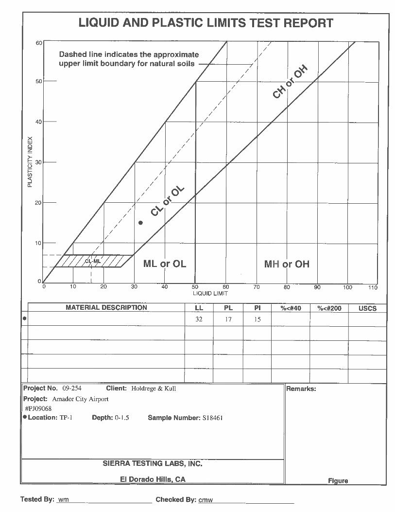
ATTERBERG LIMITS
Atterberg limits testing was performed in general accordance with ASTM D4318 and is frequently used in soil classification and identification. The soil descriptions defined by the USCS are based on these limits. Soil materials are classified in the laboratory by performing several tests that define the plastic and liquid limits on the portion of the sample passing the No. 40 sieve. Table 3.1 summarizes the test results and they are also graphically represented in Appendix D.
Table 3.1 – Summary of Atterberg Limits
Exploration Point
Sample Number
Sample Depth (feet)
Liquid Limit (%)
Plastic Limit (%)
Plastic Index (%)
USCS Classification
TP-01 1 0 to 1.5 32 17 15 Clayey SAND
MAXIMUM DRY DENSITY/OPTIMUM MOISTURE DETERMINATION
The compaction characteristics, maximum dry density and optimum moisture content were determined for selected bulk samples in accordance with ASTM D1557. Table 3.2 summarizes the test results and they are also graphically represented in Appendix D.
Table 3.2 – Summary of Maximum Density/Optimum Moisture Results
Exploration Point
Sample Number
Sample Depth (feet)
Maximum Dry Density
(pcf)
Optimum Moisture Content
(%) TP-01 1 0 to 1.5 122.6 11.8
SP-2 1 NA 127.3 9.2
DIRECT SHEAR
To determine the shear strength parameters of the on-site soils, direct shear tests were performed on selected samples in general accordance with ASTM D3080. After the initial weight and volume measurements were made, the samples were placed in a direct shear machine and a selected normal load was applied (1, 2, and 4 kips per square foot [ksf]). The sample was submerged, allowed to consolidate, and then was sheared to failure. Shear stress and sample deformations were monitored throughout the test. Table 3.3 summarizes the test results and they are also graphically represented in Appendix D.

Project No. 80301-01 Geotechnical Engineering Report for Amador County Airport Runway Improvements December 21, 2009 Page 8
Holdrege & Kull
Table 3.3 – Summary of Direct Shear Results
Exploration Point Sample Number Sample Depth (feet) Friction Angle
(degrees) Cohesion
(psf)
TP-01 1 0 to 1.5 34.0 330
SP-2 1 NA 33.5 160
4 CONCLUSIONS
The following conclusions are based on our field observations, laboratory test results, and our experience in the area.
1. Our opinion is that the site is suitable for the proposed improvements, provided that the geotechnical engineering recommendations and design criteria presented in this report are incorporated into the project plans.
2. Our primary concern is the presence of large concentrations of cobbles at shallow depths, which may affect excavatability.
3. Based on our site observations, the geology of the region, and our experience in the area, our opinion is that the risk of seismically induced hazards such as slope instability, liquefaction, and surface rupture are remote at the project site.
4. Based on the site geology and our observation of the surface conditions, we anticipate that grading and excavation onsite will reveal variably weathered, fractured, volcanic rock. Areas of highly concentrated cobbles may be encountered which may decrease the rate of excavation. In addition, spoil resulting from excavation onsite will likely consist of gravel to cobble-sized rock fragments. This material may be suitable for use as fill, depending on the nominal size of the rock fragments, but will likely require specific recommendations for fill placement and observation to confirm compaction. Preliminary recommendations addressing rock fill placement are included in this report.
5. During our site investigation, we did not encounter ultramafic rock, serpentinite, or other naturally occurring asbestos (NOA) minerals. If ultramafic rock, serpentinite or NOA-containing minerals are encountered at the site, site grading would be regulated under Cal/EPA Air Resources Board Regulation 93105, Asbestos Airborne Toxic Control Measure for Construction, Grading, Quarrying, and Surface Mining Operations (ATCM). We anticipate that, as a minimum, dust mitigation measures such as limiting site access, restricting

Project No. 80301-01 Geotechnical Engineering Report for Amador County Airport Runway Improvements December 21, 2009 Page 9
Holdrege & Kull
onsite construction vehicle speeds, covering stockpiled soil, and liberal use of water during grading will be required during grading to prevent the generation of dust from the site. We can prepare an asbestos dust mitigation plan (ADMP) for project planning and approval purposes, if required.
6. We did not observe existing fill materials within our exploratory trenches. If existing fill is encountered during construction, we should be retained to evaluate the condition of the fill, and to make recommendations to mitigate the presence of fill, if necessary. Existing fill, if encountered, should not be relied upon to support proposed improvements without testing and evaluation.
7. Although we did not observe shallow groundwater or seepage during our surface reconnaissance, areas of seepage will likely be encountered during grading onsite, particularly during the rainy season and/or in excavations which reveal the surface soil/weathered rock contact. Preliminary recommendations regarding subsurface drainage/construction dewatering are presented in this report.
8. During our site investigation, we did not observe groundwater or seepage within our exploratory trenches. However, we did observe evidence that surface water is seasonally transported through the drainage channels and swales on the property. We anticipate that moist to saturated soil conditions and groundwater may be encountered during grading, particularly in excavations that reveal the soil/rock transition. Recommendations addressing moisture conditioning, drainage, and fill placement are presented in the following sections of this report.
9. Prior to grading and construction, we should be retained to review the proposed grading plan and structural improvements to confirm our recommendations.
10. Based on our observations and testing of the stockpile materials from samples SP-01, SP-02 and SP-03, it our opinion that this material is suitable for embankment fill for this project. Based on our observations of SP-04, this material is not suitable for use as fill for this project.
5 RECOMMENDATIONS
The following geotechnical engineering recommendations are based on our understanding of the project as currently proposed, our field observations, the results of our laboratory testing program, engineering analysis, and our experience in the area.

Project No. 80301-01 Geotechnical Engineering Report for Amador County Airport Runway Improvements December 21, 2009 Page 10
Holdrege & Kull
5.1 GRADING
The following sections present our grading recommendations. The grading recommendations address clearing and grubbing, soil preparation, cut slope grading, fill placement, fill slope grading, erosion control, subsurface drainage, surface water drainage, construction dewatering, underground utility trenches, soil corrosion potential, plan review, and construction monitoring.
5.1.1 Clearing and Grubbing
The areas to be graded should be cleared and grubbed to remove vegetation and other deleterious materials as described below.
1. Strip and remove debris from clearing operations and the top 1 to 3 inches of soil containing shallow vegetation, roots and other deleterious materials. The organic topsoil can be stockpiled onsite and used in landscape areas but is not suitable for use as fill. The project geotechnical engineer should approve any proposed use of the spoil generated from stripping prior to placement.
2. Overexcavate any relatively loose debris and soil that is encountered in our exploratory trenches or any other onsite excavations to underlying, competent material. Possible excavations include exploratory trenches excavated by others, mantles or soil test pits, holes resulting from tree stump or boulder removal, and mining relics.
3. Although not observed during our investigation, if loose, untested fill is encountered during site development, overexcavate a minimum of 5 feet beyond the areas of proposed improvements.
4. Overexcavate any encountered leach lines, abandoned sewer, water, and fuel lines, and loose soil in abandoned subsurface utility line trenches within the proposed improvement areas to underlying competent soil, as determined by a representative of H&K.
5. Rocks greater than 8 inches in nominal dimension (oversized rock) should be removed from native soil by scarifying to a depth of 12 inches below finish grade in areas to support pavement, slabs-on-grade or other flatwork. Oversized rock may be used in landscape areas, rock landscape walls, or removed from the site. Oversized rock can be stockpiled onsite and used to construct fills, but must be placed at or near the bottom of deep fills and must be placed in windrows to avoid nesting. No oversized rock should be placed in the upper 3 feet of any structural fill. An H&K geotechnical engineer should approve any use of oversized rock prior to constructing fill.

Project No. 80301-01 Geotechnical Engineering Report for Amador County Airport Runway Improvements December 21, 2009 Page 11
Holdrege & Kull
6. Fine grained, potentially expansive soil that is encountered during grading should be mixed with granular soil, or overexcavated and stockpiled for removal from the project site or for later use in landscape areas. A typical mixing ratio for granular to expansive soil is 4 to 1. The actual mixing ratio should be determined by a representative of H&K.
7. Vegetation, deleterious materials, structural debris, and oversized rocks not used in landscape areas, drainage channels, or other non-structural uses should be removed from the site.
5.1.2 Cut Slope Grading
Based on our understanding of the project at this time, no permanent cut slopes are proposed to be created during grading of the proposed improvements. However, in general, permanent cut slopes should not be steeper than 2:1, horizontal to vertical (H:V).
Steeper cut slopes may be feasible, depending on the soil/rock conditions encountered and should be reviewed on a case-by-case basis. Depending on actual grading conditions, and soil/rock conditions some form of improvement (i.e. geogrids, MSE walls, soil nails) may be required if slopes steeper than 2:1 are desired. The upper two feet of all cut slopes should be graded to an approximate 2:1, H:V, slope to reduce sloughing and erosion of looser surface soil.
Temporary cut slopes may be constructed to facilitate retaining wall construction. We anticipate that subsurface conditions will be favorable for construction of temporary cut slopes no steeper than ½:1, H:V, for a maximum height of approximately 6 feet. To reduce the likelihood of sloughing or failure, temporary cut slopes should not remain over the winter. To reduce the likelihood of sloughing or failure, temporary cut slopes should not remain over the winter, should not be excavated during periods of expected wet weather, and should not be left in place for more than 48 hours without written authorization of H&K.
A representative of H&K must observe temporary cut slopes steeper than 2:1, H:V, during grading to confirm the soil and rock conditions encountered. We recommend that personnel not be allowed between the cut slope and the proposed retaining structure, form work, grading equipment, or parked vehicles during construction, unless the stability of the slope has been reviewed by H&K or the slope has been confirmed to meet OSHA excavation standards.

Project No. 80301-01 Geotechnical Engineering Report for Amador County Airport Runway Improvements December 21, 2009 Page 12
Holdrege & Kull
5.1.3 Soil Preparation for Fill Placement
Where fill placement is proposed, the surface soil exposed by site clearing and grubbing should be prepared as described below.
1. The surface soil should be scarified to a minimum depth of 12 inches below the existing ground surface, or to resistant rock, whichever is shallower. Following scarification, the soil should be uniformly moisture conditioned to within approximately 3 percentage points of the optimum moisture content in accordance with ASTM D1557.
2. The scarified and moisture conditioned soil should then be compacted to achieve a minimum relative compaction of 90 percent of the maximum dry density in accordance with ASTM D1557. The moisture content, density, and relative percent compaction should be verified by a representative of H&K. The earthwork contractor should assist our representative by excavating test pads with onsite earth moving equipment.
3. Where fill placement is proposed on native slopes steeper than approximately 5:1, H:V, a base key and routine benches must be provided. Unless otherwise recommended by the project geotechnical engineer, the base key should be excavated at the toe of the fill a minimum of 2 feet into competent stratum, as determined by a representative of H&K during construction observation. The bottom of the base key should be sloped slightly into the hillside at an approximate gradient of 5 percent or greater.
4. The fill must be benched into existing side slopes as fill placement progresses. Benching must extend through loose surface soil into firm material, and at intervals such that no loose surface soil is beneath the fill. As a minimum, a horizontal bench should be excavated every 5 vertical feet or as determined by a representative of H&K.
5.1.4 Fill Placement
Soil fill placement proposed for the project should incorporate the following recommendations:
1. Soil used for fill should consist of uncontaminated, predominantly granular, non-expansive native soil or approved import soil. If encountered, rock used in fill should be broken into pieces no larger than 8 inches in nominal diameter. Rocks larger than 8 inches are considered oversized material and should be

Project No. 80301-01 Geotechnical Engineering Report for Amador County Airport Runway Improvements December 21, 2009 Page 13
Holdrege & Kull
stockpiled for removal from the site or for use in landscape areas and drainage channels as rip-rap.
2. Import soil should be predominantly granular, non-expansive and free of deleterious material. Import material that is proposed for use onsite should be submitted to H&K for approval and possible laboratory testing at least 72 hours prior to transport to the site.
3. Cohesive, predominantly fine grained, or potentially expansive soil encountered during grading should be stockpiled for removal, mixed as directed by H&K, or used in landscape areas.
As an option, cohesive fine grained, or potentially expansive soil can often be placed in the deeper portions of proposed fill (e.g., depths greater than 3 feet below subgrade in building footprints). However, this option would have to be evaluated on a case-by-case basis by H&K with consideration of the fill depth and proposed loading conditions.
4. Soil used to construct fill should be uniformly moisture conditioned to within approximately 3 percentage points of the optimum moisture content in accordance with ASTM D1557. Wet soil may need to be air dried or mixed with drier material to facilitate placement and compaction, particularly during or following the wet season.
5. Fill should be constructed by placing uniformly moisture conditioned soil in maximum 8-inch-thick loose, horizontal lifts (layers) prior to compacting.
6. All fill should be compacted to a minimum relative compaction of 90 percent of the maximum dry density in accordance with ASTM D1557. The upper 12 inches of fill in paved areas, beneath proposed slabs-on-grade, and within building footprints should be compacted to a minimum of 95 percent relative compaction.
The moisture content, density and relative percent compaction of fill should be confirmed by a representative of H&K during construction.
5.1.5 Rock Fill Placement
Based on our observation of the rocky nature of the subsurface conditions revealed in our exploratory trenches, we anticipate that fill material generated from the project site may contain significant cobble-size rock fragments, and that compaction testing with conventional methods may be difficult or inappropriate. Typically, fill that consists primarily of soil can be tested for relative compaction by using a nuclear density gauge. Our opinion is that rock fill cannot be reliably tested using this method.

Project No. 80301-01 Geotechnical Engineering Report for Amador County Airport Runway Improvements December 21, 2009 Page 14
Holdrege & Kull
We recommend that quality assurance during rock fill placement be based on a procedural approach, or method specification, rather than a specified relative compaction. The procedural requirements will depend on the equipment used, as well as the nature of the fill material, and will need to be determined by the geotechnical engineering firm onsite. Typically, procedural recommendations are based on the measured relative compaction of a test fill constructed onsite.
Based on our experience in the area, we anticipate that the procedural specification will require a minimum of six passes (back and forth equaling one pass) with a Cat 563 or similar, self-propelled, vibratory compactor to compact a maximum 8-inch-thick, loose lift. Processing or screening of the fill material will be needed to remove rocks larger than approximately 8 inches in maximum dimension. Continuous or nearly continuous observation by a representative of H&K would be required during fill placement to confirm that procedural specifications have been met.
5.1.6 Fill Slope Grading
Based on our understanding of the project, we anticipate that 4:1, H:V fill slopes up to 20 feet in height will be created as part of the proposed improvements. In general, permanent fill slopes created onsite should be no steeper than 2:1, H:V. H&K should review fill slope configurations greater than approximately 15 feet in height, if proposed, prior to fill placement. Compaction and fill slope grading must be confirmed by H&K in the field.
Steeper fill slopes may be feasible with the use of geotextile reinforcement and/or rock facing. We can provide reinforced or buttressed fill slope design for the project, if requested.
Fill should be placed in horizontal lifts to the lines and grades shown on the project plans. Slopes should be constructed by overbuilding the slope face and then cutting it back to the design slope gradient. Fill slopes should not be constructed or extended horizontally by placing soil on an existing slope face and/or compacted by track walking.
Where soil fill slopes are proposed, oversized rock should be placed a minimum of 5 feet horizontally from the finished fill slope face.
5.1.7 Erosion Controls
Graded portions of the site should be seeded as soon as possible to allow vegetation to become established prior to and during the rainy season. In addition,

Project No. 80301-01 Geotechnical Engineering Report for Amador County Airport Runway Improvements December 21, 2009 Page 15
Holdrege & Kull
grading that results in greater than one acre of soil disturbance or in sensitive areas. The County has stated that the preparation of a site-specific storm water pollution prevention plan provided by the contractor will be required. As a minimum, the following controls should be installed prior to and during grading to reduce erosion.
1. Prior to commencement of site work, fiber rolls should be installed down slope of the proposed area of disturbance to reduce migration of sediment from the site. Fiber rolls on slopes are intended to reduce sediment discharge from disturbed areas, reduce the velocity of water flow, and aid in the overall revegetation of slopes. The fiber rolls should remain in place until construction activity is complete and vegetation becomes established.
2. All soil exposed in permanent slope faces should be hydroseeded or hand seeded/strawed with an appropriate seed mixture compatible with the soil and climate conditions of the site as recommended by the local Resource Conservation District.
3. Following seeding, jute netting or erosion control blankets should be placed and secured over the slopes steeper than 2:1, H.V.
4. Surface water drainage ditches should be established as necessary to intercept and redirect concentrated surface water away from cut and fill slope faces. Under no circumstances should concentrated surface water be directed over slope faces. The intercepted water should be discharged into natural drainage courses or into other collection and disposal structures.
5.1.8 Soil Corrosion Potential
Index testing of the soil in an effort to evaluate corrosion potential was not performed as a part of our soil evaluation. Based on review of soil survey information the native soil conditions onsite possess a moderate corrosion potential for uncoated steel and concrete.
To reduce the likelihood of corrosion problems, materials used for underground utilities, permanent subsurface drainage improvements, and foundation systems should be selected based on local experience and practice. If alternative or new construction methods or materials are being proposed, it may be appropriate to have the selected materials tested and evaluated by a corrosion engineer for compatibility with the onsite soil and groundwater conditions.

Project No. 80301-01 Geotechnical Engineering Report for Amador County Airport Runway Improvements December 21, 2009 Page 16
Holdrege & Kull
5.1.9 Surface Water Drainage
Proper surface water drainage is important to the successful development of the project. We recommend the following measures to help mitigate surface water drainage problems:
1. To reduce surface water infiltration, compact and slope all soil placed adjacent to retaining wall foundations such that water is not allowed to pond. Backfill should be free of deleterious materials.
2. Construct V-ditches at the top of cut and fill slopes where necessary to reduce concentrated surface water flow over slope faces. Typically, V-ditches should be 3 feet wide and at least 6 inches deep. V-ditches are not allowed within the proposed RSA areas per the FAA. Surface water collected in V-ditches should be directed away and downslope from proposed improvements.
5.1.10 Grading Plan Review and Construction Monitoring
Construction quality assurance includes review of plans and specifications and performing construction monitoring as described below.
1. H&K should be retained to review the final grading plans prior to construction to confirm our understanding of the project at the time of our investigation, to determine whether our recommendations have been implemented, and to provide additional and/or modified recommendations, if necessary.
2. H&K should be retained to perform construction quality assurance (CQA) monitoring of all earthwork grading performed by the contractor to determine whether our recommendations have been implemented, and if necessary, provide additional and/or modified recommendations.
5.2 STRUCTURAL IMPROVEMENT DESIGN CRITERIA
The following sections present our structural improvement design criteria and recommendations. The recommendations address foundations, seismic parameters, concrete slabs-on-grade, retaining walls and pavement design.
5.2.1 Foundations
Provided that the grading for the project is performed in accordance with the recommendations presented in this report, our opinion is that the site will be suitable for the use of conventional perimeter foundations for the proposed retaining wall along the toe of the southern runway embankment. Following are

Project No. 80301-01 Geotechnical Engineering Report for Amador County Airport Runway Improvements December 21, 2009 Page 17
Holdrege & Kull
our recommendations for foundations constructed on compacted and tested fill or competent native soil:
1. Footings for the proposed retaining wall should have a minimum width of 36 inches and penetrate through any loose surface material, potentially expansive soil, or untested fill, with a minimum of 24 inches embedment into competent native soil, weathered rock and/or compacted fill. If clay is encountered at the base of footing excavations, the footing should be deepened through the clay lens into underlying granular material or weathered rock, as determined in the field by H&K.
2. The base of the footing excavation should be approximately level. On sloping sites, it will be necessary to step the base of the footing excavation as necessary to maintain a slope of less than 10 percent at the base of the footing.
3. Footing trenches should be cleaned of all loose soil and construction debris prior to placing concrete. A representative from H&K should observe the footing excavations prior to concrete placement.
4. In an effort to reduce the likelihood of settlement-induced distress to the proposed structures, we recommend that strip and isolated footings with a minimum embedment depth of 12 inches in competent soil be sized for an allowable bearing capacity of 4,000 psf for dead plus live loads. Allowable bearing may be increased by 33 percent for additional transient loading, such as wind or seismic loads.
5. A triangularly-distributed lateral resistance (passive soil resistance) 375 psf, where d is footing depth, may be used for footings. This value may be increased by 33 percent for wind and seismic. As an alternate to the passive soil resistance described above, a coefficient of friction for resistance to sliding of 0.35 may be used.
6. In general, structures constructed adjacent to descending slopes should employ a minimum setback of either 1/3 the height of the slope, or 40 feet, whichever is less. The setback for ascending slopes is either 1/2 the slope height or 15 feet, whichever is less. Where footings are proposed within these code-based setbacks, the project geotechnical engineer should review the proposed slope configuration and provide revised setback recommendations, if appropriate.

Project No. 80301-01 Geotechnical Engineering Report for Amador County Airport Runway Improvements December 21, 2009 Page 18
Holdrege & Kull
5.2.2 Retaining Wall Design Criteria
The following active and passive pressures are for retaining walls in cut native soil or backfilled with granular soil derived from the site. If import soil is used, a representative from our firm should be retained to observe and test the soil to determine its strength properties. The pressures exerted against retaining walls may be assumed to be equal to a fluid of equivalent unit weight.
Table 5.1 presents equivalent fluid unit weights for cut native soil and onsite fill compacted per the grading recommendations presented in this report. For approximately horizontal backfill we assume that the retained fill surface will be no steeper than 10% for a minimum distance of the wall height from the back of the retaining wall. If surcharge loads (such as adjacent building foundations) or live loads will be applied within a distance of the wall height from the back of the wall, we should be retained to review the loading conditions and revise our recommendations, if necessary.
Table 5.1 - Equivalent Fluid Unit Weights (1)
Loading Condition
Retained Cut or Compacted Fill
(approximately horizontal backfill)
Retained Cut or Compacted Fill (retained
slope up to 2:1, H:V)
Active Pressure (pcf) 35 45
Passive Pressure (pcf) 375
Coefficient of Friction 0.35
Note: (1) The equivalent fluid unit weights presented are ultimate values and do not include a factor of safety. The passive pressures provided assume footings are founded in competent native soil or engineered fill.
Please note that the use of the tabulated active pressure unit weight requires that the wall design accommodate sufficient deflection for mobilization of the retained soil to occur. Typically, a wall yield of less than 1 percent of the wall height is sufficient to mobilize active conditions in granular soil. However, if the walls are rigid or restrained to prevent rotation, at-rest conditions should be used for design.
Recommendations for design and construction of retaining walls are listed below:
1. Compaction equipment should not be used directly adjacent to retaining walls unless the wall is designed or braced to resist the additional lateral pressures.

Project No. 80301-01 Geotechnical Engineering Report for Amador County Airport Runway Improvements December 21, 2009 Page 19
Holdrege & Kull
2. If any surface loads are closer to the top of the retaining wall than its height, H&K should review the loads and loading configuration. We should be retained to review wall details and plans for any wall over 10 feet in height.
3. All retaining walls must be well drained to reduce hydrostatic pressures. Walls should be provided with a drainage blanket to reduce additional lateral forces and minimize saturation of the backfill soil. Drainage blankets may consist of graded rock drains or geosynthetic blankets.
4. Rock drains should consist of a minimum 12-inch wide, Caltrans Class II or equivalent as approved by the Geotechnical Engineer, permeable drainage blanket, placed directly behind the wall; or crushed washed rock enveloped in a non-woven geotextile filter fabric such as Amoco 4546™ or equivalent. Drains should have a minimum 4-inch diameter, perforated, schedule 40, PVC pipe placed at the base of the wall, inside the drainrock, with the perforations placed down. The PVC pipe should be sloped so that water is directed away from the wall by gravity. A geosynthetic drainage blanket such as Enkadrain™ or equivalent may be substituted for the rock drain, provided the collected water is channeled away from the wall. If a geosynthetic blanket is used, backfill must be compacted carefully so that equipment or soil does not tear or crush the drainage blanket.
5. Additional lateral loading on retaining structures due to seismic accelerations may be considered at the designer’s option. For an earthquake producing a design horizontal acceleration of 0.2g, we recommend that the resulting additional lateral force applied to unrestrained (cantilevered) retaining structures with drained level backfill onsite be estimated as Pae=9H2 pounds, where H is the height of the wall in feet. The additional seismic force may be assumed to be applied at a height of 0.6H above the base of the wall. This seismic loading is for a drained, level backfill condition only; H&K should be consulted for values of seismic loading due to non-level or non-drained backfill conditions. The use of reduced factors of safety is often appropriate when reviewing overturning and sliding resistance during seismic events.
5.2.3 Pavement Design
The project is not requiring the use of asphaltic concrete pavement. However, the run-out ramps are proposed to be surfaced with aggregate base material. We make the following recommendations regarding the run-out ramp surfaces.
1. Fill must be compacted to a minimum of 90 percent of the maximum dry density in accordance with ASTM D1557. The upper 12 inches of subgrade in areas to be topped with base material must be compacted to a minimum of 95

Project No. 80301-01 Geotechnical Engineering Report for Amador County Airport Runway Improvements December 21, 2009 Page 20
Holdrege & Kull
percent of the maximum density in accordance with ASTM D1557. Moisture content, density and relative percent compaction should be verified by H&K. In addition to density testing, the subgrade must be proofrolled under the observation of a representative of H&K, prior to baserock placement
2. We recommend that a minimum of 4 inches of aggregate base material be placed over the proposed run-out subgrade. Baserock should be compacted to a minimum of 95 percent of the maximum density in accordance with ASTM D1557. Moisture content, density and relative percent compaction should be verified by H&K. Baserock should be at minimum a crushed miscellaneous base meeting the specifications presented in the latest edition of the Public Works “Green Book”.
3. Subgrade should be sloped to drain away from the proposed run-out alignment.
4. Import soil, if used, should be predominantly granular, non-expansive and free of deleterious material. Proposed import should be submitted to H&K for testing prior to transport to the site.
6 LIMITATIONS
The following limitations apply to the findings, conclusions and recommendations presented in this report:
1. Our professional services were performed consistent with the generally accepted geotechnical engineering principles and practices employed in northern California. No warranty is expressed or implied.
2. These services were performed consistent with our agreement with our client. We are not responsible for the impacts of any changes in environmental standards, practices, or regulations subsequent to performance of our services. We do not warrant the accuracy of information supplied by others, or the use of segregated portions of this report. This report is solely for the use of our client unless noted otherwise. Any reliance on this report by a third party is at the party's sole risk.
3. If changes are made to the nature or design of the project as described in this report, then the conclusions and recommendations presented in this report should be considered invalid. Only our firm can determine the validity of the conclusions and recommendations presented in this report. Therefore, we should be retained to review all project changes and prepare written responses with regards to their impacts on our conclusions and recommendations.
Project No. 80301-01 Geotechnical Engineering Report for Amador County Airport Runway Improvements December 21, 2009 Page 21
Holdrege & Kull
However, we may require additional fieldwork and laboratory testing to develop any modifications to our recommendations. Costs to review project changes and perform additional fieldwork and laboratory testing necessary to modify our recommendations are beyond the scope of services presented in this report. Any additional work will be performed only after receipt of an approved scope of services, budget, and written authorization to proceed.
4. The analyses, conclusions and recommendations presented in this report are based on site conditions as they existed at the time we performed our surface and subsurface field investigations. We have assumed that the subsurface soil and groundwater conditions encountered at the location of our exploratory points are generally representative of the subsurface conditions throughout the entire project site. However, the actual subsurface conditions at locations between and beyond our exploratory points may differ. Therefore, if the subsurface conditions encountered during construction are different than those described in this report, then we should be notified immediately so that we can review these differences and, if necessary, modify our recommendations.
5. The elevation or depth to groundwater underlying the project site may differ with time and location.
6. The project site map shows approximate exploratory point locations as determined by pacing distances from identifiable site features. Therefore, the point locations should not be relied upon as being exact nor located with surveying methods.
7. Our geotechnical investigation scope of services did not include evaluating the project site for the presence of historic mining operations or hazardous materials. Although we did not observe evidence of historic mining activity or hazardous materials within the proposed building area at the time of our field investigation, all project personnel should be careful and take the necessary precautions should hazardous materials be encountered during construction. Possible historic mining excavation not detected during our investigation may impact the proposed improvements.
8. The findings of this report are valid as of the present date. However, changes in the conditions of the property can occur with the passage of time. The changes may be due to natural processes or to the works of man, on the project site or adjacent properties. In addition, changes in applicable or appropriate standards can occur, whether they result from legislation or the broadening of knowledge. Therefore, the recommendations presented in this report should not be relied upon after a period of two years from the issue date without our review.

Project No. 80301-01 Geotechnical Engineering Report for Amador County Airport Runway Improvements December 21, 2009 Page 22
Holdrege & Kull
9. H&K should be retained to perform observation and testing of fill during all earthwork construction for this project. If another firm is hired to perform this work, then that firm should review this report and accept its findings and will assume the responsibilities of Geotechnical Engineer of Record for this project.

FIGURES Figure 1 Site Vicinity Map Figure 2 Exploratory Trench Location Map


APPENDIX A PROPOSAL

Proposal No. PJ09068PW August 27, 2009 Revised September 3, 2009 Mr. Martin Price, PE Amador County Public Works Agency 810 Court Street Jackson, California 95642
Reference: Amador County Airport Runway Improvements Martell, Amador County, California
Subject: Proposal for Geotechnical Engineering Services
Dear Mr. Price,
Holdrege & Kull (H&K) is pleased to provide this proposal to perform geotechnical engineering services for the proposed runway improvements at the Amador County Airport located in the Martell area of Amador County, California. To prepare this proposal, we discussed the project with you on August 6, 2009. We reviewed applicable portions of the undated “Runway Improvement Plans” prepared by the County and visited the proposed improvement areas at the airport with you and key members of your staff. PROPOSED PROJECT It is our understanding that the County is planning on constructing airplane run-out ramps at both ends of the existing runway. The purpose of these ramps is to provide additional runway space for airplane emergencies, primarily to help the plans stop before impacting surrounding properties. The project on the north end of the run way will result in the placement of approximately 20 feet of embankment fill and 4:1 slopes. The project at the south end of the runway will also result in the placement of 20 feet of embankment fill, and the construction of a proposed 4-foot high retaining wall. PROPOSED SCOPE OF SERVICES Based on our understanding of the project, we propose to perform the following scope of services.
County Airport Runway Imprvements PJ09068PW Proposal for Geotechnical Engineering Services August 27, 2009 (Revised September 3, 2009) Page 2
Holdrege & Kull
Coordination and Permitting
Items to be provided by the County include the right-of-entry to conduct the exploration and information regarding the type and location of any subsurface utilities existing in the area. If there are any other restrictions or special requirements regarding the site or exploration, these should also be provided by the County prior to our field work. We will contact Underground Service Alert (USA), who coordinates with underground utility companies. It normally requires 48 hours to have utilities located and we often have been required to meet with utility companies on site to show them where we plan to drill. To further reduce the risk of damage to underground utilities, H&K can contract with, or refer to the County, a private utility locating service for an additional fee. Although H&K will use reasonable caution during subsurface investigation, H&K cannot be responsible for damage to underground utilities that were not located or were improperly located by others prior to the subsurface investigation. This proposal is based on all soil test pit locations being readily accessible to conventional equipment. Layout and elevation of the borings by our personnel will be determined from available site features. If H&K lays out the test pits, the exploration point layout will be approximate. Distances from available features are generally measured using a tape or pacing, and angles are estimated. Approximate elevations will be interpolated from available drawings or by using an engineer’s level and a local reference point as a benchmark. If a specific elevation reference is desired, we recommend having the project surveyor locate our exploration point locations after excavating. Field Investigation
We will advance a total of four (4) exploratory test in the vicinity of the proposed runway improvements, two (2) at each end of the runway. The test pits will range in depth from 5 to 15 feet below the ground surface (bgs). We anticipate using a conventional back-hoe or excavator equipped with a 2-foot bucket to excavate the test pits. We also plan to use this equipment to dig several locations within the stockpiled soil located near the airport parking lot to obtain samples for determining suitability of this material for backfill import. We will obtain bulk samples of the soil encountered for laboratory testing. An engineer or geologist from our firm will log the borings in the field.

County Airport Runway Imprvements PJ09068PW Proposal for Geotechnical Engineering Services August 27, 2009 (Revised September 3, 2009) Page 3
Holdrege & Kull
The test pits will be backfilled in accordance with appropriate state regulations after completion of drilling. The client should understand that some settlement of the test pit backfill may occur. No future maintenance or filling of the trenches is included in our fee. Laboratory Testing H&K will perform laboratory tests on selected soil samples to determine their engineering material properties. Anticipated laboratory tests may include moisture/density determination, grain-size distribution, Atterberg limits and direct shear strength testing. Additional laboratory tests may be required on a case-by-case basis to evaluate potentially adverse soil conditions. We would notify you of additional costs in advance if additional laboratory testing is required based on unforeseen subsurface conditions. Engineering Analysis Based on our laboratory test results, we will perform the necessary calculations to evaluate slope stability, and to provide retaining wall (foundations and lateral earth pressures), general grading and drainage recommendations. Geotechnical Report Following completion of the above tasks, we will compile a geotechnical report that will include: ▪ Logs of exploratory test pits;
▪ Site plan showing approximate location of exploratory test pits;
▪ Description of site geology, and the soil and rock conditions encountered;
▪ Fill slope grading and stabilization recommendations;
▪ Grading and drainage recommendations;
▪ Conclusions regarding the feasibility of the proposed improvements from a geotechnical standpoint; and
▪ Retaining wall foundation and lateral pressure recommendations.

County Airport Runway Imprvements PJ09068PW Proposal for Geotechnical Engineering Services August 27, 2009 (Revised September 3, 2009) Page 4
Holdrege & Kull
CAD Services
As requested, we are including Computer Aided Design (CAD) support services to aid the county in incorporating applicable details and test pit logs into their plans. We have assumed 20 hours of time for this portion of the scope. SCHEDULE We will schedule our field investigation within one week of receiving authorization to proceed, weather and drill rig availability permitting. We can usually provide verbal preliminary geotechnical recommendations within one week following the site investigation based on the field investigation data. However, final recommendations will be developed from the field and laboratory data. We anticipate the final geotechnical report will be submitted within three to four weeks following completion of our field investigation. Standard laboratory turn-around time is two weeks for the environmental testing. We anticipate we will be able to issue our summary environmental letter report within two weeks of receiving the laboratory results. FEES We estimate the cost to provide the services described above will be $6,930 on a not to exceed time and materials basis. Project billing will be monthly on a percent complete basis. The following table breaks down the cost by task:
Proposed Tasks Costs 1 Geotechnical Report
1.1 Coordination and USA $ 400 1.2 Field Work 1 $ 2,000 1.3 Laboratory Analysis 2 $ 1,600 1.4 Engineering Analysis $ 1,250 1.5 Geotechnical Report $ 1,064 1.6 CAD Services $ 1,540
TOTAL $ 7,854
1 This cost assumes that the county will provide the excavation equipment and operators. 2 If additional testing is required, this can be performed on a time-and-expense basis.

County Airport Runway Imprvements PJ09068PW Proposal for Geotechnical Engineering Services August 27, 2009 (Revised September 3, 2009) Page 5
Holdrege & Kull
Should any conditions be encountered which require additional testing outside the scope of services outlined above, we will advise you promptly and obtain your approval on a recommended course of action. We can provide additional testing services beyond this estimate, at your request. Our scope of services above assume to working days to complete all the field work and that the County will provide the excavation equipment, operators and proper safety flagging as required by the Federal Aviation Administration. If H&K is required to provide these services, we have a quote from Wolin & Sons, Inc. which will add $2,574 to the above fee (including our 20-percent markup for providing outside services). We appreciate the opportunity to submit this proposal and we look forward to working with you on this project. If this proposal is acceptable, please sign and return a copy of this letter. If you have any questions or need further information, please call. Sincerely, HOLDREGE & KULL
Michael W. Laney, P.E., G.E. Senior Engineer RCE 56686, GE 2539 Expires 6/30/2011 I hereby authorize Holdrege & Kull to implement the above scope of services per the fee estimate outlined in this proposal. This authorization extends the existing signed contract for geotechnical engineering services , set to expire June 30, 2010, between the Amador County Public Works Agency and Holdrege & Kull to apply to the services and fees outlined in this proposal. _______________________________ Name Title _______________________________ Signature Date \\Handkjack\shared\2 Proposals\2009\PJ09068 Amador County Airport\PJ09068 Amador County Airport Improvements Pro.doc

APPENDIX B IMPORTANT INFORMATION ABOUT YOUR GEOTECHNICAL ENGINEERING REPORT (Included with permission of ASFE, Copyright 2004)


APPENDIX C EXPLORATORY TRENCH LOGS


APPENDIX D LABORATORY TEST DATA