8051 general purpose board - 3.imimg.com · 8051 general purpose board ... (txd) and receive data...
TRANSCRIPT

1
CAMPUS
COMPONENT
www.campuscomponent.com
8051 General Purpose Board
Pvt. Ltd.

8051 General Purpose Board www.campuscomponent.com
Page 2
DISCLAIMER
Information furnished is believed to be accurate and reliable at the time of publication. However, Campus Component Pvt. Ltd. assumes no responsibility arising from the use of the specifications described. The applications mentioned herein are used solely for the purpose of illustration and Campus component Pvt. Ltd. makes no warranty or representation that such applications will be suitable without further modification, nor recommends the use of its products for application that may present a risk to human life due to malfunction or otherwise. Campus Component Pvt. Ltd. does not assume any liability arising out of the application or use of any product or circuit described herein;
neither does it convey any license under its patents rights, nor the rights of other. Campus Component Pvt. Ltd. reserves the right to alter its products without prior notification. For the most up-to-date information, please visit our web site at http://www.campuscomponent.com Pictures are representational only and actual product may vary.
Copyright © 2011CAMPUS COMPONENT Pvt. Ltd. All rights reserved. Campus Component Pvt. Ltd.®, logo and
combinations thereof, are registered trademarks of CAMPUS COMPONENT Pvt. Ltd. Other terms and product
names may be trademarks of others.
8051 General Purpose Board www.campuscomponent.com
Page 3
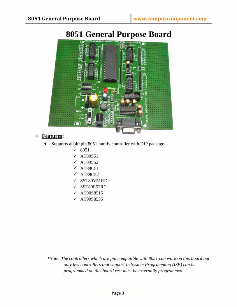
8051 General Purpose Board
Features:
Supports all 40 pin 8051 family controller with DIP package.
8051
AT89S51
AT89S52
AT89C51
AT89C52
SST89V51RD2
SST89E52RC
AT90S8515
AT90S8535
*Note: The controllers which are pin compatible with 8051 can work on this board but
only few controllers that support In System Programming (ISP) can be
programmed on this board rest must be externally programmed.

8051 General Purpose Board www.campuscomponent.com
Page 4
All ports are connected to standard 10 pin FRC connector and also has a separate
straight berg-strip connected.
FRC connector for ISP.
General purpose PCB area provided on board.
On board 11.0592 MHz crystal oscillators.
Adapter input socket for 12 VAC or DC.
Reverse polarity protected.
Voltage regulation provided by IC LM7805
Serial port for programming.
Power ON indicator LED.
Ready arrangement for serial communication through serial port.
Provides facility for resetting the board when required.
Power supply ON/OFF switch provided on board.

8051 General Purpose Board www.campuscomponent.com
Page 5
Hardware Description:
Port connector:
Four port connectors are separately provided on the board. Each port (Port A, Port
B, Port C and Port D) connectors has 10 pins. Pin identification is done with respect to
the notch provided as shown:
Fig. FRC connector
FRC cable :
Notch

8051 General Purpose Board www.campuscomponent.com
Page 6
Two FRC connectors can be connected with the help of FRC cable.FRC cable has
following pin configuration:
Fig.FRC cable
Serial Port:
A serial port is a serial communication physical interface through which
information transfers in or out one bit at a time.This port is provided for the purpose of
serial communication. This helps the microcontroller to communicate with the peripheral
device. When the user need to communicate
through the serial port, the transmit data pin
(TxD) and receive data pin (RxD) need to be
connected externally by the user. There is a 3-pin
berg strip pin-out beside IC MAX232 with pin
TxD, RxD and GND (ground). The TxD pin
should be connected to the TxD pin i.e. P3.1 pin
or pin no.11 and the RxD pin should be connected
to the RxD pin i.e. 3.0 pin or pin no.10 of the 40
pin 8051 family controller used.
MAX232CPE:
The MAX232 is an integrated circuit that converts signals from an RS-232 serial
port to signals suitable for use in TTL compatible digital logic circuits.
8051 General Purpose Board www.campuscomponent.com
Page 7
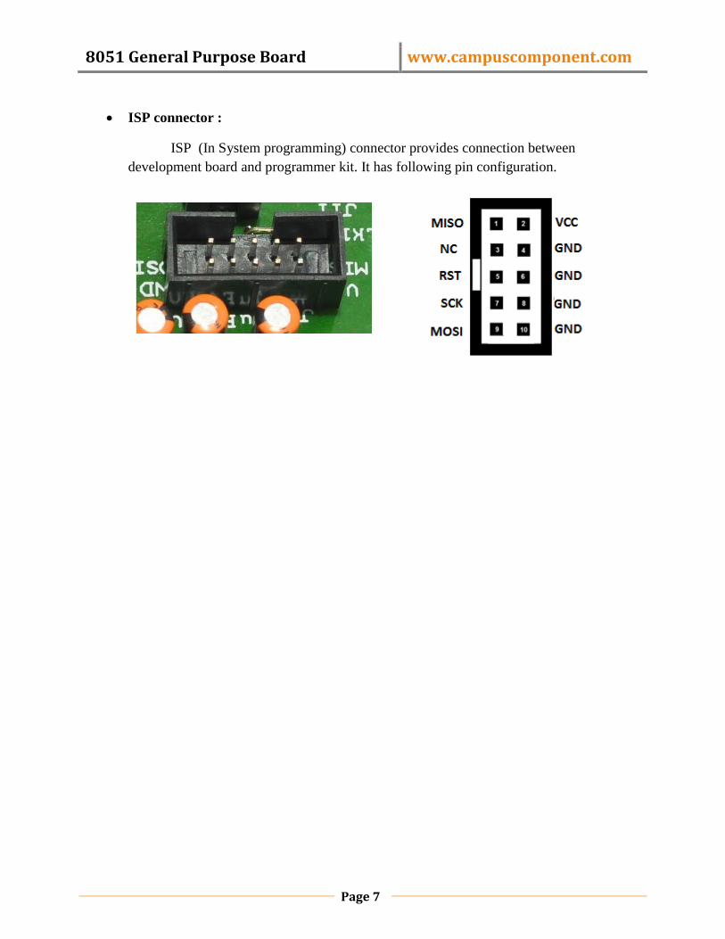
ISP connector :
ISP (In System programming) connector provides connection between
development board and programmer kit. It has following pin configuration.

8051 General Purpose Board www.campuscomponent.com
Page 8
Steps for Using Development Board with Phillips 89V51RD2
Installation of Keil µVision Software
STEP 1: Double click on installation file of Keil Software; welcome window will appear click
on ‘Next’.
STEP 2: Read License Agreement carefully and make tick on I agree and then click on
‘Next>>’.
8051 General Purpose Board www.campuscomponent.com
Page 9
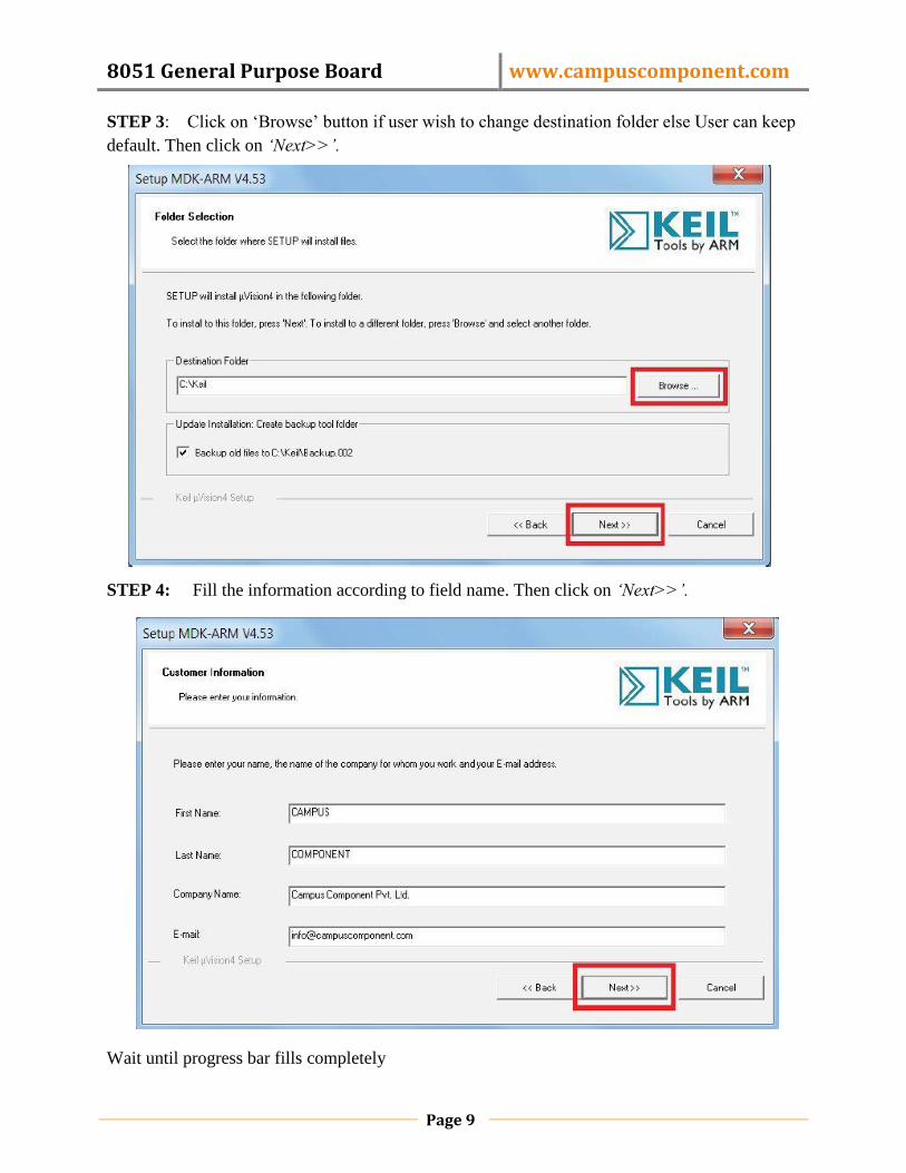
STEP 3: Click on „Browse‟ button if user wish to change destination folder else User can keep
default. Then click on ‘Next>>’.
STEP 4: Fill the information according to field name. Then click on ‘Next>>’.
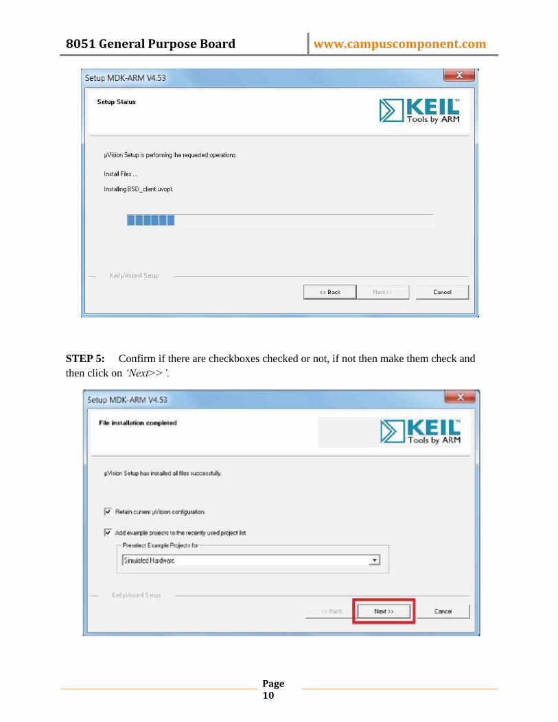
Wait until progress bar fills completely
8051 General Purpose Board www.campuscomponent.com
Page 10
STEP 5: Confirm if there are checkboxes checked or not, if not then make them check and
then click on ‘Next>>’.

8051 General Purpose Board www.campuscomponent.com
Page 11
STEP 6: Confirm if there are checkboxes checked or not, if not then make them check and
then click on ‘Next>>’.
STEP 7: New window will appear, it will ask user to „install device software’. Then click on
‘Install’.

8051 General Purpose Board www.campuscomponent.com
Page 12
Welcome window will appear
STEP 8: In main window go to main menu bar and click on ‘Project’ option. Then click on
„New µVision Project’ to create new project.

8051 General Purpose Board www.campuscomponent.com
Page 13
STEP 9: A new window will appear and ask user to put name for project, write file name and
then click on „Save’.
STEP 10: Locate ‘NXP (founded by Philips)‟ and expand it by clicking on „+‟ sign.
8051 General Purpose Board www.campuscomponent.com
Page 14
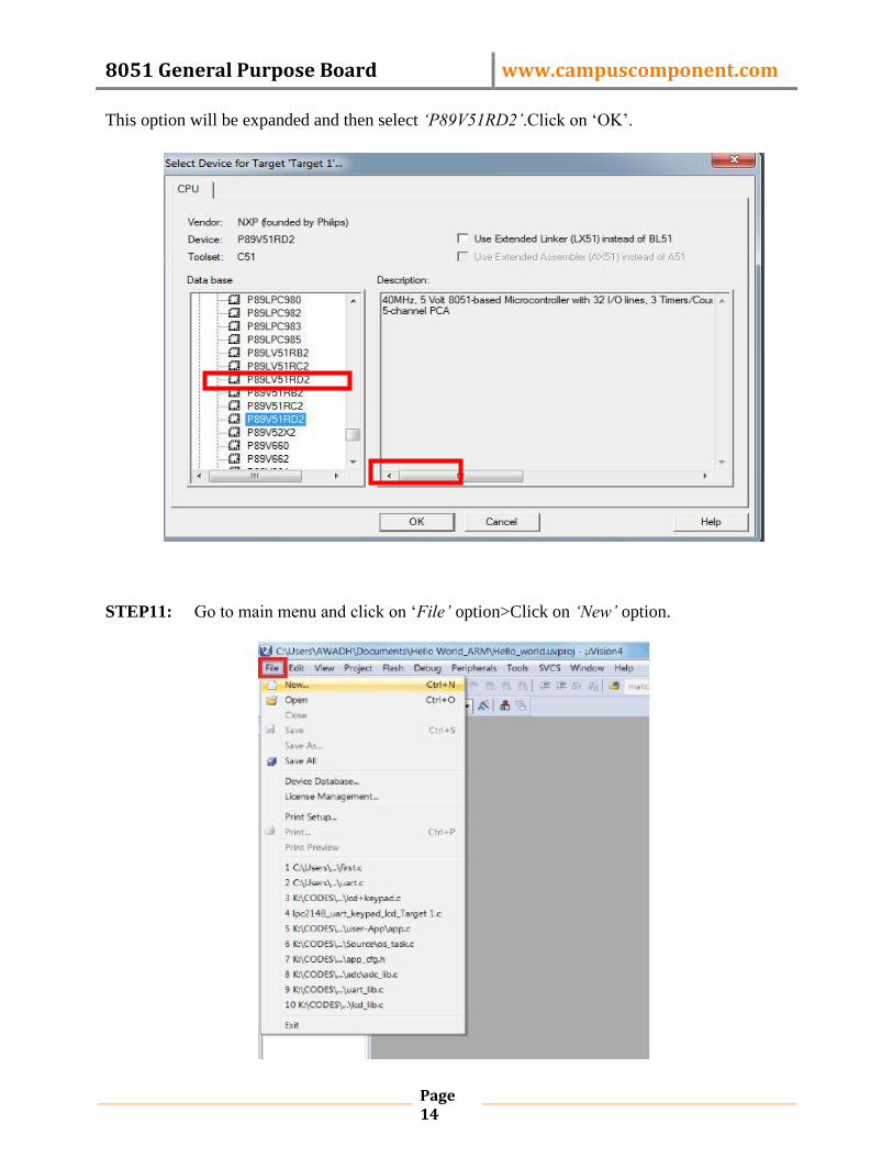
This option will be expanded and then select ‘P89V51RD2’.Click on „OK‟.
STEP11: Go to main menu and click on „File’ option>Click on ‘New’ option.

8051 General Purpose Board www.campuscomponent.com
Page 15
STEP12: Go to main menu and click on ‘File’ option>Click on „Save As..’ option
8051 General Purpose Board www.campuscomponent.com
Page 16
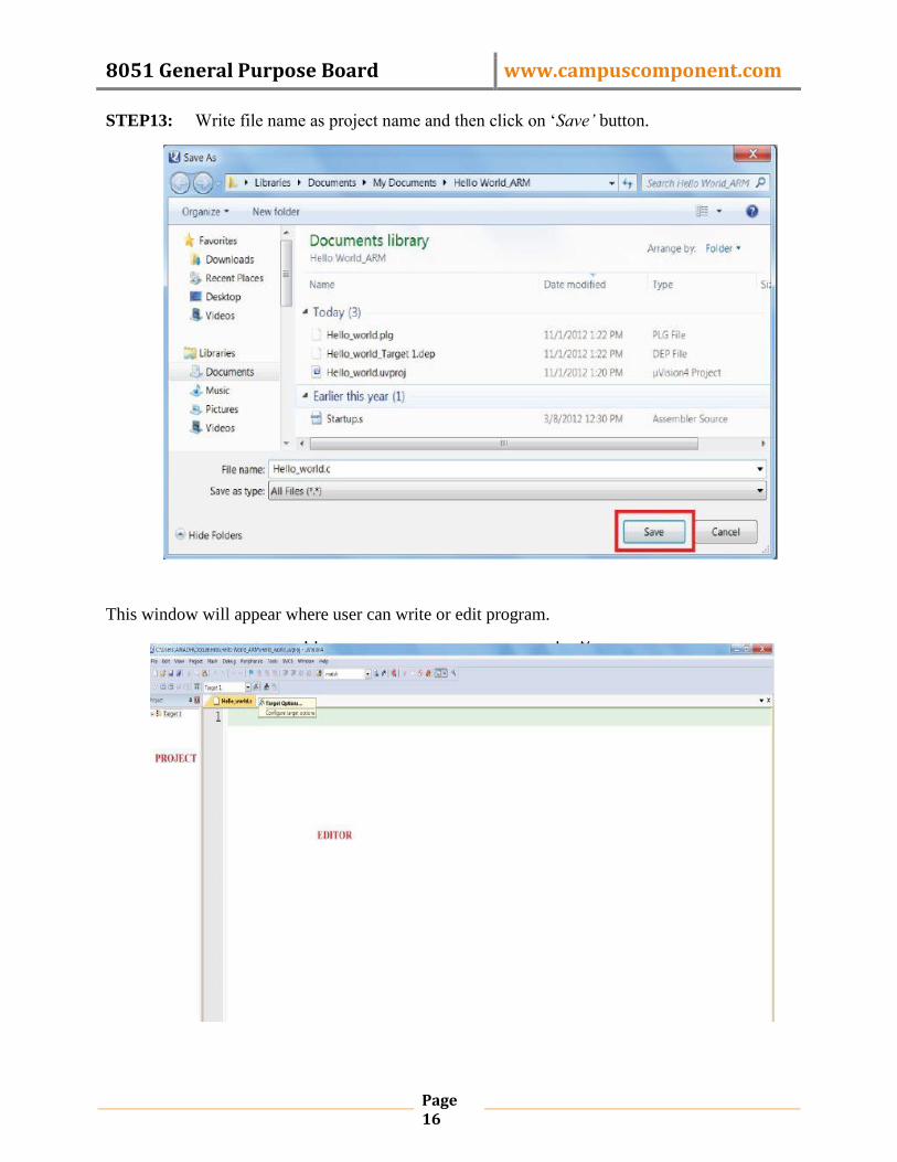
STEP13: Write file name as project name and then click on „Save’ button.
This window will appear where user can write or edit program.

8051 General Purpose Board www.campuscomponent.com
Page 17
STEP14: Select „Output‟ option then confirm status of checkboxes as shown in picture, if not
then make them check and then click on „OK‟.
STEP15: In project window right click on source group1 and then another menu will appear.
Then click on „Add Files to Group ‘Source Group …’‟.
8051 General Purpose Board www.campuscomponent.com
Page 18
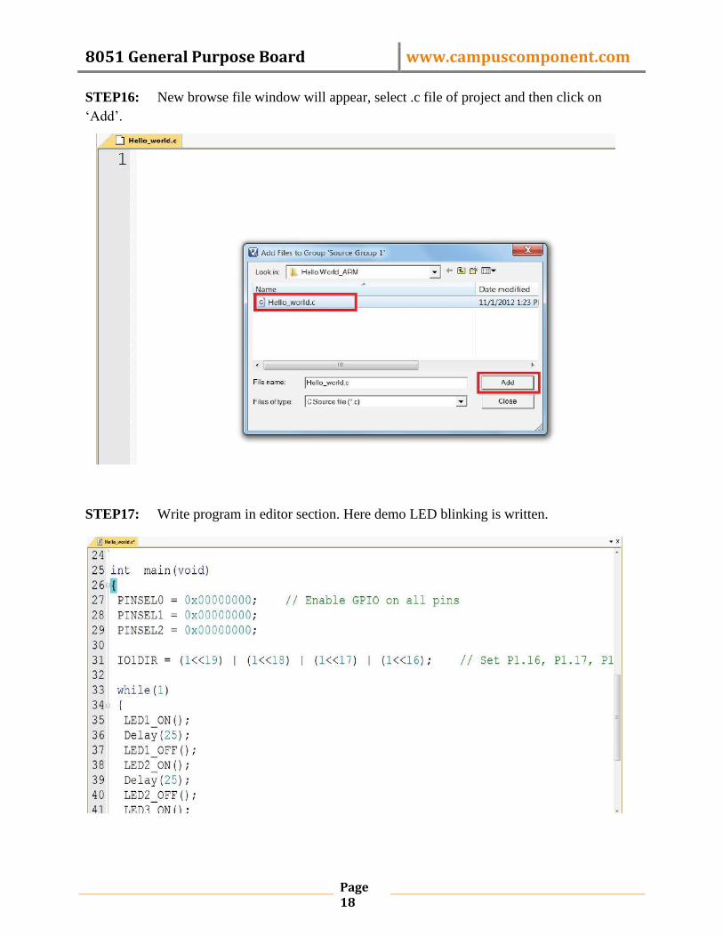
STEP16: New browse file window will appear, select .c file of project and then click on
„Add‟.
STEP17: Write program in editor section. Here demo LED blinking is written.

8051 General Purpose Board www.campuscomponent.com
Page 19

8051 General Purpose Board www.campuscomponent.com
Page 20
Installation of Flash Magic Software
STEP 1: Double click on FlashMagic.exe
STEP 2: Welcome window will appear, click on „Next>‟.
8051 General Purpose Board www.campuscomponent.com
Page 21
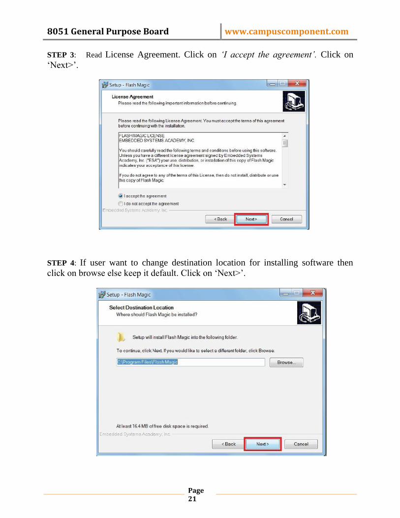
STEP 3: Read License Agreement. Click on ‘I accept the agreement’. Click on
„Next>‟.
STEP 4: If user want to change destination location for installing software then
click on browse else keep it default. Click on „Next>‟.
8051 General Purpose Board www.campuscomponent.com
Page 22
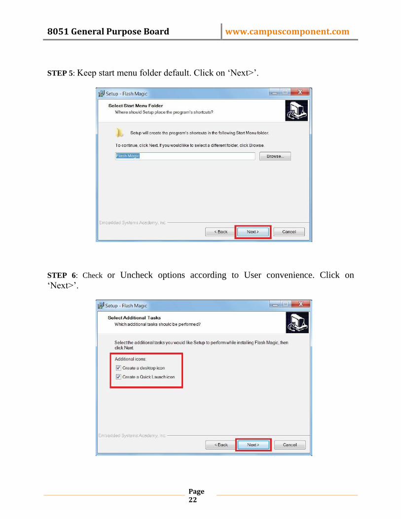
STEP 5: Keep start menu folder default. Click on „Next>‟.
STEP 6: Check or Uncheck options according to User convenience. Click on
„Next>‟.

8051 General Purpose Board www.campuscomponent.com
Page 23
STEP 7: Check Click on ‘Install’.
Let the installation complete

8051 General Purpose Board www.campuscomponent.com
Page 24
STEP 8: Click on ‘Finish’.
STEP 9: Now software windows will open by default and then Click on „Select’
button in Step1-Communication Section, then select 89V51RD from 80C51 as we
have attached P89V51RD2 on 8051Development Board.

8051 General Purpose Board www.campuscomponent.com
Page 25
STEP 10: Click on ‘Browse’ button in step3-Hex File selection. Then select .hex file
of corresponding project.
STEP 11: Click on ‘Options’ button in main toolbar. Then select ‘Advanced Options’. Now select „Asset DTR and RTS while COM Port open’.

8051 General Purpose Board www.campuscomponent.com
Page 26
STEP 12: Click on ‘Start’ button in step5-start section.
Congratulations on completing your first Microcontroller Program Burning
successfully.
Note: - AT89Sxx microcontroller can not be programmed using serial port,hence ISP
Programmer is used.
Installation of Driver
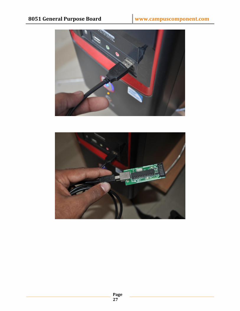
STEP 1: Connect the USB cable to the USB 8051 programmer & USB port of the
PC or Laptop, the Green LED will glow. You will get the following pop up
containing: Found New Hardware USBasp (It means drivers for this hardware is
not installed, so we need to install it.)
8051 General Purpose Board www.campuscomponent.com
Page 27

8051 General Purpose Board www.campuscomponent.com
Page 28
(Note:-If you are getting “USB Device Not Recognized” then your USB programmer is
malfunctioning.)
STEP 2: Select ‘Manage’ by right clicking on ‘My Computer’.

8051 General Purpose Board www.campuscomponent.com
Page 29
STEP 3: Select ‘Device Manager’ from ‘System Tools’ and click on ‘Other devices’
STEP 3: Select ‘USBasp’ from ‘Other devices’ and right click on ‘USBasp’ and
select ‘Update Driver Software…’

8051 General Purpose Board www.campuscomponent.com
Page 30
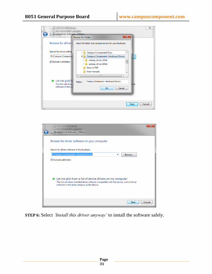
STEP 4: Click on ‘Browse my computer for driver software’.
STEP 5: Browse for the driver software in the location you have kept your drivers,
and then click on ‘Next’.
8051 General Purpose Board www.campuscomponent.com
Page 31
STEP 6: Select ‘Install this driver anyway’ to install the software safely.

8051 General Purpose Board www.campuscomponent.com
Page 32
STEP 7: Driver software installation in process.

8051 General Purpose Board www.campuscomponent.com
Page 33
STEP 8: Finally the driver will be installing & you will get
8051 General Purpose Board www.campuscomponent.com
Page 34
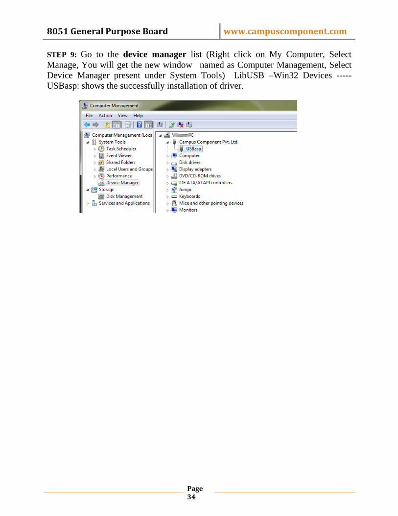
STEP 9: Go to the device manager list (Right click on My Computer, Select
Manage, You will get the new window named as Computer Management, Select
Device Manager present under System Tools) LibUSB –Win32 Devices -----
USBasp: shows the successfully installation of driver.

8051 General Purpose Board www.campuscomponent.com
Page 35
Burning the program into microcontroller using progisp:
Before you start with burning process get your programmer connected with the
development board through an FRC cable connected to ISP port and other end to
the programmer board as shown:
STEP 1: Open the Progisp software.
8051 General Purpose Board www.campuscomponent.com
Page 36
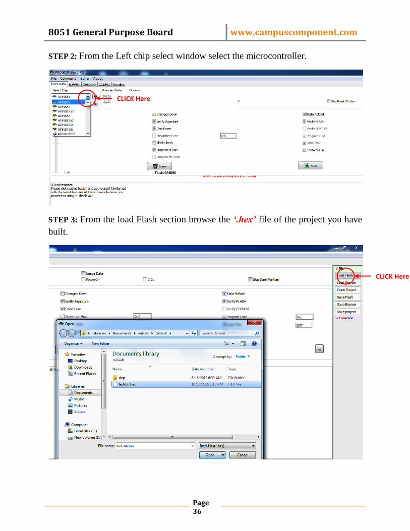
STEP 2: From the Left chip select window select the microcontroller.
STEP 3: From the load Flash section browse the ‘.hex’ file of the project you have
built.
CLICK Here
CLICK Here

8051 General Purpose Board www.campuscomponent.com
Page 37
STEP 4: when the program is loaded click on auto button and wait for some time
till it finishes programming.
Red LED on the programmer board will glow that shows the busy state of
the programmer.
When it displays the message “Erase Write Flash, Verify Flash
successfully done” your controller is ready to work as per your program,
Finally the microcontroller is programmed.

8051 General Purpose Board www.campuscomponent.com
Page 38
Troubleshooting:
Sr.
No
Problem Causes Remedies
1.
Can‟t find
programmer
1. No connection or loose
connection between serial
cable and PC.
Re-connect the serial cable
with the PC.
2. Programmer IC not present
or incorrectly placed.
Connect the IC properly
with correct orientation.
2. Programming
failed
1.Microcontroller IC not
working properly
Replace the microcontroller
IC on target Board
2.FRC cable not working Replace the cable connected
between target board and
programmer
3.Reset failed Press Reset button after
pressing Start in Flash
Magic

8051 General Purpose Board www.campuscomponent.com
Page 39
*Note: For more detail working of module refer datasheet of the ICs.
Installation of Driver:
STEP 1: Connect the USB cable to the USB AVR programmer & USB port of the PC or Laptop,
the Green LED will glow. You will get the following pop up containing: Found New Hardware
USBasp it means USB programmer is working.
(Note:-If you are getting “USB Device Not Recognized” then your USB AVR programmer is
not working.)
STEP 2: Wait for windows information “Found New Hardware Wizard”.

8051 General Purpose Board www.campuscomponent.com
Page 40
STEP 3:After device is detected Driver setup wizard opens. Select where USBASP driver “win-
driver” is located in your CD.
STEP 4: Wait few seconds with the following window
8051 General Purpose Board www.campuscomponent.com
Page 41
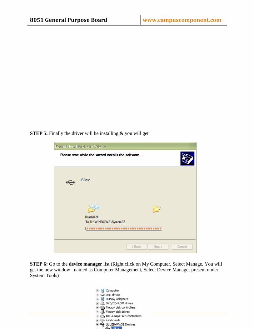
STEP 5: Finally the driver will be installing & you will get
STEP 6: Go to the device manager list (Right click on My Computer, Select Manage, You will
get the new window named as Computer Management, Select Device Manager present under
System Tools)

8051 General Purpose Board www.campuscomponent.com
Page 42
LibUSB –Win32 Devices ----- USBasp :: shows the successfully installation of driver.
Contact Address:
Campus Component Pvt. Ltd
Ackruti Chambers, Office No. 308, 3
rd Floor,
Near Laxmi Narayan Theater,
Swargate, Pune -411037
Mob.: +91-9767444555
Landline: +91-20-24275291
E-mail Address:
Location Map